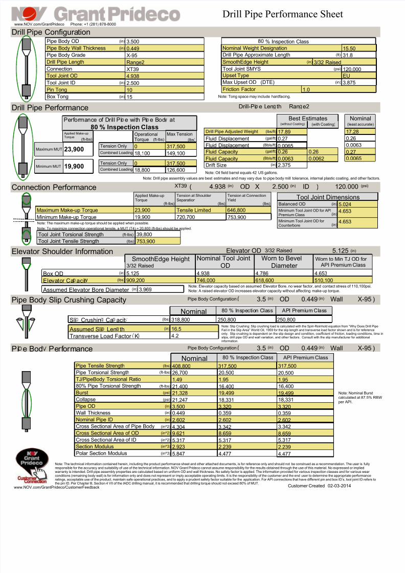
Drill Pipe Performance Sheet www.NOV.com/GrantP rideco Phone: +1 (281) 878-8000 Pipe Body OD Drill Pipe Length Pipe Body Grade Connection Tool Joint ID Drill Pipe Approximate Length Nominal Weight Designation Pipe Body Wall Thickness 3.500 0.449 Range2 XT39 2.500 4.938 10 Tool Joint SMYS Drill Pipe Configura tion Upset Type X-95 31.8 SmoothEdge Height (in) (in) (in) (in) (in) (in) (ft) (in) (psi) Max Upset OD (DTE) (in) Note: Tong space may include hardfacing. 80 % Inspection Class 1.0 Friction Factor 15 Box Tong Pin Tong Tool Joint OD 15.50 3/32 Raised 3.875 EU 120,000 Drill Pipe Performance Drill Pipe Adjusted Weight Fluid Displacement Fluid Capacity Drift Size 17.89 Fluid Capacity 0.26 2.375 0.26 Note: Drill pipe assembly values are best estimates and may vary due to pipe body mill tolerance, internal plastic coating, and other factors. 0.0063 0.0062 Note: Oil field barrel equals 42 US gallons. Best Estimates (with Coating) (without Coating) 80 % Insp ection Class Performance of Drill Pi e with Pi e Bod at Max Tension Operational Torque 23,900 19,900 Applied Make-up Torque Drill-Pi e L en th Ran e2 0 317,500 18,100 149,100 0 317,500 18,800 126,600 (lbs/ft) (gal/ft) (gal/ft) (Bbls/ft) (in) (lbs) (ft-lbs) (ft-lbs) Maximum MUT Minimum MUT 17.28 0.26 0.27 0.0065 (least accurate) Nominal Fluid Displacement 0.0065 0.0063 (Bbls/ft) Tension Only Combined Loading Tension Only Combined Loading 0.27 Maximum Make-up Torque 23,900 Minimum Make-up Torque 19,900 39,800 753,900 Connection Performance XT39 4.938 2.500 ) ( X 120 000 Tension at Connection Yield Minimum Tool Joint OD for API Premium Class Tensile Limited 646,800 720,700 753,900 Tool Joint Tensile Strength Tension at Shoulder Separation Applied Make-up Torque 4.653 Tool Joint Torsional Strength Tool Joint Dimensions (ft-lbs) (lbs) (lbs) (in) (in) (in) (psi) Balanced OD 5.024 (in) (ft-lbs) (lbs) OD ID Minimum Tool Joint OD for Counterbore 4.653 (in) Note: To maximize connection operational tensile, a MUT (T4) = 20,800 (ft-lbs) should be applied. Note: The maximum make-up torque should be applied when possible. Elevator Shoulder Information Ele vator Ca aci t 3.969 Assumed Elevator Bore Diameter Note: A raised elevator OD increases elevator capacity without affecting make-up torque. Elevator OD 5.125 Box OD 4.938 4.786 5.125 746,000 618,600 Worn to Bevel Diameter Nominal Tool Joint OD 3/32 Raised SmoothEdge Height 909,200 4.653 510,100 Worn to Min TJ OD for API Premium Class (in) (lbs) (in) (in) Note: Elevator capacity based on assumed Elevator Bore, no wear factor, and contact stress of 110,100psi. 3/32 Raised Pipe Body Slip Crushing Capacity Sli Crushin Ca acit Assumed Sli Len th Transverse Load Factor K 16.5 4.2 3.5 0.449 X-95 ) Pipe Body Configuration OD Wall 80 Nominal % I nspe ctio n Class API Premium Cl ass 318,800 250,800 250,800 (lbs) (in) (in) (in) Note: Slip Crushing: Slip crushing load is calculated with the Spiri-Reinhold equation from “Why Does Drill Pipe Fail in the Slip Area” World Oil, 1959 for the slip length and transverse load factor shown and is for reference only. Slip crushing is dependent on the slip design and condition, coefficient of friction, loading conditions, time in slips, drill pipe OD and wall variation, and other factors. Consult with the slip manufacturer for additional information. Pipe Tensile Strength 408,800 317,500 317,500 Pipe Torsional Strength 80% Pipe Torsional Strength Burst Collapse 26,700 21,400 21,328 21,247 20,500 16,400 19,499 18,331 20,500 16,400 19,499 18,331 Pi e Bod Pe rf ormance TJ/PipeBody Torsional Ratio 1.95 1.95 1.49 (lbs) (ft-lbs) (psi) (ft-lbs) (psi) Note: Nominal Burst calculated at 87.5% RBW per API. 3.5 0.449 X-95 ) Pipe Body Configuration OD Wall (in) (in) Wall Thickness Nominal Pipe ID Cross Sectional Area of OD Cross Sectional Area of ID Section Modulus Polar Section Modulus 0.449 2.602 9.621 5.317 2.923 5.847 3.320 0.359 2.602 8.659 5.317 2.239 4.477 3.320 0.359 2.602 8.659 Cross Sectional Area of Pipe Body 5.317 2.239 4.477 4.304 3.342 3.342 Pipe OD 3.500 Nominal (in^2) (in) (in^3) (in^3) (in^2) (in^2) (in) (in) 80 % Insp ection Class API Premium Class 02-03-2014 Customer Created Note: The technical information contained herein, including the product performance sheet and other attached documents, is for reference only and should not be construed as a recommendation. The user is fully responsible for the accuracy and suitability of use of the technical information. NOV Grant Prideco cannot assume responsibility for the results obtained through the use of this material. No expressed or implied warranty is intended. Drill pipe assembly properties are calculated based on uniform OD and wall thickness. No safety factor is applied. The information provided for various inspection classes and for various wear conditions (remaining body wall) is for information only and does not represent or imply acceptable operating limits. It is the responsibility of the customer and the end user to determine the appropriate performance ratings, acceptable use of the product, maintain safe operational practices, and to apply a prudent safety factor suitable for the application. For API connections that have different pin and box ID’s, tool joint ID refers to the pin ID. Per Chapter B, Section 4 VII of the IADC drilling manual, it is recommended that drilling torque should not exceed 80% of MUT. www.NOV.com/GrantPrideco/CustomerFeedback

Welcome message from author
This document is posted to help you gain knowledge. Please leave a comment to let me know what you think about it! Share it to your friends and learn new things together.
Transcript
7/21/2019 DrillPipe, 80%, 3.500 OD, 0.449 wall, EU, X-95.. XT39 (4.938 X 2.500 )
http://slidepdf.com/reader/full/drillpipe-80-3500-od-0449-wall-eu-x-95-xt39-4938-x-2500- 1/3
Drill Pipe Performance Sheetwww.NOV.com/GrantPrideco Phone: +1 (281) 878-8000
Pipe Body OD
Drill Pipe Length
Pipe Body Grade
Connection
Tool Joint ID
Drill Pipe Approximate Length
Nominal Weight DesignationPipe Body Wall Thickness
3.500
0.449
Range2
XT39
2.500
4.938
10
Tool Joint SMYS
Drill Pipe Configuration
Upset Type
X-95 31.8
SmoothEdge Height
(in)
(in)
(in)
(in)
(in)
(in)
(ft)
(in)
(psi)
Max Upset OD (DTE) (in)
Note: Tong space may include hardfacing.
80 % Inspection Class
1.0Friction Factor
15Box Tong
Pin Tong
Tool Joint OD
15.50
3/32 Raised
3.875
EU
120,000
Drill Pipe Performance
Drill Pipe Adjusted Weight
Fluid Displacement
Fluid Capacity
Drift Size
17.89
Fluid Capacity
0.26
2.375
0.26
Note: Drill pipe assembly values are best estimates and may vary due to pipe body mill tolerance, internal plastic coating, and other fa
0.0063 0.0062
Note: Oil field barrel equals 42 US gallons.
Best Estimates(with Coating)(without Coating)
80 % Inspection Class
Performance of Drill Pi e with Pi e Bod at
Max TensionOperationalTorque
23,900
19,900
Applied Make-upTorque
Drill-Pi e Len th Ran e2
0 317,500
18,100 149,100
0 317,500
18,800 126,600
(lbs/ft)
(gal/ft)
(gal/ft)
(Bbls/ft)
(in)
(lbs)(ft-lbs)(ft-lbs)
Maximum MUT
Minimum MUT
17.28
0.26
0.27
0.0065
(least accurat
Nomina
Fluid Displacement 0.0065 0.0063(Bbls/ft)Tension Only
Combined Loading
Tension Only
Combined Loading
0.27
Maximum Make-up Torque 23,900
Minimum Make-up Torque 19,900
39,800
753,900
Connection Performance XT39 4.938 2.500 )( X 120 000
Tension at Connection
Yield
Minimum Tool Joint OD for APIPremium Class
Tensile Limited 646,800
720,700 753,900
Tool Joint Tensile Strength
Tension at Shoulder
Separation
Applied Make-up
Torque
4.653
Tool Joint Torsional Strength
Tool Joint Dimensions(ft-lbs) (lbs) (lbs)
(in)
(in) (in) (psi)
Balanced OD 5.024(in)
(ft-lbs)
(lbs)
OD ID
Minimum Tool Joint OD forCounterbore
4.653(in)
Note: To maximize connection operational tensile, a MUT (T4) = 20,800 (ft-lbs) should be applied.
Note: The maximum make-up torque should be applied when possible.
levator Shoulder Information
Elevator Ca acit
3.969 Assumed Elevator Bore Diameter Note: A raised elevator OD increases elevator capacity without affecting make-up torque.
Elevator OD 5.125
Box OD 4.938 4.7865.125
746,000 618,600
Worn to BevelDiameter
Nominal Tool JointOD3/32 Raised
SmoothEdge Height
909,200
4.653
510,100
Worn to Min TJ OD for API Premium Class
(in)
(lbs)
(in)
(in)
Note: Elevator capacity based on assumed Elevator Bore, no wear factor, and contact stress of 110,100psi
3/32 Raised
ipe Body Slip Crushing Capacity
Sli Crushin Ca acit
Assumed Sli Len th
Transverse Load Factor K
16.5
4.2
3.5 0.449 X-95Pipe Body Configuration
OD Wall80Nominal % Inspection Class API Premium Class
318,800 250,800250,800(lbs)
(in)
(in) (in)
Note: Slip Crushing: Slip crushing load is calculated with the Spiri-Reinhold equation from “Why Does DrilFail in the Slip Area” World Oil, 1959 for the slip length and transverse load factor shown and is for referenonly. Slip crushing is dependent on the slip design and condition, coefficient of friction, loading conditionslips, drill pipe OD and wall variation, and other factors. Consult with the slip manufacturer for additionalinformation.
Pipe Tensile Strength 408,800 317,500 317,500
Pipe Torsional Strength
80% Pipe Torsional Strength
Burst
Collapse
26,700
21,400
21,328
21,247
20,500
16,400
19,499
18,331
20,500
16,400
19,499
18,331
i e Bod Performance
TJ/PipeBody Torsional Ratio 1.951.951.49
(lbs)
(ft-lbs)
(psi)
(ft-lbs)
(psi)
Note: Nominal Burcalculated at 87.5%
per API.
3.5 0.449 X-95Pipe Body Configuration OD Wall(in) (in)
Wall Thickness
Nominal Pipe ID
Cross Sectional Area of OD
Cross Sectional Area of ID
Section Modulus
Polar Section Modulus
0.449
2.602
9.621
5.317
2.923
5.847
3.320
0.359
2.602
8.659
5.317
2.239
4.477
3.320
0.359
2.602
8.659
Cross Sectional Area of Pipe Body
5.317
2.239
4.477
4.304 3.342 3.342
Pipe OD 3.500
Nominal
(in^2)
(in)
(in^3)
(in^3)
(in^2)
(in^2)
(in)
(in)
80 % Inspection Class API Premium Class
02-03-2014Customer Created
Note: The technical information contained herein, including the product performance sheet and other attached documents, is for reference only and should not be construed as a recommendation. The user is fullyresponsible for the accuracy and suitability of use of the technical information. NOV Grant Prideco cannot assume responsibility for the results obtained through the use of this material. No expressed or impliedwarranty is intended. Drill pipe assembly properties are calculated based on uniform OD and wall thickness. No safety factor is applied. The information provided for various inspection classes and for various wearconditions (remaining body wall) is for information only and does not represent or imply acceptable operating limits. It is the responsibility of the customer and the end user to determine the appropriate performancratings, acceptable use of the product, maintain safe operational practices, and to apply a prudent safety factor suitable for the application. For API connections that have different pin and box ID’s, tool joint ID refethe pin ID. Per Chapter B, Section 4 VII of the IADC drilling manual, it is recommended that drilling torque should not exceed 80% of MUT.
ww.NOV.com/GrantPrideco/CustomerFeedback
7/21/2019 DrillPipe, 80%, 3.500 OD, 0.449 wall, EU, X-95.. XT39 (4.938 X 2.500 )
http://slidepdf.com/reader/full/drillpipe-80-3500-od-0449-wall-eu-x-95-xt39-4938-x-2500- 2/3
CombinedLoadingforDrillPipeatCombinedLoadingforDrillPipeat
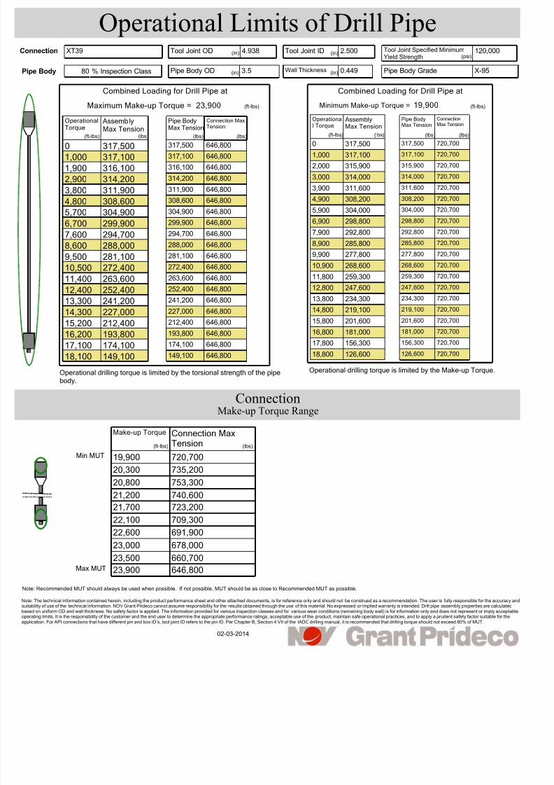
Operational Limits of Drill Pipe
% Inspection Class80 3.5
XT39 4.938Connection
Pipe Body ODPipe Body
Tool Joint OD
0.449 X-95
120,0002.500 Tool Joint Specified MinimumYield Strength
Wall Thickness Pipe Body Grade
Tool Joint ID
23,900MaximumMake-upTorque=
ConnectionMaxTension
OperationalTorque
PipeBodyMaxTension
AssemblyMaxTension
0
1,000
1,900
2,900
3,800
4,800
5,700
6,700
7,600
8,600
9,500
10,500
11,400
12,400
13,300
14,300
15,200
16,200
17,100
18,100
317,500
317,100
316,100
314,200
311,900
308,600
304,900
299,900
294,700
288,000
281,100
272,400
263,600
252,400
241,200
227,000
212,400
193,800
174,100
149,100
Operationaldrillingtorqueislimitedbythetorsionalstrengthofthepipebody.
646,800
646,800
646,800
646,800
646,800
646,800
646,800
646,800
646,800
646,800
646,800
646,800
646,800
646,800
646,800
646,800
646,800
646,800
646,800
646,800
317,500
317,100
316,100
314,200
311,900
308,600
304,900
299,900
294,700
288,000
281,100
272,400
263,600
252,400
241,200
227,000
212,400
193,800
174,100
149,100
19,900MinimumMake-upTorque=
ConnectionMaxTension
OperationalTorque
PipeBodyMaxTension
AssemblyMaxTension
0
1,000
2,000
3,000
3,900
4,900
5,900
6,900
7,900
8,900
9,900
10,900
11,800
12,800
13,800
14,800
15,800
16,800
17,800
18,800
317,500
317,100
315,900
314,000
311,600
308,200
304,000
298,800
292,800
285,800
277,800
268,600
259,300
247,600
234,300
219,100
201,600
181,000
156,300
126,600
OperationaldrillingtorqueislimitedbytheMake-upTorque.
720,700
720,700
720,700
720,700
720,700
720,700
720,700
720,700
720,700
720,700
720,700
720,700
720,700
720,700
720,700
720,700
720,700
720,700
720,700
720,700
317,500
317,100
315,900
314,000
311,600
308,200
304,000
298,800
292,800
285,800
277,800
268,600
259,300
247,600
234,300
219,100
201,600
181,000
156,300
126,600
(in) (in)
(in) (in)
(psi)
(lbs)(ft-lbs) (lbs) (lbs) (ft-lbs) (lbs) (lbs) (lbs)
(ft-lbs) (ft-lbs)
Note: Recommended MUT should always be used when possible. If not possible, MUT should be as close to Recommended MUT as possible.
Note: The technical information contained herein, including the product performance sheet and other attached documents, is for reference only and should not be construed as a recommendation. The user is fully responsible for the accurasuitability of use of the technical information. NOV Grant Prideco cannot assume responsibility for the results obtained through the use of this material. No expressed or implied warranty is intended. Drill pipe assembly properties are calculabased on uniform OD and wall thickness. No safety factor is applied. The information provided for various inspection classes and for various wear conditions (remaining body wall) is for information only and does not represent or imply acceoperating limits. It is the responsibility of the customer and the end user to determine the appropriate performance ratings, acceptable use of the product, maintain safe operational practices, and to apply a prudent safety factor suitable for tapplication. For API connections that have different pin and box ID’s, tool joint ID refers to the pin ID. Per Chapter B, Section 4 VII of the IADC drilling manual, it is recommended that drilling torque should not exceed 80% of MUT.
720,700
ConnectionMaxTension
Make-upTorque
MinMUT
MaxMUT
19,900
20,300
20,800
21,200
21,700
22,100
22,600
23,000
23,500
23,900
735,200
753,300
740,600
723,200
709,300
691,900
678,000
660,700
646,800
(ft-lbs) (lbs)
02-03-2014
Make-up Torque Range
Connection

7/21/2019 DrillPipe, 80%, 3.500 OD, 0.449 wall, EU, X-95.. XT39 (4.938 X 2.500 )
http://slidepdf.com/reader/full/drillpipe-80-3500-od-0449-wall-eu-x-95-xt39-4938-x-2500- 3/3
Connection Wear Table
ToolJoint OD
Connection MaxTension
ConnectionWear
4.938
4.912
4.886
4.86
4.834
4.808
4.782
4.756
4.731
4.705
4.679
4.653
23,900
23,400
22,900
22,400
21,900
21,400
20,900
20,400
20,000
19,500
19,000
18,600
19,900
19,500
19,100
18,700
18,200
17,800
17,400
17,000
16,600
16,200
15,900
15,500
Connection MaxTension
Min MUT
646,800
661,100
675,200
689,100
702,900
708,000
698,500
688,200
675,000
640,600
605,800
575,100
720,700
709,500
698,300
687,000
672,100
652,900
621,400
590,700
561,400
532,200
507,000
479,200
New OD
Worn OD
ConnectionTorsionalStrength
39,800
39,000
38,100
37,300
36,500
35,700
34,800
34,000
33,300
32,500
31,700
30,900
Combined Loading Table (Torque-Tension)
Pipe Body
0
317,500
1,900
316,100
3,700
312,200
5,600
305,300
7,400
295,900
9,300
282,700
Pipe Body Torque
Pipe Body MaxTension
11,200
265,600
13,000
245,100
14,900
217,500
16,700
183,300
18,600
132,000
20,400
22,600
% Inspection Class80 3.5Pipe Body ODpe Body 0.449 X-95Wall Thickness Pipe Body Grade
XT39 4.938Connection Tool Joint OD 120,0002.500 Tool Joint Specified MinimumYield Strength
Tool Joint ID(in)
(ft-lbs)
(psi)(in)
(in) (ft-lbs) (lbs) (ft-lbs) (lbs)
(in) (in)
(ft-lbs)
(lbs)
ote: The technical information contained herein, including the product performance sheet and other attached documents, is for reference only and should not be construed as a recommendation. The user is fully responsible for the accuracuitability of use of the technical information. NOV Grant Prideco cannot assume responsibility for the results obtained through the use of this material. No expressed or implied warranty is intended. Drill pipe assembly properties are calculatased on uniform OD and wall thickness. No safety factor is applied. The information provided for various inspection classes and for various wear conditions (remaining body wall) is for information only and does not represent or imply accepperating limits. It is the responsibility of the customer and the end user to determine the appropriate performance ratings, acceptable use of the product, maintain safe operational practices, and to apply a prudent safety factor suitable for thpplication. For API connections that have different pin and box ID’s, tool joint ID refers to the pin ID. Per Chapter B, Section 4 VII of the IADC drilling manual, it is recommended that drilling torque should not exceed 80% of MUT.
02-03-2014
MaxMUT
Related Documents
![1. Ammonia; NH3; [7664-41-7] Delepine, 2. Hethanol; …...Mole fraction*, x NHs 0.449 0.375 0.341 0.304 0.270 0.234 0.206 0.180 * The total pressure was equal to barometric pressure](https://static.cupdf.com/doc/110x72/5e69a4d7c533ce724e0441fd/1-ammonia-nh3-7664-41-7-delepine-2-hethanol-mole-fraction-x-nhs-0449.jpg)