2012 Rigscape 2012/12/12 Rev 1.05 R.I.D.E. Inc. Rigscape Drilling/Service Rig Procedures Special Instructions/Conditions of Use Reading user procedure manual prior to use is essential Only persons that have been deemed competent in the operation of the system should operate the system

Welcome message from author
This document is posted to help you gain knowledge. Please leave a comment to let me know what you think about it! Share it to your friends and learn new things together.
Transcript

2012
Rigscape
2012/12/12
Rev 1.05
R.I.D.E. Inc. Rigscape Drilling/Service Rig Procedures
Special Instructions/Conditions of Use
Reading user procedure manual prior to use is essential
Only persons that have been deemed competent in the
operation of the system should operate the system
R.I.D.E. Inc. Rigscape Drilling/Service Rig Procedures Manual
2012-12-12 Page 2 of 48
Rev 1.05 RGDRP_1.1
R.I.D.E. Inc. Rigscape Procedures
Table of Contents
Section
Specifications & Requirements………………………………………………………..… i.
Safety Warnings ……………………………………………………………………… 1.1.
Setup ……………………………………………………………………………………. 2.
Checklist …………………………………………………………………... 2.1.
Pivoting Davit Arm Setup …………………………………………………. 2.2.
Choosing Cable ……………………………………………………………. 2.3.
Docking Station …………………………………………………………… 2.4.
Davit Sheave Cable Installation …………………………………………. 2.5.
Magnegress/ Anchor Placement ……………………………….………... 2.6.
Magnegress Cable Install ………………………………………………... 2.7.
Tension Indicator …………………………………………………............ 2.8.
Trolley ……………………………………………………………………... 2.9.
Rigscape Shuttle ……………………………………………………………2.10.
Operation ………………………………………………………..……………………… 3.
Teardown ……………………………………………………………………………...... 4.
Maintenance ………………………………………………………………………….…. 5.
Descent Log …………………………………………………………………………... 6.
Additional Information ………………………………………………………………... 7.
Actual product specifications may vary, and features, functionality and other
product specifications are subject to change without notice or obligation.
Manuals & Amendments can be downloaded from our website: rideinc.com
R.I.D.E. Inc. recommends that a function test be performed upon rig up and/or if
the system setup has been manipulated in any way.
Please visit our website for the latest manual revisions & parts list

R.I.D.E. Inc. Rigscape Drilling/Service Rig Procedures Manual
2012-12-12 Page 3 of 48
Rev 1.05 RGDRP_1.1
i.) Specifications:
• Weights:
� 16 lbs (7kg) trolley
� 58 lbs. (28 kg) Rigscape shuttle
� 160 lbs. (75 kg) Magnegress
� 37 lbs. (18 kg) tension link
• Capacity - 310 lbs (140 kg) – 1 person
Maximum allowable wind speed for Rigscape operation:
• Double service rig: 58 mph - 50 knots - 93 kph
• Double drilling rig: 58 mph - 50 knots - 93 kph
• Triple drilling rig: 58 mph - 50 knots - 93 kph
Anchor requirements:
• Ground Anchor must resist 3,600 lbs. (1633 kg) @ 30° upward angle.
Cable Life:
• There is a 3 year maximum cable life.
o At any time no cable should be used if frayed or damaged in anyway.
R.I.D.E. Inc. Rigscape Drilling/Service Rig Procedures Manual
2012-12-12 Page 4 of 48
Rev 1.05 RGDRP_1.1
Waivers
Warning: This product is part of an emergency descent system. The user must follow
manufacturer’s instructions for each part of the system. These instructions
must be provided to the user of this equipment. The user must read &
understand these instructions before using this equipment. Manufacturer’s
instructions must be followed for proper use & maintenance of this
equipment. Alterations or misuse of this equipment, or failure to follow
instructions, may result in serious injury or death.
Important: If you have questions on the use, care or suitability of this equipment for
your application, contact R.I.D.E. Inc. (780-621-1570)
Warning: Do not use a body belt with this equipment. Body belts do not support
your entire body, which may result in serious injury or death.
Warning: It is the responsibility of the user & purchaser of this equipment to be
trained in the correct care & use of this equipment. The user & purchaser
must be aware of the operating characteristics, application limits &
consequences of improper use of this equipment.
Warning: Training must be conducted without exposing the trainee to a fall hazard.
Training should be repeated on a periodic basis.
Inspection: A formal inspection should be completed if the system parameters
are changed, such as after a system is moved, re-rigged or the anchorage is
moved.
A visual inspection must be done by the user before every use.

R.I.D.E. Inc. Rigscape Drilling/Service Rig Procedures Manual
2012-12-12 Page 5 of 48
Rev 1.05 RGDRP_1.1
Safety Warnings
1.1. Read these warnings carefully before inspecting, setting up, installing, using,
or tearing down the Rigscape/Magnegress system.
1.1.1. Wear mandatory personal protection equipment at all times.
1.1.2. Do not attempt to lift or move the Magnegress by yourself.
1.1.3. Use proper lifting techniques when inspecting, setting up, installing or
tearing down the Rigscape/Magnegress system.
1.1.4. Watch for crush points when inspecting, setting up, installing, using,
or tearing down the Rigscape/Magnegress system.
1.1.5. Watch for tripping hazards when inspecting, setting up, installing,
using, or tearing down the Rigscape/Magnegress system.
1.1.6. Do not use the Rigscape/Magnegress system unless you are wearing a
safety harness and are secured only to the trolley fall-arrest device
and shuttle working lanyard attachment ears.
1.1.7. This device is designed for single occupancy only
1.1.8. Do not use if cable, trolley or anchor is damaged.
1.2. Instructions in this manual
1.2.1. The instructions in this manual are classified into “DANGER”, “WARNING”, “CAUTION” and “NOTES”, according to the degree of risk and hindrance.

R.I.D.E. Inc. Rigscape Drilling/Service Rig Procedures Manual
2012-12-12 Page 6 of 48
Rev 1.05 RGDRP_1.1
2. Setup
2.1. Checklist
2.1.1. Create a copy of the checklist on the following page & use for your
records.

R.I.D.E. Inc. Rigscape Drilling/Service Rig Procedures Manual
2012-12-12 Page 7 of 48
Rev 1.05 RGDRP_1.1
Checklist
Section Check
2.2.2. Erect Archway ________
2.2.5. Rotate davit arm into position ________
2.4.1. Cable, Flemish eyes & swages ________
2.5.4. Docking station free rotation ________
2.5.5. Sheave groove ________
2.5.6. Davit sheave assembly ________
2.5.9. Docking station free pivot 30° ________
2.5.11. Magnetic pockets ________
2.6.2. Magnegress/Anchor placement ________
2.7.4. Magnegress brake sheave ________
2.8.1. Tension Indicator ________
2.8.5. Magnegress cover plate ________
2.9.2. Secondary brake pad ________
2.9.5. Sheave gate’s locating flap ________
2.10.2. Shuttle & pivoting arm ________
2.10.10. Shuttle docking pins ________
2.10.11. Safety cable, Flemish eyes & swages ________
2.10.12. SRL (Self-retracting lanyard) ________
Print Name _________________________
Signature___________________________
Date_______________________________
R.I.D.E. Inc. Rigscape Drilling/Service Rig Procedures Manual
2012-12-12 Page 8 of 48
Rev 1.05 RGDRP_1.1
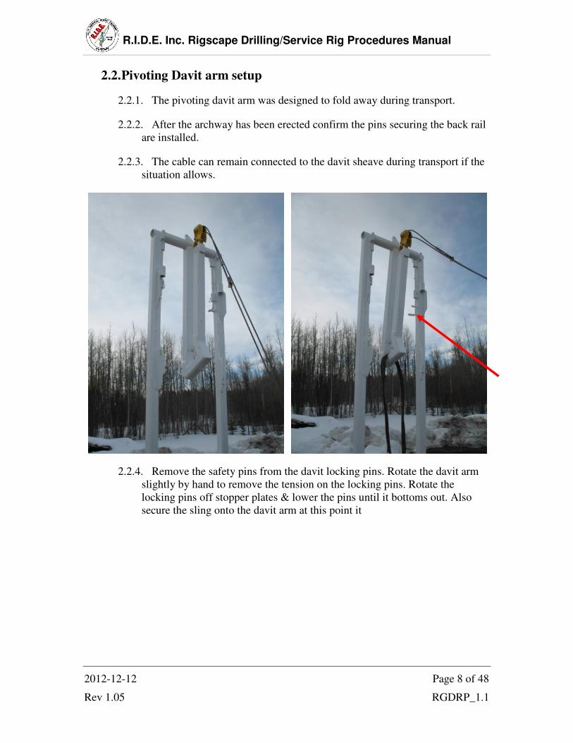
2.2. Pivoting Davit arm setup
2.2.1. The pivoting davit arm was designed to fold away during transport.
2.2.2. After the archway has been erected confirm the pins securing the back rail
are installed.
2.2.3. The cable can remain connected to the davit sheave during transport if the
situation allows.
2.2.4. Remove the safety pins from the davit locking pins. Rotate the davit arm
slightly by hand to remove the tension on the locking pins. Rotate the
locking pins off stopper plates & lower the pins until it bottoms out. Also
secure the sling onto the davit arm at this point it

R.I.D.E. Inc. Rigscape Drilling/Service Rig Procedures Manual
2012-12-12 Page 9 of 48
Rev 1.05 RGDRP_1.1
2.2.5. Using the rig mounted winch, rotate the davit arm into it working position.
Push the locking pins into the locking position & place the safety pins
2.3. Choosing cable
2.3.1. Ensure cable supplied by OEM
2.4. Docking Station
Flemish eye Swage
2.4.1. Inspect the cable for frays, kinks or any other damage. Check the Flemish
eyes & swages for damage or wear.
Danger: Do not operate system with cable including the Flemish & swage that is in
any way damaged.
Note: Call your local distributor for replacement cable.
R.I.D.E. Inc. Rigscape Drilling/Service Rig Procedures Manual
2012-12-12 Page 10 of 48
Rev 1.05 RGDRP_1.1
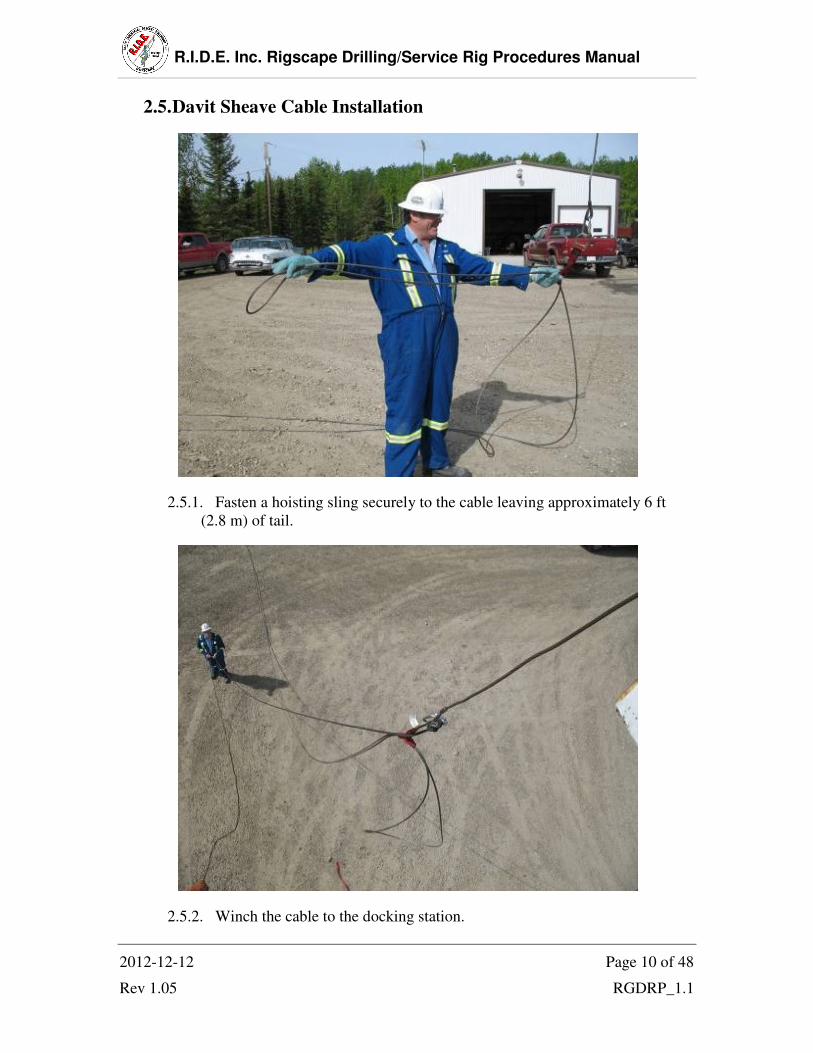
2.5. Davit Sheave Cable Installation
2.5.1. Fasten a hoisting sling securely to the cable leaving approximately 6 ft
(2.8 m) of tail.
2.5.2. Winch the cable to the docking station.
R.I.D.E. Inc. Rigscape Drilling/Service Rig Procedures Manual
2012-12-12 Page 11 of 48
Rev 1.05 RGDRP_1.1
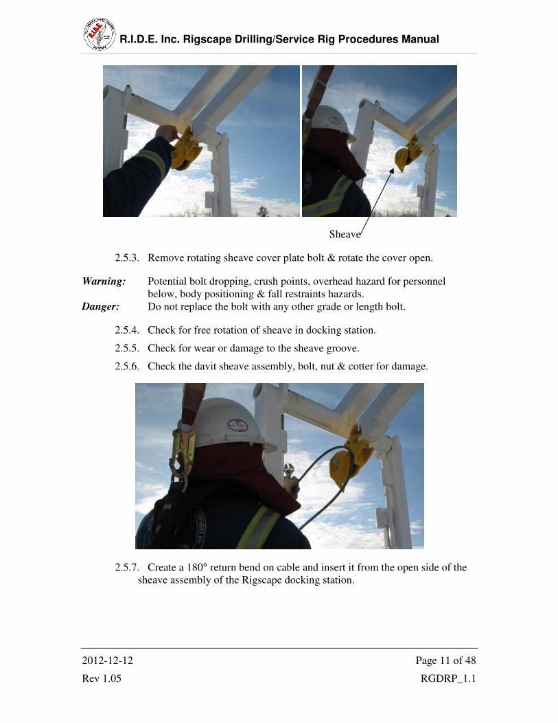
Sheave
2.5.3. Remove rotating sheave cover plate bolt & rotate the cover open.
Warning: Potential bolt dropping, crush points, overhead hazard for personnel
below, body positioning & fall restraints hazards.
Danger: Do not replace the bolt with any other grade or length bolt.
2.5.4. Check for free rotation of sheave in docking station.
2.5.5. Check for wear or damage to the sheave groove.
2.5.6. Check the davit sheave assembly, bolt, nut & cotter for damage.
2.5.7. Create a 180° return bend on cable and insert it from the open side of the
sheave assembly of the Rigscape docking station.

R.I.D.E. Inc. Rigscape Drilling/Service Rig Procedures Manual
2012-12-12 Page 12 of 48
Rev 1.05 RGDRP_1.1
2.5.8. Draw or pull the cable to the sheave & rotate the sheave assembly cover
closed & replace bolt securely.
2.5.9. Inspect the docking station pivot bolt, nut & cotter pin for damage. Check
that it rotates left to right freely (approx. total rotation 30°).
2.5.10. Disconnect the hoisting sling from the winch line & cable.
R.I.D.E. Inc. Rigscape Drilling/Service Rig Procedures Manual
2012-12-12 Page 13 of 48
Rev 1.05 RGDRP_1.1
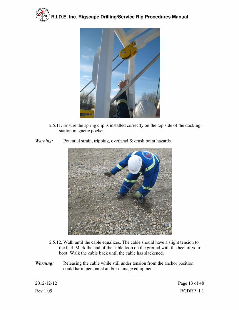
2.5.11. Ensure the spring clip is installed correctly on the top side of the docking
station magnetic pocket.
Warning: Potential strain, tripping, overhead & crush point hazards.
2.5.12. Walk until the cable equalizes. The cable should have a slight tension to
the feel. Mark the end of the cable loop on the ground with the heel of your
boot. Walk the cable back until the cable has slackened.
Warning: Releasing the cable while still under tension from the anchor position
could harm personnel and/or damage equipment.

R.I.D.E. Inc. Rigscape Drilling/Service Rig Procedures Manual
2012-12-12 Page 14 of 48
Rev 1.05 RGDRP_1.1
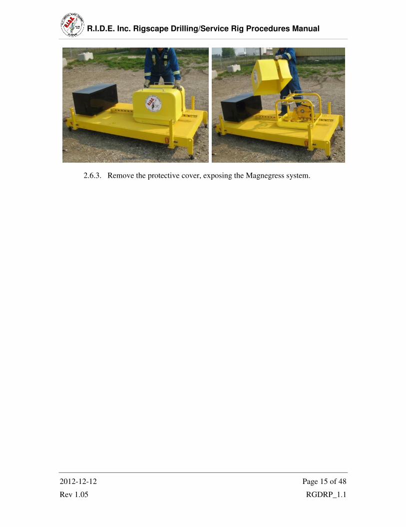
2.6. Magnegress/Anchor Placement
2.6.1. Raise the transportation legs prior to placement
2.6.2. Position the front of the anchor approximately in line to your mark on the
ground.
R.I.D.E. Inc. Rigscape Drilling/Service Rig Procedures Manual
2012-12-12 Page 15 of 48
Rev 1.05 RGDRP_1.1
2.6.3. Remove the protective cover, exposing the Magnegress system.
R.I.D.E. Inc. Rigscape Drilling/Service Rig Procedures Manual
2012-12-12 Page 16 of 48
Rev 1.05 RGDRP_1.1
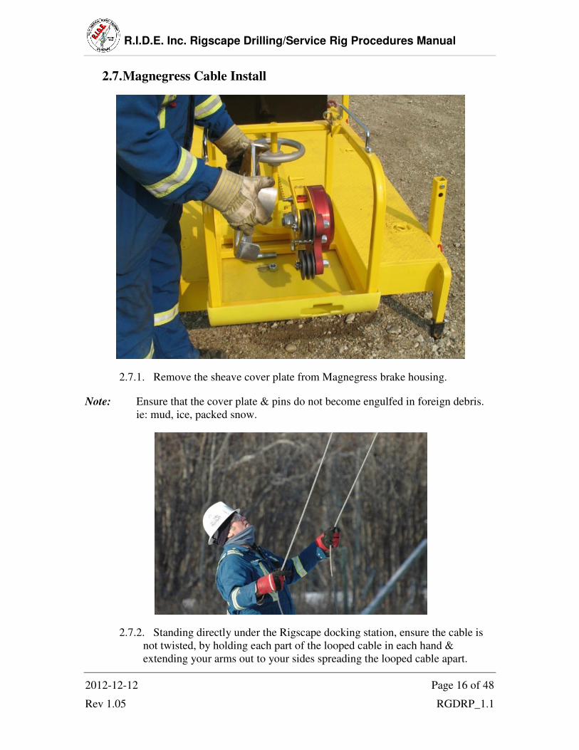
2.7. Magnegress Cable Install
2.7.1. Remove the sheave cover plate from Magnegress brake housing.
Note: Ensure that the cover plate & pins do not become engulfed in foreign debris.
ie: mud, ice, packed snow.
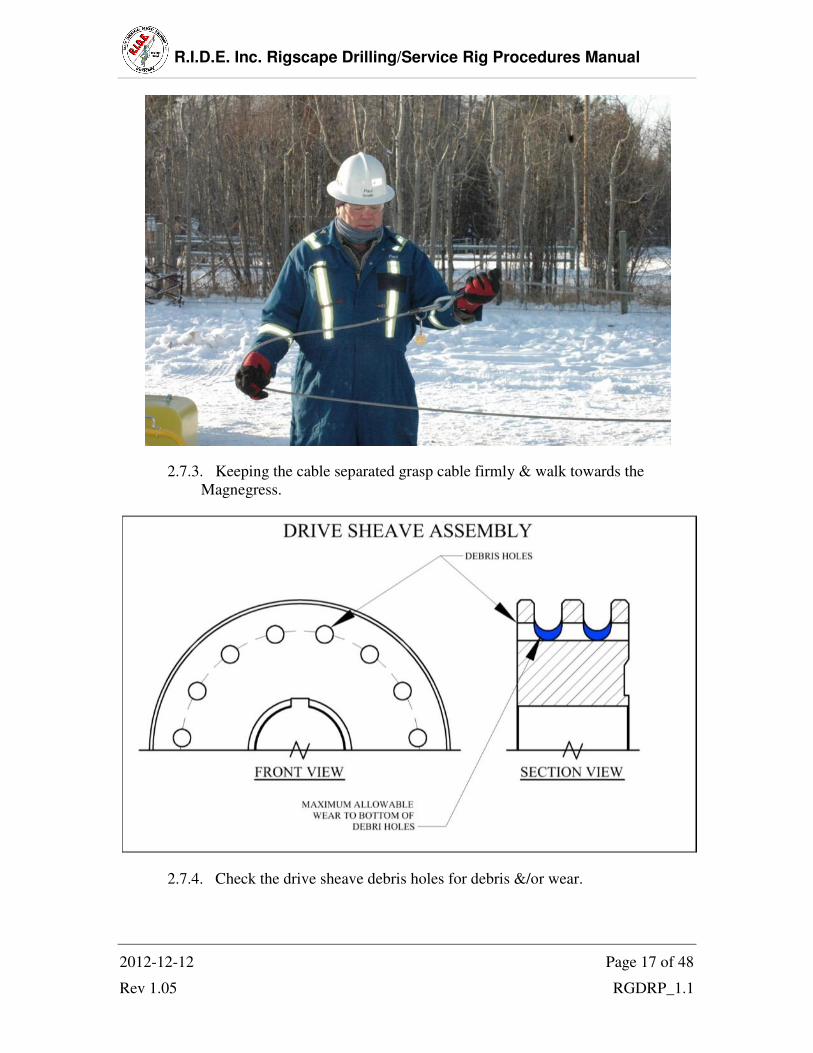
2.7.2. Standing directly under the Rigscape docking station, ensure the cable is
not twisted, by holding each part of the looped cable in each hand &
extending your arms out to your sides spreading the looped cable apart.
R.I.D.E. Inc. Rigscape Drilling/Service Rig Procedures Manual
2012-12-12 Page 17 of 48
Rev 1.05 RGDRP_1.1
2.7.3. Keeping the cable separated grasp cable firmly & walk towards the
Magnegress.
2.7.4. Check the drive sheave debris holes for debris &/or wear.

R.I.D.E. Inc. Rigscape Drilling/Service Rig Procedures Manual
2012-12-12 Page 18 of 48
Rev 1.05 RGDRP_1.1
2.7.5. Cable thread configuration
Flemish Eyes
2.7.6. Create a 180° return bend on cable and insert it around the drive sheave &
in between the idler sheaves of the Magnegress. Ensure the Flemish eyes are
on the upper cable travelling to the top of the top sheave.
R.I.D.E. Inc. Rigscape Drilling/Service Rig Procedures Manual
2012-12-12 Page 19 of 48
Rev 1.05 RGDRP_1.1
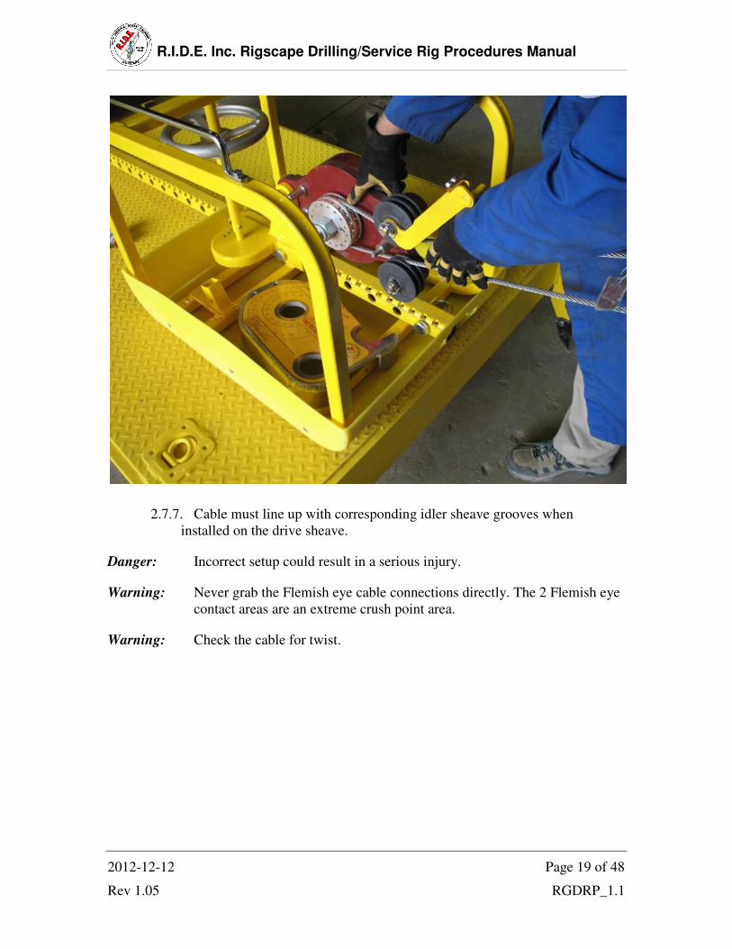
2.7.7. Cable must line up with corresponding idler sheave grooves when
installed on the drive sheave.
Danger: Incorrect setup could result in a serious injury.
Warning: Never grab the Flemish eye cable connections directly. The 2 Flemish eye
contact areas are an extreme crush point area.
Warning: Check the cable for twist.

R.I.D.E. Inc. Rigscape Drilling/Service Rig Procedures Manual
2012-12-12 Page 20 of 48
Rev 1.05 RGDRP_1.1
2.8. Tension Indicator
2.8.1. Rotate out the tension indicator. Side slip the cable across the back stop
pin until the cable slips to the top of the back stop pin.
2.8.2. Turn the pinion hand wheel clock-wise, move the brake assembly away
from rig, there by tightening the cable, tighten until the indicator pad
becomes flush with the top face of the tension indicator. When the two hole
line up, insert the adjustment bolt, install the nut and safety pin.
R.I.D.E. Inc. Rigscape Drilling/Service Rig Procedures Manual
2012-12-12 Page 21 of 48
Rev 1.05 RGDRP_1.1
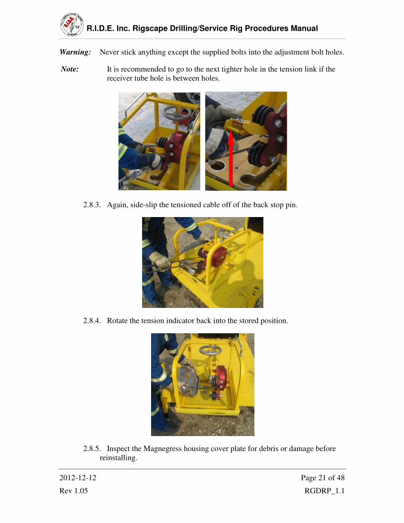
Warning: Never stick anything except the supplied bolts into the adjustment bolt holes.
Note: It is recommended to go to the next tighter hole in the tension link if the
receiver tube hole is between holes.
2.8.3. Again, side-slip the tensioned cable off of the back stop pin.
2.8.4. Rotate the tension indicator back into the stored position.
2.8.5. Inspect the Magnegress housing cover plate for debris or damage before
reinstalling.

R.I.D.E. Inc. Rigscape Drilling/Service Rig Procedures Manual
2012-12-12 Page 22 of 48
Rev 1.05 RGDRP_1.1
2.8.6. Re-install the Magnegress sheave cover plate.
Note: Cover plate will not fit on the Magnegress housing if something is not
properly in place. If this happens check cable orientation on sheave,
tension indicator orientation or debris.
Danger: All 3 cover plate pins must be installed during operation.
2.8.7. Re-install the Magnegress protective cover.

R.I.D.E. Inc. Rigscape Drilling/Service Rig Procedures Manual
2012-12-12 Page 23 of 48
Rev 1.05 RGDRP_1.1
2.9. Trolley
2.9.1. Pull & turn the lock-pin knob to lift the locking pin out of the locking pin
opening.
2.9.2. Rotate the sheave gate knob on the trolley counter clockwise until the
knob becomes completely disconnected from the threaded shaft.
2.9.3. Check that the secondary brake operates freely, the brake pad is not
excessively worn & that the sheave rotates freely.

R.I.D.E. Inc. Rigscape Drilling/Service Rig Procedures Manual
2012-12-12 Page 24 of 48
Rev 1.05 RGDRP_1.1
2.9.4. Place the cold swage, located on the upside or monkey board side of the
Flemish eye, inside the trolley, above the sheave. Insert the lower cable
inside the trolley as well but underneath the sheave. (arrow points towards
Magnegress)
Caution: Ensure Flemish eye swage is not getting pinched in between the gate & body
while tightening the sheave gate knob.
Danger: The cold cable swage must become trapped inside the trolley on the top side
of the sheave.
2.9.5. Close the sheave gate & tighten the sheave gate knob clockwise until snug.
Turn the lock-pin knob until it drops into the lock position (DO NOT use
wrenches to tighten). Inspect the sheave gate’s locator flap for damage & for
proper fit.
Note: The sheave gate knob may have to be rotated counter-clockwise slightly to allow
for the lock pin to engage.
R.I.D.E. Inc. Rigscape Drilling/Service Rig Procedures Manual
2012-12-12 Page 25 of 48
Rev 1.05 RGDRP_1.1
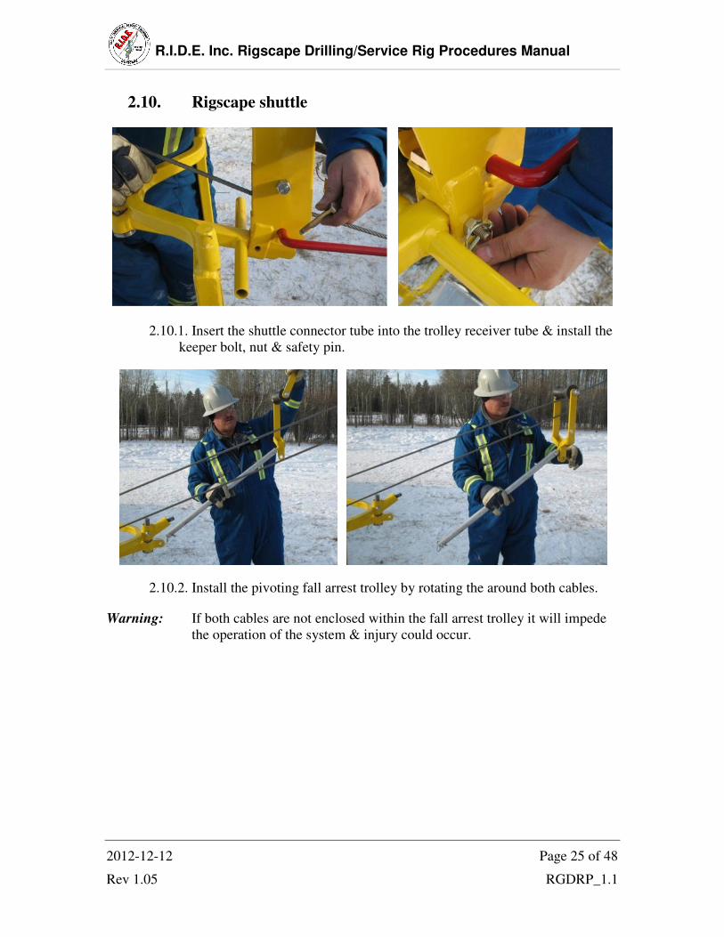
2.10. Rigscape shuttle
2.10.1. Insert the shuttle connector tube into the trolley receiver tube & install the
keeper bolt, nut & safety pin.
2.10.2. Install the pivoting fall arrest trolley by rotating the around both cables.
Warning: If both cables are not enclosed within the fall arrest trolley it will impede
the operation of the system & injury could occur.

R.I.D.E. Inc. Rigscape Drilling/Service Rig Procedures Manual
2012-12-12 Page 26 of 48
Rev 1.05 RGDRP_1.1
2.10.3. Insert the shuttle receiving pin into the receiving tube of the fall arrest
trolley spacer.
2.10.4. Install the pin through this assembly.
R.I.D.E. Inc. Rigscape Drilling/Service Rig Procedures Manual
2012-12-12 Page 27 of 48
Rev 1.05 RGDRP_1.1
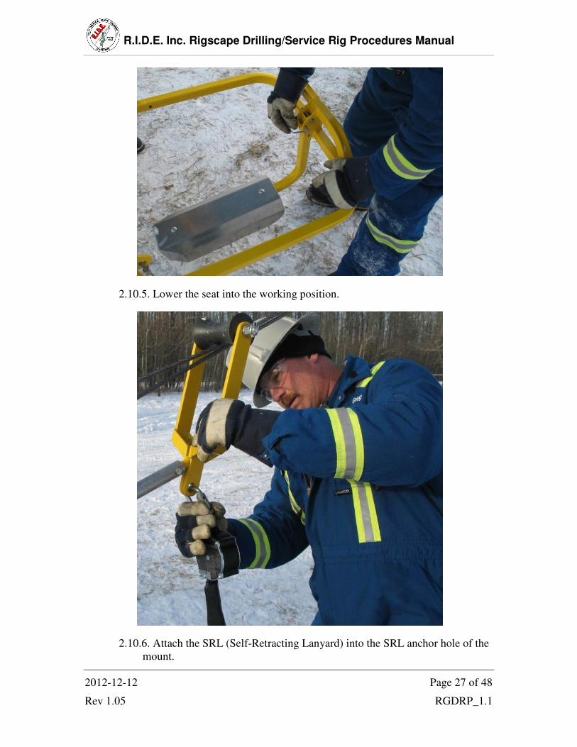
2.10.5. Lower the seat into the working position.
2.10.6. Attach the SRL (Self-Retracting Lanyard) into the SRL anchor hole of the
mount.
R.I.D.E. Inc. Rigscape Drilling/Service Rig Procedures Manual
2012-12-12 Page 28 of 48
Rev 1.05 RGDRP_1.1
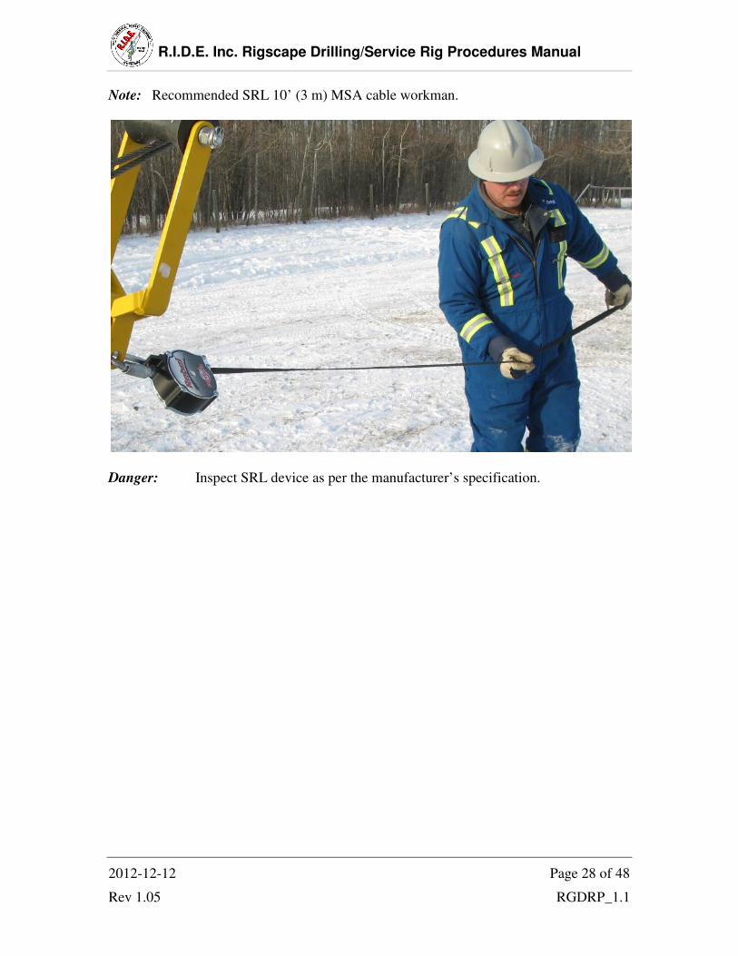
Note: Recommended SRL 10’ (3 m) MSA cable workman.
Danger: Inspect SRL device as per the manufacturer’s specification.

R.I.D.E. Inc. Rigscape Drilling/Service Rig Procedures Manual
2012-12-12 Page 29 of 48
Rev 1.05 RGDRP_1.1
2.10.7. Hoisting up to the docking station can be done in 3 different ways.
2.10.7.1. Connect a platform mounted winch cable to the winch eye on the
shuttle & winch it up to the docking station, slowing at the top and
guiding the trolley into the docking station by hand. Disconnect the
winch cable after docking is complete.
Warning: Clear communication must be established between the person on the
winch & the person docking the trolley to ensure not to over pull on the
winch causing damage to the system.
2.10.7.2. Pulling the lower cable towards the Magnegress & pulling the
upper cable towards the docking station will propel the trolley & shuttle
assembly up to the person at the docking station waiting to guide it into
place.

R.I.D.E. Inc. Rigscape Drilling/Service Rig Procedures Manual
2012-12-12 Page 30 of 48
Rev 1.05 RGDRP_1.1
2.10.7.3. Inspect the optional electric shuttle lift tool & its components.
2.10.7.4. Ensure the Magnegress sheave cover is on, set the switch on the
shuttle lift tool to the forward position (photo), place the socket on the
nut of the Magnegress sheave & engage trigger to raise the shuttle.
Note: Once the shuttle reaches the docking station the cable will slip in the
sheave.
2.10.7.5. When finished with the shuttle lifting tool return it back into its
carrying case & back into the anchor toolbox to avoid damage.

R.I.D.E. Inc. Rigscape Drilling/Service Rig Procedures Manual
2012-12-12 Page 31 of 48
Rev 1.05 RGDRP_1.1
2.10.8. Guide the shuttle into the receiving tracks on the archway.
2.10.9. Guide the two docking pins into the docking station’s magnetic receiver
tubes.
R.I.D.E. Inc. Rigscape Drilling/Service Rig Procedures Manual
2012-12-12 Page 32 of 48
Rev 1.05 RGDRP_1.1
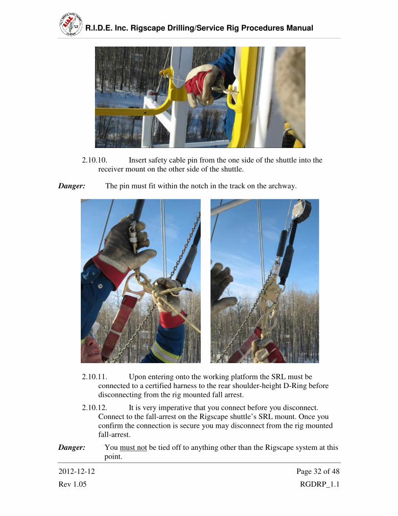
2.10.10. Insert safety cable pin from the one side of the shuttle into the
receiver mount on the other side of the shuttle.
Danger: The pin must fit within the notch in the track on the archway.
2.10.11. Upon entering onto the working platform the SRL must be
connected to a certified harness to the rear shoulder-height D-Ring before
disconnecting from the rig mounted fall arrest.
2.10.12. It is very imperative that you connect before you disconnect.
Connect to the fall-arrest on the Rigscape shuttle’s SRL mount. Once you
confirm the connection is secure you may disconnect from the rig mounted
fall-arrest.
Danger: You must not be tied off to anything other than the Rigscape system at this
point.

R.I.D.E. Inc. Rigscape Drilling/Service Rig Procedures Manual
2012-12-12 Page 33 of 48
Rev 1.05 RGDRP_1.1
2.10.13. Connect the shuttle mounted work positioning lanyard to your
harness waste belt D-ring.
2.10.14. Establish and clear restricted work area.
Danger: Ensure all personnel and operators of vehicles or equipment are aware of
the cable, block anchor or anchoring vehicle and restricted area.
Note: Nylon ribbon may be attached to the cable as a visual aid.
R.I.D.E. Inc. Rigscape Drilling/Service Rig Procedures Manual
2012-12-12 Page 34 of 48
Rev 1.05 RGDRP_1.1
3. Operation
3.1. Safety notes reminder
3.1.1. Read these warnings carefully before inspecting, setting up, installing,
using, or tearing down the Rigscape system.
3.1.2. Wear mandatory personal protection equipment at all times.
3.1.3. Use proper lifting techniques when inspecting, setting up, installing,
or tearing down the Rigscape system. Refer to Specifications (i.) for
product weights.
3.1.4. Watch for crush points when inspecting, setting up, installing, using,
or tearing down the Rigscape system.
3.1.5. Watch for tripping hazards when inspecting, setting up, installing,
using, or tearing down the Rigscape system.
3.1.6. Do not use the Rigscape system unless you are wearing a safety
harness and are secured only to the Rigscape fall-arrest device and
working lanyard.
3.1.7. This Rigscape is designed for single person only.
3.1.8. Never drive over your cables
3.1.9. Double check the system every day if set up for extended periods
between moves.
3.1.10. Ensure all personnel and operators of vehicles or equipment are
aware of the cable, anchor, anchor vehicle and restricted area.
3.1.11. An investigation must follow any and all incidents to determine the
cause and the corrective actions to be taken. Notify the manufacturer,
R.I.D.E. Inc. at 780-621-1570.
R.I.D.E. Inc. Rigscape Drilling/Service Rig Procedures Manual
2012-12-12 Page 35 of 48
Rev 1.05 RGDRP_1.1
3.2. General Operations
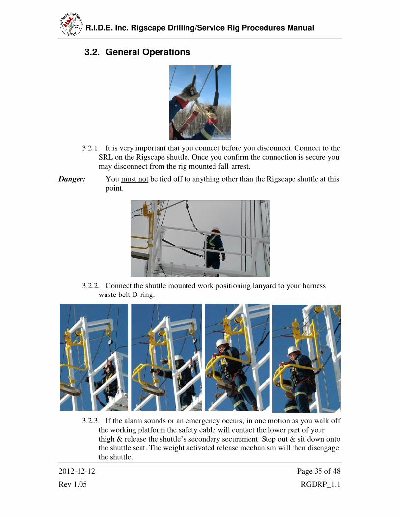
3.2.1. It is very important that you connect before you disconnect. Connect to the
SRL on the Rigscape shuttle. Once you confirm the connection is secure you
may disconnect from the rig mounted fall-arrest.
Danger: You must not be tied off to anything other than the Rigscape shuttle at this
point.
3.2.2. Connect the shuttle mounted work positioning lanyard to your harness
waste belt D-ring.
3.2.3. If the alarm sounds or an emergency occurs, in one motion as you walk off
the working platform the safety cable will contact the lower part of your
thigh & release the shuttle’s secondary securement. Step out & sit down onto
the shuttle seat. The weight activated release mechanism will then disengage
the shuttle.
R.I.D.E. Inc. Rigscape Drilling/Service Rig Procedures Manual
2012-12-12 Page 36 of 48
Rev 1.05 RGDRP_1.1
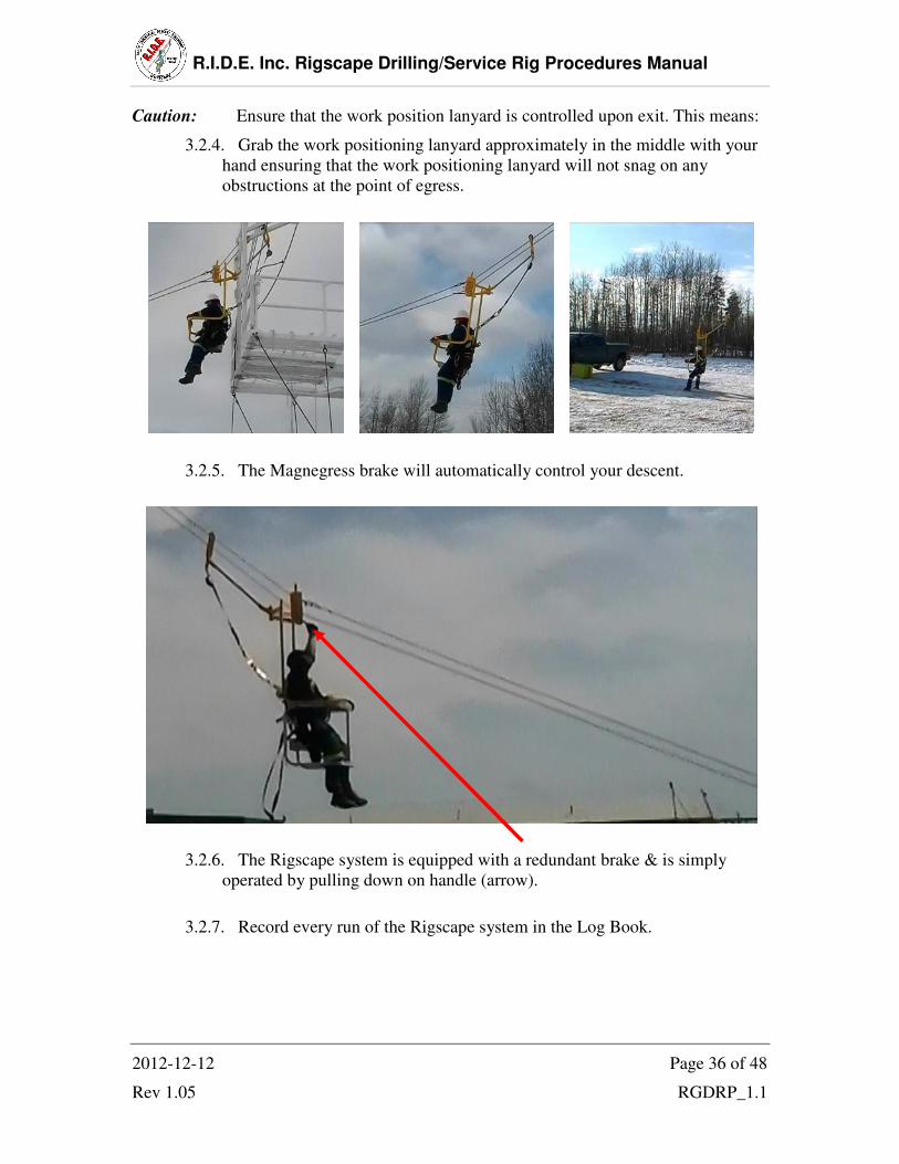
Caution: Ensure that the work position lanyard is controlled upon exit. This means:
3.2.4. Grab the work positioning lanyard approximately in the middle with your
hand ensuring that the work positioning lanyard will not snag on any
obstructions at the point of egress.
3.2.5. The Magnegress brake will automatically control your descent.
3.2.6. The Rigscape system is equipped with a redundant brake & is simply
operated by pulling down on handle (arrow).
3.2.7. Record every run of the Rigscape system in the Log Book.

R.I.D.E. Inc. Rigscape Drilling/Service Rig Procedures Manual
2012-12-12 Page 37 of 48
Rev 1.05 RGDRP_1.1
4. Teardown
4.1. This procedure assumes the Rigscape shuttle is still attached to the rig platform.
If the Rigscape shuttle has been run down to the ground, then continue with Step
4.3 of this procedure.
Option A:
4.2. Ride the Rigscape shuttle down to the ground.
Option B:
4.3. Undock shuttle from docking station & leave suspended on line.
4.4. From ground position pull shuttle down with cable using the hand over hand
technique.
4.5. Detach the SRL (Self-Retracting Lanyard) & shuttle mounted lanyard from the
shuttle. Picture 4.4.5
4.6. If require & you haven’t already uninstalled the shuttle, remove the SRL mount
spacer from the shuttle by removing the keeper bolt, nut & safety pin. Replace
bolt, nut & pin into the disassembled spacer. Picture 4.4.4
4.7. Disconnect the shuttle from the trolley by removing the keeper bolt, nut & safety
pin. Replace bolt, nut & pin into the disassembled system. Picture 4.4.1
4.8. Pull the lock-pin knob then turn to the unlocked position & loosen the trolley
sheave gate knob until the gate is opened. Picture 4.3.1
Caution: Watch for crush points when removing trolley from cable.
4.9. Remove the upper & lower cable from inside the trolley housing. Picture 4.3.3
4.10. Remove the Magnegress housing cover plate & the 3 cover plate keeper
pins. Picture 4.2.3
4.11. Turn the pinion hand wheel clock-wise to remove tension on the
adjustment bolt at this point, a second person should be used to remove the
adjustment bolt. Then turn the pinion wheel counter clock-wise all the way to the
stopper bolt to loosening the cable. Picture 4.2.10
R.I.D.E. Inc. Rigscape Drilling/Service Rig Procedures Manual
2012-12-12 Page 38 of 48
Rev 1.05 RGDRP_1.1
Caution: Watch for crush points when removing the cable.
4.12. Remove the cable from the Magnegress brake housing.
Warning: Releasing the cable while still under tension from the docking station
could slide fast & hit personnel and/or equipment.
4.13. Install the Magnegress housing cover plate & re-install the 3 cover plate
keeper pins.
4.14. Reinstall the Magnegress cage cover.
4.15. Strap & secure the Magnegress to the anchor.
4.16. Strap & secure the shuttle assembly to the anchor.

R.I.D.E. Inc. Rigscape Drilling/Service Rig Procedures Manual
2012-12-12 Page 39 of 48
Rev 1.05 RGDRP_1.1
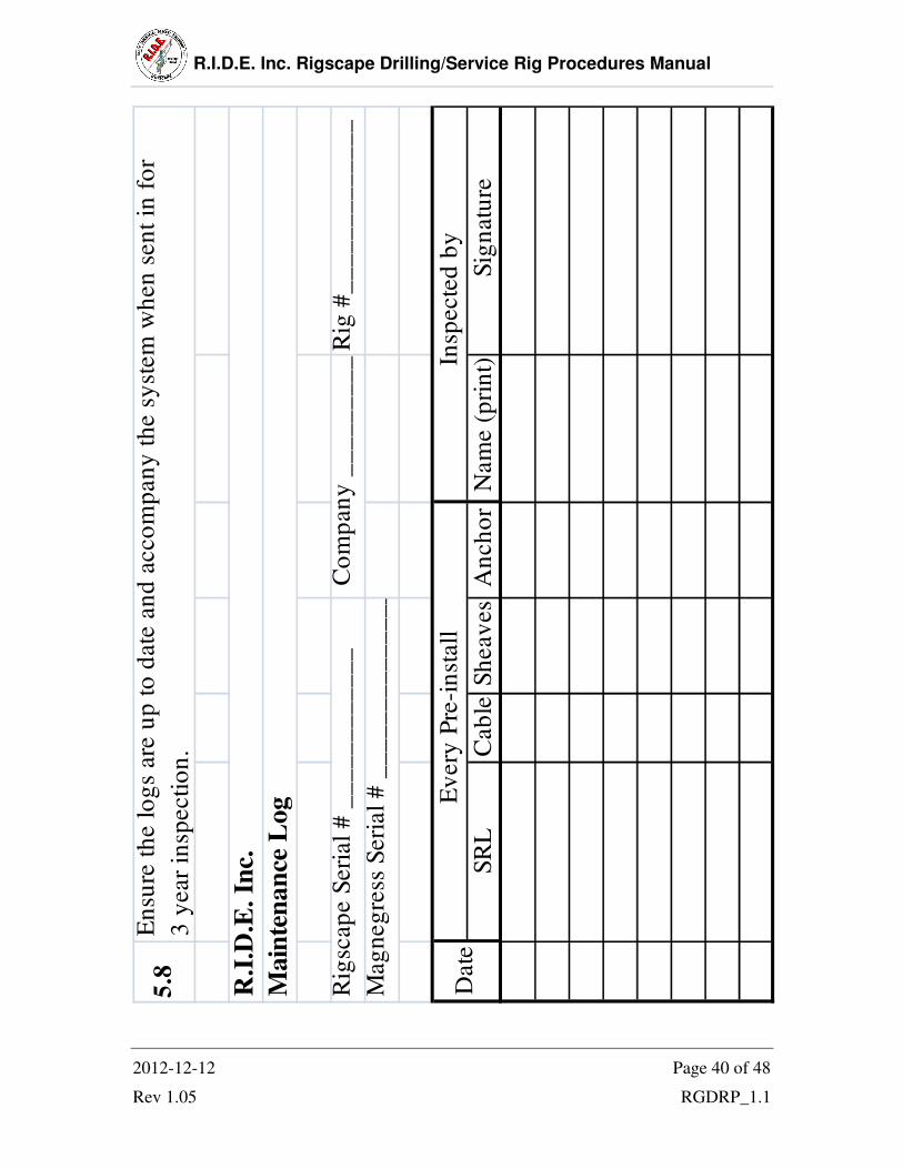
5. Maintenance Log
5.1. There can be no damage what so ever on cable. If damage has occurred the
system must be taken out of service until the cable is replaced.
5.2. The one year visual inspection on the system must be performed by a qualified
person, authorized by the manufacturer yearly. The Inspection must be
documented. If any damage is identified a complete recertification is required.
5.3. Structural Inspections are to be performed by the Manufacturer or his authorized
representative every three years.
5.4. The cable must be replaced every 3 years from the date it was put into service.
5.5. Every install the SRL must be inspected (as per manufactures instruction Pre-
use) before Rigscape shuttle is raised to the working platform.
5.6. Sample Rigscape system maintenance log on following page.
5.7. Harnesses must be inspected as per manufacture instruction.
Danger: If any damage is found, the system is to be tagged & taken out of service.
Send in the damaged component for service and/or repair.
R.I.D.E. Inc. Rigscape Drilling/Service Rig Procedures Manual
2012-12-12 Page 40 of 48
Rev 1.05 RGDRP_1.1
Rig
#_
__
__
__
__
__
__
Sig
natu
reN
am
e (
pri
nt)
A
nch
or
Sh
eav
es
Cab
leS
RL
5.8
En
sure
th
e l
og
s are
up
to
date
an
d a
cco
mp
an
y t
he s
yst
em
wh
en
sen
t in
fo
r
th
e
3 y
ear
insp
ecti
on
.
R.I
.D.E
. In
c.
Main
ten
an
ce L
og
Insp
ecte
d b
y
Co
mp
an
y _
__
__
__
__
__
__
__
Ev
ery
Pre
-in
stall
Rig
scap
e S
eri
al
# _
__
__
__
__
__
_
Mag
neg
ress
Seri
al
# _
__
__
__
__
__
__
__
_
Date

R.I.D.E. Inc. Rigscape Drilling/Service Rig Procedures Manual
2012-12-12 Page 41 of 48
Rev 1.05 RGDRP_1.1
Rig
#_
__
__
__
__
__
__
Sig
natu
reN
am
e (
pri
nt)
A
nch
or
Sh
eav
es
Cab
leS
RL
5.8
En
sure
th
e l
og
s are
up
to
date
an
d a
cco
mp
an
y t
he s
yst
em
wh
en
sen
t in
fo
r
the 3
year
insp
ecti
on
.
R.I
.D.E
. In
c.
Main
ten
an
ce L
og
Insp
ecte
d b
y
Co
mp
an
y _
__
__
__
__
__
__
__
Ev
ery
Pre
-in
stall
Rig
scap
e S
eri
al
# _
__
__
__
__
__
_
Mag
neg
ress
Seri
al
# _
__
__
__
__
__
__
__
_
Date

R.I.D.E. Inc. Rigscape Drilling/Service Rig Procedures Manual
2012-12-12 Page 42 of 48
Rev 1.05 RGDRP_1.1
Rig
#_
__
__
__
__
__
__
Sig
natu
reN
am
e (
pri
nt)
A
nch
or
Sh
eav
es
Cab
leS
RL
5.8
En
sure
th
e l
og
s are
up
to
date
an
d a
cco
mp
an
y t
he s
yst
em
wh
en
sen
t in
fo
r
the 3
year
insp
ecti
on
.
R.I
.D.E
. In
c.
Main
ten
an
ce L
og
Insp
ecte
d b
y
Co
mp
an
y _
__
__
__
__
__
__
__
Ev
ery
Pre
-in
stall
Rig
scap
e S
eri
al
# _
__
__
__
__
__
_
Mag
neg
ress
Seri
al
# _
__
__
__
__
__
__
__
_
Date
R.I.D.E. Inc. Rigscape Drilling/Service Rig Procedures Manual
2012-12-12 Page 43 of 48
Rev 1.05 RGDRP_1.1
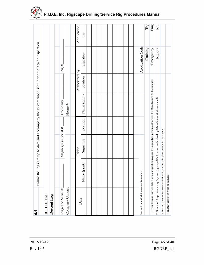
6. Descent Log
6.1. Every time the Rigscape system is used, its use must be recorded in a Log Book.
6.2. The Log must accompany the Rigscape system when it goes for its annual
inspection / certification.
6.3. Sample decent log on following page.

R.I.D.E. Inc. Rigscape Drilling/Service Rig Procedures Manual
2012-12-12 Page 44 of 48
Rev 1.05 RGDRP_1.1
Trg
Em
g
RO
Sig
natu
re
Application C
ode:
:Tra
inin
g .
:Em
erg
ency .
:Rig
out .
posi
tion
Nam
e (
pri
nt)
posi
tion
Sig
natu
re
Nam
e (
pri
nt)
6.4
Insp
ection a
nd M
ain
tenance R
em
inders
:
4. In
spect cable
for
wear
or
dam
age.
2. Str
uctu
ral In
spection e
very
3 y
ears
. (b
y a
qualifi
ed p
ers
on a
uth
ori
zed b
y M
anufa
ctu
re &
docum
ente
d)
3. In
spect sh
eaves
for
wear
as
indic
ate
d o
n the s
ide p
late
and/o
r in
the m
anual
1. 1 y
ear
from
in s
erv
ice d
ate
a v
isual in
spection r
equir
e b
y a
qualifi
ed p
ers
on a
uth
ori
zed b
y M
anufa
ctu
re &
docum
ente
d
Ensu
re the logs
are
up to d
ate
and a
ccom
pany the s
yst
em
when s
ent in
for
the 3
year
insp
ection.
R.I
.D.E
. In
c.
Des
cen
t L
og
Rig
#_____________
Application
use
Phone #
____________________________________
Auth
ori
zed b
y
Com
pany _
______________
Magnegre
ss S
eri
al # _
_______________
Rid
er
Com
pany C
onta
ct_
__________________________
Rig
scape S
eri
al # _
___________
Date

R.I.D.E. Inc. Rigscape Drilling/Service Rig Procedures Manual
2012-12-12 Page 45 of 48
Rev 1.05 RGDRP_1.1
Trg
Em
g
RO
Sig
natu
re
Application C
ode:
:Tra
inin
g .
:Em
erg
ency .
:Rig
out .
posi
tion
Nam
e (
pri
nt)
posi
tion
Sig
natu
re
Nam
e (
pri
nt)
6.4
4. In
spec
t ca
ble
fo
r w
ear
or
dam
age.
1. 1
yea
r fr
om
in s
ervic
e d
ate
a vis
ual
insp
ecti
on r
equ
ire
by a
qual
ifie
d p
erso
n a
uth
ori
zed
by M
anufa
ctu
re &
docu
men
ted
2. S
truct
ura
l In
spec
tion e
ver
y 3
yea
rs.
(by a
qual
ifie
d p
erso
n a
uth
ori
zed b
y M
anu
fact
ure
& d
ocu
men
ted
)
3. In
spec
t sh
eaves
for
wear
as
indic
ated
on the s
ide
pla
te a
nd
/or
in th
e m
anual
Insp
ection
and M
ainte
nance
Rem
inder
s:
Ensu
re the logs
are
up to d
ate
and a
ccom
pany the s
yst
em
when s
ent in
for
the 3
year
insp
ection.
R.I
.D.E
. In
c.
Des
cen
t L
og
Rig
#_____________
Application
use
Phone #
____________________________________
Auth
ori
zed b
y
Com
pany _
______________
Magnegre
ss S
eri
al # _
_______________
Rid
er
Com
pany C
onta
ct_
__________________________
Rig
scape S
eri
al # _
___________
Date
R.I.D.E. Inc. Rigscape Drilling/Service Rig Procedures Manual
2012-12-12 Page 46 of 48
Rev 1.05 RGDRP_1.1
Trg
Em
g
RO
Sig
natu
re
Application C
ode:
:Tra
inin
g .
:Em
erg
ency .
:Rig
out .
posi
tion
Nam
e (
pri
nt)
posi
tion
Sig
natu
re
Nam
e (
pri
nt)
6.4
2. S
truct
ura
l In
spec
tion e
ver
y 3
yea
rs. (b
y a
qu
alif
ied p
erso
n a
uth
ori
zed
by M
anufa
cture
& d
ocu
men
ted)
3. In
spec
t sh
eaves
fo
r w
ear
as
indic
ated o
n the s
ide
pla
te a
nd/o
r in
the
man
ual
Insp
ection a
nd M
ain
tenan
ce R
emin
ders
:
4. In
spec
t ca
ble
for
wea
r or
dam
age.
Ensu
re the logs
are
up to d
ate
and a
ccom
pany the s
yst
em
when s
ent in
for
the 3
year
insp
ection.
R.I
.D.E
. In
c.
Des
cen
t L
og
Rig
#_____________
Application
use
Phone #
____________________________________
Auth
ori
zed b
y
Com
pany _
______________
Magnegre
ss S
eri
al # _
_______________
Rid
er
Com
pany C
onta
ct_
__________________________
Rig
scape S
eri
al # _
___________
Date
1. 1
yea
r fr
om
in s
ervic
e dat
e a
vis
ual
insp
ectio
n r
equir
e by a
qual
ifie
d p
erso
n a
uth
ori
zed
by M
anufa
cture
& d
ocu
men
ted

R.I.D.E. Inc. Rigscape Drilling/Service Rig Procedures Manual
2012-12-12 Page 47 of 48
Rev 1.05 RGDRP_1.1
7. Appendix
Rig Specific Information
A) Company: __________
B) Rig #: __________________ C) Contact Person: _____________
D) Contact Phone: _____________
E) Rig Type: single double triple
F) Style: telescopic solid mast
G) Monkey Board sheave Height: ____________
H) Ground Anchor to Well Head Center: ___________________________________
I) Ground Anchor Point to Back of Monkey Board: ___________________________
J) Ground Anchor to front of sub structure: _________________________________
K) Cable Length: ______________________________
L) Rigscape Serial #: ____________________________

R.I.D.E. Inc. Rigscape Drilling/Service Rig Procedures Manual
2012-12-12 Page 48 of 48
Rev 1.05 RGDRP_1.1
7.1. Orientation Sign-off
7.1.1. Print, sign your name and date at the bottom of the page in the space provided,
indicating that you have read and understand the information in each section of
the R.I.D.E. Inc. Rigscape Service Rig Procedure Manual.
Section
2. Set up
2.2. Docking station
2.3. Magnegress
2.4. Anchorage
2.5. Magnegress sheave
2.6. Magnegress tension
2.7. Trolley
2.8. Rigscape shuttle
3.2. Operations
4. Tear down
Print Name Signature Date
_______________________ __________________________ __________
_______________________ __________________________ __________
_______________________ __________________________ __________
_______________________ __________________________ __________
_______________________ __________________________ __________
_______________________ __________________________ __________
_______________________ __________________________ __________
_______________________ __________________________ __________
_______________________ __________________________ __________
_______________________ __________________________ __________
_______________________ __________________________ __________
Related Documents