DRILLING TOOLS AND EQUIPMENT Successful way to oil & gas resources

Welcome message from author
This document is posted to help you gain knowledge. Please leave a comment to let me know what you think about it! Share it to your friends and learn new things together.
Transcript
1
DRILLING TOOLS AND EQUIPMENT
Successful way to oil & gas resources

2 3
INNOVATION LEADER. Successful way to oil & gas resources

4 5
TABLE OF CONTENTS
Company’s background ......................................................................................................................................................................... 7Integrated management system ........................................................................................................................................................ 8Potential and prospects of company’s development ........................................................................................................... 9New technological solutions ........................................................................................................................................................... 11Technological service ......................................................................................................................................................................... 13
1. Products/Rock cutting toolsDrill bit nomenclature definition.......................................................................................................................................................... 16 1.1. Typical well design drill bits per size classification ............................................................................................................. 171.2. Drill bits for surface casing .......................................................................................................................................................... 171.3. Standart bits .......................................................................... ............................................................................................................ 181.4. Standart bits .......................................................................... ............................................................................................................ 191.5. HOB-BIT bits .................................................................................................................................................................................. 201.6. KAIMAN bits ...................................................................................................................................................................................... 211.7. BULAVA bits ..................................................................................................................................................................................... 221.8. Ruddder bits ...................................................................................................................................................................................... 231.9. Sidetracking bits .............................................................................................................................................................................. 241.10. Special E (peak profile) bits ....................................................................................................................................................... 241.11. Sprut bits ......................................................................................................................................................................................... 251.12. Cutmix bits ..................................................................................................................................................................................... 261.13. Trident bit ........................................................................................................................................................................................ 261.14. Bicentric drill bits ........................................................................................................................................................................... 271.15. Core bits cdd .................................................................................................................................................................................... 281.16. Fishtail (spudding) bits ................................................................................................................................................................ 301.17. TCI cutter bits ................................................................................................................................................................................. 301.18. Hole openers ................................................................................................................................................................................. 311.19. Core bits ................................... ........................................................................................................................................................... 32
2. Workover and well intervention tools2.1. Casing exit systems ....................................................................................................................................................................... 35 2.2. Whipstock system with hydraulic anchor, no abandonment plug required ...................................................... 352.3. Whipstock system with mechanical anchor ........................................................................................................................ 362.4. Whipstock system with hydromech anchor, no abandonment plug required ............................................... 372.5. Whipstock system with hydromech anchor, no abandonment plug required ............................................... 382.6. Cemented anchor whipstock system ...................................................................................................................................... 382.7. Packered whipstock system ......................................................................................................................................................... 392.8. Special formation mill reinforced by pdc ............................................................................................................................... 392.9. Mills ...................................................................................................................................................................................................... 40
3. Expanding tools ............................................................................................................................................................................... 413.1. Section mill assembly .................................................................................................................................................................... 413.2.Hole enlargement tool ................................................................................................................................................................ 41
4. BHA components ........................................................................................................................................................................ 424.1. Stabilizers ....................................................................................................................................................................................... 424.2. Sliding type check valve .............................................................................................................................................................. 424.3. Sliding type cementing check valve ....................................................................................................................................... 424.4. Drilling slide valve SCV-106 ....................................................................................................................................................... 43
5. Mud lab ............................................................................................................................................................................................... 44
6. Burservice brand line .................................................................................................................................................................... 46
7. New developments of Burservice7.1. The BULAVA project .................................................................................................................................................................. 487.2. The coring device UKBS-185/100 ......................................................................................................................................... 497.3. Flushing and mudding device .................................................................................................................................................. 497.4. Drilling damper UDB-203............................................................................................................................................................. 50
6 7
ABOUT THE COMPANY ABOUT THE COMPANY
DEAR CUSTOMERS, PARTNERS AND COLLEAGUES!
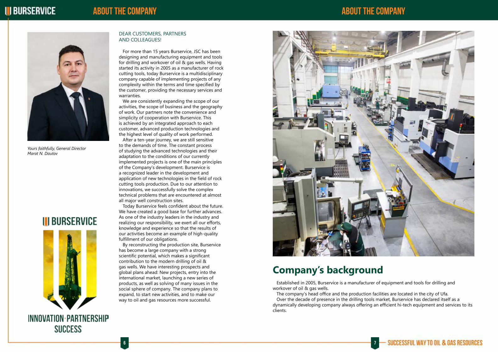
For more than 15 years Burservice, JSC has been designing and manufacturing equipment and tools for drilling and workover of oil & gas wells. Having started its activity in 2005 as a manufacturer of rock cutting tools, today Burservice is a multidisciplinary company capable of implementing projects of any complexity within the terms and time specified by the customer, providing the necessary services and warranties. We are consistently expanding the scope of our activities, the scope of business and the geography of work. Our partners note the convenience and simplicity of cooperation with Burservice. This is achieved by an integrated approach to each customer, advanced production technologies and the highest level of quality of work performed. After a ten-year journey, we are still sensitive to the demands of time. The constant process of studying the advanced technologies and their adaptation to the conditions of our currently implemented projects is one of the main principles of the Company’s development. Burservice is a recognized leader in the development and application of new technologies in the field of rock cutting tools production. Due to our attention to innovations, we successfully solve the complex technical problems that are encountered at almost all major well construction sites. Today Burservice feels confident about the future. We have created a good base for further advances. As one of the industry leaders in the industry and realizing our responsibility, we exert all our efforts, knowledge and experience so that the results of our activities become an example of high-quality fulfillment of our obligations. By reconstructing the production site, Burservice has become a large company with a strong scientific potential, which makes a significant contribution to the modern drilling of oil & gas wells. We have interesting prospects and global plans ahead: New projects, entry into the international market, launching a new series of products, as well as solving of many issues in the social sphere of company. The company plans to expand, to start new activities, and to make our way to oil and gas resources more successful.
Company’s background Established in 2005, Burservice is a manufacturer of equipment and tools for drilling and workover of oil & gas wells. The company’s head office and the production facilities are located in the city of Ufa. Over the decade of presence in the drilling tools market, Burservice has declared itself as a dynamically developing company always offering an efficient hi-tech equipment and services to its clients.
Yours faithfully, General DirectorMarat N. Dautov

8 9
INTEGRATED MANAGEMENT SYSTEM ABOUT THE ENTERPRISE
Integrated management system Burservice successfully operates an integrated management system. The integrated management system in the field of quality, health, safety and environment was implemented from 2009 to 2010. In 2010 the company successfully passed IMS certification carried out by the German certification authority TUV NORD CERT GmbH regarding compliance with the international standards: ISO 9001:2015 - with the scope of application in the field of development, production and supply of rock cutting and emergency tools, as well as rendering services for construction and repairs of oil and gas wells; ISO 14001:2015, ISO 45001:2018 - with the scope of application in the field of rendering services for construction and repairs of oil and gas wells.
CERTIFICATE OF AUTHORITY TO USE THE OFFICIAL API MONOGRAM: API Spec. 7-1
CERTIFICATE OF MEMBERSHIP IADS
Potential and prospects of company’s development OUR MISSION:
«We create and implement innovative technological solutions providing new possibilities for rock cutting tools application by oil and gas companies».
Today Burservice is a modern company with up-to-date equipping, occupying over 17 thousand m2 of administrative and production areas, carrying out the complete production cycle. Technological and engineering capacities allow our company to provide services at 50-60 wells simultaneously. Burservice geographic activity covers all main oil and gas regions in Russia. Our regional representative offices are located in Noyabrsk, Muravlenko, Nefteyugansk, Khanty-Mansiysk, Krasnodar, Buzuluk, Nizknevartovsk. In today’s market of rock cutting tools manufacturers there are leaders in terms of the quantity of bits produced, meters drilled and of course there are leaders regarding the price, who produce competitive drilling bits at low price. Nevertheless, there is no clear position of a leader who would offer technological solutions. The aspiration to take this position has become a strategic direction of our development in manufacturing of Russian PDC bits and provision of services for technological support of its performance. Nowadays we produce PDC-bits for directional and horizontal drilling. We provide complex services for sidetracking as well as core sampling in exploratory wells. There are unique projects, the results of which confirm the effective work of the company. We see the positive attitude of customers and drilling companies towards us; the cooperation has reached a new level and brings very good results for all interested parties. Over a ten-years period of activity in this market, the company has gained a reputation as a high-tech and stable company.
THE MAIN PERSPECTIVE DIRECTIONS OF THE COMPANY’S DEVELOPMENT ARE:
▪ Introduction of modern technologies for drilling tools manufacturing;
▪ Investments to production facilities and expansion of the range of drill bits, drill heads and workover tools;
▪ Improvement of reliability, quality and efficiency of products;
▪ Strengthening of the position in the domestic market and entering to the foreign markets;
▪ Ensuring the financial stability of the enterprise throughout the entire strategic horizon.
COMPANY’S MAIN FOCUS:
▪ Qualitative growth;
▪ Providing the resources necessary for the quality of the processes;
▪ Use of the theory of constraint (TOC) methods;
▪ Process approach implementation;
▪ Improvement of culture of production and services.
JOINT STOCK COMPANY AND PRODUCTION
ENTERPRISE "BURSERVICE"
CERTIFICATE OF MEMBERSHIP
2021 International Association of
Drilling Contractors
10 11
ABOUT THE ENTERPRISE RESEARCH and DEVELOPMENT
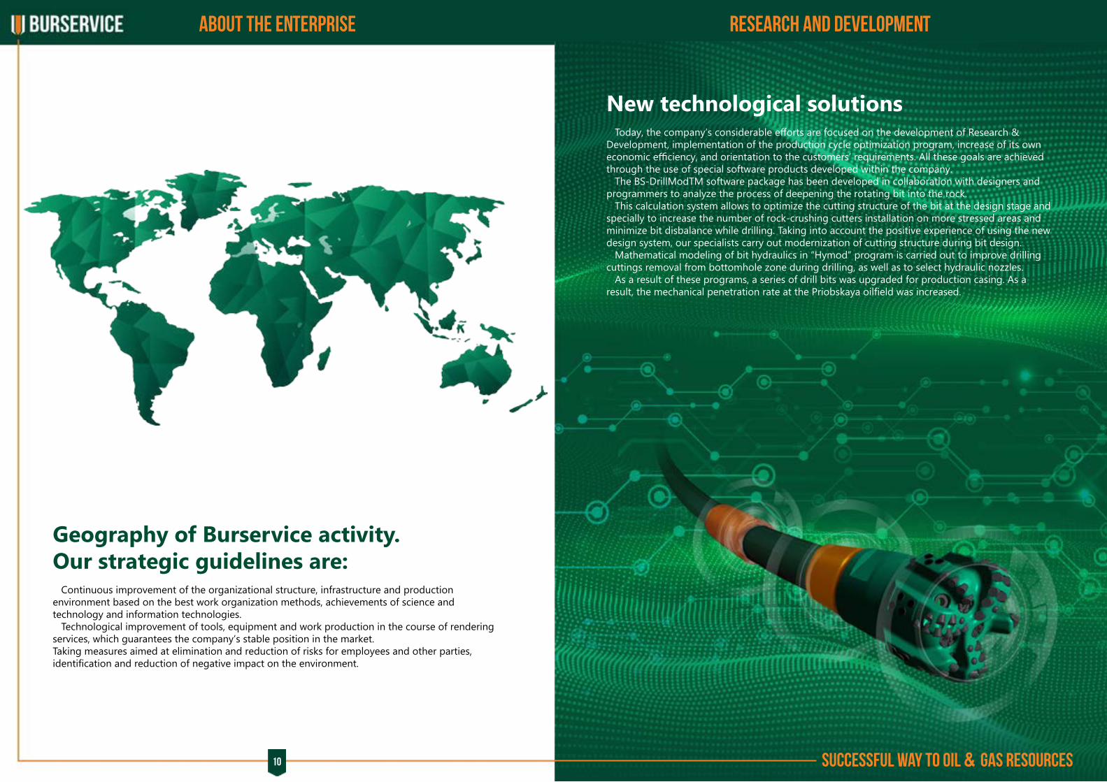
Geography of Burservice activity.Our strategic guidelines are: Continuous improvement of the organizational structure, infrastructure and production environment based on the best work organization methods, achievements of science and technology and information technologies. Technological improvement of tools, equipment and work production in the course of rendering services, which guarantees the company’s stable position in the market.Taking measures aimed at elimination and reduction of risks for employees and other parties, identification and reduction of negative impact on the environment.
New technological solutions Today, the company’s considerable efforts are focused on the development of Research & Development, implementation of the production cycle optimization program, increase of its own economic efficiency, and orientation to the customers’ requirements. All these goals are achieved through the use of special software products developed within the company. The BS-DrillModTM software package has been developed in collaboration with designers and programmers to analyze the process of deepening the rotating bit into the rock. This calculation system allows to optimize the cutting structure of the bit at the design stage and specially to increase the number of rock-crushing cutters installation on more stressed areas and minimize bit disbalance while drilling. Taking into account the positive experience of using the new design system, our specialists carry out modernization of cutting structure during bit design. Mathematical modeling of bit hydraulics in “Hymod” program is carried out to improve drilling cuttings removal from bottomhole zone during drilling, as well as to select hydraulic nozzles. As a result of these programs, a series of drill bits was upgraded for production casing. As a result, the mechanical penetration rate at the Priobskaya oilfield was increased.
Successful way to oil & gas resources

12 13
RESEARCH and DEVELOPMENT TECHNOLOGICAL SERVICE
Technological serviceDRILLING BIT SERVICE LIFE STAGES
1. CALCULATION
5. OPERATION
6. ANALYSIS
2. MODELING
4. MANUFACTURING
3. DESIGN DOCUMENTATIONDEVELOPMENT
DRILLING BIT SERVICE LIFE STAGES The main objective of the integrated section is to provide oil and gas production and drilling companies with advanced, high-tech services for horizontal and directional drilling of oil and gas wells.
THE RANGE OF SERVICES INCLUDES: ▪ Engineering support of domestic and
imported bits with drilling parameters control; ▪ Drill bits rental without the presence of an bit
maintenance engineer, which reduces drilling costs; ▪ Recovery of matrix and steel PDC bits
produced by both Russian and foreign companies; ▪ Sidetracking operations using own whipstock
set; ▪ Engineering support of PDM motors with
drilling parameters control; ▪ Geo-navigation support of wellbore trajectory
construction using telemetry system. The goal of the integrated service is to maximize the use of engine and bit potential and to ensure the most efficient drilling modes and necessary wellbore trajectory. The work is supported by experienced process engineers, with strict compliance with the rules and regulations in the field of industrial, fire safety, labor and environment protection, as defined by federal laws and local regulations of the customer.

14 15
RESEARCH and DEVELOPMENT TECHNOLOGICAL SERVICE
ENGINEERING SUPPORT OF WELL DIRECTIONAL CONTROL USING TELEMETRY SYSTEM.
Telemetric support of the well design in the process of drilling includes: ▪ Development and approval of a plan/program for the directional or horizontal well section
drilling, including calculation and creation of the design profile with technical explanations; ▪ Use of telemetry systems with a hydraulic or electromagnetic communication channel to monitor
the directional drilling process; ▪ Additional calculations and well profile adjustments during drilling, if the task is amended by the
customer; ▪ Provision of daily and final reports, analysis of the drilling work results, and making
recommendations for further optimization; ▪ Equipment and engineering staff mobilization to the customer’s production facility, and if
appropriate, to the well site.
BURSERVICE SPECIALISTS RENDER THIS SERVICE, USING TELEMETR Y SYSTEMS: ▪ with Ø172 mm electromagnetic communication channel (domestic and imported); ▪ with Ø 122.89 mm hydraulic communication channel (domestic and imported).
The telemetric packages are installed in mobile buildings or mounted on 4WD trucks.The staff, operating the telemetry systems, is trained by the equipment manufacturer specialists and have a vast working experience in this sphere.

16 17
PRODUCTS PRODUCTS
Drill bit nomenclature definition
1.1 TYPICAL WELL DESIGN DRILL BITS PER SIZE CLASSIFICATION
New projects in Russia and CIS require extensive work on bit design providing wellbore verticality. Drill bit design was adjusted to be run in certain conditions considering previous experience. Successful trial runs of new bits confirmed design adjustment efficiency. Drill bits are used to drill vertical and deviated sections thru soft to medium strength formation. 5 blades bits are most general in use. Having high ROP in soft and medium strength formations, the high impact and wear resistant PDC cutters might be used to provide good performance in hard and abrasive formations as well.
1.2 DRILL BITS FOR SURFACE CASING
1. Rock cutting tools
Bit nozzles
BS-393,7 VD 519-003 bit directional control diagram
FOR DRILLING BITS WITH OUTER DIAMETER FROM 120 UP TO 190.5 MM
FOR DRILLING BITS WITH OUTER DIAMETER FROM 190 UP TO 490 MM
FOR DRILLING BITS WITH OUTER DIAMETER FROM 295,3 UP TO MORE
BS-393,7 VD 519-003
BURSERVICE
type of bit applicationtype of cutter structureblade qtycutter sizeconfiguration number
core diameter (core bits) or enlarged hole diameter (bicentric bits) or pilot hole diameter (hole reamers and openers), mm
cbit size or outside diameter (core bits) or drift diameter (bicentric bits), mm/ - for core bits and hole openers, or X – for bicentric bits
BS 215,9 101,6 C D 12 08 001 - /
Type of bit application
S – directional (for all type of well profiles and directional systems)V – for vertical drillingB – bicentric bitC – core bit
Being:%t – slide time to total drilling time ratio%h – slide distance to total run footage ratio% ROP – slide ROP to average run ROP ratioΔ%ROP – slide ROP to rotary ROP ratio
Type of cutter structure
D – PDC cuttersDD – dual row of PDC cuttersDC – diamond composite materialH – tungsten carbide materialW – cone PDC cutters
I – sidetrack bitE – special reaming bit (“peak” profile)F – fishtail bitR- bit for RSS applicationG – drag bit
Drill bit BS-393,7 VD 519-003Well 2019, pad 1B, Ety-Purovskoe field
Avg ROP = 71.6 mph, Max ROP = 165.3 mph
18 19
PRODUCTS PRODUCTS
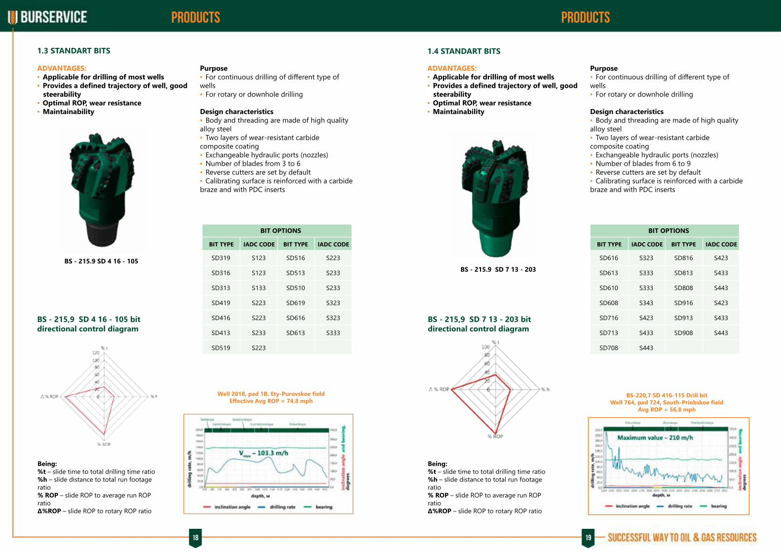
1.3 STANDART BITS
ADVANTAGES: ▪ Applicable for drilling of most wells ▪ Provides a defined trajectory of well, good
steerability ▪ Optimal ROP, wear resistance ▪ Maintainability
ADVANTAGES: ▪ Applicable for drilling of most wells ▪ Provides a defined trajectory of well, good
steerability ▪ Optimal ROP, wear resistance ▪ Maintainability
Well 2018, pad 1B, Ety-Purovskoe fieldEffective Avg ROP = 74,8 mph
BS-220,7 SD 416-115 Drill bitWell 764, pad 724, South-Priobskoe field
Avg ROP = 56,8 mph
1.4 STANDART BITS
BS - 215.9 SD 4 16 - 105BS - 215.9 SD 7 13 - 203
BS - 215,9 SD 4 16 - 105 bit directional control diagram
BS - 215,9 SD 7 13 - 203 bit directional control diagram
Being:%t – slide time to total drilling time ratio%h – slide distance to total run footage ratio% ROP – slide ROP to average run ROP ratioΔ%ROP – slide ROP to rotary ROP ratio
Being:%t – slide time to total drilling time ratio%h – slide distance to total run footage ratio% ROP – slide ROP to average run ROP ratioΔ%ROP – slide ROP to rotary ROP ratio
Purpose ▪ For continuous drilling of different type of
wells ▪ For rotary or downhole drilling
Design characteristics ▪ Body and threading are made of high quality
alloy steel ▪ Two layers of wear-resistant carbide
composite coating ▪ Exchangeable hydraulic ports (nozzles) ▪ Number of blades from 3 to 6 ▪ Reverse cutters are set by default ▪ Calibrating surface is reinforced with a carbide
braze and with PDC inserts
Purpose ▪ For continuous drilling of different type of
wells ▪ For rotary or downhole drilling
Design characteristics ▪ Body and threading are made of high quality
alloy steel ▪ Two layers of wear-resistant carbide
composite coating ▪ Exchangeable hydraulic ports (nozzles) ▪ Number of blades from 6 to 9 ▪ Reverse cutters are set by default ▪ Calibrating surface is reinforced with a carbide
braze and with PDC inserts
BIT OPTIONS
BIT TYPE IADC CODE BIT TYPE IADC CODE
SD319
SD316
SD313
SD419
SD416
SD413
SD519
SD516
SD513
SD510
SD619
SD616
SD613
S223
S233
S233
S323
S323
S333
S123
S123
S133
S223
S223
S233
S223
BIT OPTIONS
BIT TYPE IADC CODE BIT TYPE IADC CODE
SD616 S323
SD613 S333
SD610 S333
SD608 S343
SD716 S423
SD713 S433
SD708 S443
SD816 S423
SD813 S433
SD808 S443
SD916 S423
SD913 S433
SD908 S443

20 21
PRODUCTS PRODUCTS
1.5 HOB-BIT BITS
BS-155,6 SD 613-002 Drill bitWell 3751, pad 269, Ety-Purovskoe field
Avg ROP = 20,7 mph, Max ROP = 48,08 mph
Well 227, pad 65.2, Chekmagushevskoe fieldAvg ROP = 3,86 mph
1.6 KAIMAN BITS
BS – 123,8 SD 5 13 - 101 BS – 295,3 SDD 6 16 - 202
BS – 123,8 SD 5 13 - 101 bit directional control diagram
BS – 295,3 SDD 6 16 - 202 bit directional control diagram
Being:%t – slide time to total drilling time ratio%h – slide distance to total run footage ratio% ROP – slide ROP to average run ROP ratioΔ%ROP – slide ROP to rotary ROP ratio
Being:%t – slide time to total drilling time ratio%h – slide distance to total run footage ratio% ROP – slide ROP to average run ROP ratioΔ%ROP – slide ROP to rotary ROP ratio
ADVANTAGES: ▪ Optimal ROP ▪ Maintainability ▪ Premium PDC cutters for complex
formations
ADVANTAGES: ▪ Provides a defined trajectory of well, good
steerability ▪ High wear resistance ▪ Maintainability
Purpose ▪ For sidetracking drilling ▪ For rotary or downhole drilling
Design characteristics ▪ Body and threading are made of quality alloy
steel ▪ Two layers of wear-resistant carbide
composite coating ▪ ROP as for four-blade bits and steerability as
for six-blade bits ▪ Exchangeable hydraulic ports (nozzles) ▪ Number of blades 5 ▪ The range of diameters from 123.8 to 165.1
mm allows you to choose the size of hob-bit bits for any project ▪ Calibrating surface is reinforced with a carbide
braze and with PDC inserts
Purpose ▪ For continuous drilling of different type of
wells ▪ For rotary or downhole drilling
Design characteristics ▪ Body and threading are made of quality alloy
steel ▪ Two layers of wear-resistant carbide
composite coating ▪ An additional row of cuttings behind the main
one ▪ Exchageable hydraulic ports (nozzles) ▪ Number of blades from 5 to 7 ▪ Reverse cutters are set by default ▪ Calibrating surface is reinforced with a carbide
braze and with PDC inserts
BIT OPTIONS
BIT TYPE IADC CODE
SD513 S333
BIT OPTIONS
BIT TYPE IADC CODE
SDD516 S423
SDD513 S433
SDD616 S423
SDD613 S433
SDD716 S423
SDD713 S433
22 23
PRODUCTS PRODUCTS
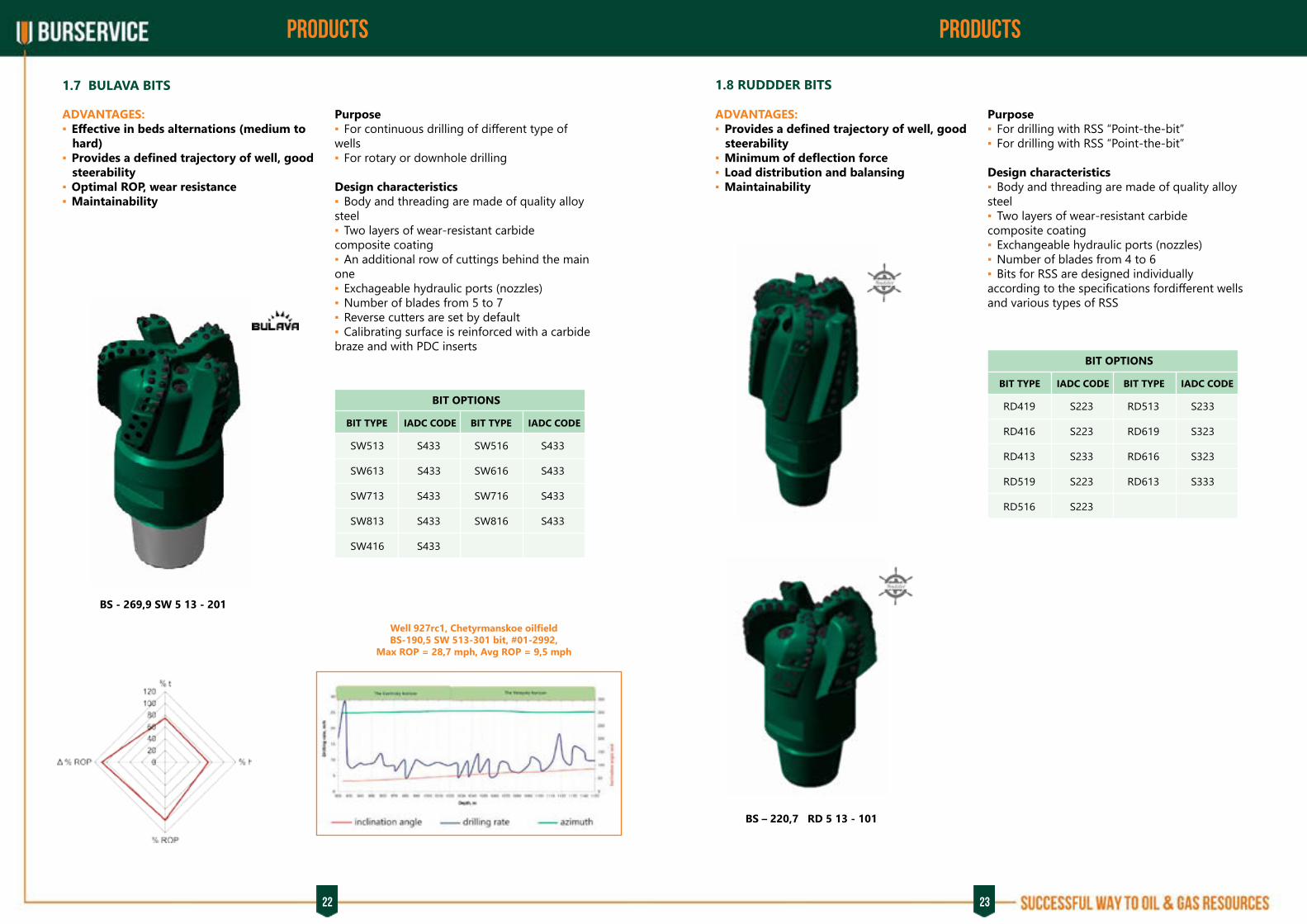
1.7 BULAVA BITS
ADVANTAGES: ▪ Effective in beds alternations (medium to
hard) ▪ Provides a defined trajectory of well, good
steerability ▪ Optimal ROP, wear resistance ▪ Maintainability
Well 927rc1, Chetyrmanskoe oilfieldBS-190,5 SW 513-301 bit, #01-2992,
Max ROP = 28,7 mph, Avg ROP = 9,5 mph
1.8 RUDDDER BITS
BS - 269,9 SW 5 13 - 201
BS – 220,7 RD 5 13 - 101
ADVANTAGES: ▪ Provides a defined trajectory of well, good
steerability ▪ Minimum of deflection force ▪ Load distribution and balansing ▪ Maintainability
Purpose ▪ For continuous drilling of different type of
wells ▪ For rotary or downhole drilling
Design characteristics ▪ Body and threading are made of quality alloy
steel ▪ Two layers of wear-resistant carbide
composite coating ▪ An additional row of cuttings behind the main
one ▪ Exchageable hydraulic ports (nozzles) ▪ Number of blades from 5 to 7 ▪ Reverse cutters are set by default ▪ Calibrating surface is reinforced with a carbide
braze and with PDC inserts
Purpose ▪ For drilling with RSS “Point-the-bit” ▪ For drilling with RSS “Point-the-bit”
Design characteristics ▪ Body and threading are made of quality alloy
steel ▪ Two layers of wear-resistant carbide
composite coating ▪ Exchangeable hydraulic ports (nozzles) ▪ Number of blades from 4 to 6 ▪ Bits for RSS are designed individually
according to the specifications fordifferent wells and various types of RSS
BIT OPTIONS
BIT TYPE IADC CODE BIT TYPE IADC CODE
RD419 S223
RD416 S223
RD413 S233
RD519 S223
RD516 S223
RD513 S233
RD619 S323
RD616 S323
RD613 S333
BIT OPTIONS
BIT TYPE IADC CODE BIT TYPE IADC CODE
SW513 S433
SW613 S433
SW713 S433
SW813 S433
SW416 S433
SW516 S433
SW616 S433
SW716 S433
SW816 S433
22 23

24 25
PRODUCTS PRODUCTS
1.9 SIDETRACKING BITS
1.10 SPECIAL E (PEAK PROFILE) BITS
BS - 219,1 ID 12 13 - 101
BS - 120,6 ED 6 13 - 002
ADVANTAGES: ▪ Provides a defined trajectory of well, good
steerability ▪ Optimal ROP, wear resistance ▪ Maintainability
ADVANTAGES: ▪ Bit profile prevents sidetracking ▪ High ROP, wear resistance ▪ Maintainability
Purpose ▪ Sidetracking in open hole ▪ Drilling of sliding down intervals with high
intensity
Design characteristics ▪ Body and threading are made of high quality
alloy steel ▪ Two layers of wear-resistant carbide
composite coating ▪ Exhangeable hydraulic ports (nozzles) ▪ Number of blades from 4 to 12 ▪ Calibrating surface is reinforced with a carbide
braze and with PDC inserts. ▪ Better flushing of the peripheral part of the
blades
Purpose ▪ For reaming, opening and calibrating of well
Design characteristics ▪ The body is made of high quality alloy steel ▪ The wear-resistant carbide composite coating ▪ Number of blades from 3 to 6 ▪ Calibrating surface is reinforced with a carbide
braze and with PDC inserts
BIT OPTIONS
BIT TYPE IADC CODE BIT TYPE IADC CODE
ID413 S232
ID513 S232
ID613 S332
IDD613 S432
ID913 S332
ID1213 S332
ID616 S322
IDD616 S422
ID916 S322
BIT OPTIONS
BIT TYPE IADC CODE BIT TYPE IADC CODE
ED310 S134
ED313 S134
ED413 S134
ED513 S234
ED613 S234
ED616 S224
ED619 S224
1.11 SPRUT BITS
ADVANTAGES: ▪ Suitable for drilling carbonate and
terrigenous sections ▪ Provides a predetermined trajectory of the
well, well managed ▪ Optimal drilling speed, increased wear
resistance ▪ Maintainability ▪ Specially designed for drilling complex
carbonate sections similar to the Ural-Volga region
Purpose ▪ For continuous drilling of different type of
wells ▪ For rotor or downhole motor driven drilling
Design characteristics ▪ Deep cone shape for better stabilization of the
bit on the face ▪ Two layers of wear-resistant carbide
composite coating ▪ Fluid stream angle to the face to reduce swirls
and erosion of the body. ▪ Single-row cutters model with 8 blades or
a 6-blade model with a reinforced shoulder paddle with a second row of cutters ▪ Reverse cutters are set by default ▪ Calibrating surface is reinforced with a carbide
braze and with PDC inserts. ▪ Special configuration of the central part of the
bit
BS - 215,9 SDD 6 16 - 209
BIT OPTIONS
BIT TYPE IADC CODE
SDD616 S423
SDD613 S433
SD813 S433

26 27
PRODUCTS PRODUCTSPRODUCTSPRODUCTS
1.12 CUTMIX BITS
ADVANTAGES: ▪ Suitable for most drilling cases ▪ Optimal speed, wear resistance ▪ Provides a predetermined trajectory of the
well, well managed ▪ Maintainability
Purpose ▪ For continuous drilling of different type of
wells ▪ For rotory or downhole drilling
Design characteristics ▪ Body and threading are made of quality alloy
steel ▪ Two layers of wear-resistant carbide
composite coating ▪ Combined with different cutter sizes ▪ Exchangeable hydraulic ports (nozzles) ▪ Number of blades 4-8 ▪ During the drilling of soft formations, larger
cutters are used. In hard formations, smaller cutters are starting work. ▪ Reverse cutters are set by default ▪ Calibrating surface is reinforced with a carbide
braze and with PDC inserts
BS – 220,7 SD 6 19 - 103
BIT OPTIONS
BIT TYPE IADC CODE BIT TYPE IADC CODE
SD419 S223
SD416 S223
SD413 S233
SD519 S223
SD516 S223
SD513 S233
SD619 S323
SD616 S323
SD613 S333
SD719 S323
SD716 S323
SD713 S333
SD816 S323
SD813 S333
1.13 TRIDENT BIT
ADVANTAGES: ▪ Suitable for drilling in underload
conditions ▪ Provides a predetermined trajectory of the
well, well managed ▪ Optimal drilling speed ▪ Maintainability ▪ Specially designed for drilling
heterogeneous sections similar to the Republic of Belarus
Purpose ▪ For continuous drilling of different type of
wells ▪ For rotary or downhole drilling ▪ For sidetracking drilling
Design characteristics ▪ «Beading» behind the cutters create a
supporting surface for the stability, allows to install the cutter above the body and increase the cutting ability. ▪ Two layers of wear-resistant carbide
composite coating ▪ Fluid stream angle to the face to reduce swirls
and erosion of the body. ▪ Number of blades 6 ▪ Reverse cutters are set by default ▪ Calibrating surface is reinforced with a carbide
braze and with PDC inserts. ▪ Special configuration of the additional three
blades
BS - 165,1 SD 6 16 - 201
BIT OPTIONS
BIT TYPE IADC CODE
SD619 S323
SD616 S323
SD613 S333

28 29
PRODUCTS PRODUCTS
1.14 BICENTRIC DRILL BITS
BS - 120,6/132 BD 5 10 - 002
ADVANTAGES: ▪ Provides a defined trajectory of well, good
steerability ▪ Optimal ROP, wear resistance ▪ Enlargement of the wellbore diameter
below casing ▪ Increasing the casing-borehole annulus to
improve the cementation operation
Purpose ▪ For drilling of any type of well and enlarging
the hole ▪ For rotor or downhole motor driven drilling
Design characteristics ▪ Body and threading are made of high quality
alloy steel ▪ Two layers of wear-resistant carbide
composite coating ▪ Number of blades from 5 to 9 ▪ Calibrating surface is reinforced with a carbide
braze and with PDC inserts
BIT OPTIONS
BIT TYPE IADC CODE BIT TYPE IADC CODE
BD708 S344
BD510 S334
BD610 S234
BD710 S334
BD513 S234
BD613 S334
BD713 S334
BD813 S434
BD913 S334
BD716 S324
1.15 CORE BITS CDD
Patented CDD core bits are used to run coring service in hard carbonate formations: ▪ Dual row of cutters allows to get optimum
formation compression resulting to reduce of contact stress on the cutters and improve coring efficiency. ▪ Core bit has reinforced head section to
improve core recovery and ensure proper core catсhing in the barrel.
BS-139. 7 /67 COD 808-002
BS-311.2/100 COD 813-001
BS-215.9/100 COD 810-001
30 31
PRODUCTS PRODUCTS
1.16 FISHTAIL (SPUDDING) BITS
1.17 TCI CUTTER BITS
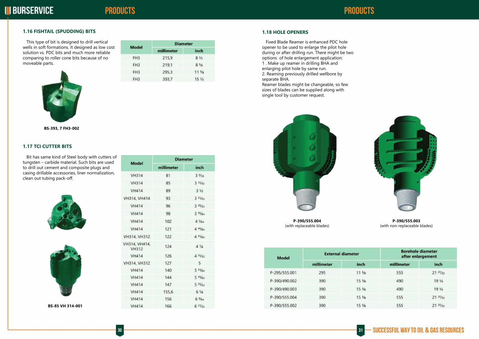
This type of bit is designed to drill vertical wells in soft formations. It designed as low cost solution vs. PDC bits and much more reliable comparing to roller cone bits because of no moveable parts.
Bit has same kind of Steel body with cutters of tungsten – carbide material. Such bits are used to drill out cement and composite plugs and casing drillable accessories, liner normalization, clean out tubing pack-off.
Fixed Blade Reamer is enhanced PDC hole opener to be used to enlarge the pilot hole during or after drilling run. There might be two options of hole enlargement application:1 . Make up reamer in drilling BHA and enlarging pilot hole by same run.2. Reaming previously drilled wellbore by separate BHA.Reamer blades might be changeable, so few sizes of blades can be supplied along with single tool by customer request.
1.18 HOLE OPENERS
BS-393, 7 FH3-002
BS-85 VH 314-001
P-390/555.004(with replaceable blades)
P-390/555.003(with non-replaceable blades)

32 33
PRODUCTS PRODUCTS
1.19 CORE BITS
General customer requirement for coring operations is high percentage of core recovery combining with maximum run length and rate of penetration. There is reinforced core part in design to provide stable core diameter and maximize its recovery. This helps to avoid sticking of core barrel and ensure core is secured in catching mechanism. There is shock absorbing insert to increase tool wear resistance and improve coring run performance (reduce vibration level, mitigate sticking and etc). Core cutting structure is designed to deliver increased rate of penetration while coring run.
BS-215,9/101,6 CD 813-003
BS-215,9/100 CD 613-002
BS-215,9/100 CD 1208-001
BS-215,9/100 CD 713-001
BS-212,7/100 CD 810-001
BS-215,9/100 CD 813-001

34 35
PRODUCTS PRODUCTS
2.1 CASING EXIT SYSTEMS
2.2 WHIPSTOCK SYSTEM WITH HYDRAULIC ANCHOR, NO ABANDONMENT PLUG REQUIRED
КОТ-146 OGN 1
Designation of casing exit tools
2. Workover and well intervention tools
anchor typewhipstock typetrips qty
tool setcasing size, mm
borehole type
KOT 168 ГМO И 1
«KOT OGN» tools set type is designed for single trip sidetrack in production casing without abandonment plug. Whipstock is non-retrievable. Tool set includes anchor, concave, hydraulic control line, shear bolt, lead (start) and secondary (watermelon) mills. Strong design and construction provides high reliability of the tool.
36 37
PRODUCTS PRODUCTS
2.3. WHIPSTOCK SYSTEM WITH MECHANICAL ANCHOR 2.4. WHIPSTOCK SYSTEM WITH HYDROMECH ANCHOR, NO ABANDONMENT PLUG REQUIRED
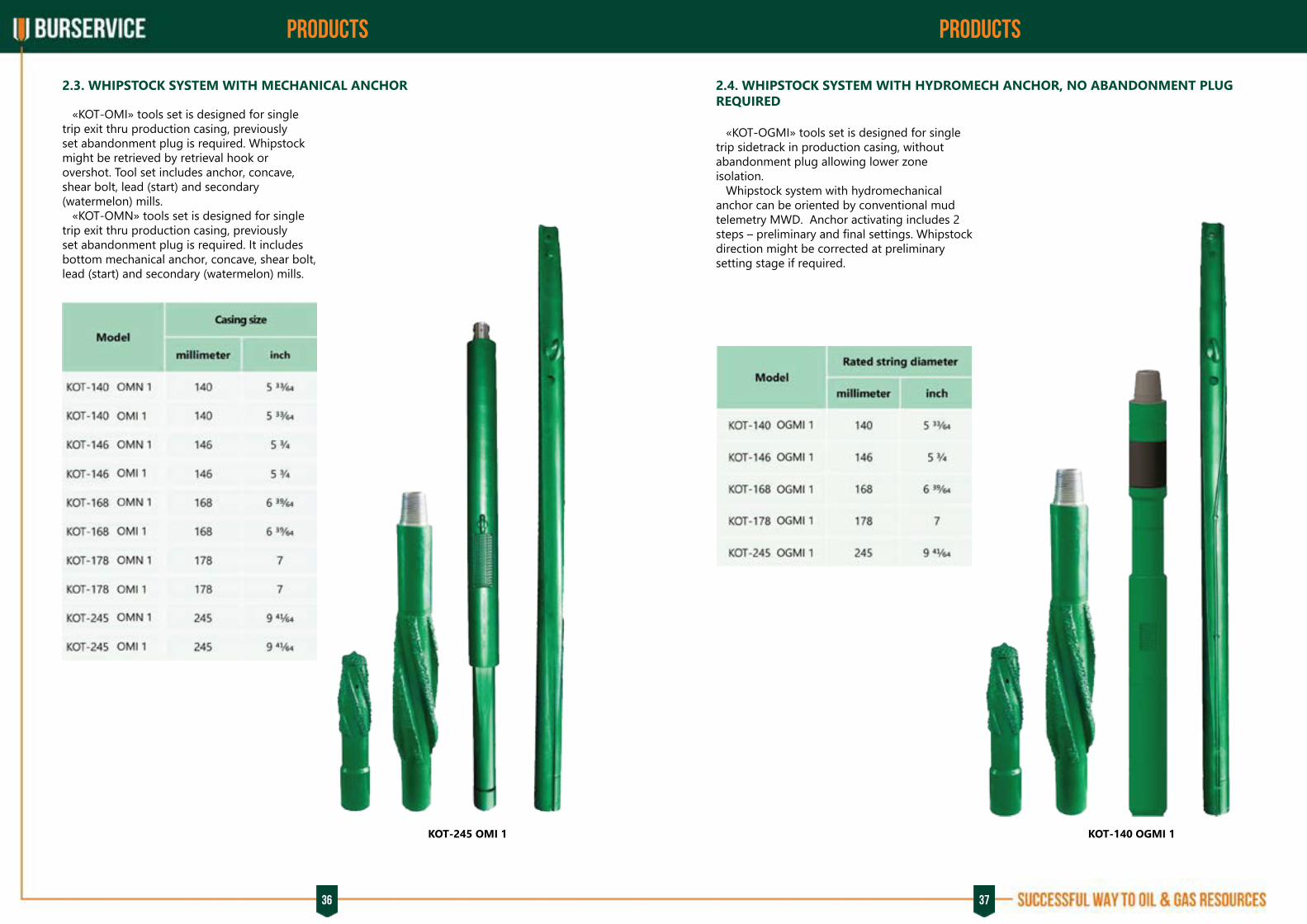
«KOT-OMI» tools set is designed for single trip exit thru production casing, previously set abandonment plug is required. Whipstock might be retrieved by retrieval hook or overshot. Tool set includes anchor, concave, shear bolt, lead (start) and secondary (watermelon) mills. «KOT-OMN» tools set is designed for single trip exit thru production casing, previously set abandonment plug is required. It includes bottom mechanical anchor, concave, shear bolt, lead (start) and secondary (watermelon) mills.
«KOT-OGMI» tools set is designed for single trip sidetrack in production casing, without abandonment plug allowing lower zone isolation. Whipstock system with hydromechanical anchor can be oriented by conventional mud telemetry MWD. Anchor activating includes 2 steps – preliminary and final settings. Whipstock direction might be corrected at preliminary setting stage if required.
КОТ-245 ОМI 1 KOT-140 OGMI 1

38 39
PRODUCTS PRODUCTS
2.5. WHIPSTOCK SYSTEM WITH HYDROMECH ANCHOR, NO ABANDONMENT PLUG REQUIRED
2.6. CEMENTED ANCHOR WHIPSTOCK SYSTEM
2.7. PACKERED WHIPSTOCK SYSTEM
2.8. SPECIAL FORMATION MILL REINFORCED BY PDC
«KOT-OGI» tools set is designed for single trip sidetrack in production casing, without abandonment plug allowing lower zone isolation.
«KOT-OMNK» tools set is designed for single trip exit thru production casing with hydraulic-set packer allowing lower zone isolation. Retrievable system «KOT-OMIK» is designed for single trip production casing exit with hydraulic-set packer allowing lower zone isolation.
Special formation mill reinforced by PDC (FSAI) is able to cut production casing and proceed drilling sidetrack wellbore thru formation in rotary mode per single trip.
«KOT-OCN» tools set is designed for two trips exit thru different casing sizes with previously setting of abandonment plug. Whipstock system is non-retrievable. Tool set includes anchor, concave, hanging pipe, xover sub, transport bolts, lead (start) and secondary (watermelon) mills. Set of mills may not be included in the kit in case of openhole run is proposed.
KOT-140 ОCN 2KOT- 140 ОGI 1 KOT-146 OMIK 1 FSAI - 124.01
«KOT-OMNK» and «KOT-OMIK» systems include bottom mechanical anchor with packer, upper anchor, concave, shear bolt, lead (start) and secondary (watermelon) mills.

40 41
PRODUCTS PRODUCTS
2.9. MILLS
Burservice manufactures mills of following types:
▪ JUNK AND FLAT BOTTOM mills are used to mill out cement and general metal junk to clean out the bottom hole. Concave shape is ideal to milling bit cones and other objects by keeping them centered under the mill. There are few types basing on milling structure – tungsten carbide tooth (FZ and FT), tungsten carbide composite material (FZI and FTI) and diamond composite mmaterial (FZA and FTA). “C” code means stabilized Mill assembly. FZPI bottom mill has combined milling structure including special chips cutters and tungsten carbide crumbs for milling sand packoffs, cement plugs, casing floats and accessories as well as common metal junk. ▪ WASHOVER SHOES are used to mill and
clean downhole equipment from outside. There are 4 types basing on milling structure – tungsten carbide grains (FKZ), tungsten carbide plates (FKP), tungsten carbide composite material (FKI) and diamond composite mmaterial (FKA).
Section miils are designed for cutting and milling a complete section of casing. Hydraulic force activates the cutter arms on the tool. Mills arms might be replaced on thre rigsite if required. Float valve might be attached to section mill assembly to prevent reverse flow and pack off tool with junk once circulation is stopped. Variety of stabilizers are also available for different casing sizes.
Typical application is open hole enlarging while drilling or by stand alone reaming run. Blades are activated by pressure drop, cutting structure is reinforced by PDC and tungsten carbide material cutters. Blades might be easily replaced on the rigsite.
FTI-210 FZPI-85 FPI-130/70 FM-120 FKKI-124
SMA-140/168
NET-185/240
▪ PILOT MILLS are used for milling stuck tubular, such as washpipe, cemented rotary shoe, liners. FP pilot assembly maintains a centered position on the tubular while the milling blades mills product away. ▪ MAGNET MILLS are used for milling and
pulling out the small metal junk from the bottom. ▪ TAPER MIILS are used to ream thru a variety
of restrictions like collapsed or jammed casing. 2 types of construction depends on cutting structure: FKK – tungsten carbide plates and FKKI – composite tungsten carbide material.
3.1. SECTION MILL ASSEMBLY
3.2. HOLE ENLARGEMENT TOOL
3. Expanding tools

42 43
PRODUCTS PRODUCTS
Designed to minimize downhole torque, reduce damage to the hole wall, and ensure maximum fluid circulation, for reaming of the borehole according to the drilling bit diameter and for centering and improvement of the drilling bit working conditions. Stabilizers are available with straight and spiral. It is manufactured from high-strength alloy steel as a single-piece tool with two connecting joint threads (coupling or nipple) and can be reinforced by hard-alloy and diamond -enhanced inserts. For order the type of the thread to be specified: M - box, H – nipple.
Designed to prevent possible entering of gas, oil or other solutions through the drilling and production string and to prevent sludging of PDM motors. The valves consist of a body with a conical seat with locking group. The main advantages of this valve are high reliability and long service life period, which is achieved by:
• simple design;• application of anti-vibration folding collar;• absence of the traditional compression springs prone to breakage.
Designed to prevent entering of the drilling fluid or the cement slurry and possible emission of gas or oil from the annular into the casing during cementing works, and for bottom plug guard. The advantages of this valve are high reliability due to significantly larger interaction surface of the conical sealing surfaces of the core seat and application of isolation joint in comparison with the applicable poppet and ball valves.
S-212 МС4 SS-295,3 СТЗ
SCV-110
SCCV-146 ОТТМ
4.1 STABILIZERS
4.2 SLIDING TYPE CHECK VALVE
4.3. SLIDING TYPE CEMENTING CHECK VALVE
4. BHA components 4.4. DRILLING SLIDE VALVE SCV-106
DESCRIPTION The valve is included as a component of BHA. Designed to prevent possible gas, oil or drilling fluid entering through drilling pipes as well as to protect the PDM motors and the bit nozzles against sludging while drilling.
44 45
MUD LAB MUD LAB
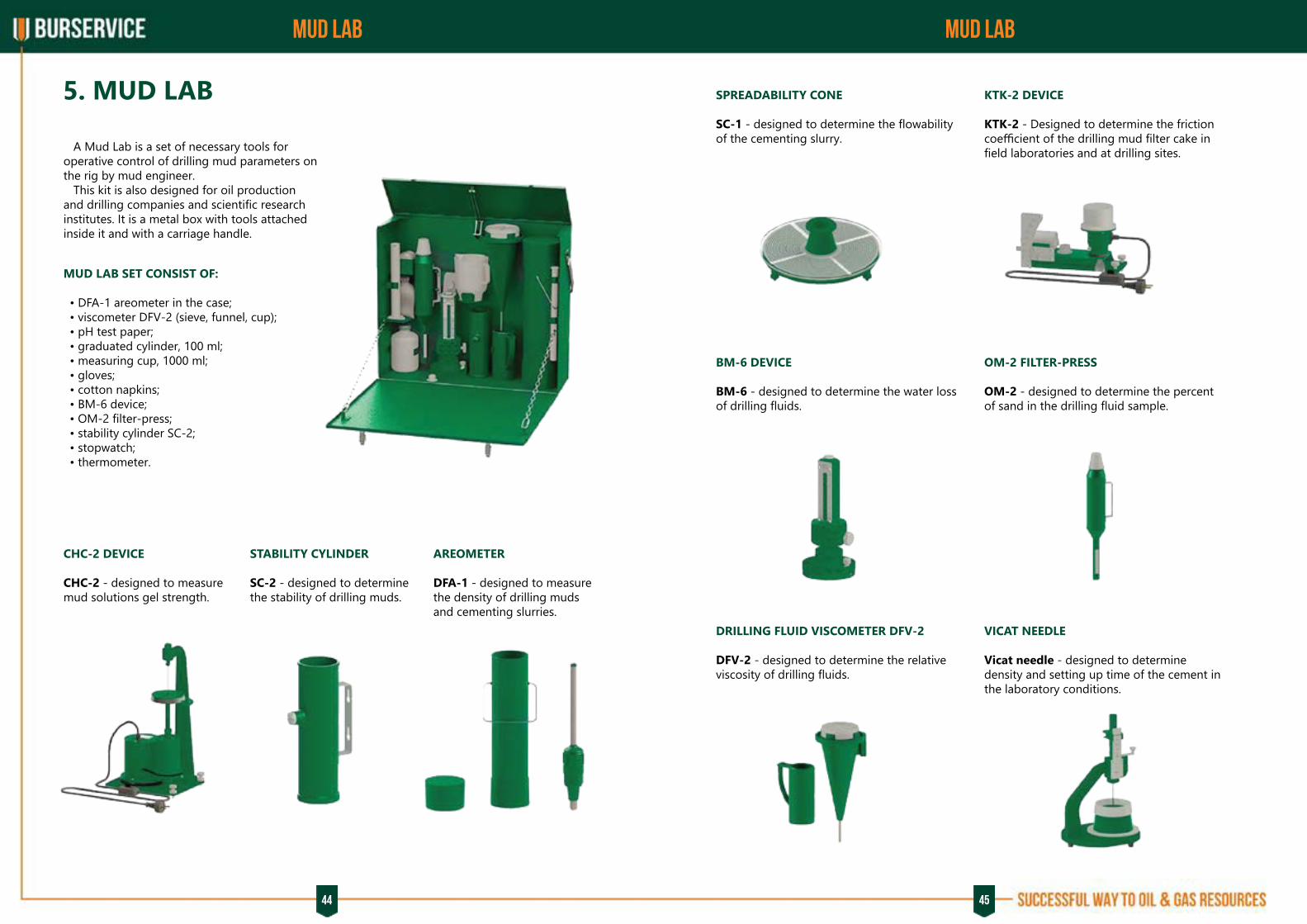
A Mud Lab is a set of necessary tools for operative control of drilling mud parameters on the rig by mud engineer. This kit is also designed for oil production and drilling companies and scientific research institutes. It is a metal box with tools attached inside it and with a carriage handle.
MUD LAB SET CONSIST OF:
• DFA-1 areometer in the case; • viscometer DFV-2 (sieve, funnel, cup); • pH test paper; • graduated cylinder, 100 ml; • measuring cup, 1000 ml; • gloves; • cotton napkins; • BM-6 device; • OM-2 filter-press; • stability cylinder SC-2; • stopwatch; • thermometer.
CHC-2 DEVICE
CHC-2 - designed to measure mud solutions gel strength.
SPREADABILITY CONE
SC-1 - designed to determine the flowability of the cementing slurry.
BM-6 DEVICE
BM-6 - designed to determine the water loss of drilling fluids.
DRILLING FLUID VISCOMETER DFV-2
DFV-2 - designed to determine the relative viscosity of drilling fluids.
KTK-2 DEVICE
KTK-2 - Designed to determine the friction coefficient of the drilling mud filter cake in field laboratories and at drilling sites.
OM-2 FILTER-PRESS
OM-2 - designed to determine the percent of sand in the drilling fluid sample.
VICAT NEEDLE
Vicat needle - designed to determine density and setting up time of the cement in the laboratory conditions.
STABILITY CYLINDER SC-2 - designed to determine the stability of drilling muds.
AREOMETER DFA-1 - designed to measure the density of drilling muds and cementing slurries.
5. MUD LAB
46 47
our BRANDs our BRANDs
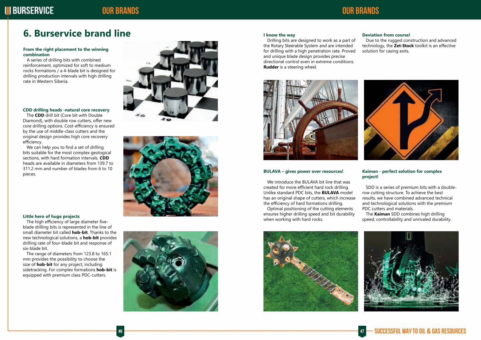
From the right placement to the winning combination A series of drilling bits with combined reinforcement, optimized for soft to medium rocks formations / a 4-blade bit is designed for drilling production intervals with high drilling rate in Western Siberia.
CDD drilling heads -natural core recovery The CDD drill bit (Core bit with Double Diamond), with double row cutters, offer new core drilling options. Cost-efficiency is ensured by the use of middle-class cutters and the original design provides high core recovery efficiency. We can help you to find a set of drilling bits suitable for the most complex geological sections, with hard formation intervals. CDD heads are available in diameters from 139.7 to 311.2 mm and number of blades from 6 to 10 pieces.
Little hero of huge projects The high efficiency of large diameter five-blade drilling bits is represented in the line of small diameter bit called hob-bit. Thanks to the new technological solutions, a hob-bit provides drilling rate of four-blade bit and response of six-blade bit. The range of diameters from 123.8 to 165.1 mm provides the possibility to choose the size of hob-bit for any project, including sidetracking. For complex formations hob-bit is equipped with premium class PDC-cutters.
I know the way Drilling bits are designed to work as a part of the Rotary Steerable System and are intended for drilling with a high penetration rate. Proved and unique blade design provides precise directional control even in extreme conditions. Rudder is a steering wheel.
BULAVA – gives power over resources!
We introduce the BULAVA bit line that was created for more efficient hard rock drilling. Unlike standard PDC bits, the BULAVA model has an original shape of cutters, which increase the efficiency of hard formations drilling. Optimal positioning of the cutting elements ensures higher drilling speed and bit durability when working with hard rocks.
Deviation from course! Due to the rugged construction and advanced technology, the Zet-Stock toolkit is an effective solution for casing exits.
Kaiman - perfect solution for complex project! SDD is a series of premium bits with a double-row cutting structure. To achieve the best results, we have combined advanced technical and technological solutions with the premium PDC cutters and materials. The Kaiman SDD combines high drilling speed, controllability and unrivaled durability.
6. Burservice brand line
48 49
NEW DEVELOPMENTS NEW DEVELOPMENTS
Within 10-15 years the rock cutting tools with polycrystalline diamond compact cutters (PDC) will have found an ever wider application, displacing the roller-cone bit. Currently, the share in the Russian drilling sector is about 85%. This leap was due to the high consumer properties of the PDC bit along with their simple and reliable design. But there are still goals to be achieved by PDC bits, due to their low competitiveness compared to roller-cone bits - in open pits formed by hard and solid rocks. On the one hand, the high contact stresses at the «cutter-rock» interface resulting in the cutter destruction, and on the other hand, the high forces required to run the cutter into the hard rock with the subsequent shear - all these factors restrict the use of typical PDC
+ =
7.1. THE BULAVA PROJECT
7. New developments of Burservice
bits in complex open pits.Therefore, our designers are faced with the task to create a design that would combine the advantages of both roller cone and PDC bits. So, on the one hand we have the design of the roller-cone bit, on the other hand - the PDC bit. The first is based on crushing shearing principle, the second - on the cutting-shearing one. Cutting is effective on soft and medium rocks, crushing - on hard and solid rocks. The rock cutting tools differ in the shape and the material composition. It would be logical to create a universal bit design combining these two principles for effective drilling of soft and medium as well as hard and solid rocks, providing the bladed bit with two different cutting structure types.
7.2. THE CORING DEVICE UKBS-185/100
7.3. FLUSHING AND MUDDING DEVICE
The coring device UKBS-185/ 100 is designed for sections. The basic design of the device is intended drilling boreholes of 0 212.7...311.2 mm and taking to take unsealed core samples. If it is necessary to a core of 100 mm. The device
MAIN PARAMETERS:The housing OD, mm 185Core diameter, mm 100Upper thread connection 3-133Lower thread connection6a 3-133
The Flushing and Mudding Device of multiple use is a circulation valve, which is able to redirect the fluid flow from inside the drilling string into the annular space, bypassing all the BHA elements located downstream of this device. FMD is activated through the activation ball while pumping the drilling mud. When the ball sits down on the seat, all the BHA elements located downstream of the FMD are cut from the flushing fluid flow. The list of tasks that can be solved by the FMD without tripping operations:
• Injection of all types of mud and plugging materials to the lost circulation zones. • Improvement of the borehole cleaning by
consists of the take a sealed core sample, the device is equipped body, the core receiver, an axial bearing, and the with the proper number of fiber glass or aluminum core sampler. It may have one, two, three, and four core tubes.
increasing the flushing flow rate (in particular, while drilling a substantial vertical deviation and horizontal wells). • Mud parameters recovery. • Replacing the technical fluids in the process of borehole development, completion, and workover.
The FMD has a unique feature - the circulation ports of the activated FMD are closed when the drilling pump is stopped, thus preventing the flushing fluid backflow from the annular space into the drilling string. The number of FMD activation/deactivation cycles depends on the volume of the ball catcher basket and can be increased by the customer’s request.
UKBS-185/100
FMD-120
50 51
NEW DEVELOPMENTS
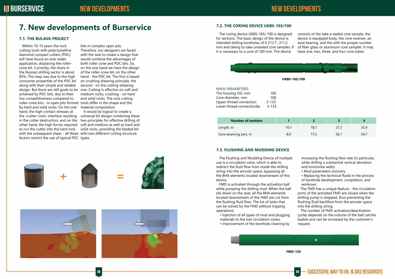
7.4. DRILLING DAMPER UDB-203
DESCRIPTION The device is designed to increase the drilling tools and elements life period, improving their operation resulting from: 1. Smoothing of axial shocks in the process of tools running-in, after making tools connections, and in the event of intermittent tool feed. 2. Absorption of the axial vibration energy, if it occurs from the positive displacement motor to the bit, and from the bit to the drilling string elements.
UDB-203

52
JOINT STOCK COMPANY SCIENTIFIC AND PRODUCTION ENTERPRISE «BURSERVICE»P.O. Box 124, Svobody str. 86/2, Ufa,the Republic of Bashkortostan, 450065 Russia,Phone +7 (347) 292 59 [email protected]
Related Documents