Drilling the Well IIT Madra s 1 Drilling the Well This describes, without calculation of the well requirements, the drilling of a subsea well. The specialist equipment required for drilling in an offshore environment is described and the differences between onshore and offshore operations emphasised. Content Anchored floating drilling vessels supplied a unique set of challenges to the oil and gas industry. Drilling technology in the early 1970s was not equipped to accommodate the constant motion of the floating drilling vessel. A system of specialty equipment had to be designed to eliminate any wave-induced motion. One of the most important pieces of equipment created to handle this challenge is the motion or drill string compensator. When drilling a well, the drill bit sits on the bottom of the wellbore and gouges and scratches away at the rock formation. The bit is connected to the drilling vessel by way of the drillstring. If using a floating drilling vessel, the vessel will move up and down due to wave action. This will cause the bit to bang into the bottom of the wellbore. This is inefficient and will damage the drill bit, the drill pipe and even the vessel. Drill bits are expensive, and as an engineer, you will want to use your drill bit for as long as possible, as when it starts drilling inefficiently, it will have to be pulled all the way out of the hole, change the bit and run it all back in again. This takes time, which costs money! For example a half-day wasted will cost $75,000.00 at January 2001 rig day rates. Therefore, getting rid of the effects of motion is important to a drilling contractor, and this is done by connecting a motion compensator to the drilling rig’s top drive. If the drilling vessel moves up, a piston like arrangement will stroke down to keep the drill bit on bottom, if the vessel moves down, the motion compensator will stroke up to stop the drill bit being gouged into the wellbore! This is one of the reasons why offshore drilling is expensive. Motion Compensators The function of a drill string motion compensator is to suspend the drilling assembly so that a constant weight is applied to the drill bit, as the floating drilling vessel moves up and down. The principle of operation is depicted in Figure 1. The motion compensator is shown as a single cylinder and piston assembly supplied by hydraulic fluid from a large pressurized accumulator. The hook is attached to the piston and the drill pipe, drill collars and drill bit are suspended from the hook. As can be seen from the diagram, the drilling assembly is shown resting on the bottom of the hole.

Welcome message from author
This document is posted to help you gain knowledge. Please leave a comment to let me know what you think about it! Share it to your friends and learn new things together.
Transcript

8/9/2019 Drilling the Well
http://slidepdf.com/reader/full/drilling-the-well 1/13
Drilling the Well
IIT Madras 1
Drilling the Well
This describes, without calculation of the well requirements, the drilling of asubsea well. The specialist equipment required for drilling in an offshore
environment is described and the differences between onshore and offshoreoperations emphasised.
Content
Anchored floating drilling vessels supplied a unique set of challenges to the oil and gasindustry. Drilling technology in the early 1970s was not equipped to accommodate theconstant motion of the floating drilling vessel. A system of specialty equipment had to bedesigned to eliminate any wave-induced motion. One of the most important pieces ofequipment created to handle this challenge is the motion or drill string compensator.
When drilling a well, the drill bit sits on the bottom of the wellbore and gouges and
scratches away at the rock formation. The bit is connected to the drilling vessel by wayof the drillstring. If using a floating drilling vessel, the vessel will move up and down dueto wave action. This will cause the bit to bang into the bottom of the wellbore. This isinefficient and will damage the drill bit, the drill pipe and even the vessel.
Drill bits are expensive, and as an engineer, you will want to use your drill bit for aslong as possible, as when it starts drilling inefficiently, it will have to be pulled all the wayout of the hole, change the bit and run it all back in again. This takes time, which costsmoney! For example a half-day wasted will cost $75,000.00 at January 2001 rig dayrates.
Therefore, getting rid of the effects of motion is important to a drilling contractor, andthis is done by connecting a motion compensator to the drilling rig’s top drive. If thedrilling vessel moves up, a piston like arrangement will stroke down to keep the drill bit
on bottom, if the vessel moves down, the motion compensator will stroke up to stop thedrill bit being gouged into the wellbore! This is one of the reasons why offshore drilling isexpensive.
Motion Compensators
The function of a drill string motion compensator is to suspend the drilling assembly sothat a constant weight is applied to the drill bit, as the floating drilling vessel moves upand down.
The principle of operation is depicted in Figure 1. The motion compensator is shownas a single cylinder and piston assembly supplied by hydraulic fluid from a largepressurized accumulator. The hook is attached to the piston and the drill pipe, drillcollars and drill bit are suspended from the hook. As can be seen from the diagram, thedrilling assembly is shown resting on the bottom of the hole.

8/9/2019 Drilling the Well
http://slidepdf.com/reader/full/drilling-the-well 2/13
Drilling the Well
IIT Madras 2
Figure 1. A Motion Compensator
Any pressure applied under the piston will provide an upward force. This force can beexpressed by the following Equation 1:
Equation 1 Force (lbs) = Pressure (psi) x Piston Area (ins2)
Consider the following example where the total hook load is 100,000 lbs, and a pressureof 1000 psi is applied to the compensator piston with an effective area of 80 squareinches. Using Equation 1:
Equation 1 Applied Force (lbs) = 1000 x 80 = 80,000 (lbs)
This means that the compensator is exerting 80,000 lbs upward pull which is not enoughto lift the drill bit off the bottom of the hole, because the total hook load is 100,000 lbs.
This means that 20,000 lbs is not supported by the compensator and is acting on the bit.This example describes a static condition. If the drilling vessel moves down, and thecompensator with it, then this action would tend to increase the weight on the bit.However the storage accumulator is providing fluid at a constant 1000 psi to theunderside of the piston, and this moves the piston upwards to support 80,000 lbs leaving20,000 lbs on the bit once again. As the vessel moves up, so does the compensator andeffect is to lift the drilling assembly out of the hole. However the piston can only support80,000 lbs as the fluid under the piston moves back into the storage accumulator at1000 psi. In this manner the floating drilling vessel moves up and down, but thecompensator moves out and in ensuring that the weight on the bit is maintained at20,000 lbs. If more or less weight is required on the bit, this is achieved by bleeding offthe air pressure, or increasing the air pressure from the air compressor/dryer assembly.
In effect the sensing device for the compensator is the drill string, resting on thebottom of the hole. In drilling operations, the neutral point between the tensioned drillstring and the portion resting in compression on the bottom of the hole is always

8/9/2019 Drilling the Well
http://slidepdf.com/reader/full/drilling-the-well 3/13
Drilling the Well
IIT Madras 3
maintained within the drill collar section of the drilling assembly. This is done becausethe drill collar sections and tool joints are far more rugged than drill pipe.
Figure 2. Schematic of a Single Cylinder Drillstring Motion Compensator.
Early derricks and travelling blocks were retrofitted with two cylinder motioncompensators. The design of drill string motion compensators usually employs twohydraulic cylinders and pistons. These cylinders and pistons are integrated into a unitthat is inserted between the travelling block and hook. The designs have evolved usingpistons in compression, or tension.
Travelling block compensators are by far the most common in use on floating drillingvessels (an example is shown in Figure 3).
Recently, with the increasing use of top-drive drilling systems, crown block motioncompensators are being used, to eliminate the number of long flexible hoses in the
derrick associated with travelling block compensators. The supply of operating fluid forthe compensator at nearly constant pressure relies on a bank of high-pressure airstorage bottles.
These air storage bottles are usually kept at operating pressure by an aircompressor/dryer.

8/9/2019 Drilling the Well
http://slidepdf.com/reader/full/drilling-the-well 4/13
Drilling the Well
IIT Madras 4
Figure 3. A Travelling Block Compensator.
An integrated system of guideline tensioners, riser tensioners and the drill string motioncompensator can all be fed high pressure air from a large bank of air bottles, supplied by
one air compressor .
The control panel for the drill string compensator is mounted adjacent to the drillersconsole and the weight indicator. The control panel is provided with system pressuregauges, compensator extension indicator, and control valves to raise or lower theoperating pressure. Most compensators have a locking mechanism that locks thecompensator together in its closed position, and the control panel will have the controllever to activate the lock mechanism.
Most drill string compensators have 20 –25 feet of stroke capacity with a dynamic loadcarrying capability ranging between 400,000 lbs and 600,000 lbs. Maximum systemoperating pressures range from 2,000 psi to 3,500 psi.
Motion compensators are often used when lowering equipment to the sea floor, to
provide a soft landing. For instance, if a BOP stack or a subsea production tree is beinglowered on to a subsea wellhead, the compensator can be set to support all but 5,000 to10,000 lbs of the total hanging load. This means that even in fairly heavy swells the BOPstack or tree is not subjected to a fierce impact when it lands on the subsea wellhead.Motion compensators are also used when landing casing hangers and when suspendingcasing strings in subsea wellheads.
The motion compensator is probably the single most important innovation thatsimplified floating drilling operations.

8/9/2019 Drilling the Well
http://slidepdf.com/reader/full/drilling-the-well 5/13
Drilling the Well
IIT Madras 5
Operation and Running of Subsea Wellhead Equipment
The function of the subsea wellhead is to provide a seabed location for suspending andsealing the wellbore casing strings. Various configurations of subsea wellhead havebeen used in the past, but most subsea wellheads are now based around the use of asingle 18 ¾ inch BOP stack rated at up to 15,000 psi. The wellhead must be able totolerate the external loading imposed by these BOP stacks and the associated drillingriser. Drilling operations and the sequence of events that lead to the running and safeoperation of subsea wellhead equipment will now be discussed.
Wellhead Installation Procedure
Initially, the floating drilling rig is moored over the drill site and ballasted to a suitabledraught. First, a heavy steel framework is attached to the bottom end of a string of drillpipe, and this framework is lowered to the seafloor. At this stage, the function of thetemporary guide base (TGB) is to establish guidance to the seabed.
Figure 4. A Temporary Guidebase.
The TGB, or drilling template, is shown in Figure 4. It is a heavy steel device that is oftencircular in shape and has a radius of approximately six feet. In spite of its name, nothingis really temporary about it, because once it is run down to the seafloor, it will probablyremain there during the life of the well.
It has an opening in the centre and four cables called guidelines are attached to four ofits outside corners. By running a TGB, a foundation point for the well is established, andan anchor point for guidewires installed. In some areas of the world, and by some drillingcontractors, a TGB is often omitted from the drilling sequence.
Conventional, guidewire-assisted drilling requires that the drilling rig be positivelyanchored to the seabed (in water depths of less than 2,000-3,000 feet). For deepwaterdrilling, where the drilling rig is located and held on site by the dynamic positioningsystem, no temporary guidebase or guidewires are needed.
The drill pipe on which the temporary guide base is lowered fits into the centreopening with a simple-release ‘J’ slot running tool. When the drill pipe lands the guidebase onto the ocean bottom, serrated legs on the bottom of the base penetrate into the
seafloor and keep it stationary. The drill pipe can be easily recovered by un-jaying therunning tool – usually by slacking off the weight of the drill pipe and turning the running
8/9/2019 Drilling the Well
http://slidepdf.com/reader/full/drilling-the-well 6/13
Drilling the Well
IIT Madras 6
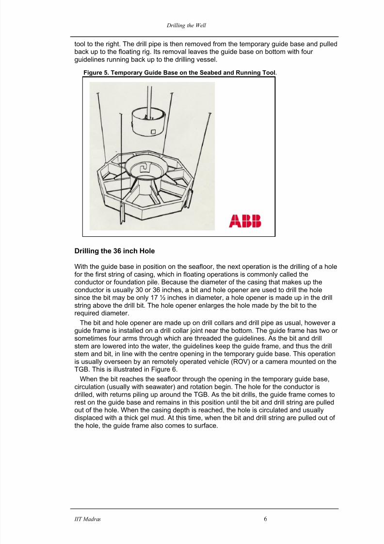
tool to the right. The drill pipe is then removed from the temporary guide base and pulledback up to the floating rig. Its removal leaves the guide base on bottom with fourguidelines running back up to the drilling vessel.
Figure 5. Temporary Guide Base on the Seabed and Running Tool.
Drilling the 36 inch Hole
With the guide base in position on the seafloor, the next operation is the drilling of a holefor the first string of casing, which in floating operations is commonly called theconductor or foundation pile. Because the diameter of the casing that makes up theconductor is usually 30 or 36 inches, a bit and hole opener are used to drill the holesince the bit may be only 17 ½ inches in diameter, a hole opener is made up in the drillstring above the drill bit. The hole opener enlarges the hole made by the bit to therequired diameter.
The bit and hole opener are made up on drill collars and drill pipe as usual, however aguide frame is installed on a drill collar joint near the bottom. The guide frame has two orsometimes four arms through which are threaded the guidelines. As the bit and drillstem are lowered into the water, the guidelines keep the guide frame, and thus the drillstem and bit, in line with the centre opening in the temporary guide base. This operationis usually overseen by an remotely operated vehicle (ROV) or a camera mounted on theTGB. This is illustrated in Figure 6.
When the bit reaches the seafloor through the opening in the temporary guide base,circulation (usually with seawater) and rotation begin. The hole for the conductor isdrilled, with returns piling up around the TGB. As the bit drills, the guide frame comes torest on the guide base and remains in this position until the bit and drill string are pulledout of the hole. When the casing depth is reached, the hole is circulated and usuallydisplaced with a thick gel mud. At this time, when the bit and drill string are pulled out ofthe hole, the guide frame also comes to surface.

8/9/2019 Drilling the Well
http://slidepdf.com/reader/full/drilling-the-well 7/13
Drilling the Well
IIT Madras 7
Fig 6. Drilling the 36 inch Hole.
At this point in the drilling operation, the hole for the conductor has been drilled. Restingon the seafloor is the temporary guide base with its four guidelines running upward tothe drilling vessel. The hole for the conductor is usually about one hundred feet deep,but this depth can vary depending on the softness or hardness of soil near the surface ofthe seafloor.
Drilling or Permanent Guide Base
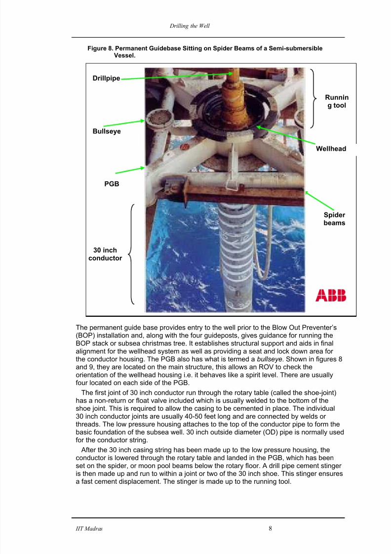
The next piece of equipment to be prepared for use is known as the drilling orpermanent guide base (PGB). This is set on the spider beams or moonpool beams andthe four guide lines (from the TGB) are inserted and trapped in the guide post slots (asillustrated in Figure 9). The 30 inch casing can then run through the centre hole of thepermanent guide base. Figure 8 shows the PGB sitting on the spider beams of a semi-submersible.
8/9/2019 Drilling the Well
http://slidepdf.com/reader/full/drilling-the-well 8/13

8/9/2019 Drilling the Well
http://slidepdf.com/reader/full/drilling-the-well 9/13
Drilling the Well
IIT Madras 9
Figure 9. PGB Going Through ‘splash zone’ of a Drilling Vessel .
The 30 inch conductor pipe and PGB are then picked up as one unit and run and landedon the temporary guide base on the seabed as shown in Figure 10.
Bullseye
Guidewires
Guide posts
RunningTool

8/9/2019 Drilling the Well
http://slidepdf.com/reader/full/drilling-the-well 10/13
Drilling the Well
IIT Madras 10
Figure 10. PGB, Cement Stinger and 30 inch Conductor.
When the 30 inch conductor is landed, circulation is established prior to the cementingoperation. The 30 inch conductor can then be cemented and the running tool releasedby right hand rotation. The running sequence for this operation is illustrated in Figure 11.
Cementing the Conductor
Once the conductor is run into the hole and the PGB is landed in the temporary guidebase, the conductor can be cemented.
Figure 11. PGB and Conductor Landed in TGB on Seabed.
8/9/2019 Drilling the Well
http://slidepdf.com/reader/full/drilling-the-well 11/13
Drilling the Well
IIT Madras 11
To cement the 30 inch conductor, cement is pumped down the inside of the drill pipe/cement stinger, which is within 30 feet of the 30 inch shoe.
Because of this non return valve known as a shoe, the cement goes out the bottom ofthe conductor and back up the annular space between the wall of the hole and theoutside of the casing.
This method of a cement stinger delivering cement to a specific area of the wellbore
(in this case the bottom), avoids the operators having to pump the entire volume of theconductor string to get cement to the bottom where its needed.
Cement is pumped until it starts to spill out onto the seafloor underneath the temporaryguide base, this will be viewed by remote TV cameras monitoring operations, eitherattached to the PGB or via ROV. When this is observed, pumping will be stopped, andthe drill pipe and cement stinger will be retrieved.
20 inch casing and the 18 ¾ inch High Pressure Wellhead Housing (HPH)
After the cement sets, the hole for the second string of casing can be drilled. To drill thehole for the 20 inch casing, a bit with a diameter a few inches smaller than the insidediameter of the conductor (approximately 26 inches) is lowered into the water to the
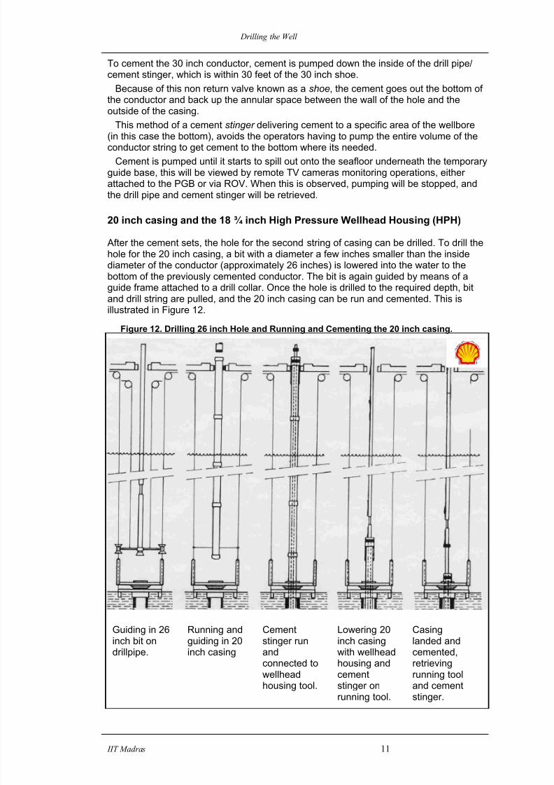
bottom of the previously cemented conductor. The bit is again guided by means of aguide frame attached to a drill collar. Once the hole is drilled to the required depth, bitand drill string are pulled, and the 20 inch casing can be run and cemented. This isillustrated in Figure 12.
Figure 12. Drilling 26 inch Hole and Running and Cementing the 20 inch casing.
Guiding in 26inch bit ondrillpipe.
Running andguiding in 20inch casing
Cementstinger runandconnected towellhead
housing tool.
Lowering 20inch casingwith wellheadhousing andcement
stinger onrunning tool.
Casinglanded andcemented,retrievingrunning tool
and cementstinger.

8/9/2019 Drilling the Well
http://slidepdf.com/reader/full/drilling-the-well 12/13
Drilling the Well
IIT Madras 12
The 18 ¾ inch HPH is attached to the top of the 20 inch casing string, and this housinglands and locks inside the LPH run earlier (with the 30 inch conductor). The highpressure housing is a critical element in the well system, it provides pressure integrity forthe well and is used to suspend the surface casing and any further casing strings. TheBOP stack attaches to the top of the HPH using a compatible wellhead connector andwill also accept a tubing hanger and conventional tree or a horizontal tree in the event
that the well is converted to production use.Once the HPH and BOP are installed, subsequent casing strings are landed in the
housing, cemented, and sealed off as required by the drilling programme. The centralouter section of the wellhead housing features a lockdown mechanism that is used tosecure it to the conductor housing. The wellhead housing body features an upwardfacing profile and a special gasket pocket for high pressure protection when the BOPstack is connected. The inside profile of the wellhead body forms a location from whichto suspend further casing strings and casing hanger packoff assemblies if the well is tobe produced.
After the 20 inch housing running tool is made to the HPH, the 20 inch casing string isrun on drill pipe and landed in the LPH on the seabed.
Figure 13. 20 inch Casing and HPH locked into LPH.
At this time, the external lock ring on the wellhead housing snaps into the groovepreparation in the 30 inch LPH. A pick up test can be performed to ensure that the HPHhas landed and locked in the correct position.
Once the contents of the 20 inch casing have been circulated, the casing string can be
cemented. Once cemented, the running tool is rotated to the right and retrieved.This places the high pressure wellhead housing with its ‘H-4’ profile in position to
accommodate the next major assembly. The next major assembly is the subsea blowout preventer stack (BOP). It is pressure
tested on the drilling rig, to ensure that it is operating properly and is then lowered downto the permanent guide base (PGB) located on the seabed. The operation and abilitiesof the BOP are covered in the topic ‘Marine Riser BOP Systems’.
A casing plan such as that shown in Figure 14 shows the depth, size and structure ofa well.

8/9/2019 Drilling the Well
http://slidepdf.com/reader/full/drilling-the-well 13/13
Drilling the Well
IIT Madras 13
Figure 14. Casing Plan for Gannet D Production Well.
RESERVOIR
42” Foundation Sleeve
10 ¾” Casing
9 5/8” Casing
7” Liner
300 ft TVSS
ca 7790 ft TVSS
355 ft TVSS
800 ft TVSS
ca 10000 ft TVSS
3090 ft
ca 7990 ft TVSS
2090 ft
30” Casing
20” Casing
Related Documents