Technical Specifications Drilling Engineering Parameters Technical Specifications 2008 GEO-data GmbH • Tel. +49 (0) 5131-4681 0 • E-mail [email protected] • Fax +49 (0) 5131-4681 50 TS DR-00 TECHNICAL SPECIFICATIONS Drilling Engineering Parameters TS DATA SHEETS - DR - Continuing development sometimes necessitates specification changes without notice

Welcome message from author
This document is posted to help you gain knowledge. Please leave a comment to let me know what you think about it! Share it to your friends and learn new things together.
Transcript
Technical Specifications Drilling Engineering Parameters
Technical Specifications
2008
GEO-data GmbH • Tel. +49 (0) 5131-4681 0 • E-mail [email protected] • Fax +49 (0) 5131-4681 50
TS
DR-00
TECHNICAL SPECIFICATIONS
Drilling Engineering Parameters
TS DATA SHEETS
- DR -
Continuing development sometimes necessitates specification changes without notice
Technical Specification Drilling Engineering Parameters
Version 2.0
November 2004
DR10_ROP(B10)-bus.doc
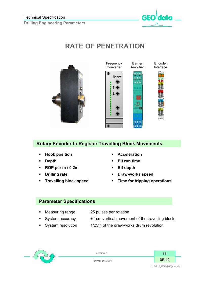
RATE OF PENETRATION Frequency Converter
Barrier Amplifier
Encoder Interface
Rotary Encoder to Register Travelling Block Movements Hook position Depth ROP per m / 0.2m Drilling rate Travelling block speed
Acceleration Bit run time Bit depth Draw-works speed Time for tripping operations
Parameter Specifications Measuring range 25 pulses per rotation System accuracy ± 1cm vertical movement of the travelling block System resolution 1/25th of the draw-works drum revolution
TS
DR-10
Technical Specification Drilling Engineering Parameters
Version 2.0
November 2004
GEO-data GmbH • Tel. +49 (0) 5131-4681 0 • E-mail [email protected] • Fax +49 (0) 5131-4681 50
TS
DR-10
Principle of Operation The rotary encoder is fitted to the main drive shaft of the draw-works. The encoder produces pulse signals in correspondence to the drum rotation and speed. The rotations of two separate pulse discs are registered inductively by proximity switches. A 90° signal phase shift enables the indication of the actual state of motion. Maintenance Once the system is set up and calibrated, generally no maintenance will be required.
Visual routine checks (daily); check the sensor positioning weekly or after each tripping operation, re-adjust if necessary Data Processing The powerful DMS software records, visualizes and displays data on different locations on the well site. The DMS submits the setting of individual alarms for “High“ and “Low“ limits. Acoustic alarms can be set at selected intervals, e.g. to indicate that a lag corrected cuttings sample is due.
Technical Specifications SENSOR B-10 Type or model: Two-channel rotary encoder Certified for hazardous area: Intrinsically safe to EEx ia IIC T6 Certificate of conformity: PTB No. Ex-83/2022X Operating temperature range: -25°C … +100°C Supply voltage: 8V DC Installation point : Fitted to the main drive shaft of the draw-works drum
Evaluation Unit Impulse Counter B10 Ex-Barrier Amplifier with
BUS System
Type or model Two-channel rotary encoder – Inputs [EEx ia] IIC
Barrier Amplifier - EEx ia IIC
Certificate of conformity: BASEEFA No. Ex-93C2412 TÜV 99 ATEX 1499 X Signal output : 4 – 20mA 4 – 20mA Supply voltage: 8 V DC 24 V DC
Bus System: Not applicable Field bus independent connectors
Installation: Logging unit; plugged into 19-inch frame (DMS rack)
Technical Specification Drilling Engineering Parameters
Version 2.0
November 2004
DR11_WOB(hy)-bus.doc
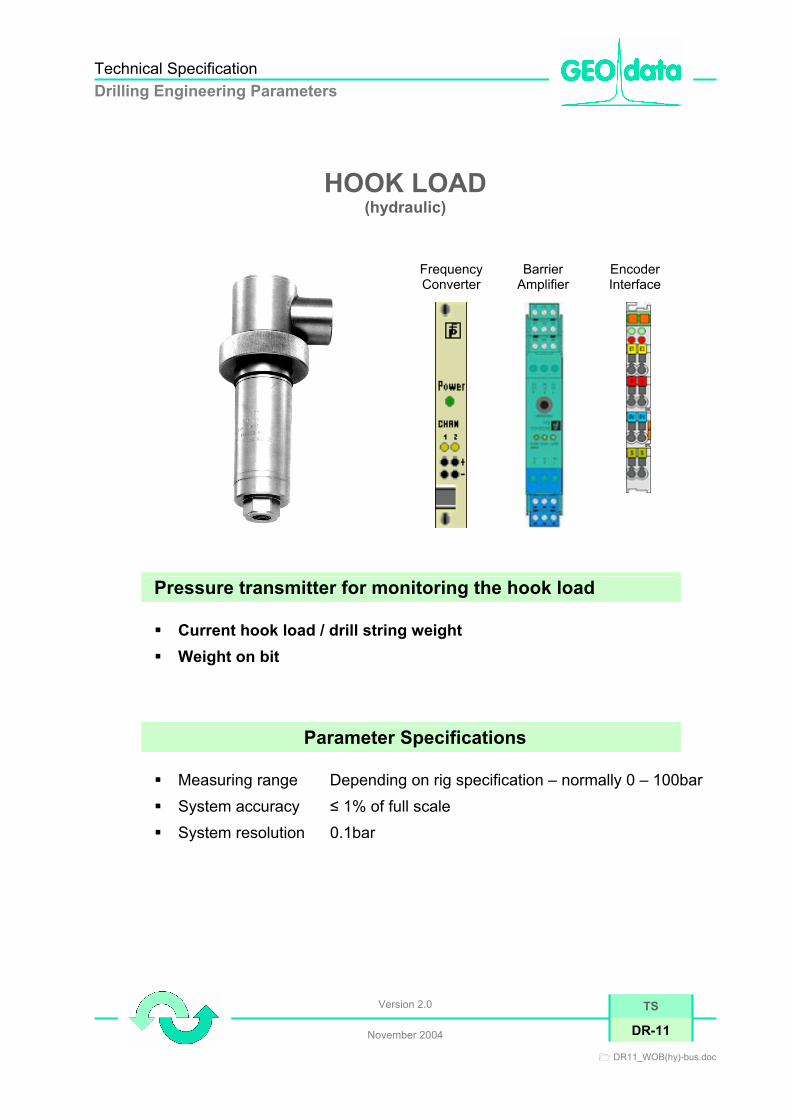
HOOK LOAD (hydraulic)
Frequency Converter
Barrier Amplifier
Encoder Interface
Pressure transmitter for monitoring the hook load Current hook load / drill string weight Weight on bit
Parameter Specifications Measuring range Depending on rig specification – normally 0 – 100bar System accuracy ≤ 1% of full scale System resolution 0.1bar
TS
DR-11

Technical Specification Drilling Engineering Parameters
Version 2.0
November 2004
GEO-data GmbH • Tel. +49 (0) 5131-4681 0 • E-mail [email protected] • Fax +49 (0) 5131-4681 50
TS
DR-11
Principle of Operation A diaphragm separates a micro-machined silicon sensor with temperature compensation from the pressure medium. Silicon oil serves as pressure transmitter. An integrated amplifier converts the output test current, which is proportional to the pressure density, into a corresponding DC signal (4 – 20mA). Maintenance Once the system is set up and calibrated, generally no maintenance will be required.
Visual routine checks (daily) shall include the observation of possible leaks in the sensor hydraulic system. Data Processing The powerful DMS software records, visualizes and displays data on different locations on the well site. The DMS submits the setting of individual alarms for “High“ and “Low“ limits.
Technical Specifications SENSOR Type or model: Pressure transmitter Certified for hazardous area: Intrinsically safe to EEx ia IIC T4 Certificate of conformity: BASEEFA No. Ex-89.C.2251 Operating temperature range: -20°C … +80°C Supply voltage: 24V DC
Installation point : Connected to the load cell of the hook load indicator at the deadline anchor (process connection e.g. 1/4" NPT HANSEN)
Evaluation Unit Transmitter / Repeater
Unit Ex-Barrier Amplifier with BUS System
Type or model Isolating amplifier – inputs EEx ia IIC Barrier Amplifier - EEx ia IIC
Certificate of conformity: BASEEFA Nr. Ex-90.C.2358X TÜV 99 ATEX 1499 X
Signal output : 4 – 20mA 4 – 20mA Supply voltage: 24 V DC 24 V DC Bus System: Not applicable Not applicable Installation: Logging unit; connected to 19-inch frame (DMS rack)

Technical Specification Drilling Engineering Parameters
Version 2.0
December 2004
DR12_WOB(el)-bus.doc
HOOK LOAD (electrical)
Frequency Converter
Barrier Amplifier
Encoder Interface
Line Tension Transducer for Monitoring the Hook Load Current hook load / drill string weight Weight on bit
Parameter Specifications Measuring range 0 – 45to (450to with 10 lines) System accuracy ± 2% of full scale System resolution 0.5to
TS
DR-12
Technical Specification Drilling Engineering Parameters
Version 2.0
November 2004
GEO-data GmbH • Tel. +49 (0) 5131-4681 0 • E-mail [email protected] • Fax +49 (0) 5131-4681 50
TS
DR-12
Principle of Operation The drilling line is fixed at the centre of the transducer body between two deflection blocks at the deadline. When additional load is applied to the drilling line, the drilling line tends to straighten at the deflection point and creates a strain on the transducer body, which the strain gauges detect. The strain gauge wheatstone bridge and the signal converter combine to produce a 4 – 20mA output signal proportional to the tension in the drilling line. Maintenance Once the system is set up and calibrated, generally no maintenance will be required.
Visual routine checks (daily); check the sensor positioning weekly or after each tripping operation, readjust if necessary. Data Processing Display, output, recording and storage of the measurements are determined by the Drill Monitoring System developed by GEO-data GmbH. The DMS submits the setting of individual alarms for “High“ and “Low“ limits.
Technical Specifications
SENSOR Type or model Line tension transducer Certified for hazardous area Intrinsically safe to EEx ia IIB T6 Certificate of conformity ISSeP No. 94C.101.199X Operating temperature range -40°C … +80°C Supply voltage 24V DC Installation point Clamped to the anchored wire rope (deadline)
Evaluation Unit
Transmitter / Repeater Unit
Ex-Barrier Amplifier with BUS System
Type or model Isolating amplifier – inputs EEx ia IIC
Barrier Amplifier EEx ia IIC
Certificate of conformity BASEEFA No Ex 90.C.2358X TÜV 99 ATEX 1499 X
Signal output 4 – 20mA 4 – 20 mA Supply voltage 24V DC 24 V DC
Bus System: Not applicable Field bus independent connectors
Installation point Logging unit; plugged into 19-inch frame (DMS rack)
Technical Specification Drilling Engineering Parameters
Version 2.0
November 2004
DR13_RPM-bus.doc
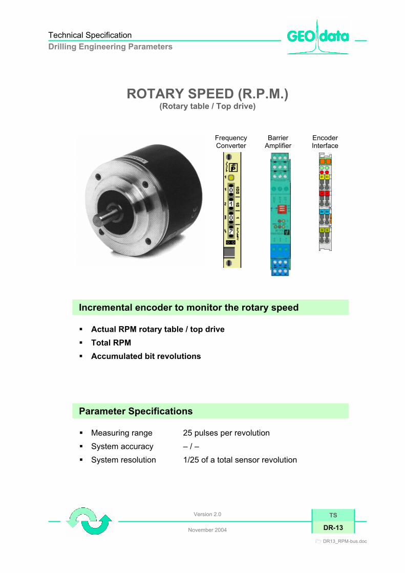
ROTARY SPEED (R.P.M.) (Rotary table / Top drive)
Frequency Converter
Barrier Amplifier
Encoder Interface
Incremental encoder to monitor the rotary speed Actual RPM rotary table / top drive Total RPM Accumulated bit revolutions
Parameter Specifications Measuring range 25 pulses per revolution System accuracy – / – System resolution 1/25 of a total sensor revolution
TS
DR-13

Technical Specification Drilling Engineering Parameters
Version 2.0
November 2004
GEO-data GmbH • Tel. +49 (0) 5131-4681 0 • E-mail [email protected] • Fax +49 (0) 5131-4681 50
TS
DR-13
Principle of Operation The rotary encoder is linked to the drive unit of the rotary table or the top-drive. The pulse disc generates, in correspondence to the rotary speed, a sequence of pulses. Inductive proximity switches convert the pulses into proportional electrical signals. Maintenance Once the system is set up and calibrated, generally no maintenance will be required.
Visual routine checks (daily); check the sensor positioning weekly or after each tripping operation, readjust if necessary. Data Processing The powerful DMS software records, visualizes and displays data on different locations on the well site. The DMS supports the setting of individual alarms for “High“ and “Low“ limits.
Technical Specifications SENSOR Type or model: Incremental encoder Certified for hazardous area: Intrinsically safe to EEx ia IIC T6 Certificate of conformity: PTB No. Ex-83/2022X Operating temperature range: -10°C … +60°C Supply voltage: 8V DC Installation point : Linked to the drive unit of the rotary table or the top drive
Evaluation Unit Transmitter / Repeater
Unit Ex-Barrier Amplifier with BUS System
Type or model Isolating amplifier – inputs EEx ia IIC Barrier Amplifier - EEx ia IIC
Certificate of conformity: PTB No. Ex-81/2065X TÜV 99 ATEX 1499 X Signal output : 4 – 20 mA 4 – 20 mA Supply voltage: 24 V DC 24 V DC
Bus System: Not applicable Field bus independent connectors
Installation: Logging unit; connected to 19-inch frame (DMS rack)

Technical Specification Drilling Engineering Parameters
Version 2.0
November 2004
DR14_Torq(hy)-bus.doc
ROTARY TORQUE (hydraulic)
Frequency Converter
Barrier Amplifier
Encoder Interface
Pressure transmitter to monitor the rotary torque High stability High accuracy High shock and vibration compliance Individual types and pressure ranges
Parameter Specifications Measuring range Depending on rig specification
Normally 0 to 400bar System accuracy ≤ 1% of full scale System resolution 0.1bar
TS
DR-14
Technical Specification Drilling Engineering Parameters
Version 2.0
November 2004
GEO-data GmbH • Tel. +49 (0) 5131-4681 0 • E-mail [email protected] • Fax +49 (0) 5131-4681 50
TS
DR-14
Principle of Operation A diaphragm separates a micro-machined silicon sensor with temperature compensation from the pressure medium. Silicon oil serves as pressure transmitter. An integrated amplifier converts the output test current, which is proportional to the pressure density, into a corresponding DC signal (4 – 20mA). Maintenance Once the system is set up and calibrated, generally no maintenance will be required.
Visual routine checks (daily) shall include the observation of possible leaks in the sensor hydraulic system. Data Processing The powerful DMS software records, visualizes and displays data on different locations on the well site. The DMS supports the setting of individual alarms for “High“ and “Low“ limits.
Technical Specifications SENSOR Type or model: Pressure transmitter Certified for hazardous area: Intrinsically safe to EEx ia IIC T4 Certificate of conformity: BASEEFA No. Ex-89.C.2251 Operating temperature range: -20°C … +80°C Supply voltage: 24V DC
Installation point : Connected to the load cell of the rotary torque indicator (process connection e.g. 1/4" NPT HANSEN)
TRANSMITTER / REPEATER UNIT
Transmitter / Repeater Unit
Ex-Barrier Amplifier with BUS System
Type or model Isolating amplifier – inputs EEx ia IIC Barrier Amplifier - EEx ia IIC
Certificate of conformity: BASEEFA No. Ex-90.C.2358X TÜV 99 ATEX 1499 X
Signal output : 4 – 20mA 4 – 20 mA Supply voltage: 24V DC 24 V DC
Bus System: Not applicable Field bus independant connectors
Installation: Logging unit; plugged into 19-inch frame (DMS rack)

Technical Specification Drilling Engineering Parameters
Issue 2.0
February 2008
DR15-1_Torq(el)-bus.doc
ROTARY TORQUE (electrical)
Mm
Current transformer to monitor the rotary torque For use on electrically-driven rotary tables or top drives Non-contact technique with fast response to input changes 5000 Volt isolation Stability maintained during severe vibrations (< 1% Low temperature effects
Parameter Specifications Measuring range 0 – 2000A (AC/DC) System accuracy ± 0,5% of full scale
TS
DR-15.1

Technical Specification Drilling Engineering Parameters
Issue 2.0
February 2008
GEO-data GmbH • Tel. +49 (0) 5131-4681 0 • E-mail [email protected] • Fax +49 (0) 5131-4681 50
TS
DR-15.1
Principle of Operation The signal pickup for the measurement of the rotary torque is a Hall-effect clamp-on current transformer, attached to the power feed cable of the rotary drive/top drive motor. The measured magnetic field strength of the electric current drawn to the motor is proportional to the rotary torque applied to the drill string. Maintenance Once the system is set up and calibrated, generally no maintenance will be required.
Visual routine checks (daily) must include the inspection of a correct sensor positioning, readjust if necessary. Data Processing Display, output, recording and storage of the measurements are determined by the Drill Monitoring System developed by GEO-data GmbH. The DMS submits the setting of individual alarms for “High“ and “Low“ limits.
Technical Specifications SENSOR Type or model Clamp-on current transformer Certified for hazardous area – / -- Certificate of conformity – / – Operating temperature range -40°C … +65°C Supply voltage 115 V AC / 50 – 400 Hz/2 VA Installation point Clamped to the power feed cable of the electric rotary
table or top drive motor Evaluation Unit Transmitter / Repeater
Unit Ex-Barrier Amplifier with BUS System
Type or model Isolating amplifier – inputs EEx ia IIC Barrier Amplifier - EEx ia IIC
Certificate of conformity: PTB No. Ex-81/2065X TÜV 99 ATEX 1499 X Signal output : 4 – 20 mA 4 – 20 mA Supply voltage: 24 V DC 24 V DC
Bus System: Not applicable Field bus independent connectors
Installation: Logging unit; connected to 19-inch frame (DMS rack)

Technical Specification Drilling Engineering Parameters
Version 2.0
November 2004
DR16_MakeUpTorq-bus.doc
MAKE-UP TORQUE (Tong / Iron roughneck)
Frequency Converter
Barrier Amplifier
Encoder Interface
Pressure transmitter to monitor the make-up torque High stability High accuracy High shock and vibration capacity Individual types and pressure ranges
Parameter Specifications Operating pressure ranges depending on rig specification
Normally to 400bars System accuracy ≤ 1% of full scale System resolution 0.1bars
TS
DR-16

Technical Specification Drilling Engineering Parameters
Version 2.0
November 2004
GEO-data GmbH • Tel. +49 (0) 5131-4681 0 • E-mail [email protected] • Fax +49 (0) 5131-4681 50
TS
DR-16
Principle of Operation A diaphragm separates a micromachined silicon sensor with temperature compensation from the pressure medium. Silicon oil serves as pressure transmitter. An integrated amplifier converts the output test current, which is proportional to the pressure density, into a corresponding DC signal (4 – 20mA). Maintenance Once the system is set up and calibrated, generally no maintenance will be required.
Visual routine checks (daily) shall include the observation of possible leaks in the sensor hydraulic system. Data Processing Display, output, recording and storage of the measurements are determined by the Drill Monitoring System developed by GEO-data GmbH. The DMS submits the setting of individual alarms for “High“ and “Low“ limits.
Technical Specifications SENSOR Type or model: Pressure transmitter Certified for hazardous area: Intrinsically safe to EEx ia IIC T4 Certificate of conformity: BASEEFA No. Ex-89.C.2251 Operating temperature range: -20°C … +80°C Supply voltage: 24V DC
Installation point : Connected to the load cell of the make-up torque indicator (process connection e.g. 1/4" NPT HANSEN)
Evaluation Unit Transmitter / Repeater
Unit Ex-Barrier Amplifier with BUS System
Type or model Isolating amplifier – inputs EEx ia IIC Barrier Amplifier - EEx ia IIC
Certificate of conformity: BASEEFA No. Ex-90.C.2358X TÜV 99 ATEX 1499 X
Signal output : 4 – 20mA 4 – 20 mA Supply voltage: 24V DC 24 V DC
Bus System: Not applicable Field bus independent connectors
Installation: Logging unit; plugged into 19-inch frame (DMS rack)

Technical Specification Drilling Engineering Parameters
Version 2.0
November 2004
DR17_CsgPres-bus.doc
ANNULAR (CASING) PRESSURE
Frequency Converter
Barrier Amplifier
Encoder Interface
Pressure transmitter for monitoring Annular Pressure High stability High accuracy High shock and vibration capacity Individual types and pressure ranges
Parameter Specifications Operating pressure ranges from 0 to 700bar System accuracy ≤ 1% of full scale System resolution 1bar
TS
DR-17
Technical Specification Drilling Engineering Parameters
Version 2.0
November 2004
GEO-data GmbH • Tel. +49 (0) 5131-4681 0 • E-mail [email protected] • Fax +49 (0) 5131-4681 50
TS
DR-17
Principle of Operation A diaphragm separates a micromachined silicon sensor with temperature compensation from the pressure medium. Silicon oil serves as pressure transmitter. An integrated amplifier converts the output test current, which is proportional to the pressure density, into a corresponding DC signal (4 – 20mA). Maintenance Once the system is set up and calibrated, generally no maintenance will be required.
Visual routine checks (daily) shall include the observation of possible leaks in the sensor hydraulic system. Data Processing The powerful DMS software records, visualizes and displays data on different locations on the well site. The DMS supports the setting of individual alarms for “High“ and “Low“ limits.
Technical Specifications SENSOR Type or model: Pressure transmitter Certified for hazardous area: Intrinsically safe to EEx ia IIC T4 Certificate of conformity: BASEEFA No. Ex-89.C.2251 Operating temperature range: -20°C … +80°C Supply voltage: 24V DC
Installation point : Connected to the load cell of the annular pressure indicator (process connection e.g. 1/4" NPT HANSEN)
Evaluation Unit Impulse Counter B10 Ex-Barrier Amplifier with
BUS System Type or model Isolating amplifier – inputs
EEx ia IIC Barrier Amplifier - EEx ia IIC
Certificate of conformity: BASEEFA No. Ex-90.C.2358X TÜV 99 ATEX 1499 X
Signal output : 4 – 20mA 4 – 20 mA Supply voltage: 24V DC 24 V DC
Bus System: Not applicable Field bus independant connectors
Installation: Logging unit; plugged into 19-inch frame (DMS rack)
Related Documents


