Schlumberger Private Drill String Design Drilling Instructor – D&M UTC

Welcome message from author
This document is posted to help you gain knowledge. Please leave a comment to let me know what you think about it! Share it to your friends and learn new things together.
Transcript

Schlumberger Private
Drill String Design
Drilling Instructor – D&M
UTC

Schlumberger Private
2 DD1 Nov 2004
Objectives 1. Describe the various effects of physical forces on steel
and calculate their extent
2. Be able to name and describe the most important physical laws and relationships which govern the behavior of steel.
3. Know where to find design information about the performance of steel tubulars.
4. Be able to select appropriate steel grades for different applications.
5. Describe and be able to apply Safety Factors (also called Design Factors in some companies) and Correction Factors.

Schlumberger Private
3 DD1 Nov 2004
Physical Laws and Relationships
The important concepts are; • Stress • Strain • Hooke's Law • Youngs Modulus • Elastic Limit • Yield Strength/Tensile Strength
Schlumberger Private
4 DD1 Nov 2004
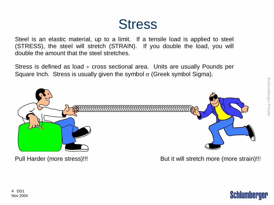
Stress Steel is an elastic material, up to a limit. If a tensile load is applied to steel (STRESS), the steel will stretch (STRAIN). If you double the load, you will double the amount that the steel stretches.
Stress is defined as load ÷ cross sectional area. Units are usually Pounds per Square Inch. Stress is usually given the symbol σ (Greek symbol Sigma).
Pull Harder (more stress)!!! But it will stretch more (more strain)!!!

Schlumberger Private
5 DD1 Nov 2004
Stress - example • If a new 5” drillpipe has a
cross sectional area of 5.2746 square inches and it supports a load of 100,000 lbs, what is the Stress in the pipe?
• If a new 3.5” drillpipe has a cross sectional area of 4.3037 square inches and it supports a load of 100,000 lbs, what is the Stress in the pipe?
• Stress = Load ÷ Area
• Stress = 100,000 ÷ 4.3037
• Stress = 23,235 psi
• Stress = Load ÷ Area
• Stress = 100,000 ÷ 5.2746
• Stress = 18,960 psi

Schlumberger Private
6 DD1 Nov 2004
Strain
Strain is defined as the amount of stretch ÷ the original length. Strain does not have any units, being a ratio. Strain is usually given the symbol ε (Greek symbol Epsilon). Strain can be due to applied stress or it can be due to thermal expansion.
Original Length ---------------- Stretch -----------------

Schlumberger Private
7 DD1 Nov 2004
Strain - example • A drillstring is 10,000 ft long and
is stuck in the hole. The pipe is
marked with chalk at the rotary
table. After pulling up on the
pipe, another mark is made on
the pipe. The marks are 2 feet
apart. What is the strain?
• Strain = Stretch ÷ Original
Length
• Strain = 2 ÷ 10,000
• Strain = 0.0002
• A drillstring is 5,000 ft long and is stuck in the hole. The pipe is marked with chalk at the rotary table. After pulling up on the pipe, another mark is made on the pipe. The marks are 2 feet apart. What is the strain?
• Strain = Stretch ÷ Original Length
• Strain = 2 ÷ 5,000
• Strain = 0.0004
Schlumberger Private
8 DD1 Nov 2004
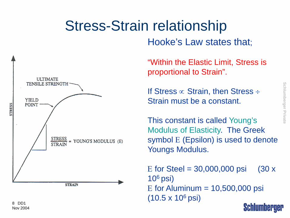
Stress-Strain relationship Hooke’s Law states that; “Within the Elastic Limit, Stress is proportional to Strain”. If Stress ∝ Strain, then Stress ÷ Strain must be a constant. This constant is called Young’s Modulus of Elasticity. The Greek symbol Ε (Epsilon) is used to denote Youngs Modulus. Ε for Steel = 30,000,000 psi (30 x 106 psi) Ε for Aluminum = 10,500,000 psi (10.5 x 10⁶ psi)

Schlumberger Private
9 DD1 Nov 2004
Young's Modulus - example • A pipe of 5 in2 cross section
area is stuck. After over-pulling 100,000 lbs a stretch of 5’ is noted. How deep is the stuck point?
• Stress = 20,000 psi • Strain = 20,000 ÷ 30,000,000 • = 0.00067 • Strain = 5 ÷ original length so original length = 5 ÷ 0.00067 = 7,463’
• A pipe of 4.5 in2 cross section area is stuck. After over-pulling 100,000 lbs a stretch of 5’ is noted. How deep is the stuck point?
• Stress = 22,222 psi • Strain = 22,222 ÷ 30,000,000 • = 0.00074 • Strain = 5 ÷ original length so original length = 5 ÷ 0.00074 = 6750’
Schlumberger Private
11 DD1 Nov 2004
Yield Strength / Tensile Strength
• Yield Strength: is the level at which the material changes from predominately elastic to predominately plastic strain behavior. Unit for this measure is PSI
• Tensile Strength:is the highest stress level a material achieves before it breaks. The unit for this measure is Lbs.

Schlumberger Private
12 DD1 Nov 2004
Drill Stem Design and Failure Prevention
Schlumberger Private
13 DD1 Nov 2004
Introduction
a. Premature and unexpected failures of drill stems cause great losses in time and material.
b. Reducing drill stem failures will improve rig operating performance and reduce expenses

Schlumberger Private
14 DD1 Nov 2004
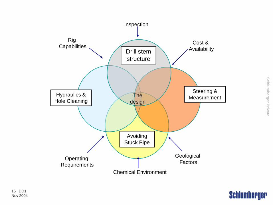
Drill string Design The objective is to design a configuration that
will drill a hole of the desired diameter to the
desired depth, while optimizing needs in four major
areas. Structural Soundness Hydraulics, hole cleaning and ROP Directional control and measurement Stuck pipe avoidance and recovery
Schlumberger Private
15 DD1 Nov 2004
Drill stem structure
Steering & Measurement Hydraulics &
Hole Cleaning
Avoiding Stuck Pipe
Operating Requirements
Rig Capabilities
Inspection
Cost & Availability
Geological Factors
Chemical Environment
The design
Schlumberger Private
16 DD1 Nov 2004
The “ADIOS” Elements
•Failure Prevention is managing all the factors and drivers that together cause a failure
•No matter what failure mechanism is involved drill stem failures happen because of weaknesses in one of the five areas or elements known as the ADIOS acronym

Schlumberger Private
17 DD1 Nov 2004
The “ADIOS” Elements
•Attributes (A): These are the metallurgical properties and dimensions that are built into each drill string component at manufacturing.
•Typical attributes include strength, toughness and other metallurgical properties.
•Maintaining the component Identity is of prime importance for establishing confidence in its metallurgy.
Schlumberger Private
18 DD1 Nov 2004
The “ADIOS” Elements
•Design (D): Drill stem design is selecting components and configuring assemblies to accomplish the drilling objective.
•The Goal is to provide a drill string that will carry the loads and resist failure.
Schlumberger Private
19 DD1 Nov 2004
The “ADIOS” Elements
•Inspection (I): Drill Stem components, unless new, have been exposed to handling damage and an unknown amount of cumulative fatigue damage.
•Inspection of used drill stem components is one way of determining that they are still fit for use.

Schlumberger Private
20 DD1 Nov 2004
The “ADIOS” Elements
• Operation (O): The Drilling operation presents many opportunities to overload and misuse the drill stem.
•Surroundings (S): The chemical and mechanical environment surrounding the drill stem can have major effect on failure probability.
Schlumberger Private
21 DD1 Nov 2004
•Keeping the drillstring together requires attention of all the five ADIOS elements.
•A drillstring can consist of components from a dozen different companies.
•Failure prevention responsibilities are often distributed
The importance of Teamwork
Schlumberger Private
22 DD1 Nov 2004
Recognizing and Responding to drill String Failures.
Schlumberger Private
23 DD1 Nov 2004
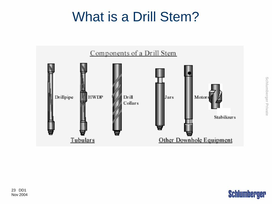
What is a Drill Stem?
yry
Schlumberger Private
24 DD1 Nov 2004
What is a Drill Stem Failure? What is a Drill Stem Failure?
a. When a component cannot perform its function
b. Complete separation (parting)
c. Leak (washout)
Location?
a. Tube body, Tool Joint or Threads
b. Any drillstem component
Schlumberger Private
25 DD1 Nov 2004
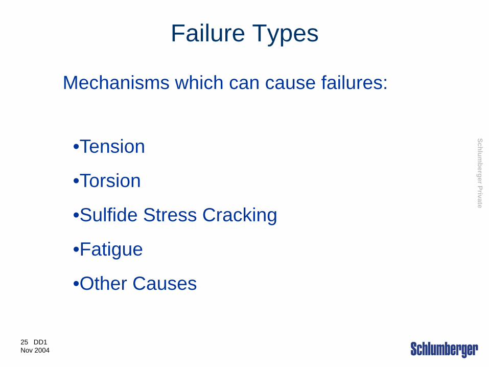
Failure Types
Mechanisms which can cause failures:
•Tension
•Torsion
•Sulfide Stress Cracking
•Fatigue
•Other Causes
Schlumberger Private
26 DD1 Nov 2004
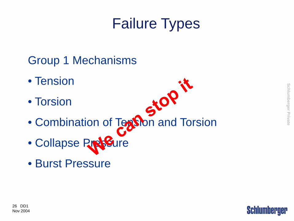
Group 1 Mechanisms
• Tension
• Torsion
• Combination of Tension and Torsion
• Collapse Pressure
• Burst Pressure
Failure Types
Schlumberger Private
27 DD1 Nov 2004
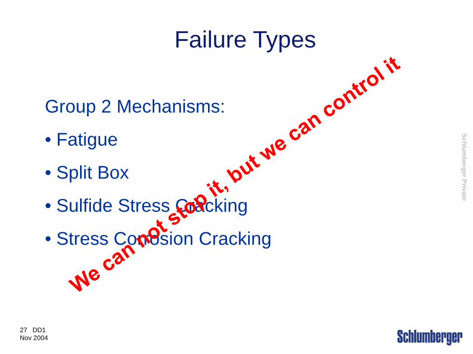
Group 2 Mechanisms:
• Fatigue
• Split Box
• Sulfide Stress Cracking
• Stress Corrosion Cracking
Failure Types

Schlumberger Private
28 DD1 Nov 2004
Failure Types
0 Yield Ultimate
Failure not possible
Failure not possible Failure possible Failure possible
Normal Operating Stress Range
Group 2 Mechanisms
Group 1 Mechanisms
Schlumberger Private
29 DD1 Nov 2004
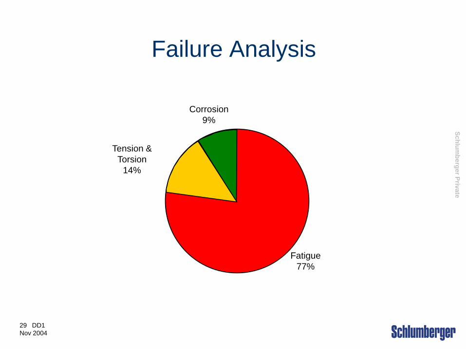
Failure Analysis
Fatigue 77%
Corrosion 9%
Tension & Torsion
14%

Schlumberger Private
30 DD1 Nov 2004
•Tensile failures occur when the tensile load exceeds the capacity of the weakest component in the drill stem. This is usually a drill pipe at the
…...
•Occasionally the tool joint will fail if the connection was made up beyond recommended torque.
Tensile Failures
top of the hole

Schlumberger Private
31 DD1 Nov 2004
Tensile Failure
a. Tensile load is greater than ultimate tensile strength.
b. Surface of break is jagged and at 45 degrees to axis of pipe.
c. Pipe is “Necked Down” adjacent to fracture.

Schlumberger Private
32 DD1 Nov 2004
Preventing Tensile & Torsional Failures
Most failures due to tension or torsion can be eliminated by the use of an effective design process and good inspection practices.
Schlumberger Private
33 DD1 Nov 2004
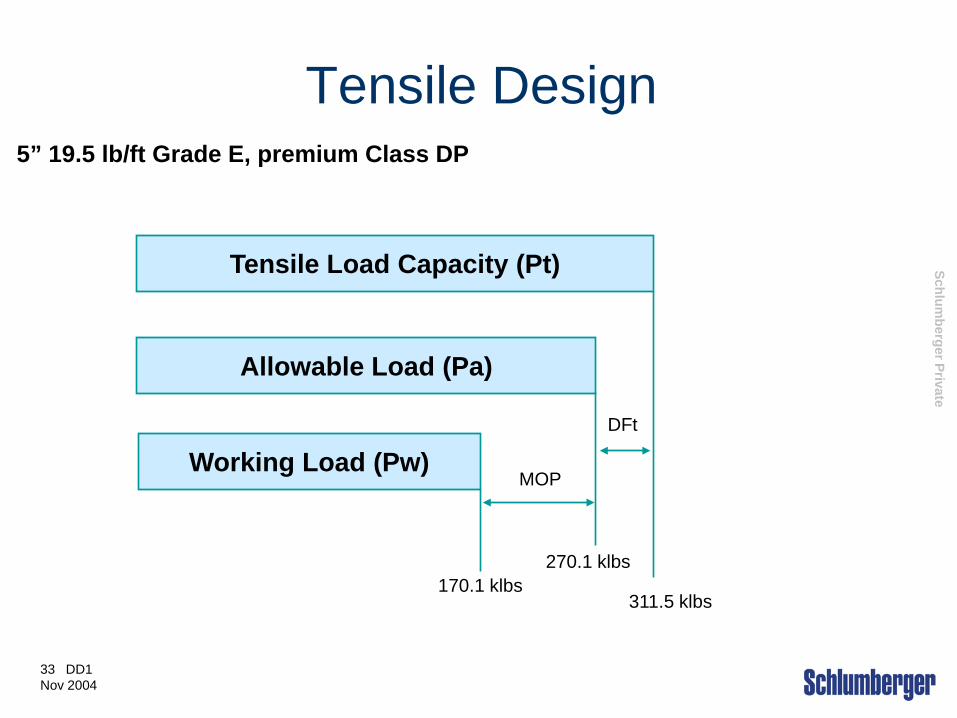
Tensile Design
Tensile Load Capacity (Pt)
Working Load (Pw)
Allowable Load (Pa)
5” 19.5 lb/ft Grade E, premium Class DP
MOP
DFt
311.5 klbs
270.1 klbs 170.1 klbs

Schlumberger Private
34 DD1 Nov 2004
Select drill pipe that is capable of carrying the anticipated loads plus a Margin of Over-pull plus a design factor.
Use a marking system that shows tube weight and grade. Check pin markings to make sure that the weight and grade are correct.
Make sure that the rig weight indicator is calibrated properly and does not exceed the allowable tensile load.
Responding to Tensile Failures
Schlumberger Private
35 DD1 Nov 2004
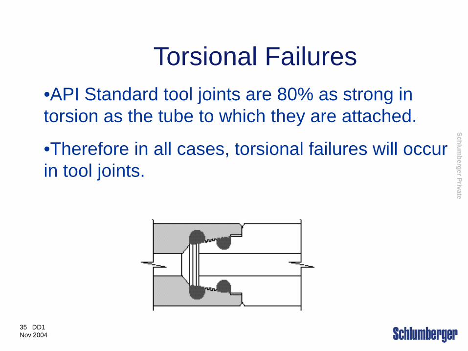
Torsional Failures •API Standard tool joints are 80% as strong in torsion as the tube to which they are attached.
•Therefore in all cases, torsional failures will occur in tool joints.
Schlumberger Private
36 DD1 Nov 2004
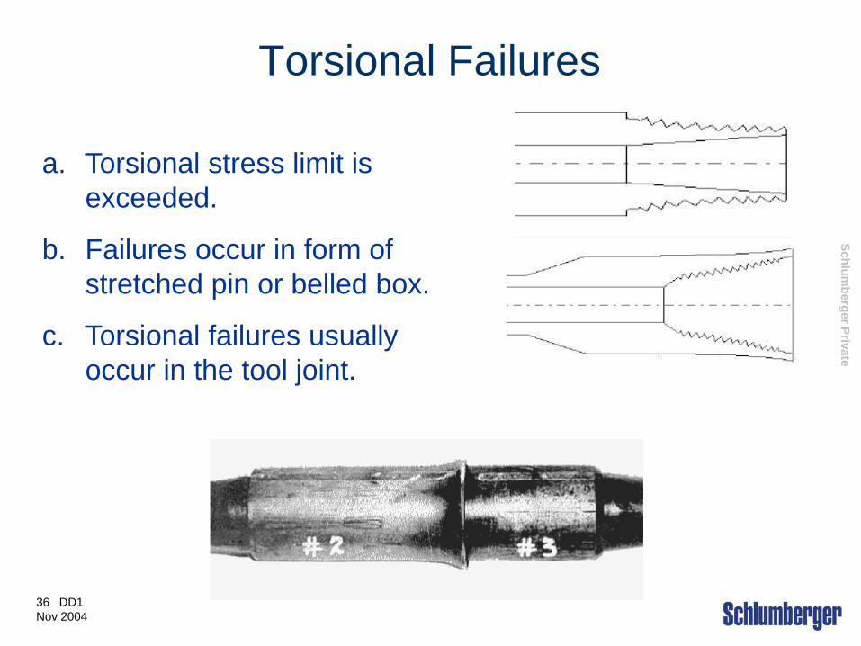
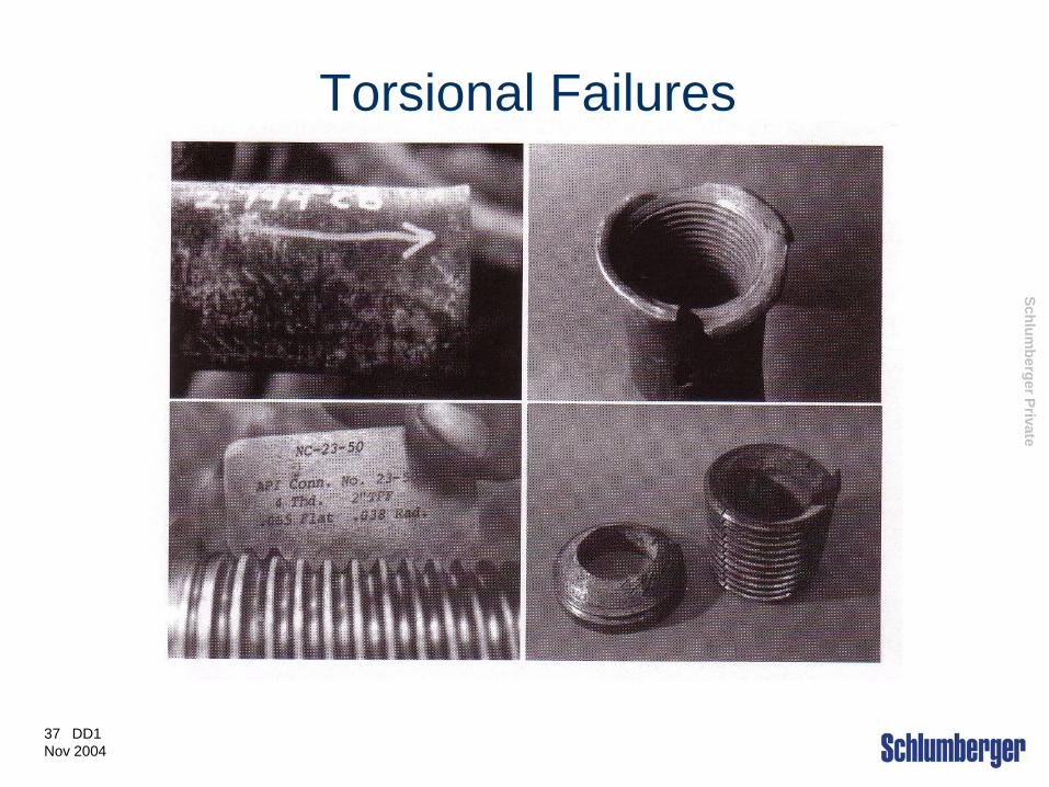
Torsional Failures
a. Torsional stress limit is exceeded.
b. Failures occur in form of stretched pin or belled box.
c. Torsional failures usually occur in the tool joint.
Schlumberger Private
37 DD1 Nov 2004
Torsional Failures
Schlumberger Private
38 DD1 Nov 2004
•Select tool joint ID and OD so that the maximum makeup torque exceeds the maximum anticipated torsion.
•Check tool joints to ensure that they meet with all the dimensional requirements.
•Make sure torque application device is working and calibrated properly.
•Use API tool joint compound with a FF between 0.95 and 1.05 or compensate the applied torque accordingly.
•Make up connections to recommended torque.
Responding to Torsional Failures
Schlumberger Private
39 DD1 Nov 2004
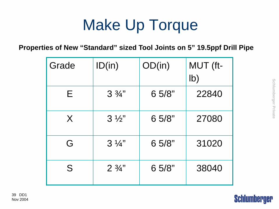
Make Up Torque Properties of New “Standard” sized Tool Joints on 5” 19.5ppf Drill Pipe
Grade ID(in) OD(in) MUT (ft-lb)
E 3 ¾” 6 5/8” 22840
X 3 ½” 6 5/8” 27080
G 3 ¼” 6 5/8” 31020
S 2 ¾” 6 5/8” 38040
Schlumberger Private
40 DD1 Nov 2004
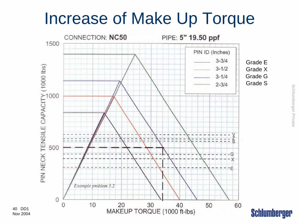
Increase of Make Up Torque
Grade E Grade X Grade G Grade S

Schlumberger Private
41 DD1 Nov 2004
Combination of Tension/Torsion Failures
• These failures are most likely to happen while fishing or pulling on stuck pipe.
Schlumberger Private
42 DD1 Nov 2004
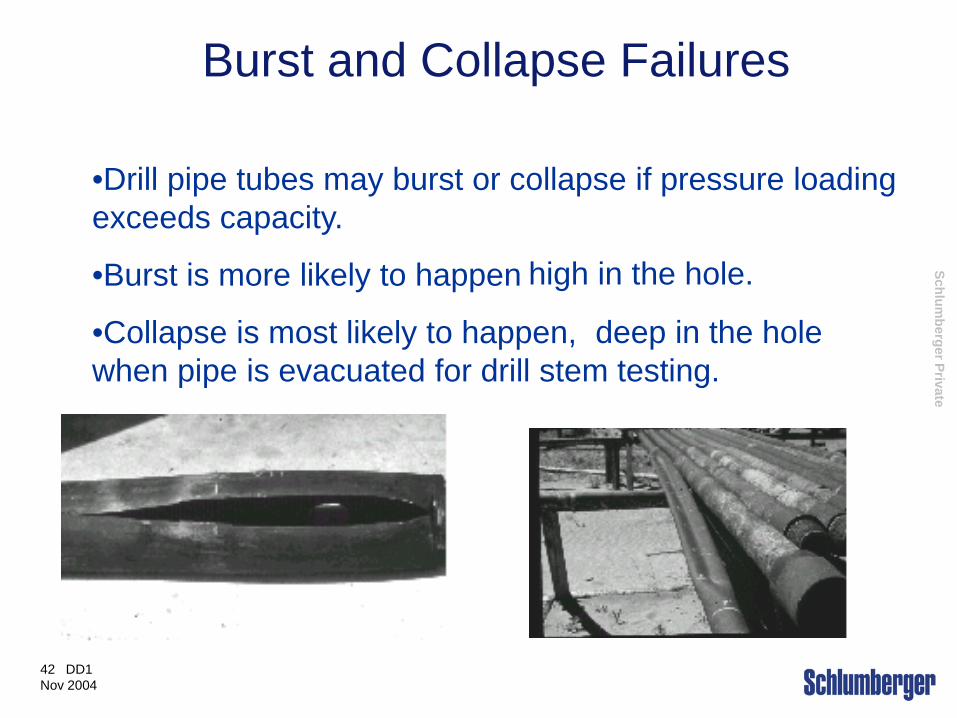
•Drill pipe tubes may burst or collapse if pressure loading exceeds capacity.
•Burst is more likely to happen
•Collapse is most likely to happen, when pipe is evacuated for drill stem testing.
Burst and Collapse Failures
high in the hole.
deep in the hole
Schlumberger Private
43 DD1 Nov 2004
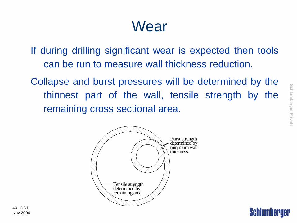
Wear If during drilling significant wear is expected then tools
can be run to measure wall thickness reduction.
Collapse and burst pressures will be determined by the thinnest part of the wall, tensile strength by the remaining cross sectional area.
Burst strengthdetermined byminimum wallthickness.
Tensile strengthdetermined byremaining area.
Schlumberger Private
44 DD1 Nov 2004
Wear reduction Wear can be reduced by;
• Reducing side force by minimizing DLS (especially
high up in the hole) and using drillpipe protectors.
• Using drilling fluids containing solids (weighted)
• Always using sharp tong dies
• Minimizing rotating hours (use down-hole motors)
• Run a “casing friendly” hardbanding material on tool
joints

Schlumberger Private
45 DD1 Nov 2004
Increased Temperature
The yield strength of most materials (including steel) reduces at higher temperatures. In deeper wells, casing yield strength MUST be degraded by using a Temperature Correction Factor, obtainable from the casing manufacturer. This reduction in design strength is applied BEFORE applying Safety or Design Factors.
Schlumberger Private
46 DD1 Nov 2004
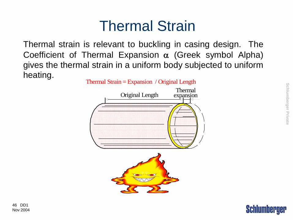
Thermal Strain Thermal strain is relevant to buckling in casing design. The Coefficient of Thermal Expansion α (Greek symbol Alpha) gives the thermal strain in a uniform body subjected to uniform heating.
ThermalexpansionOriginal Length
Thermal Strain = Expansion / Original Length

Schlumberger Private
47 DD1 Nov 2004
Coefficient of Thermal Expansion
The Coefficient of Thermal Expansion for Steel is given by:
Strain ε = 6.9 x 10⁻⁶ /°F (1.24 x 10⁻⁵ /°C)
So for every °C uniform increase in temperature, steel will expand by 0.0000124 of it’s original length.
Schlumberger Private
48 DD1 Nov 2004
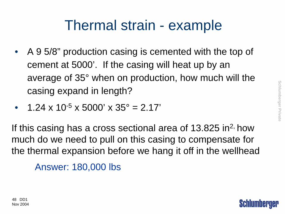
Thermal strain - example
• A 9 5/8” production casing is cemented with the top of cement at 5000’. If the casing will heat up by an average of 35° when on production, how much will the casing expand in length?
• 1.24 x 10-5 x 5000’ x 35° = 2.17’
Answer: 180,000 lbs
If this casing has a cross sectional area of 13.825 in2, how much do we need to pull on this casing to compensate for the thermal expansion before we hang it off in the wellhead

Schlumberger Private
49 DD1 Nov 2004
•With the obvious exception of tool joint to tube welds, welded components in the drill string should be avoided. Welding alters the mechanical properties unless the component is re-heat treated.
Weld Related Failures
Schlumberger Private
50 DD1 Nov 2004
Fatigue Failures - Group 2 Mechanism
• Cyclic stresses with the peak stress higher than 40% UTS
• Stress Concentrators which raise the peak stress locally
• Corrosive environment
• Fracture Toughness

Schlumberger Private
51 DD1 Nov 2004
Fatigue - contributing factors
Sources of Cyclic Loads
a. Rotating pipe in a Dog Leg
b. Rotating BHA through a hole diameter change
c. Stabilizer stick/slip
d. Rotating pipe in a wash out
e. Bit Whirl
f. Bit Bounce

Schlumberger Private
52 DD1 Nov 2004
Stress concentrators….The accelerators of fatigue:
Stress concentrators focus and magnify the cyclic stress at local points.
These points become the origin of fatigue cracks, which act as their own concentrators, to speed crack growth to ultimate failure.
Internal upsets, thread roots, slip cuts and corrosion pits are the most common stress concentrators
Stress Concentrators

Schlumberger Private
53 DD1 Nov 2004
Pipe being rotated in a dog leg
• One side in tension, one in compression.
•Addition and subtraction of forces create cyclic loading
Cyclic Stresses
Stress concentration areas
Schlumberger Private
55 DD1 Nov 2004
Cyclic Stress and Stress Concentrators
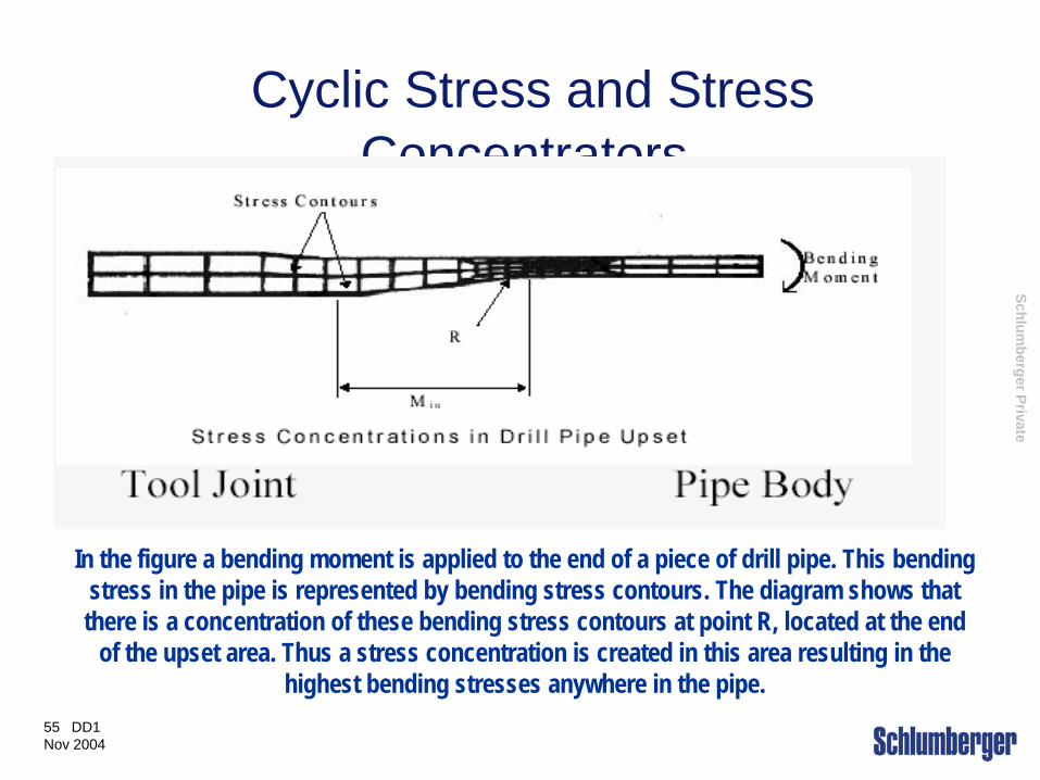
In the figure a bending moment is applied to the end of a piece of drill pipe. This bending stress in the pipe is represented by bending stress contours. The diagram shows that there is a concentration of these bending stress contours at point R, located at the end
of the upset area. Thus a stress concentration is created in this area resulting in the highest bending stresses anywhere in the pipe.
Schlumberger Private
56 DD1 Nov 2004
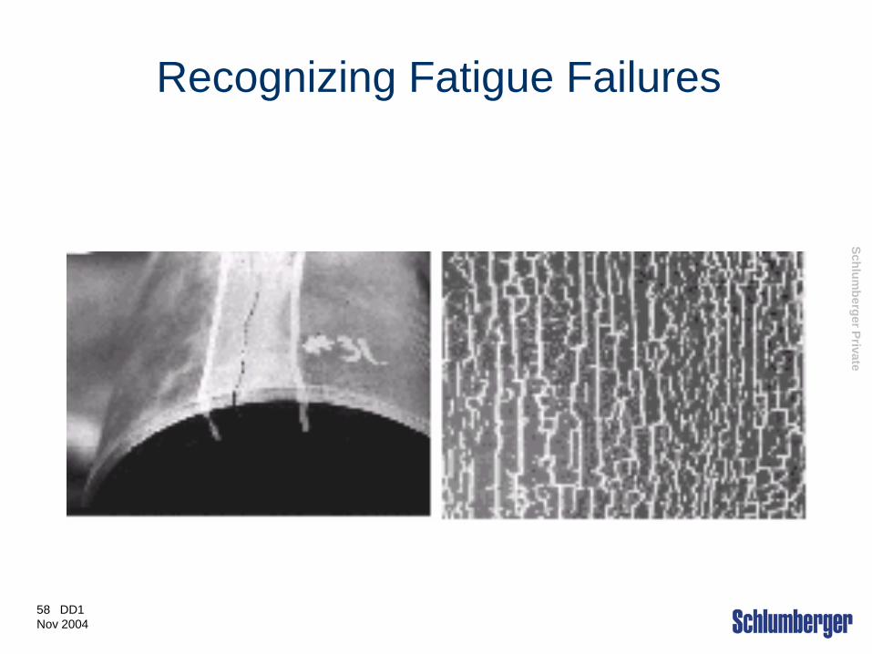
•A fatigue crack will be smooth and planar, unless the surface is altered by erosion or mechanical damage.
•The crack will be oriented perpendicular to the axis of the pipe or connection.
•Fatigue cracks will originate at high stress concentrators namely, internal upsets, slip cuts and corrosion pits.
•A fatigue crack surface will clearly show mode of attack. Ratchet marks appear when small multiple cracks join to form a large one.
Recognizing Fatigue Failures

Schlumberger Private
57 DD1 Nov 2004
Recognizing Fatigue Failures
Schlumberger Private
58 DD1 Nov 2004
Recognizing Fatigue Failures
Schlumberger Private
59 DD1 Nov 2004
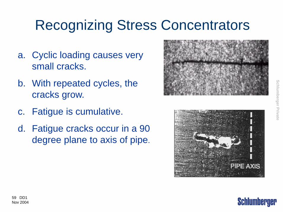
Recognizing Stress Concentrators
a. Cyclic loading causes very small cracks.
b. With repeated cycles, the cracks grow.
c. Fatigue is cumulative.
d. Fatigue cracks occur in a 90 degree plane to axis of pipe.

Schlumberger Private
61 DD1 Nov 2004
Corrosion
• Corrosion reduces the wall thickness of tubulars.
• There are three patterns of corrosion;
a. Uniform wall thickness reduction
b. Localised patterns of metal loss
c. Pitting
• The greatest problem is pitting.
• Pitting is highly localized metal loss which penetrates the wall
of the tubular.
Schlumberger Private
62 DD1 Nov 2004
Corrosion
Corrosion occurs due to electrochemical reactions with corrosive agents. Corrosion rate is increased by;
Higher temperature. Rates double for each 31°C.
Higher flow rate, especially if abrasive solids present. Erosion removes protective coatings of corrosion products and exposes fresh metal.
Higher concentration of corrosive agents (O2, H2S, CO2).
Schlumberger Private
63 DD1 Nov 2004
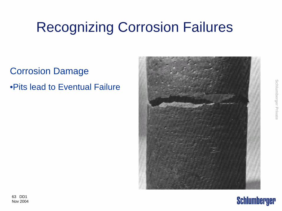
Corrosion Damage
•Pits lead to Eventual Failure
Recognizing Corrosion Failures
Schlumberger Private
64 DD1 Nov 2004
•Corrosion Damage
How much corrosion is too much?
There are no real quantitative answers to this, so most companies use an arbitrary rule of thumb that corrosion rates above 1 to 2 lb/sqft/year should get some corrective action.
Corrosiveness of Environment
Schlumberger Private
65 DD1 Nov 2004
Preventing Corrosion Corrosive attention usually falls into one or more of the areas below:
• OXYGEN
• PH
•CO2 AND CHLORIDES
•HYDROGEN SULFIDE
•BARRIERS and INHIBITORS

Schlumberger Private
66 DD1 Nov 2004
H2S Embrittlement
Exposure of high tensile steels to partial pressures of H2S greater than 0.05 psi at less than a threshold pressure (which varies by steel grade) can lead to catastrophic failure. The metal becomes brittle and will break suddenly and without warning.
Schlumberger Private
67 DD1 Nov 2004
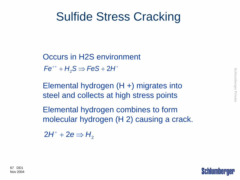
Sulfide Stress Cracking
Occurs in H2S environment
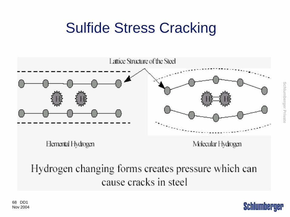
Elemental hydrogen (H +) migrates into steel and collects at high stress points
Elemental hydrogen combines to form molecular hydrogen (H 2) causing a crack.
+++ +⇒+ HFeSSHFe 22
222 HeH ⇒++
Schlumberger Private
68 DD1 Nov 2004
Sulfide Stress Cracking
Schlumberger Private
69 DD1 Nov 2004
Preventing Sulfide Stress Cracking Failures
Keep H2S out of the mud system by:
i) drilling overbalanced
ii) keeping pH high
iii) using H2S scavengers
iv) using an oil based mud
Control the Metallurgy
Use a different grade pipe

Schlumberger Private
70 DD1 Nov 2004
Fracture Toughness Fracture Toughness….The Inhibitor of Fatigue:
Fracture toughness is a measure of a materials resistance to the propagation of an existing crack, under slow strain
loads
It is more difficult to extend a crack in tough material than it is in brittle material

Schlumberger Private
71 DD1 Nov 2004
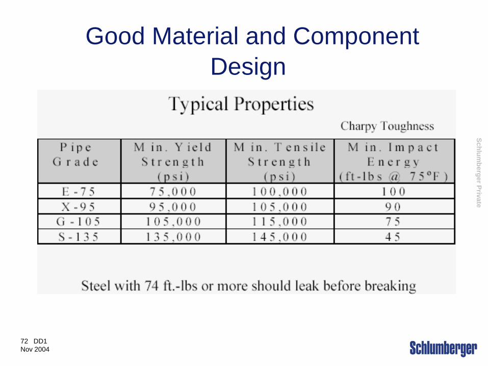
Good Material and Component Design
In practical terms, what this all means is that if a component is brittle a “small” crack will cause
catastrophic failure whereas in a tough component a larger crack can exist before the pipe parts. The
tougher the material is, the larger the crack can be before this occurs.
Schlumberger Private
72 DD1 Nov 2004
Good Material and Component Design
Schlumberger Private
73 DD1 Nov 2004
The fix for this problem is well within the grasp of the average Rocket Scientist….. REDUCE THE NUMBER AND SEVERITY OF CYCLIC AND STRESS CONCENTRATORS.
Prevention of Fatigue Failures
Schlumberger Private
74 DD1 Nov 2004
Prevention of Fatigue Failures
Fatigue cannot be eliminated
Limit the damage by:
• Early detection of Vibrations & Washouts
• Starting with good materials and component design
• Reducing cyclic stresses and stress concentrations
• Reducing corrosiveness of the environment
• Ensuring good rig site operating practices
• Following an inspection program

Schlumberger Private
75 DD1 Nov 2004
•Cyclic Stress….The cause of Fatigue:
Plan the trajectory with the lowest dogleg severity
Avoid practices that create unplanned doglegs, specially in vertical holes.
Invest in straightening trips to lower Dogleg severity.
Stabilize the BHA, especially if hole enlargement around the BHA is a problem.
Keep the Neutral point below the top of the BHA.
Keep drill-pipe compression less than critical buckling load in high angle wells
Prevention of Fatigue Failures
Schlumberger Private
76 DD1 Nov 2004
•Cyclic Stress….The cause of Fatigue: Monitor vibration. Avoid BHA configurations, bit weights, and RPM combinations that promote vibration.
Consider rotating the string more slowly, by means of introducing a mud motor to the BHA, only if hole cleaning and directional objectives allow.
Prevention of Fatigue Failures
Schlumberger Private
77 DD1 Nov 2004
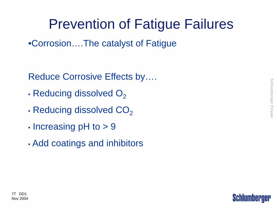
Prevention of Fatigue Failures •Corrosion….The catalyst of Fatigue
Reduce Corrosive Effects by….
• Reducing dissolved O2
• Reducing dissolved CO2
• Increasing pH to > 9
• Add coatings and inhibitors

Schlumberger Private
78 DD1 Nov 2004
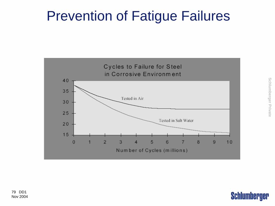
Prevention of Fatigue Failures
Schlumberger Private
79 DD1 Nov 2004
Prevention of Fatigue Failures
Schlumberger Private
80 DD1 Nov 2004
Why Inspect Connections/tubes?
Guarantee the integrity of our connections
Avoid lost in hole
Avoid tool damage such as flooding & washouts
To assess threads for repair
Customer requirements

Schlumberger Private
81 DD1 Nov 2004
Inspection Methods
Ultrasonic (wall thickness)
Magnetic Particle (cracks in thread roots and stress relief features)
Liquid (Dye) Penetrant (thread roots and stress relief features)
Electromagnetic (DP)
Visual

Schlumberger Private
82 DD1 Nov 2004
Follow an Inspection Program
Four Areas for Inspection Policy
• Inspection program to be used
• Acceptance/Rejection criteria
• Ensuring inspections are done properly
• Inspection frequency
Schlumberger Private
83 DD1 Nov 2004
Follow an Inspection Program •What is a good program?
– There is no “Perfect” answer
– DS-1 is a guide but not a policy
• Areas to consider when creating a program
– Severity of the drilling conditions
– Safety and environmental impact of a failure
– Cost impact of a failure
– Risk tolerance of management
Schlumberger Private
84 DD1 Nov 2004
Summary And Review
• What is a Drill Stem Failure?
• Mechanisms of Failure
• Prevention of Drill Stem Failures
• Inspection
Schlumberger Private
85 DD1 Nov 2004
Connections
Objectives are….
• Joint types
• Design considerations
• Stress in a joint- BSR
• How to make a connection
Schlumberger Private
86 DD1 Nov 2004
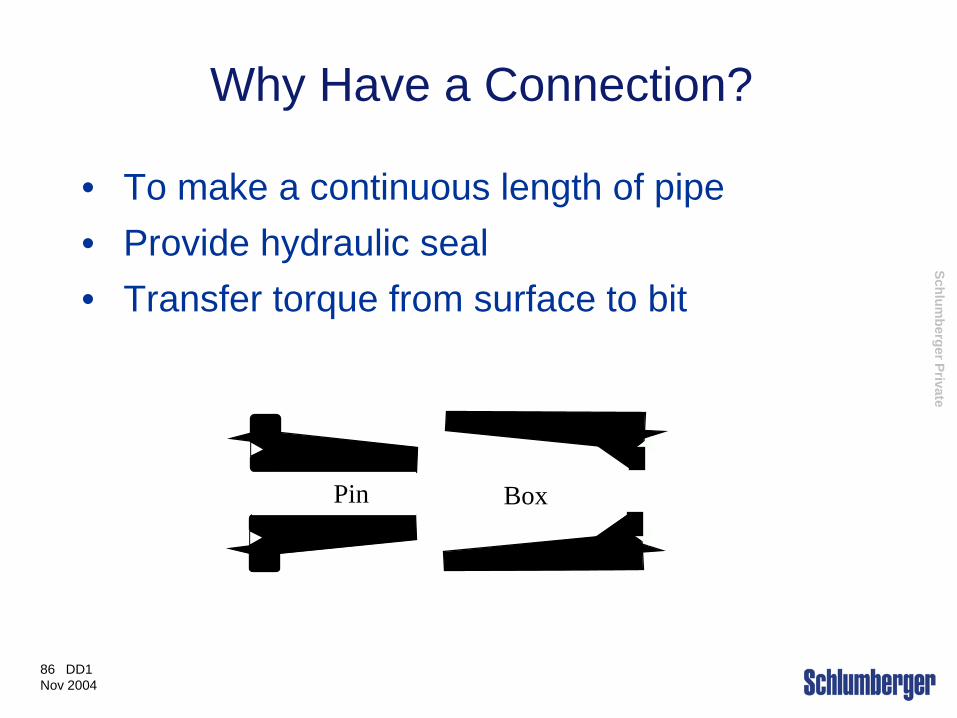
Why Have a Connection?
• To make a continuous length of pipe • Provide hydraulic seal • Transfer torque from surface to bit
Pin Box
Schlumberger Private
87 DD1 Nov 2004
Connection Design Considerations
• Thread Types (profile) • Material (Grade) • Sealing • Bending Strength • Joint Torque

Schlumberger Private
88 DD1 Nov 2004
Thread Types
Reg - Regular NC - Numbered Connections IF - Internal Flush H-90 - Hughes FH - Full Hole
Schlumberger Private
89 DD1 Nov 2004
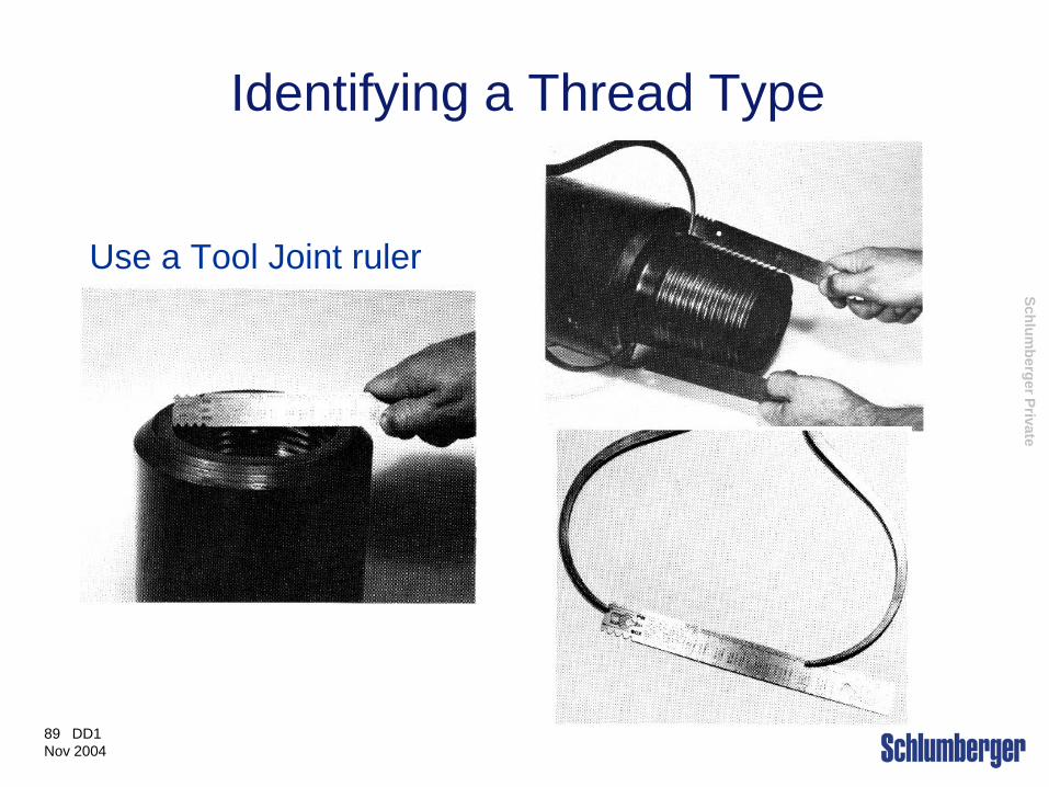
Identifying a Thread Type
Use a Tool Joint ruler
Schlumberger Private
90 DD1 Nov 2004
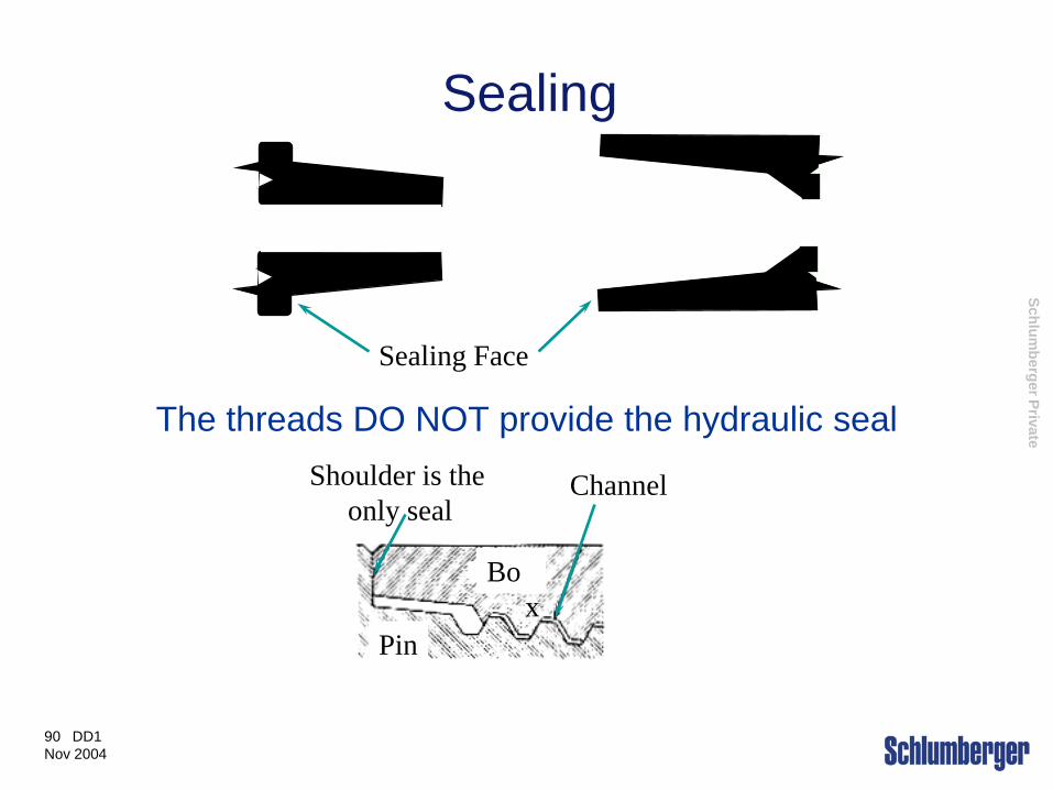
Sealing
The threads DO NOT provide the hydraulic seal
Sealing Face
Box
Pin
Shoulder is the only seal
Channel
Schlumberger Private
91 DD1 Nov 2004
Design Considerations
•Tool Joint Torsional Strength
•Drill Collar Connection Torsional Strength
•Make up torque
•Friction Factor of the Thread Dope
•Special Features on BHA Connections
Schlumberger Private
92 DD1 Nov 2004
Design Considerations
Tool Joint Torsional Strength:
Most standard tool joints are weaker in torsion than the tubes to which they are welded to.
API sets the tool joint torsional strength at the arbitary value of 80% of the tube torsional strength for most combinations.

Schlumberger Private
93 DD1 Nov 2004
Design Considerations Drill Collar connection Torsional Strength:
Torsional strength of drill collar connections will always be different from that of tool joints of the same dimensions.
Torsional capacity of drill collars is rarely a concern because the connections are usually larger and are subject to lower torsional loads than tool joints in the same string.
Drill collar torsional strength is not immediately available in most publications, but can be calculated using the following formula…
Schlumberger Private
94 DD1 Nov 2004
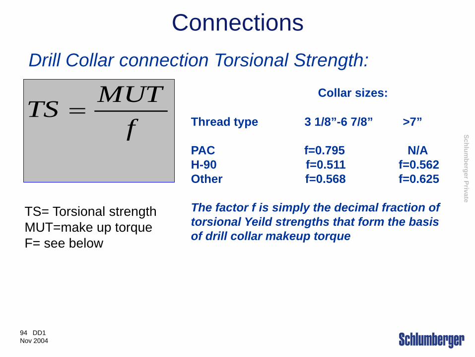
Connections Drill Collar connection Torsional Strength:
f
MUTTS =
TS= Torsional strength MUT=make up torque F= see below
Collar sizes: Thread type 3 1/8”-6 7/8” >7” PAC f=0.795 N/A H-90 f=0.511 f=0.562 Other f=0.568 f=0.625 The factor f is simply the decimal fraction of torsional Yeild strengths that form the basis of drill collar makeup torque

Schlumberger Private
95 DD1 Nov 2004
Design Considerations Other checks to make:
Combined Loading
• Tension reduces drill pipe collapse pressure capacity.
• Torsion reduces drill pipe tube tensile capacity.
• Connection makeup past a given point reduces connection tensile capacity.
• Tension reduces the torsional yield strength of pin-weak connections.

Schlumberger Private
96 DD1 Nov 2004
Bending Strength
Tension
Compression
Joint Flexing

Schlumberger Private
97 DD1 Nov 2004
Bending Stress Bending stress ratio
BSR is a ratio of the relative stiffness of the box to the pin for a given connection
Recommended BSR ranges: Traditional BSR Recommended
BSR < 6 inches 2.25 - 2.75 1.8 - 2.5 6 – 7 7/8 inches 2.25 – 2.75 2.25 - 2.75 >/= 8 inches 2.25 – 2.75 2.5- 3.2
Schlumberger Private
98 DD1 Nov 2004
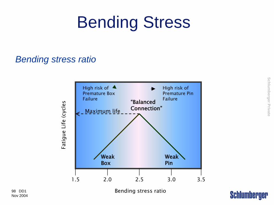
Bending Stress
Bending stress ratio
1.5 2.0 2.5 3.0 3.5
Bending stress ratio
Fatig
ue L
ife (c
ycle
s
Weak Box
Weak Pin
“Balanced Connection” Maximum life
High risk of Premature Box Failure
High risk of Premature Pin Failure
Schlumberger Private
99 DD1 Nov 2004
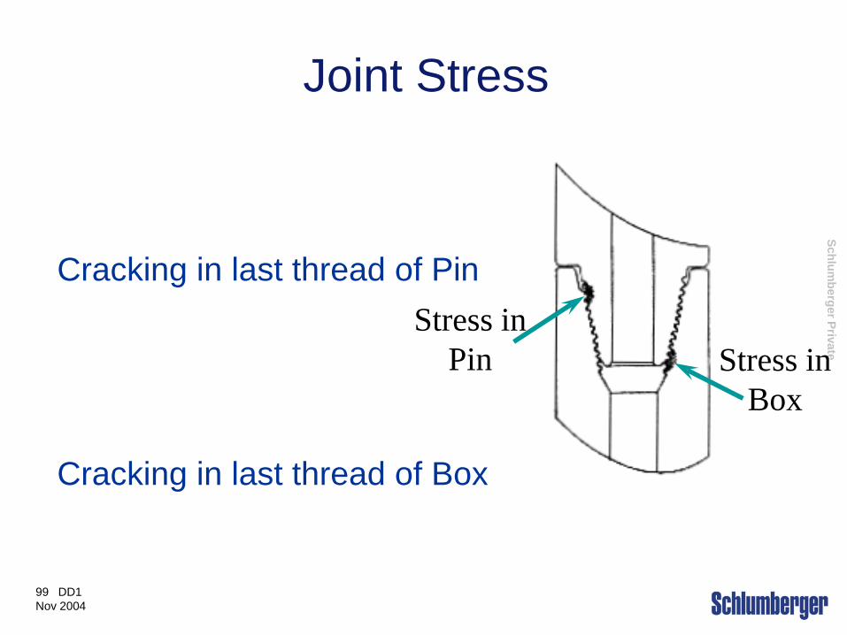
Joint Stress
Cracking in last thread of Pin
Cracking in last thread of Box
Stress in Box
Stress in Pin

Schlumberger Private
100 DD1 Nov 2004
Stress Features Stress Relief Features
- Stress Relief features as described in section 6 of API Spec 7, Should be applied on BHA connections NC-38 and Larger.
- Pin stress relief grooves are not recommended for pins smaller than NC-38 as this may weaken the tensile and torsional strength of the connection.
- Boreback boxes could be used on smaller boxes and should be considered if box failures are occurring.

Schlumberger Private
101 DD1 Nov 2004
Stress Relief Features
Normal Pin Pin with Stress Relief Groove
Normal Box Box with Bore Back Box with Stress Relief Groove
Schlumberger Private
102 DD1 Nov 2004
Stress Relief Features
Cold Rolling
- Cold Rolling BHA thread roots and stress relief surfaces increases fatigue life by placing a residual compressive stress in the thread roots.
- Cold rolling is beneficial on HWDP threads, though not on normal drillpipe tool joints.
Schlumberger Private
Making a Connection at the Rigsite
Schlumberger Private
104 DD1 Nov 2004
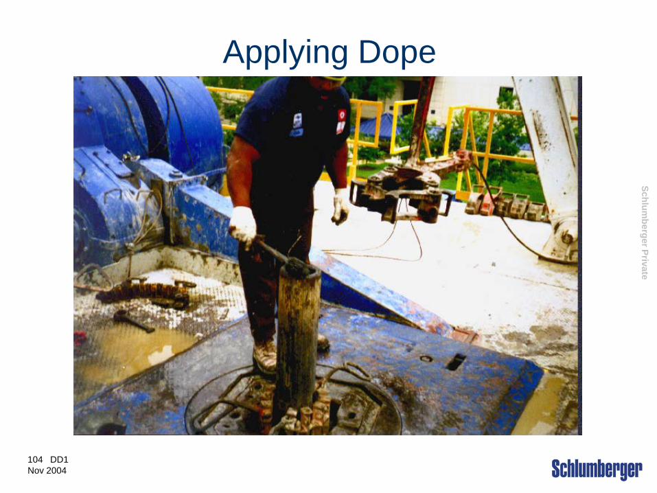
Applying Dope
Schlumberger Private
105 DD1 Nov 2004
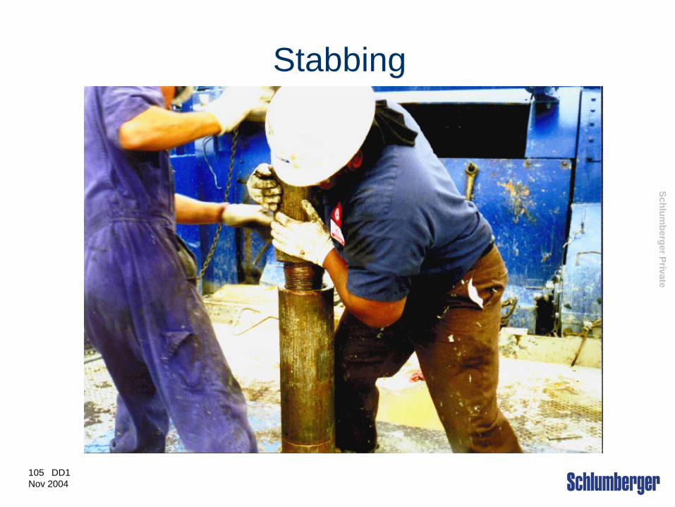
Stabbing
Schlumberger Private
106 DD1 Nov 2004
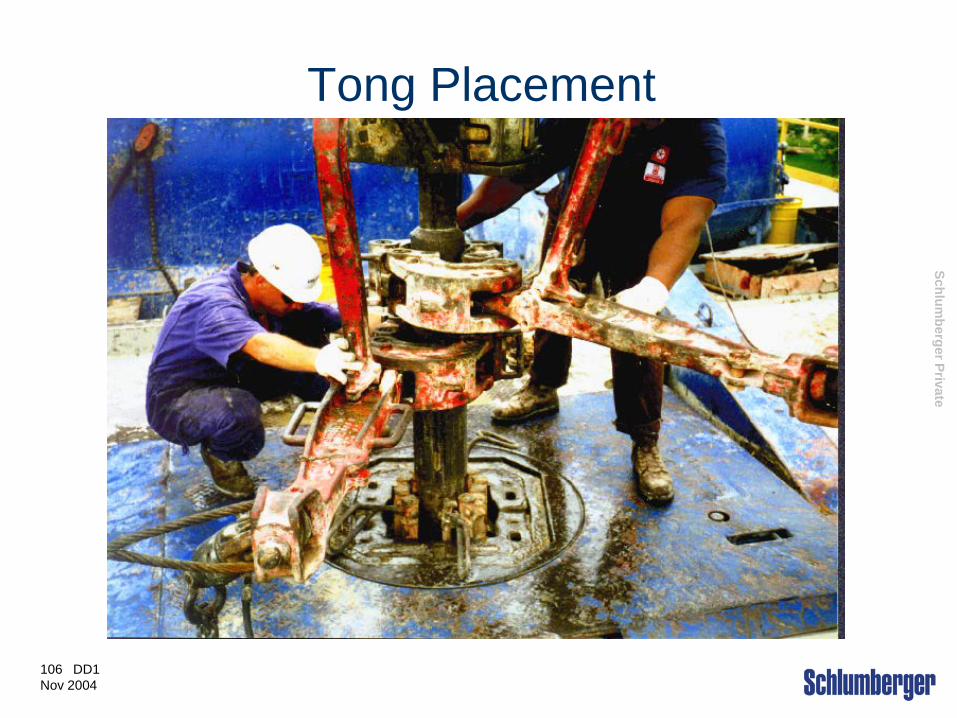
Tong Placement
Schlumberger Private
107 DD1 Nov 2004
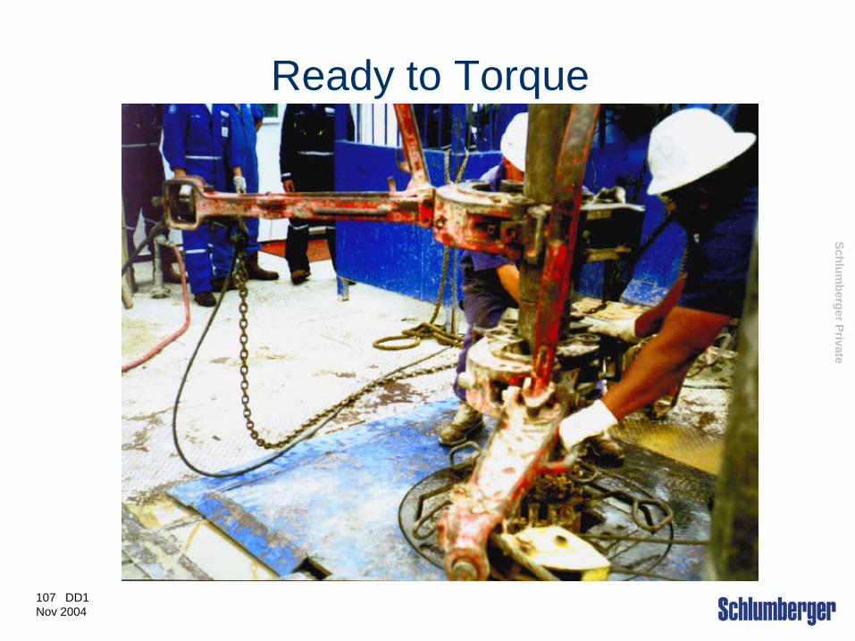
Ready to Torque
Schlumberger Private
108 DD1 Nov 2004
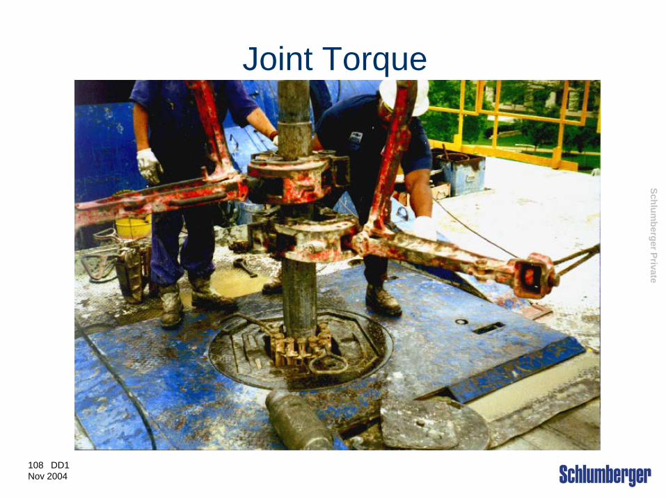
Joint Torque
Schlumberger Private
109 DD1 Nov 2004
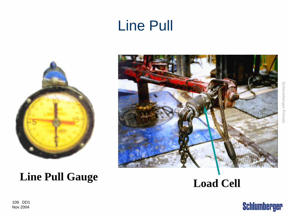
Line Pull
Load Cell Line Pull Gauge

Schlumberger Private
110 DD1 Nov 2004
Drill String Design
Related Documents