Dr.G. Ignisha Rajathi, Ph.D., Assistant Professor, Department of Computer Science and Engineering, Sri Krishna College of Engineering and Technology (Autonomous), Coimbatore. S. Nagajothi, M.E., Assistant Professor, Department of Computer Science and Engineering, Sri Krishna College of Engineering and Technology (Autonomous), Coimbatore. Dr.P. Balamurugan, Ph.D., Associate Professor, Department of Information Technology, SRM Institute of Science and Technology, Kattankulathur, Chengalpattu, Tamilnadu, India. Dr.R. Johny Elton, Ph.D., Indsoft Technologies, Tirunelveli. Published by

Welcome message from author
This document is posted to help you gain knowledge. Please leave a comment to let me know what you think about it! Share it to your friends and learn new things together.
Transcript
Dr.G. Ignisha Rajathi, Ph.D.,
Assistant Professor,
Department of Computer Science and Engineering,
Sri Krishna College of Engineering and Technology (Autonomous),
Coimbatore.
S. Nagajothi, M.E.,
Assistant Professor,
Department of Computer Science and Engineering,
Sri Krishna College of Engineering and Technology (Autonomous),
Coimbatore.
Dr.P. Balamurugan, Ph.D.,
Associate Professor, Department of Information Technology,
SRM Institute of Science and Technology, Kattankulathur, Chengalpattu,
Tamilnadu, India.
Dr.R. Johny Elton, Ph.D.,
Indsoft Technologies,
Tirunelveli.
Published by
Conceptualization of Computer Networks
Copyright © 2020 by CIIR
All rights reserved. Authorized reprint of the edition published by CIIR. No part of this book may be
reproduced in any form without the written permission of the publisher.
Limits of Liability/Disclaimer of Warranty: The authors are solely responsible for the contents of the
paper in this volume. The publishers or editors do not take any responsibility for the same in any
manner. Errors, if any, are purely unintentional and readers are required to communicate such errors to
the editors or publishers to avoid discrepancies in future. No warranty may be created or extended by
sales or promotional materials. The advice and strategies contained herein may not be suitable for every
situation. This work is sold with the understanding that the publisher is not engaged in rendering legal,
accounting, or other professional services. If professional assistance is required, the services of a
competent professional person should be sought. Further, reader should be aware that internet website
listed in this work may have changed or disappeared between when this was written and when it is read.
CIIR also publishes its books in a variety of electronic formats. Some content that appears in print may
not be available in electronic books.
ISBN 978-81-942938-5-9
Month: August 2020
Authors
Dr.G. Ignisha Rajathi
S. Nagajothi
Dr.P. Balamurugan
Dr.R. Johny Elton
Centivens Institute of Innovative Research
307, 5th Street Extension, Gandhipuram,
Coimbatore - 641012, Tamilnadu, India.
E-mail: [email protected]
Website: www.centivens.com
Preface
Always be prepared for the worst; but hope for the best – Lee
A rich knowledge of a structured approach is disseminated in a detailed version in
this book. Even if you have not known about networking before and desire to know
the different concepts of networking, then Conceptualization of Computer Networks
will get you started. It is a quick book to quick cook the state of art in Computer
Networks. You will know how easy it is to quintessence on the conceptual resolution
to the prevailing inter-juncture which is given as all under one roof.
It explains how networks work from inside out. It is a thorough text for an
introductory level learner which is clearly researched with consistent notation and
style, full set of diagrammatic and theoretic explanation. It can also be taken as a
supplemental text or reference for a huge variety of networking related courses. The
in- depth coverage of the five different modules include the fundamentals and detailed
version of link layer; media access and internetworking; routing; transport layer;
application layer; Having grabbed the fundamental framework, the detailed
conceptualization of MAC, Ethernet, Wireless LANs, Wi-Fi 802.11, Bluetooth 802.15.1,
Switching and Bridging, IP versions and many more topics have been discussed clearly
in this book. The further chapters focus on different routing protocols, global internet
followed by transport layer with protocols, connection management, congestion
control, quality of service. Most of all, the application layer concept instigates the
practical implications of E-mail, http, web services, SNMP based MIB and security.
This book supports meticulously to understand the ideas behind the implementation
of the massive network connectivity all over the galaxy.
Be assured of learning a plethora of computer networking concepts in a single
capsule – Conceptualization of Computer networks. Get ready for the treasure hunt in
Networks.


Acknowledgement
“Each one has his own gift from God”
Gratitude is the fairest blossom which springs from the soul.
Burden-bearing, laughter-sharing, forever-caring FAMILY!!!…a very happy, bliss-filled,
hearty thanks to each one of you! Our gratitude knew no bounds!
We are very much grateful to our friends and well-wishers, near and dear,
superiors and colleagues who have been a great source of encouragement and
support to us all through our endeavors.
Happiness cannot be expressed by words and help taken cannot be left without
thanking. We would like to thank all who are a part of our lives and our work.
A simple but strong word of real sense – “THANK YOU!”.

Author Biographies
Dr.G. Ignisha Rajathi received her degrees - Bachelor of Engineering and Master of
Engineering as a rank holder, in the discipline of Computer Science and Engineering under
Anna University, Chennai. She completed her Doctorate in the Faculty of Information and
Communication Engineering under Anna University, Chennai. Having 13 years of teaching
experience, she is presently working as Assistant Professor in the Department of Computer
Science and Engineering at Sri Krishna College of Engineering and Technology, Coimbatore,
India. She has marked her areas of interest as Medical imaging, Image processing, Soft
Computing. She has published more than 15 research articles in Journals, including high-
impact versions and in various Conferences. She has published books and patents. She has
trained the police force in fundamentals of computers and has delivered many invited talks
and guest lectures, also engaged in consultancy projects.
S. Nagajothi, Assistant Professor, Department of Computer Science and Engineering, Sri
Krishna College of Engineering and Technology, Coimbatore. She has completed her Bachelor
of Technology - Information Technology in the year 2014 and Master of Engineering -
Computer Science and Engineering in the year 2016 as a Rank holder. I have 3 years of
Teaching Experience. Her area of research is IoT, Machine Learning, Cloud computing and
Wireless Networks. She has published around 06 papers in Scopus indexed journals, 02 book
chapters and life member of ICSCS, IAENG and IEEE. She has also received Research Grant
from ICMR and CSIR for Conducting Seminars and Workshops.
Dr.P. Balamurugan is Associate Professor, Department of Information Technology, SRM
Institute of Science and Technology, Kattankulathur, Chengalpattu, Tamilnadu, India. He
passed BE in Computer Science and Engineering from Madurai Kamaraj University in 2003 and
ME in Computer Science and Engineering from Manonmaniam Sundaranar University in 2006.
He completed his doctorate from Anna University in 2013. He obtained GATE score in 2003. He
is recognized as a Supervisor for Ph.D Programme and M.Tech (By Research) in Information
and Communication Engineering for Anna University and Vel Tech Rangarajan Dr. Sagunthala
R & D Institute of Science and Technology. He is the member of IEEE, ACM, ISTE etc... He is
trained certificate holder of ‘High Impact Teaching Skills’ through WIPRO MISSION 1OX and
Trained Evaluator of NBA and ABET. He is in the reviewer member of 6 International/National
Journals. His research interest is mainly in Networks, Ad-hoc and Sensor Networks, and Data
Structures. He has filed and published more than five patents. He has published books “Theory
of Computation” and “Problem Solving and python Programming” and also a number of
research papers in international journals and presented papers in international conferences.
He has done a number of consultancies work at various organizations. He has delivered a
many informative guest lectures at various organizations. He has also organized and conducted
many workshops, conferences and seminars at his zone.

Dr.R. Johny Elton is a Research Fanatic with ardent passion in scientific exploration of
detailed delineation on current technologies. He did his Bachelor of Engineering Degree in
Noorul Islam College of Engineering, Thuckalay, Master of Engineering in Manonmaniam
Sundaranar University and Doctoral degree from Anna University, Chennai. His research
interests include Natural Language Processing, Computer Vision and has published research
papers in peer-reviewed Journals. Currently, he is working for Indsoft Technologies,
Tirunelveli, on various innovative research works.
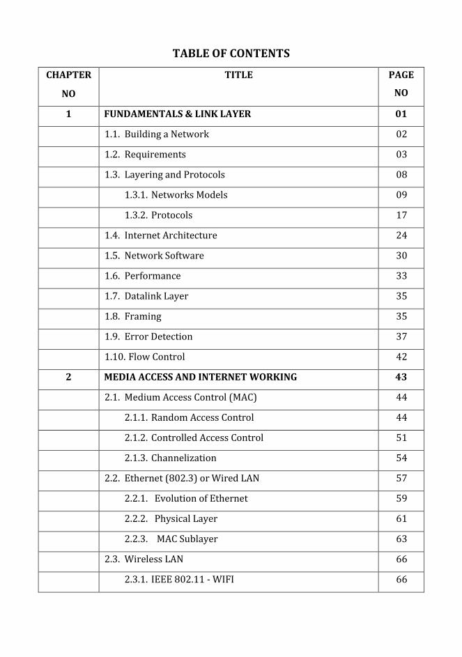
TABLE OF CONTENTS
CHAPTER
NO
TITLE PAGE
NO
1 FUNDAMENTALS & LINK LAYER 01
1.1. Building a Network 02
1.2. Requirements 03
1.3. Layering and Protocols 08
1.3.1. Networks Models 09
1.3.2. Protocols 17
1.4. Internet Architecture 24
1.5. Network Software 30
1.6. Performance 33
1.7. Datalink Layer 35
1.8. Framing 35
1.9. Error Detection 37
1.10. Flow Control 42
2 MEDIA ACCESS AND INTERNET WORKING 43
2.1. Medium Access Control (MAC) 44
2.1.1. Random Access Control 44
2.1.2. Controlled Access Control 51
2.1.3. Channelization 54
2.2. Ethernet (802.3) or Wired LAN 57
2.2.1. Evolution of Ethernet 59
2.2.2. Physical Layer 61
2.2.3. MAC Sublayer 63
2.3. Wireless LAN 66
2.3.1. IEEE 802.11 - WIFI 66

2.3.2. Architecture 66
2.3.3. MAC Sublayer 68
2.3.4. Frame Format 69
2.3.5. Physical Layer 70
2.4. Bluetooth 71
2.4.1. Architecture 71
2.4.2. Bluetooth Layers 72
2.4.2.1. Radio Layer 72
2.4.2.2. Base Band Layer 73
2.4.2.3. L2CAP 74
2.4.2.4. Data Field 74
2.5. Switching 74
2.5.1. Taxonomy of Switched Networks 75
2.5.1.1. Circuit Switched Networks 75
2.5.1.2. Message Switching (OR) Telegraph
Network
77
2.5.1.3. Packet Switching 78
2.5.2. Bridging 79
2.5.2.1. Transparent Bridge 79
2.5.2.2. Routing Bridge 80
2.6. Basic Internetworking 81
2.6.1. Internet Protocol (IP) 81
2.6.1.1. IPV4 86
2.6.2. Address Resolution Protocol (ARP) 90
2.6.3. Reverse Address Resolution Protocol (RARP) 94
2.6.4. Internet Control Message Protocol (ICMP) 95
2.6.5. Bootstrap Protocol (BOOTP) 98

2.6.6. Dynamic Host Configuration Protocol (DHCP) 99
3 ROUTING 101
3.1. Unicast Routing Protocols 102
3.1.1. Distance Vector Routing 104
3.1.1.1. Routing Information Protocol (RIP) 106
3.1.2. Link State Routing 106
3.1.2.1. Open Shortest Path First (OSPF) 110
3.1.3. Path Vector Routing 112
3.1.3.1. Border Gateway Protocol (BGP) 114
3.2. Global Internet - IPV6 116
3.3. Multicast Link State Routing 119
3.3.1. Multicast Open Shortest Path First (MOSPF) 119
3.3.2. Multicast Distance Vector (DVMRP) 120
3.3.3. Reverse Path Forwarding (RPF) 120
3.3.4. Reverse Path Broadcasting (RPB) 121
3.3.5. Reverse Path Multicasting (RPM) 121
3.3.6. Core Based Tree (CBT) 121
3.3.7. Protocol Independent Multicast (PIM) 122
4 TRANSPORT LAYER 124
4.1. Overview of Transport Layer 125
4.1.1. Duties of Transport Layer 125
4.1.2. Quality of Service (QOS) 126
4.1.3. Sockets 127
4.2. User Datagram Protocol (UDP) 129
4.2.1. Purpose of UDP 129
4.2.2. UDP Operation 131
4.2.3. Advantages of UDP 132

4.3. Transmission Control Protocol (TCP) 132
4.3.1. TCP Services 132
4.3.2. TCP Features 135
4.3.3. TCP Connection 138
4.3.4. Flow Control 139
4.3.5. Error Control (Retransmission) 140
4.4. Stream Control Transmission Protocol (SCTP) 142
4.4.1. SCTP Services 142
4.4.2. SCTP Features 143
4.4.3. SCTP Connection 146
4.5. Congestion Control 147
4.5.1. Congestion - Network Performance 147
4.5.2. Open Loop Congestion Control 148
4.5.3. Closed Loop Congestion Control 149
4.6. Quality of Service (QOS) 150
4.6.1. Flow Characteristics 151
5 APPLICATION LAYER 152
5.1. Traditional Applications 153
5.2. Email 153
5.2.1. Architecture 153
5.2.2. User Agent 156
5.2.3. Message Transfer Agent 157
5.3. Hypertext Transfer Protocol (HTTP) 161
5.4. File Transfer Protocol (FTP) 164
5.5. World Wide Web (WWW) 167
5.5.1. Architecture 167
5.5.2. Client (Browser) 168

5.5.3. Server 168
5.5.4. Uniform Resource Locator (URL) 168
5.6. Domain Name Systems (DNS) 170
5.6.1. Flat Name Space 170
5.6.2. Hierarchical Name Space 171
5.6.3. Namespace Distribution 173
5.6.4. DNS in the Internet 174
5.6.5. Messages in DNS 178
5.7. Simple Network Management Protocol (SNMP) 179
5.7.1. Concept 179
5.7.2. Management Components 180
5.7.3. Structure of Management Information (SMI) 182
5.7.4. Management Information Base (MIB) 184
5.7.5. SNMP Securities 189

1
CHAPTER 1
1. Fundamentals & Link Layer
Objectives
To understand about Network requirements and building a network.
To explain basics of networking.
To know about internet architecture.
To explain about layers and protocols.
To explain about flow and error control.
2
1. Introduction
1.1. Building a Network
Data Communication
Data communication is defined as the exchange of data or information between different
devices through any destined transmission medium, example, wire cable. Data communication
occurs with the communicating devices or systems which are composed of a combination of
hardware and software. Hardware is stated as any physical equipment and software is stated
as programs using any programming language. The efficiency of this system relies on 4
important features such as
Accuracy
Timelines
Delivery
Jitter
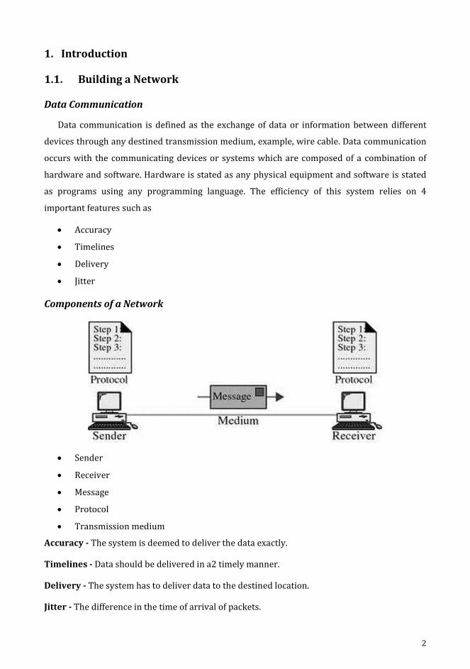
Components of a Network
Sender
Receiver
Message
Protocol
Transmission medium
Accuracy - The system is deemed to deliver the data exactly.
Timelines - Data should be delivered in a2 timely manner.
Delivery - The system has to deliver data to the destined location.
Jitter - The difference in the time of arrival of packets.
3
Sender - Device that sends the data to receiver.
Receiver - Device that receives the data from sender.
Message - The information to be communicated.
Protocol - Set of guidelines to administer data communication.
Transmission medium - Physical pattern where a message migrates from sender to receiver.
1.2. Requirements
Perspectives
Network design depends upon the following perspectives.
Application programme - Specifies the list of services needed by application.
Network designer - Lists attributes of low cost but efficient design.
Network provider - Lists the features of a system which is easy to manage and provide
security.
Scalable Connectivity
In network, only few nodes were selected for privacy and security. A system which is
capable of supporting the growth of the system to an arbitrary large size is meant to be
scalable.
Data Representation
Text
Numbers
Audio
Video
Images
Data Flow
Two devices can be communicated through 3 different forms such as simplex, half duplex
and full duplex.
Simplex
The connectivity is unidirectional ie., one way in simplex mode. Any one of any two systems
in a connection can send and only the next system can receive.
E.g: television used in our day to day life.

4
Half duplex
All stations send and receive the messages in different timelines, which is not
simultaneously passed at the same time in half duplex. This is given as when one device
transmits data, the other receives data.
E.g: walky-talky, CB radios.
Full duplex
Both stations send and receive simultaneously, where the data can be passed at the same
time under full duplex mode. Communication can be performed in both directions at the same
time. E.g: Telephone.
Network
A set of devices or nodes linked through communication links is called as network. Nodes-
>computer, printer, and scanner. All devices send and receive data, formulated by other nodes
on network. Network uses distributed systems where there is sharing of any process by
different systems.
Network Criteria
The metrics of network criteria are performance, reliability and security.

5
Physical Structure
Connection and its types – Connection establishment is the connectivity between devices
in a network. A link is a pathway to communicate and send and receive data between devices.
The types are given as follows.
Point to point
Multipoint
Point to point – The establishment of connection between 2 individual devices.
E.g: Television satellite link.
Multipoint – when a single link is shared by more than two devices, it is called as
multipoint (multidrop).
Categories of Topology
The physical establishment of network connectivity is called as topology. They are
categorised as mesh, star, bus, ring and hybrid.
Mesh
All devices establish a point to point connectivity to other devices in its scope of contact, in
mesh topology. The connected 2 devices carry messages in this topology.
No of links = n (n-1)/2, where n stands for nodes

6
Star
In star topology, a central controller holds the connectivity with the devices using devoted
link and the central controller is hub.
No of links = n, n stands for nodes.
Bus
A bus is multipoint link. The connection between the device and the main cable is done by
drop line. To establish connectivity with the metallic core a connector splices into the main
cable or punctures the sheathing of a cable through tap.
No. of links = 1 backbone, n droplines

7
Ring
A connectivity is established between 2 devices in ring topology which are in close
proximity on both sides. The transmission proceeds through the ring in a direction. Each
system in ring connects with repeater. Repeater generates bits and passes them.
No of links= n-1, n is the number of nodes
Hybrid
The mixture of different topologies is Hybrid topology.
8
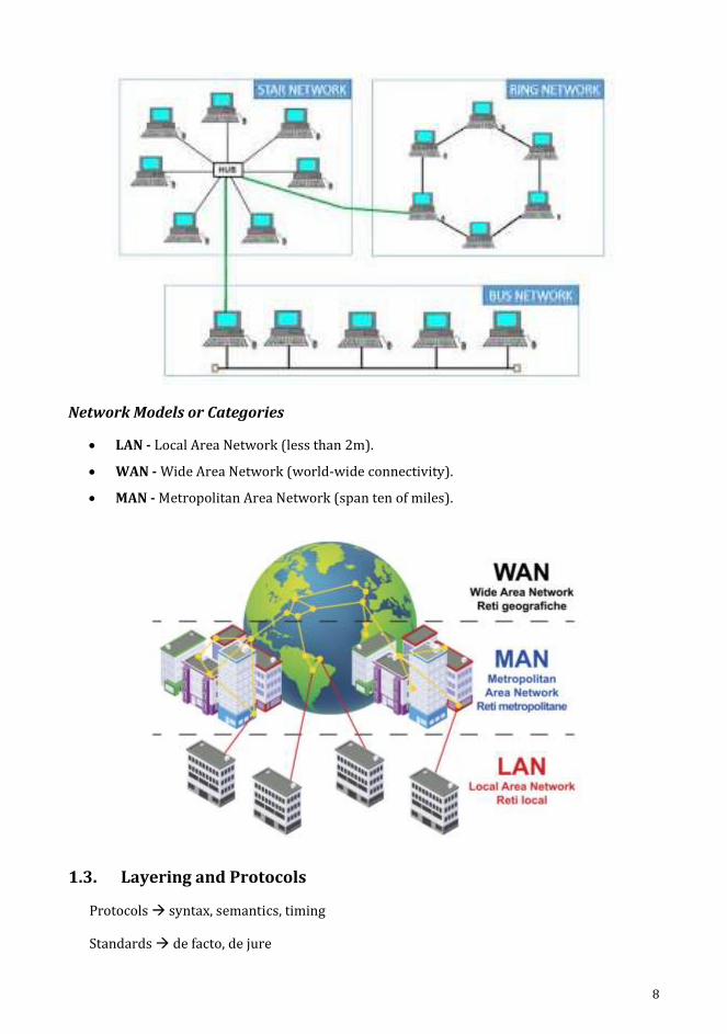
Network Models or Categories
LAN - Local Area Network (less than 2m).
WAN - Wide Area Network (world-wide connectivity).
MAN - Metropolitan Area Network (span ten of miles).
1.3. Layering and Protocols
Protocols syntax, semantics, timing
Standards de facto, de jure

9
1.3.1. Networks Models
The International Standards Organization (ISO) devoted worldwide International
Standards in 1947. In 1970, an ISO standard covers all aspects of network communications in
Open System Interconnection (OSI) models. In order to formulate connectivity with various
systems irrespective of logic of software in hardware, is the motive of OSI model. It is used to
design network architecture, which is flexible, robust and interoperable. ISO holds OSI as
model.
It consists of 7 layers which used to explore data communication. The communication is
governed by instructions and resolutions as protocol. The event in a system that enables a
communication is peer to peer process.
Over the adjacent layers of the sender and the receiver the data along with network
information is traversed or passed by interfacing.

10
Network Support Layers
Physical
Datalink
Network
Transport link these 2 layers
User Support Layers
Session
Presentation
Application
Physical Layer
It performs the process to carry a bit stream through a physical medium. It instructs the
physical systems and interfaces perform the data transfer, being properly transferring
individual bits from one system to another. Physical layer positions process to data link layer,
through the transmission medium.
Characteristics
1. Physical characteristics of interfaces and medium
2. Representation of bits
3. Data rate (transmission rate)
4. Synchronization of bits
5. Line configuration
6. Physical topology
7. Transmission mode

11
1. Data Link Layer
It is the next layer to the physical layer makes it look error-free to network layer. The frame
movement between devices is done by the data link layer. The data units being transferred to
network layer as bit streams is frames. This illustrates node-to-node delivery.
Characteristics
Different characteristics are listed as follows.
1. Framing
2. Physical addressing
3. Flow control
4. Error control
5. Access control
2. Network Layer
It facilitates the delivery of packets across networks, through links from source to
destination. It delivers packets between two devices in same network. Both networks and links
are connected to create networks of networks or mass networks called as routers or switches.
12
Characteristics
The various characteristics are listed as follows.
Logical addressing
Routing
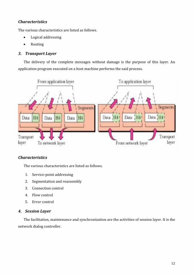
3. Transport Layer
The delivery of the complete messages without damage is the purpose of this layer. An
application program executed on a host machine performs the said process.
Characteristics
The various characteristics are listed as follows.
1. Service-point addressing
2. Segmentation and reassembly
3. Connection control
4. Flow control
5. Error control
4. Session Layer
The facilitation, maintenance and synchronization are the activities of session layer. It is the
network dialog controller.

13
Characteristics
The various characteristics are listed as follows.
Dialog control
Synchronization
5. Presentation Layer
The syntax and semantics of messages are preserved in this layer. It holds the
responsibilities of performing translation, compression and encryption.
Characteristics
The various characteristics are listed as follows.
Translation
Encryption
Compression
14
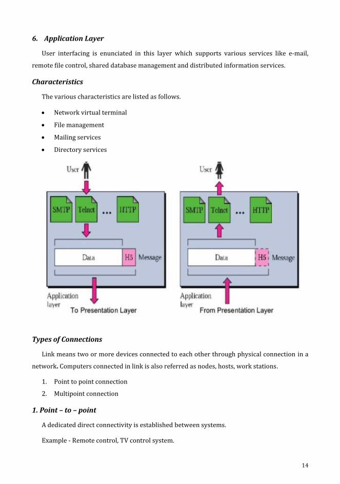
6. Application Layer
User interfacing is enunciated in this layer which supports various services like e-mail,
remote file control, shared database management and distributed information services.
Characteristics
The various characteristics are listed as follows.
Network virtual terminal
File management
Mailing services
Directory services
Types of Connections
Link means two or more devices connected to each other through physical connection in a
network. Computers connected in link is also referred as nodes, hosts, work stations.
1. Point to point connection
2. Multipoint connection
1. Point – to – point
A dedicated direct connectivity is established between systems.
Example - Remote control, TV control system.
15
2. Multipoint
Multipoint connection supports sharing of channel capacity among stations in the network.
Spatially shared communication.
Time shared connection.
Spatially shared - more than one device sharing the link simultaneously.
Time shared - devices share the link on turn by turn basis.
Switched Network
Switching is a methodology which interconnects multiple connectivity to establish a large
network to have an effective communication. A switched network contains a sequence of nodes
that are interlinked with each other known as switches. The circuit switching, packet switching
and message switching are the categories of switching.
Circuit switching - It is established by physical connectivity to form networks of ‘n’
number of channels.
Packet switching - The message is divided into packets of fixed or variable size and
transmitted.
Message switching - Messages are received, stored and transmitted.
Internetwork
When two or more devices are connected by an established communication link for sharing
data or resources or exchanging messages is called as network or networking. When two or
more networks need to be connected for the same purpose is called an internetworking or
network of computer network. The connecting devices, routers, gateways are used to connect
independent networks to form internetwork.
Addressing
The address of a node given by LAN or WAN or MAN is the physical address. Logical
address is essential for universal communications to identify each host uniquely which are not
basically dependent on underlying physical networks. Physical address changes hop-to-hop.
Logical address remains same. Process of forwarding the messages to the destined node as per
its addressing is called as routing.
Types of Address
1. Unicast - Once source & one specific destination.
2. Broadcast - One source & all nodes on the network.
3. Multicast - One source & some subsets of nodes on the network.

16
Cost Effective Resource Sharing
1. Modem (Modulator+ Demodulator)
It is used to perform both modulation and demodulation according to the requirement.
2. Multiplexer & Demultiplexer
The process of transmitting more signals simultaneously on one path is termed as
multiplexer. The process used to perform demultiplexing, which separates the signal and send
it to the appropriate destination device.
Reliability
1. Error Control
The data must be delivered to their destination accurately as it was sent from the source.
Reliability is achieved by check summing each packet in source and verifying the checksum at
the destination. Internet protocol (IP) is the mechanism which is used by TCP/IP protocols for
transmission of data.
Types of Error
1. single bit
2. multiple bit(or) burst error
Single bit – If only one bit in a given data string is permissible to change during the
transmission.
Burst bit - if two or more consecutive bits in a data string are permissible to change.
Single bits affect only one character.
Burst bits affect one or more characters.
1. Congestion
Packets are lost due to congestion in the link to overcome in the network uses congestion
control mechanisms. Congestion occurs if the users of the network send data at a rate that is
greater than the network can handle (number of packets). When enormous packets are
present in the subnet, the performance of the network will be degraded. To handle congestion
as prevention or control, this is used.
2. Retransmission
If a packet is damaged, lost, delayed during transit (or) if the acknowledgment has not yet
been received, then it will be retransmitted.
17
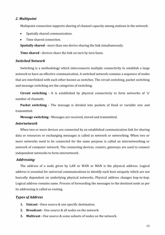
1.3.2. Protocols
The process of framing and achieving appropriate control over flow and error handling in
delivery of data is implemented in datalink layer using protocols.
In general, the data frames travel from sender to receiver because of unidirectional
property. The acknowledgement (ACK) and negative acknowledgement (NAK) which are
identified as special frames flow in direction which contradict one another with the data flow
direction. Piggybacking is the process of including ACK and NAK in the data frames, to hold the
flow and error control information.
Noiseless Channel
The protocol of noiseless channel devoid usage of flow control.
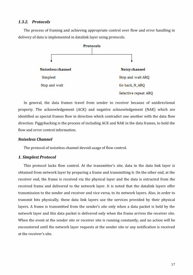
1. Simplest Protocol
This protocol lacks flow control. At the transmitter’s site, data in the data link layer is
obtained from network layer by preparing a frame and transmitting it. On the other end, at the
receiver end, the frame is received via the physical layer and the data is extracted from the
received frame and delivered to the network layer. It is noted that the datalink layers offer
transmission to the sender and receiver and vice versa, to its network layers. Also, in order to
transmit bits physically, these data link layers use the services provided by their physical
layers. A frame is transmitted from the sender’s site only when a data packet is held by the
network layer and this data packet is delivered only when the frame arrives the receiver site.
When the event at the sender site or receiver site is running constantly, and no action will be
encountered until the network layer requests at the sender site or any notification is received
at the receiver’s site.
18
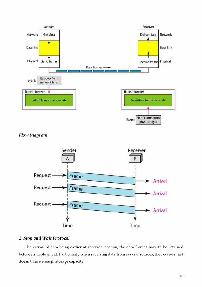
Flow Diagram
2. Stop and Wait Protocol
The arrival of data being earlier at receiver location, the data frames have to be retained
before its deployment. Particularly when receiving data from several sources, the receiver just
doesn't have enough storage capacity.
19
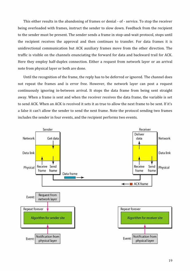
This either results in the abandoning of frames or denial - of - service. To stop the receiver
being overloaded with frames, instruct the sender to slow down. Feedback from the recipient
to the sender must be present. The sender sends a frame in stop-and-wait protocol, stops until
the recipient receives the approval and then continues to transfer. For data frames it is
unidirectional communication but ACK auxiliary frames move from the other direction. The
traffic is visible on the channels enunciating the forward for data and backward trail for ACK.
Here they employ half-duplex connection. Either a request from network layer or an arrival
note from physical layer or both are done.
Until the recognition of the frame, the reply has to be deferred or ignored. The channel does
not repeat the frames and is error free. However, the network layer can post a request
continuously ignoring in-between arrival. It stops the data frame from being sent straight
away. When a frame is sent and when the receiver receives the data frame, the variable is set
to send ACK. When an ACK is received it sets it as true to allow the next frame to be sent. If it's
a false it can't allow the sender to send the next frame. Note the protocol sending two frames
includes the sender in four events, and the recipient performs two events.
20
Flow Diagram
Noisy Channels (It Adds Idea to Flow Control)
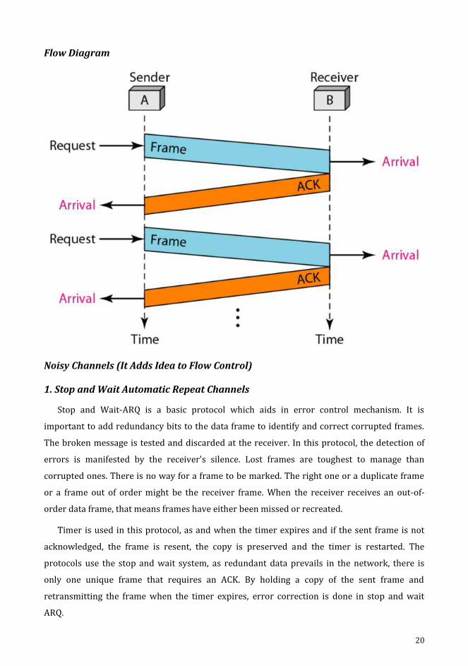
1. Stop and Wait Automatic Repeat Channels
Stop and Wait-ARQ is a basic protocol which aids in error control mechanism. It is
important to add redundancy bits to the data frame to identify and correct corrupted frames.
The broken message is tested and discarded at the receiver. In this protocol, the detection of
errors is manifested by the receiver's silence. Lost frames are toughest to manage than
corrupted ones. There is no way for a frame to be marked. The right one or a duplicate frame
or a frame out of order might be the receiver frame. When the receiver receives an out-of-
order data frame, that means frames have either been missed or recreated.
Timer is used in this protocol, as and when the timer expires and if the sent frame is not
acknowledged, the frame is resent, the copy is preserved and the timer is restarted. The
protocols use the stop and wait system, as redundant data prevails in the network, there is
only one unique frame that requires an ACK. By holding a copy of the sent frame and
retransmitting the frame when the timer expires, error correction is done in stop and wait
ARQ.
21
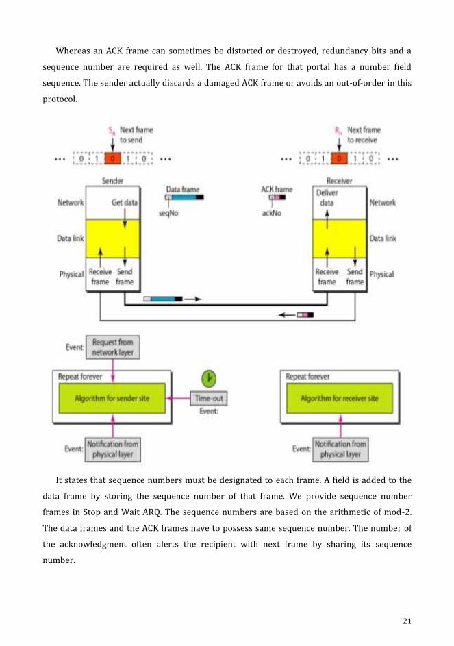
Whereas an ACK frame can sometimes be distorted or destroyed, redundancy bits and a
sequence number are required as well. The ACK frame for that portal has a number field
sequence. The sender actually discards a damaged ACK frame or avoids an out-of-order in this
protocol.
It states that sequence numbers must be designated to each frame. A field is added to the
data frame by storing the sequence number of that frame. We provide sequence number
frames in Stop and Wait ARQ. The sequence numbers are based on the arithmetic of mod-2.
The data frames and the ACK frames have to possess same sequence number. The number of
the acknowledgment often alerts the recipient with next frame by sharing its sequence
number.
22
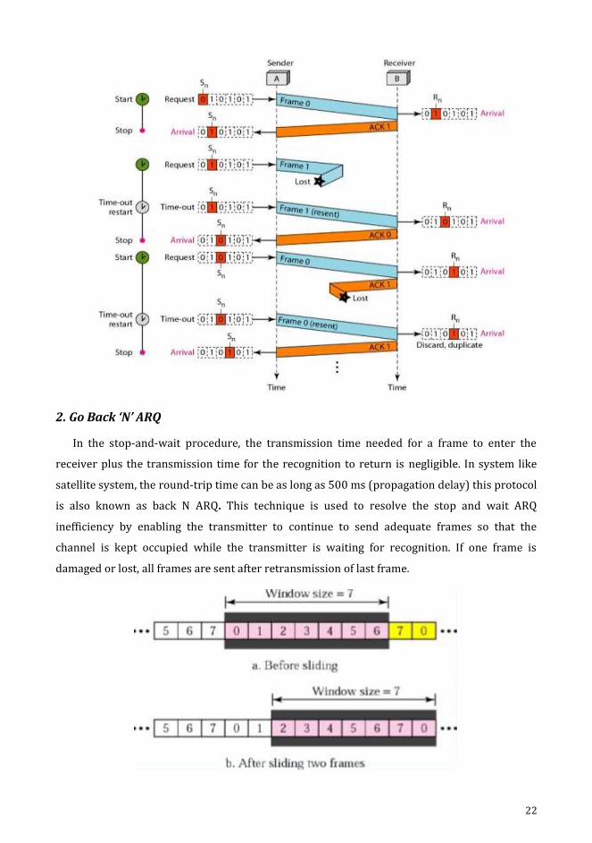
2. Go Back ‘N’ ARQ
In the stop-and-wait procedure, the transmission time needed for a frame to enter the
receiver plus the transmission time for the recognition to return is negligible. In system like
satellite system, the round-trip time can be as long as 500 ms (propagation delay) this protocol
is also known as back N ARQ. This technique is used to resolve the stop and wait ARQ
inefficiency by enabling the transmitter to continue to send adequate frames so that the
channel is kept occupied while the transmitter is waiting for recognition. If one frame is
damaged or lost, all frames are sent after retransmission of last frame.

23
The sender does not wait for an ACK signal for the next frame to be transmitted. It
continuously transmits the frames as long as the NAK signal is not received by it. NAK is sent to
sender by the recipient. If the transmitted frames are damaged or destroyed, or if the
acknowledgment is destroyed, the error can be implemented. If the second frame is impaired,
error is detected and NAK – 2 signal is sent to the receiver back. The transmitter begins
retransmission from frame 2 upon receiving this signal. The receiver discards all of the frames
obtained after frame 2.
If the receiver does not receive a specific data frame, it sends a NAK to the transmitter and
the transmitter retransmits all the frames received from the last recognised frame. After each
data frame the transmitter does not anticipate an acknowledgment in return N. The
transmitter can send as many frames as the window allows until an acknowledgment is
awaited. It must wait until the timer goes off and retransmit all frames again until limit has
been reached or the transmitter has no more frames to transmit. The selective repeat ARQ is
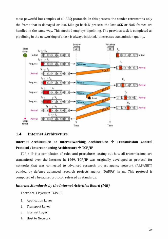
24
most powerful but complex of all ARQ protocols. In this process, the sender retransmits only
the frame that is damaged or lost. Like go-back N process, the lost ACK or NAK frames are
handled in the same way. This method employs pipelining. The previous task is completed as
pipelining in the networking of a task is always initiated. It increases transmission quality.
1.4. Internet Architecture
Internet Architecture or Internetworking Architecture Transmission Control
Protocol / Interconnecting Architecture TCP/IP
TCP / IP is a compilation of rules and procedures setting out how all transmissions are
transmitted over the Internet In 1969, TCP/IP was originally developed as protocol for
networks that was connected to advanced research project agency network (ARPANET)
ponded by defence advanced research projects agency (DARPA) in us. This protocol is
composed of a broad set protocol, released as standards.
Internet Standards by the Internet Activities Board (IAB)
There are 4 layers in TCP/IP:
1. Application Layer
2. Transport Layer
3. Internet Layer
4. Host to Network

25
TCP/IP layers was developed prior to OSI model. Host to network is a mix of physical as
well as datalink layer. The Internet layer is comparable to the network layer of the network.
The application layer consists of a mixture of session, presentation, and application layer with
transport layer support. The basic functionalities of these 4 layers are given so.
At transport layer, TCP/IP supports 3 protocols namely, TCP (Transmission Control
Protocol), UDP (User Datagram Protocol) and SCTP (Stream Control Transmission Protocol).
TCP/IP is hierarchical consisting of networking devices, each with a particular feature.
1. Host to Network (Physical and Datalink Layer)
At physical and datalink layers, no specific protocol is given in TCP/IP.
It adheres to work with standards and propriety procedures.
TCP/IP can be a LAN or WAN.
2. Network Layer (Internet Layer)
The IP in the network layer is supported by TCP/IP.
Internetworking Protocol (IP)
This protocol is unstable and connectivity-free as the strongest service delivery effort.
Best effort means IP doesn't check or monitor errors.
IP transports data in packets called datagrams.

26
Address Resolution Protocol (ARP)
ARP is used to connect a physical or station address with a logical address.
A station address is defined by each device on a connexion.
ARP is used specifically to locate a node's physical address when its internet address is
identified.
Reverse Address Resolution Protocol (RARP)
RARP helps a host to explore when its physical address is identified at international
addresses.
This is invoked when a computer initially establishes connectivity with network or
during the booting of a diskless computer.
Internet Control Message Protocol (ICMP)
ICMP is enabled during data issues and intimates to the host through gateway to notify
sender.
ICMP sends messages about query and costs from accidental loss.
Internet Group Message Protocol (ICMP)
IGMP facilitates the simultaneous transmission of messages to a set of receivers.
3. Transport Layer
Two protocols addressed the transport layer in TCP / IP: TCP, UDP.
IP is a device communication -to-host which can send a packet from one physical
device to the next.
UDP and TCP are transport-level protocols which carry a process-to - process
communication.
User Datagram Protocol (UDP)
The simplest of TCP / IP protocol is the UDP.
It is a process - to - process protocol that adds data from the data to the upper layer
with only port address, checksum, error control and length information.
Transmission Control Protocol (TCP)
TCP facilitates applications with complete transport facilities.
A stable stream transport protocol is TCP.

27
A link between both ends of the transmission must be formed before the data can be
transmitted either.
TCP breaks a data stream into smaller units at the transmitting end, called segments.
TCP collects each datagram at the receiving end, as it reorders the transmission based
on sequence numbers at the receiving end.
Stream Control Transmission Protocol (SCTP)
The SCTP supports new applications such as voice over internet.
The best features of UDP and TCP are combined in the transport layer protocol.
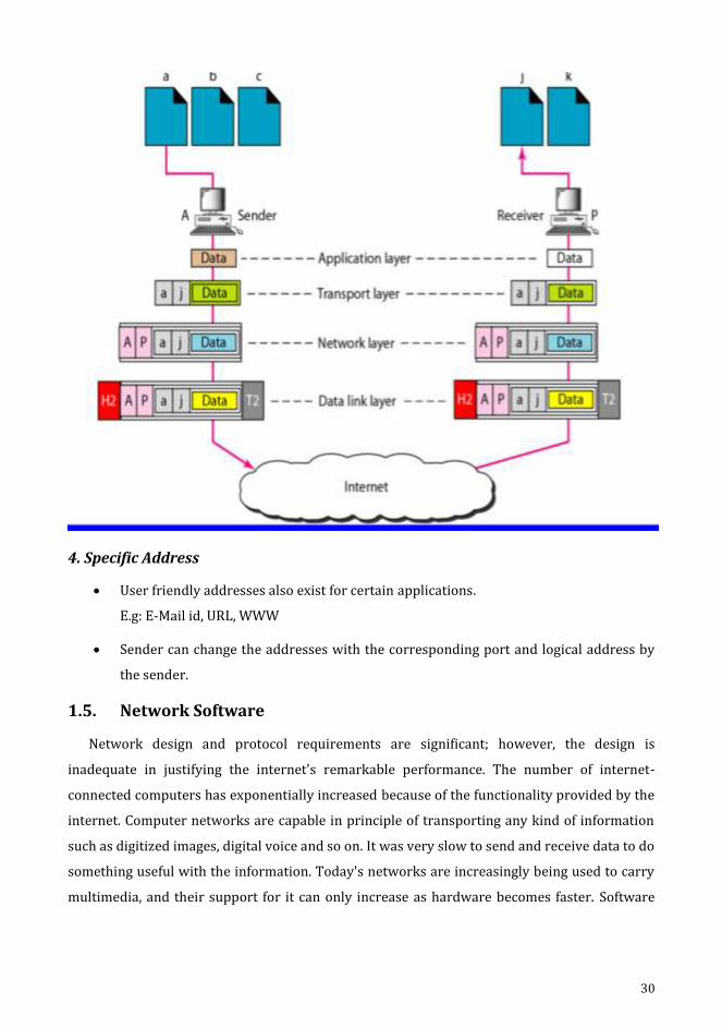
4. Application Layer
The TCP / IP application layer equals OSI session, presentation and application layers.
Addressing in TCP/IP
Various levels of addresses used in TCP/IP protocols are:
1. Physical (link) Address
2. Logical (IP) Address
3. Port Address
4. Specific Address
28
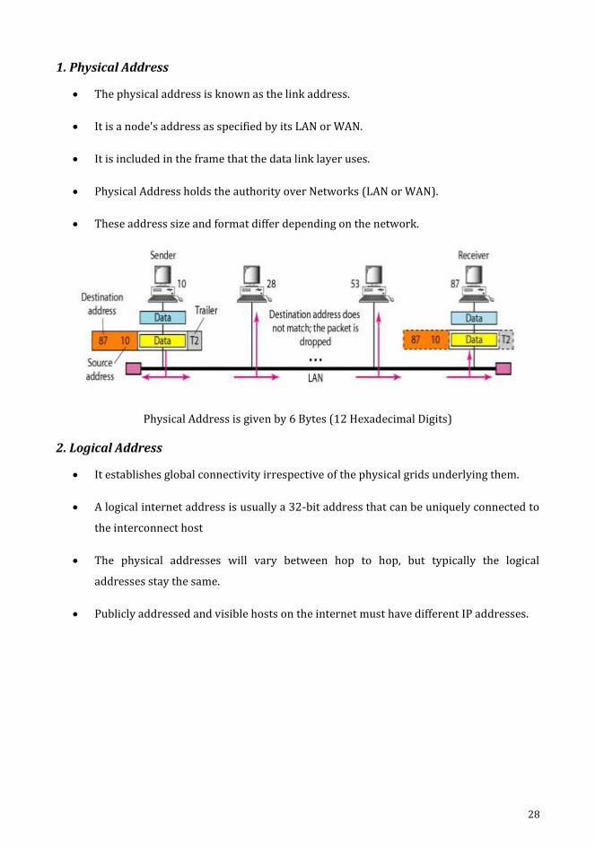
1. Physical Address
The physical address is known as the link address.
It is a node's address as specified by its LAN or WAN.
It is included in the frame that the data link layer uses.
Physical Address holds the authority over Networks (LAN or WAN).
These address size and format differ depending on the network.
Physical Address is given by 6 Bytes (12 Hexadecimal Digits)
2. Logical Address
It establishes global connectivity irrespective of the physical grids underlying them.
A logical internet address is usually a 32-bit address that can be uniquely connected to
the interconnect host
The physical addresses will vary between hop to hop, but typically the logical
addresses stay the same.
Publicly addressed and visible hosts on the internet must have different IP addresses.

29
3. Port Address
The IP and Physical address are required for information to be transported from
source to destination host.
Computer devices can concurrently run several processes.
Internet networking is an interacting mechanism with other processes.
In ICP / IP, a port address is called the label assigned to a method.
The TCP / IP port address is 16 bits long.
The Port address typically remains unchanged.
A 16-bit port address is represented by a single number.
30
4. Specific Address
User friendly addresses also exist for certain applications.
E.g: E-Mail id, URL, WWW
Sender can change the addresses with the corresponding port and logical address by
the sender.
1.5. Network Software
Network design and protocol requirements are significant; however, the design is
inadequate in justifying the internet's remarkable performance. The number of internet-
connected computers has exponentially increased because of the functionality provided by the
internet. Computer networks are capable in principle of transporting any kind of information
such as digitized images, digital voice and so on. It was very slow to send and receive data to do
something useful with the information. Today's networks are increasingly being used to carry
multimedia, and their support for it can only increase as hardware becomes faster. Software

31
applications are designed to communicate with users and a communication protocol set to
communicate across the globe.
Application Programming Interface (API)
(sockets)
The network-export interface is the place to start when implementing a network
application.
Most of the network protocols are software and network protocols along with
operating system are utilized by neighbouring computers. nearby all computer systems
implement their network protocols as part of the operating system (exported by the
network).
When the "exported via the network" interface normally refers to that given to its
networking subsystem by the OS.
This interface is also called the programming interface for network applications (APIs)
Each operating system is allowed to define its own network API using socket interface.
The benefits of any single API supported by industry are, the applications can be easily
transferrable from one OS to another and the applications are simple to be developed.
To describe socket interface, a set of services along with the syntax that can be
provided on a particular computer system.
Generalization is positively a goal of the socket interface.
A good way to think of the socket is, at the point where a local application process gets
connected to the network.
The interface defines operations for
1. Creating the socket
2. Attaching the socket to the network
3. Sending/receiving messages though the socket
4. Closing the socket
1. Creating a Socket
int socket_fd (int domain, int type, int protocol)
The protocol family in the domain specifies 3 arguments namely, PF_INET - Internet family,
PF_UNIX - Unix pipe facility and PF-PACKET - Direct access to the network interface.

32
The type argument indicates the semantic of the communication,
SOCK_STREAM_byte stream
SOCK_DGRAM_message-oriented service
The protocol argument identifies the specific protocol has been used,
UNSPEC combination of PP_INET&SOCK_SYSTEM
2. Attaching Socket to the Network
The attachment depends on the client and the server. A passive open is performed by the
application process, on the server machine.
The server invokes 3 operations namely,
int bind (int socket_fd, struct sockaddr*address, int addr_ len)
int listen (int socket_fd, int backlog)
int accept (int socket_fd, struct sockaddr*address, int*addr_len)
To link the newly formed socket to the designated location, the link operation is used. Here,
the local participant server addresses the network. The IP address of the server and the
number of ports of the TCP is available at the address. The listening operation determines how
many communications on the socket listed are pending. The accept procedure performs
accessible passive. The blocking process will not return until the combination has been
established by a remote participant. A new socket that is already in relation is returned once it
is full and the address statement includes the address of the remote participants. An active
open on the customer computer is performed by the application process, and a single
operation given below is invoked by stating who seeks to make a connection,
int connect (int socket_fd, struct sockaddr *address, int addr_len)
The address includes the address of the remote participant. Typically, the client specifies
only the address of the remote participant and the device fills in the local information. On a
well-known port, the server listens to message.
3. Sending\Receiving Messages through Socket
In general, two operations are invoked by the application process once a connection is
established, in order to send and receive the data messages,
int trx (int socket_fd, char*message, int mes_len, int flags)
int rcx (int socket_fd, char*buffer, intbuf-len, int flags)
Certain details of operations are controlled by both the operations taken as the set of flags.

33
1.6. Performance
Performance
In network design, performance is an important factor for any computers.
Two approaches measures network performance.
Bandwidth
latency
Both are put in together, to define the performance of the given link.
Bandwidth
“The number of bits that can be transmitted over the network in a certain period of
time” is defined as the bandwidth of the network.
Bits Per Second (BPS)
Latency
The time occupied by the transmit of messages from one end of the network to another
end.
Round Trip Time (RTT)
The consumption of time for message to travel between different ends.
It has 3 components.
Latency=propagation + transmit + queue
Propagation = distance / speed of light
Transmit = size / bandwidth
Where distance = length of wire in which data travels
Speed of light = speed of light over that particular wire
Size = size of packet
Bandwidth = bandwidth at which is packet to be transmitted
Jitter
Jitter is a parameter related to delay.
Jitter time is the interval between the maximum effect (or minimal effect) of a signal in
two periods.
It is produced by electromagnetic interference and cross talking with other signal
carriers.
Different data packets encounter various delays.
The data packets that hit the recipient at various times, triggering jitter.

34
Throughput = packet transfer size / packet transfer time
Transfer time = RTT + 1 / bandwidth + packet transfer size
Problems
1. If bandwidth is 10mbps, what is the bit duration time?
If bandwidth is 10mbps
The bit duration is
Bit duration=1/bandwidth
1/10*1000000
=10 microseconds
2. For I mb over a 1Gbps network with RTT 100 milliseconds, bind out the transfer time
and throughput of the link
Transfer time =RTT+1/bandwidth*transfer size
=100ms+1/1Gbps*1MB
100+1/1*1000000000*1*1000000*8
=100ms+8ms =108ms
Throughput=transfer size/transfer time
=I MB/108ms
=1*8*1000000/108*1000
=74.1Mbps
3. Consider a p-p link 50 km in length. At what bandwidth would propagation delay
(speed 2*100000000m/s) equal transmit delay for 100 bytes packet? What will be the
5/2 bytes packets?
Propagation delay = distance/speed of light
=50*1000/2*100000000 m/s =250 micro seconds
Propagation delay is equal to transmit delay
Transmit delay=size/bandwidth
=packet size/transmit delay
=800 bits/250 micro seconds
=3.2 micro bps
1000 bytes = 100*8 = 800 bits
35
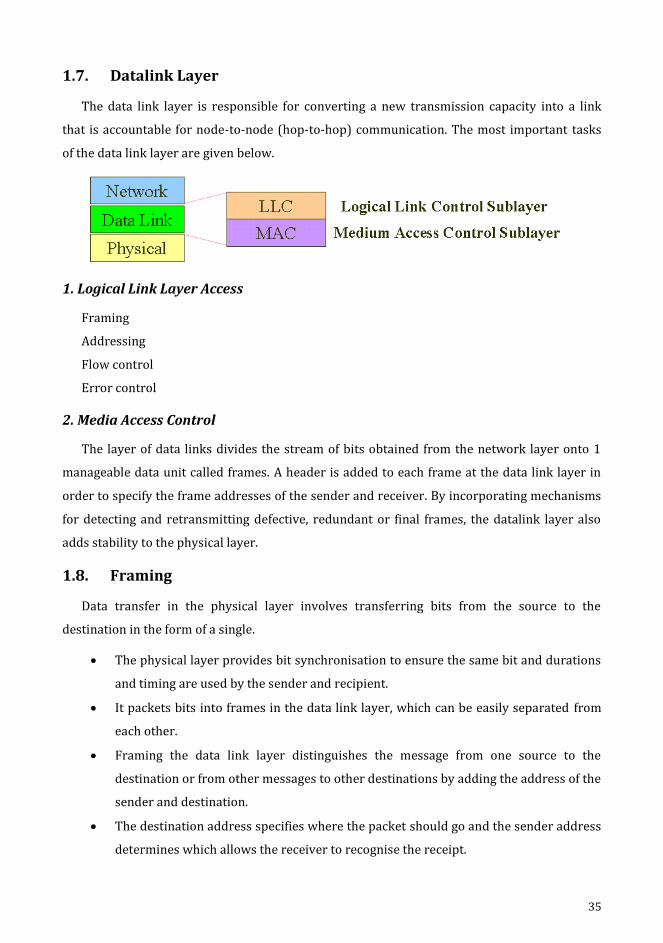
1.7. Datalink Layer
The data link layer is responsible for converting a new transmission capacity into a link
that is accountable for node-to-node (hop-to-hop) communication. The most important tasks
of the data link layer are given below.
1. Logical Link Layer Access
Framing
Addressing
Flow control
Error control
2. Media Access Control
The layer of data links divides the stream of bits obtained from the network layer onto 1
manageable data unit called frames. A header is added to each frame at the data link layer in
order to specify the frame addresses of the sender and receiver. By incorporating mechanisms
for detecting and retransmitting defective, redundant or final frames, the datalink layer also
adds stability to the physical layer.
1.8. Framing
Data transfer in the physical layer involves transferring bits from the source to the
destination in the form of a single.
The physical layer provides bit synchronisation to ensure the same bit and durations
and timing are used by the sender and recipient.
It packets bits into frames in the data link layer, which can be easily separated from
each other.
Framing the data link layer distinguishes the message from one source to the
destination or from other messages to other destinations by adding the address of the
sender and destination.
The destination address specifies where the packet should go and the sender address
determines which allows the receiver to recognise the receipt.

36
If the frame is very wide, the flow and error management is very hard to perform
efficiently.
A 1 – bit error can cause retransmission of messages even though it is a big datagram.
When a message is broken into smaller frames, only the small frame is influenced by
a single bit.
There are two types of framing.
1. Fixed size framing
2. Variable size framing
1. Fixed Size Framing
Here the boundaries of the frames need not be defined. The size acts as the delimiter.
E.g: ATM wide area network, Frames of fixed size called cells.
2. Variable Size Framing
Here the end of the frame and also the beginning of the next frame are defined. There are
two types - Character oriented approach and Bit oriented approach.
a. Character Oriented Approach
Data carried from a coding scheme, such as ASCII, with 8-bit characters.
The header carries the addresses of the source and destination and other control
information, and the trailer carrying error detection or error correction redundant bits
also has a number of 8 bits.
To distinguish one frame and the end of the frame from the next frame.
A flag composed of special characters based on the protocol, signals the start or end of
the frame.
Only text was exchanged in character-oriented framing via the data link layers.
Byte stuffing (stuffing of characters) is a special byte applied to the frame's data
segment as there is a character of the same pattern as the flag.
There is an extra byte in the data segment called escape character (ESC). Insertion of 1
additional byte to the frame, as a flag or escape character is byte stuffing.

37
b. Bit Oriented Approach
A series of bits to be interpreted by the upper layer is the data portion of a frame.
Delimiter is used separate frames from one another.
Most protocols use a special flag 01111110 of 8-bit pattern which defines the
beginning and the end of frame, as the delimiter.
Here flag creates with byte_ oriented protocols.
Bit stuffing is the process of inserting an extra 0 for every five consecutive times
following a 0 in the data, so that the receiver does not mistake the 01111110 pattern
for a flag.
1.9. Error Detection
Errors
As bits are transferred, certain unforeseeable changes occur due to interference.
This can change the signal shape that some applications need to find and resolve
errors.
There are 2 types of errors.
1. single bit error
2. burst bit error
1. Single Bit Error
Single-bit error means that only 1 bit of the data unit (byte, character, packet) has been
inverted as 1 to 0 or 0 to 1.
Only one Bit Data Unit has been modified in single bit error.
38
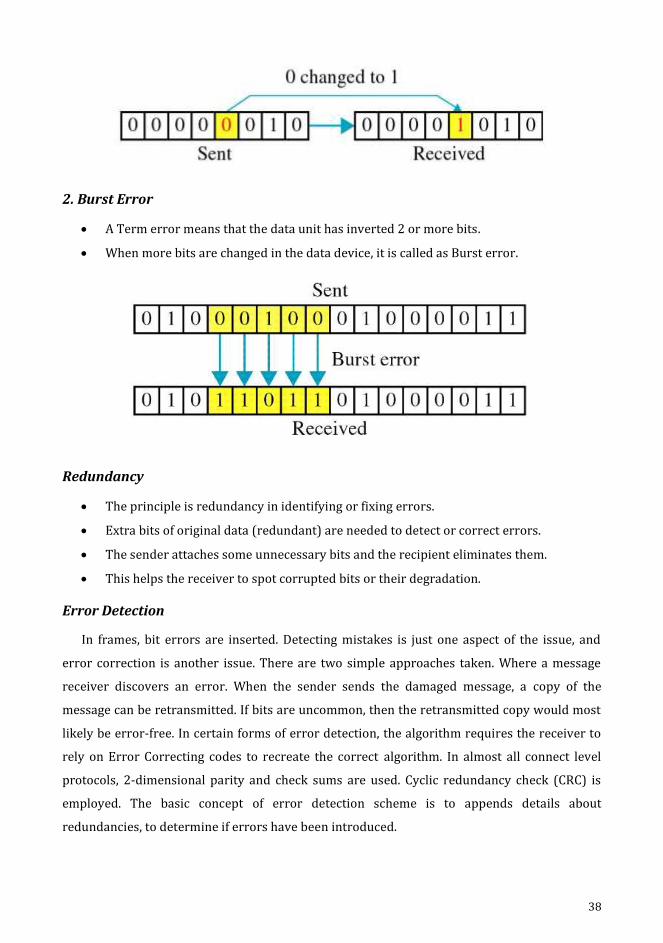
2. Burst Error
A Term error means that the data unit has inverted 2 or more bits.
When more bits are changed in the data device, it is called as Burst error.
Redundancy
The principle is redundancy in identifying or fixing errors.
Extra bits of original data (redundant) are needed to detect or correct errors.
The sender attaches some unnecessary bits and the recipient eliminates them.
This helps the receiver to spot corrupted bits or their degradation.
Error Detection
In frames, bit errors are inserted. Detecting mistakes is just one aspect of the issue, and
error correction is another issue. There are two simple approaches taken. Where a message
receiver discovers an error. When the sender sends the damaged message, a copy of the
message can be retransmitted. If bits are uncommon, then the retransmitted copy would most
likely be error-free. In certain forms of error detection, the algorithm requires the receiver to
rely on Error Correcting codes to recreate the correct algorithm. In almost all connect level
protocols, 2-dimensional parity and check sums are used. Cyclic redundancy check (CRC) is
employed. The basic concept of error detection scheme is to appends details about
redundancies, to determine if errors have been introduced.
39
Example
If the receiver finds two copies, then both are accurate.
If they vary, an error has been put into one or both of them and discarded.
Two factors for weak identification of errors.
1. It sends n redundant bits for an 1-bit message.
2. Any mistake that appears to corrupt the same bit positions in the first and
second copies of the message is undetected by several errors.
The main aim of error detection codes holds high likelihood detection of errors.
Error Detecting Codes
No new information will be added if the bits are redundant.
Extracted by some well-defined algorithm directly from the original post.
The algorithm is well-known to both the sender and recipient.
The redundant bits produced may use the message algorithm.
Both the message and a few additional bits are evoked.
The same outcome of the sender is expected at the recipient when the same algorithm
is applied.
It compares the outcome with the one that the sender sends to it.
If they match, it can be inferred that during transmission, no errors were inserted in
the message.
They are referred to as codes that detect errors.
Checksum
A checksum can be named after the algorithm used for generating code gets applied.
It is an error check which utilizes an algorithm for summing.
The term checksum is sometimes used imprecisely to denote any type of code that
detects errors like CRCs.
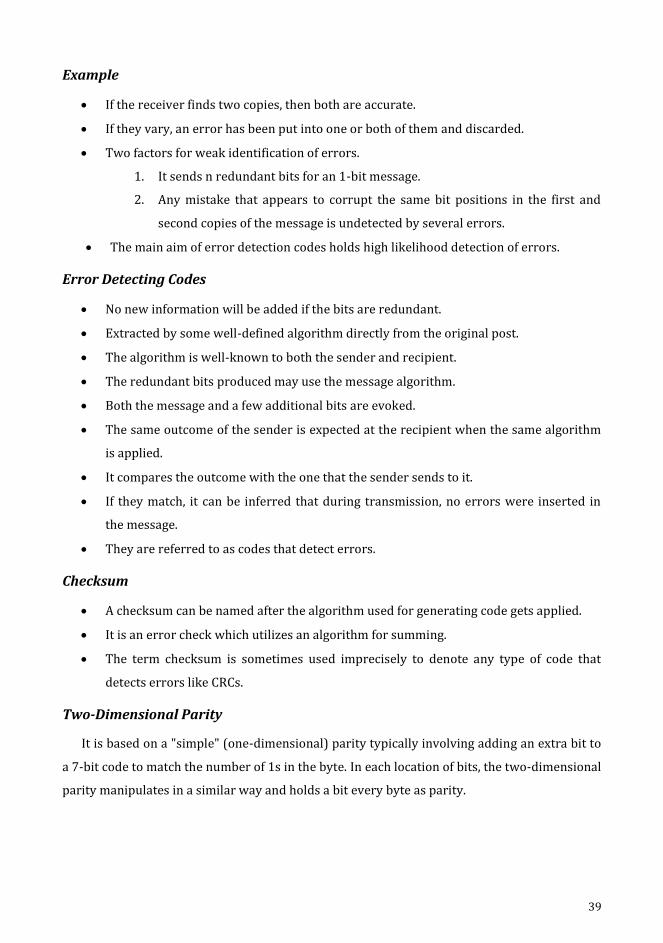
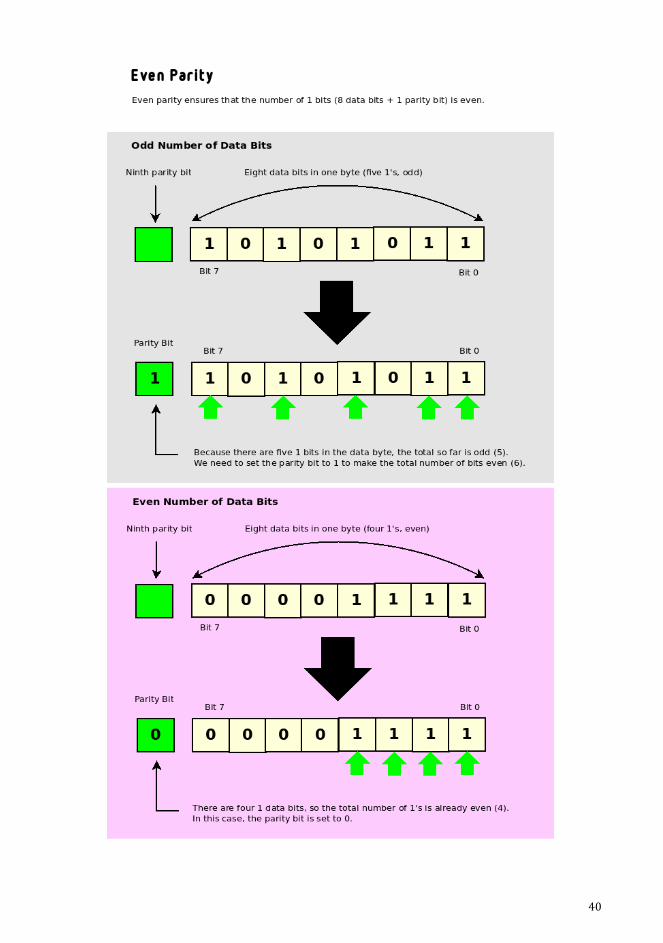
Two-Dimensional Parity
It is based on a "simple" (one-dimensional) parity typically involving adding an extra bit to
a 7-bit code to match the number of 1s in the byte. In each location of bits, the two-dimensional
parity manipulates in a similar way and holds a bit every byte as parity.
40
41
Internet Checksum Algorithm
It offers the same kind of accessibility and parity as the CRCs.
It adds up all the words that are transmitted in the internet checksum, and then
transmits the results of that number. This is called checksum.
On the received data, the receiver performs the same calculation and the results are
compared with the checksum received.
The results end up in a mismatch when any of the data transmitted is corrupted that
includes the checksum too, which intimates discrepancy to the receiver.
Cyclic Redundancy Check (CRC)
The key objective in developing algorithms for error detection is to increase the
possibility of detecting errors using only a limited number of redundant bits.
The conceptual underpinning of the CRC is embedded in a mathematical branch termed
as the finite fields.
Error correction appears to be most beneficial when:
1. Errors are relatively reliable.
E.g: wireless environment.
2. The rate value of retransmission is too high.
E.g: satellite link.
Although error detection involves sending more bits when mistakes occur, error
correction requires sending more bits all the time.
The use of networking error correction codes is referred to as forward error
correction (FEC) as error correction is done in advance by transmitting additional
details, rather than watching for problems to occur and grappling with it later
through retransmission.
Eg:- 802.11 (wireless network)
It involves vital methodologies like.
1. Acknowledgements
2. Timeouts
An acknowledgment (ACK) is a tiny control frame sent back to its peer by a protocol
indicating that it has received an earlier frame.
Retransmission of the originating frame happens when the sender fails to acquire a
receipt for a rational amount of time. This is often referred as a timeout.
42
Identification of a data frame sending back in the opposite direction and receipt of
acknowledgement is known as a piggy bank.
Error Control
Error management is the detection of errors as well as error correction.
It enables the recipient to notify the transmitter of any frames missing or disrupted in
the propagation and schedules the sender's retransmission of those frames.
Error management prefers error detection and retransmission approaches.
Automatic Repeat Request (ARQ) is termed as the occurrence of errors obtained during
a specific frame is transferred.
Data link layer error management is based on the Automatic Repeat Request (ARQ),
which is data retransmission.
1.10. Flow Control
Flow control can be explained as the amount of information that can be controlled at
the submission even before an acknowledgment is received.
It is a collection of processes that involves in instructing the sender how much data can
be transmitted before awaiting a receiver's acknowledgement.
Data flow is restricted to overpower the receive.
The recipient system is offered a limited speed to process the incoming data.
It is also responsible for warning the transmitting system and request sending a lower
number of frames or temporarily stop them, when the limit is observed.
Reviewing and analysing the arriving information is to be taken place before it can be
used.
The rate of such processing is habitually leisurelier than the rate of transmission.
Each receiving system has a memory block called a reversed buffer to store the
incoming data before it is being processed.
If the buffer starts filling up, the receiver must be able to tell the transmitter to
interrupt transmission before it can be received again.
Set of trials to limit the quantity of message sent by the sender unless awaiting the
receipts.
43
CHAPTER 2
2. Media Access and Internet Working
Objectives
To understand about Media Access Control and Internetworking.
To explain wired and wireless networks.
To know about switching and bridging.
To explain about basic internetworking – IP, ARP, RARP, ICMP, BOOTP, DHCP.
44
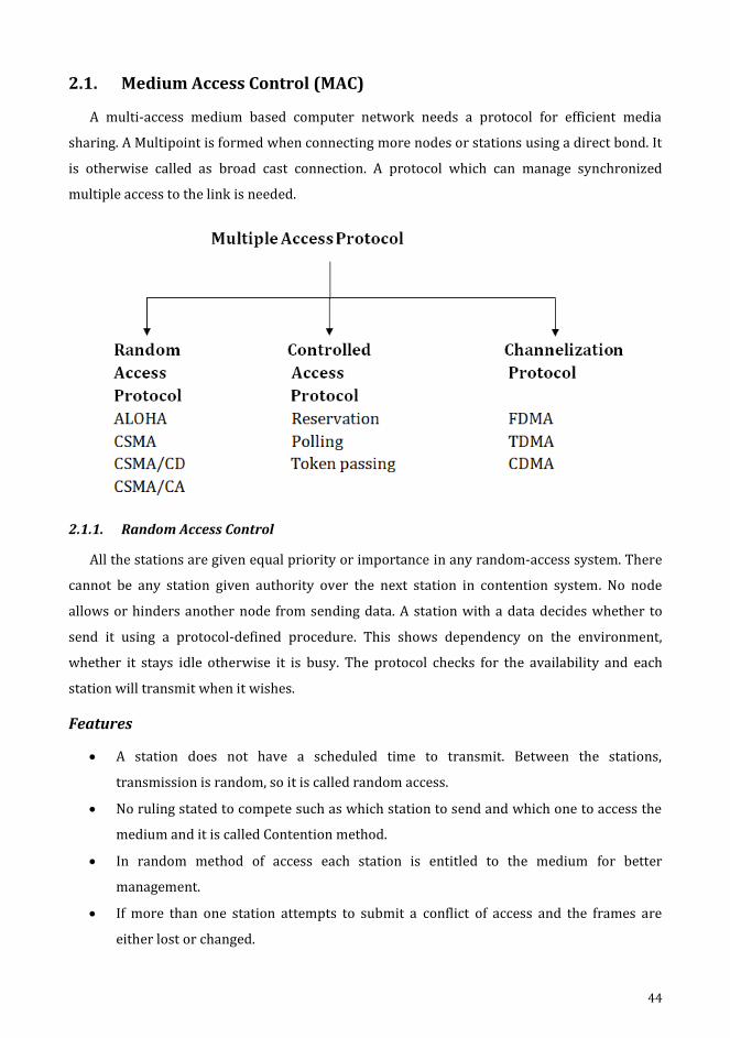
2.1. Medium Access Control (MAC)
A multi-access medium based computer network needs a protocol for efficient media
sharing. A Multipoint is formed when connecting more nodes or stations using a direct bond. It
is otherwise called as broad cast connection. A protocol which can manage synchronized
multiple access to the link is needed.
2.1.1. Random Access Control
All the stations are given equal priority or importance in any random-access system. There
cannot be any station given authority over the next station in contention system. No node
allows or hinders another node from sending data. A station with a data decides whether to
send it using a protocol-defined procedure. This shows dependency on the environment,
whether it stays idle otherwise it is busy. The protocol checks for the availability and each
station will transmit when it wishes.
Features
A station does not have a scheduled time to transmit. Between the stations,
transmission is random, so it is called random access.
No ruling stated to compete such as which station to send and which one to access the
medium and it is called Contention method.
In random method of access each station is entitled to the medium for better
management.
If more than one station attempts to submit a conflict of access and the frames are
either lost or changed.
45
Multiple Access is the methodology observed by ALOHA.
The method approved with the addition of the method facing the station is called
Carrier Sense Multiple Access (CSMA) that senses the medium prior to transmission.
There are two parallel CSMA approaches that are Carrier Sense Multi Access with
Collision Detection (CSMA / CD) and Carrier Sense Multi-Access with Collision
Avoidance (CSMA / CA).
Appropriate station is informed with the remedial action when collision has occurred
by CSMA / CD and CSMA/CA avoids collision.
a) ALOHA
It is the initial of method for accessing the data randomly, established in 1970 at the
University of Hawaii. Wireless radio LAN was its major target and also it worked out well with
a medium in sharing with others too. When a station transmits information, a different station
can simultaneously attempt to do just that. The two stations' data clash with each other.
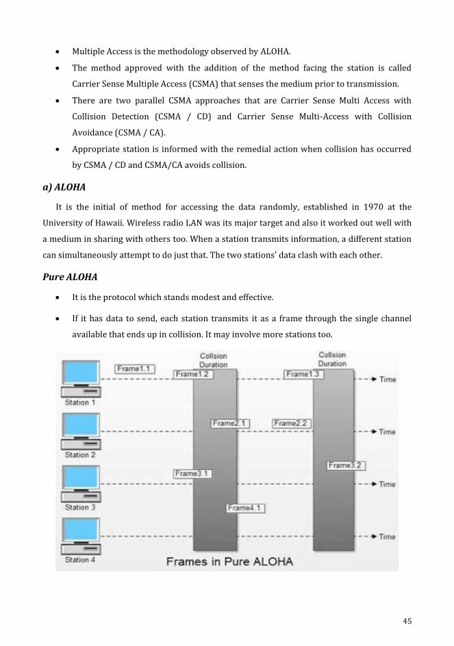
Pure ALOHA
It is the protocol which stands modest and effective.
If it has data to send, each station transmits it as a frame through the single channel
available that ends up in collision. It may involve more stations too.
46
Collision happens when one bit of a frame collocates with another frame and the
frames are lost.
This protocol is based upon receiver acknowledgments.
An acknowledgement is necessary, for a station that transmits a frame.
On delay of receiving the acknowledgement, the sender retransmits the same frame,
with the prediction that the previous one is missed on ten go.
The frames would clash again while trafficking with resending of the same frames from
these stations.
Pure ALOHA dictates wait for the station for some duration and instructs to retransmit
the data frames after the pause.
The randomness helps prevent further collisions.
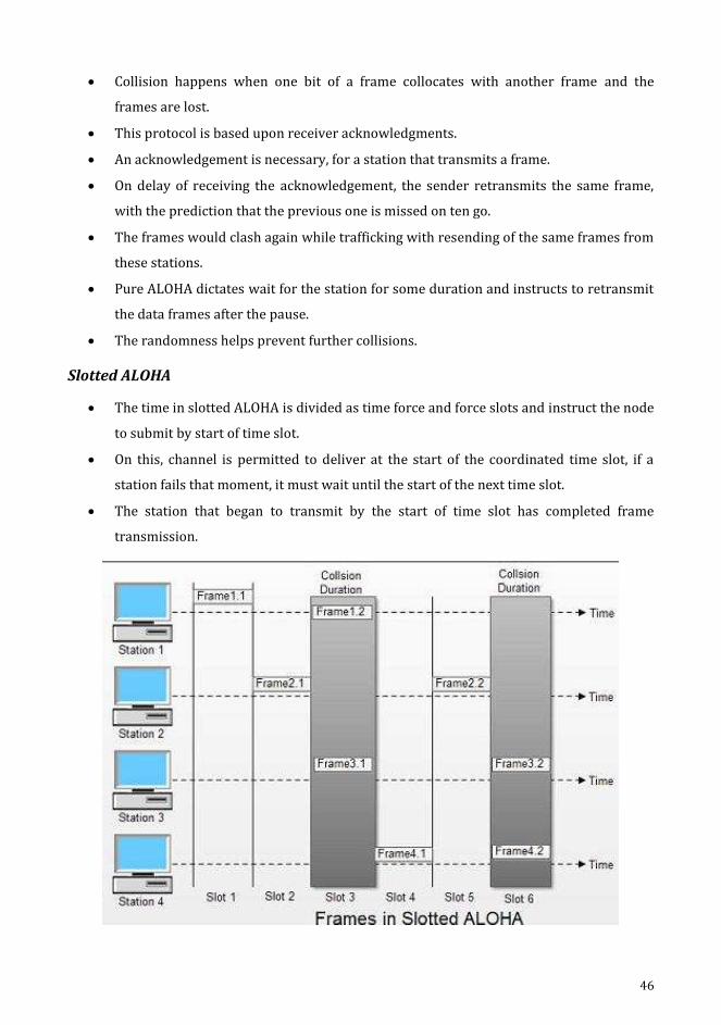
Slotted ALOHA
The time in slotted ALOHA is divided as time force and force slots and instruct the node
to submit by start of time slot.
On this, channel is permitted to deliver at the start of the coordinated time slot, if a
station fails that moment, it must wait until the start of the next time slot.
The station that began to transmit by the start of time slot has completed frame
transmission.

47
b) Carrier Sense Multiple Access (CSMA)
This protocol operates on carrier sensing principles. A station listens to the nature of
the transmission (carrier) on the cable in this protocol and intends to behave
accordingly.
Non - Persistent CSMA.
I - Persistent CSMA.
P - Persistent CSMA.
I-persistent CSMA
A modest and straight forward method.
The frames are sent immediately after the station finds the line idle.
This approach leads to maximum collision, as two or more stations can idle the line and
start sending their frames.
Non-persistent
The transmission of data is done in this mode automatically, when the line stays
passive.
For a predicted time duration it holds on and when the connection becomes active,
further checks for medium’s availability.
Decreases collision, since the nodes defer and then trace the path for submission
concurrently.
Decreases network reliability, since the medium remains idle while there are several
frame stations to transmit.
P-persistent
This method works when the medium holds time slots of length same as or bigger one
to the longest time of propagation.
P-persistent methods incorporate the benefits of those two other methods.
It decreases the risk of collision and proves efficiency.

48
c) Carrier Sense Multiple Access with Collision Detection (CSMA\CD)
The clarity of an algorithm is not specified with this CSMA method, as how to resolve
collision by employing its CSMA/CD arguments. A station tracks the medium in its system post
the transmission of a frame to see if the transmission has been carried out properly. Then the
work gets done or it resends the frame if collision occurs.
49
Time
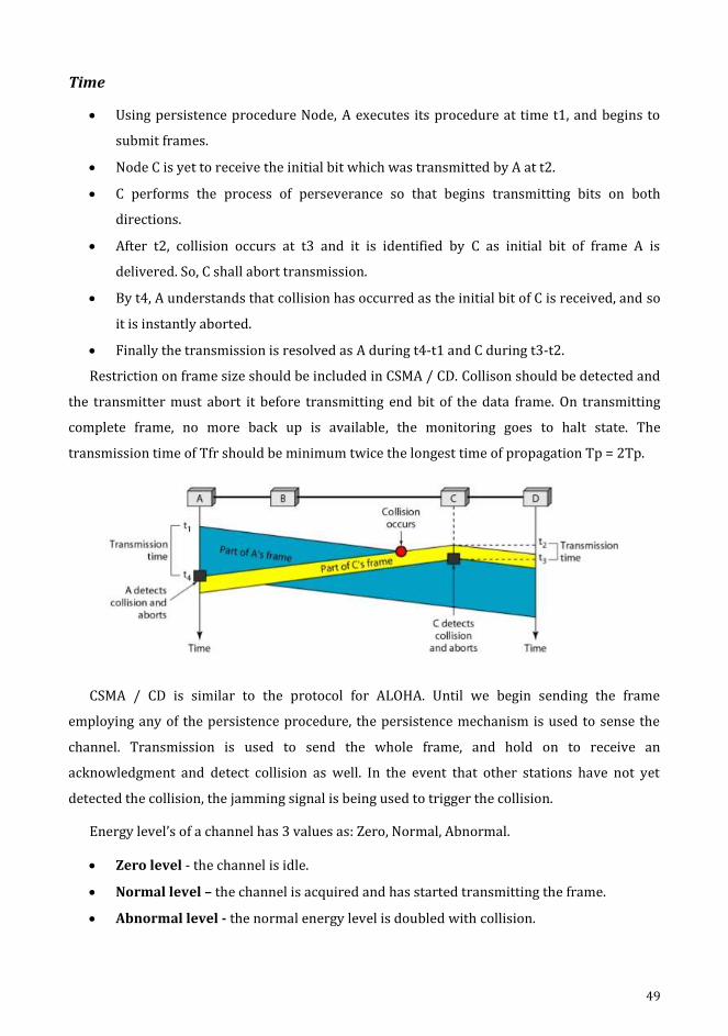
Using persistence procedure Node, A executes its procedure at time t1, and begins to
submit frames.
Node C is yet to receive the initial bit which was transmitted by A at t2.
C performs the process of perseverance so that begins transmitting bits on both
directions.
After t2, collision occurs at t3 and it is identified by C as initial bit of frame A is
delivered. So, C shall abort transmission.
By t4, A understands that collision has occurred as the initial bit of C is received, and so
it is instantly aborted.
Finally the transmission is resolved as A during t4-t1 and C during t3-t2.
Restriction on frame size should be included in CSMA / CD. Collison should be detected and
the transmitter must abort it before transmitting end bit of the data frame. On transmitting
complete frame, no more back up is available, the monitoring goes to halt state. The
transmission time of Tfr should be minimum twice the longest time of propagation Tp = 2Tp.
CSMA / CD is similar to the protocol for ALOHA. Until we begin sending the frame
employing any of the persistence procedure, the persistence mechanism is used to sense the
channel. Transmission is used to send the whole frame, and hold on to receive an
acknowledgment and detect collision as well. In the event that other stations have not yet
detected the collision, the jamming signal is being used to trigger the collision.
Energy level’s of a channel has 3 values as: Zero, Normal, Abnormal.
Zero level - the channel is idle.
Normal level – the channel is acquired and has started transmitting the frame.
Abnormal level - the normal energy level is doubled with collision.

50
A station with a frame to submit needs to track the energy level to decide if the channel is
active, idle or in collision mode.
CSMA/CD's throughput is max of ALOHA control or otherwise it is considered to be a
slotted one. The max throughput occurs at a different value of G, which holds dependency
caused by process of persistence while the value of p refers to p-persistence.
d) Carrier Sense Multiple Access/Collision Avoidance
As a collision is detected, the CSMA / CA station must be capable of receiving when
transmitting. The transmission of its data occurs with a station when it receives a signal of
non-collision and during collision, 2 signals are received, either its signal or a signal received
from other station.
The obtained signal must be substantially different in these two situations. The signal of the
second station has to append a considerable amount of energy to that provided by previous
station.
The energy of the signal stays unchangeable to that of the energy preserved during
transmission in wired network, since either cable duration seems low or repeaters to amplify
the energy exists with sender and receiver. Most of the transmitted energy in wireless
network is lost in transmission. There is very little energy in the received signal.
CSMA/CA is mainly invented for wireless network.
1. Frame space
2. Contention window
3. Acknowledgements
51
Inter Frame Space
Even if the channel is found idle, collision is prevented by deferring transmission.
The identification of a channel staying idle will not instantly mount the process.
It awaits interframe space (IFS) for a period of time.
The IFS time enables this station to be read from the pre-positioning of the signal from
a station.
The IFS variable may also be used to set the preferences for stations or frame styles.
Continuing to be idle after the IFS time the station will give, but if it still has to wait the
same time as the time of the contention.
The IFS can also be used in CSMA / CA to describe a station or frame's priority.
Contention Window
The slots are segregated to form the window of contention.
A ready-to-send station selects any slot for its idle time.
As per the binary exponential back-off technique, the slot’s count in the window varies.
For the first time it takes up one slot and doubles after the ifs duration every time the
station does not identify an inactive stream.
The station monitors the channel in contention window at the end of every time slot.
If the station finds the channel busy, rather than restarting the process it just ends the
timer and restarts it while the channel is noticed to be idle. This provides preference to
longest waiting station.
In CSMA / CA, if the station notices the channel busy, the contention window timer
doesn't restart, the timer restarts when the channel becomes passive.
Acknowledgement
Collision results in data loss.
Data can be compromised during forwarding.
As the recipient receives the data frame, a positive acknowledgment and time-out timer
is initiated.
2.1.2. Controlled Access Control
In controlled access the station consults with each other in identifying the appropriate
station to transmit. Any identified station doesn’t be granted priority to send without
authorization from connected stations.
52
a) Reservation
During this process, reservation had been made by the station before sending data.
Intervals are obtained by splitting the time and usually the data frames the reservation frame
within that duration. Having the availability of N stations in the system, the reservation frame
is exactly N reservation mini slots. Each mini slot is station owned. Therefore, whenever a data
frame has to be sent by a station, its own mini slots are reserved. The stations with these
reservations hold the authority to send the required data frame that is usually preceded by the
reservation frame.
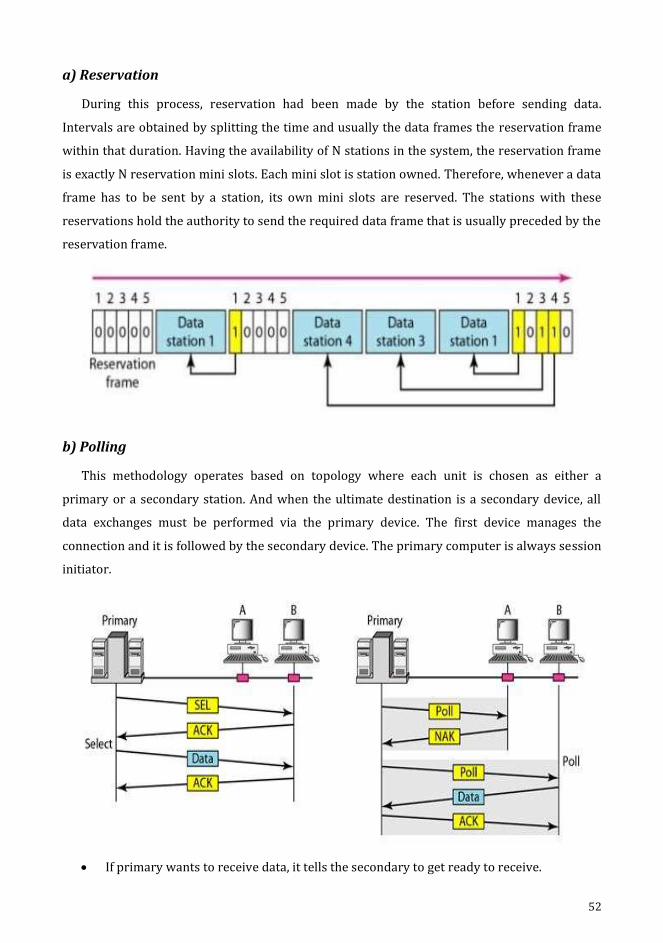
b) Polling
This methodology operates based on topology where each unit is chosen as either a
primary or a secondary station. And when the ultimate destination is a secondary device, all
data exchanges must be performed via the primary device. The first device manages the
connection and it is followed by the secondary device. The primary computer is always session
initiator.
If primary wants to receive data, it tells the secondary to get ready to receive.
53
Select
If the main computer has anything to send, the select function is used.
If it has anything to attach, attach it to the primary computer.
The primary must alert the secondary to the upcoming transmission and wait for the
secondary's ready state to be recognised.
A select (SEL) frame is created and transmitted by the primary before sending the data,
and address of the secondary is held by a field.
Poll
Whenever a primary device attempts to invoke a transmission from any other
secondary devices, this poll mechanism is utilized by the primary device.
Each system must seek to POLL, if it needs to send, whenever the primary data is ready
for receiving.
When the first secondary is contacted, the response might be a NAK or any data frame.
Assuming reflex is negative with NAK, the first one elects the next one similar to it, till it
identifies the station with transmittable data.
In case of a positive answer, the first one reads data frame and sends an
acknowledgment (ACK) confirming its reception.
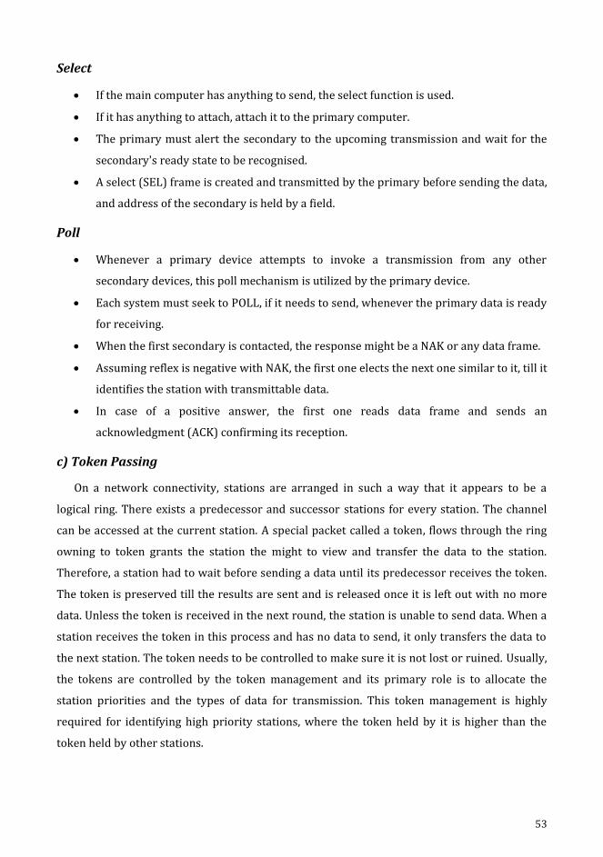
c) Token Passing
On a network connectivity, stations are arranged in such a way that it appears to be a
logical ring. There exists a predecessor and successor stations for every station. The channel
can be accessed at the current station. A special packet called a token, flows through the ring
owning to token grants the station the might to view and transfer the data to the station.
Therefore, a station had to wait before sending a data until its predecessor receives the token.
The token is preserved till the results are sent and is released once it is left out with no more
data. Unless the token is received in the next round, the station is unable to send data. When a
station receives the token in this process and has no data to send, it only transfers the data to
the next station. The token needs to be controlled to make sure it is not lost or ruined. Usually,
the tokens are controlled by the token management and its primary role is to allocate the
station priorities and the types of data for transmission. This token management is highly
required for identifying high priority stations, where the token held by it is higher than the
token held by other stations.
54
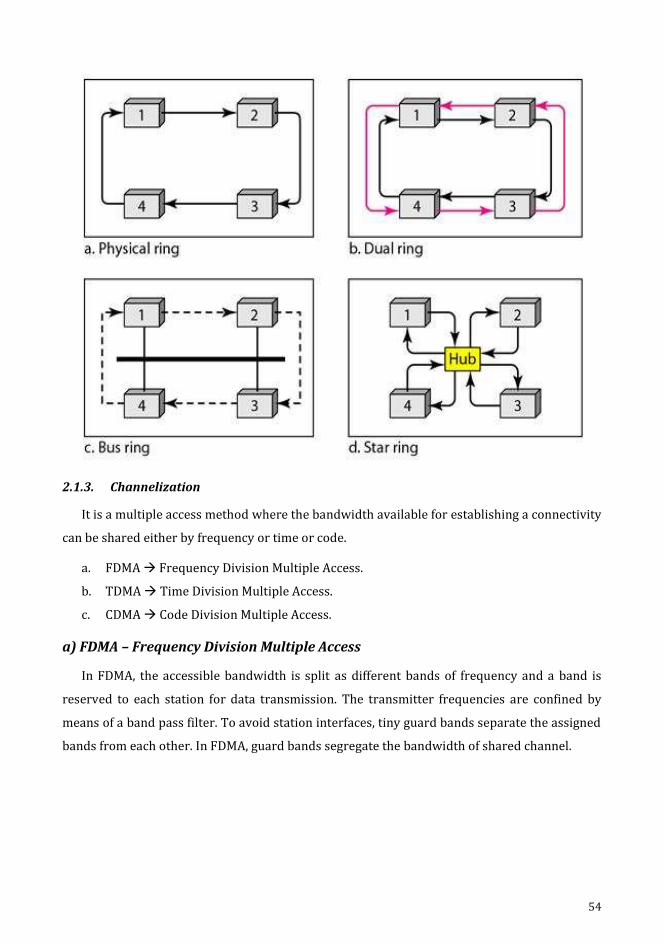
2.1.3. Channelization
It is a multiple access method where the bandwidth available for establishing a connectivity
can be shared either by frequency or time or code.
a. FDMA Frequency Division Multiple Access.
b. TDMA Time Division Multiple Access.
c. CDMA Code Division Multiple Access.
a) FDMA – Frequency Division Multiple Access
In FDMA, the accessible bandwidth is split as different bands of frequency and a band is
reserved to each station for data transmission. The transmitter frequencies are confined by
means of a band pass filter. To avoid station interfaces, tiny guard bands separate the assigned
bands from each other. In FDMA, guard bands segregate the bandwidth of shared channel.

55
FDMA specifies a predefined frequency bands or entire duration of and established
connectivity. Eg: Cellular telephone systems.
Here, the physical layer techniques integrate low-bandwidth channel loads. Low-pass is the
channels that are integrated. The multiplexer modulates, integrates and generates a band pass
signal for the signals. Every channel's bandwidth is transferred by the multiplexer. The access
method tells each station in its physical layer in the datalink layer to propagate a band pass
signal out if data passed to it. In the allocated band, the signal must be generated. The physical
layer does not contain a physical multiplexer. Automatically band pass-filter filters the signals
produced at each station. When they are sent to a popular channel, they are mixed.
b) TDMA-time Division Multiple Access
The stations share the channel's bandwidth over time in this methodology. A time slot is
assigned to each station during which it will be submitting data.
Every data is sent during the allotted slot of time duration.

56
The primary issue with TDMA is to achieve synchronisation between the various stations.
The station must be alert about the start and end of the time durations along with its location.
If the stations are scattered over a wide area of propagation delays, the delay guard times are
added to compensate. Synchronization is typically done by providing some synchronisation
bits by the start position. TDMA holds the bandwidth as a channel which shares among various
stations over time. In the physical layer, the slower data is combined and transmitted using a
faster source. The interleaving of data units are accomplished by using multiplexer. In the data
link layer, TDMA is an access process and conveys the physical layer to occupy the designated
slot of duration.
c) CDMA-code Division Multiple Access
In code division multiple access, it occupies only an allotted channel of bandwidth in the
link. It sends all the data simultaneously in no time-sharing mode. In CDMA, a channel
transmits all data concurrently.

57
For Example
Four stations 1,2,3,4 as d1, d2, d3, d4
Codes c1, c2, c3, c4
There are 2 properties
1. The multiplication of each code by another, results in 0
2. The multiplication of each code by itself, results in 4
Message = d1.c1 + d2.c2 + d3.c3 + d4.c4
2.2. Ethernet (802.3) or Wired LAN
LAN - Local Area Network
The LAN has numerous connecting methodologies stated as Ethernet, token bus or ring,
FDDI, ATM LAN etc. In 1985, IEEE developed 802 project and ANSI adopted in 1987. The
physical standards are established by subdividing data link layer as two other layers by IEEE.
1. Logical Link Control (LCC)
2. Media Access Control (MAC)
Physical Layer
It depends upon how it is implemented and the types of physical media used. The
specifications for all LAN are detailly defined by IEEE.
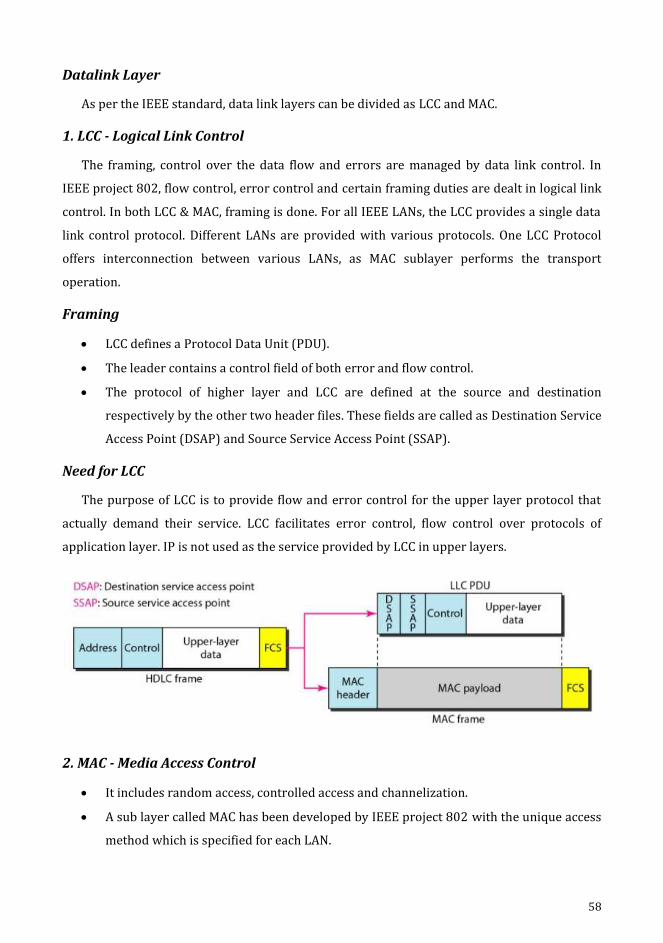
58
Datalink Layer
As per the IEEE standard, data link layers can be divided as LCC and MAC.
1. LCC - Logical Link Control
The framing, control over the data flow and errors are managed by data link control. In
IEEE project 802, flow control, error control and certain framing duties are dealt in logical link
control. In both LCC & MAC, framing is done. For all IEEE LANs, the LCC provides a single data
link control protocol. Different LANs are provided with various protocols. One LCC Protocol
offers interconnection between various LANs, as MAC sublayer performs the transport
operation.
Framing
LCC defines a Protocol Data Unit (PDU).
The leader contains a control field of both error and flow control.
The protocol of higher layer and LCC are defined at the source and destination
respectively by the other two header files. These fields are called as Destination Service
Access Point (DSAP) and Source Service Access Point (SSAP).
Need for LCC
The purpose of LCC is to provide flow and error control for the upper layer protocol that
actually demand their service. LCC facilitates error control, flow control over protocols of
application layer. IP is not used as the service provided by LCC in upper layers.
2. MAC - Media Access Control
It includes random access, controlled access and channelization.
A sub layer called MAC has been developed by IEEE project 802 with the unique access
method which is specified for each LAN.
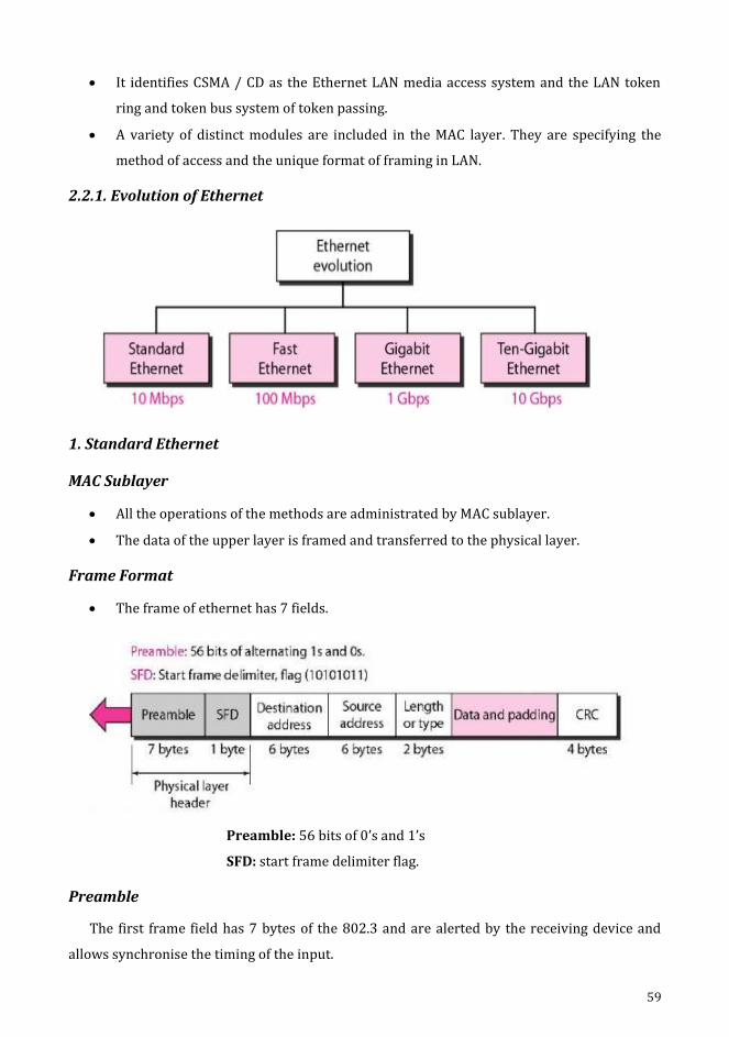
59
It identifies CSMA / CD as the Ethernet LAN media access system and the LAN token
ring and token bus system of token passing.
A variety of distinct modules are included in the MAC layer. They are specifying the
method of access and the unique format of framing in LAN.
2.2.1. Evolution of Ethernet
1. Standard Ethernet
MAC Sublayer
All the operations of the methods are administrated by MAC sublayer.
The data of the upper layer is framed and transferred to the physical layer.
Frame Format
The frame of ethernet has 7 fields.
Preamble: 56 bits of 0’s and 1’s
SFD: start frame delimiter flag.
Preamble
The first frame field has 7 bytes of the 802.3 and are alerted by the receiving device and
allows synchronise the timing of the input.

60
Start Frame Delimiter (SFD)
The next field that is obviously the second is of 1 byte and signals the frame's beginning.
The SFD frame alerts the station of synchronisation or lack of opportunity.
It also alerts the receiver that the next field is the destination address.
Destination Address (DA)
The DA field is (6 bytes) and includes the physical address of the packet receiving station or
station.
Source Address (SA)
The SA field is (6 bytes) and includes the physical address of the packet sender.
Length Type
It defines the type field or length field.
Data
This area carries data encapsulated from protocols of the higher layers. 46 bytes minimum
and -1500 bytes maximum.
CRC
This field includes knowledge about error detection.
Addressing
Every station holds unique Network Interface Card (NIC) on Ethernet. Inside the station,
NIC offers a physical address of about 6-bytes, to station. This is specified by the least
significant bit of the first byte. For unicast the bit is 0 and multicast, otherwise. The link
between the sender and the receiver, determines the destination address of the unicast that is
available with one recipient. A multicast destination address identifies a collection of

61
addresses, one to many are the links between the sender and receive. The destination address
of the broadcast holds the bits as IS in a special sect of a multicast address.
2.2.2. Physical Layer
10 Base 5: Thick Ethernet
This is a thicknet This name is formulated by referring to the size of the cable. Ethernet
specification uses bus topology with transceiver connected to a cable with thick coaxial,
through a tap.
The responsibilities of transceiver are transmitting, receiving and also collision detection. It
is associated to the cable that provides path to send and receive data through coaxial cables.
10 Base 2: Thin Ethernet
10 base 2, thin ethernet, cheaper net It is connected through bus with thinner and supple
cable. The cable will have the ability to bend to pass though the stations very close by. The
transceiver is considered as a part of NIC installed in station. It is highly cost effective when
compared to other 10 base.
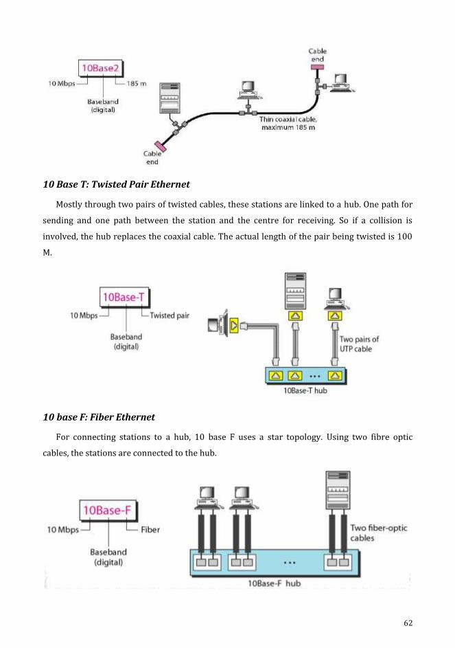
62
10 Base T: Twisted Pair Ethernet
Mostly through two pairs of twisted cables, these stations are linked to a hub. One path for
sending and one path between the station and the centre for receiving. So if a collision is
involved, the hub replaces the coaxial cable. The actual length of the pair being twisted is 100
M.
10 base F: Fiber Ethernet
For connecting stations to a hub, 10 base F uses a star topology. Using two fibre optic
cables, the stations are connected to the hub.
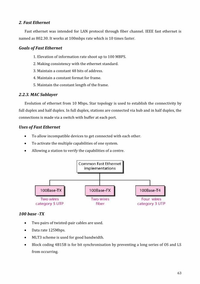
63
2. Fast Ethernet
Fast ethernet was intended for LAN protocol through fiber channel. IEEE fast ethernet is
named as 802.30. It works at 100mbps rate which is 10 times faster.
Goals of Fast Ethernet
1. Elevation of information rate shoot up to 100 MBPS.
2. Making consistency with the ethernet standard.
3. Maintain a constant 48 bits of address.
4. Maintain a constant format for frame.
5. Maintain the constant length of the frame.
2.2.3. MAC Sublayer
Evolution of ethernet from 10 Mbps. Star topology is used to establish the connectivity by
full duplex and half duplex. In full duplex, stations are connected via hub and in half duplex, the
connections is made via a switch with buffer at each port.
Uses of Fast Ethernet
To allow incompatible devices to get connected with each other.
To activate the multiple capabilities of one system.
Allowing a station to verify the capabilities of a centre.
100 base -TX
Two pairs of twisted-pair cables are used.
Data rate 125Mbps.
MLT3 scheme is used for good bandwidth.
Block coding 4B15B is for bit synchronisation by preventing a long series of OS and LS
from occurring.
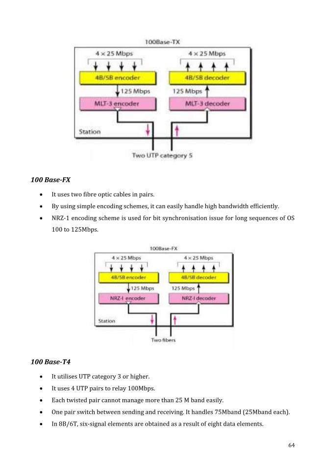
64
100 Base-FX
It uses two fibre optic cables in pairs.
By using simple encoding schemes, it can easily handle high bandwidth efficiently.
NRZ-1 encoding scheme is used for bit synchronisation issue for long sequences of OS
100 to 125Mbps.
100 Base-T4
It utilises UTP category 3 or higher.
It uses 4 UTP pairs to relay 100Mbps.
Each twisted pair cannot manage more than 25 M band easily.
One pair switch between sending and receiving. It handles 75Mband (25Mband each).
In 8B/6T, six-signal elements are obtained as a result of eight data elements.

65
3. Gigabit Ethernet
Gigabit Ethernet protocol has higher data rate of 1000Mbps. It is also known as standard
802.3z.
Goals of Gigabit Ethernet
Upgrade the speed of data to 1Gbps.
It must be made as a standard one or compatible for Fast Ethernet.
The same address of 48-bits and similar format is used for frames.
The frame lengths are maintained the same for all sizes.
Promoting auto-negation to be described in Fast Ethernet.
MAC Sublayer
Gigabit Ethernet has two approaches as given below:
a. Half-duplex
b. Full-duplex
a) Full-Duplex
There is no collision in the full-duplex Gigabit Ethernet mode; the attenuation of signal
identifies the overall cable length.
Each switch connected with buffers to store data until they are transmitted.
b) Half Duplex
A switch may be alternated with a hub which serves as a common cable if there is a
collision.
It uses CSMA/CD, which depends on minimum frame size.
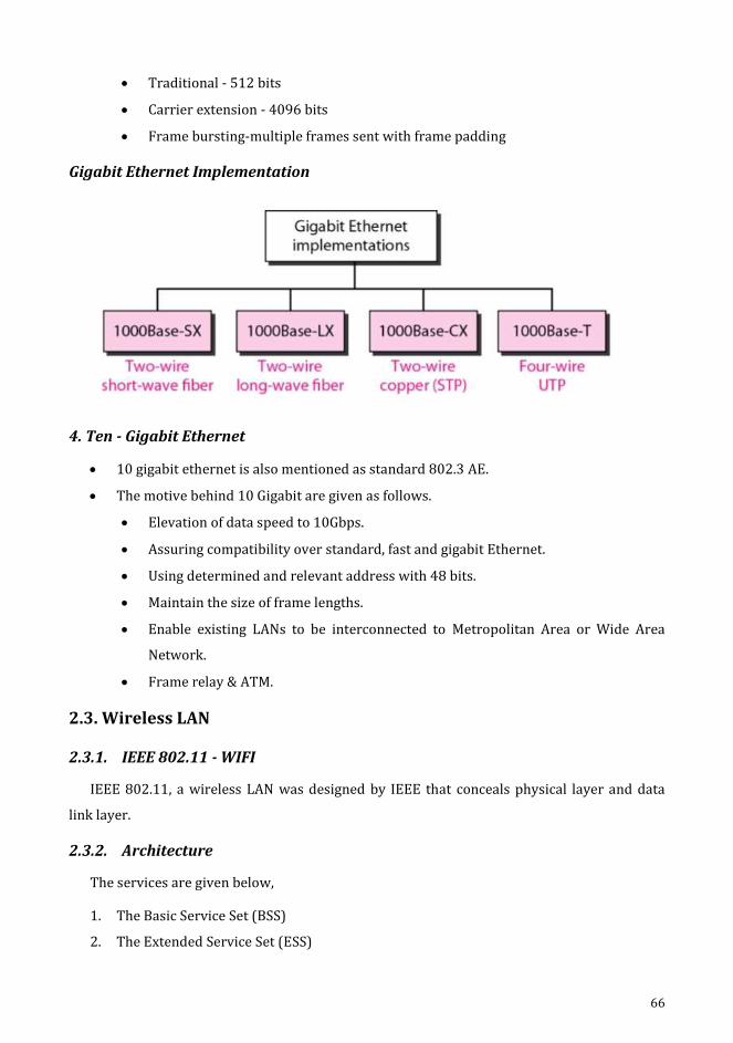
66
Traditional - 512 bits
Carrier extension - 4096 bits
Frame bursting-multiple frames sent with frame padding
Gigabit Ethernet Implementation
4. Ten - Gigabit Ethernet
10 gigabit ethernet is also mentioned as standard 802.3 AE.
The motive behind 10 Gigabit are given as follows.
Elevation of data speed to 10Gbps.
Assuring compatibility over standard, fast and gigabit Ethernet.
Using determined and relevant address with 48 bits.
Maintain the size of frame lengths.
Enable existing LANs to be interconnected to Metropolitan Area or Wide Area
Network.
Frame relay & ATM.
2.3. Wireless LAN
2.3.1. IEEE 802.11 - WIFI
IEEE 802.11, a wireless LAN was designed by IEEE that conceals physical layer and data
link layer.
2.3.2. Architecture
The services are given below,
1. The Basic Service Set (BSS)
2. The Extended Service Set (ESS)
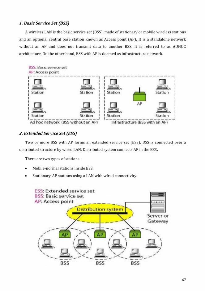
67
1. Basic Service Set (BSS)
A wireless LAN is the basic service set (BSS), made of stationary or mobile wireless stations
and an optional central base station known as Access point (AP). It is a standalone network
without an AP and does not transmit data to another BSS. It is referred to as ADHOC
architecture. On the other hand, BSS with AP is deemed as infrastructure network.
2. Extended Service Set (ESS)
Two or more BSS with AP forms an extended service set (ESS). BSS is connected over a
distributed structure by wired LAN. Distributed system connects AP in the BSS.
There are two types of stations.
Mobile-normal stations inside BSS.
Stationary-AP stations using a LAN with wired connectivity.
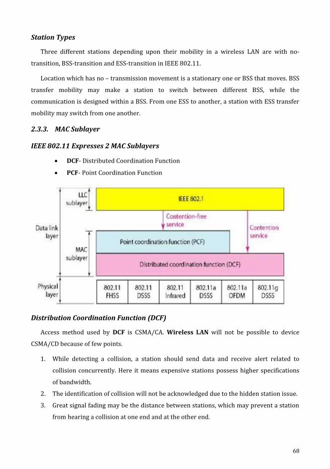
68
Station Types
Three different stations depending upon their mobility in a wireless LAN are with no-
transition, BSS-transition and ESS-transition in IEEE 802.11.
Location which has no – transmission movement is a stationary one or BSS that moves. BSS
transfer mobility may make a station to switch between different BSS, while the
communication is designed within a BSS. From one ESS to another, a station with ESS transfer
mobility may switch from one another.
2.3.3. MAC Sublayer
IEEE 802.11 Expresses 2 MAC Sublayers
DCF- Distributed Coordination Function
PCF- Point Coordination Function
Distribution Coordination Function (DCF)
Access method used by DCF is CSMA/CA. Wireless LAN will not be possible to device
CSMA/CD because of few points.
1. While detecting a collision, a station should send data and receive alert related to
collision concurrently. Here it means expensive stations possess higher specifications
of bandwidth.
2. The identification of collision will not be acknowledged due to the hidden station issue.
3. Great signal fading may be the distance between stations, which may prevent a station
from hearing a collision at one end and at the other end.
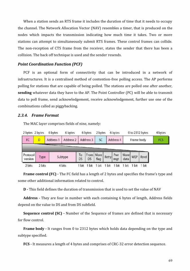
69
When a station sends an RTS frame it includes the duration of time that it needs to occupy
the channel. The Network Allocation Vector (NAV) resembles a timer, that is produced on the
nodes which impacts the transmission indicating how much time it takes. Two or more
stations can attempt to simultaneously submit RTS frames. These control frames can collide.
The non-reception of CTS frame from the receiver, states the sender that there has been a
collision. The back off technique is used and the sender resends.
Point Coordination Function (PCF)
PCF is an optional form of connectivity that can be introduced in a network of
infrastructures. It is a centralised method of contention-free polling access. The AP performs
polling for stations that are capable of being polled. The stations are polled one after another,
sending whatever data they have to the AP. The Point Controller (PC) will be able to transmit
data to poll frame, send acknowledgement, receive acknowledgement, further use one of the
combinations called as piggybacking.
2.3.4. Frame Format
The MAC layer comprises fields of nine, namely:
Frame control (FC) - The FC field has a length of 2 bytes and specifies the frame’s type and
some other additional information related to control.
D - This field defines the duration of transmission that is used to set the value of NAV
Address - They are four in number with each containing 6 bytes of length, Address fields
depend on the value to DS and from DS subfield.
Sequence control (SC) - Number of the Sequence of frames are defined that is necessary
for flow control.
Frame body - It ranges from 0 to 2312 bytes which holds data depending on the type and
subtype specified.
FCS - It measures a length of 4 bytes and comprises of CRC-32 error detection sequence.
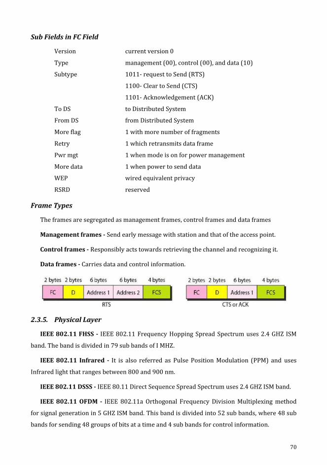
70
Sub Fields in FC Field
Version current version 0
Type management (00), control (00), and data (10)
Subtype 1011- request to Send (RTS)
1100- Clear to Send (CTS)
1101- Acknowledgement (ACK)
To DS to Distributed System
From DS from Distributed System
More flag 1 with more number of fragments
Retry 1 which retransmits data frame
Pwr mgt 1 when mode is on for power management
More data 1 when power to send data
WEP wired equivalent privacy
RSRD reserved
Frame Types
The frames are segregated as management frames, control frames and data frames
Management frames - Send early message with station and that of the access point.
Control frames - Responsibly acts towards retrieving the channel and recognizing it.
Data frames - Carries data and control information.
2.3.5. Physical Layer
IEEE 802.11 FHSS - IEEE 802.11 Frequency Hopping Spread Spectrum uses 2.4 GHZ ISM
band. The band is divided in 79 sub bands of I MHZ.
IEEE 802.11 Infrared - It is also referred as Pulse Position Modulation (PPM) and uses
Infrared light that ranges between 800 and 900 nm.
IEEE 802.11 DSSS - IEEE 80.11 Direct Sequence Spread Spectrum uses 2.4 GHZ ISM band.
IEEE 802.11 OFDM - IEEE 802.11a Orthogonal Frequency Division Multiplexing method
for signal generation in 5 GHZ ISM band. This band is divided into 52 sub bands, where 48 sub
bands for sending 48 groups of bits at a time and 4 sub bands for control information.

71
IEEE 802.11 DSSS - This describes the Direct Sequence method that is of higher rata and
the signal is generated in 2.4GHZ ISM band.
IEEE 802.11g - It gives forward error correction and OFDM using the 2.4 GHZ ISM band. It
is backward compatible with 802.11b.
2.4. Bluetooth
Bluetooth is a kind of wireless LAN technology that is designed for connecting various
devices with different functionalities such as telephone, computers, cameras, printers, and so
on. Bluetooth LAN (IEEE 802.15) is an ad hoc network, where the devices are connected
impulsively referred as gadgets. Bluetooth was initiated by Ericsson Company. This is more
suited for small area and defined as a wireless Personal Area Network (PAN).
2.4.1. Architecture
Bluetooth defines two types of network.
piconet
scatternet
Piconet
A Bluetooth is network that can be called as a piconet or otherwise called as a small net. A
piconet can have up to 8 primary stations and rest as secondary stations. All the secondary
stations synchronise with the primary with their clocks and hopping sequence. A piconet may
have only one primary station. One to one or one to many may be the contact between the
main and secondary. A piconet has a maximum of 7 secondaries and 8th can be a parked state.
A secondary is synchronised with the primary in a parked state.
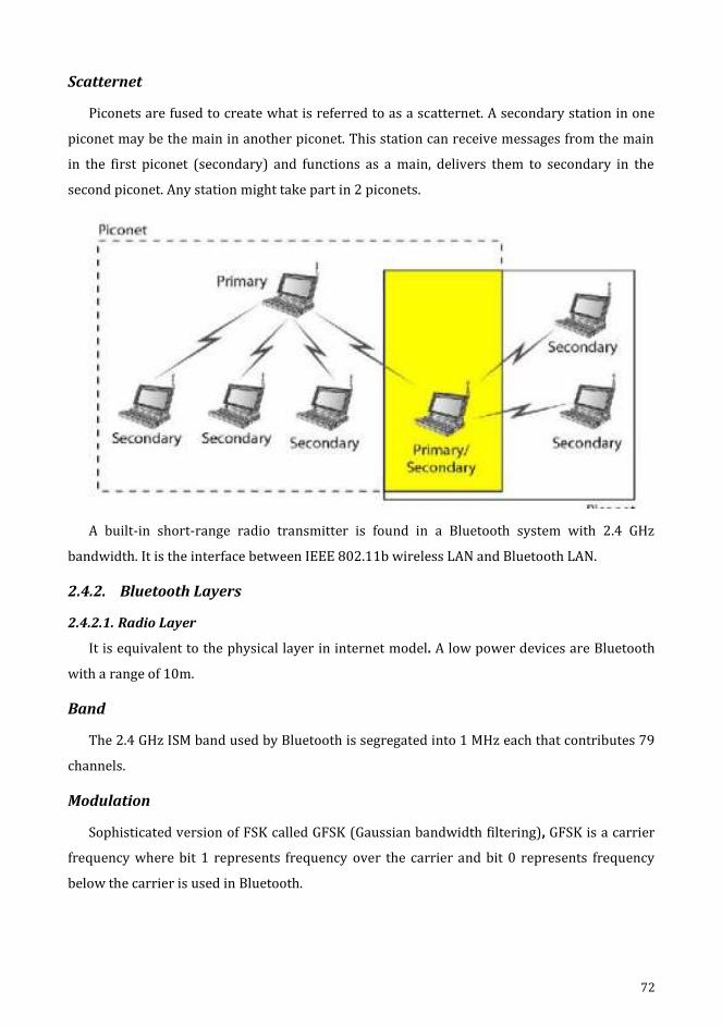
72
Scatternet
Piconets are fused to create what is referred to as a scatternet. A secondary station in one
piconet may be the main in another piconet. This station can receive messages from the main
in the first piconet (secondary) and functions as a main, delivers them to secondary in the
second piconet. Any station might take part in 2 piconets.
A built-in short-range radio transmitter is found in a Bluetooth system with 2.4 GHz
bandwidth. It is the interface between IEEE 802.11b wireless LAN and Bluetooth LAN.
2.4.2. Bluetooth Layers
2.4.2.1. Radio Layer
It is equivalent to the physical layer in internet model. A low power devices are Bluetooth
with a range of 10m.
Band
The 2.4 GHz ISM band used by Bluetooth is segregated into 1 MHz each that contributes 79
channels.
Modulation
Sophisticated version of FSK called GFSK (Gaussian bandwidth filtering), GFSK is a carrier
frequency where bit 1 represents frequency over the carrier and bit 0 represents frequency
below the carrier is used in Bluetooth.

73
FHSS - Frequency Hopping Spread Spectrum.
This methodology is used by physical layer that avoids interferences caused by different
systems or networks. It is observed that bluetooth can hop upto 1600 times in a second i.e.,
frequency modulation of the devices can be varied to 1600 times in a second. The frequency of
625 micro seconds (1/1600 s) is utilised.
2.4.2.2. Base Band Layer
MAC sublayer in LAN resembles the baseband layer. The different nodes contact each other
in the timing duration. The allotted slot is 625 micro seconds. TDMA is used as Time Division
Duplex TDMA (TDD-TDMA) by the Bluetooth with half-duplex type of communication i.e., data
is sent or received non-synchronously.
Physical Links
There are 2 types of links given as Synchronous Connection-Oriented link (SCO) which
evades delay and integrity & Asynchronous Connection-Oriented link (ACL) which overrides
latency avoidance by data integrity.
Frame Format
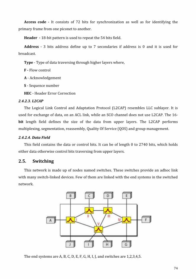
74
Access code - It consists of 72 bits for synchronization as well as for identifying the
primary frame from one piconet to another.
Header - 18-bit pattern is used to repeat the 54 bits field.
Address - 3 bits address define up to 7 secondaries if address is 0 and it is used for
broadcast.
Type - Type of data traversing through higher layers where,
F - Flow control
A - Acknowledgement
S - Sequence number
HEC - Header Error Correction
2.4.2.3. L2CAP
The Logical Link Control and Adaptation Protocol (L2CAP) resembles LLC sublayer. It is
used for exchange of data, on an ACL link, while an SCO channel does not use L2CAP. The 16-
bit length field defines the size of the data from upper layers. The L2CAP performs
multiplexing, segmentation, reassembly, Quality Of Service (QOS) and group management.
2.4.2.4. Data Field
This field contains the data or control bits. It can be of length 0 to 2740 bits, which holds
either data otherwise control bits traversing from upper layers.
2.5. Switching
This network is made up of nodes named switches. These switches provide an adhoc link
with many switch-linked devices. Few of them are linked with the end systems in the switched
network.
The end systems are A, B, C, D, E, F, G, H, I, J, and switches are 1,2,3,4,5.

75
2.5.1. Taxonomy of Switched Networks
2.5.1.1. Circuit Switched Networks
Series of continuous switches are linked through physical links in network switched circuit.
A link connecting various nodes holds a separate path composed of many connectors. This
network holds a constant flow of physical-connected switches where every connection is
segregated as h-channels.
A switch is attached to the final device. In order to get connected with the system x, it is
expected to appeal a link with x such as all switches and x agrees. The process is done in the
setup phase. On each connection, a circuit (channel) is reserved and the dedicated path is
specified by the combination of circuits or channels. At the physical stage, circuit switching

76
takes place. For the services to be used during the interaction, the station must make a
reservation. Resources such as channels, switch buffers, switch processing time, input / output
switch ports have to be preserved with confinement until the tear-down step for the overall
cycle of message transfer. During data transfer, there is no source and addressing involved.
Three Phases
1. Setup phase - A connection between the two end systems are created with the address
required for communication.
2. Data transfer phase - Two nodes (channels) can transfer data.
3. Teardown phase - When one of the parties needs to disconnect a signal is sent to each
switch to release the resources.
The telephone network is connection oriented. It involves in the transfer through a
network that has a dedicated connectivity and this is termed circuit switching.
Advantages
Dedicated transmission channel establishment provides a guaranteed data rate of
transmission.
Time delay is not found in data flow.
Disadvantages
Although the channel is idle, it cannot be used to transmit any other data.
More Bandwidth is demanded by dedicated channels.
It takes longer time to establish connection.

77
2.5.1.2. Message Switching (OR) Telegraph Network
Text message is encoded using different code to frame a sequence of data with dashes. The
text message is sent from the telegraph office which is the source to the telegraph switching
station. An operator takes the decision of routing the message based on the destination
address information the operator will either forward the message is a connectivity to the
destination is free or store the message till the communication line becomes free. Every
message is considered as an independent unit and includes both the source and destination
addresses. All complete messages are transmitted from a device to another device through the
connectivity.
Each intermediate device receives the message, ensures the readiness of the connecting
device and then forwards it to the next one. This is called as a store and forward network. The
information is more efficient and other switches that can be used to forward messages to their
ultimate destination.
Advantages
Effective traffic management is offered by prioritizing messages that needs to be
switched.
Network traffic congestion is minimized.
The network devices share the data channels.
Asynchronous communication is provided across different time zones.
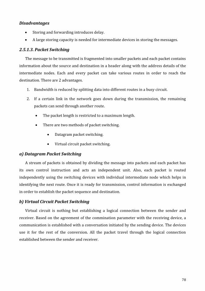
78
Disadvantages
Storing and forwarding introduces delay.
A large storing capacity is needed for intermediate devices in storing the messages.
2.5.1.3. Packet Switching
The message to be transmitted is fragmented into smaller packets and each packet contains
information about the source and destination in a header along with the address details of the
intermediate nodes. Each and every packet can take various routes in order to reach the
destination. There are 2 advantages.
1. Bandwidth is reduced by splitting data into different routes in a busy circuit.
2. If a certain link in the network goes down during the transmission, the remaining
packets can send through another route.
The packet length is restricted to a maximum length.
There are two methods of packet switching.
Datagram packet switching.
Virtual circuit packet switching.
a) Datagram Packet Switching
A stream of packets is obtained by dividing the message into packets and each packet has
its own control instruction and acts an independent unit. Also, each packet is routed
independently using the switching devices with individual intermediate node which helps in
identifying the next route. Once it is ready for transmission, control information is exchanged
in order to establish the packet sequence and destination.
b) Virtual Circuit Packet Switching
Virtual circuit is nothing but establishing a logical connection between the sender and
receiver. Based on the agreement of the commination parameter with the receiving device, a
communication is established with a conversation initiated by the sending device. The devices
use it for the rest of the conversion. All the packet travel through the logical connection
established between the sender and receiver.
79
Advantages
The bandwidth of the network can be increased in order to communicate with
numerous devices via the same network channel.
A packet can be routed using a switching node based on its requirements.
Time and transmission delay are reduced.
Disadvantages
In Packet switching, the size of the RAM is proportional to the quantity of the packets.
It requires more processing power.
2.5.2. Bridging
Bridge is used to connect two or more detached networks that are connected for
exchanging data or resources. It utilizes addressing protocols and can affect the flow control of
a single LAN. Bridges are more active at the data link layer. It receives the signal and it can
check the physical (MAC) address of source and destination stored in the frame.
Generally 2 types of bridges exist namely,
Transparent bridge
Routing bridge
2.5.2.1. Transparent Bridge
In this bridge, the stations are unaware of bridge connectivity. Transparent bridges keep a
table of address in memory to regulate the forwarding of data.

80
The duties of transparent bridge are:
1. Filtering flames
2. Forwarding
3. Blocking
Each packet traces the destination and source addresses. It checks the destination to decide
where to send the packet. If it does not recognize the destination address it relays the packet to
all of the stations on both segments. When a frame arrives at a bridge, it must choose to either
discard or forward it and if the latter is true, then decide on which LAN to put the frame.
2.5.2.2. Routing Bridge
The routing bridge is used to interconnect token ring networks. The header holds the route
to destined node, during its travel. This information is present only if the communication is
between varied LANs.
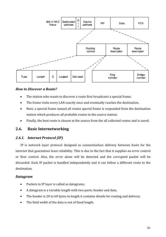
81
How to Discover a Route?
The station who wants to discover a route first broadcasts a special frame.
The frame visits every LAN exactly once and eventually reaches the destination.
Next, a special frame named all routes special frame is responded from the destination
station which produces all probable routes to the source station.
Finally, the best route is chosen at the source from the all collected routes and is saved.
2.6. Basic Internetworking
2.6.1. Internet Protocol (IP)
IP is network layer protocol designed as connectionless delivery between hosts for the
internet that guarantees least reliability. This is due to the fact that it supplies no error control
or flow control. Also, the error alone will be detected and the corrupted packet will be
discarded. Each IP packet is handled independently and it can follow a different route to the
destination.
Datagram
Packets in IP layer is called as datagrams.
A datagram is a variable length with two parts; header and data.
The header is 20 to 60 bytes in length it contains details for routing and delivery.
The field width of the data is not of fixed length.
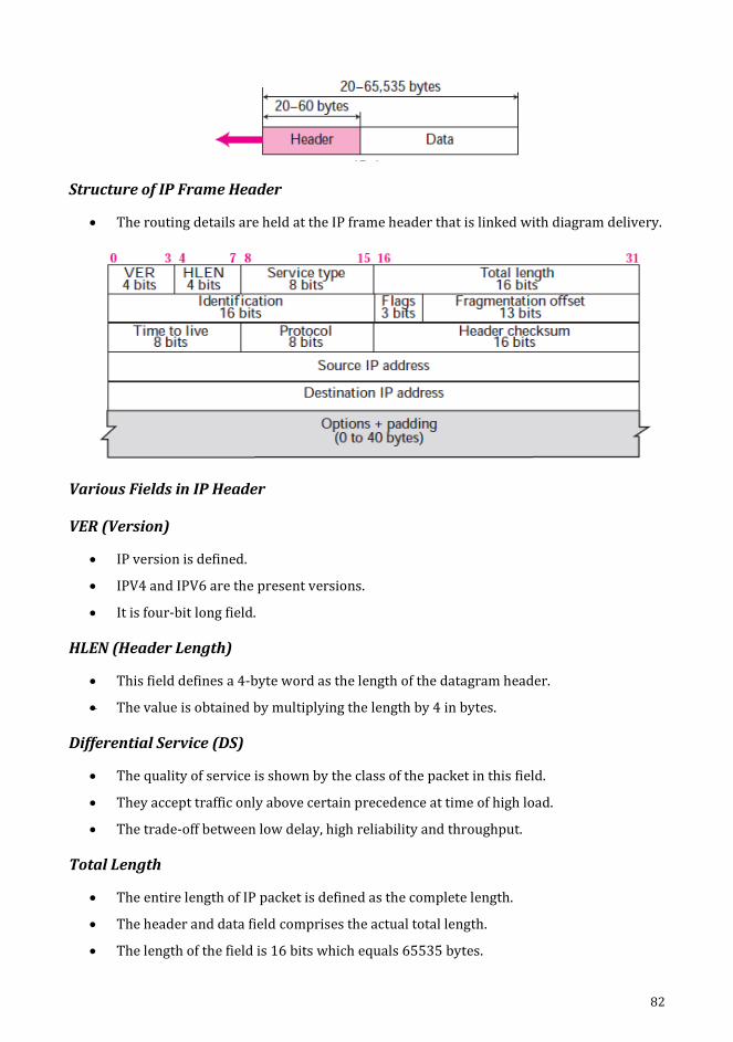
82
Structure of IP Frame Header
The routing details are held at the IP frame header that is linked with diagram delivery.
Various Fields in IP Header
VER (Version)
IP version is defined.
IPV4 and IPV6 are the present versions.
It is four-bit long field.
HLEN (Header Length)
This field defines a 4-byte word as the length of the datagram header.
The value is obtained by multiplying the length by 4 in bytes.
Differential Service (DS)
The quality of service is shown by the class of the packet in this field.
They accept traffic only above certain precedence at time of high load.
The trade-off between low delay, high reliability and throughput.
Total Length
The entire length of IP packet is defined as the complete length.
The header and data field comprises the actual total length.
The length of the field is 16 bits which equals 65535 bytes.

83
Identification; Flag; Offset
(i) Identification
The identifying the datagram that originates from the source host is held in this field.
The copier is held in all fragments, with its identification.
The identification member helps destination in reassembling fragments of datagram.
(ii) Flag
The field has 3-bits.
(0) is reserved at the first bit, whereas the second bit is referred by Do not fragment bit
and finally, the third bit is called to be more fragment bit.
(iii) Fragmentation Offset
A 13-bit field that indicates relative position of the fragmentation in the full datagram.
An 8 bytes of offset is left in the datagram.
4000 bytes are held by IP packets ranging from 0 to 3999.
It is segregated into 3.
Time to live
The field has a length of eight bits and also holds a control over most of the routers
which the datagram has made a visit.
84
Protocol
Higher level protocol is defined by this field that uses various services provided by the
IP layer.
A protocol of higher level which summarizes data in IP datagram is done by TCP.
Header Checksum
For an IP packet, the header alone is covered in this checksum.
At each point, the field will be recomputed and verified, when the fields at the header
attempts a change.
Source and Destination Address
These are used in defining the IP addresses of source and destination fields.
Options
They are used for network testing and debugging IP that provides several options of
allowing a packets sender of requisites over the path which is followed on a network,
identifies the route taken by packets which further label them with preserving
attributes of secure transmission.
Services Provided
The following services are offered by IP:
a) Addressing
The header of IP comprehends 32-bit addresses to recognize the hosts of the sender and
receiver. Intermediate routers employ the usage of these addresses in order to choose the path
for a packet via a network.
b) Fragmentation
It splits larger packets into smaller fragments that helps networks that can handle only the
smaller packets. These fragments are transparent as well.
c) Packet Timeout
Time to live (TTL) field is found in all IP packet that gets decremented whenever a router
handles a packet and is discarded, when reaches zero.

85
d) Types of Services
IP supports traffic prioritization by allowing packets to be labelled with an abstract type
service.
IP Addresses
The IP address for hosts is assigned by the network administrator.
An IP address consist of two part.
1. Address, called as network number which identifies a network.
2. Host ID, refers to each host of the network.
Network Address
This address helps in defining the network and is not possible to be allotted to a host.

86
IP Address (Decimal and Binary Form)
Subnetting
Identical network number is provided to every hosts present in a network. IP addressing
can be problematic as the network size increases. Subnetting allows an additional level of
hierarchy in IP addressing. Network is split into several smaller networks internally but it acts
like a single network. The smaller parts of a networks are called as subnets.
Subnet Mark
The number of 1s in the subnet mask is more than the number of 1s in the corresponding
default mask. Leftmost 0s are default mask to make a subnet mask.
Super Netting
The addresses of class A and B are most depleted but class C addresses are marked until
available. The prerequisite of the organisation is left unsatisfied by the C address as its size
maximizes to 256 only. Therefore, it requires more addresses which is attained by combining
several networks to form a super network.
2.6.1.1. IPV4
TCP/IP protocols uses internet protocol version 4 (IPV4) as the procedure to perform
delivery of packets.
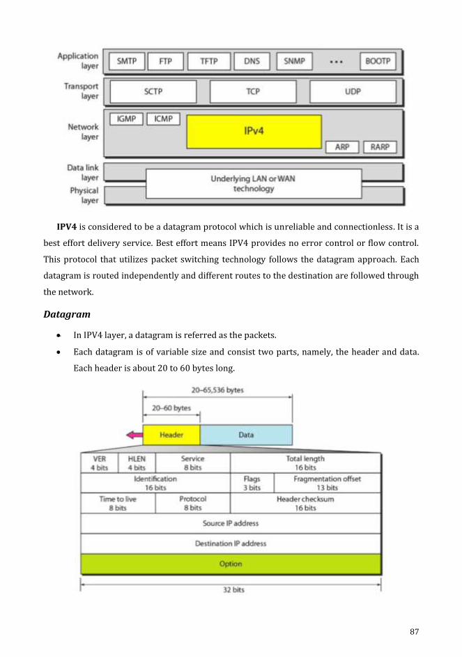
87
IPV4 is considered to be a datagram protocol which is unreliable and connectionless. It is a
best effort delivery service. Best effort means IPV4 provides no error control or flow control.
This protocol that utilizes packet switching technology follows the datagram approach. Each
datagram is routed independently and different routes to the destination are followed through
the network.
Datagram
In IPV4 layer, a datagram is referred as the packets.
Each datagram is of variable size and consist two parts, namely, the header and data.
Each header is about 20 to 60 bytes long.
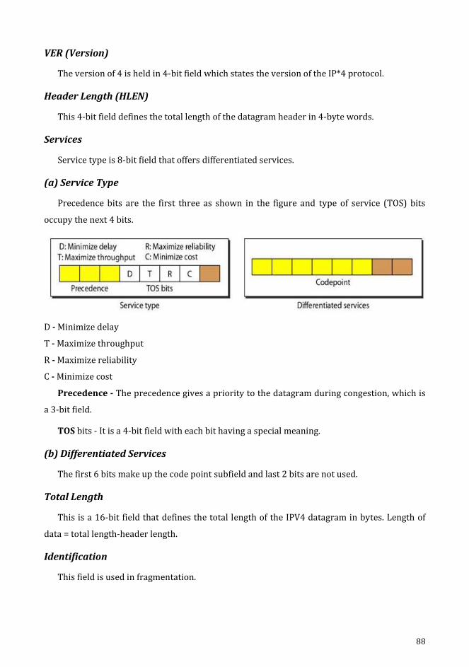
88
VER (Version)
The version of 4 is held in 4-bit field which states the version of the IP*4 protocol.
Header Length (HLEN)
This 4-bit field defines the total length of the datagram header in 4-byte words.
Services
Service type is 8-bit field that offers differentiated services.
(a) Service Type
Precedence bits are the first three as shown in the figure and type of service (TOS) bits
occupy the next 4 bits.
D - Minimize delay
T - Maximize throughput
R - Maximize reliability
C - Minimize cost
Precedence - The precedence gives a priority to the datagram during congestion, which is
a 3-bit field.
TOS bits - It is a 4-bit field with each bit having a special meaning.
(b) Differentiated Services
The first 6 bits make up the code point subfield and last 2 bits are not used.
Total Length
This is a 16-bit field that defines the total length of the IPV4 datagram in bytes. Length of
data = total length-header length.
Identification
This field is used in fragmentation.
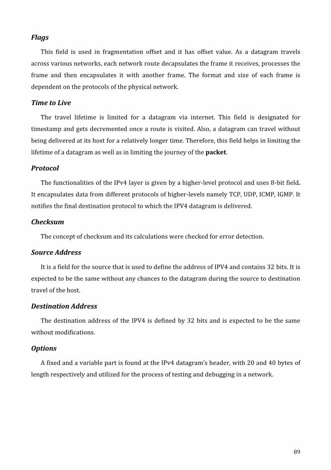
89
Flags
This field is used in fragmentation offset and it has offset value. As a datagram travels
across various networks, each network route decapsulates the frame it receives, processes the
frame and then encapsulates it with another frame. The format and size of each frame is
dependent on the protocols of the physical network.
Time to Live
The travel lifetime is limited for a datagram via internet. This field is designated for
timestamp and gets decremented once a route is visited. Also, a datagram can travel without
being delivered at its host for a relatively longer time. Therefore, this field helps in limiting the
lifetime of a datagram as well as in limiting the journey of the packet.
Protocol
The functionalities of the IPv4 layer is given by a higher-level protocol and uses 8-bit field.
It encapsulates data from different protocols of higher-levels namely TCP, UDP, ICMP, IGMP. It
notifies the final destination protocol to which the IPV4 datagram is delivered.
Checksum
The concept of checksum and its calculations were checked for error detection.
Source Address
It is a field for the source that is used to define the address of IPV4 and contains 32 bits. It is
expected to be the same without any chances to the datagram during the source to destination
travel of the host.
Destination Address
The destination address of the IPV4 is defined by 32 bits and is expected to be the same
without modifications.
Options
A fixed and a variable part is found at the IPv4 datagram’s header, with 20 and 40 bytes of
length respectively and utilized for the process of testing and debugging in a network.
90
No Operation
It is just a single-byte operation which is often utilized for filtering options.
End of Option
This is also a single-byte option utilized especially at the end of the option for padding.
Strict Source Route
In order to opt for a specific service, for e.g., the service can be a minimum delay or some
other services like maximum throughput, the sender has got a privilege in selecting a route.
This is offered by strict source route option that enables a predetermined datagram route that
travels via internet.
Loose Source Route
Even though loose source route appears to be similar to the strict source route,
nevertheless it’s rigidity is less. Various routers can be visited by the datagram.
Timestamp
This option is utilized when datagram’s time processed by routes needs to be recorded. The
routing time of a datagram is given here.
2.6.2. Address Resolution Protocol (ARP)
The internet comprises of numerous networks and routers. In general, a packet visits
various physical networks while beginning from the source host, reaching the destination host.
At the network level, the addresses are used in recognising the hosts and routers.
91
1. IP Address
An IP address is a unique internetwork address and every protocol requires IP address for
internetworking.
2. MAC Addresses
As discussed above, packets pass via physical network and at the physical level, the IP
addresses alone are not sufficient but MAC addresses are required to recognize the hosts and
routes. A MAC address is a unique local address and it is also passed through different physical
network. The IP and MAC addresses are two different identifies and both are required to be
available at the same time in the network layer. To deliver a packet to a host or a route, bi-level
addressing is required as IP addressing and MAC addressing.
Mapping can be done by using static mapping or dynamic mapping.
1. Static Mapping
A table is maintained to associate IP address with MAC address. Whenever a machine wants
to communicate with another machine knowing its IP address, then the MAC address can be
found in the table. The table of the static mapping has to be updated periodically. The Address
Resolution Protocol (ARP) associates an IP address with the physical address. On a typical
physical network LAN, each device on a link is identified by a physical or station address
usually imprinted on the Network Interface Card (NIC).
2. Dynamic Mapping
A protocol is set to discover the address of the other machine, given a known address in
dynamic mapping. The performance of dynamic mapping is defined by the following two
protocols,
Address Resolution Protocol (ARP)
Reverse Address Resolution Protocol (RARP)
ARP Operation
The association of an IP address and the appropriate MAC address is done by ARP. Every
LAN has its own physical or station address as its identification which is imprinted on the NIC.
How to Find the MAC Address?
The discovery of MAC addresses of other hosts or network requires the following steps.

92
An ARP request packet is sent when the router or host requests to discover the MAC
address of another router.
This packet includes both IP along with MAC address of transitter and the IP address
of receiver.
Although all router and host throughout the network receives and processes the ARP
request packet, only specific receiver (B) recognizes its IP address in the request
packet and reverts an ARP response packet containing IP and physical addresses of
the receiver (B).
This packet is delivered only to A (unicast) using A’s physical address in the ARP
request packet.
ARP Packet Format
The format of ARP packet that includes a variety of fields that are listed below:
Having been aware of the internet address of any node, ARP can find the physical
address.
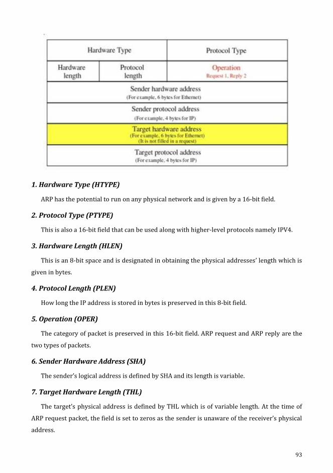
93
1. Hardware Type (HTYPE)
ARP has the potential to run on any physical network and is given by a 16-bit field.
2. Protocol Type (PTYPE)
This is also a 16-bit field that can be used along with higher-level protocols namely IPV4.
3. Hardware Length (HLEN)
This is an 8-bit space and is designated in obtaining the physical addresses’ length which is
given in bytes.
4. Protocol Length (PLEN)
How long the IP address is stored in bytes is preserved in this 8-bit field.
5. Operation (OPER)
The category of packet is preserved in this 16-bit field. ARP request and ARP reply are the
two types of packets.
6. Sender Hardware Address (SHA)
The sender’s logical address is defined by SHA and its length is variable.
7. Target Hardware Length (THL)
The target’s physical address is defined by THL which is of variable length. At the time of
ARP request packet, the field is set to zeros as the sender is unaware of the receiver’s physical
address.
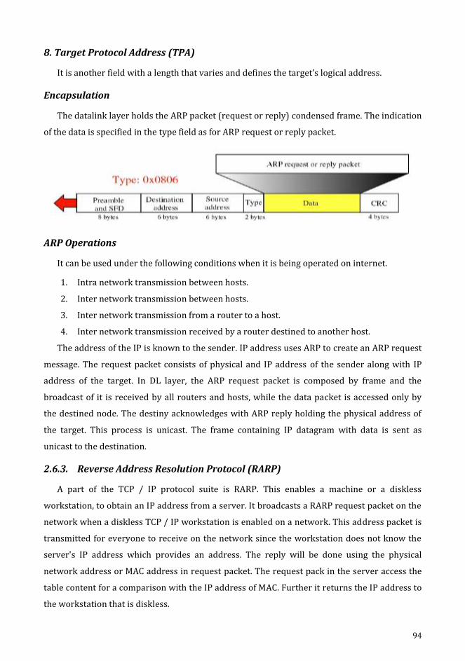
94
8. Target Protocol Address (TPA)
It is another field with a length that varies and defines the target’s logical address.
Encapsulation
The datalink layer holds the ARP packet (request or reply) condensed frame. The indication
of the data is specified in the type field as for ARP request or reply packet.
ARP Operations
It can be used under the following conditions when it is being operated on internet.
1. Intra network transmission between hosts.
2. Inter network transmission between hosts.
3. Inter network transmission from a router to a host.
4. Inter network transmission received by a router destined to another host.
The address of the IP is known to the sender. IP address uses ARP to create an ARP request
message. The request packet consists of physical and IP address of the sender along with IP
address of the target. In DL layer, the ARP request packet is composed by frame and the
broadcast of it is received by all routers and hosts, while the data packet is accessed only by
the destined node. The destiny acknowledges with ARP reply holding the physical address of
the target. This process is unicast. The frame containing IP datagram with data is sent as
unicast to the destination.
2.6.3. Reverse Address Resolution Protocol (RARP)
A part of the TCP / IP protocol suite is RARP. This enables a machine or a diskless
workstation, to obtain an IP address from a server. It broadcasts a RARP request packet on the
network when a diskless TCP / IP workstation is enabled on a network. This address packet is
transmitted for everyone to receive on the network since the workstation does not know the
server's IP address which provides an address. The reply will be done using the physical
network address or MAC address in request packet. The request pack in the server access the
table content for a comparison with the IP address of MAC. Further it returns the IP address to
the workstation that is diskless.

95
2.6.4. Internet Control Message Protocol (ICMP)
The ICMP intelligences error as well as control messages and they are sent to IP. ICMP
never makes IP reliable instead reports error and a feedback is provided for certain conditions.
ICMP designed to compensate these two deficiencies.
1. A host sometimes need to determine if a router host is alive.
2. Sometimes a network manager needs information from another host to router.
ICMP is a network layer protocol, its messages are not passed directly to the data link layer
as expected.
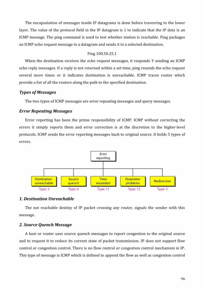
96
The encapsulation of messages inside IP datagrams is done before travesring to the lower
layer. The value of the protocol field in the IP datagram is 1 to indicate that the IP data is an
ICMP message. The ping command is used to test whether station is reachable. Ping packages
an ICMP echo request message in a datagram and sends it to a selected destination.
Ping 100.50.25.1
When the destination receives the echo request messages, it responds Y sending an ICMP
echo reply messages. If a reply is not returned within a set time, ping resends the echo request
several more times or it indicates destination is unreachable. ICMP traces routes which
provide a list of all the routers along the path to the specified destination.
Types of Messages
The two types of ICMP messages are error repeating messages and query messages.
Error Repeating Messages
Error reporting has been the prime responsibility of ICMP. ICMP without correcting the
errors it simply reports them and error correction is at the discretion to the higher-level
protocols. ICMP sends the error reporting messages back to original source. It holds 5 types of
errors.
1. Destination Unreachable
The not reachable destiny of IP packet crossing any router, signals the sender with this
message.
2. Source Quench Message
A host or router uses source quench messages to report congestion to the original source
and to request it to reduce its current state of packet transmission. IP does not support flow
control or congestion control. There is no flow control or congestion control mechanism in IP.
This type of message is ICMP which is defined to append the flow as well as congestion control

97
to IP. The source will be informed about the destruction of datagram. The source is further
instructed to quench its flow, as a congestion is identified at some place.
3. Time Exceeded Message
Two different cases are discussed under this type of message.
(1) The datagram with TTL 0 is destroyed and acknowledges with message that intimates
the source with exceed of time.
(2) The non-reception of fragments at the destiny in the stipulated time, sends a time
exceeded message to the source.
4. Parameter Problem Message
Header section of any datagram should be devoid of ambiguity. If any such indecision or
lost value is identified by a router or destination host, further the message is discarded and
intimated to sender.
5. Redirection Message
When a packet is transferred to another network, the next router's IP address should be
known. In order to find the address of the next router, an entry in routing table has to be
preserved in the router and also in the hosts, thereby routing table are continuously modified.
For each update, a redirection message is sent back to its host by ICMP.
Query Messages
The ICMP message can diagnose some of the network problems and such a diagnosis is
accomplished through the query messages. These messages are categorised as follows.
Echo Request and Reply
The prime focus of this message is diagnosis. They determine if two systems (hosts or
routers) communicates with one another.
Timestamp Request and Reply
These IP datagram holds the control over the circuit of the message visiting nodes. Clock
synchronization is also accomplished.
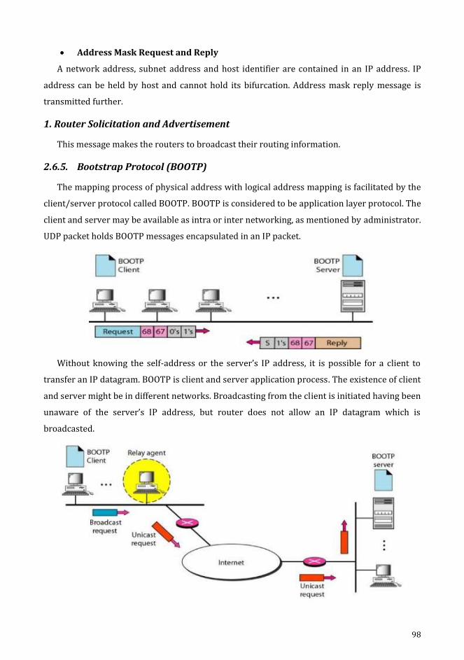
98
Address Mask Request and Reply
A network address, subnet address and host identifier are contained in an IP address. IP
address can be held by host and cannot hold its bifurcation. Address mask reply message is
transmitted further.
1. Router Solicitation and Advertisement
This message makes the routers to broadcast their routing information.
2.6.5. Bootstrap Protocol (BOOTP)
The mapping process of physical address with logical address mapping is facilitated by the
client/server protocol called BOOTP. BOOTP is considered to be application layer protocol. The
client and server may be available as intra or inter networking, as mentioned by administrator.
UDP packet holds BOOTP messages encapsulated in an IP packet.
Without knowing the self-address or the server’s IP address, it is possible for a client to
transfer an IP datagram. BOOTP is client and server application process. The existence of client
and server might be in different networks. Broadcasting from the client is initiated having been
unaware of the server’s IP address, but router does not allow an IP datagram which is
broadcasted.

99
Relay agent is the host employed to know the unicast address of a BOOTP server. The
packet received is encapsulated in unicast datagram and sent to the BOOTP server with
request. The packet with unicast address reaches the BOOTP server. The BOOTP server knows
the message coming from a relay agent because one of the fields in the request message
defines the IP address of the relay agent. The reply is received from the relay agent and
forwarded to BOOTP client.
2.6.6. Dynamic Host Configuration Protocol (DHCP)
The dynamic address allocation and also static address allocation are devised by DHCP
either manually or automatically.
Static Address Allocation
A host BOOTP client executing host requests for a static address from DHCP server, where
both are backward compatible. The Physical address and IP address are bound statically in a
database of DHCP server.
Dynamic Address Allocation
This DHCP client posts a request for temporary IP address, then the server checks with the
unused IP addresses in the pool and allocates an appropriate IP address for a specified
duration of time. When DHCP requests its server, it checks for static database. When the
address requested is present in the static database, then it’s permanent IP address is the
response message or if one such address is not present, it selects any available IP address and
assigns to client initially and appends this new notification in the dynamic database. The
address assigned from the pool is temporary address.

100
Manual and Automatic Configuration
Owing to change of physical address and IP address, manual configuration as well as
automatic configuration are used.
The manual config creates static address.
The automatic config creates dynamic address.
101
CHAPTER 3
3. Routing
Objectives
To understand about routing and its types.
To know about global internet IPv6.
To explain about unicast routing – RIP, OSPF, BGP.
To explain about multicast routing – MOSPF, DVMRP, RPF, RPB, RPM, CBT, PIM.
102
3. Routing
The means of creating routing tables to support forwarding is referred to as routing and
forwarding a packet means, it is supplied to station of its destiny. These protocols constantly
update the tables which holds the routing information for forwarding and routing consulted.
Routing Table
A host or path for every destined station, even it might be a mixture of destination to path
IP packets constitutes routing table. The routing table might be static otherwise it might be
dynamic.
Static Routing Table
Here, the details are entered manually. For each destination, the manager marks the route
in the table. If any table is built, it cannot be changed automatically when the internet change.
Administration has to manually alter the table.
Dynamic Routing Protocols
These protocols use a table that is updated occasionally by protocols such as RIP, OSPF or
BGP. The tables of the routers are updated automatically by dynamic routing protocols when
there is a shift in the Internet, such router shutdown or the infringement of connection.
3.1. Unicast Routing Protocols
A routing table can be made static or dynamic.
A static table holds manual entries.
A dynamic table holds information that is routinely changed anywhere on the internet
if there is a change.
Routing protocols are developed based on the response to the demand for expressing
dynamism.
The routing protocol combines the rules and procedures which allow routers to inform
each other on the Internet.
Optimization
In general, a packet is received at the router from the network and then transferred to a
different one. Metric stays organised in order that cost is assigned to pass through the
network. The type of protocol decides the metric that is assigned to each network.

103
Intra and Inter-domain Routing
From a network, a router receives a packet and transfers it to another network. Typically, a
single router has connections to many networks. The metric is thrown into assigning the
passage of network expense. Depending on the type of protocol, metrics are allocated to each
network.
The internet is divided into autonomous structures. Under the influence of a single
administration, a set of networks and routers forms the autonomous appliance.
In the autonomous system, routing table is called inter-domain routing. Intra-domain
routing is known as routing between autonomous systems. One or more intra-domain routing
protocols can be chosen by each independent system to handle routing within system
possessing autonomy.
Only one inter-domain routing protocol does routing between autonomous systems.

104
3.1.1. Distance Vector Routing
The minimum weighted route is the minimum cost path between the nodes in distance
vector routing.
A table of vectors with least distance to each node is maintained at each node.
The packets to the desired node are also guided by the table of each node by displaying
further hop routing on the path.
Initialization
The cost or way to reach a node is known by every node. Any node knows the distance
from self to its adjacent node that are directly connected to it.
In order to find the distance between their neighbours and themselves, each node will
send a message to their immediate neighbours.
For any entry that is not a neighbour, then the distance noted to be infinite or
unreachable.

105
Sharing
In the routing of distance vectors, whenever there is a shift, the adjacent node of each
one can get their table entry regularly.
Information sharing between neighbours is the whole principal of vector distance
routing.
If Node A is unaware of the E node but node C can and this C node can share its routing
table with A, therefore node A can reach node E as well.
If they render support each other, then the nodes A and C will boost their routing tables
as immediate neighbours.
Updating
If the two nodes receive the neighbouring two-column table, its routing table needs to
be modified.
There are 3 steps while updating.
In the second column, the receiver must append the cost of any value between itself
and the transmitting node.
If the receiving node uses information from another row, the name of the sender is
added to the third column of every row by the receiver.
The send node will be the next node in the path.
Each row of the previous table has been compared with the appropriate row of the
amended table edition by the receiving node.
The receiver selects the row with the smallest cost if the next node entry is different. If
both remains, the previous node will be held.
A new row is chosen by the receiver, while the forthcoming station has the same
marking.
By using the tables obtained from other nodes, each node will update its table.
106
When to Share
Periodic update: Routing table is sent by A node through a constant update of 30's. The
duration depends on the protocol which uses the routing of distance vectors.
Triggered update: Whenever a shift is encountered in its routing table, the neighbours
receive a routing table with 2 columns from a node. This upholds the update trigger process.
3.1.1.1. Routing Information Protocol (RIP)
This follows a methodology that implements routing within an autonomous system.
Centred around distance vector routing, this seems to be a very simple protocol. It
specifically incorporates distance vector routing with the same specifications:
Routers as well as networks are dealt in an autonomous system. Routing tables are
found in routers where in networks it is missing.
Routing table refers a network address that is specified in the first column.
3.1.2. Link State Routing
The RIP uses a very simple metric, the number of links (networks) represent the
distance to reach the destination. In RIP, this metric is referred as count of hops.
16 is specified instead of infinity, meaning which chosen route may not have more than
15 hops in an autonomous system using RIP.
The destination address is specified by the next node column.
The routing table of a node can be constructed by the Dijkstra algorithm when each
node in a domain contains the complete domain’s topology, the list of nodes, links and
the connection types, the metrics used, and link condition.
This table is unique for every node even though it uses similar topology, because
dissimilar understandings are used in calculating the topology.
The topology of each node and connexion must be dynamic, reflecting the latest state.
The topology must be changed for each node if there are adjustments at some point in
the network.

107
Somewhere in the network, the understanding of the topology at the start or post transit is
not possible.
Each node has partial knowledge of its relationship to the state in terms of type, cost and
condition.
Building Routing Tables
The 4 action sets are the requisites of link state routing in order that the routing table.
Link state routing requires four sets of actions in order that the table containing routing
data of every part indicates the least costly node for any other node.
1. Link state packet (LSP) is the creation of states by the links of each node.
2. Effectively and efficiently disseminate LSP to any other router named flood.
3. Forms the shortest tree path for every node.
4. Routing table calculation is determined by the tree which holds the quick routes.
1. Creation of LSP
The LSP can carry large amount of information.
Example: It carries minimum amount of data, a list of links, a sequence number and
age, the node identity 1.
The identity of the first two nodes and list of links are required to form a topology.
A new LSP is set apart from older ones, because flooding is encouraged by the 3rd
sequence number.
The old LSP is avoided staying long in the domain due to the 4th era.
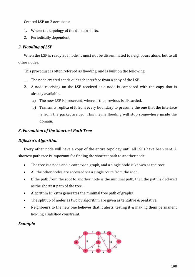
108
Created LSP on 2 occasions:
1. Where the topology of the domain shifts.
2. Periodically dependent.
2. Flooding of LSP
When the LSP is ready at a node, it must not be disseminated to neighbours alone, but to all
other nodes.
This procedure is often referred as flooding, and is built on the following:
1. The node created sends out each interface from a copy of the LSP.
2. A node receiving an the LSP received at a node is compared with the copy that is
already available.
a) The new LSP is preserved, whereas the previous is discarded.
b) Transmits replica of it from every boundary to presume the one that the interface
is from the packet arrived. This means flooding will stop somewhere inside the
domain.
3. Formation of the Shortest Path Tree
Dijkstra’s Algorithm
Every other node will have a copy of the entire topology until all LSPs have been sent. A
shortest path tree is important for finding the shortest path to another node.
The tree is a node and a connexion graph, and a single node is known as the root.
All the other nodes are accessed via a single route from the root.
If the path from the root to another node is the minimal path, then the path is declared
as the shortest path of the tree.
Algorithm Dijkstra generates the minimal tree path of graphs.
The split up of nodes as two by algorithm are given as tentative & pentative.
Neighbours to the new one believes that it alerts, testing it & making them permanent
holding a satisfied constraint.
Example

109
Pass 1: Pass 2:
Pass 3: Pass 4:
Pass 5:
Routing Table Calculation
Each node builds its table using the shortest tree path protocol.
The routing table indicates the cost from the root to reach each node.
Node Cost Next Router
A 0 -
B 5 -
C 2 -
D 3 -
E 6 C
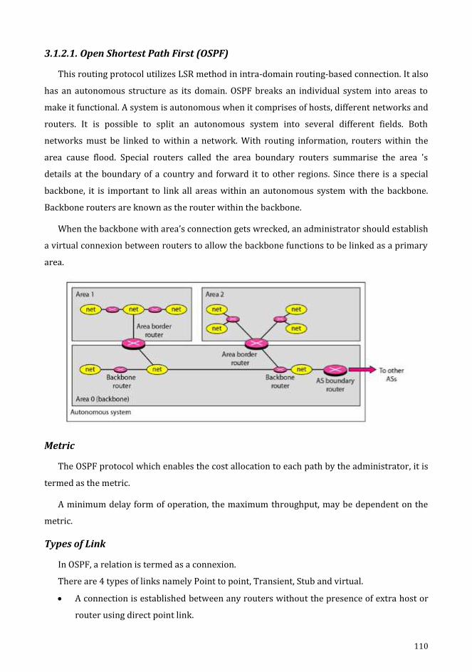
110
3.1.2.1. Open Shortest Path First (OSPF)
This routing protocol utilizes LSR method in intra-domain routing-based connection. It also
has an autonomous structure as its domain. OSPF breaks an individual system into areas to
make it functional. A system is autonomous when it comprises of hosts, different networks and
routers. It is possible to split an autonomous system into several different fields. Both
networks must be linked to within a network. With routing information, routers within the
area cause flood. Special routers called the area boundary routers summarise the area 's
details at the boundary of a country and forward it to other regions. Since there is a special
backbone, it is important to link all areas within an autonomous system with the backbone.
Backbone routers are known as the router within the backbone.
When the backbone with area’s connection gets wrecked, an administrator should establish
a virtual connexion between routers to allow the backbone functions to be linked as a primary
area.
Metric
The OSPF protocol which enables the cost allocation to each path by the administrator, it is
termed as the metric.
A minimum delay form of operation, the maximum throughput, may be dependent on the
metric.
Types of Link
In OSPF, a relation is termed as a connexion.
There are 4 types of links namely Point to point, Transient, Stub and virtual.
A connection is established between any routers without the presence of extra host or
router using direct point link.

111
A network getting attached with several routers form a transient link.
The data is allowed to enter or move off from a routing device.
If a network has no other router connector except one, that network is referred as a
stub connection.
Entry and exit of data packets from the network are done using only one router.
The administration can establish a virtual link when the connection with two routers
get damaged. It uses the longest path that possibly visits many other routers.
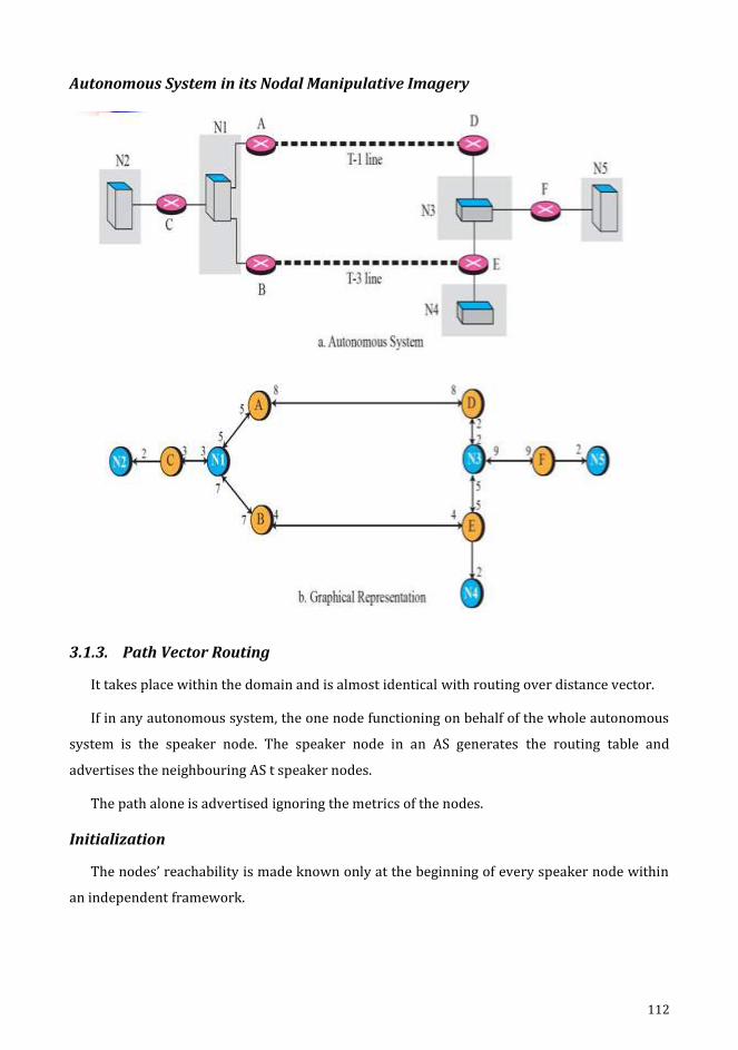
112
Autonomous System in its Nodal Manipulative Imagery
3.1.3. Path Vector Routing
It takes place within the domain and is almost identical with routing over distance vector.
If in any autonomous system, the one node functioning on behalf of the whole autonomous
system is the speaker node. The speaker node in an AS generates the routing table and
advertises the neighbouring AS t speaker nodes.
The path alone is advertised ignoring the metrics of the nodes.
Initialization
The nodes’ reachability is made known only at the beginning of every speaker node within
an independent framework.
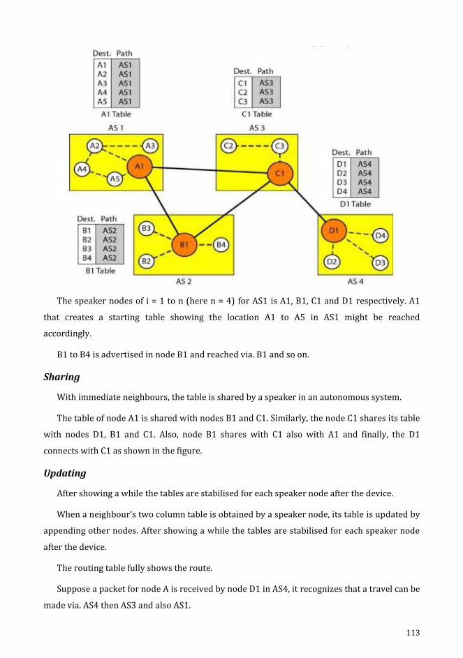
113
The speaker nodes of i = 1 to n (here n = 4) for AS1 is A1, B1, C1 and D1 respectively. A1
that creates a starting table showing the location A1 to A5 in AS1 might be reached
accordingly.
B1 to B4 is advertised in node B1 and reached via. B1 and so on.
Sharing
With immediate neighbours, the table is shared by a speaker in an autonomous system.
The table of node A1 is shared with nodes B1 and C1. Similarly, the node C1 shares its table
with nodes D1, B1 and C1. Also, node B1 shares with C1 also with A1 and finally, the D1
connects with C1 as shown in the figure.
Updating
After showing a while the tables are stabilised for each speaker node after the device.
When a neighbour’s two column table is obtained by a speaker node, its table is updated by
appending other nodes. After showing a while the tables are stabilised for each speaker node
after the device.
The routing table fully shows the route.
Suppose a packet for node A is received by node D1 in AS4, it recognizes that a travel can be
made via. AS4 then AS3 and also AS1.
114
Loop Prevention
Path vector routing helps in avoiding the loops formation as well the unpredictability
caused by the distance vector routing. A monitor is performed to all packets received to verify
whether the autonomous system is found at the destination path. The message will be
overlooked if looping is required.
Policy Routing
It is easy to implement based on path vector routing. It can check the path when a router
receives a message. A path and its destination are ignored only if the path violates the policy.
With this route, it does not both update its routings and no message is sent to its neighbour.
Optimum Path
Optimum path always suits a company. Every autonomous system can have many routes to
reach the destination.
3.1.3.1. Border Gateway Protocol (BGP)
It is an inter-domain routing protocol which uses path vector routing.
Types
The internet canbe divided into autonomous structures called hierarchical domains. An
autonomous system is the local ISP which is responsible for providing services to local
customers.
It is categorised into 3 types namely Stub, Multi-homed and Transit.
Stub
A separate AS relates to a stub in inter domain traffic which is created otherwise completed
in stub.
The traffic is sent from hosts of AS to next ASs for data. Data traffic won’t be able to pass
through a stub AS. The AS stub can either be a source or sink.
Multi-homed
A multi-homed AS possess more connectivity with another.
AS without data traffic is termed just as a sink or otherwise source. The data traffic
observed from other AS is received and it transmits data traffic over to other ASs, it shows non-
existence of transient data. It does not allow data to move through from one AS and go to
another AS.
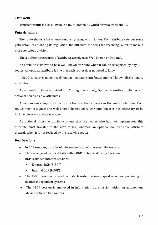
115
Transient
Transient traffic is also allowed in a multi-homed AS which forms a transient AS.
Path Attribute
The route shows a list of autonomous systems, or attributes. Each attribute sets out some
path detail. In enforcing its regulation, the attribute list helps the receiving router to make a
more conscious division.
The 2 different categories of attributes are given as Well known or Optional.
An attribute is known to be a well-known attribute when it can be recognised by any BGP
router. An optional attribute is one that each router does not need to know.
It has 2 categories namely well known mandatory attributes and well known discretionary
attributes.
An optional attribute is divided into 2 categories namely, Optional transitive attributes and
optional non transitive attributes.
A well-known compulsory feature is the one that appears in the route definition. Each
router must recognise one well-known discretionary attribute, but it is not necessary to be
included in every update message.
An optional transitive attribute is one that the router who has not implemented this
attribute must transfer to the next router, whereas, an optional non-transitive attribute
discards when it is not realized by the receiving router.
BGP Sessions
In BGP sessions, transfer of information happens between the routers.
The exchange of router details with 2 BGP routers is done by a session.
BGP is divided into two sessions:
External BGP (E-BGP)
Internal BGP (I-BGP)
The E-BGP session is used in data transfer between speaker nodes pertaining to
distinct independent systems.
The I-BGP session is employed in information transmission within an autonomous
device between two routers.
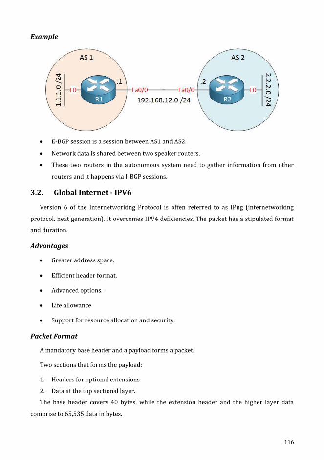
116
Example
E-BGP session is a session between AS1 and AS2.
Network data is shared between two speaker routers.
These two routers in the autonomous system need to gather information from other
routers and it happens via I-BGP sessions.
3.2. Global Internet - IPV6
Version 6 of the Internetworking Protocol is often referred to as IPng (internetworking
protocol, next generation). It overcomes IPV4 deficiencies. The packet has a stipulated format
and duration.
Advantages
Greater address space.
Efficient header format.
Advanced options.
Life allowance.
Support for resource allocation and security.
Packet Format
A mandatory base header and a payload forms a packet.
Two sections that forms the payload:
1. Headers for optional extensions
2. Data at the top sectional layer.
The base header covers 40 bytes, while the extension header and the higher layer data
comprise to 65,535 data in bytes.
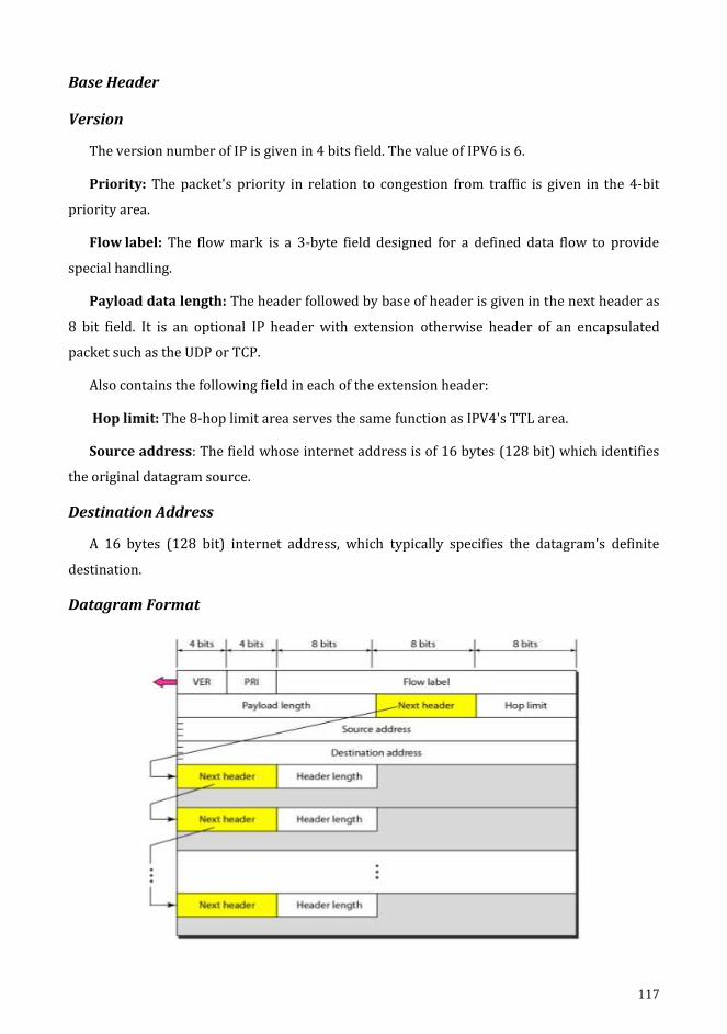
117
Base Header
Version
The version number of IP is given in 4 bits field. The value of IPV6 is 6.
Priority: The packet's priority in relation to congestion from traffic is given in the 4-bit
priority area.
Flow label: The flow mark is a 3-byte field designed for a defined data flow to provide
special handling.
Payload data length: The header followed by base of header is given in the next header as
8 bit field. It is an optional IP header with extension otherwise header of an encapsulated
packet such as the UDP or TCP.
Also contains the following field in each of the extension header:
Hop limit: The 8-hop limit area serves the same function as IPV4's TTL area.
Source address: The field whose internet address is of 16 bytes (128 bit) which identifies
the original datagram source.
Destination Address
A 16 bytes (128 bit) internet address, which typically specifies the datagram's definite
destination.
Datagram Format

118
Base Header and Payload Format
Priority
The IPV6 packet's priority field determines each packet's priority over other packets comin
g from the same source.
There are 2 types of traffics are given below:
a. Congestion controlled traffic
b. Non-congestion controlled traffic
a) Congestion Controlled Traffic
Congestion controlled traffic is referred as whenever a congestion is encountered and
the source can adapt to slowdown of traffic.
TCP protocol too could respond quickly to traffic by means of the sliding window
protocol.
It is easy to understand that delayed, misplaced or out of order packets will arrive.
Priority Meaning
1. No specific traffic
2. Background data
3. Unattended data traffic
4. Reserved
5. Attended bulk data traffic
6. Reserved
7. Interactive traffic
8. Control traffic

119
b) Non Congestion Controlled Traffic
This can be applied to the traffic predicted as causing minimal delayed.
Usually, the packets are discarded based on priorities and consistency of the data obtained.
Eg: video and audio.
Data with less redundancy can have a higher priority (15) and a lower priority (8) can be
provided by more redundancy.
Flow Label
A packet flow is called a series of data packs transmitted between a specific source and
destined node which requires a peculiar management of router.
The packet flow is uniquely determined by the combination of source address and flow
label value.
3.3. Multicast Link State Routing
Multicast routing are emerged with the extensions of unicast routing protocols.
3.3.1. Multicast Open Shortest Path First (MOSPF)
The source-oriented tree approach is employed in multicast link state routing. Multicast
open shortest path first (MOSpF) protocol is an extension of OSPF protocol that uses the
routing of multicast link state to create source based trees.
To attach a host’s unicast address with the address of the group or addresses that the host
supports, the protocol needs a new state of update packet. This is called the group membership
LSA. Only the hosts that belong to a specific group are included in the tree. The efficiency of the
trees shortest path is calculated on request by router.
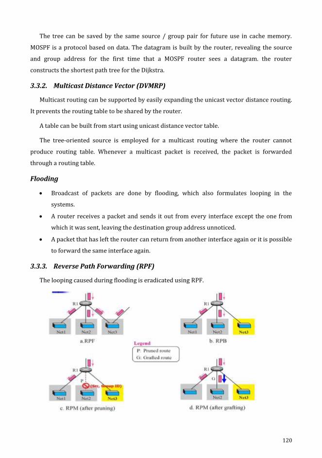
120
The tree can be saved by the same source / group pair for future use in cache memory.
MOSPF is a protocol based on data. The datagram is built by the router, revealing the source
and group address for the first time that a MOSPF router sees a datagram. the router
constructs the shortest path tree for the Dijkstra.
3.3.2. Multicast Distance Vector (DVMRP)
Multicast routing can be supported by easily expanding the unicast vector distance routing.
It prevents the routing table to be shared by the router.
A table can be built from start using unicast distance vector table.
The tree-oriented source is employed for a multicast routing where the router cannot
produce routing table. Whenever a multicast packet is received, the packet is forwarded
through a routing table.
Flooding
Broadcast of packets are done by flooding, which also formulates looping in the
systems.
A router receives a packet and sends it out from every interface except the one from
which it was sent, leaving the destination group address unnoticed.
A packet that has left the router can return from another interface again or it is possible
to forward the same interface again.
3.3.3. Reverse Path Forwarding (RPF)
The looping caused during flooding is eradicated using RPF.
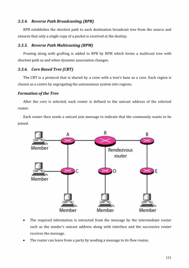
121
3.3.4. Reverse Path Broadcasting (RPB)
RPB establishes the shortest path to each destination broadcast tree from the source and
ensures that only a single copy of a packet is received at the destiny.
3.3.5. Reverse Path Multicasting (RPM)
Pruning along with grafting is added to RPB by RPM which forms a multicast tree with
shortest path as and when dynamic association changes.
3.3.6. Core Based Tree (CBT)
The CBT is a protocol that is shared by a crew with a tree’s base as a core. Each region is
chosen as a centre by segregating the autonomous system into regions.
Formation of the Tree
After the core is selected, each router is defined to the unicast address of the selected
router.
Each router then sends a unicast join message to indicate that the community wants to be
joined.
The required information is extracted from the message by the intermediate router
such as the sender's unicast address along with interface and the successive router
receives the message.
The router can leave from a party by sending a message to its flow routes.
122
Sending Multicast Packets
Any source can send a multicast packet to all members of the community after the
creation of the tree.
The packet is then sent to the rendezvous router via the rendezvous unicast address;
then distributes the packets to all community members.
Any hosts within or outside the shared tree may act as the source host.
Selecting the Appropriate Router
The following is the procedure to send packet from the source to the community members:
1. In multicast encapsulation, the part of the tree can either contain the root or not. With
unicast destination address, the packet can be sent to the centre of the core.
Using the unicast address, this part of distribution is done; the core router is the only re
ceiver.
2. Decapsulation of the unicast packet is done at the centre and interfaces that are
concerned will have or may receive.
3. The routers receiving the multicast packet, forwards them all to the interested
interfaces.
3.3.7. Protocol Independent Multicast (PIM)
The PIM has 2 independent multicast routing protocols:
a. PIM DM - Protocol Independent Multicast, the Dense Mode.
b. PIM SM - Protocol Independent Multicast, the Sparse Mode.
a) PIM DM
PIM-DM is employed when each router needs to engage in multicasting (dense mode).
It is a type of protocol that prefers tree routing using strategies such as multicasting
RPF with pruning and grafting.
DVMRP's service is almost identical with PIMDM.
Unicast protocol is used by independent system. A protocol and a table are contained in
each router that helps in identifying or seeking an ideal path to destination for the
outgoing interface.
This unicast protocol can be either a RIP or OSPF.

123
b) PIM SM
The usage of PIM-SM is where there is very less multicasting (sparse mode), such as
WAN, for each router.
The CBT protocol that uses a group-shared tree that is not justified by the protocol by
which the packet is broadcasted.

124
CHAPTER 4
4. Transport Layer
Objectives
• To recognize the transport layer.
• Illustrating the definition of TCP, UDP and SCTP.
• Learning about congestion management and its forms in order to prevent congestion.
• To consider the standard of service (QOS) and its characteristics.
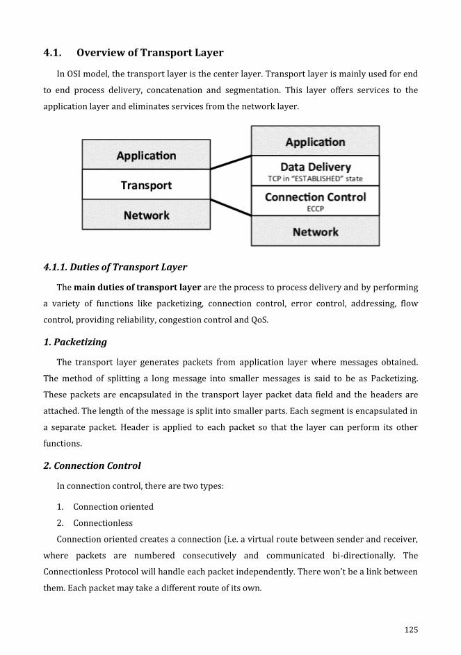
125
4.1. Overview of Transport Layer
In OSI model, the transport layer is the center layer. Transport layer is mainly used for end
to end process delivery, concatenation and segmentation. This layer offers services to the
application layer and eliminates services from the network layer.
4.1.1. Duties of Transport Layer
The main duties of transport layer are the process to process delivery and by performing
a variety of functions like packetizing, connection control, error control, addressing, flow
control, providing reliability, congestion control and QoS.
1. Packetizing
The transport layer generates packets from application layer where messages obtained.
The method of splitting a long message into smaller messages is said to be as Packetizing.
These packets are encapsulated in the transport layer packet data field and the headers are
attached. The length of the message is split into smaller parts. Each segment is encapsulated in
a separate packet. Header is applied to each packet so that the layer can perform its other
functions.
2. Connection Control
In connection control, there are two types:
1. Connection oriented
2. Connectionless
Connection oriented creates a connection (i.e. a virtual route between sender and receiver,
where packets are numbered consecutively and communicated bi-directionally. The
Connectionless Protocol will handle each packet independently. There won't be a link between
them. Each packet may take a different route of its own.
126
3. Addressing
The client needs the address of the remote machine that the client wants to connect with.
Here, the remote computer has a unique address so that it can be distinguished from the ability
to connect with the remote computer.
4. Providing Reliability
Flow management and error detection should be implemented for high reliability.
5. Flow Control
Flow control always happened from end to end delivery rather than via a single connection.
6. Error Control
Error correction can be accomplished by retransmission.
7. Congestion Control and QOS
The transport layer may allow the user to define the desired, appropriate and minimum
value of the different service parameters when setting up a connection.
Connection establishment relay
Connection establishment failure
Throughput
Transit delay
Protection
Resident error ratio
Priority
Residence
4.1.2. Quality of Service (QOS)
The QOS parameters are:
1. Connection Establishment Delay
The delay time between the instant at which a transport connection is sought and the
instant at which it is accepted is called the connection establishment delay. The shorter the
gap, the better the service is. It's the likelihood of a connection.
127
2. Connection Establishment Failure Probability
It is probable that the link will not be formed even after the maximum link has been
delayed. This could be due to network congestion, lack of table space, or any other issues.
3. Throughput
It measures the number of bytes of user data transmitted per second, calculated over a
period of time. It is calculated for each direction separately.
4. Transit Delay
It is time for a message to be sent to the source computer by the transport user and
received by the transport layer.
5. Residual Error Ratio
It calculates the amount of lost or clogged messages as a function of the total number of
messages sent. The value of this ratio should be zero and as small as possible.
6. Protection
This parameter provides a way to protect the transmitted data from being read or changed
by unauthorized parties.
7. Priority
It provides a way for the user to demonstrate that some of its connections are more
important than others, while managing congestion. Since service should be provided higher
priority than low priority connections.
8. Resilience
The transport layer spontaneously terminates the connection due to internal problems or
congestion. The resilience parameter lowers the chances of such termination.
4.1.3. Sockets
The socket specifies a series of system calls or procedures that function as an interface. The
socket also serves as an end point where two processes will interact if and only if and only if
they have a socket at either end.
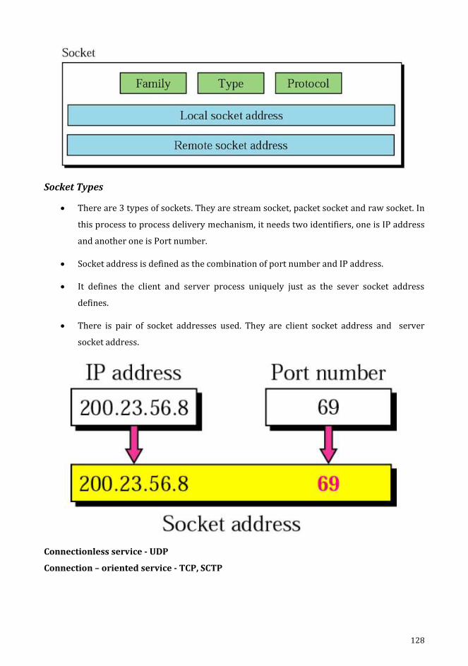
128
Socket Types
There are 3 types of sockets. They are stream socket, packet socket and raw socket. In
this process to process delivery mechanism, it needs two identifiers, one is IP address
and another one is Port number.
Socket address is defined as the combination of port number and IP address.
It defines the client and server process uniquely just as the sever socket address
defines.
There is pair of socket addresses used. They are client socket address and server
socket address.
Connectionless service - UDP
Connection – oriented service - TCP, SCTP
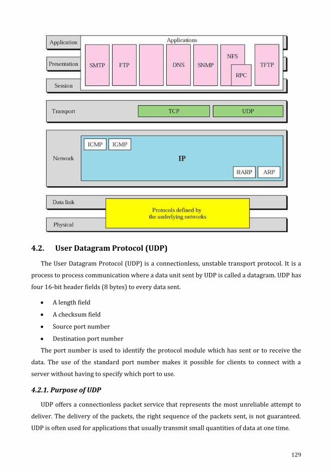
129
4.2. User Datagram Protocol (UDP)
The User Datagram Protocol (UDP) is a connectionless, unstable transport protocol. It is a
process to process communication where a data unit sent by UDP is called a datagram. UDP has
four 16-bit header fields (8 bytes) to every data sent.
A length field
A checksum field
Source port number
Destination port number
The port number is used to identify the protocol module which has sent or to receive the
data. The use of the standard port number makes it possible for clients to connect with a
server without having to specify which port to use.
4.2.1. Purpose of UDP
UDP offers a connectionless packet service that represents the most unreliable attempt to
deliver. The delivery of the packets, the right sequence of the packets sent, is not guaranteed.
UDP is often used for applications that usually transmit small quantities of data at one time.

130
It also distinguishes between multiple programs running on a single computer. Each UDP
message includes both a destination port number and a source port number. This helps to
make UDP applications accessible at the destination to send a message to the current program
and to send a reply to the application program. The UDP header is divided into four 16 bits.
1. Source Port
This port is an optional field that indicates the sending process port and the reply to the
address of absence portion. It is said to be not interested when O is not used.
2. Destination Port
The destination port has significance of a specific destination IP address.
3. Length
This field denotes the size of the UDP packet bytes; it includes the header and the data. The
minimum length of the header is 8 bytes.
4. UDP Checksum
It is used to check the consistency of the UDP header. The pseudo code header is used to
carry the checksum. It consists of data from source and destination with IP header and the UDP
header.
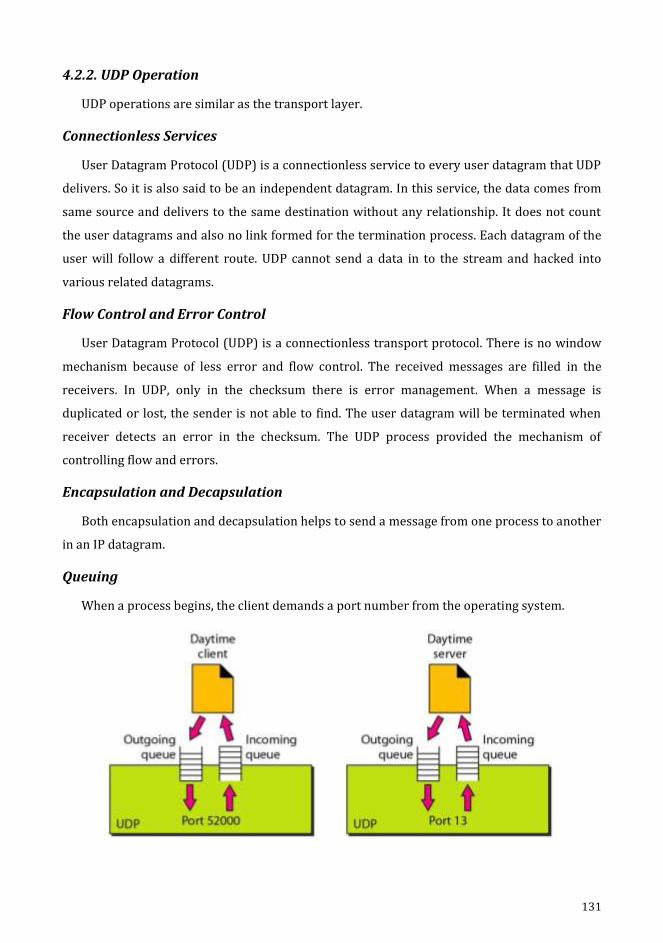
131
4.2.2. UDP Operation
UDP operations are similar as the transport layer.
Connectionless Services
User Datagram Protocol (UDP) is a connectionless service to every user datagram that UDP
delivers. So it is also said to be an independent datagram. In this service, the data comes from
same source and delivers to the same destination without any relationship. It does not count
the user datagrams and also no link formed for the termination process. Each datagram of the
user will follow a different route. UDP cannot send a data in to the stream and hacked into
various related datagrams.
Flow Control and Error Control
User Datagram Protocol (UDP) is a connectionless transport protocol. There is no window
mechanism because of less error and flow control. The received messages are filled in the
receivers. In UDP, only in the checksum there is error management. When a message is
duplicated or lost, the sender is not able to find. The user datagram will be terminated when
receiver detects an error in the checksum. The UDP process provided the mechanism of
controlling flow and errors.
Encapsulation and Decapsulation
Both encapsulation and decapsulation helps to send a message from one process to another
in an IP datagram.
Queuing
When a process begins, the client demands a port number from the operating system.
132
The incoming and outgoing queue is generated for each operation. When several number of
systems are connected with a process: port number, one incoming and one outgoing queues
will be generated. The queues will be killed, once process ended. The outgoing queue is used to
send message to the client using source port numbers. One by one the messages will be
removed by UDP after delivering them to IP after inserting the UDP header. The outgoing
queue can overflow. When a message receives at a client side, UDP immediately checks the
incoming queue whether the port number has been generated in the field of destination port
number of the user datagram. Once UDP receives the user datagram, the unreachable port
message will be send to the server from ISMP protocol. All the incoming messages from same
or different server are sent to the queue. After receiving the message at UDP server, it verifies
the port number of user datagram destination port number at incoming queue. At the end of
the queue, UDP sends an acknowledgement of receiving datagram. UDP terminates the user
datagram if there is no queue. Finally ICMP sends an unreachable request to the client. All the
incoming messages from same or different client are sent to the same queue. UDP removes the
message one by one and delivers those messages to the IP after inserting the UDP header.
4.2.3. Advantages of UDP
The process like simple request, flow control and error management are supported by
UDP.
Multicasting is also supported by UDP transport layer.
It also supports controlling process like SNMP.
It uses updating protocols for certain routes like RIP.
It is also suitable for internal flow and error management processes.
4.3. Transmission Control Protocol (TCP)
Transmission Control Protocol (TCP) is a process to process or program to program
protocol. It is a link oriented protocol where port numbers are used in TCP. Virtual connection
is established for data transmission between two TCPs. It uses an error management system
and flow control in the transport layer. This TCP protocol is always a secure transport protocol
because of connectivity-oriented and it provides reliable features to IP services.
4.3.1. TCP Services
Process to process communication is provided by port numbers in TCP. These are list of
well-known port numbers used by TCP.

133
Port Protocol Description
7 echo echoes a received/send back
9 discard discards received datagram
11 users active users
13 daytime returns day/ time
17 quote returns quote
19 chargen returns string of character
20 FTP, data File Transfer Protocol/ data
21 FTP, control File Transfer Protocol/control
23 TELNET Terminal Network
25 SMTP Simple Mail Transfer Protocol
53 DNS Domain Name Server
67 BOOTP Bootstrap Protocol
79 Finger Finger
80 HTTP HyperText Transfer Protocol
111 RPC Remote Procedure Call
Stream Delivery Service
Transmission Control Protocol (TCP) is a streaming protocol which helps to send the data
to convey using stream of bytes and enables to receive data as a stream of bytes. An imaginary
tube is used to carry the data between two processes over the internet. This imaginary
environment is used to send a mechanism that generates to write or read the stream of bytes
over the sending/receiving device.

134
Sending and Receiving Buffers
The write or read operation over data cannot be done at the same speed in sending and
receiving process. Buffers are using in TCP for storage. There are mainly 2 buffers used in TCP,
one is used for sending buffer and the receiving buffer and another is used to implement a
buffer is to use a 1 byte location circular array.
There are 3 chambers of buffer used at the sending side; they are white section, gray
section, and colored section. Empty chambers are filled by sending process in white section.
The sent data which is not recognized are presented in grey area by bytes. TCP holds these
bytes in the buffer till the acknowledgment receives. The sent data by the sender are
presented in the colored area. At the receiver side the operation will be completed easily.
There are 2 areas in the circular buffer; they are white and colored. The empty chambers are
filled by bytes in the white buffer which is obtained by the network. The received bytes are
read by the receiver side and filled in the empty chamber in colored buffer area. The chamber
is returned and recycled to the empty chamber area, once the byte is read at the receiving
process.
Segments
An empty chamber which is obtained from network is filled by bytes in the white buffer. All
the received bytes in receiving methods are read in colored segment. The chamber is returned
and recycled to the empty chamber area, once the byte is read at the receiving process.

135
Full Duplex Communication
In this communication, TCP offers data flow in both direction and at also at the same time.
In both the direction TCP buffer sends and receives the segments.
Connection Oriented Service
In a TCP, if one process needs to send and receive the data from the next process, there
establishes a two connection between them. They are,
1. In both directions, data to be exchanged.
2. Connection termination.
It is a stream oriented environment and it acknowledges the distributing bytes to its
destination. In an IP datagram, if the TCP segment is encapsulated the data can be misplaced,
corrupted or sent out of order and then it should be resented. Different paths can be used to
reach the destination.
Reliable Service
TCP is always said to be a secured protocol for transporting services. It detects and verifies
the arrival of data and its safety.
4.3.2. TCP Features
Number System
TCP is used to track the segment number in the header for both the sent and received
segments. Acknowledgment number and Sequence number are the two fields in the segment
header.

136
Byte Number
TCP numbers the transmitted bytes of data to each link. The numbering begins with a
number generated at random. They're stored in the send buffer and counted.
Sequence Number
Once the bytes numbered, sequence number will be assigned to each segment by the TCP.
In that segment, sequence number is the first byte number for each segment. Combination of
both control and data information uses the sequence number in each section. When there is no
data in the segment, sequence number will not be defined. The receiver should have a
sequence number when it has control information to acknowledge it.
Acknowledgement Number
The acknowledgement number will be used by the sender and also receiver site to confirm
the received bytes. The acknowledgment number should be given to the next byte information
to be received. Cumulative acknowledgement gives the received number of last byte.
Flow Control
Flow control uses byte-oriented. The sum of data which is transmitted by the sender is
monitored by data receiver.
Error Control
Error control is byte-oriented. Errors are detected by data unit segments.
Congestion Method
The sender’s data will be governed by the receiver and in network it is also measured by
the degree of congestion.
Source Port Address
This address is the 16-bit field. It is used to specify the port number where the host sends
the application in the section.
Destination Port Address
This address is the 16-bit field. It is used to determine the port number where the host
receives the application in the section.
Sequence Number
It is the 32-bit field. It is used to determine the first data byte and also the destination.
Initial Sequence Number (ISN) is generated by random number generator for each parity in
different direction.
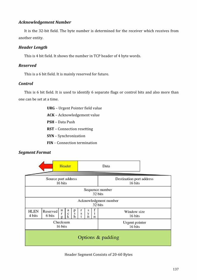
137
Acknowledgement Number
It is the 32-bit field. The byte number is determined for the receiver which receives from
another entity.
Header Length
This is 4 bit field. It shows the number in TCP header of 4 byte words.
Reserved
This is a 6 bit field. It is mainly reserved for future.
Control
This is 6 bit field. It is used to identify 6 separate flags or control bits and also more than
one can be set at a time.
URG – Urgent Pointer field value
ACK – Acknowledgement value
PSH – Data Push
RST – Connection resetting
SYN – Synchronization
FIN – Connection termination
Segment Format
Header Segment Consists of 20-60 Bytes
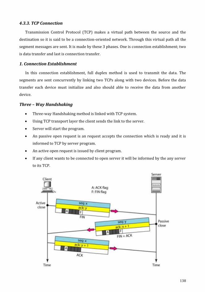
138
4.3.3. TCP Connection
Transmission Control Protocol (TCP) makes a virtual path between the source and the
destination so it is said to be a connection-oriented network. Through this virtual path all the
segment messages are sent. It is made by these 3 phases. One is connection establishment; two
is data transfer and last is connection transfer.
1. Connection Establishment
In this connection establishment, full duplex method is used to transmit the data. The
segments are sent concurrently by linking two TCPs along with two devices. Before the data
transfer each device must initialize and also should able to receive the data from another
device.
Three – Way Handshaking
Three-way Handshaking method is linked with TCP system.
Using TCP transport layer the client sends the link to the server.
Server will start the program.
An passive open request is an request accepts the connection which is ready and it is
informed to TCP by server program.
An active open request is issued by client program.
If any client wants to be connected to open server it will be informed by the any server
to its TCP.

139
There are 3 steps in this phase,
SYN segment – It consumes one sequence number and it does not carry any data.
SYN +ACK – It does consume one sequence number and it does not carry any data.
ACK segment - It does not consume one sequence number and data.
2. Data Transfer
Bi-directional data transfer can take place after the link has been formed. Both the client
and the server will submit data and acknowledgements. The receipts are piggybacked with the
results.
3. Connection Termination
Link termination uses their way or four-way handshaking. The FIN segment consumes one
sequencing number if it does not carry data. The FIN+ACK segment consumes one sequencing
number if it does not carry data.
4.3.4. Flow Control
TCP uses a sliding window to control the movement. The sliding window protocol used by
TCP is between Go-back N and selective sliding repeat window. It is byte-oriented and variable
size fixed.
The window covers a portion of the buffer containing the bytes obtained from the method.
Bytes in the window can transit and also sent without acknowledgement. The two wall on the
left and right side acts like an imaginary window. It carries out three activities: opened, closed,
and reduced. In these operations, the receiver instructions should be followed by the sender.
The windows opened by shifting the right wall to the right side. The windows closed by
shifting the left wall to the right. The window shrinks by shifting the right wall to the left. The

140
left wall moves only if it receives an acknowledgement from the previous one. The size of the
window is determined at the one end and it should be lesser than two values.
1. Receiver window (rwnd)
2. Congestion window (cwnd)
Acknowledgement section at the opposite ends value is marked at the receiver window.
The value which is calculated by the network is to prevent congestion at congestion window.
By this method the flow of data is controlled and transmission is also more effective, so the
data in not overloaded in the destination. This method is said to be as byte-oriented.
Note
Window size is small (rwnd & cwnd).
In this window the source will not submit the complete data.
The receiver can open and close the window, but not in narrow.
At the any time, destination can submit the acknowledgment at any time.
Shrinking window does not result in destination.
The sender window is shut downed by the receiver temporarily.
After the window shut downs, it can send segment of 1 byte.
4.3.5. Error Control (Retransmission)
Transmission Control Protocol (TCP) is a stable protocol for the transport layer. A data
stream is delivered to TCP to transmit the overall stream to the application. An application
program will not lose or duplicated. It provides reliability through error management. A
system identifies the corrupted, lost, duplicated or out of ordered segments by error
management. Checksum is used to identify the error and its correction and also the time
recognition.
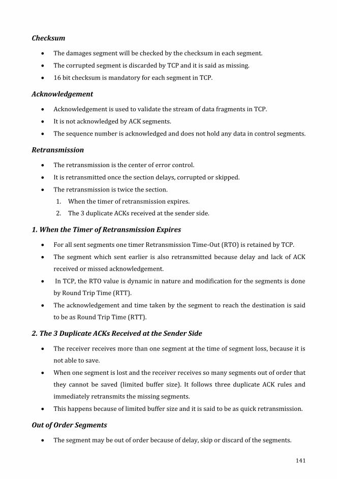
141
Checksum
The damages segment will be checked by the checksum in each segment.
The corrupted segment is discarded by TCP and it is said as missing.
16 bit checksum is mandatory for each segment in TCP.
Acknowledgement
Acknowledgement is used to validate the stream of data fragments in TCP.
It is not acknowledged by ACK segments.
The sequence number is acknowledged and does not hold any data in control segments.
Retransmission
The retransmission is the center of error control.
It is retransmitted once the section delays, corrupted or skipped.
The retransmission is twice the section.
1. When the timer of retransmission expires.
2. The 3 duplicate ACKs received at the sender side.
1. When the Timer of Retransmission Expires
For all sent segments one timer Retransmission Time-Out (RTO) is retained by TCP.
The segment which sent earlier is also retransmitted because delay and lack of ACK
received or missed acknowledgement.
In TCP, the RTO value is dynamic in nature and modification for the segments is done
by Round Trip Time (RTT).
The acknowledgement and time taken by the segment to reach the destination is said
to be as Round Trip Time (RTT).
2. The 3 Duplicate ACKs Received at the Sender Side
The receiver receives more than one segment at the time of segment loss, because it is
not able to save.
When one segment is lost and the receiver receives so many segments out of order that
they cannot be saved (limited buffer size). It follows three duplicate ACK rules and
immediately retransmits the missing segments.
This happens because of limited buffer size and it is said to be as quick retransmission.
Out of Order Segments
The segment may be out of order because of delay, skip or discard of the segments.
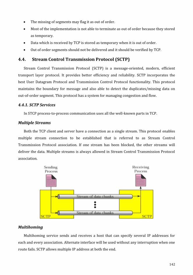
142
The missing of segments may flag it as out of order.
Most of the implementation is not able to terminate as out of order because they stored
as temporary.
Data which is received by TCP is stored as temporary when it is out of order.
Out of order segments should not be delivered and it should be verified by TCP.
4.4. Stream Control Transmission Protocol (SCTP)
Stream Control Transmission Protocol (SCTP) is a message-oriented, modern, efficient
transport layer protocol. It provides better efficiency and reliability. SCTP incorporates the
best User Datagram Protocol and Transmission Control Protocol functionality. This protocol
maintains the boundary for message and also able to detect the duplicates/missing data on
out-of-order segment. This protocol has a system for managing congestion and flow.
4.4.1. SCTP Services
In STCP process-to-process communication uses all the well-known parts in TCP.
Multiple Streams
Both the TCP client and server have a connection as a single stream. This protocol enables
multiple stream connection to be established that is referred to as Stream Control
Transmission Protocol association. If one stream has been blocked, the other streams will
deliver the data. Multiple streams is always allowed in Stream Control Transmission Protocol
association.
Multihoming
Multihoming service sends and receives a host that can specify several IP addresses for
each and every association. Alternate interface will be used without any interruption when one
route fails. SCTP allows multiple IP address at both the end.

143
Full Duplex Communication
Full duplex is used when data flows in both directions at the same time. In both
connections, it has buffer sender and receiver to send/receive the packets at both directions.
Connection Oriented Service
When process A needs to send the data and receives another data from process B. The
following shall occur:
1. An association should be created between two SCTPs.
2. In both the directions, data can be send/receive.
3. Then association can be terminated.
4.4.2. SCTP Features
Transmission Sequence Number
In Stream Control Transmission Protocol (SCTP), the one to one communication may be
used to transfer the message due to fragmentation. By numbering data chunks in SCTP, data
transmission is managed. Transmission Sequence Number (TSN) is used to number the data
chunks. TSN is 32 bit long in Stream Control Transmission Protocol (0 & 2-1).
Stream Identifier
Stream Identifier (SI) is used to identify the stream in SCTP. Before arriving to the
destination each data should have its SI in header.

144
Stream Sequence Number
In SCTP destination, the data packets will be forwarded to their stream once it arrives.
Stream Sequence Number (SSN) is used to define the data packets in their stream.
Packets
Information is transmitted as data packets and control information is transmitted as
control packets. A lot of control and data packets can be bundled in a single packet. The Stream
Control Transmission Protocol packet also has a same mechanism as the Transmission Control
Protocol portion. TCP has parts, SCTP has packets.
Acknowledgement Number
The ICP acknowledgement numbers are applied to sequence it. It is byte-oriented. However
the Stream Control Transmission Protocol acknowledgements are always packet oriented by
reference TSN.
Flow Control
Flow control is used to prevent exhausting the receiver.
Error Control
It implements error management to provide reliability.
Congestion Control
It is used to determine how many data chunks can be rejected on the network.

145
Packet Format
General Header
Source Port Address
It is 16-bit field address. Port number is determined for sending the packet.
Destination Port Address
It is 12-bit field address. Port number is determined for receiving the packet.
Verification Tag
Packets are connected by using this verification number. It is used to describe the process
that is replicated in every packet during the process.
Checksum
It is 32-bit field. It includes the CRC-32 checksum.
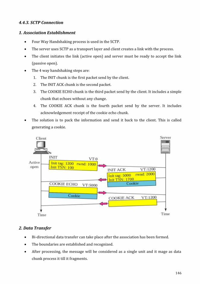
146
4.4.3. SCTP Connection
1. Association Establishment
Four Way Handshaking process is used in the SCTP.
The server uses SCTP as a transport layer and client creates a link with the process.
The client initiates the link (active open) and server must be ready to accept the link
(passive open).
The 4 way handshaking steps are:
1. The INIT chunk is the first packet send by the client.
2. The INIT ACK chunk is the second packet.
3. The COOKIE ECHO chunk is the third packet send by the client. It includes a simple
chunk that echoes without any change.
4. The COOKIE ACK chunk is the fourth packet send by the server. It includes
acknowledgement receipt of the cookie echo chunk.
The solution is to pack the information and send it back to the client. This is called
generating a cookie.
2. Data Transfer
Bi-directional data transfer can take place after the association has been formed.
The boundaries are established and recognized.
After processing, the message will be considered as a single unit and it mage as data
chunk process it till it fragments.
147
Then data chunks will be broken down by adding header to the message.
A single TSN is given for the message or fragments which has set of information.
3. Connection Termination
The process should avoid sending the new data once the process has been terminated.
The queued data should be submitted or closed before the request sends for
termination.
The three packets are used for process termination; they are shutdown, ACK shutdown,
and full shutdown.
4.5. Congestion Control
The process of avoiding congestion before it occurs or eradicate congestion after it has
been occurs is said to be as congestion control. It is divided into two wide categories.
4.5.1. Congestion - Network Performance
When network is loading the number of packets sent to the network is greater than the
ability of the network. Here the number of packets the network can handle is said to be
a network congestion.
The mechanism of managing congestion and holding the load below capacity is
congestion control.
The routers and switches have buffer queues to carry both the before and after
processing packets.
It has 2 factors to calculate the network efficiency. They are throughput and delay.
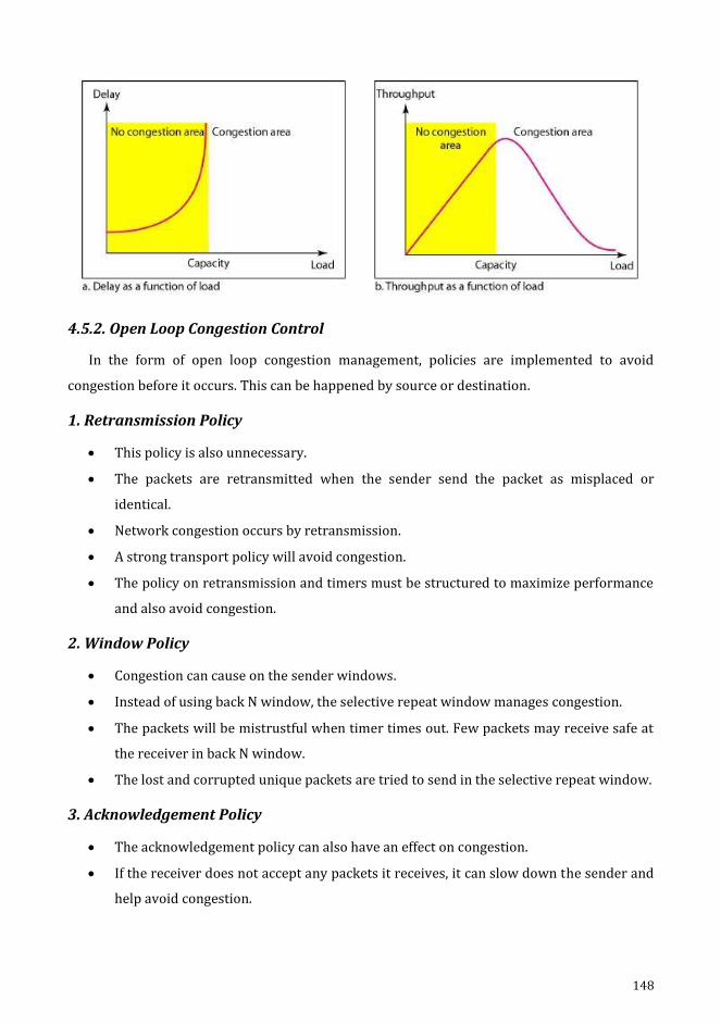
148
4.5.2. Open Loop Congestion Control
In the form of open loop congestion management, policies are implemented to avoid
congestion before it occurs. This can be happened by source or destination.
1. Retransmission Policy
This policy is also unnecessary.
The packets are retransmitted when the sender send the packet as misplaced or
identical.
Network congestion occurs by retransmission.
A strong transport policy will avoid congestion.
The policy on retransmission and timers must be structured to maximize performance
and also avoid congestion.
2. Window Policy
Congestion can cause on the sender windows.
Instead of using back N window, the selective repeat window manages congestion.
The packets will be mistrustful when timer times out. Few packets may receive safe at
the receiver in back N window.
The lost and corrupted unique packets are tried to send in the selective repeat window.
3. Acknowledgement Policy
The acknowledgement policy can also have an effect on congestion.
If the receiver does not accept any packets it receives, it can slow down the sender and
help avoid congestion.
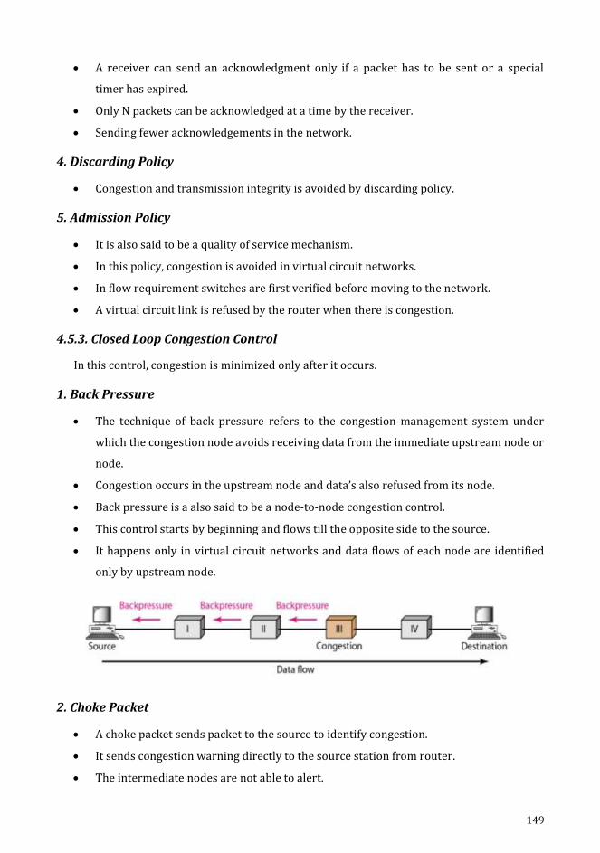
149
A receiver can send an acknowledgment only if a packet has to be sent or a special
timer has expired.
Only N packets can be acknowledged at a time by the receiver.
Sending fewer acknowledgements in the network.
4. Discarding Policy
Congestion and transmission integrity is avoided by discarding policy.
5. Admission Policy
It is also said to be a quality of service mechanism.
In this policy, congestion is avoided in virtual circuit networks.
In flow requirement switches are first verified before moving to the network.
A virtual circuit link is refused by the router when there is congestion.
4.5.3. Closed Loop Congestion Control
In this control, congestion is minimized only after it occurs.
1. Back Pressure
The technique of back pressure refers to the congestion management system under
which the congestion node avoids receiving data from the immediate upstream node or
node.
Congestion occurs in the upstream node and data’s also refused from its node.
Back pressure is a also said to be a node-to-node congestion control.
This control starts by beginning and flows till the opposite side to the source.
It happens only in virtual circuit networks and data flows of each node are identified
only by upstream node.
2. Choke Packet
A choke packet sends packet to the source to identify congestion.
It sends congestion warning directly to the source station from router.
The intermediate nodes are not able to alert.
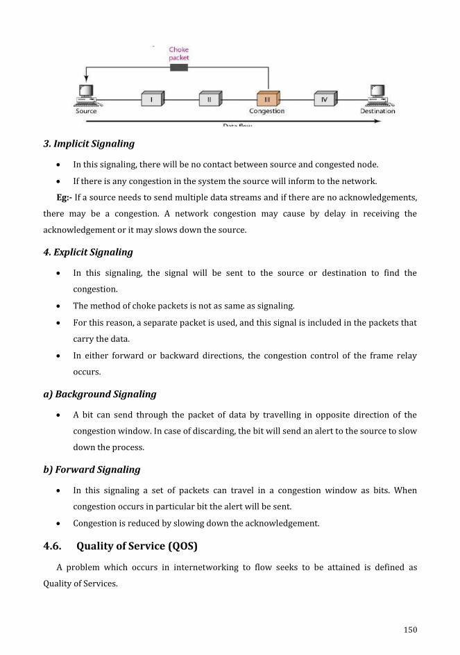
150
3. Implicit Signaling
In this signaling, there will be no contact between source and congested node.
If there is any congestion in the system the source will inform to the network.
Eg:- If a source needs to send multiple data streams and if there are no acknowledgements,
there may be a congestion. A network congestion may cause by delay in receiving the
acknowledgement or it may slows down the source.
4. Explicit Signaling
In this signaling, the signal will be sent to the source or destination to find the
congestion.
The method of choke packets is not as same as signaling.
For this reason, a separate packet is used, and this signal is included in the packets that
carry the data.
In either forward or backward directions, the congestion control of the frame relay
occurs.
a) Background Signaling
A bit can send through the packet of data by travelling in opposite direction of the
congestion window. In case of discarding, the bit will send an alert to the source to slow
down the process.
b) Forward Signaling
In this signaling a set of packets can travel in a congestion window as bits. When
congestion occurs in particular bit the alert will be sent.
Congestion is reduced by slowing down the acknowledgement.
4.6. Quality of Service (QOS)
A problem which occurs in internetworking to flow seeks to be attained is defined as
Quality of Services.

151
4.6.1. Flow Characteristics
There are 4 types of characteristics are attributed to a flow.
1. Reliability
Reliability is the characteristics that a flow requires Lack of reliability implies the failure of
a packet or an acknowledgment that includes retransmission.
Eg:- Email, transferring a file and internet connectivity.
2. Delay
This is used get delay from source to destination.
Eg:- Audio/video conference, telephony, remote access.
3. Jitter
Jitter is a difference in the delay of packets belonging to the same flow.
Eg:- If 4 packets depart in time 0,1,2,3 and arrive at 20,21,22,23 all have the same delays,
20 units of time.
If 4 packets arrive at 21,23,21,28, they will have different delays: 21,22,19,24.
Jitter is known as the variation in the delay of the packet. High jitter means that the
difference between delays is large, low jitter means that the variance is small.
4. Bandwidth
There is a variable bandwidth depending on the different applications. In video
conferencing, millions of bits per second are required to refresh the color screen while the
total number of bits in email may not even exceed a million.
152
CHAPTER 5
5. Application Layer
Objectives
Understanding Traditional Applications.
Illustrating the basics of e-mail, POP3, SMTP, MIME, IMAP.
Illustrating HTTP design and online documents.
Explaining FTP.
Learning the fundamentals of web services.
To understand the DNS and how it is distributed.
Learning about the SNMP.

153
5.1. Traditional Applications
Among the common global technologies, the World Wide Web (WWW) and E-mail,
facilitates the model of request / reply methodology. The request is submitted to server and
the response is received accordingly. Such applications come under the category of
"traditional" applications, as they describe the kind of applications which have been in
existence from the very start of the computer age. (Web plays an advanced role than simple
text application, yet the file transfers that predated it have their roots). On the other hand, the
group of applications which are popular in the current era ranges as applications based on
streaming and imaging.
Generally, an important point has to be taken a close look with priority before exploring the
details of these applications. It is the discrepancy of application programs with that of
application protocols which has to be understood. The Hyper Text Transport Protocol (HTTP),
for instance, is an application protocol used to obtain Web pages from remote servers. Other
application programs like web clients - Internet Explorer, Chrome, Firefox, and Safari deliver
an appealing window environment to users, even though they use the HTTP protocol in
common, to connect over the Internet with web servers. It is a known truth that the protocol is
published and standardized which allows interoperation of application programs created by
various companies and individuals. That's how many browsers can communicate with all of
the web servers.
5.2. Email
Electronic mail (Email) is among the most popular internet services. The message sent via
electronic mail was brief and contains only text. It allows text, audio and video to be included
into a post. This enables one message to be sent to one additional recipient.
5.2.1. Architecture
The email architecture is explained in 4 scenarios.
1. First Scenario
The Email's sender and receiver are uses on the same device that a common device directly
links. A mailbox is a particular file with permission restrictions that is part of a local storage
device. It is used to receive and store messages.

154
A user wants to send a message to Bob, while Alice is operating. Alice runs a User Agent
(UA) program to prepare and store the message in Bob’s mailbox. The message contains
addresses of mailbox of sender and receiver. Using a user agent the contents of his mailbox will
be capable of being retrieved and read at their convenience. If the sender and the email
recipient dwell on the same platform, we just require user agents.
2. Second Scenario
To deliver her message to the device at her own place, an agent programme is necessitated
for Alice. The mail server uses a queue to store message which is waiting for its turn for
transmission. In order to retrieve messages saved in the system's mailbox at his location, Bob
also requires a user agent application. The receiving message has two client and server
message transfer agents. It obviously requires 2 UA and 2 MTA (client and server) where the
sender and the recipient of an email exist in separate systems.

155
3. Third Scenario
Bob is specifically related to a system of lies. Alice is connected using a dial-up modem, DSL
or cable modem though WAN, to the system.
Alice requires a UA to prepare its message and send the same via the LAN / WAN. The UA is
called, which further proceeds to call MTA client, when Alice has to send a request. The MTA
client creates a link that is running all the time with the MTA server on the device. The machine
at the Alice site queues all received messages and the MTA client sends the messages to the
Bob site. It requires 2 UA and 2 MTA pairs when the sender is attached via LAN / WAN to the
mail server.
4. Fourth Scenario
Here also a WAN / LAN links Bob to his mail server. The mail’s reception at Bob’s mail
server makes Bob to retrieve it. The Message Access Agent (MAA) retrieves Bob’s messages to
the client. Then a request is initiates by the client to MAA server which is active always to
facilitate message transfer.
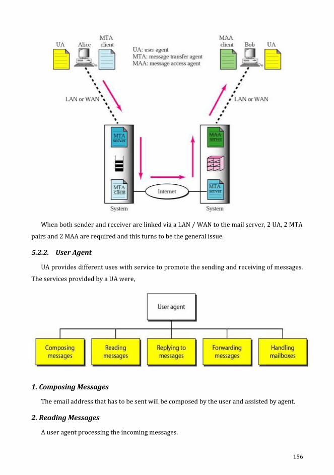
156
When both sender and receiver are linked via a LAN / WAN to the mail server, 2 UA, 2 MTA
pairs and 2 MAA are required and this turns to be the general issue.
5.2.2. User Agent
UA provides different uses with service to promote the sending and receiving of messages.
The services provided by a UA were,
1. Composing Messages
The email address that has to be sent will be composed by the user and assisted by agent.
2. Reading Messages
A user agent processing the incoming messages.
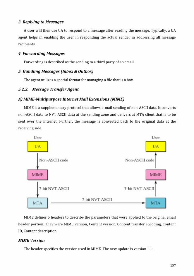
157
3. Replying to Messages
A user will then use UA to respond to a message after reading the message. Typically, a UA
agent helps in enabling the user in responding the actual sender in addressing all message
recipients.
4. Forwarding Messages
Forwarding is described as the sending to a third party of an email.
5. Handling Messages (Inbox & Outbox)
The agent utilizes a special format for managing a file that is a box.
5.2.3. Message Transfer Agent
A) MIME-Multipurpose Internet Mail Extensions (MIME)
MIME is a supplementary protocol that allows e-mail sending of non-ASCII data. It converts
non-ASCII data to NVT ASCII data at the sending zone and delivers at MTA client that is to be
sent over the internet. Further, the message is converted back to the original data at the
receiving side.
MIME defines 5 headers to describe the parameters that were applied to the original email
header portion. They were MIME version, Content version, Content transfer encoding, Content
ID, Content description.
MIME Version
The header specifies the version used in MIME. The new update is version 1.1.
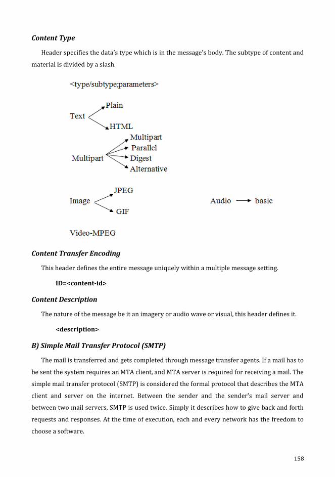
158
Content Type
Header specifies the data’s type which is in the message's body. The subtype of content and
material is divided by a slash.
Content Transfer Encoding
This header defines the entire message uniquely within a multiple message setting.
ID=<content-id>
Content Description
The nature of the message be it an imagery or audio wave or visual, this header defines it.
<description>
B) Simple Mail Transfer Protocol (SMTP)
The mail is transferred and gets completed through message transfer agents. If a mail has to
be sent the system requires an MTA client, and MTA server is required for receiving a mail. The
simple mail transfer protocol (SMTP) is considered the formal protocol that describes the MTA
client and server on the internet. Between the sender and the sender's mail server and
between two mail servers, SMTP is used twice. Simply it describes how to give back and forth
requests and responses. At the time of execution, each and every network has the freedom to
choose a software.
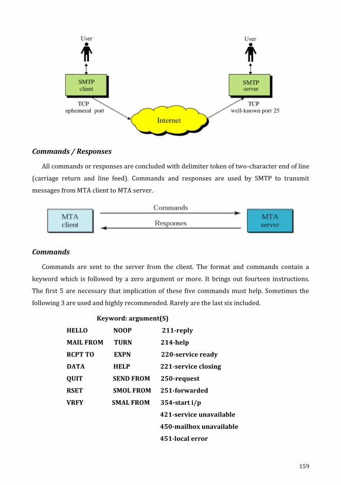
159
Commands / Responses
All commands or responses are concluded with delimiter token of two-character end of line
(carriage return and line feed). Commands and responses are used by SMTP to transmit
messages from MTA client to MTA server.
Commands
Commands are sent to the server from the client. The format and commands contain a
keyword which is followed by a zero argument or more. It brings out fourteen instructions.
The first 5 are necessary that implication of these five commands must help. Sometimes the
following 3 are used and highly recommended. Rarely are the last six included.
Keyword: argument(S)
HELLO NOOP 211-reply
MAIL FROM TURN 214-help
RCPT TO EXPN 220-service ready
DATA HELP 221-service closing
QUIT SEND FROM 250-request
RSET SMOL FROM 251-forwarded
VRFY SMAL FROM 354-start i/p
421-service unavailable
450-mailbox unavailable
451-local error

160
Responses
Responses are transmitted to client from server. It is a code of about 3-digit length which
can append with additional text.
Mail Transfer Phases
The method of e-mail transmission takes place in 3 phases. They start with connection
establishment followed by a mail transfer and ends with connection termination.
C) POP & IMAP: (MAA)
There are 2 messages access protocol. They were Post Office Protocol version: 3 (POP 3) &
Internet, Mail Access Protocol version: 4 (IMAP4).
Pop 3
In accessibility, POP 3 is easy & restricted. The POP 3 client software is installed on the
receiving machine and the POP3 application software is installed on the mail server. When the
user has to retrieve email from the mailbox on the mail server, mail access begins with the
client. On TCP port 110 the client opens a connection to the server. If the username and
password are then sent to enter the mailbox. The user will then list the mail messages one by
one and retrieve them.
There are 2 modes: one mode is delete and the other is keep. After each retrieval, the
mailbox’s mail will be removed when the mode delete is in progress and widely used while a
permanent machine is used by the user. The mail of the mail box stays after retrieval is
invoked in keep mode and is preferred while the user is away to access in order to access their
initial device. Although the mail gets read, it stays in the organising and retrieval store for
future use.

161
IMAP4
IMAP4 is more active and complex. Prior to uploading, a user should review the email
header. Scanning of contents of the email is permissible until it is downloaded by the user. In
part, downloading an email by user is possible. If bandwidth stands small and the mail includes
multimedia content which demand high bandwidth as its requirements, this is generally
advantageous. A user can build mailboxes, remove or rename them. Mailboxes may be created,
removed or renamed by a user. In an email storage folder, the mailboxes’ hierarchy can be
constructed by the user.
5.3. Hypertext Transfer Protocol (HTTP)
The HTTP is employed mostly for data access on the www. As a mix of FTP and SMTP, HTTP
works. This technology reflects the core of FTP, since it shares files along with the utilization of
TCP services. HTTP is twinned with SMTP, where the content delivery from client to server is
done. The message format is regulated by the MIME-like headers. HTTP utilizes TCP services in
a well-known port namely, port 80.
HTTP Transaction
HTTP transfers between server and client
HTTP utilizes TCP services; HTTP is considered as a stateless protocol itself.
The transaction is initialized by the client by transmitting a request message.
The server responds with a reply message.

162
Messages
The request message is a request line, a header with a body whereas a response message is
a status line, a header which seems to be a body.
Request and Status Line
A request line is considered the first line of request message. The request line is termed as a
status line of response message.
Request Type
The request type is categorized into methods and this field is useful for request message.
GET requests a document from source
HEAD requests info about document
POST sends some information
PUT sends a document
TRACE echoes the incoming request
CONNECT reserved
OPTION inquiries about available options
163
Version
The version 1.1 is observed to be the recent one of HTTP.
Status Code
It is a part of the message sequence which is identical to the one in FTP as well as SMTP
protocols. It contains a 3-digit code of range. They are,
100 ranges - informational
200 ranges - successful request
300 ranges - connects to another URL
400 ranges - error at client site
500 ranges - error at server site
Status Phrases
Response message utilizes by the field and status code is described in the text format.
Header
The client and server get some additional information that will be shared by header. One or
extra lines of header is found at the header. Each header line has a name for the header, a
column, and a space and a value for the header. The header line may go in with any of the
mentioned 4 groups under General or Response or Request or Entity.
A request header consists of general request and an entity header. A response header
consists of general, response and an entity header.
Header Name: Header Value
General Header
General information is available for the message and can be found in requests and
response, is provided in the general header.
Connection - Shows if the connection is to be terminated or not
Date - Displays the current date
MIME-version - Shows MIME version
Upgrade - Notifies which communication protocol is preferred
Request Header
The request header is blocked only when a request message is invoked and clients’
configuration and the format of the document is specified.
164
Accept Shows the client accepts.
Authorization Shows permission held by the client
From Shows email address
Host Shows host and port number
User-agent Identifies the client program.
Response Header
The response header can only be blocked by a reply message and also specifies the
configuration of the server and the basic details on the request.
Age Shows age of the document
Server Shows the server name & version
Public Shows the supported list
Entity Header
The information regarding the body of text is held in this header, which is represented in
the methods of response messages or request messages, namely POST or PUT along with a
body.
Body
The body might be found in the request or reply message. It demands a request to either
transmit or retrieve.
Proxy Server
HTTP is supported by proxy servers which is a machine holding the response copy that is a
recent one. Proxy server will receive a request from the HTTP client and its cache will be
reviewed. When the cache contains the response, the response would be sent by the proxy
server to the corresponding server. It receives the incoming response and process to align with
the future requests of other clients.
File Transfer
File transfer is an essential and a very important task required during the transfer of files
from a device to another, be it in intranet or internet.
5.4. File Transfer Protocol (FTP)
File Transfer Protocol (FTP) is used to copy a file from one host to another host. It is a
standard mechanism which is provided by TCP/IP. It separates commands and transferring

165
data makes FTP more effective. FTP uses the TCP operation. It require two connectivity to the
TCP. The well-known port 21 is used for control connection and the well-known section 20 for
network connectivity. There are three components in the client: the user interface, the device
control and the data transfer. There are two components in the server: the server control
process and the server transfer process. The control is done by the control communication and
the data transfer is done by data link.
The connection control is connected throughout the FTP session. For each file transfer the
data connection is opened and closed. It opens when the commands that require moving files
are to be used and when the file is moved, it will be closed.
Communication Over Control Connection
FTP uses the same technique as SMTP to communicate over a control link. It uses a set of 7
bit ASCII characters. Communication is carried out by each command or response is a short
line. The termination for each line is done by two characters that are line feed and carriage
return at the end-of-line token.
Communication Over Data Communication
It is different from the purpose of the control connection. The transfer of file takes place
over the data connection link under the supervision of the commands sent over the control
connection.
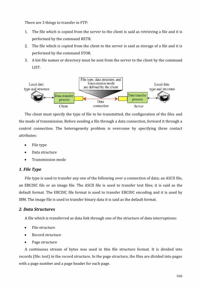
166
There are 3 things to transfer in FTP:
1. The file which is copied from the server to the client is said as retrieving a file and it is
performed by the command RETR.
2. The file which is copied from the client to the server is said as storage of a file and it is
performed by the command STOR.
3. A list file names or directory must be sent from the server to the client by the command
LIST.
The client must specify the type of file to be transmitted, the configuration of the files and
the mode of transmission. Before sending a file through a data connection, forward it through a
control connection. The heterogeneity problem is overcome by specifying three contact
attributes:
File type
Data structure
Transmission mode
1. File Type
File type is used to transfer any one of the following over a connection of data; an ASCII file,
an EBCDIC file or an image file. The ASCII file is used to transfer text files; it is said as the
default format. The EBCDIC file format is used to transfer EBCDIC encoding and it is used by
IBM. The image file is used to transfer binary data it is said as the default format.
2. Data Structures
A file which is transferred as data link through one of the structure of data interruptions:
File structure
Record structure
Page structure
A continuous stream of bytes was used in this file structure format. It is divided into
records (file: text) in the record structure. In the page structure, the files are divided into pages
with a page number and a page header for each page.
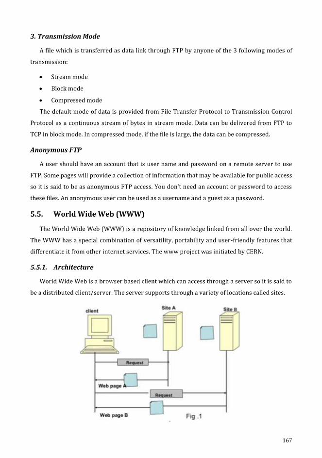
167
3. Transmission Mode
A file which is transferred as data link through FTP by anyone of the 3 following modes of
transmission:
Stream mode
Block mode
Compressed mode
The default mode of data is provided from File Transfer Protocol to Transmission Control
Protocol as a continuous stream of bytes in stream mode. Data can be delivered from FTP to
TCP in block mode. In compressed mode, if the file is large, the data can be compressed.
Anonymous FTP
A user should have an account that is user name and password on a remote server to use
FTP. Some pages will provide a collection of information that may be available for public access
so it is said to be as anonymous FTP access. You don't need an account or password to access
these files. An anonymous user can be used as a username and a guest as a password.
5.5. World Wide Web (WWW)
The World Wide Web (WWW) is a repository of knowledge linked from all over the world.
The WWW has a special combination of versatility, portability and user-friendly features that
differentiate it from other internet services. The www project was initiated by CERN.
5.5.1. Architecture
World Wide Web is a browser based client which can access through a server so it is said to
be a distributed client/server. The server supports through a variety of locations called sites.

168
One or more documents in each site is said to be as web pages. Each page links with
another page on the same or on other pages. Each site contains one or more documents
referred to as web pages. Each page can contain a link to another page on the same site or on
other pages. Pages can be retrieved and accessed using a browser.
5.5.2. Client (Browser)
A number of vendors provide commercial browsers that interpret and display a web
document and all use almost the same architecture. Each browser is normally made up of three
sections.
Controller
Client protocol
Interpreters
The controller will receive input from the keyboard or mouse and will use the client
programmes to access the text. The controller will use one of the interpreters to view the text
on the screen. The client protocol can be one of the mentioned protocols (FTP / HTTP). The
interpreter can be an HTML, Java or Java script, depending on the type of document.
5.5.3. Server
The website is stored in the server. Every time a client request arrives, the corresponding
document is forwarded to the client. To improve efficiency, servers usually store the requested
files in the memory cache; the memory is faster to access than the disk. The server can also be
made more effective by multi-threading or multi-processing. The server can respond to more
than one request at a time.
5.5.4. Uniform Resource Locator (URL)
A client who wants to access a website requires an address. HTTP uses locators to allow
access to documents scattered around the world. The URL is a standard for specifying any type
of information on the Internet. The URL describes four things:-
Protocol
Host computer
Port
Path
Protocol:// host : port / path
The protocol is a client / server program that is used to retrieve a document. A document
can be obtained by several different protocols, including HTTP/FTP. The information is stored
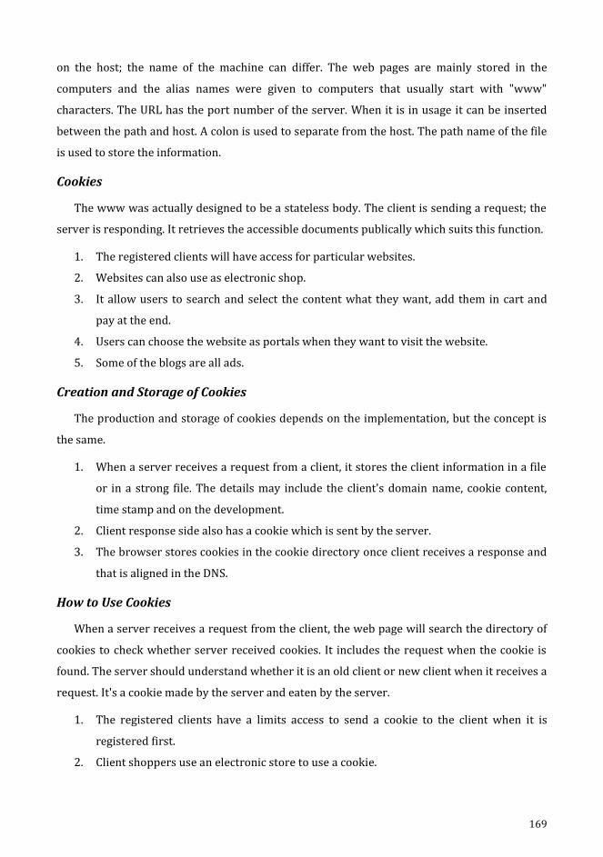
169
on the host; the name of the machine can differ. The web pages are mainly stored in the
computers and the alias names were given to computers that usually start with "www"
characters. The URL has the port number of the server. When it is in usage it can be inserted
between the path and host. A colon is used to separate from the host. The path name of the file
is used to store the information.
Cookies
The www was actually designed to be a stateless body. The client is sending a request; the
server is responding. It retrieves the accessible documents publically which suits this function.
1. The registered clients will have access for particular websites.
2. Websites can also use as electronic shop.
3. It allow users to search and select the content what they want, add them in cart and
pay at the end.
4. Users can choose the website as portals when they want to visit the website.
5. Some of the blogs are all ads.
Creation and Storage of Cookies
The production and storage of cookies depends on the implementation, but the concept is
the same.
1. When a server receives a request from a client, it stores the client information in a file
or in a strong file. The details may include the client's domain name, cookie content,
time stamp and on the development.
2. Client response side also has a cookie which is sent by the server.
3. The browser stores cookies in the cookie directory once client receives a response and
that is aligned in the DNS.
How to Use Cookies
When a server receives a request from the client, the web page will search the directory of
cookies to check whether server received cookies. It includes the request when the cookie is
found. The server should understand whether it is an old client or new client when it receives a
request. It's a cookie made by the server and eaten by the server.
1. The registered clients have a limits access to send a cookie to the client when it is
registered first.
2. Client shoppers use an electronic store to use a cookie.
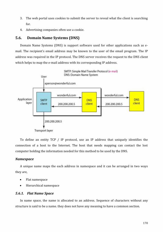
170
3. The web portal uses cookies to submit the server to reveal what the client is searching
for.
4. Advertising companies often use a cookie.
5.6. Domain Name Systems (DNS)
Domain Name Systems (DNS) is support software used for other applications such as e-
mail. The recipient's email address may be known to the user of the email program. The IP
address was required in the IP protocol. The DNS server receives the request to the DNS client
which helps to map the e-mail address with its corresponding IP address.
To define an entity TCP / IP protocol, use an IP address that uniquely identifies the
connection of a host to the Internet. The host that needs mapping can contact the lost
computer holding the information needed for this method to be used by the DNS.
Namespace
A unique name maps the each address in namespace and it can be arranged in two ways
they are,
Flat namespace
Hierarchical namespace
5.6.1. Flat Name Space
In name space, the name is allocated to an address. Sequence of characters without any
structure is said to be a name. they does not have any meaning to have a common section.
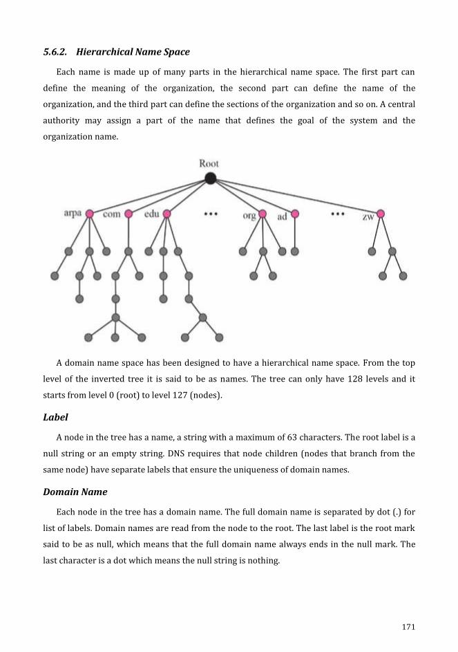
171
5.6.2. Hierarchical Name Space
Each name is made up of many parts in the hierarchical name space. The first part can
define the meaning of the organization, the second part can define the name of the
organization, and the third part can define the sections of the organization and so on. A central
authority may assign a part of the name that defines the goal of the system and the
organization name.
A domain name space has been designed to have a hierarchical name space. From the top
level of the inverted tree it is said to be as names. The tree can only have 128 levels and it
starts from level 0 (root) to level 127 (nodes).
Label
A node in the tree has a name, a string with a maximum of 63 characters. The root label is a
null string or an empty string. DNS requires that node children (nodes that branch from the
same node) have separate labels that ensure the uniqueness of domain names.
Domain Name
Each node in the tree has a domain name. The full domain name is separated by dot (.) for
list of labels. Domain names are read from the node to the root. The last label is the root mark
said to be as null, which means that the full domain name always ends in the null mark. The
last character is a dot which means the null string is nothing.
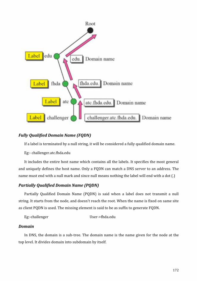
172
Fully Qualified Domain Name (FQDN)
If a label is terminated by a null string, it will be considered a fully qualified domain name.
Eg:- challenger.atc.fhda.edu
It includes the entire host name which contains all the labels. It specifies the most general
and uniquely defines the host name. Only a FQDN can match a DNS server to an address. The
name must end with a null mark and since null means nothing the label will end with a dot (.)
Partially Qualified Domain Name (PQDN)
Partially Qualified Domain Name (PQDN) is said when a label does not transmit a null
string. It starts from the node, and doesn't reach the root. When the name is fixed on same site
as client PQDN is used. The missing element is said to be as suffix to generate FQDN.
Eg:-challenger User->fhda.edu
Domain
In DNS, the domain is a sub-tree. The domain name is the name given for the node at the
top level. It divides domain into subdomain by itself.

173
5.6.3. Namespace Distribution
The solution to these problems is to transmit information to a number of computers called
the DNS service. It divides the entire space into a number of domains centered on the first
level.
Name Server Hierarchy
The information which found must be processed in the DNS. This is not accurate and quite
expensive to store such a large amount of knowledge in one computer.
In DNS, domains are divided into subdomains. Each server is responsible for each domain
either it is large or small.
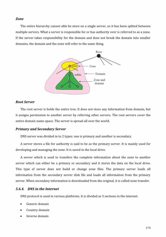
174
Zone
The entire hierarchy cannot able be store on a single server, so it has been splited between
multiple servers. What a server is responsible for or has authority over is referred to as a zone.
If the server takes responsibility for the domain and does not break the domain into smaller
domains, the domain and the zone will refer to the same thing.
Root Server
The root server is holds the entire tree. It does not store any information from domain, but
it assigns permission to another server by referring other servers. The root servers cover the
entire domain name space. The server is spread all over the world.
Primary and Secondary Server
DNS server was divided in to 2 types: one is primary and another is secondary.
A server stores a file for authority is said to be as the primary server. It is mainly used for
developing and managing the zone. It is saved in the local drive.
A server which is used to transfers the complete information about the zone to another
server which can either be a primary or secondary and it stores the data on the local drive.
This type of server does not build or change zone files. The primary server loads all
information from the secondary server disk file and loads all information from the primary
server. When secondary information is downloaded from the original, it is called zone transfer.
5.6.4. DNS in the Internet
DNS protocol is used in various platforms. It is divided as 3 sections in the internet:
Generic domain
Country domain
Inverse domain
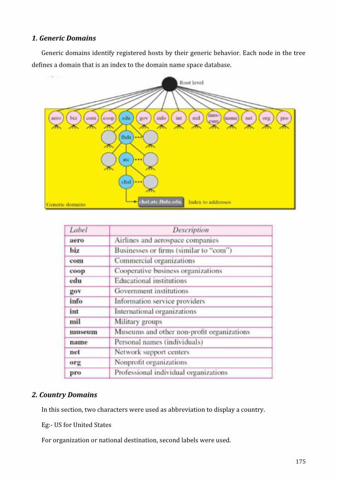
175
1. Generic Domains
Generic domains identify registered hosts by their generic behavior. Each node in the tree
defines a domain that is an index to the domain name space database.
2. Country Domains
In this section, two characters were used as abbreviation to display a country.
Eg:- US for United States
For organization or national destination, second labels were used.

176
3. Inverse Domains
Inverse domain is used to map a name address. (e.g) when the server has received a
request from the client to perform an operation. The server has a file containing a list of
authorised clients with only the IP address of the client. The server asks to send a request to
the DNS server to map the address to the name to decide whether the client is on the
authorised list. This type of query is called the inverse or pointer (PTR) query. To manage a
pointer query, the inverse domain is applied to the domain namespace with the first level node
called arpa and the second level is just a single node named in-addr. The rest of the domain will
determine the IP address.
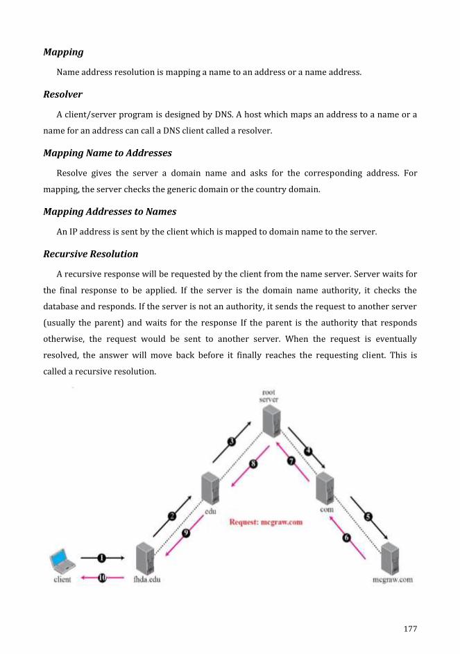
177
Mapping
Name address resolution is mapping a name to an address or a name address.
Resolver
A client/server program is designed by DNS. A host which maps an address to a name or a
name for an address can call a DNS client called a resolver.
Mapping Name to Addresses
Resolve gives the server a domain name and asks for the corresponding address. For
mapping, the server checks the generic domain or the country domain.
Mapping Addresses to Names
An IP address is sent by the client which is mapped to domain name to the server.
Recursive Resolution
A recursive response will be requested by the client from the name server. Server waits for
the final response to be applied. If the server is the domain name authority, it checks the
database and responds. If the server is not an authority, it sends the request to another server
(usually the parent) and waits for the response If the parent is the authority that responds
otherwise, the request would be sent to another server. When the request is eventually
resolved, the answer will move back before it finally reaches the requesting client. This is
called a recursive resolution.
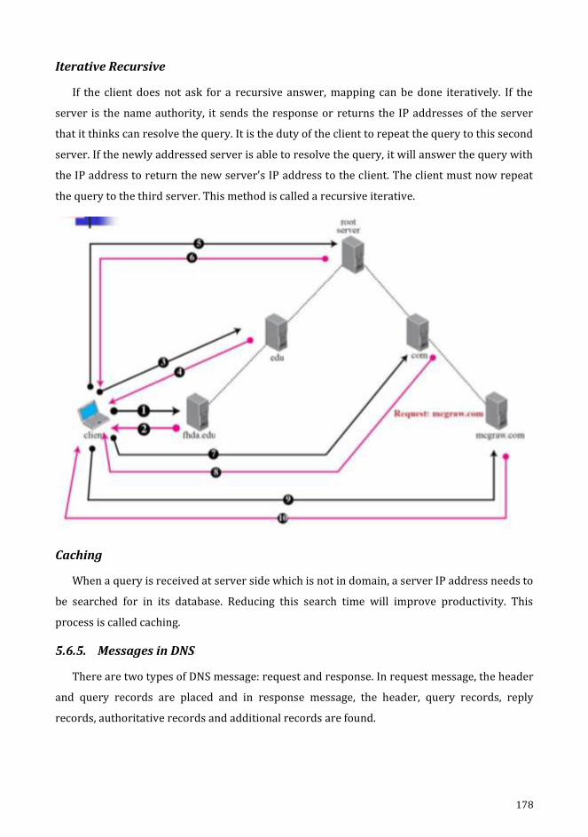
178
Iterative Recursive
If the client does not ask for a recursive answer, mapping can be done iteratively. If the
server is the name authority, it sends the response or returns the IP addresses of the server
that it thinks can resolve the query. It is the duty of the client to repeat the query to this second
server. If the newly addressed server is able to resolve the query, it will answer the query with
the IP address to return the new server's IP address to the client. The client must now repeat
the query to the third server. This method is called a recursive iterative.
Caching
When a query is received at server side which is not in domain, a server IP address needs to
be searched for in its database. Reducing this search time will improve productivity. This
process is called caching.
5.6.5. Messages in DNS
There are two types of DNS message: request and response. In request message, the header
and query records are placed and in response message, the header, query records, reply
records, authoritative records and additional records are found.

179
Header
In same header, both response and request messages filled as zero for query message in
certain fields.
The client uses identification to fit the response to the query. Every time question is sent,
the client uses a different identification number. The flags determine the form of the message
the form of desired resolution. In sub field, the count of request records includes the count of
response records of the message. The count of response records in the sub-field includes the
count of response records in the reply portion of the reply letter. The count of authoritative
parts includes the count of authoritative records in the authority’s part of the responses. The
count of additional ones in this includes the count of additional records in the additional
portion of the responses.
5.7. Simple Network Management Protocol (SNMP)
A mechanism which is used for controlling devices using Transmission Control
Protocol/Internet Protocol on the Internet is said to be as Simple Network Management
Protocol (SNMP). Mainly collection of basic operations are monitored and maintained in the
Internet.
5.7.1. Concept
The concept of manager and agent is used by SNMP. The host manager normally manages
and tracks a group of agents, normally the header.
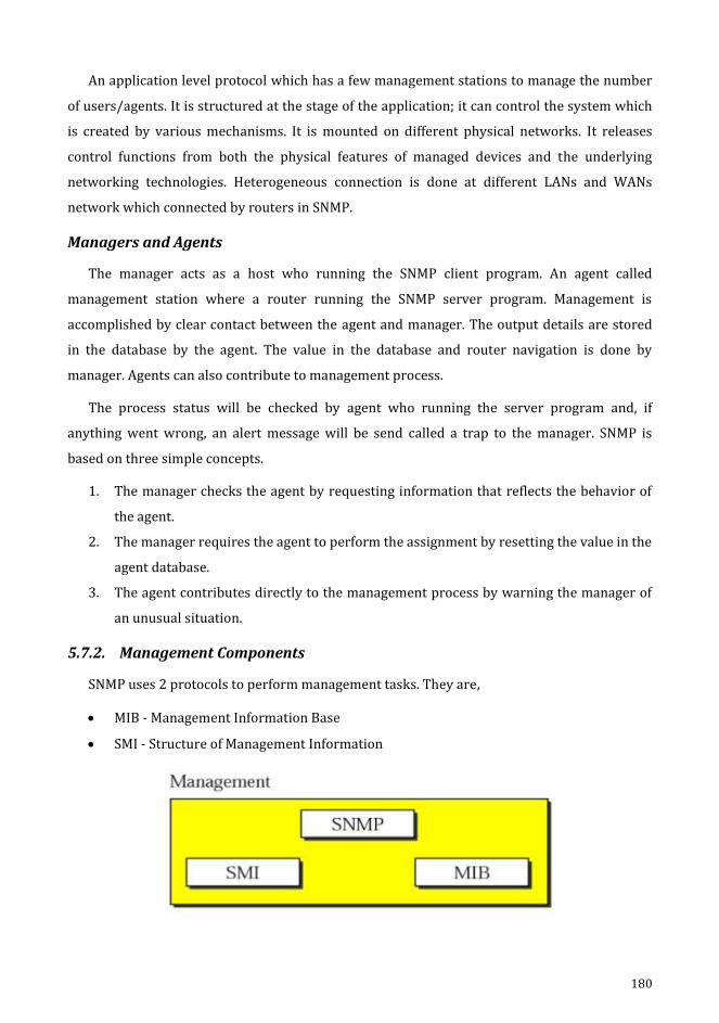
180
An application level protocol which has a few management stations to manage the number
of users/agents. It is structured at the stage of the application; it can control the system which
is created by various mechanisms. It is mounted on different physical networks. It releases
control functions from both the physical features of managed devices and the underlying
networking technologies. Heterogeneous connection is done at different LANs and WANs
network which connected by routers in SNMP.
Managers and Agents
The manager acts as a host who running the SNMP client program. An agent called
management station where a router running the SNMP server program. Management is
accomplished by clear contact between the agent and manager. The output details are stored
in the database by the agent. The value in the database and router navigation is done by
manager. Agents can also contribute to management process.
The process status will be checked by agent who running the server program and, if
anything went wrong, an alert message will be send called a trap to the manager. SNMP is
based on three simple concepts.
1. The manager checks the agent by requesting information that reflects the behavior of
the agent.
2. The manager requires the agent to perform the assignment by resetting the value in the
agent database.
3. The agent contributes directly to the management process by warning the manager of
an unusual situation.
5.7.2. Management Components
SNMP uses 2 protocols to perform management tasks. They are,
MIB - Management Information Base
SMI - Structure of Management Information

181
Role of SNMP
Reading and altering is carried out by SNMP.
Exchanged packets have object name and its status. It interprets the statistics which
produced and outcomes.
It has many important functions in the network management.
The packet format which sent from the manager to the agent is determined, and also
vice versa.
Role of SMI
SMI specifies the common rules to name types of entity range and its length and
demonstrates the values and objects production.
It does not specify objects count where the entity can control or managed by the
objects name and establishes the relation between values and object.
Role of MIB
A list of named objects, forms and its relationship between the entity are generated and
controlled by MIB.

182
5.7.3. Structure of Management Information (SMI)
The structure of management information version 2 (SMIV2) is a network management.
The properties include:
1. Object name.
2. Data type should be defined to store in the object.
3. Data transmission over the network.
SNMP guides the structure of management information and it has 3 attributes to treat it as
an object,
Object name
Data type
encoding method
Name
A hierarchical identifier is used to identify the objects in SMI like a tree structure to label
objects globally. It always starts with 1.3.6.1.2.1.
Type
Abstract Syntax Notation 1 (ASN.1) is used to define the data type in SMI. It acts as a subset
and also a superset, and two large categories of data types were used.
Simple
Structured.
Simple
Efficient data types all types of atomic data. The remaining types are taken directly from
ASN.1 and added by SMI.
5: ASN.1 & 7: SMI
Integer 4 bytes
Integer 32 4 bytes
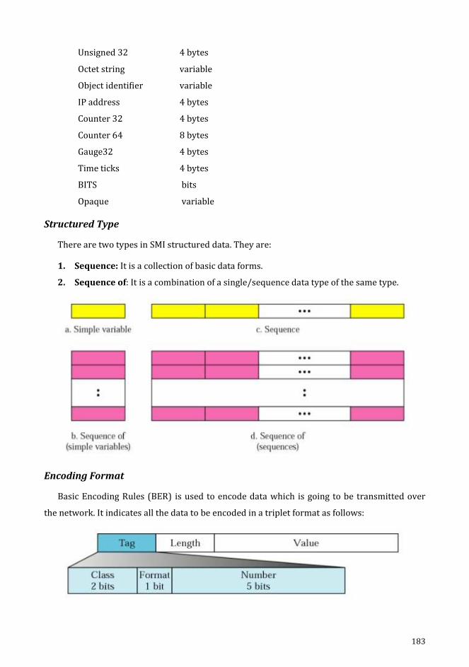
183
Unsigned 32 4 bytes
Octet string variable
Object identifier variable
IP address 4 bytes
Counter 32 4 bytes
Counter 64 8 bytes
Gauge32 4 bytes
Time ticks 4 bytes
BITS bits
Opaque variable
Structured Type
There are two types in SMI structured data. They are:
1. Sequence: It is a collection of basic data forms.
2. Sequence of: It is a combination of a single/sequence data type of the same type.
Encoding Format
Basic Encoding Rules (BER) is used to encode data which is going to be transmitted over
the network. It indicates all the data to be encoded in a triplet format as follows:
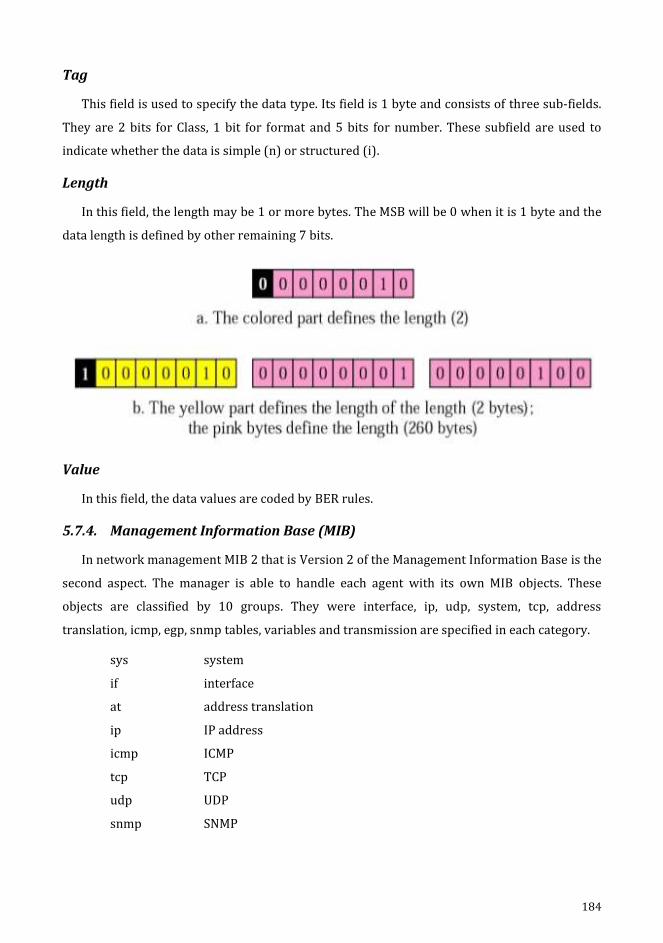
184
Tag
This field is used to specify the data type. Its field is 1 byte and consists of three sub-fields.
They are 2 bits for Class, 1 bit for format and 5 bits for number. These subfield are used to
indicate whether the data is simple (n) or structured (i).
Length
In this field, the length may be 1 or more bytes. The MSB will be 0 when it is 1 byte and the
data length is defined by other remaining 7 bits.
Value
In this field, the data values are coded by BER rules.
5.7.4. Management Information Base (MIB)
In network management MIB 2 that is Version 2 of the Management Information Base is the
second aspect. The manager is able to handle each agent with its own MIB objects. These
objects are classified by 10 groups. They were interface, ip, udp, system, tcp, address
translation, icmp, egp, snmp tables, variables and transmission are specified in each category.
sys system
if interface
at address translation
ip IP address
icmp ICMP
tcp TCP
udp UDP
snmp SNMP
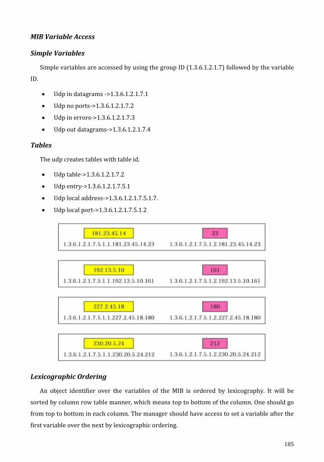
185
MIB Variable Access
Simple Variables
Simple variables are accessed by using the group ID (1.3.6.1.2.1.7) followed by the variable
ID.
Udp in datagrams ->1.3.6.1.2.1.7.1
Udp no ports->1.3.6.1.2.1.7.2
Udp in errors->1.3.6.1.2.1.7.3
Udp out datagrams->1.3.6.1.2.1.7.4
Tables
The udp creates tables with table id.
Udp table->1.3.6.1.2.1.7.2
Udp entry->1.3.6.1.2.1.7.5.1
Udp local address->1.3.6.1.2.1.7.5.1.7.
Udp local port->1.3.6.1.2.1.7.5.1.2
Lexicographic Ordering
An object identifier over the variables of the MIB is ordered by lexicography. It will be
sorted by column row table manner, which means top to bottom of the column. One should go
from top to bottom in each column. The manager should have access to set a variable after the
first variable over the next by lexicographic ordering.
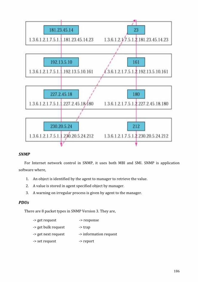
186
SNMP
For Internet network control in SNMP, it uses both MBI and SMI. SNMP is application
software where,
1. An object is identified by the agent to manager to retrieve the value.
2. A value is stored in agent specified object by manager.
3. A warning on irregular process is given by agent to the manager.
PDUs
There are 8 packet types in SNMP Version 3. They are,
-> get request -> response
-> get bulk request -> trap
-> get next request -> information request
-> set request -> report
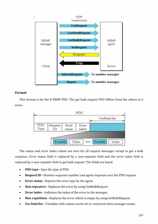
187
Format
This format is for the 8 SNMP PDU. The get bulk request PDU differs from the others in 2
areas.
The status and error index values are zero for all request messages except to get a bulk
response. Error status field is replaced by a non-repeater field and the error index field is
replaced by a max-repeater field in get bulk request. The fields are listed.
PDU type - Says the type of PDU.
Request ID - Denotes sequence number and agent response over the PDU request.
Error status - Reports the error type by the agent.
Non repeaters - Replaces the error by using GetBulkRequest.
Error index - Indicates the index of the error to the manager.
Max-repetition - Replaces the error which is empty by using GetBulkRequest.
Var bind list - Variables with values can be set or retrieved when manager wants.

188
Messages
The SNMP encloses the PDU in a message. The SNMP Version 3 message consists of version
which describes the new version as 3, the header includes the message identification values of
the message size and how message protects, and the security message parameter is used to
build a message digest. The data contains the PDU. SNMP uses a tag to describe the form of
PDU. The class is sensitive to context (10).
UDP Ports
161 - Server (as agent) and 162 - Client (as manager) are the two ports used by SNMP. The
port 761 is a server’s passive open and port 162 is a client’s active open.
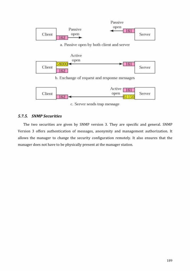
189
5.7.5. SNMP Securities
The two securities are given by SNMP version 3. They are specific and general. SNMP
Version 3 offers authentication of messages, anonymity and management authorization. It
allows the manager to change the security configuration remotely. It also ensures that the
manager does not have to be physically present at the manager station.
Related Documents


