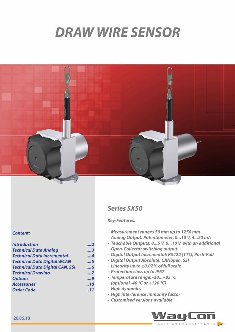
20.06.18 Content: Introduction ....2 Technical Data Analog ....3 Technical Data Incremental ....4 Technical Data Digital WCAN ....5 Technical Data Digital CAN, SSI ....6 Technical Drawing ....7 Options ....9 Accessories ..10 Order Code ..11 Series SX50 Key-Features: - Measurement ranges 50 mm up to 1250 mm - Analog Output: Potentiometer, 0...10 V, 4...20 mA - Teachable Outputs: 0...5 V, 0...10 V, with an additional Open-Collector switching output - Digital Output Incremental: RS422 (TTL), Push-Pull - Digital Output Absolute: CANopen, SSI - Linearity up to ±0.02% of full scale - Protection class up to IP67 - Temperature range: -20...+85 °C (optional -40 °C or +120 °C) - High dynamics - High interference immunity factor - Customised versions available DRAW WIRE SENSOR

Welcome message from author
This document is posted to help you gain knowledge. Please leave a comment to let me know what you think about it! Share it to your friends and learn new things together.
Transcript
20.06.18
Content:
Introduction ....2Technical Data Analog ....3Technical Data Incremental ....4Technical Data Digital WCAN ....5Technical Data Digital CAN, SSI ....6Technical Drawing ....7Options ....9Accessories ..10Order Code ..11
Series SX50
Key-Features:
- Measurement ranges 50 mm up to 1250 mm - Analog Output: Potentiometer, 0...10 V, 4...20 mA - Teachable Outputs: 0...5 V, 0...10 V, with an additional
Open-Collector switching output - Digital Output Incremental: RS422 (TTL), Push-Pull - Digital Output Absolute: CANopen, SSI - Linearity up to ±0.02% of full scale - Protection class up to IP67 - Temperature range: -20...+85 °C
(optional -40 °C or +120 °C) - High dynamics - High interference immunity factor - Customised versions available
DRAW WIRE SENSOR
- 2 -
INTRODUCTION
WayCon Positionsmesstechnik GmbH is a manufacturer of high quality draw wire position sensors for industrial use. Due to its small overall size, its short assembly time and its possible customisation, the SX sensor technology is a cost-effective and flexible solution for a wide range of industrial applications. The dynamics of the draw wire transducer allows a high motion speed and acceleration of the measuring target. Its rugged design and high quality makes applications in harsh industrial environments possible. Special instruments are available with mounting service of encoder on site, as well as customised versions of housing.
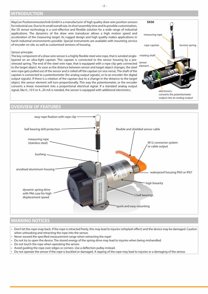
Sensor principle:The key component of a draw wire sensor is a highly flexible steel wire rope, that is winded single- layered on an ultra-light capstan. This capstan is connected to the sensor housing by a pre-stressed spring. The end of the steel wire rope, that is equipped with a rope clip gets connected to the target object. As soon as the distance between sensor and target object changes, the steel wire rope gets pulled out of the sensor and is rolled off the capstan (or vice versa). The shaft of the capstan is connected to a potentiometer (for analog output signals), or to an encoder (for digital output signals). If there is a rotation of the capstan due to a change in the distance to the target object, the sensor element will turn proportionally. This way the potentiometer, or the encoder converts a linear movement into a proportional electrical signal. If a standard analog output signal, like 0...10 V or 4...20 mA is needed, the sensor is equipped with additional electronics.
tension spring
measuring rope
rope capstan
rotating shaft
sensor element
electronics:converts the potentiometer output into an analog output
SX50
OVERVIEW OF FEATURES
easy rope fixation with rope clip
ball bearing drill protection
measuring rope (stainless steel)
bushing
anodised aluminium housing
dynamic spring drive with PA6 case for high displacement speed
flexible and shielded sensor cable
M12-connector system or cable output
waterproof housing IP65 or IP67
high linearity
2 ball bearings
quick and easy mounting
WARNING NOTICES
• Don’t let the rope snap back. If the rope is retracted freely, this may lead to injuries (whiplash effect) and the device may be damaged. Caution when unhooking and retracting the rope into the sensor.
• Never exceed the specified measurement range when extracting the rope! • Do not try to open the device. The stored energy of the spring drive may lead to injuries when being mishandled.• Do not touch the rope when operating the sensor.• Avoid guiding the rope over edges or corners. Use a deflection pulley instead.• Do not operate the sensor if the rope is buckled or damaged. A ripping of the rope may lead to injuries or a damaging of the sensor.
- 3 -
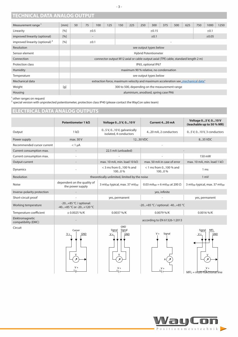
TECHNICAL DATA ANALOG OUTPUT
Measurement range 1 [mm] 50 75 100 125 150 225 250 300 375 500 625 750 1000 1250
Linearity [%] ±0.5 ±0.15 ±0.1
improved linearity (optional) [%] - ±0.1 ±0.05
improved linearity (optional) ² [%] ±0.1 -
Resolution see output types below
Sensor element Hybrid Potentiometer
Connection connector output M12 axial or cable output axial (TPE cable, standard length 2 m)
Protection class IP65, optional IP67
Humidity maximum 90 % relative, no condensation
Temperature see output types below
Mechanical data extraction force, maximum velocity and maximum acceleration see „mechanical data“
Weight [g] 300 to 500, depending on the measurement range
Housing aluminium, anodised, spring case PA6
1 other ranges on request² special version with unprotected potentiometer, protection class IP40 (please contact the WayCon sales team)
ELECTRICAL DATA ANALOG OUTPUTS
Potentiometer 1 kΩ Voltage 0...5 V, 0...10 V Current 4...20 mA Voltage 0...5 V, 0...10 V (teachable up to 50 % MR)
Output 1 kΩ 0...5 V, 0...10 V, galvanically isolated, 4 conductors 4...20 mA, 2 conductors 0...5 V, 0...10 V, 3 conductors
Power supply max. 30 V 12...30 VDC 8...35 VDC
Recommended cursor current < 1 µA -
Current consumption max. - 22.5 mA (unloaded) -
Current consumption max. - - - 150 mW
Output current - max. 10 mA, min. load 10 kΩ max. 50 mA in case of error max. 10 mA, min. load 1 kΩ
Dynamics - < 3 ms from 0...100 % and 100...0 %
< 1 ms from 0...100 % and 100...0 % 1 ms
Resolution theoretically unlimited, limited by the noise 1 mV
Noise dependent on the quality of the power supply 3 mVpp typical, max. 37 mVpp 0.03 mApp = 6 mVpp at 200 Ω 3 mVpp typical, max. 37 mVpp
Inverse-polarity protection - yes, infinite
Short-circuit proof - yes, permanent - yes, permanent
Working temperature -20...+85 °C / optional: -40...+85 °C or -20...+120 °C -20...+85 °C / optional: -40...+85 °C
Temperature coefficient ± 0.0025 %/K 0.0037 %/K 0.0079 %/K 0.0016 %/K
Elektromagnetic compatibility (EMC) - according to EN 61326-1:2013
Circuit
V +Cursor
GND
+V +
V
V +
Signal
GND
+V +
V
GNDSignal
V + Signal
+V +
A
V +
Signal
GND
+V +
V
MFL
MFL = multi-functional line
- 4 -
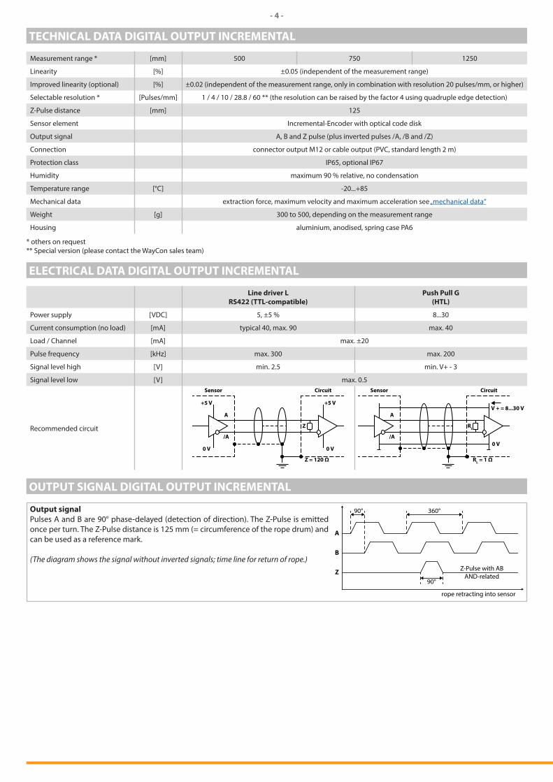
TECHNICAL DATA DIGITAL OUTPUT INCREMENTAL
Measurement range * [mm] 500 750 1250
Linearity [%] ±0.05 (independent of the measurement range)
Improved linearity (optional) [%] ±0.02 (independent of the measurement range, only in combination with resolution 20 pulses/mm, or higher)
Selectable resolution * [Pulses/mm] 1 / 4 / 10 / 28.8 / 60 ** (the resolution can be raised by the factor 4 using quadruple edge detection)
Z-Pulse distance [mm] 125
Sensor element Incremental-Encoder with optical code disk
Output signal A, B and Z pulse (plus inverted pulses /A, /B and /Z)
Connection connector output M12 or cable output (PVC, standard length 2 m)
Protection class IP65, optional IP67
Humidity maximum 90 % relative, no condensation
Temperature range [°C] -20...+85
Mechanical data extraction force, maximum velocity and maximum acceleration see „mechanical data“
Weight [g] 300 to 500, depending on the measurement range
Housing aluminium, anodised, spring case PA6
* others on request** Special version (please contact the WayCon sales team)
ELECTRICAL DATA DIGITAL OUTPUT INCREMENTAL
Line driver LRS422 (TTL-compatible)
Push Pull G(HTL)
Power supply [VDC] 5, ±5 % 8...30
Current consumption (no load) [mA] typical 40, max. 90 max. 40
Load / Channel [mA] max. ±20
Pulse frequency [kHz] max. 300 max. 200
Signal level high [V] min. 2.5 min. V+ - 3
Signal level low [V] max. 0.5
Recommended circuit Z
+5 V
0 V
+5 V
0 V
A
/A
Z = 120 Ω
Sensor Circuit
RL
V + = 8...30 V
0 V
A
/A
RL = 1 Ω
Sensor Circuit
OUTPUT SIGNAL DIGITAL OUTPUT INCREMENTAL
Output signalPulses A and B are 90° phase-delayed (detection of direction). The Z-Pulse is emitted once per turn. The Z-Pulse distance is 125 mm (= circumference of the rope drum) and can be used as a reference mark.
(The diagram shows the signal without inverted signals; time line for return of rope.)
90°
90°
360°
A
B
Z Z-Pulse with ABAND-related
rope retracting into sensor
- 5 -
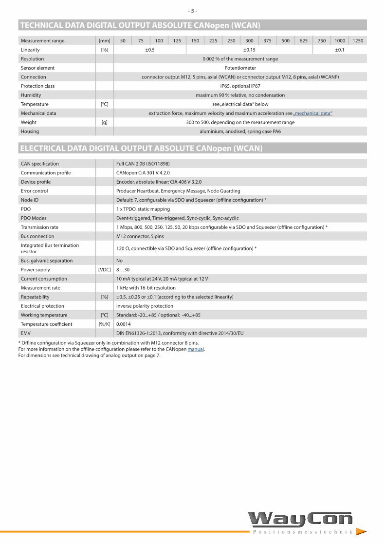
TECHNICAL DATA DIGITAL OUTPUT ABSOLUTE CANopen (WCAN)
Measurement range [mm] 50 75 100 125 150 225 250 300 375 500 625 750 1000 1250
Linearity [%] ±0.5 ±0.15 ±0.1
Resolution 0.002 % of the measurement range
Sensor element Potentiometer
Connection connector output M12, 5 pins, axial (WCAN) or connector output M12, 8 pins, axial (WCANP)
Protection class IP65, optional IP67
Humidity maximum 90 % relative, no condensation
Temperature [°C] see „electrical data“ below
Mechanical data extraction force, maximum velocity and maximum acceleration see „mechanical data“
Weight [g] 300 to 500, depending on the measurement range
Housing aluminium, anodised, spring case PA6
ELECTRICAL DATA DIGITAL OUTPUT ABSOLUTE CANopen (WCAN)
CAN specification Full CAN 2.0B (ISO11898)
Communication profile CANopen CiA 301 V 4.2.0
Device profile Encoder, absolute linear; CIA 406 V 3.2.0
Error control Producer Heartbeat, Emergency Message, Node Guarding
Node ID Default: 7, configurable via SDO and Squeezer (offline configuration) *
PDO 1 x TPDO, static mapping
PDO Modes Event-triggered, Time-triggered, Sync-cyclic, Sync-acyclic
Transmission rate 1 Mbps, 800, 500, 250, 125, 50, 20 kbps configurable via SDO and Squeezer (offline configuration) *
Bus connection M12 connector, 5 pins
Integrated Bus termination resistor 120 Ω, connectible via SDO and Squeezer (offline configuration) *
Bus, galvanic separation No
Power supply [VDC] 8…30
Current consumption 10 mA typical at 24 V, 20 mA typical at 12 V
Measurement rate 1 kHz with 16-bit resolution
Repeatability [%] ±0.5, ±0.25 or ±0.1 (according to the selected linearity)
Electrical protection inverse polarity protection
Working temperature [°C] Standard: -20...+85 / optional: -40...+85
Temperature coefficient [%/K] 0.0014
EMV DIN EN61326-1:2013, conformity with directive 2014/30/EU
* Offline configuration via Squeezer only in combination with M12 connector 8 pins.For more information on the offline configuration please refer to the CANopen manual.For dimensions see technical drawing of analog output on page 7.
- 6 -
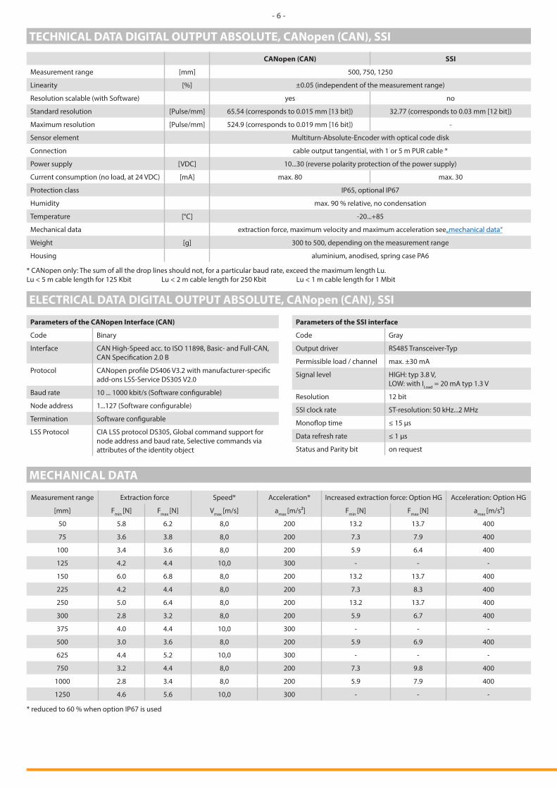
TECHNICAL DATA DIGITAL OUTPUT ABSOLUTE, CANopen (CAN), SSI
CANopen (CAN) SSI
Measurement range [mm] 500, 750, 1250
Linearity [%] ±0.05 (independent of the measurement range)
Resolution scalable (with Software) yes no
Standard resolution [Pulse/mm] 65.54 (corresponds to 0.015 mm [13 bit]) 32.77 (corresponds to 0.03 mm [12 bit])
Maximum resolution [Pulse/mm] 524.9 (corresponds to 0.019 mm [16 bit]) -
Sensor element Multiturn-Absolute-Encoder with optical code disk
Connection cable output tangential, with 1 or 5 m PUR cable *
Power supply [VDC] 10...30 (reverse polarity protection of the power supply)
Current consumption (no load, at 24 VDC) [mA] max. 80 max. 30
Protection class IP65, optional IP67
Humidity max. 90 % relative, no condensation
Temperature [°C] -20...+85
Mechanical data extraction force, maximum velocity and maximum acceleration see„mechanical data“
Weight [g] 300 to 500, depending on the measurement range
Housing aluminium, anodised, spring case PA6
* CANopen only: The sum of all the drop lines should not, for a particular baud rate, exceed the maximum length Lu.Lu < 5 m cable length for 125 Kbit Lu < 2 m cable length for 250 Kbit Lu < 1 m cable length for 1 Mbit
ELECTRICAL DATA DIGITAL OUTPUT ABSOLUTE, CANopen (CAN), SSI
Parameters of the SSI interface
Code Gray
Output driver RS485 Transceiver-Typ
Permissible load / channel max. ±30 mA
Signal level HIGH: typ 3.8 V, LOW: with ILoad = 20 mA typ 1.3 V
Resolution 12 bit
SSI clock rate ST-resolution: 50 kHz...2 MHz
Monoflop time ≤ 15 µs
Data refresh rate ≤ 1 µs
Status and Parity bit on request
Parameters of the CANopen Interface (CAN)
Code Binary
Interface CAN High-Speed acc. to ISO 11898, Basic- and Full-CAN, CAN Specification 2.0 B
Protocol CANopen profile DS406 V3.2 with manufacturer-specific add-ons LSS-Service DS305 V2.0
Baud rate 10 ... 1000 kbit/s (Software configurable)
Node address 1...127 (Software configurable)
Termination Software configurable
LSS Protocol CIA LSS protocol DS305, Global command support for node address and baud rate, Selective commands via attributes of the identity object
MECHANICAL DATA
Measurement range Extraction force Speed* Acceleration* Increased extraction force: Option HG Acceleration: Option HG
[mm] Fmin [N] Fmax [N] Vmax [m/s] amax [m/s²] Fmin [N] Fmax [N] amax [m/s²]
50 5.8 6.2 8,0 200 13.2 13.7 400
75 3.6 3.8 8,0 200 7.3 7.9 400
100 3.4 3.6 8,0 200 5.9 6.4 400
125 4.2 4.4 10,0 300 - - -
150 6.0 6.8 8,0 200 13.2 13.7 400
225 4.2 4.4 8,0 200 7.3 8.3 400
250 5.0 6.4 8,0 200 13.2 13.7 400
300 2.8 3.2 8,0 200 5.9 6.7 400
375 4.0 4.4 10,0 300 - - -
500 3.0 3.6 8,0 200 5.9 6.9 400
625 4.4 5.2 10,0 300 - - -
750 3.2 4.4 8,0 200 7.3 9.8 400
1000 2.8 3.4 8,0 200 5.9 7.9 400
1250 4.6 5.6 10,0 300 - - -
* reduced to 60 % when option IP67 is used
- 7 -
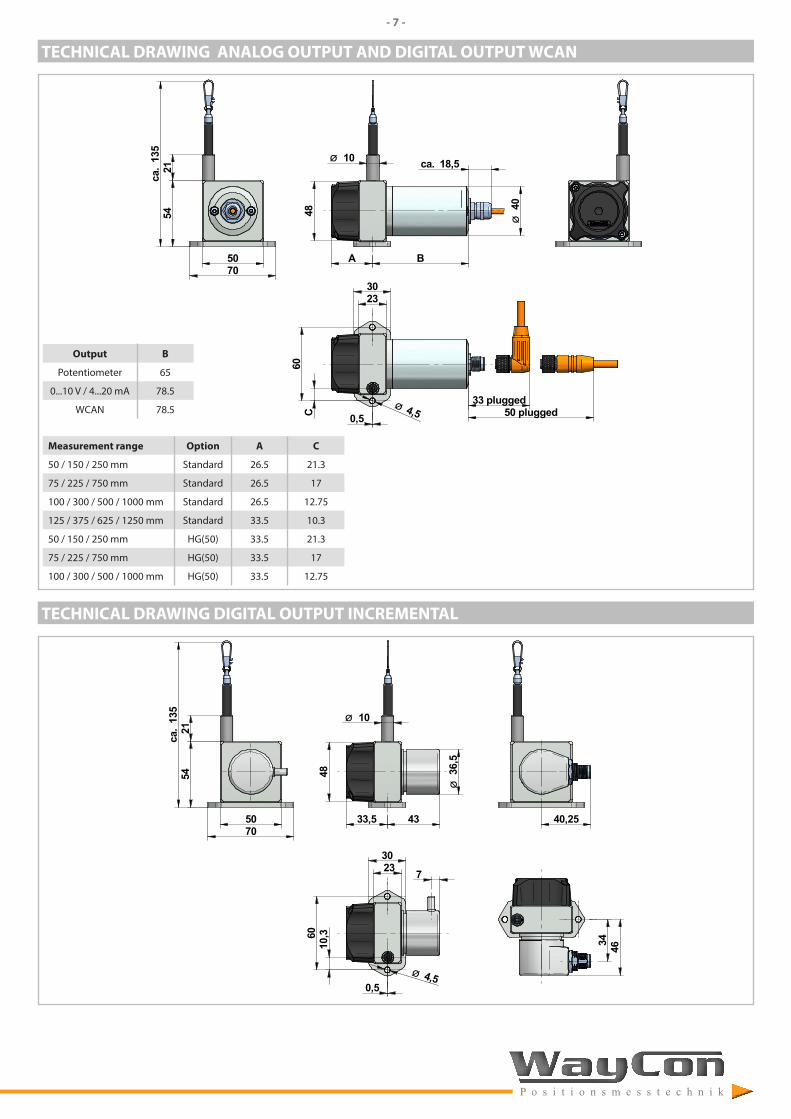
TECHNICAL DRAWING ANALOG OUTPUT AND DIGITAL OUTPUT WCAN
Output B
Potentiometer 65
0...10 V / 4...20 mA 78.5
WCAN 78.5
Measurement range Option A C
50 / 150 / 250 mm Standard 26.5 21.3
75 / 225 / 750 mm Standard 26.5 17
100 / 300 / 500 / 1000 mm Standard 26.5 12.75
125 / 375 / 625 / 1250 mm Standard 33.5 10.3
50 / 150 / 250 mm HG(50) 33.5 21.3
75 / 225 / 750 mm HG(50) 33.5 17
100 / 300 / 500 / 1000 mm HG(50) 33.5 12.75
5070
5421
135
ca.
40Ø
18,5ca.
48
A B
2330
Ø 4,50,5C60
33 plugged50 plugged
10Ø
TECHNICAL DRAWING DIGITAL OUTPUT INCREMENTAL
5421
135
ca.
5070
36,5
Ø
48
33,5 43
0,5
10,360
Ø 4,5
2330
7
40,25
34 46
10Ø
- 8 -
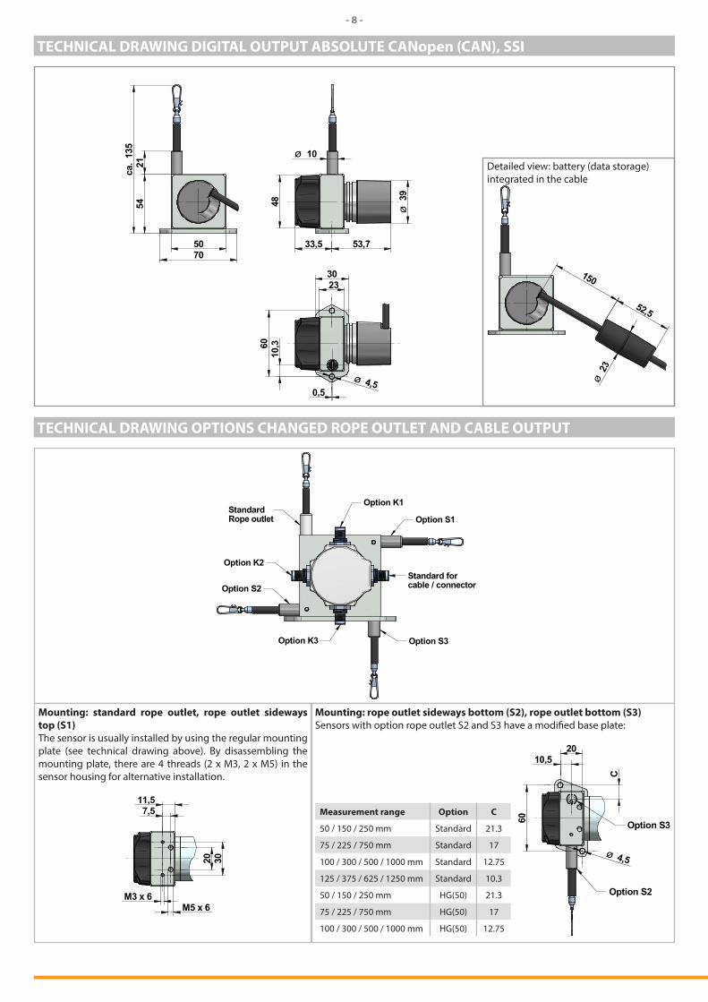
TECHNICAL DRAWING DIGITAL OUTPUT ABSOLUTE CANopen (CAN), SSI
5421
135
ca.
5070
48
33,5
0,5
10,360
Ø 4,5
2330
53,7
39Ø
10ØDetailed view: battery (data storage) integrated in the cable
150
52,5
23Ø
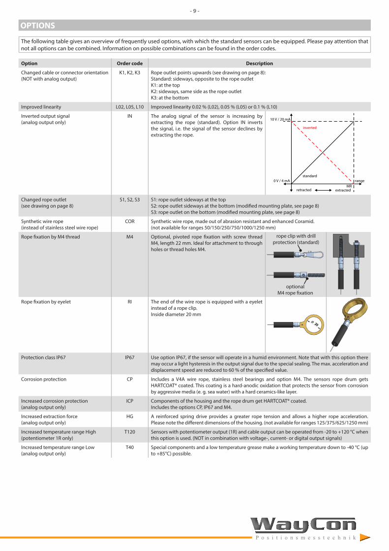
TECHNICAL DRAWING OPTIONS CHANGED ROPE OUTLET AND CABLE OUTPUT
StandardRope outlet
Standard forcable / connectorOption S2
Option K2
Option K3 Option S3
Option S1
Option K1
Mounting: standard rope outlet, rope outlet sideways top (S1)The sensor is usually installed by using the regular mounting plate (see technical drawing above). By disassembling the mounting plate, there are 4 threads (2 x M3, 2 x M5) in the sensor housing for alternative installation.
7,511,5
M3 x 6M5 x 6
20 30
Mounting: rope outlet sideways bottom (S2), rope outlet bottom (S3)Sensors with option rope outlet S2 and S3 have a modified base plate:
Measurement range Option C
50 / 150 / 250 mm Standard 21.3
75 / 225 / 750 mm Standard 17
100 / 300 / 500 / 1000 mm Standard 12.75
125 / 375 / 625 / 1250 mm Standard 10.3
50 / 150 / 250 mm HG(50) 21.3
75 / 225 / 750 mm HG(50) 17
100 / 300 / 500 / 1000 mm HG(50) 12.75
60
20
Ø 4,5
10,5
C
Option S2
Option S3
- 9 -
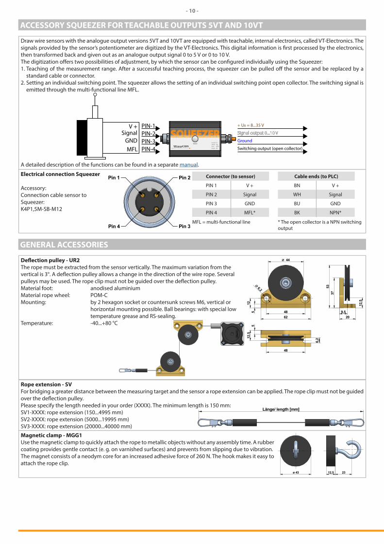
OPTIONS
The following table gives an overview of frequently used options, with which the standard sensors can be equipped. Please pay attention that not all options can be combined. Information on possible combinations can be found in the order codes.
Option Order code Description
Changed cable or connector orientation (NOT with analog output)
K1, K2, K3 Rope outlet points upwards (see drawing on page 8):Standard: sideways, opposite to the rope outletK1: at the topK2: sideways, same side as the rope outletK3: at the bottom
Improved linearity L02, L05, L10 Improved linearity 0.02 % (L02), 0.05 % (L05) or 0.1 % (L10)
Inverted output signal(analog output only)
IN The analog signal of the sensor is increasing by extracting the rope (standard). Option IN inverts the signal, i.e. the signal of the sensor declines by extracting the rope.
range
inverted
standard
retracted extractedMR
0 V / 4 mA
10 V / 20 mA
Changed rope outlet(see drawing on page 8)
S1, S2, S3 S1: rope outlet sideways at the topS2: rope outlet sideways at the bottom (modified mounting plate, see page 8)S3: rope outlet on the bottom (modified mounting plate, see page 8)
Synthetic wire rope(instead of stainless steel wire rope)
COR Synthetic wire rope, made out of abrasion resistant and enhanced Coramid.(not available for ranges 50/150/250/750/1000/1250 mm)
Rope fixation by M4 thread M4 Optional, pivoted rope fixation with screw thread M4, length 22 mm. Ideal for attachment to through holes or thread holes M4.
Rope fixation by eyelet RI The end of the wire rope is equipped with a eyelet instead of a rope clip.Inside diameter 20 mm
Ø 20
Protection class IP67 IP67 Use option IP67, if the sensor will operate in a humid environment. Note that with this option there may occur a light hysteresis in the output signal due to the special sealing. The max. acceleration and displacement speed are reduced to 60 % of the specified value.
Corrosion protection CP Includes a V4A wire rope, stainless steel bearings and option M4. The sensors rope drum gets HARTCOAT® coated. This coating is a hard-anodic oxidation that protects the sensor from corrosion by aggressive media (e. g. sea water) with a hard ceramics-like layer.
Increased corrosion protection(analog output only)
ICP Components of the housing and the rope drum get HARTCOAT® coated. Includes the options CP, IP67 and M4.
Increased extraction force(analog output only)
HG A reinforced spring drive provides a greater rope tension and allows a higher rope acceleration. Please note the different dimensions of the housing. (not available for ranges 125/375/625/1250 mm)
Increased temperature range High(potentiometer 1R only)
T120 Sensors with potentiometer output (1R) and cable output can be operated from -20 to +120 °C when this option is used. (NOT in combination with voltage-, current- or digital output signals)
Increased temperature range Low(analog output only)
T40 Special components and a low temperature grease make a working temperature down to -40 °C (up to +85°C) possible.
rope clip with drill protection (standard)
optional M4 rope fixation
- 10 -
ACCESSORY SQUEEZER FOR TEACHABLE OUTPUTS 5VT AND 10VT
Draw wire sensors with the analogue output versions 5VT and 10VT are equipped with teachable, internal electronics, called VT-Electronics. The signals provided by the sensor’s potentiometer are digitized by the VT-Electronics. This digital information is first processed by the electronics, then transformed back and given out as an analogue output signal 0 to 5 V or 0 to 10 V.The digitization offers two possibilities of adjustment, by which the sensor can be configured individually using the Squeezer:1. Teaching of the measurement range. After a successful teaching process, the squeezer can be pulled off the sensor and be replaced by a
standard cable or connector.2. Setting an individual switching point. The squeezer allows the setting of an individual switching point open collector. The switching signal is
emitted through the multi-functional line MFL.
PIN-1PIN-2PIN-3PIN-4
V +Signal
MFLGND
+ UB = 8...35 V
Signal output 0...10 V
Ground
Switching output (open collector)
A detailed description of the functions can be found in a separate manual.
Electrical connection Squeezer
Accessory: Connection cable sensor to Squeezer:K4P1,5M-SB-M12
Pin 2Pin 1
Pin 3Pin 4
Connector (to sensor)
PIN 1 V +
PIN 2 Signal
PIN 3 GND
PIN 4 MFL*
MFL = multi-functional line
Cable ends (to PLC)
BN V +
WH Signal
BU GND
BK NPN*
* The open collector is a NPN switching output
GENERAL ACCESSORIES
Deflection pulley - UR2The rope must be extracted from the sensor vertically. The maximum variation from the vertical is 3°. A deflection pulley allows a change in the direction of the wire rope. Several pulleys may be used. The rope clip must not be guided over the deflection pulley.Material foot: anodised aluminiumMaterial rope wheel: POM-CMounting: by 2 hexagon socket or countersunk screws M6, vertical or horizontal mounting possible. Ball bearings: with special low temperature grease and RS-sealing.Temperature: -40...+80 °C
5
62
3753
48
Ø 6,2
6,2
48
125
209,5
12,5
12,5
Ø 44
Rope extension - SVFor bridging a greater distance between the measuring target and the sensor a rope extension can be applied. The rope clip must not be guided over the deflection pulley.Please specify the length needed in your order (XXXX). The minimum length is 150 mm:SV1-XXXX: rope extension (150...4995 mm)SV2-XXXX: rope extension (5000...19995 mm)SV3-XXXX: rope extension (20000...40000 mm)
Länge/ length [mm]
Magnetic clamp - MGG1 Use the magnetic clamp to quickly attach the rope to metallic objects without any assembly time. A rubber coating provides gentle contact (e. g. on varnished surfaces) and prevents from slipping due to vibration.The magnet consists of a neodym core for an increased adhesive force of 260 N. The hook makes it easy to attach the rope clip.
ø 43 12,5 23
- 11 -
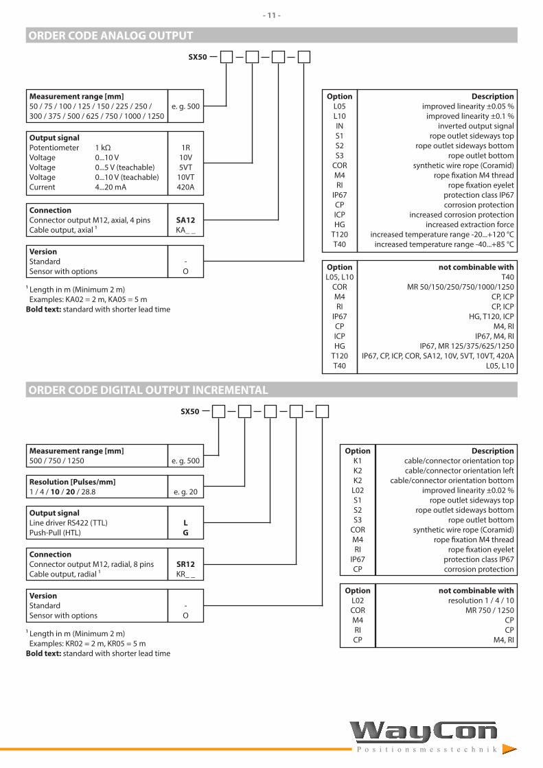
ORDER CODE ANALOG OUTPUT
SX50
Measurement range [mm]50 / 75 / 100 / 125 / 150 / 225 / 250 / 300 / 375 / 500 / 625 / 750 / 1000 / 1250
e. g. 500
Output signalPotentiometer 1 kΩVoltage 0...10 VVoltage 0...5 V (teachable)Voltage 0...10 V (teachable)Current 4...20 mA
1R10V5VT
10VT420A
ConnectionConnector output M12, axial, 4 pinsCable output, axial 1
SA12KA_ _
VersionStandardSensor with options
-O
1 Length in m (Minimum 2 m) Examples: KA02 = 2 m, KA05 = 5 mBold text: standard with shorter lead time
Descriptionimproved linearity ±0.05 %
improved linearity ±0.1 %inverted output signal
rope outlet sideways toprope outlet sideways bottom
rope outlet bottomsynthetic wire rope (Coramid)
rope fixation M4 threadrope fixation eyelet
protection class IP67corrosion protection
increased corrosion protectionincreased extraction force
increased temperature range -20...+120 °Cincreased temperature range -40...+85 °C
OptionL05L10INS1S2S3
CORM4RI
IP67CPICPHG
T120T40
not combinable withT40
MR 50/150/250/750/1000/1250CP, ICPCP, ICP
HG, T120, ICPM4, RI
IP67, M4, RIIP67, MR 125/375/625/1250
IP67, CP, ICP, COR, SA12, 10V, 5VT, 10VT, 420AL05, L10
OptionL05, L10
CORM4RI
IP67CPICPHG
T120T40
ORDER CODE DIGITAL OUTPUT INCREMENTAL
SX50
Measurement range [mm]500 / 750 / 1250 e. g. 500
Resolution [Pulses/mm]1 / 4 / 10 / 20 / 28.8 e. g. 20
Output signalLine driver RS422 (TTL)Push-Pull (HTL)
LG
ConnectionConnector output M12, radial, 8 pinsCable output, radial 1
SR12KR_ _
VersionStandardSensor with options
-O
1 Length in m (Minimum 2 m) Examples: KR02 = 2 m, KR05 = 5 mBold text: standard with shorter lead time
Descriptioncable/connector orientation topcable/connector orientation left
cable/connector orientation bottomimproved linearity ±0.02 %
rope outlet sideways toprope outlet sideways bottom
rope outlet bottomsynthetic wire rope (Coramid)
rope fixation M4 threadrope fixation eyelet
protection class IP67corrosion protection
OptionK1K2K2
L02S1S2S3
CORM4RI
IP67CP
not combinable withresolution 1 / 4 / 10
MR 750 / 1250 CPCP
M4, RI
OptionL02CORM4RICP
- 12 -
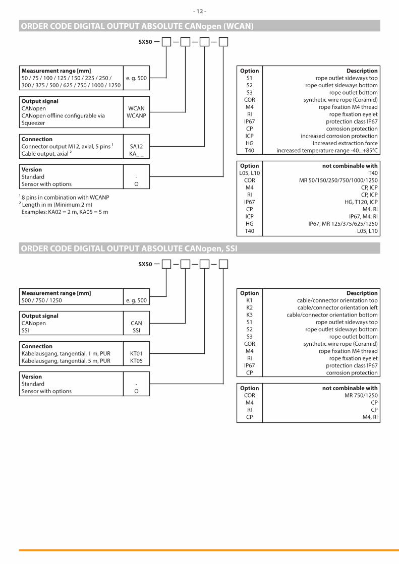
ORDER CODE DIGITAL OUTPUT ABSOLUTE CANopen (WCAN)
SX50
Measurement range [mm]50 / 75 / 100 / 125 / 150 / 225 / 250 / 300 / 375 / 500 / 625 / 750 / 1000 / 1250
e. g. 500
Output signalCANopenCANopen offline configurable via Squeezer
WCANWCANP
ConnectionConnector output M12, axial, 5 pins 1Cable output, axial ²
SA12KA_ _
VersionStandardSensor with options
-O
1 8 pins in combination with WCANP² Length in m (Minimum 2 m) Examples: KA02 = 2 m, KA05 = 5 m
Descriptionrope outlet sideways top
rope outlet sideways bottomrope outlet bottom
synthetic wire rope (Coramid)rope fixation M4 thread
rope fixation eyeletprotection class IP67corrosion protection
increased corrosion protectionincreased extraction force
increased temperature range -40...+85°C
OptionS1S2S3
CORM4RI
IP67CPICPHGT40
not combinable withT40
MR 50/150/250/750/1000/1250CP, ICPCP, ICP
HG, T120, ICPM4, RI
IP67, M4, RIIP67, MR 125/375/625/1250
L05, L10
OptionL05, L10
CORM4RI
IP67CPICPHGT40
ORDER CODE DIGITAL OUTPUT ABSOLUTE CANopen, SSI
SX50
Measurement range [mm]500 / 750 / 1250 e. g. 500
Output signalCANopenSSI
CANSSI
ConnectionKabelausgang, tangential, 1 m, PURKabelausgang, tangential, 5 m, PUR
KT01KT05
VersionStandardSensor with options
-O
Descriptioncable/connector orientation topcable/connector orientation left
cable/connector orientation bottomrope outlet sideways top
rope outlet sideways bottomrope outlet bottom
synthetic wire rope (Coramid)rope fixation M4 thread
rope fixation eyeletprotection class IP67corrosion protection
OptionK1K2K3S1S2S3
CORM4RI
IP67CP
not combinable withMR 750/1250
CPCP
M4, RI
OptionCORM4RICP
WayCon Positionsmesstechnik GmbHemail: [email protected] internet: www.waycon.biz
Head OfficeMehlbeerenstr. 482024 TaufkirchenTel. +49 (0)89 67 97 13-0Fax +49 (0)89 67 97 13-250
Office KölnAuf der Pehle 150321 BrühlTel. +49 (0)2232 56 79 44Fax +49 (0)2232 56 79 45
Subject to change without prior notice.
- 13 -
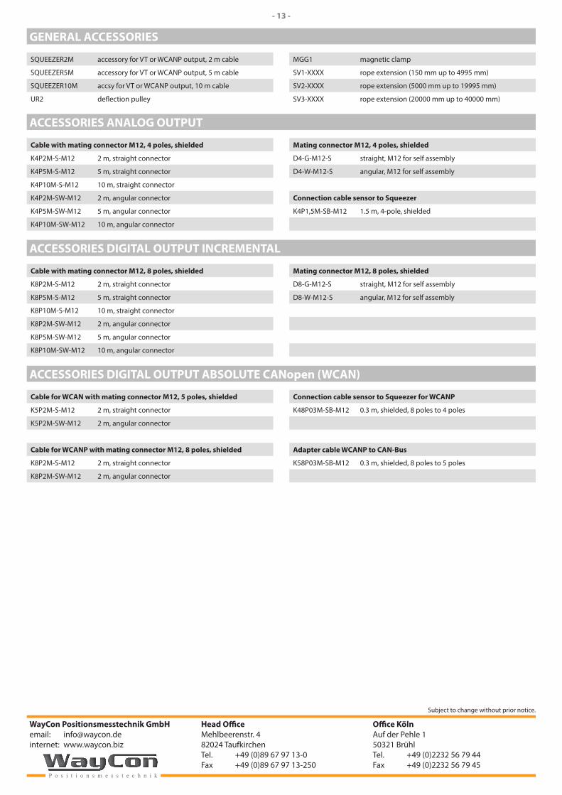
GENERAL ACCESSORIES
SQUEEZER2M accessory for VT or WCANP output, 2 m cable
SQUEEZER5M accessory for VT or WCANP output, 5 m cable
SQUEEZER10M accsy for VT or WCANP output, 10 m cable
UR2 deflection pulley
MGG1 magnetic clamp
SV1-XXXX rope extension (150 mm up to 4995 mm)
SV2-XXXX rope extension (5000 mm up to 19995 mm)
SV3-XXXX rope extension (20000 mm up to 40000 mm)
ACCESSORIES ANALOG OUTPUT
Cable with mating connector M12, 4 poles, shielded
K4P2M-S-M12 2 m, straight connector
K4P5M-S-M12 5 m, straight connector
K4P10M-S-M12 10 m, straight connector
K4P2M-SW-M12 2 m, angular connector
K4P5M-SW-M12 5 m, angular connector
K4P10M-SW-M12 10 m, angular connector
Mating connector M12, 4 poles, shielded
D4-G-M12-S straight, M12 for self assembly
D4-W-M12-S angular, M12 for self assembly
Connection cable sensor to Squeezer
K4P1,5M-SB-M12 1.5 m, 4-pole, shielded
ACCESSORIES DIGITAL OUTPUT INCREMENTAL
Cable with mating connector M12, 8 poles, shielded
K8P2M-S-M12 2 m, straight connector
K8P5M-S-M12 5 m, straight connector
K8P10M-S-M12 10 m, straight connector
K8P2M-SW-M12 2 m, angular connector
K8P5M-SW-M12 5 m, angular connector
K8P10M-SW-M12 10 m, angular connector
Mating connector M12, 8 poles, shielded
D8-G-M12-S straight, M12 for self assembly
D8-W-M12-S angular, M12 for self assembly
ACCESSORIES DIGITAL OUTPUT ABSOLUTE CANopen (WCAN)
Cable for WCAN with mating connector M12, 5 poles, shielded
K5P2M-S-M12 2 m, straight connector
K5P2M-SW-M12 2 m, angular connector
Cable for WCANP with mating connector M12, 8 poles, shielded
K8P2M-S-M12 2 m, straight connector
K8P2M-SW-M12 2 m, angular connector
Connection cable sensor to Squeezer for WCANP
K48P03M-SB-M12 0.3 m, shielded, 8 poles to 4 poles
Adapter cable WCANP to CAN-Bus
K58P03M-SB-M12 0.3 m, shielded, 8 poles to 5 poles
Related Documents