Dragonfly 6 Dragonfly 7 Installation and operation instructions English (EN) Date: 02-2016 Document number: 81345-5 © 2016 Raymarine UK Limited Release 12

Welcome message from author
This document is posted to help you gain knowledge. Please leave a comment to let me know what you think about it! Share it to your friends and learn new things together.
Transcript

Dragonfly 6Dragonfly 7
Installation and operationinstructions
English (EN)Date: 02-2016Document number: 81345-5 © 2016 Raymarine UK Limited
Release 12

Document and software changesThe following tables describe the main changes that have been made since the last release of both theproduct software and this document.• Applicable software version: Dragonfly® LightHouseTM II — Release 12• Applicable documents: 81345–5• Applicable products: Dragonfly 6 / Dragonfly 7
New features
DescriptionApplicableapplication Applicable chapter(s) or section(s)
Added support for Dragonfly-7 Pro N/A N/ASuperior downrigger sonar performance. Sonar / DownVision N/AImproved bottom tracking capabilities. Sonar / DownVision N/A
Trademark and patents noticeRaymarine, Tacktick, Clear Pulse, Truzoom, HSB, SeaTalk, SeaTalkhs, SeaTalkng, Micronet, Raytech,Gear Up, Marine Shield, Seahawk, Autohelm, Automagic, and Visionality are registered or claimedtrademarks of Raymarine Belgium.FLIR, DownVision, SideVision, Dragonfly, Quantum, Instalert, Infrared Everywhere, and The World’sSixth Sense are registered or claimed trademarks of FLIR Systems, Inc.All other trademarks, trade names, or company names referenced herein are used for identification onlyand are the property of their respective owners.This product is protected by patents, design patents, patents pending, or design patents pending.
Fair Use StatementYou may print no more than three copies of this manual for your own use. You may not make any furthercopies or distribute or use the manual in any other way including without limitation exploiting the manualcommercially or giving or selling copies to third parties.
Software updates
Important: Check the Raymarine website for the latest software releases for your product.
www.raymarine.com/software
Product handbooksThe latest versions of all English and translated handbooks are available to download in PDF format from the websitewww.raymarine.com.Please check the website to ensure you have the latest handbooks.
Copyright ©2016 Raymarine UK Ltd. All rights reserved.
ENGLISHDocument number: 81345-5Date: 02-2016


ContentsChapter 1 Important information.......................... 7TFT Displays............................................................... 8Water ingress .............................................................. 8Disclaimers ................................................................. 8Memory cards and chart cards ..................................... 8EMC installation guidelines .......................................... 8Third party software license agreements ....................... 9Declaration of conformity.............................................. 9Pixel defect policy........................................................ 9Warranty policy............................................................ 9Warranty registration.................................................... 9Product disposal .......................................................... 9IMO and SOLAS.......................................................... 9Technical accuracy .................................................... 10
Chapter 2 Document and productinformation........................................................... 112.1 Document information .......................................... 122.2 Product overview ................................................. 13
Chapter 3 Planning the installation ................... 153.1 Installation checklist ............................................. 163.2 Parts supplied...................................................... 173.3 DownVision™ transducer compatibility.................. 183.4 Tools required for installation................................. 193.5 Software updates ................................................. 193.6 Warnings and cautions ......................................... 203.7 Selecting a location for the transducer ................... 203.8 Cable routing ....................................................... 213.9 Selecting a location for the display ........................ 223.10 Installation process............................................. 23
Chapter 4 Mounting............................................. 254.1 Mounting the transducer ....................................... 264.2 Cradle mounting .................................................. 274.3 Fitting the display in the cradle .............................. 284.4 Fitting the 7 inch display in the cradle — Cradledown......................................................................... 284.5 Security ............................................................... 294.6 Removing the display from the bracket .................. 304.7 Surface mounting................................................. 314.8 Testing the transducer .......................................... 324.9 Finishing the transducer mounting......................... 32
Chapter 5 Cables and connections.................... 335.1 General cabling guidance ..................................... 345.2 Connections overview .......................................... 345.3 Cable connection ................................................. 355.4 Extension cable connection .................................. 38
Chapter 6 Getting started ................................... 396.1 Controls............................................................... 406.2 Switching the unit on and off ................................. 416.3 Initial set up procedures........................................ 41
6.4 Satellite-based navigation..................................... 426.5 Checking the sonar application ............................. 446.6 Checking the DownVision™ application ................ 446.7 Shortcuts page..................................................... 456.8 Applications ......................................................... 466.9 View switcher....................................................... 466.10 Memory cards and chart cards ............................ 476.11 Learning resources............................................. 48
Chapter 7 Fishfinder applications...................... 497.1 DownVision™ application overview....................... 507.2 Sonar application overview ................................... 507.3 Fishfinder applications' features ............................ 527.4 Fishfinder applications’ controls ............................ 527.5 Zoom .................................................................. 537.6 Range ................................................................. 547.7 Scrolling .............................................................. 547.8 A-Scope mode..................................................... 557.9 Display Options.................................................... 557.10 Sensitivity adjustments ....................................... 567.11 Color Palettes .................................................... 57
Chapter 8 Chart application................................ 598.1 Chart application overview.................................... 608.2 Electronic charts overview .................................... 618.3 Chart application controls ..................................... 638.4 Waypoints overview ............................................. 648.5 Tracks ................................................................. 718.6 Import and Export ................................................ 738.7 Waypoints and tracks storage capacity .................. 748.8 Navigation ........................................................... 748.9 Chart settings menu — cartographycompatibility .............................................................. 758.10 Chart selection................................................... 758.11 Chart Detail........................................................ 768.12 High resolution bathymetry ................................. 768.13 Chart orientation ................................................ 778.14 Text and Symbol size.......................................... 788.15 Boat position...................................................... 788.16 Community layer ................................................ 798.17 Sonar logging..................................................... 798.18 COG Vector ....................................................... 808.19 Deep Water ....................................................... 808.20 Chart objects ..................................................... 81
Chapter 9 Tools & Settings................................. 839.1 System Settings menu.......................................... 849.2 Alarms................................................................. 899.3 Backup and reset ................................................. 91
Chapter 10 Maintenance ..................................... 9310.1 Service and maintenance ................................... 9410.2 Product cleaning ................................................ 94
5

10.3 Transducer cleaning ........................................... 95
Chapter 11 Troubleshooting............................... 9711.1 Troubleshooting.................................................. 9811.2 Power up troubleshooting.................................... 9911.3 GPS troubleshooting......................................... 10011.4 Sonar / DownVision troubleshooting .................. 10111.5 Miscellaneous troubleshooting .......................... 103
Chapter 12 Technical support .......................... 10512.1 Raymarine product support and servicing........... 10612.2 Learning resources........................................... 107
Chapter 13 Technical specification.................. 10913.1 Technical specification .......................................110
Chapter 14 Spares and accessories................ 11314.1 Accessories ......................................................114
6 Dragonfly 6 / Dragonfly 7
Chapter 1: Important informationWarning: Product installation andoperation• This product must be installed andoperated in accordance with theinstructions provided. Failure to do socould result in personal injury, damageto your vessel and/or poor productperformance.
• Raymarine recommends certifiedinstallation by a Raymarine approvedinstaller. A certified installation qualifiesfor enhanced product warranty benefits.Contact your Raymarine dealer forfurther details, and refer to the separatewarranty document packed with yourproduct.
Warning: Ensure safe navigationThis product is intended only as an aidto navigation and must never be usedin preference to sound navigationaljudgment. Only official governmentcharts and notices to mariners contain allthe current information needed for safenavigation, and the captain is responsiblefor their prudent use. It is the user’sresponsibility to use official governmentcharts, notices to mariners, caution andproper navigational skill when operatingthis or any other Raymarine product.
Warning: Potential ignition sourceThis product is NOT approved for use inhazardous/flammable atmospheres. DoNOT install in a hazardous/flammableatmosphere (such as in an engine roomor near fuel tanks).
Warning: 12 Volt dc onlyThis product must only be connected to a12 volt dc power source.
Warning: High voltagesThis product may contain high voltages.Do NOT remove any covers or otherwiseattempt to access internal components,unless specifically instructed in thedocumentation provided.
Warning: Power supply voltageConnecting this product to a voltagesupply greater than the specifiedmaximum rating may cause permanentdamage to the unit. Refer to the Technicalspecification section for voltage rating.
Warning: Product groundingBefore applying power to this product,ensure it has been correctly grounded, inaccordance with the instructions provided.
Warning: Switch off power supplyEnsure the vessel’s power supply isswitched OFF before starting to install thisproduct. Do NOT connect or disconnectequipment with the power switched on,unless instructed in this document.
Caution: Service and maintenanceThis product contains no user serviceablecomponents. Please refer all maintenanceand repair to authorized Raymarinedealers. Unauthorized repair may affectyour warranty.
Caution: Transducer cable• Do NOT cut, shorten, or splice thetransducer cable.
• Do NOT remove the connector.If the cable is cut, it cannot be repaired.Cutting the cable will also void thewarranty.
Caution: Power supply protectionWhen installing this product ensure thepower source is adequately protectedby means of a suitably-rated fuse orautomatic circuit breaker.
Caution: Care of chart and memorycardsTo avoid irreparable damage to and / orloss of data from chart and memory cards:
• DO NOT save data or files to a cardcontaining cartography as the chartsmay be overwritten.
• Ensure that chart and memory cardsare fitted the correct way around. DONOT try to force a card into position.
• DO NOT use a metallic instrument suchas a screwdriver or pliers to insert orremove a chart or memory card.
Caution: Ensure card reader dooris securely closedTo prevent water ingress and consequentdamage to the product, ensure that thecard reader door is firmly closed.
Important information 7

Caution: Product cleaningWhen cleaning products:
• If your product includes a displayscreen, do NOT wipe the screen witha dry cloth, as this could scratch thescreen coating.
• Do NOT use abrasive, or acid orammonia based products.
• Do NOT use a jet wash.
TFT DisplaysThe colors of the display may seem to vary whenviewed against a colored background or in coloredlight. This is a perfectly normal effect that canbe seen with all color Thin Film Transistor (TFT)displays.
Water ingressWater ingress disclaimerAlthough the waterproof rating capacity of thisproduct meets the stated IPX standard (refer to theproduct’s Technical Specification), water intrusionand subsequent equipment failure may occur if theproduct is subjected to commercial high-pressurewashing. Raymarine will not warrant productssubjected to high-pressure washing.
DisclaimersThis product (including the electronic charts) isintended to be used only as an aid to navigation. Itis designed to facilitate use of official governmentcharts, not replace them. Only official governmentcharts and notices to mariners contain all the currentinformation needed for safe navigation, and thecaptain is responsible for their prudent use. It isthe user’s responsibility to use official governmentcharts, notices to mariners, caution and propernavigational skill when operating this or any otherRaymarine product. This product supports electroniccharts provided by third party data suppliers whichmay be embedded or stored on memory card. Useof such charts is subject to the supplier’s End-UserLicence Agreement included in the documentationfor this product or supplied with the memory card(as applicable).Raymarine does not warrant that this product iserror-free or that it is compatible with productsmanufactured by any person or entity other thanRaymarine.This product uses digital chart data, and electronicinformation from the Global Positioning System(GPS) which may contain errors. Raymarine doesnot warrant the accuracy of such information andyou are advised that errors in such information maycause the product to malfunction. Raymarine is notresponsible for damages or injuries caused by your
use or inability to use the product, by the interactionof the product with products manufactured by others,or by errors in chart data or information utilized bythe product and supplied by third parties.
Memory cards and chart cardsMicroSD memory cards can be used to back up /archive data (e.g. Waypoint, and Tracks). Oncedata is backed up to a memory card old data canbe deleted from the system, creating capacity fornew data. The archived data can be retrieved at anytime. Chart cards provide additional or upgradedcartography.It is recommended that your data is backed up to amemory card on a regular basis. Do NOT save datato a memory card containing cartography.
Compatible cardsThe following types of MicroSD cards are compatiblewith your display:• Micro Secure Digital Standard-Capacity(MicroSDSC)
• Micro Secure Digital High-Capacity (MicroSDHC)
Note:• The maximum supported memory card capacityis 32 GB.
• MicroSD cards must be formatted to use eitherthe FAT or FAT 32 file system format to enableuse with your MFD.
Speed class ratingFor best performance it is recommended that youuse Class 10 or UHS (Ultra High Speed) classmemory cards.
Chart cardsYour product is pre-loaded with electronic charts(worldwide base map). If you wish to use differentchart data, you can insert compatible chart cards intothe unit's memory card reader.
Use branded chart cards and memory cardsWhen archiving data or creating an electronic chartcard, Raymarine recommends the use of qualitybranded memory cards. Some brands of memorycard may not work in your unit. Please contactcustomer support for a list of recommended cards.
EMC installation guidelinesRaymarine equipment and accessories conform tothe appropriate Electromagnetic Compatibility (EMC)regulations, to minimize electromagnetic interferencebetween equipment and minimize the effect suchinterference could have on the performance of yoursystemCorrect installation is required to ensure that EMCperformance is not compromised.
8 Dragonfly 6 / Dragonfly 7

Note: In areas of extreme EMC interference,some slight interference may be noticed on theproduct. Where this occurs the product and thesource of the interference should be separated bya greater distance.
For optimum EMC performance we recommendthat wherever possible:• Raymarine equipment and cables connected toit are:– At least 1 m (3 ft) from any equipmenttransmitting or cables carrying radio signals e.g.VHF radios, cables and antennas. In the caseof SSB radios, the distance should be increasedto 7 ft (2 m).
– More than 2 m (7 ft) from the path of a radarbeam. A radar beam can normally be assumedto spread 20 degrees above and below theradiating element.
• The product is supplied from a separate batteryfrom that used for engine start. This is important toprevent erratic behavior and data loss which canoccur if the engine start does not have a separatebattery.
• Raymarine specified cables are used.• Cables are not cut or extended, unless doing so isdetailed in the installation manual.
Note: Where constraints on the installationprevent any of the above recommendations,always ensure the maximum possible separationbetween different items of electrical equipment, toprovide the best conditions for EMC performancethroughout the installation
Third party software licenseagreementsThis product is subject to certain third party softwarelicense agreements as listed below:• GNU — LGPL/GPL• JPEG libraries• OpenSSL• FreeTypeThe license agreements for the above can be foundon the website www.raymarine.com and on theaccompanying documentation CD if supplied.
Declaration of conformityRaymarine UK Ltd. declares that this product iscompliant with the essential requirements of EMCdirective 2004/108/EC.The original Declaration of Conformity certificatemay be viewed on the relevant product page atwww.raymarine.com.
Pixel defect policyIn common with all TFT units, the screen may exhibita few wrongly-illuminated (“dead”) pixels. Thesemay appear as black pixels in a light area of thescreen or as colored pixels in black areas.If your display exhibits MORE than the numberof wrongly-illuminated pixels allowed (refer to theproduct technical specification for details), pleasecontact your local Raymarine service center forfurther advice.
Warranty policyYour product is warranted to be free from defects inmaterials and workmanship for a period of 1 yearfrom the date of first purchase of the product or, ifinstalled on a new boat, the date of first boat deliveryto the Original Customer (please retain proof ofpurchase in case you need to claim).The full details of the Limited Warranty Policyand registration process are available online at:www.raymarine.com/warranty-dragonfly.If you do not have access to the Internet, pleasephone the relevant number below to obtain warrantypolicy information:In the USA:• Tel: +1 603 324 7900• Toll Free: +1 800 539 5539In the UK, Europe, the Middle East, or Far East:• Tel: +44 (0)13 2924 6777
Warranty registrationTo register your Raymarine product ownership,please visit www.raymarine.com and register online.It is important that you register your product toreceive full warranty benefits. Your unit packageincludes a bar code label indicating the serial numberof the unit. You will need this serial number whenregistering your product online. You should retainthe label for future reference.
Product disposalDispose of this product in accordance with theWEEE Directive.
The Waste Electrical and Electronic Equipment(WEEE) Directive requires the recycling of wasteelectrical and electronic equipment.
IMO and SOLASThe equipment described within this documentis intended for use on leisure marine boats andworkboats NOT covered by International MaritimeOrganization (IMO) and Safety of Life at Sea(SOLAS) Carriage Regulations.
Important information 9

Technical accuracyTo the best of our knowledge, the information in thisdocument was correct at the time it was produced.However, Raymarine cannot accept liability for anyinaccuracies or omissions it may contain. In addition,our policy of continuous product improvement maychange specifications without notice. As a result,Raymarine cannot accept liability for any differencesbetween the product and this document. Pleasecheck the Raymarine website (www.raymarine.com)to ensure you have the most up-to-date version(s) ofthe documentation for your product.
10 Dragonfly 6 / Dragonfly 7

Chapter 2: Document and product information
Chapter contents• 2.1 Document information on page 12• 2.2 Product overview on page 13
Document and product information 11
2.1 Document informationThis document contains important informationrelated to the installation of your Raymarine product.The document includes information to help you:• plan your installation and ensure you have all thenecessary equipment;
• install and connect your product as part of a widersystem of connected marine electronics;
• troubleshoot problems and obtain technicalsupport if required.
This and other Raymarine product documentsare available to download in PDF format fromwww.raymarine.com.
Applicable productsThis document is applicable to the following products:
Partnumber Description
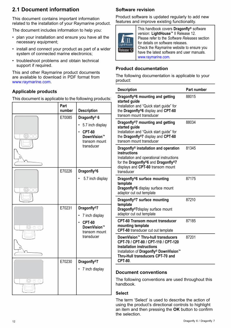
�������� E70085 Dragonfly® 6
• 5.7 inch display• CPT-60
DownVision™transom mounttransducer
�������� E70226 Dragonfly®6
• 5.7 inch display
������
E70231 Dragonfly®7
• 7 inch display• CPT-60
DownVision™transom mounttransducer
������
E70230 Dragonfly®7
• 7 inch display
Software revisionProduct software is updated regularly to add newfeatures and improve existing functionality.
Release 12
This handbook covers Dragonfly® softwareversion: LightHouse™ II Release 12.Please refer to the Software Releases sectionfor details on software releases.Check the Raymarine website to ensure youhave the latest software and user manuals.www.raymarine.com.
Product documentationThe following documentation is applicable to yourproduct:
Description Part numberDragonfly®6 mounting and gettingstarted guideInstallation and “Quick start guide” forthe Dragonfly®6 display and CPT-60transom mount transducer
88015
Dragonfly®7 mounting and gettingstarted guideInstallation and “Quick start guide” forthe Dragonfly®7 display and CPT-60transom mount transducer
88034
Dragonfly® installation and operationinstructionsInstallation and operational instructionsfor the Dragonfly®6 and Dragonfly®7displays and CPT-60 transom mounttransducer
81345
Dragonfly®6 surface mountingtemplateDragonfly®6 display surface mountadaptor cut out template
87175
Dragonfly®7 surface mountingtemplateDragonfly®7display surface mountadaptor cut out template
87210
CPT-60 Transom mount transducermounting templateCPT-60 transducer cut out template
87185
DownVision™ Thru-hull transducersCPT-70 / CPT-80 / CPT-110 / CPT-120Installation instructionsInstallation of Dragonfly® DownVision™Thru-Hull transducers CPT-70 andCPT-80.
87201
Document conventionsThe following conventions are used throughout thishandbook.
SelectThe term ‘Select’ is used to describe the action ofusing the product’s directional controls to highlightan item and then pressing the OK button to confirmthe selection.
12 Dragonfly 6 / Dragonfly 7
Directional controlsThe term ‘Directional controls’ is used to describethe Up, Down, Left and Right controls.
Document illustrationsYour product may differ slightly from that shownin the illustrations in this document, depending onproduct variant and date of manufacture.All images are provided for illustration purposes only.
User manuals Print ShopRaymarine provides a Print Shop service, enablingyou to purchase a high-quality, professionally-printedmanual for your Raymarine product.Printed manuals are ideal for keeping onboard yourvessel, as a useful source of reference wheneveryou need assistance with your Raymarine product.Visit http://www.raymarine.co.uk/view/?id=5175 toorder a printed manual, delivered directly to yourdoor.For further information about the Print Shop,please visit the Print Shop FAQ pages:http://www.raymarine.co.uk/view/?id=5751.
Note:• Accepted methods of payment for printedmanuals are credit cards and PayPal.
• Printed manuals can be shipped worldwide.• Further manuals will be added to the Print Shopover the coming months for both new and legacyproducts.
• Raymarine user manuals are also available todownload free-of-charge from the Raymarinewebsite, in the popular PDF format. These PDFfiles can be viewed on a PC / laptop, tablet,smartphone, or on the latest generation ofRaymarine multifunction displays.
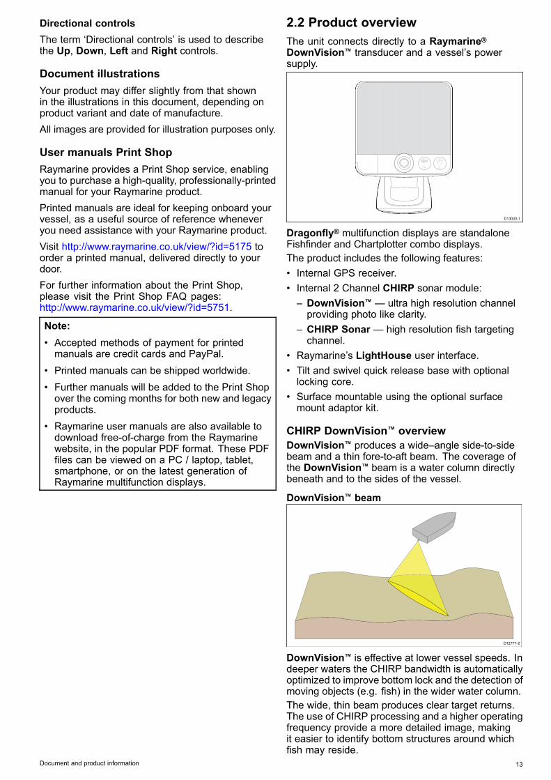
2.2 Product overviewThe unit connects directly to a Raymarine®DownVision™ transducer and a vessel’s powersupply.
��������
D13000-1
Dragonfly® multifunction displays are standaloneFishfinder and Chartplotter combo displays.The product includes the following features:• Internal GPS receiver.• Internal 2 Channel CHIRP sonar module:– DownVision™ — ultra high resolution channelproviding photo like clarity.
– CHIRP Sonar — high resolution fish targetingchannel.
• Raymarine’s LightHouse user interface.• Tilt and swivel quick release base with optionallocking core.
• Surface mountable using the optional surfacemount adaptor kit.
CHIRP DownVision™ overviewDownVision™ produces a wide–angle side-to-sidebeam and a thin fore-to-aft beam. The coverage ofthe DownVision™ beam is a water column directlybeneath and to the sides of the vessel.
DownVision™ beam
D12777-2
DownVision™ is effective at lower vessel speeds. Indeeper waters the CHIRP bandwidth is automaticallyoptimized to improve bottom lock and the detection ofmoving objects (e.g. fish) in the wider water column.The wide, thin beam produces clear target returns.The use of CHIRP processing and a higher operatingfrequency provide a more detailed image, makingit easier to identify bottom structures around whichfish may reside.
Document and product information 13

CHIRP DownVision™ screen example
CHIRP Sonar overviewCHIRP sonar produces a conical shaped beam, thecoverage of the conical beam is the water columndirectly beneath the vessel
Conical beam
D12784-2
Sonar is effective at a range of speeds. In deeperwaters the CHIRP bandwidth is automaticallyoptimized to improve bottom lock and the detectionof moving objects (e.g. fish) in the wider watercolumn.CHIRP sonar screen example
14 Dragonfly 6 / Dragonfly 7

Chapter 3: Planning the installation
Chapter contents• 3.1 Installation checklist on page 16• 3.2 Parts supplied on page 17• 3.3 DownVision™ transducer compatibility on page 18• 3.4 Tools required for installation on page 19• 3.5 Software updates on page 19• 3.6 Warnings and cautions on page 20• 3.7 Selecting a location for the transducer on page 20• 3.8 Cable routing on page 21• 3.9 Selecting a location for the display on page 22• 3.10 Installation process on page 23
Planning the installation 15

3.1 Installation checklistInstallation includes the following activities:
Installation Task1 Plan your system.2 Obtain all required equipment and tools.3 Site all equipment.4 Route all cables.5 Drill cable and mounting holes.6 Make all connections into equipment.7 Secure all equipment in place.8 Power on and test the system.
16 Dragonfly 6 / Dragonfly 7
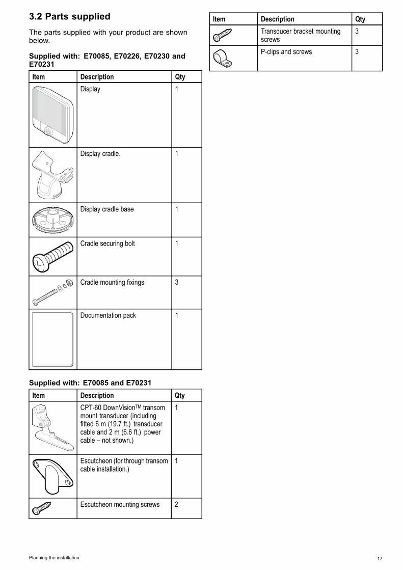
3.2 Parts suppliedThe parts supplied with your product are shownbelow.
Supplied with: E70085, E70226, E70230 andE70231Item Description Qty
���Display 1
Display cradle. 1
�� Display cradle base 1
Cradle securing bolt 1
Cradle mounting fixings 3
Documentation pack 1
Supplied with: E70085 and E70231Item Description Qty
�� CPT-60 DownVisionTM transommount transducer (includingfitted 6 m (19.7 ft.) transducercable and 2 m (6.6 ft.) powercable – not shown.)
1
Escutcheon (for through transomcable installation.)
1
Escutcheon mounting screws 2
Item Description QtyTransducer bracket mountingscrews
3
P-clips and screws 3
Planning the installation 17

3.3 DownVision™ transducercompatibility
Transducer DescriptionCompatibledisplays
CPT-DV (R70373) Single beamDownVision™transducer (3keyway connector)
• DV• Wi-Fish™
CPT-DVS(R70374)
Dual beamDownVision™and Sonartransducer (3keyway connector)
• DVS• Pro• Updated
Dragonfly 6• Updated
Dragonfly 7• * Legacy
Dragonfly 6• * Legacy
Dragonfly 7• Updated
CPT-60(A80195)
• UpdatedCPT-70(A80278)
• UpdatedCPT-80(A80279)
Dual beamDownVision™and Sonartransducer (3keyway connector)
• DVS• Pro• Updated
Dragonfly 6• Updated
Dragonfly 7• * Legacy
Dragonfly 6• * Legacy
Dragonfly 7• Legacy CPT-60
(A80195)• Legacy CPT-70
(A80278)• Legacy CPT-80
(A80279)
Dual beamDownVision™and Sonartransducer (1keyway connector)
• LegacyDragonfly 6
• LegacyDragonfly 7
• * DVS• * Pro
Note: * Adaptor cable required for connection.
Note:• Connecting a CPT-DV to a DVS or a Pro willprevent the Sonar application from functioning.
• Connecting a CPT-DVS to a DV or a orWi-Fish™ will not enable the Sonar application.
• The M cannot be connected to a transducer.
Legacy and updated productsDragonfly 6, Dragonfly 7 displays and CPT-60/ CPT-70 / CPT-80 transducer designs havebeen modified to include the improved 3 keywayconnectors.The table below identifies the effective manufacturingdate for the improved keyway connectors.
Product3 keywayintroduction date
3 keywayintroductionserial number
Dragonfly 6(E70085)
January 2015 E700850150001
Dragonfly 7(E70231)
November 2014 E702311140712
CPT-60 (A80195) December 2014 A801951240023CPT-70 (A80278) January 2015 A802780150001CPT-80 (A80279) January 2015 A802790150001
18 Dragonfly 6 / Dragonfly 7
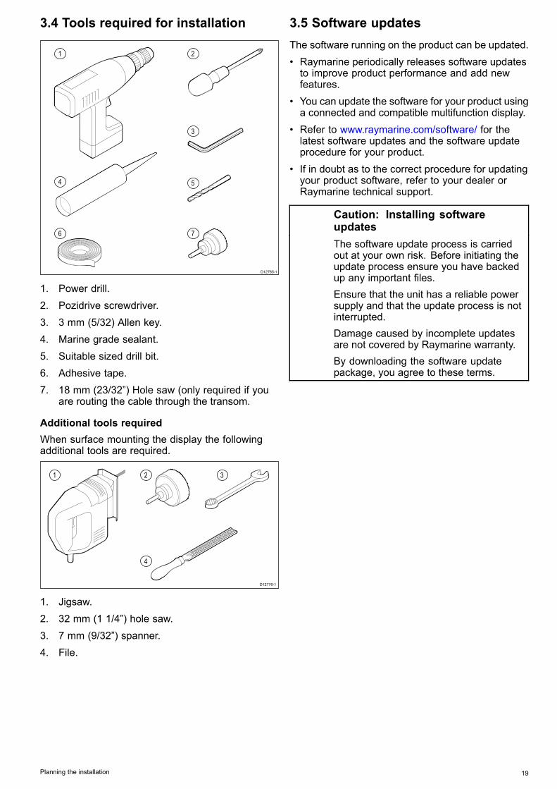
3.4 Tools required for installation
D12785-1
1
4
6
2
3
5
7
1. Power drill.2. Pozidrive screwdriver.3. 3 mm (5/32) Allen key.4. Marine grade sealant.5. Suitable sized drill bit.6. Adhesive tape.7. 18 mm (23/32”) Hole saw (only required if you
are routing the cable through the transom.
Additional tools requiredWhen surface mounting the display the followingadditional tools are required.
D12776-1
1 2
4
3
1. Jigsaw.2. 32 mm (1 1/4”) hole saw.3. 7 mm (9/32”) spanner.4. File.
3.5 Software updatesThe software running on the product can be updated.• Raymarine periodically releases software updatesto improve product performance and add newfeatures.
• You can update the software for your product usinga connected and compatible multifunction display.
• Refer to www.raymarine.com/software/ for thelatest software updates and the software updateprocedure for your product.
• If in doubt as to the correct procedure for updatingyour product software, refer to your dealer orRaymarine technical support.
Caution: Installing softwareupdatesThe software update process is carriedout at your own risk. Before initiating theupdate process ensure you have backedup any important files.Ensure that the unit has a reliable powersupply and that the update process is notinterrupted.Damage caused by incomplete updatesare not covered by Raymarine warranty.By downloading the software updatepackage, you agree to these terms.
Planning the installation 19

3.6 Warnings and cautionsImportant: Before proceeding, ensure that youhave read and understood the warnings andcautions provided in the Chapter 1 Importantinformation section of this document.
3.7 Selecting a location for thetransducerThis product is supplied with a transom mounttransducer. The guidelines below should be followedwhen selecting a location for the transducer.
Note: The transducer is not suitable for mountingon vessels where the transom is aft of thepropeller(s).
For best performance the transducer must beinstalled in a location with the least turbulence andaeration. The most effective way to determine thisis by checking the water flow around the transomwhilst underway.• The transducer should be mounted close tothe keel (centreline) of the vessel, so that thetransducer remains fully submerged when thevessel is turning.
• The transducer must be mounted a suitabledistance from the propeller(s) to avoid wake.
• For clockwise rotating propellers the transducershould be mounted on the starboard side, foranti-clockwise rotating propellers the transducershould be mounted on the port side.
D12640-1
• On a twin engine vessel the transducer should bemounted between the engines.
D12641-1
• Turbulence can also be caused by a number ofother factors such as steps, ribs, strakes, androws of rivets. The turbulence appears aft of theselocations.
20 Dragonfly 6 / Dragonfly 7

1
2
4
3
D12636-1
1 Step2 Rib3 Row of rivets4 Strake
• Air trapped under the front of the vessel can travelunder the hull and appear as aeration aft.
• If installing on the step of a stepped transom,allow sufficient room above the transducer fortransducer kick-up.
D12644-1
Note: Optimum transducer location willvary depending on vessel type. Optimumtransducer height and angle should be obtainedby testing the transducer with the vessel in thewater before locking the transducer’s position.
Transducer dimensionsThe transducer’s dimensions including the mountingbracket are shown below.
A
B
D12638-1
A 202.6 mm (8 in)B 117.4 mm (4.6 in)
3.8 Cable routingCable routing requirements for the transducer cable.
Important: To avoid interference, the cable mustbe routed as far away from VHF radio antennacables as possible.
• The cable can be routed through or over thetransom.
• Check that the cable is long enough to reachthe equipment that it will be connected to. Anoptional 4 m (13.1 ft) extension cable is availableif required.
• Ensure there is enough slack in the transducercable, at the transducer end, to allow thetransducer to pivot up and down.
• Secure the cable at regular intervals using thesupplied cable clips.
• Fill all transom mounting holes with marine-gradesealant prior to tightening securing screws.
• Fill the transom cable hole with marine-gradesealant after routing the cable (if routing throughthe transom).
• Use the supplied escutcheon to cover overthe transom cable hole (if routing through thetransom).
• Any excess cable can be coiled up at a convenientlocation.
Planning the installation 21
3.9 Selecting a location for the display
General location requirementsWhen selecting a location for the unit it is importantto consider a number of factors.
Ventilation requirementsTo provide adequate airflow:• Ensure that equipment is mounted in acompartment of suitable size.
• Ensure that ventilation holes are not obstructed.• Ensure adequate separation of equipment.
Mounting surface requirementsEnsure units are adequately supported on a securesurface. Do NOT mount units or cut holes in placeswhich may damage the structure of the vessel.
Cable routing requirementsEnsure the unit is mounted in a location which allowsproper routing and connection of cables:• Minimum cable bend radius of 100 mm (3.94 in) isrequired unless otherwise stated.
• Use cable supports to prevent stress onconnectors.
Electrical interferenceSelect a location that is far enough away fromdevices that may cause interference, such asmotors, generators and radio transmitters/receivers.
GPS location requirementsIn addition to general guidelines concerning thelocation of marine electronics, there are a numberof environmental factors to consider when installingequipment with an internal GPS antenna.
Mounting location• Above Decks mounting:It is recommended that the display is mountedabove decks as this provides optimal GPSperformance.
• Below Decks mounting:GPS performance may be less effective whenmounted below decks.
Vessel constructionThe construction of your vessel can have an impacton GPS performance. For example, the proximityof heavy structures such as a structural bulkhead,or the interior of larger vessels may result in areduced GPS signal. Before locating equipmentwith an internal GPS antenna below decks, seekprofessional assistance.
Prevailing conditionsThe weather and location of the vessel can affect theGPS performance. Typically calm clear conditionsprovide for a more accurate GPS fix. Vessels at
extreme northerly or southerly latitudes may alsoreceive a weaker GPS signal. GPS antenna mountedbelow decks will be more susceptible to performanceissues related to the prevailing conditions.
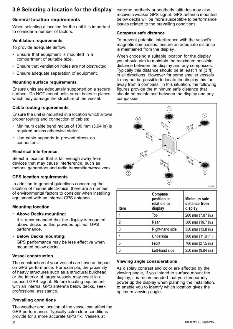
Compass safe distanceTo prevent potential interference with the vessel'smagnetic compasses, ensure an adequate distanceis maintained from the display.When choosing a suitable location for the displayyou should aim to maintain the maximum possibledistance between the display and any compasses.Typically this distance should be at least 1 m (3 ft)in all directions. However for some smaller vesselsit may not be possible to locate the display this faraway from a compass. In this situation, the followingfigures provide the minimum safe distance thatshould be maintained between the display and anycompasses.
D12650-1
200 mm(7.87 in)
350 mm(13.8 in)
700 mm
(27.5 in)
500 mm
(19.7 in)
250 mm(9.84 in) ���
1
2
3
300 mm(11.8 in)
4
5
6
Item
Compassposition inrelation todisplay
Minimum safedistance fromdisplay
1 Top 200 mm (7.87 in.)2 Rear 500 mm (19.7 in.)3 Right-hand side 350 mm (13.8 in.)4 Underside 300 mm (11.8 in.)5 Front 700 mm (27.5 in.)6 Left-hand side 250 mm (9.84 in.)
Viewing angle considerationsAs display contrast and color are affected by theviewing angle, If you intend to surface mount thedisplay, it is recommended that you temporarilypower up the display when planning the installation,to enable you to identify which location gives theoptimum viewing angle.
22 Dragonfly 6 / Dragonfly 7

5.7 inch display product dimensions
D12626-3
148 mm (5.8 in)
56 mm (2.2 in)
83.7 mm (3.3 in)
148
mm
(5.8
in)
203
mm
(8 in
)
90 mm (3.5 in)17 mm (0.7 in)
���������
7 inch product dimensions
D13037-1
191 mm (7.52 in)
61 mm (2.4 in)
84 mm (3.3 in)
156
mm
(6.1
in)
208
mm
(8.2
in)
90 mm (3.5 in)17 mm (0.7 in)
������
7 inch display cradle orientationThe 7 inch display can be mounted in ‘cradle up’ or‘cradle down’ orientation.
Cradle Up Cradle Down
The cradle mounting steps are the same regardlessof orientation.
3.10 Installation processThe steps listed below are required to successfullyinstall your product and ensure optimumperformance.1. Mounting the transducer.2. Mounting the display.3. Testing the transducer.4. Finishing the transducer mounting.
Planning the installation 23

24 Dragonfly 6 / Dragonfly 7

Chapter 4: Mounting
Chapter contents• 4.1 Mounting the transducer on page 26• 4.2 Cradle mounting on page 27• 4.3 Fitting the display in the cradle on page 28• 4.4 Fitting the 7 inch display in the cradle — Cradle down on page 28• 4.5 Security on page 29• 4.6 Removing the display from the bracket on page 30• 4.7 Surface mounting on page 31• 4.8 Testing the transducer on page 32• 4.9 Finishing the transducer mounting on page 32
Mounting 25

4.1 Mounting the transducerThe transducer must be mounted on the transomusing the mounting bracket provided. The stepsbelow describe the initial mounting steps requiredin order to test your transducers performance.After testing the transducer you must finish themounting following the instructions in the Finishingthe transducer mounting section.1. Fix the transducer mounting template to the
selected location, using masking or self-adhesivetape.
1
2
3D12632-2
1 Transducer mounting template2 Waterline3 Mounting away from propeller
2. Ensure the template is parallel to the waterline.3. Drill 2 x holes for the adjustment slot screws as
indicated on the template.
Note: Do NOT drill the third mounting hole at thisstage.
4. Fill the 2 holes with marine grade sealant.5. The kick-up adjustment screw may need to be
loosened to gain access to the mounting holes.��1
D12653-1
1 Kick-up adjustment screw
6. Ensure the transducer and bracket pivot arm arehooked over the mounting bracket back plate asshown below.
�� ��
��
��
D12651-1
7. Lift up the transducer and pivot arm to accessthe mounting holes.
�� ��
��
�� ��D12652-1
8. Using the screws provided, temporarily securethe mounting bracket using the adjustment slotson the back plate.
1
2
D12633-1
1 Locking hole2 Adjustment slots
26 Dragonfly 6 / Dragonfly 7
9. Push the transducer and pivot arm down until thebracket clicks into place.
10.Loosen the transducer pivot bolt approximately 3turns to enable adjustment.
1
D12643-1
1 Pivot bolt location
11. Adjust the angle of the transducer using theratchet mechanism, one click at a time until thetransducer face is parallel with the waterline.
The transducer position will be adjusted furtherduring testing (see Testing the transducer).
D12639-1
12.Tighten the transducer pivot bolt.13.Tighten the kick-up adjustment screw to achieve
the desired kick-up force.
The kick-up force needs to be adequate toprevent the transducer from kicking-up duringtesting but also needs to be loose enough so thatit can kick-up should the transducer be struck byan object when underway.
Note: The third locking screw is not used until thetransducer has been successfully tested.
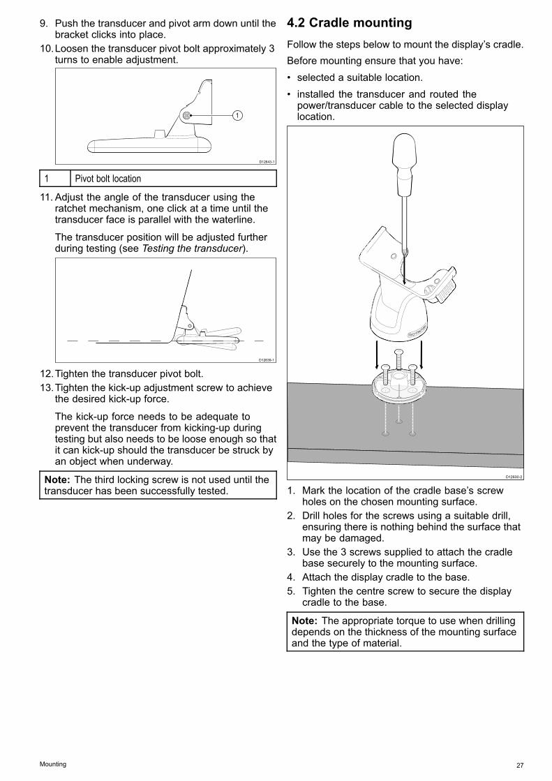
4.2 Cradle mountingFollow the steps below to mount the display’s cradle.Before mounting ensure that you have:• selected a suitable location.• installed the transducer and routed thepower/transducer cable to the selected displaylocation.
��
��
D12630-2
�
�
��
1. Mark the location of the cradle base’s screwholes on the chosen mounting surface.
2. Drill holes for the screws using a suitable drill,ensuring there is nothing behind the surface thatmay be damaged.
3. Use the 3 screws supplied to attach the cradlebase securely to the mounting surface.
4. Attach the display cradle to the base.5. Tighten the centre screw to secure the display
cradle to the base.
Note: The appropriate torque to use when drillingdepends on the thickness of the mounting surfaceand the type of material.
Mounting 27

4.3 Fitting the display in the cradleFollow the steps below to fit the display into thecradle.
D12645-3
1
4 5
2 3
�� ��1. Ensure the cradle is securely mounted.2. Position the display so that the guide on the left
hand side of the display lines up with the guideon the left hand side of the cradle.
3. Pivot the display so that the guide on the righthand side of the display lines up with the guideon the right hand side of the cradle.
4. Place your thumb on the front of the display andyour fingers behind the tab.
5. Push the display into the cradle until it clicks intoplace securely.
4.4 Fitting the 7 inch display in thecradle — Cradle downFollow the steps below to fit the 7 inch display intothe cradle in the cradle down orientation.
Note: When mounting the cradle in the cradledown orientation the display must still be fitted thecorrect way up.
1
4 5
2 3
D13036-1
1. Ensure the cradle is securely mounted.2. Position the display so that the guide on the right
hand side of the display lines up with the guideon the right hand side of the cradle.
3. Pivot the display so that the guide on the lefthand side of the display lines up with the guideon the left hand side of the cradle.
4. Place your thumb on the front of the display andyour fingers behind the locking tab.
5. Push the display into the cradle until it clicks intoplace securely.
Engaging the safety latchThe cradle supplied with the 7 inch display includesa Safety Latch that should be used to help securethe display to the cradle.
Note: The Safety Latch MUST be used whenmounting in the cradle down orientation,alternatively you can use a compatible third partysecurity lock.
D13039-1
1 2
1. Safety Latch in unlocked position.2. Safety Latch in locked position.Follow the steps below to engage the safety latch:
28 Dragonfly 6 / Dragonfly 7

1. Remove the blanking plug from the hole on therear of the display that lines up with the cradle’ssafety latch.
2. Insert the blanking plug into the hole that will beleft exposed.
3. Ensure the Safety Latch is in the unlockedposition.
4. Fit the display to the cradle following the relevantprocedure.
5. Push the Safety Latch in and turn clockwise tothe locked position.
Removing the safety latchIf you want to use a third party security lock to securethe display to the cradle then the Safety Latch mustbe removed.
D13040-1
1 2
1. Releasing safety latch retaining ring.2. Removing safety latch and retaining ring.With the Safety Latch in the unlocked position:1. Remove the display from the cradle.2. Insert the end of a small flat blade screwdriver
between the gap in the retaining ring.3. Gently lever the retaining ring apart and over the
safety latch.The safety latch and retaining ring should be kept incase required for future use.
4.5 SecurityThe display can be locked into the bracket using aproprietary lock i.e. the Thule 544 lock (not supplied).
D12635-2
The Thule 544 lock is available from retail outlets.
Note:• It is strongly recommended that the lock isadequately maintained to prevent the lock fromcorrosion and seizure.
• Raymarine does not guarantee the security ofyour display when using a lock.
• Raymarine will not be held liable for any damagecaused to the display or cradle due to the useof a lock.
Locking hole locationIf a lock is to be fitted to the display to secure it to thecradle then the blanking plug must be removed.
���2 2
1
Dxxxxx-1
1. Cradle Down locking hole location.2. Cradle Up locking hole location.Depending on display variant the unit may be fittedin the cradle in the cradle down orientation. Whenmounting in the cradle down orientation, the blankingplug should be moved to cover the exposed hole asshown below.
D13038-1
2
1
Mounting 29

1. Cradle Up position.2. Cradle Down position.
Fitting the lockWith the display mounted in the cradle:1. Remove the plastic cap that covers the cradles
locking hole.2. For fitting follow the instructions supplied with the
lock.
4.6 Removing the display from thebracketThe display can be easily removed from its mountingbracket.
D12637-3
�
1. If a lock has been fitted, ensure it is in theunlocked position.
2. Disconnect the cable from the back of the display.3. Push the cradle release clip away from the
display as shown.When the display releases you will hear a click.
4. Remove the display from the cradle.
30 Dragonfly 6 / Dragonfly 7

4.7 Surface mountingThe display can be surface mounted using theoptional surface mounting kit.Before mounting the unit ensure that you have:• selected a suitable location (a clear, flat area withsuitable clearance behind the panel is required).
• installed the transducer and routed the power /transducer cable to the selected location.
1. Fix the surface mount adaptor template to theselected location, using masking or self-adhesivetape.
2. Using a suitable hole saw (the size is indicatedon the template), make a hole in each corner ofthe cut-out area.
3. Using a suitable saw, cut along the inside edgeof the cut-out line.
4. Ensure that the surface mount adaptor fits intothe removed area and then file around the roughedge until smooth.
5. Drill 4 holes as indicated on the template toaccept the surface mount adaptor’s securingbolts.
6. Place the rear gasket onto the surface mountadaptor and press firmly onto the flange.
7. Place the surface mount adaptor into theprepared hole and secure using the nuts,washers, and bolts provided.
�����
�
��
�
�
�
������x4
D12646-1
8. Attach the front gasket to the surface mountadaptor.
9. Place the display into the surface mount adaptor.10.Secure the mounting studs to the rear of the
display.11. Place the O-rings over the mounting studs
and position in the recess around the adaptorsmounting holes.
12.Secure the display to the surface mount adaptorfrom the rear using the thumb nuts provided.
�����D12654-2
13.Connect the power / transducer cable to thedisplay.
Note: The appropriate torque to use when drillingdepends on the thickness of the mounting surfaceand the type of material.
Note: The supplied gasket provides a sealbetween the unit and a suitably flat and stiffmounting surface or binnacle. The gasket shouldbe used in all installations. It may also benecessary to use a marine-grade sealant if themounting surface or binnacle is not entirely flat andstiff or has a rough surface finish.
Mounting 31

4.8 Testing the transducerOnce the initial mounting procedures have beencarried out, the transducer must be tested prior tofinishing the mounting.The testing should be carried out with your vessel inthe water, with a depth greater than 0.7 m (2.3 ft) butless than the maximum depth limit of the system.The Sonar application will be able to maintainreadings at depths greater than the DownVisionapplication.
Note: It may not always be possible to obtaindepth readings at higher speeds due to air bubblespassing under the transducer.
1. Press and hold the Power button until a beep isheard.
2. Complete the Start-up wizard settings.3. Use the View switcher to open a view which
contains the Sonar or DownVision application.If the unit is operating correctly the bottom shouldbe visible on-screen and the depth readingdisplayed.
4. Start moving your vessel at a low speed andensure the depth reading and bottom are shownand that you have a clear image on-screen.
5. Gradually increase the vessel speed up to yourusual cruising speed, whilst checking the displayif the image becomes poor, starts skipping ormissing the bottom then the transducer needsto be adjusted.
6. Height and angle adjustments should be made insmall increments, and re-tested each time untilyou obtain optimum performance.
7. To adjust the angle of the transducer loosen thepivot bolt approximately 3 turns and then pivotthe transducer either up or down.
8. Re-tighten the pivot bolt before re-testing.9. When you achieve optimum performance at
the desired vessel speeds you can finish thetransducer mounting.
Note: It may be necessary to make severaladjustments to the transducer before obtainingoptimum performance.
4.9 Finishing the transducer mountingOnce you have achieved optimum performance atthe desired vessel speeds the transducer must belocked into position to finish the installation.
Note: If the transducer requires repositioningensure all old holes are filled with marine gradesealant.
1. Loosen the kick-up adjustment screw.2. Lift up the transducer and bracket pivot arm to
gain access to the mounting holes.3. Drill the locking hole location taking care not to
damage the mounting bracket.4. Fill the locking hole with marine grade sealant.5. Secure the transducer and bracket by fully
tightening all 3 mounting screws.6. Push the transducer and pivot arm down until it
clicks into position.7. Re-tighten the kick-up adjustment screw to the
desired level.
Note: The Kick-up adjustment screw needs to betight enough to prevent kick-up during high speedsbut loose enough to enable the kick-up featureto activate if an object hits the transducer whenunderway.
32 Dragonfly 6 / Dragonfly 7

Chapter 5: Cables and connections
Chapter contents• 5.1 General cabling guidance on page 34• 5.2 Connections overview on page 34• 5.3 Cable connection on page 35• 5.4 Extension cable connection on page 38
Cables and connections 33
5.1 General cabling guidance
Cable types and lengthIt is important to use cables of the appropriate typeand length• Unless otherwise stated use only standard cablesof the correct type, supplied by Raymarine.
• Ensure that any non-Raymarine cables are of thecorrect quality and gauge. For example, longerpower cable runs may require larger wire gaugesto minimize voltage drop along the run.
Routing cablesCables must be routed correctly, to maximizeperformance and prolong cable life.• Do NOT bend cables excessively. Whereverpossible, ensure a minimum bend diameter of 200mm (8 in) / minimum bend radius of 100 mm (4 in).
100 mm (4 in)
200 mm (8 in)
• Protect all cables from physical damage andexposure to heat. Use trunking or conduit wherepossible. Do NOT run cables through bilges ordoorways, or close to moving or hot objects.
• Secure cables in place using tie-wraps or lacingtwine. Coil any extra cable and tie it out of the way.
• Where a cable passes through an exposedbulkhead or deckhead, use a suitable watertightfeed-through.
• Do NOT run cables near to engines or fluorescentlights.
Always route data cables as far away as possiblefrom:• other equipment and cables,• high current carrying AC and DC power lines,• antennae.
Strain reliefEnsure adequate strain relief is provided. Protectconnectors from strain and ensure they will not pullout under extreme sea conditions.
Cable shieldingEnsure that the cable is properly shielded that thecable shielding is intact (e.g. hasn’t been scraped offby being squeezed through a tight area).
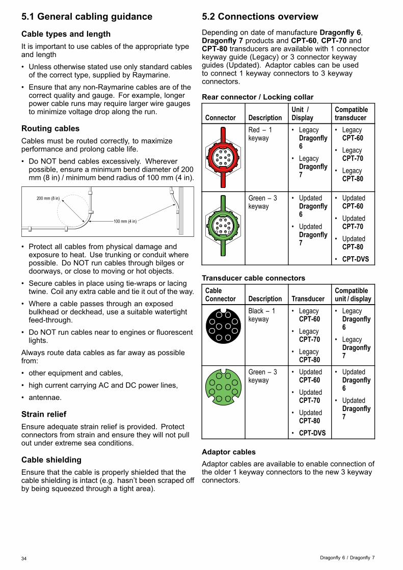
5.2 Connections overviewDepending on date of manufacture Dragonfly 6,Dragonfly 7 products and CPT-60, CPT-70 andCPT-80 transducers are available with 1 connectorkeyway guide (Legacy) or 3 connector keywayguides (Updated). Adaptor cables can be usedto connect 1 keyway connectors to 3 keywayconnectors.
Rear connector / Locking collar
Connector DescriptionUnit /Display
Compatibletransducer
Red – 1keyway
• LegacyDragonfly6
• LegacyDragonfly7
• LegacyCPT-60
• LegacyCPT-70
• LegacyCPT-80
Green – 3keyway
• UpdatedDragonfly6
• UpdatedDragonfly7
• UpdatedCPT-60
• UpdatedCPT-70
• UpdatedCPT-80
• CPT-DVS
Transducer cable connectorsCableConnector Description Transducer
Compatibleunit / display
Black – 1keyway
• LegacyCPT-60
• LegacyCPT-70
• LegacyCPT-80
• LegacyDragonfly6
• LegacyDragonfly7
Green – 3keyway
• UpdatedCPT-60
• UpdatedCPT-70
• UpdatedCPT-80
• CPT-DVS
• UpdatedDragonfly6
• UpdatedDragonfly7
Adaptor cablesAdaptor cables are available to enable connection ofthe older 1 keyway connectors to the new 3 keywayconnectors.
34 Dragonfly 6 / Dragonfly 7

Adaptor cableCompatibletransducer
Compatibledisplay / unit
A80331 —CPT-DV /CPT-DVS (3keyway ) to LegacyDragonfly 6 /Dragonfly 7 (1keyway) adaptorcable
• UpdatedCPT-60
• UpdatedCPT-70
• UpdatedCPT-80
• CPT-DVS• CPT-DV
• LegacyDragonfly 6
• LegacyDragonfly 7
A80332 —Legacy (1keyway) CPT-60 /CPT-70/ CPT-80transducer toupdate Dragonfly6 and Dragonfly7 (3 keyway )adaptor cable
• Legacy CPT-60• Legacy CPT-70• Legacy CPT-80
• UpdatedDragonfly-6
• UpdatedDragonfly-7
Legacy and updated productsDragonfly 6, Dragonfly 7 displays and CPT-60/ CPT-70 / CPT-80 transducer designs havebeen modified to include the improved 3 keywayconnectors.The table below identifies the effective manufacturingdate for the improved keyway connectors.
Product3 keywayintroduction date
3 keywayintroductionserial number
Dragonfly 6(E70085)
January 2015 E700850150001
Dragonfly 7(E70231)
November 2014 E702311140712
CPT-60 (A80195) December 2014 A801951240023CPT-70 (A80278) January 2015 A802780150001CPT-80 (A80279) January 2015 A802790150001
5.3 Cable connectionThe display has a combined power and transducercable that is attached to the transducer.
���(0.6)VM
D12642-1
1
2
5
4
3
3
1. Display rear panel connection.2. Transducer with cable attached.3. Drain wire (The drain wire is the wire with a
sheath).4. Black wire (12 V dc negative).5. Red wire (12 V dc positive).
Power distributionRaymarine recommends that all power connectionsare made via a distribution panel.• All equipment must be powered from a breaker orswitch, with appropriate circuit protection.
• All equipment should be wired to individualbreakers if possible.
Connecting the cable to the display
D13470-1
1. Ensure the locking collar is in the unlockedposition.
Cables and connections 35

2. Ensure that the cable connector is orientatedcorrectly, rotate so that the word ‘TOP’ is on thetop of the cable connector.
3. Push the cable connector all the way in, the tip ofthe arrow should be nearly touching the lockingcollar.
4. Rotate the locking collar clockwise 2 clicks, untilin the locked position.
Warning: 12 Volt dc onlyThis product must only be connected to a12 volt dc power source.
In-line fuse and thermal breaker ratingsThe following in-line fuse and thermal breaker ratingsapply to your product:In-line fuse rating Thermal breaker rating2 A slow blow 3 A (if only connecting one
device)
Note:• The suitable fuse rating for the thermal breakeris dependent on the number of devices you areconnecting. If in doubt consult an authorizedRaymarine dealer.
• Your product’s power cable may have fittedin-line fuse, if not then you can add an in-linefuse to the positive wire of your products powerconnection.
Power distributionRecommendations and best practice.• The product is supplied with a power cable. Onlyuse the power cable supplied with the product. DoNOT use a power cable designed for, or suppliedwith, a different product.
• Refer to the Power connection section for moreinformation on how to identify the wires in yourproduct’s power cable, and where to connect them.
• See below for more information on implementationfor some common power distribution scenarios.
Important: When planning and wiring, take intoconsideration other products in your system, someof which (e.g. sonar modules) may place largepower demand peaks on the vessel’s electricalsystem.
Note: The information provided below is forguidance only, to help protect your product. Itcovers common vessel power arrangements, butdoes NOT cover every scenario. If you are unsurehow to provide the correct level of protection,please consult an authorized Raymarine dealer ora suitably qualified professional marine electrician.
Implementation — direct connection to battery• The power cable supplied with your product maybe connected directly to the vessel's battery, via asuitably rated fuse or breaker.
• The power cable supplied with your product mayNOT include a separate drain wire. If this is thecase, only the power cable’s red and black wiresneed to be connected.
• If the supplied power cable is NOT fitted with aninline fuse, you MUST fit a suitably rated fuse orbreaker between the red wire and the battery’spositive terminal.
• Refer to the inline fuse ratings provided in theproduct’s documentation.
• If you need to extend the length of the power cablesupplied with your product, ensure you observethe dedicated Power cable extensions adviceprovided in the product’s documentation.
D13344-1
A
B
A Battery connection scenario A: suitable for a vessel witha common RF ground point. In this scenario, if yourproduct’s power cable is supplied with a separate drainwire then it should be connected to the vessel’s commonground point.
B Battery connection scenario B: suitable for a vesselwithout a common grounding point. In this case, if yourproduct’s power cable is supplied with a separate drainwire then it should be connected directly to the battery’snegative terminal.
Implementation — connection to distributionpanel
D13348-1
• Alternatively, the supplied power cable may beconnected to a suitable breaker or switch on thevessel's distribution panel or factory-fitted powerdistribution point.
• The distribution point should be fed from thevessel’s primary power source by 8 AWG(8.36 mm2) cable.
• Ideally, all equipment should be wired to individualsuitably-rated thermal breakers or fuses, withappropriate circuit protection. Where this is notpossible and more than 1 item of equipmentshares a breaker, use individual in-line fuses
36 Dragonfly 6 / Dragonfly 7

for each power circuit to provide the necessaryprotection.
• In all cases, observe the recommendedbreaker / fuse ratings provided in the product’sdocumentation.
• If you need to extend the length of the power cablesupplied with your product, ensure you observethe dedicated Power cable extensions adviceprovided in the product’s documentation.
Important: Be aware that the suitable fuse ratingfor the thermal breaker or fuse is dependent on thenumber of devices you are connecting.
GroundingEnsure that you observe the separate groundingadvice provided in the product’s documentation.
More informationRaymarine recommends that best practice isobserved in all vessel electrical installations, asdetailed in the following standards:• BMEA Code of Practice for Electrical andElectronic Installations in Boats
• NMEA 0400 Installation Standard• ABYC E-11 AC & DC Electrical Systems on Boats• ABYC A-31 Battery chargers and Inverters• ABYC TE-4 Lightning Protection
Power cable extensionThe product is supplied with a power cable, whichcan be extended if required.• The power cable for each unit in your systemshould be run as a separate, single length of2-wire cable from the unit to the vessel's battery ordistribution panel.
• Raymarine recommends a minimum wire gaugeof 18AWG (0.82 mm2) for any length of cableextension.
• For all lengths of extension to the power cable,ensure there is a continuous minimum voltageat the product’s power connector of 10.8 V with afully flat battery at 11 V.
Important: Be aware that some products inyour system (such as sonar modules) can createvoltage peaks at certain times, which may impactthe voltage available to other products during thepeaks.
Grounding — Dedicated drain wireThe power cable supplied with this product includesa dedicated shield (drain) wire for connection to avessel's RF ground point.It is important that an effective RF ground isconnected to the system. A single ground pointshould be used for all equipment. The unit can begrounded by connecting the shield (drain) wire ofthe power cable to the vessel's RF ground point.
On vessels without an RF ground system the shield(drain) wire should be connected directly to thenegative battery terminal.The dc power system should be either:• Negative grounded, with the negative batteryterminal connected to the vessel's ground.
• Floating, with neither battery terminal connectedto the vessel's ground
Warning: Product groundingBefore applying power to this product,ensure it has been correctly grounded, inaccordance with the instructions provided.
Warning: Positive ground systemsDo not connect this unit to a system whichhas positive grounding.
Cables and connections 37

5.4 Extension cable connectionAn optional extension cable (A80224) can be usedto extend the distance from the transducer to the unitby up to 4 m (13.1 ft).
12 V dc
���
D13471-1
2
1
3
1. Existing cable.2. Extension cable (connected to the vessel’s
power supply and to the existing cable.3. Isolated power supply wires on existing
transducer cable.
Note:• Only 1 extension cable should be used perinstallation.
• The length of the power supply wires on theextension cable is 2 m (6.6 ft).
38 Dragonfly 6 / Dragonfly 7

Chapter 6: Getting started
Chapter contents• 6.1 Controls on page 40• 6.2 Switching the unit on and off on page 41• 6.3 Initial set up procedures on page 41• 6.4 Satellite-based navigation on page 42• 6.5 Checking the sonar application on page 44• 6.6 Checking the DownVision™ application on page 44• 6.7 Shortcuts page on page 45• 6.8 Applications on page 46• 6.9 View switcher on page 46• 6.10 Memory cards and chart cards on page 47• 6.11 Learning resources on page 48
Getting started 39

6.1 Controls
���������
1
32
4
D12631 -2
1 MicroSD card reader – open the card door to insertor remove a MicroSD card. The card reader is usedfor electronic charts, archiving waypoint and trackdata and user settings.
2 UniControl – provides a rotary control, joystickand an OK push button for navigating menus andapplications and selecting items.
3 Back / View switcher button
• Press once to return to a previous menu orapplication state.
• Press in the Chart application to exit cursor modeand centre the vessel on-screen.
• Press in the Sonar or DownVision applications toresume scrolling from a paused state.
• From the top level application state (Motion modeor Scrolling mode) press once to open the Viewswitcher.
4 Power / Shortcuts button
• Press once to power the unit on.• When turned on, pressing the power button will
display the Shortcuts page.• Press and hold to turn the display off.
UniControlThe UniControl consists of Rotary, Joystick and pushbutton controls.
D12180-1
1
2
3
1. Rotary — use this to navigate through menuoptions and adjust the range in the Chartapplication and the Sonar / DownVisionapplications if set to manual range, or to cyclethrough the View switcher options.
2. Joystick— use this to move the cursor positionin applications, pan up, down, left and right inthe chart applications, navigate up and downthrough menu options or to cycle through theView switcher options.
3. OK button — push the end of the joystick to openmenus, or context menus whilst in an applicationor to confirm a selection.
Removing MicroSD card from its adaptorMicroSD memory and cartography chart cards areusually supplied inserted into an SD card adaptor.The card will need to be removed from the adaptorbefore inserting into your display.
D13468-1
40 Dragonfly 6 / Dragonfly 7

6.2 Switching the unit on and off
Powering the unit on1. Press and hold the Power button for
approximately 3 seconds to power up the unit.* On display products after approximately 5seconds the splash screen is displayed.
2. * Press OK to accept the Limitations of Usedisclaimer when it appears.
Note: * Does not apply to Wi-Fish™.
Powering the unit off1. Press and hold the Power button for
approximately 6 seconds.On display products a 3 second count-down timerwill be displayed.To cancel the power off process, release thepower button before the unit powers off.
Note: The unit will still draw a small amount ofpower from the battery when powered off, if thisis a concern unplug the connector from the backof the unit.
Low voltage warningA warning message is displayed when the product’svoltage supply drops below 10 V dc; the warningwill clear automatically when the voltage supplyraises above 11 V dc. The product may not operatecorrectly when the supply voltage is outside of thespecified operating voltage range. Please referto the product’s Technical specification for powerspecification limits.
6.3 Initial set up proceduresOnce your display has been installed andcommissioned, it is recommended that you gothrough the initial startup wizard and tutorial.
Startup wizardWhen you power-up the display for the first time orafter a system reset, the Startup Wizard is displayedafter you have accepted the Limitations On Usedisclaimer. The Startup Wizard guides you throughthe following initial settings:1. Language selection.2. Configure units.3. Finish / Tutorial.
Note: These settings can also be set at any timeusing the System Settings menu accessible fromthe Tools & Settings page.
Additional tasksIn addition to the settings covered by the Wizard, itis also recommended that the following tasks arecompleted:• Set your date and time preferences (if applicable).• Set your transducer depth offset (if applicable).• Familiarize yourself with the product usingSimulator Mode.
Setting time and date preferencesUnits that include an internal GNSS(GPS/GLONASS) receiver can timestampwaypoints and tracks with the date and time in yourpreferred format. Fishfinder only products do notinclude date and time settings.From the System Settings menu:1. Select Time and Date Set-up.2. Use the Date Format, Time Format, and Local
Time: menu items to set your time and datepreferences.
Depth OffsetDepths are measured from the transducer to the seabed, but you can apply an offset value to the depthdata, so that the displayed depth reading representsthe depth to the sea bed from either the keel or thewaterline.Before attempting to set a waterline or keeloffset, find out the vertical separation between thetransducer and either the waterline or the bottom ofthe keel on your vessel, as appropriate. Then set theappropriate depth offset value.
Getting started 41

D9343--2
1 2 3
1 Waterline offset2 Transducer / Zero offset3 Keel offset
If an offset is not applied, displayed depth readingsrepresent the distance from the transducer to thesea bed.
Setting the depth offsetOn Fishfinder products you must apply an offsetvalue for depth readings.From the System Settings menu:1. Select Sonar Set-up.2. Select Depth Offset.
The depth offset numeric adjust control isdisplayed.
3. Adjust the offset to the required value.4. Select Ok to confirm the new value and close the
numeric adjust control.
Simulator modeThe Simulator mode enables you to practiceoperating your display without data from the GPSreceiver or transducer.The simulator mode is switched on / off in theSystem Settings menu.
Note: Raymarine recommends that you do NOTuse the simulator mode whilst navigating.
Note: The simulator will NOT display any realdata. This includes safety messages.
Enabling and disabling simulator modeYou can enable and disable simulator mode byfollowing the steps below.From the System Settings menu:1. Select Simulator:.2. Select On to turn simulator mode on, or3. Select Off to turn simulator mode off.
Note: The Demo movie option is for retaildemonstration purposes only.
6.4 Satellite-based navigation
GPS StatusProducts with an internal GPS receiver or GNSS(GPS/GLONASS) receiver can use the GPS statuspage to view the status of the available satellites thatare compatible with your receiver.The satellite constellations are used to position yourboat in the Chart application. You can set up yourreceiver and check its status from the GPS Set-upmenu. For each satellite, the screen provides thefollowing information:
1
2
3
D13122-1
1. Sky view2. Satellite status3. Position and fix informationSky viewSky view is a visual representation that showsthe position of navigation satellites and their type.Satellite types are:• Circle — A circle identifies a satellite from theGPS constellation.
• Square — A square identifies an (SBAS)differential satellite.
• Diamond — A diamond identifies a satellite fromthe GLONASS constellation.
Satellite status areaThe Satellite status area displays the followinginformation about each satellite:• Type— Identifies which constellation the satellitebelongs to.
• ID— Displays the satellites identification number.• CNO (Carrier-to-noise ratio) — Displays the signalstrength of each satellite shown in the Sky view:– Grey = searching for satellite– Green = satellite in use– Orange = tracking satellite
• Azimuth and Elevation— Provides the angle ofelevation and azimuth between the location of thereceiver and the satellite.
Position and fix informationThe following positional and fix information isprovided:• Horizontal Dilution of Precision (HDOP)— HDOP is a measure of satellite navigationaccuracy, calculated from a number of factorsincluding satellite geometry, system errors inthe data transmission and system errors in the
42 Dragonfly 6 / Dragonfly 7

receiver. A higher figure signifies a greaterpositional error. A typical receiver has an accuracyof between 5 and 15 m. As an example, assuminga receiver error of 5 m, an HDOP of 2 wouldrepresent an error of approximately 15 m. Pleaseremember that even a very low HDOP figure isNO guarantee that your receiver is providing anaccurate position. If in doubt, check the displayedvessel position in the Chart application againstyour actual proximity to a known charted object.
• Estimated Horizontal Position Error (EHPE)— EHPE is a measure of the estimated error ofa position fix in the horizontal plane. The valuedisplayed indicates that your position is within acircle radius of the stated size 50% of the time.
• Fix status — indicates the actual mode thereceiver is reporting:– Fix— Satellite fix has been acquired.– No Fix— No satellite fix can be acquired.– D Fix — A differential beacon fix has beenacquired.
– SD Fix — A differential satellite fix has beenacquired.
• Position — Displays the latitude and longitudeposition of your receiver.
• Date / Time— Displays the current date and timegenerated by the position fix in UTC format .
• Mode— Identifies wether the receiver is workingin differential mode or non-differential mode.
• Datum — The receiver's datum setting affectsthe accuracy of the vessel position informationdisplayed in the Chart application. In order for yourreceiver and MFD to correlate accurately with yourpaper charts, they must be using the same datum.
Checking GPS operationYou can check that the GPS is functioning correctlyusing the Chart application.1. Open the Chart application.
2. Check the screen.
You should see:Your vessel position (indicates a GPS fix).Your current position is represented by a vesselsymbol or solid circle.A solid circle on the chart indicates that thevessel speed is too low (i.e. less than 0.15 kts) toprovide Course Over Ground (COG) data.
Note: It is recommended that you check thedisplayed vessel position in the Chart applicationagainst your actual proximity to a known chartedobject. GNSS receivers typically have an accuracyof between 5 m and 15 m.
Note: A GPS Status screen provides satellitesignal strength and other relevant information.
Getting started 43

6.5 Checking the sonar applicationProducts which include the Sonar application and theCPT-DVS transducer can use the Sonar applicationto help target fish.
From the Sonar application:1. Check the display.
With the transducer active you should see ascrolling (left to right) image that shows thebottom and underwater structure, you should alsosee a depth reading in the top left databox.
6.6 Checking the DownVision™applicationProducts which include the DownVision™application and the CPT-DV or CPT-DVS transducercan use the DownVision™ application to displayunderwater structure and objects.
From the DownVision™ application:1. Check the display.
With the transducer active you should see ascrolling (left to right) image that shows thebottom structure, you should also see a depthreading in the top left databox.
44 Dragonfly 6 / Dragonfly 7

6.7 Shortcuts pageThe shortcuts page provides access to the followingfunctions:
D12781-3
2
4
5
3
1
1 Brightness control.2 PowerSave mode — selecting will activate
PowerSave mode.3 Enable / Disable Sonar — selecting will enable or
disable the internal sonar and DownVision.4 Eject SD card — select to safely remove the
memory card.5 Screen capture — selecting saves a screenshot to
memory card.
Opening the shortcuts pageWith the display powered on:1. Press the Power button once.
The shortcuts page is displayed.2. Use the Directional controls to highlight an
option.3. Press the OK button to select the option.
Adjusting the display brightness1. Press the POWER button once.
The Shortcuts page is displayed.2. Adjust the brightness to the required level using
the Track pad.
Note: The brightness level can also be increasedby pressing the Power button multiple times.
PowerSave modeIn PowerSave mode all functions of the productremain active, but the display is placed into a lowpower state. PowerSave mode is cancelled bypressing a physical button or when an alarm eventoccurs.
Enabling PowerSave modeTo enable PowerSave mode follow the steps below.1. Press the POWER button.
The shortcuts menu is displayed.2. Select PowerSave Mode.
The display is now in PowerSave mode.3. You can wake the display from PowerSave mode
at anytime by pressing a physical button.
Note: PowerSave mode is automatically cancelledif an alarm event occurs.
Disabling and enabling the SonarThe transducer ping can be disabled and enabledfrom the shortcuts page.1. Select Disable Sonar to stop the transducer
pinging.2. Select Enable Sonar to start the transducer
pinging.
Note:• When enabled, the sonar element will ping if theview displayed contains the Sonar applicationor the Chart application
• When enabled, the DownVision™ element willping only if the view displayed includes theDownVision™ application.
ScreenshotsYou can take a screenshot of what is currentlydisplayed on the screen.Screenshots are saved in .png (Portable NetworkGraphic) format to a MicroSD Card. The savedimages can be viewed from any device capable ofviewing .png images.
Taking a screenshotYou can take a screenshot by following the stepsbelow.1. Insert a MicroSD card with suitable free space
into the card reader.2. Press the Power button.
The Shortcuts page is displayed:3. Select the Camera icon.
A confirmation message is displayed.4. Select OK.
The screenshot is now saved to the MicroSDcard.
Tip If your display has a Back button you can alsotake a screenshot by pressing and holding the Backbutton until the confirmation message appears.
Getting started 45
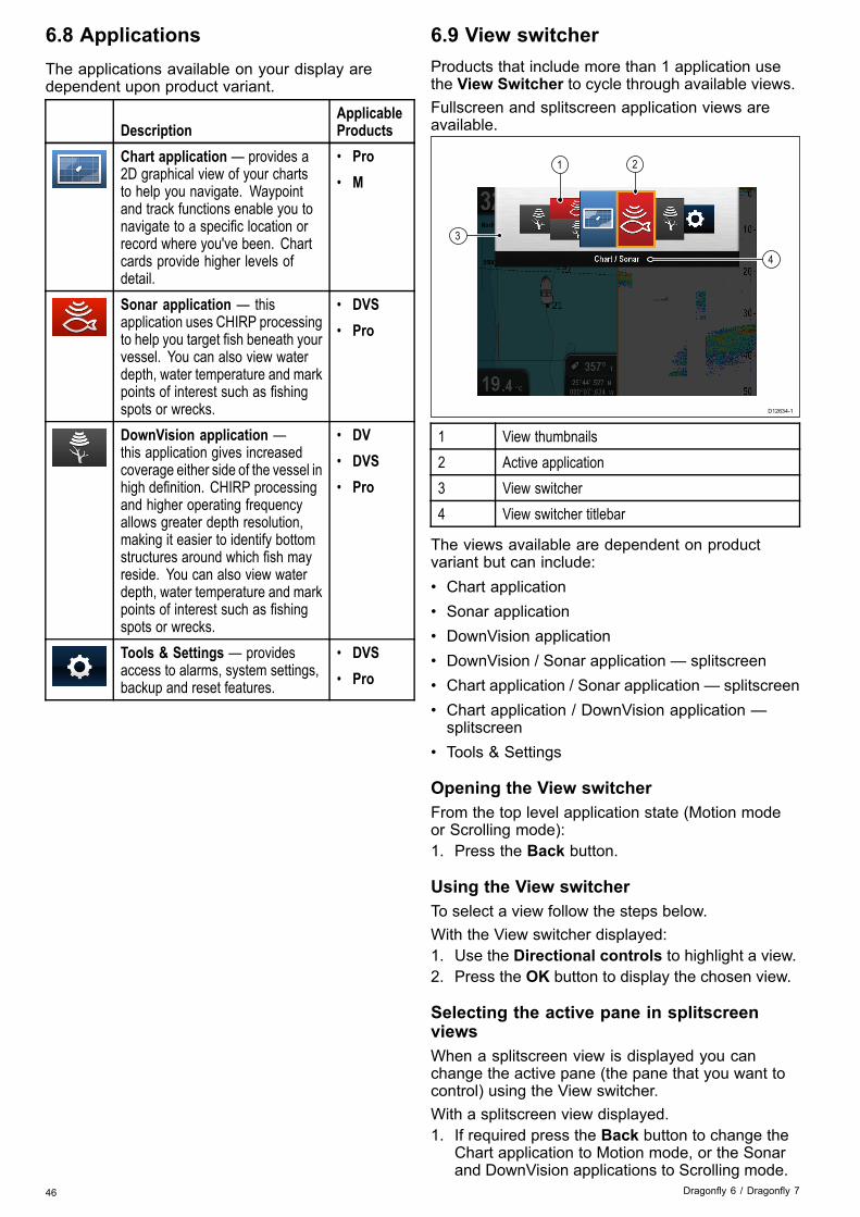
6.8 ApplicationsThe applications available on your display aredependent upon product variant.
DescriptionApplicableProducts
Chart application — provides a2D graphical view of your chartsto help you navigate. Waypointand track functions enable you tonavigate to a specific location orrecord where you've been. Chartcards provide higher levels ofdetail.
• Pro• M
Sonar application — thisapplication uses CHIRP processingto help you target fish beneath yourvessel. You can also view waterdepth, water temperature and markpoints of interest such as fishingspots or wrecks.
• DVS• Pro
DownVision application —this application gives increasedcoverage either side of the vessel inhigh definition. CHIRP processingand higher operating frequencyallows greater depth resolution,making it easier to identify bottomstructures around which fish mayreside. You can also view waterdepth, water temperature and markpoints of interest such as fishingspots or wrecks.
• DV• DVS• Pro
Tools & Settings — providesaccess to alarms, system settings,backup and reset features.
• DVS• Pro
6.9 View switcherProducts that include more than 1 application usethe View Switcher to cycle through available views.Fullscreen and splitscreen application views areavailable.
3
4
21
D12634-1
1 View thumbnails2 Active application3 View switcher4 View switcher titlebar
The views available are dependent on productvariant but can include:• Chart application• Sonar application• DownVision application• DownVision / Sonar application — splitscreen• Chart application / Sonar application — splitscreen• Chart application / DownVision application —splitscreen
• Tools & Settings
Opening the View switcherFrom the top level application state (Motion modeor Scrolling mode):1. Press the Back button.
Using the View switcherTo select a view follow the steps below.With the View switcher displayed:1. Use the Directional controls to highlight a view.2. Press the OK button to display the chosen view.
Selecting the active pane in splitscreenviewsWhen a splitscreen view is displayed you canchange the active pane (the pane that you want tocontrol) using the View switcher.With a splitscreen view displayed.1. If required press the Back button to change the
Chart application to Motion mode, or the Sonarand DownVision applications to Scrolling mode.
46 Dragonfly 6 / Dragonfly 7

2. Press the Back button again.The View switcher is displayed.
3. Use the Directional controls to highlight thepane you want to make active.
4. Press the OK button to confirm.The selected view is displayed and a border isplaced around the active pane.
6.10 Memory cards and chart cardsMicroSD memory cards can be used to back up /archive data (e.g. Waypoint, and Tracks). Oncedata is backed up to a memory card old data canbe deleted from the system, creating capacity fornew data. The archived data can be retrieved at anytime. Chart cards provide additional or upgradedcartography.It is recommended that your data is backed up to amemory card on a regular basis. Do NOT save datato a memory card containing cartography.
Compatible cardsThe following types of MicroSD cards are compatiblewith your display:• Micro Secure Digital Standard-Capacity(MicroSDSC)
• Micro Secure Digital High-Capacity (MicroSDHC)
Note:• The maximum supported memory card capacityis 32 GB.
• MicroSD cards must be formatted to use eitherthe FAT or FAT 32 file system format to enableuse with your MFD.
Speed class ratingFor best performance it is recommended that youuse Class 10 or UHS (Ultra High Speed) classmemory cards.
Chart cardsYour product is pre-loaded with electronic charts(worldwide base map). If you wish to use differentchart data, you can insert compatible chart cards intothe unit's memory card reader.
Use branded chart cards and memory cardsWhen archiving data or creating an electronic chartcard, Raymarine recommends the use of qualitybranded memory cards. Some brands of memorycard may not work in your unit. Please contactcustomer support for a list of recommended cards.
Removing MicroSD card from its adaptorMicroSD memory and cartography chart cards areusually supplied inserted into an SD card adaptor.The card will need to be removed from the adaptorbefore inserting into your display.
D13468-1
Getting started 47

Caution: Care of chart and memorycardsTo avoid irreparable damage to and / orloss of data from chart and memory cards:
• DO NOT save data or files to a cardcontaining cartography as the chartsmay be overwritten.
• Ensure that chart and memory cardsare fitted the correct way around. DONOT try to force a card into position.
• DO NOT use a metallic instrument suchas a screwdriver or pliers to insert orremove a chart or memory card.
Inserting a memory card or chart card1. Open the card door, located on the front left of
the display.2. Insert the card with the contacts facing down.3. Gently press the card all the way in to the card
slot. The card is secure when an audible clickis heard.
4. To prevent water ingress and damage to thedisplay, ensure the card door is closed.
Removing a memory card or chart card1. Select Eject Card from the shortcuts page.
A confirmation dialog is displayed.2. Open the card door.3. Push the edge of the card towards the unit, until
an audible click is heard.The card is released from the card slotmechanism.
4. Use your fingers to pull the card clear of the cardslot, using the edge of the card.
5. To prevent water ingress and damage to thedisplay, ensure the card door is closed.
6. Press the OK button to close the confirmationdialog.
6.11 Learning resourcesRaymarine has produced a range of learningresources to help you get the most out of yourproducts.
Video tutorialsRaymarine official channel onYouTube:
• http://www.youtube.com/u-ser/RaymarineInc
Video Gallery:
• http://www.rayma-rine.co.uk/view/?id=2679
Product Support videos:
• http://www.rayma-rine.co.uk/view/?id=4952
Note:• Viewing the videos requires a device with anInternet connection.
• Some videos are only available in English.
Training coursesRaymarine regularly runs a range of in-depth trainingcourses to help you make the most of your products.Visit the Training section of the Raymarine websitefor more information:• http://www.raymarine.co.uk/view/?id=2372
FAQs and Knowledge BaseRaymarine has produced an extensive set of FAQsand a Knowledge Base to help you find moreinformation and troubleshoot any issues.• http://www.raymarine.co.uk/knowledgebase/
Technical support forumYou can use the Technical support forum to aska technical question about a Raymarine productor to find out how other customers are usingtheir Raymarine equipment. The resource isregularly updated with contributions from Raymarinecustomers and staff:• http://raymarine.ning.com/
48 Dragonfly 6 / Dragonfly 7
Chapter 7: Fishfinder applications
Chapter contents• 7.1 DownVision™ application overview on page 50• 7.2 Sonar application overview on page 50• 7.3 Fishfinder applications' features on page 52• 7.4 Fishfinder applications’ controls on page 52• 7.5 Zoom on page 53• 7.6 Range on page 54• 7.7 Scrolling on page 54• 7.8 A-Scope mode on page 55• 7.9 Display Options on page 55• 7.10 Sensitivity adjustments on page 56• 7.11 Color Palettes on page 57
Fishfinder applications 49
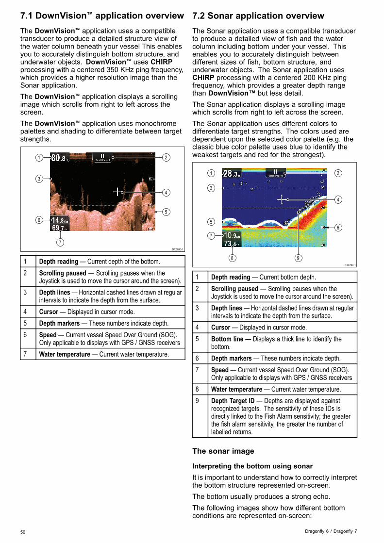
7.1 DownVision™ application overviewThe DownVision™ application uses a compatibletransducer to produce a detailed structure view ofthe water column beneath your vessel This enablesyou to accurately distinguish bottom structure, andunderwater objects. DownVision™ uses CHIRPprocessing with a centered 350 KHz ping frequency,which provides a higher resolution image than theSonar application.The DownVision™ application displays a scrollingimage which scrolls from right to left across thescreen.The DownVision™ application uses monochromepalettes and shading to differentiate between targetstrengths.
D12780-1
7
1
3
6
2
4
5
1 Depth reading— Current depth of the bottom.2 Scrolling paused — Scrolling pauses when the
Joystick is used to move the cursor around the screen).3 Depth lines—Horizontal dashed lines drawn at regular
intervals to indicate the depth from the surface.4 Cursor — Displayed in cursor mode.5 Depth markers— These numbers indicate depth.6 Speed — Current vessel Speed Over Ground (SOG).
Only applicable to displays with GPS / GNSS receivers7 Water temperature— Current water temperature.
7.2 Sonar application overviewThe Sonar application uses a compatible transducerto produce a detailed view of fish and the watercolumn including bottom under your vessel. Thisenables you to accurately distinguish betweendifferent sizes of fish, bottom structure, andunderwater objects. The Sonar application usesCHIRP processing with a centered 200 KHz pingfrequency, which provides a greater depth rangethan DownVision™ but less detail.The Sonar application displays a scrolling imagewhich scrolls from right to left across the screen.The Sonar application uses different colors todifferentiate target strengths. The colors used aredependent upon the selected color palette (e.g. theclassic blue color palette uses blue to identify theweakest targets and red for the strongest).
D12782-1
8 9
1
3
5
7
2
4
6
1 Depth reading — Current bottom depth.2 Scrolling paused — Scrolling pauses when the
Joystick is used to move the cursor around the screen).3 Depth lines—Horizontal dashed lines drawn at regular
intervals to indicate the depth from the surface.4 Cursor — Displayed in cursor mode.5 Bottom line — Displays a thick line to identify the
bottom.6 Depth markers— These numbers indicate depth.7 Speed — Current vessel Speed Over Ground (SOG).
Only applicable to displays with GPS / GNSS receivers8 Water temperature— Current water temperature.9 Depth Target ID — Depths are displayed against
recognized targets. The sensitivity of these IDs isdirectly linked to the Fish Alarm sensitivity; the greaterthe fish alarm sensitivity, the greater the number oflabelled returns.
The sonar image
Interpreting the bottom using sonarIt is important to understand how to correctly interpretthe bottom structure represented on-screen.The bottom usually produces a strong echo.The following images show how different bottomconditions are represented on-screen:
50 Dragonfly 6 / Dragonfly 7

D68
55-3
1
2
3
Item Description1 A hard bottom (sand) produces a thin line.2 A soft bottom (mud or seaweed cover) produces
a wide line.3 A rocky or uneven bottom or a wreck produces
an irregular image with peaks and troughs.
The dark layers indicate a good echo; the lighterareas indicate weaker echoes. This could mean thatthe upper layer is soft and therefore allowing soundwaves to pass to the more solid layer below.It is also possible that the sound waves are makingtwo complete trips – hitting the bottom, bouncing offthe vessel, then reflecting off the bottom again. Thiscan happen if the water is shallow or the bottom ishard.
Factors influencing the sonar imageThe quality and accuracy of the display can beinfluenced by a number of factors including vesselspeed, depth, object size and background noise.
Vessel speedThe shape of the target changes along with yourspeed. Slower speeds return flatter, more horizontalmarks. Higher speeds cause the target to thickenand arch slightly, at fast speeds the mark resemblesa double vertical line.
Target depthThe closer the target to the surface, the larger themark on screen.The depth of individual targets can be displayed byswitching on the Target Depth ID in the sonar menuMenu > Display Options. The number of targetdepths displayed is influenced by the fish alarmsensitivity level.
Water depthAs water depth increases signal strength decreases,resulting in a lighter on-screen image of the bottom.
Size of the targetThe larger the target, the larger the return on-screen.The size of a fish target is also dependent upon thesize of the fish’s swim bladder rather than its overallsize. The swim bladder varies in size betweendifferent breeds of fish.
Clutter / Background noiseThe sonar image may be impaired by echoesreceived from floating or submerged debris,particulate matter (such as plankton, phytoplankton,or silt etc.), air bubbles or even the vessel'smovement. This is known as ‘background noise’ or‘clutter’ and is controlled by the Sensitivity settings.If required you can adjust the setting manually.
Fishfinder applications 51
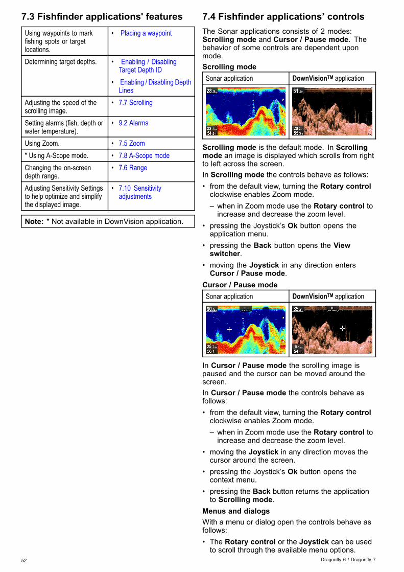
7.3 Fishfinder applications' featuresUsing waypoints to markfishing spots or targetlocations.
• Placing a waypoint
Determining target depths. • Enabling / DisablingTarget Depth ID
• Enabling / Disabling DepthLines
Adjusting the speed of thescrolling image.
• 7.7 Scrolling
Setting alarms (fish, depth orwater temperature).
• 9.2 Alarms
Using Zoom. • 7.5 Zoom* Using A-Scope mode. • 7.8 A-Scope modeChanging the on-screendepth range.
• 7.6 Range
Adjusting Sensitivity Settingsto help optimize and simplifythe displayed image.
• 7.10 Sensitivityadjustments
Note: * Not available in DownVision application.
7.4 Fishfinder applications’ controlsThe Sonar applications consists of 2 modes:Scrolling mode and Cursor / Pause mode. Thebehavior of some controls are dependent uponmode.Scrolling modeSonar application DownVisionTM application
Scrolling mode is the default mode. In Scrollingmode an image is displayed which scrolls from rightto left across the screen.In Scrolling mode the controls behave as follows:• from the default view, turning the Rotary controlclockwise enables Zoom mode.– when in Zoom mode use the Rotary control toincrease and decrease the zoom level.
• pressing the Joystick’s Ok button opens theapplication menu.
• pressing the Back button opens the Viewswitcher.
• moving the Joystick in any direction entersCursor / Pause mode.
Cursor / Pause modeSonar application DownVisionTM application
In Cursor / Pause mode the scrolling image ispaused and the cursor can be moved around thescreen.In Cursor / Pause mode the controls behave asfollows:• from the default view, turning the Rotary controlclockwise enables Zoom mode.– when in Zoom mode use the Rotary control toincrease and decrease the zoom level.
• moving the Joystick in any direction moves thecursor around the screen.
• pressing the Joystick’s Ok button opens thecontext menu.
• pressing the Back button returns the applicationto Scrolling mode.
Menus and dialogsWith a menu or dialog open the controls behave asfollows:• The Rotary control or the Joystick can be usedto scroll through the available menu options.
52 Dragonfly 6 / Dragonfly 7

• Pressing the Joystick’s Ok button selects thehighlighted option or confirms and dismisses popup messages.
• pressing the Back button returns to the previousmenu or closes the menu.
Placing a waypointDisplays with a GPS / GNSS receiver can usewaypoints to mark points of interest.1. Use the Directional controls to highlight the
desired location with the cursor.2. Press the OK button.
The context menu is displayed.3. Select Place Waypoint.
A confirmation pop up message is displayed.4. Select Ok to place the waypoint, or Edit to edit
the waypoint details.A waypoint is placed at the cursor’s location.
Context menuA context menu is available on displays with a GPS /GNSS receiver, which provides data and shortcutsto menu items.
The context menu provides the position of the cursor:• Depth• RangeThe context menu also provides the following menuitems:• Place Waypoint
Accessing the context menuYou can access the context menu by following thesteps below.1. Use the Joystick to highlight an object or area.2. Press the OK button.
The context menu is displayed.
7.5 ZoomThe Zoom function displays more detail onscreen bymagnifying a specific area of the image.When using Zoom the screen is split and displaysthe zoomed image alongside the standard image.
Sonar application DownVision application
This enables you to:• select an area from the standard view that ismagnified and displayed alongside.
• increase and decrease the zoom level.
The zoomed section is indicated on the standardscreen by the zoom box.
Adjusting the Zoom levelTo adjust the Zoom level and area follow the stepsbelow.With the Fishfinder application displayed:1. Turn the Rotary control clockwise to enable
Zoom mode.2. Subsequent clockwise turns will increase the
Zoom level3. Turning the Rotary control counter-clockwise
will decrease the Zoom level and finally revert tothe standard view.
Selecting a Zoom areaWhen using Zoom the area displayed in themagnified area of the screen can be changed.With Zoom enabled:1. Move the Joystick Up and Down to move the
magnified area up and down through the watercolumn.
Fishfinder applications 53

7.6 RangeThe Range function enables you to change the rangeof depth displayed onscreen. Where applicablechanges to the Range will apply to both the Sonarand DownVision™ applications.By default, the Range is set to automatic, this adjuststhe Range to ensure the bottom is always displayedonscreen. This is useful for targeting bigger fish andother objects located closer to the bottom such aswrecksManual Range allows you to specify a Shallow rangedepth and Deep range depth which defines the areadisplayed onscreen.
Sonar applicationDownVision™application
AutoRange
ManualRange
Switching between Auto and Manual rangeFrom the application menu:1. Select Range.2. Select Range: to switch between Auto and Man.3. With manual mode selected you can now adjust
the depth range shown onscreen.
Manually adjusting rangeTo specify the area of depth to be displayed onscreenfollow the steps below.From the application menu:1. Select Range.2. Select Range: so that Man is selected.3. Select Shallow Range.
The Shallow Range defines the depth that willbe shown at the top of the screen.
4. Adjust the Shallow Range to the required depth.5. Select Deep Range.
The Deep Range defines the depth that will beshown at the bottom of the screen.
6. Adjust the Deep Range to the required depth.
7.7 ScrollingThe image scrolls from right to left. The scroll speedcan be adjusted to help with target identification. Thescrolling can be paused by entering Cursor mode.
Scroll speedThe default scrolling speed is 100%. The scrollspeed can be slowed down to 10% of the defaultspeed.
Adjusting the scroll speedFrom the main menu:1. Select Display Options.2. Select Scroll Speed.
The Scroll speed adjustment control is displayed.3. Use the Rotary control or the Joystick to adjust
the scroll speed between 10% and 100%.4. Press the Ok or Back button to confirm and close
the adjustment control.
Pausing the scrolling imageWith the display scrolling from right to left:1. Move the Joystick directional controls in any
direction.The Scrolling will pause.
2. Press the Back button to resume scrolling.
54 Dragonfly 6 / Dragonfly 7

7.8 A-Scope modeA-Scope mode is available in the Sonar applicationonly. A-Scope mode displays a splitscreen showingthe standard view alongside a live image of the watercolumn directly beneath the transducer.
The area covered by the A-Scope is indicated at thebottom of the window. A-Scope provides a moreprecise and easier to interpret indication of the targetstrength.
Switching between A-Scope and StandardviewYou can switch between the standard view andA-Scope mode at any time following the steps below.With the standard view displayed in the Sonarapplication:1. Select Menu.2. Select Display Options.3. Select A-Scope:.
Selecting A-Scope: will switch A-Scope modeOn and Off.
Note: If Zoom mode is enabled, The screen willnot show the A-Scope until the Zoom has beendisabled.
7.9 Display OptionsThe application can be customized using the DisplayOptions menu.The display options can be used to overlay additionaldepth features and manipulate the image to enableeasier fish targeting.Available depth features:• Target Depth ID—Not available in DownVision™application
• Depth Lines• White Line — Not available in DownVision™application
Enabling / Disabling Target Depth IDYou can display the depth of targets on-screen.From the application menu:1. Select Display Options.2. Select Target Depth ID.
Selecting Target Depth ID will switch the targetdepth indicator On and Off.
Note: The strength of targets which display adepth ID is related to the Fish sensitivity setting,accessible from the Alarms menu.
Enabling / Disabling Depth LinesYou can display horizontal depth lines on-screen.From the application menu:1. Select Display Options.2. Select Depth Lines.
Selecting Depth Lines will switch the horizontaldepth lines On and Off.
Enabling / Disabling the White LineYou can display a thick line on-screen to representthe bottom, this line is primarily white in color(depending upon color palette chosen).From the application menu:1. Select Display Options.2. Select White Line.
Selecting White Line will switch the bottom lineOn and Off.
Fishfinder applications 55
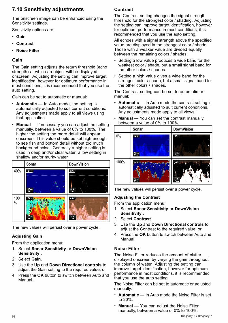
7.10 Sensitivity adjustmentsThe onscreen image can be enhanced using theSensitivity settings.Sensitivity options are:• Gain• Contrast• Noise Filter
GainThe Gain setting adjusts the return threshold (echostrength) at which an object will be displayedonscreen. Adjusting the setting can improve targetidentification, however for optimum performance inmost conditions, it is recommended that you use theauto setting.Gain can be set to automatic or manual:• Automatic — In Auto mode, the setting isautomatically adjusted to suit current conditions.Any adjustments made apply to all views usingthat application.
• Manual— If necessary you can adjust the settingmanually, between a value of 0% to 100%. Thehigher the setting the more detail will appearonscreen. This value should be set high enoughto see fish and bottom detail without too muchbackground noise. Generally a higher setting isused in deep and/or clear water; a low setting inshallow and/or murky water.
Sonar DownVision40%
100%
The new values will persist over a power cycle.
Adjusting GainFrom the application menu:1. Select Sonar Sensitivity or DownVision
Sensitivity .2. Select Gain.3. Use the Up and Down Directional controls to
adjust the Gain setting to the required value, or4. Press the OK button to switch between Auto and
Manual.
ContrastThe Contrast setting changes the signal strengththreshold for the strongest color / shading. Adjustingthe setting can improve target identification, howeverfor optimum performance in most conditions, it isrecommended that you use the auto setting.All echoes with a signal strength above the specifiedvalue are displayed in the strongest color / shade.Those with a weaker value are divided equallybetween the remaining colors / shades.• Setting a low value produces a wide band for theweakest color / shade, but a small signal band forthe other colors / shades.
• Setting a high value gives a wide band for thestrongest color / shade, but a small signal band forthe other colors / shades.
The Contrast setting can be set to automatic ormanual:• Automatic— In Auto mode the contrast setting isautomatically adjusted to suit current conditions.Any adjustments made apply to all views.
• Manual — You can set the contrast manually,between a value of 0% to 100%.
Sonar DownVision0%
100%
The new values will persist over a power cycle.
Adjusting the ContrastFrom the application menu:1. Select Sonar Sensitivity or DownVision
Sensitivity .2. Select Contrast.3. Use the Up and Down Directional controls to
adjust the Contrast to the required value, or4. Press the OK button to switch between Auto and
Manual.
Noise FilterThe Noise Filter reduces the amount of clutterdisplayed onscreen by varying the gain throughoutthe column of water. Adjusting the setting canimprove target identification, however for optimumperformance in most conditions, it is recommendedthat you use the auto setting.The Noise Filter can be set to automatic or adjustedmanually:• Automatic— In Auto mode the Noise Filter is setto 20%.
• Manual — You can adjust the Noise Filtermanually, between a value of 0% to 100%.
56 Dragonfly 6 / Dragonfly 7

– A low value decreases the depth at which thefilter is applied.
– A high value increases the depth at which thefilter is applied.
Sonar DownVision0%
100%
The new values will persist over a power cycle.
Adjusting the Noise FilterFrom the application menu:1. Select Sonar Sensitivity or DownVision
Sensitivity .2. Select Noise Filter.3. Use the Up and Down Directional controls to
adjust the Noise Filter to the required value, or4. Press the OK button to switch between Auto and
Manual.
7.11 Color PalettesVarious color palettes are available to suit differentconditions and your personal preference.The new color palette remains selected after a powercycle, The color palette is a global setting which willapply to all views.
Sonar application color palettesClassic Blue (default)
Classic Black
Classic White
Sunburst
Night Vision
Fishfinder applications 57

DownVisionTM application color palettesCopper (default)
Inv. Copper
Slate Gray
Inv. Slate Gray
Selecting a Color PaletteFrom the application’s menu:1. Select Display Options.2. Select Sonar Colors / DownVision Colors.3. Select the palette you want to use.
58 Dragonfly 6 / Dragonfly 7

Chapter 8: Chart application
Chapter contents• 8.1 Chart application overview on page 60• 8.2 Electronic charts overview on page 61• 8.3 Chart application controls on page 63• 8.4 Waypoints overview on page 64• 8.5 Tracks on page 71• 8.6 Import and Export on page 73• 8.7 Waypoints and tracks storage capacity on page 74• 8.8 Navigation on page 74• 8.9 Chart settings menu — cartography compatibility on page 75• 8.10 Chart selection on page 75• 8.11 Chart Detail on page 76• 8.12 High resolution bathymetry on page 76• 8.13 Chart orientation on page 77• 8.14 Text and Symbol size on page 78• 8.15 Boat position on page 78• 8.16 Community layer on page 79• 8.17 Sonar logging on page 79• 8.18 COG Vector on page 80• 8.19 Deep Water on page 80• 8.20 Chart objects on page 81
Chart application 59
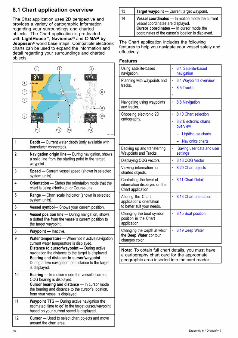
8.1 Chart application overviewThe Chat application uses 2D perspective andprovides a variety of cartographic informationregarding your surroundings and chartedobjects. The Chart application is pre-loadedwith LightHouse™, Navionics® and C-MAP byJeppesen® world base maps. Compatible electroniccharts can be used to expand the information anddetail regarding your surroundings and chartedobjects.
D12778-1
11 12 13 14
4
5
9
7
8
6
10
1 2 3
1 Depth — Current water depth (only available withtransducer connected).
2 Navigation origin line— During navigation, showsa solid line from the starting point to the targetwaypoint.
3 Speed— Current vessel speed (shown in selectedsystem units).
4 Orientation— States the orientation mode that thechart is using (North-up, or Course-up).
5 Range — Chart scale indicator (shown in selectedsystem units).
6 Vessel symbol— Shows your current position.7 Vessel position line — During navigation, shows
a dotted line from the vessel’s current position tothe target waypoint.
8 Waypoint — Inactive.9 Water temperature—When not in active navigation
current water temperature is displayed.Distance to cursor/waypoint — During activenavigation the distance to the target is displayed.Bearing and distance to cursor/waypoint —During active navigation the distance to the targetis displayed.
10 Bearing — In motion mode the vessel’s currentCOG bearing is displayed.Cursor bearing and distance — In cursor modethe bearing and distance to the cursor’s location,from your vessel is displayed.
11 Waypoint TTG — During active navigation theestimated ‘time to go’ to the target cursor/waypointbased on your current speed is displayed.
12 Cursor — Used to select chart objects and movearound the chart area.
13 Target waypoint— Current target waypoint.14 Vessel coordinates— In motion mode the current
vessel coordinates are displayed.Cursor coordinates — In cursor mode thecoordinates of the cursor’s location is displayed.
The Chart application includes the followingfeatures to help you navigate your vessel safely andeffectively:
FeaturesUsing satellite-basednavigation.
• 6.4 Satellite-basednavigation
Planning with waypoints andtracks.
• 8.4 Waypoints overview• 8.5 Tracks•
Navigating using waypointsand tracks.
• 8.8 Navigation
Choosing electronic 2Dcartography.
• 8.10 Chart selection• 8.2 Electronic charts
overview
– LightHouse charts– Navionics charts
Backing up and transferringWaypoints and Tracks.
• Saving user data and usersettings
Displaying COG vectors • 8.18 COG VectorViewing information forcharted objects.
• 8.20 Chart objects
Controlling the level ofinformation displayed on theChart application
• 8.11 Chart Detail
Altering the Chartapplication’s orientationto better suit your needs.
• 8.13 Chart orientation
Changing the boat symbolposition in the Chartapplication.
• 8.15 Boat position
Changing the Depth at whichthe Deep Water contourchanges color.
• 8.19 Deep Water
Note: To obtain full chart details, you must havea cartography chart card for the appropriategeographic area inserted into the card reader.
60 Dragonfly 6 / Dragonfly 7

8.2 Electronic charts overviewYour multifunction display includes basic worldbase maps. Electronic charts provide additionalcartographic information.The level of cartographic detail available varies fordifferent chart vendors, chart types, geographiclocations and chart scales. The chart scale in use isindicated by the scale indicator, the value displayedis the distance that the line represents across thescreen.You can remove and insert chart cards at any time.The chart screen is automatically redrawn when thesystem detects that a compatible chart card hasbeen inserted or removed.Using a dual view page it is possible to displaydifferent cartography types simultaneously.
Caution: Care of chart and memorycardsTo avoid irreparable damage to and / orloss of data from chart and memory cards:
• DO NOT save data or files to a cardcontaining cartography as the chartsmay be overwritten.
• Ensure that chart and memory cardsare fitted the correct way around. DONOT try to force a card into position.
• DO NOT use a metallic instrument suchas a screwdriver or pliers to insert orremove a chart or memory card.
LightHouseCHARTS
LightHouse chartsWith the introduction of the LightHouse II software,Raymarine multifunction displays now support theuse of Raymarine’s new LightHouse charts.LightHouse charts are derived from vector and rasterbased charts, the LightHouse chart engine enablesRaymarine to offer new chart types and regions fromaround the globe.
Refer to Raymarine’sLightHouse Chart Store:https://charts.raymarine.com forthe latest information on availableLightHouse charts.
Follow the link above and Go to the Getting Startedpage for full instructions on downloading LightHouseCharts to MicroSD card using the LightHouseDownload Manager.
Raster charts
Raster charts are an exact copy / scan of an existingpaper chart. All information is embedded directly inthe chart. Ranging in and out of raster charts willmake everything appear larger or smaller on thescreen, including text. When changing the Chartapplication’s orientation everything on the chart willrotate, including the text. As raster charts are ascanned image the file size is normally bigger whencompared to the vector equivalent.
Vector charts
Vector charts are computer generated, consistingof a series of points and lines that make up thechart. Chart objects and overlays on vector chartscan be switched on and off and chart objects canbe selected to provide further information. Rangingin and out of vector charts will make geographicalfeatures appear larger or smaller on the screen,however text and chart objects will remain the samesize regardless of range. When changing the Chartapplication’s orientation geographical features willrotate but text and chart objects will remain in thecorrect orientation for the display. As vector chartsare generated rather than a scanned image the filesize is normally smaller when compared to the rasterequivalent.
Unzipping files to memory cardThe LightHouse charts download file must beunzipped / extracted to memory card for use on yourmultifunction display.
Note: The instructions below are provided forguidance only. Depending on your PC’s operatingsystem and the archiving (zip) software in use thesteps required may differ slightly from those shownbelow. If you are unsure please consult youroperating system’s and or archiving software’shelp files.
To unzip / extract charts with a filesize over 4GB youmay need to install 3rd-party archiving (zip) softwaresuch as 7zip: http://www.7–zip.org/.
Chart application 61

Ensure you have a memory card with sufficient spacefor the charts you want to download. The File size isdisplayed on each chart region’s download page.For best performance it is recommended that youuse Class 10 or UHS (Ultra High Speed) classmemory cards.1. Locate the downloaded file.
The file will be stored in the folder you selectedor in your normal downloads folder.
2. Right click on the file and select the Extract Hereoption from the zip options.
3. Once all files have been extracted select thechart files.
4. Right click and choose Send to > RemovableDisk
The Chart files will now be copied to your memorycard.
5. Check that the files have been successfullyplaced on your memory card by viewing itscontents in your file browser.
6. Safely remove your memory card from your PC’scard reader.
7. Insert your memory card into the card reader ofyour multifunction display.
8. Open the Chart application on your multifunctiondisplay.
9. Select the new chart from the Chart selectionmenu: Menu > Presentation > Chart Selection.
The Chart screen will be redrawn to display thenewly selected chart type.
Navionics chartsYour display is supplied with a base map anddepending on unit a Navionics chart card. You mayalso purchase Navionics chart cards to get enhancedchart details and additional chart features.Your display is compatible with the followingNavionics chart cards:• Silver• Gold• Gold+• Hotmaps
Note: Refer to the Raymarine website(www.raymarine.com) for the latest list ofsupported chart cards.
C-MAP by Jeppesen chartsYour display is supplied with world base maps anddepending on purchasing options a Jeppesen chartcard. You may also purchase extra Jeppesen chartcards to get enhanced chart details and additionalchart features.Your display is compatible with the followingJeppesen chart cards:
62 Dragonfly 6 / Dragonfly 7

• C-MAP Essentials• C-MAP 4D MAX• *C-MAP 4D MAX+Refer to the Raymarine website (www.rayma-rine.com) for the latest list of supported chart cards.To check the current availability of Jeppesen chartcards and types, please visit: www.jeppesen.comor c-map.jeppesen.com.
Note: *C-MAP 4D MAX+ cartography will workwith Dragonfly® products however the ‘+’ featureswill not be available.
8.3 Chart application controlsThe Chart application consists of 2 modes: Motionmode and Cursor mode. The behavior of somecontrols are dependent upon mode. Options andsettings can also be accessed from the Chart contextmenu.Motion mode
Motion mode is the default Chart application mode.In Motion mode the boat symbol remains centeredonscreen and the Chart area moves around the boatsymbol.In Motion mode the controls behave as follows:• turning the Rotary control clockwise ranges in.• turning the Rotary control counter-clockwiseranges in.
• pressing the Joystick’s Ok button opens the Chartapplication menu.
• pressing the Back button opens the Viewswitcher.
• moving the Joystick in any direction entersCursor mode.
Cursor mode
In Cursor mode the Joystick is used to movearound the Chart area. When the cursor reachesthe edge of the screen the Chart area will pan inthat direction.In Cursor mode the controls behave as follows:• turning the Rotary control clockwise ranges in.• turning the Rotary control counter-clockwiseranges out.
• moving the Joystick in any direction pans the chartarea in that direction.
• pressing the Joystick’s Ok button opens thecontext menu.
Chart application 63
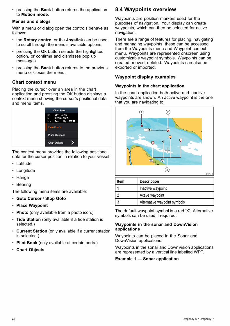
• pressing the Back button returns the applicationto Motion mode.
Menus and dialogsWith a menu or dialog open the controls behave asfollows:• the Rotary control or the Joystick can be usedto scroll through the menu’s available options.
• pressing the Ok button selects the highlightedoption, or confirms and dismisses pop upmessages.
• pressing the Back button returns to the previousmenu or closes the menu.
Chart context menuPlacing the cursor over an area in the chartapplication and pressing the OK button displays acontext menu showing the cursor’s positional dataand menu items.
The context menu provides the following positionaldata for the cursor position in relation to your vessel:• Latitude• Longitude• Range• BearingThe following menu items are available:• Goto Cursor / Stop Goto• Place Waypoint• Photo (only available from a photo icon.)• Tide Station (only available if a tide station isselected.)
• Current Station (only available if a current stationis selected.)
• Pilot Book (only available at certain ports.)• Chart Objects
8.4 Waypoints overviewWaypoints are position markers used for thepurposes of navigation. Your display can createwaypoints, which can then be selected for activenavigation.There are a range of features for placing, navigatingand managing waypoints, these can be accessedfrom the Waypoints menu and Waypoint contextmenu. Waypoints are represented onscreen usingcustomizable waypoint symbols. Waypoints can becreated, moved, deleted. Waypoints can also beexported or imported.
Waypoint display examples
Waypoints in the chart applicationIn the chart application both active and inactivewaypoints are shown. An active waypoint is the onethat you are navigating to.
D11761-3
1 2
3
Item Description1 Inactive waypoint2 Active waypoint3 Alternative waypoint symbols
The default waypoint symbol is a red ‘X’. Alternativesymbols can be used if required.
Waypoints in the sonar and DownVisionapplicationsWaypoints can be placed in the Sonar andDownVision applications.Waypoints in the sonar and DownVision applicationsare represented by a vertical line labelled WPT.Example 1 — Sonar application
64 Dragonfly 6 / Dragonfly 7
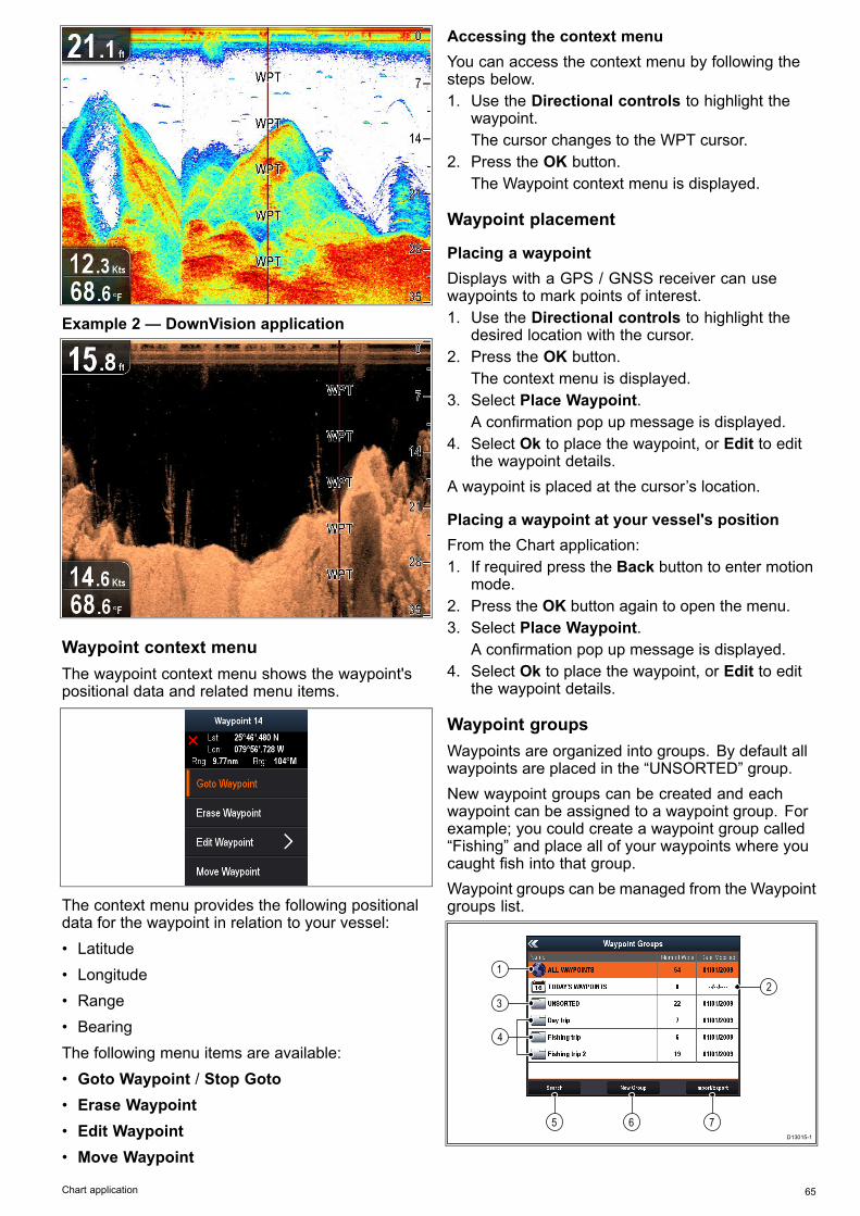
Example 2 — DownVision application
Waypoint context menuThe waypoint context menu shows the waypoint'spositional data and related menu items.
The context menu provides the following positionaldata for the waypoint in relation to your vessel:• Latitude• Longitude• Range• BearingThe following menu items are available:• Goto Waypoint / Stop Goto• Erase Waypoint• Edit Waypoint• Move Waypoint
Accessing the context menuYou can access the context menu by following thesteps below.1. Use the Directional controls to highlight the
waypoint.The cursor changes to the WPT cursor.
2. Press the OK button.The Waypoint context menu is displayed.
Waypoint placement
Placing a waypointDisplays with a GPS / GNSS receiver can usewaypoints to mark points of interest.1. Use the Directional controls to highlight the
desired location with the cursor.2. Press the OK button.
The context menu is displayed.3. Select Place Waypoint.
A confirmation pop up message is displayed.4. Select Ok to place the waypoint, or Edit to edit
the waypoint details.A waypoint is placed at the cursor’s location.
Placing a waypoint at your vessel's positionFrom the Chart application:1. If required press the Back button to enter motion
mode.2. Press the OK button again to open the menu.3. Select Place Waypoint.
A confirmation pop up message is displayed.4. Select Ok to place the waypoint, or Edit to edit
the waypoint details.
Waypoint groupsWaypoints are organized into groups. By default allwaypoints are placed in the “UNSORTED” group.New waypoint groups can be created and eachwaypoint can be assigned to a waypoint group. Forexample; you could create a waypoint group called“Fishing” and place all of your waypoints where youcaught fish into that group.Waypoint groups can be managed from the Waypointgroups list.
D13015-1
5 6 7
1
3
2
4
Chart application 65

1. All waypoints— Displays a list of all waypointssaved on your system.
2. Today’s Waypoints — Displays a list of allwaypoints created or modified today.
3. Unsorted — By default new waypoints areadded to the UNSORTED waypoint group.Selecting the group will display a list of allwaypoints that have not been assigned to aspecific group.
4. Waypoint Groups — All waypoint groups aredisplayed in the list.
5. Search — You can search for waypoints usingkeywords by selecting Search.
6. New Group — A new waypoint group can beadded by selecting New Group.
7. Import/Export—Waypoints can be exported toor imported from a microSD card by selectingImport/Export. Refer to Saving user data anduser settings for details.
Selecting a waypoints group from the list displays alist of all waypoints in that group. Additional functionsare available to help manage your waypoints.
D13013-1
5 6 7 8
4
1 2 3
1. Sort By: — Sort waypoints by Name, Range,Symbol or Date.
2. Search—Search for waypoints using keywords.3. Export— Exports the waypoint group currently
displayed to a memory card.4. Waypoint group—This is the currently selected
waypoint group.5. Rename Group— Rename the current group.6. Erase Wpts— Erase all waypoints in the group.7. Move Wpts— Move all waypoints in the group.8. Assign Symbol — Assign a new symbol to all
waypoints in the group.
Displaying the waypoints group listFrom the Chart application:1. If required, Press the Back button to enter motion
mode.2. Press the Ok button to open the Chart application
menu.3. Select Waypoints.
The waypoints group list is displayed.
Making a new waypoint groupWith the Waypoint Group List displayed:1. Select New Group.
The on-screen keyboard is displayed.2. Use the on-screen keyboard to enter the required
name for the new group.3. select SAVE .
Renaming a waypoint groupWith the Waypoint group list displayed:1. Select the group you want to rename.
Group details are displayed.2. Select Rename Group.
The on-screen keyboard is displayed.3. Using the on-screen keyboard change the group
name as required.4. Select SAVE.
Assigning a new symbol to a waypoint groupYou can assign a new waypoint symbol to all thewaypoints in a group.From the Waypoint group list:1. Select the group that you want to assign a new
waypoint symbol to.A group details list is displayed showing allwaypoints in the selected group.
2. Select Assign Symbol.A list of all available symbols is displayed.
3. Select the symbol that you want to use for thewaypoints in the selected group.A confirmation dialog is displayed.
4. Select Yes to apply the new symbols to thewaypoints, or select No to cancel.
Moving a waypoint to a different groupWith the Waypoints group list displayed:1. Select ALL WAYPOINTS.
A list of all waypoints currently on your system isdisplayed.
2. Select the waypoint you want to move.The waypoint details page is displayed.
3. Select the Group fieldA list of all groups is displayed.
4. Select the Group that you want to move thewaypoint to, or
5. Select Create New Group to move the waypointto a new group.
The waypoint is moved to the selected group.
Moving all waypoints in a group to a differentgroupYou can move all waypoints in a group to a differentgroup.With the Waypoints group list displayed:1. Select the Group that contains the waypoints you
want to move.66 Dragonfly 6 / Dragonfly 7
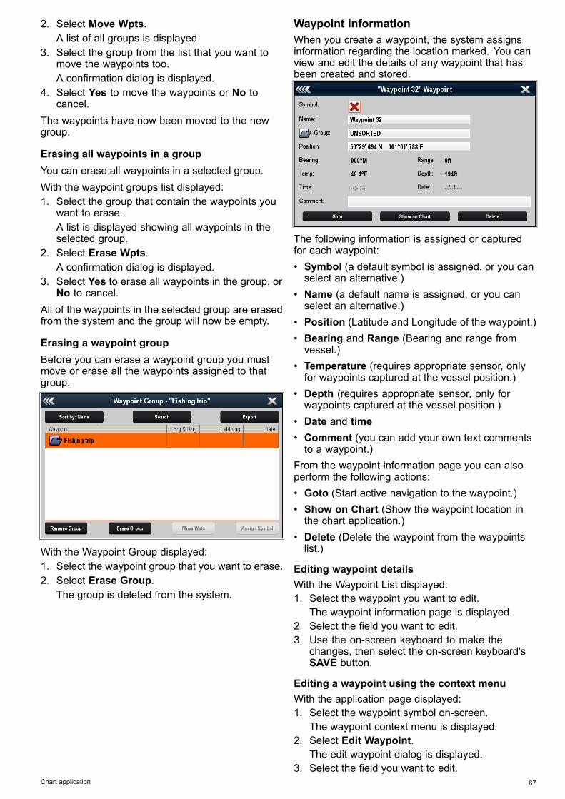
2. Select Move Wpts.A list of all groups is displayed.
3. Select the group from the list that you want tomove the waypoints too.A confirmation dialog is displayed.
4. Select Yes to move the waypoints or No tocancel.
The waypoints have now been moved to the newgroup.
Erasing all waypoints in a groupYou can erase all waypoints in a selected group.With the waypoint groups list displayed:1. Select the group that contain the waypoints you
want to erase.A list is displayed showing all waypoints in theselected group.
2. Select Erase Wpts.A confirmation dialog is displayed.
3. Select Yes to erase all waypoints in the group, orNo to cancel.
All of the waypoints in the selected group are erasedfrom the system and the group will now be empty.
Erasing a waypoint groupBefore you can erase a waypoint group you mustmove or erase all the waypoints assigned to thatgroup.
With the Waypoint Group displayed:1. Select the waypoint group that you want to erase.2. Select Erase Group.
The group is deleted from the system.
Waypoint informationWhen you create a waypoint, the system assignsinformation regarding the location marked. You canview and edit the details of any waypoint that hasbeen created and stored.
The following information is assigned or capturedfor each waypoint:• Symbol (a default symbol is assigned, or you canselect an alternative.)
• Name (a default name is assigned, or you canselect an alternative.)
• Position (Latitude and Longitude of the waypoint.)• Bearing and Range (Bearing and range fromvessel.)
• Temperature (requires appropriate sensor, onlyfor waypoints captured at the vessel position.)
• Depth (requires appropriate sensor, only forwaypoints captured at the vessel position.)
• Date and time• Comment (you can add your own text commentsto a waypoint.)
From the waypoint information page you can alsoperform the following actions:• Goto (Start active navigation to the waypoint.)• Show on Chart (Show the waypoint location inthe chart application.)
• Delete (Delete the waypoint from the waypointslist.)
Editing waypoint detailsWith the Waypoint List displayed:1. Select the waypoint you want to edit.
The waypoint information page is displayed.2. Select the field you want to edit.3. Use the on-screen keyboard to make the
changes, then select the on-screen keyboard'sSAVE button.
Editing a waypoint using the context menuWith the application page displayed:1. Select the waypoint symbol on-screen.
The waypoint context menu is displayed.2. Select Edit Waypoint.
The edit waypoint dialog is displayed.3. Select the field you want to edit.
Chart application 67

4. Use the on-screen keyboard to make thechanges, and then select the on-screenkeyboard's SAVE key.
Moving waypoints
Moving a waypoint using the context menuWith the application page displayed:1. Select the waypoint symbol on-screen.
The waypoint context menu is displayed.2. Select Move Waypoint.3. Select the new position for the waypoint.
Moving a waypoint by entering new coordinatesWith the Waypoint List displayed:1. Select All Waypoints.2. Select the relevant waypoint.
The waypoint information page is displayed.3. Select the Position field.4. Use the on-screen keyboard to make the
changes, and then select the on-screenkeyboard's SAVE key.
Erasing waypoints
Erasing a waypoint using the context menuWith the application page displayed:1. Select the waypoint symbol on-screen.
The waypoint context menu is displayed.2. Select Erase Waypoint.
The erase waypoint pop up message is displayed.3. Select Yes to confirm, or No to cancel.
Erasing a waypoint using the waypoint listWith the Waypoint List displayed:1. Select All Waypoints.2. Select the waypoint you want to erase.
The waypoint information page is displayed.3. Select Erase.
The erase waypoint pop up message is displayed.4. Select Yes to confirm, or No to cancel.
Erasing all waypoints from the system
Note: The following procedure permanentlydeletes all Waypoints from the display. BEFOREproceeding, ensure that you backup any data thatyou want to keep on to a MicroSD card.
From the Backup & Reset menu:1. Select Erase from System.2. Select Erase Waypoints from System.
A confirmation dialog is displayed.3. Select Yes to confirm.
Waypoint searchThe waypoint search feature allows you to search forwaypoints on your system.The search feature is available by selecting Searchfrom the Waypoints list.Waypoints can be searched for by:
• Name or keyword• Symbol• Area
From the search results you can erase all thewaypoints in the search list, move them to an existingor new waypoint group or assign all of the waypointsthe same waypoint symbol.
Searching for waypoints by name or keywordWaypoints can be searched for by name or keyword.From the Waypoints list:1. Select Search.
The search page is displayed.2. Use the on-screen keyboard to enter the waypoint
name or keyword.3. Select Search.
The search results are displayed.
4. Select Erase Wpts to erase the list of waypointsfrom your system, or
5. Select Move Wpts to move the waypoints to anew or existing group, or
6. Select Assign Symbol to assign a new symbolto all the waypoints in the search results list.
You can also select a waypoint from the list to viewits details, or if accessed from the Chart applicationset a goto or display the waypoint in the Chartapplication.
Searching for waypoints by symbolWaypoints can be searched for by waypoint symbol.From the Waypoints list:1. Select Search.
The search page is displayed.2. Select Symbol.
The waypoints symbol list is displayed.68 Dragonfly 6 / Dragonfly 7
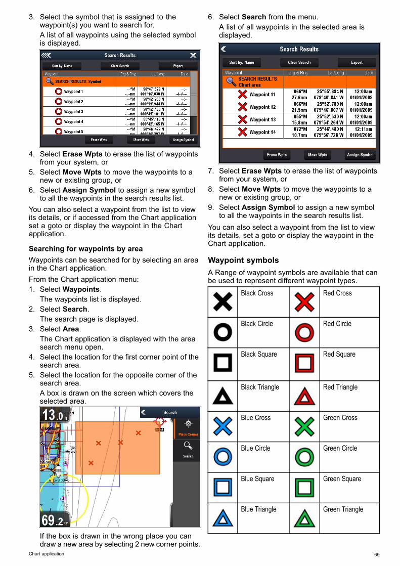
3. Select the symbol that is assigned to thewaypoint(s) you want to search for.A list of all waypoints using the selected symbolis displayed.
4. Select Erase Wpts to erase the list of waypointsfrom your system, or
5. Select Move Wpts to move the waypoints to anew or existing group, or
6. Select Assign Symbol to assign a new symbolto all the waypoints in the search results list.
You can also select a waypoint from the list to viewits details, or if accessed from the Chart applicationset a goto or display the waypoint in the Chartapplication.
Searching for waypoints by areaWaypoints can be searched for by selecting an areain the Chart application.From the Chart application menu:1. Select Waypoints.
The waypoints list is displayed.2. Select Search.
The search page is displayed.3. Select Area.
The Chart application is displayed with the areasearch menu open.
4. Select the location for the first corner point of thesearch area.
5. Select the location for the opposite corner of thesearch area.A box is drawn on the screen which covers theselected area.
If the box is drawn in the wrong place you candraw a new area by selecting 2 new corner points.
6. Select Search from the menu.A list of all waypoints in the selected area isdisplayed.
7. Select Erase Wpts to erase the list of waypointsfrom your system, or
8. Select Move Wpts to move the waypoints to anew or existing group, or
9. Select Assign Symbol to assign a new symbolto all the waypoints in the search results list.
You can also select a waypoint from the list to viewits details, set a goto or display the waypoint in theChart application.
Waypoint symbolsA Range of waypoint symbols are available that canbe used to represent different waypoint types.
Black Cross Red Cross
Black Circle Red Circle
Black Square Red Square
Black Triangle Red Triangle
Blue Cross Green Cross
Blue Circle Green Circle
Blue Square Green Square
Blue Triangle Green Triangle
Chart application 69

Anchor Wreck
Buoy Fuel
Toilets Restaurant
Ramp Caution
Green racemarkanti-clockwise
Green Racemarkclockwise
Yellow racemarkanti-clockwise
Yellow Racemarkclockwise
Red racemarkanti-clockwise
Red Racemarkclockwise
Marker Restriction
Bottom Mark Top Mark
Route Start Route End
Diver Down Diver Down 2
Oil Rig Filled Circle
FAD (FishAttractingDevice)
Concrete Rubble
Seaweed Oyster
Green Can Green Nun
Red Can Red Nun
Yellow Can Yellow Nun
Fish Trap Brushpile
Preferred Marks Post
Ledge Fish
Fish 1 Star Fish 2 Star
Fish 3 Star School Fish
Lobster Small Fish
Rocks Reef
Private Reef Public Reef
Dolphin Shark
Billfish Tank
Reef Ball Sailboat
Sportsfisher Trawler
Swimmer Martini
Tree Tower
Hill or Peak Bridge
Airplane Car
70 Dragonfly 6 / Dragonfly 7

Skull Diamond T
DiamondQuarter
Filled Triangle
8.5 TracksA track is an on-screen trail that shows the passageyou have taken. This trail is made up of a series oftrack points which are created automatically. Youcan save the track to create a permanent record ofwhere you have been.
D11754-2
Creating a trackFrom the chart application menu:1. Select Navigate.2. Select Start Track.
The start track pop up message is displayed.3. Select Ok.
As you navigate your vessel, your journey isautomatically recorded as a track.
Note: If the power fails whilst a track is beingrecorded or the position fix is lost, a break willoccur in the track.
Note: If the maximum number of tracking pointsis reached, you will be warned. The track willcontinue to be recorded with the earlier trackingpoints being overwritten.
4. To complete your track select Stop Track fromthe Navigate menu: Menu > Navigate > StopTrack.The track stopped pop up message is displayed.
5. Select Save, Erase or Cancel.• Save — Will save the track and open the Edittrack Properties dialog where you can namethe track and choose a color for the track line.
• Erase — Will erase the track.• Cancel—Will cancel the Stop Track action.
Track context menuThe Track context menu shows the track length,number of points and menu items.
The context menu provides the following menu items:• Stop Track (only available during track creation.)• Stop Goto (only available during activenavigation.)
Chart application 71

• Erase Track (not available during track creation.)• Edit Track
Accessing the context menuYou can access the context menu by following thesteps below.1. Use the Directional controls to highlight the
Track.The cursor changes to the Track cursor.
2. Press the OK button.The Track context menu is displayed.
Track editingYou can edit aspects of the stored tracks.You can:• Erase a track.• Change the name of a track.• Change the color of a track.
Displaying the track listTo display the track list follow the steps below.From the Chart application menu:1. Select Tracks.
The track list is displayed.
Renaming a trackYou can change the name of a saved track.With the track list displayed.1. Select the track you want to edit.
The track options page is displayed.2. Select Edit Name.
The on-screen keyboard is displayed.3. Use the on-screen keyboard to change the track
name.4. When finished Select SAVE.You can also edit track details by selecting EditTrack from the track context menu.
Changing the color of a trackYou can change the color of a saved track.With the track list displayed.1. Select the track you want to edit.
The track options page is displayed.2. Select Edit Color.
A list of colors is displayed.3. Select the color you want to use.You can also edit track details by selecting EditTrack from the track context menu.
Erasing tracks
Erasing a trackYou can erase tracks from the system.From the Chart application:
1. Select the Track on-screenThe track context menu is displayed.
2. Select Erase Track.A confirmation pop-up dialog is displayed.
3. Select Yes to erase the track, or4. Select No to keep the track.You can also erase a track by selecting the relevanttrack from the Track list and selecting Erase Track.
72 Dragonfly 6 / Dragonfly 7

8.6 Import and ExportWaypoints and Tracks can be imported and exportedusing a MicroSD card.
Saving waypoints and tracks to a memorycardChartplotter variant displays can save their waypointsand tracks to MicroSD card.Ensure a blank card (NOT a cartography card) isinserted into the card reader.From the Chart application:1. If required press the Back button to enter Motion
mode.2. Press the OK button to display the menu.3. Select Waypoints or Tracks as required.
The Waypoints or Track list is displayed.4. Select Import/Export.5. Select Save Waypoints to Card or Save Tracks
to Card as required.6. Select the Waypoints or Tracks that you want to
save, or select Select All.7. Select Save.
The onscreen keyboard is displayed.8. Enter a Filename.
The default filenames are Waypoints andTracks.
9. Select Save.A confirmation dialog is displayed.
10.Select OK to acknowledge and return to normaloperation, or
11. Select Eject device if you want to remove theMicroSD card from the card reader.
Importing waypoints or tracks from amemory cardChartplotter variant displays can import waypointsand tracks from MicroSD card.Ensure that the MicroSD card that contains yoursaved waypoints and / or tracks is inserted into thecard reader.From the Chart application:1. If required press the Back button to enter Motion
mode.2. Press the OK button to display the menu.3. Select Waypoints or Tracks as required.
The Waypoints or Track list is displayed.4. Select Import/Export.5. Select Retrieve from Card.
The file browser is displayed.6. Navigate to the gpx file you want to import.7. Select the file.
A confirmation dialog is displayed.8. If there is a naming conflict between waypoints or
tracks already on your system and the waypointsor tracks you are trying to import you will beprompted to either:
i. Copy as new Waypoint — The waypoint ortrack will be imported and be assigned thenext default name.
ii. Copy & Replace — The waypoint or trackon your system will be overwritten with theimported waypoint or track with the samename .
iii. Don’t Copy— The waypoint or track with thenaming conflict will not be imported.
When completed a Retrieving complete dialogbox is displayed.
9. Select OK.
Chart application 73

8.7 Waypoints and tracks storagecapacityThe display can store the following quantities ofwaypoints and tracks.
Waypoints 3,000 waypoints (split between up to 100waypoint groups)
Tracks 15 tracks (each track can contain up to 10,000points)
8.8 Navigation
Navigating to the cursor's locationIn Cursor mode you can set the Chart application toguide you to the cursor’s location.1. Use the Directional controls to move the cursor
to the desired location.2. Press the OK button.
The context menu is displayed.3. Select Goto Cursor.
Navigating to a waypointYou can set the Chart application to guide you to awaypoint.1. Use the Directional controls to highlight a
waypoint.2. Press the OK button.
The context menu is displayed.3. Select Goto Waypoint.
Navigating to a waypoint from the waypointslistFrom the Chart application:1. If required, press the Back button to enter motion
mode.2. Press the OK button to open the menu.3. Select Waypoints.
The Waypoints list is displayed.4. Select the waypoint you want to navigate to.
The Waypoint information page is displayed.5. Select Goto.
Cancelling navigation to a waypoint1. Select any position anywhere on-screen.
The waypoint context menu is displayed.2. Select Stop Goto.3. Alternatively, in the chart application, go to: Menu
> Navigate > Stop Goto.
Note: Once navigation is no longer active, thewaypoint symbol returns to its normal state, andthe dashed line between your vessel and thewaypoint is removed.
Arriving at a waypointAs your vessel approaches the target waypoint, thewaypoint arrival alarm provides a warning.1. Select Ok on the waypoint arrival alarm pop up
message.
Note: You can set the approach distance (radius)at which the waypoint arrival alarm will soundusing the Waypoint Arrival alarm located in theAlarms menu
74 Dragonfly 6 / Dragonfly 7

8.9 Chart settingsmenu—cartographycompatibilityThe options available in the Chart settings menuare dependent on the cartography in use. If thecartography in use is not compatible then the menuoption will not be shown.
Menu option Compatible cartographyChart Selection • LightHouse Charts
• Navionics® Charts• Jeppesen®
Chart Detail • LightHouse Charts• Navionics® Charts• Jeppesen®
High Res Bathy • Jeppesen®
Chart Orientation • LightHouse Charts• Navionics® Charts• Jeppesen®
Text/Symbol Size • Jeppesen®
Boat Position • Navionics® ChartsCommunity Edits • LightHouse Charts
• Navionics® Charts• Jeppesen®
Sonar Logs • Navionics® ChartsCOG Vector • LightHouse Charts
• Navionics® Charts• Jeppesen®
Deep Water From • LightHouse Charts• Navionics® Charts• Jeppesen®
8.10 Chart selectionYou can select the cartography type to be used inthe Chart application. The Chart selection appliesto the active Chart instance. You must have thenecessary cartography chart cards inserted into yourmultifunction display in order to display differentcartography type.
Selecting the Cartography typeYou can select the cartography type you want todisplay in the Chart application.Ensure you have inserted the chart card thatcontains the cartography type you want to display.From the Chart application menu:1. Select Chart Settings.2. Select Chart Selection.
A list of available cartography is displayed.3. Select the cartography type you want to display
The Chart window is re-drawn to show the selectcartography type.
Chart application 75
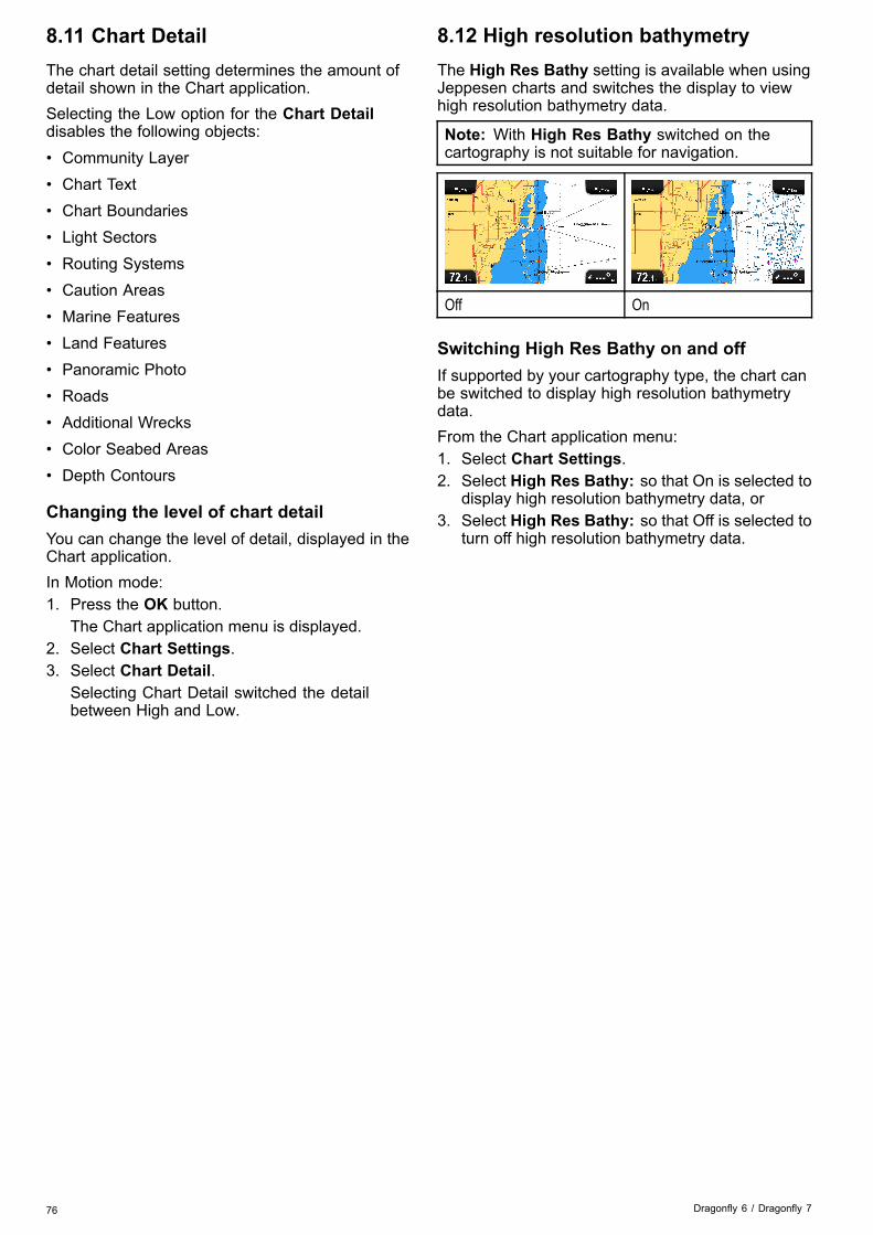
8.11 Chart DetailThe chart detail setting determines the amount ofdetail shown in the Chart application.Selecting the Low option for the Chart Detaildisables the following objects:• Community Layer• Chart Text• Chart Boundaries• Light Sectors• Routing Systems• Caution Areas• Marine Features• Land Features• Panoramic Photo• Roads• Additional Wrecks• Color Seabed Areas• Depth Contours
Changing the level of chart detailYou can change the level of detail, displayed in theChart application.In Motion mode:1. Press the OK button.
The Chart application menu is displayed.2. Select Chart Settings.3. Select Chart Detail.
Selecting Chart Detail switched the detailbetween High and Low.
8.12 High resolution bathymetryThe High Res Bathy setting is available when usingJeppesen charts and switches the display to viewhigh resolution bathymetry data.
Note: With High Res Bathy switched on thecartography is not suitable for navigation.
Off On
Switching High Res Bathy on and offIf supported by your cartography type, the chart canbe switched to display high resolution bathymetrydata.From the Chart application menu:1. Select Chart Settings.2. Select High Res Bathy: so that On is selected to
display high resolution bathymetry data, or3. Select High Res Bathy: so that Off is selected to
turn off high resolution bathymetry data.
76 Dragonfly 6 / Dragonfly 7

8.13 Chart orientationThe orientation of a chart refers to the relationshipbetween the chart and the direction that you aretravelling in.The mode you choose applies to all chart views, andis restored at power up.The following options are available:
North Up
In North Up mode, the Chart Orientation isfixed with true north pointing up (this is the usualorientation for nautical charts). As your headingchanges the vessel symbol rotates accordingly. Thisis the default orientation for the Chart application.
Course Up
In Course Up mode, during active navigation,the Chart application displays the vessel’s currentdestination waypoint directly up. As your COGchanges, the boat symbol moves accordingly. If youselect a new course, the picture will reset to displaythe new course upwards.If COG data becomes unavailable Course Up modeis suspended and the Chart application will set COGto 0°.
Setting the chart orientationFrom the chart application menu:1. Select Chart settings.
2. Select Chart Orientation.Selecting Chart Orientation switches betweenNorth Up and Course Up.
Chart application 77

8.14 Text and Symbol sizeThe size that text and symbols appears when usingJeppesen cartography can be adjusted to make thescreen easier to read from Normal to Large
Normal Large
Switching text and symbol sizeIf supported by your cartography type, the displaytext and symbols size can be increased.From the Chart application menu:1. Select Chart Setting.2. Select Text/Symbol Size: so that Large is
selected to increase the size of text and symbolsin the Chart application, or
3. Select Text/Symbol Size: so that Normal isselected to reduce text and symbol size tonormal.
8.15 Boat positionThe Boat position function determines the positionof the boat symbol on-screen.
Center
With Boat position set to Center the boat symbolremains in the center of the screen.
Offset
With Boat position set to Offset the boat symbolis offset from the center of the screen so that moreChart area is visible in front of the boat symbol.
Changing the boat positionYou can change the position the vessel icon isdisplayed on-screen.From the Chart application menu:1. Select Chart Settings.2. Select Boat Position.
Selecting Boat Position switches the boat positionbetween Center and Offset.
78 Dragonfly 6 / Dragonfly 7

8.16 Community layerIf supported by your cartography type, you candisplay User Generated Content (UGC) on the Chartapplication.
D13008-1
1
2
1. Community feature On.2. Community feature Off.To check if your Navionics cartography supportscommunity edits downloads please refer theNavionics website: for information and instructionson downloading the updates to your chart card.
Switching the community layer on and offIf supported by your cartography type, the UserGenerated Content (UGC) overlay can be switchedon and off by following the steps below.From the Chart application menu:1. Select Chart Setting.2. Select Community Edits: so that On is selected
to display UGC, or3. Select Community Edits: so that Off is selected
to turn off UGC.
8.17 Sonar loggingWhen using compatible Navionics® cartographyyou can share sonar information using Navionics®SonarCharts™.The Sonar Logging function allows logging of depthand position data to a compatible Navionics® chartcard. The saved data can then be uploaded to theNavionics® website to help improve the contourdetail of Sonar Charts on your MFD. Refer to theNavionics® website for instructions on how toupload your sonar logs.
Enabling and disabling Sonar logsSonar logging can be enabled or disabled at anytime.From the Chart application menu:1. Select Chart Setting.2. Select Sonar Logs: so that On is selected to
enable sonar logging, or3. Select Sonar Logs: so that Off is selected to
disable sonar logging.
Chart application 79

8.18 COG VectorThe chart application can be set to display a greenline to represent Course Over Ground (COG).
The green line indicates the vessel’s actual course.
Enabling and disabling the COG vectorYou can enable and disable the COG vector.From the Chart application menu:1. Select Chart Settings.2. Select COG Vector to switch between On and
Off.
8.19 Deep WaterWater depth can be represented using blue shadingwith white used to represent deep water.The depth at which water color turns from blueshading to white can be changed to suit userrequirements.Example 1 — Deep water from: 60 ft
Example 2 — Deep water from: 6 ft
The deep water feature can also be turned off so thatall water appears as white.
Note: The Deep Water function is restricted to thedepth data available on your chart card.
Changing the Deep Water From settingYou can choose the depth that water changes colorto white.From the Chart application menu:1. Select Chart Settings.2. Select Deep Water From:.3. Select the relevant depth, or select Off.Selecting Off will display all water as white regardlessof depth.
80 Dragonfly 6 / Dragonfly 7

8.20 Chart objectsIf supported by your cartography type, you candisplay additional information in the chart applicationfor cartographic objects, ports, or marinas.Depending on the chart card you are using, youcan view some or all of the following additionalinformation:• Details of each cartographic object that is markedon the chart, including source data for structures,lines, open sea areas, and so on.
• Details of ports, port features, and businessservices.
• Pilot book information (similar to what you wouldsee in a marine almanac). Pilot book informationis available at certain ports.
• Panoramic photos of ports and marinas. Theavailability of photos is indicated by a camerasymbol on the chart display.
This information can be accessed using the chartcontext menu options.
Note: The amount of object information availabledepends upon the electronic charts that you areusing for your system. For full details of thefeatures available for your chart cards contact yourchart card supplier.
Displaying pilot book informationFrom the chart application, when a port symbol isdisplayed for a port which has a pilot book:1. Select the port symbol.
The chart context menu will be displayed.2. Select Pilot Book.3. Select the relevant chapter.
Displaying panoramic photosFrom the chart application, when a camera symbol isdisplayed, indicating the availability of a photo:1. Select the camera symbol.
The chart context menu is displayed.2. Select Photo.
The photo is displayed on screen.
Note: Not all cartography types are capable ofdisplaying panoramic photos.
Displaying chart object informationFrom the chart application:1. Select an object.
The chart context menu is displayed.2. Select Chart Objects.
The Chart Object Dialog is displayed.3. Selecting available options will display detailed
information about that item.4. Selecting the position in the dialog will close the
information dialog and position the cursor overthe object.
Chart application 81

82 Dragonfly 6 / Dragonfly 7
Chapter 9: Tools & Settings
Chapter contents• 9.1 System Settings menu on page 84• 9.2 Alarms on page 89• 9.3 Backup and reset on page 91
Tools & Settings 83

9.1 System Settings menuThe options available in the System settings menu are shown below
Menu item Description OptionsKey Beep An audible sound can be made each time
a button is pressed.• On (default)• Off
Language Allows selection of the system language. See the System Languages section fordetails.
Units Set-up Allows selection of units of measurementthat will be used in all applications.
• * Distance Units• * Speed Units• Depth Units• Temperature Units
GPS Set-up Provides GPS setting options. • View Satellite Status• COG/SOG Filter:• Restart GPS
Sonar Set-up Provides sonar setting options. • Depth Offset (W)• Sonar Reset
Time and Date Set-up Allows selection of date and time formats. • Date Format:• Time Format:• Local Time:
Simulator Switches simulator mode On or Off. • Off (default)• On• On (Demo movie)
Maintenance Provides diagnostic information. Alsoenables you to reset the display to factorysettings.
See the Maintenance menu section fordetails.
Bearing Mode Determines how bearing data isdisplayed.
• True• Magnetic (default)
System LanguagesThe system can operate in the following languages:
English (US) English (UK) ArabicBulgarian Chinese CroatianCzech Danish DutchFinnish French GermanGreek Icelandic ItalianJapanese Korean NorwegianPolish Portuguese
(Brazilian)Russian
Slovenian Spanish SwedishTurkish
Selecting a languageFrom the Tools & Settings menu:1. Select System Settings.2. Select Language:3. Select the relevant language from the list.
84 Dragonfly 6 / Dragonfly 7

Units set-upYou can specify your preference for the units of measurement that will be used in all applications.Menu item Description OptionsDistance Units The units of measure that will be used in all
applications for the display of all values relatedto distance.
• Nautical Miles• NM & m (Nautical miles and meters)• Statute Miles• Kilometers
Speed Units The units of measure that will be used in allapplications for the display of all values relatedto speed.
• Knots• MPH (Miles Per Hour)• KPH (Kilometers Per Hour)
Depth Units The units of measure that will be used in allapplications for the display of all values relatedto depth.
• Feet• Meters• Fathoms
Temperature Units The units of measure that will be used in allapplications for the display of all values relatedto temperature.
• Fahrenheit• Celsius
GPS Set-up menuThe options available from the GPS set-up menu areshown below.Menu item Description OptionsView SatelliteStatus
Displays the GPSstatus page.
COG/SOGFilter:
Refer to theCOG/SOG Filtersection for details.
• Low• Medium (default)• High
Restart GPS Selecting RestartGPS will reboot theinternal GPS.
GPS StatusProducts with an internal GPS receiver or GNSS(GPS/GLONASS) receiver can use the GPS statuspage to view the status of the available satellites thatare compatible with your receiver.The satellite constellations are used to position yourboat in the Chart application. You can set up yourreceiver and check its status from the GPS Set-upmenu. For each satellite, the screen provides thefollowing information:
1
2
3
D13122-1
1. Sky view2. Satellite status3. Position and fix information
Sky viewSky view is a visual representation that showsthe position of navigation satellites and their type.Satellite types are:• Circle — A circle identifies a satellite from theGPS constellation.
• Square — A square identifies an (SBAS)differential satellite.
• Diamond — A diamond identifies a satellite fromthe GLONASS constellation.
Satellite status areaThe Satellite status area displays the followinginformation about each satellite:• Type— Identifies which constellation the satellitebelongs to.
• ID— Displays the satellites identification number.• CNO (Carrier-to-noise ratio) — Displays the signalstrength of each satellite shown in the Sky view:– Grey = searching for satellite– Green = satellite in use– Orange = tracking satellite
• Azimuth and Elevation— Provides the angle ofelevation and azimuth between the location of thereceiver and the satellite.
Position and fix informationThe following positional and fix information isprovided:• Horizontal Dilution of Precision (HDOP)— HDOP is a measure of satellite navigationaccuracy, calculated from a number of factorsincluding satellite geometry, system errors inthe data transmission and system errors in thereceiver. A higher figure signifies a greaterpositional error. A typical receiver has an accuracyof between 5 and 15 m. As an example, assuminga receiver error of 5 m, an HDOP of 2 would
Tools & Settings 85

represent an error of approximately 15 m. Pleaseremember that even a very low HDOP figure isNO guarantee that your receiver is providing anaccurate position. If in doubt, check the displayedvessel position in the Chart application againstyour actual proximity to a known charted object.
• Estimated Horizontal Position Error (EHPE)— EHPE is a measure of the estimated error ofa position fix in the horizontal plane. The valuedisplayed indicates that your position is within acircle radius of the stated size 50% of the time.
• Fix status — indicates the actual mode thereceiver is reporting:– Fix— Satellite fix has been acquired.– No Fix— No satellite fix can be acquired.– D Fix — A differential beacon fix has beenacquired.
– SD Fix — A differential satellite fix has beenacquired.
• Position — Displays the latitude and longitudeposition of your receiver.
• Date / Time— Displays the current date and timegenerated by the position fix in UTC format .
• Mode— Identifies wether the receiver is workingin differential mode or non-differential mode.
• Datum — The receiver's datum setting affectsthe accuracy of the vessel position informationdisplayed in the Chart application. In order for yourreceiver and MFD to correlate accurately with yourpaper charts, they must be using the same datum.
COG/SOG FilterThe COG/SOG filter averages the velocity vectors tocompensate for the oscillating motion of the vessel,giving a clearer indication of the vessel’s course andspeed.The filter does not affect the calculation of yourreceiver’s reported position. The velocity vectorscalculated from the signal provide an instantaneousmeasure of speed and direction of the receiver. TheCOG and SOG can therefor seem erratic undercertain conditions. For example, when a vessel ismoving slowly through rough seas, the receivermoves from side to side as well as in the directionof travel.Slow moving vessels, or vessels sailing in roughseas will benefit from a high setting, whereas apower boat that can quickly change speed anddirection will benefit from a low setting.
Sonar Set-up menuThe Sonar Set-up menu provides the followingoptions.
DepthOffset:
Offset representsthe depth of thetransducer relative to:
• Waterline = 0.0 ftand above.
• Keel = 0.1 ft andbelow.
• –9.8 to +9.8 feet —or equivalent units
Sonar Reset Restore all settingson the sonar moduleto factory default.When performing aSonar Reset, it isnormal to briefly loseconnection with thesonar module.
• Yes• No
86 Dragonfly 6 / Dragonfly 7

Time and Date set-upYou can specify your preference for the way that time and date will appear in all applications.
Menu item Description OptionsDate Format Allows you to specify the preferred format for the
display of date information in all applications.• MM:DD:YY (Month, Day, Year)• DD:MM:YY (Day, Month, Year)
Time Format Allows you to specify the preferred format for thedisplay of time information in all applications.
• 12hr• 24hr
Local Time: UTC Allows you to specify the local time zone that willbe used, in terms of an offset from UTC (UniversalCoordinated Time), in 0.5 hour increments.
• –13 to +13 hours (in 0.5 hourincrements)
Simulator modeThe Simulator mode enables you to practiceoperating your display without data from the GPSreceiver or transducer.The simulator mode is switched on / off in theSystem Settings menu.
Note: Raymarine recommends that you do NOTuse the simulator mode whilst navigating.
Note: The simulator will NOT display any realdata. This includes safety messages.
Enabling and disabling simulator modeYou can enable and disable simulator mode byfollowing the steps below.From the System Settings menu:1. Select Simulator:.2. Select On to turn simulator mode on, or3. Select Off to turn simulator mode off.
Note: The Demo movie option is for retaildemonstration purposes only.
Tools & Settings 87

Maintenance menuThis menu provides access to systems settings reset and diagnostics.
Menu item Description OptionsAbout This Unit Displays a list of details about your unit. • Device
• Serial No.• Software
Settings Reset This option resets your menu options to factorydefault. It will NOT affect your waypoints or tracks.
• Yes• No
Settings and Data Reset In addition to the settings reset detailed above,performing a settings and data reset will alsoremove ALL waypoint and track data.
• Yes• No
Back-up Settings Back-up settings to a memory card.Restore Settings Restore saved settings from a memory card.Save Logs Allows you to save error logs to SD card for
troubleshooting purposes.Erase Logs Selecting this option will erase any crash logs on
the device.
88 Dragonfly 6 / Dragonfly 7

9.2 AlarmsAlarms alert you to a situation or hazard requiring your attention.You can configure the behavior of certain alarms byselecting the relevant menu option from the Alarmsmenu.
Accessing the alarms menuThe Alarms menu can be accessed at any time byfollowing the steps below.From any application:1. Press Back to open the View switcher
If the application is currently in Cursor modethen press the Back button twice.
2. Select Tools and Settings.The Tools & Settings page is displayed.
3. Select Alarms.The Alarms menu is displayed.
Tools & Settings 89

Alarms menuThe Alarms available are dependent on the display variant.
Alarm Description OptionsDeep Water Arrival When set to On, an alarm is triggered when the
depth reaches the value specified in the DeepLimit setting. This option is only available whencurrent depth data is available.
Note: The Deep limit cannot be set to a valueless than the Shallow Limit.
Deep:
• Off (default)• OnDeep Limit:
• 2 ft (or equivalent units) to the maximum of thetransducer range
Shallow WaterArrival
When set to On, an alarm is triggered when thedepth reaches the value specified in the ShallowLimit setting. This option is only available whencurrent depth data is available.
Note:The Shallow Limit cannot be set to a depthgreater than the Deep Limit.
Shallow:
• Off (default)• OnShallow Limit:
• 2 ft (or equivalent units) to the maximum of thetransducer range
Fish If the Fish alarm and fish depth limits alarm are setto On, a warning sound is triggered if any targetmeets the sensitivity level and is within the ShallowFish Limit and Deep Fish Limit that you specify.The following items are available in the sub-menu:
• Fish— Switches fish alarm On and Off.• Fish Sensitivity — If the Fish alarm is set to
On, an alarm is triggered when the fish returnstrength reaches the sensitivity that you specify.
• Fish Depth Limits— Switches depth limits Onand Off.
• Shallow Fish Limit— Specifies the lower valuefor the Fish Alarm Depth Limit.
• Deep Fish Limit — Specifies the upper valuefor the Fish Alarm Depth Limit.
Fish
• Off (default)• OnFish Sensitivity
• 1 to 10Fish Depth Limits
• On• Off (default)Shallow Fish Limit
• 2 ft (or equivalent units) to the maximum of thetransducer range
Deep Fish Limit
• 2 ft (or equivalent units) to the maximum of thetransducer range
Water Temperature When set to On, an alarm and pop-up message istriggered when the water temperature is equal toor lower than the Lower Temp Limit, or equal to orgreater than the Upper Temp Limit.
Water Temperature
• Off (default)• OnLower Temp Limit
• 60 degrees fahrenheit (or equivalent units)• –09.9 to +99.7 degrees fahrenheit (or equivalent
units)Upper Temp Limit
• 75 degrees fahrenheit (or equivalent units)• –09.7 to 99.9 degrees fahrenheit (or equivalent
units)Waypoint ArrivalAlarm
When you arrive at a waypoint, an alarm istriggered. This setting allows you to specify thedistance from the target waypoint at which thealarm is triggered.
0.01 to 9.99 nm (or equivalent units)
90 Dragonfly 6 / Dragonfly 7
9.3 Backup and resetThe backup and reset menu provides the following functions:Save Data to Card Save waypoints and tracks to memory card.Retrieve from Card Retrieve / import waypoints and tracks from
a memory card.Erase from Card Erase files from a memory card.Erase from System Erase waypoints and tracks from the system.User Settings Backup, Reset and restore user settings,
Reset settings and data.
For details on performing these proceduresplease refer to Saving user data and usersettings.
Restart GPS Restart the internal GPS receiver.Sonar Reset Reset the internal sonar module. For details on performing a sonar reset
please refer to Resetting your system.
Saving user data and user settingsYou can save user data (waypoints and tracks) anduser settings to a memory card for later retrieval.Type of data Description NotesWaypoints Saves all waypoints
to a single archivefile.
Only 1 waypointsarchive file can besaved per memorycard.
Tracks Saves all tracks to asingle archive file.
Only 1 tracks archivefile can be saved permemory card.
User settings Saves settingsyou've made in theset-up menus to asingle archive file.
Only 1 user settingsarchive file can besaved per memorycard.
Note: It is recommended that you save your userdata and user settings to a memory card on aregular basis.
Note: It is strongly recommended that you saveuser data and settings to a separate memory card,and NOT to a chart card containing cartography.
Erasing all waypoints from the system
Note: The following procedure permanentlydeletes all Waypoints from the display. BEFOREproceeding, ensure that you backup any data thatyou want to keep on to a MicroSD card.
From the Backup & Reset menu:1. Select Erase from System.2. Select Erase Waypoints from System.
A confirmation dialog is displayed.3. Select Yes to confirm.
Erasing tracks from the system
Note: The following procedure permanentlydeletes the selected Tracks from the display.BEFORE proceeding, ensure that you backup anydata that you want to keep on to a memory card.
From the Tools & Settings page:1. Select Backup & Reset.
2. Select Erase from System.3. Select Erase Tracks from System.
The Track list is displayed.4. Select the Track that you want to delete, or5. Select Erase All.
A confirmation dialog is displayed.6. Select Yes to confirm.
Erasing waypoints and tracks from a MicroSDcardEnsure the MicroSD card with the saved waypointsand / or tracks that you want to delete is insertedinto the card reader.From the Backup & Reset menu:1. Select Erase from Card.
The file browser is displayed.2. Navigate to the file you want to delete.3. Select the file you want to delete.
A confirmation dialog is displayed.4. Select Yes to delete the file.
Saving user settings to a memory cardEnsure a memory card (NOT a chart card) is insertedinto the card reader.From the Tools & Settings page.1. Select Backup & Reset.2. Select User Settings.3. Select Back-up Settings.
When complete a saving complete dialog box isdisplayed.
4. Select OK to acknowledge and return to normaloperation, or
5. Select Eject device if you want to remove thememory card from the card reader.
Retrieving user settings from a memory cardEnsure the memory card with your user settingssaved on it is inserted into the card reader.From the Tools & Settings page.1. Select Backup & Reset.2. Select User Settings.
Tools & Settings 91

3. Select Restore Settings.When complete a Restoring complete dialog boxis displayed.
4. Select OK to acknowledge and return to normaloperation, or
5. Select Eject device if you want to remove thememory card from the card reader.
Resetting your systemYour system may be reset to its factory defaultsettings if required.There are 3 types of reset operation.• Settings reset.• Settings and data reset.• Sonar reset.
Settings resetThis option resets your setup menus to factorydefault. It will NOT affect your waypoints or tracks.
Settings and data resetIn addition to the settings reset detailed above,performing a settings and data reset will also removeALL waypoints and tracks from the system.
Sonar resetThis option resets the sonar to default settings.
Resetting system settingsFrom the Tools & Settings page:1. Select Backup & Reset.2. Select User Settings.3. Select Settings Reset.
A message is displayed prompting you to confirmthe action.
4. Select Yes to proceed with the settings reset, orNo to cancel.If Yes is selected the system will reboot and thesettings will be reset to factory defaults.
Resetting system settings and data
Note: Performing a settings and data reset erasesALL waypoints and tracks from your system.BEFORE proceeding with a settings and datareset, ensure that you backup any data that youwant to keep on to a memory card.
From the Tools & Settings page:1. Select Backup & Reset.2. Select User Settings.3. Select Settings & Data Reset.
A message is displayed prompting you to confirmthe action.
4. Select Yes to proceed with the settings and datareset, or No to cancel.If Yes is selected the system will reboot and thesettings will be reset to factory defaults and alluse data is deleted.
Resetting the sonarThe sonar setting can be reset to factory defaults.From the Tools & Settings page:1. Select System Settings.2. Select Sonar Set-up.3. Select Sonar Reset.
A confirmation dialog is displayed.4. Select Yes to reset the sonar settings.
92 Dragonfly 6 / Dragonfly 7

Chapter 10: Maintenance
Chapter contents• 10.1 Service and maintenance on page 94• 10.2 Product cleaning on page 94• 10.3 Transducer cleaning on page 95
Maintenance 93

10.1 Service and maintenanceThis product contains no user serviceablecomponents. Please refer all maintenanceand repair to authorized Raymarine dealers.Unauthorized repair may affect your warranty.
Routine equipment checksRaymarine strongly recommends that you completea number of routine checks to ensure the correct andreliable operation of your equipment.Complete the following checks on a regular basis:• Examine all cables for signs of damage or wearand tear.
• Check that all cables are securely connected.
10.2 Product cleaningBest cleaning practices.
When cleaning products:• If your product includes a display screen, do NOTwipe the screen with a dry cloth, as this couldscratch the screen coating.
• Do NOT use abrasive, or acid or ammonia basedproducts.
• Do NOT use a jet wash.
Cleaning the display caseThe display unit is a sealed unit and does not requireregular cleaning. If it is necessary to clean the unit,follow this basic procedure:1. Switch off the power to the display.2. Wipe the display with a clean, soft cloth (a
microfibre cloth is ideal).3. If necessary, use a mild detergent to remove
grease marks.
Note: Do NOT use solvents or detergents on thescreen itself.
Note: In certain conditions, condensation mayappear inside the display screen. This will notharm the unit, and can be cleared by powering onthe display for a short time.
Cleaning the display screenA coating is applied to the display screen. Thismakes it water repellent, and prevents glare. Toavoid damaging this coating, follow this procedure:1. Switch off the power to the display.2. Rinse the screen with fresh water to remove all
dirt particles and salt deposits.3. Allow the screen to dry naturally.4. If any smears remain, very gently wipe the screen
with a clean microfibre cleaning cloth (availablefrom an opticians).
94 Dragonfly 6 / Dragonfly 7

10.3 Transducer cleaningGrowth can collect on the bottom of the transducer,this can reduce performance. To prevent the buildup of sea growth, coat the transducer with a thinlayer of water based antifouling paint, available fromyour local marine dealer. Reapply paint every 6months or at the beginning of each boating season.Certain smart transducers have restrictions on whereantifouling paint is applied. Please consult yourdealer.
Note: Transducers with a temperature sensor maynot work properly if painted.
Note: Never use ketone based paint. Ketonescan attack many plastics possibly damaging thesensor.
Note: Never use spray paint on your transducer.Spraying incorporates tiny air bubbles, and amarine transducer cannot transmit properlythrough air.
Use a soft cloth and mild household detergent toclean the transducer. If the fouling is severe, removethe growth with a green scotch briteTM pad. Becareful to avoid scratching the transducers face.If your transducer has a paddlewheel you can wetsand with fine grade wet/dry paper.
Note: Harsh cleaning solvents such as acetonemay damage the transducer.
Maintenance 95

96 Dragonfly 6 / Dragonfly 7

Chapter 11: Troubleshooting
Chapter contents• 11.1 Troubleshooting on page 98• 11.2 Power up troubleshooting on page 99• 11.3 GPS troubleshooting on page 100• 11.4 Sonar / DownVision troubleshooting on page 101• 11.5 Miscellaneous troubleshooting on page 103
Troubleshooting 97

11.1 TroubleshootingThe troubleshooting information provides possiblecauses and corrective action required for commonproblems associated with marine electronicsinstallations.All Raymarine products are, prior to packing andshipping, subjected to comprehensive test andquality assurance programs. However, if youexperience problems with the operation of yourproduct this section will help you to diagnoseand correct problems in order to restore normaloperation.If after referring to this section you are still havingproblems with your unit, please contact RaymarineTechnical Support for further advice.
98 Dragonfly 6 / Dragonfly 7
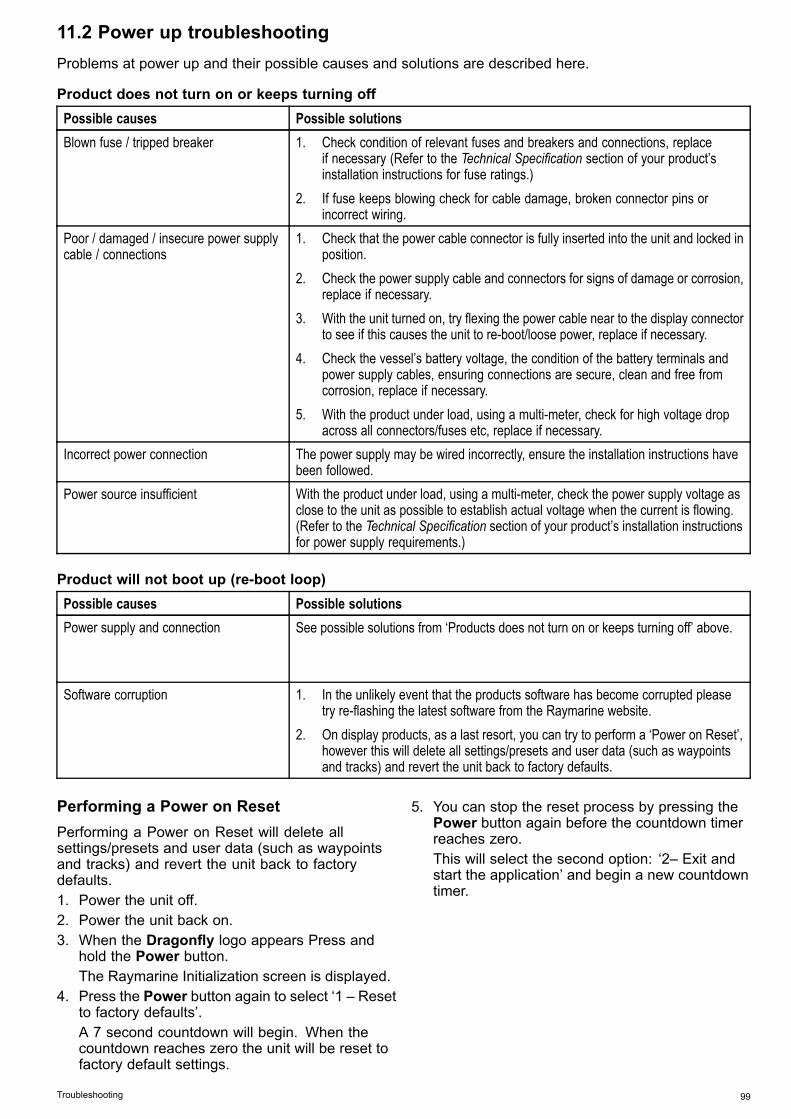
11.2 Power up troubleshootingProblems at power up and their possible causes and solutions are described here.
Product does not turn on or keeps turning offPossible causes Possible solutionsBlown fuse / tripped breaker 1. Check condition of relevant fuses and breakers and connections, replace
if necessary (Refer to the Technical Specification section of your product’sinstallation instructions for fuse ratings.)
2. If fuse keeps blowing check for cable damage, broken connector pins orincorrect wiring.
Poor / damaged / insecure power supplycable / connections
1. Check that the power cable connector is fully inserted into the unit and locked inposition.
2. Check the power supply cable and connectors for signs of damage or corrosion,replace if necessary.
3. With the unit turned on, try flexing the power cable near to the display connectorto see if this causes the unit to re-boot/loose power, replace if necessary.
4. Check the vessel’s battery voltage, the condition of the battery terminals andpower supply cables, ensuring connections are secure, clean and free fromcorrosion, replace if necessary.
5. With the product under load, using a multi-meter, check for high voltage dropacross all connectors/fuses etc, replace if necessary.
Incorrect power connection The power supply may be wired incorrectly, ensure the installation instructions havebeen followed.
Power source insufficient With the product under load, using a multi-meter, check the power supply voltage asclose to the unit as possible to establish actual voltage when the current is flowing.(Refer to the Technical Specification section of your product’s installation instructionsfor power supply requirements.)
Product will not boot up (re-boot loop)Possible causes Possible solutionsPower supply and connection See possible solutions from ‘Products does not turn on or keeps turning off’ above.
Software corruption 1. In the unlikely event that the products software has become corrupted pleasetry re-flashing the latest software from the Raymarine website.
2. On display products, as a last resort, you can try to perform a ‘Power on Reset’,however this will delete all settings/presets and user data (such as waypointsand tracks) and revert the unit back to factory defaults.
Performing a Power on ResetPerforming a Power on Reset will delete allsettings/presets and user data (such as waypointsand tracks) and revert the unit back to factorydefaults.1. Power the unit off.2. Power the unit back on.3. When the Dragonfly logo appears Press and
hold the Power button.The Raymarine Initialization screen is displayed.
4. Press the Power button again to select ‘1 – Resetto factory defaults’.A 7 second countdown will begin. When thecountdown reaches zero the unit will be reset tofactory default settings.
5. You can stop the reset process by pressing thePower button again before the countdown timerreaches zero.This will select the second option: ‘2– Exit andstart the application’ and begin a new countdowntimer.
Troubleshooting 99

11.3 GPS troubleshootingBefore troubleshooting GPS problems ensure yourproduct has the latest software, by checking theSoftware Updates page on the Raymarine websitewww.raymarine.com.
GPS cannot acquire satellite fixPossible causes Possible solutionsGeographic location or prevailing conditionspreventing satellite fix.
Check periodically to see if a fix is obtained in better conditions or anothergeographic location.A GPS Status page is available. This provides satellite signal strength and otherrelevant information.
Location of product For optimum performance the unit should be mounted above decks and not bein close proximity to any structural bulkheads or other electrical equipment orcables which may cause interference.Refer to Chapter 3 Planning the installation for details on product locationrequirements
Cannot output GPS dataPossible causes Possible solutionsThis product is a standalone product that isnot networkable, GPS data cannot be sharedwith other devices.
N/A
100 Dragonfly 6 / Dragonfly 7

11.4 Sonar / DownVision troubleshootingProblems with the Sonar or DownVision and their possible causes and solutions are described here.
Scrolling image is not being displayedPossible causes Possible solutionsSonar disabled Select Enable Sonar from the Shortcuts page.Damaged cables 1. Check the unit’s connector for broken or bent pins.
2. Check that the cable connector is fully inserted into the unit and that thelocking collar is in the locked position.
3. Check the power supply cable and connectors for signs of damage orcorrosion, replace if necessary.
4. With the unit turned on, try flexing the power cable near to the displayconnector to see if this causes the unit to re-boot/loose power, replaceif necessary.
5. Check the vessel’s battery voltage, the condition of the battery terminalsand power supply cables, ensuring connections are secure, clean and freefrom corrosion, replace if necessary.
6. With the product under load, using a multi-meter, check for high voltage dropacross all connectors/fuses etc (this can cause the Fishfinder applications tostop scrolling or the unit to reset/turn off), replace if necessary.
Damaged or fouled transducer Check the condition of the transducer ensuring it is not damaged and is free fromdebris/fouling, clean or replace as necessary.
Wrong transducer fitted The CPT-DV transducer is a DownVision™ only transducer, you cannot use theSonar application with a CPT-DV transducer connected. If you have a DVSor Pro variant display ensure you are using a dual element transducer suchas the CPT-DVS.Refer to 3.3 DownVision™ transducer compatibility for transducer compatibility.
No depth reading / lost bottom lockPossible causes Possible solutionsTransducer location Check that the transducer has been installed in accordance with the transducer
location requirements (refer to Selecting a location for the transducer of themanual for details).
Transducer angle If the transducer angle is too great the beam can miss the bottom, adjusttransducer angle and recheck.
Transducer kicked-up Check that the transducer hasn't kicked up due to hitting an object.Power source insufficient With the product under load, using a multi-meter, check the power supply
voltage as close to the unit as possible to establish actual voltage when thecurrent is flowing. (Refer to Chapter 13 Technical specification for power supplyrequirements.)
Damaged or fouled transducer Check the condition of the transducer ensuring it is not damaged and is freefrom debris / fouling.
Damaged cables 1. Check the unit’s connector for broken or bent pins.2. Check that the cable connector is fully inserted into the unit and that the
locking collar is in the locked position.3. Check the power supply cable and connectors for signs of damage or
corrosion, replace if necessary.4. With the unit turned on, try flexing the power cable near to the display
connector to see if this causes the unit to re-boot/loose power, replaceif necessary.
5. Check the vessel’s battery voltage, the condition of the battery terminalsand power supply cables, ensuring connections are secure, clean and freefrom corrosion, replace if necessary.
Troubleshooting 101

Possible causes Possible solutions
6. With the product under load, using a multi-meter, check for high voltage dropacross all connectors/fuses etc (this can cause the Fishfinder applications tostop scrolling or the unit to reset/turn off), replace if necessary.
Vessel speed too high Slow vessel speed and recheck.
Note: The Sonar channel will be able to hold bottom at higher speeds thanthe DownVision™ channel.
Bottom too shallow or too deep The bottom depth may be outside of the transducers depth range, move vesselto shallower or deeper waters as relevant and recheck. (Refer to Chapter 13Technical specification for transducer depth range.)
Note: Depending on water conditions, the Sonar channel maybe able toachieve increased depth range over the DownVision™ channel.
Poor / problematic imagePossible causes Possible solutionsScrolling paused From Cursor mode, press the Back button to enter scrolling mode.Sensitivity settings may be inappropriate forpresent conditions.
Check and adjust sensitivity settings or perform a Sonar reset.
Damaged cables 1. Check the unit’s connector for broken or bent pins.2. Check that the cable connector is fully inserted into the unit and that the
locking collar is in the locked position.3. Check the power supply cable and connectors for signs of damage or
corrosion, replace if necessary.4. With the unit turned on, try flexing the power cable near to the display
connector to see if this causes the unit to re-boot/loose power, replaceif necessary.
5. Check the vessel’s battery voltage, the condition of the battery terminalsand power supply cables, ensuring connections are secure, clean and freefrom corrosion, replace if necessary.
6. With the product under load, using a multi-meter, check for high voltage dropacross all connectors/fuses etc (this can cause the Fishfinder applications tostop scrolling or the unit to reset/turn off), replace if necessary.
Transducer location The presence of thin lines at a constant depth may be a reflection of structureson the bottom of the vessel check that the transducer has been installed inaccordance with the transducer location requirements (refer to Selecting alocation for the transducer of the manual for details).If the transducer is mounted too high on the transom it may be lifting out of thewater, check that the transducer face is fully submerged when planing andturning.
Transducer kicked-up Check that the transducer hasn't kicked up due to hitting an object.Damaged or fouled transducer Check the condition of the transducer ensuring it is not damaged and is free
from debris / fouling.Damaged transducer cable Check that the transducer cable and connection is free from damage and that
the connections are secure and free from corrosion.Turbulence around the transducer at higherspeeds may affect transducer performance
Slow vessel speed and recheck.
Interference from another transducer 1. Turn off the transducer causing the interference.2. Reposition the transducers so they are further apart.
102 Dragonfly 6 / Dragonfly 7

11.5 Miscellaneous troubleshootingMiscellaneous problems and their possible causes and solutions are described here.
Problem Possible causes Possible solutionsCheck relevant fuses and breakers.Check that the power supply cable is sound and that allconnections are tight and free from corrosion.
Intermittent problem with powerto the display.
Check that the power source is of the correct voltage andsufficient current.
Ensure you have the latestsoftware.
Check the Raymarine website regularly for softwareupdates for your product www.raymarine.com.
Display behaves erratically:
• Frequent unexpected resets.• System crashes or other
erratic behavior.
Corrupt data / other unknownissue.
Perform a Settings and Data Reset.
Important: This will result in the loss of any settingsand data (such as waypoints) stored on the product.Save any important data to a memory card beforeresetting.
Troubleshooting 103

104 Dragonfly 6 / Dragonfly 7

Chapter 12: Technical support
Chapter contents• 12.1 Raymarine product support and servicing on page 106• 12.2 Learning resources on page 107
Technical support 105

12.1 Raymarine product support andservicingRaymarine provides a comprehensive productsupport service, as well as warranty, service, andrepairs. You can access these services through theRaymarine website, telephone, and e-mail.
Product informationIf you need to request service or support, pleasehave the following information to hand:• Product name.• Product identity.• Serial number.• Software application version.• System diagrams.You can obtain this product information using themenus within your product.
Servicing and warrantyRaymarine offers dedicated service departments forwarranty, service, and repairs.Don’t forget to visit the Raymarine website toregister your product for extended warranty benefits:http://www.raymarine.co.uk/display/?id=788.Region Tele-
phoneE-mail
UnitedKingdom (UK),EMEA, andAsia Pacific
+44(0)1329246 932
United States(US)
+1 (603)324 7900
Web supportPlease visit the “Support” area of the Raymarinewebsite for:• Manuals and Documents — http://www.rayma-rine.co.uk/display/?id=10125
• FAQ / Knowledgebase — http://www.rayma-rine.co.uk/knowledgebase/
• Technical support forum — http://rayma-rine.ning.com/
• Software updates — http://www.rayma-rine.com/software
Telephone and e-mail supportRegion Tele-
phoneE-mail
United Kingdom(UK), EMEA,and Asia Pacific
+44(0)1329246 777
United States(US)
+1 (603)324 7900(Toll-free:+800 5395539)
Region Tele-phone
Australia andNew Zealand
+61 289770300
[email protected](Raymarine subsidiary)
France +33 (0)146 49 7230
[email protected](Raymarine subsidiary)
Germany +49(0)40 237808 0
[email protected](Raymarine subsidiary)
Italy +39 0299451001
[email protected](Raymarine subsidiary)
Spain +34 962965 102
[email protected](Authorized Raymarinedistributor)
Netherlands +31(0)263614 905
[email protected](Raymarine subsidiary)
Sweden +46(0)317633 670
[email protected](Raymarine subsidiary)
Finland +358(0)207619 937
[email protected](Raymarine subsidiary)
Norway +47 69264 600
[email protected](Raymarine subsidiary)
Denmark +45 437164 64
[email protected](Raymarine subsidiary)
Russia +7 495788 0508
[email protected](Authorized Raymarinedistributor)
106 Dragonfly 6 / Dragonfly 7

12.2 Learning resourcesRaymarine has produced a range of learningresources to help you get the most out of yourproducts.
Video tutorialsRaymarine official channel onYouTube:
• http://www.youtube.com/u-ser/RaymarineInc
Video Gallery:
• http://www.rayma-rine.co.uk/view/?id=2679
Product Support videos:
• http://www.rayma-rine.co.uk/view/?id=4952
Note:• Viewing the videos requires a device with anInternet connection.
• Some videos are only available in English.
Training coursesRaymarine regularly runs a range of in-depth trainingcourses to help you make the most of your products.Visit the Training section of the Raymarine websitefor more information:• http://www.raymarine.co.uk/view/?id=2372
FAQs and Knowledge BaseRaymarine has produced an extensive set of FAQsand a Knowledge Base to help you find moreinformation and troubleshoot any issues.• http://www.raymarine.co.uk/knowledgebase/
Technical support forumYou can use the Technical support forum to aska technical question about a Raymarine productor to find out how other customers are usingtheir Raymarine equipment. The resource isregularly updated with contributions from Raymarinecustomers and staff:• http://raymarine.ning.com/
Technical support 107

108 Dragonfly 6 / Dragonfly 7

Chapter 13: Technical specification
Chapter contents• 13.1 Technical specification on page 110
Technical specification 109

13.1 Technical specification
Display physical specification5.7” display 7” display
Dimensions • Width: 148 mm(5.8 in)
• Height (NOTincludingbracket): 148.3mm (5.8 in)
• Height(includingbracket): 203mm (8 in)
• Display depth(NOT includingcables): 73 mm(2.9 in)
• Display depth(includingcables): 163mm (6.4 in)
• Width: 191 mm(7.5 in)
• Height (NOTincludingbracket): 156mm (6.1 in)
• Height(includingbracket): 208mm (8.2 in)
• Display depth(NOT includingcables): 78 mm(3 in)
• Display depth(includingcables): 168mm (6.6 in)
Weight (unitincluding cradle)
0.64 kg (1.4 lbs) 0.76 kg (1.68 lbs)
Viewing angle
���
���
���
���
���
�����
�����
�����
D12625-1
C
D
A B
Dragonfly®6 Dragonfly®7A 70º 75ºB 70º 75ºC 70º 75ºD 45º 70º
Note: The viewing angles stated above weretaken using internationally agreed standards andshould be used for comparison purposes only.Do NOT install the product before testing theviewability in the desired location.
Physical specification — CPT-60 TransducerDimensions • Length: 202.6 mm (8 in)
• Height: 117.4 mm (4.6 in)Cable length 6 m (19.7 ft)Weight (unit includingcradle)
0.60 kg (1.3 lbs)
Display power specificationDragonfly®6 Dragonfly®7
Nominal supplyvoltage
12 V dc 12 V dc
Operatingvoltage range
10.8 V dc to 15.6V dc
10.8 V dc to 15.6V dc
Powerconsumption
• 8 W Max at fullbrightness.
• 4.5 W Max inPowerSavemode.
• 9.4 W Max atfull brightness.
• 4.8 W Max inPowerSavemode.
Fuse and thermalbreaker ratings
• 5 A — In-linefuse (notsupplied)
• 3 A — Thermalbreaker
• 5 A — In-linefuse (notsupplied)
• 3 A — Thermalbreaker
Display environmental specificationEnvironmental specifications below apply to alldisplay variants
Operatingtemperature
0 ºC to +55 ºC (32 ºF to 131 ºF)
Storagetemperature
-30 ºC to +70 ºC (-22 ºF to 158 ºF)
Relative humidity Maximum 75%Waterproof rating • IPX6 and IPX7
Transducer environmental specificationOperatingtemperature
0 ºC to + 40 ºC (32 ºF to 104 ºF)
Storagetemperature
–20 ºC to + 70 ºC (23 ºF to 158 ºF)
Waterproof rating • IPX6 and IPX7
Display LCD specification5.7” display 7” display
Size 5.7 in 7 inType TFT backlit LED TFT backlit LEDColordepth
24–bit 24–bit
Resolu-tion
640 x 480 VGA 800 x 480 WVGA
Aspect 4:3 16:9
110 Dragonfly 6 / Dragonfly 7
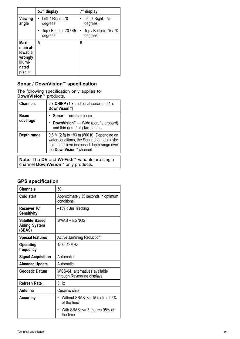
5.7” display 7” displayViewingangle
• Left / Right: 70degrees
• Top / Bottom: 70 / 45degrees
• Left / Right: 75degrees
• Top / Bottom: 75 / 70degrees
Maxi-mum al-lowablewronglyillumi-natedpixels
5 6
Sonar / DownVision™ specificationThe following specification only applies toDownVision™ products.
Channels 2 x CHIRP (1 x traditional sonar and 1 xDownVision™)
Beamcoverage
• Sonar — conical beam.• DownVision™ —Wide (port / starboard)
and thin (fore / aft) fan beam.Depth range 0.6 M (2 ft) to 183 m (600 ft). Depending on
water conditions, the Sonar channel maybeable to achieve increased depth range overthe DownVision™ channel.
Note: The DV and Wi-Fish™ variants are singlechannel DownVision™ only products.
GPS specificationChannels 50Cold start Approximately 35 seconds in optimum
conditionsReceiver ICSensitivity
–159 dBm Tracking
Satellite BasedAiding System(SBAS)
WAAS + EGNOS
Special features Active Jamming ReductionOperatingfrequency
1575.43MHz
Signal Acquisition AutomaticAlmanac Update AutomaticGeodetic Datum WGS-84, alternatives available
through Raymarine displays.Refresh Rate 5 HzAntenna Ceramic chipAccuracy • Without SBAS: <= 15 metres 95%
of the time• With SBAS: <= 5 metres 95% of
the time
Technical specification 111

112 Dragonfly 6 / Dragonfly 7

Chapter 14: Spares and accessories
Chapter contents• 14.1 Accessories on page 114
Spares and accessories 113

14.1 Accessories
DescriptionDragonfly®6part numbers
Dragonfly®7part numbers
Carrying case A80206 N/ATrolling Motor Mount A80207 A802074 m (13.1 ft) extensioncable
A80224 A80224
Surface mount adaptor A80223 A80287Sun cover R70134 A80285Mounting bracket /cradle
R70135 R70302
114 Dragonfly 6 / Dragonfly 7


www.raymarine.com
Related Documents