DraftSight Getting Started Guide
Oct 26, 2015
Uputstvo DraftSight
Welcome message from author
This document is posted to help you gain knowledge. Please leave a comment to let me know what you think about it! Share it to your friends and learn new things together.
Transcript

©2010 Dassault Systèmes, All Rights Reserved
DraftSight and the DraftSight logos are trademarks of Dassault Systèmes or its subsidiaries in the US and/or other countries. Other brand or product names are trademarks or registered trademarks of their respective holders.
The information and the software discussed in this document are subject to change without notice and are not commitments by Dassault Systemes or its subsidiaries.
No material may be reproduced or transmitted in any form or by any means, electronic or mechanical, for any purpose without the express written permission of Dassault Systèmes or its subsidiaries.
The software discussed in this document is furnished under a license and may be used or copied only in accordance with the terms of this license. Nothing stated in, or implied by, this document or its contents shall be considered or deemed a modification or amendment of any warranties set forth in the terms of the software license agreement.
Part Number: PMT1080-ENG Rev. 1
COMMERCIAL COMPUTER SOFTWARE - PROPRIETARY
U.S. Government Restricted Rights. Use, duplication, or disclosure by the government is subject to restrictions as set forth in FAR 52.227-19 (Commercial Computer Software - Restricted Rights), DFARS 227.7202 (Commercial Computer Software - Restricted Rights), DFARS 227.7202 (Commercial Computer Software and Commercial Computer Software Documentation), and in the license agreement, as applicable.
Contractor/Manufacturer:Dassault Systèmes10, rue Marcel Dassault78140 Velizy-VillacoublayFrance

DraftSight CONTENTS
i
CONTENTS
INTRODUCTIONUsing this Book . . . . . . . . . . . . . . . . . . . . . . . . . . . . . . . . . . . . . . . . . 2What is DraftSight? . . . . . . . . . . . . . . . . . . . . . . . . . . . . . . . . . . . . . . 2Conventions Used in this Book . . . . . . . . . . . . . . . . . . . . . . . . . . . . 2Start a DraftSight Session. . . . . . . . . . . . . . . . . . . . . . . . . . . . . . . . . 3DraftSight User Interface . . . . . . . . . . . . . . . . . . . . . . . . . . . . . . . . . 4
Main Menu . . . . . . . . . . . . . . . . . . . . . . . . . . . . . . . . . . . . . . . . . . 4Drop-down Menu. . . . . . . . . . . . . . . . . . . . . . . . . . . . . . . . . . . . . 4Context Menu. . . . . . . . . . . . . . . . . . . . . . . . . . . . . . . . . . . . . . . . 4Keyboard Shortcuts. . . . . . . . . . . . . . . . . . . . . . . . . . . . . . . . . . . 5Standard Toolbar. . . . . . . . . . . . . . . . . . . . . . . . . . . . . . . . . . . . . 5Graphics Area. . . . . . . . . . . . . . . . . . . . . . . . . . . . . . . . . . . . . . . . 6View Tiles . . . . . . . . . . . . . . . . . . . . . . . . . . . . . . . . . . . . . . . . . . . 6Graphics Cursor / Crosshairs . . . . . . . . . . . . . . . . . . . . . . . . . . 7Cartesian Coordinate System / Origin . . . . . . . . . . . . . . . . . . . 7Coordinate System . . . . . . . . . . . . . . . . . . . . . . . . . . . . . . . . . . . 7Model Tab and Sheet Tab . . . . . . . . . . . . . . . . . . . . . . . . . . . . . 8Command Window . . . . . . . . . . . . . . . . . . . . . . . . . . . . . . . . . . . 9Status Bar . . . . . . . . . . . . . . . . . . . . . . . . . . . . . . . . . . . . . . . . . . 10Palettes . . . . . . . . . . . . . . . . . . . . . . . . . . . . . . . . . . . . . . . . . . . . 11
Zoom Commands. . . . . . . . . . . . . . . . . . . . . . . . . . . . . . . . . . . . . . . 12Draw Toolbar . . . . . . . . . . . . . . . . . . . . . . . . . . . . . . . . . . . . . . . . . . 13Modify Toolbar . . . . . . . . . . . . . . . . . . . . . . . . . . . . . . . . . . . . . . . . 14EntitySnap Toolbar . . . . . . . . . . . . . . . . . . . . . . . . . . . . . . . . . . . . . 15Layers Toolbar . . . . . . . . . . . . . . . . . . . . . . . . . . . . . . . . . . . . . . . . . 16Layer Tools Toolbar . . . . . . . . . . . . . . . . . . . . . . . . . . . . . . . . . . . . 16Properties Toolbar . . . . . . . . . . . . . . . . . . . . . . . . . . . . . . . . . . . . . 17Mouse Buttons . . . . . . . . . . . . . . . . . . . . . . . . . . . . . . . . . . . . . . . . . 18Cancel or End Command . . . . . . . . . . . . . . . . . . . . . . . . . . . . . . . . 18Help . . . . . . . . . . . . . . . . . . . . . . . . . . . . . . . . . . . . . . . . . . . . . . . . . . 19Manipulating Toolbars . . . . . . . . . . . . . . . . . . . . . . . . . . . . . . . . . . 19
Move . . . . . . . . . . . . . . . . . . . . . . . . . . . . . . . . . . . . . . . . . . . . . . 19Display. . . . . . . . . . . . . . . . . . . . . . . . . . . . . . . . . . . . . . . . . . . . . 19

CONTENTS DraftSight
ii
Lesson 1:QUICK START
Quick Start . . . . . . . . . . . . . . . . . . . . . . . . . . . . . . . . . . . . . . . . . . . . 22Start a DraftSight Session. . . . . . . . . . . . . . . . . . . . . . . . . . . . . . . . 22Creating a New Drawing . . . . . . . . . . . . . . . . . . . . . . . . . . . . . . . . 22
Drawing Template . . . . . . . . . . . . . . . . . . . . . . . . . . . . . . . . . . . 22Set the Drawing Environment . . . . . . . . . . . . . . . . . . . . . . . . . . . . 23
Set Drawing Unit System . . . . . . . . . . . . . . . . . . . . . . . . . . . . . 23Set Drawing Boundary . . . . . . . . . . . . . . . . . . . . . . . . . . . . . . . 24Set Snap and Grid . . . . . . . . . . . . . . . . . . . . . . . . . . . . . . . . . . . 25Zoom Bounds . . . . . . . . . . . . . . . . . . . . . . . . . . . . . . . . . . . . . . . 26
Line Command. . . . . . . . . . . . . . . . . . . . . . . . . . . . . . . . . . . . . . . . . 27Open an Existing Drawing . . . . . . . . . . . . . . . . . . . . . . . . . . . . . . . 31Delete Command . . . . . . . . . . . . . . . . . . . . . . . . . . . . . . . . . . . . . . . 31
Single Entity . . . . . . . . . . . . . . . . . . . . . . . . . . . . . . . . . . . . . . . . 31Arc Command. . . . . . . . . . . . . . . . . . . . . . . . . . . . . . . . . . . . . . . . . . 32Circle Command . . . . . . . . . . . . . . . . . . . . . . . . . . . . . . . . . . . . . . . 33Entity Selection . . . . . . . . . . . . . . . . . . . . . . . . . . . . . . . . . . . . . . . . 36
Window Select . . . . . . . . . . . . . . . . . . . . . . . . . . . . . . . . . . . . . . 36Crossing Select. . . . . . . . . . . . . . . . . . . . . . . . . . . . . . . . . . . . . . 37
Delete Command . . . . . . . . . . . . . . . . . . . . . . . . . . . . . . . . . . . . . . . 37Multiple Entities. . . . . . . . . . . . . . . . . . . . . . . . . . . . . . . . . . . . . 37
Move Command. . . . . . . . . . . . . . . . . . . . . . . . . . . . . . . . . . . . . . . . 38Multiple Entites . . . . . . . . . . . . . . . . . . . . . . . . . . . . . . . . . . . . . 38Single Entity.. . . . . . . . . . . . . . . . . . . . . . . . . . . . . . . . . . . . . . . . 39
Creating a New Drawing . . . . . . . . . . . . . . . . . . . . . . . . . . . . . . . . 40Drawing Template . . . . . . . . . . . . . . . . . . . . . . . . . . . . . . . . . . . 41
Set the Drawing Environment . . . . . . . . . . . . . . . . . . . . . . . . . . . . 41Set Drawing Unit System . . . . . . . . . . . . . . . . . . . . . . . . . . . . . 41Set Drawing Boundary . . . . . . . . . . . . . . . . . . . . . . . . . . . . . . . 42Set Snap and Grid . . . . . . . . . . . . . . . . . . . . . . . . . . . . . . . . . . . 44Zoom Bounds . . . . . . . . . . . . . . . . . . . . . . . . . . . . . . . . . . . . . . . 45
Absolute and Relative Coordinates. . . . . . . . . . . . . . . . . . . . . . . . 45Absolute Coordinates . . . . . . . . . . . . . . . . . . . . . . . . . . . . . . . . 46Relative Coordinates . . . . . . . . . . . . . . . . . . . . . . . . . . . . . . . . 46Entering Keyboard Input . . . . . . . . . . . . . . . . . . . . . . . . . . . . . 46Draw a Rectangle Using Absolute Coordinates . . . . . . . . . . 47Draw the Second Shape Using Relative Coordinates . . . . . 49Draw the Third Shape Using Relative and Absolute Coordinates. . . . . . . . . . . . . . . . . . . . . . . . . . . . . . . . . . . . . . . . . 50
Print Command . . . . . . . . . . . . . . . . . . . . . . . . . . . . . . . . . . . . . . . . 51Model Tab / Sheet Tabs . . . . . . . . . . . . . . . . . . . . . . . . . . . . . . 52
Pan Commands . . . . . . . . . . . . . . . . . . . . . . . . . . . . . . . . . . . . . . . . 54Correct Drafting Mistakes . . . . . . . . . . . . . . . . . . . . . . . . . . . . . . . 56

DraftSight CONTENTS
iii
Lesson 2:DRAFTING TUTORIALS
Drafting Tutorials . . . . . . . . . . . . . . . . . . . . . . . . . . . . . . . . . . . . . . 58Start a DraftSight Session. . . . . . . . . . . . . . . . . . . . . . . . . . . . . . . . 59Create a New Drawing . . . . . . . . . . . . . . . . . . . . . . . . . . . . . . . . . . 59
Drawing Template . . . . . . . . . . . . . . . . . . . . . . . . . . . . . . . . . . . 59Set the Drawing Environment . . . . . . . . . . . . . . . . . . . . . . . . . . . . 59
Drawing Unit System . . . . . . . . . . . . . . . . . . . . . . . . . . . . . . . . 59Drawing Boundary . . . . . . . . . . . . . . . . . . . . . . . . . . . . . . . . . . 60Set Snap and Grid . . . . . . . . . . . . . . . . . . . . . . . . . . . . . . . . . . . 60Zoom Bounds . . . . . . . . . . . . . . . . . . . . . . . . . . . . . . . . . . . . . . . 60
Working with Layers . . . . . . . . . . . . . . . . . . . . . . . . . . . . . . . . . . . 61Layer 0: The Default Layer . . . . . . . . . . . . . . . . . . . . . . . . . . . 61Layer Properties . . . . . . . . . . . . . . . . . . . . . . . . . . . . . . . . . . . . 61
Manage Layers. . . . . . . . . . . . . . . . . . . . . . . . . . . . . . . . . . . . . . . . . 63Creating New Layers. . . . . . . . . . . . . . . . . . . . . . . . . . . . . . . . . 63Changing the Active Layer. . . . . . . . . . . . . . . . . . . . . . . . . . . . 63Renaming a Layer . . . . . . . . . . . . . . . . . . . . . . . . . . . . . . . . . . . 64Controlling Layer Behavior . . . . . . . . . . . . . . . . . . . . . . . . . . . 64Setting the LineColor . . . . . . . . . . . . . . . . . . . . . . . . . . . . . . . . 64Setting the Layer LineStyle . . . . . . . . . . . . . . . . . . . . . . . . . . . 64Setting a Layer LineWeight . . . . . . . . . . . . . . . . . . . . . . . . . . . 65Setting PrintStyle. . . . . . . . . . . . . . . . . . . . . . . . . . . . . . . . . . . . 65Setting Print . . . . . . . . . . . . . . . . . . . . . . . . . . . . . . . . . . . . . . . . 66Setting Description . . . . . . . . . . . . . . . . . . . . . . . . . . . . . . . . . . 66Setting Filtering and Display Options . . . . . . . . . . . . . . . . . . 66
Create Three New Layers for the Drawing . . . . . . . . . . . . . . . . . 66Create the First New Drawing . . . . . . . . . . . . . . . . . . . . . . . . . . . . 72
Draw a Circle . . . . . . . . . . . . . . . . . . . . . . . . . . . . . . . . . . . . . . . 72Draw a Hexagon . . . . . . . . . . . . . . . . . . . . . . . . . . . . . . . . . . . . 73Copy Command . . . . . . . . . . . . . . . . . . . . . . . . . . . . . . . . . . . . . 74Modify the Diameter of the Copied Circle . . . . . . . . . . . . . . 75Draw Two Parallel and Horizontal Lines. . . . . . . . . . . . . . . . 75Trim Command . . . . . . . . . . . . . . . . . . . . . . . . . . . . . . . . . . . . . 76Fillet Command . . . . . . . . . . . . . . . . . . . . . . . . . . . . . . . . . . . . . 77Mirror Command. . . . . . . . . . . . . . . . . . . . . . . . . . . . . . . . . . . . 79Rotate Command . . . . . . . . . . . . . . . . . . . . . . . . . . . . . . . . . . . . 80Trim Command . . . . . . . . . . . . . . . . . . . . . . . . . . . . . . . . . . . . . 81
Draw Entities on the Centerline Layer. . . . . . . . . . . . . . . . . . . . . 83Rectangle Command . . . . . . . . . . . . . . . . . . . . . . . . . . . . . . . . . 84SimpleNote Command . . . . . . . . . . . . . . . . . . . . . . . . . . . . . . . 84
Draw a Spline on the Construction Layer . . . . . . . . . . . . . . . . . . 85Spline Command . . . . . . . . . . . . . . . . . . . . . . . . . . . . . . . . . . . . 86
PolyLine Command . . . . . . . . . . . . . . . . . . . . . . . . . . . . . . . . . . . . . 88Edit PolyLine Command. . . . . . . . . . . . . . . . . . . . . . . . . . . . . . . . . 90
Modify the PolyLine Width . . . . . . . . . . . . . . . . . . . . . . . . . . . 90
CONTENTS DraftSight
iv
Return and Activate the Object Layer. . . . . . . . . . . . . . . . . . . . . . 91Create a Second New Drawing . . . . . . . . . . . . . . . . . . . . . . . . . . . 92
Drawing Template . . . . . . . . . . . . . . . . . . . . . . . . . . . . . . . . . . . 92Set the Drawing Environment . . . . . . . . . . . . . . . . . . . . . . . . . . . . 92
Drawing Unit System . . . . . . . . . . . . . . . . . . . . . . . . . . . . . . . . 92Set Drawing Boundary . . . . . . . . . . . . . . . . . . . . . . . . . . . . . . . 93Set Snap and Grid . . . . . . . . . . . . . . . . . . . . . . . . . . . . . . . . . . . 93Zoom Bounds . . . . . . . . . . . . . . . . . . . . . . . . . . . . . . . . . . . . . . . 93
Create New Layers for the Drawing. . . . . . . . . . . . . . . . . . . . . . . 94Create the Second Drawing . . . . . . . . . . . . . . . . . . . . . . . . . . . . . . 99
Rectangle Command . . . . . . . . . . . . . . . . . . . . . . . . . . . . . . . . . 99Pattern Command: Linear Option. . . . . . . . . . . . . . . . . . . . . 100Chamfer Command . . . . . . . . . . . . . . . . . . . . . . . . . . . . . . . . . 101Pattern Command: Circular Option . . . . . . . . . . . . . . . . . . . 103
Create the Third New Drawing . . . . . . . . . . . . . . . . . . . . . . . . . . 104Drawing Template . . . . . . . . . . . . . . . . . . . . . . . . . . . . . . . . . . 105
Set the Drawing Environment . . . . . . . . . . . . . . . . . . . . . . . . . . . 105Drawing Unit System . . . . . . . . . . . . . . . . . . . . . . . . . . . . . . . 105Set Drawing Boundary . . . . . . . . . . . . . . . . . . . . . . . . . . . . . . 105Set Snap and Grid . . . . . . . . . . . . . . . . . . . . . . . . . . . . . . . . . . 106Zoom Bounds . . . . . . . . . . . . . . . . . . . . . . . . . . . . . . . . . . . . . . 106
Create New Layers for the Drawing. . . . . . . . . . . . . . . . . . . . . . 106Construct a Circle from Two Tangent Circles and the Radius108
Offset Command . . . . . . . . . . . . . . . . . . . . . . . . . . . . . . . . . . . 110Pattern Command: Circular Option . . . . . . . . . . . . . . . . . . . 112

DraftSight CONTENTS
v
Lesson 3:BASIC DIMENSIONING
Basic Dimensioning. . . . . . . . . . . . . . . . . . . . . . . . . . . . . . . . . . . . 116Start a DraftSight Session. . . . . . . . . . . . . . . . . . . . . . . . . . . . . . . 118Dimension Toolbar . . . . . . . . . . . . . . . . . . . . . . . . . . . . . . . . . . . . 118Display the Dimension Toolbar. . . . . . . . . . . . . . . . . . . . . . . . . . 118Dimension Terminology . . . . . . . . . . . . . . . . . . . . . . . . . . . . . . . . 121
Dimension Line . . . . . . . . . . . . . . . . . . . . . . . . . . . . . . . . . . . . 121Arrow. . . . . . . . . . . . . . . . . . . . . . . . . . . . . . . . . . . . . . . . . . . . . 121Extension Line . . . . . . . . . . . . . . . . . . . . . . . . . . . . . . . . . . . . . 121Dimension Text . . . . . . . . . . . . . . . . . . . . . . . . . . . . . . . . . . . . 121Leader . . . . . . . . . . . . . . . . . . . . . . . . . . . . . . . . . . . . . . . . . . . . 121Center Mark . . . . . . . . . . . . . . . . . . . . . . . . . . . . . . . . . . . . . . . 121
Open an Existing Drawing . . . . . . . . . . . . . . . . . . . . . . . . . . . . . . 121Create a New Layer . . . . . . . . . . . . . . . . . . . . . . . . . . . . . . . . . . . . 122Working with Dimensions . . . . . . . . . . . . . . . . . . . . . . . . . . . . . . 123
Dimension Styles Manager Dialog Box . . . . . . . . . . . . . . . . 123DimensionStyle Command. . . . . . . . . . . . . . . . . . . . . . . . . . . . . . 123Linear Command . . . . . . . . . . . . . . . . . . . . . . . . . . . . . . . . . . . . . . 124
Create Two Linear Dimensions . . . . . . . . . . . . . . . . . . . . . . . 125Modify Dimension Precision Display . . . . . . . . . . . . . . . . . . . . . 126Angular Command. . . . . . . . . . . . . . . . . . . . . . . . . . . . . . . . . . . . . 128
Create an Angular Dimension . . . . . . . . . . . . . . . . . . . . . . . . 128Aligned Command . . . . . . . . . . . . . . . . . . . . . . . . . . . . . . . . . . . . . 129
Create an Aligned Dimension . . . . . . . . . . . . . . . . . . . . . . . . 129Edit Dimensions and Dimension Text . . . . . . . . . . . . . . . . . . . . 129
DimensionEdit Command. . . . . . . . . . . . . . . . . . . . . . . . . . . . 130DimensionTextEdit Command. . . . . . . . . . . . . . . . . . . . . . . . 130Dimension Text Alignment Options . . . . . . . . . . . . . . . . . . . 130Modify the Linear Dimension Text. . . . . . . . . . . . . . . . . . . . 130Measure and Rotate an Aligned Dimension . . . . . . . . . . . . 131Move Command. . . . . . . . . . . . . . . . . . . . . . . . . . . . . . . . . . . . 133
Coordinate System Command . . . . . . . . . . . . . . . . . . . . . . . . . . . 134Ordinate Command . . . . . . . . . . . . . . . . . . . . . . . . . . . . . . . . . . . . 135
Create Ordinate Dimensions . . . . . . . . . . . . . . . . . . . . . . . . . 135CenterMarks Command . . . . . . . . . . . . . . . . . . . . . . . . . . . . . . . . 136Open an Existing Drawing . . . . . . . . . . . . . . . . . . . . . . . . . . . . . . 137Create a New Layer . . . . . . . . . . . . . . . . . . . . . . . . . . . . . . . . . . . . 137DimensionStyle Command. . . . . . . . . . . . . . . . . . . . . . . . . . . . . . 137Modify the Default CenterMark Size . . . . . . . . . . . . . . . . . . . . . 138Create a Pattern of CenterMarks . . . . . . . . . . . . . . . . . . . . . . . . 139Radius Command. . . . . . . . . . . . . . . . . . . . . . . . . . . . . . . . . . . . . . 141

CONTENTS DraftSight
vi
Lesson 4:DRAFTING APPLICATION
Drafting Application . . . . . . . . . . . . . . . . . . . . . . . . . . . . . . . . . . . 146Start a DraftSight Session. . . . . . . . . . . . . . . . . . . . . . . . . . . . . . . 149Create a New Drawing . . . . . . . . . . . . . . . . . . . . . . . . . . . . . . . . . 149Set the Drawing Environment . . . . . . . . . . . . . . . . . . . . . . . . . . . 149
Drawing Template . . . . . . . . . . . . . . . . . . . . . . . . . . . . . . . . . . 149Drawing Unit System . . . . . . . . . . . . . . . . . . . . . . . . . . . . . . . 150Drawing Boundary . . . . . . . . . . . . . . . . . . . . . . . . . . . . . . . . . 150Set Snap and Grid . . . . . . . . . . . . . . . . . . . . . . . . . . . . . . . . . . 150
Create two new Layers for the drawing . . . . . . . . . . . . . . . . . . 151Draw a capacitor symbol . . . . . . . . . . . . . . . . . . . . . . . . . . . . . . . 152
Note Command . . . . . . . . . . . . . . . . . . . . . . . . . . . . . . . . . . . . 153Blocks . . . . . . . . . . . . . . . . . . . . . . . . . . . . . . . . . . . . . . . . . . . . . . . 154Draw a Simple Schematic . . . . . . . . . . . . . . . . . . . . . . . . . . . . . . . 156
Ring Command. . . . . . . . . . . . . . . . . . . . . . . . . . . . . . . . . . . . . 160Explode a Block . . . . . . . . . . . . . . . . . . . . . . . . . . . . . . . . . . . . 161
Create a New Drawing . . . . . . . . . . . . . . . . . . . . . . . . . . . . . . . . . 162Set the Drawing Environment . . . . . . . . . . . . . . . . . . . . . . . . . . . 162
Drawing Template . . . . . . . . . . . . . . . . . . . . . . . . . . . . . . . . . . 162Drawing Unit System . . . . . . . . . . . . . . . . . . . . . . . . . . . . . . . 163Drawing Boundary . . . . . . . . . . . . . . . . . . . . . . . . . . . . . . . . . 163Set Snap and Grid . . . . . . . . . . . . . . . . . . . . . . . . . . . . . . . . . . 163
Create Six New Layers . . . . . . . . . . . . . . . . . . . . . . . . . . . . . . . . . 164Draw Three Profiles. . . . . . . . . . . . . . . . . . . . . . . . . . . . . . . . . . . . 168Hatch Command . . . . . . . . . . . . . . . . . . . . . . . . . . . . . . . . . . . . . . 172Dimension the Views . . . . . . . . . . . . . . . . . . . . . . . . . . . . . . . . . . 173Dimension Commands . . . . . . . . . . . . . . . . . . . . . . . . . . . . . . . . . 174
Linear Command . . . . . . . . . . . . . . . . . . . . . . . . . . . . . . . . . . . 174Create Linear Dimensions . . . . . . . . . . . . . . . . . . . . . . . . . . . 174Apply the Tolerance . . . . . . . . . . . . . . . . . . . . . . . . . . . . . . . . 176

DraftSight
1
INTRODUCTION
When you complete this lesson, you will be able to: Understand the basic capabilities of DraftSight. Start a DraftSight session. Identify the principal components of the DraftSight user interface. Identify the graphics area, layout tabs, command window, command prompt, and
status bar. Identify the default toolbars in the user interface: Main Menu, Standard, Draw,
Modify, Layer, Properties and Entity Snap. Understand the use of the default Palettes. Manipulate toolbars by moving them and turing them on and off.

INTRODUCTION DraftSight
2 Using this Book
Using this BookThis book is designed to be used by the learner alone, without the aid of an instructor. This is a basic training guide for new DraftSight users. It is designed for users with little or no CAD experience.This guide will cover the fundamental skills necessary for efficient use of DraftSight and will provide a strong foundation for advancement.Experienced users may also benefit from using this guide by understanding the menu system and dialog used by DraftSight.This guide is organized in a chronological manner that will allow you to build on your knowledge as you progress through the course.
What is DraftSight?DraftSight is a drafting automation software tool. A coordinate system determines each point of a drawing surface or entity unambiguously. DraftSight uses the Cartesian coordinate system consisting of three coordinate axes. Axes are arranged orthogonally, crossing at the origin. All axes use the same unit of measurements.
Conventions Used in this BookThis manual uses the following typographical conventions:
Convention Meaning
17 Click Line. The steps in the lessons are numbered in sans serif bold.
Bold DraftSight commands and tools appear in this style. For
example, Clicking the Line icon means choose the Line tool on the Draw toolbar.
The symbol means press the Enter key on the keyboard.
Command prompt
Prompts and information in the command window and Command prompt are displayed in this font. For example: Specify next point»
Bold Information you type into the command window appears in this font. For example: Specify next point» 200,100
Typewriter File names are in this font. For example, Lesson 1-1

DraftSight INTRODUCTION
Start a DraftSight Session 3
Start a DraftSight Session1 Start a DraftSight session.
From the Windows Start menu, click Start, All Programs, Dassault Systemes, DraftSight.
DraftSight automatically assigns a generic name, NONAME_0.dwg to a new drawing. Each subsequent file that is open assigns another name by increasing the numeric value by 1.
If you created the DraftSight icon on your desktop, double-click the icon to start a DraftSight session.
Scroll bars may be added to the right and bottom margins on the graphics area to pan the drawing view.
INTRODUCTION DraftSight
4 Start a DraftSight Session
DraftSight User InterfaceThe default DraftSight drawing screen contains the Main Menu, Standard toolbar, Modify toolbar, Draw toolbar, Layers toolbar, Properties toolbar, the Graphics area, command window, Status bar, and Tool Palettes. Tool tips appear on each icon as you move the mouse cursor over the icon. You can resize the graphics area by click and drag at the edges of the window, or by resizing or closing the Tool Palettes, default toolbars, or command window.
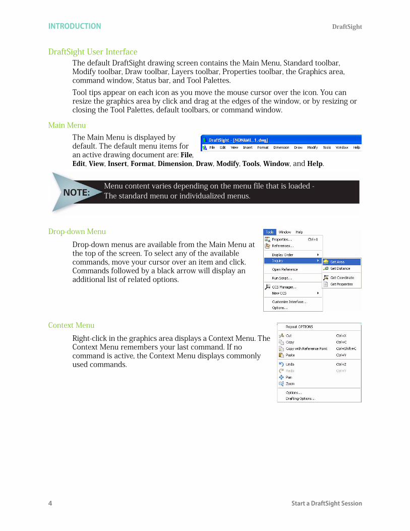
Main MenuThe Main Menu is displayed by default. The default menu items for an active drawing document are: File, Edit, View, Insert, Format, Dimension, Draw, Modify, Tools, Window, and Help.
Drop-down Menu
Drop-down menus are available from the Main Menu at the top of the screen. To select any of the available commands, move your cursor over an item and click. Commands followed by a black arrow will display an additional list of related options.
Context Menu
Right-click in the graphics area displays a Context Menu. The Context Menu remembers your last command. If no command is active, the Context Menu displays commonly used commands.
Menu content varies depending on the menu file that is loaded - The standard menu or individualized menus.
DraftSight INTRODUCTION
Start a DraftSight Session 5
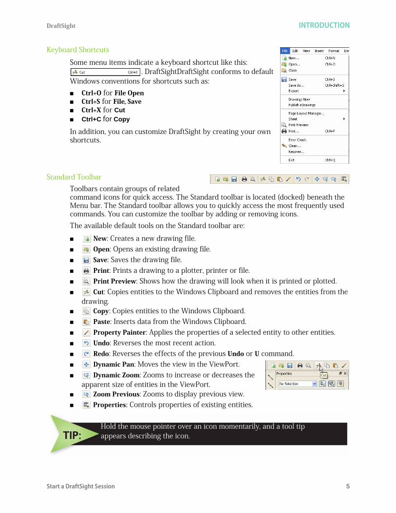
Keyboard Shortcuts
Some menu items indicate a keyboard shortcut like this: . DraftSightDraftSight conforms to default
Windows conventions for shortcuts such as: Ctrl+O for File Open Ctrl+S for File, Save Ctrl+X for Cut
Ctrl+C for Copy
In addition, you can customize DraftSight by creating your own shortcuts.
Standard ToolbarToolbars contain groups of related command icons for quick access. The Standard toolbar is located (docked) beneath the Menu bar. The Standard toolbar allows you to quickly access the most frequently used commands. You can customize the toolbar by adding or removing icons. The available default tools on the Standard toolbar are:
New: Creates a new drawing file. Open: Opens an existing drawing file. Save: Saves the drawing file. Print: Prints a drawing to a plotter, printer or file. Print Preview: Shows how the drawing will look when it is printed or plotted. Cut: Copies entities to the Windows Clipboard and removes the entities from the
drawing. Copy: Copies entities to the Windows Clipboard. Paste: Inserts data from the Windows Clipboard. Property Painter: Applies the properties of a selected entity to other entities. Undo: Reverses the most recent action. Redo: Reverses the effects of the previous Undo or U command. Dynamic Pan: Moves the view in the ViewPort. Dynamic Zoom: Zooms to increase or decreases the
apparent size of entities in the ViewPort. Zoom Previous: Zooms to display previous view. Properties: Controls properties of existing entities.
Hold the mouse pointer over an icon momentarily, and a tool tipappears describing the icon.

INTRODUCTION DraftSight
6 Start a DraftSight Session
Graphics Area
The graphics area is the part of the desktop where drawing entities are created and modified. Multiple drawings can be opened simultaneously. Each drawing and each view is represented in its own window. The individual windows can be tiled, cascaded, or enlarged to fill the graphics area.
View Tiles
The View Tiles command divides the graphics area into multiple windows. Each tile can contain a unique view of the drawing. This enables you to view different areas of the drawing, whether they are plan views in different detailing grades, or the model from different view points. You can work in only one window at a time, the current window.Click View, View Titles from the Main Menu to view your options.
For clarity, the graphics area in this book is displayed in white. Default colors can bemodified from Tools, Options, System Options, Element Colors from the Main Menu

DraftSight INTRODUCTION
Start a DraftSight Session 7
Graphics Cursor / Crosshairs
Outside the graphics area, the cursor assumes the typical Windows pointing shape. Within the graphics area, the mouse cursor appears as crosshairs during an active command.The crosshairs act as the pointer in this application. The crosshairs indicate the pointer position in the graphics area. As with the coordinate symbol, the pointer symbol also changes when the drawing view changes from a default plan view (viewed from above) to an isometric view.
Cartesian Coordinate System / Origin
A coordinate system determines each Point of a drawing surface or entity unambiguously. DraftSight uses the Cartesian coordinate system consisting of three coordinate axes. Axes are arranged orthogonally, crossing at the origin. All axes use the same measurements.All drawings are based on a Cartesian coordinate system in which perpendicular axes are used: the X, Y axes. The intersection of the two coordinate axes forms a Point call the origin.All axes originate at the origin of the coordinate system. The X axis and Y axis define a horizontal plane and is located in the lower left corner of the graphics area. The Coordinate symbol is a visual reference to the drawing. This symbol indicates the position of the axes of the coordinate system and provides orientation of the alignment of the coordinate system. The directions of the arrows displayed on the axes identify the positive side of the coordinates.
Coordinate System
The Coordinate System (CCS) icon is known as the coordinate symbol. By default, the CCS symbol and origin is displayed in the graphics area. To control the display of the coordinate system icon click View, Display, CCS Icon from the Main Menu or type csicon at the Command prompt in the command window.: csiconSpecify option»
All: By default, the CSicon command affects only the current view. The All option applies changes to the coordinate system icon in all views. You can choose from No origin, Off, On or Origin.
No origin: Displays the coordinate system icon at the lower left corner independent from the origin of the current coordinate system.
Off: Hides the Coordinate system icon.

INTRODUCTION DraftSight
8 Start a DraftSight Session
On: Displays the Coordinate system icon. Origin: Displays the coordinate system icon at the origin (0,0) of the current
coordinate system. If the origin is outside of the display, the icon is positioned in the lower left corner.
Model Tab and Sheet TabBy default, the desktop contains three tabs on the bottom left labeled: Model Sheet1 Sheet2Select the desired page by clicking the appropriate tab, which displays your drawing either as a model or as a layout sheet in your drawing.You change the drawing environment between the Model Tab (for drawing entities) and Sheet Tabs (for layouts for printing/plotting). Create your design in the Model (Model tab), and then create layouts to print/plot your drawing on a Sheet (Sheet tab).
Work with multiple Sheets (layouts) using the Sheet commandto perform additional options.

DraftSight INTRODUCTION
Start a DraftSight Session 9
Command Window
The command window provides the ability to enter commands and communicate between you and the drawing.The command window is located at the bottom section of the screen and provides status information and prompts you for the next step.Press <F2> to display the command history in a separate window. When the command window dialog box is displayed, you can scroll through the command history. Press <F2> again to close the command window dialog box.
You can move the floating command window anywhere on the screen and resize its width and height by dragging a side, bottom, or corner of the window.You must press the Enter key (after typing a command or entering a command option. The command window continues to inform you of the type of responses(s) that you must enter, until the command is either completed or terminated. Each command (Line, Circle, etc.) has its own series of prompts. The prompts in the Command prompt area that appear when a particular command is used in one situation may differ from the prompts or sequence or prompts when invoked in another situation. There are three way to terminate a command: Complete the command and return to the : prompt.
Press the Esc key to terminate the command.
Enter another command from one of the menus or toolbars, which automatically cancels any command in progress.

INTRODUCTION DraftSight
10 Start a DraftSight Session
Status Bar
The Status bar is located beneath the command window and is divided into three sections: Tool tip display, Drafting tools, and Current coordinate display. Tool tip display. The left hand side of the status bar displays tool tips. If you move the
cursor over toolbar icons, a brief description of the corresponding command or function displays in the tool tips area. Descriptions of commands selected from any of the pull-down menu items also display in this area.
Drafting tools. Drafting tools make it possible to create and modify entities more easily and accurately. Each of these drafting tools can be toggled On when needed and toggled Off when not. When used appropriately, these commands provide the power, speed, and accuracy associated with 2D CAD drafting. The following drafting tools are available:
Snap (Snap Grid) Grid (Grid Display) Ortho (Orthogonal Drawing Mode) Polar (Polar Guides) ESnap (EntitySnap) ETrack (Entity Tracking Guides)
Current coordinate display. The information field at the right of the buttons shows the X, Y, and Z coordinates of the crosshair (cursor) position.
Snap (Snap Grid)
The Snap command provides an invisible grid in the graphics area. With Snap on, the cursor can only select Points at designated (X, Y) coordinates. Use the Snap command to determine the distance between snap Points. Snap spacing may or may not be equal to the Grid spacing. You can also use an Isometric style of snap. Use isometric snap to create 2D isometric drawings representing 3D entities.
Grid (Grid Display)
The Grid command is used to display a visible pattern of dots. With Grid on, a latticed-point grid is displayed in the graphics area to help visualize distances, angles, and entity relationships. The grid is a drawing tool and is not part of the drawing. It will not be printed or plotted. The Grid spacing may or may not be equal to the Snap spacing.
Ortho (Orthogonal Drawing Mode)
The Ortho command limits the cursor movement so that it moves parallel to the axes of the current coordinate system. With Ortho on, you can only enter Points located parallel to these axes. The Ortho command makes it easier to draw and place parallel or colinear Lines on entities.

DraftSight INTRODUCTION
Start a DraftSight Session 11
Polar (Polar Guides)
The Polar command draws at exact angles at fixed intervals, starting from 3 o'clock (or East), and at additional angle increments. With Polar on, the angular direction and the distance from the last Point selected will be tracked and displayed according to the settings.
ESnap (EntitySnap)
The ESnap command provides the ability to detect and snap to geometrically significant Points on drawing entities, for example; end points, intersections, and center Points. Snapping to a significant Point provides an exact position for drawing and editing commands. The ESnap command opens the Pointer Control settings of the Drafting Options dialog box so that you can set EntitySnap.
ETrack (Entity Tracking Guides)
The ETrack command helps you draw entities at specific angles or in specific relationships to other entities. With ETrack on, temporary alignment guides help you create entities at precise positions and angles. ETrack works with ESnap and polar angle settings. You must set an EntitySnap before you can track from an ETrack Point.
PalettesPalettes are non-fixed areas on the left or right side of the graphics area which provides the ability to display or manage drawing entities. The available Palettes are: Properties Palette: Allows you to view and change
properties of entities in a drawing. The palette displays the entity's properties including the coordinates and data that define its geometry. If more than one entity is selected, the palette displays only those properties common to all entities in the selection, such as Layer, LineColor, LineScale, LineWeight and Hyperlink. If the common properties are not identical in all of the selected entities, the corresponding drop-down list or edit field of the palette displays <<Varies>>.
References Palette: Lets you control and manage Referenced drawings or image files. When you open a drawing that contains Referenced drawings, they are displayed in their current state. When multiple people work on a project over a network, it might be necessary to update the external references. The program reloads the specified drawings in their most recent saved states.
While Grid, Snap, Ortho, Polar and ESnap commands do not crerate entities,They make it possible to create them more easily and accurately.

INTRODUCTION DraftSight
12 Zoom Commands
Home Palette: Contains centralize links to online and web resources, design elements, and the latest in CAD news. The two default sections are: Community and Latest News.
Zoom Commands
The Zoom command is like a zoom lens on a camera. You can increase or decrease the viewing area, although the actual size of the entities remains constant. As you increase the visible size of entities, you view a smaller area of the drawing in greater detail as though you were closer. DraftSight provides you with numerous view options on the Zoom toolbar and the View drop-down menu. The available default tools on the Zoom toolbar are:
Zoom Center: Allows you to specify a center Point for the new view and magnification value or height.
Zoom Dynamic: Allows you to zoom in and out of the drawing window at real-time.
Zoom Previous: Allows you to undo the last zoom operation. You can restore up to ten previous displays.
Zoom Window: Allows you to show a selected part of a drawing in the largest possible scale.
Zoom Selected: Calculates the boundary of the area that contains the specified entities and zooms in or out so the entities are visible on the screen.
Zoom Factor: Allows you to zoom the display by a scale factor. This is helpful when working with sheets or when plotting or printing the drawing.
Zoom In: When you zoom in, the view of the drawing enlarges. Zoom Out: When you zoom out, the view of the drawing reduces. Zoom Bounds: Displays the entire drawing even if only a potion of the drawing
has entities. Zoom Bounds zooms to the bounds of the drawing if no entities extend beyond these bounds. If entities extend beyond the defined bounds, they are included in the calculation of the boundaries in which to zoom.
Zoom Fit: Displays the drawing with all its elements as large as possible. Unlike Zoom Bounds, Zoom Fit ignores drawing bounds. Zoom Fit includes entities on Layers that are turned off but does not include those on frozen Layers.
You can display or hide the Tool Paletts at any time to increase your graphicsarea. Tool Palettes can also be resized or minimized.

DraftSight INTRODUCTION
Draw Toolbar 13
Draw ToolbarThe default Draw toolbar contains all commands that relate to drawing 2D geometrical entities. You can use these drawing tools to create new entities such as Lines, Arcs and Circles.The available default tools on the Draw toolbar are:
Line: Creates straight Line segments. Infinite Line: Creates a set of one or more Lines that extend infinitely in both
directions from an origin. Use InfiniteLines to create frameworks or grids for use in drawing construction.
Polygon: Creates an equilateral closed PolyLine. A polygon is a closed linear PolyLine segment consisting of between 3 and 1024 equal length sides.
Rectangle: Creates a rectangular PolyLine segment. Draw rectangles with any size or orientation in the plane with square, filleted, or chamfered corners.
PolyLine: Creates PolyLines. A PolyLine consists of connected Lines or connected arc segments. You can create PolyLines with segments of different widths and fill settings. The default segment type for a PolyLine is a linear segment.
Arc: Creates an arc segment. Construct arcs of any length or radius. All Arcs are drawn from a start Point in the positive horizontal direction.
Circle: Creates a Circle segment. The default method for drawing a Circle is to specify a center point and a radius.
Ellipse: Creates an Ellipse segment. An Ellipse has a center like a Circle, but has a longer radius along its major axis and a shorter radius along its minor axis.
Ellipse Arc: Creates an Ellipse Arc segment. An Ellipse has a center like a Circle, but has a longer radius along its major axis and a shorter radius along its minor axis.
Point: Creates a Point, usually used as reference in drawings. A Point is a reference to an pattern holding the x and y coordinates of the Point.
Spline: Creates quadratic or cubic Spline curve. A Spline is a smooth curve that is fit to a set of Points. You can create a non-uniform rational B-Spline or (Nurbs) curve for any number of fit Points. You can also fit the Spline to the specified Points to within a specified tolerance value.
Hatch/Fill: Fills a specified boundary with a pattern. Hatch patterns can greatly increase the clarity and legibility of a drawing. You can fill enclosed areas or selected entities in drawings with different types of hatch patterns or a solid hatch fill.
Make Block: Defines a Block from selected entities. A Block is a collection of entities bound together as a single entity.
Region: Converts an entity enclosing an area into a Region. Transforms an entity that forms a closed shape into a Region. You can use the command to combine all entities of any closed loop - such as closed PolyLines (including polygons and donuts), Circles, Ellipses, and closed Splines - into one entity.
Note: Creates paragraph text entities that have the same text formatting applied to each line of text in the paragraph.
SimpleNote: Displays text on screen as it is entered. Create Text lines of any position, orientation, justification, height and TextStyle.
INTRODUCTION DraftSight
14 Modify Toolbar
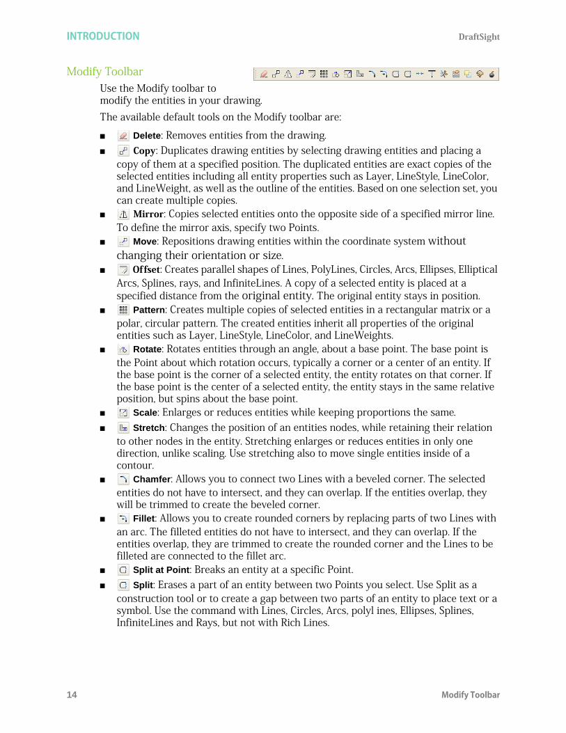
Modify ToolbarUse the Modify toolbar to modify the entities in your drawing. The available default tools on the Modify toolbar are:
Delete: Removes entities from the drawing. Copy: Duplicates drawing entities by selecting drawing entities and placing a
copy of them at a specified position. The duplicated entities are exact copies of the selected entities including all entity properties such as Layer, LineStyle, LineColor, and LineWeight, as well as the outline of the entities. Based on one selection set, you can create multiple copies.
Mirror: Copies selected entities onto the opposite side of a specified mirror line. To define the mirror axis, specify two Points.
Move: Repositions drawing entities within the coordinate system without changing their orientation or size.
Offset: Creates parallel shapes of Lines, PolyLines, Circles, Arcs, Ellipses, Elliptical Arcs, Splines, rays, and InfiniteLines. A copy of a selected entity is placed at a specified distance from the original entity. The original entity stays in position.
Pattern: Creates multiple copies of selected entities in a rectangular matrix or a polar, circular pattern. The created entities inherit all properties of the original entities such as Layer, LineStyle, LineColor, and LineWeights.
Rotate: Rotates entities through an angle, about a base point. The base point is the Point about which rotation occurs, typically a corner or a center of an entity. If the base point is the corner of a selected entity, the entity rotates on that corner. If the base point is the center of a selected entity, the entity stays in the same relative position, but spins about the base point.
Scale: Enlarges or reduces entities while keeping proportions the same. Stretch: Changes the position of an entities nodes, while retaining their relation
to other nodes in the entity. Stretching enlarges or reduces entities in only one direction, unlike scaling. Use stretching also to move single entities inside of a contour.
Chamfer: Allows you to connect two Lines with a beveled corner. The selected entities do not have to intersect, and they can overlap. If the entities overlap, they will be trimmed to create the beveled corner.
Fillet: Allows you to create rounded corners by replacing parts of two Lines with an arc. The filleted entities do not have to intersect, and they can overlap. If the entities overlap, they are trimmed to create the rounded corner and the Lines to be filleted are connected to the fillet arc.
Split at Point: Breaks an entity at a specific Point. Split: Erases a part of an entity between two Points you select. Use Split as a
construction tool or to create a gap between two parts of an entity to place text or a symbol. Use the command with Lines, Circles, Arcs, polyl ines, Ellipses, Splines, InfiniteLines and Rays, but not with Rich Lines.
DraftSight INTRODUCTION
EntitySnap Toolbar 15
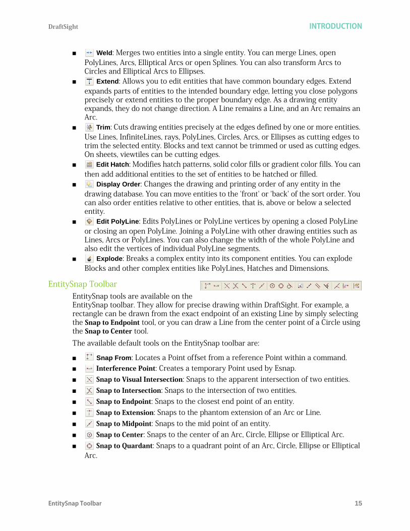
Weld: Merges two entities into a single entity. You can merge Lines, open PolyLines, Arcs, Elliptical Arcs or open Splines. You can also transform Arcs to Circles and Elliptical Arcs to Ellipses.
Extend: Allows you to edit entities that have common boundary edges. Extend expands parts of entities to the intended boundary edge, letting you close polygons precisely or extend entities to the proper boundary edge. As a drawing entity expands, they do not change direction. A Line remains a Line, and an Arc remains an Arc.
Trim: Cuts drawing entities precisely at the edges defined by one or more entities. Use Lines, InfiniteLines, rays, PolyLines, Circles, Arcs, or Ellipses as cutting edges to trim the selected entity. Blocks and text cannot be trimmed or used as cutting edges. On sheets, viewtiles can be cutting edges.
Edit Hatch: Modifies hatch patterns, solid color fills or gradient color fills. You can then add additional entities to the set of entities to be hatched or filled.
Display Order: Changes the drawing and printing order of any entity in the drawing database. You can move entities to the 'front' or 'back' of the sort order. You can also order entities relative to other entities, that is, above or below a selected entity.
Edit PolyLine: Edits PolyLines or PolyLine vertices by opening a closed PolyLine or closing an open PolyLine. Joining a PolyLine with other drawing entities such as Lines, Arcs or PolyLines. You can also change the width of the whole PolyLine and also edit the vertices of individual PolyLine segments.
Explode: Breaks a complex entity into its component entities. You can explode Blocks and other complex entities like PolyLines, Hatches and Dimensions.
EntitySnap ToolbarEntitySnap tools are available on the EntitySnap toolbar. They allow for precise drawing within DraftSight. For example, a rectangle can be drawn from the exact endpoint of an existing Line by simply selecting the Snap to Endpoint tool, or you can draw a Line from the center point of a Circle using the Snap to Center tool. The available default tools on the EntitySnap toolbar are:
Snap From: Locates a Point offset from a reference Point within a command. Interference Point: Creates a temporary Point used by Esnap. Snap to Visual Intersection: Snaps to the apparent intersection of two entities. Snap to Intersection: Snaps to the intersection of two entities. Snap to Endpoint: Snaps to the closest end point of an entity. Snap to Extension: Snaps to the phantom extension of an Arc or Line. Snap to Midpoint: Snaps to the mid point of an entity. Snap to Center: Snaps to the center of an Arc, Circle, Ellipse or Elliptical Arc. Snap to Quardant: Snaps to a quadrant point of an Arc, Circle, Ellipse or Elliptical
Arc.

INTRODUCTION DraftSight
16 Layers Toolbar
Snap to Tangent: Snaps to the tangent of an Arc, Circle, Ellipse, Elliptical Arc or Spline.
Snap to Insert: Snaps to the insertion point of entities such as Text, Blocks or Attributes.
Snap to Node: Snaps to a Point entity Snap to Parallel: Snaps parallel to a specified Line. Snap to Perpendicular: Snaps to a Point perpendicular to an entity. Snap to Nearest: Snaps to the nearest Point on an entity. Snap to None: Suppresses running EntitySnap for the selection. ESnap Settings: Sets running EntitySnap modes.
Layers ToolbarUse the Layers toolbar to create new Layers, designate active Layers, and set layer properties.The available default tools on the Layers toolbar are:
Layers PropertyManager: Controls Layer and layer properties. The Layer command creates and controls Layer and layer properties.
Show/Hide: Shows or hides a layer on the drawing. When a layer is shown, it is visible. Hidden Layers are invisible. You cannot select entities on a hidden layer.
Freeze: Suppresses or un-suppresses a layer on the drawing. When you Freeze a layer, you cannot select or modify entities on the layer. You cannot suppress (Freeze) the active layer.
Lock/Unlock: Protects or un-protects a selected layer on the drawing. When a layer is protected, you cannot edit the layer. You can only edit unprotected Layers.
LineColor: Displays the LineColor of the layer assigned layer LineColor. Layer name: displays the active name layer.
Layer Tools ToolbarUse the Layer Tools toolbar to create new Layers, designate active Layer, and set layer properties.The available default tools on the Layer Tools toolbar are:
Hide Layer: Entities on hidden Layers are invisible. you cannot select entities on hidden Layers.
Show All Layers: All Layers in the drawing become visable except those that are suppressed.
Freeze Layer: When a layer is frozen, it is protected and invisible. Thaw All Layers: Thaws all Layers in the drawing, making them visible again. Lock Layer: When you lock a layer, you cannot select or modify entities on the
layer. Unlock Layer: When you unlock a layer, you can edit entities on the layer. Isolate Layer: Use the Isolate Layers command to isolate Layers by hiding Layers.
You cannot edit entities on these Layers.

DraftSight INTRODUCTION
Properties Toolbar 17
Unisolate Layer: Turns on Layers that were turned off with the last Isolate Layer command.
Activate layer: You can activate a layer by specifying an entity on that layer. Entity to Activate Layer: This will change the Layer of the selected entity to the
active layer. Change Entity's Layer: This will change the Layer of selected entities to that of a
selected entity. Layer Delete: Deletes the layer of a selected entity. Restore Layer's State: This will undo previous changes made to layer settings.
Click Format, Layer Tools from the Main menu to display the available Layer tools.
Properties ToolbarThe Properties toolbar provides the following menu options: LineColor. You can assign LineColors to drawing entities directly or
through Layers. The LineColor command lets you determine the color of new entities.
LineStyle. Use the LineStyle command to load and set LineStyles. Choose a LineStyle to display on the active segment of the drawing.
Click Format, Layer from the Main Menu to display the Layers Manager dialog box.

INTRODUCTION DraftSight
18 Mouse Buttons
LineWeight. Determines that the entity inherits the LineWeight associated with its layer. LineWeight defines how thick or thin an entity appears. The LineWeight of entities does not change when you zoom in or out.
Mouse ButtonsIt is important to understand the basic functions of the mouse buttons. It is recommended that you use a three button mouse with DraftSight. Left mouse button: The left-mouse button is used to select menus and icons, or a
graphic entity. A single click is used to select icons, menus and entities. Middle mouse button (scroll wheel): The middle-mouse button is used to zoom in or
zoom out in the graphics area. Also, pressing the scroll wheel will allow you to pan the drawing.
Right mouse button: The right-mouse button is used to bring up the Context menu in the graphics area or additional available options during the execution of a command.
Cancel or End CommandThe Esc key is used to cancel the command in the Command prompt. For some commands, the Esc key is used to exit the command. If a command is active, you can also right-click in the graphics area and click either Enter or Cancel from the Context menu. Enter: Confirms default options of the command or ends entity selection.Cancel: Ends a command.
The default layer is called 0. It is automatically generated by the program when a new drawing is created.
DraftSight INTRODUCTION
Help 19
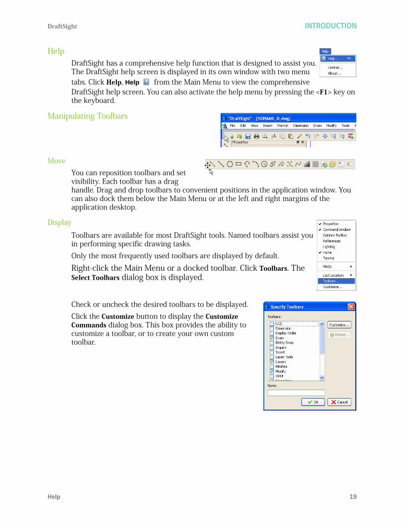
HelpDraftSight has a comprehensive help function that is designed to assist you. The DraftSight help screen is displayed in its own window with two menu tabs. Click Help, Help from the Main Menu to view the comprehensive DraftSight help screen. You can also activate the help menu by pressing the <F1> key on the keyboard.
Manipulating Toolbars
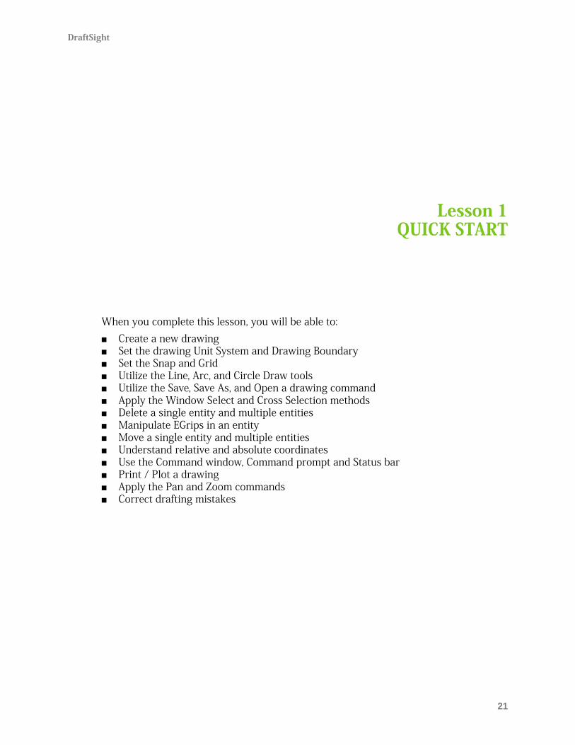
MoveYou can reposition toolbars and set visibility. Each toolbar has a drag handle. Drag and drop toolbars to convenient positions in the application window. You can also dock them below the Main Menu or at the left and right margins of the application desktop.
Display
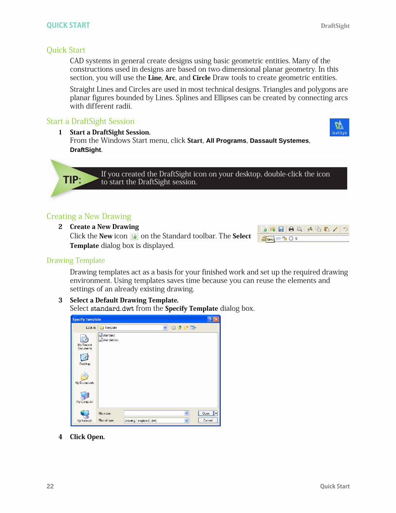
Toolbars are available for most DraftSight tools. Named toolbars assist you in performing specific drawing tasks.Only the most frequently used toolbars are displayed by default.
Right-click the Main Menu or a docked toolbar. Click Toolbars. The Select Toolbars dialog box is displayed.
Check or uncheck the desired toolbars to be displayed.Click the Customize button to display the Customize Commands dialog box. This box provides the ability to customize a toolbar, or to create your own custom toolbar.

INTRODUCTION DraftSight
20 Manipulating Toolbars
DraftSight
21
Lesson 1QUICK START
When you complete this lesson, you will be able to: Create a new drawing Set the drawing Unit System and Drawing Boundary Set the Snap and Grid Utilize the Line, Arc, and Circle Draw tools Utilize the Save, Save As, and Open a drawing command Apply the Window Select and Cross Selection methods Delete a single entity and multiple entities Manipulate EGrips in an entity Move a single entity and multiple entities Understand relative and absolute coordinates Use the Command window, Command prompt and Status bar Print / Plot a drawing Apply the Pan and Zoom commands Correct drafting mistakes
QUICK START DraftSight
22 Quick Start
Quick StartCAD systems in general create designs using basic geometric entities. Many of the constructions used in designs are based on two-dimensional planar geometry. In this section, you will use the Line, Arc, and Circle Draw tools to create geometric entities. Straight Lines and Circles are used in most technical designs. Triangles and polygons are planar figures bounded by Lines. Splines and Ellipses can be created by connecting arcs with different radii.
Start a DraftSight Session1 Start a DraftSight Session.
From the Windows Start menu, click Start, All Programs, Dassault Systemes, DraftSight.
Creating a New Drawing 2 Create a New Drawing
Click the New icon on the Standard toolbar. The Select Template dialog box is displayed.
Drawing TemplateDrawing templates act as a basis for your finished work and set up the required drawing environment. Using templates saves time because you can reuse the elements and settings of an already existing drawing.
3 Select a Default Drawing Template.Select standard.dwt from the Specify Template dialog box.
4 Click Open.
If you created the DraftSight icon on your desktop, double-click the iconto start the DraftSight session.
DraftSight QUICK START
Set the Drawing Environment 23
Set the Drawing EnvironmentSet System Units, drawing Boundary, Snap and Grid. These settings are stored in your default drawing template.
Set Drawing Unit SystemThe Unit System section of the Options - Drafting Settings dialog box, provides the ability to set: Base Angle, Length Type and Precision, Angle Type and Precision, as well as Units scale for the drawing. Five different units systems are available: Scientific Decimal Engineering Architectural Fractional The default units system is the Decimal system and can be applied to either English (inches) or metric values (millimeters).
5 Set Linear Length Precision.The Unit System section of the Options - Drawing Settings dialog box allows you to set the linear and angular unit formats. Click Format, Unit System... from the Main Menu. The Unit System portion of the Options - Drawing Settings dialog box is displayed.
Click 0.00 for Precision in the Length section of the dialog box.
QUICK START DraftSight
24 Set the Drawing Environment
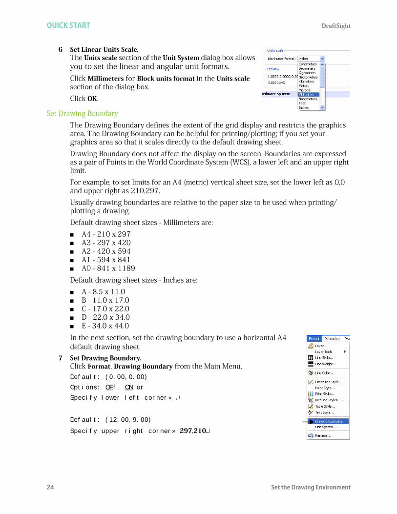
6 Set Linear Units Scale.The Units scale section of the Unit System dialog box allows you to set the linear and angular unit formats.Click Millimeters for Block units format in the Units scale section of the dialog box. Click OK.
Set Drawing BoundaryThe Drawing Boundary defines the extent of the grid display and restricts the graphics area. The Drawing Boundary can be helpful for printing/plotting; if you set your graphics area so that it scales directly to the default drawing sheet.Drawing Boundary does not affect the display on the screen. Boundaries are expressed as a pair of Points in the World Coordinate System (WCS), a lower left and an upper right limit. For example, to set limits for an A4 (metric) vertical sheet size, set the lower left as 0,0 and upper right as 210,297.Usually drawing boundaries are relative to the paper size to be used when printing/plotting a drawing. Default drawing sheet sizes - Millimeters are: A4 - 210 x 297 A3 - 297 x 420 A2 - 420 x 594 A1 - 594 x 841 A0 - 841 x 1189Default drawing sheet sizes - Inches are: A - 8.5 x 11.0 B - 11.0 x 17.0 C - 17.0 x 22.0 D - 22.0 x 34.0 E - 34.0 x 44.0In the next section, set the drawing boundary to use a horizontal A4 default drawing sheet.
7 Set Drawing Boundary.Click Format, Drawing Boundary from the Main Menu. Default: (0.00,0.00)
Options: OFf, ON or
Specify lower left corner»
Default: (12.00,9.00)
Specify upper right corner» 297,210
DraftSight QUICK START
Set the Drawing Environment 25
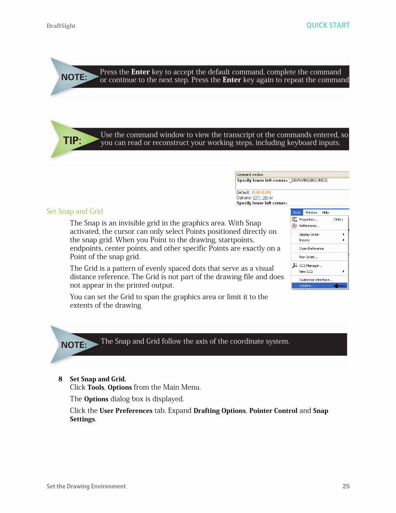
Set Snap and GridThe Snap is an invisible grid in the graphics area. With Snap activated, the cursor can only select Points positioned directly on the snap grid. When you Point to the drawing, startpoints, endpoints, center points, and other specific Points are exactly on a Point of the snap grid.The Grid is a pattern of evenly spaced dots that serve as a visual distance reference. The Grid is not part of the drawing file and does not appear in the printed output. You can set the Grid to span the graphics area or limit it to the extents of the drawing
8 Set Snap and Grid.Click Tools, Options from the Main Menu. The Options dialog box is displayed. Click the User Preferences tab. Expand Drafting Options, Pointer Control and Snap Settings.
Press the Enter key to accept the default command, complete the commandor continue to the next step. Press the Enter key again to repeat the command.
Use the command window to view the transcript ot the commands entered, soyou can read or reconstruct your working steps, including keyboard inputs.
The Snap and Grid follow the axis of the coordinate system.

QUICK START DraftSight
26 Set the Drawing Environment
Click the Enable Snap <F9> box.Enter the value of 10 in the Horizontal Snap spacing box. Press the Tab key The Vertical Snap spacing box is updated.
Expand Display and Grid Settings
Click the Enable Grid <F7> box and the Match Snap Spacing box. The Horizontal display spacing value and the Vertical display spacing value will be set to 10.00.Click OK.
Zoom Bounds
The Zoom Bounds tool provides the ability to adjust the display so that all entities in the drawing are displayed to be as large as possible.
9 Display the Drawing with the New Boundary.Drawing boundaries need to be used to adjusted to the view.
Select View, Zoom, Bounds from the Main Menu.
DraftSight QUICK START
Line Command 27
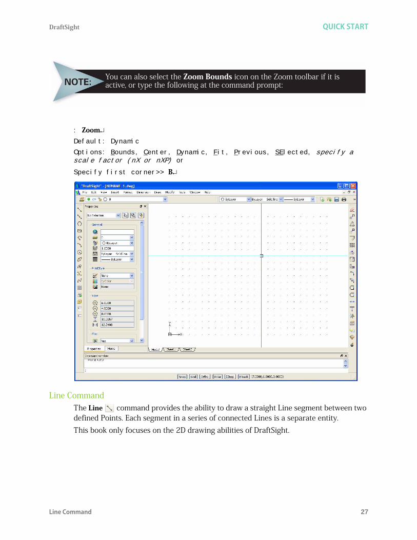
: ZoomDefault: Dynamic
Options: Bounds, Center, Dynamic, Fit, Previous, SElected, specify a scale factor (nX or nXP) or
Specify first corner>> B
Line CommandThe Line command provides the ability to draw a straight Line segment between two defined Points. Each segment in a series of connected Lines is a separate entity.This book only focuses on the 2D drawing abilities of DraftSight.
You can also select the Zoom Bounds icon on the Zoom toolbar if it isactive, or type the following at the command prompt:

QUICK START DraftSight
28 Line Command
There are four ways to define the length and position of a Line:1. Randomly select Points.2. Set a specific value for the Snap function and select Points using the Snap spacing
values.3. Enter the absolute coordinate values for the start and endpoints.4. Enter the relative coordinate values and specify the starting Point and the length and
direction of the Line.
In the next section, use two dimensional (X,Y) coordinates, and apply the Line - Snap Point method.
10 Apply the Line Command.Click the Line icon on the Draw toolbar.
Options: Segments or
Specify start point>>
Click a grid point six grid spaces up and six grid spaces to the right of the origin.Options: Segments, Undo, Enter to exit or
Specify next point>>
Click a grid point horizontally to the right six grid spaces.
Options: Segments, Undo, Close, Enter to exit or
Specify next point>>
Click a grid point vertically upward one grid space.
Options: Segments, Undo, Close, Enter to exit or
Specify next point>>

DraftSight QUICK START
Line Command 29
Click a grid point horizontally to the right two grid spaces.
Options: Segments, Undo, Close, Enter to exit or
Specify next point>>
Click a grid point vertically upward four grid spaces.
Options: Segments, Undo, Close, Enter to exit or
Specify next point>>
Click a grid point horizontally to the left two grid spaces.
Options: Segments, Undo, Close, Enter to exit or
Specify next point>>
Click a grid point vertically upward one grid space.
Options: Segments, Undo, Close, Enter to exit or
Specify next point>>
Click a grid point horizontally to the left six grid spaces.
Options: Segments, Undo, Close, Enter to exit or
Specify next point>>
Click the start grid point.

QUICK START DraftSight
30 Line Command
Options: Segments, Undo, Close, Enter to exit or
Specify next point>>
To close the Line you can also right-click and select Enter.
11 Save the Drawing.Click the Save icon on the Standard toolbar.Enter file name: Lesson 1-1.
Click Save.12 Hide the Grid.
You can hide or show the grid.
The symbol means press the Enter key.
To undo a Line segment, press Ctrl + Zor type Undo at the Command Prompt.

DraftSight QUICK START
Open an Existing Drawing 31
Click the Grid button on the Status bar.<Grid off> appears in the command window.
13 Show the Grid.Click the Grid button from the Status bar.<Grid on> appears in the command window.
Note: To turn the snap on or off , click Snap on the Status bar. Each click of a button on the Status bar will toggle the option on or off.
Also you can choose to use the function keys. Use <F7> for the Grid toggle and <F9> for the Snap toggle.
14 Close the Active Drawing.Click File, Close from the Main Menu.
Open an Existing Drawing1 Open a Drawing.
Click the Open icon on the Standard toolbar. Select Lesson 1-1 from the list.
Click Open.
Delete Command
Single Entity
The Delete command, located on the Modify toolbar, removes a selected entity while creating, editing, or detailing your drawing.
2 Delete an Entity.Click the Delete icon on the Modify toolbar.Specify entities>>
Click the right Vertical Line in the drawing. The selected Line is highlighted by turning dotted.
1 found, 1 total

QUICK START DraftSight
32 Arc Command
Specify entities>>
The linear segment is removed.
Arc CommandThe Arc command provides the ability to construct arcs of any length or radius. You can also append Arcs to other Line, PolyLine, or Arc entities. All Arcs are drawn from the start Point in the positive horizontal direction. The available Arc commands are provided later in this section.
3 Draw a Center Point Arc.Click the Arc icon on the Draw toolbar. Options: Center or
Specify start point>> c
Specify center point>>
Click a grid point centered between the two Horizontal Lines.
You can also reverse the order of operation by clicking the Line first anddisplaying the EGrips, then choosing the Delete icon.

DraftSight QUICK START
Circle Command 33
Specify start point>>
Click the endpoint of the bottom right end of the short Horizontal Line. This is your Arc start Point.
Options: Angle, chord Length or
Specify end point>>
Click the endpoint of the top right end of the short Horizontal Line. This is your endpoint.
Circle CommandThe Circle command provides the ability to use several methods to create Circles of any size. The available Circle commands are provided below. Circles may be defined by: A center point and either a radius or diameter. Two or three Points. Defining the tangents to two existing Lines or Arcs and then defining a radius value. Defining three tangent entities.
If Auto-Save is on, DraftSight will save a back-up file of your drawing.

QUICK START DraftSight
34 Circle Command
4 Draw a Circle.Click the Circle icon on the Draw toolbar.
Options: 3Point, 2Point, Ttr, TTT, Enter to exit or
Specify center point>>
Click the center point of the Arc.
Options: Diameter or
Specify radius>>
Click one grid point horizontally to the right.
5 Save the Drawing.Click File, Save As... from the Main Menu.Enter File name: Lesson 1-2.
Click Save.
Use the Save As... command to save the drawing under a different nameor in a different location

DraftSight QUICK START
Circle Command 35
Besides using the Draw toolbar to create an Arc or Circle, you can also select various Draw commands from the drop-down menu in the Main Menu. The available Circle commands are: Center, Radius: click the graphics area to define the
center point of the Circle. Click the graphics area to define the Circle radius, or enter the radius in the command window.
Center, Diameter: click the graphics area to define the center point of the Circle. Click the graphics area to define the Circle diameter, or enter the diameter in the command window.
2 Points: click two Points in the graphics area that define the Circle diameter.
3 Points: click three Points in the graphics area that define Points on the Circle.
Tangent, Tangent, Radius: click a Point on each of two entities that are tangent to the Circle to be created in the graphics area. Click a Point in the graphics area to define the radius or enter the radius at the command window.
Tangent, Tangent, Tangent: click a Point in the graphics area on each of three entities that are tangent to the Circle to be created in the graphics area. This option is useful when inscribing the Circle within a regular polygon.
The available Arc commands are: 3 Points: click the graphics area to define the start point
of the Arc. Click the endpoint to define the Arc. Start, Center, Angle: click the start point and center point
in the graphics area, and then enter the value of the Arc tangent angle from its chord.
Start, Center, End: click the start point, the center point, and the endpoint in the graphics area.
Start, Center, Length: click the start point and center point in the graphics area, and then enter the value of the Arc chord length. Click the required Points in the graphics area or enter the option values at the command line prompt.
Start, End, Angle: click the start point and endpoint in the graphics area, and enter the positive or negative value of the angle from the chord to the tangent to the start point.
Start, End Direction: click the start point, endpoint, and tangent direction from the start point in the graphics area. Click the required Points
When you specify a point coordinate as the diameter of a circle, DraftSightcalculates the distance from the center of the circle to the specified point.

QUICK START DraftSight
36 Entity Selection
in the graphics area or enter the option values at the Command Line prompt. Start, End, Radius: click the start point and endpoint in the graphics area, and then
enter the value of the Arc tangent angle from its chord. Center, Start, Angle: similar to the Start, Center, Angle command except the first Point
selected is the center point or the Arc rather than the start point. Center, Start, End: similar to the Start, Center, End command except the first Point
selected is the center point of the Arc rather than the start point. Center, Start, Length: similar to the Start, Center, Length command except the first
Point selected is the center point of the Arc rather than the start point. Continue: click a Line, PolyLine, or Arc entity in the graphics area. Click the Arc
endpoint in the graphics area.
Entity SelectionMany of DraftSight's modify and drafting commands prompt you to select one or more entities. When you select one or more entities, DraftSight highlights them by displaying dashed Lines (if no command is active, the Lines will also show the EGrips (blue blocks). There are many different ways of selecting entities. We will discuss and apply: Window Select and Crossing select.
Window SelectThe Window select method allows you to select more than one drawing entity in a defined area at a time. You define this area by specifying two corner points. Only the entities that lie completely within the rectangle will be selected.
6 Window Select Entities.Click a position above the top Horizontal Line.
Specify opposite corner:
Drag downward and to the right to create a rectangular area as illustrated.
DraftSight QUICK START
Delete Command 37
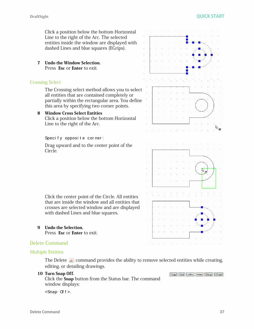
Click a position below the bottom Horizontal Line to the right of the Arc. The selected entities inside the window are displayed with dashed Lines and blue squares (EGrips).
7 Undo the Window Selection. Press Esc or Enter to exit.
Crossing SelectThe Crossing select method allows you to select all entities that are contained completely or partially within the rectangular area. You define this area by specifying two corner points.
8 Window Cross Select EntitiesClick a position below the bottom Horizontal Line to the right of the Arc.
Specify opposite corner:
Drag upward and to the center point of the Circle.
Click the center point of the Circle. All entities that are inside the window and all entities that crosses are selected window and are displayed with dashed Lines and blue squares.
9 Undo the Selection.Press Esc or Enter to exit.
Delete Command
Multiple Entities
The Delete command provides the ability to remove selected entities while creating, editing, or detailing drawings.
10 Turn Snap Off.Click the Snap button from the Status bar. The command window displays: <Snap Off>.

QUICK START DraftSight
38 Move Command
1 Click Delete on the Modify toolbar.Specify entities>>
2 Click the circumference of the Arc and Circle in the drawing. The selected Line becomes highlighted by turning dotted
1 found, 2 total
Specify entities>>
The entities are removed.
3 Save the Drawing.Click the Save icon on the Standard toolbar.
Move CommandThe Move command repositions drawing entities within the coordinate system without changing the orientation or size.
Multiple Entites1 Move Multiple Entities.
Click the Move icon on the Modify toolbar.Specify entities>>
Window select the drawing entities. Click a position above the top Horizontal Line to the left of the Vertical Line.
Specify opposite corner:
Drag downward and to the right.
With Snap on, the cursor can only select Points positioneddierectly on the Snap Grid.
DraftSight QUICK START
Move Command 39
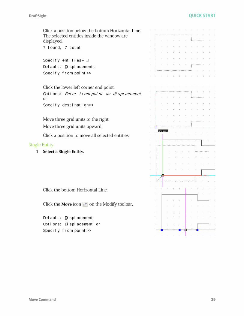
Click a position below the bottom Horizontal Line. The selected entities inside the window are displayed.7 found, 7 total
Specify entities»
Default: Displacement:
Specify from point>>
Click the lower left corner end point.Options: Enter from point as displacement or
Specify destination>>
Move three grid units to the right.Move three grid units upward.
Click a position to move all selected entities.
Single Entity.1 Select a Single Entity.
Click the bottom Horizontal Line.
Click the Move icon on the Modify toolbar.
Default: Displacement
Options: Displacement or
Specify from point>>

QUICK START DraftSight
40 Creating a New Drawing
Click two grid units below the mid point of the bottom Horizontal Line.
Options: Enter from point as displacement or
Specify destination>>
Move the selected horizontal linear segment three grid units downward as illustrated.
Click a position to move the selected entity.
2 Save the Drawing.Click the Save icon on the Standard toolbar.
3 Close the Drawing.Click File, Close from the Main Menu.
Use the Undo command to withdraw the last command. You can repeat undo until all steps in the undo list have been canceled, indicated by the message Nothing to undo in the Command prompt.
Creating a New Drawing1 Create a New Drawing
Click the New icon on the Standard toolbar. The Select Template dialog box is displayed.
To use the Undo command, click the Undo icon on the Standard toolbaror type U at the command prompt.
You can also click File, New from the Main Menu to create a new drawing.

DraftSight QUICK START
Set the Drawing Environment 41
Drawing TemplateDrawing templates act as a basis for your finished work and set up the required drawing environment. Using templates saves time because you can reuse the elements and settings of an already existing drawing.
2 Select a Default Drawing Template.Select standard.dwt from the Specify Template dialog box.
3 Click Open.
Set the Drawing EnvironmentSet System Units, drawing Boundary, Snap and Grid. These settings are stored in your default drawing template.
Set Drawing Unit SystemThe Unit System section of the Options - Drafting Settings dialog box, provides the ability to set: Base Angle, Length Type and Precision, Angle Type and Precision, as well as Units scale for the drawing. Five different units systems are available: Scientific Decimal Engineering Architectural Fractional The default units system is the Decimal system and can be applied to either English (inches) or metric values (millimeters).
Templates use the .dwt file extention.

QUICK START DraftSight
42 Set the Drawing Environment
4 Set Linear Length Precision.The Unit System section of the Options - Drawing Settings dialog box allows you to set the linear and angular unit formats. Click Format, Unit System... from the Main Menu. The Unit System portion of the Options - Drawing Settings dialog box is displayed.
Click 0.00 for Precision in the Length section of the dialog box. 5 Set Linear Units Scale.
The Units scale section of the Unit System dialog box allows you to set the linear and angular unit formats.Click Millimeters for Block units format in the Units scale section of the dialog box. Click OK.
Set Drawing BoundaryThe Drawing Boundary defines the extent of the grid display and restricts the graphics area. The Drawing Boundary can be helpful for printing/plotting; if you set your graphics area so that it scales directly to the default drawing sheet.Drawing Boundary does not affect the display on the screen. Boundaries are expressed as a pair of Points in the World Coordinate System (WCS), a lower left and an upper right limit.

DraftSight QUICK START
Set the Drawing Environment 43
For example, to set limits for an A4 (metric) vertical sheet size, set the lower left as 0,0 and upper right as 210,297.Usually drawing boundaries are relative to the paper size to be used when printing/plotting a drawing. Default drawing sheet sizes - Millimeters are: A4 - 210 x 297 A3 - 297 x 420 A2 - 420 x 594 A1 - 594 x 841 A0 - 841 x 1189
Default drawing sheet sizes - Inches are: A - 8.5 x 11.0 B - 11.0 x 17.0 C - 17.0 x 22.0 D - 22.0 x 34.0 E - 34.0 x 44.0In the next section, set the drawing boundary to use a horizontal A4 default drawing sheet.
6 Set Drawing Boundary.Click Format, Drawing Boundary from the Menu bar.
Default: (0.00,0.00)
Options: OFf, ON or
Specify lower left corner»
Default: (12.00,9.00)
Specify upper right corner» 297,210

QUICK START DraftSight
44 Set the Drawing Environment
Set Snap and GridThe Snap is an invisible grid in the graphics area. With Snap activated, the cursor can only select Points positioned directly on the snap grid. When you Point to the drawing, startpoints, endpoints, center points, and other specific Points are exactly on a Point of the snap grid.The Grid is a pattern of evenly spaced dots that serve as a visual distance reference. The Grid is not part of the drawing file and does not appear in the printed output. You can set the Grid to span the graphics area or limit it to the extents of the drawing.
7 Set Snap and Grid.Click Tools, Options from the Main Menu. The Options dialog box is displayed. Click the User Preferences tab. Expand Drafting Options, Pointer Control and Snap Settings.
Click the Enable Snap <F9> box.Enter the value of 10 in the Horizontal Snap spacing box. Press the Tab key The Vertical Snap spacing box is updated.
The Snap and grid follow the axis of the coordinate system.

DraftSight QUICK START
Absolute and Relative Coordinates 45
Expand Display and Grid Settings
Click the Enable Grid <F7> box and the Match Snap Spacing box. The Horizontal display spacing value and the Vertical display spacing value will be set to 10.00.Click OK.
Zoom Bounds
The Zoom Bounds tool provides the ability to adjust the display so that all entities in the drawing are displayed to be as large as possible.
8 Display the Drawing with the New Boundary.Drawing boundaries need to be used to adjusted to the view.
Select View, Zoom, Bounds from the Main Menu.
Absolute and Relative CoordinatesIn this manual, we will only deal with the 2D funcionality of DraftSight.All drawings are based on a Cartesian coordinate system in which two perpendicular axes are used: the X and Y axis. All axis originate in the origin Point of the coordinate system. The X axis and Y axis define a horizontal plane. In the Cartesian coordinate format, a Point is defined by its distances in the XY plane. These distances are called the XY coordinates of a Point. When you draw in two dimensions, you specify Points only on the XY plane. In CAD, the fixed Cartesian coordinate system is called the World Coordinate System (WCS). New drawings are based in the WCS.Enter coordinates as absolute or relative values. To specify the Point coordinates with respect to the previous Point (relative coordinate input), type the @ character in front of the coordinate values.

QUICK START DraftSight
46 Absolute and Relative Coordinates
Absolute CoordinatesTo specify absolute coordinates:
Enter a command requiring coordinates, for example::Line
Specify the X and Y coordinates separated by a comma. 30,60
Specify subsequent coordinates to complete the command. 35, 82
Relative Coordinates
To specify relative coordinates: Enter a command requiring coordinates. Specify the first Point. 0,0 To specify the second Point with respect to the first Point, type the @ character in front of the coordinate values. @30,60
Entering Keyboard InputWhen you enter data using the keyboard, your data is precise. With keyboard input, you can construct drawing entities with exact dimensions or with exact placement in the coordinate system.Values for distances, straight Lines, and other linear quantities are specified in drawing units. Angle values are specified in degrees.Methods and syntax to use in this book: Interactive method: use the cursor to select on the graphics area Absolute coordinate (Format: X, Y) method: enter the X and Y coordinates to locate
the Point on the active coordinate system relative to the origin. Relative rectangular coordinates (Format: @X,Y) method: enter the X and Y
coordinates relative to the last Point Direct Distance method: specify the second Point by moving the cursor to indicate
direction. Enter distance.
Type of Coordinate Input Example
Cartesian X,Y 30,60
Polar distance<angle 75<45
Type of Coordinate Input Example
Cartesian @deltaX,deltaY @30,60
Polar @relative_distance<angle @75<45

DraftSight QUICK START
Absolute and Relative Coordinates 47
Relative polar coordinates (Format: @Distance<angle) method: enter a distance and angle relative to the last Point.
Periods: enter periods for decimal points. Commas: enter commas to separate the values for the axes, for example 0,2.1 < (less than): use the < (less than) sign before angle values, for example, <30
represents a 30 degree angle.
Example of an input sequence using the keyboard: : Line Options: Segments or
Specify start point>> 40,40
Options: Segments, Undo, Enter to exit or
Specify next point>> 120,40
Options: Segments, Undo, Enter to exit or
Specify next point>> 120,80
Options: Segments, Undo, Enter to exit or
Specify next point>>
Draw a Rectangle Using Absolute Coordinates
Draw a 60,40 rectangle using the Line icon on the Draw toolbar starting at the coordinate 30,30 using absolute coordinates.
If the same size rectangle were drawn using the Line command, the resulting rectangle will be considered four individual unrelated Lines.
You can type the Command name Line, or click the Line iconon the Draw toolbar.
Commands in DraftSight are not case sensitive.
A rectangle drawn using the Rectangle command is considered to be a single entity.

QUICK START DraftSight
48 Absolute and Relative Coordinates
9 Draw the First Shape.Click the Line icon on the Draw toolbar.
Enter coordinates in the Command prompt. View the command window area, near the bottom of the graphics area.
Options: Segment or
Specify Start point>> 30,30
Options: Segments, Undo, Enter to exit or
Specify next point>> 90,30
Options: Segments, Undo, Enter to exit or
Specify next point>>90,70
Options: Segments, Undo, Close, Enter to exit or
Specify next point>>30,70
Options: Segments, Undo, Close, Enter to exit or
Specify next point>>c
10 Save the Drawing.Click File, Save As... from the Main Menu.Enter File name: Lesson 1-3.
Click Save.
The C option in the command closes the profileand ends the command.

DraftSight QUICK START
Absolute and Relative Coordinates 49
Draw the Second Shape Using Relative Coordinates
Draw a five sided shape using the Line icon on the Draw toolbar starting at the absolute coordinate 120,30 and using relative coordinates to complete the shape.
11 Draw the Five Sided Shape.Click the Line icon on the Draw toolbar.
Enter coordinates in the Command prompt.
Options: Segments or
Specify Start point>>120,30
Options: Segments, Undo, Enter to exit or
Specify next point>>@50,0
Options: Segments, Undo, Close, Enter to exit or
Specify next point>>@0,40
Options: Segments, Undo, Close, Enter to exit or
Specify next point>>@50<120
Options: Segments, Undo, Close, Enter to exit or
Specify next point>>@-10,0
Options: Segments, Undo, Close, Enter to exit or
Specify next point>>c
If you enter an incorrect coordinate, press the U key to Undo the lastcoordinate in the command.

QUICK START DraftSight
50 Absolute and Relative Coordinates
Draw the Third Shape Using Relative and Absolute Coordinates
Draw the third shape using the Line icon on the Draw toolbar starting at the absolute coordinate 30,120 and using relative coordinates and absolute coordinates to complete the shape.
12 Draw the Third Shape.Click the Line icon on the Draw toolbar.
Enter coordinates at the Command prompt.
Options: Segments or
Specify Start point>>30,120
Options: Segments, Undo, Enter to exit or
Specify next point>>@50,0
Options: Segments, Undo, Close, Enter to exit or
Specify next point>>@0,20
Options: Segments, Undo, Close, Enter to exit or
Specify next point>>@40<0
Options: Segments, Undo, Close, Enter to exit or
Specify next point>>@0,-20
Options: Segments, Undo, Close, Enter to exit or
Specify next point>>@30<0
Options: Segments, Undo, Close, Enter to exit or
Specify next point>>@40<90
Options: Segments, Undo, Close, Enter to exit or
Specify next point>>@20<0
Options: Segments, Undo, Close, Enter to exit or
Specify next point>>@30<90

DraftSight QUICK START
Print Command 51
Options: Segments, Undo, Close, Enter to exit or
Specify next point>>@-40,0
Options: Segments, Undo, Close, Enter to exit or
Specify next point>>@-20,-20
Options: Segments, Undo, Close, Enter to exit or
Specify next point>>@-20,20
Options: Segments, Undo, Close, Enter to exit or
Specify next point>>@-25,0
Options: Segments, Undo, Close, Enter to exit or
Specify next point>>c
13 Save the Drawing.Click the Save icon on the Standard toolbar.
Print CommandThe Print command provides the ability to print or plot an entire drawing sheet, or just a selected area of the sheet. You have the option to print in black and white (the default) or in color.
There are no complicated printing commands. Click the Print icon on the Standard toolbar or type Print at the Command prompt. The Print - Model dialog box is displayed. Use the Page Setup section to set a previously defined print style or create a named print style based on what you set up in the dialog box.

QUICK START DraftSight
52 Print Command
Model Tab / Sheet TabsThe DraftSight software provides the ability to work on your drawing in two different environments: Model or Sheet.You can print your drawing from Model to any scale by specifying the print setup in the Print - Model dialog box.Sheet, is a environment used for arranging various views of what was drawn in your Model. It represents the paper size which you set in the drawing environment. You can apply different scales and specify different visibility for Layer in each floating ViewPort. You can switch between Model and Sheet by selecting the appropriate tab provided at the bottom of the graphics area. Model can be accessed from the Model Tab. Selecting one of the available Sheet Tabs will access the sheet.By default, two sheet tabs are created: Sheet1 and Sheet2. You can rename these and if necessary create up to 255 additional sheet tabs. The names of the sheet tabs must be unique.

DraftSight QUICK START
Print Command 53
14 Click the sheet1 tabThis will open Sheet1
15 Right click on the Sheet1 nameThis will open the Sheet Manager Dialog box.
16 Click the Print... option. Set your options.
Page setup options: Quick print: Prints exactly what is
on screen with the system default printer, default paper size, Fit to paper size selected and Print range set to Current view.
Use previous settings: Repeats printing with the same setting you used for the previous printout.
Manual setup: Allows you to determine the print settings.

QUICK START DraftSight
54 Pan Commands
Printer/plotter: Name: Allows you to select an
output device. Printers and plotters available on your system are listed. PDF, JPG, PNG and SVG are also listed. These built in plotters print to a file in the specified format.
Properties: Allows you to set up the printer or plotter as needed in the dialog box provided by the printer's driver.
17 Select the Cancel button to return to the graphics area.
Pan CommandsThe most basic functions that change drawing views are the Pan and Zoom commands. The Pan tools move the visible portion of the drawing in a specified direction. The Pan tools do not change the position or the magnification of drawings entities.Pan allows you to view entities previously not visible because they were out of the viewing area. When panning, the scale of the view does not change, as it does when zooming.
Access various Pan tools from the Main Menu, drop-down menu in the Standard toolbar, or right-click in the graphics area. Dynamic Pan: allows you dynamically pan by moving the mouse pointer. Point Pan: use point pan to move the view of the drawing in any direction by
pointing a displacement (vector). the size of the view remains the same. You define the displacement by identifying two Points. these Points determine a
vector giving the distance and direction of the pan.
Select the Help button to explore the Print- Model dialog box in detail.
When you use the Pan tool, it as if the camera, not the scene is moving.

DraftSight QUICK START
Pan Commands 55
Left Pan: when you pan left, the visible part of the drawing moves left. Right Pan: when you pan right, the visible part of the drawing moves right. Up Pan: when you pan up, the visible part of the drawing moves up. Down Pan: when you pan down, the visible part of the drawing moves down.
18 Apply Dynamic Pan.Click the Dynamic Pan icon on the Main Menu. The Pan icon of a hand is displayed.Press Esc or Enter to exit.
Position the Pan icon in the graphics area near the second drawing as shown.Click and drag to the left. Click and drag upwards.
19 Exit Dynamic Pan.Press Esc or Enter to exit.
20 Close the Active Drawing.Click File, Close from the Main Menu.
The scroll bars on the right and bottom of the graphics area, when activated can also be used to adjust the viewing for the drawing.
Dimensions are inseted in Lesson 4.

QUICK START DraftSight
56 Correct Drafting Mistakes
Correct Drafting MistakesDraftSight provides many tools to correct drafting mistakes. Correct mistakes using the following commands:
Delete: deletes any entity from your drawing. Use the Delete command to remove selected entities while creating, editing, or detailing drawings. Click the Delete icon
on the Modify toolbar or type Delete at the Command prompt. Undo: use the Undo command to withdraw the last command. You can repeat
undo until all steps in the undo list have been canceled, indicated by the message Nothing to undo in the Command prompt. Click the Undo icon on the Standard toolbar or type U at the Command prompt.
Redo: the Redo command reverses a previous Undo operation. You can use the Redo command only if no other command has changed the drawing database since the last Undo command. Click the Redo icon on the Standard toolbar or type Redo at the Command prompt.
Undelete: use the Undelete command, like the Undo command, to restore entities that have been deleted by mistake. Also use Undelete to restore entities after creating a Block using the MakeBlock command. Type Undelete at the Command prompt.

DraftSight
57
Lesson 2DRAFTING TUTORIALS
When you complete this lesson, you will be able to: Create three new drawings with multiple Layers Use absolute coordinates the command prompt and status bar Utilize the Line, Circle (R & Ttr), Polygon, Rectangle, SimpleNote, Spline, and PolyLine
Draw commands Apply the Copy, Rotate, Move, Trim, Fillet, Mirror, Chamfer, Offset, Edit PolyLine, and
Pattern (circular & linear) Modify commands. Create a new Layer with properties Manage Layers in a drawing Move Entities to a different Layer

DRAFTING TUTORIALS DraftSight
58
Drafting TutorialsDuring this lesson, you will create three drawings by inputting absolute coordinates at the Command prompt and the graphics area.In the first drawing you will: Create three new Layers with custom
properties: Object, Centerline, and Construction.
Use the Circle, Polygon, Line, Rectangle, SimpleNote, Spline and PolyLine commands on the Draw toolbar.
Apply the Copy, Rotate, Trim, Fillet, Mirror, and Edit PolyLine commands on the Modify toolbar,
In the second drawing you will: Create three new Layers with custom properties:
Object, Construction and Centerline. Use the Rectangle, and Circle commands on the
Draw toolbar. Apply the Pattern command to create a circular
and linear pattern along with the Chamfer command on the Modify toolbar.

DraftSight DRAFTING TUTORIALS
Start a DraftSight Session 59
In the third drawing you will: Create two new Layers with custom
properties: Object and Phantom. Use the Circle (r), and Circle (Ttr)
commands on the Draw toolbar. Apply the Trim, Offset, and Pattern
(circular) commands on the Modify toolbar.
Start a DraftSight Session1 Start a DraftSight session.
From the Windows Start menu, click Start, All Programs, SolidWorks Corporation, DraftSight.
Create a New Drawing2 Create a new drawing.
Click the New icon on the Standard toolbar. The Select Template dialog box is displayed.
Drawing Template3 Select a Default Drawing Template.
Select standard.dwt from the Specify Template dialog box. 4 Click Open.
Set the Drawing Environment
Drawing Unit SystemThe default units system is the Decimal system and can be applied to either English (inches) or metric values (millimeters).
5 Set Linear Length Precision.Click Format, Unit System... from the Main Menu. The Unit System section of the Options - Drawing Settings dialog box is displayed. Select 0.00 for Length Precision.
6 Set Linear Units Scale.The Unit System section of the Options - Drawing Settings dialog box allows you to set the linear and angular unit formats. Click Millimeters for Block units format in the Units scale section of the dialog box. Click OK.
Double-clicking on the template name will also open the file.

DRAFTING TUTORIALS DraftSight
60 Set the Drawing Environment
Drawing BoundaryUse a horizontal A4 default drawing sheet.
1 Set Drawing Boundary.Click Format, Drawing Boundary from the Main Menu. Default: (0.00,0.00)
Options: OFf, ON or
Specify lower left corner»
Default: (12.00,9.00)
Specify upper right corner» 297,210
Set Snap and Grid
In this section the Grid equals the Snap.1 Set Snap and Grid.
Click Tools, Options from the Main Menu. The Options dialog box is displayed. Click the User Preferences tab. Expand Drafting Options, Pointer Control and Snap Settings.Click the Enable Snap <F9> box.Enter the value of 10 in the Horizontal Snap spacing box. Press the Tab key The Vertical Snap spacing box is updated.Expand Display and Grid Settings.Click the Enable Grid <F7> box and the Match Snap Spacing box. The Horizontal display spacing value and the Vertical display spacing value will be set to 10.00.Click OK.
Zoom Bounds2 Display the Drawing with the New Boundary.
Note: Click View, Zoom, Bounds on the Main Menu.
ZoomDefault: Dynamic
Options: Bounds, Center, Dynamic, Fit, Previous, SElected, specify a scale factor (nX or nXP) or
Specify first corner>> B
You can also select the Zoom Bounds icon on the Zoom toolbar if it is active or type the following at the command prompt:

DraftSight DRAFTING TUTORIALS
Working with Layers 61
Working with LayersWorking with Layers is analogous to drawing manually using Layers of see-through media. Parts or portions - these might be functional portions, such as Construction Lines, - of one complete drawing are drawn on different 'media' that, imposed on top of one another, form the entire drawing.Layers are useful in separating entities, such as parts or sub-assemblies, or structural components, such as pipe sizes or building materials. They also serve to separate elements such as Construction Lines, Centerlines, Outlines, and Dimensions, or items that are to be placed in a group, such as foliage in an architectural drawing. When you use Layers, you have a clearer construction of the drawing and better control over the drawing.
Layer 0: The Default LayerThe default Layer is called 0. It is automatically generated by DraftSight when a new drawing is created. This is your active Layer which is shown, un-suppressed and unlocked. The color 7 (white on a black background, or black on a white background) and the LineStyle Continuous are automatically established for this Layer.
Layer Properties Each Layer has a Status, Name, Show, Frozen, Lock, LineColor, LineStyle, LineWeight, PrintStyle Print, and Description associated with it when it is created. Anything drawn on a Layer will be drawn with that Layer's properties.There are other Layer properties that allow you to switch between different states. These are Show/Hide, Frozen/UnFrozen, and Lock/Unlock.The Layer and its properties are saved with the drawing.
You cannot erase or rename the default layer (layer 0).
It is good practice to avoid using the default layer as a drawing tool.

DRAFTING TUTORIALS DraftSight
62 Working with Layers
Layer properties include: Status: one Layer in each drawing is the active Layer.
In the Layer Properties Manager this is indicated in the Status column. All new entities are placed on this Layer.
Name: each Layer has a distinctive name to identify it. Names can contain letters, numbers, or special characters like under scores and dollar signs.
Show/Hide: An advantage of working with Layers is that it aids in visualizing the part or drawing. You can improve the clarity of a drawing by choosing Layer properly and hiding drawing entities. The show icon indicates whether the Layer is shown or hidden. You can turn each Layer on or off independently.
Frozen: These properties control the visibility and the influence of entities within the Layer. A Frozen Layer is invisible and protected and thus impossible to change. A Frozen Layer is not included when you regenerate a drawing. When working with complex drawings, freezing unneeded Layers can increase performance. When you un-freeze a Layer, it becomes visible and you can make changes to it. You cannot suppress the active Layer of a drawing.
Lock/Unlock: You can lock Layers so the entities on the Layer cannot be changed. The locked state prevents unintentional modification. When a Layer is locked, you cannot change, add, or delete entities from the Layer. You must change the status to unlocked if you want to work with the entities on this Layer. You can draw new entities on locked Layers, but it is not possible to work with them further. A locked Layer may be designated active, visible or invisible, or frozen or unfrozen.
LineColor: When you start a new drawing, new Layers are automatically assigned the LineColor white. When you create a new Layer, the Layer adopts the LineColor of the new Layer. Entities you draw on the Layer appear in the assigned LineColor except those to which you assigned a LineColor with the LineColor command.
LineStyle: A default LineStyle is assigned to a Line. If you do not choose another LineStyle, the LineStyle Continuous is automatically assigned. The chosen LineStyle is displayed in the Properties Palette.
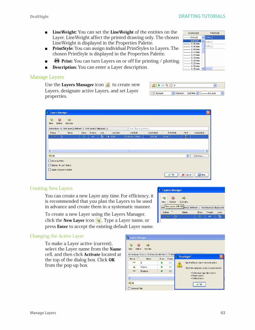
DraftSight DRAFTING TUTORIALS
Manage Layers 63
LineWeight: You can set the LineWeight of the entities on the Layer. LineWeight affect the printed drawing only. The chosen LineWeight is displayed in the Properties Palette.
PrintStyle: You can assign individual PrintStyles to Layers. The chosen PrintStyle is displayed in the Properties Palette.
Print: You can turn Layers on or off for printing / plotting. Description: You can enter a Layer description.
Manage LayersUse the Layers Manager icon to create new Layers, designate active Layers, and set Layer properties.
Creating New LayersYou can create a new Layer any time. For efficiency, it is recommended that you plan the Layers to be used in advance and create them in a systematic manner.To create a new Layer using the Layers Manager, click the New Layer icon . Type a Layer name, or press Enter to accept the existing default Layer name.
Changing the Active LayerTo make a Layer active (current), select the Layer name from the Name cell, and then click Activate located at the top of the dialog box. Click OK from the pop-up box.

DRAFTING TUTORIALS DraftSight
64 Manage Layers
Renaming a LayerTo rename a Layer in the Layer Properties Manager, double-click the Name cell of the Layer you want to rename. Type the new name, then press Enter.
Controlling Layer Behavior Show/Hide: when a Layer is shown, it is visible.
Hidden Layers are invisible. To show or hide a Layer in the Layer Properties Manager, double-click the Show icon in the Show cell that you want to change.
Frozen/UnFrozen: in addition to turning the Layer off, you can freeze Layers. The Layers that are Frozen will not be visible in the view window, nor will they be printer. Frozen Layers are similar to Layers that are off (hidden). However, Layers that are simply hidden still go through screen regeneration each time the system regenerates your drawing, whereas the Layers that are suppress are not considered during screen regeneration.
Lock/Unlock: controls the ability to edit entities on a Layer. When a Layer is locked, it is protected but visible. When a Layer is unlocked, it is unprotected and visible. To lock or unlock a Layer in the Layers Manager, double-click the Lock cell you want to change.
Setting the LineColorNew Layers are automatically assigned the LineColor white. Entities you draw will appear in the assigned LineColor for that Layer except those to which you assigned a LineColor with the LineColor command.To set a LineColor in the Layers Manager, double-click the LineColor cell you want to change. Select a color from the drop-down menu or click Specify Color for additional LineColor options.
Setting the Layer LineStyleA LineStyle is a graphical symbol that has specific settings that make the Lines appear differently. Entities you draw will appear in the assigned LineStyle except those to which you set to another LineStyle.

DraftSight DRAFTING TUTORIALS
Manage Layers 65
To set a Layer LineStyle, double-click the LineStyle cell and select the desired LineStyle or select Other, Load to load a new LineStyle from the LineStyles Manager dialog box.
By setting the LineStyle to ByLayer in the properties toolbar all elements of this Layer will be drawn with the LineStyle that is set. Elements of the Layer that were drawn with a different LineStyle than the default LineStyle are not affected by the change.
Setting a Layer LineWeightBy default, DraftSight assigns the LineWeight of the currently selected Layer in the Layer list to the newly created Layer. To set the Layer LineWeight, double-click the LineWeight cell and select the desired option.
Setting PrintStylePrintStyle is a collection of properties settings (such as LineColor, LineStyle and LineWeight) that can be assigned to a Layer or to individual entities. The chosen PrintStyle type is displayed in the Properties Palette.
The display on the screen will not change. The LineWeight will only bevisible on a printed drawing.

DRAFTING TUTORIALS DraftSight
66 Create Three New Layers for the Drawing
Setting PrintDraftSight allows you to turn Printing / Plotting on or off for visible Layers. Example, if a Layer contains Construction Lines that need not be printed, you can specify that the Layer is not printed. If you turn off printing for a Layer, the Layer is displayed but is not printed.To change the setting for the printing of Layers, double-click the icon corresponding to the Layer name located in the Print column as shown.
Setting DescriptionDouble-click inside the desired cell under the Description column to enter a Layer description.
Setting Filtering and Display OptionsYou can create filters that contain Layers you select. Grouping Layers this way establishes group filters. Two Layer group filters are predefined: All All Used Layers
Create Three New Layers for the DrawingIn this section, you will create three new Layers called Object, Construction and Centerline. As well as apply custom properties.
3 Create the first new Layer.Click the Layers Manager icon on the Layers toolbar
The Layers Manager dialog box is displayed. Note: You can also click Format, Layer from the Main Menu to display the Layers
Manager dialog box.
Click the New Layer icon. The new default name is Layer1.Rename this layer Object
Object is the new Layer name.
Double-click inside the Layer1 Name cell in orderto rename if it is not active.

DraftSight DRAFTING TUTORIALS
Create Three New Layers for the Drawing 67
The Object Layer will inherit all of the properties of the default Layer 0.
4 Create the Second New LayerClick the New Layer icon. The new default name is Layer2.Rename this Layer Construction. Construction is the new Layer name.
5 Set the Second Layer LineColor.New Layers are automatically assigned the LineColor white. Double-click the LineColor cell for the Construction Layer.Click Red.
6 Create the Second Layer LineStyle.Create a MM HIDDEN LineStyle. Double-click the LineStyle cell from the Construction Layer.Click Other. The LineStyles Manager dialog box is displayed.
Click the Load icon.
The Load LineStyles dialog box is displayed

DRAFTING TUTORIALS DraftSight
68 Create Three New Layers for the Drawing
Note: The default LineStyle file: inch.lin.
Click the Browse button.
Select MM.LIN from the Specify LineStyle File dialog box.Click Open from the Specify LineStyles File dialog box.
Select HIDDEN from the Load LineStyles dialog box.Click OK.
Use the scroll bar on the right to view items in the dialog box.

DraftSight DRAFTING TUTORIALS
Create Three New Layers for the Drawing 69
HIDDEN is added to the LineStyles dialog box.
7 Create the Second Layer LineStyle.Create a MM CENTER LineStyle.
Click the Load icon.
View the Load LineStyles dialog box. The default LineStyle file: inch.lin.
Click the Browse button.
Select MM.LIN from the Specify LineStyle File dialog box.Click Open from the Specify LineStyles File dialog box
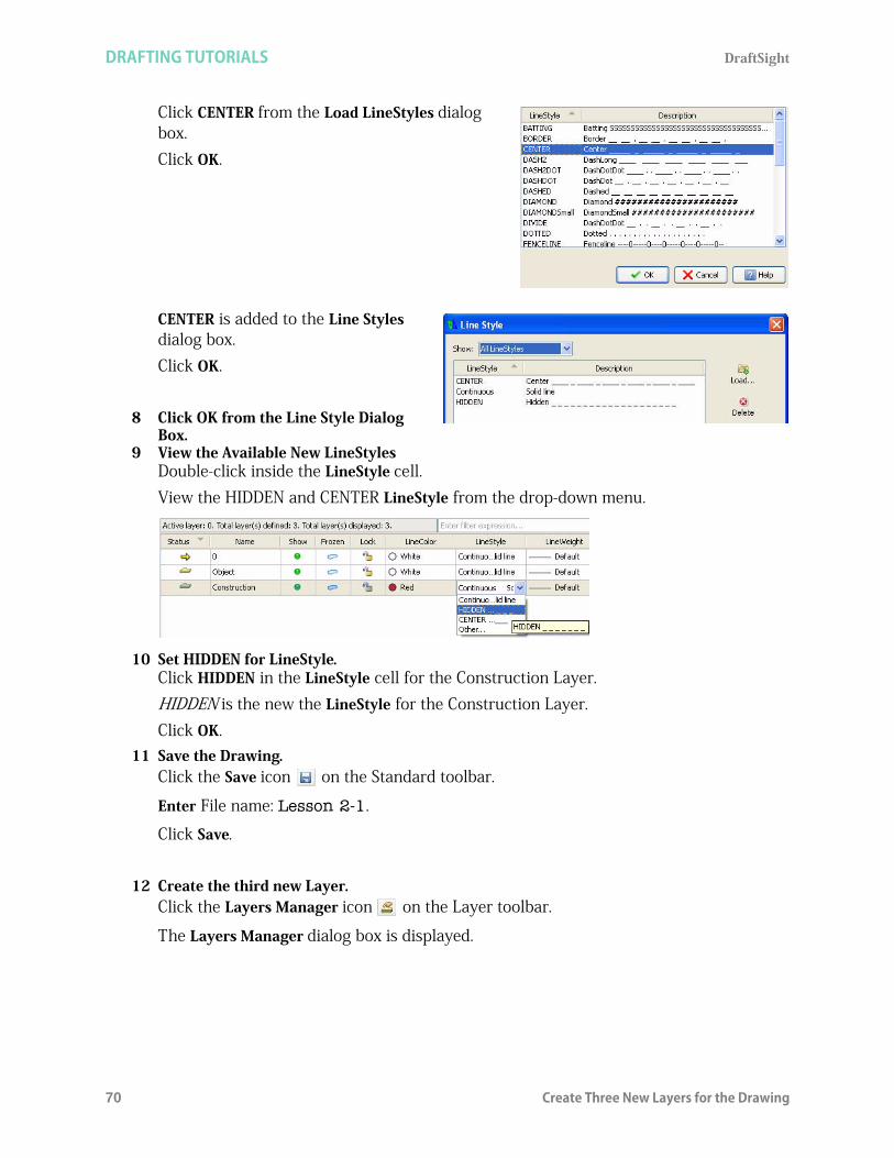
DRAFTING TUTORIALS DraftSight
70 Create Three New Layers for the Drawing
Click CENTER from the Load LineStyles dialog box.Click OK.
CENTER is added to the Line Styles dialog box.Click OK.
8 Click OK from the Line Style Dialog Box.
9 View the Available New LineStylesDouble-click inside the LineStyle cell. View the HIDDEN and CENTER LineStyle from the drop-down menu.
10 Set HIDDEN for LineStyle.Click HIDDEN in the LineStyle cell for the Construction Layer.HIDDEN is the new the LineStyle for the Construction Layer.Click OK.
11 Save the Drawing.Click the Save icon on the Standard toolbar.
Enter File name: Lesson 2-1.
Click Save.
12 Create the third new Layer.Click the Layers Manager icon on the Layer toolbar.
The Layers Manager dialog box is displayed.

DraftSight DRAFTING TUTORIALS
Create Three New Layers for the Drawing 71
Click the New Layer icon. The new default name is Layer1.
Rename this Layer Centerline.
Centerline is the new Layer name.Press the Enter key.
13 Set the Third Layer LineColor.New Layers are automatically assigned the LineColor white. Double-click the LineColor cell for the Centerline Layer.Click Blue.
14 Set the Third Layer LineStyle.Double-click the LineStyle cell for the Centerline Layer.Click CENTER. CENTER is new the LineStyle for the Centerline Layer.
15 Add a Description.Double-click inside the Description cell for the Centerline Layer.Enter Customer XYZ.Press the Enter key.
At this time, the default Layer is active.
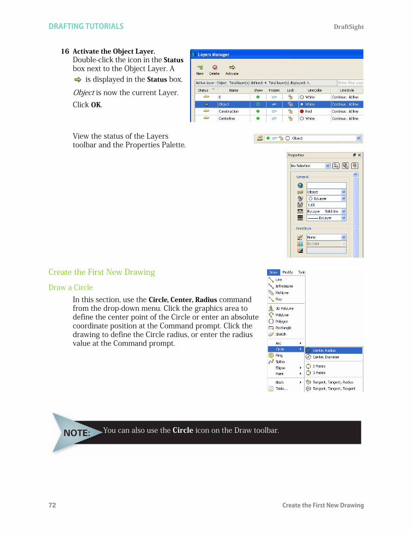
DRAFTING TUTORIALS DraftSight
72 Create the First New Drawing
16 Activate the Object Layer.Double-click the icon in the Status box next to the Object Layer. A
is displayed in the Status box.
Object is now the current Layer.Click OK.
View the status of the Layers toolbar and the Properties Palette.
Create the First New Drawing
Draw a CircleIn this section, use the Circle, Center, Radius command from the drop-down menu. Click the graphics area to define the center point of the Circle or enter an absolute coordinate position at the Command prompt. Click the drawing to define the Circle radius, or enter the radius value at the Command prompt.
You can also use the Circle icon on the Draw toolbar.

DraftSight DRAFTING TUTORIALS
Create the First New Drawing 73
1 Draw a 20mm Radius Circle as the First Entity.Click Draw, Circle, Center, Radius from the Main Menu.Options: 3Point, 2Point, Ttr, TTT Enter to exit or
Specify center point»140,150
Option: Diameter or
Specify radius»20
Draw a HexagonDraw a hexagon using the Polygon command. A Polygon is a closed linear PolyLine segment consisting of between 3 and 1024 equal length sides.
1 Draw a six Side Hexagon.Click Draw, Polygon from the Main Menu.Default: 4
Enter number of Sides» 6
Options: Side length or
Specify center point»
Click the center point of the Circle in the graphics area.
Default: COrner
Options: COrner, or Side
Specify distance option»s
Specify distance» 10
2 Save the Drawing.Click the Save icon on the Standard toolbar.

DRAFTING TUTORIALS DraftSight
74 Create the First New Drawing
Copy Command
Use the Copy command to duplicate drawing entities by selecting drawing entities and placing a copy of them at a specified position. The duplicated entities are exact copies of the selected entities including all entity properties such as Layers, LineStyles, LineColors, and LineWeight.
1 Copy the Existing Circle to the Right of the Drawing.2 Turn Snap Off.
Click the Snap button on the Status bar. The command window displays: <Snap Off>.
3 Click the Copy Icon on the Modify Toolbar.Specify entities»
Click the circumference of the Circle. The Circle is highlighted by turning dotted.1 found, 1 total
Specify entities»
Default: Displacement
Options: Displacement or
Specify from point»
Click the center point of the Circle in the graphics area.
Options: Enter to use first point as displacement or
Specify second point» 220,150
Default: Exit
Options: Exit, Undo or
Specify second point:
With Snap On, the cursor can only select points positioneddirectly on the snap grid.

DraftSight DRAFTING TUTORIALS
Create the First New Drawing 75
Modify the Diameter of the Copied CircleUse the Properties Palette to modify the diameter of the copied Circle. The Properties Palette allows you to view and change drawing entity properties. The Properties Palette is located on the right side of the graphics area.
4 Modify the Circle Diameter.Click the circumference of the copied Circle.Delete 20.00 for Radius in the Properties Palette.
Enter 10.Press Esc or Enter to exit.
5 Save the Drawing.Click the Save icon on the Standard toolbar.
Draw Two Parallel and Horizontal Lines Turn Ortho mode on.Click the Ortho button on the Status bar.
The command window displays: <Ortho On>.
Orthogonal mode limits the cursor movement so that it moves parallel to the axes of the coordinate system. You can only enter points located parallel to these axes. Orthogonal mode makes it easier to draw and place parallel or colinear Lines on entities.
6 Draw the First Linear Segment. Click the Line icon on the Draw toolbar.
Options: Segments or
Specify start point»
Click the top quadrant point of the small Circle.

DRAFTING TUTORIALS DraftSight
76 Create the First New Drawing
Options: Segments, Undo Enter to exit or
Specify next point»
Draw a Line from the top quadrant point to a point within the large Circle as illustrated.
Click a point.Options: Segments, Undo Enter to exit or
Specify next point»
:
7 Draw the Second Linear Segment. Click the Line icon on the Draw toolbar.
Options: Segments or
Specify start point»
Click the bottom quadrant point of the small Circle.
Options: Segments, Undo Enter to exit or
Specify next point»
Draw a Line from the bottom quadrant point to a point within the large Circle as illustrated.
Click a point.Options: Segments, Undo Enter to exit or
Specify next point»
Trim Command
The Trim command provides the ability to cut drawing entities precisely at the edges defined by one or more entities.Lines, InfiniteLines, Rays, PolyLines, Circles, Arcs, or Ellipses can act as cutting edges and as a result of the command execution be trimmed. Blocks and text cannot be trimmed or used as cutting edges. In a sheet the entities of type ViewPort can also be cutting edges. When you select a PolyLine as cutting edge, the command trims at its centerline.

DraftSight DRAFTING TUTORIALS
Create the First New Drawing 77
8 Trim the Top and Bottom Horizontal Lines Back to the Large Circle.
Click the Trim icon on the Modify toolbar.Specify cutting edges...
Options: Enter to specify all entities or
Specify entities»
Click the circumference of the large Circle.
1 found, 1 total
Options: Enter to specify all entities or
Specify entities»
Options: Crossing, CRossline, Project, Edge, eRase, Shift + select to extend or
Specify segments to remove»
Click the bottom Horizontal Line inside the large Circle. The inside bottom Line is trimmed.
Options: Crossing, CRossline, Project, Edge, eRase, Shift + select to extend or
Specify segments to remove»
Click the top Horizontal Line inside the large Circle. The inside top Line is trimmed
Options: Crossing, CRossline, Project, Edge, eRase, Shift + select to extend or
Specify segments to remove»
9 Turn Ortho Mode Off.Click the Ortho button on the Status bar.
Fillet Command
The Fillet Command allows you to create rounded corners by replacing part of two Lines with an Arc. The filleted entities do not have to intersect, and they can overlap. If the entities overlap, they will be trimmed (by default) to create the rounded corner. In any case, the Lines to be filleted are connected to the fillet arc.Applying a fillet radius of 0 will result in creating sharp corners instead of rounded. You can hold down the Shift key on the keyboard while selecting the entities to override the current fillet radius with a value of 0.
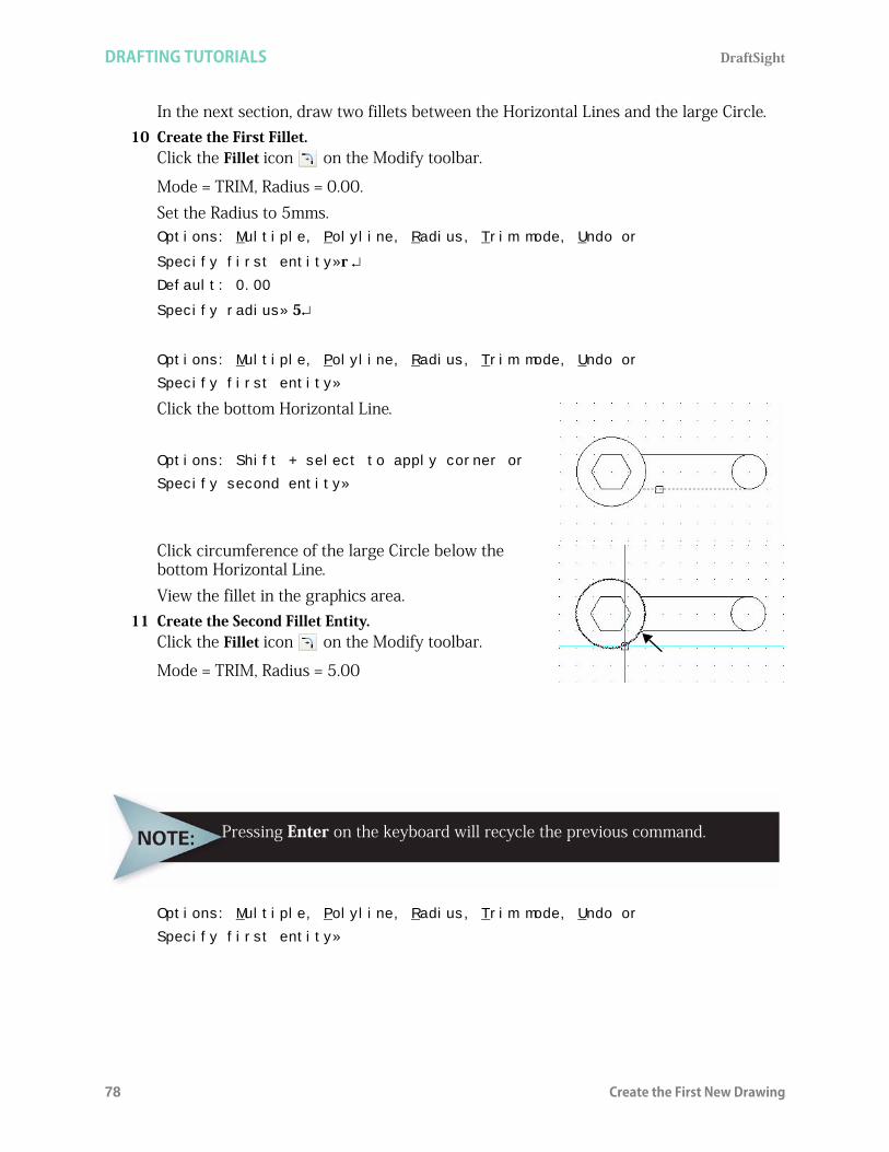
DRAFTING TUTORIALS DraftSight
78 Create the First New Drawing
In the next section, draw two fillets between the Horizontal Lines and the large Circle. 10 Create the First Fillet.
Click the Fillet icon on the Modify toolbar.
Mode = TRIM, Radius = 0.00. Set the Radius to 5mms. Options: Multiple, Polyline, Radius, Trim mode, Undo or
Specify first entity»r Default: 0.00
Specify radius» 5
Options: Multiple, Polyline, Radius, Trim mode, Undo or
Specify first entity»
Click the bottom Horizontal Line.
Options: Shift + select to apply corner or
Specify second entity»
Click circumference of the large Circle below the bottom Horizontal Line.View the fillet in the graphics area.
11 Create the Second Fillet Entity. Click the Fillet icon on the Modify toolbar.
Mode = TRIM, Radius = 5.00
Options: Multiple, Polyline, Radius, Trim mode, Undo or
Specify first entity»
Pressing Enter on the keyboard will recycle the previous command.
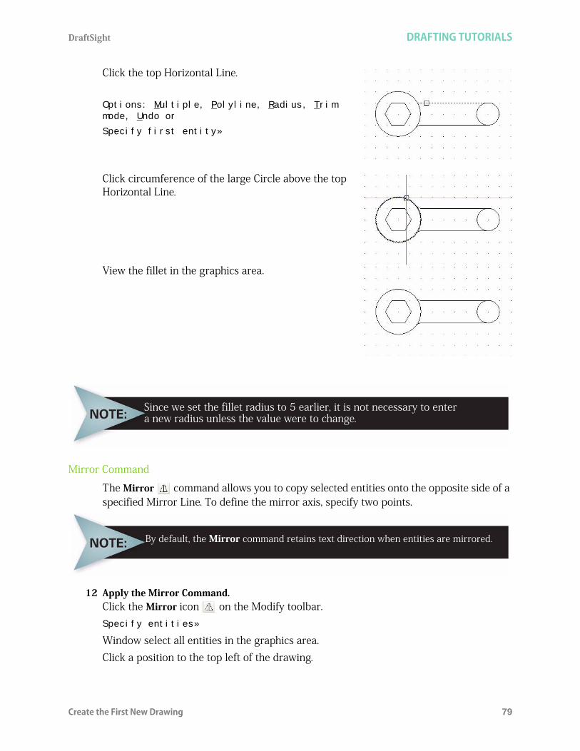
DraftSight DRAFTING TUTORIALS
Create the First New Drawing 79
Click the top Horizontal Line.
Options: Multiple, Polyline, Radius, Trim mode, Undo or
Specify first entity»
Click circumference of the large Circle above the top Horizontal Line.
View the fillet in the graphics area.
Mirror Command
The Mirror command allows you to copy selected entities onto the opposite side of a specified Mirror Line. To define the mirror axis, specify two points.
12 Apply the Mirror Command.Click the Mirror icon on the Modify toolbar.Specify entities»
Window select all entities in the graphics area. Click a position to the top left of the drawing.
Since we set the fillet radius to 5 earlier, it is not necessary to entera new radius unless the value were to change.
By default, the Mirror command retains text direction when entities are mirrored.

DRAFTING TUTORIALS DraftSight
80 Create the First New Drawing
Click a position below the bottom right of the drawing. The selected entities inside the graphics area are displayed.7 found, 7 total
Specify entities»
Specify start point of mirror line»
Click the top quadrant point of the large Circle as illustrated.
Specify end point of mirror line»
Click the bottom quadrant point of the large Circle. Accept the default setting.Default: No
Confirm: Delete source entities?
Specify Yes, or No»
13 Save the Drawing.Click the Save icon on the Standard toolbar.
Rotate Command
Use the Rotate command to rotate entities through an angle, about a base point. By default, rotation is counterclockwise.
14 Rotate the Geometry 30 DegreesClick the Rotate icon on the Modify toolbar.Active positive angle in CCS: DIRECTION+counterclockwise BASE=0
Specify entities»
When you rotate, set the Orthagonal mode to constrain the angleof rotation to 90 degree intervals.
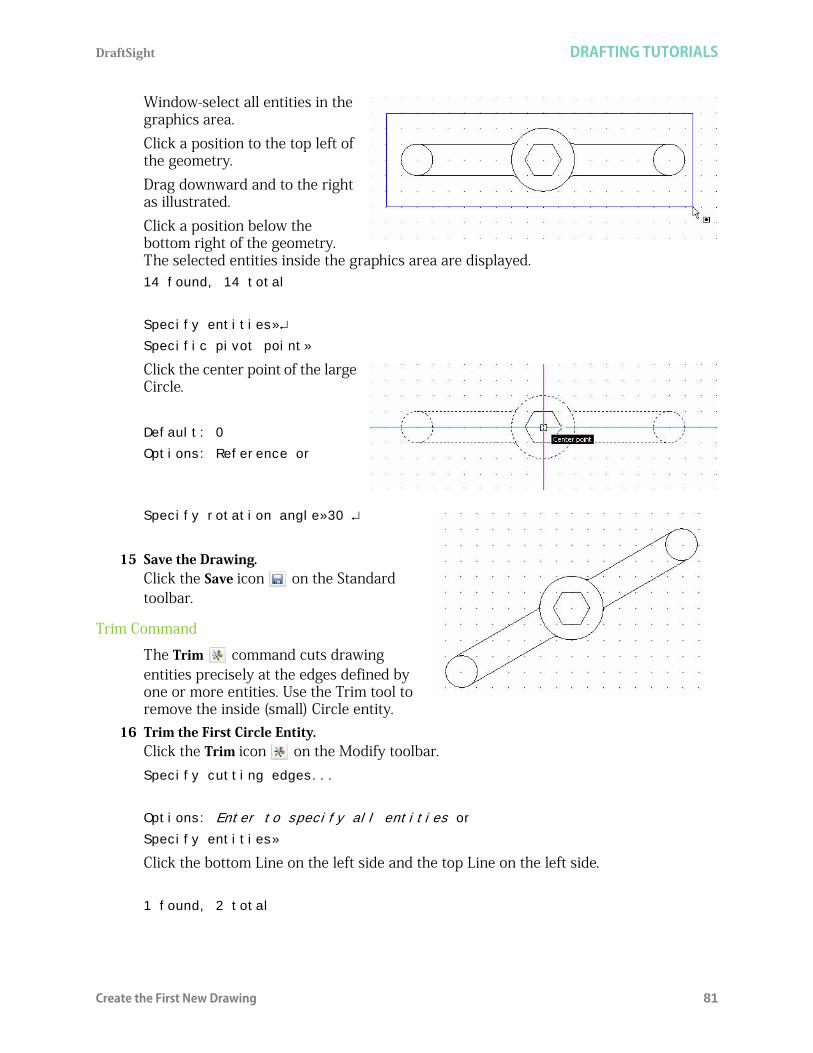
DraftSight DRAFTING TUTORIALS
Create the First New Drawing 81
Window-select all entities in the graphics area. Click a position to the top left of the geometry.Drag downward and to the right as illustrated.Click a position below the bottom right of the geometry. The selected entities inside the graphics area are displayed.14 found, 14 total
Specify entities»
Specific pivot point»
Click the center point of the large Circle.
Default: 0
Options: Reference or
Specify rotation angle»30
15 Save the Drawing.Click the Save icon on the Standard toolbar.
Trim Command
The Trim command cuts drawing entities precisely at the edges defined by one or more entities. Use the Trim tool to remove the inside (small) Circle entity.
16 Trim the First Circle Entity.Click the Trim icon on the Modify toolbar.Specify cutting edges...
Options: Enter to specify all entities or
Specify entities»
Click the bottom Line on the left side and the top Line on the left side.
1 found, 2 total

DRAFTING TUTORIALS DraftSight
82 Create the First New Drawing
Options: Enter to specify all entities or
Specify entities»
Options: Crossing, CRossline, Project, Edge, eRase, Undo, Shift + select to extend or
Specify entity to remove»
Click right side of the circumference of the small Circle that is on the left side of the entity as shown.
Specify entity to remove»
17 Trim the Second Circle Entity.Click the Trim icon on the Modify toolbar.Specify cutting edges...
Options: Enter to specify all entities or
Specify entities»
Click the bottom Line on the right side and the top Line on the right side.
1 found, 2 total
Options: Enter to specify all entities or
Specify entities»
Click left side of the circumference of the small Circle that is on the right side of the entity as shownOptions: Crossing, CRossline, Project, Edge, eRase, Undo, Shift + select to extend or
Specify entity to remove»
18 Save the Drawing.Click the Save icon on the Standard toolbar.

DraftSight DRAFTING TUTORIALS
Draw Entities on the Centerline Layer 83
Draw Entities on the Centerline LayerIn this next section, draw a Line, Circle, and Rectangle on the Centerline Layer. Only display the Centerline Layer.
19 Open the Layers Manager Dialog Box.Click the Layers Manager icon . The Layers Manager dialog box is displayed. At this time, all Layers are displayed: Default (0), Object, Construction, and Centerline.Activate the Centerline Layer
Double-click the Status icon in the Centerline Layer Show cell. Turn the Default Layer (0) Off.
Double-click the Show icon in the default (0) Show cell.Turn the Construction Layer Off.
Double-click the Show icon in the Construction Show cell.
Turn the Object Layer Off
Double-click the Show icon in the Object Show cell.
Click OK from the Layer Manager dialog box.View an empty work space.
20 Save the Drawing.Click the Save icon on the Standard toolbar.
21 Draw a Linear Segment.Click the Line icon on the Draw toolbar.Options: Segments or
Specify start point»50,50
Options: Segments, Undo, Enter to exit or
Specify next point»160,50
Options: Segments, Undo, Enter to exit or
Specify next point»
The blue LineStyle CENTER is displayed on the Centerline Layer.
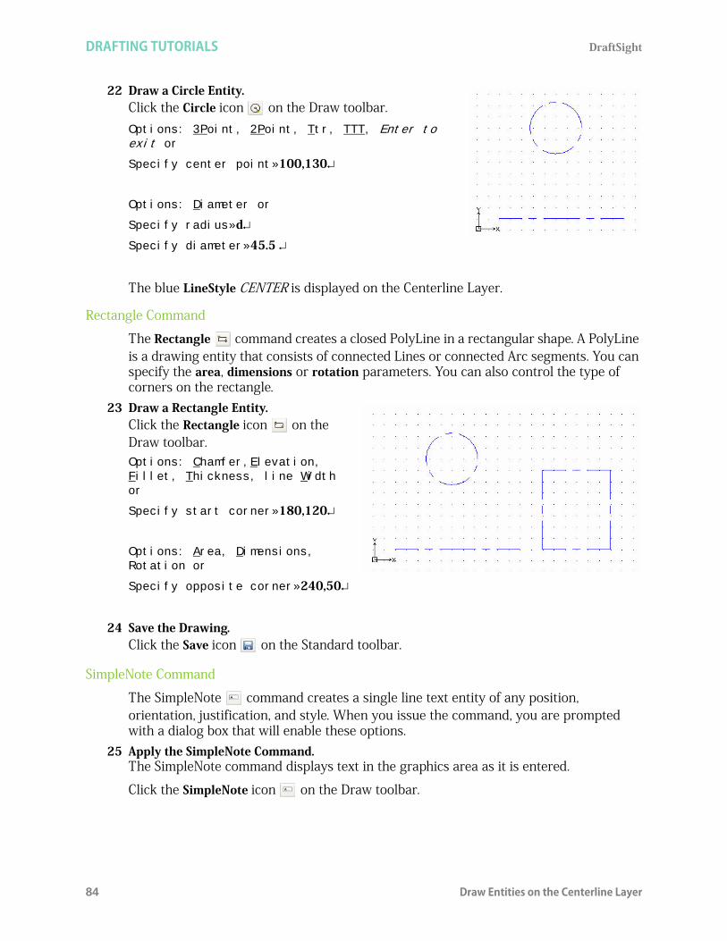
DRAFTING TUTORIALS DraftSight
84 Draw Entities on the Centerline Layer
22 Draw a Circle Entity.Click the Circle icon on the Draw toolbar.Options: 3Point, 2Point, Ttr, TTT, Enter to exit or
Specify center point»100,130
Options: Diameter or
Specify radius»d
Specify diameter»45.5
The blue LineStyle CENTER is displayed on the Centerline Layer.
Rectangle Command
The Rectangle command creates a closed PolyLine in a rectangular shape. A PolyLine is a drawing entity that consists of connected Lines or connected Arc segments. You can specify the area, dimensions or rotation parameters. You can also control the type of corners on the rectangle.
23 Draw a Rectangle Entity.Click the Rectangle icon on the Draw toolbar.Options: Chamfer,Elevation, Fillet, Thickness, line Width or
Specify start corner»180,120
Options: Area, Dimensions, Rotation or
Specify opposite corner»240,50
24 Save the Drawing.Click the Save icon on the Standard toolbar.
SimpleNote Command
The SimpleNote command creates a single line text entity of any position, orientation, justification, and style. When you issue the command, you are prompted with a dialog box that will enable these options.
25 Apply the SimpleNote Command.The SimpleNote command displays text in the graphics area as it is entered.
Click the SimpleNote icon on the Draw toolbar.

DraftSight DRAFTING TUTORIALS
Draw a Spline on the Construction Layer 85
26 Complete the Insert SimpleNote Dialog.
Input the word RECTANGLE in the text: field.
Use Insertion point X: 190Y: 40
Change Height: to 5.Click OK.
27 Save the Drawing.Click the Save icon on the Standard toolbar.
Draw a Spline on the Construction LayerIn this next section, you will draw a Spline on the Construction Layer. The default Layer, Object Layer and Construction Layer are not shown at this time.
28 Turn the Centerline Layer Off.Click the drop-down arrow from the Layers Manager.Click the Show icon in the Centerline row. Click OK from the pop-up dialog box. Make the Construction Layer active.Click the drop-down arrow from the Layers Properties Manager.
Click Construction.

DRAFTING TUTORIALS DraftSight
86 Draw a Spline on the Construction Layer
29 Save the Drawing. Click the Save icon on the Standard toolbar
.
Spline Command
The Spline command provides the ability to draw a smooth curve that is fit to a set of points. You can create a non-uniform rational B-Spline or NURBS curve for any number of fit points. You can also fit the Spline to the specified points to within a specified tolerance value.
30 Draw a Spline Entity.Click the Spline icon on the Draw toolbar.
Specify start fit point»150,60
Specify next fit point»185,80
You can either click the graphics area or enter successive points to continue the Spline or enter F to define a fit tolerance and then click or enter other Spline points. In the next section, enter a fit tolerance of .2mm.
The Construction Layer is displayed in the graphics area. The Default Layer, Object Layer and the Centerline Layer are Off.

DraftSight DRAFTING TUTORIALS
Draw a Spline on the Construction Layer 87
Options: Close, Fit tolerance, Enter for start tangent or
Specify next fit point»fDefault: 0.00
Specify fit tolerance».2
Options: Close, Fit tolerance, Enter for start tangent or
Specify next fit point»100,40
Options: Close, Fit tolerance, Enter for start tangent or
Specify next fit point»115,25.5
Options: Close, Fit tolerance, Enter for start tangent or
Specify next fit point»c
Specify tangency»
Click a position inside the graphics area as illustrated. Your drawing may differ depending on the position that you select in the graphics area.
31 Delete the Spline Entity.Select the Spline entity.
Click the Delete icon .
32 Save the Drawing.Click the Save icon on the Standard toolbar.
The fit tolerance applies to all fit points until you change it. Setting thefit tolerance to zero forces the Spline to pass through the fit points.
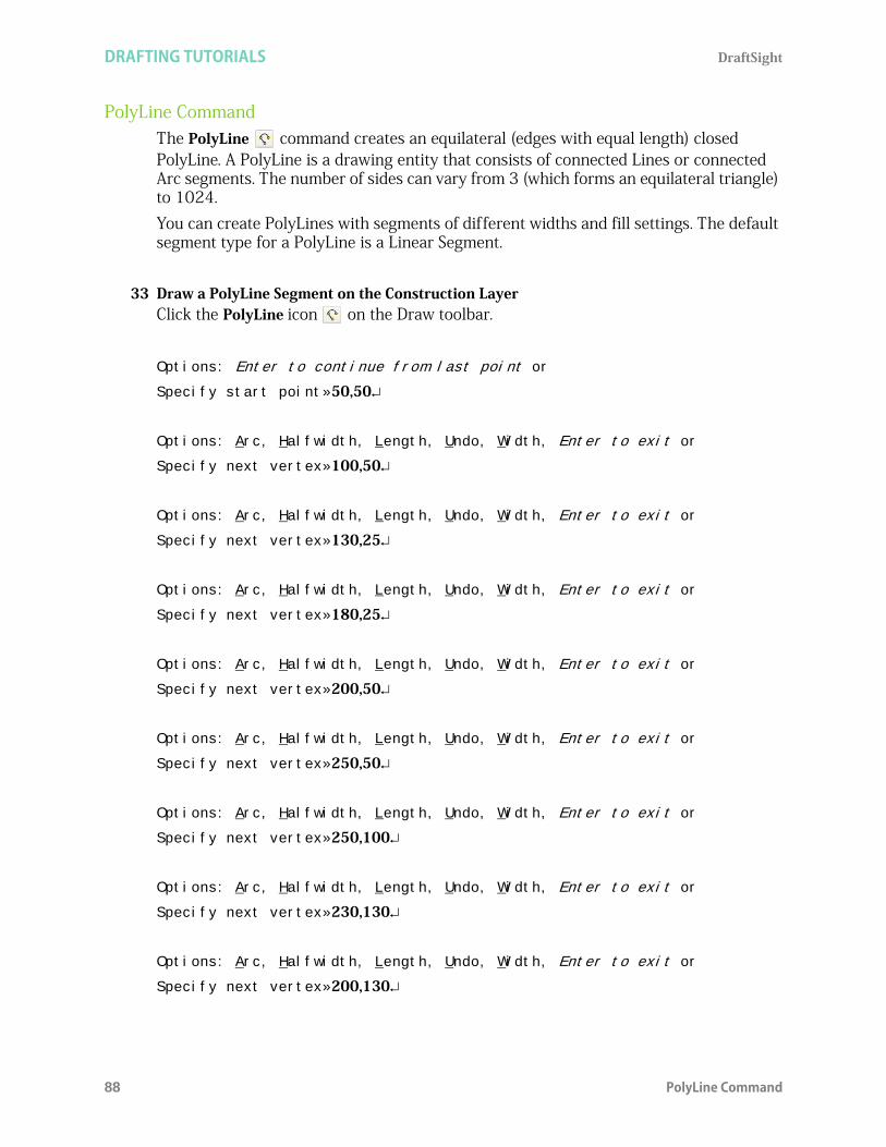
DRAFTING TUTORIALS DraftSight
88 PolyLine Command
PolyLine CommandThe PolyLine command creates an equilateral (edges with equal length) closed PolyLine. A PolyLine is a drawing entity that consists of connected Lines or connected Arc segments. The number of sides can vary from 3 (which forms an equilateral triangle) to 1024. You can create PolyLines with segments of different widths and fill settings. The default segment type for a PolyLine is a Linear Segment.
33 Draw a PolyLine Segment on the Construction LayerClick the PolyLine icon on the Draw toolbar.
Options: Enter to continue from last point or
Specify start point»50,50
Options: Arc, Halfwidth, Length, Undo, Width, Enter to exit or
Specify next vertex»100,50
Options: Arc, Halfwidth, Length, Undo, Width, Enter to exit or
Specify next vertex»130,25
Options: Arc, Halfwidth, Length, Undo, Width, Enter to exit or
Specify next vertex»180,25
Options: Arc, Halfwidth, Length, Undo, Width, Enter to exit or
Specify next vertex»200,50
Options: Arc, Halfwidth, Length, Undo, Width, Enter to exit or
Specify next vertex»250,50
Options: Arc, Halfwidth, Length, Undo, Width, Enter to exit or
Specify next vertex»250,100
Options: Arc, Halfwidth, Length, Undo, Width, Enter to exit or
Specify next vertex»230,130
Options: Arc, Halfwidth, Length, Undo, Width, Enter to exit or
Specify next vertex»200,130

DraftSight DRAFTING TUTORIALS
PolyLine Command 89
Options: Arc, Halfwidth, Length, Undo, Width, Enter to exit or
Specify next vertex»180,100
Options: Arc, Halfwidth, Length, Undo, Width, Enter to exit or
Specify next vertex»130,100
Options: Arc, Halfwidth, Length, Undo, Width, Enter to exit or
Specify next vertex»100,130
Options: Arc, Halfwidth, Length, Undo, Width, Enter to exit or
Specify next vertex»75,130
Options: Arc, Halfwidth, Length, Undo, Width, Enter to exit or
Specify next vertex»50,100
OOptions: Arc, Halfwidth, Length, Undo, Width, Enter to exit or
Specify next vertexc
34 Save the Drawing.Click the Save icon on the Standard toolbar.
Click any segment of the entity in the graphics area. View the EGrips. The EGrips display a single entity. Remember, EGrips are selectable handles (displayed as small squares) at the end points, center, vertices, insertion points, and other geometric points of entities.
35 Remove the EGrips.Press Esc or Enter to exit.

DRAFTING TUTORIALS DraftSight
90 Edit PolyLine Command
Edit PolyLine CommandThe Edit PolyLine command provides the ability to edit PolyLines, PolyLine vertices, and three-dimensional polygon meshes in several ways. PolyLines can be modified in the following ways: Open a close PolyLine or close an open PolyLine Join a PolyLine with other drawing entities such as Line, Arc or PolyLine Modify the width of the whole PolyLine Edit individual PolyLine segments by editing their control points (vertices)
Modify the PolyLine WidthIn the following section, modify the width of the PolyLine from .2mm to 5mm.
36 Apply the Edit PolyLine Command. Click the Edit PolyLine icon on the Modify toolbar.Options: Multiple or
Specify polyLine»
Click a Line segment of the polyline.Options: Decurve, Edit vertex, Fit, Join, Lengthen, Open, Spline, Undo, Width, or eXit
Specify option»w
Specify new width»5
Options: Decurve, Edit vertex, Fit, Join, Lengthen, Open, Spline, Undo, Width, or eXit
Specify option»x
37 Undo the Modification.Click the Undo icon on the Standard toolbar.
38 Turn the Construction Layer Off.Click the drop-down arrow from the Layers Properties Manager.
Click the Show icon in the Construction row.
Click OK from the pop-up dialog box.
A gray Show icon is displayed.
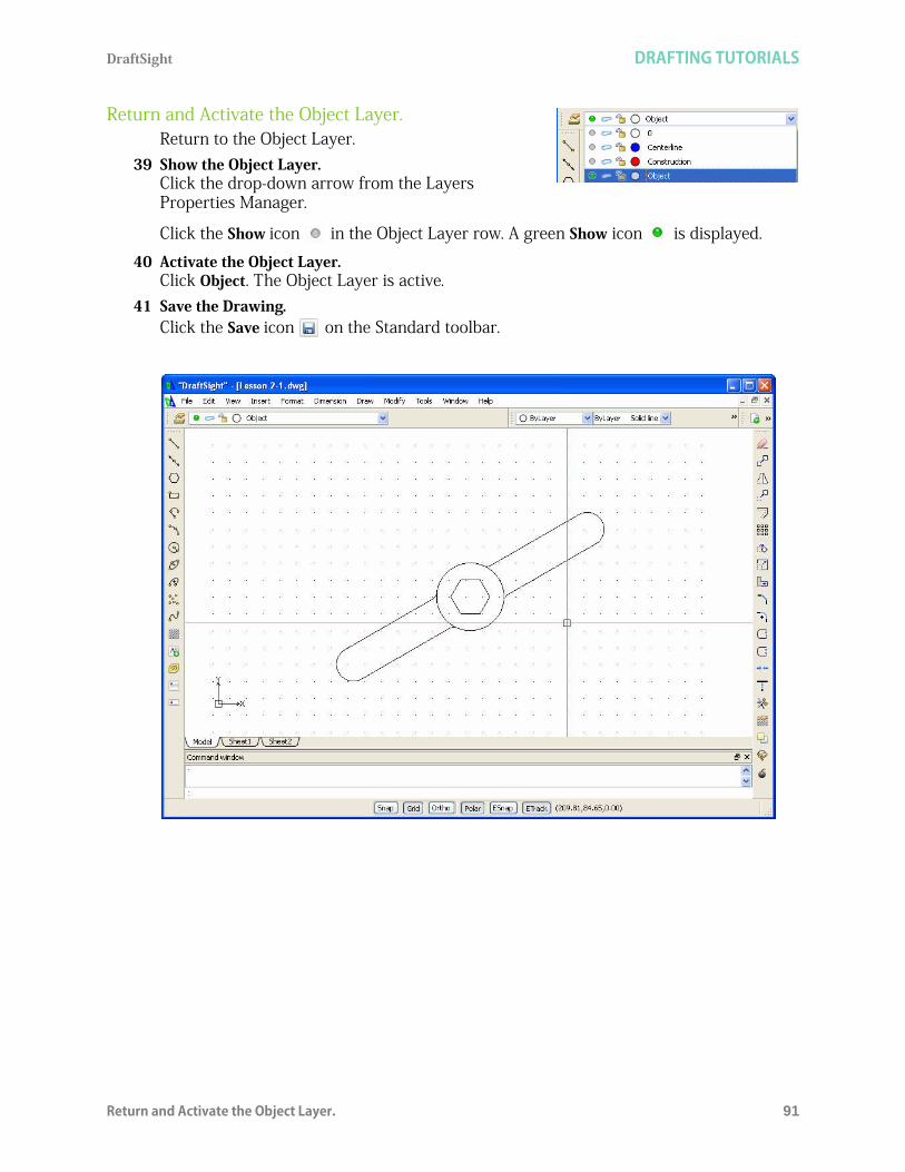
DraftSight DRAFTING TUTORIALS
Return and Activate the Object Layer. 91
Return and Activate the Object Layer.Return to the Object Layer.
39 Show the Object Layer.Click the drop-down arrow from the Layers Properties Manager.
Click the Show icon in the Object Layer row. A green Show icon is displayed.
40 Activate the Object Layer.Click Object. The Object Layer is active.
41 Save the Drawing.Click the Save icon on the Standard toolbar.

DRAFTING TUTORIALS DraftSight
92 Create a Second New Drawing
Create a Second New DrawingCreate three new Layers. Use the Rectangle, and Circle commands.Apply the Pattern command to create a Circular and Linear pattern along with the Chamfer command.Create an Object Layer and a Centerline Layer. Set custom Layer properties.
1 Create a New Drawing.Click the New icon on the Standard toolbar.
Drawing Template2 Select a Default Drawing Template.
Double-click standard.dwt from the Select Template dialog box.
Set the Drawing Environment
Drawing Unit SystemThe default units system is the Decimal system and can be applied to either English (inches) or metric values (millimeters).
3 Set Linear Length Precision.The Unit System section of the Options - Drawing Settings dialog box allows you to set the linear and angular unit formats. Click Format, Unit System... from the Main Menu. The Unit System portion of the Options - Drawing Settings dialog box is displayed.Click 0.00 for Precision in the Length section of the dialog box.
4 Set Linear Units Scale.The Units scale section of the Unit System dialog box allows you to set the linear and angular unit formats.Click Millimeters for Block units format in the Units scale section of the dialog box. Click OK.
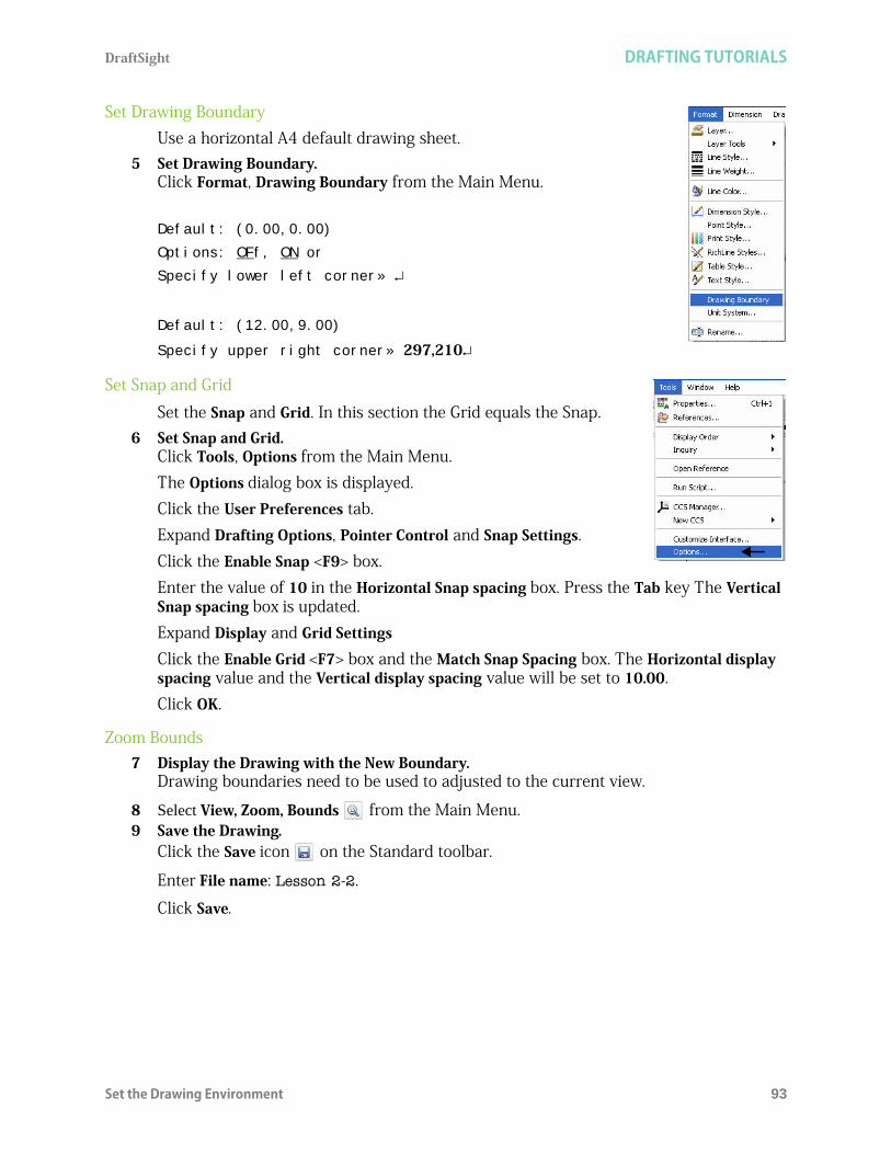
DraftSight DRAFTING TUTORIALS
Set the Drawing Environment 93
Set Drawing BoundaryUse a horizontal A4 default drawing sheet.
5 Set Drawing Boundary.Click Format, Drawing Boundary from the Main Menu.
Default: (0.00,0.00)
Options: OFf, ON or
Specify lower left corner»
Default: (12.00,9.00)
Specify upper right corner» 297,210
Set Snap and Grid
Set the Snap and Grid. In this section the Grid equals the Snap.6 Set Snap and Grid.
Click Tools, Options from the Main Menu. The Options dialog box is displayed. Click the User Preferences tab. Expand Drafting Options, Pointer Control and Snap Settings.Click the Enable Snap <F9> box.Enter the value of 10 in the Horizontal Snap spacing box. Press the Tab key The Vertical Snap spacing box is updated.Expand Display and Grid SettingsClick the Enable Grid <F7> box and the Match Snap Spacing box. The Horizontal display spacing value and the Vertical display spacing value will be set to 10.00.Click OK.
Zoom Bounds7 Display the Drawing with the New Boundary.
Drawing boundaries need to be used to adjusted to the current view.
8 Select View, Zoom, Bounds from the Main Menu.9 Save the Drawing.
Click the Save icon on the Standard toolbar.
Enter File name: Lesson 2-2.
Click Save.
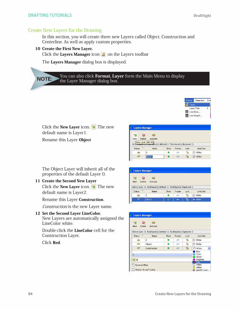
DRAFTING TUTORIALS DraftSight
94 Create New Layers for the Drawing
Create New Layers for the DrawingIn this section, you will create three new Layers called Object, Construction and Centerline. As well as apply custom properties.
10 Create the First New Layer.Click the Layers Manager icon on the Layers toolbar
The Layers Manager dialog box is displayed.
Click the New Layer icon. The new default name is Layer1.Rename this Layer Object
The Object Layer will inherit all of the properties of the default Layer 0.
11 Create the Second New LayerClick the New Layer icon. The new default name is Layer2.Rename this Layer Construction. Construction is the new Layer name.
12 Set the Second Layer LineColor.New Layers are automatically assigned the LineColor white. Double-click the LineColor cell for the Construction Layer.Click Red.
You can also click Format, Layer form the Main Menu to displaythe Layer Manager dialog box.

DraftSight DRAFTING TUTORIALS
Create New Layers for the Drawing 95
13 Create the Second Layer LineStyle.Create a MM HIDDEN LineStyle. Double-click the LineStyle cell from the Construction Layer.Click Other. The LineStyles Manager dialog box is displayed.
Click the Load icon.
The Load LineStyles dialog box is displayed
Click the Browse button.
Select MM.LIN from the Specify LineStyle File dialog box.Click Open from the Specify LineStyles File dialog box.
The default LineStyle file: inch.lin

DRAFTING TUTORIALS DraftSight
96 Create New Layers for the Drawing
Select HIDDEN from the Load LineStyles dialog box.Click OK.
HIDDEN is added to the LineStyles dialog box.
14 Create the Second Layer LineStyle.Create a MM CENTER LineStyle.
Click the Load icon.
View the Load LineStyles dialog box. The default LineStyle file: inch.lin.
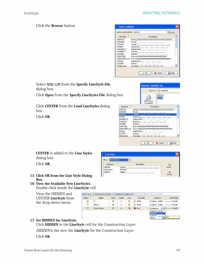
DraftSight DRAFTING TUTORIALS
Create New Layers for the Drawing 97
Click the Browse button.
Select MM.LIN from the Specify LineStyle File dialog box.Click Open from the Specify LineStyles File dialog box
Click CENTER from the Load LineStyles dialog box.Click OK.
CENTER is added to the Line Styles dialog box.Click OK.
15 Click OK from the Line Style Dialog Box.
16 View the Available New LineStylesDouble-click inside the LineStyle cell. View the HIDDEN and CENTER LineStyle from the drop-down menu.
17 Set HIDDEN for LineStyle.Click HIDDEN in the LineStyle cell for the Construction Layer.HIDDEN is the new the LineStyle for the Construction Layer.Click OK.

DRAFTING TUTORIALS DraftSight
98 Create New Layers for the Drawing
18 Save the Drawing.Click the Save icon on the Standard toolbar.
19 Create the Third New Layer.Click the Layers Manager icon on the Layer toolbar.
The Layers Manager dialog box is displayed.
Click the New Layer icon. The new default name is Layer1.
Rename this Layer Centerline.
Centerline is the new Layer name.Press the Enter key.
20 Set the Third Layer LineColor.New Layers are automatically assigned the LineColor white. Double-click the LineColor cell for the Centerline Layer.Click Blue.
21 Set the Third Layer LineStyle.Double-click the LineStyle cell for the Centerline Layer.Click CENTER. CENTER is new the LineStyle for the Centerline Layer.
22 Add a Description.Double-click inside the Description cell for the Centerline Layer.Enter Customer XYZ.

DraftSight DRAFTING TUTORIALS
Create the Second Drawing 99
Press the Enter key.
23 Activate the Object Layer.Double-click the icon in the Status box next to the Object Layer. A
is displayed in the Status box.
Object is now the current Layer.Click OK.
View the status of the Layers toolbar and the Properties Palette.
Create the Second Drawing
Rectangle Command
A rectangle drawn using the Rectangle command is considered to be a single entity. If the same sized rectangle were drawn using the Line command, the resulting rectangle will be four individual unrelated Line entities.
24 Draw a Rectangle Entity.Click the Rectangle icon on the Draw toolbar.Options: Chamfer, Elevation, Fillet, Thickness, line Width or
Specify start corner»50,50
Options: Area, Dimensions, Rotation or
Specify opposite corner»150,150
(@100,100 could be used as the relative value)25 Draw a Circle Entity
Click the Circle icon on the Draw toolbar.
At this time, the Default Layer is active.
To specify the point coordinates with respect to the previous point (relativecoordinate input, type the @ character in front of the coordinate value.

DRAFTING TUTORIALS DraftSight
100 Create the Second Drawing
Options: 3Point, 2Point, Ttr, TTT, Enter to exit or
Specify center point»70,70
Options: Diameter or
Specify radius»5
26 Turn Snap Off. Click the Snap button on the Status bar.
The command window displays: <Snap Off>.
Pattern Command: Linear Option
The Pattern command provides the ability to create multiple copies of selected entities in a rectangular matrix or a polar, circular pattern. The created entities inherit all properties of the original entities such as Layers, and Layer custom properties.
27 Create a Linear Pattern.Click the Pattern icon on the Modify toolbar.
The Pattern dialog box is displayed.Click the Linear button.Number of elements on Horizontal axis: Enter 2.Number of elements on Vertical axis: Enter 2.Spacing between elements on:Horizontal axis: Enter 60.Vertical axis: Enter 60.Click the Select entities icon.
Select the circumference of the Circle on the screen.
1 found, 1 total
Specify entities»
Click OK.
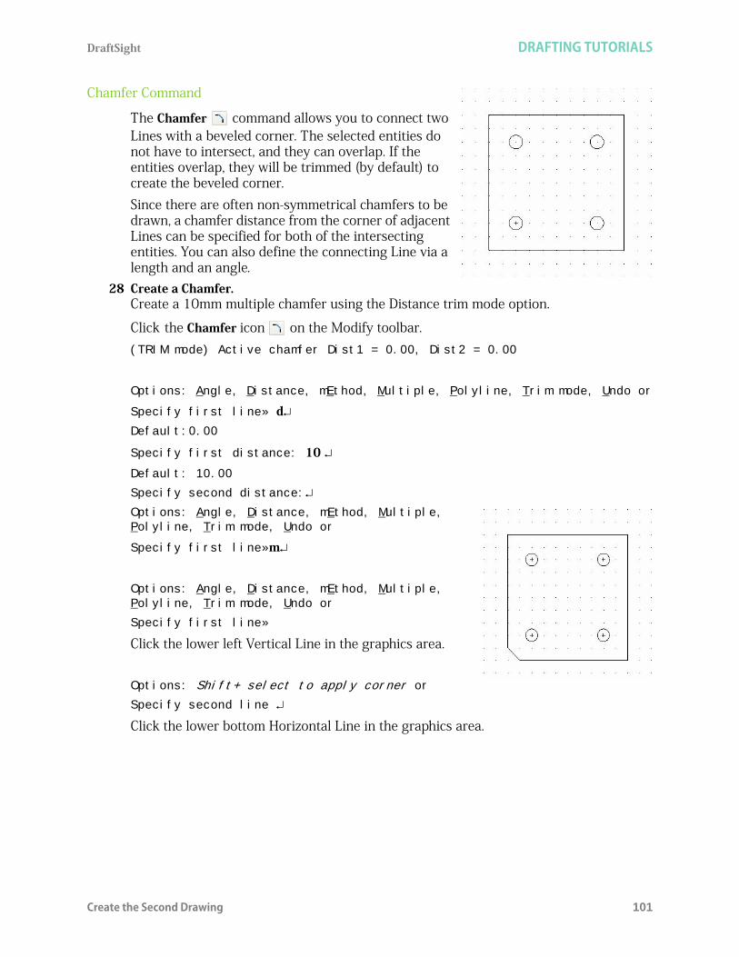
DraftSight DRAFTING TUTORIALS
Create the Second Drawing 101
Chamfer Command
The Chamfer command allows you to connect two Lines with a beveled corner. The selected entities do not have to intersect, and they can overlap. If the entities overlap, they will be trimmed (by default) to create the beveled corner.Since there are often non-symmetrical chamfers to be drawn, a chamfer distance from the corner of adjacent Lines can be specified for both of the intersecting entities. You can also define the connecting Line via a length and an angle.
28 Create a Chamfer.Create a 10mm multiple chamfer using the Distance trim mode option.
Click the Chamfer icon on the Modify toolbar.(TRIM mode) Active chamfer Dist1 = 0.00, Dist2 = 0.00
Options: Angle, Distance, mEthod, Multiple, Polyline, Trim mode, Undo or
Specify first line» dDefault:0.00
Specify first distance: 10 Default: 10.00
Specify second distance:
Options: Angle, Distance, mEthod, Multiple, Polyline, Trim mode, Undo or
Specify first line»m
Options: Angle, Distance, mEthod, Multiple, Polyline, Trim mode, Undo or
Specify first line»
Click the lower left Vertical Line in the graphics area.
Options: Shift+ select to apply corner or
Specify second line
Click the lower bottom Horizontal Line in the graphics area.
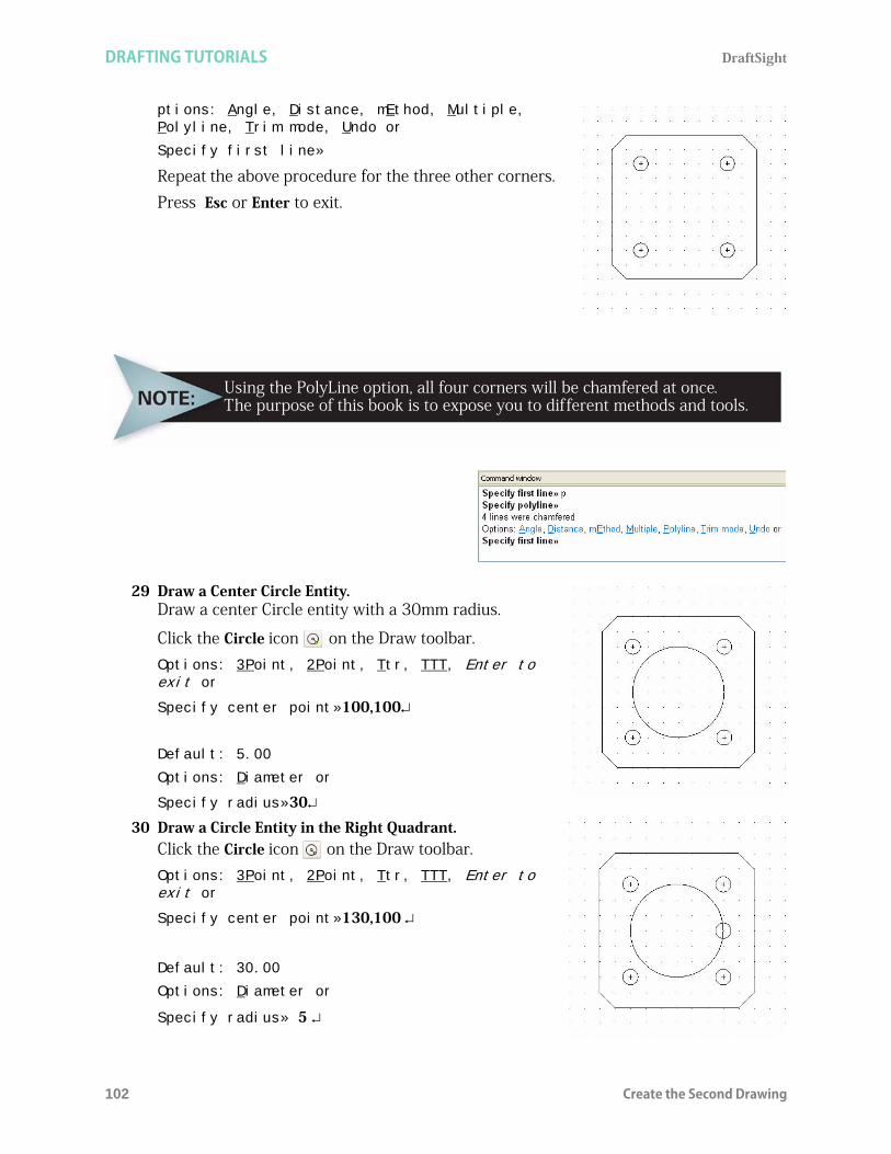
DRAFTING TUTORIALS DraftSight
102 Create the Second Drawing
ptions: Angle, Distance, mEthod, Multiple, Polyline, Trim mode, Undo or
Specify first line»
Repeat the above procedure for the three other corners. Press Esc or Enter to exit.
29 Draw a Center Circle Entity. Draw a center Circle entity with a 30mm radius.
Click the Circle icon on the Draw toolbar.Options: 3Point, 2Point, Ttr, TTT, Enter to exit or
Specify center point»100,100
Default: 5.00
Options: Diameter or
Specify radius»30
30 Draw a Circle Entity in the Right Quadrant.Click the Circle icon on the Draw toolbar.Options: 3Point, 2Point, Ttr, TTT, Enter to exit or
Specify center point»130,100
Default: 30.00
Options: Diameter or
Specify radius» 5
Using the PolyLine option, all four corners will be chamfered at once.The purpose of this book is to expose you to different methods and tools.
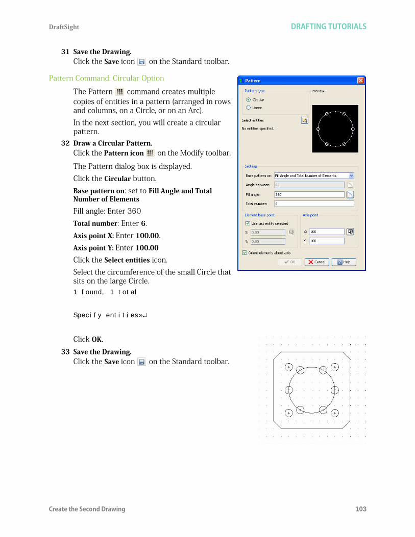
DraftSight DRAFTING TUTORIALS
Create the Second Drawing 103
31 Save the Drawing.Click the Save icon on the Standard toolbar.
Pattern Command: Circular Option
The Pattern command creates multiple copies of entities in a pattern (arranged in rows and columns, on a Circle, or on an Arc). In the next section, you will create a circular pattern.
32 Draw a Circular Pattern.Click the Pattern icon on the Modify toolbar.
The Pattern dialog box is displayed.Click the Circular button.Base pattern on: set to Fill Angle and Total Number of Elements
Fill angle: Enter 360Total number: Enter 6.Axis point X: Enter 100.00.Axis point Y: Enter 100.00Click the Select entities icon.Select the circumference of the small Circle that sits on the large Circle.1 found, 1 total
Specify entities»
Click OK.33 Save the Drawing.
Click the Save icon on the Standard toolbar.

DRAFTING TUTORIALS DraftSight
104 Create the Third New Drawing
34 Move the Large Circle to the Centerline Layer.Click the circumference of the large Circle in the graphics area.Click the drop-down arrow from the Layers Manager.
Click Centerline.
Press Esc or Enter to exit.35 Save the Drawing.
Click the Save icon on the Standard toolbar.
Create the Third New DrawingCreate two Layers. Use the Circle (r), and Circle (Ttr) Draw tools.
The Circle (Ttr) Draw command constructs a Circle from two tangent entities and the specified raduis.

DraftSight DRAFTING TUTORIALS
Set the Drawing Environment 105
Apply the Trim, Offset, and Pattern (circular) modify commands,Create an Object and a Phantom Layer. Set custom properties.
1 Create a New Drawing.Click the New icon on the Standard toolbar.
Drawing Template2 Select a Default Drawing Template.
Double-click standard.dwt from the Select Template dialog box.
Set the Drawing Environment
Drawing Unit SystemThe default units system is the Decimal system and can be applied to either English (inches) or metric values (millimeters).
3 Set Linear Length Precision.The Unit System section of the Options - Drawing Settings dialog box allows you to set the linear and angular unit formats. Click Format, Unit System... from the Main Menu. The Unit System portion of the Options - Drawing Settings dialog box is displayed.Click 0.00 for Precision in the Length section of the dialog box.
4 Set Linear Units Scale.The Units scale section of the Unit System dialog box allows you to set the linear and angular unit formats.Click Millimeters for Block units format in the Units scale section of the dialog box. Click OK.
Set Drawing BoundaryUse a horizontal A4 default drawing sheet.
5 Set Drawing Boundary.Click Format, Drawing Boundary from the Main Menu.
Default: (0.00,0.00)
Options: OFf, ON or
Specify lower left corner»
Default: (12.00,9.00)
Specify upper right corner» 297,210

DRAFTING TUTORIALS DraftSight
106 Create New Layers for the Drawing
Set Snap and GridSet the Snap and Grid. In this section the Grid and Snap spacing are equal.
6 Set Snap and Grid.Click Tools, Options from the Main Menu. The Options dialog box is displayed. Click the User Preferences tab. Expand Drafting Options, Pointer Control and Snap Settings.Click the Enable Snap <F9> box.Enter the value of 10 in the Horizontal Snap spacing box. Press the Tab key The Vertical Snap spacing box is updated.Expand Display and Grid SettingsClick the Enable Grid <F7> box and the Match Snap Spacing box. The Horizontal display spacing value and the Vertical display spacing value will be set to 10.00.Click OK.
Zoom Bounds7 Display the Drawing with the New Boundary.
Drawing boundaries need to be used to adjusted to the current view.
8 Select View, Zoom, Bounds from the Main Menu.9 Save the Drawing.
Click the Save icon on the Standard toolbar.
Enter File name: Lesson 2-3.
Click Save.
Create New Layers for the DrawingIn this section, you will create three new Layers called Object, Construction and Centerline. As well as apply custom properties.
10 Create the First New Layer.Click the Layers Manager icon on the Layers toolbar
The Layers Manager dialog box is displayed.
Click the New Layer icon. The new default name is Layer1.Rename this Layer Object

DraftSight DRAFTING TUTORIALS
Create New Layers for the Drawing 107
The Object Layer will inherit all of the properties of the default Layer 0.
11 Create the Second New LayerClick the New Layer icon. The new default name is Layer2.Rename this Layer Phantom. Phantom is the new Layer Name.
12 Set the LineColor.New Layers are automatically assigned the LineColor white. Double-click the LineColor cell for the Phantom Layer.Click Red.
13 Create a LineStyle.Create a MM PHANTOM LineStyle. Double-click the LineStyle cell from the Phantom Layer.Click Other. The LineStyles Manager dialog box is displayed.
Click the Load icon .
The default LineStyle file: inch.lin.
Click the Browse button.
Select MM.LIN for LineStyle. Double-click MM.LIN from the LineStyle File dialog box.Click PHANTOM from the Load LineStyles dialog box.Click OK.PHANTOM is added to the LineStyles Manager dialog box.Click OK.
14 Set PHANTOM for LineStyle.Click Phantom in the LineStyle cell for the Phantom Layer.PHANTOM is the new the LineStyle for the Phantom Layer.
Click OK.15 Save the Drawing.
Click the Save icon on the Standard toolbar.
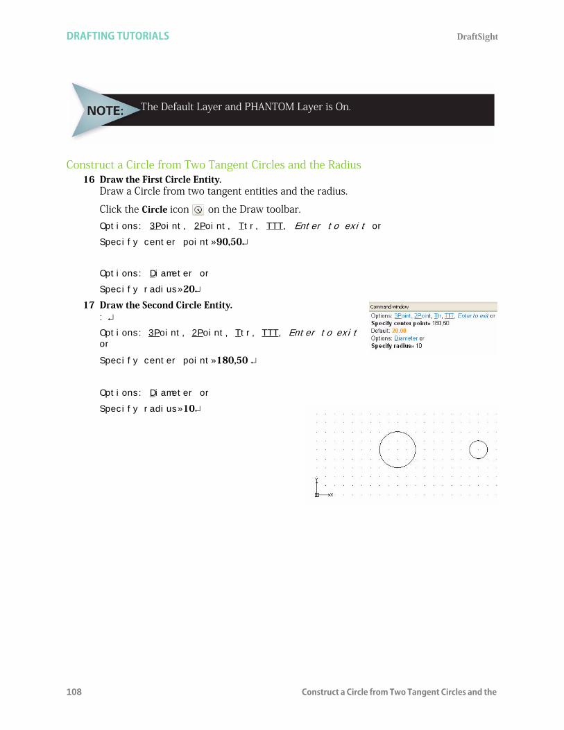
DRAFTING TUTORIALS DraftSight
108 Construct a Circle from Two Tangent Circles and the
Construct a Circle from Two Tangent Circles and the Radius16 Draw the First Circle Entity.
Draw a Circle from two tangent entities and the radius.
Click the Circle icon on the Draw toolbar.Options: 3Point, 2Point, Ttr, TTT, Enter to exit or
Specify center point»90,50
Options: Diameter or
Specify radius»20
17 Draw the Second Circle Entity.: Options: 3Point, 2Point, Ttr, TTT, Enter to exit or
Specify center point»180,50
Options: Diameter or
Specify radius»10
The Default Layer and PHANTOM Layer is On.

DraftSight DRAFTING TUTORIALS
Construct a Circle from Two Tangent Circles and the Radius 109
18 Draw the Third Circle Entity.:
Options: 3Point, 2Point, Ttr, TTT, Enter to exit or
Specify center point»ttr
Specify first tangency»
19 Turn Snap Off.Click the Snap button on the Status bar. The command window displays: <Snap Off>.
Click the first tangent point on the left Circle as illustrated.Specify first tangency»
Click the second tangent point on the right Circle.Default: 10.00
Specify radius»50
20 Draw the Fourth Circle Entity.:
Options: 3Point, 2Point, Ttr, TTT, Enter to exit or
Specify center point»ttr
Specify first tangency»
Click the first tangent point on the left Circle as illustrated.
Specify second tangency»
Click the second tangent point on the right Circle.
Default: 10.00
Specify radius»80
21 Save the Drawing.Click the Save icon on the Standard toolbar.
22 Trim the Top Circle.Click the Trim icon on the Modify toolbar.Specify cutting edges...
Options: Enter to specify all entities or

DRAFTING TUTORIALS DraftSight
110 Construct a Circle from Two Tangent Circles and the
Specify entities»
Options: Crossing, CRossline, Project, Edge, eRase, Undo, Shift + select to extend or
Specify segments to remove»
Click the top section of the 50mm Circle.Options: Crossing, CRossline, Project, Edge, eRase, Undo, Shift + select to extend or
Specify segments to remove»
Click the top section of the 80mm Circle.Options: Crossing, CRossline, Project, Edge, eRase, Undo, Shift + select to extend or
Specify segments to remove»
23 Save the Drawing.Click the Save icon on the Standard toolbar.
Offset Command
The Offset command provides the ability to create parallel shapes of Lines, PolyLines, Circles, Arcs, Ellipses, Elliptical Arcs, Splines, and InfiniteLines. A copy of a selected entity is placed at a specified distance from the original entity. The original entity stays in position.
24 Apply Offset to the Drawing.Offset the two inside Circles.
Click the Offset icon on the Modify toolbar.Default: 1.00
Options: Delete, Distance, destination Layer, Through point or
Specify distance»2

DraftSight DRAFTING TUTORIALS
Construct a Circle from Two Tangent Circles and the Radius 111
Default: Exit,
Options: Exit, Undo or
Specify source entity»
Click the circumference of the left Circle in the graphics area.
Default: Exit
Options: Both sides, Exit, Multiple, Undo or
Specify side for destination»
Click inside of the left Circle.
Default: Exit,
Options: Exit, Undo or
Specify source entity»
Click the circumference of the right Circle in the graphics area.Default: Exit
Options: Both sides, Exit, Multiple, Undo or
Specify side for destination»
Click inside of the right Circle.Specify source entity»
25 Trim the Drawing.Trim the two inside Circles and two Arcs.
Click the Trim icon on the Modify toolbar.Specify cutting edges...
Options: Enter to specify all entities or
Specify entities»
Select the top Arc.
1 found, 1 total
Options: Enter to specify all entities or
Specify entities»

DRAFTING TUTORIALS DraftSight
112 Construct a Circle from Two Tangent Circles and the
Select the bottom Arc.
1 found, 2 total
Options: Enter to specify all entities or
Specify entities»
Options: Crossing, CRossline, Project, Edge, eRase, Undo, Shift + select to extend or
Specify segments to remove»
Click the right side of the left Circle.Options: Crossing, CRossline, Project, Edge, eRase, Undo, Shift + select to extend or
Specify segments to remove»
Click the left side of the right Circle.Options: Crossing, CRossline, Project, Edge, eRase, Undo, Shift + select to extend or
Specify segments to remove»
Pattern Command: Circular Option
The Pattern command creates multiple copies of entities in a pattern (arranged in rows and columns, on a Circle, or on an Arc). In the next section, create a circular pattern.
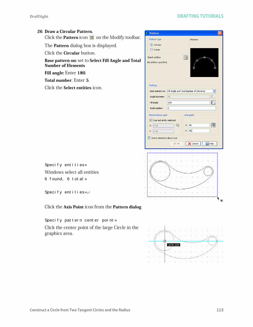
DraftSight DRAFTING TUTORIALS
Construct a Circle from Two Tangent Circles and the Radius 113
26 Draw a Circular Pattern.Click the Pattern icon on the Modify toolbar.
The Pattern dialog box is displayed.Click the Circular button.Base pattern on: set to Select Fill Angle and Total Number of Elements
Fill angle: Enter 180.Total number: Enter 5.Click the Select entities icon.
Specify entities»
Windows select all entities6 found, 6 total»
Specify entities»
Click the Axis Point icon from the Pattern dialog
Specify pattern center point»
Click the center point of the large Circle in the graphics area.

DRAFTING TUTORIALS DraftSight
114 Construct a Circle from Two Tangent Circles and the
Click OK.27 Save the Drawing.
Click the Save icon on the Standard Toolbar.
28 Move Selected Entities to the Phantom Layer.Display the four circular pattern entities on the Phantom Layer. Click the four circular pattern entities in the graphics area.
Click the drop-down arrow from the Layers Manager.
Click Phantom.
Press Esc or Enter to exit.29 Save the Drawing.
Click the Save icon on the Standard toolbar.
You are finished with this section.

DraftSight
115
Lesson 3BASIC DIMENSIONING
When you complete this lesson, you will be able to: Create two drawings with custom layer properties Use absolute coordinates the command prompt and status bar Modify DimensionStyles and precision Edit Dimensions and Dimension text Measure and rotate an Aligned Dimension Apply the Move and Pattern Modify commands Insert, Modify and Create a Pattern of CenterMarks Apply the Linear, DimensionStyle, Angular, Radius, Aligned, DimensionEdit,
DimensionTextEdit, Ordinate, Continue, and CenterMark Dimension commands Reset the Coordinate System

BASIC DIMENSIONING DraftSight
116
Basic DimensioningDuring this lesson, you will rename a drawing, modify an existing drawing and apply Dimensions using absolute coordinates in the Command prompt and the graphics area.In the first drawing you will: Open an existing drawing from Lesson 1(Lesson 1-3). Apply the Save As command and rename it Lesson 3-1. Create a new layer called Dimension with custom properties. Apply the DimensionStyle command and the Linear command to create a linear horizontal and vertical Dimension the Dimension layer.
Modify the precision of the two Dimensions.
Apply the Angular command to create an 80 degree Angular Dimension.
Apply the Aligned command to create an Aligned Dimensionon the top right angular Line.
Apply the DimensionEdit command to modify the 60.00 Linear Dimension to the WIDTH text
Measure the Aligned Dimensionangle.

DraftSight BASIC DIMENSIONING
117
Apply the DimensionTextEdit command to rotate the 50.00 Aligned Dimension text match the angle of an entity.
Reset the coordinate system (CS) from the default position.
Apply the Ordinate command to apply Dimensions on the top entity.
In the second drawing you will: Open an existing drawing from Lesson 2 (Lesson
2-2) Create a new layer called Annotations with
custom properties. Apply the DimensionStyle command to set
properties. Modify the default CenterMark size. Apply the CenterMark command and insert
CenterMarks on the Annotations layer in the drawing.
Apply the Pattern command to create a pattern of CenterMarks.
Activate the Annotations layer. Apply the Radius command to create a Radius
Dimension. Modify the default precision setting.

BASIC DIMENSIONING DraftSight
118 Start a DraftSight Session
Start a DraftSight Session1 Start a DraftSight Session.
From the Windows Start menu, click Start, All Programs, Dassault Systemes, DraftSight.
Dimension ToolbarDraftSight provides a full range of Dimensioning tools and utilities. You can use a variety of Dimensioning tools to display measurements of entities or relations between them in your drawings.By default, Dimensioning is associative. If you modify the geometry of drawing entities, Dimensions associated to them reflect the changes.
Display the Dimension Toolbar. 2 Right-click the Main menu or a docked toolbar.
Click Toolbars.... The Specify Toolbars dialog box is displayed.

DraftSight BASIC DIMENSIONING
Display the Dimension Toolbar. 119
Check the Dimension box.Click OK.
You can access the Dimension commands from the Dimension pull-down menu. Almost all of the Dimension commands are also found on the Dimension toolbar. Access on-line Help for detail information on all commands.
The following tools are available from the Dimension toolbar:
Aligned: (ParallelDimension) Creates an aligned Linear Dimension. Aligned Dimensioning is a type of Linear Dimensioning that measures and labels the absolute distance between two Points, regardless of the relative position of the axes. This lets you Dimension Lines, edges, or spaces, that are not located on the principal axes of the coordinate system, that is not parallel to the X or Y axes of the user coordinate system (UCS).
Linear:(LinearDimension) Creates a Horizontal, Vertical, or Rotated Dimension. Baseline: (BaselineDimension) Creates a series of Parallel Linear Dimensions that
share the same baseline. Baseline Dimensioning allows you to read the cumulative Dimension between two end points, extending over a number of individual Dimensions within a chain.

BASIC DIMENSIONING DraftSight
120 Display the Dimension Toolbar.
Continue: (ContinueDimension) Continues a Linear, Angular, or Ordinate Dimension from the second Extension Line of the previous or a selected Dimension. Continuous Dimensioning allows one long Dimension to be broken into shorter segments that add up to the total measurement.
Ordinate: (OrdinateDimension) Creates ordinate Point Dimensions. The command displays an X or Y coordinate with a Leader Line to create X-datum or Y-datum Dimensioning. The value of the X or Y coordinate is defined by the Point you specify, called feature position.
CenterMark: (centermark) Creates a Center Mark or Center Lines of Circles and Arcs. Center marking is used to position a mid point mark (+) or broken Lines crossing at the center of a Circle or an Arc.
Diameter: (DiameterDimension) Creates diameter Dimensions for Circles and Arcs. Unlike the Linear Dimensioning applied on Circles (which also display the diameter), no Dimension Lines are shown. The command creates a single Leader Line to show the relationship between the value and the entity itself.
Radius: (RadiusDimension) Creates radial Dimensions for Circles and Arcs. Radius Dimensioning is carried out in the same way as diameter Dimensioning, the only difference being that a radius Dimension is calculated instead of a diameter measurement.
Angular: (AngleDimension) Creates an Angular Dimension. The command lets you create the Dimension of both the interior angle between the two legs and of the exterior angle.
Arc Length: (ArclengthDimension) Creates an Arc Length Dimension. It measures the distance along an Arc or PolyLine Arc segment. To differentiate Arc Length Dimensions from Linear or Angular Dimensions, an Arc symbol is displayed with the Dimension text.
Jogged: (JoggedDimension) Creates jogged radius Dimensions for Circles and Arcs. Jogged Leader Lines are typically used when a sheet is too small to display the true center point of a Radial Dimension.
Leader: (leader) Creates Leader Lines that connect annotations to a drawing entity. Creating a Leader is often useful when the Dimension text or annotation does not fit next the drawing entity it measures or describes.
Tolerance: (tolerance) Creates tolerances (datum indicators and Basic Dimension notation).
Dimension Edit: (EditDimension) Changes the position and the angle as well as the value of Dimension text. In addition, you can modify the orientation of the Dimension Extension Lines.
Dimension Text Edit: (EditDimensionText) Moves and rotates Dimension text of a single Dimension entity. The default sequence of the command lets you position Dimension text dynamically.
Dimension Rebuild: (RebuildDimension) Applies the stored Dimension system variable settings to selected Dimensions. Unlike text styles, DimensionStyles do not automatically update when the style is changed. Note that the Dimension update permanently overrides DimensionStyles previously applied to the selected entity.

DraftSight BASIC DIMENSIONING
Dimension Terminology 121
Dimension Style: (DimensionStyle) Creates and modifies DimensionStyles DimensionStyles are the main method used to control the way Dimensions look
Dimension Terminology
Dimension LineThe Dimension Line is normally offset for clarity from the measured feature. The Dimension Line indicates the direction and length of the measured distance. Dimension Lines are usually terminated with arrows. Angular Dimension Lines become Arcs whose centers are at the vertex of the angle.
ArrowThe arrow is a mark at the end of a Dimension Line. The arrow indicates its termination. DraftSight provides the ability to apply various shapes other than arrows in some styles.
Extension LineExtension Lines, sometimes called witness Lines indicate the offset of the Dimension Line from the measured feature. Normally Extension Lines are perpendicular to the direction of the measurement.
Dimension TextThe Dimension text can consists of words, characters, numbers, and symbols used to display the measured type and value of the Dimension. Dimension text format conforms to the same linear and angular units as the default of the drawing. The text style conforms to the current text style.
LeaderThe Leader is a radial Line used to Point from the Dimension text to the Arc or Circle whose diameter or radius is being Dimensioned.
Center MarkThe center mark is used to position a mid point mark (+) or broken Lines crossing at the center of a Circle or an Arc.
Open an Existing Drawing3 Click the Open icon on the Standard toolbar.
The Open dialog box is displayed.

BASIC DIMENSIONING DraftSight
122 Open an Existing Drawing
4 Double-click Lesson 2-3. The drawing is displayed in the graphics area.
5 Save the Drawing.Click File, Save As from the Menu bar.Enter File name: Lesson 3-1.
Click Save from the Save As... dialog box.
Create a New LayerIn this section, create a new layer called Dimension with custom properties.
6 Create a new Layer.Click the Layers Manager icon. The Layers Manager dialog box is displayed.
Click the New Layer icon. The new default name is Layer1.
Rename this layer Dimension.Dimension is the new layer name.
Use the Save As command to save the drawing under a different name or ina different location.

DraftSight BASIC DIMENSIONING
Working with Dimensions 123
7 Set the LineColor.Double-click the LineColor cell for the Dimension layer.Click Red.
8 Activate the Dimension Layer.Click the Dimension layer in the Layers Manager dialog box. Click the Activate Layer button. A yellow arrow is displayed in the Dimension Status box.
9 Close the Layers Manager Dialog box.Click OK.
10 Save the Drawing.Click the Save icon on the Standard toolbar.
Working with Dimensions DimensionStyles are the main method used to control the way Dimensions look. You create and manage DimensionStyles by using the DimensionStyles Manager dialog box.
Dimension Styles Manager Dialog BoxUse the style name, input and selection dialog to either store the current settings as a Dimensioning style, or to select a predefined style as the default.
DimensionStyle CommandThe DimensionStyle command on the Dimension toolbar provides the ability to create and modify DimensionStyles. Remember, DimensionStyles are the main method used to control the way Dimensions look.
11 Set DimensionStyleClick the DimensionStyle icon on the Dimension toolbar.
The Options - Drafting Styles dialog box is displayed with the Dimensions option expanded.
By default, Continuous LineStyle is selected.

BASIC DIMENSIONING DraftSight
124 Linear Command
Expand the Fit, Dimension scale option.
View the Fit options displayed on the right side of the dialog box.Scale factor: Enter 25.Click OK.
Linear CommandThe Linear command creates a horizontal, vertical, or rotated Linear Dimension.
One way to use the Linear command is to define two Points of measurement which are the origins of the Extension Lines. The Command prompt also offers you to select an entity to be Dimensioned. Press Enter (at the prompt of the command. You are then requested to select a drawing entity to be Dimensioned. Lines, PolyLines, Circles and Arcs can be selected. The start and end points of linear entities, or the diameter of the circular entities are evaluated for the measurement. Once the Points of measurement are defined, you are prompted to indicate the position for the Dimension Line.

DraftSight BASIC DIMENSIONING
Linear Command 125
The distance between the two Points is measured along the X axis for a Horizontal Dimensioning and along the Y axis for a Vertical Dimensioning. For oblique measurements the Rotated option is provided.The measurement is placed as Dimension text based on the definitions of the current DimensionStyle.
Create Two Linear DimensionsDimension the rectangle in the graphics area. Create a Horizontal and Vertical Dimension.
12 Create a Horizontal Dimension.Click the Linear icon on the Dimension toolbar. Default: Entity
Options: Entity or
Specify first extension line position»
Click the lower left end point of the rectangle.Specify second extension line position»
Click the lower right end point of the rectangle.
Options: Angle, Horizontal, Note, Rotated, Text, Vertical or
Specify Dimension line position»
Click a position about one grid below the bottom Horizontal Line.
The Note option provides the ability to modify the Dimension textusing the Note editor dialog box.

BASIC DIMENSIONING DraftSight
126 Modify Dimension Precision Display
13 Create a Vertical Dimension.:
Default: Entity
Options: Entity or
Specify first extension line position»
Specify entity»
Click the left Vertical Line of the rectangle.
Options: Angle, Horizontal, Note, Rotated, Text, Vertical or
Specify Dimension Line position»
Click a position about two grid spaces to the left of the left Vertical Line. The rectangle now has a Vertical and Horizontal Dimension.
Modify Dimension Precision DisplayThe present Vertical and Horizontal Dimensions display four decimal places. Modify the precision of the Dimensions.
Press the Enter key ( ) to repeat the command.
The Angle option changes the angle of the dimension text.

DraftSight BASIC DIMENSIONING
Modify Dimension Precision Display 127
14 Modify Dimension Precision.Click the DimensionStyle icon on the Dimension toolbar. The DimensionStyles Manager dialog box is displayed. Expand the Linear Dimensions option. View the Linear Dimensions options displayed on the right side of the dialog box.Precision: Select 0.00 from the drop-down menu.
Click OK.
15 Save the Drawing.Click the Save icon on the Standard toolbar.

BASIC DIMENSIONING DraftSight
128 Angular Command
Angular CommandThe Angular command provides the ability to Dimension angles in your drawing. The tool creates the Dimension of both the interior angle between the two legs and of the exterior angle using various methods: Three Points: (vertex/point/point) Between two nonparallel Lines On an Arc between the two end points of the Arc, with the center as the vertex On a Circle, between two Points on the Circle, with the center as the vertex
Create an Angular DimensionCreate an 80 degree Angular Dimension.
16 Create an Angular Dimension.Click the Angular icon from the Dimension toolbar. Options: Enter to specify vertex or
Specify entity»
View the The command window for the display: <Snap Off>.
Click the Horizontal Line as illustrated.
Specify second line»
Click the left bottom Angular Line.
Options: Angle, Note, Text or
Specify dimension position»
Click a position inside the entity as illustrated.
17 Save the Drawing.Click the Save icon on the Standard toolbar.
Be sure the SNAP is set to off. Click the Snap button on the status bar.

DraftSight BASIC DIMENSIONING
Aligned Command 129
Aligned CommandThe Aligned command provides the ability to create an aligned Dimension. Aligned Dimensioning is a type of linear Dimensioning that measures and labels the absolute distance between two Points.
Create an Aligned DimensionCreate an aligned Dimension on the top right Angular Line.
18 Create an Aligned Dimension.Click the Aligned icon on the Dimension toolbar.
Default: Entity
Options: Entity or
Specify first extension line position»
Click the bottom right end point of the right side Diagonal Line as illustrated.
Specify second extension line position»
Click the top left end point of the right Diagonal Line as illustrated.
Options: Angle, Note, Text or
Specify dimension line position»
Place the Dimension.
Click a position above the Line as illustrated.
Edit Dimensions and Dimension TextDraftSight provides several Dimensioning commands which allows you to edit or format the Dimension text during the creation of the current Dimension.
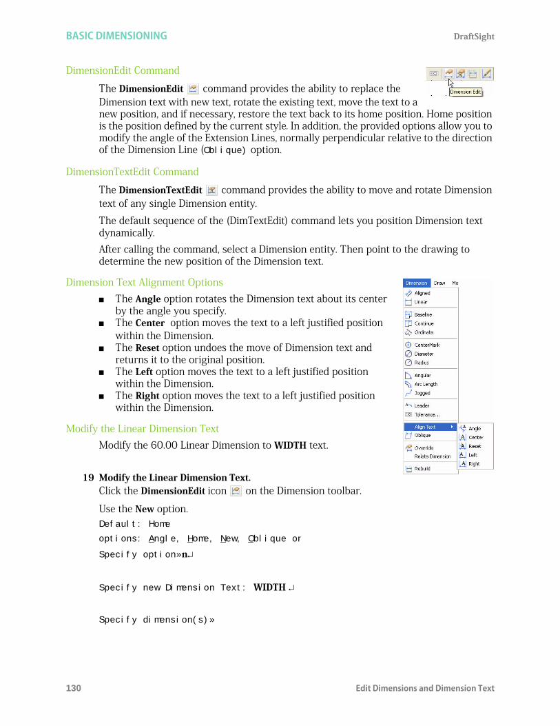
BASIC DIMENSIONING DraftSight
130 Edit Dimensions and Dimension Text
DimensionEdit Command
The DimensionEdit command provides the ability to replace the Dimension text with new text, rotate the existing text, move the text to a new position, and if necessary, restore the text back to its home position. Home position is the position defined by the current style. In addition, the provided options allow you to modify the angle of the Extension Lines, normally perpendicular relative to the direction of the Dimension Line (Oblique) option.
DimensionTextEdit Command
The DimensionTextEdit command provides the ability to move and rotate Dimension text of any single Dimension entity.
The default sequence of the (DimTextEdit) command lets you position Dimension text dynamically. After calling the command, select a Dimension entity. Then point to the drawing to determine the new position of the Dimension text.
Dimension Text Alignment Options The Angle option rotates the Dimension text about its center
by the angle you specify. The Center option moves the text to a left justified position
within the Dimension. The Reset option undoes the move of Dimension text and
returns it to the original position. The Left option moves the text to a left justified position
within the Dimension. The Right option moves the text to a left justified position
within the Dimension.
Modify the Linear Dimension TextModify the 60.00 Linear Dimension to WIDTH text.
19 Modify the Linear Dimension Text.Click the DimensionEdit icon on the Dimension toolbar.
Use the New option.Default: Home
options: Angle, Home, New, Oblique or
Specify option»n
Specify new Dimension Text: WIDTH
Specify dimension(s)»

DraftSight BASIC DIMENSIONING
Edit Dimensions and Dimension Text 131
Click the 60.00 Dimension text as illustrated.
1 found, 1 total
Specify dimension(s)»
20 Undo the Modified Linear Dimension.: U
21 Save the Drawing.Click the Save icon on the Standard toolbar.
Measure and Rotate an Aligned DimensionFirst measure the Aligned Dimension angle. Rotate the 50.00 Aligned Dimension text to match angle of the entity.
22 Measure the Aligned Dimension Angle.Click Tools, Inquiry, Get Distance from the Main Menu.
View the command window: <ESnaps On>.Specify start point»
Make sure the EnttitySnap function is set to ON. Click the ESnap buttonon the Status bar.

BASIC DIMENSIONING DraftSight
132 Edit Dimensions and Dimension Text
Click the top left end point of the Aligned Dimension.
Specify end point»
Click the bottom right end point of the Aligned Dimension.
View the angle in the XY Plane in the command window: Distance = 50.00, Angle in XY Plane = 300, Angle from XY Plane = 0
Delta X = 25.00, Delta Y = -43.30, Delta Z = 0.00
23 Rotate the Aligned Dimension Text.Click the DimensionTextEdit icon on the Dimension toolbar.
Specify dimension»
Click the 50.00 aligned Dimension text as illustrated.
Default: (174.29,101.34,0.00)
Options: Angle, Center, Home, Left, Right or
Specify new text position» a
Specify angle for Dimension Text: 300
Angle in XY Plane is 300.

DraftSight BASIC DIMENSIONING
Edit Dimensions and Dimension Text 133
Move Command
Apply the Move command to reposition drawing entities within the coordinate system without changing their orientation or size.
24 Move the Selected Entities.Click the Move icon on the Modify toolbar. Specify entities»
Select all 7 entities as illustrated.
1 found, 7 total
Select entities»
Default: Displacement
Options: Displacement or
Specify from point:
Click the end point as illustrated.
Options: Enter to use from point as displacement or
Specify destination»@100,0

BASIC DIMENSIONING DraftSight
134 Coordinate System Command
Coordinate System CommandA coordinate system determines each Point of a drawing surface or entity unambiguously. DraftSight uses the Cartesian coordinate system consisting of three coordinate axes. Axes are arranged orthogonally, crossing at the origin. All axes use the same measurements.Reset the coordinate system (CCS) from the default position. Use the CCS command to set coordinate systems and save, restore, rename, and delete them.
Reset the Coordinate System
25 Reset the Coordinate System.Set the coordinate system position to the bottom left point of the top entity.Click Snap On from the Status bar. The command window displays: <Snap On>.
Click ESnap On from the Status bar. The command window displays: <ESnaps On>.
Click Ortho On from the Status bar. The command window displays: <Ortho On>.:
: CCS Default: World
Options: align to Entity, NAmed, Previous, View, World, X, Y, Z, ZAxis or
Specify origin»
Click the bottom left point as illustrated. View the new coordinate system origin position.Option: Enter to accept or
Specify X-axis through point»
26 Save the Drawing.Click the Save icon on the Standard toolbar.

DraftSight BASIC DIMENSIONING
Ordinate Command 135
Ordinate CommandThe Ordinate command creates ordinate Point Dimensions. The graphics area displays an X or Y coordinate with a Leader Line to create X datum or Y datum Dimensioning. The value of the X or Y coordinate is defined by the Point you specify, called the feature position.
Create Ordinate DimensionsCreate Ordinate Dimensions on the top entity using the new origin position.
27 Create Ordinate Dimensions.Click the Ordinate icon on the Dimension toolbar.
Specify datum position»
Click the bottom left end point.
options: Angle, Note, Text, X datum, Y datum or
Specify dimension position»
Make sure that Snap mode is set to OFF. Click Snap on the Status bar. Thecommand window will display <Snap Off>
Make sure that Ortho mode is set to ON. Click Ortho on the Status bar. Thecommand window will disply <Ortho on>

BASIC DIMENSIONING DraftSight
136 CenterMarks Command
Click a position directly under the end point. The command window displays:
Dimension Text: 0.00
Click the Continue icon on the Dimension toolbar.
Options: Select dimension, Undo or
Specify feature position»
Click all the end points from left to right as illustrated.
Options: Select dimension, Undo or
Specify feature position»
Specify dimension»
28 Save the Drawing.Click the Save icon on the Standard toolbar.
CenterMarks CommandThe CenterMark command provides the ability to mark the center of a Circle or Arc. You can display the center as a center mark (a Point) or as a Center Line (a broken Line crossing the center). In the next section, open Lesson 2-2 and create a new layer called Annotations. Insert CenterMarks on the Annotations layer in the drawing.

DraftSight BASIC DIMENSIONING
Open an Existing Drawing 137
Open an Existing Drawing1 Click the Open icon on the Standard toolbar. The Open
dialog box is displayed.2 Double-click Lesson 2-2.
Create a New LayerIn this section, create a new layer called Annotations. Apply custom properties.
3 Create the New Layer.Click the Layers Manager icon. The Layers Manager dialog box is displayed.
Click the New Layer icon. The new default name is Layer1.
Rename this Layer Annotations.
Annotations is the new layer name.
4 Set the LineColor.New layers are automatically assigned the LineColor white. Double-click the LineColor cell for the Annotations layer.Click Magenta. Click OK.
5 Save the Drawing.Click File, Save As from the Menu bar.
Enter File name: Lesson 3-2.
Click Save from the Save As... dialog box.
DimensionStyle CommandThe DimensionStyle command on the Dimension toolbar provides the ability to create and modify DimensionStyles. Remember, DimensionStyles are the main method used to control the way Dimensions look.
6 Set DimensionStyleClick the DimensionStyle icon on the Dimension toolbar. The DimensionStyles Manager dialog box is displayed. The Options - Drafting Styles dialog box is displayed with the Dimensions option expanded.
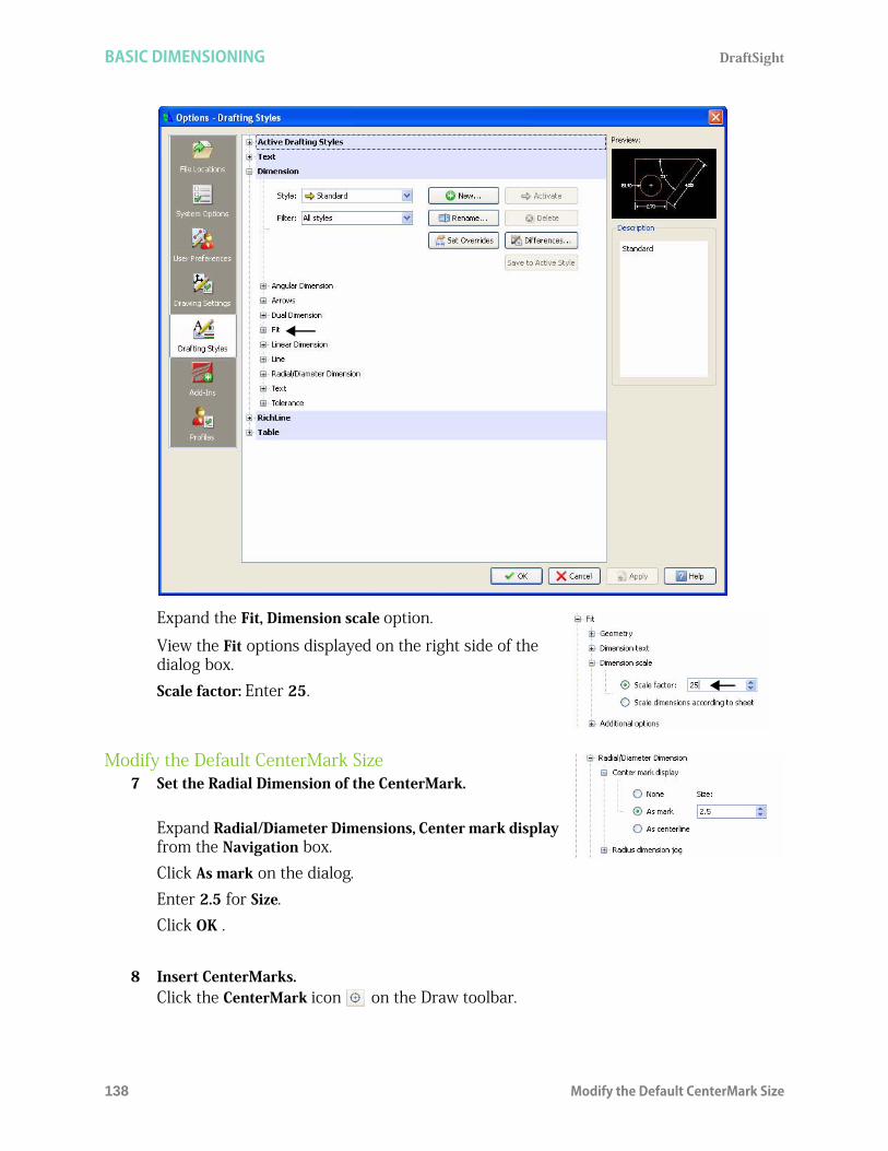
BASIC DIMENSIONING DraftSight
138 Modify the Default CenterMark Size
Expand the Fit, Dimension scale option.
View the Fit options displayed on the right side of the dialog box.Scale factor: Enter 25.
Modify the Default CenterMark Size7 Set the Radial Dimension of the CenterMark.
Expand Radial/Diameter Dimensions, Center mark display from the Navigation box.Click As mark on the dialog.Enter 2.5 for Size.Click OK .
8 Insert CenterMarks.Click the CenterMark icon on the Draw toolbar.
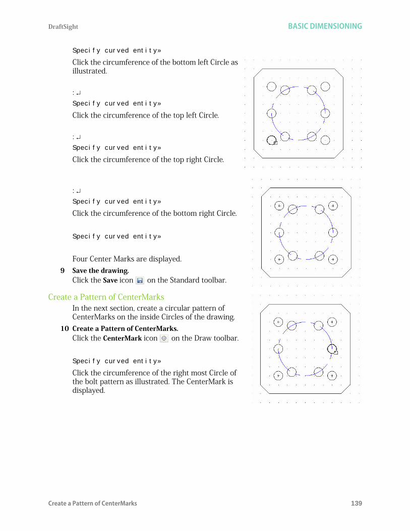
DraftSight BASIC DIMENSIONING
Create a Pattern of CenterMarks 139
Specify curved entity»
Click the circumference of the bottom left Circle as illustrated.
:
Specify curved entity»
Click the circumference of the top left Circle.
:
Specify curved entity»
Click the circumference of the top right Circle.
:
Specify curved entity»
Click the circumference of the bottom right Circle.
Specify curved entity»
Four Center Marks are displayed.9 Save the drawing.
Click the Save icon on the Standard toolbar.
Create a Pattern of CenterMarksIn the next section, create a circular pattern of CenterMarks on the inside Circles of the drawing.
10 Create a Pattern of CenterMarks.Click the CenterMark icon on the Draw toolbar.
Specify curved entity»
Click the circumference of the right most Circle of the bolt pattern as illustrated. The CenterMark is displayed.
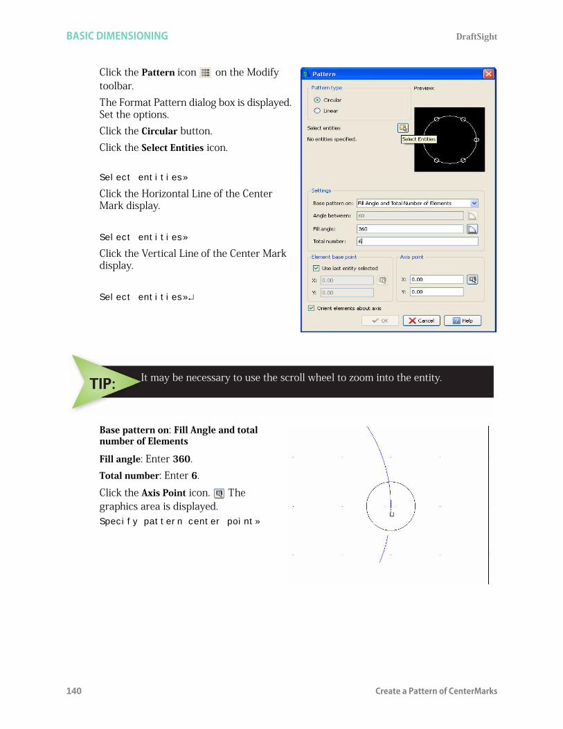
BASIC DIMENSIONING DraftSight
140 Create a Pattern of CenterMarks
Click the Pattern icon on the Modify toolbar. The Format Pattern dialog box is displayed. Set the options.Click the Circular button.Click the Select Entities icon.
Select entities»
Click the Horizontal Line of the Center Mark display.
Select entities»
Click the Vertical Line of the Center Mark display.
Select entities»
Base pattern on: Fill Angle and total number of Elements
Fill angle: Enter 360.Total number: Enter 6.
Click the Axis Point icon. The graphics area is displayed.Specify pattern center point»
It may be necessary to use the scroll wheel to zoom into the entity.

DraftSight BASIC DIMENSIONING
Radius Command 141
Click the center point of the large Circle as illustrated.
The Pattern dialog box is displayed.
View the Axis point X: = 100.00 and the Axis point Y: = 100.00
The Orient elements about axis box is check by default. This options provides the ability to have the CenterMarks rotate about the large Circle.
Click OK.
11 Activate the Annotations Layer.Click Annotations from the Layers Manager drop-down menu.
Radius CommandThe Radius command provides the ability to create Radial Dimensions for Circles and Arcs. Radius Dimensioning is carried out in the same way as Diameter Dimensioning, the only difference being that a Radius Dimension is calculated instead of a diameter measurement. Create a Radial Dimension for the large Circle.
12 Create a Radius Dimension.Click the Radius icon on the Dimension toolbar.Specify curved entity»

BASIC DIMENSIONING DraftSight
142 Radius Command
Click the circumference of the large Circle.
Options: Angle, Note, Text or
Specify dimension position»
Click a position diagonally to the right.
13 Save the Drawing.Click the Save icon on the Standard toolbar.
14 Modify the Precision.Click the DimensionStyle icon on the Dimension toolbar.
The Options - Drafting Styles dialog box is displayed with the Dimensions option expanded.
Expand Linear Dimension in the navigation box.
View the Linear Dimensions options displayed on the right side of the dialog box.Precision: Select 0.00 from the drop-down menu.
Click OK.
The dimension text = 30.0000.

DraftSight BASIC DIMENSIONING
Radius Command 143
15 Save the Drawing.Click the Save icon on the Standard toolbar.
You are finished with this section.

BASIC DIMENSIONING DraftSight
144 Radius Command

DraftSight
145
Lesson 4DRAFTING APPLICATION
When you complete this lesson, you will be able to:Apply the MakeBlock, Note, and Line Draw commands Make and Insert Blocks Create and Edit a Note Apply the Ring command Explode a Block Apply the Hatch/Fill command Create a Multiview drawing Apply a Tolerance

DRAFTING APPLICATION DraftSight
146
Drafting ApplicationDuring this lesson, you will create two new drawings using absolute coordinates in the Command prompt and the graphics area.In the first drawing you will: Create two new layers with custom properties:
Symbols and Schematic. Activate the Symbols layer. Use the Line command to draw the entities. Apply the Note command. Create a single entity with the MakeBlock
command. Use the Insert Block dialog box. Apply the Insert Block command to insert two Symbol copies. Use the Insert Block dialog box. Activate the Schematic layer. Use the Line command to draw two Horizontal
Parallel Lines between the top symbols on the Schematic layer.
Activate the Symbols layer. Apply the Line command to draw three Horizontal and Parallel Lines: 30, 20, and 10mm's in length and 5mm's apart. Draw a Vertical Line perpendicular at the mid point to the top Horizontal Line 20mms in length.
Create a single entity with the MakeBlock command.

DraftSight DRAFTING APPLICATION
147
Use the Define Block dialog box. Apply the InsertBlock command to
insert the Symbol (Ground). Use the Insert Block dialog box.
Apply the Ring command to create a ring with an inside diameter of 0mm, and outside diameter of 2mm.
Apply the Explode command. The Explode command provides the ability to explode a symbol into its component entities.
Edit the Note. Use the Edit Note dialog box.
In the second drawing you will:
Create six new layers called: Dimensions, Profile, Construction, Center, Hidden, and Section.
Apply custom properties. Draw six Horizontal InfiniteLines and seven
Vertical InfiniteLines. Draw three profiles. Utilize the Line command Draw the first profile.
A symbol loses its characteristics when exploded, and only a uniformscaled symbol can be exploded.

DRAFTING APPLICATION DraftSight
148
Draw the second profile.
Draw the third profile.
Draw two Hidden Lines views.
Apply the Hatch/Fill command.

DraftSight DRAFTING APPLICATION
Start a DraftSight Session 149
Apply the DimensionStyle command and dimension the views.
Apply a Tolerance to the diameter dimension to complete the drawing.
Start a DraftSight Session1 Start a DraftSight session.
From the Windows Start menu, click Start, All Programs, Dassault Systemes, DraftSight.
Create a New Drawing2 Create a New Drawing.
Click the New icon on the Standard toolbar. The Select Template dialog box is displayed.
Set the Drawing Environment
Drawing Template3 Select a Default Drawing Template.
Select standard.dwt from the Specify Template dialog box. 4 Click Open.
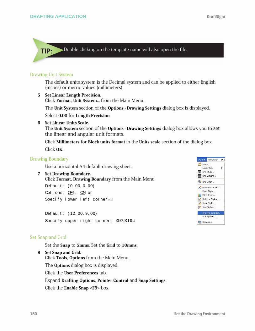
DRAFTING APPLICATION DraftSight
150 Set the Drawing Environment
Drawing Unit SystemThe default units system is the Decimal system and can be applied to either English (inches) or metric values (millimeters).
5 Set Linear Length Precision.Click Format, Unit System... from the Main Menu. The Unit System section of the Options - Drawing Settings dialog box is displayed. Select 0.00 for Length Precision.
6 Set Linear Units Scale.The Unit System section of the Options - Drawing Settings dialog box allows you to set the linear and angular unit formats. Click Millimeters for Block units format in the Units scale section of the dialog box. Click OK.
Drawing BoundaryUse a horizontal A4 default drawing sheet.
7 Set Drawing Boundary.Click Format, Drawing Boundary from the Main Menu. Default: (0.00,0.00)
Options: OFf, ON or
Specify lower left corner»
Default: (12.00,9.00)
Specify upper right corner» 297,210
Set Snap and Grid
Set the Snap to 5mms. Set the Grid to 10mms.8 Set Snap and Grid.
Click Tools, Options from the Main Menu. The Options dialog box is displayed. Click the User Preferences tab. Expand Drafting Options, Pointer Control and Snap Settings.Click the Enable Snap <F9> box.
Double-clicking on the template name will also open the file.

DraftSight DRAFTING APPLICATION
Create two new Layers for the drawing 151
Enter the value of 5 in the Horizontal Snap spacing box. Press the Tab key The Vertical Snap spacing box is updated.
Expand the Display, Grid Settings option Click the Enable Grid <F7> box.Enter 10 in the Horizontal display spacing box. Press the Tab key. The Vertical display spacing box is updated.Click OK.
9 Display the Drawing with the New Boundary.10 Click View, Zoom, Bounds on the Main Menu.11 Save the Drawing.
Click the Save icon on the Standard toolbar.
Enter File name: Lesson 4-1.
Click Save.
Create two new Layers for the drawingIn this section, create two new layers called: Symbols and Schematic. Apply custom properties.
12 Create the First New Layer.Click the Layers Manager icon on the Layers toolbar
The Layers Manager dialog box is displayed.
Click the New Layer icon. The new default name is Layer1.
Rename this layer Symbols 13 Set the LineColor.
New layers are automatically assigned the LineColor white. Double-click the LineColor cell for the Symbols layer.

DRAFTING APPLICATION DraftSight
152 Draw a capacitor symbol
Click Blue.
Accept the default LineStyle: Continous and options.
14 Create the Second New Layer.Click the New Layer icon. The new default name is Layer2.Rename this Layer Schematic. Schematic is the new layer name.
15 Set the LineColor.Double-click the LineColor cell for the Schematic layer.Click Green.
Accept the default LineStyle: Continous.16 Activate the Symbols Layer.
Click inside the Status cell of the Symbols layer.Click the Activate Layer icon. A gold arrow is displayed in the Symbols Status cell.Click OK.
Draw a capacitor symbolDraw multiple entities on the Symbols layer. Apply the Line , and Note commands. Use the Edit Note dialog box to to create a note with a 5mm height, left justify to the right of the drawing.
Create a single entity with the MakeSymbol command. Use the Define Symbol dialog box. Apply the Insert, Symbol command from the Main Menu to insert two Symbol copies. Use the Insert Symbol dialog box.
17 Apply the Line Command.Draw two Horizontal Parallel Lines 20mms long and 10mms apart.
Click the Line icon on the Draw toolbar.
Options: Segments, or
Specify start point>>50,30
Options: Segments, Undo, Enter to exit or
Specify next point>>70,30
Options: Segments, Enter to continue from last point or

DraftSight DRAFTING APPLICATION
Draw a capacitor symbol 153
Specify start point>>70,40
Options: Segments, Undo, Enter to exit or
Specify next point>>50,40
Right-click Enter.
Draw two Vertical Lines perpendicular to the midpoint of the two Horizontal Lines.:
Options: Segments, Enter to continue from last point or
Specify start point>>60,30
Options: Segments, Undo, Enter to exit or
Specify next point>>60,10
Right-click Enter. :
Options: Segments, Enter to continue from last point or
Specify start point>>60,40
Options: Segments, Undo, Enter to exit or
Specify next point>>60,60
Right-click Enter.
18 Save the Drawing.Click the Save icon on the Standard toolbar.
Note Command
The Note command provides the ability to enter multiple Lines of text that are treated as a single entity. In the next section, use the Edit Note dialog box to create a note with a 5mm height, left justify to the right of the drawing.
19 Create a Note.Click the Note icon on the Draw toolbar.
Active TextStyle: “Standard” Text height: 0.20
Specify first corner>>80,40
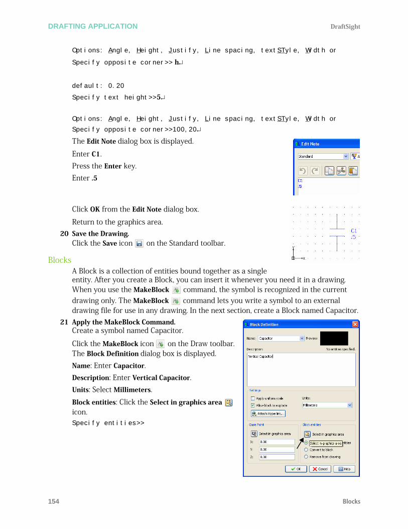
DRAFTING APPLICATION DraftSight
154 Blocks
Options: Angle, Height, Justify, Line spacing, textSTyle, Width or
Specify opposite corner>> h
default: 0.20
Specify text height>>5
Options: Angle, Height, Justify, Line spacing, textSTyle, Width or
Specify opposite corner>>100,20
The Edit Note dialog box is displayed.
Enter C1.Press the Enter key.Enter .5
Click OK from the Edit Note dialog box.
Return to the graphics area. 20 Save the Drawing.
Click the Save icon on the Standard toolbar.
BlocksA Block is a collection of entities bound together as a single entity. After you create a Block, you can insert it whenever you need it in a drawing. When you use the MakeBlock command, the symbol is recognized in the current drawing only. The MakeBlock command lets you write a symbol to an external drawing file for use in any drawing. In the next section, create a Block named Capacitor.
21 Apply the MakeBlock Command.Create a symbol named Capacitor.
Click the MakeBlock icon on the Draw toolbar. The Block Definition dialog box is displayed.Name: Enter Capacitor.Description: Enter Vertical Capacitor.Units: Select Millimeters.
Block entities: Click the Select in graphics area icon.Specify entities>>
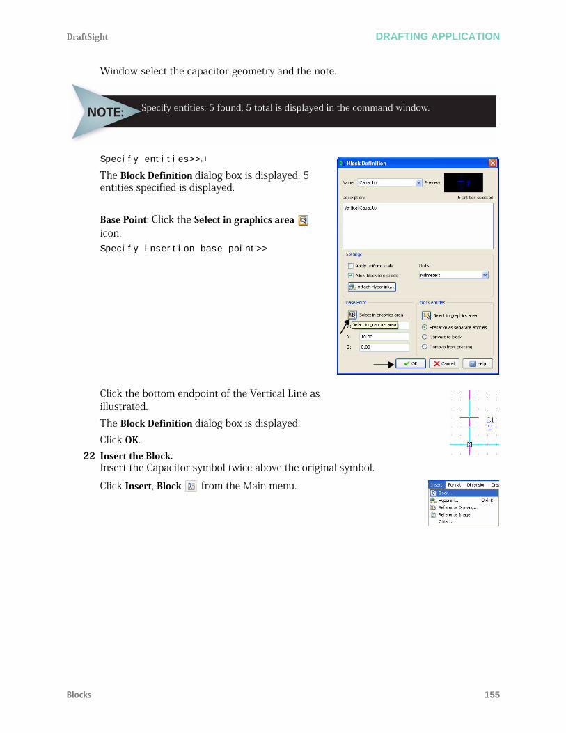
DraftSight DRAFTING APPLICATION
Blocks 155
Window-select the capacitor geometry and the note.
Specify entities>>
The Block Definition dialog box is displayed. 5 entities specified is displayed.
Base Point: Click the Select in graphics area icon.Specify insertion base point>>
Click the bottom endpoint of the Vertical Line as illustrated.The Block Definition dialog box is displayed.Click OK.
22 Insert the Block.Insert the Capacitor symbol twice above the original symbol.
Click Insert, Block from the Main menu.
Specify entities: 5 found, 5 total is displayed in the command window.

DRAFTING APPLICATION DraftSight
156 Draw a Simple Schematic
The Insert Block dialog box is displayed. The Insert Block dialog box provides the ability to select created symbols. Capacitor is selected by default. Position X: Enter 70.Position Y: Enter 90.Click OK.:
The Insert Block dialog box is displayed. Capacitor is selected by default.Position X: Enter 120.Position Y: Enter 90.Click OK.
23 Save the Drawing.Click the Save icon on the Standard toolbar.
Draw a Simple Schematic
24 Activate the Schematic Layer.Click Schematic from the drop-down menu in the Layers Manager. Schematic is the active layer.
25 Apply the Line Command.Draw two Horizontal Parallel Lines between the top symbols on the Schematic layer.
Click the Line icon on the Draw toolbar.
Click Snap from the Status bar. The command window displays: <Snap Off>.
Options: Segments, Enter to continue from last point or
Specify start point>>
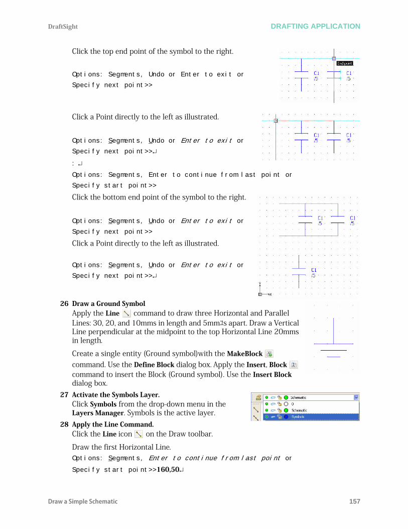
DraftSight DRAFTING APPLICATION
Draw a Simple Schematic 157
Click the top end point of the symbol to the right.
Options: Segments, Undo or Enter to exit or
Specify next point>>
Click a Point directly to the left as illustrated.
Options: Segments, Undo or Enter to exit or
Specify next point>>
: Options: Segments, Enter to continue from last point or
Specify start point>>
Click the bottom end point of the symbol to the right.
Options: Segments, Undo or Enter to exit or
Specify next point>>
Click a Point directly to the left as illustrated.
Options: Segments, Undo or Enter to exit or
Specify next point>>
26 Draw a Ground SymbolApply the Line command to draw three Horizontal and Parallel Lines: 30, 20, and 10mms in length and 5mmユs apart. Draw a Vertical Line perpendicular at the midpoint to the top Horizontal Line 20mms in length.
Create a single entity (Ground symbol)with the MakeBlock command. Use the Define Block dialog box. Apply the Insert, Block command to insert the Block (Ground symbol). Use the Insert Block dialog box.
27 Activate the Symbols Layer.Click Symbols from the drop-down menu in the Layers Manager. Symbols is the active layer.
28 Apply the Line Command.Click the Line icon on the Draw toolbar.
Draw the first Horizontal Line.Options: Segments, Enter to continue from last point or
Specify start point>>160,50
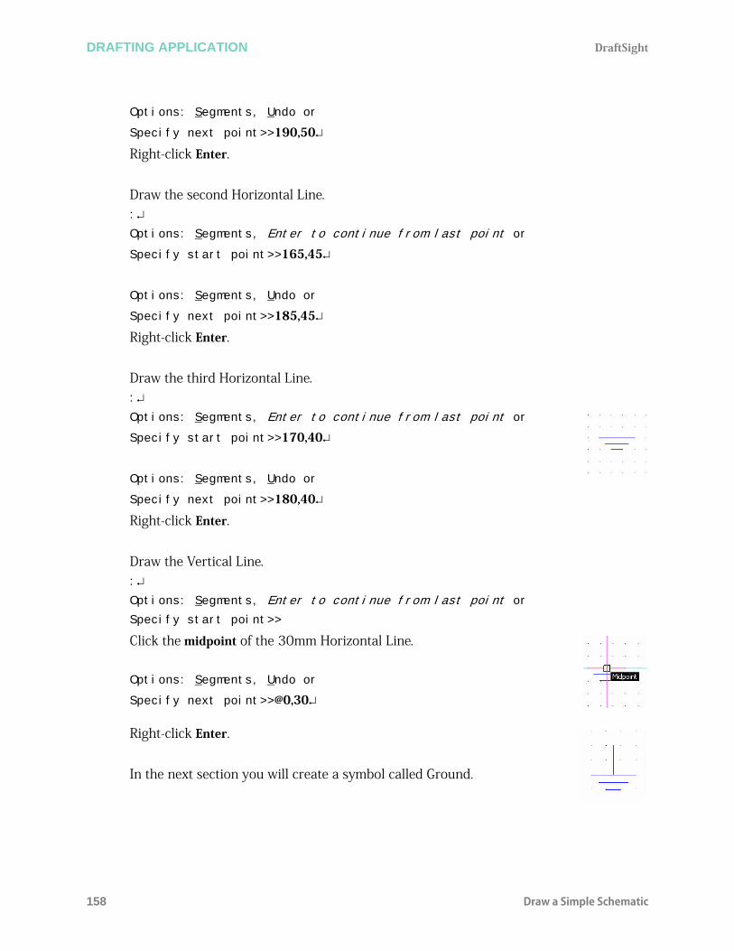
DRAFTING APPLICATION DraftSight
158 Draw a Simple Schematic
Options: Segments, Undo or
Specify next point>>190,50
Right-click Enter.
Draw the second Horizontal Line.:
Options: Segments, Enter to continue from last point or
Specify start point>>165,45
Options: Segments, Undo or
Specify next point>>185,45
Right-click Enter.
Draw the third Horizontal Line.:
Options: Segments, Enter to continue from last point or
Specify start point>>170,40
Options: Segments, Undo or
Specify next point>>180,40
Right-click Enter.
Draw the Vertical Line.:
Options: Segments, Enter to continue from last point or
Specify start point>>
Click the midpoint of the 30mm Horizontal Line.
Options: Segments, Undo or
Specify next point>>@0,30
Right-click Enter.
In the next section you will create a symbol called Ground.

DraftSight DRAFTING APPLICATION
Draw a Simple Schematic 159
29 Apply the MakeBlock Command.Create a symbol named Ground on the Symbols layer.
Click the MakeBlock icon on the Draw toolbar. The Block definition dialog box is displayed.Name: Enter Ground. Description: Enter Ground Symbol.Units: Select Millimeters.Block entities: Click the Select in graphics area
icon.Specify entities>>
Window-select the three horizontal and single Vertical Lines.Specify entities>>
The Define Symbol dialog box is displayed. 4 entities specified is displayed.
Base Point: Click the Select in graphics area icon.
Specify insertion base point>>
Click the top end point of the Vertical Line as illustrated.The Block Definition dialog box is displayed.
Click OK.
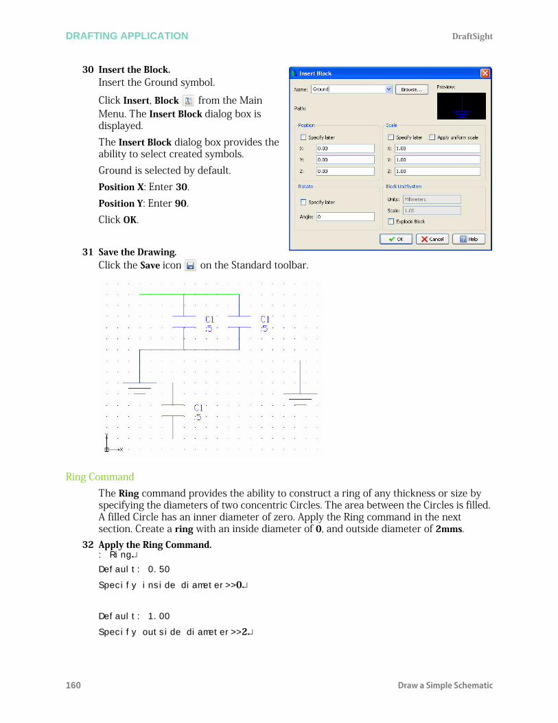
DRAFTING APPLICATION DraftSight
160 Draw a Simple Schematic
30 Insert the Block.Insert the Ground symbol.
Click Insert, Block from the Main Menu. The Insert Block dialog box is displayed. The Insert Block dialog box provides the ability to select created symbols. Ground is selected by default. Position X: Enter 30.Position Y: Enter 90.Click OK.
31 Save the Drawing.Click the Save icon on the Standard toolbar.
Ring CommandThe Ring command provides the ability to construct a ring of any thickness or size by specifying the diameters of two concentric Circles. The area between the Circles is filled. A filled Circle has an inner diameter of zero. Apply the Ring command in the next section. Create a ring with an inside diameter of 0, and outside diameter of 2mms.
32 Apply the Ring Command.: Ring
Default: 0.50
Specify inside diameter>>0
Default: 1.00
Specify outside diameter>>2

DraftSight DRAFTING APPLICATION
Draw a Simple Schematic 161
Default: exit
Specify position>>
Click the six endpoints as illustrated in the graphics area.
Default: exit
Specify position>>
Explode a Block DraftSight provides the ability to explode a Block into its component entities. A Block loses its characteristics when exploded, and only a uniform scaled Block can be exploded.
33 Explode a Block.Click the Explode icon on the Modify toolbar.
Specify entities>>
Click the Block as illustrated in the graphics area. Remember, a symbol is a single entity
1 found, 1 total
Specify entities>>
You can now select the individual Line entities and note. Press Esc or Enter to exit.
34 Save the Drawing.Click the Save icon on the Standard toolbar.
You can explode complex entities like PolyLines,Hatches and Dimensions.
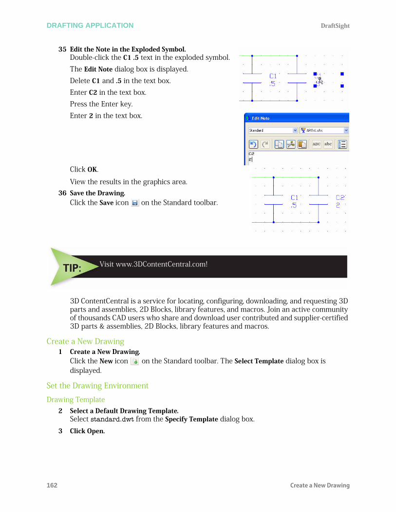
DRAFTING APPLICATION DraftSight
162 Create a New Drawing
35 Edit the Note in the Exploded Symbol.Double-click the C1 .5 text in the exploded symbol. The Edit Note dialog box is displayed.Delete C1 and .5 in the text box.Enter C2 in the text box.Press the Enter key.Enter 2 in the text box.
Click OK.
View the results in the graphics area.36 Save the Drawing.
Click the Save icon on the Standard toolbar.
3D ContentCentral is a service for locating, configuring, downloading, and requesting 3D parts and assemblies, 2D Blocks, library features, and macros. Join an active community of thousands CAD users who share and download user contributed and supplier-certified 3D parts & assemblies, 2D Blocks, library features and macros.
Create a New Drawing1 Create a New Drawing.
Click the New icon on the Standard toolbar. The Select Template dialog box is displayed.
Set the Drawing Environment
Drawing Template2 Select a Default Drawing Template.
Select standard.dwt from the Specify Template dialog box. 3 Click Open.
Visit www.3DContentCentral.com!
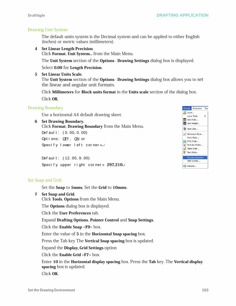
DraftSight DRAFTING APPLICATION
Set the Drawing Environment 163
Drawing Unit SystemThe default units system is the Decimal system and can be applied to either English (inches) or metric values (millimeters).
4 Set Linear Length Precision.Click Format, Unit System... from the Main Menu. The Unit System section of the Options - Drawing Settings dialog box is displayed. Select 0.00 for Length Precision.
5 Set Linear Units Scale.The Unit System section of the Options - Drawing Settings dialog box allows you to set the linear and angular unit formats. Click Millimeters for Block units format in the Units scale section of the dialog box. Click OK.
Drawing BoundaryUse a horizontal A4 default drawing sheet.
6 Set Drawing Boundary.Click Format, Drawing Boundary from the Main Menu. Default: (0.00,0.00)
Options: OFf, ON or
Specify lower left corner»
Default: (12.00,9.00)
Specify upper right corner» 297,210
Set Snap and Grid
Set the Snap to 5mms. Set the Grid to 10mms.7 Set Snap and Grid.
Click Tools, Options from the Main Menu. The Options dialog box is displayed. Click the User Preferences tab. Expand Drafting Options, Pointer Control and Snap Settings.Click the Enable Snap <F9> box.Enter the value of 5 in the Horizontal Snap spacing box. Press the Tab key The Vertical Snap spacing box is updated.Expand the Display, Grid Settings option Click the Enable Grid <F7> box.Enter 10 in the Horizontal display spacing box. Press the Tab key. The Vertical display spacing box is updated.Click OK.

DRAFTING APPLICATION DraftSight
164 Create Six New Layers
8 Display the Drawing with the New Boundary.9 Click View, Zoom, Bounds on the Main Menu.10 Save the Drawing.
Click the Save icon on the Standard toolbar.
Enter File name: Lesson 4-2.
Click Save.
Create Six New LayersIn this section, create six new layers called: Dimensions, Object, Construction, Center, Hidden, and Section. Apply custom properties.
11 Create Six New Layers.Click the Layers Manager icon on the Layers toolbar.
The Layers Manager dialog box is displayed. Create the layers as illustrated with custom properties.
T
12 Activate the Construction Layer.Click inside the Status cell of the Construction layer.Click the Activate Layer icon. A gold arrow is displayed in the Construction Status cell.Click OK.
13 Draw Six Horizontal InfiniteLinesClick the Infinite Line icon on the Draw toolbar.
Options: Angle, angle Bisect, Horizontal, Offset, Vertical, Enter to exit or
Specify position»H
The LineWeight has been changed for the Object, Hidded and Section Layers.

DraftSight DRAFTING APPLICATION
Create Six New Layers 165
Options: Enter to exit or
Specify next point»100,100
Options: Enter to exit or
Specify next point»100,130
Options: Enter to exit or
Specify next point»100,140
Options: Enter to exit or
Specify next point»100,170
Options: Enter to exit or
Specify next point»100,185
Options: Enter to exit or
Specify next point»100,200
Options: Enter to exit or
Specify next point»
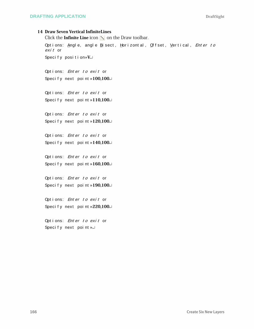
DRAFTING APPLICATION DraftSight
166 Create Six New Layers
14 Draw Seven Vertical InfiniteLinesClick the Infinite Line icon on the Draw toolbar.Options: Angle, angle Bisect, Horizontal, Offset, Vertical, Enter to exit or
Specify position»V
Options: Enter to exit or
Specify next point»100,100
Options: Enter to exit or
Specify next point»110,100
Options: Enter to exit or
Specify next point»120,100
Options: Enter to exit or
Specify next point»140,100
Options: Enter to exit or
Specify next point»160,100
Options: Enter to exit or
Specify next point»190,100
Options: Enter to exit or
Specify next point»220,100
Options: Enter to exit or
Specify next point»
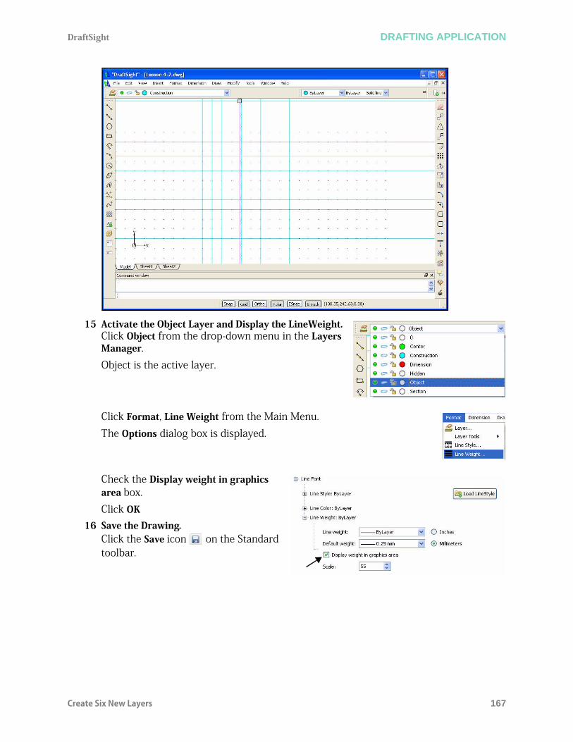
DraftSight DRAFTING APPLICATION
Create Six New Layers 167
15 Activate the Object Layer and Display the LineWeight.Click Object from the drop-down menu in the Layers Manager.Object is the active layer.
Click Format, Line Weight from the Main Menu. The Options dialog box is displayed.
Check the Display weight in graphics area box.Click OK
16 Save the Drawing.Click the Save icon on the Standard toolbar.

DRAFTING APPLICATION DraftSight
168 Draw Three Profiles.
Draw Three Profiles.Utilize the Line command.
17 Draw the First Profile.Click the Line icon on the Draw toolbarOptions: Segments, Enter to continue from last point or
Specify start point»100,100
Options: Segments, Undo, Enter to exit or
Specify next point»160,100
Options: Segments, Undo, Enter to exit or
Specify next point»160,130
Options: Segments, Undo, Enter to exit or
Specify next point»120,130
Options: Segments, Undo, Enter to exit or
Specify next point»120,140
Options: Segments, Undo, Enter to exit or
Specify next point»100,140
Options: Segments, Undo, Enter to exit or
Specify next point»c
18 Draw the Second Profile.Click the Line icon on the Draw toolbar
Options: Segments, Enter to continue from last point or
Specify start point»190,100
Options: Segments, Undo, Enter to exit or
Specify next point»220,100
Options: Segments, Undo, Enter to exit or
Specify next point»220,140

DraftSight DRAFTING APPLICATION
Draw Three Profiles. 169
Options: Segments, Undo, Enter to exit or
Specify next point»190,140
Options: Segments, Undo, Enter to exit or
Specify next point»c
Click the Line icon on the Draw toolbar
Options: Segments, Enter to continue from last point or
Specify start point»190,130
Options: Segments, Undo, Enter to exit or
Specify next point»220,130
Right-click Enter.
19 Draw the Third Profile.Click the Line icon on the Draw toolbar
Options: Segments, Enter to continue from last point or
Specify start point»100,170
Options: Segments, Undo, Enter to exit or
Specify next point»100,200
Options: Segments, Undo, Enter to exit or
Specify next point»160,200
Options: Segments, Undo, Enter to exit or
Specify next point»160,170
Options: Segments, Undo, Enter to exit or
Specify next point»c
Click the Line icon from the Draw toolbar

DRAFTING APPLICATION DraftSight
170 Draw Three Profiles.
Options: Segments, Enter to continue from last point or
Specify start point»120,170
Options: Segments, Undo, Enter to exit or
Specify next point»120,200
Right-click Enter.
Click the Circle icon on the Draw toolbar
Options: 3Point, 2Point, Ttr, TTT, Enter to exit or
Specify Center point»140,185
Options: Diameter or
Specify Radius»5
20 Save the Drawing.Click the Save icon on the Standard toolbar.
21 Activate the Hidden Layer.Click Hidden from the drop-down menu in the Layers Manager.
22 Draw the First Set of Hidden Lines View.Click the Line icon on the Draw toolbar
Options: Segments, Enter to continue from last point or
Specify start point»135,100
Options: Segments, Undo, Enter to exit or
Specify next point»135,130
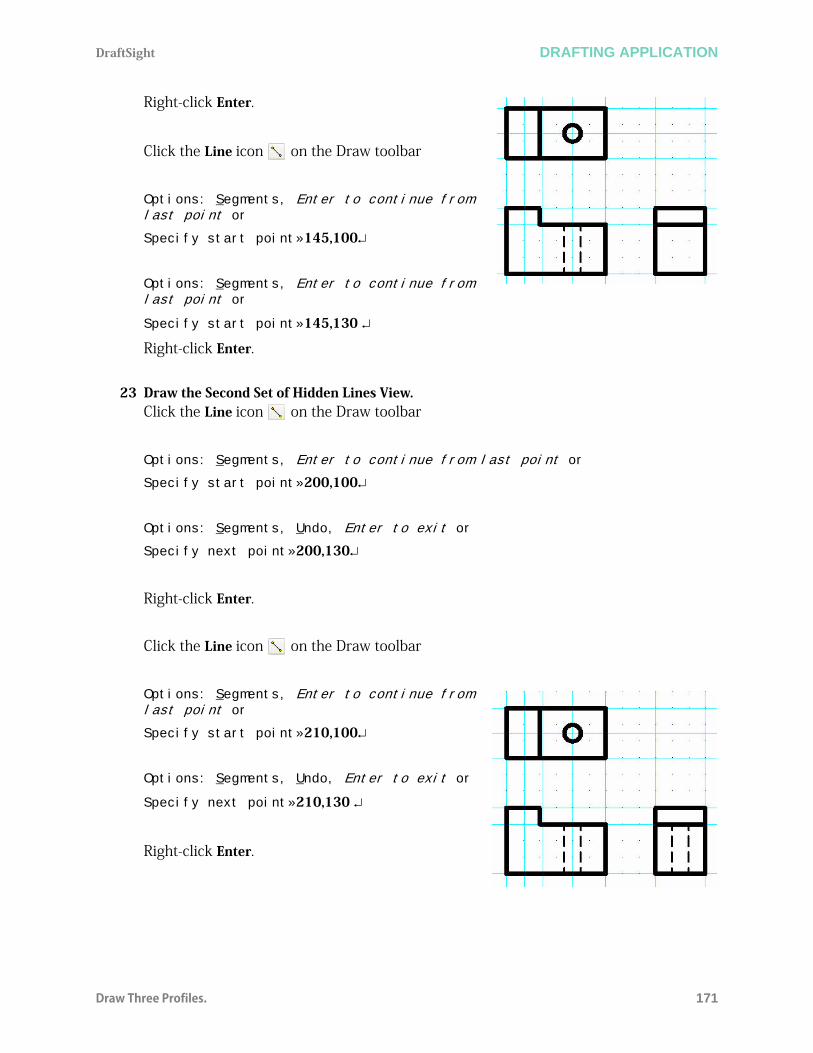
DraftSight DRAFTING APPLICATION
Draw Three Profiles. 171
Right-click Enter.
Click the Line icon on the Draw toolbar
Options: Segments, Enter to continue from last point or
Specify start point»145,100
Options: Segments, Enter to continue from last point or
Specify start point»145,130
Right-click Enter.
23 Draw the Second Set of Hidden Lines View.Click the Line icon on the Draw toolbar
Options: Segments, Enter to continue from last point or
Specify start point»200,100
Options: Segments, Undo, Enter to exit or
Specify next point»200,130
Right-click Enter.
Click the Line icon on the Draw toolbar
Options: Segments, Enter to continue from last point or
Specify start point»210,100
Options: Segments, Undo, Enter to exit or
Specify next point»210,130
Right-click Enter.
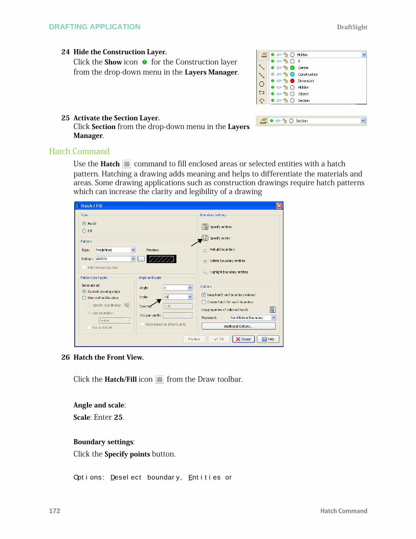
DRAFTING APPLICATION DraftSight
172 Hatch Command
24 Hide the Construction Layer.Click the Show icon for the Construction layer from the drop-down menu in the Layers Manager.
25 Activate the Section Layer.Click Section from the drop-down menu in the Layers Manager.
Hatch CommandUse the Hatch command to fill enclosed areas or selected entities with a hatch pattern. Hatching a drawing adds meaning and helps to differentiate the materials and areas. Some drawing applications such as construction drawings require hatch patterns which can increase the clarity and legibility of a drawing
26 Hatch the Front View.
Click the Hatch/Fill icon from the Draw toolbar.
Angle and scale:Scale: Enter 25.
Boundary settings:Click the Specify points button.
Options: Deselect boundary, Entities or

DraftSight DRAFTING APPLICATION
Dimension the Views 173
Specify internal point»
Click a Point to the right of the right Hidden Line as illustrated.
Click a Point to the left of the left Hidden Line. A boundary is created in both areas.Options: Deselect boundary, Entities or
Specify internal point»
Click OK.
Dimension the Views1 Activate the Dimension Layer.
Click Dimension from the drop-down menu in the Layers Manager.
The DimensionStyle command from the Dimension toolbar provides the ability to create and modify DimensionStyles.
2 Set DimensionStyleClick the DimensionStyle icon on the Dimension toolbar.
The DimensionStyles Manager dialog box is displayed.
In normal drafting practice, the Hidden Lines need to be converted to an ObjectLine for this setion view. This is only an example of the command available.
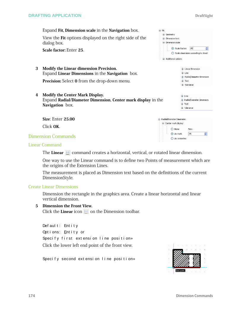
DRAFTING APPLICATION DraftSight
174 Dimension Commands
Expand Fit, Dimension scale in the Navigation box.
View the Fit options displayed on the right side of the dialog box.Scale factor: Enter 25.
3 Modify the Linear dimension Precision.Expand Linear Dimensions in the Navigation box.
Precision: Select 0 from the drop-down menu.
4 Modify the Center Mark Display.Expand Radial/Diameter Dimension, Center mark display in the Navigation box.
Size: Enter 25.00
Click OK.
Dimension Commands
Linear Command
The Linear command creates a horizontal, vertical, or rotated linear dimension.
One way to use the Linear command is to define two Points of measurement which are the origins of the Extension Lines. The measurement is placed as Dimension text based on the definitions of the current DimensionStyle.
Create Linear DimensionsDimension the rectangle in the graphics area. Create a linear horizontal and linear vertical dimension.
5 Dimension the Front View.Click the Linear icon on the Dimension toolbar.
Default: Entity
Options: Entity or
Specify first extension line position»
Click the lower left end point of the front view.
Specify second extension line position»

DraftSight DRAFTING APPLICATION
Dimension Commands 175
Click the lower right end point of the front view.
Options: Angle, Horizontal, Note, Rotated, Text, Vertical or
Specify dimension Line position»
Click a position below the bottom Horizontal Line.:
6 Create a linear vertical dimension.:.
Default: Entity
Options: Entity or
Specify first extension line position»
Click the lower left end point of the front view.
Specify second extension line position»
Click the upper left end point of the front view.
Options: Angle, Horizontal, Note, Rotated, Text, Vertical or
Specify dimension Line position»
Click a position to the left of the left Vertical Line. The front view has a vertical and horizontal linear dimension.
The Note option provides the ability to modify the Dimension text using the Note editor dialog box.
Press the Enter (key to repeat the command.

DRAFTING APPLICATION DraftSight
176 Dimension Commands
7 Add Two Additional Dimensions. Add two additional Dimensions as illustrated. The Front view is complete.
8 Save the Drawing.Click the Save icon on the Standard toolbar.
9 Dimension the Top View.Add Linear and Diameter Dimensions as illustrated.
Apply the Tolerance10 Modify the Tolerance precision.
Click the 10mm diameter Dimension.In the Properties manager palette scroll to the Tolerance section.
The Angle option changes the angle of the Dimension text.

DraftSight DRAFTING APPLICATION
Dimension Commands 177
Change the Tolerance display to Limits
Change the Upper limit to 0.10Change the Lower limit to 0.20Set suppress tolerance trailing zeros to YesPress Esc or Enter to exit.
You are finished with this section.

DRAFTING APPLICATION DraftSight
178 Dimension Commands
Related Documents