Illlllllllllllllllllllllllllllllllllllllllll SDMS DocID 2169675 Draft Work Plan Phase III Remedial Design Investigation Blosenski Landfill Superfund Site Chester County, Pennsylvania Prepared for Blosenski Participating Parties c/o de maximis, inc. Suite 290 186 Center Street Clinton, New Jersey 088089 HLA Project No. 33733 3.1 Julie A. Widman Senior Hydrogeologist Edward A. Nemecek, R.G., CPG Regional Geosciences Manager May 14, 1996 Revised October 1, 1996 ^^^HH Harding Lawson Associates = = = =.•= Engineering and Environmental Services |j=||| 131 North Third Street ^^^= Philadelphia, PA 19106 - (215)627-4505 AR300001

Welcome message from author
This document is posted to help you gain knowledge. Please leave a comment to let me know what you think about it! Share it to your friends and learn new things together.
Transcript
Illlllllllllllllllllllllllllllllllllllllllll SDMS DocID 2169675
Draft Work Plan Phase III Remedial Design Investigation Blosenski Landfill Superfund Site Chester County, Pennsylvania
Prepared for
Blosenski Participating Parties c/o de maximis, inc. Suite 290 186 Center Street Clinton, New Jersey 088089
HLA Project No. 33733 3.1
Julie A. Widman Senior Hydrogeologist
Edward A. Nemecek, R.G., CPG Regional Geosciences Manager
May 14, 1996 Revised October 1, 1996
^ ^ ^ H H Harding Lawson Associates = = = =.•= Engineering and Environmental Services | j = | | | 131 North Third Street ^ ^ ^ = Philadelphia, PA 19106 - (215)627-4505
AR300001
CONTENTS
1.0 INTRODUCTION 1
2.0 SUMMARY OF THE DRAFT SITE CONCEPTUAL MODEL 2
2.1 Site Background 2
2.2 Site Characteristics : 2
2.3 Contaminant Distribution 3
2.4 Migration Pathway Analysis 3
2.5 Phase III Remedial Design Investigation Data Needs 4
2.5.1 Characteristics of the Aquifer and Groundwater Flow System 4 2.5.2 Magnitude and Direction of Vertical and Horizontal Hydraulic Gradients 4 2.5.3 Extent of Site-Related Groundwater Impacts and Historical Concentration Trends 4 2.5.4 Potential Effects of Residential Well Pumping on Contaminant Migration 4 2.5.5 Influence of Landfill Cap on Groundwater Flow Patterns and Contaminant Concentrations5
3.0 PHASE III REMEDIAL DESIGN INVESTIGATION 6
3.1 Site Preparation 6 3.1.1 Access Agreements 6 3.1.2 Site Clearing and Road Construction 6 3.1.3 Field Trailer/Portable Sanitary Facility Installation 6
3.2 Hydrogeological Investigation 7 3.2.1 Objectives 7 3.2.2 Scope of Work 7
3.3 Groundwater Chemistry Investigation ..10 3.3.1 Objectives '. 10 3.3.2 Scope of Work 10
3.4 Investigative Derived Waste Management 13
4.0 PROJECT SCHEDULE AND DELIVERABLES 14
4.1 Project Schedule 14
4.2 Deliverables 14 4.2.1 Phase III Remedial Design Investigation Report 14
4.2.2 Technical Memoranda 14
5.0 PROJECT T E A M 15
6.0 REFERENCES.. 16
Revised October 1, 1996 G:\WORK\33733\WP\R0i2.DOC ' Harding Lawson Associates i AR300002
TABLES
1 Historical Groundwater Analytical Data (VOCs)
2 Well Construction Data
FIGURES
2-1 Site Location Map 2-2 Site Features Map 2-3 Cross-Section Location Map 2-4 Cross Section A-A' (West-East) 2-5 Cross Section B-B' (South-North) 2-6 Cross Sections C-C and D-D' (South-North) 2-7 Cross Section E-E' 2-8 Groundwater Contour Map, January 16-17, 1996 2-9 VOC Concentrations in Groundwater, 1/95, Cross Section A-A' 2-10 VOC Concentrations in Groundwater, 1/95, Cross Section B-B' 2-11 VOC Concentrations in Groundwater, 1/95, Cross Sections C-C and D-D' 2-12 VOC Concentrations in Groundwater, 1/95, Cross Sections E-E' 2- 13 VOC Concentrations in Groundwater, 1/95 (plan view) 3- 1 Proposed Monitoring Well and Staff Gage Locations 4- 1 Project Schedule
5- 1 Project Organization
APPENDIXES
A RESUMES OF PROJECT TEAM
Revised October 1,1996 G:\WORK\33733\WP\R012.DOC Harding Lawson Associates AR300003
Draft
1.0 INTRODUCTION
This draft Phase III Remedial Design Investigation Work Plan (RDI WP) has been prepared by Harding Lawson Associates (HLA) on behalf of the Blosenski Participating Parties (BPP). This Work Plan is submitted to the U.S. Environmental Protection Agency (EPA) and the Pennsylvania Department of Environmental Protection (PADEP) pursuant to the terms of the Consent Decree (Civil Action No. 93-CV-1976) for the Blosenski Landfill Superfund Site (Site) entered into in September 1995.
The Consent Decree addresses requirements associated with the development and submittal of a Phase III Remedial Design Investigation Work Plan, which includes a Sampling and Analysis Plan (SAP) and a Health and Safety Plan (HASP). Together, the Quality Assurance Project Plan (QAPP) and Field Sampling Plan (FSP) comprise the SAP. The HASP, QAPP, and FSP are included with the RD Work Plan in this document.
A remedial design investigation (RDI) is being performed at the Site to obtain additional data needed in connection with the Phase III remedy, as set forth in the Record of Decision (ROD) and Consent Decree.
G:\WORK\33733\WP\R012.DOC Harding Lawson Associates 1 AR300004
Draft
2.0 SUMMARY OF THE DRAFT SITE CONCEPTUAL MODEL
The draft Site Conceptual Model (HLA, 1996) describes the current understanding of the physical and chemical processes controlling migration of landfill constituents to the surrounding environment. In addition, the draft Site Conceptual Model identifies uncertainties regarding the hydrogeology, geology, and contaminant distribution in the vicinity of the site that must be defined in connection with Phase III. The draft Site Conceptual Model is summarized in the following paragraphs.
2.1 Site Background
The Site occupies approximately 13.6 acres in West Cain Township, Chester County, Pennsylvania (Figures 2-1 and 2-2). Disposal of municipal and industrial wastes reportedly began at the Site in the late 1940s. The landfill was never permitted and landfill operations ceased in the late 1970s.
The Site was placed on the National Priorities List (NPL) in December 1982. Under EPA supervision, a Remedial Investigation (RI) was performed at the Site in 1984 and 1985. A focused Feasibility Study (FS) to evaluate remedial alternatives was subsequently completed in February of 1986, also under EPA supervision. A Record of Decision (ROD) was issued by EPA for the Site on September 29, 1986. The selected remedy in the ROD consists of four phases:
• Phase I - Installation of a public water supply line (completed 1989)
• Phase II - Sampling and analysis of subsurface soils, and excavation and removal of buried drums, drum contents, and soils in intimate contact with the drums (completed in 1992)
• Phase III - Design investigation to define the extent and magnitude of groundwater contamination, and implementation of a source reduction program involving pumping and treating contaminated groundwater
• Phase IV - Landfill cap (completed in October 1995) and additional drum removal and disposal (to be completed in 1996). (Note: Additional drum removal during Phase IV was not contemplated in the ROD.)
In September 1995, a Consent Decree (Civil Action No. 93-CV-1976) was entered into for, inter alia, performance of the Phase III and Phase IV Remedial Design/Remedial Action at the Site.
2.2 Site Characteristics
The Site lies on the side of a ridge that forms a drainage divide between the Susquehanna and Delaware River Basins. Surface water drainage from the landfill is directed to the north, toward the unnamed tributary of Indian Spring Run. This drainage pattern existed prior to cap construction and the Phase IV cap design utilized this drainage pattern for surface water runoff from the cap.
The geology of the Site area consists of metamorphosed sedimentary rocks that have been extensively folded and faulted. Bedrock in the area is composed of the Chickies Quartzite. Beneath the Site, the Chickies Quartzite consists of both quartzite and quartzite schist. Boring logs prepared during previous investigations indicate that the bedrock is highly fractured. Drilling observations made during previous investigations also suggest the presence of a fault on the south side of the landfill, near MW2-1 and MW3-1. Figures 2-3 through 2-7 provide a cross-section location map and cross sections illustrating subsurface conditions beneath the Site.
G:\WORK\33733\WP\R012.DOC Harding Lawson Associates 2 AR300005
Draft
Groundwater flows within topographically controlled, localized flow regimes in the Site area. The ridge upon which the Site is located serves as a groundwater divide as well as a surface water divide. Groundwater elevations are highest south of the landfill at the top of this ridge, and decrease to the south and north. Figures 2-8 is a recent groundwater contour map for the Site.
Two distinct but interconnected groundwater flow regimes are apparently present beneath the Site. Under the first regime, groundwater follows the prevailing hydraulic gradient, generally in a north and northwesterly direction toward the unnamed tributary of Indian Spring Run. Under the second regime, groundwater flows along fractures or other zones of higher permeability within the aquifer following localized gradients. Flow under the second regime may be locally in directions different from the prevailing gradient.
2.3 Contaminant Distribution
The ROD identified VOCs as the principal contaminants of concern in groundwater from a human health perspective. Review of the most recent round of groundwater sampling [January 1995) ( Table 1 and Figures 2-9 through 2-13) indicates the following:
• Benzene was detected at concentrations exceeding the maximum contaminant level (MCL) only in monitoring wells onsite or near the fenceline.
• With the exception of vinyl chloride at one location, the only compound other than benzene detected at concentrations exceeding the MCL beyond the vicinity of the fenceline was trichloroethene (TCE).
• The lateral and vertical extent of groundwater impacts to the north of the Site cannot be completely evaluated because of the locations and screened intervals of the existing wells.
• The groundwater impacts at wells MWlO-1, MW15-1, and MW17-1 appear to be related and may be caused by the location of these wells along a lineament identified during previous studies.
Historical analytical data for VOCs in groundwater at the Site are limited. Monitoring events have been several years apart (i.e., 1985, 1990, and 1995). Available data suggest several wells exhibit decreased chemical concentrations between events, particularly near the fenceline. Concentration trends will be further evaluated after additional groundwater data are collected during the RDI.
2.4 Migration Pathway Analysis
Only groundwater poses a potential human exposure pathway for site-related compounds, because other pathways, i.e., soil and air, have been mitigated by remedial actions previously completed, including removal of buried drums and contaminated soils and installation of the landfill cap. While the potential for exposure exists, it has been minimized by the installation of municipal water supply lines and the provision of municipally supplied drinking water. Groundwater impacts from the Site may extend to residential wells located immediately to the south and east of the Site. However, these wells are located in areas where public water is supplied. Therefore, the pathway to exposure is not complete. Available data suggest residential wells located more than 1/2 mile southeast of the Site are not downgradient of the Site. However, pumping of these wells may have the potential to influence the migration of site-related contaminants. A second potentially complete exposure pathway may result from groundwater discharge to the unnamed tributary of Indian Spring Run north of the Site. However, further investigation is needed to resolve this issue. '
G:\WORK\33733\WP\R012.DOC Harding Lawson Associates 3 AR300006
Draft
2.5 Phase III Remedial Design Investigation Data Needs
Several uncertainties were identified during development of the draft Site Conceptual Model. These uncertainties indicate that additional data are needed to characterize both the physical groundwater flow system and the nature and extent of site-related groundwater impacts prior to design of a Phase III remedy. Data needs identified include:
• Information regarding aquifer characteristics and the groundwater flow system
• Magnitude and direction of vertical and horizontal hydraulic gradients
• Extent of VOCs in groundwater and trends in concentration over time
• Potential effects of existing and future residential well pumpage on contaminant migration
• Characterization of the influence of the landfill cap on groundwater flow patterns and VOC concentration trends
Each of these data needs is discussed in the following subsections.
2.5.1 Characteristics of the Aquifer and Groundwater Flow System
Two interconnected groundwater flow systems are thought to be present: 1) flow through the porous aquifer matrix under the prevailing hydraulic gradient, and 2) flow along fractures or other preferred pathways due to anisotropy of hydraulic conductivity within the aquifer. Based on the available data, porous media flow is believed to dominate on a site-wide and larger scale. Additional data are needed to characterize the influence of fractures on groundwater flow, and the degree of anisotropy within the aquifer.
2.5.2 Magnitude and Direction of Vertical and Horizontal Hydraulic Gradients
Based on the current understanding of hydraulic conditions, groundwater flow beneath the majority of the Site is to the northwest toward the unnamed tributary to Indian Spring Run. Groundwater is thought to be discharging, at least in part, to this tributary. However, horizontal and vertical gradients and, therefore, potential groundwater discharge, are difficult to assess beneath the Site. The difficulty is caused by the lack of paired wells and stream gages, and the variable screened intervals of the existing monitoring well network. Additional water table wells and monitoring well clusters are needed to quantify flow directions, gradients and groundwater discharge conditions.
2.5.3 Extent of Site-Related Groundwater Impacts and Historical Concentration Trends
The vertical and horizontal extent of groundwater impacts near the Site is not fully defined because of the configuration of the existing monitoring well network. The limited quantity of historical groundwater analytical data hinders a complete assessment of VOC concentration trends beneath the Site over time. Additional groundwater quality data are needed to assess the extent of site-related groundwater impacts and trends in VOC concentrations.
2.5.4 Potential Effects of Residential Well Pumping on Contaminant Migration
The public water supply line limits potential exposure to site-related constituents for residents in the immediate site area. The potential for future exposures to new residents using private water supply wells has not been evaluated. In addition, the potential for exposure of residents living east of the
G:\WORK\3 373 3\WP\R012 .DOC Harding Lawson Associates 4 AR300007
Draft
landfill (east of MW17-1) has not been identified. Additional data are needed on the potential effects of residential pumping on plume migration. In addition, it must be determined if existing private wells immediately east of MW17-1 are used for any purpose, to allow assessment of potential effects of pumpage of these wells on contaminant migration from the area of MW17-1.
2.5.5 Influence of Landfill Cap on Groundwater Flow Patterns and Contaminant Concentrations
The landfill cap was installed in October 1995. The presence of the multilayer cap will limit infiltration into the landfill and, thus, the release of any remaining mobile hazardous constituents above the water table to the groundwater flow system will be greatly reduced if not entirely eliminated. Additional groundwater elevation and groundwater quality data are needed to assess the impact of the cap on groundwater elevations and contaminant concentration trends.
G:\WORK\33733\WP\R012.DOC Harding Lawson Associates 5 AR300008
Draft
3.0 PHASE III REMEDIAL DESIGN INVESTIGATION
Several tasks have been identified to fulfill the data needs described above. These tasks are described in the following subsections.
3.1 Site Preparation
Prior to initiation of the RDI tasks, specific Site preparation is needed. This preparation will include the following:
• Access agreement negotiation • Site clearing and road construction • Field trailer installation with portable sanitary facilities • Installation of carbon treatment unit for well purge/development water
3.1.1 Access Agreements
Access agreements are currently in place with landowners adjacent to the Site where Phase III activities are anticipated. However, not all these agreements encompass clearing and monitoring well installation. In addition, some RDI activities are proposed for locations where access has not currently been granted. Prior to RDI field activities, access agreements will be finalized with the appropriate landowners.
3.1.2 Site Clearing and Road Construction
Access roads were previously constructed to several of the existing monitoring wells. However, vehicle access is needed to some existing and proposed monitoring wells. After access agreements have been finalized, and drilling locations have been approved by EPA, roads will be cleared to currently inaccessible work areas. Bulldozers or brush clearing equipment will be used to clear roads, and crushed rock will be installed, as necessary. Prior to implementing these activities, HLA will investigate local permitting requirements that may apply.
3.1.3 Field Trailer/Portable Sanitary Facility Installation
An onsite trailer will be necessary for efficient RDI field activities. The trailer will be used as a base for onsite operations, and will be placed near the Site entrance. Portable sanitary facilities will be installed near the trailer. It is assumed that electrical power and telephone service will be available from the same source providing these utilities during the Phase IV cap installation.
Revised October 1, 1996
G:\WORK\33733\WP\R012.DOC Harding Lawson Associates 6 AR300009
3.2 Hydrogeological Investigation
3.2.1 Objectives
The objectives of additional hydrogeological investigation at the Site include characterization of the following:
• Water table configuration • Nature of groundwater flow, i.e., porous medium, fracture flow, or some combination • Anisotropy of hydraulic conductivity within the aquifer • Vertical and horizontal hydraulic gradients • Groundwater discharge areas • Impacts of the cap on the groundwater flow regime • Potential effects of pumping of private wells
3.2.2 Scope of Work
Tasks identified to achieve the objectives outlined above include:
• Installation of staff gages in the unnamed tributary to Indian Spring Run and additional monitoring wells
• Water level measurements
• Surveying of monitoring well and stream gage locations
• In situ flowmeter measurements in selected wells
• Near continuous water level measurements in the eastern-portion of the site (MW17-1 area)
• Groundwater flow modeling
3.2.2.1 Water Level Measurement
Quarterly Water Level Measurements
Quarterly water level measurements will be collected at monitoring wells and staff gages for one year, to evaluate potential seasonal fluctuations in water levels and flow directions, groundwater discharge relationships, and potential landfill cap effects.
Water levels will be measured at all wells and staff gages (see FSP Section 6.2). Groundwater elevations will be calculated from the water level measurements, and groundwater elevation contour maps will be prepared from the calculated elevations. The results of the water level measurement events will be provided to EPA in technical memoranda.
Near Continuous Water Level Monitoring
Near continuous water level recorders will be installed in selected wells to supplement the quarterly data. Data collected by the recorders will be used to evaluate potential effects of capping the landfill, potential effects of residential well pumping, potential anisotropy within the aquifer, and seasonal water level fluctuations. The recorders will be moved on a periodic basis, depending upon the specific objective of the data being collected.
G:\WORK\33733\WP\R012.DOC Harding Lawson Associates 7 AR300010
Precipitation Records
Records of daily precipitation wil l be obtained on a monthly basis for the duration of the quarterly water level measurements to supplement evaluation of the water level data. Precipitation records wil l be obtained from the National Weather Service station in Coatesville, located approximately 6 miles from the Site.
3.2.2.2 Installation of Staff Gages and Additional Monitoring Wells
Two staff gages and nine additional monitoring wells are proposed for installation during the Phase III RDI. The proposed locations of the staff gages and monitoring wells are illustrated in Figure 3-1.
Staff gages wil l be installed to aid in evaluation of Site, groundwater flow characteristics and groundwater discharge areas. Up to two staff gages will be installed in the perennial portion of the unnamed tributary to Indian Spring Run (see FSP Section 6.1).
Monitoring wells wi l l be installed to provide data to:
• Characterize the water table configuration and horizontal and vertical hydraulic gradients • Assist in evaluating groundwater discharge areas • Assist in evaluating the extent of site related groundwater impacts
Existing monitoring well construction details are summarized in Table 2. Proposed monitoring well locations, screened elevations, and rationale for installation are summarized in the following table. Where monitoring wells wil l be installed adjacent to existing wells, estimated screened intervals are shown on Figures 2-4 through 2-7. Monitoring well installation procedures are provided in FSP Section 6.4.
Well Name
MW2-D
MW20-S
MW23-S
MW11-S
MW27-S
Estimated Screened Interval (Feet Mean Sea Level)
650 - 660**
650 - 660
700 - 720
725 - 745'
650 - 670
Rationale for Installation
Evaluate vertical extent of impacts to the south of landfill; complete well cluster to evaluate vertical gradients.
Evaluate horizontal extent of impacts to the northwest, downgradient of MW7-D; complete well cluster to evaluate vertical gradients.
Evaluate horizontal extent of impacts to the northwest, downgradient of MW8-1; complete well cluster to evaluate vertical gradients.
Evaluate horizontal extent of impacts at the water table to the northwest; complete well cluster to evaluate vertical gradients.
Evaluate horizontal extent of impacts to the northwest; evaluate groundwater discharge relationships near tributary.
Revised October 1, 1996
G:\WORK\33733\WP\R012.DOC Harding Lawson Associates 8 AR300011

Draft
Estimated Screened Interval Well Name (Feet Mean Sea Level) Rationale for Installation
MW27-D 600- 610**
MW7-D 650-660**
Evaluate vertical extent of impacts adjacent to the tributary; evaluate groundwater discharge relationships. .
Evaluate vertical extent of impacts; complete well cluster to evaluate vertical gradients.
MW-8D 6 5 0 . 660** Evaluate vertical extent of impacts immediately downgradient of landfill; complete well cluster to evaluate vertical gradients.
MW15-D 650 - 660* * Evaluate vertical extent of impacts to the east of landfill; complete well cluster to evaluate vertical gradients.
* Actual depth wil l be determined by depth of water table. ** Actual depth wil l be based on results of field GC testing.
During monitoring well installation, the continuous water level recorders wil l be installed in nearby wells to evaluate potential hydraulic connection between monitoring well locations and, therefore, potential anisotropy of hydraulic conductivity within the aquifer. The continual evacuation of water from the borehole during air rotary drilling simulates pumping of the aquifer. This evacuation may result in observable changes in water levels in nearby wells, if hydraulic connection is present.
3.2.2.3 Surveying
Newly installed monitoring wells and'staff gages, as well as existing wells, wi l l be surveyed to provide vertical and horizontal control, and permit accurate comparisons of water level data.
3.2.2.4 In situ Flowmeter Measurements
A heat pulse flowmeter may provide information on groundwater flow direction, aquifer anisotropy, and vertical gradients within boreholes. Measurements will be made with the flowmeter in the new monitoring wells and in selected existing wells, if this technology proves useful. Section 6.5 of the FSP describes proposed methods for use with the in situ flowmeter.
3.2.2.5 Near Continuous Water Level Measurements in the Eastern Portion of the Site (MW17-1 area)
MW17-1,' located at the eastern edge of the Site, contains low concentrations of VOCs. It is not known if groundwater flow in this area is influenced by residential well pumping to the east of the Site.
A survey wil l be performed to determine if residents immediately offsite to the east use residential wells for any purpose. Residences in this area are supplied by the public water line. However, it is not known if private wells used previously were abandoned, or if they are used for lawn watering or other nonpotable purposes.
Revised October 1, 1996
G:\WORK\33733\WP\R012.DOC Harding Lawson Associates 9 AR300012
Draft
If it is found that wells immediately east of the site are used, near continuous water level recorders will be placed in MW17-1, MW18-1, MVV15-1 and MW26-1. The recorders will be left in place for one month. The data will then be downloaded to evaluate whether the hydrograph for MW17-1 is noticeably different from those exhibited by wells MW18-1, MW15-1, and MW-26-1, suggesting that the well may be influenced by offsite pumping.
3.2.2.6 Groundwater Flow Modeling
A three-dimensional (3D) groundwater flow model will be constructed and calibrated for the Site and adjacent areas. The model will incorporate particle tracking capabilities, and will be used to simulate the following:
• Effects of the landfill cap on groundwater flow patterns
• Effects of the cap and offsite residential pumping (both existing and future) on contaminant plume migration
It will be assumed in model construction that the aquifer can be represented by an equivalent porous medium approach. Preferred flow pathways (i.e., fractures) will be approximated within the model with areas of relatively higher hydraulic conductivity and variations in anisotropy. Simulations will be performed under steady state conditions, assuming average conditions of recharge, water levels, and pumping rates. A sensitivity analysis will be performed to evaluate model sensitivity to selected model parameters.
An aerial survey will be performed over a one-half mile radius of the Site to ensure that all residences and other structures in the area have been identified. The survey will be tied into Pennsylvania state plane coordinates. The location of the residences is important for constructing residential well pumping scenarios within the model.
3.3 Groundwater Chemistry Investigation
3.3.1 Objectives
The objectives of additional investigation of groundwater chemistry include characterization of the following:
• Vertical and horizontal extent of contaminants • Contaminant concentration trends over time • Metals and SVOC concentrations in groundwater that may affect future treatment system design
• Groundwater geochemistry
3.3.2 Scope of Work
Tasks identified to achieve the objectives specified above include:
• Depth profiling of VOC concentrations at selected locations during monitoring well installation • Sampling and analysis of existing and proposed monitoring wells and surface water for VOCs • Sampling and analysis of selected wells for total and dissolved TAL metals and TCL SVOCs • Data validation
Revised October 1, 1996
G:\WORK\33733\WP\R012.DOC Harding Lawson Associates 10 AR300013
Draft
3.3.2.1 Depth Profiling of VOC Concentrations at Selected Locations
Packer testing with onsite GC analysis of TCE, 1,2-DCE, and benzene is proposed for deep monitoring well locations MW2-D, MW7-D, MW8-D, MW15-D, and MW27-D. At these locations, 10- to 20-foot intervals will be sealed off with an inflatable packer(s) as the borehole is advanced. At existing well locations (MW2-1, MW7-1, MW15-1, and MW8-1), packer testing will commerce 20 feet below the screened interval of the existing well. At the location of proposed well MW27-D, testing will commence below the water table after bedrock is encountered. Groundwater inflow to the isolated interval will be qualitatively evaluated, and groundwater samples will be collected and analyzed with an onsite GC for the parameters listed above (see FSP Sections 6.6 and 6.7).
Packer testing will be performed to the estimated depth specified in the FSP (Section 4.3.1). However, drilling will be discontinued if groundwater samples indicate concentrations of benzene, 1,2-DCE, or TCE above 0.1% of their pure phase solubility in water (benzene -1.7 mg/L; 1,2-DCE - 3.5 mg/L, TCE -1.1 mg/L). The EPA will be contacted prior to performance of additional drilling activities.
Packer testing may not be possible at some locations, because of the highly fractured nature of the bedrock. If packers cannot be sealed, EPA and PADEP will be consulted prior to selecting a completion depth for the monitoring well proposed for that location.
Once the target depth is reached a decision regarding well screen placement will be made. If two consecutive intervals indicate total concentrations of benzene, 1,2-DCE, and TCE less than 10 ug/L, the well screen will be placed over the interval with the highest apparent hydraulic conductivity. Evaluation of hydraulic conductivity will be based on television logs and pumping rates observed during packer testing. If the total concentration of 1,2-DCE, benzene, and TCE remains constant over three consecutive intervals (apparent asymptote), the well screen will be placed within the deepest interval.
3.3.2.2 Sampling and Analysis of Existing and Proposed Wells
Two semi-annual rounds of groundwater sampling will be performed during the remedial design investigation to evaluate contaminant concentration trends, horizontal and vertical extent of site-related impacts, and concentrations of contaminants that may affect treatment system design. Prior to groundwater sampling, a synoptic round of water levels will be collected from all monitoring wells. Wells to be sampled and parameters to be analyzed during the first round are discussed below. A reduced list of wells and parameters for the second round will be selected, with EPA and PADEP concurrence, after the results of the first round are evaluated. Sampling methods are discussed in FSP Section 6.8.
Revised October 1, 1996 G:\WORK\33733\WP\R012.DOC Harding Lawson Associates 11
AR300014

Wells to be sampled during the first round are listed below. Wells to be installed during the RDI are highlighted in boldface.
EW-1 MW2-1 MW2-D MW3-1 MW4-1 MW5-1 MW6-1
MW7-1 MW7-D MW8-1 MW8-D MW9-1 MW10-1
MW11-1 MW11-S MW13-1 MW14-1 MW15-1 MW15-D
MW16-1 MW17-1 MW20-1 MW20-S MW22-1 MW23-1
MW23-S MW24-1 MW25-1 MW26-1 MW27-D MW27-S
Each of the wells listed above wil l be analyzed for VOCs by EPA Method 524.2 and common ions (chloride, sulfate, carbonate/bicarbonate, alkalinity, sodium, calcium, magnesium, and potassium). Analytical methods for the common ion analyses are described in QAPP Section 8.
Selected wells wi l l be analyzed for TCL SVOCs (OLM 03.1) and total and dissolved TAL metals (ILM 04.0), in addition to VOCs and common ions. These wells include;
EW-1 MW5-1 MW6-1 MW8-1 MW10-1 MW22-1
Common ion analyses of samples collected from the wells where TAL metals analyses are performed wi l l not include sodium, calcium, magnesium, and potassium.
Surface water samples wil l be collected from the perennial portion of the unnamed tributary to Indian Spring Run and flowing springs near the perennial portion of the unnamed tributary. These samples wi l l be collected to determine if site-related contaminants are present in surface water discharge (see FSP Section 6.9 for sampling methods).
Surface water samples wi l l be collected during both semi-annual groundwater sampling events. A sample wil l be collected from the unnamed tributary where perennial flow is first observed, and a second sample wi l l be collected from springs flowing down the hillside near the perennial portion of the tributary.
3.3.2.5 Data Validation
A l l laboratory analytical data for organics and TAL metals generated during the RDI wi l l be validated in accordance with the most recent National Functional Guidelines for Data Review and Region III Modifications. Since non-CLP methods are being used for the groundwater and surface water analyses, the validation will follow the functional guidelines as closely as possible.
3.3.2.4 Sampling and Analysis of Surface Water
Revised October 1,1996 G:\WORK\33733\WP\R012.DOC Harding Lawson Associates 12
AR300015
Draft
3.4 Investigative Derived Waste Management
During drilling, soil cuttings will be separated from groundwater and will be temporarily staged on plastic sheeting at each monitoring well location. A backhoe and truck will be used to. transport the soils to the landfill for future use as a road building material.
Investigation-derived fluids (IDF) will be temporarily stored at each well in polyethylene tanks and will be disposed of at an offsite nonhazardous waste disposal facility. Based on analysis of the IDF, a decision may be made to dispose of the fluids in the onsite sedimentation basin. EPA and PADEP will be contacted and their approval received prior to performing this type of disposal.
General refuse (trash, personal protective clothing) will be disposed of at an offsite municipal disposal facility.
Revised October 1, 1996 G:\WORK\33733\WP\R012.DOC Harding Lawson Associates 13
AR300016
Draft
4.0 PROJECT SCHEDULE AND DELIVERABLES
4.1 Project Schedule
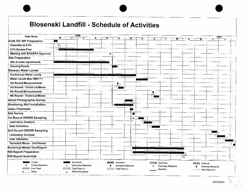
Figure 4-1 presents a proposed schedule for implementation of the Phase III RDI. The schedule may be modified from that presented in Figure 4-1 because of difficulties in obtaining access agreements or the need for additional time to complete the monitoring well drilling program. In accordance with the Order, EPA and PADEP will be notified of any change in the schedule described in the monthly progress reports no later than 7 days prior to the original date for performance of an activity. EPA and PADEP will be notified of any anticipated change in the schedule for the performance of data collection no later than 30 days prior to the performance of the data collection activity.
4.2 Deliverables
4.2.1 Phase III Remedial Design Investigation Report
A Remedial Design Investigation Report will be prepared, summarizing the results of the Phase III tasks described in the RD Work Plan. This report will include a revised Site conceptual model and the results of the first semi-annual groundwater sampling event.
4.2.2 Technical Memoranda
Technical memoranda will be prepared after each quarterly water level measurement event and after the second semi-annual groundwater sampling event. These memoranda will summarize field procedures performed, field observations, and results, and provide comparisons of new data with historical data.
A technical memorandum will also be prepared presenting the results of the numerical groundwater flow model.
G :\WORK\3 3 73 3\WP\R012 .DOC Harding Lawson Associates 14 AR300017
Draft ^ J
5.0 PROJECT TEAM
The anticipated project team and organization is presented in Figure 5-1. Resumes for the project team are contained in Appendix A.
G:\WORK\33733\WP\R012.DOC Harding Lawson Associates 15 AR300018
Draft
6.0 REFERENCES
Consent Decree (Civil Action No. 13-CV-1976). September 1995.
Harding Lawson Associates, 1996. Technical Memorandum No. 2, draft Site Conceptual Model, Blosenski Landfill Superfund Site, Chester County, Pennsylvania. February 23.
U.S. Environmental Protection Agency Region III, 1986. Record of Decision for the Blosenski Landfill Superfund Site, West Cain Township, Chester County, Pennsylvania. September 29.
G:\WORK\33733\WP\R012.DOC Harding Lawson Associates 16 AR300019
Blosenski Landfill - Schedule of Activities
Task Name
Draft RDI WP Preparation
Submittal to EPA E P A R e v i e w P l a n
Mee t i ng w i th E P A / E P A A p p r o v a l
Sitel'reparation
Site Access Agreements Clearing/Roads
Measure Water Levels C o n t i n u o u s Wa te r L e v e l s
Wate r L e v e l s Near MW17-1
4th Round - Technical Memo
Aerial Photographic Survey
3rd Round Measurements
3rd Round - Technical Memo
4th Round Measurements
Monitoring Well Installation
Insitu Flowmeter
Site Survey
1st Round GW/SW Sampling
Laboratory Analysis
Data Validation
2nd Round GW/SW Sampling
Laboratory Analysis Data Validation
Technical Memo - 2nd Round
1996
Numerical Model Dev/Report
RDI Report Preparation
RDI Report Submittal
"NT "T9S7 -
Ifi
Critical Critical Milestone Free Float Delay
• ^ I B J Noncritical O Noncritical Milestone
\7ZZZZA Total Float (+) A. Effort %Complete
Complete • Complete Milestone
\vx*<: Total Float (-)
Summary
Summary Milestone Baseline
—www External . • External Milestone
Non-Resource
AR300020

AR300021
Draft Health and Safety Plan Phase III Remedial Design Investigation Blosenski Landfill Superfund Site West Cain Township Chester County, Pennsylvania
Prepared for
Blosenski Participating Parties c/o de maximis, inc. Suite 290 186 Center Street Clinton, New Jersey 08809
HLA Project No. 33733 3.4
Julie A. Widman, P.G. Senior Hydrogeologist
John J. Kohler Designated Health and Safety Officer
May 14, 1996 Revised October 1, 1996
Harding Lawson Associates i = = ==.•= Engineering and Environmental Services 1 = s 131 North Third Street
Philadelphia, PA 19106 - (215)627-4505
AR300022
CONTENTS (continued)
15.0 EMPLOYEE EXPOSURE/INJURY INCIDENT REPORT
FIGURES
1 Site Features Map 2 Typical Work Zone Location Map 3 Route to Brandywine Hospital
APPENDICES
A Hazardous Property Information B Personnel Acknowledgment Records C Summary Tables - Maximum Concentrations in Groundwater (January 1995) D First Aid and Emergency Care D-l Heat Stress Monitoring Methods E HLA's Excavation and Trenching Policy F HLA's Permit-Required Confined Spaces Policy G Equipment Calibration and Maintenance H HLA's Well Opening/Sampling Procedure I Accident Investigation Form
DISTRIBUTION
Revised October 1, 1996 G:\WORK\33733\WP\R002.DOC Harding Lawson Associates
AR300023
Draft
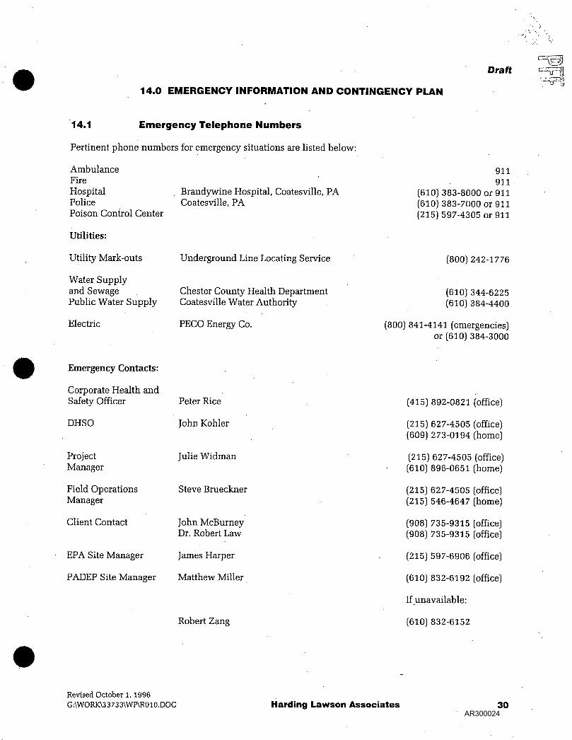
14.0 E M E R G E N C Y INFORMATION A N D C O N T I N G E N C Y P L A N
14.1 Emergency Te lephone Numbers
Pertinent phone numbers for emergency situations are listed below:
Ambulance Fire Hospital Police Poison Control Center
Utilities:
Utility Mark-outs
Water Supply and Sewage Public Water Supply
Electric
Brandywine Hospital, Coatesville, PA Coatesville, PA
Underground Line Locating Service
Chester County Health Department Coatesville Water Authority
PECO Energy Co.
911 911
(610] 383-8000 or 911 (610) 383-7000 or 911 (215) 597-4305 or 911
(800) 242-1776
(610) 344-6225 (610) 384-4400
(800) 841-4141 (emergencies) or (610) 384-3000
Emergency Contacts:
Corporate Health and Safety Officer
DHSO
Project Manager
Field Operations Manager
Client Contact
EPA Site Manager
PADEP Site Manager
Peter Rice
John Kohler
Julie Widman
Steve Brueckner
John McBurney Dr. Robert Law
James Harper
Matthew Miller
Robert Zang
(415) 892-0821 (office)
(215) 627-4505 (office) (609) 273-0194 (home)
(215) 627-4505 (office) (610) 896-0651 (home)
(215) 627-4505 (office) (215) 546-4647 (home)
(908) 735-9315 (office) (908) 735-9315 (office)
(215) 597-6906 (office)
(610) 832-6192 (office)
If unavailable:
(610) 832-6152
Revised October 1, 1996 G:\WORK\33733\WP\R010.DOC Harding Lawson Associates 30
AR300024
APPENDIX D-1
HEAT STRESS MONITORING METHODS
AR300025
Draft
APPENDIX D-1
HEAT STRESS MONITORING METHODS
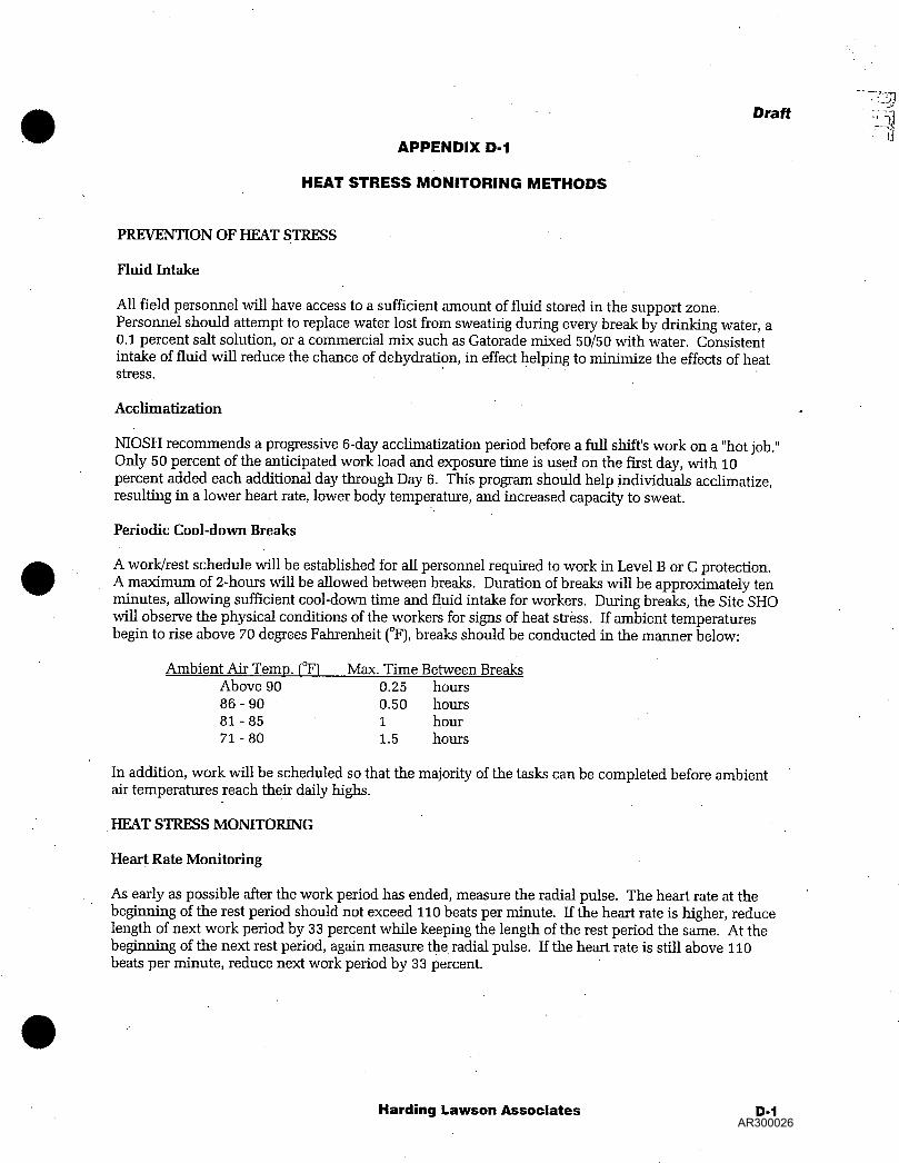
PREVENTION OF HEAT STRESS
Fluid Intake
All field personnel will have access to a sufficient amount of fluid stored in the support zone. Personnel should attempt to replace water lost from sweating during every break by drinking water, a 0.1 percent salt solution, or a commercial mix such as Gatorade mixed 50/50 with water. Consistent intake of fluid will reduce the chance of dehydration, in effect helping to minimize the effects of heat stress.
Acclimatization
NIOSH recommends a progressive 6-day acclimatization period before a full shift's work on a "hot job." Only 50 percent of the anticipated work load and exposure time is used on the first day, with 10 percent added each additional day through Day 6. This program should help individuals acclimatize, resulting in a lower heart rate, lower body temperature, and increased capacity to sweat.
Periodic Cool-down Breaks
A work/rest schedule will be established for all personnel required to work in Level B or C protection. A maximum of 2-hours will be allowed between breaks. Duration of breaks will be approximately ten minutes, allowing sufficient cool-down time and fluid intake for workers. During breaks, the Site SHO will observe the physical conditions of the workers for signs of heat stress. If ambient temperatures begin to rise above 70 degrees Fahrenheit (°F), breaks should be conducted in the manner below:
Ambient Air Temp. f°F) Max. Time Between Breaks Above 90 0.25 hours 86-90 0.50 hours 81-85 1 hour 71 - 80 1.5 hours
In addition, work will be scheduled so that the majority of the tasks can be completed before ambient air temperatures reach their daily highs.
HEAT STRESS MONITORING
Heart Rate Monitoring
As early as possible after the work period has ended, measure the radial pulse. The heart rate at the beginning of the rest period should not exceed 110 beats per minute. If the heart rate is higher, reduce length of next work period by 33 percent while keeping the length of the rest period the same. At the beginning of the next rest period, again measure the radial pulse. If the heart rate is still above 110 beats per minute, reduce next work period by 33 percent.
Harding Lawson Associates D-1 AR300026
Oral Temperature Monitoring
During the first rest period, measure the oral temperature for at least three minutes using a clinical thermometer. If oral temperature exceeds 99.6°F, shorten next work period by 33 percent. Measure oral temperature at the beginning of the next rest period. If oral temperature again exceeds 99.6°F, shorten next work period by 33 percent. Do not permit a worker to wear a semi-permeable or impermeable garment or coverall when oral temperature exceeds 100.6°F.
Harding Lawson Associates D-2 AR300027

• p i l . i.
AR300028
Draft Field Sampling Plan Phase III Remedial Design Investigation Blosenski Landfill Superfund Site Chester County, Pennsylvania
Prepared for
Blosenski Participating Parties c/o de maximis, inc. Suite 290 186 Center Street Clinton, New Jersey 08809
HLA Project No. 33733 3.2
Stephen K. Brueckner Staff Geologist II
Julie A. Widman, P.G. Senior Hydrogeologist
May 14, 1996 Revised October 1, 1996
======= Harding Lawson Associates = = : = . = Engineering and Environmental Services = = | | 131 North Third Street ===== Philadelphia, PA 19106 - (215)627-4505
AR300029
CONTENTS
Draft
1.0 INTRODUCTION 1
2.0 SUMMARY OF THE SITE CONCEPTUAL MODEL 2
2.1 Site B ackground '. 2
2.2 Site Characteristics 2
2.3 Contaminant Distribution 3
2.4 Migration Pathway Analysis 3
2.5 Phase III Remedial Design Investigation Data Needs 3
3.0 SAMPLING OBJECTIVES 5
4.0 FIELD ACTIVITIES 6
4.1 Site Preparation 6
4.2 Hydrogeological Investigation 6 4.2.1 Stream Gage Installation 6 4.2.2 Water Level Measurement 6 4.2.3 Monitoring Well Installation \ 7 4.2.4 Surveying 7 4.2.5 In Situ Groundwater Flow Meter Measurements 7
4.3 Groundwater Chemistry Investigation 7 4.3.1 Packer Testing with Onsite Gas Chromatography ; 7 4.3.2 Monitoring Well Sampling 8 4.3.3 Surface Water Sampling ; 9
4.4 Management of Investigation-Derived Waste 9
5.0 SAMPLE NOMENCLATURE 10
5.1 Numbering of New Monitoring Wells 10
5.2 Investigative Samples 10
5.3 Quality Assurance/Quality Control Samples 10
6.0 FIELD PROCEDURES 11
6.1 Stream Gage Installation 12
6.2 Water Level Measurement 12
Revised October 1,1996
F:\33733\WP\R001ia.DOC Harding Lawson Associates i AR300030

Draft
CONTENTS (Continued)
6.2.1 Manual Measurements 12 6.2.3 Near Continuos Water Level Recorders 13
6.3 Drilling Procedures 14 6.3.1 Drilling Techniques 14 6.3.2 Geologic Logging 14
6.4 Monitoring Well Construction 14 6.4.1 General ; 14 6.4.2 Installation Procedures 14 6.4.4 Monitoring Well Development 16 6.4.5 Well Survey. 16
6.5 In Situ Groundwater Flowmeter Measurements 16
6.6 Packer Testing of Bedrock Boreholes 17
6.7 Liquid Headspace Screening Using a Field GC 18
6.8 Groundwater Sample Collection .19
6.9 Surface Water Sampling ; 21
6.10 Equipment Decontamination 22
6.11 Splitting Samples With EPA 22
7.0 SAMPLE HANDLING AND ANALYSES 23
7.1 Sample Transport 23
7.2 Sample Documentation 23 7.2.1 Field Data Forms.... 23 7.2.2 Chain-of-Custody and Requests for Analyses 23 7.2.3 Field Logbook Documentation 24
8.0 REFERENCES 26
TABLES
1 Existing Monitoring Well Construction Details 2 Estimated Numbers of Samples to be Collected 3 Summary of Laboratory Data to be Collected 4 Field Parameters to be Measured During Sampling Activities 5 Sample Containers, Preservatives, and Shipping Requirements
Revised October 1,1996 F:\33733\WP\R0011a.DOC Harding Lawson Associates ii
AR300031
FIGURES
2-1 Site Features Map 4- 1 Monitoring Well and Staff Gage Location Map 5- 1 Example Sample Label 6- 1 Double-cased Monitoring Well Construction
APPENDIXES
A FIELD DOCUMENTATION FORMS
B STANDARD CALIBRATION PROCEDURES FOR FIELD INSTRUMENTS
DISTRIBUTION
F:\3 3 7 3 3\WP\R0011 a.DOC Harding Lawson Associates AR300032
Draft
1.0 INTRODUCTION
This Draft Field Sampling Plan (FSP) has been prepared by Harding Lawson Associates (HLA) on behalf of the Blosenski Participating Parties (BPP). This FSP is submitted pursuant to the terms of the Consent Decree (Civil Action No. 93-CV-1976) effective December 1995.
This Draft FSP has been prepared in accordance with the Guidance for Conducting Remedial Design and Remedial Action Under CERCLA, (OS WER Directive 9355.0-4A [1986]), A Compendium of Superfund Field Operations Methods (OSWER Directive 9355-0-14 [December 1987]), and EPA National Enforcement Investigation Center Policies and Procedures Manual (EPA 330/978-001 [May 1978, revised November 1984]) and other documents listed in the references section.
The Consent Decree addresses requirements associated with the development and submittal of a Phase III Remedial Design Investigation Work Plan for the Site (RDI WP), which includes a Sampling and Analysis Plan (SAP) and a Health'and Safety Plan (HASP). The FSP and the Quality Assurance Project Plan (QAPP) comprise the SAP. Information presented in this FSP includes sampling objectives, numbers and types of samples to be collected, sample locations, sampling procedures, and sample handling and analysis protocols. The QAPP details quality assurance and quality control (QA/QC) procedures associated with sampling and laboratory analysis, and data reporting.
The primary field activities to be conducted at this time are associated with hydrogeological remedial design studies. The field activities include well and boring installation, and groundwater and surface water sampling tasks.
F:\33733\WP\R0011a.DOC Harding Lawson Associates 1 AR300033
2.0 SUMMARY OF THE SITE CONCEPTUAL MODEL
The draft Site Conceptual Model (HLA, 1996) describes the current understanding of the physical and chemical processes controlling migration of landfill constituents to the surrounding environment. In addition, the draft Site Conceptual Model identifies uncertainties regarding the hydrogeology, geology, and contaminant distribution in the vicinity of the site that must be defined in connection with Phase III. The draft Site Conceptual Model is summarized in the following paragraphs.
2.1 Site Background
The Site occupies approximately 13.6 acres in West Cain Township, Chester County, Pennsylvania. Disposal of municipal and industrial wastes reportedly began at the Site in the late 1940s. The landfill was never permitted and landfill operations ceased in the late 1970s.
The Site was placed on the National Priorities List (NPL) in December 1982. Under EPA supervision, a Remedial Investigation (RI) was performed at the Site in 1984 and 1985. A focused Feasibility Study' (FS) to evaluate remedial alternatives was subsequently completed in February of 1986, also under EPA supervision. A Record of Decision (ROD) was issued by EPA for the Site on September 29, 1986. The selected remedy in the ROD consists of four phases:
• Phase I - Installation of a public water supply line (completed 1989)
• Phase II - Sampling and analysis of subsurface soils, and excavation and removal of buried drums, drum contents, and soils in intimate contact with the drums (completed in 1992)
• Phase III - Design investigation to define the extent and magnitude of groundwater contamination, and implementation of a source reduction program involving pumping and treating contaminated groundwater
• Phase IV - Landfill cap (completed in October 1995) and additional drum removal and disposal (to be completed in 1996). (Note: Additional drum removal during Phase IV was not contemplated in the ROD.)
In September 1995, a Consent Decree (Civil Action No. 93-CV-1976) was entered into for, inter alia, performance of the Phase III and Phase IV Remedial Design/Remedial Action at the Site.
2.2 Site Characteristics
The Site lies on the side of a ridge that forms a drainage divide between the Susquehanna and Delaware River Basins. Surface water drainage from the landfill is directed to the north, toward the unnamed tributary of Indian Spring Run. This drainage pattern existed prior to cap construction and the Phase IV cap design utilized this drainage pattern for surface water runoff from the cap.
The geology of the Site area consists of metamorphosed sedimentary rocks that have been extensively folded and faulted. Bedrock in the area is composed of the Chickies Quartzite. Beneath the Site, the Chickies Quartzite consists of both quartzite and quartzite schist. Boring logs prepared during previous investigations indicate that the bedrock is highly fractured. Drilling observations made during previous investigations also suggest the presence of a fault on the south side of the landfill, near MW2-1 and MW3-1.
Groundwater flows within topographically controlled, localized flow regimes in the Site area. The ridge upon which the Site is located serves as a groundwater divide as well as a surface water divide.
F:\33733\WP\R0011a;DOC Harding Lawson Associates 2 AR300034
Groundwater elevations are highest south of the landfill at the top of this ridge, and decrease to the south and north.
Two distinct but interconnected groundwater flow regimes are apparently present beneath the Site. Under the first regime, groundwater follows the prevailing hydraulic gradient, generally in a north and northwesterly direction toward the unnamed tributary of Indian Spring Run. Under the second regime, groundwater flows along fractures or other zones of higher permeability within the aquifer following localized gradients. Flow under the second regime may be locally in directions different from the prevailing gradient.
2.3 Contaminant Distribution
The ROD identified VOCs as the principal contaminants of concern in groundwater from a human health perspective. Review of the most recent round of groundwater sampling (January 1995) indicates the following:
• Benzene was detected at concentrations exceeding the maximum contaminant level (MCL) only in monitoring wells onsite or near the fenceline.
• With the exception of vinyl chloride at one location, the only compound other than benzene detected at concentrations exceeding the MCL beyond the vicinity of the fenceline was trichloroethene (TCE).
• The lateral and vertical extent of groundwater impacts to the north of the Site cannot be completely evaluated because of the locations and screened intervals of the existing wells.
• The groundwater impacts at wells MWlO-1, MW15-1, and MW17-1 appear to be related and may be caused by the location of these wells along a lineament identified during previous studies.
Historical analytical data for VOCs in groundwater at the Site are limited. Monitoring events have been several years apart (i.e., 1985, 1990, and 1995). Available data suggest several wells exhibit decreased chemical concentrations between events, particularly near the fenceline. Concentration trends will be further evaluated after additional groundwater data are collected during the RDI.
2.4 Migration Pathway Analysis
Only groundwater poses a potential human exposure pathway for site-related compounds, because other pathways, i.e., soil and air, have been mitigated by remedial actions previously completed, including removal of buried drums and contaminated soils and installation of the landfill cap. While the potential for exposure exists, it has been minimized by the installation of municipal water supply lines and the provision of municipally supplied drinking water. Groundwater impacts from the Site may extend to residential wells located immediately to the south and east of the Site. However, these wells are located in areas where public water is supplied. Therefore, the pathway to exposure is not complete. Available data suggest residential wells located more than 1/2 mile southeast of the Site are not downgradient of the Site. However, pumping of these wells may have the potential to influence the migration of site-related contaminants. A second potentially complete exposure pathway may result from groundwater discharge to the unnamed tributary of Indian Spring Run north of the Site. However, further investigation is needed to resolve this issue.
F:\33733\WP\R0011a.DOC Harding Lawson Associates 3 AR300035
Draft <>•
2.5 Phase III Remedial Design Investigation Data Needs
Several uncertainties were identified during development of the draft Site Conceptual Model. These uncertainties indicate that additional data are needed to characterize both the physical groundwater flow system and the nature and extent of site-related groundwater impacts prior to design of a Phase III remedy. Data needs identified include:
• Information regarding aquifer characteristics and the groundwater flow system
• Magnitude and direction of vertical and horizontal hydraulic gradients
• Extent of VOCs in groundwater and trends in concentration over time
• Potential effects of existing and future residential well pumpage on contaminant migration
• Characterization of the influence of the landfill cap on groundwater flow patterns and VOC concentration trends
Each of these data needs is addressed in the scope of work for the RDI, described in the RDI WP.
F:\33733\WP\R0011a.DOC Harding Lawson Associates 4 AR300036
Draft
3.0 SAMPLING OBJECTIVES
Sampling tasks have been included within the remedial design field investigation. The overall objective of the sampling program is to obtain data to support the most effective implementation of remedial actions at the Blosenski Landfill Site. More specific goals of the sampling activities are to obtain additional information regarding the following conditions:
• Characteristics of the groundwater flow system • Vertical and horizontal contaminant extent and historical concentration trends • Potential for offsite private wells to influence plume migration
F:\3 3 7 33\WP\R001 la.DOC Harding Lawson Associates 5 AR300037
4.0 FIELD ACTIVITIES
Draft
Specific tasks that may be performed during the remedial design investigation are presented in the RDI WP Section 3.0. During execution of these tasks, anticipated field activities include:
• Site access, clearing, and field trailer installation • Stream gage installation • Water level measurements • Installation of additional monitoring wells • Survey of monitoring well locations • In situ groundwater flow measurement • Packer testing of bedrock boreholes with onsite gas chromatography (GC) • Groundwater sampling and analysis • Surface water sampling and analysis
The following sections describe the field activities, including sample locations, the estimated number of samples to be collected, and parameters for laboratory and field analysis. Specific laboratory analyses are listed in Table 1. Estimated numbers of samples are summarized in Table 2. Field measurements that will be made during sampling are presented in Table 3 and Table 4 displays sample containers, preservatives, and shipping requirements for the proposed groundwater and surface water sampling.. Specific procedures for each field activity, as applicable, are provided in Section 6.
4.1 Site Preparation
Prior to the field investigation, specific Site preparation will be necessary. Anticipated tasks include installation of access roads, brush clearing, installation of a field trailer and portable sanitary facilities, and installation of carbon treatment for well purge and development fluids.
4.2 Hydrogeological Investigation
4.2.1 Stream Gage Installation
Stream gages will be installed at selected locations in the tributary to Indian Spring Run to assist in interpretation of hydraulic gradients. It is estimated that two gages will be installed in the perennial reaches of the tributary. Preliminary locations are shown in Figure 4-1; actual locations will be determined in the field.
4.2.2 Water Level Measurement
Quarterly water level measurements will be made over a 1-year period at existing monitoring wells and those installed during the Phase III RDI. Existing monitoring well construction details are provided in Table 1. Proposed and existing monitoring well locations are illustrated in Figure 4-1. Procedures for manual water level measurements are described in Section 6.2.
Water levels will also be monitored continuously with automatic recorders during the Phase III RDI. Near continuous water level recorder operations are described in Section 2.3.
The near continuous recorders are currently installed in the extraction well EW-1 and monitoring wells MW10-1 and MW15-1. These recorders will be moved during the Phase III RDI as needed.
F:\33733\WP\R0011a.DOC Harding Lawson Associates 6 AR300038
Draft
4.2.3 Monitoring Well Installation
Monitoring wells will be installed during the remedial design investigation to refine understanding of the groundwater flow system and to aid in defining the vertical and horizontal extent of groundwater impacts beneath the Site. Proposed locations of the monitoring wells are illustrated in Figure 4-1.
It is currently estimated that 9 additional monitoring wells will be installed during the remedial design investigation. The proposed locations of these wells are listed below.
Well Location
MW2-D MW7-D MW8-D MW11-S MW15-D MW20-S MW23-S MW27-D MW27-S
Well Description
Deep well adjacent to monitoring well MW2-1 Deep well adjacent to monitoring well MW7-1 Deep well adjacent to monitoring well MW8-1 and MW8-2 Water table well adjacent to monitoring well MWl 1-1 Deep well adjacent to monitoring well MWl 5-1 Shallow well adjacent to monitoring well MW20-1 Water table well adjacent to monitoring well MW23-1 Deep well adjacent to MW27-S Shallow well near perennial reach of the unnamed tributary to Indian Spring Run
Drilling procedures are described in Section 6.3 and monitoring well installation procedures are described in Section 6.4.
4.2.4 Surveying
After installation, the horizontal and vertical coordinates of the new and existing monitoring wells and stream gages will be surveyed by a Pennsylvania-licensed surveyor.
4.2.5 In Situ Groundwater Flow Meter Measurements
After the new monitoring wells are completed, HLA may estimate groundwater flow directions in selected new and existing wells using an in situ flow meter device if the technology proves useful. Information obtained from this activity will aid in characterizing vertical and horizontal groundwater flow gradients.
4.3 Groundwater Chemistry Investigation
4.3.1 Packer Testing with Onsite Gas Chromatography
Packer testing will be attempted at the deep monitoring wells listed in Section 4.2.3 during drilling (MW2-D, MW7-D, MW8-D, MW15-D and MW27-D). The packer testing data will be used to evaluate zones of higher hydraulic conductivity and to profile contaminant concentrations with depth. Specific procedures for packer testing are provided in Section 6.6.
It is assumed that packer testing will be performed at 10 to 20-foot intervals, depending on drilling technique and/or the existence of water producing zones to the target depth indicated below. During packer testing activities, HLA will collect groundwater samples for liquid headspace screening. The samples will be analyzed with an onsite gas chromatograph (GC) calibrated for trichloroethene (TCE), 1,2, dichloroethane (1,2-DCE) and benzene. The purpose of the field screening is to determine the vertical extent of volatile contaminants in the groundwater, which in turn will be used to decide the total depth of selected bedrock monitoring wells.
Revised October 1,1996 F:\33733\WP\R0011a.DOC Harding Lawson Associates 7
AR300039
Well Location Target Depth (Feet Mean Sea Level)
MW2-D MW7-D MW8-D MW15-D MW27-D
650 650 650 650 600
Co-located groundwater samples wil l be collected at a frequency of 10% from each borehole where packer testing is performed and wil l be submitted to the laboratory for confirmatory analysis. The confirmatory groundwater samples wil l be analyzed for TCE, 1,2-DCE, and benzene using EPA Method 524.2.
Table 2 presents the estimated number of samples to be collected and analyzed with the field GC.
4.3.2 Monitoring Well Sampling
Two semi-annual sampling rounds wil l be performed at selected monitoring wells. Proposed wells to be sampled and analyses to be performed during the first round are described below. Monitoring wells and analytical parameters to be included in the sampling events wil l be agreed upon with EPA and
During the first round, samples wil l be collected from the monitoring wells listed below. Samples wil l be analyzed for VOCs by EPA Method 524.2 and common ions. Table 3 lists proposed sample analyses, analytical methods, and data types. Table 2 presents the estimated numbers of samples to be collected. Field parameters to be measured during sampling are summarized in Table 4. Sampling procedures are described in Section 6.8.
Monitoring wells to be sampled during the first round and analyzed for VOCs and common ions include:
MW2-1 MW2-D MW3-1 MW4-1 MW5-1 MW6-1 MW7-1 MW7-D MW8-1 MW8-D MW9-1 M W l 0-1 MW11-1 MW11-S MW13-1 MW14-1 MW15-1 MW15-D M W l 6-1 M W l 7-1 MW20-1 MW20-S MW22-1 MW23-1 MW23-S MW24-1 MW25-1 MW26-1 MW27-S MW27-D EW-1
During the first round, selected monitoring wells wi l l be analyzed for total and dissolved Target Analyte List (TAL) metals and Target Compound List (TCL) semivolatile organic compounds (SVOCs). These wells include:
EW-1 MW5-1 MW6-1 MW8-1 M W l 0-1 MW22-1
PADEP.
Revised October 1, 1996 F:\33733\WP\R0011a.DOC Harding Lawson Associates 8
AR300040
Samples analyzed for TAL metals will not be analyzed for the metal constituents listed under common ions in Table 2.
4.3.3 Surface Water Sampling
Surface water samples will be collected from the tributary to Indian Spring Run during the groundwater sampling events. Samples will also be collected at a selected spring location near the perennial reach of the stream. Samples will be analyzed for VOCs by EPA Method 524.2 and common ions, as summarized in Table 2. Estimated numbers of samples are presented in Table 3.
4.4 Management of Investigation-Derived Waste
Investigation-derived waste (IDW) generated during the RI/FS activities will generally be managed in accordance with EPA's Guide to Management of Investigation-Derived Wastes quick reference fact sheet (EPA, 1992b). The types of wastes anticipated to be generated include the following:
• Well purge water • Decontamination fluids • Soil/rock drill cuttings • Development water • Disposable sampling equipment • Personal protective equipment
During drilling, soil cuttings will be separated from groundwater and will be temporarily staged on plastic sheeting at each monitoring well location. A backhoe and truck will be used to transport the soils to the landfill for future use as roadbuilding materials.
Investigation derived fluids (IDF), including well purge water, decontamination fluids, drilling fluids, and development water will be temporarily stored at each well in polyethylene tanks and will be disposed of at an offsite nonhazardous waste disposal facility.
Based on analysis of the IDF, a decision may be made to dispose of the fluids in the onsite sedimentation basin. EPA and PADEP will be contacted and their approval received, prior to performing this type of disposal.
General refuse (trash, personal protective clothing) will be disposed of an offsite municipal disposal facility.
Revised October 1,1996 F:\33733\WP\R0011a.DOC Harding Lawson Associates 9
AR300041
5.0 SAMPLE NOMENCLATURE
Draft
5.1 Numbering of New Monitoring Wells
Monitoring wells installed during the remedial design investigation that are not adjacent to existing wells will be given the designation "MW-" and numbered sequentially beginning with MW-27. In areas where new well clusters are installed, shallower wells will be assigned a "S" suffix after the number, e.g., MW27-S, and deeper wells will be assigned a "D" suffix. Where wells are installed adjacent to existing well clusters, the new wells will be assigned the same number as the existing wells and assigned a "S" or "D" suffix, as appropriate.
5.2 Investigative Samples
Field personnel are responsible for uniquely identifying and labeling all samples collected during the field investigation. Al l labeling will be completed in indelible ink and be securely affixed to the sample container. An example of a sample label is shown in Figure 5-1. Sample labels will contain the following information:
• A project number and Site name • A unique sample identification number • The sample location • A sample description (soil or groundwater) • The sample status (grab or composite) • Chemical analysis parameters (analyte and EPA method number) • The sampling date and time • Initials of sampling technician • The chemicals used for sample preservation • Any useful remarks for the laboratory
A standardized nomenclature will be used for all samples collected, and each sample will be assigned a unique name. Groundwater samples will be designated by the name of the well from which they are collected and the date on which they are collected. For example a sample collected from existing well MW6-1 on March 1, 1996, would be designated MW6-1/03-01-96.
Samples from other media will be designated by an abbreviation indicating the media sampled, followed by a numeric sample location designation and the date. Surface water samples will be designated by the prefix "SW".
As an example a surface water sample collected at surface water sampling location 1 on March 1, 1996 would be designated SW-l/03-01-96.
5.3 Quality Assurance/Quality Control Samples
Quality assurance/quality control (QA/QC) blank sample designations will indicate the type of QA/QC sample, date collected, and for rinse blanks, the matrix of the associated environmental samples. The following abbreviations will be used in addition to those listed above:
TB Trip Blank RB Rinse Blank
For example, a rinse blank collected during a groundwater sampling event on March 1, 1996, would be designated RBGW/03-01-96, and a trip blank for that event would be designated TB/03-01-96.
F:\33733\WP\R0011a.DOC Harding Lawson Associates 10 AR300042
Laboratory blind duplicate samples will be assigned a random identification number in the field by an HLA field geologist. This number will be recorded in the field notebook and keyed into the project database.
F:\33733\WP\R0011a.DOC Harding Lawson Associates 11 AR300043
6.0 FIELD PROCEDURES
This section of the FSP describes field procedures to be implemented during performance of the Phase III RDI. All procedures represent general descriptions of the manner in which field activities will be performed. Procedures may be modified in the field, based on the judgment of the onsite geologist, with concurrence by EPA or EPA's oversight contractor.
6.1 Stream Gage Installation
Stream gages will consist of a numbered incremental scale attached to a sturdy wood stake. The stake will be driven into the stream bed in the center of the stream channel, such that the scale straddles the water surface.
6.2 Water Level Measurement
6.2.1 Manual Measurements
Groundwater levels will be measured using an electronic water level indicator. The indicator probe will be equipped with standard two-lead cable, calibrated and marked in fraction of a foot intervals. A standard weighted electrode will be attached to the end of the sounder cable.
The following procedures will be used for measuring water levels:
Before Entering The Field:
• Monitoring wells to be measured and measuring points on each well will be identified. A single measuring point at each well, marked during well surveying, will be used for the measurements. This mark consists of a notch or mark in the inner casing for the previously installed wells. A . similar convention will be used for the wells to be installed. A record of the measuring point and its elevation for each well will be maintained for use in the field. Well elevation information for the previously installed wells is included on Table 1.
• Previous water level measurements for each well will be reviewed before leaving for the Site, and a summary of previous water level data will be taken to the field.
• Health and safety procedures will be reviewed with all personnel.
In The Field:
Prior to use, the water level meter will be calibrated against a stainless steel surveyor's tape.
• Each well will be approached in the appropriate level of protection as set forth in the HASP. The well will be uncapped from the upwind position and background, top of casing, and breathing zone readings will be measured with a flame- or photo-ionization detector (FID or PID). Procedures for use of the FID and PID will be consistent with their manufacturer's manual, which may vary slightly from brand to brand. The instrument manuals will be kept onsite at all times during use of these instruments.
• The water level probe will be lowered slowly into the well until a contact with the water surface is indicated by an electronic signal.
• The cable will be marked or held at the measuring point.
Draft
F:\33733\WP\R0011a.DOC Harding Lawson Associates 12 AR300044
Draft
• The depth to water reading will be read to the nearest hundredth of a foot.
• The cable will be checked to determine whether it has been cut by a sharp casing edge.
• Measurements at each well will only be taken at the marked survey point on the inner casing and will be repeated until two consecutive measurements are obtained that agree within ±0.02 foot.
• Water level measurements will be recorded on water level measurement forms (Appendix A]. Well identification, date, time, depth in feet to groundwater, and remarks relevant to groundwater level measurements will be noted.
• The previous event's water level measurement for the well will be checked. If the difference between the current water level and the previous month's water level is greater than one foot, the water level will be remeasured.
• Following water level measurement recording, the well will be recapped and locked.
• The portion of the water level probe or steel tape that has been in contact with the well water will be cleaned in detergent and water, and rinsed with tap or distilled/deionized water prior to use at each well.
The water level elevation relative to mean sea level (MSL) will be calculated by subtracting the depth to water from the elevation of the surveyed top of casing elevation measuring point. Newly acquired water level data will be compared with current and past water level data.
6.2.3 Near Continuous Water Level Recorders
Near continuous water level recorders will be installed in selected monitoring wells. The recorders will be installed and calibrated consistent with manufacturer's specifications. The recorders will collect measurements at a frequency which will allow evaluation of diurnal or other short term water level fluctuations.
In general, the procedure for installing the recorders includes the following:
• The depth to water beneath the ground surface will be measured
• The cable will be installed such that approximately 20 feet of cable lie below the static water level
• The water level will be allowed to stabilize for 15 minutes
• The recorder will be calibrated in accordance with the manufacturer's instructions. Calibration will be checked against manual water level measurements
• Data capture will be set at a selected frequency
The water level recorders will be downloaded of data during the quarterly manual water level measurement rounds. The recorders will also be re-calibrated at this time before collection of water level measurements resumes.
F:\33733\WP\R0011a.DOC Harding Lawson Associates 13 AR300045
Draft
6.3 Drilling Procedures
Anticipated drilling procedures are described in the following subsections. If field conditions warrant, these procedures may be modified, with EPA concurrence.
6.3.1 Drilling Techniques
It is anticipated that all monitoring wells will be installed below the bedrock surface. The monitoring wells will be installed using an air rotary drill rig. An air rotary rig utilizes an air hammer which is rotated and advanced while high pressure air (sometimes mixed with water or foam to reduce dust) is forced through the center of the drill stem. The high pressure air is used to clean rock cuttings from the borehole and provide pressure to run the air hammer while drilling. A downhole TV camera will be used to record bedrock conditions in deep wells, if borehole stability permits use of this equipment.
6.3.2 Geologic Logging
An HLA field geologist will write a descriptive log for each borehole based on the cuttings discharged from the borehole. Core samples from the bedrock wells will also be examined for lithologic logging purposes. The standard reporting sheets for soil borings are included in Appendix A. Information recorded will include the following:
• Drilling contractor and driller's name
• Name of geologist maintaining the log
• Boring designation and location
• Drilling method
• Date
• Best possible description of the rock cuttings and core recovered, including lithology and other characteristics
Observations of changes in drilling speed and drill rig performance and gains or losses in drilling fluid circulation that could indicate differences in subsurface conditions will also be noted on the boring log.
6.4 Monitoring Well Construction
6.4.1 General
Well construction, will in general, be in accordance with the requirements of PADEP. Variances from the procedures described below may be sought from EPA and PADEP, if Site conditions warrant.
Well borings will be drilled using air-rotary percussion. It is assumed that all deep boreholes will require a surface casing based on previous Site investigations. Shallow wells will be completed to predetermined depths, as specified in the RDI WP. Completion depths of deep wells will be based on packer testing.
6.4.2 Installation Procedures
Figure 6-1 depicts a typical double-cased monitoring well construction. In general, the following procedure will be used unless field conditions require modifications to be made:
Revised October 1,1996 F:\33733\WP\R0011a.DOC Harding Lawson Associates 14
AR300046
Draft
1. The driller will advance the boring to a depth approximately 5 feet into the competent bedrock. This depth shall be confirmed by the geologist upon inspection of the drill cuttings recovered during drilling and observations of the advancement of the drilling bit.
2. A steel casing with welded joints and an outside diameter at least four inches smaller than the borehole diameter will be lowered to the bottom of the hole and centered. Cement-bentonite grout will be emplaced in the annular space around the casing via a tremie pipe from the bottom up. The drilling fluid in the annular space will be displaced by the grout. The grout will contain no more than 5 percent bentonite. After the grout has set for 12 to 24 hours, the drilling equipment will be decontaminated and the drilling fluid inside the casing will be circulated thoroughly with potable water until all drilling fluids have been removed and only clear water remains inside the casing. If caving conditions are encountered or expected, pull back casing may need to be utilized during emplacement of grout in the annular space.
3. Drilling equipment will be decontaminated and water will be used for drilling the remainder of the boring, unless conditions indicate drilling mud is necessary for borehole stabilization.
4. Bedrock will be cored or reamed as described above. Packer testing as described in Section 6.6 will be completed prior to well installation in the deep boreholes.
5. Field observations, including inspection of the cuttings and/or core samples recovered during drilling, inflow of water into the borehole, and contaminant concentrations measured during packer testing will determine screen placement. Shallow wells will screen the water table. Completion depths of the deep wells will depend upon contaminant concentrations observed.
6. The screen and riser will be steam cleaned prior to use. The decontaminated pipe will then be inserted into the borehole to the bottom depth.
7. The filter pack will be installed using a tremie pipe. The sand level will be measured with a properly decontaminated weighted tape. This process will continue until at least 2 feet of sand is accumulated above the screened interval.
8. After installation of the sand pack, at least 2 feet of bentonite pellets will be poured into the hole to prevent the entry of grout into the filter pack and to act as a long-term barrier to liquid that may seep down into the formation/grout interface. The bentonite pellets will be installed in lifts of 1.5 to 2.5 feet. Cuttings will not be placed back in the hole.
9. If the bentonite pellets are installed above the water table, approximately 5 gallons of potable water will be poured into the annulus after each lift of bentonite pellets to cause them to swell and seal the annular space above the sand pack.
10. At least 1 hour will elapse to enable the bentonite pellets to swell properly.
11. The remaining annular space will be filled with a Portland cement slurry containing 5 percent bentonite. Potable water will be used to hydrate the mixture. The cement-bentonite slurry mixture will be emplaced with a tremie pipe placed above the bentonite seal. The tremie pipe will be perforated along the bottom 5 feet to decrease the potential for pumped grout to destroy the bentonite seal when pumped from the surface.
12. Portland cement will be inserted via tremie pipe over the cement-bentonite slurry to provide security, a surface seal and to minimize potential damage due to frost heaving.
Revised October 1,1996 F:\3 3 7 3 3\WP\R001 la.DOC Harding Lawson Associates 1 5
AR300047
Draft
13. A 2-foot-high 8-inch steel protective casing will be set into the Portland cement. A locking cap will be provided. A concrete form will be constructed 18 by 18 inches around the protective steel casing, approximately 3 inches above and 3 inches bgs.
6.4.4 Monitoring Well Development
Prior to development, all monitoring wells will be allowed to set for a period not less than 48 hours to allow the cement grout seals to cure. Following the waiting period, the new monitoring wells will be developed alternately by pumping and surging. Bailing may also be performed if the amount of sediment is great. The water level in the well will be measured prior to initiating development. Conductivity, turbidity, pH, dissolved oxygen (DO) and temperature will be measured after each well volume is removed. Standard operating procedures for field measurement equipment will be followed.
In general, the well will be pumped until turbidity has decreased to a field-determined level or stabilizes. Pumping will then be discontinued and the well will be surged. Following surging, pumping will be resumed. This process will be repeated until the discharge water has a turbidity of 10 nephelometric turbidity units (NTUs) or less, or until it remains stable over a predetermined period of surging. Conductivity, pH, and temperature should also stabilize prior to cessation of development. If turbidity, conductivity, pH, and temperature do not stabilize, at least five well volumes of water will be removed. If drilling fluids are used, at least five times the measured amount of fluid lost during drilling will also be removed.
Site personnel will stay clear of the well during development and will monitor breathing space with a PID throughout. Purged water will be collected and managed as described in Section 4.4.
6.4.5 Well Survey
Following well completion and development, the wells and stream gages will be surveyed by a licensed Pennsylvania surveyor as discussed in the RDI WP. The surveyor will record the latitude, longitude, and elevation of the ground surface, top of casing with the cap off, and the top of the inner casing. The surveyor will tie well locations into State Plane Coordinates and mean sea level (MSL). Each well will be permanently marked with the well designation.
6.5 In Situ Groundwater Flowmeter Measurements
In situ groundwater flow direction and velocity will be measured at multiple depths in the screened interval of selected monitoring wells using a heat-pulse flowmeter. The device is the Geo Flowmeter, manufactured by K.V. Associates of Falmouth, Massachusetts. The instrument operates by emitting heat pulses and simultaneously measuring the temperature differential around the circumference of the monitoring well. The heat pulses are carried in one direction by the movement of groundwater, thus causing a temperature differential. By plotting the measured temperature differential in vector form, the direction of groundwater flow can be estimated.
The following procedures are to be used to obtain insitu groundwater flow measurements:
Before Entering The Field:
• Project objectives and quality assurance procedures, measurement locations, and procedures, will be reviewed with field personnel.
• Well construction data, including location of screened interval, will be reviewed for each well to be measured.
• Health and safety procedures will be reviewed with all personnel.
Revised October 1,1996 F:\33733\WP\R0011a.DOC Harding Lawson Associates 16
AR300048
In The Field:
• Sampling crews, consisting of a senior technician from K.V. Associates and an experienced HLA geologist or hydrogeologist, will confirm well construction information.
• Before deploying the Geo Flowmeter™, all downhole equipment will be decontaminated. Decontamination will include rinsing all downhole equipment with soapy water, tap water and deionized water before use.
• A "fuzzy packer" consisting of a glass-bead filled cylinder that fits snugly down a 4-inch diameter well will be installed over the probe.
• The probe will then be slowly lowered into the well until the probe is located in the middle of the zone to be tested. A compass will be attached to the instrument, which will then be oriented to the north.
• The operator will then observe instrument readings from each of the five channels until stable readings are observed. These readings will then be recorded on the Groundwater Flow Worksheet.
• Once stable readings are observed and recorded, a measurement cycle will be initiated. After 1 1/2 minutes, values from each of the five channels are then recorded.
• After the first measurement, the probe will be reoriented 180 degrees to the south. The probe will be raised and lowered several times and then allowed to remain in place at least 5 minutes to allow heat from the previous test to dissipate and to allow groundwater flow to reestablish.
• The operator will then observe instrument readings from each of the five channels until stable readings are observed. These readings will then be recorded on the Groundwater Flow Worksheet.
• Once stable readings are observed and recorded, a measurement cycle will be initiated. After 1 1/2 minutes, values from each of the five channels will then be recorded.
6.6 Packer Testing of Bedrock Boreholes
Packer testing will be performed at the new monitoring well locations designated with a "D" suffix. The following general procedure will be followed in testing each bedrock interval:
1. The bedrock will be reamed over each 10- to 20-foot interval, as described in Section 6.2.
2. After drilling each 10- to 20-foot section, the section will be isolated from the upper portion of the boring with a single packer.
3. The packer will be inflated to the appropriate pressure.
4. Water will be pumped from the borehole to obtain a qualitative estimate of relative hydraulic conductivity. A depth-to-water probe will be inserted in the borehole to monitor water levels continuously during pumping. An attempt will be made to pump the interval at a constant rate without dewatering the interval. A PID or FID will be used to monitor the breathing zone and at the borehole. During pumping, field indicator parameters (eg., temperature, pH, conductivity) will be monitored.
Revised October 1, 1996 F:\33733\WP\R0011a.DOC Harding Lawson Associates 17
AR300049
5. After the interval has been pumped for hydraulic conductivity evaluation and field indicator parameters have stabilized in intervals that can sustain continuous pumping, a sample will be obtained from the isolated section for headspace screening using a field GC (see Section 6.7).
6. If an interval cannot be pumped without being completely dewatered, the interval will be pumped dry once, and sampling will commence once sufficient water is available.
7. Drilling of the next interval will not commence until the results of the GC analysis are known. Drilling will be discontinued if groundwater samples indicate concentrations of benzene, 1,2-DCE, or TCE above 0.1% of pure phase solubility in water (benzene -1.7 mg/L; 1,2-DCE - 3.5 mg/L; TCE -1.1 mg/L). The EPA will be contacted before additional drilling is performed.
8. Packer testing will be performed to the estimated depth indicated in Section 4.3.1.
6.7 Liquid Headspace Screening Using a Field GC
HLA will collect one groundwater sample from each sealed zone after an adequate volume of water is purged (usually a minimum of three volumes). Approximately 20 milliliters (ml) of groundwater will be collected from the lift pipe connected to the submersible pump, into a 40 ml bottle fitted with a threaded cap containing a Teflon coated septum. Each sample will be placed into a temperature controlled (approximately 20 degrees Centigrade) water bath for a minimum of 5 minutes to allow the samples to equilibrate to room temperature and to ensure that each sample will be analyzed under consistent conditions. After each sample has equilibrated, HLA will extract a sample from the vapor headspace for analysis by the field GC.
The vapor headspace samples will be collected with a 250 microliter (uL)gas-tight glass syringe or equivalent. Each vapor sample will be immediately injected into the GC for a qualitative analysis of all volatile compounds detectable by a photoionization detector utilizing an ultraviolet lamp with a 10.6 electron volt potential. The analysis time will be approximately 5 minutes per sample with the GC's isothermal capillary column maintained at 40° Centigrade. A quantitative analysis of the targeted compounds (1,2-DCE, benzene, and TCE) will also be performed.
To ensure the integrity of vapor headspace analytical results, HLA field personnel will perform the following field QC procedures. A liquid vapor headspace standard containing known concentrations of the targeted compounds will be analyzed by the GC, at a minimum, at the beginning of each day, between samples, and at the end of the day. This will aid in the quantification of volatile contaminants, if detected, in the vapor headspace samples and will ensure that the GC is operating correctly. HLA will submit groundwater samples for confirmation analyses at a rate of 10 percent. As part of the QC procedures, at least one column and/or syringe blank will also run for every 5 vapor headspace samples.
Column and syringe blanks will also be analyzed. A column blank consists of analyzing the carrier gas running through the column of the GC to evaluate the potential for carry over of contaminants within the column from previous sampling locations.
A syringe blank consists of injecting a sample of ambient air into the GC using the same syringe used for collecting the vapor headspace samples. The syringe blank is used to evaluate the potential for carry over of contaminants within the syringe from previous sampling locations. If any contaminants are detected in either blank, more blanks will be run until carry over contamination is no longer detected.
Co-located samples submitted to the laboratory will be subject to the quality control requirements in the QAPP. Sample containers, preservatives, and shipping requirements are described in Table 5 Sample handling is described in Section 7.0.
Revised October 1,1996 F:\33733\WP\R0011a.DOC Harding Lawson Associates 18
AR300050

Draft
6.8 Groundwater Sample Collection
Groundwater samples will be collected as discussed in Section 4.3.2 and the RDI WP. It is anticipated that the wells will be purged and sampled with dedicated tubing and portable low-flow submersible pumps. However, purging and sampling procedures will be modified in the field, as field conditions require. Discharge tubing used for sampling will be Teflon-lined polypropylene. Laboratory analyses will be performed by a laboratory capable of performing Contract Laboratory Program (CLP) procedures.
Prior to sampling, new monitoring wells will be allowed to stabilize for at least 14 days. In addition, synoptic water levels will be collected at all monitoring wells prior to commencing sampling.
The following procedures are to be used to obtain groundwater samples:
Before Entering The Field:
• Project objectives and quality assurance procedures, sampling locations, sampling procedures, preservation, packaging, and shipping requirements, and analytical parameters will be reviewed with field personnel.
• Data on the diameter and depth of each well to be sampled will be reviewed. This information for the previously installed wells is included on Table 4.
• Health and safety procedures will be reviewed with all personnel.
• A listing of wells to be sampled and analyses to be performed will be prepared and transmitted to the laboratory.
• The laboratory will provide clean glassware required to collect the samples. The glassware will include required preservatives, and a list of which preservatives correspond to each analyte will be included with the glassware. The laboratory will provide sufficient glassware and/or samples for trip blanks, field blanks, and/or duplicate samples to be collected at the frequency described in the QAPP.
In The Field:
• Sampling crews, consisting of experienced geologists, hydrogeologists, or field technicians, will receive labeled sample kits from the Field Team Leader and will confirm that the kits contain the correct sample bottles, preservatives, ice, chain-of-custody forms, and well construction information.
» Before purging or sampling each well, equipment will be decontaminated. Decontamination of nondedicated pumps will include rinsing the pump and tubing with soapy water, tap water and deionized water before use. Portable submersible pumps will also be flushed with potable water.
• Well number, date, time, pertinent observations (e.g., weather, well condition), casing diameter, screened interval, and sampling equipment and field instrument identification will be recorded on groundwater sampling forms (Appendix A).
• Field measurement instruments will be calibrated against known standards before making well measurements. Calibration procedures are described in Appendix B.
• Each well will be approached in the appropriate level of protection as set forth in the HASP. The well will be uncapped from the upwind position and background, top of casing, and flame-or photo-ionization detector (FID or PID) and combustible gas indicator (CGI) readings will be recorded.
Revised October 1, 1996 F:\33733\WP\R0011a.DOC Harding Lawson Associates 19
AR300051
Procedures for use of the FID, PID, and CGI will be consistent with their manufacturer's manual, which may vary slightly from brand to brand. The instrument manuals will be kept onsite at all times during use of these instruments.
• The first time a well is sampled, the well depth will be verified prior to sampling to determine if formation material has accumulated in the well. The well depth will be measured to an accuracy of 0.1 foot with a steel tape with a heavy weight secured to the end. The tape and weight will be decontaminated prior to use with detergent and water.
• The water level in the well will be measured as described in Section 6.2.1 and recorded on the groundwater sampling form.
• Where possible, purging will be performed using portable low-flow submersible pumps set near the mid-point of the well screens. The pumping rate will be set to approximate the natural in-flow rate of groundwater. This will be assessed by measurement of drawdown in the well during purging. The pumping rate will be adjusted until little to no drawdown occurs. If purging using a low-flow submersible pump is not feasible, purging will be completed using a standard submersible or a centrifugal pump. Efforts will be made to avoid pumping or bailing the wells dry.
• During purging, pH, specific conductance, temperature, oxidation-reduction potential, turbidity, and dissolved oxygen will be measured by an in-line monitoring device or with external meters and recorded periodically. Purging will continue until the variation in each parameter is less than 10 percent over three consecutive readings. If these parameters do not stabilize by the time three screen volumes of water have been removed, this will be noted and purging will be discontinued. Water quality measurements, FID or PID readings, purge method, pumping rate, pump type, cumulative purged volume, and time of the field measurements will be recorded during purging.
• Field measurements of water quality will be taken and recorded before sampling.
• Water purged from the monitoring wells will be containerized, and managed or disposed as described in Section 4.4.
• Samples will be obtained as soon as possible after purging to minimize loss of volatile constituents. If possible, samples will be collected from the discharge tubing of the low-flow pump. The flow rate during sampling will be the same as that used during purging. If samples cannot be collected from the discharge tubing, they will be collected using a Teflon or polyethylene disposable bailer with a controlled-flow bottom valve. Samples will be collected in the type of glassware and preserved as described in the QAPP.
• Samples for VOC analyses will be collected first. Sample vials for VOC analyses will be held at an angle during filling so that the stream of water flows down the side. The vials will be filled to overflowing and tightly capped to eliminate headspace or air bubbles. A new sample will be collected if an air bubble is detected in a filled VOC vial. Sample containers for other analyses will be filled to approximately 90 percent of capacity.
• After the samples for VOC analyses have been obtained, samples will be collected for SVOC analyses, metals analyses, and common ion analyses. After the sample containers are filled, samples for final measurement of field water quality parameters will be collected.
• Trip blank, field blank, and duplicate samples will be collected at the frequency outlined in the QAPP Section 4.1.
Revised October 1,1996 F:\33733\WP\R0011a.DOC Harding Lawson Associates 20
AR300052
E E -
Draft
• Immediately after filling, samples bottles will be labeled as described in the QAPP and placed on ice in storage coolers. Duplicate and blank samples will be handled in the same manner as the groundwater samples. The temperature in the sample coolers will be checked periodically with a thermometer to evaluate whether preservation requirements are met. The temperature will also be recorded by the laboratory upon receipt.
• Following sample collection, the well will be recapped and locked.
• Disposable materials (e.g., gloves, plastic sheeting, disposable bailers) will be disposed in a proper manner. If used, re-usable bailers will be decontaminated and wrapped in aluminum foil between uses. Surgical gloves will be changed between each sample location.
• Letters of transmittal, chain-of-custody documentation, and laboratory analyses schedules will be prepared at the end of each sampling event. ,
• The samples will be packaged and stored according to the procedures outlined in Section 7.1 and transported to the laboratory at the end of the day via courier or overnight delivery service.
6.9 Surface Water Sampling
Surface water samples will be collected at a selected sampling location along the stream. Depending on proximity to the shore, the sampling location may be accessed by leaning in from the shore without entering the stream or by wading into the water body using decontaminated rubber hip or chest waders. Surface water samples will not be collected within 24 hours after any significant precipitation event in the area.
Samples will be collected directly upstream of the location of sampling personnel to prevent possible contamination from the personnel or accidental collection of any stirred-up bottom sediment.
Samples will be collected by personnel wearing dedicated latex sampling gloves using a dedicated glass drum thief sampler. The drum thief sampler yields a more representative, intact sample of the water column than would filling the sampling bottles directly by dipping them into the water body.
The sampler will be lowered into the water either until the bottom of the samples comes within 6 inches of the bottom of the water body or until the top of the sampler reaches the top of the water body. A thumb is placed on top of the sampler and the sampler is withdrawn from the water body. The surface water samples will then be transferred from the sampler to laboratory-prepared sample bottles with minimal agitation.
HLA will also collect a surface water sample from naturally flowing springs located near the perennial portion of the unnamed tributary of Indian Spring Run. HLA proposes to collect the spring samples directly into the laboratory bottles designated for the analyses listed on Table 3. If the springs are producing low volumes of water, HLA will place a laboratory cleaned stainless steel mixing pan downgradient of spring flow for collection of water over time. Water collected using this technique will be transferred into the appropriate laboratory bottles as the necessary volume of water is obtained.
Field measurements of pH, conductivity, temperature, and dissolved oxygen will be collected after laboratory samples have been collected. Additional sample volume for field measurements will be collected with the dedicated drum thief sampler or stainless steel pan and transferred into a suitable container.
F:\33733\WP\R0011a.DOC Harding Lawson Associates 21 AR300053
Draft
6.10 Equipment Decontamination
The drilling equipment will be decontaminated upon mobilization, between soil boring locations, and prior to demobilization to prevent cross-contamination. Drilling equipment will be decontaminated by steam cleaning and a potable water wash. Sampling equipment will be decontaminated using procedures compatible with sampling for organics and metals. The following procedures will be employed for decontamination of sampling equipment:
1. Alconox soap and potable water wash 2. Tap water rinse 3. Distilled water rinse 4. Acetone rinse 5. Air dry 6. Distilled water rinse
6.11 Splitting Samples With EPA
EPA or its oversight contractors may require split-samples. Sampling and filling of containers will be performed by HLA personnel. When so directed by EPA, HLA will provide the EPA notice in advance of any sampling activities.
Aqueous samples will be homogenized only if heterogeneity is suspected. Aqueous sample aliquots for VOC analysis will not be homogenized in any case.
If sufficient sample volume is procured in the sample collection device (e.g., bailer), both HLA and EPA volatile vials will be filled from the same sample aliquot. If not, aqueous samples for volatile organic analysis will be collected as co-located grab samples. VOC samples cannot be homogenized.
To split aqueous samples (excluding VOC samples), a large (15- to 17-liter) glass or stainless steel' container will be used to collect the aqueous sample from the sample-collection device. When a sufficient volume has been procured to fill all necessary HLA and EPA containers, the sample aliquots will be dispensed to both parties.
Both HLA and the EPA representative should document in their respective field books the sample identification numbers each party is using and cross verify each other's notes so that the results can be accurately cross-referenced in the future.
HLA and EPA sampling representatives will jointly decide if homogenization is required for a particular split sample location. In the event of a disagreement, EPA or its representatives will make the final determination.
F:\33733\WP\R0011a.DOC Harding Lawson Associates 22 AR300054
Draft
7.0 SAMPLE HANDLING AND ANALYSES
7.1 Sample Transport
Upon collection, all samples will be sealed with custody seals, labeled, and stored at 4°C in plastic ice chests with ice or blue ice and kept chilled until analyses are performed. For each group of samples transported to the laboratory by overnight transportation, all completed chain-of-custody forms and laboratory schedules will be placed in a waterproof bag within the cooler. Samples are to be packed in plastic packing material to avoid breakage. The ice chest containing samples will be clearly labeled and sealed to prevent tampering.
7.2 Sample Documentation
7.2.1 Field Data Forms
Standard reporting sheets for soil borings are contained in Appendix A. Information recorded on the standard reporting sheets for soil borings is described in detail in Section 6.3 of this document.
A record of sample identification numbers will be maintained on standardized groundwater sampling forms. Additionally, the groundwater sampling form includes a record of significant events, observations, and measurements during sampling, such as personnel present, Site conditions, sampling procedures, measurement procedures, and instrument calibration records.
Al l entries on the groundwater sampling forms are to be in ink, signed, dated, and kept as a permanent record. The information contained in these forms is intended to provide sufficient data and observations to enable participants to reconstruct events that occurred during the project. Corrections of erroneous entries will be made by crossing a line through the error and entering the correct information. Corrections will be initialed and dated by the person making the entry. An example of the standardized groundwater sampling form used during water quality sampling is contained in Appendix A.
7.2.2 Chain-of-Custody and Requests for Analyses
Sample identification documents are to be carefully prepared so that sample identification and chain-of-custody can be maintained and sample disposition can be controlled. The sample identification documents to be used as part of this investigation are defined as:
• Sample identification labels • Chain-of-custody forms • Laboratory analysis and scheduling form
Examples of the sample identification label and chain-of-custody documents are provided in Figure 5-1 and Appendix A, respectively. Further discussion is in Section 6.0 of the QAPP.
Official custody of samples is maintained and documented from the time of sample collection up to the presentation of analytical results in the final report. The chain-of-custody form serves to cross-reference the sample identifier assigned by the Project Manager with the laboratory identification number. To document sample possession, it is necessary that chain-of-custody procedures be followed as outlined in the sections below.
F:\33733\WP\R0011a.DOC Harding Lawson Associates 23 AR300055
The field sampler will be responsible for the care and custody of the samples collected until they are transferred or dispatched properly. The field sampler will maintain custody of the samples in the following manner or by satisfying the following requirements:
• The sample will be in the field sampler's actual possession, or • In the field sampler's view after being in his/her possession, or • Locked in a secure area after having been in physical custody of the field sampler.
Samples will be packaged in sealed containers for transport and dispatched to the laboratory for analysis with a laboratory analysis and scheduling form and chain-of-custody form accompanying each shipment. The method of transport, courier name(s), and other pertinent information will be entered on the chain-of-custody accompanying the samples.
Once received at the laboratory, laboratory custody procedures will apply. At that point, it is the laboratory's responsibility to acknowledge receipt of samples and verify that the containers have not been opened or damaged. It will then be the laboratory's responsibility to maintain custody records throughout sample preparation and analysis. A designated sample custodian accepts custody of the shipped samples and verifies that the sample identification numbers of the contents match those on the chain-of-custody form(s) and notes the laboratory identification number on the form (s). Pertinent information as to shipment, pickup, and courier is entered in the "Remarks" section of the chain-of-custody form. A copy of each chain-of-custody form is then sent to the Project Manager.
7.2.3 Field Logbook Documentation
The field logbook will provide the means of recording data collection activities. The following protocols will be followed:
• Logbooks will be assigned to field personnel but will be stored in the project file when not in use. Each logbook will be identified by a project-specific number.
• The title page of each logbook will contain the following information:
- Person to whom the logbook is assigned - Logbook number
Project name - Project start date - Project end date
Information pertinent to a field survey, measurement, and/or sampling must be recorded in waterproof ink in a bound logbook. The following entries will be contained in the logbook or on appropriate forms:
• Name and title of author, date and time of entry, and physical/environmental conditions during field activity
• Location of sampling or measurement activity • Name(s) and title(s) of field crew • Name(s) and title(s) of Site visitors, and purpose of visit • Type of sampled or measured media • Sample collection or measurement method(s) • Number and volume of sample(s) collected and sample containers • Description of sampling point(s) • Description of measuring reference points • Date and time of sample collection or field measurement • Description of sample collection equipment • Description of deviations from the FSP, if any, and the rationale for the deviations
F:\33733\WP\R0011a.DOC Harding Lawson Associates 24 AR300056
Draft
• Sample identification number(s) • Sample preservative (if necessary) • Sample distribution (e.g., laboratory) • Field observations and comments • Description of field measurement instruments • Field measurement data, including calibration data • Well purge methods • Flow rates and duration during well purging . • Water levels • References for maps and photographs of sampling Site(s) • Sample documentation including dates and methods of sample shipment and bottle lot numbers • Level of personal protection being used • Signature of the person making the entry
At the end of each incomplete page, a line will be drawn across the remainder of the page and initialed to indicate the end of an entry.
F:\33733\WP\R0011a.DOC Harding Lawson Associates 25 AR300057
8.0 REFERENCES
Draft
Comprehensive Environmental Response, Compensation and Liability Act of 1980 (CERCLA): Public Law 96-510, 42 USC 9601 et.seq.
Superfund Amendments and Reauthorization Act of 1986 (SARA): Public Law 99-499.
U.S. Environmental Protection Agency, 1984, National Enforcement Investigation Center Policies and Procedures Manual, EPA 330/978-001, (revised) November.
U.S. Environmental Protection Agency, 1986, Guidance for Conducting Remedial Design and Remedial Action Under CERCLA, Oswer Directive 9355.0-4A.
U.S. Environmental Protection Agency, 1987, Data Quality Objectives for Remedial Response Activities (development process): USEPA/540/G-87/003, Office of Emergency and Remedial Response, Washington, D.C., March.
U.S. Environmental Protection Agency, 1987, A Compendium of Superfund Field Operations Methods, OSWER Directive 9355-0-14, December.
U.S. Environmental Protection Agency, 1988a, Laboratory Data Validation - Functional Guidelines for Evaluating Organics Analyses: TDD Doc. No. HQ-8401-01, Hazardous Site Evaluation Division, February.
U.S. Environmental Protection Agency, 1988b, Laboratory Data Validation - Functional Guidelines for Evaluating Inorganics Analyses, Hazardous Site Evaluation Division, July.
U.S. Environmental Protection Agency, 1988c, Guidance for Conducting Remedial Investigations and Feasibility Studies under CERCLA, Interim Final, EPA/540/6-89/004, October.
U.S. Environmental Protection Agency, 1992, Guide to Management of Investigation-Derived Wastes.
Consent Decree (Civil Action No. 13-CV-1976)
U.S. Environmental Protection Agency Region III, 1986. Record of Decisions for the Blosenski Landfill Superfund Site, West Cain Township, Chester County, Pennsylvania.
PRC/mls/JAW/jmc/MJG G:\WORK\33733\WP\R003.DOC
F:\33733\WP\R0011a.DOC Harding Lawson Associates 26 AR300058
Related Documents