Draft Water Sensitive Urban Design Engineering Guidelines Sedimentation Basins August 2005 4-33 4.6.2 Construction Checklist Sedimentation Basin Construction Inspection Checklist INSPECTED BY: SITE: DATE: TIME: CONSTRUCTED BY: WEATHER: CONTACT DURING VISIT: Checked Satisfactory Checked Satisfactory Items inspected Y N Y N Items inspected Y N Y N DURING CONSTRUCTION A. Preliminary works C. Structural components (continued) 1. Erosion and sediment control plan adopted 12. Safety protection provided 2. Limit public access 13. Pipe joints and connections as designed 3. Location same as plans 14. Concrete and reinforcement as designed 4. Site protection from existing flows 15. Inlets appropriately installed B. Earthworks 16. Inlet energy dissipation installed 5. Integrity of banks 17. No seepage through banks 6. Batter slopes as plans 18. Ensure spillway is level 7. Impermeable (solid) base installed 19. Provision of maintenance drain 8. Maintenance access (eg. ramp) installed 20. Collar installed on pipes 9. Compaction process as designed D. Vegetation 10. Level of base, banks/ spillway as designed 21. Stabilisation immediately following earthworks C. Structural components 22. Planting as designed (species and densities) 11. Location and levels of outlet as designed 23. Weed removal before stabilisation FINAL INSPECTION 1. Confirm levels of inlets and outlets 6. Check for uneven settling of banks 2. Confirm structural element sizes 7. Inlet erosion protection working 3. Check batter slopes 8. Maintenance access provided 4. Vegetation as designed 9. Construction generated sediment removed 5. Draining area for maintenance provided COMMENTS ON INSPECTION ACTIONS REQUIRED 1. 2. 3. 4. Inspection officer signature: 4.6.3 Operation and Maintenance Inspection Form The example form below should be developed and used whenever an inspection is conducted, and kept as a record on the asset condition and quantity of removed pollutants over time. Inspections should occur every 1 to 6 months depending on the size and complexity of the system. More detailed site specific maintenance schedules should be developed for major sedimentation basins and include a brief overview of the operation

Welcome message from author
This document is posted to help you gain knowledge. Please leave a comment to let me know what you think about it! Share it to your friends and learn new things together.
Transcript

Draft Water Sensitive Urban DesignEngineering Guidelines
Sedimentation Basins August 2005 4-33
4.6.2 Construction Checklist
Sedimentation Basin Construction Inspection ChecklistINSPECTED BY:
SITE: DATE:
TIME:
CONSTRUCTED BY: WEATHER:
CONTACT DURING VISIT:
Checked Satisfactory Checked SatisfactoryItems inspected
Y N Y NItems inspected
Y N Y NDURING CONSTRUCTIONA. Preliminary works C. Structural components (continued)
1. Erosion and sediment control plan adopted 12. Safety protection provided
2. Limit public access 13. Pipe joints and connections as designed
3. Location same as plans 14. Concrete and reinforcement as designed
4. Site protection from existing flows 15. Inlets appropriately installed
B. Earthworks 16. Inlet energy dissipation installed
5. Integrity of banks 17. No seepage through banks
6. Batter slopes as plans 18. Ensure spillway is level
7. Impermeable (solid) base installed 19. Provision of maintenance drain
8. Maintenance access (eg. ramp) installed 20. Collar installed on pipes
9. Compaction process as designed D. Vegetation
10. Level of base, banks/ spillway as designed 21. Stabilisation immediately following earthworks
C. Structural components 22. Planting as designed (species and densities)
11. Location and levels of outlet as designed 23. Weed removal before stabilisation
FINAL INSPECTION1. Confirm levels of inlets and outlets 6. Check for uneven settling of banks
2. Confirm structural element sizes 7. Inlet erosion protection working
3. Check batter slopes 8. Maintenance access provided
4. Vegetation as designed 9. Construction generated sediment removed
5. Draining area for maintenance provided
COMMENTS ON INSPECTION
ACTIONS REQUIRED1.
2.
3.
4.
Inspection officer signature:
4.6.3 Operation and Maintenance Inspection Form
The example form below should be developed and used whenever an inspection is conducted, and kept as arecord on the asset condition and quantity of removed pollutants over time. Inspections should occur every 1to 6 months depending on the size and complexity of the system. More detailed site specific maintenanceschedules should be developed for major sedimentation basins and include a brief overview of the operation

Draft Water Sensitive Urban DesignEngineering Guidelines
Sedimentation Basins August 2005 4-34
of the system and key aspects to be checked during each inspection.
Sedimentation Basin Maintenance ChecklistInspection Frequency: 1 to 6 monthly Date of Visit:
Location:
Description:
Site Visit by:
Inspection Items Y N Action Required (details)
Litter accumulation?
Sediment requires removal (record depth, remove if >50%)?
All structures in satisfactory condition (pits, pipes, ramps etc)?
Evidence of dumping (building waste, oils etc)?
Littoral vegetation condition satisfactory (density, weeds etc)?
Weeds require removal from within basin?
Settling or erosion of bunds/batters present?
Damage/vandalism to structures present?
Outlet structure free of debris?
Maintenance drain operational (check)?
Comments:
4.6.4 Asset Transfer Checklist
Land ownership and asset ownership are key considerations prior to construction of a stormwater treatmentdevice. A proposed design should clearly identify the asset owner and who is responsible for itsmaintenance. The proposed owner should be responsible for performing the asset transfer checklist. Fordetails on asset transfer to BCC, refer to Part C, Chapter 15 of the Subdivision and Development Guides(BCC 2000b). The table below provides an indicative asset transfer checklist.
Asset Transfer ChecklistAsset Location:
Construction by:
'On-maintenance' Period:
Treatment Y N
System appears to be working as designed visually?
No obvious signs of under-performance?
Maintenance Y N
Maintenance plans and indicative maintenance costs provided for each asset?
Vegetation establishment period completed (2 years?)
Inspection and maintenance undertaken as per maintenance plan?
Inspection and maintenance forms provided?
Asset inspected for defects?
Asset Information Y N
Design Assessment Checklist provided?
As constructed plans provided?
Copies of all required permits (both construction and operational) submitted?
Proprietary information provided (if applicable)?
Digital files (e.g. drawings, survey, models) provided?
Asset listed on asset register or database?

Draft Water Sensitive Urban DesignEngineering Guidelines
Sedimentation Basins August 2005 4-35
4.6.5 Construction and Establishment Advice
This section provides general advice for the construction and establishment of sedimentation basins and keyissues to be considered to ensure their successful establishment and operation. Some of the issues raisedhave been discussed in other sections of this chapter and are reiterated here to emphasise their importancebased on observations from construction projects around Australia.
4.6.5.1 Building Phase
At the commencement of earthworks on the development site, the sedimentation basin should be bulked outand the key structural elements (i.e. overflow pit, weir) constructed. The basin will then form part of theerosion and sediment control system during upstream development construction. Once the catchment issealed and landscaped, the sedimentation basin can be desilted to establish design bathymetry, andlandscaped.
4.6.5.2 Inlet Erosion Checks
Following the first few rainfall events, it is good practice to check the sedimentation basin to ensure erosionprotection measures are sufficient. By checking these early in the systems life, any problems can be rectified(e.g. erosion protection enhanced) and continuing problems can be avoided.
4.6.5.3 Maintenance Access
An important component of a sedimentation basin is accessibility for maintenance. If an excavator is able toreach all parts of the basin than an access ramp may not be required, however an access track around theperimeter of the basin will be required. If sediment collection requires the use of earthmoving equipment,then a stable ramp will be required into the base of the sedimentation basin (maximum slope 1:10).
4.6.5.4 Solid Base
To aid maintenance, it is recommended that the sedimentation basin is constructed with a hard (i.e. rock)bottom or a distinct sand layer. This is important if maintenance is by driving into the basin. It also serves animportant role by allowing excavator operators to detect when they have reached the base of the basinduring desilting operation.
4.6.5.5 Maintenance Drain (Optional)
To drain the sedimentation basin for removal of collected silt, maintenance drains could be installed in thebase of the basin. The drain could be connected to the wetland maintenance drain and valve to allow easywater level control.
4.6.5.6 Dewatering Collected Sediments
An area should be constructed that allows for dewatering of removed sediments from the sedimentationbasin. This area should be located such that water from the stockpiled material drains back into the basinand does not pollute downstream waters. Material should be allowed to drain for a minimum of one daybefore disposal.

Draft Water Sensitive Urban DesignEngineering Guidelines
Sedimentation Basins August 2005 4-36
4.7 Sedimentation Basin Worked Example
4.7.1 Worked Example Introduction
A constructed wetland system is proposed to treat runoff from a freeway in Brisbane. A sedimentation basinforms the ‘inlet zone’ of the wetland system. This worked example focuses on the design of thesedimentation basin component of the system. A photograph of a similar system is shown in Plate 11.
Plate 11: Example Sedimentation Basin Configuration
The site is triangular in shape with a surface area of approximately 7,000 m2 as shown in Figure 4.11. Roadrunoff is conveyed by roadside open channels and conventional stormwater pipes (up to the 50 year ARIevent) to a single outfall that discharges to the top apex of the sedimentation basin site as shown in Figure4.11. Approximately 1.0 km of the freeway, with a total contributing area of 8 ha (90 % impervious),discharges to the sedimentation basin. The site of the sedimentation basin has a fall of approximately 2 m(from 5 m AHD to 3 m AHD) towards a watercourse.
The conceptual design process established the following key design elements to ensure effective operationof the constructed wetland and sedimentation basin:
• notional permanent pool depth of sedimentation basin of 2 m• permanent pool 0.3 m (3.8 m AHD)• wetland macrophyte zone extended detention depth of 0.5 m (permanent water level of 3.5 m AHD)• sedimentation basin permanent pool level (‘control’ outlet pit level) 0.3 m above the permanent pool level
of the wetland (3.8 m AHD)• ‘spillway’ outlet weir set at the top of extended detention for the wetland and 0.3 m above the sediment
basin permanent pool level (4.1 m AHD).

Draft Water Sensitive Urban DesignEngineering Guidelines
Sedimentation Basins August 2005 4-37
Creek
Site of SedimentationBasin & WetlandSystem
6.0
5.0
4.0
3.0
150 m
55 m
Catchment inflowFreeway Carriageway
Figure 4.11: Layout of Proposed site for Sedimentation Basin
4.7.1.1 Design Objectives
As the sedimentation basin forms part of a treatment train (with the wetland macrophyte zone downstream)with the design requirements of the sedimentation basin system to:
• Promote sedimentation of particles larger than 125 µm with a 90 % capture efficiency for flows up to the‘design operation flow’ (1 year ARI peak discharge).
• Provide for connection to the downstream wetland macrophyte zone with discharge capacitycorresponding to the ‘design operation flow’ (1 year ARI peak discharge).
• Provide for bypass of the ‘above design flow’ around the wetland macrophyte zone when the inundationof the macrophyte zone reaches the design maximum extended detention depth.
4.7.2 Step 1: Determine Design Flows
4.7.2.1 Design Operation Flow
As described in Section 4.3.1, the ‘design operation flow’ is defined as the 1 year ARI and provides a basisfor sizing the sedimentation basin area and ‘control’ outlet structure.
Design flows are established using the Rational Method and the procedures provided in BCC Subdivisionand Development Guidelines (BCC 2000b) (QUDM (DPI et al. 1993) and QUDM Supplement (BCC 1994)).The site has one contributing catchment being 8 ha in area, 1 km long (along the freeway) and drained byroadside open channels and stormwater pipes.
Draft Water Sensitive Urban DesignEngineering Guidelines
Sedimentation Basins August 2005 4-38
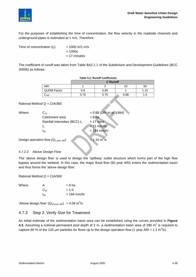
For the purposes of establishing the time of concentration, the flow velocity in the roadside channels andunderground pipes is estimated at 1 m/s. Therefore:
Time of concentration (tc) = 1000 m/1 m/s= 1000s= 17 minutes
The coefficient of runoff was taken from Table BA2.1.1 of the Subdivision and Development Guidelines (BCC2000b) as follows:
Table 4.2: Runoff Coefficients
C RunoffARI 1 2 10 50QUDM Factor 0.8 0.85 1 1.15CARI 0.70 0.75 0.88 1.0
Rational Method Q = CIA/360
Where: C10 = 0.88 (DPI et al. 1994)Catchment area = 8 haRainfall Intensities (BCC) tc = 17 minsI1 = 71 mm/hrI50 = 184 mm/hr
Design operation flow (Q1 year ARI) = 1.10 m3/s
4.7.2.2 Above Design Flow
The ‘above design flow’ is used to design the ‘spillway’ outlet structure which forms part of the high flowbypass around the wetland. In this case, the major flood flow (50 year ARI) enters the sedimentation basinand thus forms the ‘above design flow’.
Rational Method Q = CIA/360
Where A = 8 haC50 = 1.0I50 = 184 mm/hr
‘Above design flow’ (Q50 year ARI) = 4.09 m3/s
4.7.3 Step 2: Verify Size for Treatment
An initial estimate of the sedimentation basin area can be established using the curves provided in Figure4.3. Assuming a notional permanent pool depth of 2 m, a sedimentation basin area of 280 m2 is required tocapture 90 % of the 125 µm particles for flows up to the design operation flow (1 year ARI = 1.1 m3/s).

Draft Water Sensitive Urban DesignEngineering Guidelines
Sedimentation Basins August 2005 4-39
4.7.4 Step 3: Confirm Size and Dimensions of the Sedimentation Basin
4.7.4.1 Sedimentation Basin Area
Confirmation of the sedimentation basin area is provided by using Equation 4.1:
n
e
pes
dd
dd
AQ
v
nR
−
++
⋅⋅+−=)(
)(
/1
11*
Based on the description of the sedimentation basin and wetland provided in Section 4.7.1, the followingapplies:
dp = 2.0 md* = 1.0 mde = 0.3 mVs = 0.011 m/s for 125 µm particlesQ = design operation flow rate (1 year ARI) = 1.10 m3/s
An aspect ratio of 1 (W) to 4 (L) is adopted based on the available space (Figure 4.11). Using Figure 4.4(configuration I), the hydraulic efficiency (λ) is estimated to be approximately 0.4. This value is less thandesirable; however, site constraints prevent any other configuration. The turbulence factor (n) is computedfrom Equation 4.2 to be 1.67. Thus:
λ = 0.4n = 1.67
Inserting the above parameters into Equation 4.1, the required sedimentation basin area to achieve a targetsediment (125 µm) capture efficiency of 90 % is 280 m2. With a W to L ratio of 1:4, the notional dimensionsof the basin are 8.5 m x 33.0 m.
4.7.4.2 Storage Volume for Sediments
To ensure the storage zone is appropriate the following must be met:
Sedimentation Basin Storage Volume Vs > Volume of accumulated sediment over 5 years (Vs:5yr)
The sedimentation basin storage volume (Vs) is defined as the storage available in the bottom half of thesedimentation basin permanent pool depth. Considering the internal batters of the basin (Section 4.7.4) are2:1 (H:V) below the permanent water level, the area of the basin at 1 m depth is 148.5 m2 and at 2 m depthis 16.5 m2. Therefore, the sedimentation basin storage volume Vs is 82.5m3.
The volume of accumulated sediments over 5 years (Vs:5yr) is established using Equation 4.3 (using asediment discharge rate (Lo) of 1.6 m3/ha/yr):
cocyrs FLRAV ⋅⋅⋅=5:
Given Ac = 8 haR = 90 %Lo = 1.6 m3/ha/yearFc = 5 years
Draft Water Sensitive Urban DesignEngineering Guidelines
Sedimentation Basins August 2005 4-40
Storm water pipe
25 m m dia. weephole
Concrete outlet apron
Place nom . 100 m m diarock to bottom of batter
W ing W all
Plan Inlet Structure Section Inlet Structure
Storm water pipe
25 m m dia. weephole
Concrete outlet apron
Place nom . 100 m m diarock to bottom of batter
W ing W all
Plan Inlet Structure Section Inlet Structure
The total sediment accumulation is estimated to be:= 8 x 0.9 x 1.6 x 5= 57.6 m3
Therefore, Vs > Vs:5yr
Rearranging Equation 4.3, the required clean out frequency (Fc) is estimated to be:
Fc = 9.086.1
5.82
××
= 7.2 years
4.7.4.3 Internal Batters
Considering the relatively small size of the sedimentation basin (8.5 m width), it is not possible to achieve thenotional permanent pond depth of 2 m using the 5:1 (H:V) required for public safety. Therefore 4:1 (H:V)batter is to be adopted for the ground above the permanent pool level and to 0.2 m below permanent poollevel and a 2:1 (H:V) internal batter slope for 0.2 m to 2 m below the permanent pool level. Thesedimentation basin will be fenced around most of its perimeter to ensure public safety as required by BCCSediment Basin Design, Construction and Maintenance Guidelines (BCC 2001).
The base of the sedimentation basin will be lined with rock to prevent vegetation growth and to guideextraction depths during sediment removal. A summary of the sedimentation basin configuration is asfollows:
Open Water Area = 280 m2
Width = 8.5 mLength = 33.0 mDepth of Permanent Pool (dp) = 2.0 m
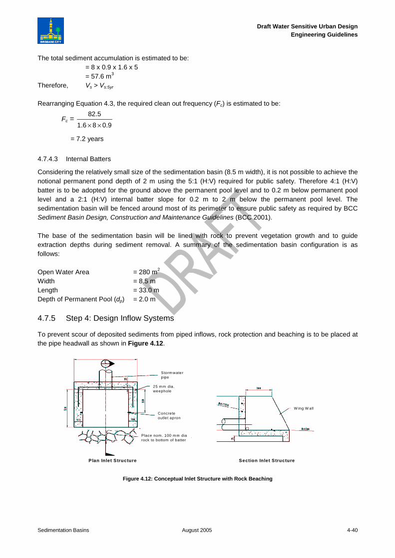
4.7.5 Step 4: Design Inflow Systems
To prevent scour of deposited sediments from piped inflows, rock protection and beaching is to be placed atthe pipe headwall as shown in Figure 4.12.
Figure 4.12: Conceptual Inlet Structure with Rock Beaching

Draft Water Sensitive Urban DesignEngineering Guidelines
Sedimentation Basins August 2005 4-41
4.7.6 Step 5: Design Outlet Structures
4.7.6.1 Design of ‘Control’ Outlet - Overflow Pit and Pipe Outlet Configuration
The ‘control’ outlet structure is to consist of an outlet pit with the crest of the pit set at the permanent poollevel of the sedimentation basin (3.8 m AHD) which is 0.3 m above the permanent water level in the wetland.The overflow pit is sized to convey the design operational flow (1 year ARI).
According to Section 4.3.5, two possible flow conditions need to be checked, i.e. weir flow conditions (withextended detention of 0.3 m) and orifice flow conditions.
Weir Flow Conditions
From Equation 4.4, the required perimeter of the outlet pit to pass 1.1 m3/s with an afflux of 0.3 m can becalculated assuming 50% blockage:
2/3hCB
QP
w
des
⋅⋅= = m8.7
3.07.15.0
1.12/3
=⋅⋅
Orifice Flow Conditions
From Equation 4.5, the required area of the outlet pit can be calculated as follows:
hgCB
QA
d
deso
⋅⋅⋅⋅=
2 =
)3.0)(81.9(26.05.0
1.1
⋅⋅= 1.5 m2
In this case, the weir flow condition is limiting. Considering the overflow pit is to convey the ‘design operationflow’ (1 year ARI) or slightly greater, a 2000 x 2000 mm pit is adopted providing a perimeter of 8 m which isgreater than the 7.8 m calculated using the weir flow equation above. The top of the pit is to be fitted with aletter box grate. This will ensure large debris does not enter the ‘control’ structure while avoiding grateblockage by smaller debris.
The size of the connection pipe (i.e. between the sedimentation basin and wetland macrophyte zone) can becalculated by firstly estimating the velocity in the connection pipe (as the outlet is submerged) using thefollowing (Equation 4.5):
gV
h⋅
⋅=2
2 2
Where: h = Head level driving flow through the pipe (defined as the ‘Spillway’ outlet levelminus the normal water level in the downstream treatment system)V = Pipe velocity (m/s)g = Gravity (9.79 m/s2)
Note: the coefficient of 2 in the equation is a conservative estimate of the sum of entry and exit loss coefficients (Kin + Kout).
Hence, V = (9.79 x 0.6)0.5 = 2.43 m/s

Draft Water Sensitive Urban DesignEngineering Guidelines
Sedimentation Basins August 2005 4-42
The area of pipe required to convey the ‘design operation flow’ (1 year ARI) is then calculated by dividing theabove ‘design operation flow’ by the velocity:
A = 1.1/2.43 = 0.453 m2
This area is equivalent to a 750 mm reinforced concrete pipe (RCP). The obvert of the pipe is to be set justbelow the permanent water level in the wetland macrophyte zone (3.5 m AHD) meaning the invert is at 2.7 mAHD.
‘Control’ Outlet Structure:
Overflow pit = 2000 x 2000 mm with letter box grate set at 3.8 m AHD pipe connection (to wetland) = 750mmRCP at 2.7m AHD
4.7.6.2 Design of ‘Spillway’ Outlet - Weir Outlet
The ‘above design flow’ is to bypass the macrophyte zone of the wetland. This will be provided by a ‘spillway’outlet weir designed to convey the ‘above design flow’ (50 year ARI) set at 0.3 m above the permanent poolof the sedimentation basin.
The length of the ‘spillway’ outlet weir determines the afflux for the 50 year ARI peak discharge and sets thetop of embankment of the sedimentation basin. It is common practice to allow for 0.3 m of freeboard abovethe afflux level when setting the top of embankment elevation. An afflux of 0.3 m has been adopted indefining the length of the spillway weir. This value was adopted as a trade off between the bank height andthe width of the weir. A bank height of 0.9 m (0.3 m afflux and 0.3 m freeboard plus 0.3 m extendeddetention) above the normal water level was deemed acceptable. The weir length is calculated using the weirflow equation (Equation 4.4) substituting outlet perimeter P with weir length L and blockage factor B=1 (noblockage):
2/3hC
QL
w
des
⋅= =
2/33.066.1
09.4
⋅= 15 m
The ‘spillway’ outlet is located adjacent to the inflow culvert to minimise risk of sediment scour.
‘Spillway’ Outlet Structure:
Spillway length = 15 m set at 0.30 m above permanent pool level (4.1 m AHD)Top of embankment set at 0.9 m above the permanent pool level (4.7 m AHD)
4.7.7 Step 6: Vegetation Specification
The vegetation specification and recommended planting density for the littoral zone around thesedimentation basin have been adapted from Chapter 12 and are summarised in the table below.
Table 4.3 Vegetation Specification for Worked Example
Zone Plant SpeciesPlanting Density
(plants/m2)Littoral Zone (edge) Carex appressa
Isolepis nodosa88
Marsh to a depth of 0.25m Eleocharis equisetinaJuncus usitatus
1010

Draft Water Sensitive Urban DesignEngineering Guidelines
Sedimentation Basins August 2005 4-43
Refer to Chapter 12 for further discussion and guidance on vegetation establishment and maintenance.
4.7.8 Step 7: Maintenance Plan
Refer to Section 4.5 for discussion on maintenance requirements for sedimentation basins and requirementsfor maintenance plans. Note that access can be gained to all areas of the basin from the banks and thereforean access ramp into the basin is not required.
4.7.9 Design Calculation Summary
The sheet below summarises the results of the design calculations.
SEDIMENTATION BASIN CALCULATION SUMMARYCalculation Task Outcome Check
Catchment Characteristics
Residential Ha
Commercial Ha
Roads 8 Ha
Storm event entering inlet pond (minor or major) 50 yr ARI
�
Conceptual Design
Notional permanent pool depth 2 m
Permanent pool level of sedimentation basin 3.8 m AHD�
1 Determine design flows
'Design operation flow' (1 year ARI) 1 year ARI
'Above design flow' (either 2 or 50 year ARI) 50 year ARI�
Time of concentration
Refer to BCC Subdivision and Development Guidelines and QUDM 17 minutes �
Identify rainfall intensities
'Design operation flow' - I1 year ARI 71 mm/hr
'Above design flow'- I2 year ARI or I50 year ARI 84 mm/hr�
Design runoff coefficient
'Design operation flow' - C1 year ARI 0.7
'Above design flow'- C2 year ARI or C50 year ARI 1�
Peak design flows
'Design operation flow' - 1 year ARI 1.1 m3/s
'Above design flow' - 2 or 5 year ARI 4.09 m3/s�
2 Verify size for treatment
Capture efficiency (of 125 µm sediment) 90 %
Area of sedimentation basin 280 m2 �
3 Confirm size and dimension of sedimentation basin
Inlet zone size
Area of sedimentation basin 280 m2
Aspect Ratio 4:1 L:W
Hydraulic Efficiency 0.4
Depth of permanent pool 2 m
�

Draft Water Sensitive Urban DesignEngineering Guidelines
Sedimentation Basins August 2005 4-44
Storage volume for sediments
Sedimentation Basin Storage Volume Vs 82.5 m3
Volume of accumulated sediment over 5 years (Vs:5yr) 57.6 m3
Vs > Vs:5yr Yes
Sediment Cleanout Frequency 7.2 years
�
Internal batters
Edge Batter Slope 1:2 V:H
Fence required yes�
4 Design inflow systems
Provision of scour protection or energy dissipation Yes �
5 Design outlet structures
Design of 'control' outlet - overflow pit and pipe outlet configuration
Overflow pit crest level 3.8 m AHD
Overflow pit dimension 2000 x 2000 L x W
Provision of debris trap Yes�
Connection pipe dimension 750 mm diam
Connection pipe invert level 2.7 m AHD�
Design of 'control' outlet - weir configuration
Weir crest level N/A m AHD
Weir length N/A m�
Design of 'spillway' outlet - weir configuration
Weir crest level 4.1 m AHD
Weir length 15 m
Depth above spillway 0.3 m
Freeboard to top of embankment 0.3 m
�
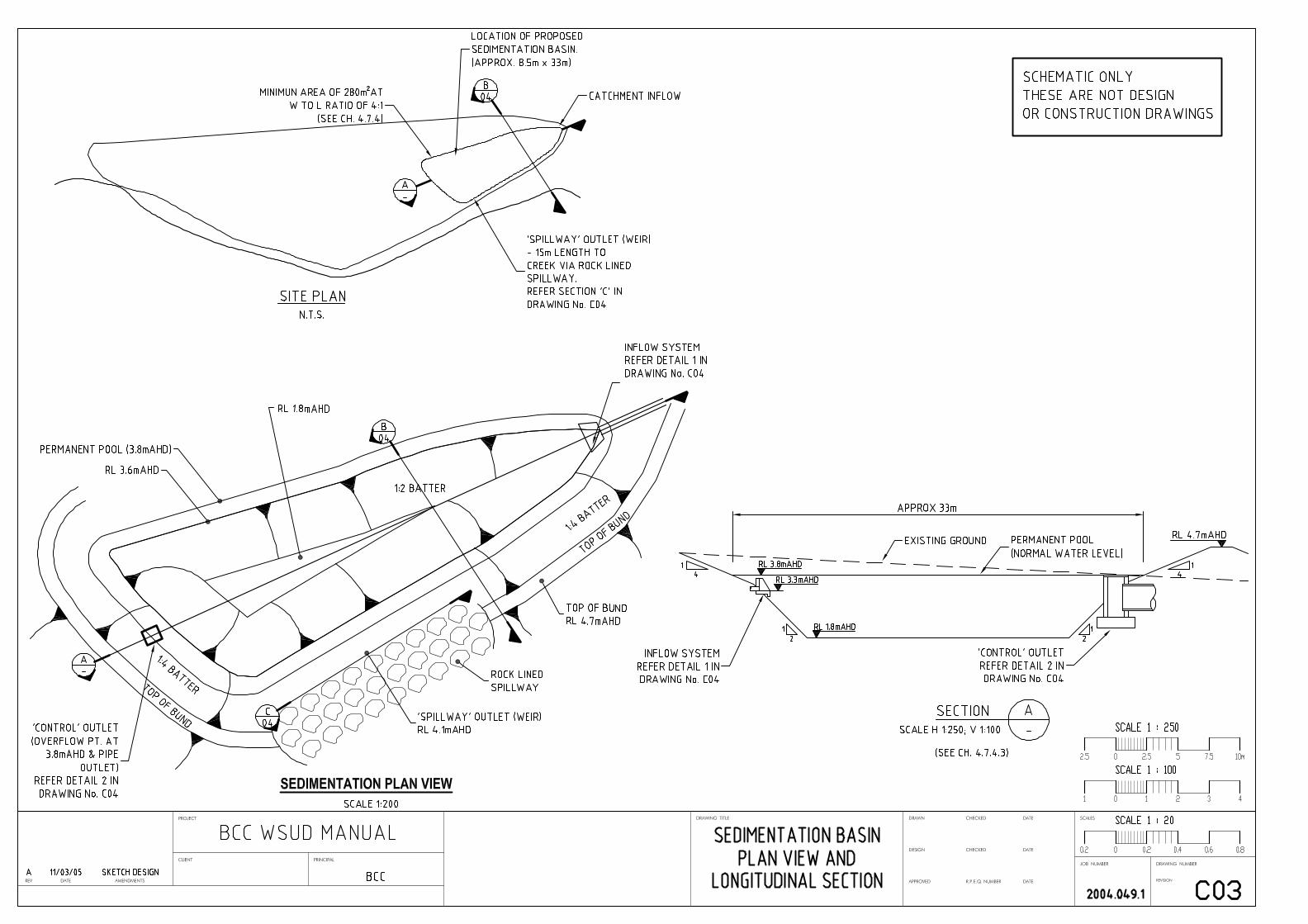
4.7.10 Construction Drawings
The drawings on page following (Drawing Number C03 and C04) illustrate the construction details of thesedimentation basin associated with the worked example.


Draft Water Sensitive Urban DesignEngineering Guidelines
Sedimentation Basins August 2005 4-47
References
BCC (Brisbane City Council) 1994, Supplement to QUDM, BCC, Brisbane
BCC 2000a, Brisbane City Plan 2000, BCC, Brisbane
BCC 2000b, Subdivision and Development Guidelines, BCC, Brisbane,http://www.brisbane.qld.gov.au/BCC:STANDARD::pc=PC_1388
BCC 2000b (with revisions 2004), Subdivision and Development Guidelines, BCC, Brisbane,http://www.brisbane.qld.gov.au/BCC:STANDARD::pc=PC_1388
BCC 2001, Sediment Basin Design, Construction and Maintenance: Guidelines, BCC, Brisbane
BCC 2005, Growing Native Plants in Brisbane, BCC, Brisbane, accessed 25th July 2005,http://www.brisbane.qld.gov.au/BCC:STANDARD::pc=PC_1927
Chow VT 1959, Open Channel Hydraulics, McGraw-Hill, New York
DPI, IMEA & BCC (Department of Primary Industries – Water Resources, Institute of Municipal EngineersAustralia – Qld Division & Brisbane City Council) 1993, Queensland Urban Drainage Manual (QUDM),prepared by Neville Jones & Associates and Australian Water Engineering for DPI, IMEA & BCC, Brisbane
Engineers Australia 2003, Australian Runoff Quality, Engineers Australia, ACT,http://www.arq.org.au/
Fair GM and Geyer JC 1954, Water Supply and Waste Disposal, vol. 2, John Wiley and Sons, New York
GBLA (Graeme Bentley Landscape Architects) 2004, Preliminary drawings for Mernda Wetland, report forStockland, GBLA, Victoria
Henderson FM 1966, Open Channel Flow, Macmillan Publishing, New York
LHCCREMS (Lower Hunter and Central Coast Regional Environmental Management Strategy) 2002, WaterSensitive Urban Design in the Sydney Region: ‘Practice Note 2 – Site Planning’, LHCCREMS, NSW,http://www.wsud.org/downloads/Planning%20Guide%20&%20PN%27s/02-Site%20Planning.pdf
McFarlane A 1997, Successful Gardening in Warm Climates, Kangaroo Press, Sydney
Persson J, Somes NLG and Wong THF 1999, ‘Hydraulic efficiency and constructed wetland and ponds’,Water Science and Technology, vol. 40 no. 3, pp. 291–289
Standards Australia 2003, AS 4419-2003: Soils for landscaping and garden use, Standards Australia
Related Documents