Draft Specification No. TI/SPC/PSI/PQR/0210 Effective from: Page 1 of 50 भारत सरकार GOVERNMENT OF INDIA रेल मंालय MINISTRY OF RAILWAYS LIksLkhfQdsLku laÛ: VhÛvkbZ Û@,lÛihÛLkhÛ@ihÛ,LkÛvkbZ @ पी Ûू ÛआरÛ@0210 SPECIFICATION NO. TI/SPC/PSI/PQR/0210 भारतीय रेलवे के ललए 25 केवी और 2X25 केवी र ैन सब-ेशन के ललए पावर ालली ररोरर के ललए तकनीकी लवलनेश Technical Specification for Power Quality Restorer for 25kV and 2x25 kV Traction Substation --/2021 tkjhdrkZ @ISSUED BY, d"kZ .k laLFkkiu fun¢'kkYk; TRACTION INSTALLATION DIRECTORATE vuq la/kku vfHkdYi vkS j ekud laxBu RESERCH DESIGNS & STANDARDS ORGANISTAION, ekuduxj]y[kuÅ&226 011 MANAK NAGAR, LUCKNOW-226011 Note: (i) This specification is the property of RDSO. No re-production shall be done without the permission of DG (TI) RDSO. (ii) All clauses of this specification shall be enforced from cut-off date ………….. Prepared by Checked and issued by SSE/PQ/TI Director-3/TI gLrk{kj@Signature vuq Ekksfnr Approved by iz ?kku dk;Z dkjh funs'kd ¼d"kZ .k laLFkkiu½ Principal Executive Director (TI) vuq ’kaflr Recommended by dk;Z dkjh funs'kd ¼d"kZ .k laLFkkiu½ Executive Director (TI)

Welcome message from author
This document is posted to help you gain knowledge. Please leave a comment to let me know what you think about it! Share it to your friends and learn new things together.
Transcript

Draft Specification No.
TI/SPC/PSI/PQR/0210
Effective from:
Page 1 of 50
भारत सरकार GOVERNMENT OF INDIA
रेल मंत्रालय MINISTRY OF RAILWAYS
LIksLkhfQdsLku laÛ: VhÛvkbZZÛ@,lÛihÛLkhÛ@ihÛ,LkÛvkbZ@ पीÛकू्यÛआरÛ@0210
SPECIFICATION NO. TI/SPC/PSI/PQR/0210
भारतीय रेलवे के ललए 25 केवी और 2X25 केवी ट्र ैक्शन सब-स्टेशन के ललए
पावर क्वाललट्ी ररस्टोरर के ललए तकनीकी लवलनरे्दश
Technical Specification for Power Quality Restorer
for 25kV and 2x25 kV Traction Substation
--/2021
tkjhdrkZ@ISSUED BY,
d"kZ.k laLFkkiu fun¢'kkYk;
TRACTION INSTALLATION DIRECTORATE
vuqla/kku vfHkdYi vkSj ekud laxBu
RESERCH DESIGNS & STANDARDS ORGANISTAION,
ekuduxj]y[kuÅ&226 011
MANAK NAGAR, LUCKNOW-226011
Note: (i) This specification is the property of RDSO. No re-production shall be done without the permission
of DG (TI) RDSO.
(ii) All clauses of this specification shall be enforced from cut-off date …………..
Prepared by Checked and issued by
SSE/PQ/TI
Director-3/TI
gLrk{kj@Signature
vuqEkksfnr
Approved by iz?kku dk;Zdkjh funs'kd ¼d"kZ.k laLFkkiu½
Principal Executive Director (TI)
vuq’kaflr
Recommended by dk;Zdkjh funs'kd ¼d"kZ.k laLFkkiu½
Executive Director (TI)

Draft Specification No.
TI/SPC/PSI/PQR/0210
Effective from:
Page 2 of 50
INDEX
Clause Title Page
No
1. Scope
2. Governing specifications
3. Environmental conditions
4. Traction power supply system
5. Technical specification
6. General arrangement of power quality restorer
7.
Control panels of power quality restorer
8. Current and potential transformers
9. Protection against lightning surges
10. Earthing
11. Painting
12. Fasteners
13. Testing of power quality restorer
14. Capitalization of losses and benefits
15. Technical data & drawings to be submitted with offer
16. Designs and drawings approval
17. Inspection and testing of prototype
18. Erection, testing & commissioning
19. Spare parts, catalogue and support documents
21. Training of Indian Railway’s engineers
Draft Specification No. TI/SPC/PSI/PQREST/0210
Effective from:
Page 3 of 50
ANNEXURES
ANNEXURE TITLE PAGE
1. Schedule of guaranteed performance, technical and other particulars
28
2. Associated specifications to power quality restorer 35
3. Measurements of power data (TBM/TSS) at a typical traction substation
36
4. Related equipment at traction substation 41
5. General scheme of supply for 25 kV, 50 Hz, single phase traction system
42
6. Benefits/loss information to be submitted by the Firm/Vendor
44
7. Method of calculation of capitalized cost 45
8. Ann-8A:Typical daily load curve of a traction substation, Ann-8B:Summarized load information furnished by
Railway
46 47
9. General schemes for power quality restorer 49
10. SLD of Scott connected 2x25kV TSS 50
11. SLD of V-Connected 2x25kV TSS 51
12. SLD of supply of 2x25kV for 25kV, 50 Hz, Single phase traction system
52

Draft Specification No. TI/SPC/PSI/PQREST/0210
Effective from:
Page 4 of 50
GLOSSARY OF ABBREVIATIONS
AMC Annual maintenance contract PWM Pulse width modulation
APP All polypropylene RMS Root mean square
BIL Basic Insulation Level SCADA Supervisory control and
data acquisition system
BT Booster transformer SVC Static VAR Compensator
CD Contract demand SVG Static VAR Generator
CRCA Cold rolled carbon annealed
CT Current transformer TDD Total Demand Distortion
EMU Electrical multiple unit THD Total Harmonic Distortion
GTO Gate turn off
HRC High rupturing capacity
HT High tension TSS Traction Sub-station
IGBT Insulated gate bipolar transistor USL Upper Specified Limit
kA Kilo ampere VSC Voltage Source Converter
kV Kilo volt WPC Wrong Phase Coupling
kVAR Kilo volt ampere reactive
kVp Kilo volt peak
LED Light emitting diode
LT Low tension
MD Maximum demand
MEMU Main line electrical multiple unit
MVA Mega volt ampere
MVAh Mega volt ampere hour
MVAR Mega volt ampere reactive
MWh Megawatt hour
OHE Overhead equipment
PCB Polychlorinated-biphenyl
PCC Point of common coupling
PT Potential transformer
PQR Power quality restorer

Draft Specification No.
TI/SPC/PSI/PQREST/0210
Effective from:
Page 5 of 50
1. SCOPE
1.1. Indian Railways employ
1.1.1. 220 or 132 or 110 kV/27 kV traction substation, availing 1-phase, 50 Hz supply at 220 or 132 or 110 kV from the supply authorities, for supplying power to the 25 kV overhead lines for electric traction. Hitherto fixed shunt capacitor banks have been provided at the traction substation for improving the average power
factor.
1.1.2. 220 or 132/55 kV, 2x25 kV Traction Sub-station (Scott connected & V-connected Transformer using incoming supply from 3 phase transmission line at 220 or 132kV from the supply authorities).
1.2. With a view to improving the average power factor and mitigating the harmonics fed into the supply source, the power quality restorer is intended to be provided at the traction substation. The Power Quality Restorer shall be rated for 52kV Voltage Class (insulation class) and should be capable of being connected directly on the 25 kV AC bus or
across +25kV & earth and -25kV earth in 2x25 KV Traction Sub-station provided with Scott connected transformer without midpoint earth or V-Connected Transformer. Dynamic compensation of reactive power and current harmonics should be achieved with the provision of suitably designed passive / active filters; Power Quality Restorer should be based on IGBTs or any further improved/advanced electronic switching devices for the purpose as necessary .
Compensation may be stepless or in small steps such that advantages of improved average power factor and mitigated harmonics are achieved as desired.
1.3. This specification covers the design, manufacture, supply, erection, testing and commissioning of the power quality restorer. It is for outdoor/indoor installation at the traction substation of 1-phase, 50Hz, 25kV AC systems including 2x25 kV feeding system on Indian Railways for mitigation of harmonics, improvement of average power factor and reduction of maximum demand.
1.4. The power quality restorer should be complete with passive / active filters, control gear, protective relays, automatic

Draft Specification No.
TI/SPC/PSI/PQREST/0210
Effective from:
Page 6 of 50
power factor/ harmonic correction, relays, IGBTs and/or other advanced suitable electronic switching devices and accessories necessary for its efficient operation. All such parts and accessories shall be deemed to be within the scope of this specification whether specifically mentioned or not. The 25 kV circuit breakers, 25 kV current and
potential transformers, 25 kV isolators, 42 kV ZnO lightning arresters, 25 kV bus bars and connectors, 25 kV post insulators etc. required for the RESTORER shall also be within the scope of supply against this specification. The Double Pole Circuit Breaker, Current and Potential Transformers etc. shall be according to the equipment mentioned in layout for 2x25 kV System.
1.5. The successful Firm/Vendor shall be required to erect and commission the equipment. The offer shall, therefore, be inclusive of all expenses including deputing engineers and supervisors by the Firm/Vendor for handling, installation, testing and commissioning of the equipment and proving the performance requirement.
1.6. All civil engineering works connected with foundations of power quality restorer, circuit breakers, isolators, series reactor, potential transformers, current transformers, ZnO lightning arresters and supporting steel structures, as also construction of building for housing any indoor equipment shall form part of this specification, and are part of scope
of work against this specification.
1.7. The power quality restorer panel should have display of the power quality parameters with storage facility and be able to ensure that Indian Railway system is able to meet the grid connectivity compliance regulations as specified in respective regulatory authority code e.g., IEEE 519-2014. PQR measures the load and source currents
with the available TSS (+25kV) protection CTs which are also used for compensation (load harmonics and source
harmonics) and same data is logged in the system and to cloud as well for monitoring and cross verification. The display
on the PQR panel will representative/indicate the actual power quality parameters at the TSS. Hence, separate meter may
not be required for power quality measurement. However, this power quality data cannot be used for actual TSS billing
data.
2. GOVERNING SPECIFICATIONS
2.1. Power quality restorer and associated equipment shall, unless otherwise specified herein, conform to the latest revision of standards mentioned below and associated specifications listed in Annexure-2 as well as the CEA regulation 2010 or latest as applicable.
2.1.1. IS : 5-1994 Colour for ready mixed paints and enamels
2.1.2. IS:13585-1 Low voltage capacitors
2.1.3. IS : 513-1994 Cold rolled low carbon steel sheets and strips
2.1.4. IEC 60747-2 Diodes
2.1.5. IEC 61071 DC Capacitors
2.1.6. IEC 60747-9 Insulated gate bipolar transistors
2.1.7. IEC 60747-15 Isolated power semiconductor devices
2.1.8. IEC-60146-2(1999), section-7
Electrical rating and characteristics of voltage source converter.
2.1.9. IEC 60664 Insulation coordination for equipment within low voltage systems (clearance and creepage distances).
2.1.10. IEC 61000-4-30 edition 3 Power quality measurement methods
2.1.11. IS 14697 AC static transformer operated watt hour meter 0.2s
2.1.12.
2.1.13. IS : 800-1984 Code of practice for use of structural steel in general building construction
2.1.14. IS : 1554 : (Pt.2) PVC insulated (heavy duty) electric cable for working voltages from 3.3kV upto and including 11 kV.
2.1.15. IS : 2026 (all parts) Power transformers
2.1.16. IS : 2099-1986 Bushing for alternating voltages above 1000 volts
2.1.17. IS : 3070-1986 Surge arrestor for a.c. systems, non-linear resistor type
2.1.18. IS : 3231 (all parts) Electrical relays for power system protection
2.1.19. IS : 3700 (all parts) Essential ratings and characteristics of semi- conductor devices.

Draft Specification No.
TI/SPC/PSI/PQREST/0210
Effective from:
Page 7 of 50
2.1.20. IS : 5553-1990 Reactors
2.1.21. IS : 11298-1991 (Pt.3/Sec.1)
Specification for plastic films for electrical purposes -polypropylene film for capacitors
2.1.22. IS : 13947-2 Air circuit breakers
2.1.23. IS : 12672-1989 Internal fuse and internal over pressure disconnectors for shunt capacitors
2.1.24. IEC-60871-1/IS-13925-1 Shunt capacitors for a.c. systems having a rated voltage above 1000 V.
2.1.25. IEC-60871-2/IS-13925-2 Shunt capacitors for a.c. systems having a rated voltage above 1000 V (endurance testing).
2.1.26. RDSO Specification No. ETI/OHE/13(4/84)
Specification for hot dip zinc galvanization
2.1.27. RDSO Specification No. ETI/OHE/18(4/84)
Specification for steel and stainless steel, nuts and washers steel bolts
2.1.28. RDSO Specification No. ETI/PSI/65(1/97)
Specification for control and relay panel.
2.1.29. RDSO Specification No. TI/SPC/PSI/CB/0000
Specification for outdoor circuit breakers for railway ac traction substations.
2.1.30. RDSO Specification No. ETI/PSI/120 (7/88)
Code of practice for earthing of power supply installation for 25 kV a.c. 50 Hz single phase traction system.
2.1.31. IEC 60146 Specification for semiconductor converters
2.1.32. IEC 519-1992 Specification for harmonic control
2.1.33. IEC 60044-1 Specification for instrument transformers, current transformers
2.1.34. IEC 61082-1 Specification for preparation of documents
2.1.35. IEC 62305 Specification for lightning protection
2.1.36. IEC 61140 Specification for protection against electric shock
2.1.37. IEC 60445 Specification for man-machine interface, marking and identification
2.1.38. IEC 60204-1 Specification for safety of machinery-electrical equipment
2.1.39. IEC 62477-1 Specification for power electronic converter systems and equipment
2.1.40. IEC 61000-4-30 Testing and measurement techniques - Power quality measurement methods
2.1.41. IS 14697 IS 14697 - AC static transformer operated watt hour meter 0.2s
2.21. In the case of any overlapping or conflict in contents of the above standards and this specification, stipulations of this specification shall prevail.
2.22. Deviations: Any deviation from this specification, proposed by the Firm/Vendor, intended to improve performance, utility and overall efficiency, will be given due consideration, provided full particulars of the
deviation with justification thereof are furnished. In such case, the Firm/Vendor shall quote according to this specification, and the deviations proposed by him shall be quoted as an alternate/ alternatives.
2.23. Site visit: The Firm/Vendors should visit the sites/sections and may carry out load and harmonic current measurements at the concerned traction substations as considered necessary so as to familiarize themselves with the local conditions and understand the technical requirements of the system in detail, and obtain clarifications
as may be necessary from the Purchaser, before tendering the Bids, and ensure that their offers meet the technical, performance and other requirements specified in this specification.
2.24. Pre-bid meeting may be arranged by the purchaser, with eligible Firm/Vendors in regard to the particular requirements against this specification, site conditions, mode of transport, availability of site, erection and
commissioning, etc. After the award of the contract, the Firm/Vendor shall be fully responsible for successful integration of the power quality restorer with the existing traction substation equipment, and with the Remote Terminal Units (RTUs). Any items/ equipment later considered as essentially required for successful integration shall fall within the scope of the supply and work of the Firm/Vendor, and no extra price will be paid by the
Purchaser on that account.

Draft Specification No.
TI/SPC/PSI/PQREST/0210
Effective from:
Page 8 of 50
3. ENVIRONMENTAL CONDITIONS
3.21. All equipment supplied against this specification shall be suitable for outdoor/ indoor use in tropical climate and in areas that are subject to heavy rainfall, pollution due to industrial and coastal climates and severe
lightning surges. The maximum ambient temperature may reach 50oC in shade, with maximum humidity
reaching up to 100%. However, for the design of the equipment, 50oC category of temperature shall be taken.
i. Maximum temperature of Air (in shade): 50oC
ii. Minimum temperature of Air (in shade): (-)10o C iii. Maximum relative humidity: 100%
iv. Annual rainfall ranging from: 1750 mm to 6250 mm
v. Maximum number of thunder storm days per annum: 85 days
vi. Maximum number of dust storm days per annum: 35 days
vii. Number of Rainy days per annum: 120 days
viii. Basic wind pressure: 200 kgf/m2
ix. Altitude above Mean Sea level (MSL) 2000 m
3.22. Vibrations: The equipment is to be installed on foundations in the ground or on steel structures, located by the side of railway tracks and is subjected to vibrations due to the passage of trains. The amplitude of these vibrations lies in the range of 30 to 150 microns, with instantaneous peaks going upto 350 microns. These vibrations occur with rapidly varying time periods in the range of 15 to 70 ms.
4. TRACTION POWER SUPPLY SYSTEM
4.21. General Scheme of 2x25 kV ac Traction System In 2x25 kV system, power is fed from the TSS at 50 kV and utilization is achieved at 25 kV by providing
Auto-transformers of adequate capacity and by providing one additional conductor normally referred as feeder wire (similar to the return conductor in BT/RC system). Centre point of the Auto Transformer is connected to the earth/rail. This arrangement facilitates +25 kV Voltage between OHE and rail and -25 kV voltage between Rail/earth and the Feeder Wire.
4.1.1. Scott Connected Transformer Scheme: (a) In this scheme 2 number Scott connected Transformers & 04 number Autotransformers are to be
installed at a TSS along with associated switchgear for Control & protection. The two windings of a
SCOTT transformer i.e., Main and Teaser windings are of equal power rating and feed either side of
the TSS independently. The supply of both the windings is at a phase difference of 90 degree and
separated by neutral section provided near TSS. Out of two Scott transformers only one is in operation
and the other is on standby. (Annexure-10)
(b) Scott Connected Transformer:
Scott- connected transformer of 60/84/100 MVA (ONAN/ONAF/OFAF) is used to feed power to the traction system. It has a voltage input on 220kV or 132kV, 3 phase, 50 Hz and two independent secondary winding for output at 55 kV. The Transformer has 2 secondary windings, one known as the

Draft Specification No.
TI/SPC/PSI/PQREST/0210
Effective from:
Page 9 of 50
main winding and the other known as the teaser winding. The two windings are identical in voltage and current rating but are in phase difference of 90 degree. These two windings of equal power rating i.e., Main & Teaser windings, feed power on either side of the TSS. The feed of different pha se is
separated by neutral section provided near TSS. The Scott Connected Transformer in ONAN Mode shall feed the 30MVA Power to each side of the TSS.
4.1.2. V Connected Transformer Scheme:
(a) In this scheme, 3 bays of V-Connected single-phase transformers are connected to different pairs of 3
phases forming on open delta connection on the primary side. Out of the 3 sets of V-Connected single-
phase transformers, one set of V-Connected transformer feeds the OHE on one side of the TSS,
another set feeds the OHE on the other side of the TSS and the third set of V-Connected transformer
remains as standby. The power supply on either side of TSS is at a phase difference of 120 degree and
therefore separated by a neutral section provided near TSS. (Annexure-11)
(b) V- Connected Transformer:
In the above arrangement, 3 number 38/53/63 MVA (ONAN/ONAF/OFAF) Open delta connected Transformers are to be installed at a TSS having 3 phase, 50Hz, 220kV or 132kV incoming supply along with associated switchgear for Control and protection. In these single-phase transformers, there
are two secondary windings in each transformer. One terminal of these secondary windings is connected with each other and connected to Rail. The outer terminals of windings are connected to Feeder wire and overhead contact/catenary wire respectively. Two transformers shall be in operation at a time and one shall be stand by. In the V connected Scheme, each transformer in ONAN mode
shall feed the 38MVA Power in either side of the TSS.
4.22. General Scheme of 25kV ac Traction System
4.1.1. Single phase supply (between phase to phase) is availed by Railway at 220/132/110 kV, 50 Hz from the 3-phase effectively earthed transmission network of the supply authorities. The 25 kV, 1-phase AC supply for railway traction is obtained through 220 or 132 or 110/ 27 kV, 13.5MVA or 21.6 MVA or 30 MVA step- down power transformers provided at the traction substation. The primary winding is connected
across the two phases of the incoming 220/132/110 kV supply. The spacing between adjacent traction substations generally varies between 40 km and 80 km. One terminal of the 27 kV secondary winding of the transformer is connected to the overhead equipment (abbreviated as OHE). The other terminal is solidly earthed and also connected to traction rails of the running track.
4.1.2. The load current flows through the OHE to the locomotives and returns through rail and earth to the traction substation.
4.1.3. Adjacent substations are fed by different pair of phases of the 3-phase grid of the supply authorities so as to provide load balancing on the grid. In the middle of adjacent traction substations, a dead zone known as “neutral section” is provided in the OHE to isolate the two supplies. The power to the OHE on either side of
the traction substation is fed by a separate feeder circuit breaker. OHE of each track is controlled by an Interrupter. In case of fault on the OHE, the concerned feeder circuit breaker clears the fault.
4.23. Brief on related equipment provided at the traction substation is given in Annexure-4. A schematic diagram of a typical arrangement, showing the “General Feeding Arrangement” of a traction system, as well as the “Schematic General Arrangement at a Traction Substation” is given in Annexure-5.
4.24. The incoming 220/132/110 kV AC supply may vary between +10% to -12.5% as per CEA regulation 2010. The supply frequency may vary by ±3% from the standard frequency of 50 Hz.
4.25. Protection system for 25 kV AC Traction System and 2x25kV AT Traction Power System
4.1.1. 25kV AC Traction System
4.25.1.1. Various relays are provided for the protection of the 25 kV AC traction power supply system. The following protective relays are provided for the protection of power transformer:
i. IDMT overcurrent Protection on 220/132/110/66 kV side. ii. Restricted earth fault protection on 220/132/110/66kV side. iii. IDMT overcurrent on 25 kV side.
iv. Restricted earth fault on 25 kV side.
4.25.1.2. The following protective relays are provided for the protection of OHE: i. Distance Protection

Draft Specification No.
TI/SPC/PSI/PQREST/0210
Effective from:
Page 10 of 50
ii. Instantaneous Over Current Protection. iii. Wrong Phase Coupling Protection.
Traction substations are now provided with static/microprocessor-based relays.
4.1.2. 2x25kV AT System
4.25.2.1. The following relays are provided for the protection of traction transformers :
i. Differential relay.
ii. Over current relay on 220 kV or 132 kV side.
iii. Grounding over-current relay on 220 KV or 132 KV.
iv. High -speed over current relay on 220 kV OR 132 kV.
v. Phase-failure relay (to detect a malfunction of a feeder circuit breaker).
4.25.2.2. The following relays are provided for the protection of OHE:
i. Distance relay (with a parallelogram protection characteristics).
ii. Delta- I type fault selective relay.
iii. Under voltage relay.
However, relevant specifications for control & relay panel for 25kV and 2x25kV TSS may be referred
for detailed information.
4.26. OHE and Traction Transformer
4.1.1. 25 kV AC
i. The OHE generally consists of a stranded cadmium copper catenary of 65 mm 2 area and a grooved copper contact wire of 107 mm2 area providing a total of 150 mm2 copper equivalent. The loop impedance of the OHE is as under:
The values without Booster Transformer (BT) and Return Conductor–
- Single track OHE 0.41∠700 ohms/km - Double track OHE 0.24 ∠700 ohms/km
- Triple track OHE 0.18 ∠700 ohms/km
The values with Booster Transformers (BT) and Return Conductor– - Single track OHE 0.70 ∠700 ohms/km - Double track OHE 0.43 ∠700 ohms/km
- Triple track OHE 0.27 ∠700 ohms/km
ii. In some sections contact wires of 150/161/193 mm2 are also used. The Firm/Vendor may obtain details of impedances from the Railway, if such wires are used.
iii. Traction Transformer: The resistance and reactance of a typical 13.5 MVA and 21.6 MVA traction power transformer at the traction substation is (0.179 + j 5.49) ohms and (0.132 + j 4.05) ohms respectively. Only one transformer is generally in service at a time.
iv. Clearances: A minimum clearance of 500 mm is provided in general between any live conductive parts at 25 kV and earthed structures in the 25 kV AC traction system. This clearance is not applicable for equipment like insulators (post/bracket/stay etc.), section insulators, and other equipment that have been type-tested for the BIL of the 25 kV system.
4.1.2. 2x25 kV AT System:
4.26.2.1. The OHE is made up of a stranded cadmium copper catenary of 65 Sq. mm. or a stranded aluminum alloy
catenary of 116 sq. mm and a grooved contact wire of 107 sq. mm making up a total of 150 sq. mm or140sq.mm
copper equivalent, respectively. As a feeder wire, a stranded aluminum alloy of 240 sq. mm. is used. The
impedance of upcoming system may change.
4.26.2.2. The calculated OHE impedance value of AT feeding circuit (OHE: Al 116-cu 107 sq. mm feeder wire:
A1 240 sq. mm) for a single-track line is 0.0601+jo.1419 ohms/km (at 25 kV System impedance), Z50=0.2404
+ j0.5684(at 50 kV System impedance) and Z25= Z50/4
4.26.2.3. The percentage impedance of a 60/84/100MVA, ONAN/ONAF/OFAF, 220kV/2X55kV or
132kV/2X55kV or 110kV/2X55kV or 66kV/2X55kV Scott connected transformer are (11 to 13) % (at 30MVA
Base) and for 54MVA, 220kV/2X(2X27) kV is 12% (at 27 MVA base). For 21.6MVA, ONAN & 38/53/63MVA ONAN/ONAF/OFAF, Single Phase transformer is (12 ± 1.2) % (at 10.8MVA & 19MVA Base).
The Traction Transformers in the system may be of secondary Centre tapped type for ensuring phase failure

Draft Specification No.
TI/SPC/PSI/PQREST/0210
Effective from:
Page 11 of 50
protection. Rating of the power transformer Rated secondary current of the Transformer of each winding 54 MVA 60MVA 21.6MVA 38MVA Continuous 500 A 545A 400 A 600A 15 Min 750 A 817.5A 600 A 800A 5
Min 1000 A 1090A 800 A 1200A
4.27. Nature of faults on the OHE system
4.1.1. OHE is subject to frequent earth faults, or snapping of OHE and touching the rail/earth, or loose wires carried by birds coming in contact with OHE below overline structures, miscreant activities etc. Faults are
cleared by feeder circuit breaker, which operates on distance protection relay and/or instantaneous overcurrent relay depending on the proximity of the fault.
4.1.2. Inadvertent coupling of two different phases between adjacent traction substations at the neutral section or at intermediate switching stations, in case of extended feed condition, is cleared by one of the feeder circuit breakers at either end of traction substation through a "mho relay” known as wrong phase coupling
relay.
4.1.3. Short Circuit Level: For different grid supply voltages, short circuit level on primary side of traction power transformer may vary between 7 to 8 kA depending upon the proximity of the traction substation to the generating station. The actual values of fault-level will be furnished by the Railway, depending upon
the location of traction substation.
4.28. Nature of load on the 25 kV / 2x25kV AT system
4.1.1. Traction load is of frequent and rapidly varying nature and may fluctuate between no-load and overloads. While a precise load cycle is difficult to forecast, a load curve for a typical day together with indications of the average power factor, will be supplied by the Railway, in a format as indicated in Annexure-8C. Annexure-3 shows the average MVA (averaged over every 15 minutes period) versus time. Railway will
also provide the summarized cycle as shown in the annexure based on which the capitalization of losses and benefits would be worked out by the Firm/Vendor, with reference to Clause 14 of this specification.
4.1.2. The AC electric rolling stock/AC-DC electric locomotive/EMUs/MEMUs are fitted with single-phase bridge connected silicon rectifiers with smoothening reactor for feeding the DC traction motors. The rectifiers introduce harmonic currents on the 25 kV power supply. Also, there are
EMUs/MEMUs/Locomotives with GTO (Gate Turn Off)/ IGBT/pulse width modulation devices, in place of silicon rectifiers. Typical percentages of current harmonics in traction load current obtained during higher load currents of about 600 A to 800 A are as follows (during lower load currents the harmonics obtained are considerably higher than the following figures):
S.No. Harmonic
order With diode
rectifier (%) 3-Phase rolling stock with
GTOs/IGBTs 1. 3rd harmonic 18 Maximum harmonic current of individual
harmonic at no time exceeds 0.5 A except third harmonic which may be upto 5 A.
The GTO or IGBT type of Locomotives/EMU/MEMU produce substantial 2nd harmonic currents which may be upto 10% of fundamental current.
2. 5th harmonic 8 3. 7th harmonic 4 4. 9th harmonic 1.5 5. 11th harmonic 1
THD (typical) 20
These are only typical values and are to serve as guidelines only. Actual values at any particular traction substation could be different depending on the type of loads and loading pattern. The average power factor
of the electric locomotive or electric multiple units varies between 0.7 lagging to near unity. Successful Firm/Vendor shall measure these values before submitting final design.
Power quality restorer should help limit these values within limits as specified by grid connectivity regulation specified by CEA
4.1.3. In big yards and in the vicinity of electric loco sheds, a number of locomotives may be idle with only the
load of their auxiliaries and drawing higher reactive power.
4.29. LT Auxiliary Power Supply
Each traction substation is generally provided with two numbers of 25 kV/240 V, 50 Hz, single phase oil filled Auxiliary Transformers. LT supply of 240 V, single phase, 50 Hz will, if necessary, be made available for working of the Power Quality Restorer (PQR) from these auxiliary transformers. The Firm/Vendor should indicate in their offer the power requirement from these transformers f or the operation of the PQR,

Draft Specification No.
TI/SPC/PSI/PQREST/0210
Effective from:
Page 12 of 50
if required. As the power from this auxiliary transformer is very limited and required for 25kV/2x25kV system operational, the firm has to supply auxiliary transformer of required capacity along with the PQR equipment and shall be installed to meet the requirement of auxiliary power. No DC supply will be made
available by Railways for any auxiliary power requirement of the PQR.
5. TECHNICAL SPECIFICATION
5.21. Traction System Particulars
i. System 25 kV, 1-Phase, 50 Hz AC traction system
ii. Nominal system voltage 25 kV (Phase to Earth)
iii. Variation in system voltage 19 kV to27.5kV (upto 30 kV at instants) (down to 17.5 kV at instants).
iv. Equipment voltage class (on 25 kV side/ 55kV side for 2x25kV System
52 kV (PQR will be provided individually on +25kV & -25kV with mid-point earthed)
v. Rated frequency 50 Hz + 3%
vi. Average power factor of the traction system
Between 0.7 and 0.8 lagging.
vii. Harmonics (typical) Refer Clause 4.5.2. viii. Load cycle (typical) Refer Clause 4.5.1
ix. Fault level at the 25 kV bus at the traction substation (maximum). (Neglecting supply source impedance)
The ratio of rated current of traction transformer to per-unit impedanceof transformer.
5.22. Power Quality Restorer
5.1.1. Purpose: The purpose of the Power Quality Restorer (PQR) to be provided at the traction substation is mainly twofold as under:
i. To limit the total harmonic demand distortion for current (TDDi) within the maximum permissible limit as per clause 5.3 of IEEE519-2014. For this purpose, load currents higher than 200 A only will be considered, since TDDi is not relevant at lower load currents.
ii. To maintain the average power factor between 0.95 lag to 0.95 lead at all loading conditions at the metering point (i.e., 220/ 132/110/66 kV bus).
5.1.2. Brief details of existing system:
5.22.2.1. Power factor: The traction load is continually varying in nature with a power factor of 0.7 to 0.8 lag; the higher power factor is generally obtained at higher load currents. At present, the reactive power compensation is provided by HT (25 kV) fixed shunt capacitor bank with 13% detuned reactor. The billing power factor is calculated as the ratio of kWh to kVAh recorded during the month; for kVAh both lag and lead power factors are considered.
5.22.2.2. Harmonic currents: The traction load current contains harmonics generated due to rectifier type electric locomotives. The harmonic currents are predominantly odd harmonics; the percentages of harmonic currents measured during higher load currents (of about 600 A to 800A) are of the order of 18%, 8%, 4% and 1.5% for 3rd, 5th, 7th and 9th harmonics respectively; the total harmonic distortion of current is about 20%. During lower load currents, the percentage harmonics measured are
considerably higher than the above-mentioned figures. As per extant CEA guidelines, the total harmonics distortion for current at maximum demand (TDDi) at metering point shall not exceed 8%. The current harmonics will be measured at point of common coupling (PCC) continuously with permanent meter, complying to IEC 61000-4-30 Edition 3 Class A, as distortion limits are to be
calculated based on daily and weekly percentile values. The power quality restorer shall be designed to meet the existing and proposed requirements as above, wherein the current distortion limits are proposed to be revised based on Isc/IL at every PCC.
So far as the voltage distortion is concerned, the system owners viz Electricity Authority are
supposed to limit the total harmonics distortion for the supply voltage to 5% with individual harmonics not being allowed to exceed 3% as per the CEA regulation for the present. Notwithstanding this, the underlying assumption is that, by limiting harmonic current injection by bulk consumers like Railways, the voltage distortion can be kept below objectionable levels. In the event that, limiting
harmonic currents alone does not result in acceptable levels of voltage distortion, the system owner

Draft Specification No.
TI/SPC/PSI/PQREST/0210
Effective from:
Page 13 of 50
viz Electricity Authority shall take action to modify system impedance characteristics and in such scenario, the power quality restorer shall not throw up passive components that affect the system impedance characteristics and in such scenario, the power quality restorer shall not throw up passive
components that affect the system impedance characteristics in a way such that voltage distortions are increased. CEA has notified vide gazette notification no. D.L.‐33004/99 dated Feb’2019, the limits of injection of current harmonics, point of harmonic measurement, method of harmonic measurement and other related matters. The power quality restorer shall be designed to meet/comply these
requirements. Maintaining Voltage Distortion (THDv) will be the responsibility of system owner / Electricity Authority.
5.2.2.3. The absolute value of peak harmonic currents in the load current should be calculated based on rated fundamental current depending on the capacity (MVA) of transformer. The transformer impedance shall be provided by Railway.
5.2.2.4.Typical Power Data of Traction Substation: The typical power data (viz. active power, reactive power, harmonic currents and total harmonic distortion (THDi) of current) of the load current recorded at a traction substation during a day is given in Annexure-3. Field measurements shall however be carried out independently by the Firm/Vendor at the concerned traction substation to assess the actual details which may be at some variance from the typical power data.
5.2.3 General scheme of power quality restorer: The Firm/Vendor can propose any suitable scheme for the power quality restorer subject to the condition that it meets the performance (refer Clause 5.2.1) and other technical & reliability requirements specified in this technical specification. The equipment may be based on passive or
active or both active and passive filters – deploying suitable switching devices like IGBT/ more advanced
switching devices as necessary. Typical schemes are given in Appendix-IV. It is desirable that the equipment proposed use air cooling. All switching operations shall be almost transient free.
5.2.4 The railway will provide the data for the harmonic content in the 25kV line for the particular traction substation as available to serve as guideline to the bidder. However, the bidder should verify the details (refer Clause 2.4) to size and quote for the power quality restorer. In addition, the successful Firm/Vendor shall also measure and
record load variation pattern and harmonic contents in load current for seven consecutive days at the traction substation in which the power quality restorer is to be provided, and design the equipment accordingly with the approval of the railway.
5.2.5 The successful Firm/Vendor shall also design the equipment and related supporting structures, including layout as per actual site conditions, which shall be approved by the railway.
5.2.6 Instantaneous and Average power factor: The instantaneous power factor on the source side of the PQR should be near to unity up to the maximum reactive power (fundamental component) that the PQR is designed to support. Further, the maximum reactive power that the PQR is designed to support should be such that, for the existing load pattern, the average power factor (kWh/kVAh computed over a month considering both lagging and leading
reactive power drawl) obtained after installation of power quality restorer shall be between 0.95 lag and 0.95
lead (or any other value specified by the purchaser in the tender document).
5.2.7 The successful Firm/Vendor shall bring to the notice of purchaser any enhancement required in the power quality restorer capacity (in kVA) as specified in the tender, in order to achieve the desired harmonic limit as well as the power factor. Such enhancement shall be at the cost of the Firm/Vendor, unless brought out at the time of bidding.
5.2.8. RATINGS
The power quality restorer as per this specification may comprise of fixed and variable compensation, depending upon the requirement at a particular traction substation. The ratings indicated below are only typical values; the desired ratings of power quality restorer based on the actual requirement at a particular traction substation shall be furnished by purchaser/railway.
5.2.8.1.Harmonic and Reactive Power Compensation: The power quality restorer shall be designed (unless otherwise specified) to provide (i) dynamic reactive power compensation for improvement of average power factor, and
(ii) filter harmonic currents from load current for containing the current harmonic demand distortion within specified limit on the source side at the point of common coupling. The power factor shall be considered as 0.8 lag at fundamental rated current of the transformer. The rating of the PQR shall be in multiple of 1 MVA(maximum) considering the compensating current for Harmonics filtering and Power factor (0.8 to .99)
improvement as about 25% and 15% of the rated current respectively. However, the firm shall measure the power factor and harmonics content for a specified period of the TSS where the PQR is to be provided, and the

Draft Specification No.
TI/SPC/PSI/PQREST/0210
Effective from:
Page 14 of 50
total capacity of the PQR in multiple of the units specified above shall be decided accordingly.
5.2.8.2. Total Demand Distortion (TDD): Should preferably be less than or equal to 7% but in no case more than
8%. The PQR equipment should have the functionality to set/modify the TDD & PF setting/priority as well as configure individual harmonic limit according to the latest CEA guidelines. The firm should ensure the adequacy
of the harmonic compensation provided, considering the actual maximum demand current at the traction substation. The value of maximum demand current will be indicated by the Railway. Adequate margin should
be provided to cater to growing demand.
5.2.8.3.In existing TSS having capacitor banks, dynamic power quality restorer should be installed, which should have the functionality of being integrated with the existing passive solutions to meet the PF and Harmonic
requirements as laid out in this specification. For new TSS, in case the active solution is proposed to be used in conjunction with Passive solution, then the passive components (HT Shunt Capacitor / Series reactor) should be compliant to the extant RDSO specification for the same.
5.2.8.4.Fixed HT shunt capacitors with variable Active Power Converters: The Firm/Vendor may propose a PQR
based on fixed HT shunt capacitors (with suitable detuning reactor, say 13%, for power factor improvement) connected on the 25 kV bus/+25kV & -25kV bus in conjunction with IGBT based voltage source converters (to generate lagging as also leading reactive power for power factor improvement, and to provide harmonic compensation for load currents).
With this type of system, the following design requirements shall be taken care of:
i. The voltage and current ratings of the HT shunt capacitors and detuning reactors shall take into account the no-load voltage of 30 kV at the 25 kV bus.
ii. The voltage and current ratings of the HT shunt capacitors and detuning reactors shall take into account the peak load current and its harmonics.
iii. The voltage and current ratings of the DC link capacitor and associated reactor of the voltage source converter shall take into account the no-load voltage of 30 kV at the 25 kV bus.
iv. The converters should be designed to provide required harmonic compensation for load currents to ensure that the total current harmonic distortion in source is within the specified limit. Calculations to this effect should be furnished along with the offer.
v. There shall be no resonance (series or parallel) in the system for all possible working combinations. The possible variations in source impedance shall be taken care of in the design.
5.2.8.5.HT Harmonic and Var Compensators (HT-HVC):
The Firm/Vendor may propose a PQR based on IGBT (or any better / more advanced switching device) based HT Voltage Source Converters directly working at 25 kV designed to provide necessary power factor improvement and harmonic compensation for load currents. Design considerations similar to those specified in Clauses 5.2.8.4 and 5.2.8.5 shall apply (except the rating of a modular panel). The Firm/Vendor should furnish
in his offer complete design details and ratings of various equipment proposed.
5.2.9. Control of Power Quality Restorer
The control of the power quality restorer should be based on the reactive power and harmonics generated by the traction load. Measurement of reactive power shall form part of the control circuitry. For this purpose, the feeder currents (through 1500- 750A/5A CTs), and the ±25 kV bus voltage (through 25 kV/110 V PT) should be utilized as input to the control circuit. Injection of capacitive/inductive kVAR can be either stepless or in suitable
small steps to closely control the Power Factor.
Changes in the kVA ratings of power quality restorer with changes in the 25 kV bus voltage should be taken care through control circuit. The power factor of the traction load usually varies from 0.70 to 0.80 (lagging).
The compensation for the harmonics should be stepless and should adapt to the changing load requirements, so that the specified Total Demand Distortion (TDD) is achieved at all loads.
5.2.9.1.Failure of a traction substation: During failure of a traction substation, supply is extended from the adjacent traction substation. In case of such feed extension, the traction transformer current of the failed substation will be zero, and whereas the two feeder currents of the failed substation will be of same magnitude but opposite in direction. During such cases, the PQR of the failed substation will operate based on the two 25 kV feeder currents and 25 kV bus voltage of the failed substation so as to provide necessary reactive power as also harmonic current
compensation. The PQR should be capable of computing absolute value of both CT current detecting automatically such cases of feed extension based on the two feeder currents and the traction transformer current;
Draft Specification No.
TI/SPC/PSI/PQREST/0210
Effective from:
Page 15 of 50
however, provision should also available for manually setting (either from remote or local mode) the failed substation and choosing the direction of feed. As such the PQR should have current feed backs not alone from the traction transformers’ currents but also from the 25 kV feeder currents.
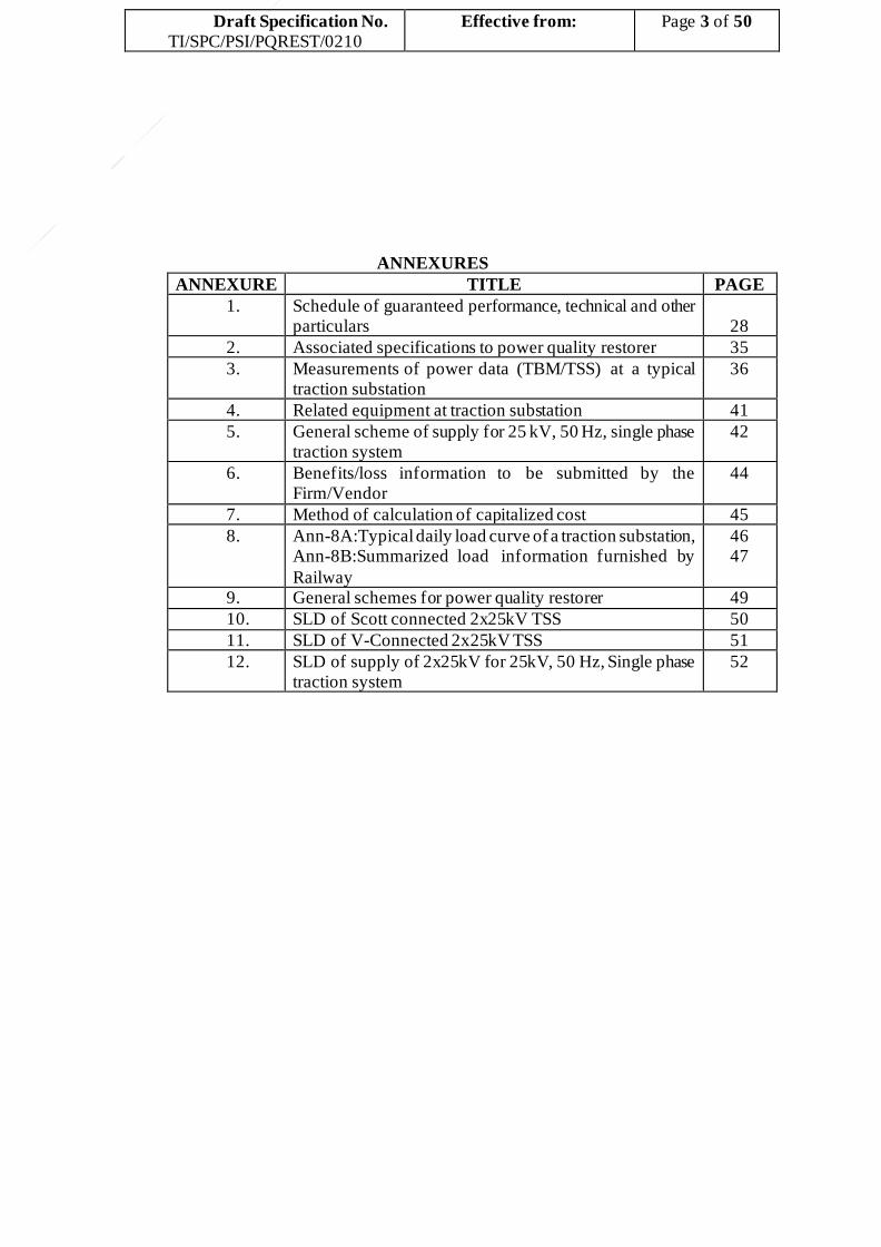
5.2.9.2.Control of Power Quality Restorer
The Active Filters shall be modular in design. The current capacity of each filter panel shall be assessed
by the maximum RMS current (as seen from the 25 kV bus) it can feed when the 25 kV bus voltage is V; the
RMS current of each panel shall be assessed as: Irms = √∑𝑖𝐼𝑖2 where i is the order of the harmonic being
compensated (including fundamental). The Active Filters shall also be designed to compensate for leading
reactive power by providing inductive reactive power in case of any over compensation due to fixed capacitors in the system.
In case of active filter, it shall be possible to choose the fundamental and/or any harmonic currents with individual current setting (maximum) and priority for compensation; alternatively, it shall also be possible to
compensate for the fundamental and/or any harmonic currents in the ratio specified by the user. Each of the filter panels shall be designed for programming the above parameters (i.e., setting of currents and priority thereof, or the current ratios) individually.
The control of harmonic and fundamental currents shall normally be such as to en sure that the total
demand distortion of current (TDDi) is within the specified limit, and to provide reactive power compensation to the maximum extent possible (after harmonic compensation) utilizing the total capacity of the active filter installations. The current sharing between the panels in circuit shall nearly be equal within a reasonable
limit so as to ensure maximum utilization of capacity.
Explanatory Note:
A. Say, there are four active filter panels installed with a rating of 60 A rms each (at 25 kV). Say, the current compensation requirement at a particular time is as under:
I1 = 80 A; I3 = 16 A; I5 = 10 A;
Now, Irms = √(802 + 162 + 102) = 82.2 (1)
Since the individual filter panel rating is 60 A, two panels are required to be in operation.
Alternative-1: First panel feeds 60 A reactive power. Second panel feeds 20 A reactive power, 16 A third harmonic, and 10 A fifth harmonic.
Now, Irms of first panel = 60A; Irms of second panel = √(202 + 162 + 102) = 27.5 A.
Total rating utilized = 60 A + 27.5 A = 87.5 A (2)
Note that the value at (2) is higher than at (1).
Alternative-2: Divide the current between the two panels equally; that is: I1 = 40 A; I3 = 8 A;
I5 = 5 A for each panel.
Now, Irms of each panel = √(402 + 82 + 52) = 41.1 A
Total rating utilized = 41.1 A + 41.1 A = 82.2 A (3)
Note that the value at (3) is the same as at (1).
Thus, Alternative-2 uses lower capacity from the two panels (as if there is a single panel of total
capacity) as compared to Alternative-1. Hence, Alternative-2 should be used for current compensation.
B. Say the maximum demand current is 800 A at 25 kV side, and the THDi of load current at 800 A is 20% at a given time. Then, the PQR should reduce the TDDi below 8% at source side.

Draft Specification No.
TI/SPC/PSI/PQREST/0210
Effective from:
Page 16 of 50
Let the PQR be set to reduce the TDDi to 7%. Considering the rating of 6 MVAR (i.e. 240 A at
25 kV) for the PQR, the net reactive power available from the PQR after controlling the TDDi to 7% (by
reducing the individual load current harmonics flowing to source by a factor of 7/20) is given by:
I1 = √ {2402 − [(20 − 7) ∗ 800/100]2} = √(2402 − 1042) = 216.3 A
That is, the MVAR available after harmonic compensation is: 216.3A*25kV/1000 = 5.4 MVAR. This
reactive power rating shall be available irrespective of the type of PQR (i.e., active, passive or
hybrid).
C. Say the maximum demand current is 800 A at 25 kV side, and the THDi of load current at 1200 A is 16% at a given time. Then, the PQR should reduce the TDDi below 8% at source side.
Let the PQR be set to reduce the TDDi to 7%; this corresponds to an RMS value of 56 A (i.e. ,7% of the maximum demand current of 800 A) of the harmonic currents flowing to source.
Now RMS value of load harmonic currents is 192 A (i.e., 16% of 1200 A). This value needs to be reduced to 56 A; in other words, each load harmonic current needs to be reduced by a factor of 56/192 – which is about 0.3.
Considering the rating of 6 MVAR (i.e., 240 A at 25 kV) for the PQR, the net reactive power available from the PQR after controlling the TDDi to 7% (by reducing the individual load current harmonics
flowing to source by a factor of 0.3) is given by:
I1 = √ (2402-1362) = 197.7 A
That is, the MVAR available after harmonic compensation is: 197.7A*25kV/1000 = 4.9 MVAR. This
reactive power rating shall be available irrespective of the type of PQR (ie, active, passive or hybrid).
D. The net reactive power available at the PCC will vary from the above calculated figures, and it can accurately be assessed using the network parameters of the particular traction substation concerned.
5.2.10. Series Reactor (Damping Reactor)/Surge Suppression Circuits
In case of fixed shunt capacitors being used for reactive power compensation, a series reactor shall be provided to limit the inrush current and surge voltage at the time of switching on the capacitor bank and also to reduce the load harmonics. The switching surge voltage shall not exceed 70 kVp on 25kV side. The series reactor shall be natural air- cooled, air- cored, dry insulated and outdoor type. The reactor shall be rated for the maximum current including harmonic currents that would flow through the capacitor bank under various operating
conditions. The reactor shall be so designed that the variation in milli-henry value, due to manufacturing tolerance, is less than + 3%.
5.2.11. Basic Insulation Level (BIL)
The Basic Insulation Level of equipment at the 25 kV side and at the LT side shall be as follows (unless
a different BIL is recommended by the Firm/Vendor for the PQR with detailed justification and relevant
standards thereof): The individual PQR with provision of earthing shall be connected to +25kV and ‐25kV w.r.t
buried rail for 55kV system, hence BIL will remain as 250kVp.
25 kV Equipment
i. 1.2/50 µs Impulse withstand voltage 250kVp
ii. One-minute wet power frequency withstand voltage (rms) 105 kV
The individual PQR with provision of earthing shall be connected to +25kV and ‐25kV w.r.t buried rail for
55kV system, hence BIL mentioned above shall be applicable for 2x25 kV system also..
For LT Equipment

Draft Specification No.
TI/SPC/PSI/PQREST/0210
Effective from:
Page 17 of 50
i. 1.2/50 µs Impulse withstand voltage Not applicable
ii. One-minute wet power frequency withstand voltage 3kV
5.2.12. Protection of Power Quality Restorer
The offer shall include design and supply of a comprehensive protection scheme for the equipment offered by the Firm/Vendor. Full details, including relay characteristics of the protection scheme offered for capacitor bank, IGBT or any other switching device etc. shall be fully explained in the offer giving necessary details and diagrams.
The protective relays offered shall be properly coordinated with the existing scheme of protection specified in the specification no. TI/SPC/PSI/PROTCT/5070, TI/SPC/PSI/PROTCT/4050 &
TI/SPC/PSI/PROTCT/7101 for Control & Relay Panel for 25kV ac Single Phase Traction power supply, 25 kV Traction Power Supply system in Mumbai Sub-urban area and 2x25kV AT System.
The protection for shunt capacitor bank (if capacitive kVAR injection is through capacitor bank) shall include protection against overcurrent, overload, overvoltage and unbalance.
Each capacitor element shall be individually protected by means of internal fuses. The fuse shall be
connected in series with each capacitor element inside the capacitor unit to limit the effects of dielectric failures. If puncture of dielectric occurs, only one element shall be disconnected so that the capacitor unit continues to operate. While selecting the fuse rating, it would be necessary to choose proper time current characteristics, which in turn significantly depend upon the cross section and circumference of the fuse. Fuses chosen shall
have adequate thermal capability and comply with relevant IS/IEC specifications.
The protection for IGBT and other electronic switching devices shall include protection against overvoltage, overcurrent etc. The firm is liable to provide necessary protection in case of failure of any equipment associated with functioning of PQR without impacting the traction power supply continuity to the running locos in the section.
5.2.13. Noise level: The noise level measured at a distance of 1 meter from indoor/ outdoor panel of PQR shall not
exceed 75 dB (A).
5.2.14. Control room ambient air temperature: In case PQR panels are provided indoor, then the ventilation of the room shall be such that the indoor ambient air temperature does not exceed the outside ambient air temperature by more than 5 K. Providing necessary ventilation arrangement shall be within the scope of work against this specification.
5.2.15. Limits for component losses: The overall losses of a capacitor unit (including losses in fuses and discharge
device) shall not be more than 0.20 W/kVAR. The dissipation factor (tan δ) of the DC link capacitor (if used)
shall not exceed 0.2% at 1 kHz and 250C. Whereas the Q-factor (ratio of XL to Rac) of the TSR, and the series
reactor used in the fixed shunt capacitor bank for power factor improvement shall not be less than 100 at 50Hz and 75oC.
6. GENERAL ARANGEMENT OF POWER QUALITY RESTORER
6.21. The power quality restorer may be of either outdoor or indoor type for connection to the 25 kV bus. The layout drawing with cross sectional details of the equipment shall be furnished by the Firm/Vendor, taking into account the existing layout of other equipment at the traction substation.
6.22. The capacitor bank, if any, shall consist of groups of individual capacitor units, connected in series- parallel combination to deliver the rated output at nominal rated system voltage, rated frequency and other system conditions. The capacitor bank and the series reactor shall be supplied complete with mounting steel rack assembly, inter-connectors between units, fuses for unit and group protection, insulators, suitable earthing
lugs (including terminal connectors) and any other material required to make the bank complete in all respects for its satisfactory operation. The steel racks shall be mounted on a concrete plinth with suitable base frames. The racks shall be complete with rack insulator and other hardware.
7. CONTROL PANELS OF POWER QUALITY RESTORER
7.21. General Particulars
7.1.1. The control panel, having the relays for the control of power quality restorer, shall be installed in the control room of unattended remote controlled traction substation. The control panel shall be of vertical

Draft Specification No.
TI/SPC/PSI/PQREST/0210
Effective from:
Page 18 of 50
mounting, self-supporting steel construction back- to- back duplex corridor type. The corridor shall be provided with a lockable door at either end permitting free access to all instruments, components, wiring, terminal connections, test block etc. Stove enameled painting shall be done on the panel. The colour of the
panel shall be “Eau de Nile green‟ conforming to shade 216 of IS:5-2007, on the exterior and white on the interior surfaces. The overall height may be 2300 mm to match with the height of the existing transformer and feeder control panels.
7.1.2. The control panel shall be fabricated from a frame made of steel section of 3 mm thick and covered by door, side cover and top cover made of 2 mm thick CRCA steel sheet. Suitable cable entries shall be
provided from the bottom of the control panel for which suitable opening shall be provided on the bottom plate. The control panel shall be suitable for erection, flush with the concrete floor, by evenly spaced grouting bolts (projecting through the base channel of its frame). The control panel, including the relay housing, shall be dust, vermin and moisture proof. The overall size of the control panel shall be subject to
the approval of Railway.
7.1.3. There shall be provision for fixing a 240 V suitable lamp for interior lighting. The lamp shall be switched ON/OFF with the help of a door switch mounted at suitable location inside the panel.
7.1.4. The protective relays shall be mounted on the back panel and shall be of semi-flush mounting type with back connections and provided with dust proof covers and test plug for secondary injection tests.
7.1.5. The front panel shall have the control switch, indication light emitting diodes (LEDs), annunciation label, alarm cancellation push button and a mimic diagram indicating connections of various equipment.
7.22. Measuring Instruments
7.1.1. Measuring instruments for measurement of voltage, current, active power, reactive power, energy (kWh, kVAh and kVARh) and frequency shall be provided on the control panel. These measurements shall be provided individually for each of the following (as applicable to the system offered by the Firm/Vendor):
i. Parameters on the primary side (25 kV side) of the HT harmonic filters. ii. Parameters on the primary side (25 kV side) of fixed shunt capacitor banks.
Multi-function, digital, LCD display (multi-line) type meters of adequate accuracy (as approved by the Railway) shall be provided for the purpose. Apart from that, analogue type ammeters and volt meters shall also be provided for each of the above.
The instruments shall generally conform to IS 13875 (Part 1-3)-1993, Class A Industrial grade accuracy. Its circuits shall be capable of withstanding 20% overload for 8 hours. It will be subjected to a
high voltage test of 2 kV rms for one minute. The Instruments shall be with dust-tight case and finished in dull black enamel.
7.1.2. Smart metering with cloud-based communication: Smart metering shall form part of this specification. It shall monitor all relevant electrical parameters and product parameters like fault logging as under:
i. The source side current, THDi, TDDi and power factor on the 25 kV bus. ii. The 25 kV bus voltage and its harmonics. iii. The HT capacitor/filter circuit current and its harmonics,
iv. The fundamental current, harmonic currents and kVA of individual modules of voltage source converter, thyristor switched reactor/capacitor, or any such modules.
v. The kW, kWh, kVAR and kVARh of the total PQR. vi. Fault logging of IGBTs, thyristors, individual VSC/TSC/TSR/TCR modules, etc as necessary.
Average values calculated over every discrete Ten minutes interval shall be stored for the various parameters like voltage, current, current/voltage harmonics, average power factor, kW, kVA, THDi
and TDDi. The smart metering shall have cloud-based monitoring system. No-Sequel DBMS (Data Base Management System) along with the virtual RTOS (Real Time Operating System) is preferred for monitoring to have better security on the IoT (Internet of Things). It shall be possible to see the data for last 3-years for analysis at any point of time.
7.23. Suitable spring return type control switch with pistol grip handle having three positions, ON/OFF/Neutral, shall be provided. The Switch shall have a sequence device to prevent two successive movements to the same position. Following indication LEDs shall be provided for indication of circuit breaker:
i. Circuit Breaker “Closed‟ - Red

Draft Specification No.
TI/SPC/PSI/PQREST/0210
Effective from:
Page 19 of 50
ii. Circuit Breaker “Open‟ - Green iii. Circuit Breaker “Auto-trip‟ Amber iv. Trip circuit “Healthy‟ - Yellow
Low consumption, extra bright, 5mm diameter light-emitting diodes shall be used wherever required. LEDs shall be suitably wired to glow on 110 V dc supply. LEDs shall be housed in suitable holders with
glazed/polished surface to act as reflector. The holders shall be screwed to the panel from inside.
7.24. A suitable two position (Local/Remote) “Change Over Switch‟ shall be provided on the control panel for operation of circuit breaker from control panel in “local‟ mode and from remote control center in “remote” mode of this switch.
7.25. Mimic Diagram The scheme of connections at the traction substation showing the incoming isolator, circuit breaker, series
reactor, IGBT or any other switching device, the capacitor bank etc. shall be represented by a single line Mimic Diagram on the control panel. The colour of the mimic diagram shall be golden yellow to shade 356 of IS:5-2007.
Automatic semaphore relay shall be incorporated in the mimic diagram to indicate the position of the circuit breaker.
The open / close position of 25 kV isolators shall be accommodated within multi-functional HMI. Push
buttons and yellow indication LEDs shall be provided on the control panel to monitor the availability of 110 V DC supply on the panel, and the continuity of trip circuit for the circuit breaker.
7.26. Annunciator Suitable annunciation labels (back lit by LEDs) shall be provided on front side of the control panel for
visual alarm of various working and fault conditions.
The visual alarm shall be of flasher type i.e., concerned LED shall flicker and shall not become stable till the alarm is accepted.
The alarm accepting and annunciation testing buttons shall be provided under the annunciator label on the control panel at a convenient height.
Along with visual alarm, there shall be provision for an audible alarm. Audible alarm bell shall work with 110 V dc. This bell shall be mounted inside the control panel. The alarm bell shall continuously ring when a fault is there and shall not stop ringing till the alarm is acknowledged. A suitable disconnection switch shall be provided for disconnection of the bell.
7.27. Remote operation
7.1.1. The control of power quality restorer shall normally be switched in or out by control commands issued by traction power controller of the remote-control center. These tele- commands shall be issued with the help of Supervisory Remote Control and Data Acquisition System, hereafter called SCADA system provided at remote control center.
7.1.2. For the purpose of tele-commands and tele-signaling, suitable terminals shall be provided on terminal
block(s), which shall be duly wired for the following: 1. Tele-signal for supervision of secondary fuse of potential transformer. 2. Tele-command for operation of circuit breaker of power quality restorer. 3. Any other tele-signals required for monitoring the healthiness of the transformer, capacitor units,
IGBT or any other switching device as recommended by the Firm/Vendor.
7.28. Suitable terminal blocks, including testing terminals, shall be mounted conveniently inside the control panel. The current rating of the contacts shall be 30 A continuous at 110 V dc. The current terminals shall be provided with short circuiting links or another suitable device. The potential terminals shall be housed in narrow recesses of the moulded insulation block to prevent accidental short circuit. Terminals on the blocks shall be stud type crimped terminal or lugs, securely tightened with nuts and spring washers. AC and DC Terminals shall
be separate. Each Terminal shall be completely shrouded.
7.29. All panel wiring shall be done with switchboard type 1100 V grade PVC insulated single core stranded tinned annealed copper cable. The AC and DC circuits shall be kept separate.
7.30. Suitable space heaters to operate on 230 V, single phase, AC supply with “ON‟ and “OFF‟ switches shall be provided inside the control panel to prevent condensation of moisture in humid weather.
7.31. One combined three pin switch plug, 5 A rating shall be provided inside the panel for using 230 V hand
lamp.
Draft Specification No.
TI/SPC/PSI/PQREST/0210
Effective from:
Page 20 of 50
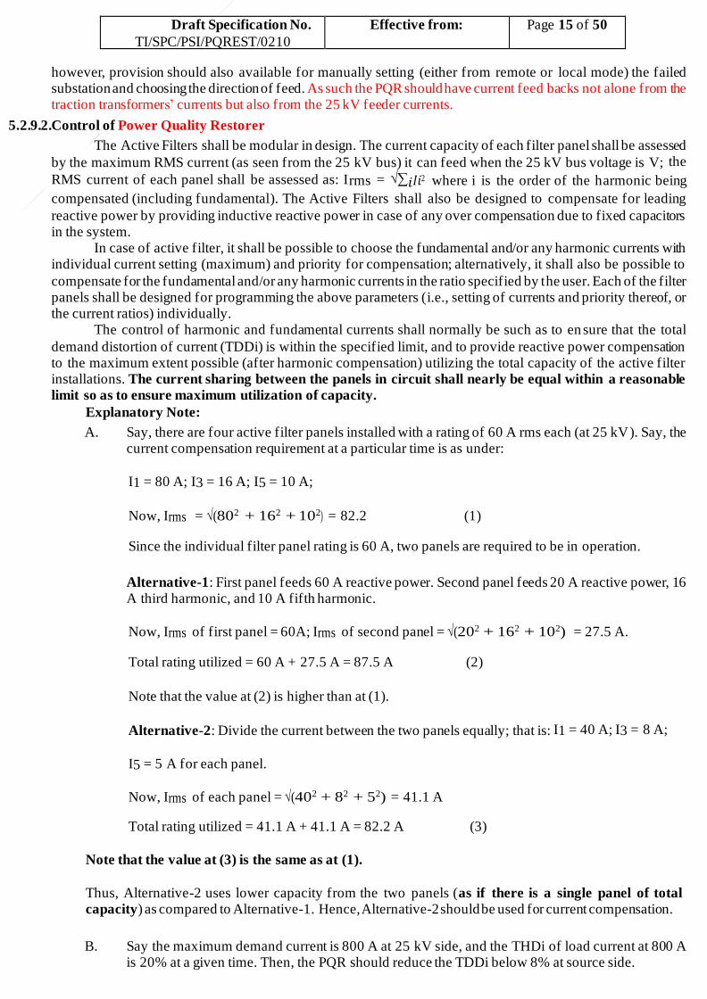
7.32. Wherever required, only HRC type cartridge fuses of appropriate rating shall be used in the control panel at easily accessible places.
7.33. Control Panel for IGBT or any other switching device control The control equipment for the control of power quality restorer scheme may preferably be housed in a
separate control panel / control box, the details of which shall be furnished by the Firm/Vendor along with the offer. The control equipment shall be built up of modular units to enable easy maintenance and replacement.
8. CURRENT AND POTENTIAL TRANSFORMERS
Suitable current and potential transformers required for the protection of capacitor bank and IGBT or any other
switching device shall be supplied by the Firm/Vendor. Full technical particulars of such transformers shall be furnished in the tender offer.
9. PROTECTION AGAINST LIGHTNING SURGES
The power quality restorer offered shall adequately be protected against lightning surges. The ratings of lightning arresters, required for the equipment offered, should be clearly indicated in the tender offer. The lightning arrester shall be metal oxide gapless type. For 25 kV system, 42 kV class 10 kA discharge current lightning arrester shall be
used. The lightning arrester shall be designed to withstand the full energy discharge from the capacitor bank, if any or IGBT based equipment to which it is connected.
10. EARTHING
Earthing arrangements shall be provided for each apparatus in accordance with RDSO specification No. TI/SPC/PSI/ERTHNG/0210 “Specification for earthing of power supply installation for 25 kV & 2x25kV AC, 50 Hz,
single phase traction system”.
11. PAINTING
11.21. Painting of structure
All steel structures exposed to weather shall be given a primer coat of zinc chromate and two coats of light grey enamel paint as per Shade 631 of IS:5-2007.
11.22. Painting of cabinet
The cabinet shall be given a primer coat of zinc chromate and two coats of light grey paint as per Shade 631 of IS:5-2007.
11.23. Painting of capacitor tank
The inside surface, in contact with insulation, shall be painted with suitable anti-rust synthetic enamel primer and two coats of heat resistant, oil insoluble, insulating varnish. The steel surfaces, exposed to weather, shall be given a primer coat of zinc chromate and two coats of light grey paint as per Shade 631 of IS:5-2007.
11.24. Painting of transformer
All steel surfaces which are exposed to weather, shall be given one primer coat of zinc chromate and two coats of light grey paint as per Shade 631 of IS:5-2007.
12. FASTENERS
All fasteners of 12 mm dia and less and exposed to atmosphere shall be of stainless steel and those above 12 mm dia shall be preferably be of stainless steel or mild steel hot dip galvanized to RDSO’s specification
No. ETI/OHE/18 (4/84).
13. TESTING OF POWER QUALITY RESTORER
13.21. General
The detailed designs and drawings shall be furnished by the successful firm to RDSO. Only after all the designs and drawings have been approved by RDSO and a written advice given to that effect, Firm/Manufacturer shall take up manufacture of the equipment as per this specification for prototype. Any change or modification required during prototype testing shall be incorporated in the drawing and
final drawing shall be submitted to RDSO for approval for regular manufacturing of the equipment. The softcopy of design document, manual etc. and softcopy of drawings in CAD files (.dwg format) shall also be submitted to RDSO. All future Power Quality Restorer shall be manufactured as per the RDSO approved drawing and designs and shall be verified by the purchaser.
13.22. Testing of equipment

Draft Specification No.
TI/SPC/PSI/PQREST/0210
Effective from:
Page 21 of 50
13.1.1. Test Schedule: Prior to giving a call to the RDSO for inspection and testing of the prototype, the successful Firm/Manufacturer shall submit a detailed “Test Schedule‟ consisting of Schematic Circuit Diagrams for each of the tests and the number of days required to complete all the tests at one stretch. Once
the schedule is approved, the tests should invariably be done accordingly.
13.1.2. However, during the process of testing or even later, the RDSO reserves the right to conduct any additional test(s) besides those specified herein on any equipment/item, so as to test the equipment/item to their satisfaction or for gaining additional information and knowledge.
13.1.3. In case any dispute or disagreement arises between the successful Firm/ Manufacturer and representative of the RDSO during the process of testing as regards the procedure for the tests and/or the
interpretation and acceptability of the results of tests, it shall be brought to the notice of the RDSO, whose decision shall be final and binding.
13.1.4. Only after the prototype Power Quality Restorer (PQR) is complete and ready in each and every respect, the successful Firm/Vendor/Manufacturer shall give the actual call for the inspection and testing with at
least 15 days’ notice for the purpose.
13.1.5. All relevant tests, as considered necessary by RDSO, as per latest IS/IEC Specifications applicable shall be conducted by RDSO on the various equipment/ components and sub- assemblies of the total system offered. The tests shall cover acceptance/ routine tests, apart f rom any type tests that may be considered necessary by RDSO. The equipment to be tested include shunt capacitors, series/shunt reactors,
active/passive filters, control panels, IGBT based voltage source converter panels, CTs, PTs, circuit breakers, etc., depending on the type of system offered.
13.23. Pre-commissioning tests
In addition to the above tests, the following tests (as applicable) shall be conducted, at site, by the successful Firm in presence of concerned railway authorities to verify the performance and design adequacy of the “Power Quality Restorer”:-
13.1.1. Efficacy of the discharge device
The efficacy of the discharge device shall be tested as per Clause 6 & 7 of IS:13585 (Part 1):1994.
13.1.2. Efficacy of the power quality restorer
i. Average power factor and current harmonic compensation: Before connecting the P Q R, the power factor and current harmonic distortions shall be measured on the 25 kV bus continuously for at least 24 hours. The harmonic analysis of the current waveform as well as of the voltage waveform shall be carried
out with and without the PQR equipment at various load currents.
After connecting the PQR, the power factor and current harmonic distortions shall be measured continuously for at least Seven days. The load current shall be recorded every 15 minutes in each case. The improvement in power factor and total harmonic distortion in source side current and total demand distortion (TDD), at different loads, shall be assessed from these observations.
ii. Rise in 25 kV bus voltage due to power quality restorer: At different loads including no-load conditions, the voltage at the 25 kV b u s shall be recorded with and without PQR. The rise in voltage
due to the PQR shall be assessed from these observations.
iii. Adequacy of ratings: The adequacy of the voltage and current ratings of the various components used in the PQR system shall be checked based on these measurements. Deficiencies in ratings, if any, shall be set right free of cost by the Firm/Vendor.
13.1.3. Efficacy of the protection system
Tests shall be done to ascertain the effectiveness of the protection system provided in the PQR system. In case of shunt capacitor, one of the capacitors in one of the limbs shall be short circuited and its effect shall be observed.
13.1.4. Temperature Rise
The capacitor bank shall be kept on for 24 hours and the temperature of one capacitor in each of the limbs shall be recorded hourly. The temperature rise of power transformers, current transformer, potential transformer and other equipment shall also be observed hourly during this period. The efficacy of the cooling system provided for various equipment shall be checked and verified.

Draft Specification No.
TI/SPC/PSI/PQREST/0210
Effective from:
Page 22 of 50
13.1.5. Matching of characteristics of shunt capacitor with that of over-voltage relay shall be verified.
13.1.6. Surge voltage measurement:
The surge voltage shall be measured at the time of switching on the capacitor. This shall be done 20 times. The voltage peak shall not be more than 70 kVp in any case.
13.1.7. Feed extension:
The proper working of the PQR during feed extension in case of failure of a traction substation shall be verified as part of pre-commissioning tests (refer Clause 5.2.9.1).
13.1.8. Schedule of pre-commissioning tests on IGBT and the balance equipment shall be mutually agreed upon between the successful Firm/Vendor and the Purchaser.
13.24. IGBT based equipment:
Following additional tests may be required to be conducted for IGBT based equipment as per IEC: 60146-2 (1999), Section-7. List of Tests, required typically for 400V, +/-350A single panel, single phase IGBT based “Power Quality Restorer” based on above applicable guidelines are as below. The single panel is to be treated as part of the total number of IGBT based panels supplied by the Supplier/Contractor.
13.1.1. Routine tests
Manufacturing process to assure the use of and proper mounting of correct sub-assemblies, components, wiring/cabling and their rouging, ferruling, use of correct lugs and their tightness, etc.
i. Visual inspections: Components Data/Ratings etc., as per General Arrangement inclusive of
Auxiliary Devices. ii. Wiring checks:As per the wiring table/schematic. iii. Insulation test: By using 1000 V Megger.
iv . Basic functional tests which include power up sequence, control logic correctness & protective control circuit functionality check at given input voltage of 400 V and final pulse delivery from controller but hardware pulse delivery to IGBT’s withheld.
v. IGBT pulse delivery and checking the “zero” current mode for IGBT based Power Quality
Restorer. vi. Checking the dynamic response with the external current command circuit. vii. Rated output test of the panel at rated voltage.
13.1.2. Type tests: i. HV/Insulation Test. ii. Heat run test for 48 hours or one hour after the temperature rise is steady whichever is earlier for
for capacitive mode and 24 hours or one hour after the temperature rise is steady whichever is
earlier for inductive mode and temperature rise. iii. Checking rated output of each panel by external current command delivery and checking of actual
IGBT based Power Quality Restorer. Current flowing the same in both capacitive and inductive mode.
iv . Input current distortion check for Distortion Factor close to unity for both, capacitive and inductive modes.
v. Any other tests, if agreed, between the manufacturer and the customer.
13.1.3. Optional tests (to be agreed before the supply)
i. Dynamics +350 A to –350 A at 400 V rated voltage (Dynamics not specified by IEC). ii. Heat run of each panel for full load for 2 hours (One hour in capacitive mode and one hour in
inductive mode). Not specified by IEC. iii. Visual input current distortion check with respect to given waveforms (Distortion factor close to
unity).
14. CAPITALISATION OF LOSSES AND BENEFITS
14.21. The benefits derived by installation of power quality restorer shall be compared against capitalization of its cost of procurement, installation and commissioning, annual maintenance contract (AMC) charges, to obtain a capitalized cost, detailed calculations for which shall be submitted by the Firm/Vendor along with the offer
using the method given in Annexure-7. The Firm/Vendor shall for this purpose clearly indicate the losses of the power quality restorer and expected benefits in the format given in Annexure-6.
14.22. Savings due to reduction in maximum demand, reduced losses in the traction power transformer due to

Draft Specification No.
TI/SPC/PSI/PQREST/0210
Effective from:
Page 23 of 50
power factor improvement, avoidance of low power factor penalty where applicable, and avoidance of current harmonic distortion surcharge where applicable, and expenditure due to various losses introduced by the PQR system shall also be capitalized as indicated in Annexure-7.
14.23. The various losses due to PQR to be considered are as under: i. Losses in all capacitor banks, including fixed/variable, dynamic etc.
ii. Losses in the active/ passive filters (like voltage source converter). iii. Switching losses and conduction losses in IGBTs or any other switching devices (if not considered
elsewhere) iv . Losses in the series/shunt reactors. v. Energy consumption for ventilation/cooling.
vi. Any other losses that may be of significance.
14.24. Device/Equipment data sheets to be attached with offer: The Firm/Vendor shall submit along with his offer detailed calculations and the proof of Device/Equipment data sheets to support the calculations of losses/benefits of Power Quality Restorer as provided by him. For the DC link capacitors used in voltage source converters, data sheets shall be provided – indicating rated voltage/current, type and make of capacitor, the loss
angle, operating temperature, ageing details etc.
15. TECHNICAL DATA AND DRAWINGS TO BE SUBMITTED WITH OFFER
15.21. The Firm/Vendor shall furnish Guaranteed Performance Data, Technical and other Particulars for the
equipment offered in the format attached as Annexure-1. The firm shall also furnish the complete protection scheme for the power quality restorer and layout drawings with cross sectional details for the power quality restorer along with their offer. Technical details of the protection employed, together with detailed calculation for the ratings of the equipment shall also be furnished with the tender offer.
15.22. The information furnished in Schedule of Guaranteed Technical Performance, Data and other Particulars shall be complete in all respects. If there is any entry like “shall be furnished later” or blanks are left against any item, the Tender is not likely to be considered as such omissions cause delay in finalizing the Tender.
15.23. The Firm/Vendor shall specifically indicate in a statement attached with their offer, the compliance with each clause and sub-clause of this specification. If any vague remarks on any clause or sub-clause of this specification are given by the Firm/Vendor, then the tender submitted by him is not likely to be considered. A
separate deviation statement shall be furnished with the offer drawing attention to the clause(s) where the Firm/Vendor seeks deviation giving detailed remarks/justification thereof. If there are no deviations, a “NIL‟” statement shall be furnished.
15.24. The Firm/Vendor shall furnish the following calculations/details with their offer. i. The details as called for in Clause 14.3 above for capitalization of losses, etc.
ii. Detailed calculations for rating of capacitor bank, series/shunt reactor, inrush current, transient over-voltage, parallel and series resonant frequencies.
iii. Details of protection scheme offered. iv. Details of supporting frame, fixing arrangement and foundation. v. Details of building requirement for housing indoor equipment of the PQR.
All civil works involved with provision of PQR, including any exclusive building, shall form part of this
specification. The masonry building of suitable height, width & length for placing indoor equipment of the
PQR should have RCC roof and 9” Thick wall. The door shall be ensured for easy movement of PQR
equipment. The sufficient exhaust fans/ blowers shall be provided to keep the inside temperature suitable for
satisfactory working of PQR equipment without failure.
15.25. The f ollowing Drawings shall be furnished as per Indian Railway Standard (in sizes of 210 mm x 297 mm or any integral multiple thereof):-
i. Schematic circuit diagram (with description of function and working of each component) of the
power quality restorer. ii. Outline General Arrangement Drawing giving the overall dimensions of various equipment of the
power quality restorer. The total area required (both indoor and outdoor) shall be brought out
clearly. iii. Arrangement of capacitor bank, IGBT/other switching devices, transformer, series/shunt reactor,
circuit breaker, isolator, lightning arrester, current and potential transformers. iv. Arrangement of core winding and magnetic path of series reactor and transformer.

Draft Specification No.
TI/SPC/PSI/PQREST/0210
Effective from:
Page 24 of 50
v. General arrangement of circuit breaker, showing mounting arrangement and overall dimensions
16. DESIGNS AND DRAWINGS APPROVAL:
16.21. The successful Firm/Vendor shall be required to submit for approval the following detailed drawings as per RDSO standard (in sizes of 210 mm x 297 mm or any integral multiple thereof) in latest version of CAD.
i. Outline general arrangement drawing of the power quality restorer installation indicating necessary
dimensions, clearances and location of equipment/fittings (all the 3 views). ii. Internal arrangement of series/shunt reactor and transformer including cross-sectional views in both
plan and elevation. iii. Schematic circuit diagram (with description of function and working of each component), wiring
diagram and dimensional drawings of various panels, complete with the ratings of various
components. iv. Supporting frame with details of fixing arrangement and foundations along with calculation for
their design.
v. Technical data sheets for all major components (like series/PWM reactor, shunt reactor, IGBT/other
advanced switching devices, shunt capacitor, DC link capacitor, filter components,) used in the
system. The justification for the adequacy of the ratings shall also be submitted.
16.22. The Firm/Vendor shall visit the traction substation, if necessary, and collect any additional data/ details required for the design of the Power Quality Restorer. It is the responsibility of the Firm/Vendor to visualize the
problems and understand the system conditions before evolving a suitable Design.
17. INSPECTION AND TESTING OF PROTOTYPE
17.21. Prototype: After approval of designs and drawings by RDSO, the firm shall manufacture an acceptable prototype of Power Quality Restorer as per approved drawings. The prototype inspection shall be carried out by the representatives of the RDSO. The bulk manufacture shall be taken up only after approval of prototype by
RDSO.
17.22. Routine inspection shall be carried out by the representatives of Railway at the manufacturer’s works.
17.23. The successful firm shall supply 3 copies of Instruction/Maintenance Manual of the Power Quality Restorer installation and its Fittings and Accessories to each Consignee(s) along with approved drawings.
18. ERECTION, TESTING AND COMMISSIONING
The power quality restorer shall be erected by the successful Firm/Vendor under the supervision of competent engineers of the successful Firm/Vendor/ manufacturer/ supplier. The equipment shall be subjected to specified proving/ pre-commissioning tests by the Railway engineer at site and with which the successful Firm/Vendor/
Manufacturer/Supplier shall also be fully associated. For this purpose, prior intimation regarding the date and location of the tests shall be given by the purchaser to the successful Firm/Vendor/manufacturer/supplier.
19. SPARE PARTS, CATALOGUE AND SUPPORT DOCUMENTS
The Firm/Vendor shall furnish along with his offer a list of spares (with cost), recommended by him for maintenance of power quality restorer installation for a period of 5 years, along with his credentials for proper after sales support. Similar works executed by the Firm/Vendor shall be furnished along with the offer giving full
particulars like when erected and commissioned, ratings, type of application, performance, reliability, failures noticed/attended etc.
20. TRAINING OF INDIAN RAILWAY’S ENGINEERS
The offer shall include the training of two engineers and four technicians of the Railway free of cost at the manufacturer’s Works in India or abroad and at the traction substation of a railway system or other public utility where power quality restorer of similar/identical design are in operation. The total duration of training for each
Engineer/Technician shall be 4 weeks of which approximately 2 weeks shall be at the manufacturer Works and 2 weeks on a railway system or public utility. The cost of travel to the country of manufacture and back shall be borne by the Railway.
21. Source code of Software used by the bidder shall be owned by the bidding entity. Alternatively, undertaking of software support for the full designed life of equipment to be furnished by the bidder. In case of company being
closed, complete source code shall be shared with Railways.
22. Designed Life of Equipment
The equipment should be designed for a working life of minimum 15 years.

Draft Specification No.
TI/SPC/PSI/PQREST/0210
Effective from:
Page 25 of 50
23. CT for controlling & Protection: To ensure reliability of protection, separate CT should be used for measurement/ control & protection.
24. Humidity monitoring & control: System should be capable of monitoring ambient humidity & imitate suitable mitigation / measures to ensure reliable operations.
25. Safety Indicators: Safety indication should be provided on PQR panel while system is in operation. Necessary interlocks should be provided, to prohibit PQR power panel/ door access when system is in power-on condition.
26. PQR Control Panel: In case the PQR is placed in a separate room/ enclosure, then a remote-control panel should be provided inside the Railway TSS Control Room to indicate the working of the PQR system, fault/ data log and execute emergency operations.
27. Warranty:
The complete PQR with all parts and accessories supplied against a purchase order/contract against the tender in which this specification is quoted, irrespective of original individual equipment (imported/indigenous) shall be guaranteed for trouble - free and satisfactory performance for a period of 42 months from the date of supply or 36 months from the date of commissioning, whichever period is earlier. Details of warranty clause, the extent of responsibility and other relevant aspects shall be included in the contract. The manufacturer shall furnish detailed
terms and conditions in this regard in his offer. The warranty shall be for complete PQR including outdoor equipment under the scope of the firm i.e., CT, PT, display, software and all other associated equipment like wiring, connectors, contactors/relays etc. The successful manufacturer shall make necessary arrangements for spare parts and other items to be kept readily available so that there is minimum disruption to the operations. The software may require
upgradation/reconfiguration from time to time as per purchaser’s/CEA modified requirements. The manufacturer shall be fully responsible for this activity during warranty. Formula for costing up gradation in the same & addition of a unit/ multiple units of PQR, duly integrated with remote monitoring to be evolved and the same shall be mentioned in the offer clearly.
ANNEXURE-1
SCHEDULE OF GUARANTEED PERFORMANCE
TECHNICAL AND OTHER PARTICULARS
S.No. Description Unit

Draft Specification No.
TI/SPC/PSI/PQREST/0210
Effective from:
Page 26 of 50
ANNEXURE-I: SHUNT CAPACITOR TECHNICAL DETAILS
(FOR HT FILTERS ALSO) 1. Make and type (attach data sheet of manufacturer) 2. Governing standards 3. Location of capacitor bank (outdoor/indoor)
4. Rated system voltage kV 5. Rated voltage of capacitor unit kV 6. Maximum voltage the capacitor unit can withstand continuously kV 7. Rated frequency Hz 8. Upper limit of temperature category 0C
9. Capacity of individual unit at its rated voltage kVAR
10. Rated current (continuous) of capacitor unit A 11. Maximum inrush current at the instant of switching A 12. Basic insulation level of capacitor unit
a) Power frequency withstand voltage b) 1.2/50 micro-second impulse withstand voltage
kVrms
kVp 13. Basic insulation level of complete capacitor bank
a) Power frequency withstand voltage b) 1.2/50 micro-second impulse withstand voltage
kVrms kVp
14. Transient current withstand capacity of each unit kA 15. Constructional details of capacitor unit
a) Dielectric material
b) Foil material & thickness c) Impregnating liquid used and its properties
16. Total maximum loss at rated voltage and at 50 Hz W/kVAR 17. Capacitor unit
a) Number of elements in series b) Number of parallel paths c) Capacitance of each unit.
μF
18. Capacitor bank a) Number of series groups b) Number of parallel units in each group c) Capacitance of the bank
μF
19. Type of internal fuse element of capacitor unit 20. Attach time/current characteristics of the fuse element
21. Discharge device a) Type b) Location
c) Time interval between de-energization and re- energization d) Residual voltage after 10 min of de-energization
Min V
22. Bushings a) Make and type

Draft Specification No.
TI/SPC/PSI/PQREST/0210
Effective from:
Page 27 of 50
b) Wet-one minute power frequency withstand voltage c) Impulse withstand voltage 1.2/50 μs full wave d) Creepage distance in air e) Number of bushings in each unit
kVrms kVp mm
23. Overall dimensions a) Capacitor unit b) Complete capacitor bank
mm
24. Weight per unit kg 25. Weight of the complete bank kg 26. Maximum loss in the complete capacitor bank at its
normal operating voltage and current W
27. Temperature class/ Insulation class/ Protection class of the capacitor bank
ANNEXURE-II – SERIES REACTOR (FOR HT FILTERS ALSO)
1. Make and type (attach data sheet of manufacturer)
2. Governing standards
3. Rated system voltage kV
4. Rated frequency Hz
5. Inductance value and tolerance mH (+/-%)
6. Quality factor (XL/R) at 50 Hz and 750C (minimum)
7. Type of reactor (type and core, cooling method, etc)
8. Rated current (fundamental), IN A
9. Rated voltage (fundamental), UN V
10. Continuous operating current, rms (including various harmonic currents)
A
11. Core linearity (as a multiple of rated current IN)
12. Value of the peak surge voltage generated at the time of switching in of shunt capacitor
kVp
13. Short circuit current rating for 3 seconds kA
14. a) Number of taps on the reactor
b) Minimum inductance c) Maximum inductance
15. Basic insulation level of reactor
c) Power frequency withstand voltage d) 1.2/50 micro-second impulse withstand voltage
kVrms kVp
16. Overall dimensions of the reactor mm
17. Total weight of the reactor kg
18. Maximum loss in the reactor at its normal operating voltage and
current W
19. Resonance frequency of the system, including shunt capacitor and series reactor (details of calculation should be enclosed with offer).
Hz
20. Temperature class/ Insulation class/ Protection class of the reactor

Draft Specification No.
TI/SPC/PSI/PQREST/0210
Effective from:
Page 28 of 50
ANNEXURE-III – CONTROL & RELAY PANEL
1. Name of manufacturer and address
2. Overall dimensions a) Length
b) Width c) Height
mm
3. a) Colour of the panel b) Colour of the mimic
4. Details of switches provided and their makes
5. Annunciations provided
6. Size of wires used for: a) Control circuit
b) Indication circuit c) General wiring d) PT and CT circuits
mm2
7. Method of cable entry
8. Details of instruments provided
ANNEXURE-IV – PROTECTIVE RELAYS OF CAPACITOR BANK
1. Instantaneous overcurrent relay
a) Type and make of relay b) Setting range available
2. Overcurrent a) Type and make of relay b) Setting range available
3. Overvoltage protection a) Type and make of relay b) Setting range available
4. Unbalance Protection a) Whether voltage operated or current
operated relays are used. b) Setting range available
c) Calculations to show that the number of capacitor units which when fail shall produce the rated over- voltage on other capacitor units and the setting range available in the relay offered suits the same shall be enclosed.
d) How provision of alarm in the case of failure of one or two capacitor units has been achieved.
e) Details (type and make and setting range) of the time delay relay.
f) Calculations to show that co-ordination between
the operation of individual fuses to isolate faulty units and unbalance protection exists should be appended.
5. The required capacity of current transformer and potential transformer in VA

Draft Specification No.
TI/SPC/PSI/PQREST/0210
Effective from:
Page 29 of 50
NOTE: The tender shall be complete with technical literature and pamphlets of the relays used.
ANNEXURE-V – PROTECTION OF IGBT, THYRISTORS
1. The Firm/Vendor shall furnish details of protection proposed for the IGBTs.
ANNEXURE-VI – SURGE ARRESTORS
1. The Firm/Vendor shall furnish full technical particulars of the surge arrestors offered.
ANNEXURE-VII: IGBT BASED VOLTAGE SOURCE CONVERTER PANEL
IGBT Technical Details
1. Make and type (attach data sheet of manufacturer)
2. Governing standards
3. Collector-emitter voltage VCES V
4. Gate-emitter voltage VGES V
5. Continuous collector current at Tc of 25oC A
6. Continuous collector current at Tc of 80oC A
7. Junction operating temperature range Tj (min. and max.) oC
8. Collector-emitter saturation voltage VCE(sat) V
9. Turn-on switching energy Eon mJ
10. Turn-off switching energy Eoff mJ
11. Thermal resistance Rth(j-c) K/W
12. Attach data sheet of the IGBT of manufacturer
DC Link Capacitor
13. Type and make (attach data sheet of manufacturer)
14. Governing standards
15. Capacitance value (and tolerance) µF
16. Rated voltage V
17. Rated current A
18. Dissipation factor tan δ (Not more than 0.2% at 1 kHz and 250C permitted)
19. Power loss in DC link capacitor W
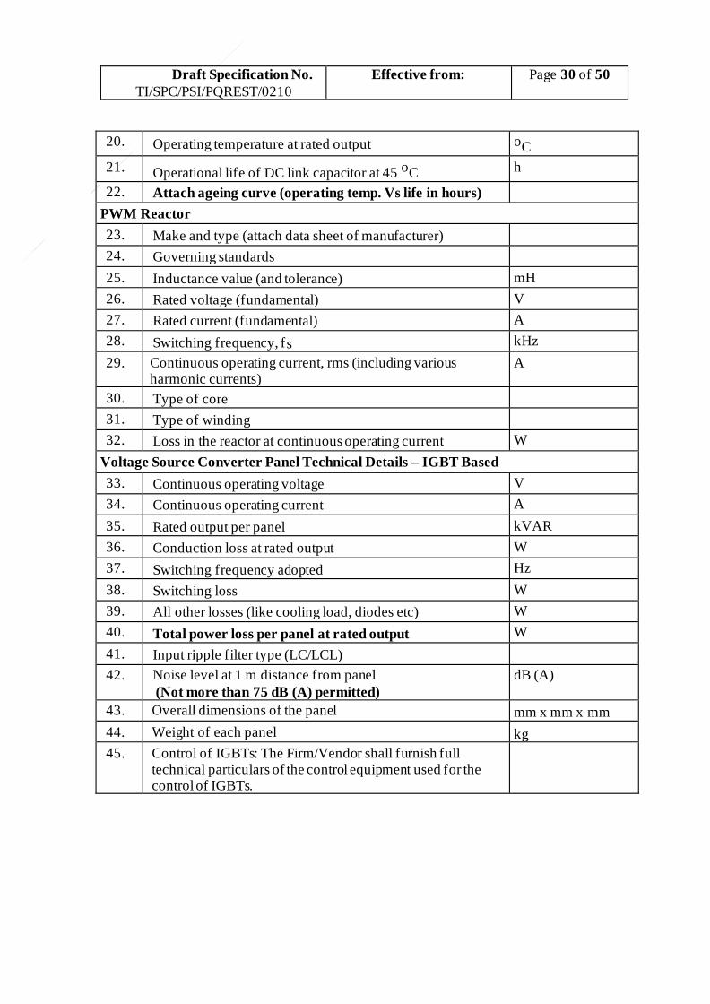
Draft Specification No.
TI/SPC/PSI/PQREST/0210
Effective from:
Page 30 of 50
20. Operating temperature at rated output oC
21. Operational life of DC link capacitor at 45 oC h
22. Attach ageing curve (operating temp. Vs life in hours)
PWM Reactor
23. Make and type (attach data sheet of manufacturer)
24. Governing standards
25. Inductance value (and tolerance) mH
26. Rated voltage (fundamental) V
27. Rated current (fundamental) A
28. Switching frequency, fs kHz
29. Continuous operating current, rms (including various harmonic currents)
A
30. Type of core
31. Type of winding
32. Loss in the reactor at continuous operating current W
Voltage Source Converter Panel Technical Details – IGBT Based
33. Continuous operating voltage V
34. Continuous operating current A
35. Rated output per panel kVAR
36. Conduction loss at rated output W
37. Switching frequency adopted Hz
38. Switching loss W
39. All other losses (like cooling load, diodes etc) W
40. Total power loss per panel at rated output W
41. Input ripple filter type (LC/LCL)
42. Noise level at 1 m distance from panel
(Not more than 75 dB (A) permitted)
dB (A)
43. Overall dimensions of the panel mm x mm x mm
44. Weight of each panel kg
45. Control of IGBTs: The Firm/Vendor shall furnish full technical particulars of the control equipment used for the control of IGBTs.
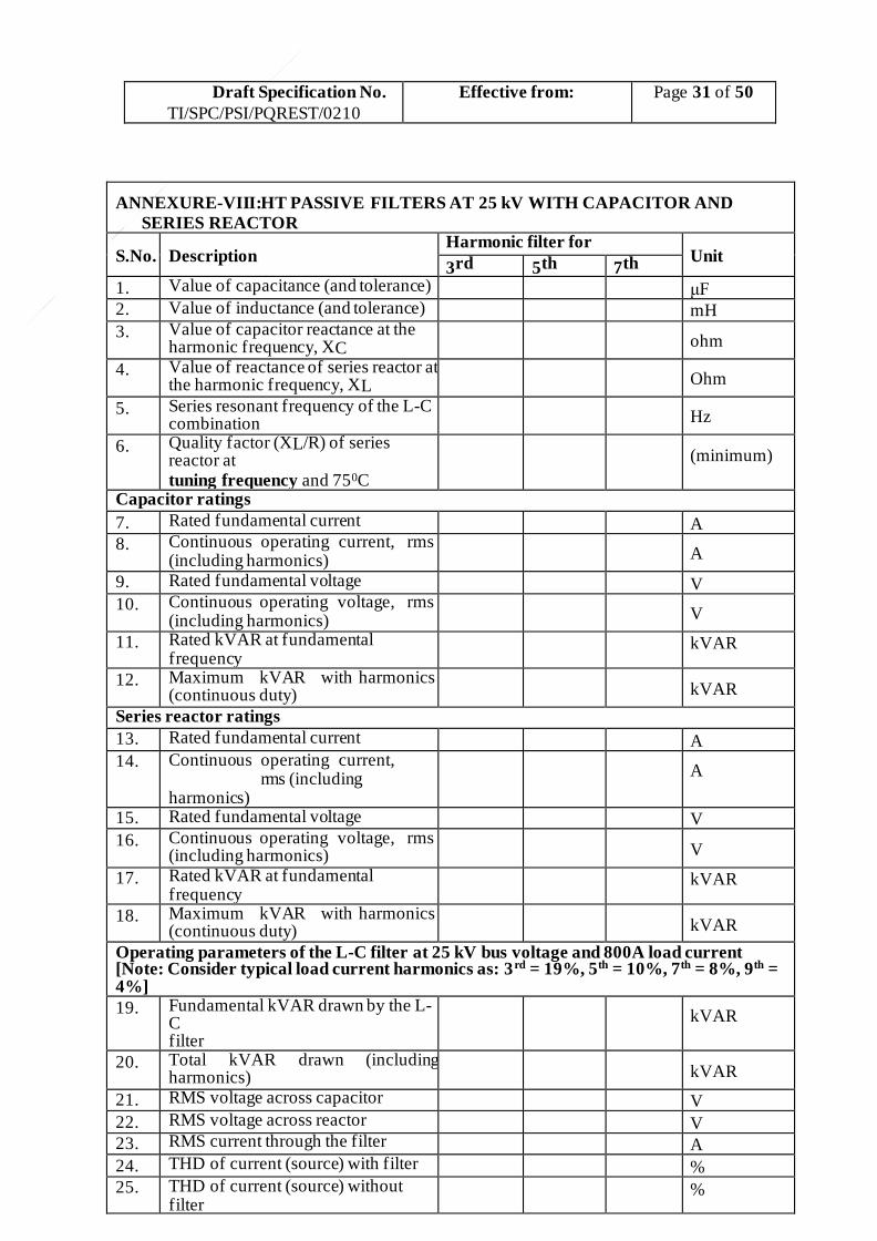
Draft Specification No.
TI/SPC/PSI/PQREST/0210
Effective from:
Page 31 of 50
ANNEXURE-VIII:HT PASSIVE FILTERS AT 25 kV WITH CAPACITOR AND
SERIES REACTOR
S.No. Description Harmonic filter for
Unit 3rd 5th 7th
1. Value of capacitance (and tolerance) μF 2. Value of inductance (and tolerance) mH
3. Value of capacitor reactance at the harmonic frequency, XC
ohm
4. Value of reactance of series reactor at the harmonic frequency, XL
Ohm
5. Series resonant frequency of the L-C combination
Hz
6. Quality factor (XL/R) of series reactor at tuning frequency and 750C
(minimum)
Capacitor ratings
7. Rated fundamental current A 8. Continuous operating current, rms
(including harmonics)
A
9. Rated fundamental voltage V 10. Continuous operating voltage, rms
(including harmonics)
V
11. Rated kVAR at fundamental frequency
kVAR
12. Maximum kVAR with harmonics (continuous duty)
kVAR
Series reactor ratings
13. Rated fundamental current A 14. Continuous operating current,
rms (including harmonics)
A
15. Rated fundamental voltage V
16. Continuous operating voltage, rms (including harmonics)
V
17. Rated kVAR at fundamental frequency
kVAR
18. Maximum kVAR with harmonics (continuous duty)
kVAR
Operating parameters of the L-C filter at 25 kV bus voltage and 800A load current [Note: Consider typical load current harmonics as: 3rd = 19%, 5th = 10%, 7th = 8%, 9th = 4%]
19. Fundamental kVAR drawn by the L-C filter
kVAR
20. Total kVAR drawn (including harmonics)
kVAR
21. RMS voltage across capacitor V
22. RMS voltage across reactor V 23. RMS current through the filter A
24. THD of current (source) with filter % 25. THD of current (source) without
filter %

Draft Specification No.
TI/SPC/PSI/PQREST/0210
Effective from:
Page 32 of 50
Other details
26. Furnish details of capacitor and reactor as in A and B above (refer page 29 and 30)
27. Detailed simulation results should be furnished along with the offer to support the data furnished above (refer Equivalent circuit at Annexure- for simulation).
ANNEXURE IX: POWER QUALITY METER FOR INCOMER
1. Make and type (attach data sheet of manufacturer)
2. Governing standards (IEC 61000-4-30 Class A Edition 3 & IS 14697 .2s and BIS certificate)

Draft Specification No. TI/SPC/PSI/PQREST/0210
Effective from:
Page 33 of 50
ANNEXURE-2 Associated specifications to Power Quality Restorer

Draft Specification No. TI/SPC/PSI/PQREST/0210
Effective from:
Page 34 of 50
ANNEXURE-3
Power Data of TBM Traction Sub-station (TSS) taken on 15/09/16 – 19:00:00 to 16/09/16–
19:00:00
Figure 1: X-axis: Fundamental load current in Amps (A) Y-axis: Reactive and 3rd harmonic currents of load current in Amps (A)
Note: Load current here refers to the measurements taken on feeder CT (CT/06) at TBM traction
substation. And the voltage measurements were done on PT/06 at TBM-TSS.
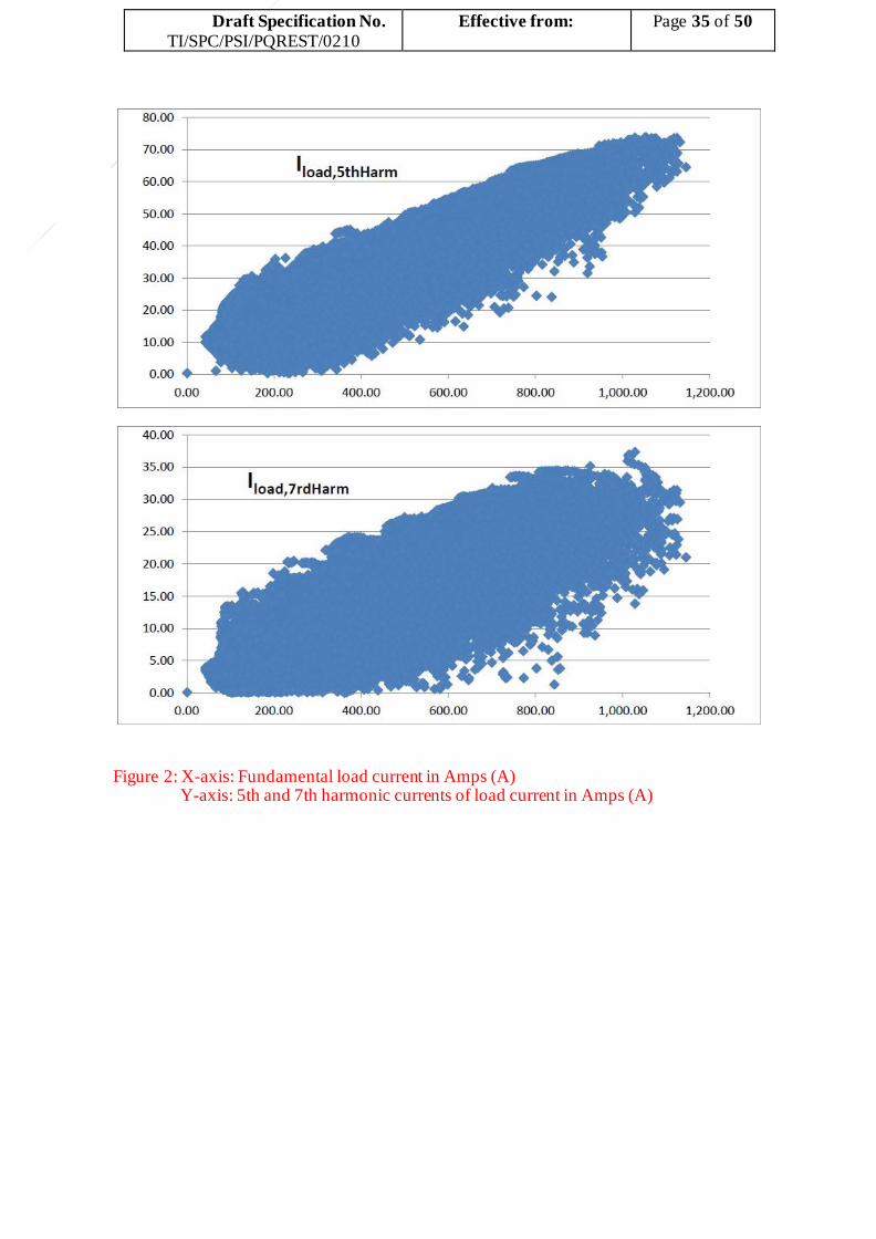
Draft Specification No. TI/SPC/PSI/PQREST/0210
Effective from:
Page 35 of 50
Figure 2: X-axis: Fundamental load current in Amps (A)
Y-axis: 5th and 7th harmonic currents of load current in Amps (A)

Draft Specification No. TI/SPC/PSI/PQREST/0210
Effective from:
Page 36 of 50
Figure 3: X-axis: Fundamental load current in Amps (A) Y-axis: 9th and 11th harmonic currents of load current in Amps (A)

Draft Specification No. TI/SPC/PSI/PQREST/0210
Effective from:
Page 37 of 50
Figure 4: X-axis: Fundamental load current in Amps (A) Y-axis: Percentage THD of the load current.

Draft Specification No. TI/SPC/PSI/PQREST/0210
Effective from:
Page 38 of 50
Figure 5: Apparent (Sload), Active (Pload) and Reactive (Qload) powers of load current over 24 h.
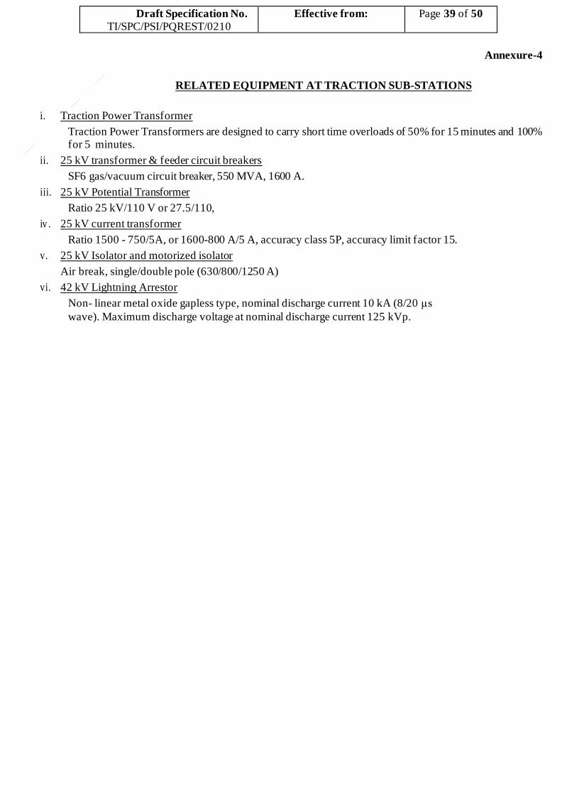
Draft Specification No. TI/SPC/PSI/PQREST/0210
Effective from:
Page 39 of 50
Annexure-4
RELATED EQUIPMENT AT TRACTION SUB-STATIONS
i. Traction Power Transformer
Traction Power Transformers are designed to carry short time overloads of 50% for 15 minutes and 100% for 5 minutes.
ii. 25 kV transformer & feeder circuit breakers
SF6 gas/vacuum circuit breaker, 550 MVA, 1600 A.
iii. 25 kV Potential Transformer
Ratio 25 kV/110 V or 27.5/110,
iv . 25 kV current transformer
Ratio 1500 - 750/5A, or 1600-800 A/5 A, accuracy class 5P, accuracy limit factor 15.
v. 25 kV Isolator and motorized isolator
Air break, single/double pole (630/800/1250 A)
vi. 42 kV Lightning Arrestor
Non- linear metal oxide gapless type, nominal discharge current 10 kA (8/20 μs
wave). Maximum discharge voltage at nominal discharge current 125 kVp.
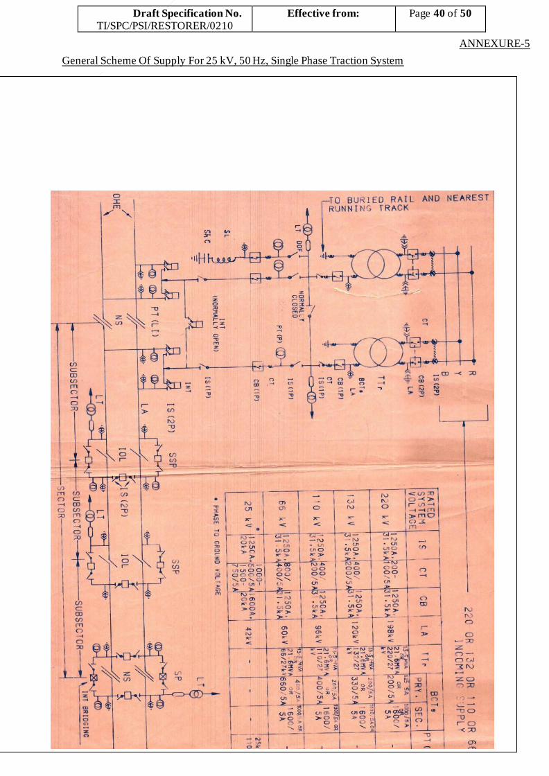
Draft Specification No. TI/SPC/PSI/RESTORER/0210
Effective from:
Page 40 of 50
ANNEXURE-5
General Scheme Of Supply For 25 kV, 50 Hz, Single Phase Traction System

Draft Specification No. TI/SPC/PSI/RESTORER/0210
Effective from:
Page 41 of 50

Draft Specification No. TI/SPC/PSI/RESTORER/0210
Effective from:
Page 42 of 50
ANNEXURE-6
BENEFIT/LOSS INFORMATION TO BE SUBMITTED BY THE VENDOR (in terms of Clause 14)
Before compensati
on (As given by railway) (1)
Maximum demand
(kVA) (2)
>120%
upto 140
% (3)
>100%
upto 120%
(4)
>80%
upto 100 %
(5)
>60%
upto 80%
(6)
>40%
upto 60%
(7)
>20%
upto 40% (8)
≤20%
(9)
Total
(10)
Hours per day After compensation
MD in kVA Average PF (kWh/kVAh)
Analysis
of power losses
(in kW)
Shunt capacitor bank losses (+)
IGBT Panel losses (+)
Losses in HT Filters (+)
Other losses (specify details) (+)
Reduction in losses in
substation transformer after compensation (-)
Net Loss L in kWh (+)
NOTE: For each of the above, the mid value of the range should be taken for integration, for
calculation of the benefit/loss. For example, for the range above 60% up to 80% the mid-value is 70%.

Draft Specification No. TI/SPC/PSI/RESTORER/0210
Effective from:
Page 43 of 50
= ∑
ANNEXURE-7
Method For Calculation Of Capitalized Cost
Data for calculation of capitalized cost Net loss “L” in kWh per day as per information furnished by Firm/Vendor in Appendix VI. Cost of procurement, installation & commissioning of power quality restorer including construction of covered area for housing indoor equipment as quoted by Firm/Vendor: Rs
“P” AMC charges per annum as quoted by Firm/Vendor: Rs “Xn” for nth year. Period of capitalization assumed, N = 8 years [ n = N*12 in months]
Discount rate, R = 0.07 per unit per annum [ r = 7 / 1200 per unit per month]
assumed for calculation of net present value of benefits and costs.
Calculation of capitalised cost
If the monthly total saving due to reduction in fixed charges by reduction in MD, low power factor penalty charges, and harmonic surcharges arising of the installation of power quality restorer is M, then the capitalized benefit B is given by:
𝑛 𝑖=1
{ 𝑀
((1+𝑟)𝑖)
} = 𝑀 [ (1+𝑟)𝑛 −1]
𝑟(1+𝑟)𝑛
If the monthly cost in energy charges for net losses of L kWh/day is Ce, then the
capitalized cost C1 is given by:
𝑛 1 𝑖=1
{ 𝐶𝑒
((1+𝑟)𝑖)
} = 𝐶𝑒 [ (1+𝑟)𝑛 −1]
𝑟(1+𝑟)𝑛
The capitalized cost C2 of AMC charges (for 5 years from 3rd year onwards) is given by:
C = 1 ∑𝑁−𝑥 { 𝑋𝑖
} where x is the warranty period in years, Xi is
2 ((1+𝑅)𝑥)
𝑖=1
((1+𝑅)𝑖)
the AMC charge for ith year, and (N-x) is the AMC period in years.
Then the total capitalized cost C of power quality restorer shall be given by:
C = P + C1 + C2 – B
Note: Reduction in Maximum Demand will be calculated as under: Load power factor, cos θ = 0.8 lag (at metering point); IR = Maximum reactive power injection
by PQR in A; Load voltage at metering point, |V| = 27 kV; uncompensated load current, |I1 | = 800 A or as given in tender document.
Then, compensated current, |I2 | = A
Maximum Demand Reduction= |V| .|I1| - |V|. |I2| kVA
B = ∑
C

Draft Specification No. TI/SPC/PSI/RESTORER/0210
Effective from:
Page 44 of 50
Annexure-8A
TYPICAL DAILY (24 Hours) LOAD CURVE AT THIRUVALAM TRACTION
SUBSTATION- LOAD CURRENT MEASURED AT 110 kV SIDE
+

Draft Specification No. TI/SPC/PSI/RESTORER/0210
Effective from:
Page 45 of 50
Annexure-8B
SUMMARISED LOAD INFORMATION FOR THIRUVLAM TSS FOR THE 12 MONTHS
The contracted maximum demand for Thiruvalam Traction Substation is 18400 kVA
The recorded maximum demand for the 12 months is furnished below.
MONT
H
RMD in
kVA
Sep-16 17778
Oct-16 14820
Nov-16 18894
Dec-16 17808
Jan-17 18258
Feb-17 18120
Mar-17 21360
Apr-17 17034
May-17 18534
Jun-17 17136
Jul-17 17730
Aug-17 17190
Draft Specification No. TI/SPC/PSI/RESTORER/0210
Effective from:
Page 46 of 50
Annexure-8C
THE TYPICAL DAILY AVERAGE POWER FACTOR BEING ACHIEVED (DERIVED FROM DAILY POWER FACTOR OF 90 CONSECUTIVE DAYS READING) IS 0928 WITH ARRANGEMENT OF TWO CAPACITOR BANKS (MAIN BANK AND ADDITIONAL BANK).
THE RATING OF THE MAIN BANK IS 2963 kVAR @ 25 kV (6600kVAR @ 40 kV). (THE MAIN BANK IS WITH 13 % DETUNED LOW LOSS SERIES REACTOR) THE RATING OF ADDITIONAL BANK IS 859kVAR @25 KV (2200kVAR @ 40 kV) (BANK IS WITHOUT SERIES REACTOR).
THE BANKS ARE SWTICHED (AUTOMATICALLY) BASED ON LOAD CURRENT AND THE ABOVE DAILY AVERAGE POWER FACTOR OF 0.928 INDICATED ABOVE IS ACHIEVED.
IN CLAUSE 4.6.3 - THE SENTENCE “THE ACTUAL VALUE OF THE FAULT LEVEL AT THIRUVALAM TRACTION SUBSTATION IS 1758 MVA AT 110 KV SIDE”IS APPENDED AT THE END OF THE CLAUSE.
IN CLAUSE 4.7.1 OF THE SPECIFICATION ENCLOSED WITH TENDER DOCUMENT UNDER LINE 4, THE SENTENCE “APPENDIX VIIIA SHOWS THE AVERAGE MVA (AVERAGED OVER EVERY 15 MINUTES PERIOD) VERSUS TIME. RAILWAYS WILL ALSO PROVIDE THE SUMMARISED CYCLE AS SHOWN IN APPENDIX-VIII B”
SHALL BE READ AS “APPENDIX –VIIIA SHOWS TYPICAL DAILY LOAD CURVE OF A TRACTION SUBSTATION” . IN CLAUSE 5.2.8.3 – THE SENTENCE “ THE CONTRACTED MAXIMUM DEMAND OF THIRUVALAM TRACTION SUBSTATION IS 18400 KVA” IS APPENDED TO THE END
OF THE CLAUSE.

Draft Specification No. TI/SPC/PSI/RESTORER/0210
Effective from:
Page 47 of 50
Annexure-9
C
CT
TRACTION
TRANSFORMER
TYPICAL SLD OF POWER QUALITY COMPENSATING EQUIPMENT
CT
H3 FIL
CB
ISOLATOR
CB
CB
H5 FIL
TO TRACTION OHE
CB
FROM FEEDER-1 CT
FROM FEEDER-2 CT
FROM TRANSFORMER-2 CT
LA
LA
25 KV BUS VOLTAGE
H7 FIL
NOTE:
1. THE TCR MAY BE ON
2. HT/LT SIDE
3. THE SLD SHOWS ALL
POSSIBLE SCHEMES (LIKE
VSC/TSC/TSR/SVC). ANY
SUITABLE SCHEME, MAY
BE OFFERED BY THE
VENDOR
PT
TRANSMISSION
LINE
FAST
RESPNSE
APFC / HARMONIC
RELAY
TSC
PT
TCR
VSC
ISOLATOR
C3
S
L3
TSC
C
TSRVSC
300 KVA
27.5/600 V
Z = 6 %
OUT GOING TO CONTROL
CIRCUIT OF VSC / TSC/ TSR etc.
FC
C
S
L
TSR
C1
S
L1
C2
S
L2

Draft Specification No. TI/SPC/PSI/RESTORER/0210
Effective from:
Page 48 of 50
Annexure 10
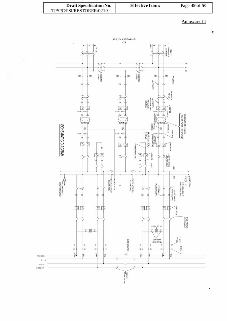
Draft Specification No. TI/SPC/PSI/RESTORER/0210
Effective from:
Page 49 of 50
Annexure 11
c

Draft Specification No. TI/SPC/PSI/RESTORER/0210
Effective from:
Page 50 of 50
Annexure 12
AT
FE
ED
ER
T
SH
UN
T C
AP
AC
ITO
R
LA
IS (
2P
)
{
F
CU
T-I
N I
NS
ULA
TO
R
CB
(2P
)
LA
T-B
US
T
AT
FE
ED
ER
PT
(T
YP
E-I
I)
UP
LIN
E
M-B
US
P.T
.F.E
. T
YP
E
NE
UT
RA
L S
EC
TIO
N
SE
RIE
S R
EA
CT
OR
CT
DN
LIN
E
F
_
F
F
_
FF
F
60k V
T
50kV
A,
25kV
/240V
200
0A
T
_1
50
0-7
50
/5A
T
F
_2
00
0A
T
F
_5
0kV
TT
T
T
MO
TO
RIS
ED
IS
(2P
)
AT
FE
ED
ER
T
TO
RA
IL
TT
T
MO
TO
RIS
ED
IS
(2P
)
60/8
4/1
00
MV
A
132
/2X
55
kV
LA
LT
{
MO
TO
RIS
ED
IS
(2P
)
F
_
FF
_
F
_
F
B
AU
TO
Tr.
YR
800-4
00
/5A
400-
200
/5A
200
0A
PT
(T
YP
E-I
)L
A
INT
. (2
P)
IS (
2P
)
IS (
2P
)
125
0A
IS (
2P
)
CB
(2P
)
125
0A
LT
T T
r
AU
TO
Tr.
L A
CB
C
TIS
2X
25
kV
TO
RA
ILC
.B. (2
P)
LA
F
F
PT
(TY
PE
-I)
132
kV
T
IS (
2P
)
INT
. (2
P)
T
PT
(T
YP
E-I
I)
220
kV
CB
(2P
)
RA
TE
D
SY
ST
EM
VO
LT
AG
E
CT
IS (
2P
)
PH
AS
E T
O G
RO
UN
D
VO
LT
AG
EIS
(2P
)
_IS
(2P
)_
F
FF
_
F
_
F
TS
S
F
F
_
F
_
F
_
F
_
TT
T
_
T
_
T
L T
SU
B-S
TA
TIO
N A
RE
A (
TS
S)
T
I N
T
T
PT
(L
I)
PT
(P
)
TT
25kV
/
100
V
CU
T-I
N I
NS
ULA
TO
R
T
IS (
2P
)
CB
(2P
)
200
0 A
CT
220 O
R 1
32 k
V IN
CO
MIN
G S
UP
PLY
25kV
/
110
V
AU
TO
Tr.
SP
110
0/5
A
AU
TO
Tr.
P.T
.F.E
. T
YP
E
NE
UT
RA
L S
EC
TIO
N
550
/5A
110
0/5
A
SS
P
330
/5A
S E
C .
TO
RA
IL
P R
Y .
PT
(T
YP
E-I
)
B C
T s
LA
INT
. (2
P)
IS (
2P
)
LA
IS (
2P
)
TT
r
SS
P
IS (
2P
)
LA
TS
S
CB
(2P
)
CB
(3P
)
LT
CT
IS (
3P
)
IS (
3P
)
{
IS (
3P
)
F
42k V
T
PT
(T
YP
E-I
)
F
LA
T
INT
. (2
P)
IS (
2P
)
IS (
2P
)
120
k V
IS (
2P
)
198kV
200
0A
TO
RA
IL
IS (
2P
)
CT
160
0A
PT
(T
YP
E-I
I)
CB
(2P
)
LA
LT
200
0A
SE
RIE
S R
EA
CT
OR
1500-
750
/5A
CT
FO
R A
BT
ME
TE
R
M-B
US
PT
FO
R A
BT
ME
TE
R
T-B
US
60/8
4/1
00
MV
A
220
/2X
55
kV
TO
RA
IL
AT
FE
ED
ER
4th
LIN
E
3rd
LIN
E
BYR
{
Related Documents