Submitted by GRSP Chair Informal document GRSP-55-25-Rev.1 (55th GRSP, 19-25 May 2014, agenda item 22) RESS-12-05Rev02 GE.14– Draft Regulation on electric vehicles of category L Submitted by the Informal Working Group on Rechargeable Energy Storage System The text reproduced below incorporate informal documents GRSP-55-07 and GRSP-55-22 amending ECE/TRANS/WP.29/GRSP/2014/11was prepared by the Informal Working Group (IWG) on Rechargeable Energy Storage System (REESS) proposing to establish a new UN Regulation annexed to the 1958 Agreement on electric vehicles of category L. Paragraphs in square brackets were not agreed by GRSP experts as outcome of discussion of its 55 th session. Formatiert: Hochgestellt Formatiert: Schriftart: Fett, Englisch (Großbritannien)

Welcome message from author
This document is posted to help you gain knowledge. Please leave a comment to let me know what you think about it! Share it to your friends and learn new things together.
Transcript
Submitted by GRSP Chair Informal document GRSP-55-25-Rev.1(55th GRSP, 19-25 May 2014,agenda item 22)
RESS-12-05Rev02
GE.14–
Draft Regulation on electric vehicles of category L
Submitted by the Informal Working Group on Rechargeable EnergyStorage System
The text reproduced below incorporate informal documents GRSP-55-07 andGRSP-55-22 amending ECE/TRANS/WP.29/GRSP/2014/11was prepared by the InformalWorking Group (IWG) on Rechargeable Energy Storage System (REESS) proposing toestablish a new UN Regulation annexed to the 1958 Agreement on electric vehicles ofcategory L. Paragraphs in square brackets were not agreed by GRSP experts as outcome ofdiscussion of its 55th session. Formatiert: Hochgestellt
Formatiert: Schriftart: Fett, Englisch (Großbritannien)
ECE/TRANS/WP.29/GRSP/2014/11
2
Uniform provisions concerning the approval of vehicles ofcategory L with regard to specific requirements for theelectric power train
ContentsPage
1. Scope ...................................................................................................................................
2. Definitions ..................................................................................................................................
3. Application for approval .............................................................................................................
4. Approval.. ..................................................................................................................................
5. Part I: Requirements of a vehicle with regard to its electrical safety .............................................
6. Part II: Requirements of a Rechargeable Energy Storage System (REESS)with regard to its safety ...............................................................................................................
7. Modifications and extension of the type approval ........................................................................
8. Conformity of production............................................................................................................
9. Penalties for non-conformity of production .................................................................................
10. Production definitively discontinued ...........................................................................................
11. Names and addresses of Technical Services responsible for conducting approval tests andof Type Approval Authorities......................................................................................................
12. Introductory provision ................................................................................................................
Annexes
1 Part 1 - Communication concerning the approval or extension or refusal or withdrawal ofapproval or production definitively discontinued of a vehicle type with regard to its electricalsafety pursuant to Regulation No. [XXX] ....................................................................................
Part 2 - Communication concerning the approval or extension or refusal or withdrawal ofapproval or production definitively discontinued of a REESS type as component/separatetechnical unit pursuant to Regulation No. [XXX] ........................................................................
2 Arrangements of the approval marks ...........................................................................................
3 Protection against direct contacts of parts under voltage ..............................................................
4A Isolation resistance measurement method for vehicle based tests ..................................................
4B Isolation resistance measurement method for component based tests of a REESS .........................
5 Confirmation method for function of on-board isolation resistance monitoring system .................
6 Part 1 - Essential characteristics of road vehicles or systems ........................................................
Part 2 - Essential characteristics of REESS ..................................................................................
Part 3 - Essential characteristics of road vehicles or systems with chassis connected to electricalcircuits ...................................................................................................................................
7 Determination of hydrogen emissions during the charge procedures of the REESS ......................
ECE/TRANS/WP.29/GRSP/2014/11
3
Appendix 1 - Calibration of equipment for hydrogen emission testing..........................................
Appendix 2 - Essential characteristics of the vehicle family .........................................................
8 REESS test procedures................................................................................................................
Appendix - Procedure for conducting a standard cycle .................................................................
8A Vibration test ..............................................................................................................................
8B Thermal shock and cycling test ...................................................................................................
8C Mechanical Drop Test for removable REESS ..............................................................................
8D Mechanical shock resulting from stationary vehicle fall-down .....................................................
8E Fire resistance .............................................................................................................................
Appendix - Dimension and technical data of firebricks ................................................................
8F External short circuit protection ..................................................................................................
8G Overcharge protection .................................................................................................................
8H Over-discharge protection ...........................................................................................................
8I Over-temperature protection .......................................................................................................
9A Withstand voltage test .................................................................................................................
9B Protection against ingress of water ..............................................................................................
ECE/TRANS/WP.29/GRSP/2014/11
4
1. Scope
This regulation does not cover post-crash safety requirements of roadvehicles.
1.1. Part I: Safety requirements with respect to the electric power train of vehiclesof categories category L1 with a maximum design speed exceeding 6 km/h,equipped with one or more traction motor(s) operated by electric power andnot permanently connected to the grid, as well as their high voltagecomponents and systems which are galvanically connected to the highvoltage bus of the electric power train.
Part I of this regulation does not cover post-crash safety requirements of roadvehicles.
1.2. Part II: Safety requirements with respect to the Rechargeable Energy StorageSystem (REESS) of vehicles of categories category [L] with a maximumdesign speed exceeding 6 km/h, equipped with one or more traction motorsoperated by electric power and not permanently connected to the grid.
Part II of this Regulation does not apply to REESS(s) whose primary use is tosupply power for starting the engine and/or lighting and/or other vehicleauxiliaries systems.
2. Definitions
For the purpose of this Regulation the following definitions apply:
2.1. "Active driving possible mode" means the vehicle mode when application ofpressure to the accelerator pedal (or activation of an equivalent control) orrelease of the brake system will cause the electric power train to move thevehicle.
2.2. "Barrier" means the part providing protection against direct contact to thelive parts from any direction of access.
2.3. "Basic insulation" means insulation applied to live parts for protectionagainst direct contact under fault-free conditions.
2.4. "Cell" means a single encased electrochemical unit containing one positiveand one negative electrode which exhibits a voltage differential across its twoterminals.
2.5. "Chassis connected to the electric circuit" means AC and DC electric circuitsgalvanically connected to the electrical chassis.
2.6. "Conductive connection" means the connection using connectors to anexternal power supply when the rechargeable energy storage system (REESS)is charged.
2.7. "Coupling system for charging the Rechargeable Energy Storage System(REESS)" means the electrical circuit used for charging the REESS from an
1 As defined in the Consolidated Resolution on the Construction of Vehicles (R.E.3.), documentECE/TRANS/WP.29/78/Rev.2, para. 2. -www.unece.org/trans/main/wp29/wp29wgs/wp29gen/wp29resolutions.html
ECE/TRANS/WP.29/GRSP/2014/11
5
external electric power supply including the vehicle inlet or a permanentlyaffixed charging cable.
2.8. "C Rate" of "n C" is defined as the constant current of the tested-device,which takes 1/n hours to charge or discharge the tested-device between 0 percent of the state of charge and 100 per cent of the state of charge.
2.9. "Direct contact" means the contact of persons with live parts.
2.10. “Double insulation” means insulation comprising both basic insulation andsupplementary insulation.
2.11. "Electrical chassis" means a set made of conductive parts electrically linkedtogether, whose potential is taken as reference.
2.12. "Electrical circuit" means an assembly of connected live parts which isdesigned to be electrically energized in normal operation.
2.13. "Electric energy conversion system" means a system that generates andprovides electric energy for electric propulsion.
2.14. "Electric power train" means the electrical circuit which includes the tractionmotor(s), and may include the REESS, the electric energy conversion system,the electronic converters, the associated wiring harness and connectors, andthe coupling system for charging the REESS.
2.15. "Electronic converter" means a device capable of controlling and/orconverting electric power for electric propulsion.
2.16. "Enclosure" means the part enclosing the internal units and providingprotection against direct contact from any direction of access.
2.17. "Exposed conductive part" means the conductive part which can be touchedunder the provisions of the protection IPXXB, and which becomeselectrically energized under isolation failure conditions. This includes partsunder a cover that can be removed without using tools.
2.18. "Explosion" means the sudden release of energy sufficient to cause pressurewaves and/or projectiles that may cause structural and/or physical damage tothe surrounding of the tested-device.
2.19. "External electric power supply" means an alternating current (AC) or directcurrent (DC) electric power supply outside of the vehicle.
2.20. "High Voltage" means the classification of an electric component or circuit, ifits working voltage is > 60 V and 1500 V DC or > 30 V and 1000 V ACroot mean square (rms).
2.21. "Fire" means the emission of flames from a tested-device. Sparks and arcingshall not be considered as flames.
2.22. "Flammable electrolyte" means an electrolyte that contains substancesclassified as Class 3 "flammable liquid" under "UN Recommendations on theTransport of Dangerous Goods – Model Regulations (Revision 17 fromJune 2011), Volume I, Chapter 2.3"2
2 www.unece.org/trans/danger/publi/unrec/rev17/17files_e.html
ECE/TRANS/WP.29/GRSP/2014/11
6
2.23. "High voltage bus" means the electrical circuit, including the coupling systemfor charging the REESS that operates on high voltage.
Where electrical circuits, that are galvanically connected to each other, aregalvanically connected to the electrical chassis and the maximum voltagebetween any live part and the electrical chassis or any exposed conductivepart is 30 V AC and 60 V DC, only the components or parts of theelectric circuit that operate on high voltage are classified as a high voltagebus.
2.24. "Indirect contact" means the contact of persons with exposed conductiveparts.
2.25. "Live parts" means the conductive part(s) intended to be electricallyenergized in normal use.
2.26. "Luggage compartment" means the enclosed space in the vehicle intended forluggage accommodation.
2.27. "Manufacturer" means the person or body who is responsible to the approvalauthority for all aspects of the type approval process and for ensuringconformity of production. It is not essential that the person or body bedirectly involved in all stages of the construction of the vehicle, system orcomponent which is the subject of the approval process.
2.28. "Onboard isolation resistance monitoring system" means the device whichmonitors the isolation resistance between the high voltage buses and theelectrical chassis.
2.29. "Open type traction battery" means a liquid type battery requiring refillingwith water and generating hydrogen gas released to the atmosphere.
2.30. "Passenger compartment" means the space for occupant accommodation,bounded by at least 4 of the following: the roof, floor, side walls, doors,window glass, front bulkhead and rear bulkhead, or rear gate, as well as bythe barriers and enclosures provided for protecting the occupants from directcontact with live parts.
2.31. "Protection degree" means the protection provided by a barrier/enclosurerelated to the contact with live parts by a test probe, such as a test finger(IPXXB) or a test wire (IPXXD), as defined in Annex 3.
2.32. "Rechargeable Energy Storage System (REESS)" means the rechargeableenergy storage system that provides electric energy for electric propulsion.
The REESS may include subsystem(s) together with the necessary ancillarysystems for physical support, thermal management, electronic control andenclosures.
2.33. "Reinforced insulation" means insulation of live parts for protection againstelectric shock equivalent to double insulation. Insulation may compromiseseveral layers which cannot be tested individually as supplementary or basicinsulation.
2.34. "Removable REESS" means a REESS that by design can be taken out fromthe vehicle by the vehicle user for off-board charging.
2.35. "Rupture" means opening(s) through the casing of any functional cellassembly created or enlarged by an event, large enough for a 12 mm diameter
ECE/TRANS/WP.29/GRSP/2014/11
7
test finger (IPXXB) to penetrate and make contact with live parts (seeAnnex 3).
2.36. "Service disconnect" means the device for deactivation of the electrical circuitwhen conducting checks and services of the REESS, fuel cell stack, etc.
2.37. "State of Charge (SOC)" means the available electrical charge in a tested-device expressed as a percentage of its rated capacity.
2.38. "Solid insulator" means the insulating coating of wiring harnesses providedin order to cover and protect the live parts against direct contact from anydirection of access; covers for insulating the live parts of connectors, andvarnish or paint for the purpose of insulation.
2.39. "Subsystem" means any functional assembly of REESS components.
2.40. "Supplementary insulation" means independent insulation applied in additionto basic insulation for protection against electric shock in the event of afailure of the basic insulation.
2.41. "Tested-device" means either the complete REESS or the subsystem of aREESS that is subjected to the tests prescribed by this Regulation.
2.42. "Type of REESS" means systems which do not differ significantly in suchessential aspects as:
(a) The manufacturer's trade name or mark;
(b) The chemistry, capacity and physical dimensions of its cells;
(c) The number of cells, the mode of connection of the cells and thephysical support of the cells;
(d) The construction, materials and physical dimensions of the casing; and
(e) The necessary ancillary devices for physical support, thermalmanagement and electronic control.
2.43. "Vehicle type" means vehicles which do not differ in such essential aspectsas:
(a) Installation of the electric power train and the galvanically connectedhigh voltage bus;
(b) Nature and type of electric power train and the galvanically connectedhigh voltage components.
2.44. "Withstand voltage" means voltage to be applied to a specimen underprescribed test conditions which does not cause breakdown and/or flashoverof a satisfactory specimen.
2.45. "Working voltage" means the highest value of an electrical circuit voltagerms, specified by the manufacturer, which may occur between anyconductive parts in open circuit conditions or under normal operatingcondition. If the electrical circuit is divided by galvanic isolation, theworking voltage is defined for each divided circuit, respectively.
3. Application for approval
3.1. Part I: Approval of a vehicle type with regard to its electrical safety,including the High Voltage System

ECE/TRANS/WP.29/GRSP/2014/11
8
3.1.1. The application for approval of a vehicle type with regard to specificrequirements for the electric power train shall be submitted by the vehiclemanufacturer or by his duly accredited representative.
3.1.2. It shall be accompanied by the under-mentioned documents in triplicate andfollowing particulars:
3.1.2.1. Detailed description of the vehicle type as regards the electric power trainand the galvanically connected high voltage bus.
3.1.2.2. For vehicles with REESS, additional evidence showing that the REESS is incompliance with the requirements of paragraph 6. of this Regulation.
3.1.3. A vehicle representative of the vehicle type to be approved shall be submittedto the Technical Service responsible for conducting the approval tests and, ifapplicable, at the manufacturer's discretion with the agreement of theTechnical Service, either additional vehicle(s), or those parts of the vehicleregarded by the Technical Service as essential for the test(s) referred to in theparagraph 6. of this Regulation.
3.2. Part II: Approval of a Rechargeable Energy Storage System (REESS)
3.2.1. The application for approval of a type of REESS or separate technical unitwith regard to the safety requirements of the REESS shall be submitted bythe REESS manufacturer or by their duly accredited representative.
3.2.2. It shall be accompanied by the under-mentioned documents in triplicate andcomply with the following particulars:
3.2.2.1. Detailed description of the type of REESS or separate technical unit asregards the safety of the REESS.
3.2.3. A component(s) representative of the type of REESS to be approved plus, atthe manufacturer's discretion, and with the agreement of the TechnicalService, those parts of the vehicle regarded by the Technical Service asessential for the test, shall be submitted to the Technical Service responsiblefor conducting the approval tests.
3.3. The Type Approval Authority shall verify the existence of satisfactoryarrangements for ensuring effective control of the conformity of productionbefore type approval is granted.
4. Approval
4.1. If the type submitted for approval pursuant to this Regulation meets therequirements of the relevant parts of this Regulation, approval of that typeshall be granted.
4.2. An approval number shall be assigned to each type approved. Its first twodigits (at present 00 for the Regulation in its form) shall indicate the series ofamendments incorporating the most recent major technical amendmentsmade to the Regulation at the time of issue of the approval. The sameContracting Party shall not assign the same number to another vehicle type.
4.3. Notice of approval or of refusal or of extension or withdrawal of approval orproduction definitively discontinued of a vehicle type pursuant to thisRegulation shall be communicated to the Parties to the Agreement applying

ECE/TRANS/WP.29/GRSP/2014/11
9
this Regulation, by means of a form conforming to the model in Annex 1,Part 1 or 2 as appropriate to this Regulation.
4.4. There shall be affixed, conspicuously and in a readily accessible placespecified on the approval form, to every vehicle or REESS or separatetechnical unit conforming to a type approved under this Regulation aninternational approval mark consisting of:
4.4.1. A circle surrounding the letter "E" followed by the distinguishing number ofthe country which has granted approval3.
4.4.2. The number of this Regulation, followed by the letter "R", a dash and theapproval number to the right of the circle described in paragraph 4.4.1.
4.4.3. In the case of an approval of a REESS or a separate technical unit of theREESS the "R" shall be followed by the symbol "ES".
4.5. If the vehicle or REESS conforms to a type approved under one or more otherRegulations annexed to the Agreement in the country which has granted approvalunder this Regulation, the symbol prescribed in paragraph 4.4.1. need not berepeated; in this case the Regulation and approval numbers and the additionalsymbols of all the Regulations under which approval has been granted in thecountry which has granted approval under this Regulation shall be placed invertical columns to the right of the symbol prescribed in paragraph 4.4.1.
4.6. The approval mark shall be clearly legible and shall be indelible.
4.6.1. In the case of a vehicle, the approval mark shall be placed on or close to thevehicle data plate affixed by the manufacturer.
4.6.2. In the case of a REESS or separate technical unit approved as a REESS, theapproval mark shall be affixed on the major element of the REESS by themanufacturer.
4.7. Annex 2 to this Regulation gives examples of the arrangements of theapproval mark.
5. Part I: Requirements of a vehicle with regard to itselectrical safety
5.1. Protection against electrical shock
These electrical safety requirements apply to high voltage buses underconditions where they are not connected to external high voltage powersupplies.
5.1.1. Protection against direct contact
Protection against direct contact with high voltage live parts is also requiredfor vehicles equipped with any REESS type approved under Part II of thisRegulation.
The protection against direct contact with the live parts, shall comply withparagraphs 5.1.1.1. and 5.1.1.2.
3 The distinguishing numbers of the Contracting Parties to the 1958 Agreement are reproduced inAnnex 3 to Consolidated Resolution on the Construction of Vehicles (R.E.3), documentECE/TRANS/WP.29/78/Rev.2/Amend.3
ECE/TRANS/WP.29/GRSP/2014/11
10
These protections (solid insulator, barrier, enclosure, etc.) shall not be able tobe opened, disassembled or removed without the use of tools.
5.1.1.1. For protection of live parts inside the passenger compartment or luggagecompartment, the protection degree IPXXD shall be provided.
5.1.1.2. Protection of live parts in areas other than the passenger compartment orluggage compartment
5.1.1.2.1. For vehicles with a passenger compartment, the protection degree IPXXBshall be satisfied.
5.1.1.2.2 For vehicles without passenger compartment, the protection degree IPXXDshall be satisfied.
5.1.1.3. Connectors
Connectors (including vehicle inlet) are deemed to meet this requirement if:
(a) They comply with 5.1.1.1. and 5.1.1.2. when separated without the useof tools; or
(b) They are located underneath the floor and are provided with a lockingmechanism; or
(c) They are provided with a locking mechanism and other componentsshall be removed with the use of tools in order to separate theconnector; or
(d) The voltage of the live parts becomes equal or below DC 60V or equalor below AC 30V (rms) within one second after the connector isseparated.
5.1.1.4. Service disconnect
For a service disconnect which can be opened, disassembled or removedwithout tools, it is acceptable if protection degree IPXXB is satisfied under acondition where it is opened, disassembled or removed without tools.
5.1.1.5. Marking
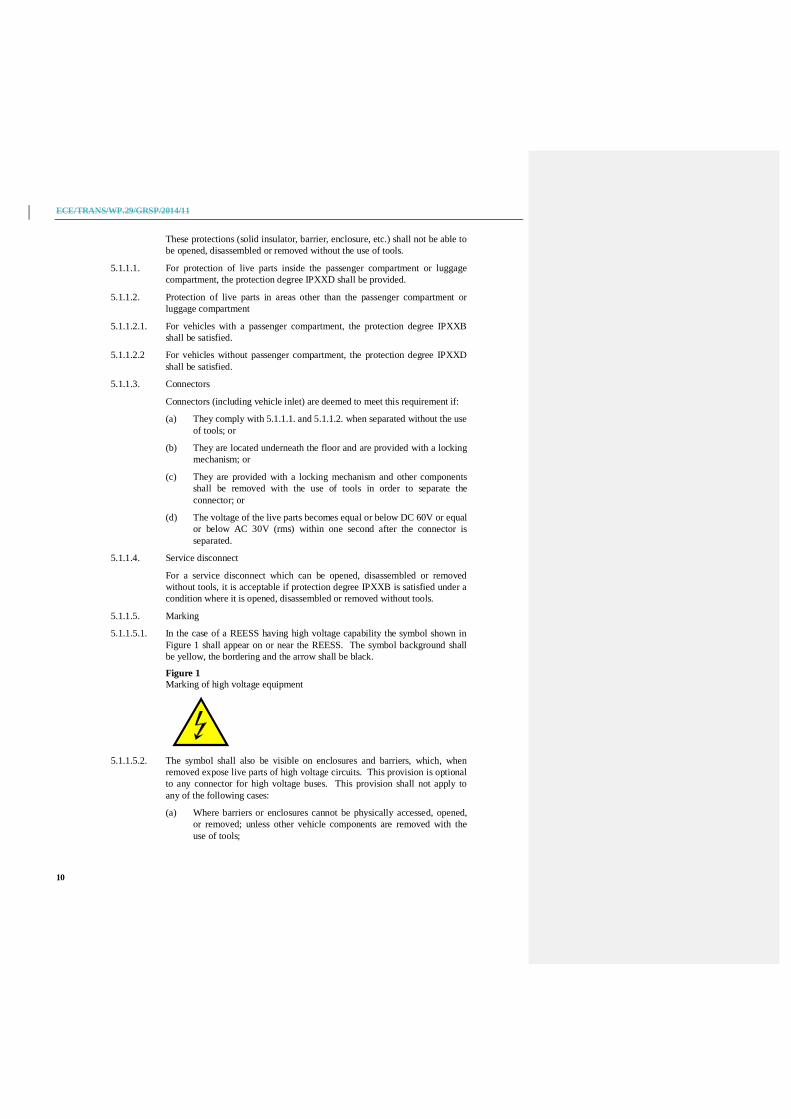
5.1.1.5.1. In the case of a REESS having high voltage capability the symbol shown inFigure 1 shall appear on or near the REESS. The symbol background shallbe yellow, the bordering and the arrow shall be black.
Figure 1Marking of high voltage equipment
5.1.1.5.2. The symbol shall also be visible on enclosures and barriers, which, whenremoved expose live parts of high voltage circuits. This provision is optionalto any connector for high voltage buses. This provision shall not apply toany of the following cases:
(a) Where barriers or enclosures cannot be physically accessed, opened,or removed; unless other vehicle components are removed with theuse of tools;

ECE/TRANS/WP.29/GRSP/2014/11
11
(b) Where barriers or enclosures are located underneath the vehicle floor.
5.1.1.5.3. Cables for high voltage buses which are not located within enclosures shallbe identified by having an outer covering with the colour orange.
5.1.2. Protection against indirect contact
Protection against indirect contact is also required for vehicles with highvoltage live parts equipped with any REESS type approved under Part II ofthis Regulation.
5.1.2.1. For protection against electrical shock which could arise from indirectcontact, the exposed conductive parts, such as the conductive barrier andenclosure, shall be galvanically connected securely to the electrical chassis byconnection with electrical wire or ground cable, or by welding, or byconnection using bolts, etc. so that no dangerous potentials are produced.
5.1.2.2. The resistance between all exposed conductive parts and the electrical chassisshall be lower than 0.1 when there is current flow of at least 0.2 amperes.
This requirement is satisfied if the galvanic connection has been establishedby welding.
5.1.2.3. In the case of motor vehicles which are intended to be connected to thegrounded external electric power supply through the conductive connection, adevice to enable the galvanical connection of the electrical chassis to theearth ground shall be provided.
The device shall enable connection to the earth ground before exteriorvoltage is applied to the vehicle and retain the connection until after theexterior voltage is removed from the vehicle.
Compliance to this requirement shall be demonstrated either by using theconnector specified by the vehicle manufacturer, or by analysis.
5.1.2.4. The requirement of paragraph 5.1.2.3. above shall not apply to the vehicleswhich satisfy (a) or (b) below:
(a) The vehicle´s REESS can be charged via the external electric powersupply only by using an off-board charger with a double insulation orreinforced insulation structure between input and output.
The performance requirements regarding the previously mentionedinsulation structure shall comply with the following requirements ofparagraph 5.1.2.4.1. and paragraph 5.1.2.4.3. and stated in itsdocumentation.
(b) The on-board charger has a double or reinforced insulation structurebetween input and the vehicle’s exposed conductive parts/electricalchassis.
The performance requirements regarding the previously mentionedinsulation structure shall comply with the following requirements ofparagraphs 5.1.2.4.1., 5.1.2.4.2., and 5.1.2.4.3.
If both systems are installed (a) and (b) have to be fulfilled.
5.1.2.4.1. Withstand voltage
5.1.2.4.1.1. For vehicle with on-board charger the test shall be conducted according toAnnex 9A to this regulation.
ECE/TRANS/WP.29/GRSP/2014/11
12
5.1.2.4.1.2. Acceptance criteria
The insulation resistance shall be equal to or greater than 7 M whenapplying 500 V DC between all the inputs connected together and thevehicle’s exposed conductive parts/electrical chassis.
5.1.2.4.2. Protection against ingress of water
5.1.2.4.2.1. This test shall be conducted according to Annex 9B of this regulation.
5.1.2.4.2.2. Acceptance Criteria
The insulation resistance shall be equal to or greater than 7 M , whenapplying 500 V DC.
5.1.2.4.3. Handling instructions
Appropriate instructions for charging shall be provided and included in themanual.4
5.1.3. Isolation resistance
This paragraph shall not apply to chassis connected electrical circuits wherethe maximum voltage between any live part and the electrical chassis or anyexposed conductive part does not exceed 30 V AC (rms) or 60 V DC.
5.1.3.1. Electric power train consisting of separate Direct Current- or AlternatingCurrent-buses
If AC buses and DC buses are galvanically isolated from each other, theisolation resistance between the high voltage bus and the electrical chassisshall have a minimum value of 100 /volt of the working voltage for DCbuses, and a minimum value of 500 /volt of the working voltage for ACbuses.
The measurement shall be conducted according to Annex 4A "Isolationresistance measurement method for vehicle based tests".
5.1.3.2. Electric power train consisting of combined DC- and AC-buses
If AC buses and DC buses are galvanically connected, isolation resistancebetween any high voltage bus and the electrical chassis shall have a minimumvalue of 500 /volt of the working voltage.
However, if all AC high voltage buses are protected by one of the twofollowing measures, isolation resistance between any high voltage bus andthe electrical chassis shall have a minimum value of 100 /V of the workingvoltage:
(a) Double or more layers of solid insulators, barriers or enclosures thatmeet the requirement in paragraph 5.1.1. independently, for examplewiring harness;
(b) Mechanically robust protections that have sufficient durability overvehicle service life such as motor housings, electronic converter casesor connectors;
4 Example of the content in the manual: "If during charging, your vehicle or charger becomessubmerged in water you should not touch either the vehicle nor the charger because of danger ofelectric shock. Also, do not use the battery nor the vehicle and ask your dealer to take (appropriate)measures."
ECE/TRANS/WP.29/GRSP/2014/11
13
The isolation resistance between the high voltage bus and the electricalchassis may be demonstrated by calculation, measurement or a combinationof both.
The measurement shall be conducted according to Annex 4A "Isolationresistance measurement method for vehicle based tests".
5.1.3.3. Fuel cell vehicles
If the minimum isolation resistance requirement cannot be maintainedover time, then protection shall be achieved by any of the following:
(a) Double or more layers of solid insulators, barriers or enclosuresthat meet the requirement in paragraph 5.1.1. independently;
(b) On-board isolation resistance monitoring system together with awarning to the driver if the isolation resistance drops below theminimum required value. The isolation resistance between the highvoltage bus of the coupling system for charging the REESS, which isnot energized besides during charging the REESS, and the electricalchassis need not be monitored. The function of the on-board isolationresistance monitoring system shall be confirmed as described inAnnex 5.
5.1.3.43. Isolation resistance requirement for the coupling system used to charge theREESS
For the coupling system (used to charge the REESS and intended to beconductively connected to the grounded external AC power supply) the isolationresistance shall be at least 1 M when the charger coupler is disconnected.During the measurement, the REESS may be disconnected.
5.2. Rechargeable Energy Storage System (REESS)
5.2.1. For a vehicle with a REESS, the requirement of either paragraph 5.2.1.1. orparagraph 5.2.1.2. shall be satisfied.
5.2.1.1. For a REESS which has been type approved in accordance with Part II of thisRegulation, installation shall be in accordance with the instructions providedby the manufacturer of the REESS, and in conformity with the descriptionprovided in Part 2 of Annex 6 to this Regulation.
5.2.1.2. The REESS shall comply with the respective requirements of paragraph 6. ofthis Regulation.
5.2.2. Accumulation of gas
Spaces for open type traction batteries that may produce hydrogen gas shallbe equipped with a ventilation fan, a ventilation duct or any other suitablemeans to prevent the accumulation of hydrogen gas.
5.2.3. Protection against electrolyte spills
Vehicles shall foresee that no spilled electrolyte from the REESS and itscomponents shall reach the driver, rider or passenger nor any person aroundthe vehicle during normal condition of use and/or functional operation.

ECE/TRANS/WP.29/GRSP/2014/11
14
When the REESS is in the put upside-down position, no electrolyte shallspill.
5.2.4. Accidental or unintentional detachment
The REESS and its components shall be installed in the vehicle in such a wayso as to preclude the possibility of inadvertent or unintentional detachment ofthe REESS.
The REESS in the vehicle shall not be ejected when the vehicle is tilted.
The REESS components shall not be ejected when the REESS is put upside-down.
5.3. Functional safety
A momentary indication shall, as minimum, be given to the driver when thevehicle is in "active driving possible mode''.
However, this provision does not apply under conditions where an internalcombustion engine directly or indirectly provides the vehicle´s propulsionpower.
When leaving the vehicle, the driver shall be informed by a signal (e.g.optical or audible signal) if the vehicle is still in the active driving possiblemode.
If the onboard REESS can be externally charged by the user, movementcaused by the vehicle's propulsion system shall not be possible while theexternal electric power supply is physically connected to the vehicle inlet.
For vehicles with a permanently connected recharge cable, the requirementabove is not applicable if using the cable to charge the vehicle prevents theuse of the vehicle (e.g. seat cannot be closed, the cable position does notallow the rider to sit in or step into the vehicle). This requirement shall bedemonstrated by using the connector specified by the vehicle manufacturer.The state of the drive direction control unit shall be identified to the driver.
5.3.1. Additional functional safety requirements
5.3.1.1. At least two deliberate and distinctive actions shall be performed by thedriver at the start-up to select the active driving possible mode.
5.3.1.2. Only a single action shall be required to deactivate the active driving possiblemode.
5.3.1.3. Indication of temporary reduced power (i.e. not resulting from a failure)and/or of state of charge (SOC) of REESS.
5.3.1.3.1. The vehicle shall have a function/device that indicates to the driver/rider ifthe power is automatically reduced below a certain level, (e.g. due toactivation of the output controller to protect the REESS or the propulsionsystem) or due to a low SOC.
5.3.1.3.2. The conditions under which these indications are given shall be determinedby the manufacturer.
A brief description of the power reduction and indicating strategy will beprescribed in Annex 6.
5.3.1.4. Driving or riding backwards

ECE/TRANS/WP.29/GRSP/2014/11
15
It shall not be possible to activate the vehicle reverse control function whilstthe vehicle is in forward motion.
5.4. Determination of hydrogen emissions
5.4.1. This test shall be carried out on all vehicles equipped with open type tractionbatteries. If the REESS has been approved under Part II of this Regulationand installed in accordance with paragraph 5.2.1.1., this test can be omittedfor the approval of the vehicle.
5.4.2. The test shall be conducted according to the method in Annex 7 of thepresent Regulation. The hydrogen sampling and analysis shall be prescribed.Other analysis methods can be approved if it is proven that they giveequivalent results.
5.4.3. During a normal charge procedure in the conditions given in Annex 7,hydrogen emissions shall be below 125 g during 5 h, or below 25 x t2 gduring t2 (in h).
5.4.4. During a charge carried out by a charger presenting a failure (conditionsgiven in Annex 7), hydrogen emissions shall be below 42 g. The chargershall limit such a failure to 30 minute maximum.
5.4.5. All the operations linked to the REESS charging shall be controlledautomatically, including the stop for charging.
5.4.6. Manual control of the charging phases shall not be possible.
5.4.7. Normal operations of connection and disconnection to the mains or powercuts shall not affect the control system of the charging phases.
5.4.8. Important charging failures shall be permanently indicated. An importantfailure is a failure that can lead to a malfunction of the charger duringcharging later on.
5.4.9. The manufacturer shall indicate, the vehicle's conformity in the owner'smanual to these requirements.
5.4.10. The approval granted to a vehicle type relative to hydrogen emissions can beextended to different vehicle types belonging to the same family, inaccordance with the definition of the family given in Annex 7, Appendix 2.
6. Part II: Requirements of a Rechargeable EnergyStorage System (REESS) with regard to its safety
6.1. General
The procedures prescribed in Annex 8 of this Regulation shall be applied.
6.2. Vibration
6.2.1. The test shall be conducted in accordance with Annex 8A of this Regulation.
6.2.2. Acceptance criteria
6.2.2.1. During the test, there shall be no evidence of:
(a) electrolyte leakage;
(b) rupture (applicable to high voltage REESS (s) only);
(c) fire;

ECE/TRANS/WP.29/GRSP/2014/11
16
(d) explosion.
Evidence of electrolyte leakage shall be verified by visual inspection withoutdisassembling any part of the tested-device.
6.2.2.2. For a high voltage REESS, the isolation resistance measured after the test inaccordance with Annex 4B to this Regulation shall not be less than100 /Volt.
6.3. Thermal shock and cycling
6.3.1. The test shall be conducted in accordance with Annex 8B to this Regulation.
6.3.2. Acceptance criteria
6.3.2.1. During the test, there shall be no evidence of:
(a) electrolyte leakage;
(b) rupture (applicable to high voltage REESS(s) only);
(c) fire;
(d) explosion.
Evidence of electrolyte leakage shall be verified by visual inspection withoutdisassembling any part of the tested-device.
6.3.2.2. For a high voltage REESS, the isolation resistance measured after the test inaccordance with Annex 4B of this Regulation shall not be less than100 /Volt.
6.4. Mechanical Tests
6.4.1. Drop Test for removable REESS
6.4.1.1. The test shall be conducted in accordance with Annex 8C of this Regulation.
6.4.1.2. Acceptance criteria
6.4.1.2.1. During the test there shall be no evidence of
(a) electrolyte leakage;
(b) rupture (applicable to high voltage REESS(s) only);
(c) fire;
(d) explosion.
Evidence of electrolyte leakage shall be verified by visual inspection withoutdisassembling any part of the Tested-Device.
6.4.1.2.2. For a high voltage REESS, the isolation resistance measured after the test inaccordance with Annex 4B of this Regulation shall not be less than 100
/Volt.
6.4.2. Mechanical shock resulting from stationary fall-over
6.4.2.1. This test shall apply to vehicles with a centre and/or side stand.
The test shall be conducted in accordance with Annex 8D of this Regulation.
6.4.2.2. Acceptance criteria
6.4.2.2.1. During the test there shall be no evidence of

ECE/TRANS/WP.29/GRSP/2014/11
17
(a) electrolyte leakage;
(b) rupture (applicable to high voltage REESS(s) only);
(c) fire;
(d) explosion.
Evidence of electrolyte leakage shall be verified by visual inspection withoutdisassembling any part of the tested-device.
6.4.2.2.2. For a high voltage REESS the isolation resistance of the tested-device shallensure at least 100 /Volt for the whole REESS measured after the test inaccordance with Annex 4B to this Regulation. or the protection degreeIPXXB shall be fulfilled for the tested-device.
6.5. Fire resistance
This test applies for vehicles with a passenger compartment only.
This test is required for REESS containing flammable electrolyte.
The test shall be carried out on one test sample.
At the manufacturer´s choice the test may be performed as, either:
(a) a vehicle based test in accordance with paragraph 6.5.1. of thisRegulation, or
(b) a component based test in accordance with paragraph 6.5.2. of thisRegulation.
6.5.1. Vehicle based test
The test shall be conducted in accordance with Annex 8E in dueconsideration of paragraph 3.2.1. of Annex 8E.
The approval of a REESS tested according to this paragraph shall be limitedto approvals for a specific vehicle type.
6.5.2. Component based test
The test shall be conducted in accordance with Annex 8E in dueconsideration of paragraph 3.2.2. of Annex 8E.
6.5.3. Acceptance criteria
6.5.3.1. During the test, the tested-device shall exhibit no evidence of explosion.
6.6. External short circuit protection
6.6.1. The test shall be conducted in accordance with Annex 8F of this Regulation.
6.6.2. Acceptance criteria;
6.6.2.1. During the test there shall be no evidence of:
(a) electrolyte leakage;
(b) rupture (applicable to high voltage REESS(s) only);
(c) fire;
(d) explosion.
Evidence of electrolyte leakage shall be verified by visual inspection withoutdisassembling any part of the tested-device.

ECE/TRANS/WP.29/GRSP/2014/11
18
6.6.2.2. For a high voltage REESS, the isolation resistance measured after the test inaccordance with Annex 4B to this Regulation shall not be less than 100 /V.
6.7. Overcharge protection
6.7.1. The test shall be conducted in accordance with Annex 8G to this Regulation.
6.7.2. Acceptance criteria
6.7.2.1. During the test there shall be no evidence of:
(a) electrolyte leakage;
(b) rupture (applicable to high voltage REESS(s) only);
(c) fire;
(d) explosion.
Evidence of electrolyte leakage shall be verified by visual inspection withoutdisassembling any part of the tested-device.
6.7.2.2. For a high voltage REESS, the isolation resistance measured after the test inaccordance with Annex 4B to this Regulation shall not be less than 100 /V.
6.8. Over-discharge protection
6.8.1. The test shall be conducted in accordance with Annex 8H to this Regulation.
6.8.2. Acceptance criteria
6.8.2.1. During the test there shall be no evidence of:
(a) electrolyte leakage;
(b) rupture (applicable to high voltage REESS(s) only);
(c) fire;
(d) explosion.
Evidence of electrolyte leakage shall be verified by visual inspection withoutdisassembling any part of the tested-device.
6.8.2.2. For a high voltage REESS the isolation resistance measured after the test inaccordance with Annex 4B to this Regulation shall not be less than 100 /V.
6.9. Over-temperature protection
6.9.1. The test shall be conducted in accordance with Annex 8I to this Regulation.
6.9.2. Acceptance criteria
6.9.2.1. During the test there shall be no evidence of:
(a) electrolyte leakage;
(b) rupture (applicable to high voltage REESS(s) only);
(c) fire;
(d) explosion.
Evidence of electrolyte leakage shall be verified by visual inspection withoutdisassembling any part of the tested-device.
6.9.2.2. For a high voltage REESS, the isolation resistance measured after the test inaccordance with Annex 4B to this Regulation shall not be less than 100 /V.
ECE/TRANS/WP.29/GRSP/2014/11
19
6.10. Emission
Possible emission of gases caused by the energy conversion process duringnormal use shall be considered.
6.10.1. Open type traction batteries shall meet the requirements of paragraph 5.4. ofthis Regulation with regard to hydrogen emissions.
Systems with a closed chemical process shall be considered as emission-freeunder normal operation (e.g. lithium-ion battery).
The closed chemical process shall be described and documented by thebattery manufacturer in Annex 6 - Part 2.
Other technologies shall be evaluated by the manufacturer and the TechnicalService regarding any possible emissions under normal operation.
6.10.2. Acceptance criteria
For hydrogen emissions see paragraph 5.4. of this Regulation.
For emission free systems with closed chemical process no verification isnecessary.
7. Modifications and extension of the type approval
7.1. Every modification of the vehicle or REESS type with regard to thisRegulation shall be notified to the Type Approval Authority which approvedthe vehicle or REESS type. The Authority may then either:
7.1.1. consider that the modifications made are unlikely to have an appreciableadverse effect and that in any case the vehicle or the REESS still complieswith the requirements, or
7.1.2. require a further test report from the Technical Service responsible forconducting the tests.
7.2. Confirmation or refusal of approval, specifying the alteration, shall becommunicated by the procedure specified in paragraph 4.3. above to theParties to the Agreement applying this Regulation.
7.3. The Type Approval Authority issuing the extension of approval shall assign aseries number to each communication form drawn up for such an extensionand inform thereof the other Parties to the 1958 Agreement applying theRegulation by means of a communication form conforming to the model inAnnex 1 (Part 1 or Part 2) to this Regulation.
8. Conformity of production
8.1. Vehicles or REESS approved under this Regulation shall be so manufacturedas to conform to the type approved by meeting the requirements of therelevant part(s) of this Regulation.
8.2. In order to verify that the requirements of paragraph 8.1. are met, appropriateproduction checks shall be carried out.
8.3. The holder of the approval shall, in particular:
ECE/TRANS/WP.29/GRSP/2014/11
20
8.3.1. ensure the existence of procedures for the effective quality control of vehiclesor REESS;
8.3.2. have access to the testing equipment necessary for checking the conformityof each approved type;
8.3.3. ensure that test result data are recorded and that the annexed documentsremain available for a period to be determined in agreement with the TypeApproval Authority;
8.3.4. analyse the results of each type of test, in order to verify and ensure theconsistency of characteristics of the vehicle or REESS, making allowance forpermissible variations in industrial production;
8.3.5. ensure that for each type of vehicle or component type at least the testsprescribed in the relevant part(s) of this Regulation are carried out;
8.3.6. ensure that any set of samples or test pieces giving evidence of non-conformity with the type of test in question shall give rise to a furthersampling and test. All necessary steps shall be taken to re-establishconformity of the corresponding production.
8.4. The Type Approval Authority which has granted type approval may at anytime verify the conformity control methods applied in each production unit.
8.4.1. At every inspection, the test records and production records shall bepresented to the visiting inspector.
8.4.2. The inspector may take samples at random to be tested in the manufacturer'slaboratory. The minimum number of samples may be determined accordingto the results of the manufacturer's own checks.
8.4.3. When the quality level appears unsatisfactory or when it seems necessary toverify the validity of the tests carried out in application of paragraph 8.4.2.,the inspector shall select samples to be sent to the technical service which hasconducted the type approval tests.
8.4.4. The Type Approval Authority may carry out any test prescribed in thisRegulation.
8.4.5. The normal frequency of inspections by the Type Approval Authority shallbe one per year. If unsatisfactory results are recorded during one of thesevisits, the Type Approval Authority shall ensure that all necessary steps aretaken to re-establish the conformity of production as rapidly as possible.
9. Penalties for non-conformity of production
9.1. The approval granted in respect of a vehicle/REESS type, pursuant to thisRegulation may be withdrawn if the requirements laid down in paragraph 8.above are not complied with, or if the vehicle/REESS or its components failto pass the tests provided for in paragraph 8.3.5. above.
9.2. If a Contracting Party to the Agreement applying this Regulation withdrawsan approval it has previously granted, it shall forthwith so notify the otherContracting Parties applying this Regulation, by means of a communicationform conforming to the Model in Annex 1 (Part 1 or Part 2) to thisRegulation.
ECE/TRANS/WP.29/GRSP/2014/11
21
10. Production definitively discontinued
If the holder of the approval completely ceases to manufacture avehicle/REESS type approved in accordance with this Regulation, he shall soinform the Authority which granted the approval. Upon receiving the relevantcommunication, that Authority shall inform thereof the other ContractingParties to the 1958 Agreement applying this Regulation by means of acommunication form conforming to the model in Annex 1 (Part 1 or Part 2)to this Regulation.
11. Names and addresses of Technical Servicesresponsible for conducting approval tests and ofType Approval Authorities
The Contracting Parties to the 1958 Agreement applying this Regulation shallcommunicate to the United Nations Secretariat the names and addresses ofthe Technical Services responsible for conducting approval tests and theType Approval Authorities which grant approval and to which formscertifying approval or extension or refusal or withdrawal of approval orproduction definitively discontinued, issued in other countries are to be sent.
12. Introductory provisionContracting Parties applying this Regulation may continue to require theproof of compliance to their national/regional provisions on Mechanicalimpact for the vehicles, which were already implemented within theirterritory at the time of entry into force of this Regulation, until the REESSsafety requirements for vehicles of category L in the event of the collision areestablished and this regulation is amended to follow above technicalrequirements.
ECE/TRANS/WP.29/GRSP/2014/11Annex 1 – Part 1
22
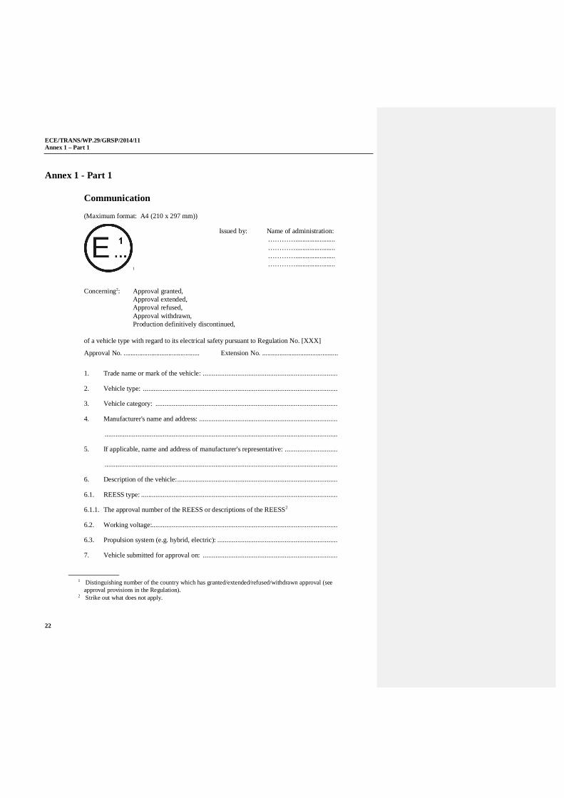
Annex 1 - Part 1
Communication
(Maximum format: A4 (210 x 297 mm))
1
Concerning2: Approval granted, Approval extended, Approval refused, Approval withdrawn, Production definitively discontinued,
of a vehicle type with regard to its electrical safety pursuant to Regulation No. [XXX]
Approval No. ............................................ Extension No. ............................................
1. Trade name or mark of the vehicle: ..........................................................................
2. Vehicle type: ...........................................................................................................
3. Vehicle category: ....................................................................................................
4. Manufacturer's name and address: ............................................................................
................................................................................................................................
5. If applicable, name and address of manufacturer's representative: .............................
................................................................................................................................
6. Description of the vehicle: ........................................................................................
6.1. REESS type: ............................................................................................................
6.1.1. The approval number of the REESS or descriptions of the REESS2
6.2. Working voltage:......................................................................................................
6.3. Propulsion system (e.g. hybrid, electric): ..................................................................
7. Vehicle submitted for approval on: ..........................................................................
1 Distinguishing number of the country which has granted/extended/refused/withdrawn approval (seeapproval provisions in the Regulation).
2 Strike out what does not apply.
Issued by: Name of administration:………….......................………….......................………….......................………….......................

ECE/TRANS/WP.29/GRSP/2014/11Annex 1 – Part 1
23
8. Technical Service responsible for conducting approval tests: ....................................
................................................................................................................................
9. Date of report issued by that Service: .......................................................................
10. Number of report issued by that Service: ..................................................................
11. Location of the approval mark: ................................................................................
12. Reason(s) for extension of approval (if applicable)2: ................................................
13. Approval granted/extended/refused/withdrawn2: ......................................................
14. Place: ......................................................................................................................
15. Date: .......................................................................................................................
16. Signature: ................................................................................................................
17. The documents filed with the request for approval or extension may be obtained onrequest.
ECE/TRANS/WP.29/GRSP/2014/11Annex 1 – Part 2
24
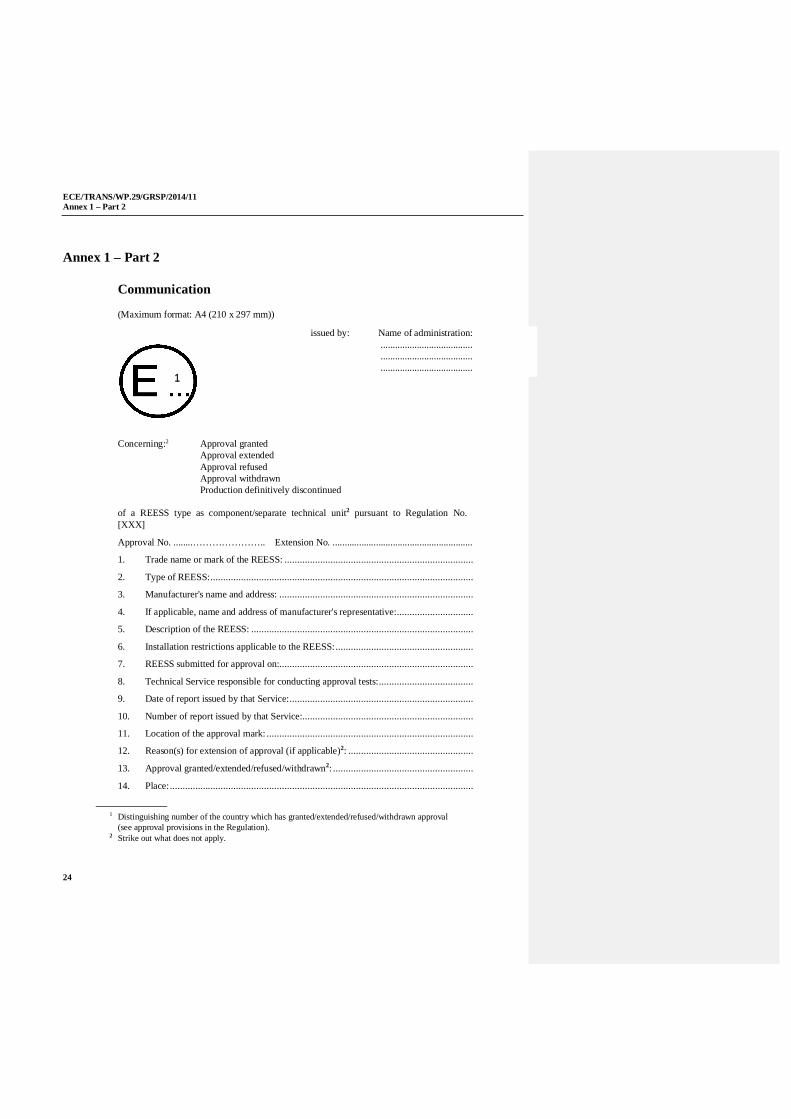
Annex 1 – Part 2
Communication
(Maximum format: A4 (210 x 297 mm))
Concerning:2 Approval grantedApproval extendedApproval refusedApproval withdrawnProduction definitively discontinued
of a REESS type as component/separate technical unit2 pursuant to Regulation No.[XXX]
Approval No. ........………………….. Extension No. ..........................................................
1. Trade name or mark of the REESS: ..........................................................................
2. Type of REESS: .......................................................................................................
3. Manufacturer's name and address: ............................................................................
4. If applicable, name and address of manufacturer's representative: ..............................
5. Description of the REESS: .......................................................................................
6. Installation restrictions applicable to the REESS: ......................................................
7. REESS submitted for approval on:............................................................................
8. Technical Service responsible for conducting approval tests: .....................................
9. Date of report issued by that Service: ........................................................................
10. Number of report issued by that Service:...................................................................
11. Location of the approval mark: .................................................................................
12. Reason(s) for extension of approval (if applicable)2: .................................................
13. Approval granted/extended/refused/withdrawn2: .......................................................
14. Place: .......................................................................................................................
1 Distinguishing number of the country which has granted/extended/refused/withdrawn approval(see approval provisions in the Regulation).
2 Strike out what does not apply.
issued by: Name of administration:..................................................................................................................
1

ECE/TRANS/WP.29/GRSP/2014/11Annex 1 – Part 2
25
15. Date: ........................................................................................................................
16. Signature: .................................................................................................................
17. The documents filed with the request for approval or extension may be obtained onrequest.
ECE/TRANS/WP.29/GRSP/2014/11Annex 2
26
Annex 2
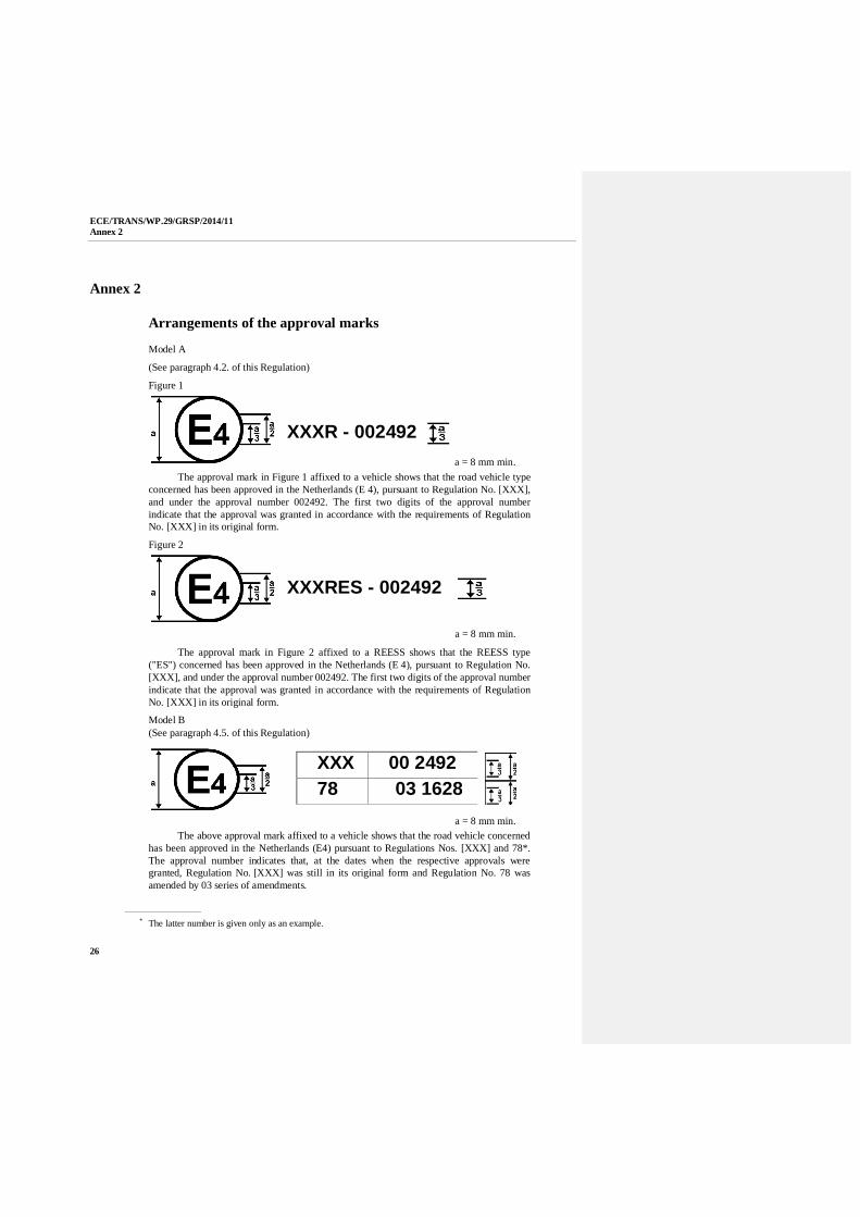
Arrangements of the approval marks
Model A
(See paragraph 4.2. of this Regulation)
Figure 1
a = 8 mm min.The approval mark in Figure 1 affixed to a vehicle shows that the road vehicle type
concerned has been approved in the Netherlands (E 4), pursuant to Regulation No. [XXX],and under the approval number 002492. The first two digits of the approval numberindicate that the approval was granted in accordance with the requirements of RegulationNo. [XXX] in its original form.
Figure 2
a = 8 mm min.
The approval mark in Figure 2 affixed to a REESS shows that the REESS type("ES") concerned has been approved in the Netherlands (E 4), pursuant to Regulation No.[XXX], and under the approval number 002492. The first two digits of the approval numberindicate that the approval was granted in accordance with the requirements of RegulationNo. [XXX] in its original form.
Model B(See paragraph 4.5. of this Regulation)
a = 8 mm min.The above approval mark affixed to a vehicle shows that the road vehicle concerned
has been approved in the Netherlands (E4) pursuant to Regulations Nos. [XXX] and 78*.The approval number indicates that, at the dates when the respective approvals weregranted, Regulation No. [XXX] was still in its original form and Regulation No. 78 wasamended by 03 series of amendments.
* The latter number is given only as an example.
XXX 00 249278 03 1628
XXXR - 002492
XXXRES - 002492
ECE/TRANS/WP.29/GRSP/2014/11Annex 3
27
Annex 3
Protection against direct contacts of parts under voltage
1. Access probes
Access probes to verify the protection of persons against access to live partsare given in Table 1.
2. Test conditions
The access probe is pushed against any openings of the enclosure with theforce specified in Table 1. If it partly or fully penetrates, it is placed in everypossible position, but in no case shall the stop face fully penetrate through theopening.
Internal barriers are considered part of the enclosure.
A low-voltage supply (of not less than 40 V and not more than 50 V) in serieswith a suitable lamp should be connected, if necessary, between the probeand live parts inside the barrier or enclosure.
The signal-circuit method should also be applied to the moving live parts ofhigh voltage equipment.
Internal moving parts may be operated slowly, where this is possible.
3. Acceptance conditions
The access probe shall not touch live parts.
If this requirement is verified by a signal circuit between the probe and liveparts, the lamp shall not light.
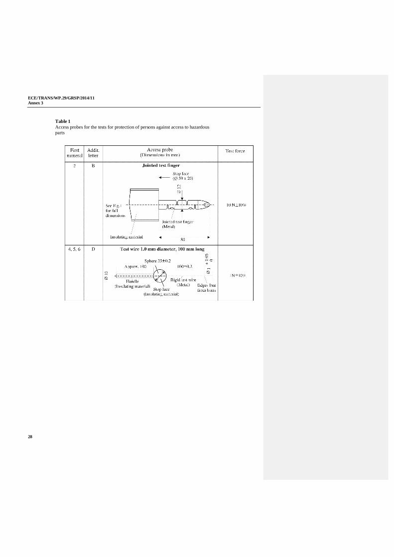
In the case of the test for IPXXB, the jointed test finger may penetrate to its80 mm length, but the stop face (diameter 50 mm x 20 mm) shall not passthrough the opening. Starting from the straight position, both joints of the testfinger shall be successively bent through an angle of upto 90 degrees with respect to the axis of the adjoining section of the fingerand shall be placed in every possible position.
In case of the tests for IPXXD, the access probe may penetrate to its fulllength, but the stop face shall not fully penetrate through the opening.
ECE/TRANS/WP.29/GRSP/2014/11Annex 3
28
Table 1Access probes for the tests for protection of persons against access to hazardousparts
ECE/TRANS/WP.29/GRSP/2014/11Annex 3
29
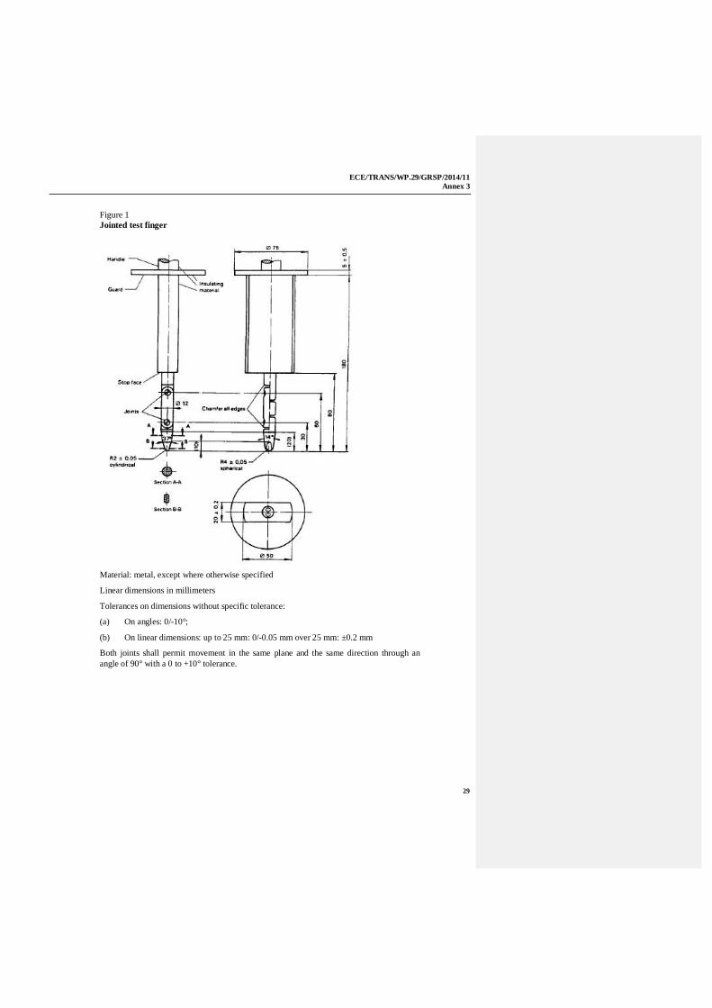
Figure 1Jointed test finger
Material: metal, except where otherwise specified
Linear dimensions in millimeters
Tolerances on dimensions without specific tolerance:
(a) On angles: 0/-10°;
(b) On linear dimensions: up to 25 mm: 0/-0.05 mm over 25 mm: ±0.2 mm
Both joints shall permit movement in the same plane and the same direction through anangle of 90° with a 0 to +10° tolerance.
ECE/TRANS/WP.29/GRSP/2014/11Annex 4A
30
Annex 4A
Isolation resistance measurement method for vehicle basedtests
1. General
The isolation resistance for each high voltage bus of the vehicle shall bemeasured or shall be determined by calculation using measurement valuesfrom each part or component unit of a high voltage bus (hereinafter referredto as the "divided measurement").
2. Measurement method
The isolation resistance measurement shall be conducted by selecting anappropriate measurement method from among those listed in paragraphs 2.1.through 2.2. of this annex, depending on the electrical charge of the live partsor the isolation resistance, etc.
The range of the electrical circuit to be measured shall be clarified inadvance, using electrical circuit diagrams, etc.
Moreover, modification necessary for measuring the isolation resistance maybe carried out, such as removal of the cover in order to reach the live parts,drawing of measurement lines, change in software, etc.
In cases where the measured values are not stable due to the operation of theon-board isolation resistance monitoring system, etc., necessary modificationfor conducting the measurement may be carried out, such as stopping of theoperation of the device concerned or removing it. Furthermore, when thedevice is removed, it shall be proven, using drawings, etc., that it will notchange the isolation resistance between the live parts and the electricalchassis.
Utmost care shall be exercised as to short circuit, electric shock, etc., for thisconfirmation might require direct operations of the high-voltage circuit.
2.1. Measurement method using voltage from off-vehicle sources
2.1.1. Measurement instrument
An isolation resistance test instrument capable of applying a DC voltagehigher than the working voltage of the high voltage bus shall be used.
2.1.2. Measurement method
An insulator resistance test instrument shall be connected between the liveparts and the electrical chassis. Then, the isolation resistance shall bemeasured by applying a DC voltage at least half of the working voltage of thehigh voltage bus.
If the system has several voltage ranges (e.g. because of boost converter) ingalvanically connected circuit and some of the components cannot withstandthe working voltage of the entire circuit, the isolation resistance betweenthose components and the electrical chassis can be measured separately byapplying at least half of their own working voltage with those componentdisconnected.
ECE/TRANS/WP.29/GRSP/2014/11Annex 4A
31
2.2. Measurement method using the vehicle’s own REESS as DC voltage source
2.2.1. Test vehicle conditions
The high voltage-bus shall be energized by the vehicle’s own REESS and/orenergy conversion system and the voltage level of the REESS and/or energyconversion system throughout the test shall be at least the nominal operatingvoltage as specified by the vehicle manufacturer.
2.2.2. Measurement instrument
The voltmeter used in this test shall measure DC values and shall have aninternal resistance of at least 10 M .
2.2.3. Measurement method
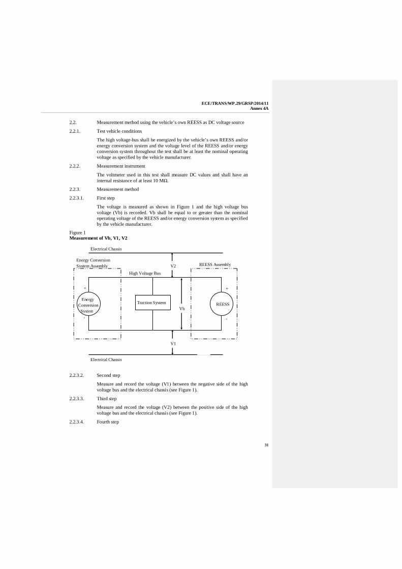
2.2.3.1. First step
The voltage is measured as shown in Figure 1 and the high voltage busvoltage (Vb) is recorded. Vb shall be equal to or greater than the nominaloperating voltage of the REESS and/or energy conversion system as specifiedby the vehicle manufacturer.
Figure 1Measurement of Vb, V1, V2
2.2.3.2. Second step
Measure and record the voltage (V1) between the negative side of the highvoltage bus and the electrical chassis (see Figure 1).
2.2.3.3. Third step
Measure and record the voltage (V2) between the positive side of the highvoltage bus and the electrical chassis (see Figure 1).
2.2.3.4. Fourth step
Electrical Chassis
Electrical Chassis
High Voltage Bus
Energy ConversionSystem Assembly REESS AssemblyV2
V1
Vb
+
-
+
-
EnergyConversion
SystemREESSTraction System
ECE/TRANS/WP.29/GRSP/2014/11Annex4A
32
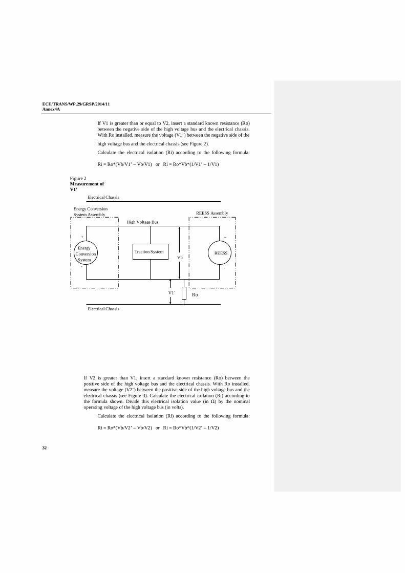
If V1 is greater than or equal to V2, insert a standard known resistance (Ro)between the negative side of the high voltage bus and the electrical chassis.With Ro installed, measure the voltage (V1’) between the negative side of the
high voltage bus and the electrical chassis (see Figure 2).
Calculate the electrical isolation (Ri) according to the following formula:
Ri = Ro*(Vb/V1’ – Vb/V1) or Ri = Ro*Vb*(1/V1’ – 1/V1)
Figure 2Measurement ofV1’
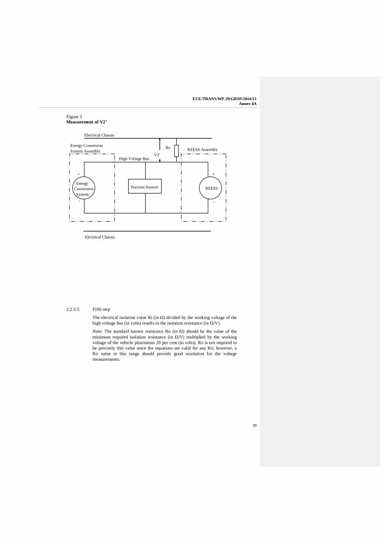
If V2 is greater than V1, insert a standard known resistance (Ro) between thepositive side of the high voltage bus and the electrical chassis. With Ro installed,measure the voltage (V2’) between the positive side of the high voltage bus and theelectrical chassis (see Figure 3). Calculate the electrical isolation (Ri) according tothe formula shown. Divide this electrical isolation value (in ) by the nominaloperating voltage of the high voltage bus (in volts).
Calculate the electrical isolation (Ri) according to the following formula:
Ri = Ro*(Vb/V2’ – Vb/V2) or Ri = Ro*Vb*(1/V2’ – 1/V2)
Electrical Chassis
Electrical Chassis
High Voltage Bus
Energy ConversionSystem Assembly REESS Assembly
V1´
Vb
+
-
+
-
EnergyConversion System
REESSTraction System
Ro
ECE/TRANS/WP.29/GRSP/2014/11Annex 4A
33
Figure 3Measurement of V2’
2.2.3.5. Fifth step
The electrical isolation value Ri (in ) divided by the working voltage of thehigh voltage bus (in volts) results in the isolation resistance (in /V).
Note: The standard known resistance Ro (in ) should be the value of theminimum required isolation resistance (in /V) multiplied by the workingvoltage of the vehicle plus/minus 20 per cent (in volts). Ro is not required tobe precisely this value since the equations are valid for any Ro; however, aRo value in this range should provide good resolution for the voltagemeasurements.
Electrical Chassis
Electrical Chassis
High Voltage Bus
Energy ConversionSystem Assembly REESS Assembly
V2'
+
-
+
-
EnergyConversion System
REESSTraction System
Ro
ECE/TRANS/WP.29/GRSP/2014/11Annex 4B
34
Annex 4B
Isolation resistance measurement method for componentbased tests of a REESS
1. Measurement method
The isolation resistance measurement shall be conducted by selecting anappropriate measurement method from among those listed in paragraphs 1.1.through 1.2. of this annex, depending on the electrical charge of the live partsor the isolation resistance, etc.
If the operating voltage of the tested-device (Vb, Figure 1) cannot bemeasured (e.g. due to disconnection of the electric circuit caused by maincontactors or fuse operation) the test may be performed with a modified testdevice to allow measurement of the internal voltages (upstream the maincontactors).
These modifications shall not influence the test results.
The range of the electrical circuit to be measured shall be clarified inadvance, using electrical circuit diagrams, etc. If the high voltage buses aregalvanically isolated from each other, isolation resistance shall be measuredfor each electrical circuit.
Moreover, modification necessary for measuring the isolation resistance maybe carried out, such as removal of the cover in order to reach the live parts,drawing of measurement lines, change in software, etc..
In cases where the measured values are not stable due to the operation of theisolation resistance monitoring system, etc., necessary modification forconducting the measurement may be carried out, such as stopping theoperation of the device concerned or removing it. Furthermore, when thedevice is removed, it shall be proven, using drawings, etc., that it will notchange the isolation resistance between the live parts and the groundconnection designated by the manufacturer as a point to be connected to theelectrical chassis when installed on the vehicle.
Utmost care shall be exercised as to short circuit, electric shock, etc., for thisconfirmation might require direct operations of the high-voltage circuit.
1.1. Measurement method using voltage from external sources
1.1.1. Measurement instrument
An isolation resistance test instrument capable of applying a DC voltagehigher than the nominal voltage of the tested-device shall be used.
1.1.2. Measurement method
An insulation resistance test instrument shall be connected between the liveparts and the ground connection. Then, the isolation resistance shall bemeasured.
If the system has several voltage ranges (e.g. because of boost converter) in agalvanically connected circuit and some of the components cannot withstandthe working voltage of the entire circuit, the isolation resistance betweenthose components and the ground connection can be measured separately by
ECE/TRANS/WP.29/GRSP/2014/11Annex 4B
35
applying at least half of their own working voltage with those componentdisconnected.
1.2. Measurement method using the tested-device as DC voltage source
1.2.1. Test conditions
The voltage level of the tested-device throughout the test shall be at least thenominal operating voltage of the tested-device.
1.2.2. Measurement instrument
The voltmeter used in this test shall measure DC values and shall have aninternal resistance of at least 10 M .
1.2.3. Measurement method
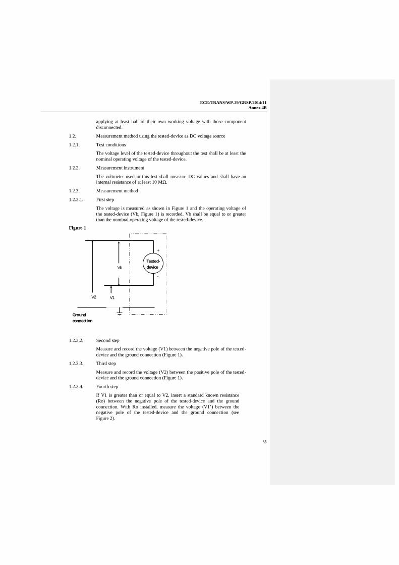
1.2.3.1. First step
The voltage is measured as shown in Figure 1 and the operating voltage ofthe tested-device (Vb, Figure 1) is recorded. Vb shall be equal to or greaterthan the nominal operating voltage of the tested-device.
Figure 1
Groundconnection
V2 V1
Vb
+
-
Tested-device
1.2.3.2. Second step
Measure and record the voltage (V1) between the negative pole of the tested-device and the ground connection (Figure 1).
1.2.3.3. Third step
Measure and record the voltage (V2) between the positive pole of the tested-device and the ground connection (Figure 1).
1.2.3.4. Fourth step
If V1 is greater than or equal to V2, insert a standard known resistance(Ro) between the negative pole of the tested-device and the groundconnection. With Ro installed, measure the voltage (V1’) between thenegative pole of the tested-device and the ground connection (seeFigure 2).

ECE/TRANS/WP.29/GRSP/2014/11Annex 4B
36
Calculate the electrical isolation (Ri) according to the following formula:
Ri = Ro*(Vb/V1’ – Vb/V1) or Ri = Ro*Vb*(1/V1’ – 1/V1)
Figure 2
Groundconnection
V1’
Vb
+
-
Tested-device
R0
If V2 is greater than V1, insert a standard known resistance (Ro) between thepositive pole of the tested-device and the ground connection. With Roinstalled, measure the voltage (V2’) between the positive pole of the tested-device and the ground connection (see Figure 3).
Calculate the electrical isolation (Ri) according to the following formula:
Ri = Ro*(Vb/V2’ – Vb/V2) or Ri = Ro*Vb*(1/V2’ – 1/V2)

ECE/TRANS/WP.29/GRSP/2014/11Annex 4B
37
Figure 3
Groundconnection
V2’
Vb
+
-R0
Tested-device
1.2.3.5. Fifth step
The electrical isolation value Ri (in ) divided by the nominal voltage of thetested-device (in volts) results in the isolation resistance (in /V).
Note 1: The standard known resistance Ro (in ) should be the value of theminimum required isolation resistance (in /V) multiplied by the nominalvoltage of the tested-device plus/minus 20 per cent (in volts). Ro is notrequired to be precisely this value since the equations are valid for any Ro;however, a Ro value in this range should provide good resolution for thevoltage measurements.
ECE/TRANS/WP.29/GRSP/2014/11Annex 5
38
Annex 5
Confirmation method for function of on-board isolationresistance monitoring system
The function of the on-board isolation resistance monitoring system shall be confirmed bythe following method:
Insert a resistor that does not cause the isolation resistance between the terminal beingmonitored and the electrical chassis to drop below the minimum required isolationresistance value. The warning shall be activated.
ECE/TRANS/WP.29/GRSP/2014/11Annex 6 – Part 1
39
Annex 6 - Part 1
Essential characteristics of road vehicles or systems
1. General
1.1. Mark (trade name of manufacturer): ........................................................................
1.2. Type: ......................................................................................................................
1.3. Vehicle category: ....................................................................................................
1.4. Commercial name(s) if available: ............................................................................
................................................................................................................................
1.5. Manufacturer's name and address: ...........................................................................
................................................................................................................................
1.6. If applicable, name and address of manufacturer's representative: ............................
1.7. Drawing and/or photograph of the vehicle: ...............................................................
1.8. Approval number of the REESS: ..............................................................................
1.9 Passenger compartment: Yes / No 1 : ........................................................................
1.10 Centre and/or side stand: Yes / No 1: .......................................................................
2. Electric motor (traction motor)
2.1. Type (winding, excitation): .....................................................................................
2.2. Maximum net power and / or maximum 30 minutes power (kW): ............................
3. REESS
3.1. Trade name and mark of the REESS: .......................................................................
3.2. Indication of all types of cells: .................................................................................
3.2.1. The cell chemistry: ...................................................................................................
3.2.2. Physical dimensions: ................................................................................................
3.2.3. Capacity of the cell (Ah): .........................................................................................
1 Strike out what does not apply.
ECE/TRANS/WP.29/GRSP/2014/11Annex 6 – Part 1
40
3.3. Description or drawing(s) or picture(s) of the REESS explaining:
3.3.1. Structure: .................................................................................................................
3.3.2. Configuration (number of cells, mode of connection, etc.): .......................................
3.3.3. Dimensions: .............................................................................................................
3.3.4. Casing (construction, materials and physical dimensions): ........................................
3.4. Electrical specification: ...........................................................................................
3.4.1. Nominal voltage (V): ...............................................................................................
3.4.2. Working voltage (V): ...............................................................................................
3.4.3. Rated cCapacity (Ah): .............................................................................................
3.4.4. Maximum current (A): .............................................................................................
3.5. Gas combination rate (in per cent): ..........................................................................
3.6. Description or drawing(s) or picture(s) of the installation of the REESS in the
vehicle: ...................................................................................................................
3.6.1. Physical support: ......................................................................................................
3.7. Type of thermal management ...................................................................................
3.8. Electronic control: ....................................................................................................
4. Fuel Cell (if any)
4.1. Trade name and mark of the fuel cell: ..................................................................
................................................................................................................................
4.2. Types of fuel cell: ..................................................................................................
4.3. Nominal voltage (V): .............................................................................................
4.4. Number of cells: ....................................................................................................
4.5. Type of cooling system (if any): ............................................................................
4.6. Max Power(kW): ...................................................................................................
4.5. Fuse and/or circuit breaker
4.5.1. Type: ......................................................................................................................
4.5.2. Diagram showing the functional range: ....................................................................
56. Power wiring harness
ECE/TRANS/WP.29/GRSP/2014/11Annex 6 – Part 1
41
56.1. Type: ......................................................................................................................
67. Protection against Electric Shock
67.1. Description of the protection concept: ......................................................................
78. Additional data
78.1. Brief description of the power circuit components installation or drawings/pictures showing the location of the power circuit components installation: ..............
78.2 Schematic diagram of all electrical functions included in power circuit: ...................
78.3. Working voltage (V): ..............................................................................................
78.4 System descriptions for low performance driving mode(s) ………………………
78.4.1 Systems’ SOC level(s) for which power reduction is activated, descriptions,
rationales ……………………………………………………………………………
78.4.2 Descriptions for systems’ reduced power mode(s) and similar mode(s),
rationales……………………………………………………………………………
ECE/TRANS/WP.29/GRSP/2014/11Annex 6 – Part 3
42
Annex 6 - Part 2
Essential characteristics of REESS
1. REESS
1.1. Trade name and mark of the REESS: ............................................................
1.2. Indication of all types of cells: .......................................................................
1.2.1. The cell chemistry: ........................................................................................
1.2.2. Physical dimensions: .....................................................................................
1.2.3. Capacity of the cell (Ah): ..............................................................................
1.3. Description or drawing(s) or picture(s) of the REESS explaining
1.3.1. Structure: ......................................................................................................
1.3.2. Configuration (number of cells, mode of connection, etc.): .............................
1.3.3. Dimensions: ..................................................................................................
1.3.4. Casing (construction, materials and physical dimensions): .............................
1.3.5. Mass of REESS (kg): ....................................................................................
1.4. Electrical specification
1.4.1. Nominal voltage (V):.....................................................................................
1.4.2. Working voltage (V): ....................................................................................
1.4.3. Rated cCapacity (Ah): ..................................................................................
1.4.4. Maximum current (A): ..................................................................................
1.5. Gas combination rate (in percentage): ............................................................
1.6. Description or drawing(s) or picture(s) of the installation of the REESS in thevehicle: .........................................................................................................
1.6.1. Physical support: ...........................................................................................
1.7. Type of thermal management: .......................................................................
1.8. Electronic control: .........................................................................................
1.9. Category of vehicles on which the REESS can be installed: ...........................
ECE/TRANS/WP.29/GRSP/2014/11Annex 6 – Part 1
43
Annex 6 - Part 3
Essential characteristics of road vehicles or systems withchassis connected to electrical circuits
1. General
1.1. Mark (trade name of manufacturer): .........................................................................
1.2. Type: .......................................................................................................................
1.3. Vehicle category: .....................................................................................................
1.4. Commercial name(s) if available: .............................................................................
1.5. Manufacturer's name and address: ............................................................................
1.6. If applicable, name and address of manufacturer's representative: .............................
................................................................................................................................
1.7. Drawing and/or photograph of the vehicle: ...............................................................
1.8. Approval number of the REESS: ..............................................................................
1.9 Passenger compartment: Yes / No 1: .........................................................................
1.10 Centre and/or side stand: Yes / No 1: .......................................................................
2. REESS
2.1. Trade name and mark of the REESS: ........................................................................
2.2. The cell chemistry: ...................................................................................................
2.3. Electrical specification:
2.3.1. Nominal voltage (V): ...............................................................................................
2.3.2. Rated cCapacity (Ah): .............................................................................................
2.3.3. Maximum current (A): .............................................................................................
2.4. Gas combination rate (in per cent): ...........................................................................
2.5. Description or drawing(s) or picture(s) of the installation of the RESSS in thevehicle: ....................................................................................................................
3. Additional data
3.1. Working voltage (V) AC circuit: ..............................................................................
3.2. Working voltage (V) DC circuit:
1 Strike out what does not apply.

ECE/TRANS/WP.29/GRSP/2014/11Annex 7
44
Annex 7
Determination of hydrogen emissions during the chargeprocedures of the REESS
1. Introduction
This annex describes the procedure for the determination of hydrogenemissions during the charge procedures of the REESS of all road vehicles,according to paragraph 5.4. of this Regulation.
2. Description of test
The hydrogen emission test (Figure 7.1 of the present annex) is conducted inorder to determine hydrogen emissions during the charge procedures of theREESS with the charger. The test consists in the following steps:
(a) vehicle/REESS preparation,
(b) discharge of the REESS,
(c) determination of hydrogen emissions during a normal charge,
(d) determination of hydrogen emissions during a charge carried out withthe charger failure.
3. Tests
3.1. Vehicle based test
3.1.1. The vehicle shall be in good mechanical condition and have been drivenat least 300 km during seven days before the test. The vehicle shall beequipped with the REESS subject to the test of hydrogen emissions, over thisperiod.
3.1.2. If the REESS is used at a temperature above the ambient temperature, theoperator shall follow the manufacturer's procedure in order to keep theREESS temperature in normal functioning range.
The manufacturer's representative shall be able to certify that the temperatureconditioning system of the REESS is neither damaged nor presenting acapacity defect.
3.2. Component based test
3.2.1. The REESS shall be in good mechanical condition and have been subject tominimum of 5 standard cycles (as specified in Annex 8, Appendix 1).
3.2.2. If the REESS is used at a temperature above the ambient temperature, theoperator shall follow the manufacturer's procedure in order to keep theREESS temperature in its normal functioning range.
The manufacturer's representative shall be able to certify that the temperatureconditioning system of the REESS is neither damaged nor presenting acapacity defect
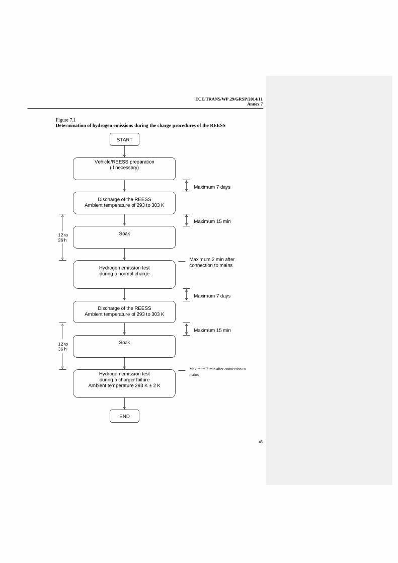
ECE/TRANS/WP.29/GRSP/2014/11Annex 7
45
Figure 7.1Determination of hydrogen emissions during the charge procedures of the REESS
Discharge of the REESSAmbient temperature of 293 to 303 K
Soak
Hydrogen emission testduring a normal charge
END
Soak
Hydrogen emission testduring a charger failure
Ambient temperature 293 K ± 2 K
START
Vehicle/REESS preparation(if necessary)
Discharge of the REESSAmbient temperature of 293 to 303 K
Maximum 7 daysdays days
Maximum 15 min
12 to36 h
12 to36 h
Maximum 7 days
Maximum 15 min
Maximum 2 min after connection tomains
Maximum 2 min afterconnection to mains
ECE/TRANS/WP.29/GRSP/2014/11Annex 7
46
4. Test equipment for hydrogen emission test
4.1. Hydrogen emission measurement enclosure
The hydrogen emission measurement enclosure shall be a gas-tight measuringchamber able to contain the vehicle/REESS under test. The vehicle/REESSshall be accessible from all sides and the enclosure when sealed shall be gas-tight in accordance with Appendix 1 to this annex. The inner surface of theenclosure shall be impermeable and non-reactive to hydrogen. Thetemperature conditioning system shall be capable of controlling the internalenclosure air temperature to follow the prescribed temperature throughout thetest, with an average tolerance of ±2 K over the duration of the test.
To accommodate the volume changes due to enclosure hydrogen emissions,either a variable-volume or another test equipment may be used. Thevariable-volume enclosure expands and contracts in response to the hydrogenemissions in the enclosure. Two potential means of accommodating theinternal volume changes are movable panels, or a bellows design, in whichimpermeable bags inside the enclosure expand and contract in response tointernal pressure changes by exchanging air from outside the enclosure. Anydesign for volume accommodation shall maintain the integrity of theenclosure as specified in Appendix 1 to this annex.
Any method of volume accommodation shall limit the differential betweenthe enclosure internal pressure and the barometric pressure to a maximumvalue of ±5hPa.
The enclosure shall be capable of latching to a fixed volume. A variablevolume enclosure shall be capable of accommodating a change from its"nominal volume" (see Annex 7, Appendix 1, paragraph 2.1.1.), taking intoaccount hydrogen emissions during testing.
4.2. Analytical systems
4.2.1. Hydrogen analyser
4.2.1.1. The atmosphere within the chamber is monitored using a hydrogen analyser(electrochemical detector type) or a chromatograph with thermal conductivitydetection. Sample gas shall be drawn from the mid-point of one side-wall orroof of the chamber and any bypass flow shall be returned to the enclosure,preferably to a point immediately downstream of the mixing fan.
4.2.1.2. The hydrogen analyser shall have a response time to 90 per cent of finalreading of less than 10 seconds. Its stability shall be better than 2 per cent offull scale at zero and at 80 per cent ± 20 per cent of full scale, overa 15-minute period for all operational ranges.
4.2.1.3. The repeatability of the analyser expressed as one standard deviation shall bebetter than 1 per cent of full scale, at zero and at 80 per cent ± 20 per cent offull scale on all ranges used.
4.2.1.4. The operational ranges of the analyser shall be chosen to give best resolutionover the measurement, calibration and leak checking procedures.
ECE/TRANS/WP.29/GRSP/2014/11Annex 7
47
4.2.2. Hydrogen analyser data recording system
The hydrogen analyser shall be fitted with a device to record electrical signaloutput, at a frequency of at least once per minute. The recording system shallhave operating characteristics at least equivalent to the signal being recorded andshall provide a permanent record of results. The recording shall show a clearindication of the beginning and end of the normal charge test and charging failureoperation.
4.3. Temperature recording
4.3.1. The temperature in the chamber is recorded at two points by temperaturesensors, which are connected so as to show a mean value. The measuringpoints are extended approximately 0.1 m into the enclosure from the verticalcentre line of each side-wall at a height of 0.9 ± 0.2 m.
4.3.2. The temperatures in the proximity of the cells are recorded by means of thesensors.
4.3.3. Temperatures shall, throughout the hydrogen emission measurements, berecorded at a frequency of at least once per minute.
4.3.4. The accuracy of the temperature recording system shall be within ±1.0 K andthe temperature shall be capable of being resolved to ±0.1 K.
4.3.5. The recording or data processing system shall be capable of resolving timeto ± 15 seconds.
4.4. Pressure recording
4.4.1. The difference p between barometric pressure within the test area and theenclosure internal pressure shall, throughout the hydrogen emissionmeasurements, be recorded at a frequency of at least once per minute.
4.4.2. The accuracy of the pressure recording system shall be within ±2 hPa and thepressure shall be capable of being resolved to ±0.2 hPa.
4.4.3. The recording or data processing system shall be capable of resolving timeto ±15 seconds.
4.5. Voltage and current intensity recording
4.5.1. The charger voltage and current intensity (battery) shall, throughout thehydrogen emission measurements, be recorded at a frequency of at least onceper minute.
4.5.2. The accuracy of the voltage recording system shall be within ±1 V and thevoltage shall be capable of being resolved to ±0.1 V.
4.5.3. The accuracy of the current intensity recording system shall be within ±0.5 Aand the current intensity shall be capable of being resolved to ±0.05 A.
4.5.4. The recording or data processing system shall be capable of resolving time to±15 seconds.
4.6. Fans
The chamber shall be equipped with one or more fans or blowers with apossible flow of 0.1 to 0.5 m3/second in order to thoroughly mix theatmosphere in the enclosure. It shall be possible to reach a homogeneoustemperature and hydrogen concentration in the chamber duringmeasurements. The vehicle in the enclosure shall not be subjected to a directstream of air from the fans or blowers.
ECE/TRANS/WP.29/GRSP/2014/11Annex 7
48
4.7. Gases
4.7.1. The following pure gases shall be available for calibration and operation:
(a) Purified synthetic air (purity < 1 ppm C1 equivalent; < 1 ppm CO;< 400 ppm CO2; < 0.1 ppm NO ); oxygen content between 18 and21 per cent by volume,
(b) Hydrogen ( H2 ), 99.5 per cent minimum purity.
4.7.2. Calibration and span gases shall contain mixtures of hydrogen (H2) andpurified synthetic air. The real concentrations of a calibration gas shall bewithin ±2 per cent of the nominal values. The accuracy of the diluted gasesobtained when using a gas divider shall be within ±2 per cent of the nominalvalue. The concentrations specified in Appendix 1 may also be obtained by agas divider using synthetic air as the dilution gas.
5. Test procedure
The test consists in the five following steps:
(a) vehicle/REESS preparation;
(b) discharge of theREESS;
(c) determination of hydrogen emissions during a normal charge;
(d) discharge of the traction battery;
(e) determination of hydrogen emissions during a charge carried out withthe charger failure.
If the vehicle/REESS has to be moved between two steps, it shall be pushedto the following test area.
5.1. Vehicle based test
5.1.1. Vehicle preparation
The ageing of REESS shall be checked, proving that the vehicle hasperformed at least 300 km during seven days before the test. During thisperiod, the vehicle shall be equipped with the traction battery submitted tothe hydrogen emission test. If this cannot be demonstrated then the followingprocedure will be applied.
5.1.1.1. Discharges and initial charges of the REESS
The procedure starts with the discharge of the REESS of the vehicle whiledriving on the test track at a steady speed of 70 per cent ± 5 per cent of themaximum speed of the vehicle during 30 minutes.
Discharging is stopped:
(a) when the vehicle is not able to run at 65 per cent of the maximumthirty minutes speed, or
(b) when an indication to stop the vehicle is given to the driver by thestandard on-board instrumentation, or
(c) after having covered the distance of 100 km.
5.1.1.2. Initial charge of the REESS
The charge is carried out:
ECE/TRANS/WP.29/GRSP/2014/11Annex 7
49
(a) with the charger;
(b) in an ambient temperature between 293 K and 303 K.
The procedure excludes all types of external chargers.
The end of REESS charge criteria corresponds to an automatic stop given bythe charger.
This procedure includes all types of special charges that could beautomatically or manually initiated like, for instance, the equalisation chargesor the servicing charges.
5.1.1.3. Procedure from paragraphs 5.1.1.1. and 5.1.1.2. shall be repeated two times.
5.1.2. Discharge of the REESS
The REESS is discharged while driving on the test track at a steady speed of70 per cent ± 5 per cent from the maximum thirty minutes speed of thevehicle.
Stopping the discharge occurs:
(a) when an indication to stop the vehicle is given to the driver by thestandard on-board instrumentation, or
(b) when the maximum speed of the vehicle is lower than 20 km/h.
5.1.3. Soak
Within fifteen minutes of completing the battery discharge operationspecified in paragraph 5.2., the vehicle is parked in the soak area. The vehicleis parked for a minimum of 12 hours and a maximum of 36 hours, betweenthe end of the traction battery discharge and the start of the hydrogenemission test during a normal charge. For this period, the vehicle shall besoaked at 293 K ± 2 K.
5.1.4. Hydrogen emission test during a normal charge
5.1.4.1. Before the completion of the soak period, the measuring chamber shall bepurged for several minutes until a stable hydrogen background is obtained.The enclosure mixing fan(s) shall also be turned on at this time.
5.1.4.2. The hydrogen analyser shall be zeroed and spanned immediately prior to thetest.
5.1.4.3. At the end of the soak, the test vehicle, with the engine shut off and the testvehicle windows and luggage compartment opened shall be moved into themeasuring chamber.
5.1.4.4. The vehicle shall be connected to the mains. The REESS is chargedaccording to normal charge procedure as specified in paragraph 5.1.4.7.below.
5.1.4.5. The enclosure doors are closed and sealed gas-tight within two minutes fromelectrical interlock of the normal charge step.
5.1.4.6. The start of a normal charge for hydrogen emission test period begins whenthe chamber is sealed. The hydrogen concentration, temperature andbarometric pressure are measured to give the initial readings CH2i, Ti and Pi
for the normal charge test.
ECE/TRANS/WP.29/GRSP/2014/11Annex 7
50
These figures are used in the hydrogen emission calculation (paragraph 6. ofthis annex). The ambient enclosure temperature T shall not be less than291 K and no more than 295 K during the normal charge period.
5.1.4.7. Procedure of normal charge
The normal charge is carried out with the charger and consists of thefollowing steps:
(a) charging at constant power during t1;
(b) over-charging at constant current during t2. Over-charging intensity isspecified by manufacturer and corresponds to the one used duringequalisation charging.
The end of REESS charge criteria corresponds to an automatic stop given bythe charger to a charging time of t1 + t2. This charging time will be limited tot1 + 5 h, even if a clear indication is given to the driver by the standardinstrumentation that the battery is not yet fully charged.
5.1.4.8. The hydrogen analyser shall be zeroed and spanned immediately before theend of the test.
5.1.4.9. The end of the emission sampling period occurs t1 + t2 or t1 + 5 hours afterthe beginning of the initial sampling, as specified in paragraph 5.1.4.6. of thisannex. The different times elapsed are recorded. The hydrogenconcentration, temperature and barometric pressure are measured to give thefinal readings CH2f, Tf and P f for the normal charge test, used for thecalculation in paragraph 6. of this annex.
5.1.5. Hydrogen emission test with the charger failure
5.1.5.1. Within seven days maximum after having completed the prior test, theprocedure starts with the discharge of the REESS of the vehicle according toparagraph 5.1.2. of this annex.
5.1.5.2. The steps of the procedure in paragraph 5.1.3. of this annex shall be repeated.
5.1.5.3. Before the completion of the soak period, the measuring chamber shall bepurged for several minutes until a stable hydrogen background is obtained.The enclosure mixing fan(s) shall also be turned on at this time.
5.1.5.4. The hydrogen analyser shall be zeroed and spanned immediately prior to thetest.
5.1.5.5. At the end of the soak, the test vehicle, with the engine shut off and the testvehicle windows and luggage compartment opened shall be moved into themeasuring chamber.
5.1.5.6. The vehicle shall be connected to the mains. The REESS is chargedaccording to failure charge procedure as specified in paragraph 5.1.5.9.below.
5.1.5.7. The enclosure doors are closed and sealed gas-tight within two minutes fromelectrical interlock of the failure charge step.
5.1.5.8. The start of a failure charge for hydrogen emission test period begins whenthe chamber is sealed. The hydrogen concentration, temperature andbarometric pressure are measured to give the initial readings CH2i, Ti and Pi
for the failure charge test.
ECE/TRANS/WP.29/GRSP/2014/11Annex 7
51
These figures are used in the hydrogen emission calculation (paragraph 6. ofthis annex). The ambient enclosure temperature T shall not be less than291 K and no more than 295 K during the charging failure period.
5.1.5.9. Procedure of charging failure
The charging failure is carried out with the suitable charger and consists ofthe following steps:
(a) charging at constant power during t'1;
(b) charging at maximum current as recommended by the manufacturerduring 30 minutes. During this phase, the charger shall supplymaximum current as recommended by the manufacturer.
5.1.5.10. The hydrogen analyser shall be zeroed and spanned immediately before theend of the test.
5.1.5.11. The end of test period occurs t'1 + 30 minutes after the beginning of the initialsampling, as specified in paragraph 5.1.5.8. above. The times elapsed arerecorded. The hydrogen concentration, temperature and barometric pressureare measured to give the final readings CH2f, Tf and Pf for the charging failuretest, used for the calculation in paragraph 6. of this annex.
5.2. Component based test
5.2.1. REESS preparation
The ageing of REESS shall be checked, to confirm that the REESS hasperformed at least 5 standard cycles (as specified in Annex 8, Appendix 1).
5.2.2. Discharge of the REESS
The REESS is discharged at 70 per cent ± 5 per cent of the nominal power ofthe system.
Stopping the discharge occurs when minimum SOC as specified by themanufacturer is reached.
5.2.3. Soak
Within 15 minutes of the end of the REESS discharge operation specified inparagraph 5.2.2. above, and before the start of the hydrogen emission test, theREESS shall be soaked at 293 K ± 2 K for a minimum period of 12 hours anda maximum of period of 36 hours.
5.2.4. Hydrogen emission test during a normal charge
5.2.4.1. Before the completion of the REESS's soak period, the measuring chambershall be purged for several minutes until a stable hydrogen background isobtained. The enclosure mixing fan(s) shall also be turned on at this time.
5.2.4.2. The hydrogen analyser shall be zeroed and spanned immediately prior to thetest.
5.2.4.3. At the end of the soak period, the REESS shall be moved into the measuringchamber.
5.2.4.4. The REESS shall be charged in accordance with the normal charge procedureas specified in paragraph 5.2.4.7. below.
5.2.4.5. The chamber shall be closed and sealed gas-tight within two minutes of theelectrical interlock of the normal charge step.

ECE/TRANS/WP.29/GRSP/2014/11Annex 7
52
5.2.4.6. The start of a normal charge for hydrogen emission test period shall beginwhen the chamber is sealed. The hydrogen concentration, temperature andbarometric pressure are measured to give the initial readings CH2i, Ti and Pi
for the normal charge test.
These figures are used in the hydrogen emission calculation (paragraph 6. ofthis annex). The ambient enclosure temperature T shall not be less than291 K and no more than 295 K during the normal charge period.
5.2.4.7. Procedure of normal charge
The normal charge is carried out with a suitable charger and consists of thefollowing steps:
(a) charging at constant power during t1;
(a) over-charging at constant current during t2. Over-charging intensity isspecified by manufacturer and corresponding to that used duringequalisation charging.
The end of REESS charge criteria corresponds to an automatic stop given bythe charger to a charging time of t1 + t2. This charging time will be limited tot1 + 5 h, even if a clear indication is given by a suitable instrumentation thatthe REESS is not yet fully charged.
5.2.4.8. The hydrogen analyser shall be zeroed and spanned immediately before theend of the test.
5.2.4.9. The end of the emission sampling period occurs t1 + t2 or t1 + 5 h after thebeginning of the initial sampling, as specified in paragraph 5.2.4.6. above.The different times elapsed are recorded. The hydrogen concentration,temperature and barometric pressure are measured to give the final readingsCH2f, Tf and Pf for the normal charge test, used for the calculation inparagraph 6. of this annex
5.2.5. Hydrogen emission test with the charger failure
5.2.5.1. The test procedure shall start within a maximum of seven days after havingcompleted the test in paragraph 5.2.4. above, the procedure shall start withthe discharge of the REESS of the vehicle in accordance withparagraph 5.2.2. above.
5.2.5.2. The steps of the procedure in paragraph 5.2.3. above shall be repeated.
5.2.5.3. Before the completion of the soak period, the measuring chamber shall bepurged for several minutes until a stable hydrogen background is obtained.The enclosure mixing fan(s) shall also be turned on at this time.
5.2.5.4. The hydrogen analyser shall be zeroed and spanned immediately prior to thetest.
5.2.5.5. At the end of the soak the REESS shall be moved into the measuringchamber.
5.2.5.6. The REESS shall be charged according to the failure charge procedure asspecified in paragraph 5.2.5.9. below.
5.2.5.7. The chamber shall be closed and sealed gas-tight within two minutes fromelectrical interlock of the failure charge step.

ECE/TRANS/WP.29/GRSP/2014/11Annex 7
53
5.2.5.8. The start of a failure charge for hydrogen emission test period begins whenthe chamber is sealed. The hydrogen concentration, temperature andbarometric pressure are measured to give the initial readings CH2i, Ti and Pi
for the failure charge test.
These figures are used in the hydrogen emission calculation (paragraph 6. ofthis annex). The ambient enclosure temperature T shall not be less than291 K and no more than 295 K during the charging failure period.
5.2.5.9. Procedure of charging failure
The charging failure is carried out with a suitable charger and consists of thefollowing steps:
(a) charging at constant power during t'1,
(b) charging at maximum current as recommended by the manufacturerduring 30 minutes. During this phase, the charger shall supplymaximum current as recommended by the manufacturer.
5.2.5.10. The hydrogen analyser shall be zeroed and spanned immediately before theend of the test.
5.2.5.11. The end of test period occurs t'1 + 30 minutes after the beginning of the initialsampling, as specified in paragraph 5.2.5.8. above. The times elapsed arerecorded. The hydrogen concentration, temperature and barometric pressureare measured to give the final readings CH2f, Tf and Pf for the charging failuretest, used for the calculation in paragraph 6. below.
6. Calculation
The hydrogen emission tests described in paragraph 5. above allow thecalculation of the hydrogen emissions from the normal charge and chargingfailure phases. Hydrogen emissions from each of these phases are calculatedusing the initial and final hydrogen concentrations, temperatures andpressures in the enclosure, together with the net enclosure volume.
The formula below is used:
i
ii2H
f
ff2Hout
42H T
PCT
PC)V
V1(10VkM
Where:
MH2 = hydrogen mass, in grams
CH2 = measured hydrogen concentration in the enclosure, in ppmvolume
V = net enclosure volume in cubic metres (m3) corrected for thevolume of the vehicle, with the windows and the luggagecompartment open. If the volume of the vehicle is notdetermined a volume of 1.42 m³ is subtracted.
Vout = compensation volume in m³, at the test temperature andpressure
T = ambient chamber temperature, in K

ECE/TRANS/WP.29/GRSP/2014/11Annex 7
54
P = absolute enclosure pressure, in kPa
k = 2.42
Where: i is the initial reading
f is the final reading
6.1. Results of test
The hydrogen mass emissions for the REESS are:
MN = hydrogen mass emission for normal charge test, in grams
MD = hydrogen mass emission for charging failure test, in grams
ECE/TRANS/WP.29/GRSP/2014/11Annex 7 - Appendix 1
55
Annex 7 - Appendix 1
Calibration of equipment for hydrogen emission testing
1. Calibration frequency and methods
All equipment shall be calibrated before its initial use and then calibrated asoften as necessary and in any case in the month before type approval testing.The calibration methods to be used are described in this appendix.
2. Calibration of the enclosure
2.1. Initial determination of enclosure internal volume
2.1.1. Before its initial use, the internal volume of the chamber shall be determinedas follows. The internal dimensions of the chamber are carefully measured,taking into account any irregularities such as bracing struts. The internalvolume of the chamber is determined from these measurements.
The enclosure shall be latched to a fixed volume when the enclosure is heldat an ambient temperature of 293 K. This nominal volume shall berepeatable within ±0.5 per cent of the reported value.
2.1.2. The net internal volume is determined by subtracting 1.42 m3 from theinternal volume of the chamber. Alternatively the volume of the test vehiclewith the luggage compartment and windows open or REESS may be usedinstead of the 1.42 m3.
2.1.3. The chamber shall be checked as in paragraph 2.3. of this appendix. If thehydrogen mass does not agree with the injected mass to within ±2 per centthen corrective action is required.
2.2. Determination of chamber background emissions
This operation determines that the chamber does not contain any materialsthat emit significant amounts of hydrogen. The check shall be carried out atthe enclosure's introduction to service, after any operations in the enclosurewhich may affect background emissions and at a frequency of at least onceper year.
2.2.1. Variable-volume enclosure may be operated in either latched or unlatchedvolume configuration, as described in paragraph 2.1.1. above. Ambienttemperature shall be maintained at 293 K ± 2 K, throughout the four-hourperiod mentioned below.
2.2.2. The enclosure may be sealed and the mixing fan operated for a period of upto 12 hours before the four-hour background-sampling period begins.
2.2.3. The analyser (if required) shall be calibrated, then zeroed and spanned.
2.2.4. The enclosure shall be purged until a stable hydrogen reading is obtained,and the mixing fan turned on if not already on.
2.2.5. The chamber is then sealed and the background hydrogen concentration,temperature and barometric pressure are measured. These are the initialreadings CH2i, Ti and Pi used in the enclosure background calculation.
2.2.6. The enclosure is allowed to stand undisturbed with the mixing fan on for aperiod of four hours.
ECE/TRANS/WP.29/GRSP/2014/11Annex 7 - Appendix 1
56
2.2.7. At the end of this time the same analyser is used to measure the hydrogenconcentration in the chamber. The temperature and the barometric pressureare also measured. These are the final readings CH2f, Tf and Pf.
2.2.8. The change in mass of hydrogen in the enclosure shall be calculated over thetime of the test in accordance with paragraph 2.4. of this annex and shall notexceed 0.5 g.
2.3. Calibration and hydrogen retention test of the chamber
The calibration and hydrogen retention test in the chamber provides a checkon the calculated volume (paragraph 2.1. above) and also measures any leakrate. The enclosure leak rate shall be determined at the enclosure'sintroduction to service, after any operations in the enclosure which mayaffect the integrity of the enclosure, and at least monthly thereafter. If sixconsecutive monthly retention checks are successfully completed withoutcorrective action, the enclosure leak rate may be determined quarterlythereafter as long as no corrective action is required.
2.3.1. The enclosure shall be purged until a stable hydrogen concentration isreached. The mixing fan is turned on, if not already switched on. Thehydrogen analyser is zeroed, calibrated if required, and spanned.
2.3.2. The enclosure shall be latched to the nominal volume position.
2.3.3. The ambient temperature control system is then turned on (if not already on)and adjusted for an initial temperature of 293 K.
2.3.4. When the enclosure temperature stabilizes at 293 K ± 2 K, the enclosure issealed and the background concentration, temperature and barometricpressure measured. These are the initial readings CH2i, Ti and Pi used in theenclosure calibration.
2.3.5. The enclosure shall be unlatched from the nominal volume.
2.3.6. A quantity of approximately 100 g of hydrogen is injected into the enclosure.This mass of hydrogen shall be measured to an accuracy of ±2 per cent of themeasured value.
2.3.7. The contents of the chamber shall be allowed to mix for five minutes andthen the hydrogen concentration, temperature and barometric pressure aremeasured. These are the final readings CH2f, Tf and Pf for the calibration ofthe enclosure as well as the initial readings CH2i, Ti and Pi for the retentioncheck.
2.3.8. On the basis of the readings taken in paragraphs 2.3.4 and 2.3.7 above andthe formula in paragraph 2.4. below, the mass of hydrogen in the enclosure iscalculated. This shall be within ±2 per cent of the mass of hydrogenmeasured in paragraph 2.3.6. above.
2.3.9. The contents of the chamber shall be allowed to mix for a minimum of10 hours. At the completion of the period, the final hydrogen concentration,temperature and barometric pressure are measured and recorded. These arethe final readings CH2f, Tf and Pf for the hydrogen retention check.
2.3.10. Using the formula in paragraph 2.4. below, the hydrogen mass is thencalculated from the readings taken in paragraphs 2.3.7 and 2.3.9. above. Thismass may not differ by more than 5 per cent from the hydrogen mass givenby paragraph 2.3.8. above.

ECE/TRANS/WP.29/GRSP/2014/11Annex 7 – Appendix 1
57
2.4. Calculation
The calculation of net hydrogen mass change within the enclosure is used todetermine the chamber's hydrocarbon background and leak rate. Initial andfinal readings of hydrogen concentration, temperature and barometricpressure are used in the following formula to calculate the mass change.
i
ii2H
f
ff2Hout
42H T
PCT
PC)V
V1(10VkM
Where:
MH2 = hydrogen mass, in grams
CH2 = measured hydrogen concentration into the enclosure, in ppmvolume
V = enclosure volume in cubic metres (m3) as measured inparagraph 2.1.1. above.
Vout = compensation volume in m³, at the test temperature andpressure
T = ambient chamber temperature, in K
P = absolute enclosure pressure, in kPa
k = 2.42
Where: i is the initial reading
f is the final reading
3. Calibration of the hydrogen analyser
The analyser should be calibrated using hydrogen in air and purifiedsynthetic air. See paragraph 4.8.2. of Annex 7.
Each of the normally used operating ranges are calibrated by the followingprocedure:
3.1. Establish the calibration curve by at least five calibration points spaced asevenly as possible over the operating range. The nominal concentration ofthe calibration gas with the highest concentrations to be at least 80 per cent ofthe full scale.
3.2. Calculate the calibration curve by the method of least squares. If theresulting polynomial degree is greater than three, then the number ofcalibration points shall be at least the number of the polynomial degree plustwo.
3.3. The calibration curve shall not differ by more than two per cent from thenominal value of each calibration gas.
3.4. Using the coefficients of the polynomial derived from paragraph 3.2. above, atable of analyser readings against true concentrations shall be drawn by stepsno greater than 1 per cent of full scale. This is to be carried out for eachanalyser range calibrated.

ECE/TRANS/WP.29/GRSP/2014/11Annex 7 - Appendix 1
58
This table shall also contain other relevant data such as:
(a) Date of calibration;
(b) Span and zero potentiometer readings (where applicable);
(c) Nominal scale;
(d) Reference data of each calibration gas used;
(e) Real and indicated value of each calibration gas used together with thepercentage differences;
(f) Calibration pressure of analyser.
3.5. Alternative methods (e.g. computer, electronically controlled range switch)can be used if it is proven to the technical service that these methods giveequivalent accuracy.

ECE/TRANS/WP.29/GRSP/2014/11Annex 7 - Appendix 2
59
Annex 7 - Appendix 2
Essential characteristics of the vehicle family
1. Parameters defining the family relative to hydrogen emissions
The family may be defined by basic design parameters which shall becommon to vehicles within the family. In some cases there may beinteraction of parameters. These effects shall also be taken into considerationto ensure that only vehicles with similar hydrogen emission characteristicsare included within the family.
2. To this end, those vehicle types whose parameters described below areidentical are considered to belong to the same hydrogen emissions.
REESS:
(a) Trade name or mark of the REESS;
(b) Indication of all types of electrochemical couples used;
(c) Number of REESS cells;
(d) Number of REESS subsystems;
(e) Nominal voltage of the REESS (V);
(f) REESS energy (kWh);
(g) Gas combination rate (in per cent);
(h) Type(s) of ventilation for REESS subsystem(s);
(i) Type of cooling system (if any).
On-board charger:
(a) Make and type of different charger parts;
(b) Output nominal power (kW);
(c) Maximum voltage of charge (V);
(d) Maximum intensity of charge (A);
(e) Make and type of control unit (if any);
(f) Diagram of operating, controls and safety;
(g) Characteristics of charge periods.

ECE/TRANS/WP.29/GRSP/2014/11Annex 8 – Appendix 1
60
Annex 8
REESS test procedures
Annex 8 - Appendix
Procedure for conducting a standard cycle
A standard cycle will start with a standard discharge followed by a standard charge.
Standard discharge:
Discharge rate: The discharge procedure including termination criteriashall be defined by the manufacturer. If not specified,then it shall be a discharge with 1C current.
Discharge limit (end voltage): Specified by the manufacturer
Rest period after discharge: Minimum 30 min
Standard charge: The charge procedure including termination criteriashall be defined by the manufacturer. If not specified,then it shall be a charge with C/3 current.
ECE/TRANS/WP.29/GRSP/2014/11Annex 8A
61
Annex 8A
Vibration test
1. Purpose
The purpose of this test is to verify the safety performance of the REESSunder a vibration environment which the REESS will likely experienceduring the normal operation of the vehicle.
2. Installations
2.1. This test shall be conducted either with the complete REESS or with relatedREESS subsystem(s) including the cells and their electrical connections. Ifthe manufacturer chooses to test with related subsystem(s), the manufacturershall demonstrate that the test result can reasonably represent theperformance of the complete REESS with respect to its safety performanceunder the same conditions. If the electronic management unit for the REESSis not integrated in the casing enclosing the cells, then the electronicmanagement unit may be omitted from installation on the tested-device if sorequested by the manufacturer.
2.2. The tested-device shall be firmly secured to the platform of the vibrationmachine in such a manner as to ensure that the vibrations are directlytransmitted to the tested-device.
3. Procedures
3.1. General test conditions
The following conditions shall apply to the tested-device:
(a) The test shall be conducted at an ambient temperature of 20 ± 10 °C;
(b) At the beginning of the test, the SOC shall be adjusted to a value inthe upper 50 per cent of the normal operating SOC range of the tested-device;
(c) At the beginning of the test, all protection devices which affect thefunction(s) of the tested-device that are relevant to the outcome of thetest shall be operational.
3.2. Test procedures
The tested-devices shall be subjected to a vibration having a sinusoidalwaveform with a logarithmic sweep between 7 Hz and 200 Hz and back to7 Hz traversed in 15 minutes
This cycle shall be repeated 12 times for a total of 3 hours in the verticaldirection of the mounting orientation of the REESS as specified by themanufacturer.
The correlation between frequency and acceleration shall be as shown intable 1 and table 2.
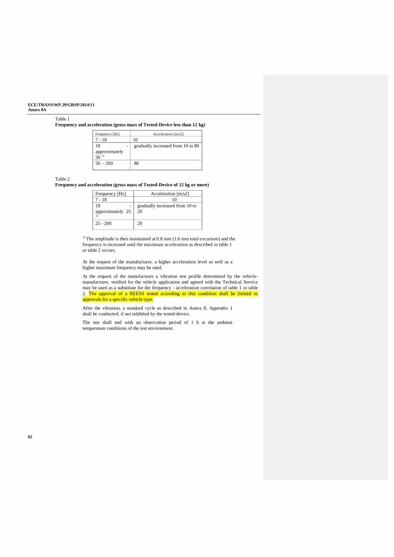
ECE/TRANS/WP.29/GRSP/2014/11Annex 8A
62
Table 1Frequency and acceleration (gross mass of Tested-Device less than 12 kg)
Frequency [Hz] Acceleration [m/s2]7 - 18 1018 -approximately50 1)
gradually increased from 10 to 80
50 - 200 80
Table 2Frequency and acceleration (gross mass of Tested-Device of 12 kg or more)
Frequency [Hz] Acceleration [m/s2]7 - 18 1018 -approximately 251)
gradually increased from 10 to20
25 - 200 20
1) The amplitude is then maintained at 0.8 mm (1.6 mm total excursion) and thefrequency is increased until the maximum acceleration as described in table 1or table 2 occurs.
At the request of the manufacturer, a higher acceleration level as well as ahigher maximum frequency may be used.
At the request of the manufacturer a vibration test profile determined by the vehicle-manufacturer, verified for the vehicle application and agreed with the Technical Servicemay be used as a substitute for the frequency - acceleration correlation of table 1 or table2. The approval of a REESS tested according to this condition shall be limited toapprovals for a specific vehicle type.
After the vibration, a standard cycle as described in Annex 8, Appendix 1shall be conducted, if not inhibited by the tested-device.
The test shall end with an observation period of 1 h at the ambienttemperature conditions of the test environment.
ECE/TRANS/WP.29/GRSP/2014/11Annex 8B
63
Annex 8B
Thermal shock and cycling test
1. Purpose
The purpose of this test is to verify the resistance of the REESS to suddenchanges in temperature. The REESS shall undergo a specified number oftemperature cycles, which start at ambient temperature followed by high andlow temperature cycling. It simulates a rapid environmental temperaturechange which a REESS would likely experience during its life.
2. Installations
This test shall be conducted either with the complete REESS or with relatedREESS subsystem(s) of the REESS including the cells and their electricalconnections. If the manufacturer chooses to test with related subsystem(s),the manufacturer shall demonstrate that the test result can reasonablyrepresent the performance of the complete REESS with respect to its safetyperformance under the same conditions. If the electronic management unit forthe REESS is not integrated in the casing enclosing the cells, then theelectronic management unit may be omitted from installation on the tested-device if so requested by the manufacturer.
3. Procedures
3.1. General test conditions
The following conditions shall apply to the tested-device at the start of thetest:
(a) The SOC shall be adjusted to a value in the upper 50 per cent of thenormal operating SOC range;
(b) All protection devices, which would affect the function of the tested-device and which are relevant to the outcome of the test shall beoperational.
3.2. Test procedure
The tested-device shall be stored for at least six hours at a test temperatureequal to 60 ± 2 °C or higher if requested by the manufacturer, followed bystorage for at least six hours at a test temperature equal to -40 ± 2 °C or lowerif requested by the manufacturer. The maximum time interval between testtemperature extremes shall be 30 minutes. This procedure shall be repeateduntil a minimum of 5 total cycles are completed, after which the tested-deviceshall be stored for 24 hours at an ambient temperature of 20 ± 10 °C.
After the storage for 24 hours, a standard cycle as described in Annex 8,Appendix 1 shall be conducted, if not inhibited by the tested-device.
The test shall end with an observation period of 1 h at the ambienttemperature conditions of the test environment.
ECE/TRANS/WP.29/GRSP/2014/11Annex 8C
64
Annex 8C
Mechanical Drop Test for removable REESS
1. PurposeSimulates a mechanical impact load which may occur at an unintended dropafter REESS removal.
2. Procedures2.1. General test conditions
The following conditions shall apply to the removed REESS at the start ofthe test:
(a) Before starting the test the SOC is at least 95 per cent of the normaloperating range as given by the manufacturer;Adjust the SOC to at least 90% of the rated capacity as specifiedin the Annex 6 Part 1 paragraph 3.4.3. or Annex 6 Part 2paragraph 1.4.3. or Annex 6 Part 3 paragraph 2.3.2.
(b) the test shall be performed at 20° C±10° C
2.2. Test procedureFree fall of the removed REESS from a height of 1.0 m (from bottom of theREESS) to a smooth, horizontal concrete pad or other flooring type withequivalent hardness.
The removed REESS shall be dropped six times from different orientationsas decided by the Technical Service. The manufacturer may decide to use adifferent removed REESS for each drop.
Directly after the termination of the drop test a standard cycle as described inAnnex 8, Appendix 1 shall be conducted, if not inhibited.
The test shall end with an observation period of 1 h at the ambienttemperature conditions of the test environment.

ECE/TRANS/WP.29/GRSP/2014/11Annex 8D
65
Annex 8D
Mechanical shock resulting from stationary vehicle fall down
1. PurposeThe purpose of this test is to verify the safety performance of the REESSunder mechanical shock which may occur during fall on the side fromstationary or parked situation.
2. Installations2.1. This test shall be conducted either with the complete REESS or with related
subsystems of the REESS including the cells and their electrical connections.
If the manufacturer chooses to test with related subsystem(s), themanufacturer shall demonstrate that the test result can reasonably representthe performance of the complete REESS with respect to its safetyperformance under the same conditions.
If the electronic management unit for the REESS is not integrated, then sucha control unit may be omitted from installation on the Tested-Device if sorequested by the manufacturer.
2.2. The Tested-Device shall be connected to the test fixture only by the intendedmountings provided for the purpose of attaching the REESS or REESSsubsystem to the vehicle.
3. Procedures3.1. General test conditions and requirements.
The following condition shall apply to the test:
(a) the test shall be conducted at an ambient temperature of 20 °C ± 10°C.
(b) at the beginning of the test, the SOC shall be adjusted to a value in theupper 50 per cent of the normal operating SOC range.
(c) at the beginning of the test, all protection devices which effect thefunction of the tested-device and which are relevant to the outcome ofthe test, shall be operational.
3.2. Test procedureThe tested-device shall be secured to the testing machine by means of a rigidmount which will support all mounting surfaces of the tested-device.
The tested-device witha gross mass of less than 12 kg shall be subjected to a half-sine shock ofpeak acceleration of 1,500 m/s2 and pulse duration of 6 milliseconds.a gross mass of 12 kg or more shall be subjected to a half-sine shock ofpeak acceleration of 500 m/s2 and pulse duration of 11 milliseconds.

ECE/TRANS/WP.29/GRSP/2014/11Annex 8D
66
For both the tested-device shall be subjected to three shocks in the positivedirection followed by three shocks in the negative direction of each threemutually perpendicular mounting positions of the tested-device for a total of18 shocks.
Directly after the termination of the mechanical shock test a standard cycle asdescribed in Annex 8, Appendix 1 shall be conducted, if not inhibited.
The test shall end with an observation period of 1 h at the ambienttemperature conditions of the test environment.

ECE/TRANS/WP.29/GRSP/2014/11Annex 8E
67
Annex 8E
Fire resistance
1. Purpose
The purpose of this test is to verify the resistance of the REESS, againstexposure to fire from outside of the vehicle due to e.g. a fuel spill from avehicle (either the vehicle itself or a nearby vehicle). This situation shouldleave the driver and passengers with enough time to evacuate.
2. Installations
2.1. This test shall be conducted either with the complete REESS or with relatedREESS subsystem(s) including the cells and their electrical connections. Ifthe manufacturer chooses to test with related subsystem(s), the manufacturershall demonstrate that the test result can reasonably represent theperformance of the complete REESS with respect to its safety performanceunder the same conditions. If the electronic management unit for the REESSis not integrated in the casing enclosing the cells, then the electronicmanagement unit may be omitted from installation on the tested-device if sorequested by the manufacturer. Where the relevant REESS subsystems aredistributed throughout the vehicle, the test may be conducted on eachrelevant of the REESS subsystem.
3. Procedures
3.1. General test conditions
The following requirements and conditions shall apply to the test:
(a) the test shall be conducted at a temperature of at least 0 °C;
(b) at the beginning of the test, the SOC shall be adjusted to a value in theupper 50 per cent of the normal operating SOC range;
(c) at the beginning of the test, all protection devices which effect thefunction of the tested-device and are relevant for the outcome of thetest shall be operational.
3.2. Test procedure
A vehicle based test or a component based test shall be performed at thediscretion of the manufacturer:
3.2.1. Vehicle based test
The tested-device shall be mounted in a testing fixture simulating actualmounting conditions as far as possible; no combustible material should beused for this with the exception of material that is part of the REESS. Themethod whereby the tested-device is fixed in the fixture shall correspond tothe relevant specifications for its installation in a vehicle. In the case of aREESS designed for a specific vehicle use, vehicle parts which affect thecourse of the fire in any way shall be taken into consideration.
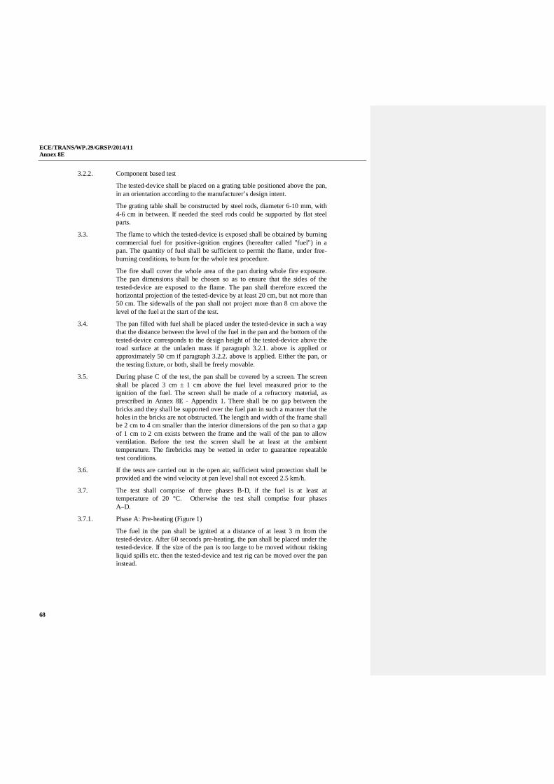
ECE/TRANS/WP.29/GRSP/2014/11Annex 8E
68
3.2.2. Component based test
The tested-device shall be placed on a grating table positioned above the pan,in an orientation according to the manufacturer’s design intent.
The grating table shall be constructed by steel rods, diameter 6-10 mm, with4-6 cm in between. If needed the steel rods could be supported by flat steelparts.
3.3. The flame to which the tested-device is exposed shall be obtained by burningcommercial fuel for positive-ignition engines (hereafter called "fuel") in apan. The quantity of fuel shall be sufficient to permit the flame, under free-burning conditions, to burn for the whole test procedure.
The fire shall cover the whole area of the pan during whole fire exposure.The pan dimensions shall be chosen so as to ensure that the sides of thetested-device are exposed to the flame. The pan shall therefore exceed thehorizontal projection of the tested-device by at least 20 cm, but not more than50 cm. The sidewalls of the pan shall not project more than 8 cm above thelevel of the fuel at the start of the test.
3.4. The pan filled with fuel shall be placed under the tested-device in such a waythat the distance between the level of the fuel in the pan and the bottom of thetested-device corresponds to the design height of the tested-device above theroad surface at the unladen mass if paragraph 3.2.1. above is applied orapproximately 50 cm if paragraph 3.2.2. above is applied. Either the pan, orthe testing fixture, or both, shall be freely movable.
3.5. During phase C of the test, the pan shall be covered by a screen. The screenshall be placed 3 cm ± 1 cm above the fuel level measured prior to theignition of the fuel. The screen shall be made of a refractory material, asprescribed in Annex 8E - Appendix 1. There shall be no gap between thebricks and they shall be supported over the fuel pan in such a manner that theholes in the bricks are not obstructed. The length and width of the frame shallbe 2 cm to 4 cm smaller than the interior dimensions of the pan so that a gapof 1 cm to 2 cm exists between the frame and the wall of the pan to allowventilation. Before the test the screen shall be at least at the ambienttemperature. The firebricks may be wetted in order to guarantee repeatabletest conditions.
3.6. If the tests are carried out in the open air, sufficient wind protection shall beprovided and the wind velocity at pan level shall not exceed 2.5 km/h.
3.7. The test shall comprise of three phases B-D, if the fuel is at least attemperature of 20 °C. Otherwise the test shall comprise four phasesA–D.
3.7.1. Phase A: Pre-heating (Figure 1)
The fuel in the pan shall be ignited at a distance of at least 3 m from thetested-device. After 60 seconds pre-heating, the pan shall be placed under thetested-device. If the size of the pan is too large to be moved without riskingliquid spills etc. then the tested-device and test rig can be moved over the paninstead.
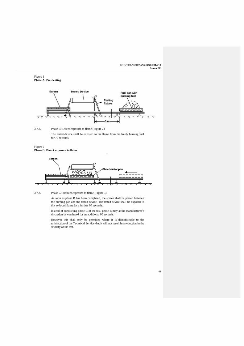
ECE/TRANS/WP.29/GRSP/2014/11Annex 8E
69
Figure 1Phase A: Pre-heating
3.7.2. Phase B: Direct exposure to flame (Figure 2)
The tested-device shall be exposed to the flame from the freely burning fuelfor 70 seconds.
Figure 2Phase B: Direct exposure to flame
3.7.3. Phase C: Indirect exposure to flame (Figure 3)
As soon as phase B has been completed, the screen shall be placed betweenthe burning pan and the tested-device. The tested-device shall be exposed tothis reduced flame for a further 60 seconds.
Instead of conducting phase C of the test, phase B may at the manufacturer’sdiscretion be continued for an additional 60 seconds.
However this shall only be permitted where it is demonstrable to thesatisfaction of the Technical Service that it will not result in a reduction in theseverity of the test.
Tested Device

ECE/TRANS/WP.29/GRSP/2014/11Annex 8E
70
Figure 3Phase C: Indirect exposure to flame
3.7.4. Phase D: End of test (Figure 4)
The burning pan covered with the screen shall be moved back to the positiondescribed in phase A. No extinguishing of the tested-device shall be done.After removal of the pan the tested-device shall be observed until such timeas the surface temperature of the tested-device has decreased to ambienttemperature or has been decreasing for a minimum of 3 hours.
Figure 4Phase D: End of test
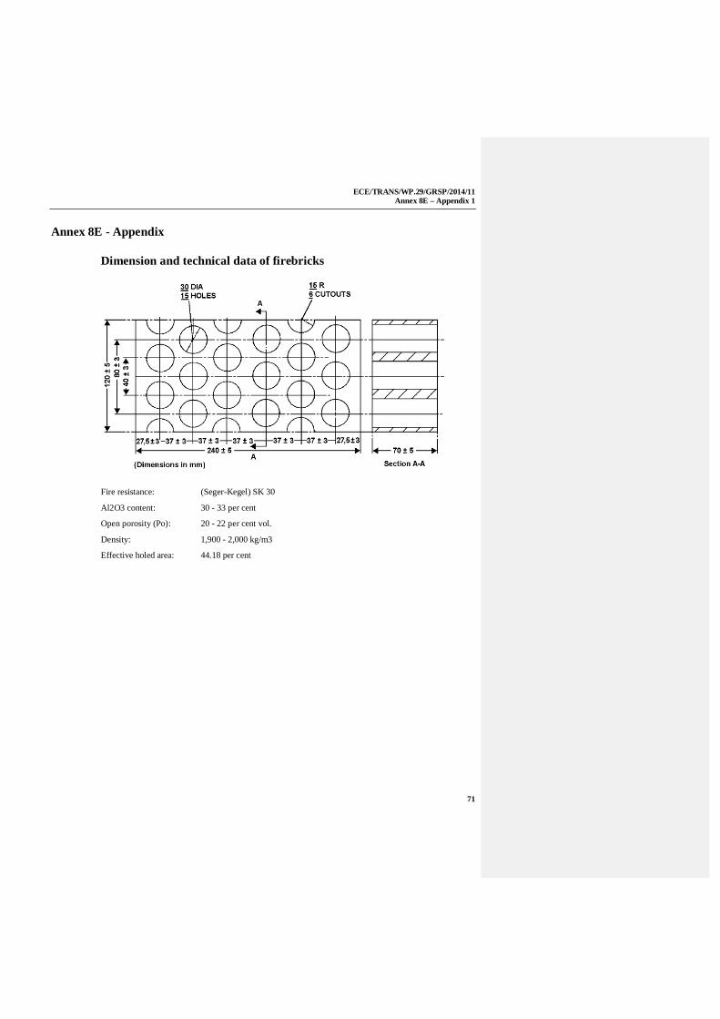
ECE/TRANS/WP.29/GRSP/2014/11Annex 8E – Appendix 1
71
Annex 8E - Appendix
Dimension and technical data of firebricks
Fire resistance: (Seger-Kegel) SK 30
Al2O3 content: 30 - 33 per cent
Open porosity (Po): 20 - 22 per cent vol.
Density: 1,900 - 2,000 kg/m3
Effective holed area: 44.18 per cent

ECE/TRANS/WP.29/GRSP/2014/11Annex 8F
72
Annex 8F
External short circuit protection
1. Purpose
The purpose of this test is to verify the performance of the short circuitprotection. This functionality, if implemented, shall interrupt or limit theshort circuit current to prevent the REESS from any further related severeevents caused by short circuit current.
2. Installations
This test shall be conducted either with the complete REESS or with relatedREESS subsystem(s), including the cells and their electrical connections. Ifthe manufacturer chooses to test with related subsystem(s), the manufacturershall demonstrate that the test result can reasonably represent theperformance of the complete REESS with respect to its safety performanceunder the same conditions. If the electronic management unit for the REESSis not integrated in the casing enclosing the cells, then the electronicmanagement unit may be omitted from installation on the tested-device if sorequested by the manufacturer.
3. Procedures
3.1. General test conditions
The following condition shall apply to the test:
(a) the test shall be conducted at a ambient temperature of 20°C ± 10 °Cor at higher temperature if requested by the manufacturer;
(b) at the beginning of the test, the SOC shall be adjusted to a value in theupper 50 per cent of the normal operating SOC range;
(c) at the beginning of the test, all protection devices which would affectthe function of the tested-device and which are relevant to theoutcome of the test shall be operational.
3.2. Short circuit
At the start of the test all relevant main contactors for charging anddischarging shall be closed to represent the active driving possible mode aswell as the mode to enable external charging. If this cannot be completed in asingle test, then two or more tests shall be conducted.
The positive and negative terminals of the tested-device shall be connected toeach other to produce a short circuit. The connection used for this purposeshall have a resistance not exceeding 5 m .
The short circuit condition shall be continued until the operation of theREESS´s protection function to interrupt or limit the short circuit current isconfirmed, or for at least one hour after the temperature measured on thecasing of the tested-device has stabilised, such that the temperature gradientvaries by a less than 4 °C through 1 hour.
ECE/TRANS/WP.29/GRSP/2014/11Annex 8F
73
3.3. Standard cycle and observation period
Directly after the termination of the short circuit a standard cycle as describedin Annex 8, Appendix 1 shall be conducted, if not inhibited by the tested-device.
The test shall end with an observation period of 1 h at the ambienttemperature conditions of the test environment.
ECE/TRANS/WP.29/GRSP/2014/11Annex 8G
74
Annex 8G
Overcharge protection
1. Purpose
The purpose of this test is to verify the performance of the overchargeprotection.
2. Installations
This test shall be conducted, under standard operating conditions, either withthe complete REESS (this maybe a complete vehicle) or with related REESSsubsystem(s), including the cells and their electrical connections. If themanufacturer chooses to test with related subsystem(s), the manufacturershall demonstrate that the test result can reasonably represent theperformance of the complete REESS with respect to its safety performanceunder the same conditions.
The test may be performed with a modified tested-device as agreed by themanufacturer and the Technical Service. These modifications shall notinfluence the test results.
3. Procedures
3.1. General test conditions
The following requirements and conditions shall apply to the test:
(a) the test shall be conducted at an ambient temperature of 20 °C ± 10 °Cor at higher temperature if requested by the manufacturer;
(b) at the beginning of the test, all protection devices which would affectthe function of the tested-device and which are relevant to theoutcome of the test shall be operational.
3.2. Charging
At the beginning all relevant main contactors for charging shall be closed.
The charge control limits of the test equipment shall be disabled.
The tested-device shall be charged with a charge current of at least 1/3C ratebut not exceeding the maximum current within the normal operating range asspecified by the manufacturer.
The charging shall be continued until the tested-device (automatically)interrupts or limits the charging. Where an automatic interrupt function failsto operate, or if there is no such function the charging shall be continued untilthe tested-device is charged to twice of its rated charge capacity.
3.3. Standard cycle and observation period
Directly after the termination of charging a standard cycle as described inAnnex 8, Appendix 1 shall be conducted, if not inhibited by the tested-device.
The test shall end with an observation period of 1 h at the ambienttemperature conditions of the test environment.
ECE/TRANS/WP.29/GRSP/2014/11Annex 8H
75
Annex 8H
Over-discharge protection
1. Purpose
The purpose of this test is to verify the performance of the over-dischargeprotection. This functionality, if implemented, shall interrupt or limit thedischarge current to prevent the REESS from any severe events caused by atoo low SOC as specified by the manufacturer.
2. Installations
This test shall be conducted, under standard operating conditions, either withthe complete REESS (this maybe a complete vehicle) or with related REESSsubsystem(s), including the cells and their electrical connections. If themanufacturer chooses to test with related subsystem(s), the manufacturershall demonstrate that the test result can reasonably represent theperformance of the complete REESS with respect to its safety performanceunder the same conditions.
The test may be performed with a modified tested-device as agreed by themanufacturer and the Technical Service. These modifications shall notinfluence the test results.
3. Procedures
3.1. General test conditions
The following requirements and condition shall apply to the test:
(a) the test shall be conducted at an ambient temperature of 20 °C ± 10 °Cor at higher temperature if requested by the manufacturer;
(b) the beginning of the test, all protection devices which would affect thefunction of the tested-device and which are relevant for the outcomeof the test shall be operational.
3.2. Discharging
At the beginning of the test, all relevant main contactors shall be closed.
A discharge shall be performed with at least 1/3 C rate but shall not exceedthe maximum current within the normal operating range as specified by themanufacturer.
The discharging shall be continued until the tested-device (automatically)interrupts or limits the discharging. Where an automatic interrupt functionfails to operate, or if there is no such function then the discharging shall becontinued until the tested-device is discharged to 25 per cent of its nominalvoltage level.
ECE/TRANS/WP.29/GRSP/2014/11Annex 8H
76
3.3. Standard charge and observation period
Directly after termination of the discharging the tested-device shall becharged with a standard charge as specified in Annex 8, Appendix 1 if notinhibited by the tested-device.
The test shall end with an observation period of 1 h at the ambienttemperature conditions of the test environment.

ECE/TRANS/WP.29/GRSP/2014/11Annex 8I
77
Annex 8I
Over-temperature protection
1. Purpose
The purpose of this test is to verify the performance of the protectionmeasures of the REESS against internal overheating during the operation,even under the failure of the cooling function if applicable. In the case that nospecific protection measures are necessary to prevent the REESS fromreaching an unsafe state due to internal over-temperature, this safe operationmust be demonstrated.
2. Installations
2.1. The following test shall be conducted with the complete REESS (maybe as acomplete vehicle) or with related REESS subsystem(s), including the cellsand their electrical connections. If the manufacturer chooses to test withrelated subsystem(s), the manufacturer shall demonstrate that the test resultcan reasonably represent the performance of the complete REESS withrespect to its safety performance under the same conditions. The test may beperformed with a modified tested-device as agreed by the manufacturer andthe Technical Service. These modifications shall not influence the test results.
2.2. Where a REESS is fitted with a cooling function and where the REESS willremain functional without a cooling function system being operational, thecooling system shall be deactivated for the test.
2.3. The temperature of the tested-device shall be continuously measured insidethe casing in the proximity of the cells during the test in order to monitor thechanges of the temperature. The on-board sensor if existing may be used. Themanufacturer and Technical Service shall agree on the location of thetemperature sensor(s) used.
3. Procedures
3.1. At the beginning of the test, all protection devices which affect the functionof the tested-device and are relevant to the outcome of the test shall beoperational, except for any system deactivation implemented in accordancewith paragraph 2.2. above.
3.2. During the test, the tested-device shall be continuously charged anddischarged with a steady current that will increase the temperature of cells asrapidly as possible within the range of normal operation as defined by themanufacturer.
3.3. The tested-device shall be placed in a convective oven or climatic chamber.The temperature of the chamber or oven shall be gradually increased until itreaches the temperature determined in accordance with paragraph 3.3.1. or3.3.2. below as applicable, and then maintained at a temperature that is equalto or higher than this, until the end of the test.

ECE/TRANS/WP.29/GRSP/2014/11Annex 8I
78
3.3.1. Where the REESS is equipped with protective measures against internaloverheating, the temperature shall be increased to the temperature defined bythe manufacturer as being the operational temperature threshold for suchprotective measures, to insure that the temperature of the tested-device willincrease as specified in paragraph 3.2. above.
3.3.2. Where the REESS is not equipped with any specific measures againstinternal over-heating, the temperature shall be increased to the maximumoperational temperature specified by the manufacturer.
3.4. The end of test: The test will end when one of the followings is observed:
(a) the tested-device inhibits and/or limits the charge and/or discharge toprevent the temperature increase;
(b) the temperature of the tested-device is stabilised, which means that thetemperature varies by a gradient of less than 4 °C through 2 hours;
(c) any failure of the acceptance criteria prescribed in paragraph 6.9.2.1.of the Regulation.

ECE/TRANS/WP.29/GRSP/2014/11Annex 9A
79
Annex 9A
Withstand voltage test
1. General
Insulation resistance shall be measured after application of the test voltage tothe vehicle with the on-board (built-in) charger.
2. Procedure
The following testing procedure shall be applicable to vehicles with on-board(built-in) chargers:
between all the inputs of the charger (plug) and the vehicle’s exposedconductive parts including the electrical chassis if present, apply a AC testvoltage of 2 x (Un + 1200) V rms at a frequency of 50 Hz or 60 Hz for oneminute, where Un is the AC input voltage (rms);
the test shall be performed on the complete vehicle;
all the electrical devices shall be connected.
Instead of the specified AC voltage, the DC voltage whose value isequivalent to the specified AC voltage’s peak value may be applied for oneminute.
After the test, measure the insulation resistance when applying 500V D.C.between all the inputs and the vehicle’s exposed conductive parts includingthe electrical chassis if present.

ECE/TRANS/WP.29/GRSP/2014/11Annex 9B
80
Annex 9B
Water resistance test
1. General
The isolation resistance shall be measured after the water resistanceperformance test has been conducted. The degree of protection of the REESSshall meet the requirements mentioned below.
2. Procedure
The following testing procedure shall be applicable to vehicles with on-board(built-in) charger.
In accordance with the test procedure to evaluate IPX5 protection againstingress of water, the Water Resistance shall be carried out by:
(a) spraying with a stream of fresh water the enclosure from allpracticable directions with a standard test nozzle as shown in figure 1.
Figure 1Test device to verify protection against water jets (hose nozzle)
D'=6.3 mm unit: mm
The conditions to be observed are as follows:
(i) internal diameter of the nozzle: 6.3 mm;
(ii) delivery rate: 12.5 l/min ± 5 per cent;
(iii) water pressure: to be adjusted to achieve the specified deliveryrate;
(iv) core of the substantial stream: circle of approximately 40 mmdiameter at 2.5 m distance from nozzle;
(v) test duration per square metre of enclosure surface area likelyto be sprayed: 1 min;
(vi) minimum test duration: 3 min;
(vii) distance from nozzle to enclosure surface: between 2.5 m and3 m.
(b) subsequently, apply 500V DC between all the inputs and the vehicle’sexposed conductive parts including the electrical chassis between allhigh voltage inputs and the vehicle’s exposed conductiveparts/electrical chassis if present to measure the insulation isolationresistance.

ECE/TRANS/WP.29/GRSP/2014/11Annex 9B
81
Related Documents


![Draft new UN Regulation on hydrogen fuelled vehicles of ... · Draft new UN Regulation on hydrogen-fuelled vehicles of categories L1, L2, ... [XXX] Uniform provisions ... thereby](https://static.cupdf.com/doc/110x72/5acc72107f8b9a875a8c9a5b/draft-new-un-regulation-on-hydrogen-fuelled-vehicles-of-new-un-regulation-on.jpg)