Mininizing the Risk of Borehole Failure Dr. Martin O. Eduvie National Water Resources Institute Kaduna 1 Minimizing the Risk of Borehole Failure by Dr. Martin O. Eduvie

Dr. Martin O. Eduvie National Water Resources Institute Kaduna 1 Minimizing the Risk of Borehole Failure by Dr. Martin O. Eduvie.
Dec 18, 2015
Welcome message from author
This document is posted to help you gain knowledge. Please leave a comment to let me know what you think about it! Share it to your friends and learn new things together.
Transcript

Minimizing the Risk of Borehole Failure by Dr. Martin O. Eduvie
1
Mininizing the Risk of Borehole Failure
Dr. Martin O. Eduvie National Water Resources Institute Kaduna

Minimizing the Risk of Borehole Failure by Dr. Martin O. Eduvie
2
When a borehole is not producing the required yield for the purpose of which it is expected to serve or constructed.
Abortive borehole Collapse borehole Producing dirty water Contaminated borehole Saline water intrusion Reducing water and siltation of borehole
What is Borehole Failure
Minimizing the Risk of Borehole Failure by Dr. Martin O. Eduvie
3
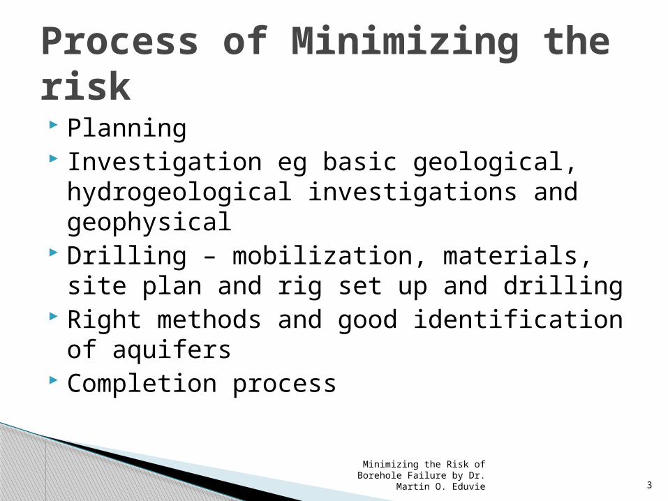
Planning Investigation eg basic geological,
hydrogeological investigations and geophysical
Drilling – mobilization, materials, site plan and rig set up and drilling
Right methods and good identification of aquifers
Completion process
Process of Minimizing the risk

Minimizing the Risk of Borehole Failure by Dr. Martin O. Eduvie
4
Geological and Hydrogeological studies Geophysical surveys (electrical resistivity
using both profiling and VES Good interpretation of Data Borehole drilling – Site rig set up,
identification of aquifers through 1. Sample inspection and analysis eg
penetration rate, grain seize analysis, observation process,
Steps by step

Minimizing the Risk of Borehole Failure by Dr. Martin O. Eduvie
5
Geophysical well logging (Electric SP and PR, gamma logs and Caliper
MaterialsEnsure that right are used e.g casing and
screen, gravel pack and good grouting
CompletionWell development eg airlifting and jetting
Geophysical well logging

Minimizing the Risk of Borehole Failure by Dr. Martin O. Eduvie
6
Constant discharge Step test Analysis of pumping test data Recommend appropriate pump based on
aquifer characteristics Water quality analysis
Pumping Test

Minimizing the Risk of Borehole Failure by Dr. Martin O. Eduvie
7
GROUNDWATER EXPLORATION METHODS
Geophysical surveying – using EM34 equipment at Kabale, Tanzania
Drilling a borehole for groundwater using a Schramm down the hole hammer system, Tanzania
BGS©NERC June 2002
BGS©NERC June 2002

Minimizing the Risk of Borehole Failure by Dr. Martin O. Eduvie
8
Tanzanian hydrogeologist analysing drilled rock chip samples
Rock chip samples presented in a half tube as a pseudo-core showing reddened oxidised near surface material at left
passing through to non-weathered grey material at right, with weathered orange
band at depth at far right
Core of grey fractured meta-shale showing
narrow calcite infilled fracture
ROCK SAMPLES OBTAINED DURING DRILLING
BGS©NERC June 2002
BGS©NERC June 2002
BGS©NERC June 2002

Processes during Drilling, Sample Inspection & Pumping Test
Samples inspection
Minimizing the Risk of Borehole Failure by Dr. Martin O. Eduvie 9

Minimizing the Risk of Borehole Failure by Dr. Martin O. Eduvie
10
Idealized Log Chart showing typical Logs and theirHydrogeologic Interpretation
SP RESISTIVITY GAMMA RAY
HOLE CALLIPER
HYDROGEOLOGICINTERPRETATION
SN 16”LN 64”
Dry Sandsome caving
Clay, homogeneous
Sand,Saline water
Clay,Sand streaks
Freshwater Sand
Clay
Sand,Brackish water

Minimizing the Risk of Borehole Failure by Dr. Martin O. Eduvie
11
Borehole Casing In progress.
Hydrogeological Data records

Minimizing the Risk of Borehole Failure by Dr. Martin O. Eduvie
12
Borehole logging to produce productive boreholes

Minimizing the Risk of Borehole Failure by Dr. Martin O. Eduvie
13

Minimizing the Risk of Borehole Failure by Dr. Martin O. Eduvie
14
RECORDING DATA DURING TEST PUMPING
Measuring the water level during a pumping test at Mangochi East, Malawi
Measuring the discharge rate during a low yielding pumping test at Oju, SE Nigeria
BGS©NERC June 2002© WSP-AF

Minimizing the Risk of Borehole Failure by Dr. Martin O. Eduvie
15
The report must highlight the following: Executive Summary Introduction – Client, location with coordinates
and purpose Logging techniques and data acquisition
methods Logger used with all calibrations. Interpretation with details of borehole design
with diagrams Conclusions and recommendations
Report Writing

Minimizing the Risk of Borehole Failure by Dr. Martin O. Eduvie
16
The information gathered during drilling boreholes and construction of wells is valuable and should be documented.
Before leaving the site it is important to compile the following information
Borehole number, Name of the village and location of borehole with GPS coordinates
Location of the borehole or well, matched to the Initial geophysical surveys A sketch map of where the borehole/well is located in relation to prominent
features Dates of construction, and activities carried out on daily basis The depths and type of drilling methods used. For example 8 inches tricone
bit to 20m depth, Down the hole hammer bit from 20m-40m Main water strikes and static water level The drilled diameters ,position of screen and casing Position and size of gravel pack ,depth of seal Length and type of development. Lithological descriptions of samples Any other relevant data/information
Contents of well completion report

Minimizing the Risk of Borehole Failure by Dr. Martin O. Eduvie
17
The information above can be used to produce a short report on the borehole with all the necessary summary information
Reports usually contain the following information: A summary of the borehole/well details A summary of the drilling information A diagram showing the construction of the borehole A diagram showing the lithology of the borehole with water
strikes Analysis of pumping test data as well as the result of the test Result of water quality analysis Recommendations as regards the type of pump to be installed,
treatment required(if necessary) and other things the client need to be aware of.
WELL COMPLETION REPORT CONTD.

Minimizing the Risk of Borehole Failure by Dr. Martin O. Eduvie
18
Report writingThe following key points should be reflected in the report.
1. Name of the village and location of borehole with GPS co-ordinates
2. Location of borehole or well, matched to the initial geophysical survey3. Dates of construction, name and roles of all those involved4. The depths and types of drilling methods used 5. Penetration times and static water level6. Drilled diameters, position of screen and casing7. Position and size of gravel pack, depth of seal,8. Length and type of development9. Lithological description of chip samples
REPORT WRITING

Minimizing the Risk of Borehole Failure by Dr. Martin O. Eduvie
19
Report should also Contain the Following・ A summary of the borehole location details・ A summary of the drilling information・ A diagram showing the construction of the borehole・ A diagram showing the lithology of the borehole with water strikesThis drilling report is usually added to the village file along with other technical information such as geophysical and village surveys and the results of hydrogeology at the site forms the building blocks for understanding how groundwater resources occur in an area.
REPORT WRITING CONTD.

Minimizing the Risk of Borehole Failure by Dr. Martin O. Eduvie
20
AN EXAMPLE OF DRILLING LOG
8''1/2
16.63
7
19
Surfacecasing
22"(2.4m)
14''(7.5m)
7.35
4.10
8
10.60
11
20m
+ +
++ +
+
++ +
20m
DTH
greenishgrey ~
brawnishgray
1st+ +
+ +
++ +
+
BrownishGray
15m+
+ 13
slightly weatheredGranitic fine Gneiss
+ ++
+ +
Gravel with Sand
+ +
10
7.5○
weathered Gneiss++ +
+
GravelPacking
10m+ ++ 9
15m
+ +
+ +
5m
10m+
6
○○ ○
○ ○
Sealing
Drilling
Grout
20''
(inch)
Midium ~ coarse Sand Brownish
2.60m
Brownish
Description of L ithology ColorWaterlevel
5m
GravelPacking
CasingProgram
Wing Bit
DiameterDepth
(m)
Well Structure
Log
Electrical LoggingDrilling Spead (min/m)
BrownishGray-White
Depth(m)
Lithology Data
1 Top Soil Black
3fine ~ medium Sand
0 50 100

Minimizing the Risk of Borehole Failure by Dr. Martin O. Eduvie
21
An example of Well Construction DataDATA OF THE WELL
Borehole No. Village Name Coordinate Altitude T. A. District Country
Date Drilling : RIG Model Method Fluid Surface hole Final depth Casing depth Final diameter
15-Sep-06 16-Sep-06 BIAC RCD DTH air 17.0m 41.0m 41.0m 215.9mm
Casings : Type ID OD Joint Type Position (m): +0.5 -26.10; -38.1-41.0 TotalPVC 101.0mm 113.0mm Socket 29.5m
Screens : Material OD Slot size Open ratio Joint Type Position (m): -26.1-38.1 Total
PVC 113.0mm 0.8mm 9.34% Socket 12.0m
Gravel pack Origen Size Position (m) Volume Pumping Test S. W. L. D.W.L. Discharge rate: Specific Capacity
SALIMA ø 1-5mm -20.0-41.0 792.0 lits GL -5.09m GL -23.00m 70.0 lits/min 3.91 L/min/m
Hand pump : AFRIDEV Setting depth : 20.955 m Pump position: GL -26.00m
Diameter (mm)& Method
Borehole structure Lithology
LEGEND:
TR = Tricone WB = Wing CG = Cement Grouting CP = Casing Pipes
HB = Hammer bit BF = Backfilling with Cuttings SP = Screen Pipes
MR = Mud Rotary AR=Air Rotary GP = Grava Pack P = Pump
DTH = Down-the-hole Hammer BS = Bentonite seal RP = riser pipes
BF BF
Yieldlit/min
0 50 100
4.0 m
Scale multiply by 10
Scale multiply by 1
BF BF
4.0 m
GP GP
GP GP
B.S.
CG CG
-45
-40
-35
-30
-25
-20
-15
-10
-5
0
-100 0 100
SP (mV)
-45
-40
-35
-30
-25
-20
-15
-10
-5
0
0 50
N-Gamma(cps)
Penetrationrate
min/m0 15 30
WB: 330.2AR
HB:215.9
DTH
20.0 m BS
41.0 m
CP
17.0 m
Gneiss, grey, moderately to slightly weathered
26.1 m
CP
-45
-40
-35
-30
-25
-20
-15
-10
-5
0
0 250 500
16 in Normal
64 in Normal
Water strike
Top soil , dark brown
38.1 m
SP
41.0 m
Gneiss, brownish grey, highly weathered with gravel
16.0 m
Mica clay, brownish grey
41.0 m
RP
P
37.0 m
Laterite, reddish brown
1.0 m
Water strike
Water strike
Water strike

Minimizing the Risk of Borehole Failure by Dr. Martin O. Eduvie
22
An Example Of The Pumping Test Data
RESULT OF STEP-DRAWDOWN TEST
Step DurationYield
QYield
QPumping water
levelDrawdown
sSpecificcapacity
(hours) (lit/min) (m3/day) (m) (m) (m3/day/m)
1 1.5 30.00 43.20 11.62 6.53 6.62
2 1.5 50.00 72.00 16.82 11.73 6.14
3 1.5 70.00 100.80 22.32 17.23 5.85
Critical pumping rate (CPR) >70 (lit/min)
Preferable pumping rate >56 (lit/min)
STEP-DRAWDOWN TESTB/H No. LW1-100
0.0
2.0
4.0
6.0
8.0
10.0
12.0
14.0
16.0
18.0
20.0
0 50 100 150 200 250 300
Time (min)
Draw
dow
n S
(m
)
1-Step : 30.00 l/min
2-Step : 50.00 l/min
3-Step : 70.00 l/min
S-Q curve (Log-Log) ; B/H No. LW1-100
1
10
100
10 100 1,000
Yield (m3/day)
Draw
dow
n (m
)

Minimizing the Risk of Borehole Failure by Dr. Martin O. Eduvie
23
Final summary of diagram in the Borehole completion report

Minimizing the Risk of Borehole Failure by Dr. Martin O. Eduvie
24
Compilation of all borehole reports in a larger data base
It could be from other sources Internal reports External reports MUST be credible
Data Base Management

Minimizing the Risk of Borehole Failure by Dr. Martin O. Eduvie
25
1. Well inventory of the
corresponding area
2. The data files for each borehole
BH1 BH3 BH2
BH4 BH6 BH5
BH7 BH8 BH9
BH1
BH2
BH3
BH4
Refer
Update
Component of the well inventory managementWell Inventory Management is consisted by two major components as follows;1.Well Inventory of the Corresponding Area2.The data files for each boreholeFigure shows the figure of the concept of these two component relations. Referring those two components enable to make the effective monitoring plan.
Well Inventory of the Corresponding Area” is consisted by the information of all boreholes in the area such as “ well ID ” , “Location taken by GPS “ , “Name of the village “ , “Type of the handpump “ , “The depth of the handpump “ , “Year of the construction “ , and so on. “The data files for each borehole” is formulated one folder for one borehole. The contents of this folder are the following information.Well Construction dataPump installation dataWater Quality dataMonitoring data
WELL INVENTORY MANAGEMENT

Minimizing the Risk of Borehole Failure by Dr. Martin O. Eduvie
26
National Rural Water Supply and Sanitation Programme
[State Level]
-Keep inventory of water supply and sanitation facilities in all
communities and a RWSS database (including quality and well
logs of all boreholes drilled in the state)
[Federal Level]
-Develop a national database for RWSS Project.
[LGA Level]
-Keep an inventory of water supply and sanitation facilities in all
Communities and monitor their operation status
-Monitor the availability of spare parts
Goal of the Well Inventory ManagementNational Rural Water Supply and Sanitation Programme :A Strategic Framework (March 2004) describe the expected role to play of the each organization (Federal, State, LGA, Community) with regards to the well inventory management showing figure ?-?. This is regards as final goal of Well Inventory Management.
GOAL OF WELL INVENTORY MANAGEMENT

Minimizing the Risk of Borehole Failure by Dr. Martin O. Eduvie
27
An Example Of Well Inventory At LGA Level
Rural Water Supply System Inventory
LGA name : KADUNA
N E
1 10046.543' 007040.626' Angwangajilo Indian Mark II unknown 1992 2009 repaired by NGO
2 10048.245' 007040.951' Turunku Indian Mark II unknown 1992 2009 repaired by NGO
3
RemarksCoordinationSerial
No.Village name Type of pump
Depth ofpump
Constructionyear

Minimizing the Risk of Borehole Failure by Dr. Martin O. Eduvie
28
A national or regional level database of all borehole drilling records should be established and kept up to date. If no such national database exists, sector stakeholders should keep and archive records of all borehole drilling work undertaken until it is established
The data from all drilling programmes and projects in the country should feed into this database
Data from the database should be made available free of restriction
There should be transparent sharing of key information on drilling programmes by Governments, NGOs and other stakeholders
DATA BASE AND RECORD KEEPING

Minimizing the Risk of Borehole Failure by Dr. Martin O. Eduvie
29
The cumulative knowledge of groundwater resources provided by adequate and accessible data achieves greatly enhances the chances of successful drilling and borehole construction
Information from dry and unsuccessful boreholes is just as important as that from the successful ones.
Government and private drilling companies should be encouraged to enforce data gathering.
DATA BASE AND RECORD KEEPING
Minimizing the Risk of Borehole Failure by Dr. Martin O. Eduvie
30
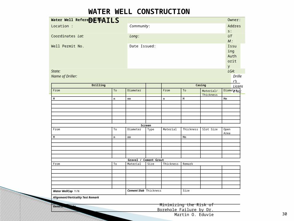
Water Well Reference No: Owner:
Location : Community: Address:
Coordinates Lat: Long: UTM :
Well Permit No. Date Issued: Issuing Authority
State: LGA:Name of Driller: Driller’
s License No:
Drilling Casing
From To Diameter From To Material/Thickness
Diameter
M m mm m M Mm
ScreenFrom To Diameter Type Material Thickness Slot Size Open AreaM m mm Mm
Gravel / Cement GroutFrom To Material Size Thickness Remark
Water WellCap Y/N Cement Slab Thickness Size
Alignment/Verticality Test Remark
General Remarks
WATER WELL CONSTRUCTION DETAILS

Minimizing the Risk of Borehole Failure by Dr. Martin O. Eduvie
31
Water Well Reference No: Owner: Location : Community: Address:Coordinates Lat: Long: UT
M :
Well Permit No. Date Issued: Issuing Authority
State: LGA:Name of Water Analyst: Labor
atory:
Constituents Unit ConcentrationSuspended solids mg/l Colour TCU Turbidity NTU TDS mg/l pH
Hardness (CaCO3) mg/l Calcium (Ca) mg/l Magnesium (Mg) mg/l Sodium (Na) mg/l Potassium (K) mg/l Chloride (Cl) mg/l
Total Alkalinity mg/l Bicarbonate mg/l Carbonate mg/l Sulphate mg/l Nitrate mg/l Flouride mg/l Iron mg/l Manganese mg/l
Zn mg/l Copper mg/l Arsenic mg/l Lead mg/l Aluminium mg/l Cadmium mg/l Cyanide mg/l Mercury mg/l
Ammonia mg/l Hydrogen Sulphide mg/l Faecal Coliform Count/100ml Total Plate Count Count/100ml
Field Measurements Temperature 0C pH
Electrical Conductivity
_________________________________________________ ________________________________________________Name: Water Analyst Signature / Stamp / Date
WATER ANALYSIS REQUEST FORM

Minimizing the Risk of Borehole Failure by Dr. Martin O. Eduvie
32
Related Documents