Date: 25/04/2017 Rédacteur Approbateur Page Dossier n°: 841691700178 M. HELLEL A. SAILLARD 01/18 Indice B: QCS SERVICES Agence de LYON – Parc de Crécy – 5B rue Claude CHAPPE 69 771 ST DIDIER AU MONT D OR cedex – Tél. : 04 72 19 81 30 – Fax : 04 72 19 81 39 – [email protected] Département AUDIT & ASSISTANCE TECHNIQUE A l'attention de Monsieur Alexis BLEUSE Responsable Travaux Entreprises 106 Avenue Clemenceau 69230 Saint-Genis-Laval Saint-Genis- Laval(69) Etude de la charpente métallique salle judo

Welcome message from author
This document is posted to help you gain knowledge. Please leave a comment to let me know what you think about it! Share it to your friends and learn new things together.
Transcript

Date: 25/04/2017 Rédacteur Approbateur Page
Dossier n°: 8 41691700178 M. HELLEL A. SAILLARD 01/18
Indice B: QCS SERVICES
Agence de LYON – Parc de Crécy – 5B rue Claude CHAPPE 69 771 ST DIDIER AU MONT D OR cedex – Tél. : 04 72 19 81 30 – Fax : 04 72 19 81 39 – [email protected]
Département AUDIT & ASSISTANCE TECHNIQUE
A l'attention de Monsieur Alexis BLEUSE
Responsable Travaux Entreprises
106 Avenue Clemenceau
69230 Saint-Genis-Laval
Saint-Genis- Laval (69)
Etude de la charpente métallique salle judo

Gymnase Guilloux- 11 Avenue Ernest Bauer 69230 Sain t-Genis-Laval – Charpente métallique
QCS SERVICES – Département AUDIT & Assistance Technique 5B rue Claude Chappe 69771 Saint-Didier-au-Mont-D’or - tél : 04.72.19.81.30 – fax : 04.40.83.52.98
Page 2 sur 18
GENERALITES
QCS SERVICES a agi en qualité de consultant techniques assujetti à une simple obligation de
moyens. Il ne saurait substituer ses fonctions ni ses responsabilités à celles des différents
intervenants, qu’ils soient concepteurs, constructeurs, installateurs, fabricants, services utilisateurs,
agents d’entretien ou de maintenance. Sa responsabilité ne se confond pas, pour la présente mission
avec la responsabilité du contrôleur technique visée par les dispositions de l’article L.111-24 du CC.H.
Il est rappelé que l’examen des ouvrages et éléments d’équipement est effectués sur les parties
visibles et accessibles au moment de la visite de l’intervenant de l’organisme, qui a procédé à aucuns
sondages destructifs.
Notre mission n’est en aucun cas une mission de maîtrise d’œuvre. Les principes de solutions
techniques indiquées dans ce rapport ne constituent pas un dossier de conception permettant
d’exécuter directement des travaux.
Le maître d’ouvrage doit en ce sens missionner un maître d’œuvre pour finaliser le projet.

Gymnase Guilloux- 11 Avenue Ernest Bauer 69230 Sain t-Genis-Laval – Charpente métallique
QCS SERVICES – Département AUDIT & Assistance Technique 5B rue Claude Chappe 69771 Saint-Didier-au-Mont-D’or - tél : 04.72.19.81.30 – fax : 04.40.83.52.98
Page 3 sur 18
SOMMAIRE1- OBJET DE LA MISSION .......................................................................................................................... 4
2- DESCRIPTION DE L'OUVRAGE ............................................................................................................. 4
2-1 Description du site ................................................................................................................................... 4
2-2 Description du batiment .......................................................................................................................... 5
2-3 Documents reçus ..................................................................................................................................... 5
2-4 Documents normatifs .............................................................................................................................. 5
3- ETUDES DE LA STRUCTURE ................................................................................................................ 5
3-1 Hypothèses de chargement ..................................................................................................................... 5 3.1.1 Chargement permanent .................................................................................................................................... 5 3-1.3 Chargement du à la neige et au vent ................................................................................................................. 6 3-1.4 Hypothèses sismiques ....................................................................................................................................... 6
3-2 Hypothèses de calculs .............................................................................................................................. 6 3.2.1 Hypothèses du matériau acier ........................................................................................................................... 6 3.2.2 Limites des déformations .................................................................................................................................. 6
3-3 Modelisation et chargement de la structure ........................................................................................... 6 3-3.1 Modélisation du bâtiment ................................................................................................................................. 6 3-3.2 chargement et combinaisons de chargement ................................................................................................... 7
3-4 Vérification de la structure aux Etats Limites Ultimes (sollicitations pondérées) .................................. 11 3-4.1 Vérification des pannes ................................................................................................................................... 11 3-4.2 Vérification des membrures supérieures des poutres treillis .......................................................................... 11 3-4.3 Vérification des membrures inférieures des poutres treillis ........................................................................... 12 3-4.4 Vérification des treillis ..................................................................................................................................... 13
3-5 Vérification de la structure aux Etats Limites Services .......................................................................... 14 3-5.1 Vérification des pannes ................................................................................................................................... 15 3-5.2 Vérification des membrures supérieures des poutres treillis .......................................................................... 16 3-5.3 Vérification des membrures inférieures des poutres treillis ........................................................................... 17
4- CONCLUSION ......................................................................................................................................... 18
ANNEXES ......................................................................................................... ERREUR ! SIGNET NON DEFINI.

Gymnase Guilloux- 11 Avenue Ernest Bauer 69230 Sain t-Genis-Laval – Charpente métallique
QCS SERVICES – Département AUDIT & Assistance Technique 5B rue Claude Chappe 69771 Saint-Didier-au-Mont-D’or - tél : 04.72.19.81.30 – fax : 04.40.83.52.98
Page 4 sur 18
1- Objet de la mission
L’objet de la mission est de vérifier la charpente métallique existante afin de valider la mise en
œuvre d’une couverture ayant une résistance thermique R ≥ 6 m².K/W sur le gymnase Guilloux ainsi
que deux radians d’un poids total de 46 kg suspendus aux pannes et aux fermes treillis.
Nous sommes intervenus sur le site le 24/11/2016 afin de procéder à un relevé de la charpente,
notre étude a été menée sur la base des documents reçus et du relevé effectué lors de notre visite sur
le site.
2- Description de l'ouvrage 2-1 Description du site
La halle industrielle est situé 11 Avenue Ernest Auboyer, Saint-Genis-Laval (69230).
Vue aérienne du site.
Vue du site.

Gymnase Guilloux- 11 Avenue Ernest Bauer 69230 Sain t-Genis-Laval – Charpente métallique
QCS SERVICES – Département AUDIT & Assistance Technique 5B rue Claude Chappe 69771 Saint-Didier-au-Mont-D’or - tél : 04.72.19.81.30 – fax : 04.40.83.52.98
Page 5 sur 18
2-2 Description du batiment
Le batiment à étudier (encadré en rouge) est un bâtiment dont les dimensions avoisinent 12 m
de large et 16 m de long. Sa hauteur au faitage est de l’ordre de 6,00 m.
Ce bâtiment est constitué d’une charpente métallique supportant une couverture de type bac
sec. Les facades des pignons sont constituées de poteaux et de panneaux de remplissage béton
armé.
La stabilité transversale et longitudinale du bâtiment est assurée par les poteaux autostables.
2-3 Documents reçus
Pour notre étude, nous n’avons reçus aucuns documents.L’étude sera menée suivant notre
relevé.
2-4 Documents normatifs
Pour notre étude, nous avons utilisés les documents suivants :
- Normes CM66 + ADDITIF 80 Règles de calculs des constructions acier.
- Normes NV65 modifiées 2009 Règles définissant les effets de la neige et du vent sur les
constructions et annexes.
- Normes NF P 22-460 « Assemblages par boulons à serrage contrôlé ».
- Normes NF P 22-430 « Assemblages par boulons non précontraints ».
- Normes NF P 22-470 « Assemblages par soudures ».
3- Etudes de la structure
3-1 Hypothèses de chargement
3.1.1 Chargement permanent
- Poids propre de la structure généré automatiquement par le logiciel.
- Couverture future Efigreen Duo 14,4 kg/m².
- Eclairage 5 kg/m².
- Faux-plafond fibralith + ossature 9,4 kg/m².
- 2 Radians d’un poids total de 46 kg suspendus en 4 points soit 11,5 kg par points.

Gymnase Guilloux- 11 Avenue Ernest Bauer 69230 Sain t-Genis-Laval – Charpente métallique
QCS SERVICES – Département AUDIT & Assistance Technique 5B rue Claude Chappe 69771 Saint-Didier-au-Mont-D’or - tél : 04.72.19.81.30 – fax : 04.40.83.52.98
Page 6 sur 18
3-1.3 Chargement du à la neige et au vent
- Neige Normale 35 kg/m².
- Neige Accidentelle 80 kg/m².
- Vent Toiture Cr=0,8 57 kg/m² .
3-1.4 Hypothèses sismiques
Sans objet : bâtiment existant.
3-2 Hypothèses de calculs
3.2.1 Hypothèses du matériau acier
Acier E24 : Nuance d’acier Fy= 235 Mpa 3.2.2 Limites des déformations
Limites de déformation des éléments de toitures : L/200
3-3 Modelisation et chargement de la structure
3-3.1 Modélisation du bâtiment

Gymnase Guilloux- 11 Avenue Ernest Bauer 69230 Sain t-Genis-Laval – Charpente métallique
QCS SERVICES – Département AUDIT & Assistance Technique 5B rue Claude Chappe 69771 Saint-Didier-au-Mont-D’or - tél : 04.72.19.81.30 – fax : 04.40.83.52.98
Page 7 sur 18
3-3.2 chargement et combinaisons de chargement
a) Chargement appliqué
Cas 1- Poids propre de la structure.
Cas 2- Poids de la couverture
Cas 3- Charges d’éclairage

Gymnase Guilloux- 11 Avenue Ernest Bauer 69230 Sain t-Genis-Laval – Charpente métallique
QCS SERVICES – Département AUDIT & Assistance Technique 5B rue Claude Chappe 69771 Saint-Didier-au-Mont-D’or - tél : 04.72.19.81.30 – fax : 04.40.83.52.98
Page 8 sur 18
Cas 4- Charges pour Faux-plafonds fibralith + ossat ure
Cas 4- Charges des 2 radians de 46 kg
Cas 6- Charges de neige normale

Gymnase Guilloux- 11 Avenue Ernest Bauer 69230 Sain t-Genis-Laval – Charpente métallique
QCS SERVICES – Département AUDIT & Assistance Technique 5B rue Claude Chappe 69771 Saint-Didier-au-Mont-D’or - tél : 04.72.19.81.30 – fax : 04.40.83.52.98
Page 9 sur 18
Cas 7- Charges de neige accidentelle
Cas 8- Charge du vent sur long-pan sur toiture isol ée (soulèvement)
Cas Type de charge Liste Valeurs de la charge
1 poids propre 1A14 16A19 21A39 4-
3A83 PZ Moins Coef=1,00
2 charge uniforme 28A39 43A48 PZ=-0,24[kN/m]
2 charge uniforme 25A27 49A57 PZ=-0,12[kN/m]
3 charge uniforme 28A39 43A48 PZ=-0,08[kN/m]
3 charge uniforme 25A27 49A57 PZ=0,04[kN/m]
4 charge uniforme 28A39 43A48 PZ=-0,21[kN/m]
4 charge uniforme 25A27 49A57 PZ=-0,11[kN/m]
5 force sur barre 34 35 38 FZ=-0,12[kN] X=0,50 relatives
5 force sur barre 37 52 53 FZ=-0,12[kN] X=0,50 relatives
5 force nodale 17 37 FZ=-0,12[kN]
6 charge uniforme 28A39 43A48 PZ=-0,58[kN/m]
6 charge uniforme 25A27 49A57 PZ=-0,29[kN/m]
7 charge uniforme 28A39 43A48 PZ=-1,32[kN/m]
7 charge uniforme 25A27 49A57 PZ=-0,66[kN/m]

Gymnase Guilloux- 11 Avenue Ernest Bauer 69230 Sain t-Genis-Laval – Charpente métallique
QCS SERVICES – Département AUDIT & Assistance Technique 5B rue Claude Chappe 69771 Saint-Didier-au-Mont-D’or - tél : 04.72.19.81.30 – fax : 04.40.83.52.98
Page 10 sur 18
Cas Type de charge Liste Valeurs de la charge
8 charge uniforme 28A39 43A48 PZ=1,22[kN/m]
8 charge uniforme 25A27 49A53 55A57 PZ=0,61[kN/m]
b) Combinaison de chargement
Combi naison Nom
9 (C) EFF/1=1*1.33 + 2*1.33 + 3*1.33 + 4*1.33 + 5*1.33
10 (C) EFF/2=1*1.00 + 2*1.00 + 3*1.00 + 4*1.00 + 5*1.00
11 (C) EFF/3=1*1.33 + 2*1.33 + 3*1.33 + 4*1.33 + 5*1.33 + 8*1.50
12 (C) EFF/4=1*1.00 + 2*1.00 + 3*1.00 + 4*1.00 + 5*1.00 + 8*1.50
13 (C) EFF/5=1*1.33 + 2*1.33 + 3*1.33 + 4*1.33 + 5*1.33 + 6*1.50
14 (C) EFF/6=1*1.00 + 2*1.00 + 3*1.00 + 4*1.00 + 5*1.00 + 6*1.50
15 (C) EFF/7=1*1.33+2*1.33+3*1.33+4*1.33+5*1.33+8*1.42+6*0.71
16 (C) EFF/8=1*1.33 + 2*1.33 + 3*1.33 + 4*1.33 + 5*1.33
17 (C) EFF/9=1*1.00+2*1.00+3*1.00+4*1.00+5*1.00+8*1.42+6*0.71
18 (C) EFF/10=1*1.00 + 2*1.00 + 3*1.00 + 4*1.00 + 5*1.00
19 (C) EFF/11=1*1.00 + 2*1.00 + 3*1.00 + 4*1.00 + 5*1.00 + 8*1.75
20 (C) EFF/12=1*1.00 + 2*1.00 + 3*1.00 + 4*1.00 + 5*1.00
21 (C) EFF/13=1*1.00 + 2*1.00 + 3*1.00 + 4*1.00 + 5*1.00 + 6*1.67
22 (C) EFF/14=1*1.00+2*1.00+3*1.00+4*1.00+5*1.00+8*1.75+6*0.83
23 (C) EFF/15=1*1.00 + 2*1.00 + 3*1.00 + 4*1.00 + 5*1.00
24 (C) DEP/1=1*1.00 + 2*1.00 + 3*1.00 + 4*1.00 + 5*1.00
25 (C) DEP/2=1*1.00 + 2*1.00 + 3*1.00 + 4*1.00 + 5*1.00 + 8*1.00
26 (C) DEP/3=1*1.00 + 2*1.00 + 3*1.00 + 4*1.00 + 5*1.00 + 6*1.00
27 (C) DEP/4=1*1.00+2*1.00+3*1.00+4*1.00+5*1.00+8*1.00+6*0.50
28 (C) ACC/1=1*1.00 + 2*1.00 + 3*1.00 + 4*1.00 + 5*1.00 + 7*0.50
29 (C) ACC/2=1*1.00 + 2*1.00 + 3*1.00 + 4*1.00 + 5*1.00
30 (C) ACC/3=1*1.00+2*1.00+3*1.00+4*1.00+5*1.00+8*1.00+7*0.50
31 (C) ACC/4=1*1.00 + 2*1.00 + 3*1.00 + 4*1.00 + 5*1.00 + 7*1.00
32 (C) ACC/5=1*1.00 + 2*1.00 + 3*1.00 + 4*1.00 + 5*1.00

Gymnase Guilloux- 11 Avenue Ernest Bauer 69230 Sain t-Genis-Laval – Charpente métallique
QCS SERVICES – Département AUDIT & Assistance Technique 5B rue Claude Chappe 69771 Saint-Didier-au-Mont-D’or - tél : 04.72.19.81.30 – fax : 04.40.83.52.98
Page 11 sur 18
3-4 Vérification de la structure aux Etats Limites Ultimes (sollicitations pondérées)
3-4.1 Vérification des pannes
CALCUL DES STRUCTURES ACIER ---------------------------------------------------------------------------------------------------------------------------------------- NORME: CM66 TYPE D'ANALYSE: Vérification des familles ---------------------------------------------------------------------------------------------------------------------------------------- FAMILLE: 1 PANNES PIECE: 37 Panne_37 POINT: 3 COORDONNEE: x = 0.50 L = 2.75 m ---------------------------------------------------------------------------------------------------------------------------------------- CHARGEMENTS: Cas de charge décisif: 31 ACC/4=1*1.00 + 2*1.00 + 3*1.00 + 4*1.00 + 5*1.00 + 7*1.00 ---------------------------------------------------------------------------------------------------------------------------------------- MATERIAU: ACIER fy = 235.00 MPa ----------------------------------------------------------------------------------------------------------------------------------------
PARAMETRES DE LA SECTION: IPE 120 ht=12.0 cm bf=6.4 cm Ay=8.06 cm2 Az=5.28 cm2 Ax=13.21 cm2 ea=0.4 cm Iy=317.75 cm4 Iz=27.67 cm4 Ix=1.74 cm4 es=0.6 cm Wely=52.96 cm3 Welz=8.65 cm3 ---------------------------------------------------------------------------------------------------------------------------------------- CONTRAINTES: SigN = 0.06/13.21 = 0.04 MPa SigFy = 7.55/52.96 = 142.55 MPa ----------------------------------------------------------------------------------------------------------------------------------------
PARAMETRES DE DEVERSEMENT: z=0.00 B=1.00 D=1.51 Sig D=135.43 MPa lD_sup=1.38 m C=1.00 kD=1.05
---------------------------------------------------------------------------------------------------------------------------------------- PARAMETRES DE FLAMBEMENT:
en y: en z: Ly=5.50 m Muy=3704.05 Lz=2.75 m Muz=1290.21 Lfy=5.50 m k1y=1.00 Lfz=2.75 m k1z=1.00 Lambda y=112.14 kFy=1.00 Lambda z=190.01 ---------------------------------------------------------------------------------------------------------------------------------------- FORMULES DE VERIFICATION: k1*SigN + kD*kFy*SigFy = 1.00*0.04 + 1.05*1.00*142.55 = 149.30 < 235.00 MPa (3.731) 1.54*Tauz = |1.54*-0.11| = |-0.17| < 235.00 MPa (1.313) ---------------------------------------------------------------------------------------------------------------------------------------- Profil correct !!!

Gymnase Guilloux- 11 Avenue Ernest Bauer 69230 Sain t-Genis-Laval – Charpente métallique
QCS SERVICES – Département AUDIT & Assistance Technique 5B rue Claude Chappe 69771 Saint-Didier-au-Mont-D’or - tél : 04.72.19.81.30 – fax : 04.40.83.52.98
Page 12 sur 18
3-4.2 Vérification des membrures supérieures des po utres treillis
CALCUL DES STRUCTURES ACIER ---------------------------------------------------------------------------------------------------------------------------------------- NORME: CM66 TYPE D'ANALYSE: Vérification des familles ---------------------------------------------------------------------------------------------------------------------------------------- FAMILLE: 2 Memb SUP PIECE: 2 MEMB SUP_2 POINT: 3 COORDONNEE: x = 1.00 L = 6.63 m ---------------------------------------------------------------------------------------------------------------------------------------- CHARGEMENTS: Cas de charge décisif: 31 ACC/4=1*1.00 + 2*1.00 + 3*1.00 + 4*1.00 + 5*1.00 + 7*1.00 ---------------------------------------------------------------------------------------------------------------------------------------- MATERIAU: ACIER fy = 235.00 MPa ----------------------------------------------------------------------------------------------------------------------------------------
PARAMETRES DE LA SECTION: 2 CAE 60x6 ht=6.0 cm bf=15.5 cm Ay=6.48 cm2 Az=6.48 cm2 Ax=13.82 cm2 ea=0.6 cm Iy=45.58 cm4 Iz=209.12 cm4 Ix=1.64 cm4 es=0.6 cm Wely=10.58 cm3 Welz=26.98 cm3 ---------------------------------------------------------------------------------------------------------------------------------------- CONTRAINTES: SigN = 162.40/13.82 = 117.51 MPa SigFy = 1.15/10.58 = 108.46 MPa SigFz = 0.01/26.98 = 0.09 MPa ----------------------------------------------------------------------------------------------------------------------------------------
PARAMETRES DE DEVERSEMENT: ---------------------------------------------------------------------------------------------------------------------------------------- PARAMETRES DE FLAMBEMENT:
en y: en z: Ly=1.65 m Muy=8.55 Lz=1.65 m Muz=20.01 Lfy=0.82 m k1y=1.04 Lfz=1.15 m k1z=1.02 Lambda y=45.43 kFy=1.21 Lambda z=29.69 kFz=1.08 ---------------------------------------------------------------------------------------------------------------------------------------- FORMULES DE VERIFICATION: k1*SigN + kD*kFy*SigFy + kFz*SigFz = 1.04*117.51 + 1.00*1.21*108.46 + 1.08*0.09 = 254.12 > 235.00 MPa (3.731) 1.54*Tauy = 1.54*0.12 = 0.19 < 235.00 MPa (1.313) 1.54*Tauz = 1.54*7.57 = 11.66 < 235.00 MPa (1.313) ---------------------------------------------------------------------------------------------------------------------------------------- Profil incorrect !!! Acceptable la contrainte n’est dépassée que de 8%.

Gymnase Guilloux- 11 Avenue Ernest Bauer 69230 Sain t-Genis-Laval – Charpente métallique
QCS SERVICES – Département AUDIT & Assistance Technique 5B rue Claude Chappe 69771 Saint-Didier-au-Mont-D’or - tél : 04.72.19.81.30 – fax : 04.40.83.52.98
Page 13 sur 18
3-4.3 Vérification des membrures inférieures des po utres treillis
CALCUL DES STRUCTURES ACIER ---------------------------------------------------------------------------------------------------------------------------------------- NORME: CM66 TYPE D'ANALYSE: Vérification des familles ---------------------------------------------------------------------------------------------------------------------------------------- FAMILLE: 3 Memb INF PIECE: 4 Memb INF_4 POINT: 3 COORDONNEE: x = 0.83 L = 8.25 m ---------------------------------------------------------------------------------------------------------------------------------------- CHARGEMENTS: Cas de charge décisif: 31 ACC/4=1*1.00 + 2*1.00 + 3*1.00 + 4*1.00 + 5*1.00 + 7*1.00 (1+2+3+4+5+7)*1.00 ---------------------------------------------------------------------------------------------------------------------------------------- MATERIAU: ACIER fy = 235.00 MPa ----------------------------------------------------------------------------------------------------------------------------------------
PARAMETRES DE LA SECTION: U 70x40x6 ht=7.0 cm bf=4.0 cm Ay=5.20 cm2 Az=4.20 cm2 Ax=8.62 cm2 ea=0.6 cm Iy=61.80 cm4 Iz=13.00 cm4 Ix=0.00 cm4 es=0.7 cm Wely=17.66 cm3 Welz=4.85 cm3 ---------------------------------------------------------------------------------------------------------------------------------------- CONTRAINTES: SigN = -124.90/8.62 = -144.90 MPa SigFy = -0.35/17.66 = -19.94 MPa SigFz = -0.00/4.85 = -0.31 MPa ----------------------------------------------------------------------------------------------------------------------------------------
PARAMETRES DE DEVERSEMENT: ---------------------------------------------------------------------------------------------------------------------------------------- PARAMETRES DE FLAMBEMENT:
en y: en z: ---------------------------------------------------------------------------------------------------------------------------------------- FORMULES DE VERIFICATION: SigN + kD*SigFy + SigFz = -144.90 + 1.00*-19.94 + -0.31 = | -165.14 | < 235.00 MPa (3.731) 1.54*Tauy = |1.54*-0.00| = |-0.01| < 235.00 MPa (1.313) 1.54*Tauz = 1.54*0.08 = 0.12 < 235.00 MPa (1.313) ---------------------------------------------------------------------------------------------------------------------------------------- Profil correct !!!

Gymnase Guilloux- 11 Avenue Ernest Bauer 69230 Sain t-Genis-Laval – Charpente métallique
QCS SERVICES – Département AUDIT & Assistance Technique 5B rue Claude Chappe 69771 Saint-Didier-au-Mont-D’or - tél : 04.72.19.81.30 – fax : 04.40.83.52.98
Page 14 sur 18
3-4.4 Vérification des treillis
CALCUL DES STRUCTURES ACIER ---------------------------------------------------------------------------------------------------------------------------------------- NORME: CM66 TYPE D'ANALYSE: Vérification des familles ---------------------------------------------------------------------------------------------------------------------------------------- FAMILLE: 4 TREILLIS PIECE: 67 TREILLIS_67 POINT: 1 COORDONNEE: x = 0.00 L = 0.00 m ---------------------------------------------------------------------------------------------------------------------------------------- CHARGEMENTS: Cas de charge décisif: 31 ACC/4=1*1.00 + 2*1.00 + 3*1.00 + 4*1.00 + 5*1.00 + 7*1.00 (1+2+3+4+5+7)*1.00 ---------------------------------------------------------------------------------------------------------------------------------------- MATERIAU: ACIER fy = 235.00 MPa ----------------------------------------------------------------------------------------------------------------------------------------
PARAMETRES DE LA SECTION: TCAR 35x2.7 ht=3.5 cm bf=3.5 cm Ay=1.74 cm2 Az=1.74 cm2 Ax=3.49 cm2 ea=0.3 cm Iy=6.06 cm4 Iz=6.06 cm4 Ix=9.32 cm4 es=0.3 cm Wely=3.46 cm3 Welz=3.46 cm3 ---------------------------------------------------------------------------------------------------------------------------------------- CONTRAINTES: SigN = -97.41/3.49 = -279.26 MPa SigFy = -0.09/3.46 = -25.31 MPa SigFz = -0.00/3.46 = -0.80 MPa ----------------------------------------------------------------------------------------------------------------------------------------
PARAMETRES DE DEVERSEMENT: ---------------------------------------------------------------------------------------------------------------------------------------- PARAMETRES DE FLAMBEMENT:
en y: en z: ---------------------------------------------------------------------------------------------------------------------------------------- FORMULES DE VERIFICATION: SigN + SigFy + SigFz = -279.26 + -25.31 + -0.80 = | -305.38 | > 235.00 MPa (3.731) 1.54*Tauy = 1.54*0.02 = 0.03 < 235.00 MPa (1.313) 1.54*Tauz = |1.54*-0.20| = |-0.30| < 235.00 MPa (1.313) ---------------------------------------------------------------------------------------------------------------------------------------- Profil incorrect !!! La contrainte est dépassée de 39%.

Gymnase Guilloux- 11 Avenue Ernest Bauer 69230 Sain t-Genis-Laval – Charpente métallique
QCS SERVICES – Département AUDIT & Assistance Technique 5B rue Claude Chappe 69771 Saint-Didier-au-Mont-D’or - tél : 04.72.19.81.30 – fax : 04.40.83.52.98
Page 15 sur 18
3-5 Vérification de la structure aux Etats Limites Services
3-5.1 Vérification des pannes
CALCUL DES STRUCTURES ACIER ---------------------------------------------------------------------------------------------------------------------------------------- NORME: CM66 TYPE D'ANALYSE: Vérification des familles ---------------------------------------------------------------------------------------------------------------------------------------- FAMILLE: 1 PANNES PIECE: 37 Panne1_37 POINT: COORDONNEE: ----------------------------------------------------------------------------------------------------------------------------------------
PARAMETRES DE LA SECTION: IPE 120 ht=12.0 cm bf=6.4 cm Ay=8.06 cm2 Az=5.28 cm2 Ax=13.21 cm2 ea=0.4 cm Iy=317.75 cm4 Iz=27.67 cm4 Ix=1.74 cm4 es=0.6 cm Wely=52.96 cm3 Welz=8.65 cm3 ---------------------------------------------------------------------------------------------------------------------------------------- DEPLACEMENTS LIMITES
Flèches uy = 0.0 cm < uy max = L/200.00 = 2.8 cm Vérifié Cas de charge décisif: 26 DEP/3=1*1.00 + 2*1.00 + 3*1.00 + 4*1.00 + 5*1.00 + 6*1.00 (1+2+3+4+5+6)*1.00 uz = 2.2 cm < uz max = L/200.00 = 2.8 cm Vérifié Cas de charge décisif: 26 DEP/3=1*1.00 + 2*1.00 + 3*1.00 + 4*1.00 + 5*1.00 + 6*1.00 (1+2+3+4+5+6)*1.00
Déplacements Non analysé ---------------------------------------------------------------------------------------------------------------------------------------- Profil correct !!!
Gymnase Guilloux- 11 Avenue Ernest Bauer 69230 Sain t-Genis-Laval – Charpente métallique
QCS SERVICES – Département AUDIT & Assistance Technique 5B rue Claude Chappe 69771 Saint-Didier-au-Mont-D’or - tél : 04.72.19.81.30 – fax : 04.40.83.52.98
Page 16 sur 18
3-5.2 Vérification des membrures supérieures des po utres treillis
CALCUL DES STRUCTURES ACIER ---------------------------------------------------------------------------------------------------------------------------------------- NORME: CM66 TYPE D'ANALYSE: Vérification des familles ---------------------------------------------------------------------------------------------------------------------------------------- FAMILLE: 2 Memb SUP PIECE: 7 MEMB SUP1_7 POINT: COORDONNEE: ----------------------------------------------------------------------------------------------------------------------------------------
PARAMETRES DE LA SECTION: 2 CAE 60x6 ht=6.0 cm bf=15.5 cm Ay=6.48 cm2 Az=6.48 cm2 Ax=13.82 cm2 ea=0.6 cm Iy=45.58 cm4 Iz=209.12 cm4 Ix=1.64 cm4 es=0.6 cm Wely=10.58 cm3 Welz=26.98 cm3 ---------------------------------------------------------------------------------------------------------------------------------------- DEPLACEMENTS LIMITES
Flèches uy = 0.0 cm < uy max = L/200.00 = 3.3 cm Vérifié Cas de charge décisif: 25 DEP/2=1*1.00 + 2*1.00 + 3*1.00 + 4*1.00 + 5*1.00 + 8*1.00 (1+2+3+4+5+8)*1.00 uz = 0.9 cm < uz max = L/200.00 = 3.3 cm Vérifié Cas de charge décisif: 26 DEP/3=1*1.00 + 2*1.00 + 3*1.00 + 4*1.00 + 5*1.00 + 6*1.00 (1+2+3+4+5+6)*1.00
Déplacements Non analysé ---------------------------------------------------------------------------------------------------------------------------------------- Profil correct !!!
Gymnase Guilloux- 11 Avenue Ernest Bauer 69230 Sain t-Genis-Laval – Charpente métallique
QCS SERVICES – Département AUDIT & Assistance Technique 5B rue Claude Chappe 69771 Saint-Didier-au-Mont-D’or - tél : 04.72.19.81.30 – fax : 04.40.83.52.98
Page 17 sur 18
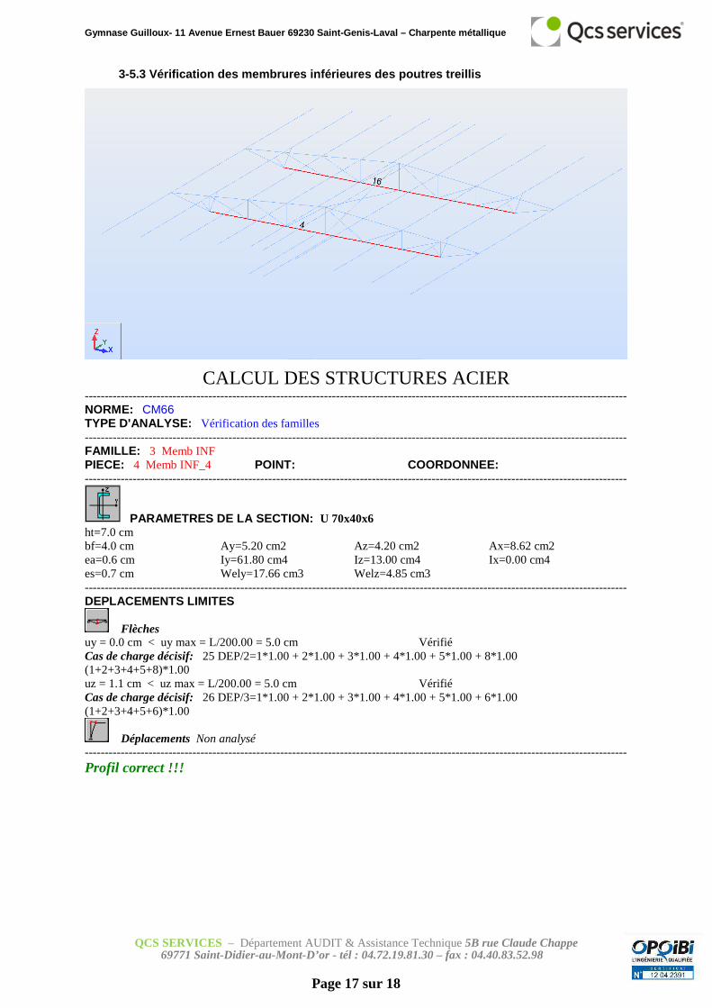
3-5.3 Vérification des membrures inférieures des po utres treillis
CALCUL DES STRUCTURES ACIER ---------------------------------------------------------------------------------------------------------------------------------------- NORME: CM66 TYPE D'ANALYSE: Vérification des familles ---------------------------------------------------------------------------------------------------------------------------------------- FAMILLE: 3 Memb INF PIECE: 4 Memb INF_4 POINT: COORDONNEE: ----------------------------------------------------------------------------------------------------------------------------------------
PARAMETRES DE LA SECTION: U 70x40x6 ht=7.0 cm bf=4.0 cm Ay=5.20 cm2 Az=4.20 cm2 Ax=8.62 cm2 ea=0.6 cm Iy=61.80 cm4 Iz=13.00 cm4 Ix=0.00 cm4 es=0.7 cm Wely=17.66 cm3 Welz=4.85 cm3 ---------------------------------------------------------------------------------------------------------------------------------------- DEPLACEMENTS LIMITES
Flèches uy = 0.0 cm < uy max = L/200.00 = 5.0 cm Vérifié Cas de charge décisif: 25 DEP/2=1*1.00 + 2*1.00 + 3*1.00 + 4*1.00 + 5*1.00 + 8*1.00 (1+2+3+4+5+8)*1.00 uz = 1.1 cm < uz max = L/200.00 = 5.0 cm Vérifié Cas de charge décisif: 26 DEP/3=1*1.00 + 2*1.00 + 3*1.00 + 4*1.00 + 5*1.00 + 6*1.00 (1+2+3+4+5+6)*1.00
Déplacements Non analysé ---------------------------------------------------------------------------------------------------------------------------------------- Profil correct !!!

Gymnase Guilloux- 11 Avenue Ernest Bauer 69230 Sain t-Genis-Laval – Charpente métallique
QCS SERVICES – Département AUDIT & Assistance Technique 5B rue Claude Chappe 69771 Saint-Didier-au-Mont-D’or - tél : 04.72.19.81.30 – fax : 04.40.83.52.98
Page 18 sur 18
4- Conclusion
D’après notre étude suite aux hypothèses de chargem ent transmise par le Maitre
d’Ouvrage, nous pouvons conclure que la charpente m étallique de la salle judo et karaté n’est
pas apte à recevoir une couverture de type Efigreen Duo qinsi que les radians.
En effet, notre étude indique un dépassement du taux de contrainte de sur les dia gonales
situées au droit des appuis de 30% principalement d u à la charge accidentelle de neige.
5- Préconisations
Nous préconsions de renforcer les 4 diagonales aux appuis, en soudant deux cornieres
20x20x3 dos à dos sous les tubes 35x35x2.5.
Tube carré 35x2.7
Cornière L 20x3
Related Documents