SERVICE MANUAL MULTIFUNCTIONAL DIGITAL SYSTEMS e-STUDIO200S File No. SME07000500 R070521D8700-TTEC Ver00_2007-07

Welcome message from author
This document is posted to help you gain knowledge. Please leave a comment to let me know what you think about it! Share it to your friends and learn new things together.
Transcript
SERVICE MANUALMULTIFUNCTIONAL DIGITAL SYSTEMS
e-STUDIO200S
File No. SME07000500R070521D8700-TTECVer00_2007-07

Trademarks• The official name of Windows 95 is Microsoft Windows 95 Operating System.• The official name of Windows 98 is Microsoft Windows 98 Operating System.• The official name of Windows Me is Microsoft Windows Millennium Edition Operating System.• The official name of Windows 2000 is Microsoft Windows 2000 Operating System.• The official name of Windows XP is Microsoft Windows XP Operating System.• Microsoft, Windows, Windows NT, Windows Vista and the brand names and product names of other
Microsoft products are trademarks or registered trademarks of Microsoft Corporation in the U.S. and/or other countries.
• Molykote is a registered trademark of Dow Corning Corporation.• Other company names and product names in this manual are the trademarks of their respective
companies.
© 2007 TOSHIBA TEC CORPORATION All rights reserved
Under the copyright laws, this manual cannot be reproduced in any form without prior written permission of TOSHIBA TEC CORPORATION. No patent liability is assumed, however, with respect to the use of the information contained herein.

Contents
Service Manual © July 2007 TOSHIBA TEC CORPORATION All rights reserved
Contents1. Precautons ....................................................................................... 1-1
1.1 Safety Warning ......................................................................................................... 1-11.2 Caution for safety ..................................................................................................... 1-2
1.2.1 Toxic material ................................................................................................. 1-21.2.2 Electric Shock and Fire Safety Precautions ................................................... 1-21.2.3 Handling Precautions ..................................................................................... 1-31.2.4 Assembly / Disassembly Precautions ............................................................ 1-31.2.5 Disregarding this warning may cause bodily injury ........................................ 1-4
1.3 ESD Precautions ...................................................................................................... 1-51.4 Super Capacitor or Lithium Battery Precautions ..................................................... 1-6
2. Product Specfcatons ................................................................... 2-12.1 Product Overview .................................................................................................... 2-12.2 Specifications .......................................................................................................... 2-2
2.2.1 General Specifications .................................................................................. 2-22.2.2 Print Specifications ....................................................................................... 2-32.2.3 Scan Specifications ...................................................................................... 2-32.2.4 Copy Specifications ..................................................................................... 2-42.2.5 Telephone Specifications ............................................................................. 2-42.2.6 Fax Specifications ......................................................................................... 2-52.2.7 Paper Handling Specifications ..................................................................... 2-62.2.8 Software ..................................................................................................... 2-62.2.9 Accessory ................................................................................................... 2-72.2.10 Consumables .......................................................................................... 2-7
3. System Overvew.............................................................................. 3-13.1 System Layout .......................................................................................................... 3-1
3.1.1 Feeding section .............................................................................................. 3-23.1.2 Transfer Ass’y ................................................................................................. 3-23.1.3 Driver Ass’y .................................................................................................... 3-23.1.4 Fixing Part (Fuser).......................................................................................... 3-2
3.1.4.1 Temperature-Intercepting Device (Thermostat) ....................................... 3-23.1.4.2 Temperature Detecting Sensor (Thermistor) ........................................... 3-23.1.4.3 Heat Roller ............................................................................................... 3-23.1.4.4 Pressure roller ......................................................................................... 3-33.1.4.5 Safety Features ....................................................................................... 3-3
3.2 Engine H/W Specification ........................................................................................ 3-53.2.1 Main Board Control Part................................................................................ 3-53.2.2 Scan Part....................................................................................................... 3-63.2.3 Fax Modem Part ............................................................................................ 3-73.2.4 Printing Process Part .................................................................................... 3-83.2.5 Line Interface Part ......................................................................................... 3-83.2.6 Engine Paper Feeding .................................................................................. 3-8
3.3 Developer Process .................................................................................................. 3-93.3.1 Fuser Specification ........................................................................................ 3-9
3.4 Scanner Part ............................................................................................................ 3-103.5 OPE (Operational Panel Equipment) ...................................................................... 3-12
Service Manual
Contents
© July 2007 TOSHIBA TEC CORPORATION All rights reserved
3.6 SMPS & HVPS ........................................................................................................ 3-133.6.1 SMPS ............................................................................................................ 3-133.6.2 HVPS Board .................................................................................................. 3-14
3.7 FUSER AC POWER CONTROL ............................................................................. 3-15
4. Algnment and Adjustments ........................................................... 4-14.1 User Mode ............................................................................................................... 4-14.2 Tech Mode and Setting ............................................................................................ 4-5
4.2.1 How to Enter Tech Mode ................................................................................ 4-54.2.2 Setting-up System in Tech Mode ................................................................... 4-64.2.3 Setting ............................................................................................................ 4-7
4.2.3.1 Changing the Display Language ............................................................. 4-74.2.3.2 Setting the Machine ID ............................................................................ 4-74.2.3.3 Setting the Date and Time ....................................................................... 4-84.2.3.4 Changing the Clock Mode ....................................................................... 4-84.2.3.5 Setting the Paper Size and Type ............................................................. 4-94.2.3.6 Setting Sounds ........................................................................................ 4-94.2.3.7 Speaker, Ringer, Key Sound, and Alarm Sound ..................................... 4-94.2.3.8 Speaker Volume ...................................................................................... 4-104.2.3.9 Toner Save Mode .................................................................................... 4-104.2.3.10 Power Save Mode ................................................................................. 4-10
4.2.4 FLASH UPGRADE ......................................................................................... 4-114.2.5 Machine Test .................................................................................................. 4-124.2.6 Report ............................................................................................................. 4-13
4.3 Control Panel ............................................................................................................ 4-144.3.1 Control Panel Functions ................................................................................. 4-14
4.4 LCD Status Error Massages .................................................................................... 4-164.5 Engine Test Mode..................................................................................................... 4-18
4.5.1 To enter the Engine Test Mode ...................................................................... 4-184.5.2 Diagnostic ....................................................................................................... 4-184.5.3 Detail Description (Engine Test Mode) ........................................................... 4-19
4.6 Paper Path and Clearing Paper Jams ..................................................................... 4-204.6.1 Copy & Scan Document Path ....................................................................... 4-204.6.2 Printer Paper Path ......................................................................................... 4-214.6.3 Clearing Paper Jams ...................................................................................... 4-22
4.6.3.1 In the Tray ................................................................................................ 4-224.6.3.2 In the Fuser Area or Around the Toner Cartridge ................................... 4-234.6.3.3 In the Paper Exit Area ............................................................................. 4-244.6.3.4 Tips for Avoiding Paper Jams When Printing on the A5-sized Paper .... 4-254.6.3.5 Tips for Avoiding Paper Jams ................................................................. 4-25
5. Dsassembly and Reassembly ........................................................ 5-15.1 General Precautions on Disassembly ...................................................................... 5-15.2 MP Tray .................................................................................................................... 5-25.3 Pick Up Roller .......................................................................................................... 5-35.4 Front Cover .............................................................................................................. 5-35.5 Cassette Tray ........................................................................................................... 5-4

Contents
Service Manual © July 2007 TOSHIBA TEC CORPORATION All rights reserved
5.6 Rear Cover ............................................................................................................... 5-55.7 Right Cover .............................................................................................................. 5-65.8 Left Cover ................................................................................................................. 5-75.9 Scan Ass'y ................................................................................................................ 5-85.10 ADF Housing .......................................................................................................... 5-95.11 OPE Unit ................................................................................................................. 5-115.12 Platen Housing ....................................................................................................... 5-125.13 Middle Cover .......................................................................................................... 5-145.14 HVPS ...................................................................................................................... 5-155.15 Main PBA ................................................................................................................ 5-165.16 RX Drive ................................................................................................................. 5-175.17 Fuser ...................................................................................................................... 5-185.18 Engine Shield (LIU PBA, SMPS) ........................................................................... 5-215.19 LSU ........................................................................................................................ 5-225.20 Paper Path Frame .................................................................................................. 5-23
6. Troubleshootng ............................................................................... 6-16.1 Checking Symptoms ............................................................................................. 6-1
6.1.1 Basic Check List........................................................................................... 6-26.1.2 Initial Inspection............................................................................................. 6-3
6.2 Bad discharge ......................................................................................................... 6-46.2.1 Wrong Print Position ..................................................................................... 6-46.2.2 JAM 0 ........................................................................................................... 6-46.2.3 JAM 1 ............................................................................................................ 6-56.2.4 JAM 2 ........................................................................................................... 6-56.2.5 Multi-Feeding .............................................................................................. 6-66.2.6 Paper rolled in the Fuser ............................................................................ 6-66.2.7 Paper rolled in the Toner Cartridge (OPC Drum) ........................................ 6-7
6.3 Set Malfunction – Causes and Solutions ................................................................. 6-86.3.1 LCD Display Defect ( in LCD Display) .................................................. 6-86.3.2 Defective OPE Keypad................................................................................... 6-86.3.3 Fuser gear melts due to overheating causing Paper Jam. ........................... 6-96.3.4 Paper Empty.................................................................................................. 6-96.3.5 Paper Empty without indication ..................................................................... 6-96.3.6 Cover Open ................................................................................................... 6-106.3.7 No error message when the cover is open ................................................... 6-106.3.8 Defective motor operation ............................................................................. 6-116.3.9 No Power ....................................................................................................... 6-116.3.10 Printed Vertical Lines become curved ......................................................... 6-11
6.4 Bad Software Environment ..................................................................................... 6-126.4.1 The printer is not working (1) ....................................................................... 6-126.4.2 The printer is not working (2) ....................................................................... 6-136.4.3 Abnormal Printing ......................................................................................... 6-146.4.4 SPOOL Error ................................................................................................. 6-15
6.5 Bad image .............................................................................................................. 6-166.5.1 Vertical Black Line and Band ....................................................................... 6-166.5.2 Vertical White Line ........................................................................................ 6-16

Service Manual
Contents
v © July 2007 TOSHIBA TEC CORPORATION All rights reserved
6.5.3 Horizontal Black Band ................................................................................... 6-176.5.4 Black/White Spot ........................................................................................... 6-176.5.5 Light Image.................................................................................................... 6-186.5.6 Dark Image or a Black ................................................................................. 6-186.5.7 Uneven Density ............................................................................................. 6-196.5.8 Background ................................................................................................... 6-196.5.9 Ghost (1) ...................................................................................................... 6-206.5.10 Ghost (2) ..................................................................................................... 6-206.5.11 Ghost (3) .................................................................................................... 6-216.5.12 Ghost (4) .................................................................................................... 6-216.5.13 Stains on the Face of Page ....................................................................... 6-216.5.14 Stains on Back of Page ............................................................................. 6-226.5.15 Blank Page Print out (1) .............................................................................. 6-226.5.16 Blank Page Print out (2) .............................................................................. 6-22
6.6 Fax & Phone Problems ............................................................................................ 6-236.6.1 No Dial Tone .................................................................................................. 6-236.6.2 Defective MF DIAL ......................................................................................... 6-236.6.3 Defective FAX FORWARD/RECEIVE ............................................................ 6-246.6.4 Defective FAX FORWARD ............................................................................. 6-246.6.5 Defective FAX RECEIVE (1) .......................................................................... 6-256.6.6 Defective FAX RECEIVE (2) .......................................................................... 6-256.6.7 Defective FAX RECEIVE (3) .......................................................................... 6-256.6.8 Defective FAX RECEIVE (4) .......................................................................... 6-266.6.9 Defective Automatic Receiving ....................................................................... 6-26
6.7 Copy Problems ......................................................................................................... 6-276.7.1 White Copy .................................................................................................... 6-276.7.2 Black Copy .................................................................................................... 6-276.7.3 Abnormal noise.............................................................................................. 6-286.7.4 Defective Image Quality ................................................................................ 6-28
6.8 Scanning Problems – Causes and Solutions ........................................................... 6-296.8.1 PC Scanning problems ................................................................................. 6-296.8.2 Poor Quality of PC Scanned images ............................................................ 6-29
6.9 Toner Cartridge Service............................................................................................ 6-306.9.1 Precautions on Safe-keeping of Toner Cartridge ........................................... 6-306.9.2 Service for the Life of Toner Cartridge ........................................................... 6-30
6.9.2.1 Redistributing Toner ................................................................................. 6-306.9.3 Standard of guarantee for consumable parts. ................................................ 6-306.9.4 Error messages in the LCD window related to toner. .................................... 6-31
6.9.4.1 Toner Low ................................................................................................ 6-316.9.4.2 Toner Empty ............................................................................................. 6-316.9.4.3 Drum Warning .......................................................................................... 6-316.9.4.4 Replace Drum .......................................................................................... 6-31
6.10 Software Problems – Causes and Solutions .......................................................... 6-326.10.1 The printer is not working (1) ..................................................................... 6-326.10.2 The printer is not working (2) ..................................................................... 6-336.10.3 Abnormal Printing ........................................................................................ 6-346.10.4 SPOOL Error ............................................................................................... 6-35

Contents
Service Manual v© July 2007 TOSHIBA TEC CORPORATION All rights reserved
7. Block Dagram ................................................................................. 7-17.1 System Block Diagram ............................................................................................. 7-1
8. Connecton Dagram ....................................................................... 8-1
9. Reference Informaton ..................................................................... 9-19.1 Troubleshooting Tool .............................................................................................. 9-19.2 Acronyms and Abbreviations (1) ............................................................................. 9-2Acronyms and Abbreviations (2) .................................................................................... 9-39.3 Selecting printer locations ....................................................................................... 9-49.4 Sample Tests Patterns ............................................................................................. 9-5

Service Manual
Contents
v © July 2007 TOSHIBA TEC CORPORATION All rights reserved

Precautons
© July 2007 TOSHIBA TEC CORPORATION All rights reservedService Manual 1-1
11. PrecautonsIn order to prevent accidents and to prevent damage to the equipment please read the precautions listed below carefully before servicing the printer and follow them closely.
1.1 Safety Warnng(1) Only to be serviced by appropriately qualified service engineers.
High voltages and lasers inside this product are dangerous. This printer should only be serviced by a suitably trained and qualified service engineer.
(2) Use only Toshiba replacement parts There are no user serviceable parts inside the printer. Do not make any unauthorized changes or additions to the printer, these could cause the printer to malfunction and create electric shock or fire hazards.
(3) Laser Safety Statement The Printer is certified as a Class I laser product conforming to the requirements of IEC 60825-1. Class I laser products are not considered to be hazardous. The laser system and printer are designed so there is never any human access to laser radiation above a Class I level during normal operation, user maintenance, or prescribed service condition.
Warning>>NeveroperateorservicetheprinterwiththeprotectivecoverremovedfromLaser/Scannerassembly.Thereflectedbeam,althoughinvisible,candamageyoureyes.Whenusingthisproduct,thesebasicsafetypre-cautionsshouldalwaysbefollowedtoreduceriskoffire,electricshock,andinjurytoper-sons.

© July 2007 TOSHIBA TEC CORPORATION All rights reservedService Manual
Precautons
1-2
1.2 Cauton for safety
1.2.1 Toxc materal
This product contains toxic materials that could cause illness if ingested.
(1) If the LCD control panel is damaged it is possible for the liquid inside to leak. This liquid is toxic. Contact with the skin should be avoided, wash any splashes from eyes or skin immediately and contact your doctor. If the liquid gets into the mouth or is swallowed see a doctor immediately.
(2) Please keep toner cartridges away from children. The toner powder contained in the toner cartridge may be harmful and if swallowed you should contact a doctor.
1.2.2 Electrc Shock and Fre Safety Precautons
Failure to follow the following instructions could cause electric shock or potentially cause a fire.
(1) Use only the correct voltage, failure to do so could damage the printer and potentially cause a fire or electric shock.
(2) Use only the power cable supplied with the printer. Use of an incorrectly specified cable could cause the cable to overheat and potentially cause a fire.
(3) Do not overload the power socket, this could lead to overheating of the cables inside the wall and could lead to a fire.
(4) Do not allow water or other liquids to spill into the printer, this can cause electric shock. Do not allow paper clips, pins or other foreign objects to fall into the printer these could cause a short circuit leading to an electric shock or fire hazard..
(5) Never touch the plugs on either end of the power cable with wet hands, this can cause electric shock. When servicing the printer remove the power plug from the wall socket.
(6) Use caution when inserting or removing the power connector. The power connector must be inserted completely otherwise a poor contact could cause overheating possibly leading to a fire. When removing the power connector grip it firmly and pull.
(7) Take care of the power cable. Do not allow it to become twisted, bent sharply round corners or other-wise damaged. Do not place objects on top of the power cable. If the power cable is damaged it could overheat and cause a fire or exposed cables could cause an electric shock. Replace a damaged power cable immediately, do not reuse or repair the damaged cable. Some chemicals can attack the coating on the power cable, weakening the cover or exposing cables causing fire and shock risks.
(8) Ensure that the power sockets and plugs are not cracked or broken in any way. Any such defects should be repaired immediately. Take care not to cut or damage the power cable or plugs when moving the machine.
(9) Use caution during thunder or lightening storms. Toshiba recommend that this machine be disconnected from the power source when such weather conditions are expected. Do not touch the machine or the power cord if it is still connected to the wall socket in these weather conditions.
(10) Avoid damp or dusty areas, install the printer in a clean well ventilated location. Do not position the machine near a humidifier. Damp and dust build up inside the machine can lead to overheating and cause a fire.
(11) Do not position the printer in direct sunlight. This will cause the temperature inside the printer to rise possibly leading to the printer failing to work properly and in extreme conditions could lead to a fire.
(12) Do not insert any metal objects into the machine through the ventilator fan or other part of the casing, it could make contact with a high voltage conductor inside the machine and cause an electric shock.
(13) Unplug the power cable and clean the area around the prongs of the plug and socket outlet once a year or more. A fire may occur when dust lies on this area.

Precautons
© July 2007 TOSHIBA TEC CORPORATION All rights reservedService Manual 1-3
1.2.3 Handlng Precautons
The following instructions are for your own personal safety, to avoid injury and so as not to damage the printer
(1) Ensure the printer is installed on a level surface, capable of supporting its weight. Failure to do so could cause the printer to tip or fall.
(2) The printer contains many rollers, gears and fans. Take great care to ensure that you do not catch your fingers, hair or clothing in any of these rotating devices.
(3) Do not place any small metal objects, containers of water, chemicals or other liquids close to the printer which if spilled could get into the machine and cause damage or a shock or fire hazard.
(4) Do not install the machine in areas with high dust or moisture levels, beside on open window or close to a humidifier or heater. Damage could be caused to the printer in such areas.
(5) Do not place candles, burning cigarettes, etc. on the printer, these could cause a fire.(6) Be sure to fix and plug in the power cable securely after the installation so that no one trips over it.
1.2.4 Assembly / Dsassembly Precautons
Replace parts carefully, always use Toshiba parts. Take care to note the exact location of parts and also cable routing before dismantling any part of the machine. Ensure all parts and cables are replaced correctly.Please carry out the following procedures before dismantling the printer or replacing any parts.
(1) Check the contents of the machine memory and make a note of any user settings. These will be erased if the mainboard is replaced.
(2) Ensure that power is disconnected before servicing or replacing any electrical parts.(3) Disconnect printer interface cables and power cables.(4) Only use approved spare parts. Ensure that part number, product name, any voltage, current or tem-
perature rating are correct.(5) When removing or re-fitting any parts do not use excessive force, especially when fitting screws into
plastic.(6) Take care not to drop any small parts into the machine.(7) Handling of the OPC Drum - The OPC Drum can be irreparably damaged if it exposed to light.
Take care not to expose the OPC Drum either to direct sunlight or to fluorescent or incandescent room lighting. Exposure for as little as 5 mins can damage the surface’s photoconductive properties and will result in print quality degradation. Take extra care when servicing the printer. Remove the OPC Drum and store it in a black bag or other lightproof container. Take care when working with the covers (especially the top cover) open as light is admitted to the OPC area and can damage the OPC Drum.
- Take care not to scratch the green surface of OPC Drum Unit. If the green surface of the Drum Cartridge is scratched or touched the print quality will be compro-mised.

© July 2007 TOSHIBA TEC CORPORATION All rights reservedService Manual
Precautons
1-4
1.2.5 Dsregardng ths warnng may cause bodly njury
(1) Be careful wth the hgh temperature part. The fuser unit works at a high temperature. Use caution when working on the printer. Wait for the fuser to cool down before disassembly.
(2) Do not put fnger or har nto the rotatng parts. When operating a printer, do not put hand or hair into the rotating parts (Paper feeding entrance, motor, fan, etc.). If do, you can get harm.
(3) When you move the prnter. When transporting/installing the printer, employ two persons and be sure to hold the positions as shown in the figure. This printer weighs 10.4kg including toner cartridge and cassette. Use safe lifting and handling tech-niques. Back injury could be caused if you do not lift carefully.
(4) Ensure the prnter s nstalled safely. The printer weighs 10.4Kg, ensure the printer is installed on a level surface, capable of supporting its weight. Failure to do so could cause the printer to tip or fall possibly causing personal injury or damag-ing the printer.
(5) Do not install the printer on a sloping or unstable surface. After installation, double check that the printer is stable.

Precautons
© July 2007 TOSHIBA TEC CORPORATION All rights reservedService Manual 1-5
1.3 ESD Precautons
Certain semiconductor devices can be easily damaged by static electricity. Such components are commonly called “Electrostatically Sensitive (ES) Devices”, or ESDs. Examples of typical ESDs are: integrated circuits, some field effect transistors, and semiconductor “chip” components.The techniques outlined below should be followed to help reduce the incidence of component damage caused by static electricity.
Caution>>Besurenopowerisappliedtothechassisorcircuit,andobserveallothersafetyprecautions.
1. Immediately before handling a semiconductor component or semiconductor-equipped assembly, drain off any electrostatic charge on your body by touching a known earth ground. Alternatively, employ a commercially available wrist strap device, which should be removed for your personal safety reasons prior to applying power to the unit under test.
2. After removing an electrical assembly equipped with ESDs, place the assembly on a conductive sur-face, such as aluminum or copper foil, or conductive foam, to prevent electrostatic charge buildup in the vicinity of the assembly.
3. Use only a grounded tip soldering iron to solder or desolder ESDs.4. Use only an “anti-static” solder removal device. Some solder removal devices not classified as “anti-static”
can generate electrical charges sufficient to damage ESDs.5. Do not use Freon-propelled chemicals. When sprayed, these can generate electrical charges sufficient
to damage ESDs.6. Do not remove a replacement ESD from its protective packaging until immediately before installing it.
Most replacement ESDs are packaged with all leads shorted together by conductive foam, aluminum foil, or a comparable conductive material.
7. Immediately before removing the protective shorting material from the leads of a replacement ESD, touch the protective material to the chassis or circuit assembly into which the device will be installed.
8. Maintain continuous electrical contact between the ESD and the assembly into which it will be installed, until completely plugged or soldered into the circuit.
9. Minimize bodily motions when handling unpackaged replacement ESDs. Normal motions, such as the brushing together of clothing fabric and lifting one’s foot from a carpeted floor, can generate static elec-tricity sufficient to damage an ESD.

© July 2007 TOSHIBA TEC CORPORATION All rights reservedService Manual
Precautons
1-6
1.4 Super Capactor or Lthum Battery Precautons
1. Exercise caution when replacing a super capacitor or Lithium battery. There could be a danger of explosion and subsequent operator injury and/or equipment damage if incorrectly installed.
2. Be sure to replace the battery with the same or equivalent type recommended by the manufacturer.3. Super capacitor or Lithium batteries contain toxic substances and should not be opened, crushed, or
burned for disposal. 4. Regarding the disposal of used batteries and IC-RAMs including lithium batteries, follow the relevant
local regulations or rules.
Cauton:Dispose of used batteries and IC-RAMs including lithium batteries according to this manual.Attenton:Se débarrasser de batteries et IC-RAMs usés y compris les batteries en lithium selon ce manuel.Vorscht:Entsorgung der gebrauchten Batterien und IC-RAMs (inclusive der Lithium-Batterie) nach diesem Handbuch.

Product Specfcatons
© July 2007 TOSHIBA TEC CORPORATION All rights reservedService Manual 2-1
2Item Descriptions RemarksModel name DP-2025Customer Benefits (Sales Points)
- Compact Size
- 22ppm/A4, 22ppm/Letter fastest speed in its price class
- Favorite Copy
- ID Card Copy
- Toner SaveKey Specification - up to 22ppm/A4 (Up to 22ppm/Letter)
- 150 sheets Multi-Purpose type paper input/50 sheets Paper Output
- 3,000 pages toner capacity
- 600dpi Print/Copy Resolution
- GDI (SPL)
- 16MB System memory
- 30 ADF
- 33.6 Kbps Fax Modem
- 100 Speed Dial
- 72 Hour Battery Back-up
2. Product Specfcatons2.1 Product Overvew

© July 2007 TOSHIBA TEC CORPORATION All rights reservedService Manual
Product Specfcatons
2-2
2.2 Specfcatons Product Specifications are subject to change without notice. See below for product specifications.
2.2.1 General Specfcatons
Item DescriptionsMajor Features Copier, Print, Scan, FaxNet Dimension (WxDxH) 438(W)x374(D)x368(H) (17.2x14.7x14.5")Net Weight (Inc. Toner Cartridge) 10.4kgCPU Chorus-2 (66MHz)LCD 2 Line x 16 charactersToner Save Yes (With toner save button)I/O Interface USB 1.1 (Compatible with USB 2.0), IEEE 1284 ParallelNetwork Interface No OS Compatibility Windows 98/Me/NT4.0/2000/XP/VistaPower Requirement 110 ~ 127 VAC, 50/60 Hz, 4.5A
220 ~ 240 VAC, 50/60 Hz, 2.5APower Consumption Sleep Mode : Under 10 W
Average : 350 WEnergy Star Compliant YesPower Switch YesNoise
Warm up
Stand by
Coping
Printing
49 dBA
35 dBA
55 dBA
53 dBAWarm up time from Power On Status
from Sleep Mode (Recovery time)
Less than 35 seconds
Less than 35 seconds
Max. Monthly Volume
Print 4,200 pagesScan ADF: 2,500 pages, PLATEN: 1,700 pages
Average Monthly Print Volume 500 pagesAverage Monthly SCAN Volume 150 pagesMachine Life ENGINE
SCANNER
5 years or 50,000 Pages. Whichever comes first
ADF : 30,000 Pages, Platen : 20,000 PagesOperation
conditions
Temperature
Humidity
10°C ~ 32 °C (50°F ~ 89°F)
20 % ~ 80 % RHApproval Class BDevice Memory 16MBPage Counter YesPrint Configuration Sheet (System Data) Yes

Product Specfcatons
© July 2007 TOSHIBA TEC CORPORATION All rights reservedService Manual 2-3
Item DescriptionsMethod Laser Beam PrintingSpeed Up to 20ppm in A4 (20ppm in Letter)Emulation SPL (GDI)Power Save Yes (Interval option: 5, 10,15, 30, 45 minute) Resolution Normal 600 x 600 dpi
RET -Memory 10MBFirst Print Out From Stand by Approx. 11 secondsTime From Cold Status Less than 41 secondsDuplex Print -WHQL Compliant Window XP/VistaPrintable Area A4: 201.6x288.6mm
LTR: 207.6x270.6mmLegal: 207.6x347.6mmFolio: 207.6x322.6mm
Halftone (Gray Scale) 256 levels
2.2.2 Prnt Specfcatons
Item DescriptionsCompatibility Twain standard / WIA Standard (Window XP/Vista)Scan Method ADF and Flad-bed CIS (Contact Image Sensor) ModulePC Scan Speed
through Platen
Lineart, Halftone 15sec Platen (18sec ADF) Gray 30sec Platen (33sec ADF) Color 75dpi, 300dpi 23sec/75sec
Resolution Optical 600 x 600 dpiEnhanced 4800 x 4800 dpi
Halftone 256 levelsScan Size
Max. Document Width Max. 216mm (8.5")Effective Scan Length 297 mm (11.7")Effective Scan Width 208mm (8.2")
Scan Depth Color 24 bitMono 1bit for Line art, Halftone, 8 Bit for Gray scale
2.2.3 Scan Specfcatons

© July 2007 TOSHIBA TEC CORPORATION All rights reservedService Manual
Product Specfcatons
2-4
2.2.4 Copy Specfcatons Item Descriptions
Copy Speed Up to 20ppm in A4 (20ppm in Letter)Resolution Optical 600x600 dpi (Scan: 600x600dpi, Print: 600x600dpi)
- Text & Text/Photo mode : 600x300dpi (ADF, Platen)
- Photo mode : 600x600dpi (Platen), 600x300dpi (ADF) Enhanced -
First Copy Out Time
Stand by Approx. 11 secondsFrom Cold Status Less then 41 seconds
Original Image type selection Text, Text/Photo, PhotoZoom Range 25-400%(Platen), 25-100%(ADF)Multi Copy 1~99 PagesPreset [Original (100%)], [A4 → A5 (71%)], [LGL → LTR (78%)], [LGL → A4
(83%)], [A4 → LTR (94%)], [EXE → LTR (104%)], [A5 → A4 (141%)], 25%, 50%, 150%, 200%, [Custom: 25-400%)]
Darkness Control 3 level (Light, Normal, Dark)Auto return to default mode Yes (after 1 minute)- Time out option: 15, 30, 60, 180 sec., Off Changeable Default mode Darkness, Original Type, Reduce/Enlarge, No. of Copies ID Card Copy
2-up
4-up
Collation
Autofit
LD Card Copy
Clone
Poster
Yes (ADF Only)
Yes (ADF Only)
Yes (ADF Only)
Yes (Platen Only)
Yes (Platen Only)
Yes (Platen Only)
Yes (Platen Only)
Item DescriptionsHandset NoOn hook Dial YesSearch Yes (Phone Book)1-Touch Dial 10 ea (0~9)Speed dial 90 locations (10~99)TAD I/F YesTone/Pulse Tone (Default), Pulse (Changing in Tech Mode)Pause YesAuto Redial YesLast Number Redial YesDistinctive Ring YesCaller ID NoExtension Phone Interface YesReport & List Tx/Rx Journal Yes Print out
Confirmation YesHelp List NoAuto Dial List YesSystem Data List List all user setting
Sound Control Ring Volume Yes (Off, Low, MED, HIGH)Key Volume Yes (On, Off)Alarm Volume Yes (On, Off)
Speaker Yes (On, Off, Comm)
2.2.5 Telephone Specfcatons

Product Specfcatons
© July 2007 TOSHIBA TEC CORPORATION All rights reservedService Manual 2-5
2.2.6 Fax SpecfcatonsItem Descriptions
Compatibility ITU-T G3Modem Speed 33.6KbpsTX Speed 3secCompression MH/MR/MMR/JPEGColor Fax Yes (Tx Only)ECM YesResolution
Std 203x98dpiFine 203x196dpiS.Fine 300x300dpiPhoto 203x196dpiColor 200x200dpiAuto Switching Yes
Scan Speed Standard approx. 3sec (ADF) Fine approx. 7.5sec (ADF)S.Fine approx. 7.5sec (ADF)
Rx fax duplex print out NoMultiple page scan speed (Memory Tx.)
7 cpm / Ltr (Standard Resolution Res.)
Receive Mode Fax, TEL, Ans/Fax, DRPDMemory
Capacity 2MB (When Power off Memory Back up)Optional Memory NoMax locations to store
to 1 Group Dial
99 locations
Fax Forward Yes (On/Off)Broadcasting 109 locations (Max locations)Cover page NODelayed fax YesMemory RX Yes
Functions Voice Request NoTTI YesRTI YesPolling NoEarth/Recall NoAuto Reduction YesRDS Yes
Junk Fax barrier YesSecurity Receive YesMemory Back-up Max. 72 hours
© July 2007 TOSHIBA TEC CORPORATION All rights reservedService Manual
Product Specfcatons
2-6
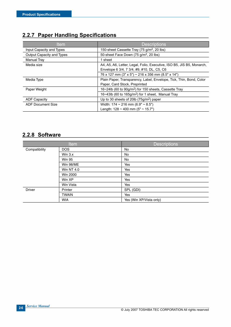
Item DescriptionsInput Capacity and Types 150-sheet Cassette Tray (75 g/m2, 20 lbs)Output Capacity and Types 50-sheet Face Down (75 g/m2, 20 lbs)Manual Tray 1 sheetMedia size A4, A5, A6, Letter, Legal, Folio, Executive, ISO B5, JIS B5, Monarch,
Envelope 6 3/4, 7 3/4, #9, #10, DL, C5, C676 x 127 mm (3" x 5") ~ 216 x 356 mm (8.5" x 14")
Media Type Plain Paper, Transparency, Label, Envelope, Tick, Thin, Bond, Color Paper, Card Stock, Preprinted
Paper Weight 16~24lb (60 to 90g/m2) for 150 sheets, Cassette Tray16~43lb (60 to 165g/m2) for 1 sheet, Manual Tray
ADF Capacity Up to 30 sheets of 20lb (75g/m2) paperADF Document Size Width: 174 ~ 216 mm (6.9" ~ 8.5")
Length: 128 ~ 400 mm (5" ~ 15.7")
2.2.7 Paper Handlng Specfcatons
2.2.8 Software Item Descriptions
Compatibility
DOS NoWin 3.x NoWin 95 NoWin 98/ME YesWin NT 4.0 YesWin 2000 YesWin XP Yes Win Vista Yes
Driver
Printer SPL (GDI)TWAIN YesWIA Yes (Win XP/Vista only)

Product Specfcatons
© July 2007 TOSHIBA TEC CORPORATION All rights reservedService Manual 2-7
2.2.9 Accessory Item Descriptions
Quick Install Guide Yes S/W CD ROM 1 CD (Contents; Electronic User's Manual, Print Driver, Twain Driver) Toner Cartridge 1 EA Power Cable 1 EA Telephone Jack 1 EAPrinter Cable USB (CND only)Tray Cover Yes
2.2.10 Consumables Item Descriptions
Type Single CartridgeHow to install Front door open and front loadingToner Yield 3,000 pages at ISO 19752 5% Coverage (Ships with 1,000 pages Starter
Toner Cartridge)Product Name PS-ZT2025Level Sensor -

© July 2007 TOSHIBA TEC CORPORATION All rights reservedService Manual
Product Specfcatons
2-8
System Overvew
© July 2007 TOSHIBA TEC CORPORATION All rights reservedService Manual 3-1
33. System Overvew
3.1 System Layout
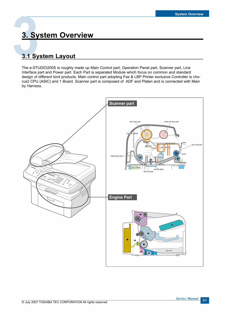
The e-STUDIO200S is roughly made up Main Control part, Operation Panel part, Scanner part, Line Interface part and Power part. Each Part is separated Module which focus on common and standard design of different kind products. Main control part adopting Fax & LBP Printer exclusive Controller is cho-rus2 CPU (ASIC) and 1 Board. Scanner part is composed of ADF and Platen and is connected with Main by Harness.
ADF ROLLER
Scanner part
Engine Part
ADF-UPPER
PICK-UP ROLLER
EXIT ROLER
WHITE BAR
ADF-GLASS
FEED ROLLER
SCAN UPPERSCAN UPPER
ADF-LOWER
COVER OPEN
BIN PATH

© July 2007 TOSHIBA TEC CORPORATION All rights reservedService Manual
System Overvew
3-2
3.1.1 Feedng secton
There is a universal cassette which automatically loads paper and the manual feed which supplies paper single sheet at a time. The cassette has a friction pad which separates paper to ensure single sheet feeding, and it has a sensor, which checks when the paper tray is empty.
- Feeding Method: MP Cassette Type - Feeding Standard: Center Loading - Feeding Capacity: Cassette-150 sheets (75g/m2, 20lb paper standard) Manual 1 sheet (Paper, OHP, Envelop, etc.) - Paper detecting sensor: Photo sensor - Paper size sensor: None
3.1.2 Transfer Ass’y
This consists of the PTL (pre-transfer lamp) and the Transfer Roller. The PTL shines a light onto the OPC drum. This lowers the charge on the drum’s surface and improves transfer efficiency.The transfer roller transfers toner from the OPC drum surface to the paper.
- Life expectancy: Over 50,000 sheets (at 16~30°C)
3.1.3 Drver Ass’y
- Gear driven power unit. The motor supplies power to the paper feed unit, the fuser unit, and the toner cartridge.
3.1.4 Fxng Part (Fuser)
- The fuser consists of the Heat Lamp, Heat Roller, Pressure Roller, Thermistor, and Thermostat. It fixes toner to the paper using pressure and heat to complete the printing job.
3.1.4.1 Temperature-Interceptng Devce (Thermostat)The thermostat is a temperature sensing device, which cuts off the power to the heat lamp to prevent overheating fire when the heat lamp or heat roller overheats.
3.1.4.2 Temperature Detectng Sensor (Thermstor)The Thermistor detects the surface temperature of the heat roller, this information is sent to the main pro-cessor which uses this information to regulate the temperature of the heat roller.
3.1.4.3 Heat RollerThe surface of the Heat Roller is heated by the Heat Lamp. As the paper passes between the Heat and Pressure rollers the toner is melted and fixed permanently to the paper. The surface of the roller is coated with Teflon. This ensures that toner does not adhere to the roller surface.
System Overvew
© July 2007 TOSHIBA TEC CORPORATION All rights reservedService Manual 3-3
3.1.4.4 Pressure rollerThe Pressure Roller mounted under the heat roller, it is made of a silicon resin, and the surface of the roller is coated with Teflon. This ensures that toner does not adhere to the roller surface.
3.1.4.5 Safety Features• To prevent overheating - 1st protection device: Hardware cuts off when overheated - 2nd protection device: Software cuts off when overheated - 3rd protection device: Thermostat cuts off mains power to the lamp.
• Safety device - Fuser power is cut off when the front cover is opened - LSU power is cut off when the front cover is opened - The temperature of the fuser cover's surface is maintained at less than 80°C to protect the user and a
caution label is attached where the customer can see it easily when the rear cover is opened.

© July 2007 TOSHIBA TEC CORPORATION All rights reservedService Manual
System Overvew
3-4
STACKER
COVER-M-SIDE R
EXTEND-SMALL
EXTEND-LARGE
TRAY CASSETTE
COVER-M_DEVE
FIXING BKT
SPEKER
COVER-M-SIDE-L
COVER-M_REAR
COVER-M_JAM
COVER-M_MIDDLE
SCANUPPER
MOTORASS’Y
SCANLOWER TIMING
BELT
CIS
SLIDER-CIS
ADFGLASS
SCANGLASS
KEY & OPECOVER
[Case part fgure]
[Scan part fgure]
System Overvew
© July 2007 TOSHIBA TEC CORPORATION All rights reservedService Manual 3-5
3.2 Engne H/W Specfcaton
1) Recording Method : LSU (Laser Scanning Unit)2) Printing Speed : 20ppm (In continuing printing base Letter, printing pages from 2nd to last during 1min)3) Recording Density : 600 dpi4) Cassette Capa. : Cassette ; 150 sheets (75g/m2 Base), 1-sheet Feeding : N/A (DRIVE Selection :
Paper, OHP, Envelop - 1 sheet)5) Manual Tray : All paper 1 sheet6) Paper Size : Cassette ,Manual ; Width = 76 ~ 216mm, Length = 127mm ~ 356mm7) Effective recording size - A4 :202 x 291 mm - Letter :208 x273mm - Legal : 208 x 350 mm - Folio : 208 x 325 mm - Top Margin: 2 ±2 mm - Left, Right Margin : 2 ±2 mm
8) CRU (Toner Cartridge) Life : 3,000 pages Printing (A4, ISO 5% Pattern Printing)9) First Print Out Time : within 11sec ( Standby )10) Warming up time : within 35sec (Ambient : 25 °C)
3.2.1 Man Board Control Part
Main control part of e-STUDIO200S is made of ASIC (CPU, Image processor, PC I/F part include, Scan interface part, FAX Modem part and Printing process I/F part. CPU handles the BUS control, I/O interface, scan interface, PC interface and other miscellaneous driver circuit.
1) Main Board - Main Board has a function of sending Current Image Video Data to LSU of the machine, controlling
motor Driving Circuit and monitoring Paper Exit Sensor, Cover Open switch, OPE Panel Inputs.2) Main Controller - CPU : Chorus2 is the main CPU and is made up on the 16/32bit RISC architecture using ARM7TDMI
core. Main CPU controls the whole system according to the program code which stored in the Flash-ROM memory.
- Summary of the Key Function Block: 1.8V for internal Core, 3.3V for I/O Pad with 4KByte Cache. Image Processor included. On-Chip clock generator with PLL. Memory and External Bank Control. DMA Control (5-Channel) Interrupt Control. 2-port USB Host/1-port USB device (ver 1.1) interface control. Parallel interface control. UART (2-Channel)
© July 2007 TOSHIBA TEC CORPORATION All rights reservedService Manual
System Overvew
3-6
Synchronous Serial Interface Control. A/D Converter (10-bit, 2-channel). General I/O Port control. Tone Generator. RTC with calendar function. S/W Assistant function (Rotator)
- Flash Memory : Stores system program and can be updated to the newer system program code through the PC interface. It stores the FAX Journal List, One Touch dial number, speed dial number, and machine configuration setup data.
Capacity : 2 Mbyte Access Time : 70 nsec
- SDRAM : SDRAM is used for Print Buffer, Scan buffer when scanning, ECM Buffer when FAX Receiving, and system working memory.
Capacity : 16 Mbyte Access Time : 66MHz based on system bus clock. Data Backup : 72 Hours Backup Battery Charging Time : 100 hours when completely discharged.
3.2.2 Scan Part
1) Image Signal Input Part - Image Signal from CIS has a level of about 1.2V and is goes to ADC of Chorus2. After ADC, CIS analog signal will be converted to 8-bit Digital signal.
2) Image Processing - On the surface of the original paper, the light from the CIS LED reflected and goes to the CIS Sensor.
Then the light is converted to the appropriate voltage suitable for ADC input. Analog signal from CIS sensor is used for ADC input then is converted to 8-bit digital data. Image processor of the Chorus2 will do the Shading correction function at first, then Gamma correction function next. After then, the data goes to different module according to the copy or FAX resolution mode. When Text mode, the image data goes to LAT module, when Photo mode, the image data goes to Error Diffusion module, when PC-Scan mode, the image data goes directly to the PC through DMA access.
Summary of the Image sensor interface is as below; - Minimum Scan Line Time :1.5ms - Scan Resolution : 600*600 dpi - Scan Width : 208mm - Function White Shading Correction Gamma Correction CIS Interface 256 Gray Scale
System Overvew
© July 2007 TOSHIBA TEC CORPORATION All rights reservedService Manual 3-7
3) CIS Driving Part - CIS Supply Voltage : +3.3V - CIS Max frequency : 5MHz - CIS Linetime Fax/Copy - 1.5ms PC-Scan - 4.5ms - White output volt. : Max 0.8V
4) ADF Driving Part : Driving ADF Stepper motor, and the maximum motor speed is 2000PPS. - MOTOR DRIVER : A3978 (Allegro) - Driving Voltage : 24V DC - Phase : 2-2 Phase 2000PPS at Quick Scan, 2-2 Phase 1000PPS AT Fine Scan, 2-2 Phase 667PPS AT Super Fine Scan
3.2.3 Fax Modem Part
1) Modem Part The modem part is consist of FM336 (FAX Modem chip), LIU (Line Interface Unit) and modem analog
front end (AFE) functional part.
- The feature of the FM336 modem chip is as below; Communication Mode : Half Duplex Modem Method - GROUP 3 : ITU-T V34, V17, V29, V27ter - Tonal Signal : ITU-T T.30 - Binary Signal : ITU-T V.21, T.30 Image Transmission Time : 3sec ( ITU-T NO.1 CHART/Memory Tx/ECM ) Data Compress : MH, MR, MMR, JPEG Modem Speed : 33600 / 28800 / 14400 / 12000 / 9600 / 7200 / 4800 / 2400 bps Receive Level : 0 ~ -48dBm Output Level - Adjustable : -6 ~ -15dBm ( 1dBm Step ) - Initial Setting : -12dBm Receive dynamic range: - 0 dBm to -43 dBmfor V.17, V.29, V.27 ter and V.21 - -9 dBm to -43 dBm for V.34 halfduplex
2) The Gain of the Line signal can be adjusted by setting the register value of the FAX modem chip, Tx and Rx path is almost directly connected to the impedance matching transformer of the LIU.
- Adjust Tx Level within Setting Level+0, -2dB range. - Adjust Rx Level that has the same level as the TIMS out level if possible, and must not exceed the
TIMS out level.3) Speaker Driving Part Analog Switch (MC14053BD) makes a path for FAX Tone, Ring, Key click sound and Analog MUX
(MC14051) makes a different signal level so that the Speaker driver chip (MC34119) can driving the Speaker with different sound volume.
© July 2007 TOSHIBA TEC CORPORATION All rights reservedService Manual
System Overvew
3-8
3.2.5 Lne Interface Part
Line interface part helps the machine connect to the PSTN or PABX Line and is made of almost primary cir-cuit.Its main function is Line connection, Line state monitoring and TAD interface that enables a extension tele-phone or TAD machine to connect to the e-STUDIO200S machine.
3.2.6 Engne Paper Feedng
1) Feeding Type : MP Cassette Type2) Feeding Standard : Center Loading3) Feeding Qty : Cassette 150 sheets (75g/m2, 20lb paper standard)4) 1 sheet (Paper, OHP, Envelope etc.)5) Separating Type: Cassette - Friction Pad Type6) Manual Tray : 1 sheet7) Driver Type : Driving by Gearing from Main Motor8) Pick_up Roller Driver : Solenoid9) Pick up Roller Rubber Material : EPDM+IRμ=1.3 or more10) Pick up Velocity : 94.8731mm/Sec (Process : 93.0667mm/sec)11) Paper detecting Sensor : Photo Sensor12) Paper Size Sensor : None13) Paper Separating Pad Material : NBB 52 °, μ=0.8~1.214) Pick_up Roller RPM : 47.683 RPM15) Feeding Pressure (Same as Transfer Roller)16) Paper Exit Type : Face Down17) Feed roller Velocity : mm/sec18) Feed Roller Material 19) Exit Sensor : Photo Sensor
3.2.4 Prntng Process Part
Printing Process part is made of PC-Interface part, PVC (Printer Video Controller), LSU control part, High Voltage control part and Fuser Unit control part. PC-interface core is included in the Chorus2 ASIC and con-trols the PC-interface. LSU control part controls the LSU polygon motor, Laser diode, video data output so that the printing image can be made up on the OPC Drum.

System Overvew
© July 2007 TOSHIBA TEC CORPORATION All rights reservedService Manual 3-9
3.3 Developer Process
- Developing Method : Non magnetic 1 element contacting method - Toner : Non magnetic 1 element shatter type toner - Toner Qty: 35gf /60gf (1k/3k) - The life span of toner 1k/3k sheets (ISO 5% Coverage ) - Toner Residual Sensor : None - OPC Cleaning : Use the conventional cleaning blade - Handling of wasted toner : Discard by collecting waste-toner at waste-toner bin. - OPC Drum Protecting Shutter : None - Classifying device for toner cartridge: ID is classified by interruption of the frame channel. - Development Roller type : conductive elastic roller - Doctor BLADE Type : Regulating toner layer by pressure - Charge Roller Type : Conductive Roller Contact-Charge
3.3.1 Fuser Specfcaton
1) Heat Lamp - Heat Lamp Terminal Shape : Terminal Single Type - Voltage 120 V : 115 ±5 %, 220 V : 230 ±5 % - Capacity : 600 Watt ±30 W - Light Qty Distribution : 140% - Life : 3000 Hr
2) Thermostat - Thermostat Type : Non-Contact type THERMOSTAT - Control Temperature : 150°C ±5°C
3) Thermistor - Thermistor Type : HF-R0060 (SEMITEC 364FL Type) - Temperature Resistance : 7 kΩ (180 °C) - SYSTEM Temperature SETTING Stand by : 165 ±5°C Printing : 175 ±5°C (5 minutes before) 170°C ±5°C (5 minutes after) Overshoot: 200°C or less Overheat :210°C or less
4) Safety Relevant Facts - Protecting device when overheating 1st protecting device : H/W cuts off when detecting an overheating 2st protecting device : S/W cuts off when detecting overheating 3st protecting device : Thermostat cuts off the power - Safety device The power of Fuser is cut-off after front cover is open. The overheating safety device for customer The surface temperature of the Fuser Cover is under 80°C
© July 2007 TOSHIBA TEC CORPORATION All rights reservedService Manual
System Overvew
3-10
3.4 Scanner Part
600dpi Color CIS Module for Flat bed, e-STUDIO200S uses the CIS scanning method
1) CIS SPEC - Scanning size : 216 mm ( width for letter-size) - Light source : LED - Scanning sensor: CIS 600/300 dpi - Scanning mode : Color SCAN / Mono SCAN - MTF : 30% (300 dpi Chart) - CIS interface : Analog output - Power supply : 3.3V - Clock Frequency: 5MHz max. - Number of output : 1 - LED Current : Red/Green/Blue : 60mA - Clamp Level : 1.1V - Connection : 12 pin FFC connector (pitch 1.0mm)
2) Scan Resolution (a) Transmission - Normal : Vertical: 3.85 Line/mm, Horizontal: 8 Pels/mm :203 x 98dpi - Fine : Vertical: 7.7 Line/mm, Horizontal: 8 Pels/mm :203 x 196dpi - Super Fine : Vertical: 11.8 Line/mm, Horizontal: 11.8 Pels/mm ;300 x 300dpi
(b) When Copy : Vertical: 11.8 Line/mm, Horizontal: 23.6 Pels/mm :600x300dpi (ADF) Vertical: 23.6 Line/mm, Horizontal: 23.6 Pels/mm :600x600dpi (Platen)
3) Half Tone (Gray Scale) : 256 Levels4) Scan Line Time (a) Tx - Normal : 1.5 ms/Line - Fine : 1.5 ms/Line - Super Fine : 1.5 ms/Line (b) Copy : 1.5 ms/Line (c) Scan - Color : 4.5msec/line - Gray : 4.5msec/line - Mono : 4.5msec/line
5) Scanning Width - MAX SCAN WIDTH : 216 mm (8.5 inches) - Effective Scan Width: 208mm
6) ADF Motor (a) Motor Spec - Rated Voltage: 24VDC - Rated Current: 0.6A (Peak)

System Overvew
© July 2007 TOSHIBA TEC CORPORATION All rights reservedService Manual 3-11
7) Motor Driver speed & method (a) FAX Transmission - Normal Mode : 2000 pps - Fine Mode : 1000 pps - Super Fine Mode : 667 pps (b) Copy Job : 667 pps, 2-2 - max (30 sheets) : 50gf - min (1 sheets) : 20gf
8) Document Detect sensor (a) Type : Photo interrupt (b) Position : ADF PBA (c) LED - max current : 50mA - max voltage : 3.3V (d) Output - Logic "H" : No Paper
- Logic "L" : Paper (e) Lever-Sensor DOC : ADF Lower Torsion Spring
9) Regi Detect sensor (a) Type : Photo interrupt (b) Position : ADF PBA (c) LED - max current : 50mA
- max voltage : 3.3V (d) Output - Logic "H" : No Paper
- Logic "L" : Paper (e) Lever-Sensor DOC : ADF Lower Torsion Spring
10) Document Scan sensor (a) Type : Photo interrupt (b) Position : ADF PBA (c) LED : - Max current : 50mA
- Max Voltage : 3.3V (d) Output - Logic "H" : Off (No Position), No Paper
- Logic "L" : On (Doc Position), Paper (e) LEVER - SENSOR SCAN : Scan Lower Torsion Spring
© July 2007 TOSHIBA TEC CORPORATION All rights reservedService Manual
System Overvew
3-12
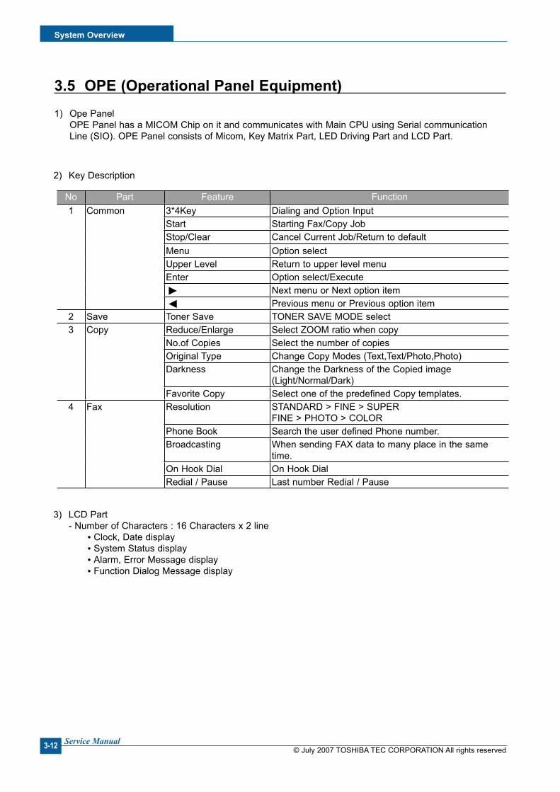
3.5 OPE (Operatonal Panel Equpment)1) Ope Panel OPE Panel has a MICOM Chip on it and communicates with Main CPU using Serial communication
Line (SIO). OPE Panel consists of Micom, Key Matrix Part, LED Driving Part and LCD Part.
2) Key Description
No Part Feature Function1 Common 3*4Key Dialing and Option Input
Start Starting Fax/Copy JobStop/Clear Cancel Current Job/Return to defaultMenu Option selectUpper Level Return to upper level menuEnter Option select/Execute Next menu or Next option item Previous menu or Previous option item
2 Save Toner Save TONER SAVE MODE select3 Copy Reduce/Enlarge Select ZOOM ratio when copy
No.of Copies Select the number of copiesOriginal Type Change Copy Modes (Text,Text/Photo,Photo)Darkness Change the Darkness of the Copied image
(Light/Normal/Dark)Favorite Copy Select one of the predefined Copy templates.
4 Fax Resolution STANDARD > FINE > SUPERFINE > PHOTO > COLOR
Phone Book Search the user defined Phone number.Broadcasting When sending FAX data to many place in the same
time.On Hook Dial On Hook DialRedial / Pause Last number Redial / Pause
3) LCD Part - Number of Characters : 16 Characters x 2 line Clock, Date display System Status display Alarm, Error Message display Function Dialog Message display

System Overvew
© July 2007 TOSHIBA TEC CORPORATION All rights reservedService Manual 3-13
3.6 SMPS & HVPS
It is the power source of entire system. It is assembled by an independent module, so it is possible to use for common use. It is mounted at back of the machine. Power part is divided by two independent PBAs - SMPS PBA and HVPS PBA. SMPS PBA supplies the DC power for driving the system and supplies the AC power to the fuser.SMPS has two output channels : +5V and +24V. HVPS PBA supplies High voltage to the developer part to make a printing image on the paper. High voltages applied to the MHV, THV, DEV, SUPPLY.
3.6.1 SMPS
1) AC Input - Input Rated Voltage : AC 220V ~ 240V / AC 110V ~ 127V - Input Voltage fluctuating range: AC 180V ~ 270V / AC 100V ~ 135V - Rated Frequency : 50/60 Hz - Frequency fluctuating range : 47 ~ 63 Hz - Input Current : Under 4.0Arms / 2.5Arms (But, the status when lamp is off or rated voltage is inputted/outputted )
2) Rated Output Power
No Item CH1 CH2 Remarks1 CHANNEL +5V +24.0V2 CONNECTOR PIN CON 2
5V PIN : #5pinGND PIN: #6pin
CON 224V PIN: #2, #3, #4GND PIN: #7pin
Jam cover switchincluded
3 Rated Output +5V ± 5% (4.75 ~ 5.25V) +24V -10%/+15% (21.6V ~ 27.6V)4 Max. Output current 0.8 A 2.5 A5 Peak Loading current 1.0 A 2.7 A within 1ms
Duration6 RIPPLE NOISE Voltage 100mVp-p or less 500mVp-p or less7 Maximum output 2.5W 36W8 Peak output 4W 55.2W 1ms9 Protection for loading
shortage andoverflowing current
Fuse Protection or Shutdownwithin 1.5A ~ 3.0A range.
Fuse Protection or Shutdownwithin 3.5A ~ 4.5A range.
No Item CH1 (+5V) CH2 (24V) System1 Stand-By 0.6 A 1.3 A AVG : 65Wh2 Printing 0.8 A 1.9 A AVG : 350Wh3 Sleep-Mode 0.5 A 0.3 A AVG : 10Wh
3) Consumption Power
© July 2007 TOSHIBA TEC CORPORATION All rights reservedService Manual
System Overvew
3-14
4) Power Cord Length : 1830 ±50mm5) Power Cord Switch : Exist6) Feature - Withstand Resistance : 100 MΩ or more (at DC 500V) - Insulating revisiting pressure : Must be no problem within 1 min. (at 1000Vac, 10mA) - Leaking Current : under 3.5mA - Running Current : under 40A PEAK (at 25 °C, COLDSTART) under 50A PEAK (In other conditions) - Rising Time : within 2Sec - Falling Time : over 20ms - Surge : Ring Wave 6KV-500A (Normal, Common)
7) Environment Condition - Operating temperature range : 0 °C ~ 40 °C - Maintaining temperature range : -20 °C ~ 40 °C - Preserving Humidity Condition : 10% ~ 90% RH - Operating atmospheric pressure range : 1atm
8) EMI Requirement : CISPR, FCC, CE, MIC,9) Safety Requirement : IEC950 UL1950, CSA950, C-UL, Semko, EK, CB, CCC (CCIB), GOST, EPA,
3.6.2 HVPS Board
The HVPS board creates the high voltage of THV/MHV/Supply/Dev and supplies them to the developer part for making best quality printing image. The HVPS part takes the 24V and outputs the high voltage such as THV/MHV/Supply/Dev, and the outputted high voltage is supplied to the toner, OPC cartridge, and transfer roller.
(a) Transfer High Voltage (THV+) - Input Voltage : 24 V DC +15% / -10% (21.6V~27.6V) - Out Voltage : +1300KV ±1.5% (200MΩ Load ) - Out Voltage Trigger : 6.5 μA - Input Voltage Variation : ±5 % Load Variation : ±5 % - Out Voltage Rising Time : 100 ms Max - Out Voltage Falling Time : 100 ms Max - Transfer Variation Voltage on Environment Variation : +500 V ~ +5000V - Control Method on environment : THV-PWM ACTIVE, transfer Active signal, of environment sens-
ing voltage is input and get feed back current, and recalculate it to resistance . - Control method on transfer output voltage : It is controlled by changing its duty of THVPWM Signal
as follows. 10% Duty : +500V, 90% Duty : +5000V
(b) Charge Voltage (MHV) - Input Voltage : 24 V DC +15% / -10% (21.6V~27.6V) - Out Voltage : -1300KV ±50V (50MΩ Load) - Out Voltage Rising Time : 50 ms Max - Out Voltage Falling Time : 50ms Max - Out Voltage Range : 30 MΩ~ 1000MΩ - Output Control Signal (MHV-PWM) : Active Low PWM signal for controlling MHV

System Overvew
© July 2007 TOSHIBA TEC CORPORATION All rights reservedService Manual 3-15
(c) Developing Voltage (DEV) - Input Voltage : 24V DC +15% / -10% (21.6V~27.6V) - Output Voltage: -350V ±20V (50MΩ Load) - Output Voltage Fluctuation range: PWM Control - Input contrast of the output stability degree : ±5 %or less - Loading contrast : ±5 %or less - Output Voltage Rising Time : 50 ms Max - Output Voltage Falling Time : 50 ms Max - Output Loading range : 10MΩ~1000MΩ - Output Control Signal (BIAS-PWM) : Active Low PWM signal for controlling MHV
(d) Supply - Output Voltage : -550V ±50V (50MΩ Load) - Input contrast of the output stability degree : under ±5 % - Loading contrast : ±5 %or less - Output Voltage Rising Time : 50 ms Max - Output Voltage Falling Time : 50 ms Max - Output Loading range : 10MΩ ~ 1000MΩ - Output Control Signal (BIAS-PWM) : Active Low PWM signal for controlling MHV
3.7 FUSER AC POWER CONTROL
The Fuser (HEAT LAMP) gets heat from AC power. The AC power controls the switch with the Triac, a semiconductor switch. The 'ON/OFF control' is operated when the gate of the Triac is turned on/off by Phototriac (insulting part). In other words, the AC control part is passive circuit, so it turns the heater on/off with taking signal from engine control part.When the 'HEATERON' signal is turned on at engine, the LED of PC102 (Photo Triac) takes the voltage and flashes. From the flashing light, the Triac part (light receiving part) takes the voltage, and the voltage is supplied to the gate of Triac and flows into the Triac. As a result, the AC current flows in the heat lamp, and heat is occurred.On the other hand, when the signal is off, the PC102 is off, the voltage is cut off at the gate of Triac, the Triac becomes off, and then the heat lamp is turned off.
1) Triac feature : 12A, 600V SWITCHING2) Phototriac Coupler (PC102) - Turn On If Current : 15mA~50mA (Design : 16mA) - High Repetitive Peak Off State Voltage : Min 600V

© July 2007 TOSHIBA TEC CORPORATION All rights reservedService Manual
System Overvew
3-16

Algnment and Adjustments
© July 2007 TOSHIBA TEC CORPORATION All rights reservedService Manual 4-1
44. Algnment and Adjustments
4.1 User ModeThe table below shows the map of User settings available in User Mode. These are fully described in theUser's Manual and are not included here.
1st level 2nd level 3rd level Default Value RETURN -- RETURNleft/right & Enter -- 14 character left/right & Enter
1. Paper Settng Paper Type
1 Paper Type Plain Paper, Thick, Thin, Bond, Colored, Card stock, Labels, Transparency, Envelope, Preprinted
Plain Paper
2 Paper Size A4, Legal, Executive, FolioA5, B5, A6, Letter
By Country
2. Machne Setup Machine ID
1 Machine ID Fax:ID:
2 Date & Time 00-00-000000:00 (AM)
3 Clock Mode 12, 24 Hours 12 hours4 Language English/FRANCAIS/
Espanol/Deutsch/Italiano/Polski/Русский, Chinese - 8 language
English
5 Power Save On 5, 10, 15, 30, 45 min.
5Off
6 Ignore Toner On Off
7 USB Mode Fast, Slow Fast

© July 2007 TOSHIBA TEC CORPORATION All rights reservedService Manual
Algnment and Adjustments
4-2
1st level 2nd level 3rd level Default Value RETURN -- RETURNleft/right & Enter -- 14 character left/right & Enter
3. Copy SetupDefault-Change
1 Default-Change
Darkness Light/Normal/Dark NormalOriginal Type Text, Text/Photo,
PhotoText
Reduce/Enlarge [Original (100%)] 100%[LGL→LTR (78%)][LGL→A4 (83%)][A4→A5 (71%)][A4→LTR ( 94%)][EXE→LTR (104%)][A5→A4 (141%)]25%50%150%200%400%[Custom: 25-400%]
No. of Copies [1-99] 12 Timeout 15, 30, 60,180 Sec, Off 60 sec3 Favorite copy Clone
Copy CollateAuto Fit2 side in 1 Pg2 Up4 UpPoster
4. Copy Feature Off
1 Off2 Clone3 Copy Collate4 Auto Fit5 ID Card Copy6 2 Up This will set to 2Up7 4 Up This will set to 4Up8 Poster

Algnment and Adjustments
© July 2007 TOSHIBA TEC CORPORATION All rights reservedService Manual 4-3
<continue..>
1st level 2nd level 3rd level Default Value RETURN -- RETURNleft/right & Enter -- 14 character left/right & Enter
5. Fax Setup Default-Change
1 Default-Change Resolution Standard/Fine/Super Fine/Photo/Color
Standard
2 Ring to Answer 1~7 23 Darkness Light/Normal/Dark Normal4 Redial Term 1~15Min 3minutes5 Redials 1~13times 7times6 MSG Confirm On, Off, On-Error On-Error7 Image TCR On, Off8 Auto Report On, Off On9 Auto Reduction On, Off On
10 Discard Size 0~30mm 20mm11 Receive Code 0~9 912 DRPD Mode set13 Receive Mode Fax, Tel, Ans/Fax,
DRPD6. Fax Feature
DelayFax 1 DelayFax Fax:2 Priority Fax Fax:3 Add Page Yes, No4 Cancel Job Yes, No
7. Advanced Fax Send Forward
1 Send Forward On, Off Off2 RCV Forward On Start Time/ End Time
Print Local CopyOff
3 Junk Fax Setup On Fax:Off Off
4 Secure Receive On, Off, Print Off5 Prefix Dial FAX: xxxxx (5 digits)6 Stamp RCV Name On, Off Off7 ECM Mode On, Off On
8. Reports Phone Book
1 Phone Book 10 ea2 Sent Report3 RCV Report4 System Data5 Scheduled Jobs6 MSG Confirm7 Junk Fax List
9. Sound/Volume Speaker
1 Speaker On, Off, Comm. Comm.2 Ringer Off, Low, Med, High Med3 Key Sound On, Off Off4 Alarm Sound On, Off On

© July 2007 TOSHIBA TEC CORPORATION All rights reservedService Manual
Algnment and Adjustments
4-4
1st level 2nd level 3rd level Default Value RETURN -- RETURNleft/right & Enter -- 14 character left/right & Enter
10. Mantenance Clean Drum
1 Clean Drum On, Off Off2 Notify Toner On, Off Off3 Clear Memory Clear All Mem.
Paper SettingMachine SetupCopy SetupFax SetupFax FeatureAdvanced FaxSound/VolumeSent ReportRCV ReportPhone Book
4 Remote Test On OffOff
<continue..>
Algnment and Adjustments
© July 2007 TOSHIBA TEC CORPORATION All rights reservedService Manual 4-5
4.2 Tech Mode and Settng
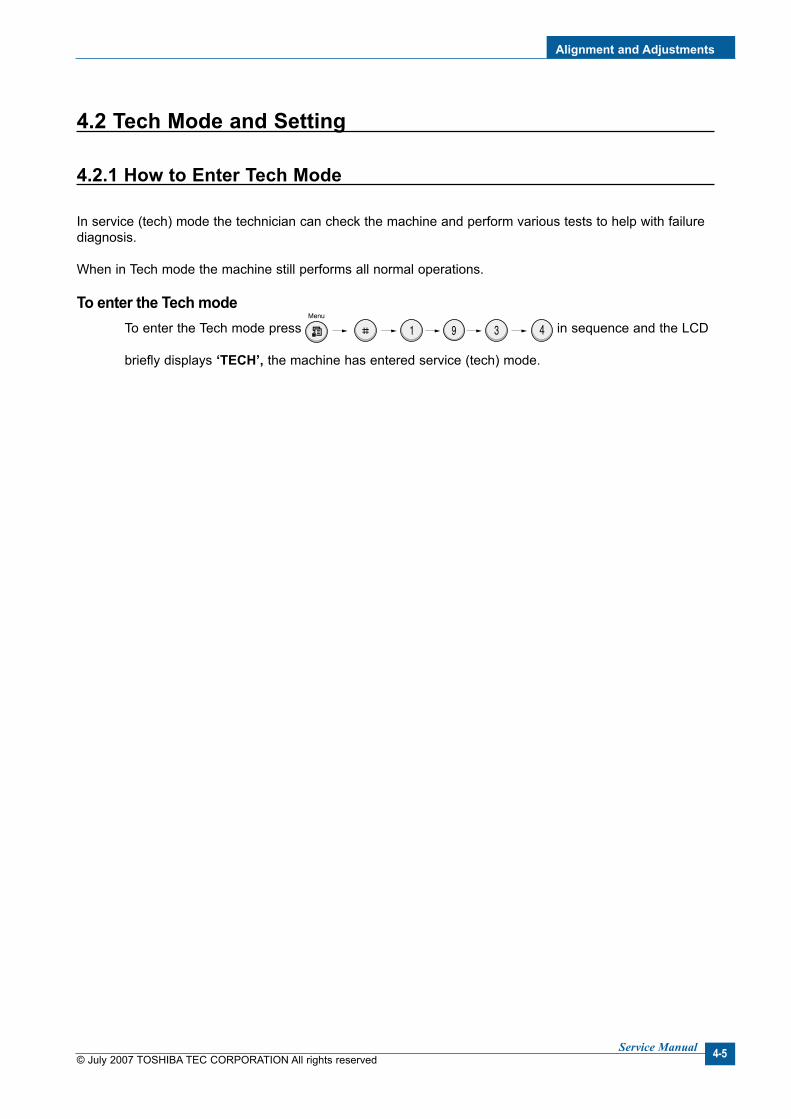
4.2.1 How to Enter Tech Mode
In service (tech) mode the technician can check the machine and perform various tests to help with failure diagnosis.
When in Tech mode the machine still performs all normal operations.
To enter the Tech mode To enter the Tech mode press
in sequence and the LCD
briefly displays ‘TECH’, the machine has entered service (tech) mode.

© July 2007 TOSHIBA TEC CORPORATION All rights reservedService Manual
Algnment and Adjustments
4-6
4.2.2 Settng-up System n Tech Mode
1st level 2nd level 3rd level Default Value RETURN -- RETURNleft/right & Enter -- 14 character left/right & Enter
Tech Mode Data Setup
1 Data Setup Send Level -9~-15 -12Modem Speed 33.6, 28.8, 14.4, 12.0,
9.6, 4.833.6
Error Rate 5%, 10% 10%Dial Mode Tone, Pulse ToneNotify Toner Customer No.
Customer NameService No.Serial No.
Clear All Mem.Clear Count Total Page Count Enter Password
CRU Print CNTFLT Scan CountADF Scan CountUsed Toner CNTEdit Toner Dot
Flash Upgrade LocalRemote
Silence Time Off/ 12 Sec/Unlimited
Off
2 Machine Test Switch TestModem TestDram TestRom TestPattern TestShading Test
3 Report ProtocolSystem Data
Key History Error InfoNew Cartridge

Algnment and Adjustments
© July 2007 TOSHIBA TEC CORPORATION All rights reservedService Manual 4-7
4.2.3 Settng
4.2.3.1 Changng the Dsplay LanguageTo change the language that displays on the control panel, follow these steps:1. Press Menu until “Machine Setup” appears on the top line of the display.2. Press the scroll button ( or ) until “Language” appears on the bottom line of the display.3. Press Enter. The current setting appears on the bottom line of the display.4. Press the scroll button ( or ) until the language you want appears on the display.5. Press Enter to save the selection.6. To return to Standby mode, press Stop/Clear.
4.2.3.2 Settng the Machne IDIn some countries, you are required by law to indicate your fax number on any fax you send. The Machine ID, containing your telephone number and name (or company name), will be printed at the top of each page sent from your machine.1. Press Menu until “Machine Setup” appears on the top line of the display. The first available menu item,
“Machine ID,” displays on the bottom line.2. Press Enter. The display asks you to enter the fax number.
If there is a number already set, the number appears.3. Enter your fax number using the number keypad.
NOTE: If you make a mistake while entering numbers, press the button to delete the last digit.
4. Press Enter when the number on the display is correct. The display asks you to enter an ID.5. Enter your name or the company name using the number keypad.
You can enter alphanumeric characters using the number keypad, and include special symbols by press-ing the 0 button. For details on how to use the number keypad to enter alphanumeric characters. If you want to enter the same letter or number in succession, enter one digit, move the cursor by press-ing the button and enter the next digit. If you want to insert a space in the name, you can also use the button to move the cursor to skip the position.
6. Press Enter when the name on the display is correct.7. To return to Standby mode, press Stop/Clear.
© July 2007 TOSHIBA TEC CORPORATION All rights reservedService Manual
Algnment and Adjustments
4-8
4.2.3.3 Settng the Date and TmeWhen you turn your machine on for the first time, the display prompts you to enter the current date and time. After entering, it will not appear anymore. All of your faxes will have the date and time printed on them.
NOTE: If power to the machine is cut off, you need to reset the correct time and date once the power has been restored.
NOTE: The date format may differ from country to country.
1. Press Menu until “Machine Setup” appears on the top line of the display.2. Press the scroll button ( or ) to display “Date & Time” on the bottom line and press Enter.3. Enter the correct time and date using the number keypad. Month = 01 ~ 12 Day = 01 ~ 31 Year = requires four digits Hour = 01 ~ 12 (12-hour mode) 00 ~ 23 (24-hour mode) Minute = 00 ~ 59
You can also use the scroll button ( or ) to move the cursor under the digit you want to correct and enter a new number.
4. To select “AM” or “PM” for 12-hour format, press the * or # button or any number button. When the cursor is not under the AM or PM indicator, pressing the * or # button immediately moves the cursor to the indicator. You can change the clock mode to 24-hour format (e.g. 01:00 PM as 13:00).
5. Press Enter when the time and date on the display is correct. When you enter a wrong number, the machine beeps and does not proceed to the next step. If this hap-pens, just reenter the correct number.
6. To return to Standby mode, press Stop/Clear.
4.2.3.4 Changng the Clock ModeYou can set your machine to display the current time using either a 12-hour or 24-hour format.1. Press Menu until “Machine Setup” appears on the top line of the display.2. Press the scroll button ( or ) until you see “Clock Mode” on the bottom line and press Enter.
The clock mode currently set for the machine displays.3. Press the scroll button ( or ) to select the other mode and then press Enter to save the selection.4. To return to Standby mode, press Stop/Clear.

Algnment and Adjustments
© July 2007 TOSHIBA TEC CORPORATION All rights reservedService Manual 4-9
4.2.3.5 Settng the Paper Sze and TypeAfter loading paper in the tray, you need to set the paper size and type using the control panel buttons. These settings will apply to copy and fax modes. For PC-printing, you need to select the paper size and type in the application program you use on your PC.1. Press Menu.
The display shows “Paper Setting” on the top line of the display.2. Press the scroll button ( or ) to display “Paper Size” on the bottom line and press Enter to access
the menu item.3. Use the scroll button ( or ) to find the paper size you are using and press Enter to save it.4. Press the button to scroll to “Paper Type” and press Enter to access the menu item.5. Use the scroll button ( or ) to find the paper type you are using and press Enter to save it.6. To return to Standby mode, press Stop/Clear.
4.2.3.6 Settng SoundsYou can control the following sounds:• Speaker: You can turn on or off the sounds from the telephone line through the speaker, such as the dial
tone or a fax tone. With this option set to “Comm.” the speaker is on until the remote machine answers.
• Ringer: You can adjust the ringer volume.• Key Sound: With this option set to “On” a key tone sounds each time a key is pressed.• Alarm Sound: You can turn the alarm sound on or off. With this option set to “On” an alarm tone sounds
when an error occurs or fax communication ends.• You can adjust the volume level using the On Hook Dial button.
4.2.3.7 Speaker, Rnger, Key Sound, and Alarm Sound1. Press Menu until “Sound/Volume” appears on the top line of the display.2. Press the scroll button ( or ) to scroll through the options. Press Enter when you see the desired
sound option.3. Press the scroll button ( or ) to display the desired status or volume for the option you have select-
ed. You will see the selection on the bottom line of the display. For the ringer volume, you can select “Off,” “Low,” “Med,” and “High”. Setting “Off” means that the ringer does not sound. The machine works normally even if the ringer is turned off.
4. Press Enter to save the selection. The next sound option appears.5. If necessary, repeat steps 2 through 4.6. To return to Standby mode, press Stop/Clear.
© July 2007 TOSHIBA TEC CORPORATION All rights reservedService Manual
Algnment and Adjustments
4-10
4.2.3.8 Speaker Volume1. Press On Hook Dial. A dial tone sounds from the speaker.2. Press the scroll button ( or ) until you hear the volume you want. The display shows the current vol-
ume level.3. Press On Hook Dial to save the change and return to Standby mode.
NOTE: You can adjust the speaker volume only when the telephone line is connected.
4.2.3.9 Toner Save ModeToner Save mode allows your machine to use less toner on each page. Activating this mode extends the life of the toner cartridge beyond what one would experience in the normal mode, but it reduces print quality.To turn the toner save mode on or off, press Toner Save.• If the button backlight is on, the mode is active and the machine uses less toner when printing a docu-
ment.• If the button backlight is off, the mode is deactivated and the machine prints with the normal quantity of
toner.
4.2.3.10 Power Save ModePower Save mode allows your machine to reduce power consumption when it is not in actual use. You can turn this mode on and select a length of time for which the machine waits after a job is printed before it switches to a reduced power state.1. Press Menu until “Machine Setup” appears on top line of the display.2. Press the scroll button ( or ) until “Power Save” appears on the bottom line. Press Enter.3. Press the scroll button ( or ) to display “On” on the bottom line and press Enter.
Selecting “Off” means that the power save mode is deactivated.4. Press the scroll button ( or ) until the time setting you want appears.
The available options are 5, 10, 15, 30, and 45 (minutes).5. Press Enter to save the selection.6. To return to Standby mode, press Stop/Clear.
Algnment and Adjustments
© July 2007 TOSHIBA TEC CORPORATION All rights reservedService Manual 4-11
4.2.4 FLASH UPGRADE
There are 2 methods to update the Flash Rom, Local and Remote.
(1) Local Machne
• DOS Command mode for USB PortConnect the PC to the set using a USB Cable and enter the DOS Command to upgrade the firmware.
< Method >1. First of all you need the following files : down_com.bin, usblist2.exe, and Rom(Firmware) File: (file name
for upgrade). Ensure you save ALL of these files in the same folder.2. At the DOS prompt enter the correct command (as shown below) and push the enter key. Then the upgrade will automatically take place.3. First, download "down_com.bin" file when the product is in the idle condition. usblst2 "down_com.bn" then you can see the message "Program Upgrade Please Wait…" on the set LCD display. Second, download "rom file" usblst2 "rom fle" After 3~4 minutes, Set will reboot automatically. (If there is no reboot after 10 minutes, please turn off/on. And try again step 3)4. Do not turn off the power during the upgrade process.5. After Firmware Upgrade, check Firmware version on the System Data List Report.
• DOS Command mode for Parallel PortConnect the PC to the set using a Parallel Cable and enter the DOS Command to upgrade the firmware.
< Method >1. First of all you need the following files : down.bat, down_com.bin, fprt.exe, and Rom File: (file name for
upgrade). Ensure you save all of these files in the same folder.2. At the DOS prompt enter the correct command (as shown below) and push the enter key.
Then the upgrade will automatically take place.3. There are two commands use the correct one depending on the condition of the set. * When the product is in the idle condition
down "rom fle" * When the product is in Ready condition
(TECH MODE --> DATA SETUP --> FLASH UPGRADE --> LOCAL) copy/b "rom fle" lpt1
4. Do not turn off the power during the upgrade process.
(2) Remote FAX
It is possible to use a set that already has the latest firmware to upgrade a remote set remotely using the telephone system.
< Method >1. On the set that has the latest firmware set it to transmit the upgrade:-
(TECH MODE --> DATA SETUP --> FLASH UPGRADE --> REMOTE)2. Enter the telephone number of the set that needs to be upgraded.
(Several faxes can be upgrade at the same time. In this case, enter each fax number.)3. When the enter button is pressed the set sends the firmware file by calling designated fax number.
(Around 10~15 minutes are needed to send the file.)
< Caution >1. The Sending and Receiving fax machines must be the same model.2. The sending fax must be set up in ECM mode and the Receiving fax memory must be 100%.
If not the function will not work.

© July 2007 TOSHIBA TEC CORPORATION All rights reservedService Manual
Algnment and Adjustments
4-12
4.2.5 Machne Test
SWITCH TEST Use this feature to test all keys on the operation control panel. The result is displayed on the LCD win-
dow each time you press a key.
MODEM TEST Use this feature to hear various transmission signals to the telephone line from the modem and to
check the modem, amplifier and speaker. If no transmission signal sound is heard, it means the modem part of the main board, amplifier, speaker or speaker harness is faulty.
DRAM TEST Use this feature to test the machine's DRAM. The result appears in the LCD display. If all memory is working normally, the LCD shows << O K >>
ROM TEST Use this feature to test the machine's ROM. The result and the software version appear in the LCD
display. • FLASH VER : 1.00 V • ENGINE VER :1.00V
PATTERN TEST Using this pattern printout you can check that the printer mechanism is functioning properly. This function is for factory manufacturing use only.
SHADING TEST The function is used to set the optimum scan quality determined by the specific characteristics of
the CIS (Contact Image Sensor). If copy image quality is poor perform this function to check the condition of the CIS unit.
< Method > 1. Select the [Shading Test] in TECH MODE
(Menu, #, 1934). 2. Push the ENTER button and an image will be
scanned. 3. After scanning the CIS SHADING PROFILE will
be print out. 4. If the printed image is different to the sample
image shown the CIS is defective.
NOTICE : WhenyoutesttheCIS,makesurethatthecoverisclosed.
MAX=229 Min=168 Avg=193 Diff=15 PRNU=6
MAX=234 Min=174 Avg=200 Diff=14 PRNU=7
MAX=241 Min=179 Avg=204 Diff=14 PRNU=4
MAX=240 Min=176 Avg=202 Diff=15 PRNU=6

Algnment and Adjustments
© July 2007 TOSHIBA TEC CORPORATION All rights reservedService Manual 4-13
4.2.6 Report
PROTOCOL LIST This list shows the sequence of the CCITT group 3 T.30 protocol during the most recent sending or
receiving operation. Use this list to check for send and receive errors.
SYSTEM DATA This list provides a list of the user system data settings and tech mode settings.
KEY HISTORY This list shows the input key history.
ERROR INFO This list display the detail machine error list.

© July 2007 TOSHIBA TEC CORPORATION All rights reservedService Manual
Algnment and Adjustments
4-14
4.3 Control Panel
4.3.1 Control Panel Functons
Sends you back to the upper menu label.
Enters Menu mode and scrolls through the menus available.
Confirms the selection on the display.
Uses to scroll through the available options for the selected menu item.
Displays the current status and prompts during an operation.
Allows you to use one of the special copy features, such as Clone, Collation, Auto Fit, ID Card Copy, 2/4 Up (multiple pages on a sheet), and Poster copying after assigning it.
Makes a copy smaller or larger than the original.
Selects the number of copies.
Selects the document type for the current copy job.
Adjusts the brightness of the documents for the current copy job.
Starts a jobs.
Dials a number or enters alphanumeric characters.
Stops an operation at any time.In Standby mode, clears/cancels the copy options, such as the darkness, the document type setting, the copy size, and the number of copies.
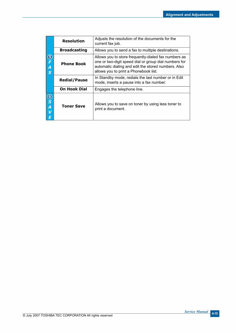
Algnment and Adjustments
© July 2007 TOSHIBA TEC CORPORATION All rights reservedService Manual 4-15
Adjusts the resolution of the documents for the current fax job.
Engages the telephone line.
Allows you to save on toner by using less toner to print a document.
In Standby mode, redials the last number or in Edit mode, inserts a pause into a fax number.
Allows you to send a fax to multiple destinations.
Allows you to store frequently-dialed fax numbers as one or two-digit speed dial or group dial numbers for automatic dialing and edit the stored numbers. Also allows you to print a Phonebook list.

© July 2007 TOSHIBA TEC CORPORATION All rights reservedService Manual
Algnment and Adjustments
4-16
4.4 LCD Status Error Massages
STATUS LCD Dsplay Descrptons
Document Jam Document Jam When Document Jam occurred at ADF module. This is displayed on LCD, print in the Transmission Journal.
Door Open or Jam Cover Open
[Front or Rear] [Cover Open]
When machine’ front side cover or Jam Cover was opened, it displayed on the LCD.
NO paper [ No Paper ] Add Paper
When there is no paper in CASSETTE Tray, machine displays this message on LCD.
PAPER JAM 0 [Paper Jam 0] Open/Close Door
When the machine encountered paper jam in pick up area, Machine displays on the LCD until DOOR OPEN & CLOSE.
PAPER JAM 1 [Paper Jam 1] Open/Close Door
When the machine encountered paper jam in the fuser area and around the toner cartridge, machine displays on the LCD until DOOR OPEN & CLOSE.
PAPER JAM 2 [Paper Jam 2] Check Inside
When the machine encountered paper jam in paper exit of Machine, machine displays on the LCD until DOOR OPEN & CLOSE.
Communication Error [COMM. Error] When the machine has problem in communication, It displayed on the LCD. Machine displays this in case of Transmission. Machine displays this in case of fax handshaking step of Reception.
Line Error [Line Error] When the machine has problem in case of Fax Data reception step.
NO ANSWER [No Answer] When the machine could not connect to remote fax after Completion of redial up to redial counter in sys-tem data.
INCOMPATIBLE [Incompatible] Remote party did not have the requested feature, such as polling.
LINE BUSY Line Busy The remote fax didn’t answer.
POWER FAILURE Power Failure When the machine’s user memory has not been back-up and there was power off / on.
STOP PRESSED [Stop Pressed] When the operator pressed the STOP button during transmission.
MEMORY FULL Memory Full When the machine has encountered the user memory was full.
FUSER ERROR CRU Fuse Error When the machine failed in installing the new toner car-tridge.
LSU ERROR [Hsync Error] Tech Mode
LSU ERROR [LSU Error] User Mode When the machine has encountered the Laser Beam Scanning unit could not reach the READY state.
TONER LOW [Toner Low] When the machine has encountered the Toner Low.
TONER EMPTY [Toner Empty] When the machine has encountered the Toner Empty.

Algnment and Adjustments
© July 2007 TOSHIBA TEC CORPORATION All rights reservedService Manual 4-17
<continue..>
STATUS LCD Dsplay Descrptons
GROUP is not available Group Not Available You have tried to select a group location where only a single location number can be used.
RETRY REDIAL? Retry Redial ? The machine is waiting for the programmed interval to auto-matically redial a previously busy station.
NO. NOT ASSIGNED NO. Not Assigned The speed dial location you tried to use has no number assigned to it.
Load document Load Document You have attempted to set up a sending operation with no document loaded into the ADF.
Memory full and cancel the job
Cancel ?1: Yes 2: No
When the machine has encountered the memory full during storing the document into memory, the machine display the "CANCEL ?" to operator whether he/she make a decision the canceling the job or accept the scanned page so far to transmit the remained documents.
Job has not been created Operation Not Assigned When operator is doing in ADD/CANCEL operation and there is no job to handle if operator entered the job no.
Low Heat Error [Low Heat Error] Temperature could not reach certain level.
Open Fuser Error Open Fuser Error The thermister has been disconnected.
Over Heat Error [Over Heat] Temperature has gone up very high degree.
No Cartridge [Jam 1] [No Cartridge]
When the machine detected the toner cartridge has not been installed, or detected jam1 in warmup state.
Memory Dial Full Memory Dial Full During Auto dial transmission when all 15 jobs are configured and try to add 16th job.

© July 2007 TOSHIBA TEC CORPORATION All rights reservedService Manual
Algnment and Adjustments
4-18
4.5 Engne Test Mode
The Engine Test Mode supplies useful functions to check the condition of the print engine. It tests the con-dition of each device and displays the result of the test on the LCD. It is divided into 5 functions (0~4), and these are shown below.
4.5.1 To enter the Engne Test Mode
To enter the Engne Test mode
Press in sequence, and the LCD briefly displays
‘Engine Test’, the machine has entered Engine Test Mode. Press “0”, “1”, “2”, “3” or “4” to select the Test No. (see list below – left hand column)
4.5.2 Dagnostc
NO. Sub No. Engine test Remark0 1 Motor Test 1 : On, 2 : Off – next test selected
2 Pick Up Test 1 : On, 2 : Off – next test selected3 Fan Test 1 : On, 2 : Off – next test selected4 Manual Clt Test 1 : On, 2 : Off – next test selected5 PTL Test 1 : On, 2 : Off – next test selected
1 1 LSU Motor Test 1 : On, 2 : Off – next test selected2 LSU Hsync Test 1 : On, 2 : Off – next test selected3 LD Test 1 : On, 2 : Off – next test selected
2 1 Feed Sensor Test 1. Check : read the sensor2. Next : Next Sensor test
2 Exit Sensor Test 1. Check : read the sensor2. Next : Next Sensor test
3 Cover Sensor Test 1. Check : read the sensor2. Next : Next Sensor test
4 Empty Sensor Test 1. Check : read the sensor2. Next : Next Sensor test
5 Manual Sensor Text 1. Check : read the sensor2. Next : Next Sensor test
3 1 Therm ADC 180 1 : On, 2 : Off (maintain the fusing temp. 80˚C)2 Therm ADC 140 1 : On, 2 : Off (maintain the fusing temp. 135˚C)3 Therm ADC 120 1 : On, 2 : Off (maintain the fusing temp. 160˚C)4 Therm ADC 100 1 : On, 2 : Off (maintain the fusing temp. 191˚C)
4 1 MHV Test 1 : On, 2 : Off (-1550V ± 50V)2 Dev Bias Test 1 : On, 2 : Off (-430V ± 20V)3 THV EN/NEG Test 1 : On, 2 : Off (-1200V +300V/-150V)4 THV ON (1300V) 1 : On, 2 : Off (+1300V ± 20V)5 THV ADC 1300V 1 : On, 2 : Off (ADC Value : 101 ± 5)6 THV ADC 600V~3500V 1 : On, 2 : Off (Compare each ADC Value)
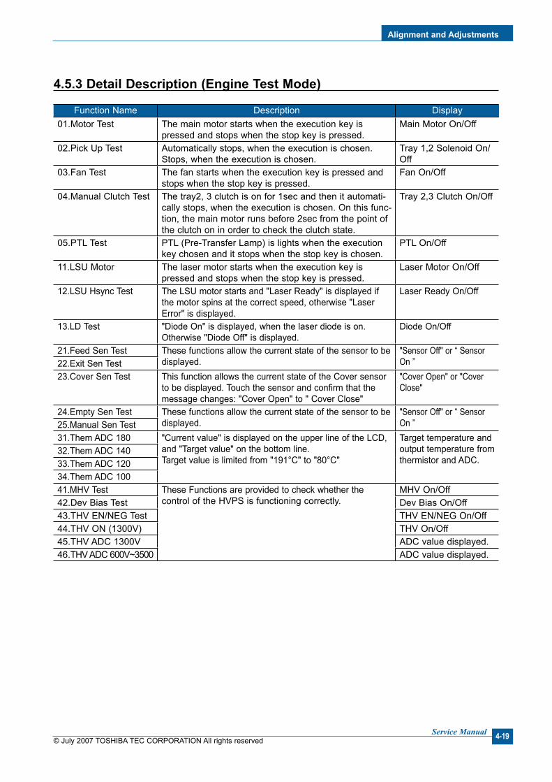
Algnment and Adjustments
© July 2007 TOSHIBA TEC CORPORATION All rights reservedService Manual 4-19
4.5.3 Detal Descrpton (Engne Test Mode)
Function Name Description Display01.Motor Test The main motor starts when the execution key is
pressed and stops when the stop key is pressed.Main Motor On/Off
02.Pick Up Test Automatically stops, when the execution is chosen.Stops, when the execution is chosen.
Tray 1,2 Solenoid On/Off
03.Fan Test The fan starts when the execution key is pressed and stops when the stop key is pressed.
Fan On/Off
04.Manual Clutch Test The tray2, 3 clutch is on for 1sec and then it automati-cally stops, when the execution is chosen. On this func-tion, the main motor runs before 2sec from the point of the clutch on in order to check the clutch state.
Tray 2,3 Clutch On/Off
05.PTL Test PTL (Pre-Transfer Lamp) is lights when the execution key chosen and it stops when the stop key is chosen.
PTL On/Off
11.LSU Motor The laser motor starts when the execution key is pressed and stops when the stop key is pressed.
Laser Motor On/Off
12.LSU Hsync Test The LSU motor starts and "Laser Ready" is displayed if the motor spins at the correct speed, otherwise "Laser Error" is displayed.
Laser Ready On/Off
13.LD Test "Diode On" is displayed, when the laser diode is on.Otherwise "Diode Off" is displayed.
Diode On/Off
21.Feed Sen Test These functions allow the current state of the sensor to be displayed.
"Sensor Off" or “ Sensor On ”22.Exit Sen Test
23.Cover Sen Test This function allows the current state of the Cover sensor to be displayed. Touch the sensor and confirm that the message changes: "Cover Open" to " Cover Close"
"Cover Open" or "Cover Close"
24.Empty Sen Test These functions allow the current state of the sensor to bedisplayed.
"Sensor Off" or “ Sensor On ”25.Manual Sen Test
31.Them ADC 180 "Current value" is displayed on the upper line of the LCD,and "Target value" on the bottom line.Target value is limited from "191°C" to "80°C"
Target temperature and output temperature fromthermistor and ADC.
32.Them ADC 14033.Them ADC 12034.Them ADC 10041.MHV Test These Functions are provided to check whether the
control of the HVPS is functioning correctly.MHV On/Off
42.Dev Bias Test Dev Bias On/Off43.THV EN/NEG Test THV EN/NEG On/Off44.THV ON (1300V) THV On/Off45.THV ADC 1300V ADC value displayed.46.THV ADC 600V~3500 ADC value displayed.

© July 2007 TOSHIBA TEC CORPORATION All rights reservedService Manual
Algnment and Adjustments
4-20
4.6 Paper Path and Clearng Paper Jams
4.6.1 Copy & Scan Document Path

Algnment and Adjustments
© July 2007 TOSHIBA TEC CORPORATION All rights reservedService Manual 4-21
4.6.2 Prnter Paper Path
1) After receiving a print command, the printer feeds paper from the main cassette or manual feeder as required.
2) The paper being fed passes the paper feed sensor. (Jam 0 occurs if the sensor is not operated within a certain time)
3) Having passed the paper feed sensor the paper moves to the paper exit sensor via printing process. (Jam 1 occurs if the sensor is not operated within a certain time)
4) The paper then passes through the paper exit sensor and out of the set. (Jam 2 occurs if the trailing edge of the paper does not pass the exit sensor within a certain time of the paper leading edge activat-ing the exit sensor)

© July 2007 TOSHIBA TEC CORPORATION All rights reservedService Manual
Algnment and Adjustments
4-22
4.6.3 Clearng Paper Jams
When a paper jam occurs, “Paper Jam” appears on the display.Refer to the table below to locate and clear the paper jam.
1. Remove the jammed paper in the tray by gen-tly pulling it straight out.
2. Open and close the front door to resume print-ing.
To avoid tearing the paper, pull out the jammed paper gently and slowly. Follow the instructions in the fol-lowingsections to clear the jam.
4.6.3.1 In the Tray
Message Location of Jam[Paper Jam 0] Open/Close Door
In the tray
[Paper Jam 1] Open/Close
In the fuser area or around the toner Door cartridge.
[Paper Jam 2] Check Inside
In the paper exit area

Algnment and Adjustments
© July 2007 TOSHIBA TEC CORPORATION All rights reservedService Manual 4-23
1. Open the front door and pull the toner car-tridge out, lightly pushing it down.
4.6.3.2 In the Fuser Area or Around the Toner Cartrdge
NOTE: The fuser area is hot. Take care when removing paper from the machine.
2. Remove the jammed paper by gently pulling it straight out.
3. Replace the toner cartridge and close the front door. Printing automatically resumes.

© July 2007 TOSHIBA TEC CORPORATION All rights reservedService Manual
Algnment and Adjustments
4-24
1. Open and close the front door. The jammed paper automatically exits the machine. If the paper does not exit, continue to step 2.
2. Gently pull the paper out of the output tray.
4.6.3.3 In the Paper Ext Area
NOTE: Inside of the machine is hot. Take care when removing paper from the machine.
3. If there is any resistance and the paper does not move when you pull, or if you cannot see the paper in the output tray, open the Jam cover by pulling the tab on it.
4. Remove the jammed paper by gently pulling it straight out.
5. Close the Jam cover.
6. Open and close the front door to resume print-ing.

Algnment and Adjustments
© July 2007 TOSHIBA TEC CORPORATION All rights reservedService Manual 4-25
1. Load the paper into the tray, as shown below.
4.6.3.4 Tps for Avodng Paper Jams When Prntng on the A5-szed PaperIf paper jams occur frequently when you print on A5-sized paper:
4.6.3.5 Tps for Avodng Paper JamsBy selecting the correct paper types, most paper jams can be avoided. When a paper jam occurs.• Follow the procedures in “Loading Paper”. Ensure that the adjustable guides are positioned correctly.• Do not overload the tray.• Do not remove paper from the tray while your machine is printing.• Flex, fan, and straighten the paper before loading.• Do not use creased, damp, or highly curled paper.• Do not mix paper types in the tray.• Use only recommended print materials. See “Paper Handling Specifications”.• Ensure that the recommended print side of print materials is facing up in the tray.
2. Open the printer’s properties window, set the paper size to A5 from the Paper tab.
3. From the Orientation option of the Layout tab, set the Rotate option to 90°.
4. Click OK to start printing. For details, see Software User’s Guide.

© July 2007 TOSHIBA TEC CORPORATION All rights reservedService Manual
Algnment and Adjustments
4-26
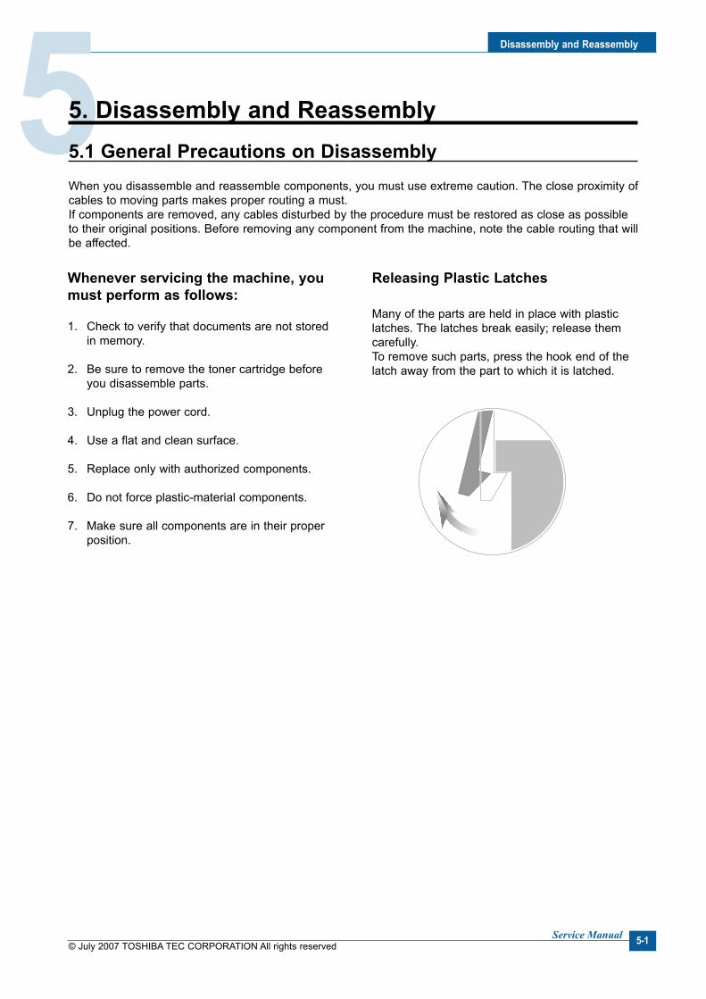
Dsassembly and Reassembly
© July 2007 TOSHIBA TEC CORPORATION All rights reservedService Manual 5-1
55. Dsassembly and Reassembly5.1 General Precautons on DsassemblyWhen you disassemble and reassemble components, you must use extreme caution. The close proximity of cables to moving parts makes proper routing a must. If components are removed, any cables disturbed by the procedure must be restored as close as possible to their original positions. Before removing any component from the machine, note the cable routing that will be affected.
Whenever servcng the machne, you must perform as follows:
1. Check to verify that documents are not stored in memory.
2. Be sure to remove the toner cartridge before you disassemble parts.
3. Unplug the power cord.
4. Use a flat and clean surface.
5. Replace only with authorized components.
6. Do not force plastic-material components.
7. Make sure all components are in their proper position.
Releasng Plastc Latches
Many of the parts are held in place with plastic latches. The latches break easily; release them carefully. To remove such parts, press the hook end of the latch away from the part to which it is latched.

© July 2007 TOSHIBA TEC CORPORATION All rights reservedService Manual
Dsassembly and Reassembly
5-2
5.2 MP Tray
1. Open the Front Cover.
Front Cover
Toner Cartridge
MP Tray
2. Release the Toner Cartridge.
3. Hold the MP Tray and pull it to the arrow direc-tion.
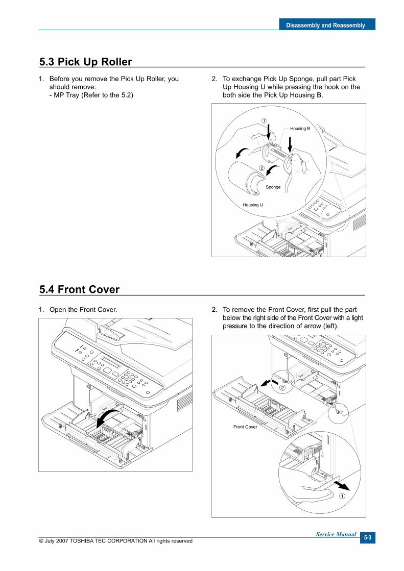
Dsassembly and Reassembly
© July 2007 TOSHIBA TEC CORPORATION All rights reservedService Manual 5-3
5.3 Pck Up Roller1. Before you remove the Pick Up Roller, you
should remove: - MP Tray (Refer to the 5.2)
2. To exchange Pick Up Sponge, pull part Pick Up Housing U while pressing the hook on the both side the Pick Up Housing B.
Housing B
2
1
Housing U
Sponge
5.4 Front Cover1. Open the Front Cover. 2. To remove the Front Cover, first pull the part
below the right side of the Front Cover with a light pressure to the direction of arrow (left).
Front Cover
2
1
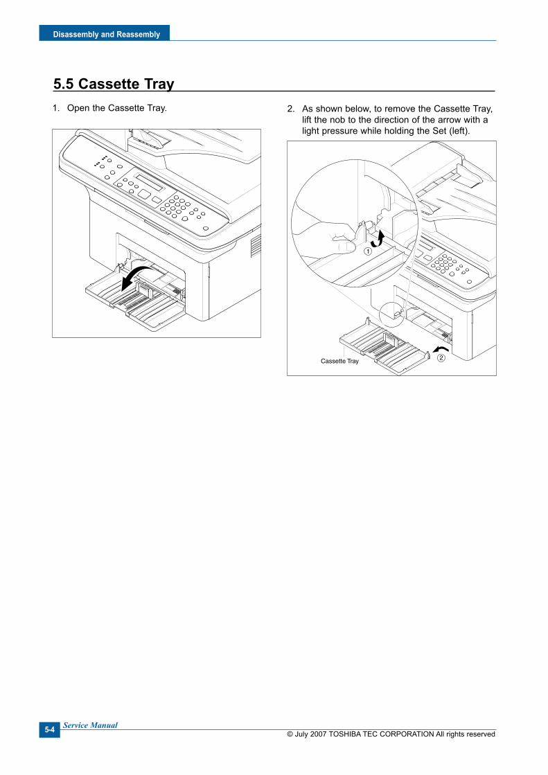
© July 2007 TOSHIBA TEC CORPORATION All rights reservedService Manual
Dsassembly and Reassembly
5-4
5.5 Cassette Tray1. Open the Cassette Tray. 2. As shown below, to remove the Cassette Tray,
lift the nob to the direction of the arrow with a light pressure while holding the Set (left).
Cassette Tray 2
1

Dsassembly and Reassembly
© July 2007 TOSHIBA TEC CORPORATION All rights reservedService Manual 5-5
5.6 Rear Cover1. Remove the four screws securing the Rear
Cover and remove it.
Jam Cover
Rear Cover
Jam Cover
Rear Cover
2. Open the Jam Cover.
3. To remove the Rear cover make sure the right Power Switch doesn't get jammed to the Rear Cover, as shown below.
4. If necessary, remove the Jam Cover in the direction of arrow, as shown below.

© July 2007 TOSHIBA TEC CORPORATION All rights reservedService Manual
Dsassembly and Reassembly
5-6
5.7 Rght Cover
1. Before you remove the Right Cover, you should remove: - Front Cover (Refer to the 5.4) - Rear Cover (Refer to the 5.6)
2. Remove the one screws securing the Right Cover.
Right Cover
Hook
Hook
3. Apply light pressure to the back of the Right Cover and pull it to the right side in the direc-tion of arrow, as shown below.
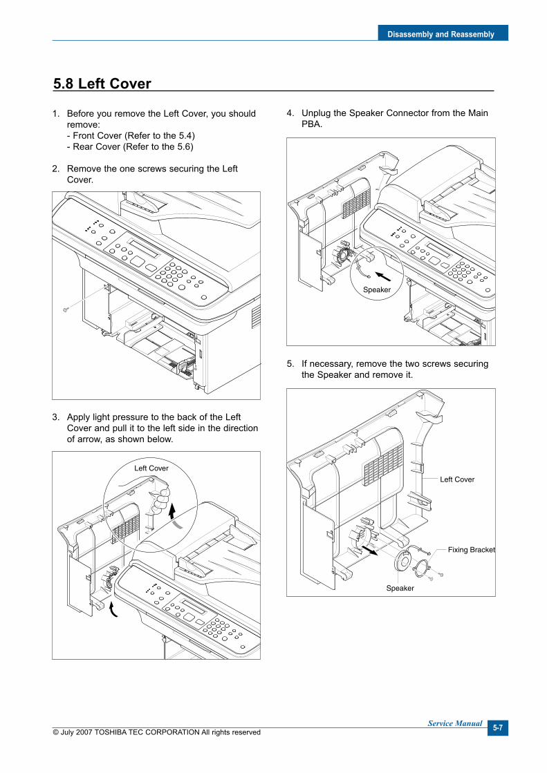
Dsassembly and Reassembly
© July 2007 TOSHIBA TEC CORPORATION All rights reservedService Manual 5-7
5.8 Left Cover
1. Before you remove the Left Cover, you should remove: - Front Cover (Refer to the 5.4) - Rear Cover (Refer to the 5.6)
2. Remove the one screws securing the Left Cover.
Left Cover
Speaker
Left Cover
Speaker
Fixing Bracket
3. Apply light pressure to the back of the Left Cover and pull it to the left side in the direction of arrow, as shown below.
4. Unplug the Speaker Connector from the Main PBA.
5. If necessary, remove the two screws securing the Speaker and remove it.

© July 2007 TOSHIBA TEC CORPORATION All rights reservedService Manual
Dsassembly and Reassembly
5-8
5.9 Scan Ass'y
1. Before you remove the Scan Ass'y, you should remove: - Rear Cover (Refer to the 5.6) - Right Cover (Refer to the 5.7) - Left Cover (Refer to the 5.8)
2. Remove the two screws from the Middle Cover and remove the screw securing the Ground Cable.
MiddleCover
MiddleCover
Ground Cable
OPE
ADFScanMotor
FlatCable
Scan Ass'y
3. Unplug the three Connectors (ADF, Scan Motor, OPE) and Flat Cable-CIS, as shown below.
4. Release the Scan Ass'y in the direction of arrow, as shown below.

Dsassembly and Reassembly
© July 2007 TOSHIBA TEC CORPORATION All rights reservedService Manual 5-9
5.10 ADF Housng
1. Before you remove the ADF Housing, you should remove: - Scan Ass'y (Refer to the 5.9)
2. Open the ADF Housing and insert a flat-blade screwdriver into the slot as shown below, and remove the Cap-Hinge from the Platen Housing and ADF Housing.
Cap-Hinge
Scan Motor Harness
ADF Housing
Platen Housing
ADF Ass’y
ADF Motor Harness
Platen Cover
TX Stacker Ass’y
3. Remove the ADF Housing from the Platen Housing. At that time, carefully release the ADF Motor Harness from the Platen Housing, as shown below.
4. Remove the two screws securing the ADF Ass'y and remove it. At that time, carefully release the ADF Motor Harness from the Platen Cover, as shown below.
5. If necessary, remove the two screws securing the TX Stacker Ass'y and remove it, as shown below.

© July 2007 TOSHIBA TEC CORPORATION All rights reservedService Manual
Dsassembly and Reassembly
5-10
Open Cover
212
Bush
1
2
Pick Up Unit
Bearing
ADF Upper
ADF Lower
ADF Motor Housing
6. Open the Open Cover and remove the Open Cover in the direction of arrow, as shown below.
7. Pull the Bush, then rotate until it reaches the slot, as shown below. Then lift the Pick Up Unit.
8. Remove the two screws securing the ADF Upper and insert a flat-blade screwdriver in to slot as shown below, and remove the ADF Upper.
9. Unplug the Connector from the ADF PBA and remove the four screws securing the ADF Motor Housing and remove it in the direction of arrow, as shown below.

Dsassembly and Reassembly
© July 2007 TOSHIBA TEC CORPORATION All rights reservedService Manual 5-11
5.11 OPE Unt
1. Open the ADF Housing and insert a flat-blade screwdriver into the crack as shown below, and remove the OPE Unit from the Platen Housing.
OPE
ADF Housing
2
1
OPE
Battery
Full Sensor
OPE PBA
OPE PBA
Rubber-Scroll
Rubber-Tel
TelScroll
Start
Stop
ResolutionCopy
FAX
Toner Save
OPE Cover
2. Unplug the three Connectors (Battery, OPE, Full Sensor), as shown below.
3. Remove the five screws securing the OPE PBA and remove it.
4. Release the Contact Rubbers, as shown below.
5. Release the Keys, as shown below.
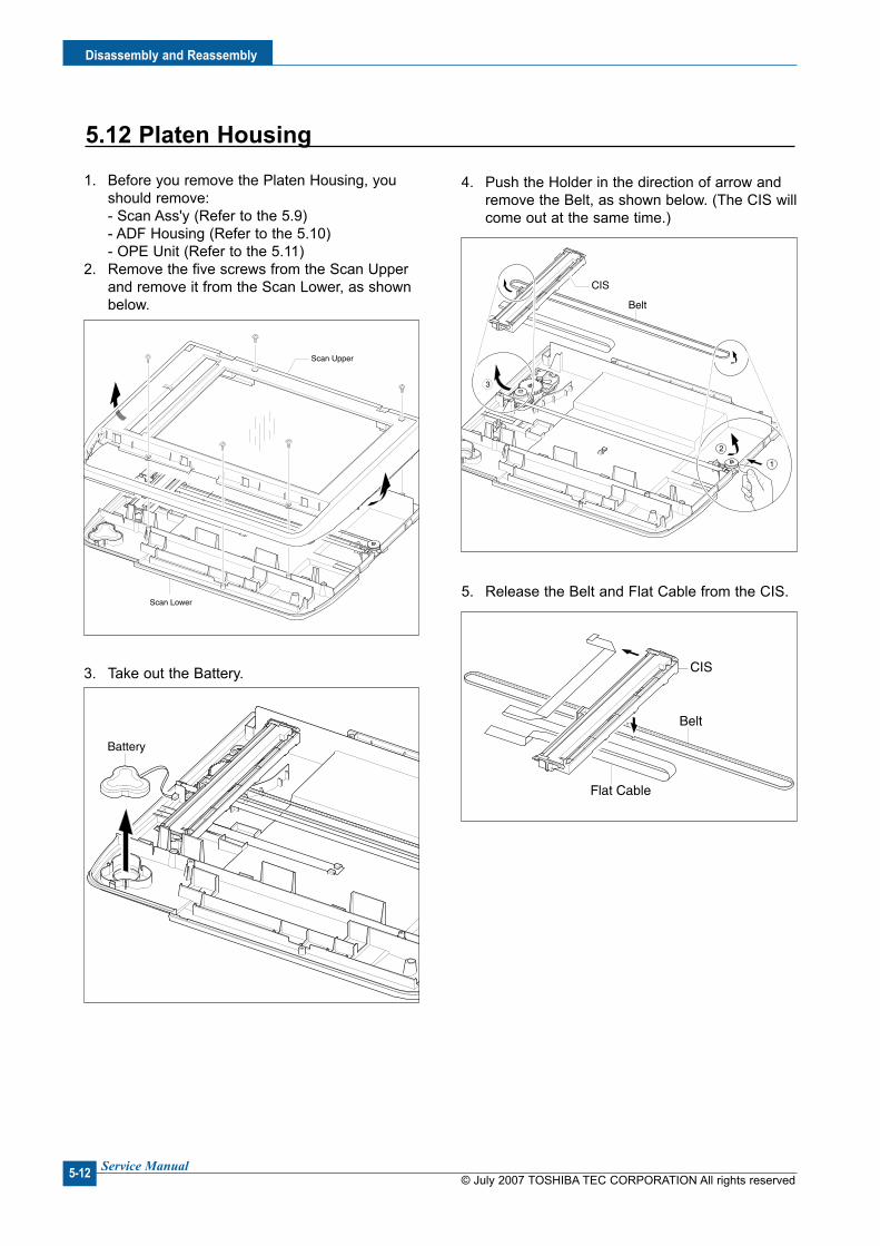
© July 2007 TOSHIBA TEC CORPORATION All rights reservedService Manual
Dsassembly and Reassembly
5-12
5.12 Platen Housng
1. Before you remove the Platen Housing, you should remove: - Scan Ass'y (Refer to the 5.9) - ADF Housing (Refer to the 5.10) - OPE Unit (Refer to the 5.11)
2. Remove the five screws from the Scan Upper and remove it from the Scan Lower, as shown below.
Scan Upper
Scan Lower
Battery
CIS
1
2
3
Belt
Belt
Flat Cable
CIS3. Take out the Battery.
4. Push the Holder in the direction of arrow and remove the Belt, as shown below. (The CIS will come out at the same time.)
5. Release the Belt and Flat Cable from the CIS.
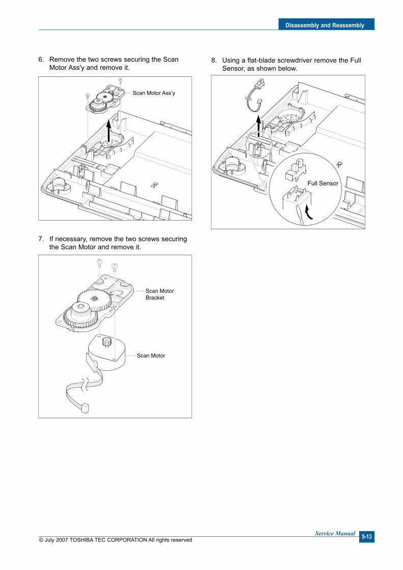
Dsassembly and Reassembly
© July 2007 TOSHIBA TEC CORPORATION All rights reservedService Manual 5-13
6. Remove the two screws securing the Scan Motor Ass'y and remove it.
Scan Motor Ass’y
Scan Motor
Scan MotorBracket
Full Sensor
7. If necessary, remove the two screws securing the Scan Motor and remove it.
8. Using a flat-blade screwdriver remove the Full Sensor, as shown below.
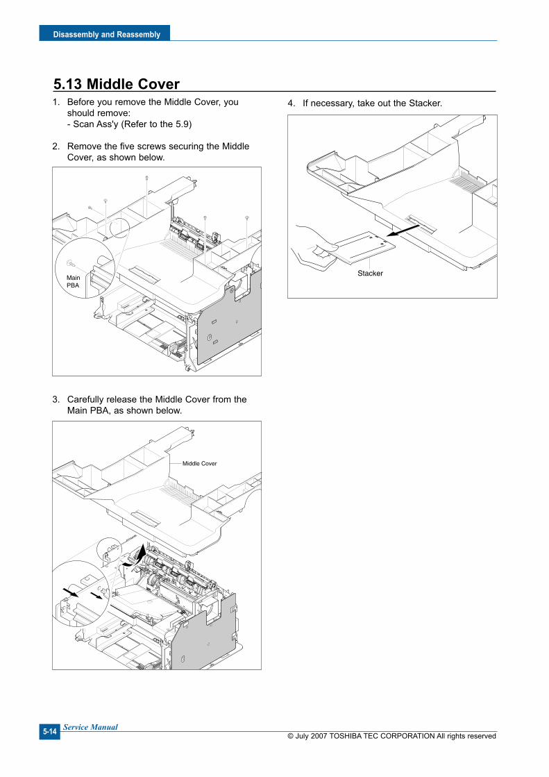
© July 2007 TOSHIBA TEC CORPORATION All rights reservedService Manual
Dsassembly and Reassembly
5-14
5.13 Mddle Cover1. Before you remove the Middle Cover, you
should remove: - Scan Ass'y (Refer to the 5.9)
2. Remove the five screws securing the Middle Cover, as shown below.
MainPBA
Middle Cover
Stacker
3. Carefully release the Middle Cover from the Main PBA, as shown below.
4. If necessary, take out the Stacker.

Dsassembly and Reassembly
© July 2007 TOSHIBA TEC CORPORATION All rights reservedService Manual 5-15
5.14 HVPS
1. Before you remove the HVPS, you should remove: - Scan Ass'y (Refer to the 5.9) - Middle Cover (Refer to the 5.13)
2. Remove the three screws securing the Sheet and remove it.
HVPS
HVPS
HVPS Ground
3. Remove the three screws securing the HVPS and remove it with the HVPS Ground, as shown below.
4. Unplug the Connector from the HVPS.

© July 2007 TOSHIBA TEC CORPORATION All rights reservedService Manual
Dsassembly and Reassembly
5-16
5.15 Man PBA
1. Before you remove the Main PBA, you should remove: - Scan Ass'y (Refer to the 5.9) - Middle Cover (Refer to the 5.13)
2. Unplug the all Connectors from the Main PBA, as shown below.
SMPS/HVPS
Main Motor
LSU
Clutch
LIUDEVE
Thermister
Main PBA
3. Remove the six screws securing the Main PBA and remove it.

Dsassembly and Reassembly
© July 2007 TOSHIBA TEC CORPORATION All rights reservedService Manual 5-17
5.16 RX Drve
1. Before you remove the RX Drive, you should remove: - Scan Ass'y (Refer to the 5.9) - Middle Cover (Refer to the 5.13) - Main PBA (Refer to the 5.15)
2. If necessary, remove the two Bracket (Port, Main PBA) and Ground, as shown below.
Port BracketGround
Main PBABracket
RX Drive
RDCN Gear
OPC DR Gear
Fuser Gear
Feed Gear
RX Motor
Motor Bracket
Gear Bracket
3. Remove the two screws securing the Engine Shield and remove the six screws securing the Frame then remove the RX Drive in the direc-tion of arrow, as shown below.
4. Remove the Connector, as shown below.
5. Release the four Gears (RDCN, OPC, Fuser, Feed) from the Frame, as shown below.
6. Remove the four screws securing the Motor Bracket and remove it. Then remove the two screws securing the Motor and remove it.

© July 2007 TOSHIBA TEC CORPORATION All rights reservedService Manual
Dsassembly and Reassembly
5-18
5.17 Fuser
1. Before you remove the Fuser, you should remove: - Scan Ass'y (Refer to the 5.9) - Middle Cover (Refer to the 5.13)
2. Unplug the two Connectors from the SMPS and Main PBA, as shown below.
Thermister
Fuser
Fuser
Lever-M-Act Exit
1
2
Cover-M-Safty
3. Remove the four screws securing the Fuser and remove it, as shown below.
4. Remove the Lever-M-Act Exit in the direction of arrow, as shown below.
5. Remove the Cover-M-Safty, as shown below.
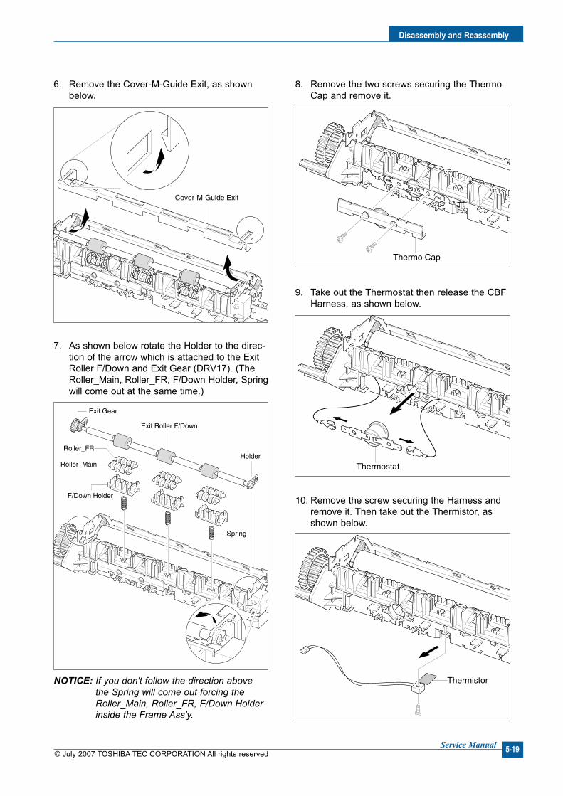
Dsassembly and Reassembly
© July 2007 TOSHIBA TEC CORPORATION All rights reservedService Manual 5-19
Cover-M-Guide Exit
Exit Roller F/Down
Holder
Exit Gear
F/Down Holder
Roller_FR
Roller_Main
Spring
Thermo Cap
Thermostat
Thermistor
6. Remove the Cover-M-Guide Exit, as shown below.
7. As shown below rotate the Holder to the direc-tion of the arrow which is attached to the Exit Roller F/Down and Exit Gear (DRV17). (The Roller_Main, Roller_FR, F/Down Holder, Spring will come out at the same time.)
NOTICE:Ifyoudon'tfollowthedirectionabovetheSpringwillcomeoutforcingtheRoller_Main,Roller_FR,F/DownHolderinsidetheFrameAss'y.
8. Remove the two screws securing the Thermo Cap and remove it.
9. Take out the Thermostat then release the CBF Harness, as shown below.
10. Remove the screw securing the Harness and remove it. Then take out the Thermistor, as shown below.
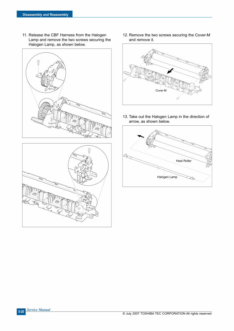
© July 2007 TOSHIBA TEC CORPORATION All rights reservedService Manual
Dsassembly and Reassembly
5-20
Cover-M
Halogen Lamp
Heat Roller
11. Release the CBF Harness from the Halogen Lamp and remove the two screws securing the Halogen Lamp, as shown below.
12. Remove the two screws securing the Cover-M and remove it.
13. Take out the Halogen Lamp in the direction of arrow, as shown below.

Dsassembly and Reassembly
© July 2007 TOSHIBA TEC CORPORATION All rights reservedService Manual 5-21
5.18 Engne Sheld (LIU PBA, SMPS)
1. Before you remove the Engine Shield, you should remove: - Scan Ass'y (Refer to the 5.9) - Middle Cover (Refer to the 5.13)
2. Unplug the all Connectors from the SMPS and LIU PBA.
Fuser
LIU Cable
SMPS Cable
Engine Shield(W/LIU PBA, SMPS)
Actuator Feed Sensor Lever
SMPS
LIU PBA
3. Remove the six screws securing the Engine Shield and release the Harness, as shown below. Then carefully release the Engine Shield from the Actuator Feed Sensor Lever.
4. When if only remove the SMPS, first remove the Rear Cover (refer to the 5.6) and unplug the Fuser Connector and remove the six screws securing the SMPS. Then unplug the Connector from the Main PBA and carefully release the SMPS, as shown below.
5. When if only remove the LIU PBA, first remove the Rear Cover (refer to the 5.6) and remove the two screws securing the LIU PBA. Then unplug the Connector from the Main PBA and release the LIU PBA as shown below.

© July 2007 TOSHIBA TEC CORPORATION All rights reservedService Manual
Dsassembly and Reassembly
5-22
5.19 LSU
1. Before you remove the LSU, you should remove: - Scan Ass'y (Refer to the 5.9) - Middle Cover (Refer to the 5.13)
2. Remove the three screws securing the LSU and remove it. Then unplug the two Connectors from the LSU.
LSU

Dsassembly and Reassembly
© July 2007 TOSHIBA TEC CORPORATION All rights reservedService Manual 5-23
5.20 Paper Path Frame
1. Before you remove the Paper Path Frame, you should remove: - Scan Ass'y (Refer to the 5.9) - Middle Cover (Refer to the 5.13) - Fuser (Refer to the 5.17) - Engine Shield (Refer to the 5.18)
2. Remove the four screws securing the Paper Path Frame and remove it in the direction of arrow, as shown below.
Solenoid-MP
Paper Path Frame
Transfer Roller
2
1
Bush(L)
Bush
3. Remove the Transfer Roller from the Frame, as shown below.
4. Remove the screw securing the Solenoid-MP and remove it, as shown below.

© July 2007 TOSHIBA TEC CORPORATION All rights reservedService Manual
Dsassembly and Reassembly
5-24

Troubleshootng
© July 2007 TOSHIBA TEC CORPORATION All rights reservedService Manual 6-1
66. Troubleshootng6.1 Checkng Symptoms
Before attempting to repair the printer first obtain a detailed description of the problem from the customer.
Power On
Indicate
Error MassageReady or
Power save
Test Print
Printing
Quality is
Normal?
Refer to Bad image
<Section 6.5>
Refer to
Error Massage
<Section 4.4>
END
- No Power
- Power Module error
- Main PBA error
- LCD Panel error
OP Panel
ON?

© July 2007 TOSHIBA TEC CORPORATION All rights reservedService Manual
Troubleshootng
6-2
6.1.1 Basc Check Lst
1. Check the Power
• Does "Warming Up" appear on the display? --> If not check power cable, switch or SMPS. --> Does the wall socket work?• Do the Motors or other components initialize (listen for main motor, fan and LSU sounds)? --> If not or there are none of the normal startup sounds check cable, switch or SMPS. --> Does the wall socket work?
2. Check the LCD Panel
• Is there any display at all? --> If not check power cable, switch or SMPS. --> Does the wall socket work?• Is the display a meaningful message care there any broken or badly formed characters? --> Check the main PBA and cable harness.• Is the message on the LCD Panel a standard error message? --> Refer to section 4.4
3. Check the Paper Path
• Is there a Paper Jam? --> Remove any paper fragments caught in the paper path.• Paper Jam occurs repeatedly at a specific point in the Paper Path. --> Open the fuser cover, Jam clear. --> Dismantle the machine and carefully inspect the region where the jam occurs.
(Especially, check if paper fragments are caught in the Fuser.)
4. Prnt the Informaton Page (Confguraton).
• Try printing a test page from a computer. --> If there is an error check cables and driver installation.
5. Check the Prnt Qualty.
• Is there are a Print Quality Problem? --> Refer to section 6.5
6. Check consumables (toner etc.).
• Using the keys print the Test Pattern. --> Expected life of various consumable parts, compare this with the figures printed and replace as
required.

Troubleshootng
© July 2007 TOSHIBA TEC CORPORATION All rights reservedService Manual 6-3
6.1.2 Intal Inspecton
1. Check Power part
1. The printer does not work no matter how long you wait. A. Is the Power Switch (printer and wall socket) turned on ? B. Is the Power Cord connected to the printer correctly ? C. Is the Power cord connected to the wall socket correctly ? D. Is wall socket working ? E. Is the unit rated at the same voltage as the supply ?2. Does the Fan work when power is turned on? A. Check the connectors on the SMPS. B. Check the fuses in the SMPS. (F1)
2. Check the Installaton Envronment.
1. Ensure the installation surface is flat, level and free from vibration. If necessary move the printer.2. Ensure that the temperature and humidity of the surroundings are within specification. If necessary move the printer.3. Ensure that the printer is position away from any air conditioning or other heating or cooling equipment.
Also ensure that is not positioned in a direct draft from any air conditioning, fan or open window. If necessary move the printer.4. Ensure the printer is not positioned in direct sunlight. If it is unavoidable use a curtain to shade the printer.5. Ensure the printer is installed in a clean dust free environment. Move the printer to clean area if necessary.6. Some industrial or cleaning processes give of fumes which can affect the printer. Move the printer away from this type of air pollution
3. Check paper type.
1. Use only paper which is of a suitable quality, weight and size? Refer to the 2.2.7.
4. Check the overall condton of the prnter
1. Is the printer properly maintained ? Clean the Paper Transport Passages. Any rollers with dirt surfaces should be cleaned or replaced.

© July 2007 TOSHIBA TEC CORPORATION All rights reservedService Manual
Troubleshootng
6-4
• Descrpton Printing begins at wrong position on the paper.
6.2.2 JAM 0
• Descrpton1. Paper is not exited from the cassette.2. Jam-0 occurs if the paper feeds into the printer.BIN PATH
BIN PATH
BIN PATH
6.2 Bad dscharge6.2.1 Wrong Prnt Poston
Check and Cause SolutonWrong sense time caused by defective feed sen-sor actuator.
Replace the defective actuator.
Check and Cause Soluton1. Check the Solenoid by using Engine Test Mode-
Pick up Test.
2. Check if the pad is loose due to bad sealing of the side-pad.
3. Check the surface of the roller-pickup for foreign matter.
4. If the paper feeds into the printer rand Jam 0 occurs, perform Engine Test Mode-Feed Sensor Test.
1. Replace the solenoid.
2. Replace the side-pad Assembly L or R, if neces-sary.
3. Clean with soft cloth dampened with IPA (Isopropyl Alcohol) or water.
4. Replace the SMPS, HVPS or Sensor.

Troubleshootng
© July 2007 TOSHIBA TEC CORPORATION All rights reservedService Manual 6-5
6.2.3 JAM 1
• Descrpton1. Recording paper is jammed in front of or inside the
fuser.2. Recording paper is stuck in the discharge roller and
in the fuser just after passing through the Actuator-Feed.
BIN PATH
BIN PATH
BIN PATH6.2.4 JAM 2
• Descrpton1. Recording paper is jammed in front of or inside the
fuser.2. Recording paper is stuck in the discharge roller and
in the fuser just after passing through the Actuator-Feed.
BIN PATH
BIN PATH
BIN PATH
Check and Cause Soluton1. If the recording paper is jammed in front of or
inside the fuser.
2. If the recording paper is stuck in the discharge roller and the fuser just after passing through the Actuator-Feed, Feed Actuator may be defective.
1. Replace the SMPS.
2. Reassemble the Actuator-Feed and Spring-Actuator if the returning is bad.
Check and Cause Soluton1. If the paper is completely fed out of the printer, but
Jam 2 occurs : Exit sensor is defective. • After the paper is completely discharged, actuator
Exit should return to the original position to shut the photo-sensor. Sometimes it takes longer hour than it should and does not return.
2. If the paper is rolled in the Fuser Roller: • This occurs when a Guide claw is broken away or
transformed. • It occurs when the Spring of a Guide claw is broken
away or transformed. • It occurs when the Heat-Roller or Pressure-Roller is
seriously contaminated with the toner.
3. Paper is accordion in the fuser.
1. Check if the exit sensor actuator is defective. • Check if the actuator exit is unformed (Check if the
lever part is unformed in shape). • Check whether burrs occur in the assembly part
of the actuator exit or not and if the actuator is smoothly operated.
• Check if foreign matters and wire get caught in the actuator exit's operation.
2. If the paper is stuck in the fuser : disassemble the fuser and remove the jammed paper, and clean the surface of the pressure roller with dry gauze.
3. Remove the jammed paper after disassembling the fuser : Clean the surface of the pressure roller with dry gauze.
• Remove the toner particles stained on the rib. • Check the assemblage and performance of the exit.

© July 2007 TOSHIBA TEC CORPORATION All rights reservedService Manual
Troubleshootng
6-6
6.2.5 Mult-Feedng
• Descrpton Multiple sheets of paper are fed at once.
6.2.6 Paper rolled n the Fuser
• Descrpton If contaminated at intervals of 57mm on the back of a paper.
Check and Cause Soluton1. Solenoid malfunction (the solenoid does not work
properly): Perform Engine Test Mode-Pick up Test.
2. Pad-Friction is contaminated with foreign matter. (oil...)
3. The face of paper is blended.
1. Replace the solenoid if necessary.
2. Clean the pad friction with soft clothe dampened with IPA (Isopropyl Alcohol).
3. Use the smooth paper.
Check and Cause Soluton1. Contamination of the pressure roller or heat roller
(Background, Hot off set).
2. Check the claw of the fuser whether it is unfitted.
1. After disassembling the fuser, clean contamina-tion between the heat roller and the thermostor and remove the contamination of the pressure roller.
2. If there is heavy background, repair it by the background troubleshooting method.
3. The surface of the heat roller with IPA or water.
4. Check the warp or separation of the sprint claw and the holder plate claw, and then manage it.

Troubleshootng
© July 2007 TOSHIBA TEC CORPORATION All rights reservedService Manual 6-7
6.2.7 Paper rolled n the Toner Cartrdge (OPC Drum)
• Descrpton Paper is rolled up in the OPC.
Check and Cause Soluton1. Paper is too much thin.
2. The face of paper is curled.
1. Recommend to use normal paper.
2. How to remove the rolled in the OPC Drum. • Remove the paper while turning the OPC Drum
against the ongoing direction.
© July 2007 TOSHIBA TEC CORPORATION All rights reservedService Manual
Troubleshootng
6-8
6.3 Set Malfuncton – Causes and Solutons
6.3.1 LCD Display Defect ( in LCD Display)
• Descrpton Strange characters are displayed in the LCD Window and OPE Panel buttons do not work.
6.3.2 Defectve OPE Keypad
• Descrpton Pressing keys does not cause the set to respond correctly
Check and Cause Soluton1. Clear the memory.
2. Check that the OPE HARNESS is connected to the Connection Board correctly.
1. Try again after clearing the memory.
2. If re-connecting the harness does not correct the fault replace the OPE Ass’y and the main Board in sequence.
Check and Cause Soluton1. Clear the memory.
2. Check that there is an audible key click when a key is pressed.
1. Check that the keypad is assembled correctly and the membrane is not damaged, replace the membrane or whole keypad assembly if necessary.
2. If the fault remains replace the OPE Ass’y and the Main board in sequence.
Troubleshootng
© July 2007 TOSHIBA TEC CORPORATION All rights reservedService Manual 6-9
6.3.3 Fuser gear melts due to overheatng causng Paper Jam.
• Descrpton Constant Jam where paper is entering Fuser unit. Fuser rollers do not turn
6.3.4 Paper Empty
• Descrpton Paper Empty is displayed in the LCD panel even when paper is loaded in the cassette.
6.3.5 Paper Empty wthout ndcaton
• Descrpton The paper empty message does not appear in the LCD when the paper cassette is empty.
Check and Cause Soluton1. Check the Heat Lamp, thermostat and thermistor. 1. Use Engine Test Mode to test the Fuser
-THERM ADC 120. Replace Fuser unit Replace SMPS or Main PBA as appropriate.
Check and Cause Soluton1. Deformed paper sensor actuator or faulty sensor.
2. SMPS PBA or Main PBA is defective.
3. Faulty cables or connectors.
1. Replace the defective actuator or sensor.
2. Replace the SMPS PBA or MAIN PBA as appropriate.
Check and Cause Soluton1. Deformed paper sensor actuator or faulty sensor.
2. SMPS PBA or Main PBA is defective.
1. Replace the defective actuator.
2. Replace the SMPS PBA or MAIN PBA as appropriate.
© July 2007 TOSHIBA TEC CORPORATION All rights reservedService Manual
Troubleshootng
6-10
6.3.7 No error message when the cover s open
• Descrpton The Cover Open message does not appears on the LCD even when the print cover is open.
6.3.6 Cover Open
• Descrpton The Cover Open message appears on the LCD even when the print cover is closed.
Check and Cause Soluton1. The ‘Open Cover’ microswitch may be stuck or
faulty.
2. The tab on the front cover may be damaged or broken.
3. Check the connector and cables between HVPS and main PBA.
1. Use TECH mode ("cover sensor test”) to check cover switch operation. Check and replace switch if neces-sary.
2. Replace the front cover.
3. Replace the Main Control board or HVPS as necessary.
Check and Cause Soluton1. The ‘Open Cover’ microswitch may be stuck or
faulty.
2. Check the connector and cables between HVPS and main PBA.
1. Use TECH mode ("cover sensor test”) to check cover switch operation. Check and replace switch if neces-sary.
2. Replace the Main Control board or HVPS S/W as necessary.

Troubleshootng
© July 2007 TOSHIBA TEC CORPORATION All rights reservedService Manual 6-11
6.3.10 Prnted Vertcal Lnes become curved
• Descrpton When printing, vertical lines are not straight.
6.3.8 Defectve motor operaton
• Descrpton Main motor is faulty and paper does not feed into the printer, resulting in Jam 0'
6.3.9 No Power
• Descrpton When system power is turned on the LCD panel does not come on.
Check and Cause Soluton1. The main motor harness or Motor PCB may be
faulty.1. Check the motor harnesses and connectors,
replace if defective. If the problem persists replace the main PBA.
Note: Check motor operation using Engine Test Mode.
Check and Cause Soluton1. Check if the power input and SMPS output are
normal.
2. LCD panel does not come on but normal start up sounds are heard.
3. After replacing SMPS display does not come on and no start up sounds are heard.
1. Replace the power supply cord or SMPS. Check power fuse and SMPS fuses replace if necessary.
2. Replace the OP panel.
3. Replace the main PBA.
Check and Cause Soluton1. Check stability of 24V supply to LSU. 1. 24V stable - Replace LSU.
24V unstable replace SMPS, if the problem per-sists replace the main PBA.
© July 2007 TOSHIBA TEC CORPORATION All rights reservedService Manual
Troubleshootng
6-12
6.4 Bad Software Envronment
6.4.1 The prnter s not workng (1)
• Descrpton While Power turned on, the printer is not working in the printing mode.
Check and Cause Soluton1. Run Self-Test Mode : Turn the power on and
pressing “System Data List” by pressing Menu-Reports-System Data.
2. Check if the PC and the printer is properly con-nected and the toner cartridge installed.
3. Printing is not working in the Windows.
4. Check if the printer cable is directly connected to peripheral devices.
1. Check the power of the printer and perform the Self-Test. If the test printing works, that means no problems in the printer itself. If the test printing does not work, that means bad functioning of the printer (not because of software).
2. Replace the printer cable. If the problems not solved even after the cable replaced, check the amount of the remaining toner.
3. Check if the connection between PC and printer port is proper. If you use windows, check if the printer driver in the controller is set up. If the printer driver is properly set up, check in which program the printing is not working. The best way to find out is to open the memo pad to check the function of printing. If it is not working in a certain program, adjust the setup the program requires. Sometimes, the printout is normal within the Windows basic programs, but it's not working in a particular program. In such case, install the new driver again. If not working in the Windows basic program, Check the setup of the port of CMOS is on ECP. And check the address of IRQ 7 and 378.
4. If the scanner needs to be connected to the print-
er, first the remove the scanner from the PC to see if the printer is properly working alone.

Troubleshootng
© July 2007 TOSHIBA TEC CORPORATION All rights reservedService Manual 6-13
6.4.2 The prnter s not workng (2)
• Descrpton After receiving the printing order, no response at all or the low speed of printing
Check and Cause Soluton1. Secure more space of the hard disk.
2. Printing error occurs even if there is enough space in the hard disk.
3. Check the parallel-port-related items in the CMOS Setup.
4. Reboot the system to print.
1. Not working with the message 'insufficient printer memory' means hard disk space problem rather than the RAM problem. In this case, provide more space for the hard disk. Secure more space using the disk utilities program.
2. The connection of the cable and printer port is not proper. Check if the connection is properly done and if the parallel port in CMOS is rightly set up.
3. As a printer port, Select ECP or SPP among SPP (Normal), ECP, and EPP modes (increase print-ing speed) SPP normal mode support 8-bit data transfer, while ECP Mode transfer the 12-bit data.
4. If the regular font is not printing, the cable or the printer driver may be defective.
Turn the PC and printer off, and reboot the sys-tem to print again. If not solved, double-click the printer in my computer. If the regular fonts are not printed this time again. The cable must be defec-tive so replace the cable with new one.
© July 2007 TOSHIBA TEC CORPORATION All rights reservedService Manual
Troubleshootng
6-14
6.4.3 Abnormal Prntng
• Descrpton The printing is not working properly even when the cable has no problem. (even after the cable is replaced)
If the printer won't work at all or the strange fonts are repeated, the printer driver may be defective or wrong setup in the CMOS Setup.
Check and Cause Soluton1. Set up the parallel port in the CMOS SETUP.
2. Printer Driver Error.
3. Error message from insufficient memory. (The printing job sometimes stops or due to insuf-ficient virtual memory, but it actually comes from the insufficient space of the hard disk.)
1. Select SPP (Normal) or ECP LPT Port the among ECP, EPP or SPP in the CMOS Setup.
2. Check the printer in My Computer. (to see if the printer driver is compatible to the present driver or delete the old driver, if defective and reinstall the new driver)
3. Delete the unnecessary files to secure enough space of the hard disk and start printing job again.
Troubleshootng
© July 2007 TOSHIBA TEC CORPORATION All rights reservedService Manual 6-15
6.4.4 SPOOL Error
• Descrpton To spool which stands for "simultaneous peripheral operations online" a computer document or task list (or "job") is to read it in and store it, usually on a hard disk or larger storage medium so that it can be printed or other-wise processed at a more convenient time (for example, when a printer is finished printing its current document).
How to delete the data n the spool manager.
In the spool manager, the installed drivers and the list of the documents waiting to be printed are shown. Select the document to be deleted and check the delete menu.
If you intend to delete the current document being printed, the data being transferred to the printer will be put out and then the document is removed. Before choosing the document, the menu is still inactive.
Or put the document out of the list and repeat the routine as in the above or finish the spool man-ager.
Check and Cause Soluton1. Insufficient space of the hard disk in the directory
assigned for the basic spool.
2. If the previous printing error not solved.
3. When expected to collide with other program.
4. When an application program or the printer driver is damaged.
5. When some files related to OS are damaged or virus infected.
6. Memory is less than suggested one.
1. Delete the unnecessary files to provide more space to start printing job.
2. If there are some files with the extension name of ****.jnl, Delete them and Reboot the Windows to restart printing job.
3. Shut down all other programs except the current one, if possible.
4. Delete the printer driver completely and reinstall it.
5. After rebooting the computer, check for viruses, restore the damaged files and reinstall the pro-gram to do the printing job.
6. Add up enough memory to the PC.
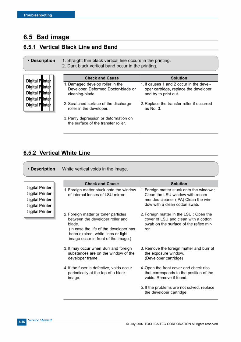
© July 2007 TOSHIBA TEC CORPORATION All rights reservedService Manual
Troubleshootng
6-16
6.5 Bad mage 6.5.1 Vertcal Black Lne and Band
Digital PrinterDigital PrinterDigital PrinterDigital PrinterDigital Printer
Digital PrinterDigital PrinterDigital PrinterDigital PrinterDigital Printer
Digital PrinterDigital PrinterDigital PrinterDigital PrinterDigital Printer
Digital PrinterDigital PrinterDigital PrinterDigital PrinterDigital Printer
Digital PrinterDigital PrinterDigital PrinterDigital PrinterDigital Printer
Digital PrinterDigital PrinterDigital PrinterDigital PrinterDigital Printer
Digital PrinterDigital PrinterDigital PrinterDigital PrinterDigital Printer
Digital PrinterDigital PrinterDigital PrinterDigital PrinterDigital Printer
Digital PrinterDigital PrinterDigital PrinterDigital PrinterDigital Printer
Digital PrinterDigital PrinterDigital PrinterDigital PrinterDigital Printer
Digital PrinterDigital PrinterDigital PrinterDigital PrinterDigital Printer
Digital PrinterDigital PrinterDigital PrinterDigital PrinterDigital Printer
Digital Digital PriDigital PrinterDigital PrinterDigital Printer
Digital PrinterDigital PrinterDigital PrinterDigital PrinterDigital Printer
Digital PrinterDigital PrinterDigital PrinterDigital PrinterDigital Printer
Digital PrinterDigital PrinterDigital PrinterDigital PrinterDigital Printer
Digital PrinterDigital PrinterDigital PrinterDigital PrinterDigital Printer
Digital PrinterDigital PrinterDigital PrinterDigital PrinterDigital Printer
Digital PrinterDigital PrinterDigital PrinterDigital PrinterDigital Printer
Digital PrinterDigital PrinterDigital PrinterDigital PrinterDigital Printer
Digital PrinterDigital PrinterDigital PrinterDigital PrinterDigital Printer
Digital PrinterDigital PrinterDigital PrinterDigital PrinterDigital Printer
Digital PrinterDigital PrinterDigital PrinterDigital PrinterDigital Printer
Digital PrinterDigital PrinterDigital PrinterDigital PrinterDigital Printer
Digital PrinterDigital PrinterDigital PrinterDigital PrinterDigital Printer
Digital PrinterDigital PrinterDigital PrinterDigital PrinterDigital Printer
Digital PrinterDigital PrinterDigital PrinterDigital PrinterDigital Printer
Digital PrinterDigital PrinterDigital PrinterDigital PrinterDigital Printer
Digital PrinterDigital PrinterDigital PrinterDigital PrinterDigital Printer
Digital PrinterDigital PrinterDigital PrinterDigital PrinterDigital Printer
• Descrpton 1. Straight thin black vertical line occurs in the printing. 2. Dark black vertical band occur in the printing.
6.5.2 Vertcal Whte Lne
Digital PrinterDigital PrinterDigital PrinterDigital PrinterDigital Printer
Digital PrinterDigital PrinterDigital PrinterDigital PrinterDigital Printer
Digital PrinterDigital PrinterDigital PrinterDigital PrinterDigital Printer
Digital PrinterDigital PrinterDigital PrinterDigital PrinterDigital Printer
Digital PrinterDigital PrinterDigital PrinterDigital PrinterDigital Printer
Digital PrinterDigital PrinterDigital PrinterDigital PrinterDigital Printer
Digital PrinterDigital PrinterDigital PrinterDigital PrinterDigital Printer
Digital PrinterDigital PrinterDigital PrinterDigital PrinterDigital Printer
Digital PrinterDigital PrinterDigital PrinterDigital PrinterDigital Printer
Digital PrinterDigital PrinterDigital PrinterDigital PrinterDigital Printer
Digital PrinterDigital PrinterDigital PrinterDigital PrinterDigital Printer
Digital PrinterDigital PrinterDigital PrinterDigital PrinterDigital Printer
Digital Digital PriDigital PrinterDigital PrinterDigital Printer
Digital PrinterDigital PrinterDigital PrinterDigital PrinterDigital Printer
Digital PrinterDigital PrinterDigital PrinterDigital PrinterDigital Printer
Digital PrinterDigital PrinterDigital PrinterDigital PrinterDigital Printer
Digital PrinterDigital PrinterDigital PrinterDigital PrinterDigital Printer
Digital PrinterDigital PrinterDigital PrinterDigital PrinterDigital Printer
Digital PrinterDigital PrinterDigital PrinterDigital PrinterDigital Printer
Digital PrinterDigital PrinterDigital PrinterDigital PrinterDigital Printer
Digital PrinterDigital PrinterDigital PrinterDigital PrinterDigital Printer
Digital PrinterDigital PrinterDigital PrinterDigital PrinterDigital Printer
Digital PrinterDigital PrinterDigital PrinterDigital PrinterDigital Printer
Digital PrinterDigital PrinterDigital PrinterDigital PrinterDigital Printer
Digital PrinterDigital PrinterDigital PrinterDigital PrinterDigital Printer
Digital PrinterDigital PrinterDigital PrinterDigital PrinterDigital Printer
Digital PrinterDigital PrinterDigital PrinterDigital PrinterDigital Printer
Digital PrinterDigital PrinterDigital PrinterDigital PrinterDigital Printer
Digital PrinterDigital PrinterDigital PrinterDigital PrinterDigital Printer
Digital PrinterDigital PrinterDigital PrinterDigital PrinterDigital Printer
• Descrpton White vertical voids in the image.
Check and Cause Soluton1. Damaged develop roller in the
Developer. Deformed Doctor-blade or cleaning-blade.
2. Scratched surface of the discharge roller in the developer.
3. Partly depression or deformation on the surface of the transfer roller.
1. If causes 1 and 2 occur in the devel-oper cartridge, replace the developer and try to print out.
2. Replace the transfer roller if occurred as No. 3.
Check and Cause Soluton1. Foreign matter stuck onto the window
of internal lenses of LSU mirror.
2. Foreign matter or toner particles between the developer roller and blade.
(In case the life of the developer has been expired, white lines or light image occur in front of the image.)
3. It may occur when Burr and foreign substances are on the window of the developer frame.
4. If the fuser is defective, voids occur periodically at the top of a black image.
1. Foreign matter stuck onto the window : Clean the LSU window with recom-mended cleaner (IPA) Clean the win-dow with a clean cotton swab.
2. Foreign matter in the LSU : Open the cover of LSU and clean with a cotton swab on the surface of the reflex mir-ror.
3. Remove the foreign matter and burr of the exposure window. (Developer cartridge)
4. Open the front cover and check ribs that corresponds to the position of the voids. Remove if found.
5. If the problems are not solved, replace the developer cartridge.

Troubleshootng
© July 2007 TOSHIBA TEC CORPORATION All rights reservedService Manual 6-17
6.5.3 Horzontal Black Band
• Descrpton Dark or blurry horizontal stripes occur in the printing periodically. (They may not occur periodically.)
Digital PrinterDigital PrinterDigital PrinterDigital PrinterDigital Printer
Digital PrinterDigital PrinterDigital PrinterDigital PrinterDigital Printer
Digital PrinterDigital PrinterDigital PrinterDigital PrinterDigital Printer
Digital PrinterDigital PrinterDigital PrinterDigital PrinterDigital Printer
Digital PrinterDigital PrinterDigital PrinterDigital PrinterDigital Printer
Digital PrinterDigital PrinterDigital PrinterDigital PrinterDigital Printer
Digital PrinterDigital PrinterDigital PrinterDigital PrinterDigital Printer
Digital PrinterDigital PrinterDigital PrinterDigital PrinterDigital Printer
Digital PrinterDigital PrinterDigital PrinterDigital PrinterDigital Printer
Digital PrinterDigital PrinterDigital PrinterDigital PrinterDigital Printer
Digital PrinterDigital PrinterDigital PrinterDigital PrinterDigital Printer
Digital PrinterDigital PrinterDigital PrinterDigital PrinterDigital Printer
Digital Digital PriDigital PrinterDigital PrinterDigital Printer
Digital PrinterDigital PrinterDigital PrinterDigital PrinterDigital Printer
Digital PrinterDigital PrinterDigital PrinterDigital PrinterDigital Printer
Digital PrinterDigital PrinterDigital PrinterDigital PrinterDigital Printer
Digital PrinterDigital PrinterDigital PrinterDigital PrinterDigital Printer
Digital PrinterDigital PrinterDigital PrinterDigital PrinterDigital Printer
Digital PrinterDigital PrinterDigital PrinterDigital PrinterDigital Printer
Digital PrinterDigital PrinterDigital PrinterDigital PrinterDigital Printer
Digital PrinterDigital PrinterDigital PrinterDigital PrinterDigital Printer
Digital PrinterDigital PrinterDigital PrinterDigital PrinterDigital Printer
Digital PrinterDigital PrinterDigital PrinterDigital PrinterDigital Printer
Digital PrinterDigital PrinterDigital PrinterDigital PrinterDigital Printer
Digital PrinterDigital PrinterDigital PrinterDigital PrinterDigital Printer
Digital PrinterDigital PrinterDigital PrinterDigital PrinterDigital Printer
Digital PrinterDigital PrinterDigital PrinterDigital PrinterDigital Printer
Digital PrinterDigital PrinterDigital PrinterDigital PrinterDigital Printer
Digital PrinterDigital PrinterDigital PrinterDigital PrinterDigital Printer
Digital PrinterDigital PrinterDigital PrinterDigital PrinterDigital Printer
6.5.4 Black/Whte Spot
Digital PrinterDigital PrinterDigital PrinterDigital PrinterDigital Printer
Digital PrinterDigital PrinterDigital PrinterDigital PrinterDigital Printer
Digital PrinterDigital PrinterDigital PrinterDigital PrinterDigital Printer
Digital PrinterDigital PrinterDigital PrinterDigital PrinterDigital Printer
Digital PrinterDigital PrinterDigital PrinterDigital PrinterDigital Printer
Digital PrinterDigital PrinterDigital PrinterDigital PrinterDigital Printer
Digital PrinterDigital PrinterDigital PrinterDigital PrinterDigital Printer
Digital PrinterDigital PrinterDigital PrinterDigital PrinterDigital Printer
Digital PrinterDigital PrinterDigital PrinterDigital PrinterDigital Printer
Digital PrinterDigital PrinterDigital PrinterDigital PrinterDigital Printer
Digital PrinterDigital PrinterDigital PrinterDigital PrinterDigital Printer
Digital PrinterDigital PrinterDigital PrinterDigital PrinterDigital Printer
Digital Digital PriDigital PrinterDigital PrinterDigital Printer
Digital PrinterDigital PrinterDigital PrinterDigital PrinterDigital Printer
Digital PrinterDigital PrinterDigital PrinterDigital PrinterDigital Printer
Digital PrinterDigital PrinterDigital PrinterDigital PrinterDigital Printer
Digital PrinterDigital PrinterDigital PrinterDigital PrinterDigital Printer
Digital PrinterDigital PrinterDigital PrinterDigital PrinterDigital Printer
Digital PrinterDigital PrinterDigital PrinterDigital PrinterDigital Printer
Digital PrinterDigital PrinterDigital PrinterDigital PrinterDigital Printer
Digital PrinterDigital PrinterDigital PrinterDigital PrinterDigital Printer
Digital PrinterDigital PrinterDigital PrinterDigital PrinterDigital Printer
Digital PrinterDigital PrinterDigital PrinterDigital PrinterDigital Printer
Digital PrinterDigital PrinterDigital PrinterDigital PrinterDigital Printer
Digital PrinterDigital PrinterDigital PrinterDigital PrinterDigital Printer
Digital PrinterDigital PrinterDigital PrinterDigital PrinterDigital Printer
Digital PrinterDigital PrinterDigital PrinterDigital PrinterDigital Printer
Digital PrinterDigital PrinterDigital PrinterDigital PrinterDigital Printer
Digital PrinterDigital PrinterDigital PrinterDigital PrinterDigital Printer
Digital PrinterDigital PrinterDigital PrinterDigital PrinterDigital Printer
• Descrpton 1. Dark or blurry black spots occur periodically in the printing. 2. White spots occur periodically in the printing.
Check and Cause Soluton1. Bad contacts of the voltage terminals to
developer.
2. The rollers of developer may be stained. OPC Drum = 75.5mm
Charge Roller = 37.7mm Supply Roller = 47.5mm Develop Roller = 35.2mm Transfer Roller = 46.2mm Heat Roller = 63.9mm Pressure Roller = 75.4mm
1. Clean each voltage terminal of the Charge, Supply, Develop and Transfer roller.
(remove the toner particles and paper particles)
2. Clean the right Gear that has relatively small gap of the teeth in the OPC.
3. If the malfunction persists, replace the developer.
Check and Cause Soluton1. If dark or blurry black spots occur peri-
odically, the rollers in the Developer may be contaminated with foreign matte or paper particles.
( Charge roller : 37.7 mm interval OPC drum : 75.5 mm interval) 2. If faded areas or voids occur in a black
image at intervals of 75.5 mm, or black spots occur elsewhere, the OPC drum surface is damaged.
3. If a black image is partially broken, the transfer voltage is abnormal or the transfer roller's life has expired.
1. Run OPC cleaning Mode Print and run the Self-test 2 or 3 times.
2. In case of 75.5 mm interval unremovable in 1, cleanly remove foreign substances stuck on the OPC location equivalent to black spots and white spots with a dry duster.
3. The transfer roller guarantees 50.000 sheets printing. If the roller's life is expired, replace it.
4. In case of 37.7 mm interval unremovable in 1, take measures as to replace the developer cartridge and try to print out.
5. Clean the inside of the set against the paper particles and foreign matter in order not to cause the trouble.

© July 2007 TOSHIBA TEC CORPORATION All rights reservedService Manual
Troubleshootng
6-18
6.5.5 Lght Image
Digital PrinterDigital PrinterDigital PrinterDigital PrinterDigital Printer
Digital PrinterDigital PrinterDigital PrinterDigital PrinterDigital Printer
Digital PrinterDigital PrinterDigital PrinterDigital PrinterDigital Printer
Digital PrinterDigital PrinterDigital PrinterDigital PrinterDigital Printer
Digital PrinterDigital PrinterDigital PrinterDigital PrinterDigital Printer
Digital PrinterDigital PrinterDigital PrinterDigital PrinterDigital Printer
Digital PrinterDigital PrinterDigital PrinterDigital PrinterDigital Printer
Digital PrinterDigital PrinterDigital PrinterDigital PrinterDigital Printer
Digital PrinterDigital PrinterDigital PrinterDigital PrinterDigital Printer
Digital PrinterDigital PrinterDigital PrinterDigital PrinterDigital Printer
Digital PrinterDigital PrinterDigital PrinterDigital PrinterDigital Printer
Digital PrinterDigital PrinterDigital PrinterDigital PrinterDigital Printer
Digital Digital PriDigital PrinterDigital PrinterDigital Printer
Digital PrinterDigital PrinterDigital PrinterDigital PrinterDigital Printer
Digital PrinterDigital PrinterDigital PrinterDigital PrinterDigital Printer
Digital PrinterDigital PrinterDigital PrinterDigital PrinterDigital Printer
Digital PrinterDigital PrinterDigital PrinterDigital PrinterDigital Printer
Digital PrinterDigital PrinterDigital PrinterDigital PrinterDigital Printer
Digital PrinterDigital PrinterDigital PrinterDigital PrinterDigital Printer
Digital PrinterDigital PrinterDigital PrinterDigital PrinterDigital Printer
Digital PrinterDigital PrinterDigital PrinterDigital PrinterDigital Printer
Digital PrinterDigital PrinterDigital PrinterDigital PrinterDigital Printer
Digital PrinterDigital PrinterDigital PrinterDigital PrinterDigital Printer
Digital PrinterDigital PrinterDigital PrinterDigital PrinterDigital Printer
Digital PrinterDigital PrinterDigital PrinterDigital PrinterDigital Printer
Digital PrinterDigital PrinterDigital PrinterDigital PrinterDigital Printer
Digital PrinterDigital PrinterDigital PrinterDigital PrinterDigital Printer
Digital PrinterDigital PrinterDigital PrinterDigital PrinterDigital Printer
Digital PrinterDigital PrinterDigital PrinterDigital PrinterDigital Printer
Digital PrinterDigital PrinterDigital PrinterDigital PrinterDigital Printer
• Descrpton The printed image is dark.
Digital PrinterDigital PrinterDigital PrinterDigital PrinterDigital Printer
Digital PrinterDigital PrinterDigital PrinterDigital PrinterDigital Printer
Digital PrinterDigital PrinterDigital PrinterDigital PrinterDigital Printer
Digital PrinterDigital PrinterDigital PrinterDigital PrinterDigital Printer
Digital PrinterDigital PrinterDigital PrinterDigital PrinterDigital Printer
Digital PrinterDigital PrinterDigital PrinterDigital PrinterDigital Printer
Digital PrinterDigital PrinterDigital PrinterDigital PrinterDigital Printer
Digital PrinterDigital PrinterDigital PrinterDigital PrinterDigital Printer
Digital PrinterDigital PrinterDigital PrinterDigital PrinterDigital Printer
Digital PrinterDigital PrinterDigital PrinterDigital PrinterDigital Printer
Digital PrinterDigital PrinterDigital PrinterDigital PrinterDigital Printer
Digital PrinterDigital PrinterDigital PrinterDigital PrinterDigital Printer
Digital Digital PriDigital PrinterDigital PrinterDigital Printer
Digital PrinterDigital PrinterDigital PrinterDigital PrinterDigital Printer
Digital PrinterDigital PrinterDigital PrinterDigital PrinterDigital Printer
Digital PrinterDigital PrinterDigital PrinterDigital PrinterDigital Printer
Digital PrinterDigital PrinterDigital PrinterDigital PrinterDigital Printer
Digital PrinterDigital PrinterDigital PrinterDigital PrinterDigital Printer
Digital PrinterDigital PrinterDigital PrinterDigital PrinterDigital Printer
Digital PrinterDigital PrinterDigital PrinterDigital PrinterDigital Printer
Digital PrinterDigital PrinterDigital PrinterDigital PrinterDigital Printer
Digital PrinterDigital PrinterDigital PrinterDigital PrinterDigital Printer
Digital PrinterDigital PrinterDigital PrinterDigital PrinterDigital Printer
Digital PrinterDigital PrinterDigital PrinterDigital PrinterDigital Printer
Digital PrinterDigital PrinterDigital PrinterDigital PrinterDigital Printer
Digital PrinterDigital PrinterDigital PrinterDigital PrinterDigital Printer
Digital PrinterDigital PrinterDigital PrinterDigital PrinterDigital Printer
Digital PrinterDigital PrinterDigital PrinterDigital PrinterDigital Printer
Digital PrinterDigital PrinterDigital PrinterDigital PrinterDigital Printer
Digital PrinterDigital PrinterDigital PrinterDigital PrinterDigital Printer
• Descrpton The printed image is light, with no ghost.
6.5.6 Dark Image or a Black
Check and Cause Soluton1. Develop roller is stained when the
toner of developer cartridge is almost consumed.
2. Ambient temperature is below than 10°C.
3. Bad contact caused by the toner stains between the high voltage ter-minal in the HVPS and the one in the set.
4. Abnormal output from the HVPS.
1. Check if the Toner Save mode is off.
2. Replace the developer cartridge and try to print out.
3. Wait 30 minutes after printer is pow-ered on before you start printing.
4. Clean up the contaminated area by the toner.
5. Replace the HVPS if the problems are not solved by the above four direc-tions.
Check and Cause Soluton1. No charge voltage in the engine
board.
2. Charge voltage is not turned on due to the bad contacts between power supply in the side of the Developer and charge terminal of HVPS.
1. Clean the high voltage charge termi-nal.
2. Check the state of the connector which connects the engine board and HVPS.
3. Replace the HVPS if not solved by the above direction 1 and 2.
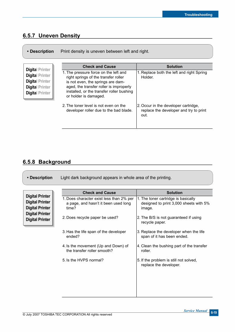
Troubleshootng
© July 2007 TOSHIBA TEC CORPORATION All rights reservedService Manual 6-19
6.5.7 Uneven Densty
Digital PrinterDigital PrinterDigital PrinterDigital PrinterDigital Printer
Digital PrinterDigital PrinterDigital PrinterDigital PrinterDigital Printer
Digital PrinterDigital PrinterDigital PrinterDigital PrinterDigital Printer
Digital PrinterDigital PrinterDigital PrinterDigital PrinterDigital Printer
Digital PrinterDigital PrinterDigital PrinterDigital PrinterDigital Printer
Digital PrinterDigital PrinterDigital PrinterDigital PrinterDigital Printer
Digital PrinterDigital PrinterDigital PrinterDigital PrinterDigital Printer
Digital PrinterDigital PrinterDigital PrinterDigital PrinterDigital Printer
Digital PrinterDigital PrinterDigital PrinterDigital PrinterDigital Printer
Digital PrinterDigital PrinterDigital PrinterDigital PrinterDigital Printer
Digital PrinterDigital PrinterDigital PrinterDigital PrinterDigital Printer
Digital PrinterDigital PrinterDigital PrinterDigital PrinterDigital Printer
Digital Digital PriDigital PrinterDigital PrinterDigital Printer
Digital PrinterDigital PrinterDigital PrinterDigital PrinterDigital Printer
Digital PrinterDigital PrinterDigital PrinterDigital PrinterDigital Printer
Digital PrinterDigital PrinterDigital PrinterDigital PrinterDigital Printer
Digital PrinterDigital PrinterDigital PrinterDigital PrinterDigital Printer
Digital PrinterDigital PrinterDigital PrinterDigital PrinterDigital Printer
Digital PrinterDigital PrinterDigital PrinterDigital PrinterDigital Printer
Digital PrinterDigital PrinterDigital PrinterDigital PrinterDigital Printer
Digital PrinterDigital PrinterDigital PrinterDigital PrinterDigital Printer
Digital PrinterDigital PrinterDigital PrinterDigital PrinterDigital Printer
Digital PrinterDigital PrinterDigital PrinterDigital PrinterDigital Printer
Digital PrinterDigital PrinterDigital PrinterDigital PrinterDigital Printer
Digital PrinterDigital PrinterDigital PrinterDigital PrinterDigital Printer
Digital PrinterDigital PrinterDigital PrinterDigital PrinterDigital Printer
Digital PrinterDigital PrinterDigital PrinterDigital PrinterDigital Printer
Digital PrinterDigital PrinterDigital PrinterDigital PrinterDigital Printer
Digital PrinterDigital PrinterDigital PrinterDigital PrinterDigital Printer
Digital PrinterDigital PrinterDigital PrinterDigital PrinterDigital Printer
Digital PrinterDigital PrinterDigital PrinterDigital PrinterDigital Printer
Digital PrinterDigital PrinterDigital PrinterDigital PrinterDigital Printer
Digital PrinterDigital PrinterDigital PrinterDigital PrinterDigital Printer
Digital PrinterDigital PrinterDigital PrinterDigital PrinterDigital Printer
Digital PrinterDigital PrinterDigital PrinterDigital PrinterDigital Printer
Digital PrinterDigital PrinterDigital PrinterDigital PrinterDigital Printer
Digital PrinterDigital PrinterDigital PrinterDigital PrinterDigital Printer
Digital PrinterDigital PrinterDigital PrinterDigital PrinterDigital Printer
Digital PrinterDigital PrinterDigital PrinterDigital PrinterDigital Printer
Digital PrinterDigital PrinterDigital PrinterDigital PrinterDigital Printer
Digital PrinterDigital PrinterDigital PrinterDigital PrinterDigital Printer
Digital PrinterDigital PrinterDigital PrinterDigital PrinterDigital Printer
Digital Digital PriDigital PrinterDigital PrinterDigital Printer
Digital PrinterDigital PrinterDigital PrinterDigital PrinterDigital Printer
Digital PrinterDigital PrinterDigital PrinterDigital PrinterDigital Printer
Digital PrinterDigital PrinterDigital PrinterDigital PrinterDigital Printer
Digital PrinterDigital PrinterDigital PrinterDigital PrinterDigital Printer
Digital PrinterDigital PrinterDigital PrinterDigital PrinterDigital Printer
Digital PrinterDigital PrinterDigital PrinterDigital PrinterDigital Printer
Digital PrinterDigital PrinterDigital PrinterDigital PrinterDigital Printer
Digital PrinterDigital PrinterDigital PrinterDigital PrinterDigital Printer
Digital PrinterDigital PrinterDigital PrinterDigital PrinterDigital Printer
Digital PrinterDigital PrinterDigital PrinterDigital PrinterDigital Printer
Digital PrinterDigital PrinterDigital PrinterDigital PrinterDigital Printer
Digital PrinterDigital PrinterDigital PrinterDigital PrinterDigital Printer
Digital PrinterDigital PrinterDigital PrinterDigital PrinterDigital Printer
Digital PrinterDigital PrinterDigital PrinterDigital PrinterDigital Printer
Digital PrinterDigital PrinterDigital PrinterDigital PrinterDigital Printer
Digital PrinterDigital PrinterDigital PrinterDigital PrinterDigital Printer
Digital PrinterDigital PrinterDigital PrinterDigital PrinterDigital Printer
• Descrpton Light dark background appears in whole area of the printing.
• Descrpton Print density is uneven between left and right.
6.5.8 Background
Check and Cause Soluton1. The pressure force on the left and
right springs of the transfer roller is not even, the springs are dam-aged, the transfer roller is improperly installed, or the transfer roller bushing or holder is damaged.
2. The toner level is not even on the developer roller due to the bad blade.
1. Replace both the left and right Spring Holder.
2. Occur in the developer cartridge, replace the developer and try to print out.
Check and Cause Soluton1. Does character exist less than 2% per
a page, and hasn’t it been used long time?
2. Does recycle paper be used?
3. Has the life span of the developer ended?
4. Is the movement (Up and Down) of the transfer roller smooth?
5. Is the HVPS normal?
1. The toner cartridge is basically designed to print 3,000 sheets with 5% image.
2. The B/S is not guaranteed if using recycle paper.
3. Replace the developer when the life span of it has been ended.
4. Clean the bushing part of the transfer roller.
5. If the problem is still not solved, replace the developer.
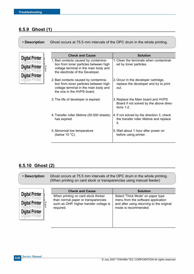
© July 2007 TOSHIBA TEC CORPORATION All rights reservedService Manual
Troubleshootng
6-20
6.5.9 Ghost (1)
Digital Printer
Digital Printer
Digital Printer
Digital Printer
Digital Printer
Digital Printer
Digital PrinterDigital PrinterDigital Printer
47.5mm
Digital Printer
Digital Printer
Digital Printer
Digital Printer
Digital Printer
Digital Printer
75.5mm
Digital Printer
Digital Printer
Digital Printer
Digital Printer
Digital Printer
Digital Printer
47.5 or 63.9mm
• Descrpton Ghost occurs at 75.5 mm intervals of the OPC drum in the whole printing.
6.5.10 Ghost (2)
Digital Printer
Digital Printer
Digital Printer
Digital Printer
Digital Printer
Digital Printer
Digital PrinterDigital PrinterDigital Printer
47.5mm
Digital Printer
Digital Printer
Digital Printer
Digital Printer
Digital Printer
Digital Printer
75.5mm
Digital Printer
Digital Printer
Digital Printer
Digital Printer
Digital Printer
Digital Printer
47.5 or 63.9mm
• Descrpton Ghost occurs at 75.5 mm intervals of the OPC drum in the whole printing. (When printing on card stock or transparencies using manual feeder)
Check and Cause Soluton1. Bad contacts caused by contamina-
tion from toner particles between high voltage terminal in the main body and the electrode of the Developer.
2. Bad contacts caused by contamina-tion from toner particles between high voltage terminal in the main body and the one in the HVPS board.
3. The life of developer is expired.
4. Transfer roller lifetime (50.000 sheets) has expired.
5. Abnormal low temperature (below 10 °C).
1. Clean the terminals when contaminat-ed by toner particles.
2. Occur in the developer cartridge, replace the developer and try to print out.
3. Replace the Main board and HVPS Board if not solved by the above direc-tions 1-2.
4. If not solved by the direction 3, check the transfer roller lifetime and replace it.
5. Wait about 1 hour after power on before using printer.
Check and Cause SolutonWhen printing on card stock thicker than normal paper or transparencies such as OHP, higher transfer voltage is required.
Select 'Thick Mode' on paper type menu from the software application and after using returning to the original mode is recommended.
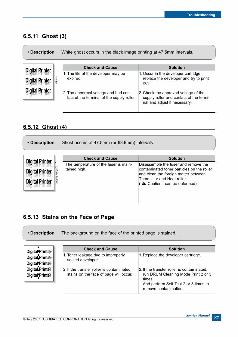
Troubleshootng
© July 2007 TOSHIBA TEC CORPORATION All rights reservedService Manual 6-21
Check and Cause SolutonThe temperature of the fuser is main-tained high.
Disassemble the fuser and remove the contaminated toner particles on the roller and clean the foreign matter between Thermistor and Heat roller. ( Caution : can be deformed)
6.5.11 Ghost (3)
Digital Printer
Digital Printer
Digital Printer
Digital Printer
Digital Printer
Digital Printer
Digital PrinterDigital PrinterDigital Printer
47.5mm
Digital Printer
Digital Printer
Digital Printer
Digital Printer
Digital Printer
Digital Printer
75.5mm
Digital Printer
Digital Printer
Digital Printer
Digital Printer
Digital Printer
Digital Printer47.5 or 63.9m
m
• Descrpton White ghost occurs in the black image printing at 47.5mm intervals.
6.5.12 Ghost (4)
Digital Printer
Digital Printer
Digital Printer
Digital Printer
Digital Printer
Digital Printer
Digital PrinterDigital PrinterDigital Printer
47.5mm
Digital Printer
Digital Printer
Digital Printer
Digital Printer
Digital Printer
Digital Printer
75.5mm
Digital Printer
Digital Printer
Digital Printer
Digital Printer
Digital Printer
Digital Printer47.5 or 63.9m
m
• Descrpton Ghost occurs at 47.5mm (or 63.9mm) intervals.
6.5.13 Stans on the Face of Page
Digital PrinterDigital PrinterDigital PrinterDigital PrinterDigital Printer
Digital PrinterDigital PrinterDigital PrinterDigital PrinterDigital Printer
Digital PrinterDigital PrinterDigital PrinterDigital PrinterDigital Printer
Digital PrinterDigital PrinterDigital PrinterDigital PrinterDigital Printer
Digital PrinterDigital PrinterDigital PrinterDigital PrinterDigital Printer
Digital PrinterDigital PrinterDigital PrinterDigital PrinterDigital Printer
Digital PrinterDigital PrinterDigital PrinterDigital PrinterDigital Printer
Digital PrinterDigital PrinterDigital PrinterDigital PrinterDigital Printer
Digital PrinterDigital PrinterDigital PrinterDigital PrinterDigital Printer
Digital PrinterDigital PrinterDigital PrinterDigital PrinterDigital Printer
Digital PrinterDigital PrinterDigital PrinterDigital PrinterDigital Printer
Digital PrinterDigital PrinterDigital PrinterDigital PrinterDigital Printer
Digital Digital PriDigital PrinterDigital PrinterDigital Printer
Digital PrinterDigital PrinterDigital PrinterDigital PrinterDigital Printer
Digital PrinterDigital PrinterDigital PrinterDigital PrinterDigital Printer
Digital PrinterDigital PrinterDigital PrinterDigital PrinterDigital Printer
Digital PrinterDigital PrinterDigital PrinterDigital PrinterDigital Printer
Digital PrinterDigital PrinterDigital PrinterDigital PrinterDigital Printer
Digital PrinterDigital PrinterDigital PrinterDigital PrinterDigital Printer
Digital PrinterDigital PrinterDigital PrinterDigital PrinterDigital Printer
Digital PrinterDigital PrinterDigital PrinterDigital PrinterDigital Printer
Digital PrinterDigital PrinterDigital PrinterDigital PrinterDigital Printer
Digital PrinterDigital PrinterDigital PrinterDigital PrinterDigital Printer
Digital PrinterDigital PrinterDigital PrinterDigital PrinterDigital Printer
Digital PrinterDigital PrinterDigital PrinterDigital PrinterDigital Printer
Digital PrinterDigital PrinterDigital PrinterDigital PrinterDigital Printer
Digital PrinterDigital PrinterDigital PrinterDigital PrinterDigital Printer
Digital PrinterDigital PrinterDigital PrinterDigital PrinterDigital Printer
Digital PrinterDigital PrinterDigital PrinterDigital PrinterDigital Printer
Digital PrinterDigital PrinterDigital PrinterDigital PrinterDigital Printer
• Descrpton The background on the face of the printed page is stained.
Check and Cause Soluton1. The life of the developer may be
expired.
2. The abnormal voltage and bad con-tact of the terminal of the supply roller.
1. Occur in the developer cartridge, replace the developer and try to print out.
2. Check the approved voltage of the supply roller and contact of the termi-nal and adjust if necessary.
Check and Cause Soluton1. Toner leakage due to improperly
sealed developer.
2. If the transfer roller is contaminated, stains on the face of page will occur.
1. Replace the developer cartridge.
2. If the transfer roller is contaminated, run DRUM Cleaning Mode Print 2 or 3 times.
And perform Self-Test 2 or 3 times to remove contamination.
© July 2007 TOSHIBA TEC CORPORATION All rights reservedService Manual
Troubleshootng
6-22
6.5.14 Stans on Back of Page
Digital PrinterDigital PrinterDigital PrinterDigital PrinterDigital Printer
Digital PrinterDigital PrinterDigital PrinterDigital PrinterDigital Printer
Digital PrinterDigital PrinterDigital PrinterDigital PrinterDigital Printer
Digital PrinterDigital PrinterDigital PrinterDigital PrinterDigital Printer
Digital PrinterDigital PrinterDigital PrinterDigital PrinterDigital Printer
Digital PrinterDigital PrinterDigital PrinterDigital PrinterDigital Printer
Digital PrinterDigital PrinterDigital PrinterDigital PrinterDigital Printer
Digital PrinterDigital PrinterDigital PrinterDigital PrinterDigital Printer
Digital PrinterDigital PrinterDigital PrinterDigital PrinterDigital Printer
Digital PrinterDigital PrinterDigital PrinterDigital PrinterDigital Printer
Digital PrinterDigital PrinterDigital PrinterDigital PrinterDigital Printer
Digital PrinterDigital PrinterDigital PrinterDigital PrinterDigital Printer
Digital Digital PriDigital PrinterDigital PrinterDigital Printer
Digital PrinterDigital PrinterDigital PrinterDigital PrinterDigital Printer
Digital PrinterDigital PrinterDigital PrinterDigital PrinterDigital Printer
Digital PrinterDigital PrinterDigital PrinterDigital PrinterDigital Printer
Digital PrinterDigital PrinterDigital PrinterDigital PrinterDigital Printer
Digital PrinterDigital PrinterDigital PrinterDigital PrinterDigital Printer
Digital PrinterDigital PrinterDigital PrinterDigital PrinterDigital Printer
Digital PrinterDigital PrinterDigital PrinterDigital PrinterDigital Printer
Digital PrinterDigital PrinterDigital PrinterDigital PrinterDigital Printer
Digital PrinterDigital PrinterDigital PrinterDigital PrinterDigital Printer
Digital PrinterDigital PrinterDigital PrinterDigital PrinterDigital Printer
Digital PrinterDigital PrinterDigital PrinterDigital PrinterDigital Printer
Digital PrinterDigital PrinterDigital PrinterDigital PrinterDigital Printer
Digital PrinterDigital PrinterDigital PrinterDigital PrinterDigital Printer
Digital PrinterDigital PrinterDigital PrinterDigital PrinterDigital Printer
Digital PrinterDigital PrinterDigital PrinterDigital PrinterDigital Printer
Digital PrinterDigital PrinterDigital PrinterDigital PrinterDigital Printer
Digital PrinterDigital PrinterDigital PrinterDigital PrinterDigital Printer
• Descrpton The back of the page is stained at 47 mm intervals.
6.5.15 Blank Page Prnt out (1)
Digital PrinterDigital PrinterDigital PrinterDigital PrinterDigital Printer
Digital PrinterDigital PrinterDigital PrinterDigital PrinterDigital Printer
Digital PrinterDigital PrinterDigital PrinterDigital PrinterDigital Printer
Digital PrinterDigital PrinterDigital PrinterDigital PrinterDigital Printer
Digital PrinterDigital PrinterDigital PrinterDigital PrinterDigital Printer
Digital PrinterDigital PrinterDigital PrinterDigital PrinterDigital Printer
Digital PrinterDigital PrinterDigital PrinterDigital PrinterDigital Printer
Digital PrinterDigital PrinterDigital PrinterDigital PrinterDigital Printer
Digital PrinterDigital PrinterDigital PrinterDigital PrinterDigital Printer
Digital PrinterDigital PrinterDigital PrinterDigital PrinterDigital Printer
Digital PrinterDigital PrinterDigital PrinterDigital PrinterDigital Printer
Digital PrinterDigital PrinterDigital PrinterDigital PrinterDigital Printer
Digital Digital PriDigital PrinterDigital PrinterDigital Printer
Digital PrinterDigital PrinterDigital PrinterDigital PrinterDigital Printer
Digital PrinterDigital PrinterDigital PrinterDigital PrinterDigital Printer
Digital PrinterDigital PrinterDigital PrinterDigital PrinterDigital Printer
Digital PrinterDigital PrinterDigital PrinterDigital PrinterDigital Printer
Digital PrinterDigital PrinterDigital PrinterDigital PrinterDigital Printer
Digital PrinterDigital PrinterDigital PrinterDigital PrinterDigital Printer
Digital PrinterDigital PrinterDigital PrinterDigital PrinterDigital Printer
Digital PrinterDigital PrinterDigital PrinterDigital PrinterDigital Printer
Digital PrinterDigital PrinterDigital PrinterDigital PrinterDigital Printer
Digital PrinterDigital PrinterDigital PrinterDigital PrinterDigital Printer
Digital PrinterDigital PrinterDigital PrinterDigital PrinterDigital Printer
Digital PrinterDigital PrinterDigital PrinterDigital PrinterDigital Printer
Digital PrinterDigital PrinterDigital PrinterDigital PrinterDigital Printer
Digital PrinterDigital PrinterDigital PrinterDigital PrinterDigital Printer
Digital PrinterDigital PrinterDigital PrinterDigital PrinterDigital Printer
Digital PrinterDigital PrinterDigital PrinterDigital PrinterDigital Printer
Digital PrinterDigital PrinterDigital PrinterDigital PrinterDigital Printer
• Descrpton Blank page is printed.
6.5.16 Blank Page Prnt out (2)• Descrpton 1. Blank page is printed. 2. One or several blank pages are printed. 3. When the printer turns on, several blank pages print.
Digital Printer
Digital Printer
Digital Printer
Digital Printer
Digital Printer
Digital Printer
Digital PrinterDigital PrinterDigital Printer
47.5mm
Digital Printer
Digital Printer
Digital Printer
Digital Printer
Digital Printer
Digital Printer
75.5mm
Digital Printer
Digital Printer
Digital Printer
Digital Printer
Digital Printer
Digital Printer
47.5 or 63.9mm
Check and Cause Soluton1. Transfer roller is contaminated.
2. Pressure roller is contaminated.
1. Perform the DRUM Cleaning Mode Print 2 or 3 times. Run Self-Test to remove the contamination of the transfer roller.
2. Replace the transfer roller if contami-nated severely.
3. Disassemble the fuser and clean the H/R (Heat Roller) and P/R (Pressure roller). And check the area between H/R and Thermistor. If contaminated, clean the area not to be deformed.
Check and Cause SolutonBad ground contacts in OPC and/or developer.
Remove contamination of the terminals of the developer and the unit.
Check and Cause Soluton1. Bad ground contacts in OPC and/or
developer.
2. Abnormal solenoid.
1. Remove contamination of the terminals of the developer.
2. Perform the engine self test using Engine Test Mode to check if the Solenoid is normal. (Refer to the 4.5)
3. If not solved by the above directions 1-2, Replace the engine board.
4. Turn the power off, delete the data of PC and try printing again.
Troubleshootng
© July 2007 TOSHIBA TEC CORPORATION All rights reservedService Manual 6-23
6.6.1 No Dal Tone
• Descrpton There is no dial tone when the On-Hook dial button is pressed.
6.6 Fax & Phone Problems
6.6.2 Defectve MF DIAL
• Descrpton The MF DIAL is not functioning.
Check and Cause Soluton1. Check that the telephone line cord supplied with
the set is connected to TEL LINE correctly.
2. Listen for a CLICK sound when the OHD key is pressed.
3. Check the connection of the HARNESS between the LIU and the Main B'd.
4. Check that the SPEAKER is connected correctly.
1. If the telephone cord is OK but there is no dial tone, try plugging a normal telephone into the wall socket. If this is OK then replace the LIU B'd.
2. If you cannot hear the OHD CLICK sound, the OPE Ass'y may be defective. Replace the OPE Ass'y. (If the key click sound if off, you cannot hear click sound even if OPE Ass’y has no problem on it)
3. Check the Speaker connection and the harness between the LIU and the Main PBA, replace as necessary.
4. Use Tech mode / Modem Test to check that the speaker and amplifier are working. Replace the Main B'd.
Check and Cause Soluton1. Check that the telephone line cord supplied with
the set is connected to TEL LINE correctly.
2. Listen for a CLICK sound when the KEY is pressed.
3. Check the connection of the HARNESS between the LIU and the Main B'd.
4. Check that the SPEAKER is connected correctly.
1. If the telephone cord is OK but there is no dial tone, try plugging a normal telephone into the wall socket. If this is OK then replace the LIU B'd.
2. If you cannot hear the OHD CLICK sound, the OPE Ass'y may be defective. Replace the OPE Ass'y. (After key click sound sets to “ON”, and you can hear click sound)
3. Check the Speaker connection and the harness between the LIU and the Main PBA, replace as necessary.
4. Use Tech mode / Modem Test to check that the speaker and amplifier are working. Replace the LIU and Main B'd in sequence.
Notes: Product supports MF DIAL type only.

© July 2007 TOSHIBA TEC CORPORATION All rights reservedService Manual
Troubleshootng
6-24
6.6.3 Defectve FAX FORWARD/RECEIVE
• Descrpton RECEIVE is functioning, but FORWARD is not functioning or received data is corrupt.
• Descrpton FAX FORWARD/RECEIVE is not functioning.
6.6.4 Defectve FAX FORWARD
Check and Cause Soluton1. Check that you can hear a dial tone by pressing
OHD.
2. Check that you can hear a RECEIVE tone when MODEM testing in TECH Mode.
1. If MODEM testing is normal and there is no dial tone, then try replacing the LIU B'd.
2. If testing the MODEM shows a fault replace the Main B'd.
Check and Cause Soluton1. Check if there is a NOISE line by pressing
on-hook dial and listening.
2. Check that the destination fax machine can receive forwarded faxes by using a different send-ing fax machine (preferably from the same wall socket).
3. Check the cable between the set and the wall socket for damage.
1. If you can hear a noisy line when using on-hook dial, replace or repair the telephone line.
2. Replace LIU.
3. Replace the line cord.
Troubleshootng
© July 2007 TOSHIBA TEC CORPORATION All rights reservedService Manual 6-25
6.6.5 Defectve FAX RECEIVE (1)
• Descrpton FORWARD is functioning, but RECEIVE is not functioning or the received data is corrupt.
• Descrpton Received data are lengthened or cut in the printing.
6.6.6 Defectve FAX RECEIVE (2)
• Descrpton The phone is ringing continuously, but it set does not answer the call.
6.6.7 Defectve FAX RECEIVE (3)
Check and Cause Soluton1. Check if there is a NOISE line by pressing
on-hook dial and listening.
2. Use a different fax machine to receive from the same sender (if possible on the same wall sock-et).
1. If you can hear a noisy line when using on-hook dial, replace or repair the telephone line.
2. Replace the LIU.
Check and Cause Soluton1. Check if there is a NOISE line by pressing
on-hook dial and listening.
2. Ask sender to send to another fax machine (if possible connected to the same wall socket).
1. If you can hear a noisy line when using on-hook dial, replace or repair the telephone line.
2. Replace LIU or main PBA in sequence.
Check and Cause SolutonCheck that the RECEIVE Mode is set to FAX MODE.
If the fault persists even when the RECEIVE Mode is changed to FAX MODE then replace the LIU and the Main B'd in sequence.

© July 2007 TOSHIBA TEC CORPORATION All rights reservedService Manual
Troubleshootng
6-26
6.6.8 Defectve FAX RECEIVE (4)
• Descrpton Received data is reduced by more than 50% in the printing.
6.6.9 Defectve Automatc Recevng
• Descrpton The automatic receiving function is not working.
Check and Cause SolutonCheck the FAX status of the forwarding side. This is a problem with the sending fax machine.
Correct the setting on the remote machine.
Check and Cause Soluton1. Check that the RECEIVE Mode is set to FAX
MODE.1. If the RECEIVE Mode is set to the TEL MODE,
reset it to the FAX MODE.
2. Even after the RECEIVE Mode is changed to the FAX Mode, the problem persists then try to replace the LIU and the Main B'd in sequence.

Troubleshootng
© July 2007 TOSHIBA TEC CORPORATION All rights reservedService Manual 6-27
6.7.1 Whte Copy
• Descrpton Blank page is printed out when copying.
6.7 Copy Problems
6.7.2 Black Copy
• Descrpton Black page is printed out when Copying.
Check and Cause Soluton1. Check the Scanner Cover is properly closed.
2. Check shading profile.
3. Check white/black reference voltage on Main PBA.
1. Room light can pass through a thin original.
2. Redo shading profile in the tech mode.
3. Replace the Main PBA.
Check and Cause Soluton1. Check for CIS problem on the Main PBA.
2. Check shading profile.
1. Check the CIS FFC Cable is properly connected.
2. Redo shading profile in the tech mode.

© July 2007 TOSHIBA TEC CORPORATION All rights reservedService Manual
Troubleshootng
6-28
6.7.3 Abnormal nose
• Descrpton There is noise from the ADF when copying.
• Descrpton The copied image is excessively light or dark.
6.7.4 Defectve Image Qualty
Check and Cause Soluton1. Check the Scanner Motor, gearbox and rollers.
2. Check the Motor Driver on Driver PBA.
1. Check for correct assembly of gears and motor. Ensure no parts are fouling and there are no for-eign objects in the mechanism or scanner path. Replace any worn parts.
2. Replace the main PBA and ADF PBA in sequence.
Check and Cause Soluton1. Check shading profile.
2. Check the gap between original and scanner glass.
3. Check printing quality.
1. Redo shading profile in the tech mode.
2. A gap of more than 0.5 mm can cause a blurred image. Ensure rollers and cover close correctly. Replace as necessary.
3. See "Print" troubleshooting.
Troubleshootng
© July 2007 TOSHIBA TEC CORPORATION All rights reservedService Manual 6-29
6.8 Scannng Problems – Causes and Solutons
6.8.1 PC Scannng problems
• Descrpton Unable to scan using a PC.
6.8.2 Poor Qualty of PC Scanned mages
• Descrpton The image PC scanned is not clear or bad.
Check and Cause Soluton1. Check the Cable (USB or Parallel) is properly
connected and that the printer can print correctly.
2. Check that the driver is installed properly.
3. Check that the copy function operates normally.
1. Reconnect the PC and printer, replace any faulty cables. If using a parallel cable, check that the parallel port is properly configured in the BIOS.
2. If printing is OK check that the Scan driver is also installed (Refer to User's Manual.)
3. If the copy function works, replace the Main PBA. If the copy function doesn't work, replace the CIS Ass'y and try again.
Check and Cause Soluton1. Use TECH mode to carry out a shading test and
examine the waveform printout.
2. Check if the resolution is set too low in PC Scan options. (Refer to User's Manual.)
1. If the CIS waveform form is abnormal replace the CIS Ass'y.
2. Teach the user about scanner resolution. (Refer to User's Manual.)
© July 2007 TOSHIBA TEC CORPORATION All rights reservedService Manual
Troubleshootng
6-30
6.9 Toner Cartrdge Servce
Only toner cartridges supplied by Toshiba should be used. Printing defects or set damage caused by the use of non-approved toner cartridges or un-licensed toner refills are not covered by the guarantee.
6.9.1 Precautons on Safe-keepng of Toner Cartrdge
Excessive exposure to direct light for more than a few minutes may cause damage to the cartridge.
6.9.2 Servce for the Lfe of Toner Cartrdge
If the printed image is light due to the toner supply becoming low you can temporarily improve the print quality by redistributing the toner (Shake the toner cartridge), however you should replace the toner car-tridge to solve the problem permanently.
6.9.2.1 Redstrbutng Toner
When the toner cartridge is near the end of its life, white streaks or light print occurs. The LCD displays the warning message, “Toner Low.” You can temporarily reestablish the print quality by redistributing the remaining toner in the cartridge.
6.9.3 Standard of guarantee for consumable parts.
Please refer to User's Manual or Instructions on Fax/Printer Consumables SVC manual for the criteria for judging the quality of consumable parts the standard of guarantee on those parts.
• Spottng a reflled cartrdge by eye. One way security screws are used in the manufacture of the cartridge – check if these are damaged.

Troubleshootng
© July 2007 TOSHIBA TEC CORPORATION All rights reservedService Manual 6-31
6.9.4 Error messages n the LCD wndow related to toner.
This section explains messages on the LCD that are related to the data stored in the EEPROM in the toner cartridge.
6.9.4.1 Toner Low
- Explanation: The amount of toner remaining is less than 10% - Solution: The cartridge is almost empty or life-expired – replace the cartridge.
6.9.4.2 Toner Empty
- Explanation: The toner cartridge is empty - Solution: Replace the cartridge.
6.9.4.3 Drum Warnng
- Explanation: This message appears when the OPC drum is nearing the end of its life (14,000 pages). This means that the life of the mechanical parts in the cartridge has expired (this is not an indication of toner remain-ing).
- Solution: After printing about 15,000 pages, in a worst case scenario, the waste toner collector might overflow and it may cause the system to fail. Also after 15,000 pages the OPC drum surface will be becoming worn and print quality will degrade, print images will become misty. It is therefore necessary to replace the cartridge even though there may be toner left in it. When this message occurs there are approximately 1,000 pages left.
6.9.4.4 Replace Drum
- Explanation: The toner cartridge mechanical life is expired. - Solution: Replace the cartridge.

© July 2007 TOSHIBA TEC CORPORATION All rights reservedService Manual
Troubleshootng
6-32
6.10 Software Problems – Causes and Solutons
6.10.1 The prnter s not workng (1)
• Descrpton While Power turned on, the printer is not working in the printing mode.
Check and Cause Soluton1. Run Self-Test Mode: using the menu buttons print
the test page.
2. Check that the PC and the printer are properly connected and that the toner cartridge installed correctly.
3. Printing is not working in the Windows.
4. Check that the printer cable is directly connected to the printer.
1. If the test print works that means there are no problems in the printer itself. If the test printing does not work that means the printer is faulty and the problem is not due to computer software or driver settings.
2. Replace the printer cable. If the problem is not solved even after the cable is replaced, check the amount of the remaining toner.
3. Check that the connection between PC and printer port are correct. If you use windows, check that the printer driver in the controller is set up correctly set up, the correct port is selected and ‘Use On-line’ is selected in the driver. If the printer driver is properly set up try printing a test page from the driver properties. Check in which pro-gram printing is not working. Try opening ‘Note Pad’ and printing. If the printer is not working in a certain program, adjust the setup within that pro-gram. Sometimes, the printout is normal within the Windows basic programs, but it's not working in a particular program. In this case, uninstall and re-install the new driver. If the printer is not work-ing in the Windows basic programs and you are printing using the parallel port check the port set-ting in CMOS is on ECP and that the address is IRQ 7 and 378 (for parallel port 1). Try using USB instead of parallel – or vice versa.
4. If you have other devices that need to share the printer port try temporarily disconnecting these devices (and perhaps even uninstalling their driv-ers) to ensure the printer works by itself. If you are using a USB hub try connecting directly to the back of the PC instead.
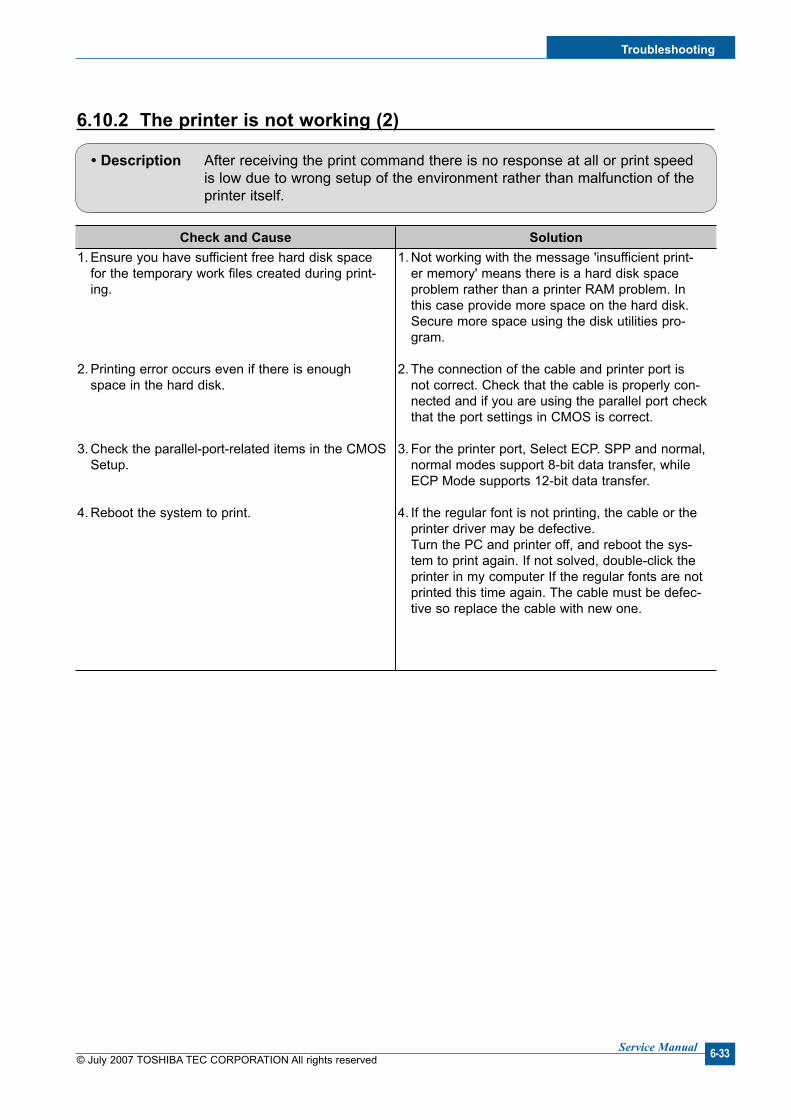
Troubleshootng
© July 2007 TOSHIBA TEC CORPORATION All rights reservedService Manual 6-33
6.10.2 The prnter s not workng (2)
• Descrpton After receiving the print command there is no response at all or print speed is low due to wrong setup of the environment rather than malfunction of the printer itself.
Check and Cause Soluton1. Ensure you have sufficient free hard disk space
for the temporary work files created during print-ing.
2. Printing error occurs even if there is enough space in the hard disk.
3. Check the parallel-port-related items in the CMOS Setup.
4. Reboot the system to print.
1. Not working with the message 'insufficient print-er memory' means there is a hard disk space problem rather than a printer RAM problem. In this case provide more space on the hard disk. Secure more space using the disk utilities pro-gram.
2. The connection of the cable and printer port is not correct. Check that the cable is properly con-nected and if you are using the parallel port check that the port settings in CMOS is correct.
3. For the printer port, Select ECP. SPP and normal, normal modes support 8-bit data transfer, while ECP Mode supports 12-bit data transfer.
4. If the regular font is not printing, the cable or the printer driver may be defective. Turn the PC and printer off, and reboot the sys-tem to print again. If not solved, double-click the printer in my computer If the regular fonts are not printed this time again. The cable must be defec-tive so replace the cable with new one.

© July 2007 TOSHIBA TEC CORPORATION All rights reservedService Manual
Troubleshootng
6-34
6.10.3 Abnormal Prntng
• Descrpton Printing does not work – even after replacing the cable Printer does not work at all or strange fonts are printed.
Check and Cause Soluton1. Set up the parallel port using CMOS SETUP.
2. Printer Driver Error.
3. Error message “insufficient memory”. (The print-ing job sometimes stops due to insufficient virtual memory, this is caused by insufficient space on the hard disk.)
1. Ensure that ECP (best) or SPP is selected in the CMOS (BIOS) setup.
2. Ensure that the correct driver is loaded. Use the driver supplied on the CD. Do not use the Microsoft driver supplied with the Windows oper-ating system. If the printer is a GDI or SPL type printer ensure that ALL OTHER GDI or SPL driv-ers are uninstalled as Windows allows only 1 of this type of driver to be loaded.
3. Delete any unnecessary files to secure enough space on the hard disk and start the print job again.

Troubleshootng
© July 2007 TOSHIBA TEC CORPORATION All rights reservedService Manual 6-35
6.10.4 SPOOL Error
• Descrpton SPOOL (simultaneous peripheral operations online) is the process Windows uses to manage print jobs. Jobs are processed and then stored on the hard disk until the printer is ready to accept them.
How to delete the data n the spool manager.
In the spool manager, the installed drivers and the list of the documents waiting to be printed are shown.
Select the document to be deleted and check delete in the menu.
If the job you are deleting is the current job when you delete the job data that has already been transferred to the printer’s memory will still be printed. If there is a problem with the printer (out of toner, offline, out of paper etc.) the job may take a long time to delete as it must wait for a time out.
Check and Cause Soluton1. Insufficient space on the hard disk in the directory
assigned for the basic spool.
2. If previous printing errors were not solved.
3. There may be conflict with other drivers or pro-grams.
4. When an application program or the printer driver is damaged.
5. When some files related to the OS are damaged or virus infected.
6. Memory is less than suggested.
1. Delete any unnecessary files to provide more space for spool storage.
2. There may be files from previous failed print jobs on the hard disk with the name in the form ‘*.jnl’. Delete these files and Reboot Windows to restart the printer.
3. Shut down all other programs except the current one, if possible.
4. Delete the printer driver completely and reinstall it.
5. After rebooting the computer, check for viruses, restore the damaged files and reinstall the application program which is not working properly.
6. Add up more memory to the PC.

© July 2007 TOSHIBA TEC CORPORATION All rights reservedService Manual
Troubleshootng
6-36
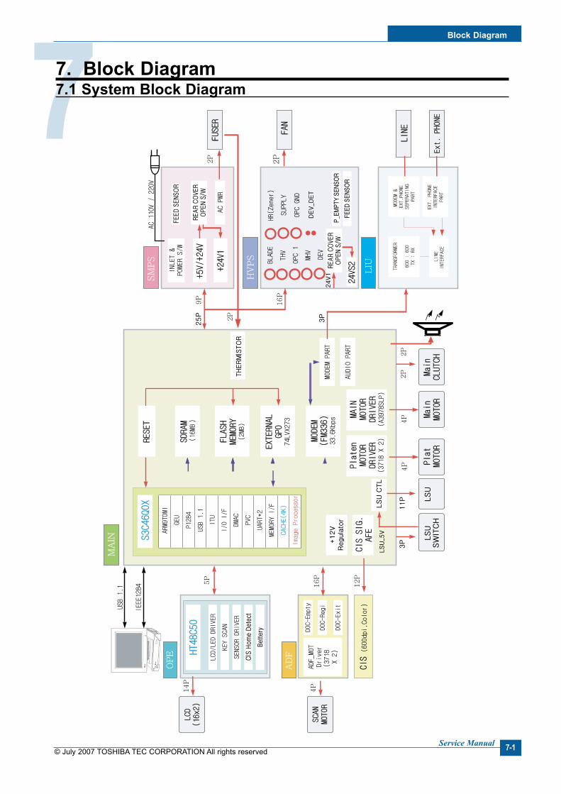
Block Dagram
Service Manual 7-1© July 2007 TOSHIBA TEC CORPORATION All rights reserved
77. Block Dagram7.1 System Block Dagram

Service Manual
Block Dagram
7-2 © July 2007 TOSHIBA TEC CORPORATION All rights reserved
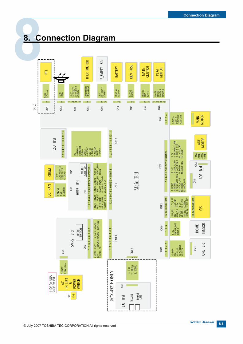
Connecton Dagram
Service Manual 8-1© July 2007 TOSHIBA TEC CORPORATION All rights reserved
88. Connecton Dagram

Service Manual
Connecton Dagram
8-2 © July 2007 TOSHIBA TEC CORPORATION All rights reserved

Reference Informaton
© July 2007 TOSHIBA TEC CORPORATION All rights reservedService Manual 9-1
99. Reference InformatonThis chapter describes the reference information for applying this training manual, and it is consist-edof the tool list, the abbreviation table, the outline of model, and so on.
9.1 Troubleshootng Tool The following tools are recommended safe and easy troubleshooting as described in this service manual.
• DVM (Dgtal Volt Meter) Standard : Indicates more than 3 digits.
• Drver Standard : "-" type, "+" type (M3 long, M3 short,
M2 long, M2 short).
• Tweezers Standard : For general home use, small type.
• Cotton Swab Standard : For general home use, for medical service.
• Cleanng Equpments Standard : An IPA (Isopropyl Alcohol) dry wipe
tissue or a gentle neutral detergent and lint-free cloth.
• Vacuum Cleaner
• Sprng Hook Standard : For general use
• Software (Drver) nstallaton CD ROM

Service Manual
Reference Informaton
9-2 © July 2007 TOSHIBA TEC CORPORATION All rights reserved
9.2 Acronyms and Abbrevatons (1)The table below explains the abbreviations and acronyms used in this service manual. Where abbreviations or acronyms are used in the text please refer to this table.
AP Access Point AC Alternating Current APC Auto Power Control ASIC Application Specific Integrated Circuit ASSY assembly BIOS Basic Input Output System BLDC Brush-less Direct Current CMOS Complementary Metal Oxide Semiconductor CN connector CON connector CPU Central Processing Unit dB decibel dbA decibel A dBM decibel milliwatt DC direct current DCU Diagnostic Control Unit DPI Dot Per Inch DRAM Dynamic Random Access Memory DVM Digital Voltmeter ECP Enhanced Capability Port EDC Embedded Diagnostic control EEPROM Electronically Erasable Programmable Read Only Memory EMI Electro Magnetic Interference EP electrophotographic EPP Enhanced Parallel Port FPOT First Printout Time F/W firmware GDI graphics device interface GND ground HBP Host Based Printing HDD Hard Disk Drive H/H High temperature and high marshy place HV high voltage HVPS High Voltage Power Supply I/F interface I/O Input and Output IC integrated circuit IDE Intelligent Drive electronics or Imbedded Drive Electronics
Abbrevatons Explanaton

Reference Informaton
© July 2007 TOSHIBA TEC CORPORATION All rights reservedService Manual 9-3
Acronyms and Abbrevatons (2)
Abbrevatons Explanaton
IEEE Institute of Electrical and Electronics Engineers. Inc IPA Isopropyl Alcohol IPM Images Per Minute LAN local area network lb pound(s) LBP Laser Beam Printer LCD Liquid Crystal Display LED Light Emitting Diode L/L Low temperature and low marshy place LSU Laser Scanning Unit MB megabyte MHz megahertz MPF Multi Purpose Feeder NIC Network Interface Card N/N Normal temperature and normal marshy place NVRAM nonvolatile random access memory OPC Organic Photo Conductor OPE Operate Panel Equipment PBA Printed Board Assembly PCL Printer Command Language, Printer Control Language PDL Page Description Language PPM Page Per Minute PPS Pulse Per Second PS Post Script PTL Pre-Transfer Lamp PWM Pulse Width Modulation Q-PID Quick Printer Initiating Device
Q’ty quantity
RAM Random Access Memory ROM Read Only Memory SCF Second Cassette Feeder SMPS Switching Mode Power Supply SPGP Samsung Printer Graphic Processor SPL Samsung Printer Language Spool Simultaneous Peripheral Operation Online SW switch sync synchronous or synchronization USB Universal Serial Bus WECA Wireless Ethernet Compatibility Alliance
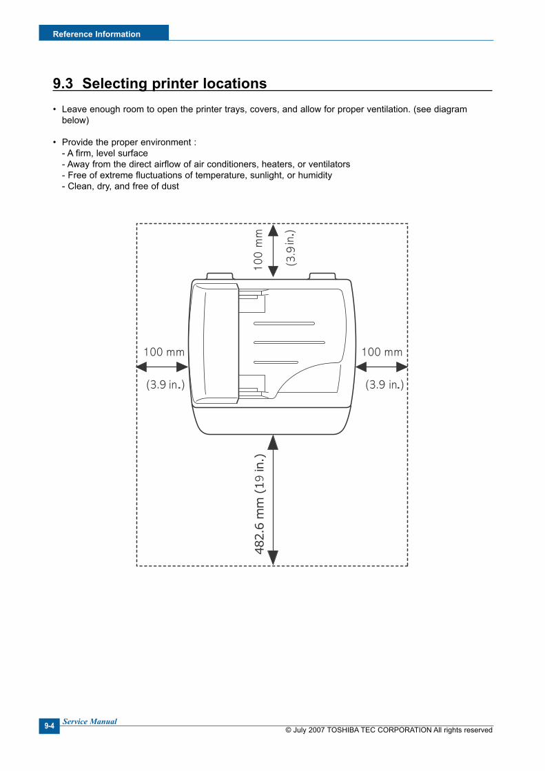
Service Manual
Reference Informaton
9-4 © July 2007 TOSHIBA TEC CORPORATION All rights reserved
9.3 Selectng prnter locatons• Leave enough room to open the printer trays, covers, and allow for proper ventilation. (see diagram
below)
• Provide the proper environment : - A firm, level surface - Away from the direct airflow of air conditioners, heaters, or ventilators - Free of extreme fluctuations of temperature, sunlight, or humidity - Clean, dry, and free of dust

Reference Informaton
© July 2007 TOSHIBA TEC CORPORATION All rights reservedService Manual 9-5
9.4 Sample Tests Patterns The sample patterns shown below are the standard test patterns used in the factory.The life of the toner cartridge, developer cartridge and printing speed are measured with the pattern shown below (5%). The A4 ISO 19752 standard pattern samples are reproduced reduced to 70% of the actual A4 size.
A4 ISO 19752 Standard Patterns

Service Manual
Reference Informaton
9-6 © July 2007 TOSHIBA TEC CORPORATION All rights reserved


Related Documents