Initial Environmental Examination (Draft) September 2015 IND: Green Energy Corridor and Grid Strengthening Project Prepared by Power Grid Corporation of India Limited for the Asian Development Bank.

Welcome message from author
This document is posted to help you gain knowledge. Please leave a comment to let me know what you think about it! Share it to your friends and learn new things together.
Transcript
Initial Environmental Examination (Draft) September 2015
IND: Green Energy Corridor and Grid Strengthening
Project
Prepared by Power Grid Corporation of India Limited for the Asian Development Bank.
This initial environmental examination is a document of the borrower. The views expressed herein do not necessarily represent those of ADB's Board of Directors, Management, or staff, and may be preliminary in nature. Your attention is directed to the “terms of use” section on ADB’s website. In preparing any country program or strategy, financing any project, or by making any designation of or reference to a particular territory or geographic area in this document, the Asian Development Bank does not intend to make any judgments as to the legal or other status of any territory or area.
Initial Environmental Examination (Draft) for
Project 44426-016 (IND): Green Energy Corridor and Grid
Strengthening Project
03 September 2015
Prepared by Power Grid Corporation of India Ltd. for the Asian Development Bank The initial environmental examination is a document of the borrower. The views expressed herein do not necessarily represent those of ADB’s Board of Directors, Management, or staff, and may be preliminary in nature.
Table of Contents
S.No. Page No.
EXECUTIVE SUMMARY 1
1.0 INTRODUCTION 3
1.1 BACKGROUND 3
1.2 THE PROJECT 3
2.0 POLICY, LEGAL AND ADMINISTRATIVE FRAMEWORK 6
2.1 NATIONAL ENVIRONMENTAL REQUIREMENTS 6
2.2 POWERGRID’S ENVIRONMENTAL AND SOCIAL AND POLICY AND PROCEDURES (ESPP)
8
2.3 ASIAN DEVELOPMENT BANK’S ENVIRONMENTAL REQUIREMENTS 9
2.4 COMPARISON OF POWERGRID’S ESPP AND ADB’S SPS 2009 9
SECTION A
DEVELOPMENT OF GREEN ENERGY CORRIDOR ISTS PART-D
12
3.0 DESCRIPTION OF THE PROJECT 12
3.1 PROJECT JUSTIFICATION 12
3.2 OBJECTIVE AND BENEFITS OF THE PROJECT 13
3.3 PROJECT HIGHLIGHTS 13
3.4 SCOPE OF WORK 13
3.5 LOCATION 14
4.0 DESCRIPION OF EXISTING ENVIRONMENT 17
4.1 RAJASTHAN STATE 17
4.2 HARYANA STATE 26
4.3 PUNJAB STATE 30
5.0 ANTICIPATED ENVIRONMENTAL IMPACTS AND MITIGATION MEASURES
40
5.1 PROJECT’S AREA OF INFLUENCE 40
5.2 IMPACTS AND MITIGATION MEASURES DUE TO LOCATION AND DESIGN
40
5.3 IMPACTS AND MITIGATION MEASURES DUE TO CONSTRUCTION PHASE
45
5.4 IMPACTS AND MITIGATION MEASURES DURING OPERATION PHASE
47
6.0 ANALYSIS OF ALTERNATIVES 50
6.1 ENVIRONMENTAL CRITERIA FOR ROUTE SELECTION 50
6.2 EVALUATION OF ALTERNATIVE ROUTE ALIGNMENT OF AJMER -BIKANER 765 KV D/C LINE
50
6.3 EVALUATION OF ALTERNATIVE ROUTE ALIGNMENT OF BIKANER- MOGA 765 KV D/C LINE
52
6.4 EVALUATION OF ALTERNATIVE ROUTE ALIGNMENT OF BIKANER (NEW)- BIKANER (RVPN) 765 KV D/C LINE
54
SECTION B
HVDC BIPOLE LINK BETWEEN WESTERN REGION (RAIGARH, CHHATTISGARH) AND SOUTHERN REGION (PUGALUR, TAMIL
60
NADU) - NORTH TRICHUR (KERALA)
7.0 DESCRIPTION OF THE PROJECT 60
7.1 PROJECT JUSTIFICATION 60
7.2 PROJECT HIGHLIGHTS 60
7.3 SCOPE OF WORK 60
7.4 LOCATION 63
8.0 DESCRIPION OF EXISTING ENVIRONMENT 66
8.1 CHHATTISGARH STATE 66
8.2 TAMIL NADU STATE 68
8.3 KERALA STATE 70
9.0 ANTICIPATED ENVIRONMENTAL IMPACTS AND MITIGATION MEASURES
74
9.1 PROJECT’S AREA OF INFLUENCE 74
9.2 IMPACTS AND MITIGATION MEASURES DUE TO LOCATION AND DESIGN
75
9.3 IMPACTS AND MITIGATION MEASURES DUE TO CONSTRUCTION PHASE
77
9.4 IMPACTS AND MITIGATION MEASURES DURING OPERATION PHASE
78
10.0 ANALYSIS OF ALTERNATIVES 81
10.1 SUBSTATION SITE SELECTION 81
10.2 ENVIRONMENTAL CRITERIA FOR ROUTE SELECTION OF ASSOCIATED FACILITIES
85
11.0 INFORMATION DISCLOSURE, CONSULTATION, AND PARTICIPATION 86
12.0 GRIEVANCE REDRESS MECHANISM 88
13.0 ENVIRONMENTAL MANAGEMENT PLAN 90
13.1 INSTITUTIONAL MECHANISM FOR MITIGATION AND MONITORING REQUIREMENTS
90
13.2 ENVIRONMENTAL MONITORING AND MANAGEMENT PLAN 92
13.3 INSTITUTIONAL MECHANISM FOR REPORTING AND REVIEW 92
14.0 CONCLUSION 106
ABBREVIATIONS
APs – Affected Persons
ASI – Archaeological Survey of India
ADB – Asian Development Bank
CEA – Central Electricity Authority
CPCB – Central Pollution Control Board
CPRI – Central Power Research Institute
CTU – Central Transmission Utility
Ckt-km – Circuit Kilometer
DC – District Collector
D/C – Double Circuit
EPS – Electric Power Survey
EMF – Electro Magnetic Field
ESMC – Environment and Social Management Cell
ESMD – Environment and Social Management Department
ESMU – Environment and Social Management Unit
EMP – Environment Management Plan
ESPP – Environmental and Social Policy & Procedures
EIA – Environmental Impact Assessment
EMP – Environmental Management Plan
EA – Executing Agency
EHV – Extra High Voltage
GIS – Gas Insulated Switchgear
GSHAP – Global Seismic hazard Assessment Program
GoI – Government of India
GRC – Grievance Redress Committee
HVDC – High Voltage Direct Current
IA – Implementing Agency
IPP – Independent Power Producers
IMD – India Metrological Department
IGNP – Indira Gandhi Nahar Project
IEE – Initial Environmental Examination
ISTS – Inter State Transmission Scheme
ICNIRP – International Commission on Non-Ionising Radiation Protection
J&K – Jammu & Kashmir
kV – Kilo Volt
LILO – Loop-In Loop-Out
MSL – Mean Sea Level
MSK – Medvedev Sponheuer Karnik
MVA – Mega Volt Ampere
MSME – Micro Small and Medium Enterprises
MoEF&CC – Ministry of Environment, Forests and Climate Change
MoP – Ministry of Power
NH – National Highway
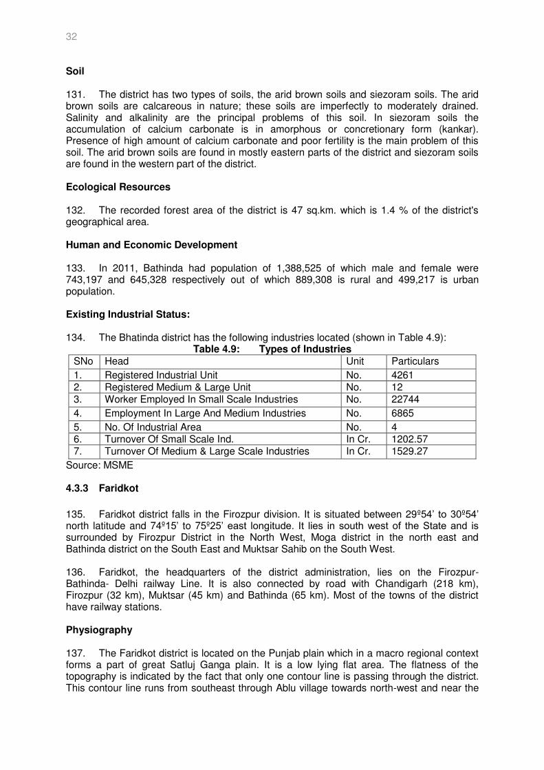
NR – Northern Region
O & M – Operation & Maintenance
POWERGRID or PGCIL/PG
– Power Grid Corporation of India Ltd.
PTCC – Power Telecom Co-ordination Committee
PMU – Project Management Unit
RVPN – Rajasthan Vidyut Prasaran Nigam
RE – Renewable Energy
RoW – Right of Way
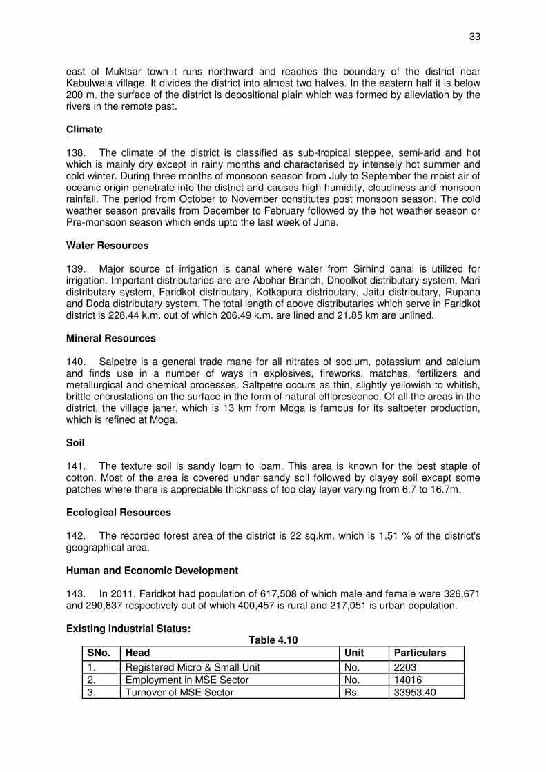
SPS – Safeguard Policy Statement
SC or S/C – Single Circuit
SSI – Small Scale Industry
SMP – Social Management Plan
SR – Southern Region
SCM – Standing Committee Meeting
SH – State Highway
STU – State Transmission Utility
S/S – Substation
SF6 – Sulphur Hexafluoride
UMPP – Ultra Mega Power Project
VSC – Voltage Source Converter
WR – Western Region
WEIGHTS AND MEASURES sq.mm. – square millimeter
Ha. (hectare) – 10,000 square meter = 2.47105 Acres
GW – Giga watt
km (kilometer) – 1,000 meters
kV – kilovolt (1,000 volts)
kW – kilowatt (1,000 watts)
MVA – Megavolt Ampere
MW – Megawatt

1
EXECUTIVE SUMMARY 1. To address the environmental and social issues related to its power transmission projects, POWERGRID has developed its corporate environmental and social policy and procedures (ESPP) based on the principles of avoidance, minimization, and mitigation. The ESPP had been updated and revised in 2009 consistent with the World Bank policy of Use of Country System policy, and applicable laws, legislation and guidelines of Government of India (GoI). 2. On 28 May 2014, the Screening Committee of the Department of Economic Affairs approved a proposal for $500 million sovereign assistance and $400 million from the non-sovereign arm from the Asian Development Bank for Power Grid Corporation of India Ltd (“PGCIL”). The project currently under preparation is slated for approval in 2015. The Project has the following outputs: (i) green energy corridor transmission system expanded in the northern region; (ii) expanded transmission interconnection capacity between the western and southern regions. 3. Environmental impacts associated with the project components are restricted to the clearing and maintenance of the right-of-way (RoW). With the development of innovative tower design being implemented by POWERGRID, the RoW requirements have been reduced from 85 m to 64 m for 765 kV S/C line and from 52 m to 46 m for 400 kV D/C line. Even with ESPP and innovative design, some residual impacts cannot be entirely avoided as about 4.8 hectares of land designated as forest (Plantation along road and canal crossing) by GoI will be affected by the project components. 4. Transmission line projects are considered environmentally-friendly in India and are exempted by the Ministry of Environment, Forests and Climate Change (MoEF&CC) from the requirements of the Environment (Protection) Act 1986. However, when transmission projects pass through forest land, clearance has to be obtained from relevant authorities under the Forest (Conservation) Act, 1980. 5. Under the Forest (Conservation) Act 1980, prior approval from the Regional Offices of MoEF&CC shall be obtained for affected areas classified as forest that will be traversed by the transmission line after detailed survey and finalization of route through forest area in consultation with local forest authorities. Most of the forests that will be traversed by the transmission line routes are plantations along road and canal crossings and are already degraded. 6. Public consultations were conducted in July 2015 and will continue throughout the project cycle. The grievance redress mechanism will be according to the ESPP procedures which are consistent with multilateral banks such as the World Bank and the relevant national regulations. 7. Potential impacts are mostly temporary. The route of transmission lines and substation sites have been finalized so that to avoid any sanctuary or protected areas and other environmentally-sensitive areas. Best available technology and best management practices are built-in to the project design. All project components will be implemented and monitored in line with the Environmental and Social Policy and Procedures of Power Grid Corporation of India Limited, which is in line with ADB SPS (2009).
8. An environmental management plan with cost estimates included in the budget as well as environmental monitoring plan is an integral part of this IEE. A semi-annual environmental monitoring report will be submitted to ADB and will be disclosed publicly at the ADB website.

2
9. According to ADB’s Safeguard Policy Statement, 2009 (SPS 2009), the project is classified as environment category B requiring an initial environmental examination (IEE). Following SPS 2009, an IEE was prepared for the project.
3
1.0 INTRODUCTION 1. In 2015, the Asian Development Bank (ADB) has approved a loan of $900 million ($500 million as sovereign and $400 million as non-sovereign) to the Government of India (GOI) to support continued investment, specifically for strengthening interregional transmission system. The Power Grid Corporation of India Limited (POWERGRID) is the Executing Agency (EA) for the loan. 1.1 Background 2. POWERGRID, the Central Transmission Utility (CTU) of India is engaged in power transmission with the mandate for planning, coordination, supervision and control over complete Inter-State transmission system. As on 30th June 2015, POWERGRID has established about 1,17,323 circuit-kilometer (Ckt-km) of transmission lines at 765 kV, 400 kV, 220 kV and 132 kV extra high voltage alternating current (EHV AC), and 500 kV high voltage direct current (HVDC) levels and196 substations (S/S) with transformation capacity of about 2,37,709 MVA. This transmission network, spread over length and breadth of India, is consistently maintained at an availability of over 99% through deployment of state-of-the-art Operation & Maintenance techniques at par with global standards. About 50 % of total power generated in India is wheeled through transmission network. 3. POWERGRID has been contributing significantly towards the development of India power sector by undertaking coordinated development of power transmission network along with effective and transparent operation of regional grids and through continuous innovations in technical and managerial fields. 1.2 The Project 4. The Project has the following outputs: (i) green energy corridor transmission system expanded in the northern region; (ii) expanded transmission interconnection capacity between the western and southern regions. 5. The project is estimated to cost $ 2,626.1 million. The Government of India (GoI) has requested a loan from ADB to help finance the project. The Executing Agency is the POWERGRID. POWERGRID has already established a Project Management Unit (PMU), functioning under the guidance of technical committee of experts and assisted as required by implementation consultants. 6. Specific details of project investments are as follows: (i) Green Energy Corridor– Inter State Transmission Scheme (ISTS) - Part-D
7. About 33 GW renewable capacity addition has been envisaged in 12th plan in the eight (8) Renewable rich states viz. Tamil Nadu, Andhra Pradesh, Karnataka, Gujarat, Maharashtra, Rajasthan, Himachal Pradesh and Jammu & Kashmir (J&K). In order to facilitate integration of such large scale renewable capacity in 12th plan, a comprehensive transmission plan comprising intra state and inter-state transmission system strengthening was identified as a part of “Green Energy Corridors”. Intra State strengthening of State Transmission Utility (STU) included transmission system within the host state for absorption of power through additional transmission system including transmission lines as well as sub-stations. 8. In view of the quantum of envisaged Renewable capacity addition, associated challenges like volatility, as well as need to enlarge balancing area through strong grid interconnections, there is a need to strengthen Inter-state transmission system. Considering
4
this, High capacity transmission corridor, as part of Inter-state transmission system, connecting major renewable pockets is being proposed right from the Bhuj Pooling station in Gujarat, Western Region (WR) to Moga in Punjab, Northern Region (NR) via Chittorgarh/Ajmer/Bikaner in Rajasthan (NR). In addition, establishment of Tirunelveli Substation and its interconnection with already planned high capacity transmission corridors associated with other Independent Power Producers (IPP) Projects in Southern Region (SR) is also proposed as part of proposed ISTS strengthening of Green Energy Corridors. Above identified ISTS scheme is to be implemented simultaneously. However from funding point of view, scheme is divided in various parts. Part-A of above scheme covers establishment of 765/400 kV substation each at Chittorgarh & Ajmer in Rajasthan & 400/230kV substation at Tirunelvelli in Tamil Nadu whereas Part-B cover establishment of 765/400 kV Banaskantha S/s interconnected to Chittorgarh & Ajmer through High capacity transmission corridors. Part-C covers establishment of 765/400 kV Bhuj Pool S/s interconnected to Banaskantha through High capacity transmission corridors. For further dispersal of power from Ajmer onwards, interconnection are also planned to Moga via Bikaner as part of Green Energy Corridors-ISTS Part-D scheme. The above inter-state transmission scheme was discussed and agreed in 32nd Standing Committee Meeting (SCM) of NR held on 31.08.13. The scheme has also been agreed by the constituents in the 29th meeting of northern regional power committee meeting held on 13.09.13. 9. The sub-project components under the above scheme include following transmission lines and substations:
Ajmer(New) – Bikaner(New) 765 kV D/c – 262.613 km Bikaner(New) – Moga(PG) 765 kV D/c – 366.226 km Bikaner(New) – Bikaner(Rajasthan Vidyut Prasaran Nigam (RVPN) 400 kV D/c
(Quad) – 25.803 km 765/400kV Ajmer Substation Extn. 765/400kV Moga (POWERGRID-PG) Substation Extn. 765/400kV Bikaner Substation (New)
10. The sub-project has an associated facility 400kV Bikaner (RVPN) Substation Extn. * (ii) HVDC Bipole link between Western region (Raigarh, Chhattisgarh) and
Southern region (Pugalur, Tamil Nadu)- North Trichur (Kerala)
11. Southern Region is facing power deficit which has arisen mainly due to (i) delay/deferment of anticipated generation projects and (ii) due to non-availability of gas for existing gas projects in Southern Region. As on date maximum power demand of Southern region is about 39,000 MW and faces a deficit of about 3400 MW inspite of import capacity of about 4920 MW from NEW grid. As per 18th Electric Power Survey (EPS) of Central Electricity Authority) CEA the expected power demand of Southern region by the end of XII and XIII plan would be about 57,200 MW and 82,200 MW respectively. Envisaged generation addition indicates power transfer requirement to Southern Region is expected to increase in coming years particularly under certain scenarios. Therefore, in view of large deficit and requirement of transmission system to meet future requirements, the implementation of HVDC link has been proposed with a capacity of 6000 MW. Also, considering conservation of RoW problem in Kerala and dispersal of power beyond Pugalur, establishment of Voltage Source Converter (VSC) based 2000 MW HVDC link between Pugalur and North Trichur* (Kerala) has also been proposed. The present project will improve import capability of Southern Region. 12. The scheme has been discussed and agreed in the 37th & 38th meeting of Standing Committee on Power System Planning in Southern Region held on 31st July, 2014 & 7th
5
March, 2015 and in the 26th meeting of Southern Region Power Committee (SRPC) held on 20th December, 2014. Further, the scheme has been discussed and agreed in the Joint meeting of the Standing Committee on Power System Planning of Southern Region meeting and Western Region held on 20th April, 2015. Ministry of Power (MoP) vide letter dated 10/12/2014 has approved the implementation of the scheme by POWERGRID under compressed time schedule through regulated tariff mechanism. Further, the scheme has also been discussed and agreed in the 34th Empowered Committee Meeting on Transmission held on 13th April, 2015 for implementation of the scheme under regulated Tariff mechanism. 13. The sub-project components include:
Establishment of Raigarh HVDC Stn +800kV with 6000 MW HVDC terminals. Establishment of Pugalur HVDC Stn +800kV with 6000 MW HVDC terminals
+320kV, 2000 MW VSC based HVDC terminal at North Trichur.
14. The sub-project has an associated facilities– Approximately 1840 km interconnecting line between ± 800 kV Raigarh (HVDC substation) – Pugalur (HVDC substation) having 6000 MW capacity. The Pugalur substation is further connected via 250 km long ± 320 kV HVDC line upto ± 320 kV North Trichur (Kerala) HVDC substation having 2000 MW capacity. 15. The project is classified as environment category B requiring an Initial Environmental Examination (IEE). Following the principles of POWERGRID’s Environmental and Social Policy and Procedures (ESPP) and ADB’s Safeguard Policy Statement (SPS) 2009, an Initial Environmental Examination (IEE) has been prepared for the project. This IEE describes the environmental issues that might arise due to setting up of the project in the states of Rajasthan, Punjab, Haryana, Chhattisgarh, Tamil Nadu and Kerala and the mitigation measures that will be undertaken by POWERGRID during design, construction and maintenance stages.
6
2.0 POLICY, LEGAL, AND ADMINISTRATIVE FRAMEWORK 16. Power transmission activity is undertaken within the purview of GOI’s laws keeping in mind appropriate international obligations and directives and guidelines with respect to environmental and social considerations of funding agencies. The following is a brief description of relevant laws and regulations: 2.1 National Environmental Requirements 2.1.1 Constitutional Provisions 17. Subsequent to the 1st United Nations Conference on Human Environment at Stockholm in June 1972, which emphasized the need to preserve and protect the natural environment, the Constitution of India was amended through the historical 42nd Amendment Act 1976 by inserting Article 48-A and 51-A (g) for protection and promotion of the environment under the Directive Principles of State Policy and the Fundamental Duties respectively. The amendment, inter alia provides: "The State shall endeavour to protect and improve the environment and to safeguard the forests and wildlife of the country". (New Article 48A). ”It shall be the duty of every citizen of India to protect and improve the natural environment including forests, lakes, rivers and wildlife and to have compassion for living creatures”. (New Article 51 A(g)). 18. Article 21 of the constitution provides that, “no person shall be deprived of his life or personal liberty except according to procedure established by law”. This article is the heart of the fundamental rights and has received expanded meaning from time to time after the decision of the Supreme Court in 1978. The Article 21 guarantees fundamental right to life – a life of dignity to be lived in a proper environment, free of danger of disease and infection. 19. Recently, the Supreme Court has broadly and liberally interpreted the Article 21, transgressed into the area of protection of environment, and held that the protection of environment and citizens’ right to live in eco-friendly atmosphere are to be interpreted as the basic right guaranteed under Article 21. Thus, the Indian Constitution has now two fold provisions. First, it gives directive to the State for the protection and improvement of environment and second, the citizens owe a constitutional duty to protect and to improve the natural environment. 2.1.2 Mandatory Requirements (National) Ministry of Power (MoP) order/sanction under the Electricity Act of 2003
20. Sanction of MoP, GOI is a mandatory requirement for taking up any new transmission project under the section 68(1) of The Electricity Act 2003. The sanction authorizes POWERGRID to plan and coordinate activities to commission the new projects. Electricity act does not explicitly deal with environmental implications of activities related to power transmission. However, POWERGRID always integrates environmental protection within its project activities. Rights-of-Way (ROW) and Compensation under the Electricity Act of 2003:
21. The act has a provision for notifying transmission company under section 164 (B) to avail benefits of eminent domain provided under the Indian Telegraph Act, 1885. MOP, GOI vide gazette notification dt 23rd Dec’03 had already notified POWERGRID under this section
7
of said act. Therefore, for the purpose of placing of any wires, poles, etc., POWERGRID has all the powers that the telegraph authority possesses. Thus, POWERGRID can erect and construct towers without actually acquiring the land. However, all damages due to POWERGRID activity are compensated at market rate. Power transmission schemes are always planned in such a way that the power of eminent domain is exercised responsibly. Forest Clearance under the Forest (Conservation) Act of 1980
22. When transmission projects pass through forest land, clearance has to be obtained from relevant authorities under the Forest (Conservation) Act, 1980. This Act aims to prevent rapid deforestation and environmental degradation. State governments cannot de-reserve any forest land or authorize its use for any non-forest purposes without prior approval from the Central government. POWERGRID projects, when involving forest areas, undergo detailed review and approval procedures to obtain a Forest Clearance certificate from Ministry of Environment, Forests and Climate Change (MoEF&CC) before starting any construction activity in the designated forest areas. Environmental Clearances under the Environment (Protection) Act of 1986
23. Transmission line projects are environmentally-clean and its operations do not involve any disposal of solid waste, effluents and hazardous substances in land, air and water. As such, transmission line projects are kept out of the purview of the Environment (Protection) Act 1986. 24. In its notification in September 2006, the MoEF&CC, GoI has exempted transmission line projects from environmental clearances due to the non-polluting nature of its activities. However, forest clearances under the Forest Conservation Act 1980 will be necessary in the event that transmission line passes through forest areas. 25. In the recent amendment of the Environment (Protection) Act 1986, it was required to obtain clearance from the MoEF&CC for power transmission projects in two districts in the Aravalis: Alwar in Rajasthan and Gurgaon in Haryana. Batteries (Management and Handling) Rules of 2001
26. MoEF&CC, vide its notification on 16 May 2001 under the section of 6, 8 and 25 of the Environment (Protection) Act 1986, has put certain restrictions on disposal of used batteries and its handling. The notification provides that it is the responsibility of bulk consumer (POWERGRID) to ensure that used batteries are not disposed of, in any manner, other than by deposing with the dealer/manufacturer/registered recycler/importer/reconditioner or at the designated collection centres – and to file half yearly return in prescribed form to the concerned State Pollution Control Board. Hazardous Wastes (Management and Handling) Amendment Rules of 2003
27. MoEF&CC, vide its notification on 20 May 2003 under the section of 6, 8 and 25 of the Environment (Protection) Act 1986, has put used mineral oil under the category of hazardous waste which requires proper handling and disposal. The notification provides that all used oil should be auctioned and/or sold to registered recyclers only and to file annual return on prescribed form to the concerned State Pollution Control Board. Ozone Depleting Substances (Regulation and Control) Rules of 2000
28. MoEF&CC, vide its notification on 17 July 2000 under the section of 6, 8 and 25 of
8
the Environment (Protection) Act 1986, has notified rules for regulation/control of Ozone Depleting Substances under the Montreal Protocol adopted by GOI on 16 September 1987. The notification provides for certain controls and regulations to be imposed on manufacturing, import, export, and use of these compounds. POWERGRID is following the provisions of the notification and is phasing out all equipment which uses these substances and planning to achieve CFC-free organization in the near future. The Biological Diversity Act, 2002
29. Under the United Nations Convention on Biological Diversity, signed at Rio de Janeiro on 5 June 1992 of which India is a party, MoEF has enacted the Biological Diversity Act of 2002 to provide for conservation of biological diversity, sustainable use of its components, and fair and equitable sharing of the benefits arising out of the use of biological resources, knowledge and for matters connected therewith. According to the Act, certain areas which are rich in biodiversity and encompass unique and representative ecosystems are identified and designated as Biosphere Reserve to facilitate its conservation. All restrictions applicable to protected areas like national park and sanctuaries are also applicable to these reserves. POWERGRID will abide by the provisions of act, wherever applicable, and try to totally avoid these biosphere reserves in selecting the final route alignment. 2.1.3 Relevant Policies
National Conservation Strategy and Policy Statement on Environment and Development of 1992
National Environment Policy of 2006 Policy Statement for Abatement of Pollution of 1992
2.2 POWERGRID's Environmental and Social Policy and Procedures (ESPP) 30. To address the environmental and social issues related to its power transmission projects, POWERGRID has developed its corporate environmental and social policy and procedures (ESPP) in 1998 based on the principles of avoidance, minimization, and mitigation. The ESPP had been updated and revised in 2009 consistent with the World Bank policy of Use of Country System policy1, and applicable laws, legislation and guidelines of GoI. This is now referred to by POWERGRID as the ESPP 2009. 31. ESPP 2009 outlines POWERGRID's approach and commitment in dealing with the environmental and social issues relating to its transmission projects, lays down the management procedures and protocols for the purpose that includes the framework for identification, assessment, and management of environmental and social concerns at both organizational and project levels. 32. Specifically on environment, the following criteria and approach are considered in the ESPP: (i) Avoid operations in environmentally-sensitive areas, eco-sensitive zones, forests,
sanctuaries, national parks, tiger/biosphere reserves, and Coastal Regulation Zone covered coastal areas;
(ii) Consider environmental implications of location, terrain, and sensitive areas in impact identification and mitigate these with innovative and practical engineering solutions;
(iii) Application of efficient and safe technology practices;
1 Power Grid Corporation of India Ltd. Environment and Social Management Department. Environmental and Social Policy & Procedures (ESPP), p5, CC/ESMD/ESPP-09.
9
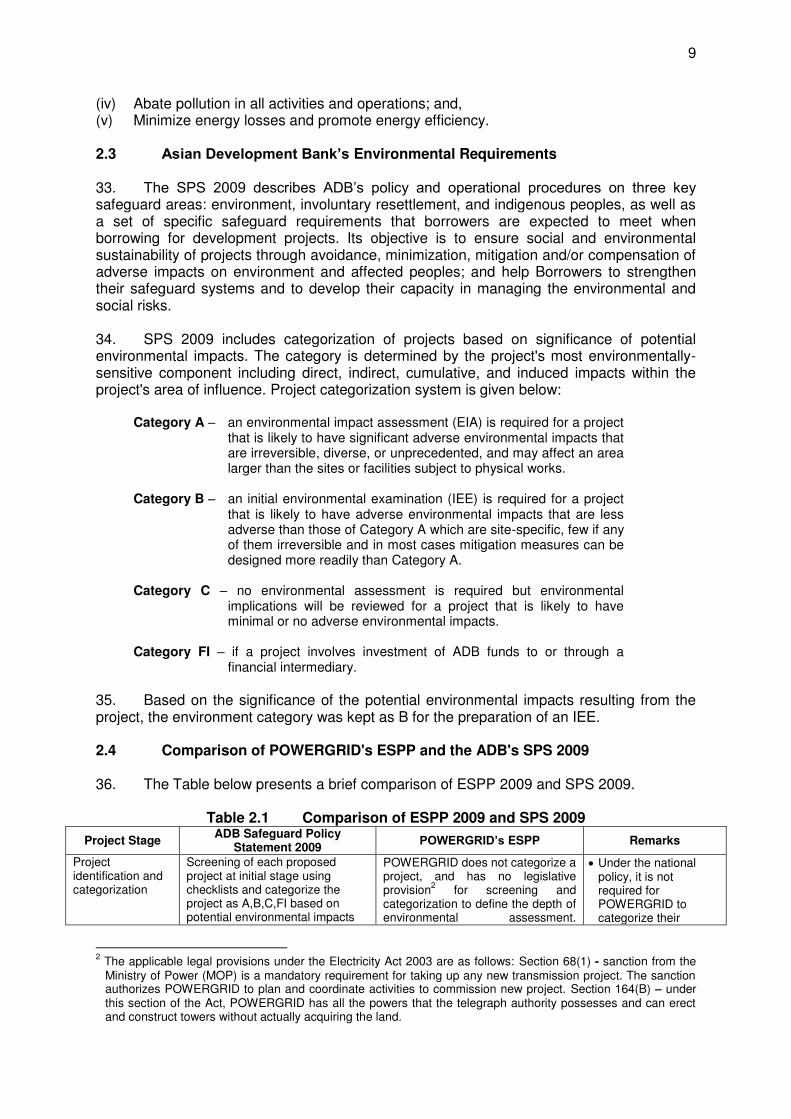
(iv) Abate pollution in all activities and operations; and, (v) Minimize energy losses and promote energy efficiency. 2.3 Asian Development Bank’s Environmental Requirements 33. The SPS 2009 describes ADB’s policy and operational procedures on three key safeguard areas: environment, involuntary resettlement, and indigenous peoples, as well as a set of specific safeguard requirements that borrowers are expected to meet when borrowing for development projects. Its objective is to ensure social and environmental sustainability of projects through avoidance, minimization, mitigation and/or compensation of adverse impacts on environment and affected peoples; and help Borrowers to strengthen their safeguard systems and to develop their capacity in managing the environmental and social risks. 34. SPS 2009 includes categorization of projects based on significance of potential environmental impacts. The category is determined by the project's most environmentally-sensitive component including direct, indirect, cumulative, and induced impacts within the project's area of influence. Project categorization system is given below:
Category A – an environmental impact assessment (EIA) is required for a project that is likely to have significant adverse environmental impacts that are irreversible, diverse, or unprecedented, and may affect an area larger than the sites or facilities subject to physical works.
Category B – an initial environmental examination (IEE) is required for a project
that is likely to have adverse environmental impacts that are less adverse than those of Category A which are site-specific, few if any of them irreversible and in most cases mitigation measures can be designed more readily than Category A.
Category C – no environmental assessment is required but environmental
implications will be reviewed for a project that is likely to have minimal or no adverse environmental impacts.
Category FI – if a project involves investment of ADB funds to or through a
financial intermediary.
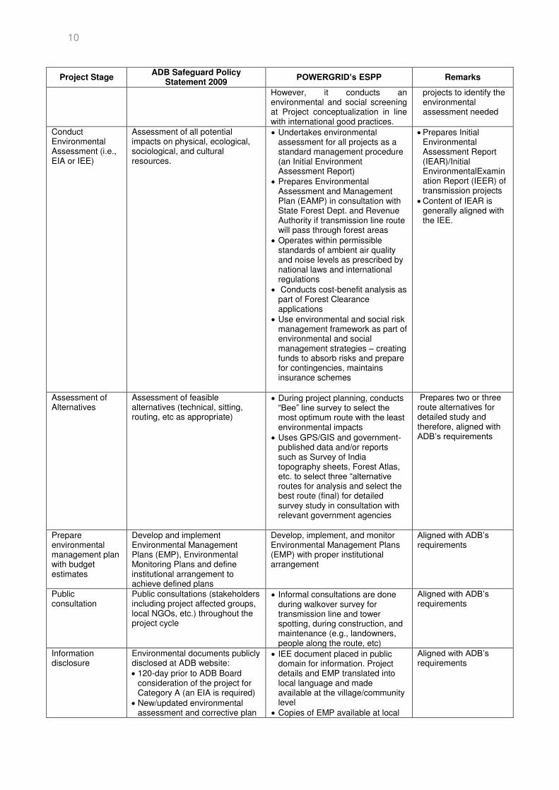
35. Based on the significance of the potential environmental impacts resulting from the project, the environment category was kept as B for the preparation of an IEE. 2.4 Comparison of POWERGRID's ESPP and the ADB's SPS 2009 36. The Table below presents a brief comparison of ESPP 2009 and SPS 2009.
Table 2.1 Comparison of ESPP 2009 and SPS 2009
Project Stage ADB Safeguard Policy
Statement 2009 POWERGRID’s ESPP Remarks
Project identification and categorization
Screening of each proposed project at initial stage using checklists and categorize the project as A,B,C,FI based on potential environmental impacts
POWERGRID does not categorize a project, and has no legislative provision
2 for screening and
categorization to define the depth of environmental assessment.
Under the national policy, it is not required for POWERGRID to categorize their
2 The applicable legal provisions under the Electricity Act 2003 are as follows: Section 68(1) - sanction from the Ministry of Power (MOP) is a mandatory requirement for taking up any new transmission project. The sanction authorizes POWERGRID to plan and coordinate activities to commission new project. Section 164(B) – under this section of the Act, POWERGRID has all the powers that the telegraph authority possesses and can erect and construct towers without actually acquiring the land.
10
Project Stage ADB Safeguard Policy
Statement 2009 POWERGRID’s ESPP Remarks
However, it conducts an environmental and social screening at Project conceptualization in line with international good practices.
projects to identify the environmental assessment needed
Conduct Environmental Assessment (i.e., EIA or IEE)
Assessment of all potential impacts on physical, ecological, sociological, and cultural resources.
Undertakes environmental assessment for all projects as a standard management procedure (an Initial Environment Assessment Report)
Prepares Environmental Assessment and Management Plan (EAMP) in consultation with State Forest Dept. and Revenue Authority if transmission line route will pass through forest areas
Operates within permissible standards of ambient air quality and noise levels as prescribed by national laws and international regulations
Conducts cost-benefit analysis as part of Forest Clearance applications
Use environmental and social risk management framework as part of environmental and social management strategies – creating funds to absorb risks and prepare for contingencies, maintains insurance schemes
Prepares Initial Environmental Assessment Report (IEAR)/Initial EnvironmentalExamination Report (IEER) of transmission projects
Content of IEAR is generally aligned with the IEE.
Assessment of Alternatives
Assessment of feasible alternatives (technical, sitting, routing, etc as appropriate)
During project planning, conducts “Bee” line survey to select the most optimum route with the least environmental impacts
Uses GPS/GIS and government-published data and/or reports such as Survey of India topography sheets, Forest Atlas, etc. to select three “alternative routes for analysis and select the best route (final) for detailed survey study in consultation with relevant government agencies
Prepares two or three route alternatives for detailed study and therefore, aligned with ADB’s requirements
Prepare environmental management plan with budget estimates
Develop and implement Environmental Management Plans (EMP), Environmental Monitoring Plans and define institutional arrangement to achieve defined plans
Develop, implement, and monitor Environmental Management Plans (EMP) with proper institutional arrangement
Aligned with ADB’s requirements
Public consultation
Public consultations (stakeholders including project affected groups, local NGOs, etc.) throughout the project cycle
Informal consultations are done during walkover survey for transmission line and tower spotting, during construction, and maintenance (e.g., landowners, people along the route, etc)
Aligned with ADB’s requirements
Information disclosure
Environmental documents publicly disclosed at ADB website: 120-day prior to ADB Board
consideration of the project for Category A (an EIA is required)
New/updated environmental assessment and corrective plan
IEE document placed in public domain for information. Project details and EMP translated into local language and made available at the village/community level
Copies of EMP available at local
Aligned with ADB’s requirements

11
Project Stage ADB Safeguard Policy
Statement 2009 POWERGRID’s ESPP Remarks
prepared during implementation Environmental monitoring
reports
level for stakeholders’ inputs (as needed)
37. Based on the brief comparison given in Table 2.1, except for categorization of projects, ESPP 2009 is generally aligned with the requirements of ADB’s SPS 2009.
12
SECTION A: DEVELOPMENT OF GREEN ENERGY CORRIDOR– ISTS - PART-D 3.0 DESCRIPTION OF THE PROJECT 3.1 Project Justification 38. It is envisaged that about 33,000 MW renewable generation capacity shall be added during 12th plan period in eight (8) RE resource rich states viz. Rajasthan (5700 MW), Gujarat (4700 MW), Tamil Nadu (7400 MW), Maharashtra (4100 MW), Karnataka (4300 MW), AP (4800 MW), HP (1300 MW) and J&K (500 MW) through Wind/Solar & Small Hydro generation. 39. Considering above quantum of envisaged Renewable capacity, it is expected that some of the Renewable Energy (RE) Resource rich states including Rajasthan shall have more RE capacity than the capacity required for fulfilling their Renewable Purchase Obligations (RPO). Further, such RE rich host state may not absorb full RE energy locally particularly during the other than peak hour conditions when renewable generation is at peak. Intermittency/ variability, inherent characteristics of renewable, also necessitates requirement of strong grid interconnections for grid stability. 40. In addition, the Indian Electricity Grid Code (IEGC) stipulates, renewable energy plants to have “MUST RUN” status and not to be subjected to “merit order dispatch” principles. Considering above, there is a need to strengthen Inter-state transmission which shall facilitate transfer of power outside the RE resource rich states with reliability and security as well as enlargement of balancing area to address volatility issues of renewables. 41. In Gujarat about 4700 MW renewable generation capacity is envisaged through Wind & Solar. Out of above, about 1100 MW Wind and 200 MW Solar generation capacity additions are envisaged in Kutch area alone. In Rajasthan about 5700 MW renewable generation capacity is envisaged through Wind & Solar. Out of above, in southern part of Rajasthan (Banswara/Pratapgarh) total about 800 MW Wind generation is envisaged near Chittorgarh. Further, about 1000 MW Wind/Solar generation potential is indicated around Bikaner in western Rajasthan. 42. Considering immense potential of renewable resources in Kutch/Banaskantha/Chittorgarh/Bikaner area, high capacity 765/400 kV substation at above location is proposed. 43. For dispersal of power, High capacity transmission corridor, as part of Inter-state transmission system (ISTS), connecting major renewable pockets is being proposed right from the Bhuj Pooling station in Gujarat (WR) to Moga in Punjab (NR) via Chittorgarh/Ajmer/Bikaner in Rajasthan (NR). Identified transmission system shall also be integrated with the grid so as to ensure optimal utilization of transmission system. 44. For onward dispersal of power beyond Ajmer/Bikaner, 765 kV High capacity transmission corridor is proposed towards Moga in Punjab, a major load centre in NR, as part of Green Energy Corridors-Part-D scheme. Moga is well connected to major hydro complexes in J&K/ Himachal Pradesh (HP) (3400 MW) and Uttarakhand (1400M W). In addition, more such hydro capacity (3300 MW) including pumped storage plants is under construction in above complexes, which shall help in addressing intermittency aspect of renewables. Moga is also inter-connected with High capacity HVDC system at Bhiwadi which shall provide flexibility in power transfer requirement to address variability of renewable generation. In this manner, this shall facilitate integration of Renewable with hydro complex, enabling supply side balancing through flexible hydropower resources as well as address intermittency issues of renewables.
13
3.2 Objective and Benefits of the Project 45. POWERGRID has undertaken and evolved the various elements of this transmission scheme keeping in view the envisaged renewable energy (RE) generation and to facilitate transfer of the RE power to load centres of Northern Region. In addition, they are likely to generate direct and indirect employment opportunities, promote industrial growth, and stimulate overall development of the area. 3.3 Project Highlights
Table 3.1 Project Highlights a) Project : Green Energy Corridors – ISTS - Part-D b) Location of the Project : Northern Region c) Project Cost Rs. 3973.92 Crores at February 2015 Price Level
(including IDC of Rs. 231.74 Crores ) d) Commissioning schedule Transmission System is proposed to be implemented
within 36 months from the date of Investment Approval.
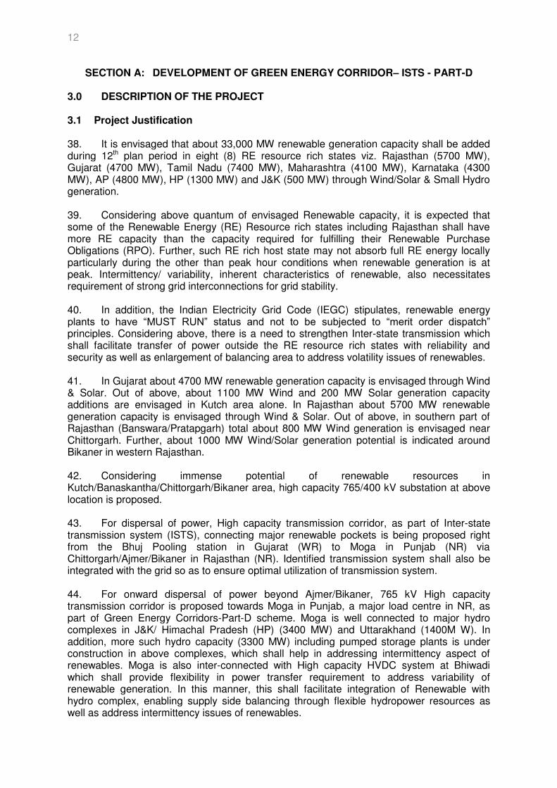
46. The above inter-state transmission scheme was discussed and agreed in 32nd Standing Committee Meeting (SCM) of Northern Region (NR) held on 31.08.13. The scheme has also been agreed by the constituents in the 29th meeting of northern regional power committee meeting held on 13.09.13. 47. The schematic of the proposed Transmission system is shown at Figure 3.1.
Figure 3.1: Schematic Diagram of the proposed Transmission System 3.4 Scope of Work 48. The complete scope of the transmission system to be implemented under the scheme is as follows: Transmission Lines
Ajmer (New) – Bikaner (New) 765 kV D/c – 262.613 km
14
Bikaner (New) – Moga (PG) 765 kV D/c – 366.226 km
Bikaner (New) – Bikaner (RVPN) 400 kV D/c (Quad) – 25.803 km
Substation
765/400kV Bikaner Substation (New)
765/400kV Ajmer Substation Extn.
765/400kV Moga (PG) Substation Extn.
400kV Bikaner (RVPN) Substation Extn. * * NOTE: Bay Extn work at this Substation to be carried out by RVPN on Deposit work basis for POWERGRID.
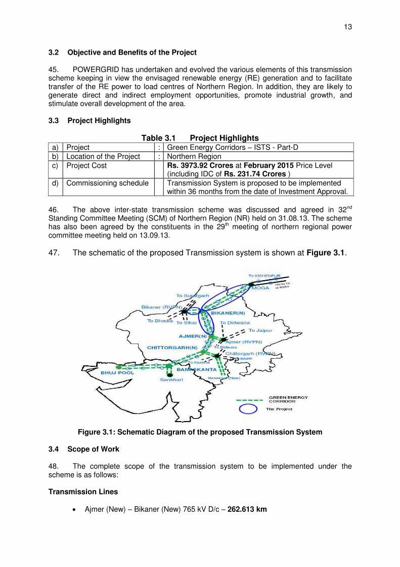
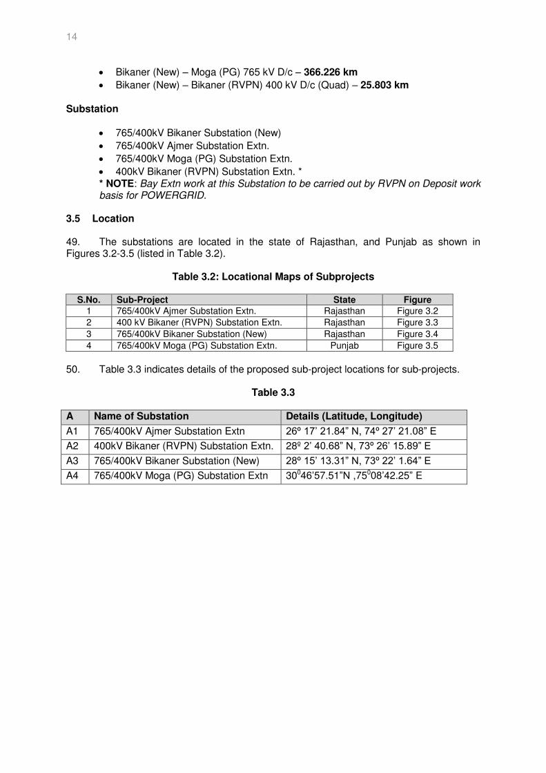
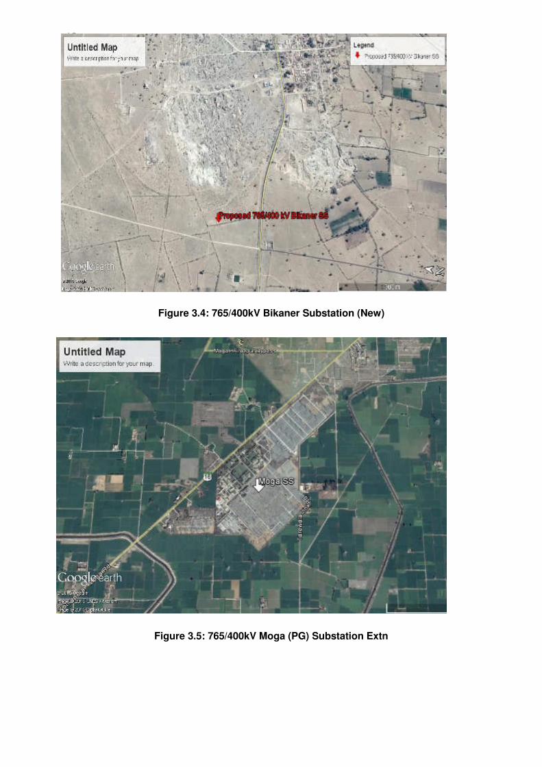
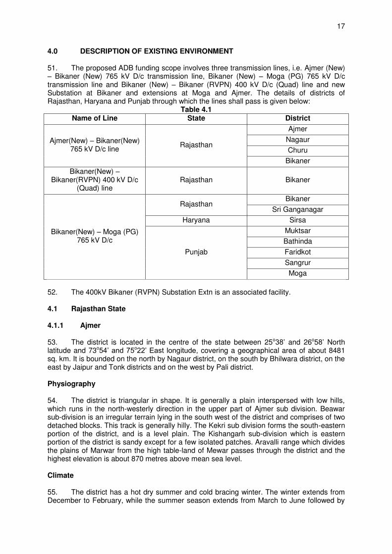
3.5 Location 49. The substations are located in the state of Rajasthan, and Punjab as shown in Figures 3.2-3.5 (listed in Table 3.2).
Table 3.2: Locational Maps of Subprojects
S.No. Sub-Project State Figure
1 765/400kV Ajmer Substation Extn. Rajasthan Figure 3.2
2 400 kV Bikaner (RVPN) Substation Extn. Rajasthan Figure 3.3
3 765/400kV Bikaner Substation (New) Rajasthan Figure 3.4
4 765/400kV Moga (PG) Substation Extn. Punjab Figure 3.5
50. Table 3.3 indicates details of the proposed sub-project locations for sub-projects.
Table 3.3
A Name of Substation Details (Latitude, Longitude)
A1 765/400kV Ajmer Substation Extn 26º 17’ 21.84” N, 74º 27’ 21.08” E
A2 400kV Bikaner (RVPN) Substation Extn. 28º 2’ 40.68” N, 73º 26’ 15.89” E
A3 765/400kV Bikaner Substation (New) 28º 15’ 13.31” N, 73º 22’ 1.64” E
A4 765/400kV Moga (PG) Substation Extn 30046’57.51”N ,75008’42.25” E
15
Figure 3.2: 765/400kV Ajmer Substation Extn
Figure 3.3: 400kV Bikaner (RVPN) Substation Extn
16
Figure 3.4: 765/400kV Bikaner Substation (New)
Figure 3.5: 765/400kV Moga (PG) Substation Extn
17
4.0 DESCRIPTION OF EXISTING ENVIRONMENT 51. The proposed ADB funding scope involves three transmission lines, i.e. Ajmer (New) – Bikaner (New) 765 kV D/c transmission line, Bikaner (New) – Moga (PG) 765 kV D/c transmission line and Bikaner (New) – Bikaner (RVPN) 400 kV D/c (Quad) line and new Substation at Bikaner and extensions at Moga and Ajmer. The details of districts of Rajasthan, Haryana and Punjab through which the lines shall pass is given below:
Table 4.1 Name of Line State District
Ajmer(New) – Bikaner(New) 765 kV D/c line
Rajasthan
Ajmer
Nagaur
Churu
Bikaner
Bikaner(New) – Bikaner(RVPN) 400 kV D/c
(Quad) line Rajasthan Bikaner
Bikaner(New) – Moga (PG) 765 kV D/c
Rajasthan Bikaner
Sri Ganganagar
Haryana Sirsa
Punjab
Muktsar
Bathinda
Faridkot
Sangrur
Moga
52. The 400kV Bikaner (RVPN) Substation Extn is an associated facility. 4.1 Rajasthan State 4.1.1 Ajmer
53. The district is located in the centre of the state between 25o38’ and 26o58’ North latitude and 73o54’ and 75o22’ East longitude, covering a geographical area of about 8481 sq. km. It is bounded on the north by Nagaur district, on the south by Bhilwara district, on the east by Jaipur and Tonk districts and on the west by Pali district. Physiography 54. The district is triangular in shape. It is generally a plain interspersed with low hills, which runs in the north-westerly direction in the upper part of Ajmer sub division. Beawar sub-division is an irregular terrain lying in the south west of the district and comprises of two detached blocks. This track is generally hilly. The Kekri sub division forms the south-eastern portion of the district, and is a level plain. The Kishangarh sub-division which is eastern portion of the district is sandy except for a few isolated patches. Aravalli range which divides the plains of Marwar from the high table-land of Mewar passes through the district and the highest elevation is about 870 metres above mean sea level. Climate 55. The district has a hot dry summer and cold bracing winter. The winter extends from December to February, while the summer season extends from March to June followed by
18
rainy season till mid of September. The temperature during the summer scales up to 45°C and goes down up to 2°C during winter. The normal annual rainfall is 527.3 mm. Water Resources 56. There are five fivers which flow through the district viz. Banas, Khari, Sagarmati, Saraswati and Rupnagar. There are natural lakes viz. Pushkar and Budha Pushkar near Ajmer city. Among the important tanks in the district are foy sagar, phool sagar, bisala, ramsar, dilwar, jawaja etc. Mineral Resources 57. Important minerals found in the district are mica, asbestos, vemiculite, soap stone, masonary stone and brickclay etc. Soil 58. Soils of Ajmer district are reddish to yellowish red and yellowish brown color. These soils are sandy loam to sandy clay loam in texture and well drained. Fertility status of these soil is, low in Nitrogen, moderate in Phosphorus and Potassium. Cultivation of crops in the soil is very much restricted due to shallow nature of these soils and presence of stones on the surface. Ecological Resources 59. The recorded forest area of the district is 282 sq.km. which is 3.33% of the district's geographical area. Human and Economic Development 60. In 2011, Ajmer had population of 2,583,052 of which male and female were 1,324,085 and 1,258,967 respectively out of which 1,547,642 is rural and 1,035,410 is urban population. Existing Industrial Status 61. In Ajmer district 8 medium scale Industries and 17663 small scale & cottage Industries were registered up to March, 2011. The total investment involved was Rs. 92,797.54 lakhs giving employment opportunities to about 87,420 persons. The main Industries of the district are based on textile, food products, leather and leather products, wood products, felspars and quartz grinding, marble, asbestos and cement. 4.1.2 Nagaur
62. Nagaur district is located between latitude 26°25’ and 27°40’ North and longitude 73°10’ and 75°15’ East. Due to its central situation in Rajasthan, it shares its borders in North with –Bikaner & Churu, in South with- Ajmer & Pali, in East with- Sikar & Jaipur & in West with- Jodhpur district. Physiography 63. The district has a geographical area of 17,718 sq.km, representing 5.18% of the total area of Rajasthan and ranks sixth among the districts of the State. The Aravali range of hills passes in eastern and south eastern part of the district. The average elevation of the hills in district is barely 310 meters.
19
Climate 64. Nagaur has a dry climate with a hot summer. Sand storms are common in summer. The district's climate is marked by extreme dryness, large variations of temperature & highly irregular rainfall patterns. The mean daily maximum temperature in May is 40.4°C and the mean daily minimum temperature is 25.7°C. Night temperatures in June are much higher than in May with mean daily minimum temperature of 27.9°C. During the summer month the maximum temperature sometimes exceeds 48°C. The humidity is highest in August with mean daily relative humidity is 80%. The annual maximum potential evapotranspiration in the district is quite high and it is highest (255.1 mm) in the month of May and lowest (76.5 mm) in the month of December. Water Resources 65. There is no river which originated from the district however; the river Luni which rises near Pushkar in Ajmer district draining western slopes of the Aravalli crosses the district in the southern part flowing for about 37 km in the western direction. It is an ephemeral river and carries runoff that is generated in the upper reaches. Channel deposits of Luni facilitate percolation during rainstorm, thereby feeding the neighbouring wells along its bank. Other nalas and streams are also ephemeral in nature which originate and die out in the district itself. There is salt lake (Sambhar Lake) at south west of Didwana having an area of 777 hectare The Nawa tehsil also shares a part of well-known Sambhar Lake in Jaipur district. There are eight (8) numbers of ponds in the district. Out of these 5 are in Degana and 3 in Parbatsar blocks. Mineral Resources 66. Nagaur district is abound with variety of mineral resources, gypsum, Limestone and Marble are the most important mineral found in the district. Nagaur district is also an important salt producing area. Soil 67. A big part of the district is covered by blown sand and sand dunes which form part of the great Thar district. Active dunes and sand shifting are main hazards to cultivation. Sand dunes are common in the north and western parts, where they arise over 30 meters and are aligned in a north west and south cast direction. Constant deterioration of soil and mining activity has resulted in soil erosion. Ecological Resources 68. The recorded forest area of the district is 121 sq.km. which is 0.68% of the district's geographical area. Human and Economic Development 69. In 2011, Nagaur had population of 3,307,743 of which male and female were 1,696,325 and 1,611,418 respectively out which 2,670,539 is rural and 637,204 is urban population. Existing Industrial Status: 70. The Nagaur district has the following industries located:
Registered Large and Medium Industries: 3 Nos
20
Registered Small Scale Industry (SSI) Units: 8162 Nos Investment in Small Scale Ind.: 14390.54 (Rs. In Lacs). Employment in Micro Small and Medium Enterprises (MSMEs): 40901 Nos .Employment in Large and Medium Industries: 581 Nos.
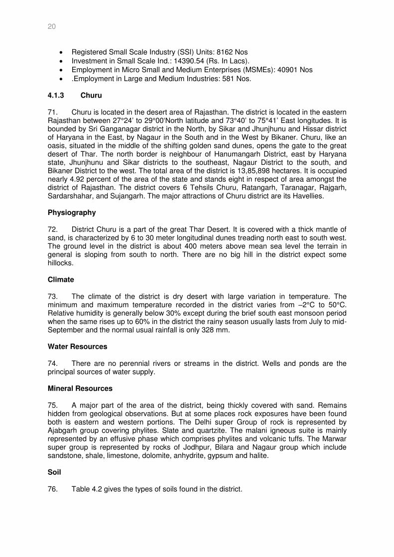
4.1.3 Churu 71. Churu is located in the desert area of Rajasthan. The district is located in the eastern Rajasthan between 27°24’ to 29°00‘North latitude and 73°40’ to 75°41’ East longitudes. It is bounded by Sri Ganganagar district in the North, by Sikar and Jhunjhunu and Hissar district of Haryana in the East, by Nagaur in the South and in the West by Bikaner. Churu, like an oasis, situated in the middle of the shifting golden sand dunes, opens the gate to the great desert of Thar. The north border is neighbour of Hanumangarh District, east by Haryana state, Jhunjhunu and Sikar districts to the southeast, Nagaur District to the south, and Bikaner District to the west. The total area of the district is 13,85,898 hectares. It is occupied nearly 4.92 percent of the area of the state and stands eight in respect of area amongst the district of Rajasthan. The district covers 6 Tehsils Churu, Ratangarh, Taranagar, Rajgarh, Sardarshahar, and Sujangarh. The major attractions of Churu district are its Havellies. Physiography 72. District Churu is a part of the great Thar Desert. It is covered with a thick mantle of sand, is characterized by 6 to 30 meter longitudinal dunes treading north east to south west. The ground level in the district is about 400 meters above mean sea level the terrain in general is sloping from south to north. There are no big hill in the district expect some hillocks. Climate 73. The climate of the district is dry desert with large variation in temperature. The minimum and maximum temperature recorded in the district varies from –2°C to 50°C. Relative humidity is generally below 30% except during the brief south east monsoon period when the same rises up to 60% in the district the rainy season usually lasts from July to mid-September and the normal usual rainfall is only 328 mm. Water Resources 74. There are no perennial rivers or streams in the district. Wells and ponds are the principal sources of water supply. Mineral Resources 75. A major part of the area of the district, being thickly covered with sand. Remains hidden from geological observations. But at some places rock exposures have been found both is eastern and western portions. The Delhi super Group of rock is represented by Ajabgarh group covering phylites. Slate and quartzite. The malani igneous suite is mainly represented by an effusive phase which comprises phylites and volcanic tuffs. The Marwar super group is represented by rocks of Jodhpur, Bilara and Nagaur group which include sandstone, shale, limestone, dolomite, anhydrite, gypsum and halite. Soil 76. Table 4.2 gives the types of soils found in the district.
21
Table 4.2: Type of Soils in Churu district Major Soils Area (‘000 ha) Percent (%) of total Deep Yellowish brown Sandy 1030 74.3 Deep Light yellowish brown Loamy 165.1 11.9 Deep Pale brown Sandy, Medium Light yellowish brown Loamy, Medium Light yellowish brown Sandy, Deep Pale brown Loamy
189.8 13.7
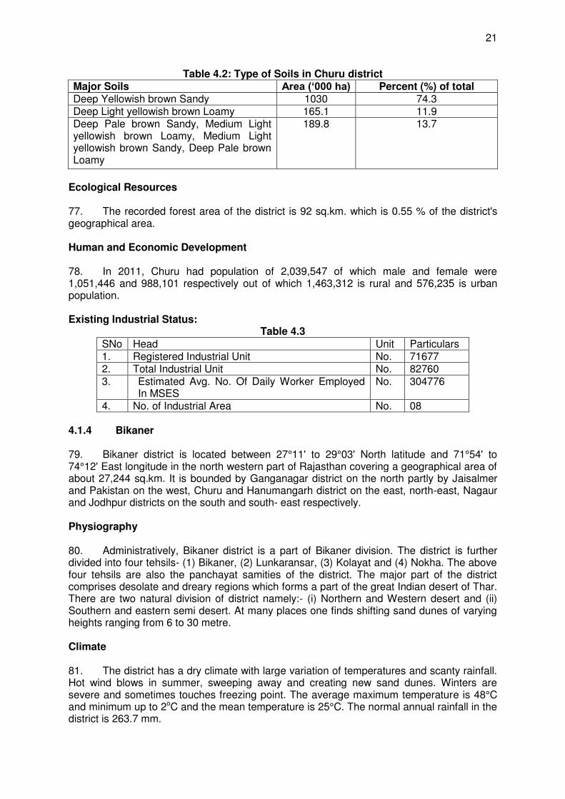
Ecological Resources 77. The recorded forest area of the district is 92 sq.km. which is 0.55 % of the district's geographical area. Human and Economic Development 78. In 2011, Churu had population of 2,039,547 of which male and female were 1,051,446 and 988,101 respectively out of which 1,463,312 is rural and 576,235 is urban population. Existing Industrial Status:
Table 4.3
SNo Head Unit Particulars 1. Registered Industrial Unit No. 71677 2. Total Industrial Unit No. 82760 3. Estimated Avg. No. Of Daily Worker Employed
In MSES
No. 304776
4. No. of Industrial Area No. 08 4.1.4 Bikaner
79. Bikaner district is located between 27°11' to 29°03' North latitude and 71°54' to 74°12' East longitude in the north western part of Rajasthan covering a geographical area of about 27,244 sq.km. It is bounded by Ganganagar district on the north partly by Jaisalmer and Pakistan on the west, Churu and Hanumangarh district on the east, north-east, Nagaur and Jodhpur districts on the south and south east respectively. Physiography 80. Administratively, Bikaner district is a part of Bikaner division. The district is further divided into four tehsils- (1) Bikaner, (2) Lunkaransar, (3) Kolayat and (4) Nokha. The above four tehsils are also the panchayat samities of the district. The major part of the district comprises desolate and dreary regions which forms a part of the great Indian desert of Thar. There are two natural division of district namely:- (i) Northern and Western desert and (ii) Southern and eastern semi desert. At many places one finds shifting sand dunes of varying heights ranging from 6 to 30 metre. Climate 81. The district has a dry climate with large variation of temperatures and scanty rainfall. Hot wind blows in summer, sweeping away and creating new sand dunes. Winters are severe and sometimes touches freezing point. The average maximum temperature is 48°C and minimum up to 2oC and the mean temperature is 25°C. The normal annual rainfall in the district is 263.7 mm.
22
Water Resources 82. There are no hills, rivers or any stream of significance. Small ephemeral streams flow in the vicinity of Kolayat, Gajner and Gura. Natural inland depression which retains some water during the summer are located near Lunkaransar, Kolayat, Jamsar and Nal. Construction of wells in the western part has led to activation of the stable dune field to a large extent. The migrating sand is however threatening the canals and roads. Mineral Resources 83. Almost entire district is devoid of rock outcrops except near Kolayat and at a few places in the south of Nokha and Dhulmera. The district is thus a vast sandy tract. All four tehsils except Kolayat, are covered with sand. Rocks locally known as ‘Magra’, are found in the parts of Kolayat tehsil. In the ‘Magra’ area various types of sand stone, clay and limestone are found at various depths. Fuller earth (Multani mitti), lignite, gypsum, while clay, yellow ochre and grit are important economic minerals. Gypsum bed upto 30 metre thick and of the best quality available in India is found in Jamser village in Bikaner tehsil. Soil 84. Duny areas are light pale brown to brown, very deep, fine sand to loamy fine sand and devoid of any pedogenic manifestation except weak segregation of alkaline earth carbonates. In associated plains and interdunal areas occur light yellowish brown to brown, loamy fine sand, very weakly blocky, non-calcareous sub soil followed by a weak to moderately developed calcic/cambic horizon and are classified accordingly as calcids/cambids. Ecological Resources 85. The recorded forest area of the district is 210 sq.km. which is 0.77 % of the district's geographical area. The vegetation of Bikaner district falls under the broad natural division of the tropical forest but due to extremely low rainfall and extremes of temperature, there is high evaporation and loss of moisture converting the district into a typical arid tract. However, where the moisture accumulates to some extent during rains, a few scattered stunted trees are found. Human and Economic Development 86. In 2011, Bikaner had population of 2,363,937 of which male and female were 1,240,801 and 1,123,136 respectively out which 1,563,553 is rural and 800,384 is urban population. Existing Industrial Status: 87. The Bikaner district has the following industries located:
Registered Industrial unit: 12396 nos. Registered Large/medium scale units: 6 nos. Estimated Avg. No. of Daily Worker Employed in MSME’s: 50292 Nos. Employment In Large and Medium Industries: 14 Nos Turnover of Small Scale Ind.: 18167 Lakhs
Turnover of Medium & Large Scale Industries: 12379 Lakhs
23
4.1.5 Sri Ganganagar
88. The district is the northern most district of the state of Rajasthan and forms a part of Indo-Gangetic plain. It is bordering Pakistan on the west and state of Punjab on the north. District Bikaner is on the south and newly formed Hanumangarh district is on the east. It is located between 28°40’ to 30°06’ north latitude and 72°39’ to 74°21’ east longitude. The district commands a very strategic geographical location having a total area of 1092878 sq. ha., which roughly works out to 3.73% of the total area of the state. Physiography 89. Although Ganganagar District lies in the great Thar desert, irrigation via the Ganga canal and Indira Gandhi Nahar Project (IGNP) canal has changed the flora and fauna. The district can be classified into five geographical regions:
1. The region irrigated by the Gang canal and the Bhakhra canal tributaries 2. Area irrigated by the Suratgarh branch of the IGNP canal 3. Area irrigated by Anoopgarh branch of IGNP canal 4. The Naali belt 5. The 'Uncha Tibba' (high sandy dunes) area of Suratgarh tehsil
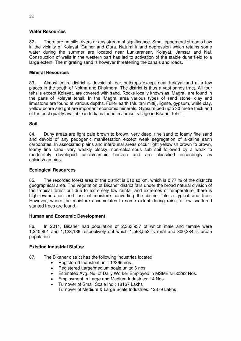
Climate 90. The climate of Sri Ganganagar varies to extreme limits. Summer temperature reaches 50° C and winter temperature dips just around 0°C. The average annual rainfall is only 200 mm. The maximum temperature in summer is 48.4°C and the minimum temperature in winter is 0.6°C. As a result there are scorching heat waves in summer and biting cold waves in winter in the whole district. Water Resources 91. The Ghaggar river is the only major river of the district. It is a seasonal river, which flows in the rainy season. It enters the district near Suratgarh and then flows in areas of Jaitsar, Vijaynagar, Anoopgarh and then crosses the Indo-Pakistani border. Mineral Resources 92. Major Minerals found in the district are Gypsum and Bricks Earth. Calmyshora is also found in minor quantities. Soil 93. Table 4.4 gives the types of soils found in the district.
Table 4.4: Type of Soils in Ganganagar district Major Soils Area (‘000 ha) Percent (%) of total Medium, Light yellowish brown, Loamy 3.46 0.38 Deep, Light yellowish brown, Loamy 875.77 96.07 Deep, Light yellowish brown, Clayey 0.55 0.06 Deep, Yellowish brown, Sandy 31.81 3.49
Source: http://agricoop.nic.in/ Ecological Resources 94. The recorded forest area of the district is 189 sq.km. which is 0.92 % of the district's geographical area.
24
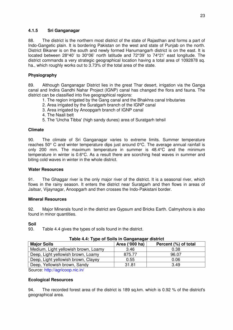
Human and Economic Development 95. In 2011, Ganganagar had population of 1,969,168 of which male and female were 1,043,340 and 925,828 respectively out of which 1,433,736 is rural and 535,432 is urban population. Existing Industrial Status: 96. Table 4.5 gives the types of industry in the Ganganagar district.
Table 4.5: Types of Industries SNo Head Unit Particulars
1. Registered Industrial Unit No. 1620 2. Total Industrial Unit No. 4171 3. Registered Medium & Large Unit No. 07 4. Estimated Avg. No. Of Daily Worker Employed In
MSME Industries No. 24384
5. Employment In Large And Medium Industries No. 2609 6. No. of Industrial Area No. 14
Source: Ministry of MSME, Govt. of India 4.1.6 Seismology in Rajasthan
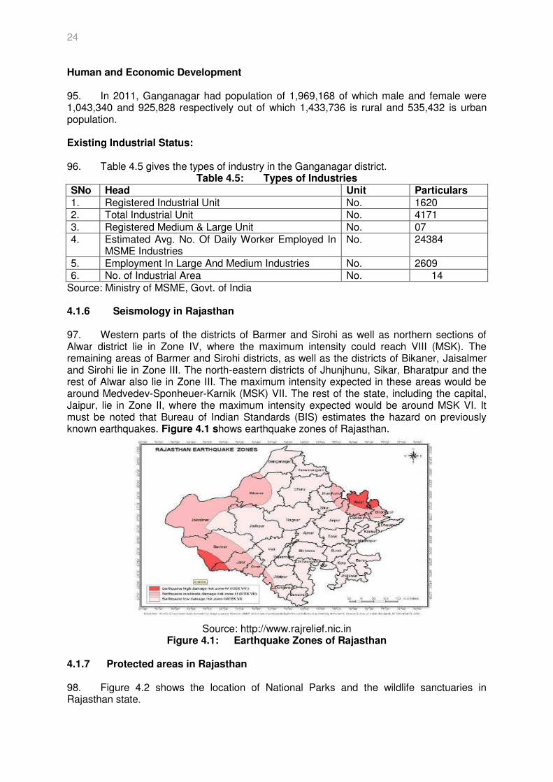
97. Western parts of the districts of Barmer and Sirohi as well as northern sections of Alwar district lie in Zone IV, where the maximum intensity could reach VIII (MSK). The remaining areas of Barmer and Sirohi districts, as well as the districts of Bikaner, Jaisalmer and Sirohi lie in Zone III. The north-eastern districts of Jhunjhunu, Sikar, Bharatpur and the rest of Alwar also lie in Zone III. The maximum intensity expected in these areas would be around Medvedev-Sponheuer-Karnik (MSK) VII. The rest of the state, including the capital, Jaipur, lie in Zone II, where the maximum intensity expected would be around MSK VI. It must be noted that Bureau of Indian Standards (BIS) estimates the hazard on previously known earthquakes. Figure 4.1 shows earthquake zones of Rajasthan.
Source: http://www.rajrelief.nic.in Figure 4.1: Earthquake Zones of Rajasthan
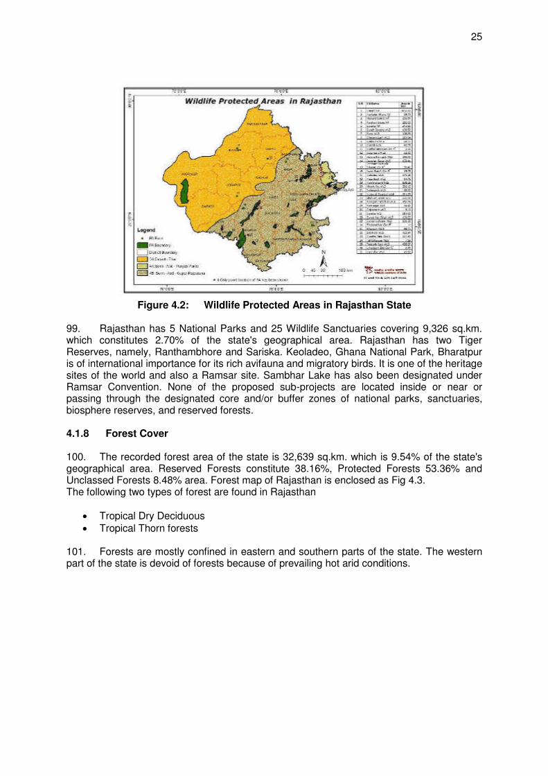
4.1.7 Protected areas in Rajasthan 98. Figure 4.2 shows the location of National Parks and the wildlife sanctuaries in Rajasthan state.
25
Figure 4.2: Wildlife Protected Areas in Rajasthan State 99. Rajasthan has 5 National Parks and 25 Wildlife Sanctuaries covering 9,326 sq.km. which constitutes 2.70% of the state's geographical area. Rajasthan has two Tiger Reserves, namely, Ranthambhore and Sariska. Keoladeo, Ghana National Park, Bharatpur is of international importance for its rich avifauna and migratory birds. It is one of the heritage sites of the world and also a Ramsar site. Sambhar Lake has also been designated under Ramsar Convention. None of the proposed sub-projects are located inside or near or passing through the designated core and/or buffer zones of national parks, sanctuaries, biosphere reserves, and reserved forests. 4.1.8 Forest Cover 100. The recorded forest area of the state is 32,639 sq.km. which is 9.54% of the state's geographical area. Reserved Forests constitute 38.16%, Protected Forests 53.36% and Unclassed Forests 8.48% area. Forest map of Rajasthan is enclosed as Fig 4.3. The following two types of forest are found in Rajasthan
Tropical Dry Deciduous Tropical Thorn forests
101. Forests are mostly confined in eastern and southern parts of the state. The western part of the state is devoid of forests because of prevailing hot arid conditions.
26
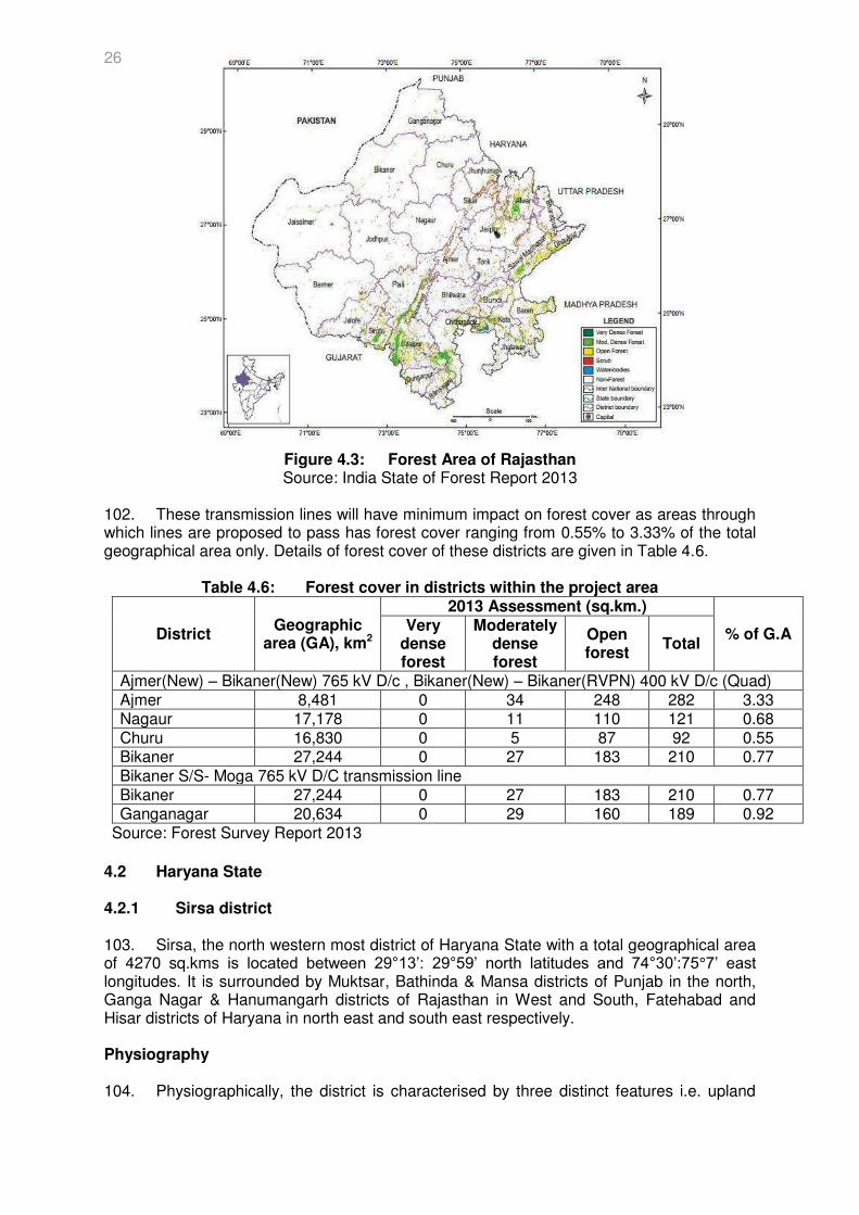
Figure 4.3: Forest Area of Rajasthan Source: India State of Forest Report 2013
102. These transmission lines will have minimum impact on forest cover as areas through which lines are proposed to pass has forest cover ranging from 0.55% to 3.33% of the total geographical area only. Details of forest cover of these districts are given in Table 4.6.
Table 4.6: Forest cover in districts within the project area
District Geographic
area (GA), km2
2013 Assessment (sq.km.)
% of G.A Very
dense forest
Moderately dense forest
Open forest
Total
Ajmer(New) – Bikaner(New) 765 kV D/c , Bikaner(New) – Bikaner(RVPN) 400 kV D/c (Quad) Ajmer 8,481 0 34 248 282 3.33 Nagaur 17,178 0 11 110 121 0.68 Churu 16,830 0 5 87 92 0.55 Bikaner 27,244 0 27 183 210 0.77 Bikaner S/S- Moga 765 kV D/C transmission line Bikaner 27,244 0 27 183 210 0.77 Ganganagar 20,634 0 29 160 189 0.92
Source: Forest Survey Report 2013
4.2 Haryana State 4.2.1 Sirsa district
103. Sirsa, the north western most district of Haryana State with a total geographical area of 4270 sq.kms is located between 29°13’: 29°59’ north latitudes and 74°30’:75°7’ east longitudes. It is surrounded by Muktsar, Bathinda & Mansa districts of Punjab in the north, Ganga Nagar & Hanumangarh districts of Rajasthan in West and South, Fatehabad and Hisar districts of Haryana in north east and south east respectively. Physiography 104. Physiographically, the district is characterised by three distinct features i.e. upland
27
plain, Alluvial bed (flood plain) of river Ghaggar and Sand dune clusters. The area as a whole is almost flat with a gentle slope towards south west direction. Climate 105. The climate of Sirsa district can be classified as tropical desert, arid and hot which is mainly dry with very hot summer and cold winter except during monsoon season when moist air of oceanic origin penetrates into the district. There are four seasons in a year. The hot weather season starts from mid-March to last week of the June followed by the south- west monsoon which lasts upto September. The transition period from September to October forms the post-monsoon season. The winter season starts late in November and remains upto first week of March. Water Resources 106. The district is mainly drained by the river Ghaggar and some artificial drains. Mineral Resources 107. No minerals are available in Sirsa District Soil 108. The district has two types of soils viz Sierozem and Desert soils. The sierozem soils are found in major parts of the district and desert soils are comparatively found in smaller part of the district especially in southern part of the district. Ecological Resources 109. The recorded forest area of the district is 55 sq.km. which is 1.29 % of the district's geographical area. Human and Economic Development 110. In 2011, Sirsa had population of 1,295,189 of which male and female were 682,582 and 612,607 respectively out of which 975,941 is rural and 319,248 is urban population. Existing Industrial Status: 111. The Sirsa district has the following industries located:
i) Registered Medium & Large Unit: 3 ii) No. of Industrial areas: 6 iii) Turnover of Medium and large Scale Industries (In lacs): Rs. 5100 lacs iv) No. of employment generated from Large and medium sector: 127 Nos
Source: MSME 4.2.2 Seismology in Haryana
112. The Haryana falls in the seismic zone IV, III, & II and therefore, the region is vulnerable to earthquakes. Although, in recent past, no major earthquakes have occurred in Haryana, yet tremors have been felt whenever there is an earthquake in the Himalayan foot-hills.
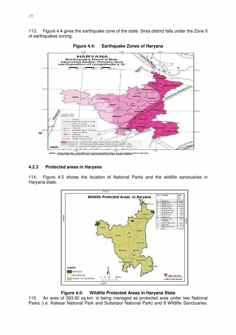
28
113. Figure 4.4 gives the earthquake zone of the state. Sirsa district falls under the Zone II of earthquakes zoning.
Figure 4.4: Earthquake Zones of Haryana
4.2.3 Protected areas in Haryana
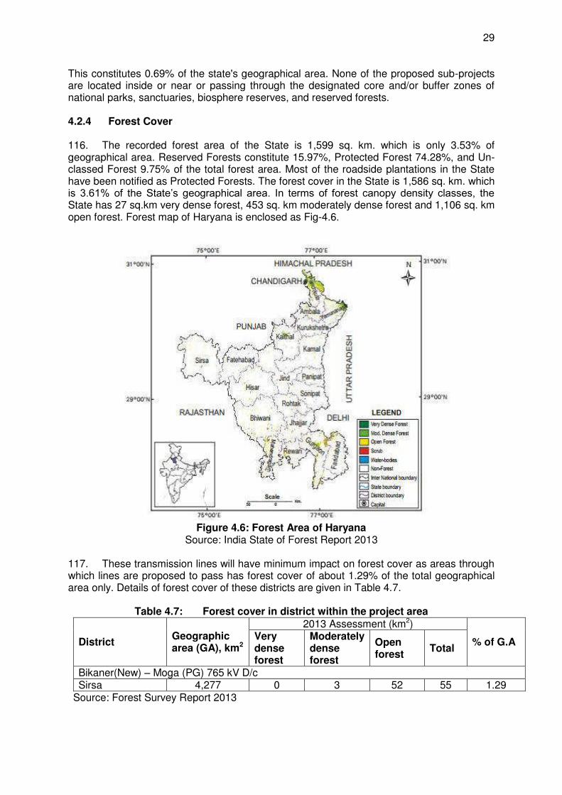
114. Figure 4.5 shows the location of National Parks and the wildlife sanctuaries in Haryana state.
Figure 4.5: Wildlife Protected Areas in Haryana State 115. An area of 303.92 sq.km. is being managed as protected area under two National Parks (i.e. Kalesar National Park and Sultanpur National Park) and 8 Wildlife Sanctuaries.
29
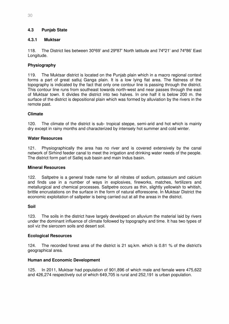
This constitutes 0.69% of the state's geographical area. None of the proposed sub-projects are located inside or near or passing through the designated core and/or buffer zones of national parks, sanctuaries, biosphere reserves, and reserved forests. 4.2.4 Forest Cover 116. The recorded forest area of the State is 1,599 sq. km. which is only 3.53% of geographical area. Reserved Forests constitute 15.97%, Protected Forest 74.28%, and Un-classed Forest 9.75% of the total forest area. Most of the roadside plantations in the State have been notified as Protected Forests. The forest cover in the State is 1,586 sq. km. which is 3.61% of the State’s geographical area. In terms of forest canopy density classes, the State has 27 sq.km very dense forest, 453 sq. km moderately dense forest and 1,106 sq. km open forest. Forest map of Haryana is enclosed as Fig-4.6.
Figure 4.6: Forest Area of Haryana Source: India State of Forest Report 2013
117. These transmission lines will have minimum impact on forest cover as areas through which lines are proposed to pass has forest cover of about 1.29% of the total geographical area only. Details of forest cover of these districts are given in Table 4.7.
Table 4.7: Forest cover in district within the project area
District Geographic area (GA), km2
2013 Assessment (km2)
% of G.A Very dense forest
Moderately dense forest
Open forest
Total
Bikaner(New) – Moga (PG) 765 kV D/c Sirsa 4,277 0 3 52 55 1.29
Source: Forest Survey Report 2013
30
4.3 Punjab State 4.3.1 Muktsar
118. The District lies between 30º69’ and 29º87’ North latitude and 74º21’ and 74º86’ East Longitude. Physiography 119. The Muktsar district is located on the Punjab plain which in a macro regional context forms a part of great satluj Ganga plain. It is a low lying flat area. The flatness of the topography is indicated by the fact that only one contour line is passing through the district. This contour line runs from southeast towards north-west and near passes through the east of Muktsar town. It divides the district into two halves. In one half it is below 200 m. the surface of the district is depositional plain which was formed by alluviation by the rivers in the remote past. Climate 120. The climate of the district is sub- tropical steppe, semi-arid and hot which is mainly dry except in rainy months and characterized by intensely hot summer and cold winter. Water Resources 121. Physiographically the area has no river and is covered extensively by the canal network of Sirhind feeder canal to meet the irrigation and drinking water needs of the people. The district form part of Satlej sub basin and main Indus basin. Mineral Resources 122. Saltpetre is a general trade name for all nitrates of sodium, potassium and calcium and finds use in a number of ways in explosives, fireworks, matches, fertilizers and metallurgical and chemical processes. Saltpetre occurs as thin, slightly yellowish to whitish, brittle encrustations on the surface in the form of natural efforescene. In Muktsar District the economic exploitation of saltpeter is being carried out at all the areas in the district. Soil 123. The soils in the district have largely developed on alluvium the material laid by rivers under the dominant influence of climate followed by topography and time. It has two types of soil viz the sierozem soils and desert soil. Ecological Resources 124. The recorded forest area of the district is 21 sq.km. which is 0.81 % of the district's geographical area. Human and Economic Development 125. In 2011, Muktsar had population of 901,896 of which male and female were 475,622 and 426,274 respectively out of which 649,705 is rural and 252,191 is urban population.
31
Existing Industrial Status: Table 4.8
Sr No
Head Unit Particulars
1. Registered Industrial Unit No. 3345 2. Total Industrial Unit No. 3345 3. Registered Medium & Large Unit No. 04
4. Employment In Small Scale Industries No. 18298
5. Employment In Large And Medium Industries
No. 1390
6. No. Of Industrial Area No. 2 7. Turnover of Small Scale Ind. In Lakh 52961.00
8. Turnover of Medium & Large Scale Industries
In Lakh 52961.00
4.3.2 Bhatinda
126. The District lies between 29o33’ & 30o36’ North latitude and 74o38’ & 75o46’ East longitude. Physiography 127. The district is situated within the Satluj-Ganga plain. The whole of the district is a low-lying flat area. The only contour line running across the area is of 220 metres The presence of only one counter indicates the flattish nature of the surface. The slope of the area is from north-east to south-west as indicated by the direction of the flow of canals and spot heights. The highest point in the area is Ratta Khera (Hisar District, Haryana) in north-eastern part with a height of 205 metres. The lowest point is at a height (Talwandi Sabo Tahsil). The elevation of the plain thus has a range of about 25 metres. Climate 128. The climate of Bathinda district can be classified as tropical steppe, semi-arid and hot which is mainly dry except in rainy months and characterised by intensely hot summer and cold winter. During three months of monsoon season from July to September the moist air of oceanic origin penetrate into the district and causes high humidity, cloudiness and good monsoon rainfall. The period from October to November constitutes post monsoon season. The cold weather season prevails from December to February followed by the hot weather season or Pre-monsoon season which ends upto the last week of June. Water Resources 129. The district has a good network of canals for irrigation and domestic purposes. The main canals in the area which feed the various distributaries and minor canals are the Bathinda branch and Kotla branch canal originated from Sirhind canal. Mineral Resources 130. Kankar, popularly known as Rore in the area occurs mainly in two different forms – (a) hard and compact sheet (hard pan deposit) and (b) nodular variety. Alkaline soil occurs in patches in the entire area of about 1.6 sq km around Bareta, Kishangarh, Sangrehri, Juglan, Khiwa Khurd, Hiron Kalan, Khiwa Kalan, Dhaipai, Bhikhi and Bhalowan (all in Mansa Tahsil). A rough estimate indicates about 13,600 tonnes of alkaline soils in these areas.
32
Soil 131. The district has two types of soils, the arid brown soils and siezoram soils. The arid brown soils are calcareous in nature; these soils are imperfectly to moderately drained. Salinity and alkalinity are the principal problems of this soil. In siezoram soils the accumulation of calcium carbonate is in amorphous or concretionary form (kankar). Presence of high amount of calcium carbonate and poor fertility is the main problem of this soil. The arid brown soils are found in mostly eastern parts of the district and siezoram soils are found in the western part of the district. Ecological Resources 132. The recorded forest area of the district is 47 sq.km. which is 1.4 % of the district's geographical area. Human and Economic Development 133. In 2011, Bathinda had population of 1,388,525 of which male and female were 743,197 and 645,328 respectively out of which 889,308 is rural and 499,217 is urban population. Existing Industrial Status: 134. The Bhatinda district has the following industries located (shown in Table 4.9):
Table 4.9: Types of Industries SNo Head Unit Particulars
1. Registered Industrial Unit No. 4261 2. Registered Medium & Large Unit No. 12 3. Worker Employed In Small Scale Industries No. 22744
4. Employment In Large And Medium Industries No. 6865
5. No. Of Industrial Area No. 4 6. Turnover Of Small Scale Ind. In Cr. 1202.57 7. Turnover Of Medium & Large Scale Industries In Cr. 1529.27
Source: MSME 4.3.3 Faridkot
135. Faridkot district falls in the Firozpur division. It is situated between 29º54’ to 30º54’ north latitude and 74º15’ to 75º25’ east longitude. It lies in south west of the State and is surrounded by Firozpur District in the North West, Moga district in the north east and Bathinda district on the South East and Muktsar Sahib on the South West. 136. Faridkot, the headquarters of the district administration, lies on the Firozpur-Bathinda- Delhi railway Line. It is also connected by road with Chandigarh (218 km), Firozpur (32 km), Muktsar (45 km) and Bathinda (65 km). Most of the towns of the district have railway stations. Physiography 137. The Faridkot district is located on the Punjab plain which in a macro regional context forms a part of great Satluj Ganga plain. It is a low lying flat area. The flatness of the topography is indicated by the fact that only one contour line is passing through the district. This contour line runs from southeast through Ablu village towards north-west and near the
33
east of Muktsar town-it runs northward and reaches the boundary of the district near Kabulwala village. It divides the district into almost two halves. In the eastern half it is below 200 m. the surface of the district is depositional plain which was formed by alleviation by the rivers in the remote past. Climate 138. The climate of the district is classified as sub-tropical steppee, semi-arid and hot which is mainly dry except in rainy months and characterised by intensely hot summer and cold winter. During three months of monsoon season from July to September the moist air of oceanic origin penetrate into the district and causes high humidity, cloudiness and monsoon rainfall. The period from October to November constitutes post monsoon season. The cold weather season prevails from December to February followed by the hot weather season or Pre-monsoon season which ends upto the last week of June. Water Resources 139. Major source of irrigation is canal where water from Sirhind canal is utilized for irrigation. Important distributaries are are Abohar Branch, Dhoolkot distributary system, Mari distributary system, Faridkot distributary, Kotkapura distributary, Jaitu distributary, Rupana and Doda distributary system. The total length of above distributaries which serve in Faridkot district is 228.44 k.m. out of which 206.49 k.m. are lined and 21.85 km are unlined. Mineral Resources 140. Salpetre is a general trade mane for all nitrates of sodium, potassium and calcium and finds use in a number of ways in explosives, fireworks, matches, fertilizers and metallurgical and chemical processes. Saltpetre occurs as thin, slightly yellowish to whitish, brittle encrustations on the surface in the form of natural efflorescence. Of all the areas in the district, the village janer, which is 13 km from Moga is famous for its saltpeter production, which is refined at Moga. Soil 141. The texture soil is sandy loam to loam. This area is known for the best staple of cotton. Most of the area is covered under sandy soil followed by clayey soil except some patches where there is appreciable thickness of top clay layer varying from 6.7 to 16.7m. Ecological Resources 142. The recorded forest area of the district is 22 sq.km. which is 1.51 % of the district's geographical area. Human and Economic Development 143. In 2011, Faridkot had population of 617,508 of which male and female were 326,671 and 290,837 respectively out of which 400,457 is rural and 217,051 is urban population. Existing Industrial Status:
Table 4.10
SNo. Head Unit Particulars
1. Registered Micro & Small Unit No. 2203
2. Employment in MSE Sector No. 14016 3. Turnover of MSE Sector Rs. 33953.40
34
Crore
4.3.4 Sangrur
144. Sangrur District falls in the southern part of the Punjab State and is bounded by latitudes 29º44’45”N and longitude 75º14’45”E. Physiography 145. Sangrur District is endowed with a nearly level surface. The occurrence of sand dune feature in some parts only breaks the monotony of the landscape. In general, the district forms a part of the Punjab Plain. The surface of this plain has been formed by the depositional work of major streams traversing through the region. Very largely, its topography is that of an alluvial plain, marked by flatness featurelessness. Soil is rich in nutrients and suitable for crops like wheat, paddy, potato and vegetables. Climate 146. The climate of the district is characterized by the dryness of the air an intensely hot summer and cold winter. The year may be divided into four seasons. The cold season starts by late November and extends to the middle of March. It is followed by hot season which continues to the end of June when the south west monsoon arrives over the district. The post monsoon season period is from October to December. Water Resources 147. There is no well-defined material drainage system in the area but for the southern part of the district, which is drained by the Ghaggar river. This river causes floods when heavy rainfall occurs in the catchment area. Three main canals pass through the area-Ghaggar branch in south western part, Kotla branch in the central part and the Bathinda branch in the northern part. All these canals run in the south westerly or westerly direction. The entire canal belongs to Sirhind canal system of Bhakhra main canal. Mineral Resources 148. A reserve of about 4.4 million tonnes of kankar has been estimated around Nadampur, Matran, Nandgarh and Balad Khurd (All in Tahsil Sangrur). The district is reported to have about 70,310 hectares of kallar affected land during the year 1973-74. Extraction of sodium salts from kallar form this district alone is likely to give substantial revenue return and in addition it ma reclaim the land without initial expenditure in effective chemical treatment. As a result, 6687 hectares of kallar affected land have been reclaimed by 1982-83. Soil 149. Soils of the district are loamy sand and sandy loam kaller land is also spotted at a few places. The spoil is sandy/brown blown sand clay the boarder of Faridkot, Moga district. Ecological Resources 150. The recorded forest area of the district is 32 sq.km. which is 0.63 % of the district's geographical area.
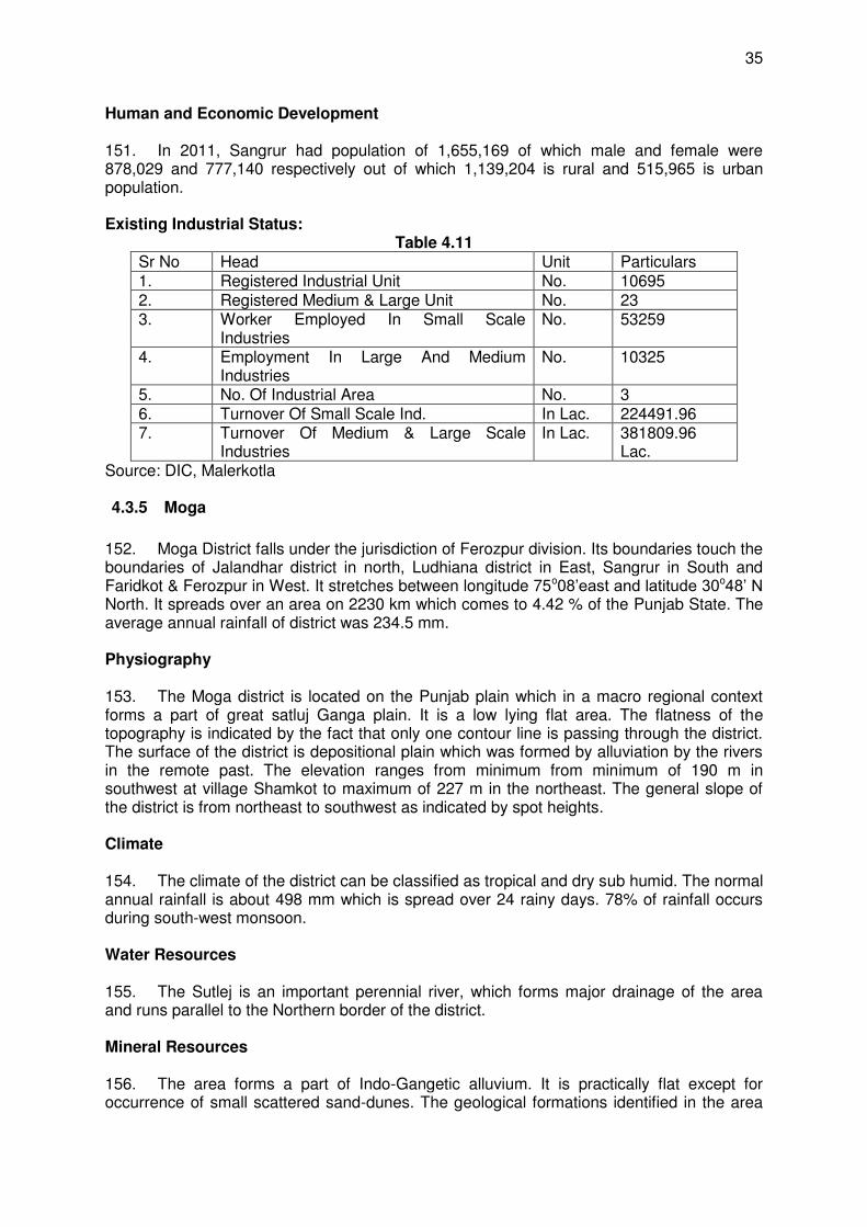
35
Human and Economic Development 151. In 2011, Sangrur had population of 1,655,169 of which male and female were 878,029 and 777,140 respectively out of which 1,139,204 is rural and 515,965 is urban population. Existing Industrial Status:
Table 4.11 Sr No Head Unit Particulars 1. Registered Industrial Unit No. 10695 2. Registered Medium & Large Unit No. 23 3. Worker Employed In Small Scale
Industries No. 53259
4. Employment In Large And Medium Industries
No. 10325
5. No. Of Industrial Area No. 3 6. Turnover Of Small Scale Ind. In Lac. 224491.96 7. Turnover Of Medium & Large Scale
Industries In Lac. 381809.96
Lac. Source: DIC, Malerkotla 4.3.5 Moga
152. Moga District falls under the jurisdiction of Ferozpur division. Its boundaries touch the boundaries of Jalandhar district in north, Ludhiana district in East, Sangrur in South and Faridkot & Ferozpur in West. It stretches between longitude 75o08’east and latitude 30o48’ N North. It spreads over an area on 2230 km which comes to 4.42 % of the Punjab State. The average annual rainfall of district was 234.5 mm. Physiography 153. The Moga district is located on the Punjab plain which in a macro regional context forms a part of great satluj Ganga plain. It is a low lying flat area. The flatness of the topography is indicated by the fact that only one contour line is passing through the district. The surface of the district is depositional plain which was formed by alluviation by the rivers in the remote past. The elevation ranges from minimum from minimum of 190 m in southwest at village Shamkot to maximum of 227 m in the northeast. The general slope of the district is from northeast to southwest as indicated by spot heights. Climate 154. The climate of the district can be classified as tropical and dry sub humid. The normal annual rainfall is about 498 mm which is spread over 24 rainy days. 78% of rainfall occurs during south-west monsoon. Water Resources 155. The Sutlej is an important perennial river, which forms major drainage of the area and runs parallel to the Northern border of the district. Mineral Resources 156. The area forms a part of Indo-Gangetic alluvium. It is practically flat except for occurrence of small scattered sand-dunes. The geological formations identified in the area
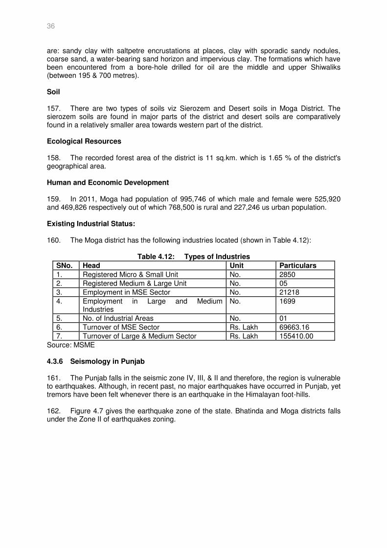
36
are: sandy clay with saltpetre encrustations at places, clay with sporadic sandy nodules, coarse sand, a water-bearing sand horizon and impervious clay. The formations which have been encountered from a bore-hole drilled for oil are the middle and upper Shiwaliks (between 195 & 700 metres). Soil 157. There are two types of soils viz Sierozem and Desert soils in Moga District. The sierozem soils are found in major parts of the district and desert soils are comparatively found in a relatively smaller area towards western part of the district. Ecological Resources 158. The recorded forest area of the district is 11 sq.km. which is 1.65 % of the district's geographical area. Human and Economic Development 159. In 2011, Moga had population of 995,746 of which male and female were 525,920 and 469,826 respectively out of which 768,500 is rural and 227,246 us urban population. Existing Industrial Status: 160. The Moga district has the following industries located (shown in Table 4.12):
Table 4.12: Types of Industries
SNo. Head Unit Particulars
1. Registered Micro & Small Unit No. 2850 2. Registered Medium & Large Unit No. 05
3. Employment in MSE Sector No. 21218
4. Employment in Large and Medium Industries
No. 1699
5. No. of Industrial Areas No. 01
6. Turnover of MSE Sector Rs. Lakh 69663.16
7. Turnover of Large & Medium Sector Rs. Lakh 155410.00 Source: MSME 4.3.6 Seismology in Punjab 161. The Punjab falls in the seismic zone IV, III, & II and therefore, the region is vulnerable to earthquakes. Although, in recent past, no major earthquakes have occurred in Punjab, yet tremors have been felt whenever there is an earthquake in the Himalayan foot-hills. 162. Figure 4.7 gives the earthquake zone of the state. Bhatinda and Moga districts falls under the Zone II of earthquakes zoning.
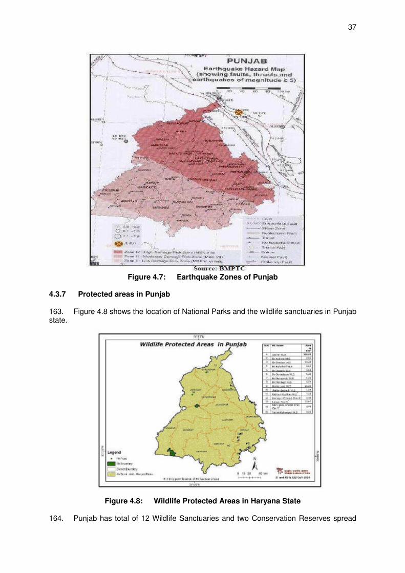
37
Figure 4.7: Earthquake Zones of Punjab 4.3.7 Protected areas in Punjab 163. Figure 4.8 shows the location of National Parks and the wildlife sanctuaries in Punjab state.
Figure 4.8: Wildlife Protected Areas in Haryana State 164. Punjab has total of 12 Wildlife Sanctuaries and two Conservation Reserves spread
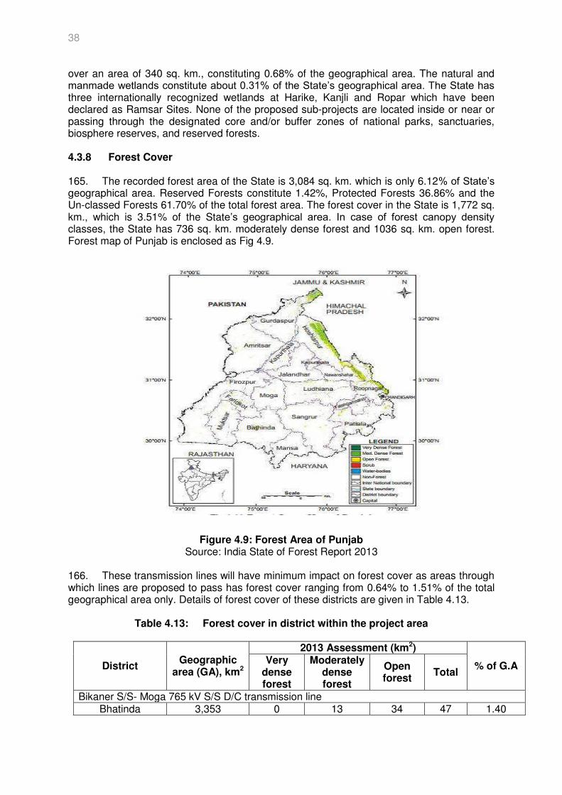
38
over an area of 340 sq. km., constituting 0.68% of the geographical area. The natural and manmade wetlands constitute about 0.31% of the State’s geographical area. The State has three internationally recognized wetlands at Harike, Kanjli and Ropar which have been declared as Ramsar Sites. None of the proposed sub-projects are located inside or near or passing through the designated core and/or buffer zones of national parks, sanctuaries, biosphere reserves, and reserved forests. 4.3.8 Forest Cover 165. The recorded forest area of the State is 3,084 sq. km. which is only 6.12% of State’s geographical area. Reserved Forests constitute 1.42%, Protected Forests 36.86% and the Un-classed Forests 61.70% of the total forest area. The forest cover in the State is 1,772 sq. km., which is 3.51% of the State’s geographical area. In case of forest canopy density classes, the State has 736 sq. km. moderately dense forest and 1036 sq. km. open forest. Forest map of Punjab is enclosed as Fig 4.9.
Figure 4.9: Forest Area of Punjab Source: India State of Forest Report 2013
166. These transmission lines will have minimum impact on forest cover as areas through which lines are proposed to pass has forest cover ranging from 0.64% to 1.51% of the total geographical area only. Details of forest cover of these districts are given in Table 4.13.
Table 4.13: Forest cover in district within the project area
District Geographic
area (GA), km2
2013 Assessment (km2)
% of G.A Very
dense forest
Moderately dense forest
Open forest
Total
Bikaner S/S- Moga 765 kV S/S D/C transmission line Bhatinda 3,353 0 13 34 47 1.40

39
Moga 1,689 0 0 11 11 0.65 Sangrur 5,108 0 6 26 32 0.64 Muktsar 2,593 0 7 14 21 0.81 Faridkot 1,458 0 4 18 22 1.51
Source: Forest Survey Report 2013
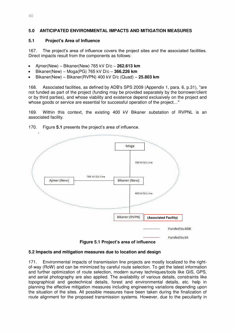
40
5.0 ANTICIPATED ENVIRONMENTAL IMPACTS AND MITIGATION MEASURES 5.1 Project's Area of Influence 167. The project’s area of influence covers the project sites and the associated facilities. Direct impacts result from the components as follows: Ajmer(New) – Bikaner(New) 765 kV D/c – 262.613 km
Bikaner(New) – Moga(PG) 765 kV D/c – 366.226 km
Bikaner(New) – Bikaner(RVPN) 400 kV D/c (Quad) – 25.803 km 168. Associated facilities, as defined by ADB's SPS 2009 (Appendix 1, para. 6, p.31), "are not funded as part of the project (funding may be provided separately by the borrower/client or by third parties), and whose viability and existence depend exclusively on the project and whose goods or service are essential for successful operation of the project…" 169. Within this context, the existing 400 kV Bikaner substation of RVPNL is an associated facility. 170. Figure 5.1 presents the project’s area of influence.
Figure 5.1 Project’s area of influence
5.2 Impacts and mitigation measures due to location and design 171. Environmental impacts of transmission line projects are mostly localized to the right-of-way (RoW) and can be minimized by careful route selection. To get the latest information and further optimization of route selection, modern survey techniques/tools like GIS, GPS, and aerial photography are also applied. The availability of various details, constraints like topographical and geotechnical details, forest and environmental details, etc. help in planning the effective mitigation measures including engineering variations depending upon the situation of the sites. All possible measures have been taken during the finalization of route alignment for the proposed transmission systems. However, due to the peculiarity in
(Associated Facility)
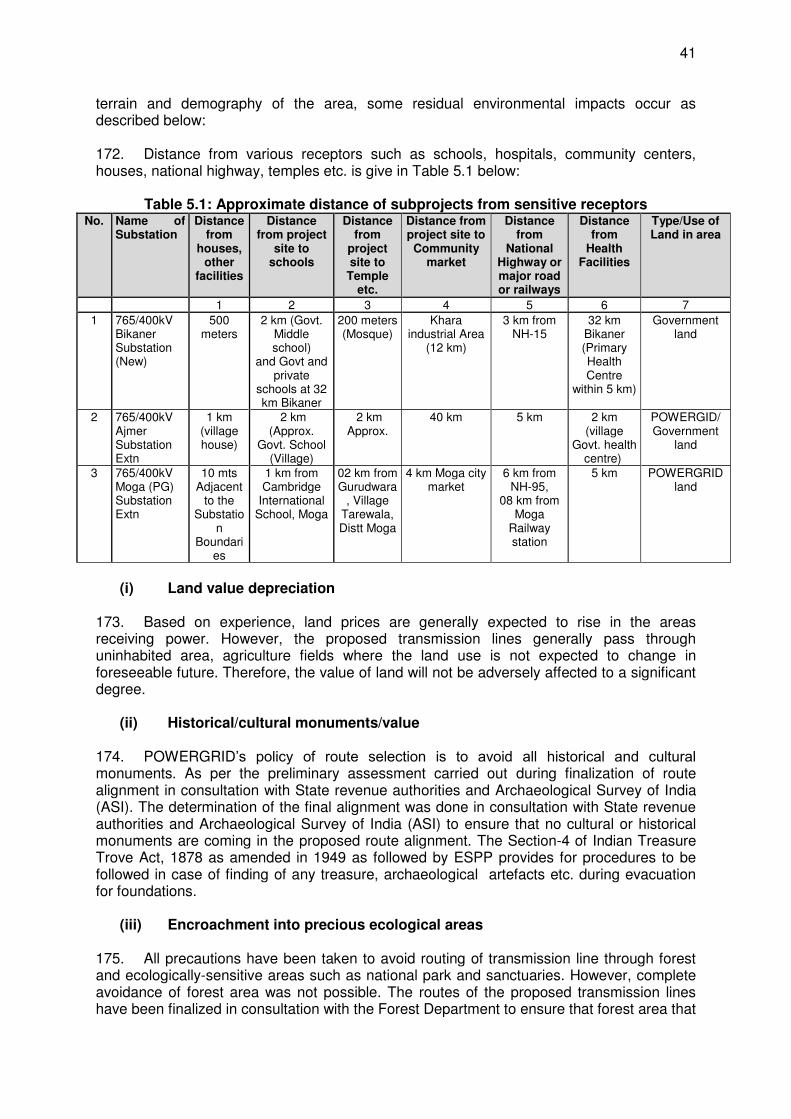
41
terrain and demography of the area, some residual environmental impacts occur as described below: 172. Distance from various receptors such as schools, hospitals, community centers, houses, national highway, temples etc. is give in Table 5.1 below:
Table 5.1: Approximate distance of subprojects from sensitive receptors No. Name of
Substation Distance
from houses,
other facilities
Distance from project
site to schools
Distance from
project site to
Temple etc.
Distance from project site to Community
market
Distance from
National Highway or major road or railways
Distance from
Health Facilities
Type/Use of Land in area
1 2 3 4 5 6 7
1 765/400kV Bikaner Substation (New)
500 meters
2 km (Govt. Middle school)
and Govt and private
schools at 32 km Bikaner
200 meters (Mosque)
Khara industrial Area
(12 km)
3 km from NH-15
32 km Bikaner (Primary Health Centre
within 5 km)
Government land
2 765/400kV Ajmer Substation Extn
1 km (village house)
2 km (Approx.
Govt. School (Village)
2 km Approx.
40 km 5 km 2 km (village
Govt. health centre)
POWERGID/ Government
land
3 765/400kV Moga (PG) Substation Extn
10 mts Adjacent
to the Substatio
n Boundari
es
1 km from Cambridge
International School, Moga
02 km from Gurudwara
, Village Tarewala, Distt Moga
4 km Moga city market
6 km from NH-95,
08 km from Moga
Railway station
5 km POWERGRID land
(i) Land value depreciation
173. Based on experience, land prices are generally expected to rise in the areas receiving power. However, the proposed transmission lines generally pass through uninhabited area, agriculture fields where the land use is not expected to change in foreseeable future. Therefore, the value of land will not be adversely affected to a significant degree.
(ii) Historical/cultural monuments/value
174. POWERGRID’s policy of route selection is to avoid all historical and cultural monuments. As per the preliminary assessment carried out during finalization of route alignment in consultation with State revenue authorities and Archaeological Survey of India (ASI). The determination of the final alignment was done in consultation with State revenue authorities and Archaeological Survey of India (ASI) to ensure that no cultural or historical monuments are coming in the proposed route alignment. The Section-4 of Indian Treasure Trove Act, 1878 as amended in 1949 as followed by ESPP provides for procedures to be followed in case of finding of any treasure, archaeological artefacts etc. during evacuation for foundations.
(iii) Encroachment into precious ecological areas
175. All precautions have been taken to avoid routing of transmission line through forest and ecologically-sensitive areas such as national park and sanctuaries. However, complete avoidance of forest area was not possible. The routes of the proposed transmission lines have been finalized in consultation with the Forest Department to ensure that forest area that
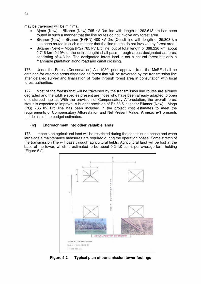
42
may be traversed will be minimal. Ajmer (New) – Bikaner (New) 765 kV D/c line with length of 262.613 km has been
routed in such a manner that the line routes do not involve any forest area. Bikaner (New) – Bikaner (RVPN) 400 kV D/c (Quad) line with length of 25.803 km
has been routed in such a manner that the line routes do not involve any forest area. Bikaner (New) – Moga (PG) 765 kV D/c line, out of total length of 366.226 km, about
0.716 km (0.19% of the entire length) shall pass through areas designated as forest consisting of 4.8 ha. The designated forest land is not a natural forest but only a manmade plantation along road and canal crossing.
176. Under the Forest (Conservation) Act 1980, prior approval from the MoEF shall be obtained for affected areas classified as forest that will be traversed by the transmission line after detailed survey and finalization of route through forest area in consultation with local forest authorities. 177. Most of the forests that will be traversed by the transmission line routes are already degraded and the wildlife species present are those who have been already adapted to open or disturbed habitat. With the provision of Compensatory Afforestation, the overall forest status is expected to improve. A budget provision of Rs 63.5 lakhs for Bikaner (New) – Moga (PG) 765 kV D/c line has been included in the project cost estimates to meet the requirements of Compensatory Afforestation and Net Present Value. Annexure-1 presents the details of the budget estimates.
(iv) Encroachment into other valuable lands
178. Impacts on agricultural land will be restricted during the construction phase and when large-scale maintenance measures are required during the operation phase. Some stretch of the transmission line will pass through agricultural fields. Agricultural land will be lost at the base of the tower, which is estimated to be about 0.2-1.0 sq.m. per average farm holding (Figure 5.2)
Figure 5.2 Typical plan of transmission tower footings
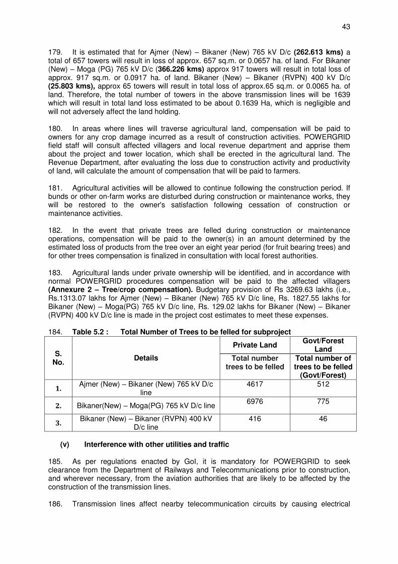
43
179. It is estimated that for Ajmer (New) – Bikaner (New) 765 kV D/c (262.613 kms) a total of 657 towers will result in loss of approx. 657 sq.m. or 0.0657 ha. of land. For Bikaner (New) – Moga (PG) 765 kV D/c (366.226 kms) approx 917 towers will result in total loss of approx. 917 sq.m. or 0.0917 ha. of land. Bikaner (New) – Bikaner (RVPN) 400 kV D/c (25.803 kms), approx 65 towers will result in total loss of approx.65 sq.m. or 0.0065 ha. of land. Therefore, the total number of towers in the above transmission lines will be 1639 which will result in total land loss estimated to be about 0.1639 Ha, which is negligible and will not adversely affect the land holding. 180. In areas where lines will traverse agricultural land, compensation will be paid to owners for any crop damage incurred as a result of construction activities. POWERGRID field staff will consult affected villagers and local revenue department and apprise them about the project and tower location, which shall be erected in the agricultural land. The Revenue Department, after evaluating the loss due to construction activity and productivity of land, will calculate the amount of compensation that will be paid to farmers. 181. Agricultural activities will be allowed to continue following the construction period. If bunds or other on-farm works are disturbed during construction or maintenance works, they will be restored to the owner's satisfaction following cessation of construction or maintenance activities. 182. In the event that private trees are felled during construction or maintenance operations, compensation will be paid to the owner(s) in an amount determined by the estimated loss of products from the tree over an eight year period (for fruit bearing trees) and for other trees compensation is finalized in consultation with local forest authorities. 183. Agricultural lands under private ownership will be identified, and in accordance with normal POWERGRID procedures compensation will be paid to the affected villagers (Annexure 2 – Tree/crop compensation). Budgetary provision of Rs 3269.63 lakhs (i.e., Rs.1313.07 lakhs for Ajmer (New) – Bikaner (New) 765 kV D/c line, Rs. 1827.55 lakhs for Bikaner (New) – Moga(PG) 765 kV D/c line, Rs. 129.02 lakhs for Bikaner (New) – Bikaner (RVPN) 400 kV D/c line is made in the project cost estimates to meet these expenses.
184. Table 5.2 : Total Number of Trees to be felled for subproject
S. No.
Details
Private Land Govt/Forest
Land
Total number trees to be felled
Total number of trees to be felled
(Govt/Forest)
1. Ajmer (New) – Bikaner (New) 765 kV D/c
line 4617
512
2. Bikaner(New) – Moga(PG) 765 kV D/c line 6976
775
3. Bikaner (New) – Bikaner (RVPN) 400 kV
D/c line 416
46
(v) Interference with other utilities and traffic
185. As per regulations enacted by GoI, it is mandatory for POWERGRID to seek clearance from the Department of Railways and Telecommunications prior to construction, and wherever necessary, from the aviation authorities that are likely to be affected by the construction of the transmission lines. 186. Transmission lines affect nearby telecommunication circuits by causing electrical
44
interference. A standing committee -- Power Telecom Co-ordination Committee (PTCC) has been constituted by GoI to plan and implement the mitigating measures for the induced voltage which may occur to nearby telecom circuit and suggest necessary protection measures to be adopted. PTCC suggests measures like rerouting of the telecom circuits, conversion of overhead telecom circuits into cables, etc. to minimize the interference. 187. The cost of such measures is determined by PTCC and is shared by POWERGRID and the Telecom Department on the basis of prevailing norms and guidelines. Though the exact cost to mitigate the impacts of induction in neighbouring telecom circuits would vary from case to case, the cost on an average works out to be INRs 50,000/per km for POWERGRID. Provision to meet these expenses has been made in the cost estimate. 188. In general, the power transmission system is planned and executed in such a way that adequate clearance is maintained between transmission lines on the one hand, and railways, civil aviation and defence installations on the other. Wherever the transmission lines pass by the airports the towers beyond specified height are painted in alternate orange and white stripes for easy visibility and warning lights (aviation) are placed atop these towers.
(vi) Interference with drainage pattern
189. As the transmission lines are constructed aerially and the blockage of ground surface is limited to area of tower footings, which is very small, there is little possibility of affecting drainage pattern. In the infrequent instances where drainage is affected, flow will be trained and guided to safe zones.
(vii) Explosion/fire hazards
190. During the survey and site selection for transmission lines and sub-stations, it has been ensured that these are kept away from oil/gas pipelines and other sites with potential for creating explosions or fires. 191. Fires due to flashover from lines can be a more serious problem in forest. Since the forest areas that will be traversed by the transmission line routes are mostly degraded and scattered within the entire alignments, fire from flashover will be unlikely. Department of Forest also incorporate safety measures such as making fire lines to prevent spreading of fire in the affected forest area.
(viii) Accelerated use of resources for short-term gains
192. The project components will not be making use of any natural resources occurring in the area during construction and operation. The construction materials such as tower members, cement, etc. shall come from factories while the excavated soil shall be used for backfilling to restore the surface. Thus, the project shall not cause any accelerated use of resources for short term gains.
(ix) Endangering of species
193. No endangered species of flora and fauna are found to exist within the areas affected by the additional project components. The location of project with respect to nearest protected areas is shown as Appendix-1 & 1(A). Table below provides details about distances of nearest national parks/Wildlife Sanctuary (WLS)/ conservation reserves from project components, if any:
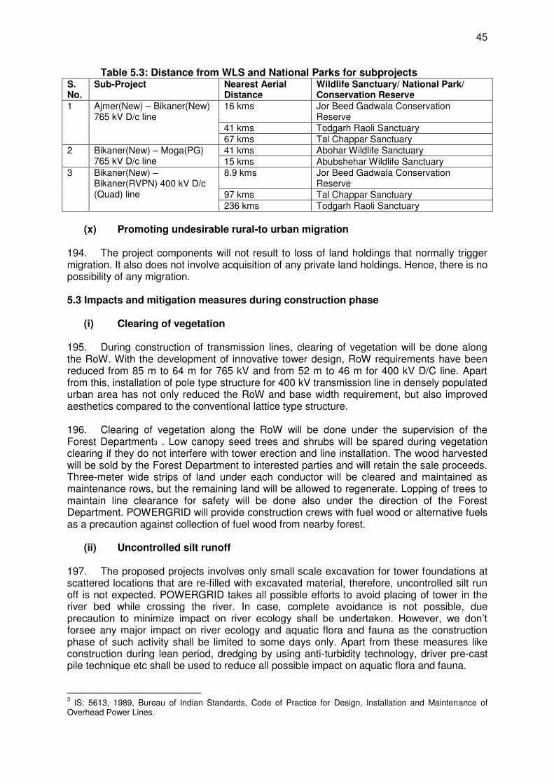
45
Table 5.3: Distance from WLS and National Parks for subprojects S. No.
Sub-Project Nearest Aerial Distance
Wildlife Sanctuary/ National Park/ Conservation Reserve
1 Ajmer(New) – Bikaner(New) 765 kV D/c line
16 kms Jor Beed Gadwala Conservation Reserve
41 kms Todgarh Raoli Sanctuary 67 kms Tal Chappar Sanctuary
2 Bikaner(New) – Moga(PG) 765 kV D/c line
41 kms Abohar Wildlife Sanctuary 15 kms Abubshehar Wildlife Sanctuary
3 Bikaner(New) – Bikaner(RVPN) 400 kV D/c (Quad) line
8.9 kms Jor Beed Gadwala Conservation Reserve
97 kms Tal Chappar Sanctuary 236 kms Todgarh Raoli Sanctuary
(x) Promoting undesirable rural-to urban migration
194. The project components will not result to loss of land holdings that normally trigger migration. It also does not involve acquisition of any private land holdings. Hence, there is no possibility of any migration. 5.3 Impacts and mitigation measures during construction phase
(i) Clearing of vegetation
195. During construction of transmission lines, clearing of vegetation will be done along the RoW. With the development of innovative tower design, RoW requirements have been reduced from 85 m to 64 m for 765 kV and from 52 m to 46 m for 400 kV D/C line. Apart from this, installation of pole type structure for 400 kV transmission line in densely populated urban area has not only reduced the RoW and base width requirement, but also improved aesthetics compared to the conventional lattice type structure. 196. Clearing of vegetation along the RoW will be done under the supervision of the Forest Department3 . Low canopy seed trees and shrubs will be spared during vegetation clearing if they do not interfere with tower erection and line installation. The wood harvested will be sold by the Forest Department to interested parties and will retain the sale proceeds. Three-meter wide strips of land under each conductor will be cleared and maintained as maintenance rows, but the remaining land will be allowed to regenerate. Lopping of trees to maintain line clearance for safety will be done also under the direction of the Forest Department. POWERGRID will provide construction crews with fuel wood or alternative fuels as a precaution against collection of fuel wood from nearby forest.
(ii) Uncontrolled silt runoff
197. The proposed projects involves only small scale excavation for tower foundations at scattered locations that are re-filled with excavated material, therefore, uncontrolled silt run off is not expected. POWERGRID takes all possible efforts to avoid placing of tower in the river bed while crossing the river. In case, complete avoidance is not possible, due precaution to minimize impact on river ecology shall be undertaken. However, we don’t forsee any major impact on river ecology and aquatic flora and fauna as the construction phase of such activity shall be limited to some days only. Apart from these measures like construction during lean period, dredging by using anti-turbidity technology, driver pre-cast pile technique etc shall be used to reduce all possible impact on aquatic flora and fauna.
3 IS: 5613, 1989, Bureau of Indian Standards, Code of Practice for Design, Installation and Maintenance of
Overhead Power Lines.
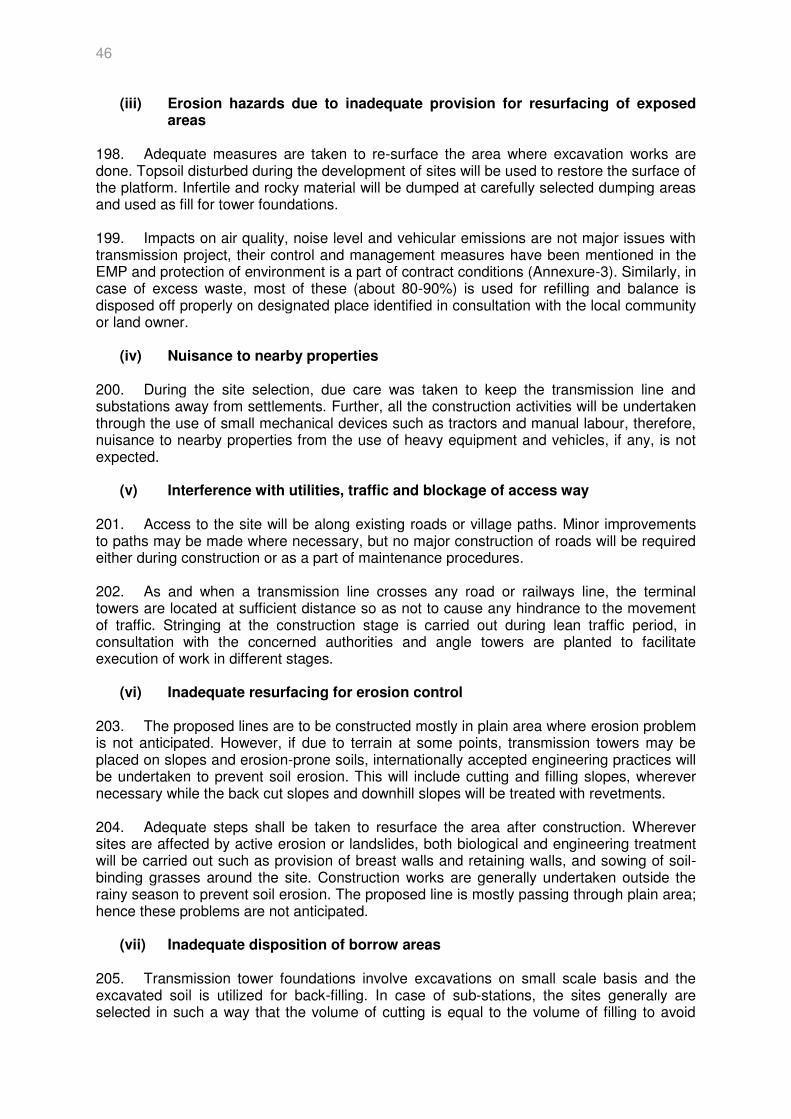
46
(iii) Erosion hazards due to inadequate provision for resurfacing of exposed areas
198. Adequate measures are taken to re-surface the area where excavation works are done. Topsoil disturbed during the development of sites will be used to restore the surface of the platform. Infertile and rocky material will be dumped at carefully selected dumping areas and used as fill for tower foundations. 199. Impacts on air quality, noise level and vehicular emissions are not major issues with transmission project, their control and management measures have been mentioned in the EMP and protection of environment is a part of contract conditions (Annexure-3). Similarly, in case of excess waste, most of these (about 80-90%) is used for refilling and balance is disposed off properly on designated place identified in consultation with the local community or land owner.
(iv) Nuisance to nearby properties
200. During the site selection, due care was taken to keep the transmission line and substations away from settlements. Further, all the construction activities will be undertaken through the use of small mechanical devices such as tractors and manual labour, therefore, nuisance to nearby properties from the use of heavy equipment and vehicles, if any, is not expected.
(v) Interference with utilities, traffic and blockage of access way
201. Access to the site will be along existing roads or village paths. Minor improvements to paths may be made where necessary, but no major construction of roads will be required either during construction or as a part of maintenance procedures. 202. As and when a transmission line crosses any road or railways line, the terminal towers are located at sufficient distance so as not to cause any hindrance to the movement of traffic. Stringing at the construction stage is carried out during lean traffic period, in consultation with the concerned authorities and angle towers are planted to facilitate execution of work in different stages.
(vi) Inadequate resurfacing for erosion control
203. The proposed lines are to be constructed mostly in plain area where erosion problem is not anticipated. However, if due to terrain at some points, transmission towers may be placed on slopes and erosion-prone soils, internationally accepted engineering practices will be undertaken to prevent soil erosion. This will include cutting and filling slopes, wherever necessary while the back cut slopes and downhill slopes will be treated with revetments. 204. Adequate steps shall be taken to resurface the area after construction. Wherever sites are affected by active erosion or landslides, both biological and engineering treatment will be carried out such as provision of breast walls and retaining walls, and sowing of soil-binding grasses around the site. Construction works are generally undertaken outside the rainy season to prevent soil erosion. The proposed line is mostly passing through plain area; hence these problems are not anticipated.
(vii) Inadequate disposition of borrow areas
205. Transmission tower foundations involve excavations on small scale basis and the excavated soil is utilized for back-filling. In case of sub-stations, the sites generally are selected in such a way that the volume of cutting is equal to the volume of filling to avoid
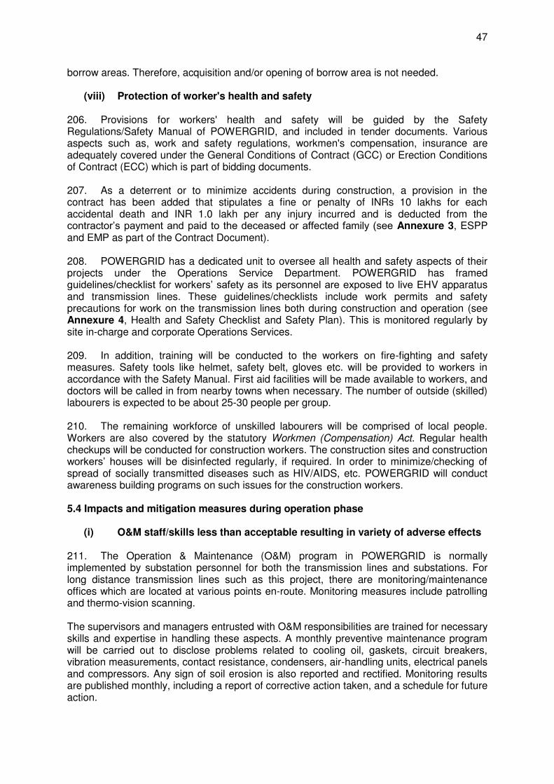
47
borrow areas. Therefore, acquisition and/or opening of borrow area is not needed.
(viii) Protection of worker's health and safety
206. Provisions for workers' health and safety will be guided by the Safety Regulations/Safety Manual of POWERGRID, and included in tender documents. Various aspects such as, work and safety regulations, workmen's compensation, insurance are adequately covered under the General Conditions of Contract (GCC) or Erection Conditions of Contract (ECC) which is part of bidding documents. 207. As a deterrent or to minimize accidents during construction, a provision in the contract has been added that stipulates a fine or penalty of INRs 10 lakhs for each accidental death and INR 1.0 lakh per any injury incurred and is deducted from the contractor’s payment and paid to the deceased or affected family (see Annexure 3, ESPP and EMP as part of the Contract Document). 208. POWERGRID has a dedicated unit to oversee all health and safety aspects of their projects under the Operations Service Department. POWERGRID has framed guidelines/checklist for workers’ safety as its personnel are exposed to live EHV apparatus and transmission lines. These guidelines/checklists include work permits and safety precautions for work on the transmission lines both during construction and operation (see Annexure 4, Health and Safety Checklist and Safety Plan). This is monitored regularly by site in-charge and corporate Operations Services. 209. In addition, training will be conducted to the workers on fire-fighting and safety measures. Safety tools like helmet, safety belt, gloves etc. will be provided to workers in accordance with the Safety Manual. First aid facilities will be made available to workers, and doctors will be called in from nearby towns when necessary. The number of outside (skilled) labourers is expected to be about 25-30 people per group. 210. The remaining workforce of unskilled labourers will be comprised of local people. Workers are also covered by the statutory Workmen (Compensation) Act. Regular health checkups will be conducted for construction workers. The construction sites and construction workers’ houses will be disinfected regularly, if required. In order to minimize/checking of spread of socially transmitted diseases such as HIV/AIDS, etc. POWERGRID will conduct awareness building programs on such issues for the construction workers. 5.4 Impacts and mitigation measures during operation phase
(i) O&M staff/skills less than acceptable resulting in variety of adverse effects
211. The Operation & Maintenance (O&M) program in POWERGRID is normally implemented by substation personnel for both the transmission lines and substations. For long distance transmission lines such as this project, there are monitoring/maintenance offices which are located at various points en-route. Monitoring measures include patrolling and thermo-vision scanning. The supervisors and managers entrusted with O&M responsibilities are trained for necessary skills and expertise in handling these aspects. A monthly preventive maintenance program will be carried out to disclose problems related to cooling oil, gaskets, circuit breakers, vibration measurements, contact resistance, condensers, air-handling units, electrical panels and compressors. Any sign of soil erosion is also reported and rectified. Monitoring results are published monthly, including a report of corrective action taken, and a schedule for future action.
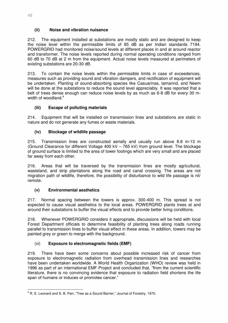
48
(ii) Noise and vibration nuisance
212. The equipment installed at substations are mostly static and are designed to keep the noise level within the permissible limits of 85 dB as per Indian standards 7194. POWERGRID had monitored noise/sound levels at different places in and at around reactor and transformer. The noise levels reported during normal operating conditions ranged from 60 dB to 70 dB at 2 m from the equipment. Actual noise levels measured at perimeters of existing substations are 20-30 dB. 213. To contain the noise levels within the permissible limits in case of exceedences, measures such as providing sound and vibration dampers, and rectification of equipment will be undertaken. Planting of sound-absorbing species like Casuarinas, tamarind, and Neem will be done at the substations to reduce the sound level appreciably. It was reported that a belt of trees dense enough can reduce noise levels by as much as 6-8 dB for every 30 m-width of woodland.4
(iii) Escape of polluting materials
214. Equipment that will be installed on transmission lines and substations are static in nature and do not generate any fumes or waste materials.
(iv) Blockage of wildlife passage
215. Transmission lines are constructed aerially and usually run above 8.8 m-13 m (Ground Clearance for different Voltage 400 kV – 765 kV) from ground level. The blockage of ground surface is limited to the area of tower footings which are very small and are placed far away from each other. 216. Areas that will be traversed by the transmission lines are mostly agricultural, wasteland, and strip plantations along the road and canal crossing. The areas are not migration path of wildlife, therefore, the possibility of disturbance to wild life passage is nil/ remote.
(v) Environmental aesthetics
217. Normal spacing between the towers is approx. 300-400 m. This spread is not expected to cause visual aesthetics to the local areas. POWERGRID plants trees at and around their substations to buffer the visual effects and to provide better living conditions. 218. Whenever POWERGRID considers it appropriate, discussions will be held with local Forest Department officials to determine feasibility of planting trees along roads running parallel to transmission lines to buffer visual effect in these areas. In addition, towers may be painted grey or green to merge with the background.
(vi) Exposure to electromagnetic fields (EMF)
219. There have been some concerns about possible increased risk of cancer from exposure to electromagnetic radiation from overhead transmission lines and researches have been undertaken worldwide. A World Health Organization (WHO) review was held in 1996 as part of an international EMF Project and concluded that, “from the current scientific literature, there is no convincing evidence that exposure to radiation field shortens the life span of humans or induces or promotes cancer.”
4 R. E. Leonard and S. B. Parr, “Tree as a Sound Barrier,” Journal of Forestry, 1970.
49
220. No EMF exposure guidelines have been drawn in India although exposure guidelines have been drawn up outside of India such as the State Transmission Lines Standards and Guidelines (USA), International Commission on Non-Ionizing Radiation Protection (ICNIRP); US National Council on Radiation, the American Conference on Government and Industrial Hygienist (ACGIH). 221. The magnetic field below 400 kV overhead power transmission lines is estimated at a maximum value of 40 micro Tesla (µT). The ICNIRP guidelines present limiting exposure to EMFs, although it adds that the levels quoted should not be interpreted as distinguishing ‘safe’ from ‘unsafe’ EMF levels. The ICNIRP guideline for the general public (up to 24 hours a day) is maximum exposure levels of 1,000 mG or 100 µ T. 222. A study carried out by Central Power Research Institute (CPRI) on POWERGRID lines reveals that the EMF about 1 m above ground near a 400 kV single circuit transmission line range from 3-7.2 µT in the ROW. 223. The impact of EMF is also dependent on the duration of exposure and therefore no significant adverse impact is envisaged. POWERGRID complies with international norms for field strength limits which are certified by Power Technologies Inc, USA. 224. POWERGRID is following the approved international standards and design, which are absolutely safe. Based on the studies carried out by different countries on the safety of EHV lines in reference to EMF effects, POWERGRID has also carried out such studies with the help of Power Technologies International (PTI), USA and Central Power research institute (CPRI), Bangalore on their design. The studies inferred that POWERGRID design are safe and follow the required international standard. Because of issues relating to need to ensure health and safety relating to the line such as fire safety, safe voltages on metallic parts of buildings, and safety clearances to avoid flashover, the transmission lines will not pass directly over any residential properties and as such the potential for EMF effects to occur will be further diminished. Given that it will be necessary to ensure that there are no properties in the ROW beneath and to the sides of the overhead line, automatic mitigation against EMF will be provided between the source of potentially high strengths (the transmission line) and the residential properties. (vii) Hazardous Waste Disposal 225. Waste batteries and transformer oil will be disposed of through lead waste re-processors in accordance with the provisions of Central Pollution Control Board (CPCB) as per Batteries (Management and Handling) Rules, 2001 and Hazardous Waste (Management, Handling, Trans-boundary Movement) Rules 2009 issued by MoEF&CC, Government of India. Procedure for disposal of used/ waste oil and used batteries is specified in the ESPP. (viii) Sulphur Hexafluoride (SF6) Leakage 226. SF6 is a non-toxic greenhouse gas used as a dielectric in circuit breakers, switch gear, and other electrical equipment. As regard control of SF6 leakage, it may be noted that the present standard of SF6 gas leakage from GIS substation is 0.5% per year. This aspect has been adequately addressed in tender document under clause 4.9 of Technical Specification of GIS. “The maximum SF6 gas leakage shall not exceed 0.5% (half percent) per year for the whole equipment and for any individual gas compartment separately. The SF6 gas leakage should not exceed 0.5% per year and the leakage rate shall be guaranteed for at least 10 years.”
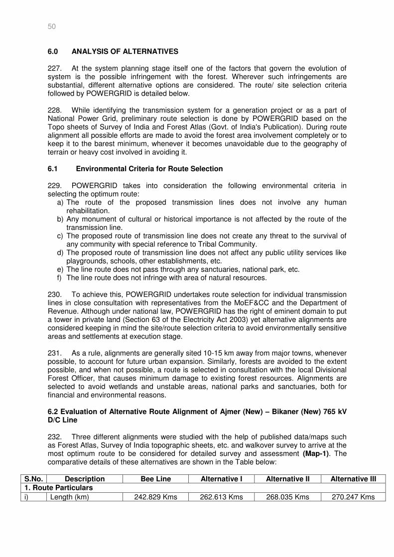
50
6.0 ANALYSIS OF ALTERNATIVES 227. At the system planning stage itself one of the factors that govern the evolution of system is the possible infringement with the forest. Wherever such infringements are substantial, different alternative options are considered. The route/ site selection criteria followed by POWERGRID is detailed below. 228. While identifying the transmission system for a generation project or as a part of National Power Grid, preliminary route selection is done by POWERGRID based on the Topo sheets of Survey of India and Forest Atlas (Govt. of India's Publication). During route alignment all possible efforts are made to avoid the forest area involvement completely or to keep it to the barest minimum, whenever it becomes unavoidable due to the geography of terrain or heavy cost involved in avoiding it. 6.1 Environmental Criteria for Route Selection 229. POWERGRID takes into consideration the following environmental criteria in selecting the optimum route:
a) The route of the proposed transmission lines does not involve any human rehabilitation.
b) Any monument of cultural or historical importance is not affected by the route of the transmission line.
c) The proposed route of transmission line does not create any threat to the survival of any community with special reference to Tribal Community.
d) The proposed route of transmission line does not affect any public utility services like playgrounds, schools, other establishments, etc.
e) The line route does not pass through any sanctuaries, national park, etc. f) The line route does not infringe with area of natural resources.
230. To achieve this, POWERGRID undertakes route selection for individual transmission lines in close consultation with representatives from the MoEF&CC and the Department of Revenue. Although under national law, POWERGRID has the right of eminent domain to put a tower in private land (Section 63 of the Electricity Act 2003) yet alternative alignments are considered keeping in mind the site/route selection criteria to avoid environmentally sensitive areas and settlements at execution stage. 231. As a rule, alignments are generally sited 10-15 km away from major towns, whenever possible, to account for future urban expansion. Similarly, forests are avoided to the extent possible, and when not possible, a route is selected in consultation with the local Divisional Forest Officer, that causes minimum damage to existing forest resources. Alignments are selected to avoid wetlands and unstable areas, national parks and sanctuaries, both for financial and environmental reasons. 6.2 Evaluation of Alternative Route Alignment of Ajmer (New) – Bikaner (New) 765 kV D/C Line 232. Three different alignments were studied with the help of published data/maps such as Forest Atlas, Survey of India topographic sheets, etc. and walkover survey to arrive at the most optimum route to be considered for detailed survey and assessment (Map-1). The comparative details of these alternatives are shown in the Table below:
S.No. Description Bee Line Alternative I Alternative II Alternative III 1. Route Particulars
i) Length (km) 242.829 Kms 262.613 Kms 268.035 Kms 270.247 Kms
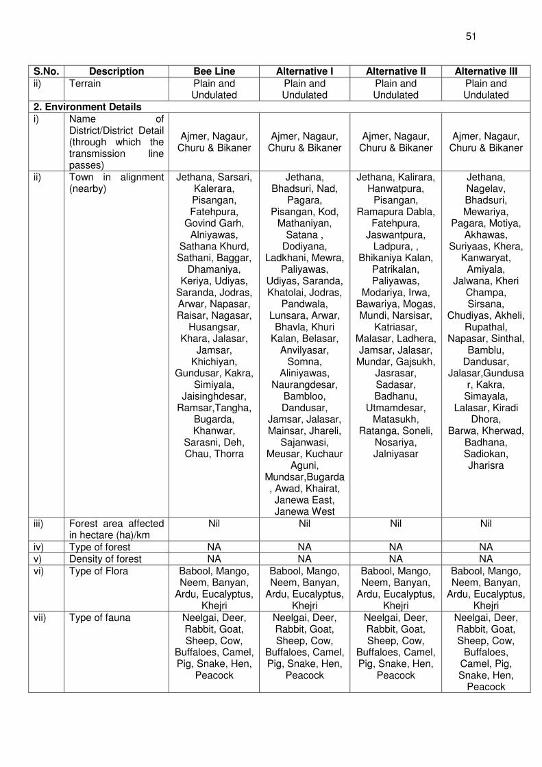
51
S.No. Description Bee Line Alternative I Alternative II Alternative III
ii) Terrain Plain and Undulated
Plain and Undulated
Plain and Undulated
Plain and Undulated
2. Environment Details i) Name of
District/District Detail (through which the transmission line passes)
Ajmer, Nagaur, Churu & Bikaner
Ajmer, Nagaur, Churu & Bikaner
Ajmer, Nagaur, Churu & Bikaner
Ajmer, Nagaur, Churu & Bikaner
ii) Town in alignment (nearby)
Jethana, Sarsari, Kalerara, Pisangan, Fatehpura,
Govind Garh, Alniyawas,
Sathana Khurd, Sathani, Baggar,
Dhamaniya, Keriya, Udiyas,
Saranda, Jodras, Arwar, Napasar, Raisar, Nagasar,
Husangsar, Khara, Jalasar,
Jamsar, Khichiyan,
Gundusar, Kakra, Simiyala,
Jaisinghdesar, Ramsar,Tangha,
Bugarda, Khanwar,
Sarasni, Deh, Chau, Thorra
Jethana, Bhadsuri, Nad,
Pagara, Pisangan, Kod,
Mathaniyan, Satana ,
Dodiyana, Ladkhani, Mewra,
Paliyawas, Udiyas, Saranda, Khatolai, Jodras,
Pandwala, Lunsara, Arwar, Bhavla, Khuri
Kalan, Belasar, Anvilyasar,
Somna, Aliniyawas,
Naurangdesar, Bambloo, Dandusar,
Jamsar, Jalasar, Mainsar, Jhareli,
Sajanwasi, Meusar, Kuchaur
Aguni, Mundsar,Bugarda, Awad, Khairat, Janewa East, Janewa West
Jethana, Kalirara, Hanwatpura,
Pisangan, Ramapura Dabla,
Fatehpura, Jaswantpura,
Ladpura, , Bhikaniya Kalan,
Patrikalan, Paliyawas,
Modariya, Irwa, Bawariya, Mogas, Mundi, Narsisar,
Katriasar, Malasar, Ladhera, Jamsar, Jalasar,
Mundar, Gajsukh, Jasrasar, Sadasar, Badhanu,
Utmamdesar, Matasukh,
Ratanga, Soneli, Nosariya, Jalniyasar
Jethana, Nagelav, Bhadsuri, Mewariya,
Pagara, Motiya, Akhawas,
Suriyaas, Khera, Kanwaryat,
Amiyala, Jalwana, Kheri
Champa, Sirsana,
Chudiyas, Akheli, Rupathal,
Napasar, Sinthal, Bamblu,
Dandusar, Jalasar,Gundusa
r, Kakra, Simayala,
Lalasar, Kiradi Dhora,
Barwa, Kherwad, Badhana, Sadiokan, Jharisra
iii) Forest area affected in hectare (ha)/km
Nil Nil Nil Nil
iv) Type of forest NA NA NA NA v) Density of forest NA NA NA NA vi) Type of Flora Babool, Mango,
Neem, Banyan, Ardu, Eucalyptus,
Khejri
Babool, Mango, Neem, Banyan,
Ardu, Eucalyptus, Khejri
Babool, Mango, Neem, Banyan,
Ardu, Eucalyptus, Khejri
Babool, Mango, Neem, Banyan,
Ardu, Eucalyptus, Khejri
vii) Type of fauna Neelgai, Deer, Rabbit, Goat, Sheep, Cow,
Buffaloes, Camel, Pig, Snake, Hen,
Peacock
Neelgai, Deer, Rabbit, Goat, Sheep, Cow,
Buffaloes, Camel, Pig, Snake, Hen,
Peacock
Neelgai, Deer, Rabbit, Goat, Sheep, Cow,
Buffaloes, Camel, Pig, Snake, Hen,
Peacock
Neelgai, Deer, Rabbit, Goat, Sheep, Cow,
Buffaloes, Camel, Pig, Snake, Hen,
Peacock
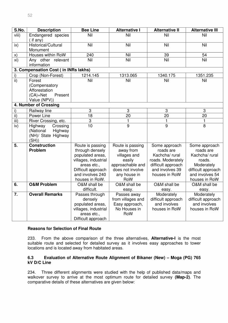
52
S.No. Description Bee Line Alternative I Alternative II Alternative III
viii) Endangered species ( if any)
Nil Nil Nil Nil
ix) Historical/Cultural Monument
Nil Nil Nil Nil
x) Houses within RoW 240 Nil 39 54 xi) Any other relevant
information Nil Nil Nil Nil
3. Compensation Cost ( in INRs lakhs)
i) Crop (Non-Forest) 1214.145 1313.065 1340.175 1351.235 ii) Forest
(Compensatory Afforestation (CA)+Net Present Value (NPV))
Nil Nil Nil Nil
4. Number of Crossing
i) Railway line 3 3 3 3 ii) Power Line 18 20 20 20 iii) River Crossing, etc. 3 1 1 1 iv) Highway Crossing
(National Highway (NH)/ State Highway (SH))
10 9 9 8
5. Construction Problem
Route is passing through densely populated areas, villages, industrial
areas etc., Difficult approach and involves 240 houses in RoW.
Route is passing away from
villages and easily
approachable and does not involve
any house in RoW
Some approach roads are
Kachcha/ rural roads. Moderately difficult approach and involves 39 houses in RoW
Some approach roads are
Kachcha/ rural roads.
Moderately difficult approach and involves 54 houses in RoW
6. O&M Problem O&M shall be difficult.
O&M shall be easy.
O&M shall be easy.
O&M shall be easy.
7. Overall Remarks Passes through densely
populated areas, villages, industrial
areas etc., Difficult approach
Passes away from villages and Easy approach, No Houses in
RoW
Moderately difficult approach
and involves houses in RoW
Moderately difficult approach
and involves houses in RoW
Reasons for Selection of Final Route 233. From the above comparison of the three alternatives, Alternative-I is the most suitable route and selected for detailed survey as it involves easy approaches to tower locations and is located away from habitated areas.
6.3 Evaluation of Alternative Route Alignment of Bikaner (New) – Moga (PG) 765 kV D/C Line 234. Three different alignments were studied with the help of published data/maps and walkover survey to arrive at the most optimum route for detailed survey (Map-2). The comparative details of these alternatives are given below:
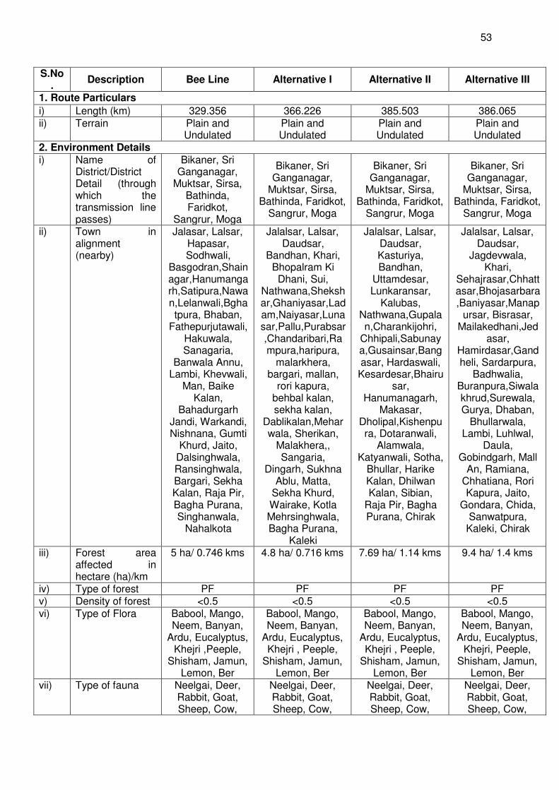
53
S.No.
Description Bee Line Alternative I Alternative II Alternative III
1. Route Particulars
i) Length (km) 329.356 366.226 385.503 386.065 ii) Terrain Plain and
Undulated Plain and Undulated
Plain and Undulated
Plain and Undulated
2. Environment Details i) Name of
District/District Detail (through which the transmission line passes)
Bikaner, Sri Ganganagar,
Muktsar, Sirsa, Bathinda, Faridkot,
Sangrur, Moga
Bikaner, Sri Ganganagar,
Muktsar, Sirsa, Bathinda, Faridkot,
Sangrur, Moga
Bikaner, Sri Ganganagar,
Muktsar, Sirsa, Bathinda, Faridkot,
Sangrur, Moga
Bikaner, Sri Ganganagar,
Muktsar, Sirsa, Bathinda, Faridkot,
Sangrur, Moga
ii) Town in alignment (nearby)
Jalasar, Lalsar, Hapasar, Sodhwali,
Basgodran,Shainagar,Hanumangarh,Satipura,Nawan,Lelanwali,Bghatpura, Bhaban,
Fathepurjutawali, Hakuwala, Sanagaria,
Banwala Annu, Lambi, Khevwali,
Man, Baike Kalan,
Bahadurgarh Jandi, Warkandi, Nishnana, Gumti
Khurd, Jaito, Dalsinghwala, Ransinghwala, Bargari, Sekha Kalan, Raja Pir, Bagha Purana, Singhanwala,
Nahalkota
Jalalsar, Lalsar, Daudsar,
Bandhan, Khari, Bhopalram Ki Dhani, Sui,
Nathwana,Shekshar,Ghaniyasar,Ladam,Naiyasar,Lunasar,Pallu,Purabsar,Chandaribari,Rampura,haripura,
malarkhera, bargari, mallan,
rori kapura, behbal kalan, sekha kalan,
Dablikalan,Meharwala, Sherikan,
Malakhera,, Sangaria,
Dingarh, Sukhna Ablu, Matta,
Sekha Khurd, Wairake, Kotla Mehrsinghwala, Bagha Purana,
Kaleki
Jalalsar, Lalsar, Daudsar, Kasturiya, Bandhan,
Uttamdesar, Lunkaransar,
Kalubas, Nathwana,Gupalan,Charankijohri,
Chhipali,Sabunaya,Gusainsar,Bangasar, Hardaswali, Kesardesar,Bhairu
sar, Hanumanagarh,
Makasar, Dholipal,Kishenpura, Dotaranwali,
Alamwala, Katyanwali, Sotha,
Bhullar, Harike Kalan, Dhilwan Kalan, Sibian,
Raja Pir, Bagha Purana, Chirak
Jalalsar, Lalsar, Daudsar,
Jagdevwala, Khari,
Sehajrasar,Chhattasar,Bhojasarbara,Baniyasar,Manap
ursar, Bisrasar, Mailakedhani,Jed
asar, Hamirdasar,Gandheli, Sardarpura,
Badhwalia, Buranpura,Siwalakhrud,Surewala, Gurya, Dhaban,
Bhullarwala, Lambi, Luhlwal,
Daula, Gobindgarh, Mall
An, Ramiana, Chhatiana, Rori Kapura, Jaito,
Gondara, Chida, Sanwatpura, Kaleki, Chirak
iii) Forest area affected in hectare (ha)/km
5 ha/ 0.746 kms 4.8 ha/ 0.716 kms 7.69 ha/ 1.14 kms 9.4 ha/ 1.4 kms
iv) Type of forest PF PF PF PF v) Density of forest <0.5 <0.5 <0.5 <0.5 vi) Type of Flora Babool, Mango,
Neem, Banyan, Ardu, Eucalyptus,
Khejri ,Peeple, Shisham, Jamun,
Lemon, Ber
Babool, Mango, Neem, Banyan,
Ardu, Eucalyptus, Khejri , Peeple,
Shisham, Jamun, Lemon, Ber
Babool, Mango, Neem, Banyan,
Ardu, Eucalyptus, Khejri , Peeple,
Shisham, Jamun, Lemon, Ber
Babool, Mango, Neem, Banyan,
Ardu, Eucalyptus, Khejri, Peeple,
Shisham, Jamun, Lemon, Ber
vii) Type of fauna Neelgai, Deer, Rabbit, Goat, Sheep, Cow,
Neelgai, Deer, Rabbit, Goat, Sheep, Cow,
Neelgai, Deer, Rabbit, Goat, Sheep, Cow,
Neelgai, Deer, Rabbit, Goat, Sheep, Cow,
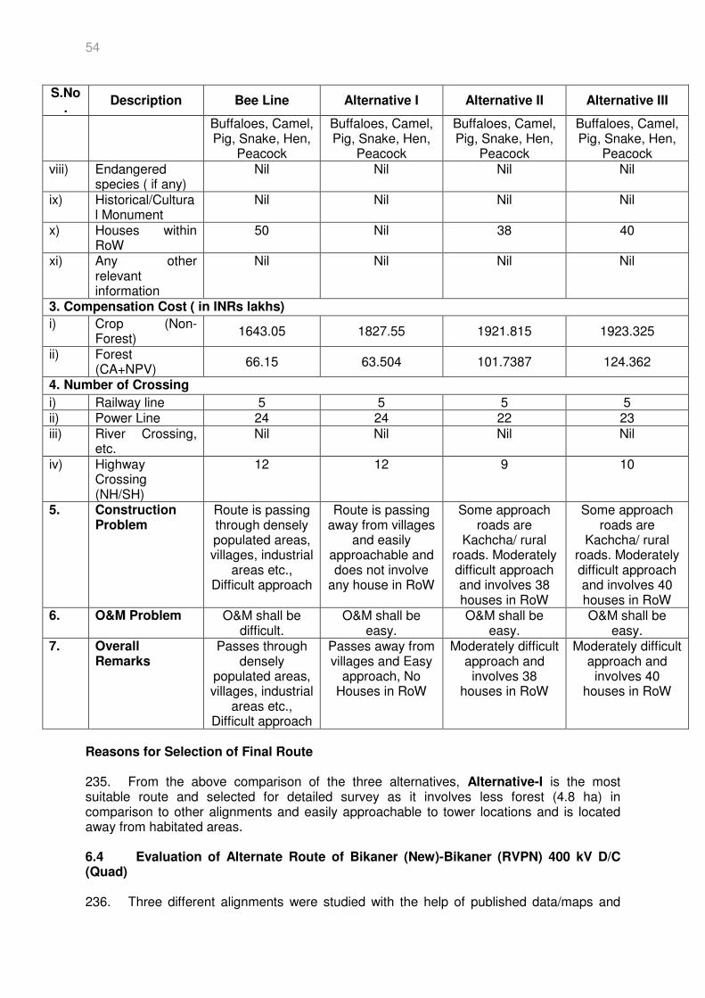
54
S.No.
Description Bee Line Alternative I Alternative II Alternative III
Buffaloes, Camel, Pig, Snake, Hen,
Peacock
Buffaloes, Camel, Pig, Snake, Hen,
Peacock
Buffaloes, Camel, Pig, Snake, Hen,
Peacock
Buffaloes, Camel, Pig, Snake, Hen,
Peacock viii) Endangered
species ( if any) Nil Nil Nil Nil
ix) Historical/Cultural Monument
Nil Nil Nil Nil
x) Houses within RoW
50 Nil 38 40
xi) Any other relevant information
Nil Nil Nil Nil
3. Compensation Cost ( in INRs lakhs)
i) Crop (Non-Forest)
1643.05 1827.55 1921.815 1923.325
ii) Forest (CA+NPV)
66.15 63.504 101.7387 124.362
4. Number of Crossing
i) Railway line 5 5 5 5 ii) Power Line 24 24 22 23 iii) River Crossing,
etc. Nil Nil Nil Nil
iv) Highway Crossing (NH/SH)
12 12 9 10
5. Construction Problem
Route is passing through densely populated areas, villages, industrial
areas etc., Difficult approach
Route is passing away from villages
and easily approachable and does not involve
any house in RoW
Some approach roads are
Kachcha/ rural roads. Moderately difficult approach and involves 38 houses in RoW
Some approach roads are
Kachcha/ rural roads. Moderately difficult approach and involves 40 houses in RoW
6. O&M Problem O&M shall be difficult.
O&M shall be easy.
O&M shall be easy.
O&M shall be easy.
7. Overall Remarks
Passes through densely
populated areas, villages, industrial
areas etc., Difficult approach
Passes away from villages and Easy
approach, No Houses in RoW
Moderately difficult approach and involves 38
houses in RoW
Moderately difficult approach and
involves 40 houses in RoW
Reasons for Selection of Final Route 235. From the above comparison of the three alternatives, Alternative-I is the most suitable route and selected for detailed survey as it involves less forest (4.8 ha) in comparison to other alignments and easily approachable to tower locations and is located away from habitated areas. 6.4 Evaluation of Alternate Route of Bikaner (New)-Bikaner (RVPN) 400 kV D/C (Quad) 236. Three different alignments were studied with the help of published data/maps and
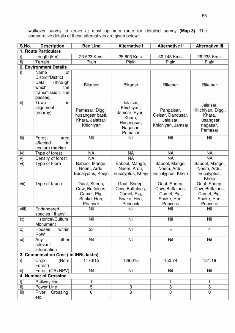
55
walkover survey to arrive at most optimum route for detailed survey (Map-3). The comparative details of these alternatives are given below:
S.No. Description Bee Line Alternative I Alternative II Alternative III 1. Route Particulars
i) Length (km) 23.523 Kms. 25.803 Kms. 30.148 Kms. 26.238 Kms. ii) Terrain Plain Plain Plain Plain 2. Environment Details i) Name of
District/District Detail (through which the transmission line passes)
Bikaner Bikaner Bikaner Bikaner
ii) Town in alignment (nearby)
Pemasar, Diggi, husangsar basti, Khara, Jalalsar,
Khichiyan
Jalalsar, Khichiyan,
Jamsar, Pyau, Khara,
Husangsar, Nagasar, Pemasar
Panpalsar, Gelsar, Dandusar,
Jalalsar, Khichiyan, Jamsar
Jalalsar, Khichiyan, Diggi,
Khara, Husangsar,
nagasar, Pemasar
iii) Forest area affected in hectare (ha)/km
Nil Nil Nil Nil
iv) Type of forest NA NA NA NA v) Density of forest NA NA NA NA vi) Type of Flora Babool, Mango,
Neem, Ardu, Eucalyptus, Khejri
Babool, Mango, Neem, Ardu,
Eucalyptus, Khejri
Babool, Mango, Neem, Ardu,
Eucalyptus, Khejri
Babool, Mango, Neem, Ardu, Eucalyptus,
Khejri vii) Type of fauna Goat, Sheep,
Cow, Buffaloes, Camel, Pig, Snake, Hen,
Peacock
Goat, Sheep, Cow, Buffaloes,
Camel, Pig, Snake, Hen,
Peacock
Goat, Sheep, Cow, Buffaloes,
Camel, Pig, Snake, Hen,
Peacock
Goat, Sheep, Cow, Buffaloes,
Camel, Pig, Snake, Hen,
Peacock viii) Endangered
species ( if any) Nil Nil Nil Nil
ix) Historical/Cultural Monument
Nil Nil Nil Nil
x) Houses within RoW
23 Nil 5 4
xi) Any other relevant information
Nil Nil Nil Nil
3. Compensation Cost ( in INRs lakhs)
i) Crop (Non-Forest)
117.615 129.015 150.74 131.19
ii) Forest (CA+NPV) Nil Nil Nil Nil 4. Number of Crossing
i) Railway line 1 1 1 1 ii) Power Line 5 3 3 3 iii) River Crossing,
etc. 0 0 0 0
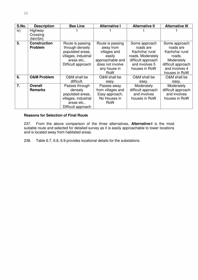
56
S.No. Description Bee Line Alternative I Alternative II Alternative III
iv) Highway Crossing (NH/SH)
1 1 1 1
5. Construction Problem
Route is passing through densely populated areas, villages, industrial
areas etc., Difficult approach
Route is passing away from
villages and easily
approachable and does not involve
any house in RoW
Some approach roads are
Kachcha/ rural roads. Moderately difficult approach
and involves 5 houses in RoW
Some approach roads are
Kachcha/ rural roads.
Moderately difficult approach
and involves 4 houses in RoW
6. O&M Problem O&M shall be difficult.
O&M shall be easy.
O&M shall be easy.
O&M shall be easy.
7. Overall Remarks
Passes through densely
populated areas, villages, industrial
areas etc., Difficult approach
Passes away from villages and Easy approach, No Houses in
RoW
Moderately difficult approach
and involves houses in RoW
Moderately difficult approach
and involves houses in RoW
Reasons for Selection of Final Route 237. From the above comparison of the three alternatives, Alternative-I is the most suitable route and selected for detailed survey as it is easily approachable to tower locations and is located away from habitated areas. 238. Table 6.7, 6.8, 6.9 provides locational details for the substations.
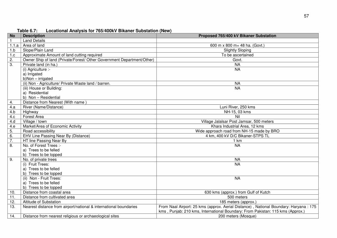
57
Table 6.7: Locational Analysis for 765/400kV Bikaner Substation (New) No Description Proposed 765/400 kV Bikaner Substation
1 Land Details 1.1.a Area of land 600 m x 800 m= 48 ha. (Govt.) 1.b Slope/Plain Land Slightly Sloping 1.c Approximate Amount of land cutting required To be ascertained 2. Owner Ship of land (Private/Forest/ Other Government Department/Other) Govt. 3. Private land (in ha.) NA
(i) Agriculture :- a) Irrigated b)Non – irrigated
NA
(ii) Non - Agriculture/ Private Waste land / barren. NA (iii) House or Building: a) Residential b) Non – Residential
NA
4. Distance from Nearest (With name ) 4.a River (Name/Distance) Luni River, 250 kms 4.b Highway NH-15, 03 kms 4.c Forest Area Nil 4.d Village / town Village Jalalsar Post Jamsar, 500 meters 4.e Market/Area of Economic Activity Khara Industrial Area, 12 kms 5. Road accessibility Wide approach road from NH-15 made by BRO 6. EHV Line Passing Near By (Distance) 4 km, 400 kV D/C Bikaner-STPS TL 7. HT line Passing Near By 1 km 8. No. of Forest Trees :-
a) Trees to be felled b) Trees to be lopped
NA
9. No. of private trees NA (i) Fruit Trees: a) Trees to be felled b) Trees to be lopped
NA
(ii) Non - Fruit Trees: a) Trees to be felled b) Trees to be lopped
NA
10. Distance from coastal area 630 kms (approx.) from Gulf of Kutch 11. Distance from cultivated area 500 meters 12. Altitude of Substation 185 meters (approx.) 13. Nearest distance from airport/national & international boundaries From Naal Airport: 25 kms (approx. Aerial Distance) , National Boundary: Haryana : 175
kms , Punjab: 210 kms, International Boundary: From Pakistan: 115 kms (Approx.) 14. Distance from nearest religious or archaeological sites 200 meters (Mosque)
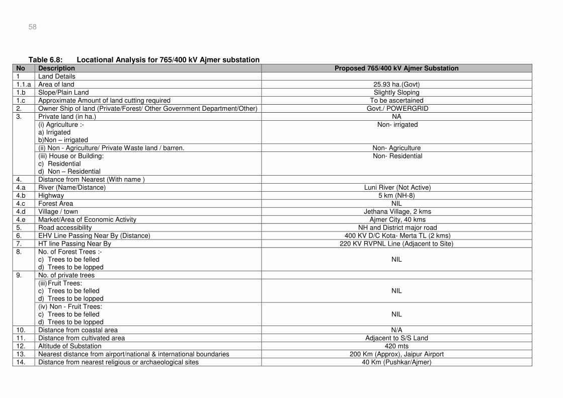
58
Table 6.8: Locational Analysis for 765/400 kV Ajmer substation
No Description Proposed 765/400 kV Ajmer Substation
1 Land Details 1.1.a Area of land 25.93 ha.(Govt) 1.b Slope/Plain Land Slightly Sloping 1.c Approximate Amount of land cutting required To be ascertained 2. Owner Ship of land (Private/Forest/ Other Government Department/Other) Govt./ POWERGRID 3. Private land (in ha.) NA
(i) Agriculture :- a) Irrigated b)Non – irrigated
Non- irrigated
(ii) Non - Agriculture/ Private Waste land / barren. Non- Agriculture (iii) House or Building: c) Residential d) Non – Residential
Non- Residential
4. Distance from Nearest (With name ) 4.a River (Name/Distance) Luni River (Not Active) 4.b Highway 5 km (NH-8) 4.c Forest Area NIL 4.d Village / town Jethana Village, 2 kms 4.e Market/Area of Economic Activity Ajmer City, 40 kms 5. Road accessibility NH and District major road 6. EHV Line Passing Near By (Distance) 400 KV D/C Kota- Merta TL (2 kms) 7. HT line Passing Near By 220 KV RVPNL Line (Adjacent to Site) 8. No. of Forest Trees :-
c) Trees to be felled d) Trees to be lopped
NIL
9. No. of private trees (iii) Fruit Trees: c) Trees to be felled d) Trees to be lopped
NIL
(iv) Non - Fruit Trees: c) Trees to be felled d) Trees to be lopped
NIL
10. Distance from coastal area N/A 11. Distance from cultivated area Adjacent to S/S Land 12. Altitude of Substation 420 mts 13. Nearest distance from airport/national & international boundaries 200 Km (Approx), Jaipur Airport 14. Distance from nearest religious or archaeological sites 40 Km (Pushkar/Ajmer)
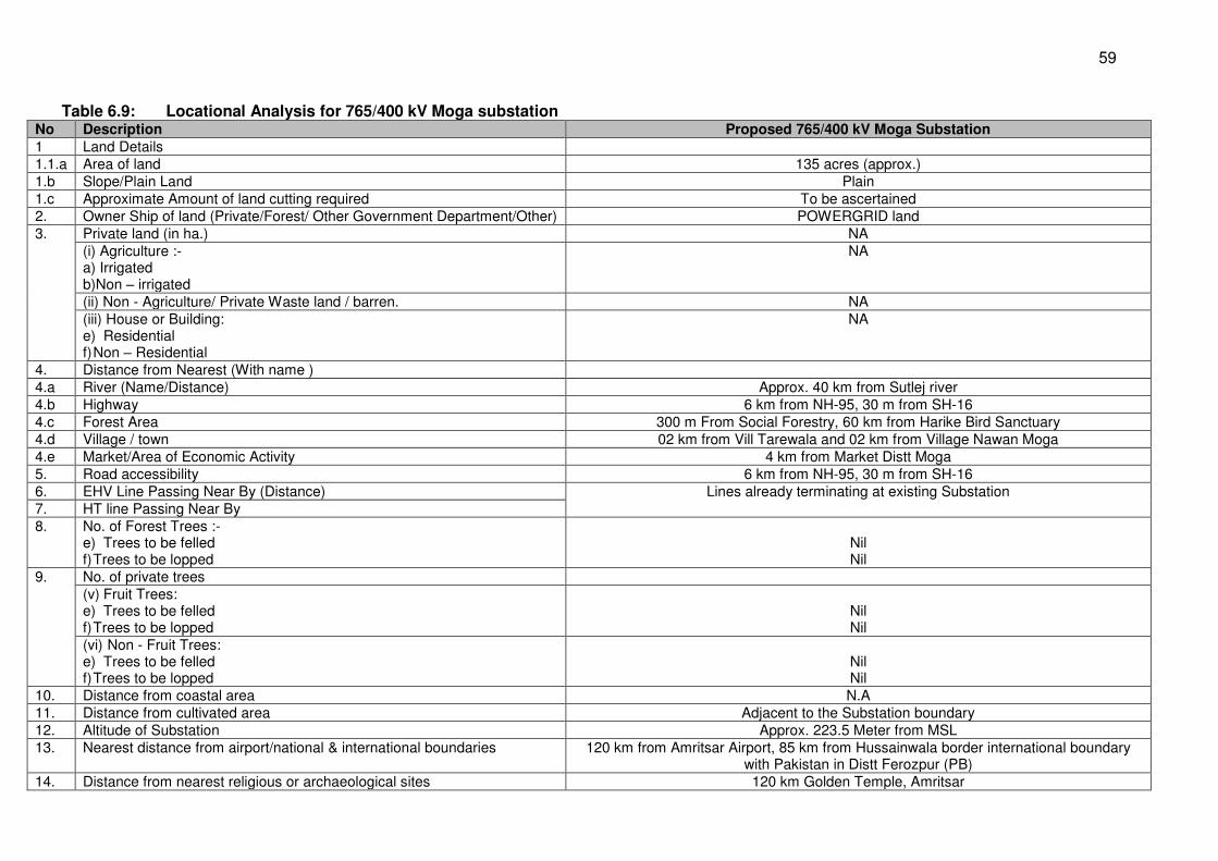
59
Table 6.9: Locational Analysis for 765/400 kV Moga substation No Description Proposed 765/400 kV Moga Substation
1 Land Details 1.1.a Area of land 135 acres (approx.) 1.b Slope/Plain Land Plain 1.c Approximate Amount of land cutting required To be ascertained 2. Owner Ship of land (Private/Forest/ Other Government Department/Other) POWERGRID land 3. Private land (in ha.) NA
(i) Agriculture :- a) Irrigated b)Non – irrigated
NA
(ii) Non - Agriculture/ Private Waste land / barren. NA (iii) House or Building: e) Residential f) Non – Residential
NA
4. Distance from Nearest (With name ) 4.a River (Name/Distance) Approx. 40 km from Sutlej river 4.b Highway 6 km from NH-95, 30 m from SH-16 4.c Forest Area 300 m From Social Forestry, 60 km from Harike Bird Sanctuary 4.d Village / town 02 km from Vill Tarewala and 02 km from Village Nawan Moga 4.e Market/Area of Economic Activity 4 km from Market Distt Moga 5. Road accessibility 6 km from NH-95, 30 m from SH-16 6. EHV Line Passing Near By (Distance) Lines already terminating at existing Substation 7. HT line Passing Near By 8. No. of Forest Trees :-
e) Trees to be felled f) Trees to be lopped
Nil Nil
9. No. of private trees (v) Fruit Trees: e) Trees to be felled f) Trees to be lopped
Nil Nil
(vi) Non - Fruit Trees: e) Trees to be felled f) Trees to be lopped
Nil Nil
10. Distance from coastal area N.A 11. Distance from cultivated area Adjacent to the Substation boundary 12. Altitude of Substation Approx. 223.5 Meter from MSL 13. Nearest distance from airport/national & international boundaries 120 km from Amritsar Airport, 85 km from Hussainwala border international boundary
with Pakistan in Distt Ferozpur (PB) 14. Distance from nearest religious or archaeological sites 120 km Golden Temple, Amritsar
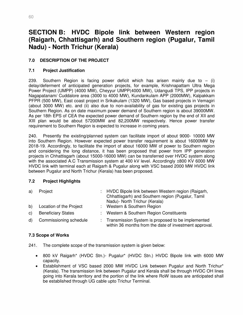
60
SECTION B: HVDC Bipole link between Western region (Raigarh, Chhattisgarh) and Southern region (Pugalur, Tamil Nadu) - North Trichur (Kerala)
7.0 DESCRIPTION OF THE PROJECT 7.1 Project Justification 239. Southern Region is facing power deficit which has arisen mainly due to – (i) delay/deferment of anticipated generation projects, for example, Krishnapattam Ultra Mega Power Project (UMPP) (4000 MW), Cheyyur UMPP(4000 MW), Udangudi TPS, IPP projects in Nagapatanam/ Cuddalore area (3000 to 4000 MW), Kundankulam APP (2000MW), Kalpakkam PFPR (500 MW), East coast project in Srikakulam (1320 MW), Gas based projects in Vemagiri (about 3000 MW) etc. and (ii) also due to non-availability of gas for existing gas projects in Southern Region. As on date maximum power demand of Southern region is about 39000MW. As per 18th EPS of CEA the expected power demand of Southern region by the end of XII and XIII plan would be about 57200MW and 82,200MW respectively. Hence power transfer requirement to Southern Region is expected to increase in coming years. 240. Presently the existing/planned system can facilitate import of about 9000- 10000 MW into Southern Region. However expected power transfer requirement is about 16000MW by 2018-19. Accordingly, to facilitate the import of about 16000 MW of power to Southern region and considering the long distance, it has been proposed that power from IPP generation projects in Chhattisgarh (about 15000-16000 MW) can be transferred over HVDC system along with the associated A.C Transmission system at 400 kV level. Accordingly ±800 KV 6000 MW HVDC link with terminal each at Raigarh & Pugalur along with VSC based 2000 MW HVDC link between Pugalur and North Trichur (Kerala) has been proposed. 7.2 Project Highlights a) Project : HVDC Bipole link between Western region (Raigarh,
Chhattisgarh) and Southern region (Pugalur, Tamil Nadu)- North Trichur (Kerala)
b) Location of the Project : Western & Southern Region
c) Beneficiary States : Western & Southern Region Constituents
d) Commissioning schedule : Transmission System is proposed to be implemented within 36 months from the date of investment approval.
7.3 Scope of Works 241. The complete scope of the transmission system is given below:
800 kV Raigarh* (HVDC Stn.)- Pugalur* (HVDC Stn.) HVDC Bipole link with 6000 MW capacity.
Establishment of VSC based 2000 MW HVDC Link between Pugalur and North Trichur* (Kerala). The transmission link between Pugalur and Kerala shall be through HVDC OH lines going into Kerala territory and the portion of the link where RoW issues are anticipated shall be established through UG cable upto Trichur Terminal.
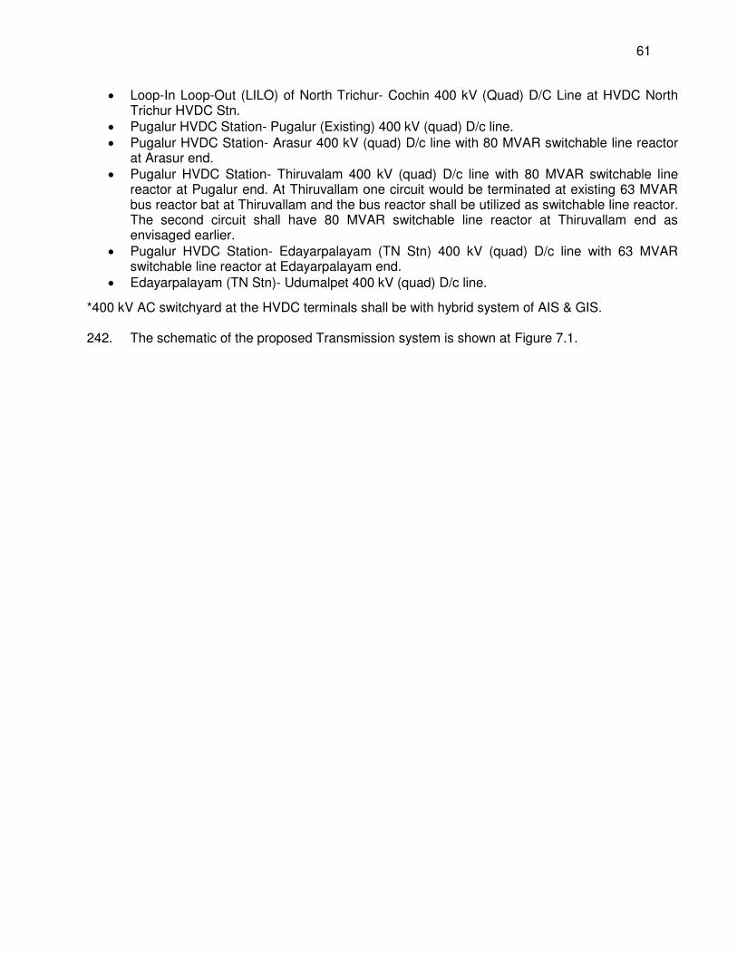
61
Loop-In Loop-Out (LILO) of North Trichur- Cochin 400 kV (Quad) D/C Line at HVDC North Trichur HVDC Stn.
Pugalur HVDC Station- Pugalur (Existing) 400 kV (quad) D/c line. Pugalur HVDC Station- Arasur 400 kV (quad) D/c line with 80 MVAR switchable line reactor
at Arasur end. Pugalur HVDC Station- Thiruvalam 400 kV (quad) D/c line with 80 MVAR switchable line
reactor at Pugalur end. At Thiruvallam one circuit would be terminated at existing 63 MVAR bus reactor bat at Thiruvallam and the bus reactor shall be utilized as switchable line reactor. The second circuit shall have 80 MVAR switchable line reactor at Thiruvallam end as envisaged earlier.
Pugalur HVDC Station- Edayarpalayam (TN Stn) 400 kV (quad) D/c line with 63 MVAR switchable line reactor at Edayarpalayam end.
Edayarpalayam (TN Stn)- Udumalpet 400 kV (quad) D/c line.
*400 kV AC switchyard at the HVDC terminals shall be with hybrid system of AIS & GIS. 242. The schematic of the proposed Transmission system is shown at Figure 7.1.
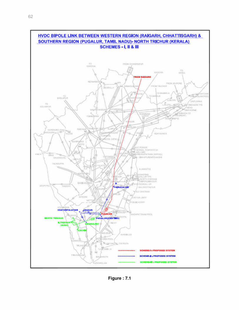
62
Figure : 7.1
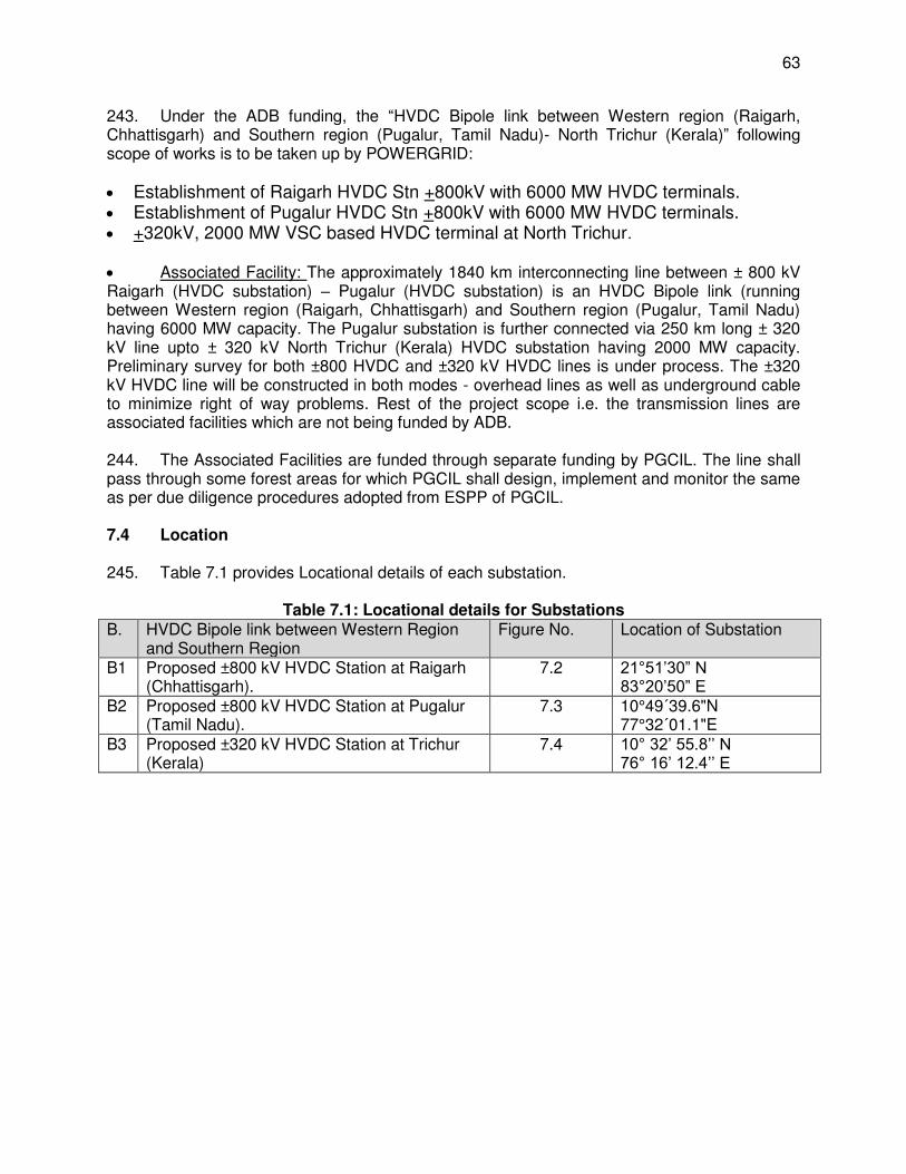
63
243. Under the ADB funding, the “HVDC Bipole link between Western region (Raigarh, Chhattisgarh) and Southern region (Pugalur, Tamil Nadu)- North Trichur (Kerala)” following scope of works is to be taken up by POWERGRID: Establishment of Raigarh HVDC Stn +800kV with 6000 MW HVDC terminals. Establishment of Pugalur HVDC Stn +800kV with 6000 MW HVDC terminals. +320kV, 2000 MW VSC based HVDC terminal at North Trichur.
Associated Facility: The approximately 1840 km interconnecting line between ± 800 kV Raigarh (HVDC substation) – Pugalur (HVDC substation) is an HVDC Bipole link (running between Western region (Raigarh, Chhattisgarh) and Southern region (Pugalur, Tamil Nadu) having 6000 MW capacity. The Pugalur substation is further connected via 250 km long ± 320 kV line upto ± 320 kV North Trichur (Kerala) HVDC substation having 2000 MW capacity. Preliminary survey for both ±800 HVDC and ±320 kV HVDC lines is under process. The ±320 kV HVDC line will be constructed in both modes - overhead lines as well as underground cable to minimize right of way problems. Rest of the project scope i.e. the transmission lines are associated facilities which are not being funded by ADB. 244. The Associated Facilities are funded through separate funding by PGCIL. The line shall pass through some forest areas for which PGCIL shall design, implement and monitor the same as per due diligence procedures adopted from ESPP of PGCIL. 7.4 Location 245. Table 7.1 provides Locational details of each substation.
Table 7.1: Locational details for Substations B. HVDC Bipole link between Western Region
and Southern Region Figure No. Location of Substation
B1 Proposed ±800 kV HVDC Station at Raigarh (Chhattisgarh).
7.2 21°51’30” N 83°20’50” E
B2 Proposed ±800 kV HVDC Station at Pugalur (Tamil Nadu).
7.3 10°49´39.6"N 77°32´01.1"E
B3 Proposed ±320 kV HVDC Station at Trichur (Kerala)
7.4 10° 32’ 55.8’’ N 76° 16’ 12.4’’ E
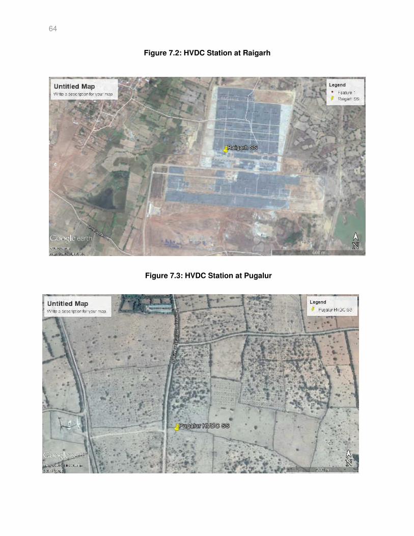
64
Figure 7.2: HVDC Station at Raigarh
Figure 7.3: HVDC Station at Pugalur
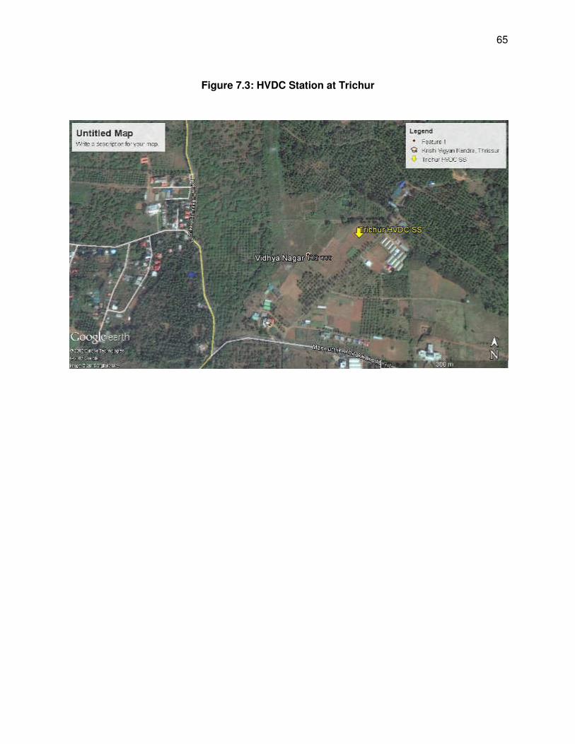
65
Figure 7.3: HVDC Station at Trichur
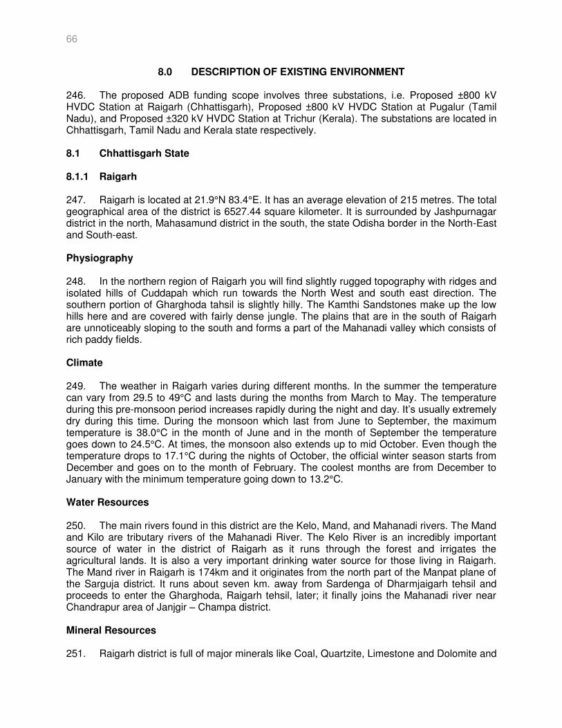
66
8.0 DESCRIPTION OF EXISTING ENVIRONMENT 246. The proposed ADB funding scope involves three substations, i.e. Proposed ±800 kV HVDC Station at Raigarh (Chhattisgarh), Proposed ±800 kV HVDC Station at Pugalur (Tamil Nadu), and Proposed ±320 kV HVDC Station at Trichur (Kerala). The substations are located in Chhattisgarh, Tamil Nadu and Kerala state respectively. 8.1 Chhattisgarh State
8.1.1 Raigarh 247. Raigarh is located at 21.9°N 83.4°E. It has an average elevation of 215 metres. The total geographical area of the district is 6527.44 square kilometer. It is surrounded by Jashpurnagar district in the north, Mahasamund district in the south, the state Odisha border in the North-East and South-east. Physiography 248. In the northern region of Raigarh you will find slightly rugged topography with ridges and isolated hills of Cuddapah which run towards the North West and south east direction. The southern portion of Gharghoda tahsil is slightly hilly. The Kamthi Sandstones make up the low hills here and are covered with fairly dense jungle. The plains that are in the south of Raigarh are unnoticeably sloping to the south and forms a part of the Mahanadi valley which consists of rich paddy fields. Climate 249. The weather in Raigarh varies during different months. In the summer the temperature can vary from 29.5 to 49°C and lasts during the months from March to May. The temperature during this pre-monsoon period increases rapidly during the night and day. It’s usually extremely dry during this time. During the monsoon which last from June to September, the maximum temperature is 38.0°C in the month of June and in the month of September the temperature goes down to 24.5°C. At times, the monsoon also extends up to mid October. Even though the temperature drops to 17.1°C during the nights of October, the official winter season starts from December and goes on to the month of February. The coolest months are from December to January with the minimum temperature going down to 13.2°C. Water Resources 250. The main rivers found in this district are the Kelo, Mand, and Mahanadi rivers. The Mand and Kilo are tributary rivers of the Mahanadi River. The Kelo River is an incredibly important source of water in the district of Raigarh as it runs through the forest and irrigates the agricultural lands. It is also a very important drinking water source for those living in Raigarh. The Mand river in Raigarh is 174km and it originates from the north part of the Manpat plane of the Sarguja district. It runs about seven km. away from Sardenga of Dharmjaigarh tehsil and proceeds to enter the Gharghoda, Raigarh tehsil, later; it finally joins the Mahanadi river near Chandrapur area of Janjgir – Champa district. Mineral Resources 251. Raigarh district is full of major minerals like Coal, Quartzite, Limestone and Dolomite and
67
minor minerals like linestone, Murram, Clay and Normal Stone. As a result of which some mineral-based industry can also be seen in the district. Soil 252. Major soils of Raigarh district are Entisol (Bhata-gravely), Inceptisol (Matasi-Sandyloam), Alfisols (Dorsa-clayloam), Vertisols (Kanhar-clayey), Others (Sandy). Ecological Resources 253. The recorded forest area of the district is 2544 sq.km. which is 35.9 % of the district's geographical area. Human and Economic Development 254. In 2011, Raigarh had population of 1,493,984 of which male and female were 750,278 and 743,706 respectively out of which 1,247,682 is rural and 246,302 is urban population. Existing Industrial Status 255. Table 8.1 provides details of the industries in the district.
Table 8.1: Industry details
SNo Head Unit Particulars 1. Registered Industrial Unit No. 9,699 2. Total Industrial Unit No. 9,699 3. Registered Medium & Large Unit No. 43 4. Estimated Avg. No. Of Daily Worker Employed In Small
Scale Industries No. 19,000
5. Employment In Large And Medium Industries No. 1,380 6. No. Of Industrial Area No. 1 7. Turnover Of Small Scale Ind. In Lacs 10,000.00 8. Turnover Of Medium & Large Scale Industries In Lacs 45,00,000.00
Source: DIC, Raigarh Hazard Profile of Chhattisgarh 256. According to GSHAP (Global Seismic Hazard Assessment Program) data, the state of Chhattisgarh falls in a region of low seismic hazard with the exception being moderate hazard in areas along the Maharashtra and Andhra Pradesh state borders. As per the 2002 Bureau of Indian Standards (BIS) map, this state also falls in Zones II & III. Historically, parts of this state have experienced seismic activity in the M4.0 range.
68
Figure 8.1 : Hazard Map for state of Chhattisgarh
Protected Area 257. None of the proposed substation subprojects are located inside or near the designated core and/or buffer zones of national parks, sanctuaries, biosphere reserves, and reserved forests. 8.2 Tamil Nadu State 8.2.1 Tiruppur (Pugalur)
258. Tiruppur district has been carved out of Coimbatore and Erode districts in the year 2008 by making it as the 32nd district of Tamil Nadu and one among the ten Well industrialised and economically developed districts of Tamil Nadu. Tiruppur is located at 11°06 27 N 77°20 23 E / 11.1075°N 77.3398°E Geographical area of Tiruppur district is 5186.34 square kilometers. Physiography 259. Tiruppur District is an inland district in the Southern Part of Peninsula. It is bounded on the north by the Erode District, on the east by the Karur and Dindigul districts, on the south by the Dindigul district and Kerala State, on the west by the Coimbatore district. It is located at about 500 Km southwest of Chennai, the capital of Tamil Nadu. It is one of the fastest developing cities and seventh largest city in Tamil Nadu. The nearest domestic airport is in Coimbatore.
69
Climate 260. Tiruppur has a salubrious climate the temperature never goes to extreme levels. March, April and May are the summer months in Tiruppur. During summer there will be mild showers and the temperature will not be very high. The winter season is September to January. June, July and August are the monsoon months for Tiruppur. During monsoon the temperature will be low and the city receives a few mild showers. Tiruppur receives rainfall mainly due to the south-west monsoon. Water Resources 261. The main rivers of the district are the Noyyal and Amaravathi, the tributaries of Cauvery flowing towards east, the Palar and Nallar river and other small rivers flowing towards west. The main rivers are Amaravathi, Noyyal, Palar, Nallar, Chinnar. Mineral Resources 262. Tiruppur district is not endowed with any remarkable mineral wealth. Major minerals like limestone, soap stone, quartz, & Feldspar occurs in this district in small quantities. Minor minerals rough stone, gravel, brick earth, & granite also occurs in this district. Availability of huge quantities lime stone in Ettimadai & Valaiyar area of Madukkarai Block has helped the growth of cement industries in Madukkarai. Soil 263. The major soils found are black soil, red soil. Ecological Resources 264. The recorded forest area of the district is 2544 sq.km. which is 35.9 % of the district's geographical area. Human and Economic Development 265. In 2011, Tiruppur had population of 2,479,052 of which male and female were 1,246,159 and 1,232,893 respectively out of which 957,941 is rural and 1,521,111 is urban population. Existing Industrial Status: 266. Table 8.2 provides details about Tiruppur district.
Table 8.2: Industry details SNo Head Unit Particulars
1. Registered Industrial Unit - MSMES No. 7068 2. Estimated Avg. No. of Daily Worker Employed In
Small Scale Industries (Registered) No. 200000
3. No. Of Industrial Area No. 7 Source: MSME
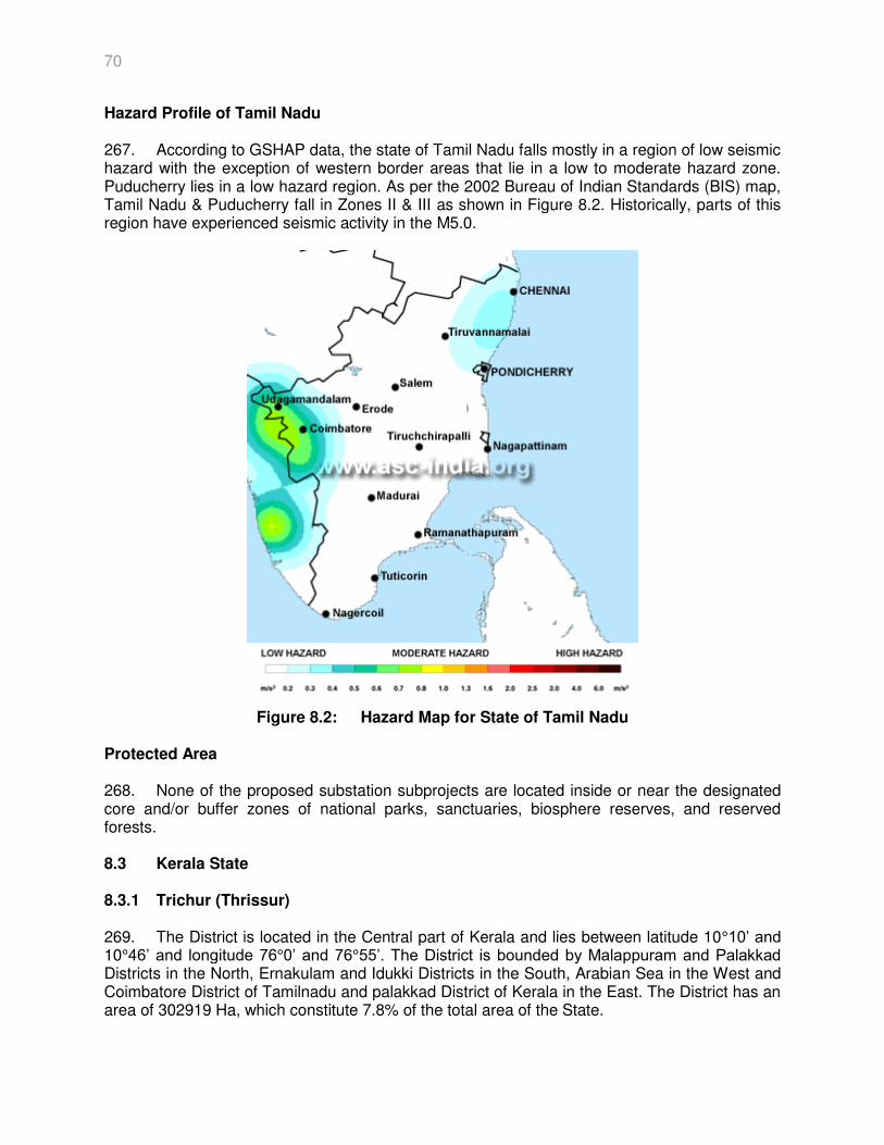
70
Hazard Profile of Tamil Nadu 267. According to GSHAP data, the state of Tamil Nadu falls mostly in a region of low seismic hazard with the exception of western border areas that lie in a low to moderate hazard zone. Puducherry lies in a low hazard region. As per the 2002 Bureau of Indian Standards (BIS) map, Tamil Nadu & Puducherry fall in Zones II & III as shown in Figure 8.2. Historically, parts of this region have experienced seismic activity in the M5.0.
Figure 8.2: Hazard Map for State of Tamil Nadu
Protected Area 268. None of the proposed substation subprojects are located inside or near the designated core and/or buffer zones of national parks, sanctuaries, biosphere reserves, and reserved forests. 8.3 Kerala State 8.3.1 Trichur (Thrissur)
269. The District is located in the Central part of Kerala and lies between latitude 10°10’ and 10°46’ and longitude 76°0’ and 76°55’. The District is bounded by Malappuram and Palakkad Districts in the North, Ernakulam and Idukki Districts in the South, Arabian Sea in the West and Coimbatore District of Tamilnadu and palakkad District of Kerala in the East. The District has an area of 302919 Ha, which constitute 7.8% of the total area of the State.
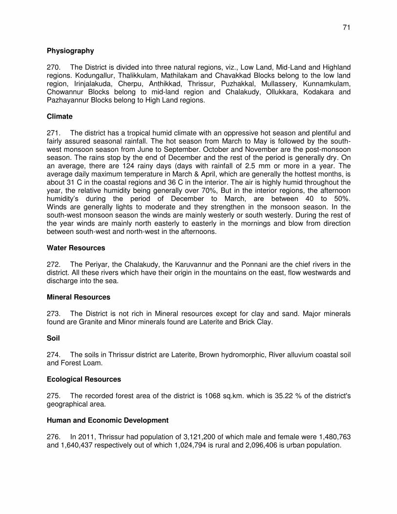
71
Physiography 270. The District is divided into three natural regions, viz., Low Land, Mid-Land and Highland regions. Kodungallur, Thalikkulam, Mathilakam and Chavakkad Blocks belong to the low land region, Irinjalakuda, Cherpu, Anthikkad, Thrissur, Puzhakkal, Mullassery, Kunnamkulam, Chowannur Blocks belong to mid-land region and Chalakudy, Ollukkara, Kodakara and Pazhayannur Blocks belong to High Land regions. Climate 271. The district has a tropical humid climate with an oppressive hot season and plentiful and fairly assured seasonal rainfall. The hot season from March to May is followed by the south-west monsoon season from June to September. October and November are the post-monsoon season. The rains stop by the end of December and the rest of the period is generally dry. On an average, there are 124 rainy days (days with rainfall of 2.5 mm or more in a year. The average daily maximum temperature in March & April, which are generally the hottest months, is about 31 C in the coastal regions and 36 C in the interior. The air is highly humid throughout the year, the relative humidity being generally over 70%, But in the interior regions, the afternoon humidity’s during the period of December to March, are between 40 to 50%. Winds are generally lights to moderate and they strengthen in the monsoon season. In the south-west monsoon season the winds are mainly westerly or south westerly. During the rest of the year winds are mainly north easterly to easterly in the mornings and blow from direction between south-west and north-west in the afternoons. Water Resources 272. The Periyar, the Chalakudy, the Karuvannur and the Ponnani are the chief rivers in the district. All these rivers which have their origin in the mountains on the east, flow westwards and discharge into the sea. Mineral Resources 273. The District is not rich in Mineral resources except for clay and sand. Major minerals found are Granite and Minor minerals found are Laterite and Brick Clay. Soil 274. The soils in Thrissur district are Laterite, Brown hydromorphic, River alluvium coastal soil and Forest Loam. Ecological Resources 275. The recorded forest area of the district is 1068 sq.km. which is 35.22 % of the district's geographical area. Human and Economic Development 276. In 2011, Thrissur had population of 3,121,200 of which male and female were 1,480,763 and 1,640,437 respectively out of which 1,024,794 is rural and 2,096,406 is urban population.
72
Existing Industrial Status: 277. Table 8.3 provided industry details of the Thissur dictirct:
Table 8.3: Industry details SNo Head Unit Particulars
1. Registered Industrial Unit No. 28290 2. Total Industrial Unit No. 29940 3. Registered Medium & Large Unit No. 11 4. Estimated Avg. No. Of Daily Worker
Employed In Small Scale Industries No. 5
5. Employment In Large And Medium Industries
No. 5892
6. No. Of Industrial Area No. 5 DA/DP & 8 MIE Source: MSME
Hazard Profile of Kerala 278. According to GSHAP data, the state of Kerala falls in a region of low to moderate seismic hazard while the same for the Lakshadweep islands yet is undefined under GSHAP. As per the 2002 Bureau of Indian Standards (BIS) map, Kerala also falls in Zones II & III while Lakshadweep lies in Zone III Figure 8.3. Historically, parts of this state have experienced seismic activity in the M5.0 range.
Figure 8.3: Hazard Map of Kerela State

73
Protected Area 279. None of the proposed substation subprojects are located inside or near the designated core and/or buffer zones of national parks, sanctuaries, biosphere reserves, and reserved forests.
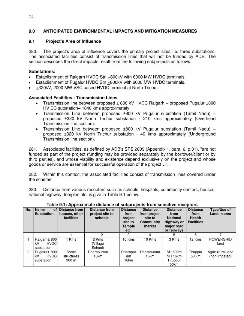
74
9.0 ANTICIPATED ENVIRONMENTAL IMPACTS AND MITIGATION MEASURES 9.1 Project's Area of Influence 280. The project’s area of influence covers the primary project sites i.e. three substations. The associated facilities consist of transmission lines that will not be funded by ADB. The section describes the direct impacts result from the following subprojects as follows: Substations:
Establishment of Raigarh HVDC Stn +800kV with 6000 MW HVDC terminals. Establishment of Pugalur HVDC Stn +800kV with 6000 MW HVDC terminals. +320kV, 2000 MW VSC based HVDC terminal at North Trichur.
Associated Facilities - Transmission Lines
Transmission line between proposed ± 800 kV HVDC Raigarh – proposed Pugalur ±800 HV DC substation– 1840 kms approximately
Transmission Line between proposed ±800 kV Pugalur substation (Tamil Nadu) – proposed ±320 kV North Trichur substation - 210 kms approximately (Overhead Transmission line section).
Transmission Line between proposed ±800 kV Pugalur substation (Tamil Nadu) – proposed ±320 kV North Trichur substation - 40 kms approximately (Underground Transmission line section).
281. Associated facilities, as defined by ADB's SPS 2009 (Appendix 1, para. 6, p.31), "are not funded as part of the project (funding may be provided separately by the borrower/client or by third parties), and whose viability and existence depend exclusively on the project and whose goods or service are essential for successful operation of the project…". 282. Within this context, the associated facilities consist of transmission lines covered under the scheme. 283. Distance from various receptors such as schools, hospitals, community centers, houses, national highway, temples etc. is give in Table 9.1 below:
Table 9.1: Approximate distance of subprojects from sensitive receptors No. Name of
Substation Distance from houses, other
facilities
Distance from project site to
schools
Distance from
project site to Temple
etc.
Distance from project
site to Community
market
Distance from
National Highway or major road or railways
Distance from
Health Facilities
Type/Use of Land in area
1 2 3 4 5 6 7
1 Raigarh± 800 kV HVDC substation
1 Kms 2 Kms (Village School)
10 Kms 10 Kms 3 Kms 12 Kms POWERGRID land
2 Pugalur± 800 kV HVDC substation
Some structures
300 m
Dharapuram 16km
Dharapuram
16km
Dharapuram 16km
SH 500m NH 16km Tiruppur
50km
Tiruppur 50 km
Agricultural land (non irrigated)
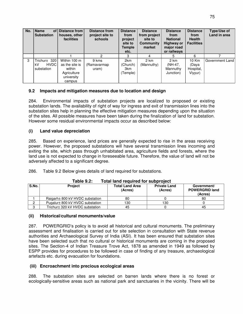
75
No. Name of Substation
Distance from houses, other
facilities
Distance from project site to
schools
Distance from
project site to Temple
etc.
Distance from project
site to Community
market
Distance from
National Highway or major road or railways
Distance from
Health Facilities
Type/Use of Land in area
1 2 3 4 5 6 7
3 Trichur± 320 kV HVDC substation
Within 100 m as the site is
within Agriculture university campus
9 kms (Ramavarmap
uram)
2km (Church)
3km (Temple)
2 km (Mannuthy)
2 km (NH-47,
Mannuthy Junction)
10 Km (Daya
Hospital, Viyyur)
Government Land
9.2 Impacts and mitigation measures due to location and design 284. Environmental impacts of substation projects are localized to proposed or existing substation lands. The availability of right of way for ingress and exit of transmission lines into the substation sites help in planning the effective mitigation measures depending upon the situation of the sites. All possible measures have been taken during the finalization of land for substation. However some residual environmental impacts occur as described below: (i) Land value depreciation 285. Based on experience, land prices are generally expected to rise in the areas receiving power. However, the proposed substations will have several transmission lines incoming and exiting the site, which pass through unhabitated area, agriculture fields and forests, where the land use is not expected to change in foreseeable future. Therefore, the value of land will not be adversely affected to a significant degree. 286. Table 9.2 Below gives details of land required for substations.
Table 9.2: Total land required for subproject
S.No. Project Total Land Area (Acres)
Private Land (Acres)
Government/ POWERGRID land
(Acres)
1 Raigarh± 800 kV HVDC substation 80 0 80 2 Pugalur± 800 kV HVDC substation 130 130 0 3 Trichur± 320 kV HVDC substation 45 0 45
(ii) Historical/cultural monuments/value 287. POWERGRID’s policy is to avoid all historical and cultural monuments. The preliminary assessment and finalisation is carried out for site selection in consultation with State revenue authorities and Archaeological Survey of India (ASI). It has been ensured that substation sites have been selected such that no cultural or historical monuments are coming in the proposed sites. The Section-4 of Indian Treasure Trove Act, 1878 as amended in 1949 as followed by ESPP provides for procedures to be followed in case of finding of any treasure, archaeological artefacts etc. during evacuation for foundations. (iii) Encroachment into precious ecological areas 288. The substation sites are selected on barren lands where there is no forest or ecologically-sensitive areas such as national park and sanctuaries in the vicinity. There will be
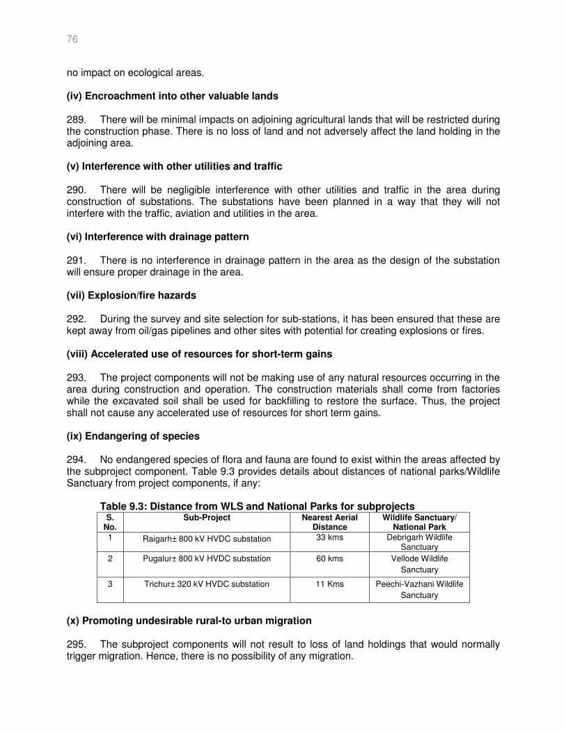
76
no impact on ecological areas. (iv) Encroachment into other valuable lands 289. There will be minimal impacts on adjoining agricultural lands that will be restricted during the construction phase. There is no loss of land and not adversely affect the land holding in the adjoining area. (v) Interference with other utilities and traffic 290. There will be negligible interference with other utilities and traffic in the area during construction of substations. The substations have been planned in a way that they will not interfere with the traffic, aviation and utilities in the area. (vi) Interference with drainage pattern 291. There is no interference in drainage pattern in the area as the design of the substation will ensure proper drainage in the area. (vii) Explosion/fire hazards 292. During the survey and site selection for sub-stations, it has been ensured that these are kept away from oil/gas pipelines and other sites with potential for creating explosions or fires. (viii) Accelerated use of resources for short-term gains 293. The project components will not be making use of any natural resources occurring in the area during construction and operation. The construction materials shall come from factories while the excavated soil shall be used for backfilling to restore the surface. Thus, the project shall not cause any accelerated use of resources for short term gains. (ix) Endangering of species 294. No endangered species of flora and fauna are found to exist within the areas affected by the subproject component. Table 9.3 provides details about distances of national parks/Wildlife Sanctuary from project components, if any:
Table 9.3: Distance from WLS and National Parks for subprojects S.
No. Sub-Project Nearest Aerial
Distance Wildlife Sanctuary/
National Park
1 Raigarh± 800 kV HVDC substation 33 kms Debrigarh Wildlife Sanctuary
2 Pugalur± 800 kV HVDC substation 60 kms Vellode Wildlife
Sanctuary
3 Trichur± 320 kV HVDC substation 11 Kms Peechi-Vazhani Wildlife
Sanctuary
(x) Promoting undesirable rural-to urban migration 295. The subproject components will not result to loss of land holdings that would normally trigger migration. Hence, there is no possibility of any migration.
77
9.3 Impacts and mitigation measures during construction phase (i) Clearing of vegetation 296. There will be no clearing required at the proposed substation sites. POWERGRID will provide construction crews with alternative fuels at the construction sites as a precaution against collection of fuel wood from nearby areas. (ii) Uncontrolled silt runoff 297. The proposed projects involves only small scale excavation for equipment foundations that will be re-filled with mostly all the excavated material, therefore, uncontrolled silt run off is not expected. POWERGRID takes all possible efforts to avoid placing of tower in the river bed while crossing the river. In case, complete avoidance is not possible, due precaution to minimize impact on river ecology shall be undertaken. However, we don’t forsee any major impact on river ecology and aquatic flora and fauna as the construction phase of such activity shall be limited to some days only. Apart from these measures like construction during lean period, dredging by using anti-turbidity technology, driver pre-cast pile technique etc shall be used to reduce all possible impact on aquatic flora and fauna. (iii) Erosion hazards due to inadequate provision for resurfacing of exposed areas 298. Adequate measures are taken to re-surface the area where excavation works are done. Topsoil disturbed during the development of site will be used to restore the surface of the platform. Infertile and rocky material will be dumped at carefully selected dumping areas and used as fill in the equipment foundations. 299. Impacts on air quality, noise level and vehicular emissions are not major issues with transmission project, their control and management measures have been mentioned in the EMP and protection of environment is a part of contract conditions (Annexure-3). Similarly, in case of excess waste, most of these (about 80-90%) is used for refilling and balance is disposed off properly on designated place identified in consultation with the local community or land owner. (iv) Nuisance to nearby properties 300. During the site selection, due care was taken to keep the substations away from settlements. Further, all the construction activities will be undertaken through the use of small mechanical devices such as tractors and manual labour, therefore, nuisance to nearby properties from the use of heavy equipment and vehicles, if any, is not expected. (v) Interference with utilities, traffic and blockage of access way 301. Access to the site will be along existing roads or village paths. No major construction of roads will be required at the proposed substation sites either during construction or as a part of maintenance procedures. (vi) Inadequate resurfacing for erosion control 302. Adequate steps shall be taken to resurface the area after construction of the substation. (vii) Inadequate disposition of borrow areas
78
303. Equipment foundations involve excavations on small scale basis and the excavated soil is utilized for back-filling. In case of sub-stations, the sites generally are selected in such a way that the volume of cutting is equal to the volume of filling to avoid borrow areas. Therefore, acquisition and/or opening of borrow area is not needed. (viii) Protection of worker's health and safety 304. Provisions for workers' health and safety will be guided by the Safety Regulations/Safety Manual of POWERGRID, and included in tender documents. Various aspects such as, work and safety regulations, workmen's compensation, insurance are adequately covered under the General Conditions of Contract (GCC) or Erection Conditions of Contract (ECC) which is part of bidding documents. 305. As a deterrent or to minimize accidents during construction, a provision in the contract has been added that stipulates a fine or penalty of INRs 10 lakhs for each accidental death and INR 1.0 lakh per any injury incurred and is deducted from the contractor’s payment and paid to the deceased or affected family (see Annexure 3, ESPP and EMP as part of the Contract Document). 306. POWERGRID has a dedicated unit to oversee all health and safety aspects of their projects under the Operations Service Department. POWERGRID has framed guidelines/checklist for workers’ safety as its personnel are exposed to live EHV apparatus and transmission lines. These guidelines/checklists include work permits and safety precautions for work on the transmission lines both during construction and operation (see Annexure 4, Health and Safety Checklist and Safety Plan). This is monitored regularly by site in-charge and corporate Operations Services. 307. In addition, training will be conducted to the workers on fire-fighting and safety measures. Safety tools like helmet, safety belt, gloves etc. will be provided to workers in accordance with the Safety Manual. First aid facilities will be made available to workers, and doctors will be called in from nearby towns when necessary. The number of outside (skilled) labourers is expected to be about 25-30 people per group. 308. The remaining workforce of unskilled labourers will be comprised of local people. Workers are also covered by the statutory Workmen (Compensation) Act. Regular health checkups will be conducted for construction workers. The construction sites and construction workers’ houses will be disinfected regularly, if required. In order to minimize/checking of spread of socially transmitted diseases such as HIV/AIDS, etc. POWERGRID will conduct awareness building programs on such issues for the construction workers. 9.4 Impacts and mitigation measures during operation phase (i) O&M staff/skills less than acceptable resulting in variety of adverse effects 309. The O&M program in POWERGRID is normally implemented by substation personnel for both the transmission lines and substations. The supervisors and managers entrusted with O&M responsibilities are trained for necessary skills and expertise in handling these aspects. A monthly preventive maintenance program will be carried out to disclose problems related to cooling oil, gaskets, circuit breakers, vibration measurements, contact resistance, condensers, air-handling units, electrical panels and compressors. Any sign of soil erosion is also reported
79
and rectified. Monitoring results are published monthly, including a report of corrective action taken, and a schedule for future action. (ii) Noise and vibration nuisance 310. The equipment installed at substations are mostly static and are designed to keep the noise level within the permissible limits of 85 dB as per Indian standards 7194. POWERGRID had monitored noise/sound levels at different places in and at around reactor and transformer. The noise levels reported during normal operating conditions ranged from 60 dB to 70 dB at 2 m from the equipment. Actual noise levels measured at perimeters of existing substations are 20-30 dB. 311. To contain the noise levels within the permissible limits in case of exceedences, measures such as providing sound and vibration dampers, and rectification of equipment will be undertaken. Planting of sound-absorbing species like Casuarinas, tamarind, and Neem will be done at the substations to reduce the sound level appreciably. It was reported that a belt of trees dense enough can reduce noise levels by as much as 6-8 dB for every 30 m-width of woodland.5 (iii) Escape of polluting materials 312. Equipment that will be installed at substations are static in nature and do not generate any fumes or waste materials. (iv) Blockage of wildlife passage 313. There are no wildlife areas in the vicinity of the proposed substations. The areas are not migration path of wildlife, therefore, the possibility of disturbance to wild life passage is nil/ remote. (v) Environmental aesthetics 314. POWERGRID plants trees at and around their substations to buffer the visual effects and to provide better living conditions. (vi) Exposure to electromagnetic fields (EMF) 315. There have been some concerns about possible increased risk of cancer from exposure to electromagnetic radiation from overhead transmission lines and researches have been undertaken worldwide. A World Health Organization (WHO) review was held in 1996 as part of an international EMF Project and concluded that, “from the current scientific literature, there is no convincing evidence that exposure to radiation field shortens the life span of humans or induces or promotes cancer.” 316. No EMF exposure guidelines have been drawn in India although exposure guidelines have been drawn up outside of India such as the State Transmission Lines Standards and Guidelines (USA), International Commission on Non-Ionizing Radiation Protection (ICNIRP); US National Council on Radiation, the American Conference on Government and Industrial Hygienist (ACGIH).
5 R. E. Leonard and S. B. Parr, “Tree as a Sound Barrier,” Journal of Forestry, 1970.
80
317. The magnetic field below 400 kV overhead power transmission lines is estimated at a maximum value of 40 µT. The ICNIRP guidelines present limiting exposure to EMFs, although it adds that the levels quoted should not be interpreted as distinguishing ‘safe’ from ‘unsafe’ EMF levels. The ICNIRP guideline for the general public (up to 24 hours a day) is maximum exposure levels of 1,000 mG or 100 µ T. 318. A study carried out by Central Power Research Institute (CPRI) on POWERGRID lines reveals that the EMF about 1 m above ground near a 400 kV single circuit transmission line range from 3-7.2 µT in the ROW. 319. The impact of EMF is also dependent on the duration of exposure and therefore no significant adverse impact is envisaged. POWERGRID complies with international norms for field strength limits which are certified by Power Technologies Inc, USA. 320. POWERGRID is following the approved international standards and design, which are absolutely safe. Based on the studies carried out by different countries on the safety of EHV lines in reference to EMF effects, POWERGRID has also carried out such studies with the help of PTI, USA and CPRI, Bangalore on their design. The studies inferred that POWERGRID design are safe and follow the required international standard. Because of issues relating to need to ensure health and safety relating to the line such as fire safety, safe voltages on metallic parts of buildings, and safety clearances to avoid flashover, the substations are planned away from any residential properties and as such the potential for EMF effects to occur will be further diminished. (vii) Hazardous Waste Disposal 321. Waste batteries and transformer oil will be disposed of through lead waste re-processors in accordance with the provisions of CPCB as per Batteries (Management and Handling) Rules, 2001 and Hazardous Waste (Management, Handling, Trans-boundary Movement) Rules 2009 issued by MoEF&CC, Government of India. Procedure for disposal of used/ waste oil and used batteries is specified in the ESPP. (viii) Sulphur Hexafluoride (SF6) Leakage 322. SF6 is a non-toxic greenhouse gas used as a dielectric in circuit breakers, switch gear, and other electrical equipment. As regard control of SF6 leakage, it may be noted that the present standard of SF6 gas leakage from GIS substation is 0.5% per year. This aspect has been adequately addressed in tender document under clause 4.9 of Technical Specification of GIS. “The maximum SF6 gas leakage shall not exceed 0.5% (half percent) per year for the whole equipment and for any individual gas compartment separately. The SF6 gas leakage should not exceed 0.5% per year and the leakage rate shall be guaranteed for at least 10 years.”
81
10.0 ANALYSIS OF ALTERNATIVES 323. At the system planning stage itself one of the factors that govern the evolution of system is the possible infringement with the forest. Wherever such infringements are substantial, different alternative options are considered. The site selection criteria followed by POWERGRID is detailed below: 324. POWERGRID shall conduct due diligence for these associated facilities as per the ESPP and Government of India and state (s) regulatory requirements. Hence the impacts and mitigation measures will only be prescribed for substations. 325. Several options of substation sites were studied in detail by POWERGRID and site options that offered the best option were considered. Mostly government land is preferred for construction of substation. 10.1 Substation site selection 326. It has always been the endeavour of the POWERGRID to minimize resettlement and rehabilitation by using government land wherever possible for its infrastructure development. In the absence / non-availability of government land private land may be selected but to minimize the social impact associated with land loss, POWERGRID has a well developed process of selection of site for new substation apart from reducing the extent of land requirement through improvement in design and other parameters. 327. The site for the construction of Sub-Station is selected by the POWERGRID after studying the different alternatives keeping in view its principles of avoidance and minimization of social impacts where the land acquisition has been limited to bare minimum. A comprehensive analysis is carried out by a team comprising representatives of Engg (CC), ESMD (CC), Engg (RHQ) and construction site. Weight age is given to the various parameters which are often site specific and due consideration is as follows:
Access to roads, railheads etc, Availability of corridor for incoming and outgoing lines; Soil type; Type of land viz Govt, revenue, private land, agricultural land; Social impacts such as number of families getting affected; Cost of compensation and extent of rehabilitation. Proposed substation site does not involve any human rehabilitation. Any monument of cultural or historical importance is not affected by the substation site. The substation land does not create any threat to the survival of any community with
special reference to tribal community. The substation site does not affect any public utility services like playgrounds, schools,
other establishments, etc. The substation site is not located inside or adjacent to boundary of any sanctuaries,
national park, etc. The substation site does not infringe with area of natural resources.
328. In the instant project also, the substation site for Pugalur has been selected after assessment of three different alternatives by a committee comprising of representatives from Site, RHQ, ESMD and Engineering, keeping view the principles of avoidance, minimization and

82
mitigation of ESPP, at Sirukinar village on Dharapuram – Kangeyam State Highway, Tiruppur district. 10.1.1 Evaluation of substation sites 329. Table 10.1 provides details of type of lands being proposed for the new substations. Table 10.2 provides Locational details of the substation sites. Table 10.1 Type of lands for substations S.No. Proposed substation Type of land
1 Raigarh± 800 kV HVDC substation POWERGRID land
2 Pugalur± 800 kV HVDC substation Private Land
3 Trichur± 320 kV HVDC substation Government Land (Agricultural university)
Raigarh± 800 kV HVDC substation: Land for Substation is available in the existing substation. No fresh land is to be acquired for construction of 800 kV HVDC Raigarh Substation.
Pugalur± 800 kV HVDC substation: Land for Substation is being purchased on willing buyer willing seller basis from private land owners.
Trichur± 320 kV HVDC substation: Land is being taken from Kerala Agricultural University (Govt Land). Land Transfer is under process.
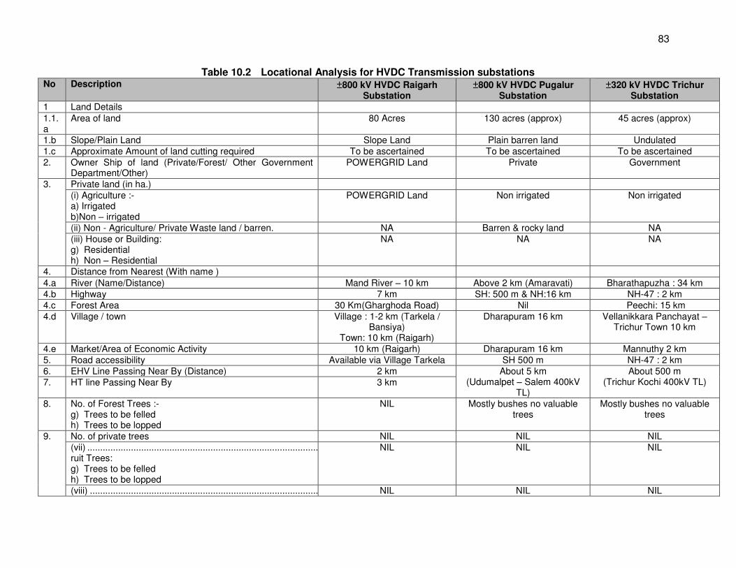
83
Table 10.2 Locational Analysis for HVDC Transmission substations No Description ±800 kV HVDC Raigarh
Substation ±800 kV HVDC Pugalur
Substation ±320 kV HVDC Trichur
Substation
1 Land Details 1.1.a
Area of land 80 Acres 130 acres (approx) 45 acres (approx)
1.b Slope/Plain Land Slope Land Plain barren land Undulated 1.c Approximate Amount of land cutting required To be ascertained To be ascertained To be ascertained 2. Owner Ship of land (Private/Forest/ Other Government
Department/Other) POWERGRID Land
Private Government
3. Private land (in ha.) (i) Agriculture :- a) Irrigated b)Non – irrigated
POWERGRID Land Non irrigated Non irrigated
(ii) Non - Agriculture/ Private Waste land / barren. NA Barren & rocky land NA (iii) House or Building: g) Residential h) Non – Residential
NA NA NA
4. Distance from Nearest (With name ) 4.a River (Name/Distance) Mand River – 10 km Above 2 km (Amaravati) Bharathapuzha : 34 km 4.b Highway 7 km SH: 500 m & NH:16 km NH-47 : 2 km 4.c Forest Area 30 Km(Gharghoda Road) Nil Peechi: 15 km 4.d Village / town Village : 1-2 km (Tarkela /
Bansiya) Town: 10 km (Raigarh)
Dharapuram 16 km Vellanikkara Panchayat – Trichur Town 10 km
4.e Market/Area of Economic Activity 10 km (Raigarh) Dharapuram 16 km Mannuthy 2 km 5. Road accessibility Available via Village Tarkela SH 500 m NH-47 : 2 km 6. EHV Line Passing Near By (Distance) 2 km About 5 km
(Udumalpet – Salem 400kV TL)
About 500 m (Trichur Kochi 400kV TL) 7. HT line Passing Near By 3 km
8. No. of Forest Trees :- g) Trees to be felled h) Trees to be lopped
NIL Mostly bushes no valuable trees
Mostly bushes no valuable trees
9. No. of private trees NIL NIL NIL (vii) ................................................................................................ruit Trees: g) Trees to be felled h) Trees to be lopped
NIL NIL NIL
(viii) ................................................................................................ NIL NIL NIL
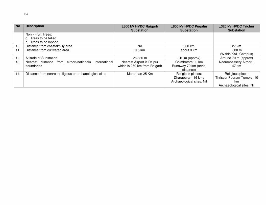
84
No Description ±800 kV HVDC Raigarh Substation
±800 kV HVDC Pugalur Substation
±320 kV HVDC Trichur Substation
Non - Fruit Trees: g) Trees to be felled h) Trees to be lopped
10. Distance from coastal/hilly area NA 300 km 27 km 11. Distance from cultivated area 0.5 km about 3 km 500 m
(Within KAU Campus) 12. Altitude of Substation 262.30 m 310 m (approx) Around 70 m (approx) 13. Nearest distance from airport/national& international
boundaries Nearest Airport is Raipur
which is 250 km from Raigarh Coimbatore 90 km
Runaway 70 km (aerial distance)
Nedumbassery Airport : 47 km
14. Distance from nearest religious or archaeological sites More than 25 Km Religious places: Dharapuram 16 kms
Archaeological sites: Nil
Religious place- Thrissur Pooram Temple -10
km Archaeological sites: Nil
85
10.2 Environmental Criteria for Route Selection for Associated facilities 330. POWERGRID takes into consideration the following environmental criteria in selecting the optimum route: The route of the proposed transmission lines does not involve any human rehabilitation. Any monument of cultural or historical importance is not affected by the route of the
transmission line. The proposed route of transmission line does not create any threat to the survival of any
community with special reference to Tribal Community. The proposed route of transmission line does not affect any public utility services like
playgrounds, schools, other establishments, etc. The line route does not pass through any sanctuaries, national park, etc. The line route does not infringe with area of natural resources. 331. To achieve this, POWERGRID undertakes route selection for individual transmission lines in close consultation with representatives from the MoEF&CC and the Department of Revenue. Although under national law, POWERGRID has the right of way to put a tower in private land (Section 63 of the Electricity Act 2003) yet alternative alignments are considered keeping in mind the site/route selection criteria to avoid environmentally sensitive areas and settlements at execution stage. 332. As a rule, alignments are generally sited 10-15 km away from major towns, whenever possible, to account for future urban expansion. Similarly, forests are avoided to the extent possible, and when not possible, a route is selected in consultation with the local Divisional Forest Officer, that causes minimum damage to existing forest resources. Alignments are selected to avoid wetlands and unstable areas, national parks and sanctuaries, both for financial and environmental reasons.
333. The route alignment study for the associated transmission lines is under progress and the study shall be done as per provisions of POWERGRID’s ESPP which is in line with ADB SPS 2009 and best route shall be finalized taking into consideration the Environmental criteria. The IEE will be prepared by POWERGRID for this associated line and will be disclosed on the POWERGRID website and shared with ADB for comments.
86
11.0 INFORMATION DISCLOSURE, CONSULTATION, AND PARTICIPATION 334. Public consultation/information is an integral part of the project implementation. Public is informed about the project at every stage of execution. During survey, POWERGRID’s site officials meet people and inform them about the routing of transmission lines. During the construction, every individual, on whose land tower is erected and people affected by ROW, is consulted. 335. Aside from this, public consultation using different techniques like public meeting, small group meeting, and informal meeting following the POWERGRID’s ESPP shall also be carried out during different activities of project cycle. During such consultation, the public will be informed about the project in general and in particular about the following: Complete project plan (i.e., its route and terminating point and substations, if any, in
between); POWERGRID design standards in relation to approved international standards; Health impacts in relation to EMF; Measures taken to avoid public utilities such as school, hospitals, etc.; Other impacts associated with transmission lines and POWERGRID’s approach to
minimizing and solving them; Land acquisition details, proposed R&R measures and compensation packages in line with
POWERGRID’s policy; and, Trees and crop compensation process. 336. POWERGRID will provide relevant environmental information, including information from the above documents in a timely manner, in an accessible place and in a form and local language(s) understandable to affected people and other stakeholders. 337. Public meetings were also organized along the routes of transmission lines (see Table 11.1). To get the maximum participation during the Public Consultation Program, a notice was served well in advance to the villagers (see Annexure 5, Details of public consultation, Plate A for photographs). The details of lines and its importance were explained to the villagers. The villagers including the Village Panchayat representatives and POWERGRID representative participated in the program. 338. The program was arranged in an interactive way and queries like crop compensation, route alignment, etc. were addressed. Most of the participants were small farmers and were worried about their land through which the transmission line will pass. They were informed that POWERGRID will not acquire their land for construction of transmission lines. Only towers will be spotted in their fields where they can do farming without any fear because the tower height is very high and even tractor can pass below the tower. 339. Moreover, it was explained that there is no risk of passing current from the transmission line as there is foolproof system of earthing for towers. The consultation process was appreciated by the villagers and were happy to know about the transparent policy of POWERGRID for the execution of the project and promised to extend their cooperation during construction of the transmission line. The process of such consultation and its documentation shall continue during project implementation and even during O&M stage.
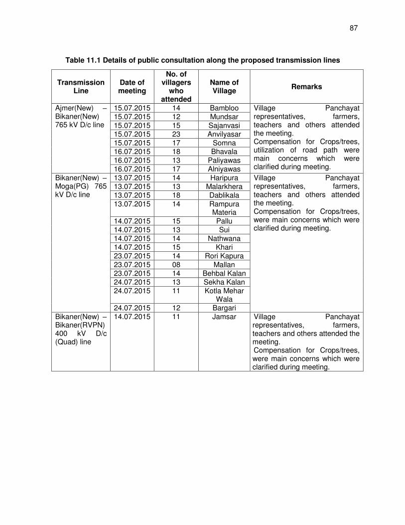
87
Table 11.1 Details of public consultation along the proposed transmission lines
Transmission Line
Date of meeting
No. of villagers
who attended
Name of Village
Remarks
Ajmer(New) – Bikaner(New) 765 kV D/c line
15.07.2015 14 Bambloo Village Panchayat representatives, farmers, teachers and others attended the meeting. Compensation for Crops/trees, utilization of road path were main concerns which were clarified during meeting.
15.07.2015 12 Mundsar 15.07.2015 15 Sajanvasi 15.07.2015 23 Anvilyasar 15.07.2015 17 Somna 16.07.2015 18 Bhavala 16.07.2015 13 Paliyawas 16.07.2015 17 Alniyawas
Bikaner(New) – Moga(PG) 765 kV D/c line
13.07.2015 14 Haripura Village Panchayat representatives, farmers, teachers and others attended the meeting. Compensation for Crops/trees, were main concerns which were clarified during meeting.
13.07.2015 13 Malarkhera 13.07.2015 18 Dablikala 13.07.2015 14 Rampura
Materia 14.07.2015 15 Pallu 14.07.2015 13 Sui 14.07.2015 14 Nathwana 14.07.2015 15 Khari 23.07.2015 14 Rori Kapura 23.07.2015 08 Mallan 23.07.2015 14 Behbal Kalan 24.07.2015 13 Sekha Kalan 24.07.2015 11 Kotla Mehar
Wala 24.07.2015 12 Bargari
Bikaner(New) – Bikaner(RVPN) 400 kV D/c (Quad) line
14.07.2015 11 Jamsar Village Panchayat representatives, farmers, teachers and others attended the meeting. Compensation for Crops/trees, were main concerns which were clarified during meeting.
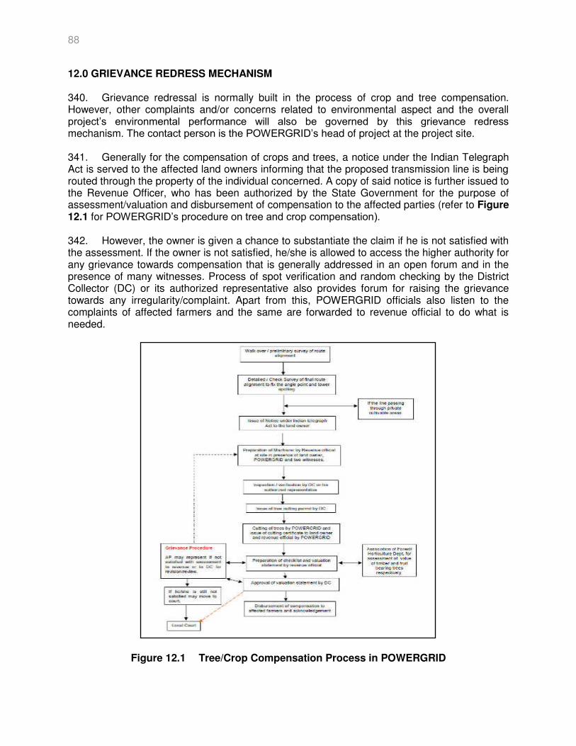
88
12.0 GRIEVANCE REDRESS MECHANISM 340. Grievance redressal is normally built in the process of crop and tree compensation. However, other complaints and/or concerns related to environmental aspect and the overall project’s environmental performance will also be governed by this grievance redress mechanism. The contact person is the POWERGRID’s head of project at the project site. 341. Generally for the compensation of crops and trees, a notice under the Indian Telegraph Act is served to the affected land owners informing that the proposed transmission line is being routed through the property of the individual concerned. A copy of said notice is further issued to the Revenue Officer, who has been authorized by the State Government for the purpose of assessment/valuation and disbursement of compensation to the affected parties (refer to Figure 12.1 for POWERGRID’s procedure on tree and crop compensation). 342. However, the owner is given a chance to substantiate the claim if he is not satisfied with the assessment. If the owner is not satisfied, he/she is allowed to access the higher authority for any grievance towards compensation that is generally addressed in an open forum and in the presence of many witnesses. Process of spot verification and random checking by the District Collector (DC) or its authorized representative also provides forum for raising the grievance towards any irregularity/complaint. Apart from this, POWERGRID officials also listen to the complaints of affected farmers and the same are forwarded to revenue official to do what is needed.
Figure 12.1 Tree/Crop Compensation Process in POWERGRID
89
343. For substation that will involve land acquisition, a Grievance Redress Committee (GRC) will be set up consisting of POWERGRID staff, representatives of local authorities, affected persons (APs), Gram Panchayat or any well-reputed person as mutually agreed by with the local authorities and APs. 344. Local people particularly the APs are informed about the existence of GRC during the consultation process. Meeting of the GRC shall be convened within 15 days of receiving a grievance for its discussion/solution. GRC aims to complete its decision within 45-90 days of receiving the grievance. 345. In these projects, land for Ajmer, Moga, Raigarh, North Trichur and Bikaner is either Government land/ POWERGRID land for which GRC shall not be required. Only for Pugalur Substation, land shall be purchased from private land owners.
90
13.0 ENVIRONMENTAL MANAGEMENT PLAN
13.1 Institutional Mechanism for Mitigation and Monitoring Requirements 346. Monitoring is a continuous process for POWERGRID at all the stages of its project cycle. Aside from the site managers reviewing the progress on a daily basis, regular project review meetings will be held at least on a monthly basis which will be chaired by the Executive Director of the region wherein apart from construction issues, the environmental aspects of the projects are discussed and remedial measures taken, wherever required. The exceptions of these meetings will be submitted to the Directors and Chairman and Managing Director of POWERGRID. The progress of various ongoing projects is also informed to the Board of Directors. Following is the organization support system for proper implementation and monitoring of the environmental and social management plan. Figure 13.1 shows the organization support structure at POWERGRID.
a) Corporate Level 347. An Environmental Management Cell at corporate level was created within POWERGRID in 1992 and subsequently upgraded to an Environment Management Department (EMD) in 1993 and in 1997 it has been further upgraded to Environment and Social Management Department (ESMD). A brief description of ESMD's responsibilities includes:
Advising and coordinating RHQs and Site to carry out environmental and social surveys for new projects.
Assisting RHQs and site to finalize routes of entire power transmission line considering environmental and social factors that could arise en-route
Help RHQs and Site to follow-up with the state forest offices and other state departments in expediting forest clearances and the land acquisition process of various ongoing and new projects
Act as a focal point for interaction with the MoEF&CC for expediting forest clearances and follow-ups with the Ministry of Power.
Imparts training to POWERGRID’s Regional Head Quarters (RHQs) &Site officials on environment and social issues and their management plan.
b) Regional Level
348. At each Regional Office, POWERGRID has an Environmental and Social Management Cell (ESMC) to manage environmental and social issues and to coordinate between ESMD at the Corporate level and the Construction Area Office (CAO). The key functions of ESMC include:
Advising and coordinating field offices to carry out environmental and social surveys for new projects envisaged in the Corporate Investment Plan
Assisting the ESMD and CAOs to finalize routes of entire power T/L considering the environmental and social factors that could arise en-route
To follow-up forest clearances and land acquisition processes with state forest offices and other state departments for various ongoing and new projects
Acting as a focal point for interaction with the ESMD and CAOs on various environmental and social aspects.
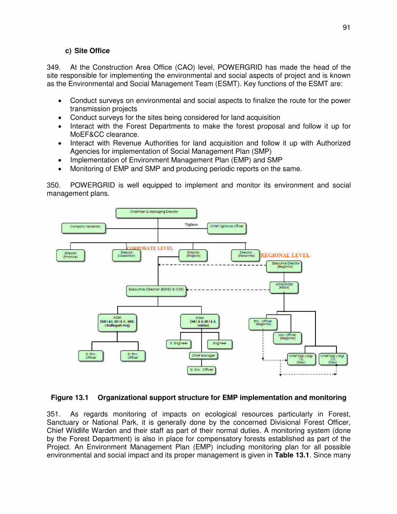
91
c) Site Office 349. At the Construction Area Office (CAO) level, POWERGRID has made the head of the site responsible for implementing the environmental and social aspects of project and is known as the Environmental and Social Management Team (ESMT). Key functions of the ESMT are:
Conduct surveys on environmental and social aspects to finalize the route for the power transmission projects
Conduct surveys for the sites being considered for land acquisition Interact with the Forest Departments to make the forest proposal and follow it up for
MoEF&CC clearance. Interact with Revenue Authorities for land acquisition and follow it up with Authorized
Agencies for implementation of Social Management Plan (SMP) Implementation of Environment Management Plan (EMP) and SMP Monitoring of EMP and SMP and producing periodic reports on the same.
350. POWERGRID is well equipped to implement and monitor its environment and social management plans.
Figure 13.1 Organizational support structure for EMP implementation and monitoring
351. As regards monitoring of impacts on ecological resources particularly in Forest, Sanctuary or National Park, it is generally done by the concerned Divisional Forest Officer, Chief Wildlife Warden and their staff as part of their normal duties. A monitoring system (done by the Forest Department) is also in place for compensatory forests established as part of the Project. An Environment Management Plan (EMP) including monitoring plan for all possible environmental and social impact and its proper management is given in Table 13.1. Since many
92
provisions of EMP are to be implemented by the contractor, monitoring of EMP implementation is included in the contract document.
13.2 Environmental Monitoring and Management Plan 352. A comprehensive and a detailed Environment Management Plan (EMP) including monitoring plan for proper mitigation is given in table for all identified environmental and social impacts has been enclosed with the subject IEE which shall be implemented during various stages of project. 353. The environment monitoring reports (EMR) will be prepared by POWERGRID semi annually as per agreed format for previous loans and submitted to ADB for review. POWERGRID is well equipped to implement and monitor its environment and social management plans.
13.3 Institutional Mechanism for Reporting and Review 354. POWERGRID, through the PMU, will be responsible for internal monitoring of EMP implementation, and will forward semi-annual progress reports of the components financed by ADB to ADB and the GoI (if required). The reports will cover EMP implementation with attention to compliance and any needed corrective actions. Ongoing consultation measures will be incorporated in the EMP. 355. Construction contractors will be responsible for the implementation of mitigation measures during the construction stage6. The IEE will be made publicly available by POWERGRID on its website. 356. ADB will (i) review and endorse updates of IEE (if needed) and EMPs before contracts are finalized and work begins; (ii) review environmental monitoring reports; and (iii) officially disclose environmental safeguards documents on its website as necessary. 357. Periodic review by corporate ESMD and higher management including review by POWERGRID CMD of all environmental issues will be undertaken to ensure that EMP and other measures are implemented at site. Annual review by independent auditor under the ISO: 14001 shall also be undertaken for compliance of agreed policy and management plan.
6 As per POWERGRID policy, provisions of ESPP and EMP are included in contract/bidding documents and already explained in Clause no. 5.3 (viii)
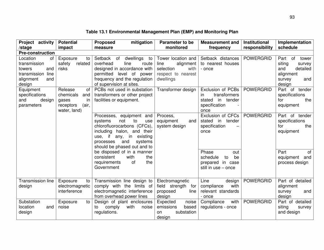
93
Table 13.1 Environmental Management Plan (EMP) and Monitoring Plan
Project activity /stage
Potential impact
Proposed mitigation measure
Parameter to be monitored
Measurement and frequency
Institutional responsibility
Implementation schedule
Pre-construction
Location of transmission towers and transmission line alignment and design
Exposure to safety related risks
Setback of dwellings to overhead line route designed in accordance with permitted level of power frequency and the regulation of supervision at sites.
Tower location and line alignment selection with respect to nearest dwellings
Setback distances to nearest houses - once
POWERGRID Part of tower siting survey and detailed alignment survey and design
Equipment specifications and design parameters
Release of chemicals and gases in receptors (air, water, land)
PCBs not used in substation transformers or other project facilities or equipment.
Transformer design Exclusion of PCBs in transformers stated in tender specification - once
POWERGRID Part of tender specifications for the equipment
Processes, equipment and systems not to use chlorofluorocarbons (CFCs), including halon, and their use, if any, in existing processes and systems should be phased out and to be disposed of in a manner consistent with the requirements of the Government
Process, equipment and system design
Exclusion of CFCs stated in tender specification – once
POWERGRID Part of tender specifications for the equipment
Phase out schedule to be prepared in case still in use – once
Part of equipment and process design
Transmission line design
Exposure to electromagnetic interference
Transmission line design to comply with the limits of electromagnetic interference from overhead power lines
Electromagnetic field strength for proposed line design
Line design compliance with relevant standards - once
POWERGRID Part of detailed alignment survey and design
Substation location and design
Exposure to noise
Design of plant enclosures to comply with noise regulations.
Expected noise emissions based on substation design
Compliance with regulations - once
POWERGRID Part of detailed siting survey and design
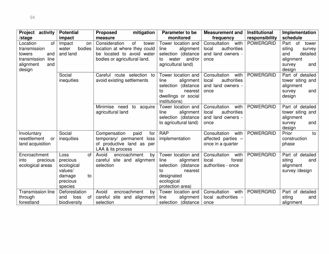
94
Project activity /stage
Potential impact
Proposed mitigation measure
Parameter to be monitored
Measurement and frequency
Institutional responsibility
Implementation schedule
Location of transmission towers and transmission line alignment and design
Impact on water bodies and land
Consideration of tower location at where they could be located to avoid water bodies or agricultural land.
Tower location and line alignment selection (distance to water and/or agricultural land)
Consultation with local authorities and land owners - once
POWERGRID Part of tower siting survey and detailed alignment survey and design
Social inequities
Careful route selection to avoid existing settlements
Tower location and line alignment selection (distance to nearest dwellings or social institutions)
Consultation with local authorities and land owners - once
POWERGRID Part of detailed tower siting and alignment survey and design
Minimise need to acquire agricultural land
Tower location and line alignment selection (distance to agricultural land)
Consultation with local authorities and land owners - once
POWERGRID Part of detailed tower siting and alignment survey and design
Involuntary resettlement or land acquisition
Social inequities
Compensation paid for temporary/ permanent loss of productive land as per LAA & its process
RAP implementation
Consultation with affected parties – once in a quarter
POWERGRID Prior to construction phase
Encroachment into precious ecological areas
Loss of precious ecological values/ damage to precious species
Avoid encroachment by careful site and alignment selection
Tower location and line alignment selection (distance to nearest designated ecological protection area)
Consultation with local forest authorities - once
POWERGRID Part of detailed siting and alignment survey /design
Transmission line through forestland
Deforestation and loss of biodiversity
Avoid encroachment by careful site and alignment selection
Tower location and line alignment selection (distance
Consultation with local authorities - once
POWERGRID Part of detailed siting and alignment
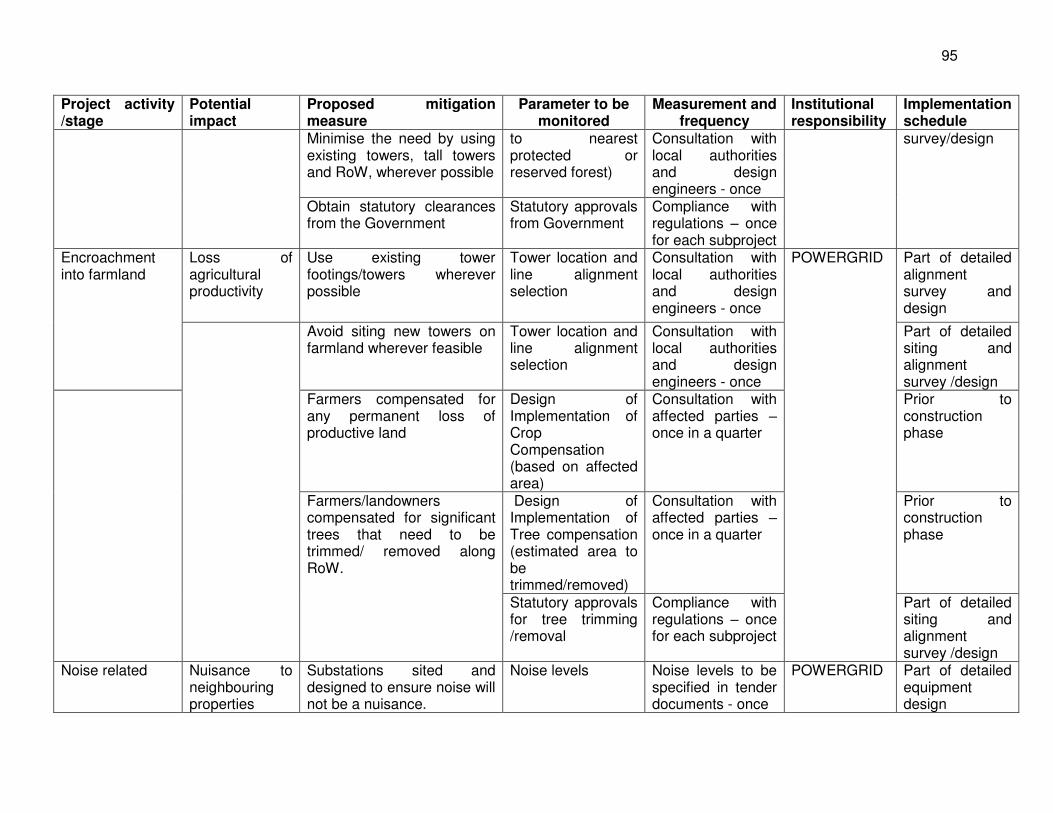
95
Project activity /stage
Potential impact
Proposed mitigation measure
Parameter to be monitored
Measurement and frequency
Institutional responsibility
Implementation schedule
Minimise the need by using existing towers, tall towers and RoW, wherever possible
to nearest protected or reserved forest)
Consultation with local authorities and design engineers - once
survey/design
Obtain statutory clearances from the Government
Statutory approvals from Government
Compliance with regulations – once for each subproject
Encroachment into farmland
Loss of agricultural productivity
Use existing tower footings/towers wherever possible
Tower location and line alignment selection
Consultation with local authorities and design engineers - once
POWERGRID Part of detailed alignment survey and design
Avoid siting new towers on farmland wherever feasible
Tower location and line alignment selection
Consultation with local authorities and design engineers - once
Part of detailed siting and alignment survey /design
Farmers compensated for any permanent loss of productive land
Design of Implementation of Crop Compensation (based on affected area)
Consultation with affected parties – once in a quarter
Prior to construction phase
Farmers/landowners compensated for significant trees that need to be trimmed/ removed along RoW.
Design of Implementation of Tree compensation (estimated area to be trimmed/removed)
Consultation with affected parties – once in a quarter
Prior to construction phase
Statutory approvals for tree trimming /removal
Compliance with regulations – once for each subproject
Part of detailed siting and alignment survey /design
Noise related Nuisance to neighbouring properties
Substations sited and designed to ensure noise will not be a nuisance.
Noise levels Noise levels to be specified in tender documents - once
POWERGRID Part of detailed equipment design
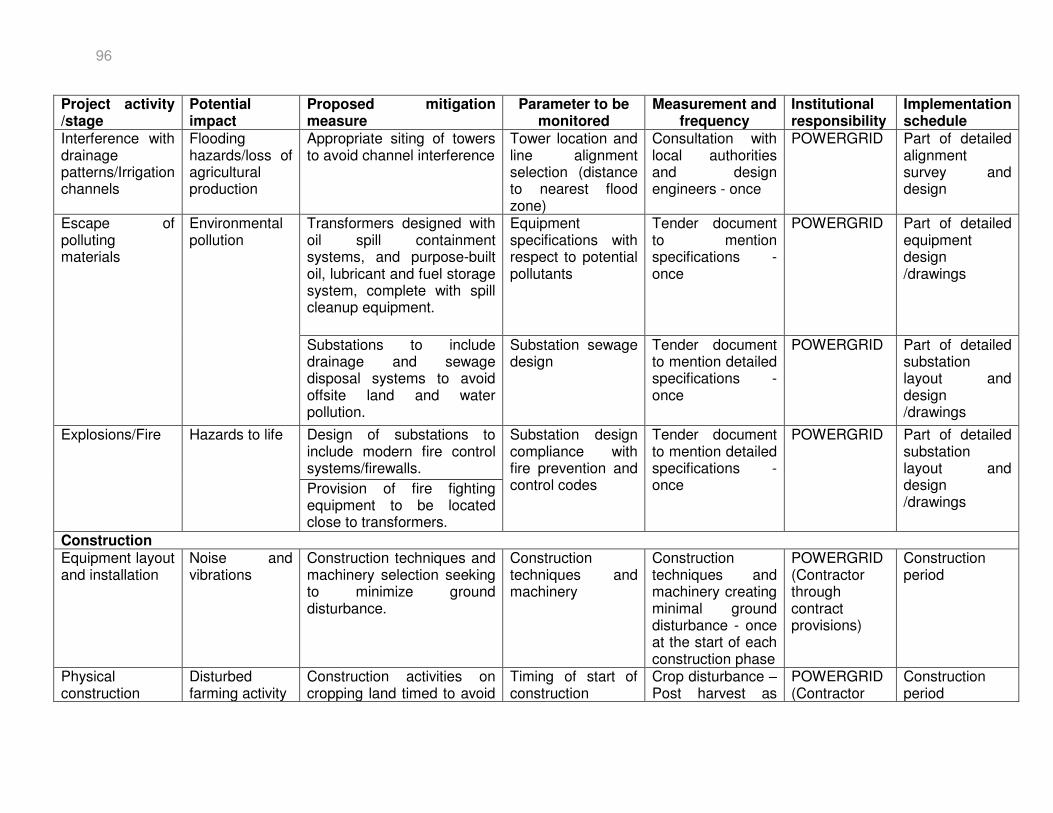
96
Project activity /stage
Potential impact
Proposed mitigation measure
Parameter to be monitored
Measurement and frequency
Institutional responsibility
Implementation schedule
Interference with drainage patterns/Irrigation channels
Flooding hazards/loss of agricultural production
Appropriate siting of towers to avoid channel interference
Tower location and line alignment selection (distance to nearest flood zone)
Consultation with local authorities and design engineers - once
POWERGRID Part of detailed alignment survey and design
Escape of polluting materials
Environmental pollution
Transformers designed with oil spill containment systems, and purpose-built oil, lubricant and fuel storage system, complete with spill cleanup equipment.
Equipment specifications with respect to potential pollutants
Tender document to mention specifications - once
POWERGRID Part of detailed equipment design /drawings
Substations to include drainage and sewage disposal systems to avoid offsite land and water pollution.
Substation sewage design
Tender document to mention detailed specifications - once
POWERGRID Part of detailed substation layout and design /drawings
Explosions/Fire Hazards to life Design of substations to include modern fire control systems/firewalls.
Substation design compliance with fire prevention and control codes
Tender document to mention detailed specifications - once
POWERGRID Part of detailed substation layout and design /drawings
Provision of fire fighting equipment to be located close to transformers.
Construction Equipment layout and installation
Noise and vibrations
Construction techniques and machinery selection seeking to minimize ground disturbance.
Construction techniques and machinery
Construction techniques and machinery creating minimal ground disturbance - once at the start of each construction phase
POWERGRID (Contractor through contract provisions)
Construction period
Physical construction
Disturbed farming activity
Construction activities on cropping land timed to avoid
Timing of start of construction
Crop disturbance –Post harvest as
POWERGRID (Contractor
Construction period
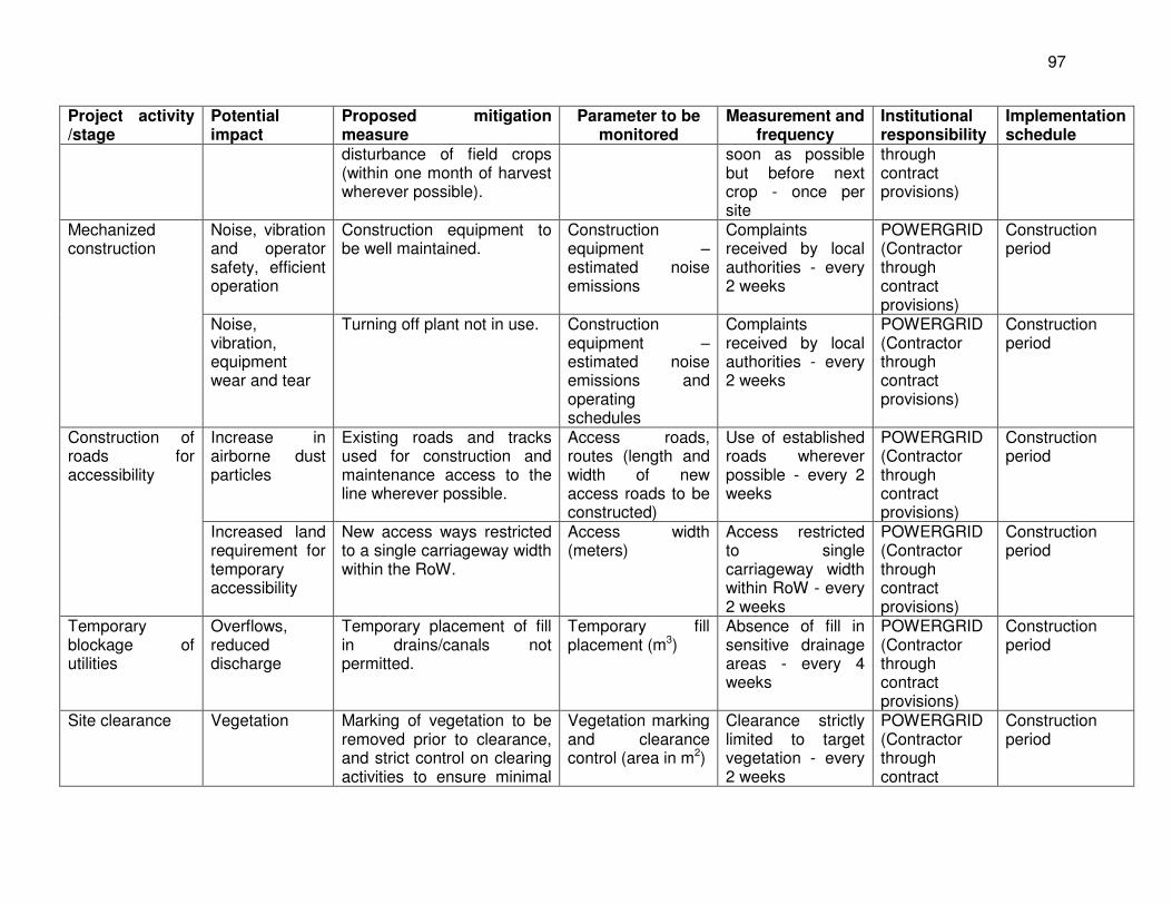
97
Project activity /stage
Potential impact
Proposed mitigation measure
Parameter to be monitored
Measurement and frequency
Institutional responsibility
Implementation schedule
disturbance of field crops (within one month of harvest wherever possible).
soon as possible but before next crop - once per site
through contract provisions)
Mechanized construction
Noise, vibration and operator safety, efficient operation
Construction equipment to be well maintained.
Construction equipment – estimated noise emissions
Complaints received by local authorities - every 2 weeks
POWERGRID (Contractor through contract provisions)
Construction period
Noise, vibration, equipment wear and tear
Turning off plant not in use. Construction equipment – estimated noise emissions and operating schedules
Complaints received by local authorities - every 2 weeks
POWERGRID (Contractor through contract provisions)
Construction period
Construction of roads for accessibility
Increase in airborne dust particles
Existing roads and tracks used for construction and maintenance access to the line wherever possible.
Access roads, routes (length and width of new access roads to be constructed)
Use of established roads wherever possible - every 2 weeks
POWERGRID (Contractor through contract provisions)
Construction period
Increased land requirement for temporary accessibility
New access ways restricted to a single carriageway width within the RoW.
Access width (meters)
Access restricted to single carriageway width within RoW - every 2 weeks
POWERGRID (Contractor through contract provisions)
Construction period
Temporary blockage of utilities
Overflows, reduced discharge
Temporary placement of fill in drains/canals not permitted.
Temporary fill placement (m3)
Absence of fill in sensitive drainage areas - every 4 weeks
POWERGRID (Contractor through contract provisions)
Construction period
Site clearance Vegetation Marking of vegetation to be removed prior to clearance, and strict control on clearing activities to ensure minimal
Vegetation marking and clearance control (area in m2)
Clearance strictly limited to target vegetation - every 2 weeks
POWERGRID (Contractor through contract
Construction period
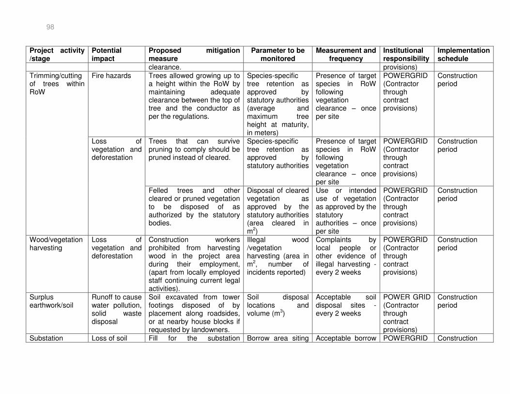
98
Project activity /stage
Potential impact
Proposed mitigation measure
Parameter to be monitored
Measurement and frequency
Institutional responsibility
Implementation schedule
clearance. provisions) Trimming/cutting of trees within RoW
Fire hazards Trees allowed growing up to a height within the RoW by maintaining adequate clearance between the top of tree and the conductor as per the regulations.
Species-specific tree retention as approved by statutory authorities (average and maximum tree height at maturity, in meters)
Presence of target species in RoW following vegetation clearance – once per site
POWERGRID (Contractor through contract provisions)
Construction period
Loss of vegetation and deforestation
Trees that can survive pruning to comply should be pruned instead of cleared.
Species-specific tree retention as approved by statutory authorities
Presence of target species in RoW following vegetation clearance – once per site
POWERGRID (Contractor through contract provisions)
Construction period
Felled trees and other cleared or pruned vegetation to be disposed of as authorized by the statutory bodies.
Disposal of cleared vegetation as approved by the statutory authorities (area cleared in m2)
Use or intended use of vegetation as approved by the statutory authorities – once per site
POWERGRID (Contractor through contract provisions)
Construction period
Wood/vegetation harvesting
Loss of vegetation and deforestation
Construction workers prohibited from harvesting wood in the project area during their employment, (apart from locally employed staff continuing current legal activities).
Illegal wood /vegetation harvesting (area in m2, number of incidents reported)
Complaints by local people or other evidence of illegal harvesting - every 2 weeks
POWERGRID (Contractor through contract provisions)
Construction period
Surplus earthwork/soil
Runoff to cause water pollution, solid waste disposal
Soil excavated from tower footings disposed of by placement along roadsides, or at nearby house blocks if requested by landowners.
Soil disposal locations and volume (m3)
Acceptable soil disposal sites - every 2 weeks
POWER GRID (Contractor through contract provisions)
Construction period
Substation Loss of soil Fill for the substation Borrow area siting Acceptable borrow POWERGRID Construction
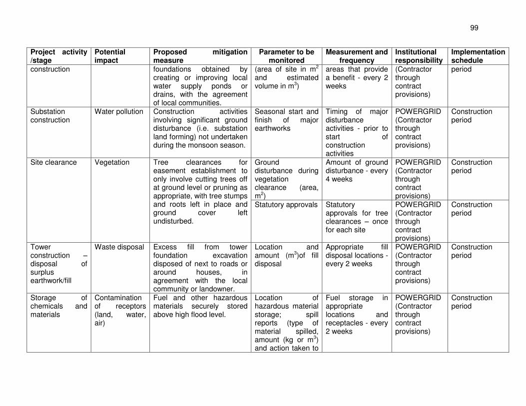
99
Project activity /stage
Potential impact
Proposed mitigation measure
Parameter to be monitored
Measurement and frequency
Institutional responsibility
Implementation schedule
construction foundations obtained by creating or improving local water supply ponds or drains, with the agreement of local communities.
(area of site in m2 and estimated volume in m3)
areas that provide a benefit - every 2 weeks
(Contractor through contract provisions)
period
Substation construction
Water pollution Construction activities involving significant ground disturbance (i.e. substation land forming) not undertaken during the monsoon season.
Seasonal start and finish of major earthworks
Timing of major disturbance activities - prior to start of construction activities
POWERGRID (Contractor through contract provisions)
Construction period
Site clearance Vegetation Tree clearances for easement establishment to only involve cutting trees off at ground level or pruning as appropriate, with tree stumps and roots left in place and ground cover left undisturbed.
Ground disturbance during vegetation clearance (area, m2)
Amount of ground disturbance - every 4 weeks
POWERGRID (Contractor through contract provisions)
Construction period
Statutory approvals Statutory approvals for tree clearances – once for each site
POWERGRID (Contractor through contract provisions)
Construction period
Tower construction – disposal of surplus earthwork/fill
Waste disposal Excess fill from tower foundation excavation disposed of next to roads or around houses, in agreement with the local community or landowner.
Location and amount (m3)of fill disposal
Appropriate fill disposal locations - every 2 weeks
POWERGRID (Contractor through contract provisions)
Construction period
Storage of chemicals and materials
Contamination of receptors (land, water, air)
Fuel and other hazardous materials securely stored above high flood level.
Location of hazardous material storage; spill reports (type of material spilled, amount (kg or m3) and action taken to
Fuel storage in appropriate locations and receptacles - every 2 weeks
POWERGRID (Contractor through contract provisions)
Construction period
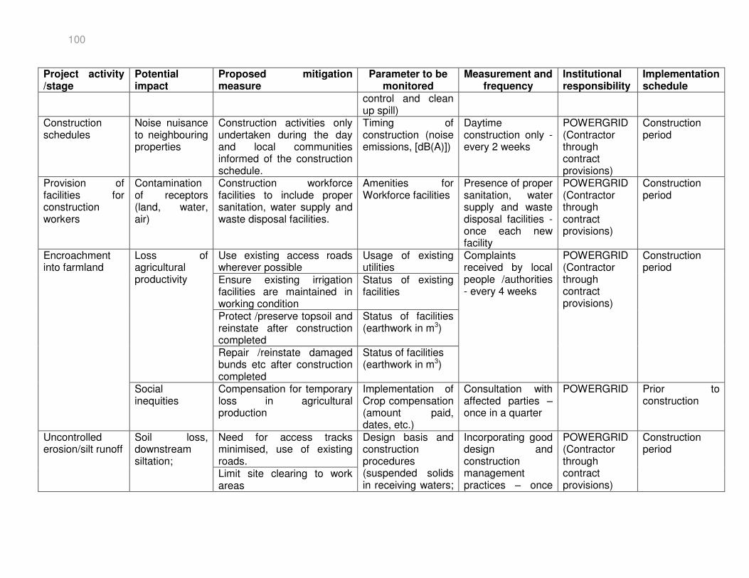
100
Project activity /stage
Potential impact
Proposed mitigation measure
Parameter to be monitored
Measurement and frequency
Institutional responsibility
Implementation schedule
control and clean up spill)
Construction schedules
Noise nuisance to neighbouring properties
Construction activities only undertaken during the day and local communities informed of the construction schedule.
Timing of construction (noise emissions, [dB(A)])
Daytime construction only - every 2 weeks
POWERGRID (Contractor through contract provisions)
Construction period
Provision of facilities for construction workers
Contamination of receptors (land, water, air)
Construction workforce facilities to include proper sanitation, water supply and waste disposal facilities.
Amenities for Workforce facilities
Presence of proper sanitation, water supply and waste disposal facilities - once each new facility
POWERGRID (Contractor through contract provisions)
Construction period
Encroachment into farmland
Loss of agricultural productivity
Use existing access roads wherever possible
Usage of existing utilities
Complaints received by local people /authorities - every 4 weeks
POWERGRID (Contractor through contract provisions)
Construction period
Ensure existing irrigation facilities are maintained in working condition
Status of existing facilities
Protect /preserve topsoil and reinstate after construction completed
Status of facilities (earthwork in m3)
Repair /reinstate damaged bunds etc after construction completed
Status of facilities (earthwork in m3)
Social inequities
Compensation for temporary loss in agricultural production
Implementation of Crop compensation (amount paid, dates, etc.)
Consultation with affected parties – once in a quarter
POWERGRID Prior to construction
Uncontrolled erosion/silt runoff
Soil loss, downstream siltation;
Need for access tracks minimised, use of existing roads.
Design basis and construction procedures (suspended solids in receiving waters;
Incorporating good design and construction management practices – once
POWERGRID (Contractor through contract provisions)
Construction period
Limit site clearing to work areas
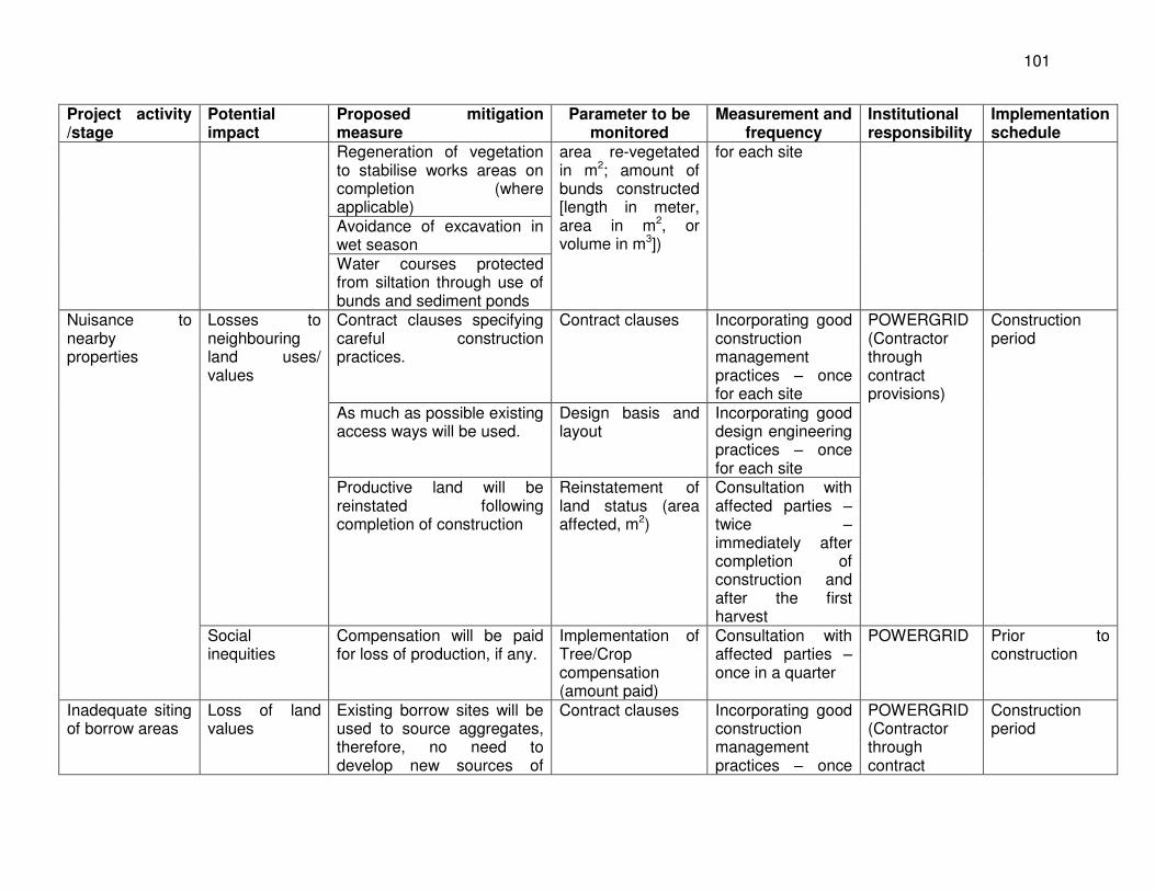
101
Project activity /stage
Potential impact
Proposed mitigation measure
Parameter to be monitored
Measurement and frequency
Institutional responsibility
Implementation schedule
Regeneration of vegetation to stabilise works areas on completion (where applicable)
area re-vegetated in m2; amount of bunds constructed [length in meter, area in m2, or volume in m3])
for each site
Avoidance of excavation in wet season Water courses protected from siltation through use of bunds and sediment ponds
Nuisance to nearby properties
Losses to neighbouring land uses/ values
Contract clauses specifying careful construction practices.
Contract clauses Incorporating good construction management practices – once for each site
POWERGRID (Contractor through contract provisions)
Construction period
As much as possible existing access ways will be used.
Design basis and layout
Incorporating good design engineering practices – once for each site
Productive land will be reinstated following completion of construction
Reinstatement of land status (area affected, m2)
Consultation with affected parties – twice – immediately after completion of construction and after the first harvest
Social inequities
Compensation will be paid for loss of production, if any.
Implementation of Tree/Crop compensation (amount paid)
Consultation with affected parties – once in a quarter
POWERGRID Prior to construction
Inadequate siting of borrow areas
Loss of land values
Existing borrow sites will be used to source aggregates, therefore, no need to develop new sources of
Contract clauses Incorporating good construction management practices – once
POWERGRID (Contractor through contract
Construction period
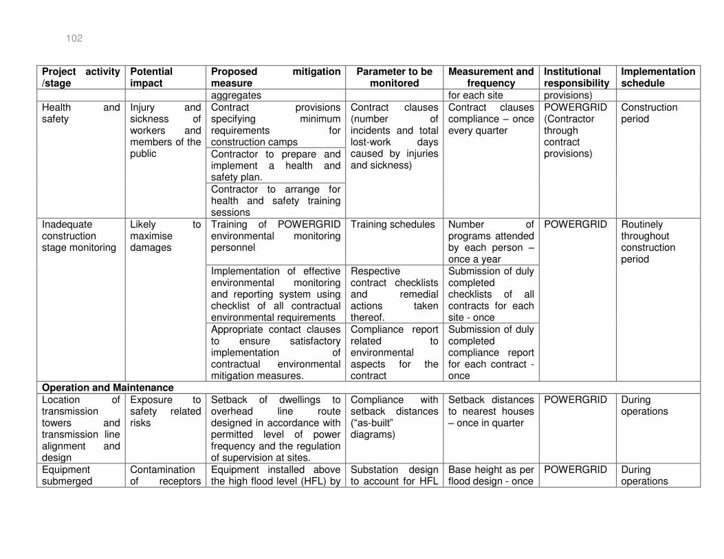
102
Project activity /stage
Potential impact
Proposed mitigation measure
Parameter to be monitored
Measurement and frequency
Institutional responsibility
Implementation schedule
aggregates for each site provisions) Health and safety
Injury and sickness of workers and members of the public
Contract provisions specifying minimum requirements for construction camps
Contract clauses (number of incidents and total lost-work days caused by injuries and sickness)
Contract clauses compliance – once every quarter
POWERGRID (Contractor through contract provisions)
Construction period
Contractor to prepare and implement a health and safety plan. Contractor to arrange for health and safety training sessions
Inadequate construction stage monitoring
Likely to maximise damages
Training of POWERGRID environmental monitoring personnel
Training schedules Number of programs attended by each person – once a year
POWERGRID Routinely throughout construction period
Implementation of effective environmental monitoring and reporting system using checklist of all contractual environmental requirements
Respective contract checklists and remedial actions taken thereof.
Submission of duly completed checklists of all contracts for each site - once
Appropriate contact clauses to ensure satisfactory implementation of contractual environmental mitigation measures.
Compliance report related to environmental aspects for the contract
Submission of duly completed compliance report for each contract - once
Operation and Maintenance Location of transmission towers and transmission line alignment and design
Exposure to safety related risks
Setback of dwellings to overhead line route designed in accordance with permitted level of power frequency and the regulation of supervision at sites.
Compliance with setback distances (“as-built” diagrams)
Setback distances to nearest houses – once in quarter
POWERGRID During operations
Equipment submerged
Contamination of receptors
Equipment installed above the high flood level (HFL) by
Substation design to account for HFL
Base height as per flood design - once
POWERGRID During operations
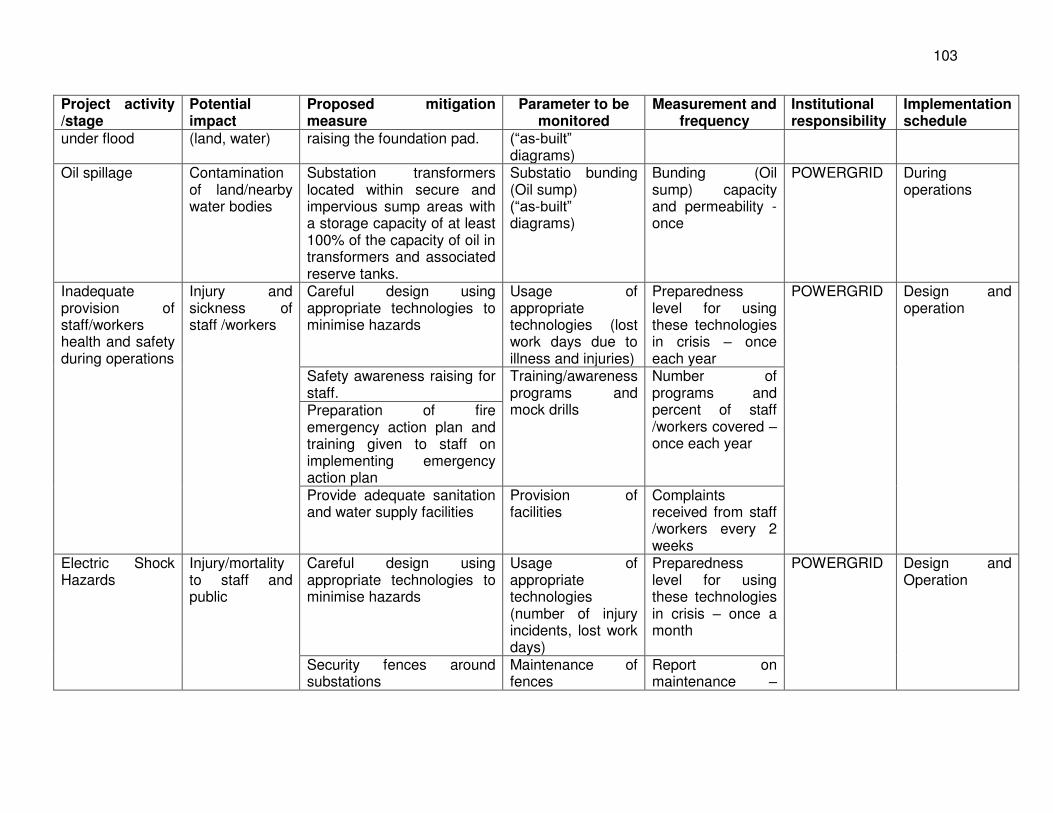
103
Project activity /stage
Potential impact
Proposed mitigation measure
Parameter to be monitored
Measurement and frequency
Institutional responsibility
Implementation schedule
under flood (land, water) raising the foundation pad. (“as-built” diagrams)
Oil spillage Contamination of land/nearby water bodies
Substation transformers located within secure and impervious sump areas with a storage capacity of at least 100% of the capacity of oil in transformers and associated reserve tanks.
Substatio bunding (Oil sump) (“as-built” diagrams)
Bunding (Oil sump) capacity and permeability - once
POWERGRID During operations
Inadequate provision of staff/workers health and safety during operations
Injury and sickness of staff /workers
Careful design using appropriate technologies to minimise hazards
Usage of appropriate technologies (lost work days due to illness and injuries)
Preparedness level for using these technologies in crisis – once each year
POWERGRID Design and operation
Safety awareness raising for staff.
Training/awareness programs and mock drills
Number of programs and percent of staff /workers covered – once each year
Preparation of fire emergency action plan and training given to staff on implementing emergency action plan Provide adequate sanitation and water supply facilities
Provision of facilities
Complaints received from staff /workers every 2 weeks
Electric Shock Hazards
Injury/mortality to staff and public
Careful design using appropriate technologies to minimise hazards
Usage of appropriate technologies (number of injury incidents, lost work days)
Preparedness level for using these technologies in crisis – once a month
POWERGRID Design and Operation
Security fences around substations
Maintenance of fences
Report on maintenance –
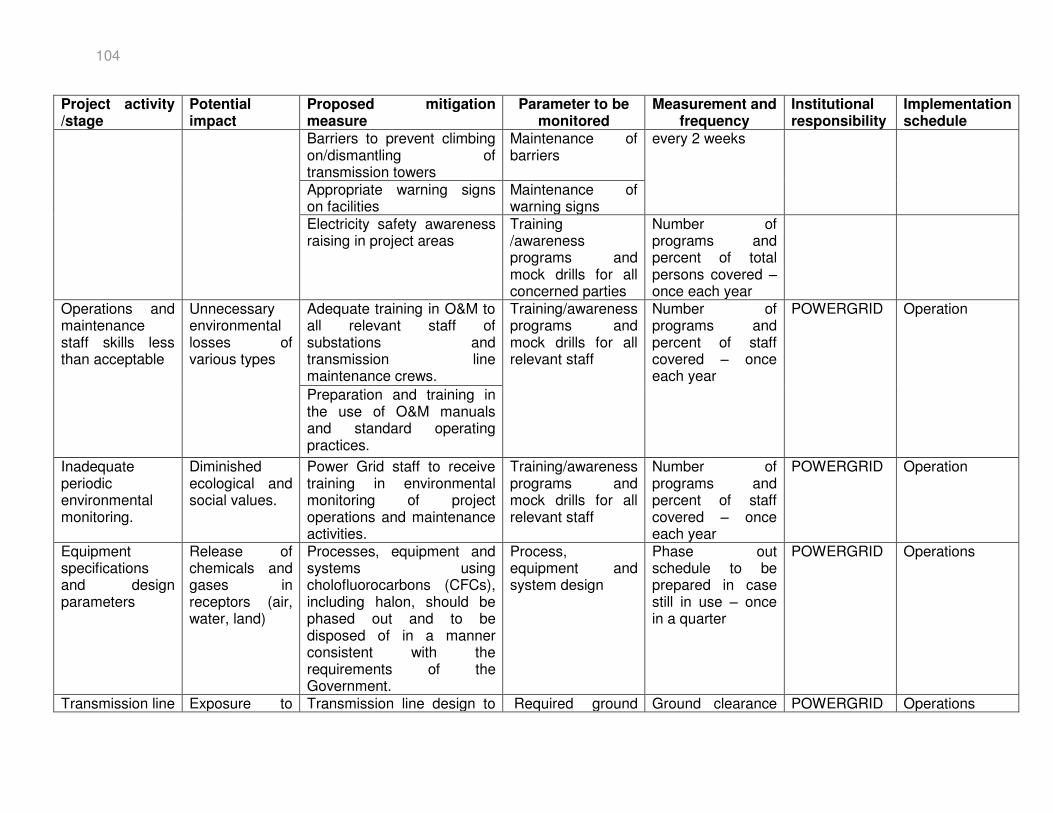
104
Project activity /stage
Potential impact
Proposed mitigation measure
Parameter to be monitored
Measurement and frequency
Institutional responsibility
Implementation schedule
Barriers to prevent climbing on/dismantling of transmission towers
Maintenance of barriers
every 2 weeks
Appropriate warning signs on facilities
Maintenance of warning signs
Electricity safety awareness raising in project areas
Training /awareness programs and mock drills for all concerned parties
Number of programs and percent of total persons covered – once each year
Operations and maintenance staff skills less than acceptable
Unnecessary environmental losses of various types
Adequate training in O&M to all relevant staff of substations and transmission line maintenance crews.
Training/awareness programs and mock drills for all relevant staff
Number of programs and percent of staff covered – once each year
POWERGRID Operation
Preparation and training in the use of O&M manuals and standard operating practices.
Inadequate periodic environmental monitoring.
Diminished ecological and social values.
Power Grid staff to receive training in environmental monitoring of project operations and maintenance activities.
Training/awareness programs and mock drills for all relevant staff
Number of programs and percent of staff covered – once each year
POWERGRID Operation
Equipment specifications and design parameters
Release of chemicals and gases in receptors (air, water, land)
Processes, equipment and systems using cholofluorocarbons (CFCs), including halon, should be phased out and to be disposed of in a manner consistent with the requirements of the Government.
Process, equipment and system design
Phase out schedule to be prepared in case still in use – once in a quarter
POWERGRID Operations
Transmission line Exposure to Transmission line design to Required ground Ground clearance POWERGRID Operations
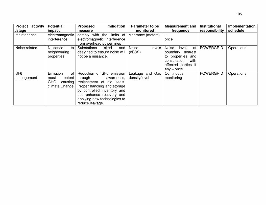
105
Project activity /stage
Potential impact
Proposed mitigation measure
Parameter to be monitored
Measurement and frequency
Institutional responsibility
Implementation schedule
maintenance electromagnetic interference
comply with the limits of electromagnetic interference from overhead power lines
clearance (meters) - once
Noise related Nuisance to neighbouring properties
Substations sited and designed to ensure noise will not be a nuisance.
Noise levels (dB(A))
Noise levels at boundary nearest to properties and consultation with affected parties if any – once
POWERGRID Operations
SF6 management
Emission of most potent GHG causing climate Change
Reduction of SF6 emission through awareness, replacement of old seals. Proper handling and storage by controlled inventory and use enhance recovery and applying new technologies to reduce leakage.
Leakage and Gas density/level
Continuous monitoring
POWERGRID Operations
106
14.0 CONCLUSION 358. None of the project components is in environmentally-sensitive areas. Careful route selection has minimized involvement of forest area to the extent possible but could not be completely avoided due to terrain and other reasons such as strip plantation along road and canal crossing. No major impact on wildlife is envisaged as the forest is not the habitat of any endangered or endemic species of fauna and flora. 359. The project will not result in any long-term significant adverse impacts. Minimal environmental impacts are anticipated, mostly during construction. These can be mitigated successfully by implementing the EMP with estimated costs for implementation. Environmental and social benefits of the project and long-term investment program objectives outweigh the temporary negative impacts. Overall, the environmental impacts associated with project are mainly limited to the construction period and can be mitigated to an acceptable level by implementation of recommended measures and by best engineering and environmental practices. 360. The route of transmission lines and substation sites avoided any sanctuary or protected areas and other environmentally-sensitive areas. Best available technology and best management practices are built-in to the project design. The proposed project was categorized as “Category B”. As noted in the IEE document, all project components will be implemented and monitored in line with the Environmental and Social Policy and Procedures of Power Grid Corporation of India Limited, which is in line with ADB SPS (2009).
ANNEXURE-1
(BUDGET ESTIMATE)
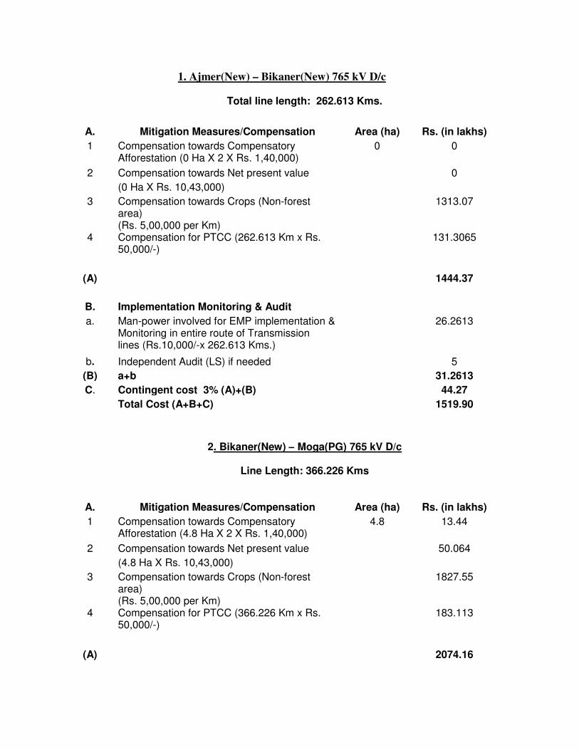
1. Ajmer(New) – Bikaner(New) 765 kV D/c
Total line length: 262.613 Kms.
A. Mitigation Measures/Compensation Area (ha) Rs. (in lakhs)
1 Compensation towards Compensatory Afforestation (0 Ha X 2 X Rs. 1,40,000)
0 0
2 Compensation towards Net present value 0
(0 Ha X Rs. 10,43,000)
3 Compensation towards Crops (Non-forest area) (Rs. 5,00,000 per Km)
1313.07
4 Compensation for PTCC (262.613 Km x Rs. 50,000/-)
131.3065
(A) 1444.37
B. Implementation Monitoring & Audit
a. Man-power involved for EMP implementation & Monitoring in entire route of Transmission lines (Rs.10,000/-x 262.613 Kms.)
26.2613
b. Independent Audit (LS) if needed 5
(B) a+b 31.2613
C. Contingent cost 3% (A)+(B) 44.27
Total Cost (A+B+C) 1519.90
2. Bikaner(New) – Moga(PG) 765 kV D/c
Line Length: 366.226 Kms
A. Mitigation Measures/Compensation Area (ha) Rs. (in lakhs)
1 Compensation towards Compensatory Afforestation (4.8 Ha X 2 X Rs. 1,40,000)
4.8 13.44
2 Compensation towards Net present value 50.064
(4.8 Ha X Rs. 10,43,000)
3 Compensation towards Crops (Non-forest area) (Rs. 5,00,000 per Km)
1827.55
4 Compensation for PTCC (366.226 Km x Rs. 50,000/-)
183.113
(A) 2074.16
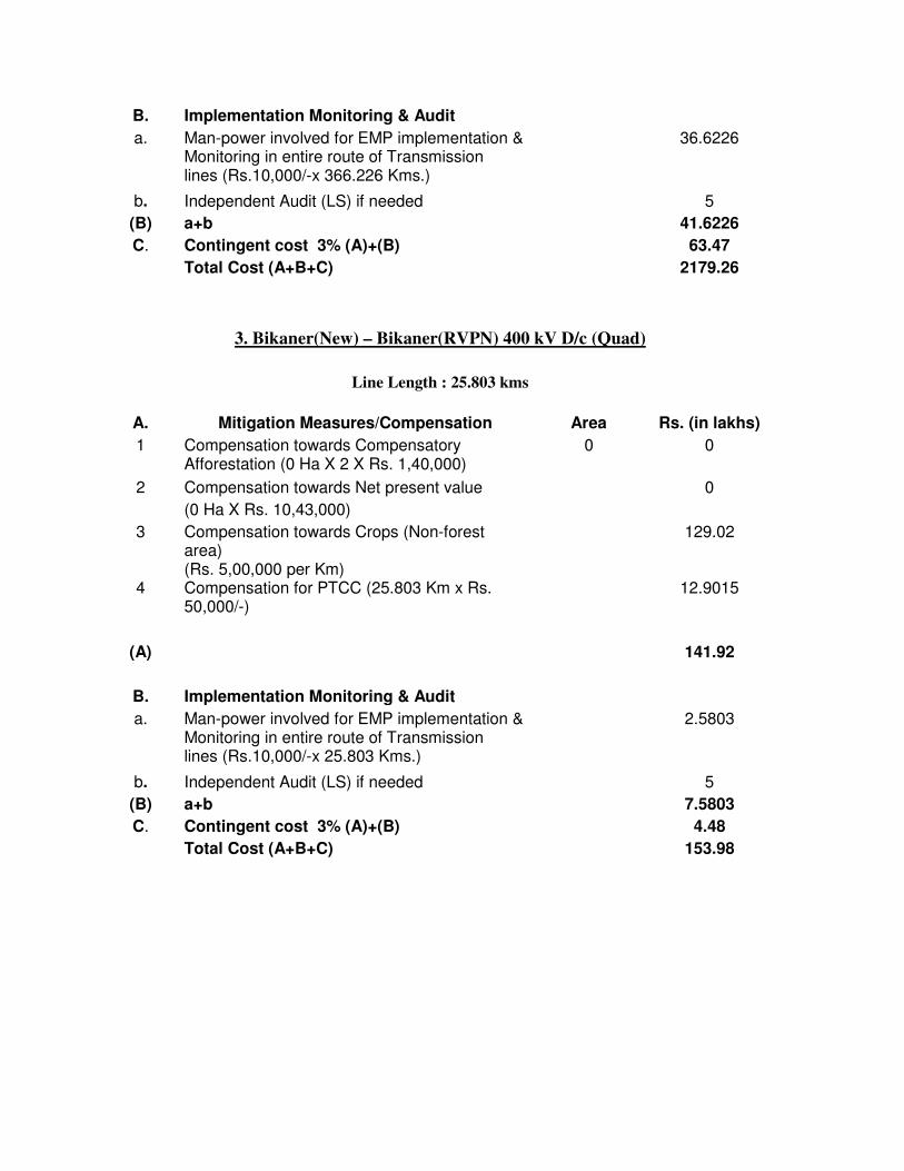
B. Implementation Monitoring & Audit
a. Man-power involved for EMP implementation & Monitoring in entire route of Transmission lines (Rs.10,000/-x 366.226 Kms.)
36.6226
b. Independent Audit (LS) if needed 5
(B) a+b 41.6226
C. Contingent cost 3% (A)+(B) 63.47
Total Cost (A+B+C) 2179.26
3. Bikaner(New) – Bikaner(RVPN) 400 kV D/c (Quad)
Line Length : 25.803 kms
A. Mitigation Measures/Compensation Area Rs. (in lakhs)
1 Compensation towards Compensatory Afforestation (0 Ha X 2 X Rs. 1,40,000)
0 0
2 Compensation towards Net present value 0
(0 Ha X Rs. 10,43,000)
3 Compensation towards Crops (Non-forest area) (Rs. 5,00,000 per Km)
129.02
4 Compensation for PTCC (25.803 Km x Rs. 50,000/-)
12.9015
(A) 141.92
B. Implementation Monitoring & Audit
a. Man-power involved for EMP implementation & Monitoring in entire route of Transmission lines (Rs.10,000/-x 25.803 Kms.)
2.5803
b. Independent Audit (LS) if needed 5
(B) a+b 7.5803
C. Contingent cost 3% (A)+(B) 4.48
Total Cost (A+B+C) 153.98
ANNEXURE-2
(TREE/CROP COMPENSATION)
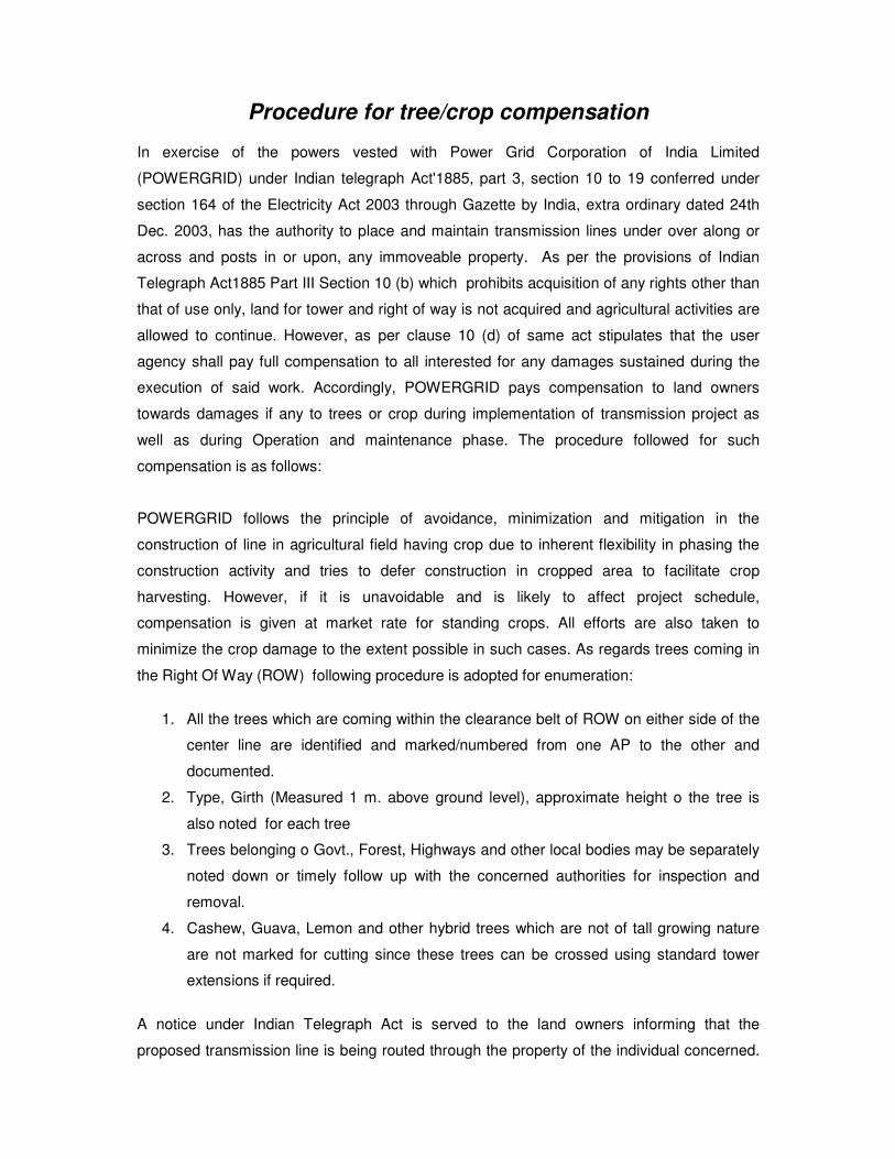
Procedure for tree/crop compensation
In exercise of the powers vested with Power Grid Corporation of India Limited
(POWERGRID) under Indian telegraph Act'1885, part 3, section 10 to 19 conferred under
section 164 of the Electricity Act 2003 through Gazette by India, extra ordinary dated 24th
Dec. 2003, has the authority to place and maintain transmission lines under over along or
across and posts in or upon, any immoveable property. As per the provisions of Indian
Telegraph Act1885 Part III Section 10 (b) which prohibits acquisition of any rights other than
that of use only, land for tower and right of way is not acquired and agricultural activities are
allowed to continue. However, as per clause 10 (d) of same act stipulates that the user
agency shall pay full compensation to all interested for any damages sustained during the
execution of said work. Accordingly, POWERGRID pays compensation to land owners
towards damages if any to trees or crop during implementation of transmission project as
well as during Operation and maintenance phase. The procedure followed for such
compensation is as follows:
POWERGRID follows the principle of avoidance, minimization and mitigation in the
construction of line in agricultural field having crop due to inherent flexibility in phasing the
construction activity and tries to defer construction in cropped area to facilitate crop
harvesting. However, if it is unavoidable and is likely to affect project schedule,
compensation is given at market rate for standing crops. All efforts are also taken to
minimize the crop damage to the extent possible in such cases. As regards trees coming in
the Right Of Way (ROW) following procedure is adopted for enumeration:
1. All the trees which are coming within the clearance belt of ROW on either side of the
center line are identified and marked/numbered from one AP to the other and
documented.
2. Type, Girth (Measured 1 m. above ground level), approximate height o the tree is
also noted for each tree
3. Trees belonging o Govt., Forest, Highways and other local bodies may be separately
noted down or timely follow up with the concerned authorities for inspection and
removal.
4. Cashew, Guava, Lemon and other hybrid trees which are not of tall growing nature
are not marked for cutting since these trees can be crossed using standard tower
extensions if required.
A notice under Indian Telegraph Act is served to the land owners informing that the
proposed transmission line is being routed through the property of the individual concerned.
The notice shall contain the particulars of the land, ownership details and the details of the
trees/crops inevitability likely to be damaged during the course of the construction of the
proposed transmission line and acknowledgement received from land owner. A copy of said
notice is further issued to the Revenue Officer, who has been authorized by the State Govt.
for the purpose of assessment/valuation and disbursement of compensation to the affected
parties.
The revenue officer shall further issue a notice of intimation to the concerned land owner and
inspect the site to verify the documents related to the proof of ownership and a detailed
Mahazar is prepared for the identified trees and crops inevitability damaged during the
course of the construction. For assessing the true value of timber yielding trees help of
forest officials is taken and for fruit bearing trees help of Horticulture department is taken.
The Mahazar shall contain the land owner details type of tree/crop, its present age, variety,
yielding pattern etc. and the same is prepared at site in the presence of the land owner.
These Mahazars are further compiled and a random verification is conducted by the
concerned District Collector OR his authorized representative in order to ascertain the
assessment carried out by the revenue office is genuine and correct. After this process the
District collector issues a tree cutting permit to Power Grid Corporation to enable removal /
damage to the standing tree/crop identified in the line corridor.
Once the tree/crop is removed / damaged, POWERGRID shall issue a tree cutting/crop
damaged notice to the land owner with a copy to the Revenue Officer to process the
compensation payment. Based on the above the compensation payment is generated by
means of a computerized programme developed by the National Informatics Center
exclusively for this purpose. The detailed Valuation statement thus generated using this
programme is verified at various levels and approval of payment of compensation is
accorded by the concerned District Collectors.
On approval of compensation, the revenue officer shall further intimate the amount payable
to the different land owners and POWERGRID arranges the payment by way of Demand
Draft to the affected parties. The payment is further disbursed at the local village office after
due verification of the documents in presence of other witnesses.
Procedure exclusively followed in Kerala State:
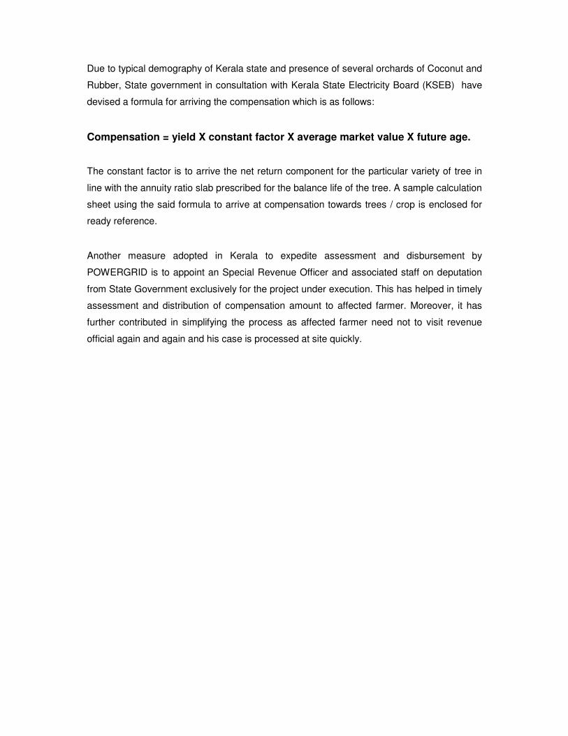
Due to typical demography of Kerala state and presence of several orchards of Coconut and
Rubber, State government in consultation with Kerala State Electricity Board (KSEB) have
devised a formula for arriving the compensation which is as follows:
Compensation = yield X constant factor X average market value X future age.
The constant factor is to arrive the net return component for the particular variety of tree in
line with the annuity ratio slab prescribed for the balance life of the tree. A sample calculation
sheet using the said formula to arrive at compensation towards trees / crop is enclosed for
ready reference.
Another measure adopted in Kerala to expedite assessment and disbursement by
POWERGRID is to appoint an Special Revenue Officer and associated staff on deputation
from State Government exclusively for the project under execution. This has helped in timely
assessment and distribution of compensation amount to affected farmer. Moreover, it has
further contributed in simplifying the process as affected farmer need not to visit revenue
official again and again and his case is processed at site quickly.
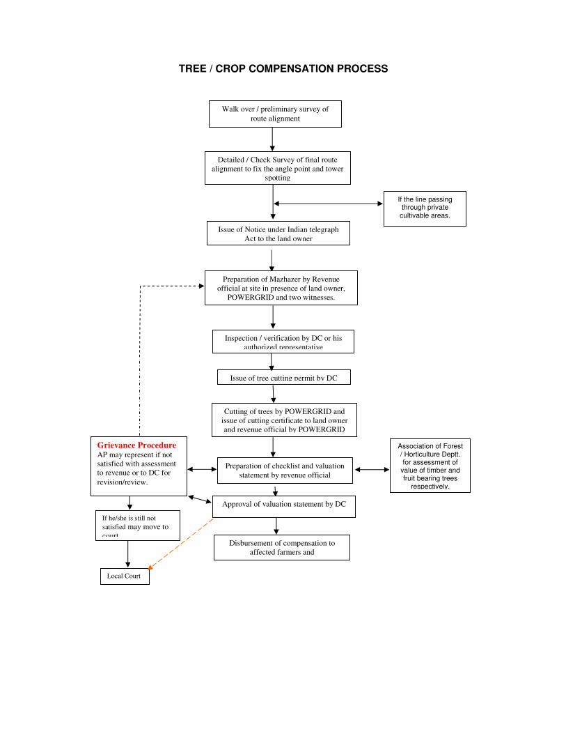
TREE / CROP COMPENSATION PROCESS
If the line passing through private
cultivable areas.
Association of Forest / Horticulture Deptt. for assessment of
value of timber and fruit bearing trees
respectively.
Grievance Procedure
AP may represent if not
satisfied with assessment
to revenue or to DC for
revision/review.
If he/she is still not
satisfied may move to
court.
Local Court
Walk over / preliminary survey of
route alignment
Detailed / Check Survey of final route
alignment to fix the angle point and tower
spotting
Issue of Notice under Indian telegraph
Act to the land owner
Preparation of Mazhazer by Revenue
official at site in presence of land owner,
POWERGRID and two witnesses.
Inspection / verification by DC or his
authorized representative
Issue of tree cutting permit by DC
Cutting of trees by POWERGRID and
issue of cutting certificate to land owner
and revenue official by POWERGRID
Preparation of checklist and valuation
statement by revenue official
Approval of valuation statement by DC
Disbursement of compensation to
affected farmers and
ANNEXURE-3
(ESPP & EMP AS A PART OF
CONTRACT DOCUMENT)
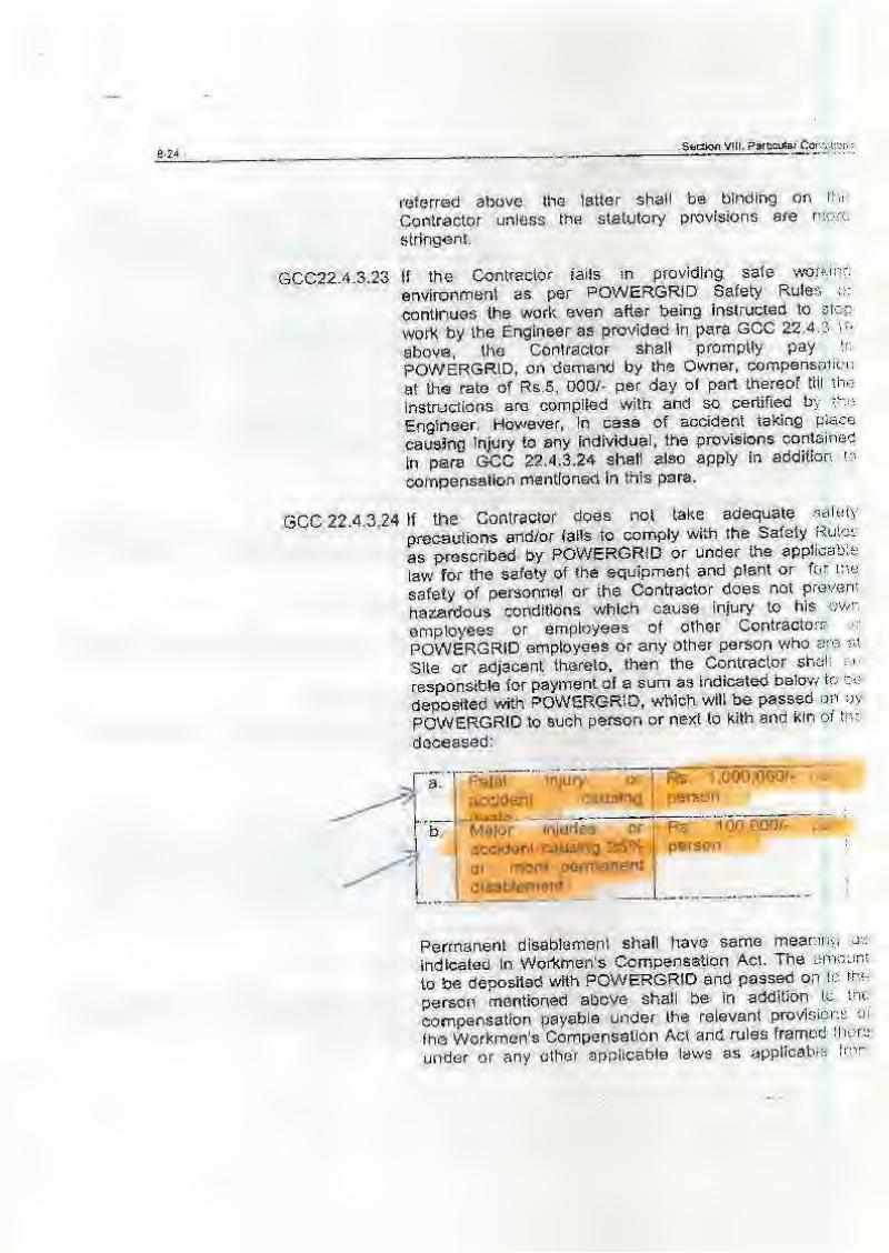

ANNEXURE-4
(HEALTH & SAFETY
CHEKLIST)
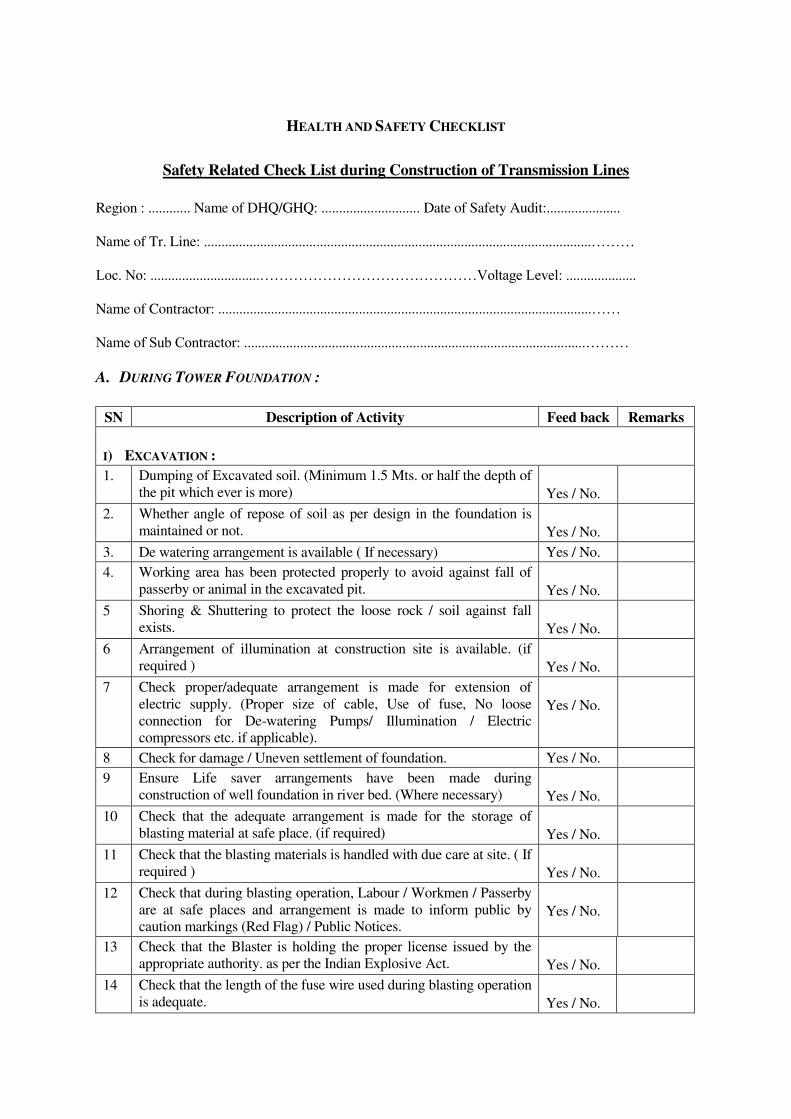
HEALTH AND SAFETY CHECKLIST
Safety Related Check List during Construction of Transmission Lines
Region : ............ Name of DHQ/GHQ: ............................ Date of Safety Audit:.....................
Name of Tr. Line: ..............................................................................................................………
Loc. No: ...............................………………………………………Voltage Level: ....................
Name of Contractor: ..........................................................................................................……
Name of Sub Contractor: .................................................................................................………
A. DURING TOWER FOUNDATION :
SN Description of Activity Feed back Remarks
I) EXCAVATION :
1. Dumping of Excavated soil. (Minimum 1.5 Mts. or half the depth of
the pit which ever is more)
Yes / No.
2.
Whether angle of repose of soil as per design in the foundation is
maintained or not.
Yes / No.
3. De watering arrangement is available ( If necessary) Yes / No.
4.
Working area has been protected properly to avoid against fall of
passerby or animal in the excavated pit.
Yes / No.
5
Shoring & Shuttering to protect the loose rock / soil against fall
exists.
Yes / No.
6
Arrangement of illumination at construction site is available. (if
required )
Yes / No.
7
Check proper/adequate arrangement is made for extension of
electric supply. (Proper size of cable, Use of fuse, No loose
connection for De-watering Pumps/ Illumination / Electric
compressors etc. if applicable).
Yes / No.
8 Check for damage / Uneven settlement of foundation. Yes / No.
9
Ensure Life saver arrangements have been made during
construction of well foundation in river bed. (Where necessary)
Yes / No.
10
Check that the adequate arrangement is made for the storage of
blasting material at safe place. (if required)
Yes / No.
11
Check that the blasting materials is handled with due care at site. ( If
required )
Yes / No.
12
Check that during blasting operation, Labour / Workmen / Passerby
are at safe places and arrangement is made to inform public by
caution markings (Red Flag) / Public Notices.
Yes / No.
13
Check that the Blaster is holding the proper license issued by the
appropriate authority. as per the Indian Explosive Act.
Yes / No.
14
Check that the length of the fuse wire used during blasting operation
is adequate.
Yes / No.
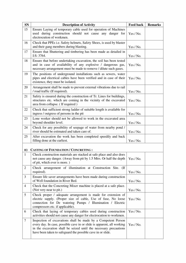
SN Description of Activity Feed back Remarks
15
Ensure Laying of temporary cable used for operation of Machines
used during construction should not cause any danger for
electrocution of workmen.
Yes / No.
16 Check that PPEs i.e. Safety helmets, Safety Shoes, is used by blaster
and their gang members during blasting.
Yes / No.
17
Ensure that Shuttering and timbering has been made as detailed in
I:S: 3764.
Yes / No.
18
Ensure that before undertaking excavation, the soil has been tested
and in case of availability of any explosive / dangerous gas,
necessary arrangement must be made to remove / dilute such gases.
Yes / No.
19
The positions of underground installations such as sewers, water
pipes and electrical cables have been verified and in case of their
existence, they must be isolated.
Yes / No.
20
Arrangement shall be made to prevent external vibrations due to rail
/ road traffic (If required).
Yes / No.
21
Safety is ensured during the construction of Tr. Lines for buildings,
structures etc. which are coming in the vicinity of the excavated
area from collapse. ( If required )
Yes / No.
22 Check that sufficient strong ladder of suitable length is available for
ingress / outgress of persons in the pit
Yes / No.
23 Lone worker should not be allowed to work in the excavated area
beyond shoulder level.
Yes / No.
24
Check for any possibility of seepage of water from nearby pond /
river should be estimated and taken care of.
Yes / No.
25 After excavation the work has been completed speedily and back
filling done at the earliest.
Yes / No.
II) CASTING OF FOUNDATION / CONCRETING :
1
Check construction materials are stacked at safe place and also does
not cause any danger. (Away from pit by 1.5 Mtrs. Or half the depth
of pit, which ever is more. )
Yes / No.
2 Check arrangement of illumination at Construction Site. (If
required).
Yes / No.
3
Ensure life saver arrangements have been made during construction
of Well foundation in River Bed.
Yes / No.
4
Check that the Concreting Mixer machine is placed at a safe place.
(Not very near to pit.)
Yes / No.
5
Check proper / adequate arrangement is made for extension of
electric supply. (Proper size of cable, Use of fuse, No loose
connection for De watering Pumps / Illumination / Electric
compressors etc. if applicable).
Yes / No.
6
Check that laying of temporary cables used during construction
activities should not cause any danger for electrocution to workmen.
Yes / No.
7
Inspection of excavations shall be made by a Competent Person
every day. In case, possible cave in or slide is apparent, all working
in the excavation shall be seized until the necessary precautions
have been taken to safeguard the possible cave in or slide.
Yes / No.
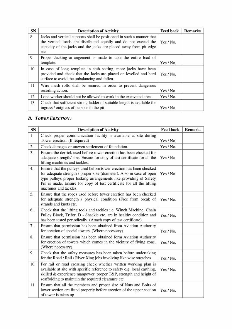
SN Description of Activity Feed back Remarks
8
Jacks and vertical supports shall be positioned in such a manner that
the vertical loads are distributed equally and do not exceed the
capacity of the jacks and the jacks are placed away from pit edge
etc.
Yes / No.
9
Proper Jacking arrangement is made to take the entire load of
template.
Yes / No.
10
In case of long template in stub setting, more jacks have been
provided and check that the Jacks are placed on levelled and hard
surface to avoid the unbalancing and fallen.
Yes / No.
11
Wire mesh rolls shall be secured in order to prevent dangerous
recoiling action.
Yes / No.
12 Lone worker should not be allowed to work in the excavated area. Yes / No.
13
Check that sufficient strong ladder of suitable length is available for
ingress / outgress of persons in the pit
Yes / No.
B. TOWER ERECTION :
SN Description of Activity Feed back Remarks
1 Check proper communication facility is available at site during
Tower erection. (If required)
Yes / No.
2. Check damages or uneven settlement of foundation. Yes / No.
3. Ensure the derrick used before tower erection has been checked for
adequate strength/ size. Ensure for copy of test certificate for all the
lifting machines and tackles.
Yes / No.
4. Ensure that the pulleys used before tower erection has been checked
for adequate strength / proper size (diameter). Also in case of open
type pulleys proper locking arrangements like providing of Safety
Pin is made. Ensure for copy of test certificate for all the lifting
machines and tackles.
Yes / No.
5. Ensure that the ropes used before tower erection has been checked
for adequate strength / physical condition (Free from break of
strands and knots etc.
Yes / No.
6.
Check that the lifting tools and tackles i.e. Winch Machine, Chain
Pulley Block, Trifor, D - Shackle etc. are in healthy condition and
has been tested periodically. (Attach copy of test certificate).
Yes / No.
7.
Ensure that permission has been obtained from Aviation Authority
for erection of special towers. (Where necessary).
Yes / No.
8.
Ensure that permission has been obtained form Aviation Authority
for erection of towers which comes in the vicinity of flying zone.
(Where necessary)
Yes / No.
9.
Check that the safety measures has been taken before undertaking
for the Road / Rail / River Xing jobs involving like wise stretches.
Yes / No.
10.
For rail or road crossing check whether written working plan is
available at site with specific reference to safety e.g. local earthing,
skilled & experience manpower, proper T&P, strength and height of
scaffolding to maintain the required clearance etc.
Yes / No.
11.
Ensure that all the members and proper size of Nuts and Bolts of
lower section are fitted properly before erection of the upper section
of tower is taken up.
Yes / No.
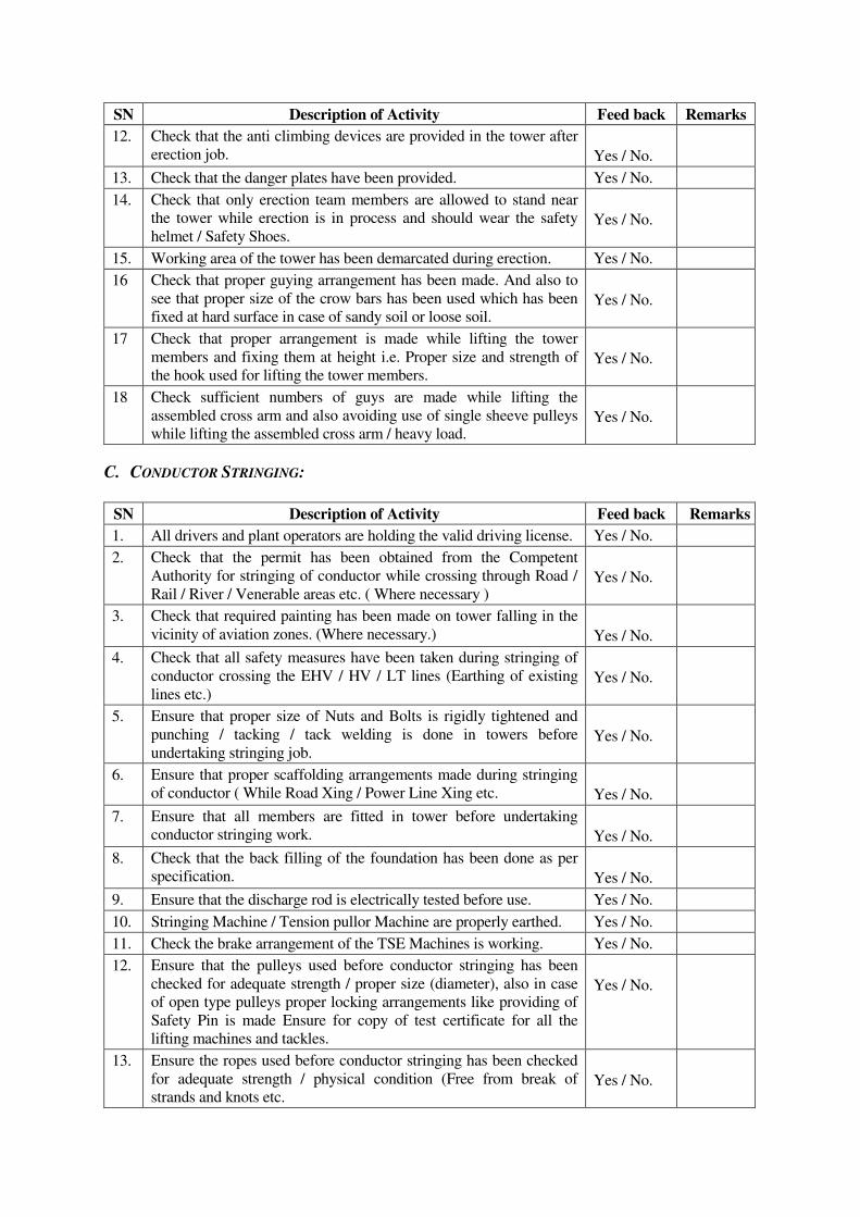
SN Description of Activity Feed back Remarks
12. Check that the anti climbing devices are provided in the tower after
erection job.
Yes / No.
13. Check that the danger plates have been provided. Yes / No.
14.
Check that only erection team members are allowed to stand near
the tower while erection is in process and should wear the safety
helmet / Safety Shoes.
Yes / No.
15. Working area of the tower has been demarcated during erection. Yes / No.
16
Check that proper guying arrangement has been made. And also to
see that proper size of the crow bars has been used which has been
fixed at hard surface in case of sandy soil or loose soil.
Yes / No.
17
Check that proper arrangement is made while lifting the tower
members and fixing them at height i.e. Proper size and strength of
the hook used for lifting the tower members.
Yes / No.
18
Check sufficient numbers of guys are made while lifting the
assembled cross arm and also avoiding use of single sheeve pulleys
while lifting the assembled cross arm / heavy load.
Yes / No.
C. CONDUCTOR STRINGING:
SN Description of Activity Feed back Remarks
1. All drivers and plant operators are holding the valid driving license. Yes / No.
2.
Check that the permit has been obtained from the Competent
Authority for stringing of conductor while crossing through Road /
Rail / River / Venerable areas etc. ( Where necessary )
Yes / No.
3.
Check that required painting has been made on tower falling in the
vicinity of aviation zones. (Where necessary.)
Yes / No.
4.
Check that all safety measures have been taken during stringing of
conductor crossing the EHV / HV / LT lines (Earthing of existing
lines etc.)
Yes / No.
5.
Ensure that proper size of Nuts and Bolts is rigidly tightened and
punching / tacking / tack welding is done in towers before
undertaking stringing job.
Yes / No.
6.
Ensure that proper scaffolding arrangements made during stringing
of conductor ( While Road Xing / Power Line Xing etc.
Yes / No.
7.
Ensure that all members are fitted in tower before undertaking
conductor stringing work.
Yes / No.
8.
Check that the back filling of the foundation has been done as per
specification.
Yes / No.
9. Ensure that the discharge rod is electrically tested before use. Yes / No.
10. Stringing Machine / Tension pullor Machine are properly earthed. Yes / No.
11. Check the brake arrangement of the TSE Machines is working. Yes / No.
12. Ensure that the pulleys used before conductor stringing has been
checked for adequate strength / proper size (diameter), also in case
of open type pulleys proper locking arrangements like providing of
Safety Pin is made Ensure for copy of test certificate for all the
lifting machines and tackles.
Yes / No.
13. Ensure the ropes used before conductor stringing has been checked
for adequate strength / physical condition (Free from break of
strands and knots etc.
Yes / No.
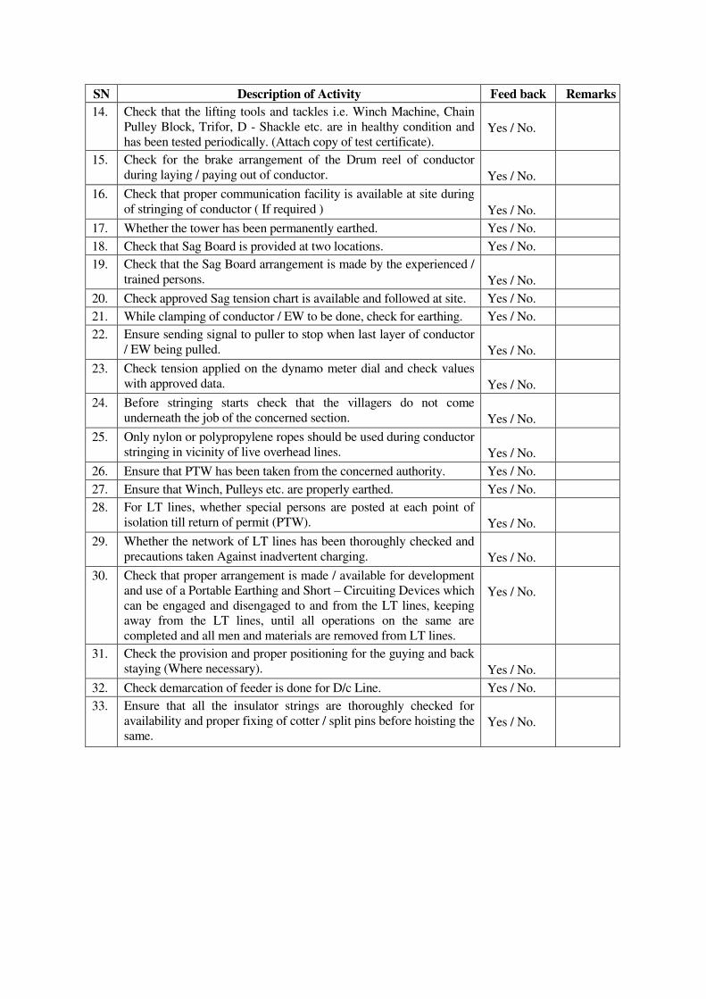
SN Description of Activity Feed back Remarks
14.
Check that the lifting tools and tackles i.e. Winch Machine, Chain
Pulley Block, Trifor, D - Shackle etc. are in healthy condition and
has been tested periodically. (Attach copy of test certificate).
Yes / No.
15.
Check for the brake arrangement of the Drum reel of conductor
during laying / paying out of conductor.
Yes / No.
16. Check that proper communication facility is available at site during
of stringing of conductor ( If required )
Yes / No.
17. Whether the tower has been permanently earthed. Yes / No.
18. Check that Sag Board is provided at two locations. Yes / No.
19.
Check that the Sag Board arrangement is made by the experienced /
trained persons.
Yes / No.
20. Check approved Sag tension chart is available and followed at site. Yes / No.
21. While clamping of conductor / EW to be done, check for earthing. Yes / No.
22.
Ensure sending signal to puller to stop when last layer of conductor
/ EW being pulled.
Yes / No.
23.
Check tension applied on the dynamo meter dial and check values
with approved data.
Yes / No.
24.
Before stringing starts check that the villagers do not come
underneath the job of the concerned section.
Yes / No.
25.
Only nylon or polypropylene ropes should be used during conductor
stringing in vicinity of live overhead lines.
Yes / No.
26. Ensure that PTW has been taken from the concerned authority. Yes / No.
27. Ensure that Winch, Pulleys etc. are properly earthed. Yes / No.
28.
For LT lines, whether special persons are posted at each point of
isolation till return of permit (PTW).
Yes / No.
29.
Whether the network of LT lines has been thoroughly checked and
precautions taken Against inadvertent charging.
Yes / No.
30.
Check that proper arrangement is made / available for development
and use of a Portable Earthing and Short – Circuiting Devices which
can be engaged and disengaged to and from the LT lines, keeping
away from the LT lines, until all operations on the same are
completed and all men and materials are removed from LT lines.
Yes / No.
31.
Check the provision and proper positioning for the guying and back
staying (Where necessary).
Yes / No.
32. Check demarcation of feeder is done for D/c Line. Yes / No.
33.
Ensure that all the insulator strings are thoroughly checked for
availability and proper fixing of cotter / split pins before hoisting the
same.
Yes / No.
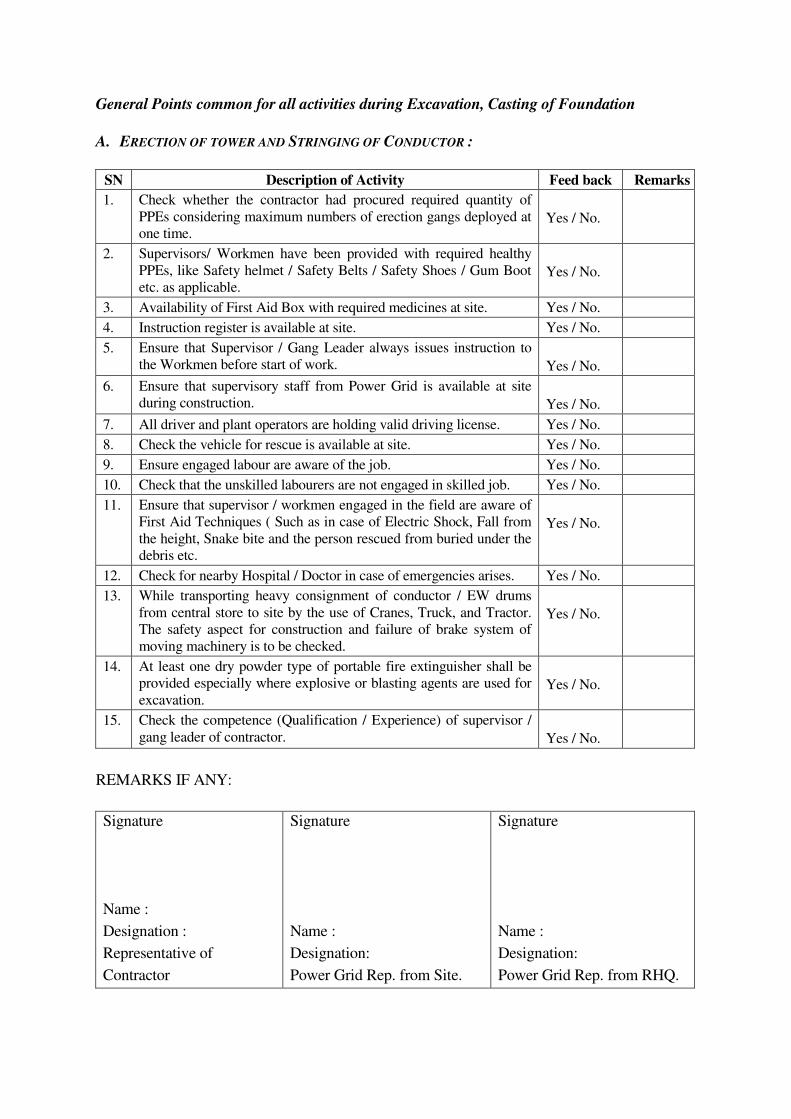
General Points common for all activities during Excavation, Casting of Foundation
A. ERECTION OF TOWER AND STRINGING OF CONDUCTOR :
SN Description of Activity Feed back Remarks
1.
Check whether the contractor had procured required quantity of
PPEs considering maximum numbers of erection gangs deployed at
one time.
Yes / No.
2.
Supervisors/ Workmen have been provided with required healthy
PPEs, like Safety helmet / Safety Belts / Safety Shoes / Gum Boot
etc. as applicable.
Yes / No.
3. Availability of First Aid Box with required medicines at site. Yes / No.
4. Instruction register is available at site. Yes / No.
5.
Ensure that Supervisor / Gang Leader always issues instruction to
the Workmen before start of work.
Yes / No.
6.
Ensure that supervisory staff from Power Grid is available at site
during construction.
Yes / No.
7. All driver and plant operators are holding valid driving license. Yes / No.
8. Check the vehicle for rescue is available at site. Yes / No.
9. Ensure engaged labour are aware of the job. Yes / No.
10. Check that the unskilled labourers are not engaged in skilled job. Yes / No.
11.
Ensure that supervisor / workmen engaged in the field are aware of
First Aid Techniques ( Such as in case of Electric Shock, Fall from
the height, Snake bite and the person rescued from buried under the
debris etc.
Yes / No.
12. Check for nearby Hospital / Doctor in case of emergencies arises. Yes / No.
13.
While transporting heavy consignment of conductor / EW drums
from central store to site by the use of Cranes, Truck, and Tractor.
The safety aspect for construction and failure of brake system of
moving machinery is to be checked.
Yes / No.
14.
At least one dry powder type of portable fire extinguisher shall be
provided especially where explosive or blasting agents are used for
excavation.
Yes / No.
15.
Check the competence (Qualification / Experience) of supervisor /
gang leader of contractor.
Yes / No.
REMARKS IF ANY:
Signature
Name :
Designation :
Representative of
Contractor
Signature
Name :
Designation:
Power Grid Rep. from Site.
Signature
Name :
Designation:
Power Grid Rep. from RHQ.
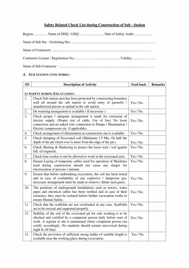
Safety Related Check List during Construction of Sub - Station
Region: ..........…. Name of DHQ / GHQ: ............................ Date of Safety Audit:......................
Name of Sub Stn. / Switching Stn.: .......................................................................................………
Name of Contractor: ..........................................................................................................……….
Contractor License / Registration No.:……………….............................Validity...............…….....
Name of Sub Contractor : .................................................................................................……….
A. SUB STATION CIVIL WORKS :
SN Description of Activity Feed back Remarks
I): SAFETY DURING EXCAVATION :
1.
Check Sub station area has been protected by constructing boundary
wall all around the sub station to avoid entry of passerby /
unauthorized person or animal in the sub station.
Yes / No.
2. De watering arrangement is available ( If necessary ) Yes / No.
3.
Check proper / adequate arrangement is made for extension of
electric supply. (Proper size of cable, Use of fuse, No loose
connection and no naked wire connection to Pumps / Illumination /
Electric compressors etc. if applicable).
Yes / No.
4. Check arrangement of illumination at construction site is available. Yes / No.
5. Check dumping of Excavated soil (Minimum 1.5 Mts. Or half the
depth of the pit which ever is more from the edge of the pit.)
Yes / No.
6.
Check Shoring & Shuttering to protect the loose rock / soil against
fall. (if required).
Yes / No.
7. Check lone worker is not be allowed to work in the excavated area. Yes / No.
8.
Ensure Laying of temporary cables used for operation of Machines
used during construction should not cause any danger for
electrocution of persons / animals.
Yes / No.
9.
Ensure that before undertaking excavation, the soil has been tested
and in case of availability of any explosive / dangerous gas,
necessary arrangement must be made to remove / dilute such gases.
Yes / No.
10.
The positions of underground installations such as sewers, water
pipes and electrical cables has been verified and in case of their
existence, they must be isolated before further excavation works to
ensure Human Safety.
Yes / No.
11. Check that the scaffolds are not overloaded in any case. Scaffolds
are to be erected and supported properly.
Yes / No.
12.
Stability of the soil of the excavated pit for safe working is to be
checked and certified by a competent person daily before start of
work. A register at site is maintained where competent person can
certify accordingly. No manhole should remain uncovered during
night & off days.
Yes / No.
13. Check the provision of sufficient strong ladder of suitable length is
available near the working place during excavation.
Yes / No.
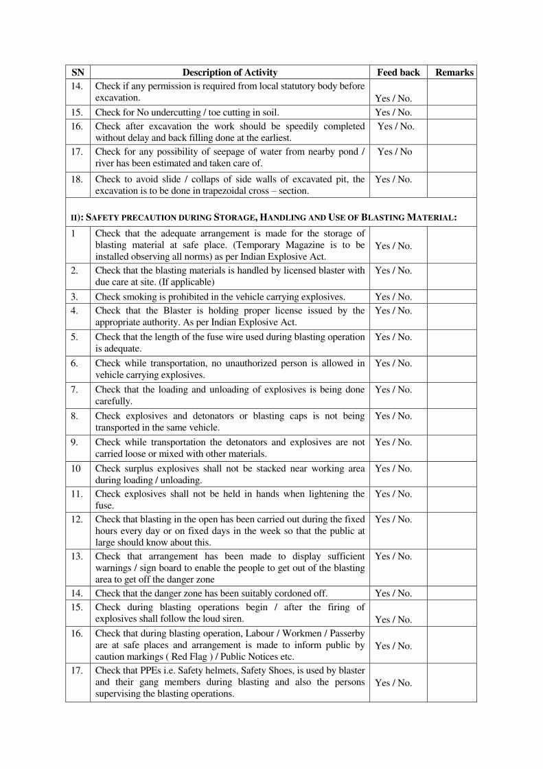
SN Description of Activity Feed back Remarks
14.
Check if any permission is required from local statutory body before
excavation.
Yes / No.
15. Check for No undercutting / toe cutting in soil. Yes / No.
16. Check after excavation the work should be speedily completed
without delay and back filling done at the earliest.
Yes / No.
17. Check for any possibility of seepage of water from nearby pond /
river has been estimated and taken care of.
Yes / No
18. Check to avoid slide / collaps of side walls of excavated pit, the
excavation is to be done in trapezoidal cross – section.
Yes / No.
II): SAFETY PRECAUTION DURING STORAGE, HANDLING AND USE OF BLASTING MATERIAL:
1 Check that the adequate arrangement is made for the storage of
blasting material at safe place. (Temporary Magazine is to be
installed observing all norms) as per Indian Explosive Act.
Yes / No.
2.
Check that the blasting materials is handled by licensed blaster with
due care at site. (If applicable)
Yes / No.
3. Check smoking is prohibited in the vehicle carrying explosives. Yes / No.
4.
Check that the Blaster is holding proper license issued by the
appropriate authority. As per Indian Explosive Act.
Yes / No.
5.
Check that the length of the fuse wire used during blasting operation
is adequate.
Yes / No.
6.
Check while transportation, no unauthorized person is allowed in
vehicle carrying explosives.
Yes / No.
7.
Check that the loading and unloading of explosives is being done
carefully.
Yes / No.
8.
Check explosives and detonators or blasting caps is not being
transported in the same vehicle.
Yes / No.
9.
Check while transportation the detonators and explosives are not
carried loose or mixed with other materials.
Yes / No.
10 Check surplus explosives shall not be stacked near working area
during loading / unloading.
Yes / No.
11. Check explosives shall not be held in hands when lightening the
fuse.
Yes / No.
12. Check that blasting in the open has been carried out during the fixed
hours every day or on fixed days in the week so that the public at
large should know about this.
Yes / No.
13. Check that arrangement has been made to display sufficient
warnings / sign board to enable the people to get out of the blasting
area to get off the danger zone
Yes / No.
14. Check that the danger zone has been suitably cordoned off. Yes / No.
15. Check during blasting operations begin / after the firing of
explosives shall follow the loud siren.
Yes / No.
16.
Check that during blasting operation, Labour / Workmen / Passerby
are at safe places and arrangement is made to inform public by
caution markings ( Red Flag ) / Public Notices etc.
Yes / No.
17.
Check that PPEs i.e. Safety helmets, Safety Shoes, is used by blaster
and their gang members during blasting and also the persons
supervising the blasting operations.
Yes / No.
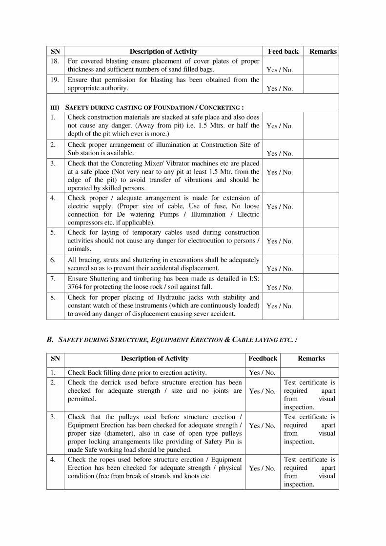
SN Description of Activity Feed back Remarks
18.
For covered blasting ensure placement of cover plates of proper
thickness and sufficient numbers of sand filled bags.
Yes / No.
19.
Ensure that permission for blasting has been obtained from the
appropriate authority.
Yes / No.
III) SAFETY DURING CASTING OF FOUNDATION / CONCRETING :
1.
Check construction materials are stacked at safe place and also does
not cause any danger. (Away from pit) i.e. 1.5 Mtrs. or half the
depth of the pit which ever is more.)
Yes / No.
2.
Check proper arrangement of illumination at Construction Site of
Sub station is available.
Yes / No.
3.
Check that the Concreting Mixer/ Vibrator machines etc are placed
at a safe place (Not very near to any pit at least 1.5 Mtr. from the
edge of the pit) to avoid transfer of vibrations and should be
operated by skilled persons.
Yes / No.
4.
Check proper / adequate arrangement is made for extension of
electric supply. (Proper size of cable, Use of fuse, No loose
connection for De watering Pumps / Illumination / Electric
compressors etc. if applicable).
Yes / No.
5.
Check for laying of temporary cables used during construction
activities should not cause any danger for electrocution to persons /
animals.
Yes / No.
6. All bracing, struts and shuttering in excavations shall be adequately
secured so as to prevent their accidental displacement.
Yes / No.
7.
Ensure Shuttering and timbering has been made as detailed in I:S:
3764 for protecting the loose rock / soil against fall.
Yes / No.
8. Check for proper placing of Hydraulic jacks with stability and
constant watch of these instruments (which are continuously loaded)
to avoid any danger of displacement causing sever accident.
Yes / No.
B. SAFETY DURING STRUCTURE, EQUIPMENT ERECTION & CABLE LAYING ETC. :
SN Description of Activity Feedback Remarks
1. Check Back filling done prior to erection activity. Yes / No.
2. Check the derrick used before structure erection has been
checked for adequate strength / size and no joints are
permitted.
Yes / No.
Test certificate is
required apart
from visual
inspection.
3. Check that the pulleys used before structure erection /
Equipment Erection has been checked for adequate strength /
proper size (diameter), also in case of open type pulleys
proper locking arrangements like providing of Safety Pin is
made Safe working load should be punched.
Yes / No.
Test certificate is
required apart
from visual
inspection.
4. Check the ropes used before structure erection / Equipment
Erection has been checked for adequate strength / physical
condition (free from break of strands and knots etc.
Yes / No.
Test certificate is
required apart
from visual
inspection.
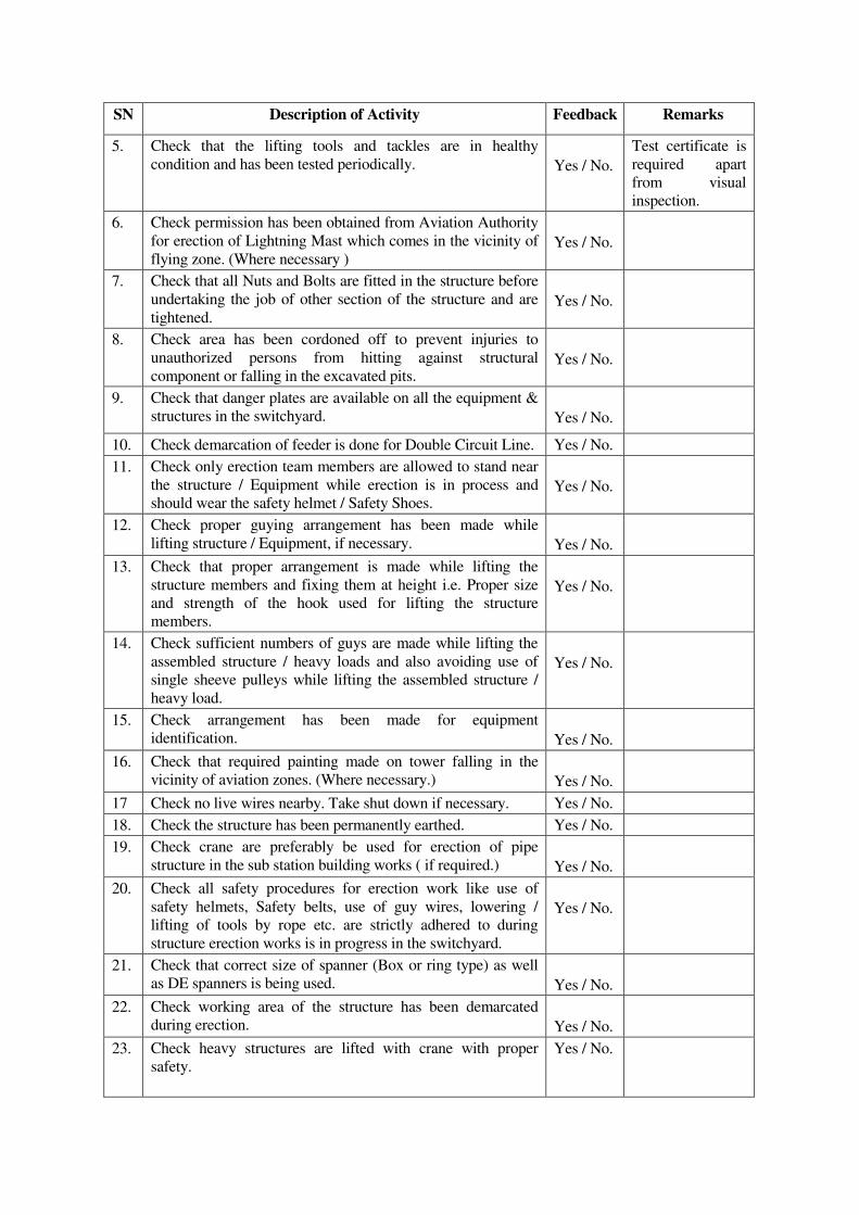
SN Description of Activity Feedback Remarks
5.
Check that the lifting tools and tackles are in healthy
condition and has been tested periodically.
Yes / No.
Test certificate is
required apart
from visual
inspection.
6.
Check permission has been obtained from Aviation Authority
for erection of Lightning Mast which comes in the vicinity of
flying zone. (Where necessary )
Yes / No.
7.
Check that all Nuts and Bolts are fitted in the structure before
undertaking the job of other section of the structure and are
tightened.
Yes / No.
8.
Check area has been cordoned off to prevent injuries to
unauthorized persons from hitting against structural
component or falling in the excavated pits.
Yes / No.
9.
Check that danger plates are available on all the equipment &
structures in the switchyard.
Yes / No.
10. Check demarcation of feeder is done for Double Circuit Line. Yes / No.
11.
Check only erection team members are allowed to stand near
the structure / Equipment while erection is in process and
should wear the safety helmet / Safety Shoes.
Yes / No.
12.
Check proper guying arrangement has been made while
lifting structure / Equipment, if necessary.
Yes / No.
13.
Check that proper arrangement is made while lifting the
structure members and fixing them at height i.e. Proper size
and strength of the hook used for lifting the structure
members.
Yes / No.
14.
Check sufficient numbers of guys are made while lifting the
assembled structure / heavy loads and also avoiding use of
single sheeve pulleys while lifting the assembled structure /
heavy load.
Yes / No.
15.
Check arrangement has been made for equipment
identification.
Yes / No.
16.
Check that required painting made on tower falling in the
vicinity of aviation zones. (Where necessary.)
Yes / No.
17 Check no live wires nearby. Take shut down if necessary. Yes / No.
18. Check the structure has been permanently earthed. Yes / No.
19.
Check crane are preferably be used for erection of pipe
structure in the sub station building works ( if required.)
Yes / No.
20. Check all safety procedures for erection work like use of
safety helmets, Safety belts, use of guy wires, lowering /
lifting of tools by rope etc. are strictly adhered to during
structure erection works is in progress in the switchyard.
Yes / No.
21.
Check that correct size of spanner (Box or ring type) as well
as DE spanners is being used.
Yes / No.
22.
Check working area of the structure has been demarcated
during erection.
Yes / No.
23.
Check heavy structures are lifted with crane with proper
safety.
Yes / No.
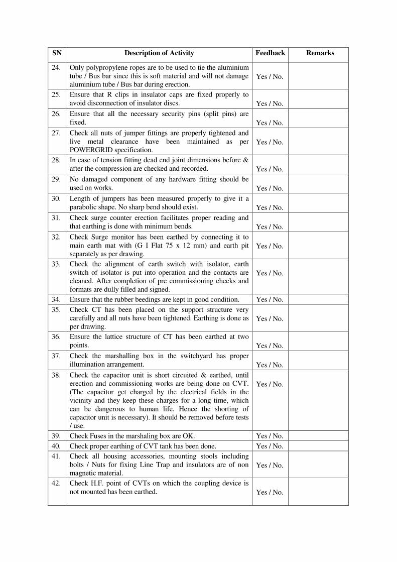
SN Description of Activity Feedback Remarks
24.
Only polypropylene ropes are to be used to tie the aluminium
tube / Bus bar since this is soft material and will not damage
aluminium tube / Bus bar during erection.
Yes / No.
25.
Ensure that R clips in insulator caps are fixed properly to
avoid disconnection of insulator discs.
Yes / No.
26. Ensure that all the necessary security pins (split pins) are
fixed.
Yes / No.
27.
Check all nuts of jumper fittings are properly tightened and
live metal clearance have been maintained as per
POWERGRID specification.
Yes / No.
28.
In case of tension fitting dead end joint dimensions before &
after the compression are checked and recorded.
Yes / No.
29.
No damaged component of any hardware fitting should be
used on works.
Yes / No.
30.
Length of jumpers has been measured properly to give it a
parabolic shape. No sharp bend should exist.
Yes / No.
31.
Check surge counter erection facilitates proper reading and
that earthing is done with minimum bends.
Yes / No.
32.
Check Surge monitor has been earthed by connecting it to
main earth mat with (G I Flat 75 x 12 mm) and earth pit
separately as per drawing.
Yes / No.
33.
Check the alignment of earth switch with isolator, earth
switch of isolator is put into operation and the contacts are
cleaned. After completion of pre commissioning checks and
formats are dully filled and signed.
Yes / No.
34. Ensure that the rubber beedings are kept in good condition. Yes / No.
35.
Check CT has been placed on the support structure very
carefully and all nuts have been tightened. Earthing is done as
per drawing.
Yes / No.
36.
Ensure the lattice structure of CT has been earthed at two
points.
Yes / No.
37.
Check the marshalling box in the switchyard has proper
illumination arrangement.
Yes / No.
38.
Check the capacitor unit is short circuited & earthed, until
erection and commissioning works are being done on CVT.
(The capacitor get charged by the electrical fields in the
vicinity and they keep these charges for a long time, which
can be dangerous to human life. Hence the shorting of
capacitor unit is necessary). It should be removed before tests
/ use.
Yes / No.
39. Check Fuses in the marshaling box are OK. Yes / No.
40. Check proper earthing of CVT tank has been done. Yes / No.
41.
Check all housing accessories, mounting stools including
bolts / Nuts for fixing Line Trap and insulators are of non
magnetic material.
Yes / No.
42.
Check H.F. point of CVTs on which the coupling device is
not mounted has been earthed.
Yes / No.
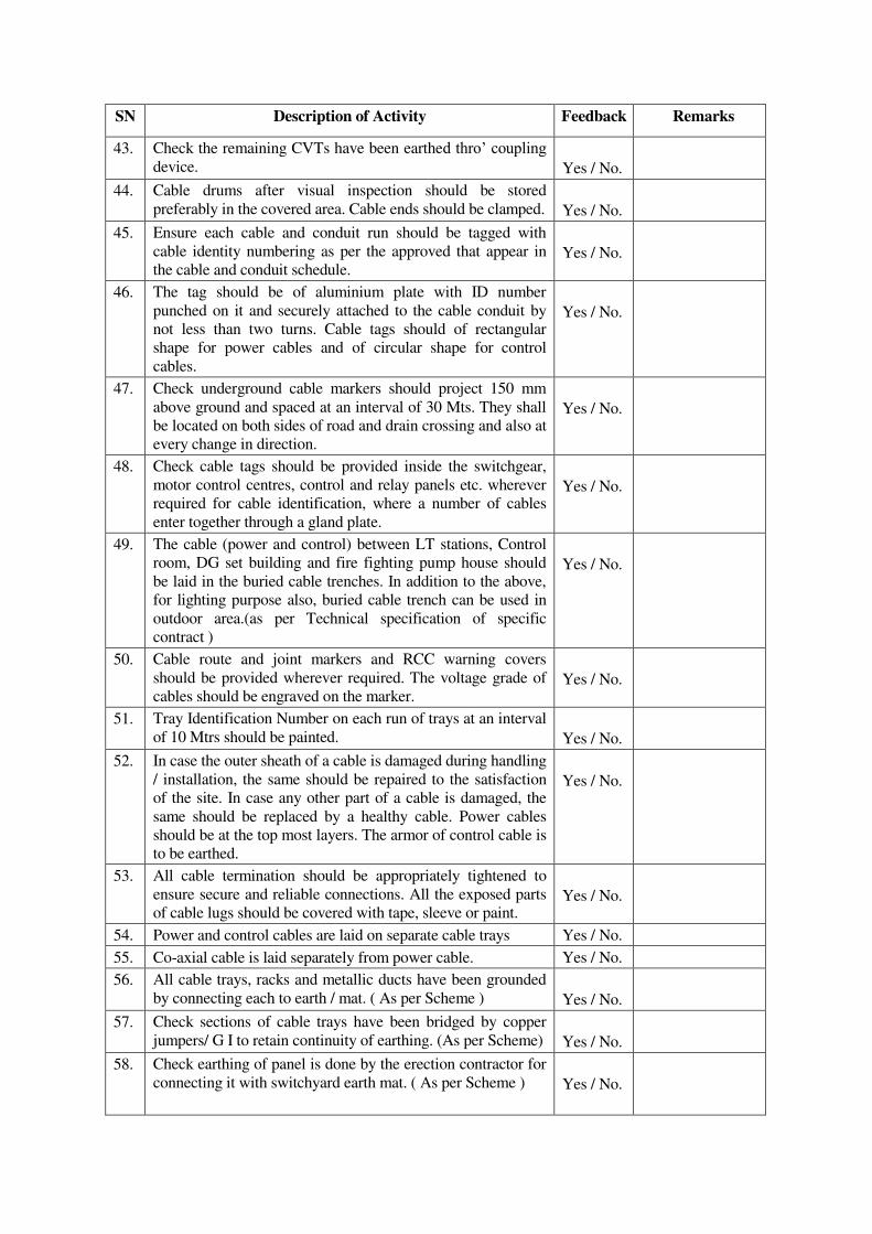
SN Description of Activity Feedback Remarks
43.
Check the remaining CVTs have been earthed thro’ coupling device.
Yes / No.
44.
Cable drums after visual inspection should be stored
preferably in the covered area. Cable ends should be clamped.
Yes / No.
45.
Ensure each cable and conduit run should be tagged with
cable identity numbering as per the approved that appear in
the cable and conduit schedule.
Yes / No.
46.
The tag should be of aluminium plate with ID number
punched on it and securely attached to the cable conduit by
not less than two turns. Cable tags should of rectangular
shape for power cables and of circular shape for control
cables.
Yes / No.
47.
Check underground cable markers should project 150 mm
above ground and spaced at an interval of 30 Mts. They shall
be located on both sides of road and drain crossing and also at
every change in direction.
Yes / No.
48.
Check cable tags should be provided inside the switchgear,
motor control centres, control and relay panels etc. wherever
required for cable identification, where a number of cables
enter together through a gland plate.
Yes / No.
49.
The cable (power and control) between LT stations, Control
room, DG set building and fire fighting pump house should
be laid in the buried cable trenches. In addition to the above,
for lighting purpose also, buried cable trench can be used in
outdoor area.(as per Technical specification of specific
contract )
Yes / No.
50.
Cable route and joint markers and RCC warning covers
should be provided wherever required. The voltage grade of
cables should be engraved on the marker.
Yes / No.
51.
Tray Identification Number on each run of trays at an interval
of 10 Mtrs should be painted.
Yes / No.
52.
In case the outer sheath of a cable is damaged during handling
/ installation, the same should be repaired to the satisfaction
of the site. In case any other part of a cable is damaged, the
same should be replaced by a healthy cable. Power cables
should be at the top most layers. The armor of control cable is
to be earthed.
Yes / No.
53.
All cable termination should be appropriately tightened to
ensure secure and reliable connections. All the exposed parts
of cable lugs should be covered with tape, sleeve or paint.
Yes / No.
54. Power and control cables are laid on separate cable trays Yes / No.
55. Co-axial cable is laid separately from power cable. Yes / No.
56.
All cable trays, racks and metallic ducts have been grounded
by connecting each to earth / mat. ( As per Scheme )
Yes / No.
57.
Check sections of cable trays have been bridged by copper
jumpers/ G I to retain continuity of earthing. (As per Scheme)
Yes / No.
58.
Check earthing of panel is done by the erection contractor for
connecting it with switchyard earth mat. ( As per Scheme )
Yes / No.
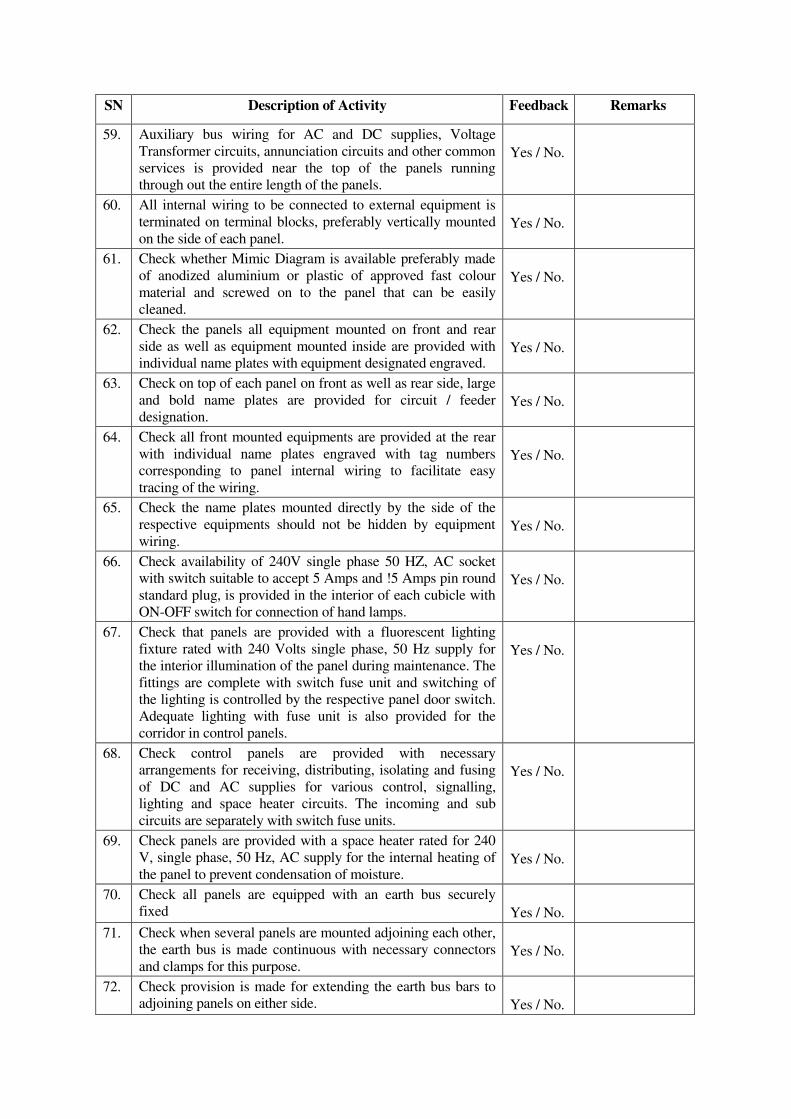
SN Description of Activity Feedback Remarks
59.
Auxiliary bus wiring for AC and DC supplies, Voltage
Transformer circuits, annunciation circuits and other common
services is provided near the top of the panels running
through out the entire length of the panels.
Yes / No.
60.
All internal wiring to be connected to external equipment is
terminated on terminal blocks, preferably vertically mounted
on the side of each panel.
Yes / No.
61.
Check whether Mimic Diagram is available preferably made
of anodized aluminium or plastic of approved fast colour
material and screwed on to the panel that can be easily
cleaned.
Yes / No.
62.
Check the panels all equipment mounted on front and rear
side as well as equipment mounted inside are provided with
individual name plates with equipment designated engraved.
Yes / No.
63.
Check on top of each panel on front as well as rear side, large
and bold name plates are provided for circuit / feeder
designation.
Yes / No.
64.
Check all front mounted equipments are provided at the rear
with individual name plates engraved with tag numbers
corresponding to panel internal wiring to facilitate easy
tracing of the wiring.
Yes / No.
65.
Check the name plates mounted directly by the side of the
respective equipments should not be hidden by equipment
wiring.
Yes / No.
66.
Check availability of 240V single phase 50 HZ, AC socket
with switch suitable to accept 5 Amps and !5 Amps pin round
standard plug, is provided in the interior of each cubicle with
ON-OFF switch for connection of hand lamps.
Yes / No.
67.
Check that panels are provided with a fluorescent lighting
fixture rated with 240 Volts single phase, 50 Hz supply for
the interior illumination of the panel during maintenance. The
fittings are complete with switch fuse unit and switching of
the lighting is controlled by the respective panel door switch.
Adequate lighting with fuse unit is also provided for the
corridor in control panels.
Yes / No.
68.
Check control panels are provided with necessary
arrangements for receiving, distributing, isolating and fusing
of DC and AC supplies for various control, signalling,
lighting and space heater circuits. The incoming and sub
circuits are separately with switch fuse units.
Yes / No.
69.
Check panels are provided with a space heater rated for 240
V, single phase, 50 Hz, AC supply for the internal heating of
the panel to prevent condensation of moisture.
Yes / No.
70. Check all panels are equipped with an earth bus securely
fixed
Yes / No.
71.
Check when several panels are mounted adjoining each other,
the earth bus is made continuous with necessary connectors
and clamps for this purpose.
Yes / No.
72.
Check provision is made for extending the earth bus bars to
adjoining panels on either side.
Yes / No.
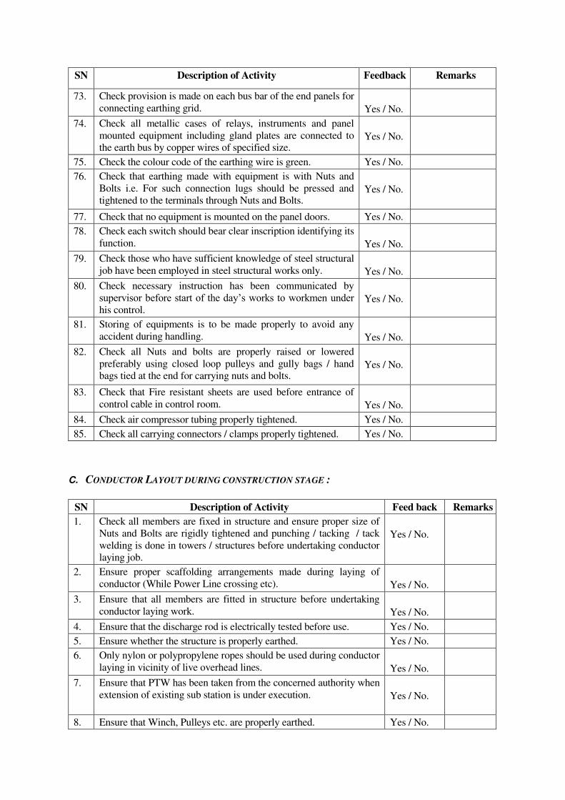
SN Description of Activity Feedback Remarks
73. Check provision is made on each bus bar of the end panels for
connecting earthing grid.
Yes / No.
74.
Check all metallic cases of relays, instruments and panel
mounted equipment including gland plates are connected to
the earth bus by copper wires of specified size.
Yes / No.
75. Check the colour code of the earthing wire is green. Yes / No.
76.
Check that earthing made with equipment is with Nuts and
Bolts i.e. For such connection lugs should be pressed and
tightened to the terminals through Nuts and Bolts.
Yes / No.
77. Check that no equipment is mounted on the panel doors. Yes / No.
78. Check each switch should bear clear inscription identifying its
function.
Yes / No.
79. Check those who have sufficient knowledge of steel structural
job have been employed in steel structural works only.
Yes / No.
80. Check necessary instruction has been communicated by
supervisor before start of the day’s works to workmen under his control.
Yes / No.
81.
Storing of equipments is to be made properly to avoid any
accident during handling.
Yes / No.
82.
Check all Nuts and bolts are properly raised or lowered
preferably using closed loop pulleys and gully bags / hand
bags tied at the end for carrying nuts and bolts.
Yes / No.
83.
Check that Fire resistant sheets are used before entrance of
control cable in control room.
Yes / No.
84. Check air compressor tubing properly tightened. Yes / No.
85. Check all carrying connectors / clamps properly tightened. Yes / No.
C. CONDUCTOR LAYOUT DURING CONSTRUCTION STAGE :
SN Description of Activity Feed back Remarks
1.
Check all members are fixed in structure and ensure proper size of
Nuts and Bolts are rigidly tightened and punching / tacking / tack
welding is done in towers / structures before undertaking conductor
laying job.
Yes / No.
2.
Ensure proper scaffolding arrangements made during laying of
conductor (While Power Line crossing etc).
Yes / No.
3.
Ensure that all members are fitted in structure before undertaking
conductor laying work.
Yes / No.
4. Ensure that the discharge rod is electrically tested before use. Yes / No.
5. Ensure whether the structure is properly earthed. Yes / No.
6.
Only nylon or polypropylene ropes should be used during conductor
laying in vicinity of live overhead lines.
Yes / No.
7.
Ensure that PTW has been taken from the concerned authority when
extension of existing sub station is under execution.
Yes / No.
8. Ensure that Winch, Pulleys etc. are properly earthed. Yes / No.
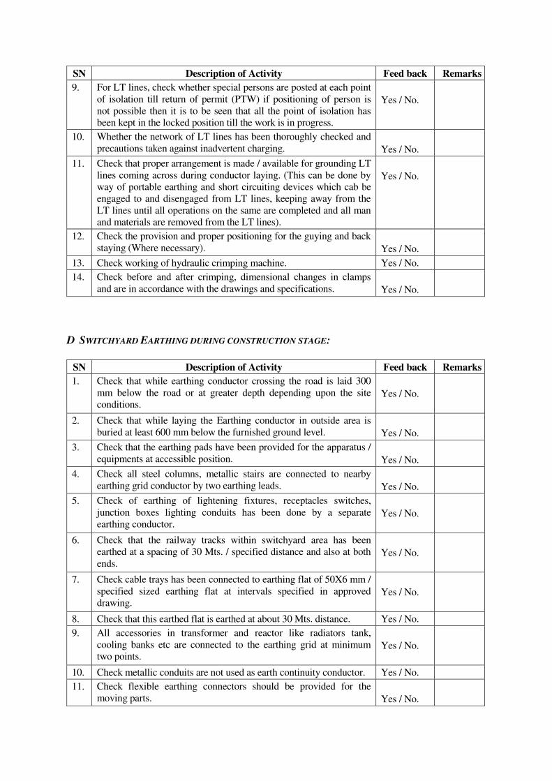
SN Description of Activity Feed back Remarks
9.
For LT lines, check whether special persons are posted at each point
of isolation till return of permit (PTW) if positioning of person is
not possible then it is to be seen that all the point of isolation has
been kept in the locked position till the work is in progress.
Yes / No.
10.
Whether the network of LT lines has been thoroughly checked and
precautions taken against inadvertent charging.
Yes / No.
11.
Check that proper arrangement is made / available for grounding LT
lines coming across during conductor laying. (This can be done by
way of portable earthing and short circuiting devices which cab be
engaged to and disengaged from LT lines, keeping away from the
LT lines until all operations on the same are completed and all man
and materials are removed from the LT lines).
Yes / No.
12. Check the provision and proper positioning for the guying and back
staying (Where necessary).
Yes / No.
13. Check working of hydraulic crimping machine. Yes / No.
14.
Check before and after crimping, dimensional changes in clamps
and are in accordance with the drawings and specifications.
Yes / No.
D SWITCHYARD EARTHING DURING CONSTRUCTION STAGE:
SN Description of Activity Feed back Remarks
1.
Check that while earthing conductor crossing the road is laid 300
mm below the road or at greater depth depending upon the site
conditions.
Yes / No.
2.
Check that while laying the Earthing conductor in outside area is
buried at least 600 mm below the furnished ground level.
Yes / No.
3. Check that the earthing pads have been provided for the apparatus /
equipments at accessible position.
Yes / No.
4.
Check all steel columns, metallic stairs are connected to nearby
earthing grid conductor by two earthing leads.
Yes / No.
5.
Check of earthing of lightening fixtures, receptacles switches,
junction boxes lighting conduits has been done by a separate
earthing conductor.
Yes / No.
6.
Check that the railway tracks within switchyard area has been
earthed at a spacing of 30 Mts. / specified distance and also at both
ends.
Yes / No.
7.
Check cable trays has been connected to earthing flat of 50X6 mm /
specified sized earthing flat at intervals specified in approved
drawing.
Yes / No.
8. Check that this earthed flat is earthed at about 30 Mts. distance. Yes / No.
9.
All accessories in transformer and reactor like radiators tank,
cooling banks etc are connected to the earthing grid at minimum
two points.
Yes / No.
10. Check metallic conduits are not used as earth continuity conductor. Yes / No.
11.
Check flexible earthing connectors should be provided for the
moving parts.
Yes / No.
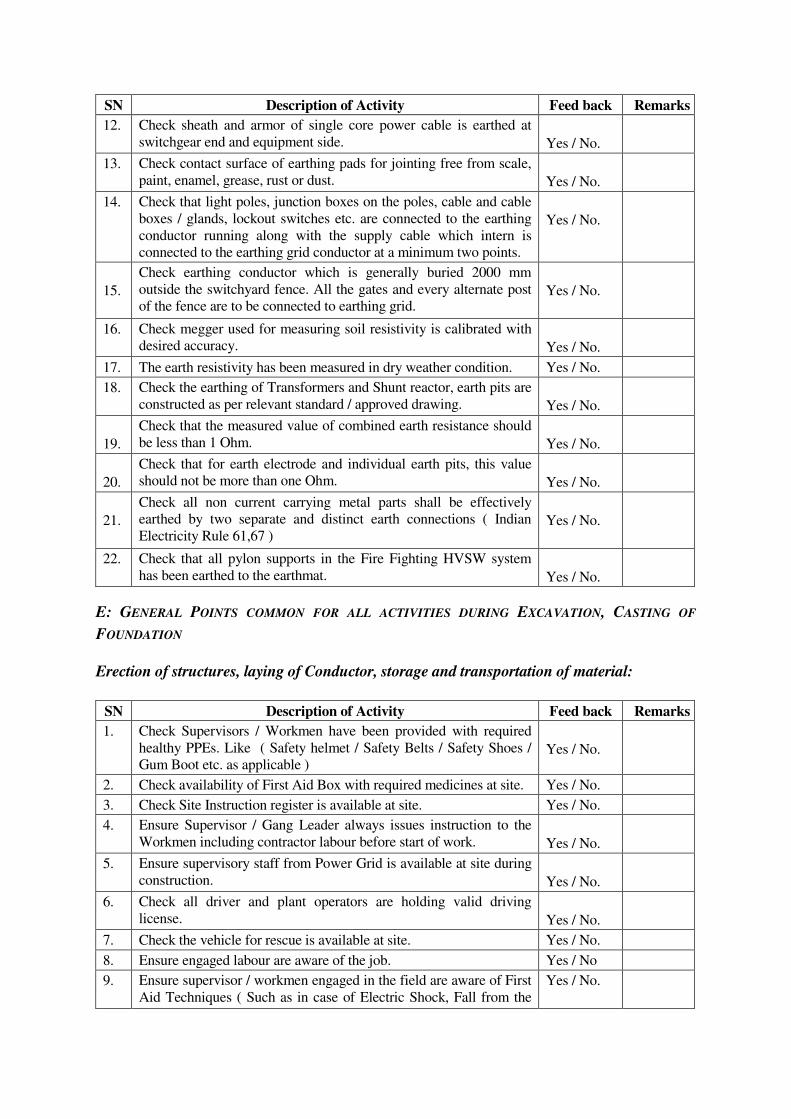
SN Description of Activity Feed back Remarks
12.
Check sheath and armor of single core power cable is earthed at
switchgear end and equipment side.
Yes / No.
13.
Check contact surface of earthing pads for jointing free from scale,
paint, enamel, grease, rust or dust.
Yes / No.
14.
Check that light poles, junction boxes on the poles, cable and cable
boxes / glands, lockout switches etc. are connected to the earthing
conductor running along with the supply cable which intern is
connected to the earthing grid conductor at a minimum two points.
Yes / No.
15.
Check earthing conductor which is generally buried 2000 mm
outside the switchyard fence. All the gates and every alternate post
of the fence are to be connected to earthing grid.
Yes / No.
16. Check megger used for measuring soil resistivity is calibrated with
desired accuracy.
Yes / No.
17. The earth resistivity has been measured in dry weather condition. Yes / No.
18. Check the earthing of Transformers and Shunt reactor, earth pits are
constructed as per relevant standard / approved drawing.
Yes / No.
19.
Check that the measured value of combined earth resistance should
be less than 1 Ohm.
Yes / No.
20.
Check that for earth electrode and individual earth pits, this value
should not be more than one Ohm.
Yes / No.
21.
Check all non current carrying metal parts shall be effectively
earthed by two separate and distinct earth connections ( Indian
Electricity Rule 61,67 )
Yes / No.
22.
Check that all pylon supports in the Fire Fighting HVSW system
has been earthed to the earthmat.
Yes / No.
E: GENERAL POINTS COMMON FOR ALL ACTIVITIES DURING EXCAVATION, CASTING OF
FOUNDATION
Erection of structures, laying of Conductor, storage and transportation of material:
SN Description of Activity Feed back Remarks
1.
Check Supervisors / Workmen have been provided with required
healthy PPEs. Like ( Safety helmet / Safety Belts / Safety Shoes /
Gum Boot etc. as applicable )
Yes / No.
2. Check availability of First Aid Box with required medicines at site. Yes / No.
3. Check Site Instruction register is available at site. Yes / No.
4.
Ensure Supervisor / Gang Leader always issues instruction to the
Workmen including contractor labour before start of work.
Yes / No.
5.
Ensure supervisory staff from Power Grid is available at site during
construction.
Yes / No.
6.
Check all driver and plant operators are holding valid driving
license.
Yes / No.
7. Check the vehicle for rescue is available at site. Yes / No.
8. Ensure engaged labour are aware of the job. Yes / No
9.
Ensure supervisor / workmen engaged in the field are aware of First
Aid Techniques ( Such as in case of Electric Shock, Fall from the
Yes / No.
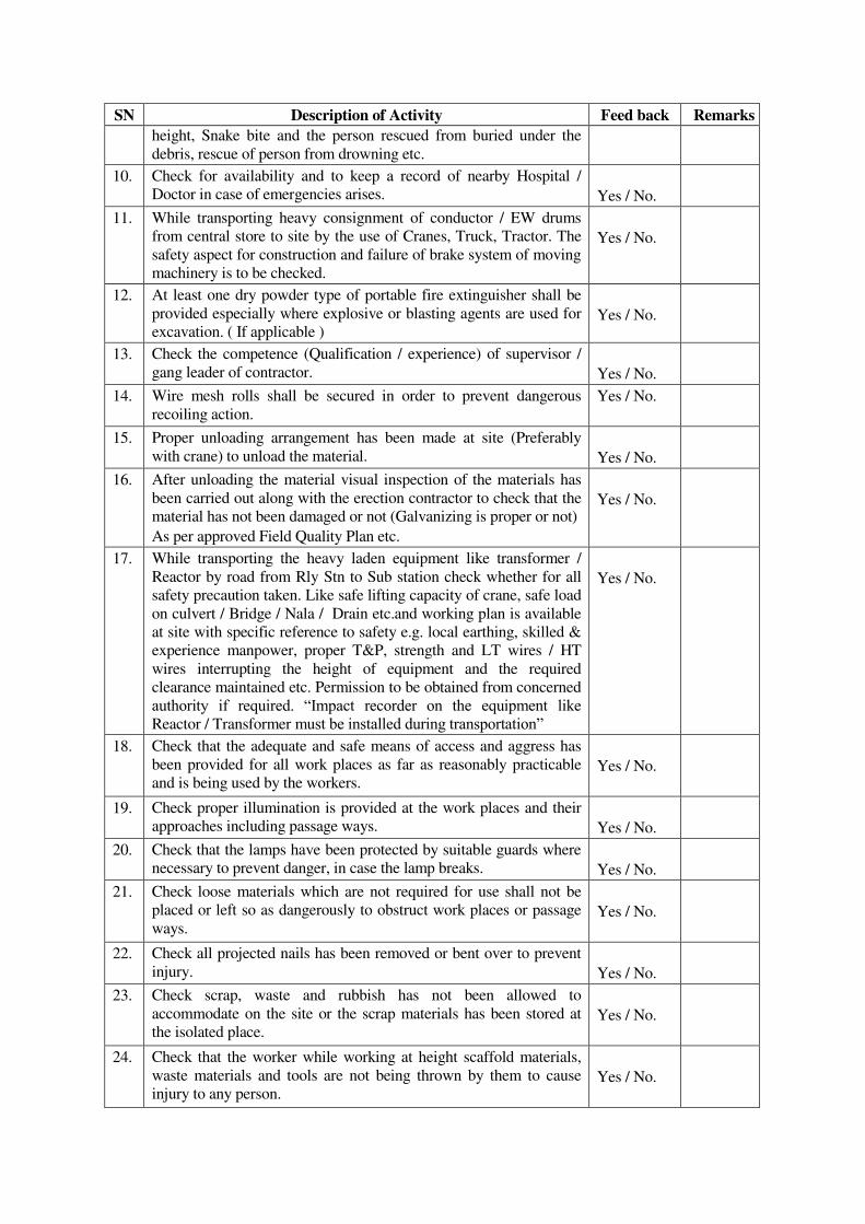
SN Description of Activity Feed back Remarks
height, Snake bite and the person rescued from buried under the
debris, rescue of person from drowning etc.
10.
Check for availability and to keep a record of nearby Hospital /
Doctor in case of emergencies arises.
Yes / No.
11.
While transporting heavy consignment of conductor / EW drums
from central store to site by the use of Cranes, Truck, Tractor. The
safety aspect for construction and failure of brake system of moving
machinery is to be checked.
Yes / No.
12.
At least one dry powder type of portable fire extinguisher shall be
provided especially where explosive or blasting agents are used for
excavation. ( If applicable )
Yes / No.
13.
Check the competence (Qualification / experience) of supervisor /
gang leader of contractor.
Yes / No.
14.
Wire mesh rolls shall be secured in order to prevent dangerous
recoiling action.
Yes / No.
15.
Proper unloading arrangement has been made at site (Preferably
with crane) to unload the material.
Yes / No.
16.
After unloading the material visual inspection of the materials has
been carried out along with the erection contractor to check that the
material has not been damaged or not (Galvanizing is proper or not)
As per approved Field Quality Plan etc.
Yes / No.
17.
While transporting the heavy laden equipment like transformer /
Reactor by road from Rly Stn to Sub station check whether for all
safety precaution taken. Like safe lifting capacity of crane, safe load
on culvert / Bridge / Nala / Drain etc.and working plan is available
at site with specific reference to safety e.g. local earthing, skilled &
experience manpower, proper T&P, strength and LT wires / HT
wires interrupting the height of equipment and the required
clearance maintained etc. Permission to be obtained from concerned
authority if required. “Impact recorder on the equipment like Reactor / Transformer must be installed during transportation”
Yes / No.
18.
Check that the adequate and safe means of access and aggress has
been provided for all work places as far as reasonably practicable
and is being used by the workers.
Yes / No.
19.
Check proper illumination is provided at the work places and their
approaches including passage ways.
Yes / No.
20.
Check that the lamps have been protected by suitable guards where
necessary to prevent danger, in case the lamp breaks.
Yes / No.
21.
Check loose materials which are not required for use shall not be
placed or left so as dangerously to obstruct work places or passage
ways.
Yes / No.
22.
Check all projected nails has been removed or bent over to prevent
injury.
Yes / No.
23.
Check scrap, waste and rubbish has not been allowed to
accommodate on the site or the scrap materials has been stored at
the isolated place.
Yes / No.
24.
Check that the worker while working at height scaffold materials,
waste materials and tools are not being thrown by them to cause
injury to any person.
Yes / No.
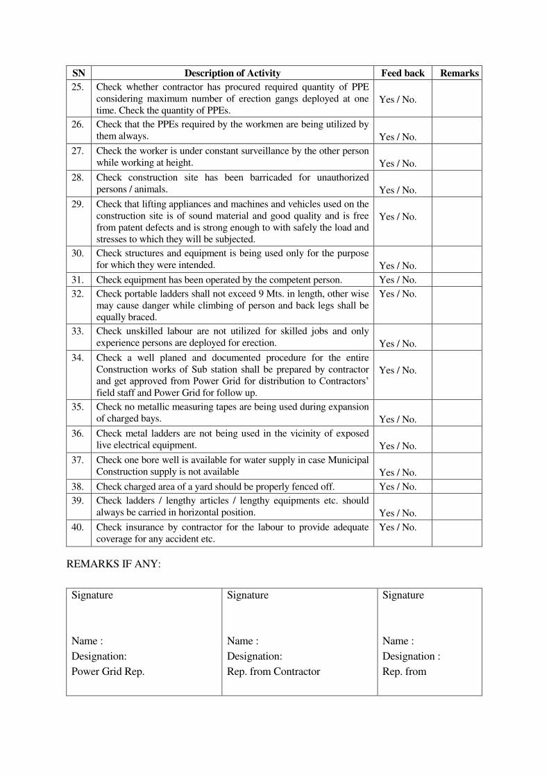
SN Description of Activity Feed back Remarks
25. Check whether contractor has procured required quantity of PPE
considering maximum number of erection gangs deployed at one
time. Check the quantity of PPEs.
Yes / No.
26. Check that the PPEs required by the workmen are being utilized by
them always.
Yes / No.
27. Check the worker is under constant surveillance by the other person
while working at height.
Yes / No.
28. Check construction site has been barricaded for unauthorized
persons / animals.
Yes / No.
29. Check that lifting appliances and machines and vehicles used on the
construction site is of sound material and good quality and is free
from patent defects and is strong enough to with safely the load and
stresses to which they will be subjected.
Yes / No.
30. Check structures and equipment is being used only for the purpose
for which they were intended.
Yes / No.
31. Check equipment has been operated by the competent person. Yes / No.
32. Check portable ladders shall not exceed 9 Mts. in length, other wise
may cause danger while climbing of person and back legs shall be
equally braced.
Yes / No.
33.
Check unskilled labour are not utilized for skilled jobs and only
experience persons are deployed for erection.
Yes / No.
34.
Check a well planed and documented procedure for the entire
Construction works of Sub station shall be prepared by contractor
and get approved from Power Grid for distribution to Contractors’ field staff and Power Grid for follow up.
Yes / No.
35.
Check no metallic measuring tapes are being used during expansion
of charged bays.
Yes / No.
36. Check metal ladders are not being used in the vicinity of exposed
live electrical equipment.
Yes / No.
37.
Check one bore well is available for water supply in case Municipal
Construction supply is not available
Yes / No.
38. Check charged area of a yard should be properly fenced off. Yes / No.
39.
Check ladders / lengthy articles / lengthy equipments etc. should
always be carried in horizontal position.
Yes / No.
40.
Check insurance by contractor for the labour to provide adequate
coverage for any accident etc.
Yes / No.
REMARKS IF ANY:
Signature
Name :
Designation:
Power Grid Rep.
Signature
Name :
Designation:
Rep. from Contractor
Signature
Name :
Designation :
Rep. from
ANNEXURE-4A
(SAFETY PLAN)
Section IX. Contract Forms 9-149
13. FORM OF SAFETY PLAN TO BE SUBMITTED BY THE CONTRACTOR WITHIN SIXTY DAYS OF AWARD OF CONTRACT [TO BE EXECUTED ON A NON JUDICIAL STAMP PAPER WORTH RS. TWENTY ONLY]
SAFETY PLAN
THIS SAFETY PLAN is made this ……….………...... day of ….……..... 20...... by ………….………………… a Company registered under the Companies Act, 1956/Partnership firm/proprietary concern having its Registered Office at ………….................[to be modified suitably for JV Contractor] (hereinafter called as ‘Contractor' which expression shall include its successors and permitted assigns) for approval of ......(insert name of the Employer)........, a company incorporated under the Companies Act, 1956 having its Registered Office at ......(insert registered address of the Employer)........ for its Contract for .……………….…...... ......(insert package name, project name alongwith Specification number of the Contract)......... WHEREAS ......(abbreviated name of the Employer)........ has awarded to the Contractor the aforesaid Contract vide its Notification of Award/Contract No. ……..……….... dated ....…………..and Amendment No. ..................... (applicable when amendments have been issued) (hereinafter called the "Contract") in terms of which the Contractor is required to submit ‘Safety Plan’ along with certain documents to the Engineer In-Charge/Project Manager of the Employer within Sixty (60) days of Notification of Award for its approval. NOW THEREFORE, the Contractor undertakes to execute the Contract as per the safety plan as follows: 1. THAT the Contractor shall execute the works as per provisions of Bidding Documents
including those in regard to Safety Precautions / provisions as per statutory requirements. 2. THAT the Contractor shall execute the works in a well planned manner from the
commencement of Contract as per agreed mile stones of work completion schedule so that planning and execution of construction works goes smoothly and consistently through out the contract duration without handling pressure in last quarter of the financial year/last months of the Contract and the shall be finalized in association with EMPLOYER Engineer In-charge/Project Manager from time to time as required.
3. THAT the Contractor has prepared the safe work procedure for each activity i.e.
foundation works including civil works, erection, stringing (as applicable), testing & commissioning, disposal of materials at site / store etc. to be executed at site, which is enclosed at Annexure – 1A (SP) for acceptance and approval of Engineer In-charge/Project Manager. The Contractor shall ensure that on approval of the same from Engineer In-charge/Project Manager , the approved copies will be circulated to Employer’s personnel at site [Supervisor(s)/Executive(s)] and Contractor’s personnel at site [Gang leader, supervisor(s) etc.] in their local language / language understood by gang.
THAT the Contractor has prepared minimum manpower deployment plan, activity wise as
stated above, which is enclosed at Annexure – 1B (SP) for approval of Engineer In-charge/Project Manager.

Section IX. Contract Forms 9-150
4. THAT the Contractor shall ensure while executing works that they will deploy minimum
25% of their own experienced work force who are on the permanent roll of the company and balance 75% can be a suitable mixed with the hired gangs / local workers / casual workers if required. The above balance 75% work force should be provided with at least 10 days training by the construction agencies at sites and shall be issued with a certificate. No worker shall be engaged without a valid certificate. Hired gang workers shall also follow safe working procedures and safety norms as is being followed by company’s workmen. It should also be ensured by the contractor that certified fitters who are climbing towers / doing stringing operations can be easily identifiable with a system like issue of Badge / Identification cards (ID cards) etc. Colour identification batches should be worn by the workers. Contractor has to ensure that inexperience workers / unskilled workers should not be deployed for skilled job.
5. THAT the Contractor’s Gang leader / Supervisor / Senior most member available at every
construction site shall brief to each worker daily before start of work about safety requirement and warn about imminent dangers and precautions to be taken against the imminent dangers (Daily Safety Drill). This is to be ensured without fail by Contractor and maintain record of each gang about daily safety instructions issued to workers and put up to EMPLOYER site In-charge for his review and record.
6. THAT the Contractor shall ensure that working Gangs at site should not be left at the
discretion of their Gang Leaders who are generally hired and having little knowledge about safety. Gang leader should be experienced and well versed with the safe working procedures applicable for transmission line/ Sub Station works. In case gang is having Gang leader not on permanent roll of the company then additional Supervisor from company’s own roll having thorough knowledge about the works would be deployed so as to percolate safety instructions up to the grass root level in healthy spirits. Contractor has to ensure close supervision while executing critical locations of transmission lines / sub stations and ensures that all safety instructions are in place and are being followed.
7. THAT the Contractor shall maintain in healthy and working condition all kind of
Equipments / Machineries / Lifting tools / Lifting tackles / Lifting gears / All kind of Ropes including wire ropes / Polypropylene ropes etc. used for Lifting purpose during execution of the project and get them periodically examined and load tested for safe working load in accordance with relevant provisions and requirement of Building & other construction workers Regulation of Employment and Conditions of Services Act and Central Rule 1998, Factories Act 1948, Indian Electricity Act 2003 before start of the project. A register of such examinations and tests shall be properly maintained by the contractor and will be promptly produced as and when desired by the Engineer In-charge/Project Manager or by the person authorised by him. The Contractor has to ensure to give special attention on the formation / condition of eye splices of wire rope slings as per requirement of IS 2762 Specification for wire rope slings and sling legs.
THAT the Contractor has prepared a list of all Lifting machines, lifting Tools / Lifting
Tackles / Lifting Gears etc. / All types of ropes and Slings which are subject to safe working load is enclosed at Annexure – 2 (SP) for review and approval of Engineer In-charge/Project Manager.
8. THAT the Contractor has to procure sufficient quantity of Personal Protective Equipment
(PPE)conforming to Indian / International standards and provide these equipment to every workman at site as per need and to the satisfaction of Engineer-in-charge/Project
Section IX. Contract Forms 9-151
Manager of EMPLOYER. The Contractor’s Site Supervisor/ Project Manager has to ensure that all workmen must use Personal Protective Equipment at site. The Contractor shall also ensure that Industrial Safety helmets are being used by all workmen at site irrespective of their working (at height or on ground). The Contractor shall further ensure use of safety shoes by all ground level workers and canvas shoes for all workers working at height, Rubber Gum Boots for workers working in rainy season and concreting job, Use of Twin Lanyard Full body Safety Harness with attachment of light weight such as aluminium alloy etc. and having features of automatic locking arrangement of snap hook, by all workers working at height for more than three meters and also for horizontal movement on tower shall be ensured by contractor. The Contractor shall not use ordinary half body safety harness at site. The Contractor has to ensure use of Retractable type fall arrestors by workers for ascending / descending on suspension insulator string and other similar works etc., Use of Mobile fall arrestor for ascending / descending from tower by all workers. The contractor has to provide cotton / leather hand gloves as per requirement, Electrical Resistance Hand gloves for operating electrical installations / switches, Face shield for protecting eyes while doing welding works and Dust masks to workers as per requirement. The Contractor will have to take action against the workers not using Personal Protective Equipment at site and those workers shall be asked to rest for that day and also their Salary be deducted for that day. EMPLOYER may issue warning letter to Project Manager of contractor in violation of above norms.
THAT the Contractor shall prepare a detailed list of PPEs, activity wise, to commensurate
with manpower deployed, which is enclosed at Annexure – 3 (SP) for review and approval of Engineer In-charge/Project Manager. It shall also be ensured that the sample of these equipment shall be got approved from EMPLOYER supervisory staff before being distributed to workers. The contractor shall submit relevant test certificates as per IS / International Standard as applicable to PPEs used during execution of work. All the PPE’s to be distributed to the workers shall be checked by EMPLOYER supervisory staff before its usage.
The Contractor also agrees for addition / modification to the list of PPE, if any, as advised
by Engineer In-Charge/Project Manager. 9. THAT the Contractor shall procure, if required sufficient quantity of Earthing Equipment /
Earthing Devices complying with requirements of relevant IEC standards (Generally IECs standards for Earthing Equipments / Earthing Devices are – 855, 1230, 1235 etc.) and to the satisfaction of Engineer In-Charge/ Project Manager and contractor to ensures to maintained them in healthy condition.
THAT the Contractor has prepared / worked out minimum number of healthy Earthing
Equipments with Earthing lead confirming to relevant IS / European standards per gang wise during stringing activity/as per requirement, which is enclosed herewith at Annexure – 4 (SP) for review and acceptance of Engineer In-Charge/ Project Manager prior to execution of work.
10. THAT the Contractor shall provide communication facilities i.e. Walky – Talkie / Mobile
Phone, Display of Flags / whistles for easy communication among workers during Tower erection / stringing activity, as per requirement.
11. THAT the Contractor undertakes to deploy qualified safety personnel responsible for
safety as per requirements of Employer/Statutory Authorities.
Section IX. Contract Forms 9-152
THAT the Contractor employing more than 250 workmen whether temporary, casual,
probationer, regular or permanent or on contract, shall employ at least one full time officer exclusively as qualified safety officer having diploma in safety to supervise safety aspects of the equipment and workmen who will coordinate with Engineer In-charge /Project Manager/Safety Coordinator of the Employer. In case of work being carried out through sub contractors the sub – contractor’s workmen / employees will also be considered as the contractor’s employees / workmen for the above purpose. If the number of workers are less than 250 then one qualified safety officer is to be deployed for each contract. He will report directly to his head of organization and not the Project Manager of contractor He shall also not be assigned any other work except assigning the work of safety. The curriculum vitae of such person shall be got cleared from EMPLOYER Project Manager / Construction staff.
The name and address of such safety officers of contractor will be promptly informed in
writing to Engineer In-charge with a copy to safety officer - In-charge before start of work or immediately after any change of the incumbent is made during the currency of the contract. The list is enclosed at Annexure – 5A (SP).
THAT the Contractor has also prepared a list including details of Explosive Operator (if
required), Safety officer / Safety supervisor / nominated person for safety for each erection / stringing gang, list of personnel trained in First Aid Techniques as well as copy of organisation structure of the Contractor in regard to safety. The list is enclosed at Annexure – 5B (SP).
12. The Project Manager shall have the right at his sole discretion to stop the work, if in his
opinion the work is being carried out in such a way that it may cause accidents and endanger the safety of the persons and/or property, and/or equipment. In such cases, the Contractor shall be informed in writing about the nature of hazards and possible injury/accident and he shall comply to remove shortcomings promptly. The Contractor after stopping the specific work can, if felt necessary, appeal against the order of stoppage of work to the Project Manager within 3 days of such stoppage of work and decision of the Project Manager in this respect shall be conclusive and binding on the Contractor.
13. THAT, if, any Employer’s Engineer/ supervisor at site observes that the Contractor is
failing to provide safe working environment at site as per agreed Safety Plan / EMPLOYER Safety Rule/ Safety Instructions / Statutory safety requirement and creates hazardous conditions at site and there is possibility of an accident to workmen or workmen of the other contractor or public or the work is being carried out in an un safe manner or he continues to work even after being instructed to stop the work by Engineer / Supervisor at site / RHQ / Corp. Centre, the Contractor shall be bound to pay a penalty of Rs. 10,000/ - per incident per day till the instructions are complied and as certified by Engineer / Supervisor of Employer at site. The work will remain suspended and no activity will take place without compliance and obtaining clearance / certification of the Site Engineer / Supervisor of the Employer to start the work.
14. THAT, if the investigation committee of Employer observes any accident or the Engineer
In-charge/Project Manager of the Employer based on the report of the Engineer/Supervisor of the Employer at site observes any failure on the Contractor’s part to comply with safety requirement / safety rules/ safety standards/ safety instruction as prescribed by the Employer or as prescribed under the applicable law for the safety of the
Section IX. Contract Forms 9-153
equipment, plant and personnel and the Contractor does not take adequate steps to prevent hazardous conditions which may cause injury to its own Contractor’s employees or employee of any other Contractors or Employer or any other person at site or adjacent thereto, or public involvement because of the Contractor’s negligence of safety norms, the Contractor shall be liable to pay a compensation of Rs. 10,00,000/- (Rupees Ten Lakh only) per person affected causing death and Rs. 1,00,000/- (Rupees One Lakh only) per person for serious injuries / 25% or more permanent disability to the Employer for further disbursement to the deceased family/ Injured persons. The permanent disability has the same meaning as indicated in Workmen’s Compensation Act 1923. The above stipulations is in addition to all other compensation payable to sufferer as per workmen compensation Act / Rules
THAT as per the Employer’s instructions, the Contractor agrees that this amount shall be
deducted from their running bill(s) immediately after the accident, That the Contractor understands that this amount shall be over and above the compensation amount liable to be paid as per the Workmen’s Compensation Act /other statutory requirement/ provisions of the Bidding Documents.
15. THAT the Contractor shall submit Near-Miss-Accident report along with action plan for
avoidance such incidence /accidents to Engineer – In-charge/ Project Manager. Contractor shall also submit Monthly Safety Activities report to Engineer – In-charge/ Project Manager and copy of the Monthly Safety Activities report also to be sent to Safety In-charge at RHQ of the Employer for his review record and instructions.
16. THAT the Contractor is submitting a copy of Safety Policy/ Safety Documents of its
Company which is enclosed at Annexure – 6 (SP) and ensure that the safety Policy and safety documents are implemented in healthy spirit.
17. THAT the Contractor shall make available of First Aid Box [Contents of which shall be as
per Building & other construction workers (Regulation of Employment and Conditions of Services Act and Central Rule 1998 / EMPLOYER Guidelines)] to the satisfaction of Engineer In-Charge/ Project Manager with each gang at site and not at camp and ensures that trained persons in First Aid Techniques with each gang before execution of work.
18. THAT the Contractor shall submit an ‘Emergency Preparedness Plan’ for different
incidences i.e. Fall from height, Electrocution, Sun Stroke, Collapse of pit, Collapse of Tower, Snake bite, Fire in camp / Store, Flood, Storm, Earthquake, Militancy etc. while carrying out different activities under execution i.e. foundation works including civil works, erection, stringing (as applicable), testing & commissioning, disposal of materials at site / store etc. which is enclosed at Annexure – 7 (SP) for approval of the Engineer In-Charge/ Project Manager before start of work.
19. THAT the Contractor shall organise Safety Training Programs on Safety, Health and
Environment and for safe execution of different activities of works i.e. foundation works including civil works, erection, stringing (as applicable), testing & commissioning, disposal of materials at site / store etc. for their own employees including sub contractor workers on regular basis.
The Contractor, therefore, submits copy of the module of training program, enclosed at
Annexure – 9 (SP), to Engineer In-charge/Project Manager for its acceptance and approval and records maintained.
Section IX. Contract Forms 9-154
20. THAT the Contractor shall conduct safety audit, as per Safety Audit Check Lists enclosed
at Annexure – 8 (SP), by his Safety Officer(s) every month during construction of Transmission Lines / Sub Stations / any other work and copy of the safety audit report will be forwarded to the Employer’s Engineer In-charge / Site In-charge/Project Manager for his comments and feedback. During safety audit, healthiness of all Personal Protective Equipments (PPEs) shall be checked individually by safety officer of contractor and issue a certificate of its healthiness or rejection of faulty PPEs and contractor has to ensure that all faulty PPEs and all faulty lifting tools and tackles should be destroyed in the presence of EMPLOYER construction staff. Contractor has to ensure that each gang be safety audited at least once in two months. During safety audit by the contractor, Safety officer’s feedback from EMPLOYER concerned shall be taken and recorded. The Employer’s site officials shall also conduct safety audit at their own from time to time when construction activities are under progress. Apart from above, the Employer may also conduct surveillance safety audits. The Employer may take action against the person / persons as deemed fit under various statutory acts/provisions under the Contract for any violation of safety norms / safety standards.
21. THAT the Contractor shall develop and display Safety Posters of construction activity at
site and also at camp where workers are generally residing. 22. THAT the Contractor shall ensure to provide potable and safe drinking water for workers
at site / at camp. 23. THAT the Contractor shall do health check up of all workers from competent agencies and
reports will be submitted to Engineer In-Charge within fifteen (15) days of health check up of workers as per statutory requirement.
24. THAT the Contractor shall submit information along with documentary evidences in regard
to compliance to various statutory requirements as applicable which are enclosed at Annexure – 10A (SP).
The Contractor shall also submit details of Insurance Policies taken by the Contractor for
insurance coverage against accident for all employees are enclosed at Annexure – 10B (SP).
25. THAT a check-list in respect of aforesaid enclosures along with the Contractor’s remarks,
wherever required, is attached as Annexure – Check List herewith. THE CONTRACTOR shall incorporate modifications/changes in this ‘Safety Plan’ necessitated on the basis of review/comments of the Engineer In-Charge/Project Manager within fourteen (14) days of receipt of review/comments and on final approval of the Engineer In-Charge/Project Manager of this ‘Safety Plan’, the Contractor shall execute the works under the Contract as per approved ‘Safety Plan’. Further, the Contractor has also noted that the first progressive payment towards Services Contract shall be made on submission of ‘Safety Plan’ along with all requisite documents and approval of the same by the Engineer In-Charge/Project Manager. IN WITNESS WHEREOF, the Contractor has hereunto set its hand through its authorised representative under the common seal of the Company, the day, month and year first above mentioned.
Section IX. Contract Forms 9-155
For and on behalf of
M/s..........………........................
WITNESS 1. Signature........................
Signature........................
Name...............................
Name...............................
2. Signature........................
Authorised representative
Name...............................
(Common Seal)
Address...........................
(In case of Company)
Note: All the annexure referred to in this “Safety Plan“ are required to be enclosed by the contractor as per the attached “Check List “ 1. Safety Plan is to be executed by the authorised person and (i) in case of contracting
Company under common seal of the Company or (ii) having the power of attorney issued under common seal of the company with authority to execute such contract documents etc., (iii) In case of (ii), the original Power of Attorney if it is specifically for this Contract or a Photostat copy of the Power of Attorney if it is General Power of Attorney and such documents should be attached to this Safety Plan.
2. For all safety monitoring/ documentation, Engineer In-charge / Regional In-charge of
safety at RHQ will be the nodal Officers for communication.
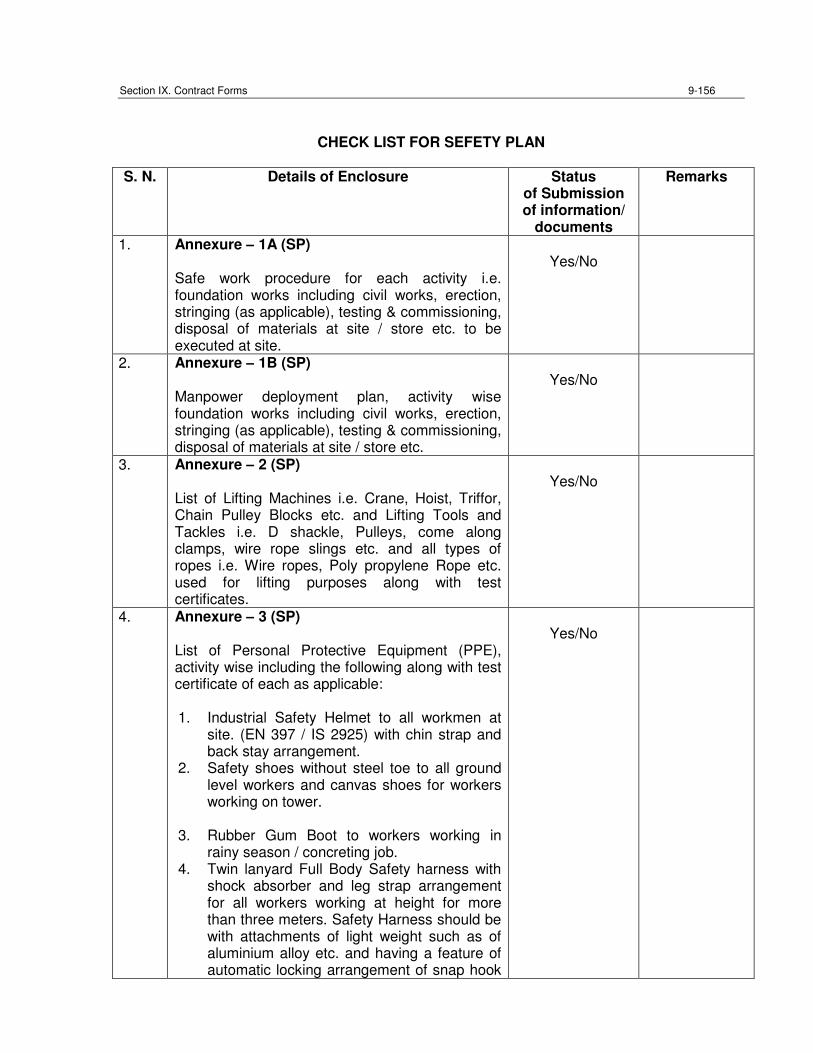
Section IX. Contract Forms 9-156
CHECK LIST FOR SEFETY PLAN
S. N. Details of Enclosure Status of Submission of information/
documents
Remarks
1. Annexure – 1A (SP) Safe work procedure for each activity i.e. foundation works including civil works, erection, stringing (as applicable), testing & commissioning, disposal of materials at site / store etc. to be executed at site.
Yes/No
2. Annexure – 1B (SP) Manpower deployment plan, activity wise foundation works including civil works, erection, stringing (as applicable), testing & commissioning, disposal of materials at site / store etc.
Yes/No
3. Annexure – 2 (SP) List of Lifting Machines i.e. Crane, Hoist, Triffor, Chain Pulley Blocks etc. and Lifting Tools and Tackles i.e. D shackle, Pulleys, come along clamps, wire rope slings etc. and all types of ropes i.e. Wire ropes, Poly propylene Rope etc. used for lifting purposes along with test certificates.
Yes/No
4. Annexure – 3 (SP) List of Personal Protective Equipment (PPE), activity wise including the following along with test certificate of each as applicable: 1. Industrial Safety Helmet to all workmen at
site. (EN 397 / IS 2925) with chin strap and back stay arrangement.
2. Safety shoes without steel toe to all ground level workers and canvas shoes for workers working on tower.
3. Rubber Gum Boot to workers working in
rainy season / concreting job. 4. Twin lanyard Full Body Safety harness with
shock absorber and leg strap arrangement for all workers working at height for more than three meters. Safety Harness should be with attachments of light weight such as of aluminium alloy etc. and having a feature of automatic locking arrangement of snap hook
Yes/No
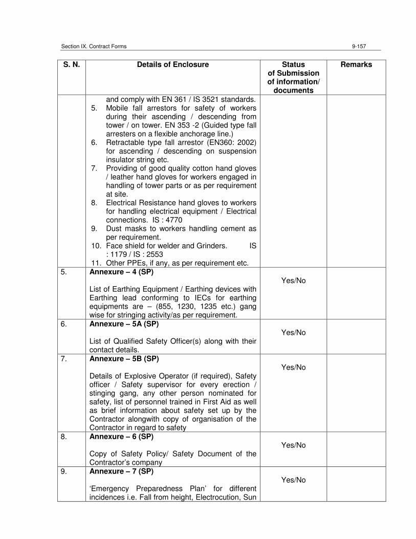
Section IX. Contract Forms 9-157
S. N. Details of Enclosure Status
of Submission of information/
documents
Remarks
and comply with EN 361 / IS 3521 standards. 5. Mobile fall arrestors for safety of workers
during their ascending / descending from tower / on tower. EN 353 -2 (Guided type fall arresters on a flexible anchorage line.)
6. Retractable type fall arrestor (EN360: 2002) for ascending / descending on suspension insulator string etc.
7. Providing of good quality cotton hand gloves / leather hand gloves for workers engaged in handling of tower parts or as per requirement at site.
8. Electrical Resistance hand gloves to workers for handling electrical equipment / Electrical connections. IS : 4770
9. Dust masks to workers handling cement as per requirement.
10. Face shield for welder and Grinders. IS : 1179 / IS : 2553
11. Other PPEs, if any, as per requirement etc. 5. Annexure – 4 (SP)
List of Earthing Equipment / Earthing devices with Earthing lead conforming to IECs for earthing equipments are – (855, 1230, 1235 etc.) gang wise for stringing activity/as per requirement.
Yes/No
6. Annexure – 5A (SP) List of Qualified Safety Officer(s) along with their contact details.
Yes/No
7. Annexure – 5B (SP) Details of Explosive Operator (if required), Safety officer / Safety supervisor for every erection / stinging gang, any other person nominated for safety, list of personnel trained in First Aid as well as brief information about safety set up by the Contractor alongwith copy of organisation of the Contractor in regard to safety
Yes/No
8. Annexure – 6 (SP) Copy of Safety Policy/ Safety Document of the Contractor’s company
Yes/No
9. Annexure – 7 (SP) ‘Emergency Preparedness Plan’ for different incidences i.e. Fall from height, Electrocution, Sun
Yes/No
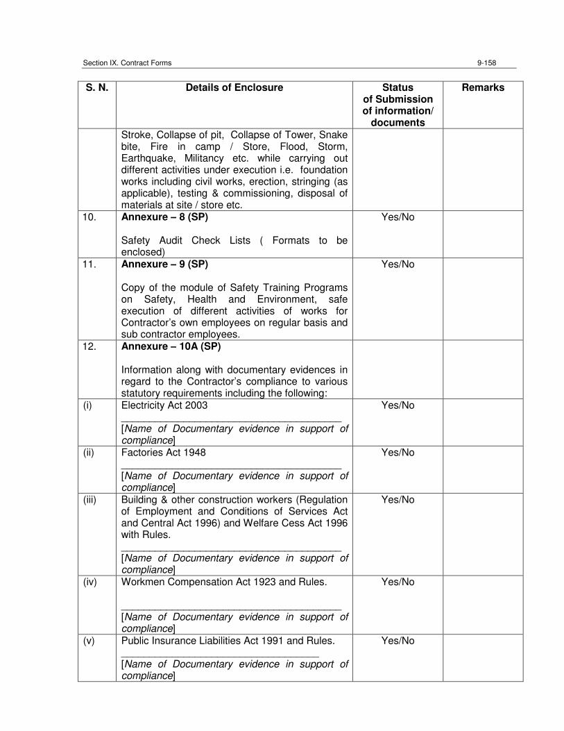
Section IX. Contract Forms 9-158
S. N. Details of Enclosure Status
of Submission of information/
documents
Remarks
Stroke, Collapse of pit, Collapse of Tower, Snake bite, Fire in camp / Store, Flood, Storm, Earthquake, Militancy etc. while carrying out different activities under execution i.e. foundation works including civil works, erection, stringing (as applicable), testing & commissioning, disposal of materials at site / store etc.
10. Annexure – 8 (SP) Safety Audit Check Lists ( Formats to be enclosed)
Yes/No
11. Annexure – 9 (SP) Copy of the module of Safety Training Programs on Safety, Health and Environment, safe execution of different activities of works for Contractor’s own employees on regular basis and sub contractor employees.
Yes/No
12. Annexure – 10A (SP) Information along with documentary evidences in regard to the Contractor’s compliance to various statutory requirements including the following:
(i) Electricity Act 2003 _______________________________________ [Name of Documentary evidence in support of compliance]
Yes/No
(ii) Factories Act 1948 _______________________________________ [Name of Documentary evidence in support of compliance]
Yes/No
(iii) Building & other construction workers (Regulation of Employment and Conditions of Services Act and Central Act 1996) and Welfare Cess Act 1996 with Rules. _______________________________________ [Name of Documentary evidence in support of compliance]
Yes/No
(iv) Workmen Compensation Act 1923 and Rules. _______________________________________ [Name of Documentary evidence in support of compliance]
Yes/No
(v) Public Insurance Liabilities Act 1991 and Rules. ___________________________________ [Name of Documentary evidence in support of compliance]
Yes/No
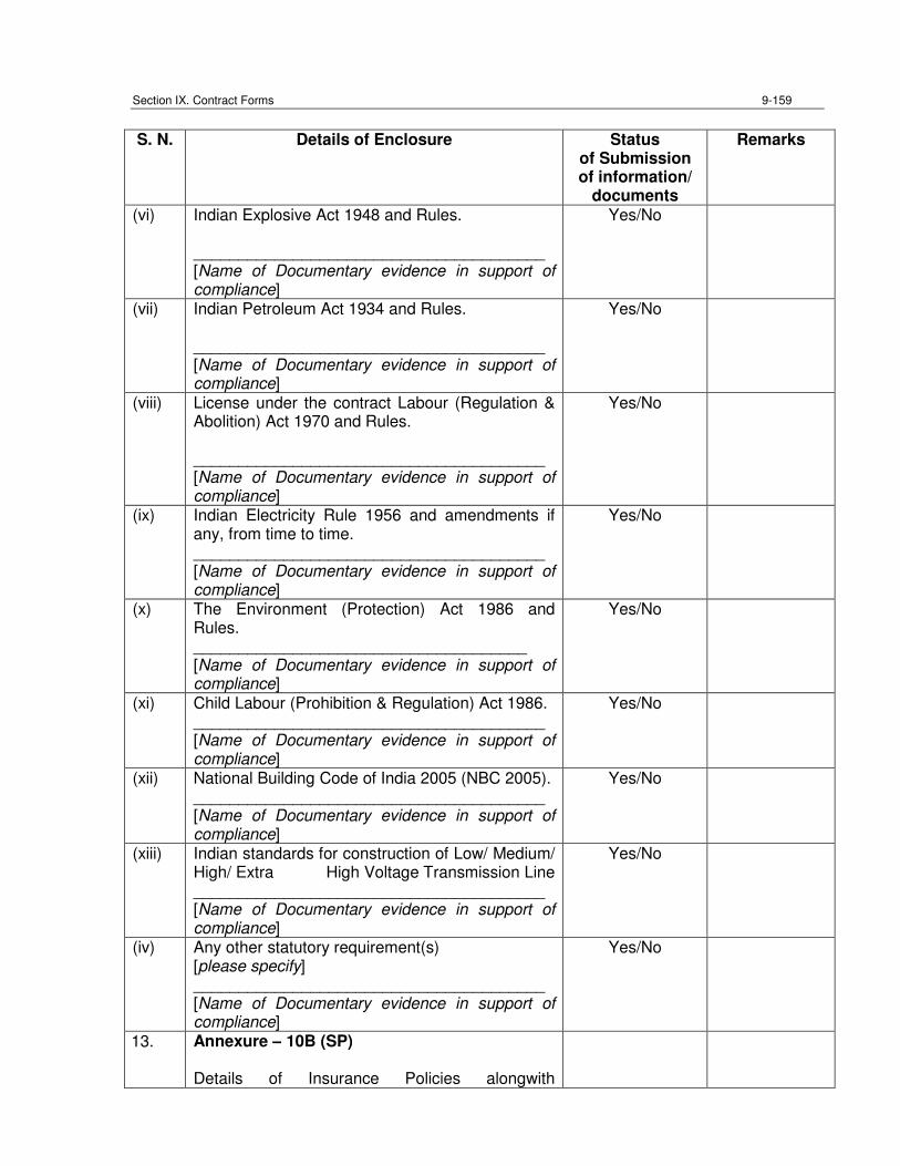
Section IX. Contract Forms 9-159
S. N. Details of Enclosure Status
of Submission of information/
documents
Remarks
(vi) Indian Explosive Act 1948 and Rules. _______________________________________ [Name of Documentary evidence in support of compliance]
Yes/No
(vii) Indian Petroleum Act 1934 and Rules. _______________________________________ [Name of Documentary evidence in support of compliance]
Yes/No
(viii) License under the contract Labour (Regulation & Abolition) Act 1970 and Rules. _______________________________________ [Name of Documentary evidence in support of compliance]
Yes/No
(ix) Indian Electricity Rule 1956 and amendments if any, from time to time. _______________________________________ [Name of Documentary evidence in support of compliance]
Yes/No
(x) The Environment (Protection) Act 1986 and Rules. _____________________________________ [Name of Documentary evidence in support of compliance]
Yes/No
(xi) Child Labour (Prohibition & Regulation) Act 1986. _______________________________________ [Name of Documentary evidence in support of compliance]
Yes/No
(xii) National Building Code of India 2005 (NBC 2005). _______________________________________ [Name of Documentary evidence in support of compliance]
Yes/No
(xiii) Indian standards for construction of Low/ Medium/ High/ Extra High Voltage Transmission Line _______________________________________ [Name of Documentary evidence in support of compliance]
Yes/No
(iv) Any other statutory requirement(s) [please specify] _______________________________________ [Name of Documentary evidence in support of compliance]
Yes/No
13. Annexure – 10B (SP) Details of Insurance Policies alongwith
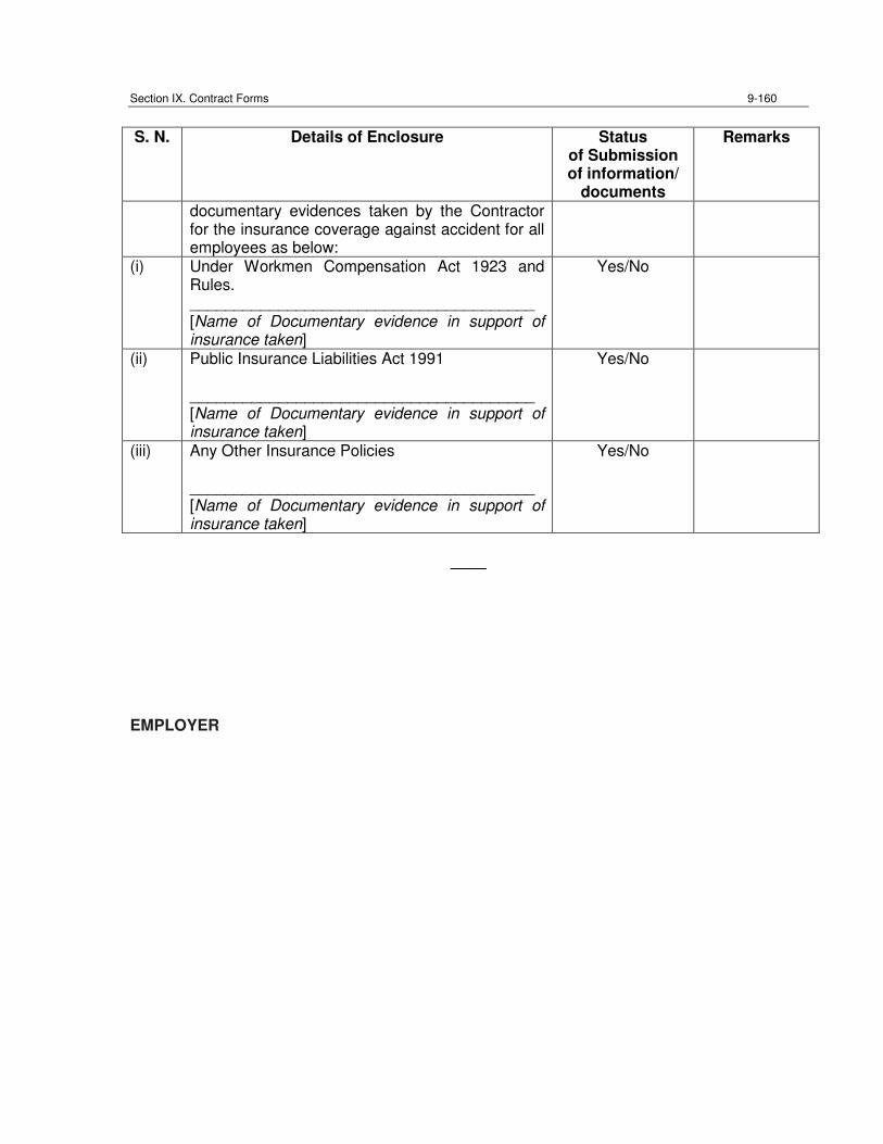
Section IX. Contract Forms 9-160
S. N. Details of Enclosure Status
of Submission of information/
documents
Remarks
documentary evidences taken by the Contractor for the insurance coverage against accident for all employees as below:
(i) Under Workmen Compensation Act 1923 and Rules. _______________________________________ [Name of Documentary evidence in support of insurance taken]
Yes/No
(ii) Public Insurance Liabilities Act 1991 _______________________________________ [Name of Documentary evidence in support of insurance taken]
Yes/No
(iii) Any Other Insurance Policies _______________________________________ [Name of Documentary evidence in support of insurance taken]
Yes/No
____
EMPLOYER
ANNEXURE-5
(DETAILS OF PUBLIC
CONSULTATION)
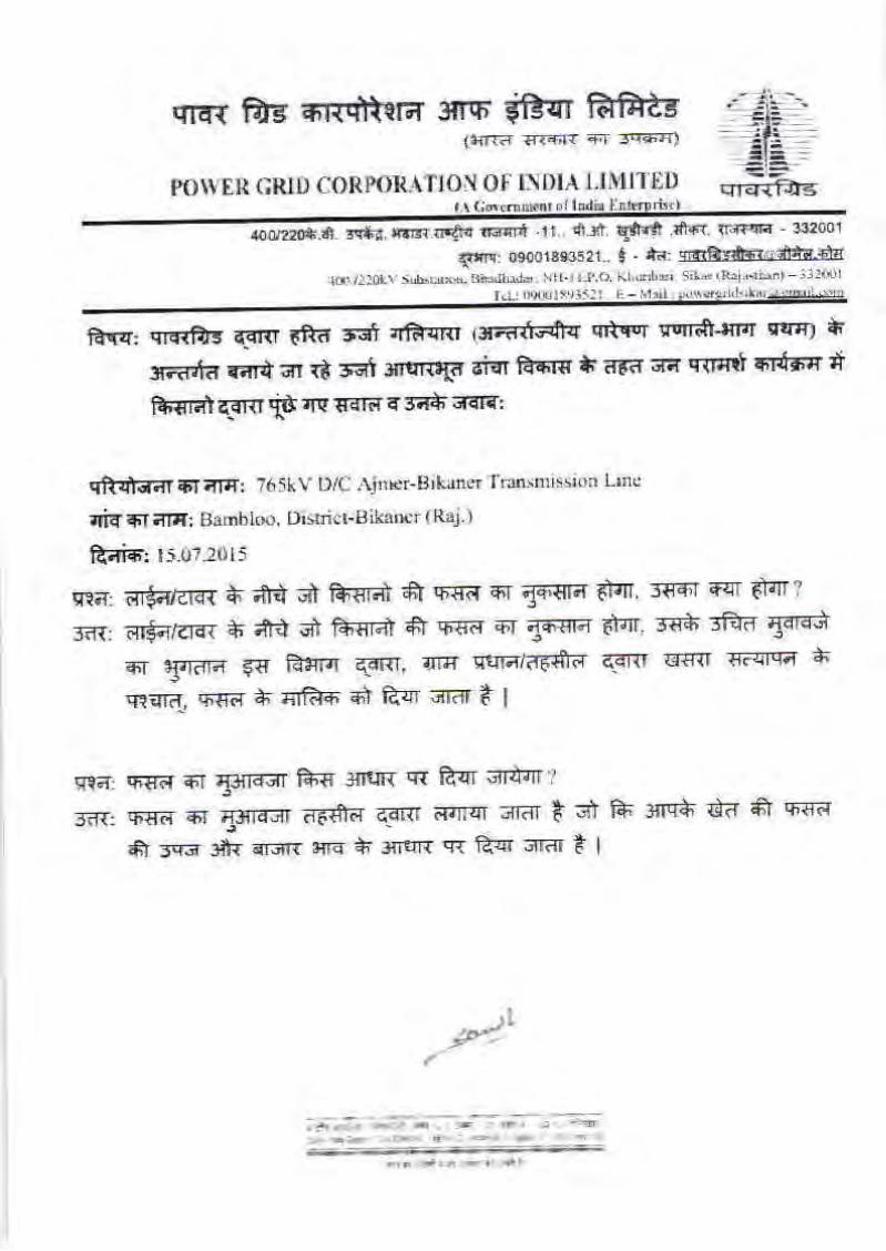
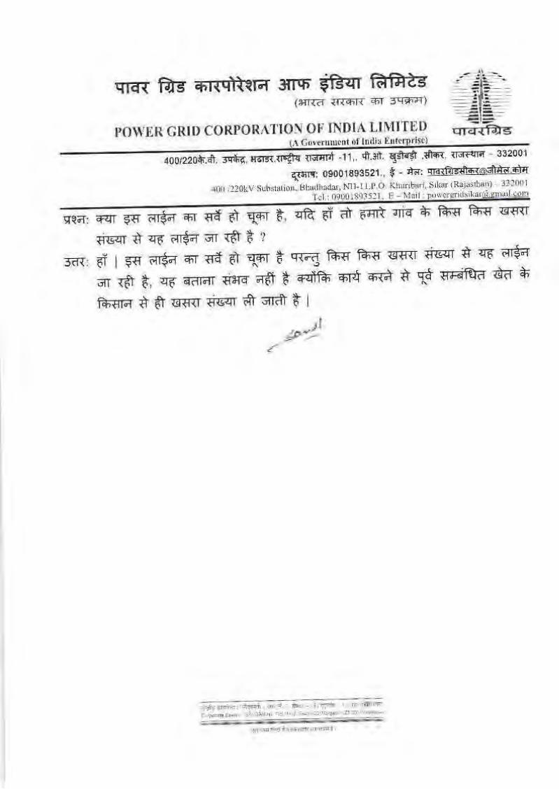
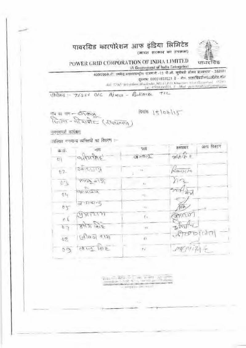
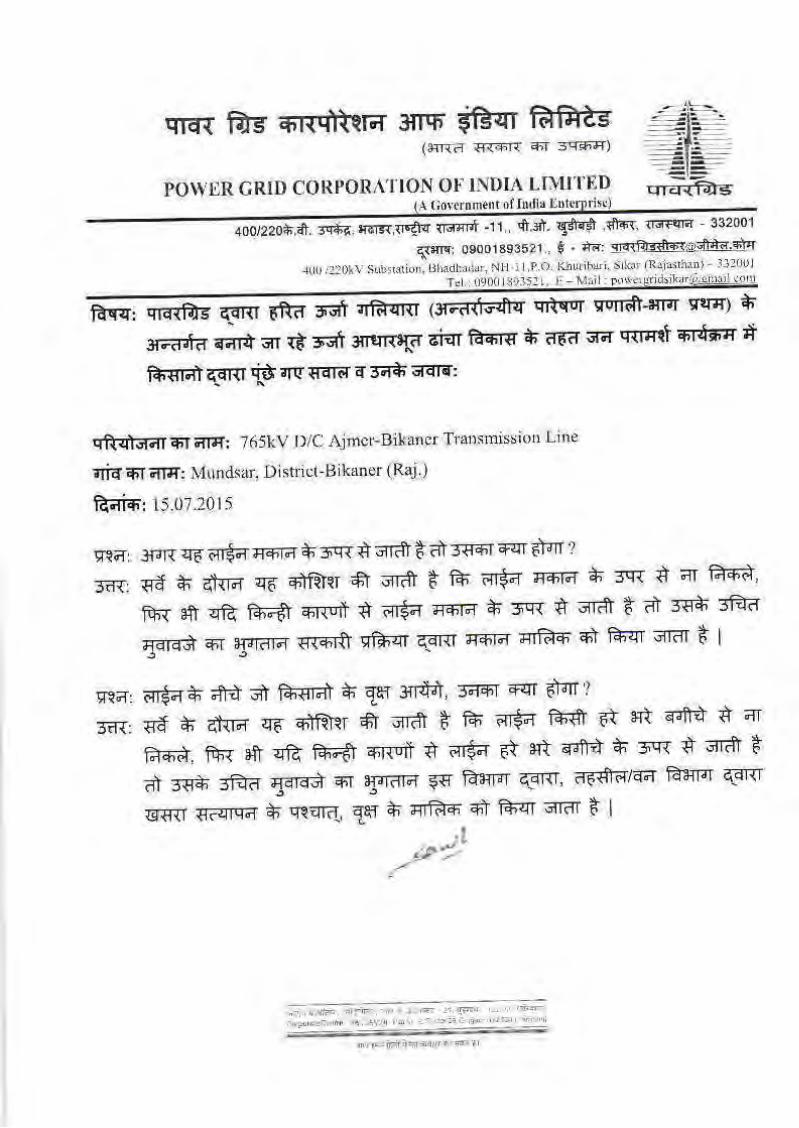

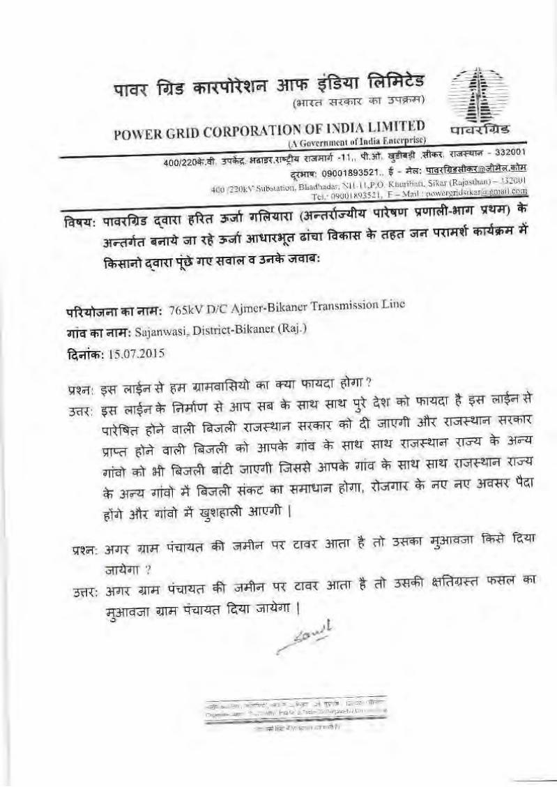
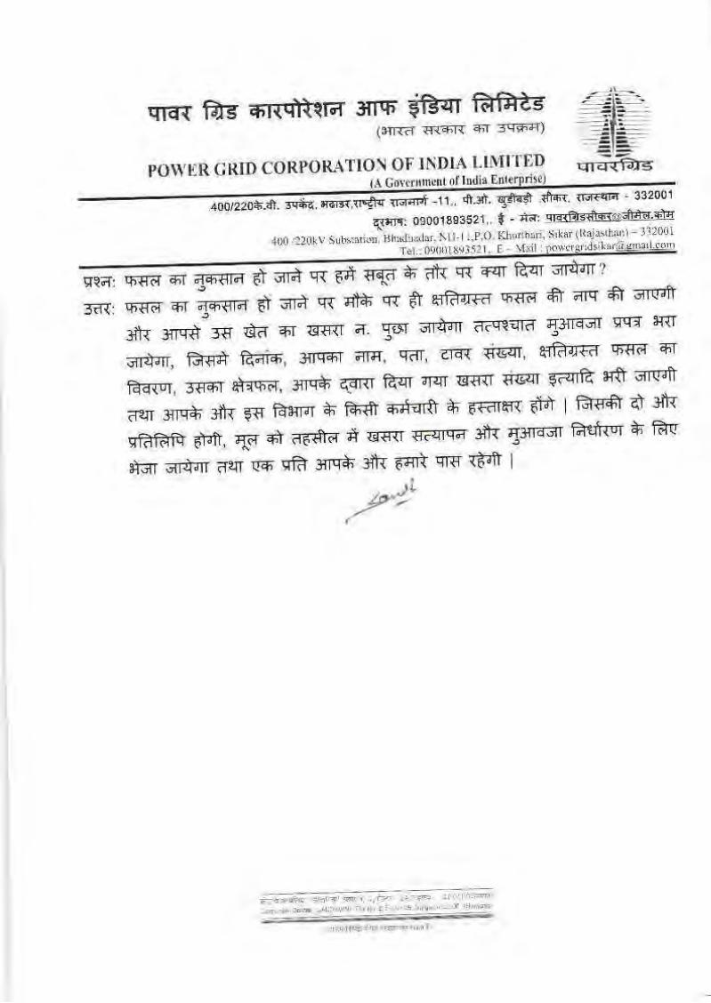
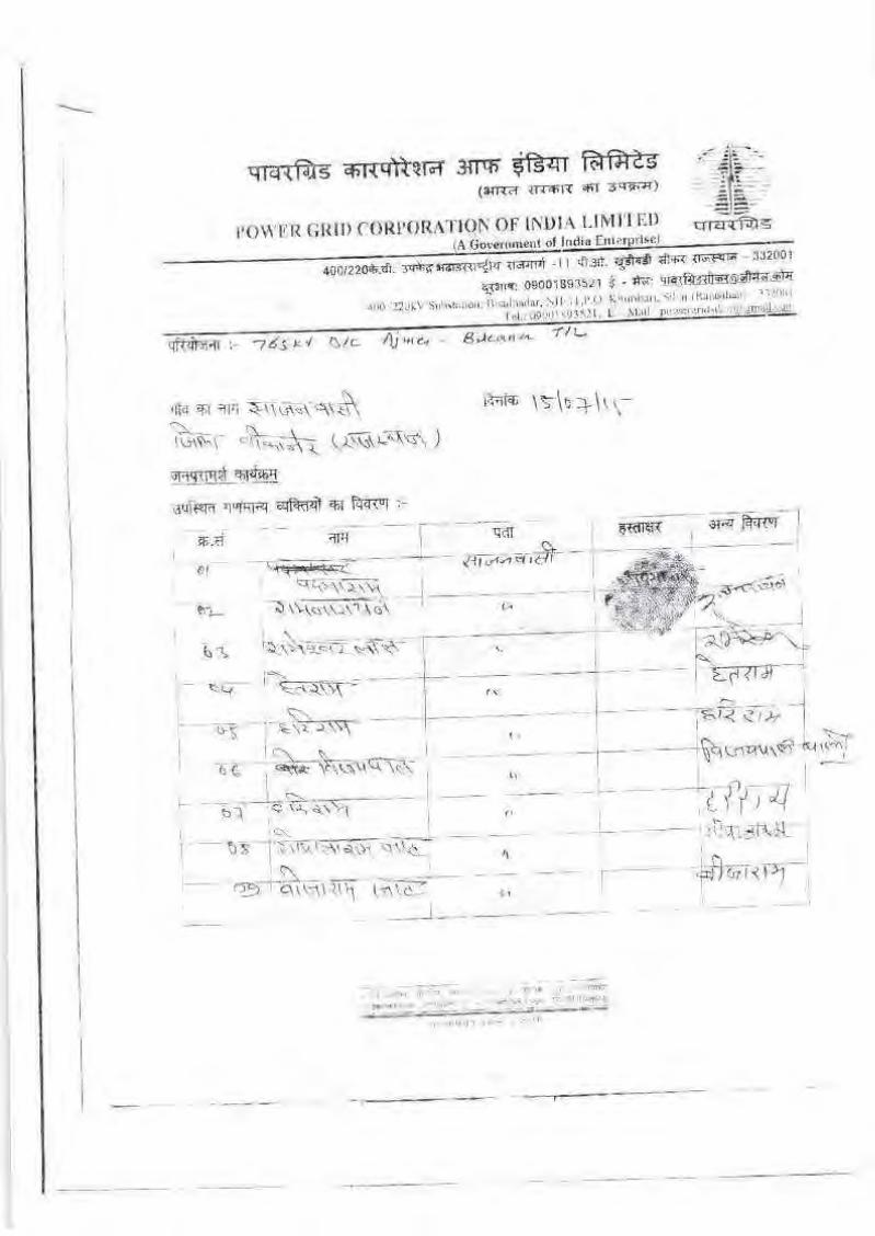
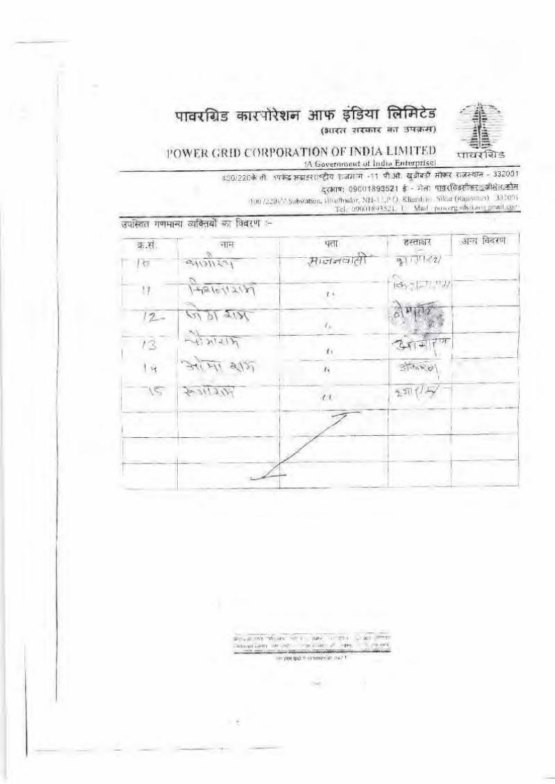

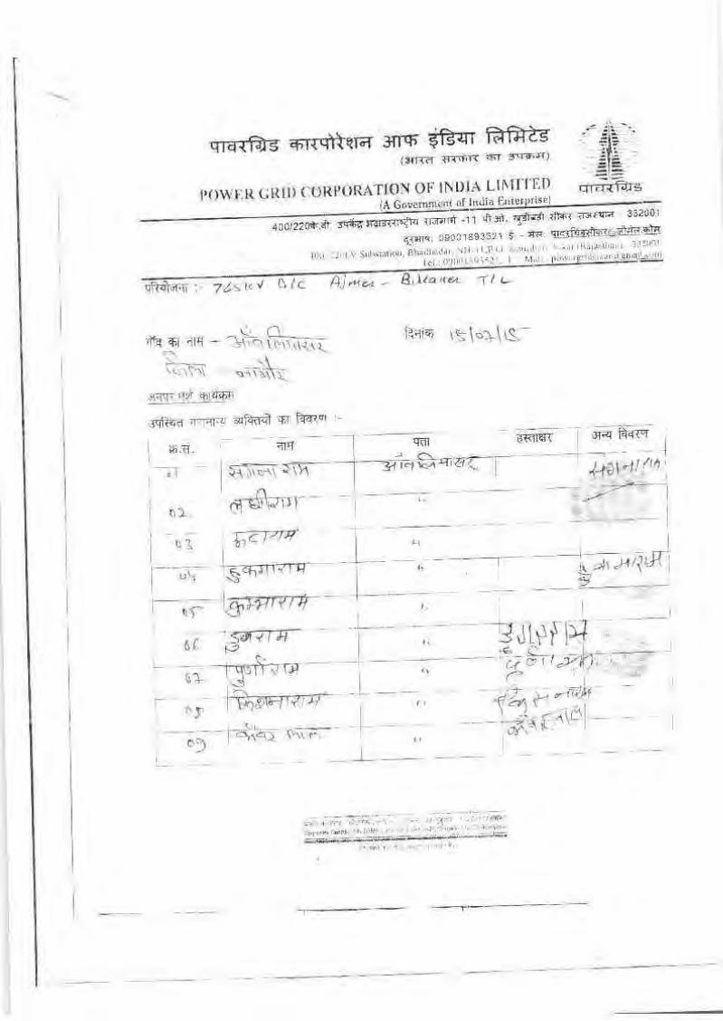
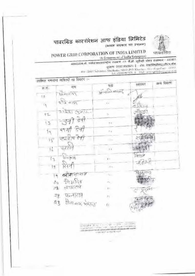
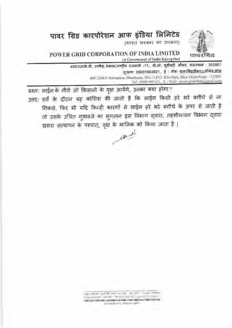
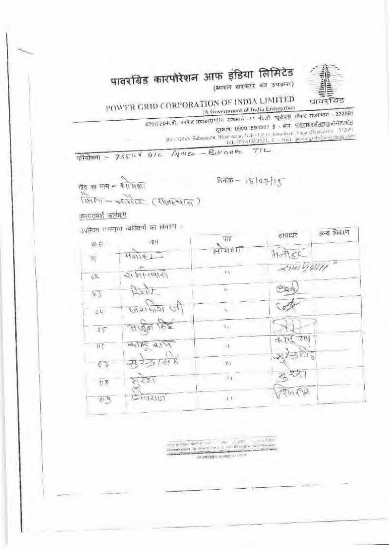
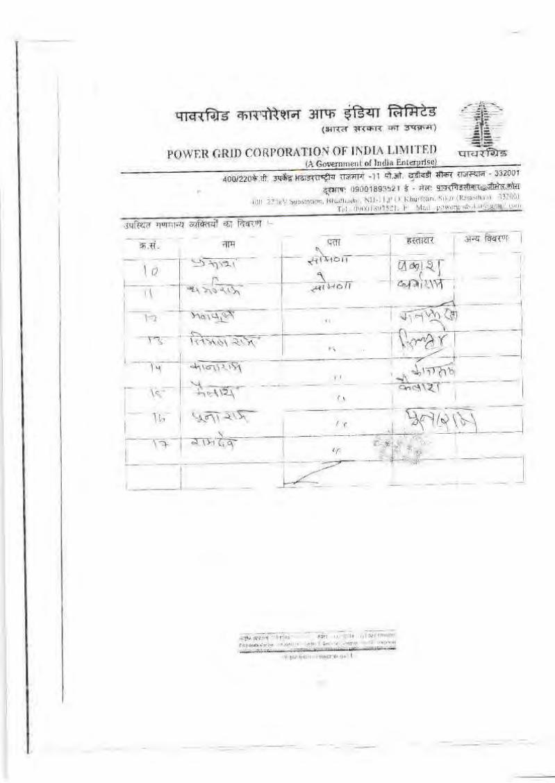
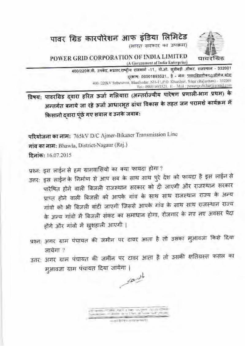
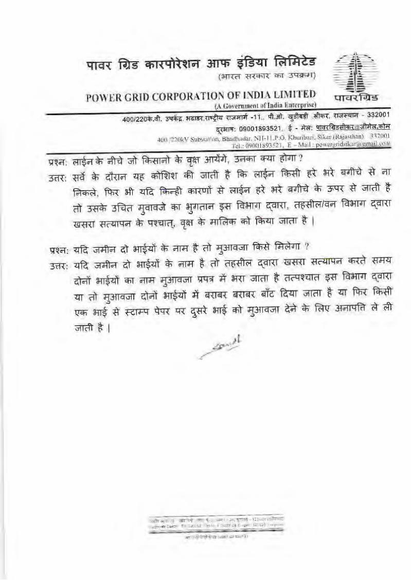
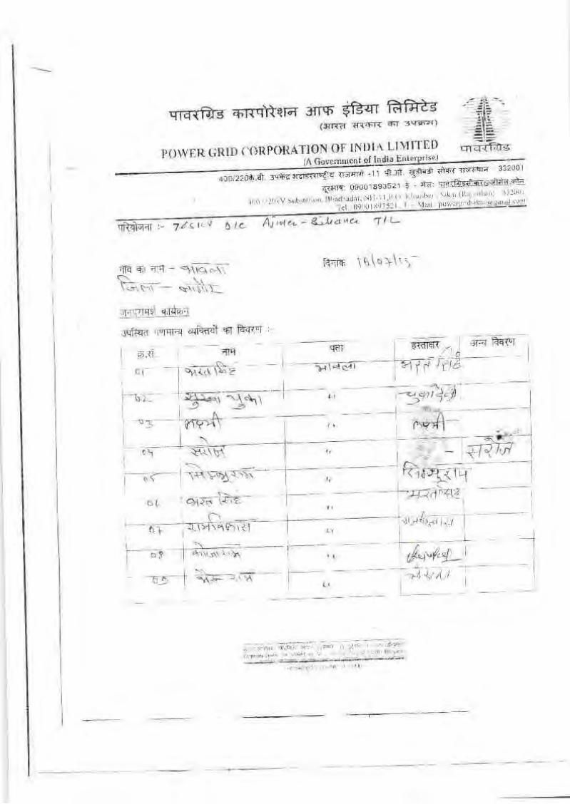
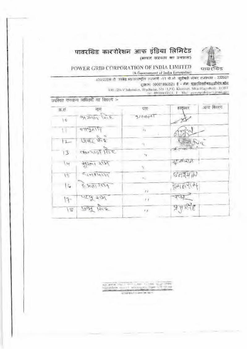
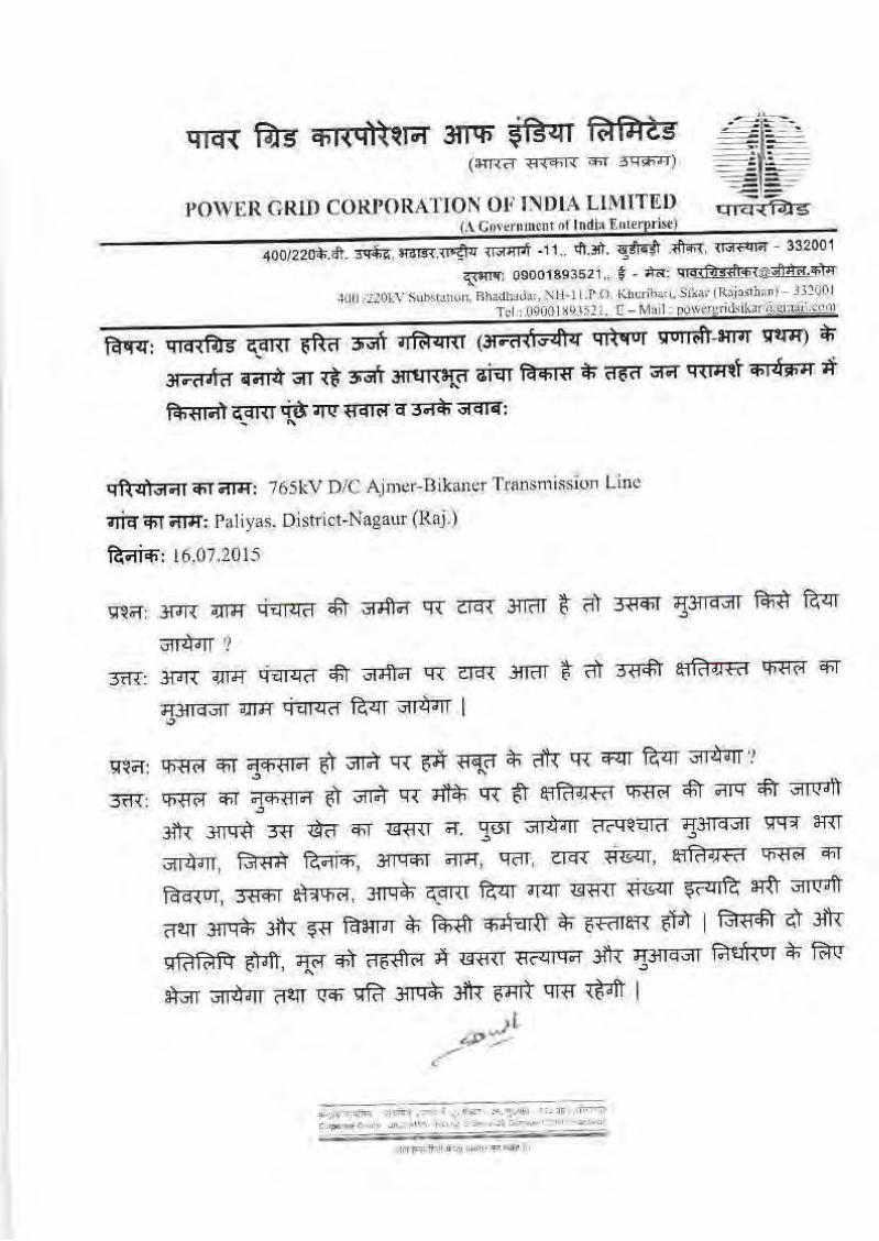
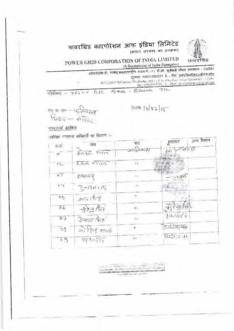
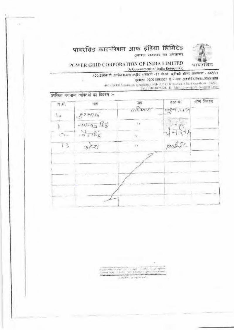
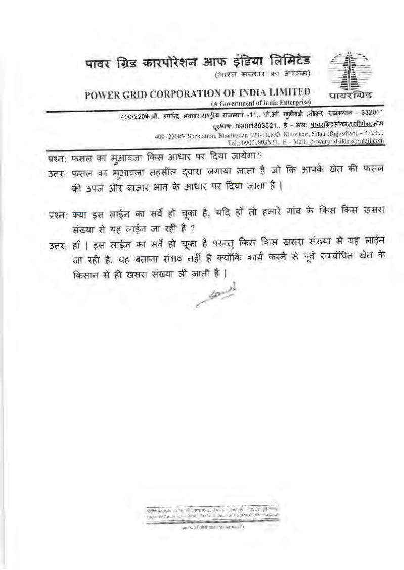

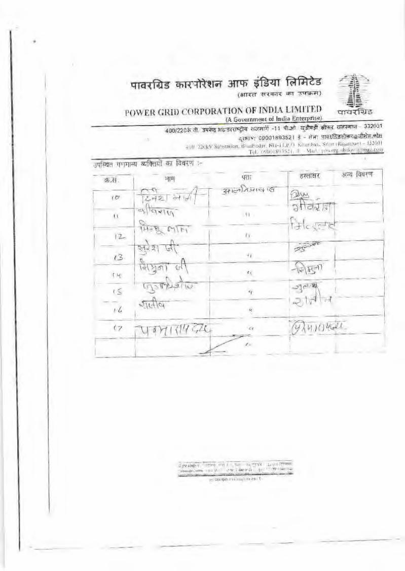
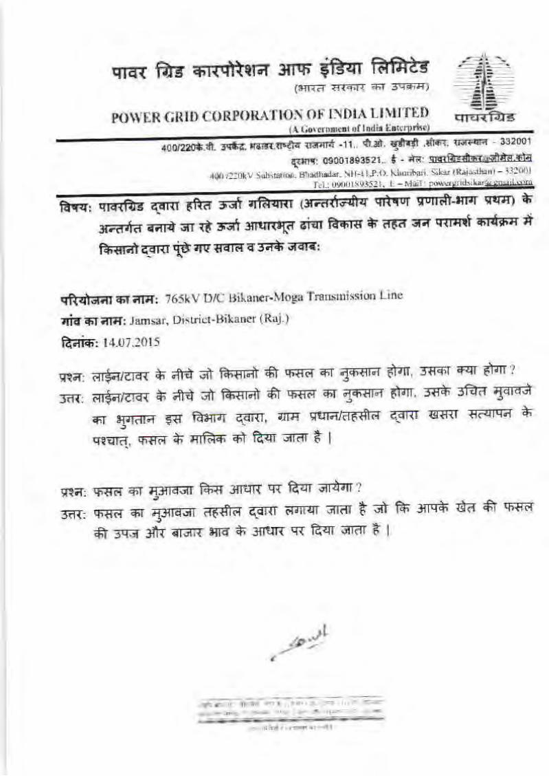

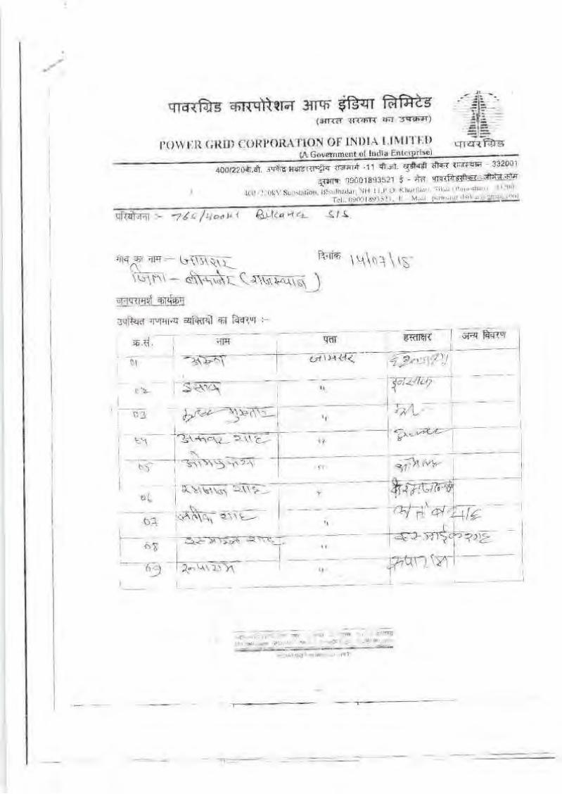

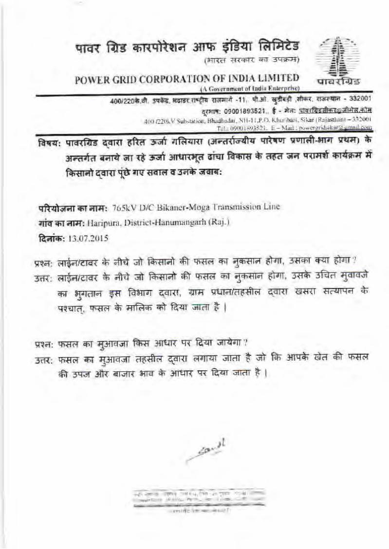
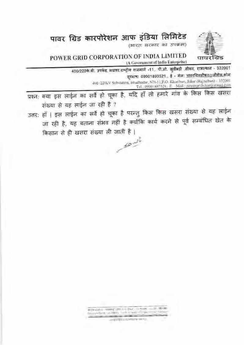
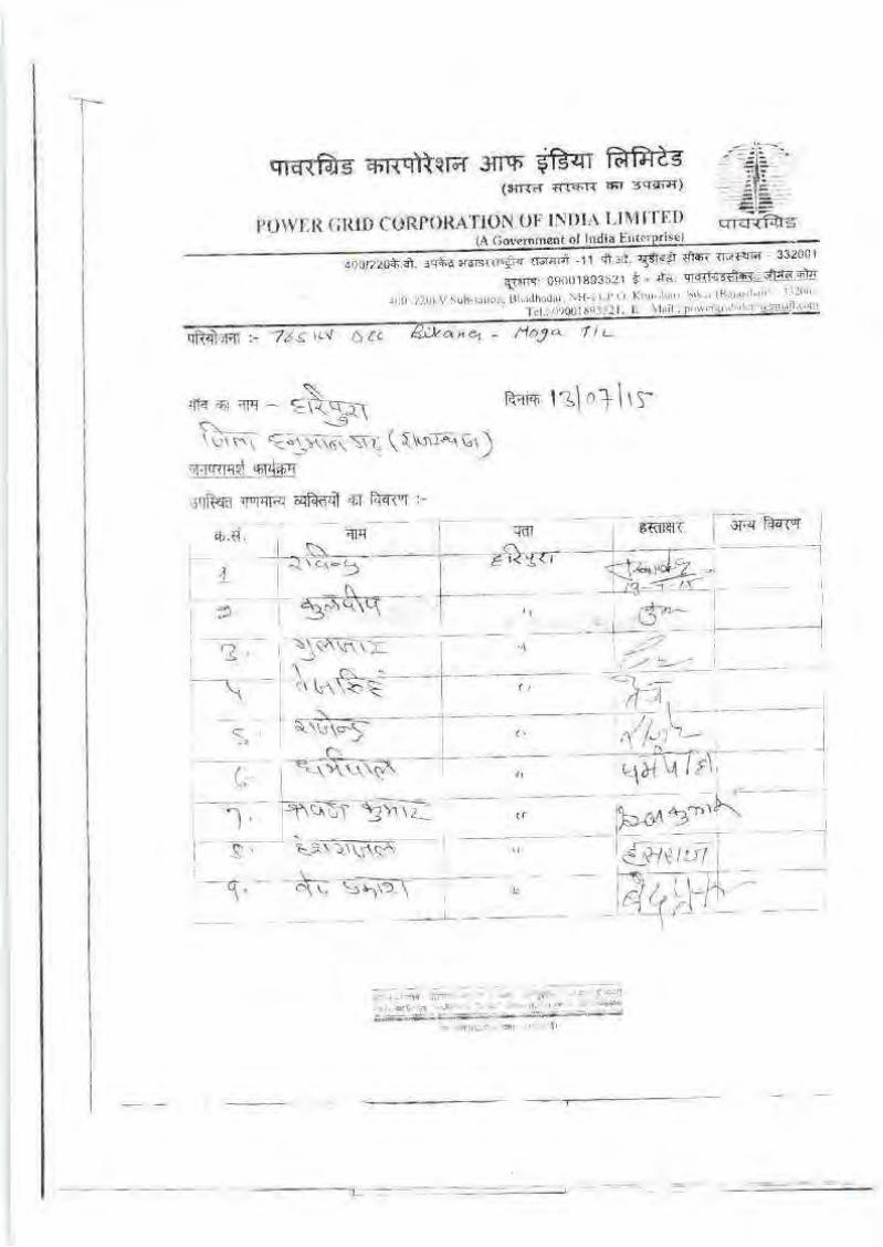
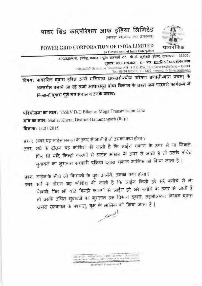
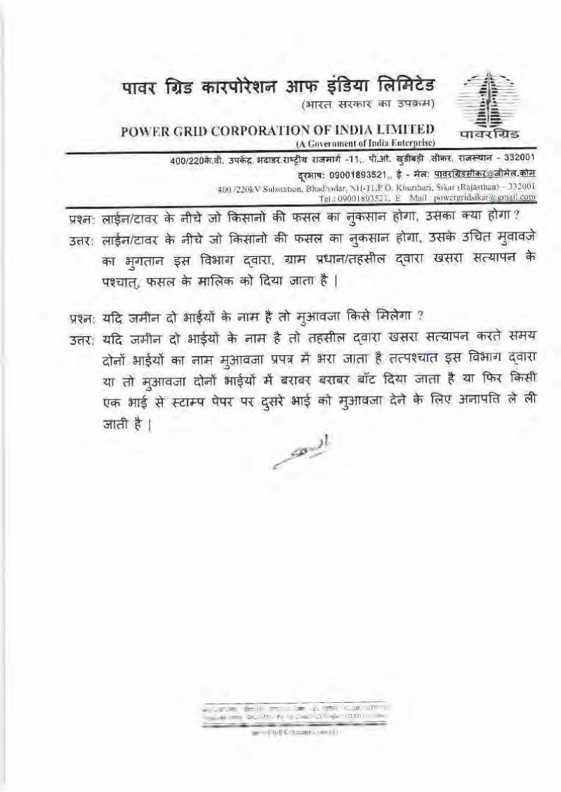
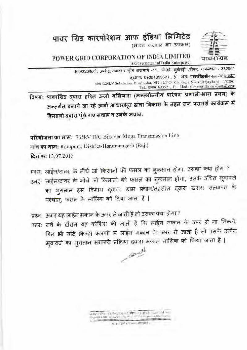
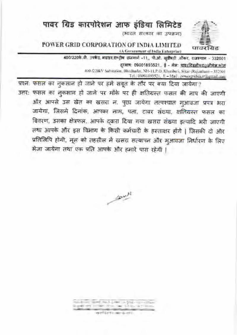
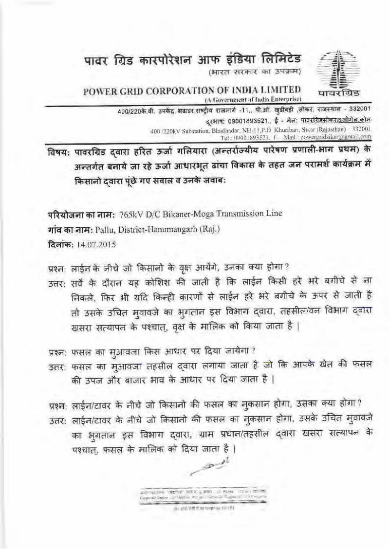

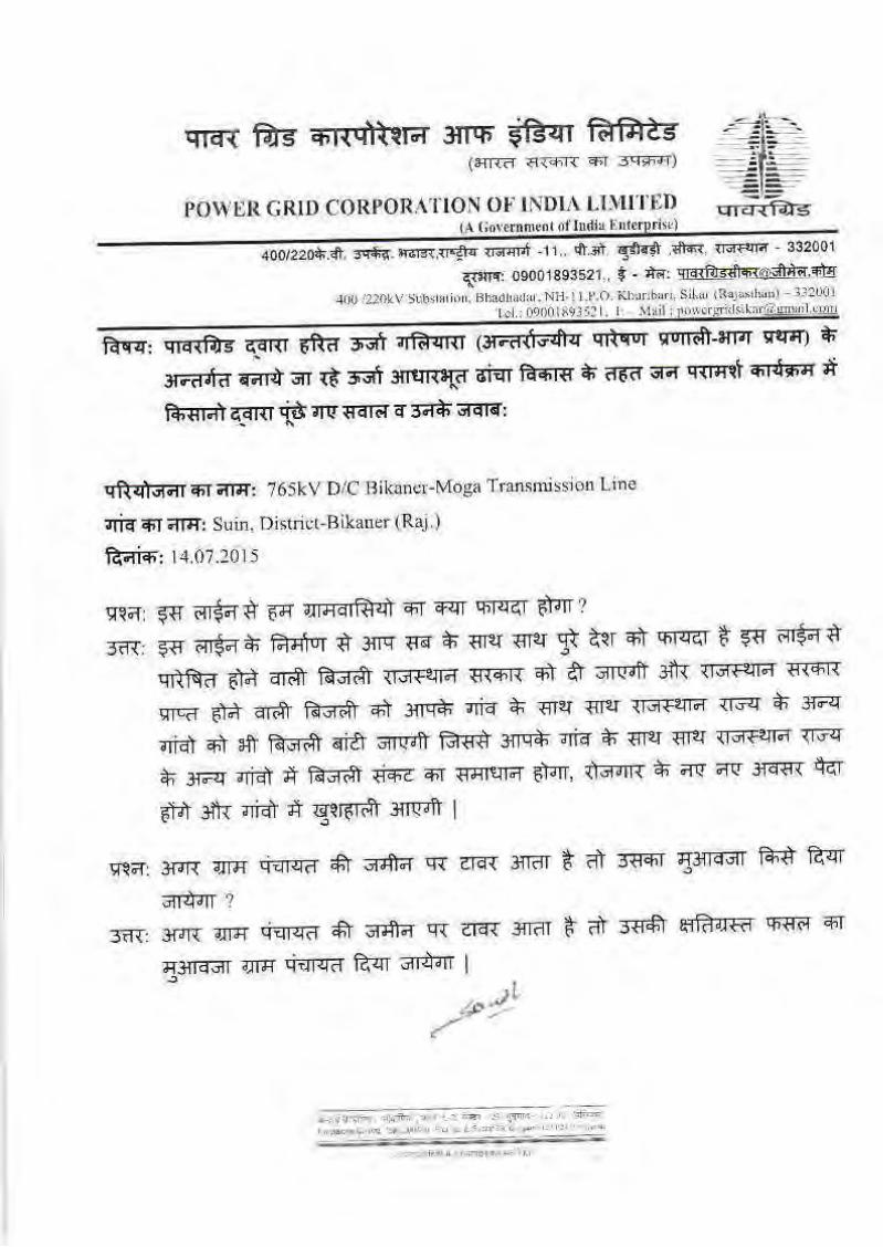
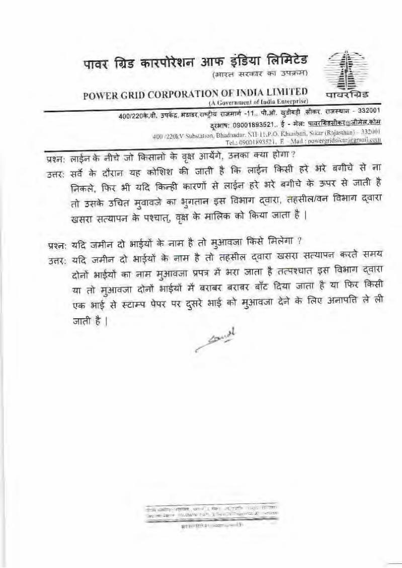
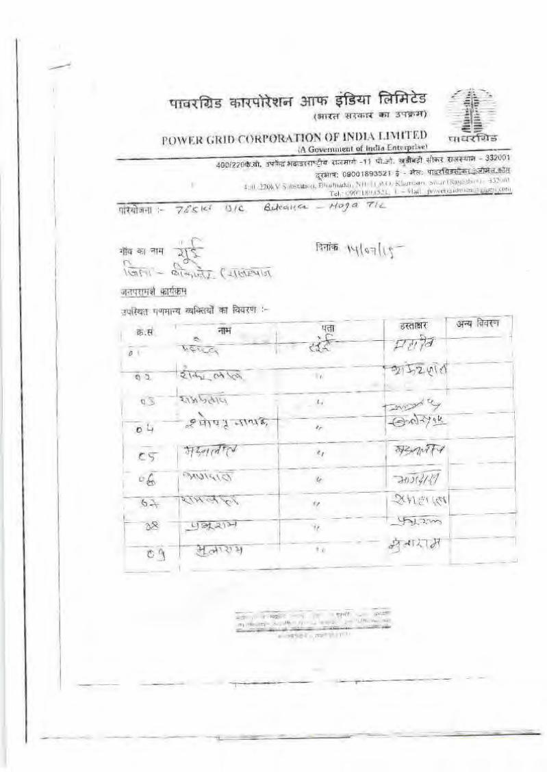
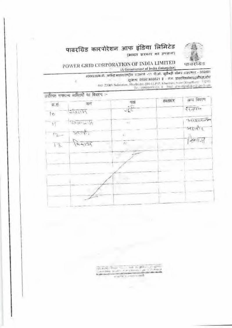
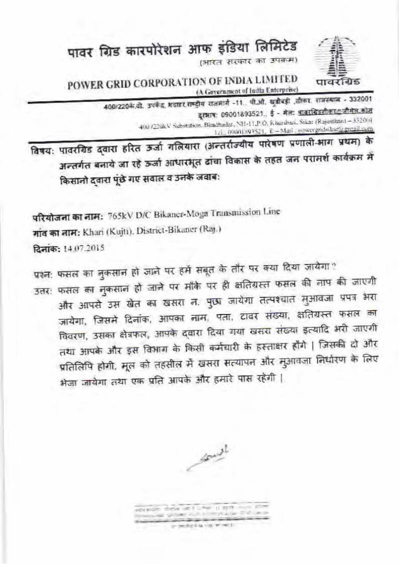
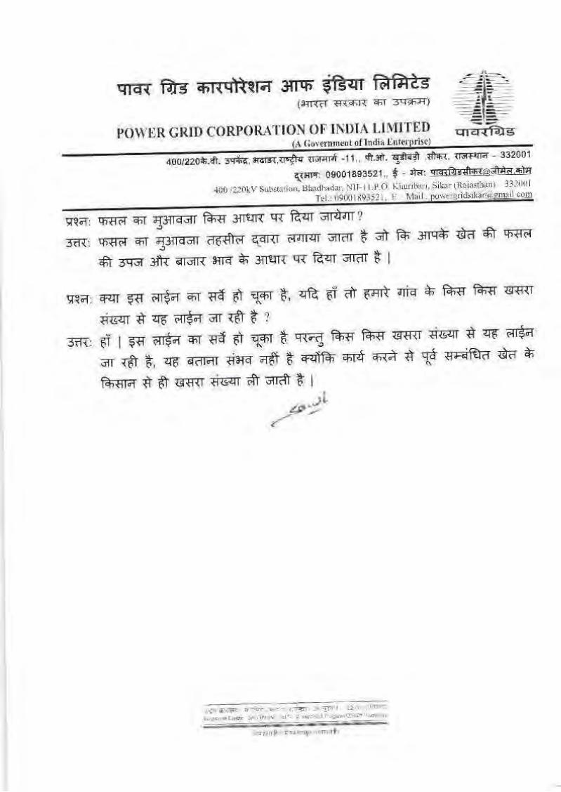
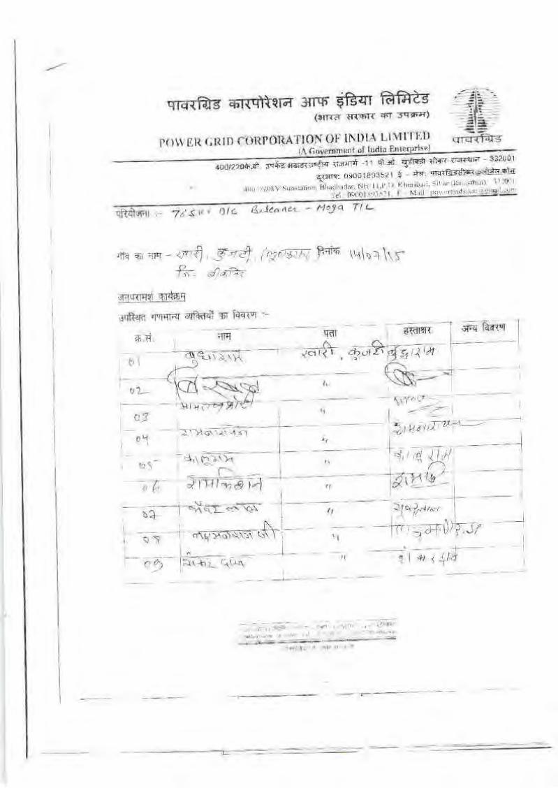
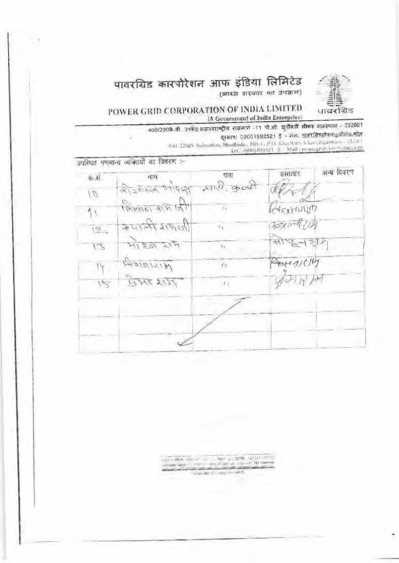
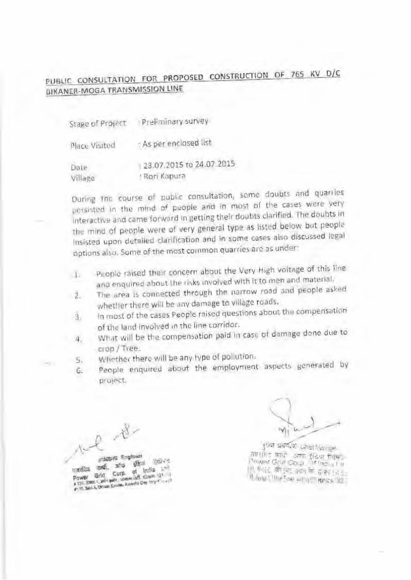
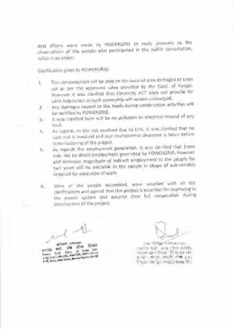
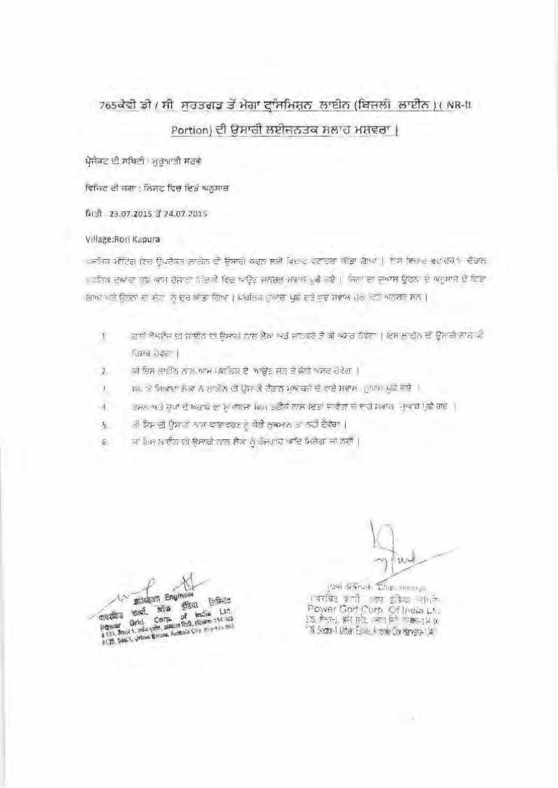
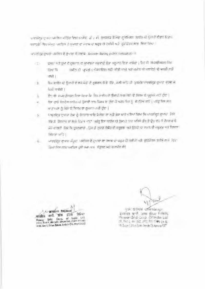
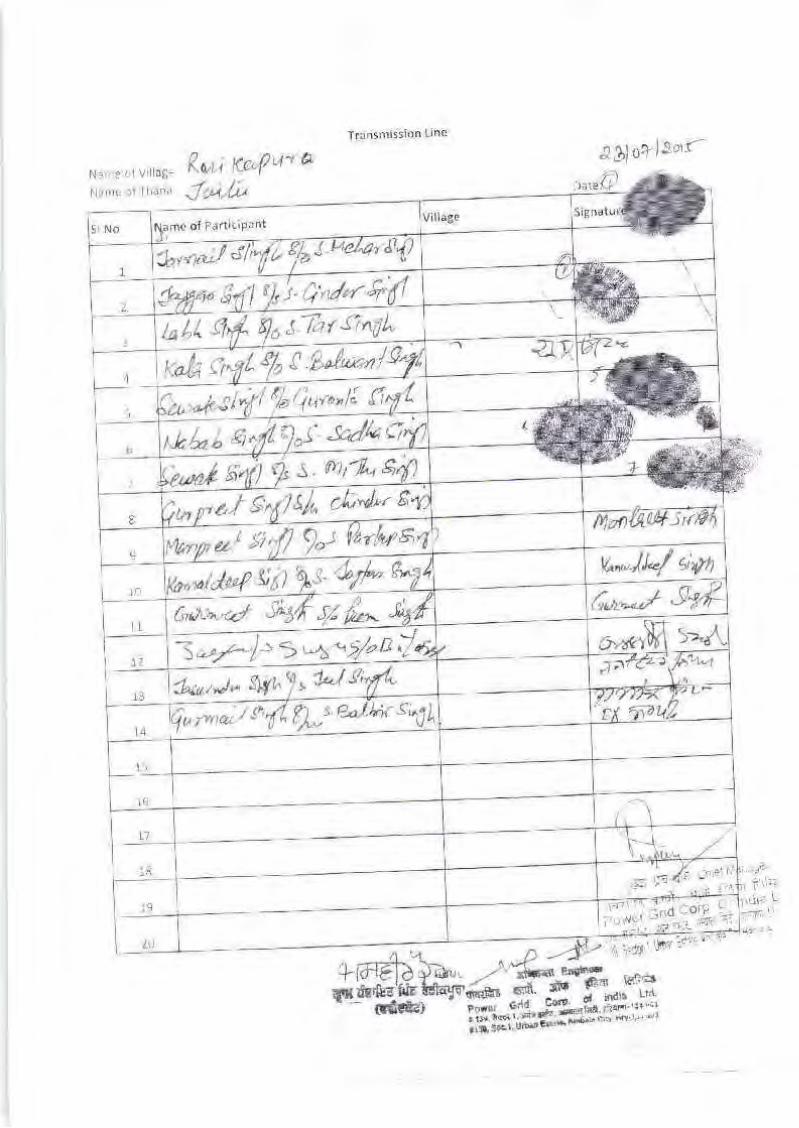
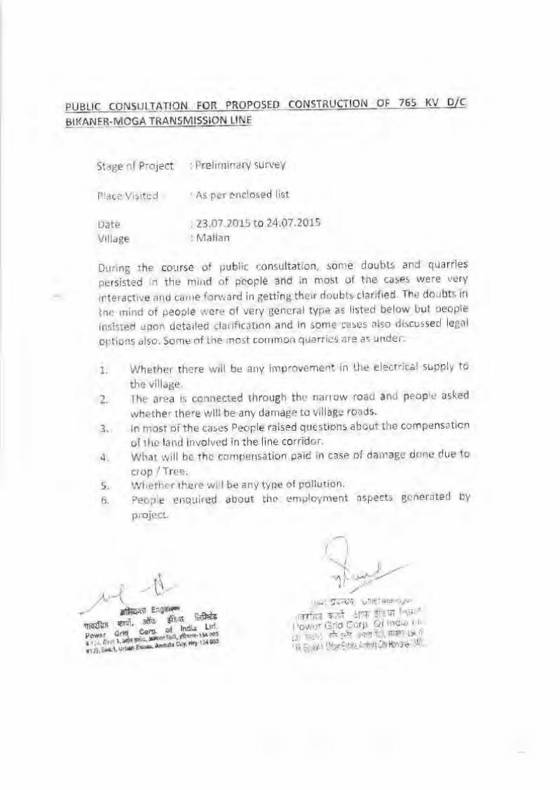
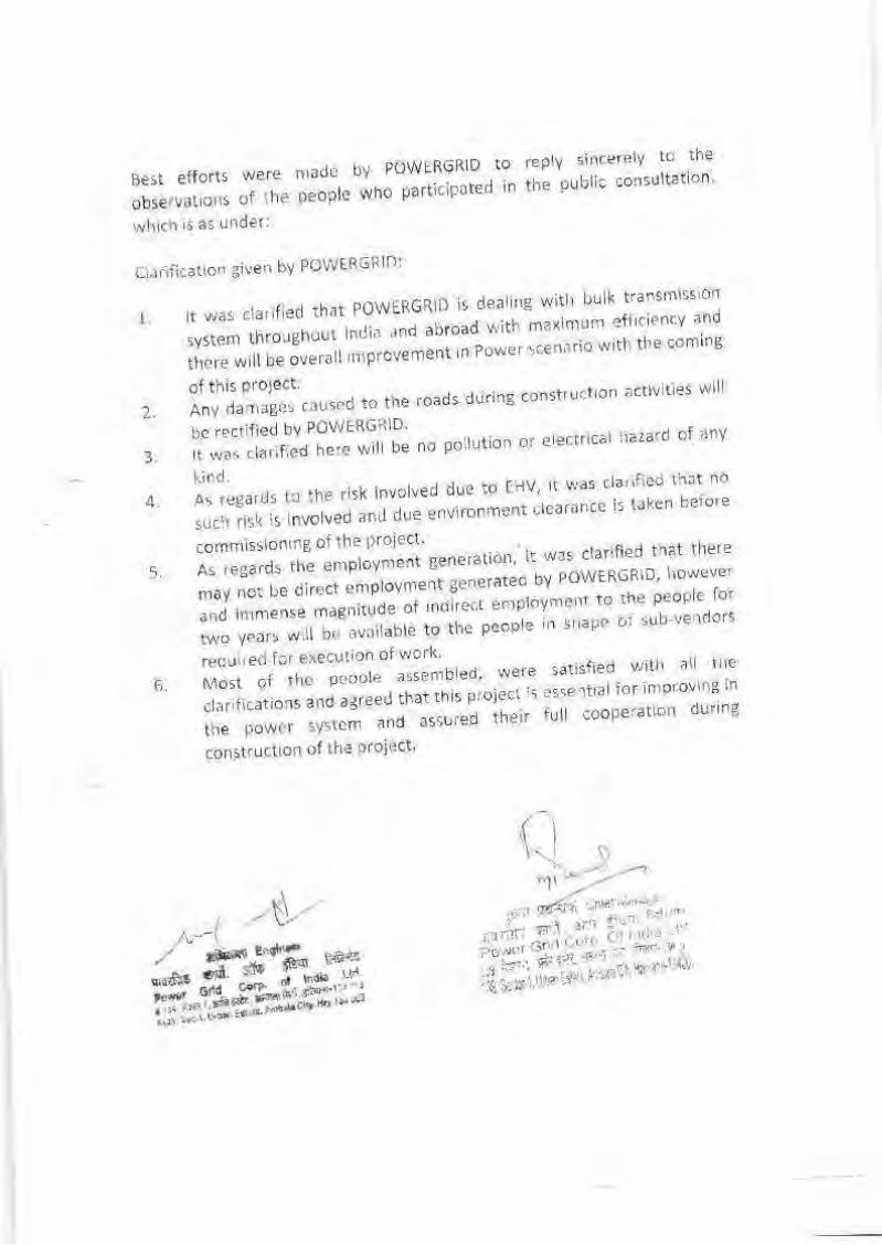
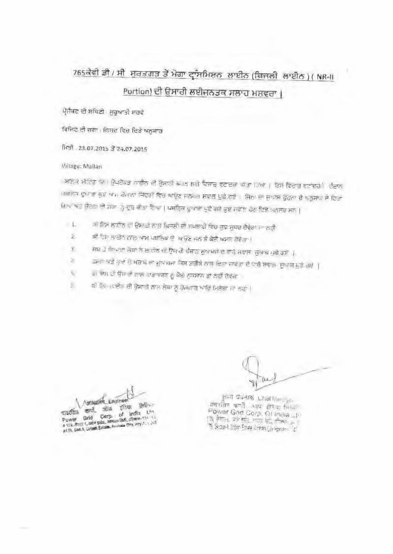
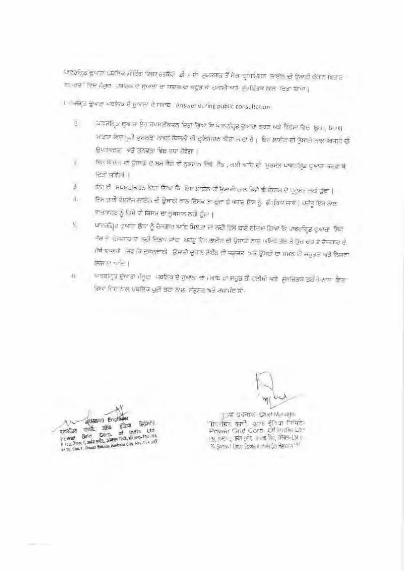
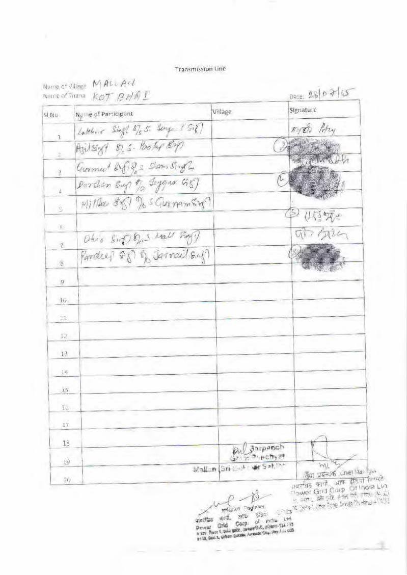
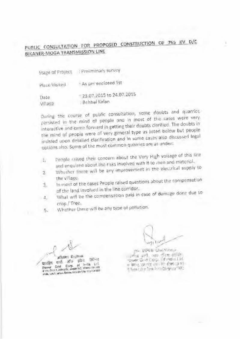
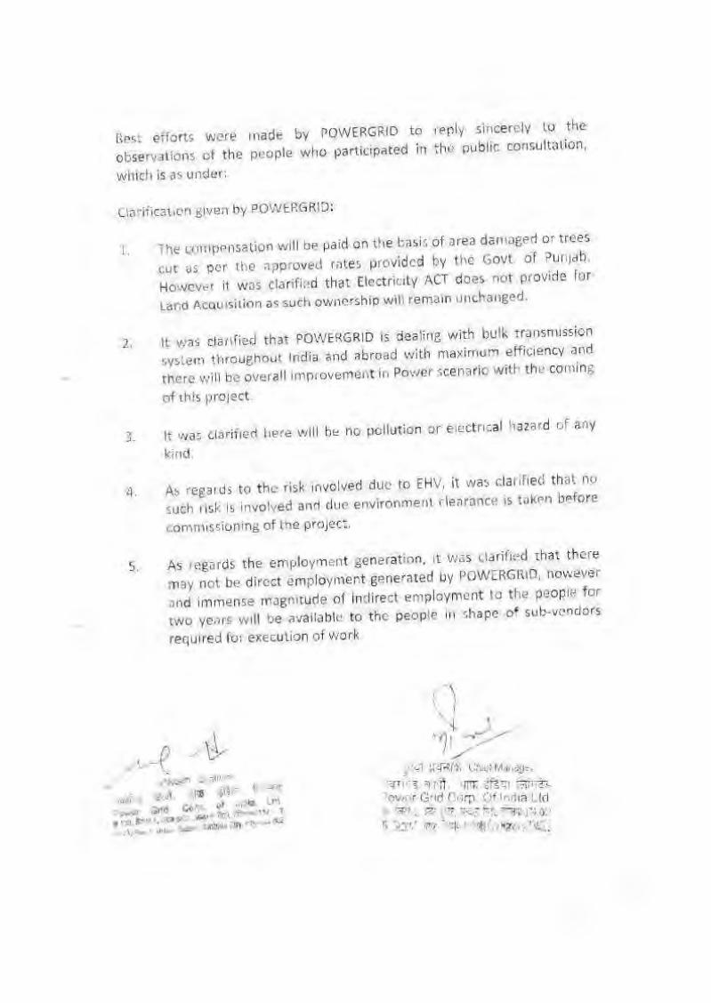
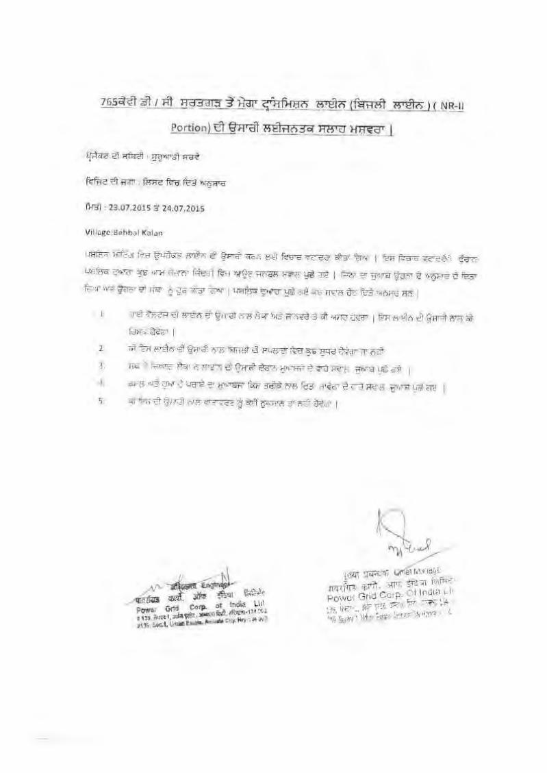
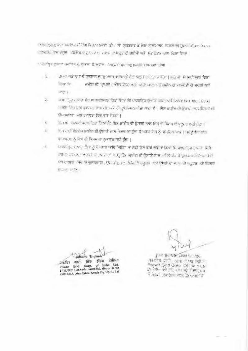
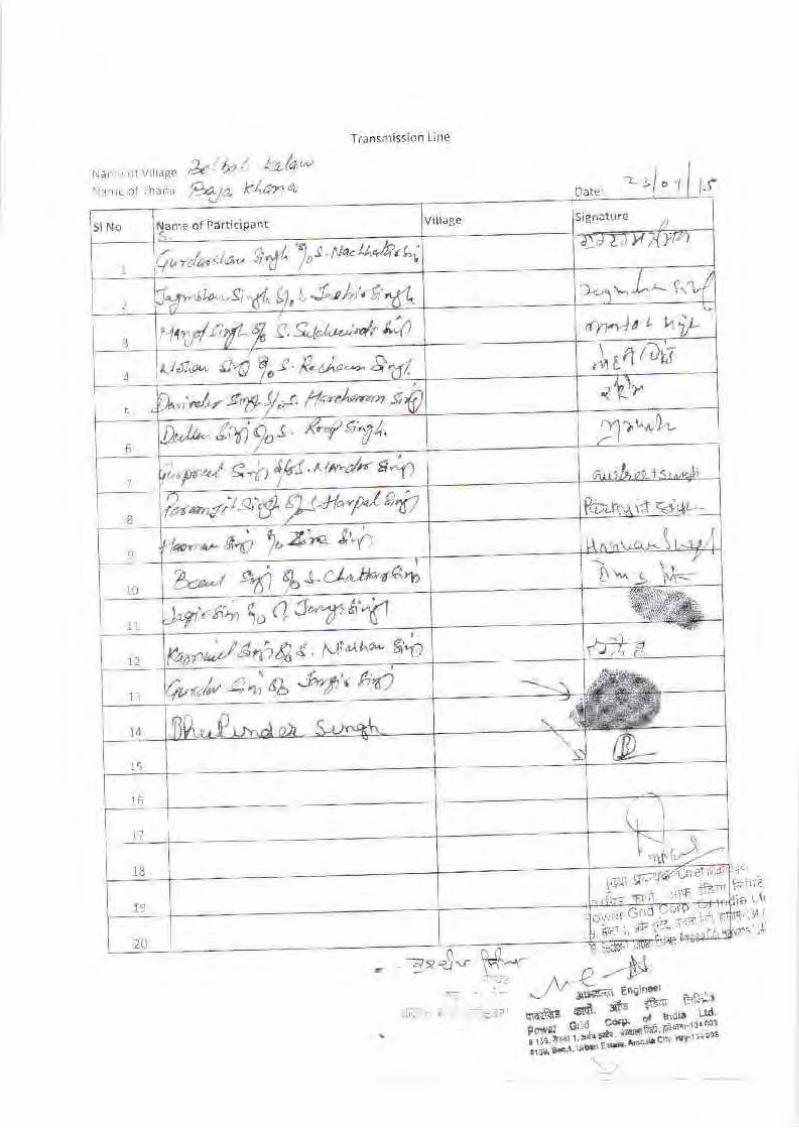
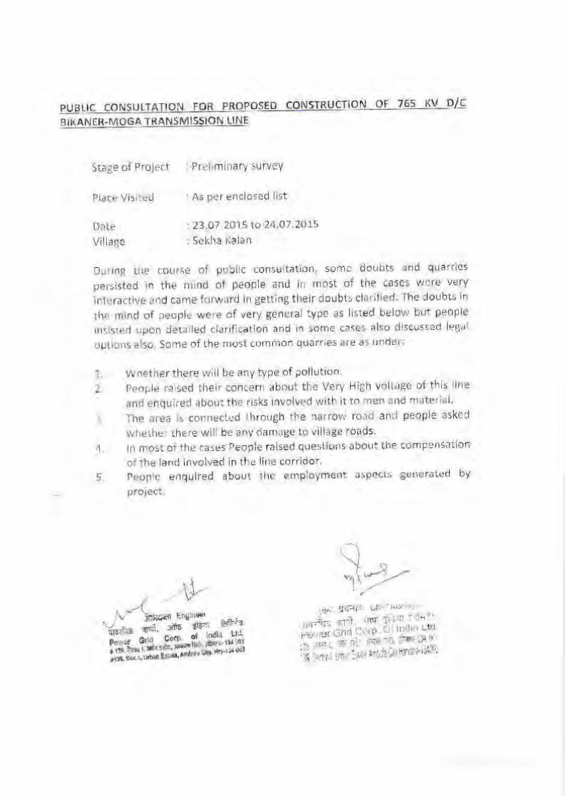
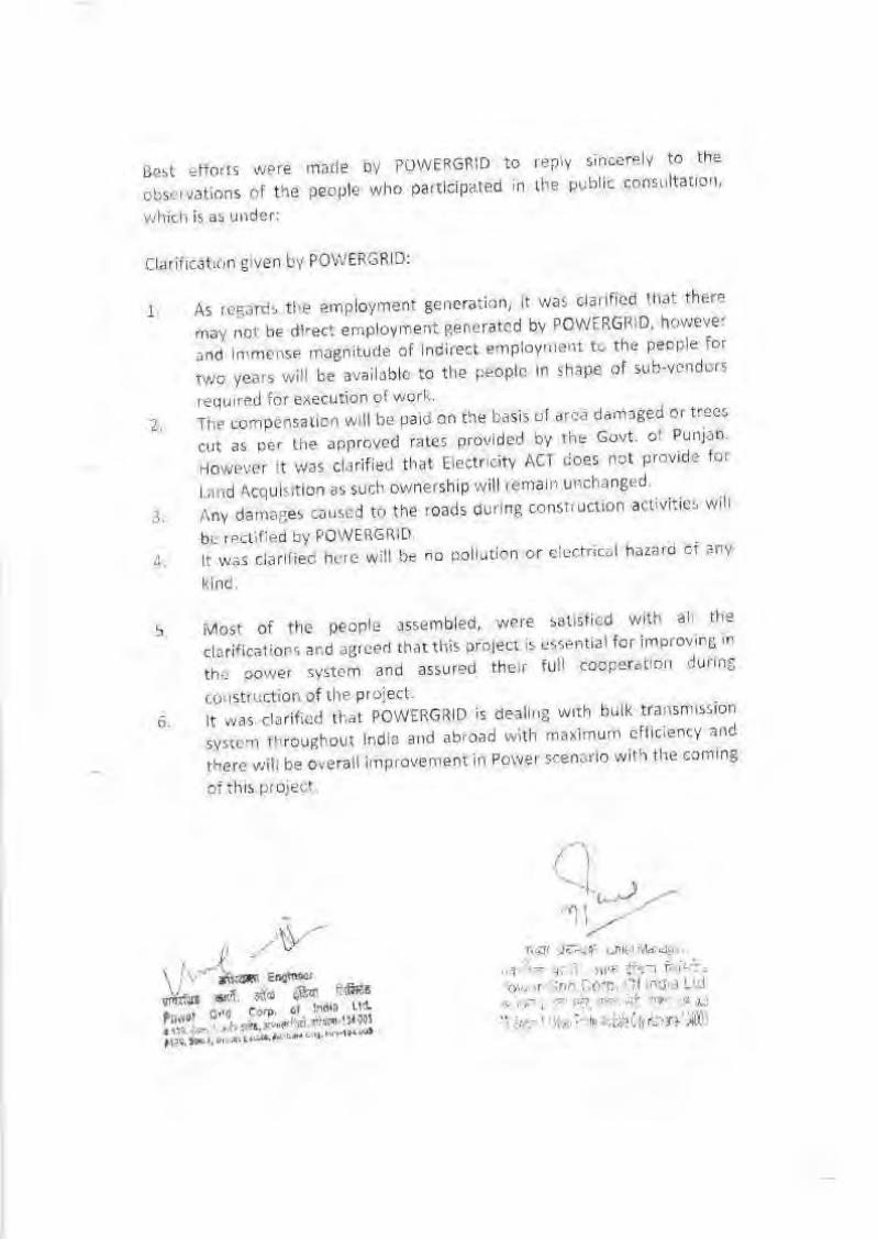
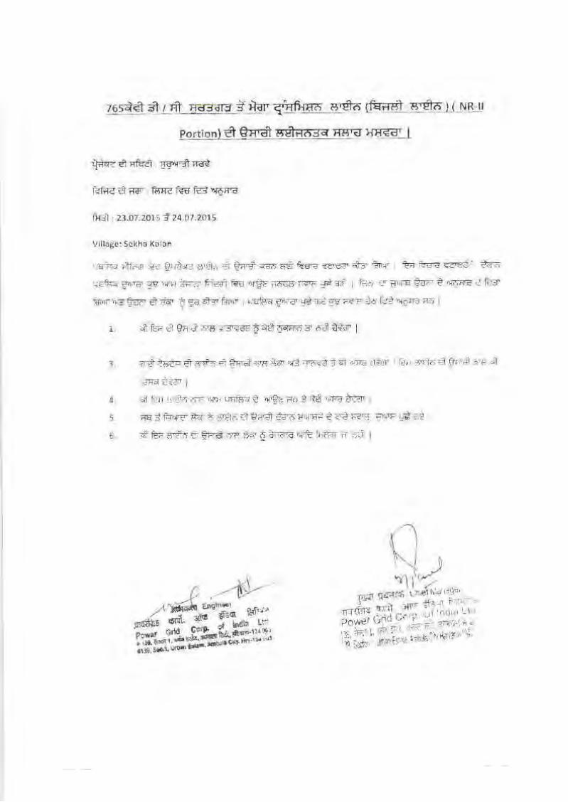
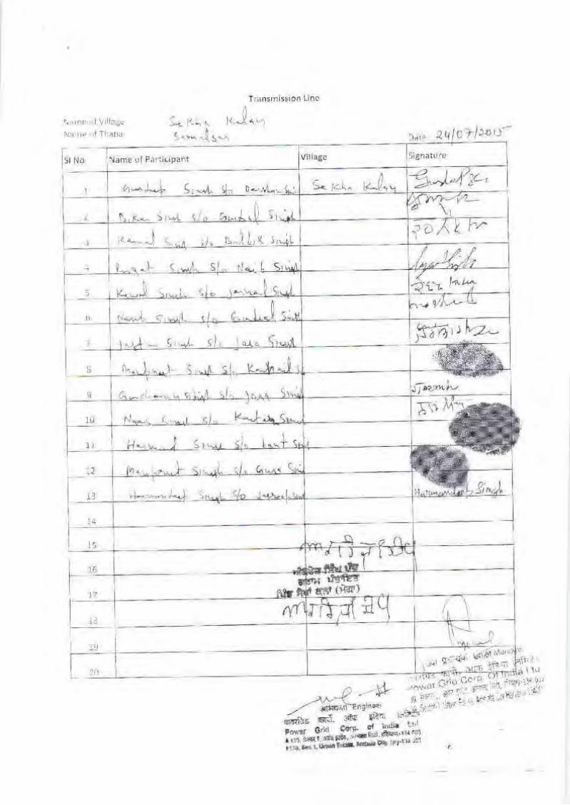
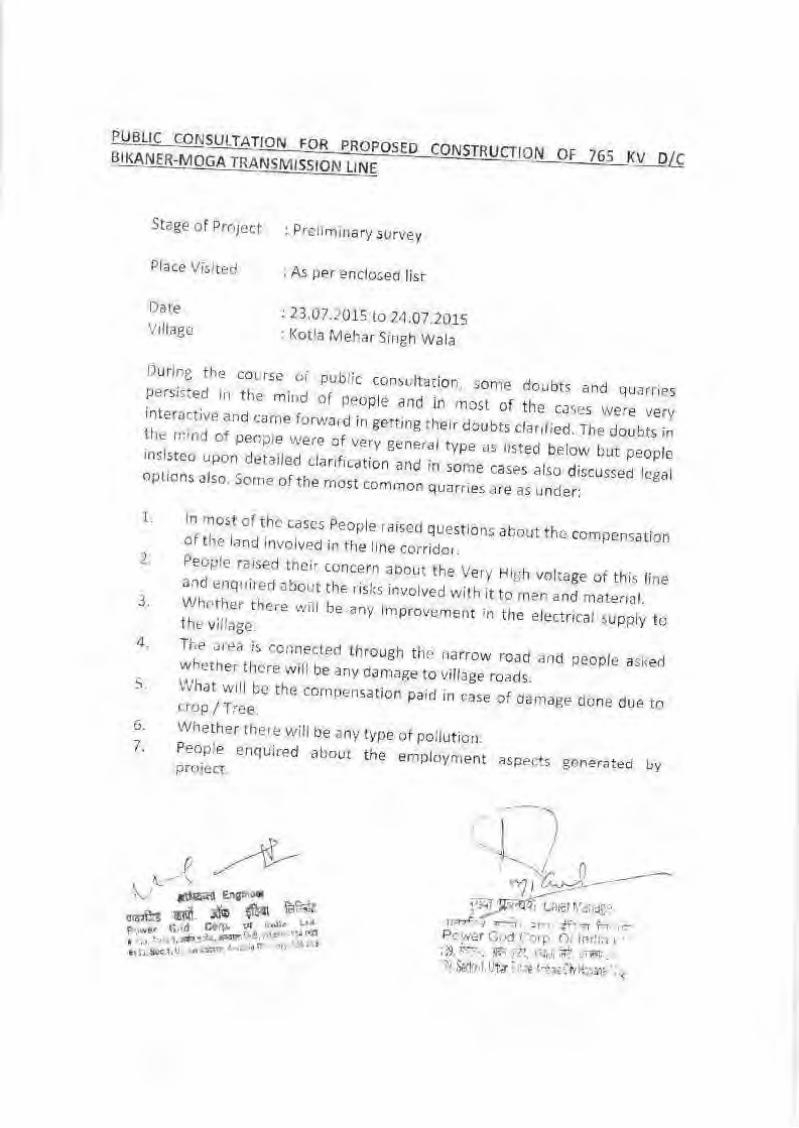
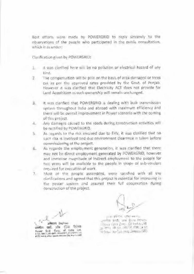
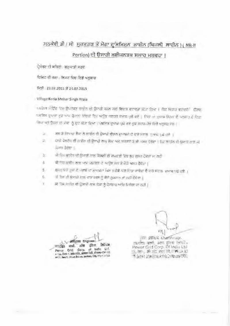
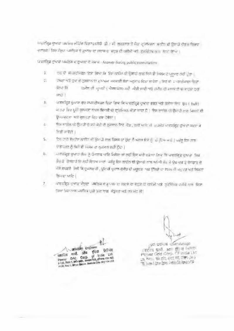
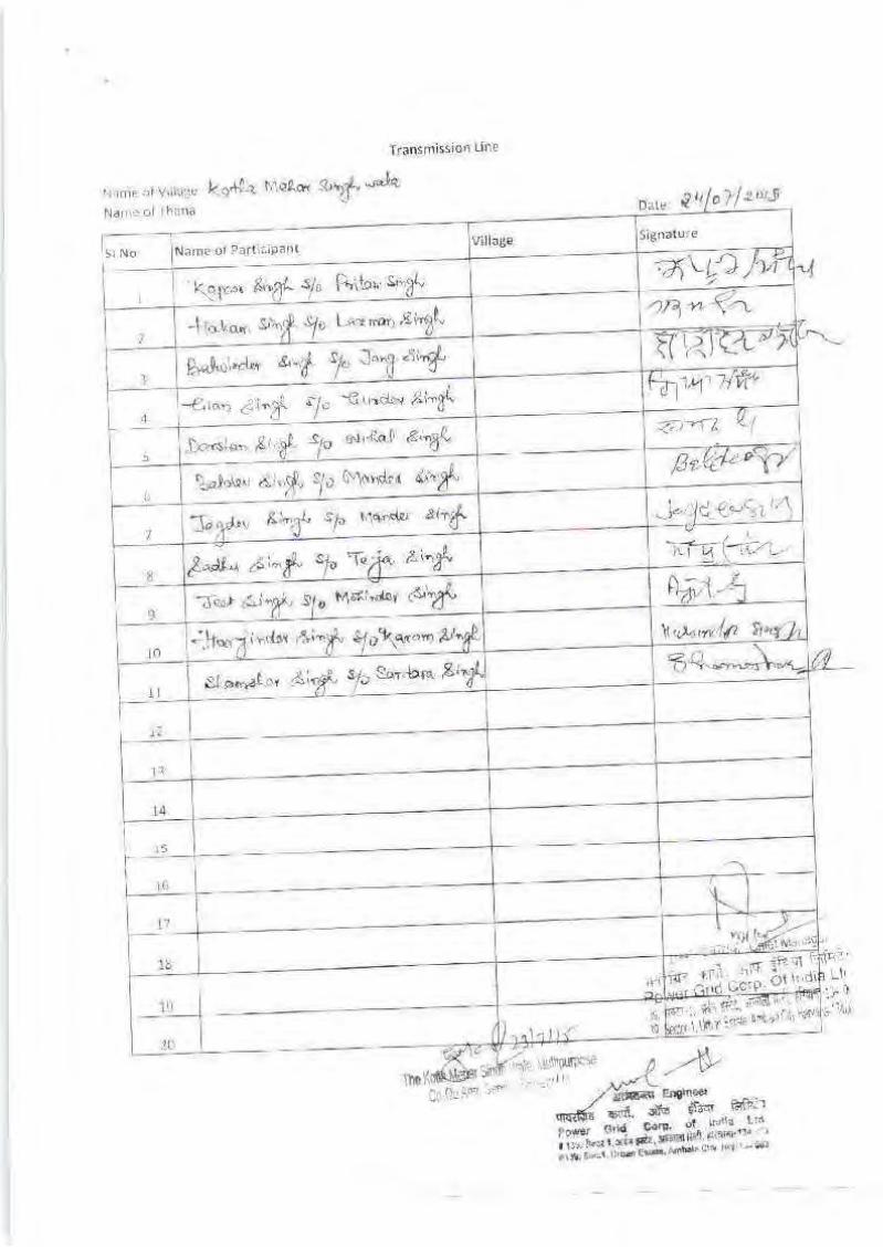
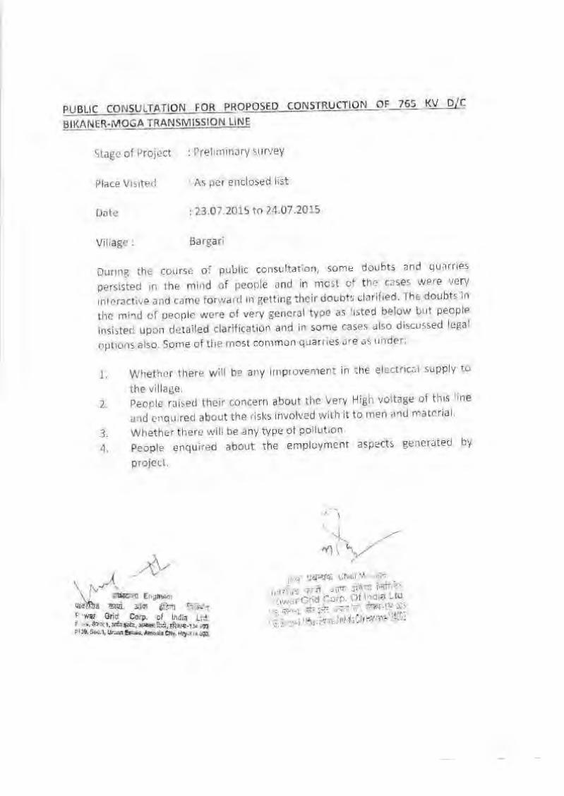
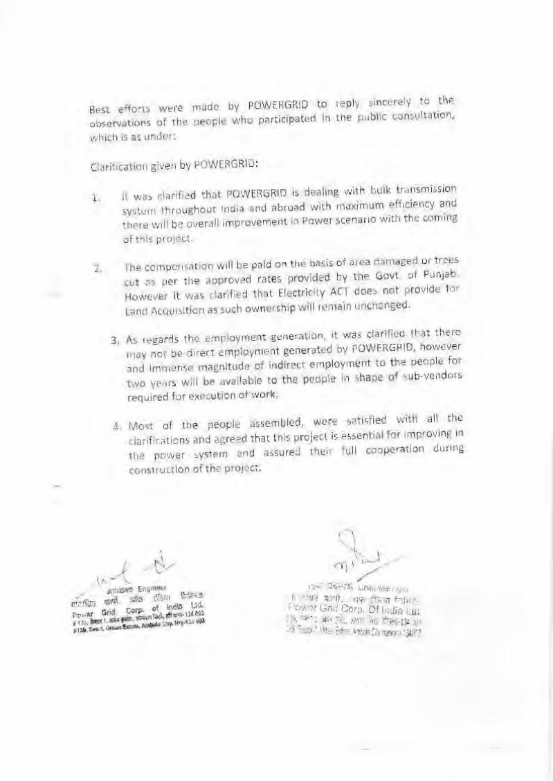
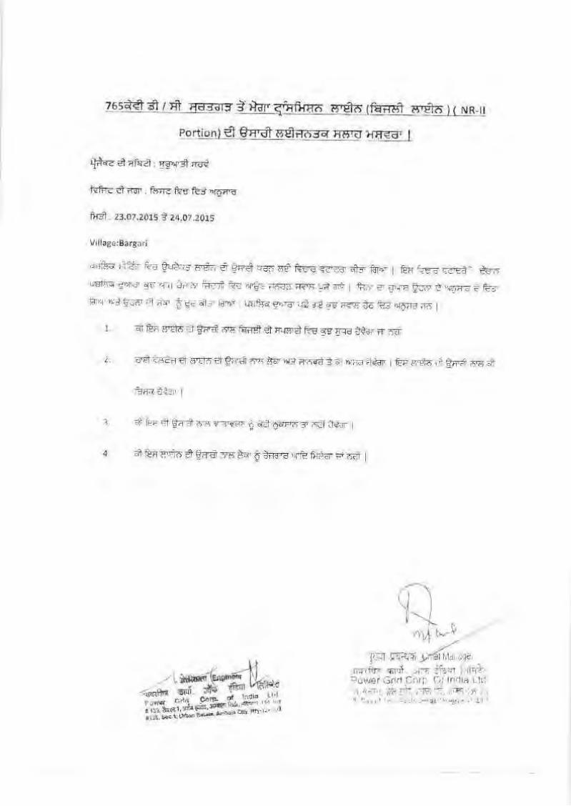
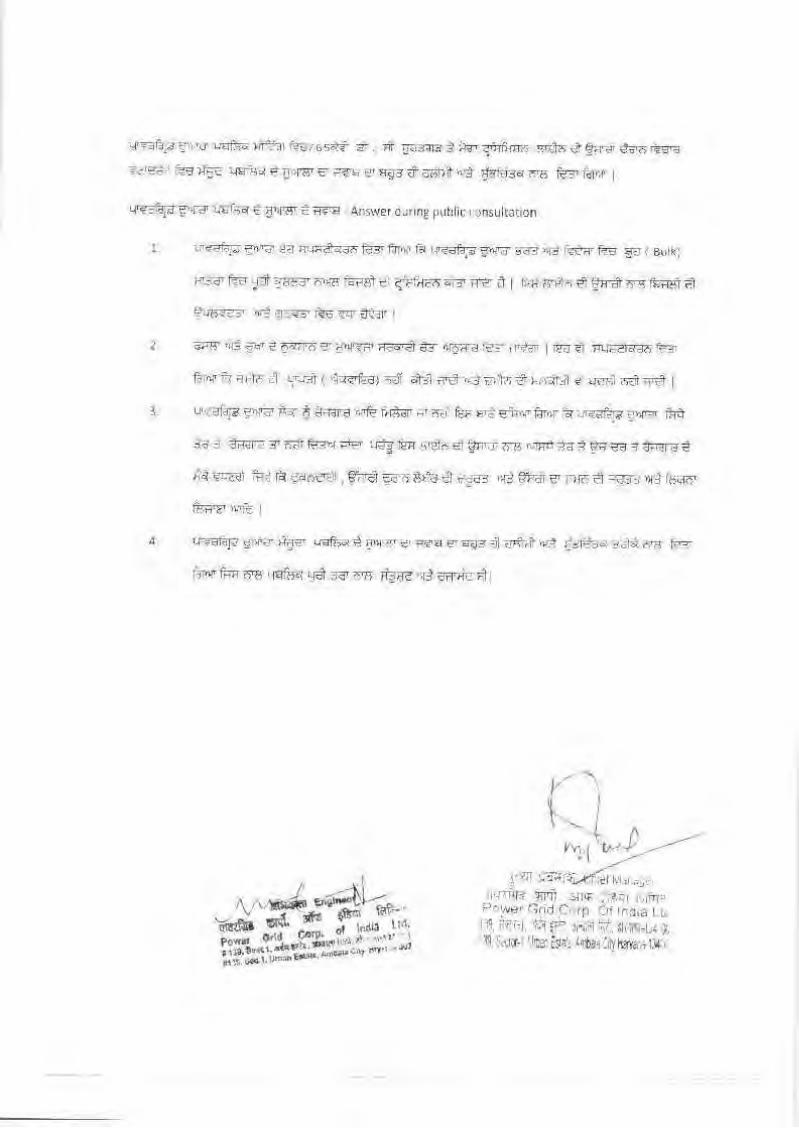
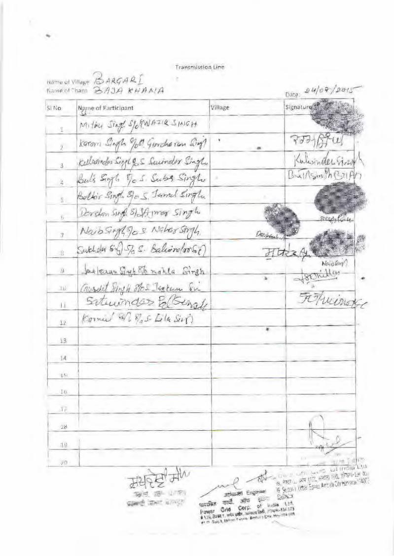
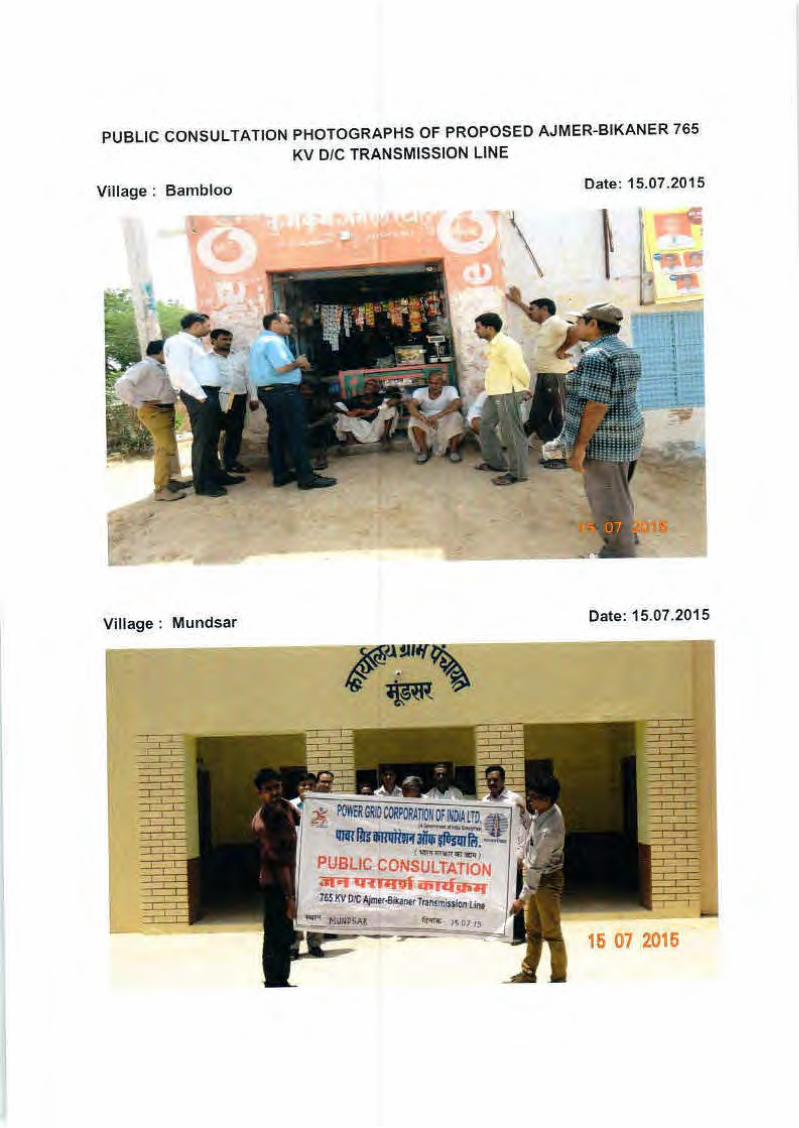
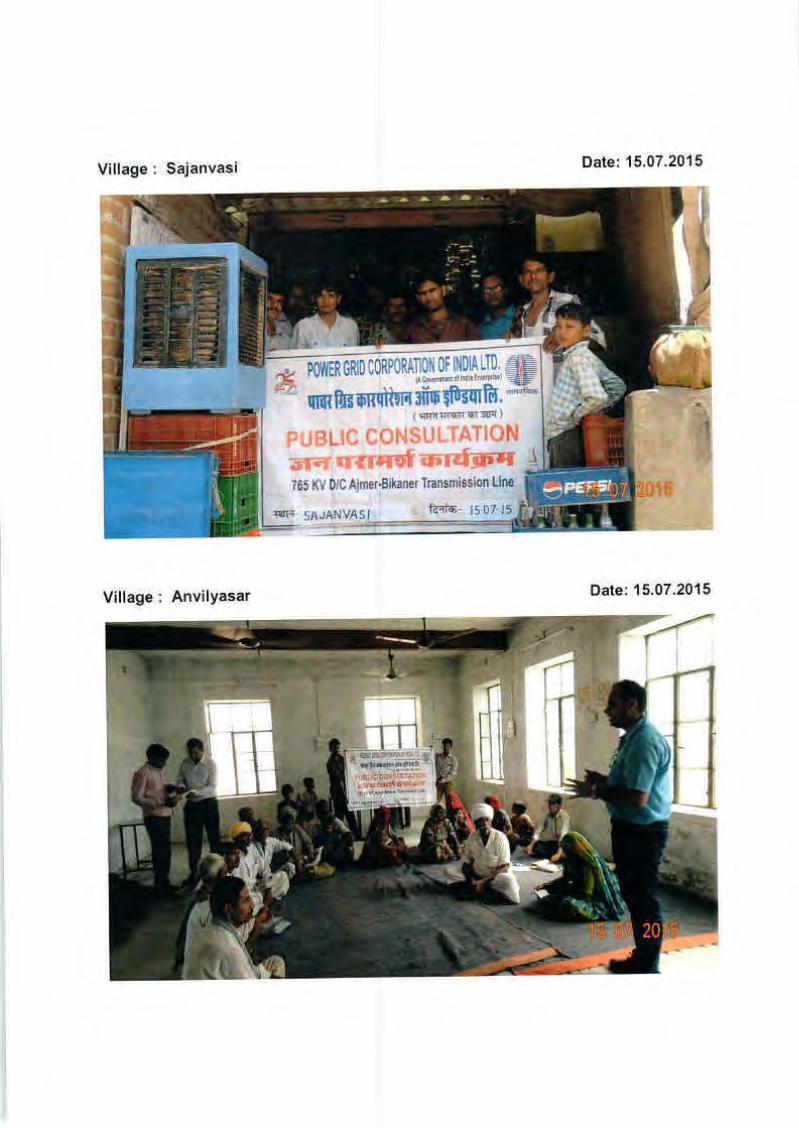
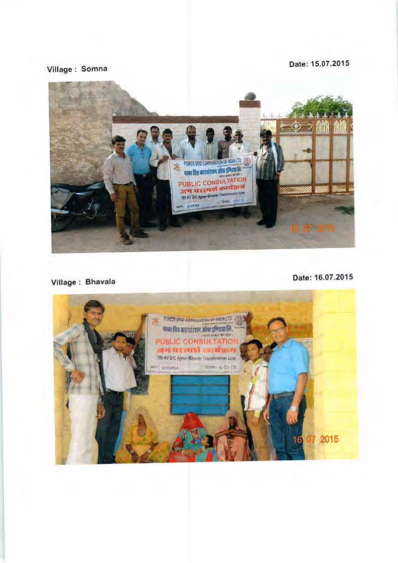
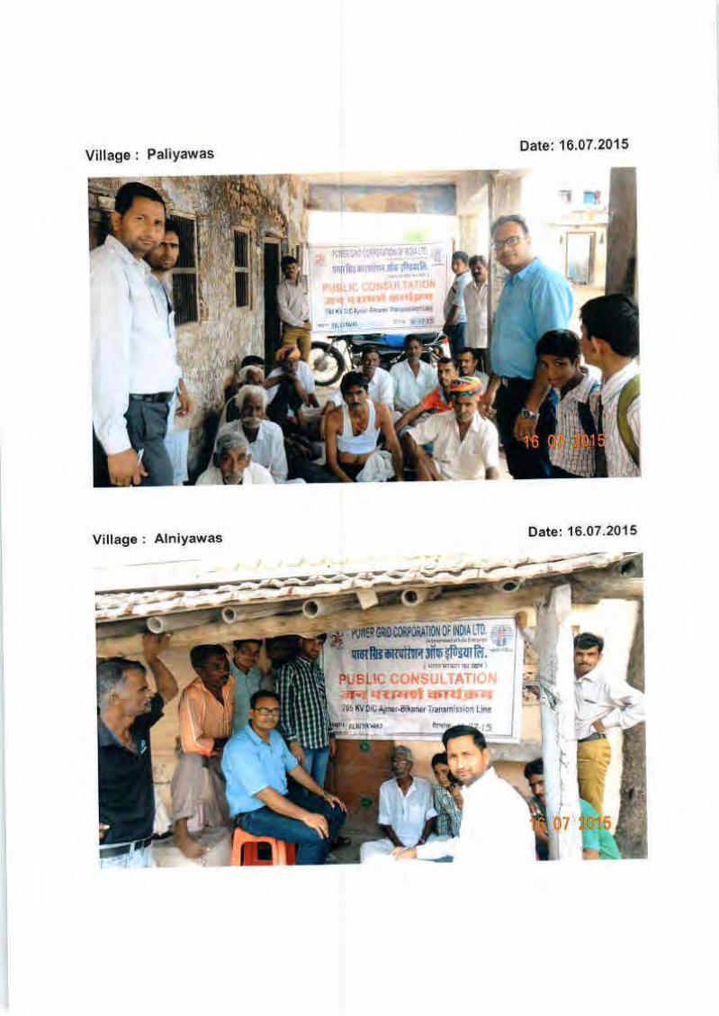
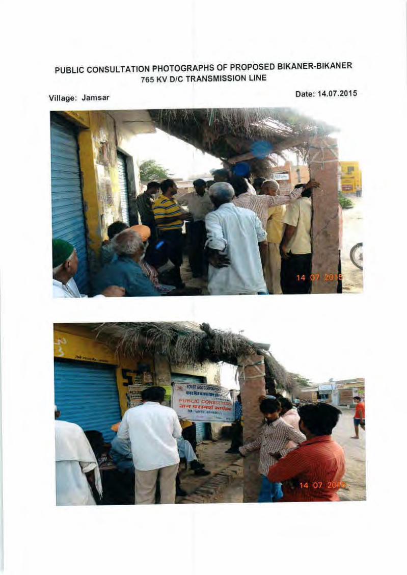
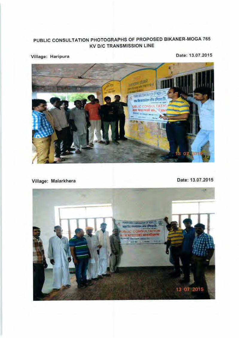
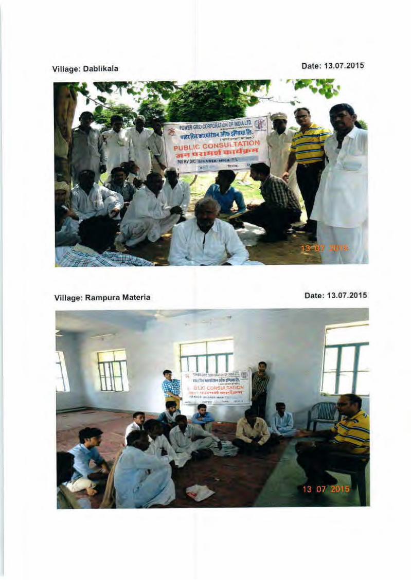
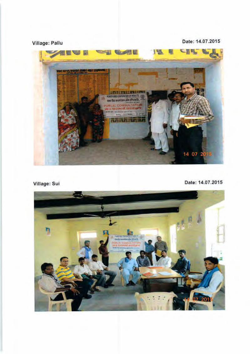
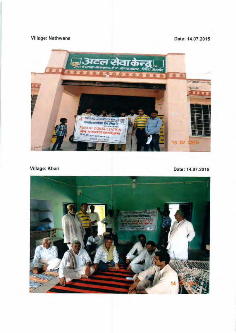
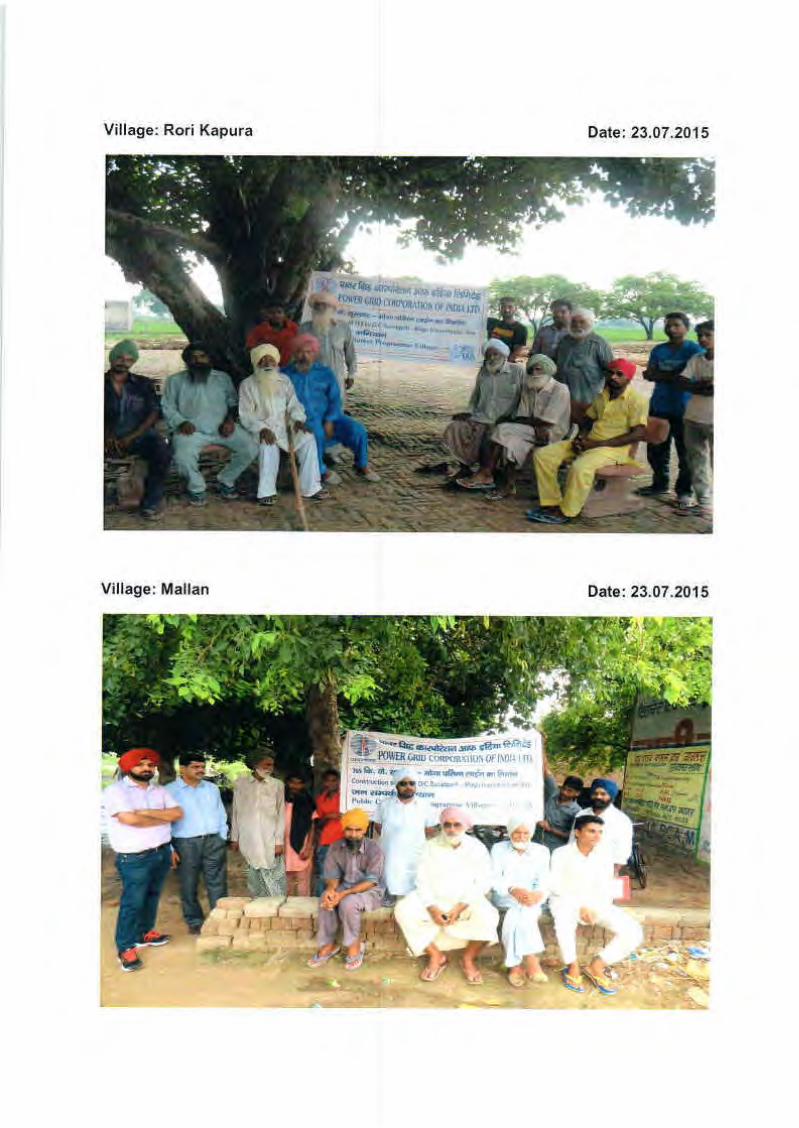
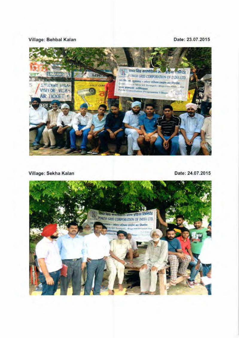
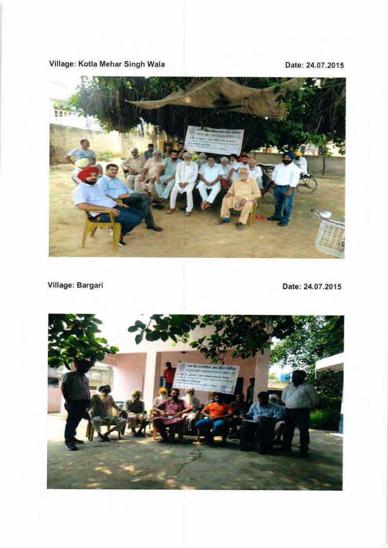
Related Documents