NORTHWESTERN UNIVERSITY Downlink Packet Scheduling and Resource Allocation for Multiuser Video Transmission Over Wireless Networks A DISSERTATION SUBMITTED TO THE GRADUATE SCHOOL IN PARTIAL FULFILLMENT OF THE REQUIREMENTS for the degree DOCTOR OF PHILOSOPHY Field of Electrical Engineering and Computer Science By Peshala V. Pahalawatta EVANSTON, ILLINOIS December 2007

Welcome message from author
This document is posted to help you gain knowledge. Please leave a comment to let me know what you think about it! Share it to your friends and learn new things together.
Transcript
NORTHWESTERN UNIVERSITY
Downlink Packet Scheduling and Resource Allocation for Multiuser Video
Transmission Over Wireless Networks
A DISSERTATION
SUBMITTED TO THE GRADUATE SCHOOL
IN PARTIAL FULFILLMENT OF THE REQUIREMENTS
for the degree
DOCTOR OF PHILOSOPHY
Field of Electrical Engineering and Computer Science
By
Peshala V. Pahalawatta
EVANSTON, ILLINOIS
December 2007

2
c© Copyright by Peshala V. Pahalawatta 2007
All Rights Reserved
3
ABSTRACT
Downlink Packet Scheduling and Resource Allocation for Multiuser Video Transmission
Over Wireless Networks
Peshala V. Pahalawatta
Video transmission over wireless networks to multiple mobile users has remained a chal-
lenging problem due to potential limitations on bandwidth and the time-varying nature of
wireless channels. Recent advances in wireless access technologies, such as, HSDPA and
IEEE 802.16, are targeted at achieving higher throughput over wireless networks. Mean-
while, advances in video compression, such as the recently developed H.264/AVC standard
as well as scalable video coding schemes aim to provide more efficient video compression as
well as increased adaptability to dynamic channel and network conditions.
This dissertation aims to benefit from the improving wireless access technologies and
video compression standards by presenting cross-layer optimized packet scheduling schemes
for the streaming of multiple pre-encoded video streams over wireless downlink packet access
networks. A gradient based scheduling scheme is presented in which user data rates are
dynamically adjusted based on channel quality as well as the gradients of a utility function.
The user utilities are designed as a function of the distortion of the received video. This
enables distortion-aware packet scheduling both within and across multiple users. In the
4
case of lossy channels with random packet losses, the utility functions are derived based on
the expected distortion of the decoded video at the receiver. The utility takes into account
decoder error concealment, an important component in deciding the received quality of the
video. Both simple and complex decoder error concealment techniques are investigated.
Simulation results show that the gradient based scheduling framework combined with
the content-aware utility functions provide a viable method for downlink packet scheduling
as it can significantly outperform current content-independent techniques. Further tests
determine the sensitivity of the system to the initial video encoding schemes, as well as to
non-real-time packet ordering techniques. Comparisons are also made between scalable and
conventional video coding techniques under the proposed schemes.
5
Acknowledgments
I would like to thank my father, Prof. P.D. Premasiri, and mother, Padma, for their
support and wisdom without which I would never have reached this far. I would also like
to thank my sisters, Vihanga and Sameerana, and of course, my entire extended family,
including my late Seeya, Aachchi, and Kotte Aachchi, who have unconditionally supported
me every step of the way. I would like to thank my wife, Kishwar Hossain, for her assistance
in every aspect of my life, including some of the “artwork” for this dissertation.
I deeply appreciate the support given to me throughout my graduate career by my ad-
visor, Prof. Aggelos Katsaggelos, as he patiently guided me towards this goal. I would also
like to thank my co-advisors, Prof. Thrasyvoulos Pappas and Prof. Randall Berry, for their
support and encouragement during this project. It has been a pleasure working with all my
advisors at Northwestern, and their perspectives and insights are reflected in every aspect
of this work. I would also like to thank Dr. Rajeev Agrawal and Hua Xu of the Network
Advanced Technology group at Motorola for their valuable advice related to the applications
of this work in industry.
I would like to thank my colleague Ehsan Maani whose collaboration resulted in the
work related to packet lossy channels in this dissertation. I greatly value the insights and
contributions resulting from the collaboration. I would like to thank my colleagues, Dr. Petar
Aleksic and Dr. Sotirios Tsaftaris, for their advice, friendship, and support as I traveled back
and forth from Champaign to complete my work. Many members, past and present, of the
6
Image and Video Processing Laboratory at Northwestern, have helped me in some manner
along the way and I thank them all for their assistance and encouragement.
I also thank Prof. Allen Taflove and Dr. Nancy Anderson for the rewarding and fulfill-
ing experience they provided me through the Residential College system at Northwestern
University. Of course, I must also thank the many students of the Lindgren and Slivka resi-
dential colleges of science and engineering for always providing me with a fresh perspective
that only an undergraduate can provide, even as I advanced deep into my graduate career.
Finally, I would like to thank the many benefactors who have helped me in the past,
from my teachers at Trinity, to my “college guidance counselor”, Mr. D.L.O. Mendis, to
my teachers and advisors at Lafayette, especially, Prof. Ismail Jouny and Prof. David
Hogenboom.
7
Table of Contents
ABSTRACT 3
Acknowledgments 5
List of Tables 9
List of Figures 10
Chapter 1. Introduction 13
1.1. Scope 13
1.2. Background 16
1.3. Contributions 25
1.4. Organization 27
Chapter 2. Packet Scheduling and Resource Allocation for Video Transmission 28
2.1. System Overview 28
2.2. A Content Aware Utility Function and Its Gradient 31
2.3. Problem Formulation 34
2.4. Solution 39
2.5. Simulation Study 40
2.6. Conclusions 56
Chapter 3. Scalable Video Encoding 57
8
3.1. Overview of Scalable Video Coding 57
3.2. Packet Scheduling with SVC 61
3.3. Simulations 66
3.4. Conclusions 72
Chapter 4. Resource Allocation in Packet Lossy Channels 74
4.1. Packet Ordering with Expected Distortion 75
4.2. Resource Allocation 77
4.3. Simulation Results 83
4.4. Conclusions 87
Chapter 5. Conclusions and Future Work 89
5.1. Summary and Conclusions 89
5.2. Future Work 90
References 96
9
List of Tables
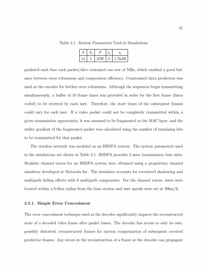
2.1 System Parameters Used in Simulations 41
2.2 Trade-off between error resilience and compression efficiency due to random I MB
insertion 53
3.1 Comparison of Ordering Methods (Total Power: P = 2.5W) 67
10
List of Figures
2.1 Overview of multiuser downlink video streaming system 29
2.2 Distortion as a function of transmitted packets for a frame from the foreman
sequence with simple error concealment. The markers indicate packet boundaries. 33
2.3 Utility function for the frame. 34
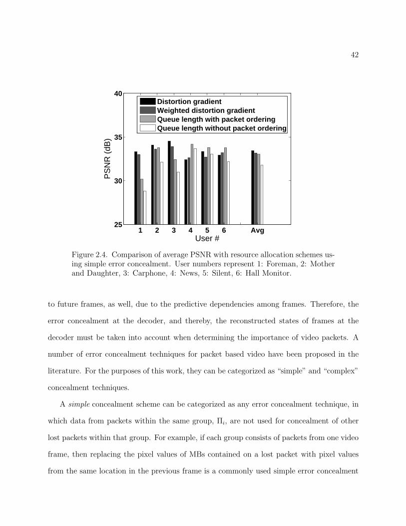
2.4 Comparison of average PSNR with resource allocation schemes using simple error
concealment. User numbers represent 1: Foreman, 2: Mother and Daughter, 3:
Carphone, 4: News, 5: Silent, 6: Hall Monitor. 42
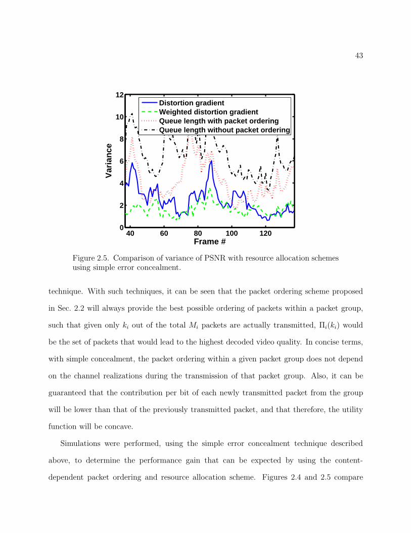
2.5 Comparison of variance of PSNR with resource allocation schemes using simple error
concealment. 43
2.6 Non-additive gain in quality due to complex concealment. Darker pixels indicate
higher gain compared to not receiving any packets from the frame. The row borders
are shown in black. (a) Packet containing MB row 5 received, (b) MB row 6 received,
(c) MB rows 5 and 6 received (Total MSE gain significantly less than the sum of (a)
and (b)) 47
2.7 User utility function after packet ordering with myopic technique for complex
concealment. The markers indicate bit boundaries for each packet. 48
2.8 Performance comparison using simple and complex error concealment techniques at
the decoder. 49
11
2.9 Comparison of average PSNR over all users and channel realizations with real-time
ordering, content-dependent offline ordering and content-independent queue length
based scheme. Higher initial quality leads to higher network congestion and more
packet losses. 51
2.10 Variance of PSNR across all users and channel realizations 51
2.11 PSNR of received video if original video is encoded with and without constrained
intra prediction. Average quality without packet losses for all sequences is close to
35dB. 54
2.12 Encoded bitrate of original video with and without constrained intra prediction. 54
2.13 PSNR of received video with varying initial bit rates corresponding to varying
quality prior to transmission losses. 55
3.1 Structure of scalable coded bitstream 58
3.2 Scalable coded bitstream with PR layers fragmented into multiple packets. 62
3.3 Distortion-bits curve for one GOP in carphone sequence using Method I. 63
3.4 Approximation of the distortion-bits curve for one GOP in carphone sequence using
Method II. 64
3.5 Packet ordering using Method III. 65
3.6 Comparison of average PSNR between distortion gradient based and maximum
throughput scheduling 69
3.7 Comparison of variance across users and channel realizations between distortion
gradient based and maximum throughput scheduling 69
12
3.8 Comparison of average received PSNR between distortion gradient based metric
and queue dependent metric; (D: Distortion-based metric, Q: Queue length-based
metric) 70
3.9 Comparison of variance of PSNR between distortion gradient based metric and
queue dependent metric. 71
3.10 Comparison of average received PSNR between scalable coded video and
H.264/AVC coded video. 72
3.11 Comparison of variance of received PSNR between scalable coded video and
H.264/AVC coded video 73
4.1 Empirical PDF of Channel SINR Given Delayed Estimate 80
4.2 Nakagami fading with order m and mean at ei 81
4.3 Average received PSNR 85
4.4 Received PSNR variance across users 86
4.5 Received PSNR variance across frames of each user’s sequence and averaged over all
users 87
4.6 Sensitivity of received quality to choice of εi when using expected distortion gradient
scheme with fixed εi. 88
4.7 Sensitivity of received quality to choice of εi when using queue length based scheme
with fixed εi 88
13
CHAPTER 1
Introduction
1.1. Scope
The anticipated popularity of mobile multimedia devices drives wireless technology to-
wards its third and fourth generation of development. Fourth generation (4G) networks
are expected to provide higher data rates, and seamless connectivity, thus enabling users
to access, store, and disseminate multimedia content without any restriction on mobility
[1]. On-Demand video and video conferencing over mobile devices are among the many
potential applications that stand to gain from the high data rates offered by such emerging
wireless networks. The eventual success of such applications depends on the efficient man-
agement of system resources such as transmission power, bandwidth, and even time, in the
case of scheduling of packets with attached delay constraints. To be efficient, the resource
allocation schemes must also take into account the time-varying, and error-prone nature of
wireless channels in a mobile environment, as well as the heterogeneous requirements of the
transmitted multimedia content.
Any wireless video streaming system is composed of three high-level components. They
are: 1) the server, which is either a media server that contains a collection of pre-encoded
video sequences that can be requested by its clients, or a device that acquires video in real-
time, compresses it, and then transmits the compressed video to its clients over the network;
2) the scheduler, which allocates the channel resources to be used for data transmission and
14
schedules the video packets; and 3) the clients that receive the data. It is becoming increas-
ingly apparent that efficient video streaming schemes will require the consideration, and
possibly the joint adaptation of source parameters, such as coding modes for macroblocks,
at the encoder or server, and network and channel parameters, such as packet transmission
schedules, and channel bandwidth allocations, at the scheduler, while also being aware of
the video decoding and error resilience schemes employed at the receiving client [2, 3, 4, 5].
Jointly adapting such parameters, controls the allocation of the available resources across
the multiple OSI network layers, from the application layer down to the physical layer. This
dissertation introduces a cross layer resource allocation and packet scheduling scheme for
multiuser video streaming over a downlink shared wireless channel. The work focuses on
the real-time transmission of pre-encoded media where each user may be receiving a differ-
ent video sequence with different characteristics from that of the other users. The resource
allocation scheme takes into account the differences in video content, the concealability of
errors in the video at the receiver, as well as the channel quality of each user. Furthermore,
the video packets in the transmission buffer of each user are scheduled such that packets of
greater importance will be given higher priority.
One of the key elements discussed in this work is that of error concealment at the decoder.
Effective error concealment techniques have been developed in the video coding community
to alleviate the ill-effects of losing individual slices of a video frame. They usually depend
on utilizing the spatial and temporal correlations that exist between packets in compressed
video [6, 7]. The exploitation of such correlations, however, introduces dependencies among
otherwise independently decodable packets. Therefore, such dependencies must be taken
into account in the packet scheduling scheme. The scheduling technique in this dissertation
15
assumes that the error concealment scheme used at the decoder is known and taken into
account at the scheduler.
A major challenge in packet scheduling for real-time video transmission is the complexity
involved in computing the packet priorities. The challenge is further magnified when error
concealment is taken into account and the quality of service is measured in terms of the actual
video quality rather than a content-independent metric such as packet loss rate. Schemes
that compute video quality over multiple transmissions and packet loss realizations can be
intractable due to the amount of computation required. Therefore the schemes discussed in
this dissertation aim to limit computational complexity by reducing the required computation
to only first order changes in video quality. In addition, techniques are shown that allow
the first order changes to be calculated offline at the encoder, and signaled to the scheduler,
thus significantly reducing the required computation at the scheduler.
This work also explores the use of scalable video coding techniques for application and
channel dependent packet scheduling and resource allocation. Scalable video coding offers
some natural advantages in terms of packet scheduling by limiting the dependencies between
packets and thereby limiting the possibility of error propagation from dropped packets. This
work explores some of the natural advantages to be had, and some pitfalls to be avoided, when
using scalable coded video in conjunction with the proposed content-dependent scheduling
and resource allocation. Also the performance of scalable coded video is compared to that
of conventionally coded non-scalable video under varying channel conditions in order to
determine the benefits of using the technique.
Whereas most of the proposed work is formulated under the assumption that perfect
channel quality feedback is available at the scheduler, this dissertation also explores the
challenges caused due to the availability of only delayed channel feedback. In that case,
16
since the exact channel conditions are not known, random packet losses can occur in the
channel, and the exact quality of the reconstructed video at the decoder cannot be known
at the scheduler. Work in this area has relied on calculating the expected distortion of the
video at the decoder where the expectation is found with respect to the probability of loss
of the transmitted packets [8, 9, 5, 10]. First order changes in the expected distortion are
calculated in this work, to utilize a two-step strategy for scheduling and resource allocation
in a wireless shared channel with random packet losses.
1.2. Background
1.2.1. Advancements in Wireless Access Technology
Since the inception of the digital cellular age with the introduction of the first GSM (Global
System for Mobile communications) networks in Europe in 1991, there has been a rapid
growth of interest in providing high speed data to mobile users over wireless networks. The
main demand for high speed data comes from the need to supply multimedia content to
mobile users. Multimedia content, and especially video, requires data rates in the order of
a few hundred kilobits per second (kbps) in order to be of sufficient quality to be useful. In
keeping with the rising demand for multimedia data transmission over wireless networks, the
world’s telecommunications bodies have also understood that the success of GSM lay at least
partly in the effort to standardize the mobile communication platforms across regional and
international boundaries. Thus, in 1996, the UMTS (Universal Mobile Telecommunications
System) Forum was established in order to introduce a new generation of wireless digital
communication standards that would lead to higher data rates, and ultimately, to multimedia
communications. The HSDPA (High Speed Downlink Packet Access) standard, [11] is the
latest standard to arise out of this effort.
17
The main features of HSDPA that differentiate it from its predecessors are the use of
Wideband Code Division Multiple Access (WCDMA)[12] for channel sharing over multiple
users combined with Time Division Multiplexing (TDM) with 2msec time slots, and packet-
switched data transmission. These features along with the very high achievable throughput
make HSDPA a very attractive standard for mobile multimedia communication and espe-
cially for video streaming applications.
One important characteristic that allows for greater efficiency in HSDPA is the ability to
obtain channel quality feedback at 2msec intervals and to dynamically optimize the resource
allocation decisions at a faster rate than previous standards. Faster adaptation to feedback
is achieved by placing the MAC scheduler at the base station node and thereby reducing the
feedback delay to the scheduler [13].
In addition to HSDPA, IEEE 802.16 (WiMAX) [14, 15] is another standard that promises
to achieve significantly high data rates over wireless networks. IEEE 802.16 uses OFDMA
(Orthogonal Frequency Division Multiple Access) instead of CDMA for bandwidth allo-
cation. Some advantages of using OFDMA are that it allows for finer granularity in the
bandwidth allocation, it offers the potential to tackle frequency selective channel fading,
and it is easily scalable to the available bandwidth of the system [16]. In terms of allowing
adaptive modulation and coding, and fast and frequent channel feedback, IEEE 802.16 is
comparable to HSDPA, and therefore, the scheduling methods mentioned in this work can
be adapted to both types of systems.
1.2.2. Scheduling and Resource Allocation in Wireless Networks
A number of cross-layer scheduling and resource allocation methods have been proposed
that exploit the time-varying nature of the wireless channel to maximize the throughput of
18
the network. These methods rely on the multi-user diversity gain achieved by selectively
allocating a majority of the available resources to users with good channel quality who
can support higher data rates [17, 18]. While achieving high overall throughput, fairness
across users must also be maintained in order to ensure that each user receives a reasonable
quality of service. A number of schemes, which attempt to achieve such a balance can be
found in [19, 20, 21, 22, 23, 24]. In [19], a fluid fair queueing model [25] is adapted
to use with packet based data transmission and time varying wireless channels. The main
purpose of the algorithm discussed in [19] is to readjust the service granted to each user
at each transmission time window in order to ensure that users that were backlogged due
to bad channel conditions will be given a greater share of the resources when their channel
conditions improve. In [20], an Exponential Rule, is used where the priority of each user
at each transmission time slot is determined as a function of the user’s queue length and
achievable data rate (which is a function of the channel state). A single user is allowed to
transmit at each time slot. [20] analyzes the stability of such a rule in terms of maintaining
quality of service and reducing delay. [21] discusses an algorithm that provides provable
short-term fairness guarantees. Many of these opportunistic scheduling methods can be
generalized as gradient-based scheduling policies [26, 27]. Gradient-based policies define a
user utility as a function of some quality of service measure, such as throughput, and then
maximize a weighted sum of the users’ data rates where the weights are determined by the
gradient of the utility function. For example, choosing the weights to be the reciprocals
of the long term average throughput of each user, leads to a proportionally fair scheduling
scheme [23]. Similarly, choosing the weights based on the delay of the head-of-line packet
of each user’s transmission queue leads to a delay-sensitive scheduling scheme [24]. A key
characteristic of gradient based policies is that they rely on the instantaneous channel states
19
of each user in order to determine the resource allocations and do not assume any knowledge
of the channel state distributions. In these policies, during each time-slot, the transmitter
maximizes the weighted sum of each user’s rate, where the (time-varying) weights are given
by the gradient of a specified utility function. One attractive feature of such policies is that
they require only myopic decisions, and hence, presume no knowledge of long-term channel
or traffic distributions.
1.2.3. Video Compression Standards
While wireless data transmission standards have evolved towards providing greater through-
put, the video coding community has also been in the process of evolving video coding
standards in order to achieve higher compression rates while providing high quality video.
Almost all the widely accepted standards, including the successful MPEG 2 standard, use
a block based hybrid motion compensated strategy for video encoding which allows spatial
and temporal correlations in the video data to be exploited with limited computational com-
plexity. This is done by temporally predicting image blocks from previously coded blocks
in the video sequence, and transform coding the residual remaining after the prediction.
Although the MPEG 2 standard [28], originally developed for digital television broadcasts,
has remained a versatile standard due to its capacity to adapt to various applications and re-
quirements, methods to improve compression efficiency and error resilience in video encoding
have evolved significantly since its inception.
The latest standard to be specified through the effort to improve video encoding is that of
H.264/AVC (Advanced Video Coding) [29]. The H.264/AVC standard, [30], first announced
in 2002, is a collaborative effort of the International Telecommunication Union (ITU), the
International Electrotechnical Commission (IEC) and the International Organization for
20
Standardization (ISO). This standard possesses multiple features that enable greater video
compression rates while also introducing methods to improve the error resilience of trans-
mitted data [31].
Some of the key features in H.264/AVC that lead towards greater compression efficiency
and are also important to aspects of this work are briefly described below. More detailed
explanations of each of these features can be found in [29].
• Variable Block Sizes for Motion Compensation: In H.264, inter (P) coded mac-
roblocks (16x16 pel) can be partitioned into smaller blocks for the purposes of mo-
tion compensation. Then, each smaller block can be assigned a motion vector and
reference picture. The smallest block size allowed is one containing 4x4 pixels, and
therefore, each P coded macroblock can potentially contain up to 16 motion vectors.
This feature enables more localized motion prediction and enables better exploita-
tion of the temporal redundancies in the sequence during compression. This can
also be an important feature when combined with temporal error concealment tech-
niques that use the motion vectors of neighboring macroblocks to estimate motion
vector of a lost macroblock. Since, each macroblock can contain up to 16 motion
vectors, more flexibility is available in choosing a candidate concealment motion
vector for a lost macroblock.
• Quarter Pixel Motion Estimation: The accuracy of motion estimation in H.264
is improved to quarter pixel resolution for the luminance component of the video
signal. This is achieved by using a 6 tap FIR filter horizontally and vertically on the
reference image prior to motion estimation in order to obtain the half pixel values,
and then averaging the integer and half pixel values in order to estimate the pixel
intensities at the quarter pixel locations. The chroma component is obtained using
21
bilinear interpolation. This allows for greater accuracy in motion compensation,
and therefore, greater compression efficiency [32].
• In-Loop Deblocking Filter: Block based motion compensated video coding tech-
niques suffer from visible compression artifacts at the block boundaries since the
accuracy of reconstruction of pixels at the block boundaries is less than that of pix-
els towards the center of the block. In order to reduce such compression artifacts,
H.264 uses an adaptive deblocking filter which is located within the hybrid motion
compensation loop. In-loop refers to the fact that the deblocking filter is applied
to each image prior to using the image as a reference for prediction of subsequent
images in the sequence. The deblocking filter is adaptively applied in order to en-
sure that natural edges in the image will not be smoothed in the process. Overall,
the deblocking filter also improves compression efficiency, since it generates a more
accurate reference frame that can be used for motion compensation of subsequent
frames [33].
• Intra Spatial Prediction: Another compression feature of H.264/AVC is that it uses
spatial prediction from neighboring macroblocks for the encoding of intra (I) mac-
roblocks. Pixel values from the macroblock directly to the left, and the one directly
above the currently coded I macroblock are used to interpolate the predicted pixel
values of the current I macroblock. Then, only the residual signal needs to be trans-
form coded. While this form of prediction achieves greater compression efficiency,
it can lead to error propagation if the spatially neighboring macroblocks are inter
coded and use unreliable reference blocks for motion compensation. Therefore, in
packet lossy channels, a constrained intra prediction mode, which stipulates that
22
only pixels from other intra coded macroblocks can be used for intra spatial predic-
tion must be employed at the encoder [31].
• Prediction from B Frames: Unlike in previous video compression standards, H.264
allows for motion compensation of bi-predictive (B) frames from previously encoded
B frames in the sequence. In addition to greater compression efficiency, this also
enables temporal scalability through hierarchical bi-prediction, which is a useful
feature for scalable video coding [34].
In addition to the improvements in compression noted above, H.264 also offers improve-
ments in terms of robustness to error, which are important to consider in the context of
wireless video streaming. Some of the more important error resilience features that are
useful for this work are briefly described below.
• Parameter Set Structure: The parameter sets in H.264/AVC contain information
that rarely needs refreshing during the decoding of the video sequence. A sequence
parameter set contains information that applies to a sequence of coded pictures and
a picture parameter set contains information that applies to one or more pictures
within the sequence. The parameter sets are encapsulated in separate NAL (Net-
work Abstraction Layer) units than the VCL (Video Coding Layer) data. Each VCL
NAL unit can refer to a parameter set using the set’s id, and therefore, multiple
VCL NAL units can use the same parameter set.
• Flexible Slice Size: H.264 allows for flexible slice sizes, where the slices can contain
any number of macroblocks in a picture. This is an important feature since some
compression features such as predictive encoding of motion vectors and DCT coef-
ficients cannot be used across slice boundaries. Therefore, larger slice sizes lead to

23
more efficient compression although smaller packet sizes allow greater flexibility in
error concealment and loss protection.
• Arbitrary Slice Ordering: Each slice of a coded picture can be decoded independently
of all other slices in the picture. Therefore, it should be possible for slices to be
transmitted out of order, and yet be handled appropriately by an H.264 decoder.
This is an important feature that is used extensively within this dissertation for
prioritization of packets within the MAC layer transmission buffer.
• Data Partitioning: Some information such as macroblock types and motion vectors
can be significantly more important for the purposes of generating a good quality
decoded picture than others. Therefore, H.264 allows for data partitioning that will
ensure that the more important data will be transmitted with higher priority. While
this feature is not directly applied in this work, the prioritization methods discussed
here can be easily generalized to the case of data partitioned sequences, as well.
Another important advancement in video compression standards has been that of im-
proving the ability to develop scalable video bitstreams that offer progressive refinement of
video quality by dynamically adapting the source rates to changing network and channel con-
ditions. In the emerging scalable extension to the H.264 video coding standard, hierarchical
bi-prediction (which is enabled by the ability in H.264 to predict from other B frames) or a
wavelet based motion compensated temporal filtering method is used for progressive refine-
ment of temporal resolution [35, 36, 37]. Quality (SNR) scalability of a given video frame
can be obtained using a fine granularity scalability technique in which the transform coef-
ficients of macroblocks are bit plane coded to obtain progressively finer resolution (smaller
quantization step sizes) [38, 39]. Further details on the particular scalable video coding
techniques investigated in this work are presented in Chapter 3.
24
1.2.4. Video Streaming Over Packet Access Networks
A wealth of work exists on video streaming in general, and on video streaming over wireless
networks, in particular. One area, which has received significant attention has been that of
optimal real-time video encoding, where the source content and channel model are jointly
considered in determining the optimal source encoding modes [40, 8, 41, 42, 43, 44]. A
thorough review of the existing approaches to joint source channel coding for video streaming
can be found in [5]. The focus in this work, however, is on downlink video streaming where
the media server is at a different location from the wireless base station, and the video
encoding cannot be adapted to changes in the channel. Packet scheduling for the streaming
of pre-encoded video is also a well-studied topic [45, 46, 47], where the focus has been on
generating resource-distortion optimized strategies for transmission and retransmission of a
pre-encoded sequence of video packets under lossy network conditions. The above methods,
however, consider point-to-point streaming systems where a video sequence is streamed to a
single client.
Packet scheduling for video streaming over wireless networks to multiple clients has con-
ventionally focused on satisfying the delay constraint requirements inherent to the system.
Examples of such work are [48, 49] and [50]. In these methods, the quality of service of the
received video is measured only in terms of the packet delay, or packet loss rate.
Methods that do consider the media content can be found in [51, 52, 53]. In [51],
a heuristic approach is used to determine the importance of frames across users based on
the frame types (I, P, or B), or their positions in a group of pictures. In [52], a concept
of incrementally additive distortion among video packets, introduced in [45], is used to
determine the importance of video packets for each user. Scheduling across users, however,
25
is performed using conventional, content-independent techniques. In [53], the priority across
users is determined as a combination of a content-aware importance measure similar to that
in [52], and the delay of the Head Of Line (HOL) packet for each user. At each time slot,
all the resources are dedicated to the user with the highest priority. It is important to note,
however, that factors such as per user resource constraints or lack of available data, can
make it advantageous to transmit to multiple users at the same time.
Multiuser streaming of scalable video has been considered in [54]. In [54], temporal
scalability, in the form of hierarchical Bi-prediction [55], and SNR scalability, in the form
of progressive refinement through fine granularity scalability (FGS) [38], is considered. A
simple packet dropping strategy is used for buffer management and a maximum throughput
scheduling strategy is used at the air interface.
1.3. Contributions
This work focuses on devising resource allocation strategies for the real-time transmission
of pre-encoded video sequences to multiple users over TDM/CDMA, TDM/OFDMA type
wireless networks in which the resources allocated to each user can be adapted at each
transmission opportunity. The work utilizes some of the new features of emerging wireless
standards as well as improvements in video compression standards in order to devise content-
dependent video packet scheduling and resource allocation strategies for multiuser video
communication. The ability to transmit streaming video content to multiple users could
potentially enable users to view news telecasts, streamed sports telecasts, etc, at high quality
on demand, from media content servers, through their mobile devices. Another motivation
for considering video streaming systems is that the drive by consumers to demand smaller
mobile phones essentially limits the capacity of phones to buffer large amounts of data. Other
26
considerations such as copyrights on the content may also prompt media content servers to
require video streaming systems.
The main contributions of this work lie in the video packet prioritization strategies and
distortion based resource allocation strategies that will enable the transmission of video
packets over wireless networks to multiple mobile users where the achievable data rates
may not be sufficient for the transmission of the complete coded bitstreams. The resource
allocation scheme departs from the schemes discussed in Sec. 1.2.4 in that it is performed
at each transmission time slot based only on the instantaneous channel fading states of
each user. A content-based utility function is proposed in which the gradients of the utility
function can be used in conjunction with the gradient-based scheduling schemes proposed
in [26]. The method orders the encoded video packets by their relative contribution to the
final quality of the video, and assigns a utility for each packet, which can then be used by
the gradient-based scheduling scheme to allocate resources across users.
Decoder error concealment, which can significantly affect the importance of video packets,
is explicitly taken into account in the formulation, and the effect of dependencies introduced
between video packets as a result of decoder error concealment is also considered.
Packet prioritization schemes for scalable coded video are also considered and methods
are proposed that determine the packet prioritization strategy such that the distortion based
utility functions obtained after prioritization are amenable to the gradient-based resource
allocation strategies proposed in this work.
In the case when packet losses in the channel are random due to channel fading, the
proposed scheme is generalized to use the expected distortions calculated at the transmitter
where the expectation is calculated with regard to the packet loss probabilities in the channel.
27
1.4. Organization
The next chapter provides the general formulation for gradient based scheduling and
resource allocation using a content-dependent utility function. The scheme is compared to
a conventional content-independent technique, and also the performance of the scheme is
demonstrated for the case when simple and complex error concealment techniques are used
at the decoder. Other important aspects of the problem such as error resilient encoding
methods and real time versus offline packet scheduling schemes are also discussed in the
chapter.
Chapter 3 extends the algorithms presented in Chapter 2 to scalable video encoding
schemes. Packet prioritization schemes that perform well in conjunction with the gradi-
ent based resource allocation framework are presented, and again, comparisons are made
between content dependent and content-independent scheduling. The scalable schemes are
also compared against the less flexible conventional video coding schemes.
In Chapter 4, the problem is extended to the case when perfect channel state information
is not available to the scheduler. In that case, random packet losses can occur in the channel,
and an expected distortion based utility needs to be calculated at the transmitter. A two
step solution is presented that jointly optimizes the resource allocation parameters in the
channel as well as the transmission rate in order to minimize the overall expected distortion
at the multiple receivers.
Chapter 5 presents a summary and the main conclusions of this work. Some avenues for
future work are also discussed.
28
CHAPTER 2
Packet Scheduling and Resource Allocation for Video
Transmission
This section describes the general system under consideration and formulates the problem
in terms of the resources and constraints pertaining to the system. The section ends with a
simulation study detailing the performance of the resource allocation scheme under various
conditions such as decoder error concealment techniques, error resilient encoding, and offline
packet ordering.
2.1. System Overview
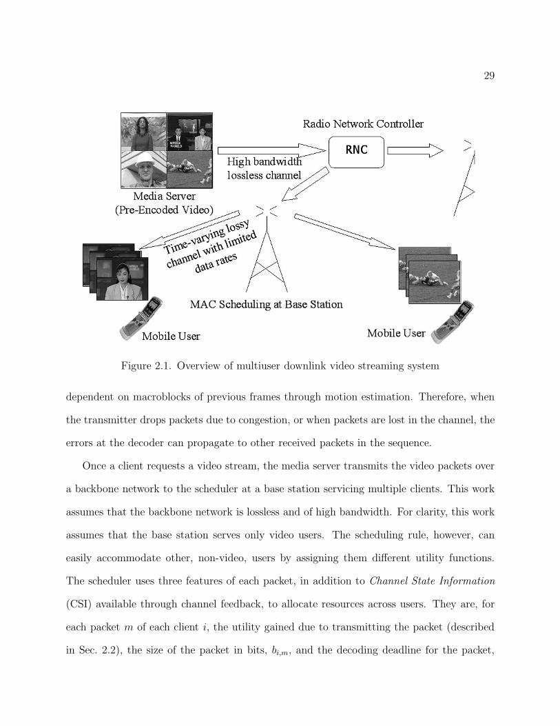
Figure 2.1 provides a high-level overview of the multiuser wireless video streaming system.
The system begins at a media server containing multiple video sequences. The server consists
of a media encoder, which, along with data compression, also packets each video sequence
into multiple data units. Each data unit/packet is independently decodable and represents
a slice of the video. In recent video coding standards, such as H.264, a slice can either be
as small as a group of a few macroblocks (MBs), or as large as an entire video frame. Each
slice header acts as a resynchronization marker, which enables the decoder to independently
decode each slice. In H.264, the encoder can also transport the slices out of order (Arbitrary
Slice Ordering) without affecting the decoder’s ability to decode each slice [30]. Note that,
although in terms of decoder operation, each slice is independently decodable, in reality,
most frames of a compressed sequence are inter frames, in which MBs can be predictively
29
Figure 2.1. Overview of multiuser downlink video streaming system
dependent on macroblocks of previous frames through motion estimation. Therefore, when
the transmitter drops packets due to congestion, or when packets are lost in the channel, the
errors at the decoder can propagate to other received packets in the sequence.
Once a client requests a video stream, the media server transmits the video packets over
a backbone network to the scheduler at a base station servicing multiple clients. This work
assumes that the backbone network is lossless and of high bandwidth. For clarity, this work
assumes that the base station serves only video users. The scheduling rule, however, can
easily accommodate other, non-video, users by assigning them different utility functions.
The scheduler uses three features of each packet, in addition to Channel State Information
(CSI) available through channel feedback, to allocate resources across users. They are, for
each packet m of each client i, the utility gained due to transmitting the packet (described
in Sec. 2.2), the size of the packet in bits, bi,m, and the decoding deadline for the packet,
30
τi,m. The decoding deadline, τi,m, stems from the video streaming requirement that all the
packets needed to decode a frame of the video sequence must be received at the decoder
buffer prior to the playback time of that frame. Multiple packets (e.g., all the packets in one
frame) can have the same decoding deadline.
The transmitter must drop any packet left in the transmission queue after the expiration
of the packet’s decoding deadline. Assuming real-time transmission, the number of transmis-
sion time slots available per each video frame can be calculated from the playback time for a
frame (approximately 33msec for 30fps video), and the length of each time-slot (e.g., 2msec
for HSDPA). Note that, unlike video conferencing systems, video streaming applications can
afford some buffer time at the decoder before starting to play back the video sequence. This
is important because, in a compressed sequence, the quality of the first frame, which is intra
coded, can have a significant impact on the quality of the following inter coded frames of
the same sequence.
The next step in Fig. 2.1 is that of receiving and decoding the video. At this point, the
decoded picture can contain numerous errors due to the loss of packets in the wireless chan-
nel, or due to the dropping of packets from the transmission queue. Typically, the decoder
attempts to conceal these errors using an appropriate error concealment technique. In gen-
eral, error concealment techniques use spatial and temporal correlations in the video data.
The decoder estimates the pixel values of macroblocks represented by lost slices using data
from the received slices of the current and/or reference frame. Therefore, error concealment
introduces an additional dependency between the slices of the sequence [6, 7].
31
2.2. A Content Aware Utility Function and Its Gradient
The main contribution of this work is to propose a utility function for video streaming
that accounts for both the dependencies between individual video packets, and the effect
that each video packet has on the final quality of the received video. The proposed utility
function is especially relevant since it can be used in conjunction with the gradient-based
scheduling scheme of [26] to enable content-aware resource allocation across multiple users.
In gradient-based scheduling algorithms, the scheduler assigns greater priority to packets
with a larger first-order change in utility. The key idea in the proposed method is to sort
the packets in the transmission buffer for each user based on the contribution of each packet
to the overall video quality, and then, to construct a utility function such that its gradient
reflects the contribution of each packet. A description of the process used to generate packet
utilities is given below.
At a given transmission time slot, t, for each user, i, pick a group of Mi available packets
such that each packet m in Mi has a decoding deadline, τi,m, greater than t. An obvious
approach would be to pick the group of packets with the same decoding deadline that com-
pose the current frame, or group of frames, to be transmitted. Each packet m consists of
bi,m bits. Note that, since the optimization is performed on a per time-slot basis, the time
index, t, remains the same throughout one optimization period, and therefore, is omitted for
the purposes of this discussion. Now, let Πi = {πi,1, πi,2, ..., πi,Mi} be the re-ordered set of
packets in the transmission queue of user i such that the transmitter will send packet πi,1
first, packet πi,2 second, and so on. Let Di[{πi,1, πi,2, ..., πi,ki}] denote the distortion given
that the transmitter sends the first ki packets in the queue to user i and drops the remaining
(Mi−ki) packets prior to transmission. Then, define the user utility for user i after ki packet
32
transmissions as,
(2.1) Ui[ki] = (Di[Πi] − Di[{πi,1, πi,2, ..., πi,ki}]),
where Di[Πi] is the minimum distortion for the frame, which occurs if the decoder receives
all of the packets in the group. Note that the scheduler will need to calculate a new utility
function only after it sends all Mi packets in the queue, or after it determines that the
decoding deadlines of all Mi packets have expired. The proposed scheme does not depend on
the metric used to calculate the distortion. For numerical simplicity, this work defines the
distortion as either the sum absolute pixel difference (SAD) or mean-squared error (MSE)
between the decoded and error-free frames. For ease of notation, let Πi(ki) = {πi,1, ..., πi,ki}.
Then, assuming a simple error concealment scheme (as described in Sec. 2.5.1), the scheduler
can guarantee that the user utility function is concave and increasing by iteratively choosing
each additional packet πi,ki+1 in a manner that maximizes the utility gradient; i.e.,
(2.2) πi,ki+1 = arg maxm/∈Πi(ki)
ui,m[ki],
where,
(2.3) ui,m[ki] =Di[Πi(ki)] − Di[{Πi(ki), m} |Πi(ki)]
bi,m.
In (2.3), Di[{Πi(ki), m} |Πi(ki)] indicates that the distortion after adding packet m may be
dependent on the currently ordered set of packets Πi(ki) from the same group. This will be
true if the decoder uses a complex error concealment technique to recover from packet losses
(See Sec. 2.5.2).
33
0 500 1000 15000
50
100
150
200
250
300
350
400
Bytes
MS
E
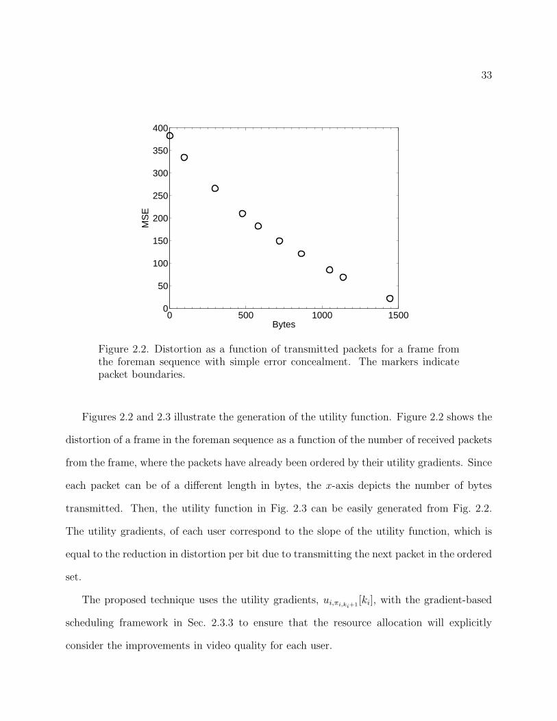
Figure 2.2. Distortion as a function of transmitted packets for a frame fromthe foreman sequence with simple error concealment. The markers indicatepacket boundaries.
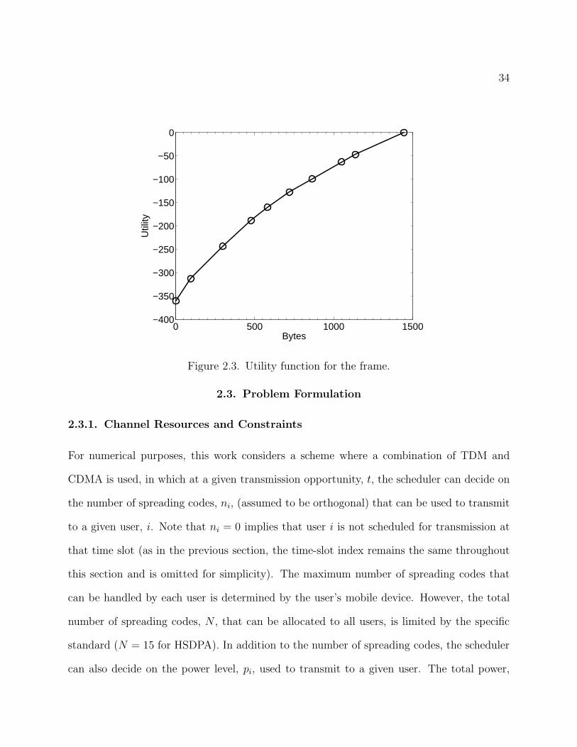
Figures 2.2 and 2.3 illustrate the generation of the utility function. Figure 2.2 shows the
distortion of a frame in the foreman sequence as a function of the number of received packets
from the frame, where the packets have already been ordered by their utility gradients. Since
each packet can be of a different length in bytes, the x-axis depicts the number of bytes
transmitted. Then, the utility function in Fig. 2.3 can be easily generated from Fig. 2.2.
The utility gradients, of each user correspond to the slope of the utility function, which is
equal to the reduction in distortion per bit due to transmitting the next packet in the ordered
set.
The proposed technique uses the utility gradients, ui,πi,ki+1[ki], with the gradient-based
scheduling framework in Sec. 2.3.3 to ensure that the resource allocation will explicitly
consider the improvements in video quality for each user.
34
0 500 1000 1500−400
−350
−300
−250
−200
−150
−100
−50
0
Bytes
Util
ity
Figure 2.3. Utility function for the frame.
2.3. Problem Formulation
2.3.1. Channel Resources and Constraints
For numerical purposes, this work considers a scheme where a combination of TDM and
CDMA is used, in which at a given transmission opportunity, t, the scheduler can decide on
the number of spreading codes, ni, (assumed to be orthogonal) that can be used to transmit
to a given user, i. Note that ni = 0 implies that user i is not scheduled for transmission at
that time slot (as in the previous section, the time-slot index remains the same throughout
this section and is omitted for simplicity). The maximum number of spreading codes that
can be handled by each user is determined by the user’s mobile device. However, the total
number of spreading codes, N , that can be allocated to all users, is limited by the specific
standard (N = 15 for HSDPA). In addition to the number of spreading codes, the scheduler
can also decide on the power level, pi, used to transmit to a given user. The total power,
35
P , that can be used by the base station is also limited in order to restrict the possibility
of interference across neighboring cells. Assuming K total users, these constraints can be
written as:
(2.4)K∑
i=1
ni ≤ N,K∑
i=1
pi ≤ P, and, ni ≤ Ni,
where Ni is the maximum number of spreading codes for user i.
The basic assumption in this work is that the constraints of the system will be such that
the transmitter may not be able to transmit all the available video packets in the transmission
queue of each user in time to meet their decoding deadlines.
2.3.2. General Problem Definition
Assume that the channel state for user i, denoted by ei, at a given time slot is known based
on channel quality feedback available in the system. The case when only imperfect channel
state information is known at the scheduler will be discussed in Chapter 4. The value of ei
represents the normalized Signal to Interference Plus Noise Ratio (SINR) per unit power and
can vary quite rapidly, and in a large dynamic range, over time. Therefore, it is reasonable
to assume that ei will be a different value at each time slot. Defining SINRi = pi
niei to be
the SINR per code for user i at a given time, the achievable rate for user i, ri, satisfies:
ri
ni= Γ(ζiSINRi).(2.5)
In (2.5), Γ(x) = B log(1 + x) represents the Shannon capacity for an AWGN channel, where
B is the symbol rate per code. Also, ζi ∈ (0, 1] represents a scaling factor that determines
the gap from capacity for a realistic system. This is a reasonable model for systems that use
36
coding techniques, such as turbo codes, that approach Shannon capacity. Setting ei = eiζi,
the achievable rates for each user as a function of the control parameters ni and pi can be
specified as follows:
ri = niB log
(
1 +piei
ni
)
(2.6)
Now, the resource allocation problem becomes one of specifying the ni and pi allocated
to each user such that a target rate, ri, can be achieved.
2.3.3. Gradient-Based Scheduling Framework
The key idea in the gradient-based scheduling technique is to maximize the projection of the
achievable rate vector, r = (r1, r2, ..., rK) on to the gradient of a system utility function [26].
The system utility function is defined as:
Ui =
K∑
i=1
Ui,(2.7)
where Ui is a concave utility function. In a content-independent scheme, Ui can be a function
of the average throughput for user i, or the delay of the head-of-line packet. The proposed
content-aware scheme, however, defines Ui to be a function of the decoded video quality as
in (2.1). Now, the gradient based resource allocation problem can be written as:
maxr∈C(e,χ)
K∑
i=1
wiui,πi,ki+1[ki]ri(2.8)
where, as in (2.3), ki denotes the number of packets already transmitted to user i, and πi,ki+1
denotes the next packet in the ordered transmission queue. The constraint set, C(e, χ),
denotes all the achievable rates given e, the vector containing the instantaneous channel
37
states of each user, and χ the set of allowable n = (n1, n2, ..., nK) and p = (p1, p2, ..., pK),
the vectors containing the assigned number of spreading codes, and assigned power levels,
of each user, respectively. Here, wi indicates an additional weighting used to attain fairness
across users over time. This work considers a content-based technique for determining wi
based on the distortion in user i’s decoded video given the previously transmitted set of
packets (i.e., user’s with poor decoded quality based on the previous transmissions will be
assigned larger weights in order to ensure fairness over time). In that case, wi will also be a
function of ki.
The formulation in (2.8) maximizes a weighted sum of the rates assigned to each user
where the weights are proportional to the gradients of the system utility function. After
each time-slot, ki will be updated, and the weights will be re-adjusted based on the packets
scheduled in the previous slot. The constraint set will also change at each time-slot due to
changes in the channel states.
Now, taking into account the system constraints specified in (2.4), as well as the for-
mula for calculating each user’s achievable rate specified in (2.6), the optimization problem
formulation becomes:
(2.9) V ∗ := max(n,p)∈χ
V (n,p),
subject to:K∑
i=1
ni ≤ N,
K∑
i=1
pi ≤ P,
where:
(2.10) V (n,p) :=K∑
i=1
wiui,πi,ki+1[ki]ni log
(
1 +piei
ni
)
,
38
and,
(2.11) χ := {(n,p) ≥ 0 : ni ≤ Ni ∀i}.
2.3.4. Additional Constraints
In addition to the main constraints specified above, a practical system is also limited by some
“per-user” constraints. Among them are, a peak power constraint per user, a maximum SINR
per code constraint for each user, and a maximum and minimum rate constraint determined
by the maximum and minimum coding rates allowed by the coding scheme.
All of the above constraints can be grouped into a per user power constraint based on
the SINR per code for each user [26]. This constraint can be viewed as:
SINRi =piei
ni∈ [si(ni), si(ni)] , ∀i,(2.12)
where si(ni) ≥ 0. For the purposes of this work, only cases where the maximum and
minimum SINR constraints are not functions of ni, i.e, SINRi ∈ [si, si], as with a maximum
SINR per code constraint, are considered. In this case, the constraint set in (2.11) becomes,
(2.13) χ := {(n,p) ≥ 0 : ni ≤ Ni, si ≤piei
ni≤ si ∀i}.
2.3.5. Extension to OFDMA
Although the above formulation is primarily designed for CDMA systems, it can also be
adapted for use in OFDMA systems under suitable conditions. For example, a common
approach followed in OFDMA systems, is to form multiple subchannels consisting of sets of
OFDM tones. In the case that the OFDM tones are interleaved to form the subchannels (i.e.,
39
interleaved channelization is used), which is the default case, referred to as PUSC (Partially
Used SubCarrier), in IEEE 802.16d/e [14], the SINR is essentially uniform across all the
subchannels for each user. Then, the number of subchannels plays an equivalent role to the
number of codes (N) in the CDMA based formulation above. Further details on gradient
based scheduling approaches with OFDMA can be found in [56].
2.4. Solution
A solution to the convex optimization problem of the type given in (2.9) for the case
when the maximum and minimum SINR constraints are not functions of ni is derived in
detail in [26]. This section simply summarizes the basic form of the solution.
The Lagrangian for the primal problem in (2.9) can be defined as:
L(p,n, λ, µ) =
∑
i
wiuini log
(
1 +piei
ni
)
+
λ
(
P −∑
i
pi
)
+ µ
(
N −∑
i
ni
)
.(2.14)
Based on this, the dual function can defined as,
(2.15) L(λ, µ) = max(n,p)∈χ
L(p,n, λ, µ),
which can be analytically computed by first keeping n, λ, µ fixed and optimizing (2.14) over
p, and then optimizing over n.
The corresponding dual problem is given by,
(2.16) L∗ = min(λ,µ)≥0
L(λ, µ).
40
Based on the concavity of V in (2.9), and the convexity of the domain of optimization, it
can be shown that a solution to the dual problem exists, and that there is no duality gap,
i.e., V ∗ = L∗.
In [26], an algorithm is given for solving the dual problem based on first optimizing over
µ for a fixed λ to find,
(2.17) L(λ) = maxµ≥0
L(λ, µ),
and then minimizing L(λ) over λ ≥ 0. For the first step, L(λ) can be analytically computed.
The function L(λ) can be shown to be a convex function of λ, which can then be minimized
via a one-dimensional search with geometric convergence.
2.5. Simulation Study
This section will detail some of the characteristics of the proposed technique based on
simulations performed using an experimental multiuser wireless video streaming setup. Mi-
nor modifications are also proposed in order to adapt the scheme to realistic conditions such
as complex error concealment techniques, fragmentation at the MAC layer, and offline packet
ordering.
Six video sequences with varied content: “foreman”, “carphone”, “mother and daugh-
ter”, “news”, “hall monitor”, and “silent”, in QCIF (176x144) format were used for the
simulations. The sequences were encoded in H.264 (JVT reference software, JM 9.3 [57])
at variable bit rates to obtain a specified average PSNR of 35dB for each frame. All frames
except the first were encoded as P frames. To reduce error propagation due to packet losses,
random I MBs were inserted into each frame during the encoding process. The frames were
41
Table 2.1. System Parameters Used in Simulations
N Ni P si si
15 5 10W 0 1.76dB
packeted such that each packet/slice contained one row of MBs, which enabled a good bal-
ance between error robustness and compression efficiency. Constrained intra prediction was
used at the encoder for further error robustness. Although the sequences begin transmitting
simultaneously, a buffer of 10 frame times was provided in order for the first frame (Intra
coded) to be received by each user. Therefore, the start times of the subsequent frames
could vary for each user. If a video packet could not be completely transmitted within a
given transmission opportunity, it was assumed to be fragmented at the MAC layer, and the
utility gradient of the fragmented packet was calculated using the number of remaining bits
to be transmitted for that packet.
The wireless network was modeled as an HSDPA system. The system parameters used
in the simulations are shown in Table 2.1. HSDPA provides 2 msec transmission time slots.
Realistic channel traces for an HSDPA system were obtained using a proprietary channel
simulator developed at Motorola Inc. The simulator accounts for correlated shadowing and
multipath fading effects with 6 multipath components. For the channel traces, users were
located within a 0.8km radius from the base station and user speeds were set at 30km/h.
2.5.1. Simple Error Concealment
The error concealment technique used at the decoder significantly impacts the reconstructed
state of a decoded video frame after packet losses. The decoder has access to only its own,
possibly distorted, reconstructed frames for motion compensation of subsequent received
predictive frames. Any errors in the reconstruction of a frame at the decoder can propagate
42
1 2 3 4 5 6 Avg25
30
35
40
User #
PS
NR
(dB
)
Distortion gradientWeighted distortion gradientQueue length with packet orderingQueue length without packet ordering
Figure 2.4. Comparison of average PSNR with resource allocation schemes us-ing simple error concealment. User numbers represent 1: Foreman, 2: Motherand Daughter, 3: Carphone, 4: News, 5: Silent, 6: Hall Monitor.
to future frames, as well, due to the predictive dependencies among frames. Therefore, the
error concealment at the decoder, and thereby, the reconstructed states of frames at the
decoder must be taken into account when determining the importance of video packets. A
number of error concealment techniques for packet based video have been proposed in the
literature. For the purposes of this work, they can be categorized as “simple” and “complex”
concealment techniques.
A simple concealment scheme can be categorized as any error concealment technique, in
which data from packets within the same group, Πi, are not used for concealment of other
lost packets within that group. For example, if each group consists of packets from one video
frame, then replacing the pixel values of MBs contained on a lost packet with pixel values
from the same location in the previous frame is a commonly used simple error concealment
43
40 60 80 100 1200
2
4
6
8
10
12
Frame #
Var
ianc
e
Distortion gradientWeighted distortion gradientQueue length with packet orderingQueue length without packet ordering
Figure 2.5. Comparison of variance of PSNR with resource allocation schemesusing simple error concealment.
technique. With such techniques, it can be seen that the packet ordering scheme proposed
in Sec. 2.2 will always provide the best possible ordering of packets within a packet group,
such that given only ki out of the total Mi packets are actually transmitted, Πi(ki) would
be the set of packets that would lead to the highest decoded video quality. In concise terms,
with simple concealment, the packet ordering within a given packet group does not depend
on the channel realizations during the transmission of that packet group. Also, it can be
guaranteed that the contribution per bit of each newly transmitted packet from the group
will be lower than that of the previously transmitted packet, and that therefore, the utility
function will be concave.
Simulations were performed, using the simple error concealment technique described
above, to determine the performance gain that can be expected by using the content-
dependent packet ordering and resource allocation scheme. Figures 2.4 and 2.5 compare

44
the quality of the received video, using 4 different methods for calculating the utilities in
(2.8). They are:
(1) Distortion Gradient - This method uses the packet ordering and utility functions
described in Sec. 2.2 but sets wi = 1 for all i in (2.10). Essentially this method
attempts to minimize the total distortion over all users without regard to fairness
for individual users.
(2) Weighted Distortion Gradient - This method is similar to the first but it sets wi to
be the distortion in user i’s decoded video frame given the packets transmitted up
to that point. This ensures that users that are suffering from degraded performance
due to effects of channel fading in previous time slots will be given a higher priority
in the current time slot.
(3) Ordered Queue Length - This method is only partially content-aware in that it
orders the video packets of each user according to their importance. The resource
allocation across users, however, is performed assuming that the utility gradients in
(2.8) are proportional to the current queue length in bits of each user’s transmission
queue. The resource allocation is similar to the M-LWDF scheme in [24].
(4) Queue Length - The final method is a direct application of the conventional content-
independent scheduling technique, again essentially the M-LWDF scheme, without
performing any packet ordering at the scheduler.
The computational complexity of the first three methods is very similar as they all use the
proposed packet ordering scheme. Assuming simple error concealment, and that the packet
group consists of the packets of one frame, the packet ordering requires one decoding of the
entire video frame, a calculation of the distortion gradients of each packet, and a sort over
45
the number of packets. Due to concealment from the previous frame, the calculation of the
distortion gradients requires that the previous decoded frame, i.e., the reconstructed frame
based on the number of packets transmitted from the previous frame, be kept in memory.
The fourth method is less computationally complex as it does not require packet ordering.
Figure 2.4 shows the average quality across 100 frames over 5 channel realizations for
each sequence. This shows that the content-aware schemes significantly out-perform the
conventional queue length based scheduling scheme. The gain in performance is mainly seen
in the sequences with more complex video content across the entire frame such as foreman,
mother and daughter, and carphone. The content aware schemes recognize the importance of
error concealment in enabling packets in more easily concealable sequences such as news and
hall monitor to be dropped, while the content-independent schemes do not. Figure 2.5 shows
the variance in PSNR per frame across all users and the 5 channel realizations. This shows
that the two schemes with content-aware gradient metrics tend to provide similar quality
across all the users (lower variance), while the queue-dependent schemes tend to favor some
users, again those whose dropped packets would have been easily concealable, over others.
Between the two schemes with content-aware metrics, a small sacrifice in average PSNR
incurred by the weighted distortion gradient metric yields significant improvement in terms
of the variance across users.
2.5.2. Complex Error Concealment
A broad review of error concealment techniques can be found in [58, 7]. Error concealment
exploits spatial and temporal redundancies in the video data. In complex temporal con-
cealment techniques, the motion vectors (MV’s) of neighboring decoded MB’s in the same
frame are used to estimate the motion vector of a lost MB. For example, one possibility is
46
to use the median MV of all the available neighboring MV’s. Another is to use a boundary
matching technique to determine the best candidate MV [59]. Errors in intra frames are con-
cealed using spatial concealment techniques that rely on weighted pixel averaging schemes
where the weight depends on the distance from the concealed pixels. More complex hybrid
spatio-temporal error concealment techniques also exist[60].
When complex concealment is used, the packet ordering scheme proposed in Sec. 2.2
changes, and the incremental gain in quality due to adding each packet is no longer additive.
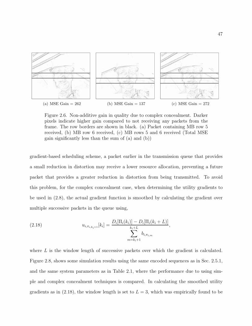
Figure 2.6 illustrates this issue for a particular frame of the foreman sequence, in which
the boundary matching technique is used for error concealment. In Fig. 2.6(a), the packet
representing the 5th row of MBs is the only packet received from the frame, and the rest of
the MBs are concealed using that packet. In (b), the 6th row is the only row received, and in
(c), both the 5th and 6th rows are received. The darker pixels in each figure indicate higher
gains in quality compared to not receiving any packets at all. Because of concealment of
neighboring packets, the effect of receiving one packet extends beyond the immediate region
represented by the packet. Therefore, adding the 6th packet to the already transmitted 5th
packet does not provide an incrementally additive gain in quality corresponding to the gain
that would occur if only the 6th packet were received.
The solution, formulated in (2.2) and (2.3), takes into account the non-additivity of
packet utilities by employing a myopic method for determining the packet orderings within
the transmission queue. For each position in the transmission queue, the packet chosen is the
one that provides the largest gain in quality after error concealment, given the packets that
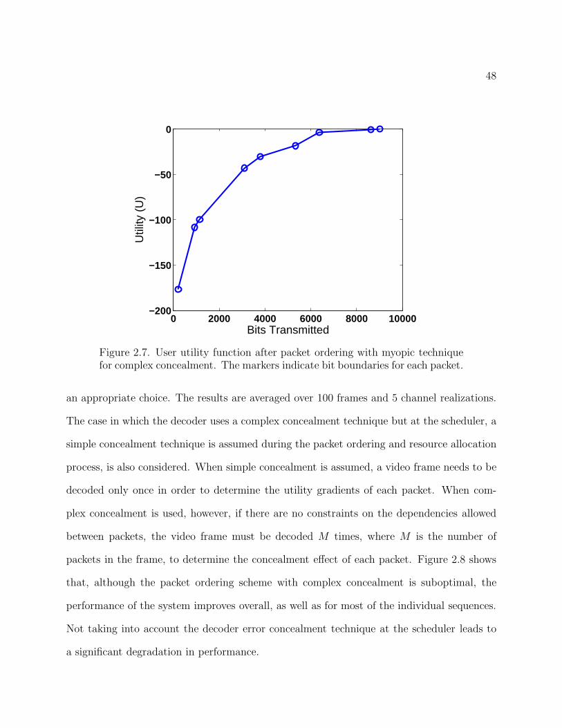
have already been added to the queue. Figure 2.7 shows an example user utility function
obtained with the myopic packet ordering scheme. The error concealment causes the utility
function to not be concave over the entire range. A result of this is that, when using a
47
(a) MSE Gain = 262 (b) MSE Gain = 137 (c) MSE Gain = 272
Figure 2.6. Non-additive gain in quality due to complex concealment. Darkerpixels indicate higher gain compared to not receiving any packets from theframe. The row borders are shown in black. (a) Packet containing MB row 5received, (b) MB row 6 received, (c) MB rows 5 and 6 received (Total MSEgain significantly less than the sum of (a) and (b))
gradient-based scheduling scheme, a packet earlier in the transmission queue that provides
a small reduction in distortion may receive a lower resource allocation, preventing a future
packet that provides a greater reduction in distortion from being transmitted. To avoid
this problem, for the complex concealment case, when determining the utility gradients to
be used in (2.8), the actual gradient function is smoothed by calculating the gradient over
multiple successive packets in the queue using,
(2.18) ui,πi,ki+1[ki] =
Di[Πi(ki)] − Di[Πi(ki + L)]ki+L∑
m=ki+1
bi,πi,m
,
where L is the window length of successive packets over which the gradient is calculated.
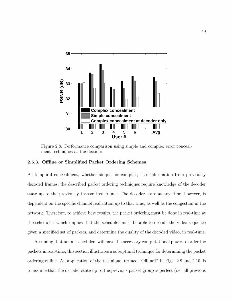
Figure 2.8, shows some simulation results using the same encoded sequences as in Sec. 2.5.1,
and the same system parameters as in Table 2.1, where the performance due to using sim-
ple and complex concealment techniques is compared. In calculating the smoothed utility
gradients as in (2.18), the window length is set to L = 3, which was empirically found to be
48
0 2000 4000 6000 8000 10000−200
−150
−100
−50
0
Bits Transmitted
Util
ity (
U)
Figure 2.7. User utility function after packet ordering with myopic techniquefor complex concealment. The markers indicate bit boundaries for each packet.
an appropriate choice. The results are averaged over 100 frames and 5 channel realizations.
The case in which the decoder uses a complex concealment technique but at the scheduler, a
simple concealment technique is assumed during the packet ordering and resource allocation
process, is also considered. When simple concealment is assumed, a video frame needs to be
decoded only once in order to determine the utility gradients of each packet. When com-
plex concealment is used, however, if there are no constraints on the dependencies allowed
between packets, the video frame must be decoded M times, where M is the number of
packets in the frame, to determine the concealment effect of each packet. Figure 2.8 shows
that, although the packet ordering scheme with complex concealment is suboptimal, the
performance of the system improves overall, as well as for most of the individual sequences.
Not taking into account the decoder error concealment technique at the scheduler leads to
a significant degradation in performance.
49
1 2 3 4 5 6 Avg30
31
32
33
34
35
User #
PS
NR
(dB
)
Complex concealmentSimple concealmentComplex concealment at decoder only
Figure 2.8. Performance comparison using simple and complex error conceal-ment techniques at the decoder.
2.5.3. Offline or Simplified Packet Ordering Schemes
As temporal concealment, whether simple, or complex, uses information from previously
decoded frames, the described packet ordering techniques require knowledge of the decoder
state up to the previously transmitted frame. The decoder state at any time, however, is
dependent on the specific channel realization up to that time, as well as the congestion in the
network. Therefore, to achieve best results, the packet ordering must be done in real-time at
the scheduler, which implies that the scheduler must be able to decode the video sequence
given a specified set of packets, and determine the quality of the decoded video, in real-time.
Assuming that not all schedulers will have the necessary computational power to order the
packets in real-time, this section illustrates a suboptimal technique for determining the packet
ordering offline. An application of the technique, termed “Offline1” in Figs. 2.9 and 2.10, is
to assume that the decoder state up to the previous packet group is perfect (i.e. all previous
50
packets are received without loss), when ordering the packets for the current group. A further
extension of this method, termed “Offline2” is to assume that the decoder state up to all but
the previous packet group is perfect, which assumes a first-order dependency among packet
groups. In these methods, each packet can be stamped offline at the media server with an
identifier marking its order within the packet group, as well as a utility gradient, which can be
directly used by the scheduler. In the case of “Offline2”, each packet will need to be marked
with M different priority values where each value corresponds to the number of packets
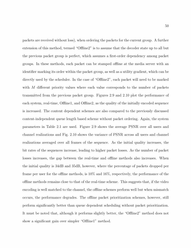
transmitted from the previous packet group. Figures 2.9 and 2.10 plot the performance of
each system, real-time, Offline1, and Offline2, as the quality of the initially encoded sequence
is increased. The content dependent schemes are also compared to the previously discussed
content-independent queue length based scheme without packet ordering. Again, the system
parameters in Table 2.1 are used. Figure 2.9 shows the average PSNR over all users and
channel realizations and Fig. 2.10 shows the variance of PSNR across all users and channel
realizations averaged over all frames of the sequence. As the initial quality increases, the
bit rates of the sequences increase, leading to higher packet losses. As the number of packet
losses increases, the gap between the real-time and offline methods also increases. When
the initial quality is 34dB and 35dB, however, where the percentage of packets dropped per
frame per user for the offline methods, is 10% and 16%, respectively, the performance of the
offline methods remains close to that of the real-time scheme. This suggests that, if the video
encoding is well matched to the channel, the offline schemes perform well but when mismatch
occurs, the performance degrades. The offline packet prioritization schemes, however, still
perform significantly better than queue dependent scheduling without packet prioritization.
It must be noted that, although it performs slightly better, the “Offline2” method does not
show a significant gain over simpler “Offline1” method.
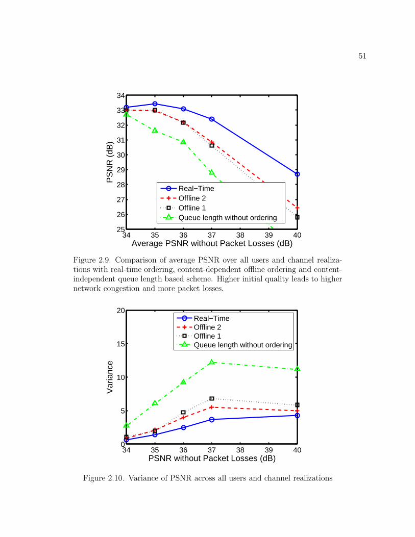
51
34 35 36 37 38 39 4025
26
27
28
29
30
31
32
33
34
Average PSNR without Packet Losses (dB)
PS
NR
(dB
)
Real−TimeOffline 2Offline 1Queue length without ordering
Figure 2.9. Comparison of average PSNR over all users and channel realiza-tions with real-time ordering, content-dependent offline ordering and content-independent queue length based scheme. Higher initial quality leads to highernetwork congestion and more packet losses.
34 35 36 37 38 39 400
5
10
15
20
PSNR without Packet Losses (dB)
Var
ianc
e
Real−TimeOffline 2Offline 1Queue length without ordering
Figure 2.10. Variance of PSNR across all users and channel realizations
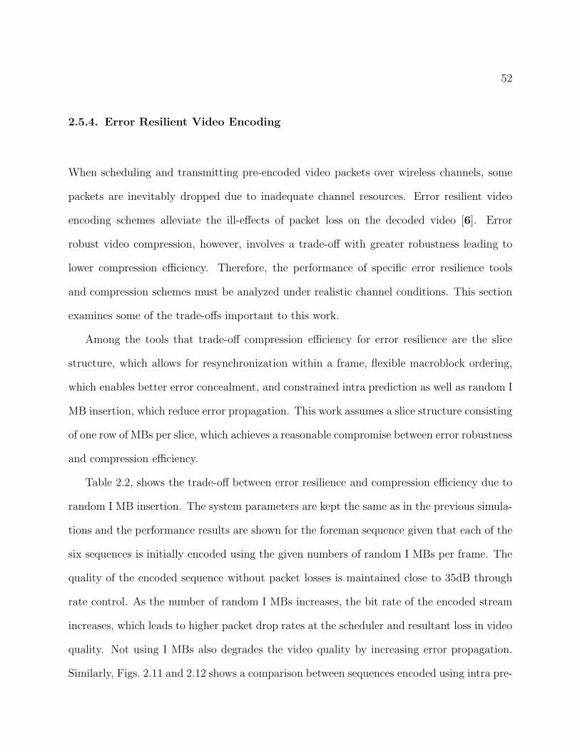
52
2.5.4. Error Resilient Video Encoding
When scheduling and transmitting pre-encoded video packets over wireless channels, some
packets are inevitably dropped due to inadequate channel resources. Error resilient video
encoding schemes alleviate the ill-effects of packet loss on the decoded video [6]. Error
robust video compression, however, involves a trade-off with greater robustness leading to
lower compression efficiency. Therefore, the performance of specific error resilience tools
and compression schemes must be analyzed under realistic channel conditions. This section
examines some of the trade-offs important to this work.
Among the tools that trade-off compression efficiency for error resilience are the slice
structure, which allows for resynchronization within a frame, flexible macroblock ordering,
which enables better error concealment, and constrained intra prediction as well as random I
MB insertion, which reduce error propagation. This work assumes a slice structure consisting
of one row of MBs per slice, which achieves a reasonable compromise between error robustness
and compression efficiency.
Table 2.2, shows the trade-off between error resilience and compression efficiency due to
random I MB insertion. The system parameters are kept the same as in the previous simula-
tions and the performance results are shown for the foreman sequence given that each of the
six sequences is initially encoded using the given numbers of random I MBs per frame. The
quality of the encoded sequence without packet losses is maintained close to 35dB through
rate control. As the number of random I MBs increases, the bit rate of the encoded stream
increases, which leads to higher packet drop rates at the scheduler and resultant loss in video
quality. Not using I MBs also degrades the video quality by increasing error propagation.
Similarly, Figs. 2.11 and 2.12 shows a comparison between sequences encoded using intra pre-
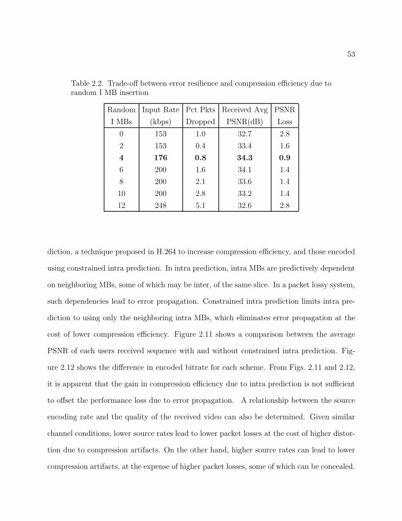
53
Table 2.2. Trade-off between error resilience and compression efficiency due torandom I MB insertion
Random Input Rate Pct Pkts Received Avg PSNR
I MBs (kbps) Dropped PSNR(dB) Loss
0 153 1.0 32.7 2.8
2 153 0.4 33.4 1.6
4 176 0.8 34.3 0.9
6 200 1.6 34.1 1.4
8 200 2.1 33.6 1.4
10 200 2.8 33.2 1.4
12 248 5.1 32.6 2.8
diction, a technique proposed in H.264 to increase compression efficiency, and those encoded
using constrained intra prediction. In intra prediction, intra MBs are predictively dependent
on neighboring MBs, some of which may be inter, of the same slice. In a packet lossy system,
such dependencies lead to error propagation. Constrained intra prediction limits intra pre-
diction to using only the neighboring intra MBs, which eliminates error propagation at the
cost of lower compression efficiency. Figure 2.11 shows a comparison between the average
PSNR of each users received sequence with and without constrained intra prediction. Fig-
ure 2.12 shows the difference in encoded bitrate for each scheme. From Figs. 2.11 and 2.12,
it is apparent that the gain in compression efficiency due to intra prediction is not sufficient
to offset the performance loss due to error propagation. A relationship between the source
encoding rate and the quality of the received video can also be determined. Given similar
channel conditions, lower source rates lead to lower packet losses at the cost of higher distor-
tion due to compression artifacts. On the other hand, higher source rates can lead to lower
compression artifacts, at the expense of higher packet losses, some of which can be concealed.
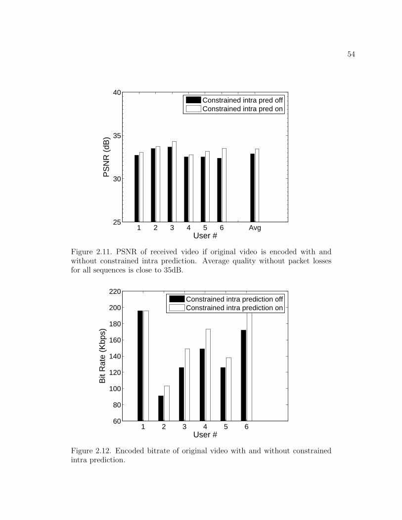
54
1 2 3 4 5 6 Avg25
30
35
40
User #
PS
NR
(dB
)
Constrained intra pred offConstrained intra pred on
Figure 2.11. PSNR of received video if original video is encoded with andwithout constrained intra prediction. Average quality without packet lossesfor all sequences is close to 35dB.
1 2 3 4 5 660
80
100
120
140
160
180
200
220
User #
Bit
Rat
e (K
bps)
Constrained intra prediction offConstrained intra prediction on
Figure 2.12. Encoded bitrate of original video with and without constrainedintra prediction.
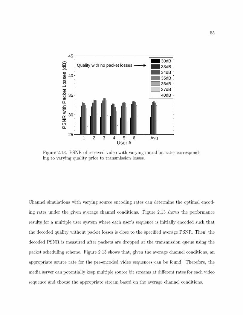
55
1 2 3 4 5 6 Avg25
30
35
40
45
User #
PS
NR
with
Pac
ket L
osse
s (d
B)
30dB33dB34dB35dB36dB37dB40dB
Quality with no packet losses
Figure 2.13. PSNR of received video with varying initial bit rates correspond-ing to varying quality prior to transmission losses.
Channel simulations with varying source encoding rates can determine the optimal encod-
ing rates under the given average channel conditions. Figure 2.13 shows the performance
results for a multiple user system where each user’s sequence is initially encoded such that
the decoded quality without packet losses is close to the specified average PSNR. Then, the
decoded PSNR is measured after packets are dropped at the transmission queue using the
packet scheduling scheme. Figure 2.13 shows that, given the average channel conditions, an
appropriate source rate for the pre-encoded video sequences can be found. Therefore, the
media server can potentially keep multiple source bit streams at different rates for each video
sequence and choose the appropriate stream based on the average channel conditions.
56
2.6. Conclusions
This chapter demonstrates that a resource allocation scheme that maximizes a weighted
sum of the rates assigned to each user where the weights are determined by distortion-based
utility gradients, is a simple but effective solution for downlink packet scheduling in wireless
video streaming applications. It provides an optimal solution for the case when the video
packets are independently decodable and a simple error concealment scheme is used at the
decoder. It is also shown that with complex error concealment at the decoder, a suboptimal
myopic solution with appropriately calculated distortion utility gradients can still provide
excellent results. The system depends on the compression and error resilience schemes used
at the encoder.
57
CHAPTER 3
Scalable Video Encoding
This chapter discusses the application of the content-aware resource allocation formu-
lation in a scalable video coding framework. The chapter presents some of the natural
advantages to be had, and some pitfalls to be avoided, when using scalable coded video in
conjunction with a content-dependent gradient-based scheduling policy.
3.1. Overview of Scalable Video Coding
An overview of the techniques and applications of scalable video coding, especially as
it pertains to SVC [61], the emerging scalable extension to H.264/AVC [30], is provided in
[35, 37]. In general, a scalable video bitstream offers three different categories of scalability
that may be used individually, or in combination. They are: spatial scalability, which allows
the transmission of the same video sequence at different resolutions depending on the user
requirements or bandwidth constraints, temporal scalability, which allows the transmission
of the video sequence at different frame rates without error propagation due to the skipped
frames, and quality (SNR) scalability, which allows the transmission of progressively refined
bitstreams depending on the available data rates. This work, focuses on optimizing over
temporal and SNR scalability levels and excludes spatial scalability since it is reasonable to
assume that the spatial resolution will remain static within one video streaming session.
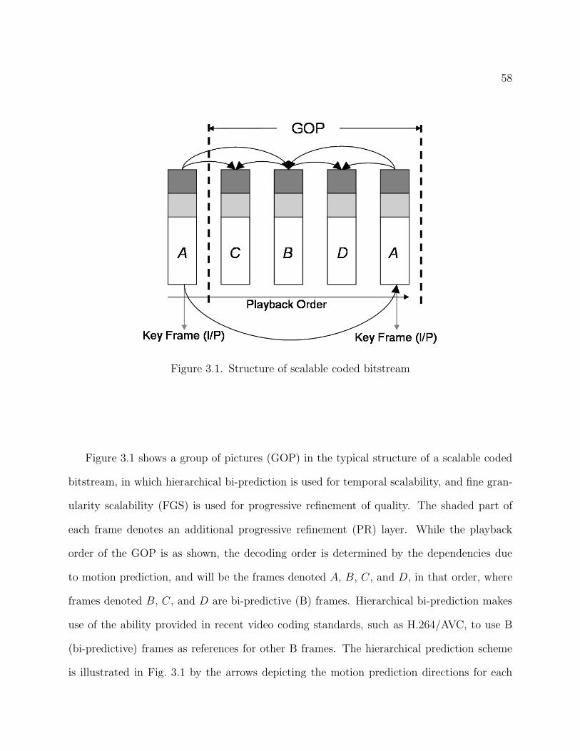
58
Figure 3.1. Structure of scalable coded bitstream
Figure 3.1 shows a group of pictures (GOP) in the typical structure of a scalable coded
bitstream, in which hierarchical bi-prediction is used for temporal scalability, and fine gran-
ularity scalability (FGS) is used for progressive refinement of quality. The shaded part of
each frame denotes an additional progressive refinement (PR) layer. While the playback
order of the GOP is as shown, the decoding order is determined by the dependencies due
to motion prediction, and will be the frames denoted A, B, C, and D, in that order, where
frames denoted B, C, and D are bi-predictive (B) frames. Hierarchical bi-prediction makes
use of the ability provided in recent video coding standards, such as H.264/AVC, to use B
(bi-predictive) frames as references for other B frames. The hierarchical prediction scheme
is illustrated in Fig. 3.1 by the arrows depicting the motion prediction directions for each
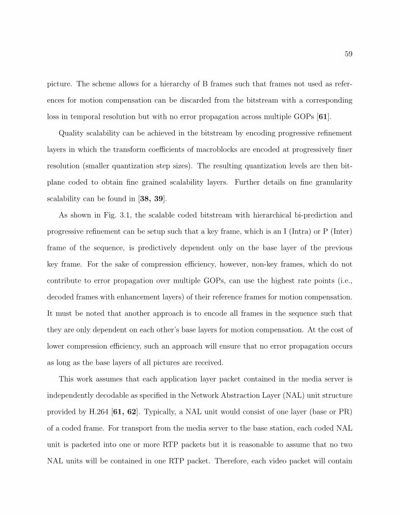
59
picture. The scheme allows for a hierarchy of B frames such that frames not used as refer-
ences for motion compensation can be discarded from the bitstream with a corresponding
loss in temporal resolution but with no error propagation across multiple GOPs [61].
Quality scalability can be achieved in the bitstream by encoding progressive refinement
layers in which the transform coefficients of macroblocks are encoded at progressively finer
resolution (smaller quantization step sizes). The resulting quantization levels are then bit-
plane coded to obtain fine grained scalability layers. Further details on fine granularity
scalability can be found in [38, 39].
As shown in Fig. 3.1, the scalable coded bitstream with hierarchical bi-prediction and
progressive refinement can be setup such that a key frame, which is an I (Intra) or P (Inter)
frame of the sequence, is predictively dependent only on the base layer of the previous
key frame. For the sake of compression efficiency, however, non-key frames, which do not
contribute to error propagation over multiple GOPs, can use the highest rate points (i.e.,
decoded frames with enhancement layers) of their reference frames for motion compensation.
It must be noted that another approach is to encode all frames in the sequence such that
they are only dependent on each other’s base layers for motion compensation. At the cost of
lower compression efficiency, such an approach will ensure that no error propagation occurs
as long as the base layers of all pictures are received.
This work assumes that each application layer packet contained in the media server is
independently decodable as specified in the Network Abstraction Layer (NAL) unit structure
provided by H.264 [61, 62]. Typically, a NAL unit would consist of one layer (base or PR)
of a coded frame. For transport from the media server to the base station, each coded NAL
unit is packeted into one or more RTP packets but it is reasonable to assume that no two
NAL units will be contained in one RTP packet. Therefore, each video packet will contain
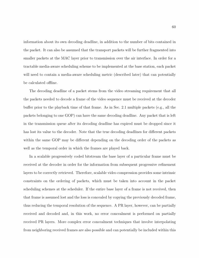
60
information about its own decoding deadline, in addition to the number of bits contained in
the packet. It can also be assumed that the transport packets will be further fragmented into
smaller packets at the MAC layer prior to transmission over the air interface. In order for a
tractable media-aware scheduling scheme to be implemented at the base station, each packet
will need to contain a media-aware scheduling metric (described later) that can potentially
be calculated offline.
The decoding deadline of a packet stems from the video streaming requirement that all
the packets needed to decode a frame of the video sequence must be received at the decoder
buffer prior to the playback time of that frame. As in Sec. 2.1 multiple packets (e.g., all the
packets belonging to one GOP) can have the same decoding deadline. Any packet that is left
in the transmission queue after its decoding deadline has expired must be dropped since it
has lost its value to the decoder. Note that the true decoding deadlines for different packets
within the same GOP may be different depending on the decoding order of the packets as
well as the temporal order in which the frames are played back.
In a scalable progressively coded bitstream the base layer of a particular frame must be
received at the decoder in order for the information from subsequent progressive refinement
layers to be correctly retrieved. Therefore, scalable video compression provides some intrinsic
constraints on the ordering of packets, which must be taken into account in the packet
scheduling schemes at the scheduler. If the entire base layer of a frame is not received, then
that frame is assumed lost and the loss is concealed by copying the previously decoded frame,
thus reducing the temporal resolution of the sequence. A PR layer, however, can be partially
received and decoded and, in this work, no error concealment is performed on partially
received PR layers. More complex error concealment techniques that involve interpolating
from neighboring received frames are also possible and can potentially be included within this
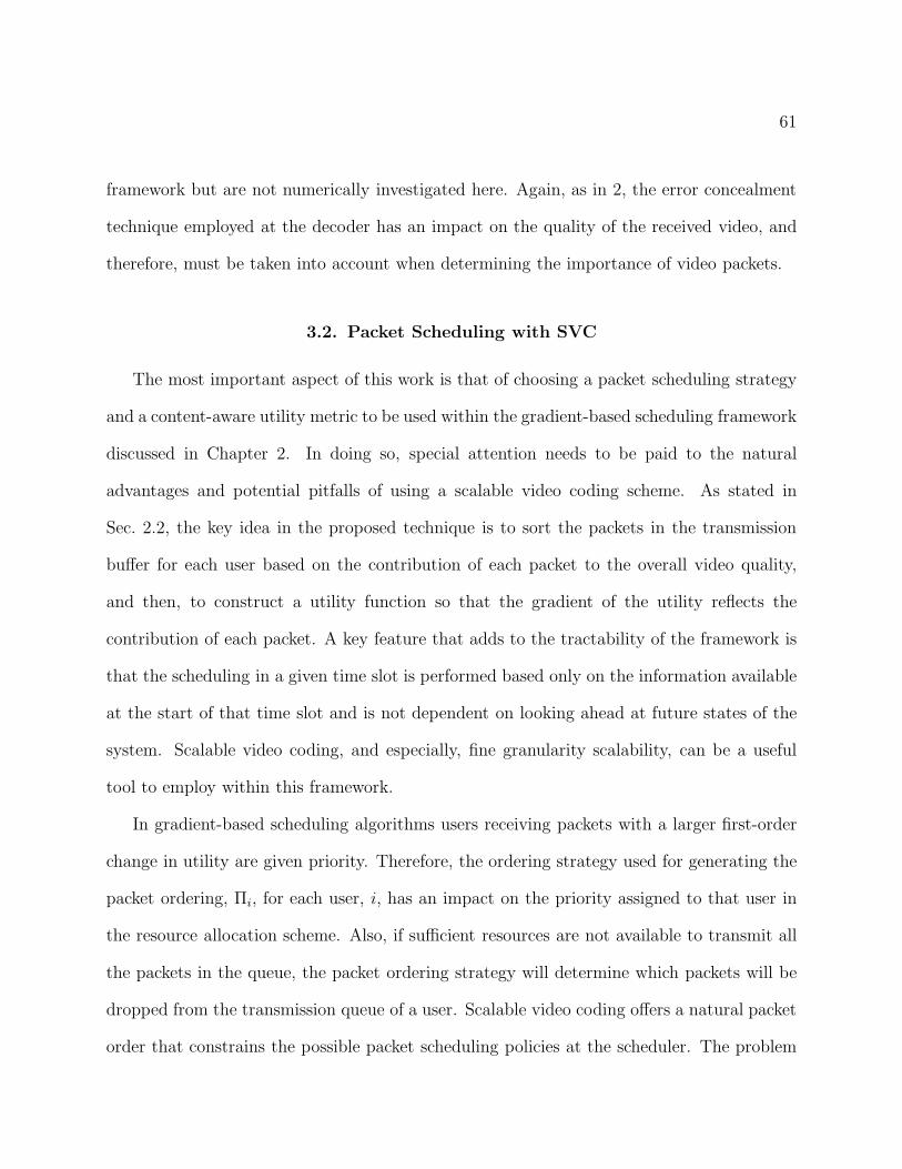
61
framework but are not numerically investigated here. Again, as in 2, the error concealment
technique employed at the decoder has an impact on the quality of the received video, and
therefore, must be taken into account when determining the importance of video packets.
3.2. Packet Scheduling with SVC
The most important aspect of this work is that of choosing a packet scheduling strategy
and a content-aware utility metric to be used within the gradient-based scheduling framework
discussed in Chapter 2. In doing so, special attention needs to be paid to the natural
advantages and potential pitfalls of using a scalable video coding scheme. As stated in
Sec. 2.2, the key idea in the proposed technique is to sort the packets in the transmission
buffer for each user based on the contribution of each packet to the overall video quality,
and then, to construct a utility function so that the gradient of the utility reflects the
contribution of each packet. A key feature that adds to the tractability of the framework is
that the scheduling in a given time slot is performed based only on the information available
at the start of that time slot and is not dependent on looking ahead at future states of the
system. Scalable video coding, and especially, fine granularity scalability, can be a useful
tool to employ within this framework.
In gradient-based scheduling algorithms users receiving packets with a larger first-order
change in utility are given priority. Therefore, the ordering strategy used for generating the
packet ordering, Πi, for each user, i, has an impact on the priority assigned to that user in
the resource allocation scheme. Also, if sufficient resources are not available to transmit all
the packets in the queue, the packet ordering strategy will determine which packets will be
dropped from the transmission queue of a user. Scalable video coding offers a natural packet
order that constrains the possible packet scheduling policies at the scheduler. The problem
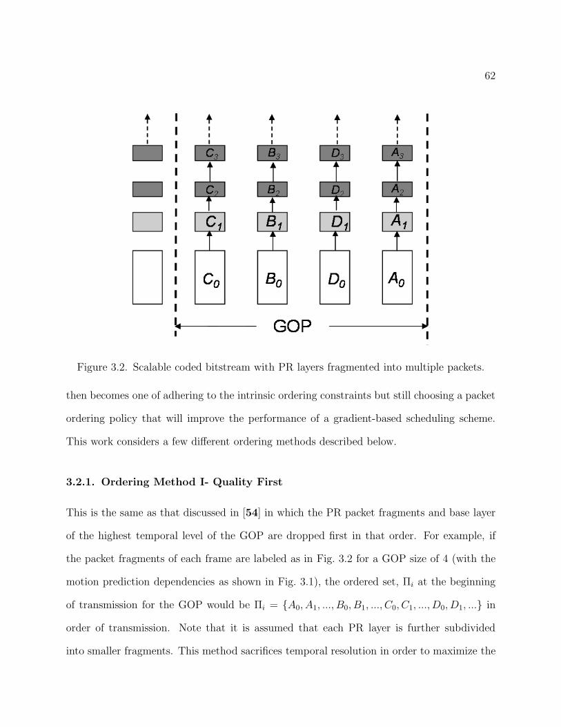
62
Figure 3.2. Scalable coded bitstream with PR layers fragmented into multiple packets.
then becomes one of adhering to the intrinsic ordering constraints but still choosing a packet
ordering policy that will improve the performance of a gradient-based scheduling scheme.
This work considers a few different ordering methods described below.
3.2.1. Ordering Method I- Quality First
This is the same as that discussed in [54] in which the PR packet fragments and base layer
of the highest temporal level of the GOP are dropped first in that order. For example, if
the packet fragments of each frame are labeled as in Fig. 3.2 for a GOP size of 4 (with the
motion prediction dependencies as shown in Fig. 3.1), the ordered set, Πi at the beginning
of transmission for the GOP would be Πi = {A0, A1, ..., B0, B1, ..., C0, C1, ..., D0, D1, ...} in
order of transmission. Note that it is assumed that each PR layer is further subdivided
into smaller fragments. This method sacrifices temporal resolution in order to maximize the
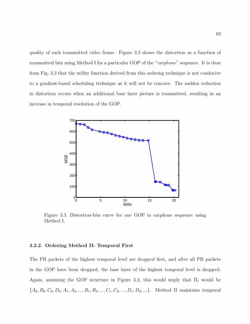
63
quality of each transmitted video frame. Figure 3.3 shows the distortion as a function of
transmitted bits using Method I for a particular GOP of the “carphone” sequence. It is clear
from Fig. 3.3 that the utility function derived from this ordering technique is not conducive
to a gradient-based scheduling technique as it will not be concave. The sudden reduction
in distortion occurs when an additional base layer picture is transmitted, resulting in an
increase in temporal resolution of the GOP.
0 5 10 15 200
100
200
300
400
500
600
700
kbits
MS
E
Figure 3.3. Distortion-bits curve for one GOP in carphone sequence usingMethod I.
3.2.2. Ordering Method II- Temporal First
The PR packets of the highest temporal level are dropped first, and after all PR packets
in the GOP have been dropped, the base layer of the highest temporal level is dropped.
Again, assuming the GOP structure in Figure 3.2, this would imply that Πi would be
{A0, B0, C0, D0, A1, A2, ..., B1, B2, ..., C1, C2, ..., D1, D2, ...}. Method II maintains temporal
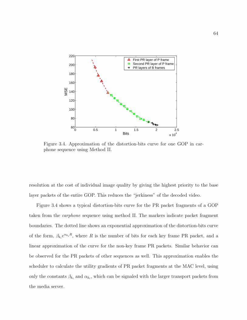
64
0 0.5 1 1.5 2 2.5
x 104
60
80
100
120
140
160
180
200
220
Bits
MS
E
First PR layer of P frameSecond PR layer of P framePR layers of B frames
Figure 3.4. Approximation of the distortion-bits curve for one GOP in car-phone sequence using Method II.
resolution at the cost of individual image quality by giving the highest priority to the base
layer packets of the entire GOP. This reduces the “jerkiness” of the decoded video.
Figure 3.4 shows a typical distortion-bits curve for the PR packet fragments of a GOP
taken from the carphone sequence using method II. The markers indicate packet fragment
boundaries. The dotted line shows an exponential approximation of the distortion-bits curve
of the form, βkieαki
R, where R is the number of bits for each key frame PR packet, and a
linear approximation of the curve for the non-key frame PR packets. Similar behavior can
be observed for the PR packets of other sequences as well. This approximation enables the
scheduler to calculate the utility gradients of PR packet fragments at the MAC level, using
only the constants βkiand αki
, which can be signaled with the larger transport packets from
the media server.
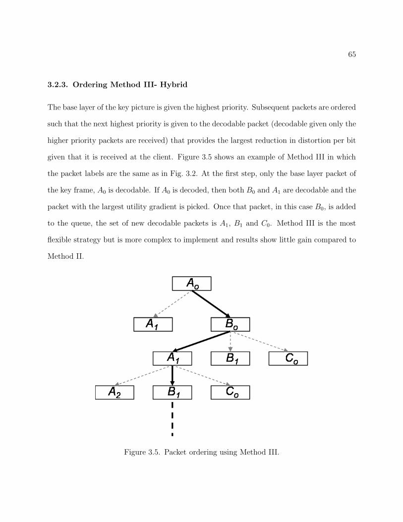
65
3.2.3. Ordering Method III- Hybrid
The base layer of the key picture is given the highest priority. Subsequent packets are ordered
such that the next highest priority is given to the decodable packet (decodable given only the
higher priority packets are received) that provides the largest reduction in distortion per bit
given that it is received at the client. Figure 3.5 shows an example of Method III in which
the packet labels are the same as in Fig. 3.2. At the first step, only the base layer packet of
the key frame, A0 is decodable. If A0 is decoded, then both B0 and A1 are decodable and the
packet with the largest utility gradient is picked. Once that packet, in this case B0, is added
to the queue, the set of new decodable packets is A1, B1 and C0. Method III is the most
flexible strategy but is more complex to implement and results show little gain compared to
Method II.
Figure 3.5. Packet ordering using Method III.
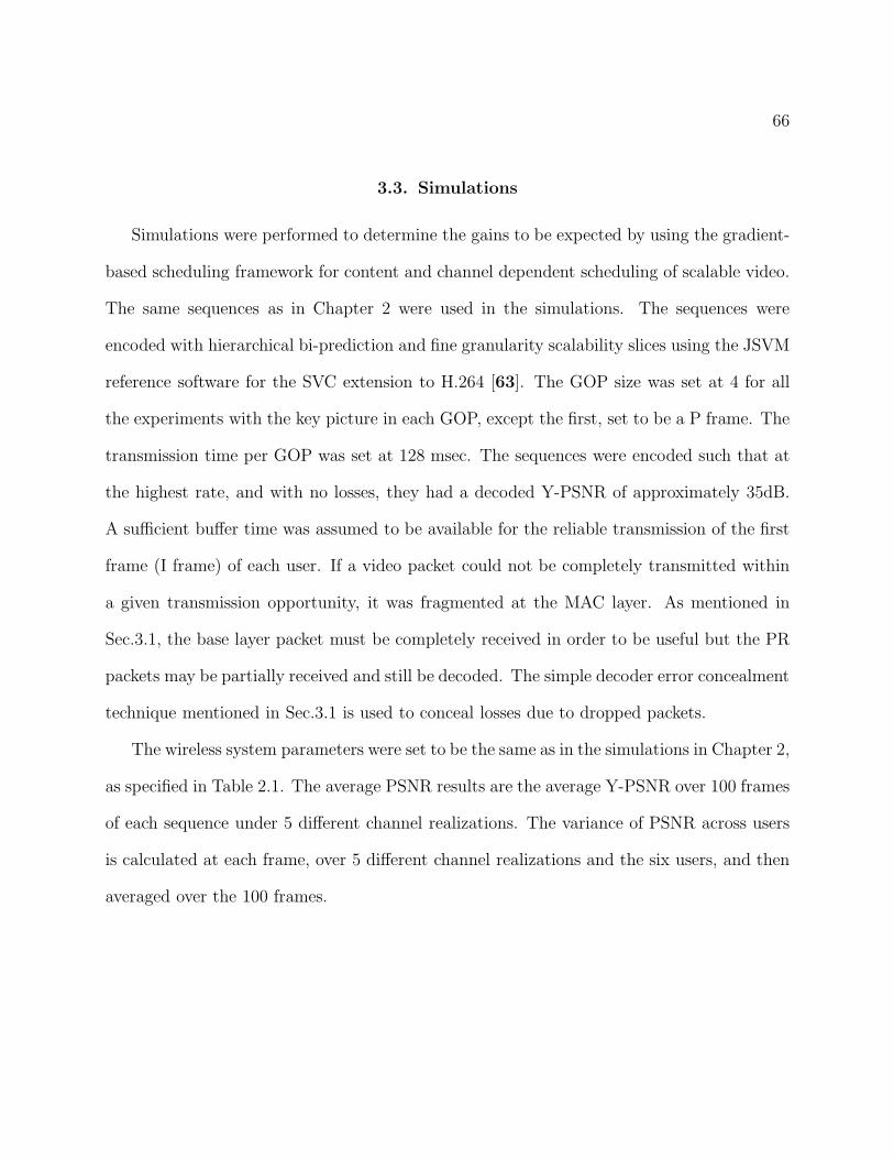
66
3.3. Simulations
Simulations were performed to determine the gains to be expected by using the gradient-
based scheduling framework for content and channel dependent scheduling of scalable video.
The same sequences as in Chapter 2 were used in the simulations. The sequences were
encoded with hierarchical bi-prediction and fine granularity scalability slices using the JSVM
reference software for the SVC extension to H.264 [63]. The GOP size was set at 4 for all
the experiments with the key picture in each GOP, except the first, set to be a P frame. The
transmission time per GOP was set at 128 msec. The sequences were encoded such that at
the highest rate, and with no losses, they had a decoded Y-PSNR of approximately 35dB.
A sufficient buffer time was assumed to be available for the reliable transmission of the first
frame (I frame) of each user. If a video packet could not be completely transmitted within
a given transmission opportunity, it was fragmented at the MAC layer. As mentioned in
Sec.3.1, the base layer packet must be completely received in order to be useful but the PR
packets may be partially received and still be decoded. The simple decoder error concealment
technique mentioned in Sec.3.1 is used to conceal losses due to dropped packets.
The wireless system parameters were set to be the same as in the simulations in Chapter 2,
as specified in Table 2.1. The average PSNR results are the average Y-PSNR over 100 frames
of each sequence under 5 different channel realizations. The variance of PSNR across users
is calculated at each frame, over 5 different channel realizations and the six users, and then
averaged over the 100 frames.
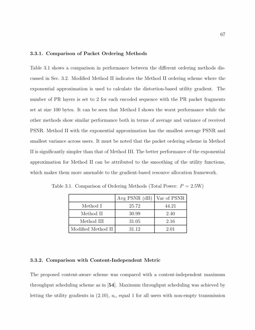
67
3.3.1. Comparison of Packet Ordering Methods
Table 3.1 shows a comparison in performance between the different ordering methods dis-
cussed in Sec. 3.2. Modified Method II indicates the Method II ordering scheme where the
exponential approximation is used to calculate the distortion-based utility gradient. The
number of PR layers is set to 2 for each encoded sequence with the PR packet fragments
set at size 100 bytes. It can be seen that Method I shows the worst performance while the
other methods show similar performance both in terms of average and variance of received
PSNR. Method II with the exponential approximation has the smallest average PSNR and
smallest variance across users. It must be noted that the packet ordering scheme in Method
II is significantly simpler than that of Method III. The better performance of the exponential
approximation for Method II can be attributed to the smoothing of the utility functions,
which makes them more amenable to the gradient-based resource allocation framework.
Table 3.1. Comparison of Ordering Methods (Total Power: P = 2.5W)
Avg PSNR (dB) Var of PSNR
Method I 25.72 44.21
Method II 30.99 2.40
Method III 31.05 2.16
Modified Method II 31.12 2.01
3.3.2. Comparison with Content-Independent Metric
The proposed content-aware scheme was compared with a content-independent maximum
throughput scheduling scheme as in [54]. Maximum throughput scheduling was achieved by
letting the utility gradients in (2.10), ui, equal 1 for all users with non-empty transmission
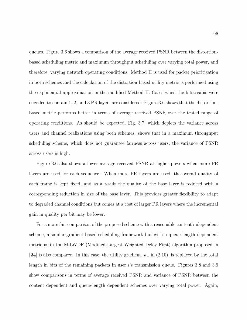
68
queues. Figure 3.6 shows a comparison of the average received PSNR between the distortion-
based scheduling metric and maximum throughput scheduling over varying total power, and
therefore, varying network operating conditions. Method II is used for packet prioritization
in both schemes and the calculation of the distortion-based utility metric is performed using
the exponential approximation in the modified Method II. Cases when the bitstreams were
encoded to contain 1, 2, and 3 PR layers are considered. Figure 3.6 shows that the distortion-
based metric performs better in terms of average received PSNR over the tested range of
operating conditions. As should be expected, Fig. 3.7, which depicts the variance across
users and channel realizations using both schemes, shows that in a maximum throughput
scheduling scheme, which does not guarantee fairness across users, the variance of PSNR
across users is high.
Figure 3.6 also shows a lower average received PSNR at higher powers when more PR
layers are used for each sequence. When more PR layers are used, the overall quality of
each frame is kept fixed, and as a result the quality of the base layer is reduced with a
corresponding reduction in size of the base layer. This provides greater flexibility to adapt
to degraded channel conditions but comes at a cost of larger PR layers where the incremental
gain in quality per bit may be lower.
For a more fair comparison of the proposed scheme with a reasonable content independent
scheme, a similar gradient-based scheduling framework but with a queue length dependent
metric as in the M-LWDF (Modified-Largest Weighted Delay First) algorithm proposed in
[24] is also compared. In this case, the utility gradient, ui, in (2.10), is replaced by the total
length in bits of the remaining packets in user i’s transmission queue. Figures 3.8 and 3.9
show comparisons in terms of average received PSNR and variance of PSNR between the
content dependent and queue-length dependent schemes over varying total power. Again,
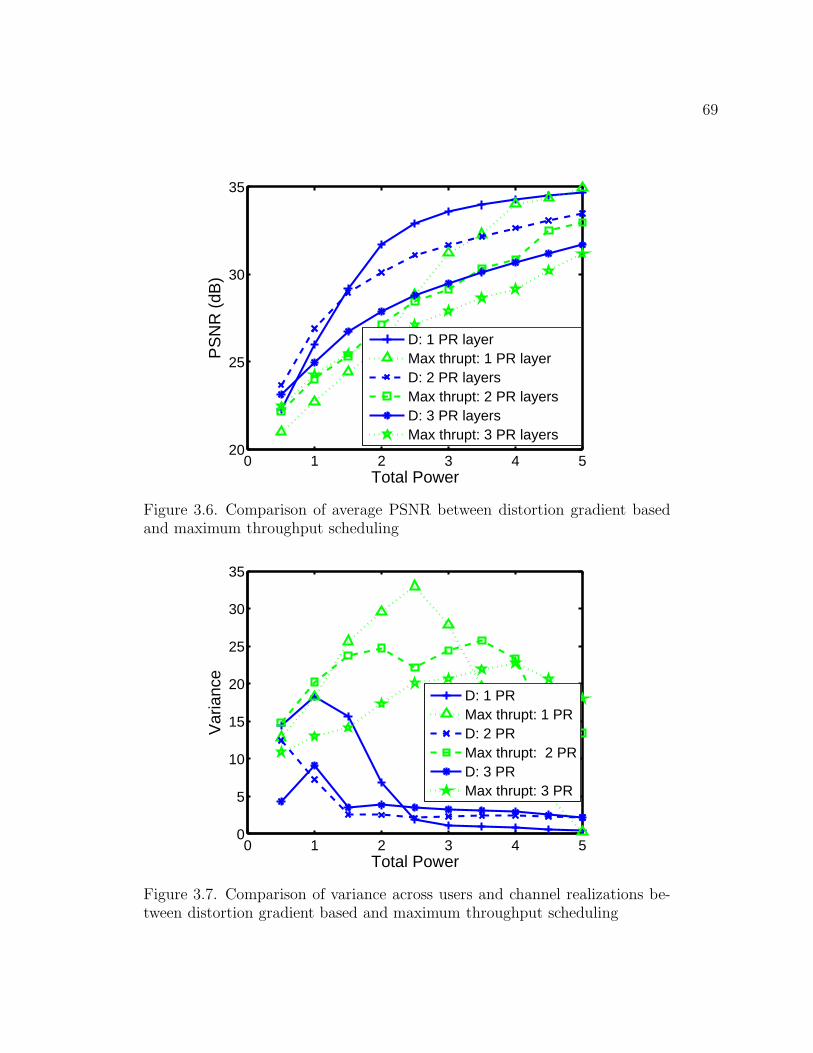
69
0 1 2 3 4 520
25
30
35
Total Power
PS
NR
(dB
)
D: 1 PR layerMax thrupt: 1 PR layerD: 2 PR layersMax thrupt: 2 PR layersD: 3 PR layersMax thrupt: 3 PR layers
Figure 3.6. Comparison of average PSNR between distortion gradient basedand maximum throughput scheduling
0 1 2 3 4 50
5
10
15
20
25
30
35
Total Power
Var
ianc
e
D: 1 PRMax thrupt: 1 PRD: 2 PRMax thrupt: 2 PRD: 3 PRMax thrupt: 3 PR
Figure 3.7. Comparison of variance across users and channel realizations be-tween distortion gradient based and maximum throughput scheduling
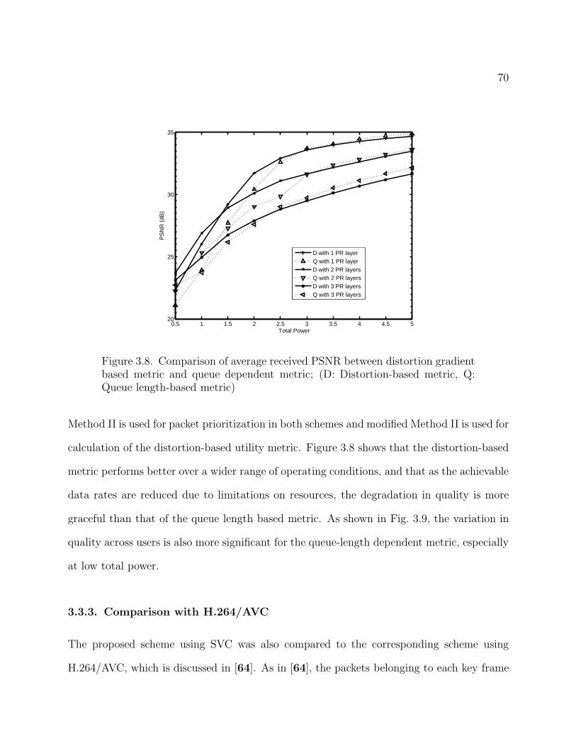
70
0.5 1 1.5 2 2.5 3 3.5 4 4.5 520
25
30
35
Total Power
PS
NR
(dB
)
D with 1 PR layerQ with 1 PR layerD with 2 PR layersQ with 2 PR layersD with 3 PR layersQ with 3 PR layers
Figure 3.8. Comparison of average received PSNR between distortion gradientbased metric and queue dependent metric; (D: Distortion-based metric, Q:Queue length-based metric)
Method II is used for packet prioritization in both schemes and modified Method II is used for
calculation of the distortion-based utility metric. Figure 3.8 shows that the distortion-based
metric performs better over a wider range of operating conditions, and that as the achievable
data rates are reduced due to limitations on resources, the degradation in quality is more
graceful than that of the queue length based metric. As shown in Fig. 3.9, the variation in
quality across users is also more significant for the queue-length dependent metric, especially
at low total power.
3.3.3. Comparison with H.264/AVC
The proposed scheme using SVC was also compared to the corresponding scheme using
H.264/AVC, which is discussed in [64]. As in [64], the packets belonging to each key frame
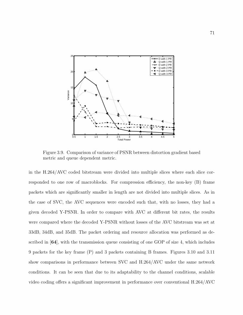
71
0.5 1 1.5 2 2.5 3 3.5 4 4.5 50
5
10
15
20
25
Total Power
Var
ianc
e
D with 1 PRQ with 1 PRD with 2 PRQ with 2 PRD with 3 PRQ with 3 PR
Figure 3.9. Comparison of variance of PSNR between distortion gradient basedmetric and queue dependent metric.
in the H.264/AVC coded bitstream were divided into multiple slices where each slice cor-
responded to one row of macroblocks. For compression efficiency, the non-key (B) frame
packets which are significantly smaller in length are not divided into multiple slices. As in
the case of SVC, the AVC sequences were encoded such that, with no losses, they had a
given decoded Y-PSNR. In order to compare with AVC at different bit rates, the results
were compared where the decoded Y-PSNR without losses of the AVC bitstream was set at
33dB, 34dB, and 35dB. The packet ordering and resource allocation was performed as de-
scribed in [64], with the transmission queue consisting of one GOP of size 4, which includes
9 packets for the key frame (P) and 3 packets containing B frames. Figures 3.10 and 3.11
show comparisons in performance between SVC and H.264/AVC under the same network
conditions. It can be seen that due to its adaptability to the channel conditions, scalable
video coding offers a significant improvement in performance over conventional H.264/AVC
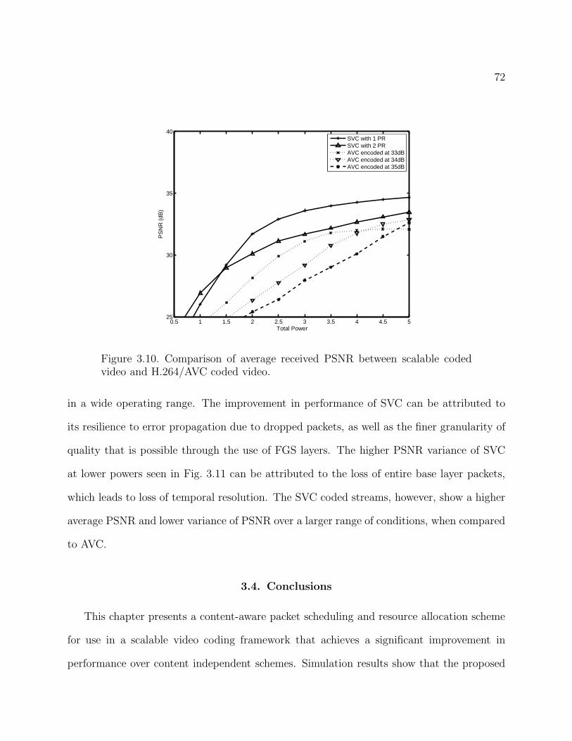
72
0.5 1 1.5 2 2.5 3 3.5 4 4.5 525
30
35
40
Total Power
PS
NR
(dB
)
SVC with 1 PRSVC with 2 PRAVC encoded at 33dBAVC encoded at 34dBAVC encoded at 35dB
Figure 3.10. Comparison of average received PSNR between scalable codedvideo and H.264/AVC coded video.
in a wide operating range. The improvement in performance of SVC can be attributed to
its resilience to error propagation due to dropped packets, as well as the finer granularity of
quality that is possible through the use of FGS layers. The higher PSNR variance of SVC
at lower powers seen in Fig. 3.11 can be attributed to the loss of entire base layer packets,
which leads to loss of temporal resolution. The SVC coded streams, however, show a higher
average PSNR and lower variance of PSNR over a larger range of conditions, when compared
to AVC.
3.4. Conclusions
This chapter presents a content-aware packet scheduling and resource allocation scheme
for use in a scalable video coding framework that achieves a significant improvement in
performance over content independent schemes. Simulation results show that the proposed
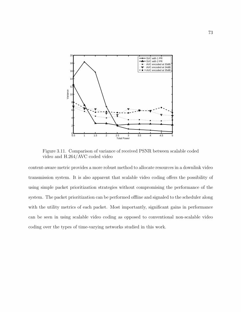
73
0.5 1 1.5 2 2.5 3 3.5 4 4.5 50
2
4
6
8
10
12
14
16
18
20
Total Power
Var
ianc
e
SVC with 1 PRSVC with 2 PRAVC encoded at 33dBAVC encoded at 34dBAVC encoded at 35dB
Figure 3.11. Comparison of variance of received PSNR between scalable codedvideo and H.264/AVC coded video
content-aware metric provides a more robust method to allocate resources in a downlink video
transmission system. It is also apparent that scalable video coding offers the possibility of
using simple packet prioritization strategies without compromising the performance of the
system. The packet prioritization can be performed offline and signaled to the scheduler along
with the utility metrics of each packet. Most importantly, significant gains in performance
can be seen in using scalable video coding as opposed to conventional non-scalable video
coding over the types of time-varying networks studied in this work.
74
CHAPTER 4
Resource Allocation in Packet Lossy Channels
Previous chapters assume the availability of perfect channel state information at the
scheduler prior to making a scheduling decision. As a result, they use a zero-outage capacity
model to determine the achievable data rates for each user. Therefore, the losses considered
in the previous simulations occur only when packets are not transmitted on time due to a
combination of the congestion at the transmission queue, and the scheduling priority of each
packet. This chapter considers a realistic scenario in which only an imperfect estimate of the
channel state is available. In this case, an outage capacity model can be used to determine a
probability of channel loss based on the estimated channel state, the allocated resources, and
the transmission rate [65]. Random channel losses combined with complex error concealment
at the decoder make it impossible for the scheduler to obtain a deterministic estimate of
the actual distortion of the sequence at the receiver. Instead, the scheduler must use the
expected quality at the receiver in order to determine its scheduling decisions. Efficient
methods exist for recursively calculating the expected distortion at the receiver [8, 66].
This chapter uses a scheme for ordering the packets by their contribution towards reducing
the expected distortion of the received video to jointly optimize the resource allocation
(power and bandwidth) and transmission rates assigned to each user such that the expected
distortion over all users is minimized.
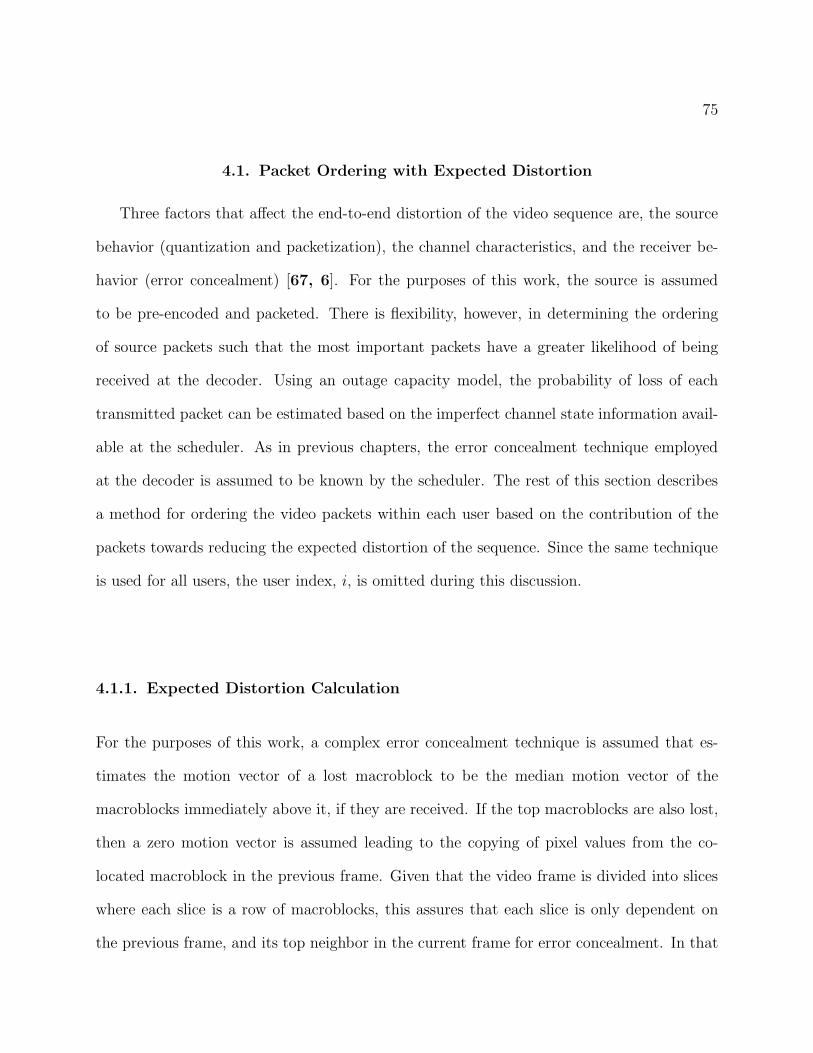
75
4.1. Packet Ordering with Expected Distortion
Three factors that affect the end-to-end distortion of the video sequence are, the source
behavior (quantization and packetization), the channel characteristics, and the receiver be-
havior (error concealment) [67, 6]. For the purposes of this work, the source is assumed
to be pre-encoded and packeted. There is flexibility, however, in determining the ordering
of source packets such that the most important packets have a greater likelihood of being
received at the decoder. Using an outage capacity model, the probability of loss of each
transmitted packet can be estimated based on the imperfect channel state information avail-
able at the scheduler. As in previous chapters, the error concealment technique employed
at the decoder is assumed to be known by the scheduler. The rest of this section describes
a method for ordering the video packets within each user based on the contribution of the
packets towards reducing the expected distortion of the sequence. Since the same technique
is used for all users, the user index, i, is omitted during this discussion.
4.1.1. Expected Distortion Calculation
For the purposes of this work, a complex error concealment technique is assumed that es-
timates the motion vector of a lost macroblock to be the median motion vector of the
macroblocks immediately above it, if they are received. If the top macroblocks are also lost,
then a zero motion vector is assumed leading to the copying of pixel values from the co-
located macroblock in the previous frame. Given that the video frame is divided into slices
where each slice is a row of macroblocks, this assures that each slice is only dependent on
the previous frame, and its top neighbor in the current frame for error concealment. In that
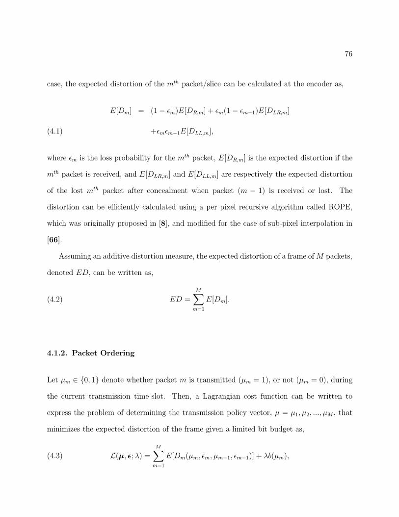
76
case, the expected distortion of the mth packet/slice can be calculated at the encoder as,
E[Dm] = (1 − ǫm)E[DR,m] + ǫm(1 − ǫm−1)E[DLR,m]
+ǫmǫm−1E[DLL,m],(4.1)
where ǫm is the loss probability for the mth packet, E[DR,m] is the expected distortion if the
mth packet is received, and E[DLR,m] and E[DLL,m] are respectively the expected distortion
of the lost mth packet after concealment when packet (m − 1) is received or lost. The
distortion can be efficiently calculated using a per pixel recursive algorithm called ROPE,
which was originally proposed in [8], and modified for the case of sub-pixel interpolation in
[66].
Assuming an additive distortion measure, the expected distortion of a frame of M packets,
denoted ED, can be written as,
(4.2) ED =M∑
m=1
E[Dm].
4.1.2. Packet Ordering
Let µm ∈ {0, 1} denote whether packet m is transmitted (µm = 1), or not (µm = 0), during
the current transmission time-slot. Then, a Lagrangian cost function can be written to
express the problem of determining the transmission policy vector, µ = µ1, µ2, ..., µM , that
minimizes the expected distortion of the frame given a limited bit budget as,
(4.3) L(µ, ǫ; λ) =
M∑
m=1
E[Dm(µm, ǫm, µm−1, ǫm−1)] + λb(µm),
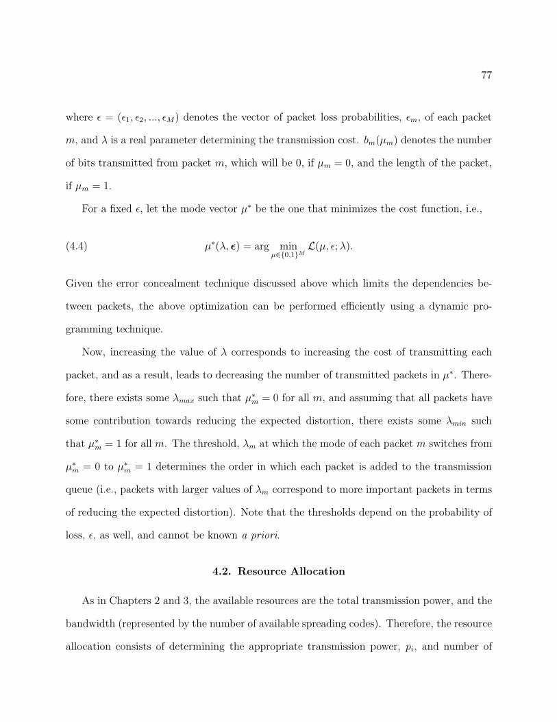
77
where ǫ = (ǫ1, ǫ2, ..., ǫM) denotes the vector of packet loss probabilities, ǫm, of each packet
m, and λ is a real parameter determining the transmission cost. bm(µm) denotes the number
of bits transmitted from packet m, which will be 0, if µm = 0, and the length of the packet,
if µm = 1.
For a fixed ǫ, let the mode vector µ∗ be the one that minimizes the cost function, i.e.,
(4.4) µ∗(λ, ǫ) = arg minµ∈{0,1}M
L(µ, ǫ; λ).
Given the error concealment technique discussed above which limits the dependencies be-
tween packets, the above optimization can be performed efficiently using a dynamic pro-
gramming technique.
Now, increasing the value of λ corresponds to increasing the cost of transmitting each
packet, and as a result, leads to decreasing the number of transmitted packets in µ∗. There-
fore, there exists some λmax such that µ∗m = 0 for all m, and assuming that all packets have
some contribution towards reducing the expected distortion, there exists some λmin such
that µ∗m = 1 for all m. The threshold, λm at which the mode of each packet m switches from
µ∗m = 0 to µ∗
m = 1 determines the order in which each packet is added to the transmission
queue (i.e., packets with larger values of λm correspond to more important packets in terms
of reducing the expected distortion). Note that the thresholds depend on the probability of
loss, ǫ, as well, and cannot be known a priori.
4.2. Resource Allocation
As in Chapters 2 and 3, the available resources are the total transmission power, and the
bandwidth (represented by the number of available spreading codes). Therefore, the resource
allocation consists of determining the appropriate transmission power, pi, and number of
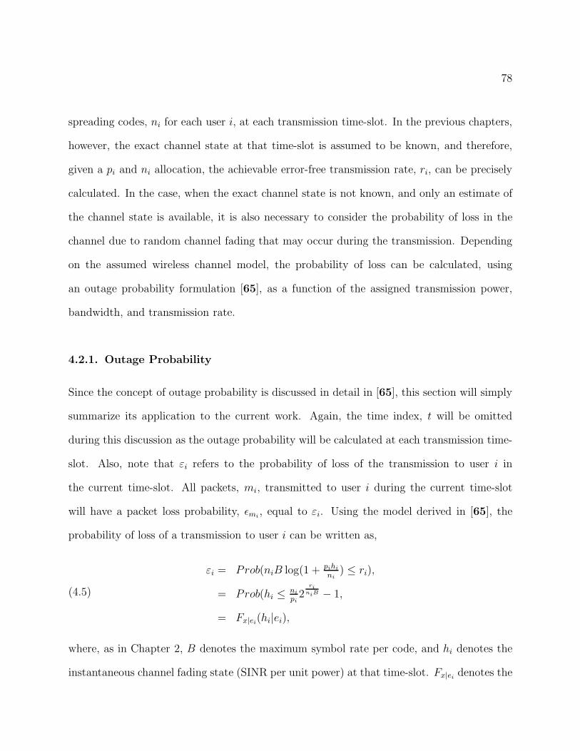
78
spreading codes, ni for each user i, at each transmission time-slot. In the previous chapters,
however, the exact channel state at that time-slot is assumed to be known, and therefore,
given a pi and ni allocation, the achievable error-free transmission rate, ri, can be precisely
calculated. In the case, when the exact channel state is not known, and only an estimate of
the channel state is available, it is also necessary to consider the probability of loss in the
channel due to random channel fading that may occur during the transmission. Depending
on the assumed wireless channel model, the probability of loss can be calculated, using
an outage probability formulation [65], as a function of the assigned transmission power,
bandwidth, and transmission rate.
4.2.1. Outage Probability
Since the concept of outage probability is discussed in detail in [65], this section will simply
summarize its application to the current work. Again, the time index, t will be omitted
during this discussion as the outage probability will be calculated at each transmission time-
slot. Also, note that εi refers to the probability of loss of the transmission to user i in
the current time-slot. All packets, mi, transmitted to user i during the current time-slot
will have a packet loss probability, ǫmi, equal to εi. Using the model derived in [65], the
probability of loss of a transmission to user i can be written as,
(4.5)
εi = Prob(niB log(1 + pihi
ni) ≤ ri),
= Prob(hi ≤ni
pi2
riniB − 1,
= Fx|ei(hi|ei),
where, as in Chapter 2, B denotes the maximum symbol rate per code, and hi denotes the
instantaneous channel fading state (SINR per unit power) at that time-slot. Fx|eidenotes the
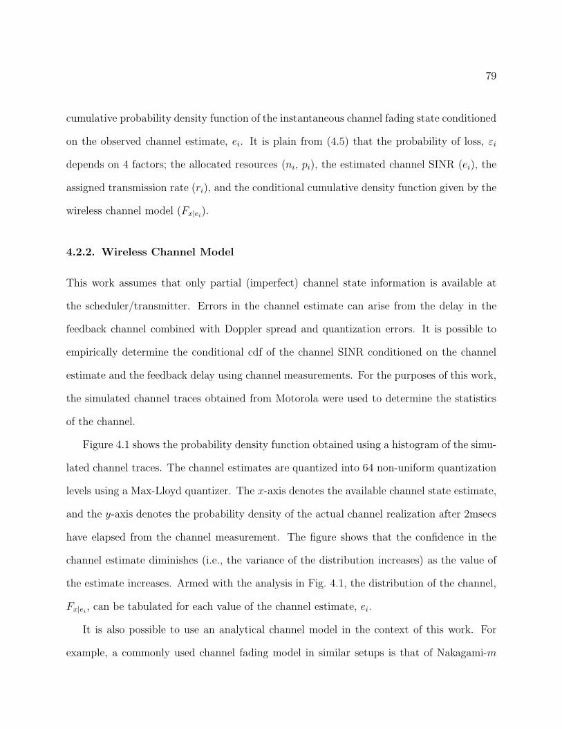
79
cumulative probability density function of the instantaneous channel fading state conditioned
on the observed channel estimate, ei. It is plain from (4.5) that the probability of loss, εi
depends on 4 factors; the allocated resources (ni, pi), the estimated channel SINR (ei), the
assigned transmission rate (ri), and the conditional cumulative density function given by the
wireless channel model (Fx|ei).
4.2.2. Wireless Channel Model
This work assumes that only partial (imperfect) channel state information is available at
the scheduler/transmitter. Errors in the channel estimate can arise from the delay in the
feedback channel combined with Doppler spread and quantization errors. It is possible to
empirically determine the conditional cdf of the channel SINR conditioned on the channel
estimate and the feedback delay using channel measurements. For the purposes of this work,
the simulated channel traces obtained from Motorola were used to determine the statistics
of the channel.
Figure 4.1 shows the probability density function obtained using a histogram of the simu-
lated channel traces. The channel estimates are quantized into 64 non-uniform quantization
levels using a Max-Lloyd quantizer. The x-axis denotes the available channel state estimate,
and the y-axis denotes the probability density of the actual channel realization after 2msecs
have elapsed from the channel measurement. The figure shows that the confidence in the
channel estimate diminishes (i.e., the variance of the distribution increases) as the value of
the estimate increases. Armed with the analysis in Fig. 4.1, the distribution of the channel,
Fx|ei, can be tabulated for each value of the channel estimate, ei.
It is also possible to use an analytical channel model in the context of this work. For
example, a commonly used channel fading model in similar setups is that of Nakagami-m
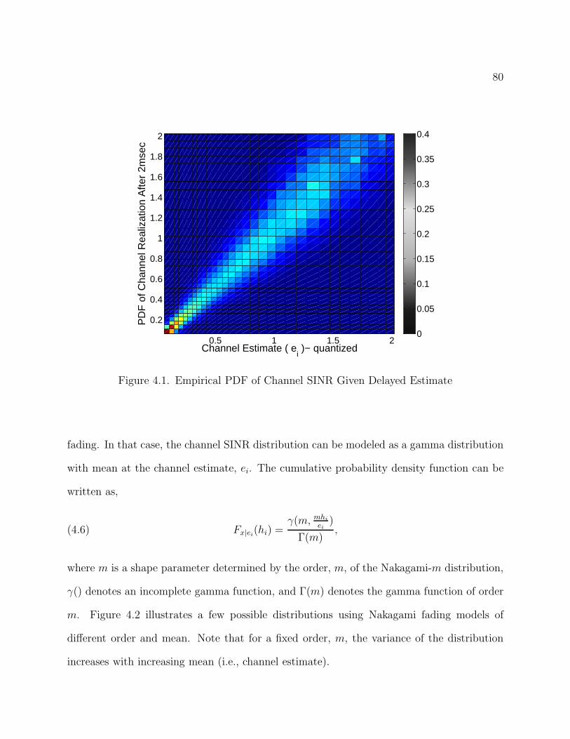
80
0.5 1 1.5 2
0.2
0.4
0.6
0.8
1
1.2
1.4
1.6
1.8
2
Channel Estimate ( ei )− quantized
PD
F o
f Cha
nnel
Rea
lizat
ion
Afte
r 2m
sec
0
0.05
0.1
0.15
0.2
0.25
0.3
0.35
0.4
Figure 4.1. Empirical PDF of Channel SINR Given Delayed Estimate
fading. In that case, the channel SINR distribution can be modeled as a gamma distribution
with mean at the channel estimate, ei. The cumulative probability density function can be
written as,
(4.6) Fx|ei(hi) =
γ(m, mhi
ei)
Γ(m),
where m is a shape parameter determined by the order, m, of the Nakagami-m distribution,
γ() denotes an incomplete gamma function, and Γ(m) denotes the gamma function of order
m. Figure 4.2 illustrates a few possible distributions using Nakagami fading models of
different order and mean. Note that for a fixed order, m, the variance of the distribution
increases with increasing mean (i.e., channel estimate).
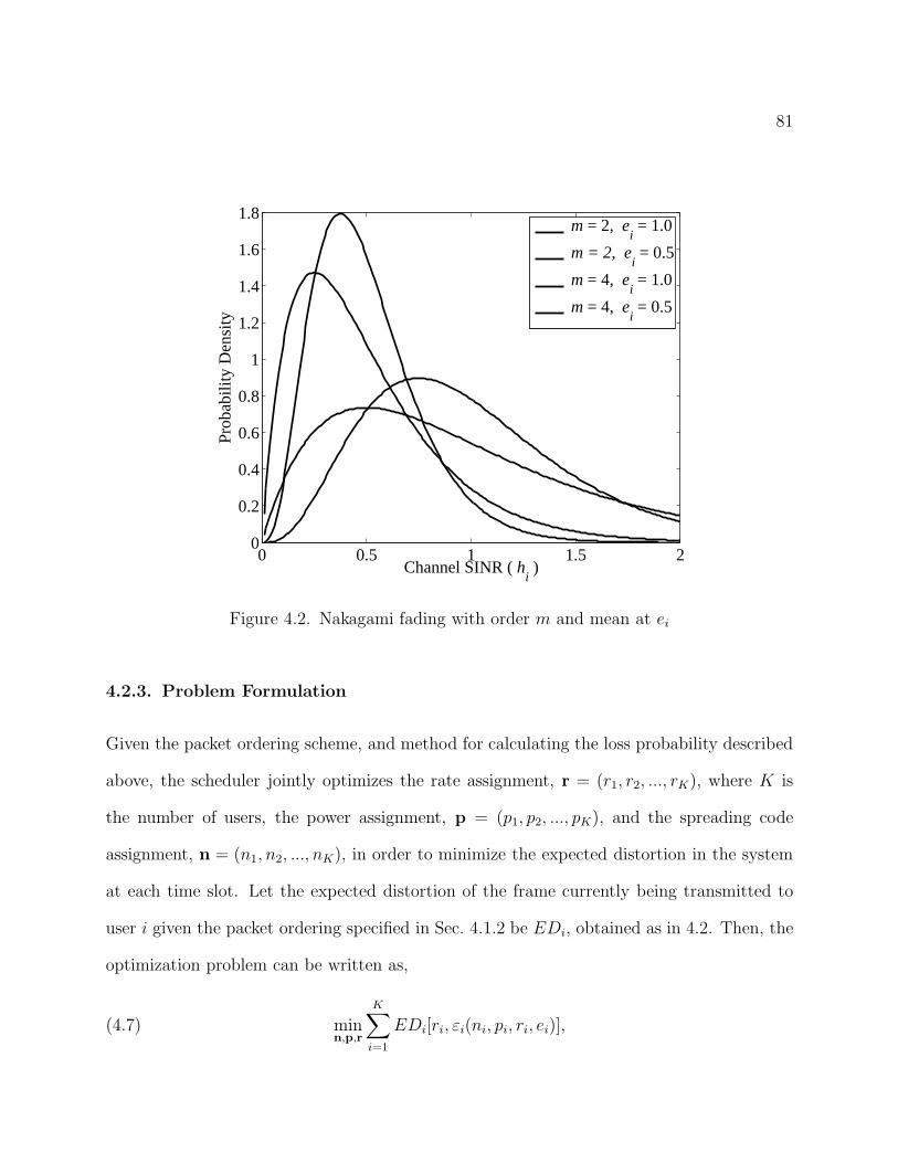
81
0 0.5 1 1.5 20
0.2
0.4
0.6
0.8
1
1.2
1.4
1.6
1.8
Channel SINR ( hi )
Prob
abili
ty D
ensi
ty
m = 2, ei = 1.0
m = 2, ei = 0.5
m = 4, ei = 1.0
m = 4, ei = 0.5
Figure 4.2. Nakagami fading with order m and mean at ei
4.2.3. Problem Formulation
Given the packet ordering scheme, and method for calculating the loss probability described
above, the scheduler jointly optimizes the rate assignment, r = (r1, r2, ..., rK), where K is
the number of users, the power assignment, p = (p1, p2, ..., pK), and the spreading code
assignment, n = (n1, n2, ..., nK), in order to minimize the expected distortion in the system
at each time slot. Let the expected distortion of the frame currently being transmitted to
user i given the packet ordering specified in Sec. 4.1.2 be EDi, obtained as in 4.2. Then, the
optimization problem can be written as,
(4.7) minn,p,r
K∑
i=1
EDi[ri, εi(ni, pi, ri, ei)],
82
such that,
(4.8) 0 ≤K∑
i=1
ni ≤ N, 0 ≤ ni ≤ Ni, ∀i,
(4.9) 0 ≤K∑
i=1
pi ≤ P, ∀i,
and,
(4.10) 0 ≤piei
ni≤ Si, ∀i.
In (4.10), Si is a maximum SINR constraint [26]. The solution to (4.7), however, is not
trivial, as an analytical form for EDi, which will satisfy different video content and channel
conditions, cannot be easily derived. Therefore, a two-step approach is used to tackle the
problem.
As a first step, observe that for a given probability of loss, εi, and channel estimate, ei,
the rate assignment, ri, must be a function of ni and pi as specified in (4.5). To further
simplify the implementation of this step, EDi is linearized, and then, for the fixed value of
εi, the problem,
(4.11) maxn,p
K∑
i=1
−∂
∂riEDi[ri(ni, pi, ǫi, ǫi] · ri(ni, pi, ǫi),
is solved subject to the constraints in (4.8), (4.9), and (4.10). Here, ∂/∂ri denotes the partial
derivative with respect to ri. Note that the gradient of EDi with respect to ri for a fixed
probability of loss can be numerically calculated using the methods described in Sec. 4.1.2,
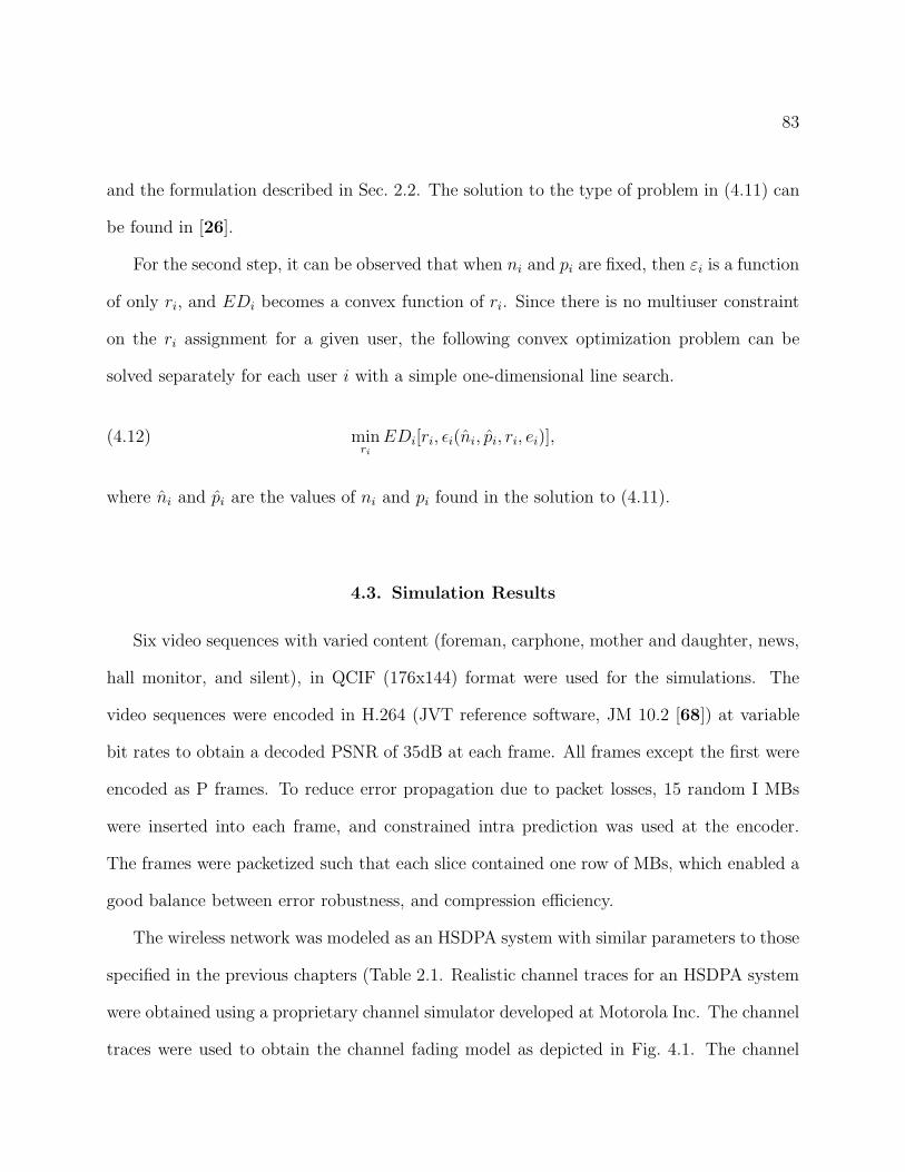
83
and the formulation described in Sec. 2.2. The solution to the type of problem in (4.11) can
be found in [26].
For the second step, it can be observed that when ni and pi are fixed, then εi is a function
of only ri, and EDi becomes a convex function of ri. Since there is no multiuser constraint
on the ri assignment for a given user, the following convex optimization problem can be
solved separately for each user i with a simple one-dimensional line search.
(4.12) minri
EDi[ri, ǫi(ni, pi, ri, ei)],
where ni and pi are the values of ni and pi found in the solution to (4.11).
4.3. Simulation Results
Six video sequences with varied content (foreman, carphone, mother and daughter, news,
hall monitor, and silent), in QCIF (176x144) format were used for the simulations. The
video sequences were encoded in H.264 (JVT reference software, JM 10.2 [68]) at variable
bit rates to obtain a decoded PSNR of 35dB at each frame. All frames except the first were
encoded as P frames. To reduce error propagation due to packet losses, 15 random I MBs
were inserted into each frame, and constrained intra prediction was used at the encoder.
The frames were packetized such that each slice contained one row of MBs, which enabled a
good balance between error robustness, and compression efficiency.
The wireless network was modeled as an HSDPA system with similar parameters to those
specified in the previous chapters (Table 2.1. Realistic channel traces for an HSDPA system
were obtained using a proprietary channel simulator developed at Motorola Inc. The channel
traces were used to obtain the channel fading model as depicted in Fig. 4.1. The channel
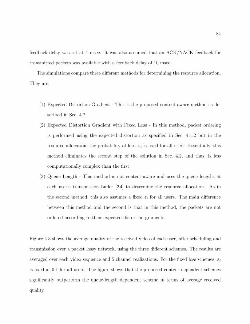
84
feedback delay was set at 4 msec. It was also assumed that an ACK/NACK feedback for
transmitted packets was available with a feedback delay of 10 msec.
The simulations compare three different methods for determining the resource allocation.
They are:
(1) Expected Distortion Gradient - This is the proposed content-aware method as de-
scribed in Sec. 4.2.
(2) Expected Distortion Gradient with Fixed Loss - In this method, packet ordering
is performed using the expected distortion as specified in Sec. 4.1.2 but in the
resource allocation, the probability of loss, εi is fixed for all users. Essentially, this
method eliminates the second step of the solution in Sec. 4.2, and thus, is less
computationally complex than the first.
(3) Queue Length - This method is not content-aware and uses the queue lengths at
each user’s transmission buffer [24] to determine the resource allocation. As in
the second method, this also assumes a fixed εi for all users. The main difference
between this method and the second is that in this method, the packets are not
ordered according to their expected distortion gradients.
Figure 4.3 shows the average quality of the received video of each user, after scheduling and
transmission over a packet lossy network, using the three different schemes. The results are
averaged over each video sequence and 5 channel realizations. For the fixed loss schemes, εi
is fixed at 0.1 for all users. The figure shows that the proposed content-dependent schemes
significantly outperform the queue-length dependent scheme in terms of average received
quality.
85
1 2 3 4 5 6 Avg20
25
30
35
User #
PS
NR
(dB
)
ED gradientED gradient with ε=0.1Queue length
Figure 4.3. Average received PSNR
Figure 4.4 and 4.5 show the variance of the received PSNR using the three different
schemes. Figure 4.4 shows the variance of quality at each video frame across all users
and channel realizations. The queue length scheme shows a significantly larger variance
across users than the others. quality at each frame over the users and channel realizations.
These results can be attributed partly to the packet ordering and also to the fact that the
queue length dependent scheme does not consider the concealability of video packets when
allocating resources across users. Therefore, assuming two users have equal queue lengths,
the user who receives video packets, that are difficult to conceal if lost, will not be given
priority over the other user. Figure 4.5 shows the variance of quality across all video frames
of the sequence and multiple channel realizations averaged over all the users. This represents
the variability in quality experienced by each user during a given transmission session. Again,
86
40 60 80 100 1200
2
4
6
8
10
Frame
Var
ianc
e
ED gradientED gradient with ε=0.1Queue length
Figure 4.4. Received PSNR variance across users
the queue length method shows a significantly higher variance. Also, the expected distortion
gradient method with fixed probability of loss shows a higher variance than the first method
that optimizes over the probability of loss.
Figures 4.6 and 4.7 show the variation in average received PSNR as the value of εi is
varied for the two schemes that use a fixed probability of loss. Figure 4.6 shows the results for
the content-aware scheme, and it is apparent that the overall video quality remains within
a 0.5dB range over a large range of ε. This result shows that the choice of ε does not
significantly affect the performance of the system for the content-aware case. Figure 4.7
shows the results for the queue length scheme. In this case, the choice of ε does have an
impact on the average received PSNR.
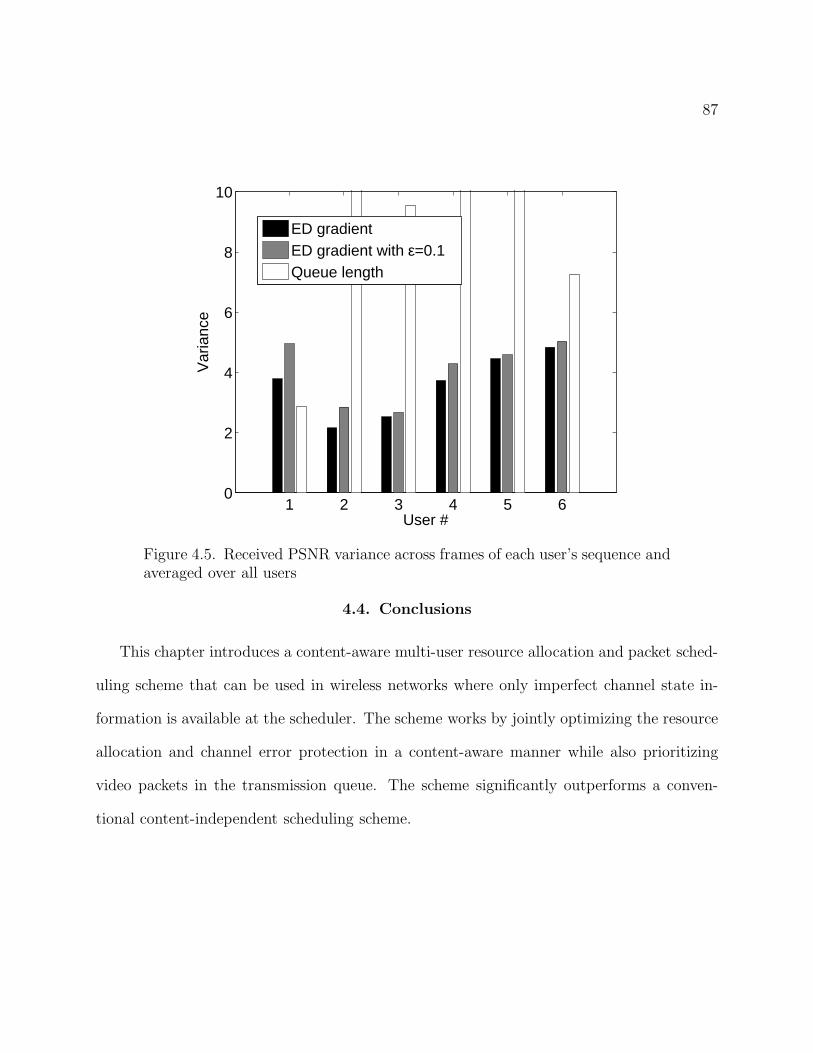
87
1 2 3 4 5 60
2
4
6
8
10
User #
Var
ianc
e
ED gradientED gradient with ε=0.1Queue length
Figure 4.5. Received PSNR variance across frames of each user’s sequence andaveraged over all users
4.4. Conclusions
This chapter introduces a content-aware multi-user resource allocation and packet sched-
uling scheme that can be used in wireless networks where only imperfect channel state in-
formation is available at the scheduler. The scheme works by jointly optimizing the resource
allocation and channel error protection in a content-aware manner while also prioritizing
video packets in the transmission queue. The scheme significantly outperforms a conven-
tional content-independent scheduling scheme.
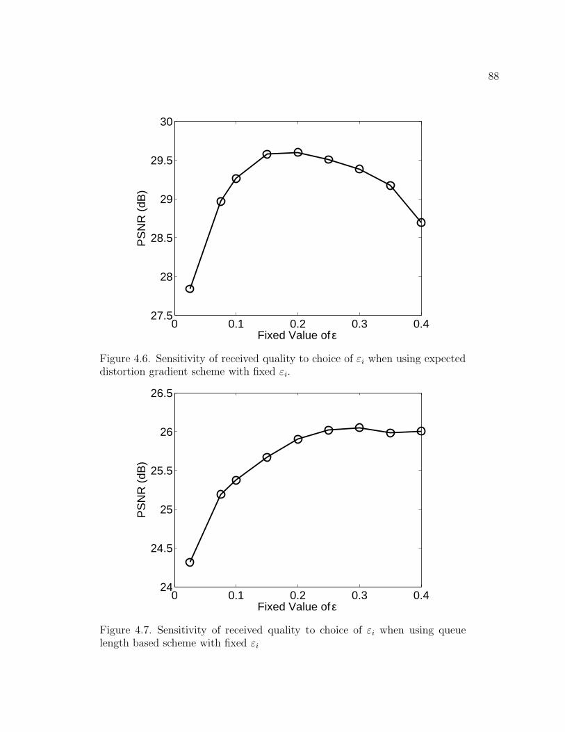
88
0 0.1 0.2 0.3 0.427.5
28
28.5
29
29.5
30
Fixed Value of ε
PS
NR
(dB
)
Figure 4.6. Sensitivity of received quality to choice of εi when using expecteddistortion gradient scheme with fixed εi.
0 0.1 0.2 0.3 0.424
24.5
25
25.5
26
26.5
Fixed Value of ε
PS
NR
(dB
)
Figure 4.7. Sensitivity of received quality to choice of εi when using queuelength based scheme with fixed εi

89
CHAPTER 5
Conclusions and Future Work
5.1. Summary and Conclusions
This dissertation addresses the problem of video packet scheduling and resource allocation
for downlink video transmission in multiuser wireless networks. The first chapter discusses
the scope of the problem, and provides some background on the advancements in wireless
access technologies, video compression standards, and scheduling theory, that have lead the
way for the proposed solutions in this work.
In the second chapter, the general scheduling and resource allocation framework is dis-
cussed in detail, with simulations showing the performance gains that can be expected by
using the distortion based utilities for resource allocation and scheduling. The simulations
using varied video content shows the value of using content-dependent techniques instead
of the conventional content-independent techniques for resource allocation. An overall per-
formance gain of over 3dB PSNR can be achieved by using the proposed techniques. An
investigation of the use of a more complicated video error concealment technique shows that
taking the complicated decoder error concealment into account at the scheduler can also be
beneficial in terms of performance. It is also important to note that the distortion based met-
ric calculations, when performed offline with less knowledge of the channel characteristics,
can still outperform the content-independent metrics.
The use of scalable video coding techniques is discussed in the second chapter with
special emphasis on the hierarchical bi-prediction and fine granularity scalability methods
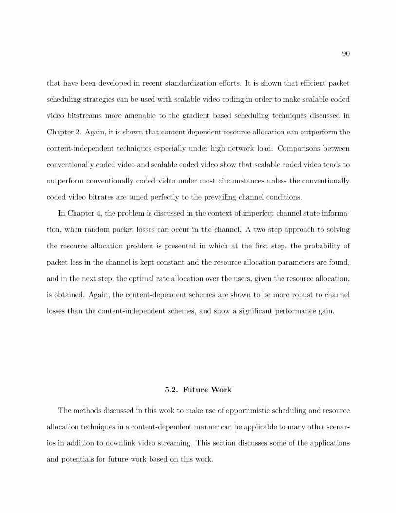
90
that have been developed in recent standardization efforts. It is shown that efficient packet
scheduling strategies can be used with scalable video coding in order to make scalable coded
video bitstreams more amenable to the gradient based scheduling techniques discussed in
Chapter 2. Again, it is shown that content dependent resource allocation can outperform the
content-independent techniques especially under high network load. Comparisons between
conventionally coded video and scalable coded video show that scalable coded video tends to
outperform conventionally coded video under most circumstances unless the conventionally
coded video bitrates are tuned perfectly to the prevailing channel conditions.
In Chapter 4, the problem is discussed in the context of imperfect channel state informa-
tion, when random packet losses can occur in the channel. A two step approach to solving
the resource allocation problem is presented in which at the first step, the probability of
packet loss in the channel is kept constant and the resource allocation parameters are found,
and in the next step, the optimal rate allocation over the users, given the resource allocation,
is obtained. Again, the content-dependent schemes are shown to be more robust to channel
losses than the content-independent schemes, and show a significant performance gain.
5.2. Future Work
The methods discussed in this work to make use of opportunistic scheduling and resource
allocation techniques in a content-dependent manner can be applicable to many other scenar-
ios in addition to downlink video streaming. This section discusses some of the applications
and potentials for future work based on this work.
91
5.2.1. Uplink Video Transmission
Applications such as uploading of video content to a centralized server, video conferencing,
and video surveillance over wireless networks are among the potential applications that
will benefit from the increased throughput offered by emerging fourth generation wireless
networks. In this setting, an important problem will be that of providing high quality of
service on the wireless uplink. Most uplink video applications will also require real-time
video encoding at the mobile client. Therefore, joint source and channel coding methods
can be envisioned in which the source and channel coding schemes adapt in real-time to the
prevailing channel conditions as well as transmitted video content. Important factors such
as exploiting multiuser diversity, maintaining fairness across users, controlling congestion,
reducing latency and increasing error resilience, must be taken into account when devising the
source and channel resource allocation strategies for multiuser wireless video communication.
Dynamic channel and network conditions as well as the need to adapt the video en-
coding in real-time, make the opportunistic scheduling and resource allocation methods
discussed in this work an attractive basis for research in uplink video transmission as well.
In the uplink case, however, the encoded packets will only be contained at the client, and
therefore, information on each user’s content will not be immediately available at the base
station. Emerging wireless technologies such as WiMAX [14] are leaning towards polling
based mechanisms to determine the resource allocations for each client. In order to perform
content-adaptive resource allocation, the information on each user’s content will need to be
communicated by each client to the MAC scheduler at the wireless base station. Therefore,
efficient methods will need to be developed for communicating content-specific information
92
(eg., distortion-based utility functions, delay deadlines) to the base station. Once such in-
formation is available content-dependent gradient-based resource allocation strategies such
as those proposed in this dissertation can be adapted to the uplink case as well.
In uplink video transmission, the base station will not have access to sufficient information
on the video content in order to perform a joint optimization over both the scheduling and
resource allocation. Therefore, the two may need to be performed separately. One possible
approach to tackle this problem would be for the mobile user to assume a fixed packet loss
rate during the packet scheduling. Then, the expected distortion gradients found using the
fixed packet loss rates can be communicated to the base station, which can in turn reply
with a resource allocation optimized over all the uplink users. The mobile client can then
adapt its transmission rate to the resources allocated by the base station.
Another important problem in multiuser uplink video transmission with real-time video
encoding is that of controlling the congestion in the wireless network. In video encoding, the
rate distortion optimization at the video encoder assumes a certain bit budget is available
for the encoding of a video frame (Note that the rate distortion optimization problem can
also be formulated as one of minimizing the source rate subject to a maximum distortion.)
Congestion control in the system can be achieved by adaptively changing the available bit
budget (or inversely, the maximum tolerable distortion) for each client based on the measured
user throughput for previous video frames. Naturally, this leads to two possible techniques,
one which simultaneously reduces the bit budget for every user given the average throughput
across all users, and the other, which performs a decentralized rate adaptation similar to the
AIMD (Additive Increase Multiplicative Decrease) scheme used in TCP based congestion
control. In the case of wireless data transmission, the choice of proper mechanism is further
complicated by the fact that packet losses can occur due to both congestion and random
93
channel quality fluctuations. Therefore, the proper technique for congestion control is an
important area for future study of uplink video transmission.
5.2.2. Video Transmission Over Mobile Ad Hoc Networks
Video transmission over mobile ad hoc wireless networks is another key area of research that
can benefit from the scheduling and resource allocation techniques discussed in this work.
Such networks can be used for military surveillance applications, for real-time video com-
munications in disaster areas and search and rescue operations, and for civilian applications
such as building and highway automation. Maintaining quality of service in such networks,
however, is a challenging problem, and although it has received some attention in recent
years, there are still many obstacles remaining to be overcome. This is especially true when
dealing with congestion and fairness related issues for the transmission of multiple video
streams over a mobile ad hoc wireless network.
Some of the challenges in this area are a result of the architecture of ad hoc wireless
networks, which can consist of a mixture of fixed and mobile wireless nodes. Mobility
implies that the routing and resource allocation in the network will need to dynamically
adapt to changing conditions as links between nodes are established and removed depending
on their changing locations, and time-varying channel conditions. Other challenges are a
result of the video content. For example, real-time video traffic imposes stringent delay
constraints that must be met for individual data packets. In addition to low delay, video
traffic requires higher overall data throughput than other types of data, which is difficult to
achieve given the low and time-varying data rates achievable in ad hoc wireless networks.
Also, the data rate requirements are highly dependent on the particular video content being
transmitted and can vary with each video flow. Therefore, the gradient-based scheduling
94
methods discussed in this work can provide a basis for overcoming the challenges related to
the allocation of resources across users in ad hoc wireless networks such that fairness and
high quality of service is maintained across multiple flows.
Current work in the area of cross-layer optimized video transmission for ad hoc wireless
networks can be found in [69, 70, 71, 72, 73, 74] where the focus is on single user transmis-
sions. Some initial work on multi-user video streaming over multi-hop wireless networks is
presented in [75], this area of research is still far from complete. Also, it can be beneficial to
consider strategies for multi-user video streaming that do not necessarily require prioritized
encoding strategies such as scalable video coding.
The work in [69, 70], as well as many of the other current approaches to video streaming
over ad hoc wireless networks, make use of simplified schemes to estimate the end-to-end
distortion of the video. Generally, these schemes assume an additive distortion model in
which each video packet has a known incremental contribution to the quality of the final
video irrespective of the other packets available at the decoder. In reality, however, as
demonstrated in this dissertation, error concealment techniques, which exploit spatial and
temporal correlations among individual video packets can, and do, play an important role in
determining the actual quality of the received video. Therefore, schemes that take complex
error concealment techniques into account can potentially be of benefit in improving the
performance of multihop video streaming applications as well.
In conclusion, it is apparent that the opportunistic content-dependent scheduling and
resource allocation methods presented in this work can be of potential benefit for applications
other than downlink video streaming as well. The problems related to real time video
encoding and transmission, uplink video transmission, and video transmission over mobile ad

95
hoc networks can lead to some exciting new areas of research in multiuser video transmission
over wireless networks.
96
References
[1] R. Berezdivin, R. Breinig, and R. Topp, “Next-generation wireless communicationsconcepts and technologies,” IEEE Commun. Mag., vol. 40, no. 3, pp. 108–116, Mar.2002.
[2] B. Girod, M. Kalman, Y. Liang, and R. Zhang, “Advances in channel-adaptive videostreaming,” Wireless Communications and Mobile Computing, vol. 2, no. 6, pp. 573–584,Sept. 2002.
[3] D. Wu, Y. Hou, and Y.-Q. Zhang, “Transporting real-time video over the internet,”Proc. IEEE, vol. 88, no. 12, pp. 1855–1877, 2000.
[4] H. Zheng, “Optimizing wireless multimedia transmission through cross layer design,” inProc. IEEE Int. Conf. on Multimedia and Expo, Baltimore, MD, USA, May 2003.
[5] A. Katsaggelos, Y. Eisenberg, F. Zhai, R. Berry, and T. Pappas, “Advances in efficientresource allocation for packet-based real-time video transmission,” Proc. IEEE, vol. 93,no. 1, pp. 135–147, Jan. 2005.
[6] Y. Wang, G. Wen, S. Wenger, and A. Katsaggelos, “Review of Error Resilient Tech-niques for Video Communications,” IEEE Signal Processing Magazine, vol. 17, no. 4,pp. 61–82, July 2000.
[7] Y. Wang and Q.-F. Zhu, “Error control and concealment for video communication: areview,” Proc. IEEE, vol. 86, pp. 974–997, May 1998.
[8] R. Zhang, S. L. Regunathan, and K. Rose, “Video coding with optimal inter/intra-modeswitching for packet loss resilience,” IEEE Trans. Commun., vol. 18, pp. 966–976, June2000.
[9] F. Zhai, Y. Eisenberg, T. Pappas, R. Berry, and A. Katsaggelos, “Joint source-channelcoding and power adaptation for energy efficient wireless video communications,” SignalProcessing: Image Communication, vol. 20, pp. 371–387, 2005.
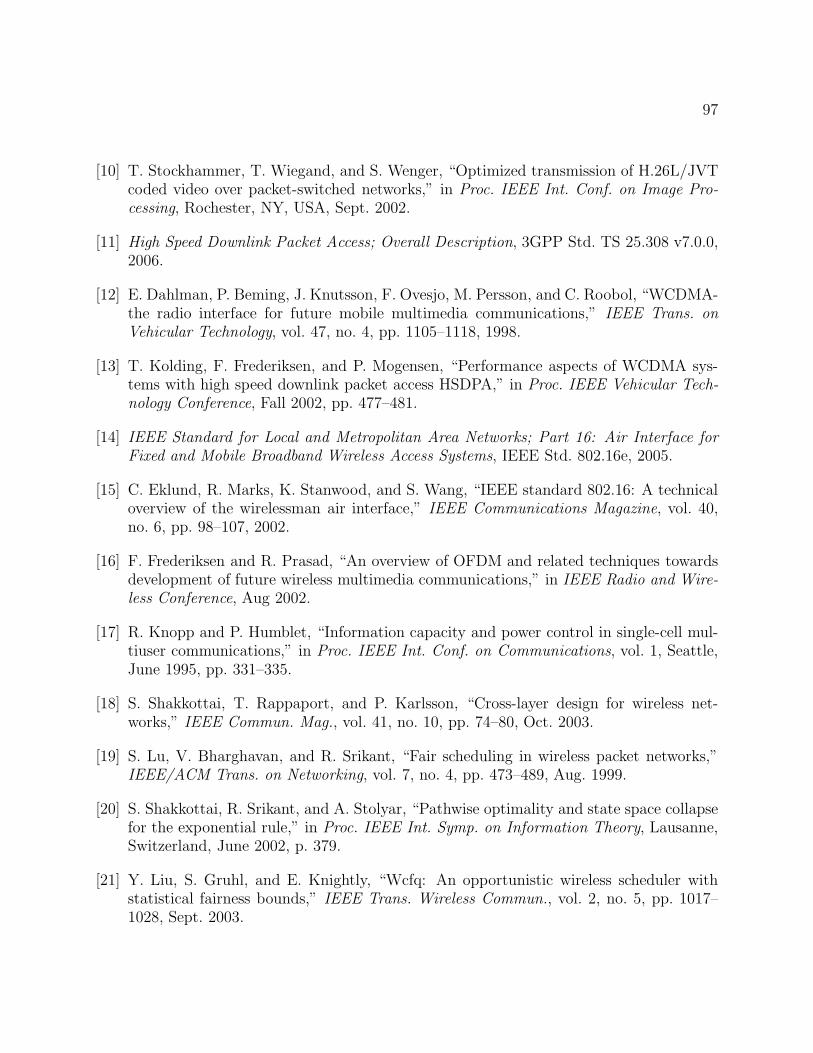
97
[10] T. Stockhammer, T. Wiegand, and S. Wenger, “Optimized transmission of H.26L/JVTcoded video over packet-switched networks,” in Proc. IEEE Int. Conf. on Image Pro-cessing, Rochester, NY, USA, Sept. 2002.
[11] High Speed Downlink Packet Access; Overall Description, 3GPP Std. TS 25.308 v7.0.0,2006.
[12] E. Dahlman, P. Beming, J. Knutsson, F. Ovesjo, M. Persson, and C. Roobol, “WCDMA-the radio interface for future mobile multimedia communications,” IEEE Trans. onVehicular Technology, vol. 47, no. 4, pp. 1105–1118, 1998.
[13] T. Kolding, F. Frederiksen, and P. Mogensen, “Performance aspects of WCDMA sys-tems with high speed downlink packet access HSDPA,” in Proc. IEEE Vehicular Tech-nology Conference, Fall 2002, pp. 477–481.
[14] IEEE Standard for Local and Metropolitan Area Networks; Part 16: Air Interface forFixed and Mobile Broadband Wireless Access Systems, IEEE Std. 802.16e, 2005.
[15] C. Eklund, R. Marks, K. Stanwood, and S. Wang, “IEEE standard 802.16: A technicaloverview of the wirelessman air interface,” IEEE Communications Magazine, vol. 40,no. 6, pp. 98–107, 2002.
[16] F. Frederiksen and R. Prasad, “An overview of OFDM and related techniques towardsdevelopment of future wireless multimedia communications,” in IEEE Radio and Wire-less Conference, Aug 2002.
[17] R. Knopp and P. Humblet, “Information capacity and power control in single-cell mul-tiuser communications,” in Proc. IEEE Int. Conf. on Communications, vol. 1, Seattle,June 1995, pp. 331–335.
[18] S. Shakkottai, T. Rappaport, and P. Karlsson, “Cross-layer design for wireless net-works,” IEEE Commun. Mag., vol. 41, no. 10, pp. 74–80, Oct. 2003.
[19] S. Lu, V. Bharghavan, and R. Srikant, “Fair scheduling in wireless packet networks,”IEEE/ACM Trans. on Networking, vol. 7, no. 4, pp. 473–489, Aug. 1999.
[20] S. Shakkottai, R. Srikant, and A. Stolyar, “Pathwise optimality and state space collapsefor the exponential rule,” in Proc. IEEE Int. Symp. on Information Theory, Lausanne,Switzerland, June 2002, p. 379.
[21] Y. Liu, S. Gruhl, and E. Knightly, “Wcfq: An opportunistic wireless scheduler withstatistical fairness bounds,” IEEE Trans. Wireless Commun., vol. 2, no. 5, pp. 1017–1028, Sept. 2003.
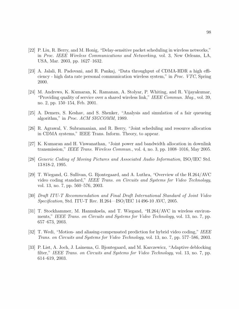
98
[22] P. Liu, R. Berry, and M. Honig, “Delay-sensitive packet scheduling in wireless networks,”in Proc. IEEE Wireless Communications and Networking, vol. 3, New Orleans, LA,USA, Mar. 2003, pp. 1627–1632.
[23] A. Jalali, R. Padovani, and R. Pankaj, “Data throughput of CDMA-HDR a high effi-ciency - high data rate personal communication wireless system,” in Proc. VTC, Spring2000.
[24] M. Andrews, K. Kumaran, K. Ramanan, A. Stolyar, P. Whiting, and R. Vijayakumar,“Providing quality of service over a shared wireless link,” IEEE Commun. Mag., vol. 39,no. 2, pp. 150–154, Feb. 2001.
[25] A. Demers, S. Keshav, and S. Shenker, “Analysis and simulation of a fair queueingalgorithm,” in Proc. ACM SIGCOMM, 1989.
[26] R. Agrawal, V. Subramanian, and R. Berry, “Joint scheduling and resource allocationin CDMA systems,” IEEE Trans. Inform. Theory, to appear.
[27] K. Kumaran and H. Viswanathan, “Joint power and bandwidth allocation in downlinktransmission,” IEEE Trans. Wireless Commun., vol. 4, no. 3, pp. 1008–1016, May 2005.
[28] Generic Coding of Moving Pictures and Associated Audio Information, ISO/IEC Std.13 818-2, 1995.
[29] T. Wiegand, G. Sullivan, G. Bjontegaard, and A. Luthra, “Overview of the H.264/AVCvideo coding standard,” IEEE Trans. on Circuits and Systems for Video Technology,vol. 13, no. 7, pp. 560–576, 2003.
[30] Draft ITU-T Recommendation and Final Draft International Standard of Joint VideoSpecification, Std. ITU-T Rec. H.264—ISO/IEC 14 496-10 AVC, 2005.
[31] T. Stockhammer, M. Hannuksela, and T. Wiegand, “H.264/AVC in wireless environ-ments,” IEEE Trans. on Circuits and Systems for Video Technology, vol. 13, no. 7, pp.657–673, 2003.
[32] T. Wedi, “Motion- and aliasing-compensated prediction for hybrid video coding,” IEEETrans. on Circuits and Systems for Video Technology, vol. 13, no. 7, pp. 577–586, 2003.
[33] P. List, A. Joch, J. Lainema, G. Bjontegaard, and M. Karczewicz, “Adaptive deblockingfilter,” IEEE Trans. on Circuits and Systems for Video Technology, vol. 13, no. 7, pp.614–619, 2003.
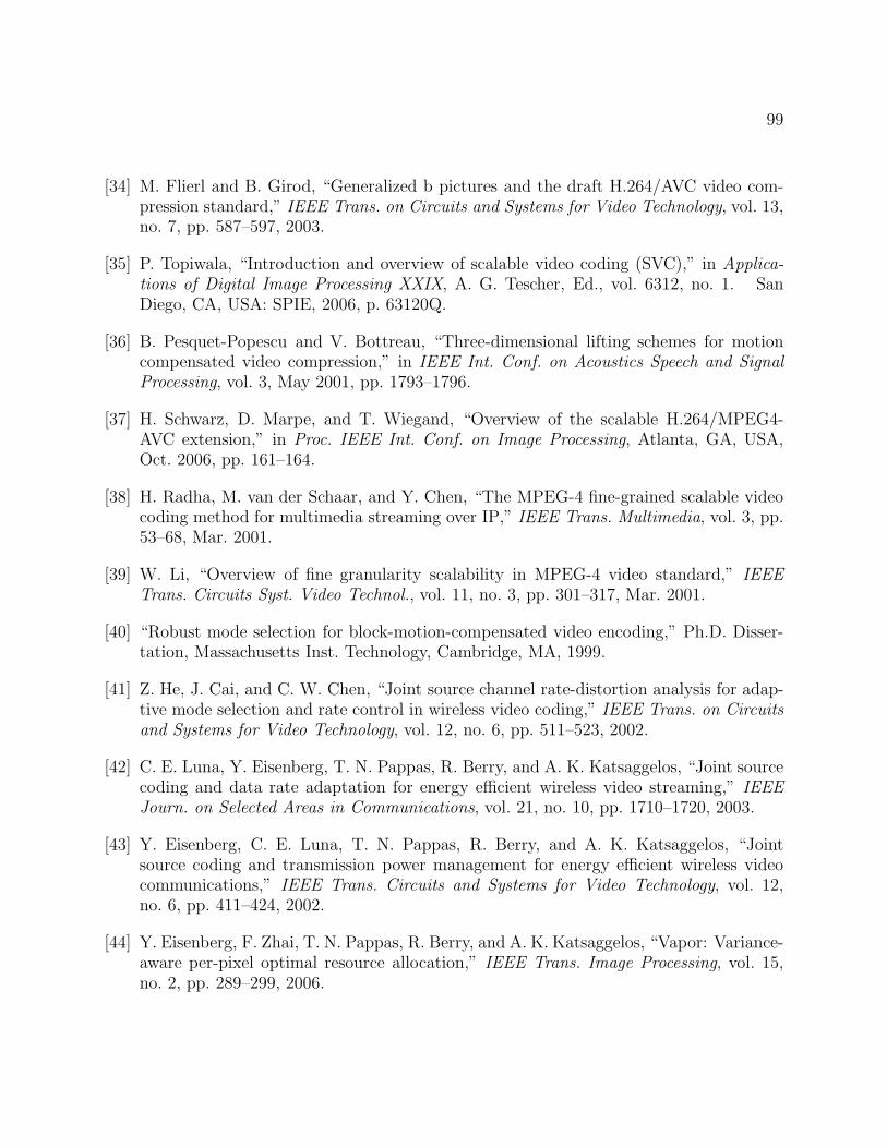
99
[34] M. Flierl and B. Girod, “Generalized b pictures and the draft H.264/AVC video com-pression standard,” IEEE Trans. on Circuits and Systems for Video Technology, vol. 13,no. 7, pp. 587–597, 2003.
[35] P. Topiwala, “Introduction and overview of scalable video coding (SVC),” in Applica-tions of Digital Image Processing XXIX, A. G. Tescher, Ed., vol. 6312, no. 1. SanDiego, CA, USA: SPIE, 2006, p. 63120Q.
[36] B. Pesquet-Popescu and V. Bottreau, “Three-dimensional lifting schemes for motioncompensated video compression,” in IEEE Int. Conf. on Acoustics Speech and SignalProcessing, vol. 3, May 2001, pp. 1793–1796.
[37] H. Schwarz, D. Marpe, and T. Wiegand, “Overview of the scalable H.264/MPEG4-AVC extension,” in Proc. IEEE Int. Conf. on Image Processing, Atlanta, GA, USA,Oct. 2006, pp. 161–164.
[38] H. Radha, M. van der Schaar, and Y. Chen, “The MPEG-4 fine-grained scalable videocoding method for multimedia streaming over IP,” IEEE Trans. Multimedia, vol. 3, pp.53–68, Mar. 2001.
[39] W. Li, “Overview of fine granularity scalability in MPEG-4 video standard,” IEEETrans. Circuits Syst. Video Technol., vol. 11, no. 3, pp. 301–317, Mar. 2001.
[40] “Robust mode selection for block-motion-compensated video encoding,” Ph.D. Disser-tation, Massachusetts Inst. Technology, Cambridge, MA, 1999.
[41] Z. He, J. Cai, and C. W. Chen, “Joint source channel rate-distortion analysis for adap-tive mode selection and rate control in wireless video coding,” IEEE Trans. on Circuitsand Systems for Video Technology, vol. 12, no. 6, pp. 511–523, 2002.
[42] C. E. Luna, Y. Eisenberg, T. N. Pappas, R. Berry, and A. K. Katsaggelos, “Joint sourcecoding and data rate adaptation for energy efficient wireless video streaming,” IEEEJourn. on Selected Areas in Communications, vol. 21, no. 10, pp. 1710–1720, 2003.
[43] Y. Eisenberg, C. E. Luna, T. N. Pappas, R. Berry, and A. K. Katsaggelos, “Jointsource coding and transmission power management for energy efficient wireless videocommunications,” IEEE Trans. Circuits and Systems for Video Technology, vol. 12,no. 6, pp. 411–424, 2002.
[44] Y. Eisenberg, F. Zhai, T. N. Pappas, R. Berry, and A. K. Katsaggelos, “Vapor: Variance-aware per-pixel optimal resource allocation,” IEEE Trans. Image Processing, vol. 15,no. 2, pp. 289–299, 2006.
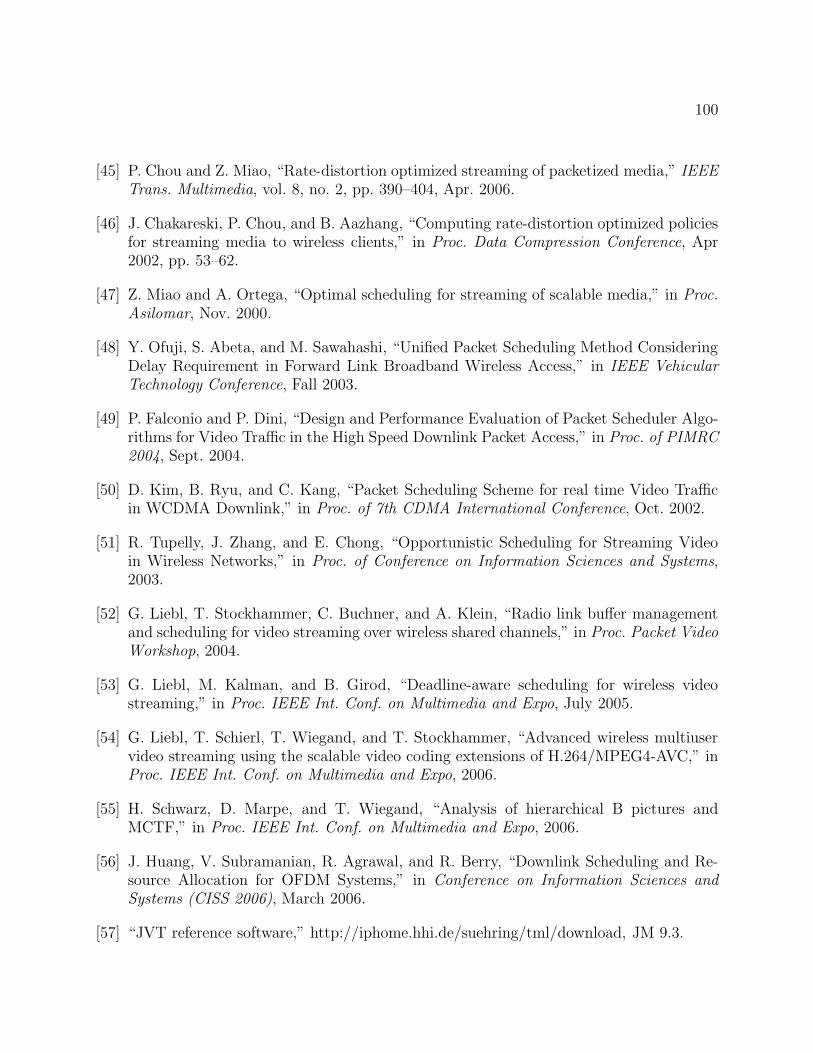
100
[45] P. Chou and Z. Miao, “Rate-distortion optimized streaming of packetized media,” IEEETrans. Multimedia, vol. 8, no. 2, pp. 390–404, Apr. 2006.
[46] J. Chakareski, P. Chou, and B. Aazhang, “Computing rate-distortion optimized policiesfor streaming media to wireless clients,” in Proc. Data Compression Conference, Apr2002, pp. 53–62.
[47] Z. Miao and A. Ortega, “Optimal scheduling for streaming of scalable media,” in Proc.Asilomar, Nov. 2000.
[48] Y. Ofuji, S. Abeta, and M. Sawahashi, “Unified Packet Scheduling Method ConsideringDelay Requirement in Forward Link Broadband Wireless Access,” in IEEE VehicularTechnology Conference, Fall 2003.
[49] P. Falconio and P. Dini, “Design and Performance Evaluation of Packet Scheduler Algo-rithms for Video Traffic in the High Speed Downlink Packet Access,” in Proc. of PIMRC2004, Sept. 2004.
[50] D. Kim, B. Ryu, and C. Kang, “Packet Scheduling Scheme for real time Video Trafficin WCDMA Downlink,” in Proc. of 7th CDMA International Conference, Oct. 2002.
[51] R. Tupelly, J. Zhang, and E. Chong, “Opportunistic Scheduling for Streaming Videoin Wireless Networks,” in Proc. of Conference on Information Sciences and Systems,2003.
[52] G. Liebl, T. Stockhammer, C. Buchner, and A. Klein, “Radio link buffer managementand scheduling for video streaming over wireless shared channels,” in Proc. Packet VideoWorkshop, 2004.
[53] G. Liebl, M. Kalman, and B. Girod, “Deadline-aware scheduling for wireless videostreaming,” in Proc. IEEE Int. Conf. on Multimedia and Expo, July 2005.
[54] G. Liebl, T. Schierl, T. Wiegand, and T. Stockhammer, “Advanced wireless multiuservideo streaming using the scalable video coding extensions of H.264/MPEG4-AVC,” inProc. IEEE Int. Conf. on Multimedia and Expo, 2006.
[55] H. Schwarz, D. Marpe, and T. Wiegand, “Analysis of hierarchical B pictures andMCTF,” in Proc. IEEE Int. Conf. on Multimedia and Expo, 2006.
[56] J. Huang, V. Subramanian, R. Agrawal, and R. Berry, “Downlink Scheduling and Re-source Allocation for OFDM Systems,” in Conference on Information Sciences andSystems (CISS 2006), March 2006.
[57] “JVT reference software,” http://iphome.hhi.de/suehring/tml/download, JM 9.3.
101
[58] M. Hong, L. Kondi, H. Schwab, and A. Katsaggelos, “Error Concealment Algorithms forConcealed Video,” Signal Processing: Image Communications, special issue on ErrorResilient Video, vol. 14, no. 6-8, pp. 437–492, 1999.
[59] Y.-K. Wang, M. Hannuksela, V. Varsa, A. Hourunranta, and M. Gabbouj, “The ErrorConcealment Feature in the H.26L Test Model,” in Proc. IEEE Int. Conf. on ImageProcessing (ICIP), 2002.
[60] S. Belfiore, M. Grangetto, E. Magli, and G. Olmo, “Spatio-Temporal Video Error Con-cealment with Perceptually Optimized Mode Selection,” in Proc. IEEE Int. Conf. onAcoustics Speech and Signal Processing (ICASSP), vol. 5, 2003, pp. 748–751.
[61] T. Wiegand, G. Sullivan, J. Reichel, H. Schwarz, and M. Wien, “Joint draft 6,” JVT-S201, 19th JVT Meeting, Geneva, CH, 2006.
[62] S. Wenger, Y.-K. Wang, and T. Schierl, “RTP payload format for SVC video,” InternetDraft, IETF, Oct. 2006.
[63] “JSVM 4 reference software,” JVT-Q203, Nice, France, Oct. 2005.
[64] P. Pahalawatta, R. Berry, T. Pappas, and A. Katsaggelos, “A content-aware schedulingscheme for video streaming to multiple users over wireless networks,” in Proc. EuropeanSignal Processing Conference, Florence, Italy, Sept. 2006.
[65] L. Ozarow, S. Shamai, and A. Wyner, “Information theoretic considerations for cellularmobile radio,” IEEE Trans. on Vehicular Technology, vol. 43, no. 2, pp. 359–378, 1994.
[66] H. Yang and K. Rose, “Advances in recursive per-pixel estimation of end-to-end distor-tion for application in H.264,” in Proc. IEEE Int. Conf. on Image Processing (ICIP),Genova, Sept. 2005.
[67] D. Wu, Y. T. Hou, B. Li, W. Zhu, Y. Q. Zhang, and H. J. Chao, “An end-to-endapproach for optimal mode selection in internet video communication: theory and ap-plication,” IEEE Trans. Commun., vol. 18, pp. 977–995, June 2002.
[68] “JVT reference software,” http://iphome.hhi.de/suehring/tml/download, JM 10.2.
[69] E. Setton, T. Yoo, X. Zhu, A. Goldsmith, and B. Girod, “Cross-layer design of ad hocnetworks for real-time video streaming,” IEEE Wireless Communications, pp. 59–65,Aug. 2005.
[70] E. Setton, X. Zhu, and B. Girod, “Congestion-optimized multi-path streaming of videoover ad hoc wireless networks,” in Proc. IEEE Int. Conf. on Multimedia and Expo, 2004.
102
[71] Y. Andreopoulos, N. Mastronarde, and M. V. der Schaar, “Cross-layer optimized videostreaming over wireless multihop mesh networks,” IEEE Journal on Selected Areas inCommunications, vol. 24, no. 11, pp. 2104–2115, Nov. 2006.
[72] Q. Li and M. V. der Schaar, “Providing adaptive qos to layered video over wireless localarea networks through real-time retry limit adaptation,” IEEE Trans. on Multimedia,vol. 6, no. 2, pp. 278–290, Apr. 2004.
[73] Y. Andreopoulos, R. Keralapura, M. V. der Schaar, and C.-N. Chuah, “Failure-awareopen-loop adaptive video streaming with packet-level optimized redundancy,” IEEETrans. on Multimedia, vol. 8, no. 6, pp. 1274–1290, Dec. 2006.
[74] M. Wang and M. V. der Schaar, “Operational rate-distortion modeling for wavelet videocoders,” IEEE Trans. on Signal Processing, vol. 54, no. 9, pp. 3505–3517, Sept. 2006.
[75] H.-P. Shiang and M. van der Schaar, “Multi-user video streaming over multi-hop wire-less networks: A distributed, cross-layer approach based on priority queueing,” IEEEJournal on Selected Areas in Communications: Special Issue on Cross-Layer OptimizedWireless Multimedia Communications, vol. 25, no. 4, pp. 770–785, May 2007.
Related Documents