Downhole Completion Tools

Welcome message from author
This document is posted to help you gain knowledge. Please leave a comment to let me know what you think about it! Share it to your friends and learn new things together.
Transcript

Downhole
Completion Tools
For over 30 years, the owners of Wireline Solutions have been involved in the manufacturing and distribution of high
quality, low cost completions tools for the oil and gas industry. The goal of the company is to provide tools and equipment that exceed required applications while at the
same time provide real cost savings to customers. The vast experience of the owners in both the domestic and
international markets enable them to provide solutions to the various problems encountered in today’s complicated
business. All tools in the catalog are field proven over many generations. In addition, specialized tools for specialized
problems can be engineered and built to customer’s specifications. For more information or help with your
completions or wireline needs, please feel free to contact us.

LANDING NIPPLES 1
CIRCULATING SLEEVES 2
HYDRO TRIP SUBS and
WIRELINE ENTRY PUMP OUT PLUGS
3
ON – OFF TOOLS 4
BLANKING PLUGS 5
CHECK VALVES and
INSTRUMENT HANGERS
6
CROSSOVERS 7
SHEAR OUT SAFETY JOINTS 8
WIRELINE SERVICE TOOLS 9
Table of Contents

Landing Nipples
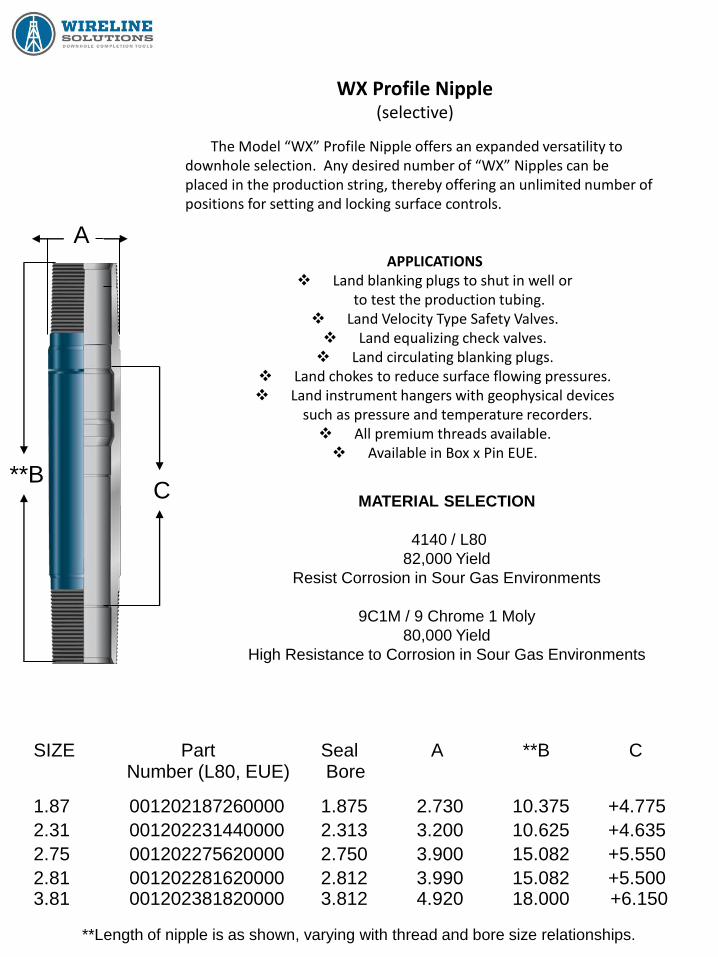
WX Profile Nipple (selective)
The Model “WX” Profile Nipple offers an expanded versatility to downhole selection. Any desired number of “WX” Nipples can be placed in the production string, thereby offering an unlimited number of positions for setting and locking surface controls.
APPLICATIONS Land blanking plugs to shut in well or
to test the production tubing. Land Velocity Type Safety Valves. Land equalizing check valves. Land circulating blanking plugs.
Land chokes to reduce surface flowing pressures. Land instrument hangers with geophysical devices
such as pressure and temperature recorders. All premium threads available. Available in Box x Pin EUE.
A
C **B
MATERIAL SELECTION
4140 / L80
82,000 Yield
Resist Corrosion in Sour Gas Environments
9C1M / 9 Chrome 1 Moly
80,000 Yield
High Resistance to Corrosion in Sour Gas Environments
SIZE Part Seal A **B C
Number (L80, EUE) Bore
2.81 001202281620000 2.812 3.990 15.082 +5.500
2.31 001202231440000 2.313 3.200 10.625 +4.635
2.75 001202275620000 2.750 3.900 15.082 +5.550
1.87 001202187260000 1.875 2.730 10.375 +4.775
3.81 001202381820000 3.812 4.920 18.000 +6.150
**Length of nipple is as shown, varying with thread and bore size relationships.
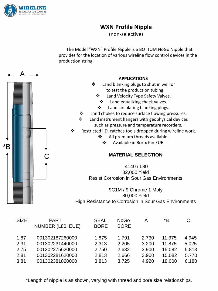
WXN Profile Nipple (non-selective)
The Model “WXN” Profile Nipple is a BOTTOM NoGo Nipple that provides for the location of various wireline flow control devices in the production string.
APPLICATIONS Land blanking plugs to shut in well or
to test the production tubing. Land Velocity Type Safety Valves. Land equalizing check valves. Land circulating blanking plugs.
Land chokes to reduce surface flowing pressures. Land instrument hangers with geophysical devices
such as pressure and temperature recorders. Restricted I.D. catches tools dropped during wireline work.
All premium threads available. Available in Box x Pin EUE.
C
*B MATERIAL SELECTION
4140 / L80
82,000 Yield
Resist Corrosion in Sour Gas Environments
9C1M / 9 Chrome 1 Moly
80,000 Yield
High Resistance to Corrosion in Sour Gas Environments
*Length of nipple is as shown, varying with thread and bore size relationships.
SIZE PART SEAL NoGo A *B C
NUMBER (L80, EUE) BORE BORE
1.87 001302187260000 1.875 1.791 2.730 11.375 4.945
2.31 001302231440000 2.313 2.205 3.200 11.875 5.025
2.75 001302275620000 2.750 2.632 3.900 15.082 5.813
2.81 001302281620000 2.813 2.666 3.900 15.082 5.770
3.81 001302381820000 3.813 3.725 4.920 18.000 6.180
A
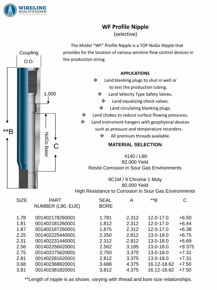
WF Profile Nipple (selective)
The Model “WF” Profile Nipple is a TOP NoGo Nipple that
provides for the location of various wireline flow control devices in
the production string.
APPLICATIONS
Land blanking plugs to shut in well or
to test the production tubing.
Land Velocity Type Safety Valves.
Land equalizing check valves.
Land circulating blanking plugs.
Land chokes to reduce surface flowing pressures.
Land instrument hangers with geophysical devices
such as pressure and temperature recorders.
All premium threads available.
C
**B
MATERIAL SELECTION
4140 / L80
82,000 Yield
Resist Corrosion in Sour Gas Environments
9C1M / 9 Chrome 1 Moly
80,000 Yield
High Resistance to Corrosion in Sour Gas Environments
**Length of nipple is as shown, varying with thread and bore size relationships.
SIZE PART SEAL A **B C
NUMBER (L80, EUE) BORE
1.78 001402178260001 1.781 2.312 12.0-17.0 +6.50
1.81 001402181260001 1.812 2.312 12.0-17.0 +6.44
1.87 001402187260001 1.875 2.312 12.0-17.0 +6.38
2.25 001402225440001 2.250 2.812 13.0-18.0 +6.75
2.31 001402231440001 2.312 2.812 13.0-18.0 +6.69
2.56 001402256620001 2.562 3.185 13.0-18.0 +9.375
2.75 001402275620001 2.750 3.375 13.0-18.0 +7.31
2.81 001402281620001 2.812 3.375 13.0-18.0 +7.31
3.68 001402368820001 3.688 4.375 16.12-18.62 +7.50
3.81 001402381820001 3.812 4.375 16.12-18.62 +7.50
1.000
Coupling
O.D.
NoG
o B
ase

WR Profile Nipple (non-selective)
The Model “WR” Profile Nipple is a Bottom NoGo Nipple that
provides for the location of various wireline flow control devices
in the production string.
APPLICATIONS
Land blanking plugs to shut in well or
to test the production tubing.
Land Velocity Type Safety Valves.
Land equalizing check valves.
Land circulating blanking plugs.
Land chokes to reduce surface flowing pressures.
Land instrument hangers with geophysical devices
such as pressure and temperature recorders.
Restricted I.D. catches tools dropped during wireline work.
All premium threads available.
C
**B
MATERIAL SELECTION
4140 / L80
82,000 Yield
Resist Corrosion in Sour Gas Environments
9C1M / 9 Chrome 1 Moly
80,000 Yield
High Resistance to Corrosion in Sour Gas Environments
**Length of nipple is as shown, varying with thread and bore size relationships.
SIZE PART SEAL NoGo A **B C
NUMBER (L80, EUE) BORE BORE
1.78 001102178260001 1.781 1.728 2.312 12.0-17.0 5.81
1.81 001102181260001 1.812 1.760 2.312 12.0-17.0 5.81
1.87 001102187260001 1.875 1.822 2.312 12.0-17.0 5.81
2.25 001102225440001 2.250 2.197 2.812 13.0-18.0 6.12
2.31 001102231440001 2.312 2.260 2.812 13.0-18.0 6.12
2.56 001102256620001 2.562 2.443 3.185 13.0-18.0 8.843
2.75 001102275620001 2.750 2.697 3.375 13.0-18.0 6.70
2.81 001102281620001 2.812 2.759 3.375 13.0-18.0 6.70
3.68 001102368820001 3.688 3.625 4.375 14.75-18.62 7.37
3.81 001102381820001 3.812 3.759 4.375 14.75-18.62 7.37
1.000
Coupling
O.D.
NoGo Base
NoGo

WHR Profile Nipple (selective)
The Model “WHR” Profile Nipple offers a Nipple which can be used in heavy tubing applications. It offers various inside diameters which allows well operator to selectively pick wherever to locate the “WHR” Nipples in the tubing string. The blanking plug offers a higher pressure rating than the normal weight tubing blanking plugs.
APPLICATIONS Land blanking plugs to shut in well or
to test the production tubing. Land velocity sub surface safety valves.
Land bottom hole chokes, check valves, circulating blanking plugs, instrument hangers. All premium threads available.
MATERIAL SELECTION
4140 / L80
82,000 Yield
Resist Corrosion in Sour Gas Environments
9C1M / 9 Chrome 1 Moly
80,000 Yield
High Resistance to Corrosion in Sour Gas Environments
* Length of nipple is as shown, varying with thread and bore size relationships.
** Part numbers shown are for EUE threads and L80 material.
SIZE ** PART SEAL A *B C
NUMBER (L80, EUE) BORE
1.71 001252171260000 1.710 2.730 10.375 5.871
1.78 001252178260000 1.781 2.730 10.375 5.871
2.12 001252212440000 2.125 3.200 10.625 5.871
2.18 001252218440000 2.188 3.200 10.625 5.871
2.31 001252231620000 2.313 3.900 15.082 5.971
2.56 001252256620000 2.562 3.900 15.082 5.971
2.75 001252275620000 2.750 3.900 15.082 5.971
2.81 001252281620000 2.813 3.900 15.082 5.971
3.81 001252381820000 3.813 5.200 17.500 7.271
A
C
*B
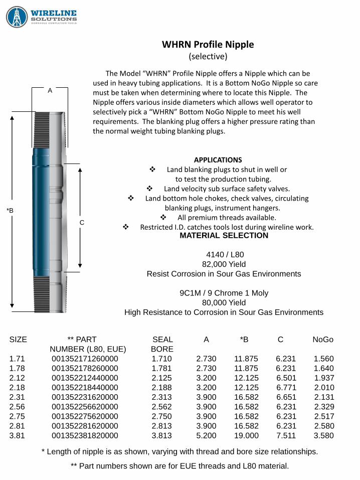
WHRN Profile Nipple (selective)
The Model “WHRN” Profile Nipple offers a Nipple which can be used in heavy tubing applications. It is a Bottom NoGo Nipple so care must be taken when determining where to locate this Nipple. The Nipple offers various inside diameters which allows well operator to selectively pick a “WHRN” Bottom NoGo Nipple to meet his well requirements. The blanking plug offers a higher pressure rating than the normal weight tubing blanking plugs.
APPLICATIONS Land blanking plugs to shut in well or
to test the production tubing. Land velocity sub surface safety valves.
Land bottom hole chokes, check valves, circulating blanking plugs, instrument hangers. All premium threads available.
Restricted I.D. catches tools lost during wireline work. MATERIAL SELECTION
4140 / L80
82,000 Yield
Resist Corrosion in Sour Gas Environments
9C1M / 9 Chrome 1 Moly
80,000 Yield
High Resistance to Corrosion in Sour Gas Environments
* Length of nipple is as shown, varying with thread and bore size relationships.
** Part numbers shown are for EUE threads and L80 material.
SIZE ** PART SEAL A *B C NoGo
NUMBER (L80, EUE) BORE
1.71 001352171260000 1.710 2.730 11.875 6.231 1.560
1.78 001352178260000 1.781 2.730 11.875 6.231 1.640
2.12 001352212440000 2.125 3.200 12.125 6.501 1.937
2.18 001352218440000 2.188 3.200 12.125 6.771 2.010
2.31 001352231620000 2.313 3.900 16.582 6.651 2.131
2.56 001352256620000 2.562 3.900 16.582 6.231 2.329
2.75 001352275620000 2.750 3.900 16.582 6.231 2.517
2.81 001352281620000 2.813 3.900 16.582 6.231 2.580
3.81 001352381820000 3.813 5.200 19.000 7.511 3.580
A
*B
C

Circulating Sleeves
WXO / WXD Circulating Sleeve
The WXO and WXD Sleeve can be installed at any point in the tubing string. More than one can
be installed without any loss of function. The sleeve can be selectively opened and closed no
matter what their positions.
The WXO and WXD Sleeve has replaceable upper and lower seals, which are easy and
inexpensive to replace. They can be of various elastomeric or non-elastomeric types.
The upper sub has a selective WX landing nipple profile machined into it to serve as a receptacle
for other flow control devices such as blanking plugs and separation tools. The lower sub has a
polished seal bore.
The Wireline Solutions Model WB Shifting Tool is used to shift the WXO and WXD Sleeve open
and closed. The sleeve is designed so that normal wireline activities will not open or close the
sleeve inadvertently. Upward jarring closes the sleeve and downward jarring opens it.
The Wireline Solutions Models WXO and WXD Circulating Sleeve is a down hole device, normally
screwed into the production tubing, that allows communication between the tubing and the casing.
The only difference between the WXO and WXD Sleeve is that the WXD Sleeve has twice the flow
area between the tubing and the casing.
APPLICATIONS
Displacing kill or completion fluid.
Allowing multiple zones to produce up one tubing string.
Selective testing of individual zones.
Selective stimulation of individual zones.
Circulation to kill the well.
Gas lifting the well
Landing a blanking plug in the profile in the upper sub to shut in the well, test the
tubing, or test the sleeve itself.
Circulating inhibitors or methanol.

WXO / WXD Circulating Sleeve
The WXO / WXD Circulating Sleeve provides a way to establish or shut off communication between the tubing and the casing. Any number of sleeves may be run in a tubing string and any or all of them may be opened or closed with a Self Releasing Positioning Tool (Model WB Shifting Tool). The only difference between the WXO and WXD Sleeve is the WXD has twice the flow area between the tubing and the casing.
The WXO / WXD Sleeve consists of the following:
Top Sub
Bottom Sub
Middle Sub
Inner Sleeve (Closing Sleeve)
Packing Sets
The Top Sub Connects to the tubing string. It contains a WX Style Locking Profile and Polish
Bore. It has an inclined shoulder which causes the WB Shifting Tool to release after the Inner
Sleeve reaches an up position. The lower end of the Top Sub is threaded to fit the Middle Sub and
is sealed by the Top Subs O-Ring.
The Middle Sub screws onto both the Top and Bottom Sub. It provides flow ports for
communication and provides for the positioning and sealing of the packing.
The Packing Sets consist of three separate groups. The Upper Packing is made up of two sets
off vee packing secured between two female steel adapters and separated by a male adapter or O-
ring. The Middle Set consists of a middle O-ring which is secured between two female steel
adapters and is held in place by split ring segments. The Bottom Set consists of two sets of vee
packing secured between two female steel adapters and separated by lower packing O-ring.
The Inner Sleeve fits inside the Middle and the Top and Bottom Subs. It has a collet latch for
positioning, an equalizing port, and flow ports for communication. The Shifting Key recesses are
inside either end of the Inner Sleeve, allowing the shifting tool to latch into and move the Inner
Sleeve either up or down.
The Bottom Sub screws onto the Middle Sub and a bottom O-ring seals this joint. It provides
three indents which position the closing sleeve and another inclined shoulder which positions the
closing sleeve and another inclined shoulder which releases the WB Shifting Tool after shifting.
The Bottom Sub also has a bottom polished bore. The lower end of the sub screws into the tubing
string.
The WXO and WXD Sleeve always opens down and closes up.

WXO / WXD Circulating Sleeve Shifting Procedure
TO OPEN:
Using the correct B Shifting Tool or alternate manufacturer’s equivalent, place the tool on the
bottom of your wireline work string with the engaging (shifting) keys looking down. Go into hole to
proper depth of sleeve. Your Shifting Tool should engage the bottom of the Inner Sleeve at the
internal shifting shoulder.
Jar Down. The Inner Sleeve should move into the equalizing position. After equalized, continue
jarring down until sleeve is in full open position. At this time, the Shifting Tool should release and
fall through the Sleeve.
To check Sleeve to see if it is fully open, pull back up into Sleeve and try to engage Inner Sleeve.
If you cannot engage Inner Sleeve, it is fully open or shear pin is sheared on Shifting Tool. Come
out of hole and check Shifting Tool. If pin is not sheared, then you can assume Sleeve is shifted.
Flowing either the tubing or casing should affect both sides if Sleeve is open.
TO CLOSE:
Place Shifting Tool on bottom of wireline work string with shifting keys looking up. Go into hole
to a point where you are sure you have gone through Sleeve. Your Shifting Tool should engage the
top of the Inner Sleeve at the internal shifting shoulder.
Jar up and continue jarring up until the Inner Sleeve is shifting into the closed position. At this
time the Shifting Tool should release and move up hole when pulled.
To check Sleeve, drop back down into Sleeve and try to engage Inner Sleeve. If you cannot
engage, assume Sleeve is closed and come out of hole. Check shear pin on Shifting Tool.
Flowing either the tubing or casing should not affect the other side if Sleeve is closed.

WXO / WXD Circulating Sleeve Working Instructions and Assembly
Use grease or pipe dope on all threaded connections and on all O-rings and Vee seals.
STEP NUMBER 1: PREPARE UPPER AND LOWER SUBS
A. Drift both upper and lower seal bores with appropriate sized drift.
B. Grease the threads and seal bores on both the Upper and Lower Subs.
C. Put Lower Sub in vice.
D. Install O-rings onto upper and lower subs.
E. Insert the Inner Sleeve into the Lower Sub collet fingers first until it stops.
F. Grease the O-ring on the Lower Sub and protruding part on the Inner Sleeve.
G. Grease the O-Ring on the Upper Sub.
STEP NUMBER 2: PREPARE BOTTOM END OF MIDDLE HOUSING
A. Hold the Middle Housing so that the bottom end is facing up (segment groove
facing up,) insert one Female Adapter Ring with grooved side facing up.
B. Insert one O-ring into the groove in Female Ring.
C. Insert another Female Adapter Ring groove side down onto the O-ring.
D. Insert Split Segments into groove inside the Middle Housing.
E. Insert one Female Adapter Ring onto Split Segments with the groove side facing up.
F. Insert appropriate number of Vee Seals grooved side facing up onto Female
Adapter Ring.
G. Insert one O-ring into groove in the Vee Seal.
H. Insert Vee Seals grooved side down facing down onto the O-ring.
I. Insert one Female Adapter Ring with the grooved side facing down onto the
Vee Seals.
J. Compress the seal stack (vee seals and o-rings) with rod, measure the stack height
and compare with the lower sub UNC thread length.
K. Grease all O-rings and Vee Seals with grease.
L. Screw the Upper Sub into the bottom end of Middle Housing until the parts shoulder.
(continued on next page)

WXO / WXD Circulating Sleeve Working Instructions and Assembly
STEP NUMBER 3: PREPARE TOP END OF MIDDLE HOUSING
A. Insert one Female Adapter Ring into the top end of the Middle Housing with the
grooved side facing up.
B. Insert the Vee Seals grooved side facing up onto the Female Adapter Ring.
C. Insert one O-ring into the groove in the Vee Seal.
D. Insert the Vee Seals grooved side facing down onto the O-ring.
E. Insert one Female Adapter Ring with the grooved side facing down onto the
Vee Seals.
F. Compress the seal stack (vee Seals and o-ring) with a rod, measure the stack height
and compare with the Upper Subs UNC thread length.
G. Grease all O-rings and Vee Seals with grease.
STEP NUMBER 2: COMPLETE ASSEMBLY, TEST, AND TORQUE
A. Vertically slide the protruding part of the Inner Sleeve into the Vee Seals and O-ring
in the Top end of the Middle Housing.
B. Screw the Lower Sub in the top end of the Middle Housing until the parts shoulder.
C. Using a “B” Shifting Tool and jar, shift the Inner Sleeve closed, open, and closed to
ensure functionality.
D. Torque sleeve tight with wrench.
E. Test to appropriate pressure.
WXO / WXD Circulating Sleeve Redress Procedure
After a WXO / WXD sleeve has been pulled from the hole, it is recommended you change
the Vee Packing and O-rings and also check packing area before running it back downhole. The
Redress procedure is as follows:
(1) Place Bottom Sub of Sleeve in vice and secure. Place stand under Sleeve for support. Tap
with hammer at area where Top Sub screws onto Middle Housing. Place wrench on Top Sub
and break top connection. Using uniform torque, unscrew Top Sub from Middle Housing.
(2) Now place wrench on Middle Housing and break connection. Unscrew Middle Housing from
Bottom Sub. Shift Inner Sleeve out of Bottom Sub. Packing should remain in Middle Housing
when unscrewed and pulled off Inner Sleeve.
(3) Remove Vee Packing, Steel Rings, and O-rings from sleeve. Clean all parts, check for flow
cuts, check packing area and caliper area, check all threads taking special care of small
threads on top and bottom subs, and check O.D. of Inner Sleeve and Shifting Shoulder on
Inner Sleeve.
(4) After all parts are cleaned and inspected, place the Bottom Sub back into vice and secure.
Grease liberally. Shift Inner Sleeve into the first indent of Bottom Sub. Grease outside of
Inner Sleeve. Assemble Vee Packing, Steel Rings, and O-rings as detailed in the Assembly
Section. Slide Packing Assembly onto Inner Sleeve.
(5) Grease outside of Packing Assembly and inside the Middle Housing. There is a groove cut
inside the Middle Housing on one end. Face this end of Middle Housing toward you. One at
a time, place a Female Adapter Ring, then an O-ring, and another Female Ring in the Middle
Housing, pushing them down until they lay bottom out just below groove. Place Split
Segments in the Middle Housing as shown in the Assembly Section. Back up with another
Female Ring.
(6) Take Middle Housing, still having the end you worked on facing you, and make up on Bottom
Sub. The Inner Sleeve should remain out of the Middle Housing far enough that you can now
place remaining Vee Packing and Rings onto it. Next, take the sub and make up onto Middle.
(7) After Sleeve is completely made up and torqued, it should be shifted and pressure tested
before being run in the hole.

1.87” WXO Circulating Sleeve w/ 2 3/8” EUE Pin X Pin
The “WXO” Circulating Sleeve provides a convenient way to
establish or shut off communication between the tubing and the annulus.
Any number of these sleeves may be run in a tubing string, and any or all
of them may be opened or closed in one run by standard wireline
methods.
DESIGN FEATURES
Features a nipple profile and a packing bore
above and below the communication ports.
Ports can be closed without leaving any obstructions in the
tubing once the shifting operation is completed.
The Model “B” Shifting Tool is used to open (jarring down) or
close (jarring up) the “WXO” Circulating Sleeve.
All premium threads available.
Material: 4140, L80, 80K Yield / Optional 13% Chrome
ITEM PART NAME No.
REQ.
PART No.
-- WXO Circulating Sleeve -- 001702187260100
1 Top Sub 1 001702187261000
2 Middle Sub 1 001702237001100
**3 O-Ring 2 #229
4 Inner Sleeve 1 001702237001200
5 Bottom Sub 1 001702187261600
6 Female Adapter, Steel 6 001702237004000
**7 Vee Packing 8 001700237002900
**8 O-Ring 3 #331
9 Split Ring Segments 4 001702237004100
**Recommended Spare Parts
Seal Bore = 1.875 Inner Sleeve I.D. = 1.945
3.063
1
2
3
3
4
5
1.686
3.8
44
19.1
91
4.2
79
4.0
00
Communication Ports
Area 1.804 sq. in.
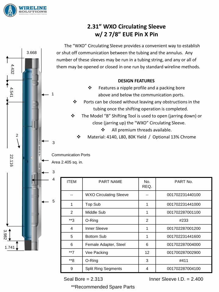
2.31” WXO Circulating Sleeve w/ 2 7/8” EUE Pin X Pin
The “WXO” Circulating Sleeve provides a convenient way to establish
or shut off communication between the tubing and the annulus. Any
number of these sleeves may be run in a tubing string, and any or all of
them may be opened or closed in one run by standard wireline methods.
DESIGN FEATURES
Features a nipple profile and a packing bore
above and below the communication ports.
Ports can be closed without leaving any obstructions in the
tubing once the shifting operation is completed.
The Model “B” Shifting Tool is used to open (jarring down) or
close (jarring up) the “WXO” Circulating Sleeve.
All premium threads available.
Material: 4140, L80, 80K Yield / Optional 13% Chrome
ITEM PART NAME No.
REQ.
PART No.
-- WXO Circulating Sleeve -- 001702231440100
1 Top Sub 1 001702231441000
2 Middle Sub 1 001702287001100
**3 O-Ring 2 #233
4 Inner Sleeve 1 001702287001200
5 Bottom Sub 1 001702231441600
6 Female Adapter, Steel 6 001702287004000
**7 Vee Packing 12 001700287002900
**8 O-Ring 3 #411
9 Split Ring Segments 4 001702287004100
**Recommended Spare Parts
Seal Bore = 2.313 Inner Sleeve I.D. = 2.400
3.668
1
3
3
4
5
22.1
16
4.5
41
4.4
32
Communication Ports
Area 2.405 sq. in.
2
3.9
82
1.741

2.75” WXO Circulating Sleeve w/ 3 1/2” EUE Pin X Pin
The “WXO” Circulating Sleeve provides a convenient way to establish
or shut off communication between the tubing and the annulus. Any
number of these sleeves may be run in a tubing string, and any or all of
them may be opened or closed in one run by standard wireline methods.
DESIGN FEATURES
Features a nipple profile and a packing bore
above and below the communication ports.
Ports can be closed without leaving any obstructions in the
tubing once the shifting operation is completed.
The Model “B” Shifting Tool is used to open (jarring down) or
close (jarring up) the “WXO” Circulating Sleeve.
All premium threads available.
Material: 4140, L80, 80K Yield / Optional 13% Chrome
ITEM PART NAME No.
REQ.
PART No.
-- “WXO” Circulation Sleeve -- 001702275620100
1 Top Sub 1 001702275621000
2 Middle Sub 1 001702350001120
**3 O-Ring 2 #237
4 Inner Sleeve 1 001702350001200
5 Bottom Sub 1 001702751621600
6 Female Adapter, Steel 4 001701350004020
**7 Vee Packing 10 001700350002920
**8 O-Ring 2 #414
9 Split Ring Segments 6 001701350004120
**10 O-Ring 1 #338
**11 Female Adapter, Steel 2 001702350004420
**Recommended Spare Parts
Seal Bore = 2.750 Inner Sleeve I.D. = 2.790
4.275
1
2 3
3
4
5
2.143
3.8
37
27.0
93
4.7
18
4.4
49
Communication Ports
Area 4.454 sq. in.

2.81” WXO Circulating Sleeve w/ 3 1/2” EUE Pin X Pin
The “WXO” Circulating Sleeve provides a convenient way to establish
or shut off communication between the tubing and the annulus. Any
number of these sleeves may be run in a tubing string, and any or all of
them may be opened or closed in one run by standard wireline methods.
DESIGN FEATURES
Features a nipple profile and a packing bore
above and below the communication ports.
Ports can be closed without leaving any obstructions in the
tubing once the shifting operation is completed.
The Model “B” Shifting Tool is used to open (jarring down) or
close (jarring up) the “WXO” Circulating Sleeve.
All premium threads available.
Material: 4140, L80, 80K Yield / Optional 13% Chrome
ITEM PART NAME No.
REQ.
PART No.
-- “WXO” Circulation Sleeve -- 001702281620100
1 Top Sub 1 001702281621000
2 Middle Sub 1 001702350001100
**3 O-Ring 2 #238
4 Inner Sleeve 1 001702350001200
5 Bottom Sub 1 001702281621600
6 Female Adapter, Steel 4 001702350004020
**7 Vee Packing 10 001700350002920
**8 O-Ring 2 #415
9 Split Ring Segments 6 001702350004120
**10 O-Ring 1 #339
**11 Female Adapter, Steel 2 001702350004420
**Recommended Spare Parts
Seal Bore = 2.813 Inner Sleeve I.D. = 2.910
4.290
1
2
3
3
4
5
3.8
77
27.0
93
4.7
50
6.0
00
Communication Ports
Area 4.454 sq. in.

2.31” WXD Circulating Sleeve w/ 2 7/8” EUE Pin X Pin
The “WXD” Circulating Sleeve provides a convenient way to establish or shut off communication between the tubing and the annulus. Any number of these sleeves may be run in a tubing string, and any or all of them may be opened or closed in one run by standard wireline methods.
DESIGN FEATURES Features a nipple profile and a packing bore above and below the communication ports.
Ports can be closed without leaving any obstructions in the tubing once the shifting operation is completed.
The Model “B” Shifting Tool is used to open (jarring down) or close (jarring up) the “WXD” Circulating Sleeve.
All premium threads available. Material: 4140, L80, 80K Yield / Optional 13% Chrome
The “WXD” has a larger flow port area (4.201) than the standard “WXO” or “WXA.”
ITEM PART NAME No.
REQ.
PART No.
-- WXD Circulating Sleeve -- 001712231440100
1 Top Sub 1 001702231441000
2 Middle Sub 1 001712287000600
**3 O-Ring 2 #233
4 Inner Sleeve 1 001712287000500
5 Bottom Sub 1 001702231441600
6 Female Adapter, Steel 6 001702287004000
**7 Vee Packing 12 001700287002900
**8 O-Ring 3 #411
9 Split Ring Segments 4 001712287004100
**Recommended Spare Parts
Seal Bore = 2.313 Inner Sleeve I.D. = 2.400
3.668
1
2
3
3
4
5
1.741
3.9
82
22.1
16
4.5
41
4.4
31
Communication Ports
Area 4.201 sq. in.

WXA / WA Circulating Sleeve
The WXA / WA Circulating Sleeve provides a way to establish or shut off communication between the tubing and the casing. Any number of sleeves may be run in a tubing string and any or all of them may be
opened or closed with a Self Releasing Positioning Tool (Model WB Shifting Tool).
The WXA / WA Sleeve consists of the following:
Top Sub
Bottom Sub
Middle Sub
Inner Sleeve (Closing Sleeve)
Packing Sets
The Top Sub of a WXA Connects to the tubing string. It contains a WX Style Locking Profile
and Polish Bore. It provides three indents which position the closing sleeve and/or inclined
shoulder which causes the WB Shifting Tool to release after the Inner Sleeve reaches the up
position. The lower end of the Top Sub is threaded to fit the Middle Sub and is sealed by the Top
Subs O-ring.
The Middle Sub screws onto both the Top and Bottom Sub. It provides flow ports for
communication and provides for the positioning and sealing of the packing.
The Packing Sets consist of three separate groups. The Upper Packing is made up of two sets
off vee packing secured between two female steel adapters and separated by a male adapter or O-
ring. The Middle Set consists of a middle O-ring which is secured between two female steel
adapters and is held in place by split ring segments. The Bottom Set consists of two sets of vee
packing secured between two female steel adapters and separated by a male adapter and O-ring.
The Inner Sleeve fits inside the Middle and the Top and Bottom Subs. It has a collet latch for
positioning, an equalizing port, and flow ports for communication. The Shifting Key recesses are
inside either end of the Inner Sleeve, allowing the shifting tool to latch into and move the Inner
Sleeve either up or down.
The Bottom Sub screws onto the Middle Sub and a bottom O-ring seals this joint. The WXA
Bottom Sub contains a bottom polish bore as well as an inclined shoulder to release the WB
Shifting Tool after shifting the Inner Sleeve. The lower end of the sub screws into the tubing string.
The WXA and WA Sleeve always opens up and closes down.
The WA Sleeve does not have a locking profile or polished seal bores. Other than that it is the
same as the WXA Sleeve.
WXA Circulating Sleeve
The WXA Sleeve can be installed at any point in the tubing string. More than one can be installed
without any loss of function. The sleeve can be selectively opened and closed no matter what their
relative positions.
The WXA Sleeve has replaceable upper and lower seals, which are easy and inexpensive to
replace. They can be of various elastomeric or non-elastomeric types.
The upper sub has a selective WX landing nipple profile machined into it to serve as a receptacle
for other flow control devices such as blanking plugs and separation tools. The lower sub has a
polished seal bore.
The Wireline Solutions Model WB Shifting Tool is used to shift the WXA Sleeve open and closed.
The sleeve is designed so that normal wireline activities will not open or close the sleeve
inadvertently. Upward jarring opens the sleeve and downward jarring closes it.
The Wireline Solutions Model WXA Circulating Sleeve is a down hole device, normally screwed into
the production tubing, that allows communication between the tubing and the casing.
APPLICATIONS
Displacing kill or completion fluid.
Allowing multiple zones to produce up one tubing string.
Selective testing of individual zones.
Selective stimulation of individual zones.
Circulating the well.
Gas lifting the well
Landing a blanking plug in the profile in the upper sub to shut in the well, test the
tubing, or test the sleeve itself.
Circulating inhibitors or methanol.

WXA / WA Circulating Sleeve Shifting Procedure
TO CLOSE:
Using the correct B Shifting Tool or alternate manufacturer’s equivalent, place the tool on the
bottom of your wireline work string with the engaging (shifting) keys looking down. Go into hole to
proper depth of sleeve. Your Shifting Tool should engage the bottom of the Inner Sleeve at the
internal shifting shoulder.
Jar down and continue jarring until the Inner Sleeve is shifted into the closed position. At this
time the Shifting Tool should release and fall through the Sleeve.
To check Sleeve to see if it is fully closed, pull back up into Sleeve and try to engage Inner
Sleeve. If you cannot engage Inner Sleeve, it is fully closed or shear pin is sheared on Shifting
Tool. Come out of hole and check Shifting Tool. If pin is not sheared, then you can assume Sleeve
is shifted. Flowing either the tubing or casing should affect both sides if Sleeve is closed.
TO OPEN:
Place Shifting Tool on bottom of wireline work string with shifting keys looking up. Go into hole
to a point where you are sure you have gone through Sleeve. Slowly pick back up through Sleeve.
Your Shifting Tool should engage the top of the Inner Sleeve at the internal shifting shoulder.
Jar up. The Inner Sleeve should move into the equalizing position. After equalizing, continue
jarring up until the Inner Sleeve is in the full open position. At this time the Shifting Tool should
release and move up hole easily when pulled.
To check Sleeve, drop back down into Sleeve and try to engage Inner Sleeve. If you cannot
engage, assume Sleeve is opened and come out of hole. Check shear pin on Shifting Tool. If
shear pin is not sheared, then you can assume sleeve is shifted. Flowing either the tubing or
casing should not affect the other side if Sleeve is opened.
WXA / WA Circulating Sleeve Working Instructions and Assembly
Use grease or pipe dope on all threaded connections and on all O-rings and Vee seals.
STEP NUMBER 1: PREPARE UPPER AND LOWER SUBS
A. Drift both upper and lower seal bores with appropriate sized drift.
B. Grease the threads and seal bores on both the Upper and Lower Subs.
C. Put Upper Sub in vice.
D. Install O-rings onto upper and lower subs.
E. Insert the Inner Sleeve into the Lower Sub collet fingers first until it stops.
F. Grease the O-ring on the Lower Sub and protruding part on the Inner Sleeve.
G. Grease the O-Ring on the Upper Sub.
STEP NUMBER 2: PREPARE BOTTOM END OF MIDDLE HOUSING
A. Hold the Middle Housing so that the bottom end is facing up (segment groove
facing up,) insert one Female Adapter Ring with grooved side facing up.
B. Insert one O-ring into the groove in Female Ring.
C. Insert another Female Adapter Ring groove side down onto the O-ring.
D. Insert Split Segments into groove inside the Middle Housing.
E. Insert one Female Adapter Ring onto Split Segments with the groove side facing up.
F. Insert appropriate number of Vee Seals grooved side facing up onto Female
Adapter Ring.
G. Insert one O-ring into groove in the Vee Seal.
H. Insert Vee Seals grooved side down facing down onto the O-ring.
I. Insert one Female Adapter Ring with the grooved side facing down onto the
Vee Seals.
J. Compress the seal stack (vee seals and o-rings) with rod, measure the stack height
and compare with the lower sub UNC thread length.
K. Grease all O-rings and Vee Seals with grease.
L. Screw the Lower Sub into the bottom end of Middle Housing until the parts shoulder.
(continued on next page)
WXA/ WA Circulating Sleeve Working Instructions and Assembly
STEP NUMBER 3: PREPARE TOP END OF MIDDLE HOUSING
A. Insert one Female Adapter Ring into the top end of the Middle Housing with the
grooved side facing up.
B. Insert the Vee Seals grooved side facing up onto the Female Adapter Ring.
C. Insert one O-ring into the groove in the Vee Seal.
D. Insert the Vee Seals grooved side facing down onto the O-ring.
E. Insert one Female Adapter Ring with the grooved side facing down onto the
Vee Seals.
F. Compress the seal stack (vee Seals and o-ring) with a rod, measure the stack height
and compare with the Upper Subs UNC thread length.
G. Grease all O-rings and Vee Seals with grease.
STEP NUMBER 2: COMPLETE ASSEMBLY, TEST, AND TORQUE
A. Vertically slide the protruding part of the Inner Sleeve into the Vee Seals and O-ring
in the Top end of the Middle Housing.
B. Screw the Upper Sub in the top end of the Middle Housing until the parts shoulder.
C. Using a “B” Shifting Tool and jar, shift the Inner Sleeve closed, open, and closed to
ensure functionality.
D. Torque sleeve tight with wrench.
E. Test to appropriate pressure.
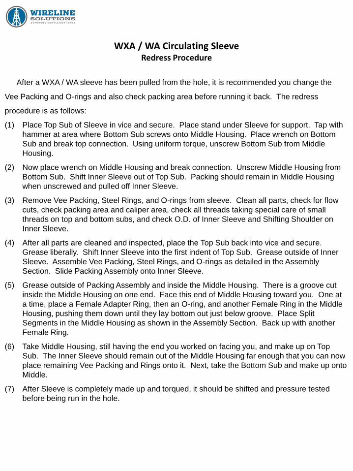
WXA / WA Circulating Sleeve Redress Procedure
After a WXA / WA sleeve has been pulled from the hole, it is recommended you change the
Vee Packing and O-rings and also check packing area before running it back. The redress
procedure is as follows:
(1) Place Top Sub of Sleeve in vice and secure. Place stand under Sleeve for support. Tap with
hammer at area where Bottom Sub screws onto Middle Housing. Place wrench on Bottom
Sub and break top connection. Using uniform torque, unscrew Bottom Sub from Middle
Housing.
(2) Now place wrench on Middle Housing and break connection. Unscrew Middle Housing from
Bottom Sub. Shift Inner Sleeve out of Top Sub. Packing should remain in Middle Housing
when unscrewed and pulled off Inner Sleeve.
(3) Remove Vee Packing, Steel Rings, and O-rings from sleeve. Clean all parts, check for flow
cuts, check packing area and caliper area, check all threads taking special care of small
threads on top and bottom subs, and check O.D. of Inner Sleeve and Shifting Shoulder on
Inner Sleeve.
(4) After all parts are cleaned and inspected, place the Top Sub back into vice and secure.
Grease liberally. Shift Inner Sleeve into the first indent of Top Sub. Grease outside of Inner
Sleeve. Assemble Vee Packing, Steel Rings, and O-rings as detailed in the Assembly
Section. Slide Packing Assembly onto Inner Sleeve.
(5) Grease outside of Packing Assembly and inside the Middle Housing. There is a groove cut
inside the Middle Housing on one end. Face this end of Middle Housing toward you. One at
a time, place a Female Adapter Ring, then an O-ring, and another Female Ring in the Middle
Housing, pushing them down until they lay bottom out just below groove. Place Split
Segments in the Middle Housing as shown in the Assembly Section. Back up with another
Female Ring.
(6) Take Middle Housing, still having the end you worked on facing you, and make up on Top
Sub. The Inner Sleeve should remain out of the Middle Housing far enough that you can now
place remaining Vee Packing and Rings onto it. Next, take the Bottom Sub and make up onto
Middle.
(7) After Sleeve is completely made up and torqued, it should be shifted and pressure tested
before being run in the hole.
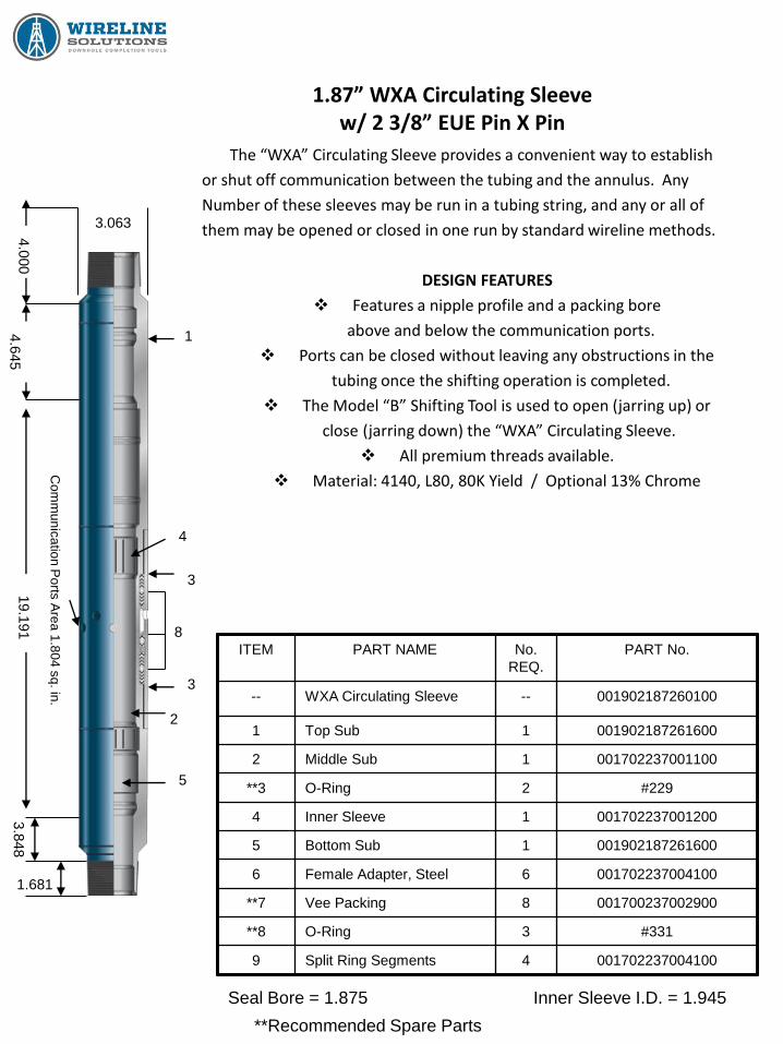
1.87” WXA Circulating Sleeve w/ 2 3/8” EUE Pin X Pin
The “WXA” Circulating Sleeve provides a convenient way to establish
or shut off communication between the tubing and the annulus. Any
Number of these sleeves may be run in a tubing string, and any or all of
them may be opened or closed in one run by standard wireline methods.
DESIGN FEATURES
Features a nipple profile and a packing bore
above and below the communication ports.
Ports can be closed without leaving any obstructions in the
tubing once the shifting operation is completed.
The Model “B” Shifting Tool is used to open (jarring up) or
close (jarring down) the “WXA” Circulating Sleeve.
All premium threads available.
Material: 4140, L80, 80K Yield / Optional 13% Chrome
ITEM PART NAME No.
REQ.
PART No.
-- WXA Circulating Sleeve -- 001902187260100
1 Top Sub 1 001902187261600
2 Middle Sub 1 001702237001100
**3 O-Ring 2 #229
4 Inner Sleeve 1 001702237001200
5 Bottom Sub 1 001902187261600
6 Female Adapter, Steel 6 001702237004100
**7 Vee Packing 8 001700237002900
**8 O-Ring 3 #331
9 Split Ring Segments 4 001702237004100
**Recommended Spare Parts
Seal Bore = 1.875 Inner Sleeve I.D. = 1.945
3.063
1
2
3
3
4
5
1.681
3.8
48
19.1
91
4.6
45
4.0
00
Com
mu
nic
atio
n P
orts
Are
a 1
.80
4 s
q. in
.
8

2.31” WXA Circulating Sleeve w/ 2 7/8” EUE Pin X Pin
The “WXA” Circulating Sleeve provides a convenient way to establish
or shut off communication between the tubing and the annulus. Any
number of these sleeves may be run in a tubing string, and any or all of
them may be opened or closed in one run by standard wireline methods.
DESIGN FEATURES
Features a nipple profile and a packing bore
above and below the communication ports.
Ports can be closed without leaving any obstructions in the
tubing once the shifting operation is completed.
The Model “B” Shifting Tool is used to open (jarring up) or
close (jarring down) the “WXA” Circulating Sleeve.
All premium threads available.
Material: 4140, L80, 80K Yield / Optional 13% Chrome
ITEM PART NAME No.
REQ.
PART No.
-- WXA Circulating Sleeve -- 001902231440100
1 Top Sub 1 001902231441000
2 Middle Sub 1 001702287001100
**3 O-Ring 2 #233
4 Inner Sleeve 1 001702287001200
5 Bottom Sub 1 001902231441600
6 Female Adapter, Steel 6 001702287004000
**7 Vee Packing 8 001700287002900
**8 O-Ring 3 #411
9 Split Ring Segments 4 001702287004100
**Recommended Spare Parts
Seal Bore = 2.313 Inner Sleeve I.D. = 2.400
3.668
1
2
3
3
4
5
1.741
3.9
82
22.1
16
4.7
09
4.3
90
Com
mu
nic
atio
n P
orts
Are
a 2
.40
5 s
q. in
.
8

2.75” WXA Circulating Sleeve w/ 3 1/2” EUE Pin X Pin
The “WXA” Circulating Sleeve provides a convenient way to establish
or shut off communication between the tubing and the annulus. Any
number of these sleeves may be run in a tubing string, and any or all of
them may be opened or closed in one run by standard wireline methods.
DESIGN FEATURES
Features a nipple profile and a packing bore
above and below the communication ports.
Ports can be closed without leaving any obstructions in the
tubing once the shifting operation is completed.
The Model “B” Shifting Tool is used to open (jarring up) or
close (jarring down) the “WXA” Circulating Sleeve.
All premium threads available.
Material: 4140, L80, 80K Yield / Optional 13% Chrome
ITEM PART NAME No.
REQ.
PART No.
-- “WXA” Circulation Sleeve -- 001902275620100
1 Top Sub 1 001902275621000
2 Middle Sub 1 001702350001120
**3 O-Ring 2 #237
4 Inner Sleeve 1 001702350001220
5 Bottom Sub 1 001902275621600
6 Female Adapter, Steel 4 001702350004020
**7 Vee Packing 10 001700350002920
**8 O-Ring 2 #414
9 Split Ring Segments 6 001701350004120
**10 O-Ring 1 #338
**11 Female Adapter, Steel 2 001702350004420
**Recommended Spare Parts
Seal Bore = 2.750 Inner Sleeve I.D. = 2.790
4.275
1
2
3
3
4
5
2.143
3.7
74
27.0
41
4.9
06
4.4
50
Com
mu
nic
atio
n P
orts
Are
a 4
.45
4 s
q. in
.
8
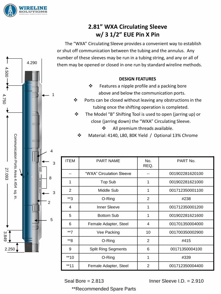
2.81” WXA Circulating Sleeve w/ 3 1/2” EUE Pin X Pin
The “WXA” Circulating Sleeve provides a convenient way to establish
or shut off communication between the tubing and the annulus. Any
number of these sleeves may be run in a tubing string, and any or all of
them may be opened or closed in one run by standard wireline methods.
DESIGN FEATURES
Features a nipple profile and a packing bore
above and below the communication ports.
Ports can be closed without leaving any obstructions in the
tubing once the shifting operation is completed.
The Model “B” Shifting Tool is used to open (jarring up) or
close (jarring down) the “WXA” Circulating Sleeve.
All premium threads available.
Material: 4140, L80, 80K Yield / Optional 13% Chrome
ITEM PART NAME No.
REQ.
PART No.
-- “WXA” Circulation Sleeve -- 001902281620100
1 Top Sub 1 001902281621000
2 Middle Sub 1 001712350001100
**3 O-Ring 2 #238
4 Inner Sleeve 1 001712350001200
5 Bottom Sub 1 001902281621600
6 Female Adapter, Steel 4 001701350004000
**7 Vee Packing 10 001700350002900
**8 O-Ring 2 #415
9 Split Ring Segments 6 00171350004100
**10 O-Ring 1 #339
**11 Female Adapter, Steel 2 001712350004400
**Recommended Spare Parts
Seal Bore = 2.813 Inner Sleeve I.D. = 2.910
4.290
1
2
3
3
4
5
2.250
3.8
49
27.0
93
4.7
50
4.5
00
Com
mu
nic
atio
n P
orts
Are
a 4
.45
4 s
q. in
.
8
WA Circulating Sleeve
The WA Sleeve has no internal landing nipple profile. The standard WA has EUE pin by pin
connections. These can be machined to match premium thread types if required.
The sealing mechanism used in the WA Sleeve is the same proven method as the Model WXA and
WXO Sleeves. This ensures full seal integrity after repeated shifting.
The Wireline Solutions Model WB Shifting Tool is used to shift the WA Sleeve open and closed.
The sleeve is designed so that normal wireline activities will not open or close the sleeve
inadvertently. Upward jarring opens the sleeve and downward jarring closes it.
The Wireline Solutions Model WA Circulating Sleeve is a “no-frills” Sleeve. It is used to provide a
means of casing-tubing communication in low pressure wells.
APPLICATIONS
Displacing kill or completion fluid.
Allowing multiple zones to produce up one tubing string.
Selective testing of individual zones.
Selective stimulation of individual zones.
Circulating the well.
Gas lifting the well
Circulating inhibitors or methanol.
The WA, though lacking a Nipple Seal Bore or profile, is similar to the WXA. It is assembled,
shifted, and redressed in the same manner as the WXA.
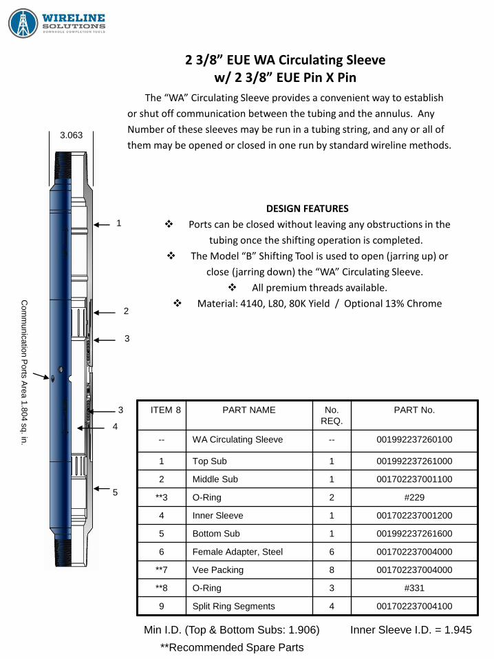
2 3/8” EUE WA Circulating Sleeve w/ 2 3/8” EUE Pin X Pin
The “WA” Circulating Sleeve provides a convenient way to establish
or shut off communication between the tubing and the annulus. Any
Number of these sleeves may be run in a tubing string, and any or all of
them may be opened or closed in one run by standard wireline methods.
DESIGN FEATURES
Ports can be closed without leaving any obstructions in the
tubing once the shifting operation is completed.
The Model “B” Shifting Tool is used to open (jarring up) or
close (jarring down) the “WA” Circulating Sleeve.
All premium threads available.
Material: 4140, L80, 80K Yield / Optional 13% Chrome
ITEM PART NAME No.
REQ.
PART No.
-- WA Circulating Sleeve -- 001992237260100
1 Top Sub 1 001992237261000
2 Middle Sub 1 001702237001100
**3 O-Ring 2 #229
4 Inner Sleeve 1 001702237001200
5 Bottom Sub 1 001992237261600
6 Female Adapter, Steel 6 001702237004000
**7 Vee Packing 8 001702237004000
**8 O-Ring 3 #331
9 Split Ring Segments 4 001702237004100
**Recommended Spare Parts
Min I.D. (Top & Bottom Subs: 1.906) Inner Sleeve I.D. = 1.945
3 8
3.063
1
2
4
5
Com
mu
nic
atio
n P
orts
Are
a 1
.80
4 s
q. in
.
3

2 7/8” EUE WA Circulating Sleeve w/ 2 7/8” EUE Pin X Pin
The “WA” Circulating Sleeve provides a convenient way to establish
or shut off communication between the tubing and the annulus. Any
Number of these sleeves may be run in a tubing string, and any or all of
them may be opened or closed in one run by standard wireline methods.
DESIGN FEATURES
Ports can be closed without leaving any obstructions in the
tubing once the shifting operation is completed.
The Model “B” Shifting Tool is used to open (jarring up) or
close (jarring down) the “WA” Circulating Sleeve.
All premium threads available.
Material: 4140, L80, 80K Yield / Optional 13% Chrome
ITEM PART NAME No.
REQ.
PART No.
-- WA Circulating Sleeve -- 001992287440100
1 Top Sub 1 001992287441000
2 Middle Sub 1 001702287001100
**3 O-Ring 2 #233
4 Inner Sleeve 1 001702287001200
5 Bottom Sub 1 001992287441600
6 Female Adapter, Steel 6 001702287004000
**7 Vee Packing 8 001700287002900
**8 O-Ring 3 #411
9 Split Ring Segments 4 001702287004100
**Recommended Spare Parts
Min I.D. (Top & Bottom Subs: 2.359) Inner Sleeve I.D. = 2.400
3 8
3.668
1
2
4
5
Com
mu
nic
atio
n P
orts
Are
a 1
.80
4 s
q. in
.
3
WL Circulating Sleeve
The WL Circulating Sleeve provides a way to establish or shut off communication between the tubing and the annulus. Any number of sleeves may be run in a tubing string and any or all of them may be opened or
closed with a Self Releasing WD-2 Shifting Tool.
The WL Sleeve consists of the following:
Top Sub
Bottom Sub
Middle Sub
Closing Sleeve
Replaceable Seals
O-rings
The Top Sub connects to the tubing string. It contains a “WF” landing nipple profile and a seal
bore. Selective and NoGo flow control accessories can be utilized with this sleeve. The Top Sub
screws onto the Middle Sub / Closing Sleeve assembly. The sleeve is built in such a manner that it
cannot be assembled incorrectly. The Middle Housing has flow ports and the Closing Sleeve seals
off in housing above and below flow ports and is shifted up to the open position and down into the
closing position. The closing sleeve has two permanently bonded seals which eliminates the seals
“blowing off” during shifting or equalizing. The replaceable seals never enter in flow path. The
Bottom Sub screws onto bottom of Middle Housing. It contains a seal bore for flow control
accessories and the lower end of Bottom Sub screws onto tubing string. Both the Top and Bottom
subs seal off in Middle Housing with O-rings. The seal bores in the Top and Bottom subs are what
the WD-2 Shifting Tool locates in to insure proper location of the shifting dogs onto the closing
sleeve. When shifted opened or closed, the shifting tool automatically releases.
WL Circulating Sleeve Shifting Procedure
The Model WD-2 Shifting Tool is used to provide a selective and controlled method of opening and
closing the Model WL Circulating Sleeve.
OPERATION:
Spring loaded shifting dogs are normally held in the closed position by the spring-loaded retractor.
If the retractor is moved away from the shifting dogs, they automatically open. In operation,
anytime the collet engages the bore of the sleeve and either slack-off weight (for opening
operation) or up strain (for closing operation) is applied, the retractor moves away from the shifting
dogs allowing them to engage the closing sleeve of the circulation sleeve. At this point, jarring up
will open the sleeve and jarring down (with shifting tool run in the inverted position) will close the
sleeve.
The tool is spaced so that upon completion the retractor is once again in position to close the
shifting dogs. When the shifting dogs collapse, the tool turns loose, thus automatically signaling
that the shifting operation is complete.
To verify that the closing sleeve has shifted, the opening or closing is repeated. If the shifting
dogs fail to engage the closing sleeve, the sleeve has been shifted completely. If desired, the
same procedure can be used to determine the position of any closing sleeve in the well.
If at any time the collet engages the bore of a sleeve, jarring action is applied in the same
direction of the tool is run (down for opening and up for closing). The shifting tool will pass through
the sleeve without disturbing the position of any closing sleeve, regardless of the position of the
closing sleeve at the time.
This feature can also be used to deliberately release the shifting dogs from a closing sleeve at
any time desired. Jarring to the reverse of the normal direction will release the shifting tool. For
extra safety, shear pins are installed in the event reverse jarring cannot be applied, or the closing
sleeve failed to move.
When opening a circulation sleeve in the presence of annulus differential, the resultant flow
caused the “flow” upward from the bore of the sleeve. This action prevents the tools from being
blown up hole when opening this sleeve.
WL Circulating Sleeve Shifting Procedure
TO OPEN:
Check adjustment dimensions “A.” Attach to a standard wireline tool string and run into the well.
Reduce running speed as the shifting tool approaches the circulating sleeve and make contact with
the NoGo shoulder in the upper end of the sleeve very slowly. Gently set down the full weight of
the wireline tool to engage the dogs with the lower of the closing sleeve. Apply an upward pull on
the wireline to verify that the shifting dogs will automatically release when the closing sleeve is in
the full open position. Verify that the closing sleeve has opened by repeating the opening
operation.
TO CLOSE:
When being run to close a sleeve, the fishing neck and thread protector must be reversed and
the tool run in the inverted position (collet on lower end of tool and dogs facing down). Check
adjustment dimension “A,” attach to standard wireline tool string and run in well. Reduce running
speed as tool approaches circulating sleeve. Collet then contacts the upper seal bore and then
lower seal bore. When the collet contacts the bottom of the seal bore in the lower sub, take a
moderate pull on the wireline to engage the shifting dogs with the top of the closing sleeve. Jar
down to shift closing sleeve closed. The shifting dogs will automatically release when closing
sleeve and the pick up rapidly to drive the collet into lower seal bore. Jar up only to move the collet
completely through both bores.
SHIFTING TOOL ADJUSTMENT PROCEDURES:
Proper operation of the “CAD-2” shifting tool requires that dimension “A” be adjusted accurately
and the proper collet to be installed prior to running the tool.
The adjustment is easily made up by loosening the set screws and rotating the control sleeve until
the proper spacing is obtained. Retighten set screws.
WL Circulating Sleeve Shifting Procedure
AUTOMATIC LOCATION COLLET: Flags the operator when a sleeve is reached. It also indicates
when the tool passes through a sleeve or landing nipple.
PROOF OF COMPLETED SHIFT: As soon as a shift, either open or close, is completed, an
attempt to repeat the operation in the same sleeve will give a positive indication that the shift was
performed.
SAFETY FEATURE: If the sleeve is opened in the presence of a differential pressure in favor of
the annulus, the release mechanism is held imperative by the flow and the pressure is sufficiently
balanced to allow safe removal.
Note: WL Sleeves can be shifted using a Halliburton “B” Shifting Tool with shear type keys.

WL Circulating Sleeve Redress Procedure
1) Place Top Sub of Sleeve in vice.
2) Break and remove Bottom Sub.
Note: Do not wrench hard on Middle Housing. If Housing is difficult to remove from Top Sub
and requires more torque, replace Bottom Sub in Housing and wrench at point where Bottom
Sub and Housing mate. You can gently tap with hammer at area where Top Sub and Housing
mate to help.
3) After Top and Bottom Sub have been removed from Housing, drive the Closing Sleeve out of
the BOTTOM of Sleeve. Closing Sleeve will not come out of top end of Housing. Use proper
size driving tool so to not distort Closing Sleeve.
4) Remove replaceable Rubber Seals off of Closing Sleeve. (Note manner in which Seals fit).
Check Permanent Rubber on Closing Sleeve. If Permanent Rubber is pitted, cut, flow cut, too
hard or brittle, distorted, or altered in any manner so as not to form a good seal against inside
of Housing, then discard complete Closing Sleeve and replace with new Closing Sleeve with
new Seals. If shifting shoulders are worn and would not make good contact with Shifting Tool,
then discard. If Closing Sleeve is in good condition, clean up, replace Seals, and set aside.
5) Check Top and Bottom Subs to make sure threads are clean and workable and Subs are not
corroded. Clean and set aside.
6) Check Middle Housing to make sure sealing surface is not pitted and is clean. Also, make
sure threads are good. Clean and set aside.
7) Replace O-rings on Top and Bottom Subs.
8) Grease all parts liberally.
9) Put Top Sub into vice.
10) Screw Housing onto Top Sub by hand or low torque wrench.
11) Put Closing Sleeve into Housing, putting Replaceable Seal end first.
12) Using proper driving tool, drive Closing Sleeve into Housing up to Top Sub being careful not to
hit threads.
13) Screw Bottom Sub into Housing. Put wrench on Bottom Sub and make up both Top and
Bottom subs at same time.
14) Shift Sleeve into closed position.
15) Pressure test to appropriate pressure and clean and paint.

1.87” WL Circulating Sleeve w/ 2 3/8” EUE Box X Pin
The “WL” Circulating Sleeve is a downhole flow control device mounted in the production tubing to provide communication between the tubing and casing annulus. It is opened by shifting an inner sleeve either up or down by standard wireline methods.
DESIGN FEATURES Features a nipple profile above and a packing
bore above and below the communication ports. Dependable, Simple, Quick
Ports can be closed without leaving any obstructions in the tubing once the shifting operation is completed.
The Model “D-2” Shifting Tool is used to open (jarring up) or close (jarring down) the “WL” Circulating Sleeve.
All premium threads available. Material: 4140 / Optional 13% Chrome
ITEM PART NAME No.
REQ.
PART No.
-- “WL” Circulating Sleeve -- 001602187260101
1 Top Sub 1 001602187261000
2 O-Ring 2 #141
3 Middle Housing 1 001602237001100
4 Loose Seals 2 238Nitrile
5 Closing Sleeve 1 001601237001318
6 Bottom Sub 1 001602187261600
Note: Length of sleeve is as shown, varying with thread and bore size
relationships.
Seal Bore = 1.875 Inner Sleeve I.D. = 1.937
2.910
1
2
3
2
4
5
1.998
5.7
15
15.0
72
5.8
38
4.7
50
Communication Ports
Area 2.838 sq. in.
6
1.000
NoG
o B
ase
Two Non-Replaceable Seals
7.9
70

2.25” WL Circulating Sleeve w/ 2 7/8” EUE Box X Pin
The “WL” Circulating Sleeve is a downhole flow control device mounted in the production tubing to provide communication between the tubing and casing annulus. It is opened by shifting an inner sleeve either up or down by standard wireline methods.
DESIGN FEATURES Features a nipple profile above and a packing
bore above and below the communication ports. Dependable, Simple, Quick
Ports can be closed without leaving any obstructions in the tubing once the shifting operation is completed.
The Model “D-2” Shifting Tool is used to open (jarring up) or close (jarring down) the “WL” Circulating Sleeve.
All premium threads available. Material: 4140 / Optional 13% Chrome
ITEM PART NAME No.
REQ.
PART No.
-- “WL” Circulating Sleeve -- 001602225440101
1 Top Sub 1 001602225441000
2 O-Ring 2 #149
3 Middle Housing 1 001602287001100
4 Loose Seals 2 278Nitrile
5 Closing Sleeve 1 001601287001318
6 Bottom Sub 1 001602225441600
Note: Length of sleeve is as shown, varying with thread and bore size
relationships.
Seal Bore = 2.250 Inner Sleeve I.D. = 2.375
3.420
1
2
3
2
4
5
2.233
6.0
38
15.8
75
6.2
09
5.1
88
Communication Ports
Area 4.137 sq.. in.
6
1.000
NoG
o B
ase
Two Non-Replaceable Seals
8.2
81
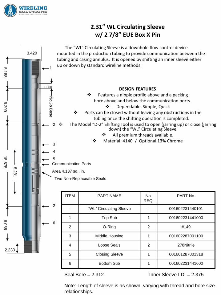
2.31” WL Circulating Sleeve w/ 2 7/8” EUE Box X Pin
The “WL” Circulating Sleeve is a downhole flow control device mounted in the production tubing to provide communication between the tubing and casing annulus. It is opened by shifting an inner sleeve either up or down by standard wireline methods.
DESIGN FEATURES Features a nipple profile above and a packing
bore above and below the communication ports. Dependable, Simple, Quick
Ports can be closed without leaving any obstructions in the tubing once the shifting operation is completed.
The Model “D-2” Shifting Tool is used to open (jarring up) or close (jarring down) the “WL” Circulating Sleeve.
All premium threads available. Material: 4140 / Optional 13% Chrome
ITEM PART NAME No.
REQ.
PART No.
-- “WL” Circulating Sleeve -- 001602231440101
1 Top Sub 1 001602231441000
2 O-Ring 2 #149
3 Middle Housing 1 001602287001100
4 Loose Seals 2 278Nitrile
5 Closing Sleeve 1 001601287001318
6 Bottom Sub 1 001602231441600
Note: Length of sleeve is as shown, varying with thread and bore size
relationships.
Seal Bore = 2.312 Inner Sleeve I.D. = 2.375
3.420
1
2
3
2
4
5
2.233
6.0
38
15.8
75
6.2
09
5.1
88
Communication Ports
Area 4.137 sq.. in.
6
1.000
NoG
o B
ase
Two Non-Replaceable Seals
8.2
81

2.75” WL Circulating Sleeve w/ 3 1/2” EUE Box X Pin
The “WL” Circulating Sleeve is a downhole flow control device mounted in the production tubing to provide communication between the tubing and casing annulus. It is opened by shifting an inner sleeve either up or down by standard wireline methods.
DESIGN FEATURES Features a nipple profile above and a packing
bore above and below the communication ports. Dependable, Simple, Quick
Ports can be closed without leaving any obstructions in the tubing once the shifting operation is completed.
The Model “D-2” Shifting Tool is used to open (jarring up) or close (jarring down) the “WL” Circulating Sleeve. All premium threads available.
Material: 4140 / Optional 13% Chrome
ITEM PART NAME No.
REQ.
PART No.
-- “WL” Circulating Sleeve -- 001602275620101
1 Top Sub 1 001602275621000
2 O-Ring 2 #237
3 Middle Housing 1 001602275621600
4 Loose Seals 2 350Nitrile
5 Closing Sleeve 1 001602350001318
6 Bottom Sub 1 001602275621600
Note: Length of sleeve is as shown, varying with thread and bore size
relationships.
Seal Bore = 2.750 Inner Sleeve I.D. = 2.875
4.500
1
2
3
2
4
5
2.375
6.7
20
16.0
79
6.7
80
5.6
57
Communication Ports
Area 6.106 sq. in.
6
1.000
NoG
o B
ase
Two Non-Replaceable Seals
8.7
50
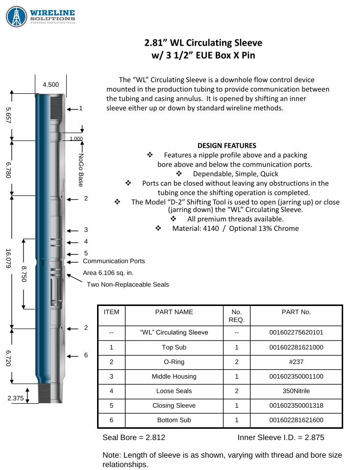
2.81” WL Circulating Sleeve w/ 3 1/2” EUE Box X Pin
The “WL” Circulating Sleeve is a downhole flow control device mounted in the production tubing to provide communication between the tubing and casing annulus. It is opened by shifting an inner sleeve either up or down by standard wireline methods.
DESIGN FEATURES Features a nipple profile above and a packing
bore above and below the communication ports. Dependable, Simple, Quick
Ports can be closed without leaving any obstructions in the tubing once the shifting operation is completed.
The Model “D-2” Shifting Tool is used to open (jarring up) or close (jarring down) the “WL” Circulating Sleeve. All premium threads available.
Material: 4140 / Optional 13% Chrome
ITEM PART NAME No.
REQ.
PART No.
-- “WL” Circulating Sleeve -- 001602275620101
1 Top Sub 1 001602281621000
2 O-Ring 2 #237
3 Middle Housing 1 001602350001100
4 Loose Seals 2 350Nitrile
5 Closing Sleeve 1 001602350001318
6 Bottom Sub 1 001602281621600
Note: Length of sleeve is as shown, varying with thread and bore size
relationships.
Seal Bore = 2.812 Inner Sleeve I.D. = 2.875
4.500
1
2
3
2
4
5
2.375
6.7
20
16.0
79
6.7
80
5.6
57
Communication Ports
Area 6.106 sq. in.
6
1.000
NoG
o B
ase
Two Non-Replaceable Seals
8.7
50
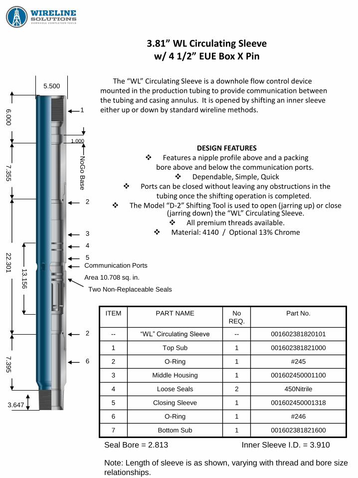
3.81” WL Circulating Sleeve w/ 4 1/2” EUE Box X Pin
The “WL” Circulating Sleeve is a downhole flow control device mounted in the production tubing to provide communication between the tubing and casing annulus. It is opened by shifting an inner sleeve either up or down by standard wireline methods.
DESIGN FEATURES Features a nipple profile above and a packing
bore above and below the communication ports. Dependable, Simple, Quick
Ports can be closed without leaving any obstructions in the tubing once the shifting operation is completed.
The Model “D-2” Shifting Tool is used to open (jarring up) or close (jarring down) the “WL” Circulating Sleeve. All premium threads available.
Material: 4140 / Optional 13% Chrome
ITEM PART NAME No
REQ.
Part No.
-- “WL” Circulating Sleeve -- 001602381820101
1 Top Sub 1 001602381821000
2 O-Ring 1 #245
3 Middle Housing 1 001602450001100
4 Loose Seals 2 450Nitrile
5 Closing Sleeve 1 001602450001318
6 O-Ring 1 #246
7 Bottom Sub 1 001602381821600
Note: Length of sleeve is as shown, varying with thread and bore size
relationships.
Seal Bore = 2.813 Inner Sleeve I.D. = 3.910
5.500
1
2
3
2
4
5
3.647
7.3
95
22.3
01
7.3
55
6.0
00
Communication Ports
Area 10.708 sq. in.
6
1.000
NoG
o B
ase
Two Non-Replaceable Seals
13.1
56

Hydro Trip Pressure Subs
&
Wireline Re-Entry Guides

2 3/8” Model “WE” Hydro Trip Pressure Sub w/ 2 3/8” EUE Box X Pin
The Model “WE” Hydro Trip Pressure Sub is a pressure actuated
device installed in tubing string below a hydrostatically actuated tool such
as a packer. It provides a method of applying pressure to activate and
set the packer and then through continued pressure, activate the Hydro
Trip Sub.
The Packer is set by circulating a ball through the packer down to ball
seat in Hydro Trip Sub. After packer is set, a continued increase in
pressure is applied to shear the shear screws in the shear ring, allowing
the ball seat collet to move down into the collet relief area and allowing
the ball to pass down the Hydro Trip Sub through the tubing, leaving a
“full open” Sub with no restrictions to production.
MATERIAL SELECTION:
4140 / P110 4140 / L80
110,000 Yield 82,000 Yield
Standard Service Resist Corrosion in
Sour Gas Environments
ITEM PART NAME No.
REQ.
PART No.
-- 2 3/8” “WE” Hydro Trip Sub -- 00152237260100
1 Top Sub 1 00152237261001
2 Drop Ball 1 1-3/4” O.D.
3 Ball Seat 1 001552237004900
4 Set Screw 1 10-31 x 3/16”
5 O-Ring 1 #229
6 Spacer 1 001552237004700
7 ** Shear Screw (Brass) 8 ¼”-20 x 5/16”
8 Shear Ring 1 00152237004800
9 Bottom Sub 1 001552237261600
SIZE
A
B
C
*D
*E
*E
2 3/8” 3.000 2.185 1.968 6.094 7.781 2.125
** Shear Value for each Brass Screw = 375# +/- 15%
Before Shift After Shift
1.625 1.906
Ball Seat I.D.
* Dimensions are for Subs with threads shown. Dimensions will vary when Subs with different threads are used.
A
1
2
3
4
5
6
7
8
9
C
F
E
D
B
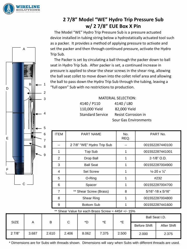
2 7/8” Model “WE” Hydro Trip Pressure Sub w/ 2 7/8” EUE Box X Pin
The Model “WE” Hydro Trip Pressure Sub is a pressure actuated
device installed in tubing string below a hydrostatically actuated tool such
as a packer. It provides a method of applying pressure to activate and
set the packer and then through continued pressure, activate the Hydro
Trip Sub.
The Packer is set by circulating a ball through the packer down to ball
seat in Hydro Trip Sub. After packer is set, a continued increase in
pressure is applied to shear the shear screws in the shear ring, allowing
the ball seat collet to move down into the collet relief area and allowing
the ball to pass down the Hydro Trip Sub through the tubing, leaving a
“full open” Sub with no restrictions to production.
MATERIAL SELECTION:
4140 / P110 4140 / L80
110,000 Yield 82,000 Yield
Standard Service Resist Corrosion in
Sour Gas Environments
ITEM PART NAME No.
REQ.
PART No.
-- 2 7/8” “WE” Hydro Trip Sub -- 001552287440100
1 Top Sub 1 001552287441001
2 Drop Ball 1 2-1/8” O.D.
3 Ball Seat 1 001552287004900
4 Set Screw 1 ¼-20 x ¼”
5 O-Ring 1 #232
6 Spacer 1 001552287004700
7 ** Shear Screw (Brass) 8 5/16”-18 x 5/16”
8 Shear Ring 1 001552287004800
9 Bottom Sub 1 001552287441600
SIZE
A
B
C
*D
*E
*E
2 7/8” 3.687 2.610 2.406 8.062 7.375 2.500
** Shear Value for each Brass Screw = 445# +/- 15%
Before Shift After Shift
2.000 2.375
Ball Seat I.D.
* Dimensions are for Subs with threads shown. Dimensions will vary when Subs with different threads are used.
C
A
D
E
F
B
9
8
7
6
5
4
3
2
1

3 1/2” Model “WE” Hydro Trip Pressure Sub w/ 3 1/2” EUE Box X Pin
The Model “WE” Hydro Trip Pressure Sub is a pressure actuated
device installed in tubing string below a hydrostatically actuated tool such
as a packer. It provides a method of applying pressure to activate and
set the packer and then through continued pressure, activate the Hydro
Trip Sub.
The Packer is set by circulating a ball through the packer down to ball
seat in Hydro Trip Sub. After packer is set, a continued increase in
pressure is applied to shear the shear screws in the shear ring, allowing
the ball seat collet to move down into the collet relief area and allowing
the ball to pass down the Hydro Trip Sub through the tubing, leaving a
“full open” Sub with no restrictions to production.
MATERIAL SELECTION:
4140 / P110 4140 / L80
110,000 Yield 82,000 Yield
Standard Service Resist Corrosion in
Sour Gas Environments
ITEM PART NAME No.
REQ.
PART No.
-- 3 1/2” “WE” Hydro Trip Sub -- 001552350620100
1 Top Sub 1 001552350621001
2 Drop Ball 1 2-1/2” O.D.
3 Ball Seat 1 001552350004900
4 Set Screw 1 ¼-20 x ¼”
5 O-Ring 1 #239
6 Spacer 1 001552350004700
7 ** Shear Screw (Brass) 8 5/16”-18 x 5/16”
8 Shear Ring 1 001552350004800
9 Bottom Sub 1 001552350621600
SIZE
A
B
C
*D
*E
*E
3 1/2” 4.500 3.225 3.000 9.625 7.125 2.875
** Shear Value for each Brass Screw = 290# +/- 15%
Before Shift After Shift
2.312 2.781
Ball Seat I.D.
* Dimensions are for Subs with threads shown. Dimensions will vary when Subs with different threads are used.
C
A
D
E
F
B 1
2
3
4
5
6
7
8
9

Model “WE” Hydro Trip Pressure Sub Sizes 2 3/8” / 2 7/8” / 3 1/2”
The Model “WE” Hydro Trip Pressure Sub is a pressure actuated device installed in tubing string below a hydrostatically actuated tool such as a packer. It provides a method of applying pressure to activate and set the packer and then through continued pressure, activate the Hydro Trip Sub. Packer is set by circulating a ball through packer down to ball seat in the Hydro Trip Sub. After packer is set, a continued increase in pressure is applied to shear the shear screws in the shear ring, allowing the ball seat collet to move down into the collet relief area and allowing the ball to pass down the Hydro Trip Sub through the tubing, leaving a “full open” Sub with no restrictions to production.
REDRESS PROCEDURE
After a Hydro Trip Sub has been pulled from well, it is manufactured such that it can be redressed and utilized again. A. Place Bottom Sub (item 9) of Hydro Trip in vice and secure. B. Remove set screws (item 4). C. Remove Top Sub (item 1) from Bottom Sub. D. After removing the Top Sub, the Ball Seat Collet (item 3) will be sticking out of the bottom end of Top
Sub. Remove Ball Seat Collet out of bottom end of Top Sub and discard. Remove O-ring from Top Sub and discard.
E. Remove Spacer (item 6) and Shear Ring (item 8) out of Bottom Sub. F. Remove sheared screws from Spacer, clean and grease all parts, including Top and Bottom Sub. G. Replace sheared screws with proper amount of new screws into the Shear Ring and Spacer. Drop
made up Shear Ring / Spacer into the Bottom Sub. Make sure item falls into place in Bottom Sub. H. Replace O-ring on Top Sub and make up Top Sub into Bottom Sub. Replace Set Screws. I. Take NEW Ball Seat Collet and with proper “driving tool” drive Ball Seat down through top of Top Sub
down to where Ball Seat bottoms out on Shear Ring. Hydro Trip Pressure Sub is ready to run.
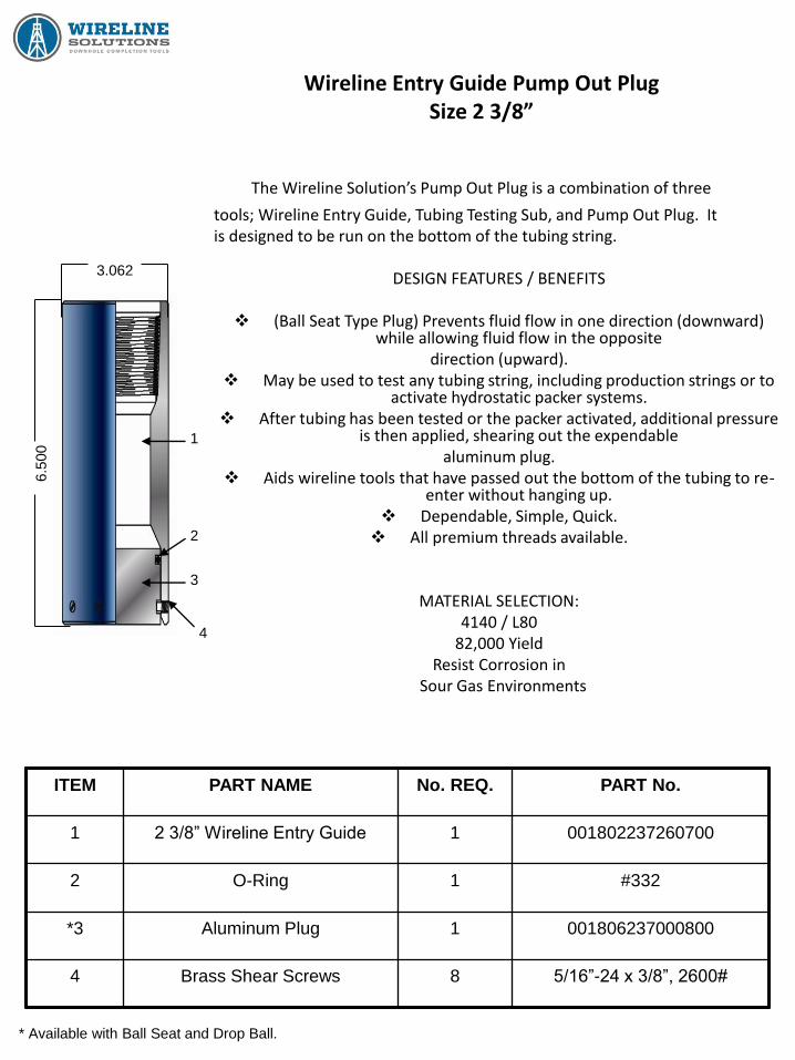
Wireline Entry Guide Pump Out Plug Size 2 3/8”
The Wireline Solution’s Pump Out Plug is a combination of three
tools; Wireline Entry Guide, Tubing Testing Sub, and Pump Out Plug. It is designed to be run on the bottom of the tubing string.
DESIGN FEATURES / BENEFITS
(Ball Seat Type Plug) Prevents fluid flow in one direction (downward) while allowing fluid flow in the opposite
direction (upward). May be used to test any tubing string, including production strings or to
activate hydrostatic packer systems. After tubing has been tested or the packer activated, additional pressure
is then applied, shearing out the expendable aluminum plug.
Aids wireline tools that have passed out the bottom of the tubing to re-enter without hanging up.
Dependable, Simple, Quick. All premium threads available.
MATERIAL SELECTION: 4140 / L80
82,000 Yield Resist Corrosion in
Sour Gas Environments
* Available with Ball Seat and Drop Ball.
ITEM PART NAME No. REQ. PART No.
1 2 3/8” Wireline Entry Guide 1 001802237260700
2 O-Ring 1 #332
*3 Aluminum Plug 1 001806237000800
4 Brass Shear Screws 8 5/16”-24 x 3/8”, 2600#
3.062
6.5
00 1
2
3
4

Wireline Entry Guide Pump Out Plug Size 2 7/8”
The Wireline Solution’s Pump Out Plug is a combination of three
tools; Wireline Entry Guide, Tubing Testing Sub, and Pump Out Plug. It
is designed to be run on the bottom of the tubing string.
DESIGN FEATURES / BENEFITS
(Ball Seat Type Plug) Prevents fluid flow in one direction (downward) while allowing fluid flow in the opposite
direction (upward).
May be used to test any tubing string, including production strings or to activate hydrostatic packer systems.
After tubing has been tested or the packer activated, additional pressure is then applied, shearing out the expendable
aluminum plug.
Aids wireline tools that have passed out the bottom of the tubing to re-enter without hanging up.
Dependable, Simple, Quick.
All premium threads available.
MATERIAL SELECTION:
4140 / L80
82,000 Yield
Resist Corrosion in
Sour Gas Environments
* Available with Ball Seat and Drop Ball
ITEM PART NAME No. REQ. PART No.
1 2 7/8” Wireline Entry Guide 1 001802287440700
2 O-Ring 1 #334
*3 Aluminum Plug 1 001806287000800
4 Brass Shear Screws 10 5/16”-24 x 3/8”, 3250#
3.668
1
4
2
3
7.0
00
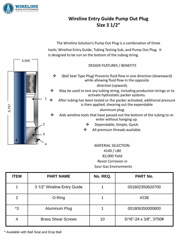
Wireline Entry Guide Pump Out Plug Size 3 1/2”
The Wireline Solution’s Pump Out Plug is a combination of three
tools; Wireline Entry Guide, Tubing Testing Sub, and Pump Out Plug. It
is designed to be run on the bottom of the tubing string.
DESIGN FEATURES / BENEFITS
(Ball Seat Type Plug) Prevents fluid flow in one direction (downward) while allowing fluid flow in the opposite
direction (upward).
May be used to test any tubing string, including production strings or to activate hydrostatic packer systems.
After tubing has been tested or the packer activated, additional pressure is then applied, shearing out the expendable
aluminum plug.
Aids wireline tools that have passed out the bottom of the tubing to re-enter without hanging up.
Dependable, Simple, Quick.
All premium threads available.
MATERIAL SELECTION:
4140 / L80
82,000 Yield
Resist Corrosion in
Sour Gas Environments
* Available with Ball Seat and Drop Ball
ITEM PART NAME No. REQ. PART No.
1 3 1/2” Wireline Entry Guide 1 001802350620700
2 O-Ring 1 #238
*3 Aluminum Plug 1 001806350000800
4 Brass Shear Screws 10 5/16”-24 x 3/8”, 3750#
4.500
1
4
2
3
5.7
57

T-2 On/Off Tools

WT Packer On-Off Tool Size 2 3/8” x 4 1/2”
The WT On-Off Tool is a tubing disconnect device that has
an internal blanking plug locking profile with seal bore for
utilizing flow control equipment. The Overshot has a box
looking up which connects to tubing string and a pin looking
down off the Stinger which connects to the packer. The WT
has two basic components that comprise the Overshot. The
Top Sub which contains two bonded rubber steel seals and the
Jay Latch which has a J Slot configuration to locate and latch
the On-Off Tool Stinger. The Jay Latch also has a wash over
shoe configuration which allows cutting through debris. The
Overshot automatically Jays up on Stinger when lowered
into well.
SPECIFIC APPLICATIONS:
Item is designed to isolate a lower zone or to disconnect the
tubing without releasing or disturbing the packer.
* Standard Left Hand Release * Automatic Jay Up * Bonded
Seals * All Nipple Profiles Available for Stinger * Full Open or
Solid Stinger Available * 10K Rated * Wash over shoe on all
Models *
MATERIAL SELECTION:
4140 / P110
110,000 Yield / Standard Service
ITEM PART NAME No. REQ. PART No.
-- Complete Assembly -- 001501237260499
1 T-2 Top Sub 1 001502237261000
2 O-Ring 2 #149
3 T-2 Seals 2 001502237001413
4 Set Screws 3 ¼-20 x UNC
5 Jay Latch 1 001501237000400
CASING
SIZE
TUBING
CONNECTION
A B C D E OVERSHOT
LENGTH
4 1/2” 2 3/8” EUE 3.750 3.750 3.250 2.609 6.812 16.250
Dimensional Data
C
1
2
3
2
4
5
B
A
D
E
Stinger
2 3/8” EUE Pin
2 3/8” EUE Box
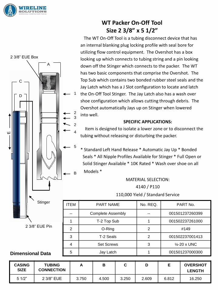
WT Packer On-Off Tool Size 2 3/8” x 5 1/2”
The WT On-Off Tool is a tubing disconnect device that has
an internal blanking plug locking profile with seal bore for
utilizing flow control equipment. The Overshot has a box
looking up which connects to tubing string and a pin looking
down off the Stinger which connects to the packer. The WT
has two basic components that comprise the Overshot. The
Top Sub which contains two bonded rubber steel seals and the
Jay Latch which has a J Slot configuration to locate and latch
the On-Off Tool Stinger. The Jay Latch also has a wash over
shoe configuration which allows cutting through debris. The
Overshot automatically Jays up on Stinger when lowered
into well.
SPECIFIC APPLICATIONS:
Item is designed to isolate a lower zone or to disconnect the
tubing without releasing or disturbing the packer.
* Standard Left Hand Release * Automatic Jay Up * Bonded
Seals * All Nipple Profiles Available for Stinger * Full Open or
Solid Stinger Available * 10K Rated * Wash over shoe on all
Models *
MATERIAL SELECTION:
4140 / P110
110,000 Yield / Standard Service
ITEM PART NAME No. REQ. PART No.
-- Complete Assembly -- 001501237260399
1 T-2 Top Sub 1 001502237261000
2 O-Ring 2 #149
3 T-2 Seals 2 001502237001413
4 Set Screws 3 ¼-20 x UNC
5 Jay Latch 1 001501237000300
CASING
SIZE
TUBING
CONNECTION
A B C D E OVERSHOT
LENGTH
5 1/2” 2 3/8” EUE 3.750 4.500 3.250 2.609 6.812 16.250
Dimensional Data
1
2
3
2
4
5
B
C
A
D
Stinger
2 3/8” EUE Pin
2 3/8” EUE Box
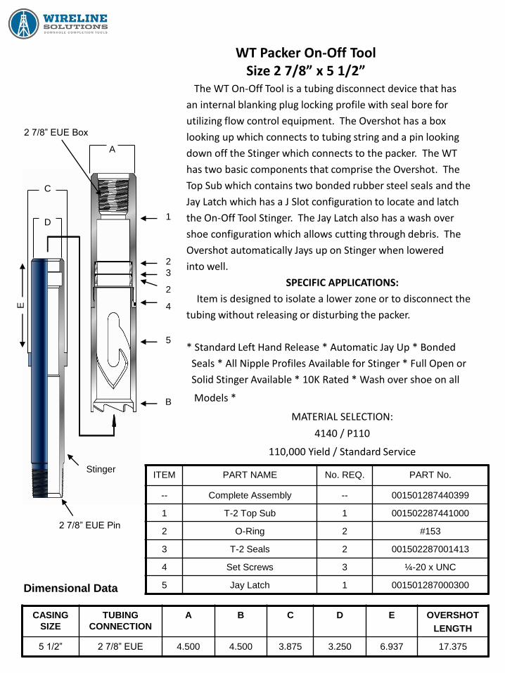
WT Packer On-Off Tool Size 2 7/8” x 5 1/2”
The WT On-Off Tool is a tubing disconnect device that has
an internal blanking plug locking profile with seal bore for
utilizing flow control equipment. The Overshot has a box
looking up which connects to tubing string and a pin looking
down off the Stinger which connects to the packer. The WT
has two basic components that comprise the Overshot. The
Top Sub which contains two bonded rubber steel seals and the
Jay Latch which has a J Slot configuration to locate and latch
the On-Off Tool Stinger. The Jay Latch also has a wash over
shoe configuration which allows cutting through debris. The
Overshot automatically Jays up on Stinger when lowered
into well.
SPECIFIC APPLICATIONS:
Item is designed to isolate a lower zone or to disconnect the
tubing without releasing or disturbing the packer.
* Standard Left Hand Release * Automatic Jay Up * Bonded
Seals * All Nipple Profiles Available for Stinger * Full Open or
Solid Stinger Available * 10K Rated * Wash over shoe on all
Models *
MATERIAL SELECTION:
4140 / P110
110,000 Yield / Standard Service
ITEM PART NAME No. REQ. PART No.
-- Complete Assembly -- 001501287440399
1 T-2 Top Sub 1 001502287441000
2 O-Ring 2 #153
3 T-2 Seals 2 001502287001413
4 Set Screws 3 ¼-20 x UNC
5 Jay Latch 1 001501287000300
CASING
SIZE
TUBING
CONNECTION
A B C D E OVERSHOT
LENGTH
5 1/2” 2 7/8” EUE 4.500 4.500 3.875 3.250 6.937 17.375
Dimensional Data
C
1
2
3
2
4
5
B
A
D
E
Stinger
2 7/8” EUE Pin
2 7/8” EUE Box

WT Packer On-Off Tool Size 2 7/8” x 7”
The WT On-Off Tool is a tubing disconnect device that has
an internal blanking plug locking profile with seal bore for
utilizing flow control equipment. The Overshot has a box
looking up which connects to tubing string and a pin looking
down off the Stinger which connects to the packer. The WT
has two basic components that comprise the Overshot. The
Top Sub which contains two bonded rubber steel seals and the
Jay Latch which has a J Slot configuration to locate and latch
the On-Off Tool Stinger. The Jay Latch also has a wash over
shoe configuration which allows cutting through debris. The
Overshot automatically Jays up on Stinger when lowered
into well.
SPECIFIC APPLICATIONS:
Item is designed to isolate a lower zone or to disconnect the
tubing without releasing or disturbing the packer.
* Standard Left Hand Release * Automatic Jay Up * Bonded
Seals * All Nipple Profiles Available for Stinger * Full Open or
Solid Stinger Available * 10K Rated * Wash over shoe on all
Models *
MATERIAL SELECTION:
4140 / P110
110,000 Yield / Standard Service
ITEM PART NAME No. REQ. PART No.
-- Complete Assembly -- 001501287444399
1 T-2 Top Sub 1 001502287441000
2 O-Ring 2 #153
3 T-2 Seals 2 001502287001413
4 Set Screws 3 ¼-20 x UNC
5 Jay Latch 1 001501287004300
6 Boot 1 001501287004316
CASING
SIZE
TUBING
CONNECTION
A B C D E OVERSHOT
LENGTH
7.00” 2 7/8” EUE 4.500 5.875 3.875 3.250 6.937 17.875
Dimensional Data
C
1
2
3
2
4
5
B
A
D
E
Stinger
2 7/8” EUE Pin
2 7/8” EUE Box
6
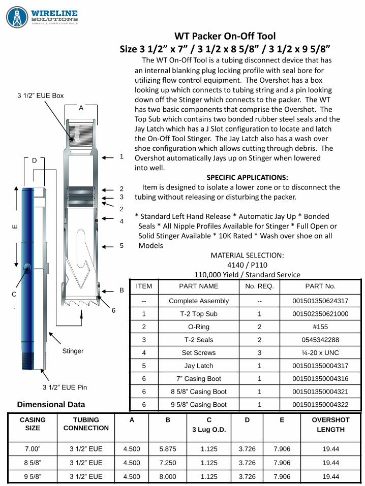
WT Packer On-Off Tool Size 3 1/2” x 7” / 3 1/2 x 8 5/8” / 3 1/2 x 9 5/8”
The WT On-Off Tool is a tubing disconnect device that has
an internal blanking plug locking profile with seal bore for utilizing flow control equipment. The Overshot has a box looking up which connects to tubing string and a pin looking down off the Stinger which connects to the packer. The WT has two basic components that comprise the Overshot. The Top Sub which contains two bonded rubber steel seals and the Jay Latch which has a J Slot configuration to locate and latch the On-Off Tool Stinger. The Jay Latch also has a wash over shoe configuration which allows cutting through debris. The Overshot automatically Jays up on Stinger when lowered into well.
SPECIFIC APPLICATIONS: Item is designed to isolate a lower zone or to disconnect the tubing without releasing or disturbing the packer. * Standard Left Hand Release * Automatic Jay Up * Bonded Seals * All Nipple Profiles Available for Stinger * Full Open or Solid Stinger Available * 10K Rated * Wash over shoe on all Models
MATERIAL SELECTION: 4140 / P110
110,000 Yield / Standard Service
ITEM PART NAME No. REQ. PART No.
-- Complete Assembly -- 001501350624317
1 T-2 Top Sub 1 001502350621000
2 O-Ring 2 #155
3 T-2 Seals 2 0545342288
4 Set Screws 3 ¼-20 x UNC
5 Jay Latch 1 001501350004317
6 7” Casing Boot 1 001501350004316
6 8 5/8” Casing Boot 1 001501350004321
6 9 5/8” Casing Boot 1 001501350004322
CASING
SIZE
TUBING
CONNECTION
A B C
3 Lug O.D.
D E OVERSHOT
LENGTH
7.00” 3 1/2” EUE 4.500 5.875 1.125 3.726 7.906 19.44
8 5/8” 3 1/2” EUE 4.500 7.250 1.125 3.726 7.906 19.44
9 5/8” 3 1/2” EUE 4.500 8.000 1.125 3.726 7.906 19.44
Dimensional Data
1
2
3
2
4
5
B
3 1/2” EUE Box
A
6
Stinger
3 1/2” EUE Pin
D
E
C
.
WT PACKER ON – OFF TOOL Redress Procedure
The Wireline Solutions WT On-Off Tool is a tubing disconnect device that has an internal
blanking plug locking profile with seal bore for utilizing flow control equipment. The Overshot has a
box looking up which connects to tubing string and a pin looking down off the Stinger which
connects to the packer. The WT has two basic components that comprise the Overshot. The Top
Sub which contains two bonded rubber steel seals and the Jay Latch which also has a J Slot
configuration to locate and latch the On-Off Tool Stinger. The Jay Latch also has a wash over
shoe configuration which allows cutting through debris. The Overshot automatically Jays
up on the Stinger when lowered into well.
SPECIFIC APPLICATIONS:
Item is designed to isolate a lower zone or to disconnect the tubing without releasing or
disturbing the packer.
* Standard Left Hand Release * Automatic Jay Up * Bonded Seals * All Nipple
Profiles Available for Stinger * Full Open or Solid Stinger Available * 10K Rated *
* Wash Over Shoe Available on all Models *
REDRESS PROCEDURE:
A. Place Bottom Sub in vice. If Stinger has not been removed from Overshot, remove.
B. Remove set screws from Top Sub.
C. Remove Top Sub.
D. After Top Sub has been removed, drive the old seals out of the bottom of Top Sub. This may
require exact sized “removal tool” which you may have to utilize. This tool must be such that
you can put in through Top Sub and “slam down” the bottom of Top Sub on a board to try to
dislodge Seals. After Seals are removed, discard.
E. Brush out and clean both the Top Sub and Bottom Sub, taking special care that the Seal Bore
in the Top Sub is clean, polished, and not scarred up. Grease Seal Bore of Top Sub. Check
out Jay Latch Configuration of Bottom Sub to insure Jays are not damaged and item will
engage Lugs of Stinger.
F. Place new Seals in Top Sub.
G. Make up Top Sub onto Bottom Sub.
H. Replace set screws. Item is now ready for Stinger.

Blanking Plugs
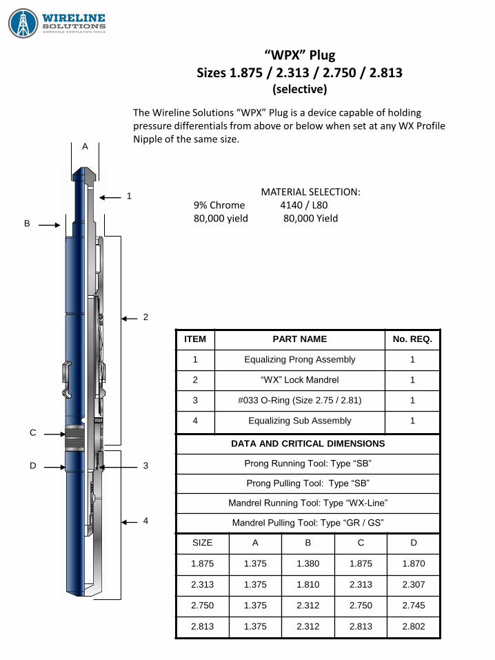
“WPX” Plug Sizes 1.875 / 2.313 / 2.750 / 2.813
(selective)
The Wireline Solutions “WPX” Plug is a device capable of holding pressure differentials from above or below when set at any WX Profile Nipple of the same size.
MATERIAL SELECTION: 9% Chrome 4140 / L80 80,000 yield 80,000 Yield
ITEM PART NAME No. REQ.
1 Equalizing Prong Assembly 1
2 “WX” Lock Mandrel 1
3 #033 O-Ring (Size 2.75 / 2.81) 1
4 Equalizing Sub Assembly 1
DATA AND CRITICAL DIMENSIONS
Prong Running Tool: Type “SB”
Prong Pulling Tool: Type “SB”
Mandrel Running Tool: Type “WX-Line”
Mandrel Pulling Tool: Type “GR / GS”
SIZE A B C D
1.875 1.375 1.380 1.875 1.870
2.313 1.375 1.810 2.313 2.307
2.750 1.375 2.312 2.750 2.745
2.813 1.375 2.312 2.813 2.802
4
1
2
3
C
D
B
A
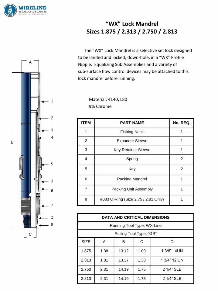
“WX” Lock Mandrel Sizes 1.875 / 2.313 / 2.750 / 2.813
The “WX” Lock Mandrel is a selective set lock designed
to be landed and locked, down-hole, in a “WX” Profile
Nipple. Equalizing Sub Assemblies and a variety of
sub-surface flow control devices may be attached to this
lock mandrel before running.
Material: 4140, L80
9% Chrome
ITEM PART NAME No. REQ.
1 Fishing Neck 1
2 Expander Sleeve 1
3 Key Retainer Sleeve 1
4 Spring 2
5 Key 2
6 Packing Mandrel 1
7 Packing Unit Assembly 1
8 #033 O-Ring (Size 2.75 / 2.81 Only) 1
SIZE A B C D
1.875 1.38 13.12 1.00 1 3/8” 14UN
2.313 1.81 13.37 1.38 1 3/4” 12 UN
2.750 2.31 14.19 1.75 2 1/4” SLB
2.813 2.31 14.19 1.75 2 1/4” SLB
DATA AND CRITICAL DIMENSIONS
Running Tool Type: WX-Line
Pulling Tool Type: “GR”
A
1
2
3
4
5
3
6
7
D
8
C
B

“WX” Lock Mandrel Sizes 1.875 / 2.313 / 2.750 / 2.813
The type “WX” Locking Mandrels are selective set lock mandrels designed to be landed down
hole in a selected “WX” Landing Nipple profile. The “WX” Lock is available with various sub
surface plug assemblies and flow control accessories. The “WX” Lock is designed for standard
weight tubing and service pressures. The Lock is made Selective by use of the WX-Line Running
Tool. They may be installed in any selected “WX” profile anywhere in the tubing string.
OPERATION
The selective locating system is designed into the WX-Line Running Tool using a set of Locating
Dogs on exterior of running tool. After the “WX” Lock is made up on the WX-Line Running Tool it is
lowered into well to selected “WX” Nipple. As the packing section of the lock is passed through the
landing nipple, the restriction is noticed by wireline operator. After selected nipple is located, the
tool string should be lowered through the nipple and stopped. The tool string should then be raised
slowly until tool stops, indicating locking dogs of running tool are on the lower end of Nipple. An
upward strain on the tool string will trip the locating dogs on the running tool and the lock mandrel
keys move into the locating position. With the lock mandrel keys now in the control position, raise
tool string 3 to 6 feet above the nipple and lower back into nipple until the mandrel keys reach
nipple profile. As the mandrel reaches the profile, the key springs move the keys into the profile
and stop the tool string. Jar downward at this time and shear the upper pin in running tool and
allow Expander Sleeve of lock mandrel to move down and be driven behind the mandrel keys.
When the Expander Sleeve is driven behind the mandrel keys, serrations retain the sleeve in the
locked position. Placing an upward strain on the tool string will determine the lock is locked in
place. If the mandrel cannot be pulled, jar upward and shear the shear pin on the lower end of
running tool allowing the tool string to come out of hole. If lock mandrel returns to surface with
running tool, it has not been properly set.
(continued on next page)
“WX” Lock Mandrel Sizes 1.875 / 2.313 / 2.750 / 2.813
PULLING
The type GR (Shear Up) and GS (Shear Down) Running / Pulling Tool is used to retrieve a “WX”
Lock Mandrel. The GR or GS Pulling Tool is lowered down to lock and dogs of the pulling tool
engage the internal fishing neck of the lock. After engagement, upward jarring on the pulling tool
picks up the Expander Sleeve moving it from behind the mandrel keys and allows the keys to
retract. At this time, lock mandrel should be able to be retrieved. NOTE: Measures must be taken
that whatever plug device or flow control accessories that have been run in conjunction with “WX”
Lock have been equalized before attempting to pull.
“WX” Lock Mandrel Sizes 1.875 / 2.313 / 2.750 / 2.813
ASSEMBLY
A. Install Keys (5) with Springs into Key Retainer Sleeve (3).
B. Insert Expander Mandrel (2) into Key Retainer Sleeve driving Expander Mandrel behind
locking keys.
C. Install Packing Mandrel (6) into lower end of Expander Mandrel until able to screw Packing
Mandrel into Key Retainer Sleeve.
D. Put Fishing Neck (1) into vice and screw Expander Mandrel into Fishing Neck, tighten.
E. Put Key Retainer Sleeve into vice and tighten Packing Mandrel onto Key Retainer Sleeve.
F. Install Female Rings, Male Center Ring and Vee Packing onto Packing Mandrel.
DISASSEMBLY
A. Place Locking Mandrel in vice by Key Retainer Sleeve. Remove Female End Rings, Male
Center Ring and Vee Packing.
B. Loosen and unscrew Packing Mandrel from Key Retainer Sleeve.
C. Place Fishing Neck in vice and pull Key Retainer Sleeve outward, exposing the Expander
Mandrel. Loosen and unscrew Expander Mandrel from Fishing Neck.
D. Remove from vice.
E. Drive Expander Mandrel out of Key Retainer Sleeve, thus enabling Keys and Springs to fall
free from Key Retainer Sleeve.
F. Clean all parts, inspect, grease and reassemble.

“WPXN” Plug Sizes 1.875 / 2.313 / 2.750 / 2.813
(non-selective)
The Wireline Solutions “WPXN” Plug is a device capable of holding
pressure differentials from above or below when set at any WXN Profile
Nipple of the same size.
MATERIAL SELECTION:
9% Chrome 4140 / L80
80,000 Yield 82,000 Yield
ITEM PART NAME No. REQ.
1 Equalizing Prong Assembly 1
2 “WXN” Lock Mandrel 1
3 #033 O-Ring (Size 2.75 / 2.81) 1
4 Equalizing Sub Assembly 1
DATA AND CRITICAL DIMENSIONS
Prong Running Tool: Type “SB”
Prong Pulling Tool: Type “SB”
Mandrel Running Tool: Type “WX-Line”
Mandrel Pulling Tool: Type “GR / GS”
SIZE A B C D
1.875 1.870 1.375 1.875 1.870
2.313 2.307 1.375 2.313 2.307
2.750 2.745 1.375 2.750 2.742
2.813 2.902 1.375 2.813 2.802
A
1
B
C
NoGo
O.D.
NoG
o B
ase
2
3
4
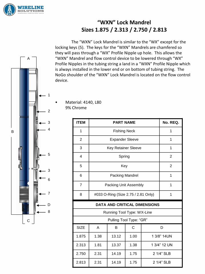
“WXN” Lock Mandrel Sizes 1.875 / 2.313 / 2.750 / 2.813
The “WXN” Lock Mandrel is similar to the “WX” except for the
locking keys (5). The keys for the “WXN” Mandrels are chamfered so they will pass through a “WX” Profile Nipple up hole. This allows the “WXN” Mandrel and flow control device to be lowered through “WX” Profile Nipples in the tubing string a land in a “WXN” Profile Nipple which is always installed in the lower end or on bottom of tubing string. The NoGo shoulder of the “WXN” Lock Mandrel is located on the flow control device. • Material: 4140, L80 9% Chrome
ITEM PART NAME No. REQ.
1 Fishing Neck 1
2 Expander Sleeve 1
3 Key Retainer Sleeve 1
4 Spring 2
5 Key 2
6 Packing Mandrel 1
7 Packing Unit Assembly 1
8 #033 O-Ring (Size 2.75 / 2.81 Only) 1
SIZE A B C D
1.875 1.38 13.12 1.00 1 3/8” 14UN
2.313 1.81 13.37 1.38 1 3/4” 12 UN
2.750 2.31 14.19 1.75 2 1/4” SLB
2.813 2.31 14.19 1.75 2 1/4” SLB
DATA AND CRITICAL DIMENSIONS
Running Tool Type: WX-Line
Pulling Tool Type: “GR”
A
1
2
3
4
5
3
6
7
D
8
C
B
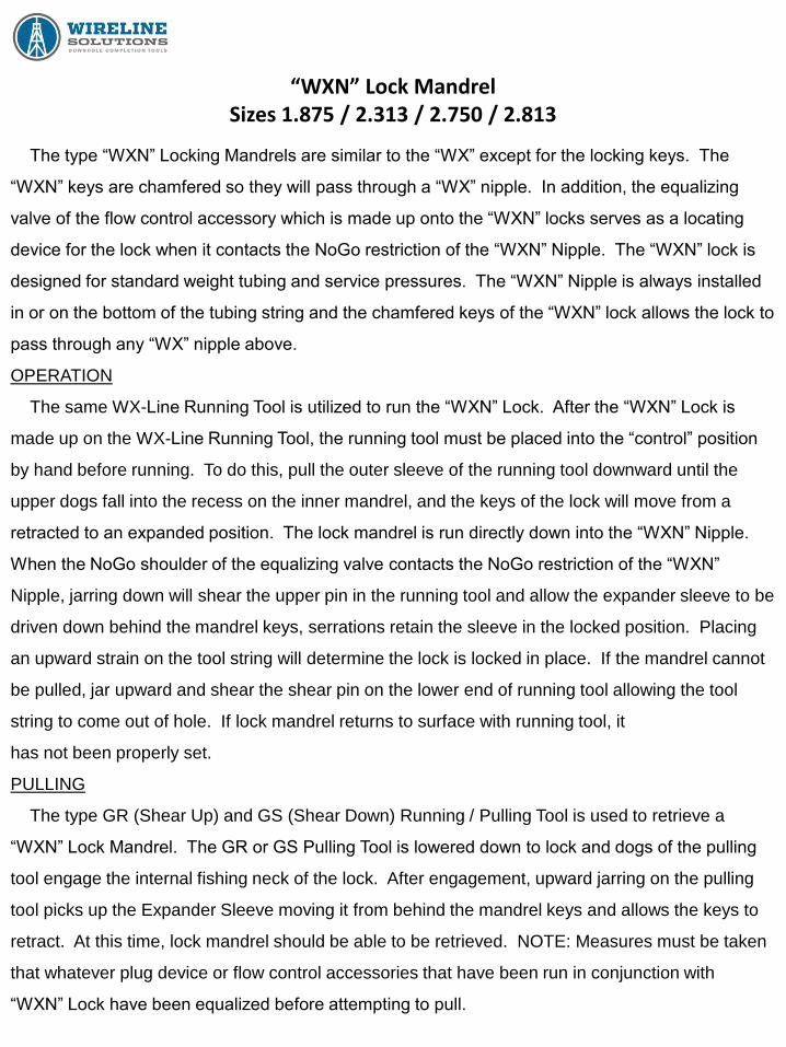
“WXN” Lock Mandrel Sizes 1.875 / 2.313 / 2.750 / 2.813
The type “WXN” Locking Mandrels are similar to the “WX” except for the locking keys. The
“WXN” keys are chamfered so they will pass through a “WX” nipple. In addition, the equalizing
valve of the flow control accessory which is made up onto the “WXN” locks serves as a locating
device for the lock when it contacts the NoGo restriction of the “WXN” Nipple. The “WXN” lock is
designed for standard weight tubing and service pressures. The “WXN” Nipple is always installed
in or on the bottom of the tubing string and the chamfered keys of the “WXN” lock allows the lock to
pass through any “WX” nipple above.
OPERATION
The same WX-Line Running Tool is utilized to run the “WXN” Lock. After the “WXN” Lock is
made up on the WX-Line Running Tool, the running tool must be placed into the “control” position
by hand before running. To do this, pull the outer sleeve of the running tool downward until the
upper dogs fall into the recess on the inner mandrel, and the keys of the lock will move from a
retracted to an expanded position. The lock mandrel is run directly down into the “WXN” Nipple.
When the NoGo shoulder of the equalizing valve contacts the NoGo restriction of the “WXN”
Nipple, jarring down will shear the upper pin in the running tool and allow the expander sleeve to be
driven down behind the mandrel keys, serrations retain the sleeve in the locked position. Placing
an upward strain on the tool string will determine the lock is locked in place. If the mandrel cannot
be pulled, jar upward and shear the shear pin on the lower end of running tool allowing the tool
string to come out of hole. If lock mandrel returns to surface with running tool, it
has not been properly set.
PULLING
The type GR (Shear Up) and GS (Shear Down) Running / Pulling Tool is used to retrieve a
“WXN” Lock Mandrel. The GR or GS Pulling Tool is lowered down to lock and dogs of the pulling
tool engage the internal fishing neck of the lock. After engagement, upward jarring on the pulling
tool picks up the Expander Sleeve moving it from behind the mandrel keys and allows the keys to
retract. At this time, lock mandrel should be able to be retrieved. NOTE: Measures must be taken
that whatever plug device or flow control accessories that have been run in conjunction with
“WXN” Lock have been equalized before attempting to pull.

“WXN” Lock Mandrel Sizes 1.875 / 2.313 / 2.750 / 2.813
ASSEMBLY
A. Install Keys (5) with Springs into Key Retainer Sleeve (3).
B. Insert Expander Mandrel (2) into Key Retainer Sleeve driving Expander Mandrel behind
locking keys.
C. Install Packing Mandrel (6) into lower end of Expander Mandrel until able to screw Packing
Mandrel into Key Retainer Sleeve.
D. Put Fishing Neck (1) into vice and screw Expander Mandrel into Fishing Neck, tighten.
E. Put Key Retainer Sleeve into vice and tighten Packing Mandrel onto Key Retainer Sleeve.
F. Install Female Rings, Male Center Ring and Vee Packing onto Packing Mandrel.
DISASSEMBLY
A. Place Locking Mandrel in vice by Key Retainer Sleeve. Remove Female End Rings, Male
Center Ring and Vee Packing.
B. Loosen and unscrew Packing Mandrel from Key Retainer Sleeve.
C. Place Fishing Neck in vice and pull Key Retainer Sleeve outward, exposing the Expander
Mandrel. Loosen and unscrew Expander Mandrel from Fishing Neck.
D. Remove from vice.
E. Drive Expander Mandrel out of Key Retainer Sleeve, thus enabling Keys and Springs to fall
free from Key Retainer Sleeve.
F. Clean all parts, inspect, grease and reassemble.
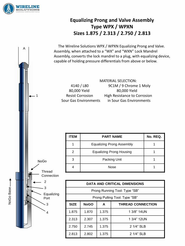
Equalizing Prong and Valve Assembly Type WPX / WPXN
Sizes 1.875 / 2.313 / 2.750 / 2.813
The Wireline Solutions WPX / WPXN Equalizing Prong and Valve. Assembly, when attached to a “WX” and “WXN” Lock Mandrel Assembly, converts the lock mandrel to a plug, with equalizing device, capable of holding pressure differentials from above or below.
MATERIAL SELECTION: 4140 / L80 9C1M / 9 Chrome 1 Moly 80,000 Yield 80,000 Yield Resist Corrosion High Resistance to Corrosion Sour Gas Environments in Sour Gas Environments
ITEM PART NAME No. REQ.
1 Equalizing Prong Assembly 1
2 Equalizing Prong Housing 1
3 Packing Unit 1
4 Nose 1
DATA AND CRITICAL DIMENSIONS
Prong Running Tool: Type “SB”
Prong Pulling Tool: Type “SB”
SIZE NoGO A THREAD CONNECTION
1.875 1.870 1.375 1 3/8” 14UN
2.313 2.307 1.375 1 3/4” 12UN
2.750 2.745 1.375 2 1/4” SLB
2.813 2.802 1.375 2 1/4” SLB
A
1
Thread
Connection
2
3
Equalizing
Port
3
4
NoG
o B
ase

Equalizing Prong and Valve Assembly Packing Details
Type WPX / WPXN Sizes 1.875 / 2.313 / 2.750 / 2.813
The Wireline Solutions WPX / WPXN Equalizing
Prong and Valve. Assembly, when attached to a “WX”
and “WXN” Lock Mandrel Assembly, converts the lock
mandrel to a plug, with equalizing device, capable of
holding pressure differentials from above or below.
ITEM PART NAME No. REQ.
1 Equalizing Prong Assembly 1
2 Equalizing Prong Housing 1
3 Backup Ring 2
4 Vee Packing 1
5 Double Male Adapter Ring 2
6 Spacer Ring 1
7 Nose 1
1
3
4
5
4
6
4
5
4
3
7
2

Bypass Blanking Plugs with Removal Mandel Models WFWG / WRZG
The Wireline Solutions “WFWG” and “WRZG” Bypass Blanking Plugs with Removable Mandrels
are positive blank-off services designed to seal off pressure from above and below. The Model
“WFWG” Blanking Plugs are equipped for Top NoGo landing in Model “WF” Non-Porting Seating
Nipples, and upper bore of Model “WL” Circulating Sleeves. The Model “WRZG” Blanking Plugs
are equipped for Bottom NoGo landing in Model “WR” Non-Porting Seating Nipples. The plugs are
compatible with normal wireline equipment and procedures.
OPERATION:
While running in the hole, the Removable Mandrel is in the down position (bypass port open) to
allow fluid bypass during setting procedure. When the plug is set in the nipple, locked in the
locking groove, and the lower shear pins have sheared, the mandrel is pulled up via the upper
pressures from above and below. Upward motion positions the groove in the mandrel under the
lock ring segments and prevents the mandrel from being moved down. The mandrel is kept from
moving up by the shear pins.
WFWG WRZG
Bypass Blanking Plugs with Removal Mandel Models WFWG / WRZG
Equalizing and Pulling Instructions
EQUALIZING (All plugs must be equalized before removing from hole)
1) Run in pulling tool and latch fishing neck of the removal mandrel.
2) Jar up to shear the pins on the removable mandrel and pull mandrel from hole.
NOTE: CAUTION! When the removable mandrel is out of the plug, the equalizing ports are open.
If pressure differential from below is high enough, the tool string may be blown
up hole unless precautions are taken.
PULLING MODELS WFWG AND WRZG
1) Run a Model B Probe on a standard pulling tool.
2) Jar down to drive the B Probe between the locks. This will retract them and at the same time
the pulling tool will latch onto the locking mandrel’s fishing neck permitting recovery of the
Bypass Blanking Plug.
CAUTION NOTE #1:
If any tool is to be landed on top of the plug or if the plug is to be tagged, care must be taken
not to run into the plug. If a tool of considerable weight has to be landed on the plug, then a
special guide that goes over the fishing neck and located on the lock mandrel will have to be
provided.
CAUTION NOTE #2:
It is possible, due to inertia when the fishing neck and mandrel are inverted, that these two
pieces could move a sufficient distance and make it impossible to pin the C-1 to the fishing
neck. If this happens, the Blanking Plug must be disassembled, the lock ring segments
removed, and the fishing neck pushed down into the proper positioning and pinning of the C-1
Running Tool. Insert the lock ring segment against the washer and finish redressing the tool.
NOTE #3:
A different fishing neck is used to run Models WFWG and WRZG tools with locks trailing or
collapsed.
Bypass Blanking Plugs with Removal Mandel Models WFWG / WRZG
Running and Setting Instructions
Models WFWG and WRZG can be run with locks trailing or retracted. NoGo Locations with Up-Facing Locks Trailing. 1) Run on Model C-1 Running Tool. 2) Locate on seal bore. 3) Pick up until up strain indicates that the up-facing locks are engaged. 4) Jar up, shearing the lower shear pins in the C-1 Running Tool, closing the bypass, shearing the upper shear pin in the C-1 Running Tool and leaving the plug in place. Selective with Up-Facing Locks Trailing. 1) Run on Model C-1 Running Tool with thread protector just below the desired landing nipple but past the next tubing joint. 2) Pick up until up strain indicates that the up-facing locks are engaged. 3) Jar up, shearing the lower pins in the C-1 Running Tool, closing the bypass port, shearing the upper shear pin in the C-1 Running Tool and leaving the plug in place. NOTE: This method (Selective with Up-Facing Locks Trailing) is not recommended to land in the upper bore of a Model “WL” Circulating Sleeve due to possibly shifting the Sleeve. Also, it is not recommended to land in a nipple with a short tubing joint immediately below it.
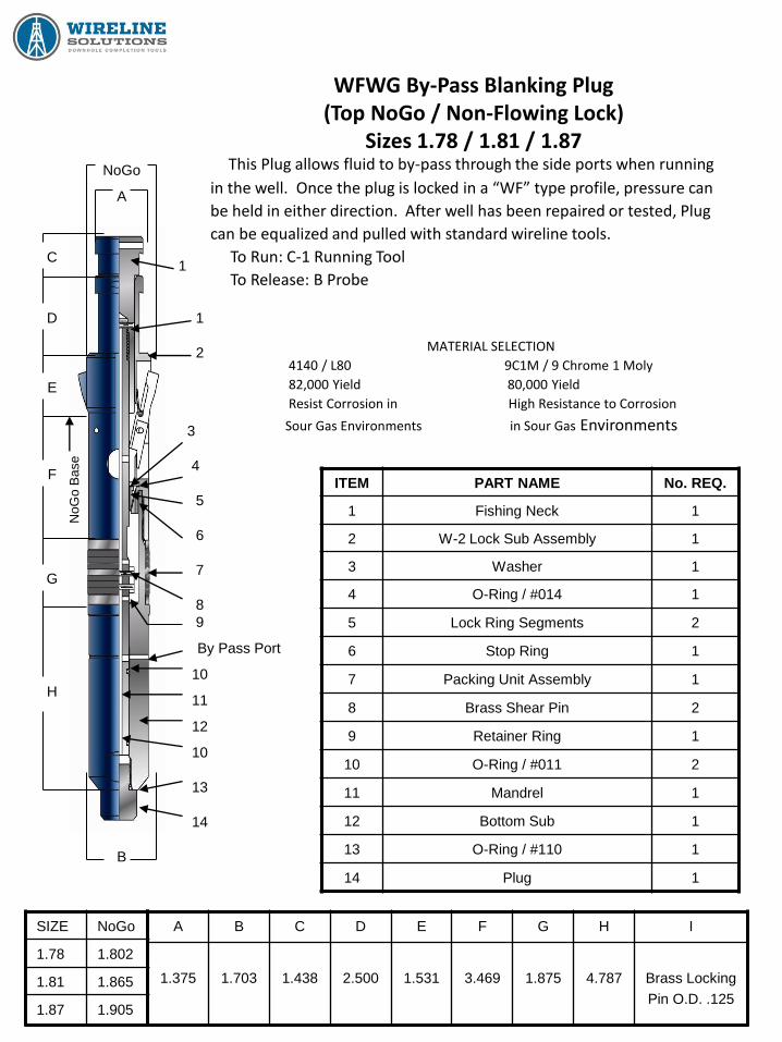
WFWG By-Pass Blanking Plug (Top NoGo / Non-Flowing Lock)
Sizes 1.78 / 1.81 / 1.87
This Plug allows fluid to by-pass through the side ports when running
in the well. Once the plug is locked in a “WF” type profile, pressure can
be held in either direction. After well has been repaired or tested, Plug
can be equalized and pulled with standard wireline tools.
To Run: C-1 Running Tool
To Release: B Probe
MATERIAL SELECTION
4140 / L80 9C1M / 9 Chrome 1 Moly
82,000 Yield 80,000 Yield
Resist Corrosion in High Resistance to Corrosion
Sour Gas Environments in Sour Gas Environments
ITEM PART NAME No. REQ.
1 Fishing Neck 1
2 W-2 Lock Sub Assembly 1
3 Washer 1
4 O-Ring / #014 1
5 Lock Ring Segments 2
6 Stop Ring 1
7 Packing Unit Assembly 1
8 Brass Shear Pin 2
9 Retainer Ring 1
10 O-Ring / #011 2
11 Mandrel 1
12 Bottom Sub 1
13 O-Ring / #110 1
14 Plug 1
SIZE NoGo
1.78 1.802
1.81 1.865
1.87 1.905
A B C D E F G H I
1.375
1.703
1.438
2.500
1.531
3.469
1.875
4.787
Brass Locking
Pin O.D. .125
NoGo
A
1
1
2
3
4
5
6
7
8
9
By Pass Port
10
11
12
10
13
14
B
C
D
E
F
G
H
NoG
o B
ase
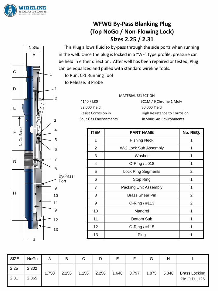
WFWG By-Pass Blanking Plug (Top NoGo / Non-Flowing Lock)
Sizes 2.25 / 2.31
This Plug allows fluid to by-pass through the side ports when running
in the well. Once the plug is locked in a “WF” type profile, pressure can
be held in either direction. After well has been repaired or tested, Plug
can be equalized and pulled with standard wireline tools.
To Run: C-1 Running Tool
To Release: B Probe
MATERIAL SELECTION
4140 / L80 9C1M / 9 Chrome 1 Moly
82,000 Yield 80,000 Yield
Resist Corrosion in High Resistance to Corrosion
Sour Gas Environments in Sour Gas Environments
ITEM PART NAME No. REQ.
1 Fishing Neck 1
2 W-2 Lock Sub Assembly 1
3 Washer 1
4 O-Ring / #018 1
5 Lock Ring Segments 2
6 Stop Ring 1
7 Packing Unit Assembly 1
8 Brass Shear Pin 2
9 O-Ring / #113 2
10 Mandrel 1
11 Bottom Sub 1
12 O-Ring / #115 1
13 Plug 1
SIZE NoGo
2.25 2.302
2.31 2.365
A B C D E F G H I
1.750
2.156
1.156
2.250
1.640
3.797
1.875
5.348
Brass Locking
Pin O.D. .125
NoGo
A
1
1
2
3
4
5
6
7
8
9
10
11
9
12
13
B
C
D
E
F
G
H
By-Pass
Port
NoG
o B
ase

WFWG By-Pass Blanking Plug (Top NoGo / Non-Flowing Lock)
Sizes 2.75 / 2.81
This Plug allows fluid to by-pass through the side ports when running
in the well. Once the plug is locked in a “WF” type profile, pressure can
be held in either direction. After well has been repaired or tested, Plug
can be equalized and pulled with standard wireline tools.
To Run: C-1 Running Tool
To Release: B Probe
MATERIAL SELECTION
4140 / L80 9C1M / 9 Chrome 1 Moly
82,000 Yield 80,000 Yield
Resist Corrosion in High Resistance to Corrosion
Sour Gas Environments in Sour Gas Environments
ITEM PART NAME No. REQ.
1 Fishing Neck 1
2 W-2 Lock Sub Assembly 1
3 Washer 1
4 O-Ring / #018 1
5 Lock Ring Segments 2
6 Stop Ring 1
7 Packing Unit Assembly 1
8 Brass Shear Pin 2
9 O-Ring / #113 2
10 Mandrel 1
11 Bottom Sub 1
12 O-Ring / #115 1
13 Plug 1
SIZE NoGo
2.75 2.802
2.81 2.865
A B C D E F G H I
2.313
2.656
1.188
2.250
1.688
4.313
1.875
5.374
Brass Locking
Pin O.D. .125
NoGo
A
1
1
2
3
4
5
6
7
8
9
10
11
9
12
13
B
C
D
E
F
G
H
By-Pass
Port
NoG
o B
ase
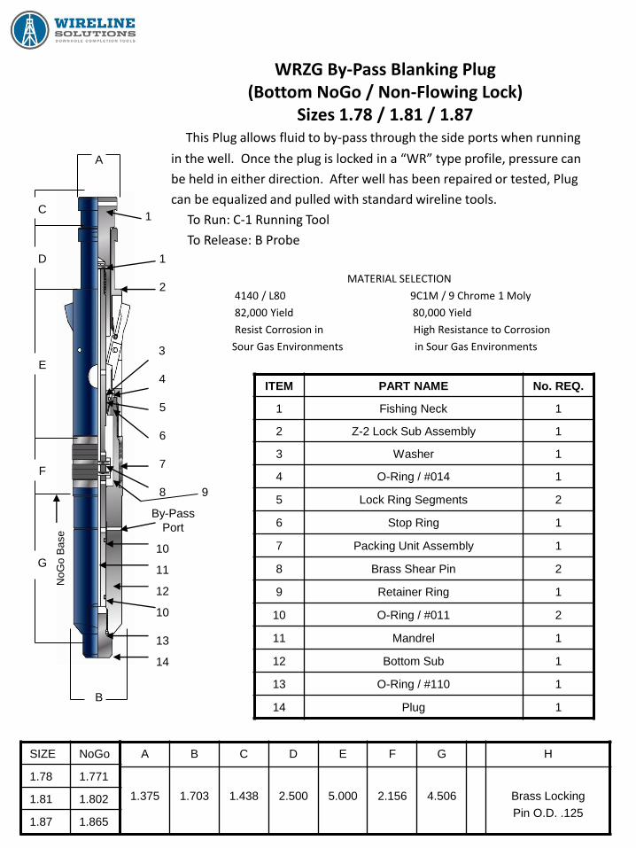
WRZG By-Pass Blanking Plug (Bottom NoGo / Non-Flowing Lock)
Sizes 1.78 / 1.81 / 1.87
This Plug allows fluid to by-pass through the side ports when running
in the well. Once the plug is locked in a “WR” type profile, pressure can
be held in either direction. After well has been repaired or tested, Plug
can be equalized and pulled with standard wireline tools.
To Run: C-1 Running Tool
To Release: B Probe
MATERIAL SELECTION
4140 / L80 9C1M / 9 Chrome 1 Moly
82,000 Yield 80,000 Yield
Resist Corrosion in High Resistance to Corrosion
Sour Gas Environments in Sour Gas Environments
ITEM PART NAME No. REQ.
1 Fishing Neck 1
2 Z-2 Lock Sub Assembly 1
3 Washer 1
4 O-Ring / #014 1
5 Lock Ring Segments 2
6 Stop Ring 1
7 Packing Unit Assembly 1
8 Brass Shear Pin 2
9 Retainer Ring 1
10 O-Ring / #011 2
11 Mandrel 1
12 Bottom Sub 1
13 O-Ring / #110 1
14 Plug 1
SIZE NoGo
1.78 1.771
1.81 1.802
1.87 1.865
A B C D E F G H
1.375
1.703
1.438
2.500
5.000
2.156
4.506
Brass Locking
Pin O.D. .125
A
1
1
2
3
4
5
6
7
8
10
11
12
10
13
14
B
C
D
E
F
G
By-Pass
Port
NoG
o B
ase
9
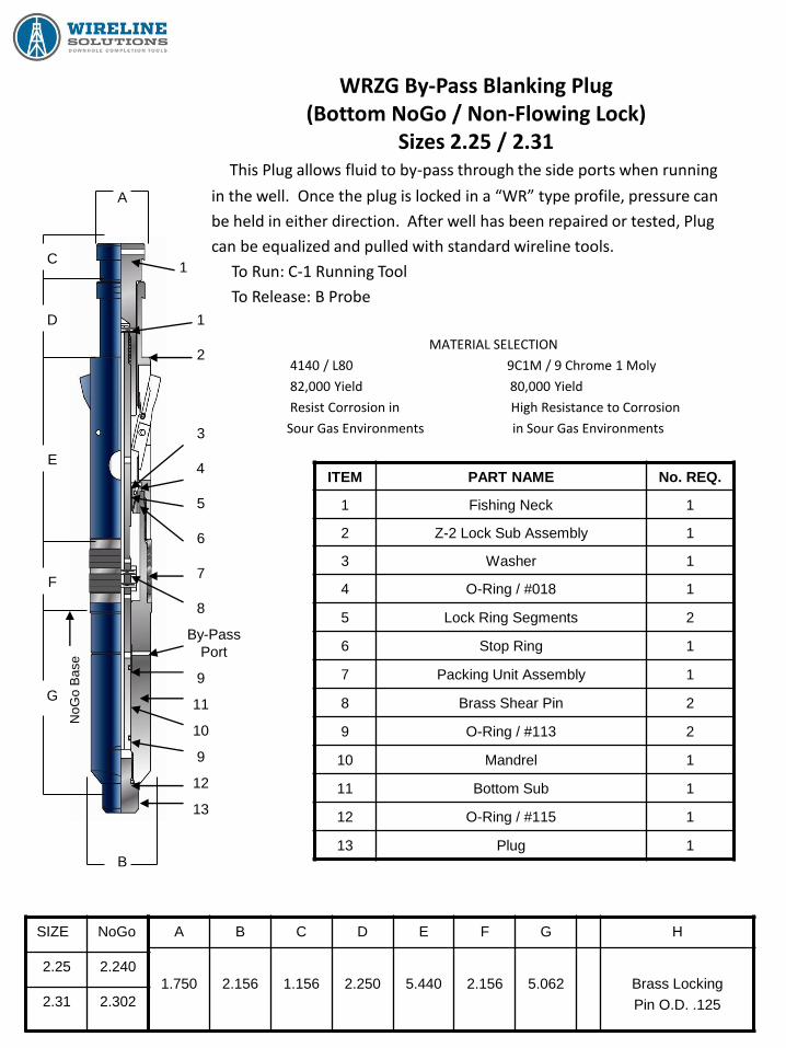
WRZG By-Pass Blanking Plug (Bottom NoGo / Non-Flowing Lock)
Sizes 2.25 / 2.31
This Plug allows fluid to by-pass through the side ports when running
in the well. Once the plug is locked in a “WR” type profile, pressure can
be held in either direction. After well has been repaired or tested, Plug
can be equalized and pulled with standard wireline tools.
To Run: C-1 Running Tool
To Release: B Probe
MATERIAL SELECTION
4140 / L80 9C1M / 9 Chrome 1 Moly
82,000 Yield 80,000 Yield
Resist Corrosion in High Resistance to Corrosion
Sour Gas Environments in Sour Gas Environments
ITEM PART NAME No. REQ.
1 Fishing Neck 1
2 Z-2 Lock Sub Assembly 1
3 Washer 1
4 O-Ring / #018 1
5 Lock Ring Segments 2
6 Stop Ring 1
7 Packing Unit Assembly 1
8 Brass Shear Pin 2
9 O-Ring / #113 2
10 Mandrel 1
11 Bottom Sub 1
12 O-Ring / #115 1
13 Plug 1
SIZE NoGo
2.25 2.240
2.31 2.302
A B C D E F G H
1.750
2.156
1.156
2.250
5.440
2.156
5.062
Brass Locking
Pin O.D. .125
A
1
1
2
3
4
5
6
7
8
9
11
10
9
13
C
D
E
F
G
B
By-Pass
Port
12
NoG
o B
ase

WRZG By-Pass Blanking Plug (Bottom NoGo / Non-Flowing Lock)
Sizes 2.75 / 2.81
This Plug allows fluid to by-pass through the side ports when running
in the well. Once the plug is locked in a “WR” type profile, pressure can
be held in either direction. After well has been repaired or tested, Plug
can be equalized and pulled with standard wireline tools.
To Run: C-1 Running Tool
To Release: B Probe
MATERIAL SELECTION
4140 / L80 9C1M / 9 Chrome 1 Moly
82,000 Yield 80,000 Yield
Resist Corrosion in High Resistance to Corrosion
Sour Gas Environments in Sour Gas Environments
ITEM PART NAME No. REQ.
1 Fishing Neck 1
2 Z-2 Lock Sub Assembly 1
3 Washer 1
4 O-Ring / #018 1
5 Lock Ring Segments 2
6 Stop Ring 1
7 Packing Unit Assembly 1
8 Brass Shear Pin 2
9 O-Ring / #113 2
10 Mandrel 1
11 Bottom Sub 1
12 O-Ring / #115 1
13 Plug 1
SIZE NoGo
2.75 2.740
2.81 2.802
A B C D E F G H
2.313
2.656
1.188
2.250
6.000
2.156
5.093
Brass Locking
Pin O.D. .125
A
1
1
2
3
4
5
6
7
8
9
10
11
12
13
C
D
E
F
G
B
9
By-Pass
Port
NoG
o B
ase

Equalizing Check Valves
&
Instrument Hangers
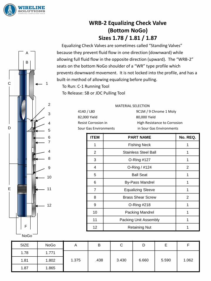
WRB-2 Equalizing Check Valve (Bottom NoGo)
Sizes 1.78 / 1.81 / 1.87
Equalizing Check Valves are sometimes called “Standing Valves”
because they prevent fluid flow in one direction (downward) while
allowing full fluid flow in the opposite direction (upward). The “WRB-2”
seats on the bottom NoGo shoulder of a “WR” type profile which
prevents downward movement. It is not locked into the profile, and has a
built-in method of allowing equalizing before pulling.
To Run: C-1 Running Tool
To Release: SB or JDC Pulling Tool
MATERIAL SELECTION
4140 / L80 9C1M / 9 Chrome 1 Moly
82,000 Yield 80,000 Yield
Resist Corrosion in High Resistance to Corrosion
Sour Gas Environments in Sour Gas Environments
ITEM PART NAME No. REQ.
1 Fishing Neck 1
2 Stainless Steel Ball 1
3 O-Ring #127 1
4 O-Ring / #124 2
5 Ball Seat 1
6 By-Pass Mandrel 1
7 Equalizing Sleeve 1
8 Brass Shear Screw 2
9 O-Ring #218 1
10 Packing Mandrel 1
11 Packing Unit Assembly 1
12 Retaining Nut 1
SIZE NoGo
1.78 1.771
1.81 1.802
1.87 1.865
A B C D E F
1.375
.438
3.430
6.660
5.590
1.062
A
B
C
D
E
NoGo
F
1
12
11
10
9
8
4
7
6
5
4
3
2
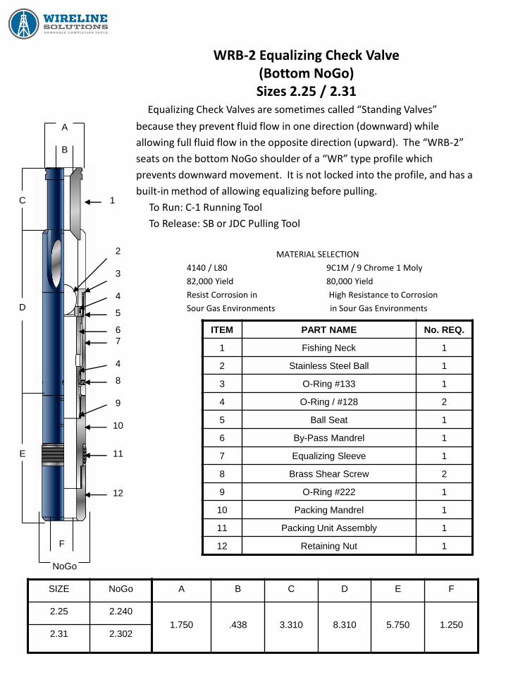
WRB-2 Equalizing Check Valve (Bottom NoGo) Sizes 2.25 / 2.31
Equalizing Check Valves are sometimes called “Standing Valves”
because they prevent fluid flow in one direction (downward) while
allowing full fluid flow in the opposite direction (upward). The “WRB-2”
seats on the bottom NoGo shoulder of a “WR” type profile which
prevents downward movement. It is not locked into the profile, and has a
built-in method of allowing equalizing before pulling.
To Run: C-1 Running Tool
To Release: SB or JDC Pulling Tool
MATERIAL SELECTION
4140 / L80 9C1M / 9 Chrome 1 Moly
82,000 Yield 80,000 Yield
Resist Corrosion in High Resistance to Corrosion
Sour Gas Environments in Sour Gas Environments
ITEM PART NAME No. REQ.
1 Fishing Neck 1
2 Stainless Steel Ball 1
3 O-Ring #133 1
4 O-Ring / #128 2
5 Ball Seat 1
6 By-Pass Mandrel 1
7 Equalizing Sleeve 1
8 Brass Shear Screw 2
9 O-Ring #222 1
10 Packing Mandrel 1
11 Packing Unit Assembly 1
12 Retaining Nut 1
SIZE NoGo
2.25 2.240
2.31 2.302
A B C D E F
1.750
.438
3.310
8.310
5.750
1.250
A
B
F
1
12
11
10
9
8
4
7
6
5
4
3
2
C
D
E
NoGo

WRB-2 Equalizing Check Valve (Bottom NoGo) Sizes 2.75 / 2.81
Equalizing Check Valves are sometimes called “Standing Valves”
because they prevent fluid flow in one direction (downward) while
allowing full fluid flow in the opposite direction (upward). The “WRB-2”
seats on the bottom NoGo shoulder of a “WR” type profile which
prevents downward movement. It is not locked into the profile, and has a
built-in method of allowing equalizing before pulling.
To Run: C-1 Running Tool
To Release: SB or JDC Pulling Tool
MATERIAL SELECTION
4140 / L80 9C1M / 9 Chrome 1 Moly
82,000 Yield 80,000 Yield
Resist Corrosion in High Resistance to Corrosion
Sour Gas Environments in Sour Gas Environments
ITEM PART NAME No. REQ.
1 Fishing Neck 1
2 Stainless Steel Ball 1
3 O-Ring #141 1
4 O-Ring / #135 2
5 Ball Seat 1
6 By-Pass Mandrel 1
7 Equalizing Sleeve 1
8 Brass Shear Screw 2
9 O-Ring #225 1
10 Packing Mandrel 1
11 Packing Unit Assembly 1
12 Retaining Nut 1
SIZE NoGo
2.75 2.740
2.81 2.802
A B C D E F
2.313
.750
3.310
8.320
7.180
1.563
A
B
F
1
12
11
10
9
8
4
7
6
5
4
3
2
C
D
E
NoGo

WFB-2 Equalizing Check Valve (Top NoGo)
Sizes 1.78 / 1.81 / 1.87
Equalizing Check Valves are sometimes called “Standing Valves”
because they prevent fluid flow in one direction (downward) while
allowing full fluid flow in the opposite direction (upward). The “WFB-2”
seats on the top NoGo shoulder of a “WF” type profile which prevents
downward movement. It is not locked into the profile, and has a built-in
method of allowing equalizing before pulling.
To Run: C-1 Running Tool
To Release: SB or JDC Pulling Tool
MATERIAL SELECTION
4140 / L80 9C1M / 9 Chrome 1 Moly
82,000 Yield 80,000 Yield
Resist Corrosion in High Resistance to Corrosion
Sour Gas Environments in Sour Gas Environments
ITEM PART NAME No. REQ.
1 Fishing Neck 1
2 Stainless Steel Ball 1
3 O-Ring #127 1
4 O-Ring / #124 2
5 Ball Seat 1
6 By-Pass Mandrel 1
7 Equalizing Sleeve 1
8 Brass Shear Screw 2
9 O-Ring #218 1
10 Packing Mandrel 1
11 Packing Unit Assembly 1
12 Retaining Nut 1
SIZE NoGo
1.78 1.802
1.81 1.865
1.87 1.905
A B C D E F G
1.375
.438
3.430
6.660
5.590
1.062
1.771
A
B
F
1
12
11
10
9
8
4
7
6
5
4
3
2
G
C
D
E
NoGo
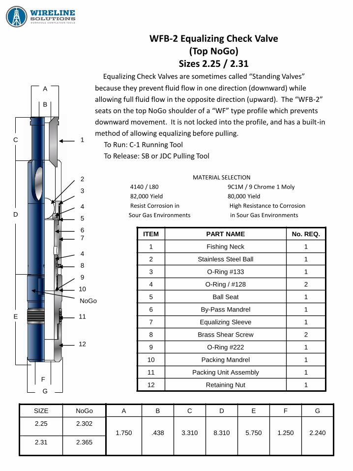
WFB-2 Equalizing Check Valve (Top NoGo)
Sizes 2.25 / 2.31
Equalizing Check Valves are sometimes called “Standing Valves”
because they prevent fluid flow in one direction (downward) while
allowing full fluid flow in the opposite direction (upward). The “WFB-2”
seats on the top NoGo shoulder of a “WF” type profile which prevents
downward movement. It is not locked into the profile, and has a built-in
method of allowing equalizing before pulling.
To Run: C-1 Running Tool
To Release: SB or JDC Pulling Tool
MATERIAL SELECTION
4140 / L80 9C1M / 9 Chrome 1 Moly
82,000 Yield 80,000 Yield
Resist Corrosion in High Resistance to Corrosion
Sour Gas Environments in Sour Gas Environments
ITEM PART NAME No. REQ.
1 Fishing Neck 1
2 Stainless Steel Ball 1
3 O-Ring #133 1
4 O-Ring / #128 2
5 Ball Seat 1
6 By-Pass Mandrel 1
7 Equalizing Sleeve 1
8 Brass Shear Screw 2
9 O-Ring #222 1
10 Packing Mandrel 1
11 Packing Unit Assembly 1
12 Retaining Nut 1
SIZE NoGo
2.25 2.302
2.31 2.365
A B C D E F G
1.750
.438
3.310
8.310
5.750
1.250
2.240
A
B
F
1
12
11
10
9
8
4
7
6
5
4
3
2
G
C
D
E
NoGo

WFB-2 Equalizing Check Valve (Top NoGo)
Sizes 2.75 / 2.81
Equalizing Check Valves are sometimes called “Standing Valves”
because they prevent fluid flow in one direction (downward) while
allowing full fluid flow in the opposite direction (upward). The “WFB-2”
seats on the top NoGo shoulder of a “WF” type profile which prevents
downward movement. It is not locked into the profile, and has a built-in
method of allowing equalizing before pulling.
To Run: C-1 Running Tool
To Release: SB or JDC Pulling Tool
MATERIAL SELECTION
4140 / L80 9C1M / 9 Chrome 1 Moly
82,000 Yield 80,000 Yield
Resist Corrosion in High Resistance to Corrosion
Sour Gas Environments in Sour Gas Environments
ITEM PART NAME No. REQ.
1 Fishing Neck 1
2 Stainless Steel Ball 1
3 O-Ring #141 1
4 O-Ring / #135 2
5 Ball Seat 1
6 By-Pass Mandrel 1
7 Equalizing Sleeve 1
8 Brass Shear Screw 4
9 O-Ring #225 1
10 Packing Mandrel 1
11 Packing Unit Assembly 1
12 Retaining Nut 1
SIZE NoGo
2.75 2.802
2.81 2.865
A B C D E F G
2.313
.750
3.310
8.320
7.180
1.563
2.740
A
B
F
1
12
11
10
9
8
4
7
6
5
4
3
2
C
D
E
NoGo
G

WFWB Instrument Hanger (Top NoGo)
Sizes 1.78 - 2.81
This Instrument Hanger is used to land and lock geophysical
instruments in “WF” type profiles to allow recording of reservoir data.
FEATURES / BENEFITS
It allows the well’s Safety System to remain
in full operation during the survey.
It allows removal of wireline from a corrosive
environment to prevent damage of wireline.
Several wells may be surveyed with one wireline.
To Run: C-1 Running Tool
To Release: B Probe
To Pull: SB Pulling Tool
MATERIAL SELECTION
4140 / L80 9C1M / 9 Chrome 1 Moly
82,000 Yield 80,000 Yield
Resist Corrosion in High Resistance to Corrosion
Sour Gas Environments in Sour Gas Environments
SIZE NoGo
1.78 1.802
1.81 1.865
1.87 1.905
2.25 2.302
2.31 2.365
2.75 2.802
2.81 2.865
A B C
7.500
2.141
1.875
7.690
2.171
2.656
8.250
2.219
1.938
D
.750” O.D.
16 UNF
NoGo
A
B
C
NoGo
Base
W-2 Lock
Sub-Assy.
Bottom
Adapter

WRZB Instrument Hanger (Bottom NoGo) Sizes 1.78 - 2.81
This Instrument Hanger is used to land and lock geophysical
instruments in “WR” type profiles to allow recording of reservoir data.
FEATURES / BENEFITS
It allows the well’s Safety System to remain
in full operation during the survey.
It allows removal of wireline from a corrosive
environment to prevent damage of wireline.
Several wells may be surveyed with one wireline.
To Run: C-1 Running Tool
To Release: B Probe
To Pull: SB Pulling Tool
MATERIAL SELECTION
4140 / L80 9C1M / 9 Chrome 1 Moly
82,000 Yield 80,000 Yield
Resist Corrosion in High Resistance to Corrosion
Sour Gas Environments in Sour Gas Environments
SIZE NoGo
1.78 1.771
1.81 1.802
1.87 1.865
2.25 2.240
2.31 2.302
2.75 2.740
2.81 2.802
A B C
7.500
2.141
1.875
7.690
2.171
2.656
8.250
2.219
2.406
1.938
2.437
D
.750” O.D.
16 UNF
NoGo
A
B
C
Z-2 Lock
Sub Assy.
Bottom
Adapter
NoGo Base
D

Crossovers
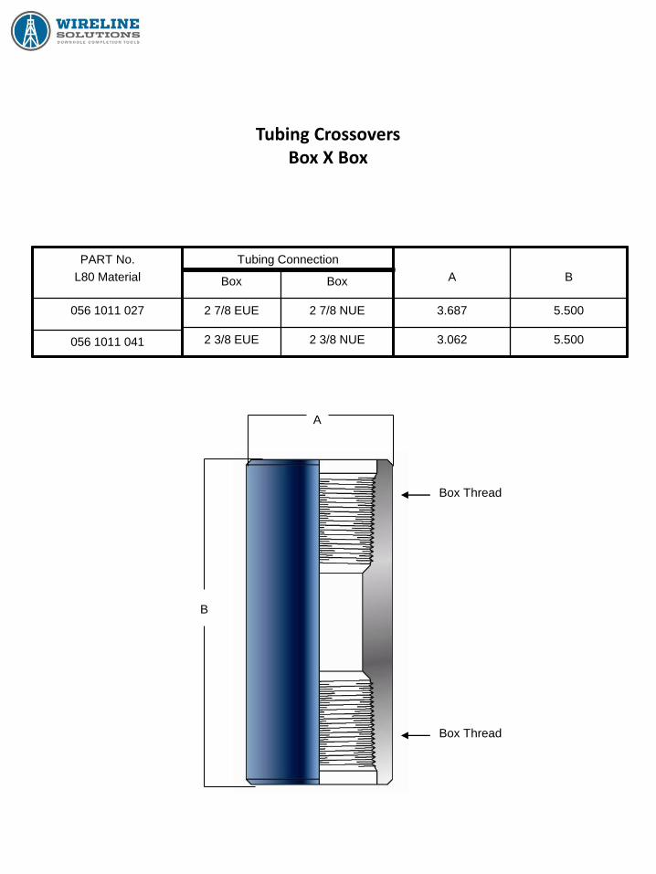
Tubing Crossovers Box X Box
PART No.
L80 Material
056 1011 027
056 1011 041
Tubing Connection
Box Box
2 7/8 EUE 2 7/8 NUE
2 3/8 EUE 2 3/8 NUE
A
B
3.687 5.500
3.062 5.500
A
B
Box Thread
Box Thread

Tubing Crossovers Box X Pin
PART No.
L80 Material
056 1011 093
056 1011 003
056 1011 022
056 1011 016
056 1011 001
056 1011 089
Tubing Connection
Box Pin
2 7/8 NUE 2 7/8 EUE
2 3/8 NUE 2 3/8 EUE
2 7/8 EUE 3 1/2 EUE
3 1/2 EUE 2 7/8 EUE
2 7/8 EUE 2 3/8 EUE
2 3/8 EUE 2 7/8 EUE
A
B
3.486 7.000
2.875 5.500
3.750 7.000
4.500 8.000
3.687 6.500
3.500 6.500
A
B
Box Thread
Pin Thread

Shear Out Safety Joints

Shear Out Safety Joints
Sizes: 2 3/8 & 2 7/8
DESCRIPTION:
The Wireline Solutions Shear Out Safety Joint allows
straight pull release of the tubing string at a controlled
shear value where retrieval problems are anticipated.
The Safety Joint is placed between a packer and a
sand screen to provide means of releasing and
retrieving the production string.
SHEAR VALUE:
The Shear Out Safety Joint can be run using from 2 to
12 brass shear pins, each valued at 5,000 lbs., allowing
the shear value of the tool to be varied from 10,000 to
60,000 lbs. The tool is shipped with all 12 pins in place,
unless specified otherwise. Remove the necessary
number of shear pins required to obtain the desired
releasing pull. The remaining pins should be as evenly
spaced as possible.
In determining the desired shear-out force, two factors
should be considered; pressure in favor of the tubing
acts on a sealed-off area tending to shear the joint
loose. The total weight of all tubing and equipment
suspended below the joint is carried by the shear pins.
The shear-out force should be sufficiently high to
overcome both of these forces.
SIZE PART NUMBER MAX O.D. NOM I.D. STANDARD
BOX X PIN
O-RING
(2 REQUIRED)
2 3/8” 001561237260100 3.094 1.93 2 3/8” EU 8 RND #229
2 7/8” 001561287440100 3.719 2.44 2 7/8” EU 8 RND #233
3 1/2” 001561350620100 4.500 3.00 3 1/2” EU 10 RND
4 1/2” 001561450820100 5.031 3.90 4 1/2” LTC 8 RND

Wireline Service Tools

Wireline Tool String
The Wireline Tool String as an assembly of wireline tools connected to
the wireline (slickline) for setting, pulling, or servicing downhole
equipment. An assembly of wireline tools is used to deliver surface
controlled impacts (jar action) to manipulate devices within the well
bore.
A standard set of wireline tools typically consists of:
Wireline Socket (rope socket) provides a means for connecting the wireline to the tool string.
Wireline Stem (sinker bar) is used as weight to overcome well pressure, fluids, and friction to sink the tools into the well bore. Stem is also used to transmit force either upward or downward to set or retrieve downhole controls.
Wireline Knuckle Joint is used for flexibility through the tool string.
Wireline Jars (spang type link jars) used for obtaining a hammering effect by upward or downward movement.
Wireline running tool, pulling tool, or other service tool required to perform services desired.
Tool strings are available in various sizes that are designed by nominal dimensions rather than tubing sizes.
Wireline Tool
String Size – O.D.
Thread Connection
Pin X Box
Fishing Neck
Size
1” 5/8” – 11 NC 1.000”
1 1/4” 15/16” – 10 UN 1 3/16”
1 1/2” 15/16” – 10 UN 1 3/8”
1 3/4” 1 1/16” – 10 UN 1 3/4”
2 1/8” 1 1/16” – 10 UN 1 3/4”
Other Sizes Available Upon Request
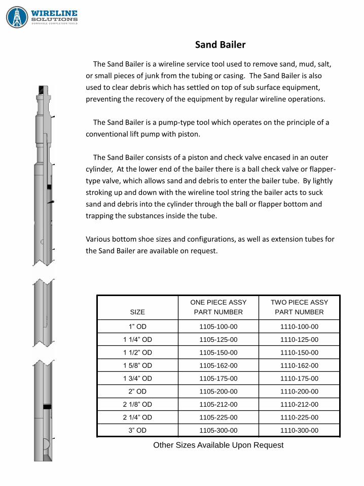
Sand Bailer
The Sand Bailer is a wireline service tool used to remove sand, mud, salt,
or small pieces of junk from the tubing or casing. The Sand Bailer is also
used to clear debris which has settled on top of sub surface equipment,
preventing the recovery of the equipment by regular wireline operations.
The Sand Bailer is a pump-type tool which operates on the principle of a
conventional lift pump with piston.
The Sand Bailer consists of a piston and check valve encased in an outer
cylinder, At the lower end of the bailer there is a ball check valve or flapper-
type valve, which allows sand and debris to enter the bailer tube. By lightly
stroking up and down with the wireline tool string the bailer acts to suck
sand and debris into the cylinder through the ball or flapper bottom and
trapping the substances inside the tube.
Various bottom shoe sizes and configurations, as well as extension tubes for
the Sand Bailer are available on request.
SIZE
ONE PIECE ASSY
PART NUMBER
TWO PIECE ASSY
PART NUMBER
1” OD 1105-100-00 1110-100-00
1 1/4” OD 1105-125-00 1110-125-00
1 1/2” OD 1105-150-00 1110-150-00
1 5/8” OD 1105-162-00 1110-162-00
1 3/4” OD 1105-175-00 1110-175-00
2” OD 1105-200-00 1110-200-00
2 1/8” OD 1105-212-00 1110-212-00
2 1/4” OD 1105-225-00 1110-225-00
3” OD 1105-300-00 1110-300-00
Other Sizes Available Upon Request

Hydrostatic Bailer
The Hydrostatic Bailer is a wireline service tool used when
substances to be bailed cannot be removed by a pump bailer.
This sometimes occurs when small metallic particles or other
type debris become lodged on top of the dogs of a lock
mandrel, etc.
The Hydrostatic Bailer is made of a cylinder, about 5 feet
long, with a shear disc mechanism at the bottom. The cylinder
is at atmospheric pressure, sealed off from well pressure with
an O-ring. When the obstruction is reached, the disc is sheared
by downward jarring.
Different skirt sizes can be fitted for various tubing and tool
sizes. Brass shear discs are available in different thicknesses
for various well pressures.
Other Sizes Available Upon Request
SIZE PART NUMBER
1 1/4” OD 1140-125-00
1 1/2” OD 1140-150-00
1 5/8” OD 1140-162-00
2” OD 1140-200-00
2 1/2” OD 1140-250-00
3” OD 1140-300-00
Junk Basket
Bottom

Blind Box
The Blind Box is used when heavy downward jarring on an
obstruction is required. It can also be used to cut wireline on a rope
socket during fishing operations.
The Blind Box is flat on the bottom and hardened to reduce damage.
The O.D. of the Blind Box should be matched in accordance with the
tubing in which it is to be used.
Other Sizes Available Upon Request
SIZE
MAX O.D.
THREAD
CONNECTION
FISHING NECK
SIZE
PART NUMBER
1.250” 15/16 – 10 UN PIN 1 3/16” 1150-125-00
1.500” 15/16 – 10 UN PIN 1 3/16” 1150-150-00
1.750” 15/16 – 10 UN PIN 1 3/8” 1150-175-00
2.250” 15/16 – 10 UN PIN 1 3/8” 1150-225-00
2.500” 15/16 – 10 UN PIN 1 3/8” 1150-250-00
2.750” 1 1/16” – 10 UN
PIN
1 3/4 1150-275-00

Centralizer
The Centralizer is a wireline service tool designed to ensure that the
work string service tool is at most central position, especially during
wireline operations in deviated wells. It is normally attached to the tool
string just above the running tool, pulling tool, or other service tool being
used.
The Centralizer is available in a variety of sizes, with either Steel or
Teflon construction
Other Sizes Available Upon Request
DESCRIPTION PART NUMBER
Assembly 1195-000-00
Adjustable Bow String Centralizer
(See Picture)
NOMINAL SIZE PART NUMBER
2” 1190-200-00
2 1/2” 1190-250-00
3” 1190-300-00
Teflon Centralizer
NOMINAL SIZE MAX O.D. PART NUMBER
2” 1.843” 1185-184-00
2 1/2” 2.250” 1185-225-00
3” 2.700” 1185-270-00
Steel Centralizer
Other Sizes Available Upon Request

Gauge Ring (Paraffin Cutter)
The Gauge Ring is a wireline service tool used to gauge the I.D. of
the tubing in which it is run. It should be run prior to running or pulling a
sub-surface device, thus assuring the operator that the tubing is
unobstructed down to the depth that he will be working.
The Gauge Ring may also be used as a paraffin / wax cutter or to
determine the profile of a bridge of debris inside the tubing.
SIZE
MAX O.D.
THREAD
CONNECTION
FISHING NECK
SIZE
PART NUMBER
1.250” 15/16” – 10 UN PIN 1 3/16” 2650-125-00
1.500” 15/16” – 10 UN PIN 1 3/16” 2650-150-00
1.750” 15/16” – 10 UN PIN 1 3/16” 2650-175-00
1.843” 15/16” – 10 UN PIN 1 3/8” 2650-184-00
1.906” 15/16” – 10 UN PIN 1 3/8” 2650-190-00
2.250” 15/16” – 10 UN PIN 1 3/8” 2650-225-00
2.343” 15/16” – 10 UN PIN 1 3/8” 2650-234-00
2.500” 15/16” – 10 UN PIN 1 3/8” 2650-250-00
2.750” 1 1/16” – 10 UN PIN 1 3/4” 2650-275-00
2.875” 1 1/16” – 10 UN PIN 1 3/4” 2650-287-00
Other Sizes Available Upon Request

Go-Devil
The Go-Devil is a wireline service tool that makes it possible to cut a
conventional wireline when the tool string is entangled in wire or
covered with sand or debris, and the rope socket is no longer clear
making a cutter bar or wireline snipper ineffective.
The Go-Devil is constructed of a solid length of bar with a slot
through which the wireline is passed. Once the wireline is secured
through the Go-Devil, it is dropped downhole in the same manner as a
cutter bar.
Other Sizes Available Upon Request
SIZE
FISHING NECK
SIZE
PART #
2 Ft. LONG
PART #
3 Ft. LONG
PART #
5 Ft. LONG
1 1/4” 1 3/16” 2270-125-02 2270-125-03 2270-125-05
1 1/2” 1 3/8” 2270-150-02 2270-150-02 2270-150-05
1 3/4” 1 3/4” 2270-175-02 2270-175-03 2270-175-05
1 7/8” 1 3/4” 2270-187-02 2270-187-03 2270-187-05
2 1/8” 1 3/4” 2270-212-02 2270-212-03 2270-212-05

Impression Block
The Impression Lock is a wireline service tool used to take
impressions of foreign objects within the well bore. The Impression
Block is a useful tool during fishing operations, as the impression taken
will define the shape and relative position of the obstruction so that the
proper fishing tool may be selected.
The Impression Block is constructed of a hollow steel housing open
at one end and filled with lead, with a pin through the leaded section to
keep it in tact. The impression is made on the exposed soft lead face
on the bottom on the Impression Block.
Other Sizes Available Upon Request
SIZE
MAX O.D.
THREAD
CONNECTION
FISHING NECK
SIZE
PART
NUMBER
1.250” 15/16” – 10 UN PIN 1 3/16” 2300-125-00
1.500” 15/16” – 10 UN PIN 1 3/16” 2300-150-00
1.750” 15/16” – 10 UN PIN 1 3/16” 2300-175-00
1.875” 15/16” – 10 UN PIN 1 3/8” 2300-187-00
2.000” 15/16” – 10 UN PIN 1 3/8” 2300-200-00
2.250” 15/16” – 10 UN PIN 1 3/8” 2300-225-00
2.375” 15/16” – 10 UN PIN 1 3/8” 2300-237-00
2.500” 15/16” – 10 UN PIN 1 3/8” 2300-250-00
2.750” 1 1/6” – 10 UN PIIN 1 3/4” 2300-275-00
2.875” 1 1/16” – 10 UN PIN 1 3/4” 2300-287-00

Spang Type Stroke Jars
“Spang Type” Jars utilize the weight of the stem connected
immediately above to deliver upward or downward jarring impacts by
manipulating the wireline at the surface.
Effective jarring impacts depends on the weight of the stem used, the
length of the strength of the jars, the size and depth of the tools, the
viscosity of the fluid in the tubing, and the well pressure acting upon the
cross sectional area of the wireline.
Jars are constructed of two pieces linked together (similar to along
chain link), which are free to be extended or collapsed creating a stroke
type motion.
Other Sizes Available Upon Request
SIZE
STROKE
LENGTH
THREAD CONNECTION
BOX X PIN
FISHING
NECK SIZE
PART #
1” 18” 5/8” – 11 NC 1.000” 2305-100-18
1 1/4” 20” 15/16” – 10 UN 1 3/16” 2305-125-20
1 1/4” 30” 15/16” – 10 UN 1 3/16” 2305-125-30
1 1/2” 20” 15/16” – 10 UN 1 3/8” 2305-150-20
1 1/2” 30” 15/16” – 10 UN 1 3/8” 2305-150-30
1 3/4” 20” 1 1/16” – 10 UN 1 3/4” 2305-175-20
1 3/4” 30” 1 1/16” – 10 UN 1 3/4” 2305-175-30
1 7/8” 20” 1 1/16” – 10 UN 1 3/4” 2308-187-20
1 7/8” 30” 1 1/16” – 10 UN 1 3/4” 2305-187-30
2 1/8” 20” 1 1/16” – 10 UN 1 3/4” 2305-212-30
2 1/8” 30” 1 1/16” – 10 UN 1 3/4” 2305-212-30
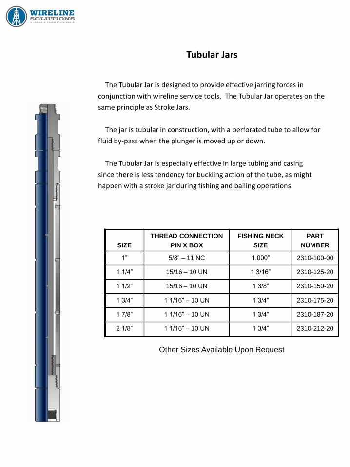
Tubular Jars
The Tubular Jar is designed to provide effective jarring forces in
conjunction with wireline service tools. The Tubular Jar operates on the
same principle as Stroke Jars.
The jar is tubular in construction, with a perforated tube to allow for
fluid by-pass when the plunger is moved up or down.
The Tubular Jar is especially effective in large tubing and casing
since there is less tendency for buckling action of the tube, as might
happen with a stroke jar during fishing and bailing operations.
Other Sizes Available Upon Request
SIZE
THREAD CONNECTION
PIN X BOX
FISHING NECK
SIZE
PART
NUMBER
1” 5/8” – 11 NC 1.000” 2310-100-00
1 1/4” 15/16 – 10 UN 1 3/16” 2310-125-20
1 1/2” 15/16 – 10 UN 1 3/8” 2310-150-20
1 3/4” 1 1/16” – 10 UN 1 3/4” 2310-175-20
1 7/8” 1 1/16” – 10 UN 1 3/4” 2310-187-20
2 1/8” 1 1/16” – 10 UN 1 3/4” 2310-212-20

Knuckle Joint / Knuckle Jar
The Knuckle Joint is a wireline tool accessory used to
provide flexibility in the tool string. The Knuckle Joint is
constructed with a ball and socket and is recommended
for use within all wireline tool strings.
Other Sizes Available Upon Request
SIZE
THREAD CONNECTION
PIN X BOX
FISHING NECK
SIZE
PART
NUMBER
1” 5/8” – 11 NC 1.000” 2395-100-00
1 1/4” 15/16 – 10 UN 1 3/16” 2395-125-20
1 1/2” 15/16 – 10 UN 1 3/8” 2395-150-20
1 3/4” 1 1/16” – 10 UN 1 3/4” 2395-175-20
1 7/8” 1 1/16” – 10 UN 1 3/4” 2395-187-20
2 1/8” 1 1/16” – 10 UN 1 3/4” 2395-212-20
SIZE
THREAD CONNECTION
PIN X BOX
FISHING NECK
SIZE
PART
NUMBER
1 1/4” 15/16 – 10 UN 1 3/16” 2390-125-20
1 1/2” 15/16 – 10 UN 1 3/8” 2390-150-20
1 3/4” 1 1/16” – 10 UN 1 3/4” 2390-175-20
1 7/8” 1 1/16” – 10 UN 1 3/4” 2390-187-20
2 1/8” 1 1/16” – 10 UN 1 3/4” 2390-212-20
Other Sizes Available Upon Request
Knuckle Joint
Knuckle Jar
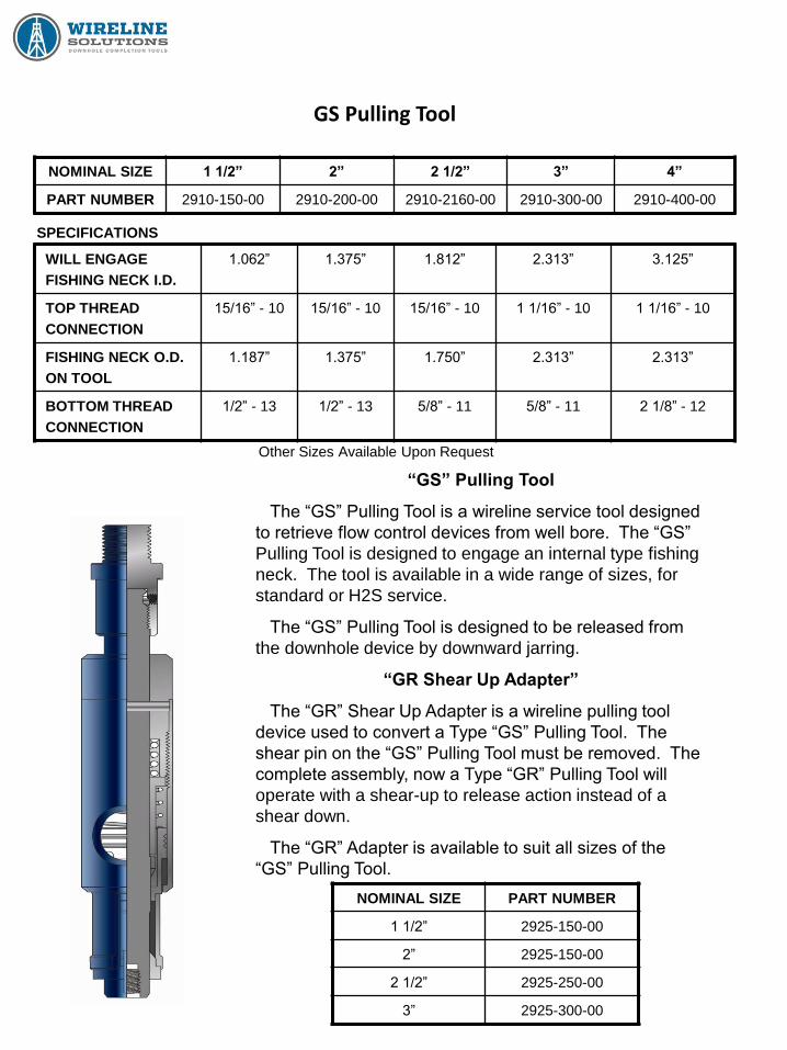
GS Pulling Tool
NOMINAL SIZE 1 1/2” 2” 2 1/2” 3” 4”
PART NUMBER 2910-150-00 2910-200-00 2910-2160-00 2910-300-00 2910-400-00
Other Sizes Available Upon Request
SPECIFICATIONS
WILL ENGAGE
FISHING NECK I.D.
1.062”
1.375” 1.812” 2.313” 3.125”
TOP THREAD
CONNECTION
15/16” - 10 15/16” - 10 15/16” - 10 1 1/16” - 10 1 1/16” - 10
FISHING NECK O.D.
ON TOOL
1.187” 1.375” 1.750” 2.313” 2.313”
BOTTOM THREAD
CONNECTION
1/2” - 13 1/2” - 13
5/8” - 11 5/8” - 11 2 1/8” - 12
“GS” Pulling Tool
The “GS” Pulling Tool is a wireline service tool designed
to retrieve flow control devices from well bore. The “GS”
Pulling Tool is designed to engage an internal type fishing
neck. The tool is available in a wide range of sizes, for
standard or H2S service.
The “GS” Pulling Tool is designed to be released from
the downhole device by downward jarring.
“GR Shear Up Adapter”
The “GR” Shear Up Adapter is a wireline pulling tool
device used to convert a Type “GS” Pulling Tool. The
shear pin on the “GS” Pulling Tool must be removed. The
complete assembly, now a Type “GR” Pulling Tool will
operate with a shear-up to release action instead of a
shear down.
The “GR” Adapter is available to suit all sizes of the
“GS” Pulling Tool.
NOMINAL SIZE PART NUMBER
1 1/2” 2925-150-00
2” 2925-150-00
2 1/2” 2925-250-00
3” 2925-300-00

JD Pulling Tool
NOMINAL
SIZE
“JDC” ASSEMBLY “JDS” ASSEMBLY
1 1/4” 2930-125-00
1 3/8” 2930-137-00
1 1/2” 2930-150-00 2935-150-00
1 5/8” 2930-162-00 2935-162-00
2” 2930-200-00 2935-200-00
2 1/2” 2930-250-00 2935-250-00
3” 2930-300-00 2935-300-00
4” 2930-400-00 2935-400-00
“JD” Series Wireline Pulling Tool
The “JD” Pulling Tool is a wireline service tool designed to remove retrievable subsurface devices
with external fishing necks from well. This tool has collet-type dogs with large latching area. It is
also available with different length cores which make the reach of the tool adaptable to retrieve
subsurface devices with fishing necks of different lengths.
The “JD” Pulling Tool utilizes the “D” top sub which is made up to the skirt of the tool. The dogs,
which are mounted on the skirt, are inserted into the vertical openings in the skirt. The “JD” Series
Pulling Tool can be released, if necessary from the retrievable device by downward jarring.
In the Pulling Tool nomenclature, the second letter is used to designated the direction of shear
release. A”JD” is a “jar down” release tool. The third letter designates core length: with a “C” being
a “long” core and an “S” core being a “short” core. A third core length, designated as an “L” core is
even shorter but has limited applications.
SIZE
TYPE
TO ENGAGE
FISHING NECK
O.D.
REACH
MAX O.D. TOP
THREAD
CONNECTION
1 1/4” JDC .875” 1.937” 1.281” 15/16-10
1 3/8” JDC 1.000” 1.875” 1.375” 15/16-10
1 1/2” JDC 1.187” 1.093” 1.422” 15/16-10
1 1/2” JDS 1.187” 1.843” 1.422” 15/16-10
1 1/2” JUC 1.187” 1.093” 1.422” 15/16-10
1 1/2” JUS 1.187” 1.843” 1.422” 15/16-10
1 5/8” JDC 1.187” 1.093” 1.625” 15/16-10
2” JDC 1.375” 1.437” 1.859” 15/16-10
2” JDS 1.375” 2.125” 1.859” 15/16-10
2” JUC 1.375” 1.437” 1.859” 15/16-10
2” JUS 1.375” 2.125” 1.859” 15/16-10
2 1/2” JDC 1.750” 1.312” 2.250” 15/16-10
2 1/2” JDS 1.750” 2.187” 2.250” 15/16-10
2 1/2” JUC 1.750” 1.312” 2.250” 15/16-10
2 1/2” JUS 1.750” 2.187” 2.250” 15/16-10
3” JDC 2.312” 1.437” 2.796” 1 1/16-10
3” JDS 2.312” 2.125” 2.796” 1 1/16-10
3” JUC 2.312” 1.437” 2.796” 1 1/16-10
3” JUS 2.312” 2.125” 2.796” 1 1/16-10
4” JDC 3.125” 2.312” 3.750” 1 1/16-10
4” JUC 3.125” 2.312” 3.750” 1 1/16-10
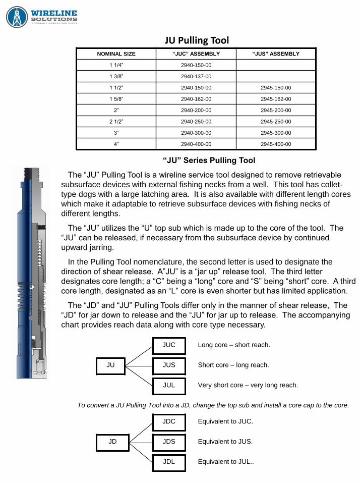
JU Pulling Tool NOMINAL SIZE “JUC” ASSEMBLY “JUS” ASSEMBLY
1 1/4” 2940-150-00
1 3/8” 2940-137-00
1 1/2” 2940-150-00 2945-150-00
1 5/8” 2940-162-00 2945-162-00
2” 2940-200-00 2945-200-00
2 1/2” 2940-250-00 2945-250-00
3” 2940-300-00 2945-300-00
4” 2940-400-00 2945-400-00
“JU” Series Pulling Tool
The “JU” Pulling Tool is a wireline service tool designed to remove retrievable
subsurface devices with external fishing necks from a well. This tool has collet-
type dogs with a large latching area. It is also available with different length cores
which make it adaptable to retrieve subsurface devices with fishing necks of
different lengths.
The “JU” utilizes the “U” top sub which is made up to the core of the tool. The
“JU” can be released, if necessary from the subsurface device by continued
upward jarring.
In the Pulling Tool nomenclature, the second letter is used to designate the
direction of shear release. A”JU” is a “jar up” release tool. The third letter
designates core length; a “C” being a “long” core and “S” being “short” core. A third
core length, designated as an “L” core is even shorter but has limited application.
The “JD” and “JU” Pulling Tools differ only in the manner of shear release, The
“JD” for jar down to release and the “JU” for jar up to release. The accompanying
chart provides reach data along with core type necessary.
JU
JUC
JUS
JUL
JDL
JDS
JDC
JD
To convert a JU Pulling Tool into a JD, change the top sub and install a core cap to the core.
Long core – short reach.
Equivalent to JUL..
Equivalent to JUS.
Equivalent to JUC.
Very short core – very long reach.
Short core – long reach.

R Pulling Tool
NOMINAL SIZE “RB” ASSEMBLY “RS” ASSEMBLY “RJ” ASSEMBLY
1 1/2” 2960-150-00 2965-150-00 2970-150-00
2” 2960-200-00 2965-200-00 2970-200-00
2 1/2” 2960-250-00 2965-250-00 2970-250-00
3” 2960-300-00 2965-300-00 2970-300-00
4” 2960-400-00 2965-400-00 2970-400-00
“R” Pulling Tool
The “R” Pulling Tool is a wireline service tool designed to remove retrievable
subsurface devices with external fishing necks from a well. This tool utilizes a
set of three dogs to engage the fishing neck.
The “R” Pulling Tool is available in a wide range of sizes, with three reaches in
each sizes. All tools can be supplied for standard or H2S service.
The “R” Pulling Tool is designed to be released from the downhole device by
upward jarring.
By changing only the core of the “R” Pulling Tool, it is possible to obtain a “RB”,
“RS”, or “RJ” Pulling Tool
DATA and DIMENSIONS
SIZE
TYPE
TO ENGAGE
FISHING NECK
O.D.
REACH
MAX O.D.
TOP THREAD
CONNECTION
1 1/2” RB 1.187” 1.265” 1.430” 15/16-10
1 1/2” RS 1.187” 1.797” 1.430” 15/16-10
1 1/2” RJ 1.187” 2.547” 1.430” 15/16-10
2” RB 1.375” 1.219” 1.770” 15/16-10
2” RS 1.375” 1.984” 1.770” 15/16-10
2” RJ 1.375” 2.547” 1.770” 15/16-10
2 1/2” RB 1.750” 1.203” 2.180” 15/16-10
2 1/2” RS 1.750” 1.984” 2.180” 15/16-10
2 1/2” RJ 1.750” 2.547 2.180” 15/16-10
3” RB 2.312” 1.297” 2.740” 1 1/16”-10
3” RS 2.312” 2.156” 2.740” 1 1/16”-10
3” RJ 2.312” 2.609” 2.740” 1 1/16”-10
4” RB 3.125” 1.406” 3.718” 1 1/16”-10
4” RS 3.125” 2.156” 3.718” 1 1/16”-10
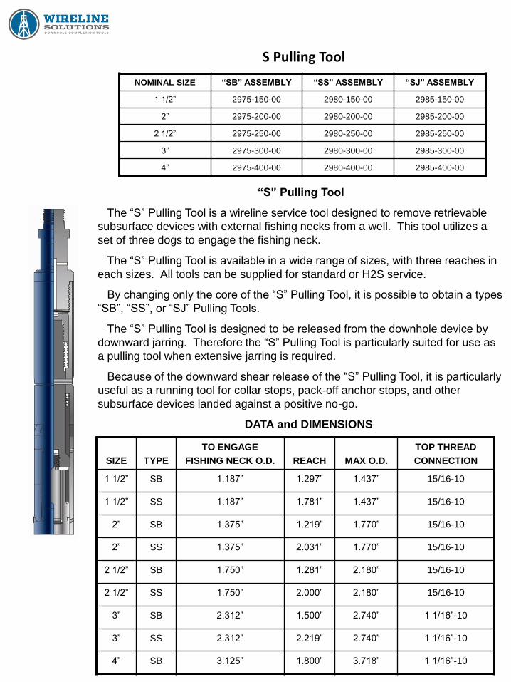
S Pulling Tool
NOMINAL SIZE “SB” ASSEMBLY “SS” ASSEMBLY “SJ” ASSEMBLY
1 1/2” 2975-150-00 2980-150-00 2985-150-00
2” 2975-200-00 2980-200-00 2985-200-00
2 1/2” 2975-250-00 2980-250-00 2985-250-00
3” 2975-300-00 2980-300-00 2985-300-00
4” 2975-400-00 2980-400-00 2985-400-00
“S” Pulling Tool
The “S” Pulling Tool is a wireline service tool designed to remove retrievable
subsurface devices with external fishing necks from a well. This tool utilizes a
set of three dogs to engage the fishing neck.
The “S” Pulling Tool is available in a wide range of sizes, with three reaches in
each sizes. All tools can be supplied for standard or H2S service.
By changing only the core of the “S” Pulling Tool, it is possible to obtain a types
“SB”, “SS”, or “SJ” Pulling Tools.
The “S” Pulling Tool is designed to be released from the downhole device by
downward jarring. Therefore the “S” Pulling Tool is particularly suited for use as
a pulling tool when extensive jarring is required.
Because of the downward shear release of the “S” Pulling Tool, it is particularly
useful as a running tool for collar stops, pack-off anchor stops, and other
subsurface devices landed against a positive no-go.
DATA and DIMENSIONS
SIZE
TYPE
TO ENGAGE
FISHING NECK O.D.
REACH
MAX O.D.
TOP THREAD
CONNECTION
1 1/2” SB 1.187” 1.297” 1.437” 15/16-10
1 1/2” SS 1.187” 1.781” 1.437” 15/16-10
2” SB 1.375” 1.219” 1.770” 15/16-10
2” SS 1.375” 2.031” 1.770” 15/16-10
2 1/2” SB 1.750” 1.281” 2.180” 15/16-10
2 1/2” SS 1.750” 2.000” 2.180” 15/16-10
3” SB 2.312” 1.500” 2.740” 1 1/16”-10
3” SS 2.312” 2.219” 2.740” 1 1/16”-10
4” SB 3.125” 1.800” 3.718” 1 1/16”-10

Rope Socket (Single Strand)
SIZE PART NUMBER FISHING NECK O.D. THREAD CONNECTION
1” 3100-100-00 1.000” 5/8”- 11 NC
1 1/4” 3100-125-00 1.187” 15/16”- 10 UN
1 1/2” 3100-150-00 1.375” 15/16” – 10 UN
1 3/4” 3100-175-00 1.750” 1 1/16” – 10 UN
1 7/8” 3100-187-00 1.750” 1 1/16” – 10 UN
2 1/8” 3100-212-00 1.750” 1 1/16” – 10 UN
The Single Strand Rope Socket is used to securely attach .082” or .092”
wireline to the tool string. The rope socket consists of a body, spring, spring
support thimble, and disc.
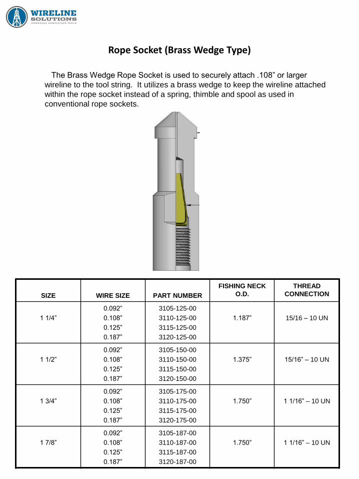
Rope Socket (Brass Wedge Type)
SIZE
WIRE SIZE
PART NUMBER
FISHING NECK
O.D.
THREAD
CONNECTION
1 1/4”
0.092”
0.108”
0.125”
0.187”
3105-125-00
3110-125-00
3115-125-00
3120-125-00
1.187”
15/16 – 10 UN
1 1/2”
0.092”
0.108”
0.125”
0.187”
3105-150-00
3110-150-00
3115-150-00
3120-150-00
1.375”
15/16” – 10 UN
1 3/4”
0.092”
0.108”
0.125”
0.187”
3105-175-00
3110-175-00
3115-175-00
3120-175-00
1.750”
1 1/16” – 10 UN
1 7/8”
0.092”
0.108”
0.125”
0.187”
3105-187-00
3110-187-00
3115-187-00
3120-187-00
1.750”
1 1/16” – 10 UN
The Brass Wedge Rope Socket is used to securely attach .108” or larger
wireline to the tool string. It utilizes a brass wedge to keep the wireline attached
within the rope socket instead of a spring, thimble and spool as used in
conventional rope sockets.
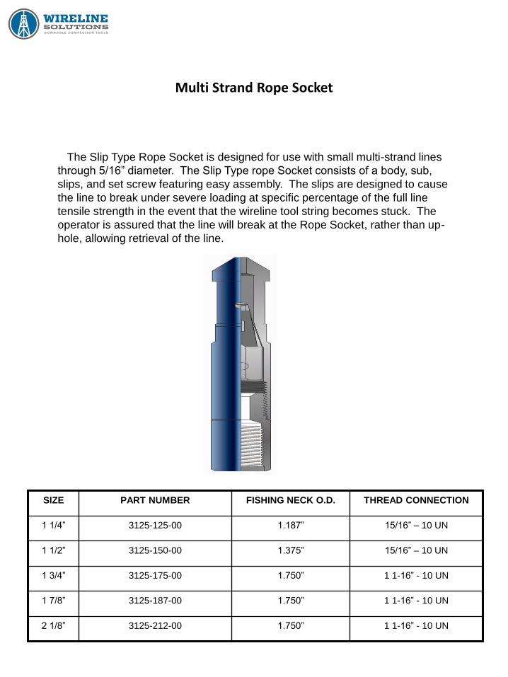
Multi Strand Rope Socket
SIZE PART NUMBER FISHING NECK O.D. THREAD CONNECTION
1 1/4” 3125-125-00 1.187” 15/16” – 10 UN
1 1/2” 3125-150-00 1.375” 15/16” – 10 UN
1 3/4” 3125-175-00 1.750” 1 1-16” - 10 UN
1 7/8” 3125-187-00 1.750” 1 1-16” - 10 UN
2 1/8” 3125-212-00 1.750” 1 1-16” - 10 UN
The Slip Type Rope Socket is designed for use with small multi-strand lines
through 5/16” diameter. The Slip Type rope Socket consists of a body, sub,
slips, and set screw featuring easy assembly. The slips are designed to cause
the line to break under severe loading at specific percentage of the full line
tensile strength in the event that the wireline tool string becomes stuck. The
operator is assured that the line will break at the Rope Socket, rather than up-
hole, allowing retrieval of the line.
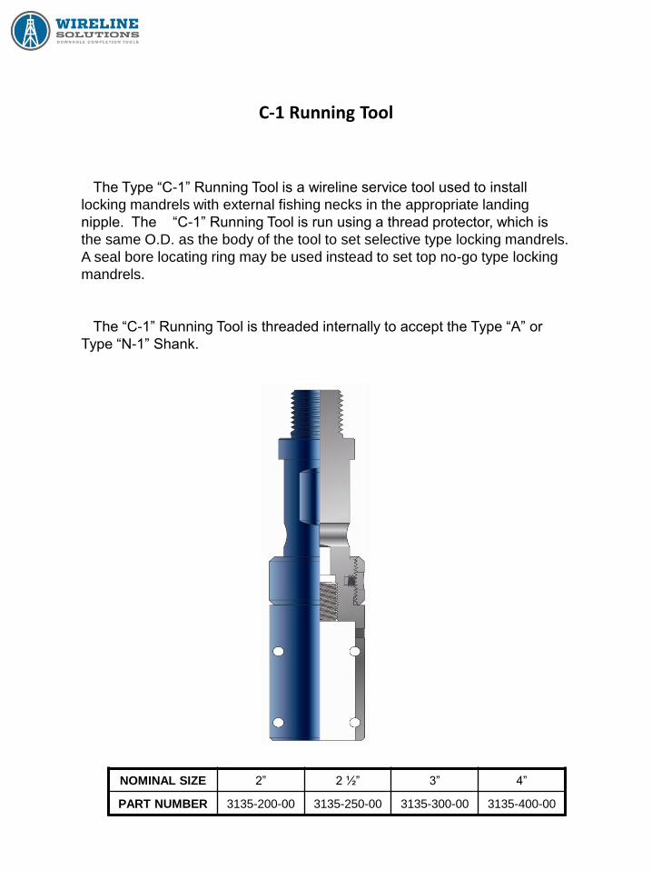
C-1 Running Tool
NOMINAL SIZE 2” 2 ½” 3” 4”
PART NUMBER 3135-200-00 3135-250-00 3135-300-00 3135-400-00
The Type “C-1” Running Tool is a wireline service tool used to install
locking mandrels with external fishing necks in the appropriate landing
nipple. The “C-1” Running Tool is run using a thread protector, which is
the same O.D. as the body of the tool to set selective type locking mandrels.
A seal bore locating ring may be used instead to set top no-go type locking
mandrels.
The “C-1” Running Tool is threaded internally to accept the Type “A” or
Type “N-1” Shank.

X-Line Running Tool
SIZE PART NUMBER
1.500” 3200-150-00
1.625” 3200-162-00
1.875” 3200-187-00
2.313” 3200-231-00
2.750” 3200-275-00
2.813” 3200-281-00
3.813” 3200-381-00
The X-Line Selective Running Tool is designed to install subsurface
controls using a type X Locking Mandrel. The selective features of the X
Running Tool allow the operator to install the downhole device in a pre-
determined WX Landing Nipple by adjusting the tool into the selective
position. If the subsurface control is to be installed in the upper most
landing nipple, the locking mandrel may be run with the keys in the control
or location position.
In addition to setting the X Locking Mandrel, the Running Tool may be
used to locate WX Landing Nipples.
The R Selective Running Tool, similar in design, is available in a wide
range of sizes to install Type R Locking Mandrels in heavy weight tubings.
SIZE PART NUMBER
1.710” 3205-171-00
1.781” 3205-178-00
2.125” 3205-212-00
2.188” 3205-218-00
2.562” 3205-256-00
3.688” 3205-368-00
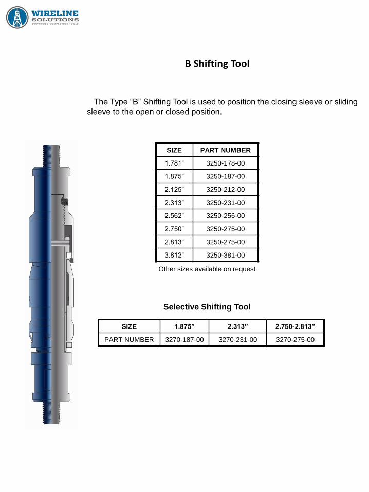
B Shifting Tool
SIZE PART NUMBER
1.781” 3250-178-00
1.875” 3250-187-00
2.125” 3250-212-00
2.313” 3250-231-00
2.562” 3250-256-00
2.750” 3250-275-00
2.813” 3250-275-00
3.812” 3250-381-00
Other sizes available on request
The Type “B” Shifting Tool is used to position the closing sleeve or sliding
sleeve to the open or closed position.
Selective Shifting Tool
SIZE 1.875” 2.313” 2.750-2.813”
PART NUMBER 3270-187-00 3270-231-00 3270-275-00

Stem (Weight Bar)
SIZE
FISHING NECK
SIZE
PART #
2’ LONG
PART #
3’ LONG
PART #
5’ LONG
1” 1.000” 3350-100-02 3350-100-03 3350-100-05
1 1/4” 1 3/16” 3350-125-02 3350-125-03 3350-125-05
1 1/2” 1 3/8” 3350-150-02 3350-150-03 3350-150-05
1 3/4” 1 3/4” 3350-175-02 3350-175-03 3350-175-05
1 7/8” 1 3/4” 3350-187-02 3350-187-03 3350-187-05
2 1/8” 1 3/4” 3350-212-02 3350-212-03 3350-212-05
Other sizes available on request
Wireline Stems, often referred to as weight bars provide the mass required
in jarring operations and the mass required to enable the tool string to “fall”
against the tubing differential pressure and friction at the wireline stuffing
box.
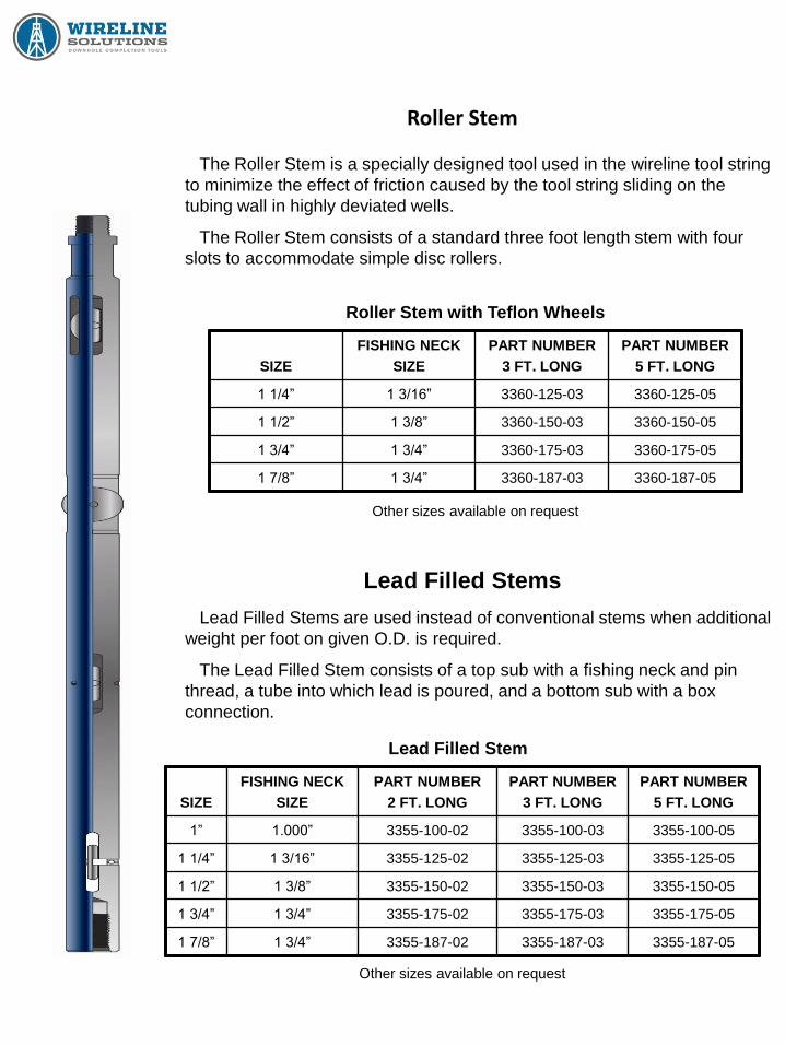
Roller Stem
SIZE
FISHING NECK
SIZE
PART NUMBER
3 FT. LONG
PART NUMBER
5 FT. LONG
1 1/4” 1 3/16” 3360-125-03 3360-125-05
1 1/2” 1 3/8” 3360-150-03 3360-150-05
1 3/4” 1 3/4” 3360-175-03 3360-175-05
1 7/8” 1 3/4” 3360-187-03 3360-187-05
Other sizes available on request
The Roller Stem is a specially designed tool used in the wireline tool string
to minimize the effect of friction caused by the tool string sliding on the
tubing wall in highly deviated wells.
The Roller Stem consists of a standard three foot length stem with four
slots to accommodate simple disc rollers.
Roller Stem with Teflon Wheels
Lead Filled Stems
SIZE
FISHING NECK
SIZE
PART NUMBER
2 FT. LONG
PART NUMBER
3 FT. LONG
PART NUMBER
5 FT. LONG
1” 1.000” 3355-100-02 3355-100-03 3355-100-05
1 1/4” 1 3/16” 3355-125-02 3355-125-03 3355-125-05
1 1/2” 1 3/8” 3355-150-02 3355-150-03 3355-150-05
1 3/4” 1 3/4” 3355-175-02 3355-175-03 3355-175-05
1 7/8” 1 3/4” 3355-187-02 3355-187-03 3355-187-05
Lead Filled Stems are used instead of conventional stems when additional
weight per foot on given O.D. is required.
The Lead Filled Stem consists of a top sub with a fishing neck and pin
thread, a tube into which lead is poured, and a bottom sub with a box
connection.
Lead Filled Stem
Other sizes available on request

Type F Collar Stop
NOMINAL SIZE 2” 2 1/2” 3”
PART NUMBER 3400-200-00 3400-250-00 3400-300-00
MINIMUM I.D. .875” 1.125” 1.625”
FISHING NECK O.D. 1.375” 1.750” 2.312”
Other sizes available on request
The Type ”F” Collar Stop is designed to locate and set in tubing coupling
recesses. The Type “F” Collar Stop is used to prevent tools from falling
through the tubing and into the casing and is applicable for a wide range of
wireline operations.
Type F Collar Stop
Collar Stop Running Tool
TYPE 2” – 2 1/2”
Collar Stop
3”
Collar Stop
PART NUMBER 3130-000-12 3130-000-13

Tubing End Locator
SIZE – O.D. 1 1/4” 1 1/2” 1 3/4”
PART NUMBER 3570-125-00 3570-150-00 3570-175-00
Other sizes available on request
The Tubing End Locator is used to locate the lower end of the tubing so
that its depth may be accurately measured.
The Tubing End Locator consists of a slotted body in which a spring-
loaded latch is retained. A shear pin limits the outward travel or rotation of
the latch. When the tool emerges from the lower end of the tubing, the latch
will be stopped in a position that is approximately perpendicular to the body
and can now re-enter the tubing until the shear pin is cut.
Tubing End Locator
Tubing Swedge
Tubing Swedge The Tubing Swedge is used to swedge out mashed areas and other
obstructions in the tubing string to insure the free passage of the subsurface
controls. It is also used to open orange-peel type bull plugs on the lower
end of the tubing.
The Tubing Swegde is tapered on both ends. The upper end is threaded
with a pin connection and a fishing neck. Since the largest portions of the
swedge is approximately equal to the drift diameter of the tubing, a fluid
course is provided through the central bore and lateral ports.
SIZE
MAX O.D.
THREAD
CONNECTION
FISHING NECK
SIZE
PART
NUMBER
1.250” 15/16” – 10 UN PIN 1 3/16” 3580-125-00
1.500” 15/16” – 10 UN PIN 1 3/16” 3580-150-00
1.750” 15/16” – 10 UN PIN 1 3/16” 3580-175-00
1.843” 15/16” – 10 UN PIN 1 3/8” 3580-184-00
1.906” 15/16” – 10 UN PIN 1 3/8” 3580-190-00
2.250” 15/16” – 10 UN PIN 1 3/8” 3580-225-00
2.343” 15/16” – 10 UN PIN 1 3/8” 3580-234-00
2.500” 15/16” – 10 UN PIN 1 3/8” 3580-250-00
2.750” 1 1/16” – 10 UN PIN 1 3/4” 3580-275-00
2.875” 1 1/16” – 10 UN PIN 1 3/4” 3580-287-00
Other sizes available on request
Tubing End
Locator
Tubing Swedge

Wireline Grab
SIZE
MAX O.D.
PART #
2 PRONG
PART #
4 PRONG
1.500” 3620-150-00 3625-150-00
1.750” 3620-175-00 3625-175-00
2.250” 3620-225-00 3625-225-00
2.500” 3620-250-00 3625-250-00
2.625” 3620-262-00 3625-262-00
2.700” 3620-270-00 3625-270-00
Other sizes available on request
The Wireline Grab is a wireline service tool normally
used to retrieve wireline that has been broken in the
well bore. The Wireline Grab has flexible legs with
pointed barbs inside each leg to form hooks that will
catch the looped end of the broken wireline.
Wireline Grab
Tubing Swedge
Center Spear
Other sizes available on request
DESCRIPTION PART NUMBER
ASSEMBLY 1180-200-00
The Center Spear is a wireline service tool used to
fish out broken wireline from the well bore. If the ball
of wire is too compacted making it impossible to use a
conventional wireline grab, this tool is used to pierce
the ball of wire, loosen the wire, and retrieve it from the
well bore.
Wireline Grab Center Spear
Related Documents