DOUBLE SKIN MODULAR AIR HANDLING UNIT Round Edge

Welcome message from author
This document is posted to help you gain knowledge. Please leave a comment to let me know what you think about it! Share it to your friends and learn new things together.
Transcript
DOUBLE SKIN MODULAR
AIR HANDLING UNITRound Edge
AIR HANDLING UNIT / P1
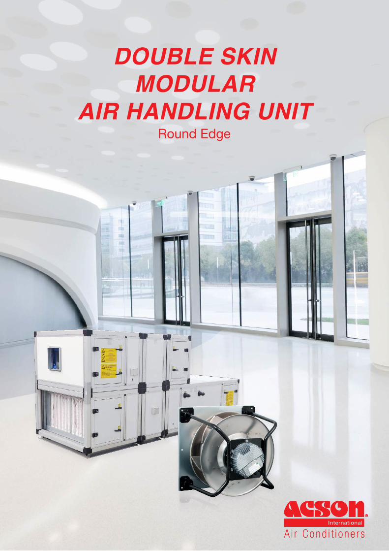
AIR HANDLING UNITAcson Double Skin Modular Air Handling Unit is designed based on modular panelling concept which making it suitable to be subdivided into multiple sections to be assembled on the site. It comes with a wide variability of air flow rate range of 330 to 25,000 lps (1100 to 90000 CMH or 700 to 52974 CFM) and up to a total static pressure of 2000 pa (8” W.G). Acson Air Handling Units can handle both chilled water and direct expansion system. Acson Double Skin Modular Air Handling Unit is made up of Double Skin Polyurethane foam (PUR) insulation panel. The PU foam insulation thickness can be 25mm or 50mm with density 40 kg/m3. Acson Double Skin Modular Air Handling Unit is highly reliable in terms of its quality and performance as it is Eurovent certified or AHRI 1350 certified. Special customized design for non-standard AHU upon customer request is available
Eurovent is widely regconised for its high standards and strict requirements on its air conditioner performance. This standard focuses on mechanical features of AHU and performance of entire AHU.
Acson AHU model with Eurovent Certified : (A)DM1, (A)DM2 and (A)DM2TB.
This standard provides strict test method for thermal and mechanical performance of a central station air-handling unit’s (AHU) casing which covered performance of casing deflection, casing air leakage, thermal transmittance with leakage, thermal transmittance without leakage, and thermal bridging.
Acson AHU model with AHRI 1350 certified : ADA1, ADA2 and ADA2TB.Certified in accordance with AHRI Central Station Air-handling Unit Casing Certification Program, which is based one on AHRI Standard 1350. Certified Units may be found in the AHRI Directory at www.ahridirectory.org
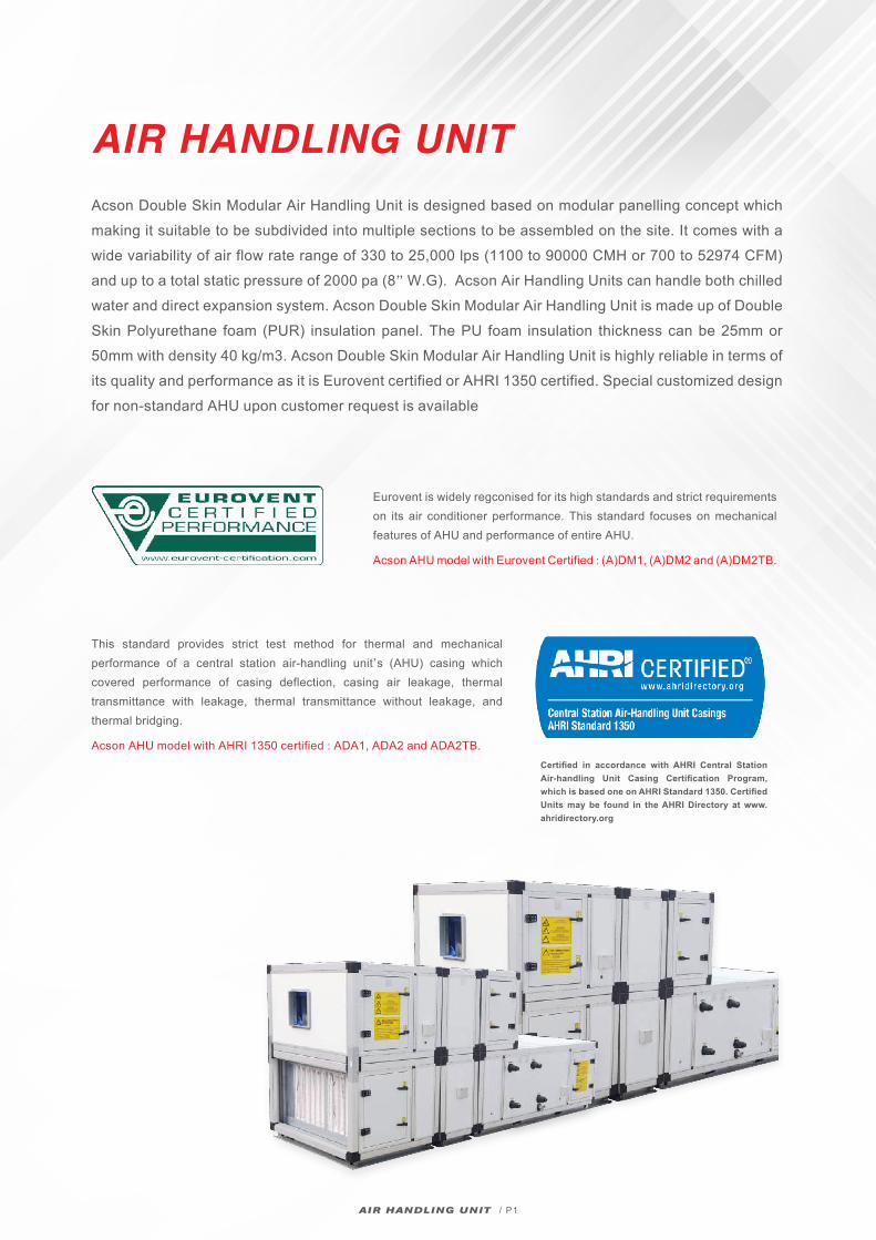
AHRI 1350 Certified Ratings
ADA Cabinet Reaches
Low GradeHigh Grade
Strength Class CD1 CD2 CD3 CD4 CD5
Rating Differential Static Pressure, in H2o 10 8 6 4 1
Maximum Normalized Deflection, in/in of span 0.0033 0.0042 0.0042 0.0042 ≥ 0.0042
Casing Deflection Rating Class CD2 CD2 CD3
Casing Air Leakage Class CL2 CL2 CL3
Thermal Transmittance Class with Leakage
CT2 CT3 CT4
Thermal Transmittance Class without leakage
CT2 CT3 CT4
Thermal Bridging Class CB2 CB3 CB3
Casing air leakage class CL1 CL2 CL3 CL6 CL12
Maximum Casing Air Leakage Rate,cfm/100ft2 (at P=1 in.H2o) 1 2 3 6 12
Thermal Transmittance Class CT1 CT2 CT3 CT4 CT5
Thermal Transmittance with Leakage (U), BTU / hr / ft2 / oF U ≤ 0.16 0.16 > U ≥
0.260.26 > U ≥
0.390.36 > U ≥
0.61 U > 0.61
Thermal Transmitance Class CT1 CT2 CT3 CT4 CT5
Thermal Transmittance without Leakage (U), BTU / hr / ft2 / oF U ≤ 0.14 0.14 > U ≥
0.230.23 > U ≥
0.360.36 > U ≥
0.55 U > 0.55
Thermal Bridging class CB1 CB2 CB3 CB4 CB5
Thermal Bridging Factor, Kb Kb ≥ 0.8 0.8 > Kb ≥ 0.6
0.6 > Kb ≥ 0.4
0.4 > Kb ≥ 0.2 Kb < 0.2
Class Classification of AHRI Standard 1350 (I-P)DA2TB DA2 DA1
AIR HANDLING UNIT / P2
EN 1886 Standard
ADM Cabinet Reaches
Low GradeHigh Grade
Strength Class D1 D2 D3
Maximum relative deformation of the cabinet under bearable pressure mm/m
4 10 ≥ 10Casing Strength D1(M) D1(M) D1(M)
Casing Air Leakage L1/L2 L1/L2 L2 / >L3
Filter By-passed Leakage F9 F9 F9
Thermal Transmittance T2 T3 T4
Thermal Bridging Factor TB2 TB3 TB3
Filter by-passed class F9 F8 F7 F6 G1-F5
Maximum by-pass leakage rate, k in % of the volume flow rate 0.5 1 2 4 6
Thermal Transmitance Class T1 T2 T3 T4 T5
Heat transfer coefficient of the cabinet (U) W/(m2.K) U ≤ 0.5 0.6 ≤ U <
1.01.0 ≤ U ≤
1.41.4 ≤ U ≤
2.0No
requirement
Thermal Transmitance Class TB1 TB2 TB3 TB4 TB5
Cold Bridge coefficient of the cabinet (Kb)
0.75 ≤ Kb≤ 1.0
0.6 ≤ Kb ≤ 0.75
0.45 ≤ Kb ≤ 0.6
0.3 ≤ Kb ≤ 0.45
Norequirement
Class Classification of EN1886 StandardDM2TB DM2 DM1
Air Leakage class L1 L2 L3
Maximum Air leakage rate of the cabinet under test pressure of 400 Pa (I/s/m2)
0.15 0.44 1.32
Maximum Air leakage rate of the cabinet under test pressure of +700 Pa (I/s/m2)
0.22 0.63 1.90
AIR HANDLING UNIT / P3
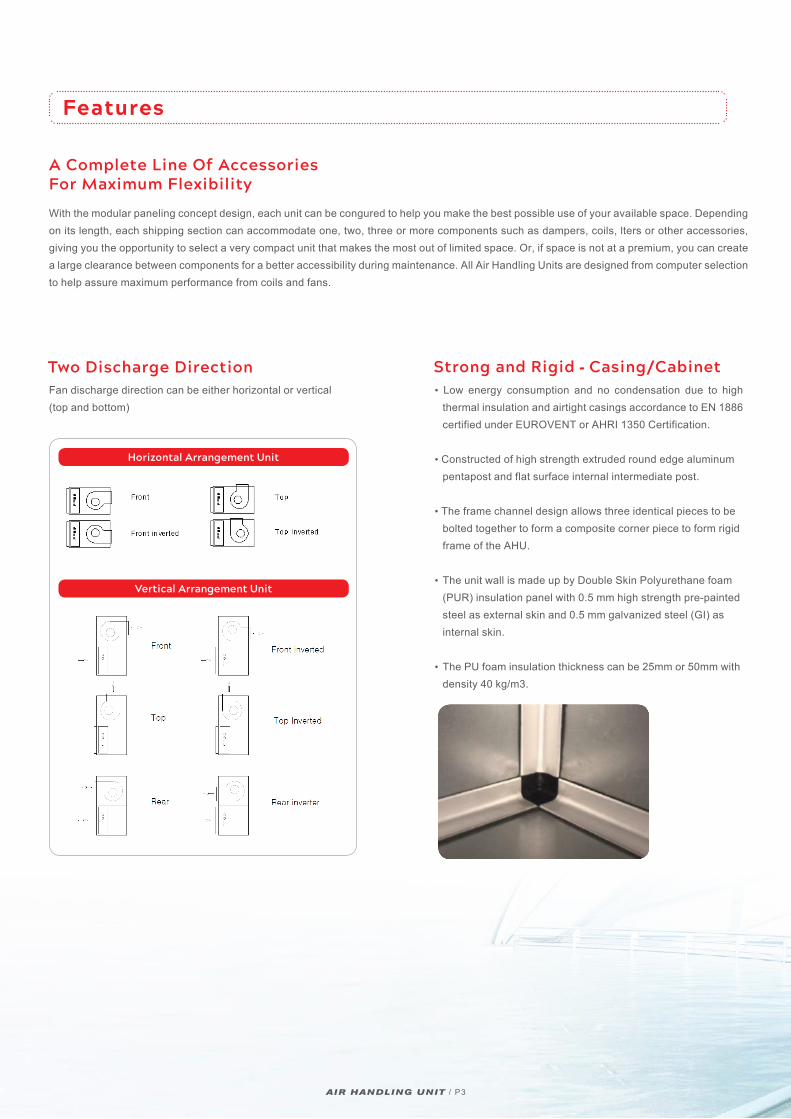
Two Discharge Direction
Fan discharge direction can be either horizontal or vertical (top and bottom)
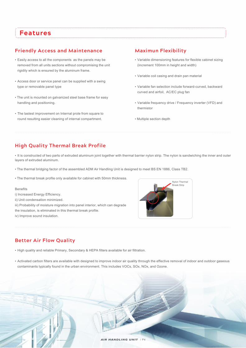
Strong and Rigid - Casing/Cabinet
• Low energy consumption and no condensation due to high thermal insulation and airtight casings accordance to EN 1886 certified under EUROVENT or AHRI 1350 Certification.
• Constructed of high strength extruded round edge aluminum pentapost and flat surface internal intermediate post.
• The frame channel design allows three identical pieces to be bolted together to form a composite corner piece to form rigid frame of the AHU.
• The unit wall is made up by Double Skin Polyurethane foam (PUR) insulation panel with 0.5 mm high strength pre-painted steel as external skin and 0.5 mm galvanized steel (GI) as internal skin.
• The PU foam insulation thickness can be 25mm or 50mm with density 40 kg/m3.
Features
Horizontal Arrangement Unit
Vertical Arrangement Unit
A Complete Line Of AccessoriesFor Maximum Flexibility
With the modular paneling concept design, each unit can be congured to help you make the best possible use of your available space. Depending on its length, each shipping section can accommodate one, two, three or more components such as dampers, coils, lters or other accessories, giving you the opportunity to select a very compact unit that makes the most out of limited space. Or, if space is not at a premium, you can create a large clearance between components for a better accessibility during maintenance. All Air Handling Units are designed from computer selection to help assure maximum performance from coils and fans.
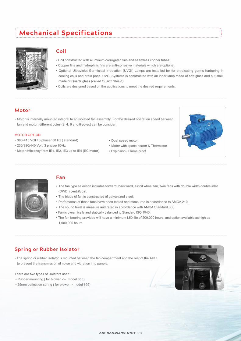
• It is constructed of two parts of extruded aluminum joint together with thermal barrier nylon strip. The nylon is sandwiching the inner and outer layers of extruded aluminum.
• The thermal bridging factor of the assembled ADM Air Handling Unit is designed to meet BS EN 1886, Class TB2.
• The thermal break profile only available for cabinet with 50mm thickness.
Benefitsi) Increased Energy Efficiency.ii) Unit condensation minimized. iii) Probability of moisture migration into panel interior, which can degrade the insulation, is eliminated in this thermal break profile.iv) Improve sound insulation.
AIR HANDLING UNIT / P4
Friendly Access and Maintenance
• Easily access to all the components as the panels may be removed from all units sections without compromising the unit rigidity which is ensured by the aluminum frame.
• Access door or service panel can be supplied with a swing type or removable panel type
• The unit is mounted on galvanized steel base frame for easy handling and positioning.
• The lastest improvement on Internal prole from square to round resulting easier cleaning of internal compartment.
Maximun Flexibility
• Variable dimensioning features for flexible cabinet sizing (increment 100mm in height and width) • Variable coil casing and drain pan material • Variable fan selection include forward-curved, backward curved and airfoil, AC/EC plug fan
• Variable frequency drive / Frequency inverter (VFD) and thermistor
• Multiple section depth
Features
High Quality Thermal Break Profile
Better Air Flow Quality
• High quality and reliable Primary, Secondary & HEPA filters available for air filtration.
• Activated carbon filters are available with designed to improve indoor air quality through the effective removal of indoor and outdoor gaseous contaminants typically found in the urban environment. This includes VOCs, SOx, NOx, and Ozone.
Nylon Thermal Break Strip
Fan
• The fan type selection includes forward, backward, airfoil wheel fan, twin fans with double width double inlet (DWDI) centrifugal. • The blade of fan is constructed of galvanized steel.• Perfomance of these fans have been tested and measured in accordance to AMCA 210.• The sound level is measure and rated in accordance with AMCA Standard 300. • Fan is dynamically and statically balanced to Standard ISO 1940. • The fan bearing provided will have a minimum L50 life of 200,000 hours, and option available as high as 1,000,000 hours.
Mechanical Specifications
Coil
Motor
Spring or Rubber Isolator
• Coil constructed with aluminum corrugated fins and seamless copper tubes. • Copper fins and hydrophilic fins are anti-corrosive materials which are optional. • Optional Ultraviolet Germicidal Irradiation (UVGI) Lamps are installed for for eradicating germs harboring in cooling coils and drain pans. UVGI Systems is constructed with an inner lamp made of soft glass and out shell made of Quartz glass (called Quartz Shield).• Coils are designed based on the applications to meet the desired requirements.
• Motor is internally mounted integral to an isolated fan assembly. For the desired operation speed between fan and motor, different poles (2, 4, 6 and 8 poles) can be consider.
MOTOR OPTION • 380-415 Volt / 3 phase/ 50 Hz ( standard) • 230/380/440 Volt/ 3 phase/ 60Hz• Motor efficiency from IE1, IE2, IE3 up to IE4 (EC motor)
• The spring or rubber isolator is mounted between the fan compartment and the rest of the AHU to prevent the transmission of noise and vibration into panels.
There are two types of isolators used: • Rubber mounting ( for blower <= model 355) • 25mm deflection spring ( for blower > model 355)
• Dual speed motor • Motor with space heater & Thermistor• Explosion / Flame proof
AIR HANDLING UNIT / P5
AIR HANDLING UNIT / P6
Optional Add Ons
VFD/ Frequency Inverter• VFD is a type of adjustable-speed drive used in electro- mechanical drive systems to control motor speed and torque by varying motor input frequency and voltage.• VFD providing protection for motor operation.• VFD can very the frequency within 30Hz to 60Hz in order to control motor rotation in AHU.
Heat Recovery Wheel• It is constructed of aluminum coated with heat transfer material (silica gel or others) which is rotated by an electric motor at constant or variable speed. • Can reduce the capacity of ventilation equipment.• Can work at lower temperature without frosting occurs. • Recover both latent and sensible heat by allowing reduction in system capacity about 30 to 65%. • Prevent sick building syndrome.
Humidifier• It is an electric device which is used to increase the air relative humidity in atmosphere without steam source.• It is a constant temperature humidifier.• Its principle is the common electrode humidifier regulates the generated steam by the way of controlling water level and electrical current.
Electrical Heater• Electric heaters are optional with either single step or multi step of heating process.• Heaters are available in 220-230V and the wiring can be in single phase / 3 phase for contactor or thyristor control.
Mixing Box• It is an air inlet section to mix fresh and return air according to the system designer’s requirement.• It consists of damper in parallel blades with opposed rotating blade with driving shaft. • The damper blades are fabricated of aluminum and continuous Thermoplastic Elastomer (TPE) seals are inserted onto every damper blade.• The rotated rod of handle is made of brass and handle is fabricated of aluminum casting.
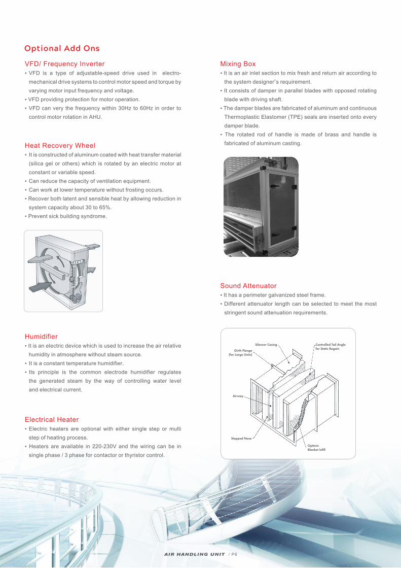
Sound Attenuator• It has a perimeter galvanized steel frame.• Different attenuator length can be selected to meet the most stringent sound attenuation requirements.
Controlled Tail Anglefor Static Regain
Silencer Casing
Girth Flange(for Large Units)
Airway
Stepped Nose
OptimisBlanket Infill
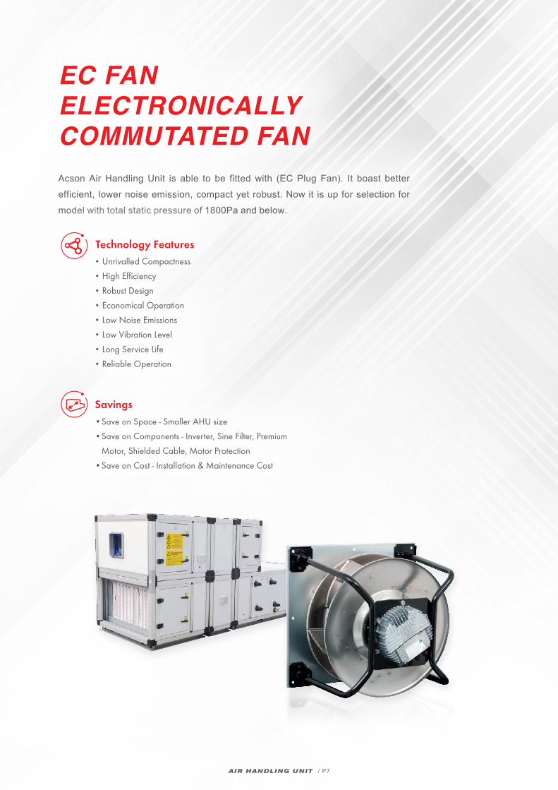
EC FANELECTRONICALLY COMMUTATED FANAcson Air Handling Unit is able to be fitted with (EC Plug Fan). It boast better efficient, lower noise emission, compact yet robust. Now it is up for selection for model with total static pressure of 1800Pa and below.
AIR HANDLING UNIT / P7
Savings
• Save on Space - Smaller AHU size
• Save on Components - Inverter, Sine Filter, Premium
Motor, Shielded Cable, Motor Protection
• Save on Cost - Installation & Maintenance Cost
Technology Features
• Unrivalled Compactness
• High Efficiency
• Robust Design
• Economical Operation
• Low Noise Emissions
• Low Vibration Level
• Long Service Life
• Reliable Operation
AIR HANDLING UNIT / P8
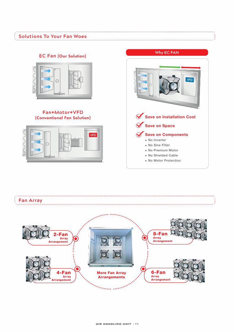
Solutions To Your Fan Woes
Fan Array
Save on Installation Cost
Save on Space
Save on Components• No Inverter
• No Sine Filter
• No Premium Motor
• No Shielded Cable
• No Motor Protection
More Fan ArrayArrangements
8-Fan Array Arrangement
2-Fan Array
Arrangement
4-Fan Array
Arrangement
6-Fan Array Arrangement
EC Fan (Our Solution)
Fan+Motor+VFD (Conventional Fan Solution)
Why EC FAN
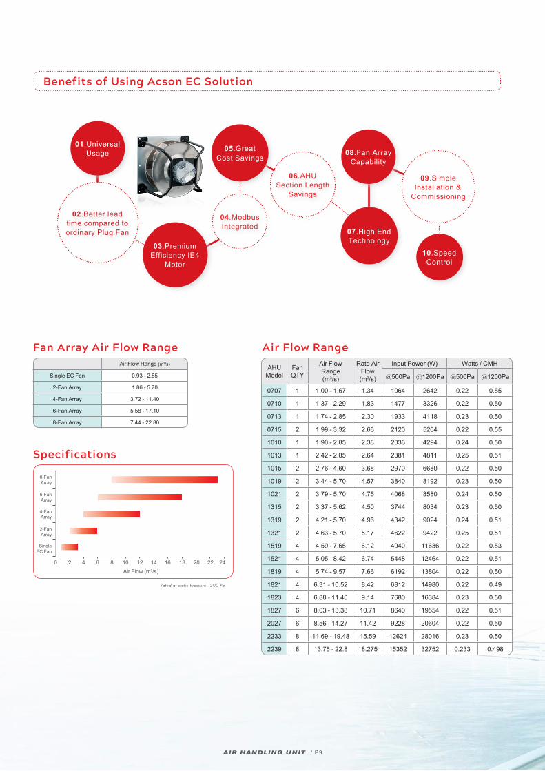
Benefits of Using Acson EC Solution
AIR HANDLING UNIT / P9
Specifications
Fan Array Air Flow Range
Rated at static Pressure 1200 Pa
0 6 12 18 242 8 14 204 10 16 22Air Flow (m3/s)
8-Fan Array
6-Fan Array
4-Fan Array
2-Fan Array
SingleEC Fan
Air Flow Range (m3/s)
Single EC Fan 0.93 - 2.85
2-Fan Array 1.86 - 5.70
4-Fan Array 3.72 - 11.40
6-Fan Array 5.58 - 17.10
8-Fan Array 7.44 - 22.80
Air Flow Range
AHUModel
FanQTY
Air Flow Range(m3/s)
Rate Air Flow
(m3/s)
Input Power (W) Watts / CMH
@500Pa @1200Pa @500Pa @1200Pa
0707 1 1.00 - 1.67 1.34 1064 2642 0.22 0.55
0710 1 1.37 - 2.29 1.83 1477 3326 0.22 0.50
0713 1 1.74 - 2.85 2.30 1933 4118 0.23 0.50
0715 2 1.99 - 3.32 2.66 2120 5264 0.22 0.55
1010 1 1.90 - 2.85 2.38 2036 4294 0.24 0.50
1013 1 2.42 - 2.85 2.64 2381 4811 0.25 0.51
1015 2 2.76 - 4.60 3.68 2970 6680 0.22 0.50
1019 2 3.44 - 5.70 4.57 3840 8192 0.23 0.50
1021 2 3.79 - 5.70 4.75 4068 8580 0.24 0.50
1315 2 3.37 - 5.62 4.50 3744 8034 0.23 0.50
1319 2 4.21 - 5.70 4.96 4342 9024 0.24 0.51
1321 2 4.63 - 5.70 5.17 4622 9422 0.25 0.51
1519 4 4.59 - 7.65 6.12 4940 11636 0.22 0.53
1521 4 5.05 - 8.42 6.74 5448 12464 0.22 0.51
1819 4 5.74 - 9.57 7.66 6192 13804 0.22 0.50
1821 4 6.31 - 10.52 8.42 6812 14980 0.22 0.49
1823 4 6.88 - 11.40 9.14 7680 16384 0.23 0.50
1827 6 8.03 - 13.38 10.71 8640 19554 0.22 0.51
2027 6 8.56 - 14.27 11.42 9228 20604 0.22 0.50
2233 8 11.69 - 19.48 15.59 12624 28016 0.23 0.50
2239 8 13.75 - 22.8 18.275 15352 32752 0.233 0.498
01.Universal Usage
04.Modbus Integrated
05.Great Cost Savings
08.Fan Array Capability
07.High End Technology
10.Speed Control
06.AHU Section Length
Savings
03.Premium Efficiency IE4
Motor
09.Simple Installation &
Commissioning
02.Better lead time compared to ordinary Plug Fan
A5MHA SERIES / P10
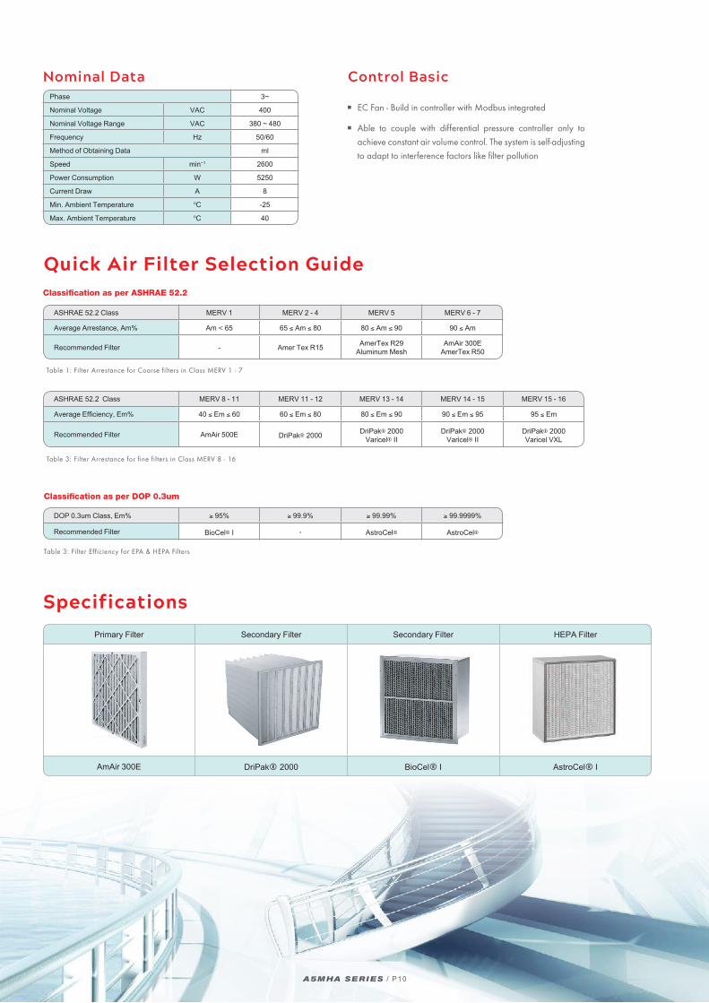
Nominal DataPhase 3~
Nominal Voltage VAC 400
Nominal Voltage Range VAC 380 ~ 480
Frequency Hz 50/60
Method of Obtaining Data ml
Speed min~1 2600
Power Consumption W 5250
Current Draw A 8
Min. Ambient Temperature ºC -25
Max. Ambient Temperature ºC 40
Control Basic
EC Fan - Build in controller with Modbus integrated
Able to couple with differential pressure controller only to
achieve constant air volume control. The system is self-adjusting
to adapt to interference factors like filter pollution
Specifications
Primary Filter Secondary Filter Secondary Filter HEPA Filter
AmAir 300E DriPak® 2000 BioCel® I AstroCel® I
Quick Air Filter Selection Guide
ASHRAE 52.2 Class MERV 1 MERV 2 - 4 MERV 5 MERV 6 - 7
Average Arrestance, Am% Am < 65 65 ≤ Am ≤ 80 80 ≤ Am ≤ 90 90 ≤ Am
Recommended Filter - Amer Tex R15 AmerTex R29Aluminum Mesh
AmAir 300EAmerTex R50
Classification as per ASHRAE 52.2
Table 1: Filter Arrestance for Coarse filters in Class MERV 1 - 7
ASHRAE 52.2 Class MERV 8 - 11 MERV 11 - 12 MERV 13 - 14 MERV 14 - 15 MERV 15 - 16
Average Efficiency, Em% 40 ≤ Em ≤ 60 60 ≤ Em ≤ 80 80 ≤ Em ≤ 90 90 ≤ Em ≤ 95 95 ≤ Em
Recommended Filter AmAir 500E DriPak® 2000 DriPak® 2000 Varicel® II
DriPak® 2000 Varicel® II
DriPak® 2000 Varicel VXL
Table 3: Filter Arrestance for fine filters in Class MERV 8 - 16
DOP 0.3um Class, Em% ≥ 95% ≥ 99.9% ≥ 99.99% ≥ 99.9999%
Recommended Filter BioCel® I - AstroCel® AstroCel®
Table 3: Filter Efficiency for EPA & HEPA Filters
Classification as per DOP 0.3um
AIR HANDLING UNIT / P11
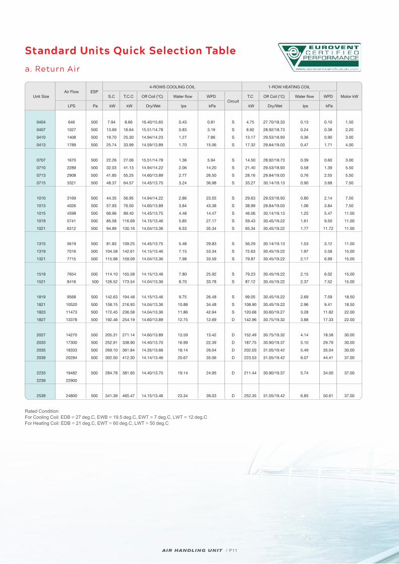
Standard Units Quick Selection Table
a. Return Air
Unit SizeAir Flow ESP
4-ROWS COOLING COIL 1-ROW HEATING COIL
Motor kWS.C T.C.C Off Coil (°C) Water flow WPDCircuit
T.C Off Coil (°C) Water flow WPD
LPS Pa kW kW Dry/Wet lps kPa kW Dry/Wet lps kPa
0404 646 500 7.94 8.66 16.40/15.65 0.43 0.81 S 4.75 27.70/18.33 0.13 0.10 1.50
0407 1027 500 13.69 16.64 15.51/14.78 0.83 3.19 S 8.92 28.92/18.73 0.24 0.38 2.20
0410 1408 500 19.70 25.30 14.94/14.23 1.27 7.86 S 13.17 29.53/18.93 0.36 0.90 3.00
0413 1789 500 25.74 33.99 14.59/13.89 1.70 15.06 S 17.32 29.84/19.03 0.47 1.71 4.00
0707 1670 500 22.26 27.06 15.51/14.78 1.36 5.94 S 14.50 28.92/18.73 0.39 0.60 3.00
0710 2289 500 32.03 41.13 14.94/14.22 2.06 14.20 S 21.40 29.53/18.93 0.58 1.39 5.50
0713 2908 500 41.85 55.25 14.60/13.89 2.77 26.50 S 28.16 29.84/19.03 0.76 2.55 5.50
0715 3321 500 48.37 64.57 14.45/13.75 3.24 36.98 S 33.27 30.14/19.13 0.90 3.68 7.50
1010 3169 500 44.35 56.95 14.94/14.22 2.86 23.55 S 29.63 29.53/18.93 0.80 2.14 7.50
1013 4026 500 57.93 76.50 14.60/13.89 3.84 43.38 S 38.99 29.84/19.03 1.06 3.84 7.50
1015 4598 500 66.96 89.40 14.45/13.75 4.48 14.47 S 46.06 30.14/19.13 1.25 5.47 11.00
1019 5741 500 85.58 116.69 14.15/13.46 5.85 27.17 S 59.43 30.45/19.22 1.61 9.50 11.00
1021 6312 500 94.89 130.16 14.04/13.36 6.53 35.34 S 65.34 30.45/19.22 1.77 11.72 11.00
1315 5619 500 81.83 109.25 14.45/13.75 5.48 29.83 S 56.29 30.14/19.13 1.53 3.12 11.00
1319 7016 500 104.58 142.61 14.15/13.46 7.15 53.34 S 72.63 30.45/19.22 1.97 5.58 15.00
1321 7715 500 115.98 159.09 14.04/13.36 7.98 33.59 S 79.87 30.45/19.22 2.17 6.99 15.00
1519 7654 500 114.10 155.58 14.15/13.46 7.80 25.92 S 79.23 30.45/19.22 2.15 6.02 15.00
1521 8416 500 126.52 173.54 14.04/13.36 8.70 33.78 S 87.12 30.45/19.22 2.37 7.52 15.00
1819 9568 500 142.63 194.48 14.15/13.46 9.75 26.48 S 99.05 30.45/19.22 2.69 7.59 18.50
1821 10520 500 158.15 216.93 14.04/13.36 10.88 34.48 S 108.90 30.45/19.22 2.96 9.41 18.50
1823 11473 500 172.45 236.58 14.04/13.36 11.86 42.94 S 120.68 30.60/19.27 3.28 11.82 22.00
1827 13378 500 192.48 254.19 14.60/13.89 12.75 12.69 D 142.96 30.75/19.32 3.88 17.33 22.00
2027 14270 500 205.31 271.14 14.60/13.89 13.59 13.42 D 152.49 30.75/19.32 4.14 18.58 30.00
2033 17300 500 252.91 338.90 14.40/13.70 16.99 22.39 D 187.75 30.90/19.37 5.10 29.79 30.00
2035 18333 500 269.10 361.84 14.35/13.66 18.14 26.04 D 202.03 31.05/19.42 5.49 35.04 30.00
2039 20284 500 302.50 412.30 14.14/13.46 20.67 35.06 D 223.53 31.05/19.42 6.07 44.41 37.00
2233 19482 500 284.78 381.65 14.40/13.70 19.14 24.95 D 211.44 30.90/19.37 5.74 34.00 37.00
2239 22900
2539 24800 500 341.39 465.47 14.15/13.46 23.34 39.03 D 252.35 31.05/19.42 6.85 50.61 37.00
Rated Condition: For Cooling Coil: EDB = 27 deg.C, EWB = 19.5 deg.C, EWT = 7 deg.C, LWT = 12 deg.CFor Heating Coil: EDB = 21 deg.C, EWT = 60 deg.C, LWT = 50 deg.C
AIR HANDLING UNIT / P12
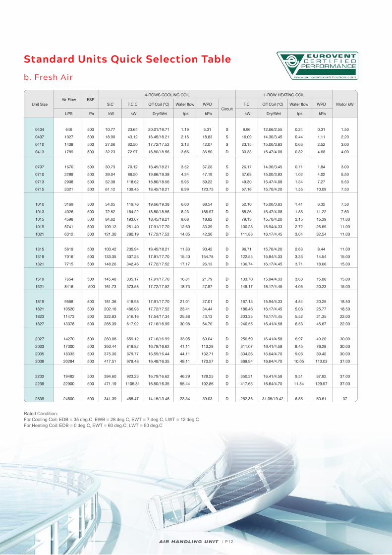
Standard Units Quick Selection Table
b. Fresh Air
Unit SizeAir Flow ESP
4-ROWS COOLING COIL 1-ROW HEATING COIL
Motor kWS.C T.C.C Off Coil (°C) Water flow WPDCircuit
T.C Off Coil (°C) Water flow WPD
LPS Pa kW kW Dry/Wet lps kPa kW Dry/Wet lps kPa
0404 646 500 10.77 23.64 20.01/19.71 1.19 5.31 S 8.96 12.66/2.55 0.24 0.31 1.50
0407 1027 500 18.90 43.12 18.45/18.21 2.16 18.83 S 16.09 14.30/3.45 0.44 1.11 2.20
0410 1408 500 27.06 62.50 17.72/17.52 3.13 42.07 S 23.15 15.00/3.83 0.63 2.52 3.00
0413 1789 500 32.23 72.97 18.80/18.56 3.66 36.50 D 30.33 15.47/4.08 0.82 4.68 4.00
0707 1670 500 30.73 70.12 18.45/18.21 3.52 37.28 S 26.17 14.30/3.45 0.71 1.84 3.00
0710 2289 500 39.04 86.50 19.66/19.38 4.34 47.19 D 37.63 15.00/3.83 1.02 4.02 5.50
0713 2908 500 52.38 118.62 18.80/18.56 5.95 89.22 D 49.30 15.47/4.08 1.34 7.27 5.50
0715 3321 500 61.12 139.45 18.45/18.21 6.99 123.75 D 57.16 15.70/4.20 1.55 10.09 7.50
1010 3169 500 54.05 119.76 19.66/19.38 6.00 88.54 D 52.10 15.00/3.83 1.41 6.32 7.50
1013 4026 500 72.52 164.22 18.80/18.56 8.23 166.97 D 68.26 15.47/4.08 1.85 11.22 7.50
1015 4598 500 84.62 193.07 18.45/18.21 9.68 18.82 D 79.13 15.70/4.20 2.15 15.39 11.00
1019 5741 500 109.12 251.40 17.91/17.70 12.60 33.39 D 100.28 15.94/4.33 2.72 25.69 11.00
1021 6312 500 121.30 280.19 17.72/17.52 14.05 42.36 D 111.88 16.17/4.45 3.04 32.54 11.00
1315 5619 500 103.42 235.94 18.45/18.21 11.83 90.42 D 96.71 15.70/4.20 2.63 8.44 11.00
1319 7016 500 133.35 307.23 17.91/17.70 15.40 154.78 D 122.55 15.94/4.33 3.33 14.54 15.00
1321 7715 500 148.26 342.46 17.72/17.52 17.17 26.13 D 136.74 16.17/4.45 3.71 18.66 15.00
1519 7654 500 145.48 335.17 17.91/17.70 16.81 21.79 D 133.70 15.94/4.33 3.63 15.80 15.00
1521 8416 500 161.73 373.58 17.72/17.52 18.73 27.97 D 149.17 16.17/4.45 4.05 20.23 15.00
1819 9568 500 181.36 418.98 17.91/17.70 21.01 27.01 D 167.13 15.94/4.33 4.54 20.25 18.50
1821 10520 500 202.16 466.98 17.72/17.52 23.41 34.44 D 186.46 16.17/4.45 5.06 25.77 18.50
1823 11473 500 222.83 516.16 17.54/17.34 25.88 43.13 D 203.35 16.17/4.45 5.52 31.35 22.00
1827 13378 500 265.39 617.92 17.16/16.99 30.98 64.70 D 240.55 16.41/4.58 6.53 45.67 22.00
2027 14270 500 283.08 659.12 17.16/16.99 33.05 69.04 D 256.59 16.41/4.58 6.97 49.20 30.00
2033 17300 500 350.44 819.82 16.79/16.62 41.11 113.28 D 311.07 16.41/4.58 8.45 76.28 30.00
2035 18333 500 375.30 879.77 16.59/16.44 44.11 132.71 D 334.36 16.64/4.70 9.08 89.42 30.00
2039 20284 500 417.51 979.48 16.49/16.35 49.11 170.57 D 369.94 16.64/4.70 10.05 113.03 37.00
2233 19482 500 394.60 923.23 16.79/16.62 46.29 128.25 D 350.31 16.41/4.58 9.51 87.82 37.00
2239 22900 500 471.19 1105.81 16.50/16.35 55.44 192.86 D 417.65 16.64/4.70 11.34 129.97 37.00
2539 24800 500 341.39 465.47 14.15/13.46 23.34 39.03 D 252.35 31.05/19.42 6.85 50.61 37
Rated Condition: For Cooling Coil: EDB = 35 deg.C, EWB = 28 deg.C, EWT = 7 deg.C, LWT = 12 deg.CFor Heating Coil: EDB = 0 deg.C, EWT = 60 deg.C, LWT = 50 deg.C
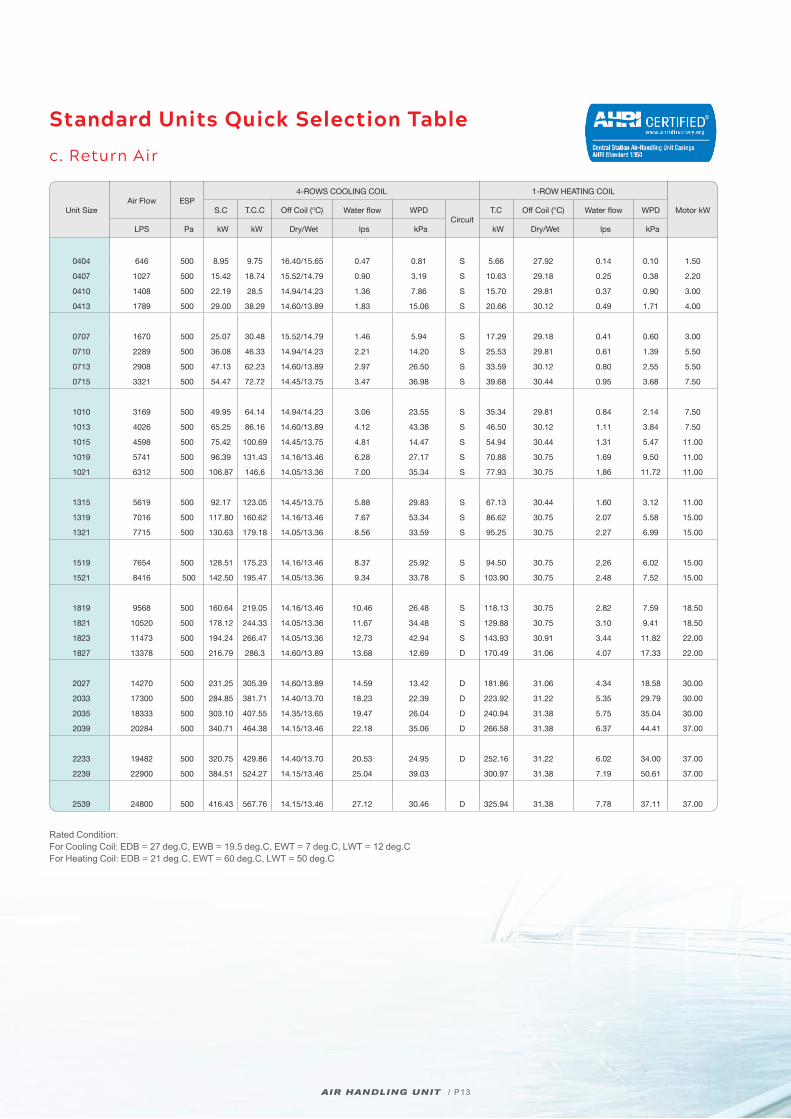
Standard Units Quick Selection Table
c. Return Air
Unit SizeAir Flow ESP
4-ROWS COOLING COIL 1-ROW HEATING COIL
Motor kWS.C T.C.C Off Coil (°C) Water flow WPDCircuit
T.C Off Coil (°C) Water flow WPD
LPS Pa kW kW Dry/Wet lps kPa kW Dry/Wet lps kPa
0404 646 500 8.95 9.75 16.40/15.65 0.47 0.81 S 5.66 27.92 0.14 0.10 1.50
0407 1027 500 15.42 18.74 15.52/14.79 0.90 3.19 S 10.63 29.18 0.25 0.38 2.20
0410 1408 500 22.19 28.5 14.94/14.23 1.36 7.86 S 15.70 29.81 0.37 0.90 3.00
0413 1789 500 29.00 38.29 14.60/13.89 1.83 15.06 S 20.66 30.12 0.49 1.71 4.00
0707 1670 500 25.07 30.48 15.52/14.79 1.46 5.94 S 17.29 29.18 0.41 0.60 3.00
0710 2289 500 36.08 46.33 14.94/14.23 2.21 14.20 S 25.53 29.81 0.61 1.39 5.50
0713 2908 500 47.13 62.23 14.60/13.89 2.97 26.50 S 33.59 30.12 0.80 2.55 5.50
0715 3321 500 54.47 72.72 14.45/13.75 3.47 36.98 S 39.68 30.44 0.95 3.68 7.50
1010 3169 500 49.95 64.14 14.94/14.23 3.06 23.55 S 35.34 29.81 0.84 2.14 7.50
1013 4026 500 65.25 86.16 14.60/13.89 4.12 43.38 S 46.50 30.12 1.11 3.84 7.50
1015 4598 500 75.42 100.69 14.45/13.75 4.81 14.47 S 54.94 30.44 1.31 5.47 11.00
1019 5741 500 96.39 131.43 14.16/13.46 6.28 27.17 S 70.88 30.75 1.69 9.50 11.00
1021 6312 500 106.87 146.6 14.05/13.36 7.00 35.34 S 77.93 30.75 1.86 11.72 11.00
1315 5619 500 92.17 123.05 14.45/13.75 5.88 29.83 S 67.13 30.44 1.60 3.12 11.00
1319 7016 500 117.80 160.62 14.16/13.46 7.67 53.34 S 86.62 30.75 2.07 5.58 15.00
1321 7715 500 130.63 179.18 14.05/13.36 8.56 33.59 S 95.25 30.75 2.27 6.99 15.00
1519 7654 500 128.51 175.23 14.16/13.46 8.37 25.92 S 94.50 30.75 2.26 6.02 15.00
1521 8416 500 142.50 195.47 14.05/13.36 9.34 33.78 S 103.90 30.75 2.48 7.52 15.00
1819 9568 500 160.64 219.05 14.16/13.46 10.46 26.48 S 118.13 30.75 2.82 7.59 18.50
1821 10520 500 178.12 244.33 14.05/13.36 11.67 34.48 S 129.88 30.75 3.10 9.41 18.50
1823 11473 500 194.24 266.47 14.05/13.36 12.73 42.94 S 143.93 30.91 3.44 11.82 22.00
1827 13378 500 216.79 286.3 14.60/13.89 13.68 12.69 D 170.49 31.06 4.07 17.33 22.00
2027 14270 500 231.25 305.39 14.60/13.89 14.59 13.42 D 181.86 31.06 4.34 18.58 30.00
2033 17300 500 284.85 381.71 14.40/13.70 18.23 22.39 D 223.92 31.22 5.35 29.79 30.00
2035 18333 500 303.10 407.55 14.35/13.65 19.47 26.04 D 240.94 31.38 5.75 35.04 30.00
2039 20284 500 340.71 464.38 14.15/13.46 22.18 35.06 D 266.58 31.38 6.37 44.41 37.00
2233 19482 500 320.75 429.86 14.40/13.70 20.53 24.95 D 252.16 31.22 6.02 34.00 37.00
2239 22900 500 384.51 524.27 14.15/13.46 25.04 39.03 300.97 31.38 7.19 50.61 37.00
2539 24800 500 416.43 567.76 14.15/13.46 27.12 30.46 D 325.94 31.38 7.78 37.11 37.00
Rated Condition: For Cooling Coil: EDB = 27 deg.C, EWB = 19.5 deg.C, EWT = 7 deg.C, LWT = 12 deg.CFor Heating Coil: EDB = 21 deg.C, EWT = 60 deg.C, LWT = 50 deg.C
AIR HANDLING UNIT / P13
AIR HANDLING UNIT / P14
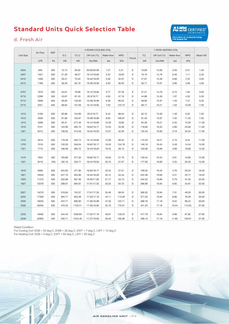
Standard Units Quick Selection Table
d. Fresh Air
Unit SizeAir Flow ESP
4-ROWS COOLING COIL 1-ROW HEATING COIL
Motor kWS.C T.C.C Off Coil (°C) Water flow WPDCircuit
T.C Off Coil (°C) Water flow WPD
LPS Pa kW kW Dry/Wet lps kPa kW Dry/Wet lps kPa
0404 646 500 12.13 26.62 20.63/20.08 1.27 5.31 S 10.69 13.06 0.26 0.31 1.50
0407 1027 500 21.29 48.57 19.14/18.66 2.32 18.83 S 19.19 14.76 0.46 1.11 2.20
0410 1408 500 30.47 70.40 18.44/18.00 3.36 42.07 S 27.61 15.48 0.66 2.52 3.00
0413 1789 500 36.30 82.19 19.48/18.98 3.93 36.50 D 36.17 15.97 0.86 4.68 4.00
0707 1670 500 34.61 78.98 19.14/18.66 3.77 37.28 S 31.21 14.76 0.75 1.84 3.00
0710 2289 500 43.97 97.43 20.3/19.77 4.65 47.19 D 44.88 15.48 1.07 4.02 5.50
0713 2908 500 59.00 133.60 19.48/18.98 6.38 89.22 D 58.80 15.97 1.40 7.27 5.50
0715 3321 500 68.84 157.06 19.14/18.66 7.50 123.75 D 68.17 16.21 1.63 10.09 7.50
1010 3169 500 60.88 134.89 20.3/19.77 6.44 88.54 D 62.13 15.48 1.48 6.32 7.50
1013 4026 500 81.68 184.97 19.48/18.98 8.84 166.97 D 81.40 15.97 1.94 11.22 7.50
1015 4598 500 95.31 217.46 19.14/18.66 10.39 18.82 D 94.38 16.21 2.25 15.39 11.00
1019 5741 500 122.90 283.15 18.62/18.17 13.53 33.39 D 119.60 16.45 2.86 25.69 11.00
1021 6312 500 136.62 315.58 18.44/18.00 15.07 42.36 D 133.43 16.69 3.19 32.54 11.00
1315 5619 500 116.48 265.74 19.14/18.66 12.69 90.42 D 115.33 16.21 2.75 8.44 11.00
1319 7016 500 150.20 346.04 18.62/18.17 16.53 154.78 D 146.16 16.45 3.49 14.54 15.00
1321 7715 500 166.99 385.72 18.44/18.00 18.42 26.13 D 163.08 16.69 3.89 18.66 15.00
1519 7654 500 163.86 377.50 18.62/18.17 18.03 21.79 D 159.45 16.45 3.81 15.80 15.00
1521 8416 500 182.16 420.77 18.44/18.00 20.10 27.97 D 177.90 16.69 4.25 20.23 15.00
1819 9568 500 204.83 471.90 18.62/18.17 22.54 27.01 D 199.32 16.45 4.76 20.25 18.50
1821 10520 500 227.70 525.96 18.44/18.00 25.12 34.44 D 222.38 16.69 5.31 25.77 18.50
1823 11473 500 250.98 581.36 18.26/17.83 27.77 43.13 D 242.52 16.69 5.79 31.35 22.00
1827 13378 500 298.91 695.97 17.91/17.50 33.24 64.70 D 286.89 16.94 6.85 45.67 22.00
2027 14270 500 318.84 742.37 17.91/17.50 35.46 69.04 D 306.02 16.94 7.31 49.20 30.00
2033 17300 500 394.71 923.38 17.55/17.16 44.11 113.28 D 371.00 16.94 8.86 76.28 30.00
2035 18333 500 422.71 990.90 17.36/16.98 47.33 132.71 D 398.76 17.18 9.52 89.42 30.00
2039 20284 500 470.25 1103.21 17.26/16.90 52.70 170.57 D 441.20 17.18 10.54 113.03 37.00
2233 19482 500 444.45 1039.84 17.55/17.16 49.67 128.25 D 417.79 16.94 9.98 87.82 37.00
2239 22900 500 530.71 1245.49 17.27/16.90 59.49 192.86 D 498.10 17.18 11.90 129.97 37.00
Rated Condition: For Cooling Coil: EDB = 35 deg.C, EWB = 28 deg.C, EWT = 7 deg.C, LWT = 12 deg.CFor Heating Coil: EDB = 0 deg.C, EWT = 60 deg.C, LWT = 50 deg.C
AIR HANDLING UNIT / P15
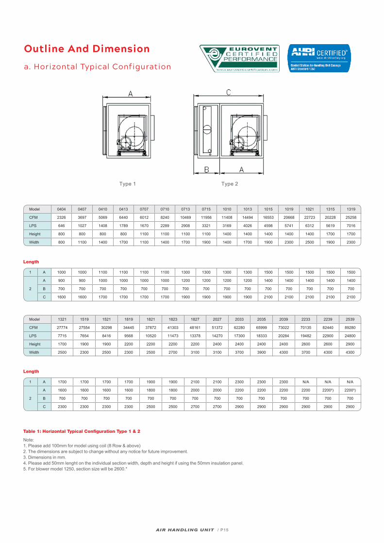
Outline And Dimension
a. Horizontal Typical Configuration
Type 1 Type 2
Model 0404 0407 0410 0413 0707 0710 0713 0715 1010 1013 1015 1019 1021 1315 1319
CFM 2326 3697 5069 6440 6012 8240 10469 11956 11408 14494 16553 20668 22723 20228 25258
LPS 646 1027 1408 1789 1670 2289 2908 3321 3169 4026 4598 5741 6312 5619 7016
Height 800 800 800 800 1100 1100 1100 1100 1400 1400 1400 1400 1400 1700 1700
Width 800 1100 1400 1700 1100 1400 1700 1900 1400 1700 1900 2300 2500 1900 2300
Model 1321 1519 1521 1819 1821 1823 1827 2027 2033 2035 2039 2233 2239 2539
CFM 27774 27554 30298 34445 37872 41303 48161 51372 62280 65999 73022 70135 82440 89280
LPS 7715 7654 8416 9568 10520 11473 13378 14270 17300 18333 20284 19482 22900 24800
Height 1700 1900 1900 2200 2200 2200 2200 2400 2400 2400 2400 2600 2600 2900
Width 2500 2300 2500 2300 2500 2700 3100 3100 3700 3900 4300 3700 4300 4300
1 A 1000 1000 1100 1100 1100 1100 1300 1300 1300 1300 1500 1500 1500 1500 1500
2
A 900 900 1000 1000 1000 1000 1200 1200 1200 1200 1400 1400 1400 1400 1400
B 700 700 700 700 700 700 700 700 700 700 700 700 700 700 700
C 1600 1600 1700 1700 1700 1700 1900 1900 1900 1900 2100 2100 2100 2100 2100
Length
1 A 1700 1700 1700 1700 1900 1900 2100 2100 2300 2300 2300 N/A N/A N/A
2
A 1600 1600 1600 1600 1800 1800 2000 2000 2200 2200 2200 2200 22005) 22005)
B 700 700 700 700 700 700 700 700 700 700 700 700 700 700
C 2300 2300 2300 2300 2500 2500 2700 2700 2900 2900 2900 2900 2900 2900
Length
Note:1. Please add 100mm for model using coil (8 Row & above)2. The dimensions are subject to change without any notice for future improvement.3. Dimensions in mm.4. Please add 50mm lenght on the individual section width, depth and height if using the 50mm insulation panel.5. For blower model 1250, section size will be 2600.*
Table 1: Horizontal Typical Configuration Type 1 & 2
AIR HANDLING UNIT / P16
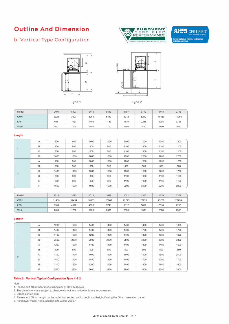
Outline And Dimension
b. Vertical Type Configuration
Type 1 Type 2
Model 0404 0407 0410 0413 0707 0710 0713 0715
CMH 2326 3697 5069 6440 6012 8240 10469 11956
LPS 646 1027 1408 1789 1670 2288 2908 3321
Width 800 1100 1400 1700 1100 1400 1700 1900
Model 1010 1013 1015 1019 1021 1315 1319 1321
CMH 11408 14494 16553 20668 22723 20228 25258 27774
LPS 3169 4026 4598 5741 6312 5619 7016 7715
Width 1400 1700 1900 2300 2500 1900 2300 2500
1
A 900 900 1000 1000 1000 1000 1200 1200
B 800 800 800 800 1100 1100 1100 1100
C 800 800 800 800 1100 1100 1100 1100
D 1600 1600 1600 1600 2200 2200 2200 2200
2
A 900 900 1000 1000 1000 1000 1200 1200
B 500 500 500 500 500 500 500 500
C 1400 1400 1500 1500 1500 1500 1700 1700
D 800 800 800 800 1100 1100 1100 1100
E 800 800 800 800 1100 1100 1100 1100
F 1600 1600 1600 1600 2200 2200 2200 2200
1
A 1200 1200 1400 1400 1400 1400 1400 1600
B 1400 1400 1400 1400 1400 1700 1700 1700
C 1100 1200 1200 1400 1400 1400 1600 1600
D 2500 2600 2600 2800 2800 3100 3300 3300
2
A 1200 1200 1400 1400 1400 1400 1400 1600
B 500 500 500 500 500 500 500 500
C 1700 1700 1900 1900 1900 1900 1900 2100
D 1400 1400 1400 1400 1400 1700 1700 1700
E 1100 1200 1200 1400 1400 1400 1600 1600
F 2500 2600 2600 2800 2800 3100 3300 3300
Note:1. Please add 100mm for model using coil (8 Row & above)2. The dimensions are subject to change without any notice for future improvement.3. Dimensions in mm.4. Please add 50mm lenght on the individual section width, depth and height if using the 50mm insulation panel.5. For blower model 1250, section size will be 2600.*
Table 2 : Vertical Typical Configuration Type 1 & 2
Length
Length
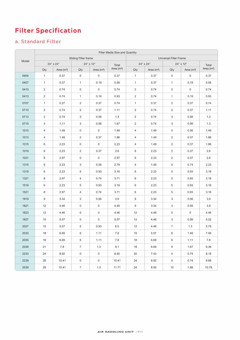
Filter Specification
a. Standard Filter
Model
Filter Media Size and Quantity
Sliding Filter frame Universal Filter Frame
24" x 24" 24" x 12" Total Area (m²)
24" x 24" 24" x 12" Total Area (m²)Qty Area (m²) Qty Area (m²) Qty Area (m²) Qty Area (m²)
0404 1 0.37 0 0 0.37 1 0.37 0 0 0.37
0407 1 0.37 1 0.19 0.56 1 0.37 1 0.19 0.56
0410 2 0.74 0 0 0.74 2 0.74 0 0 0.74
0413 2 0.74 1 0.19 0.93 2 0.74 1 0.19 0.93
0707 1 0.37 2 0.37 0.74 1 0.37 2 0.37 0.74
0710 2 0.74 2 0.37 1.11 2 0.74 2 0.37 1.11
0713 2 0.74 3 0.56 1.3 2 0.74 3 0.56 1.3
0715 3 1.11 3 0.56 1.67 2 0.74 3 0.56 1.3
1010 4 1.49 0 0 1.49 4 1.49 0 0.56 1.49
1013 4 1.49 2 0.37 1.86 4 1.49 2 0.37 1.86
1015 6 2.23 0 0 2.23 4 1.49 2 0.37 1.86
1019 6 2.23 2 0.37 2.6 6 2.23 2 0.37 2.6
1021 8 2.97 0 0 2.97 6 2.23 2 0.37 2.6
1315 6 2.23 3 0.56 2.79 4 1.49 4 0.74 2.23
1319 6 2.23 5 0.93 3.16 6 2.23 5 0.93 3.16
1321 8 2.97 4 0.74 3.71 6 2.23 5 0.93 3.16
1519 6 2.23 5 0.93 3.16 6 2.23 5 0.93 3.16
1521 8 2.97 4 0.74 3.71 6 2.23 5 0.93 3.16
1819 9 3.34 3 0.56 3.9 9 3.34 3 0.56 3.9
1821 12 4.46 0 0 4.46 9 3.34 3 0.56 3.9
1823 12 4.46 0 0 4.46 12 4.46 0 0 4.46
1827 15 5.57 0 0 5.57 12 4.46 3 0.56 5.02
2027 15 5.57 5 0.93 6.5 12 4.46 7 1.3 5.76
2033 18 6.69 6 1.11 7.8 15 5.57 8 1.49 7.06
2035 18 6.69 6 1.11 7.8 18 6.69 6 1.11 7.8
2039 21 7.8 7 1.3 9.1 18 6.69 9 1.67 8.36
2233 24 8.92 0 0 8.92 20 7.43 4 0.74 8.18
2239 28 10.41 0 0 10.41 24 8.92 4 0.74 9.66
2539 28 10.41 7 1.3 11.71 24 8.92 10 1.86 10.78
AIR HANDLING UNIT / P17
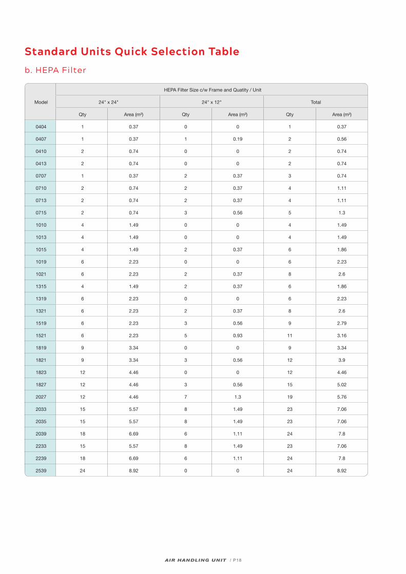
Standard Units Quick Selection Table
b. HEPA Filter
Model
HEPA Filter Size c/w Frame and Quatity / Unit
24" x 24" 24" x 12" Total
Qty Area (m²) Qty Area (m²) Qty Area (m²)
0404 1 0.37 0 0 1 0.37
0407 1 0.37 1 0.19 2 0.56
0410 2 0.74 0 0 2 0.74
0413 2 0.74 0 0 2 0.74
0707 1 0.37 2 0.37 3 0.74
0710 2 0.74 2 0.37 4 1.11
0713 2 0.74 2 0.37 4 1.11
0715 2 0.74 3 0.56 5 1.3
1010 4 1.49 0 0 4 1.49
1013 4 1.49 0 0 4 1.49
1015 4 1.49 2 0.37 6 1.86
1019 6 2.23 0 0 6 2.23
1021 6 2.23 2 0.37 8 2.6
1315 4 1.49 2 0.37 6 1.86
1319 6 2.23 0 0 6 2.23
1321 6 2.23 2 0.37 8 2.6
1519 6 2.23 3 0.56 9 2.79
1521 6 2.23 5 0.93 11 3.16
1819 9 3.34 0 0 9 3.34
1821 9 3.34 3 0.56 12 3.9
1823 12 4.46 0 0 12 4.46
1827 12 4.46 3 0.56 15 5.02
2027 12 4.46 7 1.3 19 5.76
2033 15 5.57 8 1.49 23 7.06
2035 15 5.57 8 1.49 23 7.06
2039 18 6.69 6 1.11 24 7.8
2233 15 5.57 8 1.49 23 7.06
2239 18 6.69 6 1.11 24 7.8
2539 24 8.92 0 0 24 8.92
AIR HANDLING UNIT / P18
CAT-AHU-1901
Related Documents