DOUBLE SHEET CONTROL E20 Double Sheet Detector R1000-series E20 with integrated fieldbus interface Electro magnetic principles – microcontroller based Single – sided contact double sheet control of ferrous materials No force after measurement 4 exchangeable sensors for double sheet control of 0.1 – 12 mm (.004 - .472 inch) sheet thickness Optional version 4P allows connection of up to four identical sensors Programmable for 255 different sheet thicknesses and materials Calibration without sheet samples Digital display of sheet thickness and operational parameters Monitoring of over-gauge and under-gauge limit Monitoring of operating voltage and sensor gap Galvanically isolated 3-bit input interface and 5-bit output interface Integrated fieldbus interface with process and parameter interface − Profibus DP − ControlNet − DeviceNet − Interbus-S − CanOpen − ProfiNet IO − CC-Link − EtherNet/IP − EtherCAT ► ► ► ► ► ► ►

Welcome message from author
This document is posted to help you gain knowledge. Please leave a comment to let me know what you think about it! Share it to your friends and learn new things together.
Transcript

DOUBLE SHEET CONTROL E20
Double Sheet Detector R1000-series E20
with integrated fieldbus interface Pos: 1 /D oppelbl ech/Geräte/E20/Deckbl att/D eckbl att @ 0\mod_1173195768953_501.doc @ 3188
Electro magnetic principles – microcontroller based
Single – sided contact double sheet control of ferrous materials
No force after measurement
4 exchangeable sensors for double sheet control of 0.1 – 12 mm (.004 - .472 inch) sheet thickness
Optional version 4P allows connection of up to four identical sensors
Programmable for 255 different sheet thicknesses and materials
Calibration without sheet samples
Digital display of sheet thickness and operational parameters
Monitoring of over-gauge and under-gauge limit
Monitoring of operating voltage and sensor gap
Galvanically isolated 3-bit input interface and 5-bit output interface
Integrated fieldbus interface with process and parameter interface
− Profibus DP − ControlNet − DeviceNet − Interbus-S − CanOpen − ProfiNet IO − CC-Link − EtherNet/IP − EtherCAT
►
►
►
►
►
►
►

Copyright
© 2015 ROLAND ELECTRONIC GmbH Otto-Maurer-Str. 17 DE 75210 Keltern
All rights on this document are at Roland Electronic GmbH. Reproduction (also partly), electronical coverage, translation, transmission to third parties,
only with our prior permission.
Subject to change without further notice.
===== Ende der Stückliste =====
Manual
Double Sheet Detector R1000 series UDK20
with integrated fieldbus interface B0048191 / Rev. 1.5 Table of content
ROLAND ELECTRONIC GmbH · Otto-Maurer-Str. 17 · DE 75210 Keltern · Phone +49 (0)7236-9392-0 · Fax +49 (0)7236-9392-33 3
Declaration of conformity according to EC directives ..................................................................................... 5
1 Safety advices ........................................................................................................................................ 7
1.1 Declaration of icons ............................................................................................................................. 7
1.2 Safety instructions and warnings for user ............................................................................................ 7
1.3 Intended use ........................................................................................................................................ 8
1.4 Fieldbus terms ...................................................................................................................................... 8
2 Technical data ........................................................................................................................................ 9
2.1 Technical data control unit UDK20 ...................................................................................................... 9
2.2 Versions of the control unit UDK20 .................................................................................................... 11
2.3 Sensors .............................................................................................................................................. 12
2.4 Sensor performance data (Measuring time) for ferrous (FE) material ............................................... 13
2.5 Sensor data for non-ferrous (NF) material ......................................................................................... 14
2.6 Sensor data (air gap) ......................................................................................................................... 15
2.7 Sensor cables .................................................................................................................................... 16
3 System description .............................................................................................................................. 21
3.1 Measurement principle ....................................................................................................................... 21
3.2 General hints for process security ..................................................................................................... 21
3.3 Control unit ......................................................................................................................................... 22
3.4 Parameters of the control unit ............................................................................................................ 22
3.5 Application samples ........................................................................................................................... 27
4 Mounting ............................................................................................................................................... 33
4.1 General mounting instructions ........................................................................................................... 33
4.2 Dimensions of the system .................................................................................................................. 34
4.3 Mounting of sensors ........................................................................................................................... 37
4.4 Automatic tool changer ...................................................................................................................... 50
5 Electrical installation ........................................................................................................................... 51
5.1 General instructions ........................................................................................................................... 51
5.2 Configuration of connectors ............................................................................................................... 52
5.3 Connecting diagram - examples ........................................................................................................ 64
5.4 Internal wiring of the Sensor-Switch-Box SSBUDK10 ....................................................................... 67
6 Communication with the PLC ............................................................................................................. 69
6.1 Fieldbus specific messages ............................................................................................................... 69
6.2 Data transmission communication ..................................................................................................... 70
6.3 Process channel ................................................................................................................................. 71
6.4 Parameter channel ............................................................................................................................. 86
6.5 External I/O control ............................................................................................................................ 93
6.6 Fieldbus configuration file .................................................................................................................. 98
7 Start-up ................................................................................................................................................ 103
7.1 Initially applying power to the system .............................................................................................. 103
7.2 Operation ......................................................................................................................................... 104
7.3 Configuration menu .......................................................................................................................... 105
7.4 General information regarding the configuration ............................................................................. 107
7.5 Changing, setting-up or checking the configuration ......................................................................... 107

Manual
Double Sheet Detector R1000 series UDK20
with integrated fieldbus interface Table of content B0048191 / Rev. 1.5
4 ROLAND ELECTRONIC GmbH · Otto-Maurer-Str. 17 · DE 75210 Keltern · Phone +49 (0)7236-9392-0 · Fax +49 (0)7236-9392-33
7.6 Program parameters ....................................................................................................................... 108
7.7 System parameters ......................................................................................................................... 114
7.8 Data storage via serial RS232-interface ......................................................................................... 124
7.9 Firmware update ............................................................................................................................. 124
8 Operation ............................................................................................................................................ 125
8.1 Abbreviated operating instructions .................................................................................................. 125
8.2 Entering a measurement program .................................................................................................. 126
9 Fault messages, causes and remedies ........................................................................................... 129
9.1 Fault messages of the Sensor-Switch-Box ..................................................................................... 130
9.2 Fault concerning memory ................................................................................................................ 131
9.3 Faults concerning Zero adjust ......................................................................................................... 131
9.4 Faults concerning Teach-In ............................................................................................................. 132
9.5 Faults concerning RS232 Transmission ......................................................................................... 132
9.6 Faults concerning measuring operation .......................................................................................... 132
9.7 Faults concerning keyboard ............................................................................................................ 133
9.8 Faults concerning supply voltage .................................................................................................... 133
9.9 Faults Sensor Switch Box ............................................................................................................... 133
9.10 Faults concerning PLC parallel inputs ......................................................................................... 133
9.11 Faults fieldbus interface ............................................................................................................... 134
9.12 Other faults .................................................................................................................................. 134
10 Maintenance ....................................................................................................................................... 135
10.1 Replacement of sensors .............................................................................................................. 135
10.2 Exchange of control unit .............................................................................................................. 136
10.3 Replacement of fuses .................................................................................................................. 137
10.4 Data back up via the fieldbus interface or serial interface ........................................................... 137
10.5 Firmware update via RS232 interface ......................................................................................... 137
10.6 Short description RPP-XP software ............................................................................................. 138
10.7 Spare parts .................................................................................................................................. 138
11 Technical records .............................................................................................................................. 139
11.1 Fieldbus configuration files .......................................................................................................... 139
11.2 Exchange of equipment ............................................................................................................... 139
11.3 Parameter channel commands .................................................................................................... 140
12 Order data .......................................................................................................................................... 147
12.1 Versions of control unit UDK20 ................................................................................................... 147
12.2 System accessories ..................................................................................................................... 148
12.3 Sensors and accessories............................................................................................................. 149
12.4 Cables .......................................................................................................................................... 149
12.5 Cable plugs and cable sockets .................................................................................................... 149
12.6 Other accessories ........................................................................................................................ 150
13 Appendix ............................................................................................................................................ 151
13.1 System configuration form ........................................................................................................... 151
Manual
Double Sheet Detector R1000 series UDK20
with integrated fieldbus interface B0048191 / Rev. 1.5 Safety advices
ROLAND ELECTRONIC GmbH · Otto-Maurer-Str. 17 · DE 75210 Keltern · Phone +49 (0)7236-9392-0 · Fax +49 (0)7236-9392-33 5
Declaration of conformity according to EC directives
Manufacturer: Roland Electronic GmbH
Otto-Maurer-Str. 17
DE 75210 Keltern
Product name: UDK20
Product type: Double Sheet Detector R1000 Series
Roland Electronic GmbH declares that the product listed above complies with the requirements of the EMC directives listed below.
Applied Directives:
2006/95/EG Low Voltage Directive
EN61010-1: 2010
2004/108/EG: EMC Directive
EN61000-6-2: 2005-08 EN61000-6-4: 2007-01
Date of mark’s apposition: 16.02.2015
Keltern, 16.02.2015 Managing Director
Place, Date Signature Function of the signer
The declaration confirms the compliance with the cited directives. However, it is not any implied warranty of fitness for a particular purpose especially as it may relate to product liability.
The safety instructions and warnings must be observed.
ISO 9001 : 2008
Reg.-no. 5152 QM08

Manual
Double Sheet Detector R1000 series UDK20
with integrated fieldbus interface Safety advices B0048191 / Rev. 1.5
6 ROLAND ELECTRONIC GmbH · Otto-Maurer-Str. 17 · DE 75210 Keltern · Phone +49 (0)7236-9392-0 · Fax +49 (0)7236-9392-33
Blank page

Manual
Double Sheet Detector R1000 series UDK20
with integrated fieldbus interface B0048191 / Rev. 1.5 Safety advices
ROLAND ELECTRONIC GmbH · Otto-Maurer-Str. 17 · DE 75210 Keltern · Phone +49 (0)7236-9392-0 · Fax +49 (0)7236-9392-33 7
1 Safety advices
1.1 Declaration of icons
Warning - general dangers!
Reference to imminent hazards, which can result in severe bodily harm or death.
Warning - dangers by high voltage!
Reference to imminent hazards due to electricity, which can result in severe bodily harm or death.
Attention - Damage of construction units!
Reference to a potential imminent situation, which can result in damage to the product or environs.
Note
Useful reference to an application or deepening information.
1.2 Safety instructions and warnings for user
This handbook contains all information required for the correct operation of the Roland equipment.
It has been written for technically qualified personnel.
Unauthorized tampering with the unit, especially ignoring the warnings in this handbook, can cause malfunction and damage to the unit. Only authorized personnel should be allowed to make changes to the unit and perform cable connections especially the power supply.
Should it be necessary, e.g. in case of service or repair, to make measurements within the unit, then all customary accidents prevention procedures should be observed. Only professional electrical tools should be used.
Note The factory pre-settings – especially the upper / lower limit values – have been chosen such that an optimal machine protection is ensured.
Diverging settings can impair the machine protection.
Safety advice for persons with cardiac pacemakers!
Persons with cardiac pacemakers are to stay away from the sensors!
The strong magnetic / electromagnetic fields of the sensors can cause malfunction of cardiac pacemakers and other such apparatus!
Warning When connecting or disconnecting the sensor plug you must stop measurement! Non-observance can result in a damage of the sensor!

Manual
Double Sheet Detector R1000 series UDK20
with integrated fieldbus interface Technical data B0048191 / Rev. 1.5
8 ROLAND ELECTRONIC GmbH · Otto-Maurer-Str. 17 · DE 75210 Keltern · Phone +49 (0)7236-9392-0 · Fax +49 (0)7236-9392-33
1.3 Intended use
Flexible Manufacturing Systems in the sheet processing industry require reliable Double Sheet Control systems in order to protect presses and other sheet processing machines against damage caused by feeding multiple sheets.
The Double Sheet Detector R1000 UDK20 was specifically developed for this technical environment. Depending on the application (type of material, thickness, sensor gap) the UDK20 can be used with up to four sensors. The reliable function of the Double Sheet Detector depends therefore markedly on the selection of the correct sensors and the mounting of the sensors.
1.4 Fieldbus terms
Within this manual the following Field bus specific expressions are used:
Term used in the manual Field bus specific expression
Master Scanner
Slave ControlNet adapter / node
Baud rate Data rate
Bus address Mac ID / node address

Manual
Double Sheet Detector R1000 series UDK20
with integrated fieldbus interface B0048191 / Rev. 1.5 Technical data
ROLAND ELECTRONIC GmbH · Otto-Maurer-Str. 17 · DE 75210 Keltern · Phone +49 (0)7236-9392-0 · Fax +49 (0)7236-9392-33 9
2 Technical data
2.1 Technical data control unit UDK20
Operating voltage: 24 VDC, +6 V / -2 V Power consumption: 60 W (operation: <60 W, in idle: <10 W) Switch on current: 10 Amps for 1 ms External fuse: 5 Amps medium time lag Weight: approx. 1.5 kg (3.30 lbs) Ambient temperature: 0 - 50 °C (30 - 122° F)
Wall mount enclosure:
Protection category: IP65
Dimensions without screw fittings: approx. 225 x 240 x 80 mm (L x W x H) approx. 8.85 x 9.45 x 3.15 inch (L x W x H)
Dimensions with screw fittings: approx. 225 x 360 x 80 mm (L x W x H) approx. 8.85 x 14.2 x 3.15 inch (L x W x H)
Front panel enclosure:
Protection category: IP40 (inside) IP65 (front cover)
Dimensions: approx. 240 × 240 × 120 mm (L x W x H) approx. 9.45 × 9.45 × 4.7 inch (L x W x H)
Additional characteristics:
• 255 parameter sets memory
• Programming via pushbuttons or fieldbus
• 3 potential free optocoupler inputs 24 VDC with joint common
Specification: min. switching voltage HIGH: 20 VDC max. switching voltage HIGH: 30 VDC min. switching voltage LOW: 0 VDC max. switching voltage LOW: 8 VDC
• 5 potential free optocoupler outputs with positive external supply
Specification: max. switching voltage: 50 VDC max. switching current: 100 mA (internal current limitation) max. switching power: 2.4 W (only resistor load)
Attention In case of inductive load a coil protection diode should be used. Otherwise the signal output could be destroyed by the excess voltage generated by switching the inductive load off.

Manual
Double Sheet Detector R1000 series UDK20
with integrated fieldbus interface Technical data B0048191 / Rev. 1.5
10 ROLAND ELECTRONIC GmbH · Otto-Maurer-Str. 17 · DE 75210 Keltern · Phone +49 (0)7236-9392-0 · Fax +49 (0)7236-9392-33
• RS232 interface
Specification:
Baudrate: 4800
Data Bits: 8
Parity-Bit: None
Stop-Bit: 1
Hardware Handshake: None
The selection of the interface parameters with the exception of the baudrate is made via the software and cannot be changed by user.
• Fieldbus interface
Profibus-DP interface according to the EN 50170, protocol version 1.10, max. baud rate 12 Mbit/s
ControlNet communication adapter (profile number 12) according to int. ControlNet specification
DeviceNet communication adapter (profile number 12) according to ODVA specification (group two only server)
Interbus-S - interface, certification protocol no. 440 (500 kbit/s; RS422)
CanOpen - interface, according to DS301 v4.02 compliant
ProfiNet IO – interface
CC-Link V1
EtherNet/IP
EtherCAT

Manual
Double Sheet Detector R1000 series UDK20
with integrated fieldbus interface B0048191 / Rev. 1.5 Technical data
ROLAND ELECTRONIC GmbH · Otto-Maurer-Str. 17 · DE 75210 Keltern · Phone +49 (0)7236-9392-0 · Fax +49 (0)7236-9392-33 11
2.2 Versions of the control unit UDK20
The control unit article key is coded as follows:
1. Control unit UDK20 for connection of one sensor
A = Control unit
B = Type of fieldbus: PR = Profibus-DP CN = ControlNet DN = DeviceNet (B-coded) DNT = DeviceNet (A-coded) IN = Interbus-S CP = CanOpen (B-coded) COP = CanOpen (A-coded) PN = ProfiNet IO CC = CC-Link EN = EtherNet/IP ET = EtherCAT
C = pluggable connections at control unit
D = Control unit in front panel enclosure
2. Control unit UDK20 for connection of up to two sensors, all sensors are plug connected directly at the unit.
A = Control unit
B = Connection of up to 2 sensors
C = Type of fieldbus: PR = Profibus-DP CN = ControlNet DN = DeviceNet (B-coded) DNT = DeviceNet (A-coded) IN = Interbus-S CP = CanOpen (B-coded) COP = CanOpen (A-coded) PN = ProfiNet IO CC = CC-Link EN = EtherNet/IP ET = EtherCAT
D = pluggable connections at control unit
E = Control unit in front panel enclosure
Basing on the article key shown above the following versions are available:
• UDK20-xx-S: Unit for connection of one sensor (max. 4 via SSB), in industrial enclosure, with data backup via Fieldbus or serial port
• UDK20-xx-S-FP: Unit as previous, but for front plate mounting
• UDK20-2PW-xx-S: Unit for connection of max. two sensors, in industrial enclosure, with data backup via Fieldbus or serial port
• UDK20-2PW-xx-S-FP: Unit as previous, but for front plate mounting
B C D
UDK20 xx- -S-FP
B C D E
UDK20 xx- -S-FP-2PW

Manual
Double Sheet Detector R1000 series UDK20
with integrated fieldbus interface Technical data B0048191 / Rev. 1.5
12 ROLAND ELECTRONIC GmbH · Otto-Maurer-Str. 17 · DE 75210 Keltern · Phone +49 (0)7236-9392-0 · Fax +49 (0)7236-9392-33
2.3 Sensors
The sensor description has the following code:
A = Electro magnet B = Eddy current C = Diameter D = Model E = Thread F = Quick disconnect
Fig. 1: Designation of sensors
2.3.1 Sensor PW42AGS
Fig. 2: Sensor PW42AGS
Technical data
FE - Measuring range 1): 0.2 – 4.0 mm .01 - .16 inch
NE - Measuring range 1): see sensor data for NF - material
Ambient temperature: 0 – 60 °C 30 – 140 °F
Class of protection: IP65
Weight: approx. 0.5 kg 1.1 lbs
Sensor cable: pluggable 1) Related to single sheet thickness
W42AGS
A B C D E F
Manual
Double Sheet Detector R1000 series UDK20
with integrated fieldbus interface B0048191 / Rev. 1.5 Technical data
ROLAND ELECTRONIC GmbH · Otto-Maurer-Str. 17 · DE 75210 Keltern · Phone +49 (0)7236-9392-0 · Fax +49 (0)7236-9392-33 13
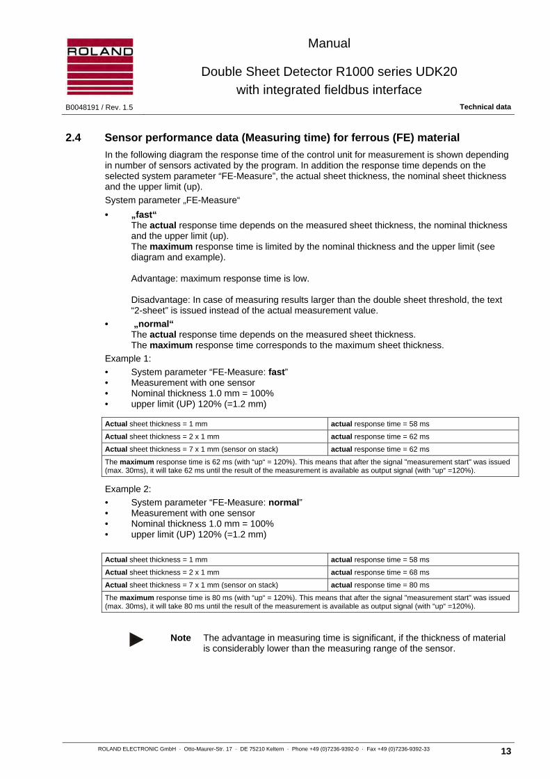
2.4 Sensor performance data (Measuring time) for ferrous (FE) material
In the following diagram the response time of the control unit for measurement is shown depending in number of sensors activated by the program. In addition the response time depends on the selected system parameter “FE-Measure”, the actual sheet thickness, the nominal sheet thickness and the upper limit (up).
System parameter „FE-Measure“
• „fast“ The actual response time depends on the measured sheet thickness, the nominal thickness and the upper limit (up). The maximum response time is limited by the nominal thickness and the upper limit (see diagram and example). Advantage: maximum response time is low. Disadvantage: In case of measuring results larger than the double sheet threshold, the text “2-sheet” is issued instead of the actual measurement value.
• „normal“ The actual response time depends on the measured sheet thickness. The maximum response time corresponds to the maximum sheet thickness.
Example 1:
• System parameter “FE-Measure: fast” • Measurement with one sensor • Nominal thickness 1.0 mm = 100% • upper limit (UP) 120% (=1.2 mm)
Actual sheet thickness = 1 mm actual response time = 58 ms
Actual sheet thickness = 2 x 1 mm actual response time = 62 ms
Actual sheet thickness = 7 x 1 mm (sensor on stack) actual response time = 62 ms
The maximum response time is 62 ms (with “up“ = 120%). This means that after the signal "measurement start" was issued (max. 30ms), it will take 62 ms until the result of the measurement is available as output signal (with “up“ =120%).
Example 2:
• System parameter “FE-Measure: normal” • Measurement with one sensor • Nominal thickness 1.0 mm = 100% • upper limit (UP) 120% (=1.2 mm)
Actual sheet thickness = 1 mm actual response time = 58 ms
Actual sheet thickness = 2 x 1 mm actual response time = 68 ms
Actual sheet thickness = 7 x 1 mm (sensor on stack) actual response time = 80 ms
The maximum response time is 80 ms (with “up“ = 120%). This means that after the signal "measurement start" was issued (max. 30ms), it will take 80 ms until the result of the measurement is available as output signal (with “up“ =120%).
Note The advantage in measuring time is significant, if the thickness of material is considerably lower than the measuring range of the sensor.
Manual
Double Sheet Detector R1000 series UDK20
with integrated fieldbus interface Technical data B0048191 / Rev. 1.5
14 ROLAND ELECTRONIC GmbH · Otto-Maurer-Str. 17 · DE 75210 Keltern · Phone +49 (0)7236-9392-0 · Fax +49 (0)7236-9392-33
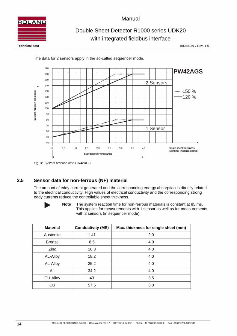
The data for 2 sensors apply in the so-called sequencer mode.
Fig. 3: System reaction time PW42AGS
2.5 Sensor data for non-ferrous (NF) material
The amount of eddy current generated and the corresponding energy absorption is directly related to the electrical conductivity. High values of electrical conductivity and the corresponding strong eddy currents reduce the controllable sheet thickness.
Note The system reaction time for non-ferrous materials is constant at 85 ms. This applies for measurements with 1 sensor as well as for measurements with 2 sensors (in sequencer mode).
Material Conductivity (MS) Max. thickness for single sheet (mm)
Austenite 1.41 2.0
Bronze 8.5 4.0
Zinc 16.3 4.0
AL-Alloy 18.2 4.0
AL-Alloy 25.2 4.0
AL 34.2 4.0
CU-Alloy 43 3.5
CU 57.5 3.0
Standard working range
Single sheet thickness (Nominal thickness) [mm]
40
50
60
70
80
90
100
110
120
130
140
150
160
170
2 Sensors
1 Sensor
PW42AGS
150 %120 %
0,5 1,0 1,5 2,0 2,50 3,0 3,5 4,0

Manual
Double Sheet Detector R1000 series UDK20
with integrated fieldbus interface B0048191 / Rev. 1.5 Technical data
ROLAND ELECTRONIC GmbH · Otto-Maurer-Str. 17 · DE 75210 Keltern · Phone +49 (0)7236-9392-0 · Fax +49 (0)7236-9392-33 15
2.6 Sensor data (air gap)
Double sheet thresholds above 120% reduce the performance of the system with regard to air gaps between the sheets and increase the systems reaction time according to the diagram.
Air gaps influence the performance negatively because air has - in contrast to steel - a high resistance to the magnetic flux. Therefore, air gaps reduce the performance of the system considerably (see chapter “3.1 Measuring principle and conditions influencing measurement accuracy“).
For reliable double sheet monitoring there should be no air gap between sheet and sensor and also between the sheets. The most reliable double sheet recognition results, if no air gaps exist. These aspects should be specifically observed when mounting the sensors.
The eddy current principle is more forgiving with regard to air gaps than the electromagnetic principle. However, for most reliable performance precaution should be taken to avoid air gaps between sensor and sheet. The permissible air gaps between first and second sheet can be slightly higher than for steel.
The influence of air gaps are described in the following diagrams.
Max. air gap between sensor and first sheet (1st air gap)
Max. air gap between first and second sheet (2nd air gap)
The data apply for a set upper limit of 120%.
2 3 4 5 6 7
0,20,40,60,81,01,21,41,61,82,02,22,42,62,83,0
Sheet thickness[mm]
1.
0,5 1,5 2,5 3,5 4,5 5,5 6,5
PW42AGS
1.s
t air
gap
[mm
]
NF
FE
2 3 4 5 6 7
123456789
10
[mm]0,5 1,5 2,5 3,5 4,5 5,5 6,5
PW42AGSFE
NF
2.
11
2.n
d a
ir g
ap [m
m]

Manual
Double Sheet Detector R1000 series UDK20
with integrated fieldbus interface Technical data B0048191 / Rev. 1.5
16 ROLAND ELECTRONIC GmbH · Otto-Maurer-Str. 17 · DE 75210 Keltern · Phone +49 (0)7236-9392-0 · Fax +49 (0)7236-9392-33
2.7 Sensor cables
Suitable cable type:
• Superflex (C)Y PURKOMBI 2 x 1,0 mm² + 4 x 2 x 0,25 mm²
• The cable is oil-proof and suitable for drag chains
- Bending radius flexible use min. 110 mm
Cable marking:
• for PW42AGS:
SCPWS-GG (straight receptacle at the sensor) SCPWS-GW (right angle receptacle at the sensor)
The cable has quick disconnects at both ends. The plug at the control unit side is always straight.
Note The sensor cable is an active component of the sensor technology. The
technical data of the sensors is valid only if the cable specification is met. A shielded cable (2 x 1,0 mm² + 4 x 2 x 0,25 mm²) must be used. The cable length can be to up to 50 m. Following the rule "the shorter the better" generally leads to better measuring results.
2.7.1 Sensor cable SCPWS for PW42AGS sensor
Cable socket, sensor side Cable plug, unit side
Socket contacts Plug contacts
Right angle cable socket, sensor side
1 grey 2 pink 3 red 4 black / violet 5 blue 6 brown 1 mm² 7 brown 8 white 1 mm² 9 green Enclosure blank (Shield)
Fig. 4: Sensor cable SCPWS
3
4 5
6
7
81
9
54
26
24
3
45
6
7
8 1
9
60

Manual
Double Sheet Detector R1000 series UDK20
with integrated fieldbus interface B0048191 / Rev. 1.5 Technical data
ROLAND ELECTRONIC GmbH · Otto-Maurer-Str. 17 · DE 75210 Keltern · Phone +49 (0)7236-9392-0 · Fax +49 (0)7236-9392-33 17
to Sensor to control unit
Cable socket Bootlace ferrules
1 grey 2 pink 3 red 4 black / violet 5 blue 6 brown 1 mm² 8 white 1 mm² 7 brown 9 green Enclosure blank (Shield)
Cable types for the sensor PW42AGS (order data):
• SCPWS-GG (straight receptacle at the sensor) • SCPWS-GW (right angle receptacle at the sensor)
The standard length is 5 meter. Cable length up to 50 meter made to order, longer cables please enquire.
Note In particular with larger lengths the sensor cable should not be placed
directly adjacent to cables with large noise potential.
The cable is drag cable suitable and oil resistant. Cable type: • Superflex (C)Y PURKOMBI 2 x 1,0 mm² + 4 x 2 x 0,25 mm²
pinkredblackvioletbluebrown *white *browngreen
1
2
3
4
5
6
8
7
9PW
42A
GS
1234
56879
1
2
3
4
5
6
8
7
9
1234
56879

Manual
Double Sheet Detector R1000 series UDK20
with integrated fieldbus interface Technical data B0048191 / Rev. 1.5
18 ROLAND ELECTRONIC GmbH · Otto-Maurer-Str. 17 · DE 75210 Keltern · Phone +49 (0)7236-9392-0 · Fax +49 (0)7236-9392-33
2.7.1.1 Installation of the sensor cable
Fig. 5: Installation of the sensor cable
The following instructions are essential when installing the sensor cable:
1. Take notice of the keyway on the sensor head! Do not use during tightening a pipe wrench or similar tools, since the pin contacts could be destroyed.
2. Be careful about the screw-in depth! Turn the cable socket until the edge flushes with the sensor head. (see the O-ring)
3. Tighten the securing grub screw after connecting the cable socket with an allen wrench (1.5 mm)!
Note The securing grub screw is not present at every cable type
2.7.2 Sensor cable extensions
A sensor cable extension can be relatively easy made. For this a SCPWS-GG or SCPWS-GW cable is always needed.

Manual
Double Sheet Detector R1000 series UDK20
with integrated fieldbus interface B0048191 / Rev. 1.5 Technical data
ROLAND ELECTRONIC GmbH · Otto-Maurer-Str. 17 · DE 75210 Keltern · Phone +49 (0)7236-9392-0 · Fax +49 (0)7236-9392-33 19
2.7.3 Cable for Sensor-Switch-Box SSBUDK10
The cable SVCPWS-SSBUDK10 is used for connecting the control unit to the Sensor Switch Box. The following pin configuration and dimensions apply:
to Sensor-Switch-Box to unit
Cable socket Cable plug
1 white 2 green 3 brown 4 yellow 5 grey Enclosure blank (Shield)
1 white 2 green 3 brown 4 yellow 5 grey Enclosure blank (Shield)
to Sensor-Switch-Box to unit
Cable socket Cable plug
1 white 2 green 3 brown 4 yellow 5 grey Enclosure blank (Shield)
Cable type for SSBUDK10 (order data):
• SVCPWS-SSBUDK10 The standard length is 5 meter.
Note For the connection of the SSBUDK10 to the sensor PW42AGS the SCPWSGG or SCPWS-GW are used.
2
3
5
4
51
22
22 2
3
5
4
1
2
3
4
5grey
white
brown
green
yellow
SS
BU
DK
10
1
2
3
5
4
1
2
3
5
4
Manual
Double Sheet Detector R1000 series UDK20
with integrated fieldbus interface System description B0048191 / Rev. 1.5
20 ROLAND ELECTRONIC GmbH · Otto-Maurer-Str. 17 · DE 75210 Keltern · Phone +49 (0)7236-9392-0 · Fax +49 (0)7236-9392-33
Blank page

Manual
Double Sheet Detector R1000 series UDK20
with integrated fieldbus interface B0048191 / Rev. 1.5 System description
ROLAND ELECTRONIC GmbH · Otto-Maurer-Str. 17 · DE 75210 Keltern · Phone +49 (0)7236-9392-0 · Fax +49 (0)7236-9392-33 21
3 System description
Flexible manufacturing systems in sheet metal processing require automated and reliable double sheet control systems in order to safeguard presses and other processing machinery against damage due to multiple sheets. This applies not only to steel but also to aluminum and other non-ferrous metals as well as non-magnetic stainless-steel (austenite), materials as they are increasingly being used in automotive applications. In addition, the production of so-called “Tailor Welded Blanks“ (TWB) has created complex manufacturing systems with special requirements regarding automated double sheet control systems.
The Double Sheet Detector UDK20 was specifically developed for this technical environment. The special feature of the system is the ability to monitor ferrous and non-ferrous materials with one sensor only - the PW42AGS.
A system for one measuring point consists of the following three components: • Control unit
• Sensor PW42AGS for ferrous and non-ferrous materials
• Sensor cable
3.1 Measurement principle
The Double Sheet Detector UDK20 combines the electromagnetic and eddy current measurement principles. It monitors the sheet thickness from one side only and in the case of steel does exert forces only during measurement. A change of the sheet thickness causes a change of the inductance. The control unit calculates the sheet thickness resulting from this change. Based on the predetermined thresholds 0-sheet, 1-sheet, or 2-sheets of output signals are generated.
3.2 General hints for process security
The process security of the system is influenced by the following factors:
• the stability of the measuring values
• the setting of under-gauge threshold and over-gauge threshold
• the evaluation of the status signals
Stable measuring conditions will result in stable measuring results. For measuring procedures with single-sided contacting sensors the air gap between sensor and material surface is a decisive criterion.
Air gaps varying from measurement to measurement will cause varying measuring results. Basically, such situations are bad, since in such cases the user is inclined to decrease the under-gauge threshold and to increase the over-gauge threshold. On doing so, the user puts up with the drastically increasing risk of not detecting a double sheet.
The following external factors decisively influence the stability of measuring results and need to be considered for operation of a double sheet detector:
• the air gap between sensor and material surface
• the magnetical characteristics of the material
• the tolerance in material thickness

Manual
Double Sheet Detector R1000 series UDK20
with integrated fieldbus interface System description B0048191 / Rev. 1.5
22 ROLAND ELECTRONIC GmbH · Otto-Maurer-Str. 17 · DE 75210 Keltern · Phone +49 (0)7236-9392-0 · Fax +49 (0)7236-9392-33
From this some simple rules derive, which enable a large degree of process security when abided by:
• Always care for good contact of the sensor with the material!
• Use separate programs to measure different sheet thickness (and alloy)!
• Adjust the switching thresholds as tight as possible!
Furthermore it is necessary that the control checks all status signals of the UDK20, also the 0-sheet signal. While measuring, only the 1-sheet signal may occur. If 0-sheet or 2-sheet occurs, the measured sheet may not be transported on. In such cases, the sheet will usually be deposited, re-picked and measured again. • The control needs to evaluate all status signals !
Checking-up through the 0-sheet signal is to assure that a sheet really is in front of the sensor during measuring. If 0-sheet occurs while measuring, the measurement is not correct. For example, a defective sensor holder might prevent the sensor from contacting the sheet. Monitoring the sheet thickness would then only be performed apparently.
In case of double sheet fatal consequences could then result.
3.3 Control unit
The UDK20 is based on the product platform R1000.
Major features of the control unit:
• Programmable for 255 different sheet thicknesses and materials
• Fieldbus interface for the control, operation and data exchange with the PLC
• Calibration by a Teach-In procedure
• Digital display of sheet thickness and operating parameters
• Monitoring of over gauge and under gauge limits
• Monitoring of operating voltage and sensor gap
• Optocoupler for direct I/O control via the PLC for fast measurement operations
• Software firmware update
• Data backup via fieldbus interface or serial interface
3.4 Parameters of the control unit
The UDK20 provides for extensive configuration. So, different customer requirements can be served. Configuration is performed by setting system parameters and program parameters. System parameters are set only once on commissioning, and will then remain unchanged. Program parameters contain items which are material and job depending, and enable individual adaptation to the measuring task.

Manual
Double Sheet Detector R1000 series UDK20
with integrated fieldbus interface B0048191 / Rev. 1.5 System description
ROLAND ELECTRONIC GmbH · Otto-Maurer-Str. 17 · DE 75210 Keltern · Phone +49 (0)7236-9392-0 · Fax +49 (0)7236-9392-33 23
3.4.1 System parameters
“Language“
System languages available for operating the unit via display and keyboard:
• German • English • Spanish • Italian • French
“Display in“
Switches the indication of the thickness values on the display between mm inch.
“Bus readout“
Switches the out feeding of the thickness values via Field bus between mm inch.
“Bus address“
Sets the bus address, as far as a participant address is required for Field bus. Value range 1…125
“Baud rate“
Sets the Baud rate of the Field bus (as far as required for the Field bus).
In case off EtherNet/IP: DHCP/IP/SUBNET/GATEWAY
“CLR parameter (Clear Program Parameter)“
Delete all program parameters. For doing so, the parameter needs to be set to “yes“. Executing the command requires several minutes, since the program memory will completely cleared. All program parameters will be reset to the default values and existing Teach-In data will be deleted. Using this function only makes sense if a unit is to be newly used for another machine.
“Password yes/no“
Switches the password request on/off. If the password request is set “on“, the system / program parameters can only be changed after the password has been entered.
“FE-Measurement fast/normal”
For time-critical applications the measuring time can be slightly shortened for measuring FE material. If “fast“ is selected and double sheet occurs, the measuring is terminated on reaching the upper switch limit, and the information “2-sheet“ is released. If “normal“ is selected, the measuring will be executed to the end and the measured thickness will be displayed.
“Sensor type“
At the time of editing the sensor type PW42A is available. For this sensor a characteristical curve for linearization purposes exists.

Manual
Double Sheet Detector R1000 series UDK20
with integrated fieldbus interface System description B0048191 / Rev. 1.5
24 ROLAND ELECTRONIC GmbH · Otto-Maurer-Str. 17 · DE 75210 Keltern · Phone +49 (0)7236-9392-0 · Fax +49 (0)7236-9392-33
“Number of sensors“
Defines the number of connected sensors. Those sensors are then available for measuring.
At a 2-channel unit (UDK20-2PW...) max. 2 sensors can be connected, at a 1-channel system with sensor-switch-box max. 4 sensors can be connected.
“FE-T-limit“
On teaching-in of FE material the deviation of the measured thickness from the nominal thickness will be monitored. Certain ferromagnetic materials show larger deviations as usual. In these cases the 33% / 142% setting makes sense. Default setting is 66% / 125%. Both values represent the permitted relative range of measured to nominal thickness. If the measuring value is not within this range, the Teach-In cannot be performed and will be aborted with an error message.
“Measuring mode“
Sets how the measuring is to be triggered. The following modes are available:
• Demo
The demo mode is only intended for test and demonstration purposes. In this mode measuring is performed until the demo mode is switched off again. For doing so, another mode must be selected. The repetition time of the measuring is 1 second for FE material, for NE and LM material it is below 0.085 seconds.
• Ext. Single (default setting)
Here a single measuring is performed. For doing so, the signal “Measuring start“ must be externally fed. Another measuring requires a new flank of the “Measuring start“ signal.
• Ext. Permanently
Here the measuring is maintained as long as the signal “Measuring start“ is fed. The repetition time of the measuring is 0.5 seconds for FE material, for NE and LM material it is below 0.085 seconds.
“Hold 2-sheet“
Currently only “no“ is possible.
“External Measurement start“
The signal “Measurement start“ can be linked via 3 opto coupler inputs (Measuring start input 1,2,3). Possible configurations:
• IN0 (default setting)
• IN0 and IN1
• IN0 and IN1 and IN2
“Output 0-1-2“
Sets the logics voltage for outputs 0-,1-,2-sheet and "Warning". Default setting is 0 VDC.
“External Adjust“
Sets whether an external Teach-In / zero adjust is to be possible. If “yes“ is set, the PLC can trigger the procedure via the inputs “Teach-In 0-, 1-sheet“. Default setting is “no“.
• The external adjust may only be performed under supervision of an operator.
Manual
Double Sheet Detector R1000 series UDK20
with integrated fieldbus interface B0048191 / Rev. 1.5 System description
ROLAND ELECTRONIC GmbH · Otto-Maurer-Str. 17 · DE 75210 Keltern · Phone +49 (0)7236-9392-0 · Fax +49 (0)7236-9392-33 25
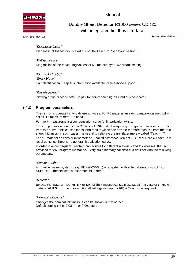
“Diagnostic factor“
Diagnostic of the factors located during the Teach-In. No default setting.
“W-Diagnostics“
Diagnostics of the measuring values for NF material type. No default setting.
“UDK20-PR-S-(1)“
“SV:xx HV:xx“
Unit identification. Keep this information available for telephone support.
“Bus diagnostic“
Viewing of the process data. Helpful for commissioning on Field bus connected.
3.4.2 Program parameters
The sensor is operated in two different modes. For FE material an electro magnetical method – called “P“ measurement – is used.
For the P measurement a compensation curve for linearization exists.
The compensation curve fits to ST37 steel. Other steel alloys resp. magnetical materials deviate from this curve. This causes measuring results which can deviate for more than 5% from the real sheet thickness. In such cases it is useful to calibrate the unit (later merely called “Teach-In“).
For NF material an eddy current method – called “W“ measurement – is used. Here a Teach-In is required, since there is no general linearization curve.
In order to avoid frequent Teach-In procedures for different materials and thicknesses, the unit provides for 255 program memories. Every such memory consists of a data set with the following parameters.
“Sensor number“
For multi-channel systems (e.g. UDK20-2PW…) or a system with external sensor switch box SSBUDK10 the selected sensor must be entered.
“Material“
Selects the material type FE, NF or LM (slightly magnetical stainless steels). In case of unknown material AUTO must be chosen. For all settings (except for FE) a Teach-In is required.
“Nominal thickness“
Changes the nominal thickness. It can be shown in mm or inch. Default setting either 0,03mm or 0,001 inch.

Manual
Double Sheet Detector R1000 series UDK20
with integrated fieldbus interface System description B0048191 / Rev. 1.5
26 ROLAND ELECTRONIC GmbH · Otto-Maurer-Str. 17 · DE 75210 Keltern · Phone +49 (0)7236-9392-0 · Fax +49 (0)7236-9392-33
“TO“ and “TU“
Changes the limit values for the lower and upper switching threshold. The values can be entered either in % or in mm/inch. On these thresholds the status signals depend. In a window comparator the three signals will be generated from the measuring signal. The signal “0-sheet“ is generated when the measuring signal falls short of the lower switching threshold. The lower switching threshold TU can be set from 1...99%. The signal “2-sheet“ is generated when the upper switching threshold is exceeded. The upper switching threshold TO can be set from 100...150%. If the measuring value is within both limits, the signal “1-sheet“ is generated.
a
b
c
TO
TU
Signal range for 0-sheet
Signal range for 1-sheet
Signal range for 2-sheet
switching threshold for upper limit
switching threshold for lower limit
Fig. 6: Visualization of switching thresholds
The preset values (TO=120% resp. TU=80%) should only be changed under the following aspects: 1. the 1-sheet range becomes restricted, since the measuring values are very stable. Thus the process security increases. The restriction can be done by decreasing the TO value, by increasing the TU value, or both.
2. the 1-sheet range becomes extended for a time. Thus the process security decreases. Such an action should only be performed in exceptional cases, the user has to decide about that. Extending the 1-sheet range is commonly considered due to mechanical problems (air gap, uneven sheets). This measure prevents the machine from standstill, until the mechanical problem is solved.
“Zero adjust“
Before commissioning a new system, after having exchanged a sensor or a sensor cable or a control unit, a zero adjust must be performed. This zero adjust eliminates the variation of the sensors. The sensors can be zero adjusted “separately“ or “all in one stroke“.
• The zero adjustment is valid for all programs and should be performed only once !
“Teach-In“
Initiates a Teach-In via keyboard. Teach-In is required for NF material and – partially – also for FE material. Depending on status and material the items “ok“/“missing“/“on“/“without“ can be selected.
• The value “ok“ indicates that a Teach-In has been successfully performed.
• The value “missing“ indicates that a Teach-In is required and was not yet performed. This item does not appear for “Material“ setting “FE“.
• The value “on“ indicates that a Teach-In is currently being performed.
• The value “without“ indicates that a Teach-In is not necessarily required. This item appears only for “Material“ setting “FE“.
210
Signal
Obere SchaltschwelleUpper switching threshold
Untere SchaltschwelleLower switching threshold
a
b
c
TO
TU

Manual
Double Sheet Detector R1000 series UDK20
with integrated fieldbus interface B0048191 / Rev. 1.5 System description
ROLAND ELECTRONIC GmbH · Otto-Maurer-Str. 17 · DE 75210 Keltern · Phone +49 (0)7236-9392-0 · Fax +49 (0)7236-9392-33 27
3.5 Application samples
The following are two typical application examples for the use of the UDK20.
UDK20-xx-S with one Sensor
Manual
Double Sheet Detector R1000 series UDK20
with integrated fieldbus interface System description B0048191 / Rev. 1.5
28 ROLAND ELECTRONIC GmbH · Otto-Maurer-Str. 17 · DE 75210 Keltern · Phone +49 (0)7236-9392-0 · Fax +49 (0)7236-9392-33
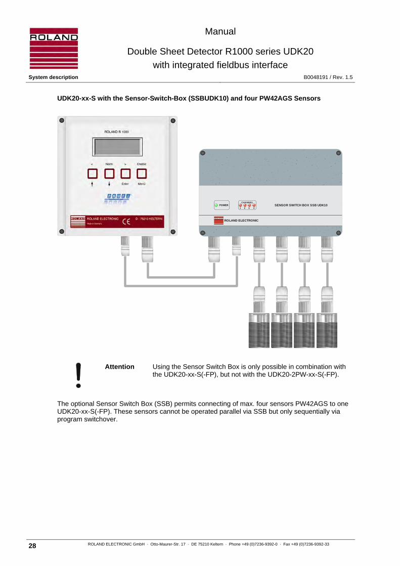
UDK20-xx-S with the Sensor-Switch-Box (SSBUDK10) and four PW42AGS Sensors
Attention Using the Sensor Switch Box is only possible in combination with the UDK20-xx-S(-FP), but not with the UDK20-2PW-xx-S(-FP).
The optional Sensor Switch Box (SSB) permits connecting of max. four sensors PW42AGS to one UDK20-xx-S(-FP). These sensors cannot be operated parallel via SSB but only sequentially via program switchover.
CHANNEL
1 2 3 4
ROLAND ELECTRONIC
SENSOR SWITCH BOX SSB UDK10

Manual
Double Sheet Detector R1000 series UDK20
with integrated fieldbus interface B0048191 / Rev. 1.5 System description
ROLAND ELECTRONIC GmbH · Otto-Maurer-Str. 17 · DE 75210 Keltern · Phone +49 (0)7236-9392-0 · Fax +49 (0)7236-9392-33 29
UDK20-2PW-xx-S with two PW42AGS Sensors
The switching of the sensors can be made as follows:
a) with the so-called sequencer mode (automatic switching by the unit) b) by program switching
Manual
Double Sheet Detector R1000 series UDK20
with integrated fieldbus interface System description B0048191 / Rev. 1.5
30 ROLAND ELECTRONIC GmbH · Otto-Maurer-Str. 17 · DE 75210 Keltern · Phone +49 (0)7236-9392-0 · Fax +49 (0)7236-9392-33
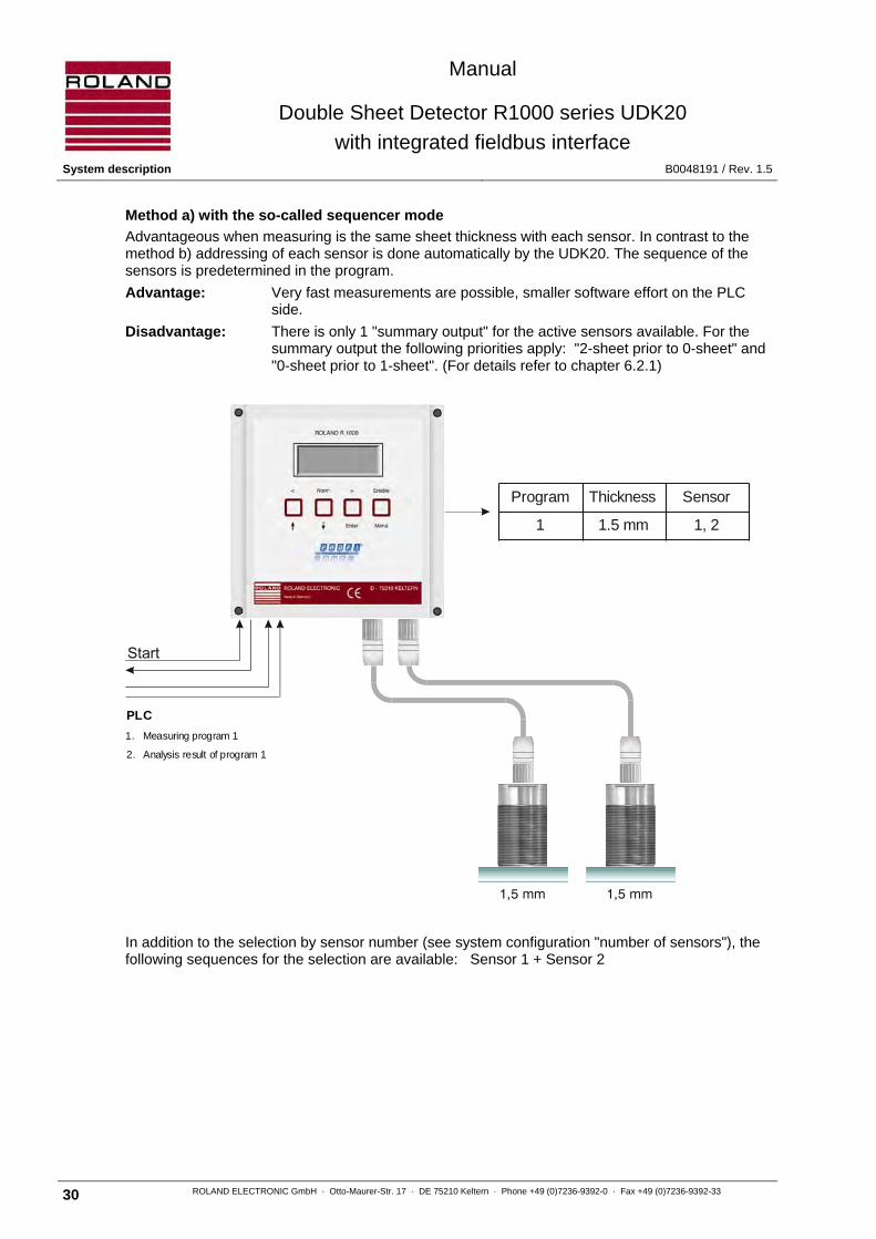
Method a) with the so-called sequencer mode
Advantageous when measuring is the same sheet thickness with each sensor. In contrast to the method b) addressing of each sensor is done automatically by the UDK20. The sequence of the sensors is predetermined in the program.
Advantage: Very fast measurements are possible, smaller software effort on the PLC side.
Disadvantage: There is only 1 "summary output" for the active sensors available. For the summary output the following priorities apply: "2-sheet prior to 0-sheet" and "0-sheet prior to 1-sheet". (For details refer to chapter 6.2.1)
In addition to the selection by sensor number (see system configuration "number of sensors"), the following sequences for the selection are available: Sensor 1 + Sensor 2
Program Thickness Sensor
1 1.5 mm 1, 2
PLC
1. Measuring program 1
2. Analysis result of program 1
1,5 mm1,5 mm

Manual
Double Sheet Detector R1000 series UDK20
with integrated fieldbus interface B0048191 / Rev. 1.5 System description
ROLAND ELECTRONIC GmbH · Otto-Maurer-Str. 17 · DE 75210 Keltern · Phone +49 (0)7236-9392-0 · Fax +49 (0)7236-9392-33 31
Method b) with program switching
Meaningful, if the sheets to be monitored by the various sensors have different sheet thicknesses. Also suitable if the nominal thickness changes from cycle to cycle.
For this procedure the respective parameter set (program) must contain nominal thickness and sensor number. The selection of the program is then performed by the PLC.
Disadvantage: A long time is required for switching the program via the parallel interface.
0.7 mm1.0 mm
Program Thickness Sensor
1 1.0 mm 1
2 0.7 mm 2
PLC
1. Select programm 1
2. Measuring programm 1
3. Analysis result of programm 1
4. Select programm 2
5. Measuring programm 2
6. Analysis result of programm 2

Manual
Double Sheet Detector R1000 series UDK20
with integrated fieldbus interface Mounting B0048191 / Rev. 1.5
32 ROLAND ELECTRONIC GmbH · Otto-Maurer-Str. 17 · DE 75210 Keltern · Phone +49 (0)7236-9392-0 · Fax +49 (0)7236-9392-33
Blank page

Manual
Double Sheet Detector R1000 series UDK20
with integrated fieldbus interface B0048191 / Rev. 1.5 Mounting
ROLAND ELECTRONIC GmbH · Otto-Maurer-Str. 17 · DE 75210 Keltern · Phone +49 (0)7236-9392-0 · Fax +49 (0)7236-9392-33 33
4 Mounting
The mounting of the Double Sheet Detector R1000 UDK20 determines the measurement accuracy and the reliability of operation. The system was designed for operating in rough industrial environments. However, the following mounting instructions should be observed in order to minimize mechanical, thermal, and electromagnetic influences on the operation.
4.1 General mounting instructions
The enclosure for wall mounting meets IP65 and is designed for mounting the enclosure close to the sensor location. This results in the use of shorter sensor cables with a corresponding lower exposure to electromagnetic noise and could therefore result in better measurements.
The control unit should be installed in locations where no vibration exists and no additional heat is transferred into the system (even better reduce the heat in the control unit). In addition the control unit should be installed in such a fashion that it can be easily opened for service purposes. During the operation the control unit and the sensors should be under visual control of the operating personnel.
Attention Strong vibrations and additional heat can damage the control unit.
In case of panel or operator consoles the front panel version should be used.

Manual
Double Sheet Detector R1000 series UDK20
with integrated fieldbus interface Mounting B0048191 / Rev. 1.5
34 ROLAND ELECTRONIC GmbH · Otto-Maurer-Str. 17 · DE 75210 Keltern · Phone +49 (0)7236-9392-0 · Fax +49 (0)7236-9392-33
4.2 Dimensions of the system
4.2.1 Dimensions of the unit in industrial enclosure
All dimensions are in mm. Tolerance: ±0.4 mm
Fig. 7: Dimensions of the wall mount enclosure - connection view
Front view
Note For the connection of the plugs a minimum additional space of 120 mm below the control unit is necessary.
All dimensions are in mm. Tolerance: ±0.4 mm
Fig. 8: Dimensions of the wall mount enclosure - front view
2253
50
20
Manual
Double Sheet Detector R1000 series UDK20
with integrated fieldbus interface B0048191 / Rev. 1.5 Mounting
ROLAND ELECTRONIC GmbH · Otto-Maurer-Str. 17 · DE 75210 Keltern · Phone +49 (0)7236-9392-0 · Fax +49 (0)7236-9392-33 35
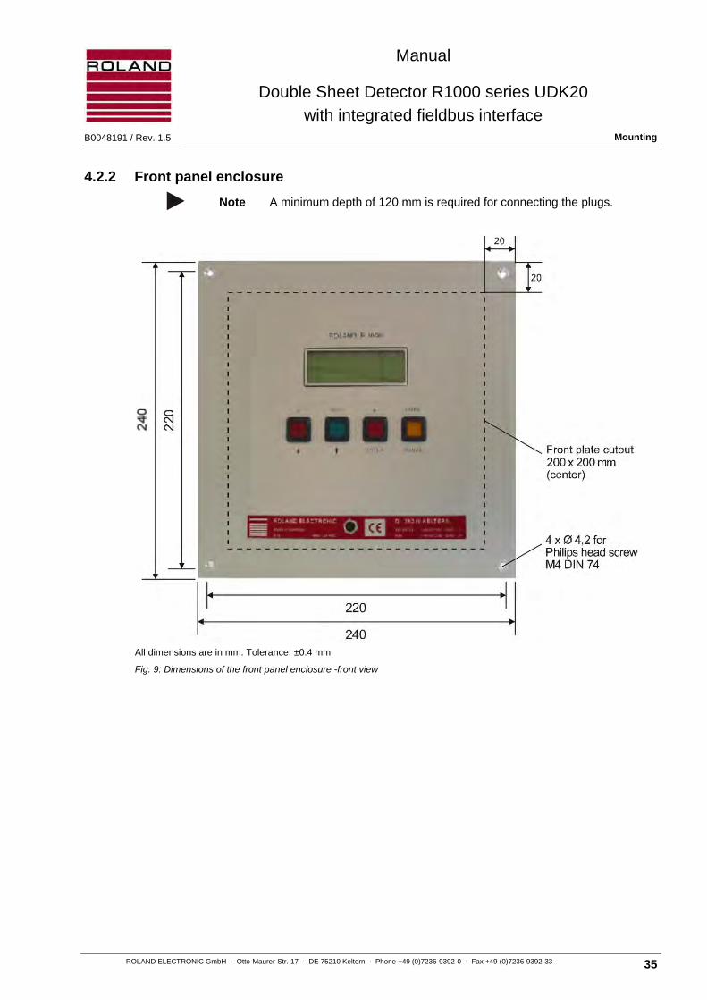
4.2.2 Front panel enclosure
Note A minimum depth of 120 mm is required for connecting the plugs.
All dimensions are in mm. Tolerance: ±0.4 mm
Fig. 9: Dimensions of the front panel enclosure -front view
Manual
Double Sheet Detector R1000 series UDK20
with integrated fieldbus interface Mounting B0048191 / Rev. 1.5
36 ROLAND ELECTRONIC GmbH · Otto-Maurer-Str. 17 · DE 75210 Keltern · Phone +49 (0)7236-9392-0 · Fax +49 (0)7236-9392-33
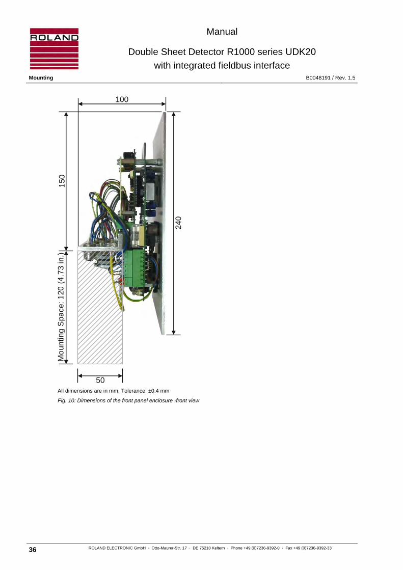
All dimensions are in mm. Tolerance: ±0.4 mm
Fig. 10: Dimensions of the front panel enclosure -front view
240
100
150
Mo
untin
g S
pace
: 120
(4
.73
in.)
50

Manual
Double Sheet Detector R1000 series UDK20
with integrated fieldbus interface B0048191 / Rev. 1.5 Mounting
ROLAND ELECTRONIC GmbH · Otto-Maurer-Str. 17 · DE 75210 Keltern · Phone +49 (0)7236-9392-0 · Fax +49 (0)7236-9392-33 37
4.3 Mounting of sensors
The reliable function of the Double Sheet Detector depends to a great degree on the correct mounting of the sensors. The following mounting rules should be followed:
• The sensor must be mounted perpendicular to the sheet and fully contact the sheet surface. Foreign matter should not obstruct the contact.
• Tilting or air gaps between the sensor and the sheet surface can result in faulty measurements.
• It is possible to cover the sensor surface with thin Teflon in order to avoid damage to the sheet metal surface. However, this will reduce the performance and is, therefore, not recommended.
• Mounting in steel / distance to magnets
• It is important to set the under gauge threshold of the control unit and analyze the under gauge signal at the 0-sheet output.
• It is important to set the upper gauge threshold of the control unit and analyze the upper gauge signal at the 2-sheet output.
• A spring loaded mounting bracket or the installation directly into the vacuum cup is recommended (see the following sections).
Attention Air gaps can result in faulty measured values. This applies also to tilting or partial gaps or bowed sheets. Ignoring these factors can result in unreliable operations.
The UDK20 can detect unintentional air gaps. The lower limit (“low“) should be used for this purpose. The lower limit should be adjusted to more than 80%. An air gap causes a decrease of the measured value. As soon as the measured value falls below the under gauge threshold, then under gauge is signaled at the 0-sheet output. It is absolutely necessary that the control unit stops the current operation and issue is a fault signal. Only if this fault condition is eliminated should sheet processing be allowed to continue.
5 mm
5 m
mX X
X Y
kein Stahlno steel
keine Magneteno magnets
X = Sensordurchmesser Sensor diameter
y = Sensordurchmesser½½ Sensor diameter

Manual
Double Sheet Detector R1000 series UDK20
with integrated fieldbus interface Mounting B0048191 / Rev. 1.5
38 ROLAND ELECTRONIC GmbH · Otto-Maurer-Str. 17 · DE 75210 Keltern · Phone +49 (0)7236-9392-0 · Fax +49 (0)7236-9392-33
4.3.1 Checklist for Mounting of contacting Sensors
In the interest of longest lifetime and operational security the following items should be observed when mounting contacting sensors and checked in regular intervals.
Point of attention Possible influences Checked
Cable type 1 Use only the recommended cable with highest flexibility and durability.
Cable routing
2 Avoid any tension of the cable. Route the cable with enough clearance.
3 Special care has to be taken to the route of cable in front of sensor plug, if a flexible sensor bracket is used. The cable should never have a bend close to the plug. Also the meander of the cable has to be symmetrically to the axis of the plug, see enclosed sketch.
Plug 4 Correctly tighten the arresting ring of the plug. This avoids too strong wear of contacts. If possible choose a sensor with fixed cable instead.
Sensor mounting in the destacking tool
5 Use a sensor bracket which is flexible enough to let the sensor align also to tilted sheets. This avoids unnecessary wear of sensor contact surface.
6 Properly adjust sensor edge so that it aligns with the rubber burls of the suction cup. Do not allow excess end. See enclosed sketch. This avoids unnecessary wear of sensor contact surface.
7 Properly adjust sensor mounting in regard to the lifting suction cups of tooling. Do not allow sensor suction cup to excess lifting suction cups. This avoids unnecessary wear of sensor contact surface.
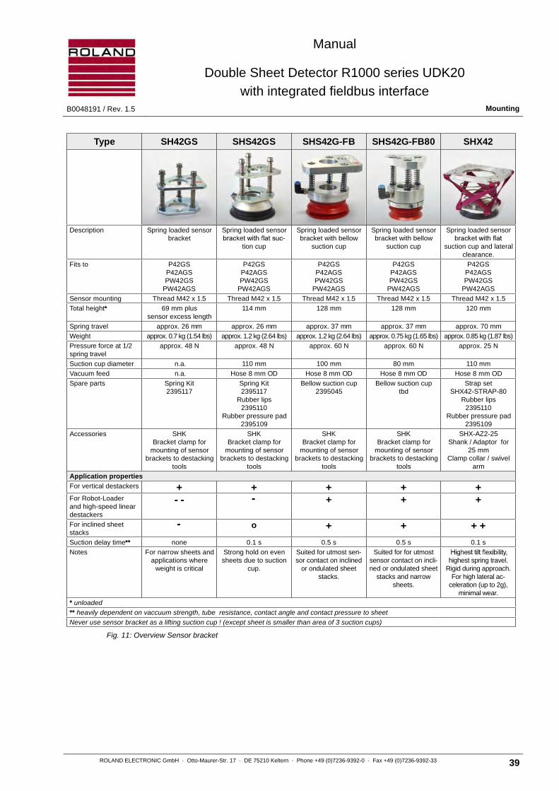
4.3.2 Spring loaded sensor bracket
P-sensors should always be fitted into spring mounted sensor bracket rather than rigid mounting arrangements.
A substantial advantage is in the fact that the sensor presents itself perpendicular to the sheet metal surface even though sensor bracket and sheet surface may not be completely aligned at a right angle.
It is important to observe that lateral cable pull does not tilt the sensor. In addition it must be ensured that the springs do not get stuck. If the springs get stuck tilting of the sensor may result or stuck springs can actually provoke tilting. Ideally the spring mounted bracket should be pre-loaded in order to ensure that the sensor is presented perpendicular to the sheet even under dynamic conditions.
NoppenBurlsSensorkante
Sensor edge
SaugerSuction cup
Sensor
Manual
Double Sheet Detector R1000 series UDK20
with integrated fieldbus interface B0048191 / Rev. 1.5 Mounting
ROLAND ELECTRONIC GmbH · Otto-Maurer-Str. 17 · DE 75210 Keltern · Phone +49 (0)7236-9392-0 · Fax +49 (0)7236-9392-33 39
Fig. 11: Overview Sensor bracket
Type SH42GS SHS42GS SHS42G-FB SHS42G-FB80 SHX42
Description Spring loaded sensorbracket
Spring loaded sensor-
tion cup
Spring loaded sensorbracket with bellow
suction cup
Spring loaded sensorbracket with bellow
suction cup
Spring loaded sensor
suction cup and lateralclearance.
Fits to P42GSP42AGSPW42GS
PW42AGS
P42GSP42AGSPW42GS
PW42AGS
P42GSP42AGSPW42GS
PW42AGS
P42GSP42AGSPW42GS
PW42AGS
P42GSP42AGSPW42GS
PW42AGS
Sensor mounting Thread M42 x 1.5 Thread M42 x 1.5 Thread M42 x 1.5 Thread M42 x 1.5 Thread M42 x 1.5
Total height* 69 mm plussensor excess length
114 mm 128 mm 128 mm 120 mm
Spring travel approx. 26 mm approx. 26 mm approx. 37 mm approx. 37 mm approx. 70 mm
Weight approx. 0.7 kg (1.54 lbs) approx. 1.2 kg (2.64 lbs) approx. 1.2 kg (2.64 lbs) approx. 0.75 kg (1.65 lbs) approx. 0.85 kg (1.87 lbs)
Pressure force at 1/2spring travel
approx. 48 N approx. 48 N approx. 60 N approx. 60 N approx. 25 N
Suction cup diameter n.a. 110 mm 100 mm 80 mm 110 mm
Vacuum feed n.a. Hose 8 mm OD Hose 8 mm OD Hose 8 mm OD Hose 8 mm OD
Spare parts Spring Kit2395117
Spring Kit2395117
Rubber lips2395110
Rubber pressure pad2395109
Bellow suction cup2395045
Bellow suction cuptbd
Strap setSHX42-STRAP-80
Rubber lips2395110
Rubber pressure pad2395109
Accessories SHKBracket clamp for
mounting of sensorbrackets to destacking
tools
SHKBracket clamp for
mounting of sensorbrackets to destacking
tools
SHKBracket clamp for
mounting of sensorbrackets to destacking
tools
SHKBracket clamp for
mounting of sensorbrackets to destacking
tools
SHX-AZ2-25Shank / Adaptor for
25 mmClamp collar / swivel
arm
Application properties
For vertical destackers + + + + +For Robot-Loaderand high-speed lineardestackers
+ + +
For inclined sheetstacks
o + + + +
Suction delay time** none 0.1 s 0.5 s 0.5 s 0.1 s
Notes For narrow sheets andapplications where
weight is critical
Strong hold on evensheets due to suction
cup.
Suited for utmost sen-sor contact on inclined
or ondulated sheetstacks.
Suited for for utmostsensor contact on incli-ned or ondulated sheet
stacks and narrowsheets.
highest spring travel.Rigid during approach.
For high lateral ac-celeration (up to 2g),
minimal wear.
* unloaded
** heavily dependent on vaccuum strength, tube resistance, contact angle and contact pressure to sheet
Never use sensor bracket as a lifting suction cup ! (except sheet is smaller than area of 3 suction cups)

Manual
Double Sheet Detector R1000 series UDK20
with integrated fieldbus interface Mounting B0048191 / Rev. 1.5
40 ROLAND ELECTRONIC GmbH · Otto-Maurer-Str. 17 · DE 75210 Keltern · Phone +49 (0)7236-9392-0 · Fax +49 (0)7236-9392-33
4.3.2.1 Spring loaded sensor bracket SH42GS
Fig. 12: Spring loaded sensor bracket SH42GS
66
"A"
57
Hub
max
.65
min
.25
98
10Ø
View in direction "A"without sensor
ø20.5
30O
50
110
8045°
120°
75°
40
90
Sensor
movable
fixed
All Dimensions are in mm. Tolerance: ±0.4 mm.

Manual
Double Sheet Detector R1000 series UDK20
with integrated fieldbus interface B0048191 / Rev. 1.5 Mounting
ROLAND ELECTRONIC GmbH · Otto-Maurer-Str. 17 · DE 75210 Keltern · Phone +49 (0)7236-9392-0 · Fax +49 (0)7236-9392-33 41
4.3.3 Spring loaded sensor bracket with flat suction cup
Destacking of blanks is done mostly with the vacuum suction cups. For the measurement of the sheet thickness the sensors should rest vertically and flat on the sheet. The best contact to the sheet surface is made by mounting the sensor into a vacuum suction cup.
That suction cups present the sensor vertically to the sheet surface and function fast because of the low volume of air required. Deviations from the right angle have to be compensated by the spring-loaded Sensor brackets, otherwise no vacuum can be generated. Bellow style vacuum suction cups can themselves compensate deviations from the right angle but they can also pull an inclined sensor to the sheet surface or in inclined sheet to the sensor leading to instability of measurement. The forces acting in this process can lead to wear and tear to the bracket and lips of the suction cups. Generating and releasing vacuum requires considerably longer time.
The suction cups are not designed to lift and carry the sheet. In order to prevent inadvertently the sensor losing touch to the sheet it is necessary to maintain a certain degree of spring load between sensor and sheet. Sensor cable and vacuum hoses should be mounted in such a fashion that low angular forces act on the sensor bracket. If necessary the sensor thread can be sealed with a permanently elastic sealant (Hylomar, Loctite) or a narrow Teflon web.
The spring-loaded sensor bracket contains fixing holes to attach the bracket to the carrying tooling. In special cases (on request) is an operation without the vacuum cup or the lifting/carrying of the sheet with the sensor bracket possible.
4.3.3.1 Spring travel of SHS42GS
Fig. 13: Spring travel for SHS42GS
674
6
ausgefedert (Zug)extracted (pull)
54
46
unbelastetunstressed
26
46
eingefedert (Druck)retracted (pressure)
Manual
Double Sheet Detector R1000 series UDK20
with integrated fieldbus interface Mounting B0048191 / Rev. 1.5
42 ROLAND ELECTRONIC GmbH · Otto-Maurer-Str. 17 · DE 75210 Keltern · Phone +49 (0)7236-9392-0 · Fax +49 (0)7236-9392-33
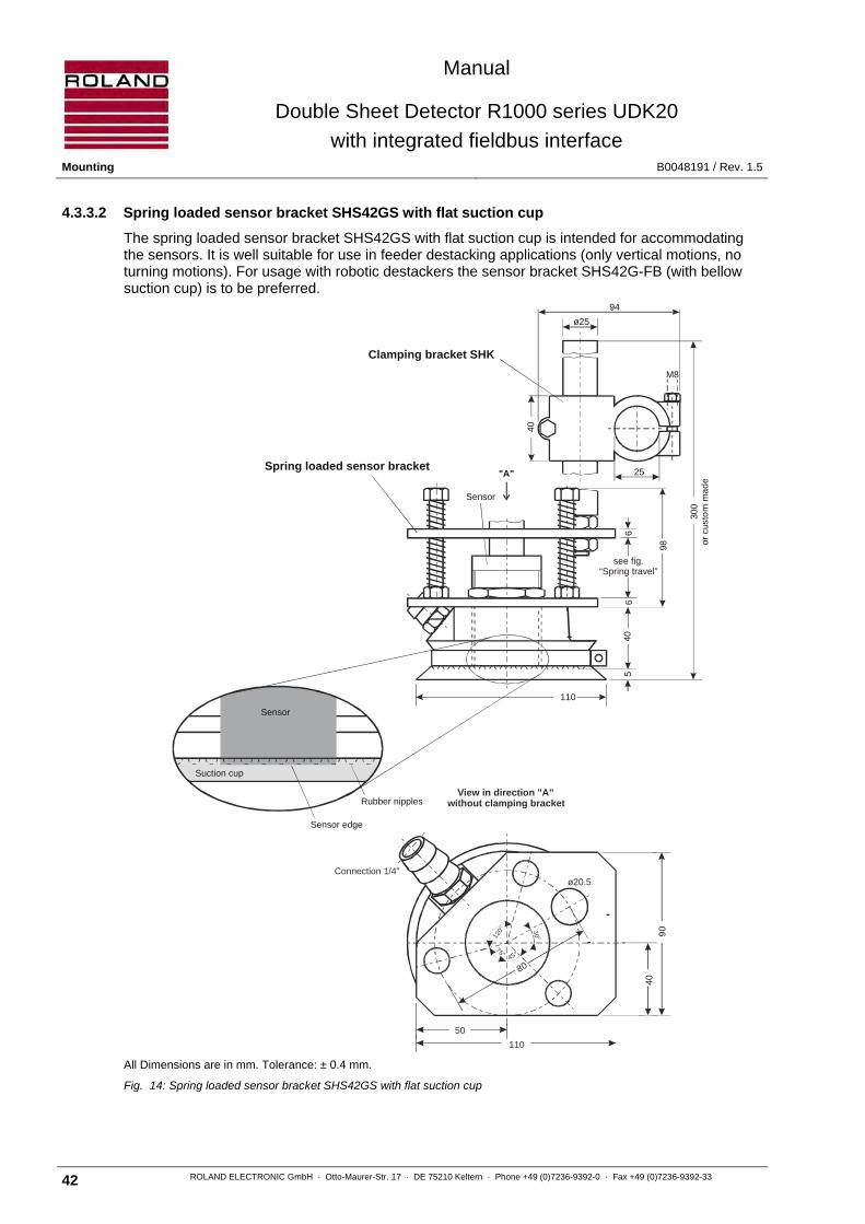
4.3.3.2 Spring loaded sensor bracket SHS42GS with flat suction cup
The spring loaded sensor bracket SHS42GS with flat suction cup is intended for accommodating the sensors. It is well suitable for use in feeder destacking applications (only vertical motions, no turning motions). For usage with robotic destackers the sensor bracket SHS42G-FB (with bellow suction cup) is to be preferred.
All Dimensions are in mm. Tolerance: ± 0.4 mm.
Fig. 14: Spring loaded sensor bracket SHS42GS with flat suction cup
Clamping bracket SHK
110
Spring loaded sensor bracket
Sensor
65
6
ø25
25
94
M8
Rubber nipples
Sensor edge
Sensor
Suction cup
"A"
40
300
orcu
sto
mm
ade
98
40
Connection 1/4"
View in direction "A"without clamping bracket
ø20.5
30O
50
110
8045°
120°
75°
4090
see fig.“Spring travel”
Manual
Double Sheet Detector R1000 series UDK20
with integrated fieldbus interface B0048191 / Rev. 1.5 Mounting
ROLAND ELECTRONIC GmbH · Otto-Maurer-Str. 17 · DE 75210 Keltern · Phone +49 (0)7236-9392-0 · Fax +49 (0)7236-9392-33 43
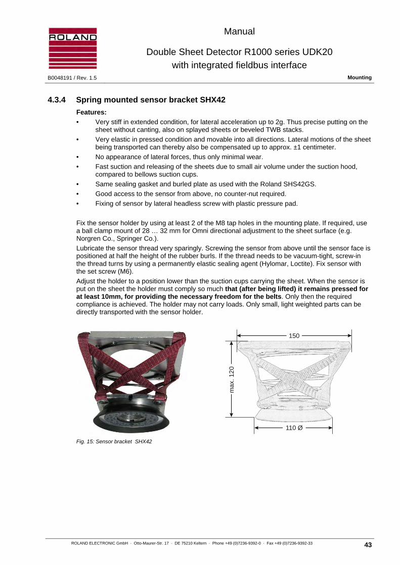
4.3.4 Spring mounted sensor bracket SHX42
Features:
• Very stiff in extended condition, for lateral acceleration up to 2g. Thus precise putting on the sheet without canting, also on splayed sheets or beveled TWB stacks.
• Very elastic in pressed condition and movable into all directions. Lateral motions of the sheet being transported can thereby also be compensated up to approx. ±1 centimeter.
• No appearance of lateral forces, thus only minimal wear.
• Fast suction and releasing of the sheets due to small air volume under the suction hood, compared to bellows suction cups.
• Same sealing gasket and burled plate as used with the Roland SHS42GS.
• Good access to the sensor from above, no counter-nut required.
• Fixing of sensor by lateral headless screw with plastic pressure pad.
Fix the sensor holder by using at least 2 of the M8 tap holes in the mounting plate. If required, use a ball clamp mount of 28 … 32 mm for Omni directional adjustment to the sheet surface (e.g. Norgren Co., Springer Co.).
Lubricate the sensor thread very sparingly. Screwing the sensor from above until the sensor face is positioned at half the height of the rubber burls. If the thread needs to be vacuum-tight, screw-in the thread turns by using a permanently elastic sealing agent (Hylomar, Loctite). Fix sensor with the set screw (M6).
Adjust the holder to a position lower than the suction cups carrying the sheet. When the sensor is put on the sheet the holder must comply so much that (after being lifted) it remains pressed for at least 10mm, for providing the necessary freedom for the belts. Only then the required compliance is achieved. The holder may not carry loads. Only small, light weighted parts can be directly transported with the sensor holder.
Fig. 15: Sensor bracket SHX42
150
110 Ø
max
. 12
0
Manual
Double Sheet Detector R1000 series UDK20
with integrated fieldbus interface Mounting B0048191 / Rev. 1.5
44 ROLAND ELECTRONIC GmbH · Otto-Maurer-Str. 17 · DE 75210 Keltern · Phone +49 (0)7236-9392-0 · Fax +49 (0)7236-9392-33
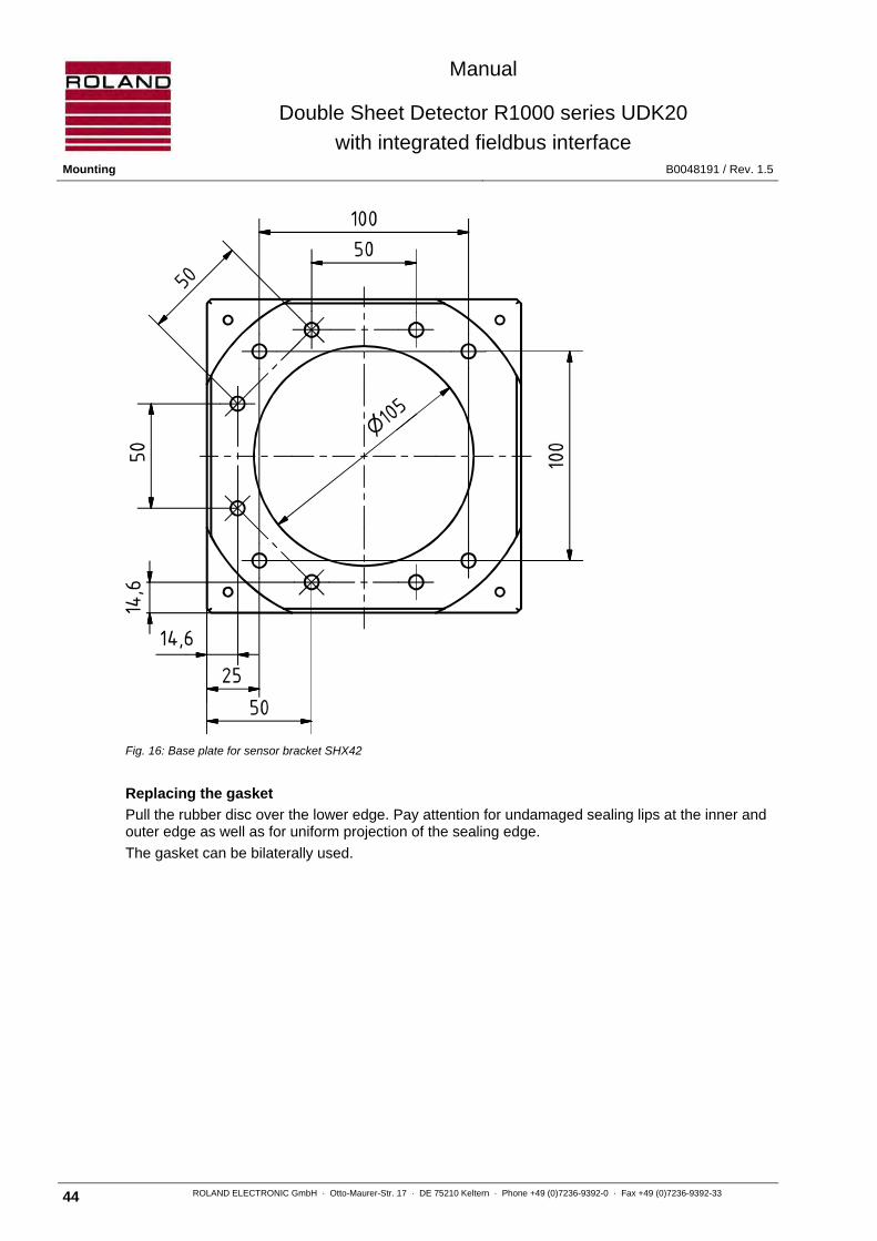
Fig. 16: Base plate for sensor bracket SHX42
Replacing the gasket
Pull the rubber disc over the lower edge. Pay attention for undamaged sealing lips at the inner and outer edge as well as for uniform projection of the sealing edge.
The gasket can be bilaterally used.
Manual
Double Sheet Detector R1000 series UDK20
with integrated fieldbus interface B0048191 / Rev. 1.5 Mounting
ROLAND ELECTRONIC GmbH · Otto-Maurer-Str. 17 · DE 75210 Keltern · Phone +49 (0)7236-9392-0 · Fax +49 (0)7236-9392-33 45
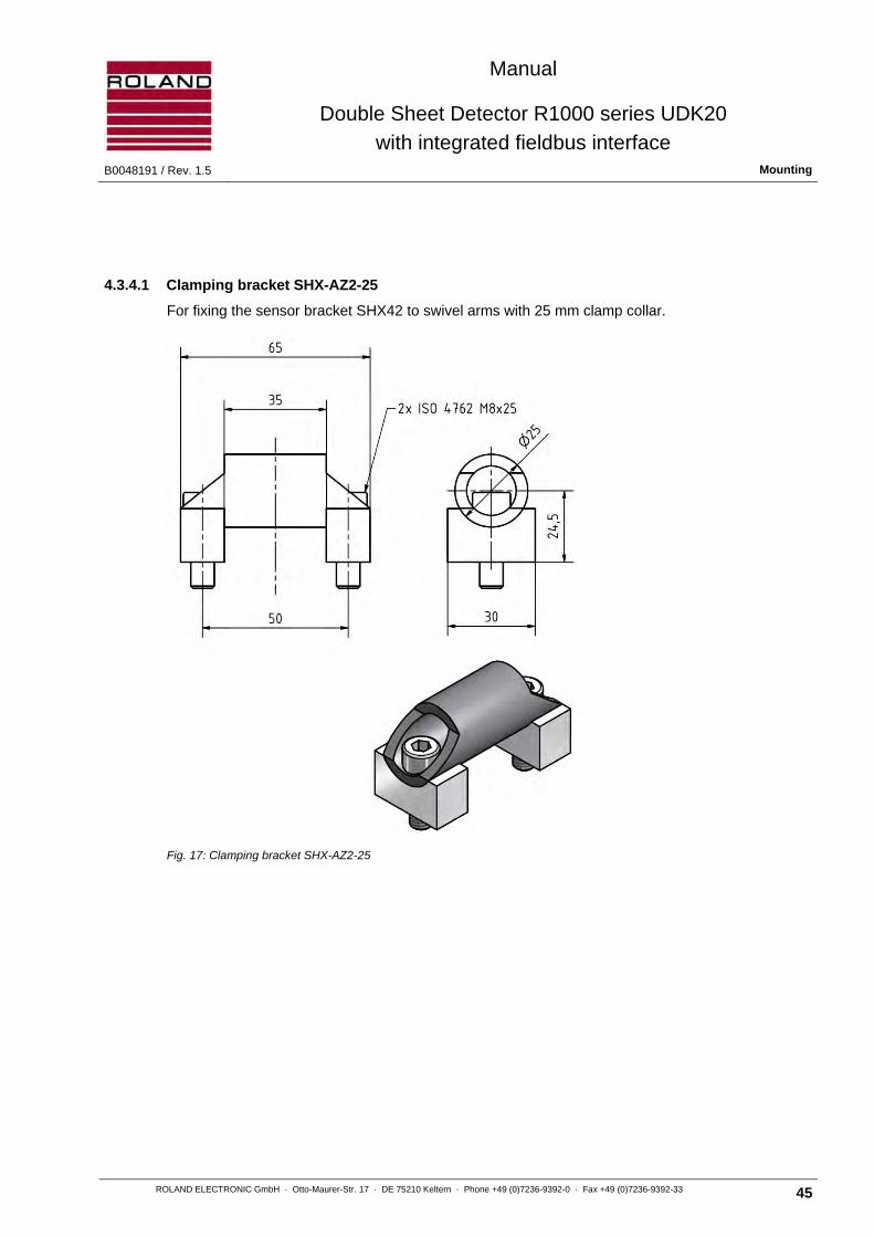
4.3.4.1 Clamping bracket SHX-AZ2-25
For fixing the sensor bracket SHX42 to swivel arms with 25 mm clamp collar.
Fig. 17: Clamping bracket SHX-AZ2-25
Manual
Double Sheet Detector R1000 series UDK20
with integrated fieldbus interface Mounting B0048191 / Rev. 1.5
46 ROLAND ELECTRONIC GmbH · Otto-Maurer-Str. 17 · DE 75210 Keltern · Phone +49 (0)7236-9392-0 · Fax +49 (0)7236-9392-33
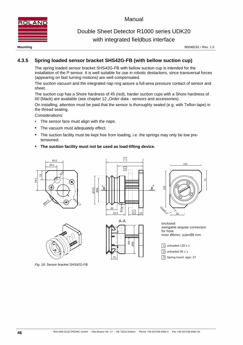
4.3.5 Spring loaded sensor bracket SHS42G-FB (with bellow suction cup)
The spring loaded sensor bracket SHS42G-FB with bellow suction cup is intended for the installation of the P sensor. It is well suitable for use in robotic destackers, since transversal forces (appearing on fast turning motions) are well compensated.
The suction vacuum and the integrated nap ring assure a full-area pressure contact of sensor and sheet.
The suction cup has a Shore hardness of 45 (red), harder suction cups with a Shore hardness of 60 (black) are available (see chapter 12 „Order data - sensors and accessories).
On installing, attention must be paid that the sensor is thoroughly sealed (e.g. with Teflon tape) in the thread seating.
Considerations:
• The sensor face must align with the naps.
• The vacuum must adequately effect.
• The suction facility must be kept free from loading, i.e. the springs may only be low pre-tensioned.
• The suction facility must not be used as load-lifting device.
Fig. 18: Sensor bracket SHS42G-FB
: unloaded 128 ± 1
: unloaded 90 ± 1
: Spring travel: appr. 37
enclosed:swingable angular connectionfor hoseinner Ø6mm, outerØ8 mm
1
2
3
60,5
39,5
69,5
33 Ø21
Ø84,5M42x1,5
10x45,0 °
M42x1,5
11013
0
70
50
A-A
38
65,5
Ø10
2
Ø85
15
Ø99
20
Ø8
Manual
Double Sheet Detector R1000 series UDK20
with integrated fieldbus interface B0048191 / Rev. 1.5 Mounting
ROLAND ELECTRONIC GmbH · Otto-Maurer-Str. 17 · DE 75210 Keltern · Phone +49 (0)7236-9392-0 · Fax +49 (0)7236-9392-33 47
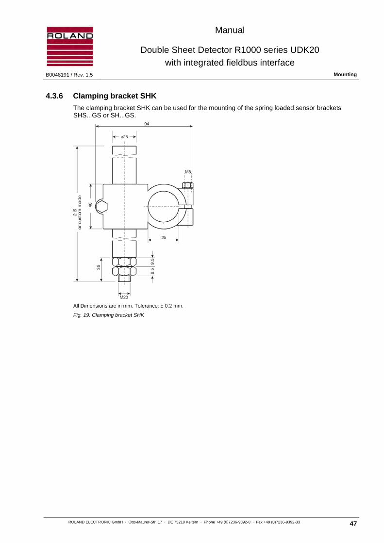
4.3.6 Clamping bracket SHK
The clamping bracket SHK can be used for the mounting of the spring loaded sensor brackets SHS...GS or SH...GS.
All Dimensions are in mm. Tolerance: ± 0.2 mm.
Fig. 19: Clamping bracket SHK
25
94
M20
M8
21
40
95
3
95
orcu
stom
mad
e
.
.
5
5
Manual
Double Sheet Detector R1000 series UDK20
with integrated fieldbus interface Mounting B0048191 / Rev. 1.5
48 ROLAND ELECTRONIC GmbH · Otto-Maurer-Str. 17 · DE 75210 Keltern · Phone +49 (0)7236-9392-0 · Fax +49 (0)7236-9392-33
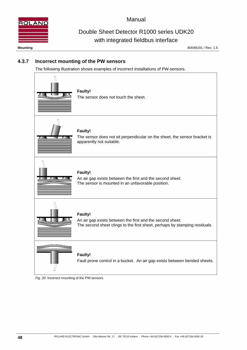
4.3.7 Incorrect mounting of the PW sensors
The following illustration shows examples of incorrect installations of PW-sensors.
Faulty!
The sensor does not touch the sheet.
Faulty!
The sensor does not sit perpendicular on the sheet, the sensor bracket is apparently not suitable.
Faulty!
An air gap exists between the first and the second sheet. The sensor is mounted in an unfavorable position.
Faulty!
An air gap exists between the first and the second sheet. The second sheet clings to the first sheet, perhaps by stamping residuals.
Faulty!
Fault prone control in a bucket. An air gap exists between bended sheets.
Fig. 20: Incorrect mounting of the PW-sensors

Manual
Double Sheet Detector R1000 series UDK20
with integrated fieldbus interface B0048191 / Rev. 1.5 Mounting
ROLAND ELECTRONIC GmbH · Otto-Maurer-Str. 17 · DE 75210 Keltern · Phone +49 (0)7236-9392-0 · Fax +49 (0)7236-9392-33 49
4.3.8 Electromagnetic interference
Electromagnetic interference can affect the measuring accuracy of the sensor. Therefore the sensors should not be installed close to devices which cause electromagnetic interference. Such devices are e.g. frequency converters, servo motors or proximity switches on inductive basis. In case of switching magnets a minimum distance of 20 mm should be observed in order to avoid feedback. The sensor cables should not be placed directly adjacent to cables with large interference potential, e.g. power supply cable. This applies especially to longer cable lengths.
4.3.9 Mounting of the Sensor-Switch-Box SSBUDK10
Note The Sensor-Switch-Box SSBUDK10 should be installed in locations where no vibration exists and no additional heat is transferred into the system (even better reduce the heat in the control unit). Furthermore, the Sensor-Switch-Box must be installed such that it is always accessible and can be easily opened for service purposes. During the operation the Sensor-Switch-Box and the sensors should be under visual control of the operating personnel.
All Dimensions are in mm. Tolerance: ± 0.4 mm.
Fig. 21: Sensor-Switch-Box SSBUDK10

Manual
Double Sheet Detector R1000 series UDK20
with integrated fieldbus interface Electrical installation B0048191 / Rev. 1.5
50 ROLAND ELECTRONIC GmbH · Otto-Maurer-Str. 17 · DE 75210 Keltern · Phone +49 (0)7236-9392-0 · Fax +49 (0)7236-9392-33
4.4 Automatic tool changer
The Roland sensors can be used within an ATC concept (Automatic tool change).
The only requirements we have established are:
Every sensor signal must have its own contact.
The contacts must be low resistive (only gold contacts!).
The contacts must be suited for peak currents of 2 ampere.
The shielding of the cable must not be interrupted and therefore have its own contact.
The contacts must be protected from contamination.
Do not route the cable together with other cables leading high currents.
Die metallic parts of the tooling have to be grounded.
It is not allowed to open the connector during the measuring operation.
After each tool change it is required to perform a zero set command.
Attention Incorrect wiring may destroy the control unit or the sensor.

Manual
Double Sheet Detector R1000 series UDK20
with integrated fieldbus interface B0048191 / Rev. 1.5 Electrical installation
ROLAND ELECTRONIC GmbH · Otto-Maurer-Str. 17 · DE 75210 Keltern · Phone +49 (0)7236-9392-0 · Fax +49 (0)7236-9392-33 51
5 Electrical installation
5.1 General instructions
The sensor cables should be kept as short as possible in order to minimize the influence of electromagnetic noise. Cable shields must be connected according to the connection diagrams only and should not have any additional connections.
Attention Damaged cable installations can result in additional electrical connections. This can disturb the measured values.
5.1.1 Mounting instruction for M12 connectors with arresting ring
These connectors have a positioning key at the plug and a positioning slot at the receptacle. These items are designed to prevent incorrect connecting positions.
For this reason if plug and receptacle are connected together then these positioning features should fit to each other.
Only then it is possible to connect plug and receptacle without force and with proper pin configuration.
A Positioning slot at female connector
B Positioning nose at male connector
C Threaded arresting ring
D Connector assembly ring. Never turn this ring when arresting the plug with the arresting ring C.
Fig. 22: Positioning facility and arresting ring
When the connection is established correctly as described, plug and socket can be arrested with the arresting ring.
Important
1) Turn only the threaded arresting ring C ! If the whole plug becomes turned, the locking facility and the contact pins will break and the connector will become useless.
2) Never mis-use parts of a connector as holder for mounting the counterpart.
C
A
B

Manual
Double Sheet Detector R1000 series UDK20
with integrated fieldbus interface Electrical installation B0048191 / Rev. 1.5
52 ROLAND ELECTRONIC GmbH · Otto-Maurer-Str. 17 · DE 75210 Keltern · Phone +49 (0)7236-9392-0 · Fax +49 (0)7236-9392-33
5.2 Configuration of connectors
UDK20-xx-S in industrial enclosure
UDK20-xx-S-FP as front plate mount
A Connection for RS232
B1 RSI Interface
B2 Opto coupler output
C1 Fieldbus * output
C2 Fieldbus * input
D Sensor Connection
E Connection for system grounding
F Connection for sensor-switch-box
G Power supply connection / opto coupler input
* The fieldbus connections comply with the according type of Fieldbus (For details refer to chapter 5.2.3)
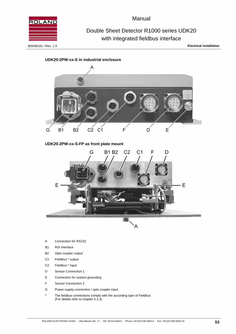
Manual
Double Sheet Detector R1000 series UDK20
with integrated fieldbus interface B0048191 / Rev. 1.5 Electrical installation
ROLAND ELECTRONIC GmbH · Otto-Maurer-Str. 17 · DE 75210 Keltern · Phone +49 (0)7236-9392-0 · Fax +49 (0)7236-9392-33 53
UDK20-2PW-xx-S in industrial enclosure
UDK20-2PW-xx-S-FP as front plate mount
A Connection for RS232
B1 RSI Interface
B2 Opto coupler output
C1 Fieldbus * output
C2 Fieldbus * input
D Sensor Connection 1
E Connection for system grounding
F Sensor Connection 2
G Power supply connection / opto coupler input
* The fieldbus connections comply with the according type of Fieldbus (For details refer to chapter 5.2.3)
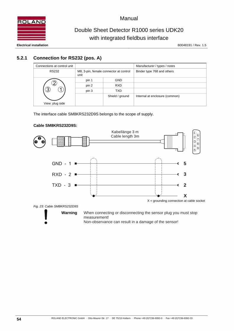
Manual
Double Sheet Detector R1000 series UDK20
with integrated fieldbus interface Electrical installation B0048191 / Rev. 1.5
54 ROLAND ELECTRONIC GmbH · Otto-Maurer-Str. 17 · DE 75210 Keltern · Phone +49 (0)7236-9392-0 · Fax +49 (0)7236-9392-33
5.2.1 Connection for RS232 (pos. A)
Connections at control unit Manufacturer / types / notes
RS232 M8, 3-pin, female connector at control unit
Binder type 768 and others
View: plug side
pin 1 GND
pin 2 RXD
pin 3 TXD
Shield / ground Internal at enclosure (common)
The interface cable SM8KRS232D9S belongs to the scope of supply.
Cable SM8KRS232D9S:
X = grounding connection at cable socket
Fig. 23: Cable SM8KRS232D9S
Warning When connecting or disconnecting the sensor plug you must stop measurement! Non-observance can result in a damage of the sensor!
3
RXD - 2
TXD - 3
5
3
2
1
2
3
4
5
6
7
8
9
Kabellänge 3 mCable length 3m
X
3

Manual
Double Sheet Detector R1000 series UDK20
with integrated fieldbus interface B0048191 / Rev. 1.5 Electrical installation
ROLAND ELECTRONIC GmbH · Otto-Maurer-Str. 17 · DE 75210 Keltern · Phone +49 (0)7236-9392-0 · Fax +49 (0)7236-9392-33 55
5.2.2 Connection of Optocoupler outputs and RSI interface (pos. B1 and B2)
Note The optocoupler inputs are placed at the supply voltage connection (pos. G)
The RSI enables the operation of future ROLAND sensors which have not only the signal output but also the RSI interface.
On the following pages the pin configuration of the optocoupler outputs and the RSI (ROLAND serial interface) are described.
Connector at control unit Manufacturer / types / notes
Optocoupler output M8, 8-pin, A-coded, female
connector at control unit Binder type 713 and others
View: plug side
pin 1 +24VDC External supply 24V DC
pin 2 OUT0 1st optocoupler output
pin 3 OUT1 2nd optocoupler output
pin 4 OUT2 3rd optocoupler output
pin 5 OUT3 4th optocoupler output
pin 6 OUT4 5th optocoupler output
pin 7 -
pin 8 Shield / ground Internal at enclosure (common)
RSI M12, 5-pin, A-coded, female
connector at control unit Binder type 713 and others
View: plug side
pin 1 Shield / ground Internal at enclosure (common)
pin 2 -
pin 3 GND
pin 4 RSI- High
pin 5 RSI- High
Table: Pin configuration of optocoupler output and RSI interface
Optocoupler outputs for fast switching operation
For reasons of velocity and for diagnostic purposes it could be useful to issue the relevant switching signal 0-sheet, 1-sheet, 2-sheet via a real-time interface. Latency periods and cycle times of fieldbus communications are eliminated.
Signal Meaning Notes
OUT0 0-sheet 1st optocoupler output
OUT1 1-sheet 2nd optocoupler output
OUT2 2-sheet 3rd optocoupler output
OUT3 Enable 4th optocoupler output
OUT4 Warning 5th optocoupler output
Warning When connecting or disconnecting the sensor plug you must stop measurement! Non-observance can result in a damage of the sensor!
5
7 8
4
3
2
1 25
4 3
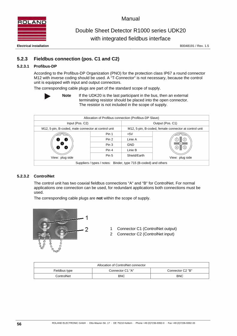
Manual
Double Sheet Detector R1000 series UDK20
with integrated fieldbus interface Electrical installation B0048191 / Rev. 1.5
56 ROLAND ELECTRONIC GmbH · Otto-Maurer-Str. 17 · DE 75210 Keltern · Phone +49 (0)7236-9392-0 · Fax +49 (0)7236-9392-33
5.2.3 Fieldbus connection (pos. C1 and C2)
5.2.3.1 Profibus-DP
According to the Profibus-DP Organization (PNO) for the protection class IP67 a round connector M12 with inverse coding should be used. A “T-Connector“ is not necessary, because the control unit is equipped with input and output connectors.
The corresponding cable plugs are part of the standard scope of supply.
Note If the UDK20 is the last participant in the bus, then an external
terminating resistor should be placed into the open connector. The resistor is not included in the scope of supply.
Allocation of Profibus connection (Profibus-DP Slave)
Input (Pos. C2) Output (Pos. C1)
M12, 5-pin, B-coded, male connector at control unit M12, 5-pin, B-coded, female connector at control unit
View: plug side
Pin 1 +5V
View: plug side
Pin 2 Linie A
Pin 3 GND
Pin 4 Linie B
Pin 5 Shield/Earth
Suppliers / types / notes: Binder, type 715 (B-coded) and others
5.2.3.2 ControlNet
The control unit has two coaxial fieldbus connections “A“ and “B“ for ControlNet. For normal applications one connection can be used, for redundant applications both connections must be used.
The corresponding cable plugs are not within the scope of supply.
1 Connector C1 (ControlNet output) 2 Connector C2 (ControlNet input)
Allocation of ControlNet connector
Fieldbus type Connector C1 "A" Connector C2 "B"
ControlNet BNC BNC
2
5
1
3 4
5
21
34
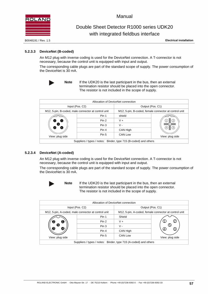
Manual
Double Sheet Detector R1000 series UDK20
with integrated fieldbus interface B0048191 / Rev. 1.5 Electrical installation
ROLAND ELECTRONIC GmbH · Otto-Maurer-Str. 17 · DE 75210 Keltern · Phone +49 (0)7236-9392-0 · Fax +49 (0)7236-9392-33 57
5.2.3.3 DeviceNet (B-coded)
An M12 plug with inverse coding is used for the DeviceNet connection. A T-connector is not necessary, because the control unit is equipped with input and output.
The corresponding cable plugs are part of the standard scope of supply. The power consumption of the DeviceNet is 30 mA.
Note If the UDK20 is the last participant in the bus, then an external
termination resistor should be placed into the open connector. The resistor is not included in the scope of supply.
Allocation of DeviceNet connection
Input (Pos. C2) Output (Pos. C1)
M12, 5-pin, B-coded, male connector at control unit M12, 5-pin, B-coded, female connector at control unit
View: plug side
Pin 1 shield
View: plug side
Pin 2 V +
Pin 3 V -
Pin 4 CAN High
Pin 5 CAN Low
Suppliers / types / notes: Binder, type 715 (B-coded) and others
5.2.3.4 DeviceNet (A-coded)
An M12 plug with inverse coding is used for the DeviceNet connection. A T-connector is not necessary, because the control unit is equipped with input and output.
The corresponding cable plugs are part of the standard scope of supply. The power consumption of the DeviceNet is 30 mA.
Note If the UDK20 is the last participant in the bus, then an external
termination resistor should be placed into the open connector. The resistor is not included in the scope of supply.
Allocation of DeviceNet connection
Input (Pos. C2) Output (Pos. C1)
M12, 5-pin, A-coded, male connector at control unit M12, 5-pin, A-coded, female connector at control unit
View: plug side
Pin 1 Shield
View: plug side
Pin 2 V +
Pin 3 V -
Pin 4 CAN High
Pin 5 CAN Low
Suppliers / types / notes: Binder, type 715 (A-coded) and others
2
5
1
3 4
5
21
34
125
43
1 25
4 3

Manual
Double Sheet Detector R1000 series UDK20
with integrated fieldbus interface Electrical installation B0048191 / Rev. 1.5
58 ROLAND ELECTRONIC GmbH · Otto-Maurer-Str. 17 · DE 75210 Keltern · Phone +49 (0)7236-9392-0 · Fax +49 (0)7236-9392-33
5.2.3.5 CanOpen (B-coded)
An M12 plug with inverse coding is used for the CanOpen connection. A T-connector is not necessary, because the control unit is equipped with input and output.
The corresponding cable plugs are part of the standard scope of supply.
Note If the UDK20 is the last participant in the bus, then an external
termination resistor should be placed into the open connector. The resistor is not included in the scope of supply.
Allocation of CanOpen connection
Input (Pos. C2) Output (Pos. C1)
M12, 5-pin, B-coded, male connector at control unit M12, 5-pin, B-coded, female connector at control unit
View: plug side
Pin 1 shield
View: plug side
Pin 2 n. a.
Pin 3 GND
Pin 4 CAN_H
Pin 5 CAN_H
Suppliers / types / notes: Binder, type 715 (B-coded) and others
5.2.3.6 CanOpen (A-coded)
An M12 plug with inverse coding is used for the CanOpen connection. A T-connector is not necessary, because the control unit is equipped with input and output.
The corresponding cable plugs are part of the standard scope of supply.
Note If the UDK20 is the last participant in the bus, then an external
termination resistor should be placed into the open connector. The resistor is not included in the scope of supply.
Allocation of CanOpen connection
Input (Pos. C2) Output (Pos. C1)
M12, 5-pin, A-coded, male connector at control unit M12, 5-pin, A-coded, female connector at control unit
View: plug side
Pin 1 shield
View: plug side
Pin 2 n. a.
Pin 3 GND
Pin 4 CAN_H
Pin 5 CAN_H
Suppliers / types / notes: Binder, type 715 (A-coded) and others
2
5
1
3 4
5
21
34
125
43
1 25
4 3

Manual
Double Sheet Detector R1000 series UDK20
with integrated fieldbus interface B0048191 / Rev. 1.5 Electrical installation
ROLAND ELECTRONIC GmbH · Otto-Maurer-Str. 17 · DE 75210 Keltern · Phone +49 (0)7236-9392-0 · Fax +49 (0)7236-9392-33 59
5.2.3.7 Interbus-S
The corresponding cable plugs are part of the standard scope of supply.
Allocation of Interbus-S connection
Input (Pos. C2) Output (Pos. C1)
M12, 5-pin, B-coded, Male contacts at the control unit (male socket)
M12, 5-pin, B-coded Female contacts at the control unit (female socket)
View: plug side
pin 1 DO
View: plug side
pin 1 DO
pin 2 /DO pin 2 /DO
pin 3 DI pin 3 DI
pin 4 /DI pin 4 /DI
pin 5 GND pin 5 GND
Plug enclosure shield Plug enclosure shield
The module supports 500 kbit/s operation.
5.2.3.8 ProfiNet IO
The ProfiNet IO connection is implemented as 1-Port.
Allocation of ProfiNet IO connection
Round-shape connector, M12, 4-pin., D-coded, socket contact at control unit (Pos. C2)
View:
Plug side
Pin 1 TD +
Pin 2 RD +
Pin 3 TD –
Pin 4 RD –
Plug enclosure Shield
The corresponding cable plugs are part of the standard scope of supply.
2
5
1
3 4
5
1 2
4 3
1
2
3
4
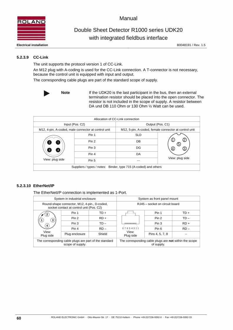
Manual
Double Sheet Detector R1000 series UDK20
with integrated fieldbus interface Electrical installation B0048191 / Rev. 1.5
60 ROLAND ELECTRONIC GmbH · Otto-Maurer-Str. 17 · DE 75210 Keltern · Phone +49 (0)7236-9392-0 · Fax +49 (0)7236-9392-33
5.2.3.9 CC-Link
The unit supports the protocol version 1 of CC-Link.
An M12 plug with A-coding is used for the CC-Link connection. A T-connector is not necessary, because the control unit is equipped with input and output.
The corresponding cable plugs are part of the standard scope of supply.
Note If the UDK20 is the last participant in the bus, then an external termination resistor should be placed into the open connector. The resistor is not included in the scope of supply. A resistor between DA und DB 110 Ohm or 130 Ohm ½ Watt can be used.
Allocation of CC-Link connection
Input (Pos. C2) Output (Pos. C1)
M12, 4-pin, A-coded, male connector at control unit M12, 5-pin, A-coded, female connector at control unit
View: plug side
Pin 1 SLD
View: plug side
Pin 2 DB
Pin 3 DG
Pin 4 DA
Pin 5 ---
Suppliers / types / notes: Binder, type 715 (A-coded) and others
5.2.3.10 EtherNet/IP
The EtherNetI/P connection is implemented as 1-Port.
System in industrial enclosure System as front panel mount
Round-shape connector, M12, 4-pin., D-coded, socket contact at control unit (Pos. C2)
RJ45 – socket on circuit board
View:
Plug side
Pin 1 TD +
View:
Plug side
Pin 1 TD +
Pin 2 RD + Pin 2 TD –
Pin 3 TD – Pin 3 RD +
Pin 4 RD – Pin 6 RD –
Plug enclosure Shield Pins 4, 5, 7, 8 --
The corresponding cable plugs are part of the standard scope of supply.
The corresponding cable plugs are not within the scope of supply.
2
3 4
1 25
4 3
1
2
3
412345678

Manual
Double Sheet Detector R1000 series UDK20
with integrated fieldbus interface B0048191 / Rev. 1.5 Electrical installation
ROLAND ELECTRONIC GmbH · Otto-Maurer-Str. 17 · DE 75210 Keltern · Phone +49 (0)7236-9392-0 · Fax +49 (0)7236-9392-33 61
5.2.3.11 EtherCAT
Round-shape connector, M12, 4-pin., D-coded, socket contact at control unit
IN (Pos. C2) OUT (Pos. C1)
View: Plug side
Pin 1 TD +
Pin 2 RD +
Pin 3 TD –
Pin 4 RD –
Plug enclosure Shield
The corresponding cable plugs are part of the standard scope of supply.
5.2.4 Sensor connection (pos. D)
The sensor connection at the control unit is a quick disconnect type. The following cable is to be used:
• SCPWS-GG or SCPWS-GW for PW42AGS
Connector at control unit (pos. D) Manufacturer / types / notes
PW42AGS M23, (6+3) pin, Female connector at control unit
Coninvers, series RC
View: Plug side
pin 1 W-in 1
pin 2 W-in 2
pin 3 +12 VDC
pin 4 0 VDC
pin 5 -12 VDC
pin 6 P-lead 1
pin 7 W-out 1
pin 8 P-lead 2
pin 9 W-out 2
Enclosure Shield
5.2.5 Connection of earth ground (pos. E)
The enclosure of the R1000 has an M6 threaded screw for earth ground connection. This screw must be connected to the earth ground of the equipment with a copper wire gauge of 1.5 mm² cross section.
Attention The earth ground/central machine ground must not be connected to + 24 VDC.
1
2
3
4
1
2
3
4
3
4 5
6
7
81
9
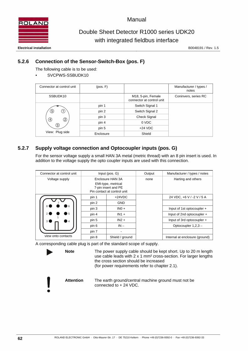
Manual
Double Sheet Detector R1000 series UDK20
with integrated fieldbus interface Electrical installation B0048191 / Rev. 1.5
62 ROLAND ELECTRONIC GmbH · Otto-Maurer-Str. 17 · DE 75210 Keltern · Phone +49 (0)7236-9392-0 · Fax +49 (0)7236-9392-33
5.2.6 Connection of the Sensor-Switch-Box (pos. F)
The following cable is to be used:
• SVCPWS-SSBUDK10
Connector at control unit (pos. F) Manufacturer / types / notes
SSBUDK10 M18, 5-pin, Female connector at control unit
Coninvers, series RC
View: Plug side
pin 1 Switch Signal 1
pin 2 Switch Signal 2
pin 3 Check Signal
pin 4 0 VDC
pin 5 +24 VDC
Enclosure Shield
5.2.7 Supply voltage connection and Optocoupler inputs (pos. G)
For the sensor voltage supply a small HAN 3A metal (metric thread) with an 8 pin insert is used. In addition to the voltage supply the opto coupler inputs are used with this connection.
Connector at control unit Input (pos. G) Output Manufacturer / types / notes
Voltage supply Enclosure HAN 3A
EMI-type, metrical 7-pin insert and PE
Pin contact at control unit
none Harting and others
view onto contacts
pin 1 +24VDC 24 VDC, +6 V / -2 V / 5 A
pin 2 GND
pin 3 IN0 + Input of 1st optocoupler +
pin 4 IN1 + Input of 2nd optocoupler +
pin 5 IN2 + Input of 3rd optocoupler +
pin 6 IN – Optocoupler 1,2,3 –
pin 7 -
pin 8 Shield / ground Internal at enclosure (ground)
A corresponding cable plug is part of the standard scope of supply.
Note The power supply cable should be kept short. Up to 20 m length use cable leads with 2 x 1 mm² cross-section. For larger lengths the cross section should be increased (for power requirements refer to chapter 2.1).
Attention The earth ground/central machine ground must not be connected to + 24 VDC.
2
3
5
4
12
3 4
5
67
8

Manual
Double Sheet Detector R1000 series UDK20
with integrated fieldbus interface B0048191 / Rev. 1.5 Electrical installation
ROLAND ELECTRONIC GmbH · Otto-Maurer-Str. 17 · DE 75210 Keltern · Phone +49 (0)7236-9392-0 · Fax +49 (0)7236-9392-33 63
Optocoupler inputs for fast measurements
For real-time measurements it is possible to start measurement with external optocoupler inputs. The optocoupler function with a control voltage of 20 to 28 VDC. For connections see table on page 40 "Pin configuration of voltage supply connection".
Signal Meaning Note
IN0 External measurement start 1 1st optocoupler input
IN1 External measurement start 2 2nd optocoupler input
IN2 External measurement start 3 3rd optocoupler input
The combination of measurement start 1, 2 and 3 can be adjusted in the system configuration menu.
Note Measurement start signal can be issued either via the process
channel or via an optocoupler. Simultaneous measurement start signals result in fault messages.

Manual
Double Sheet Detector R1000 series UDK20
with integrated fieldbus interface Electrical installation B0048191 / Rev. 1.5
64 ROLAND ELECTRONIC GmbH · Otto-Maurer-Str. 17 · DE 75210 Keltern · Phone +49 (0)7236-9392-0 · Fax +49 (0)7236-9392-33
5.3 Connecting diagram - examples
5.3.1 Connecting diagram UDK20 with one sensor
1 Cable
Order no.: SCPWS-GG (straight cable socket) Order no.: SCPWS-GW (90° angle socket)
Superflex (C)Y PURKOMBI 2 x 1,0 mm² + 4 x 2 x 0,25 mm²
1a Cable plug (9 contacts)
Order no.: 2277004
Pin 1 grey Pin 2 pink Pin 3 red Pin 4 black Pin 5 blue Pin 6 brown, 1 mm² Pin 7 brown Pin 8 white, 1 mm² Pin 9 green Enclosure blank (Shield)
1b Cable socket (9 contacts)
Order no.: 2276005 (straight) 2276007 (90° angle)
Pin 1 grey Pin 2 pink Pin 3 red Pin 4 black Pin 5 blue Pin 6 brown, 1 mm² Pin 7 brown Pin 8 white, 1 mm² Pin 9 green Enclosure blank (Shield)
Optional disconnection point
When a disconnection point is requested then 2 cables of type SCPWS-xx can be directly connected!
Fig. 24: UDK20 with one PW42AGS sensor

Manual
Double Sheet Detector R1000 series UDK20
with integrated fieldbus interface B0048191 / Rev. 1.5 Electrical installation
ROLAND ELECTRONIC GmbH · Otto-Maurer-Str. 17 · DE 75210 Keltern · Phone +49 (0)7236-9392-0 · Fax +49 (0)7236-9392-33 65
5.3.2 Connecting diagram UDK20 with SSBUDK10 and four sensors
1 Cable 2 Cable
Order no.: SCPWS-GG (straight cable socket) Order no.: SCPWS-GW (90° angle socket)
Order no.: SVCPWS-SSBUDK10
Superflex (C)Y PURKOMBI 2 x 1,0 mm² + 4 x 2 x 0,25 mm²
1a Cable plug (9 contacts) 2a Cable plug (5 contacts)
Order no.: 2277004 Order no.: 2277010
Pin 1 grey Pin 2 pink Pin 3 red Pin 4 black Pin 5 blue Pin 6 brown, 1 mm² Pin 7 brown Pin 8 white, 1 mm² Pin 9 green Enclosure blank (Shield)
Pin 1 white Pin 2 green Pin 3 brown Pin 4 yellow Pin 5 grey Enclosure blank (Shield)
1b Cable socket (9 contacts) 2b Cable socket (5 contacts)
Order no.: 2276005 (straight) 2276007 (90° angle)
Order no.: 2276010
Pin 1 grey Pin 2 pink Pin 3 red Pin 4 black Pin 5 blue Pin 6 brown, 1 mm² Pin 7 brown Pin 8 white, 1 mm² Pin 9 green Enclosure blank (Shield)
Pin 1 white Pin 2 green Pin 3 brown Pin 4 yellow Pin 5 grey Enclosure blank (Shield)
Fig. 25: UDK20 with SSBUDK10 and four PW42AGS sensors
1b
1a1a1a1a
1b
1b 1b
1 1 1
1a 1b2a 2b
2
1
P OWE RCHANNE L
1 2 3 4
ROLAND ELECTRONIC
SENSOR SWITCH BOX SSB UDK10

Manual
Double Sheet Detector R1000 series UDK20
with integrated fieldbus interface Electrical installation B0048191 / Rev. 1.5
66 ROLAND ELECTRONIC GmbH · Otto-Maurer-Str. 17 · DE 75210 Keltern · Phone +49 (0)7236-9392-0 · Fax +49 (0)7236-9392-33
5.3.3 Connecting diagram UDK20-2PW with two sensors
1 Cable
Order no.: SCPWS-GG (straight cable socket) Order no.: SCPWS-GW (90° angle socket)
Superflex (C)Y PURKOMBI 2 x 1,0 mm² + 4 x 2 x 0,25 mm²
1a Cable plug (9 contacts)
Order no.: 2277004
Pin 1 grey Pin 2 pink Pin 3 red Pin 4 black Pin 5 blue Pin 6 brown, 1 mm² Pin 7 brown Pin 8 white, 1 mm² Pin 9 green Enclosure blank (Shield)
1b Cable socket (9 contacts)
Order no.: 2276005 (straight) 2276007 (90° angle)
Pin 1 grey Pin 2 pink Pin 3 red Pin 4 black Pin 5 blue Pin 6 brown, 1 mm² Pin 7 brown Pin 8 white, 1 mm² Pin 9 green Enclosure blank (Shield)
Optional disconnection point
When a disconnection point is requested then 2 cables of type SCPWS-xx can be directly connected!
Fig. 26: UDK20-2PW with two PW42AGS sensors

Manual
Double Sheet Detector R1000 series UDK20
with integrated fieldbus interface B0048191 / Rev. 1.5 Electrical installation
ROLAND ELECTRONIC GmbH · Otto-Maurer-Str. 17 · DE 75210 Keltern · Phone +49 (0)7236-9392-0 · Fax +49 (0)7236-9392-33 67
5.4 Internal wiring of the Sensor-Switch-Box SSBUDK10
X1, X3, X4, X5 und X6 Meaning Colour of wire
Pin 1 W-In 1 grey
Pin 2 W-In 2 pink
Pin 3 + 12 VDC red
Pin 4 0 VDC black (black/violet in sensor cable)
Pin 5 - 12 VDC blue
Pin 6 P-line 1 brown, 1 mm²
Pin 7 W-Out 1 brown
Pin 8 P-line 2 white, 1 mm²
Pin 9 W-Out 2 green
X2 Meaning Colour of wire
Pin 1 Switch-over signal 1 white
Pin 2 Switch-over signal 2 green
Pin 3 Control signal brown
Pin 4 0 VDC yellow
Pin 5 + 24 VDC grey
Fig. 27: Internal wiring of the Sensor-Switch-Box SSBUDK10
41 42 43 44 45g
rey
wh
ite
gre
en
ye
llow
bro
wn
504947 48 55 5554535251 26 27 2928 3021 22 23 24 25 36 37 3938 4031 32 33 34 35
6 7 98 101 2 3 4 5 16 17 1918 2011 12 13 14 15
gre
y
pin
k
red
bla
ck
blu
e
bro
wn
, 1
mm
²
wh
ite,
1 m
m²
bro
wn
gre
en
to X2 to X3 to X4
to X1 to X5 to X6
X1X2
X3 X4 X5 X6
X7
gre
y
pin
k
red
bla
ck
blu
e
bro
wn
, 1
mm
²
wh
ite,
1 m
m²
bro
wn
gre
en
gre
y
pin
k
red
bla
ck
blu
eb
row
n,
1 m
m²
wh
ite,
1 m
m²
bro
wn
gre
en
gre
y
pin
k
red
bla
ck
blu
e
bro
wn
, 1
mm
²
wh
ite,
1 m
m²
bro
wn
gre
en
gre
en
wh
ite,
1 m
m²
bro
wn
bro
wn
, 1
mm
²
blu
e
gre
y
pin
k
red
bla
ck

Manual
Double Sheet Detector R1000 series UDK20
with integrated fieldbus interface Communication with the PLC B0048191 / Rev. 1.5
68 ROLAND ELECTRONIC GmbH · Otto-Maurer-Str. 17 · DE 75210 Keltern · Phone +49 (0)7236-9392-0 · Fax +49 (0)7236-9392-33
Blank page
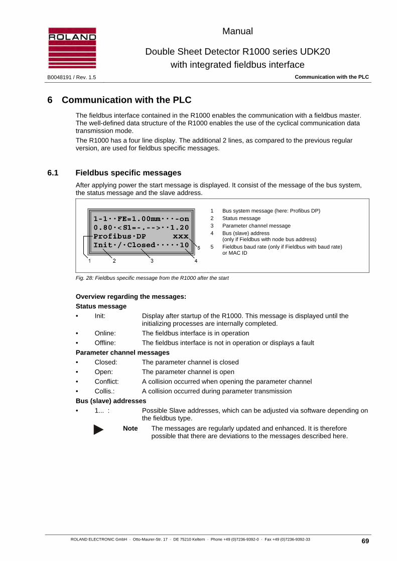
Manual
Double Sheet Detector R1000 series UDK20
with integrated fieldbus interface B0048191 / Rev. 1.5 Communication with the PLC
ROLAND ELECTRONIC GmbH · Otto-Maurer-Str. 17 · DE 75210 Keltern · Phone +49 (0)7236-9392-0 · Fax +49 (0)7236-9392-33 69
6 Communication with the PLC
The fieldbus interface contained in the R1000 enables the communication with a fieldbus master. The well-defined data structure of the R1000 enables the use of the cyclical communication data transmission mode.
The R1000 has a four line display. The additional 2 lines, as compared to the previous regular version, are used for fieldbus specific messages.
6.1 Fieldbus specific messages
After applying power the start message is displayed. It consist of the message of the bus system, the status message and the slave address.
1 Bus system message (here: Profibus DP)
2 Status message
3 Parameter channel message
4 Bus (slave) address (only if Fieldbus with node bus address)
5 Fieldbus baud rate (only if Fieldbus with baud rate) or MAC ID
Fig. 28: Fieldbus specific message from the R1000 after the start
Overview regarding the messages:
Status message
• Init: Display after startup of the R1000. This message is displayed until the initializing processes are internally completed.
• Online: The fieldbus interface is in operation
• Offline: The fieldbus interface is not in operation or displays a fault
Parameter channel messages
• Closed: The parameter channel is closed
• Open: The parameter channel is open
• Conflict: A collision occurred when opening the parameter channel
• Collis.: A collision occurred during parameter transmission
Bus (slave) addresses
• 1... : Possible Slave addresses, which can be adjusted via software depending on the fieldbus type.
Note The messages are regularly updated and enhanced. It is therefore
possible that there are deviations to the messages described here.

Manual
Double Sheet Detector R1000 series UDK20
with integrated fieldbus interface Communication with the PLC B0048191 / Rev. 1.5
70 ROLAND ELECTRONIC GmbH · Otto-Maurer-Str. 17 · DE 75210 Keltern · Phone +49 (0)7236-9392-0 · Fax +49 (0)7236-9392-33
6.2 Data transmission communication
Presently the R1000 uses an I/O configuration for the cyclical data exchange with the master. This means that for each transmission direction 1 parameter channel (8 Byte) as well as one process channel has been provided. In contrast to the UDK10 (4 Byte) with the UDK20 16 byte for the process channel are used.
The following table shows the layout of the communication facility:
Mas
ter
Data direction Input Data direction
R10
00
→ Byte E0
Parameter channel
→ → Byte E1 → → Byte E2 → → Byte E3 → → Byte E4 → → Byte E5 → → Byte E6 → → Byte E7 → → Byte E8
Process channel
→ → Byte E9 → → Byte E10 → → Byte E11 → → Byte E12 → → Byte E13 → → Byte E14 → → Byte E15 → → Byte E16 → → Byte E17 → → Byte E18 → → Byte E19 → → Byte E20 → → Byte E21 → → Byte E22 → → Byte E23 →
Data direction Output Data direction ← Byte S0
Parameter channel
← ← Byte S1 ← ← Byte S2 ← ← Byte S3 ← ← Byte S4 ← ← Byte S5 ← ← Byte S6 ← ← Byte S7 ← ← Byte S8
Process channel
← ← Byte S9 ← ← Byte S10 ← ← Byte S11 ← ← Byte S12 ← ← Byte S13 ← ← Byte S14 ← ← Byte S15 ← ← Byte S16 ← ← Byte S17 ← ← Byte S18 ← ← Byte S19 ← ← Byte S20 ← ← Byte S21 ← ← Byte S22 ← ← Byte S23 ←
The R1000 is controlled by the process channel and via the parameter channel all systems and program data are accessible.

Manual
Double Sheet Detector R1000 series UDK20
with integrated fieldbus interface B0048191 / Rev. 1.5 Communication with the PLC
ROLAND ELECTRONIC GmbH · Otto-Maurer-Str. 17 · DE 75210 Keltern · Phone +49 (0)7236-9392-0 · Fax +49 (0)7236-9392-33 71
6.3 Process channel
The process channel functions with the bytes I/O8 through I/O23. The parallel interface used in the regular R1000 is simulated via are the process channel which makes the direct program selection possible.
As a new function the inputs read by the R1000 for program selection are mirrored onto the available outputs of the process channel. It is therefore possible to check the function of the R1000 via the PLC.
Layout of the process channel: Inputs
Byte Description
I8 Control (previously menu = 0)
I9 Program selection 1 - 255 (previously menu = 1)
I10 free
I11 free
I12 Control sensor 1
I13 free
I14 free
I15 Control sensor 2
I16 free
I17 free
I18 free
I19 free
I20 free
I21 free
I22 free
I23 free
Outputs
Byte Description
O8 Control signals (0-sheet, 1-sheet, 2-sheet)
O9 Mirroring I9
O10 Sensor selection I10 and measuring value, thickness S1
O11 Measuring value, thickness S1
O12 Control signal sensor 1
O13 Measuring value, thickness sensor 1
O14 Measuring value, thickness sensor 1
O15 Control signal sensor 2
O16 Measuring value, thickness sensor 2
O17 Measuring value, thickness sensor 2
O18 free
O19 free
O20 free
O21 free
O22 free
O23 free

Manual
Double Sheet Detector R1000 series UDK20
with integrated fieldbus interface Communication with the PLC B0048191 / Rev. 1.5
72 ROLAND ELECTRONIC GmbH · Otto-Maurer-Str. 17 · DE 75210 Keltern · Phone +49 (0)7236-9392-0 · Fax +49 (0)7236-9392-33
6.3.1 Process channel – functions and signals
Bytes 8 - 11: Byte.Bit PLC → R1000 (BIN) R1000 → PLC (BOUT)
8.0 System test Function result
8.1 Measurement start Current measuring program: Teach-In performed
8.2 Teach-In 0-sheet / zero adjust Function fault
8.3 Teach-In 1-sheet Ready 1)
8.4 --- Warning 2)
8.5 Clear 2-sheet / clear 0-1-2 outputs 0-sheet 2) (summary output)
8.6 Program switching 1-sheet 2) (summary output)
8.7 Reset function fault 2-sheet 2) (summary output)
9.0 Bit 0 measuring program Bit 0 current measuring program
9.1 Bit 1 measuring program Bit 1 current measuring program
9.2 Bit 2 measuring program Bit 2 current measuring program
9.3 Bit 3 measuring program Bit 3 current measuring program
9.4 Bit 4 measuring program Bit 4 current measuring program
9.5 Bit 5 measuring program Bit 5 current measuring program
9.6 Bit 6 measuring program Bit 6 current measuring program
9.7 Bit 7 measuring program Bit 7 current measuring program
10.0 ---
High byte thickness value 3) (sensor 1)
10.1 ---
10.2 ---
10.3 ---
10.4 ---
10.5 ---
10.6 --- Current sensor selection A
10.7 --- Current sensor selection B
11.0 ---
Low byte thickness value 3) (sensor 1)
11.1 ---
11.2 ---
11.3 ---
11.4 ---
11.5 ---
11.6 ---
11.7 ---
1), 2), 3)
Footnotes see Table “Bytes 21 to 23”
Explanation of the summary output function in case of 0-sheet, 1-sheet, 2-sheet:
If the equipment is operated in the sequencer mode (program with several sensors, e.g. 1+2), then the measurement results are issued as “summary output“. The following priorities are assigned:
• If one or several of the sensors issue the double sheet signal (2-sheet), then the “summary output“ is 2-sheet
• If only the 1-sheet is present, then the “summary output“ is 1-sheet
• Otherwise the “summary output“ is 0-sheet
If the results of individual sensors are required, then interrogate bytes 12-23.
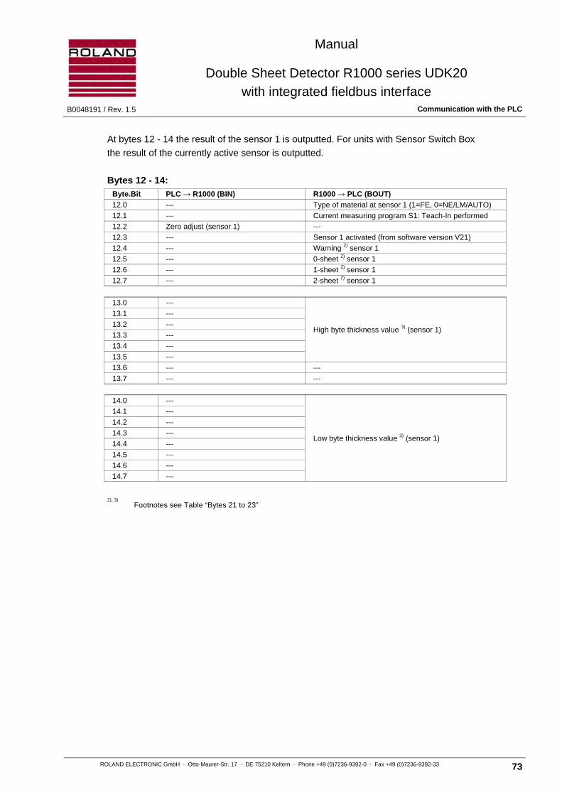
Manual
Double Sheet Detector R1000 series UDK20
with integrated fieldbus interface B0048191 / Rev. 1.5 Communication with the PLC
ROLAND ELECTRONIC GmbH · Otto-Maurer-Str. 17 · DE 75210 Keltern · Phone +49 (0)7236-9392-0 · Fax +49 (0)7236-9392-33 73
At bytes 12 - 14 the result of the sensor 1 is outputted. For units with Sensor Switch Box
the result of the currently active sensor is outputted.
Bytes 12 - 14: Byte.Bit PLC → R1000 (BIN) R1000 → PLC (BOUT)
12.0 --- Type of material at sensor 1 (1=FE, 0=NE/LM/AUTO)
12.1 --- Current measuring program S1: Teach-In performed
12.2 Zero adjust (sensor 1) ---
12.3 --- Sensor 1 activated (from software version V21)
12.4 --- Warning 2) sensor 1
12.5 --- 0-sheet 2) sensor 1
12.6 --- 1-sheet 2) sensor 1
12.7 --- 2-sheet 2) sensor 1
13.0 ---
High byte thickness value 3) (sensor 1)
13.1 ---
13.2 ---
13.3 ---
13.4 ---
13.5 ---
13.6 --- ---
13.7 --- ---
14.0 ---
Low byte thickness value 3) (sensor 1)
14.1 ---
14.2 ---
14.3 ---
14.4 ---
14.5 ---
14.6 ---
14.7 ---
2), 3)
Footnotes see Table “Bytes 21 to 23”
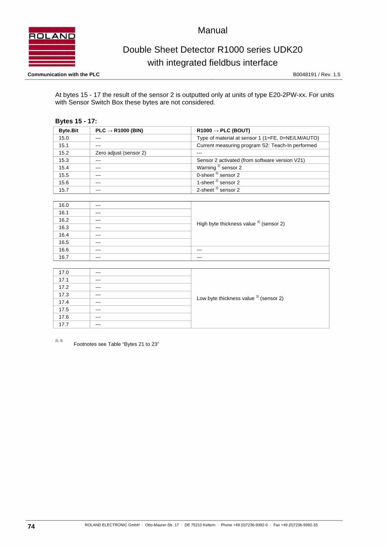
Manual
Double Sheet Detector R1000 series UDK20
with integrated fieldbus interface Communication with the PLC B0048191 / Rev. 1.5
74 ROLAND ELECTRONIC GmbH · Otto-Maurer-Str. 17 · DE 75210 Keltern · Phone +49 (0)7236-9392-0 · Fax +49 (0)7236-9392-33
At bytes 15 - 17 the result of the sensor 2 is outputted only at units of type E20-2PW-xx. For units with Sensor Switch Box these bytes are not considered.
Bytes 15 - 17: Byte.Bit PLC → R1000 (BIN) R1000 → PLC (BOUT)
15.0 --- Type of material at sensor 1 (1=FE, 0=NE/LM/AUTO)
15.1 --- Current measuring program S2: Teach-In performed
15.2 Zero adjust (sensor 2) ---
15.3 --- Sensor 2 activated (from software version V21)
15.4 --- Warning 2) sensor 2
15.5 --- 0-sheet 2) sensor 2
15.6 --- 1-sheet 2) sensor 2
15.7 --- 2-sheet 2) sensor 2
16.0 ---
High byte thickness value 3) (sensor 2)
16.1 ---
16.2 ---
16.3 ---
16.4 ---
16.5 ---
16.6 --- ---
16.7 --- ---
17.0 ---
Low byte thickness value 3) (sensor 2)
17.1 ---
17.2 ---
17.3 ---
17.4 ---
17.5 ---
17.6 ---
17.7 ---
2), 3) Footnotes see Table “Bytes 21 to 23”

Manual
Double Sheet Detector R1000 series UDK20
with integrated fieldbus interface B0048191 / Rev. 1.5 Communication with the PLC
ROLAND ELECTRONIC GmbH · Otto-Maurer-Str. 17 · DE 75210 Keltern · Phone +49 (0)7236-9392-0 · Fax +49 (0)7236-9392-33 75
Bytes 18 - 20: Byte.Bit PLC → R1000 (BIN) R1000 → PLC (BOUT)
18.0 --- ---
18.1 --- ---
18.2 --- ---
18.3 --- ---
18.4 --- ---
18.5 --- ---
18.6 --- ---
18.7 --- ---
19.0 --- ---
19.1 --- ---
19.2 --- ---
19.3 --- ---
19.4 --- ---
19.5 --- ---
19.6 --- ---
19.7 --- ---
20.0 --- ---
20.1 --- ---
20.2 --- ---
20.3 --- ---
20.4 --- ---
20.5 --- ---
20.6 --- ---
20.7 --- ---

Manual
Double Sheet Detector R1000 series UDK20
with integrated fieldbus interface Communication with the PLC B0048191 / Rev. 1.5
76 ROLAND ELECTRONIC GmbH · Otto-Maurer-Str. 17 · DE 75210 Keltern · Phone +49 (0)7236-9392-0 · Fax +49 (0)7236-9392-33
Bytes 21 - 23: Octet.bit PLC -> R1000 (BIN) R1000 -> PLC (BOUT)
21.0 --- ---
21.1 --- ---
21.2 --- ---
21.3 --- ---
21.4 --- ---
21.5 --- ---
21.6 --- ---
21.7 --- ---
22.0 --- ---
22.1 --- ---
22.2 --- ---
22.3 --- ---
22.4 --- ---
22.5 --- ---
22.6 --- ---
22.7 --- ---
23.0 --- ---
23.1 --- ---
23.2 --- ---
23.3 --- ---
23.4 --- ---
23.5 --- ---
23.6 --- ---
23.7 --- ---
1)
Ready / ENABLE (via I/O): If 0/0V, then control unit fault. Operator action necessary at the control unit, e.g. memory fault, voltage missing or too low. 2)
The control unit configuration can be selected 0V active or 24V active for these outputs. This applies also to I/O outputs. 3)
The measuring value is spent as follows:
HIGH BYTE (Byte 10 resp. 13, 16, 19, 22 without Bit 6, 7) Low Byte (Byte 11 resp. 14, 17, 20, 23)
1. Micrometer = 0…16000µm
2. 1 - 10000 inch = 0…6300 inch
For the output of the actual sensor selection via fieldbus following binary scheme applies:
Binary scheme sensor selection
Sensor selection B Sensor selection A Sensor
0 0 1
0 1 2
1 0 3
1 1 4
Note In the following timing diagrams all outputs and inputs via the bus are designated as BOUT and BIN, in contrast, the opto coupler interface uses OUT or IN.
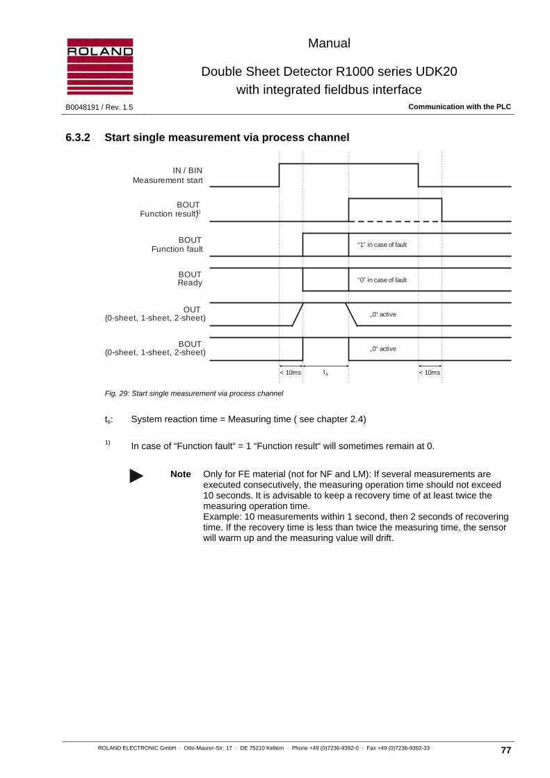
Manual
Double Sheet Detector R1000 series UDK20
with integrated fieldbus interface B0048191 / Rev. 1.5 Communication with the PLC
ROLAND ELECTRONIC GmbH · Otto-Maurer-Str. 17 · DE 75210 Keltern · Phone +49 (0)7236-9392-0 · Fax +49 (0)7236-9392-33 77
6.3.2 Start single measurement via process channel
Fig. 29: Start single measurement via process channel
ts: System reaction time = Measuring time ( see chapter 2.4)
1) In case of “Function fault“ = 1 “Function result“ will sometimes remain at 0.
Note Only for FE material (not for NF and LM): If several measurements are executed consecutively, the measuring operation time should not exceed 10 seconds. It is advisable to keep a recovery time of at least twice the measuring operation time. Example: 10 measurements within 1 second, then 2 seconds of recovering time. If the recovery time is less than twice the measuring time, the sensor will warm up and the measuring value will drift.
IN / BINMeasurement start
BOUTFunction result)1)
BOUTFunction fault
BOUTReady
OUT(0-sheet, 1-sheet, 2-sheet)
BOUT(0-sheet, 1-sheet, 2-sheet)
“1” in case of fault
“0” in case of fault
„0“ active
„0“ active
< 10ms ts < 10ms

Manual
Double Sheet Detector R1000 series UDK20
with integrated fieldbus interface Communication with the PLC B0048191 / Rev. 1.5
78 ROLAND ELECTRONIC GmbH · Otto-Maurer-Str. 17 · DE 75210 Keltern · Phone +49 (0)7236-9392-0 · Fax +49 (0)7236-9392-33
Set “Measurement start“ to HIGH
Waiting for “Function fault“ or Waiting for “Function result“
In case of “Function fault“:
- Pause 100 ms
- Set “Measurement start” to LOW
- Reset “Function fault“
In case of “Function result":
- Analyze
- Set “Measurement start” to LOW
Explanation:
• If a fault occurs when initiating the function (for instance a previous function is still active) then only the “Function fault“ is displayed. The “Function result“ will not be displayed. The other outputs remain in their current status.
• If the fault occurs during execution, the “Function fault“ is displayed. The “Function result“ will not be displayed (if the fault is connected to the function). The outputs remain in their current status.
• If the fault occurs after the result, for instance, by a faulty operation then this has no influence on the “Function result“.
• If the “Measurement start“ cycle is shorter than the duration of the function then the “Function result“ will not be displayed. However, the function is nevertheless executed ! For safety reason the control should not be executed in this fashion !
• If the “Measurement start“ cycle is longer than the duration of the function then the “Function result“ will be displayed as shown in the timing diagram.
Note Faults which are not critical can be deleted via the process channel with the “Reset function fault“ command.
Note The measured timing periods were determined with 12 Mbit- Profibus. These timing periods can vary with different transmission rates and bus systems. The cycle time of the PLC has not been taken into account.

Manual
Double Sheet Detector R1000 series UDK20
with integrated fieldbus interface B0048191 / Rev. 1.5 Communication with the PLC
ROLAND ELECTRONIC GmbH · Otto-Maurer-Str. 17 · DE 75210 Keltern · Phone +49 (0)7236-9392-0 · Fax +49 (0)7236-9392-33 79
6.3.3 Start continuous measurement via process channel
Fig. 30: Timing diagram for start continuous measurement via process channel
Note The output “Function result“ is set with the appearance of the first measurement value and then remains set.
Note The measured timing periods were determined with 12 Mbit- Profibus. These timing periods can vary with different transmission rates and bus systems. The cycle time of the PLC has not been taken into account.
ts: System reaction time = Measuring time ( see chapter 2.4)
tp: Additional recovery time of 0.5 seconds (for FE-material)
1) In case of “Function fault“ = 1 “Function result“ will sometimes remain at 0.
< 5ms ts < 10msts pt+ ts pt+ ts pt+ ts pt+
IN / BINMeasurement start
BOUTFunction result)1)
BOUTFunction fault
BOUTReady
BOUTBus(0-sheet, 1-sheet, 2-sheet)
OUT(0-sheet, 1-sheet, 2-sheet)
„1” if fault
„0” if fault
„0“ active
„0“ active

Manual
Double Sheet Detector R1000 series UDK20
with integrated fieldbus interface Communication with the PLC B0048191 / Rev. 1.5
80 ROLAND ELECTRONIC GmbH · Otto-Maurer-Str. 17 · DE 75210 Keltern · Phone +49 (0)7236-9392-0 · Fax +49 (0)7236-9392-33
6.3.4 Program switching
Fig. 31: Timing diagram for program switching
Note The measured timing periods were determined with 12 Mbit- Profibus. These timing periods can vary with different transmission rates and bus systems. The cycle time of the PLC has not been taken into account.
*1 The switch-over times depend on the last measured material and the material to be measured in the new program.
< 25ms for FE => FE or NF (or lm) => FE < 170ms for NF (or LM) => NF (or LM) < 440ms for FE => NF (or LM)
1) In case of “Function fault“ = 1 “Function result“ will sometimes remain at 0.
Program no. Bit 7 Bit 6 Bit 5 Bit 4 Bit 3 Bit 2 Bit 1 Bit 0
1 0 0 0 0 0 0 0 0
2 0 0 0 0 0 0 0 1
… … … … … … … … …
255 1 1 1 1 1 1 1 0
not used 1 1 1 1 1 1 1 1
Program switching
BIN Binary valueMeasurement program
BOUT Binary valueCurrent measurment program
BOUTFunction result)1)
BOUTFunction fault
BOUTReady
< 10ms
„1” if fault
0V if fault
*1< 10ms

Manual
Double Sheet Detector R1000 series UDK20
with integrated fieldbus interface B0048191 / Rev. 1.5 Communication with the PLC
ROLAND ELECTRONIC GmbH · Otto-Maurer-Str. 17 · DE 75210 Keltern · Phone +49 (0)7236-9392-0 · Fax +49 (0)7236-9392-33 81
6.3.5 System test
The system test must be performed before each measuring cycle. During the test, no sheet should be in front of the sensor which is used in the active program.
Fig. 32: Timing diagram for system test
Note The measured timing periods were determined with 12 Mbit- Profibus. These timing periods can vary with different transmission rates and bus systems. The cycle time of the PLC has not been taken into account.
1) In case of “Function fault“ = 1 “Function result“ will sometimes remain at 0.
BINSystem test
BOUTFunction result)1)
BOUTFunction fault
BOUTReady
OUT Warning(0-sheet, 1-sheet, 2-sheet)
BOUT Warning(0-sheet, 1-sheet, 2-sheet)
OUTENABLE
„1” if fault
0V if fault
< 100ms < 10ms< 10ms

Manual
Double Sheet Detector R1000 series UDK20
with integrated fieldbus interface Communication with the PLC B0048191 / Rev. 1.5
82 ROLAND ELECTRONIC GmbH · Otto-Maurer-Str. 17 · DE 75210 Keltern · Phone +49 (0)7236-9392-0 · Fax +49 (0)7236-9392-33
6.3.6 Clear 2-sheet / Clear 0-, 1- , 2-sheet outputs
Fig. 33: Timing diagram for clear sheet outputs
Note The measured timing periods were determined with 12 Mbit- Profibus. These timing periods can vary with different transmission rates and bus systems. The cycle time of the PLC has not been taken into account.
Function result)1)
BOUTFunction fault
BOUTReady
OUT(0-sheet, 1-sheet, 2-sheet)
BOUT(0-sheet, 1-sheet, 2-sheet)
BIN CLR 2-sheet(0-sheet, 1-sheet, 2-sheet)
„0“ active
„0“ active
„1” if fault
0V if fault
< 20ms < 10ms< 10ms

Manual
Double Sheet Detector R1000 series UDK20
with integrated fieldbus interface B0048191 / Rev. 1.5 Communication with the PLC
ROLAND ELECTRONIC GmbH · Otto-Maurer-Str. 17 · DE 75210 Keltern · Phone +49 (0)7236-9392-0 · Fax +49 (0)7236-9392-33 83
6.3.7 Teach-In 0-sheet / Zero adjust
At zero adjust Bit 8.2 the sensor is nulled in the active program.
Fig. 34: Timing diagram for Teach-In / zero adjust
Note The measured timing periods were determined with 12 Mbit- Profibus. These timing periods can vary with different transmission rates and bus systems. The cycle time of the PLC has not been taken into account.
1) In case of “Function fault“ = 1 “Function result“ will sometimes remain at 0.
BIN Teach-In 0-sheetZero adjust
1 Sensor = 8 sec.2 Sensor = 15 sec.
„1” if fault
0V if fault
BOUTFunction result)1)
BOUTFunction fault
BOUTReady
< 10ms< 10ms

Manual
Double Sheet Detector R1000 series UDK20
with integrated fieldbus interface Communication with the PLC B0048191 / Rev. 1.5
84 ROLAND ELECTRONIC GmbH · Otto-Maurer-Str. 17 · DE 75210 Keltern · Phone +49 (0)7236-9392-0 · Fax +49 (0)7236-9392-33
6.3.8 Teach-In 1-sheet
The sensors used in the active program are teached.
Note During Teach-In one sheet of nominal thickness must be placed in front of the sensor.
Note A zero adjust procedure must be executed immediately before the Teach-In procedure.
Fig. 35: Timing diagram for Teach-In 1-sheet
Note The uncorrected thickness (thickness taken from the curve) is issued via the process channel. Should the thickness deviate more then 10 percent (exceptions 20 percent) from the nominal thickness then the cause for this deviation must be investigated. This could be: wrong sheet, wrong thickness, bowed sheet, air gap between sensor and sheet.
Note The measured timing periods were determined with 12 Mbit- Profibus. These timing periods can vary with different transmission rates and bus systems. The cycle time of the PLC has not been taken into account.
1) In case of “Function fault“ = 1 “Function result“ will sometimes remain at 0.
7 sec. < 10ms
„1” if fault
0V if fault
BOUTFunction result)1)
BOUTFunction fault
BOUTReady
BINTeach-In 1-sheet
< 10ms

Manual
Double Sheet Detector R1000 series UDK20
with integrated fieldbus interface B0048191 / Rev. 1.5 Communication with the PLC
ROLAND ELECTRONIC GmbH · Otto-Maurer-Str. 17 · DE 75210 Keltern · Phone +49 (0)7236-9392-0 · Fax +49 (0)7236-9392-33 85
6.3.9 Reset Function fault
Fig. 36: Timing diagram for reset function fault
OUT ENABLE is not reset if a critical systems fault is present. Examples are memory fault, power failure, or voltage too low. Critical faults cannot be reset via the process channel. It is necessary to eliminate the cause of the fault.
Note The measured timing periods were determined with 12 Mbit- Profibus. These timing periods can vary with different transmission rates and bus systems. The cycle time of the PLC has not been taken into account.
1) In case of “Function fault“ = 1 “Function result“ will sometimes remain at 0.
< 10ms
„1” if fault
0V if fault
BOUTFunction result)1)
BOUTFunction fault
BOUTENABLE
BINReset function fault

Manual
Double Sheet Detector R1000 series UDK20
with integrated fieldbus interface Communication with the PLC B0048191 / Rev. 1.5
86 ROLAND ELECTRONIC GmbH · Otto-Maurer-Str. 17 · DE 75210 Keltern · Phone +49 (0)7236-9392-0 · Fax +49 (0)7236-9392-33
6.4 Parameter channel
The parameter channel is designed to exchange systems and parameter data of the R1000 with the master. Primary purpose is the central data backup on the master. In addition, certain measurement and operating parameters can be extracted from the R1000 and analyzed by the master.
Note The configuration of the data format has to be compatible with the
PLC for consistent data transmission!
The data transmission via the parameter channel must be initiated with the service “Open parameter channel“. The end of data transmission mission via the parameter channel must be completed with the service “Close parameter channel“.
If the parameter channel is open then it is not possible to issue control commands via the process channel or via inputs on the keyboard.
6.4.1 Structure of the parameter channel
Structure of the parameter channel
Meaning I/O Byte Notes
Byte 0 1 2 3 4 5 6 7
Management x Data access control (reading, writing, handshake)
Program index x Selection of the tooling program
Parameter index x Selection of the parameter
Application data byte 0 x
MSB (most significant byte) LSB (least significant byte)
Application data byte 1 x
Application data byte 2 x
Application data byte 3 x
Checksum x Checksum of the transferred bytes 1 - 6
Data access control
Services are initiated exclusively by the master. The R1000 as slave cannot initiate data transmissions.
The management byte (I0) is used by the master to select the service (for example writing or reading) and to confirm the access. The R1000 confirms via the management byte (O0) the execution of the command. If an access is not allowed and therefore, the service cannot be executed, then the R1000 declares this action a collision.
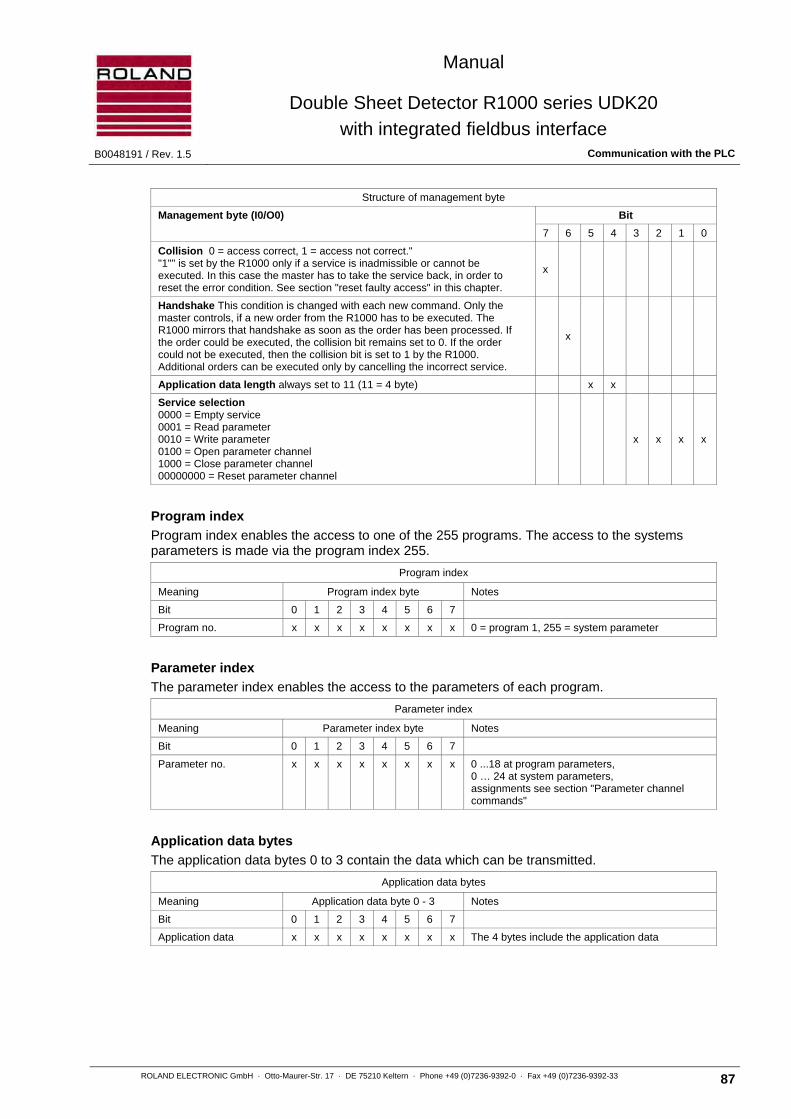
Manual
Double Sheet Detector R1000 series UDK20
with integrated fieldbus interface B0048191 / Rev. 1.5 Communication with the PLC
ROLAND ELECTRONIC GmbH · Otto-Maurer-Str. 17 · DE 75210 Keltern · Phone +49 (0)7236-9392-0 · Fax +49 (0)7236-9392-33 87
Structure of management byte
Management byte (I0/O0) Bit
7 6 5 4 3 2 1 0
Collision 0 = access correct, 1 = access not correct." "1"" is set by the R1000 only if a service is inadmissible or cannot be executed. In this case the master has to take the service back, in order to reset the error condition. See section "reset faulty access" in this chapter.
x
Handshake This condition is changed with each new command. Only the master controls, if a new order from the R1000 has to be executed. The R1000 mirrors that handshake as soon as the order has been processed. If the order could be executed, the collision bit remains set to 0. If the order could not be executed, then the collision bit is set to 1 by the R1000. Additional orders can be executed only by cancelling the incorrect service.
x
Application data length always set to 11 (11 = 4 byte) x x
Service selection 0000 = Empty service 0001 = Read parameter 0010 = Write parameter 0100 = Open parameter channel 1000 = Close parameter channel 00000000 = Reset parameter channel
x x x x
Program index
Program index enables the access to one of the 255 programs. The access to the systems parameters is made via the program index 255.
Program index
Meaning Program index byte Notes
Bit 0 1 2 3 4 5 6 7
Program no. x x x x x x x x 0 = program 1, 255 = system parameter
Parameter index
The parameter index enables the access to the parameters of each program.
Parameter index
Meaning Parameter index byte Notes
Bit 0 1 2 3 4 5 6 7
Parameter no. x x x x x x x x 0 ...18 at program parameters, 0 … 24 at system parameters, assignments see section "Parameter channel commands"
Application data bytes
The application data bytes 0 to 3 contain the data which can be transmitted.
Application data bytes
Meaning Application data byte 0 - 3 Notes
Bit 0 1 2 3 4 5 6 7
Application data x x x x x x x x The 4 bytes include the application data

Manual
Double Sheet Detector R1000 series UDK20
with integrated fieldbus interface Communication with the PLC B0048191 / Rev. 1.5
88 ROLAND ELECTRONIC GmbH · Otto-Maurer-Str. 17 · DE 75210 Keltern · Phone +49 (0)7236-9392-0 · Fax +49 (0)7236-9392-33
Checksum
The checksum is formed of the bytes 1 – 6.
Checksum
Meaning Checksum byte Notes
Bit 0 1 2 3 4 5 6 7
Checksum x x x x x x x x Checksum of data communication bytes 1 - 6
The checksum of bytes 1 - 6 is calculated and the least significant byte of the result is inserted into byte 7.
6.4.2 Service "Open parameter channel"
The service open parameter channel is initiated by the master with the selection of the service. The content of the index bytes I1, I2 and the application data bytes 0 through 3 are not relevant. The checksum of bytes 1 through 6 is calculated and inserted in byte 7. To initiate the service the master changes the handshake bit.
To avoid data fault the following sequence is compulsory:
1. Service selection, program index, parameter index 2. Switch handshake
In addition consistent data transmission from master is necessary.
Note For the service “Open parameter channel“ the index bytes I1,I2 and the application data bytes I3... I6 are not relevant.
The R1000 checks the data with the checksum and mirrors the application data, the service selection and the index selection into O1, O2.The R1000 sets the handshake bit in O0.0 only in the last step and signals thereby that the data is valid. This sequence is observed by the R1000 in order to avoid data faults.
The slave should ensure a consistent data transmission.
Attention If reading cannot be executed the collision bit is set. The fault number is transmitted instead of application data, see section “6.4.8 Reset faulty access“. The collision bit can be deleted with one of the following services: Close parameter channel, Empty service or Reset parameter channel.

Manual
Double Sheet Detector R1000 series UDK20
with integrated fieldbus interface B0048191 / Rev. 1.5 Communication with the PLC
ROLAND ELECTRONIC GmbH · Otto-Maurer-Str. 17 · DE 75210 Keltern · Phone +49 (0)7236-9392-0 · Fax +49 (0)7236-9392-33 89
6.4.3 Service "Close parameter channel"
The service “Close parameter channel“ is initiated by the master by selecting the service. The content of the index bytes I1, I2 and the application data bytes 0 through 3 is not relevant. The checksum of bytes 1 through 6 is calculated and inserted in byte 7. To initiate the service the master changes the handshake bit.
To avoid data fault the following sequence is compulsory:
1. Service selection, program index, parameter index 2. Switch handshake
In addition consistent data transmission from master is necessary.
Note For the service “Open parameter channel“ the index bytes I1,I2 and the application data bytes I3... I6 are irrelevant.
The R1000 checks the data with the checksum and mirrors the application data bytes, the service selection and the index selection in O1, O2. The R1000 sets the handshake bit in O0.0 only in the last step and signals thereby that the data is valid. This sequence is observed by the R1000 in order to avoid data faults.
The slave should ensure a consistent data transmission.
Attention If the checksum is correct then the closing of the parameter channel is always executed. A set collision bit is thereby deleted.
6.4.4 Service "Read parameters"
The master initiates the service “Read parameter“ by selecting the service, and index bytes I1 and I2. The content of the application data bytes 0 to 3 is not relevant. The checksum of byte 1 through 6 is calculated and inserted in byte 7. To initiate the service the master changes the handshake bit.
In order to avoid data faults the following sequence is compulsory:
1. Service selection, program index, parameter index 2. Switch handshake
In addition consistent data transmission from master is necessary.
Note The application data bytes I3 - I6 of the service “Read parameter“ are not relevant.
The R1000 checks the data with the checksum and makes the content of the respective parameters available in the application data bytes of parameter channel O3 ... O6. In addition the R1000 mirrors the service “Read parameter“ and the index adjustment in O1, O2. Only in the last step sets the R1000 the handshake bit into O0.0 and indicates thereby that the data is valid.
This sequence is observed by the R1000 in order to avoid data faults.
The slave should ensure a consistent data transmission.
Attention A collision bit is set if reading cannot be executed. Instead of application data the default number is transmitted, see “6.4.8 Reset faulty access“.

Manual
Double Sheet Detector R1000 series UDK20
with integrated fieldbus interface Communication with the PLC B0048191 / Rev. 1.5
90 ROLAND ELECTRONIC GmbH · Otto-Maurer-Str. 17 · DE 75210 Keltern · Phone +49 (0)7236-9392-0 · Fax +49 (0)7236-9392-33
6.4.5 Service "Write parameters"
Initiate the master with the setting of the service selection, the index bytes I1 and I2. The content of the application data bytes 0 to 3 are also stored. The checksum of byte 1 through 6 is calculated and inserted in byte 7. To initiate the service the master changes the handshake bit.
In order to avoid data faults the following sequence is compulsory:
1. Service selection, program index, parameter index, application data byte 0 to 3 2. Switch handshake
In addition consistent data communication from the master is necessary.
The R1000 checks the data with the checksum and transfers the content of the application data bytes of the parameter channel I3 … I6 into its own parameter memory. Afterwards the R1000 mirrors the index adjustment in O1, O2 and the application data in O3 … O6. Only in the last step inserts the R1000 the handshake bit in O0.0 and indicates thereby that the data has been completely accepted. The same sequence applies here also, in order to avoid data faults.
The slave should ensure a consistent data transmission.
Attention If writing cannot be executed, the collision bit is set. In place of the application data a fault number is transmitted, see section “6.4.8 Reset faulty access“.
6.4.6 Service "Empty service"
The master initiates the service “Empty service“ with the setting of the service selection. The content of the index bytes I1, I2 and the application data bytes 0 to 3 are not relevant. The checksum of byte 1 through 6 is calculated and inserted in byte 7. To initiate the service the master switches the handshake bit.
In order to avoid data faults the following sequence is compulsory:
1. Service selection, program index, parameter index, application data byte 0 to 3 2. Switch handshake
In addition consistent data communication from the master is necessary.
The R1000 checks the data with the checksum and mirrors the index adjustment in O1, O2 and the application data in O3 ... O6. A possibly set collision bit is set back. Only in the last step inserts the R1000 the handshake bit in O0.0 and indicates thereby that the data has been completely accepted. The same sequence applies here also, in order to avoid data faults.
The slave should ensure a consistent data transmission.
Attention If the service “Empty service“ cannot be executed, the collision bit is set (remains set). In place of the application data a fault code is transmitted, see section “6.4.8 Reset faulty access“.
Manual
Double Sheet Detector R1000 series UDK20
with integrated fieldbus interface B0048191 / Rev. 1.5 Communication with the PLC
ROLAND ELECTRONIC GmbH · Otto-Maurer-Str. 17 · DE 75210 Keltern · Phone +49 (0)7236-9392-0 · Fax +49 (0)7236-9392-33 91
6.4.7 Service "Reset parameter channel"
The service “Rest parameter channel“ initiates the master by transferring a zero string. The service was added for safety reasons during the start up of the system or in case a fault occurs in the bus.
The R1000 closes the parameters channel and mirrors "parameters channel closed" (38 00 00 00 00 00 00 00 Hex). The handshake bit remains set to 0. The collision bit is also set to 0.
Attention If the fieldbus is off-line the service “Reset parameter channel“ is automatically executed.
6.4.8 Reset faulty access
For the following reasons a service cannot be executed:
• The current operating conditions do not allow the execution of the selected service.
• The collision bit in the management byte has not been reset.
• The index register address invalid parameters.
• The service cannot be applied to this parameter.
• The application data contains inadmissible values.
• The service is unknown.
The reasons above can prevent the service execution during reading or writing. The R1000 indicates this problem by the collision bit. In order to prevent an additional uncontrolled access procedure, the R1000 expects the reset of the called service by the master. In addition the master executes an “Empty service“ with the confirmation of a handshake. After receipt of this empty order, the R1000 puts the collision bit back and confirms the service with a handshake. Thus the fault condition can be reset and the R1000 is available for further orders.
Note If necessary the collision bit can be reset by the service “Close parameter channel“ and by the service “Reset parameter channel“. However the parameter channel is thereby closed.
6.4.9 Listing of parameter channel commands
A list with all parameter channel commands is specified in chapter “11.3
Manual
Double Sheet Detector R1000 series UDK20
with integrated fieldbus interface Communication with the PLC B0048191 / Rev. 1.5
92 ROLAND ELECTRONIC GmbH · Otto-Maurer-Str. 17 · DE 75210 Keltern · Phone +49 (0)7236-9392-0 · Fax +49 (0)7236-9392-33
6.4.10 Example: Remote control with parameter adjustment for the UDK20
H is the handshake bit and switched by the master and with each data transmission via the parameter channel (see section of “6.4.1 Layout of the parameters channel - data access control“)
1. Terminate current activities via I/O or process channel
2. Open parameter channel with service “Open parameter channel“ - Transfer: 0H110100b 00h 00h 00h 00h 00h 00h 00h - Wait for answer: 0H110100b 00h 00h 00h 00h 00h 00h 00h - In case of a collision: Undo the collision with the service “Empty service“, remove the cause of the collision and open again. If necessary evaluate fault number in application data bytes.
3. Set sensor number to the desired program index (e.g. program number 7, sensor number 1) - Transfer: 0H110010b 06h 01h 00h 00h 00h 01h 08h - Wait for answer: 0H110010b 06h 01h 00h 00h 00h 01h 08h - In case of a collision: Undo the collision with the service “Empty service“, remove the cause of the collision and open again. If necessary evaluate fault number in application data byte
4. Set nominal thickness to the desired program index (e.g. program number 7, 1.00 mm) - Transfer: 0H110010b 06h 02h 00h 00h 03h E8h F3h - Wait for answer: 0H110010b 06h 02h 00h 00h 03h E8h F3h - In case of a collision: Undo the collision with the service “Empty service“, remove the cause of the collision and open again. If necessary evaluate fault number in application data byte
5. Set the lower limit to the desired program index (e.g. program number 7, 80%) - Transfer: 0H110010b 06h 04h 00h 00h 03h 20h 2Dh - Wait for answer: 0H110010b 06h 04h 00h 00h 03h 20h 2Dh - In case of a collision: Undo the collision with the service “Empty service“, remove the cause of the collision and open again. If necessary evaluate fault number in application data byte
6. Set the upper limit to the desired program index (e.g. program number 7, 120%) - Transfer: 0H110010b 06h 05h 00h 00h 04h B0h BFh - Wait for answer: 0H110010b 06h 05h 00h 00h 04h B0h BFh - In case of a collision: Undo the collision with the service “Empty service“, remove the cause of the collision and open again. If necessary evaluate fault number in application data byte
7. Close Parameter channel - Transfer: 0H111000b 00h 00h 00h 00h 00h 00h 00h - Wait for answer: 0H111000b 00h 00h 00h 00h 00h 00h 00h - In case of collision: Undo the collision with service “Empty service“, remove the cause of the collision (normally only wrong content or checksum are possible) and close. If necessary evaluate fault number in application data bytes.
8. Switch program number via the process channel (e.g. switch to program number 7) - Transfers: byte 9: 06h, byte 8: 40h - Answer: byte 8: 01h, byte 9: 06h - In case of malfunctioning the “Function fault“ is returned (see also section “6.3 Process channel“)
9. Execute zero adjust via the process channel (without sheet in front of the sensor) - Transfer: byte 8: 04h - Answer: byte 8: 01h - In case of malfunctioning the “Function fault“ is returned (see also section “6.3 Process channel“)
10. Execute Teach-In via the process channel (attach sheet with nominal thickness to the sensor) - Transfer: byte 8: 08h - Answer: byte 8: 01h - The thickness from the curve is sent to byte 10 and 11. If the issued thickness deviates more than 10% (exceptions 20%) of the nominal thickness, then it is necessary to search for the cause. This could be: wrong sheet, wrong thickness, warped sheets, air gap between sensor and sheet. - In case of malfunctioning the “Function fault“ is returned (see also section “6.3 Process channel“)
11. Open, if necessary, the parameters channel again and read the internal program parameter (1-13) of the selected programs and store the data backup in the PLC. Then close the parameters channel again.

Manual
Double Sheet Detector R1000 series UDK20
with integrated fieldbus interface B0048191 / Rev. 1.5 Communication with the PLC
ROLAND ELECTRONIC GmbH · Otto-Maurer-Str. 17 · DE 75210 Keltern · Phone +49 (0)7236-9392-0 · Fax +49 (0)7236-9392-33 93
6.5 External I/O control
The system is normally controlled via the process channel. The exception is the signal "Measurement start", which, for fast procedures, can also be controlled via the optocoupler inputs (IN). A mixed operation is also possible. The control cannot, however, be made simultaneously by both signal sources.
The “Measurement start“ signals can be initiated via the process channel or the opto couplers. Simultaneous initiation is not possible. That means that the initiation of measurement start is not accepted by opto couplers, if measurement start of the process channel is active or not processed. The same applies to the other way.
optocoupler inputs
Signal Meaning Notes
IN0 Measurement start input 1 Optocoupler input 1 24 V active
IN1 Measurement start input 2 Optocoupler input 2 24 V active
IN2 Measurement start input 3 Optocoupler input 3 24 V active
The “Measurement start“ inputs are linked in different combinations via AND. The following configuration can be selected in the control unit:
• IN0
• IN0 and IN1
• IN0 and IN1 and IN2
In addition the signals 0-, 1-, 2-sheet, ENABLE and warning are available for further processing via optocoupler (OUT).
optocoupler ouputs
Signal Meaning Notes
OUT0 Output 0-sheet 1st Optocoupler output standard 0 V active (selection in the control unit configuration)
OUT1 Output 1-sheet 2nd Optocoupler output standard 0 V active (selection in the control unit configuration)
OUT2 Output 2-sheet 3rd Optocoupler output standard 0 V active (selection in the control unit configuration)
OUT3 Output ENABLE 4th Optocoupler output standard 24 V active (cannot be selected for safety reasons)
OUT4 Warning 5th Optocoupler output standard 0 V active (cannot be selected for safety reasons)

Manual
Double Sheet Detector R1000 series UDK20
with integrated fieldbus interface Communication with the PLC B0048191 / Rev. 1.5
94 ROLAND ELECTRONIC GmbH · Otto-Maurer-Str. 17 · DE 75210 Keltern · Phone +49 (0)7236-9392-0 · Fax +49 (0)7236-9392-33
6.5.1 Explanation of summary output 0-sheet, 1-sheet and 2-sheet:
If the unit is used in sequencer-mode (more than 1 sensor in a program e.g. 1+3+4), the measurement result is formed as summary output. The priorities are:
2-sheet is issued if at least one sensor detects 2-sheet.
1-sheet is issued if all sensors detect 1-sheet.
0-sheet is issued if no 2-sheet is detected but at least one sensor detects 0-sheet.
Truth table for summary output
Sensor 1 Sensor 2 Sensor 3 Sensor 4
2-sheet is issued if:
2-sheet any condition
any condition 2-sheet any condition
any condition 2-sheet any condition
any condition 2-sheet
1-sheet is issued if:
1-sheet 1-sheet 1-sheet 1-sheet
0-sheet is issued if:
0-sheet 0-sheet / 1-sheet
0-sheet / 1-sheet 0-sheet 0-sheet / 1-sheet
0-sheet / 1-sheet 0-sheet 0-sheet / 1-sheet
0-sheet / 1-sheet 0-sheet
The results of the separate sensors are available in the bytes 12-23 and can be used as required.
6.5.2 Signal "Enable"
The signal “ENABLE“ corresponds with the two process channel signals BOUT “Ready“ and BOUT “Function fault“ according to the following Boolean logic.
Fig. 37: Boolean function “ENABLE”
If the signal BOUT “Ready“ is reset, then a fault has occurred, which requires a user intervention at the control unit. Possible causes: memory faults, missing or too low voltages.
Note The timing diagrams in the sections “6.5.4“ and “6.5.5“ do not contain an
explicit chart of the signal “ENABLE“.
&BOUTReady
BOUTFunction fault
ENABLE
ENABLE = BOUT Ready BOUT Function fault
Manual
Double Sheet Detector R1000 series UDK20
with integrated fieldbus interface B0048191 / Rev. 1.5 Communication with the PLC
ROLAND ELECTRONIC GmbH · Otto-Maurer-Str. 17 · DE 75210 Keltern · Phone +49 (0)7236-9392-0 · Fax +49 (0)7236-9392-33 95
6.5.3 Signal "Warning"
The “Warning“ signal is an additional output signal with fixed evaluation thresholds.
The signal becomes activated if the measurement result is below 80% or above 120% of the preset nominal value.
Application:
If the "Warning" is active in the measurement, though only one sheet in front of the sensor, measurement problems may have occurred:
• Air gap between sensor and sheet
• Wrong type of sheet
• Sensor coverage not sufficient
Note If these requirements are met, but a warning signal is issued, then the
Teach-In must be repeated. The requirements from section “4.3 Sensor mounting“ should be observed.
Note The signal will also be activated if measurements without a sheet
(measurement value <80%) and measurements with double sheet / two sheets (measurement value >120%).

Manual
Double Sheet Detector R1000 series UDK20
with integrated fieldbus interface Communication with the PLC B0048191 / Rev. 1.5
96 ROLAND ELECTRONIC GmbH · Otto-Maurer-Str. 17 · DE 75210 Keltern · Phone +49 (0)7236-9392-0 · Fax +49 (0)7236-9392-33
6.5.4 Start single measurement via external input
Fig. 38: Timing diagram for Start single measuring via external inputs
Note The operation of the individual measurement, which is initiated via
the external input, can be controlled via the process channel, see section “6.3.2 Start single measurement via process channel“. If no control is done via the process channel, then the measurement operation must be controlled by the signal “ENABLE“, see section “6.5.2 Signal ENABLE“.
Note Only for FE material (not for NF and LM): If several measurements are executed consecutively, the measuring operation time should not exceed 10 seconds. It is advisable to keep a recovery time of at least twice the measuring operation time. Example: 10 measurements within 1 second, then 2 seconds of recovering time. If the recovery time is less than twice the measuring time, the sensor will warm up and the measuring value will drift.
ts: System reaction time = Measuring time ( see chapter 2.4)
1)
In case of “Function fault“ = 1 “Function result“ will sometimes remain at 0.
IN / BINMeasurement start
BOUTFunction result)1)
BOUTFunction fault
BOUTReady
OUT(0-sheet, 1-sheet, 2-sheet)
BOUT(0-sheet, 1-sheet, 2-sheet)
“1” in case of fault
“0” in case of fault
„0“ active
„0“ active
< 10ms ts < 10ms

Manual
Double Sheet Detector R1000 series UDK20
with integrated fieldbus interface B0048191 / Rev. 1.5 Communication with the PLC
ROLAND ELECTRONIC GmbH · Otto-Maurer-Str. 17 · DE 75210 Keltern · Phone +49 (0)7236-9392-0 · Fax +49 (0)7236-9392-33 97
6.5.5 Start continuous measurement via external input
Fig. 39: Timing diagram for start continuous measurement via external inputs
Note The output function result is set with the arrival of the first measured
value and remains set.
ts: System reaction time = Measuring time ( see chapter 2.4)
tp: Additional recovery time of 0.5 seconds (for FE-material)
1) In case of “Function fault“ = 1 “Function result“ will sometimes remain at 0.
< 5ms ts < 10msts pt+ ts pt+ ts pt+ ts pt+
IN / BINMeasurement start
BOUTFunction result)1)
BOUTFunction fault
BOUTReady
BOUTBus(0-sheet, 1-sheet, 2-sheet)
OUT(0-sheet, 1-sheet, 2-sheet)
„1” if fault
„0” if fault
„0“ active
„0“ active

Manual
Double Sheet Detector R1000 series UDK20
with integrated fieldbus interface Communication with the PLC B0048191 / Rev. 1.5
98 ROLAND ELECTRONIC GmbH · Otto-Maurer-Str. 17 · DE 75210 Keltern · Phone +49 (0)7236-9392-0 · Fax +49 (0)7236-9392-33
6.6 Fieldbus configuration file
6.6.1 GSD file for Profibus-DP
The GSD file contains the specific configuration data of the slave. The data must be known to the Profibus master.
The manufacturers of the Profibus master supply the tools for the integration of the GSD file into the Profibus network. Suitable are for example the Siemens step 7 tools. Roland Electronic does not supply such tools, because they have to be compatible with the interface design of the master.
The GSD file is supplied on a CD or can be downloaded from the Roland homepage.
Note 24 Bytes I/O must be set.
6.6.2 EDS file for ControlNet
The EDS file contains the specific configuration data of the ControlNet adapter. The data must be known to the scanner.
The manufacturers of the scanner supply the tools for the integration of the EDS file into the ControlNet network. Suitable are for example Rockwell RSNetworx configuration tools. Roland Electronic does not supply such tools, because they have to be compatible with the interface design of the scanner.
The EDS file is supplied on a CD or can be downloaded from the Roland homepage.
Note: 24 Bytes I/O must be set.
6.6.3 EDS file for DeviceNet
The EDS file contains the specific configuration data of the slaves. The data must be known to the DeviceNet master.
The manufacturers of the DeviceNet master supply the tools for the integration of the EDS file into the DeviceNet network. Suitable are for example the Allen-Bradley DeviceNet manager. Roland Electronic does not supply such tools, because they have to be compatible with the interface design of the master.
The EDS file is supplied on a CD or can be downloaded from the Roland homepage.
Note 24 Bytes I/O must be set.

Manual
Double Sheet Detector R1000 series UDK20
with integrated fieldbus interface B0048191 / Rev. 1.5 Communication with the PLC
ROLAND ELECTRONIC GmbH · Otto-Maurer-Str. 17 · DE 75210 Keltern · Phone +49 (0)7236-9392-0 · Fax +49 (0)7236-9392-33 99
6.6.4 EDS file for CanOpen
The EDS file contains the specific configuration data of the slaves. The data must be known to the master.
The manufacturers of the master supply the tools for the integration of the EDS file into the network. Roland Electronic does not supply such tools, because they have to be compatible with the interface design of the master.
The EDS file is supplied on a CD or can be downloaded from the Roland homepage.
Note 3 PDOs with 8 Bytes each are set.
6.6.5 GSD file for ProfiNet IO
The GSD file contains the specific configuration data of the device. The data must be known to the controller.
The manufacturers of the controller supply the tools for the integration of the GSD file into the Profibus network. Roland Electronic does not supply such tools, because they have to be compatible with the interface design of the controller.
The GSD file is supplied on a CD or can be downloaded from the Roland homepage.
Note 24 Bytes I/O must be set.
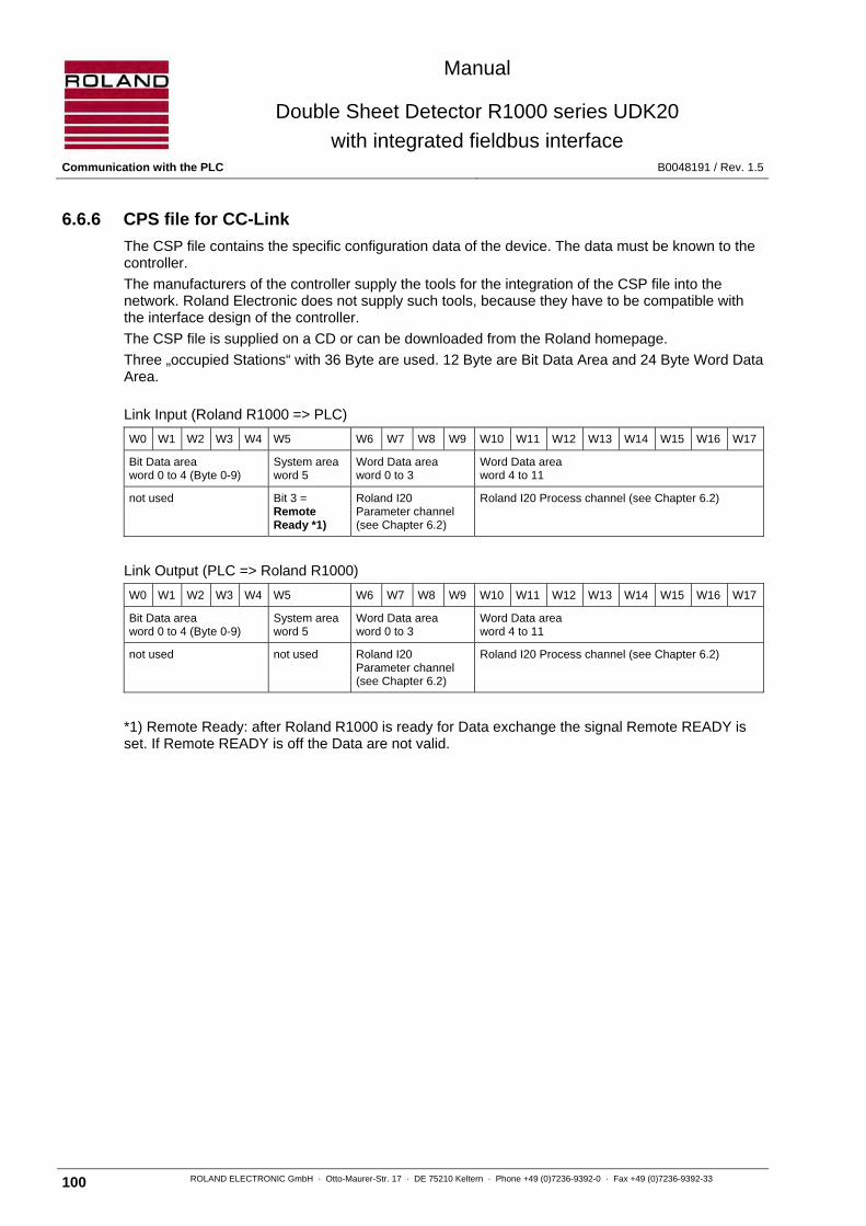
Manual
Double Sheet Detector R1000 series UDK20
with integrated fieldbus interface Communication with the PLC B0048191 / Rev. 1.5
100 ROLAND ELECTRONIC GmbH · Otto-Maurer-Str. 17 · DE 75210 Keltern · Phone +49 (0)7236-9392-0 · Fax +49 (0)7236-9392-33
6.6.6 CPS file for CC-Link
The CSP file contains the specific configuration data of the device. The data must be known to the controller.
The manufacturers of the controller supply the tools for the integration of the CSP file into the network. Roland Electronic does not supply such tools, because they have to be compatible with the interface design of the controller.
The CSP file is supplied on a CD or can be downloaded from the Roland homepage.
Three „occupied Stations“ with 36 Byte are used. 12 Byte are Bit Data Area and 24 Byte Word Data Area.
Link Input (Roland R1000 => PLC)
W0 W1 W2 W3 W4 W5 W6 W7 W8 W9 W10 W11 W12 W13 W14 W15 W16 W17
Bit Data area word 0 to 4 (Byte 0-9)
System area word 5
Word Data area word 0 to 3
Word Data area word 4 to 11
not used Bit 3 = Remote Ready *1)
Roland I20 Parameter channel (see Chapter 6.2)
Roland I20 Process channel (see Chapter 6.2)
Link Output (PLC => Roland R1000)
W0 W1 W2 W3 W4 W5 W6 W7 W8 W9 W10 W11 W12 W13 W14 W15 W16 W17
Bit Data area word 0 to 4 (Byte 0-9)
System area word 5
Word Data area word 0 to 3
Word Data area word 4 to 11
not used not used Roland I20 Parameter channel (see Chapter 6.2)
Roland I20 Process channel (see Chapter 6.2)
*1) Remote Ready: after Roland R1000 is ready for Data exchange the signal Remote READY is set. If Remote READY is off the Data are not valid.

Manual
Double Sheet Detector R1000 series UDK20
with integrated fieldbus interface B0048191 / Rev. 1.5 Communication with the PLC
ROLAND ELECTRONIC GmbH · Otto-Maurer-Str. 17 · DE 75210 Keltern · Phone +49 (0)7236-9392-0 · Fax +49 (0)7236-9392-33 101
6.6.7 EDS file for EtherNet/IP
The EDS file contains the specific configuration data of the device. The data must be known to the controller.
The manufacturers of the controller supply the tools for the integration of the EDS file into the network. Roland Electronic does not supply such tools, because they have to be compatible with the interface design of the controller.
The EDS file is supplied on a CD or can be downloaded from the Roland homepage.
Note 24 Bytes I/O must be set.
6.6.8 Device Description file for EtherCAT
The Device Description file contains the specific configuration data of the device. The data must be known to the controller.
The manufacturers of the controller supply the tools for the integration of the Device Description file into the network. Roland Electronic does not supply such tools, because they have to be compatible with the interface design of the controller.
The Device Description file is supplied on a CD or can be downloaded from the Roland homepage.
Note 24 Bytes I/O must be set.

Manual
Double Sheet Detector R1000 series UDK20
with integrated fieldbus interface Start-up B0048191 / Rev. 1.5
102 ROLAND ELECTRONIC GmbH · Otto-Maurer-Str. 17 · DE 75210 Keltern · Phone +49 (0)7236-9392-0 · Fax +49 (0)7236-9392-33
Blank page
Manual
Double Sheet Detector R1000 series UDK20
with integrated fieldbus interface B0048191 / Rev. 1.5 Start-up
ROLAND ELECTRONIC GmbH · Otto-Maurer-Str. 17 · DE 75210 Keltern · Phone +49 (0)7236-9392-0 · Fax +49 (0)7236-9392-33 103
7 Start-up
7.1 Initially applying power to the system
The R1000 UDK20 is designed for an operating voltage of 24 VDC (+ 6 V / - 2 V). This voltage is to be checked before applying power. The control unit is automatically switched on by applying the power.
After applying power, the type of system, the version number and the bus system message are briefly displayed. Then the system switches into that measurement menu, which was active before the unit was switched off.

Manual
Double Sheet Detector R1000 series UDK20
with integrated fieldbus interface Start-up B0048191 / Rev. 1.5
104 ROLAND ELECTRONIC GmbH · Otto-Maurer-Str. 17 · DE 75210 Keltern · Phone +49 (0)7236-9392-0 · Fax +49 (0)7236-9392-33
7.2 Operation
Note Units with CanOpen bus module require approx. 30 seconds to reach
the operational status after applying power to the system.
Note The system is factory adjusted for “single measurement“. Therefore the system functions only if the signal “measurement start“ is activated via the fieldbus. The modification of the configuration is described in the following sections.
After applying power to the system, the version number and the bus system message are briefly displayed. Afterwards the system switches into that measurement menu which was active before the unit was switched off.
Fig. 40: Frontal view of the R1000 with enlarged display detail
LED functions (symbols above the keys)
< ON, if the measured value reaches (or falls short of) the lower limit value.
Norm ON, if the measured value is within the lower and upper limit values.
> ON, if the measured value reaches (or exceeds) the upper limit value.
Enable - blinks, if a fault is present - ON, if the equipment is in measurement mode - OFF, during parameter programming with the keyboard
Key functions (symbols below the keys)
▲ Changes the parameters (forward)
▼ Changes the parameters (backwards)
Enter Selects a parameter for changing and confirming the change
Menu Activates the menu level, for deleting a fault message and exiting the menu level.
1 LED functions2 Pushbutton functions3 Program number4 Selected sensor5 Type of material6 Nominal thickness7 Measurement status
1-1 FE=1.00mm -on0.80 <S1=1.02> 1.20Profibus DP xxxOnline / closed 1
3 4 5 6 7
8 9
10
13 14
11
12
1-1 FE=1.00mm -on0.80 <S1=1.02> 1.20Profibus DP xxxOnline / closed 1
8 Lower limit value 9 Upper limit value10 Bus type11 Bus baud rate or MAC-ID12 Fieldbus status13 Sensor number with selected value14 Bus address

Manual
Double Sheet Detector R1000 series UDK20
with integrated fieldbus interface B0048191 / Rev. 1.5 Start-up
ROLAND ELECTRONIC GmbH · Otto-Maurer-Str. 17 · DE 75210 Keltern · Phone +49 (0)7236-9392-0 · Fax +49 (0)7236-9392-33 105
7.3 Configuration menu
7.3.1 Main menu structure
Fig. 41: Main structure of configuration menu
7.3.2 Sub structure “Program parameters”
Fig. 42: Sub structure „Program parameters“
ButtonMENU
Config.
Review change(password)
System Parameter 7.7 General system configuration
Program Parameter 7.6 Parameter of the respective measurement programs
Data backup 7.8 Backup of the data stored in the systemvia RS232-Interface
Firmware-Update 7.9 Firmware-Update
NF
LM (slightly magn. NF)
all
missing
on
without
ok
separate
0.03 - 4 mm (0.001 - 0.157 inch)
Auto
FE
Material
Teach-In
Program Parameter
Program no. (1-255)
Sensor number
Nominal thickness
up% (100-150%) and absolute
low% (0 - 99%) and absolute
Zero adjust off
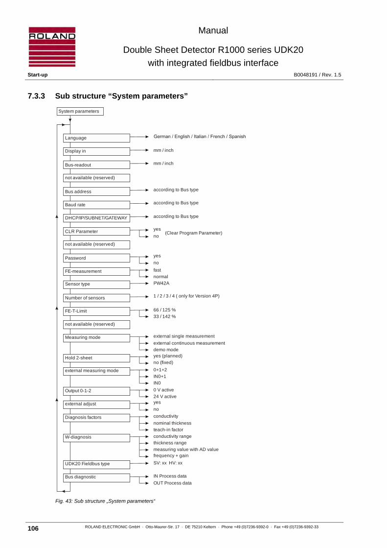
Manual
Double Sheet Detector R1000 series UDK20
with integrated fieldbus interface Start-up B0048191 / Rev. 1.5
106 ROLAND ELECTRONIC GmbH · Otto-Maurer-Str. 17 · DE 75210 Keltern · Phone +49 (0)7236-9392-0 · Fax +49 (0)7236-9392-33
7.3.3 Sub structure “System parameters”
Fig. 43: Sub structure „System parameters“
external single measurement
external continuous measurement
demo mode
yes
no
0 V active
24 V activeyes
no
1 / 2 / 3 / 4 ( only for Version 4P)
yes
no
according to Bus type
according to Bus type
according to Bus type
no (fixed)
yes (planned)
0+1+2
IN0+1
IN0
mm / inch
(Clear Program Parameter)
mm / inch
PW42A
conductivity
nominal thickness
SV: xx HV: xx
IN Process data
OUT Process data
conductivity range
66 / 125 %
33 / 142 %
thickness range
measuring value with AD valuefrequency + gain
normal
fast
teach-in factor
CLR Parameter
DHCP/IP/SUBNET/GATEWAY
FE-T-Limit
Language
System parameters
Display in
Bus address
Measuring mode
Hold 2-sheet
Password
Output 0-1-2
external adjust
Number of sensors
FE-measurement
Bus-readout
not available (reserved)
Sensor type
Baud rate
not available (reserved)
not available (reserved)
external measuring mode
Diagnosis factors
UDK20 Fieldbus type
Bus diagnostic
W-diagnosis

Manual
Double Sheet Detector R1000 series UDK20
with integrated fieldbus interface B0048191 / Rev. 1.5 Start-up
ROLAND ELECTRONIC GmbH · Otto-Maurer-Str. 17 · DE 75210 Keltern · Phone +49 (0)7236-9392-0 · Fax +49 (0)7236-9392-33 107
7.4 General information regarding the configuration
Note The correct configuration depends on the communication with the PLC,
on the measurement task and the connected components.
The following rules apply to the operation in the configuration mode:
• The configuration mode is activated (while in measurement mode) by pressing the MENU key.
• The configuration mode is terminated or cancelled by pressing the MENU key.
• The selected / set parameters can be changed when the items are blinking in the display.
• The selected / set parameters are activated by pressing the ENTER key.
7.5 Changing, setting-up or checking the configuration
In order to select, set-up or check the system / program parameters, press the MENU key.
The following menu is shown (here: Profibus):
Fig. 44: Indication after calling-up the menu
This menu option permits either reviewing or changing the configuration.
• Configuration review: The system / program parameters cannot be changed. The measurement mode is not interrupted.
• Configuration change: All system / program parameters can be changed after entering the password.
The following menu option is shown.
Fig. 45: Password request
Each blinking digit can be changed with the arrow keys and confirmed with ENTER. After having entered the correct password, the following menu appears for the adjustment of the configuration mode.
If the entered password is incorrect then the cursor returns to the first digit of the password and the input must be repeated. The input of the password can be aborted by pressing the MENU button.
Note A fault is generated if PLC commands are executed while entering the password or changing parameters.
configuration review Profibus DP ONLINE / Closed 1
password 4711

Manual
Double Sheet Detector R1000 series UDK20
with integrated fieldbus interface Start-up B0048191 / Rev. 1.5
108 ROLAND ELECTRONIC GmbH · Otto-Maurer-Str. 17 · DE 75210 Keltern · Phone +49 (0)7236-9392-0 · Fax +49 (0)7236-9392-33
Fig. 46: Selecting the configuration mode
Available configuration modes:
• Configuration system parameter • Configuration program parameter • Data backup • Firmware update
System parameters are general adjustments (e.g. language). Program parameters are application specific adjustments (e.g. input of nominal sheet thickness).
Note After exiting the configuration mode the password remains active for five
minutes. Thus other configuration adjustments can be made, without re-entering the password. If no key is pressed (while in the menu level), then the program changes to the measurement mode
7.6 Program parameters
The program parameters contain the information required for the various measurement programs. For accessing the program parameters, select the mode “configuration program parameter“ and confirm with ENTER.
Program parameter 1: Selecting the measuring program to be configured.
Fig. 47: Selecting the program to be configured
Here the measuring program (1-255) to be configured is selected. All following adjustments apply to the selected program (here: program no. 1).
Program parameter 2: Selecting the sensor to be used for measurement.
Fig. 48: Selecting the sensor
Possible choices:
• 2PW-units: 1 / 2 / 1+2
• with SSB: 1 / 2 / 3 / 4
configuration program parameters
program par. 1 program no.: 1
program par. 2 sensor: 1

Manual
Double Sheet Detector R1000 series UDK20
with integrated fieldbus interface B0048191 / Rev. 1.5 Start-up
ROLAND ELECTRONIC GmbH · Otto-Maurer-Str. 17 · DE 75210 Keltern · Phone +49 (0)7236-9392-0 · Fax +49 (0)7236-9392-33 109
Program parameter 3: Setting the material of the sheet to be measured.
Fig. 49: Setting the material
Possible choices:
• Auto: During Teach-In the system determines by itself the type of material in front of the sensor.
• NF (non-ferrous): Nonmagnetic material, e.g. aluminum, austenitic stainless steel
• FE (ferrous): Magnetic material
• mag. NF (LM): low magnetic material
Program parameter 4: Setting the nominal thickness of the sheet to be measured.
Fig. 50: Setting the nominal thickness
Value range:
• 0.03 mm to 4 mm (.001 inch to 0.157 inch)
Program parameter 5: Setting the percentage threshold of the upper limit value.
Fig. 51: Setting the upper limit
Value range:
• 100% to 150%
At the same time the absolute limit value is displayed.
Program parameter 6: Setting the percentage threshold of the lower limit value.
Fig. 52: Setting the lower limit
Value range:
• 0% to 99%
At the same time the absolute limit value is displayed.
program par. 3 material: auto
program par. 4 nominal: 0.90mm
program par. 5 up 150% 1.350mm
program par. 6 low: 50% 0.450mm

Manual
Double Sheet Detector R1000 series UDK20
with integrated fieldbus interface Start-up B0048191 / Rev. 1.5
110 ROLAND ELECTRONIC GmbH · Otto-Maurer-Str. 17 · DE 75210 Keltern · Phone +49 (0)7236-9392-0 · Fax +49 (0)7236-9392-33
Program parameter 7: Zero adjust
Fig. 53: Status of Zero adjust
Zero adjust is initiated with the ENTER key. If no zero adjust was executed or if it has to be repeated, the menu option “on“ has to be selected.
Then the following message appears (with version 2PW only):
• Separate: All connected sensors must be zero adjusted individually; each sensor is addressed individually for yes or no.
• Common: All sensors are zero adjusted at the same time. In any case the zero adjust continues with the following message, requesting to remove the sheet:
Fig. 54: Removing sheet for zero adjust
After having the sheet removed, press the ENTER key. Then the following message appears during the zero adjust:
Fig. 55: Display during zero adjust
Note Fault messages are described in the chapter 9. “Fault messages“.
When the zero adjust is completed, the following message appears:
Fig. 56: Zero adjust successfully completed
The zero adjust is now completed.
program par. 7 zero adj.: off
program par. 7 remove sheet!
program par. 7 please wait
program par. 7 zero adj.: done

Manual
Double Sheet Detector R1000 series UDK20
with integrated fieldbus interface B0048191 / Rev. 1.5 Start-up
ROLAND ELECTRONIC GmbH · Otto-Maurer-Str. 17 · DE 75210 Keltern · Phone +49 (0)7236-9392-0 · Fax +49 (0)7236-9392-33 111
Program parameter 8: Teach-In
Fig. 57: Status of Teach-In
Possible choices:
• Missing: A Teach-In has not been executed (only for NF) • Without: There is no Teach-In existing, unit can be operated anyhow (only for FE) • OK: A Teach-In was already executed • On: Performs a Teach-In
Note In order to enable measuring with a particular parameter set, a Teach-In must have been executed.
If no Teach-In was executed or if a Teach-In has to be repeated, the menu option “on“ has to be selected. Then the following two messages appear in succession:
Fig. 58: Removing sheet for Teach-In
Fig. 59: Attaching a sheet for Teach-In
Now a sheet with the nominal thickness must be presented to the sensor.
Attention A sheet must be attached to the sensor without air gap. The position of the sheet during Teach-In must be the same as for normal operation. Otherwise the measurement result could be faulty.
Then press the ENTER key.
During the Teach-In procedure the following message is displayed:
Fig. 60: Display during the Teach-In
Note Fault messages are described in chapter 9. “Fault messages ".
program par. 8 Teach-In: on
program par. 8 remove sheet!
program par. 8 attach sheet!
program par. 8 please wait

Manual
Double Sheet Detector R1000 series UDK20
with integrated fieldbus interface Start-up B0048191 / Rev. 1.5
112 ROLAND ELECTRONIC GmbH · Otto-Maurer-Str. 17 · DE 75210 Keltern · Phone +49 (0)7236-9392-0 · Fax +49 (0)7236-9392-33
Then the following message appears:
Fig. 61: Teach-In measurement value
This measured value can be accepted or changed, e.g. to calibrate the control unit.
After the Teach-In has been completed the following message appears:
Fig. 62: Teach-In successfully completed
Attention For sequence 1+2 the Teach-In is separately performed for sensor 1 and 2.
Entering the information for the selected measuring program is now completed.
program par. 8 TI-value: 0.97mm
program par. 8 Teach-In: ok
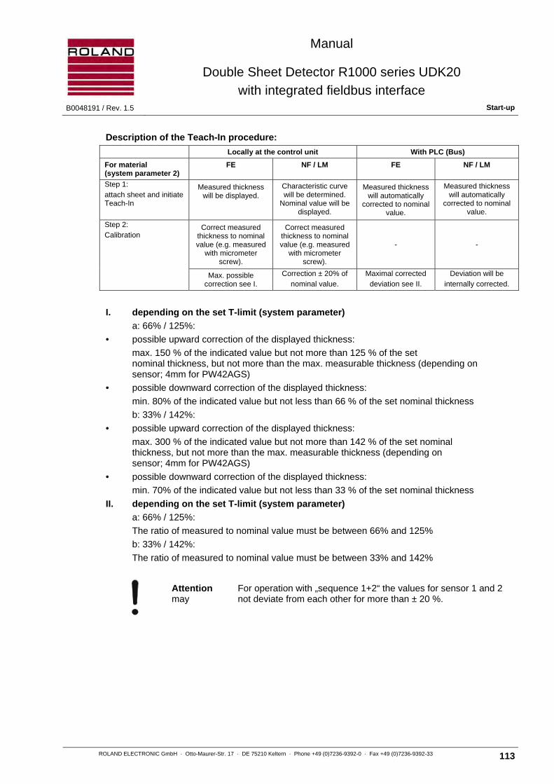
Manual
Double Sheet Detector R1000 series UDK20
with integrated fieldbus interface B0048191 / Rev. 1.5 Start-up
ROLAND ELECTRONIC GmbH · Otto-Maurer-Str. 17 · DE 75210 Keltern · Phone +49 (0)7236-9392-0 · Fax +49 (0)7236-9392-33 113
Description of the Teach-In procedure:
Locally at the control unit With PLC (Bus)
For material (system parameter 2)
FE NF / LM FE NF / LM
Step 1:
attach sheet and initiate Teach-In
Measured thickness will be displayed.
Characteristic curve will be determined.
Nominal value will be displayed.
Measured thickness will automatically
corrected to nominal value.
Measured thickness will automatically
corrected to nominal value.
Step 2:
Calibration Correct measured
thickness to nominal value (e.g. measured
with micrometer screw).
Correct measured thickness to nominal value (e.g. measured
with micrometer screw).
- -
Max. possible correction see I.
Correction ± 20% of
nominal value.
Maximal corrected
deviation see II.
Deviation will be
internally corrected.
I. depending on the set T-limit (system parameter)
a: 66% / 125%:
• possible upward correction of the displayed thickness:
max. 150 % of the indicated value but not more than 125 % of the set nominal thickness, but not more than the max. measurable thickness (depending on sensor; 4mm for PW42AGS)
• possible downward correction of the displayed thickness:
min. 80% of the indicated value but not less than 66 % of the set nominal thickness
b: 33% / 142%:
• possible upward correction of the displayed thickness:
max. 300 % of the indicated value but not more than 142 % of the set nominal thickness, but not more than the max. measurable thickness (depending on sensor; 4mm for PW42AGS)
• possible downward correction of the displayed thickness:
min. 70% of the indicated value but not less than 33 % of the set nominal thickness
II. depending on the set T-limit (system parameter)
a: 66% / 125%:
The ratio of measured to nominal value must be between 66% and 125%
b: 33% / 142%:
The ratio of measured to nominal value must be between 33% and 142%
Attention For operation with „sequence 1+2“ the values for sensor 1 and 2 may not deviate from each other for more than ± 20 %.

Manual
Double Sheet Detector R1000 series UDK20
with integrated fieldbus interface Start-up B0048191 / Rev. 1.5
114 ROLAND ELECTRONIC GmbH · Otto-Maurer-Str. 17 · DE 75210 Keltern · Phone +49 (0)7236-9392-0 · Fax +49 (0)7236-9392-33
7.7 System parameters
Note The selected system configuration should be documented in the form
“System configuration“ in the chapter “13.2. This information is required in case a system needs to be exchanged.
The general adjustments are specified in the system parameters.
For accessing, select the “system parameter configuration“ mode and confirm with ENTER.
System parameter 1: Setting the dialogue language.
Fig. 63: Selecting the dialogue language
Possible choices:
• English • German • Italian • French • Spanish
System parameter 2: Selecting the dimensions for the display (mm / inch).
Fig. 64: Selecting the dimension for the display
When changing the measurement dimensions, then the sheet metal thicknesses of the stored program parameters are also converted into the new dimension. In addition, %mm and %inch are also available (not for 4P version).
System parameter 3: Selecting the dimensions for output via fieldbus (mm / inch).
Fig. 65: Selecting the dimensions for the fieldbus output
system parameter 1 language: english
system parameter 2 display in: mm
system parameter 3 bus readout: mm

Manual
Double Sheet Detector R1000 series UDK20
with integrated fieldbus interface B0048191 / Rev. 1.5 Start-up
ROLAND ELECTRONIC GmbH · Otto-Maurer-Str. 17 · DE 75210 Keltern · Phone +49 (0)7236-9392-0 · Fax +49 (0)7236-9392-33 115
System parameter 4: not available (reserve).
Fig. 66: Reserved system parameter
System parameter 5: Setting the bus address.
Fig. 67: Setting the fieldbus address
• Profibus: 1 - 125 • ControlNet: 0 - 99 • DeviceNet: 0 - 63 • CanOpen: 1 - 127 • ProfiNet IO: – – • CC-Link: 1 – 62 • EtherNet/IP – – • EtherCAT – –
Note for Profibus: If this adjustment is to be made in the hardware, then the bus
address can be set with the rotary switches inside the enclosure (1 to 99). If this adjustment is to be made via software, then the rotary switches must be turned to address 0.
This system parameter is only for EtherNET/IP
If DHCP is switched on, the IP-setting will done via DHCP. If DHCP switched off, must the IP-address, SubNET and Gateway be selected.
Fig. 68: Setting DHCP
Here is the IP-address selected.
Fig. 69: Setting IP-address
Here is the SubNet selected.
Fig. 70: Setting SubNet
Here is the Gateway selected.
Fig. 71: Setting Gateway
system parameter 4 not available
system parameter 5 bus address: 1
system parameter 5 EthernetIP DHCP: no
system parameter 5b IP: 192.168. 0. 10
system parameter 5c Snet:255.255.255. 0
system parameter 5d GWay: 0. 0. 0. 0

Manual
Double Sheet Detector R1000 series UDK20
with integrated fieldbus interface Start-up B0048191 / Rev. 1.5
116 ROLAND ELECTRONIC GmbH · Otto-Maurer-Str. 17 · DE 75210 Keltern · Phone +49 (0)7236-9392-0 · Fax +49 (0)7236-9392-33
Fig. 72: Setting bus baud rate
Depending on the fieldbus type, the bus baud rate can be set.
Profibus: up to 12Mbps/s; selection at master
Controlnet: -----
DeviceNet: 125/250/500/kBit
CanOpen: 10/20/50/125/250/500/800/1000 kbps
ProfiNet IO: ----
CC-Link: 125/625kbps 2,5/5/10Mbps
EtherNet/IP: – –
EtherCAT: – –
Interbus: 500 kbits/s
System parameter 6: Deleting all measuring programs.
Fig. 73: Deleting of measuring programs
Possible choices:
• yes • no
Attention The deletion cannot be undone.
System parameter 7: not available (reserve).
Fig. 74: Reserved system parameter
system parameter 5b bus baud rate: 500kb
system parameter 6 CLR param.: no
system parameter 7 not available

Manual
Double Sheet Detector R1000 series UDK20
with integrated fieldbus interface B0048191 / Rev. 1.5 Start-up
ROLAND ELECTRONIC GmbH · Otto-Maurer-Str. 17 · DE 75210 Keltern · Phone +49 (0)7236-9392-0 · Fax +49 (0)7236-9392-33 117
System parameter 8: Switching the password function on / off.
Fig. 75: Switching the password on / off
Attention If no password is activated, then all parameters can be accessed at any time. We recommend this only during starting-up the system. For daily operation the password function should be activated.
System parameter 9: Selecting the speed of measurement.
Fig. 76: Selecting the speed of measurement
Possible choices:
• FE Measurement normal: With this kind of measuring the system reaction time depends on the measured sheet thickness. The maximum can be inferred from the diagrams in the chapter "2.4 Sensor data“.
• FE Measurement fast: Here it can be recognized whether double sheet metal rests against the sensor before the "normal" end of the measurement. The system reaction time is shorter and dependent on the adjusted nominal thickness as well as the upper limit value.
Disadvantage: In case of measuring results larger than the double sheet threshold, a double sheet signal is issued instead of the actually measured values.
For NF and LM (slightly magnetic NF) the exact measuring value is always output.
System parameter 10: Specifying the type of sensor.
Fig. 77: Specifying the type of sensor
Note Currently only the type of sensor PW42A is selectable.
system parameter 8 password: yes
system parameter 9 FE-Measurement: fast
system parameter 10 sensor type: PW42A

Manual
Double Sheet Detector R1000 series UDK20
with integrated fieldbus interface Start-up B0048191 / Rev. 1.5
118 ROLAND ELECTRONIC GmbH · Otto-Maurer-Str. 17 · DE 75210 Keltern · Phone +49 (0)7236-9392-0 · Fax +49 (0)7236-9392-33
System parameter 11: Specifying the number of connected sensors (only for 4P unit).
Fig. 78: Specifying the number of sensors
Possible choices:
• for 2PW-unit: 1 / 2 sensors • for SSB: 1 / 2 / 3 / 4 sensors
Attention Changing the current configuration will delete all stored program parameters. Then for all sheet types the nominal thickness values must be re-entered and the Teach-In must be performed again.
System parameter 12: Specifying the Teach-In limits for FE.
Fig. 79: Sensor selection
Possible choices:
• 66% / 125% (default setting)
• 33% / 142%
During Teach-In of FE material the deviation of the measured thickness from the nominal thickness is monitored. Certain ferro-magnetic materials show a larger deviation than usual. In those cases the 33%/142% setting instead of the default 66%/125% setting is useful. Both values represent the permitted relative range from measured to nominal thickness. If the measuring value is not within this range, the Teach-In cannot be performed and will be aborted with an error message.
System parameter 13: not available (reserve).
Fig. 80: Reserved system parameter
system parameter 11 number of sensors: 2
system parameter 12 FE-T-Limit: 66%/125%
system parameter 13 not available
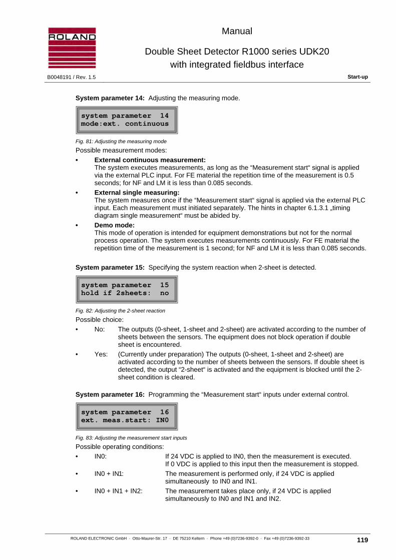
Manual
Double Sheet Detector R1000 series UDK20
with integrated fieldbus interface B0048191 / Rev. 1.5 Start-up
ROLAND ELECTRONIC GmbH · Otto-Maurer-Str. 17 · DE 75210 Keltern · Phone +49 (0)7236-9392-0 · Fax +49 (0)7236-9392-33 119
System parameter 14: Adjusting the measuring mode.
Fig. 81: Adjusting the measuring mode
Possible measurement modes:
• External continuous measurement: The system executes measurements, as long as the “Measurement start“ signal is applied via the external PLC input. For FE material the repetition time of the measurement is 0.5 seconds; for NF and LM it is less than 0.085 seconds.
• External single measuring: The system measures once if the “Measurement start“ signal is applied via the external PLC input. Each measurement must initiated separately. The hints in chapter 6.1.3.1 „timing diagram single measurement“ must be abided by.
• Demo mode: This mode of operation is intended for equipment demonstrations but not for the normal process operation. The system executes measurements continuously. For FE material the repetition time of the measurement is 1 second; for NF and LM it is less than 0.085 seconds.
System parameter 15: Specifying the system reaction when 2-sheet is detected.
Fig. 82: Adjusting the 2-sheet reaction
Possible choice:
• No: The outputs (0-sheet, 1-sheet and 2-sheet) are activated according to the number of sheets between the sensors. The equipment does not block operation if double sheet is encountered.
• Yes: (Currently under preparation) The outputs (0-sheet, 1-sheet and 2-sheet) are activated according to the number of sheets between the sensors. If double sheet is detected, the output “2-sheet“ is activated and the equipment is blocked until the 2- sheet condition is cleared.
System parameter 16: Programming the “Measurement start“ inputs under external control.
Fig. 83: Adjusting the measurement start inputs
Possible operating conditions:
• IN0: If 24 VDC is applied to IN0, then the measurement is executed. If 0 VDC is applied to this input then the measurement is stopped.
• IN0 + IN1: The measurement is performed only, if 24 VDC is applied simultaneously to IN0 and IN1.
• IN0 + IN1 + IN2: The measurement takes place only, if 24 VDC is applied simultaneously to IN0 and IN1 and IN2.
system parameter 14 mode:ext. continuous
system parameter 15 hold if 2sheets: no
system parameter 16 ext. meas.start: IN0

Manual
Double Sheet Detector R1000 series UDK20
with integrated fieldbus interface Start-up B0048191 / Rev. 1.5
120 ROLAND ELECTRONIC GmbH · Otto-Maurer-Str. 17 · DE 75210 Keltern · Phone +49 (0)7236-9392-0 · Fax +49 (0)7236-9392-33
System parameter 17: Setting the output logic (0-sheet, 1-sheet, 2-sheet outputs).
Fig. 84: Setting the output logic
Possible choices:
• 0 V: As shown in the timing diagrams and the wiring diagrams
• +24 V: The outputs 0-sheet, 1-sheet and 2-sheet are inverted, i.e. the respective signals in the timing diagrams and wiring diagrams must be seen inverted.
Note The outputs “Enable“ and “Warning“ are not affected thereby.
System parameter 18: Deactivating / activating the external calibration via fieldbus.
Fig. 85: Deactivating / activating the external calibration
Here the external calibration, which is possible via fieldbus with the signals “Teach-In“ and “zero adjust“, can be deactivated / activated.
System parameter 19: Diagnostic factors.
This system parameter is used for the equipment diagnostics and should not be changed by the user.
Fig. 86: Diagnostic factors (fixed)
Fig. 87: Indicating the investigated conductance
Here the conductivity investigated for this program is shown (here: program 12)
Extra: = slightly magnetical NF material
FE = magnetical steel
For NF material the conductivity range is shown.
With the ENTER key and UP/ DOWN keys all programs can be polled / indicated.
The ENTER key will exit the section.
The UP key leads to the following menu item:
system parameter 17 output 0-1-2: 0V
system parameter 18 ext. adjust: no
system parameter 19 diagnostic factors
system parameter 19 P12 LW: 24-32ms/m

Manual
Double Sheet Detector R1000 series UDK20
with integrated fieldbus interface B0048191 / Rev. 1.5 Start-up
ROLAND ELECTRONIC GmbH · Otto-Maurer-Str. 17 · DE 75210 Keltern · Phone +49 (0)7236-9392-0 · Fax +49 (0)7236-9392-33 121
Fig. 88: Indicating the nominal thickness for the program
Here the nominal thickness for this program is shown (here: program 12).
With the ENTER key and UP/ DOWN keys all programs can be polled / indicated.
The ENTER key will exit the section.
The UP key leads to the following menu item:
Fig. 89: Indicating the factor for the program, investigated on Teach-In
Here the factor (2PW units: both factors) for this program, investigated on Teach-In, is shown (here: program 12).
With the ENTER key and UP/ DOWN keys all programs can be polled / indicated.
The ENTER key will exit the section.
The UP key leads to the following menu item:
Fig. 90: Exiting the factor diagnosis section
The ENTER key will exit the factor diagnostics.
System parameter 13: Equipment diagnostics (W-diagnosis)
Fig. 91: W-diagnostics
Note The settings of the current program will be taken over as default settings.
The ENTER key leads to the following menu item:
Fig. 92: Setting the conductivity range fort he diagnosis
Here the conductivity range for the diagnosis is set.
• Extra: = slightly magnetical NF material
• FE = magnetical steel
system parameter 19 P12 N=2.12mm
system parameter 19 P12 FKT=1.112
system parameter 19 P12 EXIT
system parameter 20 W-diagnostics
system parameter 20 EC: 24-32mS/m

Manual
Double Sheet Detector R1000 series UDK20
with integrated fieldbus interface Start-up B0048191 / Rev. 1.5
122 ROLAND ELECTRONIC GmbH · Otto-Maurer-Str. 17 · DE 75210 Keltern · Phone +49 (0)7236-9392-0 · Fax +49 (0)7236-9392-33
For NF material the conductivity range is shown.
With the ENTER key and UP/ DOWN keys all ranges can be selected. The ENTER key will exit the section.
The UP key leads to the following menu item:
Fig. 93: Setting the thickness range for the diagnosis
Here the thickness range for the diagnosis is set. With the ENTER key and UP/ DOWN keys all ranges can be selected. The ENTER key will exit the section.
The UP key leads to the following menu item:
Fig. 94: Indicating the thickness calculated from the characteristic curve
Here the value of the analog-digital converter and the thickness (calculated from the characteristic curve) are shown (without Teach-In correction). For 2PW units the values for both sensors will be shown.
The UP key leads to the following menu item:
Fig. 95: Indicating the frequency and gain
Here the used frequency and gain is shown.
The UP key leads to the following menu item:
Fig. 96: De-magnetizing the sensor
Here the sensor will be de-magnetized.
The UP key leads to the following menu item:
Fig. 97: Exiting the factor diagnosis section
The ENTER key will exit the factor diagnosis section.
system parameter 20 DB: <4.00 mm
system parameter 20 AD: 2048 D: 1.22mm
system parameter 20 F= 250Hz V= 157
system parameter 20 sensor demagnet.
system parameter 20 EXIT
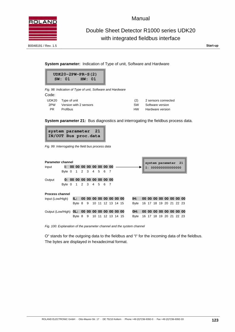
Manual
Double Sheet Detector R1000 series UDK20
with integrated fieldbus interface B0048191 / Rev. 1.5 Start-up
ROLAND ELECTRONIC GmbH · Otto-Maurer-Str. 17 · DE 75210 Keltern · Phone +49 (0)7236-9392-0 · Fax +49 (0)7236-9392-33 123
System parameter: Indication of Type of unit, Software and Hardware
Fig. 98: Indication of Type of unit, Software and Hardware
Code: UDK20 Type of unit (2) 2 sensors connected
2PW Version with 2 sensors SW Software version
PR Profibus HW Hardware version
System parameter 21: Bus diagnostics and interrogating the fieldbus process data.
Fig. 99: Interrogating the field bus process data
Parameter channel
Input I: 00 00 00 00 00 00 00 00
Byte 0 1 2 3 4 5 6 7
Output 0: 00 00 00 00 00 00 00 00
Byte 0 1 2 3 4 5 6 7
Process channel
Input (Low/High) IL: 00 00 00 00 00 00 00 00
Byte 8 9 10 11 12 13 14 15
Output (Low/High) 0L: 00 00 00 00 00 00 00 00
Byte 8 9 10 11 12 13 14 15
IH: 00 00 00 00 00 00 00 00 Byte 16 17 18 19 20 21 22 23
0H: 00 00 00 00 00 00 00 00 Byte 16 17 18 19 20 21 22 23
Fig. 100: Explanation of the parameter channel and the system channel
O“ stands for the outgoing data to the fieldbus and “I“ for the incoming data of the fieldbus.
The bytes are displayed in hexadecimal format.
UDK20-2PW-PR-S(2) SW: 01 HW: 01
system parameter 21 IN/OUT Bus proc.data
system parameter 21
I: 0000000000000000

Manual
Double Sheet Detector R1000 series UDK20
with integrated fieldbus interface Operation B0048191 / Rev. 1.5
124 ROLAND ELECTRONIC GmbH · Otto-Maurer-Str. 17 · DE 75210 Keltern · Phone +49 (0)7236-9392-0 · Fax +49 (0)7236-9392-33
7.8 Data storage via serial RS232-interface
For better prevention from loss of data, a data backup procedure is available for the system configuration and the parameter sets. This is made via the RS232-interface (not in B- versions). The secured data can be transferred to spare units in case of exchange after a failure.
The data backup is accomplished with the RPP software available from ROLAND.
The data backup procedure can be selected in the menu configuration. The following menu is displayed during the data backup.
Fig. 101: Status of data backup
7.9 Firmware update
Roland systems are constantly enhanced. In order to use new functions, firmware update is required.
For performing such an update, the Double Sheet Detector must be connected to the RS232-interface of the computer via the supplied cable. In the configuration mode the firmware update must be selected, then the following messages are alternatingly displayed:
Fig. 102: Messages for activating firmware update
The firmware update is activated by simultaneously pressing the keys arrow and ENTER for 5 seconds:
Fig. 103: Start firmware update
The update will then be executed via the “Phytec“ Flash Tool. This tool can be found on the enclosed CD.
Firmware update arrow key UP + ENTER
FIRMWARE UPDATE start pressing key
ROLAND R1000 BUS - FIRMWARE UPDATE - CONNECT RS232 - PRESS ENTER TO EXIT
Parameter backup active

Manual
Double Sheet Detector R1000 series UDK20
with integrated fieldbus interface B0048191 / Rev. 1.5 Operation
ROLAND ELECTRONIC GmbH · Otto-Maurer-Str. 17 · DE 75210 Keltern · Phone +49 (0)7236-9392-0 · Fax +49 (0)7236-9392-33 125
8 Operation
8.1 Abbreviated operating instructions
After applying power to the system, the version number and the bus system message are briefly displayed. Afterwards the system switches into that measurement menu which was active before the unit was switched off.
Note Units with CanOpen bus module require appr. 30 seconds to reach the
operational status after applying power to the system.
Note The system is factory adjusted for “single measurement“. Therefore the system functions only if the signal “measurement start“ is activated via the fieldbus. The modification of the configuration is described in chapter 7 “Start-up”
Fig. 104: Frontal view of the R1000 with enlarged display detail
LED functions (symbols above the keys)
< ON, if the measured value reaches (or falls short of) the lower limit value.
Norm ON, if the measured value is within the lower and upper limit values.
> ON, if the measured value reaches (or exceeds) the upper limit value.
Enable - blinks, if a fault is present - ON, if the equipment is in measurement mode - OFF, during parameter programming with the keyboard
Key functions (symbols below the keys)
▲ Changes the parameters (forward)
▼ Changes the parameters (backwards)
Enter Selects a parameter for changing and confirming the change
Menu Activates the menu level, for deleting a fault message and exiting the menu level.
1 LED functions2 Pushbutton functions3 Program number4 Selected sensor5 Type of material6 Nominal thickness7 Measurement status
1-1 FE=1.00mm -on0.80 <S1=1.02> 1.20Profibus DP xxxOnline / closed 1
3 4 5 6 7
8 9
10
13 14
11
12
1-1 FE=1.00mm -on0.80 <S1=1.02> 1.20Profibus DP xxxOnline / closed 1
8 Lower limit value 9 Upper limit value10 Bus type11 Bus baud rate or MAC-ID12 Fieldbus status13 Sensor number with selected value14 Bus address
Manual
Double Sheet Detector R1000 series UDK20
with integrated fieldbus interface Operation B0048191 / Rev. 1.5
126 ROLAND ELECTRONIC GmbH · Otto-Maurer-Str. 17 · DE 75210 Keltern · Phone +49 (0)7236-9392-0 · Fax +49 (0)7236-9392-33
In the measuring mode the measured value can be read in the display. The control unit automatically compares the measured value with the adjusted thresholds. The result is transmitted via the interface to the PLC and also to the front panel LED's.
During the normal measurement process no further actions on the control units are necessary with the following few exceptions. The following situations require action directly at the control unit or an action via the field bus interface:
• Clear fault and error messages (see to chapter “9. Error messages, causes and remedies“)
• Teaching of new types of metal and sheet metal thicknesses (see section “7.6 Configuration of the program parameters“)
• Clearing a 2-sheet condition (in preparation)
The following notes for the measuring operations should be observed:
Note If the measured value fluctuates and deviates substantially from nominal
value during normal operation then an air gap between sensor and sheet surface is the most likely cause. A renewed Teach in cannot overcome this problem.
Note Do not adjust the upper limit (“up“) above 120 %.
8.2 Entering a measurement program
1 Make sure that there is no sheet in front of the sensor
2 Press them menu key and move to “change“, confirm with ENTER key
3 Enter the password
4 Move to "program parameter" and confirm with ENTER key
5 Make sure that there is no sheet in front of the sensor
6 Select the desired program number in the control unit
7 If sensor a Sensor Switch Box is installed select the desired sensor
8 For the type of material select “auto“
9 Enter nominal thickness (standard thickness of the sheet to be processed)
10 Set lower threshold TU to 80% set (default settings)
11 Set upper threshold TO to 120% set (default settings)
12 Ensure that no sheet is in front of the sensor
13 Select "Teach-In" and move to “on“, confirm with ENTER key
14 Remove sheet in front of the sensor, confirm with ENTER key
15 If the control unit signals “attach sheet to sensor“, operate machinery to accomplish this. Ensure that there is no air gap between sensor and sheet metal surface. Confirm with ENTER key.
Attention The sheet used for the teaching process must have the same sheet thickness and same electrical conductivity (in case of non- magnetic metal e.g. aluminum) as the sheet to be processed.
Manual
Double Sheet Detector R1000 series UDK20
with integrated fieldbus interface B0048191 / Rev. 1.5 Operation
ROLAND ELECTRONIC GmbH · Otto-Maurer-Str. 17 · DE 75210 Keltern · Phone +49 (0)7236-9392-0 · Fax +49 (0)7236-9392-33 127
16 The control unit shows the measured thickness in the display.
General rules for monitoring ferrous material (steel that can be magnetized) and non-ferrous materials (aluminum, non-magnetic stainless steel, slightly magnetic non-ferrous material):
• FE: The measured value should not deviate by more then 5%, (max. 10% with coated sheets, exceeding 10% with nickel) from the actual thickness of the measured sheet. If it deviates more, then the cause could be a wrong sheet thickness or an air gap, which has to be eliminated (do not use bowed sheet for teaching). The measured value must now be adjusted to the actual sheet thickness.
• NF and LM (slightly magnetic material): The measured value must be adjusted to the actual sheet thickness
17 Confirm the Teach-In and adjustment with the ENTER key and exit the menu “programming“.
Example: Nominal thickness 2.00 mm
The micrometer measures actual value to be: 1.92 mm.
The Teach-In shows a value of: 1.89 mm.
The display value must now be corrected to 1.92 mm.

Manual
Double Sheet Detector R1000 series UDK20
with integrated fieldbus interface Fault messages, causes and remedies B0048191 / Rev. 1.5
128 ROLAND ELECTRONIC GmbH · Otto-Maurer-Str. 17 · DE 75210 Keltern · Phone +49 (0)7236-9392-0 · Fax +49 (0)7236-9392-33
Blank page

Manual
Double Sheet Detector R1000 series UDK20
with integrated fieldbus interface B0048191 / Rev. 1.5 Fault messages, causes and remedies
ROLAND ELECTRONIC GmbH · Otto-Maurer-Str. 17 · DE 75210 Keltern · Phone +49 (0)7236-9392-0 · Fax +49 (0)7236-9392-33 129
9 Fault messages, causes and remedies
In case of malfunction a message containing the fault number and the associated error text is displayed
Fig. 105: Example of a fault message
The fault number indicates the fault and the probable cause. The fault description and the suitable measures to remedy the fault condition are found in the following tables. The cause of malfunction must be eliminated before the equipment can continue operation.
The fault can be cleared by pressing the MENU key on the control unit.
Note As long as the cause of the fault is not eliminated, the fault cannot be
cleared.
The fault messages are summarized into the following classes:
• Memory faults
• Zero adjust faults
• Teach-In faults
• Transmission faults (RS232)
• Measuring operating faults
• Keyboard faults
• Operating voltage faults
• Sensor-Switch-Box faults
• PLC input faults
• Fieldbus faults
• Other faults
Error code: 60 power

Manual
Double Sheet Detector R1000 series UDK20
with integrated fieldbus interface Fault messages, causes and remedies B0048191 / Rev. 1.5
130 ROLAND ELECTRONIC GmbH · Otto-Maurer-Str. 17 · DE 75210 Keltern · Phone +49 (0)7236-9392-0 · Fax +49 (0)7236-9392-33
9.1 Fault messages of the Sensor-Switch-Box
If the Sensor-Switch-Box was configured though none is attached to the system, then the system emits a fault message. In order to reconfigure the equipment to the correct adjustment “no Sensor Switch Box“, the unit must be switched off and on.
The following message is displayed:
Fig. 106: System does not recognize a Sensor-Switch-Box
After pressing the MENU key the following message is displayed:
Fig. 107: Selection, if the Sensor-Switch-Box is to be operated
Adjustment for operating the Sensor Switch Box:
• yes: The equipment should continue operating with a Sensor Switch Box. The fault is cleared. If the fault condition is not eliminated, then the fault message appears again.
• no = CLR Param.: The equipment has to be reconfigured to operate without a Sensor Switch Box. All program parameters are deleted.
Attention The deletion of the programs parameter cannot be undone.
The arrow keys allow the change between “yes“ and “no“. Confirm the selection with the ENTER key.
no switchbox or defective
UDK20+switchbox? yes
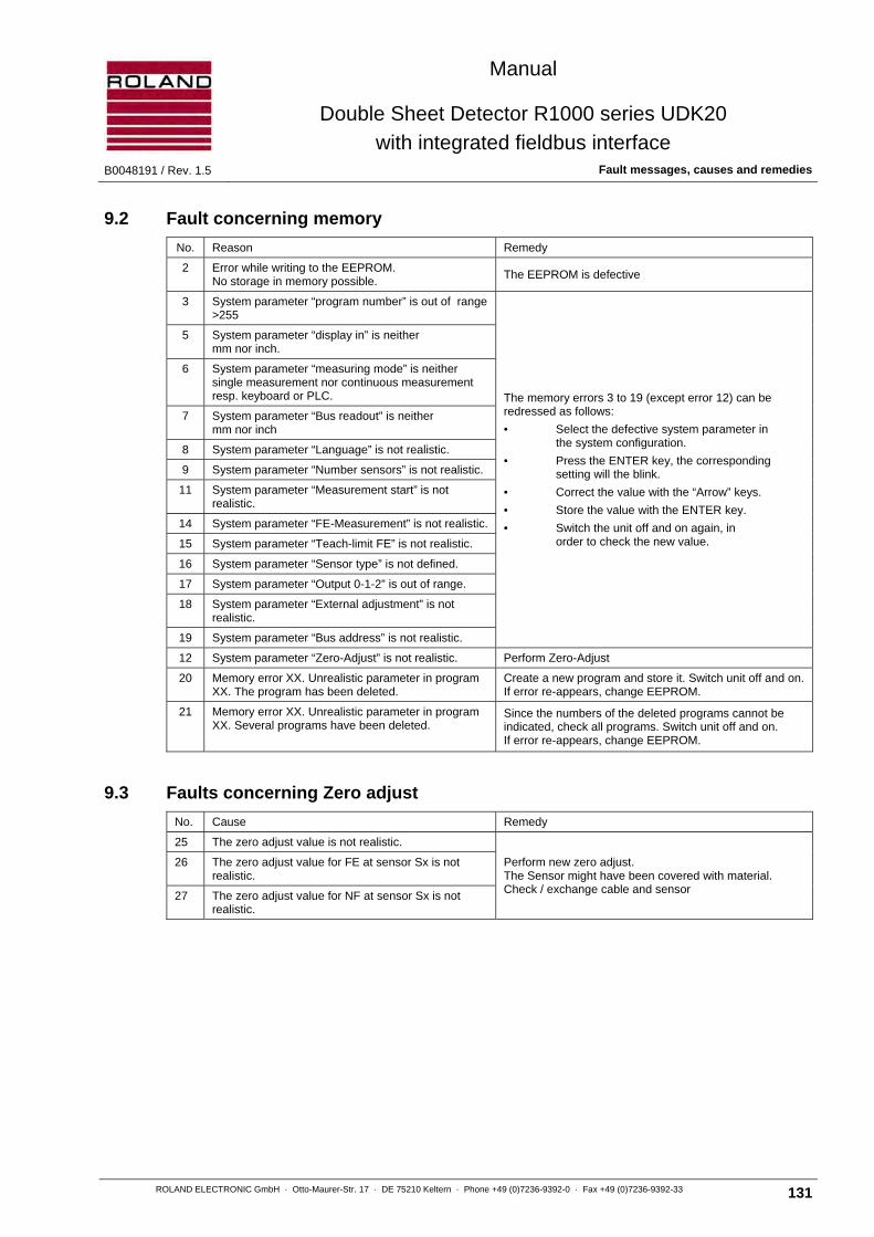
Manual
Double Sheet Detector R1000 series UDK20
with integrated fieldbus interface B0048191 / Rev. 1.5 Fault messages, causes and remedies
ROLAND ELECTRONIC GmbH · Otto-Maurer-Str. 17 · DE 75210 Keltern · Phone +49 (0)7236-9392-0 · Fax +49 (0)7236-9392-33 131
9.2 Fault concerning memory
No. Reason Remedy
2 Error while writing to the EEPROM. No storage in memory possible.
The EEPROM is defective
3 System parameter “program number” is out of range >255
The memory errors 3 to 19 (except error 12) can be redressed as follows:
• Select the defective system parameter in the system configuration.
• Press the ENTER key, the corresponding setting will the blink.
• Correct the value with the “Arrow” keys.
• Store the value with the ENTER key.
• Switch the unit off and on again, in order to check the new value.
5 System parameter “display in” is neither mm nor inch.
6 System parameter “measuring mode” is neither single measurement nor continuous measurement resp. keyboard or PLC.
7 System parameter “Bus readout” is neither mm nor inch
8 System parameter “Language” is not realistic.
9 System parameter “Number sensors” is not realistic.
11 System parameter “Measurement start” is not realistic.
14 System parameter “FE-Measurement” is not realistic.
15 System parameter “Teach-limit FE” is not realistic.
16 System parameter “Sensor type” is not defined.
17 System parameter “Output 0-1-2” is out of range.
18 System parameter “External adjustment” is not realistic.
19 System parameter “Bus address” is not realistic.
12 System parameter “Zero-Adjust” is not realistic. Perform Zero-Adjust
20 Memory error XX. Unrealistic parameter in program XX. The program has been deleted.
Create a new program and store it. Switch unit off and on. If error re-appears, change EEPROM.
21 Memory error XX. Unrealistic parameter in program XX. Several programs have been deleted.
Since the numbers of the deleted programs cannot be indicated, check all programs. Switch unit off and on. If error re-appears, change EEPROM.
9.3 Faults concerning Zero adjust
No. Cause Remedy
25 The zero adjust value is not realistic.
Perform new zero adjust. The Sensor might have been covered with material. Check / exchange cable and sensor
26 The zero adjust value for FE at sensor Sx is not realistic.
27 The zero adjust value for NF at sensor Sx is not realistic.

Manual
Double Sheet Detector R1000 series UDK20
with integrated fieldbus interface Fault messages, causes and remedies B0048191 / Rev. 1.5
132 ROLAND ELECTRONIC GmbH · Otto-Maurer-Str. 17 · DE 75210 Keltern · Phone +49 (0)7236-9392-0 · Fax +49 (0)7236-9392-33
9.4 Faults concerning Teach-In
No. Cause Remedy
30 The sheet cannot be taught because there is no sheet in front of the sensor or the sheet thickness is wrong.
Check sheet for correct thickness. Repeat Teach-In. If fault appears again, the sensor might be defective.
31 Automatic material detection is not possible. Select material manually.
32 For LM material (slightly magnetical) only material with a thickness of up to 2mm can be measured.
---
9.5 Faults concerning RS232 Transmission
No. Cause Remedy
40 Checksum does not correspond to transmitted information
Check program and data transmission connection
41 Dimension is incorrect (mm instead of in. or in. instead of mm) or no numerical character at the position expected (e.g. --.00MM instead of 00.001MM).
Compare transmitted dimension and dimension in the parameter set at UDK20. Numerical characters in the data format require a number. (e.g. 00.011MM or 01.0000MM)
45 The transmitted value is out of the defined range (e.g. Program no. > 255)
Repeat data transmission with correct values.
47 The serial commands are following too fast. Include a small pause between the individual serial values.
49 The command is not known. Check command.
9.6 Faults concerning measuring operation
No. Cause Remedy
50 The AD converter or hardware is defective. Change AD converter / hardware.
51 The current between sensor Sx and unit has been interrupted during measurement.
Check cable , connectors and sensor; if necessary exchange. Check whether the sensor was removed during measurement (Counter-induction).
52 a) Measuring time is not realistic (too short) b) The zero adjust was done with sheet
a) Exchange sensor b) Perform zero adjust without sheet
53 Shortcut inside of sensor / sensor cable (also between lead and shields).
Exchange sensor / cable.
54 Before measuring, the following items must have been performed:
• nominal thickness was entered • Zero adjust was performed • Teach-In was performed
• Enter nominal thickness • Perform Zero adjust • Perform Teach-In

Manual
Double Sheet Detector R1000 series UDK20
with integrated fieldbus interface B0048191 / Rev. 1.5 Fault messages, causes and remedies
ROLAND ELECTRONIC GmbH · Otto-Maurer-Str. 17 · DE 75210 Keltern · Phone +49 (0)7236-9392-0 · Fax +49 (0)7236-9392-33 133
9.7 Faults concerning keyboard
No. Cause Remedy
55 Changing of system / program parameters is not possible, for a serial fieldbus function is active (e.g. Teach-In or Measurement start).
Await completion of fieldbus function or terminate it.
56 Changing of system / program parameters is not possible, for a parallel function is active (e.g. Teach- In or Measurement start).
Await completion of fieldbus function or terminate it.
57 Changing of system / program parameters is not possible, since the parameter channel is opened via Field bus.
Close the parameter channel.
9.8 Faults concerning supply voltage
No. Cause Remedy
60 Operating voltage was below 20 VDC. Check power supply.
62 Sensor voltage too low. Check external power supply (insufficient power ?). Contact Roland Electronic Service Department.
9.9 Faults Sensor Switch Box
No. Cause Remedy
65 Error in the Sensor Switch Box. If a Sensor Switch Box is connected, check box and cables. Otherwise read the notes in chapter 9.1.
9.10 Faults concerning PLC parallel inputs
No. Cause Remedy
71 The parallel function is not possible, because the system was configured for the “demo mode”.
Configure the system parameter “Measurement mode”to “external continuous measurement” or “single measurement”.
72 The parallel function is not possible, because the system is operated via the keyboard.
Terminate the operation via keyboard and return the system to neutral operation by pressing the menu key.
73 The parallel function cannot be performed because a fieldbus function is active, e.g. “Teach-In” via the fieldbus and “measurement start” via parallel inputs.
Wait for the completion of the fieldbus function or terminate it and repeat parallel function.
74 The parallel function cannot be performed because the parameter channel is opened via Field bus.
Close the parameter channel.

Manual
Double Sheet Detector R1000 series UDK20
with integrated fieldbus interface Maintenance B0048191 / Rev. 1.5
134 ROLAND ELECTRONIC GmbH · Otto-Maurer-Str. 17 · DE 75210 Keltern · Phone +49 (0)7236-9392-0 · Fax +49 (0)7236-9392-33
9.11 Faults fieldbus interface
No. Cause Remedy
80 The installed fieldbus coupler is defective. Switch unit off and on, if the fault reappears then the equipment has to be returned.
82 The fieldbus function is not possible, for a parallel PLC function is active, e.g. “Measurement start” via the parallel PLC inputs and in addition “Measurement start” via the fieldbus.
Avoid simultaneous operation.
83 The fieldbus function is not possible, for another field bus function is active at the same time, e.g.
“Measurement start” and “Program switching”.
Implement only one function.
84 The fieldbus function is not possible, for the measuring mode is set to ”Demo”.
Configure the parameter “measurement operation”
to “external continuous measurement” or “external single measurement”.
85 The fieldbus function is not possible, for the menu (keyboard operation) is operational.
Terminate the operation via the keyboard and with the “Menu” key return the unit to its basic mode.
86 The activated fieldbus function is not possible or disabled in the system.
If the function is required, then it should be activated under “systems configuration”.
88 The program number activated in the menu program selection is > 255.
Select a valid program number.
91 The field bus function cannot be executed, for the parameter channel is active.
Close parameter channel.
92 The parameter channel is wrongly served.
94-98 Internal timing problem with bus module.
99 Bus module is defective.
9.12 Other faults
No. Cause Remedy
> 100 An error has occurred which cannot be unequivocally identified to one of the above error codes.
Contact Roland Electronic Service Department.

Manual
Double Sheet Detector R1000 series UDK20
with integrated fieldbus interface B0048191 / Rev. 1.5 Maintenance
ROLAND ELECTRONIC GmbH · Otto-Maurer-Str. 17 · DE 75210 Keltern · Phone +49 (0)7236-9392-0 · Fax +49 (0)7236-9392-33 135
10 Maintenance
Generally, the Double Sheet Detector R1000 UDK20 requires no special or regular maintenance.
If new types of sheet metal and dimensions are to be processed, then a new Teach-In for new programs to be stored is necessary, see also section 7.6 “Program parameter 8 - Teach-In“.
In the following cases a new Teach-In for all programs becomes necessary:
• If a sensor exchange was not done according to the instructions in the following section “Sensor exchange“
Note Changes in metallic sensor brackets can change the measured value. Sensor brackets made of metal with higher conductivity extract more energy from the sensor (and vice versa) due to the eddy current effect. Thus the stored programs lose their validity.
10.1 Replacement of sensors
In order to further use the taught programs, the following must be observed:
• Before the sensor is removed, its installation position must be exactly documented. This applies especially to the installation position with regard to the measuring axis.
• The original installation position in all directions has to be restored. This applies especially to the gaps between the sheets.
Attention If the original sensor positions cannot be restored, then the Teach-In has to be repeated for all programs.
After having exchanged a sensor, the zero adjust must be performed again.
Proceed as follows:
For a standard control unit with one sensor:
1 Ensure that no sheet is in front of the sensor
2 Press the MENU key, select “change“ and confirm with the ENTER key
3 Enter the password
4 Change to “program parameter“ and confirm with the ENTER key
5 Ensure that no sheet is in front of the sensor
6 Change to “zero adjust“ and select “on“
7 Control unit shows “remove sheet”. Confirm with the ENTER key
8 Control unit shows “zero adjust: active“, then “zero adjust: off“
9 Exit the programming with the MENU key

Manual
Double Sheet Detector R1000 series UDK20
with integrated fieldbus interface Maintenance B0048191 / Rev. 1.5
136 ROLAND ELECTRONIC GmbH · Otto-Maurer-Str. 17 · DE 75210 Keltern · Phone +49 (0)7236-9392-0 · Fax +49 (0)7236-9392-33
For a 2PW control unit with up two sensors:
1 Verify that no sheet is in front of the sensor resp. the sensors
2 Press the MENU key, switch to “change“ and confirm with the ENTER key
3 Enter the password
4 Switch to “program parameter“ and confirm with the ENTER key
5 Verify that no sheet is in front of the sensor resp. the sensors
6 Switch to “zero adjust“ and confirm with the ENTER key
7 Select “zero adjust: separate“ or “zero adjust: common“
7.1 If “zero adjust: separate“, then confirm with ENTER key
7.1.1 Display: “zero adjust S1: on / remove sheet“ If zero adjusts desired, then ENTER key, or if zero adjusts not desired, then activate “off“ and confirm with ENTER
7.1.2 Display: “zero adjust S2: off“ If zero adjusts not desired, then press ENTER key, or if zero adjusts is desired, then activate “on“ and press ENTER
7.2 If “zero adjust: common“, then confirm with ENTER key, all connected sensors are zero adjusted.
8 The display “zero adjust: active“ appears, and then “zero adjust: off“
9 Leave programming with the MENU key.
10.2 Exchange of control unit
Exchange with help of the RPP software (only with C-versions):
The UDK20 provides for backup and re-writing the equipment parameters via the RS232 interface, with help of the provided RPP software.
Exchange without help of the RPP software:
After exchanging the equipment, the original system configuration must be restored. Therefore, the form „System Configuration“ in chapter „Technical Documents“ (which had been filled out during set-up) can be used. If this form is not available or filled out, the information on the system configuration must be retrieved from the equipment documentation.

Manual
Double Sheet Detector R1000 series UDK20
with integrated fieldbus interface B0048191 / Rev. 1.5 Maintenance
ROLAND ELECTRONIC GmbH · Otto-Maurer-Str. 17 · DE 75210 Keltern · Phone +49 (0)7236-9392-0 · Fax +49 (0)7236-9392-33 137
10.3 Replacement of fuses
Attention The fuse should be checked only by trained personnel, since it is necessary to open the control unit.
The power supply fuse is 5 x 20 mm, 5 Amp slow blow. A spare fuse is accommodated in the control unit. The position of the spare fuse is shown in the picture below.
Note The picture shows a control unit for front panel mounting.
The position of the fuse is identical in the wall mount enclosure.
1 Fuse
2 Spare fuse
Fig. 108: Position of fuses in theR1000
10.4 Data backup via the fieldbus interface or serial interface
The R1000 offers the possibility of data exchange with a master. The system and program parameter can be stored in the PLC via the fieldbus. In addition, stored or modified data can be written back again into the control unit. The data backup via the RS232 interface is also possible.
10.5 Firmware update via RS232 interface
The enhanced main board now contains a more efficient µC, larger SRAM memory as well as a flash memory. Thus for the first-time a ROLAND firmware update is possible without exchanging EPROMs. The R1000 has therefore now a RS232-interface as a standard.
For the firmware update the Phytec Company Flashtool should to be used, which runs as application under Windows and is part of the scope of supply.

Manual
Double Sheet Detector R1000 series UDK20
with integrated fieldbus interface Technical records B0048191 / Rev. 1.5
138 ROLAND ELECTRONIC GmbH · Otto-Maurer-Str. 17 · DE 75210 Keltern · Phone +49 (0)7236-9392-0 · Fax +49 (0)7236-9392-33
10.6 Short description RPP-XP software
The RPP-XP software serves the purpose of creating a data backup onto an external PC and rewriting it back onto a ROLAND system.
In case of a defective control unit this backup can be transferred to another control unit.
The instructions of the programs can be accessed via the help function after installation (pdf).
Hardware requirements
• C-version of a ROLAND unit series R1000, such as E10, E20, I10, UDK10, UDK20 or Fieldbus units
• PC with Windows® 95 / 98 / 2000 / NT / XP / Vista / 7 installed and a free serial interface or USB, set at COM1 ... COM10
• null modem cable for the serial interface, or USB-serial adapter
• Your installation directory must have write permissions for later users.
• Switch the device to backup mode (For details refer to chapter 7.8).
10.7 Spare parts
ROLAND ELECTRONIC recommends to inventory the following spare parts (minimum):
• One sensor
• A set of cables
Whether a spare control unit should be kept in inventory has to be decided on individual basis.

Manual
Double Sheet Detector R1000 series UDK20
with integrated fieldbus interface B0048191 / Rev. 1.5 Technical records
ROLAND ELECTRONIC GmbH · Otto-Maurer-Str. 17 · DE 75210 Keltern · Phone +49 (0)7236-9392-0 · Fax +49 (0)7236-9392-33 139
11 Technical records
11.1 Fieldbus configuration files
The configuration files for the respective fieldbus systems can be found on the enclosed CD.
11.2 Exchange of equipment
11.2.1 Exchange of a UDK10 fieldbus control unit with a UDK20 field bus system
A R1000 UDK10 fieldbus control unit can be completely replaced by a R1000 UDK20 field bus unit. The following must thereby be considered.
1. Enclosure
The enclosure with connections and mounting fixtures is fully compatible.
2. Power consumption
The UDK20 field bus has a power consumption of max. 60W, compared with 17W of the UDK10. Thus the cross-section of the cable leads of the power supply should be selected accordingly.
3. Fieldbus interface
The process channel has been extended from 4 bytes to 16 bytes (i.e. altogether 24 bytes for the UDK20 fieldbus unit, compared with 12 bytes of the UDK10 fieldbus unit). The control via the fieldbus interface is compatible, however extended accordingly. The equipment now supplies also the individual measuring results with the additional bytes and offers additional operational features.
4. External I/O control
The external I/O control of the UDK20 fieldbus control unit corresponds to that of the UDK10 fieldbus system.
5. Measurement functions
The UDK20 fieldbus has a shorter measuring time. With the new so-called sequencer mode two sensors can be interrogated more efficiently.
6. Sensors
The previously used sensors PW42GS can no longer be used with the UDK 20 field bus units. For operating a UDK20 field bus unit the sensor PW42AGS is used.
7. Sensor cable
The sensor cables are fully compatible.
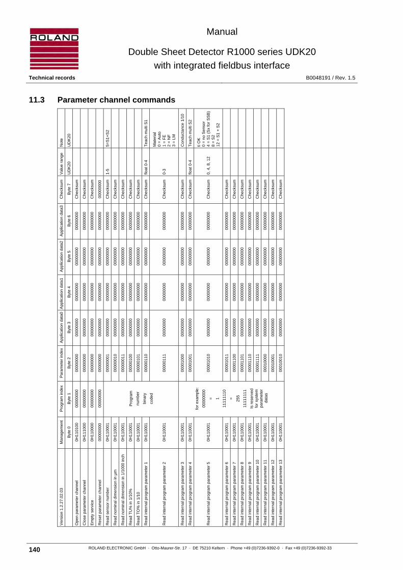
Manual
Double Sheet Detector R1000 series UDK20
with integrated fieldbus interface Technical records B0048191 / Rev. 1.5
140 ROLAND ELECTRONIC GmbH · Otto-Maurer-Str. 17 · DE 75210 Keltern · Phone +49 (0)7236-9392-0 · Fax +49 (0)7236-9392-33
11.3 Parameter channel commands
No
te
UD
K2
0
5=
S1
+S
2
Te
ach
mu
lti S
1
Ma
teria
l 0
= A
uto
1
= F
E
2 =
NF
3
= L
M
Co
nd
uct
an
ce 1
/10
Te
ach
mu
lti S
2
ti O
K
0 =
no
Se
nso
r 4
= S
1 (
Sx
for
SS
B)
8 =
S2
12
= S
1 +
S2
Va
lue
ra
nge
UD
K2
0
1-5
floa
t 0-4
0-3
floa
t 0-4
0,
4, 8
, 12
Che
cksu
m
Byt
e 7
Che
cksu
m
Che
cksu
m
Che
cksu
m
00
000
000
Che
cksu
m
Che
cksu
m
Che
cksu
m
Che
cksu
m
Che
cksu
m
Che
cksu
m
Che
cksu
m
Che
cksu
m
Che
cksu
m
Che
cksu
m
Che
cksu
m
Che
cksu
m
Che
cksu
m
Che
cksu
m
Che
cksu
m
Che
cksu
m
Che
cksu
m
Che
cksu
m
Ap
plic
atio
n d
ata
3
Byt
e 6
00
000
000
00
000
000
00
000
000
00
000
000
00
000
000
00
000
000
00
000
000
00
000
000
00
000
000
00
000
000
00
000
000
00
000
000
00
000
000
00
000
000
00
000
000
00
000
000
00
000
000
00
000
000
00
000
000
00
000
000
00
000
000
00
000
000
Ap
plic
atio
n d
ata
2
Byt
e 5
00
000
000
00
000
000
00
000
000
00
000
000
00
000
000
00
000
000
00
000
000
00
000
000
00
000
000
00
000
000
00
000
000
00
000
000
00
000
000
00
000
000
00
000
000
00
000
000
00
000
000
00
000
000
00
000
000
00
000
000
00
000
000
00
000
000
Ap
plic
atio
n d
ata
1
Byt
e 4
00
000
000
00
000
000
00
000
000
00
000
000
00
000
000
00
000
000
00
000
000
00
000
000
00
000
000
00
000
000
00
000
000
00
000
000
00
000
000
00
000
000
00
000
000
00
000
000
00
000
000
00
000
000
00
000
000
00
000
000
00
000
000
00
000
000
Ap
plic
atio
n d
ata
0
Byt
e 3
00
000
000
00
000
000
00
000
000
00
000
000
00
000
000
00
000
000
00
000
000
00
000
000
00
000
000
00
000
000
00
000
000
00
000
000
00
000
000
00
000
000
00
000
000
00
000
000
00
000
000
00
000
000
00
000
000
00
000
000
00
000
000
00
000
000
Pa
ram
ete
r in
de
x
Byt
e 2
00
000
000
00
000
000
00
000
000
00
000
000
00
000
001
00
000
010
00
000
011
00
000
100
00
000
101
00
000
110
00
000
111
00
001
000
00
001
001
00
001
010
00
001
011
00
001
100
00
001
101
00
001
110
00
001
111
00
010
000
00
010
001
00
010
010
Pro
gra
m in
dex
Byt
e 1
00
000
000
00
000
000
00
000
000
00
000
000
Pro
gra
m
nu
mb
er
bin
ary
cod
ed
for
exa
mp
le:
00
000
000
=
1
11
111
110
=
25
5
11
111
111
Is r
ese
rve
d
for
syst
em
pa
ram
ete
r d
ata
s
Ma
na
gem
en
t
Byt
e 0
0H
11
010
0
0H
11
100
0
0H
11
000
0
00
000
000
0H
11
000
1
0H
11
000
1
0H
11
000
1
0H
11
000
1
0H
11
000
1
0H
11
000
1
0H
11
000
1
0H
11
000
1
0H
11
000
1
0H
11
000
1
0H
11
000
1
0H
11
000
1
0H
11
000
1
0H
11
000
1
0H
11
000
1
0H
11
000
1
0H
11
000
1
0H
11
000
1
Ve
rsio
n 1
.2.2
7.0
2.0
3
Op
en
pa
ram
ete
r ch
ann
el
Clo
se p
ara
me
ter
cha
nne
l
Em
pty
serv
ice
Re
set
para
me
ter
chan
ne
l
Re
ad
se
nso
r n
um
be
r
Re
ad
no
min
al d
ime
nsi
on
in µ
m
Re
ad
no
min
al d
ime
nsi
on
in 1
/10
00 in
ch
Re
ad
TU
% in
1/1
0%
Re
ad
TO
% in
1/1
0
Re
ad
inte
rna
l pro
gra
m p
ara
me
ter
1
Re
ad
inte
rna
l pro
gra
m p
ara
me
ter
2
Re
ad
inte
rna
l pro
gra
m p
ara
me
ter
3
Re
ad
inte
rna
l pro
gra
m p
ara
me
ter
4
Re
ad
inte
rna
l pro
gra
m p
ara
me
ter
5
Re
ad
inte
rna
l pro
gra
m p
ara
me
ter
6
Re
ad
inte
rna
l pro
gra
m p
ara
me
ter
7
Re
ad
inte
rna
l pro
gra
m p
ara
me
ter
8
Re
ad
inte
rna
l pro
gra
m p
ara
me
ter
9
Re
ad
inte
rna
l pro
gra
m p
ara
me
ter
10
Re
ad
inte
rna
l pro
gra
m p
ara
me
ter
11
Re
ad
inte
rna
l pro
gra
m p
ara
me
ter
12
Re
ad
inte
rna
l pro
gra
m p
ara
me
ter
13
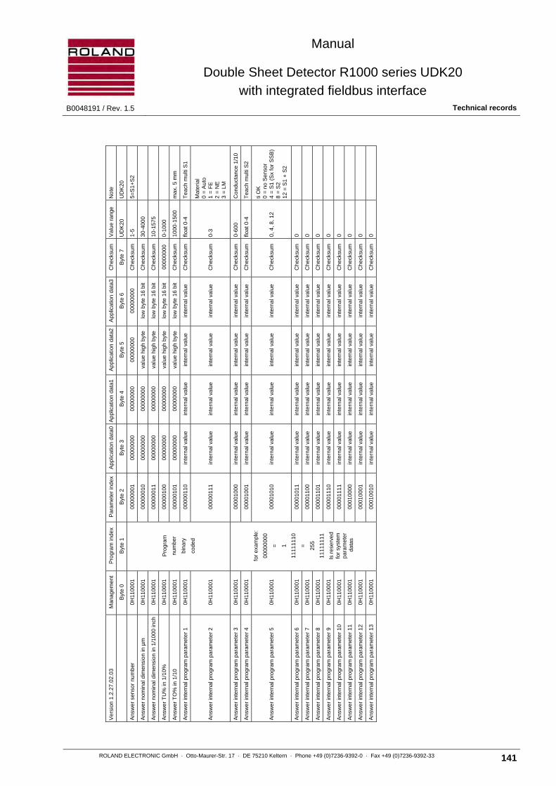
Manual
Double Sheet Detector R1000 series UDK20
with integrated fieldbus interface B0048191 / Rev. 1.5 Technical records
ROLAND ELECTRONIC GmbH · Otto-Maurer-Str. 17 · DE 75210 Keltern · Phone +49 (0)7236-9392-0 · Fax +49 (0)7236-9392-33 141
No
te
UD
K2
0
5=
S1
+S
2
ma
x. 5
mm
Te
ach
mu
lti S
1
Ma
teria
l 0
= A
uto
1
= F
E
2 =
NE
3
= L
M
Co
nd
uct
an
ce 1
/10
Te
ach
mu
lti S
2
ti O
K
0 =
no
Se
nso
r 4
= S
1 (
Sx
for
SS
B)
8 =
S2
12
= S
1 +
S2
Va
lue
ra
nge
UD
K2
0
1-5
30
-400
0
10
-157
5
0-1
000
10
00-1
500
floa
t 0-4
0-3
0-6
00
floa
t 0-4
0,
4, 8
, 12
0
0
0
0
0
0
0
0
Che
cksu
m
Byt
e 7
Che
cksu
m
Che
cksu
m
Che
cksu
m
00
000
000
Che
cksu
m
Che
cksu
m
Che
cksu
m
Che
cksu
m
Che
cksu
m
Che
cksu
m
Che
cksu
m
Che
cksu
m
Che
cksu
m
Che
cksu
m
Che
cksu
m
Che
cksu
m
Che
cksu
m
Che
cksu
m
Ap
plic
atio
n d
ata
3
Byt
e 6
00
000
000
low
byt
e 1
6 b
it
low
byt
e 1
6 b
it
low
byt
e 1
6 b
it
low
byt
e 1
6 b
it
inte
rna
l va
lue
inte
rna
l va
lue
inte
rna
l va
lue
inte
rna
l va
lue
inte
rna
l va
lue
inte
rna
l va
lue
inte
rna
l va
lue
inte
rna
l va
lue
inte
rna
l va
lue
inte
rna
l va
lue
inte
rna
l va
lue
inte
rna
l va
lue
inte
rna
l va
lue
Ap
plic
atio
n d
ata
2
Byt
e 5
00
000
000
valu
e h
igh
byt
e
valu
e h
igh
byt
e
valu
e h
igh
byt
e
valu
e h
igh
byt
e
inte
rna
l va
lue
inte
rna
l va
lue
inte
rna
l va
lue
inte
rna
l va
lue
inte
rna
l va
lue
inte
rna
l va
lue
inte
rna
l va
lue
inte
rna
l va
lue
inte
rna
l va
lue
inte
rna
l va
lue
inte
rna
l va
lue
inte
rna
l va
lue
inte
rna
l va
lue
Ap
plic
atio
n d
ata
1
Byt
e 4
00
000
000
00
000
000
00
000
000
00
000
000
00
000
000
inte
rna
l va
lue
inte
rna
l va
lue
inte
rna
l va
lue
inte
rna
l va
lue
inte
rna
l va
lue
inte
rna
l va
lue
inte
rna
l va
lue
inte
rna
l va
lue
inte
rna
l va
lue
inte
rna
l va
lue
inte
rna
l va
lue
inte
rna
l va
lue
inte
rna
l va
lue
Ap
plic
atio
n d
ata
0
Byt
e 3
00
000
000
00
000
000
00
000
000
00
000
000
00
000
000
inte
rna
l va
lue
inte
rna
l va
lue
inte
rna
l va
lue
inte
rna
l va
lue
inte
rna
l va
lue
inte
rna
l va
lue
inte
rna
l va
lue
inte
rna
l va
lue
inte
rna
l va
lue
inte
rna
l va
lue
inte
rna
l va
lue
inte
rna
l va
lue
inte
rna
l va
lue
Pa
ram
ete
r in
de
x
Byt
e 2
00
000
001
00
000
010
00
000
011
00
000
100
00
000
101
00
000
110
00
000
111
00
001
000
00
001
001
00
001
010
00
001
011
00
001
100
00
001
101
00
001
110
00
001
111
00
010
000
00
010
001
00
010
010
Pro
gra
m in
dex
Byt
e 1
Pro
gra
m
nu
mb
er
bin
ary
cod
ed
for
exa
mp
le:
00
000
000
=
1
11
111
110
=
25
5
11
111
111
Is r
ese
rve
d
for
syst
em
pa
ram
ete
r d
ata
s
Ma
na
gem
en
t
Byt
e 0
0H
11
000
1
0H
11
000
1
0H
11
000
1
0H
11
000
1
0H
11
000
1
0H
11
000
1
0H
11
000
1
0H
11
000
1
0H
11
000
1
0H
11
000
1
0H
11
000
1
0H
11
000
1
0H
11
000
1
0H
11
000
1
0H
11
000
1
0H
11
000
1
0H
11
000
1
0H
11
000
1
Ve
rsio
n 1
.2.2
7.0
2.0
3
Ans
we
r se
nsor
nu
mb
er
An
swe
r no
min
al d
ime
nsio
n in
µm
An
swe
r no
min
al d
ime
nsio
n in
1/1
00
0 in
ch
An
swe
r T
U%
in 1
/10
%
An
swe
r T
O%
in 1
/10
An
swe
r in
tern
al p
rog
ram
pa
ram
ete
r 1
An
swe
r in
tern
al p
rog
ram
pa
ram
ete
r 2
An
swe
r in
tern
al p
rog
ram
pa
ram
ete
r 3
An
swe
r in
tern
al p
rog
ram
pa
ram
ete
r 4
An
swe
r in
tern
al p
rog
ram
pa
ram
ete
r 5
An
swe
r in
tern
al p
rog
ram
pa
ram
ete
r 6
An
swe
r in
tern
al p
rog
ram
pa
ram
ete
r 7
An
swe
r in
tern
al p
rog
ram
pa
ram
ete
r 8
An
swe
r in
tern
al p
rog
ram
pa
ram
ete
r 9
An
swe
r in
tern
al p
rog
ram
pa
ram
ete
r 1
0
An
swe
r in
tern
al p
rog
ram
pa
ram
ete
r 1
1
An
swe
r in
tern
al p
rog
ram
pa
ram
ete
r 1
2
An
swe
r in
tern
al p
rog
ram
pa
ram
ete
r 1
3

Manual
Double Sheet Detector R1000 series UDK20
with integrated fieldbus interface Technical records B0048191 / Rev. 1.5
142 ROLAND ELECTRONIC GmbH · Otto-Maurer-Str. 17 · DE 75210 Keltern · Phone +49 (0)7236-9392-0 · Fax +49 (0)7236-9392-33
No
te
UD
K2
0
5=
S1
+S
2
ma
x. 5
mm
Te
ach
mu
lti S
1
Ma
teria
l 0
= A
uto
1
= F
E
2 =
NE
3
= L
M
Co
nd
uct
an
ce 1
/10
Te
ach
mu
lti S
2
ti O
K
0 =
no
Se
nso
r 4
= S
1 (
Sx
for
SS
B)
8 =
S2
12
= S
1 +
S2
Va
lue
ra
nge
UD
K2
0
1-5
30
-400
0
10
-157
5
0-1
000
10
00-1
500
floa
t 0-4
0-3
0-6
00
floa
t 0-4
0,
4, 8
, 12
0
0
0
0
0
0
0
0
Che
cksu
m
Byt
e 7
Che
cksu
m
Che
cksu
m
Che
cksu
m
Che
cksu
m
Che
cksu
m
Che
cksu
m
Che
cksu
m
Che
cksu
m
Che
cksu
m
Che
cksu
m
Che
cksu
m
Che
cksu
m
Che
cksu
m
Che
cksu
m
Che
cksu
m
Che
cksu
m
Che
cksu
m
Che
cksu
m
Ap
plic
atio
n d
ata
3
Byt
e 6
valu
e 8
bit
low
byt
e 1
6 b
it
low
byt
e 1
6 b
it
low
byt
e 1
6 b
it
low
byt
e 1
6 b
it
inte
rna
l va
lue
inte
rna
l va
lue
inte
rna
l va
lue
inte
rna
l va
lue
inte
rna
l va
lue
inte
rna
l va
lue
inte
rna
l va
lue
inte
rna
l va
lue
inte
rna
l va
lue
inte
rna
l va
lue
inte
rna
l va
lue
inte
rna
l va
lue
inte
rna
l va
lue
Ap
plic
atio
n d
ata
2
Byt
e 5
00
000
000
valu
e h
igh
byt
e
valu
e h
igh
byt
e
valu
e h
igh
byt
e
valu
e h
igh
byt
e
inte
rna
l va
lue
inte
rna
l va
lue
inte
rna
l va
lue
inte
rna
l va
lue
inte
rna
l va
lue
inte
rna
l va
lue
inte
rna
l va
lue
inte
rna
l va
lue
inte
rna
l va
lue
inte
rna
l va
lue
inte
rna
l va
lue
inte
rna
l va
lue
inte
rna
l va
lue
Ap
plic
atio
n d
ata
1
Byt
e 4
00
000
000
00
000
000
00
000
000
00
000
000
00
000
000
inte
rna
l va
lue
inte
rna
l va
lue
inte
rna
l va
lue
inte
rna
l va
lue
inte
rna
l va
lue
inte
rna
l va
lue
inte
rna
l va
lue
inte
rna
l va
lue
inte
rna
l va
lue
inte
rna
l va
lue
inte
rna
l va
lue
inte
rna
l va
lue
inte
rna
l va
lue
Ap
plic
atio
n d
ata
0
Byt
e 3
00
000
000
00
000
000
00
000
000
00
000
000
00
000
000
inte
rna
l va
lue
inte
rna
l va
lue
inte
rna
l va
lue
inte
rna
l va
lue
inte
rna
l va
lue
inte
rna
l va
lue
inte
rna
l va
lue
inte
rna
l va
lue
inte
rna
l va
lue
inte
rna
l va
lue
inte
rna
l va
lue
inte
rna
l va
lue
inte
rna
l va
lue
Pa
ram
ete
r in
de
x
Byt
e 2
00
000
001
00
000
010
00
000
011
00
000
100
00
000
101
00
000
110
00
000
111
00
001
000
00
001
001
00
001
010
00
001
011
00
001
100
00
001
101
00
001
110
00
001
111
00
010
000
00
010
001
00
010
010
Pro
gra
m in
dex
Byt
e 1
Pro
gra
m
nu
mb
er
bin
ary
cod
ed
for
exa
mp
le:
00
000
000
=
1
11
111
110
=
25
5
11
111
111
Is r
ese
rve
d
for
syst
em
pa
ram
ete
r d
ata
s
Ma
na
gem
en
t
Byt
e 0
0H
11
001
0
0H
11
001
0
0H
11
001
0
0H
11
001
0
0H
11
001
0
0H
11
001
0
0H
11
001
0
0H
11
001
0
0H
11
001
0
0H
11
001
0
0H
11
001
0
0H
11
001
0
0H
11
001
0
0H
11
001
0
0H
11
001
0
0H
11
001
0
0H
11
001
0
0H
11
001
0
Ve
rsio
n 1
.2.2
7.0
2.0
3
Writ
e s
en
sor
num
be
r
Writ
e n
om
ina
l dim
ensi
on
in µ
m
Writ
e n
om
ina
l dim
ensi
on
in 1
/10
00 in
ch
Writ
e T
U%
in 1
/10
%
Writ
e T
O%
in 1
/10
Writ
e in
tern
al p
rog
ram
pa
ram
ete
r 1
Writ
e in
tern
al p
rog
ram
pa
ram
ete
r 2
Writ
e in
tern
al p
rog
ram
pa
ram
ete
r 3
Writ
e in
tern
al p
rog
ram
pa
ram
ete
r 4
Writ
e in
tern
al p
rog
ram
pa
ram
ete
r 5
Writ
e in
tern
al p
rog
ram
pa
ram
ete
r 6
Writ
e in
tern
al p
rog
ram
pa
ram
ete
r 7
Writ
e in
tern
al p
rog
ram
pa
ram
ete
r 8
Writ
e in
tern
al p
rog
ram
pa
ram
ete
r 9
Writ
e in
tern
al p
rog
ram
pa
ram
ete
r 1
0
Writ
e in
tern
al p
rog
ram
pa
ram
ete
r 1
1
Writ
e in
tern
al p
rog
ram
pa
ram
ete
r 1
2
Writ
e in
tern
al p
rog
ram
pa
ram
ete
r 1
3

Manual
Double Sheet Detector R1000 series UDK20
with integrated fieldbus interface B0048191 / Rev. 1.5 Technical records
ROLAND ELECTRONIC GmbH · Otto-Maurer-Str. 17 · DE 75210 Keltern · Phone +49 (0)7236-9392-0 · Fax +49 (0)7236-9392-33 143
No
te
UD
K2
0
La
ngu
age
Dis
pla
y in
Bus
re
adou
t
(re
serv
e)
Bu
s ad
dre
ss
(rsi
)
Pas
swor
d
(Se
nso
r ty
pe
)
No
. o
f se
nso
rs
(re
serv
e)
(re
serv
e)
Me
asu
rem
ent
mo
de
Ho
ld 2
-sh
eet
1-2
-3 M
ea
s. S
tart
Le
vel 0
-1-2
Ext
. A
dju
stm
ent
(re
serv
e)
(re
serv
e)
(re
serv
e)
Te
ach
-Lim
it
FE
me
as.
Mod
e
Sys
tem
ser
ies
Sys
tem
typ
e
So
ftw
are
ve
rsio
n
Va
lue
ra
nge
UD
K2
0
0-4
0-2
0-2
0
acc.
to
field
bus
0
0,
1
3
1-4
0
0
0-2
0
1,
2, 3
0,
1
0,
1
0
0
0
0,
1
0,
1
Pla
in t
ex t
Pla
in t
ex t
1-…
Che
cksu
m
Byt
e 7
Che
cksu
m
Che
cksu
m
Che
cksu
m
Che
cksu
m
Che
cksu
m
Che
cksu
m
Che
cksu
m
Che
cksu
m
Che
cksu
m
Che
cksu
m
Che
cksu
m
Che
cksu
m
Che
cksu
m
Che
cksu
m
Che
cksu
m
Che
cksu
m
Che
cksu
m
Che
cksu
m
Che
cksu
m
Che
cksu
m
Che
cksu
m
Che
cksu
m
Che
cksu
m
Che
cksu
m
Ap
plic
atio
n d
ata
3
Byt
e 6
00
000
000
00
000
000
00
000
000
00
000
000
00
000
000
00
000
000
00
000
000
00
000
000
00
000
000
00
000
000
00
000
000
00
000
000
00
000
000
00
000
000
00
000
000
00
000
000
00
000
000
00
000
000
00
000
000
00
000
000
00
000
000
00
000
000
00
000
000
00
000
000
Ap
plic
atio
n d
ata
2
Byt
e 5
00
000
000
00
000
000
00
000
000
00
000
000
00
000
000
00
000
000
00
000
000
00
000
000
00
000
000
00
000
000
00
000
000
00
000
000
00
000
000
00
000
000
00
000
000
00
000
000
00
000
000
00
000
000
00
000
000
00
000
000
00
000
000
00
000
000
00
000
000
00
000
000
Ap
plic
atio
n d
ata
1
Byt
e 4
00
000
000
00
000
000
00
000
000
00
000
000
00
000
000
00
000
000
00
000
000
00
000
000
00
000
000
00
000
000
00
000
000
00
000
000
00
000
000
00
000
000
00
000
000
00
000
000
00
000
000
00
000
000
00
000
000
00
000
000
00
000
000
00
000
000
00
000
000
00
000
000
Ap
plic
atio
n d
ata
0
Byt
e 3
00
000
000
00
000
000
00
000
000
00
000
000
00
000
000
00
000
000
00
000
000
00
000
000
00
000
000
00
000
000
00
000
000
00
000
000
00
000
000
00
000
000
00
000
000
00
000
000
00
000
000
00
000
000
00
000
000
00
000
000
00
000
000
00
000
000
00
000
000
00
000
000
Pa
ram
ete
r in
de
x
Byt
e 2
00
000
001
00
000
010
00
000
011
00
000
100
00
000
101
00
000
110
00
000
111
00
001
000
00
001
001
00
001
010
00
001
011
00
001
100
00
001
101
00
001
110
00
001
111
00
010
000
00
010
001
00
010
010
00
010
011
00
010
100
00
010
101
00
010
110
00
010
111
00
011
000
Pro
gra
m in
dex
Byt
e 1
11
111
111
11
111
111
11
111
111
11
111
111
11
111
111
11
111
111
11
111
111
11
111
111
11
111
111
11
111
111
11
111
111
11
111
111
11
111
111
11
111
111
11
111
111
11
111
111
11
111
111
11
111
111
11
111
111
11
111
111
11
111
111
11
111
111
11
111
111
11
111
111
Ma
na
gem
en
t
Byt
e 0
0H
11
000
1
0H
11
000
1
0H
11
000
1
0H
11
000
1
0H
11
000
1
0H
11
000
1
0H
11
000
1
0H
11
000
1
0H
11
000
1
0H
11
000
1
0H
11
000
1
0H
11
000
1
0H
11
000
1
0H
11
000
1
0H
11
000
1
0H
11
000
1
0H
11
000
1
0H
11
000
1
0H
11
000
1
0H
11
000
1
0H
11
000
1
0H
11
000
1
0H
11
000
1
0H
11
000
1
Ve
rsio
n 1
.2.2
7.0
2.0
3
Rea
d sy
stem
par
am
ete
r 1
Rea
d sy
stem
par
am
ete
r 2
Rea
d sy
stem
par
am
ete
r 3
Rea
d sy
stem
par
am
ete
r 4
Rea
d sy
stem
par
am
ete
r 5
Rea
d sy
stem
par
am
ete
r 6
Rea
d sy
stem
par
am
ete
r 7
Rea
d sy
stem
par
am
ete
r 8
Rea
d sy
stem
par
am
ete
r 9
Rea
d sy
stem
par
am
ete
r 10
Rea
d sy
stem
par
am
ete
r 11
Rea
d sy
stem
par
am
ete
r 12
Rea
d sy
stem
par
am
ete
r 13
Rea
d sy
stem
par
am
ete
r 14
Rea
d sy
stem
par
am
ete
r 15
Rea
d sy
stem
par
am
ete
r 16
Rea
d sy
stem
par
am
ete
r 17
Rea
d sy
stem
par
am
ete
r 18
Rea
d sy
stem
par
am
ete
r 19
Rea
d sy
stem
par
am
ete
r 20
Rea
d sy
stem
par
am
ete
r 21
Rea
d sy
stem
par
am
ete
r 22
Rea
d sy
stem
par
am
ete
r 23
Rea
d sy
stem
par
am
ete
r 24

Manual
Double Sheet Detector R1000 series UDK20
with integrated fieldbus interface Technical records B0048191 / Rev. 1.5
144 ROLAND ELECTRONIC GmbH · Otto-Maurer-Str. 17 · DE 75210 Keltern · Phone +49 (0)7236-9392-0 · Fax +49 (0)7236-9392-33
No
te
UD
K2
0
La
ngu
age
Dis
pla
y in
Bu
s re
adou
t
(re
serv
e)
Bu
s ad
dre
ss
(rsi
)
Pas
swor
d
(Se
nso
r ty
pe
)
No
. o
f se
nso
rs
(re
serv
e)
(re
serv
e)
Me
asu
rem
ent
mo
de
Ho
ld 2
-sh
eet
1-2
-3 M
ea
s. S
tart
Le
vel 0
-1-2
Ext
. A
dju
stm
ent
(re
serv
e)
(re
serv
e)
(re
serv
e)
Te
ach
-Lim
it
FE
me
as.
Mod
e
Sys
tem
ser
ies
Sys
tem
typ
e
So
ftw
are
ve
rsio
n
Va
lue
ra
nge
UD
K2
0
0-4
0-2
0-2
0
acc.
to
field
bus
0
0,
1
3
1-4
0
0
0-2
0
1,
2, 3
0,
1
0,
1
0
0
0
0,
1
0,
1
Pla
in t
ex t
Pla
in t
ext
1-…
Che
cksu
m
Byt
e 7
Che
cksu
m
Che
cksu
m
Che
cksu
m
Che
cksu
m
Che
cksu
m
Che
cksu
m
Che
cksu
m
Che
cksu
m
Che
cksu
m
Che
cksu
m
Che
cksu
m
Che
cksu
m
Che
cksu
m
Che
cksu
m
Che
cksu
m
Che
cksu
m
Che
cksu
m
Che
cksu
m
Che
cksu
m
Che
cksu
m
Che
cksu
m
Che
cksu
m
Che
cksu
m
Che
cksu
m
Ap
plic
atio
n d
ata
3
valu
e 8
bit
valu
e 8
bit
valu
e 8
bit
valu
e 8
bit
low
byt
e 1
6 b
it
valu
e 8
bit
valu
e 8
bit
valu
e 8
bit
valu
e 8
bit
valu
e 8
bit
valu
e 8
bit
valu
e 8
bit
valu
e 8
bit
valu
e 8
bit
valu
e 8
bit
valu
e 8
bit
low
byt
e 1
6 b
it
low
byt
e 1
6 b
it
low
byt
e 1
6 b
it
low
byt
e 1
6 b
it
low
byt
e 1
6 b
it
1 s
ign
1 s
ign
00
000
000
valu
e 8
bit
Ap
plic
atio
n d
ata
2
00
000
000
00
000
000
00
000
000
00
000
000
valu
e h
igh
byt
e
00
000
000
00
000
000
00
000
000
00
000
000
00
000
000
00
000
000
00
000
000
00
000
000
00
000
000
00
000
000
00
000
000
valu
e h
igh
byt
e
valu
e h
igh
byt
e
valu
e h
igh
byt
e
valu
e h
igh
byt
e
valu
e h
igh
byt
e
1 s
ign
1 s
ign
00
000
000
00
000
000
Ap
plic
atio
n d
ata
1
00
000
000
00
000
000
00
000
000
00
000
000
00
000
000
00
000
000
00
000
000
00
000
000
00
000
000
00
000
000
00
000
000
00
000
000
00
000
000
00
000
000
00
000
000
00
000
000
00
000
000
00
000
000
00
000
000
00
000
000
00
000
000
1 s
ign
1 s
ign
00
000
000
00
000
000
Ap
plic
atio
n d
ata
0
00
000
000
00
000
000
00
000
000
00
000
000
00
000
000
00
000
000
00
000
000
00
000
000
00
000
000
00
000
000
00
000
000
00
000
000
00
000
000
00
000
000
00
000
000
00
000
000
00
000
000
00
000
000
00
000
000
00
000
000
00
000
000
1 s
ign
1 s
ign
00
000
000
00
000
000
Pa
ram
ete
r in
de
x
Byt
e 2
00
000
001
00
000
010
00
000
011
00
000
100
00
000
101
00
000
110
00
000
111
00
001
000
00
001
001
00
001
010
00
001
011
00
001
100
00
001
101
00
001
110
00
001
111
00
010
000
00
010
001
00
010
010
00
010
011
00
010
100
00
010
101
00
010
110
00
010
111
00
011
000
Pro
gra
m in
dex
Byt
e 1
11
111
111
11
111
111
11
111
111
11
111
111
11
111
111
11
111
111
11
111
111
11
111
111
11
111
111
11
111
111
11
111
111
11
111
111
11
111
111
11
111
111
11
111
111
11
111
111
11
111
111
11
111
111
11
111
111
11
111
111
11
111
111
11
111
111
11
111
111
11
111
111
Ma
na
gem
en
t
Byt
e 0
0H
11
000
1
0H
11
000
1
0H
11
000
1
0H
11
000
1
0H
11
000
1
0H
11
000
1
0H
11
000
1
0H
11
000
1
0H
11
000
1
0H
11
000
1
0H
11
000
1
0H
11
000
1
0H
11
000
1
0H
11
000
1
0H
11
000
1
0H
11
000
1
0H
11
000
1
0H
11
000
1
0H
11
000
1
0H
11
000
1
0H
11
000
1
0H
11
000
1
0H
11
000
1
0H
11
000
1
Ve
rsio
n 1
.2.2
7.0
2.0
3
Ans
wer
sys
tem
par
amet
er 1
Ans
wer
sys
tem
par
amet
er 2
Ans
wer
sys
tem
par
amet
er 3
Ans
wer
sys
tem
par
amet
er 4
Ans
wer
sys
tem
par
amet
er 5
Ans
wer
sys
tem
par
amet
er 6
Ans
wer
sys
tem
par
amet
er 7
Ans
wer
sys
tem
par
amet
er 8
Ans
wer
sys
tem
par
amet
er 9
Ans
wer
sys
tem
par
amet
er 1
0
Ans
wer
sys
tem
par
amet
er 1
1
Ans
wer
sys
tem
par
amet
er 1
2
Ans
wer
sys
tem
par
amet
er 1
3
Ans
wer
sys
tem
par
amet
er 1
4
Ans
wer
sys
tem
par
amet
er 1
5
Ans
wer
sys
tem
par
amet
er 1
6
Ans
wer
sys
tem
par
amet
er 1
7
Ans
wer
sys
tem
par
amet
er 1
8
Ans
wer
sys
tem
par
amet
er 1
9
Ans
wer
sys
tem
par
amet
er 2
0
Ans
wer
sys
tem
par
amet
er 2
1
Ans
wer
sys
tem
par
amet
er 2
2
Ans
wer
sys
tem
par
amet
er 2
3
Ans
wer
sys
tem
par
amet
er 2
4

Manual
Double Sheet Detector R1000 series UDK20
with integrated fieldbus interface B0048191 / Rev. 1.5
ROLAND ELECTRONIC GmbH · Otto-Maurer-Str. 17 · DE 75210 Keltern · Phone +49 (0)7236-9392-0 · Fax +49 (0)7236-9392-33 145
No
te
UD
K2
0
La
ngu
age
Dis
pla
y in
Bu
s re
adou
t
(re
serv
e)
Bu
s ad
dre
ss
(rsi
)
Pas
swor
d
(Se
nso
r ty
pe
)
No
. o
f se
nso
rs
(re
serv
e)
(re
serv
e)
Me
asu
rem
ent
mo
de
Ho
ld 2
-sh
eet
1-2
-3 M
ea
s. S
tart
Le
vel 0
-1-2
Ext
. A
dju
stm
ent
(re
serv
e)
(re
serv
e)
(re
serv
e)
Te
ach
-Lim
it
FE
me
as.
Mod
e
Sys
tem
ser
ies
Sys
tem
typ
e
So
ftw
are
ve
rsio
n
Va
lue
ra
nge
UD
K2
0
0-4
0-2
0-2
0
acc.
to
field
bus
0
0,
1
3
1-4
0
0
0-2
0
1,
2, 3
0,
1
0,
1
0
0
0
0,
1
0,
1
Pla
in t
ex t
Pla
in t
ext
1-…
Che
cksu
m
Byt
e 7
Che
cksu
m
Che
cksu
m
Che
cksu
m
Che
cksu
m
Che
cksu
m
Che
cksu
m
Che
cksu
m
Che
cksu
m
Che
cksu
m
Che
cksu
m
Che
cksu
m
Che
cksu
m
Che
cksu
m
Che
cksu
m
Che
cksu
m
Che
cksu
m
Che
cksu
m
Che
cksu
m
Che
cksu
m
Che
cksu
m
Che
cksu
m
Che
cksu
m
Che
cksu
m
Che
cksu
m
Ap
plic
atio
n d
ata
3
Byt
e 6
valu
e 8
bit
valu
e 8
bit
valu
e 8
bit
valu
e 8
bit
low
byt
e 1
6 b
it
valu
e 8
bit
valu
e 8
bit
valu
e 8
bit
valu
e 8
bit
valu
e 8
bit
valu
e 8
bit
valu
e 8
bit
valu
e 8
bit
valu
e 8
bit
valu
e 8
bit
valu
e 8
bit
low
byt
e 1
6 b
it
low
byt
e 1
6 b
it
low
byt
e 1
6 b
it
low
byt
e 1
6 b
it
low
byt
e 1
6 b
it
00
000
000
00
000
000
00
000
000
Ap
plic
atio
n d
ata
2
Byt
e 5
00
000
000
00
000
000
00
000
000
00
000
000
valu
e h
igh
byt
e
00
000
000
00
000
000
00
000
000
00
000
000
00
000
000
00
000
000
00
000
000
00
000
000
00
000
000
00
000
000
00
000
000
valu
e h
igh
byt
e
valu
e h
igh
byt
e
valu
e h
igh
byt
e
valu
e h
igh
byt
e
valu
e h
igh
byt
e
00
000
000
00
000
000
00
000
000
Ap
plic
atio
n d
ata
1
Byt
e 4
00
000
000
00
000
000
00
000
000
00
000
000
00
000
000
00
000
000
00
000
000
00
000
000
00
000
000
00
000
000
00
000
000
00
000
000
00
000
000
00
000
000
00
000
000
00
000
000
00
000
000
00
000
000
00
000
000
00
000
000
00
000
000
00
000
000
00
000
000
00
000
000
Ap
plic
atio
n d
ata
0
Byt
e 3
00
000
000
00
000
000
00
000
000
00
000
000
00
000
000
00
000
000
00
000
000
00
000
000
00
000
000
00
000
000
00
000
000
00
000
000
00
000
000
00
000
000
00
000
000
00
000
000
00
000
000
00
000
000
00
000
000
00
000
000
00
000
000
00
000
000
00
000
000
00
000
000
Pa
ram
ete
r in
de
x
Byt
e 2
00
000
001
00
000
010
00
000
011
00
000
100
00
000
101
00
000
110
00
000
111
00
001
000
00
001
001
00
001
010
00
001
011
00
001
100
00
001
101
00
001
110
00
001
111
00
010
000
00
010
001
00
010
010
00
010
011
00
010
100
00
010
101
00
010
110
00
010
111
00
011
000
Pro
gra
m in
dex
Byt
e 1
11
111
111
11
111
111
11
111
111
11
111
111
11
111
111
11
111
111
11
111
111
11
111
111
11
111
111
11
111
111
11
111
111
11
111
111
11
111
111
11
111
111
11
111
111
11
111
111
11
111
111
11
111
111
11
111
111
11
111
111
11
111
111
11
111
111
11
111
111
11
111
111
Ma
na
gem
en
t
Byt
e 0
0H
11
001
0
0H
11
001
0
0H
11
001
0
0H
11
001
0
0H
11
001
0
0H
11
001
0
0H
11
001
0
0H
11
001
0
0H
11
001
0
0H
11
001
0
0H
11
001
0
0H
11
001
0
0H
11
001
0
0H
11
001
0
0H
11
001
0
0H
11
001
0
0H
11
001
0
0H
11
001
0
0H
11
001
0
0H
11
001
0
0H
11
001
0
0H
11
001
0
0H
11
001
0
0H
11
001
0
Ve
rsio
n 1
.2.2
7.0
2.0
3
Writ
e sy
stem
par
amet
er
1
Writ
e sy
stem
par
amet
er
2
Writ
e sy
stem
par
amet
er
3
Writ
e sy
stem
par
amet
er
4
Writ
e sy
stem
par
amet
er
5
Writ
e sy
stem
par
amet
er
6
Writ
e sy
stem
par
amet
er
7
Writ
e sy
stem
par
amet
er
8
Writ
e sy
stem
par
amet
er
9
Writ
e sy
stem
par
amet
er
10
Writ
e sy
stem
par
amet
er
11
Writ
e sy
stem
par
amet
er
12
Writ
e sy
stem
par
amet
er
13
Writ
e sy
stem
par
amet
er
14
Writ
e sy
stem
par
amet
er
15
Writ
e sy
stem
par
amet
er
16
Writ
e sy
stem
par
amet
er
17
Writ
e sy
stem
par
amet
er
18
Writ
e sy
stem
par
amet
er
19
Writ
e sy
stem
par
amet
er
20
Writ
e sy
stem
par
amet
er
21
Writ
e sy
stem
par
amet
er
22
Writ
e sy
stem
par
amet
er
23
Writ
e sy
stem
par
amet
er
24
Bus
add
ress
:
Bau
drat
e:
00 =
150
kB
01 =
250
kB
10 =
500
kB
11 =
not
use
d
0 -
63*
for
Dev
iceN
et:

Manual
Double Sheet Detector R1000 series UDK20
with integrated fieldbus interface B0048191 / Rev. 1.5
146 ROLAND ELECTRONIC GmbH · Otto-Maurer-Str. 17 · DE 75210 Keltern · Phone +49 (0)7236-9392-0 · Fax +49 (0)7236-9392-33
Blank page
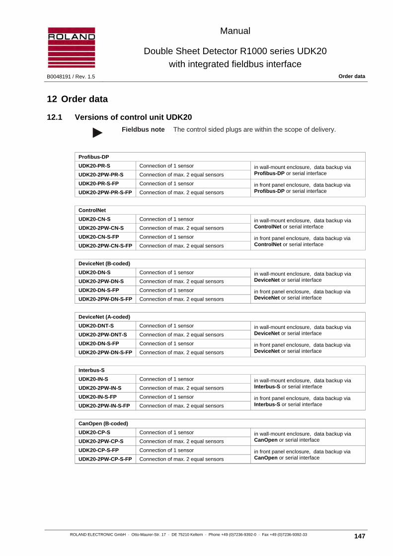
Manual
Double Sheet Detector R1000 series UDK20
with integrated fieldbus interface B0048191 / Rev. 1.5 Order data
ROLAND ELECTRONIC GmbH · Otto-Maurer-Str. 17 · DE 75210 Keltern · Phone +49 (0)7236-9392-0 · Fax +49 (0)7236-9392-33 147
12 Order data
12.1 Versions of control unit UDK20
Fieldbus note The control sided plugs are within the scope of delivery.
Profibus-DP
UDK20-PR-S Connection of 1 sensor in wall-mount enclosure, data backup via Profibus-DP or serial interface UDK20-2PW-PR-S Connection of max. 2 equal sensors
UDK20-PR-S-FP Connection of 1 sensor in front panel enclosure, data backup via Profibus-DP or serial interface UDK20-2PW-PR-S-FP Connection of max. 2 equal sensors
ControlNet
UDK20-CN-S Connection of 1 sensor in wall-mount enclosure, data backup via ControlNet or serial interface UDK20-2PW-CN-S Connection of max. 2 equal sensors
UDK20-CN-S-FP Connection of 1 sensor in front panel enclosure, data backup via ControlNet or serial interface UDK20-2PW-CN-S-FP Connection of max. 2 equal sensors
DeviceNet (B-coded)
UDK20-DN-S Connection of 1 sensor in wall-mount enclosure, data backup via DeviceNet or serial interface UDK20-2PW-DN-S Connection of max. 2 equal sensors
UDK20-DN-S-FP Connection of 1 sensor in front panel enclosure, data backup via DeviceNet or serial interface UDK20-2PW-DN-S-FP Connection of max. 2 equal sensors
DeviceNet (A-coded)
UDK20-DNT-S Connection of 1 sensor in wall-mount enclosure, data backup via DeviceNet or serial interface UDK20-2PW-DNT-S Connection of max. 2 equal sensors
UDK20-DN-S-FP Connection of 1 sensor in front panel enclosure, data backup via DeviceNet or serial interface UDK20-2PW-DN-S-FP Connection of max. 2 equal sensors
Interbus-S
UDK20-IN-S Connection of 1 sensor in wall-mount enclosure, data backup via Interbus-S or serial interface UDK20-2PW-IN-S Connection of max. 2 equal sensors
UDK20-IN-S-FP Connection of 1 sensor in front panel enclosure, data backup via Interbus-S or serial interface UDK20-2PW-IN-S-FP Connection of max. 2 equal sensors
CanOpen (B-coded)
UDK20-CP-S Connection of 1 sensor in wall-mount enclosure, data backup via CanOpen or serial interface UDK20-2PW-CP-S Connection of max. 2 equal sensors
UDK20-CP-S-FP Connection of 1 sensor in front panel enclosure, data backup via CanOpen or serial interface UDK20-2PW-CP-S-FP Connection of max. 2 equal sensors

Manual
Double Sheet Detector R1000 series UDK20
with integrated fieldbus interface Order data B0048191 / Rev. 1.5
148 ROLAND ELECTRONIC GmbH · Otto-Maurer-Str. 17 · DE 75210 Keltern · Phone +49 (0)7236-9392-0 · Fax +49 (0)7236-9392-33
CanOpen (A-coded)
UDK20-COP-S Connection of 1 sensor in wall-mount enclosure, data backup via CanOpen or serial interface UDK20-2PW-COP-S Connection of max. 2 equal sensors
UDK20-COP-S-FP Connection of 1 sensor in front panel enclosure, data backup via CanOpen or serial interface UDK20-2PW-COP-S-FP Connection of max. 2 equal sensors
ProfiNet IO
UDK20-PN-S Connection of 1 sensor in wall-mount enclosure, data backup via ProfiNet or serial interface UDK20-2PW-PN-S Connection of max. 2 equal sensors
UDK20-PN-S-FP Connection of 1 sensor in front panel enclosure, data backup via ProfiNet or serial interface UDK20-2PW-PN-S-FP Connection of max. 2 equal sensors
CC-Link
UDK20-CC-S Connection of 1 sensor in wall-mount enclosure, data backup via CC-Link or serial interface UDK20-2PW-CC-S Connection of max. 2 equal sensors
UDK20-CC-S-FP Connection of 1 sensor in front panel enclosure, data backup via CC-Link or serial interface UDK20-2PW-CC-S-FP Connection of max. 2 equal sensors
EtherNet/IP
UDK20-EN-S Connection of 1 sensor in wall-mount enclosure, data backup via EtherNet/IP or serial interface UDK20-2PW-EN-S Connection of max. 2 equal sensors
UDK20-EN-S-FP Connection of 1 sensor in front panel enclosure, data backup via EtherNet/IP or serial interface UDK20-2PW-EN-S-FP Connection of max. 2 equal sensors
EtherCAT
UDK20-ET-S Connection of 1 sensor in wall-mount enclosure, data backup via EtherCAT or serial interface UDK20-2PW-ET-S Connection of max. 2 equal sensors
UDK20-ET-S-FP Connection of 1 sensor in front panel enclosure, data backup via EtherCAT or serial interface UDK20-2PW-ET-S-FP Connection of max. 2 equal sensors
12.2 System accessories
Order information Description
SSBUDK10 Sensor Switch Box, for connecting of up to 4 sensors (not for UDK20-2PW versions)
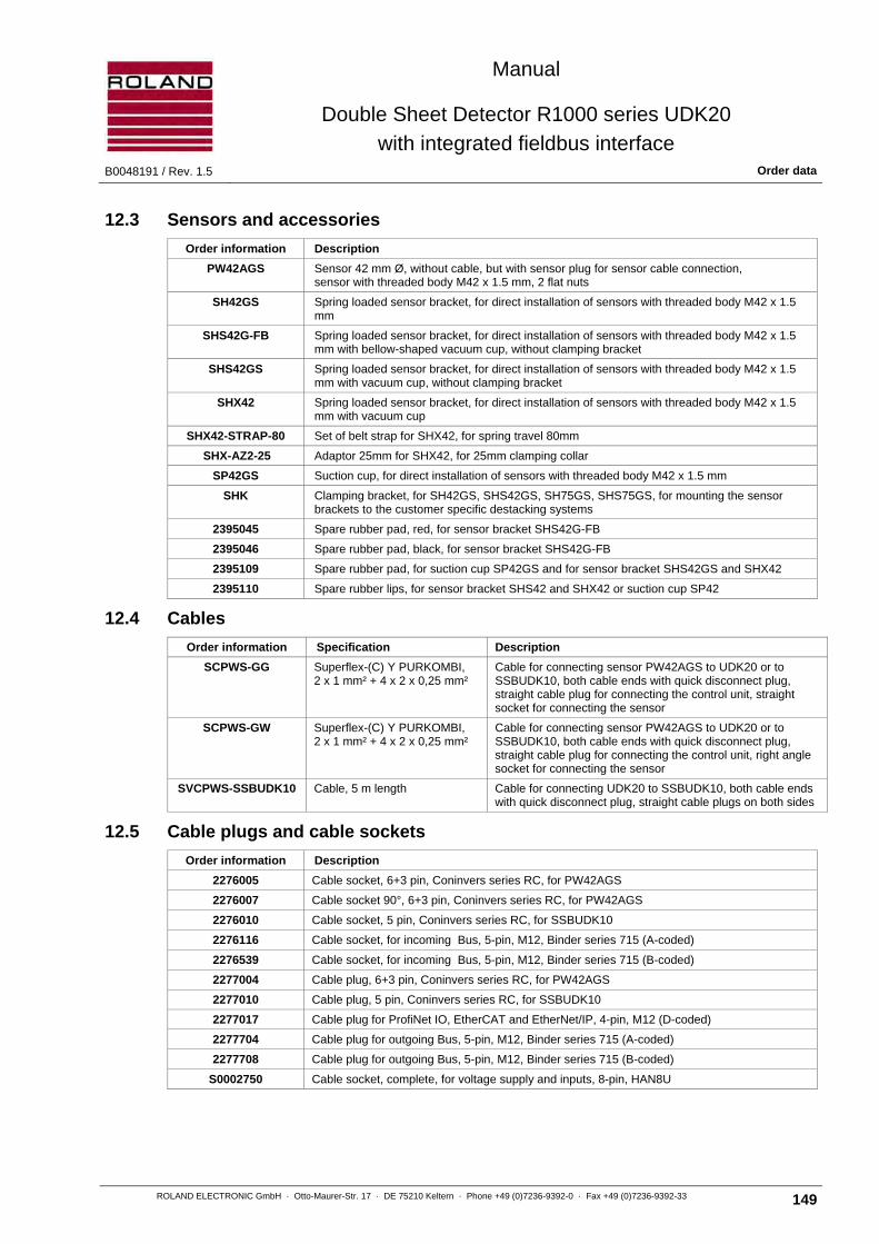
Manual
Double Sheet Detector R1000 series UDK20
with integrated fieldbus interface B0048191 / Rev. 1.5 Order data
ROLAND ELECTRONIC GmbH · Otto-Maurer-Str. 17 · DE 75210 Keltern · Phone +49 (0)7236-9392-0 · Fax +49 (0)7236-9392-33 149
12.3 Sensors and accessories
Order information Description
PW42AGS Sensor 42 mm Ø, without cable, but with sensor plug for sensor cable connection, sensor with threaded body M42 x 1.5 mm, 2 flat nuts
SH42GS Spring loaded sensor bracket, for direct installation of sensors with threaded body M42 x 1.5 mm
SHS42G-FB Spring loaded sensor bracket, for direct installation of sensors with threaded body M42 x 1.5 mm with bellow-shaped vacuum cup, without clamping bracket
SHS42GS Spring loaded sensor bracket, for direct installation of sensors with threaded body M42 x 1.5 mm with vacuum cup, without clamping bracket
SHX42 Spring loaded sensor bracket, for direct installation of sensors with threaded body M42 x 1.5 mm with vacuum cup
SHX42-STRAP-80 Set of belt strap for SHX42, for spring travel 80mm
SHX-AZ2-25 Adaptor 25mm for SHX42, for 25mm clamping collar
SP42GS Suction cup, for direct installation of sensors with threaded body M42 x 1.5 mm
SHK Clamping bracket, for SH42GS, SHS42GS, SH75GS, SHS75GS, for mounting the sensor brackets to the customer specific destacking systems
2395045 Spare rubber pad, red, for sensor bracket SHS42G-FB
2395046 Spare rubber pad, black, for sensor bracket SHS42G-FB
2395109 Spare rubber pad, for suction cup SP42GS and for sensor bracket SHS42GS and SHX42
2395110 Spare rubber lips, for sensor bracket SHS42 and SHX42 or suction cup SP42
12.4 Cables
Order information Specification Description
SCPWS-GG Superflex-(C) Y PURKOMBI, 2 x 1 mm² + 4 x 2 x 0,25 mm²
Cable for connecting sensor PW42AGS to UDK20 or to SSBUDK10, both cable ends with quick disconnect plug, straight cable plug for connecting the control unit, straight socket for connecting the sensor
SCPWS-GW Superflex-(C) Y PURKOMBI, 2 x 1 mm² + 4 x 2 x 0,25 mm²
Cable for connecting sensor PW42AGS to UDK20 or to SSBUDK10, both cable ends with quick disconnect plug, straight cable plug for connecting the control unit, right angle socket for connecting the sensor
SVCPWS-SSBUDK10 Cable, 5 m length Cable for connecting UDK20 to SSBUDK10, both cable ends with quick disconnect plug, straight cable plugs on both sides
12.5 Cable plugs and cable sockets
Order information Description
2276005 Cable socket, 6+3 pin, Coninvers series RC, for PW42AGS
2276007 Cable socket 90°, 6+3 pin, Coninvers series RC, for PW42AGS
2276010 Cable socket, 5 pin, Coninvers series RC, for SSBUDK10
2276116 Cable socket, for incoming Bus, 5-pin, M12, Binder series 715 (A-coded)
2276539 Cable socket, for incoming Bus, 5-pin, M12, Binder series 715 (B-coded)
2277004 Cable plug, 6+3 pin, Coninvers series RC, for PW42AGS
2277010 Cable plug, 5 pin, Coninvers series RC, for SSBUDK10
2277017 Cable plug for ProfiNet IO, EtherCAT and EtherNet/IP, 4-pin, M12 (D-coded)
2277704 Cable plug for outgoing Bus, 5-pin, M12, Binder series 715 (A-coded)
2277708 Cable plug for outgoing Bus, 5-pin, M12, Binder series 715 (B-coded)
S0002750 Cable socket, complete, for voltage supply and inputs, 8-pin, HAN8U

Manual
Double Sheet Detector R1000 series UDK20
with integrated fieldbus interface Appendix B0048191 / Rev. 1.5
150 ROLAND ELECTRONIC GmbH · Otto-Maurer-Str. 17 · DE 75210 Keltern · Phone +49 (0)7236-9392-0 · Fax +49 (0)7236-9392-33
12.6 Other accessories
Order information Description
RPP Software for data backup
SM8KRS232D9S Cable for RS232 connection to PC, 3 m length

Manual
Double Sheet Detector R1000 series UDK20
with integrated fieldbus interface B0048191 / Rev. 1.5 Appendix
ROLAND ELECTRONIC GmbH · Otto-Maurer-Str. 17 · DE 75210 Keltern · Phone +49 (0)7236-9392-0 · Fax +49 (0)7236-9392-33 151
13 Appendix
13.1 System configuration form
Standard settings are printed bold, deviations are marked.
Language: ( ) D ( ) E ( ) I ( ) S ( ) F
Sensor type: ( ) PW42AGS
Number of sensors: ( ) 1 ( ) 2 ( ) 3 ( ) 4
Display in: ( ) mm ( ) inch
Bus readout: ( ) mm ( ) inch
Measurement mode: ( ) Demo ( ) external single ( ) external continuous
FE-Teach-Limit: ( ) 66% / 125 % ( ) 33% / 142 %
FE-Measuring (P): ( ) normal ( ) fast
Bus address ( ) 1 ( ) other ( ) Hardware
Bus baud rate: ( ) _______________
MAC ID: ( ) _______________
DHCP:___________ IP:___________ SubNet:_____________ Gateway:_____________
Password: ( ) yes ( ) no
Ext. meas. Start: ( ) IN0 ( ) IN0+IN1 ( ) IN0+IN1+IN2
Level 0-1-2: ( ) 0 VDC ( ) +24 VDC
External adjust ( ) yes ( ) no
Unit version: ( ) _______________

Manual
Double Sheet Detector R1000 series UDK20
with integrated fieldbus interface Appendix B0048191 / Rev. 1.5
152 ROLAND ELECTRONIC GmbH · Otto-Maurer-Str. 17 · DE 75210 Keltern · Phone +49 (0)7236-9392-0 · Fax +49 (0)7236-9392-33
---------- End of Document ----------
Related Documents


