Double Seat Valve DELTA DE3 Operating Manual Rev.1 BA DE3 0000002 Ident-No.: 170 731 APV Rosista GmbH Zechenstrasse 49 D-59425 Unna Tel. : (02303) 1 08 - 0 Fax. : (02303) 1 08 - 210

Welcome message from author
This document is posted to help you gain knowledge. Please leave a comment to let me know what you think about it! Share it to your friends and learn new things together.
Transcript
Double Seat Valve
DELTA DE3
Operating Manual
Rev.1
BA DE3 00 00002Ident-No.: 170 731
APV Rosista GmbHZechenstrasse 49D-59425 UnnaTel. : (02303) 1 08 - 0Fax. : (02303) 1 08 - 210
1. General Information
2. Safety Instructions
3. Operation
4. Additional Equipment
5. Cleaning
6. Installation
7. Dimensions / Weights
8. Technical Data
9. Materials
10. Maintenance
11. Assembly Instructions
12. Disassembly - Assembly Tool(lower shaft seal)
13. Detection of Seal Damage
14. Spare Parts and Lubrication
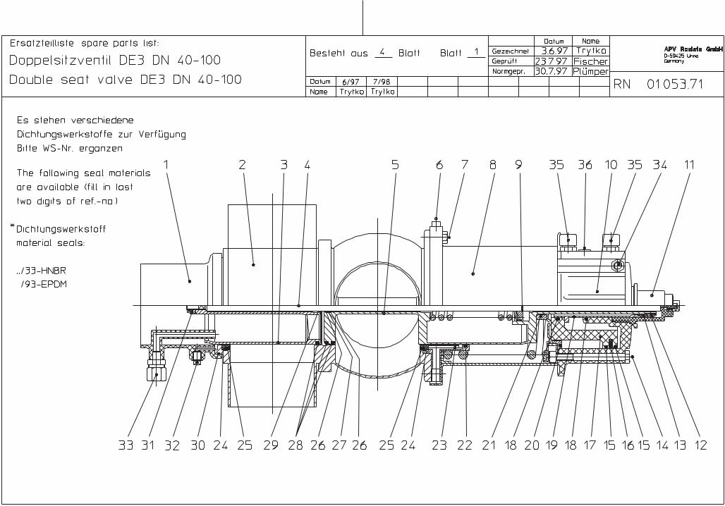
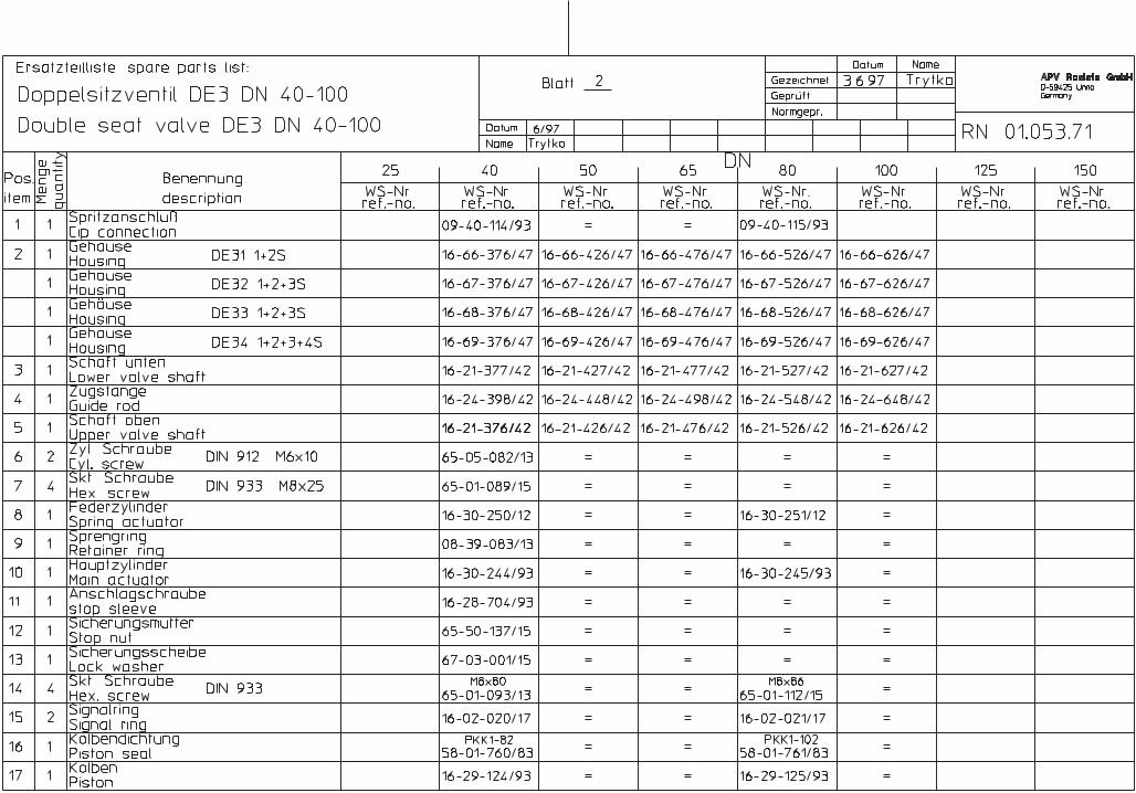
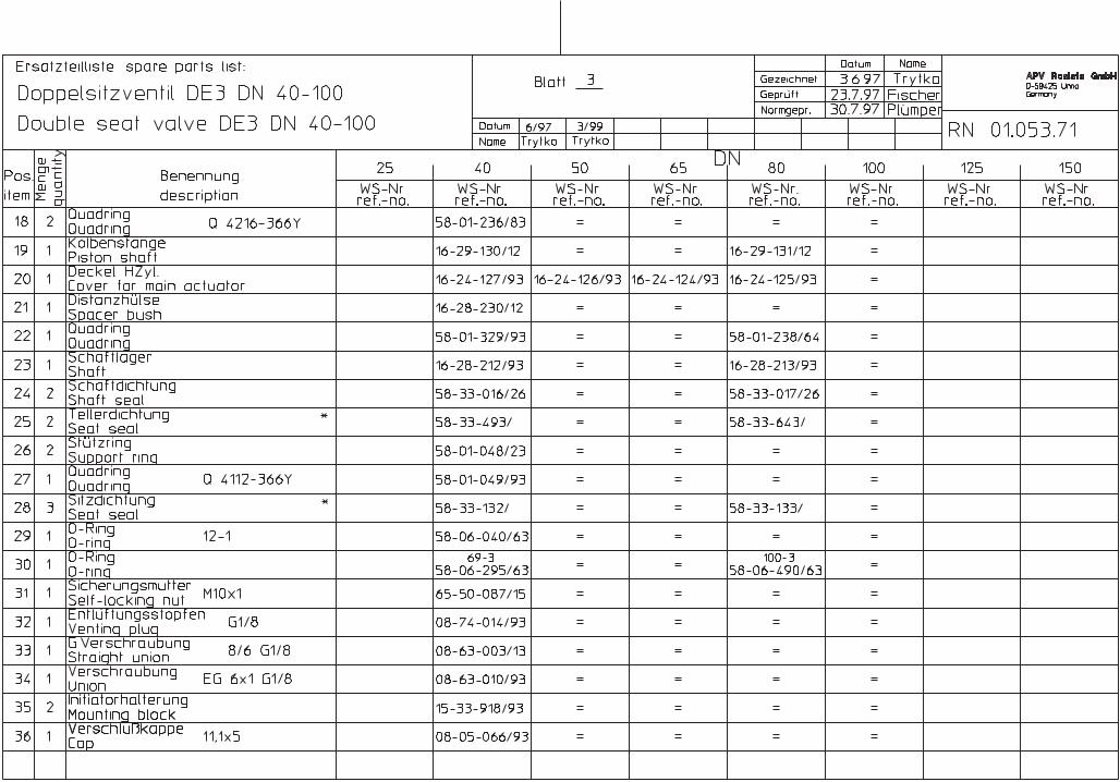
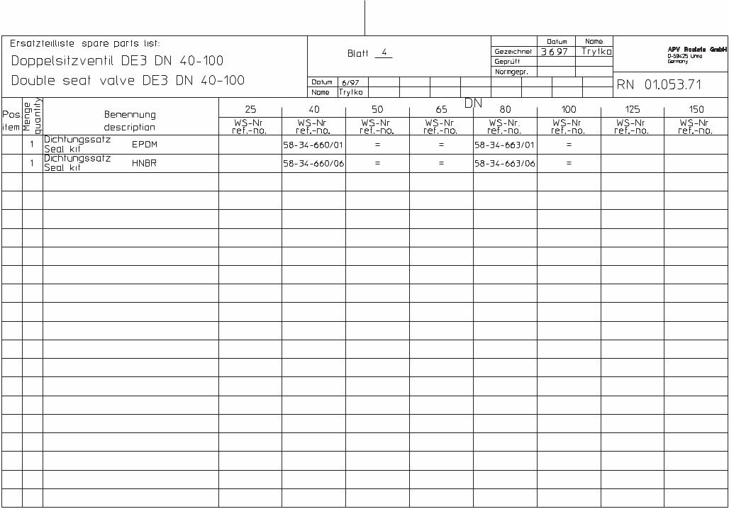
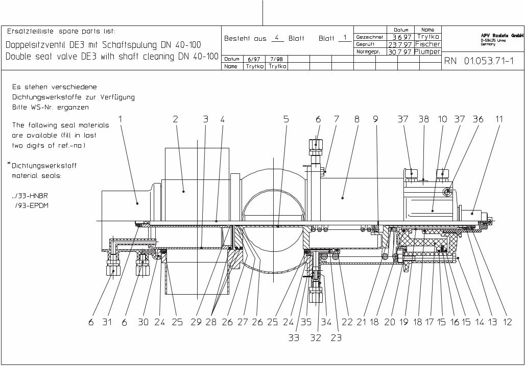
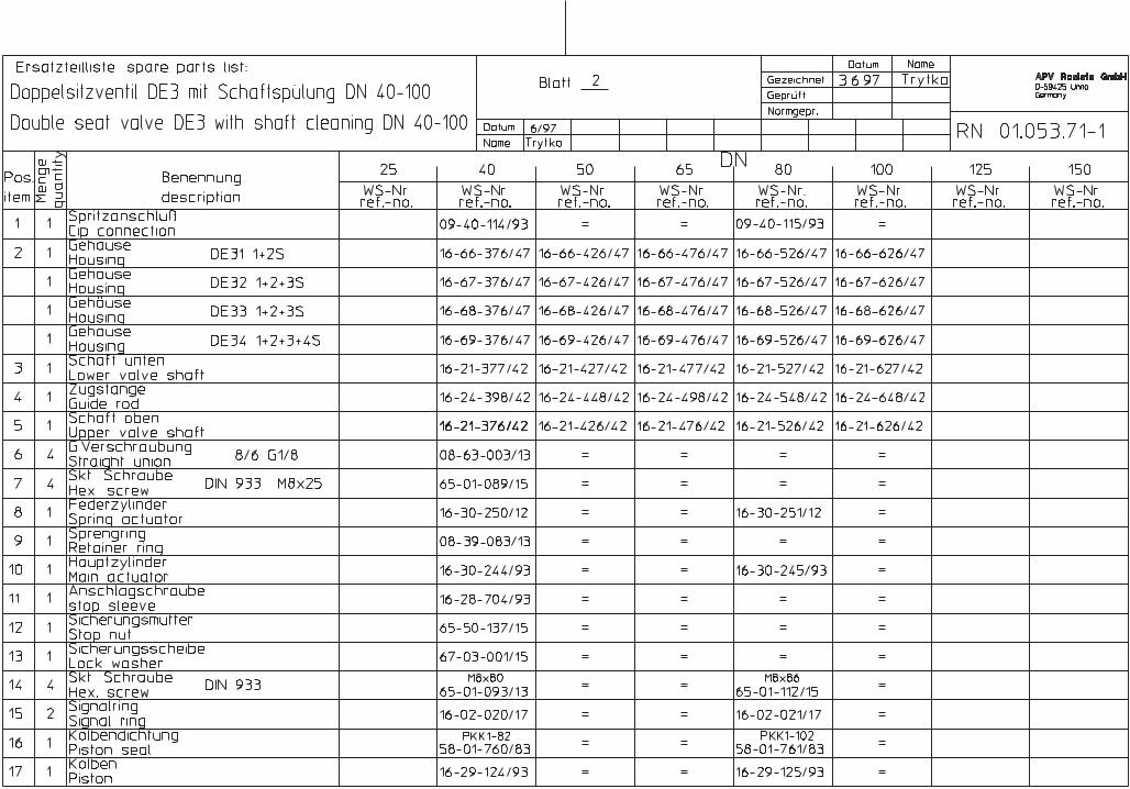
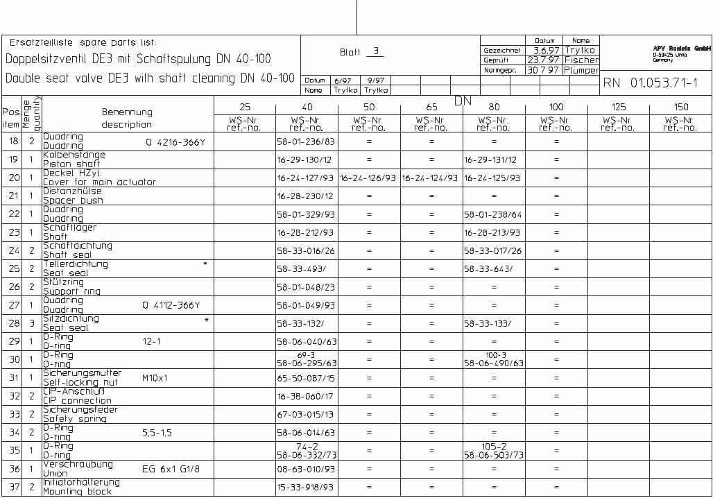
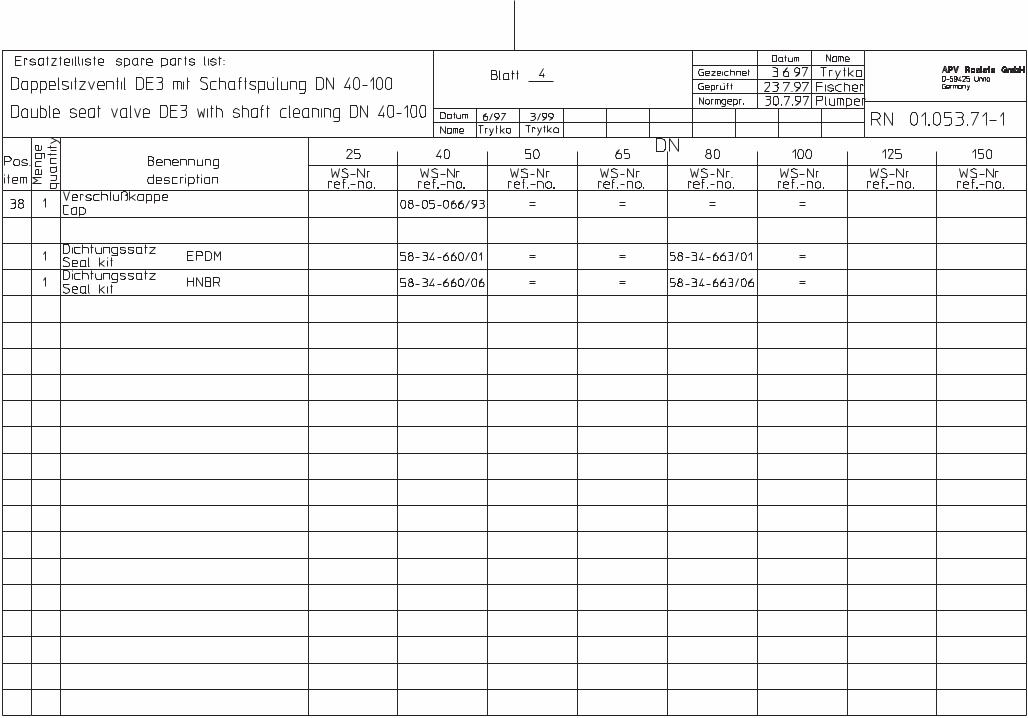
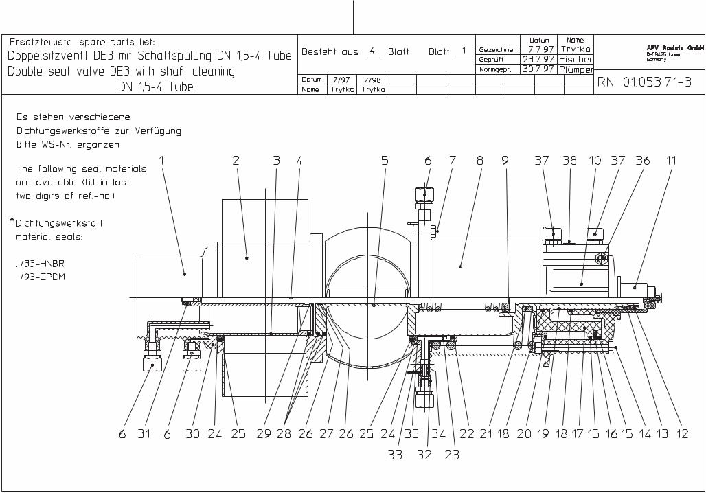
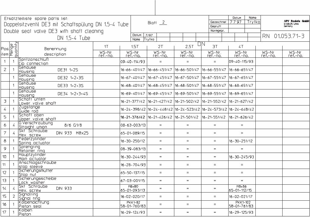
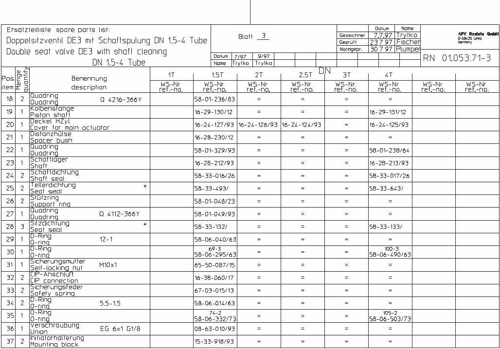
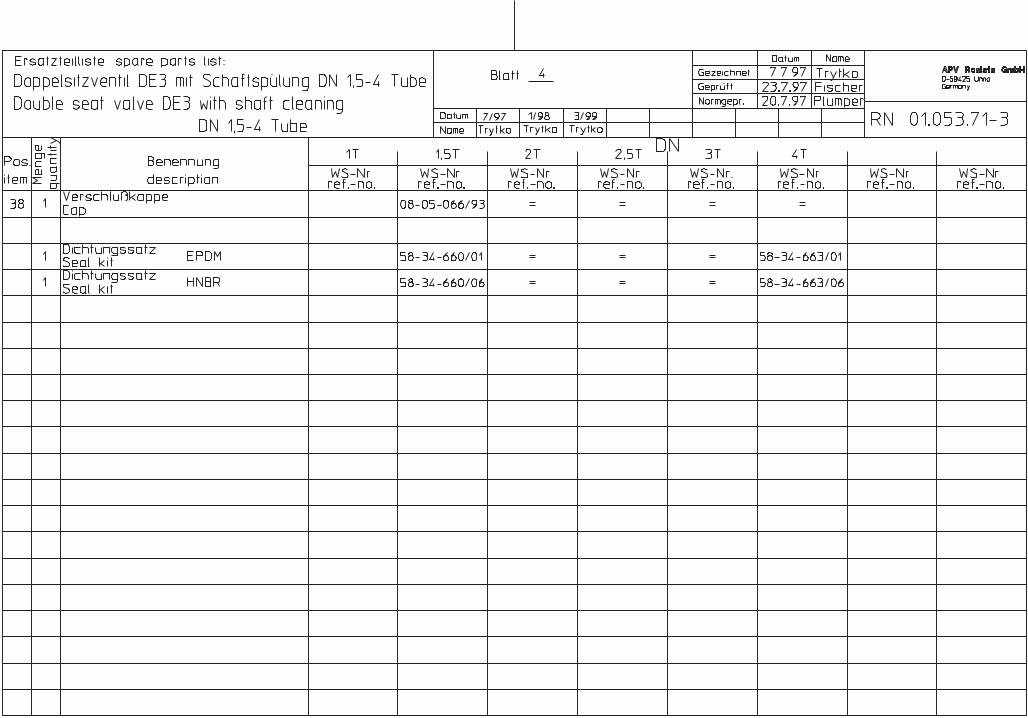
DE 3 - DN design - RN - 01.053.71
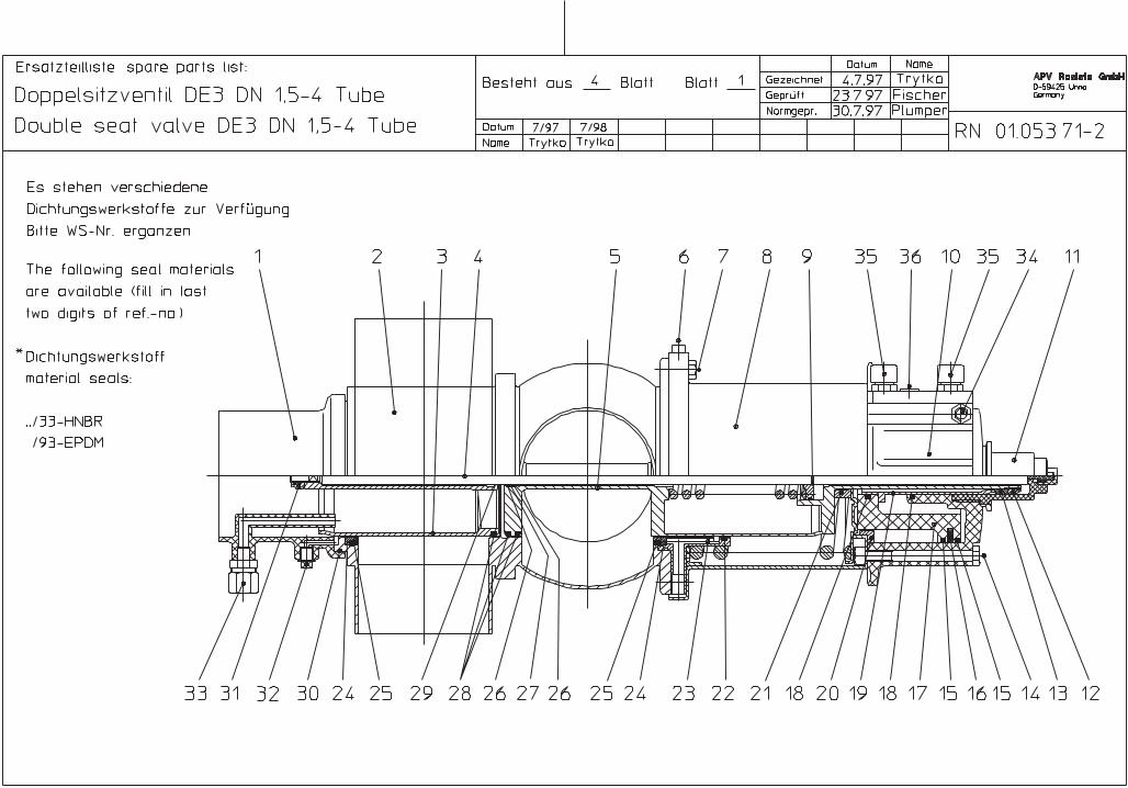
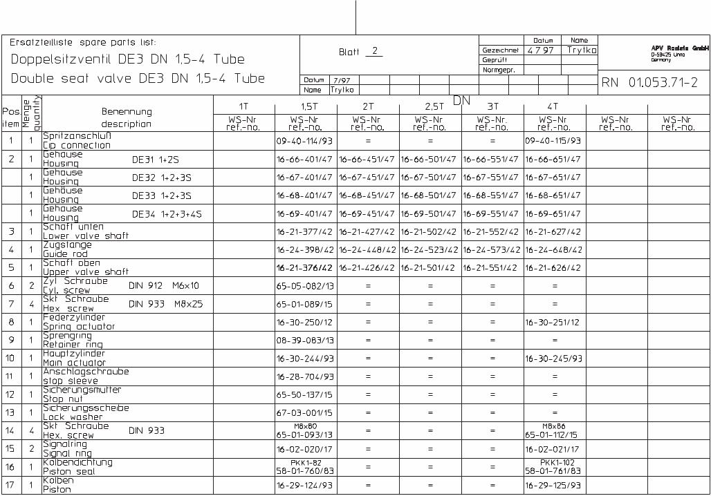
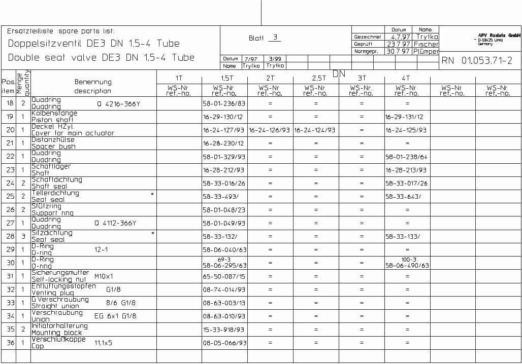
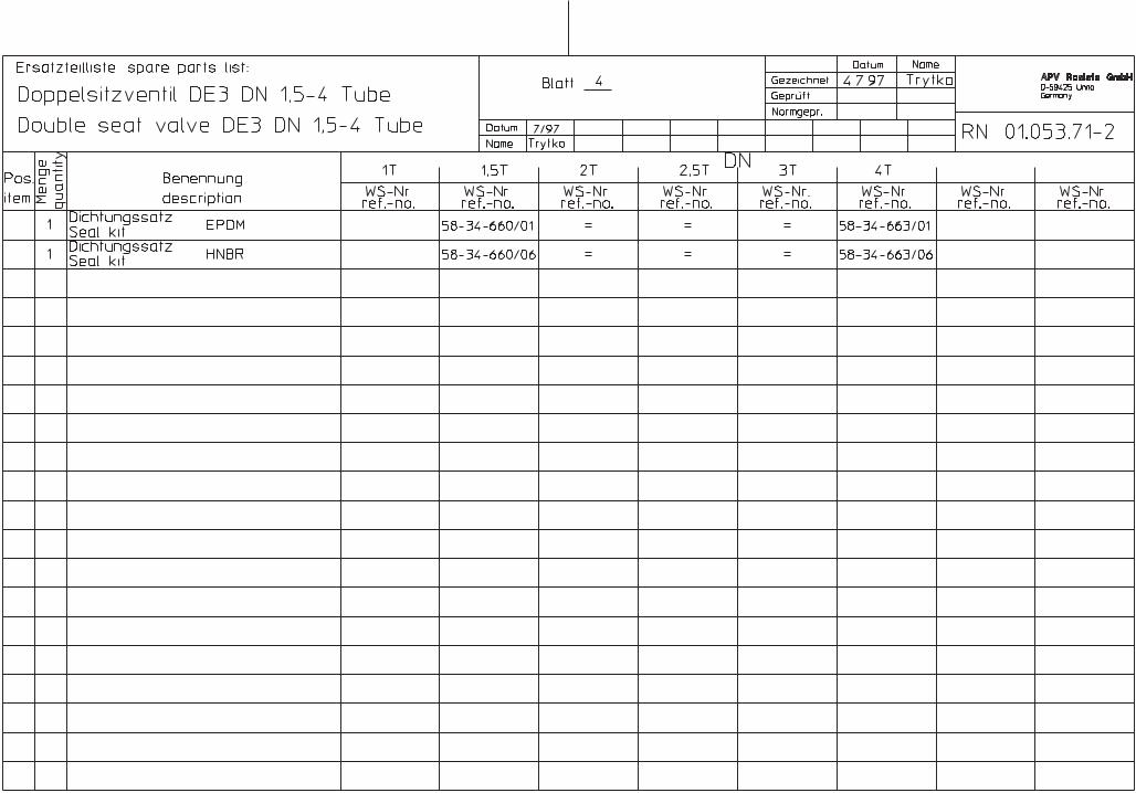
DE 3 - Tube design - RN - 01.053.71 - 2
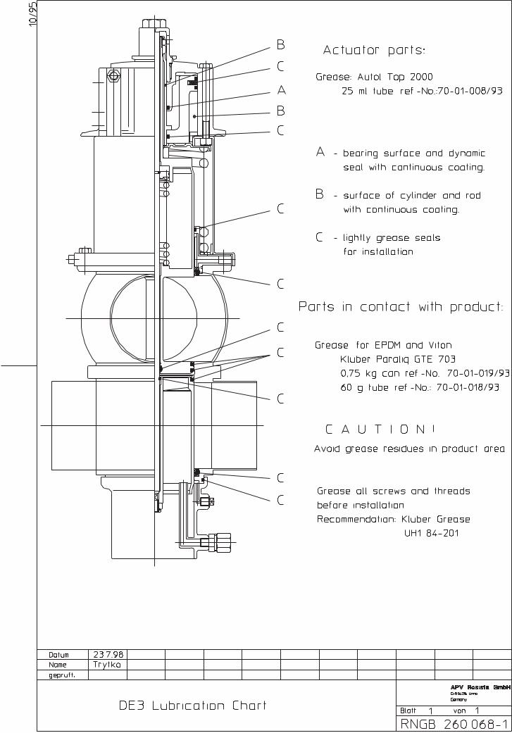
DE 3 - Lubrication Chart - RN - 260.068 - 1
Content:
1Double Seat Valve DE 3Operating Manual: Rev.1
This operating manual has to be read carefully and be observed by the competent operating and maintenance personnel.
We have to point out that we do not accept any liability for damage or malfunctions resulting from the non-compliance with theoperating manual.
Descriptions and data given herein are subject to technical changes.
2. Safety Instructions
Danger!
- Before starting maintenance work, any pressure source in thepipe and cleaning system must be switched off !
- Observe assembly instructions to ensure safe maintenance of thevalve.
- Connections which are not used, should be sealed by a plug.
- A safe discharge of the corresponding cleaning liquids must be ensured.
- Spring tension in the actuator, do not open it by force.
3. Operation
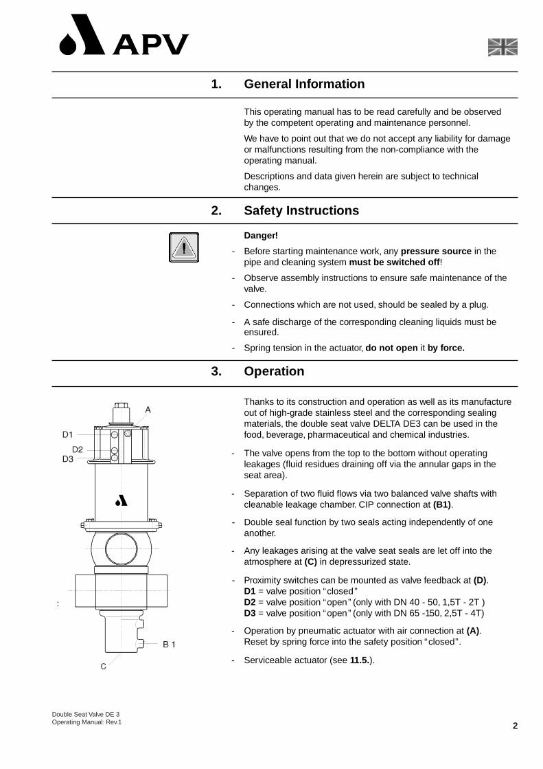
Thanks to its construction and operation as well as its manufacture out of high-grade stainless steel and the corresponding sealing materials, the double seat valve DELTA DE3 can be used in the food, beverage, pharmaceutical and chemical industries.
- The valve opens from the top to the bottom without operating leakages (fluid residues draining off via the annular gaps in theseat area).
- Separation of two fluid flows via two balanced valve shafts withcleanable leakage chamber. CIP connection at (B1).
- Double seal function by two seals acting independently of oneanother.
- Any leakages arising at the valve seat seals are let off into theatmosphere at (C) in depressurized state.
- Proximity switches can be mounted as valve feedback at (D).D1 = valve position “closed”D2 = valve position “open” (only with DN 40 - 50, 1,5T - 2T )D3 = valve position “open” (only with DN 65 -150, 2,5T - 4T)
- Operation by pneumatic actuator with air connection at (A).Reset by spring force into the safety position “closed”.
- Serviceable actuator (see 11.5.).
1. General Information
2Double Seat Valve DE 3Operating Manual: Rev.1
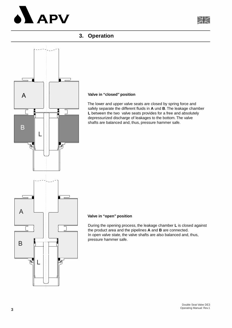
Valve in “closed” position
The lower and upper valve seats are closed by spring force andsafely separate the different fluids in A und B. The leakage chamber L between the two valve seats provides for a free and absolutelydepressurized discharge of leakages to the bottom. The valveshafts are balanced and, thus, pressure hammer safe.
Valve in “open” position
During the opening process, the leakage chamber L is closed against the product area and the pipelines A and B are connected.In open valve state, the valve shafts are also balanced and, thus,pressure hammer safe.
3. Operation
3Double Seat Valve DE3
Operating Manual: Rev.1
- Valve feedback switchesSwitches to signal the limit position of the valve shafts can optionally be installed at the actuator (see 11.4.e and page 2).We recommend to use one of our APV standard types.Operating distance: 5 mm / diameter: 11 mm.If a different valve position indicator is provided by the customer,we cannot take over any guarantee for a faultless function.
- Control UnitA control unit DELTA CU with solenoid valves for the pneumatic control of the valve can be installed directly on top of the actuator.
- Field BusThe installation of the intelligent control system DELTA CU “Valve Net” (field bus technology) is also possible, directly.
5. Cleaning
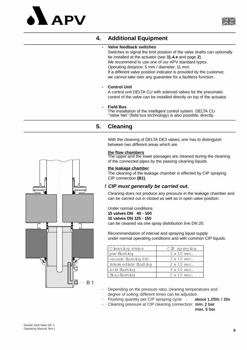
With the cleaning of DELTA DE3 valves, one has to distinguish between two different areas which are
the flow chamb ersThe upper and the lower passages are cleaned during the cleaningof the connected pipes by the passing cleaning liquids.
the leakage chamb erThe cleaning of the leakage chamber is effected by CIP spraying.CIP connection (B1).
! CIP must generally be carried out.Cleaning does not produce any pressure in the leakage chamber andcan be carried out in closed as well as in open valve position.
Under normal conditions15 valves DN 40 - 10010 valves DN 125 - 150can be cleaned via one spray distribution line DN 25.
Recommendation of interval and spraying liquid supply under normal operating conditions and with common CIP liquids.
4. Additional Equipment
4Double Seat Valve DE 3Operating Manual: Rev.1
Cleani ng st eps CIP sprayi ngpre-flushi ng 3 x 10 sec.caust ic flushi ng 80 C 3 x 10 sec.interm ediate flushi ng 2 x 10 sec.acid flushi ng 3 x 10 sec.final flushi ng 2 x 10 sec.
- Depending on the pressure ratio, cleaning temperatures anddegree of soiling, different times can be adjusted.
- Flushing quantity per CIP spraying cycle : about 1.25ltr. / 10s- Cleaning pressure at CIP cleaning connection: min. 2 bar
max. 5 bar .
5Double Seat Valve DE 3
Operating Manual: Rev.1
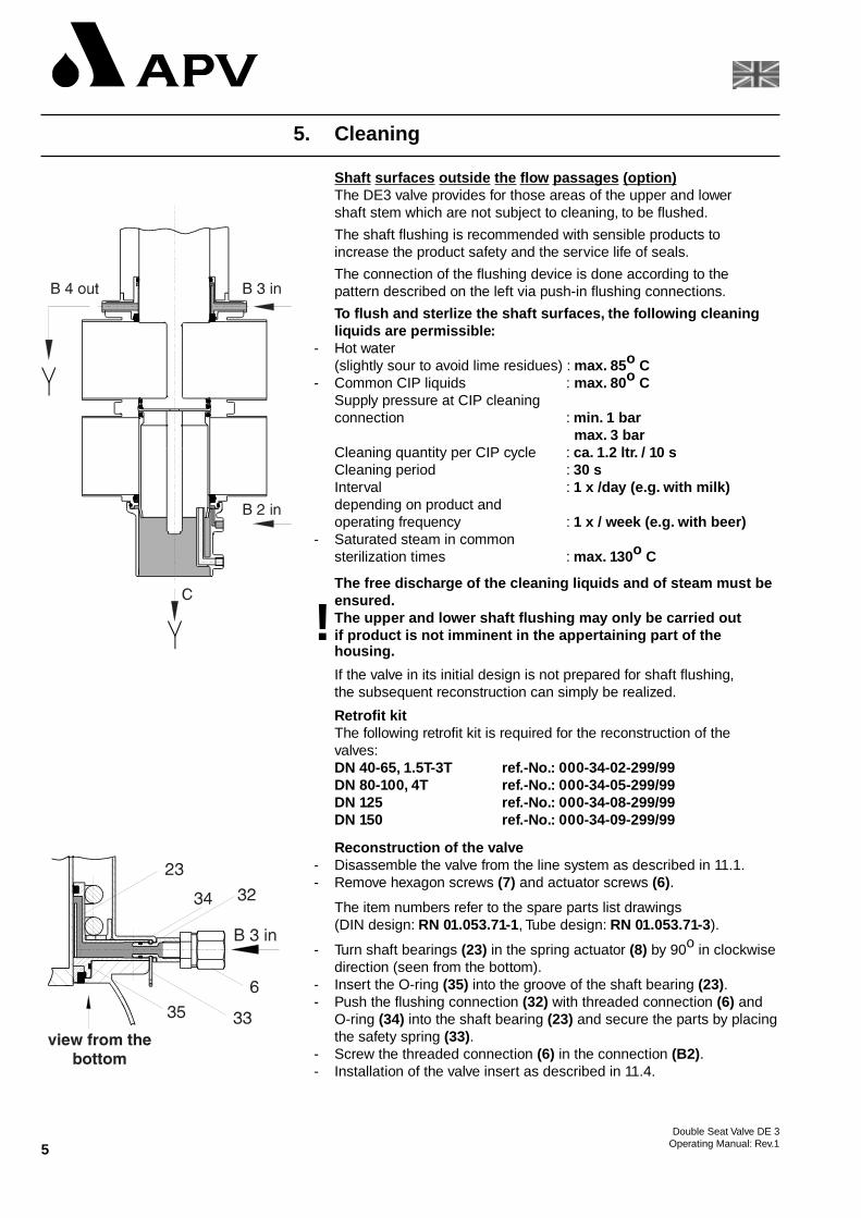
Shaf t sur faces outsid e the flow passages (opt ion)The DE3 valve provides for those areas of the upper and lower shaft stem which are not subject to cleaning, to be flushed.
The shaft flushing is recommended with sensible products toincrease the product safety and the service life of seals.
The connection of the flushing device is done according to thepattern described on the left via push-in flushing connections.
To flush and sterlize the shaft surfaces, the following cleaning liquids are permissible:
- Hot water(slightly sour to avoid lime residues) : max. 85o C
- Common CIP liquids : max. 80o CSupply pressure at CIP cleaningconnection : min. 1 bar
max. 3 barCleaning quantity per CIP cycle : ca. 1.2 ltr. / 10 sCleaning period : 30 sInterval : 1 x /day (e.g. with milk)depending on product and operating frequency : 1 x / week (e.g. with beer)
- Saturated steam in common sterilization times : max. 130o C
The free discharge of the cleaning liquids and of steam must beensured.The upper and lower shaft flushing may only be carried out! if product is not imminent in the appertaining part of thehousing.
If the valve in its initial design is not prepared for shaft flushing,the subsequent reconstruction can simply be realized.
Retrofit kitThe following retrofit kit is required for the reconstruction of the valves:DN 40-65, 1.5T-3T ref.-No.: 000-34-02-299/99DN 80-100, 4T ref.-No.: 000-34-05-299/99DN 125 ref.-No.: 000-34-08-299/99DN 150 ref.-No.: 000-34-09-299/99
Reconstruction of the valve- Disassemble the valve from the line system as described in 11.1.- Remove hexagon screws (7) and actuator screws (6).
The item numbers refer to the spare parts list drawings(DIN design: RN 01.053.71-1, Tube design: RN 01.053.71-3).
- Turn shaft bearings (23) in the spring actuator (8) by 90o in clockwisedirection (seen from the bottom).
- Insert the O-ring (35) into the groove of the shaft bearing (23).- Push the flushing connection (32) with threaded connection (6) and
O-ring (34) into the shaft bearing (23) and secure the parts by placingthe safety spring (33).
- Screw the threaded connection (6) in the connection (B2).- Installation of the valve insert as described in 11.4.
5. Cleaning
Installation of the hose connections
a) upper shaft cleaning:cleaning liquid supply at B3 (see identification at spring actuator)cleaning liquid supply at B4
b) lower shaft cleaning:cleaning liquid supply at B2cleaning liquid supply at C
6. Installation
- The valve must be installed in vertical position to enable liquids todrain off the valve body and leakage chamber.
- The valve housing can be welded directly into the pipe system(valve insert can be dismantled completely).
- Attention : Observe welding instructions.
- Installation and dismantling heights (see para. 7 ).
6.1 Welding Instructions
- Before welding of the valve, the valve insert must be dismantledfrom the housing. A careful handling without damage to the partsmust be provided (see 11.1). To avoid destruction of the lower shaftseal, it need not be removed, but remain in the valve housing.
- Welding may only be carried out by certified welders (EN 287 - 1).(Seam quality EN 25817 ,,B”.)
- The welding of the valve housings must be effected in such a waythat deformation strain cannot be transferred to the valve body.
- The preparation of the weld seam up to 3 mm thickness must becarried out in butt manner as a square butt joint without air.(Consider shrinkage!)
- TIG orbital welding should be aimed at!
- After welding of the valve housing or of the mating flanges and afterwork at the pipelines, the corresponding parts of the installation orpipelines must be cleaned from welding residues and soiling beforebeing operated to prevent the valve and the seals from being damaged. If these cleaning instructions are not observed, weldingresidues and dirt particles can settle in the valve and cause damage.
- Any damage resulting from the nonobservance of these welding
instructions is not subject to our guarantee.
5. Cleaning
6Double Seat Valve DE3Operating Manual: Rev.1
7Double Seat Valve DE 3
Operating Manual: Rev.1
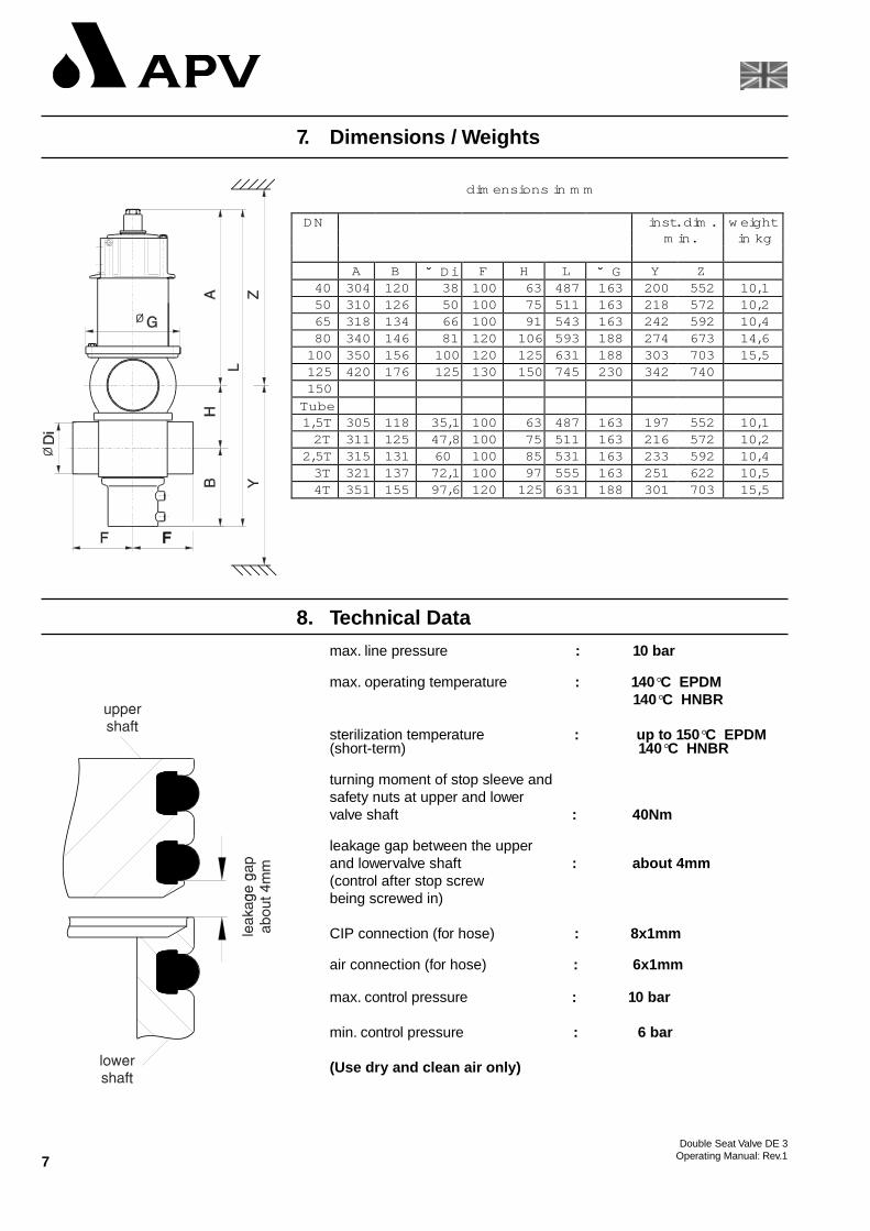
8. Technical Data
max. line pressure : 10 bar
max. operating temperature : 140°C EPDM140°C HNBR
sterilization temperature : up to 150 °C EPDM(short-term) 140°C HNBR
turning moment of stop sleeve andsafety nuts at upper and lowervalve shaft : 40Nm
leakage gap between the upper and lowervalve shaft : about 4mm(control after stop screwbeing screwed in)
CIP connection (for hose) : 8x1mm
air connection (for hose) : 6x1mm
max. control pressure : 10 bar
min. control pressure : 6 bar
(Use dry and clean air only)
7. Dimensions / Weights
dim ensions in m m
DN inst . dim . w eightm in. in kg
A B ˘̆ D i F H L ˘̆ G Y Z40 304 120 38 100 63 487 163 200 552 10,150 310 126 50 100 75 511 163 218 572 10,265 318 134 66 100 91 543 163 242 592 10,480 340 146 81 120 106 593 188 274 673 14,6
100 350 156 100 120 125 631 188 303 703 15,5125 420 176 125 130 150 745 230 342 740150
Tube1,5T 305 118 35,1 100 63 487 163 197 552 10,1
2T 311 125 47,8 100 75 511 163 216 572 10,22,5T 315 131 60 100 85 531 163 233 592 10,4
3T 321 137 72,1 100 97 555 163 251 622 10,54T 351 155 97,6 120 125 631 188 301 703 15,5
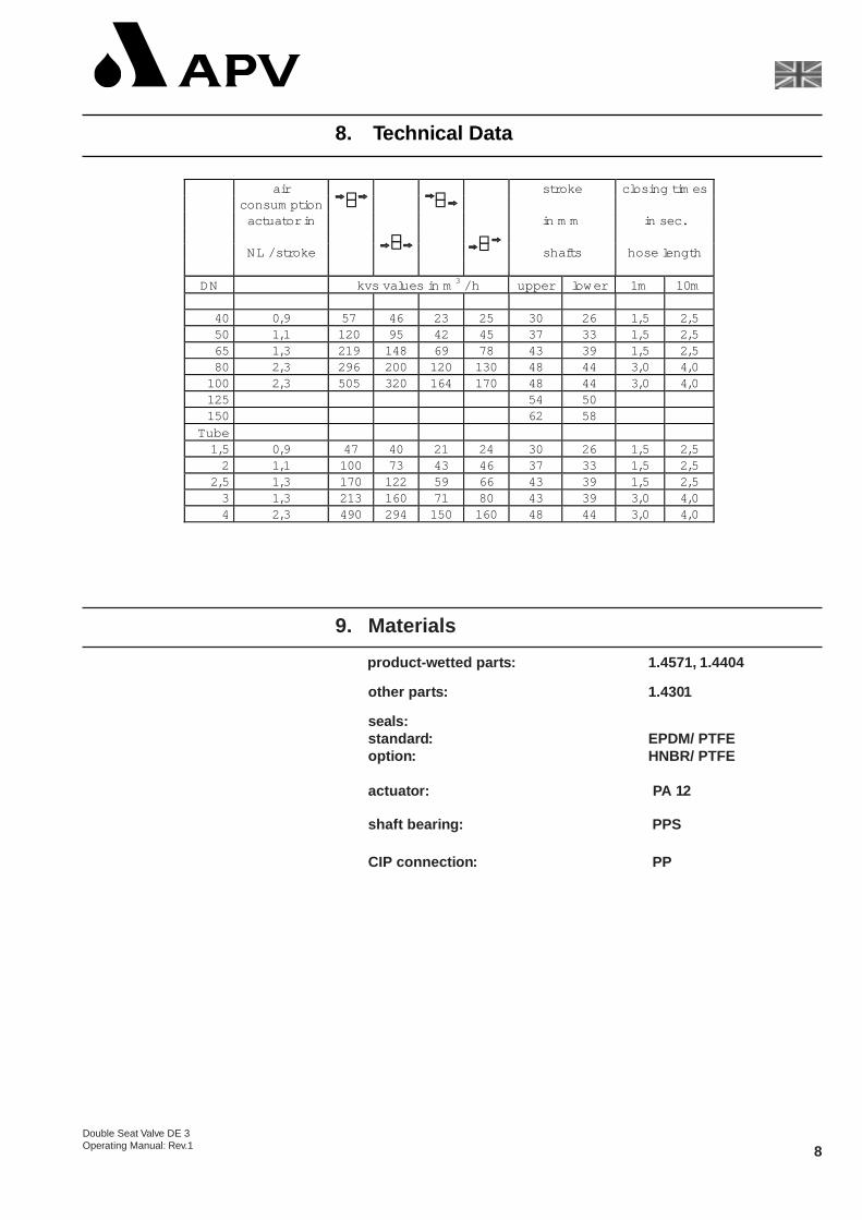
ai r st roke cl osi ng tim esconsum pt ion
act uat or in in m m in sec.
NL / st roke shaf ts hose lengt h
DN kvs val ues in m3 / h upper l ow er 1m 10m
40 0,9 57 46 23 25 30 26 1, 5 2,550 1,1 120 95 42 45 37 33 1, 5 2,565 1,3 219 148 69 78 43 39 1, 5 2,580 2,3 296 200 120 130 48 44 3, 0 4,0
100 2,3 505 320 164 170 48 44 3, 0 4,0125 54 50150 62 58
Tube1,5 0,9 47 40 21 24 30 26 1, 5 2,5
2 1,1 100 73 43 46 37 33 1, 5 2,52,5 1,3 170 122 59 66 43 39 1, 5 2,5
3 1,3 213 160 71 80 43 39 3, 0 4,04 2,3 490 294 150 160 48 44 3, 0 4,0
8. Technical Data
8Double Seat Valve DE 3Operating Manual: Rev.1
9. Materials
product-wetted parts: 1.4571, 1.4404
other parts: 1.4301
seals:standard: EPDM/ PTFEoption: HNBR/ PTFE
actuator: PA 12
shaft bear ing: PPS
CIP connection: PP
9Double Seat Valves DE 3Operating Manual: Rev.1
- The maintenance intervals depend on the application and should be determined by the user himself after some regular checks .
- Compressed air is not required to dismantle the valve.
- Tools required:- 1x spanner SW13- 2x spanner SW17- 2x spanner SW24- Disassembly and assembly support for the lower shaft seal,
ref.-No. 000 51-13-100/17
- Replacement of seals according to assembly instructions.
- Assembly of the valve according to assembly instructions.
- Provide all seals with a thin layer of grease before their installation !!!!!
Recommendation:APV food-grade-grease for EPDM and HNBR(0,75 kg/ can - ref.-No. 000 70-01-019/93)(60 g/ tube - ref.-No. 000 70-01-018/93)
Recommendation for the actuator:APV pneumatic grease:(25 ml/ tube - ref.-No.000 70-01-008/93 )
11. Assembly Instructions
The item numbers refer to the spare parts lists(DIN: RN 01.053.71 Tube: RN 01.053.71-2)
11.1 Dismantling from pipe system
a. Shut off line pressure in the product and cleaning line.Discharge pipes if possible.
b. Disconnect control air line.
c. Loosen nuts of feedback support (35) and remove feedback switch.
d. Remove flange screws (7) from spring actuator (8).
e. Screw one flange screw into the tapped hole of the spring actuatorwhich induces the complete valve insert to be lifted. Do notremove the screw, it is used as support for the installation of the insert.
f. Carefully lift the valve insert vertically out of housing.
10. Maintenance
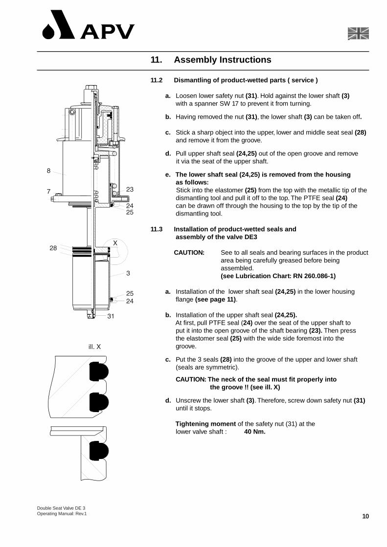
11.2 Dismantling of product-wetted parts ( service )
a. Loosen lower safety nut (31). Hold against the lower shaft (3)with a spanner SW 17 to prevent it from turning.
b. Having removed the nut (31), the lower shaft (3) can be taken off.
c. Stick a sharp object into the upper, lower and middle seat seal (28)and remove it from the groove.
d. Pull upper shaft seal (24,25) out of the open groove and removeit via the seat of the upper shaft.
e. The lower shaft seal (24,25) is removed from the housingas follows:Stick into the elastomer (25) from the top with the metallic tip of the dismantling tool and pull it off to the top. The PTFE seal (24)can be drawn off through the housing to the top by the tip of the dismantling tool.
11.3 Installation of product-wetted seals andassembly of the valve DE3
CAUTION: See to all seals and bearing surfaces in the productarea being carefully greased before being assembled.(see Lubrication Chart: RN 260.086-1)
a. Installation of the lower shaft seal (24,25) in the lower housing flange (see page 11) .
b. Installation of the upper shaft seal (24,25).At first, pull PTFE seal (24) over the seat of the upper shaft toput it into the open groove of the shaft bearing (23). Then pressthe elastomer seal (25) with the wide side foremost into thegroove.
c. Put the 3 seals (28) into the groove of the upper and lower shaft(seals are symmetric).
CAUTION: The neck of the seal must fit properly into the groove !! (see ill. X)
d. Unscrew the lower shaft (3). Therefore, screw down safety nut (31)until it stops.
Tightening moment of the safety nut (31) at the lower valve shaft : 40 Nm.
11. Assembly Instructions
10Double Seat Valve DE 3Operating Manual: Rev.1
11Double Seat ValveDE 3
Operating Manual: Rev.1
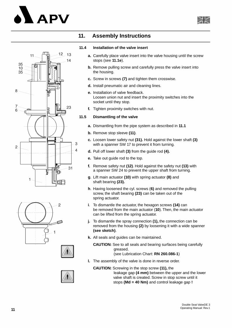
11.4 Installation of the valve insert
a. Carefully place valve insert into the valve housing until the screwstops (see 11.1e).
b. Remove pulling screw and carefully press the valve insert into the housing.
c. Screw in screws (7) and tighten them crosswise.
d. Install pneumatic air and cleaning lines.
e. Installation of valve feedback.Loosen union nut and insert the proximity switches into thesocket until they stop.
f. Tighten proximity switches with nut.
11.5 Dismantling of the valve
a. Dismantling from the pipe system as described in 11.1
b. Remove stop sleeve (11).
c. Loosen lower safety nut (31). Hold against the lower shaft (3)with a spanner SW 17 to prevent it from turning.
d. Pull off lower shaft (3) from the guide rod (4).
e. Take out guide rod to the top.
f. Remove safety nut (12). Hold against the safety nut (13) witha spanner SW 24 to prevent the upper shaft from turning.
g. Lift main actuator (10) with spring actuator (8) and shaft bearing (23).
h. Having loosened the cyl. screws (6) and removed the pullingscrew, the shaft bearing (23) can be taken out of thespring actuator.
i. To dismantle the actuator, the hexagon screws (14) canbe removed from the main actuator (10). Then, the main actuator can be lifted from the spring actuator.
j. To dismantle the spray connection (1), the connection can beremoved from the housing (2) by loosening it with a wide spanner(see sketch) .
k. All seals and guides can be maintained.
CAUTION: See to all seals and bearing surfaces being carefully greased.(see Lubrication Chart: RN 260.086-1)
l. The assembly of the valve is done in reverse order.
CAUTION: Screwing in the stop screw (11), the leakage gap (4 mm) between the upper and the lowervalve shaft is created. Screw in stop screw until it stops (Md = 40 Nm) and control leakage gap !
11. Assembly Instructions
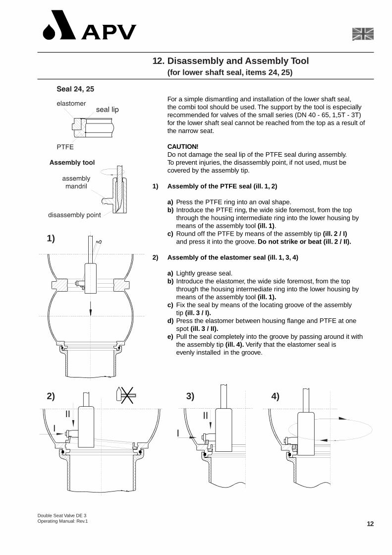
For a simple dismantling and installation of the lower shaft seal,the combi tool should be used. The support by the tool is especiallyrecommended for valves of the small series (DN 40 - 65, 1,5T - 3T)for the lower shaft seal cannot be reached from the top as a result ofthe narrow seat.
CAUTION!Do not damage the seal lip of the PTFE seal during assembly.To prevent injuries, the disassembly point, if not used, must becovered by the assembly tip.
1) Assembly of the PTFE seal (ill. 1, 2)
a) Press the PTFE ring into an oval shape.b) Introduce the PTFE ring, the wide side foremost, from the top
through the housing intermediate ring into the lower housing by means of the assembly tool (ill. 1) .
c) Round off the PTFE by means of the assembly tip (ill. 2 / I) and press it into the groove. Do not strike or beat (ill. 2 / II).
2) Assembly of the elastomer seal (ill. 1, 3, 4)
a) Lightly grease seal.b) Introduce the elastomer, the wide side foremost, from the top
through the housing intermediate ring into the lower housing by means of the assembly tool (ill. 1).
c) Fix the seal by means of the locating groove of the assemblytip (ill. 3 / I).
d) Press the elastomer between housing flange and PTFE at onespot (ill. 3 / II).
e) Pull the seal completely into the groove by passing around it with the assembly tip (ill. 4). Verify that the elastomer seal is evenly installed in the groove.
12Double Seat Valve DE 3Operating Manual: Rev.1
12. Disassembly and Assembly Tool(for lower shaft seal, items 24, 25)
2) 3)
1)
4)
13
The exchange of seals is to be carried out as described in 11.
Closed valve position.* Pressure in the upper housing
- Leakage at the upper housing flange.Replace upper shaft seal (24,25).
- Leakage out of the leakage chamber of the lower shaft.Replace upper seat seal (28).
* Pressure in the lower housing.Remove CIP connection (1) (see 11.5.j).
- Leakage out of the leakage chamber of the lower shaft.Replace lower seat seal (28).
- Leakage at the external surface of the lower shaft.Replace lower shaft seal (24,25).
Open valve position
- Leakage out of the leakage chamber of the lower shaft.Replace seal at lower shaft (28).
14. Spare Parts and Lubrication
(see annex)
13. Detection of Seal Damage
Double Seat ValveDE 3Operating Manual: Rev.1
Related Documents