Double Negative Metamaterial Physics, Design, and Experiments Dr. Richard Ziolkowski, Univ Arizona (KITP Quantum Optics 7/10/02) 1 Double Negative Metamaterial Designs, Experiments, and Applications Richard W. Ziolkowski Electromagnetics Laboratory Department of Electrical and Computer Engineering University of Arizona Tucson, Arizona 85721-0104 [email protected] Tel. (520) 621-6173 Fax. (520) 621-8076 Santa Barbara Center for Theoretical Physics Quantum Optics Workshop: Week 1 Metamaterials exhibit qualitatively new response functions that are not observed in the constituent materials themselves and result, for instance, from the inclusion of artificially fabricated, extrinsic, low dimensional inhomogeneities Examples: Artificial dielectrics FSS, Electromagnetic bandgap structures Negative index (neg eps, mu) materials Metamaterials Artificial materials that exhibit electromagnetic responses generally not found in nature Metamaterials may lead to new physics and engineering concepts

Welcome message from author
This document is posted to help you gain knowledge. Please leave a comment to let me know what you think about it! Share it to your friends and learn new things together.
Transcript

Double Negative Metamaterial Physics, Design, and Experiments
Dr. Richard Ziolkowski, Univ Arizona (KITP Quantum Optics 7/10/02) 1
Double Negative Metamaterial Designs, Experiments, and Applications
Richard W. Ziolkowski
Electromagnetics LaboratoryDepartment of Electrical and Computer Engineering
University of ArizonaTucson, Arizona 85721-0104
[email protected]. (520) 621-6173Fax. (520) 621-8076
Santa Barbara Center for Theoretical PhysicsQuantum Optics Workshop: Week 1
Metamaterials exhibit qualitatively new response functions thatare not observed in the constituent materials themselves and result, for instance, from the inclusion of artificially fabricated, extrinsic, low dimensional inhomogeneities
Examples: Artificial dielectricsFSS, Electromagnetic bandgap structuresNegative index (neg eps, mu) materials
Metamaterials
Artificial materials that exhibit electromagnetic responsesgenerally not found in nature
Metamaterials may lead to new physics and engineering concepts

Double Negative Metamaterial Physics, Design, and Experiments
Dr. Richard Ziolkowski, Univ Arizona (KITP Quantum Optics 7/10/02) 2
Compact DNG metamaterials having negative index of refraction have been designed, fabricated and tested experimentally
�HFSS and FDTD simulators have been used to design
several DNG (ε ε < 0 and µ µ < 0) metamaterials (MTMs)
�Extraction formula have been derived to determine the
MTM’s effective permitt ivity and permeability
�Experimental results confirm the realization of DNG MTMs
that are matched to free space and have a negative index of refraction
�Several potential applications have been studied:
Efficient Electr ically Small Antennas (EESAs)
Metamaterials lead to a variety of novel electromagnetic effects
�The propagation characteristics of waves in DNG media
( εε < 0, µµ < 0 )confirm the possibility of a negative index of refraction
�Negative angles of refraction exist for DNG media
�DNG Drude MTMs have been characterized
with an FDTD simulator and confirm
�Demonstrate phase and phase front compensators
�paraxial beam focusing
�negative angles of refraction for power flow

Double Negative Metamaterial Physics, Design, and Experiments
Dr. Richard Ziolkowski, Univ Arizona (KITP Quantum Optics 7/10/02) 3
EM Properties of aggregates of atoms / molecules are typically characterized by their electric and magnetic dipole moments
E
Dielectr ic
+
-
+
-+
-
+
- p
P = Σi pi / V
= εε0 χ E
εε = εε0 ( 1 + χ )
χ = electr ic susceptibility

Double Negative Metamaterial Physics, Design, and Experiments
Dr. Richard Ziolkowski, Univ Arizona (KITP Quantum Optics 7/10/02) 4
✬ Recursive Convolution Method
D = ε * E
✢ Auxiliary Differential Equation Method
A(∂t ) D = B(∂t ) E
✪ Polarization / Magnetization Method
A(∂t ) P = B(∂t ) E
Material responses are incorporated into our FDTD Maxwell equation solver through
equivalent polarization and magnetization models
P & M equations are solved self-consistently with Maxwell equations

Double Negative Metamaterial Physics, Design, and Experiments
Dr. Richard Ziolkowski, Univ Arizona (KITP Quantum Optics 7/10/02) 5

Double Negative Metamaterial Physics, Design, and Experiments
Dr. Richard Ziolkowski, Univ Arizona (KITP Quantum Optics 7/10/02) 6
Real part of lossy Drude model for different plasma frequencies
f0 = 30 GHz
✪ Wave propagation and power flow is causal
✪ The medium is right-handed with respect to the directionof propagation
✬ The medium is left-handed with respect to the directionthe wave vector direction
Wave properties in DNG media are “ unusual”
Normal
E
H
k
DOP, Poynting’s Vector
DNG
E
H
k
DOP, Poynting’s Vector

Double Negative Metamaterial Physics, Design, and Experiments
Dr. Richard Ziolkowski, Univ Arizona (KITP Quantum Optics 7/10/02) 7
Analytical and FDTD simulation problem geometries
z = 0 z = +dz = -z0
2TDLM slab, DNG slab
Plane wave source

Double Negative Metamaterial Physics, Design, and Experiments
Dr. Richard Ziolkowski, Univ Arizona (KITP Quantum Optics 7/10/02) 8
Response for Neg εε, Neg µµ, and Matched DNG media

Double Negative Metamaterial Physics, Design, and Experiments
Dr. Richard Ziolkowski, Univ Arizona (KITP Quantum Optics 7/10/02) 9
Ear ly time Late time
FDTD modeling of wave propagation in DNG media confirms causal behavior and negative index of refraction

Double Negative Metamaterial Physics, Design, and Experiments
Dr. Richard Ziolkowski, Univ Arizona (KITP Quantum Optics 7/10/02) 10
Susceptibility of 2TDLM material was designed to produce the desired super luminal medium response
χχαα==11, , χχββ ==1010−−55, , χχγγ = = −−00..55, , ωωp = = ωω00 = = 11 GHz
Propagation through 2TDLM slabs with χχγγ = +0.5, 0.0, -0.5 demonstrate the superluminal effect

Double Negative Metamaterial Physics, Design, and Experiments
Dr. Richard Ziolkowski, Univ Arizona (KITP Quantum Optics 7/10/02) 11
FDTD simulations of plane wave propagation through a matched 2TDLM metamaterial confirms the superluminal behavior
FDTD simulations of plane wave propagation through a matched 2TDLM metamaterial slab confirms the causal super luminal transmission of information
Double Negative Metamaterial Physics, Design, and Experiments
Dr. Richard Ziolkowski, Univ Arizona (KITP Quantum Optics 7/10/02) 12

Double Negative Metamaterial Physics, Design, and Experiments
Dr. Richard Ziolkowski, Univ Arizona (KITP Quantum Optics 7/10/02) 13
Analytical and FDTD simulation problem geometries
z = 0 z = +dz = -z0
2TDLM slab, DNG slab
Cylindrical source

Double Negative Metamaterial Physics, Design, and Experiments
Dr. Richard Ziolkowski, Univ Arizona (KITP Quantum Optics 7/10/02) 14
FDTD simulations of cylindrical wave interaction with lossy Drude DNG slab with εε((ωω00) ) ))//εε00 = = µµ((ωω0 0 ))//µµ00 = = −−11
show no foci
Electric field intensity at one time over FDTD simulation space
Electric field intensity at one time over FDTD simulation space
FDTD simulations of cylindrical wave interaction with lossy Drude DNG slab with εε((ωω00))//εε00 = = µµ((ωω00))//µµ00 = = −−6
show the predicted beam formation

Double Negative Metamaterial Physics, Design, and Experiments
Dr. Richard Ziolkowski, Univ Arizona (KITP Quantum Optics 7/10/02) 15
DNG slab solution requires a negative angle of refraction for both phase and Poynting’s vector, but phase and Poynting’s directions are opposite
Snell’s Law: θθtrans = sin-1 ( θθinc / n )
Normal interface
Free space
Regular medium
DNG interface
Free space
DNG Medium
Negative angle of refraction for power flow follows immediately from Maxwell’ s equations
kz = + ( ω2 εµ – kx2 )1/2
DNG medium
x
z
k
S x
z
kz = - ( ω2 εµ – kx2 )1/2
Normal DPS medium

Double Negative Metamaterial Physics, Design, and Experiments
Dr. Richard Ziolkowski, Univ Arizona (KITP Quantum Optics 7/10/02) 16
Super-prism effect requires local modifications of thewave vector – index surface
�EBG produces local curvature
var iations in the index surface
�Poynting’svector is perpendicular
to index surface
�Negative angle of refraction is realized
�Are the CLS-CLL metamaterial effects
the same??
�Material extraction indicates simpler DNG
propertiesIndex sur face
k vectorsS vectors
• Superprism effect (negative index of refraction) associated withEBGs(electromagnetic bandgaps) Notomi, Kosaka, …
Electric field intensity at one time over FDTD simulation space
Poynting’s vector amplitude at one time over FDTD simulation space

Double Negative Metamaterial Physics, Design, and Experiments
Dr. Richard Ziolkowski, Univ Arizona (KITP Quantum Optics 7/10/02) 17
Geometry of largerFDTD problemthat models afinite (w0=λλ) Gaussianbeaminteractingwith a n = -1DNG DrudeMTM Slab
SourcePlane �
Electr icFieldIntensity
Ear ly in time for a20 degreeangle ofincidence,3-cycleGaussianbeaminteractingwith an = -1 at30 GHz, Low Loss DNG slab

Double Negative Metamaterial Physics, Design, and Experiments
Dr. Richard Ziolkowski, Univ Arizona (KITP Quantum Optics 7/10/02) 18
Electr icFieldIntensity
At a time when a 20 degreeangle ofincidence3-cycleGaussianbeamisinteractingwith an = -1 at30 GHz, Low Loss DNG slab
Electr icFieldIntensity
At a time when a 20 degreeangle ofIncidence, 3-cycleGaussianbeamhas finishedinteractingwith an = -1 at30 GHz, Low Loss DNG slab
Double Negative Metamaterial Physics, Design, and Experiments
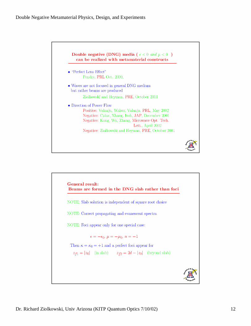
Dr. Richard Ziolkowski, Univ Arizona (KITP Quantum Optics 7/10/02) 19
Electr icFieldIntensity
Late in time for a20 degreeangle ofincidence, CW Gaussianbeaminteractingwith an = -1 at30 GHz,Low Loss DNG slab
Geometry of smallerFDTD problemthat models afinite (w0=λλ) Gaussianbeaminteractingwith a n = -6DNG DrudeMTM Slab
Source �Plane

Double Negative Metamaterial Physics, Design, and Experiments
Dr. Richard Ziolkowski, Univ Arizona (KITP Quantum Optics 7/10/02) 20
Electr icFieldIntensity
Ear ly in time for a20 degreeangle ofincidence,3-cycleGaussianbeaminteractingwith an = -6 at30 GHz, Low Loss DNG slab
Electr icFieldIntensity
At a time when a 20 degreeangle ofincidence3-cycleGaussianbeamisinteractingwith an = -6 at30 GHz, Low Loss DNG slab

Double Negative Metamaterial Physics, Design, and Experiments
Dr. Richard Ziolkowski, Univ Arizona (KITP Quantum Optics 7/10/02) 21
Electr icFieldIntensity
At a slightlylater time when a 20 degreeangle ofincidence3-cycleGaussianbeamis stillinteractingwith an = -6 at30 GHz, Low Loss DNG slab
Electr icFieldIntensity
At a time when a 20 degreeangle ofIncidence, 3-cycleGaussianbeamhas finishedinteractingwith an = -6 at30 GHz, Low Loss DNG slab

Double Negative Metamaterial Physics, Design, and Experiments
Dr. Richard Ziolkowski, Univ Arizona (KITP Quantum Optics 7/10/02) 22
Electr icFieldIntensity
Late in time for a20 degreeangle ofincidence, CW Gaussianbeaminteractingwith an = -6 at30 GHz,Low Loss DNG slab
DNG SlabDPS Slab
A DNG slab channels the electromagnetic field energy into a paraxial beam
Distr ibution of |E|2 at the same time for a CW source

Double Negative Metamaterial Physics, Design, and Experiments
Dr. Richard Ziolkowski, Univ Arizona (KITP Quantum Optics 7/10/02) 23
Matched DNG medium could lead to phase compensation techniques and devices
Matched media: Z = Z0 so there are no reflections
R = (Z - Z0) / (Z + Z0) = 0
Negative Phase: A DNG slab combined with a devicethat produces a positive phase shift, could lead to a zero phase point at theoutput of the combined device-slab
DNG slabs can be used to achievephase front compensation
DNG Slab DPS Slab

Double Negative Metamaterial Physics, Design, and Experiments
Dr. Richard Ziolkowski, Univ Arizona (KITP Quantum Optics 7/10/02) 24
The phase fronts converge in the DNG slab
Distr ibution of |E|2 at a single time instant ear ly in the FDTD simulation
The phase fronts diverge in the DPS slab
Distr ibution of |E|2 at a single time instant

Double Negative Metamaterial Physics, Design, and Experiments
Dr. Richard Ziolkowski, Univ Arizona (KITP Quantum Optics 7/10/02) 25
The phase fronts are planar near their exit from the DNG-DPS slab combination => 0o phase-shift delay line
Distr ibution of |E|2 at a single time instant fter steady state is achieved
Compact metamaterials having negative index of refraction have been designed, fabricated and tested experimentally
�All structures constructed with Rogers Corporation
5880 Duroid ( εεr = 2.2, µµr = 1.0, tan d = 0.0009 )31 mil ( 100 mil = 2.54 mm ) thick, 125 mil polyethylene spacers
�S-parameters measured with a free space measurement
system at X-band frequencies
�Experimental results confirm the realization of DNG MTMs
that are matched to free space
�Very good agreement between numerical and
experimental results

Double Negative Metamaterial Physics, Design, and Experiments
Dr. Richard Ziolkowski, Univ Arizona (KITP Quantum Optics 7/10/02) 26
Electr ic dipole metamaterial
5 layers
31 x 24 elements
Unit element
Magnetic dipole metamaterial
34 x 4 elements
Unit element
E
H
k
E
H
k
Dipoles Only Split r ings only
The first experiments only measured the orthogonal structure’s components separately

Double Negative Metamaterial Physics, Design, and Experiments
Dr. Richard Ziolkowski, Univ Arizona (KITP Quantum Optics 7/10/02) 27
CLSs, SRRs, & composite planar structure
Free space measurement system
Second series of measurements were performed toconfirm the HFSS simulation results showing the
DNG medium effects for the planar structure
The S21 experimental data shows the predicted reflection bands for the electr ic and magnetic dipole
metamaterials

Double Negative Metamaterial Physics, Design, and Experiments
Dr. Richard Ziolkowski, Univ Arizona (KITP Quantum Optics 7/10/02) 28
Electr ic dipolemetamaterial
CapacitivelyLoaded Str ip
( CLS )Unit element
Magnetic dipolemetamaterial Split Ring
Resonator ( SRR )
Unit element
H
E
k
E
H
k
Integrated electr ic and magnetic dipole designproduces a matched metamaterial
E
H
k
Planar design – etched duroid
Coupling between electricand magnetic dipoles

Double Negative Metamaterial Physics, Design, and Experiments
Dr. Richard Ziolkowski, Univ Arizona (KITP Quantum Optics 7/10/02) 29
HFSS / FDTD Simulation Region
The composite planar MTM S-parameters werecalculated with Ansoft’s HFSS

Double Negative Metamaterial Physics, Design, and Experiments
Dr. Richard Ziolkowski, Univ Arizona (KITP Quantum Optics 7/10/02) 30
The effective permittivity and permeability were extracted from the HFSS S-parameter calculations
The composite planar MTM exhibits matching to free spacein two frequency regions ( and nearly three )

Double Negative Metamaterial Physics, Design, and Experiments
Dr. Richard Ziolkowski, Univ Arizona (KITP Quantum Optics 7/10/02) 31
S12, Sp l it r ing s on ly
-50
-40
-30
-20
-100
1 0
2 0
5E+09 7E+09 9E+09 1.1E+10 1.3E+10 1.5E+10
Freqeunc y
Ma
gn
itu
de
(
dB
)S12, Composite planar structure
-6 0
-5 0
-4 0
-3 0
-2 0
-1 0
0
10
20
5E+09 7E+09 9E+09 1.1E+10 1.3E+10 1.5E+10
Fre qu e n cy
Ma
gn
itu
de
(
dB
)
The S21 experimental data shows the predicted broadtransmission band for the matched DNG medium
Effective permittivity and permeability parameters are commonly extracted from S-parameter (calculated/measured) values using
the Nicolson, Ross, and Weir approach
1
1)exp(
1
1
2
2
21
21
21
21
11212
11211
−±=Γ
−±==
−−=
++=
−=+=
YY
XXikd�
VV
VVY
VV
VVX
SSV
SSV
djk
Z
djk
Z
djk
Z
ck
r
r
r
r
rr
0
0
0
0
)ln(
1
1
)ln(
1
1
1
1
)ln(
Γ+Γ−=
Γ−Γ+=
Γ−Γ+=
=
=
ε
µ
εµ
µε
ω
Double Negative Metamaterial Physics, Design, and Experiments
Dr. Richard Ziolkowski, Univ Arizona (KITP Quantum Optics 7/10/02) 32
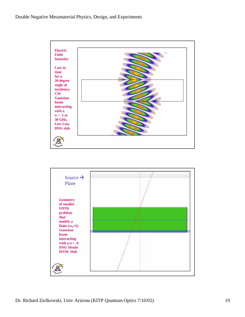
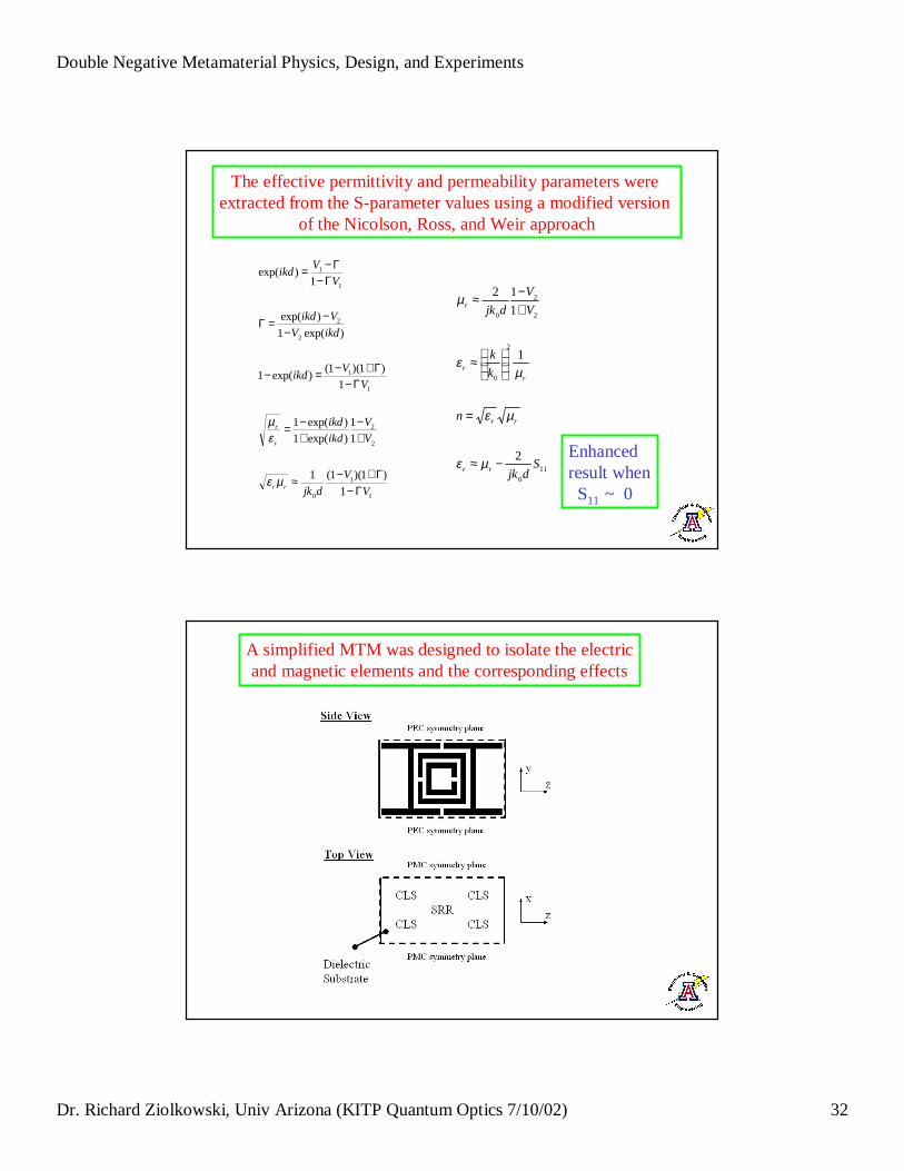
The effective permittivity and permeability parameters were extracted from the S-parameter values using a modified version
of the Nicolson, Ross, and Weir approach
1
1
0
2
2
1
1
2
2
1
1
1
)1)(1(1
11
)exp(1)exp(1
1)1)(1(
)exp(1
)exp(1
)exp(
1)exp(
V
V
djk
V
V
ikd
ikd
V
Vikd
ikdV
Vikd
V
Vikd
rr
r
r
Γ−Γ+−≈
+−
+−=
Γ−Γ+−=−
−−=Γ
Γ−Γ−=
µε
εµ
110
2
0
2
2
0
2
1
1
12
Sdjk
n
k
k
V
V
djk
rr
rr
r
r
r
−≈
=
≈
+−≈
µε
µε
µε
µ
Enhancedresult whenS11 ~ 0
A simplified MTM was designed to isolate the electricand magnetic elements and the corresponding effects

Double Negative Metamaterial Physics, Design, and Experiments
Dr. Richard Ziolkowski, Univ Arizona (KITP Quantum Optics 7/10/02) 33
S-parameters, Ansoft’ sHFSS
CLS-only MTM
Extracted effective permittivity
SRR-only MTM
S-parameters, Ansoft’ sHFSS Extracted effective permeability

Double Negative Metamaterial Physics, Design, and Experiments
Dr. Richard Ziolkowski, Univ Arizona (KITP Quantum Optics 7/10/02) 34
The effective material responses raise interesting issues
20
2
2
20
2
22
2
2
20
2
2
20
2
2
||1
1
1
ωωωχµ
ωωω
ωχωωχωχχ
ω
ωε
ωω
χωε
ωωω
χωχ
αβγ
−−≈⇒
+Γ+−
++−=
−≈
−−≈⇒
+Γ+−=
Lr
ppm
pr
Lpr
Lpe
j
j
jLorentz Model
Two TimeDerivativeLorentz Model
Drude Model
Composite MTM structure
S-parameters, Ansoft’ sHFSS Extracted effective permittivity and permeabili ty
Double Negative Metamaterial Physics, Design, and Experiments
Dr. Richard Ziolkowski, Univ Arizona (KITP Quantum Optics 7/10/02) 35
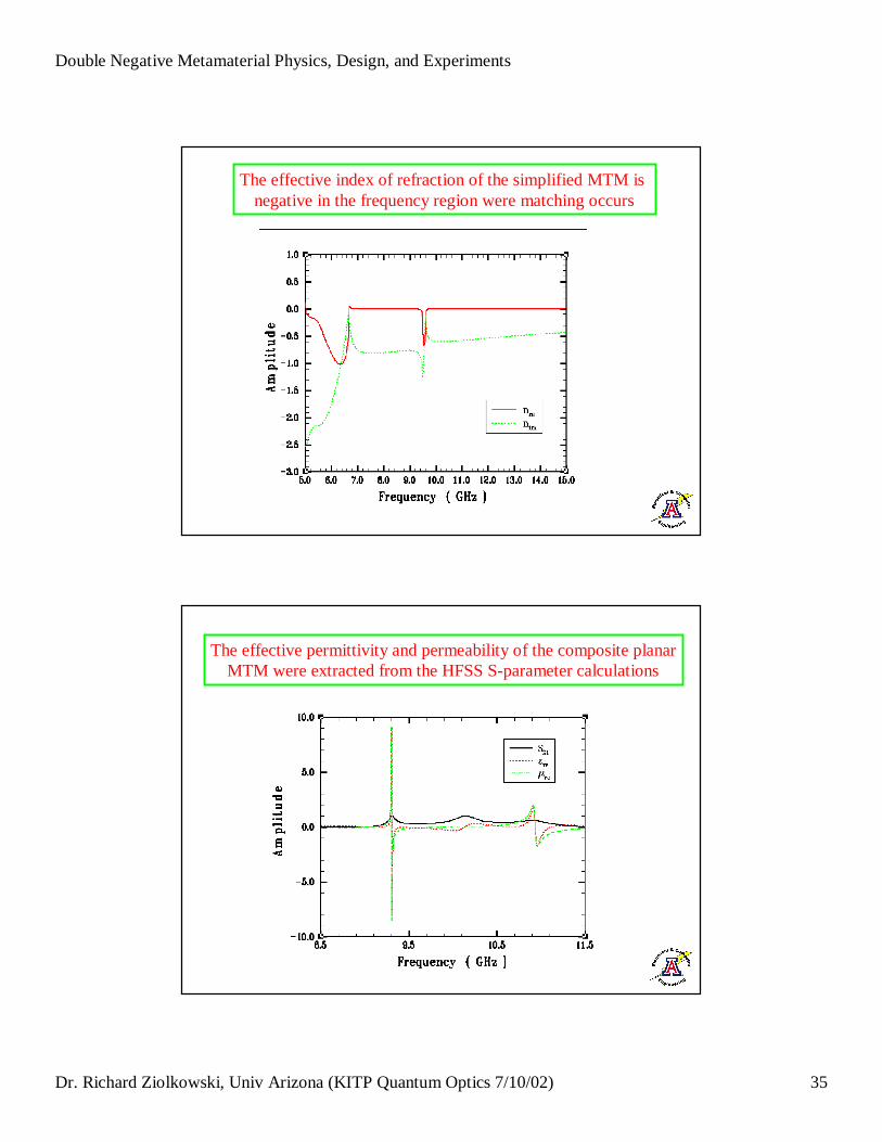
The effective index of refraction of the simplified MTM is negative in the frequency region were matching occurs
The effective permittivity and permeability of the composite planarMTM were extracted from the HFSS S-parameter calculations

Double Negative Metamaterial Physics, Design, and Experiments
Dr. Richard Ziolkowski, Univ Arizona (KITP Quantum Optics 7/10/02) 36
A negative effective index of refraction was extracted from the HFSS S-parameter calculations and from the FDTD calculations
HFSS results FDTD results
Confirmation that negative index of refraction MTMs have been realized
Metamaterials and improved antenna performance: Artificial perfect magnetic conductors (PMCs) – High Z surfaces
ElectricDipole
Image
PEC
ElectricDipole
Image
PMC
�Double the field strength
�Increase the bandwidth (Hansen)
R = -1 R = +1

Double Negative Metamaterial Physics, Design, and Experiments
Dr. Richard Ziolkowski, Univ Arizona (KITP Quantum Optics 7/10/02) 37
SRR Design with Dimensions
20 milsb
25 milsa
95 milsW2
95 milsL 2
55 milsW1
55 milsL 1
10 milst
10 milsg
g
tg
W1
W2
L2L1
gga
b
100 mils = 2.54 mm
One element unit cell
EH
k
-30.0
-25.0
-20.0
-15.0
-10.0
-5.0
0.0
5.0
5.0 10.0 15.0
Frequency ( GHz )
Mag
nitu
de (
dB
)
1 SRR
2 SRRs
3 SRRs
4 SRRs
HFSS calculated S11 values for the SRR MTM with a depth of 1, 2, 3, 4 SRR elements show complete reflectivity near the design frequency of 10GHz
Double Negative Metamaterial Physics, Design, and Experiments
Dr. Richard Ziolkowski, Univ Arizona (KITP Quantum Optics 7/10/02) 38
-200
-150
-100
-50
0
50
100
150
200
5.0 6.0 7.0 8.0 9.0 10.0 11.0 12.0 13.0 14.0 15.0Frequency ( GHz )
S11 Magnitude ( dB )
S11 Phase ( degrees )
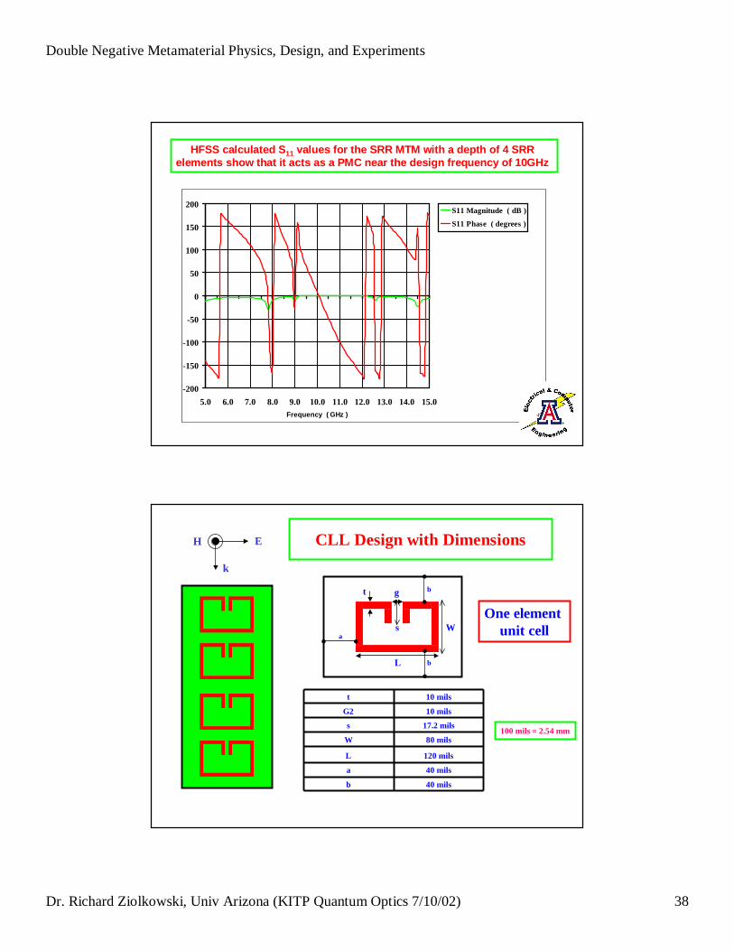
HFSS calculated S11 values for the SRR MTM with a depth of 4 SRR elements show that it acts as a PMC near the design frequency of 10GHz
CLL Design with Dimensions
40 milsb
40 milsa
120 milsL
80 milsW
17.2 milss
10 milsG2
10 milst
L
W
gt
sa
b
b
100 mils = 2.54 mm
One element unit cell
EH
k

Double Negative Metamaterial Physics, Design, and Experiments
Dr. Richard Ziolkowski, Univ Arizona (KITP Quantum Optics 7/10/02) 39
HFSS calculated S11 values for the SRR MTM with a depth of 1, 2, 3, 4 CLL elements show complete reflectivity near the design frequency of 10GHz
-50
-40
-30
-20
-10
0
10
5 6 7 8 9 10 11 12 13 14 15
Frequency ( GHz )
Mag
nitu
de
( d
B )
1 CLL
2 CLLs3 CLLs4 CLLs
-200
-150
-100
-50
0
50
100
150
200
5 6 7 8 9 10 11 12 13 14 15
Frequency ( GHz )
S11 Magnitude ( dB )
S11 Phase ( degrees )
HFSS calculated S11 values for the CLL MTM with a depth of 4 CLL elements show that it acts as a PMC near the design frequency of 10GHz
Double Negative Metamaterial Physics, Design, and Experiments
Dr. Richard Ziolkowski, Univ Arizona (KITP Quantum Optics 7/10/02) 40
-100
-80
-60
-40
-20
0
20
40
60
80
100
9.0 10.0 11.0
Frequency ( GHz )
S11 Magnitude ( dB )
S11 Phase ( degrees )
zoom
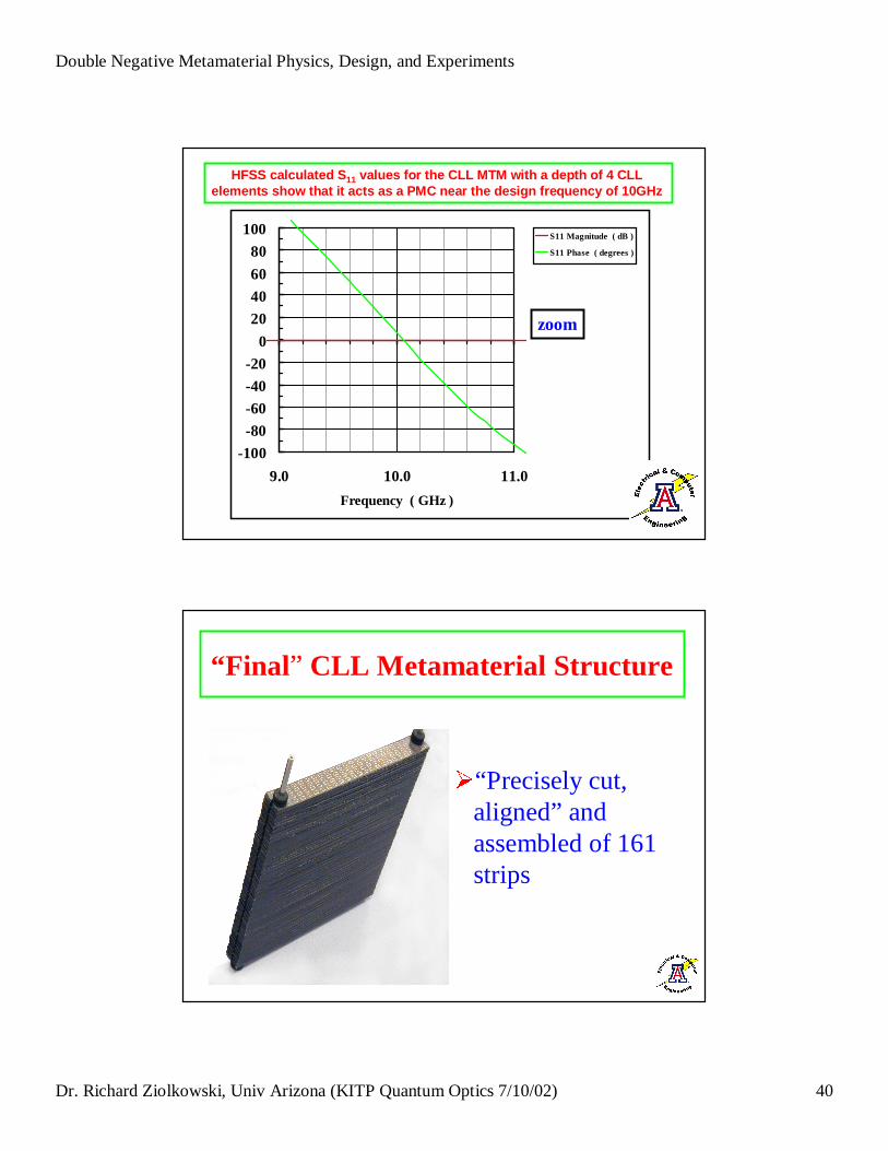
HFSS calculated S11 values for the CLL MTM with a depth of 4 CLL elements show that it acts as a PMC near the design frequency of 10GHz
“ Final” CLL Metamaterial Structure
“Precisely cut, aligned” and assembled of 161 strips

Double Negative Metamaterial Physics, Design, and Experiments
Dr. Richard Ziolkowski, Univ Arizona (KITP Quantum Optics 7/10/02) 41
The CLL MTM was measured with a free space measurement system
• Measure the CLL MTM with its designed orientation
• Measure the CLL MTM with a 90° rotation
• HP 8720C networkanalyzer to measure the S-parameters
MUT
X-band rectangular horn
-70
-60
-50
-40
-30
-20
-10
0
7.0 8.0 9.0 10.0 11.0 12.0 13.0 14.0
Frequency ( GHz )
Mag
nit
ude
( d
B )
Measured magnitude of S21 for the CLL MTM slab

Double Negative Metamaterial Physics, Design, and Experiments
Dr. Richard Ziolkowski, Univ Arizona (KITP Quantum Optics 7/10/02) 42
-30
-25
-20
-15
-10
-5
0
7.0 8.0 9.0 10.0 11.0 12.0 13.0 14.0
Frequency ( GHz )
Mag
nitu
de
( d
B )
Measured magnitude of S11 for the CLL MTM slab
Phase Reference Plane measurementwas achieved with a reference copper plate
A copper plate is
placed over the mouth of the flange of the transmit antenna
Double Negative Metamaterial Physics, Design, and Experiments
Dr. Richard Ziolkowski, Univ Arizona (KITP Quantum Optics 7/10/02) 43
-200
-150
-100
-50
0
50
100
150
200
9.0 9.5 10.0 10.5 11.0
Frequency ( GHz )
S11 Magnitude ( dB )
S11 Phase ( degrees )
S11 Rel. Phase ( degrees )
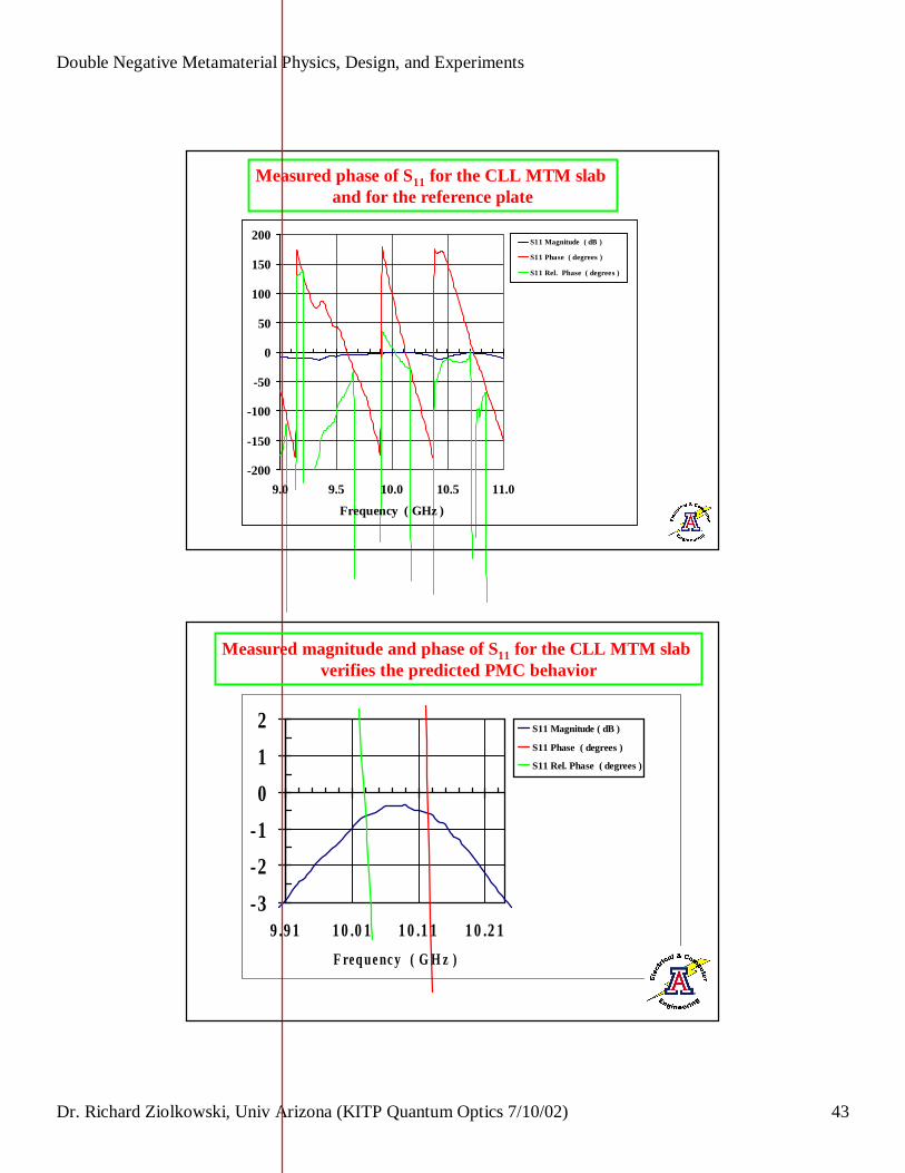
Measured phase of S11 for the CLL MTM slab and for the reference plate
-3
-2
-1
0
1
2
9.91 10.01 10.11 10.21
F r eq uency ( G H z )
S11 Magnitude ( dB )
S11 Phase ( degrees )
S11 Rel. Phase ( degrees )
Measured magnitude and phase of S11 for the CLL MTM slab verifies the predicted PMC behavior
Double Negative Metamaterial Physics, Design, and Experiments
Dr. Richard Ziolkowski, Univ Arizona (KITP Quantum Optics 7/10/02) 44
-35
-30
-25
-20
-15
-10
-5
0
5
9.0 10.0 11.0
Frequency ( GHz )
Mag
nitu
de (
dB
)
MTM
MTM Rotated 90
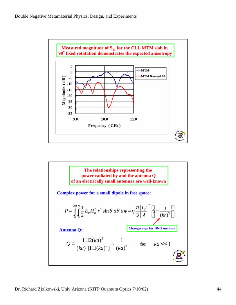
Measured magnitude of S11 for the CLL MTM slab in 90o fixed rotatation demonstrates the expected anisotropy
22* 2 0
30 0
1sin 1
2 3 ( )
I l jP E H r d d
kr
π π
θ φπθ θ φ η
λ = = − ∫ ∫
323
2
)(
1
])(1[)(
)(21kakaka
kaQ ≈
++= for 1<<ka
The relationships representing the power r adiated by and the antenna Q
of an electr ically small antennas are well-known
Complex power for a small dipole in free space:
Antenna Q: Changes sign for DNG medium

Double Negative Metamaterial Physics, Design, and Experiments
Dr. Richard Ziolkowski, Univ Arizona (KITP Quantum Optics 7/10/02) 45
Can a DNG spherical shell be used to improve the power radiated by an electr ically small antenna??
We have solved analytically the problem of an electr ically small
li near dipole antenna surr ounded
by a spherical shell of DNG material
Allison K ipple, PhD candidate
Calculating the radiated power normalized to the small dipole value as a function of the radius r 2, we find that there several regions of where the
radiated power is enhanced significantly and, corr espondingly, where Q is reduced
a = λλ / 750 = 4.0E-5 m, r 1= λλ/15 = 0.002 m for f0 = 10 GHz and n = -3
0.0
5.0
10.0
15.020.0
25.0
30.0
35.0
40.0
45.0
50.0
0.000 0.005 0.010 0.015 0.020
O u t er r ad iu s of D N G S hell (m )
Ra
dia
ted
po
we
r g
ain
0.0
0.2
0.4
0.6
0.8
1.0
1.2
0.000 0.005 0.010 0.015 0.020
O uter r adius of D N G shell ( m )
No
rm
ali
zed
Q

Double Negative Metamaterial Physics, Design, and Experiments
Dr. Richard Ziolkowski, Univ Arizona (KITP Quantum Optics 7/10/02) 46
A very largepower gain is predicted for a thin DNG shellAND with a reasonabable bandwidth
Antenna Q(normalized tofree space value)is reduced to near zero where thelarge power gainoccurs
0.0
5.0
10.0
15.0
20.0
25.0
30.0
35.0
40.0
45.0
50.0
0.002 0.003 0.004 0.005
Outer radius of DNG shell ( m )
Rad
iate
d p
ow
er g
ain
0.0
0.2
0.4
0.6
0.8
1.0
1.2
0.002 0.003 0.004 0.005
O u ter r ad i u s o f D N G s h e ll ( m )
No
rmal
ize
d Q
a = λλ / 750 = 4.0E-5 m, r1= λλ/15 = 0.002 m for f0 = 10 GHz and n = -3
Antenna Q(normalized toFree space value)is reduced to near zero where thelarge power gainoccurs
Significant power gain with a reasonable bandwidth is predicted for a larger and thicker DNG shell
a = λλ / 750 = 4.0E-5 m, r 1= λλ/15 = 0.002 m for f0 = 10 GHz and n = -3
0.0
2.0
4.0
6.0
8.0
10.0
12.0
14.0
0.006 0.008 0.010 0.012 0.014
Outer r adius of DNG shell ( m )
Rad
iate
d p
ower
gai
n
0.0 0
0.0 2
0.0 4
0.0 6
0.0 8
0.1 0
0.1 2
0.1 4
0.1 6
0.1 8
0.0 0 6 0.0 0 8 0.0 1 0 0.0 1 2 0.0 1 4
O u ter r ad i u s o f D N G s h e l l ( m )
Nor
mal
ized
Q
Double Negative Metamaterial Physics, Design, and Experiments
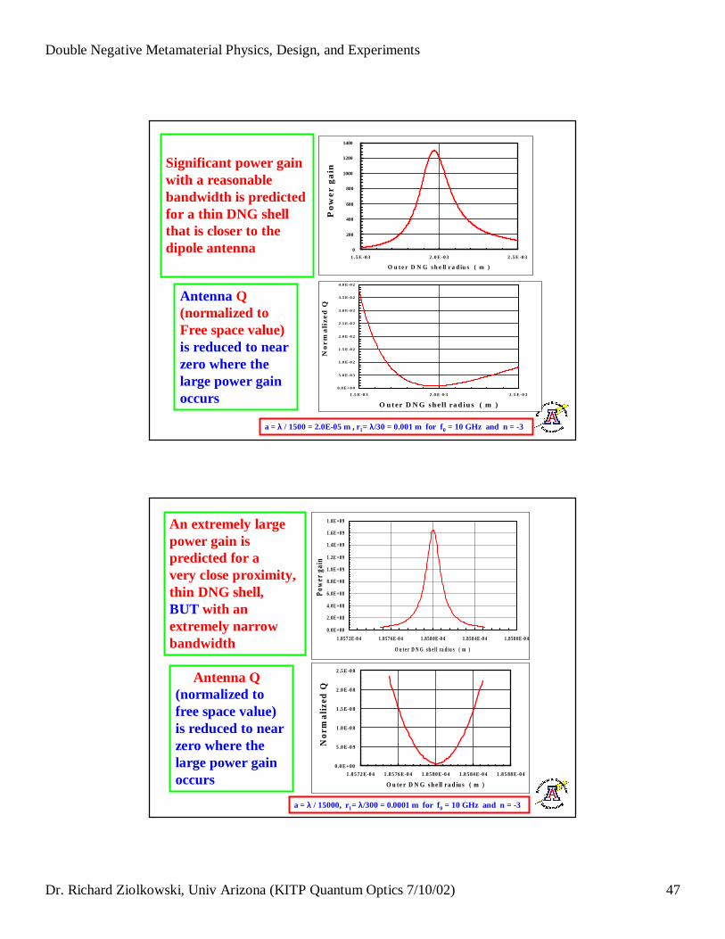
Dr. Richard Ziolkowski, Univ Arizona (KITP Quantum Optics 7/10/02) 47
0
200
400
600
800
1000
1200
1400
1.5E -0 3 2.0E -0 3 2.5E -0 3
O u t e r D N G sh ell r a d iu s ( m )
Po
we
r g
ain
Antenna Q(normalized toFree space value)is reduced to near zero where thelarge power gainoccurs
Significant power gain with a reasonable bandwidth is predicted for a thin DNG shell that is closer to the dipole antenna
a = λλ / 1500 = 2.0E-05 m , r1= λλ/30 = 0.001 m for f0 = 10 GHz and n = -3
0.0E+00
5.0E-03
1.0E-02
1.5E-02
2.0E-02
2.5E-02
3.0E-02
3.5E-02
4.0E-02
1.5 E -0 3 2.0 E -0 3 2.5 E -0 3
O ut er D N G shell r ad i us ( m )
No
rm
ali
zed
Q
0.0E+00
2.0E+08
4.0E+08
6.0E+08
8.0E+08
1.0E+09
1.2E+09
1.4E+09
1.6E+09
1.8E+09
1.8572E-04 1.8576E-04 1.8580E-04 1.8584E-04 1.8588E-04
O u t er D N G sh el l r a d i u s ( m )
Pow
er g
ain
0.0E+00
5.0E-09
1.0E-08
1.5E-08
2.0E-08
2.5E-08
1.8 572E-04 1.8 576E-04 1.8 580E-04 1.8 584E-04 1.8 588E-04
O u t er D N G sh ell r ad iu s ( m )
Nor
mal
ized
Q
An extremely largepower gain is predicted for a very close proximity, thin DNG shell, BUT with anextremely narrow bandwidth
Antenna Q(normalized tofree space value)is reduced to near zero where thelarge power gainoccurs
a = λλ / 15000, r1= λλ/300 = 0.0001 m for f0 = 10 GHz and n = -3

Double Negative Metamaterial Physics, Design, and Experiments
Dr. Richard Ziolkowski, Univ Arizona (KITP Quantum Optics 7/10/02) 48
Compact metamaterials having negative index of refraction have been designed, fabricated and tested experimentally
�HFSS and FDTD simulators have been used to design
several DNG (ε ε < 0 and µ µ < 0) metamaterials (MTMs)
�Extraction formula have been derived to determine the
MTM’s effective permitt ivity and permeability
�Experimental results confirm the realization of DNG MTMs
that are matched to free space and have a negative index of refraction
�Several potential applications have been studied:
Efficient Electr ically Small Antennas (EESAs)
Thank you for li stening�
Special Issue of IEEE Antennas and Propagationon Metamaterials
R. W. Ziolkowski and N. Engheta, Guest Editors
Contributions due October 1, 2002
Related Documents