Dosimetric properties of an amorphous silicon electronic portal imaging device for verification of dynamic intensity modulated radiation therapy Peter B. Greer a) and Carmen C. Popescu Department of Medical Physics, B.C. Cancer Agency, Vancouver Island Centre, 2410 Lee Avenue, Victoria V8R 6V5, Canada ~Received 2 July 2002; accepted for publication 21 April 2003; published 20 June 2003! Dosimetric properties of an amorphous silicon electronic portal imaging device ~EPID! for verifi- cation of dynamic intensity modulated radiation therapy ~IMRT! delivery were investigated. The EPID was utilized with continuous frame-averaging during the beam delivery. Properties studied included effect of buildup, dose linearity, field size response, sampling of rapid multileaf collimator ~MLC! leaf speeds, response to dose-rate fluctuations, memory effect, and reproducibility. The dependence of response on EPID calibration and a dead time in image frame acquisition occurring every 64 frames were measured. EPID measurements were also compared to ion chamber and film for open and wedged static fields and IMRT fields. The EPID was linear with dose and dose rate, and response to MLC leaf speeds up to 2.5 cm s 21 was found to be linear. A field size dependent response of up to 5% relative to d max ion-chamber measurement was found. Reproducibility was within 0.8% ~1 standard deviation! for an IMRT delivery recorded at intervals over a period of one month. The dead time in frame acquisition resulted in errors in the EPID that increased with leaf speed and were over 20% for a 1 cm leaf gap moving at 1.0 cm s 21 . The EPID measurements were also found to depend on the input beam profile utilized for EPID flood-field calibration. The EPID shows promise as a device for verification of IMRT, the major limitation currently being due to dead-time in frame acquisition. © 2003 American Association of Physicists in Medicine. @DOI: 10.1118/1.1582469# Key words: EPID, electronic portal imaging device, verification, intensity modulated radiation therapy, portal dosimetry I. INTRODUCTION Due to its complexity, dynamic intensity modulated radiation therapy ~IMRT! presents a challenge to verify that the de- sired fluence and hence dose distribution is delivered by the linear accelerator. One approach to IMRT verification is to transfer the IMRT fluences for each field to a test phantom and calculate the cumulative dose distribution with the radio- therapy treatment planning system ~RTPS!. These fields can then be delivered to the test phantom setup on the linear accelerator, the dose distribution measured ~generally with film!, and the result compared to the RTPS dose calculation. 1 This procedure is, however, time-consuming involving recal- culation of the IMRT plan, set-up time on the linear accel- erator, film processing and digitization, and comparison to the plan. Frequent film calibration and processor quality as- surance is also necessary. An alternative approach to ensure the integrity of the IMRT delivery is to verify the fluence or dose delivered for each field. In this case the fluence can be transferred to a flat phantom and the dose at a plane in the phantom calculated by the RTPS. A measurement of the delivered dose for the field made with film can be compared to an expected dose calculated by the RTPS system. 2,3 The accuracy of the RTPS dose calculation algorithm to calculate dose based on a given input fluence and patient anatomy would be verified sepa- rately as part of the commissioning process for IMRT. 4 How- ever this approach again requires a large workload. Electronic portal imaging devices ~EPIDs! present an at- tractive possibility to verify IMRT delivery due to their two- dimensional digital format. Multiple verification images can also be rapidly acquired without the necessity to re-enter the treatment room to position film. For pre-treatment verifica- tion the EPID image can be compared to a predicted portal dose image ~PDI! calculated from the fluence map for the field. 5,6 Another potential application is to verify the dose delivery in vivo with the EPID image acquired during the IMRT treatment, by comparison to a predicted transmission image. 7,8 Until recently video-camera and liquid-ion chamber based EPIDs have been utilized for these applications. The dosim- etric properties of these types of EPIDs have been exten- sively studied. 9–11 More recently their application to verifi- cation of dynamic IMRT has been addressed. 5,6 However, flat-panel amorphous silicon based EPIDs are rapidly replac- ing these EPIDs due to their superior image quality for treat- ment setup verification. 12 El-Mohri et al. 13 studied the dosi- metric properties of their in-house developed amorphous silicon imager, while McCurdy et al. 14 investigated some ba- sic properties for static field dosimetry. The dosimetric prop- erties of amorphous silicon EPIDs and their applicability for 1618 1618 Med. Phys. 30 „7…, July 2003 0094-2405Õ2003Õ30„7…Õ1618Õ10Õ$20.00 © 2003 Am. Assoc. Phys. Med.

Welcome message from author
This document is posted to help you gain knowledge. Please leave a comment to let me know what you think about it! Share it to your friends and learn new things together.
Transcript
Dosimetric properties of an amorphous silicon electronic portalimaging device for verification of dynamic intensity modulatedradiation therapy
Peter B. Greera) and Carmen C. PopescuDepartment of Medical Physics, B.C. Cancer Agency, Vancouver Island Centre, 2410 Lee Avenue,Victoria V8R 6V5, Canada
~Received 2 July 2002; accepted for publication 21 April 2003; published 20 June 2003!
Dosimetric properties of an amorphous silicon electronic portal imaging device~EPID! for verifi-cation of dynamic intensity modulated radiation therapy~IMRT! delivery were investigated. TheEPID was utilized with continuous frame-averaging during the beam delivery. Properties studiedincluded effect of buildup, dose linearity, field size response, sampling of rapid multileaf collimator~MLC! leaf speeds, response to dose-rate fluctuations, memory effect, and reproducibility. Thedependence of response on EPID calibration and a dead time in image frame acquisition occurringevery 64 frames were measured. EPID measurements were also compared to ion chamber and filmfor open and wedged static fields and IMRT fields. The EPID was linear with dose and dose rate,and response to MLC leaf speeds up to 2.5 cm s21 was found to be linear. A field size dependentresponse of up to 5% relative todmax ion-chamber measurement was found. Reproducibility waswithin 0.8%~1 standard deviation! for an IMRT delivery recorded at intervals over a period of onemonth. The dead time in frame acquisition resulted in errors in the EPID that increased with leafspeed and were over 20% for a 1 cmleaf gap moving at 1.0 cm s21. The EPID measurements werealso found to depend on the input beam profile utilized for EPID flood-field calibration. The EPIDshows promise as a device for verification of IMRT, the major limitation currently being due todead-time in frame acquisition. ©2003 American Association of Physicists in Medicine.@DOI: 10.1118/1.1582469#
Key words: EPID, electronic portal imaging device, verification, intensity modulated radiationtherapy, portal dosimetry
onethto
omio
e
onael
ta
heor
flatthos
ivpa
-nthea-rtaleeeion
edim-ten--
lac-at-
ous-p-or
I. INTRODUCTION
Due to its complexity, dynamic intensity modulated radiatitherapy~IMRT! presents a challenge to verify that the dsired fluence and hence dose distribution is delivered bylinear accelerator. One approach to IMRT verification istransfer the IMRT fluences for each field to a test phantand calculate the cumulative dose distribution with the radtherapy treatment planning system~RTPS!. These fields canthen be delivered to the test phantom setup on the linaccelerator, the dose distribution measured~generally withfilm!, and the result compared to the RTPS dose calculati1
This procedure is, however, time-consuming involving recculation of the IMRT plan, set-up time on the linear accerator, film processing and digitization, and comparisonthe plan. Frequent film calibration and processor qualitysurance is also necessary.
An alternative approach to ensure the integrity of tIMRT delivery is to verify the fluence or dose delivered feach field. In this case the fluence can be transferred to aphantom and the dose at a plane in the phantom calculby the RTPS. A measurement of the delivered dose forfield made with film can be compared to an expected dcalculated by the RTPS system.2,3 The accuracy of the RTPSdose calculation algorithm to calculate dose based on a ginput fluence and patient anatomy would be verified se
1618 Med. Phys. 30 „7…, July 2003 0094-2405 Õ2003Õ30„7…
-e
-
ar
.l--os-
atedee
en-
rately as part of the commissioning process for IMRT.4 How-ever this approach again requires a large workload.
Electronic portal imaging devices~EPIDs! present an at-tractive possibility to verify IMRT delivery due to their twodimensional digital format. Multiple verification images caalso be rapidly acquired without the necessity to re-entertreatment room to position film. For pre-treatment verifiction the EPID image can be compared to a predicted podose image~PDI! calculated from the fluence map for thfield.5,6 Another potential application is to verify the dosdelivery in vivo with the EPID image acquired during thIMRT treatment, by comparison to a predicted transmissimage.7,8
Until recently video-camera and liquid-ion chamber basEPIDs have been utilized for these applications. The dosetric properties of these types of EPIDs have been exsively studied.9–11 More recently their application to verification of dynamic IMRT has been addressed.5,6 However,flat-panel amorphous silicon based EPIDs are rapidly reping these EPIDs due to their superior image quality for trement setup verification.12 El-Mohri et al.13 studied the dosi-metric properties of their in-house developed amorphsilicon imager, while McCurdyet al.14 investigated some basic properties for static field dosimetry. The dosimetric proerties of amorphous silicon EPIDs and their applicability f
1618Õ1618Õ10Õ$20.00 © 2003 Am. Assoc. Phys. Med.
t.u-r
,flutiera
am
,
sith-or
anve
t
nhan
orr.s
Uise
iethsimfirlivreathno
3ggdie
e
lddge-anthe
onfli-10fortheali--
cel-ev-
er
ec-ldto
ofm-
tore-
re-uphe 6cin-ofion
1619 P. B. Greer and C. C. Popescu: Verification of dynamic IMRT 1619
dynamic IMRT verification are therefore of current interesIn this study the dosimetric properties of an amorpho
silicon EPID for verification of dynamic IMRT were investigated. These properties included effect of buildup, dosesponse, field size response, relative dosimetry accuracysponse to rapid MLC leaf speeds, and beam dose-ratetuations. The dependence of response on EPID calibraand a dead time in image frame acquisition occurring ev64 frames were measured, as was the reproducibility forsolute dosimetry. The EPID was also compared to ion chber and film measurements for IMRT test patterns.
II. METHODS AND MATERIALS
A. EPID and image acquisition
The amorphous silicon EPID~aS500, Varian, Palo AltoCA! consists of a 1 mm copper metal plate, a 134 mg/cm2
gadolinium oxysulphide phosphor screen~Kodak, LanexFast B! that includes a 0.18 mm polyester reflector, and40330 cm2 ~5123384 pixel! a-Si array. Each pixel consistof a light sensitive photodiode and a thin-film transistor wa pixel pitch of 0.7830.78 mm2. The copper plate lies beneath a 10-mm-thick foam layer with 1 mm of epoxy fbinding. The scintillator and amorphous silicon array~;1mm thick! are bound to the underside of the copper plateare enclosed between thin layers of black paper to prelight scatter from the copper plate or components beneatharray, reaching the array. Beneath this lies a further 8 mmfoam and 1 mm epoxy. A 1.6-mm-thick plastic collisiocover~epoxy with glass and foam! encloses the detector witan air gap of approximately 1.5 cm between the coverthe detector surface. The EPID was integrated with a 6EX~6MV ! linear accelerator with a dynamic multileaf collimat~DMLC! with 1 cm leaf width from the same manufactureAll investigations were performed with a nominal beam dorate of 400 MU min21 ~6.7 MU s21!.
Image acquisition is controlled by the Acquisition CP~IAS2! located in the treatment room. An image framescanned row by row, with a fixed number of rows scannper beam pulse. Each individual image frame is acquired;0.125 s at a 400 MU/min dose rate. This frame time varslightly depending on the nominal dose-rate setting ofaccelerator. To record an IMRT delivery with this EPID sytem, there are two possible modes of operation, multipleage acquisition and continuous frame averaging. In themode, multiple images are acquired during radiation deery, with each image being the average of a fixed numbeframes. In this case, however there is a delay betweenacquired image due to the transfer of the image fromAcquisition CPU to the disk and database. This delay isfixed and can be more than 2 s.15 This mode is unlikely to beused to verify dynamic IMRT where leaf speeds of up tocm s21 are possible.16 In the continuous frame-averaginmode that was used in this work, a single image consistinthe average of many image frames is acquired during ration delivery. The EPID will average successively acquirframes up to a limit of 9999 frames.
Medical Physics, Vol. 30, No. 7, July 2003
s
e-re-c-
onyb--
a
dntheof
d
e
dinse--
st-ofchet
ofa-d
The EPID imageI (x,y) obtained from continuous framaveraging is therefore:
I ~x,y!51
N (j 51
N
I j~x,y!, ~1!
where I j (x,y) is the jth image frame, andN is the totalnumber of frames acquired.
B. EPID calibration
The EPID is calibrated by the acquisition of dark-fie~DF! and flood-field~FF! images. The DF image is acquirewith no radiation and records the pixel offsets. The FF imais recorded with an open field ‘‘uniform’’ irradiation to determine differences in individual pixel sensitivities. Whenimage is acquired by the EPID the DF is subtracted andimage is then divided by the normalized FF image:
I ~x,y!5S I raw~x,y!2DF~x,y!
FF~x,y!2DF~x,y! D @FF~x,y!2DF~x,y!#mean.
~2!
This calibration, however requires a uniform FF calibratiimage.17 To achieve uniformity, an optimum thickness osolid water buildup has to be found. The EPID was cabrated with thicknesses of solid water buildup of 5, 7.5,cm and no buildup. The flatness of the flood-field imageeach calibration was examined using profiles throughcentral axis in cross-plane and in-plane directions. The cbration field size was 40330 cm2 at isocenter with the detector at a source–detector distance~SDD! of 105 cm. Thesolid water was placed on the detector surface and the acerator positioned vertically downward. The detector was leled to remove any sag due to the solid water.
Immediately following each calibration, the solid watwas removed, and an image was acquired of a 20320 cm2
open field. This open field image has the flood-field corrtion for the previous calibration applied. Thus four open fieimages were acquired, each with identical input fluencethe detector~no buildup on EPID!, but with different flood-field corrections corresponding to 0, 5, 7.5, and 10 cmsolid water buildup. These open field images were then copared to ion-chamber measurement atdmax, to see whetherthe EPID image, with flood-field correction correspondsthe ion chamber. The ion-chamber measurement wascorded in a water tank with a 0.125 cc ion chamber~Well-hofer Dosimetrie, Schwarzenbruck, Germany! at 1.5 cmdepth at a source–surface distance~SSD! of 100.0 cm for thesame field size.
C. Dosimetric properties
1. Effect of buildup
To determine whether added buildup material wasquired for accurate dosimetry, the effect of added buildplaced on the detector surface on the EPID response for tMV beam was investigated. The 1 mm copper plate and stillator screen provides inherent buildup. Solid waterthickness 0.5, 1.0, and 1.5 cm were placed on the collis
s
eirce
ck
nthith
twgrawith
frob
asn
th,t
dthawsp
twa,sntthged
tdu
detede
epther,ents
ioning
iser
iona
iv-onwe-
dised
lestlyxis.toch
red orr, ififthetheto agaf
rerag-ofeafPIDion-achthe
ro-at
1620 P. B. Greer and C. C. Popescu: Verification of dynamic IMRT 1620
cover surface leaving a gap of;2.5 cm to the amorphousilicon. Open field images of a 10310 cm2 field were ac-quired with the EPID at 105 cm from the source. Ten framwere averaged for each image. The images were acquwith a delay after the beam was turned on so that the acerator dose rate had stabilized. The mean and standardviation of the pixel values in a 10310 pixel region at thecenter of the field were recorded for each solid water thiness.
Images of open fields of size 535, 10310, and 20320cm2 were then recorded as above with the EPID with awithout the buildup material present. Profiles throughcentral axis were obtained. The beam profiles with and wout the buildup material present were compared.
2. Dose response
As the EPID image is the average of acquired frames,images acquired with different dose or monitor unit settinshould result in the same pixel values provided the doseand hence dose/frame is the same. The pixel valueshowever, be sensitive to dose rate as this will changedose per frame. To obtain a measure of integrated dosethe images, the pixel values must therefore be multipliedthe number of frames acquired@Eq. ~1!#.
The linearity of the EPID to variations in dose rate winvestigated by comparison to ion-chamber measuremeTo modify the dose rate the SDD was varied by varyingdistance below isocenter~5.5, 20.2, 30.2, 40.1, 53.1, 64.4and 83.5 cm!. No extra buildup was utilized on the EPID. Aeach distance, three images of a 535 cm2 field were acquiredand the mean pixel values in a 10310 pixel region at thecenter of each field were recorded. Each image consisteten averaged frames acquired following a delay afterbeam was turned on. This delay ensured stability of thecelerator dose rate. To determine the relative dose ratedistance, the 0.125 cc ion chamber was placed in a permini-phantom at a 3 cmdepth at each SDD.
To verify linear response with dose, images of a 10310cm2 open field were acquired. The EPID was positioned afixed detector distance of 105.0 cm, and varying dosedelivered with monitor unit~MU! settings of 10, 20, 50, 100and 200. For each MU setting, frames were continuouaveraged during the irradiation. The pixel values at the ceof the field were obtained as described earlier and weremultiplied by the number of frames acquired for each imaThe linearity of delivered dose with MU setting was verifieby ion-chamber measurement in the mini-phantom.
3. Field size response
The field size response of the EPID was comparedion-chamber measurement. The detector was positione105 cm from the source and field sizes defined by the mtileaf collimators were varied from 434 to 24324 cm2.Three images were acquired for each setting with no adbuildup on the EPID. The images were acquired withframes after dose-rate stabilization and pixel values recoras described earlier. To record the change in dose with fi
Medical Physics, Vol. 30, No. 7, July 2003
sedl-
de-
-
de-
ostell,emy
ts.e
ofec-ithex
as
lyeren.
oatl-
dnedld
size, ion-chamber measurements were performed at a dof 1.5 cm in a solid water phantom with 5 cm of backscattand 105.0 cm to the chamber. Both sets of measuremwere normalized to the 10310 cm2 values.
4. Effect of dead time in frame acquisition
The EPID system has a dead time in frame acquisitoccurring every 64 frames. The ACPU is capable of addup to 64 frames in its 20 bit hardware memory~frame-buffer!. Every 64 frames the content of the frame-buffermoved to the 32-bit-wide DRAM of the CPU. This transftakes ;0.16 s. A reset frame~non-image frame! is thenacquired.15 This represents a dead time in image acquisitof ;0.28 s every 64 frames, approximately equivalent toloss of two image frames. As radiation is continuously delered during this dead time, the effect of the dead timerecording dynamic IMRT was investigated. Sliding windodeliveries were performed with a uniform 1 cm leaf gap btween the two banks of multileaf collimator~MLC! leavesand a 10310 cm2 field. Three leaf speeds of 0.25, 0.5, an1.0 cm s21 were created by modifying the MU setting. Thpattern should result in a uniform beam profile and is utilizas a quality assurance test of leaf-speed stability.18 Imageswere acquired by continuously averaging frames. Profiwere obtained along the direction of leaf motion direcunder the center of the MLC leaf adjacent to the central aReduction in signal from a uniform profile occurring duethe dead time in frame acquisition was quantified for ealeaf speed.
5. Response with leaf speed
Leaf speeds of up to 2.5 cm s21 are utilized at our centefor DMLC delivery. If the EPID pixels integrate the dosbetween consecutive frame read-outs, then leaf speeframe rate should not affect the acquired signal. Howevesignal is collected for only a portion of the frame time, orthe pixels saturate before frame readout then errors insignal may occur. It is important therefore to ensure thatEPID accurately records the rapid changes in dose ratepixel that occur during DMLC radiation delivery. Slidinwindow deliveries were performed with a uniform 1 cm legap between the two banks of MLC leaves for a 10310 cm2
field. The leaf speed was varied from 0.33 to 2.5 cm s21 byvarying the number of monitor units. Three images weacquired for each leaf speed with continuous frame aveing, and the image values multiplied by the numberframes acquired. Profiles under the center of the MLC ladjacent to the central axis were analyzed to obtain the Esignal for each leaf speed. These were compared tochamber measurements made in the mini-phantom for eleaf speed at the center of the field under the center ofsame MLC leaf.
6. Response to dose-rate fluctuations
The readout of the amorphous silicon array is synchnized with the beam pulses. The EPID is also calibratedeach fixed accelerator dose rate~e.g., 400 MU/min! used for
oa
ua
sulnefebt50mte
dehm
ne
oxs
d
w
ei
nit
re
in
l.nrein
al
d
ngfilmhpre
washeorV
r,s
ra-
v-ted
tosti-gehen.
inxis
-a-aria-tep-ofitydametralion
n
geslidm
-
ra-es.xisberthend
sti-m-off-enred-
1621 P. B. Greer and C. C. Popescu: Verification of dynamic IMRT 1621
clinical imaging. The DF and FF images are different feach dose rate due to variation in the dose rate and imacquisition timing. During IMRT treatments if the MLCleaves cannot reach a pre-defined position with maximleaf speed then beam hold-offs result where the accelerreduces dose rate~‘‘holds-off beam’’! until the leaves havereached the desired position. This can result in large dorate fluctuations during the delivery. Potentially these coaffect the EPID signal where the EPID system is desigand calibrated with a fixed accelerator dose rate. The efof beam hold-offs on the EPID signal were examinedrecording a ‘‘step-wedge’’ IMRT pattern with and withoubeam hold-offs. For the pattern, dose settings of 50 andMU were utilized to deliver the field with and without beahold-offs. During the 50 MU irradiation the beam dose rafluctuated to less than 200 MU/min at times during thelivery. Beam profiles directly under the leaf adjacent to tcentral axis were obtained from the EPID images and copared.
7. Memory effect
The memory effect of the EPID was studied in a mansimilar to that utilized by van Eschet al.6 for the liquid ion-chamber EPID. An image was acquired with a 535 cm2 fieldsize, followed immediately by an image of a 20320 cm2
field size. The interval between the two images was apprmately 15 s. A memory effect of the EPID will manifest aan increase in the pixel value for the 20320 cm2 field size inthe region of irradiation of the 535 cm2 field. An image wasacquired of the 20320 cm2 field after several minutes haelapsed for comparison. Profiles across the 20320 cm2 fieldimages were compared to see whether the pixel valueelevated due to a memory effect.
8. Relative dosimetry
The accuracy of the EPID in recording open and wedgstatic fields was investigated. Images were acquired wopen fields from 535 up to 20320 cm2. These images wereacquired with ten frames following dose-rate stabilizatioThe EPID was positioned at 105.0 cm from the source wno added buildup material. Similarly images were acquiwith 45° and 60° steel wedges for field sizes of 20320 and15315 cm2, respectively. The transmitted beam contasome variation in beam energy across the field~in thewedged direction! due to the varying thickness of steeEPID profiles through the central axis for the open fields ain the wedged direction for the wedged fields were compato ion-chamber measurements recorded at 1.5 cm depthwater phantom at 100.0 cm SSD. The EPID result was scto 101.5 cm to enable comparison, assuming there wouldno change in EPID measurement at 101.5 and 105 cmtances apart from beam divergence.
IMRT test patterns were recorded with the EPID usicontinuous frame-averaging mode and compared tomeasurement. A bar-pattern test fluence was created witin-house software package. This fluence consisted of barterns of different spatial frequencies, with the highest f
Medical Physics, Vol. 30, No. 7, July 2003
rge
mtor
e-ddcty
0
-e-
r
i-
as
dth
.hd
s
dda
edbeis-
anat--
quency having 1 cm bars spaced at 2 cm intervals. Thisinput to the RTPS as an ‘‘optimal fluence map’’ and tRTPS then calculated leaf trajectories and a ‘‘deliverable’’‘‘actual’’ fluence map. These were recorded on the 6 Maccelerator with Kodak XV film~Eastman-Kodak, RochesteNY! at 1.5 cm depth in a solid water phantom. The filmwere digitized with a Vidar scanner~Vidar Corp, Herndon,PA! and converted to relative dose with a measured calibtion curve.
For pre-treatment verification of the IMRT fluence deliery, the EPID image can either be compared to a predicPDI, or converted to a ‘‘fluence’’ image for comparisonthe expected fluence without the patient present. To invegate the potential of the EPID for this application, an imawas acquired of a clinical IMRT field and compared to tfluence map utilized by the RTPS for the dose distributioThe field was from a clinical six field parotid plan. Profilesthe leaf motion direction were compared at the central aand at off-axis planes.
9. Reproducibility
The reproducibility of the EPID signal is particularly important if the EPID is to be utilized to record not only reltive dose measurements but also record absolute dose vtions. The reproducibility was assessed by recording a swedge IMRT delivery on multiple occasions over a periodone month. This pattern consisted of five uniform intenslevels~bars! with relative intensities of 0.2, 0.4, 0.6, 0.8, an1.0. At each measurement the EPID was set up at the sposition. The differences between profiles through the cenaxis of the field were quantified and the standard deviatcalculated.
III. RESULTS
A. EPID calibration
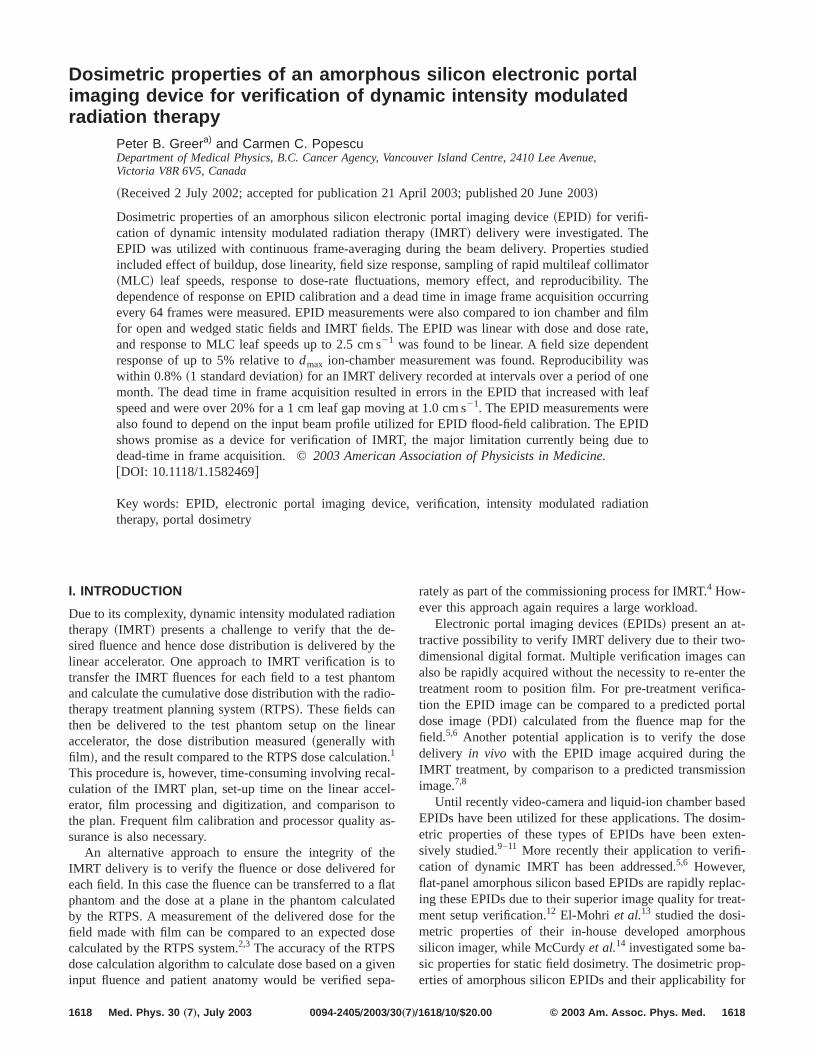
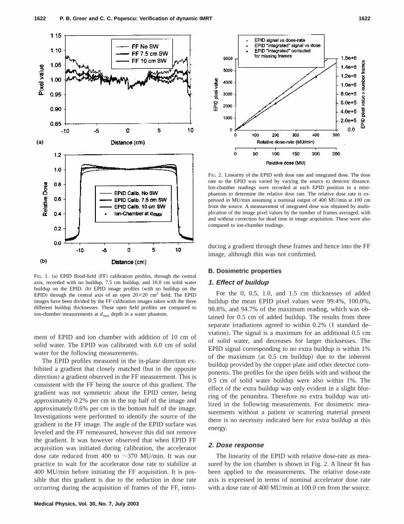
The effect of the thickness of solid water utilized wherecording the FF calibration image is shown in Fig. 1~a!.This shows profiles through the central axis of the FF imarecorded with no buildup, 7.5 cm buildup, and 10.0 cm sowater buildup on the EPID. The FF profile with 10 cbuildup is relatively flat, while the profile with no buildupincreases rapidly off-axis. Figure 1~b! shows EPID measurements~with no buildup on the EPID! of an open 20320 cm2
field. The EPID images have been divided by the FF calibtion images from these three different buildup thicknessThese EPID profiles, again obtained through the central ain the cross-plane direction, are compared to ion-chammeasurement at 1.5 cm depth in a water tank. For clarity5 cm of solid water result, which was between the zero a7.5 cm thickness, has been omitted.
The EPID calibrated with no buildup shows an underemation of the beam profile as measured with the ion chaber. The FF image in this case reduces the pixel valuesaxis. The result when the EPID was calibrated with betwe5.0 and 7.5 cm of solid water closely matched the measuion-chamber profile~within 2%!. There was reduced agree
oflid
ex
ishinne
tha
oFto
s-ao
e FF
ded%,
ob-ee
mThe%
m-theer-ti-a-ent
this
a-as-rateratece.
lte
thrd
osence.ini-
s ex-cmulti-
withalso
1622 P. B. Greer and C. C. Popescu: Verification of dynamic IMRT 1622
ment of EPID and ion chamber with addition of 10 cmsolid water. The EPID was calibrated with 6.0 cm of sowater for the following measurements.
The EPID profiles measured in the in-plane directionhibited a gradient that closely matched~but in the oppositedirection! a gradient observed in the FF measurement. Thconsistent with the FF being the source of this gradient. Tgradient was not symmetric about the EPID center, beapproximately 0.2% per cm in the top half of the image aapproximately 0.6% per cm in the bottom half of the imagInvestigations were performed to identify the source ofgradient in the FF image. The angle of the EPID surface wleveled and the FF remeasured, however this did not remthe gradient. It was however observed that when EPIDacquisition was initiated during calibration, the acceleradose rate reduced from 400 to;370 MU/min. It was ourpractice to wait for the accelerator dose rate to stabilize400 MU/min before initiating the FF acquisition. It is posible that this gradient is due to the reduction in dose roccurring during the acquisition of frames of the FF, intr
FIG. 1. ~a! EPID flood-field ~FF! calibration profiles, through the centraaxis, recorded with no buildup, 7.5 cm buildup, and 10.0 cm solid wabuildup on the EPID.~b! EPID image profiles~with no buildup on theEPID! through the central axis of an open 20320 cm2 field. The EPIDimages have been divided by the FF calibration images taken with thedifferent buildup thicknesses. These open field profiles are compareion-chamber measurements atdmax depth in a water phantom.
Medical Physics, Vol. 30, No. 7, July 2003
-
isegd.es
veFr
at
te-
ducing a gradient through these frames and hence into thimage, although this was not confirmed.
B. Dosimetric properties
1. Effect of buildup
For the 0, 0.5, 1.0, and 1.5 cm thicknesses of adbuildup the mean EPID pixel values were 99.4%, 100.098.8%, and 94.7% of the maximum reading, which wastained for 0.5 cm of added buildup. The results from thrseparate irradiations agreed to within 0.2%~1 standard de-viation!. The signal is a maximum for an additional 0.5 cof solid water, and decreases for larger thicknesses.EPID signal corresponding to no extra buildup is within 1of the maximum~at 0.5 cm buildup! due to the inherentbuildup provided by the copper plate and other detector coponents. The profiles for the open fields with and without0.5 cm of solid water buildup were also within 1%. Theffect of the extra buildup was only evident in a slight bluring of the penumbra. Therefore no extra buildup was ulized in the following measurements. For dosimetric mesurements without a patient or scattering material presthere is no necessity indicated here for extra buildup atenergy.
2. Dose response
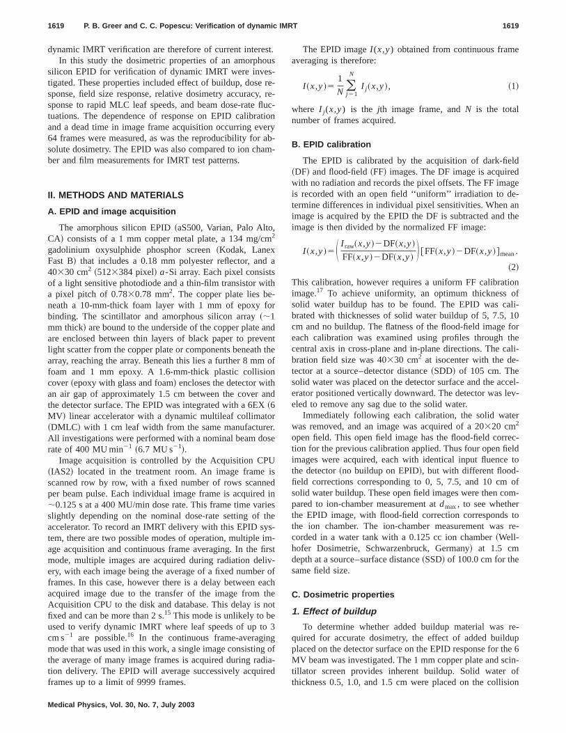
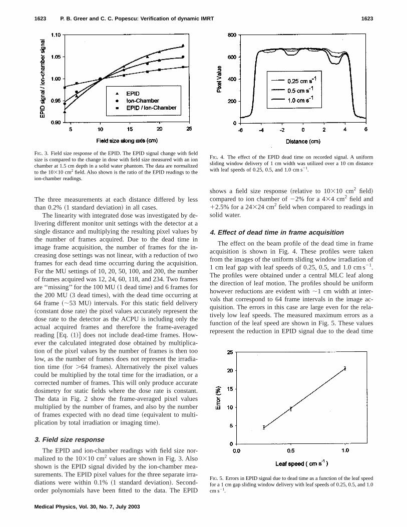
The linearity of the EPID with relative dose-rate as mesured by the ion chamber is shown in Fig. 2. A linear fit hbeen applied to the measurements. The relative doseaxis is expressed in terms of nominal accelerator dosewith a dose rate of 400 MU/min at 100.0 cm from the sour
r
eeto
FIG. 2. Linearity of the EPID with dose rate and integrated dose. The drate to the EPID was varied by varying the source to detector distaIon-chamber readings were recorded at each EPID position in a mphantom to determine the relative dose rate. The relative dose rate ipressed in MU/min assuming a nominal output of 400 MU/min at 100from the source. A measurement of integrated dose was obtained by mplication of the image pixel values by the number of frames averaged,and without correction for dead time in image acquisition. These werecompared to ion-chamber readings.
le
deab
intwonbe
t
hethg-
icatod
aatanuebe
oroeairr
I
n
eenf
ngm
ac-la-s auesime
eln ilize
rmce
eed.0
1623 P. B. Greer and C. C. Popescu: Verification of dynamic IMRT 1623
The three measurements at each distance differed bythan 0.2%~1 standard deviation! in all cases.
The linearity with integrated dose was investigated bylivering different monitor unit settings with the detector atsingle distance and multiplying the resulting pixel valuesthe number of frames acquired. Due to the dead timeimage frame acquisition, the number of frames for thecreasing dose settings was not linear, with a reduction offrames for each dead time occurring during the acquisitiFor the MU settings of 10, 20, 50, 100, and 200, the numof frames acquired was 12, 24, 60, 118, and 234. Two framare ‘‘missing’’ for the 100 MU~1 dead time! and 6 frames forthe 200 MU~3 dead times!, with the dead time occurring a64 frame~;53 MU! intervals. For this static field delivery~constant dose rate! the pixel values accurately represent tdose rate to the detector as the ACPU is including onlyactual acquired frames and therefore the frame-averareading@Eq. ~1!# does not include dead-time frames. However the calculated integrated dose obtained by multipltion of the pixel values by the number of frames is thenlow, as the number of frames does not represent the irration time ~for .64 frames!. Alternatively the pixel valuescould be multiplied by the total time for the irradiation, orcorrected number of frames. This will only produce accurdosimetry for static fields where the dose rate is constThe data in Fig. 2 show the frame-averaged pixel valmultiplied by the number of frames, and also by the numof frames expected with no dead time~equivalent to multi-plication by total irradiation or imaging time!.
3. Field size response
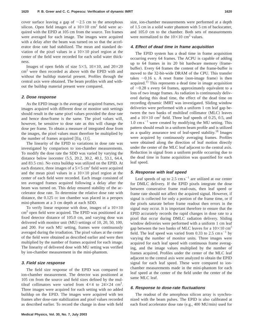
The EPID and ion-chamber readings with field size nmalized to the 10310 cm2 values are shown in Fig. 3. Alsshown is the EPID signal divided by the ion-chamber msurements. The EPID pixel values for the three separatediations were within 0.1%~1 standard deviation!. Second-order polynomials have been fitted to the data. The EP
FIG. 3. Field size response of the EPID. The EPID signal change with fisize is compared to the change in dose with field size measured with achamber at 1.5 cm depth in a solid water phantom. The data are normato the 10310 cm2 field. Also shown is the ratio of the EPID readings to thion-chamber readings.
Medical Physics, Vol. 30, No. 7, July 2003
ss
-
yin-o.r
es
eed
-oia-
et.sr
-
-a-
D
shows a field size response~relative to 10310 cm2 field!compared to ion chamber of22% for a 434 cm2 field and12.5% for a 24324 cm2 field when compared to readings isolid water.
4. Effect of dead time in frame acquisition
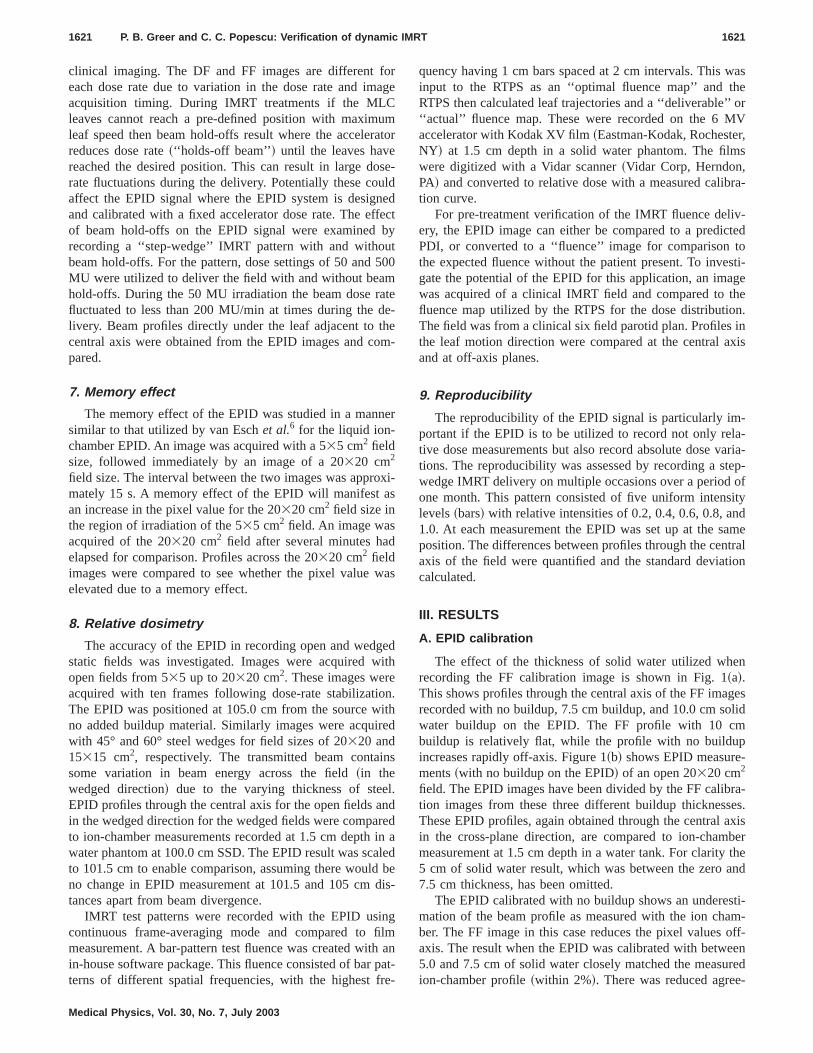
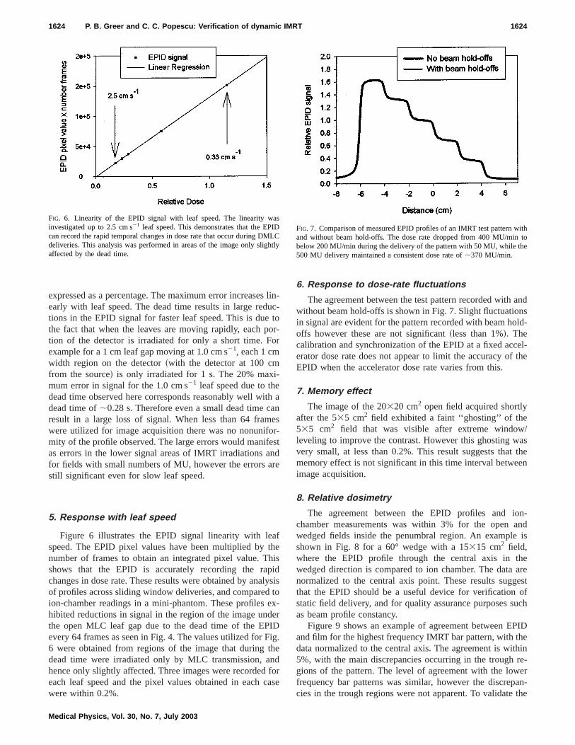
The effect on the beam profile of the dead time in framacquisition is shown in Fig. 4. These profiles were takfrom the images of the uniform sliding window irradiation o1 cm leaf gap with leaf speeds of 0.25, 0.5, and 1.0 cm s21.The profiles were obtained under a central MLC leaf alothe direction of leaf motion. The profiles should be uniforhowever reductions are evident with;1 cm width at inter-vals that correspond to 64 frame intervals in the imagequisition. The errors in this case are large even for the retively low leaf speeds. The measured maximum errors afunction of the leaf speed are shown in Fig. 5. These valrepresent the reduction in EPID signal due to the dead t
doned
FIG. 4. The effect of the EPID dead time on recorded signal. A unifosliding window delivery of 1 cm width was utilized over a 10 cm distanwith leaf speeds of 0.25, 0.5, and 1.0 cm s21.
FIG. 5. Errors in EPID signal due to dead time as a function of the leaf spfor a 1 cm gapsliding window delivery with leaf speeds of 0.25, 0.5, and 1cm s21.
sutoo
i-
ithae
oresnre
afthhipilyt
edeIDi
thnf
ca
andnsld-
el-the
/asthe
en
on-and
is
heareestofuch
PIDhethinre-eran-the
asIDMLht
ithto
e
1624 P. B. Greer and C. C. Popescu: Verification of dynamic IMRT 1624
expressed as a percentage. The maximum error increaseearly with leaf speed. The dead time results in large redtions in the EPID signal for faster leaf speed. This is duethe fact that when the leaves are moving rapidly, each ption of the detector is irradiated for only a short time. Fexample for a 1 cmleaf gap moving at 1.0 cm s21, each 1 cmwidth region on the detector~with the detector at 100 cmfrom the source! is only irradiated for 1 s. The 20% maxmum error in signal for the 1.0 cm s21 leaf speed due to thedead time observed here corresponds reasonably well wdead time of;0.28 s. Therefore even a small dead time cresult in a large loss of signal. When less than 64 framwere utilized for image acquisition there was no nonunifmity of the profile observed. The large errors would manifas errors in the lower signal areas of IMRT irradiations afor fields with small numbers of MU, however the errors astill significant even for slow leaf speed.
5. Response with leaf speed
Figure 6 illustrates the EPID signal linearity with lespeed. The EPID pixel values have been multiplied bynumber of frames to obtain an integrated pixel value. Tshows that the EPID is accurately recording the rachanges in dose rate. These results were obtained by anaof profiles across sliding window deliveries, and comparedion-chamber readings in a mini-phantom. These profileshibited reductions in signal in the region of the image unthe open MLC leaf gap due to the dead time of the EPevery 64 frames as seen in Fig. 4. The values utilized for F6 were obtained from regions of the image that duringdead time were irradiated only by MLC transmission, ahence only slightly affected. Three images were recordedeach leaf speed and the pixel values obtained in eachwere within 0.2%.
FIG. 6. Linearity of the EPID signal with leaf speed. The linearity winvestigated up to 2.5 cm s21 leaf speed. This demonstrates that the EPcan record the rapid temporal changes in dose rate that occur during Ddeliveries. This analysis was performed in areas of the image only sligaffected by the dead time.
Medical Physics, Vol. 30, No. 7, July 2003
lin-c-or-r
ans-td
esdsisox-r
g.edorse
6. Response to dose-rate fluctuations
The agreement between the test pattern recorded withwithout beam hold-offs is shown in Fig. 7. Slight fluctuatioin signal are evident for the pattern recorded with beam hooffs however these are not significant~less than 1%!. Thecalibration and synchronization of the EPID at a fixed accerator dose rate does not appear to limit the accuracy ofEPID when the accelerator dose rate varies from this.
7. Memory effect
The image of the 20320 cm2 open field acquired shortlyafter the 535 cm2 field exhibited a faint ‘‘ghosting’’ of the535 cm2 field that was visible after extreme windowleveling to improve the contrast. However this ghosting wvery small, at less than 0.2%. This result suggests thatmemory effect is not significant in this time interval betweimage acquisition.
8. Relative dosimetry
The agreement between the EPID profiles and ichamber measurements was within 3% for the openwedged fields inside the penumbral region. An exampleshown in Fig. 8 for a 60° wedge with a 15315 cm2 field,where the EPID profile through the central axis in twedged direction is compared to ion chamber. The datanormalized to the central axis point. These results suggthat the EPID should be a useful device for verificationstatic field delivery, and for quality assurance purposes sas beam profile constancy.
Figure 9 shows an example of agreement between Eand film for the highest frequency IMRT bar pattern, with tdata normalized to the central axis. The agreement is wi5%, with the main discrepancies occurring in the troughgions of the pattern. The level of agreement with the lowfrequency bar patterns was similar, however the discrepcies in the trough regions were not apparent. To validate
Cly
FIG. 7. Comparison of measured EPID profiles of an IMRT test pattern wand without beam hold-offs. The dose rate dropped from 400 MU/minbelow 200 MU/min during the delivery of the pattern with 50 MU, while th500 MU delivery maintained a consistent dose rate of;370 MU/min.
nthenioheon
wt tcihtt
r fvi-
re-
af-r-tions aernthe
ali-el
of
asRT
theaswill
r-le
gegle
d ina
rela-
Th
erte
by
1625 P. B. Greer and C. C. Popescu: Verification of dynamic IMRT 1625
use of film for comparison to the EPID, film measuremeof 10310 and 20320 cm2 open field profiles at 1.5 cm deptin solid water were compared to ion-chamber measuremrecorded in a water phantom. Agreement of the film andchamber for the open field profiles was within 2% in thigh-dose region and within 3 mm in the penumbral regi
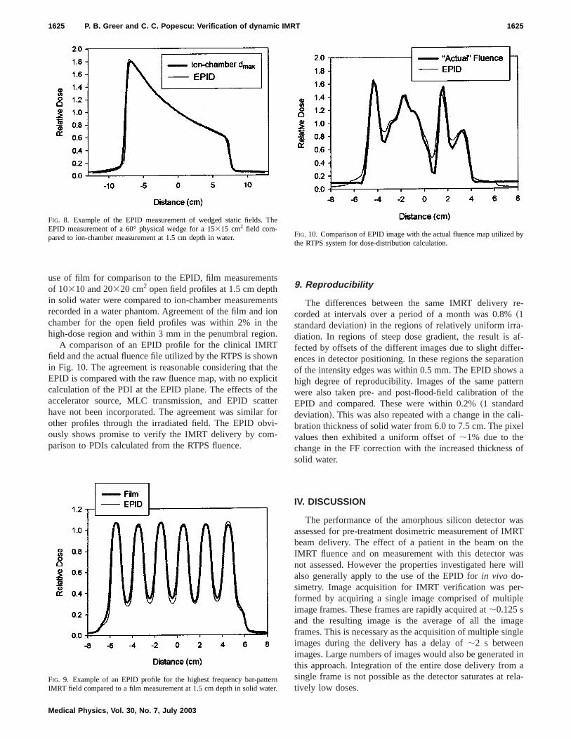
A comparison of an EPID profile for the clinical IMRTfield and the actual fluence file utilized by the RTPS is shoin Fig. 10. The agreement is reasonable considering thaEPID is compared with the raw fluence map, with no explicalculation of the PDI at the EPID plane. The effects of taccelerator source, MLC transmission, and EPID scahave not been incorporated. The agreement was similaother profiles through the irradiated field. The EPID obously shows promise to verify the IMRT delivery by comparison to PDIs calculated from the RTPS fluence.
FIG. 8. Example of the EPID measurement of wedged static fields.EPID measurement of a 60° physical wedge for a 15315 cm2 field com-pared to ion-chamber measurement at 1.5 cm depth in water.
FIG. 9. Example of an EPID profile for the highest frequency bar-pattIMRT field compared to a film measurement at 1.5 cm depth in solid wa
Medical Physics, Vol. 30, No. 7, July 2003
s
tsn
.
nheteeror-
9. Reproducibility
The differences between the same IMRT deliverycorded at intervals over a period of a month was 0.8%~1standard deviation! in the regions of relatively uniform irra-diation. In regions of steep dose gradient, the result isfected by offsets of the different images due to slight diffeences in detector positioning. In these regions the separaof the intensity edges was within 0.5 mm. The EPID showhigh degree of reproducibility. Images of the same pattwere also taken pre- and post-flood-field calibration ofEPID and compared. These were within 0.2%~1 standarddeviation!. This was also repeated with a change in the cbration thickness of solid water from 6.0 to 7.5 cm. The pixvalues then exhibited a uniform offset of;1% due to thechange in the FF correction with the increased thicknesssolid water.
IV. DISCUSSION
The performance of the amorphous silicon detector wassessed for pre-treatment dosimetric measurement of IMbeam delivery. The effect of a patient in the beam onIMRT fluence and on measurement with this detector wnot assessed. However the properties investigated herealso generally apply to the use of the EPID forin vivo do-simetry. Image acquisition for IMRT verification was peformed by acquiring a single image comprised of multipimage frames. These frames are rapidly acquired at;0.125 sand the resulting image is the average of all the imaframes. This is necessary as the acquisition of multiple sinimages during the delivery has a delay of;2 s betweenimages. Large numbers of images would also be generatethis approach. Integration of the entire dose delivery fromsingle frame is not possible as the detector saturates attively low doses.
e
nr.
FIG. 10. Comparison of EPID image with the actual fluence map utilizedthe RTPS system for dose-distribution calculation.
ntidollnilidit.itfiealt
e.FFtirao
elthaedlsgal
cto
oty-
c-di1%tha-n
leeee.aosive
f
-ousint,omm
ontr
hefo
oseit
aheis
e-e-leaf
etheosedlingith
ac-s tot-orsngead
e-pairhe
-leafectsnsamwn
h-in-
terisud-le
ambe
fortrylds
t forin
ll.
atafor
rgiespa-
e-
1626 P. B. Greer and C. C. Popescu: Verification of dynamic IMRT 1626
The calibration of the EPID with a FF image is importafor accurate dose response as all acquired images are divby the normalized FF image. This image is acquired to crect for non-uniformities in the EPID response, and ideathe input beam profile for the FF acquisition should be uform. Although the FF image acquired with 10 cm of sowater was relatively flat, the open field measurement wthis FF correction applied was higher than ion chamberpotential explanation is that the EPID over-responds wincreasing distance off-axis. This is apparent in the FF profor no buildup on the EPID which is higher off-axis than thtrue beam ‘‘horns.’’ Therefore a FF correction image thcontains an approximation to this over-response can resubetter agreement with measurement than a flat FF imag
A gradient was also introduced into the calibrationimage, potentially due to the accelerator dose-rate reducduring the acquisition of this image. To overcome this a gdient correction can be applied to all acquired images,potentially the gradient can be removed from the flood fiif this effect is reproducible and stable. The influence ofcalibration FF was also found to be important by Parset al.17 for the liquid ion-chamber EPID, where they utilize10 cm of solid water to calibrate the EPID. Software toofor the user to verify the flatness of the calibration FF imafor accurate dosimetry would be a useful addition to the cbration software module.
The change in dose with added buildup on the detecorresponds within 1.3% to percentage depth dose datasuming an inherent water-equivalent buildup of the EPID1.0 cm. This is reasonable assuming a copper plate densi8960 kg/m3, and the additional buildup from the 0.5-mmthick scintillator ~that includes a 0.18 mm polyester refletor!. There was a small increase in EPID signal with adtional buildup of 0.5 cm. However as this was less thanand as there was little change in profiles recorded withEPID, additional buildup was not utilized in this investigtion. Were the EPID to be utilized with the patient presethen buildup may be required to remove contaminant etrons from the patient.6 However for pre-treatment fluencverification, there is no requirement found here for addbuildup on the detector. If higher energies are utilized ththe requirement for buildup would have to be reassessed
The linearity of the EPID to dose and dose rate isimportant property of the amorphous silicon device as dcalibration conversion of acquired pixel values to relatdose is not required. Linear behavior was also observedprototype amorphous silicon EPIDs12,13 and for this EPIDmodel by McCurdyet al.14 The cause of the field size response observed in the present study is not clear. This cbe due to the increase in scattered radiation with increafield size. Since the scatter has a low energy componeneffect on the EPID’s phosphor response is enhanced cpared to ion chamber due to the presence of high atonumber components in the phosphor.
In static field delivery the dead time in image acquisitireduces slightly the number of frames. Accurate dosimecan be performed by multiplication of the pixel values by ttotal irradiation time or the number of frames corrected
Medical Physics, Vol. 30, No. 7, July 2003
edr-y-
hAhle
tin
on-r
dei
ei-
ras-fof
-
e
tc-
dn
ne
or
ldg
its-
ic
y
r
dead time. The dead time does not affect the relative dprofile of the image for constant dose-rate irradiation asaffects all parts of the image equally.
This is not the case for DMLC delivery where onlyportion of the detector is irradiated at a particular time. Tdead time in frame acquisition occurring every 64 framesidentified as a major limitation of this device for DMLCfields. With the rapid leaf speeds during IMRT delivery, dlays in sampling of the intensity have significant consquences. The errors observed here were over 20% for aspeed of 1.0 cm s21 with a 1 cm gapbetween the leaves. Therrors increased linearly with increasing leaf speed. Asleaf speed increases the time that a detector region is expto the beam is reduced and so a small dead time in sampbecomes more important. The error will also increase wdecreasing leaf gap for the same leaf speed.
To overcome this problem the EPID images can bequired with less than 64 frames. This however correspondonly 8 s for beam delivery. Alternatively if a large MU seting is utilized then leaf speeds will be slower and the errare kept small. A similar method was utilized by Chaet al.16 for the liquid ion-chamber device to overcome thslow image acquisition speed. The correction of this detime is difficult. The location of the major signal loss dpends upon the locations and leaf speeds of each leafduring the dead time. Obviously this is a problem that tmanufacturer will ultimately have to address.
The measurements performed for EPID response~ac-counting for the dead time! showed that the EPID can accurately record the rapid dose-rate changes that occur withspeeds of up to 2.5 cm/s. The EPID also accurately reflthe effect of beam hold-offs during the delivery. This meathat the synchronization of the image acquisition with bepulses is not crucial to accurate dosimetry. This was shoin Fig. 7 where an IMRT profile was recorded with and witout dose-rate fluctuations. The memory effect was alsovestigated and was negligible over a time interval of;15 s.It is possible that the memory effect is greater for shortime intervals. Investigation of the time decay of thmemory effect would therefore be of interest. This was stied for the liquid ion-chamber EPID by acquiring multipimages after the irradiation had finished.6 It was not possiblewith our detector system to acquire images after the behad switched off, and the delay in each image would also;2 s.
The comparison of EPID and ion-chamber resultsstatic fields show that this device is applicable to dosimeof static fields. The agreement of open and wedged fiewas within 3%. There was no energy response apparenwedged fields across the wedged direction. The variationenergy in this circumstance however is relatively smaHalf-value layers for 333 cm2 open field and 60° wedgefields at 6 MV calculated from percentage depth dose dare 11.5 and 12.5 cm, respectively. Previous workmetal/phosphor19 and amorphous silicon systems14 hasshown that the energy response increases for lower enesuch as scattered from the beam-defining system or thetient. This is potentially the reason for the higher EPID r
aorlethd
inerrethoof
so
rb
mn
lu
-gngreore
ntf
gei-ntrIDnT
oeaRCe
ofenaa
nis
ndand
gionl:
t
S.ng,io-leJ.
an,
-tedo-
.o-
-
ens,c-u-
lio-
M.lec-d
f a
n
ijn-g-
g
.at-
i-lec-
ary,
ivey,’’
nicles,’’
af
innflu-
1627 P. B. Greer and C. C. Popescu: Verification of dynamic IMRT 1627
sponse compared with ion chamber in the tails of the beevident in Figs. 1 and 8. The potential utility of the EPID fquality assurance of beam flatness, symmetry, wedge angapparent. However a deficiency of the current system isimages cannot be acquired during enhanced dynamic wedeliveries.
The agreement of EPID and film was found to be with5% for IMRT fields. This agreement is promising considing the EPID signal in this study is essentially the rawsponse of the system. The only corrections applied todata were the inherent FF and DF corrections. Further wis required to improve this for quantitative verificationIMRT. Film is currently widely utilized for IMRT verifica-tion due to its two-dimensional format and high spatial relution.
The EPID signal was found to be very reproducible oveperiod of one month. This suggests that the EPID couldutilized for absolute dose verification. This is currently hapered by the EPID recording average dose per frame andoverall dose. To obtain a measure of dose, the image vamust be externally multiplied by the number of frames~cor-rected for detector dead time! that were averaged, or alternatively the total irradiation time. The possibility of performinDMLC quality assurance is also enhanced by this findiand this is currently being investigated at our clinic. Cashould be taken when recalibrating the EPID, ensuring idtical calibration conditions, to avoid a change in the FF crection. Alternatively, we are currently investigating wheththe EPID can be utilized without regular recalibration.
The purpose of this work was to examine the fundameperformance of the amorphous silicon EPID as a detectorDMLC delivery of intensity modulated fields. The next staof this project will be to utilize this understanding to faciltate accurate dosimetric measurements. These can thecompared to predicted PDIs for pre-treatment dosimeverification of IMRT. The comparison of the measured EPimage and the actual fluence utilised by the RTPS showFig. 10 demonstrate the potential of this device for IMRdelivered fluence verification.
V. CONCLUSIONS
Several properties of an amorphous silicon EPID for dsimetry of IMRT fields were assessed. The EPID has lindose response and the signal is highly reproducible for IMverification. Sampling rate is adequate for the rapid MLleaf speeds utilized during IMRT delivery. Calibration of thEPID with a uniform input beam profile~for nonuniformsensitivity! is required for accurate dosimetry. Limitationsthe EPID system were identified including a field size depdent response, and errors due to a dead time in image fracquisition. The amorphous silicon EPID shows promisean efficient verification tool for IMRT delivery, the mailimitation at present being the dead time in frame acqution.
Medical Physics, Vol. 30, No. 7, July 2003
m
isatge
--e
rk
-
ae-otes
,en--r
alor
beic
in
-r
T
-mes
i-
ACKNOWLEDGMENTS
The authors would like to acknowledge Julie Roberts, aShawn Stapleton who developed the IMRT bar patternssoftware to produce optimal fluence maps.
a!Present address: Newcastle Mater Hospital, Locked Bag 7, Hunter ReMail Center, NSW 2310, Australia; electronic [email protected]. Rhein and P. Ha¨ring, ‘‘The IMRT phantom verification procedure aHeidelberg,’’ Radiother. Oncol.61, S2 ~2001! ~abstract!.
2C. Burman, C. Chui, G. Kutcher, S. Leibel, M. Zelefsky, T. LoSasso,Spirou, Q. Wu, J. Yang, J. Stein, R. Mohan, Z. Fuks, and C. C. Li‘‘Planning, delivery, and quality assurance of intensity-modulated radtherapy using dynamic multileaf collimator: A strategy for large-scaimplementation for the treatment of carcinoma of the prostate,’’ Int.Radiat. Oncol., Biol., Phys.39, 863–873~1997!.
3X. Wang, S. Spirou, T. LoSasso, J. Stein, C. S. Chui, and R. Moh‘‘Dosimetric verification of intensity modulated fields,’’ Med. Phys.23,317–327~1996!.
4M. Essers, M. de Langen, M. L. P. Dirkx, and B. J. M. Heijmen, ‘‘Commissioning of a commercially available system for intensity modularadiotherapy dose delivery with dynamic multileaf collimation,’’ Radither. Oncol.60, 215–224~2001!.
5K. L. Pasma, M. L. P. Dirkx, M. Kroonwijk, A. G. Visser, and B. J. MHeijmen, ‘‘Dosimetric verification of intensity modulated beams prduced with dynamic multileaf collimation using an electronic portal imaging device,’’ Med. Phys.26, 2373–2378~1999!.
6A. van Esch, B. Vanstraelen, J. Verstraete, G. Kutcher, and D. Huysk‘‘Pretreatment dosimetric verification by means of a liquid-filled eletronic portal imaging device during dynamic delivery of intensity modlated treatment fields,’’ Radiother. Oncol.60, 181–190~2001!.
7K. L. Pasma, B. J. M. Heijmen, M. Kroonwijk, and A. G. Visser, ‘‘Portadose image prediction for dosimetric treatment verification in radtherapy: An algorithm for open beams,’’ Med. Phys.25, 830–840~1998!.
8K. L. Pasma, M. Kroonwijk, J. C. J. de Boer, A. G. Visser, and B. J.Heijmen, ‘‘Accurate portal dose measurement with a fluoroscopic etronic portal imaging device~EPID! for open and wedged beams andynamic multileaf collimation,’’ Phys. Med. Biol.43, 2047–2060~1998!.
9F. F. Yin, M. C. Schell, and P. Rubin, ‘‘Input/output characteristics omatrix ion-chamber electronic portal imaging system,’’ Med. Phys.21,1447–1454~1994!.
10Y. Zhu, X.-Q. Jiang, and J. van Dyk, ‘‘Portal dosimetry using a liquid iochamber matrix: Dose response studies,’’ Med. Phys.22, 1101–1106~1995!.
11M. Essers, B. R. Hoogervorst, M. van Herk, H. Landson, and B. J. Mheer, ‘‘Dosimetric characteristics of a liquid-filled electronic portal imaing device,’’ Int. J. Radiat. Oncol., Biol., Phys.33, 1265–1272~1995!.
12P. Munro and D. C. Bouius, ‘‘X-ray quantum limited portal imaginusing amorphous silicon flat-panel arrays,’’ Med. Phys.25, 689–702~1998!.
13Y. El-Mohri, L. E. Antonuk, J. Yorkston, K. W. Jee, M. Maolinbay, K. LLam, and J. H. Siewerdsen, ‘‘Relative dosimetry using active matrix flpanel imager~AMFPI! technology,’’ Med. Phys.26, 1530–1541~1999!.
14B. M. C. McCurdy, K. B. Luchka, and S. Pistorius, ‘‘Dosimetric investgation and portal dose image prediction using an amorphous silicon etronic portal imaging device,’’ Med. Phys.28, 911–924~2001!.
15Heinrich Riem, Varian Medical Systems, Baden, Switzerland, Febru2002 ~private communication!.
16J. Chang, G. S. Mageras, C. S. Chui, C. C. Ling, and W. Lutz, ‘‘Relatprofile and dose verification of intensity modulated radiation therapInt. J. Radiat. Oncol., Biol., Phys.47, 231–240~2000!.
17H. Parsaei, E. El-Khatib, and R. Rajapakshe, ‘‘The use of an electroportal imaging system to measure portal dose and portal dose profiMed. Phys.25, 1903–1909~1998!.
18C.-S. Chui, S. Spirou, and T. LoSasso, ‘‘Testing of dynamic multilecollimation,’’ Med. Phys.23, 635–641~1996!.
19D. A. Jaffray, J. J. Battista, A. Fenster, and P. Munro, ‘‘X-ray scattermegavoltage transmission radiography: Physical characteristics and ience on image quality,’’ Med. Phys.21, 45–60~1994!.
Related Documents