DOPPLER SPEEDLOG DS-50 INSTALLATION MANUAL This manual provides the information necessary for the installation of the FURUNO DS-50 Doppler Speedlog. For best performance please follow the recommended procedures. Table of Contents SAFETY INSTRUCTIONS.................... i 1. SYSTEM CONFIGURATION........... 1 2. EQUIPMENT LISTS ........................ 3 3. OVERVIEW ................................... 12 4. MOUNTING ................................... 15 5. WIRING ......................................... 24 6. INITIAL SETTING.......................... 31 7. CHANGING POWER SUPPLY SPECIFICATION ............................... 35 8. LIST OF DIP SWITCH SETTING .. 37 OUTLINE DRAWINGS .................... D-1 INTERCONNECTION DIAGRAMS ..S-1 All brand and product names are trademarks, registered trademarks or service marks of their respective holders. www.furuno.co.jp

Welcome message from author
This document is posted to help you gain knowledge. Please leave a comment to let me know what you think about it! Share it to your friends and learn new things together.
Transcript

DOPPLER SPEEDLOG DS-50 INSTALLATION MANUAL
This manual provides the information necessary for the installation of the FURUNO DS-50 Doppler Speedlog. For best performance please follow the recommended procedures.
Table of Contents
SAFETY INSTRUCTIONS.................... i
1. SYSTEM CONFIGURATION........... 1
2. EQUIPMENT LISTS ........................ 3
3. OVERVIEW ................................... 12
4. MOUNTING ................................... 15
5. WIRING ......................................... 24
6. INITIAL SETTING.......................... 31
7. CHANGING POWER SUPPLY SPECIFICATION ............................... 35
8. LIST OF DIP SWITCH SETTING .. 37
OUTLINE DRAWINGS .................... D-1
INTERCONNECTION DIAGRAMS ..S-1
All brand and product names are trademarks, registered trademarks or service marks of their respective holders.www.furuno.co.jp
miyosi

The paper used in this manualis elemental chlorine free.
・FURUNO Authorized Distributor/Dealer
9-52 Ashihara-cho,Nishinomiya, 662-8580, JAPAN
Telephone : +81-(0)798-65-2111
Fax : +81-(0)798-65-4200
A : JUN 1996.Printed in JapanAll rights reserved.
Q : SEP . 16, 2009Pub. No. IME-72410-Q
*00080757011**00080757011*(TATA ) DS-50*00080757011**00080757011** 0 0 0 8 0 7 5 7 0 1 1 *

ii

DISTRIBUTION BOXMD-550
TERMINAL BOXDS-802
DISTANCE INDICATORDS-840
Note: When Processor Unit DS-510 is used Transceiver Unit is incorporated in the DS-510.

DISTRIBUTION BOXMD-550
TERMINAL BOXDS-802
DISTANCE INDICATORDS-840

3
2. EQUIPMENT LISTS
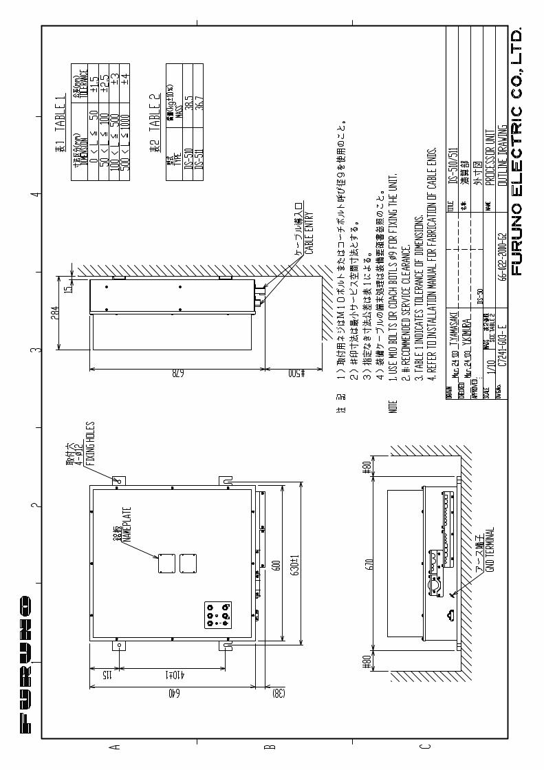
Standard Supply No. Name Type Qty Remarks 1 Main Display DS-500 1 Flush mount/Bulkhead mount
2 Processor Unit DS-510/511 1 Bulkhead mount/Deck mount, DS-510 incorporates DS-520
3 Transceiver Unit DS-520 1 Bulkhead mount/Deck mount, required only with DS-511
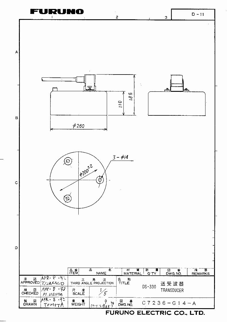
4 Transducer DS-530 1 5 Tank DS-531 1
SP65-00400 For DS-510 6 Spare Parts SP65-00410
1 setFor DS-511
CP65-00700 For DS-510 7 Installation Materials CP65-00710
1 setFor DS-511
Optional Supply No. Name Type Code No. Remarks
1 Installation materials for bulkhead mount
CP65-00704 002-886-970 For main display unit
2 Gate Valve DS-532 000-028-993 Including installation materials
3 Gate Valve Inst. Materials MF-220-C-6 000-069-367 For gate valve, option
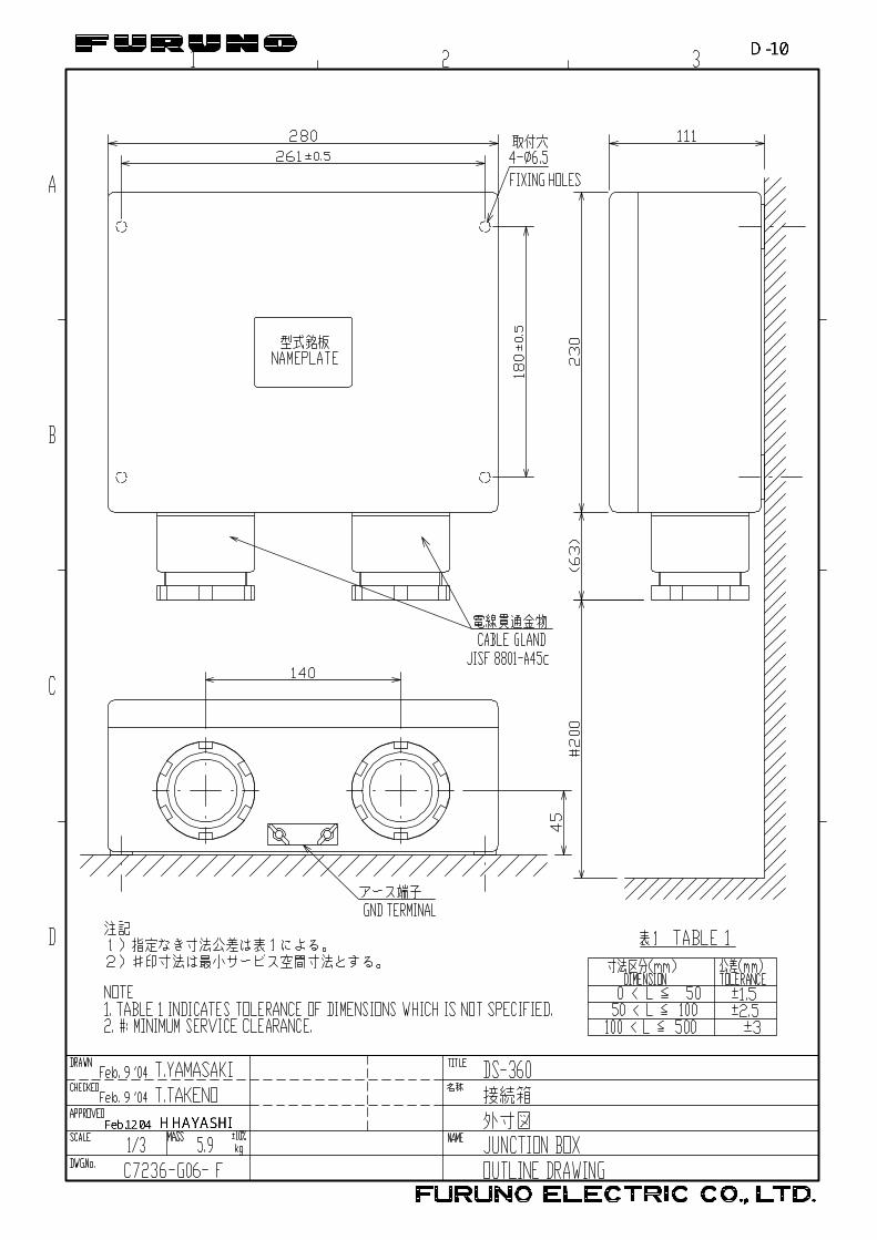
4 Operation Panel DS-501 Including installation materials CI-630 5 Junction Box DS-360 000-027-994
Including installation materials CP66-00703: 006-927-330
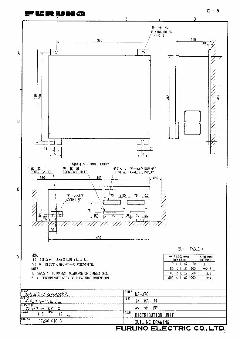
6 Distribution Box DS-370 Bulkhead mount/Deck mount DS-350 Waterproof construction 7 Digital Indicator DS-351 Indoor use DS-381 Flush mount DS-382 Bulkhead mount MF-22A FE-90 Flush mount
8 Analog Indicator
FL-90 Flush mount DS-389 9 Range Switch Box MF-22R
4
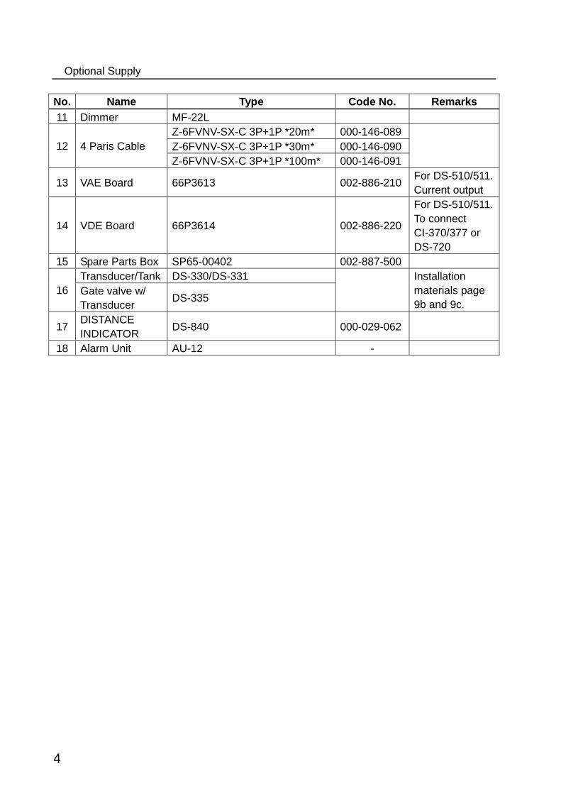
Optional Supply No. Name Type Code No. Remarks 11 Dimmer MF-22L
Z-6FVNV-SX-C 3P+1P *20m* 000-146-089 Z-6FVNV-SX-C 3P+1P *30m* 000-146-090 12 4 Paris Cable Z-6FVNV-SX-C 3P+1P *100m* 000-146-091
13 VAE Board 66P3613 002-886-210 For DS-510/511.Current output
14 VDE Board 66P3614 002-886-220
For DS-510/511.To connect CI-370/377 or DS-720
15 Spare Parts Box SP65-00402 002-887-500 Transducer/Tank DS-330/DS-331
16 Gate valve w/ Transducer DS-335
Installation materials page 9b and 9c.
17 DISTANCE INDICATOR DS-840 000-029-062
18 Alarm Unit AU-12 -

CODE NO. 002-885-350-00
TYPE CP65-00701
略 図
OUTLINE
名 称
NAME
数量
Q'TY用途/備考
REMARKS
番 号
NO.
型名/規格
DESCRIPTIONS
1/1
-2
INSTALLATION MATERIALS
工事材料表
65AC-X-9401
+トラスタッピンネジ 1シュ
SELF-TAPPING SCREW5X16 SUS304 1種 4
000-805-494-00
1
CODE NO.
5X16 SUS304
000-162-607-10
圧着端子
CRIMP-ON LUGFV1.25-M3(LF) 18
000-166-740-10
2
CODE NO.
CODE NO. 002-885-360-00
TYPE CP65-00711
略 図
OUTLINE
名 称
NAME
数量
Q'TY用途/備考
REMARKS
番 号
NO.
型名/規格
DESCRIPTIONS
1/1
-3
INSTALLATION MATERIALS
工事材料表
65AC-X-9407
ハリマーク TB5
STICKER66-022-2102-1
1
100-237-961-00
1
CODE NO.
66-022-2102-1 ROHS
100-237-961-10
圧着端子
CRIMP-ON LUGFV1.25-M3(LF)
100
000-166-740-10
2
CODE NO.
圧着端子
CRIMP-ON LUGFV1.25-M4 アカ
18
000-536-715-00
3
CODE NO.
FV1.25-M4(LF)
000-166-741-10
圧着端子
CRIMP-ON LUGFV2-M4
3
000-536-716-00
4
CODE NO.
FV2-M4
000-157-229-10
コネクタ(SRCN)
CONNECTOR(SRCN)SRCN6A16-10P
2
000-160-728-10
5
CODE NO.
emiyoshi
テキストボックス
5


CODE NO. 002-885-670-00
TYPE CP65-00702
略 図
OUTLINE
名 称
NAME
数量
Q'TY用途/備考
REMARKS
番 号
NO.
型名/規格
DESCRIPTIONS
1/1
-4
INSTALLATION MATERIALS
工事材料表
65AC-X-9405
平座金
FLAT WASHERM10 SUS316L 3
000-147-299-00
1
CODE NO.
M10 SUS316L
000-167-416-10
バネ座金
SPRING WASHERM10 SUS316L 3
000-147-303-00
2
CODE NO.
M10 SUS316L
000-167-389-10
六角ボルト 全ネジ
HEX.BOLTM10X120 SUS316L 3
000-162-962-10
3
CODE NO.
(略図の寸法は、参考値です。 DIMENSIONS IN DRAWING FOR REFERENCE ONLY.)
FURUNO ELECTRIC CO .,LTD. 65AC-X-9405
型式/コード番号が2段の場合、下段より上段に代わる過渡期品であり、どちらかが入っています。 なお、品質は変わりません。
TWO TYPES AND CODES MAY BE LISTED FOR AN ITEM. THE LOWER PRODUCT MAY BE SHIPPED IN PLACE OF THE UPPER PRODUCT. QUALITY IS THE SAME.
emiyoshi
テキストボックス
7

CODE NO. 000-028-995-00
TYPE CP65-00720
略 図
OUTLINE
名 称
NAME
数量
Q'TY用途/備考
REMARKS
番 号
NO.
型名/規格
DESCRIPTIONS
1/1
-11
INSTALLATION MATERIALS
工事材料表
65AC-X-9403
パッキン.2.
PACKING65-002-1004-0 ROHS
1
850-210-040-10
1
CODE NO.
Oリング
O-RINGJB1AG-280
1
000-851-348-00
2
CODE NO.
バネ座金
SPRING WASHERM12 SUS316L
12
000-167-396-10
3
CODE NO.
六角ボルト 全ネジ
HEXAGONAL HEAD BOLTM12X150 SUS316L
12
000-162-791-10
4
CODE NO.
バネ座金
SPRING WASHERM22 SUS316L
24
000-167-403-10
5
CODE NO.
六角ナット
HEX.NUTM22 SUS316L
24
000-167-472-10
6
CODE NO.
六角ボルト
HEX.BOLTM22X70LX50S SUS316L
12
000-162-827-10
7
CODE NO.
六角ボルト
HEX.BOLTM22X80LX50S SUS316L
12
000-162-857-10
8
CODE NO.
コスモグリスダイナマックス
GREASENo.1 400ジャバラチューヴ
1
000-165-774-10
9
CODE NO.
(略図の寸法は、参考値です。 DIMENSIONS IN DRAWING FOR REFERENCE ONLY.)
FURUNO ELECTRIC CO .,LTD. 65AC-X-9403
型式/コード番号が2段の場合、下段より上段に代わる過渡期品であり、どちらかが入っています。 なお、品質は変わりません。
TWO TYPES AND CODES MAY BE LISTED FOR AN ITEM. THE LOWER PRODUCT MAY BE SHIPPED IN PLACE OF THE UPPER PRODUCT. QUALITY IS THE SAME.
emiyoshi
テキストボックス
8

CODE NO. 002-885-370-00
TYPE CP65-00703
略 図
OUTLINE
名 称
NAME
数量
Q'TY用途/備考
REMARKS
番 号
NO.
型名/規格
DESCRIPTIONS
1/1
-3
INSTALLATION MATERIALS
工事材料表
65AC-X-9404
DS-50
+バインドタッピン1シュ
+TAPPING SCREW4X16 SUS304
4
000-163-914-10
1
CODE NO.
圧着端子
CRIMP-ON LUGFV1.25-M4(LF)
7
000-166-741-10
2
CODE NO.
CODE NO. 002-886-970-00
TYPE CP65-00704
略 図
OUTLINE
名 称
NAME
数量
Q'TY用途/備考
REMARKS
番 号
NO.
型名/規格
DESCRIPTIONS
1/1
-2
INSTALLATION MATERIALS
工事材料表
65AC-X-9406
DS-50
六角スリワリ セムスB
HEX.HEAD SLOT BOLT-B WASHER
M6X12 SUS3044
000-162-946-10
1
CODE NO.
取付足
MOUNTING PLATE66-019-5571-0
2
カラー選択有り TO BE SELECTED BY COLOR
100-178-670-00
2
CODE NO.
66-019-5571-0 ROHS
100-178-670-10
emiyoshi
テキストボックス
9a

CODE NO. 002-876-310-00
TYPE CP66-00840
略 図
OUTLINE
名 称
NAME
数量
Q'TY用途/備考
REMARKS
番 号
NO.
型名/規格
DESCRIPTIONS
1/2
-9
INSTALLATION MATERIALS
工事材料表
66AM-X-9415
防水ゴム
RUBBER PACKING66-019-1202-0 ROHS
1
100-178-550-10
1
CODE NO.
座金
COUNTERSUNK WASHER66-019-1203-1 ROHS
1
100-178-561-10
2
CODE NO.
ケーブルグランド
CABLE GLAND66-019-1204-1 ROHS
1
100-178-571-10
3
CODE NO.
平座金
FLAT WASHER66-019-1205-1 ROHS
3
100-176-531-10
4
CODE NO.
キャップ
LID66-019-1983-1
3
100-176-521-00
5
CODE NO.
六角ボルト
HEX.BOLT66-019-1984-3 ROHS
3
100-214-533-10
6
CODE NO.
バネ座金
SPRING WASHERM12 SUS316L
6
000-167-396-10
7
CODE NO.
平座金
FLAT WASHERM6 TP340
2
000-168-314-10
8
CODE NO.
六角ナット 1シュ
HEX.NUTM6 TW340
2
000-168-315-10
9
CODE NO.
スプリングワッシャ
SPRING WASHERM6 チタン(TB340)
2
000-168-316-10
10
CODE NO.
(略図の寸法は、参考値です。 DIMENSIONS IN DRAWING FOR REFERENCE ONLY.)
FURUNO ELECTRIC CO .,LTD. 66AM-X-9415
型式/コード番号が2段の場合、下段より上段に代わる過渡期品であり、どちらかが入っています。 なお、品質は変わりません。
TWO TYPES AND CODES MAY BE LISTED FOR AN ITEM. THE LOWER PRODUCT MAY BE SHIPPED IN PLACE OF THE UPPER PRODUCT. QUALITY IS THE SAME.
emiyoshi
テキストボックス
9b

CODE NO. 002-876-310-00
TYPE CP66-00840
略 図
OUTLINE
名 称
NAME
数量
Q'TY用途/備考
REMARKS
番 号
NO.
型名/規格
DESCRIPTIONS
2/2
-9
INSTALLATION MATERIALS
工事材料表
66AM-X-9415
六角スリワリ ボルト
HEX.BOLTM6X30 SUS316L
1
000-150-024-00
11
CODE NO.
M6X30 SUS316L
000-162-907-10
CODE NO. 002-884-990-00
TYPE SP66-00512
ITEM NO.
NAME OF PART OUTLINE
DWG. NO.
OR
PERSET
PERVES
SPARE
WORKING
QUANTITY REMARKS/CODE NO.
BOX NO. P
SHIP NO. SPARE PARTS LIST FOR U S ESETS PER VESSEL
-1
TYPE NO.
66AM-X-9315 1/1
締付ハンドル
66-019-1253-1
1TIGHTENING HANDLE
100-176-501-00
1
シリコングリス
G30M
1SILICONE GREASE
000-824-012-00
2
G-30M-100
000-169-306-10
9c
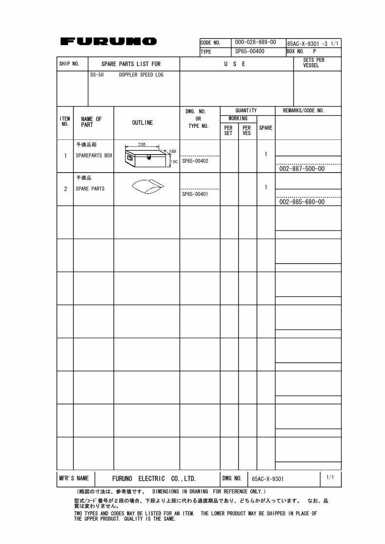
CODE NO. 000-028-989-00
TYPE SP65-00400
ITEM NO.
NAME OF PART OUTLINE
DWG. NO.
OR
PERSET
PERVES
SPARE
WORKING
QUANTITY REMARKS/CODE NO.
BOX NO. P
SHIP NO. SPARE PARTS LIST FOR U S ESETS PER VESSEL
-3
TYPE NO.
65AC-X-9301 1/1
DS-50 DOPPLER SPEED LOG
予備品箱
SP65-00402
1SPAREPARTS BOX
002-887-500-00
1
予備品
SP65-00401
1SPARE PARTS
002-885-680-00
2
1/1MFR'S NAME FURUNO ELECTRIC CO.,LTD. DWG NO.
(略図の寸法は、参考値です。 DIMENSIONS IN DRAWING FOR REFERENCE ONLY.)
65AC-X-9301
型式/コード番号が2段の場合、下段より上段に代わる過渡期品であり、どちらかが入っています。 なお、品質は変わりません。
TWO TYPES AND CODES MAY BE LISTED FOR AN ITEM. THE LOWER PRODUCT MAY BE SHIPPED IN PLACE OF THE UPPER PRODUCT. QUALITY IS THE SAME.
emiyoshi
テキストボックス
10

CODE NO. 000-028-990-00
TYPE SP65-00410
ITEM NO.
NAME OF PART OUTLINE
DWG. NO.
OR
PERSET
PERVES
SPARE
WORKING
QUANTITY REMARKS/CODE NO.
BOX NO. P
SHIP NO. SPARE PARTS LIST FOR U S ESETS PER VESSEL
-3
TYPE NO.
65AC-X-9302 1/1
DS-50 DOPPLER SPEED LOG
予備品箱
SP65-00402
1SPAREPARTS BOX
002-887-500-00
1
予備品
SP66-00503
1SPARE PARTS
002-876-340-00
2
予備品
SP65-00401
1SPARE PARTS
002-885-680-00
3
1/1MFR'S NAME FURUNO ELECTRIC CO.,LTD. DWG NO.
(略図の寸法は、参考値です。 DIMENSIONS IN DRAWING FOR REFERENCE ONLY.)
65AC-X-9302
型式/コード番号が2段の場合、下段より上段に代わる過渡期品であり、どちらかが入っています。 なお、品質は変わりません。
TWO TYPES AND CODES MAY BE LISTED FOR AN ITEM. THE LOWER PRODUCT MAY BE SHIPPED IN PLACE OF THE UPPER PRODUCT. QUALITY IS THE SAME.
emiyoshi
テキストボックス
11

PACKING LIST 65AD-X-9853 -6
DS-840/HK
N A M E O U T L I N E DESCRIPTION/CODE Q'TY
1/1
ユニット UNIT
航程計
REMOTE DISTANCE INDICATORDS-840/DS-840-HK
000-029-022-00
1
**
付属品 ACCESSORIES
フラッシュマウントF
FLUSH MOUNTING PANELFP65-00401
002-889-360-00
1
付属品 ACCESSORIES
フラッシュマウントS
FLUSH MOUNTING PANELFP65-00402
002-889-370-00
1
付属品 ACCESSORIES
付属品
ACCESSORIESFP65-00403
002-889-380-00
1
工事材料 INSTALLATION MATERIALS
工事材料
INSTALLATION MATERIALSCP65-00801
002-889-350-00
1
その他工材 OTHER INSTALLATION MATERIALS
ケーブル組品MJ
CABLE ASSY.MJ-A7SPF0009-020C
000-159-686-10
1
ケーブル組品MJ
CABLE ASSY.MJ-A6SPF0013-020C
000-159-701-10
1
注記) 1.コ-ド番号末尾の[**]は、選択部品の代表コ-ド番号を表します。
CODE NUMBER ENDED BY "**" INDICATES THE NUMBER OF TYPICAL MATERIAL.
(略図の寸法は、参考値です。 DIMENSIONS IN DRAWING FOR REFERENCE ONLY.) 65AD-X-9853
型式/コード番号が2段の場合、下段より上段に代わる過渡期品であり、どちらかが入っています。 なお、品質は変わりません。
TWO TYPES AND CODES MAY BE LISTED FOR AN ITEM. THE LOWER PRODUCT MAY BE SHIPPED IN PLACE OF THE UPPER PRODUCT. QUALITY IS THE SAME.
emiyoshi
テキストボックス
11a


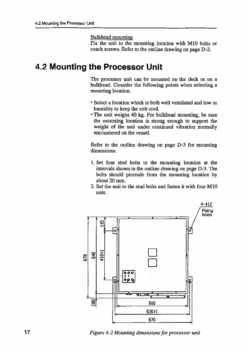
15
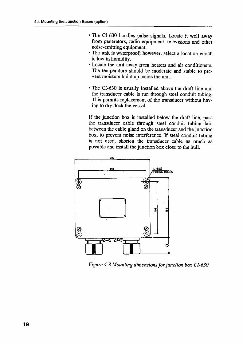
4.MOUNTING
NOTICEDo not apply paint, anti-corrosive sealantor contact spray to coating or plastic parts of the equipment.
Those items contain organic solvents that can damage coating and plastic parts, especially plastic connectors.
4.1 Mounting the Main Display
The main display can be mounted in a panel(flush mount)or on a bulkhead.Consider the following Points when selecting a mounting. • Select a location where the display can be easily viewed and
operated.
• Select a location out of direct sunlight and free of water Splash.
• The unit weighs 4.5kg.Be sure the mounting location is strong enough to support the weight of the unit.
Flush mounting
Refer to the outline drawing on page D-1 for mounting dimensions. 1. Prepare a cutout in the mounting location referring to Figurer2.1
on the next page. 2.Unfasten four bolts on the front panel to separate the front panel
from the chassis. Save the bolts for later use. 3.Set the chassis to the mounting location and fasten with four
tapping screws (5x16). Note:Leave sufficient slack in cabling so the unit can drawn out
for maintenance and servicing. 4.Connect wires to the terminal strip referring to the next chapter. 5.Fasten the front panel to the chassis with four bolts removed at
step2・


yotamura
長方形
yotamura
長方形


24
5. WIRING
5.1 Remarks on Cabling 1. Cable between transducer and transceiver unit This cable carries very weak signals having amplitude of less than 0.1 µV, which are easily interfered by noise. There fore, dedicate steel conduit tubing exclusively for this cable. For the conduit which runs vertically, line it with vibration absorbing material prevent cable vibration. Cable to use
Cable Name Z-6FVN-SX 3P+1P Outer diameter 18.7 ± 0.5 mm Weight 450 kg/km Outer sheath Rubber Armor None 2. Cables between transceiver unit and processor unit (via junction
box DS-360) These cable carries echoes signal having amplitude of greater than 0.1 mV, which can be interfered by noise from high power electrical power cables. Therefore, do not run these cables through steel conduit tubing with the following cables: • Cable carrying more than a few kilowatts of power to fluctuating loads. • Cable carrying switching waves generated by thyristor, etc. • Transmission antenna cable of radio equipment.
Observe also the guidelines given for “3. Other cables.” Cable to use
Cable Name TTYCY-19S Outer diameter 38.8 ± 1.6 mm Weight 2050 kg/km 3. Other cables Observe the guidelines which follow to prevent noise and interference • When cables run parallel with power cables, separate them 40 cm minimum. • For cables run into non-metallic conduit tubing or duct behind a bulkhead, use cable
with armor and no protective covering and ground it every 50 cm.

5.2 Cable Fabrication
25
5.2 Cable Fabrication 1. Transducer cable
Shorten considering location on terminal strip
Insulating tubing
FV1.25-4
FV1.25-4
FV1.25-4
Taping
Rubber gasket
Taping
Gland
To #16 terminal on terminal strip
Figure 5-1 Fabrication of transducer cable 2. Cable between transceiver unit, junction box and processor unit
(TTYCY-19S) 1) Transceiver unit/ junction box
Anticorrosive sheath
Rubber gasket
FV1.25-4
Washer Armor
Note: 1. Unravel shield only near terminal strip.2. Fold back armor onto
washer and insert between washer and gland.
Figure 5-2 Cable fabrication 2) Processor unit
Cores and shields are fabricated the same as on transceiver unit/junction box side. To ground the cable, remove paint from the armor and set the armor in the cable clamp.
Figure 5-3 Cable fabrication
5.2 Cable Fabrication
26
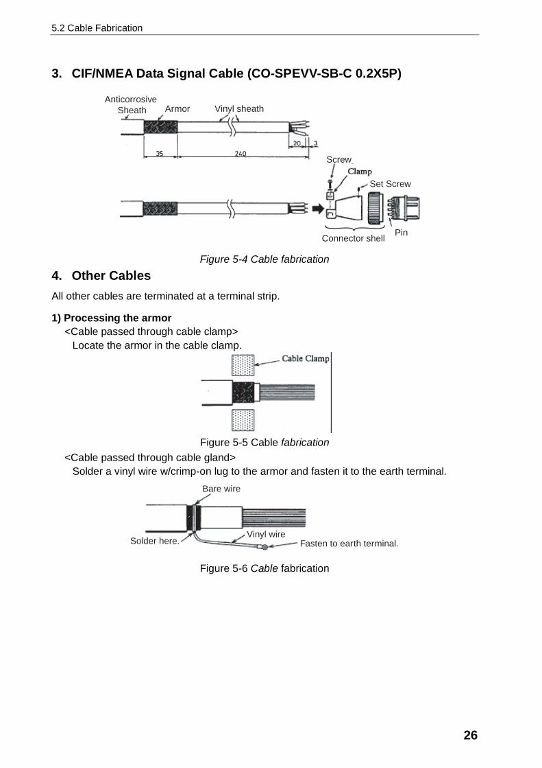
3. CIF/NMEA Data Signal Cable (CO-SPEVV-SB-C 0.2X5P)
Anticorrosive Sheath Armor Vinyl sheath
PinConnector shell
Set Screw
Screw
Figure 5-4 Cable fabrication 4. Other Cables All other cables are terminated at a terminal strip.
1) Processing the armor <Cable passed through cable clamp>
Locate the armor in the cable clamp.
Figure 5-5 Cable fabrication
<Cable passed through cable gland> Solder a vinyl wire w/crimp-on lug to the armor and fasten it to the earth terminal.
Bare wire
Solder here.Vinyl wire
Fasten to earth terminal.
Figure 5-6 Cable fabrication

5.2 Cable Fabrication
27
2) Processing the shield <Individual shields>
Undo individual shields only near the terminal strip to which its wire is connected. Tape shields for insulation.
Vinyl tape
Individual shield
Figure 5-7 Cable fabrication <Common shield>
Undo individual shields only near the terminal strip to which its wire is connected. Tape shields for insulation.
Common shield
Vinyl Tape
Figure 5-8 Cable fabrication

5.2 Cable Fabrication
28
5. Insulation of cables for transducer When installing of the Transducer Unit DS-330 (option), check insulation as shown in the procedure below. Insulation check
1. Remove all cores and shields of the transducer from the terminal board. All wires of the transducer are open.
2. Set the multimeter to the maximum resistance range and measure the resistance between each transducer line (TD1, TD2, TD3) and individual or common shield.
Multimeter
Red
BlackCable of
transducer
TD Black
TD Red
TD Green
Temperature Sensor 1 Yellow, White
Temperature Sensor Blue, Grey
Red
Black
Red
Black
Measurement places - polarity lead - polarity lead Resistance value for insulation
Red wire of black sheath
Shield in black sheath
Red wire of black sheath
Common shield
Red wire of red sheath
Shield in red sheath
Red wire of red sheath
Common shield
Red wire of green sheath
Shield in green sheath
Red wire of green sheath
Common shield
Digital multimeter: More than 10MΩ. Analog multimeter: Needle does not swing.
Note) If rating is not met at a location, suspect faulty insulation. Replace a new one.

5.3 Remarks on Connection of Other Equipment
29
5.3 Remarks on Connection of Other Equipment 1. KP input Signal for reject interference When a TX trigger pulse (KP) input to the system is giving off interference, note the following.
1) Interference Rejection Signal Input Circuit Two iuput ports are provided in the processor unit for connection of KP for interference rejection. Use either port.
1
2
3
4
5
6
TB3
External KP1
4mA
4mA
22Ω
22Ω
22Ω
22ΩExternal KP2
Figure 5-9 KP input circuit
2) Current Requirement Recommended current is 4 mA while the circuit operates normally at 2 mA to 20 mA. Adjust resistance of output circuit in equipment connected to obtain recommended current.
3) Signal logic Use signal logic equivalent to electric current flow when the system is transmitting.
5.3 Remarks on Connection of Other Equipment
30
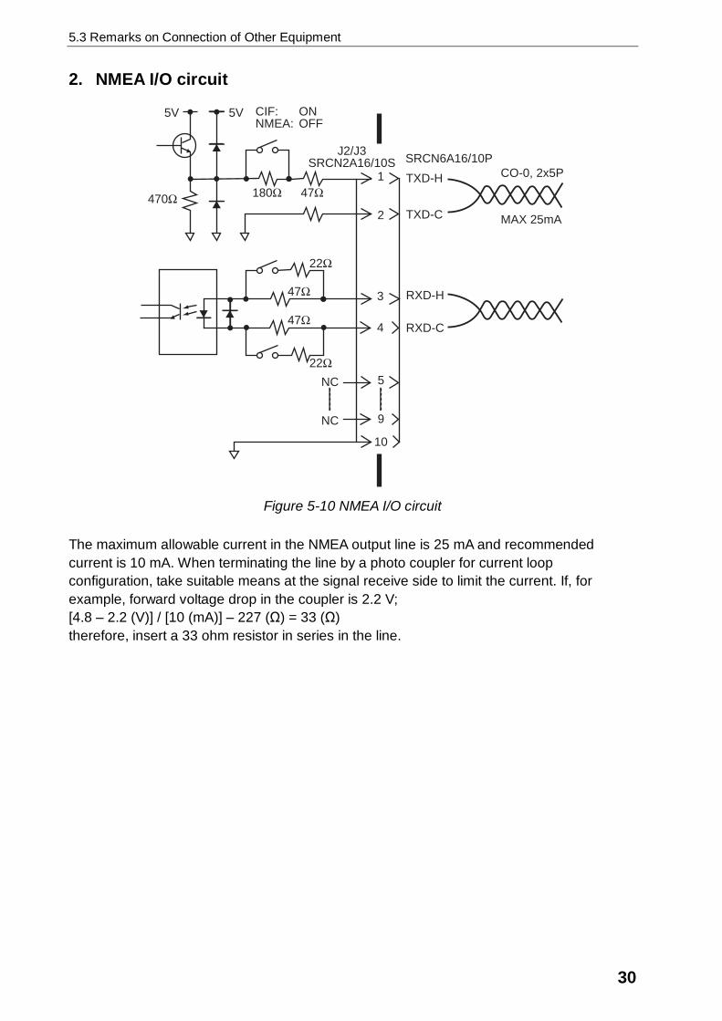
2. NMEA I/O circuit
1
2
3
4
5
9
10
NC
NC
TXD-H
TXD-C
RXD-H
RXD-C
5V 5V
470Ω 180Ω 47Ω
CIF: ONNMEA: OFF
J2/J3SRCN2A16/10S SRCN6A16/10P
CO-0, 2x5P
MAX 25mA
22Ω
47Ω
47Ω
22Ω
Figure 5-10 NMEA I/O circuit
The maximum allowable current in the NMEA output line is 25 mA and recommended current is 10 mA. When terminating the line by a photo coupler for current loop configuration, take suitable means at the signal receive side to limit the current. If, for example, forward voltage drop in the coupler is 2.2 V; [4.8 – 2.2 (V)] / [10 (mA)] – 227 (Ω) = 33 (Ω) therefore, insert a 33 ohm resistor in series in the line.

Board Jumper Function Setting
VMT Board66P3611
JP4JP5JP6JP7JP8
Analog indicatorselection
Distributor selection
JP4:1,3 JP7:1,3JP5:1,3 JP8:1JP6:1,3
JP4:2,4 JP7:2,4JP5:2,4 JP8:2JP6:2,4
Remove VOC Board(66P3612) and MCNA Board(66P3616) to access the Jumpers under the MCNA board.


This page is intentionally left blank.

37
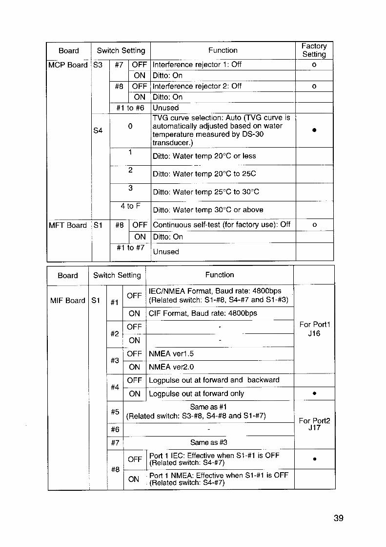
8. LIST OF DIP SWITCH SETTINGS
DIP Switch Location
The DIP switches are located on the boards shown in the table below.
tinU draoB hctiwSPID005-SDtinUyalpsiD draoBPCV )ffolla(1S
115/015-SDtinUrossecorP draoBPCM 4S,3S,2S,1SdraoBTFM 1S
draoBFIM )esuon:6Sdna5S,2S(,4S,3S,1S
Setting and Function of DIP Switch
™: Do not change setting.¡: Change setting as required.


40
draoB gnitteShctiwS noitcnuF yrotcaFgnitteS
draoBFIM 4S 1# 2# noitceleseslupnurecnatsidrofdeepss'pihS
FFO FFO &retaw-hguorhtdeeps&dnuorg-eht-revodeepSrosnesvanmorfdefdeeps
FFO NO retaw-hguorhtdeeps&dnuorg-eht-revodeepS
NO - dnuorg-eht-revodeepS
6#ot3# desunU
7# FFO ).3#-1S:hctiwsdetaleR(0.2ro5.1reVAEMN:1troP
NO)NO:8#-1S(0.3.reVAEMN:1troP
)FFO:8#-1S(2dE1-26116CEI:1troP ¡
8# FFO ).7#-1S:hctiwsdetaleR(0.2ro5.1reVAEMN:2troP
NO)NO:8#-3S(0.3.reVAEMN:2troP
)FFO:8#-3S(2dE1-26116CEI:2troP ¡
3S 8#FFO FFOsi5#-1SnehwevitceffE:CEI2troP
)8#-4S:hctiwsdetaleR( ¡
NO FFOsi5#-1SnehwevitceffE:AEMN2troP)8#-4S:hctiwsdetaleR(
Setting of CIF/NMEA(1) and CIF/NMEA(2) portsYou can choose output data format among IEC, NMEA and CIF.
gnitteS
1troP.AEMNroCEI,FICroftamroftuptuotceleS
)AEMN(CEI/FIC AEMN/CEI reV)AMEN(CEI reV)AEMN(CEI
1#-1S 8#-1S 7#-4S 3#-1S
FIC NO - - -
2dE1-26116CEI FFO FFO NO -
0.3reVAEMN FFO NO NO -
0.2reVAEMN FFO NO FFO NO
5.1reVAEMN FFO NO FFO FFO
gnitteS
2troP.AEMNroCEI,FICroftamroftuptuotceleS
)AEMN(CEI/FIC AEMN/CEI reV)AMEN(CEI reV)AEMN(CEI
5#-1S 8#-3S 8#-4S 7#-1S
FIC NO - - -
2dE1-26116CEI FFO FFO NO -
0.3reVAEMN FFO NO NO -
0.2reVAEMN FFO NO FFO NO
5.1reVAEMN FFO NO FFO FFO


KIMURA
Mar. 27 '03
KIMURA
三好 悦子
D-2
KIMURA
Mar. 27 '03
KIMURA
三好 悦子
D-3

hhayashi
H.HAYASHI
hhayashi
hhayashi
Feb. 12' 04
三好 悦子
D-4


Dec.17'07 R.Esumi
emiyoshi
テキストボックス
D-6


This page is intentionally left blank.

yhatai
テキストボックス
Y. Hatai
emiyoshi
テキストボックス
D-8
hhayashi
hhayashi
H.HAYASHI
hhayashi
Feb.12'04
三好 悦子
D-10

電子署名
者 :
T.
Mat
sugu
ch
emiyoshi
テキストボックス
D-12

miyazawa
D-13

miyazawa
D-14

miyazawa
D-15

This page is intentionally left blank.
kg
TITLE
MASS
A
B
C
D
NAME
名前
654321
APPROVED
SCALE
CHECKED
DRAWN
INTERCONNECTION DIAGRAM
CO-0.2x5P: CO-SPEVV-SB-C 0.2x5P,φ13.5
MF-22L詳細
表1 TABLE 1
DETAIL FOR MF-22L
相互結線図
調光器
アナログ指示器
3kΩ/25W
3kΩ/25W
MF-22LDIMMER
DARK BRIGHT
(for 200-240V)
INDICATORANALOG
200-240VAC100-120/ U
VL
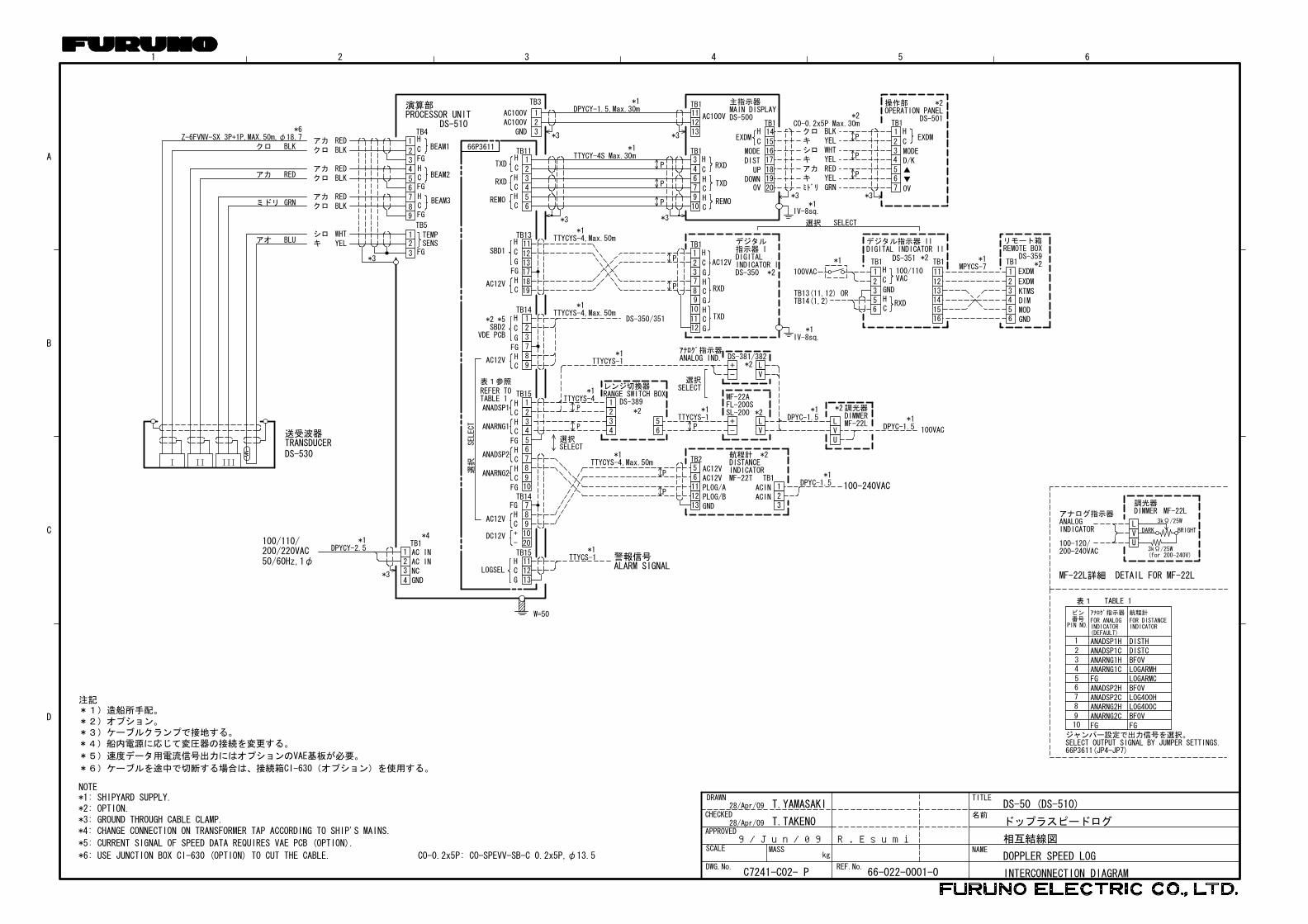
DS-50 (DS-510)
ドップラスピードログ
DOPPLER SPEED LOG
ジャンパー設定で出力信号を選択。SELECT OUTPUT SIGNAL BY JUMPER SETTINGS.66P3611(JP4-JP7)
PIN NO.
ピン番号
アナログ指示器
INDICATORFOR ANALOG
FGBF0VLOG400CLOG400HBF0VLOGARMCLOGARMHBF0VDISTCDISTH
FGANARNG2CANARNG2HANADSP2CANADSP2HFGANARNG1CANARNG1H
ANADSP1HANADSP1C
10
65
4
23
1
78
9
(DEFAULT)
航程計
FOR DISTANCEINDICATOR
NOTE
注記*1)造船所手配。*2)オプション。*3)ケーブルクランプで接地する。*4)船内電源に応じて変圧器の接続を変更する。
*5)速度データ用電流信号出力にはオプションのVAE基板が必要。
*6)ケーブルを途中で切断する場合は、接続箱CI-630(オプション)を使用する。
*1: SHIPYARD SUPPLY.*2: OPTION.*3: GROUND THROUGH CABLE CLAMP.*4: CHANGE CONNECTION ON TRANSFORMER TAP ACCORDING TO SHIP'S MAINS.
*5: CURRENT SIGNAL OF SPEED DATA REQUIRES VAE PCB (OPTION).
*6: USE JUNCTION BOX CI-630 (OPTION) TO CUT THE CABLE.
W=50
*2
DIGITAL INDICATOR IIデジタル指示器 II
56
3
1
2GND
RXDCH
H
C
TB1DS-359
リモート箱REMOTE BOX
DIMMOD
EXDM
KTMS
EXDM
4
65
1
32
14
1615
11
1312
*1MPYCS-7
TB1TB1*3
アオ
ミドリ
アカ
クロ BLK
RED
GRN
BLU キシロ
クロアカ
クロアカ
クロアカ
WHTYEL
REDBLK
BLKRED
BLKRED
1
3
21
2
6
89
7
4
5
3
TB5TEMP
FGSENS
TB4
HC
C
H
BEAM2
BEAM3
BEAM1
HC
FG
FG
FG
66P3611
RXD
REMO
TXD
TB11
C
HCHC
H
*1TTYCY-4S Max.30m
*1DPYCY-1.5,Max.30m
TB14
*2DS-351
選択
SELECT
警報信号TB15111213
LOGSEL
TB14
8
20
7
109
DC12V
AC12V
TB15
10
65
4
23
1
78
9
表1参照
TABLE 1REFER TO
*2 *5
VDE PCBSBD2
AC12V
FGHC
H
C
G
HCHC
HCHC
ANADSP1
ANARNG1
ANADSP2
ANARNG2
FG
FG
RXD
TXD
REMO
H
HC
C
C
H
AC100V
TB1
TB1
3467910
111213
P
TB1
23
1
G
C
H
89
7
1211
10GCH
HCG
RXD
TXD
IV-8sq.
AC12V
*2
DIGITALINDICATOR I
デジタル指示器 I
DS-3501819
17
1213
11TB13
AC12V
FGHC
SBD1H
C
G
P
*1TTYCS-1
123456
主指示器MAIN DISPLAYDS-500
*1IV-8sq.
*3ミドリキアカキシロキクロ
GRN
REDYEL
YELWHTYELBLK
DISTMODE
DOWN
EXDM
TB1
1819
171615
14
20
H
C
UP
OV
演算部PROCESSOR UNIT
DS-510
789
123
FGHC+-
HCG
TB3
AC100VAC100V
GND
123
P
P
P
*3*3
*3 *3
*2CO-0.2x5P Max.30m
操作部
7
4
56
23
1TB1
C
HEXDM
MODE
D/K
OV
DS-501OPERATION PANEL
*2
*3
P
P
P
Z-6FVNV-SX 3P+1P,MAX.50m,φ18.7
*1TTYCYS-4,Max.50m
*1TTYCYS-4,Max.50m
DS-350/351
100VAC
*1
*1
TB14(1,2)TB13(11,12) OR
100/110VAC
SELECT選択
ALARM SIGNAL
DPYCY-2.5*1
3
1
4
2
TB1*4
NC
AC INAC IN
GND
200/220VAC100/110/
50/60Hz,1φ
*3
*6
AC12VAC12V
65
PLOG/BGND
PLOG/A
131211
TB2
P
P
*1TTYCYS-4,Max.50m
ACINACIN
TB1
321
*1DPYC-1.5 100-240VAC
航程計DISTANCEINDICATORMF-22T
*2
選択SELECT
IIIIII
送受波器
DS-530TRANSDUCER
T.YAMASAKI
T.TAKENO
GND
P43
12 *2
*1レンジ切換器RANGE SWITCH BOX
DS-389
65
選択SELECT
-+DS-381/382
VL*2
VL
-+
MF-22AFL-200SSL-200 *2*1
TTYCYS-1*1
DPYC-1.5*2調光器
MF-22LDIMMER
UVL
ANALOG IND.アナログ指示器
P
P
TTYCYS-4
100VAC
*1DPYC-1.5
*1TTYCYS-1
C7241-C02- P
28/Apr/09
28/Apr/09
66-022-0001-0REF.No.DWG.No.
9/Jun/09 R.Esumi
emiyoshi
テキストボックス
S-1
kg
TITLE
MASS
A
B
C
D
NAME
名前
654321
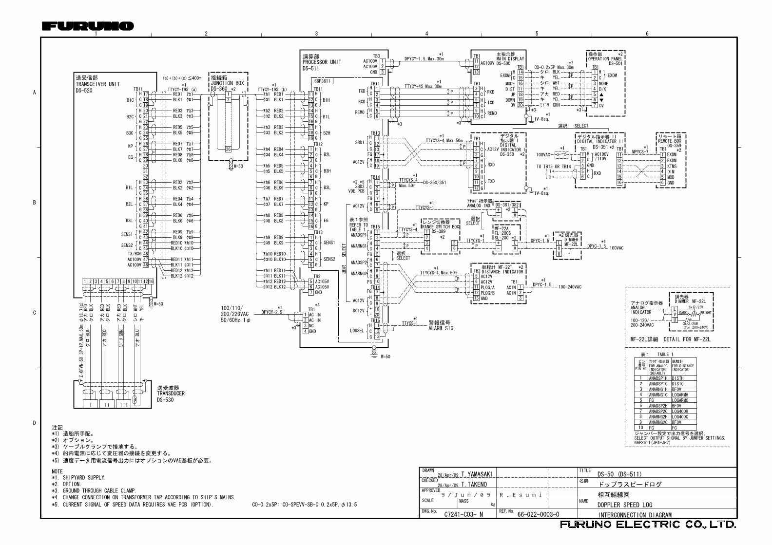
*1) 造船所手配。
*3) ケーブルクランプで接地する。
*5) 速度データ用電流信号出力にはオプションのVAE基板が必要。
*4) 船内電源に応じて変圧器の接続を変更する。
*2) オプション。
注記
NOTE
CO-0.2x5P: CO-SPEVV-SB-C 0.2x5P,φ13.5*5. CURRENT SIGNAL OF SPEED DATA REQUIRES VAE PCB (OPTION).
*4. CHANGE CONNECTION ON TRANSFORMER TAP ACCORDING TO SHIP'S MAINS.*3. GROUND THROUGH CABLE CLAMP.
*1. SHIPYARD SUPPLY.*2. OPTION.
APPROVED
SCALE
CHECKED
DRAWNT.YAMASAKI
T.TAKENO
相互結線図
INTERCONNECTION DIAGRAM
ドップラスピードログ
DOPPLER SPEED LOG
DS-50 (DS-511)
MF-22L詳細
表1 TABLE 1
DETAIL FOR MF-22L
調光器
アナログ指示器
3kΩ/25W
3kΩ/25W
MF-22LDIMMER
DARK BRIGHT
(for 200-240V)
INDICATORANALOG
200-240VAC100-120/ U
VL
*2*1*1
(a)+(b)+(c)≦400m
W=50
TTYCY-19S (b)TTYCY-19S (a)
W=50
W=50
DS-360JUNCTION BOX接続箱
36
21
送受信部TRANSCEIVER UNITDS-520
161211109874 65321
キシロ
クロ
アカ
クロ
アカ
クロ
アカ
YEL
WHT
BLK
RED
BLK
RED
BLK
RED
アオ
ミドリ
アカ
クロ
BLU
GRN
RED
BLK
414039383736353433
B2L
B1L BLK2RED2
クロ2アカ2
BLK4 クロ4RED4 アカ4
BLK6RED6
クロ6アカ6
B3LG
HC
G
HC
G
HC
BLK11 クロ11RED11 アカ11
BLK12RED12
クロ12アカ12
AC100VAC100V
4847
4243
SENS1BLK9 クロ9RED9 アカ9H
C444546TX/RXG
SENS2BLK10RED10
クロ10アカ10H
C
BLK5 クロ5RED5 アカ5
BLK3RED3
クロ3アカ3
32313029282726
HC
HC
EGBLK8 クロ8RED8 アカ8
KPBLK7 クロ7RED7 アカ7
252423222120191817
B3C
B2C
B1C BLK1RED1
クロ1アカ1
G
G
G
HC
C
H
HC
TB11
B2H
B1L
B1H
BLK11クロ11RED11アカ11
BLK12RED12
クロ12アカ12
BLK3RED3
クロ3アカ3
BLK2RED2
クロ2アカ2
BLK9クロ9RED9アカ9
BLK10RED10
クロ10アカ10
BLK8クロ8RED8アカ8
BLK7クロ7RED7アカ7
BLK6RED6
クロ6アカ6
BLK5クロ5RED5アカ5
BLK4クロ4RED4アカ4
BLK1RED1
クロ1アカ1
TB3
GNDAC105VAC105V
765
SENS2
654
TB13
G
HC
G
HC SENS1
3
21
EG
KP
B3H
B3L
161514
G
HC
131211987654
G
HC
G
HC
G
HC
321
B2LG
HC
G
G
G
HC
C
H
HC
TB12
TB11
191817161514131211
66P3611
*2*2
DIGITAL INDICATOR II
DS-351
デジタル指示器 II
TO TB13 OR TB14
100VAC
*1
56
3
1
2GND
RXDCH
H/110VCAC100V
21
TB1DS-359
リモート箱REMOTE BOX
DIMMOD
EXDM
KTMS
EXDM
4
65
1
32
14
1615
11
1312
SELECT選択
*1MPYCS-7
TB1TB1
RXD
REMO
TXD1
234
56
TB11
C
HCHC
H
*1TTYCY-4S Max.30m
*1DPYCY-1.5,Max.30m
*2 *5TB14
VDE PCBSBD2
AC12V
FGHC
H
C
G
選択SELECT
選択
SELECT
警報信号ALARM SIG.
TB15111213
LOGSEL C
G
H
TB14
8
20
7
109
DC12V
AC12VC
H
FG
+-
TB15
10
65
4
23
1
78
9
表1参照
TABLE 1REFER TO
HCHC
HCHC
ANADSP1
ANARNG1
ANADSP2
ANARNG2
FG
FG
PIN NO.
ピン番号
アナログ指示器
INDICATORFOR ANALOG
FGBF0VLOG400CLOG400HBF0VLOGARMCLOGARMHBF0VDISTCDISTH
FGANARNG2CANARNG2HANADSP2CANADSP2HFGANARNG1CANARNG1H
ANADSP1HANADSP1C
ジャンパー設定で出力信号を選択。SELECT OUTPUT SIGNAL BY JUMPER SETTINGS.66P3611(JP4-JP7)
10
65
4
23
1
78
9
(DEFAULT)
航程計
FOR DISTANCEINDICATOR
123789
H
HC
C
C
H
AC100V
TB1
TB1
3467910
111213
*1IV-8sq.
1819
17
1213
11TB13
AC12V
FGHC
SBD1H
C
G P
TB1
G
C
H
*1TTYCYS-4,Max.50m
P
GCH
HCG
AC12V
RXD
TXD
RXD
TXD
REMO
DIGITALINDICATOR I
デジタル指示器 I
DS-350 *2
123789101112
IIIIII
DS-500MAIN DISPLAY主指示器
IV-8sq.
ミドリキアカキシロキクロ
GRN
REDYEL
YELWHTYELBLK
DISTMODE
DOWN
EXDM
TB1
1819
171615
14
20
H
C
UP
OV*3
*1
送受波器
DS-530TRANSDUCER
DS-511PROCESSOR UNIT演算部 TB3
GNDAC100VAC100V
3
21
*3 *3
P
P
P
*2CO-0.2x5P Max.30m
P
P
P
7
4
56
23
1
C
HEXDM
MODE
D/K
OV*3
TB1
*2OPERATION PANEL操作部
DS-501
DPYCY-2.5*1
3
1
4
2
TB1*4
NC
AC INAC IN
GND
200/220VAC100/110/
50/60Hz,1φ
*3
Z-6FVN-SX3P+1P,MAX.50m,φ18.7(c)
GND
P43
12 *2
*1レンジ切換器RANGE SWITCH BOX
DS-389
65
選択SELECT
-+DS-381/382
VL*2
VL
-+
MF-22AFL-200SSL-200 *2*1
TTYCYS-1*1
DPYC-1.5*2調光器
MF-22LDIMMER
UVL
ANALOG IND.アナログ指示器
P
P
TTYCYS-4
100VAC
*1DPYC-1.5
*1TTYCYS-1
DS-350/351P
P
TTYCYS-4*1
Max.50m
C7241-C03- N
28/Apr/09
28/Apr/09
DWG.No. REF.No.66-022-0003-0
*1TTYCYS-4,Max.50m
AC12VAC12V
65
PLOG/BGND
PLOG/A
131211
*1
TB2
ACINACIN
TB1
321
DPYC-1.5
DISTANCE INDICATORMF-22T航程計 *2
P
P100-240VAC
TTYCS-1*1
9/Jun/09 R.Esumi
emiyoshi
テキストボックス
S-2

A
B
C
D
1 2 3 4 5 6
名称
NAME
TITLE
MASSSCALE
APPROVED
CHECKED
DRAWN
kg
相互結線図
INTERCONNECTION DIAGRAM
FURUNO ELECTRIC CO., LTD.
CO-0.2x2P: CO-SPEVV-SB-C 0.2x2P,φ10.5
T.YAMASAKI
ANALOGCH
DSP
34
12
TB1 MF-22R
5 CH
RANGE
67
FG
FG
レンジ切換器RANGE SWITCH BOX
*58910
*4. WHEN TWO DISTRIBUTION BOXES ARE USED, CONNECT ONE DIST. BOX TO "OTX" BOARD.
NOTE *1. SHIPYARD SUPPLY.
*2. OPTION.
*3. DISTRIBUTION BOX CAN INCORPORATE SEVEN BOARDS IN ANY COMBINATION.
*5. JUMPER CONNECTION SETTING REQUIRED.
*6. USE #6 TO #8 FOR No.2 INDICATOR.
*4)分配器を2個使用するときはOTX基板に接続する。
注記
*2)オプション。
*1)造船所手配。
*3)分配器には任意の組み合わせで最大7枚の基板組み込みが可能。
*5)ジャンパー設定が必要。
*6)2台目の指示器は#6~#8に接続する。
T.TAKENO
DS-50 (DS-370)
ドップラスピードログ
DOPPLER SPEED LOG
123
HCGHCG
STATUS
789
ANALOG V
1234567
CH
CH
89101112C
H
GND
CH
TXD
LG400T
ALARM
CH
DC12V
TTYCYS-1 *1
TTYCYS-1 *1
AC12V
HCG
123
HCG
456789
RXD
LG400T
ALARM
101112
HC
12VDC
0V
TB15
66P3340OCP
P
P
P
P
P
P
船速アナログ電圧信号
船速ステータス接点信号SHIP'S SPEED STATUS SIG.
SHIP'S SPEED VOLT SIG.
66P3342VOAV
66P3346TOTX
分配器DISTRIBUTION BOX
DS-370
*3
123
HCGHCG
ANALOG C
STATUS
789
TTYCYS-1 *1
TTYCYS-1 *1P
P
船速ステータス接点信号
船速アナログ電流信号
SHIP'S SPEED STATUS SIG.
SHIP'S SPEED VOLT SIG.
66P3342COAC
1234567
CH
CH
89101112C
HDC12V
HCG
LG400T
GND
STATUS
LG200R(LG400R)
CHLG200R
(LG400R)
P
P航程信号DISTANCE SIG.
TTYCYS-1 *1
TTYCYS-1 *1
P
P
TTYCYS-4 *1
66P3346LOLG
航程信号または船速ステータス接点信号DISTANCE/STATUS SIG.
1234567
CH
CH
89101112C
H
GND
CH
SPD IN
CH
DC12V
CKS
TXS
AC12V
P
P
P
66P3345ODD
MAX.150m デジタル指示器DIGITAL INDICATOR
TTYCY-4S *1
123456789101112
HCG
HCG
HCG
HCG
TB3
AC100VOUT
AC100VOUT
AC100VOUT
AC100VOUT
*4
W=50
*1
HCG
123
TB1DPYCY-1.5
50/60Hz,1φ
100/110/200/220VAC
123
P
P456
P789
TB15ANADSP1-HANADSP1-CANARNG1-HANARNG1-C
FGANADSP2-HANADSP2-CANARNG2-HANARNG2-C
10
P1020
TB14
TB13789
PTTYCYS-1 *1
DISTANCE SIG.航程信号
789
P
TB11
P1020
FG 13
FG
DC12V-HDC12V-C
200P4-H200P4-C200P4-G
200P5-H200P5-C200P5-G200P6-H200P6-C
*5
123410BF0V
SRCN6A16-10P
P
J16/J17 TTYCS-1 *1 ORCO-0.2x2P *2
W=50
TXD-H
RXD-HTXD-C
RXD-C
3456
12
RD1-HRD1-CFG
FG
TB1
3417
TD1-ATD1-B
VIN(+)VIN(-)
OUTPUTDATA 2~8
DISTRIBUTION BOX分配器 MD-550
*2
CIF/NMEA DATA 1/2航法データ1・2
1920
P
10
1718
TB12EXKP1-HEXKP1-C
EXKP2-HEXKP2-C
FG
P
P141516
111213
TB14
P171819
TTYCYS-1 *1
TTYCYS-1 *1
TTYCYS-1 *1
200P1-H200P1-C200P1-G200P2-H200P2-C200P2-G200P3-H200P3-C200P3-G
P
TB15141516
TTYCYS-1 *1KPOUT-HKPOUT-CKPOUT-G
66P3611
TTYCYS-1 *1KP入力KP INPUT
航程信号DISTANCE SIG.
KP出力KP OUTPUT
*1DPYCY-2.5
2
4
1
3
GND
AC INAC IN
NC
TB1100/110/
50/60Hz, 1φ200/220VAC
DS-510/511演算部PROCESSOR UNIT
3456
12
78910
*1
*1DPYC-1.5
調光器
MF22L-1/2DIMMER
*2
DS-802
端子台箱TERMINAL BOX
*2
FUSE(1A)
1234567
123456
RD-BRD-ATD-BTD-A
24V-P0VFG
DIMGNDPSW1PSW2P-ON0V
J1
アオ
クロ
キ
シロ
アカ
シロクロ
ミドリ
BLU
BLK
YEL
WHT
REDGRN
WHTBLK
J2
航程計DISTANCE INDICATOR
DS-840 *2MJ-A7SPF
MJ-A6SPF
MJ-A7SPF0009,2m
MJ-A6SPF0013,2m
DPYC-1.5*1100/110/
220/230VAC1φ,50/60Hz
整流器RECTIFIERPR-62 *2
DPYC-1.5*1
IV-2sq.
*1IV-2sq.
DIGITAL INDICATOR/DISTANCE INDICATOR
デジタル指示器/航程計
MAX.50mTTYCY-4S
*1
12-24VDC
123
HCG
CH 4
5
ANALOGDSP 1
RANGE*6
OAD 66P3342D
56111213 GND
PLOG 1BPLOG 1A
DC12ADC12A
TB2
100-240VAC123
*1TB1DPYCY-1.5
DISTANCE INDICATOR航程計 MF-22T *2
P43
12
65
-+
VL
VL
-+
UVL
P
P
TTYCYS-1*1
DPYC-1.5*1
TTYCYS-4
アナログ指示器ANALOG IND.
DIMMERMF-22L
調光器*2DPYC-1.5
*1TTYCYS-1
*1 *2SL-200FL-200SMF-22A
*2DS-381/382
SELECT選択
DS-389RANGE SWITCH BOXレンジ切換器
*1
*2
*1TTYCYS-4,MAX.150m
*1TTYCYS-4,MAX.150m
12 AC12VC
HP
TB1
DIGITAL INDICATOR Iデジタル指示器 I
DS-350
78
RXDCHP
12 G
12
TB1
563
RXDCHCH
GND
P
P
デジタル指示器ⅡDIGITAL INDICATOR Ⅱ
DS-351 *1MPYCS-7
TB1111213141516
AC100/110V
リモート箱REMOTE BOX
DS-359
34
12
56
DIMMERMODEGND
Kt/m/s
*1IV-8sq.
100VAC
C7241-C04- J
28/Apr/09
28/Apr/09
DWG.No. REF.No.66-022-0002- 0
TTYCY-4S,MAX.50m*1
9/Jun/09 R.Esumi
emiyoshi
テキストボックス
S-3
CBA
43
21
MASS
DWG.No.
SCALE
APPROVED
CHECKED
DRAWN
NAME
TITLE
kg
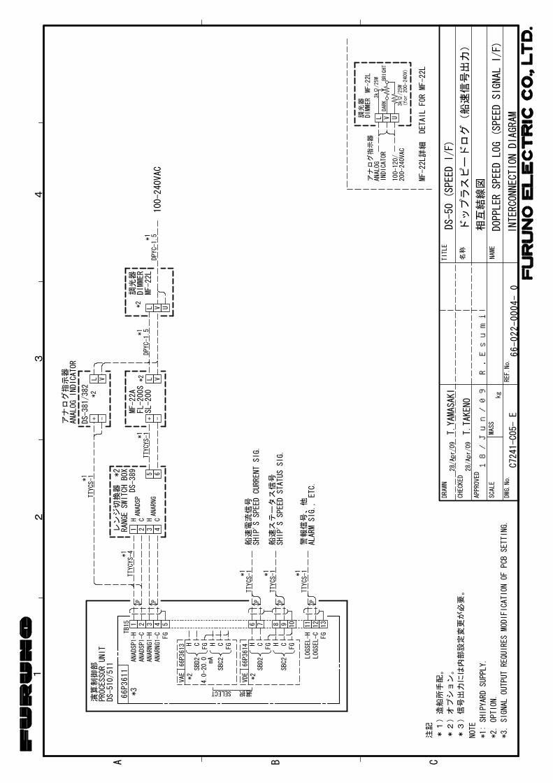
*1:
SHIPYARD
SUPPLY.
NOTE
注記
*3)
信号出
力には内
部設
定変
更が
必要
。
*3.
SIGNAL
OUTPUT
REQUIRESMODIFICATION
OFPCBSETTING.
INTE
RCON
NECTI
ONDIA
GRAM
相互
結線
図
DS-5
0(SP
EED
I/F)
*2)オプシ
ョン。
*2.
OPTION.
*1)造船所
手配。
ドッ
プラ
スピ
ード
ログ
(船
速信
号出
力)
DOP
PLER
SPEE
DLO
G(S
PEED
SIG
NAL
I/F)
MF-22L詳
細DETAIL
FOR
MF-22L
調光
器
アナ
ログ
指示
器
3kΩ
/25W
3kΩ
/25W
MF-22L
DIMMER
DARK
BRIGHT
(for
200-240V)
INDICATOR
ANALOG
200-240VAC
100-120/
UVL
ANADSP1-H
ANADSP1-C
ANARNG1-H
ANARNG1-C
1TB15
FG
2 3 4 5 6 7 8 9 10
H CFG H CFG
SBD2
SBC2
*2
PROCESSORUNIT
DS-510/511
演算
制御部
*3
VDE
66P3614
選択SELECT
111213
LOGSEL-H
LOGSEL-CFG
P P
TTYCS-1*1
TTYCS-1*1
P P
船速電流信号
SHIP'S
SPEED
CURRENT
SIG.
船速ステータス信号
SHIP'S
SPEED
STATUS
SIG.
TTYCS-1*1
P
警報信号、他
ALARM
SIG.,
ETC.
1 2 3 4
H C H C
レンジ切換器
RANGE
SWITCH
BOX
DS-389
ANADSP
ANARNG
5 6*2
+ -
66P3611
H CFG H CFG
VAE
66P3613
SBD2
SBC2
4.0-20.0mA
*2
TTYCYS-1
*1
+ -DS-381/382
TTYCS-1
*1
L V L V
TTYCYS-4*1
MF-22A
FL-200S
SL-200
DPYC-1.5*1
L V U
MF-22L
DIMMER
調光
器*2
100-240VAC
DPYC-1.5*1
66-022-0004-
0REF.No.
T.YAMASAKI
T.TAKENO
28/Apr/09
28/Apr/09
名称
C7241-C05-
E
ANALOG
INDICATOR
アナログ指示器
*2
*2
18/Jun/09 R.Esumi
emiyoshi
テキストボックス
S-4
Related Documents