All brand and product names are trademarks, registered trademarks or service marks of their respective holders. www.furuno.co.jp Installation Manual DOPPLER SONAR DS-60 SAFETY INSTRUCTIONS ............................................................................ i SYSTEM CONFIGURATION ....................................................................... ii EQUIPMENT LISTS .................................................................................... iii 1. INSTALLATION .................................................................................. 1-1 1.1 Display Unit DS-600 .................................................................................................. 1-1 1.2 Transceiver Unit DS-620 ........................................................................................... 1-4 1.3 Distributor Unit DS-610.............................................................................................. 1-5 1.4 Transducer ................................................................................................................ 1-6 1.5 Junction Box DS-640, DS-645A/B (option).............................................................. 1-16 1.6 Installation of Display Unit with DS-605 (Water Proof Box, option) ......................... 1-17 1.7 Remote Controller RD-501/Dimmer Controller RD-502 (option) ............................. 1-20 1.8 Rate-of-Turn Gyro DS-670 (option) ......................................................................... 1-21 2. WIRING ............................................................................................... 2-1 2.1 Distributor Unit DS-610.............................................................................................. 2-2 2.2 Transceiver Unit DS-620 ........................................................................................... 2-5 2.3 Display Unit DS-600, Remote Controller RD-501/ Dimmer Controller RD-502 (option) ........................................................................... 2-6 2.4 Junction Box (option) ................................................................................................. 2-8 3. MENU SETTINGS ............................................................................... 3-1 3.1 How to Use the Service Menu ................................................................................... 3-1 3.2 How to Set the System Menu .................................................................................... 3-3 APPENDIX 1 CALIBRATION ................................................................ AP-1 APPENDIX 2 JIS CABLE GUIDE .......................................................... AP-4 PACKING LISTS...................................................................................... A-1 OUTLINE DRAWINGS............................................................................. D-1 INTERCONNECTION DIAGRAM ............................................................ S-1

Welcome message from author
This document is posted to help you gain knowledge. Please leave a comment to let me know what you think about it! Share it to your friends and learn new things together.
Transcript

All brand and product names are trademarks, registered trademarks or service marks of their respective holders.
www.furuno.co.jp
Installation ManualDOPPLER SONAR
DS-60
SAFETY INSTRUCTIONS ............................................................................ i
SYSTEM CONFIGURATION ....................................................................... ii
EQUIPMENT LISTS.................................................................................... iii
1. INSTALLATION ..................................................................................1-11.1 Display Unit DS-600 ..................................................................................................1-11.2 Transceiver Unit DS-620 ...........................................................................................1-41.3 Distributor Unit DS-610..............................................................................................1-51.4 Transducer ................................................................................................................1-61.5 Junction Box DS-640, DS-645A/B (option)..............................................................1-161.6 Installation of Display Unit with DS-605 (Water Proof Box, option) .........................1-171.7 Remote Controller RD-501/Dimmer Controller RD-502 (option) .............................1-201.8 Rate-of-Turn Gyro DS-670 (option) .........................................................................1-21
2. WIRING ...............................................................................................2-12.1 Distributor Unit DS-610..............................................................................................2-22.2 Transceiver Unit DS-620 ...........................................................................................2-52.3 Display Unit DS-600, Remote Controller RD-501/
Dimmer Controller RD-502 (option)...........................................................................2-62.4 Junction Box (option).................................................................................................2-8
3. MENU SETTINGS...............................................................................3-13.1 How to Use the Service Menu ...................................................................................3-13.2 How to Set the System Menu ....................................................................................3-3
APPENDIX 1 CALIBRATION ................................................................AP-1
APPENDIX 2 JIS CABLE GUIDE..........................................................AP-4
PACKING LISTS...................................................................................... A-1
OUTLINE DRAWINGS............................................................................. D-1
INTERCONNECTION DIAGRAM ............................................................ S-1

The paper used in this manual
is elemental chlorine free.
・FURUNO Authorized Distributor/Dealer
9-52 Ashihara-cho,
Nishinomiya, 662-8580, JAPAN
Telephone : +81-(0)798-65-2111
Fax : +81-(0)798-65-4200
A : MAR 2010.Printed in JapanAll rights reserved.
A1 : MAY 23, 2011
Pub. No. IME-72640-A1
*00017233810**00017233810*(HIMA ) DS-60*00017233810**00017233810*
* 0 0 0 1 7 2 3 3 8 1 0 *

i
SAFETY INSTRUCTIONS
WARNING CAUTIONHave a qualified serviceman do theinstallation.
Only qualified personnel should work inside the equipment.
Use Chugoku Toso brand Marine Star 20 anti-fouling paint or the equivalentfor the transducer.
Coat thinly and evenly. A thick coat can reduce output power.
Turn off the power at the switchboard before installing the equipment.
Fire or electrical shock can result if the power on.
Confirm that the power supply voltageis compatible with the voltage rating of the equipment.
Connection to the wrong power supply cancause fire or damage to the equipment.
The mounting location for the display, distributor and transceiver unit must satisfy the following conditions:
-Away from rain and water splash-Out of direct sunlight-Away from air conditioner vents-Moderate and stable in temperature and humidity
Do not install the unit in a place subject to rain or water splash.
Fire or electrical shock can result.
WARNING Indicates a potentially hazardous situation which, if not avoided, could result in death or serious injury.
CAUTION Indicates a potentially hazardous situation which, if not avoided, may result in minor or moderate injury.
Warning, Caution Mandatory Action Prohibitive Action
Observe the compass safe distances to prevent interference to a magnetic compass.
DS-600 0.60 m 0.40 mDS-605 0.95 m 0.60 mDS-610 3.15 m 2.00 mDS-620 3.20 m 2.05 mDS-640 1.15 m 0.70 mDS-670 1.65 m 1.05 mDS-645A 1.90 m 1.25 mDS-645B 2.00 m 1.30 m
Standard Steering
CAUTIONAttach protective earth securely to the ship’s body.
The protective earth (grounding) is requiredfor the AC power supply to prevent electri-cal shock.
Do not weld the tank with transducer tothe ship’s hull.
Use the specified power cable.
Fire can result if an incorrect cable is used.

ii
SYSTEM CONFIGURATIONS
DISTRIBUTOR UNITDS-610
JUNCTION BOXDS-640 or 645A/B
TRANSCEIVER UNITDS-620
IEC 61162 Output x 5
IEC 61162 Input x 3
Distance Run Pulse x 4
Alarm System
External KP x 1
KP Output x 1
RATE-OF-TURN GYRO
DS-670
DS-600/DISPLAY
UNIT
MAIN DISPLAY UNIT
DS-600/RD-50/RD-20
DISPLAYUNIT
SUB DISPLAY UNIT
100-240 VAC
TRANSDUCERDS-630 or DS-631
� Dashed lines indicate optional equipment.� Environmental category:
Max. 5
Analog Meter Output x 2
RD-501REMOTE
CONTROLLER
RD-502DIMMER
CONTROLLER
RD-501REMOTE
CONTROLLER
RD-502DIMMER
CONTROLLER
Protected fromweather
DS-670, DS-600, DS-620, DS-640, RD-501, RD-502, DS-645A/B
DS-630, DS-631Exposed to weather
Protected from weather DS-600 in DS-605 cabinet
Analog Voltage Output x 1
Analog Current Output x 1
Heading

iii
EQUIPMENT LISTS
Standard supply
Name Type Code No. Qty Remarks
Display Unit DS-600 - 1 8.4” color LCD
Distributor Unit DS-610 - 1
Transceiver Unit DS-620 - 1
Transducer DS-630 - 1 No watertight connector Select one.
DS-631 - w/watertight connector
Transducer Tank DS-660 - 1 For DS-630/631 Select one.
Gate Valve DS-661 - 1 For DS-630 only
Installation Material CP26-01501 001-081-900 1 set For DS-600
CP66-01701 001-082-190 1 set For DS-610
CP66-01702 001-082-290 1 set For DS-620
CP66-01703 001-082-630 1 set For DS-630
CP66-01740 000-016-374 1 set For DS-631 (CP66-01704, 30 m cable)
CP66-01750 000-016-375 1 set For DS-631 (CP66-01704, 40 m cable)
CP66-01760 000-016-376 1 set For DS-631 (CP66-01760, 50 m cable)
CP66-01770 000-016-377 1 set For DS-631 (CP66-01760, 60 m cable)
CP66-01710 001-082-830 1 set For DS-661 when shipped assembled
CP66-01711 001-082-800 For DS-661 when shipped separated
CP66-01712 001-082-820 1 set For DS-661, gasket
Spare Parts SP26-00101 001-076-450 1 set For DS-600 (other than Deep Sea)
001-077-030 For DS-600 (Deep Sea)
SP66-00901 001-082-200 1 set For DS-610 (other than Deep Sea)
001-082-210 For DS-610 (Deep Sea)
SP66-00902 001-082-520 1 set For DS-620 (other than Deep Sea)
001-082-530 For DS-620 (Deep Sea)
Accessories FP66-00701 001-082-140 1 set For DS-600

iv
Optional Supply
Name Type Code No. Qty Remarks
Rate-of-turn Gyro DS-670 - 1
Display Unit DS-600 - 1 8.4” color LCD
Hanger OP26-8 000-016-313 1 For DS-600
Junction Box DS-640 - 1 w/Installation materials (CP66-01721)
DS-645A/B -
Water Proof Box DS-605-R 000-016-398 1 w/Installation materials (CP66-01731), right-hand open door
DS-605-L 000-016-727 w/Installation materials (CP66-01731), left-hand open door
Frange OP66-6 000-016-400 1 For DS-600
Tightening Handle OP66-7 001-082-950 1
Remote Controller RD-501 000-016-197 1
Dimmer Controller RD-502 000-016-198 1
Analog Indicator FL-200S-1 000-015-997-10 1 -10 to 30 kn, flush mount
FL-200S-2 000-015-998-10 1 -10 to 40 kn, flush mount
SL-200-1 000-016-000-10 1 -10 to 30 kn, bulkhead mount
SL-200-2 000-016-164-10 1 -10 to 40 kn, bulkhead mount
FL-200S-1W 000-174-599-10 1 -10 to 30 kn, flush mount
FL-200S-3 000-174-600-10 1 -10 to 20 kn, flush mount

1-1
1. INSTALLATION
1.1 Display Unit DS-600Mounting consideration
The display unit can be installed on a desktop, on the underside of a table, or flush mounted in a panel. When you select a mounting location, keep in mind the following points:
• Locate the display unit away from exhaust pipes and vents.• Select an installation location that is well ventilated.• Locate the display unit where shock and vibration are minimal.• Allow enough maintenance space at the sides and rear of the display unit and leave enough
slack in cables to facilitate maintenance and servicing.• Observe the compass safe distances (see page i) to prevent the interference to a magnetic
compass.• The nominal viewing distance for the display unit is 1 m. Select a suitable mounting location
considering that distance.
Flush mount
See the outline drawing in the back of this manual. Before you fasten the display unit to the cutout, first connect the cables referring to chapter 2.
1. Make a cutout in the mounting location as shown in the illustration below.
NOTICENOTICEDo not apply paint, anti-corrosive sealantor contact spray to coating or plastic parts of the equipment.
Those items contain organic solvents thatcan damage coating and plastic parts,especially plastic connectors.
78 (3.07”)12 (0.47”)240 (9.45”)
240
(9.4
5”)
Pilot hole(four places)
223+0.5 (8.78”)223+
0.5
(8.7
8”)
228+
1 (8
.98”
) (fo
r out
door
)228+1 (8.98”)(for outdoor)
18 (0.71”)
18 (0.71”)(for outdoor)
Fixing hole (4- 6)
232+1 (9.13”)(for indoor)
232+
1 (9
.13”
) (fo
r ind
oor)
22 (0.87”)(for indoor)
or

1. INSTALLATION
1-2
Note: Dimensions for the cutout are different depending on the mounting location, indoor or out-door. For the outdoor mouting, ask dockyard to construct a waterproof case for the display unit.
2. Make four pilot holes for self-tapping screws (diameter: 5 mm) in the location indicated in the illustration on page 1-1.
3. Insert the sponge to the display unit from the rear side.4. Set the display unit to the cutout and fasten the display unit with four self-tapping screws
(5x20).5. Set a cosmetic cap to each fixing hole on the front panel. See page 1-3.
Desktop or table underside mount
The display unit can be mounted on a desktop or on the underside of a table using the optional hanger. See the outline drawing for details.
1. Remove the hanger mounting plate from the hanger assembly.2. Fasten the hanger mounting plate to the display unit from the left side and right side with four
binding head screws (M5x12).
3. Make a four pilot holes for self-tapping screws (5x20) in the mounting location.4. Fix the hanger to the mounting location with four self-tapping screws (5x20).5. Screw knobs into the display unit loosely.6. Set the display unit to the hanger.7. Tighten the knobs to fasten the hanger to the display unit.
Hanger assembly (Type: OP26-8, Code No.: 000-016-313-00)
Name Type Code No. Qty
Self-tapping screw 5x20 000-171-997-10 4
Binding head screw M5x12 000-171-999-10 4
Hanger assy. OP26-8-1 001-081-920-00 1
Screw (M5x12)
Hanger mountingplate (left side)

1. INSTALLATION
1-3
8. Set a cosmetic cap to each fixing hole on the front panel.
How to set the cosmetic cap and alarm lid assy.
Set a cosmetic cap to each fixing hole on the front panel as shown in the illustration below.
For the display unit to be used as a sub display, attach the alarm lid (supplied as accessories) to the [ALARM] key to prevent accidental operation of the key.
260+
5 (1
0.24
”)
288+5 (11.34”)
240 (9.45”)
279+
5 (1
0.98
”)
51+5 (2.01”)149 (5.87”)
91 (3.58”)24
0 (9
.45”
)
Fixing hole (4- 7) 190+0.5 (7.48”)
75+0
.5 (2
.95”
)40
Set cosmetic cap to hole so cap is flush with panel.
ALARM
Alarm lid assy.(For sub display only)
Attach the double-sided tapeto the reverse side of the lid, and attach the lid here.

1. INSTALLATION
1-4
1.2 Transceiver Unit DS-620Installation considerations
• Since the transceiver unit generates heat, install it in a dry, well-ventilated place. The cooling fans at the top of the unit must not be obstructed, to allow heat to escape.
• This unit is designed for bulkhead mounting to permit dissipation of heat. If bulkhead mounting is absolutely impossible, mount the unit on the floor leaving at least 350 mm clearance between it and the floor to permit dissipation of heat.
• Reinforce the mounting area, if necessary.• Leave space around the unit for maintenance and checking. Refer to the drawing at the back of
this manual for minimum recommended maintenance space.• A magnetic compass will be affected if the transceiver unit is placed too close to it. Observe the
compass safe distances to prevent disturbance to the magnetic compass (page i).Use four hex. bolts (M10x20) to fix the transceiver unit to the mounting area. See the outline draw-ing at the back of this manual.
1. Screw in lower hex. bolts so there is 5 mm clearance between bottom of screw head and bulk-head.
2. Hang the unit on the bolts, then tighten the bolts.3. Fasten the unit with upper hex. bolts.
Fixing hole 2- 12 210±1 (8.27”)
590±
1 (2
3.23
”)15
(0.5
9”)
12 (0.47”) 210±1 (8.27”)
620
(24.
41”)
2-R635
(1.3
8”)
(7)

1. INSTALLATION
1-5
1.3 Distributor Unit DS-610The distributor unit can be mounted on the deck or on a bulkhead. Consider the following points when selecting a mounting location.
• Select a location which is both well ventilated and low in humidity to keep the unit cool.• For bulkhead mounting, be sure the mounting location is strong enough to support the weight
under the continued vibration normally encountered on the vessel.• A magnetic compass will be affected if the distribution box is too close. Observe the compass
safe distances to prevent disturbance to the magnetic compass.1. Screw in lower hex. bolts so there is 5 mm clearance between bottom of screw head and bulk-
head.2. Hang the unit on the bolts, then tighten the bolts.3. Fasten the unit with upper hex. bolts.
Fixing hole2- 12
620±1 (24.41”)
450±
1 (1
7.72
”)98
(3.8
6”)
12 (0.47”)
R6
630
(24.
80”)
(37)
(1.4
6”)

1. INSTALLATION
1-6
1.4 TransducerThe performance of this equipment is directly dependent on the installation of the transducer.
The installation of the transducer and the tank must be accomplished by a dockyard referring to the installation drawings at the later part of this manual.
1.4.1 Installation locationTo decide the location of the transducer, the following points must be taken into account.
• Locate the transducer of DS-60 at least 2 m from the transducer of an echo sounder.
• Separate as far as possible from air bubble sources; e.g., side thruster and water disposal pipes.
• Install in close proximity to the keel, for uniform water flow.• Generally, best performance is obtained by mounting on the bow; the stern side is influenced
more easily by air bubbles and propeller cavitation.• Do not apply any paint to the transducer face.• Visually confirm that the “FORE” mark on the transducer is oriented to the ship’s bow direction
after the installation.
STERN BOW
2000 mm or more
Recommended locationfor echo sounder transducer
ECHO SOUNDER TRANSDUCER
DOPPLER SONAR TRANSDUCER

1. INSTALLATION
1-7
1.4.2 Installation using the transducer tank DS-660
Transducer tank DS-660, sectional view
1. Remove flange (4), fixing plate (5), fixing gland (6), washer (7) and gasket (8) from the tank.2. Set the tank to the place which was selected at paragraph 1.4.1.
The “FORE-AFT” line on the tank must be parallel with the line between ship’s fore and aft (error: within 3°).
For horizontal direction, the bottom of the tank (2) must be parallel with the draft.
DS-660 Tank, top view
3. Weld the tank (2) to the ship’s hull. The doubling and welding methods are left up to the ship-yard.
4. Paint the tank (2), flange (4) and fixing plate (5) the same color as the ship’s body. -The tank (2) is pre-painted with zinc rich primer. -The flange (4) and fixing plate (5) are pre-painted with zinc rich primer and anti-corrosion coat (BANNOH 500). If necessary, remove it with the sandblast, then paint the flange (4) and fixing plate (5) the same color as the ship’s body.
5. Apply liquid gasket (supplied) to the top of the transducer evenly.
14 910
1213 11
5
678
2
1615
HullFO
RE
AFT Ship’ s bow
Seal these parts with masking tape.

1. INSTALLATION
1-8
6. Mount the fixing plate (5) on the transducer (1).7. Attach seal washer (16) to hex. bolt M8x12 (15).8. Use hex. bolt (15)(16) assembled at step 7 to fasten the transducer (1) and fixing plate (5).
Mate bolt head at the top of the transducer with the hole on the fixing plate as shown in the fig-ure below.
9. Use M16 nut (11), spring washer (12) and flat washer (13) to fix the transducer (1) w/fixing plate to the fixing flange (4).
10.For the transducer DS-631, do the following steps:1) Attach the grommet (supplied) to the location marked with a white line on the transducer
cable.2) Fix the grommet attached at step 1) to the notch shown below, by using the cable fixing
plate (17), hex. bolt M6x12 (18), spring washer M6 (19).3) Pass the connector at the end of the transducer cable between the transducer and M16
bolt, and attach the notch as shown below.
4) Connect the cable assy. (supplied) to the connector attached at step 3). Clean the connector faces and pins before the connection.
Transducer (1)
Fixing flange (4)
Fixing plate (5)
Hex. bolt (15)Seal washer (16)M16 hex. nut (11)
M16 spring washer (12)
M16 flat washer (13)
Mate bolt head to hole.
Transducer cable
Attach the connector to this notch.
Pass the cable between the transducer and this bolt.
Grommet
Cable fixing plate (17)M6 spring washer (19)Hex. bolt M6x12 (18)
Notch(for grommet)
White mark

1. INSTALLATION
1-9
5) Attach the metal fixing (supplied) to the connector, and use two bolts M6x20 and spring washers M6 to fix them.
11.Pass the fixing gland (6), washer (7) and gasket (8) through the transducer cable (DS-631: cable assy), and slide them to the white line on the cable.
12.Pass the cable through the hole at the top of the tank (2).
Metal fixing
Hex. bolt (M6x20)
Spring washer (M6)
Cable assy.
White line (printed on the cable)
Fixing gland (6)
Washer (7) (The hollow side must be upward.)
Gasket (8)
Tank (2)
Transducer cable

1. INSTALLATION
1-10
13.Use the tightening handle (option) to fasten the fixing gland (6) from the inside of the tank (2).The distance between the bottom of the fixing gland (6) and tank must be less than 15 mm.
Transducer tank, sectional view
14.Rotate the fixing flange (4) twice horizontally to make two loops.These loops make it easy to put the cable in the tank.
15.Use the bolt M10x25 (9) and spring washer M10 (10) to fasten the fixing flange (4) to the tank (2).
less than 15 mmFixing gland
Tank
Transducer cable
M10x25 hex. bolt (9)
M10 spring washer (10)
Rotate the fixing flange (4) twice horizontally to make two loops on the cable.

1. INSTALLATION
1-11
1.4.3 Installation with gate valve DS-661
DS-661 gate valve, sectional view
Note: To install the gate valve, service space of 1000 mm height is necessary. For details, see the installation drawing at the back of this manual.
1. When your unit is shipped assembled, remove the five items shown below:• Gate valve (2)• Spacer (3)• Gasket (5), 2 pcs.• Shaft (6)
1
2
5
1717 1818
5
1717 1818 1919
6
7
8
24242323 2525
4
3
2626 2727
2222
1313 1212 1111
21212020
1515
1414
1010 9
1616
Gasket 2 (5)
Gasket 1 (5)
Spacer (3)
Gate valve (2)
Shaft (6)
Fore-Aft line

1. INSTALLATION
1-12
2. Set the spacer (3) to the place selected at paragraph 1.4.1.The “FORE-AFT” line on the spacer must be parallel with the ship's fore and aft line (within
3°). For horizontal direction, the bottom of the spacer must be parallel with the ship's draft.3. Weld the spacer (3) to the ship's hull. The welding and doubling methods are left up to the
shipyard.4. Unfasten M12 hex. nut (20), spring washer (21) and flat washer (22) to remove the shaft (6)
from the seachest cap (4).
5. Paint the gate valve (2), spacer (3) and seachest cap (4) the same color as ship's body. Paint only gray-colored areas; for other part, seal with a masking tape.
6. Pass the cable from the transducer (1) through the shaft (6) from the bottom.7. Apply liquid gasket (supplied) on the top of the transducer (1).8. Use hex. bolt (26) and seal washer (27) to fasten the transducer (1) to the shaft (6).
-M12 hex. nut (20)-M12 spring washer (21)-M12 flat washer (22)
Seachest cap (4)
Shaft (6)

1. INSTALLATION
1-13
9. Pass the gasket (8), flat washer (7) and fixing gland (11) through the transducer cable.
10.Fasten the fixing gland (11) to the top of the shaft (6).The height between the top of the fixing gland (11) and the top of the shaft (6) must be less
than 7 mm.11.Apply grease (supplied) to both sides of the gasket 1 (5), and set it on the spacer (3).12.Apply grease (supplied) to the inside of the spacer (3).13.Clean the top and bottom of the gate valve (2), and mount it on the gasket 1 (5) mounted on
the spacer (3) at step 11.
Gasket (8)
Washer (7)The hollow side must be downward.
Fixing gland (11)
Seal washer (27)Hex. bolt (26)
Transducer (1)
Shaft (6)
Transducer cable

1. INSTALLATION
1-14
14.Fasten M20 hex. nut (17) and spring washer (18) loosely to the stud bolt of the spacer (3).
15.Apply grease (supplied) to both sides of the gasket 2 (5), and set it on the gate valve (2).16.Use hex. nut (17), spring washer (18) and hex. bolt (19) to mount the seachest cap (4) of the
shaft (6) on the gate valve (2).
17.Move the shaft (6) upward and downward by hands to check if it moves smoothly.
Gasket 1 (5)Apply grease to both sides.
Spacer (3)
Gate valve (2)
Apply grease to the inside.
M20 hex. nut (17)M20 spring washer (18)
Gasket 2 (5)(Apply grease to both sides.)
Seachest cap (4)
Hex. bolt (19)
Hex. nut (17)Spring washer (18)
Fore mark

1. INSTALLATION
1-15
18.Check that fore marks are aligned, and fasten hex. nut (17), spring washer (18) and hex. bolt (19) tightly.
19.Fasten hex. nut (20), spring washer (21) and flat washers (22) removed at step 4 to stud bolt on the seachest cap.
The distance between the seachest cap (4) and flange (7) must be 5 mm.
How to open the gate valve
When you open or close the gate valve, unfasten two nuts shown below to rotate the handle. Then, fasten nuts to fix the handle.
-M12 hex. nut (20)-M12 spring washer (21)-M12 flat washer (22)
Fore mark
(at the bottom of the transducer)
5 mm
Flange (7)
Seachest cap (4)

1. INSTALLATION
1-16
1.5 Junction Box DS-640, DS-645A/B (option)Installation considerations
The junction box forms a joint between the distributor and the transceiver unit, and extends the distance between them to max. 500 m. Install it as below:
• Keep the junction box away from noise-emitting electrical machinery, for example, electric gen-erator, radio transmitter and TV.
• Do not install the junction box in place of high temperature and humidity.See the outline drawing at the back of this manual.
Dimensions for DS-640
Dimensions for DS-645A/B
200±1 (7.87”)
120±1 (4.72”)
220±
1 (8
.66”
)
233
(9.1
7”)
7 (0.2
8”)
6 (0
.24”
)
5 (0.20”)
5 (0.20”)
10 (0.39”)
12
R2.5
R2.5
(7) (
0.28
”)
200±1 (7.87”)
220±1 (8.66”)
)”9.11( 1±203
)” 5. 21( 713
7)” 82. 0(
)” 42. 0( 6
5 (0.20”)
5 (0.20”)
10 (0.39”)
12
R2.5
R2.5
)”64.1( )73(
292 (11.50”)

1. INSTALLATION
1-17
1.6 Installation of Display Unit with DS-605 (Water Proof Box, option)
For installation of the display unit on the wings of the bridge, use the optional water proof box DS-605. Fix the DS-605 on the bulkhead and set the display unit therein.
Mounting considerations
The DS-605 has waterproofing protection of IP56. When you select a mounting location for the waterproof box, keep in mind the following points.
• Keep the unit away from electromagnetic field-generating equipment like motors and genera-tors.
• For maintenance and checking purposes, leave enough space at the sides of the unit and leave slack in cables. See the outline drawing at the back of this manual.
• A magnetic compass will be affected if the waterproof box is too close to the magnetic com-pass. Observe the compass safe distances (see page i) to prevent interference to a magnetic compass.
Mounting procedure
Note: Mount the DS-605 on the bulkhead so the cable glands and the drain hole are down.
1. Fix the DS-605 on the wings of the bridge.1) Insert the seal washer to four fixing holes.2) Fix the DS-605 with four M10 bolts (dockyard supply).
Installation materials for DS-605 (Type: CP66-01731, Code No.: 001-082-660-00)
Name Type Code No. Qty Remarks
Seal Washer 03-001-3002-0 RoHS 300-130-020-10 4
Gasket (2) 26-003-1605 100-355-310-10 1 For DS-60
Washer (2) 26-003-1607 100-355-320-10 2
Cable Gland Washer JIS F8801 25C 000-172-238-10 2 For RD-50
Cable Grand Inner gasket JIS F8801 25C 000-171-892-10 1
Silicon Rubber S-8400W 50G 000-158-483-10 1
340 (13.39”)
4-ø15
310 ± 0.5 (12.20”)
62 (2
.44”
)17
6 ±
0.5
(6.9
3”)
Fixing hole
Cable gland
Note: Mount the unit so the cable glands are down.

1. INSTALLATION
1-18
3) Apply silicon rubber to M10 bolts as shown below.
2. Connect the TTYCS-4 cable to the DS-600 through the cable glands for the DS-605.1) Fabricate the cable as shown below.
2) Pass the clamping gland, washer (26-003-1607), gasket (26-003-1605) and washer (sup-plied as installation materials) onto the cable, in that order.
Apply sellicon rubber.Apply sellicon rubber.
Seal washerSeal washer
NutNut
M10 boltM10 bolt
Vinyl seath
80 (for TB3) 35
7
ArmorShield
M3
Vinyl tape
130
TTYCYS-4
Vinyl seath
Fold back and wrap internal shield and fix it by cable clamp.
x2

1. INSTALLATION
1-19
3) Pass the cable through the cable gland as shown below.
4) Put the flush mounting sponge to the flange from the rear side of the DS-600.5) Open the front cover of the DS-605 and connect the ground wire attached inside the DS-
605 to the ground terminal on the rear of the DS-600.6) Connect the cables to the DS-600. Refer to chapter 2.
3. Remove each binding head screw from four corners of the DS-605 and set the D-600 to the DS-605.
4. Apply silicon grease to the binding head screws and fix the DS-600 to the DS-605 with four binding head screws.
5. Tighten the clamping glands to fix the cables.6. Apply the putty to the cable glands for waterproofing.7. Connect the ground terminal for the DS-605 to the ground terminal on the hull with the IV-1.25
sq. wire.
Washer*Gasket*
TTYCYS-4 cable
{ Clamping gasket
*: Attached inside the cable gland

1. INSTALLATION
1-20
How to change orientation of the front cover of DS-605
The front cover of the DS-605 can be oriented up, down, right or left. To change the orientation of the front cover, do the following.
Note: Set the front cover so the FURUNO logo on the cover is right side up. The drain hole must be down.
1. Remove eight screws from two hinges.2. Remove two screws from the latch.3. Remove the hinges and the hidden lids for fixing hole of latch in consideration of the opening
direction.The hidden lids for fixing hole of latch are taped on each side.4. Orient the front cover as desired and fix the hinges and latch.
1.7 Remote Controller RD-501/Dimmer Controller RD-502 (option)
The optional remote controller RD-501 and dimmer controller RD-502 can be flush mounted in a panel. The size and the mounting procedure are shared by RD-501 and RD-502. For the mounting location, refer to the mounting considerations for the display unit in section1.2.
Note: Before you fasten the display unit to the cutout, first connect the cables referring to chapter 2.
1. Make a cutout in the mounting location (88 mm (width) x 76 mm (height)).2. Make four holes of 4 mm diameter in the locations indicated in the illustration below.3. Set the remote controller or dimmer controller to the cutout. Insert four binding head screws
(M3x12) from the front side then fasten the unit with four sets of flat washers, spring washers and hexagonal nuts from the rear side.
Hinge
Latch
Screws for hinge
Hidden lids for fixing hole of latch(four sides)
DISP UNIT MODE
REMOTE CONTROLLERRD-501
88 ± 1.0 (3.46”)86 ±
0.5
(3.3
9”)
76 ±
1.0
(2.9
9”)
Fixing hole (4- 4)86 ± 0.5 (3.39”)

1. INSTALLATION
1-21
1.8 Rate-of-Turn Gyro DS-670 (option)The rate-of-turn gyro must be installed, in a location with minimal vibration, so that the sensor in-side the unit is level to within 1 degree. (There is no designation for orientation of the unit.) Select the location considering that the cable for connection with the distributor is 5 m.
Note: When installing the rate-of-turn gyro, wear the earth strap to prevend the electrification.
Use the four stud bolts, flat washers, spring washers and eight adjust nuts to fix the unit. See the outline drawing at the back of this manual.
Use the XH connector (supplied with DS-670) to connect cables.
Leveling adjustment
This adjustment must be performed while the ship is in dry-dock where it has no heeling and trim-ming inclinations.
Place a T-type level meter on top of the sensor to measure longitudinal and transverse inclination. To level the sensor, turn the adjust bolts.
T-type level meter Sensor
Adjust bolt

1. INSTALLATION
1-22
This page is intentionally left blank.

2-1
2. WIRING
Refer to the interconnection diagram at the back of this manual to connect cables.
Precautions for cable installation
Observe the following guidelines to prevent noise, interference problem.
• The transducer cable carries very weak signals (amplitude less than 0.1 μV), which are easily interfered by noise. The need for a good ground cannot be overempha-sized.
• Locate DS-60 cables away from the transmission antenna cable or radio equip-ment.
• Locate the DS-60 cables away from the power cables mentioned below. Also, sep-arate cables at least 400 mm when the cables are run parallel with power cables.• Cable carrying more than a few kilowatts power to fluctuating loads• Cable carrying switching waves generated by thyristor, etc.
TTYCYS-4 or TTYCS-4(Max. 150 m)
DistributorDS-610
Display Unit(main)
DS-600
Remote Controller RD-501/Dimmer Controller RD-502
TTYCY-4
Transducer cable(30 m/40 m/50 m/60 m) Transducer
DS-630/631
TransceiverUnitDS-620
TTYCY-4S*
*The cable length between DS-620 and DS-610 must be less than 500 m.
Note: For details of JIS (Japan Industrial Standard) cables, see APPENDIX 2.
100-240 VAC(DPYC-2.5)
ANALOG VOLTAGE OUT (TTYCS-1)ANALOG CURRENT OUT (TTYCS-1)
KP IN/OUT (TTYCS-1, x2)ALARM SYSTEM
ANALOG METER OUT (TTYCYS-1Q, x2)DIGITAL OUTDIGITAL OUT
IEC61162/IN (TTYCS-1, x3)IEC61162/OUT (TTYCS-1, x5)
Display Unit (sub) DS-600, RD-20/50 (x5)
LOG/CONTACT, 200 pulse (DPYCY-1.5, x4)
DS-670(S66-9-5)
TTYCY-4S*
DPYCY-4.0*DPYCY-4.0*
TTYCY-19S orTTYCY-10S*
JunctionBox(option) DS-
645ADS-645B
DS-640

2. WIRING
2-2
Connection of WAGO connector
Remove the WAGO connector from each unit and connect each cable core to the WAGO connector. See the interconnection diagram at the back of this manual. The terminal opener is attached inside each unit.
2.1 Distributor Unit DS-610The Distributor Unit DS-610 has two lines of cable clamps, and there are 13 cable en-trances in total. The cables and corresponding cable entrances are shown on the re-verse side of the top cover of the DS-610. Fabricate cables referring to page 2-4. Pass the cables through their respective cable entrances and connect them to WAGO con-nectors.
How to connect wires to WAGO connector
Press downward.
Terminal opener
Wire
Twist WAGO connector
Procedure1. Twist the cores.2. Set and press the terminal opener downward.3. Insert the wire to hole.4. Remove the terminal opener.5. Pull the wire to confirm that it is secure.
Cable clamps, entrances
Top cover

2. WIRING
2-3
Cable clamps(two sets)
IV-2 sq.
1 11 0987654321
TB1
TB6 TB7
TB8TB9
TB10
TB11
TB2
TB3
TB4TB5
Earth plates (two sets):Fix each shield of cables here.
TB101 TB102
654321
1 51 41 31 21 11 0987654321
54321
7654321
987654321
1 0987654321
1 41 31 21 11 0987654321
1 21 11 0987654321
1 31 21 11 0987654321
87654321
DP
YC
Y-2.
5 (P
ower
)
DP
YC
Y-4
(Pow
er fo
r DS
-620
)
DP
YC
-1.5
(LO
G O
UTP
UT)
TTY
CY-
4S (D
S-6
20/6
40/6
45A
)TT
YC
S-1
(IE
C61
162
IN)
TTY
CS
-4 (M
ain
disp
lay)
TTY
CS
-1Q
(Ana
log
met
er)
TTY
CS
-1 (A
nalo
g O
UT)
TTY
C-7
S (A
LAR
M)
TTY
CS
-1 (I
EC
6116
2 O
UT)
TTY
CS
-1 (K
P IN
/OU
T)TT
YC
S-4
/TTY
CY
S-4
(Sub
dis
play
)
TTY
CS
-4/T
TYC
YS
-4(S
ub d
ispl
ay)
S66
-9-5
(Rat
e-of
-turn
gyro
DS
-670
)
(inside the shield cover)

2. WIRING
2-4
3207
Vinyl tape
TB1 (LOG OUT), DPYC-1.5
TB2 (IEC61162 IN), TTYCS-1
2507
100
TB3 (Analog meter), TTYCS-1Q
3007
100
TB4 (KP IN/OUT), TTYCS-1250
7
TB6 (DS620/640), TTYCY-4S
1807
80
TB7 (DS600), TTYCS-4
1707
TB8 (ALARM), TTYC-7S200
7
TB9 (IEC61162 OUT), TTYCS-1
2007
TB10 (Sub display), TTYCS-4/TTYCYS-4 (for DS-605)
2507
80
2207
80
8050
TB101 Power (main), DPYCY-2.5
×3Vinyl tape
TB5 (DS670), S66-9-5250
750
100
×5
×3
100
Vinyl tape
Vinyl tape
Vinyl tape
Vinyl tape ×3100
×6 100
100
100
100
DS-610 Distributor Unit
10050
TB102 Power (for DS-620), DPYCY-4
Vinyl tape
3007
100 Vinyl tape
TB3 (Analog current/voltage), TTYCS-1
TB11 (Sub display), TTYCS-4/TTYCYS-4 (for DS-605)

2. WIRING
2-5
2.2 Transceiver Unit DS-620Cables TTYCY-4S, DPYCY-4 and the transducer cable are connected to the DS-620. Fabricate and pass them through their respective the cable clamps at the bottom.
Note: The transducer cable has nine twisted-pairs of signal lines (w/polarity). Be care-ful to connect them to the correct connectors in the transceiver unit.
DS-620 Transceiver unit
80307
Vinyl tape
TTYCY-4S
10
80
×3DPYCY-4
150 3010
Conductive tape(TR-19 L=3000, supplied)Wrap the conductive tape around cable two or three times, and set the taped part in the cable clamp.
7
Transducer cable
400 (for TB6*)
250 (for TB5*)
150 (for TB4*)
100
Vinyl tape
Wrap wires of cables connectedto TB4, TB5 and TB6 with conductivetape. Then, wrap them with vinyl tape.
×3
×3×3
TB1
TB2
TB4
TB5
TB6
DPYCY-4.0 TTYCY-4S Transducer cable
2020
20
50
1234567
123456
123456
123456
1 2

2. WIRING
2-6
2.3 Display Unit DS-600, Remote Controller RD-501/Dimmer Controller RD-502 (option)Use the TTYCS-4 cable to connect the display unit DS-600 to the distributor.
Note: The cable length must be less than 150 m.
DS-600 Display unitTTYCS-4 (TB1/2, for distributor) (TB3, for RD-501/502 (option))
Arbitrary length100
Wind the shield..
7
Vinyl tape
35
Vinyl tape
Sheath
100
Wind the shield..
7
Vinyl tape
35
Vinyl tape
TTYCS-1 (TB4, for RD-20/50 (option))
Sheath
Arbitrary length
x 3
M4
1107
Vinyl tape
TTYCS-4
75
×2
RD-501 (end of RD-501)
M4Sheath
Armor
507
Vinyl tape
TTYCS-4
65×2
RD-502 (end of RD-502)
M4
Sheath
Armor
Arbitary length
Arbitary length

2. WIRING
2-7
Connect cables fabricated on the previous page to terminals on the back of the unit, and fix them with clamps.
DS-600, example of connection
When using the optional water proof box DS-605, TTYCYS-4 cable is necessary.
to Distributor Unit
Dimmer ControllerRD-502
Remote ControllerRD-501
2 1 2 13456
2 134
TB1
TTYCS-4
TB4 TB2
TB3
IV-1.25 sq.4
9 8 7 6 5 4 3 2 19 8 7 6 5 4 3 2 1
TTYCS-4
Display Unit DS-600
4
to RD-20/50
TT
YC
S-1
to RD-501
2 1 2 13456
2 134
TB1
TB4
TB2TB3
RD-20/RD-50 (ex. RD-50)
DC
For detail, see Operator’s Manual for RD-20 or RD-50.

2. WIRING
2-8
2.4 Junction Box (option)The optional Junction Box DS-640 permits extension of the cable connected between the Junction Box and the Transceiver Unit up to maximum of 500 m.
2.4.1 DS-640Fabricate two TTYCY-4S and DPYCY-4 cables as shown below.
DS-640, internal view
120307
Vinyl tape
TB1/TB2, TTYCY-4S
TB101, DPYCY-4.0
100
×3
10
60 30
Vinyl tape
10
DS-640 Junction Box
TTYCY-4SDPYCY-4
8 7 6 5 4 3 2 1 8 7 6 5 4 3 2 1
TTYCY-4S
TB1 TB2
TB101
12
12

2. WIRING
2-9
2.4.2 DS-645A/645BWhen using the JIS cable TTYCY-19S or TTYCY-10S between the distributor and the transceiver unit, select the optional DS-645A and B. These units are supplied with one pair, and you should take care to install them correctly; DS-645A: connected to the dis-tributor unit, DS-645B: connected to the transceiver unit.
DS-645A/B Junction Box
260 x3 , 100 (x6) 20
160
30
Vinyl tape
7
DPYCY-4.070 10 30
TTYCY-4S
7270
10 30
160x3
7
Vinyl tape
Vinyl tape
TTYCY-19S or TTYCY-10SDPYCY-4
8 7 6 5 4 3 2 1 8 7 6 5 4 3 2 1
TTYCY-4S
TB1 TB2
TB3

2. WIRING
2-10
2.5 Rate-of-Turn Gyro DS-670 (option)Connect the signal cable S66-9-5 (7P, supplied with DS-670) and DPYC-1.5 cable (lo-cal supply) as described on the reverse side of the top cover.
DPYC-1.5(Local supply)
25
20
5
Vinyl tapeS66-9-5 cable(7pin, supplied with DS-670)

3-1
3. MENU SETTINGS
After the installation is completed, set up the system from the Service and System menus.
3.1 How to Use the Service Menu1. Press the [PWR] key while pressing the [DISP] key to show the Service menu.
Service menu
2. Press or to select a menu item, and press the [ENT] key to show the setting window.3. Press or to change the setting, and press the [ENT] key. To return to the menu, press the
[MENU/ESC] key.To enter alphanumeric data; for example, Ship’s Name, do the following:1) A character input box appears, with the input cursor at the far-left position.
2) Press or to select character.3) Press the [ENT] key to confirm selection.4) Repeat steps 2) and 3) to complete the item.You can move the input cursor with the [ENT] and [MENU/ESC] keys.[ENT]: Move right.[MENU/ESC]: Move left.
4. Repeat steps 2 and 3 to complete the setting.For items to be set at the installation, see the table on next page.
5. Press the [PWR] key to turn the power off.
ROT RESET
Input cursor

3. MENU SETTINGS
3-2
Menu item Meaning Option (default in boldface)
Operation Select Main or Sub to use. (For the display unit connected to TB7 in DS-610, select Main.)
Main, Sub
Output Data Format Select the version of IEC61162 data to output from DS-610.
IEC61162-1 Ed.2IEC61162-1 Ed.3IEC61162-2 Ed.1
Input Data Format IEC 61162_IN_1 Select IEC data format input to the channel 1 of the IN port, TB2-#1, 2 in DS-610. (main display only)
IEC61162-1 Ed.2IEC61162-1 Ed.3IEC61162-2 Ed.1
61162_IN_2 Select IEC data format to input to the channel 2 of the IN port, TB2-#3, 4 in DS-610. (main display only)
61162_IN_3 Select IEC data format to input to the channel 3 of the IN port, TB2-#5, 6 in DS-610. (main display only)
NMEA 61162_IN_1 Select NMEA data baud rate to input to the channel 1 of the IN port, TB2-#1, 2 in DS-610. (main display only)
480038400
61162_IN_2 Select NMEA data baud rate to input to the channel 2 of the IN port, TB2-#3, 4 in DS-610. (main display only)
61162_IN_3 Select NMEA data baud rate to input to the channel 3 of the IN port, TB2-#5, 6 in DS-610. (main display only)
IEC61162 IN Monitor Monitor the IEC input signal described above. (main display only)
SIO Monitor Monitor the serial signal input to the display units. (main and sub)
Reference Point Select the reference position to use to calcu-late ship’s speed. (main display only)
BowTransducerCenter
Alarm Buzzer Select ON to get the audio alarm when an alarm is violated. (main display only)
ON, OFF
Alarm Hysteresis Set the amount of tolerance to apply to the Speed Limit alarm. For example, if you set “1 kn” here and “30 kn” for the Speed Limit alarm, that alarm is cancelled when ship’s speed drops to 29 kn from 30 kn.
0 to 5 kn
L/L digit Set the number of digits to show for the min-utes indication in latitude and longitude posi-tion.
3 digit, 4 digit
Others For the serviceman. These are not used at the installation.

3. MENU SETTINGS
3-3
3.2 How to Set the System MenuSet the items on the System menu after completing those on the System menu.
3.2.1 How to show the System menu1. Press the [PWR] key to turn the power on.2. Press the [MENU/ESC] key to show the main menu.3. Press to select [System], and press the [ENT] key.
System menu
3.2.2 How to set ship’s dataEnter the dimensions of your ship on the Setting Ships Data menu.
1. Press to select [Setting Ship’s Data], and press the [ENT] key to show the Setting Ships Data menu.
Setting Ship’s Data menu

3. MENU SETTINGS
3-4
2. Select an item, and press the [ENT] key to show the setting window.Refer to the table in below to enter the dimensions.
3. Press the [MENU/ESC] key to close the menu.
3.2.3 How to enter offset values1. Press to select [Offset Data], and [ENT] key to show the Offset Data menu.
2. Select [Trim], and press the [ENT] key.
3. Enter the offset value for inclined angle, and press the [ENT] key (setting range: -12.5 to +12.5°, +: rise at bow).
4. Press to select [Heel], and press the [ENT] key.5. Enter the offset value for the heel, and press the [ENT] key (setting range: -12.5 to +12.5°, +:
rise at port).6. Press to select [XDCR], and press the [ENT] key.
Item Meaning Setting range
LOA Ship’s length 50.0 to 400.0 m
B Ship’s width 5.0 to 100.0 m
L1 Horizontal distance from the ship’s bow to transducer 0.0 m to the setting value for “LOA”
L2 Horizontal distance from port to transducer 0.0 m to the setting value for “B”
L3 Horizontal distance from sip’s bow to GPS antenna 0.0 m to the setting value for “LOA”
L4 Horizontal distance from port to GPS antenna 0.0 m to setting value for “B”
L5 Horizontal distance from ship’s bow and CCRP (bridge) 0.0 m to setting value for “LOA”
D Horizontal distance between transducers for DS-60 and echo sounder.
0.0 m to (“LOA”-”L1”)
3. MENU SETTINGS
3-5
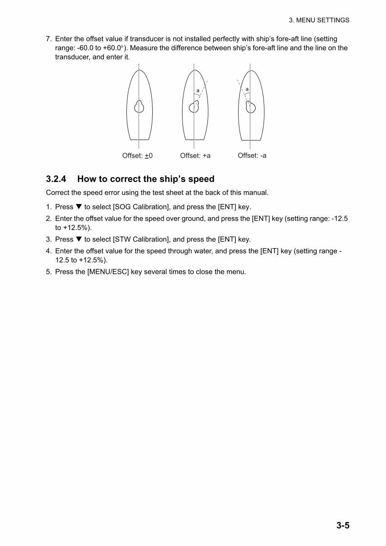
7. Enter the offset value if transducer is not installed perfectly with ship’s fore-aft line (setting range: -60.0 to +60.0°). Measure the difference between ship’s fore-aft line and the line on the transducer, and enter it.
3.2.4 How to correct the ship’s speedCorrect the speed error using the test sheet at the back of this manual.
1. Press to select [SOG Calibration], and press the [ENT] key.2. Enter the offset value for the speed over ground, and press the [ENT] key (setting range: -12.5
to +12.5%).3. Press to select [STW Calibration], and press the [ENT] key.4. Enter the offset value for the speed through water, and press the [ENT] key (setting range -
12.5 to +12.5%).5. Press the [MENU/ESC] key several times to close the menu.
Offset: +0 Offset: +a Offset: -a

3. MENU SETTINGS
3-6
This page is intentionally left blank.

AP-1
APPENDIX 1 CALIBRATION
Milepost run
It is common practice to check a new ship’s performance at an official trial run. Take this op-portunity to calibrate the DS-60. In practice, the ship speed is evaluated as follows.
1. Calculation with transit postsSteer the ship at a steady speed on the test course, e.g. A→B in the illustration. Speed is ob-tained from the following equations. Note that Sg1 and Sg2 are both speeds over the ground (SOG); however the DS-60 provides the speed through the water. To find the speed through the water, a return trip is necessary.
Sg1 = d/t1 X 3600 (kn)... (1)Sg2 = d/t2 X 3600 (kn)... (2)Sw + St = Sg1 (kn)... (kn3)Sw - St = Sg2 (kn)... (4)Adding (4) and (3), we get;2Sw = Sg1 + Sg2 (kn)
Therefore, Sw = (Sg1 + Sg2)/2 (kn)... (5)where,d = distance run (nm),
t1 = time taken to run 1 (second),t2 = time taken to run 2 (second). (Note: Runs 1 and 2 are in opposite direction.)Sw = Speed through the water (kn),St. = Speed of tide current (kn),Sg1 = SOG for run 1 (kn),Sg2 = SOG for run 2 (kn).Thus we can find a speed through the water by making a round tip.
P1
P1'
P2
P2'
A B
d
Sg1
Sg2
Transit posts Transit posts

APPENDIX
AP-2
2. Calculation with DS-60To measure the distance run between points A and B by DS-60, do the following:
1. Reset the distance run figure of DS-60 to zero by selecting Reset on the Trip DIST menu at the moment the ship passes point A.
2. Run the ship from A to B at full speed, timing with a stopwatch.3. Read the distance run (nm) and time taken to run (second) exactly at the moment the
shipshape point B.4. Run the ship from B to A at full speed rehearing to step 1 through 3.
Where,n1 (nm) = distance run from A to B measured by DS-60n2 (nm) = distance run from B or A measured by DS-60
Therefore, the average run from A to B measured by DS-60Therefore, the average ship speeds of run 1 and run 2 are calculated as follows.
Slog1 (kn) = n1/t1 X 3600Slog2 (kn) = n2/t1 X3600
The average ship speed of round trip is Slog (kn) = (Slog1 + Slog2)/2 ...(6)
3. Speedily errorFrom (5) and (6),Error = (Sw - Slog)/Slog X 100 (%)... (7)
This error can be corrected at SPEED OFFSET on the system menu as follows:
1. Press the [MENU/ESC] key.2. Select SYSTEM MENU and press the [ENT] key.3. Select SPEED OFFSET and press the [ENT] key.4. Enter the value of error.
Repeat the above procedure several times to satisfy the speed accuracy specification.

TES
T S
ITE
SH
IP'S
LE
NG
TH(m
)D
RA
FTFo
reA
ftM
ean
(m)
NA
ME
Ser
. No.
DO
CK
YA
RD
TRIM
(m)
DA
TE:
EM
-Log
Dep
thC
ours
eW
ind
Cur
rent
Rem
arks
Run
No.
(kn)
Tim
e (s
)
Mea
n
Mea
n
Mea
n
Mea
n
Mea
n
Dis
tanc
e ru
nS
east
ate
(kn)
(kn)
(m)
(deg
)(m
/s)
knTi
me
Out
RP
M
CA
LIB
RA
TIO
N S
HE
ET
FOR
DS
-60
Tim
e (s
)Spe
ed(k
n)E
rro r
Eng
ine
Mile
post
Dop
pler
spe
ed lo
g
hmaki
テキストボックス
AP-3

AP-4
APPENDIX 2 JIS CABLE GUIDE
Core Cable Core Cable
Type Area Diameter Type Area Diameter
TTYCS-4
MPYC-5
TPYC
The following reference table lists gives the measurements of JIS cables commonly used with Furuno products:
Cables listed in the manual are usually shown as Japanese Industrial Standard (JIS). Use the following guide to locate an equivalent cable locally.
JIS cable names may have up to 6 alphabetical characters, followed by a dash and a numerical value (example: DPYC-2.5). For core types D and T, the numerical designation indicates the cross-sectional Area (mm2) of the core wire(s) in the cable. For core types M and TT, the numerical designation indicates the number of core wires in the cable.
1. Core Type 2. Insulation Type 3. Sheath TypeD Double core power line P Ethylene Propylene Y Vinyl T Triple core power line
M 1 mm Multi core
TT 0.75mm twisted pair communications (1Q=quad cable)
4. Armor Type 5. Shielding Type 6. Core SheathC Steel Y Corrosive Resistant S All cores in one sheath -S Individually sheathed cores
SLA
DPYC
Diameter Diameter
DPYC-1.5 1.5mm2 1.56mm 11.7mm
DPYC-2.5 2.5mm2 2.01mm 12.8mm
DPYC-4 4.0mm2 2.55mm 13.9mm
DPYC-6 6.0mm2 3.12mm 15.2mm
DPYCY-2.5 2.5mm2 2.01mm 14.8mm
DPYCY-4 4.0mm 2.55mm 15.9mm
DPYCYSLA-1.5 1.5mm2 1.56mm 13.9mm
DPYCYSLA-2.5 2.5mm2 2.01mm 15.0mm
MPYC-2 1.0mm2 1.29mm 10.0mm
MPYC-4 1.0mm2 1.29mm 11.2mm
MPYC-7 1.0mm2 1.29mm 13.2mm
MPYCY-12 1.0mm2 1.29mm 19.0mm
MPYCY-19 1.0mm2 1.29mm 22.0mm
TTYC-7S 0.75mm2 1.11mm 20.8mm
TTYCSLA-1 0.75mm2 1.11mm 9.4mm
TTYCSLA-1Q 0.75mm2 1.11mm 10.8mm
TTYCSLA-4 0.75mm2 1.11mm 15.7mm
TTYCY-4S 0.75mm2 1.11mm 17.9mm
TTYCYS-1 0.75mm2 1.11mm 12.1mm
TTYCYS-4 0.75mm2 1.11mm 18.5mm
TPYCY-1.5 1.5mm2 1.56mm 14.5mm
TPYCY-2.5 2.5mm2 2.01mm 15.5mm
TPYCY-4 4.0mm2 2.55mm 16.9mm
TPYCYSLA-1.5 1.5mm2 1.56mm 13.9mm
EX: DPYCYS - 1.5 MPYC - 5Designation type Core Area (mm2) Designation type # of cores
1 2 3 4 5 6 1 2 3 4
-SLA Individually sheathed cores, plastic tube sheathw/aluminum tape
All cores in one sheath, plastic tube sheathw/aluminum tape

A-2
A-1

A-4
A-3

A-6
A-5

A-8
A-7

A-1
0A
-9

A-1
2A
-11

ynishiyama
テキストボックス
8/Mar/2010 Y.NISHIYAMA
hmaki
テキストボックス
D-1

hmaki
テキストボックス
D-2

ynishiyama
テキストボックス
18/Feb/2011 Y.NISHIYAMA
emiyoshi
テキストボックス
D-3

9/Dec/08 R.Esumi
hmaki
テキストボックス
D-4

5/Mar/09 R.Esumi
hmaki
テキストボックス
D-5

9/Dec/08 R.Esumi
hmaki
テキストボックス
D-6

ynishiyama
テキストボックス
29/Mar/2011 Y.NISHIYAMA
emiyoshi
テキストボックス
D-7

ynishiyama
テキストボックス
29/Mar/2011 Y.NISHIYAMA
emiyoshi
テキストボックス
D-8

ynishiyama
テキストボックス
20/Jul/2010 Y.NISHIYAMA
emiyoshi
テキストボックス
D-9

ynishiyama
テキストボックス
20/Jul/2010 Y.NISHIYAMA
emiyoshi
テキストボックス
D-10

ynishiyama
テキストボックス
17/Mar/2011 Y.NISHIYAMA
emiyoshi
テキストボックス
D-11

ynishiyama
テキストボックス
17/Mar/2011 Y.NISHIYAMA
emiyoshi
テキストボックス
D-12

ynishiyama
テキストボックス
6/May/2010 Y.NISHIYAMA
emiyoshi
テキストボックス
D-13

1 2 4 5 63
B
A
D
C
NAME
名称
TITLE
kgMASS
DWG No.
SCALE
APPROVED
CHECKED
DRAWN
REF.No.INTERCONNECTION DIAGRAM
相互結線図
DS-60
ドップラソナー
DOPPLER SONAR
P
P
P
123
6
478
*1
P
TB75
NCNC 9
10
12
*1 TB101
*1
*1
P
P
P
TB412345
67
12345
TB5
NC
NC
DPYC(Y)-2.5
TTYC(Y)S-1
TTYC(Y)S-1
P
P
P
P
P
P
123456789101112
TB8
NCNC
1314
123456
TB2
TB4TRANSCEIVERDS-620
TB5
TB6
TTYCY-4S*1
7
123456
接続箱
DS-640JUNCTION BOX
*2
DPYCY-4*1
12
12
DPYCY-4AC-HAC-C
*1
78
TB112345678
TB2
123456
123456
123456
TB6
56
P
P
P
1234567
レートジャイロ変換器RATE-0F-TURNGYRO CONVERTER
J3(NH7P)
12
TB1ACAC
1φ,50/60Hz100VAC
CO-0.2x5P,MAX.5m
*1DPYC-1.5
KP出力KP OUTPUT
外部KPEXTERNAL KP
1φ,50/60Hz100-240VAC
123456
TB2TD1ATD1BRD1ARD1BCONPCONN
1TB1
P
P
P
34
12
*1TTYCY-4S
0VFG
+12V
NC9
12
TB102
NC
*1IV-2sq.
1234
678
5
9101112
DETAIL FOR RD-20RD-20接続詳細
GND
NCNC
P
P
P
P
Vout
RD2ARD2BTD2ATD2BRD1ARD1B
DC_HDC_C
*1
*1TTYCS-1
*1TTYCS-1
*1DPYC-1.5
NMEA0183
12-24VDC
RD-501/502
RD-20
リモートディスプレイREMOTE DISPLAY
RD-20
*1IV-1.25sq.
TTYCS-4
*1IV-2sq.
MAX.500m
SPEED_LIMIT_NSPEED_LIMIT_P
DST2TRX_NDST2TRX_P
TRX2DST_NTRX2DST_P
TRX_KP_NTRX_KP_P
TRX_KP_NTRX_KP_PDST2TRX_NDST2TRX_PTRX2DST_NTRX2DST_P
REMOTE_ACK_NREMOTE_ACK_PLOCAL_ACK_NLOCAL_ACK_PECHO_FAIL_NECHO_FAIL_P
POWER_FAIL_PPOWER_FAIL_N
SYSTEM_FAIL_NSYSTEM_FAIL_P
DST2ROT_NDST2ROT_P
ROT2DST_NROT2DST_P
KP_IN_NKP_IN_PKP_OUT_NKP_OUT_P
24VDC_M_P
DSP2DST_PDST2DSP_NDST2DSP_P
DSP2DST_N
RMT_NRMT_P
24VDC_M_N
AC_OUT_CAC_OUT_H
ROT_RMT_PROT_RMT_N
+DC_H-DC_C
*1IV-1.25sq.
指示器DISPLAY UNITDS-600
SHIP'S MAIN_H
分配器DISTRIBUTERDS-610
SHIP'S MAIN_C 2
TXD-HTXD-CRXD-HRXD-C
送受信部
TTYC(Y)S-4,MAX.100m
アラームシステムALARM SYSTEM
TTYC(Y)-7S,MAX.100m*1
CO-0.2x5P: CO-SPEVV-SB-C 0.2x5P,φ13.5
VSF-2sq.5m
TB10
P
P
P
12
43
TB11
5678
1TB1
TB2RD1ARD1B
34
同上DITTO
*1
*1IV-1.25sq.
または OR
DS-605 防水箱 WATERPROOF BOX
指示器DISPLAY UNIT
*2DS-600
24VDC2_N24VDC2_P
DST2DSP2_NDST2DSP2_P
DST2DSP1_NDST2DSP1_P
24VDC1_P24VDC1_N +DC_H
-DC_C2
TTYCYS-4,MAX.100m*2
P
P
P
P
P
P
P
*1
12
43
5678
910111213NC
同上DITTO
34
MAX.30m
1TB1
TB2
P12
TB4
(W/O
RD-501)
*1
*1
GND
TB31234
1234 GND
9
9
調光器DIMMER
RD-502CONTROLLER
*2
1234 GND
6789 GND
5 NC9
RD2ARD2BVout
TD2ATD2BVin
RD1ARD1B
TD2ATD2B
Vout
TD2ATD2BVin
*1
*2RD-50(RD-20)
REMOTE DISPLAYリモートディスプレイ
REMOTE DISPLAYRD-20/50
リモートディスプレイ
TTYCS-4
TTYCS-4
P
P
RD-501 *2
REMOTECONTROLLER
リモート操作部
*1IV-1.25sq.
IV-1.25sq.
IV-1.25sq.
*1
24VDC5_N24VDC5_P
DST2DSP5_NDST2DSP5_P
24VDC4_N24VDC4_P
DST2DSP4_NDST2DSP4_P
24VDC3_N24VDC3_P
DST2DSP3_NDST2DSP3_P
RD2ARD2B
+DC_H-DC_C
*1
2
TTYC(Y)S-1
TTYC(Y)S-4.MAX.100m
P
P
*1
9101112
NC
TB31234
5678
*1
P
P
P
P
P
12345678910
TB9
12NCNC 11
NC 13
15NC14
ANA_DISP1_HANA_DISP1_CANA_RNG1_PANA_RNG1_N
ANA_DISP2_PANA_DISP2_NANA_RNG2_PANA_RNG2_N
ANA_V_PANA_V_NANA_C_PANA_C_N
61162_OUT_1_P61162_OUT_1_N61162_OUT_2_P61162_OUT_2_N61162_OUT_3_P61162_OUT_3_N61162_OUT_4_P61162_OUT_4_N61162_OUT_5_P61162_OUT_5_N
TTYC(Y)S-1,MAX.100m
TTYC(Y)S-1Q,MAX.100m
同上DITTO
アナログ指示器ANALOG INDICATOR
TTYC(Y)S-1Q,MAX.100m*1
*1
*1
TTYC(Y)S-1,MAX.100m アナログ出力ANALOG OUTPUT
TTYC(Y)S-1,MAX.100m
*1IV-2sq.
TB112345678
NC
同上DITTO
同上DITTO
123456
TB2
P
P
P
NC9
11 NC10
61162_IN_1_P61162_IN_1_N61162_IN_2_P61162_IN_2_N61162_IN_3_P61162_IN_3_N
LOG_OUT_1_PLOG_OUT_1_NLOG_OUT_2_PLOG_OUT_2_NLOG_OUT_3_PLOG_OUT_3_NLOG_OUT_4_PLOG_OUT_4_N
航程計LOG(200P)
航法装置NAVIGATIONAL
EQUIPMENT
*1
*1TTYC(Y)S-1,MAX.100m
DPYC(Y)-1.5,MAX.100m
*1
123456
TB2TD1ATD1BRD1ARD1BCONPCONN
1TB1+DC_H-DC_C2
TTYCS-4,MAX.100mP
P
12
4324VDC_P
24VDC_N
指示器DISPLAYUNIT
*1IV-1.25sq.
GND
1234
TB3
Vout
RD2ARD2B
P
P
DS-600
同上DITTO
ECDIS/AIS/VDR
レーダー、魚群探知機等RADAR/ECHO SOUNDER, ETC.
*1TTYCS-4
CONTROLLER
リモート操作部/調光器REMOTE/DIMMER
RD-501/502
REMOTE DISPLAYリモートディスプレイ
または ORRD-50/20
DS-600を副指示器として使用するときFOR USE DS-600 AS A REMOTE DISPLAY
DSTDSP_PDSTDSP_N
DS-610
T.YAMASAKI
30/40/50/60m66S1314-2,66S1314-1
TRANSDUCER送受波器
DS-630/631
チャチャ/クロアカアカ/クロダイダイ/クロ
キキ/クロミドリミドリ/クロアオアオ/クロ
シロ
シロ
シロ
クロ
チャ
アカ
シロ
シロ
シロ
シロ
シロ
シロ
ダイ
キ
ミドリ
アオ
ムラサキ
ハイ
WHT
WHT
WHT
BLK
BRN
RED
WHT
WHT
WHT
WHT
WHT
WHTGRY
PPL
BLU
GRN
YEL
ORG
ムラサキムラサキ/クロハイハイ/クロシロシロ/クロ
BRNBRN/BLKREDRED/BLKORGORG/BLK
YELYEL/BLKGRNGRN/BLKBLUBLU/BLK
WHT/BLK
GRY/BLKGRYPPL/BLKPPL
WHT
P
P
P
P
P
P
P
P
P
(ベース/ライン BASE/LINE)
*3
NOTE
*1: SHIPYARD SUPPLY.
*2: OPTION.
*1)造船所手配。
*2)オプション。
注記
*3)絶縁の色はどちらか一方が出荷。
*3: INSULATOR COLORS ARE SHOWN IN EITHER CASE.
H.MAKI
TB3TB1
DS-670 *2
10/Mar/2011
10/Mar/2011
C7264-C01- H 66-031-0001-1
ynishiyama
テキストボックス
11/Mar/2011 Y.NISHIYAMA
emiyoshi
テキストボックス
S-1

24
3
A
1
B C
DRAWN
CHECKED
APPROVED
DWG.No.
TITLE
NAME
名称
NOTE
注記
INTERCONNECTIONDIAGRAM
相互結線
図
REF.No.
SCALE
MASS
kg
T.YAMASAKI
DS-645A/B
接続箱
JUNCTIONBOX
DS-60
1 2 3 4 5 6 7NCNC
8
TRX2DST_P
TRX2DST_N
DST2TRX_P
DST2TRX_N
TRX_KP_P
TRX_KP_N
1 2 3 4 5 6 7NC
NC
8
TRX2DST_P
TRX2DST_N
DST2TRX_P
DST2TRX_N
TRX_KP_P
TRX_KP_N
TB2
TB1
*1)造船所
手配。
*1:
SHIPYARD
SUPPLY.
DS-645A
JUNCTION
BOX
接続箱
*1
TTYCY-4S
TB6
5 6
P P P
3 41 2
NC
9
DST2TRX_N
DST2TRX_P
TRX2DST_N
TRX2DST_P
TRX_KP_N
TRX_KP_P
DS-610
分配器
1 2 3 4 5 6 7NCNC
8
TRX2DST_P
TRX2DST_N
DST2TRX_P
DST2TRX_N
TRX_KP_P
TRX_KP_N
1 2 3 4 5 6 7NC
NC
8
TRX2DST_P
TRX2DST_N
DST2TRX_P
DST2TRX_N
TRX_KP_P
TRX_KP_NTB2
TB1
5 63 41 2
TRX_KP_N
TRX_KP_P
TB2
TRX2DST_N
TRX2DST_P
DST2TRX_N
DST2TRX_P
NC
7
P P P
*1
TTYCY-4S
DS-645B
JUNCTIONBOX
接続
箱
DS-620
送受
信部
TRANSCEIVER
TTYCY-19S/10S
*1
P P P
7TB3
1 2 3 4 5 6
TB3
※
NC
160V
ENC
0V
0VNC
120V
0V
120V
DPYCY-4*1
1 2
TB102
AC_OUT_C
AC_OUT_H
8
1 2 3 4TB3
1 2
TB101
AC-H
AC-C
DPYCY-4*1
TB3 85 6 7
P P
T1 *1
*1
100-120V
200-240V
ACVOLTAGE
※ジ
ャン
パー
設定
JUMPERSETTING
JP1
JP2
#3-#5
#4-#6
#4-#5
TOTAL
CABLE
LENGTH:
UP
TO
500m.
最大
ケー
ブル
長さ
:500m
IV-2sq.
IV-2sq.
PE
C7264-C02-B
H.MAKI
21/Apr/2011
21/Apr/2011
DISTRIBUTOR
66-031-4501-0
26/Apr/2011 D.MILLS
emiyoshi
テキストボックス
S-2
Related Documents