WESTINGHOUSE NON-PROPRIETARY CLASS 3 . WCAP-15302 Donald C. Cook Nuclear Plant Units I and 2 Modifications of the Containment Systems Westinghouse Safety Evaluation (SECL-99-076, Revision 3) PgR .g><XO 991'OOg 99'O6 M Poa September, 1999 xxxx.doc Westinghouse Electric Company LLC P.O. Box 355 Pittsburgh, PA 15230-0355 1999 Westinghouse Electric Company LLC AllRights Reserved

Welcome message from author
This document is posted to help you gain knowledge. Please leave a comment to let me know what you think about it! Share it to your friends and learn new things together.
Transcript

WESTINGHOUSE NON-PROPRIETARY CLASS 3
. WCAP-15302
Donald C. Cook Nuclear Plant Units I and 2Modifications of the Containment Systems
Westinghouse Safety Evaluation
(SECL-99-076, Revision 3)
PgR .g><XO 991'OOg99'O6
MPoa
September, 1999
xxxx.doc
Westinghouse Electric Company LLCP.O. Box 355
Pittsburgh, PA 15230-0355
1999 Westinghouse Electric Company LLCAllRights Reserved

'h/estinghouse Safety Evaluation SECL-99-076, Revision 3
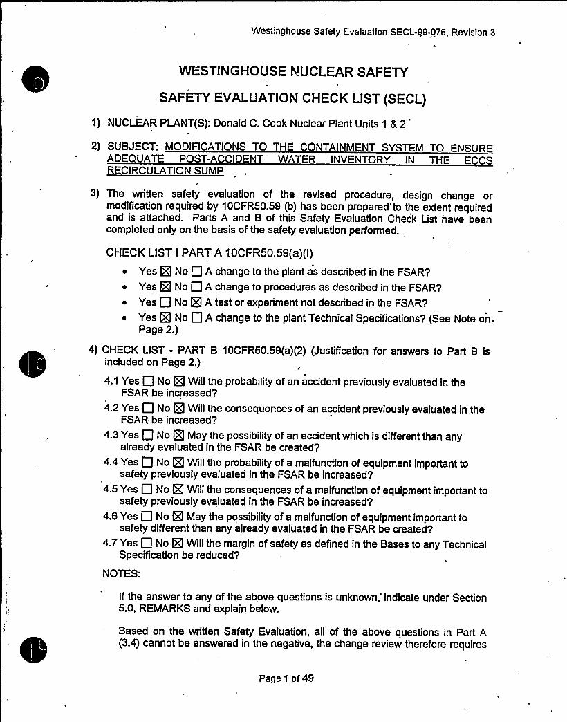
WESTINGHOUSE NUCLEAR SAFETY
SAFETY EVALUATIONCHECK LIST (SECL)
1) NUCLEAR PLANT(S): Donald C. Cook Nuclear Plant Units 1 & 2')
SUBJECT: MODIFICATIONS TO THE CONTAINMENT SYSTEM TO ENSUREADE UATE POST-ACCIDENT WATER INVENTORY IN THE ECCSRECIRCULATIONSUMP
I
3) The written safety evaluation of the revised procedure, design change ormodification required by 10CFR50.59 (b) has been prepared" to the extent requiredand is attached. Parts A and B of this Safety Evaluation Check List have beencompleted only on the basis of the safety evaluation performed.
CHECK LIST I PART A 10CFR50.59(a)(I)
~ Yes H No Q A change to the plant as described in the FSAR'?
~ Yes g No Q A change to procedures as described in the FSAR'?
~ Yes P No g A test or experiment not described in the FSAR'?
~ Yes g No A change to the plant Technical Specifications'? (See Note on.Page 2.)
4) CHECK LIST - PART B 10CFR50.59(a)(2) (Justification for answers to Part B isincluded on Page 2.)
4.1 Yes Q No g) Will the probability of an accident previously evaluated in theFSAR be increased'
4.2 Yes Q No g Will the consequences of an accident previously evaluated in theFSAR be increased'
4.3 Yes Q No g May the possibility of an accident which is different than anyalready evaluated in the FSAR be created'
4.4 Yes Q No g Will the probability of a malfunction of equipment important tosafety previously. evaluated in the FSAR be increased?
4.5 Yes 0 No g Willthe consequences of a malfunction of equipment important tosafety previously evaluated in the FSAR be increased?
4.6 Yes 0 No gl May the possibility of a malfunction of equipment important tosafety different than any already evaluated in the FSAR be created?
4.7 Yes No g Will the margin of safety as defined in the Bases to any TechnicalSpecification be reduced'
NOTES:
If the answer to any of the above questions is unknown,'indicate under Section5.0, REMARKS and explain below.
Based on the written Safety Evaluation, all of the above questions in Part A(3.4) cannot be answered in the negative, the change review therefore requires
Page 1 of 49

Westinghouse Safety Evaluation SEC:L-99-076, Revision 3Page 2 of 49
an application for license amendment as required by 10CFR50.59(c), besubmitted to the NRC pursuant to 10CFR50.90.
5) REMARKS:
The answers given in Section 3, Part A, and Section 4, Part B, of the Safety EvaluationChecklist, are based on the attached Safety Evaluation.
FOR FSAR UPDATE
Section: N/A Pages: N/A Tables: N/A Figures: N/AI
Reason for/Description of Change:
N/A
6) SAFETY EVALUATlO APP OV L LADDER:
Prepared by: Date:
Reviewed by:'


Westinghouse Safety Evaluation SECL-99-076, Revision 3
Westinghouse Safety Evaluation
(SECL 99-076, Revision 3)
Donald C. Cook Nuclear Plant Units 1 8 2
Modifications To The. Containment Systems
This Westinghouse Safety Evaluation of the modifications to the containment systemsof Donald C. Cook Nuclear Plants Units 1 & 2 has been performed in support of theattendant application for license amendment, as required by 10CFR50.59(c) to besubmitted to the NRC pursuant to 10CFR50.90.
Page 3 of 49

Westinghouse Safety Evaluation SECL-99-076, Revision 3
WESTINGHOUSE SAFETY EVAL'UATION
DONALDC. COOK PLANT UNITS 1 & 2
MODIFICATIONSTO THE CONTAINMENTSYSTEM
Table of Contents
1. BACKGROUND.
2. LICENSING BASIS2.1 Technical Specifications.
5
.6
.7
.7
.7
.8
.8~ ~ ~ ~ ~ 8
.8
.820
3. SAFETY EVALUATIONS3.1 Non-LOCA Related Evaluation.3.2 Mechanical Components and Systems Evaluation.
3.2.1 Structural and Mechanical Systems3.2.2 NSSS Component, and Control Systems Evaluation,
3.3 Fluid Systems Evaluation."3.3.1 RWST Drain-Down Calculation.
3.4 Containment Integrity Evaluation.3.4.1 Short Term LOCA M&E/ Subcompartment: Loop Compartment Analyses,Reactor Cavity, Pressurizer Enclosure; and, Short Term MSLB M&E/Subcompartment: Steam Generator Enclosure and Fan Accumulator RoomAnalyses. 223.4.2 Containment Integrity (Long Term LOCA) 233.4.3 Post-LOCA Hydrogen Generation Evaluation. 273.4.4 Main Steamline Break (MSLB) Mass and Energy Release. 273.4.5 Conclusions Of Containment Integrity Evaluation 29
3.5 LOCA and LOCA-Related Analyses. 293.5.1 Introduction 293.5.2 Evaluation of the Post-LOCA Subcriticality Calculation... 31
3.5.3 Evaluation of the Post-LOCA Long Term Core Cooling Analysis ................. 333.5.4 Changes which Impact the Small Break and Large Break LOCA Analysis... 353.5.5 LOCA Evaluation Summary and Conclusions . 36
3.6 Emergency Operating Procedures Evaluation. .433.7 Steam Generator Tube Rupture Evaluation. 433.8 Radiological Consequences Evaluation. 43
4. DETERMINATIONOF NO SIGNIFICANT HAZARDS 45
5. REFERENCES 48
Page 4 of 49


Westinghouse Safety Evaluation SECL-99-076, Revision 3
SAFETY EVALUATION.OF CONTAINMENTSYSTEMMODIFICATIONS
1. BACKGROUND
The Donald C. Cook Nuclear Plant Units 1 and 2 Containment/ECCS design is based
on the assumption that water will accumul'ate in the recirculation sump following an
accident. The sources of water include the Refueling Water Storage Tank (RWST)volume (from RCS leakage and/or containment spray (CTS) actuation), condensatefrom the ice condenser, RCS inventory, and inventory from the ECCS accumulators.However, the amount of water available from these sources is time-dependent based
on the specific accident scenario. It is assumed that sufficient water is available to
assure satisfactory containment spray / ECCS pump operation in recirculation mode.
The current design of the Donald C. Cook containment and safety systems includesfeatures that can result in a portion of the water injected into containment beingdiverted away from the recirculation sump and not being returne. Thus, depending on
the accident scenario, there may not be sufficient water in the sump to assure
satisfactory pump operation during recirculation mode, i.e., sufficient water to precludevortex formation. This possibility was not identified during the original design andconstruction of the plants because the postulated events that can lead to insufficientinventory are small break LOCAs, and the emphasis during construction regarding the
containment an'd safety system design was focused on large break LOCAs.
AEP is now proposing design changes, described in Reference 1 to address this issue.
As discussed in Reference 1, the design changes are intended to ensure the
availability of sufficient post-accident containment water inventory to meet theestablished NPSH requirements for the ECCS and CTS pumps, and to prevent vortexformation in the containment ECCS recirculation sump. The Licensing Bases
requirements for the ECCS recirculation sump are that the sump level must be at, orabove the 602'10" elevation at the time of switch-over to the recirculation mode, and
that the level must remain above 602'10" while in recirculation mode. This level wasdemonstrated by testing to be adequate for satisfactory ECCS pump performance (i.e.,
adequate NPSH and no vortexing). Because satisfactory operation of the ECCS
systems requires proper function of the sump (i.e., minimum water level must be
maintained), the sump must satisfy all design requirements for the same limitingconditions as the ECCS systems. These include all postulated licensing basis eventsand postulated single failures. The plant modifications determined to meet theseobjectives are described briefly below:
a) Partition Wall Penetration
In order to insure that water which enters the annulus area after a LOCA can return to
the sump, penetrations will be added to the partition wall which forms the "chimney"
area inside the crane wall behind the Pressurizer Relief Tank (PRT). This will require a
design change to add these penetrations and other design features necessary to insure
water level will equalize between the annulus and the active sump area.
'age 5of49

Westinghouse. Safety Evaluation SECL-99-'076, Revision 3
b) CEQ Fan Room Drains
The CEQ fan room has drains to preclude the accumulation of water after containment
spray actuation. Since a separate design change is replacing the check valves in the
drain lines with safety related components to resolve a condition report, the drains will
be rerouted to the reactor coolant system loop compartment for convenience.
c) Increase RWST Overflow Height
Addition of elbows and a vertical section to the RWST overflow line to allow a higherwater level, that combined with a re-spanning of the tank instrumentation will result in
an increase in the total amount'of water which can be delivered from the tank.
d) Containment Sump Level Instrumentation Upgrade
The sump level instrumentation will be upgraded to improve the accuracy of the sumplevel information available to the operators for execution of the plant emergency
operating procedures (EOPs).
e) CEQ Fan Start Logic
The CEQ fans currently start on the High-2 containment pressure signal with a delay of
9 2 1 minutes, resulting in fan actuation after the containment spray starts. For smaller
break sizes, containment spray severely limits the rate of ice melt from the ice
condenser because much of the energy released into containment from the RCS is
removed by the containment spray, rather than the ice condenser. To increase the rate
of ice melt, and thus, increase the amount of water in the containment sump at the time
of switch-over from the RWST, the CEQ fans will be started on a High-1 containment
pressure signal with a minimal delay (120 2 12 seconds).
f) Reduced Ice Mass in the Ice Condenser
To comply with the current ice mass technical specification (TS 3/4.6.5.1) would requiresignificant maintenance of the ice bed during each plant outage. With this newcontainment integrity analysis presented herein, the ice weight required by the
Technical Specifications may be reduced, resulting in greater operational flexibility forthe ice condenser.
This Safety Evaluation considers these design changes as well as other plant changesthat have resulted from related Condition Reports, with the purpose of determining the
impact of the modifications on the licensing bases of the units, and demonstrating thatthe modifications will not adversely affect the subsequent safe operation of the Donald
C. Cook Nuclear Plant Units 1 and 2.
2: LICENSING BASIS
This document provides the Containment Integrity and LOCA and LOCA-related safetyanalyses required for implementation of the modifications to the containment system as
described herein, and the related changes to the input assumptions of affected safetyanalyses that are, in turn, required for the restart of the Donald C. Cook Units . It is the
Page 6 of 49

Westinghouse Safety Evaluation SECL-99-076, Revision 3
purpose of this document to support the attendant application for license amendmentas required by 10CFR50.59(c), to be submitted to the NRC pursuant to 10CFR50.90,and the determination that no.significant hazards consideration is involved per10CFR50.92. This document also presents the results of the revised analyses andsupporting information necessary to update the UFSARs of Donald C. Cook NuclearPlant Units 1 8 2.
2.1 Technical Specifications
The current Technical Specifications (Reference 2) must be revised to incorporate therelevant containment modifications evaluated herein. The potentially affected sectionsof the Donald C. Cook Nuclear Plant Units 1.& 2 Technical Specifications are listedbelow.
Technical S ecification Number3.1.2.73.1.2.8B 3/4.1
3.5.5B 3/4.5.53.6.5.1
B 3/4.6.5.1
Technical S ecification TitleBorated Water Sources - ShutdownBorated Water Sources - OperatingBases for Reactivity Control Systems(B oration)Refueling Water Storage TankBases for Refueling Water Storage TankIce BedBases for Ice Bed
3. SAFETY EVALUATIONS
Westinghouse has reviewed the following areas with respect to the modifications to thecontainment systems and the related changes to the accident analyses inputassumptions identified in Reference 3:
Containment Analyses
Emergency Operating Procedures
Technical Specifications
LOCA and LOCA- Related Analyses
Non-LOCA Analyses
NSSS Component and Control Systems
Fluid Systems
The only areas found to be potentially affected by these modifications and referencedchanges to the accident analysis input assumptions were the Emergency OperatingProcedures, Mechanical and Fluid Systems, Containment Integrity Analysis, LOCAAnalyses and the Radiological Analysis. It should be noted that while the subjectchanges affect the EOPs and Radiological Analyses, the effect in those areas will beaddressed by AEP and/or Westinghouse in a separate Safety Evaluation.
3.1 Non-LOCA Related Evaluation
The non-LOCA Safety Analyses presented in Chapter 14 of the UFSAR(s) are notadversely affected by the modifications to the containment systems described herein.Further, this activity does not affect normal plant operating parameters, accident
Page 7 of 49
"Westinghouse Safety Evaluation SECL-99-076, Revision 3
mitigation capabilities, nor the assumptions used in the non-LOCA transients, and noconditions more limiting than those enveloped by the current non-LOCA analyses arecreated. Thus, the'conclusions presented in the FSAR for the non-LOCA SafetyAnalyses will remain valid.given implementation of these modifications.
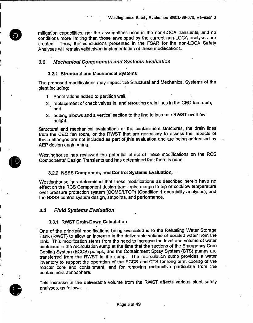
3.2 Mechanical Components and Systems Evaluation4
3.2.1 Structural and Mechanical Systems
The proposed modifications may impact the Structural and Mechanical Systems of theplant including:
1. Penetrations added to partition wall,
2. replacement of check valves in, and rerouting drain lines in the CEQ fan room,'nd
3. adding elbows and a vertical section to the line to increase RWST overflowheight.
Structural and mechanical evaluations of the containment structures, the drain linesfrom the CEQ fan room, or the RWST that are necessary to assess the impacts ofthese changes are not included as part of.this evaluation and are being addressed byAEP design engineering.
Westinghouse has reviewed the potential effect of these modifications on the RCSComponents'esign Transients and has determined that there is none.
3.2.2 NSSS Component, and Control Systems Evaluation,
Westinghouse has determined that these modiTications as described herein have noeffect on the RCS Component design transients, margin to trip or cold/low temperatureover pressure protection system (COMS/LTOP) (Condition 1 operability analyses), andthe NSSS control system design, setpoints, and performance.
3.3 Fluid Systems Evaluation
3.3.1 RWST Drain-Down Calculation
One of the principal modifications being evaluated is to the Refueling Water StorageTank (RWST) to allow an increase in the deliverable volume of borated water from thetank. This modification stems from the need to increase the level and volume of watercontained in the recirculation sump at the time that the suctions of the Emergency CoreCooling System (ECCS) pumps, and the Containment Spray System (CTS) pumps aretransferred from the RWST to the sump. The recirculation sump provides a waterinventory to support the operation of the ECCS and CTS for long term cooling of thereactor core and containment, and for removing radioactive particulate from thecontainment atmosphere.
This increase in the deliverable volume from the RWST affects various plant safetyanalyses, as follows:
Page 8 of 49

Westinghouse Sai'ety'c.valu1tioh SECL-99-076, Revision 3
The net positive suction head available (NPSHA) for the ECCS and CTS pumps is
dependent on the minimum water levels in the RWST, as well as the minimumwater levels in the recirculation sump. The verification of adequate NPSHA for thesafeguard pumps is being performed by AEP in a separate evaluation. Accordingly,the analyses performed by Westinghouse assume that there is adequate NPSH forthe Charging, Safety Injection, Residual Heat Removal (RHR), and CTS pumpsover the range of levels encountered when taking suction from the RWST or thesump.
The increase in RWST volume will increase the time period after a LOCA followingwhich recirculation is initiated and completed. The core decay heat load will,therefore, be lower for longer times following the accident during the recirculation
'hase.The lower decay heat load at. the time that recirculation is initiated will,therefore, provide a benefit for long term core cooling, as well as for hot legrecirculation and for boron concentration/precipitation in the reactor vessel.
The longer time required to drain the RWST to the switch-over. setpoint will alsoincrease the amount of ice that will melt in the ice condenser and mix with the otherwater sources in the recirculation sump. This increased ice bed melt-out will
potentially reduce the sump water temperature at the onset of recirculation,
providing benefit for both core cooling and heat removal via the containmentsprays. Because the ice is borated, the concentration of boron in the recirculated
sump water will increase because of the larger mass of melted ice in the sump,providing a benefit for post-LOCA subcriticality calculations.
For the containment integrity analysis, the sequence of operations used forswitching the safeguard systems from the RWST to the recirculation sump involvesa period of time durin'g which all containment spray flow is stopped while the CTS
pump suctions are re-aligned from the RWST to the sump. With a larger RWST,this interruption in spray flow occurs further out in time following the accident, whichaffects the containment pressure calculations.
Changes to RWST volume and ice bed mass have been evaluated for their effecton long-term sump pH. These changes were small in magnitude, and therefore,were determined to have a negligible affect on the calculation of record on sumppH. In fact, in some cases, the changes were offsetting. In summary, there is no
net.effect on the calculated sump pH values, and the current TechnicalSpeciTication pH limits of 7.6 to 9.5 (TS Bases 3/4.5.5) for the post-LOCAcontainment sump recirculation water will be maintained.
3.3.1.1AEP Supplied Inputs to RWST Drain-Down Calculation
The following key inputs to the RWST Drain-Down calculations have been receivedfrom AEP:
Reference 3 gives the minimum delivered volume prior to initiating switch-overoperations as at least 280,000 gallons, and the minimum total delivered volume atthe'completion of switch-over as at least 314,000 gallons. A key interpretation thenused in this RWST Drain-Down calculation is that the 314,000 minimum totaldeliverable volume corresponds to the point in the switch-over procedure where the
safety injection and charging pumps cease taking suction from the RWST. Due to
the discharge pressure developed by the RHR pumps, this occurs when the RHR
Page 9 of 49

Westinghouse Safety Fvaluation SiCL-9 -076, Revision 3
2)
heat exchanger outlet valves supplying the suctions of the charging and safetyinjection pumps are opened, causing the check valves in the RWST suction lines tothese pumps to close, thereby stopping all suction flow from the RWST.
The sequence for loading the safeguards pumps onto the emergency power supplybuses following an accident are as provided in Reference 4. Specifically, thestarting times for the charging pump, safety injection pump, RHR pump, and spraypump are 3, 7, 11, and 31 seconds, respectively, after the diesel delay time. (Notethat the times in Reference 4 include a ten second diesel dolay time.) Even thoughit is conservative to empty the RWST as rapidly as possible for the LOCA andContainment analyses, the worst cases for the LOCA and Containment transientsoccur with a simultaneous loss of off-site power. Therefore, to be consistent withthose accident analyses, the RWST drain-down analyses were performed usingpump starting times that include the diesel startup delay and loading sequence toreflect a Loss of Offsite Power.
3) This RWST Drain-Down calculation by Westinghouse also assumes thatReference 5 is an accurate representation of the switch-over procedure, and thatany later revisions to ES-1.3 are similar to Reference 5 in the areas critical to thecalculation.
4) The sequence of operator actions during the switch-over procedure, and the timesrequired to accomplish those actions, are described below for two alternativescenarios. The simplest scenario stops both trains of RHR/spray at the beginningof switch-over, and re-starts both trains of RHR/spray five minutes later. Thisscenario was used when calculating the RWST Drain-Down to support containmentintegrity and radiological dose analyses because it maximizes the time durationduring which containment cooling and the scrubbing action of the containmentsprays for removing iodine from the containment atmosphere are suspended. Thisswitch-over scenario is also used for the LOCA analysis because it interrupts theflow from the RHR pump. However, for LOCA, an additional, more complicatedswitch-over scenario is provided in Reference 6. The Reference 6 sequenceprovides for a three minute interruption in RHR flow during switch-over from thetime period beginning 120 seconds after the initiation of switch-over when thesecond train of RHR/CTS pumps are stopped, and extending to 300 seconds afterswitch-over when the first train of RHR/CTS pumps are re-started. Additionally, flowfrom the RWST is finally terminated at 660 seconds after the initiation of switch-over, when the RHR heat exchanger outlet valves are opened to supply thesuctions of the charging and safety injection pumps. The RHR pump dischargepressure then causes the check valves in the RWST suction lines to the chargingand safety injection pumps to close, effectively terminating suction flow from thetank.
5) The maximum containment spray flow per train is 3700 gpm (Reference 7), and7400 gpm when both trains are in operation.
6) The minimum containment spray flow rate is 2932 gpm per train (Reference 3).
Because the RWST Drain-Down calculations are utilized in different accident analyses,they have. been biased to conservatively affect these different analyses. The results of
Page 10 of 49
Ii iw " IC 7
Westinghouse Safety Evaluation SECL-99-076, Revision 3
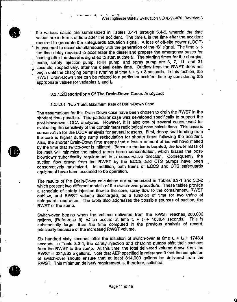
the various cases are summarized in Tables 3.4-1 through 3.4-6, wherein the timevalues are in terms of time after the accident. The time t, is the time after the accidentrequired to generate the safeguards actuation signal, A loss of off-site power (LOOP)is assumed to occur simultaneously with the generation of the "S" signal. The time 4 is
the time delay required to accelerate the diesel and prepare the emergency buses forloading after the diesel is signaled to start at time t,. The starting times for the charging
: pump, safety injection pump, RHR pump, and spray pump are 3, 7, 11, and 31
,: seconds, respectively, after the diesel delay time. Outflow from the RWST does notbegin until the charging pump is running at time t, + 4+ 3 seconds. In this fashion, theRWST Drain-Down time can be related to a particular accident time by considering theappropriate values for variables t, and g.
3.3.1.2Descriptions Of The Drain-Down Cases Analyzed:
3.3.1.2.1 Two Train, Maximum Rate of Drain-Down Case
The assumptions for this Drain-Down case have been chosen to drain the RWST in theshortest time possible. This particular case was developed specifically to support thepost-blowdown LOCA analyses. However, it is also one of several cases used forevaluating the sensitivity of the containment radiological dose calculations. This case is
conservative for the LOCA analysis for several reasons. First, decay heat loading fromthe core is higher during sump recirculation for shorter times following the accident.
Also, the shorter Drain-Down time means that a lesser amount of ice will have melted
by the time that switch-over is initiated. Because the ice is borated, the lower mass ofice melt will minimize the mixed mean boron concentration, which biases the post-blowdown subcriticality requirement in a conservative direction. Consequently, thesuction flow drawn from the RWST by the ECCS and CTS pumps have beenconservatively maximized. In addition, both trains of ECCS and CTS safeguardsequipment'have been assumed to be operation.
The results of the Drain-Down calculation are summarized in Tables 3.3-1 and 3.3-2which present two different models of the switch-over procedure. These tables providea schedule of safety injection flow to the core, spray flow to the containment, RWSToutflow, and RWST volume discharged, as a function of time for two trains ofsafeguards operation. The table also addres'ses the possible sources of suction, theRWST or the sump.
Switch-over begins when the volume delivered from the RWST reaches 280,000gallons, (Reference 3), which occurs at time t, + Q+ 1088.4 seconds. This is
substantially larger than the time computed in the previous analysis of record,principally because of the increased RWST volume.
Six hundred sixty seconds after the initiation of switch-over at time t, + 4 + 1748.4seconds, in Table 3.3-1, the safety injection and charging pumps shift their suctionsfrom the RWST to the sump. At this time, the total delivered volume drawn from theRWST is 321,862.5 gallons. Note that AEP specified in reference 3 that the completionof switch-over should ensure that at least 314,000 gallons be delivered from theRWST. This minimum delivery requirement is, therefore, satisfied.
Page 11 of 49

'vVe~1ingiiouse Safety Evaluation SECL-99-'076, Revision 3
Table 3.3-1 shows a three minute interruption in RHR flow during switch-over from thetime that the second train of RHR/CTS pumps are stopped at 120 seconds after theinitiation of switch-over, (time t. + td + 1208.4 seconds), until 300 seconds after
the'nitiationof switch-over, (time t, + td+ 1388.4 seconds), when the first train of RHR/CTSpumps is re-started with their suctions aligned to the sump.
Table 3.3-2 shows a five minute interruption in RHR and CTS flow during the switch-over. The RHR and CTS pumps are stopped at the beginning of recirculation when280,000 gallons have been delivered from the RWST, and are re-started five minuteslater. The charging and safety injection pumps cease taking suction from the RWSTwhen the total delivered volume from the RWST reaches 314,000 gallons at time t, + td
+2266.4 seconds after the accident.
The calculation and transmittal of results for these cases are documented byReferences 8 and 9.
3.3.1.2.2 Single Train, Maximum Rate of Drain-Down Case
The assumptions for this case have been chosen to drain the RWST as rapidly aspossible, consistent with the assumption that only one train of safeguards equipment isin operation. The calculation and transmittal of results, respectively, is documented byReferences 10 and 11. This particula'r case was developed specifically to support thecontainment integrity analysis. However, it is also one of several used for evaluatingthe sensitivity of the containment radiological dose calculations. This case„isconservative for the purposes of containment integrity analysis, because the intent ofthe integrity analysis is to conservatively bound the maximum containment pressurepost-LOCA. Due to the effectiveness of containment sprays in minimizing containmentpressure, it is therefore, consistent to assume only one train of safeguards equipmentin operation for the Drain-Down calculation. Additionally, the suction flows for thesingle train of safeguards pumps taking suction from the RWST have beenconservatively'maximized. The degree of conservatism has been reduced from theprevious, analysis of record wherein the pump flows were based on mechanicalcomponent limits. For this re-analysis, the flows are based on maximum allowableflows permitted by Technical Specification SR4.5.2.h for the Charging and the SafetyInjection pumps.
The results of the Drain-Down calculations are summarized in Tables 3.3-3 through 3.3-6. These tables provide schedules of safety injection flow rate to the core, spray flowrate to the containment, RWST outflow, and RWST volume discharged, as a functionof time for a single train of safeguards operation. The tables also address the possiblesources of suction —RWST or sump, and they represent different cases, depending onvariations in the assumptions for RHR system configuration and containment sprayflow, which are discussed in more detail below.
The RHR system configuration analyzed heretofore has assumed the cross-tie headerto be open for the Drain-Down calculation. With the cross-tie open, the single RHRpump delivers to all four loops instead of just'two. The suction flow from the RWST is,therefore, substantially larger when the cross-tie is open, than when it is closed. Thisassumption is conservative because it results in draining the RWST faster, causing theswitch to hotter sump water at an earlier time in the transient. This hotter sump water
Page 12 of 49

l ~
0

Wesiingitouse Safety 2vaiuation Sf=CL-99-076, Revision 3i
reduces the heat removed from the containment by the sprays. The calculations haveconsidered the possibility that the RHR cross-tie could be either opened or closed.
The containment spray flow rates have been provided to Westinghouse by AEP in
References 3 and 7. Heretofore, the containment pressure transient has beenanalyzed using the minimum spray rate, while the RWST Drain-Down time wascalculated using the maximum spray rate. This is conservative, because both the heatremoval by the sprays, and also the duration of the cold water spray from the RWST,are intentionally minimized. For these calculations, therefore, the RWST Drain-Downtime was determined using both a minimum spray value of 3100 gpm per train, and a
maximum spray flow of 3700 gpm per train. The resulting Drain-Down times can,therefore, be matched if desired, to the spray flows assumed in the containmentintegrity analysis.
Tables 3.3-3 through 3.3-6 cover all four possible combinations of ECCS flows from theRHR pumps, and spray flows from the CTS pumps. Minimum RHR and minimum sprayflows obviously result in the slowest Drain-Down time in Table 3.3-3. Maximum RHRflow and maximum containment spray flow result in the fastest single-train Drain-Downtime in Table 3.3-6. (Note that Table 3.3-6 corresponds to the previous RWST Drain-
Down calculation of record). Table 3.3-6 is the case that has been used for the re-
analysis of the containment pressure transient.
Switch-over begins when the volume delivered from the RWST reaches 280,000gallons per Reference 3. In Table 3.3-6, the corresponding switch-over time is
t, + td+ 1769 seconds following the accident.
The RHR and spray pumps are stopped at the beginning of the switch-over operation.They are re-started 300 seconds later with suction from the sump. There is, therefore,a five minute period without RHR or spray flow. This five minute interruption in flow is
reflected in each table during the switch-over.
While the RHR and spray pump suctions are transferred to the sump, the charging andthe safety injection pumps continue to draw from the RWST, until the volume deliveredfrom the RWST reaches 314,000 gallons. This occurs at 1707 seconds after theinitiation of switch-over in all four cases. In Table 3.3-6, the completion of switch-overcorresponds to time t, + td+ 3476 seconds after the accident. At this time the safetyinjection and charging pump suctions are supplied from the outlet of the RHR heatexchanger, and the RHR pump discharge pressure causes the check valves in theRWST suction lines to these pumps to close.
Page 13 of 49

Westinghouse Safety Evaluation SECL-99-076, Revisio
Table-3.3-1 Switch-over Involving A 3-Minute Interruption In RHR/CTS Flow
ECCS Flow To RCS From Spray Flow To Suction Flow from RWST
RWST/Sump Containment (GPM)
(GPM) From RWST/Sump(GPM)
0/00/00/0
EventTime AfterAccident
(sec)
VolumeDelrvered
FromRWST
(Gallons)000
OIO
0/0790.8/0
S & LOOPDiesel AvailableCharging Pump
S~artSl Pump Start
RHR Pump StartCTS Pump Start
t,t,+4
t~+ 4+ 3
0
0
790.8
0/00/0
7400/0
790.8 + 953.1 = 1743.9/0
790.8 + 936.8 + 6594.1 = 8321.7/0
790.8 + 936.8 + 6594.1 = 8321.7/0
t,+4+7t,+4+11t,+4+31
790.8 + 953.1 = 1743.9/0
790.8 + 936.8 + 6594.1 = 8321.7/0
790.8+ 936.8+ 6594.1 + 7400 =
15,721.7790.8 + 936.8 + 6594.1 + 7400 =
15,721.7790.8+ 939.8+ 5109.9+ 3700 =
10,540.5790.8+ 953.1 = 1743.9
52.72168.98
2942.88
280,000t, + 4+ 1088.4 Begin Switch-over 790.8+ 936.8+ 6594.1 = 8321.7/0 7400/0
295,721.73700/0
0/0
0/3700 311,493.9
790.8 + 936.8 = 1727.6/6609.6 313,224.5
0/7630 321,862.5
t, + 4+ 1148.4 Stop East 790.8+ 939.8+ 5109.9 = 6840.5RHR/CTS Pump
t, + 4+ 1208.4 Stop West 790.8 + 953.1 = 1743.9 306,262.2
RHR/CTS Pumpt, + 4+ 1388.4 Re-start East 790.8+ 939.8 = 1730.6/4436 790.8 + 939.8 = 1730.6
RHR/CTS Pumpt, + 4+ 1448.4 Re-start West O/74OO 790.8 + 936.8 = 1727.6
RHR/CTS Pumpt, + 4+ 1748.4 Open RHR Hx O/740 O 0
valves To Chg/SlPumps
Notes to Table 3.3-1:
t,: time after accident required to generate safeguards actuation signal in seconds. A coincident loss of off-site power occurs
at this time.
4: time delay in seconds required to accelerate diesel before loading of safeguards components on emergency buses can
begin.
Page 14 of 49


Westinghouse Safety Evaluation SECL-99-076, Revisi
Time AfterAccident
(sec)
t,t,+4
ts+ 4+ 3
t,+4+7t,+4+11
t,+4+31
t, + 4+ 1088.4
t, + 4+ 1388.4
t, + 4+ 2266.4
Note:
VolumeDelivered
FromRWST
(Gallons)0
0
0
52.72
168.98
1
0
0
790.8
790.8+ 953.1 = 1743.9/0
790.8 + 936.8.+ 6594.1 =
8321.7/0
790.8 + 936.8 + 6594.1 + 7400= 15,721.7
790.8 + 953.1 =. 1743.9
0/0
0/0
790.8/0
790.8+ 953.1 = 1743.9/0
790.8+ 936.8+ 6594.1 =8321.7/0
790.8+ 936.8+ 6594.1 =
8321.7/0
790.8 + 953.1 = 1743.9/0
S & LOOP
Diesel Available
Charging Pump Start
Sl Pump Start
RHR Pump Start
CTS Pump Start 7400/0 2942.88
280,000Begin Switch-overStop East/West
RHR/CTS Pumps
Re-start East/WestRHR/CTS Pumps
Open RHR Hx valvesTo Chg/Sl Pumps
0/0
790.8+ 936.8 = 1727.6 288,719.50/7400790.8 + 936.8 = 1727.6/6609.6
O/74OO0/7630 0 314,000
Table 3.3-2. For Switch-over Involving A 5-Minute Interruption In RHR/CTS Flow
Event ECCS Flow To RCS From Spray Flow To Suction Flow from RWST
RWST/Sump Containment (GPM)
(GPM) From RWST/Sump(GPM)
0/0
0/0
0/0
0/0
0/0
t,: time after accident required to generate safeguards actuation signal in seconds. A coincident loss of off-site power occurs
at this time.
4: time delay in seconds required to accelerate diesel before loading of safeguards components on emergency buses can. begin.
Page 15 of 49

Westinghouse Safety Evaluation SECL-99-076, Revisio
Table 3.3-3
Time AfterAccident
(sec)
S" & LOOP
- Single Train RWST Drain-down With Minimum RHR Flow (Cross-tie Closed) and Minimum Spray Flow
Event Analysis Flow To RCS From Spray Flow To RWST OuNow RWSTRWST/Sump Containment From (GPM) Delivered
(GPM) RWST /Sump Volume(GPM) (Gallons)
0/0 0/0 0 0
Diesel Available
t, + 4+ 3 Charging Pump Start
0/0
379/0
D/D
0/0 555
t,+4+7 Sl Pump Start 379+ 544.4= 923.4/0 0/0
t, + 4+ 11 RHR Pump Start 923.4+ 2543.3 = 3466.7/0 0/0
t, + 4+ 31 CTS Pump Start
t, + 4+ 2199 Earliest Switch-overSetpoint Reached
t, + 4+ 2199 Stop RHR/CTS Pumps
3466.7 / 0
3466.7 / 0
923.4 /0
2932/0
2932/ 0
0/0
t, + 4+ 3906 Lowest RWST Level atwhich Chg 8 Sl pumpsstill draw suction from
RWST
923.4 I 2563.2 0 / 2932
t, + 4+ 2499 Start RHR/CTS 923.4 / 2563.2 0 I 2932
555 + 640 = 1195.
1195 + 3408.6 = 4603.6
4603.6 + 3100 = 7703.6
7703.6
1195
1195
1195
37
116.67
1651.2
280,000
280,000
285,975
314,000
Note: t,: time after accident required to reach safeguards actuation signal "S", causing simultaneous loss of off-site power "LOOP"
4..time delay after safeguards actuation signal and LOOP required to prepare diesel for loading
Page 16 of 49
Westinghouse Safety Evaluation SECL-99-076, Revisio
4 S &LOOP 0/0
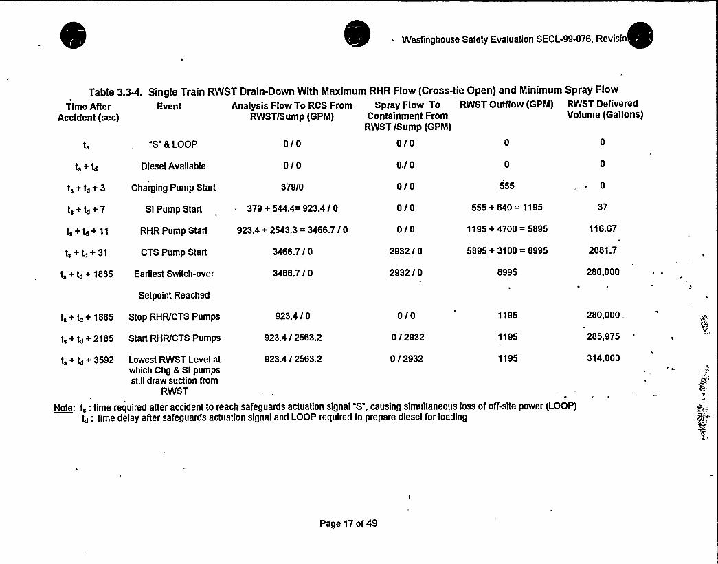
Table 3.3Q. Single Train RWST Drain-Down With Maximum RHR Flow (Cross-tie Open) and Minimum Spray Flow
Time After Event Analysis Flow To RCS From Spray Flow To RWST OuNow (GPM) RWST Delivered
Accident (sec) RWST/Sump (GPM) Containment From Volume (Gallons)RWST /Sump (GPM)
0/0 0 0
Diesel Available 0/0 O.l 0
t, + 4+ 3 Charging Pump Start 379/0
t,+4+7 Sl Pump Start - 379+ 544.4= 923.4/0
t, + 4+ 11 RHR Pump Start 923.4+ 2543.3 = 3466.7/0
t, + 4+ 31 CTS Pump Start 3466.7 / 0
t, + 4+ 1885 Earliest Switch-over 3466.7 / 0
Setpoint Reached
0/0
0/0
0/0
2932/ 0
2932 / 0
555
555 + 640 = 1195
1195+ 4700 = 5895
5895+ 3100 = 8995
8995
0
37
116.67
2081.7
280,000
t, + 4+ 1885 Stop RHR/CTS Pumps
t, + 4+ 2185 Start RHR/CTS Pumps
923.4 / 0
923.4 / 2563.2
0/0
0 / 2932
1195
1195
923.4 I 2563.2 11950 / 2932t, + 4+ 3592 Lowest RWST Level atwhich Chg & Sl pumpsstill draw suction from
RWST
Note: t,: time required after accident to reach safeguards actuation signal S", causing simultaneous loss of off-site power (LOOP)4: time delay after safeguards actuation signal and LOOP required to prepare diesel for loading
280,000
285,975
314,000
Page 17 of 49

0

t
Westinghouse Safety Evaluation SECL-99-076, Revi
t,t.+t
t,+/+3ts+ td+ 7ts+ td+ 11
ts+ td+ 31
ts+ td+ 2042
ts+ td+ 2042
ts+ td+ 2342
ts+ td+ 3749
Note:
"S" & LOOPDiesel Available
Charging Pump StartSl Pump Start
RHR Pump Start
CTS Pump Start
Earliest Switch-overSetpoint Reached
Stop RHR/CTSPumps
Start RHR/CTSPumps
Lowest RWST Levelat which Chg & Slpumps still draw
suction from RWST
0/00/0
379/0379 + 544.4= 923.4 / 0
923.4+ 2543.3 = 3466.7 /0
3466.7/0
3466.7 / 0
923.4 / 0
923.4 / 2563.2
923.4 / 2563.
Table 3.3-5. Single Train RWST Drain-Down With Minimum RHR
Time After Event . Analysis Flow To RCS FromAccident. RWSTISump
(sec) (GPM)
00
555555+ 640 = 11951195+ 3408.6 =
4603.64603.6+ 3700 =
8303.68303.6
1651.23700/0
3700/ 0 280,000
280,000
285,975
314,000
0/0 1195
11950 /3700
0/3700 1195
Flow (Cross-tie Closed) and Maximum Spray Flow
Spray Flow To RWST OuNow — RWST DeliveredContainment From (GPM) . Volume
RWST /Sump (Gallons)(GPM)0./ 0 00/0 00/0
~0
0/0 370/0 116.67
t,: time required after accident to reach safeguards actuation signal "S", causing simultaneous loss of off-site power "LOOP"
4: time delay after safeguards actuation signal and LOOP required to prepare diesel for loading=
Page 18 of 49

'estinghouse Safety Evaluation SECL-99-076, Revis
Table 3.3-6.
Time AfterAccident
(sec)
0/0
Single Train RWST Drain-Down With Maximum RHR Flow (Cross-tie Open) and Maximum Spray Flow
Event Analysis Flow To RCS From Spray Flow To RWST OuNow RWST Delivered
RWSTISump Containment From (GPM) Volume
(GPM) RWST /Sump (GPM) (Gallons)
"S" & LOOP 0/0 0/0 0 0
Diesel Available 0/0 0 0
t, + 4+ 3 Charging Pump Start 379/0 0/0 555
t +/+7t,+/+11
t,+ Q+ 31
t, + 4+ 1769
RHR Pump Start 923.4+ 2543.3 = 3466.7/0
CTS Pump Start 3466.7/0
0/0
3700/0
Earliest Switch-overSetpoint Reached
3466.7 / 0 3700 /0
Sl Pump Start 379+ 544.4= 923.4/0 0/0 555+ 640 = 1195
1195 + 4700 = 5895
5895 + 3700 = 9595
9595
37
116.67
2081.7
280,000
t, + Q + 1769 Stop RHR/CTS Pumps
t, + 4-+ 2069 Start RHR/CTS Pumps
923.4 /0
923.4/2563.2
0/0
0/3700
t, + Q+ 3476
Note:"LOOP
Q: time
923.4/2563.2 0/3700
delay after safeguards actuation signal and LOOP required to prepare diesel for loading
Lowest RWST Level atwhich Chg & Slpumps still draw
suction from RWST
ts: time required after accident to reach safeguards actuation signal "S, causing
1195
1195
1195
280,000
285,975.
314,000
simultaneous loss of off-site power
Page 19 of 49
Westinghouse Safety Evaluation'SECL-99-076, Revision 3
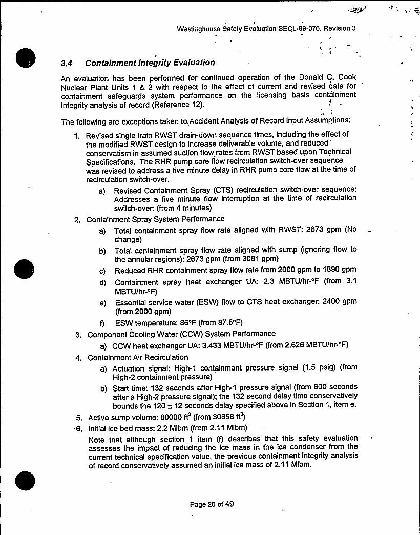
3.4 Containment Integrity Evaluation
An evaluation has been performed for continued operation of the Donald C. CookNuclear Plant Units 1 8 2 with respect to the effect of current and revised data forcontainment safeguards system performance on the licensing basis containment
integrity analysis of record (Reference 12).
The following are exceptions taken to,Accident Analysis of Record Input Assumptions:
1. Revised single train RWST drain-down sequence times, including the effect ofthe modified RWST design to increase deliverable volume, and
reduced'onservatism
in assumed suction flow rates from RWST based upon TechnicalSpecifications. The RHR pump core flow recirculation switch-over sequencewas revised to address a five minute delay in RHR pump core flow at the time ofrecirculation switch-over.
a) Revised Containment Spray (CTS) recirculation switch-over sequence:Addresses a five minute flow interruption at the time of recirculationswitch-over. (from 4 minutes)
2. Containment Spray System Performance
a) Total containment spray flow rate aligned with RWST: 2673 gpm (Nochange)
b) Total containment spray flow rate aligned with sump (ignoring flow tothe annular regions): 2673 gpm (from 3081 gpm)
c) Reduced RHR containment spray flow rate from 2000 gpm to 1890 gpm
d) Containment spray heat exchanger UA: 2.3 MBTU/hr-'F (from 3.1
MBTU/hr-'F)
e) Essential service water (ESW) flow to CTS heat exchanger. 2400 gpm(from 2000 gpm)
f) ESW temperature: 86'F (from 87.5'F)
3. Component Cooling Water (CCW) System Performance
a) CCW heat exchanger UA: 3.433 MBTU/hr-'F (from 2.626 MBTU/hr-'F)
4. Containment Air Recirculation
a) Actuation signal: High-1 containment pressure signal (1.5 psig) (fromHigh-2 containment pressure)
b) Start time: 132 seconds after High-1 pressure signal (from 600 secondsafter a High-2 pressure signal); the 132 second delay time conservativelybounds the 120 2 12 seconds delay specified above in Section 1, item e.
5. Active sump volume: 80000 ft'from 30858 ft')
6. Initial ice bed mass: 2.2 Mlbm (from 2.11 Mlbm)
Note that although section 1 item (f) describes that this safety evaluationassesses the impact of reducing the ice mass in the ice condenser from thecurrent technical speciTication value, the previous containment integrity analysisof record conservatively assumed an initial ice mass of 2.11 Mlbm.
Page 20 of 49

„1
Westinghouse dafeiy Evaluation SECL-99-016, Revision.3
7. Revised Ice Bed Temperature: An ice bed temperature range of 10 'F to 27 'F .
was appropriately addressed.
8. Revised Containment Structural Heat Sink model based upon the Donald C. ~
Cook Unit 2 Uprating Program (Reference 16), modified per Condition Report „CR 99-17460, which is supported by ALTRAN calculation number 99219-C-02(References 3 and 33).
9. Residual Heat Removal Containment Spray performance: placing RHR spray in'ervicewith respect to equipment delays and response times, operators
establish RHR spray no later than 1.25 hours following the start of the accident,if the following conditions exist: 1) The Containment Spray System is in
operation (implying that. the containment pressure has exceeded the analysissetpoint of 3.5 psig; 2) Less than both (2) CTS pumps are operating; and, 3)
~ The plant RHR system has been transferred to cold leg recirculation.
10. RHR heat exchanger UA: 2.2 MBTU/hr-'F (from 2.22 MBTU/hr-'F)
11. Containment net free volumes as provided:
~ Upper compartment: 734,978 ft'from 734,829 ft')
~ Lower compartment: 296,769 ft'from 304,629 ft')
~ Lower compartment (dead-ended): 61,928 ft'from 61,340 ft')
12. Steam generator metal mass: based upon SG dry weight of 714,000 Ibm (from620,562 Ibm)
13. Effects due to Hydrogen Mitigation System
a) A reduction in ice mass due to hydrogen combustion was assumed in theprevious analysis to account for the hydrogen subcompartment analysis thatidentified the hydrogen flammability limitwould be exceeded in the icecondenser following the limiting large break LOCA event. However, for thelimiting large break LOCA with respect to containment integrity (i.e. the RCS
pump suction line break), core-wide clad oxidation is significantly less whencompared with the limiting large break LOCA with respect to peakcontainment hydrogen. Therefore, for the RCS pump suction break, the" icemass penalty was not assumed.
b) The energization of the hydrogen recombiners is delayed for six hours toprevent influencing the calculated peak containment pressure analysis.Operation of the Hydrogen recombiners after this time will not result in a
higher calculated peak containment pressure.
c) Heat load due to Distributive Ignition System (DIS) of 10kw was addressed.
14. Additional pressure penalties:
a) Pressure penalty due to non-condensable hydrogen gas generated duringDBA LOCA event: 0.1 psi (from 0 psi)
b) Pressure penalty due to leakage from the control air system during a DBALOCA event: 0.1 psi (from 0 psi)
The limiting single failure for containment integrity is the loss of an emergency dieselgenerator, which results in the loss of one train of safety injection, the failure of onecontainment safeguards train (i.e., one containment spray pump), and the failure of oneair return fan. Loss of off-site power is assumed at event initiation.
Page 21 of 49

Westinghouse Safety Evaluation SECL-99-076, Revision 3
The following accident analyses related to the Containment Integrity were evaluated:
1. Short Term LOCA M&E/Subcornpartment
The loop subcompartment analysis is performed to ensure that the walls of the loopsubcompartments, including the lower crane wall, upper crane wall, operating deck, andthe containment shell, can maintain their structural integrity during the short pressurepulse (generally less than 3 seconds) which accompanies a high energy line piperupture (LOCA) within the subcompartment. Also, this analysis verifies the adequacy ofthe ice condenser performance.
The reactor cavity analysis is performed to ensure that the walls in the immediateproximity of the reactor vessel can maintain" their structural integrity during the shortpressure pulse which accompanies a high energy line pipe rupture within the reactorcavity region. Loads on the reactor vessel are also determined.
The pressurizer enclosure analysis is performed to ensure that the walls in theimmediate proximity of the pressurizer enclosure can maintain their structural integrity.Loads acting across the pressurizer are also determined.
2. Short Term MSLB Subcompartment
This subcompartment analysis is performed to ensure the walls of the steam generatorenclosure and fan accumulator room can maintain their structural integrity during theshort pulse which accompanies a high energy line pipe rupture within the enclosure.
3. Long Term LOCA/Containment Integrity
The LOCA Containment Integrity Analysis demonstrates the acceptability of thecontainment safeguards systems to mitigate the consequences of a hypothetical largebreak LOCA. The containment safeguards systems must be capable of limiting thepeak containment pressure to less than the design pressure. Analysis results are alsoused to support environmental temperature qualiTication.
4. Long Term MSLB/Containment Integrity
This analysis is performed to verify that containment and equipment are adequate forthe containment temperature conditions following a postulated MSLB.
3.4.1 Short Term LOCA M8E / Subcompartment: Loop CompartmentAnalyses, Reactor Cavity, Pressurizer Enclosure; and, Short TermMSLB M&E/ Subcompartment: Steam Generator Enclosure and FanAccumulator Room Analyses
Based upon a review of References 3, 11, 13, 14, and 15 it can be concluded that theanalysis assumptions used for the Containment Integrity Analysis of Record (Reference12) are acceptable/bounding for continued operation. The exceptions listed above donot factor into the short term analyses because the affected equipment is not reliedupon in the analysis during th'e short duration of the transient'(<3 seconds). Insummafy, the current licensing basis for the short term LOCA and MSLB mass andenergy release and subcompartment analyses are bounding with respect to futureoperation.
Page 22 of 49

Westinghouse Safety Evaluation SECL-99-076, Revision 3
3.4.2 Cont" inment Integrity (Long Term LOCA)
The long-term LOCA mass and energy release and containment integrity analysisdemonstrates the acceptability of the containment safeguards systems to mitigate thecontainment consequences of a hypothetical design basis pipe break. The analysisensures that the containment heat removal capability is sufficient to remove the"maximum possible discharge of mass and energy release to containment from theNuclear Steam Supply System without exceeding the acceptance criteria peak designpressure of 12 psig (Technical Specification Bases, 3/4.6.1.4 Internal Pressure).
The current licensing basis long-term LOCA mass and energy release and containmentintegrity analysis is documented and discussed in Reference 12. The containmentpeak pressure documented in Reference 12 is 11.49 psig. I
Again, by review of the References 3, 11, 13 14 and 15, it was concluded that theanalysis assumptions used for the Containment Integrity Analysis of Record (Reference12) are applicable and bounding for analyzing continued operation with the exceptionof-the changes listed in this evaluation.
Detailed system alignments were modeled with respect to the RHR CCW, EssentialService Water (ESW), and Containment Spray system (CTS) in conjunction with theemergency operating procedures used for switch-over of the ECCS and CTS pumpsuction flow from the refueling water storage tank (RWST) to the containment sump.
Detailed analyses were performed addressing LOCA mass and energy release andcontainment response following a postulated LOCA mass and energy release.Although some of the accident analysis input assumptions used to support theReference 12 licensing basis analysis of record have been revised, resulting in reducedconservatism or improved system performance, there are a few issues which haveaffected the analysis negatively, and potentially tend to increase the containmentpressure. These issues are:
1. Reduced containment spray flow rate during the recirculation phase.
2. Increased active sump volume.3. Early actuation of containment recirculation fans.-4. Increased steam generator metal mass.
5. Evolved hydrogen mass partial pressure penalty.6. Decreased initial ice bed mass from the current Technical Specification value.
7. Increased compression pressure.
8. Decreased containment spray heat exchanger performance (reduced UA value).
In contrast, in several areas plant operating conditions have been improved in terms ofheat removal capability, as follows:
1. The ESW flow to the CTS heat exchanger was increased.
2. The calculated CCW heat exchanger UA was increased-.
3. The ESW temperature was decreased.
4. The calculated RHR heat exchanger UA was increased.
5. The CCW flow to the RHR heat exchanger was increased.
Page 23 of 49
Wesiingnouse Gafety Evaluation SECL-99-076, Revision 3
6. The duration of the Lower Compartment CTS on injection was increased due torevised RWST drain-down calculation.
7. A revised Structural Heat Sink model was used that provides for improvedstructural heat removal capacity as compared to the older containment structuralheat sink model utilized in the previous analysis of record (Reference 12).
The new containment analysis was completed addressing the redefined plant operatingconditions. In addition to the above, improvements in the Westinghouse LOCA massand energy release calculation technique were implemented. These improvementsinclude the use of additional data points to increase accuracy with regard to LOCAmass.and.energy releases and a refined process to better represent the ECCS andcontainment spray recirculation switch-over procedure, and are acceptable within theapplicable NRC-approved methodology. The current licensing model (Reference 12)utilizes a revised structural heat sink model developed for the Donald C. Cook Unit 23600 MWt Uprating Program, (Reference 16). This model was incorporated into thisreanalysis effort, as well, although the model was modified with respect to References3 and 32.
With respect to the potential penalties and benefits identified above, a comprehensivecomposite analysis was performed. The potential penalties identified adversely affect(increase) the mass and energy release available to containment through reducing thesteam condensation and also by reducing heat removal capability of the containmentsafeguard systems. Thus, earlier ice bed melt-out would be experienced, and in turn a
possible increase in containment peak pressure. The effects of the penalties arecompensated, however, by margins derived from the incorporation of the enhancedUnit 2 Uprating Program's structural heat sink model, a revised RWST drain-down forcontainment spray operation, an increased initial total ice mass (2.2 Mlbsm), and theimproved LOCA mass and energy release calculation process.
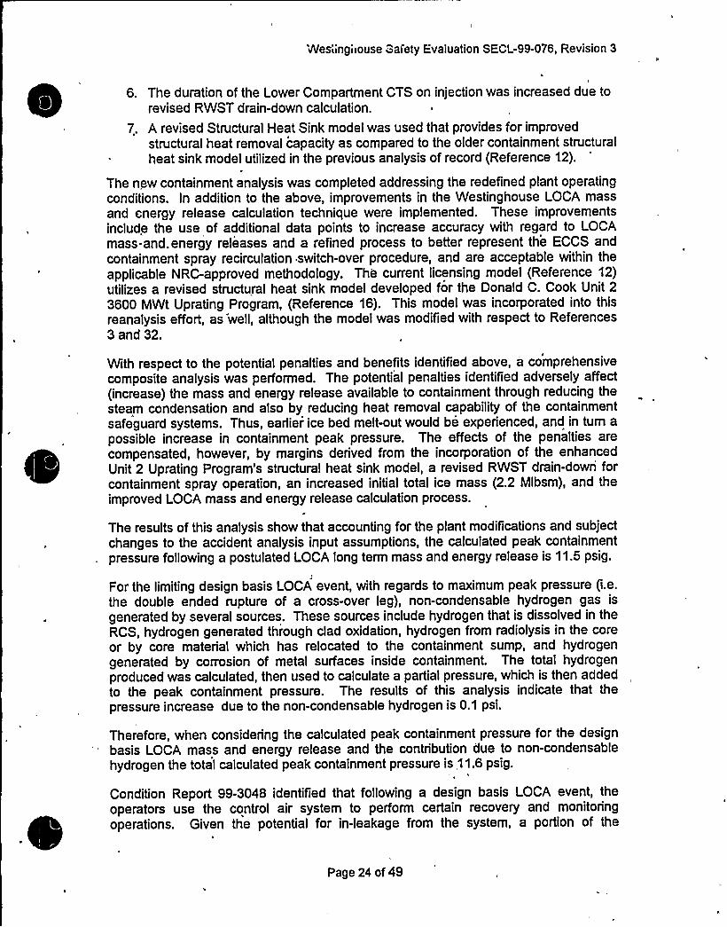
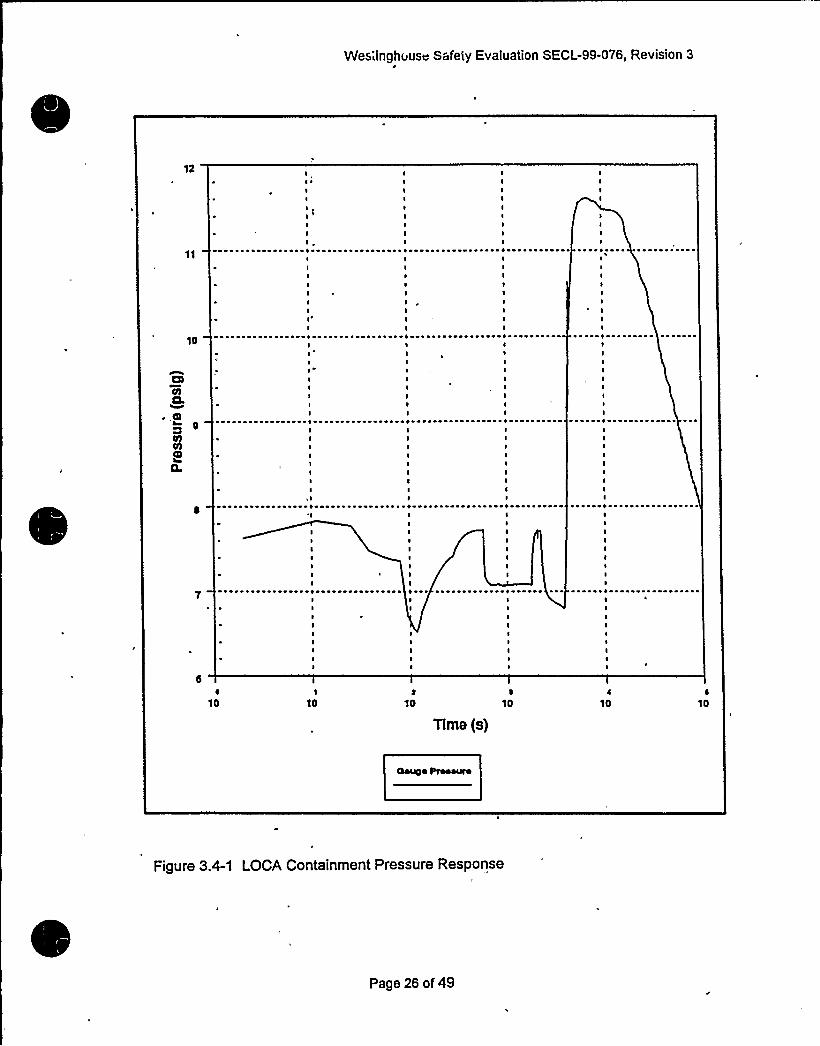
The results of this analysis show that accounting for the plant modifications and subjectchanges to the accident analysis input assumptions, the calculated peak containmentpressure following a postulated LOCA long term mass and energy release is 11.5 psig.
For the limiting design basis LOCA event, with regards to maximum peak pressure (i.e.the double ended rupture of a cross-over leg), non-condensable hydrogen gas is
generated by several sources. These sources include hydrogen that is dissolved in theRCS, hydrogen generated through clad oxidation, hydrogen from radiolysis in the coreor by core material which has relocated to the containment sump, and hydrogengenerated by corrosion of metal surfaces inside containment. The total hydrogenproduced was calculated, then used to calculate a partial pressure, which is then addedto the peak containment pressure. The results of this analysis indicate that thepressure increase due to the non-condensable hydrogen is 0.1 psi.
Therefore, when considering the calculated peak containment pressure for the designbasis LOCA mass and energy release and the contribution due to non-condensablehydrogen the total calculated peak containment pressure is 11.6 psig.
Condition Report 99-3048 identified that following a design basis LOCA event, theoperators use the control air system to perform certain recovery and monitoringoperations. Given the potential for in-leakage from the system, a portion of the
Page 24 of 49

* " Westinghouse Safety Evaluation SECL-99-076, Revision 3
r
containment pressure margin has been allotted to address in-leakage. Per Reference.17, the control air system leakage will be limited by operator action such that the effecton containment pressure will be less than 0.1 psi.
ln summary, the analyses conclude that plant modifications and subject changes to theaccident analysis input assumptions do not result in exceeding the acceptancecriterion, peak design pressure of,12 psig (Technical Specification Bases, 3/4.6.1.4Internal Pressure). In addition, when considering the allowance of 0.1 psi due tocontrol air system leakage post-LOCA, the calculated peak containment pressure is
less than an equivalent acceptance criterion of 11.9 psig. Figure 3.4-1 presents theLOCA containment pressure response.
Page 25 of 49
~ ~
~ ~
Westinghouse Safety Evaluation SECL-99-076, Revision 3
3.4.3 Post-LOCA Hydrogen Generation Evaluation
A review of the post-LOCA containment pressures and temperatures associated withthe containment"integrity analyses indicates that the previous analysis of record is notaffected by the updated pressure information that results from the modifications to thecontainment .systems considered in this evaluation. The updated containmenttemperatures, however, result in a s!ight increase in hydrogen production fromcorrosion of materials. The additional hydrogen that is generated from this sourceincreases the total hydrogen generated from all sources by approximately 0.5-1.5percent during the first 100 hours after a LOCA.
Thus, to maintain the containm'ent concentration less than the Regulatory Guide 1.7limit of four volume percent, the updated analysis of'record (Reference 18) indicatesthat it is necessary to initiate operation of the Hydrogen Recombiners at 22 hours aftera LOCA. The previous analysis of record indicated that for initiation of operation of theHydrogen Recombiner at 24 hours, the maximum concentration in the containmentwould be 4.0 volume percent. Hence, the impact of the updated containment integrityanalysis is to reduce the time by which the Hydrogen Recombiners should beoperational after a LOCA by 2 hours, i.e., from 24 hours to 22 hours.
3.4.4 Main Steamline Break (MSLB) Mass and Energy Release
Containment response calculations for postulated steam line break mass and energyreleases inside containment are performed to ensure that containment pressure andtemperature do not exceed acceptable limits used for equipment qualification. Thecurrent licensing basis for main steam line break containment integrity is documentedand discussed in Reference 12. The limiting case among the double-ended ruptures,which yielded a calculated peak temperature of 298.9'F, is the 1.4 ft'ouble-endedrupture, 102% power, MSIV failure case.. The most limiting case in terms of peakcalculated temperature for the small split breaks is the 0.942 ft'plitbreak, 30% power,with an MSIV failure. This case resulted in a calculated peak temperature of 325.3
'F.'ith
respect to the licensing-basis analysis for the steamline break (SLB) mass andenergy releases into containment, this analysis makes no assumption regarding theavailability of long-term recirculation water towards event mitigation. The SLB transientis a short-term event compared to a LOCA event, and containment recirculation is not
. assumed to occur within the duration for which the transient is analyzed. Therefore,there is no affect from these modifications on the SLB mass and energy releases insidecontainment. Because a postulated main steamline break event is of such short
~ duration (i.e., -1000 seconds), it would be over prior to the use of the heat exchangersor emergency procedure for cold leg recirculation or accounting for active sump volumeimpact of the containment response transient or ice mass bed melt-out. And, withrespect to. containment spray flow, the reduction in spray flow has no effect becauserecirculation is not assumed for the SLB transient.
Thus the items from the exceptions listed above which are germane to the SLBcontainment response analysis are the containment air recirculation fans (air returnfans) and the net free volumes of the containment compartments, and the revisedcontainment structural heat sink model, as specified in Section 3.4, item 8, above. Thechange in containment compartment net free volume has a primary influence on
Page 27 of 49
' ..Westinghouse Safety Evaluation SECL-99-076, Revision 3
containment peak pressure,'lthough the change in compartment volume wasconsidered in the SLB containment response. The containment air recirculation fansare required to provide a continuous mixing of the containment compartmentatmosphere for the long-term post blowdown accident environment. For accidentanalysis conditions, only one fan is modeled based upon the limiting single failure of atrain of containment safeguards equipment. The capacity of one fan is 39000 cfm fromthe upper compartment into the lower compartment. The air recirculation fans havesufficient head to overcome the compartment pressure differentials that occur after theSLB. The fans will discharge air from the upper compartment to the lowercompartment, thereby returning the air to the lower compartment which was displacedby the blowdown.
Although the fans are modeled during both the, containment response transientfollowing a LOCA and MSLB, the greatest impact. resulting from'their actuation andoperation is seen during the LOCA transient response due to the long term transientscenario. The air return fans are modeled to operate upon reaching the High-1containment pressure setpoint, and a 132 second delay. During the LOCA responsetransient the fans provide a flow path early in the tran'sient. Therefore, their functionplays an important role (before the time of peak pressure) in the containment responsecalculation. During the MSLB containment response calculation, the fans function in a
similar manner. However, the time that the fans'ctuate follows the time when thecontainment peak pressure and temperature occur. The MSLB peak containmentpressure and temperature are driven by mass and energy release. The peak pressureand temperature occurs prior to containment spray or recirculation air return fanactuation. Therefore, their impact on the containment response transient is minimal.Their primary effect is on the rate of containment depressurization and cool down after132 seconds into the MSLB containment response transient, by which time the peak .
containment lower compartment temperature would have already occurred.
The containment peak pressure and temperature occur within 110 seconds of the eventinitiation. The containment sprays are modeled to actuate upon a 115'second delayfrom when the containment High-2 pressure setpoint is reached. Thus, the operation ofthe recirculation air return fan has no impact on the peak containment temperature, nor,the containment spray operation.
As it was for the LOCA basis with respect to the containment structural heat sinkmodel, the revised structural heat sink model specified in Section 3.4, item 8 wasutilized here.
The Donald C. Cook Units 1 8 2 containment response following a postulated mainsteamline break has been reanalyzed for conditions reflecting the current plant design.For the new analysis, the limiting double-ended rupture case which yielded a calculatedpeak temperature of 323.3 'F, was the 1.4 ft'ouble-ended rupture, 100% power,MSIV failure case. The most limiting case in terms of peak calculated temperature forthe small split breaks is the 0.86 ft'plit break, at 100% power, with an AuxiliaryFeedwater Runout Protection (AFWRP) failure. This case resulted in a calculated peaktemperature of 324.7 'F.
Page 28 of 49

Westinghouse Safety Evaluation SECL-99-076, Revision 3
3.4.5 Conclusions Of Containment Integrity Evaluation
Based upon the results of the preceding LOCA and MSLB evaluations, it can beconcluded that Long-term LOCA and MSLB analyses have been performed inconformance with the relevant requirements of the Standard Review Plan (SRP)Sections 6.2.1.1.B and 6.2.1.3. Compliance with the relevant requirements of 10CFR50 Appendix A, General Design Criteria (GDC) 16, 38, and 50, and 10CFR 50Appendix K is demonstrated by showing that the containment design pressure is notexceeded at any time in the transient, and because all available sources of energyhave been included, which is more restrictive than the GDC criteria in Appendix H ofthe original FSAR, to which the Cook plants are licensed. These sources includereactor power, decay heat, core stored energy, energy stored in the reactor vessel andinternal, metal-water reaction energy, and stored energy in the secondary system.The results of these evaluations also show that these modifications do not compromisethe conclusions, or the pressure and temperature margins demonstrated in the currentDonald C. Cook Nuclear Plant Units 1 & 2 Containment Integrity Safety Analyses.
d
3.5 LOCA and LOCA-Related Analyses
The following evaluations address the Peak Clad Temperature (PCT) post-LOCAsubcriticality and Long Term Core Cooling (LTTC) analyses for the impact of theproposed containment systems modifications and associated changes to the accidentanalysis input assumptions.
3.5.1 Introduction
Several issues have been identified for the Donald C. Cook Nuclear Plant Units 1 and 2in the safety analyses and plant layout which affect the post-LOCA subcriticalityanalysis performed by Westinghouse to support plant operation. Plant specific post-LOCA subcriticality calculations are performed each core relo'ad cycle to ensure thatthe core will remain subcritical after a Reactor Coolant System (RCS) pipe break of 1.0ft'r larger. Clearly, in performing the above analyses, it is critical that the inputassumptions made regarding equipment availability and performance are consistentwith the plant layout and operation, and post-accident Emergency OperatingProcedures (EOPs). Furthermore, several other licensing issues related to the LOCAanalyses for Donald C. Cook Units 1 & 2 are being resolved to support plant restart.
A revised, comprehensive set of input assumptions have been defined to support post-LOCA analyses for the Donald C. Cook Nuclear Plant Units 1 and 2 (Reference 19).The changes covered by these new L'OCA analyses are:
1. Removal of any reliance on flow through the hot leg nozzle gap for both largebreak LOCA and post-LOCA sump boron dilution.
2. Revised Refueling Water Storage Tank (RWST) deliverable water volume at theinitiation of recirculation (volume increased to 280,000 gals).
3. Revised maximum containment spray flow (Changed from 3600 gpm to 3700gpm per pump).
4. Revised sump geometry assumptions to account for the sump and reactorcavity water volume.
Page 29 of 49


Westinghouse Safety Evaluation SECi=99-076, Revision 3
5. Decreased minimum; and increased maximum ice bed mass.
6. Decreased minimum RWST temperature, from 75'F to 70'F.
7. Interruption of RHR flow of up to five minutes during switch-over to recirculationmode cooling.
8. Asymmetric Safety Injection Evaluations, Small Break LOCA (SBLOCA)
9. Boron Depletion of 3.1 % in the RWST and accumulators.
10. Earlier actuation of the CEQ fans
The above list covers plant changes, and/or changes in input assumptions that affectthe LOCA analyses since the shutdown of Donald C. Cook Units 1 & 2 in September1997. The impact of all of the above issues on the large and small break LOCA, thepost-LOCA subcriticality, and long term core cooling analysis is addressed below.
The post-LOCA subcrlticality confirmation refers to the calculations performed everycore reload cycle to determine if the water contained in the sump after a large breakLOCA contains sufficient boron to ensure that the core will remain subcritical for the
long term post-LOCA, assuming that no control rods insert. The methodologyspecifically considers the boron concentration of the active sump at switchover to sumprecirculation mode cooling with cold leg injection. At the switchover to recirculation,control rod insertion is credited to address subcriticality. This is addressed in a
separate AEP submittal to the NRC.
The post-LOCA Long Term Core Cooling (LTCC) analyses refer to calculationsperformed to:
~ preclude boron precipitation in the core post-LOCA; and,
~ determine the required post-LOCA safety injection performance in both coldand hot leg recirculation mode cooling to ensure that the core does notreheat significantly.
The post-LOCA LTCC analysis performed to preclude boron precipitation in the core is
referred to as the Hot Leg Switch-over Analysis. In the mid-1970's the NRC postulatedthat for all possible locations in the RCS piping for a large break LOCA, except hot legbreaks, while in cold leg recirculation mode cooling, the boiling in the core will cause a
buildup of boron. Eventually, the boron could become so concentrated that boronwould begin to precipitate blocking the flow of safety injection to the core, therebyreducing the ability to continue to cool the core. To prevent this, the safety injection is
switched to the hot leg to flush the core, via flow reversal, of the concentrated boronbefore boron precipitation would occur. A conservative boron precipitation limit of23.5% is applied. The maximum hot leg switchover time is computed based on thisboron precipitation limit. This calculation is redone only when there are changes to the
limiting volume or boron concentration for the various sources of water available to cool
the core, post-LOCA (i.e., Accumulators, RWST, Boron Injection Tank, ice bed, and
RCS volume).
The other part of the LTCC analysis involves computing the safety injection systemperformance required to exceed core boil-off based on conservative core decay heat atthe time of switchover to cold leg and hot leg recirculation mode cooling. These flows
Page 30 of 49

Westinghouse Safety Evaluation SECL-99-076, Revision 3
are reconfirmed 'only when there are changes to the safety injection systemperformance, alignment, or pump availability, or when the timing changes for cold leg orhot leg recirculation mode cooling.
3.5.2 Evaluation of the Post-LOCA Subcriticality Calculation
Although some of the input assumptions used to perform initial beginning-of-cycle(BOC) subcriticality calculations for Donald C. Cook Unit 1 Cycle 16, and Unit 2 Cycle12 have been revised for the restart calculations performed for this safety evaluation,there are two new issues which affect the methods used to.perform the post-LOCAsubcriticality calculation:
1. The potential for diversion of the break flow into regions of the containme'ntother than the active sump, i.e. the reactor cavity; and,
2. Explicit modeling of the active sump volume, and the subsequent effect on thesubcriticality calculations.
3.5.2.1 Diversion of Borated Water SourcesI
A more dilute mixture than previously calculated may exist in the active sump if theRWST and/or Accumulator water are assumed to fill the reactor cavity first. Thisphenomenon is partially precluded because breaks equal to or greater than 1 ft'annotoccur in the reactor cavity because no penetration is larger than 1 ft. The followingdiscussion will examine the potential for loss of RWST and accumulator water into thereactor cavity:
Large ruptures of the reactor vessel are not required to be considered in the evaluationof the ECCS for PWRs. Section c(1) of Appendix K to 10CFR50.46, and supportingNRC opinions state clearly that a spectrum of pipe breaks need to be considered(vessel integrity is covered by other regulations and criteria). In fact, leaks in the vesselpenetrations', such as the instrumentation thimbles, have been considered in the ECCSdesign.
In a large break LOCA, the initial break flow is RCS mass in the form of a steam-watermixture. Because of the initial high stored energy, the RCS water flashes andgenerates large amounts of steam. After the RCS pressure falls below 600 psia,accumulators begin to inject. The injected water is bypassed out of the break until theRCS has depressurized. After reflood has begun and the downcomer has been filled,some of the water injected from accumulators and pumped safety injection spills out ofthe break on the vessel side, along with vented steam. The evaluation below examinesthe potential for the borated water injected into the vessel from the accumulators andRWST reaching the reactor cavity, and thereby not being available for pumped injectionfrom the sump.
3.5.2.1.1 Double Ended Guillotine Break:
A, break can be postulated at the weld between the reactor vessel inlet (or outlet)nozzle and the reactor coolant piping, which would place the break about 2 to 3 feetaway from the reactor cavity, and within the penetration through the biological shield.In a double ended guillotine break, to create sufficient area for the double ended break
Page 31 of 49

Vv'estingnouse Safety Evaluation SECL-99-076, Revision 3
which must be assumed in the ECCS analysis,.the piping on the loop side of the breakmust be postulated to move backward away from'the reactor vessel nozzle and out ofthe biological shield tunnel. To allow this type of movement, a loop support must be
assumed to fail. It can, therefore, be assumed that large double ended guillotinebreaks cannot occur within the biological shield.
3.5.2.1.2 Split Breaks:
Longitudinal and circumferential: split breaks must also be postulated in the LOCAanalysis. A limited displacement double ended guillotine break (i.e., a guillotine break
*
in which the loop supports do not fail) can be postulated with a resulting break area ofabout 1 ft'150 in', Reference 20). Longitudinal split breaks must also be postulated.For this case, the water flowing from the break would be directed radially around the
pipe. Previous analyses using the TMD subcompartment computer code (Reference
21) indicated that approximately 28 percent of the break flow will initially flow towardsthe vessel and into the reactor cavity. The post-LOCA subcriticality calculationsperformed prior to the September 1997 shutdown. of the Donald C. Cook plants did notrequire an assumption regarding the split in break flow since the calculation assumedcomplete mixing of all sources of boron and water. New supporting calculations havebeen performed which model the flow of water and boron to the different containmentcompartments to determine the importance of the potential for flow into the reactorcavity with resped to boron concentration.
3.5.2.2Active Sump Volume
Depending on the assumptions made for containment spray flow rate, Sl systemperformance, and spillage location from the broken loop, the potential for the active
sump to fill prior to switchover to cold leg recirculation mode cooling must be
considered. Therefore, the calculations performed for computing the active sumpboron concentration were modified to track the volume of water entering the active
sump. At the time the active sump is filled, the calculation then considers the active
sump spilling to the reactor cavity, while spray and break flow continue to enter theactive sump, and the subsequent effect this has on the boron concentration in the
sump.
3.5.2.2.1 D. C Cook Units 1 8 2 Post-LOCA Subcriticality Analysis:
The original subcriticality calculations performed to support Unit 1 Cycle 16 operationidentified 221 ppm of margin to the post-LOCA subcriticality limit at the beginning of the
cycle (BOC). This calculation was redone to update the limitfor.
1. Revised Refueling Water Storage Tank (RWST) deliverable water volume at theinitiation of recirculation (volume increased to 280,000 gals).
2. Revised maximum containment spray flow (Changed from 3600 gpm to 3700
gpm per pump).
3. Revised sump geometry assumptions to account for the sump and reactorcavity water volume.
4. Boron Depletion of 3.1 % in the RWST and accumulators.
Page 32 of 49

0

Westinghouse Safety Evaluation SECL-99-076, Revision 3
The revised calculations treat the active sump and the piping 'annulus as one largesump. This treatment is conservative for cold leg recirculation mode switch-over
- subcriticality calculations, as it results in the lowest possible sump boron concentration.The revised calculations were based on Donald C. Cook Unit 2 BOC 12 which boundboth Units.
Parametric studies of the inputs to the revised subcriticality calculation were performedto determine the sensitivity of the calculation to the ranges of the quantities used.Table 3.5-1 lists the various quantities studied. The values of the quantities used in theparametric studies are defined in detail in Table 3.5-1A. Table 3.5-2 lists the results ofthe parametric studies. The limiting results are produced by Case 6 and Case 8, andform a composite limit curve for the post-LOCA subcriticality. Based on the Unit 1
Cycle 16 boron requirements, the pre-trip'RCS boron concentration of 1381 ppmrequires 1530 ppm of boron in the post-LOCA active sump to assure that the coreremains subcritical at the time that safety injection is switched to cold leg injectionrecirculation mode cooling (References 22, and 23). The calculation demonstrates thatthe active sump will have a minimum of 1940 ppm of boron'at the time of switch-over tocold leg injection recirculation mode cooling. Therefore, there is 410 ppm (1940- 1530)of margin to the subcriticaiity limit at switch-over to cold leg injection recirculation modecooling.
Based on Unit 2 Cycle 12 boron requirements, the pre-trip RCS boron concentration of1691 ppm requires 1776 ppm of boron in the post-LOCA active sump in order to assurethat the core remains subcritical at the time that safety injection is switched to cold leginjection recirculation mode cooling (Reference 24). The calculation demonstrates thatthe active sump will have a minimum of 2012 ppm of boron at the time of switch-over tocold leg injection recirculation mode cooling. Therefore, there is 236 ppm (2012 - 1776),of margin to the subcriticality limit at switchover to cold leg injection recirculation modecooling..
In past analyses, the subcriticality was required to be confirmed at switchover to hot leginjection recirculation mode cooling since the boron concentration in the sump dilutesas it is building up in the core due to boiling. However, control rod insertion has beendemonstrated to occur following the large cold leg loss of coolant accident (Reference25). Therefore, post-LOCA subcriticality can be demonstrated for restart of Donald C.Cook Unit 1 Cycle 16 and Unit 2 Cycle 12 with no credit taken for the hot leg nozzlegap.
3.5.3 Evaluation of the Post-LOCA Long Term Core Cooling Analysis
1
3.5.3.1 Long Term Cooling Evaluation Assumptionsl
- 3.5.3.1.1 Long Term Core Cooling (LTCC) Flow:
Both the large break and the small break LOCA are evaluated to ensure that the safetyinjection flows in the cold leg injection recirculation mode and the hot leg injectionrecirculation mode are sufficient to keep the core covered (minimum hot leg switchovertime), and preclude the precipitation of boron (maximum hot leg switchover time).Other than the bounding assumptions made in determining the performance of the
Page 33 of 49


Westinghouse, Safety Evaluation SECL-99-076, Revision 3
safety injection system (Reference 19), the assumptions made in the LTCC analysisare:
No flow reduction or penalty due to obstructions or other conditions upstream ofthe pumps.
2. Continuous flow from the pumps must be sufficient to remove decay heat. It is
assumed that Appendix K requirements apply (1971 decay heat plus 20%).Typically, additional design factors are applied to the computed boil-off rate to
. account for entrained liquid leaving the break with the vapor.
3. If the flow is interrupted, sufficient flow must be re-established to remove decayheat and replenish RCS mass, within a time period before core re-uncoveryoccurs. Interruption of RHR flow at the time of transfer to recirculation is an
example of the type of interruption that must be evaluated.
3.5.3.1.2 Hot Leg Switchover:
The revised input assumptions which affect the Long Term Core Cooling (LTCC)
analysis, specifically the Hot Leg Switchover (HLSO) analysis performed to preclude
boron precipitation in the core post-LOCA, are:
1. Revise'd Refueling Water Storage Tank (RWST) deliverable water volume
2. Explicit accounting for the sump water volume.
3. Decreased minimum, and increased maximum ice bed mass.
4. Decreased minimum RWST temperature, from 75'F to 70'F.
These new inputs have been incorporated in a revised analysis, for both Donald C.
Cook Units, of the core boron build-up to determine the time at which the safetyinjection must be switched to the hot leg to preclude precipitation of boron in the post-
LOCA core. It is noteworthy that the post-LOCA LTCC analysis, unlike the subcriticality
analysis, is independent of the reload cycle of operation. Therefore, the post-LOCALTCC analyses presented herein will remain applicable to both Donald C. Cook Units 1
& 2, so long as the performance of their respective safety injection systems, and theirrespective "boron concentrations and volumes of the sources of boron remain
unchanged.
3.5.3.1.3 Donald C. Cook Units 1 & 2 Post-LOCA LTCC Analysis:
New post-LOCA LTCC analyses performed for Donald C. Cook Units 1 & 2 indicate thatswitchover to hot leg injection recirculation mode cooling, post-LOCA must occurbetween 2.5 and 7.5 hours after a LOCA. Switchover cannot occur prior to 2.5 hours.after a LOCA due to insufficient safety injection flows to ensure that the core will not
uncover post-LOCA for all break sizes and locations in the reactor coolant piping. Theswitchover to hot leg injection cannot occur after 7.5 hours in order to preclude
precipitation of boron in the core. Furthermore, an additional evaluation has been
performed to demonstrate that the RHR flow can be interrupted for up to five minutes
during the switchover to recirculation mode cooling without causing the core to re-'ncoverpost-LOCA at the earliest possible initiation of recirculation mode cooling of
1089 seconds (1089 =. 60 = 18.15 minutes). The evaluation of this interruption is an
addition to the requirement, specified in Reference 26, of fifty minutes as the earliest
Page 34 of 49

0

Westinghouse Safety Evaluation SECL-99-076, Revision 3
time that the RHR pumps can be diverted to RHR spray for both the Donald C. CookNuclear Plants. Provided all the timing criteria are 'met, adequate cooling will beprovided to both the Donald C. Cook Unit 1 & 2 cores.
It is further noted that after fiftyminutes the Charging and safety injection pumps, whichtake their suction from the discharge of the RHR pumps, can provide sufficient flow tomaintain core cooling. So, direct injection into the RCS from the RHRS is not requiredfor hot leg recirculation because a safety injection pump can provide adequate flow toback flush the core for mitigation of boron precipitation.
3.5.4 Changes which Impact the Small Break and Large Break LOCA Analysis
Some of the changes listed affect the short-term large and small break LOCA analysesperformed to compute Peak Clad Temperature as per the requirements of10CFR50.46. The revised short-term LOCA analyses have been addressedseparately, in Reference 27.
Further to these above mentioned changes treated in Reference 27, and as describedpreviously, a reduction in the CEQ fan start time is being considered to increase therate of ice melt for smaller break sizes, and thus, increase the amount of water in thecontainment sump at the time of switch-over from the RWST. The current large breakLOCA analyses models a 480 second (8 minute) CEQ fan start time, consistent withthe minimum value for a 9+1 minute setpoint. This evaluation considers reducing thatvalue to 108 seconds, consistent with the minimum value for a 120 212 secondsetpoint.
Because the CEQ fans facilitate heat removal during the large break LOCAcontainment pressure transient; and, because minimum containment pressure is
limiting for large break LOCA, 10 CFR 50.46 Appendix K requires modeling activecontainment heat removal systems at their maximum performance. It is, therefore,necessary to examine the impact of this proposed reduction in the CEQ fan start time
~ on the large break LOCA analysis. (Note that the reduction in the CEQ fan start timewill have no impact on any other LOCA analysis within the Donald C. Cook Unit 1 & 2licensing bases, because containment active heat removal systems are not modeled forsmall break LOCA or post-LOCA analyses).
The current licensing basis large break LOCA analyses for the Donald C. Cook Units 1
& 2 (References 12 and 16, respectively) assume a 480 second CEQ fan start time.Although modeled at their maximum performance in the containment backpressureanalysis performed for the ECCS performance analysis, the CEQ fans remove an orderof magnitude less heat than the containment spray or heat sinks. So, the CEQ fansaccount for only a small part of the heat removal. In fact, at 480 seconds, the CEQfans are shown to have no effect on the large break LOCA analysis, because the.transient is terminated prior to 480 seconds.
The proposed start time of 108 seconds, however, does lie within the analyzed range ofthe current large break LOCA analyses for both Donald C. Cook Units. So, this earlierstart time has been evaluated, and determined to have a negligible impact oncontainment pressure response, i.e., <0.2 psi at a time in the transient when thecontainment pressure is already very low (<2.5 psig). Therefore, it is concluded that
Page 35 of 49

Westinghouse Safety Evaluation SECL-99-076, Revision 3
the reduction in the CEQ fan start time from 480 to 108 seconds would, likewise, havea negligible effect on the computed Peak Clad Temperature (PCT) for the Donald C.
Cook Units 1 & 2.
3.5.5 LOCA Evaluation Summary and Conclusions
LOCA analyses have been performed to support restart of Donald C. Cook NuclearPlant Units 1 8 2. These analyses were performed considering the following revised
assumptions:
1. Removal of any reliance on flow through the hot leg nozzle gap for both largebreak LOCA PCT calculations, as well as the post-LOCA sump boron dilutionanalysis.
.2. Revised Refueling Water Storage Tank (RWST) deliverable water volume at theinitiation of recirculation (volume increased to 280,000 gals).
3. Revised maximum containment spray flow (Changed from 3600 gpm to 3700
gpm per pump).
4. Revised sump geometry assumptions to account for the sump and reactorcavity water volume.
5. Decreased minimum, and increased maximum ice bed mass.
6. Decreased minimum RWST temperature, from 75'F to 70'F.
7. An interruption of RHR flow of up to five minutes during switchover torecirculation mode cooling.
8. Asymmetric Safety Injection Evaluations.
9. Boron depletion of 3.1% in the RWST and accumulators.
10. Reduced delay in CEQ fan start time.
10CFR50.46 (Reference 28) requires that core cooling be provided for the long termafter a LOCA. Calculations confirming that the core remains subcntical, post-LOCA are
performed by Westinghouse to support each core reload. The subcriticality of the core
must be assured at the time of switchover to cold leg recirculation mode cooling.Because the reactivity of the core varies for each reload cycle, the assurance ofsubcriticality must be reaffirmed for each core reload.
As discussed herein, it was concluded that large break LOCA subcriticality can be
assured for restart of Donald C. Cook Units 1 8 2. Also, plant specific evaluations forasymmetric safety injection, and removal of the hot leg nozzle gap dependence forLBLOCA have been analyzed. Therefore, it can be demonstrated that operation ofDonald C. Cook Units 1 8 2 meets all the requirements of 10CFR50.46 for a LOCA.
Page 36 of 49


Westinghouse Safety Evaluation SECL-99-076, Revisl
Table 3.5-1. Parametric Studies. Performed to Identify LimitingSubcriticality Analysis Inputs
Case 0 Split%
28
EOB
(sec)
100
ECCS
Press.
(psig)
30
Ice Rate
(gpm)2955
Spray
(gpm)
7400
ECCS
Flow
Min Inactive
(gpm)
BIT Spray Diversion RWST
Temperature
('F)700F
RWST/ACC CB
(ppm)2325/2228
40 100 30 2955 7400 Min Inactive 700F 2325/2228
28
2850'00 0'95530 2955 7400
7400
Min
Min
Inactive
Inactive
70'F
70'F
2325/2228
2325/2228
28 .
0
100 30
100 30
5258
2955
7400
7400
Min
Min
Inactive
Inactive 0
700F
70OF
2325/2228
2325/2228
28 100 30 2955 3700 Min Inactive 700F 2325/2228
0'00 0'258'400 Min Inactive 700F 2325/2228
28 100 30 2955 7400 Min Inactive 0 120'F'325/2228~ - Inputs varied from Case 1.
Page 37 of 49


'vVestinghouse Safety evaluation SECL-99-076, Revision 3
Table 3.5-1 Nomenclature:~ Split% refers to the percent of break flow that enters the reactor cavity instead of the active
sump.~ EOB is End-Of-Bypass time, the time when ECCS will no longer be bypassed around the
downcomer and out the break.~ ECCS Press. is the assumed Reactor Coolant System pressure during the post-LOCA Long
Term Core Cooling (LTCC).~ Ice Rate is the averago ice melting rate due to the large break LOCA.~ Spray is the total assumed containment spray system flow rate.
~ ECCS Flow indicates if minimum or maximum ECCS system performance is assumed.~ BIT indicates the status of the Boron Injection Tank that was assumed throughout these
case studies. Inactive implies no boron in the BIT; active implies a high concentration ofboron in the BIT (20,000 ppm).
~ Spray Diversion refers to the rate at which containment spray enters the piping annulusregion of the containment.
~ RWST Temperature is the temperature assumed in computing the density for converting thewater volume to a mass.
~ RWST/ACC CB is the boron concentration assumed for the Refueling Water Storage-Tankand Accumulator for each case.
Page 38 of 49

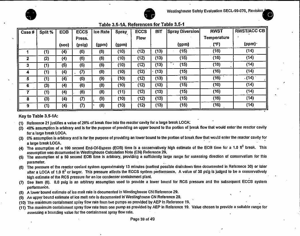
Westinghouse Safety Evaluation SECL-99-076, Revision
Table 3.5-1A. References for Table 3.5-1
ECCS
Press.
(sec) (psig)
Case ¹ Split% EOB Ice Rate Spray
(gpm) (gpm)
ECCS
Flow
BIT Spray Diversion
(gpm)
RWST
Temperature
('F)
RWSTIACC CB
(ppm).
(1) (4) (6)
(2) (4) (6)
(1) (5) (6)
('l) (4) - (7)
(1) (4) (6)
(3) (4) (6)
('l) (4) . (6)
(3) (4) (7)
(1) (4) (7)
(9)
(8)
(10) (12)
(10) (12)
(8) (10) (12)
(8) (10) (12)
(8) (10) (12)
(8) (10) (12)
(9) (10) (12)
(8) (10) (12)
(8) (11) (12)
(13)
(13)
(13)
(13)
(13)
(13)
(13)
(13)
(13)
(15)
(15)
(15)
(15)
(15)
(15)
(15)
(15)
(15)
(16)
(16)
(16)
(16)
(16)
(16)
(16)
(16)
(16)
(14)
('l4)
(14)
(14)
.(14)
(14)
(14)
(14)
(14)
Key to Table 3.5-1A:
(1) Reference 21 justifies a value of 28% of break flow into the reactor cavity for a large break LOCA:
(2) 40% assumption is arbitrary and is for the purpose of providing an upper bound to the portion of break flow that would enter the reactor cavity
for a large break LOCA.
(3) 0% assumption is arbitrary and is for the purpose of providing an lower bound to the portion of break flow that would enter the reactor cavity for
a large break LOCA.
(4) The assumption of a 100 second End-Of-Bypass (EOB) time is a conservatively high estimate of the EOB time for a 1.0 ft break. Thisassumption was documented in Westinghouse Calculation Note (CN) Reference 29.
(5) The assumption of a 50 second EOB time is arbitrary, providing a sufficiently large range for assessing direction of conservatism for this
parameter.
(6) The pressure of the reactor coolant system approximately 13 minutes (earliest possible draindown time documented in Reference 30) or later
after a LOCA of 1.0 ft'r larger. This pressure affects the ECCS system performance. A value of 30 psig is judged to be a conservatively
high estimate of the RCS pressure for an ice condenser containment plant.
p) See Item (6). 0.0 psig is an arbitrary assumption used to provide a lower bound for RCS pressure and the subsequent ECCS system
performance.
(8) A lower bound estimate of ice melt rate is documented in Westinghouse CN Reference 29.
(9) An upper bound estimate of ice melt rate is documented in'Westinghouse CN Reference 29.
(10) The maximum containment spiay flow rate from two pumps as provided by AEP in Reference 19.
(11) The maximum containment spray flow rate from one pump as provided by AEP in Reference 19. Value chosen to provide a suitable range forassessing a bounding value for the containment spray flow rate.
Page 39 of 49
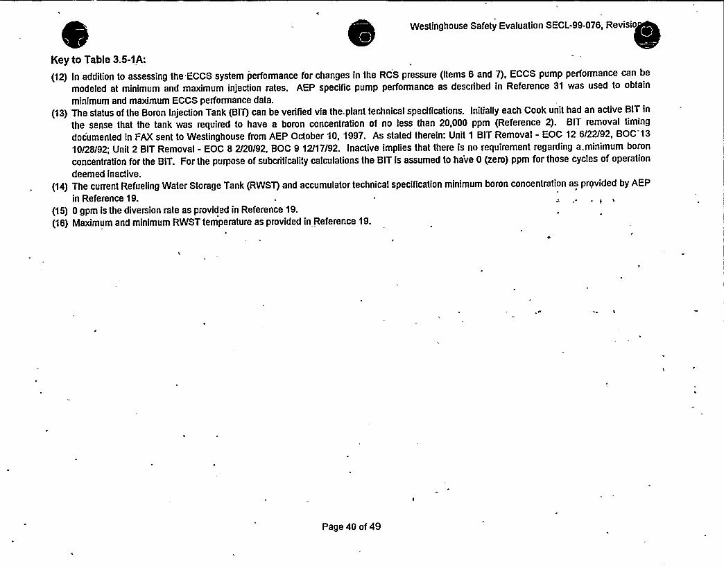
Westinghouse Safety Evaluation SECL-99-076, Revisio
Key to Table 3.5-1A:
(12) In addition to assessing the ECCS system performance for changes in the RCS pressure (Items 6 and 7), ECCS pump performance can be
modeled at minimum and maximum injection rates. AEP specific pump performance as described in Reference 31 was used to obtain
minimum and maximum ECCS performance data.
(13) The status of the Boron Injection Tank (BIT) can be verified via the, plant technical specifications. Initiallyeach Cook unit had an active BIT in
the sense that the tank was required to have a boron concentration of no less than 20,000 ppm (Reference 2). BIT removal timing
documented in FAX sent to Westinghouse from AEP October 10, 1997. As stated therein: Unit 1 BIT Removal - EOC 12 6/22/92, BOC 13
10/28/92; Unit 2 BIT Removal - EOC 8 2/20/92, BOC 9 12/17/92. Inactive implies that there is no requirement regarding a.minimum boron
concentration for the BIT. For the purpose of subcriticality calculations the BIT is assumed to have 0 (zero) ppm for those cycles of operation
deemed inactive.
(14) The current Refueling Water Storage Tank (RWST) and accumulator technical specification minimum boron concentration as prqvided by AEP
in Reference 19.
(15) 0 gpm is the diversion rate as provided in Reference 19.
(16) Maximum and minimum RWST temperature as provided in Reference 19./
Page 40 of 49


Westinghouse Safety Evaluation SECL-99-076, Revision 3
Table 3.5-2. Results of Donald C. Cook Units 1 & 2 Subcriticality Parametric Studies
CaseNo.
RCS Ce of: Relatior ship
Active Sump Ca. Pre-Trip to Active
(ppm) for Pre-Trip Sump Boron Conc.
Unit 1 Cycle 16 Active
Sump Boron Conc.
Unit 2 Cycle 12 Active
Sump Boron Conc.
0 ppm 2000 ppm y=mx+b @ 1381
ppm
Margin @1691 Margin
ppm
1694.98
1733.71
1696.08
1694.35
1700.4
1611.94
1695.31
1623.08
1698.41
2120.16 0.21259x+ 1694.98
2121.62 0.19396x+ 1733.71
2120.25 0.21208x + 1696.08
2120.79 0.21322x+ 1694.35
2083 0.19130x + 1700.40
2116.44 0.25225x+ 1611.94
2093.53 0.19911x+ 1695.31
2082.67 0.22979x+ 1623.08
2121.28 0.21143x+ 1698.41
1988.57
2001.56
~ 1988.97
1988.81
1964.59
1960.3
1970.28
1940.42
1990.4
458.568
471.564
458.97
458.807
434.587
430.3
440.281
410.424
460.401
2054.47 278.471
2061.69 285.691
2054.72 278.71
2054.91 '78.90,
2023.89 247.891
2038.5 262.49
2032.01 256.00
2011.66 235.6
2055.95 279.94
Page 41 of 49
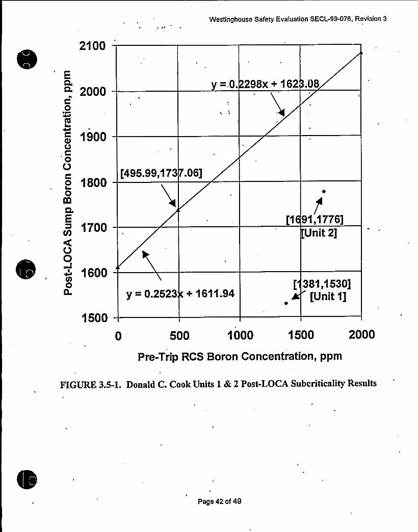
Westinghouse Safety Evaluation SECL-99-076, Revision 3
2100
EQ.CL
0~~
IVC0000
2000
1900
1800[496.99,173 .06j
=.0. 298x+ 162 .08
1700I;1 91,1776]
Unit 2]
1600
1500
y = 0.2523 + 1611.94[ 361,1630]
|Unit 1]
0 500 1000 1500 2000
Pre-Trip RCS Boron Concentration, ppm
FIGURE 3.5-1. Donald C. Cook Units 1 dk, 2 Post-LOCA Subcriticality Results
Page 42 of 49

Westinghouse Safety Evaluation SECL-99-076, Revision 3
3.6 Emergency Operating Procedures Evaluation
'n the current version of the Donald C. Cook Nuclear Plants Emergency OperatingProcedures (EOPs) as well as the Westinghouse Owners Group Emergency ResponseGuidelines (ERGs), upon which the EOPs are based, the plant operator uses theRWST switch-over level as the primary indication for performing the actions associatedwith re-aligning the safety injection system to the containment sump. These actions are,prescribed in the EOP / ERG ES-1.3, "Transfer to Cold Leg Recirculation". Theoperator is directed to ECA-1.1, "Transfer to Emergency Coolant Recirculation", if theactions in ES-1.3 cannot be performed. The actions prescribed in ECA-1.1 would beperformed for situations considered beyond design basis, including multiple pumpand/or valve failures, and an inadequate level in the containment sump. Because themodifications proposed (specifically the containment sump level instrumentationupgrade) will improve the uncertainties associated with the sump level indication, theoperator would be more likely to remain in ES-1.3 for a design basis large or smallLOCA, than be required to transition to ECA-1.1.
It is, therefore, concluded that by reducing the sump level uncertainties, the change is abeneficial one, and does not adversely impact the probability or consequences of theLOCA. Once the revised uncertainties are determined, they could be factored into theplant EOPs.
3.7 Steam Generator Tube Rupture Evaluation
Because the Steam Generator Tube Rupture analysis methodology does not modelcontainment response nor the RWST, the proposed containment system modificationswould not impact the Westinghouse SGTR analysis methodology or assumptions, andwould, therefore, not alter the results of the analysis of record for the SGTR event.
3.8 Radiological Consequences Evaluation
The proposed modifications have been evaluated to determine the impact on the LOCARadiological Consequences Analysis. It was concluded that the changes would eitherprovide a benefit for, or have no impact on the analysis. A discussion of each of themodifications follows:
Partition Wall Penetration: This modification is intended to insure that water that entersthe annulus area after a LOCA can return to the sump. The LOCA radiologicalconsequences analysis includes an ECCS leakage case that considers leakage outsidecontainment of the water being recirculated. The concentration of iodine in this water iscalculated using the amount of iodine assumed to be deposited in the sump and thesump water volume. A higher sump water volume reduces the concentration of iodinein the recirculating water, and consequently, reduces the activity released due to ECCSwater leakage. The additional penetrations therefore provide a benefit for this analysis.No other cases include sump modeling and are, therefore, not impacted by the change.
CE Fan Room Drains: This modification is intended to insure that water which enters. the CEQ fan rooms area after a LOCA can return to the sump. As discussed above, amodification which results in increased sump water volume is a benefit for the ECCS
Page 43 of 49
Westinghouse Safety Evaluation SECL-99-076, Revision 3
leakage case. The modification, therefore, provides a benefit for the radiologicalconsequences analysis.
Increased RWST Overflow Hei ht: This modification is intended to increase the amountof water that is injected into the RCS from the RWST, that in turn, increases theamount of water that will end up in the sump. As discussed above, a modification thatresults in increased'sump water volume is a benefit for the ECCS leakage case. Thismodification will also result in an increased period of injection spray. The injectionspray has a higher capability for iodine removal. Thus, increasing the duration ofinjection provides a benefit for the case which considers the release of iodine from thecontainment gas space. This modification, therefore, provides a benefit for theradiological consequences analysis.
Containment Sum Level Instrumentation U rade: This modification is intended solelyto improve the accuracy of the sump level information available to the operators. It hasno impact on the radiological consequences analysis.
~CR i'.Tli dw i i i d
thus, the amount of water contained in the sump at the time of switch-over from RWSTinjection. As discussed above, a modification which results in increased sump watervolume is a benefit for the ECCS leakage case. In addition, starting the fans earlierprovides for better removal of the iodine released to the containment atmosphere,providing a benefit for the case that considers the release of iodine from thecontainment gas space.
Reduced Ice Mass in the Ice Condenser. A lower ice mass would reduce the amount ofwater in the sump, which would be a penalty for the ECCS leakage case, as explainedabove. However, the analysis conservatively models the sump volume as remainingconstant from the start of recirculation, rather than increasing the volume as additionalice is melted. The amount of ice melted at the start of recirculation is not appreciablyaffected by the total ice weight. Therefore, the reduced ice mass would not adverselyimpact the analysis.
Page 44 of 49

Westinghouse Safety Evaluation SECL-99-076, Revision 3
4. DETERMINATIONOF NO SIGNIFICANTHAZARDS
The modifications proposed to be made to the Donald C. Cook Units 1 8 2Containment Systems to ensure adequate long term post-accident core cooling havebeen evaluated using the guidance of NEI 96-07. On the basis, then, of the safet,assessments presented above, the following arguments may be used in thedetermination that the proposed modifications and the attendant TechnicalSpecification changes involve no significant hazards consideration per the criteria of50.92(c)
4.1 Willthe probability of an accident previously evaluated in the FSARbe increased?
The proposed modifications to the Containment Systems, and the attendant changes toinput assumptions of related safety analyses evaluated herein do not result in a
condition where the material and construction standards which were applicable prior tothe change are altered. System integrity is maintained. The modiTications do notcause the initiation of any accident nor create any new credible limiting single failurenor result in any event previously deemed incredible being made credible. The existingseparation of the control and protection functions are not adversely impacted. In
addition, the functional requirements of safety related systems and components, whichare related to accident mitigation, have not been altered.
It has been demonstrated in this Safety Evaluation that the conclusions of the designbasis analyses assessed herein do not change. The Containment SystemmodiTications are intended to mitigate the consequences of an accident by furtherensuring proper operation of the recirculation sump and related equipment. Again, all
design basis accident analyses addressed in this safety evaluation remain valid withthe incorporation of the revised the accident analysis input assumptions. Therefore,the probability of an accident previously evaluated in the FSAR will not be increased bythis change.
4.2 Willthe consequences of an accident previously evaluated in theFSAR be increased'
The proposed modifications to the Containment Systems, and the attendant changes toinput assumptions of related safety analyses evaluated herein, do not affect theintegrity of the fuel assembly or reactor internals or any fission product barrier such thattheir function in the control of radiological consequences is affected. Nor would theresponse of safety related mitigation systems to accident scenarios, as described in theFSAR be in any way changed, degraded, or prevented. In addition, there is no effecton any assumption previously made in the radiological consequence evaluations noreffect on the mitigation of the radiological consequences of an accident described in
the FSAR. The Post-LOCA analyses discussed in this safety evaluation demonstratethat decay heat is removed and that long term cooling is assur'ed. Therefore, theconsequences of an accident previously evaluated in the FSAR will not be increased.
Page 45 of 49

0

Westinghouse Safety Evaluation SECL-99-076, Revision 3
4.3 May the possibility of an accident which is different than anypreviously evaluated in the FSAR be created?
The proposed modifications to the Containment Systems, and the attendant changesto input assumptions of related safety analyses evaluated herein do not cause theinitiation of any accideht rior create any new credible limiting single failure. Nor do theyresu(t in any event previously deemed incredible being made credible. In addition, thefunctional requirements of safety related systems and components, which are related toaccident mitigation, have not been altered. As such, it4oes not create the possibility ofan accident different than any evaluated in the FSAR.
4.4 Willthe probability of a malfunction of equipment important to safetypreviously evaluated in the FSAR be increased?
The proposed modifications to the Containment Systems, and the attendant changes toinput assumptions of related safety analyses evaluated herein do not result in anincreased probability of scenarios previously deemed improbable. Nor do they createany new failure modes for the safety-related equipment. The proposed modifications,furthermore, result in no original design specification, such as seismic requirements,electrical separation requirements and environmental qualification, being altered.
'n'ddition,they result in no equipment used in accident mitigation being exposed to anadverse environment. No new performance requirements are imposed on anyequipment important to safety. Therefore, the modifications will not increase theprobability of a malfunction of,equipment important to safety previously evaluated in theFSAR.
4.5 Willthe consequences of a malfunction of equipment important tosafety previously evaluated in the FSAR be increased?
The proposed modifications to the Containment Systems, and the attendant changes toinput assumptions of related safety analyses evaluated herein do not result in adifferent response of safety-related systems and components to accident scenariosthan that postulated in the FSAR. No new equipment malfunctions have beenintroduced that will affect fission product barrier integrity. In addition, there is no effecton any assumption previously made in the radiological consequence evaluations noreffect on the mitigation of the radiological consequences of an accident described in
the FSAR. No new performance requirements are imposed on any equipmentimportant to safety. Nor is the response of safety related mitigation systems toaccident scenarios, as described in the FSAR, in any way degraded or prevented.Limiting single failures of the ECCS pumps, CTS pumps and CEQ fans have alreadybeen considered in the accident analyses. The Post-LOCA analyses discussed in thissafety evaluation demonstrate that decay heat is removed and that long term cooling isassured. Therefore, the proposed modifications will not increase the consequences ofa malfunction of equipment important to safety previously evaluated in the FSAR.
Page 46 of 49

Westinghouse Safety Evaluation SECL-99-076, Revision 3
4.6 May the possibility of a malfunction of.equipment important to safetydifferent than any already evaluated in the FSAR be created'
The proposed modifications to the Containment Systems, and the attendant changes toinput assumptions of related safety analyses evaluated. herein do not result in adifferent response of safety-related systems and components to accident scenariosthan, that postulated in the, FSAR. No new equipment malfunctions have beenintroduced that will affect fission product barrier integrity. In additIon, there is no effecton any assumption previously made in the radiological consequence evaluations noreffect on the mitigation of the radiological consequences of an accident described inthe FSAR. No new performance requirements are imposed, on the equipmentimportant to safety. Therefore, the proposed modification will not increase theconsequences of a malfunction of equipment important to safety previously evaluatedin the FSAR.
4.7 Willthe margin of safety as defined in the Bases to any TechnicalSpeciTications be reduced'
The modiTication will have no affect on the availability, operability or performance of thesafety-related systems and components. In fact, it is the intent of these proposedmodifications to the Containment Systems to ensure the proper function of suchequipment, The proposed modifications do, however, require changes to the TechnicalSpecifications as discussed in the safety evaluation, but they do not prevent anyinspections or surveillances required by the Technical Specifications. Therefore, themodifications will not reduce the margin of safety, as described in the bases to anyTechnical Specification.
The Bases of the Technical Specifications are founded in part on the ability of theregulatory criteria being satisfied assuming the limiting conditions for operation (LCO)for various systems. Conformance to the regulatory criteria for operation of the DonaldC. Cook Units with the proposed modifications is demonstrated by the analyses andassessments discussed herein, and the regulatory limits are shown not to be exceeded,the margin of safety as defined in the Technical Specifications is not reduced.
4.8 CONCLUSION
This evaluation of the proposed modifications to the Donald C. Cook Units 1 8 2Containment Systems, the attendant changes to input assumptions of related safetyanalyses, and the resulting changes to the plants'echnical Specifications concludesthat no significant hazards consideration per the criteria of 10CFR50.92 is involved.This conclusion is based on the fact that it has been demonstrated that thesemodifications do not increase the probability of occurrence or the consequences of anaccident previously evaluated in the FSAR. Nor has any mechanism for an accident ormalfunction, which has not been previously evaluated in the FSAR, been identified.Also, the change does not decrease the margin of safety as identified in the basis forany Technical Specification.
Page 47 of 49


'Westinghbu& Safety Evaluation SECL-99-076, Revision 3
6. REFERENCES
1. AEP Letter to Westinghouse (Messrs. Bass & Hawley to Corletti) dated July 8, 1999- Requestfor Integrated Safety Evaluation2. Donald C. Cook Technical Specifications, Unit 1 Amendment 226, December 1998; and Unit 2Amendment 211, December 19983. AEP Design Input Transmittal (DIT)-B-00003-01, Transmitted to Westinghouse by AEP letter(Messrs Hafer and Bass to Corletti) dated July 2, 1999, and attachments, including DIT-B-00003-CO, Transmitted to Westinghouse by AEP letter dated June 15, 1999; and, the Analysis InputAssumptions for the post-LOCA Analyses/Evaluations, Transmitted to Westinghouse by AEPletter dated June 18, 1999.4. AEP Letter to Westinghouse AEP/W SGTP-22, December 14, 1994, Donald C. Cook NuclearPlant Steam Generator Tube Plugging Analysis Technical Documentation TransmittalG. AEP Procedure Number 02-OHP 4023 ES-1.3, Rev. 6, Transfer To Cold Leg Recirculation,
'/22/99
6. AEP Letter to Westinghouse (Vanderburg to Peck) dated September 18, 19987. AEP letter from Vance VanderBurg to Don Peck of Westinghouse, August 19, 19988. Westinghouse Calculation CN-FSE-99-98, Rev. 1, Two Train RWST Draindown For LOCA-Donald C. Cook Units 1 & 29. Westinghouse memorandum SAE/FSE-AEP/AMP-0806, Two Train RWST DraindownTransient for Donald C. Cook Units 1 & 2 for LOCA10. Westinghouse Calculation CN-FSE-99-95, Revision 1 Single Train RWST DraindownContainment Integrity Case - Donald C. Cook Units 1 & 211. Westinghouse memorandum SAE/FSE-AEP/AMP-0758, 7/6/99, Single Train RWSTDraindown Transient for Donald C. Cook Units 1 & 212. WCAP-14285, Revision 1, 'Donald C. Cook Nuclear Plant Unit 1 Steam Generator TubePlugging Program Licensing Report, May 1995.13. FAX from Jim Hawley to M. Corletti, transmitting DIT No. DIT-B-00005-03, (Subject:Containment Volumes and Containment Spray UA, ESW Flow, and Temperature), 7/9/99.14. FAX from Jim Hawley to John Koiano, transmitting DIT No. DIT-B-00003-03, (Subject:Containment Integrity Analysis; Containment Spray UA and ESW Flow to CTS Hx), 7/1 0/99.
'5.
FAX form Jim Hawley to John Kolano, transmitting DIT No. DIT-B-00003-04, (Subject:Containment Integrity Analysis; Sump Volume and ESW Maximum Temperature), 7/10/99.16. WCAP-14488, 'Donald C. Cook Nuclear Plant Unit 2 3600 MWt Uprating Program LicensingReport, December 1996.17 AEP Design Input Transmittal (DIT)-B-00003-05, transmitted to Westinghouse by AEP letter(Messrs Hafer and Bass to Corletti) dated September 22, 199918. AEP-99-267, Donald C. Cook Units 1 and 2, Post-LOCA Hydrogen Evaluation Report-Revision 3', August 20, 1999.19. AEP Letter to W (Brassart to Corletti), Units 1 and 2 Analysis Input Assumptions for thepost-LOCA Analyses/Evaluations', dated June 18, 1999.20. WCAP-8951 (Non-Propnetaiy), Mendler, O. J., "Method of Analysis and Evaluation of JetImpingement Loads from Postulated Pipe Breaks".21. WCAP-7833 Supplement 1, "Supplementary Information to WCAP-7833, Design andPerformance Evaluations of the Ice Condenser Reactor Containment System for the Donald C.Cook Nuclear
Plant.'2.
SEC-LIS-5123-C8, 'Cook Unit 1 and 2 (AEP/AMP) Post-LOCA Analyses to Support PlantRestart, December 11, 1998.23. CAA-98-272, 'Donald C. Cook Unit 1 Cycle 16 Revised Post-LOCA Data for Restart at 4,736MWD/MTU",November 30, 1998.24. CN-AM12-089, 'Cook Unit 2 Cycle 12- New Gales for Xe Credit, Options A and B, May 21,1999.25. Westinghouse memorandum SAE-LIS-99-191, 'Transmittal of Report on Donald C. CookControl Rod Insertion, dated'April 13, 1999.
Page 48 of 49


I
V.'elirghou=e "afety =valuation SECL-99-076, Revision 3
26. AEP-95-200 (NSAL-95-001), "American Electric Power Service Corporation Donald C. CookNuclear Plant Units 1 and 2 Minimum Cold Leg Recirculation Flow", January 19, 1995.27. AEP-99-059, '10 CFR 50.46 Annual Notification and Reporting for 1998/SBLOCAAsymmetric HHSI Report," July 12, 1999.28. "Acceptance Criteria for Emergency Core Cooling Systems for Water Cooled Nuclear Power
3, January 4, 1974, Amended September 16, 1988.29. W Calculution Note ¹SEC-LIS-5123-C3, Donald C. Cook Unit 1 and 2 (AEP/AMP)Justification for Past Operation for Unit 1 Cycle 16 and Unit 2 Cycle 11 for Post-LOCASubcriticality', November 5, 1997.30: SEC-LIS-95481, "Revised LOCA Input to the Donald C. Cook Nuclear Plant Unit 1 and 2(AEP/AMP) LOCA Review of EOP E-O, E-1, ES-1.2, and FR-Z.1', September 11, 1998.31. WCAP-14286, American Electric Power Service Corporation Donald C. Cook Nuclear PlantUnit 1 Steam Generator Tube Plugging Program Engineering Report, December 1995, Volume2, Appendix A - Analysis Input Assumptions.32. Email from AEP to Westinghouse (Messrs. Jim Hawley and Jeff Bass to M. Corletti),'Containment Spray Heat Exchanger and CEQ Fan Start. Logic", August 20, 199933. AEP Letter to Westinghouse (Messrs. D. R. Hafer and J. C. Bass to M. Corletti), "Transmittalof Accident Analysis Input Assumptions - DIT-B-00003-02, DIT-B-00003-03, DIT-B-00003-04",July 19,1999.34. AEP Letter to Westinghouse (V. Vanderburg to D.Peck), 'Ice Bed Temperature', October 7,1998.35. Technical Manual No. 1440-c352: 'Vertical Steam Generator Instructions for IndianaMichigan Power Company, Donald C. Cook Nuclear Plant Unit 2.
Page 49 of 49

LER No. 315-97/017-01 and 316/97-005-01
26.0 LER No. 315/97-017-01 and 316/97-005-01
~ Event Description: Vortexing in Containment'Sump Leading to the Failure ofRHR Pumps
Date ofEvent: October 8, 1997
Plant: D.C. Cook Units 1 and 2
26.1 Summary of Issue
Several conditions identified at D.C. Cook (Ref. 1) indicated the possibility ofreducing the amount ofwater available in the containment sump. A reduced water level in the sump can lead to either netpositive suction head (NPSH) problems or air entrainment problems (due to vortexing) for the residualheat removal (RHR) pumps. Figure 1 shows the different elevations that are referred to in the text andthe relative location of the RHR suction pipe with respect to those elevations. Note that the sump levelrequired by design basis to ensure against NPSH problems as well as the vortexing problems is 602'-10."
Issues related to remature termination of in ection from RWST
Several issues discovered at Cook showed the possibility for premature termination of injection from the
~
~
refueling water storage system (RWST) to the reactor coolant system (RCS) during a loss-of-coolantaccident (LOCA). During the injection phase, water in the RWST is transferred from the RWST to thecontainment via the RCS. AtD.C. Cook, when the RWST level decreases to the low alarm setpoint(nominally 32.23% ofspan), the operators start transferring from injection to containment'sumprecirculation. Therefore, at least 68% of the RWST inventory of350,000 gallons willbe available in thecontainment sump when the RHR pumps start taking suction from the containment. However, four issuesassociated with the RWST level indication can result in termination of injection at a point much higher ~
that 32.23%. They are: (a) an error made in the setpoint calculation (friction loss calculation that did notincorporate the entrance loss factor); (b) a second error made in the setpoint calculation that did notcorrect for the velocity head loss correction factor in the Bernoulli equation; (c) failure to adequatelyconsider the uncertainties; and (d) a drip catch installed in the 10-inch RWST overflow line that couldresult in an additional negative 8% level error due to the vacuum created inside the RWST at high flowrates. Preliminary investigations performed by the licensee indicated that application oferrors (a), (b),and (c) could cause the actual RWST water level to be higher than the indicated level by approximately20% of instrument span (about 6 feet of level) when the flowrates from both RHR and containment spray(CTS) pumps are'at their maximum. When combined with issue (d), the total error could be as high as
28%. As a result, inventory transferred from the RWST to the containment could be nearly 98,000gallons (28% of350,000 gallons) less than the amount anticipated to be present in the containment sumpwhen sump recirculation staits. The reduction in the amount ofwater in the sump, can reduce thecontainment sump water level and lead to air entrainment ofRHR pumps. Since all ofthe above errorsare dependent upon the flowvelocity, for small break LOCAs (especially those that do not require CTS),this issue is irrelevant.
August 17, 1999

LER No. 315-97/017-01 and 316/97-005-01
Issues related to diversion ofwater from the containment sum to the inactive containment sum
LER 315-97-017 (Ref. 3) reported a design flaw at Cook which results in diversion ofwater from theactive sump volume to inactive sump volumes. Water in the inactive volumes willnot be available forrecirculation. Figure 2 shows the location ofthe reactor relative to the active and the inactivecontainment sumps. Figure 3 shows how the containment spray pumps can transfer the inventory fromthe active sump to the inactive sump. Figure 4 shows the volumes in the inactive and active sumps. Themagnitude and the nature of flowdiversion paths are as follows: (a) The CTS system is designed toprovide a flowof300 gpm per train to spray nozzles in the accumulator/fan rooms of the containment.The accumulator/fan rooms are directly above the drain to the pipe annulus. (b) Inventory is lost fromCTS to the inactive sump not only through the lower containment nozzles to the fan accumulator roomsbut also through the upper containment nozzles down the stairwells. (c) Unsealed penetrations in thecrane wall allow water to flow from the active sump to the passive sump. Reference 8 provides theelevations and effective areas ofeach ofthe penetrations. The total area ofthe penetrations is estimatedto be approximately 143 square inches. The lowest penetration is at 600'-7" and has a magnitude of6.231square inches. The two major penetrations are 35.579 and 57.617 square inches and they are located at602'-4" and 600'-10", respectively. Diversion ofwater from the active sump to the inactive sump canreduce the containment sump water level and lead to vortexing and air entrainment in RHR pumps.
Issues related to containment water level and containment sum level indications
Step 1 ofRevision 4 to the emergency operating procedure, (EOP) Ol-OHP 4023.ES-1.3 (Ref. 4),instructs the operator to check whether the containment water level is greater than 15% prior toestablishing sump recirculation. The 15% containment water level equates to an elevation of601'-6".According to Reference 1, while this water level is adequate for NPSH considerations, it does not assurethe prevention ofemergency core cooling system (ECCS) pump vortex formation and air entrainment. Aminimum containment level'of 602'-10" is necessary to eliminate the likelihood ofvortex formation andair entrainment. The 602'-10" level is named the "minimum safe level" and it was established using scalemodel testing in 1977, when both RHR and CTS pumps were operated at run out flows. After includinginstrument uncertainties, this relates to a 29% containment water level. Ifthe containment water level liasnot reached 15%, the procedure mentioned above would allow the operators to start establishing sumprecirculation ifthe containment sump level was greater than 97%. This.equates to an approximateelevation of599'-4", which is nearly 3'elow the level required to prevent vortexing and air entrainment.As a result, during an event, the operators may start the RHR pumps prematurely and create vortexingand air entrainment. Therefore, at large RHR and CTS flows, this cautionary statement in the EOPcannot be credited as a defense against vortexing in the containment sump. For small break LOCAs,since the combined RHR and CTS flows are much less than the total pump run out flows, this issue isirrelevant. I
The Froude number is indicative ofthe potential for vortexing. This number is proportional to the flowvelocity and inversely proportional to the square root of the elevation difference between the pumpsuction and the free surface. For example, ifthe flowvelocity is reduced by a factor of two, the elevation
August 17, 1999

LER No. 315-97/017-01 and 316/97-005-01
difference needed to avoid vortexing can be reduced by a factor of4. Therefore, for small (or even mostmedium) breaks, this issue is irrelevant.
Issues related to the ice mass
The inspections at Cook revealed a large number of issues related to the mass of ice in the ice condensers.Ifthere was a significant reduction in the mass of ice in the ice condensers in the "as-found" condition,that could have impacted the sump water level after a LOCA. However, based on communications withthe licensee (Paul Schoepf, August 9, 1999), it was found that the ice mass in the as-found condition wasnot significantly less than the technical specification requirement. Note that non-QA/crude estimates ofice weights were 2.71E6 lbs for Unit 1 and 2.83E6 lbs for Unit2. The technical specification requirementin the as-'found condition was 2.37E6 lbs. Even ifthe absolute values were significantly (e.g., 10%)lower than these crude estimates, the risk analysis would still be unaffected. Therefore, the issuesrelating to ice mass are ignored in the risk analysis in all LOCA and feed-and-bleed sequences.
The changes to the core damage frequency (CDF) associated with the issues discussed above depend onthe impact ofother issues on the RHR cooling and auxiliary feedwater (AFW) capabilities. The CDFassociated with the issues discussed above is summarized in Table 1. Table 1 summarizes the initiatingevent frequencies of initiators that are affected by the debris in the sump, products ofknown probabilitiesand the frequency for each initiator, summary ofqualitative assessment of the unknown probability, andthe expected change in CDF for each initiator. Overall, the total CDF change associated with the issuesidentified above is less than 1 x 10~/Year and therefore, they are not risk-significant.
26.2 Modeling and Affected Sequences
The RHR pumps may vortex and entrain air ifthey are started when the sump inventory is inadequate.Even ifthe pumps are successfully started, ifthe event requires containment spray, that spray pump maygradually divert flow from the active sump to the inactive sump. As a result, air entrainment may occurduring late stages ofsump recirculation. Any LOCAor feed-and-bleed scenario may require sumprecirculation. 'Therefore, the followingcore damage sequences are considered:
'Se uence I - Small LOCA Stuck o en PORVs or SRVs RCP seal LOCAs Small i e breaks or Feed-and-bleed coolin - Earl failure of sum recirculation
~ Small LOCA or feed-and-bleed cooling occurs;~ Sump recirculation is required due to inability to depressurize RCS and establish RHR cooling;~ Operator starts RHR pump even ifthe sump level is less than 15% ofcontainment water level or 97%
ofcontainment sump level;~ RHR pumps entrain air due to vortexing when pumps start; and~ RHR pumps fail due to vortexing
Se uence 2- Small LOCA Stuck o en PORVs or SRVs RCP seal LOCAs Small i e breaks or Feed-and-bleed coolin - Late failure of sum recirculation
August 17, 1999

LER No. 315-97/017-01 and 316/97-005-01
~ Small LOCA or feed-and-bleed cooling occurs;~ Sump recirculation is required due to inability to depressurize RCS and establish RHR cooling;~ RHR pumps entrain air due to vortexing during long term operation; and~ RHR pumps fail due to vortexing.
Se uence 3 - Medium LOCA - Earl failure of sum recirculation
~ Medium LOCAoccurs;~ Operator starts RHR pump even ifthe sump level is less than 15% ofcontainment water level or 97%
ofcontainment sump level;. ~ RHR pumps entrain air due to vortexing when the pumps start; and
~ RHR pumps fail due to vortexing
Se uence 4- Medium LOCA - Late failure of sum recirculation
~ Medium LOCA occurs;~ RHR pumps entrain air due to vortexing during long term operation; and~ RHR pumps fail due to vortexing.
Se uence 5- Lar e LOCA- Earl failure ofsum recirculation
~ Large LOCA occurs;~ Operator starts RHR pump even ifthe sump level is less than 15% ofcontainment water level or 97%
ofcontainment sump level;~ RHR pumps entrain air due to vortexing when the pumps start; and~ RHR pumps fail due to vortexing.
Se uence 6- Lar e LOCA - Late failure ofsum recirculation
~ Large LOCA occurs;~ RHR pumps entrain air due to vortexing during long term operation; and~ RHR pumps fail due to vortexing.
26.3 Frequencies, Probabilities, and Assumptions
Three analyses, two ofwhich were performed by vendors sponsored by the licensee (Ref. 8, 9) and thethird analysis paid for by NRC (Ref. 10), provide the basis for many of the probabilities discussed in thissection.
Reference 8 is a MAAP4 analysis performed to determine the active sump conditions during a cold legrecirculation following a double ended cold leg LOCA. Using an RWST inventory of350,000 gallonsand an initial ice mass of2.43E6 Ibs, and factoring in communications between the active and the inactivesumps below the 602'-.10" level, the active sump level was determined to be 9.5 feet at the beginning of
. August 17, 1999


LER No. 315-97/017-01 and 316/97-005-01
the switchover to recirculation. The calculation showed that the level would increase to 11 feet by thetime switchover is complete. The long term equilibrium level in the active sump is 7.8 feet. Theelevation 598'-9 3/8" is treated as the zero level. Therefore, the design basis required level (602'-10")equates to approximately 4 feet. This calculation used the original sump recirculation procedure that haderrors which could result in premature termination of injection from RWST during a design basis LOCA.In conclusion, the analysis demonstrated that in spite ofthe several errors in the RWST level setpoints,during a design basis LOCA, the active sump water level would have been well above the required limitof602'-10" during the early and late phases ofa large LOCA.
Reference 9 is a Fauske &Associates (FAI)calculation. This study showed that under design basis largebreak LOCA and a spectrum ofsmall break LOCAs, a proposed increase in total mass together with otherexisting water sources would provide sufficient water in the sump. Even though the calculations wereperformed with a proposed increase in the mass of ice rather than the mass of ice required by currenttechnical specifications, the calculations can be applicable to the "as-found" condition due to thefollowing. At the time ofplant shutdown, the technical specifications required the ice weight to be2,371,451 lbs. The proposed increase would require 2,590,000 lbs of ice. However, note that a non-QAcrude estimate ofthe weight of ice in the condenser showed 2.71E6 lbs of ice in Unit 1 and 2.85E6 Ibs ofice in Unit 2. Since the weight of ice in the "as-found" condition exceeds the proposed ice mass,calculations in Reference 9 have applicability to the "as-found" condition.
Reference 10 is a calculation performed by Science and Engineering Associates (SEA) forNRC. This~
~
~report provides results for two analyses; a 2 inch pipe break and a 6 inch pipe break. The 6-inchscenarios showed that the containment water level would stay well above the minimum safe level, even inthe calculation that assumed the most conservative ice melt parameters. The limiting2 inch breakshowed that under conservative assumptions (no accumulator injection, break is in the annulus, CTSsprays operate continuously, and ice dissolves slowly), the sump level could drop 3'elow the minimumsafe level. However, the analyses concluded that this may be safe since (a) the minimum safe level wasestablished for run out flows rather than the 2-inch break flows, and (b) very conservative assumptionswere used.
Se uence 1 - Small LOCA Stuck o en PORVsorSRVs RCP seal LOCAs Small i e breaks orFeed-and-bleed coolin - Earl failure ofsum recirculation
~ Small LOCA or feed-and-bleed cooling occurs - Rates ofInitiatingEvents at US. 1V'uclear PowerPlants: 1987-1995 (Ref. 4) indicates that the frequency ofsmall LOCAs (includes stuck open PORVsand SRVs, RCP seal LOCAs, and small pipe breaks) is 9 x 10'/year. Assuming the AFW reliabilityat Cook was not significantly affected by other Cook issues related to AFW, the frequency offeed-and-bleed cooling scenario at Cook is negligible compared to the small LOCA frequency. Therefore,the total frequency of small LOCAs and feed-and bleed cooling sequences is approximately 9 x 10'/year.
~ Sump recirculation is required due to inability to depressurize and establish RHR cooling - Operatingexperience shows that during most small LOCAs, the loss ofcoolant rates and the condition ofthe
August 17, 1999

LER No. 315-97/017-01 and 316/97-005-01
RCS allows the operators to depressurize and use RHR cooling. During the time period 1987-1995,there were two stuck open SRV events (classifie as small LOCAs in Ref. 4), and during both theseevents, sump recirculation was not needed (Ref. 5, 6). During the event that occurred at FortCalhoun, approximately 21,500 gallons ofRCS water was discharged from the RCS to thecontainment. This is much less than the discharge required to demand ECCS sump recirculation.During the event that occurred at Calvert Cliffs, only 5000 gallons ofreactor coolant discharged tothe containment floor. During the TMI-2event (March 28, 1979), a stuck open PORV released271,000 gallons ofRCS water to the sump. However, during the TAI-2event, sump recirculationwas not demanded.
Two RCP seal LOCA events. are discussed in Reference 4. During the 1975 May event at RobinsonUnit 2 (no LER, page I-3'ofRef. 4), a total of 132,500 gallons ofRCS water was released to thecontainment sump before RHR cooling was established. The maximum leak rate was 500 gpm.During this event, the sump recirculation function was not needed. During the event at ArkansasNuclear One Unit 1 (Ref. 7), approximately 60,000 gallons ofwater collected in the containmentbefore RHR cooling was established. The maximum leak rate was 300 gpm. The containmentpressure increased by 0.5 psi, at which time the reactor building containment coolers were put intoservice. During this event, sump recirculation was not needed.
There have been no small pipe break LOCAs or feed-and-bleed cooling events in the industry. Feed-and-bleed cooling uses the pressurizer PORVs or SRVs to bleed RCS while injecting RCS with highpressure injection. AtD.C. Cook, the pressurize is equipped with three PORVs that are capable ofbleeding the RCS. Based on discussions with operations at D.C. Cook (Richard Stressed, June 30,1999), using simulator exercises, the feed-and-bleed cooling can depressurize the reactor prior to
'depleting the RWST. Therefore, the likelihood ofcooling down the reactor with feed-and-bleedcooling prior to requiring sump recirculation is assumed to be equal to the likelihood during a smallLOCA.
Using the Bays method and zero demands for sump recirculation during 5 small LOCAs, theprobability ofrequiring sump recirculation during a small LOCA is calculated to be 0.08 (/2 eventson 6 demands).
~ Operator starts the RHR pump even ifthe sump level is less than 15% ofcontainment water level or97% ofcontainment sump level - Step 1 ofthe EOP requires that the operators verify that thecontainment water level is greater than 15% or containment sump level is greater than 97% prior totransferring to sump recirculation.'his assures at least a 599'A" level ofwater in the sump. Eventhough this level is lower than the minimum safe level for RHR and CTS pump run out flows, it isadequate for low flow rates experienced during small break LOCAs. Therefore, for small LOCAs,this procedural step can be credited as a defense.
Assuring adequate water level in the sump is the Step 1 ofthe EOP. Missing Step 1 ofan EOP is notlikely. Reference 12 (Table 20-5) suggests 0.003 as the probability offailure to execute a step in theprocedure.
August 17, 1999

0

LER No. 315-97/017-01 and 316/97-005-01
~ RHR pumps entrain air due to vortexing when the pumps start - Break sizes less than 2 inches areconsidered under small LOCAs. For small breaks this probability is negligible due to the followingreasons:
Reference 10 points out that for breaks less than 2" (Ref. 10 analyzed 1" and t/i " breaks) the sprayswillnot initiate until the ice depletes adding to the sump inventory. Without CTS, the flow ratescould be a few 100 gpm, and, at these flow rates, the velocity dependent RWST errors are essentiallyabsent. (A2" break where the sprays initiate is discussed under medium LOCA).
As pointed out earlier, the minimum safe level was established for the condition in which both RHRand CTS pumps incur run out flows. The total combined RHR and CTS flow is 15,600 gpm.Following a small break without CTS, the total ECCS flowrate may be a few 100 gpm (Assume 1000gpm). The Froude number, which is indicative ofthe potential for vortexing, can be used to explainhow the flow level required to prevent vortexing varies with the flow rate (or fiowvelocity). TheFroude number is proportional to the velocity and inversely proportional to the square root ofthelevel difference between the pump suction and water level. At 602'-10", the pump suction isapproximately 6'elow the minimum water level of602'-10". When the flow rate reduces &om15,600 to 1000 (nearly 1/16th), the level difference can reduce by a factor of 1/256 before theidentical Froude number (and thereby the same vortexing potential) is achieved. That is, at a few 100gpm, having the suction pipe fully immersed may be adequate to prevent vortexing.
RHR pumps fail due to vortexing - Ifthe RHR pumps entrain air as a result ofvortexing, they willnot immediately fail. The pumps can run for a limited period with air entrained, and indications inthe control room (e.g., fluctuating pump currents) may allow the operator to intervene (stop thepumps) and avoid pump failure. Tripping ofone oftwo pumps may cut down the flowrate and endvortexing and air entrainment. This capability to recover is not credited, and it is conservativelyassumed that the failure probability is 1.0.
Se uence 2 - Small LOCA Stuck o en PORVs or SRVs RCP seal LOCAs Small i e breaks or Feed-and-bleed coolin - Late failure of sum recirculation
Small LOCA or feed-and-bleed cooling occurs - Rates ofInitiatingEvents at US. Nuclear PowerPlants: 1987-1995 (Ref. 5) indicates that the frequency ofsmall LOCAs (includes stuck open PORVsand SRVs, RCP seal LOCAs, small pipe breaks) is 9 x 10'/year. Assuming, the AFW at Cookreliabilitywas not significantly affected by other Cook issues related to AFW, the frequency offeed-and-bleed cooling scenario at Cook is negligible compared to the small LOCA frequency. Therefore,the total frequency ofsmall LOCAs and feed-and bleed cooling sequences is 9 x 10'/year.
~ Sump recirculation is required due to inabilityto depressurize and establish RHR cooling - Thisprobability is estimated to be 0.08. The basis for this probability is discussed under Sequence 1.
~ RHR pumps entrain air due to vortexing during long term operation - Sequence 1 showed why theprobability of this event is negligible for a small break LOCA at the time when RHR pumps need to
August 17, 1999

LER No. 315-97/017-01 and 316/97-005-01
be started to support sump recirculation. However, there is a potential for vortexing to occur in thelong-term operation since CTS willinitiate after ice depletes and start transferring water from theactive sump to the inactive sump. Analysis oftwo small breaks (1" and Yi ") documented inReference 9 shows that under both these breaks, the long-term equilibrium levels willprovideadequate sump levels to prevent vortexing. Reference 9 did not credit the penetrations in the cranewall that tend to equalize the water levels in the active and passive sumps when the level exceeds600'-7". Crediting these penetrations willmake iteven less likelythat the active sump level fall
'elow600'-7" in the long-term. As discussed in Sequence 1, this probability is negligible, especiallygiven the fact that at the low flowrates encountered, containment sump levels that are much lowerthan minimum safe level are acceptable.
The total CTS and RHR flowcan be higher during long-term since CTS may be in operation due todepletion ofall the ice. Even ifboth CTS sprays operate, the total flowwillbe about 8000 gpm(about ~/~ oftotal pump run out flows). Athalfofthe flowvelocity, the Froude number wouldindicate an allowance to drop the elevation (difference between free surface and pump suction) by afactor of4. Since at 602'-10", the elevation is approximately 6', halfofthe fiowwillallow anelevation of 1'-6", which equates to roughly 598'-4" as the minimum safe level.
~ ~ RHR pumps fail due to vortexing - Ifthe RHR pumps entrain air as a result ofvortexing, they willnot immediately fail. The pumps can run for a limited period with air entrained, and indications inthe control room (e.g., fluctuating pump currents) may allow the operator to intervene (stop thepumps) and avoid pump failure. Tripping ofone of two pumps may cut down the flow rate and endvortexing and air entrainment. This capability to recover is not credited, and it is conservativelyassumed that the failure probability is 1.0.
Se uence 3 - Medium LOCA - Earl failure of sum recirculation
~ Medium LOCA occurs - Rates ofInitiatingEvents at US. Nuclear Power Plants: 1987-1995 (Ref. 4)indicates that the frequency ofmedium LOCAs is 4 x 10'/year.
II
~ Operator starts the RHR pump even ifthe sump level is less than 15% ofcontainment water level or97% ofcontainment sump level - Step 1 of the EOP requires that the operators verify that thecontainment water level is greater than 15% or containment sump level is greater than 97% prior totransferring to sump recirculation. This assures at least a 599'-4" level ofwater in the sump. Eventhough this level is lower than the minimum safe level for RHR and CTS pump run out flows, itmaybe adequate for most medium break LOCAs. However, for medium LOCAs, this step in the EOP is
not credited, and the failure probability is conservatively assumed to be 1.0.
~ RHR pumps entrain air due to vortexing when the pumps start - Medium break LOCAs includebreaks ranging from 2" to 6". Findings from References 9 and 10 on the 6" break analysis are
discussed under large LOCA. Further, detailed analysis on this issue has shown that the 2" break is
more limiting since a 2" break can occur in the annulus, and, as a result, break flow is discharged into
August 17, 1999

LER No. 315-97/017-01 and 316/97-005-01
the annulus or the reactor cavity rather than to the active sump. Therefore, the likelihood ofthisevent for a 2" break (limitingcase ofa medium break LOCA) is discussed below.
Reference 9 analyzed a 2" break LOCA in which RCS water was assumed to flow into the reactorcavity rather than to the active sump. The accumulators were assumed to inject for this 2" break.CTS was assumed to actuate and divert some flow to the inactive sump from the active sump. Underthis postulated scenario, the ice melt rate exceeded the water removal rate from the containment, and,as result, active sump level continued to increase. Afterall the ice melted, the active sump leveldecreased until the inactive sump filled and began to spill over to the active sump. The final
active'ump
equilibrium level was 604', which is 14" above the required minimum safe level.
Reference 10 analyzed a 2" break in the annular compartment. The accumulators were assumed tonot dump and the CTS sprays ran continuously, diverting flow from the active sump to the inactivesump. The CTS sprays were not turned off since the containment pressure remained slightly abovethe 1.5 psig turnoffsetpoint. Conservative ice melt parameters were used in this calculation (10% ofice remaining even after 40 hours after the break). Under these assumptions, Figure 15 ofReference10 shows that the water level in the sump would have been above the minimum safe level when theRHR pumps needed to start taking suction from the containment sump (During this postulated event,later on in the accident, the sump water level fell below the minimum safe level. This is discussed inthe next sequence). (It should also be noted here that the RWST level errors, which depend on theflowvelocity, are negligible for a 2" break.)
Based on the results ofanalyses of6" break LOCAs (discussed under large LOCAs) and 2" breakLOCAs (discussed abov'e), the probability ofhaving a water level less than 602'-10" at the time RHRpumps must be started is negligible. Therefore, for a medium break LOCA the probability ofthisevent is negligible.
~ RHR pumps fail due to vortexing - Ifthe RHR pumps entrain air as a result ofvortexing, they willnot immediately fail. The pumps can run for a limited period with air entrained, and indications inthe control room (e.g., fluctuating pump currents) may allow the operator to intervene (stop thepumps) and avoid pump failure. Tripping ofone oftwo pumps may cut down the flowrate and endvortexing and air entrainment. This capability to recover is not credited, and it is conservativelyassumed that the failure probability is 1.0.
Se uence 4 - Medium LOCA - Late failure ofsum recirculation
~ Medium LOCA occurs - Rates ofInitiatingEvents at US. Nuclear Power Plants: 1987-1995 (Ref. 4)indicates that the frequency ofmediuin LOCAs is 4 x 10'/year.
~ RHR pumps entrain air due to vortexing during long-term operation -The probability ofthis event isnegligible.
August 17, 1999
LER No. 315-97/017-01 and 316/97-005-01
The limiting2" break in the annulus analyzed in Reference 10 is summarized here to support theabove conclusion.
For a 2" break LOCA, under conservative assumptions on ice melt rates (10% of ice remains evenafter 40 hours) and CTS sprays (sprays operate continuously, diverting flow from the active sump tothe inactive sump for 40 hours), the sump level can fall as much as 3'elow the minimum safe level.That is, the level may fall to approximately 599'-10" (See Figure 15 ofReference 10). However,Reference 10 concludes that the probability ofvortexing during this scenario is very low since theminimum safe level was established for run out fiow from CTS and RHR. Even though Reference 10did not provide a basis for this conclusion, the followingparagraph offers the possible explanation.
The total combined RHR and CTS flow is 15,600 gpm. Following a 2-inch break, the total ECCS(CTS and RHR) flowrate is less than 8000 gpm. The Froude number is proportional to the velocityand inversely proportional to the square root ofthe level difference between the pump suction andwater level. At602'-10", the free water surface is approximately 6'bove the pump suction waterlevel. When the flow rate reduces from 15,600 to 8000 (nearly half), the level difference can reduceby a factor of4 before the identical Froude number (and thereby the same vortexing potential) isachieved. That is, even ifthe water elevation is 1'-6" (i.e., the elevation is 598'-4"), vortexing is notanticipated.
In addition to many of the conservatisms in the analysis that concluded the level could be 3'elow theminimum safe level, it ignored the holes in the crane wall (total area approximately 142 squareinches) that would allow water to flowback from the inactive sump to the active sump. These holes(unless they get plugged up by debris) willallow water to return to the active sump and keep theactive sump level higher than the calculated value.
~ RHR pumps fail due to vortexing - Ifthe RHR pumps entrain air as a result ofvortexing, they willnot immediately fail. The pumps can run for a limited period with air entrained, and indications inthe control room (e.g., fluctuating pump currents) may allow the operator to intervene (stop thepumps) and avoid pump failure. Tripping ofone of two pumps may cut down the flow rate and endvortexing and air entrainment. This capability to recover is not credited, and it is conservativelyassumed that the failure probability is 1.0.
Se uence 5 - Lar e LOCA - Earl failure ofsum recirculation
~ Large LOCA occurs - Rates ofInitiatingEvents at US. Nuclear Power Plants: 1987-1995 (Ref. 4)indicates that the frequency of large LOCAs is 5 x 10~/year.
~ Operator starts the RHR pump even ifthe sump level is less than 15% ofcontainment water level or97% ofcontainment sump level - Step 1 of the EOP requires that the operators verify that thecontainment water level is greater than 15% or containment sump level is greater than 97% prior totransferring to sump recirculation. This assures at least a 599'-4" level ofwater in the sump. Thislevel is lower than the minimum safe level for RHR and CTS pump run out flows. Therefore, for
10 August 17, 1999

LER No. 315-97/017-01 and 316/97-005-01
large LOCAs, this procedural step in the EOP is not credited, and the failure probability isconservatively assumed to be 1.0.
/
~ RHR pumps entrain air due to vortexing when the pumps start - Based on information provided inReferences 8, 9, 10, and 11 the probability ofthis event is negligible. The probability ofthis eventfor breaks ranging from 6" to design basis LOCA is discussed here.
Reference 8 has shown that during a design basis LOCA, in spite ofRWST level errors, the activesump level willbe several feet above the design basis level. References 9 and 10 show that evenduring other large LOCAs (greater or equal to 6"), even under conservative assumptions, the activesump level willexceed 602'-10". For these LOCAs, the rate of ice dissolution is sufficient to offsetany reduction in inventory from the RWST and diversions via the containment spray.
~ RHR pumps fail due to vortexing - Ifthe RHR pumps entrain air as a result ofvortexing, they willnot immediately fail. The pumps can run for a limited period with air entrained, and indications inthe control room (e.g., fluctuating pump currents) may allow the operator to intervene (stop thepumps) and avoid pump failure. Tripping ofone oftwo pumps may cut down the flow rate and endvortexing and air entrainment. This capability to recover is not credited, and it is conservativelyassumed that the failure probability is 1.0..
Se uence 6 - Lar e LOCA - Late failure ofsum recirculation
~ Large LOCA occurs - Rates ofInitiatingEvents at US. Nuclear Power Plants: 1987-1995 (Ref. 4)indicates that the frequency of large LOCAs is 5 x 10~/year.
~ RHR pumps entrain air due to vortexing during long term operation - There is a possibility that evenifthe sump level was above 602'-10" when the sump recirculation begins, due to CTS operation or
'the penetrations between the active sump and the inactive sump, the sump level may go below thatlevel after a period oftime. The followingdiscussions show that for large LOCAs this probability isnegligible.
Reference 8 shows that for a design basis LOCA, during the injection phase, the sump level continuesto increase during injection in spite ofthe penetrations and flowdiversions via CTS since the injectionflow and the rate of inventory addition from ice dissolution exceed the rate of flow diversion. After, thelevel peaks at 11 feet, the continuous flowdiversion causes the level to reduce and stabilize at 7.8 feet.Since the minimum required level for RHR and CTS run out flows (602'-10") equates to approximately 4feet, 7.8 feet allows adequate margin to prevent vortexing throughout the long term sump recirculation.
Figure 10 ofReference 10 shows how the containment sump level remains several feet above theminimum safe level many hours after the accident. This reference states that even for a calculationthat assumes the most conservative ice melt parameters (30% ice remained when the calculation wasterminated at 40 hours), the calculated water level was three feet above the minimum safe level. Thiscalculation benefltted from the two realistic assumptions that (a) the break is in the lower containment
August 17, 1999

LER No. 315-97/017-01 and 316/97-005-01
since the annulus region does not contain 6" RCS piping, and (b) CTS was turned off5.6 hours intothe accident when the containment pressure dropped below 1.5 psig.
r
~ RHR pumps fail due to vortexing - Ifthe RHR pumps entrain air as a result ofvortexing, they willnot immediately fail. The pumps can run for a limited period with air entrained, and indications inthe control room (e.g., fluctuating pump currents) may allow the operator to intervene (stop thepumps) and avoid pump failure. Tripping ofone oftwo pumps may cut down the flow rate and endvortexing and air entrainment. This capability to recover is not credited, and it is conservativelyassumed that the failure probability is 1.0.
26.4 Core Damage Frequency Calculation or the Bounding Calculation
The frequency associated with the feed-and-bleed sequences depend on the resolution ofother issuesaffecting AFW and RHR cooling. To provide perspective on these sequences the following informationis provided.
Ifthe resolution of issues results in no significant changes to AFW or RHR cooling failure probabilities,the change in core damage frequency would be the sum ofthe following:
Se uence I - Small LOCA Stuck o en PORVs or SRVs RCP seal LOCAs Small i e breaks or Feed-and-bleed coolin - Earl failure ofsum recirculation
(Frequency ofsmall LOCA: 9 x 10'/critical year) x(Criticalityfactor for Cook Unit 1: 0.79 critical years/calendar year) x(Probability sump cooling is required due to inability to depressurize and establish RHR cooling: 0.08) x(Probability ofoperator omitting Step 1 ofEOP: 0.003) x(Probability ofRHR pumps entraining air due to vortexing when pumps start: negligible) x(Probability ofRHR pumps failing due to vortexing: 1.0) = 1.7 x 10~/year x probability ofRHR pumpsentraining air. Since the unknown probability is negligible, the change in CDF is negligible.
'e uence 2 - Small LOCA Stuck o en PORVs or SRVs RCP seal LOCAs Small i e breaks or Feed-and-bleed coolin - Late failure of sum recirculation
(Frequency ofsmall LOCA: 9 x 10'/critical year) x(Criticalityfactor for Cook Unit 1: 0.79 critical years/calendar year) x(Probability'sump cooling is required due to inability to depressurize and establish RHR cooling: 0.08) x(Probability ofRHR pumps entraining air due to vortexing during long term operation: negligible) x(Probability ofRHR pumps failing due to vortexing: 1.0) = 5.8 x 10"/year x probability ofRHR pumpsentraining air. Since the unknown probability is negligible, the change in CDF is negligible.
Se uence 3 - Medium LOCA - Earl failure of sum recirculation
(Frequency ofmedium LOCA: 4 x 10'/critical year) x
12 August 17, 1999

LER No. 315-97/017-01 and 316/97-005-01
(Criticalityfactor for Cook Unit 1: 0.79 critical years/calendar year) x(Probability ofRHR pumps entraining air due to vortexing when pumps start: negligible) x(Probability ofRHR pumps failing due to vortexing: 1.0) = 3.2 x 10'/year x probability ofRHR pumpsentraining air. Since the unknown probability is negligible, the change in CDF is negligible.
Se uence 4 - Medium LOCA - Late failure ofsum recirculation
(Frequency ofmedium LOCA: 4 x 10'/critical year) x(Criticalityfactor for Cook Unit 1: 0.79 critical years/calendar year) x(Probability ofRHR pumps entraining air due to vortexing during long term operation: negligible) x(Probability ofRHR pumps failing due to vortexing: 1.0) = 3.2 x 10'/year x probability ofRHR pumpsentraining air. Since the unknown probability is negligible, the change in CDF is negligible.
Se uence 5 - Lar e LOCA - Earl failure ofsum recirculation
(Frequency of large LOCA: 5 x 10~/critical year) x(Criticalityfactor for Cook Unit 1: 0.79 critical years/calendar year) x(Probability ofRHR pumps entraining air due to vortexing when pumps start: negligible) x(Probability ofRHR pumps failing due to vortexing: 1.0) = 4.0 x 10~/year x p'robability ofRHR pumpsentraining air. Since the unknown probability is negligible, the change in CDF is negligible.
Se uence 6- Lar e LOCA - Late failure of sum recirculation
'I
Frequency of large LOCA: 5 x 10~/critical year) x(Criticalityfactor for Cook Unit 1: 0.79 critical years/calendar year) x(Probability ofRHR pumps entraining air due to vortexing during long term operation: negligible) x(Probability ofRHR pumps failing'due to vortexing: 1.0) = 4.0 x 10~/year x probability ofRHR pumpsentraining air. Since the unknown probability is negligible, the change in CDF is negligible.
The summary of these sequences is provided in Table l. As shown in Table 1, the change to the coredamage frequency associated with these issues, on their own, would not be risk-significant.
26.5 References
1. Donald C. Cook, Units 1 &2 Design Inspection (NRC Inspection Report No 50-315, 316/97-201)November 26, 1997.
2. LER 315/97-011, Rev. 2, "Operation Outside Design Basis for ECCS and Containment Spray Pumps
for Switchover to Recirculation Sump Suction," December 2, 199S.
3. LER 315/97-017, Rev. 1, "Condition Outside Design Basis Results in Technical Specification
Required Shutdown," October S, 1997.
13 August 17, 1999


LER No. 315-97/017-01 and 316/97-005-01
4,
5.
J. P. Poloski, et. al., Rates ofInitiatingEvents at U.S. Nuclear Power Plants: 1987-1995,NUREG/CR-5750, February 1999.
LER 285/92-023, Rev. 0, "Reactor Trip Due to Inverter Malfunction and Subsequent PressurizerSafety Valve Leak," August 3, 1992.
6. LER 317/94-007, Rev. 1, "Reactor Trip Caused by Closure ofTurbine Stop Valves," June 16, 1995.
, 7. LER 313/80-015, Rev. 2, "Reactor Coolant Pump 'C'eal Cartridge Failure," April 13, 1981.
8. Letter from Tom Elicson (Fauske &Associates, Inc.) to Ray Sartor (American Electric Power),."MAAP4 Analysis to Determine Active Sump Conditions During Cold Leg Recirculation Followinga Double Ended Cold Leg LOCA,"October 14, 1997.
9. R. E. Henry, T. Elicson, C. Hemy, C.Y. Paik, "MAAP4Small Break LOCAAnalysis for the D.C.Cook Plant," FAI/97-104, Revision 0, October 1997.
10. C.J. Shaffer and D.V. Rao, "Confirmatory Calculations ofthe D.C. Cook Sump Water Level," SEA97-3703-A: 5, January 5, 1997.
11. Letter from John B. Hickman (NRC) to E. E. Fitzpatrick (indiana Michigan Power Company),"Donald C. Cook Nuclear Plant, Units 1 and 2 - Issuance ofAmendments Re: Ice Weight andSurveillance Requirement (TACNOs, M99742 and M99743), " January 2, 1998.
12. A.D. Swain, and H.E. Guttmann, Handbook ofHuman ReliabilityAnalysis with Emphasis on NuclearPower Plant Applications, NUREG/CR - 1278, August 1983.
14 August 17, 1999
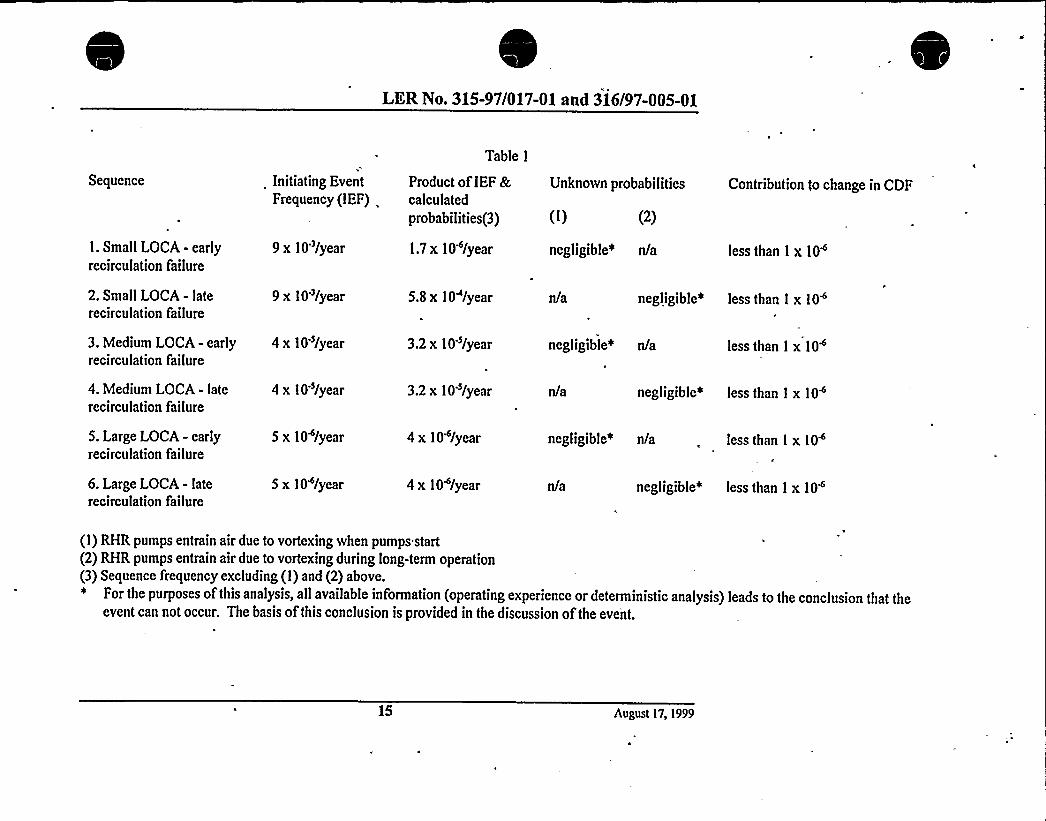
LER No. 315-97/017-01 and 316/97-005-01
Sequence
1. Small LOCA - earlyrecirculation failure
2. Small LOCA - laterecirculation failure
Initiating EventFrequency (IEF)
9 x 10'/year
9 x 10'/year
Table 1
Product ofIEF &calculated
probabilities(3)
1.7 x 10~/year
5.8 x 10 /year
(I) (2)
negligible~ n/a less than 1 x 10~
negligible~ less than I x 10~
Unknown probabilities Contribution to change in CDF
3. Medium LOCA - early 4 x 10'/yearrecirculation failure
3.2 x 10'/year negligible~ n/a less than I x 10
4. Medium LOCA - laterecirculation failure
5. Large LOCA - earlyrecirculation failure
6. Large LOCA - laterecirculation failure
4 x 10'/year
5 x 10 /year
5 x 10'/year
3.2 x 10'/year
4x10 /year
4x10 /year
negligible~ less than I x 10~
negligible* n/a less than 1 x 10
negltgtble~ less than 1 x 10~
(1) RHR pumps entrain air due to vortexing when pumps start(2) RHR pumps entrain air due to vortexing during long-term operation(3) Sequence frequency excluding (1) and (2) above.
For the purposes of this analysis, all available information (operating experience or deterministic analysis) leads to the conclusion that theevent can not occur. The basis ofthis conclusion is provided in the discussion of the event.
15 August 17, 1999

-EL 614'-0"
BL 612'-0"
6I~
Vcnl
EL 604'-11 3/8"5 Vcn(Holes
Ef. 603'- l l 3/8"~ ~
~ ~
Fine Scrccn
Post-Modification
floor
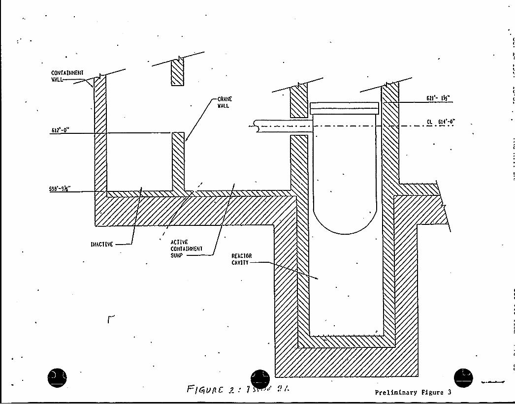
COHfAIHHEN1
WALL
CRAHE
WALL
612'-0"CL 614'-0"
595'-9
IHACIIVE
/ACI IVE
CO) IIAIWEH1SUHP REAC10R
CAVIII
t-/PqPgC g . PrelirnI.nary Figure 3

ontairiment rayim i ie
I
ow c ematicContainment Spray (CTS)
:A'dogirijlator'y.'Vpp:.
ps~.'."':::
:,pont: '.:
;Nozslc's'.:-
','.Tii'::.'-:,:;Q'qn'den je,r.
Steam
CQ
0O
NozzleFlow
(DlceMeltandCondensedSteam
'ia 'iaFan Ptairwe(l
AccumulatorRooms
viaRefuelingCanalDrains
Inactive Sump Active Sump
'. RCS
LiquidBreakFlow
ReactorC'avity
CCS
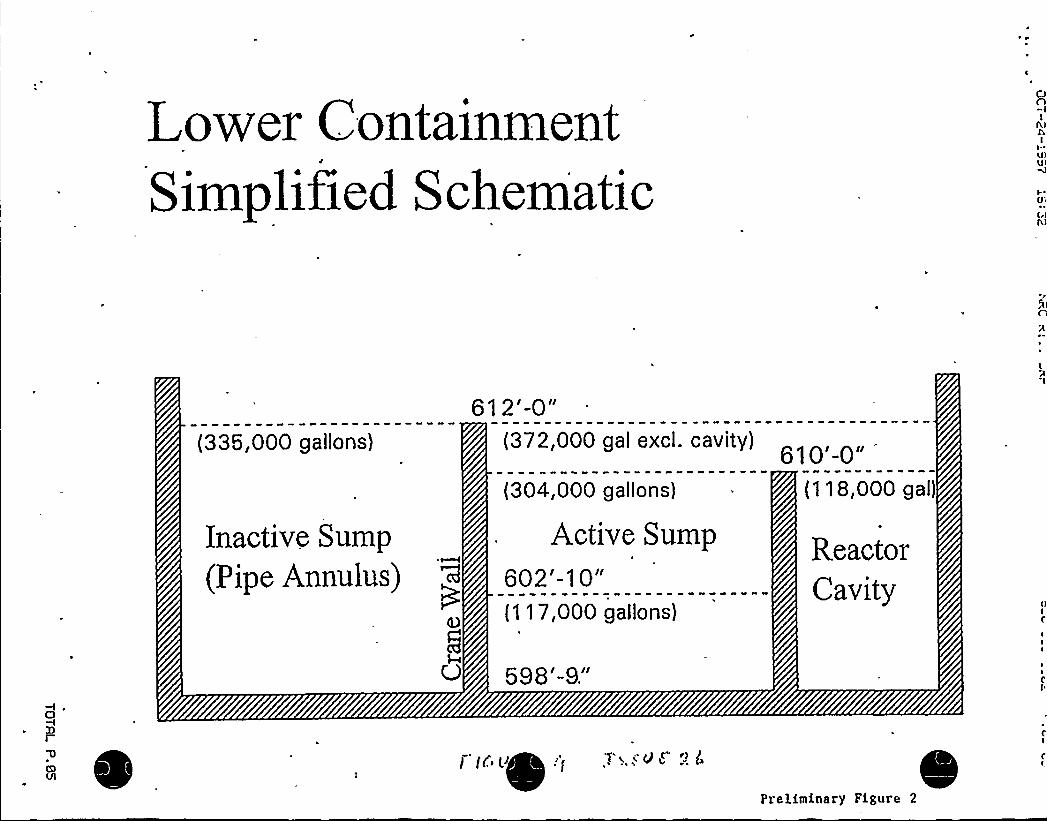
ower ontainmentJ
1II1P 1 1e c ematic
(335,000 gallons)
Inactive Sump
(Pipe Annulus)
61 2'-0"(372,000 gal excl. cavity)
(304,000 gallons)
Active Sump602'-10"(117,000 gallons)
{118,000 gal)
ReactorCavltp
598'-B"
'T i i'() ~<
Preliminary Figure 2

0

LER No. 315/97-018, 315/97-024, 315/98-012
27.0 LER Nos. 315/97-018, 315/97-024, 315/98-012
Event Description: 1/4 Inch Particulate Requirement Not Maintained inContainment Recirculation Sump
Date ofEvent: March 5, 1998
Plant: D.C. Cook, Units land 2
27.1 Summary of Issue
This issue addresses the cumulative impact ofseveral conditions that had increased the likelihood offailing the high pressure injection (HPI) system during the sump recirculation phase at D.C. Cook. Theimpact ofthese conditions on the likelihood offailing the containment spray (CTS) system is alsoaddressed..
According to Reference 1, on September 5, 1997, it was determined that the 1/4 inch particulate retentionrequirement for the containment recirculation sump was violated in 1978 due to an improper designchange. The 1/4 inch requirement ensures that debris which may be large enough to plug the CTS (size3/8 inch) is not swept into the CTS header through the recirculation sump. The 1/4 inch requirement alsoprotects ECCS from foreign material during the sump recirculation phase. The safety injection andcentrifugal charging pumps are vulnerable to large debris due to tight clearances. Other components thatare vulnerable are safety injection needle valves and check valves throughout ECCS and CTS.
ll
As shown in Figure 1, prior to the design change, a perforated plate installed inside the recirculationsump and grating installed at the opening ofthe recirculation sump prevented debris from entering thesuction pipes for the residual heat removal (RHR) (during sump recirculation) and CTS. During thedesign change, as shown in Figure 2, the perforated plate was moved. The particle retention capabilitywas retained only at the entrance to the recirculation sump. As shown in Figure 2, when the perforatedplate was removed, several pathways that could bypass the screens were created: (a) five 3/4 inch holes inthe upper roofof the recirculation sump, (b) gaps greater than 1/4 inch between the curb opening aroundthe recirculation sump entrance, (c) gaps greater than 1/4 inch in the lower containment sump cover(particles larger than 1/4 inch may enter the lower containment sump which in turn could enter therecirculation sump via the connecting 8" drain line), and (d) the 3" drain line from the ice condenser tothe containment sump. Figure 3 shows the communication paths between the recirculation sump,containment sump, and the ice condenser.
The safety significance associated with these screen bypass paths exacerbated due to two other conditionsdiscovered at D.C. Cook. They are: (a) discovery ofdebris in the containment sump (Ref. 2), and (b)discovery ofdebris in the ice condenser (Ref. 3, 4).
The changes to the core damage frequency (CDF) associated with this issue depends on the impact ofother issues on the RHR c'ooling and auxiliary feedwater (AFW) capabilities. The CDF associated with
August 26, 1999


LER No. 315/97-01S, 315/97-024, 315/9S-012
1
this issue, on its own, is summarized in Table 1. Table 1 summarizes the initiating event frequencies ofinitiators that are affected by the debris in the sump, products ofknown probabilities and the frequencyfor each initiator, summary ofqualitative assessment ofthe unknown probability, and the expectedchange in CDF for each initiator. Overall, the total CDF change associated with this issue is less than 1 x10~/Year and therefore, on its own, this issue is not risk-significant.
27.2 Modeling and Affected Sequences
During the design change, when the perforated plate was removed, four pathways that could bypass thescreens were created. They are: (a) the pathway through the five 3/4 inch holes in the upper roofof therecirculation sump, (b) gaps greater than 1/4 inch between the curb opening around the recirculation
'umpentrance, (c) gaps greater than 1/4 inch in the lower containment sump cover (particles larger than1/4 inch may enter the lower containment sump which in turn could enter the recirculation sump via theconnecting 8" drain line), and (d) 3" drain line from the ice condenser to the containment sump. Ifdebrisof large size (greater than 1/4 inch) bypasses the screen and enters the recirculation sump, during thesump recirculation phase ofa LOCA or feed-and-bleed cooling scenario, the debris may get ingested byRHR pumps. Since RHR pumps are used with HPI pumps in piggy-back mode, the debris that passesthrough the RHR pumps enters the HPI system. Iflarge debris (greater than 1/4 inch) enters the HPIsystem, then the HPI system may fail.
Therefore, for debris in the sump or the ice condenser to affect core damage sequences, an accident thatrequires the sump recirculation function must occur. LOCAs ofdifferent sizes, and feed-bleed-coolingsequences subsequent to transients or accidents require sump recirculation. For the ease ofpresentingresults ofthe analysis, multiple initiators (large LOCAs, medium LOCAs, small LOCAs, feed-and-bleedcooling after transients, feed-and-bleed cooling after main steam line breaks inside containment, etc.)were grouped into three classes: (a) large LOCAs, (b) medium LOCAs, and (b) small LOCAs and feed,and bleed sequences. These three groups were selected since the critical parameters such as icedissolution rates and the likelihood ofthe need to enter the sump recirculation vary between these threeclasses.
Unlike small LOCAs, sump recirculation phase is essential for large and medium LOCAs, in order toprevent core damage. In addition, for large and medium break LOCAs, the cross-tie capability cannot becredited due to large uncertainties associated with time available to establish the cross-tie capability, andthe low probability ofachieving success with the additional inventory ofwater available from the secondrefueling water storage tank (RWST).
Iflarge debris enters the recirculation sump, the CTS pumps may ingest that debris and fail that systemby clogging the spray nozzles. IfCTS fails, the containment integrity,.can fail. Failure ofthe containmentintegrity in turn could lead to sump recirculation failure.
Therefore, the six accident sequences considered in this analysis are:
Se uence 1- Lar e LOCA and loss ofHPI
August 26, 1999
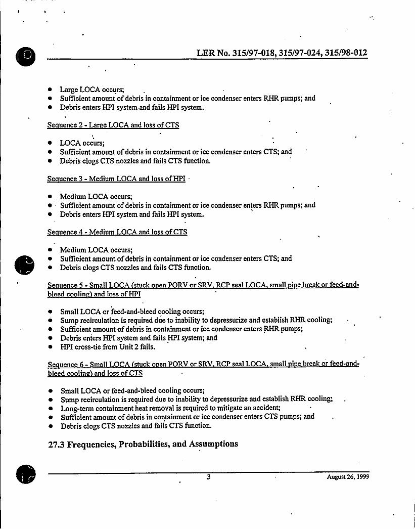
LER No. 315/97-01S, 315/97-024, 315/9S-012
~ Large LOCA occurs;~ Sufficient amount ofdebris in containment or ice condenser enters RHR pumps; and~ Debris enters HPI system and fails HPI system.
I'e
uence 2- Lar e LOCA and loss ofCTS
~ LOCA occurs;~ Sufficient amount ofdebris in containment or ice condenser enters CTS; and~ Debris clogs CTS nozzles and fails CTS function.
Se uence 3 - Medium LOCA and loss ofHPI =
~ Medium LOCA occurs;~ Sufficient amount ofdebris in containment or ice condenser enters RHR pumps; and~ Debris enters HPI system and fails HPI system.
Se uence 4 - Medium LOCA and loss ofCTS
~ Medium LOCA occurs;~ Sufficient amount ofdebris in containment or ice condenser enters CTS; and~ Debris clogs CTS nozzles and fails CTS function.
Se uence5-Small LOCA stucko enPORVorSRV RCP seal LOCA small i ebreakor feed-and-bleed coolin and loss ofHPI
~ Small LOCAor feed-and-bleed cooling occurs;Sump recirculation is required due to inability to depressurize and establish RHR cooling;
~ Sufficient amount ofdebris in containment or ice condenser enters RHR pumps;~ Debris enters HPI system and fails HPI system; and~ HPI cross-tie from Unit 2 fails.
Se uence 6- Small LOCA stuck o en PORV or SRV RCP seal LOCA small i e break or feed-and-
bleed coolin and loss ofCTS
~ Small LOCA or feed-and-bleed cooling occurs;~ Sump recirculation is required due to inability to depressurize and establish RHR cooling;~ Long-term containment heat removal is required to mitigate an accident;~ Sufficient amount ofdebris in containment or ice condenser enters CTS pumps; and~ Debris clogs CTS nozzles and fails CTS function.
27.3 Frequencies, Probabilities, and Assumptions
August 26, 1999

LER No. 315/97-018, 315/97-024, 315/98-012
Se uence 1 -Lar eLOCAand loss ofHPI
~ Large LOCA occurs - Rates ofInitiatingEvents at US. Nuclear Power Plants: 1987-1995 (Ref. 5)indicates that the frequency of large LOCAs is 5 x 10~/critical year.
~ Sufficient amount ofdebris in containment or ice condenser enters RHR pumps - The likelihood ofgeneration and transport ofdebris from the containment or the ice condenser to the RHR or the CTSpump suction is considered under this event. The likelihood ofdebris transport to the RHR pumpsuction from two sources (sump and ice condenser) via four pathways (five 3/4." holes onrecirculation sump roof, gaps greater than 1/4 inch between the curb opening around the recirculationsump entrance, lower containment sump cover gaps greater than 1/4 inch, and debris that may enterthe containment sump from the ice condenser via the 3" through the 8" line connecting thecontainment sump and the recirculation sump) during a LOCAmust be considered. The probabilityofdebris in containment or ice condenser entering the RHR or CTS pump suction cannot bequantified. However, for reasons discussed below, it can be shown that only a small quantity of soft,relatively small (less than 1") can arrive at the CTS or RHR pumps. Therefore, for large LOCAs thisprobability is low. The bases ofthis conclusion are discussed below:
0 Debris from containment: The mechanisms associated with debris generation, transport, anddeposition are described below. Even ifthe debris is delivered,to the screens, they must findtheir way into the sumps through gaps around the screen. The probability ofthis is lowexcept for debris that is small and soft (buoyant). The roofofthe recirculation sump thatcontains the five 3/4 inch holes is at an elevation of604'-l l 3/8." Only buoyant debris(since there is at least 10 minut'es available for heavy debris to deposit) ofsmall size (lessthan 3/4 inch) can enter through these holes. Given the very small size (only 3/4 inches indiameter and there are only 5 holes), the probability ofdebris entering through these holes islow.
Debris Generation: Debris is generated in three phases ofa large LOCA; initial blasteffect during pipe rupture, erosion during jet impingement, and pre-existing debrissuch as dirt, dust, rust flakes, and failed coatings. Allof these phases are applicableto a large LOCA.
Debris Trans ort: Debris is transported by (a) blast forces within the containment,(b) steam and air flows during the blow down phase, and finally (c) "washdown."Allofthese transport methods willbe available during a large LOCA. However,there are many barriers that would prevent transport ofdebris to the suction ofthepumps.
Debris de osition: During a large LOCA, approximately 10 minutes may elapsebefore sump recirculation is established. During this time, any heavy large debriswilldeposit on the containment floor. Once debris is settled, unless high flow rates
August 26, 1999

LER No. 315/97-01S, 315/97-024, 315/9S-012
occur, the debris willnot be transported. Therefore, the debris that is suspended and'available to block sump screens willbe minimal.
Likelihood ofdebris de ositin on screens versus assin throu h a s: The softbuoyant debris that arrives at the sump can either deposit on screens (and be heldthere due to approach flowvelocity ) or go through one ofthe bypass paths. Thefirst bypass path, the five 3/4" holes on the roofofthe recirculation sump, has a totalarea ofapproximately 2 square inches. The size of the gaps around the screens isunknown. Assuming a Y~" all around the sump screen, the total area ofthe gapwould be 240 square inches (assuming a 480" periphery). Therefore, inconsideration ofthe size ofthe recirculation sump screen (the area ofthe 1/4" meshscreen at the entrance to the containment sump is ignored in comparison to therecirculation sump screen area), the probability ofdebris ofundesirable size (greaterthan 1/4 inch and less than size ofgap around screen) is approximately 0.02.
Debris from the ice condenser: An additional source ofdebris was found in the icecondenser. The nature and the volume ofdebris present were such that, ifthe debris couldbe transported to the RHR or CTS pump suction, they may have capability to be ingestedand fail HPI or CTS. Material such as tape, gloves, coat wrap, plastic banding cloth, icebasket coupling screws and screw heads, nuts and bolts, ice basket cruciform wire, rope,rags, wood paper, small and large tools were found in the Unit 1 ice condenser. There wereapproximately three 55-gallon drums in the Unit 1 ice condenser. In order for the debrisdescribed above to arrive at the RHR or CTS screens, the followingevents must occur:
The ice condenser baskets have 1" holes. The above debris must go through the 1"
holes. Therefore, debris (tools, tape rolls, plastic wraps etc.) that is greater than 1"
size willbe trapped inside the ice condenser baskets (When the Unit 1 ice condenserwas thawed, most material that was considered as transportable to the sump stayedinside ice baskets). Only the debris that was between ice baskets may go into thecontainment sump.
The debris that escapes the ice baskets must go through the floor grating (1.75"opening).
Debris that passes through the above obstacles enters 12" drain line. From here,debris must go through a 12" flapper valve in order to enter the lower containmentor enter a 3" drain line that has low points. Allheavy small items (e.g., bolts) willdeposit along low points during this transport. As a result ofthe above describedtortuous path only light (less density than water) small (less than 1") debris can betransported to the entrance of the RHR or CTS pumps.
Ifany debris enters the lower containment, it must find the way into'the RHR orCTS pumps suctions via the 3/4" holes either on the sump roof or through the gaps
August 26, 1999

LER No. 315/97-01S, 315/97-024, 315/9S-012
around screens. Both these are unlikely unless the debris is very small in size and
buoyant.
Ifany debris enters the containment sump via the 3" drain line, that debris mustmove through an 8" line connecting the recirculation sump and containment sump.This line is above the bottom ofthe containment sump. Then the debris must moveapproximately 4'p in order to be ingested by the pumps.
~ Debris enters HPI system and fails HPI system - Ifdebris enters the RHR suction, several eventsmust occur in order to fail the HPI system. The discussion above on the probability ofdebris enteringthe RHR or CTS suction showed that (a) it is not credible for heavy large size debris to enter the RHRpump suction, and (b) the probability ofsoft, small size debris entering the RHR or CTS pumpsuction during a large LOCA is low. Ifsoft debris enters the RHR pumps, they willpass through theRHR pump impellers that are capable ofgrinding them to even smaller pieces. In order to fail theHPI, the debris must escape this grinding activity while passing through the RHR pumps. Then, thesoft debris must deposit in valves. At the high flow rates and high discharge pressure, it is difficultfor soft debris ofsmall size to clog valves. Since the debris is small in size and soft, and broken intoeven smaller pieces by the RHR pumps, the HPI pumps willnot fail. In consideration ofall ofthe
~ above, the above probability is considered low.
Se uence 2- Lar e LOCA and loss ofCTS
~ Large LOCA occurs - Rates ofInitiatingEvents at US. Nuclear Power Plants: 1987-1995 (Ref. 5).indicates that the frequency ofa large LOCAs is 5 x 10~/critical year.
~ Sufficient amount ofdebris in containment or ice condenser enters CTS - This probability is low.The bases of this conclusion are discussed under Sequence 1.
~ Debris clogs CTS nozzles and fails CTS function - This probability is negligible due to the followingreasons:
CTS at Cook has two 100% capacity trains. That is, with both trains operating, even if50%ofthe spray nozzles plugged, design pressure during the design basis LOCA (12 psig) will-not be exceeded.
o The design basis pressure for the containment is 12 psig. However, the containment failureis significantly greater than 12 psig. According to the Cook IPE, the high confidence
(greater than 95%) low probability (less than 5%) failure pressure is 36 psig.
It is already established that soft, buoyant, and small (small enough to pass through either the3/4" holes or 1" strainers, or gaps around the sump screen) would enter the CTS pumps. The
CTS pumps are vertical centrifugal pumps with 600 HP. Therefore, they can handle thisdebris without failing. In addition, when this debris passes through the CTS pump they will
August 26, 1999

LER No. 315/97-018, 315/97-024, 315/98-012
be grinded to small pieces. Given that the ramp bottom spray nozzles are 3/8", the softdebris, after they pass through the CTS pumps willmost likelybe able to pass through the *
CTS nozzles.
Se uence 3 - Medium LOCA and loss ofHPI
~ Medium LOCA occurs - Rates ofInitiatingEvents at US. Nuclear Power Plants: 1987-1995 (Ref. 5)indicates that the frequency ofa medium LOCAs is 4 x 10 s/critical year.
~ Sufficient amount ofdebris in containment or ice condenser enters RHR pumps - In Sequence 1, abasis was provided to conclude that this probability is low. For medium LOCAs, the probability willbe even lower due to the following:
0 In comparison to a large LOCA, a longer time would elapse before establishing sumprecirculation, The longer time would permit additional debris deposition.
In comparison to a large LOCA, a medium LOCAwould generate less debris during thebreak.
Compared to a large LOCA, the relatively lower flow rates inside containment would reducethe likelihood ofdebris transport.
~ ebris enters HPI system and fails HPI system - Due to reasons discussed under Sequence 1, thisprobability is low.
Se uence 4 - Medium LOCA and loss ofCTS
~ Medium LOCA occurs - Rates ofInitiatingEvents at US. Nuclear Power Plants: 1987-1995 (Ref. 5)indicates that the frequency ofmedium LOCAs is 4 x 10~/Year.
~ Sufficient amount ofdebris in containment or ice condenser enters CTS - Due to the reasonsdiscussed under Sequence 3, this probability is considered low.
~ Debris clogs CTS nozzles and fails CTS function - For a medium LOCA also, this probability isdetermined to be negligible. See discussion under Sequence 2 for the basis for this conclusion.
Se uence 5 - Small LOCA stuck o en PORV or SRV RCP seal LOCA small i e break or feed-and-bleed coolin and loss ofHPI
~ Small LOCA or feed-and-bleed cooling occurs - Rates ofInitiatingEvents at US. Nuclear PowerPlants: 1987-1995 (Ref. 5) indicates that the frequency ofsmall LOCAs (includes stuck open PORVsor SRVs, RCP seal LOCAs, small pipe breaks) is 9 x 10'/critical year. Assuming, the AFW at D.C.Cook reliabilitywas not significantly affected by other D.C. Cook issues related to auxiliary feed
August 26, 1999

LER No. 315/97-01S, 315/97-024, 315/9S-012
water (AFW), the frequency offeed-and-bleed cooling scenarios at D.C. Cook is negligible comparedto the small LOCA frequency. Therefore, the total frequency ofsmall LOCAs and feed-and bleedcooling sequences is 9 x 10'/critical year.
~ Sump recirculation is required due to inability to depressurize and establish RHR cooling - Operatingexperience shows that during most small LOCAs, the loss ofcoolant rates and the condition of thereactor coolant system (RCS) allows the operators to depressurize and,use RHR cooling. During thetime period 1987-1995, there were two stuck open SRV events (classified as small LOCAs in Ref. 5)and during both these events, sump recirculation was not needed (Ref. 6, 7). During the event thatoccurred at Fort Calhoun (1992), approximately 21,500 gallons ofRCS water was discharged fromthe RCS to the containment. This is much less than the discharge required to demand ECCS sumprecirculation. During the event that occurred at Calvert Cliffs (1994), only 5000 gallons ofreactorcoolant discharged to the containment floor. During the TMI-2event (1979), 271,000 gallons ofRCS water was released to the sump. However, during the IMI-2event sump recirculation was notdemanded.
Two RCP seal LOCA events are discussed in Reference 5. During the May 1975 event at RobinsonUnit 2 (no LER, page I-3 ofRef. 5), a total of 132,500 gallons ofRCS water was released to thecontainment sump before RHR cooling was established. The maximum leak rate was 500 gpm.During this event, the sump recirculation function was not needed. During the event at ArkansasNuclear One (Ref. 8), approximately 60,000 gallons ofwater collected in the containment beforeRHR cooling was established. The maximum leak. rate was 300 gpm. The containment pressureincreased by 0.5 psi at which time the reactor building containment coolers were put into service.During this event, sump recirculation was not needed.
There have been'no small pipe break LOCAs or feed-and-bleed cooling events in the U.S. operatingexperience. Feed-and-bleed cooling uses the pressurizer PORVs or SRVs to bleed RCS whileinjecting RCS with high pressure injection. AtD.C. Cook, the pressurizer is equipped with threePORVs that are capable. ofbleeding the RCS. Based on simulator exercises, the feed-and-bleedcooling can depressurize the reactor prior to depleting the RWST'. Therefore, the likelihood of .
cooling down the reactor with feed-and-bleed cooling prior to requiring sump recirculation isassumed to be equal to the likelihood during a small LOCA.
Using the Bayes method and a Jeffery's non-informative prior, zero demands for sump recirculationduring 5 small LOCAs, the probability ofrequiring sump recirculation during a small LOCA iscalculated to be 0.08 (tl~ event on 6 demands).
~ Sufficient amount ofdebris in containment or ice condenser enters RHR pumps - Under Sequence 1,
this probability was concluded to be low and a basis was given for that conclusion. For a smallLOCA, the followingadditional factors make the probability ofthis event negligible:
'Based on discussions with operations at D.C. Cook (Richard Strasser 6/30/99)
August 26,'1999
IER No. 315/97-018, 315/97-024, 315/98-012
Debris Generation: Debris is generated in three phases ofa LOCA; initial blast effect duringpipe rupture, erosion during jet impingement, and pre-existing debris such as dirt, dust, rustflakes, and failed coatings. During a stuck open PORV or SRV or a feed-and-bleed coolingscenario, the liquid enters the quench tank and release from the ruptured disk. During anRCP seal LOCA, the primary coolant exits through RCP seals. Small breaks are breaks lessthan 2" and the zone of influence (area in which the break causes debris generation) for suchbreaks are relatively small. Therefore, for small LOCAs, the initial shock waves, and jetimpingement effects are absent or minimal. As a result, the amount ofdebris created duringa small LOCA would be much less than that created during a medium LOCA or a largeLOCA. That is, the probability ofcreating a significant amount ofdebris is low.
0 4M'ndair flows during the blow down phase, (iii)and fmally transported by water or
"washdown." Since for most LOCAs, primary water is released from the quench tank, orRCP seal LOCAs, the amount ofdebris transported Ey the first two mechanisms is low. Formost LOCAs, CTS spray may not be demanded. This reduces the amount ofdebristransported by "wash down."
o Debris de osition: During a small LOCA, the rate at which the loss ofcoolant occurs is low.During the Fort Calhoun event, the leak rate was 200 gpm. A total ofapproximately 21,500gallons was released to the containment sump. The Calvert Cliffsevent resulted in amaximum leak rate of25 gpm and a total ofapproximately 5000 gallons was released to thecontainment. The Tech Spec required inventory ofRWST inventory at Cook is 350,000gallons. Therefore, during a small LOCA event at D.C. Cook, many hours may elapsebefore recirculation is required. Ifany debris was generated and transported, there would beample time for.debris to settle. Once debris is settled, the debris willnot be transported.During a small LOCA, the flow rates inside the containment willbe low (except in locationswhere there are flow restrictions). Therefore, the debris that is suspended and available toblock sump screens willbe minimal.
~ Debris enters HPI system and fails HPI system - Due to reasons discussed under Sequence I, thisprobability is low.
~ Cross-tie from Unit 2 fails - The D.C. Cook station has two RWSTs (One RWST dedicated to eachunit). The RWSTs have cross-tie capability. In the event ofsump recirculation failure during a smallLOCA, the cross-tie can be aligned to add borated water to RCS. The additional RCS inventory of350,000 gallons willprovide additional time to continue depressurizing and cooling down the RCS.In order to cross-tie the RWSTs, the followingactions must be performed: (a) recognize need tocross-tie (sump recirculation failure and failure to recover by securing and restarting the pump thatcavitates), and (b) change valve alignments to inject from the other unit's RWST. Both ofthe aboveactions must be accomplished prior to core uncoveiy. The time available to core uncovery issignificantly impacted by the decay heat levels when the sump recirculation function is demandedand failed due to debris ingestion.
August 26, 1999

LER No. 315/97-018, 315/97-024, 315/98-012
Based on the Cook IPE (Ref. 9), 100 minutes elapse before sump recirculation is needed. Therefore,ifthe sump recirculation fails during a small LOCA, itwillhappen a few hours into the accident, andthe decay heat levels would be relatively low. At low decay heat level, there willbe adequate time tocross-tie the other unit's RWST. In the absence ofsignificant details on the steps that the operatorswould followto align the second unit's RWST, a probability of0.34 is used for failure probability.In'the accident sequence precursor (ASP) analysis, a 0.34 recovery probability is used for thosefailures that appears recoverable in the period at the failed equipment rather than from the controlroom, given that the equipment was accessible (Ref. 10). Even though the Cook IPE does notprovide a failure probability for the cross-tie ofRWST, it does provide failure probabilities forseveral other cross-ties. For example, cross-tie ofCVCS is assigned a failure probability of2.2 x
10'or
a loss ofcomponent cooling water scenario and failure probability of0.29 for'the loss ofemergency service water (ESW) scenario. In comparison to these numbers, use of0.34 for theRWST cross-tie is reasonable.
Se uence 6- Small LOCA Stuck 0 en PORV or SRV RCP seal LOCA small i e break or feed-and-bleed coolin and loss ofCTS "
~ Small LOCA or feed-and-bleed cool ing occurs - Rates ofInitiatingEvents at US. Nuclear PowerPlants: 1987-1995 (Ref. 5) indicates that the frequency of small LOCAs (includes stuck open PORVsor SRVs, RCP seal LOCAs, or small pipe breaks) is 9 x 10'/critical year. Assuming, the AFWreliability at Cook was not significantly aFected by other Cook issues related to AFW, the frequencyofa feed-and-bleed cooling scenario at Cook is negligible compared to the small LOCA frequency.Therefore, the total frequency ofsmall LOCAs and feed-and bleed cooling sequences is 9 x 10
'/critical year.
~ Sump recirculation is required due to inability to depressurize and establish RHR cooling - Thisprobability is 0.08. The basis for this probability is discussed under Sequence 1 above.
~ Long-term containment heat removal is required to mitigate an accident - It is assumed that anyaccident that requires sump recirculation willrequire CTS for long-term containment heat removal.Therefore, this probability is assumed to be 1.0.
~ Sufficient amount ofdebris in containment or ice condenser enters CTS pumps - For reasons
discussed in Sequence 5, this probability is negligible for a small LOCA.
~ Debris clogs CTS nozzles and fails CTS function - This probability is negligible. The basis for thisconclusion is discussed under Sequence 2 (large LOCA). The probability ofthis event willbe lowerfor a small LOCA compared to large LOCA since the likelihood ofdemanding CTS spray duringsmall LOCAs is low. (At Cook, the ice condenser starts providing cooling after the containmentpressure reaches 0.5 psig. Also, the auto start pressure ofthe CTS sprays at Cook is 2.9 psig.).
10 August 26, 1999

LER No. 315/97-018, 315/97-024, 315/98-012
27.4 Core Damage Frequency Calculation or the Bounding Calculation
The frequency associated with the feed-and-bleed sequences depend on the resolution ofother issuesaffecting AFW and RHR cooling. To provide perspective on these sequences the following informationis provided.
Ifthe resolution of issues results in no significant changes to AFW or RHR cooling failure probabilities,the change in core damage frequency would be the suin of the following:
Se uence 1 -Lar e LOCA and loss ofHPI
(Frequency of large LOCA: 5 x 10~/critical year) x(Criticalityfactor for Cook Unit 1: 0.79 critical years/calendar year) x(Probability that sufficient amounts ofdebris in containment or ice condenser enters RHR pumps: low) x(Probability ofdebris entering the RHR system and failing the RHR system: low) = 4.0 x 10~/Year x (alow probability) x (another low probability). Since the unknown probabilities are low, the change in CDFis less than 1 x 10~.
Se uence 2 - Lar e LOCA and loss ofCTS
(Frequency of large LOCA: 5 x 10~/critical year) x(Criticalityfactor for Cook Unit 1: 0.79 critical years/calendar year) x(Probability that sufficient amounts ofdebris in containment or ice condenser enters CTS pumps: low) x(Probability ofdebris entering the CTS system and failing the CTS system: negligible) = 4.0 x 10~/Year x(a low probability) x (a negligible low probability). Since the unknown probabilities are low ornegligible, the change in CDF is less than 1 x 10~.
Se uence 3 - Medium LOCA and loss ofHPI
(Frequency ofmedium LOCA: 4 x 10'/critical year) x(Criticalityfactor for Cook Unit 1: 0.79 critical years/calendar year) x(Probability that sufficient amounts ofdebris in containment or ice condenser enters RHR pumps: low) 'x
(Probability ofdebris entering the RHR system and failing the RHR system: low) = 3.2 x 10'/Year x (alow probability) x (another low probability). Since the unknown probabilities are low, the change in CDFis less than 1 x 10~.
Se uence 4- Medium LOCA and loss ofCTS
(Frequency ofmedium LOCA: 4 x 10'/critical year) x(Criticalityfactor for Cook Unit 1: 0.79 critical years/calendar year) x(Probability that sufficient amounts ofdebris in containment or ice condenser enters CTS pumps: low) x
August 26, 1999

LER No. 315/97-018, 315/97-024, 315/98-012
(Probability ofdebris entering the CTS system and failing the CTS system: negligible) = 3.2 x 10'/Year x(a low probability) x (a negligible probability). Since the unknown probabilities are low or negligible, thechange in CDF is less than 1 x 10~.
Se uence 5 - Small LOCA stuck o en PORV or SRV RCP seal LOCA small i e break or feed-and-bleed coolin and loss ofHPI
(Frequency of small LOCA or feed and bleed cooling event: 9 x 10'/critical year) x(Criticalityfactor for Cook Unit 1: 0.79 critical years/calendar year) x(Probability ofsump cooling is required due to inability to depressurize and establish RHR cooling: .08) x(Probability that sufficient amounts ofdebris in containment or ice condenser enters RHR pumps:negligible)(Probability ofdebris entering the HPI system and failing the HPI system: low) x(Probability ofcross-tie from Unit 2 fails: 0.34) = 1.9 x 10~/Year x (a low probability) x (a negligibleprobability). Since the unknown probabilities are low or negligible, the change in CDF is less than 1 x10~.
Se uence 6- Small LOCA stuck o en PORV or SRV RCP seal LOCA small i e break or feed-and-bleed coolin and loss ofCTS
(Frequency ofsmall LOCA or feed and bleed cooling event: 9 x 10'/critical year) x(Criticalityfactor for Cook Unit 1: 0.79 critical years/calendar year) x(Probability ofsump cooling is required due to inability to depressurize and establish RHR cooling: .08) x(Probability that long term heat removal requires CTS pumps: 1.0) x(Probability that sufficient amounts ofdebris in containment or ice condenser enters RHR pumps:negligible)(Probability ofdebris entering the CTS system and failing the CTS system: negligible) x'(Probability ofcross-tie from Unit 2 fails: 0.34) = 1.9 x 10"/Year x (a negligible probability) x (anothernegligible probability). Since the unknown probabilities are negligible, the change in CDF is less than 1
x 10~.
The summary ofthese sequences is provided in Table 1. As shown in Table 1, the change to the coredamage frequency associated with this issue, on its own, would not be risk-significant.
27.5 References
1. LER 315/97-018, Rev. 1, "Failure to Maintain 1/4 Inch Particulate Retention Requirement for theContainment Recirculation Sump Results in a Condition Outside the Design Basis," event dateSeptember 5, 1997.
2. LER 315/97-024, "Material Discovered in Containment Degrades Containment Recirculation Sumpand Results in Condition Outside Design Basis," September 17, 1997.
August 26, 1999
LER No. 315/97-018, 315/97-024, 315/98-012
3. LER 315/98-012, Rev. 1, "1/4 Inch Particulate Requirement Not Maintained in ContainmentRecirculation Sump," Marcli 5, 1998.
4. LER 315/98-017, Rev. 1, "Debris Recovered from the Ice Condenser Represents UnanalyzedCondition," March 27, 1998.
5. J. P. Poloski, et. al., Rates ofInitiatingEvents at US. Nuclear Power Plants: 1987-1995,NUREG/CR-5750, February 1999.
6. LER 285/92-023, Rev. 0, "Reactor Trip Due to Inverter Malfunction and Subsequent PressurizerSafety Valve Leak," August 3, 1992.
7. LER 317/94-007, Rev. 1, "Reactor Trip Caused by Closure ofTurbine Stop Valves," June 16, 1995.
8. LER 313/80-015, Rev. 2, "Reactor Coolant Pump 'C'eal Cartridge Failure," April 13, 1981.
9. Donald C. Cook Nuclear Plant, Units 1 and 2, Individual Plant Examination, Revision 1, October1995.
10. NUIKG/CR-4674, Vol. 25, "Precursors to Potential Severe Core Damage Accidents: 1996,"December 1997.
August 26, 1999

LKRNo. 315/97-018, 315/97-024, 315/98-012
Sequence Initiating EventFrequency (IEF)
3. Medium LOCA &HPI
4 x 10'/Year
1. Large LOCA &HPI 5 x 10 /Year
2. Large LOCA &CTS 5 x 10~/Year
Product ofIEF &calculatedprobabilities (6)
4 x 10~/Year
4 x 10~/Year
3.2 x 10'/Year
low»»4
low»»low*»'2)
(3)
low**4 n/a
n/a negligible»
low**'/a
Table 1
Unknown probabilities Contribution to change inCDF
less than 1 x 10~
less than 1 x 10~
less than 1 x 10
4. Medium LOCA & 4 x 10'/YearCTS
3.2 x 10'/Year low»* n/a negligible» less than I x 10
5. Small LOCA &HPI 9 x 10'/Year
6. Small LOCA &CTS 9 x 10'/Year
1.9 x 10 /Year
1.9 x 10"/Year negligible* n/a negligible»
negligible* low»* n/a less than I x 10~
less than I x 10~
(I) Sufficient amount ofdebris in containment or ice condenser enters RHR or CTS pump suction(2) Debris enters HPI system and fails HPI system
(3) Debris clogs CTS nozzles and fails CTS function(4) The product ofthese two low probabilities is assumed to be less than 0.25
(5) The product ofthese two low probabilities is assumed to be less than 0.03
(6) Sequence frequency excluding (1), (2), and (3) aboveFor the purposes of this analysis, "negligible" implies that all available informatiori (operating experience or deterministic analysis) leads tothe conclusion that the event can not occur. The basis of this conclusion is provided in the discussion of the event.
*» For the purposes of this analysis, "low"probability implies that available information (operating experience or deterministic analysis) can notrule out occurrence of the event. However, several low probability barriers must be overcome for the event to occur. The basis ofthisconclusion is provided in the discussion ofthe event.
14 August 26, 1999


EL 6 I2'-0"
On»
EL 604'-I I 3/8"
EL 603'-l I 3/8"
Grating 6" Vent
Crane V/all
Zn
EL 598-9 3/8~ EL 598'-9 3/8"
EL 596' l/4"
Pcrlorated
Place 4e.e//Oyp
Jp+
EL 59 l '-l"
Pre-Modification0
6)tAe)3Vl
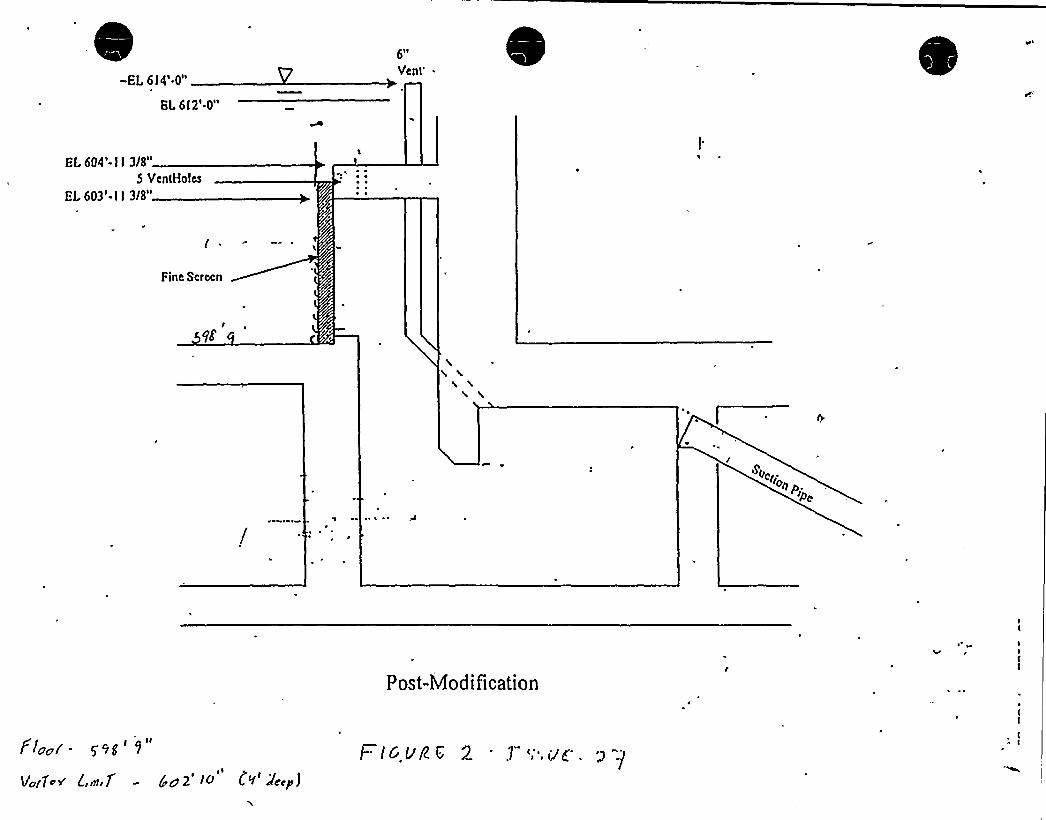
-EL 6 I 4'.0"
BL 6 I 2'.0"
6II
Vent'I.
604'- I I 3/8"5 VenlHolcs
EI. 603'- l l 3/8"
~ ~~ ~
Fine Scrccn
~ ~
Post-Modi ficatipn
Flea/ - y~g'"
Vufl<v' nt 7 -
gyes'0
(V'c~p j
F Ic vg t; 2 1'',igg.


.ATION PLANOV1AIVMCRT lCE COHOEHSKR
COVTAINMCHT
ICC. CONOLNSC.R.(ABOs>L)
VS sITWELL
ICEACTORChs> ITY5VMCs
orAIII5
TL CsBC CGs
I DRAIN
>ss sO
ICTCIT$%CCJP VCIVI 'To ISOCDJAQWT I>'> VstttCPICVV>to ~ IOSC CC COVS A>C)
ITC'04 POIVTocsIII CTIICJLT
(CTPICIU(I
Ot>>VWAtt
SPILL FROM LOVIEILCOIslTAINIABTCT
TO'ACTORChVITV SAIDC S .PT. 5PIu.ARED)
Ettv. Is ~ I'soW
(Cl) lts 0%IIN LIVLS5PACCD AROIITIOCO NIAINsICIII
TCIVSITC PICE
SI NISIClt
PIPEIQNNEI.(INVQU>$)SUMP
SEALEl.. Is
CO'A's
~c
Sl NS Stst +CS.IIC'ts
111 s, ttkIAA
11S
OCNV Its>CCVtl b>ts Y
ALPDLLIvcs
LO'>>ERCONTAINIslfNT50>s>P
CNL/ r O'v csOsl'0'lc
; ~ >
CLCV
fsOSAO't>'AIAINTLSIC
W. Itttc>tLlao't
1Ct'LOS'"
Icl'I %les %.
MIVSTAVSSCS>t ISCCSC~.~i>sec
ett.o.c'ss>I.Ills\I
st 41>tcecsss> 1
111 4 Coosts>tCCCSV>>14CVI ttOINVS
Otlss ts ss
Otlss ta 'ss
lo'I~
cvosc4,
s
tttt>W
ant4 I/VStl. O
gKBI)s>'Etc)
OII'l>C.
Lctltl
IB
Cc>VI CURB~E>5g AP
PIPE TUNNELTLOOR DosAVIS
COO>I
~I
s'>s
~%. s's s'
rhl tc ME>IT 5045 PPUMPS Q»>OO CT TOH
5 HPs>ts>st S %
S1CEC>550 C
4'CCI4CULITIGV CAIIIP
s>>S Is'C Ie CC SC 4'0 OCCP
s 1%
10 CCCXuq Kct COO»IIT>PI VO IO>I>ls>CIIStir tVPI>» ss sssl ~ s ~ s sss ~ sm
EI 5
~ IMI>JSTR
REIIMENTAT>ns>
'IX.B'M>VS.TICV. Oez.o-dREACTOR COOLANTORAIN TANr PIT
Is) D>ttIOS CPB-g5
lvt.Ttct. Ol svtsst1. 'S1 si lg
~ 1'>4CRGCNCY ORAU>REACTOR COOLANT DR.5 EE OMI. 1>ss ~ I 0 iIc sc

LER No. 315/97-024-04
28.0 LER No. 315/97-024-04
Event Description: Material Discovered in Containment Degrades ContainmentRecirculation Sump and Results in Condition Outside'DesignBasis
Date ofEvent: September 17, 1997
Plant: D.C. Cook, Units land 2
'28.1 Summary of Issue
LER 315/97-024-04 (Ref. 1) reported the discovery ofa fibrous material known as Fiberfrax in anelectrical cable tray inside the Unit 2 containment. Subsequent investigations revealed the existence ofthis material in Unit 1 containment as well. Itwas determined that quantity ofmaterial present in Unit 1
and Unit 2 containments had the potential to cause excessive blockage ofthe containment recirculationsump screen during the recirculation phase ofan accident rendering the sump inoperable. Investigationsdetermined that the fibrous material resulted from design changes that installed fire stops in 12 cable traysin the Unit 1 containment and 15 cable trays in the Unit2 containment. The installation procedure used
~
~ ~
during the design implementation did not require removal ofthe fibrous material from the containmentafter completion ofthe change. Walkdowns identified other material which could block the sump screenduring sump recirculation. A fibrous insulation material known as Temp-Mat was identified in severalareas in the containment annulus (inactive sump) and the lower volume (active sump). Miscellaneousmaterials such as tape, labels and equipment stored in the containments were also identified as potentialcontributors to the sump clogging. In addition, a limited amount ofunqualified coatings was identified aswell as some coatings that lacked suitable adhesion. Section b.l and b.2 ofReference 2 (NRC InspectionReport on fibrous material in containment) provide details on the quantity ofdebris found inside the Unit1 and Unit 2 containments.
Both Unit 1 and Unit 2 containments have ice condensers. Reference 3 reported the discovery ofadditional debris inside these ice condensers. According to Reference 3, debris was found in a sample ofice from the ice condenser system. When the whole Unit 1 ice condenser was thawed, three 55-gallondrums ofdebris were collected. Since ice dissolves during a loss-of-coolant accident (LOCA), the debristrapped in the ice could have exacerbated the fibrous material condition.
The changes to the core damage frequency (CDF) associated with this issue, on its own, are summarizedin Table 1 (See page 18). Table 1 summarizes the initiating event frequencies of initiators that areaffected by the debris in sump, product ofknown probabilities and the frequency associated with eachinitiator, summary ofqualitative assessment ofthe unknown probability, and the expected change in theCDF for each initiator. Overall, unless the issues associated with the residual heat removal (RHR) systemor the auxiliary feedwater (AFW) system significantly affects the functionality ofthose systems (whichwould increase the feed-and-bleed scenario frequency), the total CDF change associated with this issue,on its own, is less than 1 x 10~/year. Therefore, on its own, this issue is not risk significant.
August 3, 1999

LER No. 315/97-024-04
28.2 Modeling and Affected Sequences
During a LOCA, fibrous material and other debris is generated initiallyduring the blast effects and the
initial shock wave resulting from the pipe rupture. Additional debris willbe generated during blowdown,
due to jet impingement. Particles ofcorrosion products may also be released as a result of the LOCA or
they may exist in the sump as "sludge." Furthermore, loose materials that are present in the containment- such as loose paint coatings are a possible source ofdebris. The debris generated during a LOCA is
transported in three phases. Initially,the debris willbe distributed by blast forces within the containment.
During blowdown, the debris willbe transported by steam and air flow. Finally debris willbe transported
by water as "washdown" occurs. During washdown, the transport depends on whether the containment
spray system is activated or not.
Any accident sequence that demands sump recirculation willbe affected by the potential to clog the sump
screen by material in the containment. Large, medium, and small LOCAs can generate sump debris and
transport them to the sump. In order to recognize the difference in the debris generation potential forreactor coolant system (RCS) inventory losses via the quench tank and also to differentiate between the
location ofthe break with respect to the RCS hot legs, the three types ofsmall LOCAs [stuck open safety
reliefvalves (SRVs) or power-operated reliefvalves (PORVs), reactor coolant pump (RCP) seal LOCAs,
and small pipe breaks] are treated separately.
Depending upon the break location and size, a small LOCAmay be mitigated by cooling down and using
residual heat removal (RHR) cooling before the depletion of the refueling water storage tank (RWST). In
fact, past operating events show that during small LOCAs, reactors can be depressurized and cooled
down without entering the sump recirculation phase. This capability is credited in the small LOCA and
feed-and-bleed accident sequences. Due to rapid loss ofthe RWST and low likelihood ofre-fillingthe
RCS, the large and medium LOCAs willalways require sump recirculation after successful injection.
Clogging ofsuction strainers does not always lead to non-recoverable pump failures. Even though no
actual experience is available on Pressurized Water Reactors (PWRs), past events at Boiling Water
Reactors (BWRs) provide insights to the behavior ofRHR pumps when the screens are clogged up bydebris. Therefore, a recovery factor willbe added to the sequences. Based on past experience, the
'ecovery actions include (a) securing and re-starting pumps, or (b) continuing to run pumps with debris.
At D.C. Cook, the RWST ofone unit can be cross tied and used to feed the RCS ofthe second unit. This
additional source ofborated water would provide additional time to cool down and depressurize the
reactor for small LOCA sequences. Since the RCS cannot be refilled in a timely manner to establish
RHR cooling, medium LOCAs and large LOCAs cannot credit the cross-tie capability.
Transient events where the steam generator cooling function is failed and feed-and-bleed cooling is used
to remove decay heat may eventually need sump recirculation when the sump debris depletes. Feed-and-
bleed cooling sequences resulting from main steam line breaks (MSLBs) and feed line breaks (MFLBs)inside the containment needs to be considered separately from other feed-and-bleed sequences since the
August 3, 1999

LER No.'15/97-024-04
initiating event (steam line or feed line break) can result in increased debris generation compared to thefeed-and-bleed sequences associated with other transients.
Clogging ofthe sump screens can cause net positive suction head (NPSH) problems for containmentspray(CTS) pumps as well as for the RHR pumps. CTS pumps are used to remove heat from thecontainment in the long-term operation (ice condensers complement the CTS sprays until all ice ismelted). Failure of the CTS pumps could lead to overpressurizing the containment, and this in turn couldchallenge containment integrity and sump recirculation capability. However, CTS pumps are notconsidered in the accident sequences since the CTS pumps have much higher. margins compared to theRHR pumps. At the design flow rate of4600 gpm, assuming a pool 4'eep, the RHR pumps have a
.NPSH margin of9'. At its design flowrate of3200 gpm, the CTS pumps have a NPSH margin of20'.(Ref. 12). Therefore, when head losses occur as a result ofdebris clogging up the screens, the RHRpumps willfail before the'CTS pumps. There can be situations where during some small'LOCA or feed-and-bleed sequences where only CTS pumps rather than RHR pumps are needed. For example, duringsmall LOCAs, the CTS pumps may be demanded before the RHR pumps since the containment pressurecan reach the CTS automatic actuation set point (2.9 psig) before the RWST level drops to a level thatre'quires establishing sump recirculation. However, the discussion of small LOCA sequences shows thatdebris generatio'n, and transport during these sequences do not allow adequate debris buildups and headlosses to challenge the 20'PSH margin available to CTS pumps (Ref. 12).
'herefore,the sequences of interest are as follows:
Se uence 1 - Stuck 0 en PORVs or SRVs
~ Stuck open PORV or SRV occurs;~ Sump cooling is required due to inabilityto depressurize and establish RHR cooling;~ Screen clogs up during recirc and causes a head loss across screen resulting RHR pump cavitation;~ Operator fails to recover RHR pumps or continue flow in degraded condition; and~ Cross-tie from Unit 2 fails.
Se uence 2- Feed-and- Iced coolin exce t those resultin from MSLB &MFLB inside containment
~ Feed-and-bleed cooling occurs;~ Sump cooling is required due to inability to depressurize and establish RHR cooling;~ Screen clogs up during recirc and causes a head loss across screen resulting RHR pump cavitation;~ Operator fails to recover RHR pumps or continue flow in degraded condition; and~ Cross-tie from Unit 2 fails.
Se uence 3 - Feed-and-bleed coolin associated with MSLB &MFLB inside containment
~ Following a MSLB &MFLB inside containment event, feed-and-bleed cooling occurs;~ Sump cooling is required due to inability to depressurize and establish RHR cooling;~ Screen clogs up during recirc and causes a head loss across screen resulting RHR pump cavitation;
August 3, 1999

IER No. 315/97-024-04
~ Operator fails to recover RHR pumps or continue flow in degraded condition; and~ Cross-tie from Unit2 fails.
Se uence4-RCP seal LOCAs
~ RCP seal LOCA occurs;~ Sump cooling is required due to inability to depressurize and establish RHR cooling;~ Screen clogs up during recirc and causes a head loss across screen resulting RHR pump cavitation;~ Operator fails to recover RHR pumps or continue flow in degraded condition; and~ Cross-tie from Unit2 fails.
Se uence 5 - Small i e break LOCA
~ Small pipe break LOCA occurs;~ Sump cooling is required due to inabilityto depressurize and establish RHR cooling;~ Screen clogs up during recirc and causes a head loss across screen resulting RHR pump cavitation;~ Operator fails to recover RHR pumps or continue flow in degraded condition; and~ Cross-tie from Unit 2 fails.
Se uence 6- Medium or lar e LOCA
~ Medium or Large LOCA occurs;~ Screen clogs up during recirc and causes a head loss across screen resulting RHR pump cavitation;
and~ Operator fails to recover RHR pumps or continue flow in degraded condition.
28.3 Frequencies, Probabilities, and Assumptions
Se uence I -StuckO enPORVsorSRVs
~ Stuck open PORV or SRV occurs - Rates ofInitiatingEvents at US. Nuclear Power Plants: 1987-1995 (Ref. 14) indicates that the frequency ofstuck open PORVs and SRVs at PWRs is 6 x 10'/critical year.
~ Sump cooling is required due to inability to depressurize and establish RHR cooling - Operatingexperience shows that during a stuck open SRV or a PORV the leak rates and the coridition oftheRCS allows the operators to depressurize and use RHR cooling. During the time period 1937-1995,there were two stuck open SRV events and during both these events, sump recirculation was notneeded (Ref. 4, 5). During the event that occurred at Fort Calhoun, approximately 21,500 gallons ofRCS water was discharged from the RCS to the containment. This is much less than the dischargerequired to demand emergency core cooling system (ECCS) sump recirculation. During the eventthat occurred at Calvert Cliffsonly 5000 gallons ofreactor coolant discharged to the containmentfloor. During the TMI-2event (3/2S/79), a stuck open PORV released 271,000 gallons ofRCS water
August 3, 1999

LER No. 315/97-024-04
to the sump. However, even during the TMI-2event sump recirculation was not demanded. Inaddition to these events, during 2 RCP seal LOCA events (see sequence 4 for the details ofthe RCPseal LOCAs), the operators were able to successfully depressurize the RCS and establish RHRcooling. Since there were zero needs for sump recirculation during five occasions, using theBayesian method the probability of requiring ECCS sump recirculation is estimated at 0.08 (t/i sump
. recirculation events during 6 events).
~ Screen clogs up during recirc and causes a head loss across screen resulting RHR pump cavitation-Whether the screen can clog up during sump recirculation depends on (a) the amount ofdebrisgenerated during this small LOCA, (b) the amount ofdebris transported to the recirculation sump,and (c) the amount ofdebris that would eventually deposit on the sump screen.
0 Debris Generation Debris is generated in three phases ofa LOCA; initial blast effect duringpipe rupture, erosion during jet impingement, and pre-existing debris such as dirt, dust, rustflakes, and failed coatings. During a stuck open PORV or SRV, the liquid enters the quenchtank and releases from there. The initial shock waves and jet impingement effects areabsent. As a result, there is consensus (Ref. 6, 7, 8) that the amount ofdebris created by thissmall LOCA is much less than that created during a medium LOCA or a large LOCA.Therefore, the probability ofcreating a significant amount ofdebris is negligible.
4 (">and air flows during the blowdown phase, (iii)and finally transport by water or"washdown." Since RCS water is released from the quench tank, the amount ofdebristransported by the first two mechanisms is low. AtD.C. Cook, the containment sprayactuates at 2.9 psig. Therefore, the possibility ofspray actuation cannot be ruled out forbreaks classified under stuck open SRVs and stuck open PORVs, even though during theactual two events at Fort Calhoun and Calvert ClifFs (Ref. 4 and 5) that form the basis forthis initiating event frequency, spray actuation did not occur. Ifthe sprays actuate, that ~
would enhance transport ofdebris.
Debris from the ice condenser At Cook, an additional source ofdebris was present sincethere was debris trapped in the ice condenser. The nature and the volume ofdebris presentwere such that, ifthe debris could be transported to the sump screens, it had the potential toblock the screens. Material such as tape, gloves, coat wrap, plastic banding cloth, ice basketcoupling screws and screw heads, nuts and bolts, ice basket cruciform wire, rope, rags,wood, paper, and small and large tools were found in the Unit 1 ice condenser. There wereapproximately three 55-gallon drums ofdebris in the Unit 1 ice condenser. In order for thedebris described above to deposit on the screen the followingevents must occur:
The ice condenser baskets have 1" holes. The above debris must go through the 1"
holes. Therefore, debris (tools, tape rolls, plastic wrap, etc.) that is greater than 1" insize willbe trapped inside the ice condenser baskets (When the Unit 1 ice condenserwas thawed, most ofthe material that was considered as transportable to the sumpstayed inside ice baskets). Only during a large LOCA can one postulate blowdown
August 3, 1999

LER No. 315/97-024-04
forces large enough to send the material trapped inside ice baskets up the 48'all icebaskets. Even ifmaterial travels up the 48'ce baskets, it must go through upperdeck grating, and over to and down the refueling cavity drains.Debris that escaped the ice baskets and the debris outside ofthe ice condenser mustgo through the floorgrating (1.75" opening).Debris that passes through the above obstacles enters a 12" drain line. From here,debris must go through a 12" flapper valve in order to enter the lower containmentor enter a 3" drain line that has low points. Any debris that enters the 3" line willbypass the screens. Allheavy small items (e.g., bolts) willdeposit along low pointsduring this transport.As a result ofthe above described tortuous path only light (less density than water)small (less than 1") debris can be transported from the ice condenser,to the sump,and the contribution from this material to the sump clogging is negligible.
Debris de osition During a stuck open PORV or SRV, the rate at which the loss ofcoolantoccurs is relatively low. During the two events at Fort Calhoun and Calvert Cliffs, the flowrates were as follows: During the Fort Calhoun event, the leak rate was 200 gpm. A total ofapproximately 21,500 gallons was released to the containment sump. The Calvert Cliffsevent resulted in a maximum leak rate of25 gpm and a total ofapproximately 5000 gpm wasreleased to the containment. The Tech Spec required RWST inventory at Cook is 350,000gallons. Even though RWST depletion may occur due to CTS (CTS starts when thecontainment pressure reaches 2.9 psig) CTS willbe turned offwhen the pressure reaches 1.5
psig. Furthermore, an ice condenser door willopen at 0.5 psig. The overall impact is lowlikelihood ofCTS demand during small breaks. In fact, for breaks smaller than 2", the,sprays may not actuate until all ofthe ice in the ice condensers melt. Therefore, during astuck open PORV or an SRV event at D.C. Cook, many hours willelapse beforerecirculation is required. Ifany debris was generated and transported, there would be ampletime for the debris to settle. 'Once debris is settled, unless high fiow rates occur, the debriswillnot be transported. During small LOCAs, the flow rates inside the containment willbelow (except in locations where there are flow restrictions). Therefore, the debris that issuspended and available to block sump screens willbe minimal.
Head Loss at sum The NPSH required for the RHR pumps depend upon many parametersthat include the following: Design characteristics ofpump, Pump speed (NPSH requiredincreases with speed), Pump flowrate (NPSH required increases with flow rate), and Liquidtemperature (NPSH required decreases with increasing temperature). During a stuck openPORV or an SRV event, even ifthe sump recirculation function was demanded, itwouldoccur late in the accident (hours or days after the event) when the decay heat levels are low.Therefore, the flow rates required to cool the core would be relatively low. As a result, theNPSH required at pump suction willbe low during a small LOCA. In addition, since theflow rates across the screen are low, the head loss across the screen would be smaller thanwhat is required during a large LOCA. For example, based on analysis performed anddocumented by the licensee in Reference 12, the head loss across the sump screen is 9 ft-
August 3, 1999

j'R No. 315/97-024-04
water at 15,600 gpm (maximum flow rates during a large LOCA from both RHR and CTStrains). Atabout 2000 gpm, the head loss for the same debris loading is less than 1 ft-water.The net effect is increased NPSH margin at the pump suction during a small LOCAcompared to a large or medium LOCA. As a result, during small LOCAs, the likelihood ofcavitation willbe low even ifdebris deposits on the screen.
As the discussion above shows, (a) the low like likelihood ofgenerating debris during a RCS release thatoccurs through the quench tank, (b) low flows that do not support debris transport to the sump, (c)considerable time elapsed before sump recirculation starts that allows debris and fibrous material todeposit, and (d) the low NPSH requirement and low head losses associated with low flow rates, theprobability ofthe screen clogging up leading to the cavitation ofsump pumps during the stuck openPORV or SRV event is negligible.
~ Operator fails to recover RHR pumps or continue flow- Operating experience from BWRs andengineering analysis can be used to estimate an upper bound for this probability. Even ifthe RHRpumps incur cavitating conditions, both operating experience and pump vendor data has shown thatthe pumps willnot immediately fail. Rather, operating experience supports the notion that cavitatingconditions willannunciate their existence in the control room via fluctuating motor currents or alarmsfor the high differential pressure across a sump screen and prompt the operators to take remedialactions.
The following two events show that during stuck open reliefvalves, the strainers may continue tooperate in a degraded condition, even though sump debris deposits on them. These two operatingexperiences are related BWRs. (There are no actual events from PWRs). During the suction strainerplugging event at Limerick Unit 1 (Ref. 9), which is a BWR, when the suction strainer plugged,operators detected that abnormal condition by observing the fluctuating motor current and flow on the"A"loop ofsuppression pool cooling. The operator believed the cause to be cavitation and securedthe loop. After it was checked, the "A"pump was successfully restarted and no further problemswere observed. During the event at Perry, following an unexpected shutdown on March 26, 1993(Ref. 13), safety reliefvalves were utilized for reactor pressure control, and RHR A and B pumpswere operated simultaneously in the suppression pool cooling mode for two hours. Following theshift ofRHR A loop to the shutdown cooling mode, RHR B was operated for an additional 5 hours.An inspection performed on April 14, 1993, showed that the RHR B strainer was fouled anddeformed. Without disturbing the debris on the strainer, a test run ofthe RHR B pump wasperformed with suction pressure monitored. With a static suction pressure of9.25 psig, pump suctionpressure decreased to an indicated 0 psig after 8 hours ofoperation, and although the pump flowremained adequate, the pump was secured.
Even though the above two conditions relate to BWRs whose strainers are different from those ofPWRs, in terms ofthe propensity to be plugged, the vertical strainer at Cook is less likelyto plugcompared to the cylindrical strainer at BWRs (Ref. 18). Therefore, the Bayesian method is used tocalculate the probability ofnot failing the RHR due to clogging after a small LOCA event. Giventhat there were no failures ofpumps during two demands, using the Bayesian update the likelihood of
August 3, 1999

LER No. 315/97-024-04
I
failing RHR pumps given debris deposits on the strainers can be estimated to be 0.16 (t/u failures in 3demands). In addition'to this operating experience, other information available suggests that RHRpumps do not fail immediately upon clogging. In its regulatory analysis section, Refer'ence S pointsout that the ECCS would be able to continue operating for some period oftime under cavitationconditions. It goes on to state that some licensees have vendor data demonstrating this capability.
~ Cross-tie from Unit 2 fails - The D.C. Cook plant has two-RWSTs, one dedicated to each of its units,and these RWSTs have cross-tie capability. During a stuck open PORV or SRV, in the event thesuction strainer clogs due to fibrous material and other debris, and that eventually leads to the failureofRHR pumps, the cross-tie can be aligned to add borated water to the RCS. The additional RCSinventory of350,000 gallons willprovide ample time to continue depressurizing and cooling downduring flows that are typically encountered during stuck open PORVs or SRVs.
In order to cross;tie the RWSTs given that sump recirculation has failed, the followingactions mustbe performed: (a) recognize need to cross-tie (sump recirculation failure and failure to recover bysecuring and restarting the pump that cavitates), and (b) change valve alignments to inject from theother unit's RWST. Both ofthe above actions must be accomplished prior to core uncovery. Thetime available to core uncovery is significantly impacted by the decay heat levels when the sumprecirculation function is demanded and failed due to debris ingestion. Based on the Cook IPE (Ref.11) 100 minutes elapse before sump recirculation is needed. This is conservative since it is assumedthat a significant amount ofRWST depletes due to containment spray. After sump recirculation isestablished (approximately 100 minutes after the LOCA), additional time willbe expended for thescreens to clog up. Based on the past BWR related events, screens do not clog immediately due todebris. During the event at Limerick, the screen clogged in 30 minutes. During the SwedishBarseback event, the screens plugged up in 70 minutes. Therefore, ifthe sump recirculation fails dueto debris clogging during a small LOCA, itwillhappen a few hours into the accident, and the decayheat levels would be relatively low. At low decay heat level, there willbe adequate time to cross-tiethe other unit's RWST. In the absence ofsignificant details on the steps that the operators wouldfollowto align the second unit's RWST, a probability of0.34 is used for failure probability. In theAccident Sequence Precursor (ASP) analysis, 0.34 recovery probability is used for those failures thatappear recoverable in the period at the failed equipment, rather than from the control room, given thatthe equipment was accessible (Ref. 10). Even though the Cook IPE (Ref. 11) does not provide afailure probability for the cross-tie ofRWSTs, it does provide failure probabilities for several othercross-ties. For example, cross-tie ofchemical and volume control system (CVCS) is assigned afailure probability of2.2 x 10'or a loss ofcomponent cooling water scenario and a failureprobability of0.29 for the loss ofemergency service water (ESW) scenario. In comparison to thesenumbers, use of0.34 for the RWST cross-tie failure probability is reasonable.
Se uence 2 - Feed-and-bleed coolin exce t those resultin from MSLB &MFLB inside containment
~ Feed-and-bleed scenario occurs - Rates ofInitiatingEvents at U.S. Nuclear Power Plants 1987-1995(Ref. 14, Table 3.3) indicates that the frequency of a loss ofoffsite power is 0.046/critical year; thefrequency ofa total loss offeedwater flow is 0.085/critical year; and the frequency ofa total loss of
August 3, 1999

LER No. 315/97-024-04
condenser heat sink events (power conversion system) is 0.12/critical year. This adds up to a totalfrequency of0.25/critical year. For Cook Unit 1, the criticality factor is 0.79 critical year/reactorcalendar year (Ref. 14, Table H-3). Therefore, the frequency ofa reactor trip with a loss offeedwater, offsite power, or the power conversion system is about 0.2/year (0.79 x 0.25). From theCook standardized plant analysis risk (SPAR) model, the failure probability ofthe auxiliaryfeedwater (AFW) system is 1.1 x 10~. Therefore, the frequency of feed-and-bleed events requiringrecirculation is 1.1 x 10" times 0.2, or about 2 x 10'/year.
~ Sump cooling is required due to inabilityto depressurize and establish RHR cooling - Feed-and-bleedcooling uses the pressurizer PORVs or SRVs to bleed RCS while injecting RCS with high pressureinjection. AtD.C. Cook, the pressurizer is equipped with three PORVs that are capable ofbleedingthe RCS. Based on discussions with operations at D.C. Cook (Richard Strasser 6/30/99, CookOperations), simulator exercises have shown that the feed-and-bleed cooling can depressurize thereactor prior to depleting the RWST. Therefore, the probability that was calculated for the stuckopen PORV or SRV case (0.0S) is reasonable for the Cook feed-and-bleed cooling scenario.
~ Screen clogs up during recirc and causes a head loss across screen resulting RHR pump cavitation-The debris generation, transport, and deposition mechanisms, and the factors affecting head lossacross the sump screen during a feed-and-bleed cooling scenario are similar to those encounteredduring a stuck open PORV or SRV scenario. Therefore, due to the reasons identical to thosediscussed in Sequence 1, this probability is negligible.
Operator fails to recover. RHR pumps or continue flow- Due to the reasons discussed under thisevent in Sequence 1 a probability of0.16 is used.
Cross-tie from Unit2 fails - Due to the reasons discussed under this event in Sequence 1, aprobability of0.34 is used.
Se uence 3 - Feed-and-bleed coolin associated with MSLB &MFLB inside containment
~ Following a MSLB &MFLB inside containment event, feed-and-bleed cooling occurs - Rates of1nitiating Events at US. Nuclear Power Plants 1987-1995 (Ref. 14, Table 3.1) indicates that thefrequency ofa steam line break/leak event inside containment is 1 x 10'/critical year. The frequencyoffeed line break/leak events is 3.4 x 10'/critical year. Conservatively assuming that all feed linebreaks occur inside containment, the total frequency of steam and feed line breaks/leaks insidecontainment is 4.4 x 10'/critical year. For Cook Unit 1, the criticalityfactor is 0.79 criticalyear/reactor calendar year (Ref. 14, Table H-3). From the Cook standardized plant analysis risk(SPAR) model, the failure probability ofthe AFW system is 1.1 x 10 . Therefore, the frequency offeed-and-bleed events requiring recirculation after a steam line break or a feed line break event is 3.S
x 10'/calendar year.
~ Sump cooling is required due to inability to depressurize and establish RHR cooling -Feed-and-bleed
cooling uses the pressurizer PORVs or SRVs to bleed RCS while injecting RCS with high pressure
injection. AtD.C. Cook, the pressurizer is equipped with three PORVs that are capable ofbleeding
August 3, 1999
LER No. 315/97-024-04
the RCS. Based on discussions with operations at D.C. Cook (Richard Strasser 6/30/99, CookOperations), simulator exercises have shown that the feed-and-bleed cooling can depressurize thereactor prior to depleting the RWST. Therefore, the probability that was calculated for the stuckopen PORV or SRV case (0.08) is reasonable for the Cook feed-and-bleed cooling scenario.
~ Screen clogs up during recirc and causes a head loss across screen resulting RHR pump cavitation-The debris transport, and deposition mechanisms, and the factors affecting the head loss across thesump screen during a feed-and-bleed cooling scenario are similar to those encountered during otherfeed-and-bleed cooling scenarios in which no pipe break occurred inside the containment. The maindifference between this scenario and the other scenarios is the potential to generate significantamounts ofdebris due to the break inside containment. However, other factors (transport anddeposition mechanisms) associated with feed-and-bleed cooling willkeep this probability negligible.
~ Operator fails to recover RHR pumps or continue flow in degraded condition - Due to the reasonsdiscussed under this event in Sequence 1 a probability of0.16 is used.
~ Cross-tie from Unit 2 fails - Due to the reasons discussed under this event in Sequence 1, a
probability of0.34 is used.
Se uence 4- RCP seal LOCAs
~ RCP seal LOCA occurs - Rates ofInitiatingEvents at U.S. Nuclear Power Plants 1987-1995 (Ref.14, Table 3.1) indicates that the frequency ofan RCP seal LOCA is 2.5 x 10'/critical year. Thisfrequency results from two actual events that resulted in a significant loss ofcoolant through the RCSseals. In the May 1975 event at Robinson Unit2 (no LER, page I-3 ofRef. 14), a total of 132,500gallons ofRCS water was released to the containment sump before RHR cooling was established.The maximum leak rate was 500 gpm. During the event at Arkansas Nuclear One Unit 1 (Ref. 15),approximately 60,000 gallons ofwater collected in the containment before RHR cooling wasestablished. The maximum leak rate was 300 gpm. The containment pressure increased by 0.5 psi, atwhich time the reactor building containment coolers were put into service.
~ Sump cooling is required due to inability to depressurize and establish RHR cooling - Even thoughthere have been many RCP seal degraded events, only the two events discussed above were used tocalculate the initiating event frequency since the'leak rates associated with the others did not exceed40 gpm. In both these events, the operators were able to establish RHR cooling prior to requiringsump recirculation. In addition to these, the operators were able to establish RHR cooling during 3
stuck open PORV/SRV events (See sequence 1 for details). Using the Bayesian method, theprobability of requiring sump recirculation during a small LOCA event is calculated to be 0.08 (t/~
events on 5 demands).
Screen clogs up during recirc and causes a head loss across screen resulting RHR pump cavitation-As pointed out under the discussion on the RCP seal LOCA initiating event frequency, the flow rates
encountered during RCP seal LOCAs are relatively low. The maximum flow rate encountered duringan RCP seal LOCA was 500 gpm (May 1975 event at Robinson 2, Ref. 14). Therefore, the debris
10 August 3, 1999

LER No. 315/97-024-04
generation, transport, and deposition mechanisms, and the factors affecting head loss across the sumpscreen during an RCP seal LOCA scenario are similar to those encountered during stuck open PORVor SRV scenarios. During the stuck open PORV or SRV scenario, the RCS water is released throughthe quench tank. Therefore, initial blast effects or the blowdown forces that generate debris areabsent. Similarly, during an RCP seal LOCA events, such forces that generate debris are absent. Asa result, this probability is negligible.
~ Operator fails to recover RHR pumps or continue flow in degraded condition - Due to the reasonsdiscussed under this event in Sequence 1 a probability of0.16 is used.
~ Cross-tie from Unit2 fails - Due to the reasons discussed under this event in Sequence 1, aprobability of0.34 is used.
Se uence 5-Small i ebreak LOCA
~ Small pipe break LOCA occurs; - Rates ofInitiatingEvents at US. Nuclear Power Plants 1987-1995(Ref. 14, Table 3.3) indicates that the frequency ofa small pipe break LOCA is 5.0 x 10~/criticalyear. This frequency results from zero'events since WASH-1400 (Ref. 16) in both PWR and BWRhistory.
~ Sump cooling is required due to inability to depressurize and establish RHR cooling - There is nooperating experience to estimate the probability ofthe capability to establish RHR cooling followinga small LOCA. Unlike a stuck open pressurizer PORV or an SRV, the break may not be at a highlocation. Unlike an RCP seal LOCA, the break may not be via a seal which can be stopped aftercooling down RCS. In the absence ofdata, experience related to RCP seals and stuck openSRVs/PORVs is used to estimate this probability at 0.08.
~ Screen clogs up during recirc and causes a head loss across screen resulting RHR pump cavitation-The debris generation, transport, and deposition mechanisms, and the factors affecting head lossacross the sump screen during a small LOCA scenario are similar to those encountered during a stuckopen PORV or an RCP seal LOCA since the flow rates are low. The main difference between thisscenario and the stuck open PORV scenarios is the potential to generate more debris since there is a
pipe break. However, since the pipe break is small (less than 2" in diameter), the area of impact isrelatively small. Therefore, the amount ofdebris generated willbe much less compared to a mediumor a large break LOCA. In addition, other factors (time available for debris deposition, low flows thatdo not support debris transport, relatively low NPSH required due to low fiows combined with highNPSH margin available due to reduced head loss across screens as a result of low flow rates) makethis probability negligible.
~ Operator fails to recover RHR pumps or continue flow in degraded condition - Due to the reasons
discussed under this event in Sequence 1 a probability of0.16 is used.
Cross-tie from Unit 2 fails - Due to lack ofoperating experience, this probability is conservativelyassumed to be 1.0.
August 3, 1999

LER No. 315/97-024-04
Se uence 6- Medium or lar e LOCA
~ Medium or large LOCA occurs - Rates ofInitiatingEvents at UZ Nuclear Power Plants 1987-1995(Ref. 14, Table 3.3) indicates that the frequency ofa medium or large LOCA is 4.5 x 10'/criticalyear.
~ Screen clogs up during recirc and causes a head loss across screen resulting RHR pump cavitation-Based on the discussion below under medium or large LOCAs, the probability ofthis event isassumed to be low (low enough so that the product ofthe medium LOCA frequency and this event isless than 1 x 10~/year.) The issue ofsump debris potentially clogging up the sump screen such thatthe head losses across the screen fails the recirculation pumps, has been a generic issue that hasreceived both regulatory and industry attention over many years (Ref. S). For BWRs, considerableresearch has been carried out to investigate this area. However, for PWRs, the research program hasjust begun (with D.C. Cook as a pilot plant)(Ref. S). A plant specific analysis performed to assess the"as found" condition (Ref. 12) and the independent review ofthat analysis (Ref. 17), lead to theconclusion that for the "as found" condition the probability ofclogging the sump during a medium ora large LOCA is low (low enough so that the product ofthe large LOCA frequency of5.0 x 10~ andthe probability ofthis event is less than 1 x 10~/year.). The bases for this conclusion, in summary are's follows:
A plant specific analysis performed by Innovative Technology Solutions (ITS) (a vendorcontracted by licensee) concluded that the "as found" conditions would not have blocked thesump screen to a degree that would have prevented effective functioning ofthe sump in therecirculation mode for the full spectrum ofLOCAs (Ref. 12).
An NRC inspection report agreed that the assumptions used in the ITS analysis areacceptable (Ref. 2). (Note that NRC did not review and concur with the final analysis. NRCsimply agreed that the assumptions ofthe analysis are acceptable).
An independent review performed by Scientech (Ref. 17) agreed with the ITS findings.
ITS has made a conservative (extremely conservative for medium LOCAs) assumption in aparametric input that has a significant impact on head loss (flow rate through sump wasassumed to be 15,600 gallons).
The summary ofanalysis and key assumptions ofthe analysis documented in Reference 12is as follows. The analysis used models developed by the USNRC, as reported inNUIT/CR-6224 (Ref. 19) for BWR ECCS suction strainers. Selected guidance was alsoadopted from the BWR Owner's Group (BWROG) resolution guidance. Consistent with theanalysis in BWRs, large breaks were postulated to occur at weld locations ofRCS pipes.Hence, the analysis assumed only insulation in the lower containment willbe available as
sump debris. Even though only insulation near the actual location ofa postulated break isexpected to be damaged, the analysis conservatively assumed that all insulation below the
August 3, 1999

LER No. 315/97-024-04
614'evel willact as debris (Note that for medium LOCAs, whose size is limited to breaksless than 6" in diameter, the zone-of-influence or the area affected by the break is much lessthan that for large breaks. Therefore, for a medium LOCA, the actual amount. ofdebrisgenerated willbe less than that for a large LOCA). Based on the two-dimensionalcomputational fluid dynamics ofthe flow field ofwater on the containment and based onother engineering analysis, 50% ofthe debris is expected to be camed to the sump screens.Since Fiberfrax insulation was found only outside ofthe crane wall, it was assumed thatFiberfrax willnot impact the large LOCAs. However, some ofthe Fiberfrax (5 lbs.) wasassumed to enter the lower containment from the containment annulus. Assuming a 4'eeppool, the NPSH margin for RHR pumps at a flowrate of4600 gpm was estimated at 9'. Forthe CTS pumps, the NPSH margin at 3200 gpm was 20 ft. Therefore, RHR pumps are.limitingforNPSH. These NPSH margins are for the large break LOCAs for which the flowrates are at the maximum. ( For medium and small LOCAs, flow rates are lower andtherefore, the NPSH margin willbe greater than 9'.) The analysis used an effective sumpscreen area of76 square feet. Head losses were calculated using a total flow rate of 15,600gpm (both RHR and CTS pumps running at maximum flow). Based on BWROG resolutionguidance, head loss due to reflective metallic insulation (RMI)was neglected. Two LOCAscenarios (large and small) were analyzed. Since large LOCAs can only occur in RCSpiping, this break was assumed to occur in the lower portion of the containment building. Incomparison, the small LOCA was assumed to occur in the containment annulus. Thequantities ofdirt/dust and rust flakes listed in the BWROG UtilityResolution Guidance(URG) were assumed to be applicable to D.C. Cook. The debris bed that develops on thesump screen was assumed to be uniform. Based on discussions with Michael Marshall (Ref.18), many of the above assumptions were determined to be conservative. The bases of someassumptions (e.g., the assumption that composition ofFiberfrax is similar to Min-Kfor thepurposes ofthis analysis) were unknown.
This analysis identifies the two major contributors to the head loss across sump screens to bethe debris quantity and the screen approach velocity. The analysis made conservativeassumptions for both those parameters. For the debris, the analysis assumed that the totalquantity ofTemp-Mat insulation below 614'n the containment would be destroyed. Nocredit was taken for the spatial separation between the location ofthe break and the locationofthe insulation. For the approach velocity, the analysis assumed the maximum approachvelocity by assuming total flow from both RHR and CTS pumps, even though the actualflows required during the recirc phase would be much lower. The analysis showed that thehead loss across the screen willbe less than 9 ft It concluded that the "as found" conditionswould not have blocked to a degree that would have prevented effective functioning of thesump in the recirculation mode for the full spectrum ofLOCAs.
Reference 2 (the NRC inspection report) did not agree with the initial analysis that wasperformed by ITS on the sump operability in 1997. However, it did agree with revisedassumptions and models used in the analysis. The licensee used Scientech (Ref. 17) toperform an independent review ofthe safety implications of the "as found" conditions atD.C. Cook. One analysis reviewed by Scientech engineers was the ITS analysis of sump
13 August 3, 1999

t


LER No. 315/97-024-04
debris. Scientech's independent review team considered two additional sources ofdebris thatwere not included in the ITS analysis (foreign material found in the ice beds and charcoalpaper in the containment auxiliary clean-up ventilation units) and concluded that neither ofthem would have contributed significantly to the debris generated during a LOCA. Insummary, Scientech concluded that the ITS analyses are acceptable.
r~ Operator fails to recover RHR pumps or continue flow in degraded condition - Due to the reasons
discussed under this event in Sequence 1 a probability of0.16 is used.
~ Operator fails to recover RHR pumps or continue flow in degraded condition - Due to lack ofoperating experience, this probability is conservatively assumed to be 1.0.
28.4 Core Damage Frequency Calculation or the Bounding Calculation
The frequency associated with the feed-and-bleed sequences depend on the resolution ofother issuesaffecting AFW and RHR cooling. To provide, perspective on these sequences the following informationis provided.
h
Ifthe resolution of issues results in no significant changes to AFW or RHR cooling failure probabilities,the change in core damage frequency would be the sum ofthe following:
Se uence 1 -StuckO enPORVsorSRVs
(Frequency ofstuck open PORV or SRV: 6 x 10'/critical year) x(Criticalityfactor for Cook Unit 1: 0.79 critical years/calendar year) x
, (Probability sump cooling is required due to inability to depressurize and establish RHR cooling: 0.08) x(Probability screen clogs up during recirc and causes adequate head loss to cavitate RHR pumps:negligible)(Probability ofoperator failing to recover RHR pumps or continue flow: 0.16) x(Probability cross-tie from Unit 2 fails: 0.34) = 2.1 x 10'/year x probability screen clogging up duringrecirculation causing adequate head losses to cavitate RHR pumps. Since the unknown probability isnegligible, the change in CDF is negligible.
Se uence 2 - Feed-and-bleed coolin exce t those resultin from MSLB Ec MFLB inside containment
(Frequency offeed-and-bleed cooling: 2 x 10'/critical year) x(Probability sump cooling is required due to inability to depressurize and establish RHR cooling: 0.08) x(Probability screen clogs up during recirc and causes adequate head loss to cavitate RHR pumps:negligible)(Probability ofoperator failing to recover RHR pumps or continue flow: 0.16) x-(Probability cross-tie from Unit2 fails: 0.34) = 8.6 x 10~/year x probability screen clogging up duringrecirculation causing adequate head losses to cavitate RHR pumps. Since the unknown probability isnegligible, the change in CDF is negligible.
14 August 3, 1999


IER No. 315/97-024-04
Se uence 3 - Feed-and-bleed coolin associated with MSLB &MFLB inside containment
(Frequency offeed-and-bleed cooling: 3.8 x 10'/critical year) x(Probability sump cooling is required due to inabilityto depressurize and establish RHR cooling: 0.08) x(Probability screen clogs up during recirc and causes adequate head loss to cavitate RHR pumps: low)(Probability ofoperator failing to recover RHR pumps or continue flow: 0.16) x(Probability cross-tie from Unit 2 fails: 0.34) = 1.7 x 10'/year x probability screen clogging up duringrecirculation causing adequate head losses to cavitate RHR pumps. Since the unknown probability islow, the change in CDF is negligible.
Se uence 4- RCP Seal LOCAs
(Frequency ofRCP seal LOCAs: 2.5 x 10'/critical year) x(Criticality factor for Cook Unit 1: 0.79 critical years/calendar year) x(Probability sump cooling is required due to inability to depressurize and establish RHR cooling: 0.08) x(Probability screen clogs up during recirc and causes adequate head loss to cavitate RHR pumps:negligible)(Probability ofoperator failing to recover-RHR pumps or continue flow: 0.16) x(Probability cross-tie from Unit 2 fails: 0.34) = 8.6 x 10~/year x probability screen clogging up duringrecirculation causing adequate head losses to cavitate RHR pumps. Since the unknown probability isnegligible, the change in CDF is negligible.
Se uence 5 - Small i e break LOCA
(Frequency ofsmall LOCAs: 5.0 x 10~/critical year) x(Criticalityfactor for. Cook Unit 1: 0.79 critical years/calendar year) x(Probability sump cooling is required due to inability to depressurize and establish RHR cooling: 0.08) x(Probability screen clogs up during recirc and causes adequate head loss to cavitate RHR pumps:negligible) x(Probability ofoperator failing to recover RHR pumps or continue fiow: 0.16) x(Probability'cross-tie from Unit 2 fails: 1.0) = 5.1 x 10~/year x probability screen clogging up duringiecirculation causing adequate head losses to cavitate RHR pumps. Since the unknown probability isnegligible, the change in CDF is negligible.
Se uence 6- Medium or lar e LOCA
(Frequency ofmedium or large break LOCAs: 4.5 x 10'/critical year) x(Criticality factor for Cook Unit I: 0.79 critical years/calendar year) x(Probability screen clogs up during recirc and causes adequate head loss to cavitate RHR pumps: low) x(Probability ofoperator failing to recover RHR pumps or continue flow: 0.16) x(Probability ofoperator failing to recover RHR pumps or continue flow: 1.0) = 5.8 x 10~/year xprobability screen clogging up during recirculation causing adequate head losses to cavitate RHR pumps.Since the unknown probability is low, the change in CDF is negligible.
15 August 3, 1999
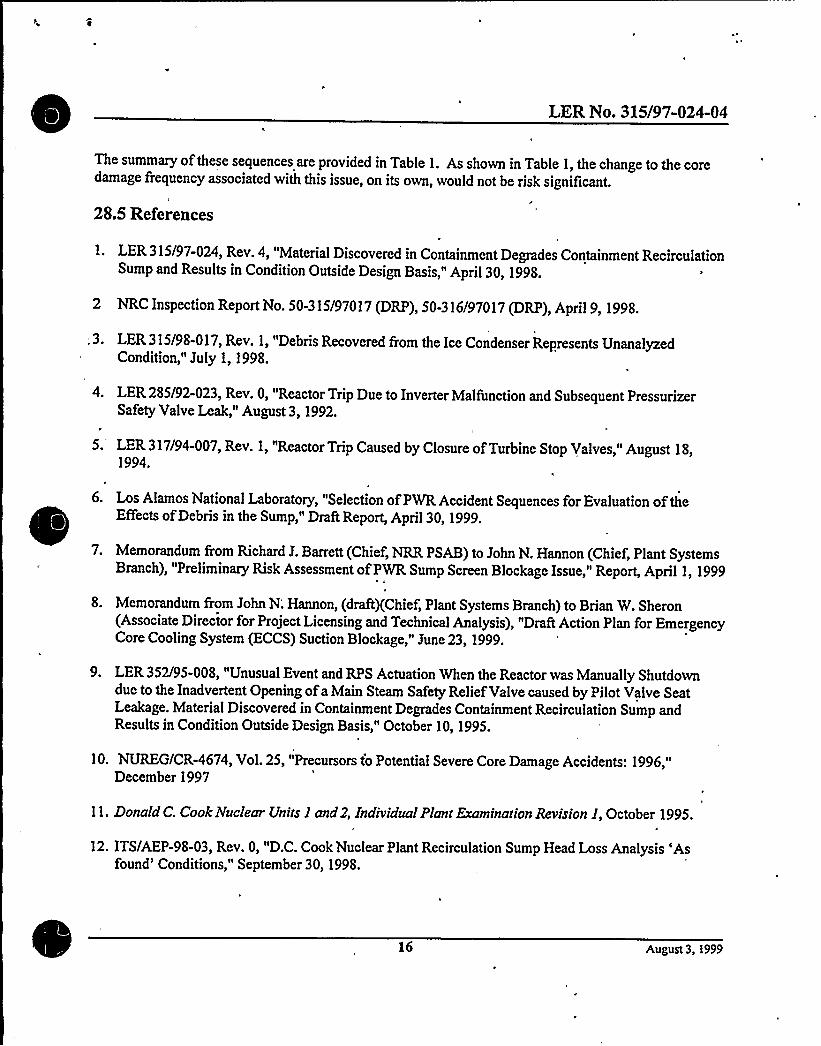
LER No. 315/97-024-04
The summary of these sequences are provided in Table 1. As shown in Table 1, the change to the coredamage frequency associated with this issue, on its own, would not be risk significant.
28.5 References
1. LER 315/97-024, Rev. 4, "Material Discovered in Containment Degrades Containment RecirculationSump and Results in Condition Outside Design Basis," April30, 1998.
2 NRC Inspection Report No. 50-315/97017 (DRP), 50-316/97017 (DRP), April9, 1998.
.3. LER315/98-017, Rev. 1, "Debris Recovered from the Ice Condenser Represents UnanalyzedCondition," July 1, 1998.
4. LER 285/92-023, Rev. 0, "Reactor Trip Due to Inverter Malfunction and Subsequent PressurizerSafety Valve Leak," August 3, 1992.
I
5. LER 317/94-007, Rev. 1, "Reactor Trip Caused by Closure ofTurbine Stop Valves," August 18,1994.
6. Los Alamos National Laboratory, "Selection ofPWR Accident Sequences for Evaluation of theu
I Effects ofDebris in the Sump," Draft Report, April30, 1999.
7. Memorandum from Richard J. Barrett (Chief, NRR PSAB) to John N. Hannon (Chief, Plant SystemsBranch), "Preliminary Risk Assessment ofPWR Sump Screen Blockage Issue," Report, April 1, 1999
8. Memorandum from John N; Hannon, (draftxChief, Plant Systems Branch) to Brian W. Sheron(Associate Director for Project Licensing and Technical Analysis), "Draft Action Plan for EmergencyCore Cooling System (ECCS) Suction Blockage," June 23, 1999.
9. LER 352/95-008, "Unusual Event and RPS Actuation When the Reactor was Manually Shutdowndue to the Inadvertent Opening ofa Main Steam Safety Relief Valve caused by Pilot Valve SeatLeakage. Material Discovered in Containment Degrades Containment Recirculation Sump andResults in Condition Outside Design Basis," October 10, 1995.
10. NUIT/CR-4674, Vol. 25, "Precursors to Potential Severe Core Damage Accidents: 1996,"December 1997
11. Donald C. Cook ¹cleai Units I and 2, Individual Plant Examination Revision I, October 1995.
12. ITS/AEP-98-03, Rev. 0, "D.C. Cook Nuclear Plant Recirculation Sump Head Loss Analysis 'Asfound'onditions," September 30, 1998.
16 August 3, 1999

LER No. 315/97-024-04
13. LER 440/93-011, Rev. 0, "Excessive Strainer Differential Pressure Across the RHR Suction StrainerCould have Compromised Long Term Cooling During Post-LOCA Operation," May 19, 1993.
14. J. P. Poloski, et. al., Rates ofInttiating Events at US. Nuclear Power Plants: 1987-1995,NUREG/CR-5750, February 1999.
15. LER 313/80-015, Rev. 2, "RCP Seal ofRCP C Failure," April 13, 1981.
16. WASH-1400, Reactor Safety Study, 1975.
17. Letter report from Scientech Inc. (Roger J. Mattson to Robert P. Powers) on "Safety Assessment ofDC Cook Units 1 and 2 "As Found" Condition Prior to Plant Shutdown," February 22, 1999.
18. Personal Communications between Sunil D. Weerakkody, and M. Marshall (NRC-Research).
19. "Parametric Study ofthe Potentila for BWR ECCS Strainer Blockage Due to LOCA GeneratedDebris, "NUIT/CR-6224, October 1995.
17 August 3, 1999


LER No. 315/97-024-04
Table 1 - Changes to Core Damage Frequency (CDF) for LER No. 315/97-024-04
Initiator Initiating EventFrequency (IEF)
Product ofIEF&calculatedprobabilities(1)
Probability. ofscreen
clogging up duringrecirculation and causingadequate head. loss tocavitate RHR pumps
Contributionto change inCDF
Stuck open 6 x 10'/criticalPORVs or SRVs year
2.1 x 10~/year negligible* less than 1 x10~/year
Feed-and-Bleedcoolingsequences(except MSLB &MFLB)
2 x 10'/criticalyear
8.6 x 10~/year negligible* less than 1 x10~/year
Feed-and-Bleed 3.8 x 10'/criticalcooling yearsequences (afteraMSLB &MFLB)
1.7 x 10'/year negligible» less than 1 x10~/year
RCP SealLOCAs
SmallLOCAs
2.5 x 10'/criticalyear
5 x 10"/critical .
year5.1 x 10~/year negligible»
h
8.6 x 10~/year negligible* less than 1 x'0~/year
less than 1 x10~/year
Medium or Large 4.5 x 10'/criticalLOCAs . year
3.6 x 10'/year low»» less than 1 x10~/year .
For the purposes ofthis analysis, all available information (operating experience or deterministicanalysis) leads to the conclusion that the event can not occur. The basis ofthis conclusion isprovided in the discussion ofthe event.
»» For the purposes ofthis analysis, available information (operating experience or deterministicanalysis) can not rule out occurrence ofthe event. However, several low probability barriers must beovercome for the event to occur. The basis ofthis conclusion is provided in the discussion oftheevent. For this sequence, it is assumed that the probability ofthis event is less than 0.027.
(1) Sequence frequency excluding the probability ofscreen clogging up during recirculation and causingadequate head loss to cavitate RHR pumps.
18 August 3, 1999

NRC Insp. Report No. 50-315/97-201, Finding E1.1.1.2.A(1); LER 315/97-011-02
36.0 NRC Inspection Report No. 50-315/97-201, Finding E1.1.1.2.A(1) and LER315/97-011 Rev. 2
Event Description: Failure to Account for RWST Level Setpoint Errors Caused by Flow-InducedEffects and the Potential for RHR Pump Failure due to Vortexing
Date ofEvent:
Plant:
November 1997, August 1997
D.C. Cook, Units 1 and 2
36.1 Summary of Issue
This issue addresses several Refueling Water Storage Tank (RWST) level errors that had not beenaccounted for in the RWST level instrumentation uncertainty (error) analysis when calculating thesetpoints related to transfer ofthe post-loss-of-coolant accident (LOCA) injection source from the RWSTto the containment sump, as well as the potential for residual heat removal (RHR) pump damage due tovortexing while the pump suction was being supplied from the RWST (Refs. 1, 2).
Procedure 01-OHP 4023.ES-1.3, "Transfer to Cold Leg Recirculation," Rev. 4 (Ref. 3), is entered fromprocedure 01-OHP 4023.E-1, "Loss ofReactor or Secondary Coolant," Rev. 7 (Ref. 4), when indicatedRWST level is less than 32%. Provided both RHR pumps are available following a LOCA and either thecontainment water level is greater than 15% or the containment sump level is greater than 97%', the WestRHR and containment spray (CTS) pumps are stopped ifthey are running (large- and medium-breakLOCA), aligned for recirculation, and restarted. Both safety injection (SI) and charging pump suctionpathways are then aligned to take suction from the West RHR train, after which the SI and charging
'umpsuctions are isolated from the RWST (the SI and charging pumps continue to run during thetransfer to the sump).
Ifboth RHR trains are operating and after the West RHR and CTS pump suctions are aligned to thecontainment sump, the East RHR and CTS pumps willcontinue to take suction from the RWST until anindicated RWST level of 10% reached, when operators realign the East trains to the containment sump.The SI and charging pump suctions are then configured such that either the East or West RHR trains canprovide flow to these pumps. Ifthe East train transfer is delayed, the East RHR pump willautomaticallytrip when the RWST low-low level setpoint is reached (nominally 9.09% ofspan). Any other pumps thatare still taking suction from the RWST when the low-low level trip setpoint is reached are placed in pull-to-lock by the operators.
Ifeither the East or West RHR train is unavailable, Ref. 3 instructs the operators to align the operableRHR train for sump recirculation at the time the procedure is entered, i.e., not to wait until the RWST
'A containment water level of602'0" provides adequate NPSH and protection against vortexing during cold Ic:grecirculation for all LOCA scenarios (Rcf. 1). However, an indicated containmcnt water level of 15% (601'"), while acccptablcfrom an NPSH and vortexing standpoint, provides no margin ofprotection against vortexing for limitingbreaks. An indicatedcontainment sump level of97% does not prevent pump damage due to vortexing (Rcfs. 1, 5).
August 18 1999

NRC Insp. Report No. 50-315/97-201, Finding E1.1.1.2.A(1); LER 315/97-011-02
level is less than 10% ifthe East train is the only operable train.
Ref. 1 determined that a potential for vortexing and air entrainment existed prior to reaching the RHRpump automatic trip setpoint. Vortexing and air entrainment, ifsevere, could damage the pumps thatwere still taking suction from the RWST. A draft licensee calculation, available at the time that the Ref. 1
inspections were performed, indicated that incipient RHR pump vortexing could occur at an RWST level12 inches above the low-low level setpoint, and that 2% air entrainment [the limitofpump operabilitydefined in Loss ofRHR Cooling 6%ile the RCS is Partially Filled, WCAP-11916, July 1988 (Ref. 6)]could be experienced at a level 2.5 inches below the low-low level setpoint.
However, the draft licensee calculation did not consider RWST level instrument uncertainties. Whenthese are taken into account, Ref. 1 concluded that an actual water level that was below the top oftheECCS suction pipe could exist when the RWST low-low level trip occurs. Instrument error couldincrease the vortexing duration and potentially result in RHR and CTS pump failure before the pumpswere transferred to the containment sump.
The potential for RHR and CTS pump vortexing was offset by RWST level setpoint errors identifiedduring the Ref. 1 inspection and in Ref.2. These errors were caused by flow-induced effects:
RWST level transmitters 1LS-950 and -951, which cue the operators to initiate transfer to sumprecirculation, are located in the ECCS suction pipe connected to the RWST. The flow ratethrough the suction pipe results in entrance and velocity head losses which negatively bias thestatic pressure sensed by the transmitters and results in an indicated RWST water level that islower than the actual level. Preliminary licensee investigations reported in Ref. 1 indicated thatthe combined effect from flow-induced errors and instrument uncertainty would beapproximately 20% of instrument span at the time the low level alarm setpoint is reachedfollowinga large-break LOCA.
Ref. 2 identified a further condition that could result in an additionhl negative 8% level error .
when the low level setpoint was reached. This condition involved the installation ofdrip catcheson the 10-in RWST overflow lines at Units 1 and 2. The overflow lines provide RWST venting ifthe normal 8-in vent line becomes plugged. A 1976 calculation estimated a tank-to-atmospheremaximum differential pressure of02 psi followinga large-break LOCA ifthe overflow line wasblocked. A revised calculation performed prior to the submittal ofRef. 2, which correctedseveral discrepancies in the original calculation, estimated instead a differential pressure of 1.03psi, with a corresponding RWST level error of2.4 ft.
The RWST level setpoint errors also potentially impact the RHR pumps following transfer to thecontainment sump, because the decreased inventory transferred to the sump as a result ofthe level errorsincreases the likelihood ofair entrainment due to vortexing during recirculation. The potential forvortexing in the containment sump is addressed under Issue 26, together with other concerns that alsoaffect vortexing in the sump (e.g., the impact ofwater diversion f'rom the active to the inactive sump).
The change in core damage frequency associated with this issue is dependent upon resolution of the
August 18, 1999

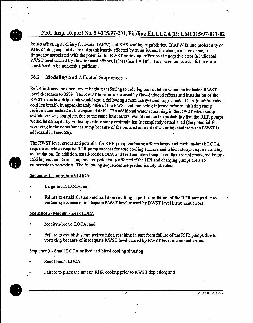
NRC Insp. Report No. 50-315/97-201, Finding E1.1.1.2.A(1); I ER 315/97-011-02
issues affecting auxiliary feedwater (AFW) and RHR cooling capabilities. IfAFW failure probability orRHR cooling capability are not significantly affected by other issues, the change in core damagefrequency associated with the potential for RWST vortexing, offset by the negative error in indicatedRWST level caused by flow-induced effects, is less than I x 10~. This issue, on its own, is thereforeconsidered to be non-risk significant.
36.2 Modeling and Affected Sequences
Ref. 4 instructs the operators to begin transferring to cold leg recirculation when the indicated RWSTlevel decreases to 32%. The RWST level errors caused by flow-induced effects and installation oftheRWST overflow drip catch would result, following a maximally-sized large-break LOCA (double-endedcold leg break), in approximately 40% of the RWST volume being injected prior to initiating
sump'ecirculationinstead ofthe expected 68%. The additional water remaining in the RWST when sumpswitchover was complete, due to the same level errors, would reduce the probability that the RHR pumpswould be damaged by vortexing before sump recirculation is completely established (the potential forvortexing in the containment sump because ofthe reduced amount ofwater injected from the RWST isaddressed in Issue 26).
The RWST level errors and potential for RHR pump vortexing affects large- and medium-break LOCAsequences, which require RHR pump success for core cooling success and which always require cold legrecirculation. In addition, small-break LOCA and feed and bleed sequences that are not recovered beforecold leg recirculation is required are potentially. affected ifthe HPI and charging pumps are alsovulnerable to vortexing. The following sequences are predominately affected:
Se uence 1- Lar e-break LOCA:
Large-break LOCA; and
Failure to establish sump recirculation resulting in part from failure ofthe RHR pumps due tovortexing because of inadequate RWST level caused by RWST level instrument errors.
Se uence 2- Medium-break LOCA
Medium-break LOCA; and
~ Failure to establish sump recirculation resulting in part from failure ofthe RHR pumps due tovortexing because of inadequate RWST level caused by RWST level instrument errors.
I
Se uence 3 - Small LOCA or feed and bleed coolin situation
Small-break LOCA;
Failure to place the unit on RHR cooling prior to RWST depletion; and
August 12, 1999


NRC Insp. Report No. 50-315/97-201, Finding E1.1.1.2.A(l); I ER 315/97-011-02
Failure to establish sump recirculation resulting in part from failure ofthe HPI and chargingpumps due to vortexing. (ifapplicable) because of inadequate RWST level caused by RWST levelinstrument errors.
Se uence4- Feed and Bleed followin a loss ofall feedwater
Feed and bleed following a loss ofall feedwater;
Failure to recover secondary-side cooling prior to RWST depletion; and
Failure to establish sump recirculation resulting in part from failure ofthe HPI and chargingpumps due to vortexing (ifapplicable) because of inadequate RWST level caused by RWST levelinstrument errors.
36.3 Frequencies, Probabilities and Assumptions
Se uence 1- Lar e-break LOCA:
Large-break LOCA - The frequency ofa large-break LOCA is assumed to be 5 x 10~/yr (Ref. 7).
Failure to establish sump recirculation resulting in part from failure ofthe RHR pumps due tovortexing because of inadequate RWST level caused by RWST level instrument errors. The flow-induced RWST level errors during a large-break LOCA negatively bias indicated level by up toapproximately 28% ofspan, including instrument error. Subtracting a positive instrument error of'3.07% (Ref. 1) results in an RWST level bias ofapproximately 25%. Therefore, even ifthe WestRHR pump transfer to cold leg recirculation failed and the East RHR train transfer was delayeduntil an indicated RWST level of9.09% (where an automatic RHR pump trip is actuated),substantial RWST inventory would still exist. An RWST level error ofat least 6.3% would existthroughout the large-break LOCA size range (see the discussion for Sequence 2). Suchinventories would prevent vortexing.. The probability ofRHR pump failure due to vortexing in theRWST is therefore negligible.
Combining the large-break LOCA initiating event frequency (5.0 x 10~/yr) with the probability ofRHRpump failure due to RWST vortexing (negligible) results in a negligible significance estimate for large-break LOCA. lh
Se uence 2- Medium-break LOCA:
Medium-break LOCA - The frequency ofa medium-break LOCA is assumed to be 4 x 10'/yr(Ref. 7).
Failure to establish sump recirculation resulting in part from failure ofthe RHR pumps due tovortexing because of inadequate RWST level caused by RWST level instrument errors. The flow-induced RWST level errors during a medium-break LOCA would negatively. bias indicated level
August 12, 1999


NRC Insp. Report No. 50-315/97-201, Finding E1.1.1.2.A(l); LER 315/97-011-02
to a lesser extent than for a large-break LOCA. The effect ofECCS flowon RWST level error isnot precisely known, but is a sum ofvelocity (v) and velocity-squared (v') terms. MinimumRWST level error due to flow-induced effects, which would increase the likelihood ofRWSTvortexing, would occur ifthe error was dominated by v'-terms. Since containment spray isactuated following a medium-break LOCA, the ECCS flow rate would be expected to be no lessthan 50% of that for a large-break LOCA (Ref. 5, Table B-1). Assuming the RWST level error isa function ofv, an RWST level error of25% ofthe large-break LOCA error, or 6.3%, can beestimated. This again would result in a significant RWST inventory at the point that the East RHRpump would trip. This inventory would eliminate the potential for East RHR pump damage due tovortexing in the RWST iftransfer ofthe West RHR pump were to fail. The probability ofRHRpump failure due to vortexing in the RWST is therefore negligible.
Combining the medium-break LOCA initiating event frequency (4.0 x 10~/yr) with the probability ofRHRpump failure due to RWST vortexing (negligible) results in a negligible significance estimate for medium-break LOCA.
Se uence 3 - Small-Break LOCA
Small-break LOCA; andFailure to place the unit on RHR cooling prior to RWST depletion.
The frequency ofa small-break LOCAwith failure to place the unit on RHR cooling prior todepleting the RWST and transferring to cold leg recirculation is 9.5 x 10'/yr, based on the modeldocumented in Ref. 8.
Failure to establish sump recirculation resulting in part from failure ofthe HPI and chargingpumps due to vortexing as a result of, inadequate RWST level caused by RWST level instrumenterrors. As described in the Summary, provided both RHR pumps are available, the HPI andcharging pumps are aligned for sump recirculation in conjunction with the alignment ofthe WestRHR train at 32% indicated RWST level.
For the purposes ofthis analysis a small-break LOCA is assumed to result in a peak containmentpressure that does not demand containment spray. The ECCS flowrate is therefore substantiallysmaller than for a medium- or large-break LOCA, on the order of500- 1000 gpm. This low flowrate would result in little flow-induced RWST level error to offset the potential for pump damagedue to vortexing iftransfer ofthe HPI and charging pumps in conjunction with alignment oftheWest RHR train to the containment sump were to fail.
Using the same approach as for a medium-break LOCA, the flow-induced RWST error can bebounded. Assuming the flow-induced error is dominated by v -terms (which minimizes the levelbias), a flow rate of 1000 gpm results in a level bias of0.2%. This is much smaller than thenominal RWST, level instrument uncertainty described in Ref. 1 (-3.75%, +3.07%). In this case,the potential may exist for vortexing-induced failure ofthe HPI and charging pumps ifthey arevulnerable to vortexing and iftheir realignment with the West RHR train fails.
August 12, 1999

NRC Insp. Report No. 50-315/97-201, Finding E1.1.1.2.A(l); LER 315/97-011-02
Based on Ref. 1, air entrainment at a 2% operational limitis estimated to occur for the RHRpumps at 2.5 inches below the RHR pump trip setpoint (RWST low-low level setpoint of9.09%).Assuming the RWST instrument error described in Ref. 1 represents k2a ofan approximatelynormal distribution', a probability of0.4 ofunacceptable RHR pump vortexing prior to RHRpump trip is estimated. Assuming the operators delay East train alignment until the -10%indicated RWST level is reached when vortexing becomes a potential problem (this isconservative since Ref. 3 instructs the operators to transfer the operable train at 32% level ifoneofthe trains is inoperable) and that the 0.4 probability is also applicable to the HPI and chargingpumps (this is most likelyconservative, considering the HPI and charging pump flow rates) andcombining itwith the probability offailing to align the West RHR train to the containment sump,1.3 x 10 PVest RHR pump suction valve IMO-320 fails to close (3.0 ~ 10'), West recirculationsump isolation valve IMO-306 fails to open (3.0 x 10'), West RHR pump fails to start and run(3.7 < 10'), HPI pump suction valve IMO-350 from West RHR heat exchanger fails to open (3.0< 10'), or HPI pump suction cross-tie valves IMO-361 or -362 fail to open (2.7 > 10")], results inan overall failure probability of0.4 < 1.3 < 10', or 5.2 > 10'.
However, for a small LOCAwithout containment spray, the flow rates are relatively low (less than1000 gpm). Therefore, between initiation ofsump recirculation to reaching a RWST level thatcould introduce vortexing, significant amount oftime is available (at least 1 hour). This long timeperiod minimizes the chance that the East RHR train transfer willbe delayed until the -1 0%RWST level is reached when vortexing becomes a potential problem.
Combining the frequency ofa small-break LOCA with failure to place the unit on RHR cooling prior todepleting the RWST (9.5 >< 10'/yr) with the failure probability estimated in the previous paragraph resultsin a most-likely conservative significance estimate for small-break LOCA of4.9 x 10'/yr. Whencombined with the likelihood offailing to establish East RHR train recirculation before -10% RWST level(assumed to be 0.1), the sequence frequency becomes 4.9 < 10~/yr.
The above frequency assumes'containment spray is not actuated for a small-break LOCA. Ifcontainmentspray is actuated and is not terminated by the operators, then the ECCS flow rate from the RWST wouldapproximate that for a medium-break LOCA in the 2+-in range. In this case, the flow-induced RWSTlevel instrument errors would offset the potential impact ofvortexing (as described for a medium-breakLOCAunder Sequence 2) and result in a negligible significance estimate.
Se uence 4 - Feed and Bleed followin a loss ofall feedwater
Feed and bleed followinga loss ofall feedwater;Failure to recover secondary-side cooling prior to RWST depletion.
The frequency of feed and bleed with failure to recover secondary-side cooling prior to depletingthe RWST is 1.6 > 10~/yr, based on the model documented in Ref. 8.
Sce the precursor analysis ofLER 269/98404.
August 12, 1999
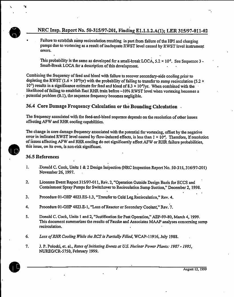
NRC Insp. Report No. 50-315/97-201, Finding E1.1.1.2.A(1); LER 315/97-011-02
~ . Failure to establish sump recirculation resulting in part from failure ofthe HPI and chargingpumps due to vortexing as a result of inadequate RWST level caused by RWST level instrumenterrors.
This probability is the same as developed for a small-break LOCA', 5.2 < 10'. See Sequence 3-Small-Break LOCA for a description ofthis development.
Combining the frequency of feed and bleed with failure to recover secondaiy-side cooling prior todepleting the RWST (1.6 x 10~/yr) with the probability offailing to transfer'o sump recirculation (5.2 >
10') results in a significance estimate for feed and bleed of8.3 x 10'/yr. When combined with thelikelihood offailing to establish East RHR train before -10% RWST level when vortexing becomes apotential problem (0.1), the sequence frequency becomes negligible.
36.4 Core Damage Frequency Calculation or the Bounding Calculation
The frequency associated with the feed-and-bleed sequence depends on the resolution ofother issuesaffecting AFW and RHR cooling capabilities.
this issue, on its own
36.5 References
The change in core damage frequency associated with the potential for vortexing, offset by the negativeerror in indicated RWST level caused by fiow-induced effects, is less than 1 >< 10~. Therefore, ifresolutionof issues affecting AFW and RHR cooling do not significantly affect AFW or RHR failure probabilities,
, is non-risk significant.
.Donald C. Cook, Units 1 &2 Design Inspection (NRC Inspection Report No. 50-315, 316/97-201)November 26, 1997.
2. Licensee Event Report 315/97-011, Rev. 2, "Operation Outside Design Basis for ECCS andContainment Spray Pumps for Switchover to Recirculation Sump Suction," December 2, 1998.
3. Procedure 01-OHP 4023.ES-1.3, "Transfer to Cold Leg Recirculation," Rev. 4.
Procedure 01-OHP 4023.E-1, "Loss ofReactor or Secondary Coolant," Rev. 7.
Donald C. Cook, Units 1 and 2, "Justification for Past Operation," AEP-99-80, March 4, 1999.This document summarizes the results ofFauske and Associates MAAPanalyses concerning sumprecirculation.
6. Loss ofRHR Cooling While the RCS is Partially Filled, WCAP-11916, July 1988.
7. J. P. Poloski, et. al., Rates ofInitiatingEvents at US. Nuclear Power Plants: 1987- 1995,NUIKG/CR-5750, February 1999.
August 12, 1999

NRC Insp. Report No. 50-315/97-201, Finding E1.1.1.2.A(l); LER 315/97-011-02
8. Idaho National Engineering Laboratory, SimplifiedPlant Analysis Risk Modelfor Cook Units l and2 (ASP PS'R B), Revision 2QA; March 1998.
August 12, 1999

NRC Inspection Report No. 50-315, 316/97-201, Finding E1.2.1.2.H(b)
38.0 NRC Inspection Report No. 50-315, 316/97-201, Finding E1.2.1.2.H(b)
Event Description: Licensee's GL 89-13 Performance Trending ofEDG WaterJacket Cooler Degradation Found to be Ineffective
Date ofEvent: August 1997
Plant: D. C. Cook, Units 1 and 2
38.1 Summary of Issue
The NRC staff conducted a design and performance review of the heat exchangers associated with theEDG water jacket coolers, lube oil, and aftercoolers at D. C. Cook, Units 1 and 2 (Cook 1 and 2) fromAugust 4 through September 11, 1997 (Ref. 1). This review was performed based on the preliminaiyteam findings associated with the elevated lake temperatures." Its purpose was to determine the adequacyofthe testing performed by the licensee and the associated acceptance criteria contained in the licensee'sprogram guidance for complying with Generic Letter (GL) 89-13, "Service Water System ProblemsAffecting Safety-Related Equipment."
The inspection team found that the licensee's GL 89-13 performance trending ofEDG water jacket coolerI degradation was ineffective. Performance trending ofthe EDG water jacket coolers consisted offlowing'CW/ESWcooling in-series through the EDG water jacket, lube oil, and aftercoolers. ESW outlet
temperatures were recorded and trends were charted over several tests. Results ofthe temperature profilefrom the heat exchangers, which was used as a measure ofheat exchanger degradation, indicated thattemperature values were relatively constant over the several testing periods monitored by the licensee.However, the inspection team identified that the heat exchanger outlet temperature was controlled bytemperature valves, which automatically regulate temperature by changing the flow rate through the heatexchangers. Therefore, the data collected by the licensee was only an indication that the temperaturecontrol valves were functioning, and not an indication ofwhether there was any heat exchangerdegradation.
The core damage frequency associated with this issue is less than 1 x 10~/year, making the issue non-risksignificant.
38.2 Modeling and Affected Sequences
Results ofa review ofoperating experience at Cook do not support the increase in the failure probabilityof the EDG water jacket coolers due to excessive fouling beyond the nominal failure probability that isimplied by this finding, for the following reasons (Note that both Cook units report EDG problems inaccordance with Regulatory Guide 1.108):
August 18, 1999


NRC Inspection Report No. 50-315, 316/97-201, Finding E1.2.1.2.H(b)
~ AEOD's report on EDG reliability (Ref. 2) identified only two LERs (2/92 and 9/92) submitted byCook 1 and 2 that reported EDG train failures - neither involved problems with EDG cooling or theEDG water jacket coolers.
~ A search ofthe SCSS database (Ref. 3) for the years 1990-98 yielded only one LER reportingproblems with the emergency ac power system (including the EDG water jacket coolers) at the Cookunits other than the two LERs identified in the first bullet item above. This LER reported a problemwith an EDG auxiliary system that was unrelated to the EDG water jacket coolers.
~ A search ofNPRDS (Ref. 4) for failure records regarding the EDG cooling water system at the Cookplant for the period 1985-1995 yielded no reported failures involving the EDG water jacket coolers.
Therefore, no core damage sequences increased in frequency as a result ofthis condition.
38.3 Frequencies, Probabilities, and Assumptions
Since no core damage sequences increased in frequency, frequencies and probabilities were notcalculated.
38.4 Core Damage Frequency Calculation or the Bounding Calculation
No core damage sequences increased in frequency as a result ofthis condition. Therefore, the change incore damage frequency was determined to be zero.
38.5 References
1. Donald C. Cook, Units 1 &2 Design Inspection (NRC Inspection Report No. 50-315, 316/97-201):November 26, 1997.
2. "Emergency Diesel. Generator Power System Reliability: 1987-1993," AEOD/S96-03, Idaho NationalEngineering Laboratory, Idaho Falls, Idaho, February 1996.
3. "Sequence Coding and Search System for Licensee Event Reports: User's Guide," NUREG/CR-3905, Nuclear Operations Analysis Center, Oak Ridge National Laboratory, Oak Ridge Tennessee37831, August 1984.
4. Nuclear Plant Reliability Data System, Institute ofNuclear Power Operations, Atlanta, Georgia.
August 18, 1999

LER 315/9S-013-01
41.0 Improper Splice Configurations for Pressurizer Power-Operated ReliefValve LimitSwitches
'Event Description: Improper Splice Configurations for Pressurizer Power-Operated Relief Valve Position Indication LimitSwitches
Date ofEvent: March 6, 1998
Plant: D.C. Cook, Units 1 and 2
41.1 Summary of Issue
On March 6, 1998, it was determined that the splices for the limitswitches on the Unit 1 power-operatedreliefvalves (PORVs) were installed without the "breakout boot" required for EnvironmentalQualification (EQ). A single Raychem splice was used instead ofthe required EQ breakout boot, whichis used to splice a pair of leads to a single field cable. Although the breakout boot was installed on the
'nit2 PORV limitswitches, a problem with the length ofthe splice overlap existed at a different splicelocation, resulting in the PORVs for both units being declared inoperable. The Unit2 splice did not havethe required overlap length of2 inches and therefore did not meet EQ requirements; the root cause could
~
~
~
not be determined. The event is described in LER 315/98-013-01 (Ref. 1).
The change in core damage frequency associated with this issue is negligible and the issue has negligiblesynergistic effects with other issues. Therefore, this issue willbe screened out from the integratedanalysis.
41.2 Modeling and Affected Sequences
Affected sequences are those that result in steam in the containment and require pressurizer PORVs formitigation. Loss-of-coolant accidents (LOCAs) ofall sizes, high energy line breaks (HELBs) insidecontainment, and feed and bleed sequences result in steam in the containment, but not all require
. pressurizer PORVs for mitigation. The sequences of interest therefore include medium LOCAs (in theevent ofhigh pressure injection failure), which require opening of2 of3 pressurizer PORVs fordepressurization, and small LOCAs, transients, and large steamline/feedline breaks inside containment,all ofwhich require opening of2 of3 pressurizer PORVs for primary bleed and feed (Ref. 2).
41.3 Frequencies, Probabilities, and Assumptions
The licensee conducted an engineering evaluation ofthe installed configurations. The first issue was thelack ofa breakout boot, which is designed to provide a seal where two conductors leave a singleconductor. The three individual Unit 1 conductors were insulated with Raychem WCSF heat shrinktubing instead ofa breakout boot. The entire assembly was then covered with the same tubing. The
August 27, 1999
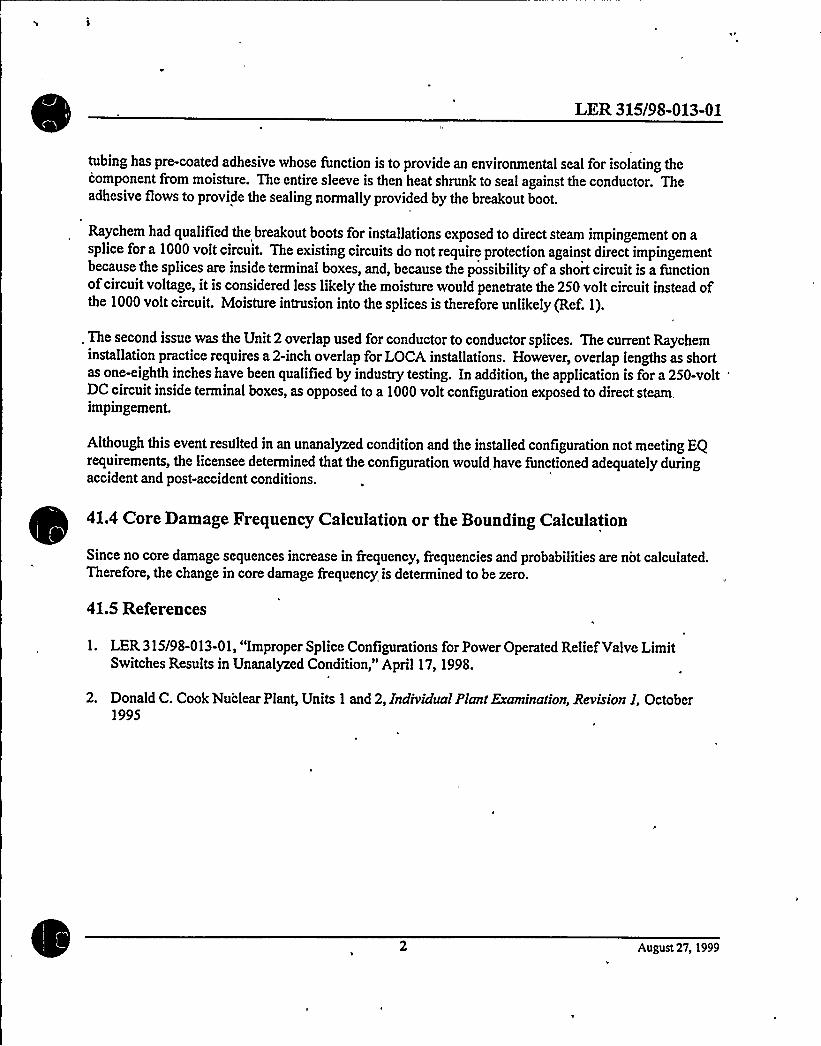
LER 315/9S-013-01
tubing has pre-coated adhesive whose function is to provide an environmental seal for isolating thecomponent from moisture. The entire sleeve is then heat shrunk to seal against the conductor. Theadhesive flows to provide the sealing normally provided by the breakout boot.
Raychem had qualified the breakout boots for installations exposed to direct steam impingement on asplice for a 1000 volt circuit. The existing circuits do not require protection against direct impingementbecause the splices are inside terminal boxes, and, because the possibility ofa short circuit is a functionofcircuit voltage, it is considered less likelythe moisture would penetrate the 250 volt circuit instead ofthe 1000 volt circuit. Moisture intrusion into the splices is therefore unlikely (Ref. I).
. The second issue was the Unit 2 overlap used for conductor to conductor splices. The current Raycheminstallation practice requires a 2-inch overlap for LOCA installations. However, overlap lengths as shortas one-eighth inches have been qualified by industry testing. In addition, the application is for a 250-voltDC circuit inside terminal boxes, as opposed to a 1000 volt configuration exposed to direct steam.impingement.
Although this event resttlted in an unanalyzed condition and the installed configuration not meeting EQrequirements, the licensee determined that the configuration would have functioned adequately duringaccident and post-accident conditions.
41.4 Core Damage Frequency Calculation or the Bounding Calculation
Since no core damage sequences increase in frequency, frequencies and probabilities are not calculated.Therefore, the change in core damage frequency is determined to be zero.
41.5 References
1. LER 315/98-013-01, "Improper Splice Configurations for Power Operated Relief Valve LimitSwitches Results in Unanalyzed Condition," April 17, 1998.
2. Donald C. Cook Nu'clear Plant, Units 1 and 2, Individual Plant Eraminarion, Revision I, October1995
August 27, 1999

LER 316/9S-003
44.0 Two Pressurizer Safety Valves Fail to LiftWithin Setpoint Tolerance
Event Description: Two ofthree pressurizer safety valves failed to liftwithin TSset point tolerance of 1 percent.
Date ofEvent: March 4, 1998
Plant: D.C. Cook, Unit2
44.1 Summary of Issue
On March 4, 1998, two ofthree Unit2 pressurizer safety valves were found to have liftpoints thatexceeded their Technical Specification (TS) value by more than the 1 percent tolerance allowed. Theevent was reported as an unanalyzed condition and as an operation prohibited by the plant's TS (Ref. 1).One valve lifted at 1.52 percent above the TS value, and the other at 3.42 percent above the TS value.The valves failed to liftdue to set point drift; no cause ofthe set point driftwas identified.
The change in core damage frequency associated with this issue is negligible and the issue has negligiblesynergistic effects with other issues. Therefore, this issue willbe screened out from the integratedanalysis.
~
~
44.2 Modeling and Affected Sequences
Affected sequences are those that require pressurizer safety valves for accident mitigation. Thesequences of interest therefore include anticipated transient without scram (ATWS) events (ifthetransient is initiated from 40 percent power or greater), which require opening ofthree of threepressurizer safety valves (in addition to opening ofpressurizer PORVs) for primary pressure relief, andtransients, which may require opening ofsafety valves as backups for pressurizer PORVs for primarybleed and feed (Ref. 2).
44.3 Frequencies, Probabilities, and Assumptions
The reactor vessel and pressurizer were designed to Section IIIofthe ASME Boiler and Pressure Vesselcode which allows a maximum transient pressure of2735 psig, 110 percent ofthe design pressure (2485psig). The highest found liftpoint, 2570 psig, would not have allowed the reactor coolant system toexceed 110 percent of the design pressure. Based on Updated Final Safety Analysis Report (UFSAR)Table 4.1-2 (Ref. 3), the hydrostatic test pressure (cold) is 3106 psig. Therefore, the minor deviation inthe liftpoint does not increase the reactor coolant system (RCS) failure probability due to oveipressure.The licensee intends to submit a TS revision for'Unit2 to change the se tpoint tolerance to plus or minus3 percent. This revision willmake the Unit 2 TS consistent with the Unit 1 TS.
August 27, 1999
LER 316/9S-003
According to the UFSAR, the charging pumps at Cook have a maximum discharge pressure of2740 psig(Ref. 3). Therefore, even at the highest liftpoint of2570 psig, the charging pumps are capable ofperforming feed and bleed using the pressurizer safety valves.
According to the Cook IPE (Ref. 2), ATWS sequences that initiate at power levels grater than 40 percent,require three out ofthree pressurizer safety valves to control RCS pressure. Setpoint driftcould cause asmall delay in opening of two ofthe three as-found safety valves, but would not impact theirfunctionality. Considering that the RCS hydrostatic test pressure is 3106 psig and the highest as-fouridsafety valve liftpoint was 2570 psig, and the very low frequency ofATWS events, the potential increasein core damage frequency due to the ATWS sequence is negligible.
Although this event resulted in an unanalyzed condition and operation prohibited by the plant's TS,maximum RCS pressure would not have been exceeded. Therefore, no core damage sequences wereaffected
44.4 Core Damage Frequency Calculation or the Bounding Calculation
Since no core damage sequences increase in frequency, frequencies and probabilities are not calculated.Therefore, the change in core damage frequency is determined to be zero.
44.5 References
l. LER 316/98-003, "Two Pressurizer Safety Valves Fail to LiftWithin Setpoint Tolerance" April 1,1998.
2. Donald C. Cook Nuclear Plant, Units 1 and 2, Individual Plant Examination, Revision I, October1995
3 Donald C. Cook Nuclear Plant, Units 1 and 2, Updated Final Safety Analysis Report.
August 27, 1999

LER No. 316/98-005
53.0 LER No. 316/98-005
Event Description: Potential for High Energy Line Break to Degrade ComponentCooling Water System
Date ofEvent: July 1998
Plant: Donald C. Cook Nuclear Plant, Units 1 and 2
53.1 Event Summary
On July 15, 1998, with Donald C. Cook Nuclear Plant, Units 1 and 2 (Cook 1 and 2) in cold shutdown, itwas determined that a postulated crack in a D.C. Cook Unit 2 main steam line could degrade the ability ofthe component cooling water (CCW) pumps to perform their design function (Ref. 1). The CCW pumps forboth units are adjacent.to one another in a semi-enclosed area in the AuxiliaryBuilding. Next to the areawhere the pumps are located is a pipe chase enclosing two Unit2 main steam lines and a main feedwater line.This pipe chase can be accessed through any one of three doors. Although the pipe chase walls provide aqualified high energy line break (HELB) barrier, the licensee could find no calculations which show that thedoors would withstand the energy released from a postulated critical crack. The CCW pump motors andother equipment are not qualified for a high temperature/high h'umidity environment. As a result, ifthepostulated HELB were to occur, the potential would exist for both units. to suffer a total loss ofCCW.
The estimated conditional core damage probability (CCDP) associated with this condition is 6.9 x 10'. Thisis an increase (importance) of 1.3 x 10'ver the nominal core damage probability (CDP) for a one-yearperiod for Cook 1 of5.6 x 10'. The same results apply to Unit 2 as well.
53.2 Event Description
On July 15, 1998, with both units in Operating Mode 5, cold shutdown, the licensee determined that a,postulated crack in a Unit2 main steam line could degrade the abilityofadjacent CCW pumps forboth unitsto perform their design function. The condition was reported on August 14, 1998, as an unanalyzed conditionin Interim LER 316/98-005, Rev. 0, (Ref. 1).
The CCW pumps forboth units are adjacent to one another in a semi-enclosed area in the AuxiliaryBuilding.Next to the area where the CCW pumps are located is a pipe chase enclosing two Unit2 main steam lines anda main feedwater line, which can be accessed through any one ofthree access doors. Although the walls ofthe pipe chase provide a qualified HELBbarrier, the licensee was unable to find any calculations which showthat these access doors would withstand the energy released from a postulated critical crack in a high energyline. The CCW pump motors and other equipment are not qualified for the high temperature/high humidityenvironment that would exist followinga HELB.


LER No. 316/98-005
53.3 Additional Event-Related Information
As stated above, there are two main steam lines and one main feedwater line running through the pipe chaseof interest. This pipe chase contains only main steam and main feedwater (large bore) piping. There are nosmall bore high energy branch lines in this area. The licensee's preliminary investigation found that thereare no high stress pipe segments in this area which are vulnerable to cracks or breaks; There are three accessdoors'between the pipe chase and CCW room, which open into the CCW room. The length of pipingadjacent to each ofthe doors is about 20 to 30 feet, which means a total ofabout 60 to 90 feet are situatednear the doors. This represents an estimated five percent ofall ofthe high energy piping in the plant (Ref.2).
References 2 and 3 provides the following information: The pipe chase in question communicates with asteam tunnel, which is a large area. Roughly 50 percent ofthe total high energy piping in the plant is locatedin this area. Apostulated failure ofthe high energy piping in this large area could send steam into the pipechase adjoining the CCW rooms. Ifthe pressure increase due to the postulated piping failure is high enough,then the doors from the pipe chase to the CCW pump room may open, and allow steam to enter that room.No calculations were available which showed whether a break in a location in the steam tunnel could createa pressure increase large enough to open doors to the CCW pump room. However, based on References 2and 3, it is known that one end of the steam tunnel is open to the turbine building. Therefore, the turbinebuilding provides a large, potential escape path for steam generated from postulated breaks in the piping inthe steam tunnel. The other end of the steam tunnel is also open to a very large, potential steam escapevolume. Due to the existence ofthese potential escape paths, only those postulated pipe breaks that occur .
close to the doors leading from the pipe chase to the CCW rooms are likelyto send steam into the room thathouses the CCW pumps.
53.4 Modeling Assumptions
The frequency ofHELBs in main steam lines and main feedwater lines used in this analysis was derived fromdata in NUREG/CR-5750 (Ref. 5). In this report, the mean frequency per critical year for steam linebreaksfleaks outside containment, based on seven events in 729 critical years, is estimated to be 1.0 x 10'per year. The frequency for feedwater breaks/leaks, based on two events in 729 critical years, is 3.4 x
10'er
year.
Of the seven steam line events that contributed to the 1.0 x 10'er year frequency only one occurred in a
main steam line. Since the area next to the CCW rooms contains only main steam lines (i.e., no small bore
piping or branch lines), only this event was considered applicable to the issue being analyzed. However; thisevent was also dismissed from further consideration, since it consisted ofa sample probe failure in a mainsteam line that would not have been large enough to pressurize the large area and cause a door to open. The
frequency for steam line breaks/leaks was therefore estimated to be 7 x 10~ per year; using Bayesian updatemethods with 0 events in 729 critical years.
Based on Reference 5, the two events that contribute to the main feed line break frequency occurred at
Millstone Point Units 2 and 3. The root causes ofboth these breaks were erosion and corrosion. Therefore,

LER No. 316/9S-005
these two failures may be applicable to the area under consideration. (Reference 6, the mechanicalengineering branch technical position, MEB 3-1, does not provide a basis to exclude these failures from theinitiating event frequency calculation for this area, since itdoes not require postulation offailures attributedto erosion and corrosion.) As a result, the estimated frequency remained at 3.4 x 10'er year.
The criticality factor for Cook Unit 2 is 0.68 (Ref. 5). The criticality factor for Unit 2 was used in thisanalysis to calculate the initiating event frequency rather than the factor for Unit 1 because the piping in thepipe chase ofconcern is associated with Unit 2. As a result, the frequency is 4.7 x 10~ per year (0.68 x 7 x10~) for steam line breaks/leaks, and 2.3 x 10'er year (0.68 x 3.4 x 10') for feedwater breaks/leaks. Thefrequency ofHELBs is therefore the sum ofthe two frequencies, or 2.8 x 10'per year.
The above estimate applies to HELBs in main steam lines or main feedwater lines anywhere in the plant. 5determine the initiating event frequency in the specific area ofinterest, the above frequency is multiplied by0.05, the percentage ofthe piping in the pipe chase that is located in the vicinityof the doors. Ream froma pipe break anywhere in the tunnel could potentially enter the pipe chase. Howevei; due to the largepotential escape paths, it was assumed that only breaks which occurred in the piping in the vicinityof thedoors to the room that houses the CCW pumps would be capable of opening any one of the three doors.Since approximately 5% ofthe piping is in the vicinityof the doors, the estimated frequency ofHELBs inthe area of interest is therefore 0.05 x 2.8 x 10', or 1.4 x 10" per year.
As stated in Reference 1, the CCW pump motors and associated equipment are not qualified for the hightemperature/high humidity environment. Operating experience was reviewed to investigate the response ofpumps that are not qualified to high humidity to events that impose those environmental conditions on thesepumps. First, approximately 80 LERs that reported water spray, cascade, flood, or high humidity problemsaffecting pumps were identified using the sequence coding and search system (SCSS). Ofthese, a sampleof approximately 50% were reviewed and 4 were identified for detailed review, since they containedinformation on pumps impacted by steam environments. The review identified whether the pumps failedwhen subjected to high humidity or temperature environment. Ifa failure did occur, the nature ofthe failurewas examined to determine the recoverability. Some observations from this review are as follows. Of
the'our
events that were reviewed in detail (LER302/91-003 and 251/90-008), during two events, pumps failedwhen exposed to steam environment due to moisture intrusion in to the motor winding. These did not appearto be recoverable. There was one event where the pumps continuously ran even when water had collectedin the lower motor bearings (LER 285/92-031). The forth event (LER 272/90-033) appeared to be arecoverable pump failure. Exact count of failures and demands could not be used to estimate a failureprobability due to biases in reporting failed versus successful pumps exposed to moisture. However, in lightofthese observations, a probability of0.5 appears to be a reasonable estimate for the probability offailingboth CCW pumps and the spare CCW pump when exposed to the steam environment. Considering the natureof the failures (e.g., shorts in motor windings), itwas assumed that for recovery is not credible.
Ifthe CCW pumps failed due to the postulated steam environment, cooling to the reactor coolant pump (RCP)seals would be lost. Even though the RCP seals can also be cooled by seal injection, since the chargingpumps require CCW forcharging pump seal cooling, the seal injection function would also be lost. With noseal cooling, the Westinghouse type RCP seals would degrade rapidly. The D. C. Cook Nuclear PlantIndividual Plant Examination (IPE) (Ref. 4) assumes that the RCP seals willfail with a probability of 1.0 if

LER No. 316/98-005
seal cooling is unavailable for one hour. This assumption is overly conservative since all 8 RCPs at D.C.Cook Units 1 and 2 have newer high temperature seals. Based on the RCP seal failure models suggestedNUREG/CR-4550 (Ref. 7), for new high temperature seals, the failure probability when seal cooling is lostfor an extended period is 0.19.
Ifan RCP seal LOCA were to occur, according to the modeling discussed in the Cook IPE (Ref. 4), andbased on actual RCP seal LOCA events, high pressure injection (high pressure, low volume), is needed tomitigate the accident. However, all four high pressure injection pumps at the D. C. Cook plant are cooledby CCW, so a loss ofCCW would lead to a loss ofhigh pressure injection. According to the D.C. CookFSAR(Ref. 3), all high pressure injection (HPI) pumps at Cook are highly dependent on CCW. The seal andlube oil heat exchangers ofthe two safety injection pumps are cooled by CCW. In addition, the pump gear,lube oil, and seal exchangers ofthe centrifugal charging pumps are also cooled by CCW. Even ifthe HPIpumps could inject for a short duration, in order to terminate the RCP seal LOCA and stabilize the reactorcoolant system (RCS), the RCS must be cooled down and depressurized. With CCW unavailable, theoperator would be expected to trip the RCPs. Therefore, forced circulation would be unavailable. %th onlynatural circulation in the RCS and auxiliary feedwater (AFW) available, it is unlikely that the RCS wouldbe stabilized before the HPI pump seals would be damaged due to loss ofcooling. Therefore, the probabilityoffailure ofall HPI pumps, given that CCW was unavailable, was assumed to be 1.0.
Since the CCW for both units would have failed due to the steam environment, cross-tie capability was not
~~
~
credited in this analysis.
53.5 Analysis Results
Figure 1 shows the accident sequence that leads to core damage. This sequence consists ofthe following:
~ Amain steam line break occurs in the high energy pipe chase in the vicinityof one ofthe three doorsleading to the CCW pump room
~ Failure ofrunning and standby CCW pumps and the spare CCW pump due to high humidity and hightemperature environment
~ Failure ofRCP seals given failure to recover any CCW pump and restore seal cooling to the RCPs
~ . Failure to recover HPI pumps prior to core uncoveiy
The results of this analysis is based on one key assumption. Since there are no calculations showing thecapability ofthe CCW pump room pipe chase access doors to withstand the pressures created by steam lineor main feed line breaks, at least one ofthem would open during a break, allowing steam to enter the CCWpump room.
Since failure of the CCW pumps would cause an RCP seal LOCA and would also fail the mitigatingcapability (i.e., the HPI pumps), a steam line break or a main feedwater line break in the vicinityof thesedoors willlead to core damage. Thus the conditional core damage frequency (CCDF - conditional frequency
LER No. 316/98-005
of subsequent core damage given the failures observed during an operational event) associated with thiscondition becomes the is 1.3 x 10'1.4 x 10" x 0.5 x .19) per year. The overall nominal core damagefrequency is 5.6 x 10'er year [estimated using the NRC's standardized, plant risk analysis (SPAR) modelfor the D. C. Cook plant]. Therefore, the conditional core damage frequency (CCDF) is 1.3 x 10'+ 5.6 x10' 6.9 x 10'er year. For a one year period, the associated CCDP is 1- exp[(6.9 x 10'/year) x (1 year)]= 6.9 x 10'. The nominal CDP for the same period is 1- exp[(5.6 x 10'/year) x (1 year)] = 5.6 x 10'. Usingthese two values, an increase in CDP (importance) of6.9 x 1'0' 5.6 x 10" = 1.3 x 10's estimated.
53.6 Acronyms
. AFWCCDFCCDPCDFCDPCCWHELBHPIIPELOCARCP
auxiliary feedwaterconditional core damage frequencyconditional core damage probabilitycore damage frequencycore damage probabilitycomponent cooling waterhigh energy line breakhigh pressure injectionindividual plant examinationloss-of-coolant accidentreactor coolant pumpsreactor coolant system
53.7 References
1. LER 316/9S-005, "Potential for High Energy Line Break to Degrade Component Cooling WaterSystem," August 14, 1998.
2. Personal communications, R.J. Stakenborghs (American Electric Power) and S. Weerakkody (U.S. Nuclear Regulatory Commission), July 13 and 15, 1999.
3. Donald C. Cook Nuclear Plant, Units 1 and 2, Updated Final Safety Analysis Report,
4. Donald C. Cook Nuclear Plant, Units I and 2, Individual Plant Examination Revision I, October1995.
5. J. P. Poloski, et. al., Rates of Initiating Events at US. Nuclear Power Plants: 1987 - 1995,NUREG/CR-5750, December 199S.
6. Relaxation in Arbitrary Intermediate Pipe Rupture Requirements (Generic Letter 87-11), BranchTechnical Position MEB 3-1, "Postulated Rupture Locations in Fluid System Piping Inside andOutside Containment," Rev. 2, June 1987.

LER No. 316/9S-005
7. "Analysis of Core Damage Frequency for Internal Events: Expert Judgement Elicitation,"NUREG/CR-4550, Vol. 2, April 1989.
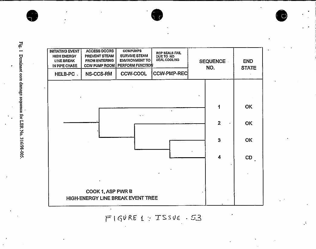
INITIATINGEVENT
HIGH ENERGYLINE BREAK
IN PIPE CHASE
ACCESSDOORS CCWPUMPS
PREVENT STEAM SURVIVE STEAM
FROM ENTERING ENVIRONMENTTO
CCW PUMP ROOM PERFORM FUNCTIO
RCP SEALS FAILDUETO NOSEAL COOLING SEQUENCE .
NO.
END
STATEHELB-PC . NS-CCS-RM CCW-COOL CCW-PMP-REC
OK
OK
OK
CD
COOK 1, ASP PWR B
HIGH-ENERGY LINE BREAK EVENTTREE
LER Nos. 315/98-01, 04, 05, 06, 07, 10, 15, 17, 24, 26, 32, 37; 316/98-04
65.0 LER Nos. 315/98-01, 04, 05, 06, 07, 10, 15, 17, 24, 26, 32, 37; 316/98-04
Event Description: "As Found" Conditions in the Ice Condenser Containment Notin Accordance with Design Basis
Date ofEvents: January 4- August 30, 1998
Plant: D. C. Cook, Units 1 and 2
65.1 Summary of Issue
The issues considered in this risk assessment are associated with the performance ofthe ice condensercontainment. Thirteen Licensee Event Reports (LERs) were issued by D. C. Cook as the result ofquestions raised by an NRC inspection in 1998 (Ref. 1). The inspection identified several degradedconditions ofthe ice baskets. An assessment ofthe "as found" conditions in the ice condenser was madeby the licensee with assistance from Westinghouse (Ref. 2). SCIENTECH was contracted by the licenseeto conduct an independent review ofthe analyses and evaluation conducted by the licensee andWestinghouse (Ref. 3).
The 13 LERs that describe "as found" containment performance conditions can be grouped into threesafety functions: (1) ice condenser bypass, (2) ice basket structural integrity, and (3) ice condenserperformance. These three safety functions maintain the peak containment pressure within its designcapability during a postulated loss-of-coolant accident (LOCA)or main steam line breaks (MSLB) insidecontainment. The LERs are listed in References 4-16. These issues are summarized below.
The synergistic effects ofall ice condenser issues except those associated with postulated earthquakes areincluded in this assessment. The aggregated impact of issues 6, 8, 52, 65, 67, 68, 69, 71, 72, 73, 74, and75 are considered here. This assessment addresses the aggregate ofthe 12 issues on the containmentoverpressure failure and the associated core damage sequence. The impact on core damage sequencesdue to debris in the containment sump and the ice condenser are addressed under issues 26 and 28,respectively.
The change in core damage frequency associated with the aggregate impact ofall conditions is less than1 x 10~/year, making these issues non-risk significant. In addition, the increase, in the probability ofcontainment failure due to overpressure, as a result of the aggregate impact ofall ice condenser issuesconsidered in this assessment, is negligible. Therefore, the synergistic effects of the 12 issues have noimpact on containment performance.
S
Ice condenser bypass. Ice condenser bypass is a condition where steam released from a pipe breakLOCA can flowdirectly from the lower compartment into the upper deck area without being condensedin the ice condenser. According to the D. C. Cook Updated Final Safety Analysis Report (UFSAR), thedesign basis (maximum) bypass flowarea around the ice bed is five square feet (Ref. 17, Section 5.2.2.4).
August 18, 1999


LER Nos. 315/9S-01, 04, 05, 06, 07, 10, 15, 17, 24, 26, 32, 37; 316/9S-04
Three LERs (LERs: 315/98-001-2, 316/98-004-1, 315/98-037-1) reported that the accumulative area ofpotential ice condenser bypass in the "as found" condition was about 36.5 square feet for Unit 1 and 35.0square feet for Unit 2.
The safety issue concerning the "as found" increase area of ice condenser bypass is the potential for thepeak containment pressure exceeding design limits, thereby potentially impacting containment integrity.
Ice basket damage. The D. C. Cook containment contains 1,944 ice baskets in 24 bays (81 baskets perbay). Each ice basket is approximately 48 feet in length and 12 inches in diameter. Plant technicalspecifications require that a sample of 144 buckets be weighed'every 18 months. The technicalspecifications also provide requirements on the sampling and additional testing when an ice basket fails tomeet the minimum weight requirement. Damage to the ice baskets was found to have occurred duringice-weighing in which the ice baskets must be slightly picked up. Damage included buckled bottoms,broken ligaments, bent rims, dents, damaged weldments, basket deformation, unpinned baskets, andmissing or broken connecting screws from vertical ice basket sections (LERs: 315/98-005-3, 315/9S-006-2, 315/98-032-0).
The safety issue concerning the "as found" condition ofthe ice baskets is the potential ejection ofloosened and broken baskets from the ice bed during an accident. A displaced ice basket could affect theice bed geometry during an accident, thereby creating bypass flow routes. Also, ejected ice baskets couldimpact structures or equipment located in the upper containment compartment.
Ice condenser performance. Several LERs were issued that identified "as found" conditions in the icecondenser containment relating to ice mal-distribution and steam fiowmal-distribution conditions. Theice mal-distribution conditions were due to unweighed, under- and over-weight ice baskets caused bynon-conservative assumptions in surveillance procedures and supporting software programs (LERs:315/98-007-1, 315/98-015-1, 315/98-024-0, 315/98-026-0); and ice displacement caused by three barrelloads ofdebris found in the ice baskets during ice melt/replacement (LER 315/98-017-1). The steamflowmal-distribution conditions were caused by partially blocked ice channels between ice basketscaused by flowblockage due to excessive frost build-up in the channels between ice baskets'(LER315/98-004-2).
The minimum technical specifications weight requirement for an ice basket is 1,333 pounds. An NRCinspection report (Ref. 1) reports that out of 1;944 ice baskets, the licensee determined that 221 baskets in.Unit 1 and 171 baskets in Unit 2 have never been weighed. In addition, a sample of54 of these baskets inUnit 2 was weighed. About 75% of the baskets sampled were less than the technical specificationsminimum weight. The lightest ice basket weighed 800 pounds. Several baskets had missing ice insegments ranging from 6 to 1S feet in height.
Based on a 100% inspection, the flow passage blockage was estimated to be 6.7% to 18.8% per bay inUnit 1 and 4.1% to 17.4% per bay in Unit 2. Ten ofthe 24 bays were found with blockages greater than15%. The flowpassages in between the ice baskets must be kept clear ofobstruction to assure even steam
August 18, 1999

LER Nos. 315/98-01, 04, 05, 06, 07, 10, 15, 17, 24, 26, 32, 37; 316/98-04
flowthrough the ice beds during a post-accident period. The technical specifications do not state whatamount ofblockage in flowpassages renders the ice condenser inoperable. However, LER 315/98-004-2stated that in response to previous instances of fiowpassage blockages, a blockage limitof 15% of thetotal upward flowarea was determined based on the analysis performed for the Unit 1 ReducedTemperature and Pressure program.
65.2 Affected Containment Failure Modes and Core Damage Sequence
Any accident that releases energy to containment relies on the ice condenser for heat removal from thecontainment. Containment heat removal is essential to keep the peak containment pressure below thedesign value. At the D. C. Cook plant, the containment pressure is controlled by two systems. In theshort-term, the ice condenser and the containment spray remove heat from the containment atmosphereby condensing steam. In the long-term, the containment spray system, which is equipped with a heatexchanger, recirculates water from the containment recirculation sump and removes heat from thecontainment.
Conditions that bypass steam fiow routes around ice baskets (due to ejected ice baskets and bypassopenings greater than analysis assumptions) or limitpressure suppression performance ofthe icecondenser (due to mal-distributed ice and steam flow through the baskets) willresult in the reduction insteam condensation. Ifsteam does not adequately condense, the pressure rise in the containment willnote be arrested and the peak pressure may be exceeded. Ifthe peak pressure exceeds the design value, thereis a probability that the containment willfail due to overpressure. As a result, the sump recirculationcapability may be affected since a breached containment has the potential to reduce the available netpositive suction head for th'e residual heat removal pumps. In addition, a cracked containment may allowwater to bypass the recirculation sump.
The followingaccidents release energy to the containment: (1) a LOCA ofany size, (2) MSLB insidecontainment, and (3) an accident condition which relies on the feed and bleed cooling capability. Ofthese accidents, only LOCAs and feed and bleed sequences resulting from MSLBs are considered sinceother systems or actions required to mitigate MSLBs (isolation of the break and cooldown with intactloops) are unaffected by loss ofcontainment integrity.
Therefore, the sequence of interest is as follows:1
~ Any size LOCA, or feed and bleed cooling scenario; and
~ Sump recirculation failure due to inadequate inventory for sump recirculation. Inadequatecontainment performance causes containment failure due to excessive containment overpressure.A ruptured containment boundary results in excessive steam bypass and loss ofsump inventory.
65.3 Frequencies, Probabilities, and Assumptions
August 18, 1999

LER Nos. 315/9S-01, 04, 05, 06, 07, 10, 15, 17, 24, 26, 32, 37; 316/9S-04
The D. C. Cook containment design basis criterion is 12 psig. The UFSAR states that the maximumcalculated pressure for various postulated design basis accident scenarios is 11.49 psig (Ref. 17, Section14.3.4.1.3.1). The failure pressure ofthe containment is much greater than the design pressure of 12 psig,based on the D. C. Cook Individual Plant Examination (Ref. 18, Section 4.'2.1). The Individual PlantExam'ination (IPE) reports that the high condition low probability failure limitfor the containment is 36psig. That is, there is 95% confidence that at 36 psig the probability containment failure is less than 5%.As shown in the attached figure (from Ref. 18, Figure 4.2-1), the containment failure probability is nearzero at peak pressures less than about 30 psig. Further, the licensee reported in a letter to the formerAtomic Energy Commission dated July 24, 1973, that the containment for Unit 1 was subjected to aninternal pressure of 16.1 psig during a containment integrity check in 1973 with no evidence ofdamage tothe integrity ofthe containment.
65.4 Effect on Containment Failure and Core Damage Sequence
The three issue groups relating to the performance to the ice condenser containment are assessedqualitatively to determine the change in containment performance using realistic (rather than designbasis) failure limits, redundancies, and the magnitude ofdegradations. The assessment ofcontainmentperformance based on "as found" conditions is discussed in three parts. First, the effect on the peakcontainment pressure due to the ice condenser bypass issue is discussed. Second, the synergistic effecton the peak containment pressure due to ice condenser performance (mal-distributions) and ice basketdamage issues is presented. Finally, the synergistic effect ofall three issue groups concludes thisassessment.
Ice condenser bypass. The cumulative effect ofthe "as found" bypass flowpaths was 36.5 square feetfor Unit 1 and 35.0 square feet for Unit 2. The UFSAR states that the design basis bypass area is 5square feet (Ref. 17, Section 5.2.2.4). The UFSAR describes the accident analyses for different size pipebreaks and the allowable ice condenser bypass flow for each case. Analysis results indicate a value of35square feet as the allowable deck leakage area for the entire spectrum ofbreak sizes (Ref. 17, Table14.3.4-2). The limitingcase is an 8-inch break with one spray pump operating at 2000 gpm (80 degrees
F), which results in a peak containment pressure of 12.0 psig. The design flow rate ofone containmentspray pump is 3200 gpm (Ref 17, Table 6.3-1). An 8-inch break with two spray pumps operating (4000
'pm at 80 degrees F) results in a peak containment pressure of 12.2 psig with a 56 square foot bypassarea. Thus, the identified historical value ofbypass ofabout 36 square feet for Unit 1 and about 35square feet for Unit 2 is bounded by UFSAR analysis when assuming the operation ofboth containmentspray pumps, but is outside ofthe ice condenser design basis value of5 square feet.
Ice basket damage. The safety issue concerning the "as found" conditions of the ice baskets is thepotential ejection of loosened and broken baskets from the ice bed during an accident. An ejected icebasket affects the ice bed geometry during an accident, thereby creating bypass flow routes. Allof the"as found" ice basket damage conditions are bounded by the potential degraded ice basket conditionreported in LER 315/98-006-2. This LER reported a deficiency in the surveillance procedure for
August 18, 1999

LER Nos. 315198-01, 04, 05, 06, 07, 10, 15, 17, 24, 26, 32, 37; 316/98-04
weighing ice baskets. The procedure contained a step which'potentially allowed the unpinning ofup to60 ice baskets during Modes 3 and 4.
The LER reported that the safety significance of60 baskets ejecting during a postulated accident has beenevaluated by Westinghouse for two cases: unobstructed baskets and obstructed baskets. During apostulated accident, ifunobstructed baskets are not secured at the bottom rim, they could eject 13 feet 5inches upward into the upper plenum area ofthe ice condenser due to blowdown forces. Unobstructedbaskets are those baskets that are not impeded by an intermediate deck frame. The upward displacementofthese baskets would not be enough to open steam bypass flow routes around the ice condenser.
For the obstructed baskets that are located below the intermediate deck frames, multiple unsecuredbaskets ejecting simultaneously and impacting an intermediate deck frame in one bay may cause theframe to plastically deform. However, this scenario was judged by Westinghouse to be extremelyunlikely for the following reasons: (1) basket columns would need to be of identical weight and exertidentical frictional forces on the lattice steel framework; (2) no lateral forces could be exerted against thebasket columns during the blowdown, and (3) basket columns would need to have exactly'the same netuplift force transient. Further, it was judged that the current calculated subcompartment loadings for thepeak differential pressure across the shell, the operating deck, the lower crane wall, and the upper cranewall willessentially be unaffected whenever the effects of the 60 unpinned baskets is considered.
The LER concluded that the possibility ofthe unpinned ice baskets or ice basket columns ejecting fromthe ice bed is extremely remote. Ifan ejection were to occur, the resultant configuration would notprevent the ice condenser from performing its intended function. A recent evaluation by Westinghousereported in Reference 2 supported this earlier conclusion.
Ice condenser performance. The safety issue concerning the performance ofthe ice condenser involvesthe mal-distribution of steam flowthrough the ice baskets due to partially blocked ice channels betweenbaskets, and mal-distribution of ice the baskets due to underweight or missing ice. Reference 2 reportsthe results ofthe licensee's analysis to determine the peak containment pressures for design basis LOCAsand MSLBs for the "as found" condition ofthe ice condenser containment. The results ofan earlieranalysis that was performed by Westinghouse for the licensee in May 1998 are referenced in thisdocument.
The analysis used the NRC-approved LOTIC containment response computer code. Models weredeveloped to include the varying weights of ice in the baskets, the partially blocked ice channels betweenice baskets, and the effects ofa steam flowbypass through the ice condenser due to postulated ice basketdisplacement caused by blowdown forces. In addition, the models included an increase in the total icemass that closely represents the actual mass ofthe ice in the ice condenser. The total mass of ice used inthe analysis was 2.53E+6 pounds. The "as found" weight ofthe ice was estimated by the licensee'o be
Rough estimates of ice weights in the Units I and 2 ice condensers were provided by thelicensee. The ice weights were estimated from ice melt volumes as the result of icereplacement operations in l998. The estimates factored the volume of ice melt in the
temporary ice melt tanks, the volume ofwater spilled in the containment, and specificgravity. These estimates are not design verified calculations.
August 18, 1999

LER Nos. 315/98-01, 04, 05, 06, 07, 10, 15, 17, 24, 26, 32, 37; 316/98-04
2.7E+6 pounds in Unit 1 and 2.8E+6 pounds in Unit 2. The minimum technical specification for the totalice weight at the time ofplant shutdown was 2.37E+6 pounds. The total mass assumed in the UFSARanalysis was 2.11E+6 'pounds.
From Reference 2, the increased ice mass resulted in a calculated peak containment pressure of 11.2 psig,which is below the current UFSAR analysis of 11.49 psig. The slight reduction in the calculated peakpressures is attributed to the utilization ofenhanced heat sink modeling and increased initial ice mass(420,000 pounds more or a 20% increase). This shows that even a 12% decrease in the minimum mass ofice as required by the technical specifications (at the time plant shut down) has little effect on the peakpressure.
Reference 2 further reports the results ofan earlier analysis that considered the increase in ice mass, (2.53E+6 pounds) and three synergistic conditions discussed above: (1) mal-distribution of ice weight inthe baskets, (2) mal-distribution ofsteam flowthrough the baskets, and (3) effects offiowbypass due toice basket displacement during an accident. The peak containment pressure calculated under theseconditions is 11.92 psig or 0.71 psig higher than the identical LOTIC analysis that assumed only theincrease in ice mass (i.e., 11.2 psig).
Synergistic effects ofall three safety issues. From the assessment ofthe synergistic effect of "as found"ice and steam flowmal-distributions, and flowbypass from postulated partially ejected ice baskets, thepeak containment pressure calculated by Westinghouse is 11.92 psig. The increase in the peak pressureas the result ofthis synergistic effect is less than 1 psig for a large break LOCA or MSLB.
From a UFSAR sensitivity analysis that calculated peak containment pressures for varying sizes ofLOCAs and bypass fiows areas, the worst case break size resulted in a peak containment pressure of 12.2psig for a 35 square foot bypass area. This analysis assumes one-third the total design flow rate ofbothcontainment spray pumps.
The combined effects ofa 36 square foot bypass flowarea and slight reduction in ice condenserperformance willbe well below the 35 psig containment failure pressure assumed in the IPE.
In light ofthis information, the probability ofthe peak pressure exceeding the containment failurepressure leading to sump recirculation failure due to these "as found" ice condenser containmentconditions is negligible. Therefore, the change in core damage frequency associated with the affected'sequence is zero.
65.5 References
l. U.S. Nuclear Regulatory Commission Inspection Report No. 50-315/98005(D.S.); 50-316/98005(D.S.), April 10, 1998
2. Westinghouse Electric Company, "Donald C. Cook Nuclear Plant Units 1 and 2, Justification forPast Operation," EP-99-080, Pittsburgh, PA., March 4, 1999.
August 18, 1999

LER Nos. 315/9S-OI, 04, 05, 06, 07, 10, 15, 17, 24, 26, 32, 37; 316/9S-04
3. SCIENTECH, Inc. "Safety Assessment ofD. C. Cook Units 1 and 2 "As Found" Condition Priorto Plant Shutdown," Golden CO., February 22, 1999.
LER 315/98-001, Revision 2, "Containment AirRecirculation System Flow Testing ResultsIndicate Condition Outside the Design Basis," event date January 4, 1998.
LER 315/98-004, Revision 2, "Inadequate Maintenance and Surveillance'Practices Results inRestricted Ice Condenser Flow Passages," event date January 22, 1998.
6. LER 315/98-005, Revision 3, "Screws Missing from Ice Condenser Ice Basket Coupling RingsResults in Potential Unanalyzed Condition," event date January 22,'1998.
7. LER 315/98-006, Revision 2, "Ice Basket Weighing Option Results in Potential UnanalyzedCondition Due to Lack ofTechnical Basis for Option," event date February 25, 1998.
LER 315/98-007, Revision 1, "Ice Condenser Weights Used to Determine TechnicalSpecification Compliance Not Representative," event date Februaty 11, 1998.
LER 315/98-010, Revision 1, "Ice Condenser Intermediate Deck Doors Structural DiscrepanciesResult From Failure to Follow Procedures, " event date March 3, 1998.
10. LER 315/98-015, Revision 1, "Ice Weight Requirements Potentially Not Met Due toNonconservative Assumption in Software Program, " event date March 12, 1998.
11. LER 315/98-017, Revision 1, "Debris Recovered from Ice Condenser Represents UnanalyzedCondition," event date March 27, 1998.
12. LER 315/98-024, Revision 0, "Allegation Concerning Accuracy ofIce Basket Weights," eventdate April 17; 1998.
13. LER 315/98-026, Revision 0, "Technical Specification Surveillance Requirement 4.6.5.1.b.2 NotMet Due to failure to Accurately Transfer Requirements into Plant Procedure," event date April30, 1998.
14. LER 315/98-032, Revision 0, "Defective and Missing Ice Condenser Basket Welds RepresentsUnanalyzed Condition and 10 CFR Part 21 Report," event date June 6, 1998.
15. LER 315/98-037, Revision 1, "Ice Condenser Bypass Leakage Exceeds Design Basis LimitofFive Square Feet," event date August 12, 1998.
16. LER 316/98-004, Revision 1, "Ice Condenser Bypass Potentially in Excess ofDesign BasisLimit,"event date March 19, 1998.
17 Donald C. Cook Nuclear Plant, Units 1 and 2, Updated Final Safety Analysis Report.
August 18, 1999

LER Nos. 315/9S-01, 04, 05, 06, 07, 10, 15, 17, 24, 26, 32, 37; 316/9S-04
P
18. Donald C. Cook Nuclear Plant, Units 1 and 2, Individual Plant Examination, Revision 1, October, 1995.
August 18, 1999

tO
i—
G3CC(0o
lAQ
WK-j cn
CC1J
COOK FFlILURE PRESSURE 95/95 CONFIDENCE.~BASENATg TOTAl
II
I II I
III
««««IIIII
IIIII
I
IIIIII
IIIIIr
IIII
J
IIIIJ
IIII
«««««««««««lsIIIII«««««««««rIIII
~ ««««««««+IIII
«jeIIIII««pIIIII
IIIIIII
I~ I .
III
IIIII
IIIII
IIII
II
I
III
IIIIIIIIII
« I ««I
««««««IIIIIIr
IIIII
IIIIIl
IIIII
1II
30 90 50 60 . , 70CONTAINMENT PRESSURF PSIG
20
'
Figure 4.2-1 D. C. Cook containment fragility curve I'or basemat failure.
I—IC)URE t 't gruE-
80

LER Nos. 315/9S-001-02; 315/9S-009-01; 315/98-019-02; 315/98-033; InspectionReport 50-315/98007(DRP)
S0.0 LER Nos. 315/98-001-02; 315/98-009-01; 315/9S-019-02; 315/9S-033;Inspection Report 50-315/98007(DRP)
Event Description: Hydrogen recombiner issues
Date ofEvent: January 4, 1998; February 17, 1998; April 7, 1998;June 1, 1998
Plant: D.C. Cook, Units 1 and 2
S0.1 Summary of Issues
This writeup addresses the synergistic effects of issues ¹80, ¹82, ¹83, and ¹84.
Low AirFlow in at Least One Localized Portion ofthe Containment ssue ¹80During follow-up to a licensee identified blockage ofa containment hydrogen mixing line in January1998, airflow testing ofthe containment air recirculation/hydrogen skimmer system was performed. Thehydrogen skimmer system is designed to control the hydrogen concentration in the compartments below 4percent. This is accomplished by purging the compartments using a portion ofthe atmosphere in thelower containment. This flowmixes the atmosphere from the lower containment with the atmosphere inthe compartment, diluting any hydrogen that is generated in the compartment. The test demonstrated thatas-found flows in certain steam generator and pressurizer compartments, fan-accumulator rooms, andinstrument rooms were less than the flows stated in Updated Final Safety Analysis Report (UFSAR)Section 5.5.3. The lower flows could reduce the effectiveness ofmixing effect ofthe system. Inaddition, an incorrectly installed valve actuator in the system created a flowpath that bypassed the icecondenser, creating the potential for increased peak pressure in the upper containment followinganaccident. The event was reported as a condition outside the design basis (Ref. 1). An apparent violationwas identified for the failure to comply with 10 CFR 50.59 (Ref. 2).
H dro en Recombiner Resistance to Ground Surveillance Re uirement Not Met Issue ¹82On February 17, 1998, it was determined that the Unit 1 hydrogen recombiner surveillance requirement4.6.4.2.b.4 was not met on June 17, 1997 (Ref. 3). This requirement verifies the in(egrity ofall heaterelectrical circuits associated with the electric hydrogen recombiners by performing a continuity andresistance to ground test immediately following a system functional test and achieving a minimumresistance of 10,000 ohms. On June 17, 1997, the timing ofthe resistance measurement was not inaccordance with the Technical Specification (TS) requirement to immediately perform the resistance toground test. In addition, resistance to ground was found to be 6,000 ohms instead ofthe 10,000 TSminimum. A second test about one-half hour later produced acceptable results.
H dro en Recombiner Tem erature Circuit Technical S ecification Surveillance Re uirement Not Met~ ~ssue 883
August 27, 1999

LER Nos. 315/98-001-02; 315/98-009-01; 315/9S-019-02; 315/98-033; InspectionReport 50-315/98007(DRP)
On April7, 1998, it was determined that the electric hydrogen recombiner (EHR) Technical Specification(TS) surveillance requirement 4.6.4.2.b.l was not met. The licensee's procedure for calibratingtemperature measurement circuitry directed the technician to calibrate only the control room readoutdevice instead ofall instrumentation and control circuits in the loop. EHR temperature is used to proveoperability ofthe recombiners. In addition, a design deficiency existed in the temperature circuit,resulting in the plant being in an unanalyzed condition. Details of the event are provided in LER 315/98-019-02 (Ref. 4). A related issue on an inadequate.
H dro en Recombiner Wattmeter Circuit Technical S ecification Surveillance Re uirement Not Met~ssue N84
On June 11, 1998, itwas determined that the electric hydrogen recombiner technical specification (TS)surveillance requirement 4.6.4.2.b.l was not met. This requirement calls for a channel calibration ofallrecombiner instrumentation and control circuits. However, the procedure used directs the technician tocalibrate only the control room readout device. Calibration ofthe recombiner wattmeter logic converter,which controls electrical power to the heater elements, was not included in the calibration procedure.Details ofthe event are provided in LER 315/98-033 (Ref. 5).
The effect on containment performance associated with these issues (¹80, ¹82, ¹83, and ¹84) isnegligible and the issues have negligible synergistic effects with other issues. Therefore, these issues arescreened out from the integrated analysis (except for the potential impact of issue ¹80 on the icecondenser performance). That impact has been combined with all other ice condenser related issues (seeissue ¹65).
80.2 Affected Containment Failure Modes
These issues have the potential to affect the containment failure mode ofoverpressure due to hydrogencombustion.
With respect to issue ¹80, the pressurizer and steam generator compartments were analyzed for hydrogengeneration by the licensee. The results showed that hydrogen remained below the 4 percent volume limit'even with the low flowcondition. In addition, the licensee analyzed post-LOCA ice condenserperformance with the flowpath in the system that bypassed the ice condenser. Containment performancewas not affected by the bypass flowpath. Therefore, Although the event resulted in a condition outsidethe design basis for an extended period oftime, containment failure modes were not affected by thiscondition.
With respect to issue ¹82 above, this Unit 1 TS violation was reviewed against Unit 2 TS requirements.The Unit 2 TSs, which are based on the standard Westinghouse TSs, do not have the requirement toperform the resistance test immediately after the functional test, and no basis for performing the testcould be found. After discussions between the licensee and Westinghouse, it was determined that therequirement for testing immediately was an error (Ref. 3). Moreover, a rev'iew ofpast surveillance testdata between 1989 and 1998 by the licensee showed no instances where hydrogen recombiners were
August 27, 1999


LER Nos. 315/98-001-02; 315/9S-009-01; 315/98-019-02; 315/98-033; InspectionReport 50-315/98007(DRP)
returned to service with resistance values less than the required TS minimum. In addition„no otherinstances were found where it was necessary to perform a second test. Therefore, although the plant wasoperated in a condition prohibited by TS, there is reasonable assurance that the recombiners would haveperformed their intended function ifcalled upon.
With respect to issue ¹83, actual plant data showed that errors associated with the EHR temperaturecircuits to be minimal, and that the recombiners woul'd have performed their function in the event ofapostulated accident.
. With respect to issue ¹84, the hydrogen recombiner wattmeter controller circuit is used to controlelectrical power to the recombiner electrical heater elements. The controller circuit did not receive aproper channel calibration. Even though this lack ofa calibration resulted in a condition prohibited bythe plant's TSs, licensee's TS surveillances have shown no degradation, based on the actual time for thehydrogen recombiners to reach the TS required temperature, given an initial power setting on thewattmeter controller.
S0.3 Effect on Containment Failure
In all ofthe above issues, the "as-found" condition plant showed no degraded or failed components.~
~
~ ~
Therefore, hydrogen recombiners would have functioned successfully ifdemanded. The increase in thelikelihood ofcontainment overpressure failure due to hydrogen combustion was negligible. Therefore,these issues have is essentially no impact on containment performance.
S0.4 References
1. LER 315/98-001-02, "Containment AirRecirculation System Flow Testing Results IndicateCondition Outside the Design Basis," May 8, 1998.
2. Donald C. Cook, Units 1 &2, NRC Inspection Report No. 50-315, 316/98-007 (DRP), June 3, 1998.
3 LER 315/98-009-01, "Hydrogen Recombiner Surveillance Requirement Not Being Met Results in aCondition Prohibited by Technical Specifications," April20, 1998.
4 LER 315/98-019-02, "Hydrogen Recombiner Temperature Circuit Technical SpecificationSurveillance Requirement Not Met," July 31, 1998.
5 LER 315/98-033, "Hydrogen Recombiner Wattmeter Circuit Technical Specification SurveillanceRequirement Not Met," July 13, 1998.
August 27, 1999

LERs No. 315/97-026-01 and 315/98-052-01
9.0 LERs No. 315/97-026-01 and 315/98-052-01
Event Description: Potential for Overpressurization ofControl AirHeaders CouldHave Resulted in Degradation ofSafety-Related Equipment
Date ofEvent: LER 315/97-026 - September 1997
, LER 315/98-052 - November 1998
Plant: D.C. Cook, Units 1 and 2
9.1 Summary of Issue
This writeup addresses the synergistic effects of issues P9 and 863 when they aggregate.
Failure ofa sin le ressure re lator in o en osition leadin to the'failure ofboth safe -related trains~Issue 89AtD.C. Cook, the main control air header is at a pressure of 100 psig. It feeds three headers which are at20, 50, and 85 psig. In each ofthe low pressure headers, two pressure regulator that are in parallel linesmaintain the pressure boundary between main header and low pressure header. Normally, one of theparallel paths are left closed while the regulator on the other parallel line willopen or close to regulatepressure in the low pressure header. Failure ofthis regulators in the open position can lead tooverpressurization ofthe low pressure headers and subject redundant safety-related reliefvalves on the20, 50, and 85 psig control air headers to 100 psig (Ref. 1).
I
Overpressurization ofthe 85 psig header does not affect core damage mitigating systems.Overpressurization ofthe 50 psig header can cause a reactor trip with some containment isolation valves(CIVs) going to "failsafe" positions. Overpressurization ofthe 20 psig header could result in thedegradation ofthe residual heat removal (RHR) system. In LER 97-026, itwas assumed that both RHRheat exchanger outlet valves assume a partially closed position while high pressure lasts. However, thelicensee is re-evaluating that assumption. In this analysis, therefore, to be conservative, it is assumed thatthe RHR heat exchanger outlet valves assume a closed position. As a result, both trains ofRHR areassumed to be unavailable for mitigating any size loss-of-coolant accident (LOCA) or feed and bleedsituation. In addition, over pressurizing the 20 psig header could lead to a reactor trip (Ref. 1).
Failure of the turbine-driven A'FW um manual loader ssue 863During a safety system functional inspection self-assessment ofthe auxiliary feedwater (AFW) system inthe fall of 1998, it was concluded that a potential failure mode for an air operated component, the turbine-driven AFW pump (TDAFP) speed control manual loader, could result in the AFW system failing toproduce the flow rates assumed in accident analyses (Ref. 2). The pneumatic input to the speed controlmanual loader is supplied from the 20 psig compressed air header. When the input to the speed controlmanual loader is 20 psig, the loader output can vary from 3 psig to 15 psig (a loader output of3 psigcorresponds to the maximum pump speed of4350 rpm and a loader output of 15 psig corresponds to the
August 27, 1999

t7
0

LERs No. 315/97-026-01 and 315/9S-052-01
minimum pump speed of 1900 rpm.) Ifthe pressure regulator in the 20 psig header fails open, the inputto the speed control manual loader willbe 100 psig rather than 20 psig. At a 100 psig input, the s'peedcontrol manual loader could fail such that the AFW flow is minimum. Assuming an additional singleactive failure ofa motor-driven AFW pump, the AFW system would not be able to produce the AFWfiowrates assumed in the accident analyses. Additional instances ofthe same failure mode may alsoexist; in January 1999 it was identified that the Centrifugal Charging Pumps discharge flowcontrol valvewas also susceptible to this failure mode.
The change in core damage frequency (CDF) associated with these two issues is dependent uponresolution of the other issues affecting the core-damage frequency. Ifother issues do not significantly
~ affect the functionality ofthe motor driven auxiliary feedwater (AFW) trains, feed-and-bleed cooling, orthe high pressure injection systems, the change in CDF associated with these two issues, on their own, isless than 1 x 10~/year. Therefore, on their own, these two issues are not risk significant.
9.2 Modeling and Affected Sequences
Six different cases were considered for modeling the issues reported in LERs 315/97-026 and 315/98-052: (a) failure of the regulator in the open position in the 85 psig, 50 psig, or the 20 psig header followedby an accident; or (b) an accident or reactor trip followed by a pressure regulator failure.
According to Ref. 1, ifthe pressure regulator in the 85 psig header fails open, it does not affect coredamage mitigating systems or cause a reactor trip or an accident. Therefore, this scenario is not modeled.
Failure ofthe pressure regulator in the 50 psig header in the open position trips the reactor and causessome CIVs to go to their fail-safe position (Ref. '1). This scenario is modeled as Sequence l.
Failure ofthe pressure regulator in the 20 psig header in the open position degrades the performance ofthe RHR, AFW, and charging systems. According to Ref. 1, the RHR heat exchanger outlet valves gopartially closed. According to Ref. 2, the TDAFP goes to its minimum speed of 1900 rpm, and thecharging pumps could be degraded. A controlled manual shutdown may be needed after this event. Thisscenario is modeled as Sequence 2.
Ifthe pressure regulator in the 85 psig header fails open after an accident, according to Ref. 1, no coredamage mitigating systems are affected. Therefore, this scenario willnot be modeled.
The impact ofa failure ofthe pressure regulator in the 50 psig header in the open position subsequent toan accident is limited to a reactor trip. Therefore, ifthis regulator fails open after an accident, theadditional impact on the scenario is negligible since the accident would already have tripped the reactor.
Ifthe pressure regulator in the 20 psig header fails open after an accident or reactor trip, the followingsystems willbe degraded: (a) RHR; (b) AFW; and (c) charging. The following initiators willbeconsidered: (i) large or medium LOCA (Sequence 3); (ii)small LOCA or feed-and-bleed cooling
August 27, 1999
LERs 'No. 315/97-026-01 and 315/98-052-01
(Sequence 4); (iii) loss ofoffsite power, including station blackout (Sequence 5); and (iv) reactor trip(Sequence 6).
In consideration ofthe above, the six sequences of interest are as follows:
Se uence l - Reactor tri as a result of ressure re ulator failure in o en osition in 50 si header:
~ Reactor trip (as a result ofpressure regulator failure in the open position in the 50 psig header); and
~ Core damage probability given a reactor trip.
Se uence 2- Pressure re lator failure in the o en osition in the 20 si header:
~ Pressure regulator fails open in the 20 psig header;
~ Controlled manual shutdown, given pressure regulator failure;
~ Reactor trip during controlled manual shutdown; and
~ Core damage probability given RT and degraded RHR system, TDAFWpump, and charging system.
Se uence 3 - Lar e or medium LOCA:
~ Large or medium LOCA;
~ Pressure regulator fails in the open position in the 20 psig header; and
~ Both trains ofRHR fail to inject or recirculate, given the pressure regulator failure.
Se uence 4- Small LOCA or feed-and-bleed coolin
~ Small LOCA or feed-and-bleed cooling;
~ Sump cooling is required due to inability to depressurize and establish RHR cooling;
Pressure regulator fails in the open position in the 20 psig header; and .
~ Both trains ofRHR fail to recirculate, given the pressure regulator failure.
Se uence 5 - Loss ofoffsite ower includin station blackout:
~ Loss ofoffsite power, including station blackout;
August 27, 1999

0

LERs No. 315/97-026-01 and 315/98-052-01
~ Pressure regulator fails in the open position in the 20 psig header; and
~ Core damage probability given degraded TDAFPs, RHR system, and charging system.
Se uence 6- Reactor tri
~ Reactor trip; and
~ Pressure regulator fails in the open position in the 20 psig header.
~ Core damage probability given degraded TDAFPs, RHR system, and charging system.
9.3 Frequencies, Probabilities, and Assumptions
Se uence 1 -Reactortri asaresultof ressurere ulator failure in o en osition in 50 si header:
~ Reactor trip - A review ofCook operating experience using Reference 3 revealed no reactor trips due. to pressure regulator failures in 22 reactor years. Using the criticality factor of0.79 for Cook 1 and a
Bayesian update, the frequency ofa reactor trip due to a pressure regulator failure is 1.7 x 10'.
~ Core damage probability given a reactor trip - From the Cook standardized plant risk analysis(SPAR) model, the conditional probability ofcore damage given a reactor trip is 1.3 x 10~.
Se uence 2- Pressure re lator failure in the o en osition in the 20 si header:
~ Pressure regulator failure in the open position in the 20 psig header - Based on IEEE-500, page 1038,one-inch 150 psi pressure regulator valve failure rate is 3.3 x 10~ per hour. For a two- to six-inchline, the failure rate is 2.9 x 10'er hour. In order to determine whether the use of these genericfailure rates for Cook is justifiable, a discussion was held with the control air system manager atCook (Ref. 6). Based on this discussion, the failure rate ofthe pressure regulators at Cook in theopen position was calculated as follows. There are 20 pressure regulators at both Cook units (10 perunit). Six ofthese regulators are valved in /~ the time since they have parallel paths. Therefore, atany given time, effectively, only 7 regulators are in service. To the best recollection of the control airsystem manager, there was only 1 regulator failure in the open position during the approximately 20years ofoperation ofboth Cook units. Using Bayes method, one failure in approximately 40 years ofoperation at an average criticality factor of.74 (The criticality factor for Unit 1 is 0.79. For Unit 2,the criticality factor is 0.68) results in a failure rate of 1.5/(14 x 20 x 8760 x .74). This isapproximately equal to 8 x 10'er hour. Even though the plant specific rate is less than the genericrates by approximately a factor of4, conservatively, the generic rates are used. Using the higher ofthe two generic failure rates and assuming a uniform pressure regulator failure rate, and using a 24-hour mission time, the pressure regulator failure probability within a 24 hour mission time is 8 x 10'.
August 27, 1999

LERs No. 315/97-026-01 and 315/9S-052-01
~ Controlled manual shutdown, given pressure regulator failure - Assume 1.0 to be conservative.
~ Reactor trip during controlled manual shutdown - Based on Ref. 5, (page 8-12), there were 10 reactortrips during 148 controlled plant shutdowns. Therefore, the probability ofreactor trip during theevent is approximated by a value of.068.
~ Core damage probability given reactor trip and degraded RHR system, TDAFW. pump, and chargingsystem - Based on the SPARmodel, core damage probability(CDP) is 2 x 10'. The CDP wascalculated assuming that both RHR trains, the TDAFWpump, and the charging system are failed due
~ to the pressure regulator failure.
Se uence 3 - Lar e or medium LOCA:
~ Large or medium LOCA occurs - The frequency ofa large break LOCA is 5 x 10~ per year, and thefrequency ofmedium LOCA is 4 x 10'er year (Ref. 3). The sum ofthe above frequencies istherefore 4.5 x 10'er year.
~ Pressure regulator failure in the open position in the 20 psig header - A probability of 8 x 10'sused. The basis for this probability is discussed under sequence 2.
~
~
~ Both trains ofRHR fail to inject or recirculate - Since it is conservatively assumed that both trains ofRHR are unavailable, the probability ofboth RHR trains failing to inject or recirculate is assumed tobe 1.0.
Se uence 4- Small LOCA or feed-and-bleed coolin:
~ Small LOCA or feed-and-bleed cooling - The frequency ofa small LOCA is the sum of the frequencyofa small pipe break LOCA, 5 x 10~, a stuck open pressurizer PORV, 1 x 10', a stuck opensafety/relief valve, 5 x 10', and a reactor coolant pump seal LOCA, 2.5 x 10'er year, or a total of9x 10'er year (Ref:3). Feed-and-bleed can be disregarded since two motor-driven AFW pumps areunaffected.
~ '
Pressure regulator failure in the open position in the 20 psig header - A probability of 8 x 10'sused. The basis for this probability is discussed under sequence 2.
~ Sump cooling is required due to inability to depressurize and establish RHR cooling - Since the RHRis affected due the pressure regulator failure, it is conservatively assumed that the RHR coolingcannot be established. Therefore, this probability is assumed to be 1.0.
August 27, 1999


LERs No. 315/97-026-01 and 315/9S-052-01
~ Both trains ofRHR fail to inject or recirculate - Since it is conservatively assumed that both trains ofRHR are unavailable, the probability ofboth RHR trains failing to inject or recirculate is assumed tobe 1.0.
Se uence 5 - Loss ofoffsite ower includin station blackout:
~ Loss ofoffsite power, including station blackout - The frequency ofa loss ofoffsite power is 4.6 x10'er critical year (Ref. 3).
~ Pressure regulator failure in the open position in the 20 psig header - A probability of 8 x 10'sused. The basis for this probability is discussed under sequence 2.
~ Core damage probability given a loss ofoffsite power, degraded TDAFPs, RHR system, and chargingsystem - The core damage probability is 1.1 x 10" (SPAR model).
Se uence 6- Reactor tri
~ Reactor trip - Ref. 3 indicates that the average industry frequency ofany event that requires a reactortrip from all causes is 1.4 trips per critical year. When adjusted by the average criticality factor of0.79 for Cook Unit 1 (Ref. 3, Table H-3), the initiating event frequency is 1.1 per reactor calendaryear (1.4 x 0.79).
~ Pressure regulator failure in the open position in the 20 psig header - A probability of 8 x 10'sused. The basis for. this probability is discussed under sequence 2.
~ Core damage plobability given reactor trip and degraded TDAFPs, RHR system, and charging system- 2 x 10'(SPAR model).
9.4 Core Damage Frequency Calculation or the Bounding Calculation
The frequencies associated with the sequences depend on the resolution ofother issues affecting the core~ damage frequency. To provide perspective on these sequences the following information is provided.
Ifthe resolution of issues results in no significant changes to the high pressure injection system, motordriven AFW trains, and RHR cooling failure probabilities, the change in core damage frequency wouldbe the sum ofthe following frequencies:
Se uence 1 - Reactor tri as a result of ressure re ulator failure in o en osition in 50 si header:
The change in core damage frequency for Sequence 1 is:
(Frequency ofreactor trip given pressure regulator fails open in 50 psig header): 1.7 x 10') x
August 27, 1999

LERs No. 315/97-026-01 and 315/98-052-01
(Core damage probability given a reactor trip: 1.3 x 10~) = 2.2 x 10~ per year.
Se uence 2- Pressure re ulator failure in the o en osition in the 20 si header:
The change in core damage frequency for Sequence 2 is:
(Frequency ofpressure regulator failure in the open position in the 20 psig header: 2.9 x 10'er year) x(Controlled manual shutdown, given pressure regulator failure: 1.0) x(Reactor trip during controlled manual shutdown: 0.068) x(Criticalityfactor: 0.79 critical year/reactor calendar year) x(CDP given RT and degraded RHR, TDAFP, and charging system: 2 x 10') = 3.1 x 10~ per year.
Se uence 3 - Lar e or medium LOCA:
The change in core damage frequency for Sequence 3 is:
(Frequency ofa large or medium LOCA: 4.5 x 10'er year) x(Pressure regulator failure rate in the open position in the 20 psig header: S x 10' x(Probability offailure ofboth trains ofRHR during injection or recirculation: 1.0) x(Criticalityfactor: 0.79 critical year/reactor calendar year) = 2.8 x 10'er year.
Se uence 4- Small LOCA:
The change in core damage frequency for Sequence 4 is:
(Frequency ofsmall LOCA: 9 x 10'er year) x
(Sump cooling is required due to inability to depressurize and establish RHR cooling: 1.0) x(Pressure regulator failure in the open position in the 20 psig header: 8 x 10') x(Criticalityfactor: 0.79 critical year/reactor calendar year) = S.S x 10'er year.
Se uence 5 - Loss ofoffsite ower includin station blackout:
The change in core damage frequency for Sequence'5 is:
(Frequency of loss ofoffsite power,.including station blackout: 4.6 x 10'er critical year ) x(Criticalityfactor: 0.79 critical year/reactor calendar year) x(Pressure regulator failure in the open position in the 20 psig header: 8 x 10 s) x(CDP given degraded TDAFPs, RHR, and charging system: 1.1 x 10 per year) = 3.2 x 10" per year.
Se uence 6 - Reactor tri
August 27, 1999

LERs No. 315/97-026-01 and 315/9S-052-01
The change in core damage frequency for Sequence 6 is:
(Frequency ofreactor trip: 1.1 per calendar year) x(Pressure regulator failure in the open position in the 20 psig header: 8 x 10') x(CDP given degraded TDAFPs, RHR system, and charging system: 2 x 10') = 1.8 x 10~ per year.
The sum ofall of the above sequence frequencies is less than 1 x 10~ per year. Therefore, synergisticeffect ofthese two issues, on their own, are not risk-significant.
9.5 References
LER 315/97-026, Rev. 1, "Potential for Overpressurization ofthe Control AirHeadersDetermined to be Unanalyzed Condition," November 17, 1997.
3.
LER 315/98-052, Rev. 1; "Potential Failure Mode for AirOperated Components Not Consideredin Original Design," January 19, 1999.
J. P. Poloski, et. al., Rates ofInitiatingEvents at US. Nuclear Power Plants: I987- 1995,NUREG/CR-5750, December 1998.
4. Donald C. Cook Nuclear Units I and 2, IndividualPlant Examination Revision I, October 1995.
5; J.D. Andrachek, et. al., "Probabilistic Risk Analysis of the RPS and ESFAS Test Times and
t Completion Times," WCAP-14334-NP-A, Rev. 1, May 1995.
Personal communications with Mr. M.R. Michaelson (Cook station control air system manager),July 26, 1999.
August 27, 1999

ATTACHMENT2 TO C1199-16
WESTINGHOUSE ELECTRIC COMPANYWCAP-15131, REVISION 1 (PROPRIETARY)

WESTINGHOUSE PROPRIETARY CLASS 2
WCAP-'1 5131Revision 1
Technical Justification forEliminating Large Primary Loop Pipe
Rupture as the Structural Design Basis forthe D. C. Cook Units 1 and 2 Nuclear Power Plants
D. C. BhowmickC. K. Ng
A. T. Paterson
October 1999
Reviewer:J. F. Petsche
Approved:S. A. Swamy, anagerStructural Mechanics Technology
This document contains information proprietary to Westinghouse Electric Company LLC, andNuclear Services Division; it is submitted in confidence and is to be used solely for the purposefor which it is furnished, then returned upon request. This document and such information isnot to be reproduced, transmitted, disclosed or used otherwise in whole or in part without priorwritten authorization of Westinghouse Electric Company LLC, and Nuclear Services Division.
oA4438cvr.doc: 1 b-102899
Westinghouse Electric Company LLCP.O. Box 355
Pittsburgh, PA 15230-0355
1999 Westinghouse Electric Company LLCAll Rights Reserved
WESTINGHOUSE PROPRIETARY CLASS 2
FOREWORD
This document contains Westinghouse Electric Company LLC proprietary information and datawhich has been identified by brackets. Coding"'ssociated with the brackets sets forth thebasis on which the information is considered proprietary. These codes are listed with theirmeanings in WCAP-7211 (Reference 1-1).
The proprietary information and data contained in this report were obtained at considerableWestinghouse expense and its release could seriously affect our competitive position. Thisinformation is to be withheld from public disclosure in accordance with the Rules of Practice10CFR2.790 and the information presented herein be safeguarded in accordance with10CFR2.903. Withholding of this information does not adversely affect the public interest.
This information has been provided for your internal use only and should not be released topersons or organizations outside the Directorate of Regulation and the ACRS without theexpress written approval of Westinghouse Electric Company LLC. Should it become necessaryto release this information to such persons as part of the review procedure, please contactWestinghouse Electric Company LLC, which will make the necessary arrangements required toprotect the Corporation's proprietary interests.
The proprietary information is deleted in the unclassified version of this report (WCAP-15132).
o54438.doc:1b-091399

WESTINGHOUSE PROPRIETARY CLASS 2 V
TABLE OF CONTENTSEXECUTIVE SUMMARYINTRODUCTION ~ ~ ~ ~ ~ ~ ~ o ~ ~ ~ ~ ~ ~ ~ ~ ~ ~ ~ ~ ~ ~ ~ ~ ~ ~ ~ ~ ~ ~ ~ ~ ~ ~ ~ ~ ~ ~ ~ ~ ~ ~ ~ ~ ~ ~ ~ ~ o ~ ~ ~ ~ ~ ~ ~ ~ ~ ~ ~ ~ ~ ~ ~
1.1 PURPOSE1.2 BACKGROUND INFORMATION......1.3 SCOPE AND OBJECTIVES....1.4 REFERENCES
~ ~ ~ ~ ~ ~ ~ ~ ~ ~ ~ ~ XI
. 1-11-1
. 1-1
. 1-2
. 1-3
2.0 OPERATION AND STABILITYOF THE REACTOR COOLANT SYSTEM ....... ~ ~....~.... ~ 2-12.1 STRESS CORROSION CRACKING............... 2-1
3.0
2.2 WATER HAMMER. ~ ~ ~ ~ ~ ~ ~ ~ I ~ ~ ~ ~ ~ ~ ~ 0 ~ ~ ~ ~ ~ ~ ~ ~ ~ ~ ~ ~ ~ ~ ~ ~ ~ ~ ~ ~ ~ ~ ~ ~ ~ ~ ~ ~ 0 ~ 2-22.3 LOW CYCLE AND HIGH CYCLE FATIGUE.....~.......... 2-22.4 REFERENCES................ ~ ~.... ~ ~ ~ ~ ~ ~ ~ ~ ~ ~ ~ ~ ~ ~ ~ ~ ~ ~ ~ ~ 0 ~ 0 ~ ~ ~ ~ ~ ~ 1 ~ ~ 2 3
PIPE GEOMETRY AND LOADING......................... ~ ~........... ~ .............. 3-13.1 INTRODUCTIONTO METHODOLOGY..................... 3-13.2 CALCULATIONOF LOADS AND STRESSES ...... 3-13.3 LOADS FOR LEAK RATE EVALUATION .... ~ .... ~ .................. 3-23.4 LOAD COMBINATIONFORCRACKSTABILITYANALYSES 3-2
4.0
3..5 REFERENCES.........~............~......................~....~.......... ~ ~ ~
MATERIALCHARACTERIZATION4.1 PRIMARYLOOP PIPE AND FITTINGS MATERIALS4.2 TENSILE PROPERTIES.~....~.........,........................................4.3 FRACTURE TOUGHNESS PROPERTIES ..~........ ~ ..~........~................4.4 REFERENCES
CRITICALLOCATIONS AND EVALUATIONCRITERIA5.1 CRITICALLOCATIONS5.2 FRACTURE CRITERIA.
... 3-3
~ ~ ~ 0 ~ ~ ~ ~ ~ 0
~ ~ 1 ~ 0 ~ ~ ~ 0 ~ ~
~ ~ ~ 0 ~ ~ ~ 0 ~ ~ ~
. 4-14-4
5-15-15-1
6.0 LEAK RATE PREDICTIONS6.1 INTRODUCTION6.2 GENERAL CONSIDERATIONS6.3 CALCULATIONMETHOD6.4 LEAKRATE CALCULATIONS6.5 REFERENCES..„.............
~ ~ 0 ~ ~ ~ ~ ~ ~ 0 ~ ~ ~ ~ ~ ~
~ ~ ~ ~ ~ ~ 0 ~ ~ I ~
6-1
6-1
... 6-2~ ~ 0 ~ ~ ~ ~ ~ 0 ~ ~ ~ ~ ~ ~ ~ ~ ~ ~ ~ ~ ~ ~ ~ ~ 0 ~ ~ ~ ~ ~ ~ ~ ~ ~ ~ I ~ ~ ~ ~ 0 ~ ~ 0 ~ ~ ~ ~ ~ ~ ~ 0 ' ~
7.0 FRACTURE MECHANICS EVALUATION.7.1 LOCAL FAILURE MECHANISM.
~ 7-1. ~ . 7-1
7.2 GLOBALFAILURE MECHANISM......~.......~............~....~......................... 7-1
8.0
9.0
7.3 RESULTS OF CRACK STABILITYEVALUATION...~..........7.4 REFERENCES
FATIGUE CRACK GROWTH ANALYSIS8.1 REFERENCES
ASSESSMENT OF MARGINS
. 7-3.. 7-3
.. 8-1...... 8-2
~ ~ ~ 0 ~ 0 ~ ~ ~ ~
10.0 CONCLUSIONS
APPENDIX A LIMITMOMENT
. 10-1
~ A-1
054438.doc:1b.091399


WESTINGHOUSE PROPRIETARY CLASS 2 VII
LIST OF TABLES
Table Title Page
Table 3-1 Dimensions, Normal Loads and Normal Stresses for D. C. CookUnits 1 and 2 3-4
Table 3-2 Faulted Loads and Stresses for D. C. Cook Units 1 and 2 3-5
Table 4-1 Measured Tensile Properties for D. C. Cook Unit 1 Primary LoopP'iping System. ~ ~ ~ ~ ~ ~ ~ ~ ~ ~ ~ ~ ~ ~ ~ ~ ~ oo ~ ~ ~ ~ ~ ~ ~ ~ oo ~ ~ ~ ~ ~ ~ ~ 4 6
Table 4-2 Measured Tensile Properties for D. C. Cook Unit 2 PrimaryLoop Piping System 4-8
Table 4-3 Mechanical Properties for D. C. Cook Units 1 and 2 Materials at0perating Temperatures......,......,.... ~ ..,.........~..........,.......................... 4-10
Table 4-4
Table 4-5
Chemistry and Fracture Toughness Properties of the Material Heats ofD. C. Cook Unit 1.
Chemistry and Fracture Toughness Properties of the MaterialHeats of D. C. Cook Unit 2
. 4-11
4-14
Table 4-6
Table 6-1
Table 7-1
Fracture Toughness Properties for D. C. Cook Units 1 and 2 PrimaryLoops for Leak-Before-Break Evaluation at Critical Locations....................... 4-16
Flaw Sizes Yielding a Leak Rate of 10 gpm at the Governing Locations.......... 6-3
Stability Results for D. C. Cook Units 1 and 2 Based on Elastic-PlasticJ-integral Evaluations........ ~ .. ....................... 7-4
Table 7-2 Stability Results for D. C. Cook Units 1 and 2 Based on Limit Load .........~....... 7-4
Table 8-1 Summary of Reactor Vessel Transients.......................... ...8-3
Table 8-2 Typical Fatigue Crack Growth at [Nozzle Safe-End Region]"'40 years) ...... 8-4
Table 9-1 Leakage Flaw Sizes, Critical Flaw Sizes and Margins forD. C. Cook Units 1 and 2 . 9-2
o34438.doc:1b.091599

WESTINGHOUSE PROPRIETARY CLASS 2 IX
LIST OF FIGURES
Figure Title Page
3-1
3-2
4-1
Hot Leg Coolant Pipe.
Schematic Diagram of D. C. Cook Units 1 and 2 Primary LoopShowing Weld Locations..
Representative Lower Bound True Stress - True Strain Curve for A351
.. 3-6
. 3-7
C QQOgF8M at 620 F ................................................................................................. 4-17
4-2
4-3
6-1
Representative Lower Bound True Stress - True Strain Curve for A351C QQOQF8M at 548 F o ~ ~ ~ ~ ~ ~ ~ ~ ~ o ~ ~ ~ ~ ~ ~ ~ ~ ~ ~ ~ ~ ~ ~ ~ ~ ~ ~ ~ ~ ~ ~ o ~ ~ ~ ~ ~ ~ ~ ~ oo ~ ~ ~ ooo ~ ~ ~ o ~ ooo ~ ~ ~ ~ ~ ~ o ~ ~ ~ ~ ~ ~ ~ ooo ~ ~ ~ ooooooo ~ ~ ooo ~ o 4-18
Pre-Service J. vs. ha for SA351 CF8M Cast Stainless Steel at 600'F............... 4-19
Analytical Predictions of Critical Flow Rates of Steam-Water Mixtures ............... 6-4
6-2
6-3
7-1
7-2
8-1
8-2
[Critical or Choked]"'ressure Ration as a Function of L/D.
Idealized Pressure Drop Profile Through a Postulated Crack.
[Fully Plastic]"'tress Distribution ...
Critical Flaw Size Prediction - Hot Leg at Location 1
Critical Flaw Size Prediction - Cross-over Leg at Location 10.
Critical Flaw Size Prediction - Cold Leg at Location 11
Typical Cross-Section of [RPV Inlet Nozzle Safe-End]"'.
Reference Fatigue Crack Growth Curves for [Carbon and LowAlloy Ferritic
Steels]"'-56-6
7-5
7-6
7-7
7-8
8-5
............ 8-6
8-3 Water~ o ~ o o ~ ~ ~ ~ ~ ~ ~ 8
Reference Fatigue Crack Growth Law for [Inconel 600]"'n aEnvironment at 600'F ............................ ~ . ~ ~ . ~ ~.........................
A-1 Pipe with a Through-Wall Crack in Bending. ..A-2
054438.doc:1b.091599

WESTINGHOUSE PROPRIETARY CLASS 2 XI
EXECUTIVE SUMMARY
The original structural design basis of the reactor coolant system for the American Electric~ ~Power Company D. C. Cook Units 1 and 2 Nuclear Power Plants required consideration of
dynamic effects resulting from pipe break and that protective measures for such breaks beincorporated into the design. Subsequent to the original D. C. Cook design, an additionalconcern of asymmetric blowdown loads was raised as described in Unresolved Safety Issue A-2(Asymmetric Blowdown Loads on the Reactor Coolant System). D. C. Cook Units 1 and 2Nuclear Power Plants were part of the utilities which sponsored Westinghouse to resolve theA-2 issue. Generic analyses by Westinghouse to resolve the A-2 issue were approved by theNRC and documented in Generic Letter 84-04 (reference 1-2).
The approved Westinghouse Generic Analyses were indicated to be directly applicable toD. C. Cook Units 1 and 2 in NRC letter dated November 22, 1985 (reference 1-10). In thatletter, which addressed removal of the A-2 issue as a license condition for D. C. Cook Unit 2,the NRC stated that:
"...This license amendment is related to the ongoing review for protection against postulatedpipe rupture. On February 1, 1984, the NRC issued Generic Letter 84-04 to all operating PWRlicensees on the subject of "Safety Evaluation of Westinghouse Topical Reports Dealing withElimination of Postulated Pipe Breaks in PWR Primary Main Loops." We have completed ourreview of your Generic Letter 84-04 responses and have found them acceptable...
Generic Letter 84-04 was issued to form a basis for the issuance of partial exemptions toGDC-4. These exemptions would allow licensees to remove or not to install protection againstasymmetric dynamic loads in the primary main coolant loop. Our Safety Evaluation alsoconcludes that our submissions as part of the Westinghouse Owners Group and your letterdated September 10, 1984 would satisfy the requirements of the proposed rule, if adoptedwithout modification...."
Research by the NRC and industry coupled with operating experience determined that safetycould be negatively impacted by placement of pipe whip restraints on certain systems. As aresult, NRC and industry initiatives resulted in demonstrating that Leak-before-break (LBB)criteria can be applied to reactor coolant system piping based on fracture mechanicstechnology and material toughness.
Subsequently, the NRC modified 10CFR50 General Design Criterion 4, and published in theIVI..M. j 0 b', i fi I I."M ifi i fSDesign Criterion 4 Requirements for Protection Against Dynamic Effects of Postulated PipeRuptures (Reference 1-3)." This change to the rule allows use of leak-before-break technologyfor excluding from the design basis the dynamic effects of postulated ruptures in primarycoolant loop piping in pressurized water reactors (PWRs).
This report demonstrates compliance with LBB technology for the D. C. Cook reactor coolantsystem piping based on a plant specific analysis. The report documents the plant specificgeometry, loading, and material properties used in the fracture mechanics evaluation.
o54438.doc:1 b-102899 October 1999Revision 1

XII WESTINGHOUSE PROPRIETARY CLASS 2
include cast stainless steel, fracture toughness considering thermal aging were determined foreach heat of material.
This Report includes the temperature, pressure and loadings generated as a result of theD. C. Cook Unit 2 uprating program and changes in component weight due to Units 1 and 2replacement Steam Generator conditions.
Based on loading, pipe geometry and fracture toughness considerations, enveloping criticallocations were determined at which leak-before-break crack stability evaluations were made.Through-wall flaw sizes were found which would cause a leak at a rate of ten (10) times theleakage detection system capability of the plant. Large margins for such flaw sizes weredemonstrated against flaw instability. Finally, fatigue crack growth was shown not to be anissue for the primary loops.
It is concluded that LBB criterion is valid for the stated loading conditions and dynamic effects ofreactor coolant system primary loop pipe breaks need not be considered in the structural designbasis of the D. C. Cook Nuclear Power Plants for the Unit 2 uprating and Units 1 and 2replacement steam generator conditions.
034438.doc:1b-9/15/99

WESTINGHOUSE PROPRIETARY CLASS 2 XIII
Revision 1 Identification~ ~
Revision 1 is to modify first and second paragraphs of executive summary, Section 3.1,Section 6.4 and to add Referenc'e 6.3 and Page xiii.
The revisions are identified by vertical lines in the right column.
054438.doc:1b-102899 October 1999Revision 1

WESTINGHOUSE PROPRIETARY CLASS 2
1.0 INTRODUCTION
1.1 PURPOSE
This report applies to the D. C. Cook Units 1 and 2 Reactor Coolant System (RCS) primary looppiping. It is intended to demonstrate that for the specific parameters of the D; C. Cook Units 1
and 2 Nuclear Power Plants, RCS primary loop pipe breaks need not be considered in thestructural design basis. The approach taken has been accepted by the Nuclear RegulatoryCommission (NRC) (Reference 1-3).
1.2 BACKGROUND INFORMATION
Westinghouse has performed considerable testing and analysis to demonstrate that RCSprimary loop pipe breaks can be eliminated from the structural design basis of all Westinghouseplants. The concept of eliminating pipe breaks in the RCS primary loop was first presented tothe NRC in 1978 in WCAP-9283 (Reference 1-4). That topical report employed a deterministicfracture mechanics evaluation and a probabilistic analysis to support the elimination of RCSprimary loop pipe breaks. That approach was then used as a means of addressing GenericIssue A-2 and Asymmetric LOCA Loads.
Westinghouse performed additional testing and analysis to justify the elimination of RCSprimary loop pipe breaks. This material was provided to the NRC along with Letter ReportNS-EPR-2519 (Reference 1-5).
0The NRC funded research through Lawrence Livermore National Laboratory (LLNL)to addressthis same issue using a probabilistic approach. As part of the LLNLresearch effort,Westinghouse performed extensive evaluations of specific plant loads, material properties,transients, and system geometries to demonstrate that the analysis and testing previouslyperformed by Westinghouse and the research performed by LLNLapplied to all Westinghouseplants (References 1-6 and 1-7). The results from the LLNLstudy were released at a March 28,1983, ACRS Subcommittee meeting. These studies, which are applicable to all Westinghouseplants east of the Rocky Mountains, determined the mean probability of a direct LOCA (RCSprimary loop pipe break) to be 4.4 x 10" per reactor year and the mean probability of anindirect LOCA to be 10'er reactor year. Thus, the results previously obtained byWestinghouse (Reference 1-4) were confirmed by an independent NRC research study.
Based on the studies by Westinghouse, LLNL, the ACRS, and the AIF, the NRC completed asafety review of the Westinghouse reports submitted to address asymmetric blowdown loadsthat result from a number of discrete break locations on the PWR primary systems. The NRCStaff evaluation (Reference 1-2) concludes that an acceptable technical basis has beenprovided so that asymmetric blowdown loads need not be considered for those plants that candemonstrate the applicability of the modeling and conclusions contained in the Westinghouseresponse or can provide an equivalent fracture mechanics demonstration of the primary coolantloop integrity. In a more formal recognition of Leak-Before-Break (LBB) methodologyapplicability for PWRs, the NRC appropriately modified 10 CFR 50, General Design Criterion 4,
INTRODUCTION054438.doc:1b-091399
1-2 WESTINGHOUSE PROPRIETARY CLASS 2
"Requirements for Protection Against Dynamic Effects for Postulated Pipe Rupture"(Reference 1-3).
1.3 SCOPE AND OBJECTIVES
The general purpose of this investigation is to demonstrate leak-before-break for the primaryloops in D. C. Cook Units 1 and 2 on a plant specific basis. The recommendations and criteriaproposed in Reference 1-8 are used in this evaluation. These criteria and resulting steps of theevaluation procedure can be briefly summarized as follows:
1. Calculate the applied loads. Identify the locations at which the highest stress occurs.
2. Identify the materials and the associated material properties.
3. Postulate a surface flaw at the governing locations. Determine fatigue crack growth.Show that a through-wall crack will not result.
Postulate a through-wall flaw at the governing locations. The size of the flaw should belarge enough so that the leakage is assured of detection with margin using the installedleak detection equipment when the pipe is subjected to normal operating loads. Amargin of 10 is demonstrated between the calculated leak rate and the leak detectioncapability.
5. Using faulted loads, demonstrate that there is a margin of at least 2 between theleakage flaw size and the critical flaw size.
6. Review the operating history to ascertain that operating experience has indicated noparticular susceptibility to failure from the effects of corrosion, water hammer or low andhigh cycle fatigue.
7. For the materials actually used in the plant provide the properties including toughnessand tensile test data. Evaluate long term effects such as thermal aging.
8. Demonstrate margin on applied load.
This report provides a fracture mechanics demonstration of primary loop integrity for theD. C. Cook Units 1 and 2 Plants consistent with the NRC position for exemption fromconsideration of dynamic effects.
Several computer codes are used in the evaluations. The computer programs are underConfiguration Control which has requirements conforming to NRC's Standard Review Plan 3.9.1(Reference 1-9). The fracture mechanics calculations are independently verified(benchmarked).
INTRODUCTIONoA4438.doc:1b-9/13/99

WESTINGHOUSE PROPRIETARY CLASS 2 1-3
O1.41-1
REFERENCES
WCAP-7211, Revision 3, "Energy Systems Business Unit Policy and Procedures forManagement, Classification, and Release of Information," March, 1994.
1-2 USNRC Generic Letter 84-04, Subject: "Safety Evaluation of Westinghouse TopicalReports Dealing with Elimination of Postulated Pipe Breaks in PWR Primary MainLoops," February 1, 1984.
1-3 Nuclear Regulatory Commission, 10 CFR 50, Modification of General Design Criteria 4Requirements for Protection Against Dynamic Effects of Postulated Pipe Ruptures, FinalRule, Federal Register/Vol. 52, No. 207/Tuesday, October 27, 1987/Rules andRegulations, pp. 41288-41295.
WCAP-9283, "The Integrity of Primary Piping Systems of Westinghouse Nuclear PowerPlants During Postulated Seismic Events," March, 1978.
1-5 Letter Report NS-EPR-2519, Westinghouse (E. P. Rahe) to NRC (D. G. Eisenhut),Westinghouse Proprietary Class 2, November 10, 1981.
1-6 Letter from Westinghouse (E. P. Rahe) to NRC (W. V. Johnston) dated April 25, 1983.
Letter from Westinghouse (E. P. Rahe) to NRC (W. V. Johnston) dated July 25, 1983.
Standard Review Plan: Public Comments Solicited; 3.6.3 Leak-Before-Break EvaluationProcedures; Federal Register/Vol. 52, No. 167/Friday August 28, 1987/Notices,pp. 32626-32633.
1-9 Nuclear Regulatory Commission, Standard Review Plan Section 3.9.1, "Special Topicsfor Mechanical Component," NUREG-0800, Revision 2, July 1981.
1-10 Nuclear Regulatory Commission Docket ¹'s 50-315 and 50-316 Letter fromSteven A. Varga, Chief Operating Reactor Branch ¹1, Division of Licensing, toMr. John Dolan, Vice President, Indiana and Michigan Electric Company, datedNovember 22, 1985.
INTRODUCTIONoA4438.doc:1b491599

WESTINGHOUSE PROPRIETARY CLASS 2 2-1
2.0 OPERATION AND STABILITYOF THE REACTOR COOLANTSYSTEM
H
2.1 STRESS CORROSION CRACKING
The Westinghouse reactor coolant system primary loops have an operating history thatdemonstrates the inherent operating stability characteristics of the design. This includes a lowsusceptibility to cracking failure from the effects of corrosion (e.g., intergranuiar stress corrosioncracking (IGSCC)). This operating history totals over 950 reactor-years, including 13 plantseach having over 25 years of operation, 12 other plants each with over 20 years of operationand 8 plants each over 15 years of operation.
In 1978, the United States Nuclear Regulatory Commission (USNRC) formed the second PipeCrack Study Group. (The first Pipe Crack Study Group (PCSG) established in 1975 addressedcracking in boiling water reactors only.) One of the objectives of the second PCSG was toinclude a review of the potential for stress corrosion cracking in Pressurized WaterReactors (PWR's). The results of the study performed by the PCSG were presented inNUREG-0531 (Reference 2-1) entitled "Investigation and Evaluation of Stress CorrosionCracking in Piping of Light Water Reactor Plants." In that report the PCSG stated:
"The PCSG has determined that the potential for stress-corrosion cracking in PWRprimary system piping is extremely low because the ingredients that produce IGSCC arenot all present. The use of hydrazine additives and a hydrogen overpressure limit theoxygen in the coolant to very low levels. Other impurities that might causestress-corrosion cracking, such as halides or caustic, are also rigidly controlled. Only forbrief periods during reactor shutdown when the coolant is exposed to the air and duringthe subsequent startup are conditions even marginally capable of producingstress-corrosion cracking in the primary systems of PWRs. Operating experience inPWRs supports this determination. To date, no stress corrosion cracking has beenreported in the primary piping or safe ends of any PWR."
During 1979, several instances of cracking in PWR feedwater piping led to the establishment ofthe third PCSG. The investigations of the PCSG reported in NUREG-0691 (Reference 2-2)further confirmed that no occurrences of IGSCC have been reported for PWR primary coolantsystems.
As stated above, for the Westinghouse plants there is no history of cracking failure in thereactor coolant system loop. The discussion below further qualifies the PCSG's findings.
For stress corrosion cracking (SCC) to occur in piping, the following three conditions must existsimultaneously: high tensile stresses, susceptible material, and a corrosive environment. Sincesome residual stresses and some degree of material susceptibility exist in any stainless steelpiping, the potential for stress corrosion is minimized by properly selecting a material immune toSCC as well as preventing the occurrence of a corrosive environment. The materialspecifications consider compatibility with the system's operating environment (both internal and
OPERATION AND STABILITYOF THE REACTOR COOLANTSYSTEM0:VI438.doc:1b-091399

2-2 WESTINGHOUSE PROPRIETARY CLASS 2
external) as well as other material in the system, applicable ASME Code rules, fracturetoughness, welding, fabrication, and processing.
The elements of a water environment known to increase the susceptibility of austenitic stainlesssteel to stress corrosion are: oxygen, fluorides, chlorides, hydroxides, hydrogen peroxide, andreduced forms of sulfur (e.g., sulfides, sulfites, and thionates). Strict pipe cleaning standardsprior to operation and careful control of water chemistry during plant operation are used to
prevent the occurrence of a corrosive environment. Prior to being put into service, the piping is
cleaned internally and externally. During flushes and preoperational testing, water chemistry is
controlled in accordance with written specifications. Requirements on chlorides, fluorides,conductivity, and Ph are included in the acceptance criteria for the piping.
During plant operation, the reactor coolant water chemistry is monitored and maintained within
very specific limits. Contaminant concentrations are kept below the thresholds known to be
conducive to stress corrosion cracking with the major water chemistry control standards beingincluded in the plant operating procedures as a condition for plant operation. For example,during normal power operation, oxygen concentration in the RCS is expected to be in the ppbrange by controlling charging flow chemistry and maintaining hydrogen in the reactor coolant atspecified concentrations. Halogen concentrations are also stringently controlled by maintainingconcentrations of chlorides and fluorides within the specified limits. Thus during plantoperation, the likelihood of stress corrosion cracking is minimized.
2.2 WATER HAMMER
Overall, there is a low potential for water hammer in the RCS since it is designed and operatedto preclude the voiding condition in normally filled lines. The reactor coolant system, including
piping and primary components, is designed for normal, upset, emergency, and faultedcondition transients. The design requirements are conservative relative to both the number oftransients and their severity. Relief valve actuation and the associated hydraulic transientsfollowing valve opening are considered in the system design. Other valve and pump actuationsare relatively slow transients with no significant effect on the system dynamic loads. To ensuredynamic system stability, reactor coolant parameters are stringently controlled. Temperatureduring normal operation is maintained within a narrow range by control rod position; pressure is
controlled by pressurizer heaters and pressurizer spray also within a narrow range forsteady-state conditions. The flow characteristics of the system remain constant during a fuelcycle because the only governing parameters, namely system resistance and the reactorcoolant pump characteristics, are controlled in the design process. Additionally, Westinghousehas instrumented typical reactor coolant systems to verify the flow and vibration characteristicsof the system. Preoperational testing and operating experience have verified the Westinghouseapproach. The operating transients of the RCS primary piping are such that no significantwater hammer can occur.
2.3 LOW CYCLE AND HIGH CYCLE FATIGUE
Low cycle fatigue considerations are accounted for in the design of the piping system throughthe fatigue usage factor evaluation to show compliance with the rules of Section III of the ASME
OPERATION AND STABILITYOF THE REACTOR COOLANTSYSTEM034438.doc:1b.9/13/99

WESTINGHOUSE PROPRIETARY CLASS 2 2-3
Code. A further evaluation of the low cycle fatigue loadings was carried out as part of this studyin the form of a fatigue crack growth analysis, as discussed in Section 8.0.
High cycle fatigue loads in the system would result primarily from pump vibrations. These areminimized by restrictions placed on shaft vibrations during hot functional testing and operation.During operation, an alarm signals the exceedence of the vibration limits. Field measurementshave been made on a number of plants during hot functional testing, including plants similar toD. C. Cook Units 1 and 2. Stresses in the elbow below the reactor coolant pump resulting fromsystem vibration have been found to be very small, between 2 and 3 ksi at the highest. Thesestresses are well below the fatigue endurance limit for the material and would also result in anapplied stress intensity factor below the threshold for fatigue crack growth.
2.4 REFERENCES
2-1 Investigation and Evaluation of Stress-Corrosion Cracking in Piping of Light WaterReactor Plants, NUREG-0531, U.S. Nuclear Regulatory Commission, February 1979.
2-2 Investigation and Evaluation of Cracking Incidents in Piping in Pressurized WaterReactors, NUREG-0691, U.S. Nuclear Regulatory Commission, September 1980.
OPERATION AND STABILITYOF THE REACTOR COOLANTSYSTEMo:VI438.doc:1b491399

WESTINGHOUSE PROPRIETARY CLASS 2 3-1
3.0 PIPE GEOMETRY AND LOADING
3.1 INTRODUCTIONTO METHODOLOGY
The general approach is discussed first. As an example a segment of the primary coolant hotleg pipe is shown in Figure 3-1. The as-built outside diameter and minimum wall thickness ofthe pipe are 34.68 in. and 2.74 in., respectively, as shown in the figure. The normal stresses atthe weld locations are from the load combination procedure discussed in Section 3.3 whereasthe faulted loads are as described in Section 3.4. The components for normal loads arepressure, dead weight and thermal expansion. An additional component, Safe ShutdownEarthquake (SSE), is considered for faulted loads. Tables 3-1 and 3-2 show the envelopingloads for D.C. Cook Units 1 and 2. As seen from Table 3-2, the highest stressed location in theentire loop is at Location 1 at the reactor vessel outlet nozzle to pipe weld. This is one of thelocations at which, as an enveloping location, leak-before-break is to be established.Essentially a circumferential flaw is postulated to exist at this location which is subjected to boththe normal loads and faulted loads to assess leakage and stability, respectively. The loads(developed below) at this location are also given in Figure 3-1.
Since the geometry and operating temperature of the cross-over leg and the cold leg aredifferent than the hot leg, locations other than highest stressed location were examined takinginto consideration both fracture toughness and stress. The three most critical locations areidentified after the full analysis is completed. Once loads (this section) and fracture
~
~
~
~toughnesses (Section 4.0) are obtained, the critical locations are determined (Section 5.0). Atthese locations, leak rate evaluations (Section 6.0) and fracture mechanics evaluations(Section 7.0) are performed per the guidance of Reference 3-1. Fatigue crack growth(Section 8.0) and stability margins are also evaluated (Section 9.0).
All the weld locations for evaluation are those shown in Figure 3-2.
3.2 CALCULATIONOF LOADS AND STRESSES
The stresses due to axial loads and bending moments are calculated by the following equation:
F Ma= —+-A Z
(3-1)
where,
o = stress
F = axial load
M = bending moment
A = pipe cross-sectional area
Z = section modulus
Pipe Geometry and LoadingoA4438non.doc:1b-102899
October 1999Revision 1

3-2 WESTINGHOUSE PROPRIETARY CLASS 2
The bending moments for the desired loading combinations are calculated by the followingequation:
M= M'y+Mz (3-2)
where,
M = bending moment for required loading
MY = Y component of bending moment
MZ = Z component of bending moment
The axial load and bending moments for leak rate predictions and crack stability analyses arecomputed by the methods to be explained in Sections 3.3 and 3.4.
3.3 LOADS FOR LEAKRATE EVALUATION
The normal operating loads for leak rate predictions are calculated by the following equations:
F = Fpw+ FTH+ Fp
My = (My)pw + (My)TH + (My)p
Mz — (Mz)pw + (Mz)TH + (Mz)p
(3-3)
(3-4)
(3-5)
The subscripts of the above equations represent the following loading cases:
DW = deadweight
TH = normal thermal expansion
P = load due to internal pressure
This method of combining loads is often referred as the al ebraic sum method (Reference 3-1).
The loads based on this method of combination are provided in Table 3-1 at all the locationsidentified in Figure 3-2. The as-built dimensions are also given.
3.4 LOAD COMBINATIONFOR CRACK STABILITYANALYSES
In accordance with Standard Review Plan 3.6.3 (Reference 3-1), the absolute sum of loadingcomponents can be applied which results in higher magnitude of combined loads. If crackstability is demonstrated using these loads, the LBB margin on loads can be reduced from E2 to1.0. The absolute summation of loads are shown in the following equations:
F = I FPw I+ I FTH I+ I FP I+ I F$$ EINERTIA I+ I F$ $ EAM I (3-6)
PIPE GEOMETRY AND LOADINGo&438.doc:1b-9/13/99

WESTINGHOUSE PROPRIETARY CLASS 2 3-3
Mv = I (Mv)ow I+ 1(IVORY)TH I + I (Mv)P I + I (Mv)ssEINERTIA I+ I (Mv)ssEAM I
Mz = I (Mz)ow I+ I (Mz)THI+ I (Mz)I I+ I (Mz)SSEINERTIA I+ I (Mz)SSEAM I
(3-7)
(3-8)
where subscripts SSE, INERTIAand AM mean safe shutdown earthquake, inertia and anchormotion, respectively.
The loads so determined are used in the fracture mechanics evaluations (Section 7.0) todemonstrate the LBB margins at the locations established to be the governing locations. Theseloads at all the locations of interest (see Figure 3-2) are given in Table 3-2.
3.5 REFERENCES
3-1 Standard Review Plan: Public Comments Solicited; 3.6.3 Leak-Before-Break EvaluationProcedures; Federal Register/Vol. 52, No. 167/Friday, August 28, 1987/Notices,pp. 32626-32633.
PIPE GEOMETRY AND LOADINGo&438.doc:1b.091399

3-4 WESTINGHOUSE PROPRIETARY CLASS 2
Table 3-1 Dimensions, Normal Loads and Normal Stresses for D. C. Cook Units 1 & 2 ieLocation'inimumOutside Diameter Thickness
(in) (in)Axial
Load'kips)
Bending Momen(in-kips) Total Stress (ksi)
5
10,
12
13
14
34.68
34.68
34.68
37.75
37.62
37.04
37.04
37.04
37.04
37.62
32.90
32.90
32.90
33.56
2.74
2.74
2.74
3.27
3.21
2.92
2.92
2.92
2.92
3.21
2.60
2.60
2.60
2.93
1529
1476
1476
1534
1664
1761
1767
1707
1707
1796
1372
1365
1365
1364
28495
1315
6238
14649
4557
3281
3505
1014
2894
7313
5116
934
5106
5536
19.58
6.02
8.44
9.54
6.46
6.96
7.07
5.87
6.63
7.84
8.50
6.06
8.46
7.63
a. See Figure 3-2b. Included Pressure
PIPE GEOMETRY AND LOADINGo&438.doc:1b-9/13/99
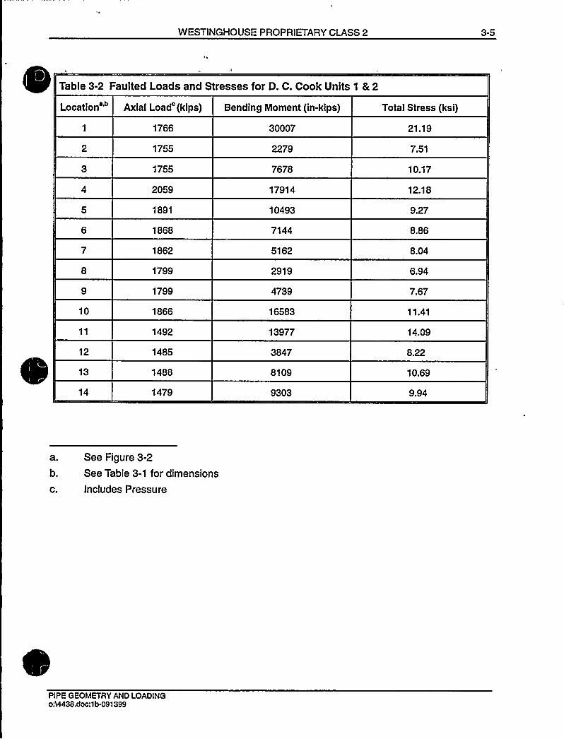
WESTINGHOUSE PROPRIETARY CLASS 2 3-5
Table 3-2 Faulted Loads and Stresses for D. C. Cook Units 1 & 2
Location'0
12
13
14
Axial Load'(kips)
1766
1755
1755
2059
1891
1868
1862
1799
1799
1866
1492
1485
1488
1479
Bending Moment (in-kips)
30007
2279
7678
17914
10493
7144
5162
2919
4739
16583
13977
3847
8109
9303
Total Stress (ksi)
21.19
7.51
10.17
12.18
9.27
8.86
8.04
6.94
7.67
11.41
14.09
8.22
10.69
9.94
a. See Figure 3-2
b. See Table 3-1 for dimensions
c. Includes Pressure
PIPE GEOMETRY AND LOADINGo i4438.doc:1b-091399

3-6 WESTINGHOUSE PROPRIETARY CLASS 2
. ThicknessCrack
ghee g~
+> vs+
.OD
NormalLoads'orce':
1529 kips
Faulted Loads
force': 1766 kips
OD' 34.68 int' 2.74
bending moment: 28495 in-kips bending moment: 30007 in-kips
'ee Table 3-1
See Table 3-3'ncludes the force due to a pressure of 2250 psia
Figure 3-1 Hot Leg Coolant Pipe
PIPE GEOMETRY AND LOADINGo%438.doc:1b-9/13/99

WESTINGHOUSE PROPRIETARY CLASS 2 3-7
ReactorPressureVessel 14
13
HOT LEG
COLD LEG
Steam Generator
Reactor Coolant Pump
CROSSOVER LEG
HOT LEG
Temperature 620'F, Pressure: 2250 psia
CROSSOVER LEG
Temperature 548'F, Pressure: 2250 psia
COLD LEG
Temperature 548'F, Pressure: 2250 psia
Figure 3-2 Schematic Diagram of D. C. Cook Units 1 and 2Primary Loop Showing Weld Locations
PIPE GEOMETRY AND LOADINGo54438.doc:1b-091399

WESTINGHOUSE PROPRIETARY CLASS 2
4.0 MATERIALCHARACTERIZATION
4.1 PRIMARY LOOP PIPE AND FITTINGS MATERIALS
The primary loop pipe and the elbow fittings for the D. C. Cook Units 1 and 2 are A351 CF8M.
4.2 TENSILE PROPERTIES
The Pipe Certified Materials Test Reports (CMTRs) for D. C. Cook Units 1 and 2 were used toestablish the tensile properties for the leak-before-break analyses. The CMTRs include tensileproperties at room temperature and/or at 650'F for each of the heats of material. Theseproperties are given in Table 4-1 for Unit 1 and in Table 4-2 for Unit 2.
The representative properties at 620'F and 548'F were established from the tensile propertiesat 650'F given in Tables 4-1 and 4-2 by utilizing Section III of the 1989 ASME Boiler andPressure Vessel Code (Reference 4-1). Code tensile properties at 620'F and 548'F wereobtained by interpolating between the 500'F, 600'F and 650'F tensile properties. Ratios of thecode tensile properties at 620'F and 548'F to the corresponding tensile properties at 650'Fwere then applied to the 650'F tensile properties given in Tables 4-1 and 4-2 to obtain the plantspecific properties for A351 CF8M at 620'F and 548'F.
The average and lower bound yield strengths and ultimate strengths are given in Table 4-3.The ASME Code moduli of elasticity values are also given, and Poisson's ratio was taken as0.3.
For leak-before-break fracture evaluations at the critical locations the true stress-true straincurves for A351 CF8M at 620'F and 548'F must be available. These curves were obtainedusing the Nuclear Systems Materials Handbook (Reference 4-2). The lower bound truestress-true strain curves are given in Figures 4-1 and 4-2.
4.3 FRACTURE TOUGHNESS PROPERTIES
The pre-service fracture toughnesses of cast stainless steels in terms of JI, have been found tobe very high at 600 F. Typical results for a cast material are given in Figure 4-3. JI, isobserved to be over 2500 in-Ibs/in'. However, cast stainless steel is susceptible to thermalaging at the reactor operating temperature, that is, about 290'C (550'F). Thermal aging of caststainless steel results in embrittlement, that is, a decrease in the ductility, impact strength, andfracture toughness, of the material. Depending on the material composition, the Charpy impactenergy of a cast stainless steel component could decrease to a small fraction of its originalvalue after exposure to reactor temperatures during service.
The susceptibility of the material to thermal aging increases with increasing ferrite contents.The molybdenum bearing CF8M shows increased susceptibility to thermal aging.
MATERIALCHARACTERIZATION034438.doc:1b-091399

4-2 WESTINGHOUSE PROPRIETARY CLASS 2
In 1994, the Argonne National Laboratory (ANL) completed an extensive research program inassessing the extent of thermal aging of cast stainless steel materials. The ANL researchprogram measured mechanical properties of cast stainless steel materials after they have beenheated in controlled ovens for long periods of time. ANLcompiled a data base, both from datawithin ANLand from international sources, of about 85 compositions of cast stainless steelexposed to a temperature range of 290-400'C (550-750'F) for up to 58,000 hours (6.5 years).From this data base, ANLdeveloped correlations for estimating the extent of thermal aging ofcast stainless steel (References 4-3 and 4-4).
ANLdeveloped the fracture toughness estimation procedures by correlating data in the database conservatively. After developing the correlations, ANLvalidated the estimation proceduresby comparing the estimated fracture toughness with the measured value for several caststainless steel plant components removed from actual plant service. The ANLproceduresproduced conservative estimates that were about 30 to 50 percent less than actual measuredvalues. The procedure developed by ANLin Reference 4-4 was used to calculate the fracturetoughness values for this analysis. ANLresearch program was sponsored and the procedurewas accepted (Reference 4-5) by the NRC.
[The chemical composition is available from CMTR and is provided in Tables 4-4 and 4-5. TheSchoeffer equation given in ASTM A-800 (Reference 4-6) was used to determine the ferritecontent. The composition ratio used in determining the ferrite is a function of chromium, silicon,molybdenum, columbium, carbon, manganese, and nitrogen. The equation given in ASTMA-800 (Reference 4-6) for calculating ferrite is:
CR=0.9+3.38883x10'F-5.58175x10 F +4.22861 x10F'here
CR is the composition ratio as given by: CR = (Cr)J(NI),
(Cr), = Cr+ 1.5 Si+ 1.4 Mo + Cb -4.99 = chromium equivalent
(Ni), = Ni + 30C + 0.5 Mn + 26 (N-0.02) + 2.77 = nickel equivalent
where the elements are in percent weight and F (or 5c) is ferrite in percent volume.
(4-1)
(4-2)
(4-3)
The following equations are taken from Reference 4-4.
The saturation room temperature (RT) impact energy of cast stainless steel was determinedfrom the chemical composition available from CMTR and provided in Tables 4-4 and 4-5.
For CF 8M steel with (10% Ni the saturation value of RT impact energy C, (J/cm') is thelower value determined from
log 19C„ I = 1.10+ 2.12 exp (-0.041 Q)
MATERIALCHARACTERIZATION054438.doc:1b-9/13/99

WESTINGHOUSE PROPRIETARY CLASS 2 4-3
[where the material parameter I|I is expressed as
c~
~
~ 2
~
~ ~
~ IIIII = 5, (Ni+ Si+ Mn)'C+ 0.4N)/5; (4-5)
and from
log IpC~I = 7.28 - 0.011 Bc - 0.1 85CI' 0.369MO - 0.451 Sl
-0.007Ni - 4.71 (C + 0.4N) (4-6)
For CF 8M steel with >10% Ni, the saturation value of RT impact energy C„, (J/cm') is thelower value determined from
log1pC I = 1.10+ 2.64 exp (-0.064ItI)
where the material parameter ItI is expressed as
I|I = 5, (Ni + Si + Mn)'C + 0.4N)/5
and from
(4-7)
(4-8)
logIpCygg 7.28 - 0.01 1 5, - 0.1 85Cr - 0.369Mo - 0.451 Si
-0.007Ni - 4.71(C + 0.4N)
The saturation J-R curve at 290'C (554'F), for static-cast CF 8M steel is given by
(4-9)
Jd = 49 [C„~I]'
[da]" (4-10)
and for centrifugally cast CF 8M steel, by
Jd = 57 [C„ t] 'b,a]"
where the exponent n is expressed as
n = 0.23+ 0.06 log 1p [C„ t]
(4-11)
(4-12)
where Jd is the "deformation J" in kJ/M'nd ha is the crack extension in mm.
For the D. C. Cook primary loop equation 4-10 was used conservatively to calculate the J valuefor both pipes and elbows. The crack extension for "Jd" at initiation was calculated using theASTM E813-85 procedures, "Jd" at initiation (JIc) was defined on the 0.2mm offset line. Thechemical composition and fracture toughness values calculated for D. C. Units 1 and 2 primaryloop piping systems are given in Table 4-4 and 4-5. JIc values are converted to in-lb/in'ndshown in Tables 4-4 and 4-5.]
"'ATERIAL
CHARACTERIZATIONo:VI438.dpc:1b-091399
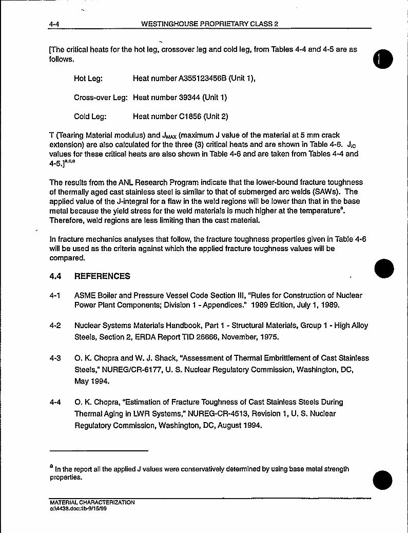
4-4 WESTINGMOUSE PROPRIETARY CLASS 2
P he critical heats for the hot leg, crossover leg and cold leg, from Tables 4-4 and 4-5 are asfollows.
Hot Leg: Heat number A355123456B (Unit 1),
Cross-over Leg: Heat number 39344 (Unit 1)
Cold Leg: Heat number C1 856 (Unit 2)
T (Tearing Material modulus) and JMAX (maximum J value of the material at 5 mm crackextension) are also calculated for the three (3) critical heats and are shown in Table 4-6. JIcvalues for these critical heats are also shown in Table 4-6 and are taken from Tables 4-4 and4 5 ~a,c,e
The results from the ANLResearch Program indicate that the lower-bound fracture toughnessof thermally aged cast stainless steel is similar to that of submerged arc welds (SAWs). Theapplied value of the J-integral for a flaw in the weld regions will be lower than that in the basemetal because the yield stress for the weld materials is much higher at the temperature'.Therefore, weld regions are less limiting than the cast material.
In fracture mechanics analyses that follow, the fracture toughness properties given in Table'4-6will be used as the criteria against which the applied fracture toughness values will becompared.
4.4 REFERENCES
4-1 ASME Boiler and Pressure Vessel Code Section III, "Rules for Construction of NuclearPower Plant Components; Division 1 - Appendices." 1989 Edition, July 1, 1989.
4-2 Nuclear Systems Materials Handbook, Part 1 - Structural Materials, Group 1 - High Alloy
Steels, Section 2, ERDA Report TID 26666, November, 1975.
4-3 O. K. Chopra and W. J. Shack, "Assessment of Thermal Embrittlement of Cast Stainless
Steels," NUREGICR-6177, U. S. Nuclear Regulatory Commission, Washington, DC,
May 1994.
4-4 O. K. Chopra, "Estimation of Fracture Toughness of Cast Stainless Steels During
Thermal Aging in LWR Systems," NUREG-CR-4513, Revision 1, U. S. Nuclear
Regulatory Commission, Washington, DC, August 1994.
In the report all the applied J values were conservatively determined by using base metal strengthproperties.
MATERIALCHARACTERIZATIONoA4438.doc:1b-9/15/99
WESTINGHOUSE PROPRIETARY CLASS 2 4-5
I4-5 "Flaw Evaluation of Thermally aged Cast Stainless Steel in Light-Water Reactor
Applications," Lee, S.; Kuo, P. T.; Wichman, K.; Chopra, O.; Published in International
Journal of Pressure Vessel and Piping, June 1997.
4-6 ASTMASOOM-84- Standard Practice for Steel Casting, Austenitic Alloy, Estimating
Ferrite Content Thereof, Section 1 - Iron and Steel Products, Vol. 01.02, Ferrous
Castings; Ferroalloys; Shipbuilding.
MATERIALCHARACTERIZATIONo54438.doc:1b-091599

4-6 WESTINGHOUSE PROPRIETARY CLASS 2
Table 4-1 Measured Tensile Properties for D. C. Cook Unit 1 PrimaryLoop Piping System
At Room Temperature
Heat Number
39405-1
39125-2
36668-3
36806-2
35222-2
35366-2
38929-2
38875-3
34027-2
36106-2
48833-1
49083-2
39344-2
38992-2
35366-2
36348-1
36106-1
36668-2
37034-3
38408-2
38636-3
33975-2
35794-1
Location
X-over Leg
X-over Leg
Cold Leg
X-over Leg
X-over Leg
X-over Leg
X-over Leg
X-over Leg
X-over Leg
X-over Leg
X-over Leg
X-over Leg
X-over Leg
X-over Leg
X-over Leg
X-over Leg
X-over Leg
X-over Leg
Cold Leg
Cold Leg
Cold Leg
X-over Leg
X-over Leg
YIELD
(PSI)
40200
43300
43800
42900
48000
42100
47400
41350
33900
37900
39100
41925
54000
48500
42100
43800
42000
44700
55500
46200
42300
44400
43800
ULTIMATE
(PSI)
79900
85600
85600
87200
87600
84200
89400
83950
73600
76300
81100
86700
95000
86900
84200
81800
83900
85400
96000
86380
84000
86000
86600
MATERIALCHARACTERIZATIONo:8438.doc:1b.9/15/99
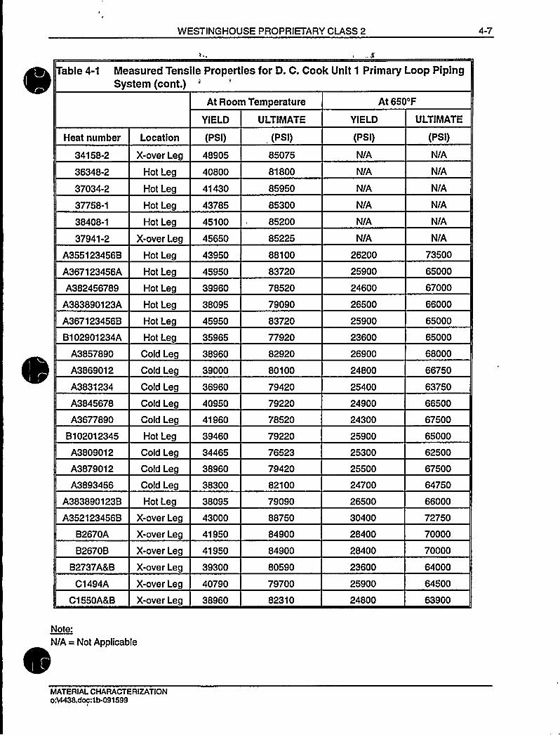
WESTINGHOUSE PROPRIETARY CLASS 2 4-7
able 4-1 Measured Tensile Properties for D. C. Cook Unit 1 Primary Loop PipingSystem (cont.)
At Room Temperature At 650'F
Heat number
34158-2
36348-2
37034-2
37758-1
Location
X-over Leg
Hot Leg
Hot Leg
Hot Leg
YIELD
(PSI)
48905
40800
41430
43785
ULTIMATE
(PSI)
85075
81800
85950
85300
YIELD
(PSI)
N/A
N/A
N/A
N/A
ULTIMATE
(PSI)
N/A
N/A
N/A
N/A
38408-1
37941-2
Hot Leg
X-over Leg 45650 85225
45100 85200 N/A
N/A
N/A
N/A
A355123456B
A367123456A
A382456789
A383890123A
A367123456B
B102901234A
A3857890
A3869012
A3831234
A3845678
A3677890
B102012345
A3809012
A3879012
A3893456
A383890123B
A352123456B
B2670A
B2670B
B2737ALB
C1494A
C1550AKB
Hot Leg
Hot Leg
Hot Leg
Hot Leg
Hot Leg
Hot Leg
Cold Leg
Cold Leg
Cold Leg
Cold Leg
Cold Leg
Hot Leg
Cold Leg
Cold Leg
Cold Leg
Hot Leg
X-over Leg
X-over Leg
X-over Leg
X-over Leg
X-over Leg
X-over Leg
43950
45950
39960
38095
45950
35965
38960
39000
36960
40950
41960
39460
34465
38960
38300
38095
43000
41950
41950
39300
40790
38960
88100
83720
78520
79090
83720
77920
82920
80100
79420
79220
78520
79220
76523
79420
82100
79090
88750
84900
84900
80590
79700
82310
26200
25900
24600
26500
25900
23600
26900
24800
25400
24900
24300
25900
25300
25500
24700
26500
30400
28400
28400
23600
25900
24800
73500
65000
67000
66000
65000
65000
68000
66750
63750
66500
67500
65000
62500
67500
64750
66000
72750
70000
70000
64000
64500
63900
Note:
N/A = Not Applicable
MATERIALCHARACTERIZATIONo VI438.doc:1b-091599

4-8 WESTINGHOUSE PROPRIETARY CLASS 2
Table 4-2 Measured Tensile Properties for D. C. Cook Unit 2 Primary LoopPiping System
At Room Temperature
YIELD ULTIMATE YIELD
At 650'F
ULTIMATE
Heat number
55186
55186
55186
57370
55158
55158
56445
56844
56844
56877
57370
57412
56913
56869
56869
56445
57452
56949
57123
56525
55228
55228
56445
56445
Location
Cold Leg
Cold Leg
Cold Leg
X-over Leg
X-over Leg
X-over Leg
X-over Leg
X-over Leg
X-over Leg
X-over Leg
X-over Leg
X-over Leg
X-over Leg
X-over Leg
X-over Leg
X-over Leg
X-over Leg
X-over Leg
X-over Leg
Hot Leg
Hot Leg
Hot Leg
Hot Leg
Hot Leg
(PSI)
41000
48800
48800
44900
47700
50000
47200
46100
50500
42700
44800
44400
43800
50000
49400
47200
47700
41600
47200
47200
34800
38200
47200
47200
(PSI)
84200
86500
86500
76900
79700
82000
75500
76300
80800
75200
76900
78600
75800
83100
85300
85500
76300
74100
78600
79700
79200
80800
75500
75500
(PSI)
N/A
30900
21500
N/A
N/A
30900
25300
N/A
30300
24700
N/A
28100
24700
N/A
31400
25300
28000
25300
31400
23600
N/A
27000
25300
25300
(PSI)
N/A
65700
55000
N/A
N/A
62900
58400
N/A
63400
59500
N/A
59500
56100
N/A
67400
58400
59500
58400
62900
61200
N/A
64600
58400
58400
Note:
N/A = Not Applicable
MATERIAl CHARACTERIZATIONoM438.doc:1b-9/15/99

WESTINGHOUSE PROPRIETARY CLASS 2 4-9
Table 4-2 Measured Tensile Properties for D. C. Cook Unit 2 Primary LoopPiping System (cont.)'t
Room Temperature At 650'F
Heat number
56525
C2285A&B
C1686A-1 &A-2
C2254
C2145
C1618
C1982C&D
C1913
B1931
B2591
C2110
C1941
C1967A&B
C2092A8 B
C1875A8 B
C1845
C1856
C1881
C1974
Location
Hot Leg
Hot Leg
X-over Leg
Hot Leg
Hot Leg
Hot Leg
Hot Leg
Hot Leg
Cold Leg
Cold Leg
Cold Leg
Cold Leg
X-over Leg
X-over Leg
X-over Leg
Cold Leg
Cold Leg
Cold Leg
Cold Leg
YIELD
(PSI)
47200
40834
40300
42200
39960
31960
39460
42950
37000
48450
39460
40960
43950
37460
41950
39460
48000
42450
37960
ULTIMATE YIELD
(PSI) (PSI)
79700 23600
80519 23800
77750 23400
82500 22700
82010 23300
78920 24400
77922 21400
81618 24800
75800 22300
81918 23200
79920 21500
81420 23300
78220 21400
76523 23900
81610 23300
80920 22000
88250 28300
80910 23600
78420 20900
ULTIMATE
(PSI)
61200
63750
62500
64000
66250
63750
60250
68500
64000
66250
65500
67000
63750
63000
68000
65500
73750
68000
61500
MATERIALCHARACTERIZATIONo%438.doc:1b-091599
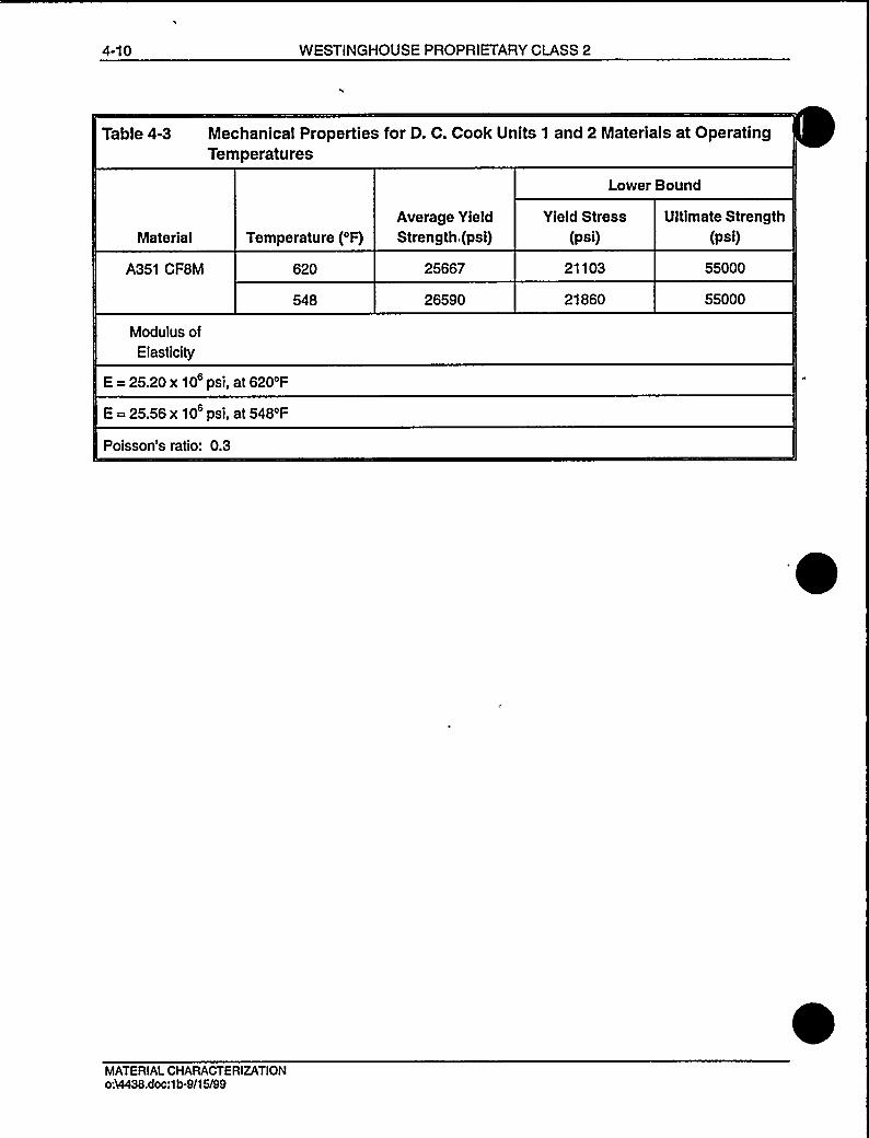
4-10 WESTINGHOUSE PROPRIETARY CLASS 2
Table 4-3 Mechanical Properties for D. C. Cook Units 1 and 2 Materials at OperatingTemperatures
Lower Bound
Material
A351 CF8M
Modulus ofElasticity
Temperature ('F)
620
548
Average Yield
Strength,(psi)
25667
26590
Yield Stress(psi)
21103
21860
Ultimate Strength(psi)
55000
55000
E=25.20x10 psi, at 620'F
E=25.56x10 psi, at 548'F
Poisson's ratio: 0.3
MATERIALCHARACTERIZATION054438.doc:1b-9/15/99

WESTINGHOUSE PR TARYCLASS 2 4-11
able 4-4 Chemistry and Fracture Toughness Properties of the Material Heats of D. C. Cook Unit 1
Heat Number
0/
Nl C Mn Cr Sl
0/
Mo (Cr)e (Ni)e F(=5c) 1Cvsat
2Cvsat
34c
n (in/lbfin~)
35222-2
39344-2
9.57
9.11
0.06
0.06
0.76 20.67 0.62
0.72 20.69 1.41
2.47
2.46
0.04 20.07 15.30
0.04 21.26 14.82
15.74 28.69 56.75
22.92 44.01 28.11
46.44
17.17
46.44 0.33 794
17.17 0.30 550
38992-2 9.30
B102901234A 9.75
'A355123456B 10.06
'A367123456A 9.80
'A382456789 9.40
"A3857890 9.55
A3869012 9.74
"A3845678 10.25
'B1 0201 2345 9.75
"A3893456 9.81
A352123456B 9.86
0.04
0.05
0.06
0.06
0.06
0.04
0.04
0.06
0.05
0.05
0.04
0.52 20.00 0.90
1.02 20.17 0.75
0.93 20.92 0.73
0.68 20.70 0.67
0.72 20.70 0.67
0.83 20.60 0.76
0.91 20.10 0.74
0.96 20.40 0.78
0.96 20.20 0.79
0.98 20.52 0.78
0.09 21.00 0.69
2.40
. 2.62
2.73
2.76
2.80
2.67
2.76
2.62
2.78
2.79
2.70
0.04 19.72 14.31
0.04 19.97 15.31
0.04 20.81 15.88
0.04 20.58 15.61
0.04 20.64 15.11
0.04 20.49 14.72
0.04 20.08 14.94
0.04 20.25 16.08
0.04 20.29 15.28
0.04 20.61 15.35
0.04 20.83 15.06
19.39 24.96 72.78
15.38 26.94 63.45
15.69 32.76 26.57
16.11 30.44 51.11
18.67 33.04 44.37
20.24 28.13 58.75
17.45 25.35 70.74
13.17 28.78 33.00
16.58 28.94 55.86
17.37 30.69 50.38
19.67 24.94 72.86
55.76
49.57
29.66
33.58
30.62
38.70
48.47
41.01
39.76
34.03
34.54
55.76 0.33 849
49.57 0.33 813
26.57 0.32 646
33.58 0.32 704
30.62 0.32 681
38.70 0.33 742
48.47 0.33 806
33.00 0.32 700
39.76 0.33 749
34.03 0.32 708
34.54 0.32 712
B2670A
B2670B
9.86
9.86
0.06
0.06
0.84 20.55 0.80
0.84 20.55 0.80
2.96
2.96
0.04 20.90 15.63
0.04 20.90 15.63
17.10 34.37 41.49
17.10 34.37 41.49
25.71
25.71
25.71 0.31 638
25.71 0.31 638
39405-1 9.31
B2737A&B 9.81 0.06
0.06
0.90 20.27 0.75
0.73 18.36 0.96
2.80
2.03
0.04 20.33 15.61
0.04 17.65 15.03
15.25 30.44 51.11
9.49 17.45 136.91
36.66
149.23
36.66 0.32 727
136.91 0.36 1181
MATERIALCHARACTERIZATIONo:9438.doc:1b-9/I3/99

WESTINGHOUSE PROPRIETARY CLASS 2 4-12
able 4-4 Chemistry and Fracture Toughness Properties of the Material Heats of D. C. Cook Unit 1 (cont.)
Heat Number Ni
0/
C
0/
Mn Cr
0/
Si Mo
0/
N (Cr)e (Ni)e F(=5c) 1Cvait
2Cvset
3C~~t
JIC
n (In/Ibfin')
39125-2
"36668-3
36806-2
35366-2
38929-2
38875-3
34027-2
36106-2
48833-1
49083-2
35366-2
36348-1
36106-1
36668-2
"37034-3
"38408-2
"38636-3
33975-2
9.92
9.42
9.35
9.26
9.71
9.35
9.69
9.65
9.04
9.25
9.26
9.62
9.65
9.42
9.29
9.36
9.57
9.54
0.05 0.63 19.46
0.06 0.63 19.61
0.06 0.68 18.77
0.06 1.12 18.45
0.06 0.91 19.63
0.05 0.70 19.10
0.06 0.74 18.65
0.05 0.62 19.49
0.08 0.92 18.96
0.05 0.63 18.52
0.06 1.12 18.45
0.07 1.10 19.57
0.05 0.62 19.49
0.06 0.63 19.61
0.06 0.70 18.87
0.08 1.18 19.14
0.08 0.84 19.63
0.07 0.92 19.60
0.96
0.90
1.12
0.82
1.31
1.04
0.86
0.94
0.86
1.14
0.82
1.00
0.94
0.90
1.12
1.38
1.24
1.02
2.39 0.04 19.26
2.24 0.04 19.11
2.03 0.04 18.30
2.20 0.04 17.77
2.08 0.04 19.52
2.11 0.04 18.62
2.14 0.04 17.95
2.20 0.04 18.99
2.15 0.04 18.27
2.08 0.04 18.15
2.20 0.04 17.77
2.15 0.04 19.09
2.20 0.04 18.99
2.24 0.04 19.11
2.08 0.04 18.47
2.10 0.04 19.16
2.08 0.04 19.41
2.30 0.04 19.36
15.28
15.09
15.04
15.17
15.52
14.75
15.41
15.01
15.45
14.61
15.17
15.82
15.01
15.09
14.99
15.90
15.94
15.65
13.20 23.08
13.52 24.64
11.26 21.28
9.34 17.81
13.11 28.36
13.33 21.64
9.07 17.57
13.45 22.31
9.80 22.03
12.38 19.85
9.34 17.81
10.82 25.56
13.45 22.31
13.52 24.64
11.94 22.40
10.75 29.33
11.30 29.45
12.16 27.56
83.72
74.46
96.84
132.28
57.91
93.97
135.34
88.99
91.03
109.56
132.28
69.71
88.99
74.46
88.34
54.58
54.19
60.92
69.11
70.32
101.41
144.41
52.48
94.61
133.87
81.71
92.89
114.91
144.41
66.65
81.71
70.32
91.64
50.80
47.67
54.91
69.11
70.32
96.84
132.28
52.48
93.97
133.87
81.71
91.03
109.56
132.28
66.65
81.71
70.32
88.34
50.80
47.67
54.91
0.34 919
0.34 924
0.35 1040
0.36 1167
0.33 830
0.35 1029
0.36 1172
0.34 977
0.35 1017
0.35 1088
0.36 1167
0.34 906
0.34 977
0.34 924
0.35 1005
0.33 820
0.33 801
0.33 844
ALCHARACTERIZATII
.doc: 1 b.091399

WESTINGHOUSE PROo ETARYCLASS 2 4-13
able 4-4 Chemistry and Fracture Toughness Properties of the Material Heats of D. C. Cook Unit 1 (cont.)
Heat Number Nl C Mn
0/
Cr Sj Mo
0/
N (Cr)e (Nl)e F(=5c) 1Cvaat
2CVaat
3Cy~i
JIC
n (ln/Ibiin~)
35794-1
34158-2
'36348-2
'37034-2
'37758-1
'38408-1
37941-2
A383890123A
'A367123456B
"A3831234
"A3677890
"A3809012
"A3879012
'A383890123B
C1494A
C1550A&B
9.49
9.20
9.62
9.29
9.59
9.36
9.57
9.50
9.80
9.90
9.85
9.80
9.61
9.50
9.66
9.80
0.05 0.58 19.98
0.06 0.79 19.22
0.07 1.10 19.57
0.06 0.70 18.87
0.04 0.07 19.31
0.08 1.18 19.14
0.04 0.96 19.80
0.07 0.98 20.00
0.06 0.68 20.70
0.05 0.96 19.57
0.03 1.01 19.35
0.04 0.90 19.55
0.06 0.96 19.80
0.07 0.98 20.00
0.05 0.92 19.99
0.07 0.86 19.65
0.76 2.07
0.88 2.18
1.00 2.15
1.12 2.08
1.08 2.16
1.38 2.10
0.96 2.08
0.75 2.66
0.67 2.76
0.78 2.84
0.76 2.60
0.69 2.66
0.78 2.73
0.75 2.66
0.79 2.57
0.70 2.66
0.04
0.04
0.04
0.04
0.04
0.04
0.04
0.04
0.04
0.04
0.04
0.04
0.04
0.04
0.04
0.04
19.03 14.83 14.31
18.60 14.94 12.50
19.09 15.82 10.82
18.47 14.99 11.94
18.96 14.38 16.13
19.16 15.90 10.75
19.16 14.80 14.89
19.86 15.64 13.67
20.58 15.49 16.62
19.73 15.43 14.09
19.14 14.81 14.79
19.32 15.00 14.55
19.80 15.44 14.28
19.86 15.64 13.67
19.78 15.17 15.36
19.43 15.88 11.56
22.15
22.45
25.56
22.40
20.84
29.33
22.02
29.65
31.41
25.20
18.37
21.14
27.96
29.65
26.21
25.66
90.11 87.58
88.00 91.86
69.71 66.65
88.34 91.64
100.50 82.26
54.58 50.80
91.12 -=83.56
53.53 43.48
48.41 33.15
71.52 53.05
125.36 89.08
97.96 75.53
59.38 47.37
53.53 43.48
66.65 53.68
69.24 55.81
87.58 0.35 1002
88.00 0.35 1004
66.65 0.34 906
88.34 0.35 1005
82.26 0.34 979
50.80 0.33 820-
83.56 0.35 985
43.48 0.33 775
33.15 0.32 701
53.05 0.33 833
89.08 0.35 1009
75.53 0.34 949
47.37 0.33 799
43.48 0.33 775
53.68 0.33 83?
55.81 0.33 849
Heats for the Hot LegHeats for the Cold Leg
All other heats are in cross-over leg.N is assumed as 0.04Cb (Columbium) = 0
'From Equations 4-4 or 4-7'From Equations 4-6 or 4-9'Minimum of Cv~,'nd
CyggI'ATERIAL
CHARACTERIZATIONoh4438.doc:1b-9/13/99

WESTINGHOUSE PROPRIETARY CIASS 2 4-14
Table 4-5 Chemistry and Fracture Toughness Properties of the Material Heats of D. C. Cook Unit 2
HeatNumber NI Mn
0/
Cr
0/
Si
0/
Mo
0/
N (Cr)e (Ni)e F(=5c)1
Cvsat2
Cvsat3
Acn (In/Ib/in~)
C2285A8 B 9.71
57370 10.10
57412 9.33
57452 10.76
'C2254 9.76
'C191 3 9.71
*'B2591 9.66
"C2110 9.91
"C1 941 9.71
C1967A8 B 9.61
55158 9.01
C1875AKB 9.56
"C1 845 9.80
"C1856 9.66
"C1 881 9.66
'C1686A-1 8 9.76A-2
0.05
0.08
0.07
0.07
0.04
0.05
0.05
0.04
0.05
0.05
0.07
0.06
0.05
0.08
0.05
0.05
0.89 20.95 0.72
1.01 20.30 0.83
0.87 20.70 0.90
0.92 20.70 0.95
0.93 20.95 0.73
0.87 20.11 0.78
1.05 20.68 0.73
0.94 20.21 0.77
0.94 20.45 0.72
0.91 20.67 0.80
0.92 20.00 1.14
1.02 20.67 0.76
0.97 20.31 0.84
0.98 20.89 0.90
0.95 20.67 0.72
0.90 19.91 0.73
2.67
2.79
2.75
2.70
2.65
2.75
2.96
2.71
2.65
2.67
2.50
2.75
2.82
2.85
2.77
2.71
0.04 20.78 15.09
0.04 20.46 16.56
0.04 20.91 15.41
0.04 20.92 16.87
0.04 20.77 14.98
0.04 20.14 15.19
0.04 20.93 15.39
0.04 20.17 15.13
0.04 20.25 15.23
0.04 20.62 15.11
0.04 20.22 15.12
0.04 20.67 15.42
0.04 20.53 15.34
0.04 21.24 16.10
0.04 20.64 15.18
0.04 19.81 15.26
19.35 32.73 45.09
12.11 33.15 26.09
18.15 38.46 34.51
12.28 33.69 25.44
19.90 29.07 55.44
16.46 28.04 59.09
18.37 31.73 47.55
16.86 25.50 70.03
16.68 28.46 57.54
18.58 31.43 48.35
17.09 36.02 38.38
17.27 33.76 42.78
17.17 30.55 50.80
16.14 41.27 30.93
18.30 31.01 49.49
15.05 25.77 68.70
31.81
29.15
22.90
25.72
35.17
42.98
28.33
47.35
42.84
33.69
30.71
30.46
34.27
18.22
33.84
52.81
31.81 0.32 690
26.09 0.32 642
22.90 0.31 612
25.44 0.31 636
35.17 0.32 716
42.98 0.33 771
28.33 0.32 662
47.35 0.33 799
42.84 0.33 770
33.69 0.32 705
30.71 0.32 681
30.46 0.32 679
34.27 0.32 710
18.22 0.31 562
33.84 0.32 706
52.81 0.33 832
lALCHARACTEAIZATION.doc:1b-091399

WESTINGHOUSE PRO~ ETARYCLASS 2
able 4-5 Chemistry and Fracture Toughness Properties of the Material Heats of D. C. Cook Unit 2 (cont.)
|Ia,c,e
HeatNumber Ni
0/
C Mn Cr Sl
0/
Mo
0/
N (Cr)e (Nl)e F(=5c) 1Cvsst
2Cvsst
34c
n (In/Ib/jn )
'C2145
'C1618
'C1982C& 0
"B1931
C2092A&B
"C1 974
"55186
'56445'6844
56877
56913
56869
56949
57123
'56525
'55228
9.46 0.06 0.89
9.81 0.06 0.90
9.81 0.06 0.88
9.76 0.07 0.95
9.61 0.07 0.93
10.26 0.06 0.93
9.14 0.05 0.88
10.82 0.08 0.95
9.62 0.06 0.91
10.22 0.06 0.84
10.68 0.08 0.88
10.82 0.07 0.94
10.35 0.07 0.88
10.35 0.07 0.82
9.50 0.08 0.97
9.05 0.06 0.88
19.71
20.03
19.89
19.52
19.89
20.23
19.60
19.68
19.54
19.54
20.05
19.93
18.25
18.25
18.12
18.10
0.75 2.65 0.04
0.69 2.75 0.04
0.71 2.61 0.04
0.69 2.63 0.04
0.72 2.65 0.04
0.78 2.71 0.04
0.90 2.70 0.04
1.13 2.34 0.04
1.08 2.48 0.04
1.11 2.65 0.04
1.00 2.15 0.04
1.01 2.75 0.04
1.23 2.89 0.04
1.16 2.67 0.04
0.99 2.20 0.04
0.86 2.25 0.04
19.56 15.26
19.93 15.61
19.62 15.60
19.25 15.89
19.69 15.72
20.20 16.08
19.74 14.63
19.66 17.24
19.64 15.43
19.93 15.99
19.57 17.07
20.31 16.94
19.15 16.44
18.74 16.41
17.70 15.94
17.55 14.84
14.25 26.69 64.54
13.99 27.64 60.64
13.10 25.88 68.20
11.03 24.66 74.38
12.84 28.00 59.24
13.06 28.44 33.70
17.75 27.94 59.47
8.10 25.88 40.16
13.84 28.36 57.93
12.57 28.30 34.01
8.35 25.29 41.99
10.48 29.39 31.79
9.08 24.25 45.64
8.17 21.36 59.25
6.97 17.58 135.30
9.81 17.36 138.18
54.53 54.53
46.56. 46.56
55.76 55.76
62.01 62.01
48.33 48.33
40.95 33.70
48.05 48.05
44.58 40.16
48.46 48.46
41.58 34.01
51.01 41.99
33.62 31.79
50.72 45.64
67.29 59.25
118.63 118.63
152.82 138.18
0.33
0.33
0.33
0.34
0.33
0.32
0.33
0.33
0.33
0.32
0.33
0.32
0.33
0.34
0.35
0.36
842
794
849
883
805
705
804
752
806
708
765
690
789
868
1121
1185
Heats for the Hot LegHeats for the Cold Leg
Allother heats are in cross-over leg.N is assumed as 0.04Cb (Columbium) = 0
'From Equations 4-4 or 4-7From Equations 4-6 or 4-9
'Minimum of Cv~,'nd
C„~I'ATERIAL
CHARACTERIZATIONo54438.doc:1b-9/13/99

4-16 WESTINGHOUSE PROPRIETARY CLASS 2
Table 4-6 Fracture Toughness Properties for D. C. Cook Units 1 and 2 Primary Loopsfor Leak-Before-Break Evaluation at Critical Locations
Heat No.
A355123456B
39344
C1856
JIc (in-Ibfin )
646
550
562
T~,< (non-dim)
52
41
42
JMAx (in-Ibfin')
1784
1464
1505
Comments
Hot Leg
Cross-over Leg
Cold Leg
MATERIALCHARACTERIZATIONo&438.doc:1b.9/15/99
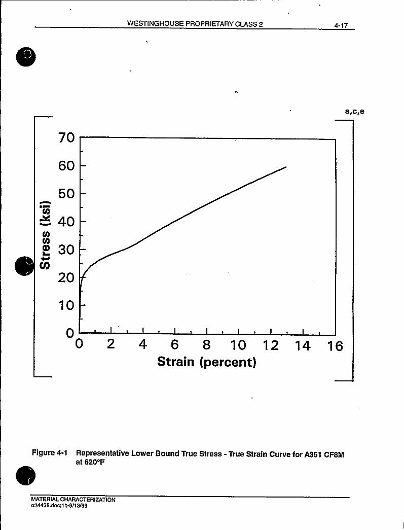
WESTINGHOUSE PROPRIETARY CLASS 2 4-17
a,c,e
60
50
~ 40
I 30V)
20
10
00 2 4 6 8 10 12 14 16
Strain (percent)
Figure 4-1 Representative Lower Bound True Stress - True Strain Curve for A351 CF8Mat 620'F
MATERIALCHARACTERIZATIONoM438.doc:1b.9/13/99

4-18 WESTINGHOUSE PROPRIETARY CLASS 2
a,c,e
70
60
50
~ 40
I 30M
20,
10
00 2 4 6 8 10 12 14 16
Strain (percent)
Figure 4-2 Representative Lower Bound True Stress - True Strain Curve for A351 CFSMat 548'F
MATERIALCHARACTERIZATIONo:I4438.doc:1 b-091399

WESTINGHOUSE PROPRIETARY CLASS 2 4-19
16,000 a,c,e
12,OOO
BLUNTINGLINE
B,ooo
J ~ 5200 $ n-1bi)nIcT ~ 600'F
4,000
.2 .4Crack Extens)on, aa ($ n.)
Figure 4-3 Pre-Service J vs. d a for SA351 CFSM Cast Stainless Steel at 600 F
MATERIALCHARACTERIZATIONoA4438.doc:1b-9/13/99
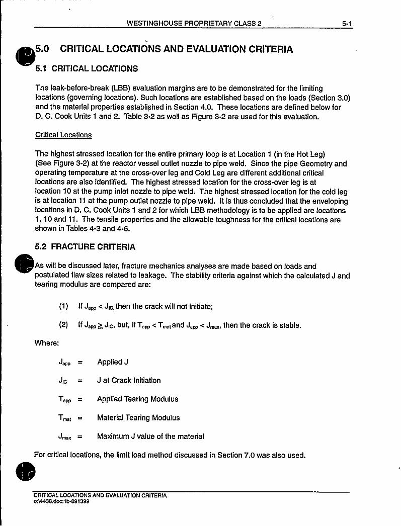
WESTINGHOUSE PROPRIETARY CLASS 2 5-1
6.0 CRITICALLOCATIONS AND EVALUATIONCRITERIA
5.1 CRITICALLOCATIONS
The leak-before-break (LBB) evaluation margins are to be demonstrated for the limitinglocations (governing locations). Such locations are established based on the loads (Section 3.0)and the material properties established in Section 4.0. These locations are defined below forD. C. Cook Units 1 and 2. Table 3-2 as well as Figure 3-2 are used for this evaluation.
Critical Locations
The highest stressed location for the entire primary loop is at Location 1 (in the Hot Leg)(See Figure 3-2) at the reactor vessel outlet nozzle to pipe weld. Since the pipe Geometry andoperating temperature at the cross-over leg and Cold Leg are different additional criticallocations are also identified. The highest stressed location for the cross-over leg is atlocation 10 at the pump inlet nozzle to pipe weld. The highest stressed location for the cold legis at location 11 at the pump outlet nozzle to pipe weld. It is thus concluded that the envelopinglocations in D. C. Cook Units 1 and 2 for which LBB methodology is to be applied are locations1, 10 and 11. The tensile properties and the allowable toughness for the critical locations areshown in Tables 4-3 and 4-6.
5.2 FRACTURE CRITERIA
As will be discussed later, fracture mechanics analyses are made based on loads andpostulated flaw sizes related to leakage. The stability criteria against which the calculated J andtearing modulus are compared are:
(1 ) If J pp ( Jic then the crack will not initiate;
(2) If J pp ) Jic but, ifT,pp ( T t and J pp ( J then 'the crack Is stable.
Where:
Japp = Applied J
Jic = J at Crack Initiation
T,~ = Applied Tearing Modulus
T,< = Material Tearing Modulus
J = Maximum J value of the material
For critical locations, the limit load method discussed in Section 7.0 was also used.
CRITICALLOCATIONS AND EVALUATIONCRITERIA054438.doc:1b-091399

WESTINGHOUSE PROPRIETARY CLASS 2
6.0 LEAKRATE PREDICTIONS
6.1 INTRODUCTION
The purpose of this section is to discuss the method which is used to predict the flow throughpostulated through-wall cracks and present the leak rate calculation results for through-wallcircumferential cracks.
6.2 GENERAL CONSIDERATIONS
The flow of hot pressurized water through an opening to a lower back pressure causes flashingwhich can result in choking. For long channels where the ratio of the channel length, L, tohydraulic diameter, DH, (L/DH) is greater than [40, both choking and frictional effects must be
considered. In this situation the flow can be described as being single-phase through thechannel until the local pressure equals the saturation pressure of the fluid. At this point, theflow begins to flash and choking occurs. Pressure losses due to momentum changes will
dominate for L/DH(40. However, for large L/DH values, friction pressure drop willbecomeimportant and must be considered along with the momentum losses due to flashing]"".
6.3 CALCULATIONMETHOD
The basic method used in the leak rate calculations is the method developed by [Fauske(Reference 6-1) for the two-phase choked flow, and then adding to it the additional frictionalpressure loss upstream of the choked exit plane.]""
The flow rate through a crack was calculated in the following manner. Figure 6-1 fromReference 6-1 was used to estimate the critical pressure, Pc, for the primary loop enthalpycondition and an assumed flow. Once Pc was found for a given mass flow, the [stagnationpressure upstream of the choked plane]"" was found from Figure 6-2 (taken fromReference 6-1). For all cases considered, since [L/DH )40, Pc/Po is equal to 0.55.]""Therefore, this method willyield the two-phase pressure drop due to momentum effects asillustrated in Figure 6-3, where Po is the operating pressure. Now using the assumed flow rate,G, the frictional pressure drop can be calculated using
(L/D„-40)G',(6-1)
where the friction factor f is determined using the [Moody diagram.]"'he crack relativeroughness, E, was obtained from fatigue crack data on stainless steel samples. The relative
roughness value used in these calculations was [300 micro-inchesRMS.]"'he
frictional pressure drop using equation 6-1 is then calculated for the assumed flow rate andadded to the [momentum pressure drop calculated using the Fauske model]"'o obtain thetotal pressure drop from the primary system to the atmosphere. That is, for the primary loop
LEAKRATE PREDICTIONSo54438.doc:1b-091399

6-2 WESTINGHOUSE PROPRIETARY CLASS 2
Absolute Pressure - 14.7 = [AP~- (bPt+ AP2~ choked flow)]"'6-2)for a given assumed flow rate G. If the right-hand side of equation 6-2 does not agree with thepressure difference between the primary loop and the atmosphere, then the procedure isrepeated until equation 6-2 is satisfied to within an acceptable tolerance which in turn leads tocorrect flow rate value for a given crack size.
6.4 LEAKRATE CALCULATIONS
Leak rate calculations were made as a function of crack length at the governing locationspreviously identified in Section 5.1. The normal operating loads of Table 3-1 were applied, inthese calculations. The crack opening areas were estimated using the method ofReference 6-2 and the leak rates were calculated using the two-phase flow formulationdescribed above. The average material properties of Section 4.0 (see Table 4-3) were used forthese calculations.
The flaw sizes to yield a leak rate of 10 gpm were calculated at the governing locations and aregiven in Table 6-1. The flaw sizes so determined are called leakage flaw sizes.
In reference 6-3, the D. C. Cook Units 1 and 2 RCS pressure boundary leak detection system-was determined to meet the criteria previously established for leak detection systems (1 gpm infour hours) when utilizing leak-before-break. Thus, to satisfy the margin of 10 on the leak rate,the flaw sizes (leakage flaw sizes) are determined which yield a leak rate of 10 gpm.
6.5 REFERENCES
6-1 [Faust, H. K., "Critical Two-Phase, Steam Water Flows," Proceedings of the HeatTransfer and Fluid Mechanics Institute, Stanford, California, Stanford University Press,1961]"'.
6-2 Tada, H., "The Effects of Shell Corrections on Stress Intensity Factors and the CrackOpening Area of Circumferential and a Longitudinal Through-Crack in a Pipe,"Section II-1, NUREG/CR-3464, September 1983.
6-3 Nuclear Regulatory Commission Docket ¹'s 50-315 and 50-31 6 Letter from Steven A.Varga, Chief Operating Reactor Branch ¹1, Division of Licensing, to Mr. John Dolan,Vice President, Indiana and Michigan Electric Company, dated November 22, 1985.
Leak Rate PredictionsoA4438non.doc:1b-10/28/99
October 1999Revision 1

WESTINGHOUSE PROPRIETARY CLASS 2 6-3
Table 6-t Flaw Sizes Yielding a Leak Rate of 10 gpm at the GoverningLocations
a.c,e
Location Leakage Flaw Size (in)
3.87
10 7.79
7.04
LEAKRATE PREDICTIONS034438.doc:1b-091399
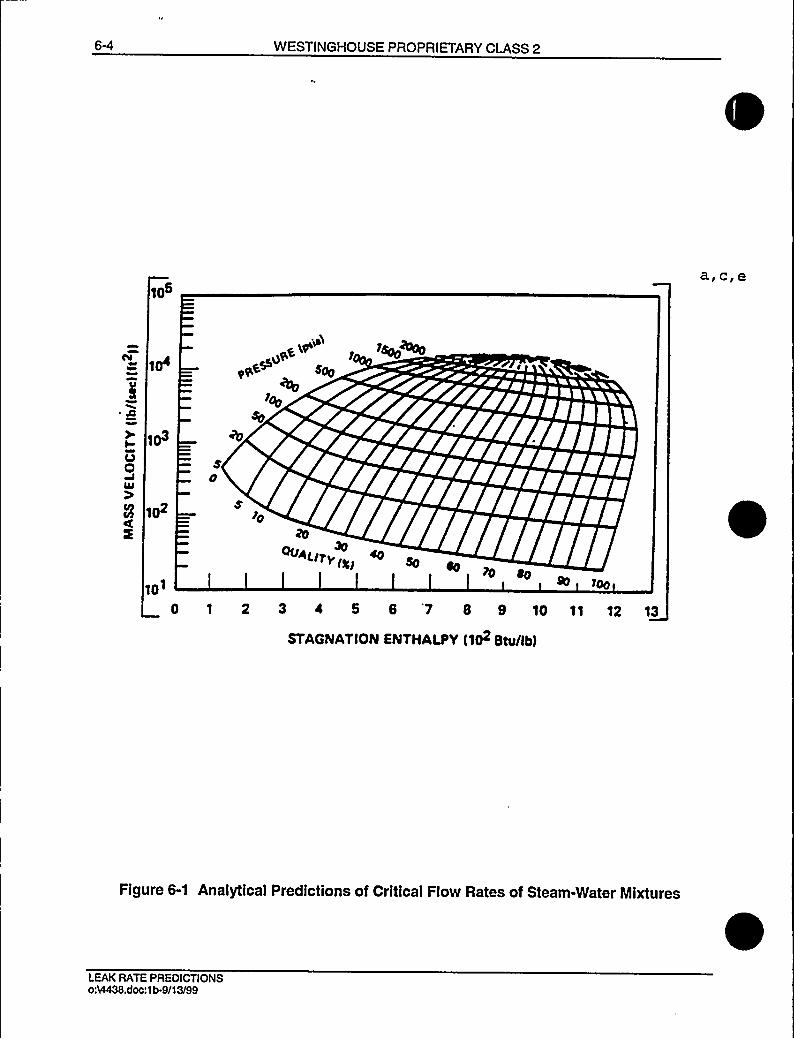
6-4 WESTINGHOUSE PROPRIETARY CLASS 2
105
~ O
I
U0UJ0'
102
u~gw r >(oo ohio
~qS+ Spy
7q
10'0u~(.(rv(
~ s,(gp~o eo
Qy
0 1 2 3 0 5 S 7 8 9 10 11 '12 13
STAGNATION ENTHALPY (102 Btu/Ib)
Figure 6-1 Analytical Predictions of Critical Flow Rates of Steam-Water Mixtures
LEAKRATE PREDICTIONSoA4438.doc:1b-9/13/99

WESTINGHOUSE PROPRIETARY CLASS 2
0.6
OCL
CL
aI
tLLLJ
a
0.5
0.4
0.3
0.2
0.1
LEGENO:
OATA INITIALPRESS., prig
0 LOW(100600)
Q INTERMEO (700-1200)
HIGH (1200 1800)
0.0
0 2 4 6 8 10 12 14 16 18 20
LENGTH/OIAMETERRATIO (L/0)
Figure 6-2 [Criticai or Choked]"'ressure Ratio as a Function of L/D
LEAKRATE PREOICTIONS054438.doc:1b-091399

6-6 WESTINGHOUSE PROPRIETARY CLASS 2
a,c,e
Po
a,c,e
SINGLE PHASEFRICTIONALPRESSURE DROP
Psat
CHOKED 24FLOW PRESSUREDROP
Figure 6-3 Idealized Pressure Drop Profile Through a Postulated Crack
LEAKRATE PREDICTIONS0:9438.doc:1b-9/13/99
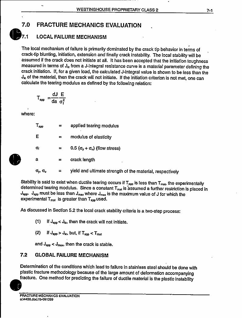
WESTINGHOUSE PROPRIETARY CLASS 2 7-1
7.0 FRACTURE MECHANICS EVALUATION
7.1 LOCALFAILURE MECHANISM
The local mechanism of failure is primarily dominated by the crack tip behavior in terms ofcrack-tip blunting, initiation, extension and finally crack instability. The local stability will beassumed if the crack does not initiate at all. It has been accepted that the initiation toughnessmeasured in terms of JI, from a J-integral resistance curve is a material parameter defining thecrack initiation. If, for a given load, the calculated J-integral value is shown to be less than theJI, of the material, then the crack will not initiate. If the initiation criterion is not met, one cancalculate the tearing modulus as defined by the following relation:
dJ ET
I
where:
aI
ay> au
applied tearing modulus
modulus of elasticity
0.5 (a„+ a„) (flow stress)
crack length
yield and ultimate strength of the material, respectively
Stability is said to exist when ductile tearing occurs if T,~ is less than T 1, the experimentallydetermined tearing modulus. Since a constant T
< is assumed a further restriction is placed inJ~. J,~ must be less than J where J is the maximum value of J for which theexperimental T,1 is greater than T,~used.
As discussed in Section 5.2 the local crack stability criteria is a two-step process:
(1) IfJ~< JI„ then the crack will not initiate.
(2) IfJ~ > JI„but, ifT~ < T~1
and J~ < J, then the crack is stable.
7.2 GLOBALFAILURE MECHANISM
Determination of the conditions which lead to failure in stainless steel should be done withplastic fracture methodology because of the large amount of deformation accompanyingfracture. One method for predicting the failure of ductile material is the plastic instability
FRACTURE MECHANICS EVALUATIONo:VI438.doc:1tH$ 1399
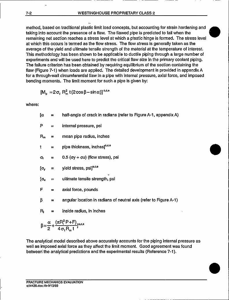
7-2 WESTINGHOUSE PROPRIETARY CLASS 2
method, based on traditional plastic limit load concepts, but accounting for strain hardening andtaking into account the presence of a flaw. The flawed pipe is predicted to fail when theremaining net section reaches a stress level at which a plastic hinge is formed. The stress levelat which this occurs is termed as the flow stress. The flow stress is generally taken as theaverage of the yield and ultimate tensile strength of the material at the temperature of interest.This methodology has been shown to be applicable to ductile piping through a large number ofexperiments and willbe used here to predict the critical flaw size in the primary coolant piping.The failure criterion has been obtained by requiring equilibrium of the section containing theflaw (Figure 7-1) when loads are applied. The detailed development is provided in appendix Afor a through-wall circumferential flaw in a pipe with internal pressure, axial force, and imposedbending moments. The limit moment for such a pipe is given by:
[Mb =2a,R'(2cosp-sinu)]"'here:
[c = half-angle of crack in radians (refer to Figure A-1, appendix A)
P = internal pressure, psi
R = mean pipe radius, inches
t = pipe thickness,inches]"'I
= 0.5 (ay+ au) (flow stress), psi
[a„= yield stress, psi]""
[a„= ultimate tensile strength, psi
F = axial force, pounds
P = angular location in radians of neutral axis (refer to Figure A-1)
RI — inside radius, in inches
u (nRI2P+F) „,2 4aIR t
The analytical model described above accurately accounts for the piping internal pressure aswell as imposed axial force as they affect the limit moment. Good agreement was foundbetween'he analytical predictions and the experimental results (Reference 7-1).
FRACTURE MECHANICS EVAI.UATIONo:VI438.doc:1b-9/13/99
WESTINGHOUSE PROPRIETARY CLASS 2 7-3
For application of the limit load methodology, the material, including consideration of theconfiguration, must have a sufficient ductility and ductile tearing resistance to sustain the limitload.
7.3 RESULTS OF CRACK STABILITYEVALUATION
Stability analyses were performed at the governing locations established in Section 5.1. Theelastic-plastic fracture mechanics (EPFM) J-integral analyses for through-wall circumferentialcracks in a cylinder were performed using the procedure in the EPRI fracture mechanicshandbook (Reference 7-2).
The lower-bound material properties of Section 4.0 were applied (see Table 4-3). The fracturetoughness properties established in Section 4.3 and the normal plus SSE loads given in
Table 3-2 were used for the EPFM calculations. Evaluations were performed at the criticallocations identified in Section 5.1. The results of the elastic-plastic fracture mechanicsJ-integral evaluations are given in Table 7-1.
A stability analysis based on limit load was performed for these locations as described inSection 7.2. The welds, at these locations, are assumed conservatively as GTAW and SMAWcombination weld. The "Z" factor correction for SMAW was applied (Reference 7-3) as follows:
Z = 1.15 [1.0 + 0.013 (OD-4)]
where OD is the outer„diameter of the pipe in inches.
The Z-factors were calculated for the critical locations, using the dimensions given in Table 3-1.TheZfactorwas1.61 forlocation1. TheZfactorwas1.65for location10. TheZfactorwas1.58 for location 11. The applied loads were increased by the Z factors and plots of limit loadversus crack length were generated as shown in Figures 7-2, 7-3 and 7-4. Table 7-2summarizes the results of the stability analyses based on limit load. The leakage flaw sizes arealso presented on the same table.
7A REFERENCES
7-1 Kanninen, M. F., et. al., "Mechanical Fracture Predictions for Sensitized Stainless SteelPiping with Circumferential Cracks," EPRI NP-192, September 1976.
7-2 Kumar, V., German, M. D. and Shih, C. P., "An Engineering Approach for Elastic-PlasticFracture Analysis," EPRI Report NP-1931, Project 1237-1, Electric Power ResearchInstitute, July 1981.
7-3 Standard Review Plan; Public Comment Solicited; 3.6.3 Leak-Before-Break EvaluationProcedures; Federal Register/Vol. 52, No. 167/Friday, August 28, 1987/Notices,pp. 32626-32633.
FRACTURE MECHANICS EVALUATIONo%438.doc:1b-091399

7-4 WESTINGHOUSE PROPRIETARY CLASS 2
Table 7-1 Stability Results for D. C. Cook Units 1 and 2 Based onElastic-Plastic J-Integral Evaluations
Fracture CriteriaCalculated
Values
Location
10
Flaw Size
(in)
7.74
15.58
14.08
J/c (in-Ib/In )
646
550
562
52
41
42
JMAX (In-Ib/In'
1784
1464
1505
J~pp
(in-Ib/in )
474
188
305
Note: T~~ is not applicable since J~ < Jfc
Table 7-2 Stability Results for D. C. Cook Units 1 and 2 Based on LimitLoad
a,c,e
Location
10
Critical Flaw Size (in)
19.60
36.66
28.83
Leakage Flaw Size
3.87
7.79
7.04
FRACTURE MECHANICS EVALUATIONoM438.doc:1b-9/1 3/99

WESTINGHOUSE PROPRIETARY CLASS 2 7-5
2Q
Neutral Axis
Figure 7-1 [Fully Plastic]"'tress Distribution
FRACTURE MECHANICS EVALUATIONo34438.doc:1b-091399

7-6 WESTINGHOUSE PROPRIETARY CLASS 2
80,000
a,c,e
70,000CL~ eo,ooo~~~ 50,000
LLl 4O,OOO
0~ 30,000
—20,000
10,000
(19.60,48270)
010 20 30
FLAW LENGTH (inchesj40
OD = 34.68 in. Gy = 21.10 ksi F = 1766.0 kips
t = 2.74 in. 0 u = 55.00 ksi M.= 30007 in-kips
A351-CF8M with SMAW weld
Figure 7-2 Critical Flaw Size Prediction - Hot Leg at Location 1
FRACTURE MECHANICS EVAI.UATIONo54438.doc:1b-9/13I99
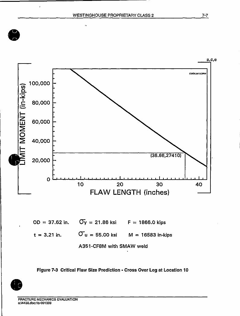
WESTINGHOUSE PROPRIETARY CLASS 2 7-7
a,c,e
100,000CL
80,000
60,000
O4o,ooo
f-
20,000(36.66,2741 0)
10 20 30
FLAW LENGTH (inches)
OD = 37.62in. Oy = 21.86ksi F = 1866.0kips
t = 3.21 in. 0 u = 55.00 ksi M = 16583 in-kips
A351-CF8M with SMAW weld
Figure 7-3 Critical Flaw Size Prediction - Cross Over Leg at Location 10
FRACTURE MECHANICS EVALUATIONo34438.doc:1b-091399
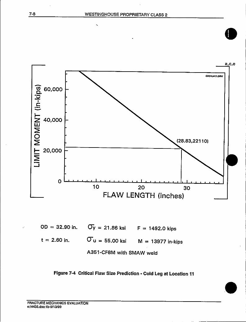
7-8 WESTINGHOUSE PROPRIETARY CLASS 2
~+ 60,000
IC
~~I-Z 40,000LLI
0I- 20,000
(28.83,221 10)
010 20 30
FLAW LENGTH (inches)
OD = 32.90 in. Gy = 21.86 ksi F = 1492.0 kips
t = 2.60 in. 0 u = 55.00 ksi M = 13977 in-kips
A351-CF8M with SMAW weld
Figure 7-4 Critical Flaw Size Prediction - Cold Leg at Location 11
FRACTURE MECHANICS EVALUATIONoA4438.doc:1b-9/13/99

WESTINGHOUSE PROPRIETARY CLASS 2 8-1
8.0 FATIGUE CRACK GROWTH ANALYSIS
To determine the sensitivity of the primary coolant system to the presence of small cracks, afatigue crack growth analysis was carried out for the [vessel inlet nozzle safe-end]"" region ofa typical system (see Location [14]"'fFigure 3-2). This region was selected because crackgrowth calculated here will be typical of that in the entire primary loop. Crack growthscalculated at other locations can be expected to show less than 10% variation.
A [finite element stress analysis was carried out for the inlet nozzle safe end region]"'f aplant typical in geometry and operational characteristics to any Westinghouse PWR System.[The specific system was a plant with piping outside diameter 33 inches in diameter, and2.75 inches wall thickness. The corresponding dimensions for D. C. Cook Units 1 and 2 are33.56 inches in diameter and 2.93 inches wall thickness. These differences are insignificant asfar as fatigue crack growth analysis is concerned.]"'ll normal, upset, and test conditionswere considered. A summary of generic applied transients is provided in Table 8-1.Circumferentially oriented surface flaws were postulated in the region, assuming the flaw waslocated in three different locations, as shown in Figure 8-1. Specifically, these were:
Cross Section A:[Inconel]"'ross
Section B: [SA 508 Cl. 2 or 3 LowAlloySteel]"'ross
Section C: [Stainless Steel]""
Fatigue crack growth rate laws were used [from the ASME Code Section XI for the carbonsteel, shown in Figure 8-2, and developed from the literature for the other two materials. Thelaws were all structured for applicability to pressurized water reactor environments.]"'he lawfor stainless steel was derived from Reference 8-1, a compilation of data for austenitic stainlesssteel in a PWR water environment was presented in Reference 8-4, and it was found that theeffect of the environment on the crack growth rate was very small. From this information it wasestimated that the environmental factor should be conservatively set at [2.0]"'n the crackgrowth rate equation from Reference 8-1.
For stainless steel, the fatigue crack growth formula is:
[da/dn = CFSEd,K'here:
C = 2.42x1 0F = frequency factor (F=1.0 for temperature below 800'F)S = R ratio correction (S=1.0 for R=O; S=1+1.8R for 0 ( R ( 0.8, andS = 43.75+57.79 R for R) 0.8)E = environmental factor (E=2.0 for PWR environment, E=1.0 for air)hK = range of stress intensity factor, in psilinR = KmilK x
da/dn = crack growth rate inmicro-inches/cycle]"'ATIGUE
CRACK GROWTH ANALYSIS0:VI438.doc:1b491399

8-2 WESTINGHOUSE PROPRIETARY CLASS 2
[The fatigue crack growth rate for Inconel 600 in a water environment was derived from acollection of data from two different sources. A relatively large body of data is available forinconel 600 in an air environment of 600'F (Reference 8-2) and these data were used toestablish the slope of the reference curve, as shown in Figure 8-3. The environmentalenhancement of crack growth for this material is characterized by the data available inReference 8-3, and these points were used to set the location of the water curve at a growthrate of approximately a factor of five above the air curve. The resulting equation is:]"'
[—=(2.23x10 )K„'''
dn
where: [+II=hK/(1.0-0.5R)]"'he
unit for crack growth rate da/dn is in equation is inches per cycle, and the unitfor K,II is ksiIin
where: dK is the stress intensity factor range.
The calculated fatigue crack growth for semi-elliptic surface flaws of circumferential orientationand various depths is summarized in Table 8-2, and shows that the crack growth is very small,[regardless of which material is assumed.]""
8.'t REFERENCES
8-1 James, L. A. and Jones, D. P., "Fatigue Crack Growth Correlations for AusteniticStainless Steel in Air, Predictive Capabilities in Environmentally Assisted Cracking,"ASME publication PVP-99, December 1985.
8-2 [James, L. A., "Fatigue Crack Propagation Behavior of Inconel 600," in HanfordEngineering Development Labs Report HEDL-TME-76-43, May
1976.]"'-3
[Hale, D. A., et al., "Fatigue Crack Growth in Piping and RPV Steels in Simulated BWRWater Environment," Report GEAP 24098/NUREG CR-0390, Jan.
1978.]"'-4
Bamford, W. H., "Fatigue Crack Growth of Stainless Steel Piping in a Pressurized WaterReactor Environment," Trans. ASME Journal of Pressure Vessel Technology, Vol. 101,Feb. 1979.
FATIGUE CRACK GROWTH ANALYSISoA4438.doc:1b-9/13/99
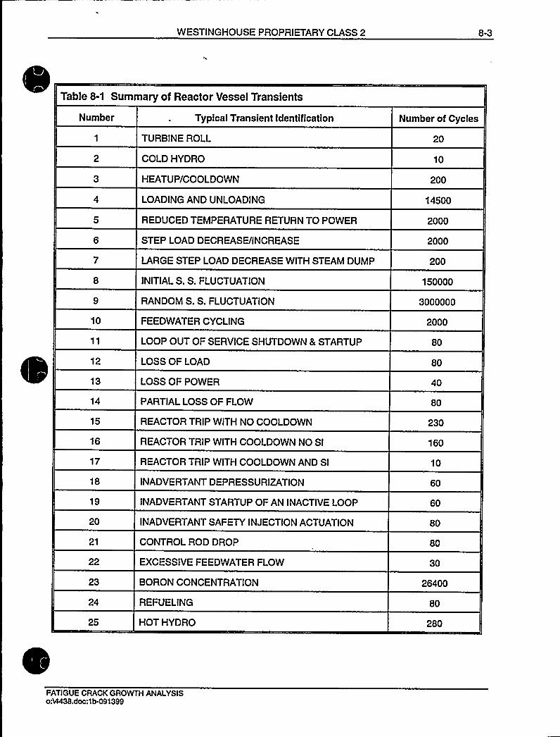
WESTINGHOUSE PROPRIETARY CLASS 2 8-3
Table 8-1 Summary of Reactor Vessel Transients
Number Typical Transient Identification Number of Cycles
1 TURBINE ROLL
COLD HYDRO
3 HEATUP/COOLDOWN
4 LOADINGAND UNLOADING
5 REDUCED TEMPERATURE RETURN TO POWER
6 STEP LOAD DECREASE/INCREASE
7 LARGE STEP LOAD DECREASE WITH STEAM DUMP
8 INITIALS. S. FLUCTUATION
9 RANDOM S. S. FLUCTUATION
20
10
200
14500
2000
2000
200
150000
3000000
10
12
13
14
15
16
17
18
19
20
21
22
23
24
25
FEEDWATER CYCLING
LOOP OUT OF SERVICE SHUTDOWN & STARTUP
LOSS OF LOAD
LOSS OF POWER
PARTIALLOSS OF FLOW
REACTOR TRIP WITH NO COOLDOWN
REACTOR TRIP WITH COOLDOWN NO SI
REACTOR TRIP WITH COOLDOWN AND SI
INADVERTANTDEPRESSURIZATION
INADVERTANTSTARTUP OF AN INACTIVELOOP
INADVERTANTSAFETY INJECTION ACTUATION
CONTROL ROD DROP
EXCESSIVE FEEDWATER FLOW
BORON CONCENTRATION
REFUELING
HOT HYDRO
2000
80
80
40
80
230
160
10
60
60
80
80
30
26400
80
280
FATIGUE CRACK GROWTH ANALYSIS0%438.doc:1b-091399

8-4 WESTINGHOUSE PROPRIETARY CLASS 2
Table 8-2 Typical Fatigue Crack Growth at [Nozzle Safe-End Region]"'40 years)
FINALFLAW (in.)
Initial Flaw (in.)
0.292
0.300
0.375
0.425
[FerriticSteel]"'.3120
0.3207
0.4020
0.4568
[Stainless]"'.2977
0.3057
0.3825
0.4336
f(nconel]"'.2973
0.3056
0.3833
0.4353
FATIGUE CRACK GROWTH ANALYSIS054438.doc:1b 9/13/99

WESTINGHOUSE PROPRIETARY CLASS 2 8-5
STAINLESS STEELFORGING
INCONELWELD
STAINLESS STEELFIELD WELD
SA508 CL.2or3 APPROX.8-12 in.
2.93 in
IIIIII
13.8IIIII
5 in.
STAINLESS STEELCLADDING
NOZZLE AXIS
CROSS-SECTION CCROSS-SECT(ON B
CROSS-SECTION A
Dimensions in inches
Figure 8-1 Typical Cross-Section of [RPV Inlet Nozzle
Safe-End]"'ATIGUE
CRACK GROWTH ANALYSISo54438.doc:1b.091399

~ ~ ~
~ '~ ~ ~
~ '
~ ~~ ' ~, ~
~ ~ J
~ ~ ~ ~
~ ~
~ ~
~ ~
~ '
~ ~ ~
~ '
~ '~ ~ ~
~ ~ J
~ ~
~ ~
~ ' ~ ~ ~

WESTINGHOUSE PROPRIETARY CLASS 2 8-7
103 B~cie
WATER: —= 2.23 X 10 13 K 6.66dadn eff '
VPg 1040co
XURC
QaIlJI
Kx
< 1O.6
)CCJ
lLV
AIR: FROM JAMES.~40 CPM.R ~0.05SINE WAVE
WATER:FROM HALE ET. AL0 5 CPM. R "-0.06, SINE WAVE
Q 0.3 CPM. R > 0.6. SINE WAVE
1O-6
"eH*A
1-2
20
Ikiign)50 100
Figure 8-3 Reference Fatigue Crack Growth Law for [inconel 600]~" in a WaterEnvironment at 600 F
FATIGUE CRACK GROWTH ANALYSISoM438.doc:1b-091399

WESTINGHOUSE PROPRIETARY CLASS 2 9-1
9.0 ASSESSMENT OF MARGINS
The results of the leak rates of Section 6.4 and the corresponding stability and fracturetoughness evaluations of Sections 7.1, 7.2 and 7.3 are used in performing the assessment ofmargins. Margins are shown in Table 9-1.
In summary, at all the critical locations relative to:
Flaw Size - Using faulted loads obtained by the absolute sum method, a margin of 2 ormore exists between the critical flaw and the flaw having a leak rate of 10 gpm (theleakage flaw),
2. Leak Rate - A margin of 10 exists between the calculated leak rate from the leakageflaw and the leak detection capability of 1 gpm.
3. Loads - At the critical locations the leakage flaw was shown to be stable using thefaulted loads obtained by the absolute sum method (i.e., a flaw twice the leakage flawsize is shown to be stable; hence the leakage flaw size is stable). A margin of 1 onloads using the absolute summation of faulted load combinations is satisfied.
ASSESSMENT OF MARGINSo%438.doc:1b/091399

9-2 WESTINGHOUSE PROPRIETARY CLASS 2
Table 9-1 Leakage Flaw Sizes, Critical Flaw Sizes and Margins forD. C. Cook Units 1 and 2
Location
10
Leakage Flaw Size
3.87 in.
3.87 in.
7.79 in.
7.79 in.
7.04 in.
Critical Flaw Size
19.60'n.
7.74 in.
36.66'n.
15.58'in.
28.83'n.
Margin
5.1'2.0
47
>2.0
4.1
7.04 in. 14.08 in. >2.0
'based on limit load
based on J integral evaluation
ASSESSMENT OF MARGINS0&438.doc:1b-9/13/99
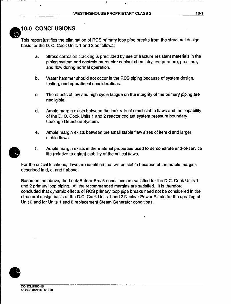
WESTINGHOUSE PROPRIETARY CLASS 2 10-1
10.0 CONCLUSIONS
This report justifies the elimination of RCS primary loop pipe breaks from the structural designbasis for the D. C. Cook Units 1 and 2 as follows:
a. Stress corrosion cracking is precluded by use of fracture resistant materials in the
piping system and controls on reactor coolant chemistry, temperature, pressure,and flow during normal operation.
b. Water hammer should not occur in the RCS piping because of system design,testing, and operational considerations.
c. The effects of low and high cycle fatigue on the integrity of the primary piping arenegligible.
d. Ample margin exists between the leak rate of small stable flaws and the capabilityof the D. C. Cook Units 1 and 2 reactor coolant system pressure boundaryLeakage Detection System.
e. Ample margin exists between the small stable flaw sizes of item d and largerstable flaws.
f. Ample margin exists in the material properties used to demonstrate end-of-servicelife (relative to aging) stability of the critical flaws.
For the critical locations, flaws are identified that will be stable because of the ample marginsdescribed in d, e, and f above.
Based on the above, the Leak-Before-Break conditions are satisfied for the D.C. Cook Units 1
and 2 primary loop piping. AII the recommended margins are satisfied. It is thereforeconcluded that dynamic effects of RCS primary loop pipe breaks need not be considered in thestructural design basis of the D.C. Cook Units 1 and 2 Nuclear Power Plants for the uprating ofUnit 2 and for Units 1 and 2 replacement Steam Generator conditions.
CONCLUSIONSoA4438.doc:1 b-091399

WESTINGHOUSE PROPRIETARY CLASS 2 A-1
APPENDIX A
LIMlTMOMENT
[The internal stress system at the crack plane has to be in equilibrium with the applied loading,i.e., the hydrostatic pressure P, axial force F, and the bending moment Mb. The angle P whichidentifies the point of stress inversion follows from the equilibrium of horizontal forces (SeeFigure A-1). That is:
(—-a+))R taI-(—-p)R ta,= —R, P+F/21I' =K 2
Solving for P,
(x <RI'+F2 4R ta,
The external bending moment at the instant of failure follows from the equilibrium of moments,which is most easily taken around the 1-1 axis. Thus Mb can be determined from
tt Ã-+II —II2 2 2
M, =2a,R —t( fcosgdg f cosgdg)m 0
or
M, =2a, R'(2cosP —
sinu)]"'PPENDIX
A - LIMITMOMENTo64438.doc:1b-091399

A-2 WESTINGHOUSE PROPRIETARY CLASS 2
III
6$
//I
IIIII
I1
1
\
'DI
III
I/I
O IK//
MX
6$
0)
Figure A-1 Pipe with a Through-Wall Crack in Bending
APPENDIX A- LIMITMOMENTo54438.doc:1b-9/13/99

WESTINGHOUSE NON-PROPRIETARY CLASS 3
WCAP-1 6132Revision 1
Technical Justification forEliminating Large Primary Loop Pipe
Rupture as the Structural Design Basis forthe D. C. Cook Units 1 and 2 Nuclear Power Plants
D. C. BhowmickC. K. Ng
A. T. Paterson
October 1999
Reviewer:. F. Petsche
Approved:S. A. am, Ma erStructural Mechanics Technology
oA4438cvr-non.doc:1b-102799
Westinghouse Electric Company LLCP.O. Box 355
Pittsburgh, PA 15230-0355
1 999 Westinghouse Electric Company LLCAll Rights Reserved

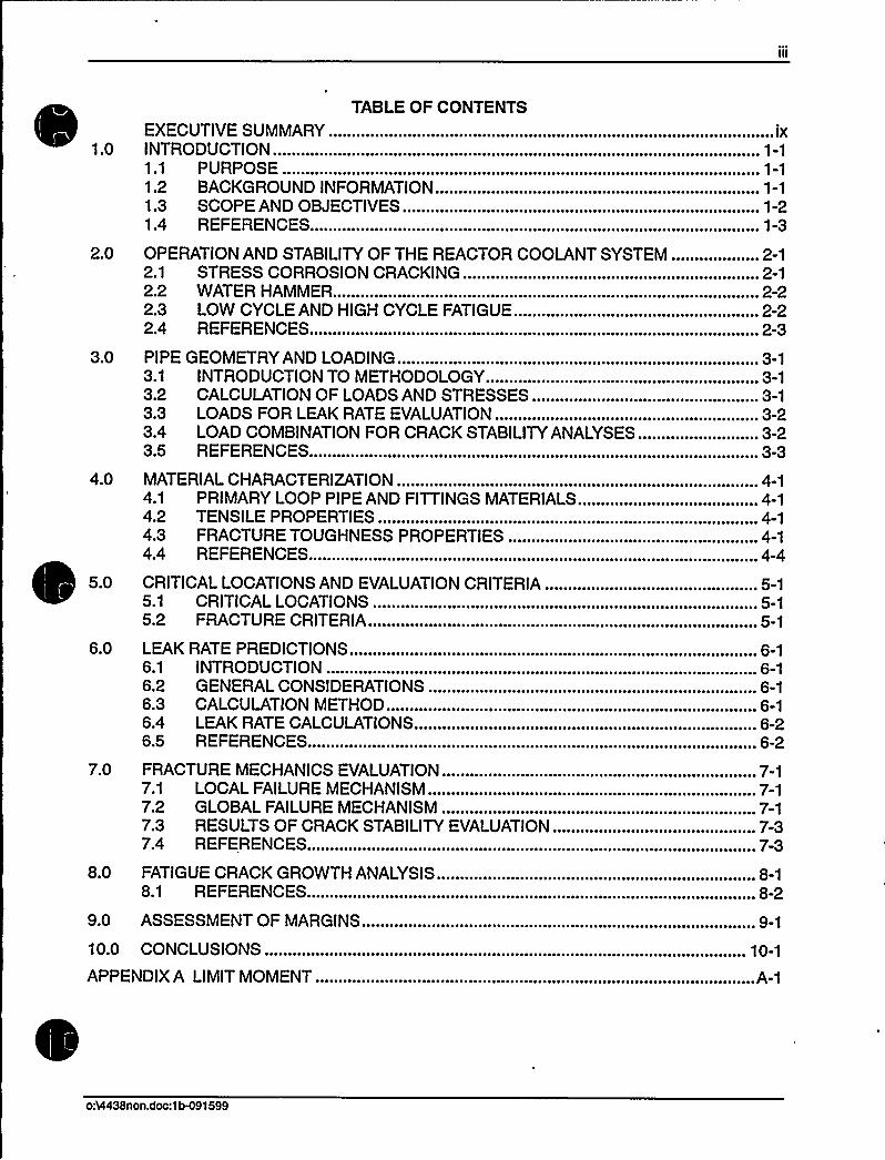
„ TABLE OF CONTENTSEXECUTIVE SUMMARY.INTRODUCTION.........1.1 PURPOSE1.2 BACKGROUND INFORMATION.1.3 SCOPE AND OBJECTIVES1.4 REFERENCES
....... IX
~ \ ~ ~ ~ ~ ~ ~ 0 ~ I ~ ~ ~ ~ 0 ~ ~ ~ ~ ~ ~ ~ ~ ~ ~ ~ ~ ~ ~ ~ ~ ~ ~ ~ ~
. 1-2...... 1-3
2.0 OPERATION AND STABILITYOF THE REACTOR COOLANT SYSTEM ................... 2-12.1 STRESS CORROSION CRACKING...... ~ .... ...,.... 2-1
3.0
4.0
5.0
6.0
7.0
8.0
9.0
10.0
2.2 WATER HAMMER.2.3 LOW CYCLE AND HIGH CYCLE FATIGUE2.4 REFERENCES
PIPE GEOMETRY AND LOADING.3.1 INTRODUCTIONTO METHODOLOGY...........3.2 CALCULATIONOF LOADS AND STRESSES3.3 LOADS FOR LEAK RATE EVALUATION........................... ~ ~
3.4 LOAD COMBINATIONFOR CRACK STABILITYANALYSES3.5 REFERENCES
MATERIALCHARACTERIZATION...~...........4.1 PRIMARY LOOP PIPE AND FITTINGS MATERIALS4.2 TENSILE PROPERTIES4.3 FRACTURE TOUGHNESS PROPERTIES4.4 REFERENCES
CRITICALLOCATIONS AND EVALUATIONCRITERIA.5.1 CRITICALLOCATIONS5.2 FRACTURE CRITERIA....LEAKRATE PREDICTIONS ..6.1 INTRODUCTION6.2 GENERAL CONSIDERATIONS6.3 CALCULATIONMETHOD.6.4 LEAK RATE CALCULATIONS6.5 REFERENCES
FRACTURE MECHANICS EVALUATION.............7.1 LOCAL FAILURE MECHANISM7.2 GLOBALFAILURE MECHANISM .
7.3 RESULTS OF CRACK STABILITYEVALUATION......~....7.4 REFERENCES
FATIGUE CRACK GROWTH ANALYSIS8.1 REFERENCES
ASSESSMENT OF MARGINS......~...~.............~... ~ ..
CONCLUSIONS
2-22-2
. 2-3
............. 3-1...... 3-1
~ ~ 0 ~ ~ 0 ~ OO ~
~ ~ ~ ~ ~ ~ ~ ~ \ ~
. 3-2... ............. 3-3
.. 4-1~ 4-1
........ 4-14-1
. 4-4
... 5-1......... 5-1
.. 5-1
.. 6-1.. ~ ... ~ ... 6-1
6-1~ ~ ~ ~ ~ ~ ~ 0
6-26-2
.. 7-1. . ....... 7-1
~ ~ ~ ~ ~ ~ \ ~ ~ 0 ~ 0 ~ ~ ~ ~ ~
...... 7-37-3
8-1~ ~ ~ ~ ~ ~ ~ ~ ~ ~ \
~ r ~ ~ ~ 9 1
10-1
APPENDIX A LIMITMOMENT...... ~ 0 ~ 0 ~ ~ ~ ~ 0 ~ ~ 0 ~ ~ ~ ~ ~ ~ ~ ~ ~ ~ E ~
oA4438non.doc:1b491599

LIST OF TABLES
Title Page
Table 3-1 Dimensions, Normal Loads and Normal Stresses for D. C. CookUnits 1 and 2 . 3-4
Table 3-2
Table 4-1 Measured Tensile Properties for D. C. Cook Unit 1 Primary LoopPiping Systems ~ ~ ~ ~ ~ ~ ~ ~ ~ ~ ~ ~ ~ ~ ~ ~ ~ ~ ~ ~ ~ ~ ~ ~ ~ ~ ~ ~ ~ ~ ~ ~ ~ ~ ~ ~ ~ ~ ~ ~ ~ 4 6
Faulted Loads and Stresses for D. C. Cook Units 1 and 2. ~ ...... ~ . ~ .. ~ .~......, . 3-5
Table 4-2
Table 4-3
Measured Tensile Properties for D. C. Cook Unit 2 PrimaryLoop Piping System.
Mechanical Properties for D. C. Cook Units 1 and 2 Materials atOperating Temperatures .
. 4-8
. 4-10
Table 4-4 Chemistry and Fracture Toughness Properties of the Material Heats ofD. C. Cook Unit 1... .......4-11
Table 4-5 Chemistry and Fracture Toughness Properties of the MaterialHeats of D. C. Cook Unit 2 . 4-14
Table 4-6
Table 6-1
Fracture Toughness Properties for D. C. Cook Units 1 and 2 PrimaryLoops for Leak-Before-Break Evaluation at Critical Locations.. ~ ~................... 4-16
Flaw Sizes Yielding a Leak Rate of 10 gpm at the Governing Locations .......... 6-3
Table 7-1 Stability Results for D. C. Cook Units 1 and 2 Based on Elastic-PlasticJ-Integral Evaluations 7-4
Table 7-2
Table 8-1
Stability Results for D. C. Cook Units 1 and 2 Based on Limit Load ~....~....~...... 7-4
Summary of Reactor Vessel Transients .~......~...... 8-3
Table 8-2 Typical Fatigue Crack Growth at t ]"'40 years) ...... 8-4
Table 9-1 Leakage Flaw Sizes, Critical Flaw Sizes and Margins forD. C. Cook Units 1 and 2 ..~............ ~ ..~...... ~ ~ ~ ~ ~ ~ ~ ~ 9-2
oh4438non.doc:1b491 599
VII
LIST OF FIGURES
Title Page
3-1
3-2
Hot Leg Coolant Pipe.
Schematic Diagram of D. C. Cook Units 1 and 2 Primary LoopShowing Weld Locations..
~ ~ ~ o ~ ~ ~ ~ ~ ~ o ~ ~ ~ ~ ~ ~ ~ o ~ ~ ~ ~ ~ ~ 3 6
~ 3 7
4-1
4-2
4-3
6-1
Representative Lower Bound True Stress - True Strain Curve for A351CFSM at 620'F ~ oo ~ ~ ~ ~ ~ ~ ~ ~ ~ ~ ~ ~ ~ ooo ~ ~ ~ ~ ~ ooo ~ ~ ~ os 4 1 7
Representative Lower Bound True Stress - True Strain Curve for A351CFSM at 548'F ........................~....................................... . 4-18
Pre-Service J. vs. d,a for SA351 CF8M Cast Stainless Steel at 600'F............... 4-19
Analytical Predictions of Critical Flow Rates of Steam-Water Mixtures ............... 6-4
6-2
6-3
]"'ressure Ration as a Function of UD .
Idealized Pressure Drop Profile Through a Postulated Crack.
~ 6-5
. 6-6
7-1
7-2
]""Stress Distribution........ ~ ..Critical Flaw Size Prediction - Hot Leg at Location 1
~ ~ ~ ~ ~ ~ o ~ ~ ~ ~ ~ ~ ~ 7 5
.. 7-6
Critical Flaw Size Prediction - Cross-over Leg at Location 10. . 7-7
Critical Flaw Size Prediction - Cold Leg at Location 11 ~.... ~ ~............~.... 7-8
8-1
8-2
8-3
Typical Cross-Section of [
Reference Fatigue Crack Growth Curves for []a.c.e
Reference Fatigue Crack Growth Law for [Environment at 600'F
]a.c.e
]"'ina Water
. 8-5
8-6
8-7
A-1 Pipe with a Through-Wall Crack in Bending. ~ .. ~ ..~.............................. ~ ~.............. ~ .A-2
OM438non.doc:1b491599
EXECUTIVE SUMMARY
The original structural design basis of the reactor coolant system for the American ElectricPower Company D. C. Cook Units 1 and 2 Nuclear Power Plants required consideration ofdynamic effects resulting from pipe break and that protective measures for such breaks be
incorporated into the design. Subsequent to the original D. C. Cook design, an additionalconcern of asymmetric blowdown loads was raised as described in Unresolved Safety Issue A-2
(Asymmetric Blowdown Loads on the Reactor Coolant System). D. C. Cook Units 1 and 2Nuclear Power Plants were part of the utilities which sponsored Westinghouse to resolve theA-2 issue. Generic analyses by Westinghouse to resolve the A-2 issue were approved by theNRC and documented in Generic Letter 84-04 (Reference 1-2).
The approved Westinghouse Generic Analyses were indicated to be directly applicable toD. C. Cook Units 1 8 2 in NRC letter dated November 22, 1985 (Reference 1-10). In that letter,which addressed removal of the A-2 issue as a license condition for D. C. Cook Unit 2, the NRCstated that:
"...This license amendment is related to the ongoing review for protection against postulatedpipe rupture. On February 1, 1984, the NRC issued Generic Letter 84-04 to all operating PWRlicensees on the subject of "Safety Evaluation of Westinghouse Topical Reports Dealing withElimination of Postulated Pipe Breaks in PWR Primary Main Loops." We have completed ourreview of your Generic Letter 84-04 responses and have found them acceptable...
Generic Letter 84-04 was issued to form a basis for the issuance of partial exemptions toGDC-4. These exemptions would allow licensees to remove or not to install protection againstasymmetric dynamic loads in the primary main coolant loop. Our Safety Evaluation alsoconcludes that our submissions as part of the Westinghouse Owners Group and your letterdated September 10, 1984 would satisfy the requirements of the proposed rule, if adoptedwithout modification...."
Research by the NRC and industry coupled with operating experience determined that safetycould be negatively impacted by placement of pipe whip restraints on certain systems. As aresult, NRC and industry initiatives resulted in demonstrating that Leak-before-break (LBB)criteria can be applied to reactor coolant system piping based on fracture mechanicstechnology and material toughness.
Subsequently, the NRC modified 10CFR50 General Design Criterion 4, and published in the(V~I... ) 0 . i ti I I
.'"M diN i fGDesign Criterion 4 Requirements for Protection Against Dynamic Effects of Postulated PipeRuptures (Reference 1-3)." This change to the rule allows use of leak-before-break technologyfor excluding from the design basis the dynamic effects of postulated ruptures in primarycoolant loop piping in pressurized water reactors (PWRs).
This report demonstrates compliance with LBB technology for the D. C. Cook reactor coolantsystem piping based on a plant specific analysis. The report documents the plant specificgeometry, loading, and material properties used in the fracture mechanics evaluation.
054438non.doc:1b-102799 October 1999Revision 1

include cast stainless steel, fracture toughness considering thermal aging were determined foreach heat of material.
This Report includes the temperature, pressure and loadings generated as a result of theD. C. Cook Unit 2 uprating program and changes in component weight due to Units 1 and 2
replacement Steam Generator conditions.
Based on loading, pipe geometry and fracture toughness considerations, enveloping criticallocations were determined at which leak-before-break crack stability evaluations were made.Through-wall flaw sizes were found which would cause a leak at a rate of ten (10) times theleakage detection system capability of the plant. Large margins for such flaw sizes weredemonstrated against flaw instability. Finally, fatigue crack growth was shown not to be an
issue for the primary loops.
It is concluded that LBB criterion is valid for the stated loading conditions and dynamic effects ofreactor coolant system primary loop pipe breaks need not be considered in the structural designbasis of the D. C. Cook Nuclear Power Plants for the Unit 2 uprating and Units 1 and 2replacement steam generator conditions.
oh4438n on.doc:1b.091599

XI
I REVISION 1 IDENTIFICATION
Revision 1 is to modify first and second paragraphs of executive summary, Section 3.1,Section 6.4 and to add Reference 6.3 and Page xi.
The revisions are identified by vertical lines in the right column.
oA4438non.doc:1b-1 02799 October 1999Revision 1
1-1
1.0 INTRODUCTION
1.1 PURPOSE
This report applies to the D. C. Cook Units 1 and 2 Reactor Coolant System (RCS) primary looppiping. It is intended to demonstrate that for the specific parameters of the D. C. Cook Units 1
and 2 Nuclear Power Plants, RCS primary loop pipe breaks need not be considered in thestructural design basis. The approach taken has been accepted by the Nuclear RegulatoryCommission (NRC) (Reference 1-3).
1.2 BACKGROUND INFORMATION
Westinghouse has performed considerable testing and analysis to demonstrate that RCSprimary loop pipe breaks can be eliminated from the structural design basis of all Westinghouseplants. The concept of eliminating pipe breaks in the RCS primary loop was first presented tothe NRC in 1978 in WCAP-9283 (Reference 1-4). That topical report employed a deterministicfracture mechanics evaluation and a probabilistic analysis to support the elimination of RCSprimary loop pipe breaks. That approach was then used as a means of addressing GenericIssue A-2 and Asymmetric LOCA Loads.
Westinghouse performed additional testing and analysis to justify the elimination of RCSprimary loop pipe breaks. This material was provided to the NRC along with Letter ReportNS-EPR-2519 (Reference 1-5).
The NRC funded research through Lawrence Livermore National Laboratory (LLNL)to addressthis same issue using a probabilistic approach. As part of the LLNLresearch effort,Westinghouse performed extensive evaluations of specific plant loads, material properties,transients, and system geometries to demonstrate that the analysis and testing previouslyperformed by Westinghouse and the research performed by LLNLapplied to all Westinghouseplants (References 1-6 and 1-7). The results from the LLNLstudy were released at a March 28,1983, ACRS Subcommittee meeting. These studies, which are applicable to all Westinghouseplants east of the Rocky Mountains, determined the mean probability of a direct LOCA (RCSprimary loop pipe break) to be 4.4 x 10" per reactor year and the mean probability of anindirect LOCA to be 10'er reactor year. Thus, the results previously obtained byWestinghouse (Reference 1-4) were confirmed by an independent NRC research study.
Based on the studies by Westinghouse, LLNL, the ACRS, and the AIF, the NRC completed asafety review of the Westinghouse reports submitted to address asymmetric blowdown loadsthat result from a number of discrete break locations on the PWR primary systems. The NRCStaff evaluation (Reference 1-2) concludes that an acceptable technical basis has beenprovided so that asymmetric blowdown loads need not be considered for those plants that candemonstrate the applicability of the modeling and conclusions contained in the Westinghouseresponse or can provide an equivalent fracture mechanics demonstration of the primary coolantloop integrity. In a more formal recognition of Leak-Before-Break (LBB) methodologyapplicability for PWRs, the NRC appropriately modified 10 CFR 50, General Design Criterion 4,
INTRODUCTIONoA4438non.doc:1b491399

1-2
"Requirements for Protection Against Dynamic Effects for Postulated Pipe Rupture"(Reference 1-3).
1.3 SCOPE AND OBJECTIVES
The general purpose of this investigation is to demonstrate leak-before-break for the primaryloops in D. C. Cook Units 1 and 2 on a plant specific basis. The recommendations and criteriaproposed in Reference 1-8 are used in this evaluation. These criteria and resulting steps of theevaluation procedure can be briefly summarized as follows:
2.
Calculate the applied loads. Identify the locations at which the highest stress occurs.
Identify the materials and the associated material properties.
3. Postulate a surface flaw at the governing locations. Determine fatigue crack growth.Show that a through-wall crack will not result.
Postulate a through-wall flaw at the governing locations. The size of the flaw should belarge enough so that the leakage is assured of detection with margin using the installedleak detection equipment when the pipe is subjected to normal operating loads. Amargin of 10 is demonstrated between the calculated leak rate and the leak detectioncapability.
5. Using faulted loads, demonstrate that there is a margin of at least 2 between theleakage flaw size and the critical flaw size.
6. Review the operating history to ascertain that operating experience has indicated noparticular susceptibility to failure from the effects of corrosion, water hammer or low andhigh cycle fatigue.
7. For the materials actually used in the plant provide the properties including toughnessand tensile test data. Evaluate long term effects such as thermal aging.
8. Demonstrate margin on applied load.
This report provides a fracture mechanics demonstration of primary loop integrity for theD. C. Cook Units 1 and 2 Plants consistent with the NRC position for exemption fromconsideration of dynamic effects.
Several computer codes are used in the evaluations. The computer programs are underConfiguration Control which has requirements conforming to NRC's Standard Review Plan 3.9.1
(Reference 1-9). The fracture mechanics calculations are independently verified(benchmarked).
INTRODUCTIONo&438non.doc:1b-9/13/99
1-3
1A REFERENCES
1-1 WCAP-7211, Revision 3, "Energy Systems Business Unit Policy and Procedures forManagement, Classification, and Release of Information," March, 1994.
1-2 USNRC Generic Letter 84-04, Subject: "Safety Evaluation of Westinghouse TopicalReports Dealing with Elimination of Postulated Pipe Breaks in PWR Primary MainLoops," February 1, 1984.
1-3 Nuclear Regulatory Commission, 10 CFR 50, Modification of General Design Criteria 4Requirements for Protection Against Dynamic Effects of Postulated Pipe Ruptures, FinalRule, Federal RegisterNol ~ 52, No. 207/Tuesday, October 27, 1987/Rules andRegulations, pp. 41288-41 295.
1-4 WCAP-9283, "The Integrity of Primary Piping Systems of Westinghouse Nuclear PowerPlants During Postulated Seismic Events," March, 1978.
1-5 Letter Report NS-EPR-2519, Westinghouse (E. P. Rahe) to NRC (D. G. Eisenhut),Westinghouse Proprietary Class 2, November 10, 1981.
1-6 Letter from Westinghouse (E. P. Rahe) to NRC (W. V. Johnston) dated April 25, 1983.
Letter from Westinghouse (E. P. Rahe) to NRC (W. V. Johnston) dated July 25, 1983.
Standard Review Plan: Public Comments Solicited; 3.6.3 Leak-Before-Break EvaluationProcedures; Federal RegisterNol. 52, No. 167/Friday August 28, 1987/Notices,pp. 32626-32633.
1-9 Nuclear Regulatory Commission, Standard Review Plan Section 3.9.1, "Special Topicsfor Mechanical Component," NUREG-0800, Revision 2, July 1981.
1-10 Nuclear Regulatory Commission Docket ¹'s 50-315 and 50-316 Letter fromSteven A. Varga, Chief Operating Reactor Branch ¹1, Division of Licensing, toMr. John Dolan, Vice President, Indiana and Michigan Electric Company, datedNovember 22, 1985.
INTRODUCTIONoA4438non.doc:1b491599

2-1
2.0 OPERATION AND STABILITYOF THE REACTOR COOLANTSYSTEM
2.1 STRESS CORROSION CRACKING
The Westinghouse reactor coolant system primary loops have an operating history thatdemonstrates the inherent operating stability characteristics of the design. This includes a lowsusceptibility to cracking failure from the effects of corrosion (e.g., intergranular stress corrosioncracking (IGSCC)). This operating history totals over 950 reactor-years, including 13 plantseach having over 25 years of operation, 12 other plants each with over 20 years of operationand 8 plants each over 15 years of operation.
In 1978, the United States Nuclear Regulatory Commission (USNRC) formed the second PipeCrack Study Group. (The first Pipe Crack Study Group (PCSG) established in 1975 addressedcracking in boiling water reactors only.) One of the objectives of the second PCSG was toinclude a review of the potential for stress corrosion cracking in Pressurized WaterReactors (PWR's). The results of the study performed by the PCSG were presented inNUREG-0531 (Reference 2-1) entitled "Investigation and Evaluation of Stress CorrosionCracking in Piping of Light Water Reactor Plants." In that report the PCSG stated:
"The PCSG has determined that the potential for stress-corrosion cracking in PWRprimary system piping is extremely low because the ingredients that produce IGSCC arenot all present. The use of hydrazine additives and a hydrogen overpressure limit theoxygen in the coolant to very low levels. Other impurities that might causestress-corrosion cracking, such as halides or caustic, are also rigidly controlled. Only forbrief periods during reactor shutdown when the coolant is exposed to the air and duringthe subsequent startup are conditions even marginally capable of producingstress-corrosion cracking in the primary systems of PWRs. Operating experience inPWRs supports this determination. To date, no stress corrosion cracking has beenreported in the primary piping or safe ends of any PWR."
During 1979, several instances of cracking in PWR feedwater piping led to the establishment ofthe third PCSG. The investigations of the PCSG reported in NUREG-0691 (Reference 2-2)further confirmed that no occurrences of IGSCC have been reported for PWR primary coolantsystems.
As stated above, for the Westinghouse plants there is no history of cracking failure in thereactor coolant system loop. The discussion below further qualifies the PCSG's findings.
For stress corrosion cracking (SCC) to occur in piping, the following three conditions must existsimultaneously: high tensile stresses, susceptible material, and a corrosive environment. Sincesome residual stresses and some degree of material susceptibility exist in any stainless steelpiping, the potential for stress corrosion is minimized by properly selecting a material immune toSCC as well as preventing the occurrence of a corrosive environment. The materialspecifications consider compatibility with the system's operating environment (both internal and
OPERATION AND STABILITYOF THE REACTOR COOLANT SYSTEMoA4438non.doc:1b491399

2-2
external) as well as other material in the system, applicable ASME Code rules, fracturetoughness, welding, fabrication, and processing.
The elements of a water environment known to increase the susceptibility of austenitic stainlesssteel to stress corrosion are: oxygen, fluorides, chlorides, hydroxides, hydrogen peroxide, andreduced forms of sulfur (e.g., sulfides, sulfites, and thionates). Strict pipe cleaning standardsprior to operation and careful control of water chemistry during plant operation are used toprevent the occurrence of a corrosive environment. Prior to being put into service, the piping iscleaned internally and externally. During flushes and preoperational testing, water chemistry iscontrolled in accordance with written specifications. Requirements on chlorides, fluorides,conductivity, and Ph are included in the acceptance criteria for the piping.
During plant operation, the reactor coolant water chemistry is monitored and maintained withinvery specific limits. Contaminant concentrations are kept below the thresholds known to beconducive to stress corrosion cracking with the major water chemistry control standards beingincluded in the plant operating procedures as a condition for plant operation. For example,during normal power operation, oxygen concentration in the RCS is expected to be in the ppbrange by controlling charging flow chemistry and maintaining hydrogen in the reactor coolant atspecified concentrations. Halogen concentrations are also stringently controlled by maintainingconcentrations of chlorides and fluorides within the specified limits. Thus during plantoperation, the likelihood of stress corrosion cracking is minimized.
2.2 WATER HAMMER
Overall, there is a low potential for water hammer in the RCS since it is designed and operatedto preclude the voiding condition in normally filled lines. The reactor coolant system, includingpiping and primary components, is designed for normal, upset, emergency, and faultedcondition transients. The design requirements are conservative relative to both the number oftransients and their severity. Relief valve actuation and the associated hydraulic transientsfollowing valve opening are considered in the system design. Other valve and pump actuationsare relatively slow transients with no significant effect on the system dynamic loads. To ensuredynamic system stability, reactor coolant parameters are stringently controlled. Temperatureduring normal operation is maintained within a narrow range by control rod position; pressure iscontrolled by pressurizer heaters and pressurizer spray also within a narrow range forsteady-state conditions. The flow characteristics of the system remain constant during a fuelcycle because the only governing parameters, namely system resistance and the reactorcoolant pump characteristics, are controlled in the design process. Additionally, Westinghousehas instrumented typical reactor coolant systems to verify the flow and vibration characteristicsof the system. Preoperational testing and operating experience have verified the Westinghouseapproach. The operating transients of the RCS primary piping are such that no significantwater hammer can occur.
2.3 LOW CYCLE AND HIGH CYCLE FATIGUE
Low cycle fatigue considerations are accounted for in the design of the piping system throughthe fatigue usage factor evaluation to show compliance with the rules of Section III of the ASME
OPERATION AND STABILITYOF THE REACTOR COOLANT SYSTEMo&438non.doc:1b-9/13/99

2-3
Code. A further evaluation of the low cycle fatigue loadings was carried out as part of this studyin the form of a fatigue crack growth analysis, as discussed in Section 8.0.
High cycle fatigue loads in the system would result primarily from pump vibrations. These areminimized by restrictions placed on shaft vibrations during hot functional testing and operation.During operation, an alarm signals the exceedence of the vibration limits. Field measurementshave been made on a number of plants during hot functional testing, including plants similar toD. C. Cook Units 1 and 2. Stresses in the elbow below the reactor coolant pump resulting fromsystem vibration have been found to be very small, between 2 and 3 ksi at the highest. Thesestresses are well below the fatigue endurance limit for the material and would also result in anapplied stress intensity factor below the threshold for fatigue crack growth.
2.4 REFERENCES
2-1 Investigation and Evaluation of Stress-Corrosion Cracking in Piping of Light WaterReactor Plants, NUREG-0531, U.S. Nuclear Regulatory Commission, February 1979.
2-2 Investigation and Evaluation of Cracking Incidents in Piping in Pressurized WaterReactors, NUREG-0691, U.S. Nuclear Regulatory Commission, September 1980.
OPERATION AND STABILITYOF THE REACTOR COOLANTSYSTEMo:I4438non.doc:1b491399

3-1
3.0 PIPE GEOMETRY AND LOADING
3.1 INTRODUCTIONTO METHODOLOGY
The general approach is discussed first. As an example a segment of the primary coolant hotleg pipe is shown in Figure 3-1. The as-built outside diameter and minimum wall thickness ofthe pipe are 34.68 in. and 2.74 in., respectively, as shown in the figure. The normal stresses atthe weld locations are from the load combination procedure discussed in Section 3.3 whereasthe faulted loads are as described in Section 3.4. The components for normal loads arepressure, dead weight and thermal expansion. An additional component, Safe ShutdownEarthquake (SSE), is considered for faulted loads. Tables 3-1 and 3-2 show the envelopingloads for D. C. Cook Units 1 and 2. As seen from Table 3-2, the highest stressed location in theentire loop is at Location 1 at the reactor vessel outlet nozzle to pipe weld. This is one of thelocations at which, as an enveloping location, leak-before-break is to be established.Essentially a circumferential flaw is postulated to exist at this location which is subjected to boththe normal loads and faulted loads to assess leakage and stability, respectively. The loads(developed below) at this location are also given in Figure 3-1.
Since the geometry and operating temperature of the cross-over leg and the cold leg aredifferent than the hot leg, locations other than highest stressed location were examined takinginto consideration both fracture toughness and stress. The three most critical locations areidentified after the full analysis is completed. Once loads (this section) and fracture
~
~
~
~
~toughnesses (Section 4.0) are obtained, the critical locations are determined (Section 5.0). Atthese locations, leak rate evaluations (Section 6.0) and fracture mechanics evaluations(Section 7.0) are performed per the guidance of Reference 3-1. Fatigue crack growth(Section 8.0) and stability margins are also evaluated (Section 9.0).
All the weld locations for evaluation are those shown in Figure 3-2.
3.2 CALCULATIONOF LOADS AND STRESSES
The stresses due to axial loads and bending moments are calculated by the following equation:
F M0'=—+-A Z
(3-1)
where,
o = stress
F = axial load
M = bending moment
A = pipe cross-sectional area
Z = section modulus
Pipe Geometry and Loadingo54438 non.doc:1b-102799
October 1999Revision 1
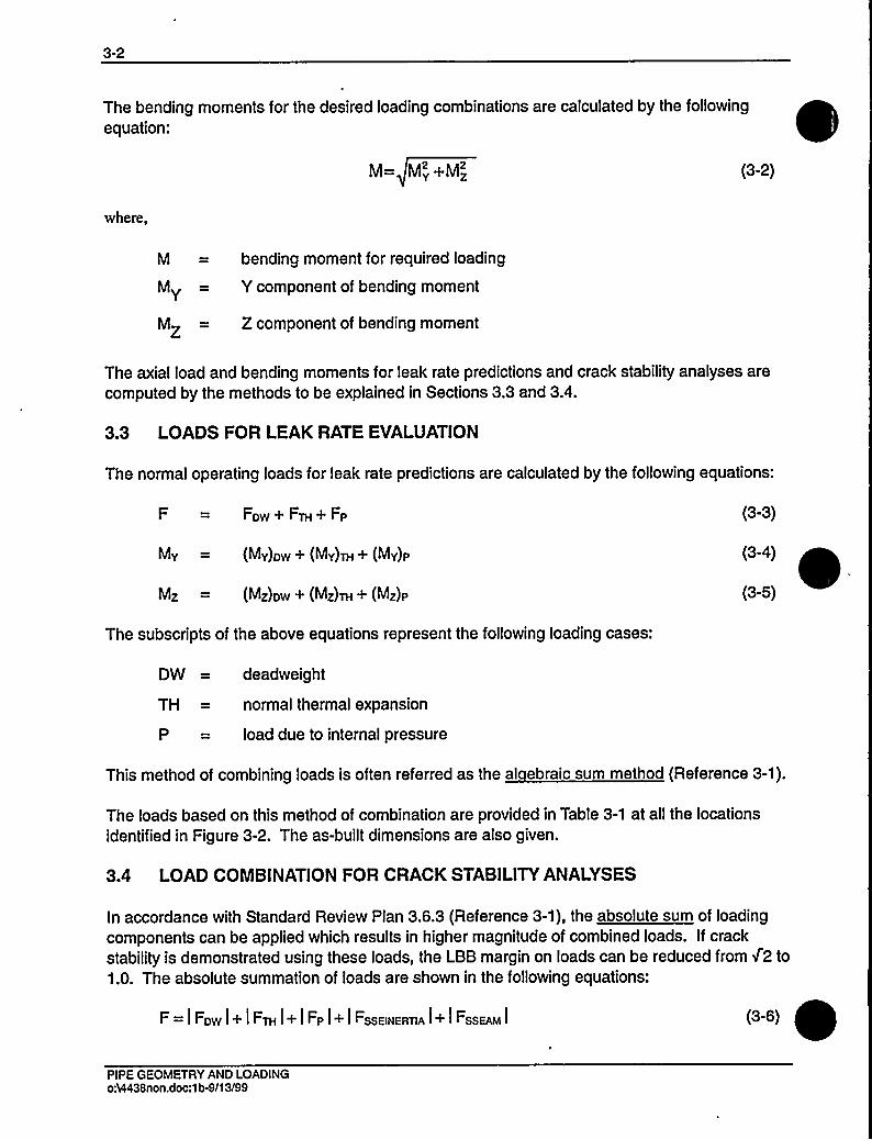
3-2
The bending moments for the desired loading combinations are calculated by the followingequation:
M= My+Mz (3-2)
where,
M = bending moment for required loading
MY— Y component of bending moment
MZ = Z component of bending moment
The axial load and bending moments for leak rate predictions and crack stability analyses arecomputed by the methods to be explained in Sections 3.3 and 3.4.
3.3 LOADS FOR LEAKRATE EVALUATION
The normal operating loads for leak rate predictions are calculated by the following equations:
FDw + FTH+ FP
My = (My)Dw+ (My)TH+ (My)p
Mz = (Mz)ow + (Mz)TH + (Mz)P
(3-3)
(3-4)
(3-5)
The subscripts of the above equations represent the following loading cases:
DW = deadweight
TH = normal thermal expansion
P = load due to internal pressure
This method of combining loads is often referred as the al ebraic sum method (Reference 3-1).
The loads based on this method of combination are provided in Table 3-1 at all the locationsidentified in Figure 3-2. The as-built dimensions are also given.
3.4 LOAD COMBINATIONFOR CRACK STABILITYANALYSES
In accordance with Standard Review Plan 3.6.3 (Reference 3-1), the absolute sum of loadingcomponents can be applied which results in higher magnitude of combined loads. If crackstability is demonstrated using these loads, the LBB margin on loads can be reduced from Z2 to1.0. The absolute summation of loads are shown in the following equations:
F = I Fow I+ I FTH I+ I Fp I+ I FssEINERTIA I+ I FssEAM I (3-6)
PIPE GEOMETRY AND LOADINGo:VI438non.doc:1b-9/13/99

3-3
Mv = 1(Mv)ow I+ I (Mv)TH I + 1(Mv)P I+ I (Mv)ssswERT(A I+ I (Mv)ssEAM I
Mz = I (Mz)ow I+ I (Mz)TH1+ 1(Mz)I I+ I (Mz)ssEIIIERTIA I+ I (Mz)ssEAM I
(3-7)
(3-8)
where subscripts SSE, INERTIAand AM mean safe shutdown earthquake, inertia and anchormotion, respectively.
The loads so determined are used in the fracture mechanics evaluations (Section 7.0) todemonstrate the LBB margins at the locations established to be the governing locations. Theseloads at all the locations of interest (see Figure 3-2) are given in Table 3-2.
3.5 REFERENCES
3-1 Standard Review Plan: Public Comments Solicited; 3.6.3 Leak-Before-Break EvaluationProcedures; Federal Register/Vol. 52, No. 167/Friday, August 28, 1987/Notices,pp. 32626-32633.
PIPE GEOMETRY AND LOADINGoA4438non.doc:1b-091399

3-4
Table 3-1 Dimensions, Normal Loads and Normal Stresses for D. C. Cook Units 1 & 2
Outside DiameterLocation'in)Minimum
Thickness Axial Load Bending Momen(in) (kips) (in-kips) Total Stress (ksi)
10
12
13
14
34.68
34.68
34.68
37.75
37.62
37.04
37.04
37.04
37.04
37.62
32.90
32.90
32.90
33.56
2.74
2.74
2.74
3.27
3.21
2.92
2.92
2.92
2.92
3.21
2.60
2.60
2.60
2.93
1529
1476
1476
1534
1664
1761
1767
1707
1707
1796
1372
1365
1365
1364
28495
1315
6238
14649
4557
3281
3505
1014
2894
7313
5116
934
5106
5536
19.58
6.02
8.44
9.54
6.46
6.96
7.07
5.87
6.63
7.84
8.50
6.06
8.46
7.63
a. See Figure 3-2b. Included Pressure
PIPE GEOMETRY AND LOADINGoA4438non.doc:1b.9/13/99

3-5
Table 3-2 Faulted Loads and Stresses for D. C. Cook Units 1 8 2
Location'xial Load'(kips) Bending Moment (in-kips) Total Stress (ksi)
10
12
13
14
1766
1755
1755
2059
1891
1868
1862
1799
1799
1866
1492
1485
1488
1479
30007
2279
7678
17914
10493
7144
5162
2919
4739
16583
13977
3847
8109
9303
21.19
7.51
10.17
12.18
9.27
8.86
8.04
6.94
7.67
11.41
14.09
8.22
10.69
9.94
a. See Figure 3-2
b. See Table 3-1 for dimensions
c. Includes Pressure
PIPE GEOMETRY AND LOADINGoh4438non.doc:1b491399

3-6
Crack
pic (~
rfTl
.OD
NormalLoads'orce':
1529 kips
bending moment: 28495 in-kips
Faulted Loads
force': 1766 kips
bending moment: 30007 in-kips
OD'= 34 68 in= 2.74
'ee Table 3-1
See Table 3-3'ncludes the force due to a pressure of 2250 psia
Figure 3-1 Hot Leg Coolant Pipe
PIPE GEOMETRY AND LOADINGo54438.doc:1b.9/13/99

3-7
ReactorPressureVessel "4
13
HOT LEG
COLD LEG
Reactor Coolant Pump
Steam Generator
CROSSOVER LEG
HOT LEG
Temperature 620'F, Pressure: 2250 psia10
CROSSOVER LEG
Temperature 548'F, Pressure: 2250 psia
COLD LEG
Temperature 548'F, Pressure: 2250 psia
Figure 3-2 Schematic Diagram of D. C. Cook Units 1 and 2Primary Loop Showing Weld Locations
PIPE GEOMETRY AND LOADING0&438.doc:1b491399
4-1
4.0 MATERIALCHARACTERIZATION
4.1 PRIMARY LOOP PIPE AND FITT INGS MATERIALS
The primary loop pipe and the elbow fittings for the D. C. Cook Units 1 and 2 are A351 CF8M.
4.2 TENSILE PROPERTIES
The Pipe Certified Materials Test Reports (CMTRs) for D. C. Cook Units 1 and 2 were used toestablish the tensile properties for the leak-before-break analyses. The CMTRs include tensileproperties at room temperature and/or at 650'F for each of the heats of material. Theseproperties are given in Table 4-1 for Unit 1 and in Table 4-2 for Unit 2.
The representative properties at 620'F and 548'F were established from the tensile propertiesat 650'F given in Tables 4-1 and 4-2 by utilizing Section III of the 1989 ASME Boiler andPressure Vessel Code (Reference 4-1). Code tensile properties at 620'F and 548'F wereobtained by interpolating between the 500'F, 600'F and 650'F tensile properties. Ratios of thecode tensile properties at 620'F and 548'F to the corresponding tensile properties at 650'Fwere then applied to the 650'F tensile properties given in Tables 4-1 and 4-2 to obtain the plantspecific properties for A351 CF8M at 620'F and 548'F.
The average and lower bound yield strengths and ultimate strengths are given in Table 4-3.
~ ~
The ASME Code moduli of elasticity values are also given, and Poisson's ratio was taken as0.3.
For leak-before-break fracture evaluations at the critical locations the true stress-true straincurves for A351 CF8M at 620'F and 548'F must be available. These curves were obtainedusing the Nuclear Systems Materials Handbook (Reference 4-2). The lower bound truestress-true strain curves are given in Figures 4-1 and 4-2.
4.3 FRACTURE TOUGHNESS PROPERTIES
The pre-service fracture toughnesses of cast stainless steels in terms of JI, have been found tobe very high at 600'F. Typical results for a cast material are given in Figure 4-3. JI, isobserved to be over 2500 in-lbs/in'. However, cast stainless steel is susceptible to thermalaging at the reactor operating temperature, that is, about 290'C (550'F). Thermal aging of caststainless steel results in embrittlement, that is, a decrease in the ductility, impact strength, andfracture toughness, of the material. Depending on the material composition, the Charpy impactenergy of a cast stainless steel component could decrease to a small fraction of its originalvalue after exposure to reactor temperatures during service.
The susceptibility of the material to thermal aging increases with increasing ferrite contents.The molybdenum bearing CF8M shows increased susceptibility to thermal aging.
MATERIALCHARACTERIZATIONoM438non.doc:1b491399

4-2
In 1994, the Argonne National Laboratory (ANL) completed an extensive research program in
assessing the extent of thermal aging of cast stainless steel materials. The ANLresearchprogram measured mechanical properties of cast stainless steel materials after they have beenheated in controlled ovens for long periods of time. ANLcompiled a data base, both from datawithin ANLand from international sources, of about 85 compositions of cast stainless steelexposed to a temperature range of 290-400'C (550-750'F) for up to 58,000 hours (6.5 years).From this data base, ANLdeveloped correlations for estimating the extent of thermal aging ofcast stainless steel (References 4-3 and 4-4).
ANLdeveloped the fracture toughness estimation procedures by correlating data in the database conservatively. After developing the correlations, ANLvalidated the estimation proceduresby comparing the estimated fracture toughness with the measured value for several caststainless steel plant components removed from actual plant service. The ANLproceduresproduced conservative estimates that were about 30 to 50 percent less than actual measuredvalues. The procedure developed by ANL in Reference 4-4 was used to calculate the fracturetoughness values for this analysis. ANL research program was sponsored and the procedurewas accepted (Reference 4-5) by the NRC.
MATERIALCHARACTERIZATIONo:Q438non.doc:1b-9/13/99
4-3
MATERIALCHARACTERIZATIONo&438non.doc:1b%91399

4-4
The results from the ANL Research Program indicate that the lower-bound fracture toughnessof thermally aged cast stainless steel is similar to that of submerged arc welds (SAWs). Theapplied value of the J-integral for a flaw in the weld regions will be lower than that in the basemetal because the yield stress for the weld materials is much higher at the temperature'.Therefore, weld regions are less limiting than the cast material.
In fracture mechanics analyses that follow, the fracture toughness properties given in Table 4-6will be used as the criteria against which the applied fracture toughness values will becompared.
4.4 REFERENCES
4-1 ASME Boiler and Pressure Vessel Code Section III, "Rules for Construction of NuclearPower Plant Components; Division 1 - Appendices." 1989 Edition, July 1, 1989.
4-2 Nuclear Systems Materials Handbook, Part 1 - Structural Materials, Group 1 - High Alloy
Steels, Section 2, ERDA Report TID 26666, November, 1975.
4-3 O. K. Chopra and W. J. Shack, "Assessment of Thermal Embrittlement of Cast Stainless
Steels," NUREG/CR-6177, U. S. Nuclear Regulatory Commission, Washington, DC,
May 1994.
4-4 O. K. Chopra, "Estimation of Fracture Toughness of Cast Stainless Steels During
Thermal Aging in LWR Systems," NUREG-CR-4513, Revision 1, U. S. Nuclear
Regulatory Commission, Washington, DC, August 1994.
In the report all the applied J values were conservatively determined by using base metal strengthproperties.
MATERIALCHARACTERIZATIONoA4438non.doc:1b-9/15/99

4-5
4-5 "Flaw Evaluation of Thermally aged Cast Stainless Steel in Light-Water Reactor
~ ~ ~
~
Applications," Lee, S.; Kuo, P. T.; Wichman, K.; Chopra, O.; Published in International
Journal of Pressure Vessel and Piping, June 1997.
4-6 ASTMA800M-84- Standard Practice for Steel Casting, Austenitic Alloy, Estimating
Ferrite Content Thereof, Section 1 - Iron and Steel Products, Vol. 01.02, Ferrous
Castings; Ferroalloys; Shipbuilding.
MATERIALCHARACTERIZATIONoA4438non.doc:1b491599

4-6
Table 4-1 Measured Tensile Properties for D. C. Cook Unit 1 PrimaryLoop Piping System
At Room Temperature
Heat Number
39405-1
39125-2
36668-3
36806-2
35222-2
35366-2
38929-2
38875-3
34027-2
36106-2
48833-1
49083-2
39344-2
38992-2
35366-2
36348-1
36106-1
36668-2
37034-3
38408-2
38636-3
33975-2
35794-1
Location
X-over Leg
X-over Leg
Cold Leg
X-over Leg
X-over Leg
X-over Leg
X-over Leg
X-over Leg
X-over Leg
X-over Leg
X-over Leg
X-over Leg
X-over Leg
X-over Leg
X-over Leg
X-over Leg
X-over Leg
X-over Leg
Cold Leg
Cold Leg
Cold Leg
X-over Leg
X-over Leg
YIELD
(PSI)
40200
43300
43800
42900
48000
42100
47400
41350
33900
37900
39100
41925
54000
48500
42100
43800
42000
44700
55500
46200
42300
44400
43800
ULTIMATE
(PSI)
79900
85600
85600
87200
87600
84200
89400
83950
73600
76300
81100
86700
95000
86900
84200
81800
83900
85400
96000
86380
84000
86000
86600
MATERIALCHARACTERIZATIONo:M438non.doc:1b-9/15/99

4-7
able 4-1 Measured Tensile Properties for D. C. Cook Unit 1 Primary Loop PipingSystem (cont.)
At Room Temperature At 650'F
Heat number Location
YIELD
(PSI)
ULTIMATE
(PSI)
YIELD
(PSI)
ULTIMATE
(PSI)
34158-2
36348-2
37034-2
37758-1
38408-1
37941-2
X-over Leg
Hot Leg
Hot Leg
Hot Leg
Hot Leg
X-over Leg
48905
40800
41430
43785
45100
45650
85075
81800
85950
85300
85200
85225
N/A
N/A
N/A
N/A
N/A
N/A
N/A
N/A
N/A
N/A
N/A
A355123456B Hot Leg
A367123456A Hot Leg
A382456789 Hot Leg
A383890123A Hot Leg
A367123456B Hot Leg
B102901234A Hot Leg
43950
45950
39960
38095
45950
35965
88100
83720
78520
79090
83720
77920
26200
25900
24600
26500
25900
23600
73500
65000
67000
66000
65000
65000
A3857890
A3869012
A3831234
A3845678
A3677890
Cold Leg
Cold Leg
Cold Leg
Cold Leg
Cold Leg
38960
39000
36960
40950
41960
82920
80100
79420
79220
78520
26900
24800
25400
24900
24300
68000
66750
63750
66500
67500
B1 02012345 Hot Leg 39460 79220 25900 65000
A3809012
A3879012
A3893456
Cold Leg
Cold Leg
Cold Leg
34465
38960
38300
76523
79420
82100
25300
25500
24700
62500
67500
64750
A3838901 23B Hot Leg
A352123456B X-over Leg
38095
43000
79090
88750
26500
30400
66000
72750
B2670A
B2670B
B2737A&B
C1494A
X-over Leg
X-over Leg
X-over Leg
X-over Leg
41950
41950
39300
40790
84900
84900
80590
79700
28400
28400
23600
25900
70000
70000
64000
64500
C1550A&B X-over Leg 38960 82310 24800 63900
Note:
N/A = Not Applicable
MATERIALCHARACTERIZATIONo VI438non.doc:1b491599
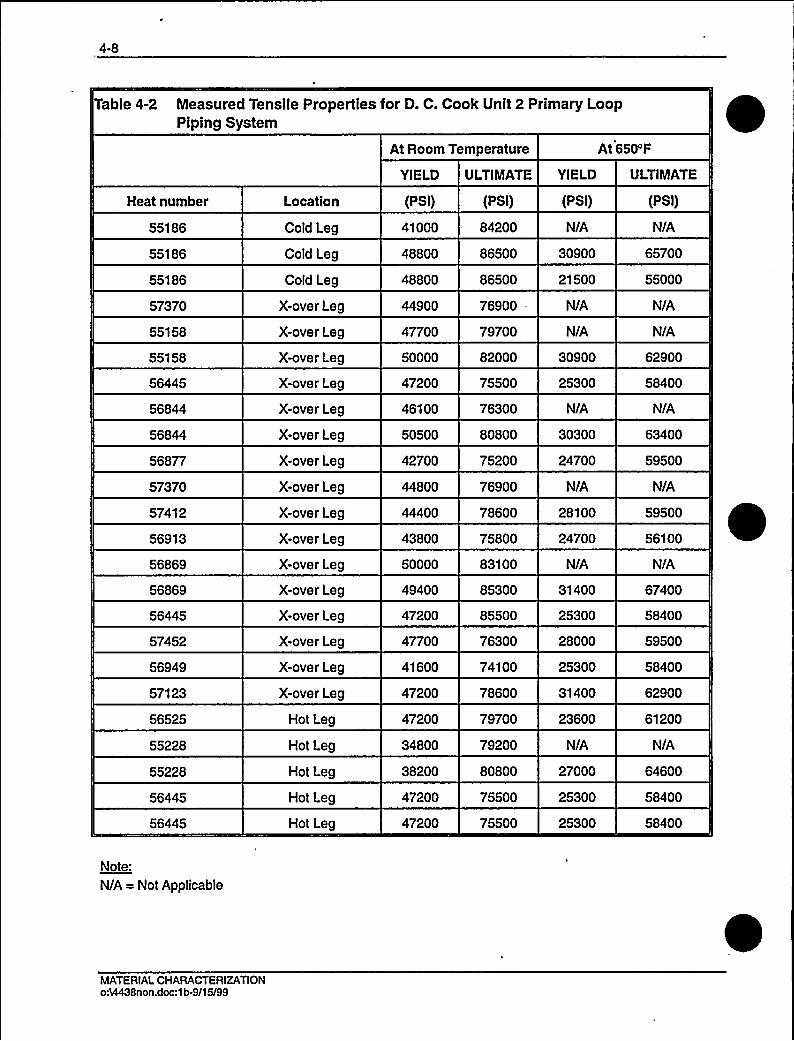
4-8
Table 4-2 Measured Tensile Properties for D. C. Cook Unit 2 Primary LoopPiping System
At Room Temperature At 650'F
YIELD ULTIMATE YIELD ULTIMATE
Heat number
55186
55186
55186
57370
55158
55158
56445
56844
56844
56877
57370
57412
56913
56869
56869
56445
57452
56949
57123
56525
55228
55228
56445
56445
Location
Cold Leg
Cold Leg
Cold Leg
X-over Leg
X-over Leg
X-over Leg
X-over Leg
X-over Leg
X-over Leg
X-over Leg
X-over Leg
X-over Leg
X-over Leg
X-over Leg
X-over Leg
X-over Leg
X-over Leg
X-over Leg
X-over Leg
Hot Leg
Hot Leg
Hot Leg
Hot Leg
Hot Leg
(PSI)
41000
48800
48800
44900
47700
50000
47200
46100
50500
42700
44800
44400
43800
50000
49400
47200
47700
41600
47200
47200
34800
38200
47200
47200
(PSI)
84200
86500
86500
76900
79700
82000
75500
76300
80800
75200
76900
78600
75800
83100
85300
85500
76300
74100
78600
79700
79200
80800
75500
75500
(PSI)
N/A
30900
21500
N/A
N/A
30900
25300
N/A
30300
24700
N/A
28100
24700
N/A
31400
25300
28000
25300
31400
23600
N/A
27000
25300
25300
(PSI)
N/A
65700
55000
N/A
N/A
62900
58400
N/A
63400
59500
N/A
59500
56100
N/A
67400
58400
59500
58400
62900
61200
N/A
64600
58400
58400
Note:
N/A = Not Applicable
MATERIALCHARACTERIZATIONoh4438non.doc:1b-9/15/99

4-9
able 4-2 Measured Tensile Properties for D. C. Cook Unit 2 Primary LoopPiping System (cont.)
At Room Temperature At 650'F
Heat number
56525
C2285A8 B
C1686A-1 &A-2
C2254
C2145
C1618
C1982C&D
C1913
B1931
B2591
C2110
C1941
C1967A&B
C2092A&B
C1875A8 B
C1845
C1856
C1881
C1974
Location
Hot Leg
Hot Leg
X-over Leg
Hot Leg
Hot Leg
Hot Leg
Hot Leg
Hot Leg
Cold Leg
Cold Leg
Cold Leg
Cold Leg
X-over Leg
X-over Leg
X-over Leg
Cold Leg
Cold Leg
Cold Leg
Cold Leg
YIELD
(PSI)
47200
40834
40300
42200
39960
31960
39460
42950
37000
48450
39460
40960
43950
37460
41950
39460
48000
42450
37960
ULTIMATE YIELD
(PSI) (PSI)
79700 23600
80519 23800
77750 23400
82500 22700
8201023300'8920
24400
77922 21400
81618 24800
75800 22300
81918 23200
79920 21500
81420 23300
78220 21400
76523 23900
81610 23300
80920 22000
88250 28300
80910 23600
78420 20900
ULTIMATE
(PSI)
61200
63750
62500
64000
66250
63750
60250
68500
64000
66250
65500
67000
63750
63000
68000
65500
73750
68000
61500
MATERIALCHARACTERIZATIONoA4438non.doo:1b491599

4-10
Table 4-3 Mechanical Properties for D. C. Cook Units 1 and 2 Materials at OperatingTemperatures
Lower Bound
Material
A351 CF8il/l
Modulus ofElasticity
Temperature ('F)
620
548
Average YieldStrength (psi)
25667
26590
Yield Stress(psi)
21103
21860
Ultimate Strength(psi)
55000
55000
E = 25.20 x10'psi, at 620'F
E=25.56x10 psi, at548'F
Poisson's ratio: 0.3
MATERIALCHARACTERIZATIONoA4438non.doc:1b-9/15/99
4-11
able 4-4 Chemistry and Fracture Toughness Properties of the Material Heats of D. C. Cook Unit 1 a,c,e
MATERIALCHARACTERIZATIONoM438non.doc:lb-9/I3/99

4-12
able 4-4 Chemistry and Fracture Toughness Properties of the Material Heats of D. C. Cook Unit 1 (cont.) a,c,e,
ALCHARACTERIZATIONnon.doc:1 tH$1399

4-13
able 4-4 Chemistry and Fracture Toughness Properties of the Material Heats of D. C. Cook Unit 0 (cont.) a,c,e
MATERIALCHARACTERI2ATIONoA4438non.doc:1b.9/13/99
4-14
Table 4-5 Chemistry and Fracture Toughness Properties of the Material Heats of D. C. Cook Unit 2 a,c,e
RIZATIONon.doc:1 tH$1399

4-15
Table 4-5 Chemistry and Fracture Toughness Properties of the Material Heats of D. C. Cook Unit 2 (cont.) a,c,e
MATERIALCHARACTERIZATIONo:N438non.doc:1b-9/13/99

4-16
MATERIALCHARACTERIZATIONoA4438non.doc:1b-091399

4-17
a,c,e
Figure 4-1 Representative Lower Bound True Stress - True Strain Curve for A351 CF8Mat 620'F
MATERIALCHARACTERIZATIONo&438non.doc:1b-9/13/99
a,c,e
Figure 4-2 Representative Lower Bound True Stress - True Strain Curve for A351 CF8Mat548 F
MATERIALCHARACTERIZATIONoA4438non.doc:1b-091399

a,c,e
Figure 4-3 Pre-Service J vs. ha for SA351 CF8M Cast Stainless Steel at 600'F
MATERIALCHARACTERIZATIONoA4438non.doc:1b-9/13/99

5-1
5.0 CRITICALLOCATIONS AND EVALUATIONCRITERIA
5.1 CRITICALLOCATIONS
The leak-before-break (LBB) evaluation margins are to be demonstrated for the limitinglocations (governing locations). Such locations are established based on the loads (Section 3.0)and the material properties established in Section 4.0. These locations are defined below forD. C. Cook Units 1 and 2. Table 3-2 as well as Figure 3-2 are used for this evaluation.
Critical Locations
The highest stressed location for the entire primary loop is at Location 1 (in the Hot Leg)(See Figure 3-2) at the reactor vessel outlet nozzle to pipe weld. Since the pipe Geometry andoperating temperature at the cross-over leg and Cold Leg are different additional criticallocations are also identified. The highest stressed location for the cross-over leg is atlocation 10 at the pump inlet nozzle to pipe weld. The highest stressed location for the cold legis at location 11 at the pump outlet nozzle to pipe weld. It is thus concluded that the envelopinglocations in D. C. Cook Units 1 and 2 for which LBB methodology is to be applied are locations1, 10 and 11. The tensile properties and the allowable toughness for the critical locations areshown in Tables 4-3 and 4-6.
5.2 FRACTURE CRITERIA
As will be discussed later, fracture mechanics analyses are made based on loads andpostulated flaw sizes related to leakage. The stability criteria against which the calculated J andtearing modulus are compared are:
(1) lf J,» < JIC, then the crack will not initiate;
(2) If J,pp> JIC, but, if T,pp< T Iand J pp( J „, then the crack is stable.
Where:
Japp—— Applied J
JIc = J at Crack Initiation
T pp Applied Tearing Modulus
T „= Material Tearing Modulus
J,„= Maximum J value of the material
For critical locations, the limit load method discussed in Section 7.0 was also used.
CRITICALLOCATIONS AND EVALUATIONCRITERIAoA4438non.doc:1b491399

6-1
6.0 LEAKRATE PREDICTIONS
6.1 INTRODUCTION
The purpose of this section is to discuss the method which is used to predict the flow throughpostulated through-wall cracks and present the leak rate calculation results for through-wallcircumferential cracks.
6.2 GENERAL CONSIDERATIONS
The flow of hot pressurized water through an opening to a lower back pressure causes flashingwhich can result in choking. For long channels where the ratio of the channel length, L, tohydraulic diameter, DH, (L/DH) is greater than [
]a,c,e
6.3 CALCULATIONMETHOD
The basic method used in the leak rate calculations is the method developed by [
]a,c,e
The flow rate through a crack was calculated in the following manner. Figure 6-1 fromReference 6-1 was used to estimate the critical pressure, Pc, for the primary loop enthalpycondition and an assumed flow. Once Pc was found for a given mass flow, the []""was found from Figure 6-2 (taken fromReference 6-1). For all cases considered, since [ ]""Therefore, this method willyield the two-phase pressure drop due to momentum effects asillustrated in Figure 6-3, where Po is the operating pressure. Now using the assumed flow rate,G, the frictional pressure drop can be calculated using
hP) ——[ ]a@,e (6-1)
where the friction factor f is determined using the [ ]"'he crack relativeroughness, E, was obtained from fatigue crack data on stainless steel samples. The relativeroughness value used in these calculations was [
]"'he
frictional pressure drop using equation 6-1 is then calculated for the assumed flow rate andadded to the [ ]"'oobtain thetotal pressure drop from the primary system to the atmosphere. That is, for the primary loop
LEAK RATE PREDICTIONSoA4438non.doc:1b491399

6-2
Absolute Pressure - 14.7 = []Q,c,e (6-2)
for a given assumed flow rate G. If the right-hand side of equation 6-2 does not agree with thepressure difference between the primary loop and the atmosphere, then the procedure isrepeated until equation 6-2 is satisfied to within an acceptable tolerance which in turn leads tocorrect flow rate value for a given crack size.
6.4 LEAKRATE CALCULATIONS
Leak rate calculations were made as a function of crack length at the governing locationspreviously identified in Section 5.1. The normal operating loads of Table 3-1 were applied, inthese calculations. The crack opening areas were estimated using the method ofReference 6-2 and the leak rates were calculated using the two-phase flow formulationdescribed above. The average material properties of Section 4.0 (see Table 4-3) were used forthese calculations.
The flaw sizes to yield a leak rate of 10 gpm were calculated at the governing locations and aregiven in Table 6-1. The flaw sizes so determined are called leakage flaw sizes.
In Reference 6-3, the D. C. Cook Units 1 and 2 RCS pressure boundary leak detection systemwas determined to meet the criteria previously established for leak detection systems (1 gpm infour hours) when utilizing leak-before-break. Thus, to satisfy the margin of 10 on the leak rate,the flaw sizes (leakage flaw sizes) are determined which yield a leak rate of 10 gpm.
6.5 REFERENCES
6-1 [
)a,c,e
6-2 Tada, H., "The Effects of Shell Corrections on Stress Intensity Factors and the CrackOpening Area of Circumferential and a Longitudinal Through-Crack in a Pipe,"Section II-1, NUREG/CR-3464, September 1983.
6-3 Nuclear Regulatory Commission Docket ff's 50-315 and 50-316 Letter fromSteven A. Varga, Chief Operating Reactor Branch ff1, Division of Licensing, toMr. John Dolan, Vice President, Indiana and Michigan Electric Company, datedNovember 22, 1985.
Leak Rate PredictionsoA4438non.doc:1b-10/27/99
October 1999Revision 1

6-3
a,c,e
LEAK RATE PREDICTIONSoA4438non.doc:1b491399

6-4
a,c,e
Figure 6-1 Analytical Predictions of Critical Flow Rates of Steam-Water Mixtures
LEAKRATE PREDICTIONSoA4438non.doc:1b-9/13/99
6-5
a,c,e
Figure 6-2 [ ]""Pressure Ratio as a Function of Llo
LEAKRATE PREDICTIONSoA4438non.doc:1b%91399
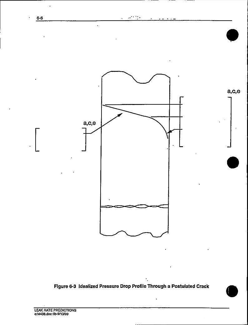
6-6
a,c,e
a,c,e
Figure 6-3 Idealized Pressure Drop Profile Through a Postulated Crack
LEAKRATE PREDICTIONSoM438.doc:1b-9/13/99

7.0 FRACTURE MECHANICS EVALUATION
7.1 LOCAI FAILURE MECHANISM
The local mechanism of failure is primarily dominated by the crack tip behavior in terms ofcrack-tip blunting, initiation, extension and finally crack instability. The local stability will beassumed if the crack does not initiate at all. It has been accepted that the initiation toughnessmeasured in terms of JI, from a J-integral resistance curve is a material parameter defining thecrack initiation. If, for a given load, the calculated J-integral value is shown to be less than theJI, of the material, then the crack will not initiate. If the initiation criterion is not met, one cancalculate the tearing modulus as defined by the following relation:
dJ ET
~PI'here:
applied tearing modulus
modulus of elasticity
0.5 (o„+ cr„) (flow stress)
crack length
a„, a„= yield and ultimate strength of the material, respectively
I
Stability is said to exist when ductile tearing occurs if T,~ is less than T „ the experimentallydetermined tearing modulus. Since a constant T, is assumed a further restriction is placed inJ~. J,~ must be less than J where J is the maximum value of J for which theexperimental T,I is greater than T,~ used.
As discussed in Section 5.2 the local crack stability criteria is a two-step process:
(1) If J~< JI„ then the crack will not initiate.
(2) If J~> JI„but, if T,~< T~I
and J~ < J „, then the crack is stable.
7.2 GLOBALFAILURE MECHANISM
Determination of the conditions which lead to failure in stainless steel should be done withplastic fracture methodology because of the large amount of deformation accompanyingfracture. One method for predicting the failure of ductile material is the plastic instability
FRACTURE MECHANICS EVALUATIONo VI438non.doc:1b491399
7-2
method, based on traditional plastic limit load concepts, but accounting for strain hardening andtaking into account the presence of a flaw. The flawed pipe is predicted to fail when theremaining net section reaches a stress level at which a plastic hinge is formed. The stress levelat which this occurs is termed as the flow stress. The flow stress is generally taken as theaverage of the yield and ultimate tensile strength of the material at the temperature of interest.This methodology has been shown to be applicable to ductile piping through a large number ofexperiments and will be used here to predict the critical flaw size in the primary coolant piping.The failure criterion has been obtained by requiring equilibrium of the section containing theflaw (Figure 7-1) when loads are applied. The detailed development is provided in appendix Afor a through-wall circumferential flaw in a pipe with internal pressure, axial force, and imposedbending moments. The limit moment for such a pipe is given by:
where:
)a.c,e
aI = 0.5 (ay+ au) (flow stress), psi
The analytical model described above accurately accounts for the piping internal pressure aswell as imposed axial force as they affect the limit moment. Good agreement was foundbetween the analytical predictions and the experimental results (Reference 7-1).
FRACTURE MECHANICS EVALUATIONoA4438non.doc:1b-9/13/99
7-3
For application of the limit load methodology, the material, including consideration of theconfiguration, must have a sufficient ductility and ductile tearing resistance to sustain the limitload.
7.3 RESULTS OF CRACK STABILITYEVALUATION
Stability analyses were performed at the governing locations established in Section 5.1. Theelastic-plastic fracture mechanics (EPFM) J-integral analyses for through-wall circumferentialcracks in a cylinder were performed using the procedure in the EPRI fracture mechanicshandbook (Reference 7-2).
The lower-bound material properties of Section 4.0 were applied (see Table 4-3). The fracturetoughness properties established in Section 4.3 and the normal plus SSE loads given inTable 3-2 were used for the EPFM calculations. Evaluations were performed at the criticallocations identified in Section 5.1. The results of the elastic-plastic fracture mechanicsJ-integral evaluations are given in Table 7-1.
A stability analysis based on limit load was performed for these locations as described inSection 7.2. The welds, at these locations, are assumed conservatively as GTAW and SMAWcombination weld. The "Z" factor correction for SMAW was applied (Reference 7-3) as follows:
Z = 1.15 t1.0 + 0.013 (OD-4)]
where OD is the outer diameter of the pipe in inches.
The Z-factors were calculated for the critical locations, using the dimensions given in Table 3-1.The Z factor was 1.61 for location 1. The Z factor was 1.65 for location 10. The Z factor was1.58 for location 11. The applied loads were increased by the Z factors and plots of limit loadversus crack length were generated as shown in Figures 7-2, 7-3 and 7-4. Table 7-2summarizes the results of the stability analyses based on limit load. The leakage flaw sizes arealso presented on the same table.
7.4 REFERENCES
7-1 Kanninen, M. F., et. al., "Mechanical Fracture Predictions for Sensitized Stainless SteelPiping with Circumferential Cracks," EPRI NP-192, September 1976.
7-2 Kumar, V., German, M. D. and Shih, C. P., "An Engineering Approach for Elastic-PlasticFracture Analysis," EPRI Report NP-1931, Project 1237-1, Electric Power ResearchInstitute, July 1981.
7-3 Standard Review Plan; Public Comment Solicited; 3.6.3 Leak-Before-Break EvaluationProcedures; Federal Register/Vol. 52, No. 167/Friday, August 28, 1987/Notices,pp. 32626-32633.
FRACTURE MECHANICS EVALUATIONoA4438non.doc:1b491399

7-4
Note: T~ is not applicable since J~ < JIc
a,c,e
FRACTURE MECHANICS EVALUATIONo:VI438non.doc:1b-9/13/99

7-5
0'f
2Q
Neutral Axis
Figure 7-1 [ ]"'tress Distribution
FRACTURE MECHANICS EVALUATIONo54438.doc:1b-091399
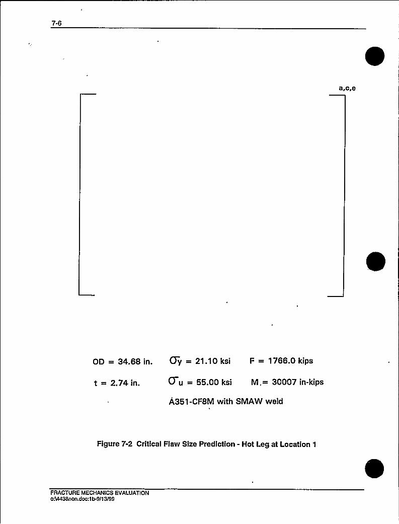
7-6
OD = 34.68 in. (7y = 21.10 ksi F = 1766.0 kips
t = 2.74in. 0 u = 55.00 ksi M.= 30007 in-kips
A351-CF8M with SMAW weld'I
Figure 7-2 Critical Flaw Size Prediction - Hot Leg at Location 1
FRACTURE MECHANICS EVALUATIONoh4438non.doc:1b.9/13/99

a,c,e
OD = 37.62 in. Gy = 21.86 ksi F = 1866.0 kips
t = 3.21 in. 0 u = 55.00 ksi M = 16583 in-kips
A351-CF8M with SMAW weld
Figure T-3 Critical Flaw Size Prediction - Cross Over Leg at Location 10
FRACTURE MECHANICS EVALUATIONoA4438non.doc:1b-091399
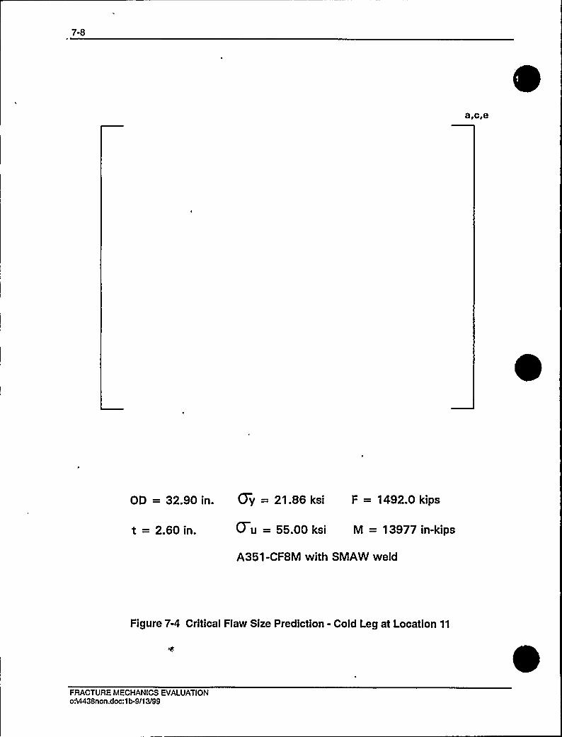
7-8
OD = 32.90 in. (7y = 21.86 ksi F = 1492.0 kips
t = 2.60 in. 0 u = 55.00 ksi M = 13977 in-kips
A351-CF8M with SMAW weld
Figure 7-4 Critical Flaw Size Prediction - Cold Leg at Location 11
FRACTURE MECHANICS EVALUATIONoA4438non.doc:1b-9/13/99

8-1
8.0 FATIGUE CRACK GROWTH ANALYSIS
To determine the sensitivity of the primary coolant system to the presence of small cracks, afatigue crack growth analysis was carried out for the [ ]"'egion of atypical system (see Location [ ]"'fFigure 3-2). This region was selected because crackgrowth calculated here will be typical of that in the entire primary loop. Crack growthscalculated at other locations can be expected to show less than 10% variation.
A[ ]"'ofaplant typical in geometry and operational characteristics to any Westinghouse PWR System.[
]"'IInormal, upset, and test conditionswere considered. A summary of generic applied transients is provided in Table 8-1.Circumferentially oriented surface flaws were postulated in the region, assuming the flaw waslocated in three different locations, as shown in Figure 8-1. Specifically, these were:
Cross Section A: [
Cross Section B: [
]a.c,e
]a.c,e
]a,c.eCross Section C: [
Fatigue crack growth rate laws were used [
]"'he law forstainless steel was derived from Reference 8-1, a compilation of data for austenitic stainlesssteel in a PWR water environment was presented in Reference 8-4, and it was found that theeffect of the environment on the crack growth rate was very small. From this information it wasestimated that the environmental factor should be conservatively set at [ ]"'n the crackgrowth rate equation from Reference 8-1.
For stainless steel, the fatigue crack growth formula is:
]a,c,e
FATIGUE CRACK GROWTH ANALYSISoA4438non.doc:1b-091399
8-2
]a,c,e
where: [~a,c,e
The unit for crack growth rate da/dn is in equation is inches per cycle, and the unitfor Ke» is ksidin
where: AK is the stress intensity factor range.
The calculated fatigue crack growth for semi-elliptic surface flaws of circumferential orientationand various depths is summarized in Table 8-2, and shows that the crack growth is very small,
~a,c,e
8.1 REFERENCES
8-1 James, L. A. and Jones, D. P., "Fatigue Crack Growth Correlations for AusteniticStainless Steel in Air, Predictive Capabilities in Environmentally Assisted Cracking,"ASME publication PVP-99, December 1985.
8-2 [
8-3 [
8-4 Bamford, W. H., "Fatigue Crack Growth of Stainless Steel Piping in a Pressurized WaterReactor Environment," Trans. ASME Journal of Pressure Vessel Technology, Vol. 101,Feb. 1979.
FATIGUE CRACK GROWTH ANALYSISoA4438non.doc:1b-9/13/99

8-3
Table 8-1 Summary of Reactor Vessel Transients
Number Typical Transient Identification Number of Cycles
1 TURBINE ROLL
COLD HYDRO
3 HEATUP/COOL DOWN
4 LOADINGAND UNLOADING
5 REDUCED TEMPERATURE RETURN TO POWER
6 STEP LOAD DECREASE/INCREASE
7 LARGE STEP LOAD DECREASE WITH STEAM DUMP
8 INITIALS. S. FLUCTUATION
9 RANDOM S. S. FLUCTUATION
20
10
200
14500
2000
2000
200
150000
3000000
10
12
13
14
15
16
17
18
19
20
21
22
23
24
25
FEEDWATER CYCLING
LOOP OUT OF SERVICE SHUTDOWN 8 STARTUP
LOSS OF LOAD
LOSS OF POWER
PARTIALLOSS OF FLOW
REACTOR TRIP WITH NO COOLDOWN
REACTOR TRIP WITH COOLDOWN NO SI
REACTOR TRIP WITH COOLDOWN AND SI
INADVERTANTDEPRESSURIZATION
INADVERTANTSTARTUP OF AN INACTIVELOOP
INADVERTANTSAFETY INJECTION ACTUATION
CONTROL ROD DROP
EXCESSIVE FEEDWATER FLOW
BORON CONCENTRATION
REFUELING
HOT HYDRO
2000
80
80
40
80
230
160
10
60
60
80
80
30
26400
80
280
FATIGUE CRACK GROWTH ANALYSISoA4438non.doc:1b491399

8-4
Table 8-2 Typical Fatigue Crack Growth at t
FINALFLAW (in.)
]"'40 years)
Initial Flaw (in.)
0.292
0.300
0.375
0.425
0.3120
0.3207
0.4020
0.4568
]a.c,e ]a,c,e
0.2977
0.3057
0.3825
0.4336
]a,c,e
0.2973
0.3056
0.3833
0.4353
FATIGUE CRACK GROWTH ANALYSISoA4438non.doc:1b-9/13/99
8-5
a,c,e
Figure 8-1 Typical Cross-Section of [ ]s,c,e
FATIGUE CRACK GROWTH ANALYSISoh4438n on.doc:1b.091399

8-6
Figure 8-2 Reference Fatigue Crack Growth Curves for [~a,c,e
FATIGUE CRACK GROWTH ANALYSISoA4438non.doc:1b.9/13/99
8-7
B,c,e
Figure 8-3 Reference Fatigue Crack Growth Law for [Environment at 600'F
]"'n a Water
FATIGUE CRACK GROWTH ANALYSISoA4438non.doc:1b-091399

9-1
9.0 ASSESSMENT OF MARGINS
The results of the leak rates of Section 6.4 and the corresponding stability and fracturetoughness evaluations of Sections 7.1, 7.2 and 7.3 are used in performing the assessment ofmargins. Margins are shown in Table 9-1.
ln summary, at all the critical locations relative to:
1. Flaw Size - Using faulted loads obtained by the absolute sum method, a margin of 2 ormore exists between the critical flaw and the flaw having a leak rate of 10 gpm (theleakage flaw).
2. Leak Rate - A margin of 10 exists between the calculated leak rate from the leakageflaw and the leak detection capability of 1 gpm.
Loads - At the critical locations the leakage flaw was shown to be stable using thefaulted loads obtained by the absolute sum method (i.e., a flaw twice the leakage flawsize is shown to be stable; hence the leakage flaw size is stable). A margin of 1 onloads using the absolute summation of faulted load combinations is satisfied.
ASSESSMENT OF MARGINSoA4438non.doc:1b/091399
9-2
'based on limit load
'based on J integral evaluation
ASSESSMENT OF MARGINSoh4438non.doc:1b.9/13/99

't0.0 CONCLUSlONS
This report justifies the elimination of RCS primary loop pipe breaks from the structural designbasis for the D. C. Cook Units 1 and 2 as follows:
a. Stress corrosion cracking is precluded by use of fracture resistant materials in thepiping system and controls on reactor coolant chemistry, temperature, pressure,and flow during normal operation.
b. Water hammer should not occur in the RCS piping because of system design,testing, and operational considerations.
c. The effects of low and high cycle fatigue on the integrity of the primary piping arenegligible.
d. Ample margin exists between the leak rate of small stable flaws and the capabilityof the D. C. Cook Units 1 and 2 reactor coolant system pressure boundaryLeakage Detection System.
e. Ample margin exists between the small stable flaw sizes of item d and largerstable flaws.
f. Ample margin exists in the material properties used to demonstrate end-of-servicelife (relative to aging) stability of the critical flaws.
For the critical locations, flaws are identified that will be stable because of the ample marginsdescribed in d, e, and f above.
Based on the above, the Leak-Before-Break conditions are satisfied for the D.C. Cook Units 1
and 2 primary loop piping. All the recommended margins are satisfied. It is thereforeconcluded that dynamic effects of RCS primary loop pipe breaks need not be considered in thestructural design basis of the D.C. Cook Units 1 and 2 Nuclear Power Plants for the uprating ofUnit 2 and for Units 1 and 2 replacement Steam Generator conditions.
CONCLUSIONSo:VI438non.doc:1b.091399

A-1
APPENDIX A
LIMITMOMENT
APPENDIX A - LIMITMOMENToA4438non.doc:1b491399
A-2
Figure A-1 Pipe with a Through-Wall Crack in Bending
APPENDIX A - LIMITMOMENToA4438non.doc:1b-9/13/99
OhlBii~AL
UNITED STATES OF AMERICA
NUCI EAR REGUI ATORY COMMISSION
Title: BRIEFING ON THE D.C. COOK PLANT
PUBLIC MEETING
Location: Rockville, Maryland
V
Date: Monday, January 10, 2000
Pages: 1 - 115
ANN RILEY4 ASSOCIATES, LTD.1025 Connecticut Avenue, NW, Suite 1014
Washington, D.C. 20036(202) 842-0034


'DISCLAIMER
This is an unofficial transcript of a meeting of
the United States Nuclear Regulatory Commission held on
January 10, 2000, in the Commission's office at One White
Flint North, Rockville, Maryland. The meeting was open to
public attendance and observation. This transcript has not
been reviewed, corrected or edited, and it may contain
inaccuracies.
The transcript is intended solely for general
informational purposes. As provided by 10 CFR* 9.103, it isnot part of the formal or informal record of decision of the
matters discussed. Expressions of opinion in thistranscript do not necessarily reflect final determination or
beliefs. No pleading or other paper may be filed with the
Commission in any proceeding as the result of, or addressed
to, any statement or argument contained herein, except as
the Commission may authorize.

UNITED STATES OF AMERICA
NUCLEAR REGULATORY COMMISSION
OFFICE OF THE SECRETARY
BRIEFING ON THE D.C. COOK PLANT
PUBLIC MEETING
10
12
13
1S'7
.18
20
21
22
23
24
25
Nuclear Regulatory Commission
Commissioners~ Conference Room
Building 1
One White Flint North
11555 Rockville Pike
Rockville, Maryland
Monday, January 10, 2000
The Commission met in open session, pursuant to, notice, at 10:05 a.m., the Honorable RICHARD MESERVE,
Chairman of the Commission, presiding.COMMISSIONERS PRESENT:
RICHARD A. MESERVE, Chairman
GRETA J. DICUS, Commissioner
NILS J. DIAZ, Commissioner
EDWARD McGAFFIGAN, JR., Commissioner
JEFFREY S. MERRIFIELD, Commissioner
ANN RILEY & ASSOCIATES, LTD.~ Court Reporters
1025 Connecticut Avenue, NW, Suite 1014Washington, D.C. 20036
(202) 842-0034
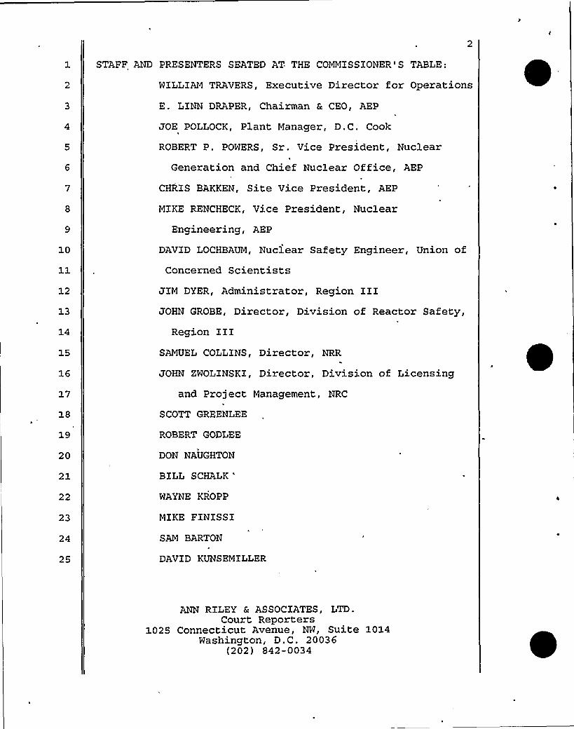
10
13
14
15
17
19
20
21
22
23
25
STAFF AND PRESENTERS SEATED AT THE COMMISSIONER'S TABLE
WILLIAMTRAVERS, Executive Director for Operations
E. LINN DRAPER, Chairman 8 CEO, AEP
JOE POLLOCK, Plant Manager, D.C. Cook
ROBERT P. POWERS, Sr.. Vice President, Nuclear
Generation and Chief Nuclear Office, AEP
CHRIS BAKKEN, Site Vice President, AEP
MIKE RENCHECK, Vice President, Nuclear
Engineering, AEP
DAVID LOCHBAUM, Nuclear Safety Engineer, Union of
Concerned ScientistsJIM DYER, Administrator, Region IIIJOHN GROBE, Director, Division of Reactor Safety,
Region IIISAMUEL COLLINS, Director, NRR
JOHN SWOLINSKI, Director, Division of Licensing
and Project Management, NRC
SCOTT GREENLEE
ROBERT GODLEE
DON NAUGHTON
BILL SCHALK
'AYNEKROPP
MIKE FINISSI
SAM BARTON
DAVID KUNSEMILLER
ANN RILEY Ec ASSOCIATES g LTDCourt Reporters
1025 Connecticut Avenue, NW, Suite 1014Washington, D.C. 20036
(202) 842-0034

PRO'CEED INGS[10:05 a.m.)
CHAIRMAN MESERVE: Good morning. On behalf of the
Commission I would like to welcome you to today's briefingon the D.C. Cook plant.
The Commission will hear from representatives ofAmerican Electric Power, the licensee for D.C. Cook, the
NRC's Region III office, and Mr. David Lochbaum of the Union
of Concerned Scientists.10 The D AC. Cook plant was shut down in September,
12
13
14
18
-1997, following an Architect and Engineering inspection thatidentified significant problems with safety systems.
Subsequent inspections identified additional safety system
deficiencies, most notably with the ice condensers. The NRC
issued a confirmatory action letter in September, 1997,
requiring the licensee to address issues discovered duringthe AE inspection and to perform further assessments and
take appropriate corrective actions prior to restarting the
19
20
21
22
23
24
25
plant.After a slow start AEP has made substantial
progress in discovering, evaluating and correcting a largenumber of issues, and after more than two years of effort iswithin sight of achieving restart.
I visited the D.C. Cook plant in December, 1999,
and was impressed with the frank discussion by AEP of past
ANN RILEY & ASSOCIATES, LTD.Court Reporters
1025 Connecticut Avenue, NW, Suite 1014Washington, D.C. 20036
(202) 842-0034

2
problems and deficiencies and of the steps that it had been
taking to ensure that these problems and deficiencies are
corrected and do not recur.
I was also impressed by the magnitude and qualityof the NRC Staff.'s oversight activities.
', 10
12
13
14
16
17
I understand that copies of the handouts are
available at the entrances. Unless my colleagues have 'any
comments they would like to make, you may proceed.
COMMISSIONER MERRIFIELD: Well, actually, Mr.~ Chairman, just to make a note, since our last meeting I,too, have had the opportunity to travel to Michigan and
visit at the D.C. Cook facility and meet with the
individuals at this table as well as the staff of the
facility and our Staff up there, and I would share the
Chairman's comments about the work being done by thelicensee and equally as well the hard work being done by ourStaff to resolve these issues and move forward, and so thank
18
20
21
22
23
proceed:
CHAIRMAN MESERVE: If not, Dr. Draper, you may
DR. DRAPER: Thank you, Chairman Meserve,
and'ou
very much for your additional consideration.CHAIRMAN MESERVE: Any other opening statements?
[No response.]
24
25
thank you, Commissioners, for taking the time to be with us
today.
ANN RILEY & ASSOCIATES ~ LTDCourt Reporters
1025 Connecticut Avenue, NW, Suite 1014Washington, D.C. 20036
(202) 842-0034

~
I am Linn Draper, Chairman and Chief Executive of
American Electric Power. With me today are Bob Powers,
Senior Vice President, Nuclear Generation, who isresponsible for all aspects of our D.C. Cook operations;
Chris Bakken, D. C. Cook Site Vice President; Mike Rencheck,
Vice President of Nuclear Engineering; and Joe Pollock, the
D.C. Cook Plant Manager.
Bob is our Chief Nuclear Officer. He will lead
10
12
14
17
18
19
20
the presentation today to review the progress made towards
the restart of the Cook plant.Chris Bakken joined AEP from Public Service
Electric & Gas Company, where he was Plant Manager for the
two Salem units. Chris was a key manager responsible forreturning those units for operation, and instillin'g the high
standards of safety, reliability and accountability that1
enabled that organization to continue to perform well.Mike Rencheck joined AEP from Florida Power
Corporation, where he was Director of Engineering. He was
part of the successful Crystal River 3 restart as well as
the Salem restarts at PSESG.
21
23
24
25
Joe Pollock also joined us from Public Service
Electric R Gas Company, where he was the Maintenance Manager
and previously the Quality Assurance Manager.
This has been a long and costly outage to AEP. Ithas been necessary to make. improvements to our systems, our
C
ANN RILEY Ec ASSOCIATES, LTD.Court Reporters
1025 Connecticut Avenue, NW, Suite 1014Washington, D.C. 20036
(202) 842-0034

10
12
14
16
17
18
19
20
21
22
23
24
25
components, material condition, processes, personneltraining and our organizational culture. It has also been
an important outage because it marks a renewed commitment. byAEP to safety returning the D.C. Cook units to full power
operation.
As the Chairman mentioned, the outage began inSeptember of 1997. We shut down both units to address
concerns raised by the NRC regarding the ability of theemergency core cooling system and the containment system tofunction properly in the unlikely event of a loss of coolantaccident.
In early 1998, after we clearly saw the magnitude
and the nature of .the ice condensers issues, we decided tomelt the ice and rebuild the ice condensers to a superiorcondition. This was the first of many similar and toughdecisions to do the right thing when confronted with a
problem involving the capability of a safety system or a
component to perform its intended function. In fact, doingthe right thing every step of the way has become the majortheme for all of the, work done at the Cook plant.
It was clearly demonstrated in our decision a year
ago to stop the outage work and take the extra time tocomplete the expanded system's readiness, reviews that bothMike and Bob will discuss. It was reinforced as we
authorized the resources to begin the necessary repairs and
ANN RILEY & ASSOCIATES, LTD.Court Reporters
1025 Connecticut Avenue, NW, Suite 1014Washington, D.C. 20036
(202) 842-0034

:
10
modifications to the plant and to revamp engineering
programs, surveillance programs, and the Corrective ActionProgram and other areas in need of improvement that you willmore about in just a few minutes.
Under the direction of Bob Powers, we have made
significant changes to the D.C. Cook management team. We
have a number of the members of the Cook team here today.
Bob, Chris and Mike will discuss some of the culturalchanges we have made to strengthen our management team and
prepare for the restart of the Cook units.
12
13
14
15
17
Many of the Cook team men and women have assistedin the restart of other nuclear plants across the country.They further demonstrate AEP's commitment to provide theresources necessary to restart this important generationresource for our system.
When we met last with the Commission in November,
1998, I said it was clear to me that one factor that led to18 our present situation was an insular and complacent attitude19
20
21
22
23
24
25
that had developed over many years within the Nuclear
Generation Department. We were not identifying our own
problems. We were not aggressive in correcting the problems
th'at we did identify. We did not question conditions thathad existed for many years and our oversight of the Cook
operations was not adequate.
AEP has made a commitment to provide the resources
ANN RILEY R ASSOCIATES, LTD.Court Reporters
1025 Connecticut Avenue, NW, Suite 1014Washington, D.C. 20036
(202) 842-0034

necessary to correct these conditions to restart the Cook
units and to return our Nuclear Generation Division to an
4i
10
13
18
industry leadership position.As I mentioned in the beginning, this outage has
been very expensive to AEP. We have lost the entire output
of one of our largest generation plants for over two years.
We have spent considerable additional resources rebuildingthe ice condensers and making other necessary modifications
and repairs to the plant.With the progress we will report today, we can now
see the end to this outage, basically on the schedule thatwe announced in the middle of last year. We are confident
that the investment in D.C. Cook will result in a safer,
more reliable and more efficient operating plant. We
clearly understand that excellence in nuclear plantperformance will return economic dividends to AEP by
enabling Cook to achieve higher capacity factors, lower
operating and maintenance costs, and shortened refuelling19 and maintenance outages.
20
22
23
24
25
We are also preparing Cook for license renewal.
We think that extension of its useful life beyond the
current limits of the NRC operating licenses will be
valuable to us. In fact, it will be a key to our economic
recovery.
We look forward to the D.C. Cook's plant's
ANN RILEY Sc ASSOCIATES, LTD.Court Reporters
1025 Connecticut Avenue, NW, Suite 1014Washington, D.C. 20036
(202) 842-0034

10
11
13
14
15
17
18
19
20
21
22
23
24
25
resumption of its critical role in meeting the electricitysupply needs in Michigan and Indiana. AEP's commitment tonuclear power also extends beyond the Cook plant to the
acquisition of 'a 25 percent interest in the South Texas
Proj'ect through our merger with the Central and Southwest
Corporation. The approval process is moving forward on a
definitive timeline and we expect to complete the merger inthe spring.
Nuclear power will be a long-term and significantcomponent of the AEP generation mix. In order to ensure the
success of Cook and the nuclear generation business sectorin both the near and long-term futures, AEP has taken stepsto improve its oversight. I am personally continuing.myactive oversight of Cook through periodic meetings with Bob
Powers and the independent safety review. group. This group
is made up of six well-respected nuclear consultants who
report to Bob as Chief Nuclear Officer and to me as CEO.
ln our reorganization following the merger withCSW, nuclear generation will continue to report directly tome. I will continue to devote a significant segment of my
time to ensure nuclear safety and the effectiveness of our
nuclear power operations.
Bob and I meet essentially monthly with the AEP
Board of Directors or with our Nuclear Oversight Committee
of that Board that was formed in April of 1999. The Nuclear
ANN RILEY & ASSOCIATES, LTD.Court Reporters
1025 Connecticut Avenue, NW, Suite 1014Washington, D.C..20036
(202) 842-0034

10
10
Oversight Committee is made up of five outside Directors of
our corporation. Its purpose is to provide long-term,
focused oversight of this important sector of the company.
It has met four times -- once at the Cook plant -- to review
Cook restart work and plans. The committee will continue to
meet periodically to review the Cook status.In sum, as you will hear from Bob and his team, we
have made significant progress this past year, and have the
end of this long outage in sight. We have assembled a
talented and experienced management team which is instilling11 the right kind of safety consciousness and standards for12
13
14
15
16
1'7
18 ~
19
20
21
excellence. AEP has given its full support and commitment
of resources to Bob and the Cook team to do the job right,I
and they are doing just that.If there are not questions, we will commence with
the formal presentation. There is an agenda slide which Ibelieve has come up. Bob will begin with an overview or
perspective of what we found needed to be changed, the
process we are using to make those changes, and a snapshot
of where we currently stand, then Mike will discuss the
extensive discovery effort completed by the Cook team, its22 .results and some of our more important accomplishments.
23
24
25
Chris will cover the implementation phase of our
restart plan, discussing the preparations being made to
ensure a safe restart of the Cook units, and finally Bob
ANN RILEY Ec'SSOCIATES, LTD.Court Reporters
1025 Connecticut Avenue, NW, Suite 1014Washington, D.C.- 20036
(202) 842-0034
11
will provide some closing remarks, and we would be delightedto entertain questions either now or along the way, however
you prefer.CHAIRMAN MESERVE: Why don't we proceed, and we'l
come back to questions at the end of the presentation.DR. DRAPER: Bob?
MR. POWERS: Thank you, Linn.
10
12
When I came to Cook in August of 1998, restartefforts had been underway for about a year. I arrived witha background of what a well-run plant looked like, and based
on my understanding of the situation at Cook I knew that a
substantial challenge lay ahead for the employees and for13 me.
~s
17
To help define that challenge and determine the
best course of action in response, I had to access what the
differences were between performance at Cook and the
performance we would need to successfully restart and for
20
21
22
23
25
long-term operations.
As a starting point for this comparison I compared
what I saw at Cook with four essential cultural attributesfound at successful nuclear plants. I believe the
fundamentals of a healthy nuclear safety culture include the
characteristic that people must be first and foremost
focused on safety. There must be capable leadership withinthe organizations and at the senior management level. The
ANN RILEY &. ASSOCIATES, LTD.Court Reporters
1025 Connecticut Avenue, NW, Suite 1014Washington, D.C. 20036
(202) 842-0034

12
10
12
13
15
16
17
, 18
19
20
organizations must also be self-critical, and the Corrective
Action Program must operate effectively. Finally, people
must be adequately trained and prepared for their jobs.
As you might imagine, I used a number of sources
to gather data for my assessment and how the culture at D.C.
Cook compared with these fundamentals. I received numerous
briefings from my direct reports and their staffs and Italked with many of our employees. I physically observed
ongoing work, toured critical plant areas, and reviewed key
documentation related to the work and problems that had been
identified up to that point.I also sponsored assessments by our Quality
Assurance Department and chartered other independent
assessments.
The principal findings of my assessments are
listed on the right hand side of the slide. Basically Idetermined that the people at Cook had become insular intheir focus and approach to managing the power plant. This
led to gaps between how Cook did business and how many inthe industry were doing business, particularly in the
22
'324
25
engineering disciplines.While the organization at Cook had been dedicated
over the years to-ensuring that the plant ran well, Ibelieve Cook's good operating history had a substantial
influence on how people viewed problems when they arose.
ANN RILEY 6c ASSOCIATES, LTD.~ Court Reporters
1025 Connecticut Avenue, NW, Suite 1014Washington, D.C. 20036
(202) 842-0034

13
.'0
12
For example, even when technical issues were identified by
the NRC's Architect-Engineering Inspection Team, I believe
many people at Cook didn' fully appreciate what these and,
other identified problems meant in terms of breakdowns and
design control and compliance with the licensing basis.I found that change management was not effective.
This was probably best seen in the move of the Engineering
organization in two stages from New York City to Columbus,
Ohio, and then to our near-site offices. Large numbers ofexperienced engineers were lost because of the moves and the
impact on the organization led to a lack of understanding
and focus on certain areas such as design and licensing13 bases
14 I also confirmed that there were deficient~s
17
18
19
20
21
22
23
24
25
processes and programs. This was particularly notable inthe areas of design control, safety evaluations, correctiveactions, and training.
In the area of corrective actions, problems were
not being found or documented in some cases, but inaddition, when they were identified there too often was
little or no follow-up. This left a backlog of unresolved
issues. Besides the problems with the ice condenser these
technical issues reduced assurance that certain systems were
capable of meeting their safety and accident mitigationfunctions.
ANN RILEY & ASSOCIATES, LTD.Court Reporters
1025 Connecticut Avenue, NW, Suite 1014Washington, D.C. 20036
(202) 842-0034
10
12
13
14
15
17
My assessment also revealed that our trainingprograms were in poor shape. This situation enabled the
insular perspective found at the site, rather than servingas a platform to enhance human performance and help assure
that industry standards were being met.
In retrospect, and having had the benefit now ofour expanded discovery efforts, I can understand why'ecouldn't answer a number of fundamental design and licensingbasis questions raised by the Architect-Engineering Team and
other NRC inspectors. Simply stated, as an organizationCook had lost focus on maintaining the design basis and inproviding strong configuration management, which are both
vital to preserving safety margins.
Overall, it was clear to me that the fundamentals
were missing.
Faced with the gaps I mentioned, and the missingfundamentals, I had re-establish a foundation for successful
18 *
19
20
restart and beyond. This required setting the overalldirection for the organization. It also required puttingsome stakes in the ground to help guide our people along the
21
22
w.ay.
I came to Cook, with high standards,'s did my
23
24
25
management team. We all recognized that to achieve
successful cultural change we must communicate our standards
effectively and provide continual reinforcement.
ANN RILEY & ASSOCIATES, LTD.Court Reporters
1025 Connecticut Avenue, NW, Suite 1014Washington, D.C. 20036
(202) 842-0034

15
This next slide summarizes my standards as key
management expectations. It is through the implementation
of these expectations that we are changing the culture at
Cook.
9
10'hesemanagement expectations are placed
throughout the plant and our engineering offices. When Irolled them out, I met with my managers and supervisors to
discuss the expectations. I indicated that it was my goal
for each manager to internalize the expectations, pass them
on to the staffs, and begin to use them in the conduct of
work;
12
14
17
18
20
21
22
24 ~
25
I don't intend to go over each of these with you
this morning. However, I would like to make a few pointsabout them.
First, I would like you to note that the
expectations are behavior-based. I believe that to sustain
change people must learn repeatable behaviors that support
the nuclear safety fundamentals I previously mentioned.
The second point I want to make is that the end
results of these expectations are the same ones demonstrated
by personnel at well-performing plants. For example,
promptly identifying and correcting problems leads to a
questioning attitude. Doing what we say we will do leads to
ownership. Accepting accountability for yourself and your
, coworkers builds teamwork and an entire organization
ANN RILEY & ASSOCIATES, LTD.Court Reporters
1025 Connecticut Avenue, NW, Suite 1014Washington, D.C. 20036
(202) 842-0034

,J
grounded on the principle of accountability.
16
10
14
15
16
17
18
19
20
21
22
23
Each of these expectations focuses on people.
Although the plant- and our processes are very, very
important, ultimately people make all the difference. When
the units and the processes are completely fixed, the
strength of our people will be the way we reach our ultimate
goal of world class performance.
In the end, what we are doing at Cook is nothing
fancy. We are concentrating on the fundamentals like clear
management expectations, and I believe if we do the
fundamentals right, we" will be successful in restarting the
plants and long-term safe and efficient operation.
At this point in our change efforts my management
team and I are still providing strong top-down direction forthe organization. However, we are seeing signs that our
management expectations are taking hold. In fact, some of
the performance improvements that Nike and Chris willdiscuss later are a direct, result of this.
I fully expect that as our staff matures and
becomes more self-sustaining they will be able to take on
more responsibility for determining the successful directionof our efforts. This will allow my senior management staffand me to concentrate our attention on other long-term
issues such as business process redesign and license
25 " renewal.
ANN RILEY & ASSOCIATES ~ LTDCourt Reporters
1025 Connecticut Avenue, NW, Suite 1014Washington, D.C. 20036
(202) 842-0034

17
~
However, setting expectations and getting our
people moving in the right direction was just part of what
was needed to restart the plants. This next slide providesan overview of our restart plan.
This slide, gives you an overview of the majorsteps in our restart process. The process involves fourbasic phases.
First, discovery of issues; then implementation ofcorrective actions;'third, verification our corrective
10 actions were effective, ultimately leading to restart by the11 units. This is the process we have been following since12
14
::17
" 18
19
20
early of last year.
However, as I alluded to earlier, the initialdiscovery efforts at Cook were limited'n focus. When Ifirst arrived at Cook, the information I was rece'iving from
my staff indicated that in their minds the recovery effortwas nearing completion. As much as I hoped the Cook staffwas correct, I pulled the string on this information and themore I pulled the more the message was mixed.
As I looked harder, it became clear that the.21
22
23
24
25
initial discovery efforts had not been conducted usingeffective procedures, nor had effective training been givento the engineers performing. the reviews. Consequently, the
results were inconsistent and only a limited number ofissues were identified.
ANN RILEY Fc ASSOCIATES, LTD.Court Reporters
1025 Connecticut Avenue, NW, Suite 1014Washington, D.C. 20036
(202) 842-0034
Because of this limited focus, we didn' have a
full understanding of the causes and thus we didn't reallyknow where else to look. In addition, it seemed like every
time the NRC looked at an area more issues were uncovered.
10
13
15
16
It was obvious that we needed to broaden our
review. To start us down this path in September of 1998 Ihelped assure that we did a thorough and comprehensive jobwhile conducting a safety system functional inspection of
the auxiliary feedwater system at the Cook plants.Now since this system had supposedly been scrubbed
by our -- cleaned by our previous reviews, it would .serve as
a bellwether of the accuracy of our previous efforts. Later
in the fall of 1998 I also initiated a Blue Ribbon expert
panel review of our engineering programs. Both of these
efforts turned up substantive issues requiring furtherevaluation and by late 1998 it was clear to me thatsomething bold needed to be done if the facility was to
18 restart.19 lt was in this same timeframe that I hi.red Mike
20
21
22
23
24
25
Rencheck and subsequently directed a more thorough discovery
effort take place. Under Mike's leadership, our initialdiscovery process was expanded to include a more
comprehensive review of our plant systems and also the
performance of our departments and of our key processes
Mike will give you more detail about the discovery process
ANN RILEY & ASSOCIATES, LTD.Court Reporters
1025 Connecticut Avenue, NW, Suite 1014Washington, D.C. 20036
(202) 842-0034
19
9
10
12
13
14
15
17
18
19
in his presentation.
During the initial period of our expanded
discovery early last year, it became clear that I would need
to further rebuild the management team as well. Chris and
Joe and Mike represent important elements of that rebuildingprocess. It also became clear that we would have to re-
I
establish the Engineering organization, improve our
oversight capability and work to restore our credib'ilj.tywith the NRC.
We believe we have made substantial progress ineach of these areas. Chris and Mike will give you more
detail about our implementation efforts later on.
So where does this leave us today? As the icon
illustrates, we are currently putting all the pieces
together that are necessary for the Cook organization to not
only safety restart the units but support our longer term
goal of excellence. We have not completed all the
remediation work yet, but we do know what else needs to be
done. We have a schedule to perform the remaining work and
20
21
22
23
24
25
we are committed to safety and quality along the way as we
have been throughout our restart efforts.We have accomplished a great deal over the last
year. For example, we have submitted the items in our
confirmatory action letter to you for closure. We have
submitted all of our license amendment requests for Unit 2
ANN RILEY Ec ASSOCIATES, LTD.~ Court Reporters
1025 Connecticut Avenue, NW, Suite 1014Washington, D.C. 20036
(202) 842-0034
20
restart. We have undergone numerous NRC inspections,including several major inspections such as the recent
Engineering Corrective Action Team Inspection, ECATI, and
these inspections support our belief that the Engineering
organization has improved and that our Corrective ActionII
Program, our self-evaluation process, and our training atthe Cook facility are effective.
10
12
14
15
16
From an organizational standpoint, we are turningour attention to human performance, and Chris will discuss
that later.In addition, I have personally devoted time to
ensuring that there is a strong management team for restartand beyond. On this latter point, we have assembled a
strong leadership team here at Cook, and I expect it toprovide a guiding and stabilizing force for our futureefforts.
17 The individuals seated behind me are a few of the
18
19
people -- introduce yourself, guys.
MR. FINISSI: Mike Finissi, Director of Plant
20
21
Engineering.
MR. GODLEE:'obert Godlee, Director of Regulatory
22 Affairs.23 MR. KROPP: Wayne Kropp, Director of Performance
24 Assurance.
25 MR. GREENLEE: Scott Greenlee, Design Engineering
ANN RILEY Ec ASSOCIATES, LTD.Court Reporters
1025 Connecticut Avenue, NW, Suite 1014Washington, D.C. 20036
(202) 842-0034
Director.21
-3
Engineer.
MR. BARTON: Sam Barton, Site Senior License.
MR. NAUGHTON: Don Naughton, Senior Systems
MR. SCHALK: Bill Schalk, Communications.
MR. KUNSEMILLER: Dave Kunsemiller, TechnicalAssistance.
MR. POWERS: Thanks, guys.
10
12
13
14
15
16
17
.18
19
20
21
22
23
These and other individuals represent the
management and technical depth of our current team.
Although we may experience some turnovers in moves toward
normal staffing levels, we intend to keep high-performingpeople by providing them with a challenging and rewardingenvironment.
Now with regards to the physical work of fixingthe plant we also have accomplished a great deal but by farthe singlemost man-hour intensive effort we have underway isthe re'pair and reload of our ice condensers. I would liketo give you a brief description of this work and provide an
update of where we are today with their refurbishment.Next slide, please.
MR. POWERS: Approximately 3,800 bags of ice, likethe one shown here; were filled using the Cook Plant ice-
24
25
making machine in 1998.,Each bag contains approximately
1,200 pounds of ice and it has been stored in an off-site
ANN RILEY Ec ASSOCIATES, LTD.~ Court Reporters
1025 Connecticut Avenue, NW, Suite 1014Washington, D.C. 20036
(202) 842-0034

22
10
12
16
17
.18
19
20
21
22
23
24
25
cold storage facility since that time. We have periodicallysampled the ice while it 'has been in storage to ensure itsquality.
As the first step in reloading, the ice istransported by refrigerated tractor-trailers to the station.After removal, it is brought to an ice crusher, which isshown in the next slide. Each bag is brought in and a
crusher forklift is used to perform an initial breakup of
the ice. The workers on the platform that you see in the
slide then begin the process of breaking the ice intosmaller chunks to feed into a pulverizer-crusher.
The ice then travels by auger and by blowers to
the ice condensers, during which time it is conditioned withrefrigerated air. This conditioning minimizes moisture
intrusion into the ice condenser, limiting frostaccumulation and sublimation of the ice.
The next slide shows the actual loading of the ice
into the ice condenser baskets.
The ice piping from the blowers is connected to a
cyclone separator in the ice condenser. The cyclone
separates the forced refrigerated air from the ice itselfand then the ice then falls into the baskets. The green airflow passage bags that you see in. the slide are installedprior to the ice being loaded in order to limit the amount
of ice which falls out of the baskets.
ANN RILEY Ec ASSOCIATES g LTD~ Court Reporters
1025 Connecticut Avenue, NW, Suite 1014Washington, D.C. 20036
(202) 842-0034

~ Reviewing some'of the numbers. There are 1,944
ice baskets in the condenser, and each basket isapproximately 12 inches in diameter and 48 feet long.Technical specifications require a total ice weight of
23
2,590,000 pounds and we expect to loan about 3 millionpounds in the Unit 2 ice condenser. At the present time we
have loaded half of the Unit 2 ice condenser and are justinitiating the process of weighing the first baskets.
10
Reloading j.ce is a major milestone for the people
at D.C. Cook. I hope the short overview I just providedwith you of the ice load helps you appreciate that we have
12 not only accomplished a great deal in discovering and
13
14
xs
17
18
20
22
23
25
resolving issues, but we have made significant progress inrestoring the physical plant since I last spoke to the
Commission in November of 1998: True to our key management
expectations, we are doing what we said we would do.
Let me quickly summarize the key points of my
opening remarks. The picture that best describes where we
are today is that we know what our problems are. We have
identified the necessary corrective actions and we are
nearing completion of our restart efforts. Frankly, where
we are now feels more and more like a refueling outage.
What faces us in the near term is simply to complete the
remaining work with quality and with safety.For the longer term, we intend to continue to
ANN RILEY & ASSOCIATES, LTD.Court Reporters
1025 Connecticut Avenue, NW, Suite 1014Washington, D.C. 20036
(202) 842-0034

10
12
13
14
15
16
17
24
focus on the fundamentals. As we improve there, our
leadership team will turn more attention to the challenges
of deregulation, license renewal and more efficientoperating cycles.
With this overview, let me turn the presentationover to Mike Rencheck.
MR. RENCHECK: Thank you, Bob. As Bob indicated,you can categorize areas, our areas of focus into plant,processes and people, Today I am going to concentrate on
how we set about identifying our issues and some of theA
.results that we have achieved.
One of the first things that I did when I came toCook was to establish a solid processing -- process fordiscovering our problems, and I did that by utilizingprocesses that I had found effective in the past.
The next slide shows the key elements of thisprocess. Discovery was the first of four phases in our
18 restart process. Discovery was designed to identify19
20
21
22
23
24
25
problems that could adversely affect the safe and reliableoperation of the Cook units. It contained the following *
attributes to ensure that problems were thoroughly evaluated
consistent with their safety importance.
As the first bullet on the slide indicates,discovery was an industry-proven process used in the
recovery and restart of other nuclear plants. It is
ANN RILEY & ASSOCIATES, LTD.Court Reporters
1025 Connecticut Avenue, NW, Suite 1014Washington, D.C. 20036
(202) 842-0034
25
~
10
12
13
14
15
17
18
~ 19
20
21
22
23
24
25
described in our restart plan and has been implemented
through formal procedures.
Second, discovery utilized personnel with the
broad-based expe'rience in the recovery and restart ofnuclear units, combined with Cook experienced personnel. We
also used industry peer reviews and visited other nuclear,
utilities to ensure that lessons learned were incorporated
into our process.
Third, discovery applied comprehensive and
intrusive methods, and we did this through three principalefforts. One of these was our expanded system readiness
reviews. These reviews provided a detailed and disciplinedassessment of essentially all safety and risk-significantsystems. Non-risk-significant systems were also reviewed
but to a lesser degree. We also conducted programmatic
assessments that were designed to evaluate whether processes
critical to restart were in place and functioning properly.125 per REM baseline assessments were performed. This
resulted in 94 detailed self-assessments of the programs
being conducted.
The last effort involved our functional area
assessments, which included 18 departmental reviews. These
reviews were conducted to determine whether department
practices, as well as personnel and management capabilitieswere adequate to support start-up and safe plant operation.
ANN RILEY Ec ASSOCIATES, LTD.Court Reporters
1025 Connecticut Avenue, NW, Suite 1014Washington, D.C. 20036
(202) 842-0034

26
12
The fourth bullet on the slide focuses on our
corrective action program. Early in our discovery process,
we completely revamped our corrective action program to make
it consistent with other well-designed industry processes.
We utilized our new program to document, understand the
extent of condition, and then to promptly fix the identifiedproblems that came out of discovery.
Finally, we subjected our discovery effort, scope,
approach, results and proposed corrective actions to a
demanding oversight by our various oversight groups such as
our System Readiness Review Board and our Plant Operations
Review Committee. These efforts were also audited and
13
14
16
17
18
assessed in detail by our performance assurance department.
We believe that our discovery process utilizedindustry best practices, techniques, and experienced people
to assure rigorous and comprehensive evaluation of the
problems at D.C. Cook.
Let me now discuss what we found. As the left~ 19
20
21
22
23
24
25
side of this slide indicates, our discovery effortsidentified issues in three areas -- people issues, process
issues and plant issues. In the area of people issues, the
problems generally included an organization that had become
insular in its approach to change. This resulted in the
inability to raise standards and keep pace with industry
changes, to consistently identify conditions adverse to
ANN RILEY Ec ASSOCIATES, LTD.Court Reporters
1025 Connecticut Avenue, NW, Suite 1014Washington, D.C. 20036
(202) 842-0034

27
10
12
quality, determine root causes and implement correctiveactions in a timely manner, to adequately train and qualifypersonnel in important areas such as our design'ndlicensing basis, and, finally, to effectively establish,communicate and implement standards and management
expectations.
Regarding process issues, a number of our
processes had become deficient and ineffective, resulting inproblems such as inconsistent design control, inadequate
saf ety evaluations, inadequate operability determinations,deficient post-maintenance and post-modification testing,and insufficient work management programs and associated
processes.
14
18
19
20
21
Many of the plant or technical issues arose from
the process issues I just mentioned. - This gener'ally
resulted in eroded safety margins, missing documentation and
inoperable plant equipment. Some specific examples includemissing or deficient design documentation, deficiencies inthe areas of material condition, for example, our'icecondensers, deficiencies in the design of some systems or
components, examples are motor-operated valves.
22
23
24
Throughout the discovery effort, issues were
documented in our corrective action program. The issues
were categorized as restart or post-restart required using
an industry-proven screen criteria. Management then
ANN RILEY &'SSOCIATES, LTD.Court Reporters
1025 Connecticut Avenue, NW, Suite 1014Washington, D.C. 20036,
(202) 842-0034It

28
analyzed the restart issues and developed a list ofapproximately 40 items that required additional management
attention due to their potential safety significance. To
date, we"have been resolving these issues and have found
10
12
14
15
16
17
19
20
21
22
23
that several have had some safety significance, namely, ourice condensers, our high energy line break program, and ourmotor-operated valves. 'Although we have determined how'osolve these issues, we are continuing in our efforts to do
so.
In summary, these issues generally represent thefundamental reasons for our shutdown. Our processes and
C
people skills, fundamental to sound engineering practices,were ineffective. Alignment among our license, our designbasis documentation and the plant's hardware in some
instances was at, best unknown, and, at worst, variedsubstantially.
Clearly, we faced a significant challenge at 'Cook.
However, let me give you some perspective on this challenge.Cook represents the third recovery effort that I have been
associated with. In general, the problems at Cook are not'nique. With the possible exception of the ice condenser
and the extent of our documentation deficiencies, the
problems at Cook have been seen throughout the industry in24 one form or another.
25 We have been uti'lizing industry-proven corrective
ANN RILEY & 'ASSOCIATES, LTD.Court Reporters
1025 Connecticut Avenue, NW, Suite 1014Washington, D.C. 20036
(202) 842-0034

29
10
12
13
14
zs
17
18
19
20
22
23
25
actions to address many of our identified problems. I have
personal experience with many of these such as our expanded
system readiness review, resolution of our high energy linebreak issues and other industry operating experience, and,
therefore, I have confidence in their effectiveness.
The right side of the slide identifies the
corrective action focus areas we used to reestablish and
strengthen our engineering capabilities. In the engineering
department, we specifically focused on the capabilities of
our people, that is, their skills and knowledge, and the
processes we use to do our work.
First, we had to assure that our management and
oversight were sound. To accomplish this, we hired several
new management individuals that understood the need forsetting high expectations and following through with
coaching and direction of both our AEP employees and the
contractors that we were utilizing.We understand that the level of engineering
performance is directly proportional to the knowledge and
skills possessed by our personnel, as well as the quality of
the supporting training program. In this regard, we
conducted an assessment of personnel competence. Two areas
were considered, engineering judgment and problem-solving
knowledge. The assessment indicated that engineering
judgment was adequate, but problem-solving skills needed
ANN RILEY & ASSOCIATES, LTD.Court Reporters
1025 Connecticut Avenue, NW, Suite 1014Washington, D.C. 20036
(202) 842-0034
30
enhancement.
Our assessment also found that many engineers
lacked the full understanding of configuration control,design and licensing basis, safety evaluations and
operability. Consequently, we initiated a comprehensive
remedial training program. In some cases all engineering
personnel, including contractors received the training. In
other cases, we targeted training to a specific engineering
10
12
13
14
15
16
17
18'0
22
23
24
25
group .
I will give you an example. The population of AEP
and contractor personnel received training in management
expectations, responsibilities, safety focus, conservative
decision-making, design and licensing basis, operabilitydetermination, 10 CFR 50.59 safety evaluation fundamentals,
configuration management, design control, calculations and ~
the development of solutions.'nd some of the specifictargeted training was applied to AEP engineering personnel
in areas such as effective problem-solving and human errorreduction techniques.
An 80 percent passing score was required on tests,and when personnel did,not achieve this grade, remediation
training was performed. Academic review boards were also
conducted for those personnel not meeting standards.
We have since performed several follow-up
assessments to evaluate the effectiveness of our efforts.
ANN RILEY Ec ASSOCI'ATES, LTD.Court Reporters
1025 Connecticut Avenue, NW, Suite 1014Washington, D.C.,20036
(202) 842-0034

~
10
12
14
31
Based on the quality of work products and root cause
analyses, engineering personnel are showing an overallimprovement such as an increased understanding of the designand licensing basis, and they are demonstrating a greaterquestioning attitude toward their work.
For the longer term, to ensure that improvements
seen to date are maintained and increased, we have revamped
our engineering support personnel training program. The
program includes establishing position-specific guides for,engineering personnel to achieve and then maintain their.qualifications.
In summary, we are challenging our people to meet
higher standards. We believe this focus will help us reach
our goal of excellence in the future.15
17
18 ~
19
20
21
22
Now, in addition to the skills and knowledge
training, we have also been improving our practices and
procedures used by our people. As part of the programmatic
assessment effort that I mentioned earlier, engineeringprocesses and programs were thoroughly evaluated.
For example, we
performed�'detailed
reviews
involving safety evaluations, design control, engineeringcalculations, the design change process and configuration
23
24
25
management. And not only the programs, we also took a lookat the documentation associated with these programs such as
our updated Final Safety Analysis Report, our calculations
ANN RILEY & ASSOCIATES, LTD.Court Reporters
1025 Connecticut Avenue, NW, Suite 1014Washington, D.C. 20036
(202) 842-0034

32
2
10
12
13
and our safety evaluations.
Issues identified for corrective action duringthese reviews were documented as condition reports in ourcorrective action program for disposition. Some of thecorrective actions we took in response to these reviewsincluded incorporating best industry practices into ourprograms, establishing the design engineering organization
II
as the design authority,'eveloping a station-wideconfiguration management policy and associated procedures,
IE
-and completing a comprehensive revision of our designcontrol processes, and,",last, establishing oversight of ourengineering products through our engineering effectivenessdepartment and formal review committees such as our DesignReview Board.
15 In summary, we have improved our skills, practices16
17
18
19
20
21
22
23
24
25
and procedures, and I am seeing the results from ourefforts. The documentation for our design and licensingbasis is being rebaselined were appropriate. Approximately190 modifications are being installed at D.C. Cook toimprove the safety and reliability of our plant.
Our performance indicators such as root cause
quality, safety evaluation quality and calculation qualityalso show me that we are on an improving trend and meeting
management expectations for restart.These next two slides illustrate our performance
ANN RILEY '& ASSOCIATES, LTD.Court Reporters
1025 Connecticut Avenue, NW, Suite 1014Washington, D.C. 20036
(202) 842-0034

33
3
in these two areas. This slide shows the percentage ofacceptance by the Plant Operations Review Committee for50.59 safety screenings and evaluations going back toFebruary of last year. This team set high standards and, as
you can see, back in February of last year, 50.59 screens
were being rejected and sent back for further analysis.This ultimately resulted in higher quality evaluations"thatare consistently meeting our expectations today.
10
12
13
14
Another key indicator that directly relates to ourcorrective action program and the ability of the
organization to find problems and develop effectivecorrective actions is the quality of our root causes. Thisnext slide shows our most recent performance. The qualityof our root cause evaluations is measured by the corrective
.17
18
20
22
23
24
25
actions department and is scored using a variety of factorssuch as safety significance, did we achieve the root cause,
and extent of condition. These factors are weighted into a
composite score that is applied against a management
standard or a goal. Although we expect the quality tocontinue to increase in the future, root cause evaluations
I
are meeting management' higher expectations and are on a
generally improving trend.
The improvements in these and other fundamental
areas, along with the new processes, and the development ofdesign changes, the control of documentation, and
ANN RILEY 6 ASSOCIATES, LTD.Court Reporters
1025 Connecticut Avenue, NW, Suite 1014Washington, D.C. 20036
(202) 842-0034

34
configuration management; among others, have resulted in'rebaselining our design and license basis documentation and
plant modifications, where appropriate. This provides us
with reasonable assurance and gives us a sound foundationfor safe and reliable plant operation.
These improvements also indicate the beginning ofa longer term cultural change in the engineering department.With our continued leadership and oversight with the safety
10
first focus, we will.not repeat past mistakes.I am encouraged with our progress, however, our
work in the engineering'epartment is not complete. We
still have challenges ahead and I would like to highlight13 these for you in the next slide.
Although the 'current quality of our engineering15 products, such as design change packages and safety16 evaluations are at an acceptable level for restart, we must
17 continue to improve. Our improvements must reduce our18 reliance on multiple review processes and increase our
engineers'nowledge and skills. Our goal is for the20 engineers to produce products that continually meet our
higher standards. This will be achieved in part by
22
23
24
enhancing our organizational capabilities, and we will do
this through our training programs, and through the use ofpersonnel performance techniques such as human error
25 reduction and performance assessments.
ANN RILEY & ASSOCIATES, LTD.Court Reporters
1025 Connecticut Avenue, NW, Suite 1014Washington, D.C. 20036
(202) 842-0034

35
: Another focus area is on contractor reliance.During this restart period, we have relied heavily on
outside help. These contracts have been under the
management and direction of AEP employees doing this effortand we appreciate their contributions. Quite frankly, we
could not have tackled this restart effort without them.
10
12
13
14
15
17
18
19
20
21
22
23
24
25
Having said that, however, we must now continue reducing ourreliance on them to ensure that we have the internalknowledge and capabilities for the longer term journey toexcellence.
Finally, we recognize that to be successful, theD.C. Cook Station must be an operations-led organization.Engineering, of course, plays a critical part in supportingthe safe and reliable operation of the units. We have
substantially improved, but we must continue to improve the
quality and timeliness of our products delivered tooperations.
These are the challenges ahead for the engineeringdepartment. I would now like to turn the presentation overto Chris Bakken.
MR. BAKKEN: Thank you, Mike. To pick up on Bob's
earlier discussion of desired behaviors, we believe thatbeing self-critical and developing sound corrective actionsrequires that we focus on effective oversight. At Cook, we
believe that oversight is fundamental to the success of our
ANN RILEY &: ASSOCIATES, LTD.Court Reporters
1025 Connecticut Avenue, NW, Suite 1014Washington, D.C. 20036
(202) 842-0034

36
restart work, as well as to our long-term goals
Oversight is a broad concept and involves
activities such as monitoring, assessing; coaching and
providing feedback. It is demonstrated by individual1t
behavior, as well as through structured processes and
programs.
On an individual basis, Joe, Mike and I. all
10
12
13
14
15
16
17
19
20
21
22
incorporate oversight into our everyday activities. For
example, during daily team meetings, we carefully evaluate
the information provided by our staffs. We provide feedback
and we encourage people to take a broader view of problems,
and to voice their opinions. We believe that this approach
promotes openness and better teamwork, and it also resultsin more comprehensive solutions.
This example shows you how we provide oversight on
a personal level. But oversight is also built into our
restart plan as a structured process. As the next slideshows, our restart effort was designed to provide several
layers of oversight. This slide was first shown to the NRC
staff during an 0350 meeting last fall. This slide breaks
our restart process down into three basis parts, discovery,
implementation, and verification, which then lead to restart23 of the units through the final phase, start-up and power
24
25
ascension, which is not shown on this slide.The boxes are, color-coded with blue representing
ANN RILEY Ec ASSOCIATES, LTD.Court Reporters
1025 Connecticut Avenue, NW, Suite 1014Washington, D.C. 20036
(202) 842-0034

37
: work activities, yellow representing assessment and
oversight activities, and green representing approval orconcurrence of successfully completed activities. The slidehighlights the yellow boxes. As you can see, oversight, inone form or another, occurs in each major step of our
restart process.
10
12
14
15
17
18
19
20
21
22
23
24
25
We did not move from discovery without an
evaluation of the effectiveness of our efforts to identifyproblems. A third party panel of experts, the System
Readiness Review Board, or SRRB, principally performed thisI
evaluation. As we move towards the completion of our
implementation efforts, you can see that, once again, we are
using oversight as an important element of our process.
Again, SRRB, along with our Plant Operations Review
Committee, is providing oversight.In our final phase of the restart, we again will
be utilizing several oversight reviews. This consists'ainlyof department self-assessments and final affirmation
reviews by senior management and the Plant Operations Review
Committee.
Throughout the entire restart process, oversight-is also provided by quality assurance. As your staff has
noted during several inspections, quality assurance has
provided intrusive and insightful review of our restartactivities. Line management now sees the benefit of these
ANN RILEY & 'ASSOCIATES, LTD.Court Reporters
1025 Connecticut Avenue, NW, Suite 1014Washington, D.C. 30036
(202) 842-0034

38
insights and is actively seeking. quality assurance's
feedback.
We believe the structured use of oversight, along
with our personal efforts to oversee a'ctivities at the site,has ensured that we are, doing a quality job. It is a major
reason why we have confidence in the effectiveness of our
efforts to date.
10
13
15
16
17
18 ~
19
20
21
22
23
24
25
Two other major reasons why we have thisconfidence is that our discovery effort was thorough and
comprehensive, and we are being successful in our transition.from an engineering-led organization to an operations-led
organization. This next slide illustrates this transition.As mentioned earlier, our restart plan began with
the discovery phase. This intensive arid time-consuming
effort was headed up by engineering for several reasons
First, many of the problems at Cook were centered on design
and license basis issues, as well as technicalissues.'econd,
Mike Rencheck had extensive personal experience inleading such an effort.,
The left side of this slide identifies the key
activities performed under Mike's direction. In addition to
discovering our problems, Mike and his organization were
responsible for developing the solutions to our problems, as* well as reestablishing the safety margins and the design
bases of our plant and processes.
ANN RILEY Ec 'SSOCIATES g LTDCourt Reporters
1025 Connecticut Avenue, NW, Suite 1014Washington, D.C. 20036
(202) 842-0034

13
14
15
16
39
Through these efforts, we also began the process
of changing the culture of all of our people. Together,
these activities have helped ready us for the transition to
power operations. In particular, they have given us
confidence that when our plant modifications are complete,
the operators will have safe and reliable plant equipment,
as well as effective procedures. These activities have also
provided momentum for our longer term journey to excellence.
As we move through this transition period, I can
tell you as an operator myself, that the operations
organization is anxious to resume control of the plant.Since my arrival in the spring of 1999, I have been hard at
work with my organization to reshape the culture among our
staff.As the right side of the slide indicates, I
believe there are four fundamentals that define an
17
18
19
20
22
23
24
25
operations-led organization. First and foremost, the
operations organization is responsible for operating the
plant in a safe and reliable manner. In order to do this,the operators must be trained; maintain their qualificationsand be knowledgeable of their license responsibilities.
Second, an operations-led organization must be a
competent and demanding customer. The proper maintenance of
the plant and the processes are critical to an operator's
job. This means that operators must work well with
ANN RILEY & ASSOCIATES, LTD.~ Court Reporters
1025 Connecticut Avenue, NW, Suite 1014Washington, D.C. 20036
(202) 842-0034
10
12
13
14
16
17
19
20
21
40
engineering, maintenance and other support organizations toassure that plant and processes are well maintained.
However, the operators must also hold those responsible formaintenance accountable, both in terms of their product and
their services. Without quality services and products, the
operators are more likely to be unnecessarily challenged inthe form of equipment failures or malfunctions.
Third, an operations-led organization must >e
constantly assessing itself and those supporting it. Unless
an organization is self-critical, it cannot be assured ofgrowth or continuous improvement.
Finally, as the leader of plant operations, the
operations department must be among the first to demonstrate
the behaviors embodied in the management expectations thatBob discussed earlier.
We are well into our transition to an operations-led organization. This has involved instilling higherstandards, reshaping the leadership within my variousorganizations and improving our work processes. To help us
4
complete our transition, we in operations have been
concentrating on improving our skills and capabilities. We
22
23
24
25
also have been focusing on enhancing the processes we relyupon to do our jobs.
MR. BAKKEN: We have accomplished a great deal
over the past year. However, since our time is limited,
ANN RXLEY 6c ASSOCIATES, LTD.~ Court Reporters
1025 Connecticut Avenue, NW, Suite 1014Washington, D.C. 20036
(202) 842-0034
10
12
13
14
will only highlight some of the activities that are
preparing us to return the power operation.
First, let me talk about operator training. We
believe that a strong training program is key to our long-
term success.
In October of 1998, our training programs foroperations were placed on probation by NPO. We gave thistraining program top priority, and in April of 1999, we
achieved accreditation renewal of the operations training.programs.
Subsequent NRC inspections have also noted our
training improvements. Concerning operational skills, one
area we'e been focusing on is human error reduction.We have established human performance goals, and
we trimmed the performance of each crew. We utilized thisinformation in our training program and during periodic crew
17
18
briefings.We have provided our operators with a variety of
19 training opportunities on this subject. For example,
20
21
22
23
24
25
operators have attended a human errors reduction trainingcourse, they have attended the NPO Team-building Workshop.
They have participated in our shift manager mentoring
program, and they have participated in our Hop Hallet Crew
Training.
For those of you not familiar with Mr. Hallet,
ANN RILEY & ASSOCIATES, LTD.Court Reporters
1025 Connecticut Avenue, NW, Suite 1014Washington, D.C. 20036
(202) 842-0034

he's the author of the Industrial Operators Handbook, 'and isa recognized authority on individual and crew human
performance.
Because human error reduction is such an importantk
element of our long-term success, we recently hired a sitehuman performance manager. Although her efforts aredirected to all of our organizations, I have specificallyasked her to focus her near-term efforts on error reductionwithin operations and maintenance departments.
10 We have also focused on the ability,of our staff
12
14
15
16
17
18
20
21
22
23
24
25
to perform effect root-cause analysis. Training courses
have been provided, and this has increased the number ofoperations staff members who are now qualified root-causeinvestigators.
In-field operations by operations management have
been increased. The expectation is to provide oversight ofthe actual work at the job site, providing support and/orcoaching where necessary.
Peer checking has been incorporated into the day-
to-day conduct of the operations staff, and more time isbeing devoted to interfaces between managers and theircrews, as well as between the Operations and the QualityAssurance Departments.
An operations-led organization cannot stand on itsown. It is supported by Engineering, which Mike has spoken
ANN RILEY & ASSOCIATES, LTD.Court Reporters
1025 Connecticut Avenue, NW, Suite 1014Washington, D.C. 20036
(202) 842-0034

43
of earlier, as well as other organizations such as
Maintenance.
I want to briefly mention what we have
accomplished in our Maintenance Department: We continue tofocus on augmenting our staffing ranks. Over the pastseveral months, we have nearly doubled the permanent -AEP
staffing levels in supervision and craft available for" plantmaintenance.
10
12
13
14
X5
17
18
19
20
At the same time, we continue to reduce our
reliance on contractors. While we need contractor supportto help us complete the work on Unit II, and for the restartof Unit I, it is my intent to carefully eliminate the
majority of,our contractors by the end of this year.Another area of continuing focus in maintenance is
training. The plans we are currently developing willachieve sufficient skills and qualifications in mechanical,
electrical, and instrumentation and controls, to support the
contractor reductions at the conclusion of the Unit Irestart.
I'd like to also mention that the health of our
22
23
24
25
maintenance training programs and instructional staf f were
reviewed in November of last year by an NPO accreditationteam. I believe these programs will receive accreditation
,renewal in March of this year.
The last area I „will talk about concerns a few of
ANN RILEY Sc ASSOCIATES i LTDCourt Reporters
1025 Connecticut Avenue, NW, Suite 1014Washington, D.C. 20036
(202) 842-0034

the processes that we have upgraded that are key to safeoperations. One of these involves operabilitydeterminations under Generic Letter 91-18.
P
We revised the governing procedure to providebetter guidance to personnel when performing these
determinations. We provided training on those proceduralchanges.
44
10
13
14
15
16
17
18
19
20
22
23
24
25
We established the Operations Department as theclear owner of the program. We also implemented, on a
temporary basis, a shift operating review team,'nd on a
long-term basis, a cross functional event screeningcommittee, both of which are designed to reduce the burden
on the control of operators for reviewing Condition Reports\
and performing prompt operability determinations.These were some of the measures we put in place to
handle the large volume of issues encountered during ourdiscovery efforts.
In addition, as part of our new electroniccorrective action reporting'ystem, we enhanced the dataavailable to the operators. The data screens now includeinformation on operability, reportability, and mode
constraint require'ments.
The other process I would like to briefly discussis our emergency operating procedures or EOPs. Early in ourrestart effort, we recognized that our EOPs needed to be
ANN RILEY & ASSOC IATES g LTDCourt Reporters
1025 Connecticut Avenue, 8W, Suite 1014Washington, D.C. 20036
(202) 842-0034
45
:
10
13
14
18
19
substantially revised.
We have largely completed this effort, bringingthem up to current industry standards. At this time, the
procedures themselves have been fully revised. Review and
approval by our„Plant Operating Review Committee iscomplete.
Now, operators are currently being trained on thenew procedures in the simulator. As you can see on thisslide, on this important area, we'e made steady progress,and, in general, adhered to our schedule, and completed this.effort last Friday, not in time to update the slides.
I have only highlighted some of the many
initiatives that we have implemented to help us transitionto an operations-led organization.
We have made tremendous progress, and overall, Ibelieve we are demonstrating an improving trend. Of course,'as in any restart situation, the startup and testing phase
is where everything comes to'gether, and where the quality ofour efforts can be measured.
20
21.
22
If you will turn to the next slide, I would liketo discuss our restart and power ascension testing program.
As we complete the implementation'phase of our
23
24
25
restart efforts, the Operations Department is resuming
control of the plant systems through the system turnoverprocess.
ANN RILEY Sc ASSOCIATES, LTD.Court Reporters
1025 Connecticut Avenue, NW, Suite 1014Washington, D.C. 20036
(202) 842-0034
46
'0
12
13
14
15
16
17
18
19
20
21
22
23
24
25
To date, 17 of 86 systems, have been turned" over toOperations. This means that the systems have been tested,as allowed by current plant conditions, and Operations has
found that they meet their standards for safety and
reliability. This turnover process is an initial step inthe startup and power ascension program.
I would like to point out that from the beginningof this discussion, that the modifications that are beingperformed on the Cook Units are limited in scope and, ingeneral, are not significantly changing any of the
operational capabilities of the plant.This is unlike other restart efforts. As an
example of what I'm referring to, during the Salem restart,we installed a digital feedwater control system, and rebuiltthe entire process control system to improve the plant'scapabilities.
This required extensive testing such as severalload rejection tests to confirm its effectiveness. Ingeneral, the modifications at Cook involve equipment
compliance upgrades, such as the motor-operated valve and
high-energy line break work.
We are not installing modifications that willcause the plant to respond significantly differently from
when it was shut down, and, therefore, the testing programs
are much more modest in scope.
ANN RILEY & ASSOCIATES, LTD.Court Reporters
1025 Connecticut Avenue, NW, Suite 1014Washington, D.C. 20036
(202) 842-0034

47
3
'10
12
13
14
17
18
19
20
21
22
23
24
25
With the turnover of- systems complete, and
concurrence of AEP management and the NRC, we will take the
reactor critical and ultimately proceed to 100-percent
power. This chain of events will be under the control of
the Operations Department, utilizing what we call a Startup
and Power Ascension Program.
Before I describe'he program itself, I would liketo discuss its basis priorities. mplementing these
priorities is essential to achieving an event-free restartof the plant.
Safety is our top priority during this criticalphase of restarting the units. We are committed to
proceeding only in a controlled and deliberate manner. By
control, I mean that the startup is conducted by a strong,
operations-led organization with full responsibility to
direct actions and events safely at all times.
By deliberate, I mean that we will have a high
degree of certainty, that is, the outcome of next actions
are well known, are safe, and are in accordance with our
overall plans.
If we have a problem, we will stop, assess, and
implement appropriate corrective actions before proceeding.
As to the program itself, we have a plan document
that is the Startup and Power Ascension Testing Program
Procedure. This procedure describes the key steps in our
ANN RILEY Ec ASSOCIATES, LTD.Court Reporters
1025 Connecticut Avenue, NW, Suite 1014Washington, D.C. 20036
(202) 842-0034

program, and has been reviewed by the System Readiness
Review Board.
12
13
14
15
16
17
18
19
20
21
22
-The program is divided into four phases:
Component testing, system testing, integral functionaltesting, and power ascension testing. This building-block
approach assures that the plant equipment, both,
independently and as an integrated system, can be reliedupon to perform its„intended function.
The program itself is nearly identical to the one
used during the Salem restart. System test plans have been
developed in accordance with the scope of the work performed
during this outage.
The plans are owned by the system manager, and are
thoroughly reviewed by a system engineering supervisor, an
operations senior reactor operator, and a test review board.,
Plans are updated as necessary on a continuing basis.
As we execute our plan and perform the various
tests, there will be oversight on-shift to assure thatproper expertise and management attention is available toaddress both routine,and emergent situations.
The around-the-clock oversight includes a shiftplant manager, a shift engineering manager, and a shift test
23
24
25
engineer.
As startup proceeds, the test results will be
reviewed by the Test Review Board to ensure that the test
ANN RILEY Ec ASSOCIATES, LTD.Court Reporters
1025 Connecticut Avenue, NW, Suite 1014Washington, D.C. 20036
(202) 842-0034

49
10
12
13
14
15
17
, 18
19
20
achieved its intended function, and that the results meet
the defined acceptance criteria.We anticipate that we will face some emerging
issues as we proceed with the startup and testing. But as Ihave previously stated, we have skilled individuals and
processes to resolve problems as they emerge.
,Once again, the Cook organization is committed torestarting the plant in a safe, controlled, and deliberatemanner. It is only by doing so that we can have an adeguate
level of assurance that the restart will meet our goal ofbeing even-free.
There are two final topics I would like to cover
briefly: First, if you will turn to the next slide, I want
to go over where we are from a schedule standpoint.I
This-slides shows the total person-hours that we
have expended, and, more importantly, the black line shows
the person-hours remaining to be completed.
As you can see, the lines have crossed, which
means that we are well past the halfway point of the outage
work. Additionally, little emergent work is being added,
21
22
which means that if we do what is scheduled and do it on
time, we should be close to our scheduled completion date of23
24
25
April 1st for Unit II.I want to again point out that challenges
occasionally do arise, and we will take the time to do the
ANN RILEY & ASSOCIATES, LTD.- Court Reporters
1025 Connecticut Avenue, NW, Suite 1014Washington, D.C. 20036
(202) 842-0034
50
'0
13
14
15
job right. Xf called for, we will not hesitate to stop
work, reassess, and assure safety and quality are met before
resuming our work.
The final topic I would like to discuss concerns
the focus areas that I see ahead for my organization, which
I have listed on the next slide.The first focus area is to ensure that the restart
and operation of Unit II is not affected by the continuing
outage efforts on Unit I. To accomplish this, we are
dedicating portions of our staff to these separate
activities.Specifically, the Unit IX staff will focus on the
critical functions of reactor restart, testing, and power
ascension activities.The Unit I staff will focus on the ongoing steam
17
.18
20
21
22
23
24
25
generator replacement and completion of the Unit I outage.
The shift plant manager an'd operations shiftmanager have overall responsibility for both plants, and
they have both the resources and guidance from senior
management to assure both .the, event-free restart and
operation of Unit II and the adequate control of work at
Unit X.
I can assure you that I fully understand the
demands that will be placed on these crews. The situationis very similar to when I was at Salem, including the steam
ANN RILEY Ec ASSOCIATES, LTD.~ Court Reporters
1025 Connecticut Avenue, NW, Suite 1014Washington, D.C. 20036
(202) 842-0034

51
~
generator replacement.
We were successful at Salem, and are employing the
same techniques here to ensure success at Cook.
In the area of human performance, I spoke about
this previously, and as I indicated, our long-term success
will greatly depend on the efforts in this area. It is my
intention to initiate a sitewide human performance strategyconsistent with the best-performing plants in the industry
to continue our improvements in this area.
In addition, we continue to be committed to an
12
open environment for personnel to raise concerns. As with
other restart situations, we have and will continue to face.
13
14
some issues in this area.
To date, however, I believe that we have been
::17
18
19
20
21
22
23
24
25
successful in addressing these matters. We significantlyupgraded our Employee Concerns Program last year, and we
have conducted training for supervisors and employees on how
to maintain an effective, safety-conscious work environment.
These efforts, combined with our upgraded
corrective action program, provide a multifaceted approach
to assure a healthy work environment at Cook.
The third focus area is control of work. During
an outage such as this one, our goal is to control work in a
systematic and deliberate manner. This is critical to our
safety-first fundamental, and is the ultimate responsibility
ANN RILEY 6 ASSOCIATES g LTDCourt Reporters
1025 Connecticut Avenue, NW, Suite 1014Washington, D.C. 20036
(202) 842-0034

52
10
13
14
15
16
18'9
20
21
22
23
25
of the Operations Department.
Operators and management are taking control of the
day-to-day activities, and ensuring that they do not letsituations control them, minimizing challenges to the
control room. This is consistent with our top priority of
safety first.The fourth focus area is our backlogs. These are
being monitored and evaluated to assure minimal impact on
plant operations. This effort is from both an individual,as well as an aggregate effect point of view.
Only those items that management believes can be
safely deferred to online maintenance or the next outage
will be moved past restart.Obviously there is still work ahead of us, and as
we proceed, there will be emerging issues that the
organization must address. However, we are ready for them.
As the site Uice President, I'm committed to
stopping and assessing when necessary, and proceeding only
when we have the confidence that we can do so safely.We will use our new skills effectively, exhibit a
questioning attitude, and demand quality from ourselves and
others to assure safe and reliable operations.
This concludes my .part of the presentation. Bob?
MR. POWERS: Thanks,'hris. I'l take just a few
minutes to wrap up what we presented today, and give you a
ANN RILEY & ASSOC IATES ~ LTD ~
Court Reporters1025 Connecticut Avenue, NW, Suite 1014
Washington, D.C. 20036(202) 842-0034

53
~
10
brief sense of where I see us heading for the future.Could I have the next slide, please? This slide
captures the key points that we'd like to leave you withtoday.
During the restart process, we have learned some
key lessons: First, we understand the aspects of our pastperformance that contributed to the shutdown of the Units.
The discovery process and the associated resultshave caused all of us at Cook to reflect on where we were
two years ago, and we'e made a commitment not to repeat the
12
past.
We'e learned how to find and how to fix our13
14
15
problems. We now have the disciplined processes and thequestioning attitude to assure that root causes are
effectively identified, and that corrective actions areeffectively implemented.
17
18
We'e learned that it takes a sound plan toachieve our goals. Our restart plan has provided the
~ 19
20
21
22
23
24
25
necessary guidance and flexibility to both address ourinitial problems and to make the necessary adjustments as
emerging issues reveal themselves.
As most of you recall, I spoke to the Commission
in November of 1998. I described my vision for world classperformance and how we would go about achieving it.
We developed a comprehensive restart plan, and we
ANN RILEY & ASSOCIATES, LTD.Court Reporters
1025 Connecticut Avenue, NW, Suite 1014Washington, D.C. 20036
(202) 842-0034
are doing what we said we would do; we are nearing
54
completion. We believe'he restart of Unit II is in sight,and should occur in the Spring of this year.
Unit I should follow in the Pall, with its steam
10
12
14
15
16
generators replaced as well.We have learned that even with good planning,
we'l have challenges ahead. Not everything is going to go
smoothly, but we have developed the skills to effectivelyaddress emergent problems.
Thee is more work to be done with our people and
processes to reach our goals. However, we do know how toevaluate these challenges and plan for their resolution.
Most of all, we'e learned not to rush the work ofrestart. We have and will stop work when necessary toreinforce our higher expectations and achieve the results ofdoing the job right the first time.
Our efforts in terms of time and resources,
19
20
22
23
25
especially over the past 12 months, have been both difficultand enlightening, but there're definite'rewards.
They are manifested in a more robust plant thatwill respond properly when called upon by our operators.They also show up in changes to our culture and processes
I
which are grounded in our higher management expectations.Through our restart efforts, we'e built a
foundation based on four fundamentals: A safety-first
ANN RILEY & ASSOCIATES i LTDCourt Reporters
1025 Connecticut Avenue, "NW, Suite 1014Washington, D.C. 20036
(202) 842-0034

55
10
12
13
14
17
18
19
20
21
22
23
24
25
culture, capable leadership, self-critical organizations
supported by an effective corrective action program, and
trained, well-prepared people.
These foundational elements are allowing us to
build the infrastructure that will support world class
performance. They are also helping us as an organization to
modify behaviors and make a fundamental change in our
culture.Those changes include improvement in our
questioning attitude, accountability, teamwork, and
ownership.
As I mentioned, we are seeing signs of changes inthese areas, but we still have a ways to go. With continued
attention to our management expectations, we will achieve
our goal of safe, reliable, and event-free operation and
ultimately world class performance.
On behalf of all of us at Cook, I want to thank
you for the opportunity to address the Commission today, and
this concludes our formal presentation.
CHAIRMAN MESERVE: Good. Thank you very much.
I'd like to express my appreciation to all of you for what
was really a remarkably candid appraisal of the situationthat you have confronted. It's clear that you made very
aggressive efforts to deal with the situation.Could you say something about the work that
ANN RILEY 6c 'ASSOCIATES, LTD.Court Reporters
1025 Connecticut Avenue, NW, Suite 1014Washington, D.C. 20036
(202) 842-0034

56
10
13
remains to be completed? You indicated that the ice
condenser was about half filled, and so what other things of
major significance are before you, before you'e ready to
commence the restart?MR. POWERS: There are about 200,000 hours of
physical work remaining in the outage. Half the ice
condenser remains to be filled.That work involves refurbishment of approximately
80 or 90 of our motor-operated valves. It includes the
physical work to implement the 190 some odd design changes,
although some are complete and underway.
There are some of the design changes that remain
to be resolved. And it involves the work associated with14
16
17
18
20
22
23
24
our system turnover windows, where we'e gone through and
taken a comprehensive scrub of the corrective action
documents that have been identified on each system, and any
physical work that needs to be done in terms of mainten'ance,
repair, it includes that as well.There is attendant work that is not showing up in
that 200,00 man-hours, and that would be some paperwork
i,ssues, analytical work, closure work that's associated
principally in the engineering and supporting organization.
I think that gives you a pretty good assessment on
what remains to be done.,
25 COMMISSIONER NERRIFIELD: Nr. Chairman, I have
ANN RILEY Sc ASSOCIATES) LTD.Court Reporters
1025 Connecticut Avenue, NW, Suite 1014Washington, D.C. 20036
(202) 842-0034
57
just a clarifying question, if I can?
What's the split between Unit II and Unit I inthat 200,000 hours?"
10
12
13
MR. BAKKEN: That doesn't account for Unit I.COMMISSIONER MERRIFIELD: That's only for Unit II?MR. BAKKEN: Yes, we'e treating Unit I as a
separate entity, and really the only substantive work that'going on now in Unit I is steam generator placement, because
we don't want to distract the organization on Unit II.That project will go through the end of March,,and
that point then we'l make an assessment, depending on the
condition of Unit II, on what work we then pick up and do on
Unit I. And we'l look at that very carefully to make sure
they don't adversely impact each other. Clearly, Unit IIwill take precedence.
MR. POWERS: The 200 man-hours of work represents
17
18
19
20
21
22
23
24
25
about eight weeks worth of work at the rate we are working
it down. I think this outage is going to be time-dependent,
both on our continued ability to work that 200,000 man-
hours down, but it's also'become like a refueling outage, a
process of appropriately managing the critical path
activities where certain key lead items, whether it bej
associated with the design or the procurement of parts,really will determine the ultimate length of the outage.
COMMISSIONER DICUS: Okay, I have a couple of
ANN RILEY Sc ASSOCIATES, LTD.Court Reporters
1025 Connecticut Avenue, NW, Suite 1014Washington, D.C. 20036
(202) 842-0034

58
quick questions, if I could. One of them is on what you
just said, the critical path issues.
,10
12
13
14
To what extent is the NRC -- I mean, where are we
in the critical path? Is there something that you need from
us?
MR. POWERS: No, Commissioner. The support from
the staff has included critical questioning; it's included a
thorough review. But the from the standpoint of support of
the project, that questioning and review has been timely.It's been scheduled to support our restart activities.
The licensing support, again, has involved
critical questioning, tough standards, high standards, but
the license products for the Cook Unit XI restart are coming
at a pace that will support the schedule, and I don't -- inany of my internal documents, I don't see the words, NRC interms of critical path between us and getting the Units
19
20
21
22
23
24
25
restarted.COMMISSIONER DXCUS: And then my second question
is going to go to the issue of the new reactor oversight
program that we 'e going to implement later on this year.
The first par't of this question is probably
somewhat philosophical, and you can get into it if you like,or if you want to defer, that's okay, too.
But if we had had the new oversight process inplace a year or two or three or four ago, would it have
ANN RILEY & ASSOCIATES, LTD.Court Reporters
1025 Connecticut Avenue, NW, Suite 1014Washington, D.C. 20036
(202) 842-0034

59
2
10
12
13
14
given you a greater signal early on that you had problems atD.C. Cook, and that those problems needed to be addressed?
Would it have given you a heads-up on that? That's the ~
philosophical part of that question.But the second part of it, in light of the fact
that we are going to a new oversight process program, in theactivities that you have ongoing, which you have so
carefully and thoroughly reviewed for us, have you
incorporated this new oversight process in your thinking, in-your going forward, as you said on some of your slides, to=-look at and to operate the plant under a new oversightprocess, such as it is.
And I guess the third part of the question is, are
bayou
ready to go under a new oversight process?
~s
question.
MR. POWERS: Okay, there are three parts to the
17
18'9
question.
COMMISSIONER DICUS: Yes. It's a three-part
MR. POWERS: Let me philosophize first. Going
20
21
22
23
24
forward, I think the NRC has developed a good oversightprocess for the nuclear industry. I do believe, if I can
answer the question by way of looking forward first, thenI'l go back in time, we will have a sound corrective actionprogram.
In the conduct of that corrective action program,
ANN RILEY Sc ASSOCIATES, LTD.Court Reporters
1025 Connecticut Avenue, NW, Suite 1014Washington, D.C. 20036
(202) 842-0034

60
2
3
10
12
13
14
15
16
17
18
19
20
21
22
23
24
25
we will identify issues, and they will be scrubbed for'heirsafety significance. This will be a key element and a key.
input into the oversight process, and you will have a
dataset that indicates what types of issues are being
identified at the Cook plant.In addition, you have engineered as part of your
oversight process, some cross-cutting inspection activitiesthat will take a look at the corrective action program forits health, and continue to take a look at the engineering
.organization in terms of doing some cross -- some verticalreviews to take a look at the health of the engineering
organization.
With all of those elements in place, I think the
new assessment program will find problems like we'e talked
about, earlier.Now, looking back in retrospect, the Cook plant
did not have a healthy corrective action program, nor was itdoing a particularly in-depth review and look at itsengineering activities.
So I'm not sure the feeding, the initial process
of getting issues out on the table would have fed the
oversight process. So, from,my own personal philosophical
standpoint, looking at it now as a senior member of industry
management, a healthy corrective action process is very,
very critical to ensuring that the oversight process will
ANN RILEY & ASSOCIATES> LTD.Court Reporters
1025 Connecticut Avenue, NW, Suite 1014Washington, D.C. 20036
(202) 842-0034

work.
And second question, related to whether our
thoughts about the new oversight process and staring up,
with Unit II having been shut down now for getting close to
two and a half years, a lot of critical data that goes intothe performance metrics is either old or not available.
Several of the performance indicators require
7,000 critical hours of the reactor to effectively establish
the denominator on some of the indicators.10
12
13
14
17
As a result, we have talked with your staff and
suggested that a transition program from the old oversight
effort would be most appropriate for the startup of Cook.
So we have a meeting scheduled in February to talkto the staff about what that transitional plan would look
like. It certainly would include the continued utilizationof the restart metrics that we have established, and they
are numerous ones, and they cover a broad gambit of safety-
19
20
21
22
23
24
25
related issues at the plant.The 03.50 panel, in some form or fashion, will
probably stay in place to oversee this transition, and we
would move aggressively to move and transition to the new
oversight program within about a year of restarting the
first unit.COMMISSIONER DICUS: All right, thank you.
MR. POWERS: Did I answer the third part'?
ANN RILEY & 'ASSOCIATES, LTD.Court Reporters
1025 Connecticut Avenue, NW, Suite 1014Washington, D.C. 20036
(202) 842-0034

62
COMMISSIONER DICUS: You just answered the thirdone, yes. You just go into the third one. You'e not quiteready to do it yet, the transition?
MR. POWERS: Yes, that's our perspective.COMMISSIONER DICUS: Right
10
12
13
14
15
16
17
18
19
20
21
22
23
24
CHAIRMAN MESERVE: Commissioner Diaz?
COMMISSIONER DIAZ: Yes, I want to echo the.Chairman's comments regarding the ability to self-criticizeyourselves and go forward. There obviously has been a majoreffort, and your discovery efforts, I guess, have all been
major steps.
I'e got a couple of questions, both of them
really related, and I will state them first.When you looked through your present to the
supporting material, there's some programmatic items, you
know, in the case of the specific list that have highpriority, which I w'ill tend to qualify them, but you can see
them safety-significant or risk-significant.And then when you get to the restart issues or
probability questions, those same items take place with low
priority. A case in question is the ice condenser which
most -- leads me to my second part of the question.There is some'iscrepancy, at least to me, at
first sight, in the way you prioritize these issues for25 whether they are case-specific or whether they are
ANN RILEY & ASSOCIATES, LTD.Court Reporters
1025 Connecticut Avenue, NW, Suite 1014Washington, D.C. 20036
(202) 842-0034

63
:
10
12
13
15
operational issues.
And the second part of the question is, as you
know, we went through -- I wouldn't call it traumatic, but a
very, very stressful period with Millstone in trying to
determine what were the Millstone issues. You know,
Millstones has had thousands of issues, and we keep being
hammered with how you'e going to resolve thousands of'ssues.
And it happens that really practically any power
plant or any industry has thousands of issues to resolve.
However, the Commission is always concerned with those
issues that are safety issues, or lately, we might be even
calling them risk-significant, ambivalent, or use them both
ways. We don't ever know which way to use them. 'But we use
them in a way that confuses everybody, including ourselves.
[Laughter.]
COMMISSIONER DIAZ: So, you mentioned, when you-18
20
— and Mike Rencheck was the only one to talk about
specifically what were some of the safety issues. You talkabout the ice condenser and the high-energy lines and the
21
22
23
24
25
motor-operated valves.
Are those the only real safety and risk-\
significant issues that your discovery showed up, or are
those are the only ones youhighlighted'f
so, okay; if .not, what other safety and risk-
ANN RILEY & ASSOCIATES, LTD.Court Reporters
1025 Connecticut Avenue, NW, Suite 1014Washington, D.C. 20036
(202) 842-0034

64
significant issues had to be not only analyzed, but
resolved? And what is the status of both?
they?
So, first, the discrepancy, and second, what are
MR. RENCHECK: Let me back up. I think I might
10
12
13
14
15
16
17
provide you with some insight on how we went about
establishing the items we have been paying increased
attention to, to give you some background, and then I'lanswer the question specifically.
We used an industry-proven process that we had
used at Salem for screening issues as they came up and we
entered them into our Corrective Action Program, so we would
call restart issues issues that were safety issues,
operability issues, design and licensing basis issues,
configuration management issues, a gamut of regulatorycompliance as well.
When we took a look at those issues that we were
18
20
21
calling "restart required" we had a very experienced
management team and we went through all of those items,
identifying what issues and general issues could result insomething that was safety significant. That is the list of
22 40 that I had talked about.
23
24
After we scrubbed through all of the issues we
found, we had about 40 on our list that we knew that we had
25 to pay increased attention to because they could have some
ANN RILEY & ASSOCIATES, LTD.Court Reporters
1025 Connecticut Avenue, NW, Suite 1014Washington, D.C. 20036
(202) 842-0034
65
10
12
safety significance to them.
Now as we have been resolving them to date we have
only identified those three that truly had safetysignificance to them, although we are continuing to work
through the issues and we continue to look through theissues
COMMISSIONER DIAZ: Excuse me -- have high safetysignificance? Obviously the other 40 have some safetysignificance. You want to prioritize them in a level ofrequiring major attention from you and also have regulatorysignificance. Is that
MR. RENCHECK: That is correct.
14
17
18
20
21
22
23
24
25
COMMISSIONER DIAZ: That is correct, okay.r
MR. RENCHECK: That is how we came up with thelist. We are still working on them. We have three to date:the ice condenser, motor-operated valves, and high energyline break.
Now I believe you asked about the inconsistency.I believe if you look at those issues they are each inthemselves have -- play a different role in the plant, so we
do not intend to communicate an inconsistency with the
priority on them. They all are being looked at at the same
level.COMMISSIONER DIAZ: Okay, but it clearly says it
is high priority in here, it's low priority in there, and,
ANN RILEY & ASSOCIATES, LTD.Court Reporters
1025 Connecticut Avenue, NW, Suite 1014Washington, D.C. 20036
(202) 842-0034
66
10
13
14
15
16
17
18'9
20
21
22
you know, if I am a layman, which I, you know, tend to be,
some of the time I look at it and say wait a minute, you
know, you are placing different priorities at different,times.
On issues of safety significance, I just reallyfocusing on safety significant issue, shouldn't the clearpriority on safety significant issues be maintained
throughout'r is the process you are establishing, you know,
culls them some time and say they are no longer high
priority'? I don't understand.
MR. RENCHECK: I guess to answer that question we
have placed again increased management attention on those 40
issues, placing them in a higher realm of management
attention and a higher priority than the other issues thatwe have had for restart. We have periodically reviewed them
internally as well as with the Staff.COMMISSIONER DIAZ:'he question is should some of
those that are very importan't like the ice containment orthe high energy lines or the motor operated valves, should
they carry that same priority into the operation?
MR. RENCHECK: We are correcting those issues forr'estart so as we restart our facility, we will be restoring
23
24
our plant back to its design licensing basis or having new
licensing actions that we have already worked with your
25 Staff on.
ANN RILEY Ec'SSOCIATES, LTD.Court Reporters
1025 Connecticut Avenue, NW, Suite 1014Washington, D.C. 20036
(202) 842-0034

67
CHAIRMAN MESERVE: Commissioner McGaffigan?
10
12
13
14
;:17
COMMISSIONER McGAFFIGAN: Thank you. I want tojoin the Chairman in commending this group of folks fortheir straightforwardness, not only today but over the lastyear or so in tackling the problems of restart.
One issue that comes to mind, since the plant has
been down for so long, how are you stocked for licencedreactor operators, senior reactor operators and I assume you
probably have some classes ready to do their manipulationsand whatever once you have a plant to manipulate -- where do
you stand in trained people?
MR. POLLOCK: We are in a little differentposition with the restart at Cook than some of the otherplants. We are actually going to be restarting Cook
primarily with operators that had operated the plant priorto the shutdown.
In fact, it is pretty well -- I believe it'
19
20
21
actually 95 percent SROs and 80 percent ROs and of that 95
percent SROs some of those are ROs who have been upgraded
through the licensing process to SROs, so basically we are
restarting Cook plant'with operators who had operated Cook
22
23
24
25
prior to the shutdown.
COMMISSIONER McGAFFIGAN: You didn't lose people?
MR. POLLOCK: We didn't lose people from thatstandpoint, although there's some changes, some people who
ANN RILEY &. ASSOCIATES, LTD.Court Reporters
1025 Connecticut Avenue, NW, Suite 1014Washington, D.C. 20036
(202) 842-0034
68
10
12
16
17
were in different positions and were relicensed. We haven'
lost people.
Additionally, we have 24 SROs slated for trainingclasses that we have brought in that were previouslylicensed from other plants to augment this and go into a
training program starting this spring -- actually, two
training programs we will have going this spring.That is on the licensed side, and then we'have
brought in nearly 40 equipment operators to augment our
staff also going through the training program.
COMMISSIONER McGAFFIGAN: This is a philosophical
question that Commissioner Dicus asked. You have one set of
standards for restart, and we have heard that from other
plants that some of these folks have worked at, and I know
they are going forward to achieve excellence, firstquartile, whatever. How do you see -- how long do you see
that period taking to achieve the higher standards that you
18
19
20
21
22
hope to achieve?
MR. POWERS: Well, we would love to be able totell you that it could happen over a short period of time,
but realistically the cultural change and making sure that
it is embedded in the fabric of our culture -in our
23 estimation will take from three to five years to see its24 full fruition demonstrate itself25 In the short- term, let ' say over the first year
ANN RILEY &. ASSOCIATES, LTD.Court Reporters
1025 Connecticut Avenue, NW, Suite 1014Washington, D.C. 20036
(202) 842-0034

69
~
10
'12
13
14
17
20
or so following restart we still see us in a mode of
providing a lot of directive top-down management as the
cultural attributes get further and further developed
throughout the organization.
We have a'usiness plan that is being put together
to carry our efforts of continuing that change past restart.There will be 10 strategic initiatives that we'l go to work
on some of the human performance issues that Chris alluded
to, some of the strategic performance initiative that we
need to tackle in terms of enhanced reliability for the
units, improved refueling outage performance and the like,and we have included resources to support that business plan
as part of our going forward effort but overall I would say
you are looking at a couple refueling cycles to really see
the results of that cultural change.-
COMMISSIONER McGAFFIGAN: And then one finalquestion. This may be for Dr. Draper. The Corbin MacNeills
of the world and Don Hinzes say you are either a shark or
you are going to be eaten.
[Laughter.)
21
22
23
24
25
COMMISSIONER McGAFFIGAN: And one of the issues isinsularity. I mean the reason I bring it up -- there is a
safety nexus. You know, some of the plants -- once Mike
worked at Crystal River and it's now been purchased by
Carolina Power & Light, I believe, or merged -- there is a
ANN RILEY & ASSOCIATES, LTD.Court Reporters
1025 Connecticut Avenue, NW, Suite 1014Washington, D.C. 20036
(202) 842-0034

70
trend in the industry towards in that case it was a single
unit. You have a two-unit plant so you have more personnel,
3 but the notion that, the philosophical notion that some
people in the industry put forward is that you need a group
of plants to help provide people with career path
opportunities to retain them and that sort of thing, so do
you see -- how will you deal with the insularity issue on a
10
13
18
20
21
22
23
24
25
more global scale'
DR. DRAPER: Well, we think restarting the unitsgives us a variety of options. The options are relativelyobvious, I suppose.
One has been suggested -- that you could eithersell or buy and become either larger or nonexistent. There
are intermediate possibilities, we think. The fact that we
will have the relationship with the South Texas Project'I
means that there are really four units that have some
relationship one to another.
There is also the possibility that we would form
some sort of an operational alliance of the type that has
been formed by the Wisconsin companies. Those companies are
nearby. Some of the units at least have similarities to our
own plant, so it is a bridge we have not yet crossed. We
recognize that it is something that is certainly worthy of
attention, but I wouldn't say it is as obvious as perhaps
Corbin thinks it is, that a two-unit, substantial sized
ANN RZLEY Ec ASSOCIATES, LTD.Court Reporters
1025 Connecticut Avenue, NW, Suite 1014Washington, D.C. 20036
(202) 842-0034

~
10
plant couldn't be successful. I think it probably could be,
but that is not necessarily the optimum situation.We will just as we go forward evaluate what those
options are..COMMISSIONER McGAFFIGAN: Thank you.
CHAIRMAN MESERVE: Commissioner Merrifield.COMMISSIONER MERRIFIELD: Obviously, you know, a
lot of the success here is due to the fact that you brought
in the strong management team. In fact, you have so many of
them here it makes me wonder who is left at the plant today
but
12
13
::17
18
20
21
22
23
25
[Laughter.]
COMMISSIONER MERRIFIELD: I guess my question isinstitutionalization of changes so that when this group of
folks leaves down the line you will still have the rightkind of results, that this is not a person-driven process,
that it has become institutionalized within the system, and4
I wonder if you could just touch a little bit on how you are
going about doing that.DR. DRAPER: Let me make a comment and then ask
Bob to comment as well. I think you are absolutely right.One of the things that we believe we had done is
to put together an absolutely top notch team of people who
have had experiences at a variety of'uccessful operating
plants as well as the restart plants, and so we think we
ANN RILEY & ASSOCIATES, LTD.Court Reporters
1025 Connecticut Avenue, NW, Suite 1014Washington, D.C. 20036
(202) 842-0034

72
have a top layer organization that is second to none.
The trick is to, as you suggest, institutionalizethat, be sure that the people who are in the succession planhave equally good skills and we'l be working very hard tobe sure that we don't have a team that is the All Star team
10
12
13
14
15
16
leading off, with nobody else sitting on the bench, and thatis a challenge for us. We believe that. we have capabilitieswithin our own organization for developing people who have
been there,„ and we will doubtless continue to -look around as
needed to fill in behind these guys.
NR. POWERS: Let me answer the question on a
personal level. I came to help this plant achieve worldclass performance and my job is not done, so I plan to stickit out and make sure that happens.
Now having said that., the plan that I am
implementing is twofold for about the next year or so. Itwill be a top-down effort to ensuie that the, culturalattributes that I mentioned are in fact demonstrated on a
20
21
22
23
24
25
day to day basis, and I plan to make sure that the
management team that is in place is motivated and
appropriately compensated to stick it through as well.In the longer'erm, the pre-eminent, the first
strategic initiative in our business plan will be the human
performance initiative. It includes a vision that says toachieve the operating focus that Chris Bakken described we
ANN RILEY & ASSOCIATES, LTD.Court Reporters
1025 Connecticut Avenue, 'NW, Suite 3.014Washington, D.C., 20036
(202) 842-0034
73
~
10
12
13
14
17
18 '
19
20
21
22
23
24
25
will license people throughout the facility to get an
operational perspective or certify them. Those will be
engineers and maintenance people and radiation protectionand chemistry people who will get a sense of what it is liketo operate the facility so that they can carry that spiritof what it takes to truly have operational focus forward.
Those will be the types of actionable items we
will have to accomplish over the next three, four, fiveyears to really make sure that this is self-sustaining, and
be less susceptible to the senior management team deciding.to go off and pursue other adventures, and that is what we
are committed to do.
CHAIRMAN MESERVE: Thank you very much.
COMMISSIONER MERRIFIELD: Mr'. Chairman -- I'msorry, that wasn't my only question.
CHAIRMAN MESERVE: Could you make it brief now,.
Jeff?
COMMISSIONER MERRIFIELD: Can you estimate thesize of the backlogs you expect at restart and how you are
going to deal with that given the fact that you may have
emerging issues under power?
MR. BAKKEN: Yes. The specific size of the
backlog, Commissioner, is a.little bit too early to tell.We do have a meeting planned with the Staff to discuss thebacklogs in detail and our„ plans for addressing them in
ANN RILEY & ASSOCIATES, LTD.Court Reporters
1025 Connecticut Avenue, NW, Suite 1014Washington, D.C. 20036
(202) 842-0034

74
March. In general, the backlog are scrubbed careful'ly using
the restart criteria that we have with the same process that
has been used elsewhere.
10
14
19
20
21
22
2'3
24
We will be very careful going through it to look
to make sure that the individual component as well as
potentially aggregate impact is adequately reviewed to make
sure that there is no safety issue and that we don't miss a
design or license basis issue or a reliability issue.
All of that review is being done by the system
manager as well as the senior reactor operator and
ultimately comes to our plant operating review committee forreview and approval. It is a pretty rigorous review process
to make sure it is okay.
COMMISSIONER MERRIFIELD: One final briefquestion. Commissioner Dicus asked about readiness renewal
oversight process, but I am interested in whether you have
any insights at this point on how we might integrate the
03.50 process into that new program as well?
MR. POWERS: The 03.50 process, Commissioner?
I think that deserves some thought. There is a
big difference -- the 03.50 process is really a process to
drive discovery. The oversight process is one that reallyneeds to have programs in a healthy status to work as Imentioned. Beyond that, we really haven't thought through
25 any--
ANN RILEY Ec ASSOCIATES, LTD.Court Reporters
1025 Connecticut Avenue, NW, Suite 1014Washington, D.C. 20036
(202) 842-0034

75
COMMISSIONER MERRIPIELD: Okay,'erhaps it's foranother day. You brought us some insight on that. Thank
4
10
13
14
17
18
19
20
22
23
24
25
you.
CHAIRMAN MESERVE: Good. I would like to thank
you all very much. It's been a very helpful presentation.
I would like to turn now to Mr. David Lochbaum,
who, as most of you know, is a Nuclear Safety Engineer 'with
the Union of Concerned Scientists. He has been followingthe situation at this plant carefully over the years.
Welcome.
MR. LOCHBAUM: Good morning. Thank you forsoliciting our views on this matter.
Nineteen months ago I sat at this table to discuss
the proposed restart of Millstone Unit 3. My presentation
at that time ended with these two conclusions, quote, "NU's
future performance cannot be predicted, but it is known that
the NRC Staff lacks the ability to reliably shut down plants
with regulatory performance problems. Millstone Unit 3
should not start without that adequate protection standard
being met."
There are many similarities between D.C. Cook Unit
2 today and the Millstone Unit 3 facility in June of 1998.
Both had been closed for more than two years while theirowners made numerous corrections to both the physical plant
and to its procedures.
ANN RILEY & 'ASSOCIATES, LTD.Court Reporters
1025 Connecticut Avenue, NW, Suite 1014Washington, D.C. 20036
(202) 842-0034

76
4 ~
10
12
13
14
15
16
17
18
19
20
21
22
23
24
25
We believe that the extent of these changes
strongly suggests failure by the plant owners and also by
the NRC to have properly focused on safety. D.C. Cook'
owners have provided today a lengthy listing of plantmodifications, equipment upgrades, and procedure changes
that they have made to support their assertion that the
facility is preparing to restart.Millstone's owners provided a comparable listing
in June of 1998 and similar time and effort has gone intoexamining these lists in an attempt to ensure that the
necessary safety margins have been restored.
The compilation and scrutiny of D.C. Cook's listis as important now as it was for Millstone in 1998. The
long length of these lists demonstrates that substantial
erosion of safety margins occurred. -I will try to avoid my
usual exchange with Commissioner Diaz over this subject by
not stating that this meant that the plants crossed the linebetween safe and unsafe. - Instead, I will say that thismeant the plants crossed the line from acceptable
performance into unacceptable performance.
The key .diff'erence between Millstone in 1998 and
D.C. Cook today has nothing to do with their respective
laundry lists. The key difference is that the NRC Staff now
has a list of what it has corrected. At the top of that
list is the revised reactor oversight process. In 1998 the
ANN RILEY & ASSOCIATES ~ LTDCourt Reporters
1025 Connecticut Avenue, NW, Suite 1014Washington, D.C. 20036
(202) 842-0034

77
NRC Staff did not have such a list. At best it had an IOU
slip.
10
12
13
14
In effectively implemented reactor oversightprocess is vital for D.C. Cook, for Millstone, and for alloperating nuclear plants. If performance declines an
effectively implemented oversight program wills step in and
prevent safety margins from being eroded to the point where
the line between acceptable and unacceptable performance iscrossed.
In 1998 we lacked confidence that the NRC Staffhad the means to detect and correct declining performance atMillstone should that occur following restart. After all,the Staff was using the same policies and procedures thathad been used unsuccessfully prior to Millstone's extended
outage.
17
18
19
20
21
22
23
24
25
Today we have confidence that the revised reactoroversight process, if implemented effectively, can providethe Staff with the means to detect unacceptable operation atD.C. Cook if its performance declines following restart.
The qualifier in that statement, "if implemented
effectively," should not be discounted. The old reactoroversight process could have been successful if it had been
implemented effectively.We are encouraged that the Staff' plans for
implementing the new process include monitoring and follow-
ANN RILEY Ec ASSOCIATES, LTD.Court Reporters
1025 Connecticut Avenue, NW, Suite 1014Washington, D.C. 20036
(202) 842-0034

up checks to increase the chances of successful
implementation.
78
10
12
13
14
15
17
, 18
20
21
23
24
25
We recommend that the revised reactor oversightprocess be applied to all operating nuclear plants as soon
as practical. It is the adequate protection standard thatwe felt was lacking in June of 1998.
Thank you for listening to our views.
CHAIRMAN MESERVE: Thank you very much, Mr.
Lochbaum.
You would agree, would you not, that there has tobe some sort of a transition in the case of D.C. Cook
because they don't have the critical data available to go
full-fledged into the new oversight program.
MR. LOCHBAUM: Right. An earlier draft of my
written statement suggested that we apply it to D.C. Cook atrestart, after discussions with Mr. Grobe and others that,your point is well taken, the plant is not ready to allowthat to happen. It is going to take some time for something
to happen, so that I agree that that needs to happen.
CHAIRMAN MESERVE: Thank you. Any questions from
my colleagues?
COMMISSIONER MERRIFIELD: Yes.
COMMISSIONER McGAFFIGAN: Yes.
CHAIRMAN MESERVE: Others?
COMMISSIONER DICUS: Go ahead.
ANN RILEY Ec ASSOCIATES, LTD.~ Court Reporters
1025 Connecticut Avenue, NW, Suite 1014Washington, D.C. 20036
(202) 842-0034
79
COMMISSIONER McGAFFIGAN: On the oversight
process, you heard earlier that -- what was broken at D.C.
Cook.
10
Are you confident -- I mean you have sat on thisBoard -- that if implemented effectively that we would have
found the corrective action program problems and the design.
problems at D.C. Cook with the revised inspection program?
COMMISSIONER DICUS: And if I could, also the
people problems as well, if I could tag that on.
MR. LOCHBAUM: I think it would have been, and the
.13
14
17
19
20
21
22
23
24
25
evidence that I used to base that guess is the -- and Idon't have it today, I wish I did -- we plotted the NRC
inspection findings for a two year period before September
of 1997 and a nine-month period afterwards', and they
averaged roughly eight or nine findings, which included
Level 1, 2, 3 and 4 noncited violations.They averaged eight or nine of those before
September, 1997, and they jumped,to like 75 in a peak month
afterwards. They went up. There was a dramatic sea change.
We felt that D.C. Cook's performance didn't change
overnight. The perception changed overnight.
I don't know that the director of the oversight
process would have found it at the exact earliestopportunity but I think it would have found it earlier than
September of '97.
ANN RILEY &, ASSOCIATES, L'TD.Court Reporters
1025 Connecticut Avenue, NW, Suite 1014Washington, D.C. 20036
(202) 842-0034

80
COMMISSIONER McGAFFIGAN: Would the PIs have found
it or would it have been in inspection findings?
MR. LOCHBAUM: I think it was a race, because most
of the data comes through the PI format. My guess would be
PIs would have found it first. I think some of the back-
10
12
13
testing that is done in SECY 99.07 or 7(a), I forget which
one, indicates that some of the findings PIs did go other
than green at D.C. Cook so I think that would have been an
indication. Whether .the NRC's supplemental inspections then
fully explain what the problems were and pointed out the
„people problems Commissioner Dicus pointed out, I suspect
that would have happened or that there was an opportunity
for that to have happened.
COMMISSIONER McGAFFIGAN: I would like to
15
16
17
18 ~
19
20
21
22
23
24
25
continue. I don't want to turn this into a new inspection
program. We will have another opportunity on that, but the
significance determination process for inspection findings,do you think some of the inspection findings that were there
to be found would have triggered a white or yellow, they
wouldn't have all been green inspection findings if you had
a properly implemented new oversight process?
I mean these are all theoretical questions.
MR. LOCHBAUM: Right. I hope they would have. Ifnot, at least it would have pr'ompted a debate, which would
have given groups like ours an opportunity to have a voice
ANN RILEY & ASSOCIATES, LTD.Court Reporters
1025 Connecticut Avenue, NW, Suite 1014Washington, D.C. 20036
(202) 842-0034
in the debate, but I think it would have -- absent
absent -- I really do--
81
COMMISSIONER McGAFFIGAN: Okay.
MR. LOCHBAUM: I have no data to prove that, but Ido believe it would have.
6 COMMISSIONER McGAFFIGAN: Thank you.
COMMISSIONER DIAZ: Well, I'm sorry we are not
disagreeing a lot today. That makes me wonder whether I am
getting old.10
12
13
14
17
18
20
22
23
24
25
[Laughter.]
COMMISSIONER DIAZ: David, but I just wanted tosay that I personally, I believe the Commission appreciates,you know, your comments early in the process with this, how
you brought things out, and I am glad we pay attention, and
you have been very valuable to us in this process, and we--I just want to say thank you.
MR. LOCHBAUM: I appreciate that. Thank you.
COMMISSIONER MERRIFIELD: Commissioner Diaz,
beating me to the punch, I agree. I think your assistancein the D.C. Cook oversight, the new oversight process and
the 2.06 process have all been valuable and I hope our
positive comments don't take away from your constituency'srespect for what you do, because certainly I have respect
for it.COMMISSIONER DIAZ: He will disagree soon. Don'
ANN RILEY & ASSOCIATES, LTD.Court Reporters
1025 Connecticut Avenue, NW, Suite 1014Washington, D.C. 20036
(202) 842-0034

82
worry about it.[Laughter.]
MR. LOCHBAUM: Not yet though.
10
12
13
14
15
16
17
19
20
COMMXSSXONER MERRIFIELD: I want to say we have
been dealing with the issues relative to Millstone and D.C.
Cook within the time that I have been a Commissioner, and
even dissatisfaction with the way in which we were doingsome things at D.C. Cook and at Millstone and have aot had
quite the same level of concern about what we have been
doing at D.C. Cook.
At both we used the 03.50 process, and so my
question for you is do we have an issue here in terms of a
different way of implementing the 03.50 process? Xs it a
different way that the regions have acted in their oversightefforts? Is there some inconsistency within how we were
acting here at Headquarters? Do we have some otherprogrammatic weaknesses?
Where is it that is the source of a difference, inyour opinion, in terms of how we acted relative to Millstoneand how we have been acting relative to D.C. Cook?
21
22
23
24
25
MR. LOCHBAUM: Well, I think the 03.50 process isintentionally broad-based and they can cover a number ofapplications. Therefore, that allows a lot of flexibilityon level of detail, what is within the scope, what is out ofthe scope.
ANN RILEY & ASSOCIATES, LTD.Court Reporters
1025 Connecticut Avenue, NW, Suite 1014Washington, D.C. 20036
(202) 842-0034
83
'0
12
13
14
Z5
Even with that issue, I think it was more in how
it was implemented at Millstone versus how it was
implemented at D.C. Cook, so I don't think it is a specificproblem with the procedure. It seemed'o me to be the way
it was implemented.
When I attended or monitored Millstone meetings,
there were -- the Staff asked questions, but there was 'no
follow-up. There were no strings pulled. It seemed to be
accepted on faith what Millstone was doing. I am not sayingMillstone was doing a bad job, just when I look at how
Region III has handled D.C. Cook, there have been probingquestions. It is not adversarial so it is not a differentapproach, but there is a greater public confidence. AtMillstone it didn't look like -- when I came away from a
Millstone meeting I usually had questions that I would have
asked had I been allowed to speak.
17
19
20
21
22
23
24
25
At the D."C. Cook meetings it was very seldom thatthe region didn't ask the questions first. That led me togreater confidence that they were doing a thorough jobasking the questions that I would ask if I could speak, so Ithink that is the difference that I obser'ved.
COMMISSIONER MERRIFIELD: Thank you.
CHAIRMAN MESERVE: Thank you. We very much
appreciate
MR. LOCHBAUM: Thank you.
ANN RILEY & ASSOCIATES) LTD.Court Reporters
1025 Connecticut Avenue, NW, Suite 1014Washington, D.C. 20036
(202) 842-0034

84
morning.
CHAIRMAN MESERVE: --- your participation this
Our final panel will consist of various members of
the Staff. Good morning.
DR. TRAVERS: Well, I think we'e settled, Mr.
10
12
13
14
Chairman.
CHAIRMAN MESERVE: Why don't you proceed?
DR. TRAVERS: Thank you very much. Good morning.
As you pointed out earlier, Chairman, in your comments, the
Agency has certainly been significantly involved'nevaluating the corrective actions at D.C. Cook.
Today we plan to provide you with our perspective
on a number of issues, including the status of the
licensee's corrective actions, and our own Manual Chapter
15
16
17
18
19
20
21
23
25
0350 restart assessment process.
Joining me at the table this morning are Jim Dyer,
the Regional Administrator, Region III, Jack Grobe, who isJim's Director of the Division of Reactor Safety; Sam
Collins, the Director of the Office of Nuclear Reactor
Regulation; John Zwolinski, who is Sam' Director of the
Division of Licensing and Project Management.
Other members of the NRC staff who have been key
to our activities at D.C. Cook will be identified in a few
moments by both Jim Dyer,and John Zwolinski.
This is the fourth time in the past two years that
ANN RILEY Ec'ASSOCIATES, LTD.Court Reporters
1025 Connecticut Avenue, NW, Suite 1014Washington, D.C. 20036
(202) 842-0034

85
10
12
13
14
15
17
we'e had the opportunity to discuss the performance at D.C.
Cook with the Commission. In July of 1998, we discussed
D.C. Cook performance at the annual briefing on operating
reactors.
As a result of that meeting, we concluded that the
performance at D.C. Cook was declining. In November of
1998, we met with the Commission to discuss D.C. Cook
performance in detail, with the particular focus on
engineering performance issues.
In May of 199, we discussed D.C. Cook performance
again at the annual briefing, and we informed the Commission
that D.C. Cook had been categorized as an Agency-focus
plant. This was done in recognition that the issues at D.C.
Cook had for some time been the focus of senior NRC
management attention.D.C. Cook remains an Agency-focus plant, and the
staff intends to utilize the senior management meeting "
18 schedule for this Spring as the vehicle for making the
19
20
21
22
23
24
25
determination of whether the Agency-focus classificationshould be retained or changed.
This determination would include our assessment of
the power operations subsequent to any restartauthorization. Restart authorization will occur after the
Manual Chapter 0350 restart panel has determined that
actions have been satisfactorily completed for safe restart
ANN RILEY & ASSOCIATES, LTD.Court Reporters
1025 Connecticut Avenue, NW, Suite 1014Washington, D.C. 20036
(202) 842-0034

at Unit II
10
12
17
18
19
20
21
22
23
24
25
Jim Dyer, in coordination with Sam Collins and
myself, will make a final determination regarding the
restart of the D.C. Cook plant.Importantly, the 035 panel will continue to
evaluate Unit II performance following restart to ensure
that American Electric Power actions to improve performance
are sustained.
I would like to now to turn it over to Jim Dyer
who is going to begin our formal presentation.
MR. DYER: Thank you, Bill. May I have Slide 1,
please.
Mr. Chairman, Commissioners, here with me today isJack Grobe, who in addition to being the Director of the
Division of Reactor Safety in Region III, is also the 0350
panel chairman. John Zwolinski is the Vice Chairman for the
0350 panel for D.C. Cook restart.Additionally, Region III staff who are also here
involved with the D.C. Cook project are Tony Vagel, the DRP
Branch Chief, Bruce Bartlett, his Senior Resident Inspector
for D.C. Cook, Gary Shear, the DRS Branch Chief, lead Branch
Chief for D.C. Cook, and Mel Holmberg, the lead engineer forthe D.C. Cook restart activities.
Can I have the second slide, please'? For today'
presentation, our plan is that I will first summarize NRC
ANN RILEY Ec ASSOClATES, LTD.Court Reporters
1025 Connecticut Avenue, NW, Suite 1014Washington, D.C..20036
(202) 842-0034
87
~
oversight activities since the shutdown of the D.C. CookI
Units, and focusing on those activities since our lastbriefing in May, 1999.
10
And then John Zwolinski will present the status of
licensing activities that are in progress or have been
completed to support the D.C. Cook restart. And then,
finally, we will address the staff oversight activitiesplanned for the restart and the operation.
Overall, the NRC has expended approximately 20,000
hours of direct inspection effort at the D.C. Cook plant11 . since 1997, in the past three years.
13
COMMISSIONER DIAZ: Excuse me, how many?
MR. DYER: About 20, 000 hours since 1997, 1998 and
14
;:17
.18
19
20
21
23
25
1999. And of those, about half of them, or 10,000 hours of
direct inspection effort, have been focused on what I willcall the recovery and discovery efforts of the licensee. ~
Slide 3, please. For a little history, inSeptember, 1997, in followu'p to the architect engineering
inspections and subsequent plant shutdown, dual-unitshutdown of both D.C. Cook Units, Region III issued a
confirmatory action letter documenting the actions thatAmerican Electric Power would take prior to their restart.
Those actions included resolution of nine specificissues identified during the NRC inspection, as well as our
understanding that American Electric Power would determine
ANN RILEY Sc ASSOCIATES, LTD.Court Reporters
1025 Connecticut Avenue, NW, Suite 1014Washington, D.C. 20036
(202) 842-0034

88
whether similar engineering problems existed in other safetyI
systems.
Subsequently, additional problems were discovered,
and as a result, the NRC issued a Severity Level II problem
violation -- issued violations that constituted a Severity
Level II problem, and issued a $ 500,000 civil penalty in the
10
12
13
14
15
latter part of 1998.
And in March, 1998, American Electric Power
developed a restart plan that expanded and included system
.readiness reviews of those risk-significant systems to bound
the problems found by the inspection.
At that same time, the NRC commenced its 0350
restart panel, formed its 0350 restart panel, and issued itsinitial case-specific checklist for D.C. Cook restart.
Later in 1998, American Electric Power completed
16
18
19
20
21
22
23
24
25
their plant system readiness reviews that were intended to
bound the significant issues, and in September, the NRC
observed American Electric Power'a contracted safety system
functional inspection of the auxiliary feedwater system.
That inspection identified significant operabilityissues that had been missed by these system readiness
reviews. Also in September, NRC ipspectors identifiedoperability concerns with motor-operated valves that furtherquestioned the effectiveness of their system readiness
reviews.
ANN RILEY & ASSOCIATES, LTD.Court Reporters
1025 Connecticut Avenue, NW, Suite 1014Washington, D.C. 20036
(202) 842-0034

89
'0
12
13
14
15
17
18
19
At the November 30th, 1998 Commission meeting,
briefing on D.C. Cook, American Electric Power was bringingin their outside engineering and management talent,performing self-assessments, and revising their approach torestart, and in March, 1999, they revised their restart planto include the expanded system readiness reviews and
assessment of programs and functional areas.
Overall, up until March of 1999, fromthe'eptember
1997 date until March 1999, the NRC expended
approximately 4,000 hours of direct inspection effort toidentify the scope of their problems to the licensee, and
have them initiate their expanded system readiness reviews.
Next Slide 4, please. The expanded system
readiness reviews, programmatic assessments, and the
functional reviews conducted by American Electric Power
staff, augmented by experienced contractors, the process
identified numerous deficiencies, some of which requiredrepair, system modi fications, and license amendments, as we
heard earlier from the licensee20 This was the status of the activities at the time
21
22
23
24
we last briefed the Commission in May of 1999. This pastSummer, the Manual Chapter 0350 restart panel focused
several inspections on the American Electric Power problem
discovery efforts, using our own experienced inspectors and
25 'ontractor personnel.
ANN RILEY Sc ASSOCIATES, LTD.Court Reporters
1025 Connecticut Avenue, NW, Suite 1014Washington, D.C. 20036
(202) 842-0034

90
Our inspections evaluated the conduct oflicensee's problem discovery efforts, reviewed the resultantinput to their corrective action process, and assessed the
adequacy of the licensee's oversight of this discoveryprocess.
We also conducted a safety system functional
10
inspection of two safety systems as an independent
validation of their efforts. -We found the expanded system
readiness reviews to be effective in identifying thedeficiencies impacting safety system functions thatconfirmed that American Electric Power had conducted
13
14
15
17
18
19
20
21
sufficiently self-critical reviews of their programs and
functional areas, and that the performance assessment
organization of D.C. Cook provided critical oversight "of
plant activities.This effort ended up and was completed in
September of 1999, and the NRC expended approximately 3,000
hours of direct inspection effort to review their discoveryefforts.
Following this validation of the discovery.
efforts, the case-specific checklist was expanded to capture
22
23
the necessary licensee corrective actions to support the
safe restart.24
25
Slide 5, please. This past Fall, inspections have
been conducted to review the effectiveness of American
ANN RILEY & ASSOCIATES, LTD.Court Reporters
1025 Connecticut Avenue, NW, Suite 1014Washington, D.C. 20036
(202) 842-0034
91
Electric Power's efforts to correct the deficiencies
identified during their discovery efforts.
6
7
10
To date, we have spent approximately 2500 hours of
direct inspection effort, reviewing such areas as operator
training, corrective actions program, safety evaluations,
preventive maintenance, operability determinations, ice
condenser corrections, and incorporating instrument
uncertainties into equipment design testing and plantprocedures, as well as some of the engineering correctiveactions activities that were discussed earlier by Mr.
Rencheck.
12
14
16
17
19
20
21
22
23
24
The inspections confirm progress in resolving many
of the restart issues. Our inspections and NRR staffreviews have confirmed adequate resolutions of the'issues
identified in the confirmatory action letter and the nine
issues in the bounding concern.
We are currently considering the staff'srecommendation to close out this confirmatory action letter.The remaining restart activities would then be managed
through a case-specific checklist in the 0350 process.
Slide 6, please. At this point, I'd like to turn
the discussion of the licensing activities over to John
Zwolinski .
MR. ZWOLINSKI:, Good morning. I would like to
recognize members of the NRR staff, our Project Manager,
ANN RILEY Ec ASSOCIATES, LTD.Court Reporters
1025 Connecticut Avenue, NW, Suite 1014Washington, D.C. 20036
(202) 842-0034

92
sitting behind me, is John Stang, who has had the
responsibility for Cook for the last couple of years. His
Section Chief is Claudia Craig, who has also been deeply
involved with the facility.I'd also like to note that there are others on the
10
12
13
14
16
17
18
19
20
22
23
24
NRR staff that have been deeply involved with technical
reviews under the Division of Engineering and Divisi,on 'of
System Safety and who supported the work.
As compared to other extended shutdown plants,D.C. Cook did not require the processing of a large number
of license amendments as Cook has undertaken an effort to
restore the original design basis of the plant.The licensee chose to make modifications at the
plant, in lieu of trying to use analysis to justify the
conditions found during the enhanced system readiness
review.
Examples include the repair and restoration of the
ice condenser to its original design and licensing basis,
removal of foreign material, and repair of ice baskets, forexample; removal of fibrous material.
They also cut holes in the containment crane wall
to allow reactor coolant to flow back to the recirculation
sump to maintain levels in the sump.
Thus, our technical staff focused on questions and
concerns raised regarding licensing basis of the plant, and
ANN RILEY Ec ASSOCIATES, LTD.Court Reporters
1025 Connecticut Avenue, NW, Suite 1014,Washington, D.C. 20036
(202) 842-0034
93
e
10
12
13
trying to maintain a schedule to support licenseesubmittals.
This has been especially true over the past year.Two major issues resolved by the technical staff were
unreviewed safety questions concerning sump pump
performance, ice rates, also credit for control rodinsertion following a large break loca.
We have monitored licensee design and licenseeinitiatives that were identified as a result of thelicensee's enhanced system readiness review process and ourown inspection process.
In order to facilitate the licensing process, we
not only interact with the licensee on a daily basis; we
conduct a senior management-level phone call on a weeklybasis. Typically, NRR, the Region, residents, and thelicensee, participate on this important call.
17
18
19
20
21
22
23
24
25
We'e taken steps to ensure surprises have been
minimized, and use the concept of over-communication toensure any and all issues are raised promptly, thus tryingto attain or maintain our ability to stay out in front ofany critical licensing issues.
Remaining issues before the staff that require ourapproval prior to restart: Changes to containment spray
pump surveillance, deletion of a reference to reactorcoolant pump volume as referenced in the technical
ANN RILEY & ASSOCIATES, LTD.Court Reporters
1025 Connecticut Avenue, NW, Suite 1014Washington, D.C. 30036
(202) 842-0034

4
10
12
13
14
specification, and issuance of an order against NUREG 0737
to modify hydrogen monitoring. These are all scheduled to
be completed before the end of January.
To put in context, the staff's efforts, we'ecompared our efforts to a few plants that have been inextended outages, specifically Salem and Crystal River. For
Cook, in 1999, our staff has spent approximately 1600 hours
resolving 13 issues. For Salem, the staff spent
considerable time in the early stages of that plantshutdown, but in the following year, resources spent were
.considerably less than Cook.
Whereas, with Crystal River in the last year, we
spent about 3500 hours on 34 issues, so Crystal River was3
very heavily into the licensing side of the house, Cook
being far less.
16
17
18
That concludes my remarks.
MR. DYER: Slide 7,, please.. As we heard earlier,American Electric Power plans to restart D.C. Cook Unit EZ
in March of this year, and Unit I later this Summer, after20
21
22
23
24
25
steam generator replacement.
The NRC Manual Chapter 0350 restart panel has
effectively focused NRC activities to accomplish the
necessary regulatory actions to meet this schedule. As John
said, licensing activities have been well coordinated, as
well as the inspection activities in working with the AEP
ANN RlLEY Ec ASSOClATES, LTD.Court Reporters
1025 Connecticut Avenue, NW, Suite 1014Washington, D.C. 20036
(202) 842-0034
95
:
10
12
13
14
17
18
20
21
22
staff.We'e held frequent meetings onsite, in the
Region, and here at'eadquarters to solicit stakeholderinput, and to give them the opportunity to observe the
regulatory process.
The restart panel continues to review-plantissues, emerging issues within the station, and tocoordinate our inspection schedules, and review and assess
the overall work environment for individuals to raise safetyconcerns.
Currently, we have some remaining inspections tocomplete prior to restart. As part of our continuedvalidation of the corrective action program, we will inspectthe motor-operated valve program, electrical protectioncoordination, return .to service of saf ety systems, and thesurveillance testing program.
Just prior to restart, we will also conduct an
operational readiness inspection with continuous controlroom observation, and our senior reactor analysts will also
- assess the risk impact of any deferred work after restart.Overall, we 'expect to expend approximately 1200
hours of direct inspection effort in this restart effort,23
24
25
going forward from today.
Restart approval will follow the" existing 0350
manual process. The 0350 panel will continue to evaluate
ANN RILEY & ASSOCIATES, LTD.Court Reporters
1025 Connecticut Avenue, NW, Suite 1014Washington, D.C. 20036
(202) 842-0034

10
13
15
the Unit II performance, following restart, to ensure that
improved performance is'sustained.We'l also provide oversight for the Unit I
restart, after steam generator replacement, and we'lsupport transition of D.C. Cook to the new oversight panel.
The implementation of the risk-informed baseline
inspection program and the revised assessment process willbe delayed beyond April 1st. To minimize the impact during
the restart of the units and until D.C. Cook has been
operated in sufficient time to develop the valid performance
indicators, the NRC, as we heard earlier, the NRC and D.C.
Cook will meet in February to discuss the transition plan.We'l have a plan put together before April 1st to handle
the transition.That concludes my prepared remarks.
CHAIRMAN MESERVE: Thank you very much. I thinkthe staff should be commended for their efforts, and we
19
appear to be headed towards a successful conclusion with
what is a very obviously major effort. That reflects very
20
22
23
24
25
well on all of you.
I don't really have any questions for you about
the specifics of the restart process, but I wonder if having
been in the middle of this, there are some observations you
make or lessons we should learn about when we confront thissituation again.
ANN RILEY Ec ASSOCIATES, LTD.Court Reporters,.
1025 Connecticut Avenue, NW, Suite 1014Washington, D.C. 20036
(202) 842-0034
97
Hopefully we won',t, but the possibility exists.Are there things that we'should learn from this whole
process that you'e been under that have to do with our own
way of dealing with these situations, things we should
undertake that would improve the way we approach the kinds
of problems that you'e been dealing with for the last few
years?
MR. DYER: Mr. Chairman, I think that the biggest
lesson that I have learned -- and we talked about this, and
I think Commissioner Dicus and the other Commissioners have
12
13
raised the issue -- about looking with 20/20 hindsight, what
would we have done with the new assessment process and Cook?
Sam Collins and I have had several discussions
about this. It's the importance of', we have to make the new,
process discover the D.C. Cook's before they get this bad.
17
.18
19
And I don't know whether the performance indicators would
have discovered it, but focusing on the inspection program,
it is -- we need to make sure that the tools are there.
I look at it now -- I believe that the new
20
21
22
23
25
assessment program with the inspection that's currentlyprovided, could find, can find. The challenge that is on me
as a Regional Administrator, and Jack as the DRS Director
and our team, is to make sure that we put the right kinds of
people and have the right kind of inspection effort and
talent to identify some of the design basis issues that
ANN RILEY & ASSOCIATES, LTD.~ Court Reporters
1025 Connecticut Avenue, NW, Suite 1014Washington, D.C. 20036
(202) 842-0034
98
2
10
13
15
16
17
wouldn't lend themselves to performance indicators.And that we ensure that the performance indicators
that do come forward are properly categorized so that we get
the true picture of performance at the site.CHAIRMAN MESERUE: Thank you. Commissioner Dicus,
do you have any questions?
COMMISSIONER DICUS: Just a quick one. I'l ask
Commissioner Merrifield's question for him.
On the 350 process, he's brought this up with the
other presenters, and to what extent the 350 process might
have to change under the new oversight -- new reactor
oversight program that we'e going to. I'm just asking itto you, what you think, because it is going to require some
modification, but it has also been a very successful
program, particularly with D.C. Cook.
Do you want to jump on that oneP
MR. DYER: I'm not sure how the new -- what we'e18
19
20
21
22
23
24
25
looking at to go - - to tie it to the 350 process to go
forward. I anticipate that it will be somewhat like we haver
right now.
There are some critical parts of the 0350 process
that I think have to be there. I think the communications
channels that it opens up at the point where we make theI
decision to dedicate the resources, and to manage and to a
structured approach, to manage the resources that we'e
ANN RILEY Ec ASSOCIATES, LTD.Court Reporters
1025 Connecticut Avenue, NW, Suite 1014Washington, D.C. 20036
(202) 842-0034
99
10
focusing on a problem plant, are critical. That still has
to be there.
Jack is much more familiar with it, so I'l let ~
him talk, if he has anything he wants to add.
MR. GROBE: I'e studied the new draft procedure
for the new 0350 process, and Sam Collins's staff and Iconsidered whether we should implement the new process,'nce
April 1 comes around.'e concluded that we should not,
because it is predicated upon valid performance indicatorsand other things that we didn't do under the old process.
12
13
But there are a couple of things that I have
learned through this process. I believe this outage could
have been shorter, had we been more intrusive earlier in the
14 0350 process.
Behaviors that we'e learned in the Regions over
17
18
the years have shown we have to provide findings. If a
licensee doesn't listen to those findings, we make new
inspections and provide more findings.19
20
22
23
24
25
But we weren't very -- I don't want to say
directive, but severely intrusive early in the discovery
-efforts that occurred in 1998. Consequently, it wasn'
until later in '98 when we were going to do an aux feedwater
SSFI and the licensee requested that they be permitted to do
that with our oversight, that't truly came to the surface,
that the early system reviews were not being effective.
ANN RILEY 6 ASSOCIATES, LTD.Court Reporters
1025 Connecticut Avenue, NW, Suite 1014Washington, D.C. 20036
(202) 842-0034

100
5
We had indications of that earlier, and I believe'I
we should have become more intrusive earlier, and done a
more thorough engineering inspection earlier in thatprocess.
With respect to the new, risk-informed baseline
inspection program, for that program to be effective, the
licensee has to have a robust corrective action program. So
it's somewhat of a guess, whether or not the new program
could have been effective with Cook in its, as Bob Powers
10
13
14
16
18
19
20
described, insular, nonfunctional from the standpoint of
corrective action, mode that it was in.The new inspection program has corrective action
program inspection modules; the old program had those; As
Jim indicated, our challenge is to be more effective inimplementing those new inspection modules.
In addition, the new program includes a much more
intense design focus, once every other year, which was not
included in the old program.
So, from that standpoint, those are the lessons
learned from Cook and Millstone.21
22
23
24
25
COMMISSIONER DICUS: Okay, thank you.
MR. COLLINS: I think we'e going to go forward
since -- speaking for the Program Office -- we track the
oversight process improvements through the tasking't
memorandum, and as you know, they go to level of detail.
ANN RILEY & ASSOCIATES, LTD.Court Reporters
1025 Connecticut Avenue, NW, Suite 1014Washington, D.C..20036
(202) 842-0034

101
We have moved improvement initiatives in both the
old 350 process, the oversight process, obviously, and also
the confirmatory action letter process, into our operating
plan as an organization for NRR.
Our regulatory effectiveness matrix includes an
initiatives area that includes all of these areas.
The application of the program, specifically the'I
CAL and the 0350 process at Cook was more of a hybrid than
we might have seen 'at a Salem or a South Texas, for that10
12
13
15
matter.
The hybrid aspect of it was that we had a tendency
to be more in-process than confirmatory, once a licensee has
come to a conclusion or has completed a program.
That's a credit to Jim and Jack and the resources
in Region III, in that in the area of changed management,'
the staff was able to move for a back-end review, once all
~ 19
20
the answers were there, to an in-process review wherein they
look at the process by which the licensee comes to
conclusions, take a sample of the application of those
processes, and then move on and only sample the subsequent
applications.22
23
24
25
The 0350 process is the same way. The disciplinehaving to do with the restart items is very focused towards
those specific regulatory risk-significant issues which need
to be confirmed by the Region, rather than go back and
ANN RILEY Kc ASSOCIATES ~ LTDCourt Reporters
1025 Connecticut Avenue, NW, Suite 1014Washington, D.C. 20036
(202) 842-0034
102
10
13
14
15
17
18
19
recouping all of the items on the outstanding list and
ensuring that they'e complete before plant restart.„So these initiatives are in process as a result of
lessons learned, not only from Cook, but as a learning
organization from the past three cases. We have already
revised the confirmatory action letter procedure; that'-been done.
The 0350 process procedure is in draft, so we'emoving down the road as a result of these.
CHAIRMAN MESERVE: Commissioner Diaz?
COMMISSIONER DIAZ: Yes, obviously practice makes
perfect, and you guys have so much practice in Millstone and
Crystal River and so forth, that, you know, you were able to
use better processing.
I have a two-part question, one directed to John
and one to .Jim. It's the same question.
We all realize, you know, what happened when you
got into the discovery of the auxiliary feedwater and the
MOVs and the significance of those issues, and how, you
20
21
22
23
24
25
know, you it was -- by the licensee, and you -- and now
almost at the end of the process, John, what is the
confidence level that you have that all major safety-
significant issues have been discovered or have been
discovered and already remedied?
MR. ZWOLINSKI: I'l go ahead and start.
ANN RILEY 6 ASSOCIATES, LTD.Court Reporters
1025 Connecticut Avenue, NW, Suite 1014Washington, D.C. 20036
(202) 842-0034
103
0
10
12
COMMISSIONER DIAZ: I'm talking about your part,the licensee design, and then I'm going to turn to Jim and
ask him the same question on the rest of the issues.
MR. ZWOLINSKI: The licensee did the expanded
system readiness xeviews and identified a myriad of issues.
It was then incumbent on us to run it through a process inwhich the staff was satisfied that the licensee had
identified significant issues, risk-significant iss'ues,
unresolved safety questions, or were they issues that were
less significant that could be deferred?
So there restart checklist became a very important
vehicle for the licensee to use and for us to look at also.
13
18
19
20
21
22
23
25
So that went in parallel.The licensee -- and, by the way, this was all done
through our 0350 panel. The licensee presented the resultsof many of these reviews. We independently checked that,verified the licensee was making proper use of 91.18, the
degraded nonconforming conditions, and ultimately was
satisfied that the restart checklist that they were using
was defensible and critical safety concerns had been
resolved.
The licensee did mention that they are stilladdressing high-energy line break issues, and they have a
process in place that we have been looking at. And they'ealso looking at their motor-operated valve program, and
ANN RILEY Ec ASSOCIATES, LTD.Court Reporters
1025 Connecticut Avenue, NW, Suite 1014Washington, D.C. 20036
(202) 842-0034

104
making changes there.
10
12
13
14
16
17
18
20
21
22
23
24
Should a USQ arise, then perhaps there would be
the need for an amendment, but we are monitoring those two
areas very closely. And right now, we don't see the need to
perform an independent technical review.
COMMISSIONER DIAZ: Okay, so you'e prettyconfident that process worked sufficiently, so that there
will be no surprise. You know we got a surprise with
Millstone at almost the very end.
MR. ZWOLINSKI:,Commissioner, I had the
opportunity to work on Salem, to work on Crystal River.
COMMISSIONER DIAZ: That's right:MR. ZWOLINSKI: And now Cook, and I see the same
process being implemented three times, so I'm becoming
fairly familiar with it.I want to retain that arm'-length, and
questioning the attitude, but it appears that this facilityhas quite a bit of design margin. They share this with ius,
and we verify that.Our analysis during licensing reviews shows
margin. So, yes, I feel that we'e certainly on the righttrack and have handled the licensing amendments
appropriately.As far as the licensee's activiti'es, their
25 discovery programs seem to be very extensive, and our
ANN RILEY Ec ASSOCIATES, LTD.Court Reporters
1025 Connecticut Avenue, NW, Suite 1014Washington, D.C. 20036
(202) 842-0034

105
~
inspectors were ultimately able to conclude that the program
was, indeed, aggressive.
So the summary of the headquarters look, as well
as the inspection look, appears to have given this licensee
the marks that they'e requested as far as mimicking the
other licensees.
COMMISSIONER DIAZ: Okay, and now the same
question on the rest of the issues, Jim?
10
12
13
14
17
18
19
20
22
23
MR. DYER: Well, from the inspection standpoint,
Commissioner, I think--COMMISSIONER DIAZ: Including human performance,
if you please.
MR. DYER: I think from the inspection standpoint
certainly in the discovery phase when we invested 3000 hours
of direct inspection, that is five FTE that we delivered
when observing their inspection -- excuse me, observing
their discovery phase, independently validating it, and then
watching their process for making sure that those actions
got into the corrective action process.
That is a phenomenal amount of inspection and we
used again, and I'l echo the presentation, we used our very
best inspectors. We went through and identified ahead of
time our best senior resident inspectors. I worked with the
'24
25
other regions to get talent from the other regions as well
as from Headquarters. We paid top,dollar to get the top
ANN RILEY & ASSOCIATES, LTD.Court Reporters
1025 Connecticut Avenue, NW, Suite 1014Washington, D.C. 20036
(202) 842-0034
106
10
12
13'4
15
16
contractors to come out and support our inspection effort,and so that 3000 hours of inspection effort really wrung out
their overall processes and did our own independent
validation to identify it.Jack can correct me if I'm wrong, but there was
essentially no surprises during our inspections. There was
a couple of more minor issues and that, but there. was
nothing that was a show-stopper or anything that would jump
up on our radar screen through the discovery phase.
The human performance was part of that. We had
done an operator training inspection. Earlier'some of the
EOPs and the procedure issues or concerns we found that the
licensee has essentially set standards higher than ours and
is out trying to implement them, and we haven't -- we have
gone in in very much a confirmatory role.MR. GROBE: Just to echo and expand on a couple
things that Sam and Jim have said, we took a different„18
19
approach at Cook, and that was to be more in process to
avoid, as Jim said, shooting any air balls at the last20
21
22
23
minute. We didn't want to have a repeat where they finishtheir discovery phase and we came in and did some
inspections and concluded it was inadequate. That would
have been a failure obviously on. Cook's part but also on our
part, so we performed oversight in process, first as they
developed their programs, as soon as they had a program
ANN RILEY & ASSOCIATES> LTD.Court Reporters
1025 Connecticut Avenue, NW, Suite 1014Washington, D.C. 20036
(202) 842-0034

107
~
10
12
14
15
developed we provided immediate comment on that, and we did
provide comments that enhanced the quality of the program.
It was a good program. The program included as a
starting point identifying the key functions that each
safety system served, so it started from that as a
foundation, then going to identify what design documents
existed, and in approximately 40 percent of'he cases they
couldn't find the documents, and then they had to
reconstitute those.
I had three Staff that were onsite supplementing
the resident team essentially full time for about three
months. As each step was taken by the licensee, we would
provide critical oversight and feedback.
As Jim indicated there were no show-stoppers inour inspection findings. We made findings, had good folksout there looking, and then at the end confirmed with two
17
18
19
20
21
22
23
24
25
independent SSFIs of two safety systems to ensure that we
had thorough oversight.
COMMISSIONER DIAZ: Okay, Mr. Chairman, one tinyquestion with a very short answer, and it is directed to the
licensee.
We sometimes, you know, the Staff gets between a
rock and a hard place. They are too intrusive or they are
not intrusive enough and it appears by getting in process
that some improvements were made to the process.I
ANN RILEY & ASSOCIATES, LTD.Court Reporters
1025 Connecticut Avenue, NW, Suite 1014Washington, D.C. 20036
(202) 842-0034
4
10
12
13
15
16
18
19
20
21
22
23
24
25
108
Do you agree or disagree with the Staff assessment
that being in process was helpful?DR. DRAPER: Oh, we absolutely agree that that was
a helpful move.
COMMISSIONER DIAZ: Thank you
CHAIRMAN MESERVE: Commissioner McGaffigan.
COMMISSIONER McGAFFIGAN: One quick guesti.on', and
then perhaps one slightly longer.
Mr. Dyer, you said that you have a Staffrecommendation to lift the CAL under consideration. How
I
.long is that review going to take, or is that imminent, you-
decision on that?
MR. DYER: I believe it will happen -- we get back
this week--
[Laughter.]
COMMISSIONER McGAFFIGAN: If we let you guys do.
your work--MR. DYER: Well, yes. The Staff's recommendation
is the inspectors that were inspecting all the individualitems have agreed that the nine items and we closed out the
bounding issue as part of the discovery inspections, then we
had the nine specific issues.
There was one for.NRR evaluation, which I believe
was the last one in NRR inspe'ctions that exited last week,
closed out all the issues.
ANN RILEY R ASSOCIATES, LTD.Court Reporters
1025 Connecticut Avenue, NW, Suite 1014Washington, D.C. 20036
(202) 842-0034
109
COMMISSIONER McGAFFIGAN: The more philosophical
issue, just to go back to this oversight issue, all the
hypotheticals we are asking about oversight which may be
more appropriate to our March Commission meeting than today,
but since D.C. Cook is in front of us, the new oversight
process, would the PIs have caught D.C. Cook?
8
If you have a broken Corrective Action Program,
will our Corrective Action Program inspections catch D.C.
Cook, would they have, or is it the design inspections?
By having the PIs, we are freeing up resources to
do modules that we didn't do before. Is it the design
12
13
15
18
20
22
23
24d
25
inspection that would have caught D.C. Cook? Just
hypothetically, you know, David says, Mr. Lochbaum says ifproperly implemented we will catch the D,C. Cooks next time.
I am not as sure, because I am not sure how the significance
determination process gets you white and yellow findings on
things like broken Corrective Action Programs and broken
design bases, and so that is my question.
MR. DYER: From my perspective, it can, and we
need to make it. That's my mindset.
COMMISSIONER McGAFFIGAN: My mindset too, but you
have to be able to analytically be able to show that at some
point.MR. DYER: And I think the question we are still
wrestling with too, and Sam probably could speak to this, is
ANN RILEY & ASSOCIATES, LTD.Court Reporters
1025 Connecticut Avenue, NW, Suite 1014Washington, D.C. 20036
(202) 842-0034

110
the cross-cutting issues, and how we find those things.
I don't know whether or not the PIs would have led
the Corrective Action Program or the design inspection. We
have all three of those tools. When we get to our PPR
process, we need to be able to put it together and come up
with the conclusions much sooner.\
MR. GROBE: If I could just correct some
10
12
13
15
information that was alluded to earlier.The benchmarking that was done earlier this
year -- excuse me, last year -- of the new safety
determination process, significance determination process,
utilized the findings that came from Cook followingshutdown, looked at all of those findings and concluded
there would have been actually several red findings had
those issues been identified.16
17
18
~ 19
20
21
22
23
24
Cook was a well operating plant prior to the
shutdown. It operated reliably and they were a middle-of-
the-road performer as far as our inspection findings were
concerned.
DR. TRAVERS: But I think the sorts of findings
you are talking about are not performance indicators as much
as they are design basis issues that have subsequently
COMMISSIONER McGAFFIGAN: So it's really design
basis
25 DR. TRAVERS: So I think corrective actions and
ANN RILEY Ec ASSOCIATES, LTD.Court Reporters
1025 Connecticut Avenue, NW, Suite 1014Washington, D.C. 20036
(202) 842-0034
~
111
design basis issues are the ones that I think of the Cook
experience as the ones embodied in the oversight program inaddition to the PIs.
COMMISSIONER McGAFFIGAN: ,And the SDP did pump out
even red findings'P
DR. TRAVERS: Yes.
COMMISSIONER MCGAFFIGAN: Once you got them?
Okay.
MR. COLLINS: I am very careful with absolutes,
10
12
13'4
15
and I am perhaps not quite as optimistic as maybe some of
our other stakeholders who have been at the table, because Ithink some of this has yet to play out, as well as the
licensee' involvement.
We have to realize that the licensee plays a major
role it16
17
18
19
20
21
22
23
24
25
COMMISSIONER DICUS: It's critical.'R.
COLLINS: -- in ensuring that their internalCorrective Action Program, which I believe NEI would
acknowledge has to be sharpened up in order for the
oversight process to work appropriately, the self-assessments, the peer reviews, there is a dual burden here.
Our process needs to drive it. We need to
understand licensees''capability and their processes, but
there are also obligations on the licensees'nd.The same for those remaining issues before plant
ANN RILEY &: ASSOCIATES, LTD.Court Reporters
1025 Connecticut Avenue, NW, Suite 1014Washington, D.C. 20036
(202) 842-0034

112
10
12
13
14
15
16
restart. This is a status briefing. The plant is not ready1
to restart. The process has to play out. We do have an ASP
finding, high energy. line break, that the Office of Research
is providing support as they have throughout the restartprocess, and discovery will continue in some important areas
by licensees -- not in new areas, but as far as the extent
of condition.
What we have to be comfortable with is that the
NRC processes in place, 03.50 oversight process and
inspection and licensing, will be able to respond to those
licensees'indings through the remainder of the restartprocess and come to appropriate regulatory decision. I am
confident in that.CHAIRMAN MESERVE: Commissioner Merrifield.COMMISSIONER MERRIFIELD: Yes, I have three quick
questions, I think. They probably all can be answered with
17
18
19
20
a yes or no.
During your presentation you discussed a varietyof the problems that were identified at D.C. Cook and the
efforts underway by the licensee to resolve those as part of
21
22
23
24
25
$.ts corrective action.
Are you confident the licensee has taken the steps
necessary to address the root causes of the problems
identified in the plant.so that they do not, these problems
of this nature don't reoccur in the future?
ANN RILEY Ec 'ASSOCIATES, LTD.Court Reporters
1025 Connecticut Avenue, NW, Suite 1014Washington, D.C. 20036
(202) 842-0034

113
MR. DYER: Yes, sir.COMMISSIONER MERRIFIELD: We at this point have
10
12
13
14
is
17
19
20
21"
22
23
24
25
had a lot of focus on Unit 1. My sense is at least from
what I have heard so far is many of the performance and
programmatic problems at the plant were common to both
units.Are we taking steps necessary to review. our
inspection efforts relative to Unit 2 so we can reduce our
inspection efforts as it results to Unit 1 going forward'?
MR. DYER: Jack, I'l let you--MR. GROBE: Yes. The first unit is actually Unit
2. It is backwards this time, but the programmatic issues
that are corrected for Unit 2 restart are also going to be
valid for Unit 1 restart.We have already started mapping out the inspection
that we believe is necessary for Unit 1 restart. It will be
substantially less than what we have done in Unit 2 and we
will primarily focus on the more significant engineering
modifications and verification that those were perf ormed
correctly and then the similar inspections to what we are
doing now going forward on system return to service and
preparation of the operators for operating two unitssimultaneously safely.
COMMISSIONER MERRIFIELD: My final one is do we
have any NRR or Region III resources dedicated to restart or
ANN RILEY Sc'SSOCIATES, LTD.Court Reporters
1025 Connecticut Avenue, NW, Suite 1014Washington, D.C. 20036
(202) 842-0034

114
on the licensing efforts so that these efforts can be
carried out in a timely manner?
MR. DYER: The answer to that is no, but we do
10
12
13
14
have sufficient resources within the agency, and that is theway -- I view as the agency focus effort for D.C. Cook toget resources from the other regions as well as NRR, so
collectively as an agency we do have the resourcesfor'estart
but we are beyond the regional level.MR. COLLINS: I think this is a good example of
the teaming aspect where Region Ii I think in particular, as
a result of the performance of their plants in that region,has provided a significant amount of resources, the otherregions also, but Region II particularly.
MR. DYER: Yes, sir.15
16
17
18
19
20
COMMISSIONER MERRIFIELD: -Thank you.
CHAIRMAN MESERVE: Thank you very much.
On behalf of the Commission, I would like to thankAmerican Electric Power, Mr. Lochbaum, and the NRC Staff forproviding a very thoughtful and helpful briefing.
It is clear that AEP faced a daunting challenge at21
22
23
24
D.C. Cook and hopefully they are. well on their path to itsresolution. It is also clear that the NRC Staff, and I am
referring here to resident, regional and Headquarters staff,have played an integral part in reaching a solution -here,
25 and I would like to thank you all.
ANN RILEY & ASSOCIATES, LTD.Court Reporters
1025 Connecticut Avenue, NW, Suite 1014Washington, D.C. 20036
(202) 842-0034

~
[Whereupon, at 12:33 p.m., the briefing was
concluded.]
115
10
12
13
14
15
17
. 18
19
20
21
22
23
25
ANN RILEY Ec ASSOCIATES, LTD.~ Court Reporters
1025 Connecticut Avenue, NW, Suite 1014Washington, D.C. 20036
(202) 842-0034
CERTIFICATE
This is to certify that the attached description of a meeting
of the U.S. Nuclear Regulatory Commission entitled:
TITLE OF MEETlNG: BRIEFING ON THE D.C. COOK PLANT
PUBLIC MEETING
PLACE OF MEETING: Rockville, Maryland
DATE OF MEETING: Monday, January 10, 2000
was held as herein appears, is a true and accurate record ofthe meeting, and that this is the original transcript thereoftaken stenographically by me, thereafter reduced totypewriting by me or under the direction of the courtreporting company
Transcriber: Ros Gershon
Reporter: D
'ERSON'I,MERIC
~WMPresentation to the
Nuclear Regulatory Commission4
January 10, 2000
Dr. E. Linn Draper, Jr.
Chairman, CEO, 8President - AEP
Agenda
Introduction Linn Draper
Overview Bob Powers
Discovery, Results 8
Corrective ActionsMike Rencheck 8
Chris Bakken
Closing Remarks Bob Powers
Bob Powers
Senior Vice Presidenf &Chief Nuclear OffIcer

Gap AnalysisDesired Attributes S m toms at Cook
C
p"-*:-,:.';„".:,:: .-.".—,<.".-~.""-'~p'" "", '",g -".p<
'tl„kgb�.g-„:~!,;,
. Y»'-~g'."'Qg«~«~c.g+»'>PE"iW~p'$ . (<i~)~ ~ijgY+ift9fc..:
:;,'.-'::~ .-J;4i "~Q.,"4".Fi&;-:=~,:,"~
~'«~$ : F44"; X «'»«~«,:ifiS~ciMg»".~'at .«iAgws':A<.«'«34.4«>7ce I~««ig«W'ii«ig«$))gv~«++i/ A&,»~>«,' f~q«gd I QrvN«5
,,:g!@~SU
g. Q g~jll 4 i .i ~ 'ii'"fbi"g(,'fiQj'-':II",.,Ip~L-'Lf<~i$
'i'j)xigg<!,'li.'-
'.H~k'ggggiQgi fgi+e /f «ft<l~ii '::
l ~ ~iv~i«T«" '««< r "<'~'v.,'.«Ai«pg4.4'g»-. -Ml'I'i«'«w«'gq«.««~ «pii ««p '7««««ii««~a~«~pt+ I > ««ii, Pgr»~»+~
The Fundamentals Were Missing '
IWanage ment Expectations~3'
p I i
~ 1 t ~ ~ ~ ~ 4 w ~ yt'P+w)4 Py(gh'4pP Qj jg +5
I: ..: @--Commiinicate effectivelys Promptly identify and
correct problemsI Plan Plan Plan - then
execute, check, adjust@ Do what we say we willdo
',,y„, @Remove~them,an,d they ....";":,'=.',-,"!: ~.r'e 'lace~with:us-and we
I Have "mutual"accountability
II Line management ownsqualityI Have passions
NI Passiton
't ~ ~ .-... » .. - .. W ~ ~ —f:..:...'..~ . 2W ~ ~
RebviVding 7he FundamentalsThrough Behavior Change

Restart Process
Interna I Oversight
.Bfsoo, erjj,~'~Yl@Rn4%i4''lde,
tgi~gnderstand,$
:-"Glass . <
Implementation
i@i," Repair:"9>Systems,'.programs,
Processes
~~/~Verification
P ";,':;: Caniim":<,Correctivei;:-'~ Actions,4- Perform!!gy-')
. ~System Test.j""»;& Heat~p
Restart
Startup IPower
AscensionTesting
SuccessfulOperations
-!.
We KriowHow to Find andFix'ur
Problems7

Present State@ Problems Are Known@- Corrective Actions Identifiedwl Implementation Nearing
CompletionPeopl
!JF.>Ãk!
Plant
loc
LLL<LLLiLLli

A ~ ]- A A ~
~ ~'; II ~
h~ 3'>~P c.'
I 'II
1
l~
li
jrI
L+
c)
~r~»
—.Wv~
.. <4
QPe~
L~ ~ ~
~

A ~ ~ ~ ~
I
%~ (Q"
:IQ)
1 ~I
Ig<4g
)i
'-i4 j~
i
g9
t+ r s ~
'1,.I
p
C~ E 1
l1
h'

~ i ~ ~ e
l:
A
gJ
1
i;
yg~e
I
C
11
.Jj
C
.~ jiC Va:rfl
C
t
)

Present StateII Problems Are KnownIl Corrective Actions IdentifiedIl Implementation Nearing
CompletionPeopl,
V~@tC
Plant
l I I( l ill) i )i
.i+Qt'+
We are Working Our Plan & ScheduleI

Mike Rencheck
Vice PresidentNuclear Engineering
Key Elements of Discovery
m Industry Proven Process
@ Experienced People
@ Comprehensive IIntrusive Methods
@ Use of Corrective Action Program
@ Rigorous Review
Discovery Process wasRigorous and Comprehensive "

What We FoundInsularPeople
ManagementOversight
DeficientProcesses
tssues Led to--;-.',
S'afety Breakdown .-,'.~:
l ~
Margins'J
MissingDocumentation
inoperableEguiptnent
Config'Uration,:,'„:Management'J
'~; Alignment and -.~
Controlof
- License',."- Documentation'.j':
";.;.~,-..P.lant.-";.-,,p.'raining
Practices ISolutions
'.fRewstablished Pl Ocedul es& Strengthened4'esign I
LicensingBases
PlantModifications
15
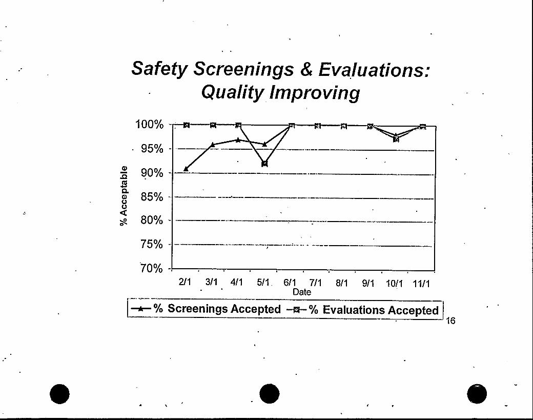
Safety Screenings 8 Evaluations:Qualify Improving
100% -:
- 95%--
90%-
85%-
g 80%-
75%-
70%- I
2/1 3/1 4/1 5/1. 6/1 7/1 8/1 9/1 10/1 11/1Date
[~% Screenings Accepted ~% Evaluations Accepted16

" 32.
28--
24
O 2OI16
OQ 120
LL'
e 4
p.
Root Cause Quality(Units 1 8, 2)
Quali Index28 - 35 = Excellent20 - 27,= Meets Standards
I I
May-99 Jun-99 JuI-99 Aug-99 Sep-99 Oct-99 Nov-99
17

Focus Going Forward
I Further Improve Product QualityI
II Enhance Organizational Capabilities
I Decrease Reliance on Contractors
w Transition to Plant Operations
We Are Preparedfor the Challenges Ahead

Chris Bakken
Site Vice President

Oversight Integrated Into Process:;=,. Discoy.er::=. ; Document
Discoveryva uate
.; Develop'pprove Implement"'mplementation
Verification
Accept Assess Affirm Approve(CNO)
Restart
Performance Assurance
NRG InspectionsConcur
(Region III,Adqiinistrator) 20
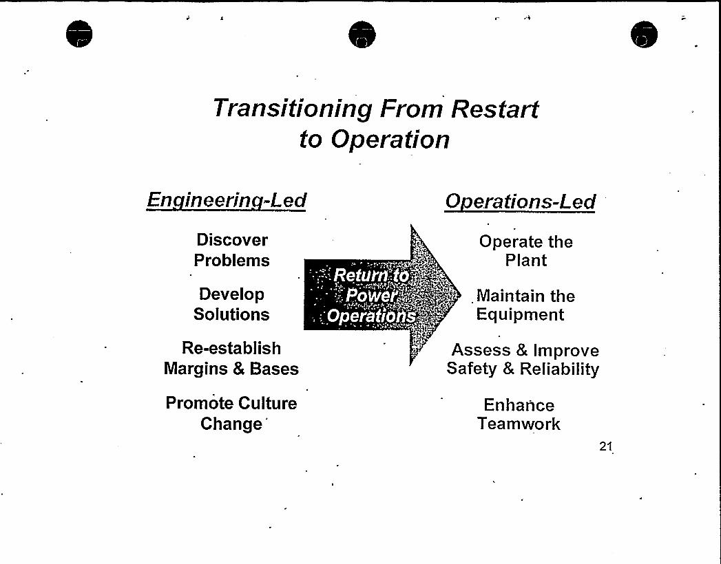
Transitioning From Restartto Operation
En ineerin L-ed Q erations-Led
DiscoverProblems
DevelopSolutions
Re-establishMargins 8 Bases
Promote Culture
Change'perate
thePlant
Maintain theEquipment
Assess 8 ImproveSafety 8 Reliability
EnhanceTeamwork
21.

Emergency Procedure Upgrade Project(Unit 2 8 Common)
450-
400-
350Ul
300CJ
250—Kg 200 .
~~
150
100
Actual
50
0.
~rp-
22
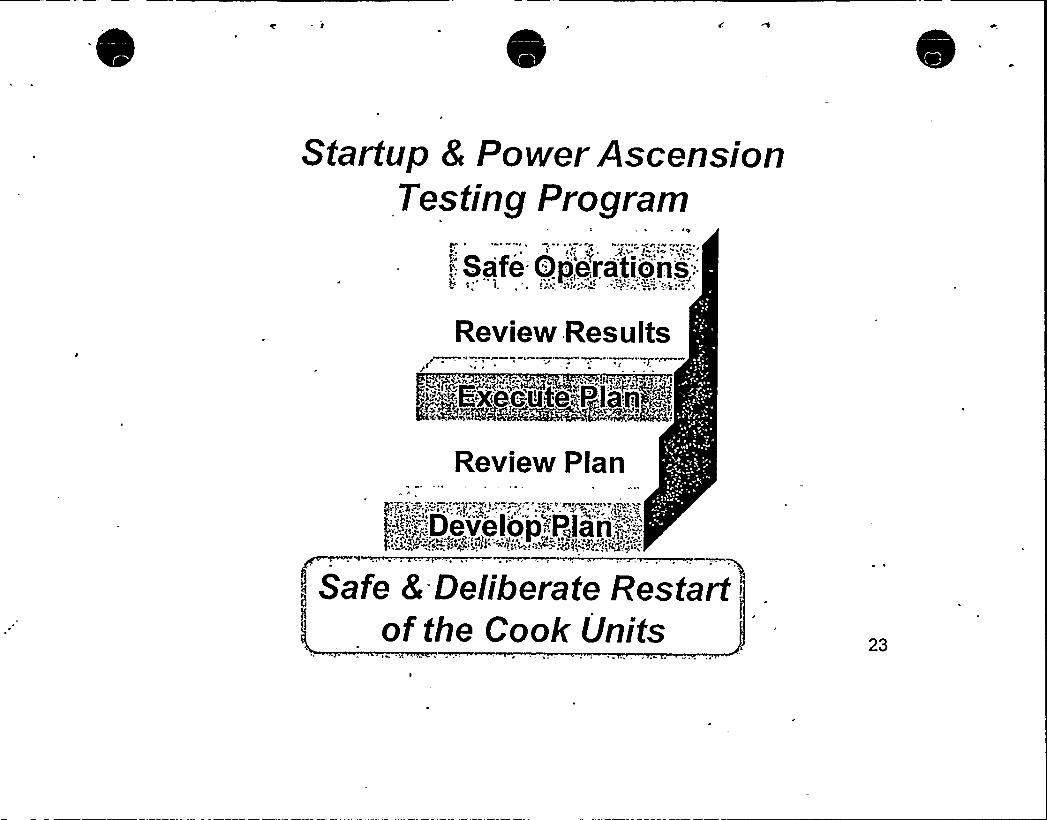
Startup 8 Power AscensionTesting Program
.:: Safe Operations:
Review Results
„="~ -':x"e,cu 'e;"".<.a'ri,.-".".,
Review Plan
4-;,'~:.".:D.evelop.-;:P,,lan'.;-',.;:-",';
. "I4
Safe 8 Deliberate Restartof the Cook Units 23
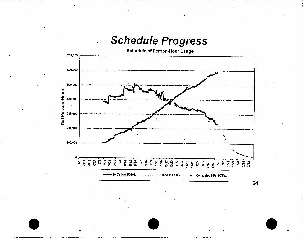
700,000 .
Schedu/e F'mgressSchedule of Person-Hour Usage
600,000
500,000Vl
0400,000
0lD
300,000
K200,000
100,000
0C9 r 0 h '0 0) ~ Ol 0 4 C4 0 h IO C9 ~ Ch h Q N ON ~>v cv cv Q ~ Pl -p) Q ~ cv Q p ~,cv
~To Go Hrs 1OTAL - - - ~ SITE Schedule 01/03 ~ Completed HRs TOTAL
24

Focus Going Foneard
I Unit 2I Unit 1
@ Human Performance
@ Control of Work
@ Backlogs
We Are Preparedfor the Challenges Ahead .
25

Bob Powers
Senior Vice President &Chief Nuclear Officer
26

Summary
@ We Understand the Past
II We Know How to Find and Fix Our Problems
s We Are Workirig Our Plan & Schedule
I We Are Prepared for the Challenges Ahead~ - — *.
We Are Taking the Timeto Do the Job Right
27
Doingit right ...
Every step o the way.COOK NUCLEAR PLANT

UNION OFCONCERNEDSClENTISTS
January 10, 2000
Chairman Richard ivleserveCommissioner Nils J. DiazCommissioner Greta J. DicusCommissioner Edward ivfcGaffigan. Jr.Commissioner Jeffrey S. ivlerrifieldUnited States Nuclear Regulatory CommissionWashington, DC 20555-0001
, SUBJECT: RESTART OF DONiALDC. COOK NUCLEAR PLANT
Dear Chairman and Commissioners:
On June 2. 1998. I participated in the Commission brieting on the proposed restart of ivfillstone Unit 3.ivly presentation ended ivith these tivo conclusions:
~ NU's future performance cannot be predicted, but it is known that the NRC staff lacks theability to reliably shut down plants with regulatory performance problems.
~ iVIillstone Unit 3 should not restart without that adequate protection standard being met.
There are many similarities between D C Cook Unit 2 today and the lvlillstone Unit 3 facility in June1998. Both had been closed for more than tivo years ivhile tht!ir owner made numerous corrections to thephysical plant and to procedures. To UCS, the extent of these changes strongly suggests failure by theplant owners —and by the NRC —to have properly focused on safety.
There are also key differences. Based on evidence such as the orifices installed in the recirculation spraysystem piping which caused the almost immediate common-mode fat10re of the expansion bellows in all
, lines and the unexpectedly large number of Level 4 discrepancy reports, we had zero confidence that theNRC's Special Projects Office divas doing an adequate job ofensuring Millstone was ready to restart.Based on evidence such as the addition ot the Generic Letter 89-10 MOV program to the i>lanualChapter 0350 scope. ive have sufficient contidence that the NRC's Region IIIstaff is doing an adequatejob ot determining ivhen D C Cook is ready tor restart. UCS provided additional commentary on thedift'erences betiveen ivlillstone and D C Cook in our letter of December 4, 1998.
The most important difference between June 1998 and today is the change in the NRC's regulatoryoversight process. IVe opposed the!vfillstone resta'rt because we felt that the NRC staff lacked the abilityto tal'e appropriate. timely actions t'or operating nuclear plants with pertormance problems. The revisedreactor oversight process is precisely the type ot "adequate protection standard" that we felt needed to bein place before ivlillstone Unit 3 divas restarted.
Washington Office: 1616 P Street NW Suite 310 o Washington OC 20036-1495 ~ 202-3324900 ~ FAX: 202.3324905
~
~Cambridge HeadquarterS: TWO Brattle Square ~ Cambridge MA 02238 9105 ~ 617 547 5552 ~ FAX.'17-864.9405California Office: 2397 Shattuck Avenue Suite 203 ~ Berkeley CA 94704.1567 ~ 510-843-1872 ~ FAX: 510.843.3785
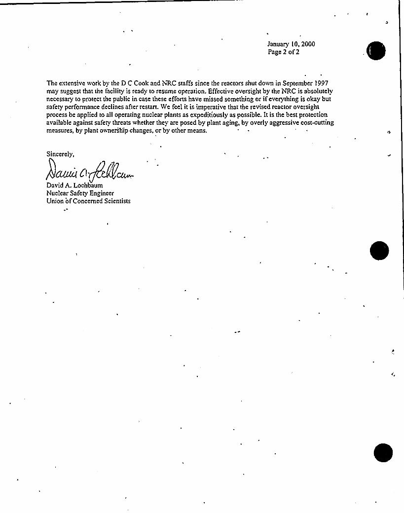
January 10, 2000Page 2 of2
\
The extensive work by the D C Cook and NARC staffs since the reactors shut down in September 1997
may suggest that the facility is ready to resume operation. Effective oversight by the NRC is absolutelynecessary to protect the public in case these efforts have missed something or ifeverything is okay butsafety performance declines after restart. Ne feel it is imperative that the revised reactor oversightprocess be applied to all operating nuclear plants as expeditiously as possible. It is the best protectionavailable against safety threats whether they are posed by plant aging, by overly aggressive cost-cuttingmeasures, by plant ownersh'ip changes, or by other means.
Sincerely,
i'ue<Ci.
David A. LochbaumNuclear Safety EngineerUnion ofConcerned Scientists

UNION OFCONCERNEDSCIENTISTS
December 4, 1998
Chairman Shirley A. JacksonCommissioner Nils J. DiazCommissioner Greta J. DicusCommissioner Edward gvfcGaffigan, Jr.Commissioner Jeffrey S. MerrifieldUnited States Nuclear Regulatory CommissionWashington, DC 20555-0001
SUBJECT: NRC Regulatory Performance ln the D C Cook Matter
Dear Chairman and Commissioners:
Thank you for the opportunity to comment during the November 30 Commission briefing on D C Cook.At the time, we had not finalized our perspectives on D C Cook so I was unable to accept the invitation. Iam providing our comments, which were updated to address issues raised during the briefing.
We divide our D C Cook experience into two portions. The NRC's regulatory performance prior to mid-January 1998 was mostly bad although there were some positives. Since mid-January 1998, theregulatory performance has been satisfactory with one notable exception.
BackaroundWe had not been monitoring conditions at D C Cook prior to September 1997. But we had been closelymonitoring the NRC's architect/engineer inspections because we were interested in the adequacy ofdesign bases information. Millstone demonstrated that configuration management problems had thepotential for adversely affecting safety margins. Through the issuance of Information Notice 96-17 inMarch 1996 and the 50.54(f) letters in Ot!tober 1996, the NRC commiihicated Millstone's designbases/configuration management problems to the nuclear industry with its expectations in this area.
The lgr'RC complemented the 50.54(f)-effort with the architect/engineer inspections. These inspectionsverified the 50.54(t) responses. In addition, they assessed the original designs.,
r
These NRC actions were the appropriate response to the iMillstone findings. A problem was identified ativlillstone, but it was only one data point. Rather than simply correcting the known problems atMillstone, the NRC's actions provided the means to understand the extent of the industry's design basesproblems.
Washington ONce: 1616 P Street NW Suite 310 o Washington OC 20036-1495 ~ 202.3324900 ~ FAX; 202-3324905Cambridge Headquarters: Two Brattle Square ~ Cambridge MA 02238.9105 ~ 617.547-5552 ~ FAX: 617-864-9405
Cali(amia QNtce: 2397 Shaiiuck Avenue Suite 203 ~ Berkeley CA 94704.1567 ~ 510.843-1872 ~ FAX: 510-843-3785

December 4, 1998Page 2
Pre-January 1998 Ex erienceD C Cook's shutdown due to problems identified during the hRC's architect"engineer inspectionattracted our auention. The NRC's Confirmatory Action Lener along with information in the NARC'sDaily Event Reports indicated that there were serious problems in both of the high-risk safety systemsexamined by the av'RC team. Some of these problems dated back to the plant's construction while othershad been recently introduced.
There was some discussion during the November 30 briefing about these findings in light ofD CCook's prior SALP history. We never considered looking at the SALP history when we sought to put thefindings in context. Instead, we reviewed the licensee's February 1997 response to the 50.54(f) letter. Welearned that the licensee was in the middle of a design bases document (DBD) development effort. TheDBDs for some systems had already been issued while several others were to'be developed. According tothe licensee, DBDs were not issued until a verification/validation effort provided reasonable assurancethat their information accurately represented the as-built plant configuration.
1
The DBDs for the systems examined during the NRC's A/E inspection had been issued before February1997. In our view, that fact eliminated any excuse for these systems having so many serious, undetectedproblettis. The development, verification, and validation efforts for the DBDs on these two systemsshould have identified these problems. Had the DBDs for these systems not been completed, we wouldhave given the licensee benefit of the doubt and assumed that many, ifnot all, of the problems wouldhave been self-identified by that effort.
In our view, the CAL did two important things. First, it ensured that the specific hardware problemsidentified by the NRC team were corrected prior to restart. And second, it ensured that the programmaticdeticiencies that caused the hardware problems were corrected prior to restart. We fullyagreed that thesesteps were necessary.
However, we felt that another step was also warranted. The licensee's programmatic deficiencies, whichwere responsible for many of the problems identified during the AIE inspection, could have causedhardware problems in systems other than the two examined by the NRC. There was no evidence or otherreason to suspect, yet alone believe, that the problems were confined to just these two systems.Furthermore, there was ample reason to believe that any problems would remain undetected. After all,the licensee's best self-assessment efforts had been plainly demonstrated to be less than adequate. Yetthe NRC was not taking any steps to verify that the sixty-plus other safety systems were reasonablyproblem-free prior to restart.
The purpose of our 2.206 petition was to fill the hole in the NRC's CAL. We asked that the plant not be
permitted to restart until there was reasonable assurance that there were undetected problems in othersystems. XVe submitted the petition on October 9, 1997, because I had been informed by Mr. Jan Strasmaof Region IIIand Mr. John Hickman ofNRR-HQ that the licensee expected to restart D C Cook by lateOctober 1997. I had also been told by Mr. Hickman that the AIE inspection report might not be issued
until after restart. We felt compelled to submit the petition based on the available information. We
requested a public hearing to present our concerns to the NRC staff.
Throughout October and i4ovember. the restart date repeatedly slipped a couple weeks at a time. Byletter dated December 2. 1997. the licensee intormed the NiRC that the CAL items had been resolved and
the plant was ready to restart. By letter dated December 9, 1997, the NRC acknowledged receiving ourpetition submitted two months earlier and indicated that it was under consideration.

December 4, 1998Page 3
During the first v eek of January 1998, I called lvfr. John Hickman who had been"assigned as Petitios
; Ianager. He informed me about a upcoming!hd'RC meeting with the licensee to review the CAL-itemsand indicated that the tSRC might liftthe CAL shortly thereafter. Having heard ~nothin from the htRCregarding our petition other than the December 9 receipt acknowledgement, I asked Mr. Hickman aboutits status. He told me that the 'hhdRC had decided not to grant our request for a public hearing and plannedto issue a Director's Decision after the plant restarted. I asked why the NRC had denied our petition. Mr.Hickman explained that the NRC staffhad not yet rendered a decision on the petition, but would do soafter restart. To us, defemng the decision until after restart was essentially denying the petition since wesought actions which could only be performed before restart.
We responded to this totally absurd NRC position by going to battle stations..We immediately initiated a
media campaign to alert every newspaper, TV station, and radio station near the plant to the cavalierattitude being taken by the NRC staff. We also contacted activists and UCS members livingnear theplant-and encouraged them to contact their state and local government officials about the problems at DC Cook.
After a few headlines and Congressional inquiries, the NRC staff reversed its decision and decided itcould spare a few minutes'to listen to our concerns. On January 12, 1998, I read a prepared
statement'isting
our concerns during a public meeting. This meeting marked the end of the first portion ofour D CCook experience. For us, the worst was over.
UCS submitted our petition on October 9, 1997, based. on a thorough evaluation of information availableat that time. To our dismay, the issues raised in our petition were virtually ignored by the NRC staff intheir haste to get the CAL items closed out so the plant could be restarted. We feel this reflects a
pen'asive attitude by the NRC staff that safety concerns raised by the public, whether via allegations,2.206 petitions, or questions. are merely distractions to be handled as time allows rather than as inputivhtch might have any consequence.
Post-Janua 1998 Ex erienceThe second phase began on a positive note. NRC inspectors arrived at the D C Cook site within the nextday or so to look into the ice condenser concerns. We did not raise these ice condenser concerns —wemerely reminded the NRC staff about them. Mr. Curtis Overall had expressed these same concerns to the
C Region II staff during 1996 and to the NRC Inspector General s office during March 1997. Mr.Overall met with me the day before going to the IG. The NRC Region II staff handled Mr. Overall'sconcerns by merely calling the licensees for the Watts Bar, Sequoyah, Catawba, and McGuire nuclearplants and asking ifthey had any ice condenser problems. This 'tele-regulating'as the extent of RegionII s efforts to examine Mr. Overall's concerns.
4RC Region 111 handled the concerns in an, entirely different manner. They sent inspectors to look at the
D C Cook ice condensers. These inspectors contacted me, and then Mr. Overall, to ensure that they had a
thorough understanding of the concerns. They confirmed suspected problems with the metal screws and
identitied other problems. The thdRC staff invoked its Manual Chapter 0350 process for D C Cook in
April 1998'after the licensee opted to melt out both ice condensers for inspections and repairs.
I The prepared statement had been toned down —twice —by UCS management in Cambridge.

December 4, 1998Page 4
I have attended all of the D C Cook public meetings held in Rockville during 1998 and reviewed all ofthe NRC correspondence to the licensee this year. Based on this information, it is apparent that our roleis to stay out of the way and let the; vRC staff do its job. It is doing a very fine job.
The NRC staff s actions since mid-January 1998 are even more impressive when contrasted with theMillstone Unit 3 restart process. At D C Cook, the NRC staff has expanded the scope when warranted asevidenced by adding the Generic Letter 89-10 MOV issues to the restart list and by following up on theAFW system SSFI findin~;At Millstone, the NRC staff was unwilling to expand the scope for anyreason. At D C Cook, the NRC staff backed probing questions with rigorous onsite inspections. AtMillstone, the NRC staff essentially asked 'true/false'uestions and performed cursory inspections. At DC Cook, the NRC staff gave careful consideration to public input. At Millstone, the NRC staff dressedwell for public meetings.
The Millstone Unit 3 and D C Cook situations are very similar. Both plants remained shut down for anextended period while numerous hardware and programmatic problems were corrected. The NRC staffimplemented Manual Chapter 0350 in both cases. The same process yielded exactly opposite results. Icannot suggest a single change to improve the 0350 process for D C Cook and have confidence that theplant willnot be restarted until it has the necessary safety margins. Ifivfillstone Unit 3 had adequatesafety margins at restart, it was in spite of the NRC staff, not because of them. I halfway believe that the5 fillstone Special Projects Office would have dismissed a report that the reactor head was fastened withVelcro with some lame excuse like, "well, are you aware. ofany reactor accident that has been caused byVelcro?"
The only fault that we can find with the NRC's regulatory performance for D C Cook since mid-January1998 involves the proposed 5500,000 civil penalty. As we pointed out during the August 1998 informalhearing on our petition, the NRC could have imposed a civilpenalty of at least $4.627 billion. We didnot advocate such a severe tine, but thought that a Millstone-sized fine was warranted. That D C Cookreceived the 'volume discount'id not surprise us because the NRC's current enforcement policy isextremely subjective and inconsistent. We call it the "Wheel of Misfortune."
Noteworth PerformancesDuring the November 13'1998, stakeholder meeting, several people commented on the talent anddedication of the NRC staff. UCS shares these views and would like to take this opportunity to identifywhat we consider to be stellar performance by NRC staff related to Htb D C Cook issues:
Mr. John Thompson led the '.vRC's A/E inspection team. While the team found numerous seriousproblems, it was not like shooting fish in a barrel. The dead-end portions of the containment hadeluded detection for nearly thirty years. It was a subtle finding of high safety significance. The othertindings, such as the containment sump cover problem, were also very commendable catches. Mr.Thompson deserves credit for leading this team to such important findings.
%fr. Edward Schweibinz participated in the fibrous material inspection and follow-up activities.During a public meeting in Rockville. Mr. Schweibinz resisted several attempts by the licensee todismiss the extent and severity ot the fibrous material problems based on half-truths and t'alse
promises. Mr. Schweibinz deserves credit for having prepared so well tor this encounter.
Mr. lvIelvin Holmberg participated in the ice condenser inspection and follow-up activities. During a
ibfanual Chapter 0350 meeting in Rockville, Mr. Holmberg displayed a thorough understanding of

December 4, 1998Page 5
the design and licensing bases for the D C Cook ice condensers. During that meeting, both 4~RC andlicensee staff deferred to b Ir. Holmberg's knowledge of the subject. ivfr. Holmberg deserves creditfor having mastered this complex information and applying it so effectively.
Mr. John Grobe chaired the lvfanual Chapter 0350 panel for D C Cook. During two public meetingsin Rockville and the pre-decisional enforcement conference, Mr. Grobe repeatedly asked probingquestions with substantive follow-ups. He insisted that the licensee show the NRC staff that thingswere okay and did not rely solely on the licensee's unsubstantiated positive responses. Mr. Grobedeserves credit for conducting the Manual Chapter 0350 process in a fair and effective manner.
Mr. John Stang was the Petition Manager for our petition beginning in February 1998. Mr. Stangensured that he fullyunderstood the issues raised in our petition, its supplement, and relatedallegations. Mr. Stang notified me promptly ofany developments regarding our petition. Mr. Stangdeserves credit for very capable administration of our petition.
VCS realizes that there are many other individuals as capable and dedicated as these five gentlemen. Atthe risk ofslighting others, we felt their performance merited recognition.
Unresolved IssuesUCS feels confident that D C Cook willbe restart until the necessary safety margins have been restored.The bad news is that the following issues remain unresolved:
1. We cannot understand why D C Cook was shut down in September 1997. The reason stated for theshut down, reiterated at least twice during the November 30, 1998, Commission briefing, was thatthe dead-end compartment issue raised doubt about the plant's ability to cope with a small-break loss .
ofcoolant accident (LOCA). For a large-break LOCA, sufficient water inventory would be available.The risk tactor appears comparable to that from the BWR suction strainer issue. Yet, no BWR had toshut down. The NRC allowed these BWRs to operate until modifications could be made at the nextrefueling outage. It seems either unriecessary for D C Cook to shut down or improper for the BIVRsto continue operating. We believe that the only reason that D C Cook was shut down was because the
'RC identified its problems while the BWR suction strainer problems were identified by thelicensees. The NRC's charter is to protect the public —not the feelings or finances of the licensees.
2. We cannot understand why the 4i'RC staff s reaction to the D C Cook findings did not addresspossible undetected hardware problems in the other sixty-plus safety systems. Hindsight shows thatour call for an examination into these other systems was warranted. However, we feel that such anexamination was warranted even ifno other problems had been identified. The problems identifiedby the NRC A/E team were serious. The plant should not have been restarted without a determinationifthese were its only problems.
3. We cannot understand how the 4RC staff could even think about deferring its decision on ourpetition until after restart. There's something profoundly wrong with the 2.206 process because
safety concerns are not being addressed in good faith by the NRC staff. We sincerely feel, but willnever be able to prove, that D C Cook would have restarted in early 1998 with its ice condenserbroken had we not launched a media campaign. We still believe that the NRC staff evaluates safetyissues based on their Neilson ratings instead ot on their safety merits.
December 4 1998Page 6
We cannot understand why the NRC's Manual Chapter 0350 process allows such widespread resultsas experienced at D C Cook and Millstone Unit 3. The D C Cook experience suggests that theprocess, when implemented properly, is effective. The Millstone experience suggests that the NRClacks the ability to ensure this process is properly implemented.
I
5. We cannot understand why the NRC staff 'buried'afety concerns that Mr. Overall raised during1996 and 1997. There's something profoundly wrong in Region II. We feel, but fortunately willnever be able to prove,&at the ice condenser concerns would still be buried ifD C Cook were inRegion II. Had the NRC Region II staff done the right thing in 1996, then the D C Cook and Catawbaproblems would have been identified and corrected before 1998.
UCS is not seeking a direct response on these unresolved issues. Instead, we respectfully request that youkept these issues in mind as you review the NRC staQ's proposed changes to the inspection,enforcement, and assessment processes. I agree with Commissioner Diaz's comment that the enemy ofgood is better, but many of these issues can and should be corrected by good processes.
Sincerely,
P4&David A. Lochb mNuclear Safety EngineerUnion ofConcerned Scientists
CC: i41r. John Thompsonlvlr. Edward SchweibinzIvfr. Melvin HolmbergMr. John GrobeMr. John Stang
D.C. COOK RESTART OVERSIGHTAa id««i4'4 ~ l««r «. l l+ ««Alh)A4 « ~ 2 e4 «At . Ikey v +~a~ A~AA.4w'4dk+v'4I «014 tl44 . W4 41 «eAkL, A'« ~ . ~ 'tel
Cjj
@0
January 10, 2000
Slide 1

D.C. COOK RESTART OVERSIGHT
A. BRIEF OUTAGE HISTORY
B. ASSESSMENT, OF D.C. COOK PROBLEMDISCOVERY
C. ASSESSMENT OF D.C. COOKCORRECTIVE ACTIONS
D. STATUS OF LICENSING ACTIVITIES
E. NRC RESTART ACTIONS
Slide 2

A. BRIEF OUTAGE HISTORYt ,. ~ w i > c « " ~ s ~> ~ »
~ PLANT SHUTDOWN IN SEPTEMBER 1997
~ NRC IMPLEMENTS MC 0350 RESTARTOVERSIGHT PROCESS
~ 1998 DISCOVERY EFFORTS
~ RESTART PLAN MODIFIEDIN MARCH 1999
Slide 3

B. ASSESSMENT OF D.C. COOKPROBLEM DISCOVERY
~ D.C. COOK REASSESSES SYSTEMSPROGRAMS AND FUNCTIONS
~ NRC CONDUCTS CONFIRMATORYINSPECTIONS
Slide 4

C. ASSESSMENT OF D.C. COOKCORRECTIVE ACTIONS
~ CASE SPECIFIC CHECKLIST RESTARTISSUE RESOLUTION
~ CONFIRMATORYACTIONLETTER STATUS
Slide 5

D. STATUS OF LICENSINGACTIVITIES
~ r. 44 kl 4 44 ~ ('N "A lt 0 "V 4 w 41+I,''I I I ~ 'al IIAtu El/1@I - ~ \I ~ 4 „A4W«e g 8 '. V4
~ LICENSING ISSUES RESOLUTION~ REMAININGLICENSING ACTIONS FOR
RESTART
Slide 6

E. NRC RESTART ACTIONS
~ REMAININGINSPECTIONS FOR RESTART~ RESTART APPROVAL PROCESS
~ POST-RESTART OVERSIGHT~ TRANSITIONTO REVISED INSPECTION
AND ASSESSMENT PROCESS
Slide 7

JPN t~ ~
pt
g
Related Documents