1077-2618/10/$26.00©2010 IEEE An overview of recent research BY J. ACERO, J.M. BURD IO, L.A. BARRAG AN, D. NAVARRO, R. ALONSO, J.R. GARC IA, F. MONTERDE, P. HERN ANDEZ, S. LLORENTE, & I. GARDE T HIS ARTICLE PROPOSES SEVERAL research topics pertaining to the design and modeling of domestic induction appli- ances. Each topic stresses the most signifi- cant advances and future tendencies. The emphases and relative contributions of the articles published during the last few years are also discussed. In January 2008, Moreland’s article ‘‘The Induction Range: Its Performance and Its Development Prob- lems’’ [1] entered its 35th year of publication, which is one of the earliest references in the field of domestic induction heating. In addition, some patents dealing with induction-heating cookers of the past were almost contemporary [2]–[4]. During these 35 years, domestic induction hobs became increasingly popular because of their specific features such as safety, cleanliness, quick warming, and high efficiency. Some of these features derive from the fact that the heating is directly gener- ated in the vessel, unlike the traditional contact-heat- ing methods. The high efficiency of the induction hobs is attracting the attention of researchers devoted to highly efficient power electronic systems. Induction cookers constitute a major domestic applica- tion of the induction-heating phenomena. In such devices, Digital Object Identifier 10.1109/MIAS.2009.935495 © MASTERSERIES 39 IEEE INDUSTRY APPLICATIONS MAGAZINE MAR j APR 2010 WWW.IEEE.ORG/IAS

Welcome message from author
This document is posted to help you gain knowledge. Please leave a comment to let me know what you think about it! Share it to your friends and learn new things together.
Transcript

1077-2618/10/$26.00©2010 IEEE
An overview ofrecent research
B Y J . A C E R O ,J . M . B U R DI O ,L . A . B A R R A G A N ,D . N A V A R R O ,R . A L O N S O ,J . R . G A R CI A ,F . M O N T E R D E ,P . H E R N A N D E Z ,S . L L O R E N T E ,& I . G A R D E
THIS ARTICLE PROPOSES SEVERAL
research topics pertaining to the design
and modeling of domestic induction appli-
ances. Each topic stresses the most signifi-
cant advances and future tendencies. The emphases and
relative contributions of the articles published during the
last few years are also discussed.
In January 2008, Moreland’s article ‘‘The Induction
Range: Its Performance and Its Development Prob-
lems’’ [1] entered its 35th year of publication, which is
one of the earliest references in the field of domestic
induction heating. In addition, some patents dealing
with induction-heating cookers of the past were almost
contemporary [2]–[4]. During these 35 years, domestic
induction hobs became increasingly popular because of
their specific features such as safety, cleanliness, quick
warming, and high efficiency. Some of these features
derive from the fact that the heating is directly gener-
ated in the vessel, unlike the traditional contact-heat-
ing methods. The high efficiency of the induction hobs
is attracting the attention of researchers devoted to
highly efficient power electronic systems.
Induction cookers constitute a major domestic applica-
tion of the induction-heating phenomena. In such devices,Digital Object Identifier 10.1109/MIAS.2009.935495
©M
AS
TE
RS
ER
IES
39
IEE
EIN
DU
STR
YA
PP
LICA
TION
SM
AG
AZ
INE
MA
RjA
PR
20
10
WW
W.IE
EE
.OR
G/IA
S
the desired heating is done in metallic vessels by varyingthe magnetic field, which in turn is generated by a planarcoil fed by a power electronics inverter. Basically, adomestic induction arrangement consists of a planar mul-titurn winding situated below a metallic vessel and sup-plied by a medium-frequency power source, normallyoperated between 20 and 100 kHz. Therefore, domesticinduction-heating appliances encompass a variety of tech-nologies traditionally grouped into converters, digitalcontrol, and magnetic components (Figure 1). In this arti-cle, some of the recent research carried out in these topics
is reviewed, and some remarkable milestones since pub-lishing [1] are listed.
Inverter Topologiesand Modulation StrategiesInduction appliances get energy from the mains voltage,which is rectified by a bridge of diodes. A bus filter isdesigned to allow a high-voltage ripple, getting a resultantinput power factor close to one. Then an inverter topologysupplies the ac (between 20 and 100 kHz) to the inductioncoil. Today, burners of domestic induction appliances aredesigned to deliver up to 3.5 kW ac. A schematic diagramof the power stage of a domestic induction apparatus isshown in Figure 2.
Formerly, the power electronics was located in a forced-air-cooled separate box placed on the floor, using thyris-tors as switching devices [5]. However, in the later 1990s,the application of the resonant inverter topologies causedthe integration of the electronics and the inductors in acompact hob, whose housing is compatible with the con-ventional resistive cookers. Having in mind that hobs arenormally placed over an oven, an environment tempera-ture of 75 C (167 F) is usually considered for electronicsdesign purposes, and a highly efficient energy conversionis mandatory. Today, resonant inverter topologies are com-monly used in induction hobs. The most used topologiesare the full-bridge [6], [7], half-bridge [8]–[12], and twosingle-switch inverter topologies, namely zero-voltage
switching (ZVS) [13], [14] and zero-current switching [15]. At present,the half-bridge topology is the mostpopular one because of its robustnessand cost savings [16].
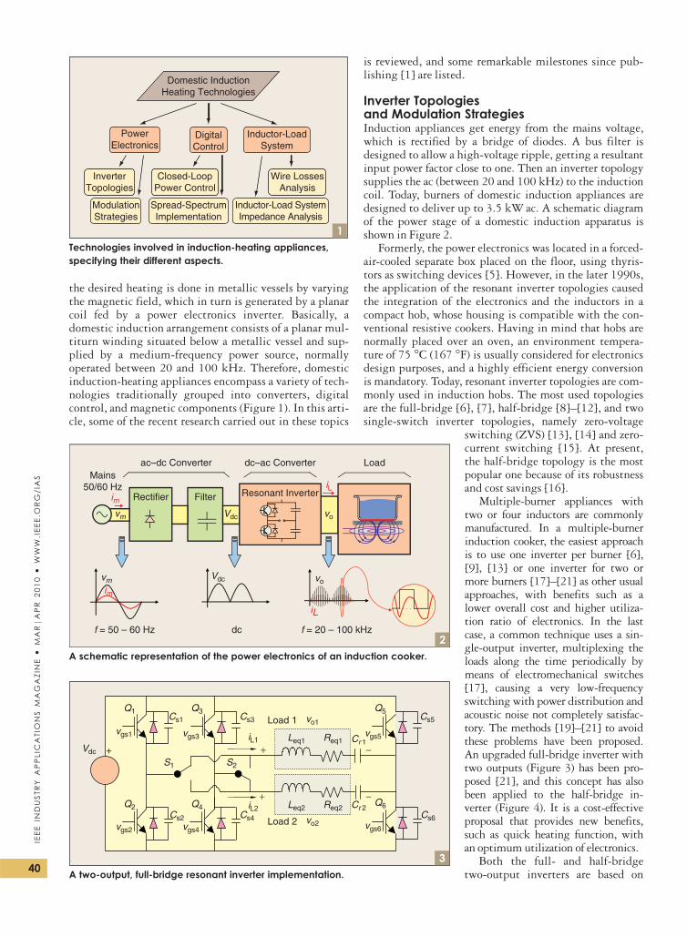
Multiple-burner appliances withtwo or four inductors are commonlymanufactured. In a multiple-burnerinduction cooker, the easiest approachis to use one inverter per burner [6],[9], [13] or one inverter for two ormore burners [17]–[21] as other usualapproaches, with benefits such as alower overall cost and higher utiliza-tion ratio of electronics. In the lastcase, a common technique uses a sin-gle-output inverter, multiplexing theloads along the time periodically bymeans of electromechanical switches[17], causing a very low-frequencyswitching with power distribution andacoustic noise not completely satisfac-tory. The methods [19]–[21] to avoidthese problems have been proposed.An upgraded full-bridge inverter withtwo outputs (Figure 3) has been pro-posed [21], and this concept has alsobeen applied to the half-bridge in-verter (Figure 4). It is a cost-effectiveproposal that provides new benefits,such as quick heating function, withan optimum utilization of electronics.
Both the full- and half-bridgetwo-output inverters are based on
ModulationStrategies
Inductor-LoadSystem
Domestic InductionHeating Technologies
Inductor-Load SystemImpedance Analysis
PowerElectronics
DigitalControl
InverterTopologies
Spread-SpectrumImplementation
Closed-LoopPower Control
Wire LossesAnalysis
1Technologies involved in induction-heating appliances,specifying their different aspects.
vm vo
vo
im
iL
iL
Mains50/60 Hz
vm
f = 50 – 60 Hz
FilterRectifier
ac–dc Converter
dc f = 20 – 100 kHz
Resonant Inverter
dc–ac Converter Load
Vdc
Vdc
2
im
A schematic representation of the power electronics of an induction cooker.
Vdc
Load 1
Load 2
+ −iL2
iL1+
S1 S2
Cs1 Cs3
Cs4Cs2
Cs5
Cs6
+ −
vo1
vo2
vgs1
vgs2
vgs3 vgs5
vgs6vgs4
Q1 Q3 Q5
Q6Q4Q2
Leq1
Leq2
Req1
Req2 Cr 2
Cr 1
3A two-output, full-bridge resonant inverter implementation.
40
IEE
EIN
DU
STR
YA
PP
LIC
ATI
ON
SM
AG
AZI
NE
MA
RjA
PR
20
10
WW
W.I
EE
E.O
RG
/IA
S
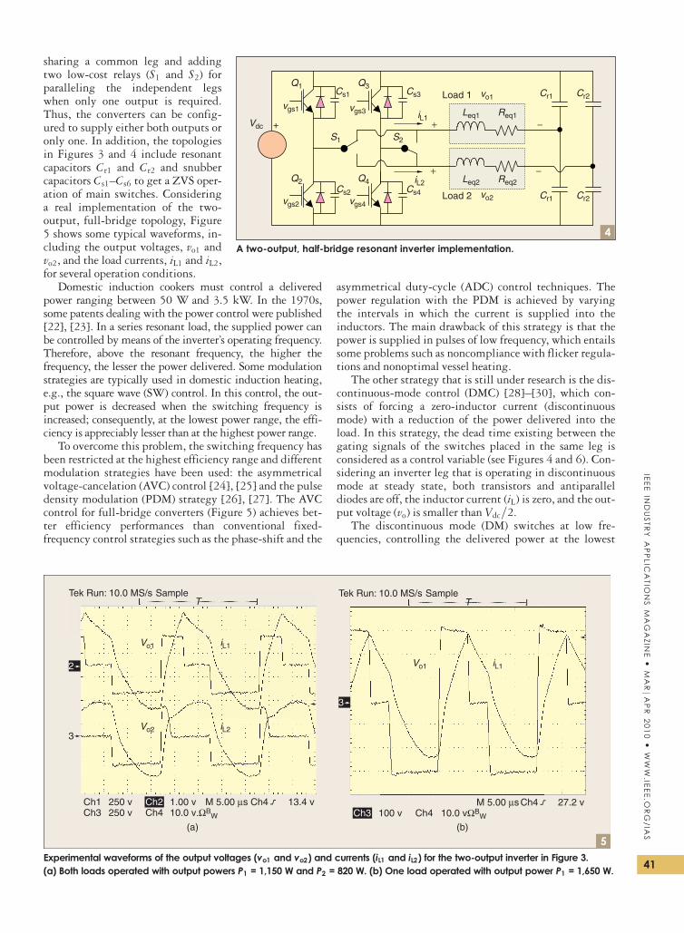
sharing a common leg and addingtwo low-cost relays (S1 and S2) forparalleling the independent legswhen only one output is required.Thus, the converters can be config-ured to supply either both outputs oronly one. In addition, the topologiesin Figures 3 and 4 include resonantcapacitors Cr1 and Cr2 and snubbercapacitors Cs1–Cs6 to get a ZVS oper-ation of main switches. Consideringa real implementation of the two-output, full-bridge topology, Figure5 shows some typical waveforms, in-cluding the output voltages, vo1 andvo2, and the load currents, iL1 and iL2,for several operation conditions.
Domestic induction cookers must control a deliveredpower ranging between 50 W and 3.5 kW. In the 1970s,some patents dealing with the power control were published[22], [23]. In a series resonant load, the supplied power canbe controlled by means of the inverter’s operating frequency.Therefore, above the resonant frequency, the higher thefrequency, the lesser the power delivered. Some modulationstrategies are typically used in domestic induction heating,e.g., the square wave (SW) control. In this control, the out-put power is decreased when the switching frequency isincreased; consequently, at the lowest power range, the effi-ciency is appreciably lesser than at the highest power range.
To overcome this problem, the switching frequency hasbeen restricted at the highest efficiency range and differentmodulation strategies have been used: the asymmetricalvoltage-cancelation (AVC) control [24], [25] and the pulsedensity modulation (PDM) strategy [26], [27]. The AVCcontrol for full-bridge converters (Figure 5) achieves bet-ter efficiency performances than conventional fixed-frequency control strategies such as the phase-shift and the
asymmetrical duty-cycle (ADC) control techniques. Thepower regulation with the PDM is achieved by varyingthe intervals in which the current is supplied into theinductors. The main drawback of this strategy is that thepower is supplied in pulses of low frequency, which entailssome problems such as noncompliance with flicker regula-tions and nonoptimal vessel heating.
The other strategy that is still under research is the dis-continuous-mode control (DMC) [28]–[30], which con-sists of forcing a zero-inductor current (discontinuousmode) with a reduction of the power delivered into theload. In this strategy, the dead time existing between thegating signals of the switches placed in the same leg isconsidered as a control variable (see Figures 4 and 6). Con-sidering an inverter leg that is operating in discontinuousmode at steady state, both transistors and antiparalleldiodes are off, the inductor current (iL) is zero, and the out-put voltage (vo) is smaller than Vdc=2.
The discontinuous mode (DM) switches at low fre-quencies, controlling the delivered power at the lowest
Vdc
Load 1
Load 2
+ −iL2
iL1+
S1 S2
Cs1 Cs3
Cs4Cs2
+ −
vo1
vo2
vgs1
vgs2
vgs3
vgs4
Q1 Q3
Q4Q2
Leq1
Leq2
Req1
Req2
Cr1
Cr1
Cr2
Cr2
4A two-output, half-bridge resonant inverter implementation.
Tek Run: 10.0 MS/s Tek Run: 10.0 MS/s SampleTT
Sample
Ch1Ch3
Ch2Ch4
1.00 v
(a) (b)
Vo2
Vo1
iL2
iL1
Vo1 iL1
M 5.00 µs Ch4 13.4 v10.0 v.ΩB
W
250 v250 v
2
3
Ch4M 5.00 µs Ch4 27.2 v
10.0 vΩBW100 vCh3
3
5Experimental waveforms of the output voltages (vo1 and vo2) and currents (iL1 and iL2) for the two-output inverter in Figure 3.(a) Both loads operated with output powers P1 = 1,150 W and P2 = 820 W. (b) One load operated with output power P1 = 1,650 W.
41
IEE
EIN
DU
STR
YA
PP
LICA
TION
SM
AG
AZ
INE
MA
RjA
PR
20
10
WW
W.IE
EE
.OR
G/IA
S
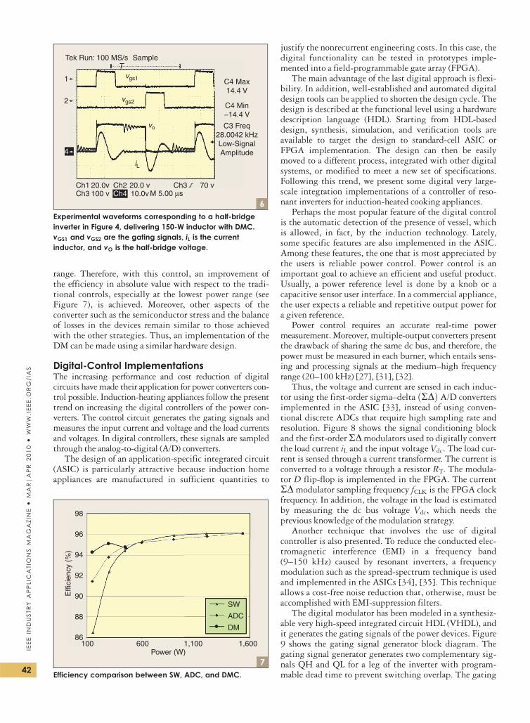
range. Therefore, with this control, an improvement ofthe efficiency in absolute value with respect to the tradi-tional controls, especially at the lowest power range (seeFigure 7), is achieved. Moreover, other aspects of theconverter such as the semiconductor stress and the balanceof losses in the devices remain similar to those achievedwith the other strategies. Thus, an implementation of theDM can be made using a similar hardware design.
Digital-Control ImplementationsThe increasing performance and cost reduction of digitalcircuits have made their application for power converters con-trol possible. Induction-heating appliances follow the presenttrend on increasing the digital controllers of the power con-verters. The control circuit generates the gating signals andmeasures the input current and voltage and the load currentsand voltages. In digital controllers, these signals are sampledthrough the analog-to-digital (A/D) converters.
The design of an application-specific integrated circuit(ASIC) is particularly attractive because induction homeappliances are manufactured in sufficient quantities to
justify the nonrecurrent engineering costs. In this case, thedigital functionality can be tested in prototypes imple-mented into a field-programmable gate array (FPGA).
The main advantage of the last digital approach is flexi-bility. In addition, well-established and automated digitaldesign tools can be applied to shorten the design cycle. Thedesign is described at the functional level using a hardwaredescription language (HDL). Starting from HDL-baseddesign, synthesis, simulation, and verification tools areavailable to target the design to standard-cell ASIC orFPGA implementation. The design can then be easilymoved to a different process, integrated with other digitalsystems, or modified to meet a new set of specifications.Following this trend, we present some digital very large-scale integration implementations of a controller of reso-nant inverters for induction-heated cooking appliances.
Perhaps the most popular feature of the digital controlis the automatic detection of the presence of vessel, whichis allowed, in fact, by the induction technology. Lately,some specific features are also implemented in the ASIC.Among these features, the one that is most appreciated bythe users is reliable power control. Power control is animportant goal to achieve an efficient and useful product.Usually, a power reference level is done by a knob or acapacitive sensor user interface. In a commercial appliance,the user expects a reliable and repetitive output power fora given reference.
Power control requires an accurate real-time powermeasurement. Moreover, multiple-output converters presentthe drawback of sharing the same dc bus, and therefore, thepower must be measured in each burner, which entails sens-ing and processing signals at the medium–high frequencyrange (20–100 kHz) [27], [31], [32].
Thus, the voltage and current are sensed in each induc-tor using the first-order sigma–delta RDð Þ A/D convertersimplemented in the ASIC [33], instead of using conven-tional discrete ADCs that require high sampling rate andresolution. Figure 8 shows the signal conditioning blockand the first-order RD modulators used to digitally convertthe load current iL and the input voltage Vdc. The load cur-rent is sensed through a current transformer. The current isconverted to a voltage through a resistor RT. The modula-tor D flip-flop is implemented in the FPGA. The currentRD modulator sampling frequency fCLK is the FPGA clockfrequency. In addition, the voltage in the load is estimatedby measuring the dc bus voltage Vdc, which needs theprevious knowledge of the modulation strategy.
Another technique that involves the use of digitalcontroller is also presented. To reduce the conducted elec-tromagnetic interference (EMI) in a frequency band(9–150 kHz) caused by resonant inverters, a frequencymodulation such as the spread-spectrum technique is usedand implemented in the ASICs [34], [35]. This techniqueallows a cost-free noise reduction that, otherwise, must beaccomplished with EMI-suppression filters.
The digital modulator has been modeled in a synthesiz-able very high-speed integrated circuit HDL (VHDL), andit generates the gating signals of the power devices. Figure9 shows the gating signal generator block diagram. Thegating signal generator generates two complementary sig-nals QH and QL for a leg of the inverter with program-mable dead time to prevent switching overlap. The gating
Tek Run: 100 MS/s
C4 Max14.4 V
C4 Min−14.4 V
C3 Freq28.0042 kHzLow-SignalAmplitude
TSample
Ch1Ch3
20.0v100 v
20.0 v10.0vCh4
Ch2
vo
vgs2
vgs1
iL
M 5.00 µsCh3 70 v
4
2
1
6Experimental waveforms corresponding to a half-bridgeinverter in Figure 4, delivering 150-W inductor with DMC.vGS1 and vGS2 are the gating signals, iL is the currentinductor, and vO is the half-bridge voltage.
Effi
cien
cy (
%)
98
96
94
92
90
88
86100 600 1,100 1,600
Power (W)
SW
ADC
DM
7Efficiency comparison between SW, ADC, and DMC.
42
IEE
EIN
DU
STR
YA
PP
LIC
ATI
ON
SM
AG
AZI
NE
MA
RjA
PR
20
10
WW
W.I
EE
E.O
RG
/IA
S
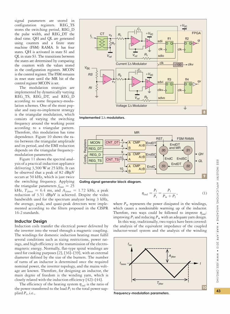
signal parameters are stored inconfiguration registers. REG_TSstores the switching period, REG_Dthe pulse width, and REG_DT thedead time. QH and QL are generatedusing counters and a finite statemachine (FSM) RAMA. It has fourstates. QH is activated in state S1 andQL in state S3. The transitions betweenthe states are determined by comparingthe counters with the values storedin the configuration registers. MCONis the control register. The FSM remainsin reset state until the MR bit of thecontrol register MCON is set.
The modulation strategies areimplemented by dynamically varyingREG_TS, REG_DT, and REG_Daccording to some frequency-modu-lation schemes. One of the most pop-ular and easy-to-implement strategyis the triangular modulation, whichconsists of varying the switchingfrequency around the working pointaccording to a triangular pattern.Therefore, this modulation has timedependence. Figure 10 shows the ra-tio between the triangular amplitudeand its period, and the EMI reductiondepends on the triangular frequency-modulation parameters.
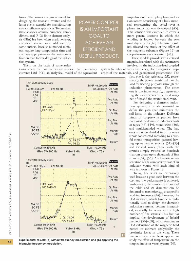
Figure 11 shows the spectral anal-ysis of a practical induction appliancedelivering 3,500 W at 25 kHz. It canbe observed that a peak of 82 dBlVoccurs at 50 kHz, which is just twicethe switching frequency. Applyingthe triangular parameters fbase ¼ 25kHz, Tjitter ¼ 6.4 ms, and Ajitter ¼ 1.72 kHz, a peakreduction of 3.51 dBlV is achieved. Despite the videobandwidth used for the spectrum analyzer being 3 kHz,the average, peak, and quasi-peak detectors were imple-mented according to the filters proposed in the CISPR16-2 standards.
Inductor DesignInduction coils transfer the electrical power delivered bythe inverter into the vessel through a magnetic coupling.The windings for domestic induction heating must fulfilseveral conditions such as sizing restrictions, power rat-ings, and high efficiency in the transmission of the electro-magnetic energy. Normally, flat-type spiral windings areused for cooking purposes [2], [36]–[39], with an externaldiameter defined by the size of the burners. The numberof turns of an inductor is determined once the requirednominal power, the inverter topology, and the mains volt-age are known. Therefore, for designing an inductor, themain degree of freedom is the winding yarn, which isclosely related with the induction efficiency [42]–[44].
The efficiency of the heating system gind is the ratio ofthe power transferred to the load Pl to the total power sup-plied Pt, i.e.,
gind ¼Pl
Pt
¼ Pl
Pw þ Pl
, (1)
where Pw represents the power dissipated in the windings,which causes a nondesirable warming up of the inductor.Therefore, two ways could be followed to improve gind:improving Pl and reducing Pw with an adequate yarn design.
In this way, traditionally, two topics have been covered:the analysis of the equivalent impedance of the coupledinductor-vessel system and the analysis of the winding
iL
D Q
R1
VrefVref
Vref
CT
sdio
sdiiRT
vXFPGA
clk
C1
C1
+−
qi
+Vcc
+Vcc
+VccR2
R2
R1
Vdc
sdvo
clkv
vY
RS
RI
+−
D Q
clk
clk ÷100
+−
+
−+−
ff1 ff2
D Qsdvi
clkv
qvD Q
clk
ff3 ff4
Voltage Σ∆ Modulator
Current Σ∆ Modulator
8Implemented RD modulators.
9
FSM RAMA
QH
QL
CNT_DT
CNT_TSREG_TS
REG_D
REG_DT
Con
fig. R
egis
ters
EndDT
EndSC
EndC
MCON CMPA
BA≥B
A≥B
A≥B
CMPB
A
CMPA
B
EndSC
EndDTand MR
EndC
EndDT
RST
S1
S2S3
S0
MR
4
4
9
10
10
Gating signal generator block diagram.
Tjitter
A jitter
tfbase
fsw
10Frequency-modulation parameters.
43
IEE
EIN
DU
STR
YA
PP
LICA
TION
SM
AG
AZ
INE
MA
RjA
PR
20
10
WW
W.IE
EE
.OR
G/IA
S
losses. The former analysis is useful fordesigning the resonant inverter, and thelatter one is essential for manufacturingsafe and efficient appliances. To carry outthese analyses, accurate numerical three-dimensional (3-D) finite element analy-sis (FEA) has been often used; however,analytical studies were addressed bysome authors, because numerical meth-ods require long computation time andare more appropriate for the design veri-fication than for the design of the induc-tion system.
Then, on the basis of some solu-tions where real conductors are replaced by filamentarycurrents [38]–[41], an analytical model of the equivalent
impedance of the simpler planar induc-tion system (consisting of a bulk mate-rial representing the vessel over aplanar inductor) was developed [45].This solution was extended to cover amore general scenario in which thewinding is located between the twomultilayer media [46]. The latter resulthas allowed the study of the effect ofthe magnetic substrate (Figure 12) onthe performance of the system [47].
These models provide two electricalmagnitudes related with the parametersinvolved in the induction-load coupled
system (number of turns, frequency, electromagnetic prop-erties of the materials, and geometrical parameters). The
first one is the resistance DR, repre-senting the power transferred into theload for heating purposes through theinduction phenomenon. The otherone is the inductance Leq, represent-ing the ratio between the total mag-netic flux and the excitation current.
For designing a domestic induc-tion system, it is also essential todefine the yarn that minimizes theself-losses in the inductor. Differentkinds of copper-wire profiles havebeen used for domestic inductors: foilsor tapes [48], [49], round wires [50],and multistranded wires. The lastones are often divided into litz wires(those constructed according to a care-ful strand-transposition pattern) hav-ing up to tens of strands [51]–[53]and twisted wires (those with thestrands simply twisted or bunched)that can group up to thousands of finestrands [54], [55]. A schematic repre-sentation of the comparative cost of aninductor wound with each kind ofwire is shown in Figure 13.
Today, litz wires are extensivelyused because a good ratio between thecost and the performance is achieved;furthermore, the number of strands ofthe cable and its diameter can bedesigned to maximize gind at a specificworking frequency [44]. However, theFEA methods, which have been tradi-tionally used to design the domesticinduction systems, become impracti-cal, especially for wires with a highnumber of fine strands. This fact hasimplied the development of hybridmethods [56]–[58], which combine anFEA calculation of the magnetic fieldneeded to estimate analytically theproximity losses in the wires. Thesemethods have also been applied tostudy the effect of temperature on thecoupled inductor-vessel system [59].
14:19:29 20 May 2002 Manual
Manual
MKR 49.99 kHz82.08 dBµV Qp Auto
At Mkr
Avg AutoAt Mkr
Qp ManAt Mkr
Avg ManAt Mkr
MarkerData
Return
T
hp
PeakLog10dB/
MA SBSC FSCORR
Center 49.89 kHz#Res BW 200 Hz
Span 10.00 kHz#Swp 4.73 s#Vbw 3 kHz
(a)
(b)
Qp 79.63Avg 76.92
Ref Level95.0 dBµV
Ref 95.0 dBµV #At 10 dB
14:27:10 20 May 2002MKR 49.42 kHz
78.57 dBµV Qp AutoAt Mkr
Avg AutoAt Mkr
Qp ManAt Mkr
Avg ManAt Mkr
MarkerData
Return
T
hp
PeakLog10dB/
MA SBSC FSCORR
Center 50.24 kHz#Res BW 200 Hz
Span 10.00 kHz#Swp 4.73 s#Vbw 3 kHz
Qp 75.05Avg 69.83
Ref Level100.0 dBµV
Ref 100.0 dBµV #At 10 dB
11Experimental results: (a) without frequency modulation and (b) applying thetriangular frequency modulation.
POWER CONTROLIS AN IMPORTANT
GOAL TOACHIEVE AN
EFFICIENT ANDUSEFUL PRODUCT.
44
IEE
EIN
DU
STR
YA
PP
LIC
ATI
ON
SM
AG
AZI
NE
MA
RjA
PR
20
10
WW
W.I
EE
E.O
RG
/IA
S
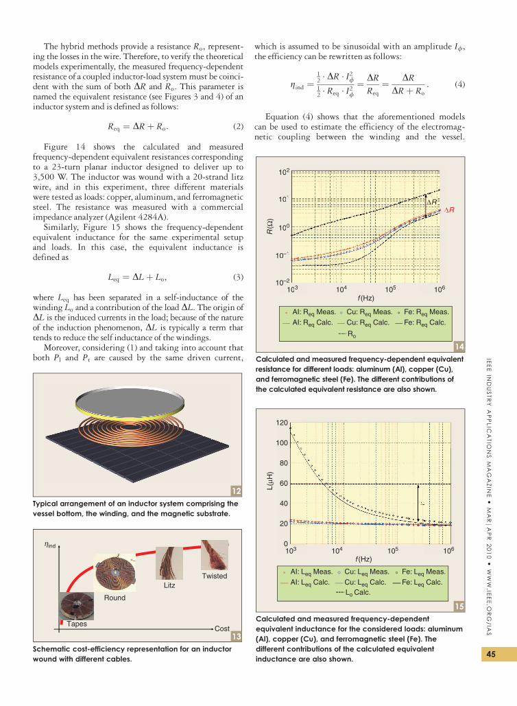
The hybrid methods provide a resistance Ro, represent-ing the losses in the wire. Therefore, to verify the theoreticalmodels experimentally, the measured frequency-dependentresistance of a coupled inductor-load system must be coinci-dent with the sum of both DR and Ro. This parameter isnamed the equivalent resistance (see Figures 3 and 4) of aninductor system and is defined as follows:
Req ¼ DRþ Ro: (2)
Figure 14 shows the calculated and measuredfrequency-dependent equivalent resistances correspondingto a 23-turn planar inductor designed to deliver up to3,500 W. The inductor was wound with a 20-strand litzwire, and in this experiment, three different materialswere tested as loads: copper, aluminum, and ferromagneticsteel. The resistance was measured with a commercialimpedance analyzer (Agilent 4284A).
Similarly, Figure 15 shows the frequency-dependentequivalent inductance for the same experimental setupand loads. In this case, the equivalent inductance isdefined as
Leq ¼ DLþ Lo, (3)
where Leq has been separated in a self-inductance of thewinding Lo and a contribution of the load DL. The origin ofDL is the induced currents in the load; because of the natureof the induction phenomenon, DL is typically a term thattends to reduce the self inductance of the windings.
Moreover, considering (1) and taking into account thatboth Pl and Pt are caused by the same driven current,
which is assumed to be sinusoidal with an amplitude I/,the efficiency can be rewritten as follows:
gind ¼12 DR I2
/12 Req I2
/
¼ DR
Req
¼ DR
DRþ Ro
: (4)
Equation (4) shows that the aforementioned modelscan be used to estimate the efficiency of the electromag-netic coupling between the winding and the vessel.
12Typical arrangement of an inductor system comprising thevessel bottom, the winding, and the magnetic substrate.
Cost
TwistedLitz
ηind
Round
13Tapes
Schematic cost-efficiency representation for an inductorwound with different cables.
102
101
100
10–1
10–2
103 104
f (Hz)105 106
∆R
R(Ω
)
AI: Req Meas.
AI: Req Calc.
Ro
Cu: Req Calc.
Cu: Req Meas.
Fe: Req Calc.
Fe: Req Meas.
102
101
1000
0–1
0–2
103 104 105 106
∆∆
14
∆R
Calculated and measured frequency-dependent equivalentresistance for different loads: aluminum (Al), copper (Cu),and ferromagnetic steel (Fe). The different contributions ofthe calculated equivalent resistance are also shown.
AI: Leq Meas.
AI: Leq Calc.Lo Calc.Cu: Leq Calc.
Cu: Leq Meas.
Fe: Leq Calc.
Fe: Leq Meas.
103 104
f (Hz)105 106
120
100
80
60
40
20
0
L(µH
)
15Calculated and measured frequency-dependentequivalent inductance for the considered loads: aluminum(Al), copper (Cu), and ferromagnetic steel (Fe). Thedifferent contributions of the calculated equivalentinductance are also shown.
45
IEE
EIN
DU
STR
YA
PP
LICA
TION
SM
AG
AZ
INE
MA
RjA
PR
20
10
WW
W.IE
EE
.OR
G/IA
S
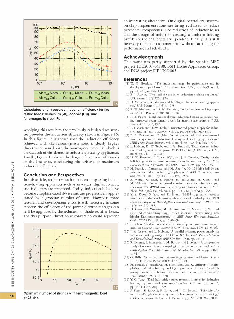
Applying this result to the previously calculated resistan-ces provides the induction efficiency shown in Figure 16.In this figure, it is shown that the induction efficiencyachieved with the ferromagnetic steel is clearly higherthan that obtained with the nonmagnetic metals, which isa drawback of the domestic induction-heating appliances.Finally, Figure 17 shows the design of a number of strandsof the litz wire, considering the criteria of maximuminduction efficiency.
Conclusion and PerspectivesIn this article, recent research topics encompassing induc-tion-heating appliances such as inverters, digital control,and inductors are presented. Today, induction hobs havebecome a sophisticated device and are progressively appre-ciated by a growing number of users. However, moreresearch and development effort is still necessary in someaspects: the efficiency of the power electronic stages canstill be upgraded by the reduction of diode rectifier losses.For this purpose, direct ac/ac conversion could represent
an interesting alternative. On digital controllers, system-on-chip implementations are being evaluated to reduceperipheral components. The reduction of inductor lossesand the design of inductors creating a uniform heatingprofile are the challenges still pending. Finally, it is stillnecessary to reduce customer price without sacrificing theperformance and reliability.
AcknowledgmentsThis work was partly supported by the Spanish MECproject TEC2007-64188, BSH Home Appliances Group,and DGA project PIP 179/2005.
References[1] W. C. Moreland, ‘‘The induction range: Its performance and its
development problems,’’ IEEE Trans. Ind. Appl., vol. IA-9, no. 1,
pp. 81–85, Jan./Feb. 1973.
[2] B. J. Austin, ‘‘Work coil for use in an induction cooking appliance,’’
U.S. Patent 4 029 926, 1974.
[3] H. Yamamura, K. Matsuo, and N. Nagai, ‘‘Induction heating appara-
tus,’’ U.S. Patent 4 115 677, 1978.
[4] R. W. Mackency and T. M. Heinrich, ‘‘Induction heat cooking appa-
ratus,’’ U.S. Patent 44 085 300, 1978.
[5] P. H. Peters, ‘‘Metal base cookware induction heating apparatus hav-
ing improved power control circuit for insuring safe operation,’’ U.S.
Patent 4 151 387, 1979.
[6] L. Hobson and D. W. Tebb, ‘‘Transistorized power supply for induc-
tion heating,’’ Int. J. Electron., vol. 59, pp. 533–542, May 1985.
[7] F. P. Dawson and P. Jain, ‘‘A comparison of load commutated
inverter system for induction heating and melting applications,’’
IEEE Trans. Power Electron., vol. 6, no. 4, pp. 430–441, July 1991.
[8] L. Hobson, D. W. Tebb, and F. G. Turnbull, ‘‘Dual element induc-
tion cooking unit using power MOSFETs,’’ Int. J. Electron., vol. 59,
no. 6, pp. 747–757, 1985.
[9] H. W. Koertzen, J. D. van Wyk, and J. A. Ferreira, ‘‘Design of the
half bridge series resonant converter for induction cooking,’’ in IEEEPower Electronics Specialists Conf. (PESC) Rec., 1995, pp. 729–735.
[10] M. Kamli, S. Yamamoto, and M. Abe, ‘‘A 50–150 kHz half-bridge
inverter for induction heating applications,’’ IEEE Trans. Ind. Elec-tron., vol. 43, no. 1, pp. 163–172, Feb. 1996.
[11] S. Wang, K. Izaki, I. Hirota, H. Yamashita, H. Omori, and
M. Nakaoka, ‘‘Induction-heated cooking appliance using new qua-
siresonant ZVS-PWM inverter with power factor correction,’’ IEEETrans. Ind. Appl., vol. 34, no. 4, pp. 705–712, July/Aug. 1998.
[12] Y. S. Kwon, S. Yoo, and D. Hyun, ‘‘Half-bridge series resonant
inverter for induction heating applications with load-adaptative PFM
control strategy,’’ in IEEE Applied Power Electronics Conf. (APEC) Rec.,1999, pp. 575–581.
[13] H. Omori, H Yamasita, M. Nakaoka, and T. Maruhashi, ‘‘A novel
type induction-heating single ended resonant inverter using new
bipolar Darlington-transistors,’’ in IEEE Power Electronics SpecialistsConf. (PESC) Rec., 1985, pp. 590–599.
[14] I. Cohen, ‘‘Evaluation and comparison of power conversion topolo-
gies,’’ in European Power Electronics Conf. (EPE) Rec., 1993, pp. 9–16.
[15] J. M. Leisten and L. Hobson, ‘‘A parallel resonant power supply for
induction cooking using a GTO,’’ in IEE Int. Conf. Power Electronicsand Variable Speed Drivers (PEVSD) Rec., 1990, pp. 224–230.
[16] S. Llorente, F. Monterde, J. M. Burdio, and J. Acero, ‘‘A comparative
study of resonant inverter topologies used in induction cookers,’’ in
IEEE Applied Power Electronics Conf. (APEC) Rec., 2002, pp. 1168–1174.
[17] G. Rilly, ‘‘Schaltung zur stromversorgung einer induktiven kosch-
stelle,’’ European Patent 028 604 4A2, 1988.
[18] M. Kiuchi, T. Mizukawa, H. Kominami, and K. Amagami, ‘‘Multi-
ple-load induction heating cooking apparatus with means for elimi-
nating interference between two or more commutation circuits,’’
U.S. Patent 4 092 510, 1978.
[19] Y. C. Jung, ‘‘Dual half bridge series resonant inverter for induction
heating appliance with two loads,’’ Electron. Lett., vol. 35, no. 16,
pp. 1345–1346, Aug. 1999.
[20] F. Forest, E. Laboure, F. Costa, and J. Y. Gaspard, ‘‘Principle of a
multi-load/single converter system for low power induction heating,’’
IEEE Trans. Power Electron., vol. 15, no. 2, pp. 223–230, Mar. 2000.
98.5
98
97.5
97
96.5
96
95.50 10 20 30
no
40 50
η ind
(%)
17Optimum number of strands with ferromagnetic loadat 25 kHz.
AI: ηind Meas.
AI: ηind Calc. Cu: ηind Calc.
Cu: ηind Meas.
Fe: ηind Calc.
Fe: ηind Meas.
103 104
f (Hz)105 106
100
9095
70
80
50
60
30
40
10
20
0
η ind
(%)
16Calculated and measured induction efficiency for thetested loads: aluminum (Al), copper (Cu), andferromagnetic steel (Fe).
46
IEE
EIN
DU
STR
YA
PP
LIC
ATI
ON
SM
AG
AZI
NE
MA
RjA
PR
20
10
WW
W.I
EE
E.O
RG
/IA
S
[21] J. M. Burdıo, F. Monterde, J. R. Garcıa, L. A. Barragan, and
A. Martınez, ‘‘A two-output series-resonant inverter for induction-
heating cooking appliances,’’ IEEE Trans. Power Electron., vol. 20,
no. 4, pp. 815–822, July 2005.
[22] R. L. Steigerwald, ‘‘Constant duty cycle control of induction cooking
inverter,’’ U.S. Patent 3 781 505, 1972.
[23] R. W. MacKenzie, P. Wood, T. M. Heinrich, and R. M. Oates,
‘‘Frequency controlled induction heating apparatus,’’ U.S. Patent 44
085 300, 1978.
[24] J. M. Burdıo, L. A. Barragan, F. Monterde, D. Navarro, and
J. Acero, ‘‘Asymetrical voltage-cancellation control for full-bridge
series resonant inverters,’’ IEEE Trans. Power Electron., vol. 19, no. 2,
pp. 461–469, Mar. 2004.
[25] L. A. Barragan, J. M. Burdıo, J. I. Artigas, D. Navarro, J. Acero,
and D. Puyal, ‘‘Efficiency optimization in ZVS series resonant inver-
ters with asymmetrical voltage-cancellation control,’’ IEEE Trans.Power Electron., vol. 20, no. 5, pp. 1036–1044, Sept. 2005.
[26] H. Sugimura, H. Omori, S. K. Kwon, H. W. Lee, and M. Nakaoka,
‘‘High efficiency discrete pulse modulation controlled high frequency
series load resonant soft switching inverter for induction-heated fix-
ing roller,’’ in IEEE Power Electronics Specialists Conf. (PESC) Rec.,2006, pp. 2495–2500.
[27] N.-J. Park, D.-Y. Lee, and D.-S. Hyun, ‘‘A power-control scheme
with constant switching frequency in class-D inverter for induction-
heating jar application,’’ IEEE Trans. Ind. Electron., vol. 54, no. 3,
pp. 1252–1260, June 2007.
[28] S. Shah and A. K Upadhyay, ‘‘Analysis and design of a half bridge
parallel resonant converter operating in discontinuous mode,’’ in IEEEApplied Power Electronics Conf. (APEC) Rec., 1990, pp. 165–174.
[29] V. Belaguli and A. K. S. Bhat, ‘‘Series-parallel resonant converter
operating in discontinuous current mode. Analysis, design, simula-
tion, and experimental results,’’ IEEE Trans. Circuits Syst. I, vol. 47,
pp. 433–442, Apr. 2000.
[30] I. Millan, D. Puyal, J. M. Burdio, C. Bemal, and J. Acero,
‘‘Improved performance of half-bridge series resonant inverter for
induction heating with discontinuous mode control,’’ in IEEEApplied Power Electronics Conf. (APEC) Rec., 2007, pp. 1293–1298.
[31] J. Acero, J. I Artigas, J. M Burdıo, L. A. Barragan, and S. Llorente,
‘‘Power measuring in two-output resonant inverters for induction
cooking appliances,’’ in IEEE Power Electronics Specialists Conf. (PESC)Rec., 2002, pp. 1161–1166.
[32] F. Forest, S. Faucher, J. Y. Gaspard, D. Montloup, J. J. Huselstein,
and C. Joubert, ‘‘Frequency-synchronized resonant converters for the
supply of multiwinding coils induction cooking appliances,’’ IEEETrans. Ind. Electron., vol. 54, no. 1, pp. 441–452, Feb. 2007.
[33] J. Acero, D. Navarro, L. A. Barragan, I. Garde, J. I. Artigas, and
J. M. Burdıo, ‘‘FPGA-based power measuring for induction heating
appliances using sigma-delta A/D conversion,’’ IEEE Trans. Ind. Elec-tron., vol. 54, no. 4, pp. 1843–1852, July 2007.
[34] J. Acero, J. M. Burdıo, L. A. Barragan, D. Navarro, and S. Llorente,
‘‘EMI improvements using the switching frequency modulation in a
resonant inverter for domestic induction heating appliances,’’ in IEEEPower Electronics Specialists Conf. (PESC) Rec., 2004, pp. 3108–3112.
[35] L. A. Barragan, D. Navarro, J. Acero, I. Urriza, and J. M. Burdıo,
‘‘FPGA implementation of a switching frequency modulation circuit
for EMI reduction in resonant inverters for induction heating appli-
ances,’’ IEEE Trans. Ind. Electron., vol. 51, no. 1, pp. 11–20, Jan.
2008.
[36] J. Karklys and M. Smerciyan, ‘‘Induction heating coil,’’ U.S. Patent
04 453 067, 1982.
[37] J. Gaspard, ‘‘Induction cooker with coil support having spiral-shaped
housing for spiral coils,’’ U.S. Patent 5 686 006, 1997.
[38] M. S. Adler, ‘‘A field-theoretical approach to magnetic induction
heating of thin circular plates,’’ IEEE Trans. Magn., vol. MAG-10,
no. 4, pp. 1118–1125, Dec. 1974.
[39] W. G. Hurley and J. G. Kassakian, ‘‘Induction heating of circular
ferromagnetic plates,’’ IEEE Trans. Magn., vol. MAG-15, no. 3,
pp. 1174–1181, July 1979.
[40] W. G. Hurley and M. C. Duffy, ‘‘Calculation of self and mutual
impedances in planar magnetic structures,’’ IEEE Trans. Magn.,vol. 31, pp. 2416–2422, July 1995.
[41] W. G. Hurley and M. C. Duffy, ‘‘Calculation of self and mutual
impedances in planar sandwich inductors,’’ IEEE Trans. Magn.,vol. 33, pp. 2282–2289, May 1997.
[42] H. W. E. Koertzen, J. D. Van Wyk, and J. A. Ferreira, ‘‘Investigat-
ing the influence of material properties on the efficiency of an
induction heating load transformer using FEM simulation,’’ in Proc.IEEE Industry Applications Society Annual Meeting (IAS), 1995,
pp. 868–873.
[43] P. Dorland, J. D. van Wyk, and O. H. Stielau, ‘‘On the influence of
coil design and electromagnetic configuration of the efficiency of an
induction melting furnace,’’ IEEE Trans. Ind. Appl., vol. 36, no. 4,
pp. 946–957, July/Aug. 2000.
[44] J. Acero, R. Alonso, J. M. Burdıo, L. A. Barragan, and J. I. Artigas,
‘‘An electromagnetic-based model for calculating the efficiency in
domestic induction heating appliances,’’ in IEEE Power Electronics Spe-cialists Conf. (PESC) Rec., 2006, pp. 153–158.
[45] J. Acero, R. Alonso, J. M. Burdıo, L. A. Barragan, and D. Puyal,
‘‘Analytical equivalent impedance for a planar circular induction
heating system,’’ IEEE Trans. Magn., vol. 42, pp. 84–86, Jan. 2006.
[46] J. Acero, R. Alonso, L. A. Barragan, and J. M. Burdıo, ‘‘Modeling of
planar spiral inductors between two multilayer media for induction
heating applications,’’ IEEE Trans. Magn., vol. 42, pp. 3719–3729,
Nov. 2006.
[47] J. Acero, R. Alonso, J. M. Burdıo, and L. A. Barragan, ‘‘Enhance-
ment of induction heating performance by sandwiched planar wind-
ings,’’ Electron. Lett., vol. 42, pp. 241–242, Feb. 2006.
[48] P. Hernandez, F. Monterde, J. R. Garcıa, and J. M. Burdıo, ‘‘Power
loss optimisation of foil coils for induction cooking,’’ in IEEE Indus-trial Electronics Society Conf. (IECON) Rec., 1998, pp. 371–374.
[49] J. R. Garcıa and J. A. Garcıa, ‘‘Improved coil for induction heating,’’
European Patent 0 936 843 A2, 1999.
[50] J. Acero, R. Alonso, L. A. Barragan, J. M. Burdıo, and D. Navarro,
‘‘Loss analysis and optimization of round-wire planar windings for
domestic induction heating appliances,’’ in IEEE Applied PowerElectronics Conf. (APEC) Rec., 2006, pp. 553–558.
[51] A. W. Lotfi and F. C. Lee, ‘‘A high frequency model for litz-wire for
switch-mode magnetics,’’ in IEEE Industry Applications Society AnnualMeeting (IAS) Rec., 1993, pp. 1169–1175.
[52] F. Tourkhani and P. Viarouge, ‘‘Accurate analytical model of winding
losses in round litz-wire windings,’’ IEEE Trans. Magn., vol. 37,
no. 1, pp. 538–543, Jan. 2001.
[53] J. Acero, R. Alonso, J. M. Burdio, L. A. Barragan, and D. Puyal,
‘‘Frequency-dependent resistance in litz-wire planar windings for
domestic induction heating appliances,’’ IEEE Trans. Power Electron.,vol. 21, pp. 856–866, July 2006.
[54] X. Tang, C. R. Sullivan, X. Tang, and C. R. Sullivan, ‘‘Stranded wire
with uninsulated strands as a low-cost alternative to litz wire,’’ in
IEEE Power Electronics Specialists Conf. (PESC) Rec., 2003, pp. 289–295.
[55] J. Acero, R. Alonso, J. M. Burdıo, L. A. Barragan, and C. Carretero,
‘‘A model of losses in twisted-multistranded wires for planar wind-
ings used in domestic induction heating appliances,’’ in IEEE AppliedPower Electronics Conf. (APEC) Rec., 2007, pp. 1247–1253.
[56] C. R. Sullivan, ‘‘Optimal choice for number of strands in a litz-wire
transformer winding,’’ IEEE Trans. Power Electron., vol. 14, no. 2,
pp. 283–291, Mar. 1999.
[57] C. R. Sullivan, ‘‘Cost constrained selection of strand diameter and
number in litz-wire transformer winding,’’ IEEE Trans. Power Elec-tron., vol. 16, no. 2, pp. 281–288, Mar. 2001.
[58] S. Wang, M. A. de Rooij, W. G. Odendaal, J. D. van Wyk, and
D. Boroyevich, ‘‘Reduction of high-frequency conduction losses using
a planar litz structure,’’ IEEE Trans. Power Electron., vol. 20, no. 2,
pp. 261–267, Mar. 2005.
[59] C. Carretero, J. Acero, R. Alonso, J. M. Burdıo, and F. Monterde,
‘‘Temperature influence on equivalent impedance and efficiency of
inductor systems for domestic induction heating appliances,’’ in IEEEApplied Power Electronics Conf. (APEC) Rec., 2007, pp. 153–158.
J. Acero ([email protected]), J.M. Burdıo, L.A. Barragan,D. Navarro, and R. Alonso are with the Universidad deZaragoza, Spain. J.R. Garcıa, F. Monterde, P. Hernandez,S. Llorente, and I. Garde are with Bosch and Siemens HomeAppliances Group in Zaragoza, Spain. Acero and Burdıo areMembers of the IEEE. This article first appeared as ‘‘TheDomestic Induction-Heating Appliance: An Overview of RecentResearch’’ at the 2008 Applied Power Electronics Conferenceand Exposition. 47
IEE
EIN
DU
STR
YA
PP
LICA
TION
SM
AG
AZ
INE
MA
RjA
PR
20
10
WW
W.IE
EE
.OR
G/IA
S
Related Documents