1 SPF-001 (Rev.D1) DOCUMENT RELEASE AND CHANGE FORM Prepared For the U.S. Department of Energy, Assistant Secretary for Environmental Management By Washington River Protection Solutions, LLC., PO Box 850, Richland, WA 99352 Contractor For U.S. Department of Energy, Office of River Protection, under Contract DE-AC27-08RV14800 TRADEMARK DISCLAIMER: Reference herein to any specific commercial product, process, or service by trade name, trademark, manufacturer, or otherwise, does not necessarily constitute or imply its endorsement, recommendation, or favoring by the United States government or any agency thereof or its contractors or subcontractors. Printed in the United States of America. Release Stamp 1. Doc No: RPP-SPEC-62735 Rev. 00 2. Title: Procurement Specification for 242-A Evaporator Recirculation Pump P-B-1 3. Project Number: ☒ N/A 4. Design Verification Required: ☐ Yes ☒ No 5. USQ Number: ☒ N/A N/A-3 6. PrHA Number Rev. ☒ N/A Clearance Review Restriction Type: public 7. Approvals Title Name Signature Date Clearance Review Aardal, Janis D Aardal, Janis D 11/07/2018 Design Authority Servin, Mario A Servin, Mario A 11/05/2018 Checker Bentley, Kenneth Bentley, Kenneth 11/01/2018 Document Control Approval Hood, Evan Hood, Evan 11/07/2018 Engineering Discipline Lead-Civil/Structural Scott, Mark A Scott, Mark A 11/01/2018 Engineering Discipline Lead-Electrical Rambo, Charles L Rambo, Charles L 10/16/2018 Engineering Discipline Lead-Mechanical Goessmann, Glen E Goessmann, Glen E 11/01/2018 Engineering Hoisting and Rigging SME Mackey, Tom Mackey, Tom 11/05/2018 Originator Servin, Mario A Servin, Mario A 11/04/2018 Other Approver Balint, Gregory G Balint, Gregory G 11/01/2018 Quality Assurance Thompson, Tyler J Thompson, Tyler J 10/30/2018 Responsible Engineering Manager Houghton, David J Houghton, David J 11/06/2018 USQ Evaluator Dosramos, Eduardo Dosramos, Eduardo 11/06/2018 Welding Engineer Berkey, James Berkey, James 10/16/2018 8. Description of Change and Justification Initial release. 9. TBDs or Holds ☒ N/A 10. Related Structures, Systems, and Components a. Related Building/Facilities ☐ N/A b. Related Systems ☐ N/A c. Related Equipment ID Nos. (EIN) ☐ N/A 242-A 242A 242A-HR-CRN-005 242A-HR-CRN-006 P-B-1 P-B-1-M 11. Impacted Documents – Engineering ☒ N/A Document Number Rev. Title 12. Impacted Documents (Outside SPF): N/A 13. Related Documents ☐ N/A Document Number Rev. Title RPP-SPEC-41919 01 SPECIFICATION FOR RECIRCULATION PUMP P-B-1 14. Distribution Name Organization Balint, Gregory G COGNIZANT SYSTEM ENGINEERING Bentley, Kenneth 242-A EVAPORATOR ENGINEERING Castleberry, Jim L TFP PROJECT MANAGEMENT Houghton, David J TF PROJECTS & INTEGRITY ENGRNG Smith, Gregory E TANK FARM PROJECTS ENGINEERING Trevino, Johnny M 242-A EVAPORATOR ENGINEERING Nov 07, 2018 DATE:

Welcome message from author
This document is posted to help you gain knowledge. Please leave a comment to let me know what you think about it! Share it to your friends and learn new things together.
Transcript

1 SPF-001 (Rev.D1)
DOCUMENT RELEASE AND CHANGE FORMPrepared For the U.S. Department of Energy, Assistant Secretary for Environmental ManagementBy Washington River Protection Solutions, LLC., PO Box 850, Richland, WA 99352Contractor For U.S. Department of Energy, Office of River Protection, under Contract DE-AC27-08RV14800
TRADEMARK DISCLAIMER: Reference herein to any specific commercial product, process, or service by trade name, trademark, manufacturer, or otherwise, does not necessarily constitute or imply its endorsement, recommendation, or favoring by the United States government or any agency thereof or its contractors or subcontractors. Printed in the United States of America.
Release Stamp
1. Doc No: RPP-SPEC-62735 Rev. 00
2. Title:Procurement Specification for 242-A Evaporator Recirculation Pump P-B-1
3. Project Number: ☒ N/A 4. Design Verification Required:
☐ Yes ☒ No
5. USQ Number: ☒ N/A
N/A-3
6. PrHA Number Rev. ☒ N/A
Clearance Review Restriction Type:public
7. Approvals
Title Name Signature Date
Clearance Review Aardal, Janis D Aardal, Janis D 11/07/2018
Design Authority Servin, Mario A Servin, Mario A 11/05/2018
Checker Bentley, Kenneth Bentley, Kenneth 11/01/2018
Document Control Approval Hood, Evan Hood, Evan 11/07/2018
Engineering Discipline Lead-Civil/Structural Scott, Mark A Scott, Mark A 11/01/2018
Engineering Discipline Lead-Electrical Rambo, Charles L Rambo, Charles L 10/16/2018
Engineering Discipline Lead-Mechanical Goessmann, Glen E Goessmann, Glen E 11/01/2018
Engineering Hoisting and Rigging SME Mackey, Tom Mackey, Tom 11/05/2018
Originator Servin, Mario A Servin, Mario A 11/04/2018
Other Approver Balint, Gregory G Balint, Gregory G 11/01/2018
Quality Assurance Thompson, Tyler J Thompson, Tyler J 10/30/2018
Responsible Engineering Manager Houghton, David J Houghton, David J 11/06/2018
USQ Evaluator Dosramos, Eduardo Dosramos, Eduardo 11/06/2018
Welding Engineer Berkey, James Berkey, James 10/16/2018
8. Description of Change and Justification
Initial release.
9. TBDs or Holds ☒ N/A
10. Related Structures, Systems, and Components
a. Related Building/Facilities ☐ N/A b. Related Systems ☐ N/A c. Related Equipment ID Nos. (EIN) ☐ N/A
242-A 242A 242A-HR-CRN-005242A-HR-CRN-006P-B-1P-B-1-M
11. Impacted Documents – Engineering ☒ N/A
Document Number Rev. Title
12. Impacted Documents (Outside SPF):
N/A
13. Related Documents ☐ N/A
Document Number Rev. Title
RPP-SPEC-41919 01 SPECIFICATION FOR RECIRCULATION PUMP P-B-1
14. Distribution
Name Organization
Balint, Gregory G COGNIZANT SYSTEM ENGINEERING
Bentley, Kenneth 242-A EVAPORATOR ENGINEERING
Castleberry, Jim L TFP PROJECT MANAGEMENT
Houghton, David J TF PROJECTS & INTEGRITY ENGRNG
Smith, Gregory E TANK FARM PROJECTS ENGINEERING
Trevino, Johnny M 242-A EVAPORATOR ENGINEERING
� � � � � � � � � � � � � � � � � � � � � � � � � � � � � � � � � � � � �Nov 07, 2018
DATE:

A-6002-767 (REV 3)
RPP-SPEC-62735, Rev. 0
Procurement Specification for 242-A Evaporator Recirculation Pump P-B-1
Author Name:
M.A. Servin
Tank Farm Projects Engineering
Washington River Protection Solutions, LLC
Richland, WA 99352U.S. Department of Energy Contract DE-AC27-08RV14800
EDT/ECN: UC:
Cost Center: Charge Code:
B&R Code: Total Pages:
Key Words: P-B-1 Pump, Recirculation Pump, Procurement Specification, 242-A Evaporator
Abstract: This Specification provides the minimum requirements for the design and fabrication of the
P-B-1 Pump for use at the 242-A Evaporator, which is located in the 200 East Area of the U.S.
Department of Energy’s Hanford Nuclear Waste Site. Construction of the 242-A Evaporator started in
1974 and operation began in 1977. The mission of the 242-A Evaporator is to support environmental
restoration and remediation of the Hanford Site by optimizing the 200 Area double-shell tank waste
volumes through radioactive liquid waste volume reduction. Volume reduction is accomplished through
an evaporation process that uses a conventional forced-circulation, vacuum evaporation system operating
at low pressure to concentrate radioactive waste solutions. The P-B-1 pump function is to recirculate
withn the evaporator recirculation waste loop.
TRADEMARK DISCLAIMER. Reference herein to any specific commercial product, process, or service by trade name, trademark, manufacturer, or otherwise, does not necessarily constitute or imply its endorsement, recommendation, or favoring by the United States Government or any agency thereof or its contractors or subcontractors.
Release Approval Date Release Stamp
Approved For Public Release
� � � � � � � � � � � � � � � � � � � � � � � � � � � � � � � � � � � � �
� � � � � � � � ! � " # � $ � % & ' ( ) � * + , - . / & + 0 / ) 1 Nov 07, 2018
DATE:

RPP-SPEC-62735, Rev. 0
Procurement Specification for 242-A
Evaporator Recirculation Pump P-B-1
M.A. Servin
Tank Farm Projects Engineering
Washington River Protection Solutions LLC
Date Published
November 2018
Prepared for the U.S. Department of Energy
Office of River Protection
P.O. Box 850
Richland, Washington
2 3 3 4 5 3 6 7 4 8 9 : ; < 2 = > ? @ @ A A B : B 9 @ A C 4 : D ; A E F ; G H I 8

RPP-SPEC-62735, Rev. 0
This page was intentionally left blank
2 3 3 4 5 3 6 7 4 8 9 : ; < 2 = > ? @ @ A A B : B 9 @ A C 4 : D ; A E F I G H I 8

RPP-SPEC-62735, Rev. 0
i
TABLE OF CONTENTS
1.0 SCOPE ............................................................................................................................ 1-1
2.0 APPLICABLE DOCUMENTS..................................................................................... 2-1
2.1 NON-GOVERNMENT DOCUMENTS.............................................................. 2-1
2.2 NON-CODE OF RECORD DOCUMENTS ....................................................... 2-3
2.3 GOVERNMENT DOCUMENTS........................................................................ 2-3
3.0 TECHNICAL REQUIREMENTS ............................................................................... 3-1
3.1 ITEM DEFINITION ............................................................................................ 3-1
3.2 INTERFACE DEFINITION................................................................................ 3-1
3.2.1 Pump Assembly Interface with 242-A Evaporator .................................. 3-1
3.2.2 Pump Assembly Interface with Pump Casing ......................................... 3-2
3.2.3 Electrical Service Interface ...................................................................... 3-2
3.2.4 Shaft Seal – Barrier Fluid Interface ......................................................... 3-2
3.2.5 Vibration Monitoring System Interface ................................................... 3-3
3.2.6 Motor Bearing Grease Lines Interface (Not Available) .......................... 3-3
3.2.7 Lifting Yoke Interface.............................................................................. 3-3
3.2.8 Impact Wrench Interface.......................................................................... 3-3
3.2.9 Interface Critical Dimensions .................................................................. 3-3
3.3 CHARACTERISTICS ......................................................................................... 3-5
3.3.1 General Requirements.............................................................................. 3-5
3.3.2 Fluid Characteristics ................................................................................ 3-5
3.3.3 Pump Functional Characteristics ............................................................. 3-6
3.3.4 Pump Physical Characteristics................................................................. 3-6
3.3.5 Reliability................................................................................................. 3-8
3.3.6 Maintainability......................................................................................... 3-8
3.3.7 Environment............................................................................................. 3-9
3.4 DESIGN AND CONSTRUCTION ..................................................................... 3-9
3.4.1 Seismic Design/Analysis ......................................................................... 3-9
3.4.2 Rotor Dynamic Analysis........................................................................ 3-10
3.4.3 Critical Speed Analysis.......................................................................... 3-10
3.4.4 Pump Assembly Installation and Lifting & Handling Design/Analysis 3-10
3.4.5 Materials ................................................................................................ 3-12
3.5 DRAWINGS AND MANUALS........................................................................ 3-13
3.6 FABRICATION/ASSEMBLY PROCESSES ................................................... 3-13
3.6.1 Cleaning and Painting ............................................................................ 3-14
3.6.2 Special Tools.......................................................................................... 3-15
3.6.3 Marking.................................................................................................. 3-15
2 3 3 4 5 3 6 7 4 8 9 : ; < 2 = > ? @ @ A A B : B 9 @ A C 4 : D ; A E F < G H I 8

RPP-SPEC-62735, Rev. 0
ii
4.0 QUALITY ASSURANCE REQUIREMENTS............................................................ 4-1
4.1 QUALITY ASSURANCE PROGRAM .............................................................. 4-1
4.2 QUALIFICATIONS ............................................................................................ 4-1
4.2.1 Welding Personnel and Procedures ......................................................... 4-1
4.2.2 Welding Inspectors and Procedures......................................................... 4-2
4.3 INSPECTIONS AND TESTING......................................................................... 4-2
4.3.1 Weld Inspection and Examination ........................................................... 4-4
4.3.2 Radiographic Examination of Impeller.................................................... 4-4
4.3.3 Megger Test ............................................................................................. 4-5
4.3.4 Pump Motor Driver Testing..................................................................... 4-5
4.3.5 Hydrostatic Test ....................................................................................... 4-5
4.3.6 Pre-Pump Run-In Performance Test ........................................................ 4-5
4.3.7 Pump Run-in Test .................................................................................... 4-6
4.3.8 Pump Sealing System Leak Inspection.................................................... 4-6
4.3.9 Post-Pump Run-In Performance Test ...................................................... 4-6
4.3.10 Load Test ................................................................................................. 4-7
5.0 DOCUMENT SUBMITTAL......................................................................................... 5-1
5.1 APPROVAL OF SUBMITTALS ........................................................................ 5-3
5.2 LIST OF SUBMITTALS..................................................................................... 5-3
6.0 PREPARATION FOR DELIVERY............................................................................. 6-1
6.1 PRESERVATION AND PACKAGING ............................................................. 6-1
6.2 MARKING .......................................................................................................... 6-1
6.3 SHIPPING AND HANDLING............................................................................ 6-1
6.4 TRANSPORTATION.......................................................................................... 6-2
7.0 NOTES............................................................................................................................ 7-1
7.1 LIST OF ACRONYMS ....................................................................................... 7-1
7.2 UNITS.................................................................................................................. 7-2
8.0 APPENDICES................................................................................................................ 8-1
8.1 APPENDIX A – PUMP CURVE FOR FACILITY PUMP ................................ 8-1
8.2 APPENDIX B – MOTOR DATA SHEET .......................................................... 8-3
LIST OF FIGURES
Figure 8-1 PUMP CURVE FOR P-B-1 PUMP ........................................................................... 8-2
Figure 8-2. Motor Data Sheet ...................................................................................................... 8-4
2 3 3 4 5 3 6 7 4 8 9 : ; < 2 = > ? @ @ A A B : B 9 @ A C 4 : D ; A E F 8 G H I 8
RPP-SPEC-62735, Rev. 0
iii
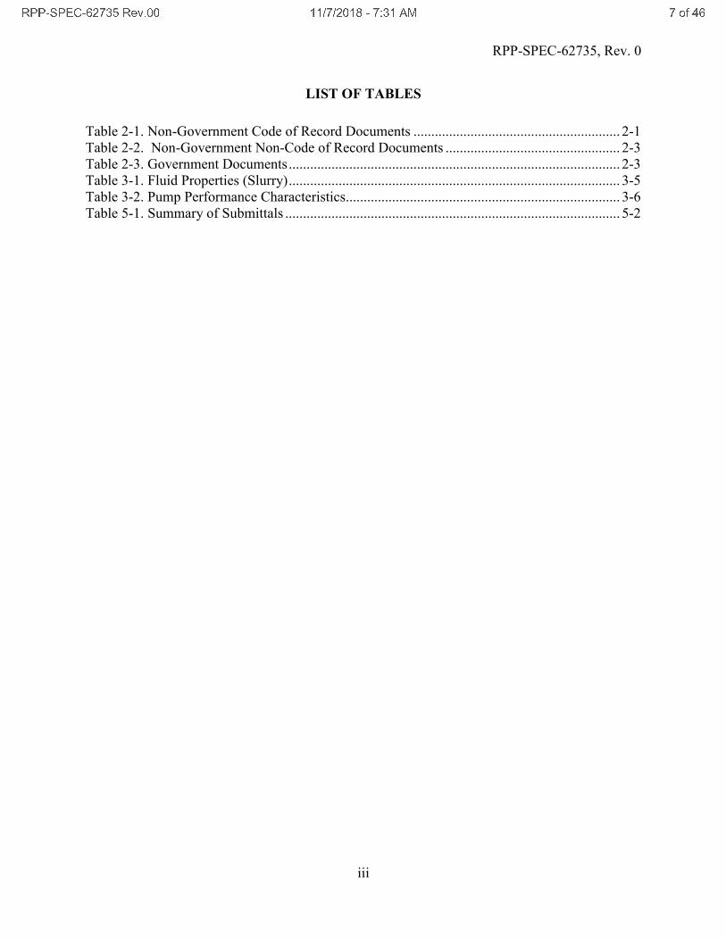
LIST OF TABLES
Table 2-1. Non-Government Code of Record Documents .......................................................... 2-1
Table 2-2. Non-Government Non-Code of Record Documents ................................................. 2-3
Table 2-3. Government Documents............................................................................................. 2-3
Table 3-1. Fluid Properties (Slurry)............................................................................................. 3-5
Table 3-2. Pump Performance Characteristics............................................................................. 3-6
Table 5-1. Summary of Submittals .............................................................................................. 5-2
2 3 3 4 5 3 6 7 4 8 9 : ; < 2 = > ? @ @ A A B : B 9 @ A C 4 : D ; A E F : G H I 8

RPP-SPEC-62735, Rev. 0
1-1
1.0 SCOPE
This Specification provides the minimum requirements for the design and fabrication of the
vertical, axial flow pump (referred to as the P-B-1 pump) for use at the 242-A Evaporator, which
is located in the 200 East Area of the U.S. Department of Energy’s Hanford Nuclear Waste Site.
Construction of the 242-A Evaporator started in 1974 and operation began in 1977. The mission
of the 242-A Evaporator is to support environmental restoration and remediation of the Hanford
Site by optimizing the 200 Area double-shell tank waste volumes through radioactive liquid
waste volume reduction. Volume reduction is accomplished through an evaporation process that
uses a conventional forced-circulation, vacuum evaporation system operating at low pressure to
concentrate radioactive waste solutions.
The 242-A Evaporator has been identified as a critical facility for continued and future Hanford
operations. The vertical, axial impeller type pump is an integral component of the 242-A
Evaporator, in which the P-B-1 pump recirculates slurry within the evaporator recirculation
waste loop.
For this scope, work includes design, fabrication, assembly, inspection, testing, documentation,
packaging, and shipping of a vertical axial impeller type pump designed to interface with the
existing 242-A Evaporator. This scope includes the Pump Assembly (motor-shaft-impeller
assembly), remotable gasket, stand, and any custom handling equipment required to maneuver
(e.g., transport/install) the pump assembly. The intent is to procure a replacement pump
assembly that uses the existing pump casing, interface with the existing facility utilities and meet
performance requirements. The Buyer will install the Pump Assembly into an existing pump
casing currently installed at the facility.
All requirements in this Specification are applicable to a single pump assembly.
Work does not include site services, installation, or operation of site equipment. Additionally,
work does not include fabrication of the items provided by Buyer (e.g., interfacing connectors) to
be installed on the Pump Assembly. Government furnished equipment (GFE) include the
following items to support construction and testing:
! Pump Casing (Lawrence Pump Inc. Drawing E25252),
! Long & Short Alignment Dowel (H-2-57331, “Mechanical Equipment Details Short & Long
Dowels”),
! Stud & Locking Pin (H-2-57332, “Mechanical EQPT Detail-Stud”),
! 2”, 3-Way Connector Nozzles (H-2-32447, “Details & Assy. Stainless Steel 2”-3” Way
Conn. Nozzle”),
! 2”, 3-Way Vertical Connector Nozzle (H-2-32427, “Horizontal and Vertical 3 Way Type 2”
Connector”),
! Free Nuts, 1-1/4 inch (H-2-52963, “Mechanical Equipment Details – Free Nut”), and
! Lower Electrical Connector (H-2-32401, “Assembly Lower Electrical Equip. Connector”)
2 3 3 4 5 3 6 7 4 8 9 : ; < 2 = > ? @ @ A A B : B 9 @ A C 4 : D ; A E F C G H I 8

RPP-SPEC-62735, Rev. 0
2-1
2.0 APPLICABLE DOCUMENTS
2.1 NON-GOVERNMENT DOCUMENTS
The following documents of the exact issue shown in Table 2-1 form a part of this Specification
to the extent specified herein and establish the Code of Record (COR). In the event of a conflict
between documents referenced herein and the requirements of this Specification, the Buyer shall
be notified to obtain interpretation and clarification.
Table 2-1. Non-Government Code of Record Documents
Industry Consensus Codes And Standards
Document Number Title
AISC 15th Ed., 2017 Steel Construction Manual, American Institute of Steel Construction (AISC),
Chicago, Illinois.
ANSI/HI 14.6, 2011 Rotodynamic Pumps for Hydraulic Performance Acceptance Tests, ANSI/Hydraulic
Institute (HI), New York, New York.
API 541, 2014 Form-wound Squirrel Cage Induction Motors—375 kW (500 Horsepower) and Larger,
American Petroleum Institute (API), NW, Washington, DC.
ASCE 07, 2015 Minimum Design Loads for Buildings and Other Structures, American Society of
Civil Society, Reston, Virginia.
ASME B&PVC,
Section IX, 2017
Boiler and Pressure Vessel Code (B&PVC) – Welding and Brazing Qualifications,
American Society of Mechanical Engineers (ASME), New York, New York.
ASME B31.1, 2016 Power Piping, American Society of Mechanical Engineers, New York, New York.
ASME BTH-1, 2014 Design of Below-the-Hook Lifting Devices, ASME, New York, New York.
ASME B30.20, 2013 Below-the-Hook Lifting Devices, ASME, New York, New York.
ASME Y14.1, 2012 Decimal Inch Drawing Sheet Size and Format, American Society of Mechanical
Engineers, New York, New York.
ASME Y14.2M, 2008 Line Conventions and Lettering, American Society of Mechanical Engineers,
New York, New York.
ASME Y14.3, 2012 Orthographic and Pictorial Views, American Society of Mechanical Engineers, New
York, New York.
ASME Y14.5, 2009 Dimensioning and Tolerancing, American Society of Mechanical Engineers, New York,
New York.
ASME Y14.38, 2007 Abbreviations and Acronyms, American Society of Mechanical Engineers, New York,
New York.
ASNT SNT-TC-1A,
2016
Recommended Practice, American Society for Nondestructive Testing (ASNT),
Columbus, Ohio.
ASTM A 744/744M Standard Specification for Castings, Iron-Chromium-Nickel, Corrosion
Resistant, for Severe Service, American Society for Testing and Materials
(ASTM International), West Conshohocken, PA.
ASTM A890 Standard Specification for Castings, Iron-Chromium-Nickel-Molybdenum
Corrosion-Resistant, Duplex (Austenitic/Ferritic) for General Application,
American Society for Testing and Materials (ASTM International), West
Conshohocken, PA.
2 3 3 4 5 3 6 7 4 8 9 : ; < 2 = > ? @ @ A A B : B 9 @ A C 4 : D ; A E F J G H I 8

RPP-SPEC-62735, Rev. 0
2-2
ASTM E 186 Standard Reference Radiographs for Heavy Walled (2 to 4 1/2 in. Steel
Castings) American Society for Testing and Materials (ASTM International),
West Conshohocken, Pennsylvania.
ASTM E 446 Standard Reference Radiographs for Steel Castings up to 2-in, in Thickness
American Society for Testing and Materials (ASTM International), West
Conshohocken, Pennsylvania..
AWS D1.1, 2016 Structural Welding Code - Steel, American Welding Society (AWS), Miami, Florida.
AWS D1.6, 2017 Structural Welding Code – Stainless Steel, American Welding Society, Miami, Florida.
AWS QC1, 2007 Specifications for AWS Certification of Welding Inspectors, 6th Edition, American
Welding Society, Miami, Florida.
IEC 60034-14, 2007 Rotating electrical machines – Part 14: Mechanical vibration of certain machines with
shaft heights 56 mm and higher – Measurement, evaluation and limits of vibration
severity, International Electrotechnical Commission, Geneva, Switzerland.
IEEE 112, 2017 IEEE Standard Test Procedure for Polyphase Induction Motors and Generators, Institute
of Electrical and Electronics Engineers, New York, New York.
ISO 1940-1, 2003 Mechanical Vibration Balance Requirements for Rotors in a Rigid State. International
Organization for Standardization, Geneva, Switzerland.
Hydraulic Institute Hydraulic Institute Standards, ANSI/Hydraulic Institute (HI), New York, New York.
NEMA Standard
MG-1, 2016
Motors and Generators, National Electrical Manufacturers Association (NEMA),
Arlington, Virginia.
NIST Handbook 143,
5th Edition, 2007
State Weights and Measures Laboratories Program Handbook, National Institute of
Standards and Technology (NIST), Harris, G.L., Gaithersburg, Maryland.
RPP-8360, Rev. 6 Lifting Attachment and Lifted Item Evaluation
TFC-ENG-STD-06 Design Loads for Tank Farm Facilities
TFC-ENG-STD-34 Standard for the Selection of Non-Metallic Materials in Contact with Tank Waste
2 3 3 4 5 3 6 7 4 8 9 : ; < 2 = > ? @ @ A A B : B 9 @ A C 4 : D ; A E F A @ G H I 8

RPP-SPEC-62735, Rev. 0
2-3
2.2 NON-CODE OF RECORD DOCUMENTS
The following documents of the exact issue shown in Table 2-2 are utilized in, or referenced by
this document, form a part of this Specification to the extent specified herein but are not
considered to be COR documents.
Table 2-2. Non-Government Non-Code of Record Documents
Document Number Title
1402-WRP-041B 242-A Impact Wrench
A 44106 Detail of Propeller Part No.81
H-2-32427, Sheet 1-2 Horizontal and Vertical 3 Way Type 2” Connector
H-2-99028, Sheet 1-4 Pump Assembly P-B-1
H- 2-52963 Mechanical Equipment Details – Free Nut
H-2-31103, Sheet 1-4 Canyon Impact Wrench PUREX Type
H-2-7249 Socket – Canyon Impact Wrench
H-2-32447 Details & Assy. Stainless Steel 2”-3 Way Conn. Nozzle
H-2-32401, Sheet 1-2 Assembly Lower Electrical Equip. Connector
H-2-57331 Mechanical Equipment Details Short & Long Dowels
H-2-57332 Mechanical EQPT Detail-Stud
H-2-99046 Lifting Yoke P-B-1 Pump
E-25252 Detail of Casing for 28-in. Vertical impeller pump
TFC-BSM-IRM_DC-C-07 Vendor Processes
2.3 GOVERNMENT DOCUMENTS
Documents listed in Table 2-3 constitute a part of this Specification to the extent specified
herein. The most current version of the documents shall be used unless otherwise specified. In
the event of conflict between the documents referenced herein and the contents of this
Specification, the Buyer shall be notified to obtain interpretation and clarification.
Table 2-3. Government Documents
Document Number Title
49 CFR 393, Subpart I Protection Against Shifting and Falling Cargo
DOE-RL-92-36 Hanford Site Hoisting and Rigging Manual
2 3 3 4 5 3 6 7 4 8 9 : ; < 2 = > ? @ @ A A B : B 9 @ A C 4 : D ; A E F A A G H I 8

RPP-SPEC-62735, Rev. 0
3-1
3.0 TECHNICAL REQUIREMENTS
3.1 ITEM DEFINITION
The P-B-1 pump assembly is a vertical axial flow pump driven by an electrical induction motor.
The pump assembly shall conform to Hydraulic Institute Standards, or a proven alternative
design, except as modified and supplemented by this Specification. The assembly drawing of the
pump currently installed is shown in H-2-99028, Sheet 1-4. The P-B-1 pump is in a heavily
shielded, high radiation, pump room, which prevents normal access for typical maintenance,
installation and removal activities. Concrete cover blocks are required to be removed to gain
access to the pump. Activities such as maintenance, installation and removal are to be conducted
via remotely operated tools suspended from an overhead 5-ton bridge crane, which includes the
removal of the Pump Assembly from the installed location to a lower radiation dose area.
The P-B-1 pump consists of the Pump Assembly (motor-shaft-impeller assembly) attached via a
gasketed and bolted flange joint to a pump casing. The pump casing is an integral part of the
evaporator recirculation piping and will not be replaced as part of this scope. The casing is a
bottom suction, side discharge design and is flanged to 28-inch recirculation pipework. The
design of the flanged joint between the Pump Assembly and pump casing is such that the pump
assembly can be removed from the casing, remotely by the overhead bridge crane, to permit
relocation to a lower radiation area for maintenance, or replacement of the remotable
(flange/pump) gasket.
The installed pump casing at the facility will be re-used with new Pump Assembly. The Buyer
will provide a spare pump casing to the Seller for fit-up and testing purposes.
3.2 INTERFACE DEFINITION
3.2.1 Pump Assembly Interface with 242-A Evaporator
The pump interfaces with a pump casing, utilities, facility Monitor and Control System (MCS),
remote impact wrench, and custom lifting device. The pump is lifted using a custom lifting yoke.
Mechanical and electrical interfaces are made using specialty mechanical and electrical
connectors, which will be supplied by Buyer for pump construction. The interfaces are defined
on existing design details. The following interfaces are identified for the pump:
! Pump Casing Interface.
! Electrical Service Interface.
! Shaft Seal – Barrier Fluid Interface.
! Vibration Monitoring System Interface.
! Motor Bearing Grease Lines Interface (Not Available).
! Lifting Yoke Interface.
! Impact Wrench Interface
2 3 3 4 5 3 6 7 4 8 9 : ; < 2 = > ? @ @ A A B : B 9 @ A C 4 : D ; A E F A 9 G H I 8

RPP-SPEC-62735, Rev. 0
3-2
3.2.2 Pump Assembly Interface with Pump Casing
The pump assembly will be flanged onto an existing pump casing in the facility. Integral to the
pump casing are 6 studs to be used for the flange connection. The pump casing is shown on
Lawrence Pumps Inc. Drawing E25252. Two dowels, a long and short dowel on the pump casing
orient the Pump Assembly into position. A custom gasket, called the “Remotable Gasket”,
equipped with lifting bails for remote removal and replacement, is located between the pump
casing flange, and the Pump Assembly to provide recirculation line seal. The Remotable Gasket
is shown on H-2-99028, Sheet 3.
The pump casing suction inlet contains a profiled section, including 5 equally spaced vanes. The
pump axial impeller will interface with this profiled section. The design for the pump axial
impeller is shown in Lawrence Pumps Inc. Drawing A 44106..
3.2.3 Electrical Service Interface
460V electric power will be supplied to the pump through an electrical jumper that includes an
upper terminal connector. This connector will mate with the buyer provided lower connector (H-
2-32401, Sht. 1 & 2, PN3) to be mounted by the Seller on pump assembly. Buyer will not
supply the upper connector for testing purposes. The wiring of the lower connector shall match
the current configuration. See H-2-99028, Sheet 1 for motor electrical wiring diagram and wire
size requirements.
3.2.4 Shaft Seal – Barrier Fluid Interface
The current pump uses a double-acting balanced, cartridge seal, which uses a barrier fluid for
sealing cleaning and cooling. If required for the new pump shaft seal, two barrier fluids are
available. During operation, filtered raw water, filtered to 5 microns, is used initially as the
barrier fluid. Once the waste evaporation process is running, seal barrier fluid is switched to
process condensate, which is slightly cleaner than the raw water, and reduces water additions to
the process. The seal barrier fluid has the following parameters:
Min Pressure 35 psig
Max Pressure 90 psig
Min Flowrate 0.25 gpm
Max Flowrate 0.3 gpm
Max Temperature 120 o F
Ph (Process Condensate) 9-11
Max Ammonia Content 0.15 mol/l (6.8 g/l)
The seal barrier fluid will be provided to the pump through a jumper that mates with the Buyer
furnished 2-inch and 3-way connector nozzle (See Drawing H-2-32447).This connection is
configured with a seal water supply line, a seal water return line, seal water drain and seal cavity
drain line as shown in H-2-99028, Sheet. 1. A drain is available at the facility to capture any
water drainage from the seal.
2 3 3 4 5 3 6 7 4 8 9 : ; < 2 = > ? @ @ A A B : B 9 @ A C 4 : D ; A E F A ; G H I 8

RPP-SPEC-62735, Rev. 0
3-3
3.2.5 Vibration Monitoring System Interface
There are three vibration sensors mounted in the existing motor. These three vibration sensors
terminate at a 13-point lower electrical connector (H-2-32401, Sheet 1). This connector is
mounted on the Pump Assembly and mates with the upper connector (H-2-32401, Sht. 3) which
is part of a removable jumper that connects to site MCS. Three wire pairs are available for this
application. The vibration monitoring transducers communicate with the facility MCS via 4-
20mA signals. Additionally, plug connections, where manual data can be collected, for each
vibration sensor are available at the facility. The current design includes the vibration transducers
are wired as shown on H-2-99028, Sheet 1.
3.2.6 Motor Bearing Grease Lines Interface (Not Available)
The original design included a 2-in, 3-way connector for the motor bearing grease lines. This
jumper is no longer used. The pump currently installed at the facility has been refurbished by
replacing the lower radial bearing for the pump motor with a sealed bearing and replacing the
grease supply lines to the upper bearing with localized zerk fittings. Sealed bearings are
preferred.
3.2.7 Lifting Yoke Interface
The current pump design is configured with lifting bails that mate with a purpose-built lifting
yoke (see H-2-99046). The lifting features of any new Pump Assembly should mate with the
yoke. The location of these features should ensure that when the Pump Assembly is lifted in the
vertical position using these lifting bails and lifting yoke it hangs level and plumb to support for
installation and removal of the pump. Seller shall provide the required lifting device if
modifications to the location and/or configuration of the lifting bails are made.
3.2.8 Impact Wrench Interface
The current pump design is configured with 6 studs & accompanying free nuts to flange the
pump assembly with the casing. A remote impact wrench, as shown in 1402-WRP-041B, is used
to make this flange connection. The Pump Assembly shall ensure enough clearance is provided
to engage the remote impact wrench with the free nuts.
3.2.9 Interface Critical Dimensions
The new P-B-1 pump will be installed in an existing recirculation loop in which the piping has
little tolerance for modification. Therefore, the critical dimensions of the P-B-1 pump are the
dimensions that affect the interface points of the pump assembly with the facility which include,
but not limited to:
1. The pump assembly flange/pump cover dimensions,
2. Location of all connections to existing facility utilities including vibration transducer
signals,
3. Pump casing and its internal features.
4. Lifting bail location.
5. Access for removal and handling of the new pump.
2 3 3 4 5 3 6 7 4 8 9 : ; < 2 = > ? @ @ A A B : B 9 @ A C 4 : D ; A E F A I G H I 8

RPP-SPEC-62735, Rev. 0
3-4
The Seller is responsible for identifying any modification to the pump that can affect the critical
dimensions. The Buyer shall review and approve any of these modifications.
2 3 3 4 5 3 6 7 4 8 9 : ; < 2 = > ? @ @ A A B : B 9 @ A C 4 : D ; A E F A < G H I 8

RPP-SPEC-62735, Rev. 0
3-5
3.3 CHARACTERISTICS
3.3.1 General Requirements
The Pump Assembly shall be designed, fabricated, examined, tested, packaged, and shipped in
accordance with the codes and standards listed in this Specification. Any deviation from the
referenced codes and standards shall have prior approval from the Buyer. If any conflicting
requirements are identified within this Specification,, deviations from such requirements, shall
have prior approval from the Buyer.
Drawing H-2-99028, Sht. 1-4, represents an existing installed pump and may be used for
component type, arrangement, connection position and orientation, and dimensions to ensure
interchangeability of the pump assemblies. This Specification supersedes any equivalent
references found on these drawings. Unless specifically approved by the Buyer, all components,
fabricated parts, and assemblies supplied by the Seller shall be fully compatible with the pump
casing furnished by the Buyer.
3.3.2 Fluid Characteristics
The pump shall move a radioactive slurry with a range of physical properties listed in Table 3-1.
Table 3-1. Fluid Properties (Slurry)
Waste Property Range
Specific Gravity 1.0 – 1.8
Viscosity, cP 1 - 140
Temperature (flushes/transfers) 40 to 200∀F
pH range - Normal 7-15
pH range – Acid Flush 1 - 7
Particle Size (Micron) 15 – 1000
Hardness 3 – 5 MOHS Scale
Abrasiveness, Miller Number (ASTM G75-82) < 100
Solids Loading (vol %) 0% - 30% by vol
Sodium Hydroxide 0 – 8.0 M
Sodium Aluminate 0 – 3.0 M
Sodium Nitrate (NaNO3) 0 – 5.0 M
Sodium Nitrate (NaNO2) 0 – 4.43 M
Sodium Carbonate 0 – 2.0 M
Sodium Phosphate 0 – 0.21 M
Water 100 – 30% by weight
Total Organic Constituents 0 – 80 gm/L
NaF (for pH 7 only) 0 – 0.6 M
Ammonia 0 – 0.4 M
NaCl (for pH 7 only) 0 – 0.6 M
2 3 3 4 5 3 6 7 4 8 9 : ; < 2 = > ? @ @ A A B : B 9 @ A C 4 : D ; A E F A 8 G H I 8

RPP-SPEC-62735, Rev. 0
3-6
The P-B-1 pump will recirculate a slurry stream that is being evaporated. The process begins by
introducing and recirculating water. Then vacuum is applied (to nominally 60 torr) and steam is
applied to heat the recirculating fluid to the boiling point. The liquid portion of the tank waste
(supernatant) is added continuously to the evaporator/separator system until the slurry is
concentrated to a density, typically 1.37 – 1.42, which provides the required volume reduction.
Once the target density is reached, flow to a receiver tank is initiated (via another pump), and the
process runs continuously until the source material is exhausted, or processing objectives are
met.
When concentrated, the stream being recirculated is a slurry, consisting of a concentrated salt
solution with precipitated salts. The precipitated salts are predominantly natroxalate (sodium
oxalate), thermonatrite (sodium carbonate), natrophosphate, kogarkoite, and nitratine (sodium
nitrate). Small volumes of other salts or insoluble solids are possible.
3.3.3 Pump Functional Characteristics
The pump shall have a stable head/capacity curve that continuously rises from run-out to shut-
off. The hydraulic requirements of the pump are detailed in Case 1, shown in Table 3-2. Pump
maintenance will be preceded by pumping a decontamination solution described in Case 2.
Attachment A provides the pump curve for the current pump.
Table 3-2. Pump Performance Characteristics
Parameter Case 1 Case 2
Media Pumped Slurry per Table 3-1 Water
Temperature 200 oF (max) 210 oF
Specific Gravity 1.8 (max) 0.96
pH Normal 7 - 15 7.0
pH Acid Flush 1 - 7 -
Vapor Pressure 12 psia 14.1 psia
Viscosity 10 – 140 cP 0.3 cP
Rated Conditions Case 1 Case 2
Flow 14,000 GPM 16,100 GPM
Total Dynamic Head 21.0 ft. 10.85 ft.
Static Suction Head 26.4 ft. 26.4 ft.
Suction Pressure 3.91 psig 10.22 psig
3.3.4 Pump Physical Characteristics
3.3.4.1 Pump External Physical Characteristics
a) The pump assembly shall be a pullout design (e.g. Pump Assembly to be removable
without removing pump casing). The Pump Assembly, the remotely installed gasket, and
all services to the pump will be installed and removed by a remotely controlled 5-ton
bridge crane and a remotely controlled impact wrench.
b) The design shall minimize the collection or holdup of liquid on the external pump
surfaces. The design shall allow for easy wash-down of external surfaces during removal.
2 3 3 4 5 3 6 7 4 8 9 : ; < 2 = > ? @ @ A A B : B 9 @ A C 4 : D ; A E F A : G H I 8

RPP-SPEC-62735, Rev. 0
3-7
c) Adequate vertical approach clearance shall be maintained around nut retainers to permit
access by a remotely operated impact wrench (reference drawing H-2-31103). For this
reason, the current design limits the motor diameter not to exceed 36”.
d) The pump assembly height shall not be greater than 5’-7” when installed (i.e., from the
bottom of the pump flange/cover to the top motor). This is to avoid any interference with
the concrete cover blocks used at the facility.
3.3.4.2 Pump Internal Physical Characteristics
a) The pump shall be self-draining with no internal traps, which can retain liquids.
b) The pump shall be provided with balanced double silicon carbide mechanical seals,
unless specifically agreed otherwise with the Buyer in writing. Five-micron filtered water
or process condensate [See Section 3.2.4 for parameters] are available for shaft seal purge
and cooling. Static pressure of the pumped fluid at the pump cover shall be no greater
than 10 psig.
c) The design pressure of the shaft seal chamber shall be a minimum of 90 psig.
d) The impeller shall be dynamically balanced in accordance with ISO 1940-1.
e) The pump shall be designed such that there is no significant (first or second, as a
minimum) critical speed within 25% (above or below) of operating speed at any
operating condition, as verified in the Seller’s calculations.
f) The rotor assembly shall be sized and supported to minimize vibration and promote
maximum bearing life.
g) Surfaces that will be regularly wetted with the pumped process fluid require special
considerations to minimize areas that could trap or hold contamination. Areas of concern
include:
! Exposed bolt threads,
! Crevices between pump and seal flanges,
! Impeller hub area.
3.3.4.3 Pump Motor Characteristics
a) The motor shall be in accordance with NEMA Standard MG-1, Type B. The motor shall
be 460 V, 3-phase, 60 Hz., operating at 720 rpm rated at 200 HP (electric). The insulation
system shall consist of minimum Class H, or better, insulation material. See motor data
sheet in Appendix B. Note the service factor in the Data Sheet should be 1.15 not 1.5.
b) Motor horsepower capacity shall not be exceeded when operating at any point on the
pump curve, with the fluid specified in Section 3.3.2 of this Specification.
c) The motor #1 wire leads from the windings shall be spliced to the #4 SA 125 leads in the
motor J Box using bolted type connections and encased from there in a flexible carbon
2 3 3 4 5 3 6 7 4 8 9 : ; < 2 = > ? @ @ A A B : B 9 @ A C 4 : D ; A E F A C G H I 8

RPP-SPEC-62735, Rev. 0
3-8
steel liquid tight conduit that is connected to the lower electrical connector. The Seller is
responsible for providing a NEMA 3R motor connection box.
d) The procedures given in IEEE STD. 118 and IEEE STD. 119 should be used when
measuring the resistance of the stator winding (and the rotor winding on wound-rotor
machines).
e) Motor bearings shall be constructed and lubricated to maximize service life. The motor
thrust bearing can carry the thrust load of the pump as well as the rotor weight.
f) A vibration monitoring system shall be provided which shall include monitoring in 3 axes
(e.g., vertical, horizontal & lateral). The vibration monitoring system components shall be
in accordance with the following description:
1. Vibration Transducer(s) with matching connector and manufacturer's standard
pigtail cable assembly shall be installed on the motor. The cable shall be
terminated in a NEMA 3R junction box installed on the motor frame.
2. Signal conditioning amplifier for peak to peak (mils) displacement monitoring
and indication, with high and low alarms, and internal calibration and controls, in
a rack mountable case for Buyer's 120V AC, 60 Hz power supply.
3. Vibration spectrum analysis capability is a desired upgrade from original.
3.3.5 Reliability
a) The operating regime for the pump includes up to 4, short duration campaigns, of
approximately two weeks each through a typical year. The recirculation pump is expected
to operate for up to 10,000 hours of intermittent operation over a 10-year period with
minimum preventive maintenance, which may include no maintenance.
b) During the intervening periods of downtime restrictions due to radiation prevent
personnel access to perform manual maintenance servicing or repair in situ. The pump
shall be designed to accommodate this duty.
3.3.6 Maintainability
a) The pump will be flanged into a recirculation loop in a high radiation environment that
restricts manual access for normal maintenance activities. All design changes that affect
maintenance requirements for the pump shall be approved by the Buyer.
b) The Pump Assembly shall be interchangeable as a complete unit and in component parts
for ease of maintenance.
c) Preventive maintenance provisions to account for layups and long term storage shall be
considered by Seller. Specifically, a method to manually rotate the rotating assembly
shall be considered. Seller shall provide a recommendation for such provisions to be
approved by Buyer.
2 3 3 4 5 3 6 7 4 8 9 : ; < 2 = > ? @ @ A A B : B 9 @ A C 4 : D ; A E F A J G H I 8

RPP-SPEC-62735, Rev. 0
3-9
3.3.7 Environment
The following are the ambient conditions for which the P-B-1 pump assembly shall be designed:
Temperature, °F: 120
Pressure: Atmospheric
Relative humidity, %: 15 to 90
Radiation Level, R/hr: 300
3.4 DESIGN AND CONSTRUCTION
Hydraulic Institute Standards, or proven alternative design standards, shall be considered an
integral part of this Specification, and shall be complied with except as modified or
supplemented herein. The pump shall be designed and constructed in accordance with the
manufacturer’s standard practices and approved design and fabrication details.
The Seller shall prepare a Pump Design Report that documents the material selection, design,
analysis (including calculation package), component Specification data, electrical product
acceptability, drawings for the pump and motor driver, and a 3-dimensional computer aided
design solid body model of the pump assembly compatible with SolidWorks®.
Following completion of fabrication, assembly and testing, the Seller shall develop a Final Pump
Data Package to include Pump Design Report, all testing procedures and results documentation;
completed shop travelers, welder qualifications and nondestructive examination (NDE)
procedures with NDE personnel qualifications; chemical and physical test reports;
inspection/examination reports; updated vendor data and as-built drawings including a finalized
3-dimensional computer aided design solid body model of the pump assembly; installation,
operation and maintenance manuals; and spare parts list.
3.4.1 Seismic Design/Analysis
The Seller shall provide a seismic analysis in accordance with TFC-ENG-STD-06, Design Loads
for Tank Farm Facilities, to ensure the pump maintains structural integrity after a seismic event.
For the structural analysis the following input requirements and assumptions shall be used:
a. Load combinations, allowable stresses and strength requirements shall comply with the
International Building Code (IBC) and American Society of Civil Engineers (ASCE) 7.
b. Design spectral response accelerations applicable:
SDS (short periods) Vertical = 0.346g Horizontal = 0.588g
SD1 (1 second period) Vertical = 0.098g Horizontal = 0.192g
2 3 3 4 5 3 6 7 4 8 9 : ; < 2 = > ? @ @ A A B : B 9 @ A C 4 : D ; A E F 9 @ G H I 8

RPP-SPEC-62735, Rev. 0
3-10
c. IBC Seismic Use Risk Category I/II, Seismic Design Category D, with Importance Factor
of 1.0.
d. There is no design requirement that the pump remain functional following a seismic
event; however, it is a design requirement that the pump assembly retain its structural
integrity and to be removable following such a seismic event.
e. Additional inputs for seismic analysis to be provided by Buyer as needed.
3.4.2 Rotor Dynamic Analysis
The Seller shall provide a rotor dynamic analysis supporting the rotating element design and
support features, ensuring minimum vibration and high reliability. This analysis shall be used to
verify that there are no damaging responses in the lateral or torsional rotor dynamic modes of
vibration at the operating speed of the pump.
3.4.3 Critical Speed Analysis
The Seller shall provide a natural frequency analysis to demonstrate that there is no significant
(first or second, as a minimum) critical speed (wet) within 25% (above or below) of the pump
assembly operating speed.
3.4.4 Pump Assembly Installation and Lifting & Handling Design/Analysis
Installation of the pump will be by overhead bridge crane with 5-ton capacity. The Pump
Assembly will be lifted in the vertical position using lifting attachments on the assembly and a
lifting yoke (H-2-99046). The pump shall be designed to hang in a vertical orientation so that it
can be installed in the pump casing using an overhead crane. The Seller shall provide rigging and
handling instructions.
All crane and rigging shall be in accordance with DOE/RL-92-36 the Hanford Site Hoisting and
Rigging Manual, and the Buyer’s procedures. The manufacturer may use the following
Specifications for hoisting and rigging or provide lifting instructions proprietary to the
manufacturer.
3.4.4.1 Lifting Attachments and Equipment Design
The pump should use the lifting bail design of the current pump configuration. The current
design or any alternative designs for the lifting attachment(s) on the pump (lifting eyes, lugs,
ears, etc.) and the lifted item shall be designed/evaluated in accordance with RPP-8360, Lifting
Attachment and Lifted Item Evaluation, except that ASME BTH-1 should be used to verify
lifting lugs hole diameter compared to the shackle pin diameter (the D to d ratio). The design
shall consider equipment orientation, i.e., vertical. Other appropriate design standards may be
used with the approval of the Buyer. Hoisting and rigging device or equipment designs, tests, and
reports shall be submitted to the Buyer for safety evaluation and approval during design review.
2 3 3 4 5 3 6 7 4 8 9 : ; < 2 = > ? @ @ A A B : B 9 @ A C 4 : D ; A E F 9 A G H I 8

RPP-SPEC-62735, Rev. 0
3-11
3.4.4.2 Below-the-Hook Lifting Device Requirements
If below the hook (BTH) lifting devices are needed, then the structural and mechanical below the
hook lifting devices, as defined by ASME B30.20, Below-the-Hook Lifting Devices, shall
conform to the requirements of ASME B30.20. The design of BTH devices shall conform to the
requirements of ASME BTH-1, Design of Below- The-Hook Lifting Devices. Load supporting
devices not clearly defined as BTH shall be clarified by contacting the Buyer for interpretation.
The Seller shall submit documentation and calculations to the Buyer as evidence that the
appropriate welding codes, qualified welders, non-destructive examination procedures, testing
requirements, etc., have been used. Calculations will be required for the design of all BTH
devices and associated lifting points. Below-the-hook lifting devices shall be load tested to 125%
of the rated load as required by DOE-RL-92-36. All custom designed Hanford Site lifting
devices shall be rated for cold weather temperature of at least 10 °F.
BTH lifting devices shall be provided with markings in accordance with ASME B30.20 and tags
in accordance with DOE/RL-92-36. In addition to the requirements of ASME B30.20 and
DOE/RL-92- 36, the marking shall include Hanford drawing number (if applicable), special
lifting instructions, and clearly indicate lifting attachments. The marking shall be in the form of a
name tag, name plate, or other permanent marker.
The above requirements do not apply to the existing BTH shown on drawing H-2-99046.
3.4.4.3 Pump Lifting and Handling
Lifting instructions and lift diagrams shall be provided. The lift diagram must show estimated
weight and center of gravity. The Pump Assembly must be level and plumb when suspended,
which will need to be determined visually. The design shall consider the pump orientation. All
lift points, both permanent and temporary (if necessary), shall be identified on the pump
assembly.
The Seller shall provide a lift analysis to ensure the fully assembled pump can be lifted without
distortion, damage, or exceeding allowable stresses when using the existing crane and BTH lifter
or new BTH lifter. Any temporary attachment points on the pump at a location analyzed to
prevent pump damage shall be clearly identified.
The Seller shall detail any special handling requirements in the instruction manual to ensure that
the Pump Assembly can be safely lifted and installed without damage to the pump. The plan
shall address righting the pump if shipped horizontally. All drawings and procedures required for
pump installation/removal and operation shall be included in the manual for quick reference. All
lift/attachment points shall be designated in the Shipping and Handling Plan (See Section 6.3).
The pump assembly should be stored and transported vertically to prevent damage. The Seller
shall design and provide a stand compliant with AISC, Steel Construction Manual, to allow the
pump rotating assembly to be loaded, and off-loaded from a truck trailer via two methods:
! A single crane utilizing the lifting yoke (H-2-99046) or BTH lifting device attached to
designated lift points.
2 3 3 4 5 3 6 7 4 8 9 : ; < 2 = > ? @ @ A A B : B 9 @ A C 4 : D ; A E F 9 9 G H I 8

RPP-SPEC-62735, Rev. 0
3-12
! Single forklift utilizing designated engagement sleeves built into the stand.
The pump assembly installed on the stand will enter the facility via a 11’ 6” tall door. Preferably,
the stand would provide sufficient clearance to remove the impeller for maintenance (min. of 14”
is required) and provide enough clearance to get pump assembly installed on the stand through
the door.
3.4.4.4 Welds / Critical Welds
All critical welds on the equipment shall be identified in the design media. For the purpose of
this requirement, critical welds are defined as those welds whose failure could result in loss of
load or loss of load control. All critical welds on lifting devices shall be full-penetration welds,
if possible, and shall be verified by approved NDE.
3.4.5 Materials
a) Materials must be selected by the Seller based on acceptable performance when subjected
to the environmental exposures described in Sections 3.3.2 and 3.3.3.
b) Material and components shall be new.
c) All metallic portions of assembly in contact with either the pumped fluid or seal water
shall be stainless steel of suitable type and grade for the purpose intended except the
impeller shall be ASTM A890, with supplemental requirement S32 (tensile test). Note
previous specifications for impeller material specified ASTME A 744 Grade CD4MCU.
Pipe and/or tubing for seal water shall be seamless stainless steel. Motor frame, lifting
attachments, fasteners, and other external components can be carbon steel. Seller to
provide recommendation for impeller material to be approved by Buyer.
d) Material selection shall be identified within the design data for Buyer review, and
material certification data shall be submitted prior to shipment for Buyer approval.
Material identification shall include the applicable ASTM Specification number and any
proposed supplementary feature listed as optional in the ASTM Specifications. Material
certification shall present the results of chemical analysis and physical tests required in
applicable ASTM Specifications.
e) Brass, bronze, and copper base materials, if used, shall not come in contact with the
pumped waste fluid. The use of aluminum is not acceptable.
f) The materials of construction shall be chosen to prevent differential thermal expansion of
the individual pump components (i.e. shaft) from adversely affecting the performance of
the pump over the specified range of operating temperatures.
g) All major pressure boundary and rotating parts shall be furnished to ASTM material
specifications and shall include Certified Material Test Reports (CMTRs).
h) Materials used for other parts shall be clearly identified on the bill of material as to
material type and grade; however, CMTR are not required. Materials shall be non-
2 3 3 4 5 3 6 7 4 8 9 : ; < 2 = > ? @ @ A A B : B 9 @ A C 4 : D ; A E F 9 ; G H I 8

RPP-SPEC-62735, Rev. 0
3-13
asbestos, non-absorbent and suitable for the chemical and radiation environment in which
they are used. All elastomers used shall comply with TFC-ENG- STD-34, Standard for
the Selection of Non-Metallic Materials in Contact with Tank Waste.
3.5 DRAWINGS AND MANUALS
a) As-built, detailed, dimensioned assembly drawings shall be submitted to the Buyer for
approval. Drafting shall be done according to applicable ASME Y14 series standards
(ASME Y14.1, Y14.2M, Y14.3, Y14.5 and Y14.38). As-built dimensions shall include
the following at a minimum:
1. Distance from the bottom of the pump impeller to the base of the pump flange
plate (not including the gasket thickness).
2. Distance from the bottom of the pump flange plate (not including the gasket
thickness) to the top of the motor.
3. Distance from the end-face and applicable centerlines of each mechanical
connection to a single datum to allow the fabrication of future piping spools.
b) All component parts shall be listed in the bill of materials, referring to the applicable
material Specifications or manufacturer and part number or supplier’s fabrication
drawing.
c) A manufacturer’s Installation, Operation and Maintenance (IOM) manual shall be
supplied with the pump. Instruction manuals shall contain storage, installation/removal,
start-up, operation and maintenance instructions for the pump and all associated
equipment. As discussed in Section 3.4.4.3, lifting instructions including lift diagrams
shall be included in the IOM manual.
3.6 FABRICATION/ASSEMBLY PROCESSES
a) Welding of pump pressure-containing components or any repairs to such parts shall be
performed in accordance with ASME B31.1.
b) Welding of structural members, as well as any repairs to such parts, shall be performed in
accordance with the applicable AWS welding standard (i.e. AWS D1.1 for steel or AWS
D1.6 for stainless steel) for statically loaded structures, as applicable.
c) Machining or grinding of stainless steel shall be done with tools that have never come in
contact with materials other than stainless steel. In addition, the following shall apply:
! Wire brushing of stainless steel shall be done using stainless steel brushes that have
never been used on materials other than stainless steel.
! Grinding wheels shall be resin-bonded aluminum oxide.
! Rotary files shall be faced with tungsten carbide.
2 3 3 4 5 3 6 7 4 8 9 : ; < 2 = > ? @ @ A A B : B 9 @ A C 4 : D ; A E F 9 I G H I 8

RPP-SPEC-62735, Rev. 0
3-14
d) Metallic material-handling devices used for machining, positioning, supporting, welding,
etc. that come in contact with stainless steel shall be made of stainless steel. It is
acceptable to use high-strength carbon steel clamping devices such as machine chuck
jaws on stainless steel, provided the Seller has a program or procedure for ensuring that
the stainless steel has not been contaminated by the carbon steel. This procedure shall be
available at the Seller's facility for the Buyer's review.
e) The finish for structural shapes and plate surfaces shall be mill finish, 125 RMS on cut
surfaces and machined surfaces shall be 250 micro inches RMS finish or better to achieve
function.
f) The nozzle and electrical connector locations to be “As Built” to the nearest 1/64”.
3.6.1 Cleaning and Painting
a) Before delivery to the site, the pump and all associated components shall be cleaned with
a cleaning procedure or plan prepared by the Seller and submitted to the Buyer for
approval prior to use. Pump and all associated components shall be clean to the extent
such that extraneous materials, such as those listed below, are not present.
! Metallic or other dusts (shop dust), chips, and turnings
! Abrasive particles or dirt
! Weld splatter
! Rust and other loose corrosion products
! Magnetic/liquid penetrant residues, dye check, etc.
! Foreign material, such as paper, plastic, wood, tape or tape adhesive
! Cutting oils
! Excess lubrication grease and oil
! Marking dyes
! Residual test fluids
b) Cleaning solutions shall not contain halogenated compounds. Solvents and cleaning
solutions used on stainless steel shall not exceed 25 ppm for halides and less than 50 ppm
for chlorides.
c) Mechanical cleaning tools used on stainless steel shall not have been previously used on
carbon steel or any other materials that would contaminate stainless steel surfaces.
d) Exposed carbon steel components shall be protected with an epoxy paint. Powder coating
is an approved alternative to paint, color shall be gray or as specified by the Buyer. The
color of free nut retainers and lifting bails shall be yellow. Supports for nozzles and
brackets shall be a different color than the motor.
e) Stainless steel components do not require painting except as needed for identification or
for targeting. Paint used on stainless steel shall be epoxy-phenolic or Buyer approved
alternate.
2 3 3 4 5 3 6 7 4 8 9 : ; < 2 = > ? @ @ A A B : B 9 @ A C 4 : D ; A E F 9 < G H I 8
RPP-SPEC-62735, Rev. 0
3-15
f) The following areas of the pump shall be painted yellow for targeting.
! A 1-1/2-inch band around the top of dowel guides/holes or as space permits.
! Nozzle kick plate.
! The top portion of lifting bails.
g) Identification shall be painted on the pump as described in Section 3.6.3.
h) Visual direction indicating disk on top of the motor shall be painted half red and half
yellow.
3.6.2 Special Tools
a) Special tools and fixtures required to disassemble, assemble, lift, or maintain the pump or
associated components shall be included in the quotation and furnished with delivery of
the unit.
b) Each tool shall be labeled to indicate its intended use, with instructions in the manual on
its use. Any special tooling required shall be supplied by Seller at a minimum of 2 each.
c) The pump is to be placed, secured, and delivered utilizing an appropriate fixture (stand).
3.6.3 Marking
a) The pump identification number (P-B-1) shall be as stated in the procurement
documentation. The pump identification number, this Specification number and revision,
and the weight of the complete pump assembly, shall be painted on the motor frame. The
numbers/letters shall not be less than 1 in. high block type, black on yellow background.
The use of a vinyl decal, minimum 3 mil thickness, is acceptable for identifying only the
Specification number/revision and weight.
b) The pump shall have a manufacturer's nameplate with the following minimum
information:
! Flow(GPM),
! Head (ft.),
! Horsepower (HP),
! RPM,
! Impeller Diameter,
! Assembly weight,
! This Specification number and revision,
! Purchase order number.
2 3 3 4 5 3 6 7 4 8 9 : ; < 2 = > ? @ @ A A B : B 9 @ A C 4 : D ; A E F 9 8 G H I 8

RPP-SPEC-62735, Rev. 0
4-1
4.0 QUALITY ASSURANCE REQUIREMENTS
4.1 QUALITY ASSURANCE PROGRAM
a) The Seller shall comply with the quality assurance requirements stated in the
Procurement Documents.
b) The Seller shall have a Quality Assurance Program (QAP) that establishes quality
control.
a) Once the Seller's QAP is approved by the Buyer, any deficiency to the approved contract
or QAP must be reported to Buyer for evaluation. Reports shall be in writing and
submitted within 24 hours of the identification of the deficiency.
b) The QAP shall apply to all activities, including subcontracted activities and work
performed for the Buyer.
4.2 QUALIFICATIONS
4.2.1 Welding Personnel and Procedures
Personnel and procedures for welding pressure-retaining components along with attachments
thereto, shall have been qualified in accordance with ASME B31.1, paragraph 127.5 prior to the
start of welding. Personnel and procedures for welding structural components shall have been
qualified in accordance with the applicable AWS welding standard (i.e. AWS D1.1 for steel or
AWS D1.6 for stainless steel) prior to the start of welding (welding qualifications and procedures
per ASME B&PVC, Section IX are acceptable).
In lieu of qualification of Welder Procedure Specifications (WPSs), Standard Welding Procedure
Specifications (SWPS) developed and controlled by the AWS and accepted in Article V of
ASME B&PVC Section IX may be utilized within the specific limitations of ASME B31.1
paragraph 127.5.4. The AWS is considered a responsible and recognized organization and prior
approval is not required. If utilized, SWPS shall be demonstrated and documented in accordance
with ASME B31.3 and ASME IX (QW-100.1, Article V and Appendix E). Document
demonstration tests using Form QW-485 (from ASME B&PVC Section IX) or equivalent form.
SWPS shall be demonstrated prior to the start of welding. Documentation tests are considered
synonymous with qualification of a WPS in accordance with ASME B&PVC Section IX, QW-
100.3 and the current edition and mandatory addenda of ASME B&PVC Section IX shall be
used.
A copy of welder performance qualification test results and renewal of qualification
documentation shall be maintained at the jobsite for the Buyer's evaluation, if desired. A copy of
the Weld Procedure Specifications, Procedure Qualification Records, and Supporting
Demonstration Records, as applicable, shall be maintained at the jobsite for the Buyer's
evaluation, if desired.
2 3 3 4 5 3 6 7 4 8 9 : ; < 2 = > ? @ @ A A B : B 9 @ A C 4 : D ; A E F 9 : G H I 8

RPP-SPEC-62735, Rev. 0
4-2
4.2.2 Welding Inspectors and Procedures
Visual weld examinations shall be performed, and appropriate documentation prepared by
Certified Welding Inspectors (CWI) who have received certification in accordance with AWS
QC1. Certified Associate Welding Inspectors (CAWI), certified in accordance with AWS QC1,
may perform examinations when under immediate direction of Certified Welding Inspectors.
Qualification/certifications of CAWI and CWI under whom the examinations were performed,
shall be included in the Pump Final Data Package.
Personnel performing nondestructive examination shall be certified in accordance with Seller's
written practice, which shall meet requirements of ASNT-SNT-TC-1A. Level II or III personnel
shall be used to interpret test results.
The Seller shall maintain a file containing personnel certifications and nondestructive
examination performance procedures as applicable at the fabrication site for Buyer's evaluation,
if desired.
4.3 INSPECTIONS AND TESTING
a) The Seller shall develop a fabrication, inspection, and test plan (FIT plan) that sequences
the fabrication operations and denotes the Seller’s inspection and test points. The FIT
plan shall be reviewed and approved by the Buyer prior to the start of fabrication. At the
time of the review of the FIT, the buyer shall specify all applicable witness and hold
points.
b) The Buyer reserves the right to witness all tests listed below and shall be given a
minimum of ten working days’ written notice prior to each test date. It should be noted
that third party inspectors may be required to be present during testing as the
representative for the Buyer or an independent representative for the Buyer’s
stakeholders. The following includes the witness/hold points for the Buyer and/or their
representative for specific points in the fabrication/testing process:
! Welding and NDE of pressure retaining components (Section 4.3.1),
! Megger Testing (Section 4.3.3),
! Pump Motor Driver Testing (Section 4.3.4),
! Hydrostatic pressure testing (Section 4.3.5),
! Pre-pump run-in performance test (Section 4.3.6),
! Pump sealing system leak check (Section 4.3.8),
! Pump run-in test (Section 4.3.7). Only the start and finish of the 24-hr run-in test need
to be witnessed to ensure proper operation of the pump assembly,
! Post-pump run-in performance test (Section 4.3.9).
Any additional witness/hold points for the Buyer and/or their representatives will be
specified during their review and approval of the FIT plan.
2 3 3 4 5 3 6 7 4 8 9 : ; < 2 = > ? @ @ A A B : B 9 @ A C 4 : D ; A E F 9 C G H I 8

RPP-SPEC-62735, Rev. 0
4-3
c) Prior to the performance of these tests, the Seller shall submit a procedure for each test to
the Buyer for review and approval. Test information recorded or calculated shall be
documented and submitted to the Buyer.
d) Inspection/examination of the pump assembly shall be in accordance with applicable
Hydraulic Institute Standards, or other appropriate standards.
e) Verification shall be performed all on critical dimensions. The Buyer will provide critical
as-built dimensions for the existing design and required tolerances to Seller. The Seller is
responsible for verifying the location and dimensions that affect interface points of the P-
B-1 Pump (See Section 3.2.3) are in accordance with the Buyer approved fabrication
drawings.
f) The Seller shall submit all nonconformance reports (NCRs) that specify “Use-As-Is” or
“Repair” to the Buyer with a proposed disposition for approval. Work related to that
NCR shall not proceed until the NCR disposition is approved by the Buyer.
g) NDE reports and radiographs shall be traceable to the item examined, include all essential
examination parameters, and signed and dated by the NDE examiner. These reports and
radiographs shall be submitted for approval by the Buyer prior to shipment of completed
items.
h) For measuring and test equipment (M&TE) used in examination/inspections and testing,
the Seller shall provide legible, reproducible copies of Certificates of Calibration
traceable to the National Institute of Standards and Technology or other documented
evidence must be submitted stating the basis of the calibration. This is not required for
commercial equipment such as timing instruments, rulers, tape measures, and levels, if
such equipment provides the required accuracy.
i) Where NIST compliance is required, Measurement and Testing Equipment used in the
tests shall comply with NIST Handbook 143.
j) A pump casing will be furnished by the Buyer. The spare pump casing will be shipped to
the Seller to use for testing purposes. The pump casing is shown on Lawrence Pumps Inc.
Drawing E25252.
k) A vertical 2”, 3-way connector (Drawing H-2-32427, Assembly 2) will be supplied by
the Buyer to facilitate the Seller's testing that is required.
l) Final test reports shall be submitted with shipment. Pump tests shall be conducted in
accordance with Hydraulic Institute Standards (ANSI/HI 14.6). Data and test results shall
be obtained and presented as outlined in the standards.
2 3 3 4 5 3 6 7 4 8 9 : ; < 2 = > ? @ @ A A B : B 9 @ A C 4 : D ; A E F 9 J G H I 8

RPP-SPEC-62735, Rev. 0
4-4
4.3.1 Weld Inspection and Examination
Piping and containment welds, joints, and attachments thereto shall be examined in accordance
with ASME B31.1 for normal service. Volumetric examination [radiographic test (RT) or
ultrasonic test (UT)] of welds where specified by ASME B31.1 shall be performed where
possible (i.e., in-process examination shall not be specified). 100% of RT of pipe butt welds,
with the exception of grease lines, per ASME B31.1 shall be performed.
Inspection and examination of structural welds shall be performed in accordance with the
applicable AWS welding standard (i.e. AWS D1.1 for carbon steel or AWS D1.6 for stainless
steel). Welding qualifications and procedures per ASME B&PVC, Section IX, are acceptable. In
accordance with original drawings, 100% liquid penetrant testing on structural welds cover pass
per applicable AWS standard shall be performed.
All welds shall be visually inspected as a minimum. The seller shall perform 100% visual
examination of all root and cover welds for the pump and pipe pressure containment welds. Weld
maps shall be prepared and submitted. Non-destructive examinations, including Visual,
Penetrant Test, Radiographic Testing, or Magnetic Particle Test examinations, shall be recorded
and submitted. Radiographic Testing film shall be included as part weld documentation submittal
if Radiographic Testing was performed.
Certified weld examination reports shall be provided.
4.3.2 Radiographic Examination of Impeller
The finished propeller shall be given a 100% X-ray examination per ASTM E 446 and E 186 as
determined by the thickness of the material examined. The classifications from which to
determine the radiographic standards to be used for evaluation of defects shall be:
Under ASTM E 446 Under ASTM E 186
Category Severity Level Category Severity Level
A 5 A 4
B 5 B 4
C 5 All types C 4 All types
D 1 D 1
E 1 E 1
F 1 F 1
G 1
2 3 3 4 5 3 6 7 4 8 9 : ; < 2 = > ? @ @ A A B : B 9 @ A C 4 : D ; A E F ; @ G H I 8

RPP-SPEC-62735, Rev. 0
4-5
4.3.3 Megger Test
A megger test shall be conducted on the pump motor. Prior to the megger test perform a
continuity check between the phases to ensure no shorts exist. The megger test shall be
conducted between each phase and the ground individually. The acceptable value is greater than
or equal to the values in MG-1. Measured megger resistances shall be recorded. Resistance
measurements shall be corrected for temperature and documented in the test results.
4.3.4 Pump Motor Driver Testing
The motor shall be given the following testing listed below to demonstrate that it is free from
mechanical and electrical defects. The testing shall be conducted in accordance with ANSI/IEEE
Standard 112.
This testing shall include:
! Typical tests on completed assembly motors per NEMA MG-1, Section 12.55.
! ANSI/IEEE Standard 112, Method B, dynamometer test
! ANSI/IEEE Standard 112, Locked rotor tests
! Vibration Tests: For vibration refer to NEMA MG 1 Part 7, IEC 60034-14 [B4], API 541
[B2], or other specified standards as applicable. Vibration displacement, measured at the
outer edge of the mounting flange, shall not exceed 0.002 inch under any stable operating
condition of the pump.
! Test voltage: The commonly specified AC high-potential test voltage for factory testing
of new stators is 1000 V plus two times the rated voltage of the machine.
! Speed-torque and speed-current curves: The speed-torque characteristic is the
relationship between torque and speed, embracing the range from zero to synchronous
speed for a motor and from synchronous speed to pull-out speed for an induction
generator. This relation, when expressed as a curve, will include maximum (breakdown),
pull up or pull out, and locked-rotor torques. A speed-torque and speed-current curve test
shall be performed using whichever method the supplier choses.
4.3.5 Hydrostatic Test
a) The pump casing with pump assembly installed shall be hydrostatically tested at a
pressure of 50 psig. There shall be no drop in pressure when under test for 4 hours.
b) Water used for hydrostatic and performance testing shall be tested for chlorides if
austenitic stainless steel wetted materials are present. The chloride content of the test
medium shall not exceed 50 ppm for water temperatures of < 149 °F.
c) A test certification shall be provided with final data submittals.
4.3.6 Pre-Pump Run-In Performance Test
A performance test, performed prior to the pump run-in test, shall be conducted using the fully
assembled pump in accordance with Hydraulic Institute Standards (ANSI/HI 14.6). The
performance test shall obtain sufficient data points, including rated performance point and run-
2 3 3 4 5 3 6 7 4 8 9 : ; < 2 = > ? @ @ A A B : B 9 @ A C 4 : D ; A E F ; A G H I 8

RPP-SPEC-62735, Rev. 0
4-6
out, to plot a full performance curve at the rated speed. The following shall be recorded and/or
calculated:
! Flow rate
! Total head
! Power input
! Pump efficiency
! Actual speed (rpm)
! Motor amperage and voltage (one each phase)
! Pump Vibration
Following pump testing, the Seller shall prepare a certified correct pump curve reflecting pump
performance at the discharge nozzle with water. Information shall include impeller type and size,
head/flow curve, and estimates of BHP @ maximum specific gravity (1.8), efficiency, and
NPSHR. Information shall include high- and low-end allowable operating regions and any
limitations of operation.
4.3.7 Pump Run-in Test
A run-in test shall be performed on the fully assembled pump. The run-in test shall be performed
in compliance with Hydraulic Institute Standards (ANSI/HI 14.6), and be conducted for a
minimum of 24 hours of continuous operation, with the pump operating at the rated performance
point. As a minimum, the following readings shall be determined and recorded every 30 minutes
during the test: Flow rate, total dynamic head, NPSH, power input, actual speed (rpm), motor
amperage and voltage (on each phase), and pump vibration.
4.3.8 Pump Sealing System Leak Inspection
The pump shaft sealing systems shall be inspected for operation and any leakage of the pumped
fluid into the barrier fluid. No observable leakage shall be permitted. Mechanical seal and
assembled seal water supply lines shall be leak tight to 135 psig.
Leak test for the remotable gasket shall be performed at 14 psig. See H-2-99028, Sht. 3, note 4
for details.
4.3.9 Post-Pump Run-In Performance Test
A performance test, performed after to the pump run-in test, shall be conducted using the fully
assembled pump. The intention of this test is to validate that the pump run-in has not degraded
the performance of the pump. The performance test shall obtain sufficient data points, including
rated performance point and run- out, to plot a full performance curve at the rated speed. The
following shall be recorded and/or calculated: Flow rate, total head, power input, pump
efficiency, actual speed (rpm), and motor amperage and voltage (one each phase).
Following pump testing, the Seller shall prepare a certified correct pump curve reflecting pump
performance at the discharge nozzle with water. Information shall include impeller type and size,
number of stages, head/flow curve, and estimates of BHP @ maximum specific gravity (1.8),
2 3 3 4 5 3 6 7 4 8 9 : ; < 2 = > ? @ @ A A B : B 9 @ A C 4 : D ; A E F ; 9 G H I 8

RPP-SPEC-62735, Rev. 0
4-7
efficiency, and NPSHR. Information shall include high- and low-end allowable operating regions
and any limitations of operation.
4.3.10 Load Test
Any pump lifting device provided shall be tested at one and a half times the weight of the pump
assembly. The maximum test load shall be stenciled on the lifting device on two sides in
minimum 2 inch letters. A test certification shall be provided.
2 3 3 4 5 3 6 7 4 8 9 : ; < 2 = > ? @ @ A A B : B 9 @ A C 4 : D ; A E F ; ; G H I 8

RPP-SPEC-62735, Rev. 0
5-1
5.0 DOCUMENT SUBMITTAL
Required submittals are identified and listed on the procurement Master Submittal Register
(MSR). Table 5-1 provides a summary of these submittals. The MSR identifies the minimum
submittals required by this Specification and identifies when the submittals are required to be
submitted in the procurement process. The MSR included with the purchase order will constitute
the governing MSR.
Submittals shall be provided using the TOC Incoming Letter of Transmittal form provided by the
Procurement Specialist. All transmittal subject headings shall contain, at a minimum, the
subcontract number, submittal number, and submittal description.
Submittals shall be provided in electronic format unless available only as a hard copy.
Electronic submittals shall be sent in accordance with instructions provided by the Procurement
Specialist. Electronic formats must be non-password protected in one of the formats noted on
the Procurement Website located and the following web address:
http://www.hanford.gov/tocpmm/files.cfm/APPROVED_ELECTRONIC_RECORD_FOR
MATS.pdf
All deliverable documentation shall be complete, accurate, legible, and reproducible. Before
delivery, design media and documents shall be reviewed by qualified Subcontractor personnel
for technical adequacy and appropriate content in accordance with the Subcontractor’s Quality
Assurance procedures. The Subcontractor shall attest, in writing, to the accuracy and
completeness of the information contained in the final deliverables.
Deliverables shall be subject to approval by the BTR. Deliverables shall comply with this
Specification and technical basis documents and other requirements identified herein.
2 3 3 4 5 3 6 7 4 8 9 : ; < 2 = > ? @ @ A A B : B 9 @ A C 4 : D ; A E F ; I G H I 8

RPP-SPEC-62735, Rev. 0
5-2
Table 5-1. Summary of Submittals
Item Title Purpose When required
1 Schedule Pre Evaluation With Proposal
2 Proposal Data Pre Evaluation With Proposal
3 Quality Assurance Program Certification Approval With Proposal
4 Pump Design Report Approval Prior to Fabrication
5 Fabrication, Inspection, and Test Plan Approval Prior to Fabrication
6 Welder Performance Qualifications Approval Prior to Fabrication
7 WPSs, PQRs, SWPSs, and SWPS Demonstration Records Approval Prior to Fabrication
8 CWI and CAWI Certifications Approval Prior to Fabrication
9 NDE Personnel Certification Records Approval Prior to Fabrication
10 Test Procedures Approval Prior to Testing
11 Certified Test Data and Reports Approval Prior to Shipment
12 Inspections and Examination Results Approval Prior to Shipment
13 Radiography Film & Associated Reader Sheets. Approval Prior to Shipment
14 Certificate of Conformance and Suspect Counterfeit Items
Statement
Approval Prior to Shipment
15 Installation, Operation, and Maintenance Manuals Review/Information Prior to Shipment
16 Preservation, Packaging, Shipping, Storage and Lifting
Plan
Approval Prior to Shipment
17 Nonconformance reports, if applicable Approval Prior to Shipment
18 Final Pump Data Package with As-Builts and Spare Parts
List
Approval Prior to Shipment
2 3 3 4 5 3 6 7 4 8 9 : ; < 2 = > ? @ @ A A B : B 9 @ A C 4 : D ; A E F ; < G H I 8

RPP-SPEC-62735, Rev. 0
5-3
5.1 APPROVAL OF SUBMITTALS
All submittals transmitted shall include the designation in the Master Submittal Register (MSR)
per TOC Vendor Processes stated in TFC-BSM-IRM_DC-C-07. Submittals are divided into two
types: 1) those requiring “approval” (e.g., approval data or pre-purchase evaluation data); and 2)
those “not requiring approval” (e.g., vendor information data). Submittals “not requiring
approval” will be reviewed to verify completeness and adequacy for their intended purposes. A
submittal requiring approval that is not approved is identified as: 1) “Not Approved Revise and
Resubmit.” The submittal is considered technically deficient, or incomplete, and therefore
unacceptable. Resubmittal is required, hence the fabrication, procurement, or performance of
procedures shall not proceed; or 2) “Approved with Exception.” Fabrication, procurement, and
performance may proceed, and resubmittal is required to verify incorporation of the exception.
Submittals “not requiring approval” that are determined to be incomplete or inadequate will be
marked “Resubmit.” An explanation of the deficiencies will be included for corrective action by
the Seller.
Approval by the Buyer does not relieve the Seller of responsibility for accuracy or adequacy of
design under this Specification.
If any revision has been made to previously submitted items, the Seller shall resubmit updated
versions of said items for approval, in addition to the items listed above.
Certified data shall be defined to mean that the design adequacy of a given item (document,
drawing, calculation, etc.) be verified by persons other than those who prepared the item. Each
deliverable (drawing, calculation, etc.) shall have at least an originator's/preparer's signature and
a checked-by or approved-by signature.
5.2 LIST OF SUBMITTALS
This list of submittals along with relevant dates shall be kept as part of the MSR.
Identify each submittal by the purchase order number and Seller’s identification number.
1. Schedule.
a. Design/Fabrication Schedule: Submit a schedule showing design, fabrication,
assembly, testing and shipment of the equipment after receipt of the order.
2. Proposal Data
a. Work Plan: Submit a work plan showing design & fabrication approach.
3. Quality Assurance Program Certification
4. Pump Design Report. At a minimum, the following information shall be included in the
Pump Design Report:
a. Pump Performance Data: Information shall include impeller type and size,
predicted head/flow curve, and estimates of bhp @ maximum specific gravity,
2 3 3 4 5 3 6 7 4 8 9 : ; < 2 = > ? @ @ A A B : B 9 @ A C 4 : D ; A E F ; 8 G H I 8

RPP-SPEC-62735, Rev. 0
5-4
efficiency, and NPSHR. Information shall include high- and low-end allowable
operating regions and any limitations of operation.
b. 3-dimensional computer aided design solid body model of the pump.
c. General arrangement drawing(s): Detailed, dimensioned drawings, including bill
of materials, with Specification information.
d. Motor Driver Data, including certified driver outline and dimensional drawings.
e. Cross-Sectional/Outline Drawing(s)
f. Electrical and instrumentation wiring diagrams, elementaries, and instrumentation
data sheets.
g. Seismic Analysis (See Section 3.4.1).
h. Rotor Dynamic Analysis (See Section 3.4.2).
i. Critical Speed Analysis (See Section 3.4.3).
j. Lifting Analysis (See Section 6.3).
k. Transportation Calculations (See Section 3.4.4.3).
5. Fabrication, Inspection, and Test Plan which include Welds Maps.
6. Welder Performance Qualifications.
7. Certified Weld Inspector Certifications including current Eye Test.
8. Welding Procedure Specifications and Applicable Procedure Qualification Records.
9. NDE Personnel Certification Records including current Eye Test.
10. Test Procedures. The following information shall be submitted:
a. Megger Test (See Section 3.4.3).
b. Pump Motor Driver Testing (See Section 3.4.4).
c. Hydrostatic Testing (See Section 3.4.5).
d. Pre-Pump Run-in Performance Test (See Section 3.4.6),
e. Pump Run-in Test (See Section 3.4.7).
f. Pump Sealing System Leak Inspection (See Section 3.4.8).
g. Post-Pump Run-in Performance Test (See Section 3.4.9).
11. Certified Test Data and Reports. The test data and reports shall be submitted. Once
approved, the test results shall become part of the Final Pump Data Package:
a. Megger Test Results (See Section 3.4.3).
b. Pump Motor Driver Test Results (See Section 3.4.4).
c. Hydrostatic Test Results (See Section 3.4.5).
d. Pre-Pump Run-in Performance Test Results (See Section 3.4.6),
e. Pump Run-in Test Results (See Section 3.4.7).
2 3 3 4 5 3 6 7 4 8 9 : ; < 2 = > ? @ @ A A B : B 9 @ A C 4 : D ; A E F ; : G H I 8

RPP-SPEC-62735, Rev. 0
5-5
f. Pump Sealing System Leak Inspection Results (See Section 3.4.8).
g. Post-Pump Run-in Performance Test Results (See Section 3.4.9).
h. Certified Material Test Reports.
12. Inspection and Examination Results, including:
a. Weld Inspection and Examination Results (See Section 4.3.1). See submittal 13
for Radiography Film & Associated Reader Sheets.
b. M&TE Calibration Reports.
13. Radiography Film & Associated Reader Sheets. A copy of all RT film associated with
this procurement shall be sent to Buyer.
14. Certificate of Conformance and Suspect Counterfeit Items Statement
15. Installation, Operation, and Maintenance Manuals
16. Preservation, Packaging, Shipping, Storage and Lifting Plan.
17. Nonconformance Reports, if applicable.
18. Final Pump Data Package, including approved Items 3 through 17, shall include the
complete documentation and record of P-B-1 Pump. Final Pump Data Package shall
include:
a. Final detailed, dimensioned drawings, including bill of materials with
Specification information, with all redlines incorporated.
b. 3-dimensional computer aided design solid body model of the pump.
c. Completed FIT Plans.
d. Critical dimension verification.
e. NDE Records/Reports.
2 3 3 4 5 3 6 7 4 8 9 : ; < 2 = > ? @ @ A A B : B 9 @ A C 4 : D ; A E F ; C G H I 8

RPP-SPEC-62735, Rev. 0
6-1
6.0 PREPARATION FOR DELIVERY
6.1 PRESERVATION AND PACKAGING
a) All items shall be dried and cleaned to protect against rust and corrosion.
b) All items shall be protected from dirt, soil, and moisture and packaged for long-term
storage in a indoors/temperature controlled facility.
c) All items shall be packaged, as required, to eliminate damage during shipping, handling,
and storage. Temporary bracing, fixtures, or hardware installed to stabilize furnished
items during shipment or handling (excluding packaging materials) shall be tagged or
otherwise identified so that it can be removed before installation or operation of the item.
Electrical cable ends shall be sealed and secured to prevent moisture entry into cable.
6.2 MARKING
Prior to shipment, all packages shall be clearly and suitably tagged to identify, at a minimum:
! The Buyer’s name with destination address
! The Seller’s name with return address
! Package numbers showing the Purchase Order Number followed by the packagenumber
and the total number of packages
! Procurement Specification Number
! Package contents description
! Weight of package
! Center of gravity
! Parts list (for each package)
! Handling instructions (e.g., Fragile, Center of Gravity, Keep Dry, This Side Up, Sling
Here, Do Not Freeze) and stacking limitations, as appropriate
! Special Handling instructions.
6.3 SHIPPING AND HANDLING
a) The Seller shall submit to the Buyer for review and approval a Shipping and Handling
Plan that includes pump assembly preservation, packaging, shipping, storage, and lifting
procedures. Buyer approval of the plan is required before packaging and shipment. If a
special type of transportation to protect equipment is required, those devices shall be part
of the Seller’s package and identified as special equipment.
b) The entire pump shipping assembly shall be protected during shipping.
c) Other components being shipped shall be boxed or crated in a manner to prevent damage
during shipment and to permit handling by forklift or hoist while in storage or during
installation.
2 3 3 4 5 3 6 7 4 8 9 : ; < 2 = > ? @ @ A A B : B 9 @ A C 4 : D ; A E F ; J G H I 8

RPP-SPEC-62735, Rev. 0
6-2
d) The boxed or crated components shall be blocked and securely fastened to prevent
shifting, crushing, or bumping during handling.
e) All packages shall be suitably marked on the outside to facilitate identification on the
purchase order, the package contents, and any special handling instructions. Procedures
for marking for shipment shall be included in the Seller's packing plan.
f) The pump and seal water system shall be protected from freezing during shipment.
g) Material not shipped in a weatherproof vehicle shall be protected from weather by a
second sealed envelope or in a manner acceptable to the Buyer. Shipping procedures shall
define the method of protecting components from the weather.
h) Shipping dunnage, tie-downs, etc., shall be such that the system components cannot be
damaged or unduly stressed in any manner from carrier vibration or acceleration-
deceleration.
i) Buyer equipment provided to the Seller for use during testing shall be returned to the
Buyer with the pump shipment.
6.4 TRANSPORTATION
The Seller shall be responsible for delivery of the pump to the Hanford on-site storage
warehouse to be off-loaded. The Buyer shall be responsible for off-loading of the pumps
utilizing the stand designated lifting points provided by the Seller (See Section 3.4.4). The Seller
shall recommend the preferred transportation method and provide protection of the equipment
during transit. The Seller shall be responsible for all equipment damage ocurring as a result of
improper transportation. All components, unless specified otherwise in this section or related
sections, shall be compatible with being transported by public roadway to the contract specified
destination unless otherwise specified or allowed by equipment specific design documents. Items
shall either be self-supporting or provided with packing and dunnage to ensure their stability and
protection from damage.
The Seller shall provide instructions and diagrams for securing all shipping packages including
handling instructions be made available for the off-loading of the item. The pump assembly shall
be shipped in accordance with the applicable DOT standards and in an orientation ready for
lifting. Additional handling of the equipment to orientate it for lifting is not acceptable. Transport
and tie-down instructions and diagrams shall be provided. Lift points shall not be used for
transport tie-downs. Transport tie-down points shall be identified on the equipment. Calculations
to include requirements of 49 CFR 393, Subpart I, Protection Against Shifting and Falling
Cargo, shall be required for the design of all transport tie-down attachment points.
Offloading at The Buyer’s designated delivery site will be performed by the Buyer or a Buyer-
designated representative.
2 3 3 4 5 3 6 7 4 8 9 : ; < 2 = > ? @ @ A A B : B 9 @ A C 4 : D ; A E F I @ G H I 8

RPP-SPEC-62735, Rev. 0
7-1
7.0 NOTES
7.1 LIST OF ACRONYMS
AISC American Institute of Steel Construction
ANSI American National Standards Institute
API American Petroleum Institute
ASCE American Society of Civil Engineers
ASME American Society of Mechanical Engineers
ASNT American Society of for Nondestructive Testing
ASTM American Society for Testing and Materials
AWS American Welding Society
BTH below-the-hook
CAWI Certified Associate Welding Inspector
GFE government furnished equipment
CFR Code of Federal Regulations
CMTR Certified Material Test Reports
COR Code of Record
CWI Certified Weld Inspector
DOT Department of Transportation
FIT fabrication, inspection, and test plan
HI Hydraulic Institute
IEEE Institute of Electrical and Electronics Engineers
IOM Installation, Operation and Maintenance
ISO International Organization for Standardization
NCR nonconformance reports
NDE nondestructive examination
NEMA National Electrical Manufacturers Association
NIST National Institute of Standards and Technology
NPSH net positive suction head
M&TE measuring and test equipment
MCS monitor and control system
MSR master submittal report
QAP quality assurance plan
RT Radiographic examination
SWPS Standard Welder Procedure Specifications
TOC tank operations contractor
WPS Welding Procedure Specifications
2 3 3 4 5 3 6 7 4 8 9 : ; < 2 = > ? @ @ A A B : B 9 @ A C 4 : D ; A E F I A G H I 8

RPP-SPEC-62735, Rev. 0
7-2
7.2 UNITS
“ inch
°F degrees Fahrenheit
cP centipoise
ft. foot or feet
g gravity
g/L or gm/L gram per liter
gpm gallon per minute
HP horsepower
Hz hertz
M molar
mol/l moles per liter
ppm parts per million
psia pounds per square inch absolute
psig pounds per square inch gauge
R/hr Rad/hour
rpm rotations per minute
V volts
Vol % volume percent
2 3 3 4 5 3 6 7 4 8 9 : ; < 2 = > ? @ @ A A B : B 9 @ A C 4 : D ; A E F I 9 G H I 8

RPP-SPEC-62735, Rev. 0
8-1
8.0 APPENDICES
8.1 APPENDIX A – PUMP CURVE FOR FACILITY PUMP
2 3 3 4 5 3 6 7 4 8 9 : ; < 2 = > ? @ @ A A B : B 9 @ A C 4 : D ; A E F I ; G H I 8

RP
P-S
PE
C-6
2735, R
ev. 0
8-2
Fig
ure
8-1
PU
MP
CU
RV
E F
OR
P-B
-1 P
UM
P
KLL MNLOP MQRSTUK VW XYY
ZZ[S[RYZ\ MS ]TZ_
` abQ

RPP-SPEC-62735, Rev. 0
8-3
8.2 APPENDIX B – MOTOR DATA SHEET
2 3 3 4 5 3 6 7 4 8 9 : ; < 2 = > ? @ @ A A B : B 9 @ A C 4 : D ; A E F I < G H I 8

RPP-SPEC-62735, Rev. 0
8-4
-
Figure 8-2. Motor Data Sheet
2 3 3 4 5 3 6 7 4 8 9 : ; < 2 = > ? @ @ A A B : B 9 @ A C 4 : D ; A E F I 8 G H I 8
Related Documents