Data-Over-Cable Service Interface Specifications DOCSIS® 3.1 MAC and Upper Layer Protocols Interface Specification CM-SP-MULPIv3.1-I07-150910 ISSUED Notice This DOCSIS specification is the result of a cooperative effort undertaken at the direction of Cable Television Laboratories, Inc. for the benefit of the cable industry and its customers. You may download, copy, distribute, and reference the documents herein only for the purpose of developing products or services in accordance with such documents, and educational use. Except as granted by CableLabs® in a separate written license agreement, no license is granted to modify the documents herein (except via the Engineering Change process), or to use, copy, modify or distribute the documents for any other purpose. This document may contain references to other documents not owned or controlled by CableLabs. Use and understanding of this document may require access to such other documents. Designing, manufacturing, distributing, using, selling, or servicing products, or providing services, based on this document may require intellectual property licenses from third parties for technology referenced in this document. To the extent this document contains or refers to documents of third parties, you agree to abide by the terms of any licenses associated with such third-party documents, including open source licenses, if any. Cable Television Laboratories, Inc., 2013 - 2015

Welcome message from author
This document is posted to help you gain knowledge. Please leave a comment to let me know what you think about it! Share it to your friends and learn new things together.
Transcript

Data-Over-Cable Service Interface Specifications DOCSIS® 3.1
MAC and Upper Layer Protocols Interface Specification
CM-SP-MULPIv3.1-I07-150910 ISSUED
Notice
This DOCSIS specification is the result of a cooperative effort undertaken at the direction of Cable Television Laboratories, Inc. for the benefit of the cable industry and its customers. You may download, copy, distribute, and reference the documents herein only for the purpose of developing products or services in accordance with such documents, and educational use. Except as granted by CableLabs® in a separate written license agreement, no license is granted to modify the documents herein (except via the Engineering Change process), or to use, copy, modify or distribute the documents for any other purpose.
This document may contain references to other documents not owned or controlled by CableLabs. Use and understanding of this document may require access to such other documents. Designing, manufacturing, distributing, using, selling, or servicing products, or providing services, based on this document may require intellectual property licenses from third parties for technology referenced in this document. To the extent this document contains or refers to documents of third parties, you agree to abide by the terms of any licenses associated with such third-party documents, including open source licenses, if any.
Cable Television Laboratories, Inc., 2013 - 2015

CM-SP-MULPIv3.1-I07-150910 Data-Over-Cable Service Interface Specifications
2 CableLabs 09/10/15
DISCLAIMER
This document is furnished on an "AS IS" basis and neither CableLabs nor its members provides any representation or warranty, express or implied, regarding the accuracy, completeness, noninfringement, or fitness for a particular purpose of this document, or any document referenced herein. Any use or reliance on the information or opinion in this document is at the risk of the user, and CableLabs and its members shall not be liable for any damage or injury incurred by any person arising out of the completeness, accuracy, or utility of any information or opinion contained in the document.
CableLabs reserves the right to revise this document for any reason including, but not limited to, changes in laws, regulations, or standards promulgated by various entities, technology advances, or changes in equipment design, manufacturing techniques, or operating procedures described, or referred to, herein.
This document is not to be construed to suggest that any company modify or change any of its products or procedures, nor does this document represent a commitment by CableLabs or any of its members to purchase any product whether or not it meets the characteristics described in the document. Unless granted in a separate written agreement from CableLabs, nothing contained herein shall be construed to confer any license or right to any intellectual property. This document is not to be construed as an endorsement of any product or company or as the adoption or promulgation of any guidelines, standards, or recommendations.

MAC and Upper Layer Protocols Interface Specification CM-SP-MULPIv3.1-I07-150910
09/10/15 CableLabs 3
Document Status Sheet
Document Control Number CM-SP-MULPIv3.1-I07-150910
Document Title MAC and Upper Layer Protocols Interface Specification
Revision History I01 – Released 10/29/13 I02 – Released 03/20/14 I03 – Released 06/10/14 I04 – Released 12/18/14 I05 – Released 03/26/15 I06 – Released 06/11/15 I07 – Released 09/10/15
Date September 10, 2015
Status Work in Progress
Draft Issued Closed
Distribution Restrictions Author Only CL/Member CL/ Member/ Vendor
Public
Key to Document Status Codes
Work in Progress An incomplete document, designed to guide discussion and generate feedback that may include several alternative requirements for consideration.
Draft A document in specification format considered largely complete, but lacking review by Members and vendors. Drafts are susceptible to substantial change during the review process.
Issued A generally public document that has undergone Member and Technology Supplier review, cross-vendor interoperability, and is for Certification testing if applicable. Issued Specifications are subject to the Engineering Change Process.
Closed A static document, reviewed, tested, validated, and closed to further engineering change requests to the specification through CableLabs.
Trademarks CableLabs® is a registered trademark of Cable Television Laboratories, Inc. Other CableLabs marks are listed at http://www.cablelabs.com/certqual/trademarks. All other marks are the property of their respective owners.
CM-SP-MULPIv3.1-I07-150910 Data-Over-Cable Service Interface Specifications
4 CableLabs 09/10/15
Contents 1 SCOPE ................................................................................................................................................................ 19
1.1 Introduction and Purpose ............................................................................................................................. 19 1.2 Background .................................................................................................................................................. 19
1.2.1 Broadband Access Network ................................................................................................................. 19 1.2.2 DOCSIS Network and System Architecture ......................................................................................... 20 1.2.3 Service Goals ....................................................................................................................................... 21 1.2.4 Statement of Compatibility ................................................................................................................... 21 1.2.5 Reference Architecture ........................................................................................................................ 22 1.2.6 DOCSIS 3.1 Documents ....................................................................................................................... 22
1.3 Requirements ............................................................................................................................................... 23 1.4 Conventions ................................................................................................................................................. 23 1.5 Organization of Document ........................................................................................................................... 23
2 REFERENCES .................................................................................................................................................. 25
2.1 Normative References ................................................................................................................................. 25 2.2 Informative References ................................................................................................................................ 28 2.3 Reference Acquisition ................................................................................................................................. 29
3 TERMS AND DEFINITIONS .......................................................................................................................... 30
4 ABBREVIATIONS AND ACRONYMS .......................................................................................................... 42
5 OVERVIEW AND THEORY OF OPERATIONS ......................................................................................... 49
5.1 MULPI Key Features ................................................................................................................................... 49 5.2 Technical Overview ..................................................................................................................................... 51
5.2.1 CMTS and CM Models ........................................................................................................................ 52 5.2.2 Downstream Convergence Layer ......................................................................................................... 56 5.2.3 OFDMA Upstream ............................................................................................................................... 57 5.2.4 QoS ...................................................................................................................................................... 58 5.2.5 Multicast Operation ............................................................................................................................. 64 5.2.6 Network and Higher Layer Protocols .................................................................................................. 65 5.2.7 CM and CPE Provisioning and Management ...................................................................................... 65 5.2.8 Enhanced Support for Timing Protocol ............................................................................................... 66 5.2.9 Energy Management ............................................................................................................................ 67 5.2.10 Relationship to the Physical HFC Plant Topology .............................................................................. 67 5.2.11 Cable Modem Service Group (CM-SG) ............................................................................................... 70 5.2.12 CMTS Downstream Service Model Example ....................................................................................... 75
6 MEDIA ACCESS CONTROL SPECIFICATION ......................................................................................... 77
6.1 Introduction ................................................................................................................................................. 77 6.1.1 Overview .............................................................................................................................................. 77 6.1.2 Definitions ........................................................................................................................................... 77 6.1.3 Future Use ........................................................................................................................................... 81
6.2 MAC Frame Formats ................................................................................................................................... 81 6.2.1 Generic MAC Frame Format............................................................................................................... 81 6.2.2 Packet-Based MAC Frames ................................................................................................................. 84 6.2.3 MAC Frames with FC_TYPE 0x01 ...................................................................................................... 85 6.2.4 MAC-Specific Headers ........................................................................................................................ 86 6.2.5 Extended MAC Frame Length ............................................................................................................. 91 6.2.6 Extended MAC Headers ....................................................................................................................... 91
6.3 Segment Header Format .............................................................................................................................. 97 6.4 MAC Management Messages ...................................................................................................................... 98
6.4.1 MAC Management Message Header ................................................................................................... 98 6.4.2 Time Synchronization (SYNC) ........................................................................................................... 103
MAC and Upper Layer Protocols Interface Specification CM-SP-MULPIv3.1-I07-150910
09/10/15 CableLabs 5
6.4.3 Upstream Channel Descriptor (UCD) ............................................................................................... 103 6.4.4 Upstream Bandwidth Allocation Map (MAP) .................................................................................... 118 6.4.5 Ranging Request Messages ................................................................................................................ 126 6.4.6 Ranging Response (RNG-RSP) .......................................................................................................... 132 6.4.7 Registration Request Messages .......................................................................................................... 140 6.4.8 Registration Response Messages ....................................................................................................... 142 6.4.9 Registration Acknowledge (REG-ACK) ............................................................................................. 146 6.4.10 Upstream Channel Change Request (UCC-REQ) ............................................................................. 147 6.4.11 Upstream Channel Change Response (UCC-RSP) ............................................................................ 147 6.4.12 Dynamic Service Addition – Request (DSA-REQ) ............................................................................. 147 6.4.13 Dynamic Service Addition – Response (DSA-RSP) ........................................................................... 149 6.4.14 Dynamic Service Addition – Acknowledge (DSA-ACK) .................................................................... 150 6.4.15 Dynamic Service Change – Request (DSC-REQ) .............................................................................. 151 6.4.16 Dynamic Service Change – Response (DSC-RSP) ............................................................................. 153 6.4.17 Dynamic Service Change – Acknowledge (DSC-ACK) ..................................................................... 154 6.4.18 Dynamic Service Deletion – Request (DSD-REQ) ............................................................................. 155 6.4.19 Dynamic Service Deletion – Response (DSD-RSP) ........................................................................... 156 6.4.20 Dynamic Channel Change – Request (DCC-REQ) ............................................................................ 156 6.4.21 Dynamic Channel Change – Response (DCC-RSP) .......................................................................... 162 6.4.22 Dynamic Channel Change – Acknowledge (DCC-ACK) ................................................................... 164 6.4.23 Device Class Identification Request (DCI-REQ) ............................................................................... 165 6.4.24 Device Class Identification Response (DCI-RSP) ............................................................................. 165 6.4.25 Upstream Transmitter Disable (UP-DIS) .......................................................................................... 165 6.4.26 Test Request (TST-REQ) .................................................................................................................... 165 6.4.27 Downstream Channel Descriptor (DCD) .......................................................................................... 165 6.4.28 MAC Domain Descriptor (MDD) ...................................................................................................... 165 6.4.29 Dynamic Bonding Change Request (DBC-REQ) ............................................................................... 177 6.4.30 Dynamic Bonding Change Response (DBC-RSP) ............................................................................. 178 6.4.31 Dynamic Bonding Change Acknowledge (DBC-ACK) ...................................................................... 179 6.4.32 DOCSIS Path Verify Request (DPV-REQ) ........................................................................................ 180 6.4.33 DOCSIS Path Verify Response (DPV-RSP) ....................................................................................... 181 6.4.34 Status Report (CM-STATUS) ............................................................................................................. 182 6.4.35 CM Control Request (CM-CTRL-REQ) ............................................................................................. 183 6.4.36 CM Control Response (CM-CTRL-RSP) ........................................................................................... 184 6.4.37 Energy Management Request (EM-REQ) .......................................................................................... 185 6.4.38 Energy Management Response (EM-RSP) ........................................................................................ 186 6.4.39 Status Report Acknowledge (CM-STATUS-ACK) .............................................................................. 187 6.4.40 OFDM Channel Descriptor (OCD) ................................................................................................... 187 6.4.41 Downstream Profile Descriptor (DPD) ............................................................................................. 190 6.4.42 OFDM Downstream Spectrum Request Message (ODS-REQ) .......................................................... 194 6.4.43 OFDM Downstream Spectrum Response (ODS-RSP) ....................................................................... 194 6.4.44 OFDM Downstream Profile Test Request (OPT-REQ) ..................................................................... 195 6.4.45 OFDM Downstream Profile Test Response (OPT-RSP).................................................................... 199 6.4.46 OFDM Downstream Profile Test Acknowledge (OPT-ACK) ............................................................ 201 6.4.47 DOCSIS Time Protocol – Request (DTP-REQ) ................................................................................. 202 6.4.48 DOCSIS Time Protocol – Response (DTP-RSP) ............................................................................... 202 6.4.49 DOCSIS Time Protocol – Info (DTP-INFO) ...................................................................................... 203 6.4.50 DOCSIS Time Protocol – Acknowledge (DTP-ACK) ........................................................................ 204
6.5 PHY Link Channel .................................................................................................................................... 204 6.5.1 PLC Structure .................................................................................................................................... 206 6.5.2 Timestamp Message Block ................................................................................................................. 207 6.5.3 Energy Management Message Block ................................................................................................. 208 6.5.4 Message Channel Message Block ...................................................................................................... 209 6.5.5 Trigger Message Block ...................................................................................................................... 210 6.5.6 Future Use Message Blocks ............................................................................................................... 212

CM-SP-MULPIv3.1-I07-150910 Data-Over-Cable Service Interface Specifications
6 CableLabs 09/10/15
7 MEDIA ACCESS CONTROL PROTOCOL OPERATION ....................................................................... 214
7.1 Timing and Synchronization ...................................................................................................................... 214 7.1.1 Global Timing Reference ................................................................................................................... 214 7.1.2 CM Synchronization .......................................................................................................................... 214 7.1.3 Ranging .............................................................................................................................................. 214 7.1.4 Timing Units and Relationships ......................................................................................................... 216 7.1.5 Extended Timestamp .......................................................................................................................... 218 7.1.6 Timestamp Rules for Systems with both Primary Capable OFDM Channels and Primary Capable SC-QAM Channels ............................................................................................................................................ 219
7.2 Upstream Data Transmission ..................................................................................................................... 219 7.2.1 Upstream Bandwidth Allocation ........................................................................................................ 219 7.2.2 Upstream Transmission and Contention Resolution .......................................................................... 236 7.2.3 Upstream Service Flow Scheduling Services ..................................................................................... 242 7.2.4 Continuous Concatenation and Fragmentation ................................................................................. 246 7.2.5 Pre-3.0 DOCSIS Concatenation and Fragmentation ........................................................................ 247
7.3 Upstream – Downstream Channel Association within a MAC Domain .................................................... 247 7.3.1 Primary Downstream Channels ......................................................................................................... 247 7.3.2 MAP and UCD Messages .................................................................................................................. 249 7.3.3 Multiple MAC Domains ..................................................................................................................... 249
7.4 DSID Definition ........................................................................................................................................ 249 7.5 Quality of Service ...................................................................................................................................... 250
7.5.1 Concepts ............................................................................................................................................ 250 7.5.2 Object Model ..................................................................................................................................... 255 7.5.3 Service Classes .................................................................................................................................. 256 7.5.4 Authorization ..................................................................................................................................... 257 7.5.5 States of Service Flows ...................................................................................................................... 258 7.5.6 Service Flows and Classifiers ............................................................................................................ 260 7.5.7 General Operation ............................................................................................................................. 261 7.5.8 QoS Support for Joined IP Multicast Traffic ..................................................................................... 263 7.5.9 Other Multicast and Broadcast Traffic .............................................................................................. 274 7.5.10 Hierarchical QoS ............................................................................................................................... 275
7.6 Packet Queuing .......................................................................................................................................... 278 7.6.1 Downstream Traffic Priority.............................................................................................................. 278 7.6.2 Active Queue Management ................................................................................................................ 279
7.7 Data Link Encryption Support ................................................................................................................... 280 7.7.1 MAC Messages .................................................................................................................................. 280 7.7.2 Framing ............................................................................................................................................. 280 7.7.3 Multiple Transmit Channel Mode Operation and Packet Encryption ............................................... 280
7.8 Downstream Profiles ................................................................................................................................. 281 7.8.1 CM and CMTS Profile Support .......................................................................................................... 281 7.8.2 Changes to the Profiles ...................................................................................................................... 282 7.8.3 Service Flow to Profile Mapping ....................................................................................................... 282
7.9 CM Downstream MER Reporting Protocol ............................................................................................... 282 7.9.1 Calculations ....................................................................................................................................... 282 7.9.2 Message Flow .................................................................................................................................... 283
8 CHANNEL BONDING ................................................................................................................................... 284
8.1 Upstream and Downstream Common Aspects .......................................................................................... 284 8.1.1 Service Flow Assignment ................................................................................................................... 284 8.1.2 CMTS Bonding and Topology Requirements ..................................................................................... 287
8.2 Downstream Channel Bonding .................................................................................................................. 288 8.2.1 Multiple Downstream Channel Overview .......................................................................................... 288 8.2.2 CMTS Downstream Bonding Operation ............................................................................................ 289 8.2.3 Sequenced Downstream Packets ........................................................................................................ 290 8.2.4 Cable Modem Physical Receive Channel Configuration ................................................................... 295

MAC and Upper Layer Protocols Interface Specification CM-SP-MULPIv3.1-I07-150910
09/10/15 CableLabs 7
8.2.5 QoS for Downstream Channel Bonding............................................................................................. 303 8.3 Upstream Channel Bonding ....................................................................................................................... 303
8.3.1 Granting Bandwidth .......................................................................................................................... 304 8.3.2 Upstream Transmissions with Upstream Channel Bonding .............................................................. 304 8.3.3 Dynamic Range Window .................................................................................................................... 305
8.4 Partial Service ............................................................................................................................................ 308
9 DATA FORWARDING .................................................................................................................................. 309
9.1 General Forwarding Requirements ............................................................................................................ 309 9.1.1 CMTS Forwarding Rules ................................................................................................................... 310 9.1.2 CM Address Acquisition, Filtering and Forwarding Rules ............................................................... 311
9.2 Multicast Forwarding ................................................................................................................................. 315 9.2.1 Introduction Multicast Forwarding ................................................................................................... 315 9.2.2 Downstream Multicast Forwarding ................................................................................................... 316 9.2.3 Downstream Multicast Traffic Encryption ........................................................................................ 322 9.2.4 Static Multicast Session Encodings ................................................................................................... 324 9.2.5 IGMP and MLD Support ................................................................................................................... 324 9.2.6 Encrypted Multicast Downstream Forwarding Example ................................................................... 327 9.2.7 IP Multicast Join Authorization ......................................................................................................... 331 9.2.8 Multicast in a DOCSIS 3.1 OFDM Channel with Multiple Downstream Profiles............................. 334
10 CABLE MODEM - CMTS INTERACTION ............................................................................................ 336
10.1 CMTS Initialization ................................................................................................................................... 336 10.2 Cable Modem Initialization and Reinitialization ....................................................................................... 336
10.2.1 Scan for Downstream Channel .......................................................................................................... 337 10.2.2 Continue Downstream Scanning ........................................................................................................ 340 10.2.3 Service Group Discovery and Initial Ranging ................................................................................... 340 10.2.4 Authentication .................................................................................................................................... 361 10.2.5 Establishing IP Connectivity ............................................................................................................. 362 10.2.6 Registration with the CMTS ............................................................................................................... 381 10.2.7 Baseline Privacy Initialization ........................................................................................................... 399 10.2.8 Service IDs During CM Initialization ................................................................................................ 399
10.3 Periodic Maintenance ................................................................................................................................ 400 10.4 OFDM Profile Usability Testing Process .................................................................................................. 403
10.4.1 Downstream Profile Usability Testing Process ................................................................................. 403 10.5 Upstream OFDMA Data Profile Assignment and Testing ....................................................................... 410
10.5.1 Assignment of OFDMA Upstream Data Profile (OUDP) IUCs ........................................................ 410 10.6 Fault Detection and Recovery .................................................................................................................... 412
10.6.1 CM Downstream Channel Lost Lock Handling ................................................................................. 413 10.6.2 MAC Layer Error-Handling .............................................................................................................. 417 10.6.3 Partial Channel Mode of OFDM Downstream Channel ................................................................... 419 10.6.4 CM Status Report ............................................................................................................................... 419
10.7 DOCSIS Path Verification ......................................................................................................................... 429 10.7.1 DPV Overview ................................................................................................................................... 429 10.7.2 DPV Reference Points ....................................................................................................................... 429 10.7.3 DPV Math .......................................................................................................................................... 430 10.7.4 DPV Per Path Operation ................................................................................................................... 431 10.7.5 DPV Per Packet Operation ................................................................................................................ 432
10.8 DOCSIS Time Protocol ............................................................................................................................. 432 10.8.1 DTP Overview ................................................................................................................................... 432 10.8.2 DOCSIS and PTP Clock Types .......................................................................................................... 433 10.8.3 True Ranging Offset ........................................................................................................................... 434 10.8.4 DTP Math .......................................................................................................................................... 434 10.8.5 DTP Example ..................................................................................................................................... 437 10.8.6 DTP Signaling ................................................................................................................................... 438 10.8.7 DTP Configuration ............................................................................................................................ 438
CM-SP-MULPIv3.1-I07-150910 Data-Over-Cable Service Interface Specifications
8 CableLabs 09/10/15
10.8.8 DTP System Level Performance ........................................................................................................ 439
11 DYNAMIC OPERATIONS ........................................................................................................................ 442 11.1 Upstream Channel Descriptor Changes ..................................................................................................... 442 11.2 Dynamic Service Flow Changes ................................................................................................................ 443
11.2.1 Dynamic Service Flow State Transitions ........................................................................................... 444 11.2.2 Dynamic Service Addition ................................................................................................................. 452 11.2.3 Dynamic Service Change ................................................................................................................... 463 11.2.4 Dynamic Service Deletion ................................................................................................................. 474
11.3 Pre-3.0 DOCSIS Upstream Channel Changes ........................................................................................... 479 11.4 Dynamic Downstream and/or Upstream Channel Changes ....................................................................... 479
11.4.1 DCC General Operation .................................................................................................................... 479 11.4.2 DCC Exception Conditions ................................................................................................................ 483 11.4.3 DCC State Transition Diagrams ........................................................................................................ 485
11.5 Dynamic Bonding Change (DBC) ............................................................................................................. 490 11.5.1 DBC General Operation .................................................................................................................... 490 11.5.2 Exception Conditions ......................................................................................................................... 501 11.5.3 DBC State Transition Diagrams ........................................................................................................ 503
11.6 Autonomous Load Balancing .................................................................................................................... 514 11.6.1 Load Balancing Groups ..................................................................................................................... 514 11.6.2 CMTS Load Balancing Operation ..................................................................................................... 515 11.6.3 Multiple Channel Load Balancing ..................................................................................................... 516 11.6.4 Initialization Techniques during Autonomous Load Balancing ......................................................... 516 11.6.5 Load Balancing Policies .................................................................................................................... 517 11.6.6 Load Balancing Priorities ................................................................................................................. 517 11.6.7 Load Balancing and Multicast ........................................................................................................... 517 11.6.8 Externally-Directed Load Balancing ................................................................................................. 518
11.7 Energy Management Operations ............................................................................................................... 518 11.7.1 Energy Management Features ........................................................................................................... 518 11.7.2 Entry and Exit for Energy Management Modes ................................................................................. 519 11.7.3 Energy Management 1x1 Feature ...................................................................................................... 523 11.7.4 DOCSIS Light Sleep (DLS) Feature .................................................................................................. 524 11.7.5 Interaction between Battery Backup and DLS ........................................................................................ 531
11.8 Downstream Profile Descriptor Changes ................................................................................................... 532
12 SUPPORTING FUTURE NEW CABLE MODEM CAPABILITIES .................................................... 535
12.1 Downloading Cable Modem Operating Software ...................................................................................... 535 12.2 Future Capabilities ..................................................................................................................................... 536
ANNEX A WELL-KNOWN ADDRESSES (NORMATIVE) ......................................................................... 537
A.1 Addresses ................................................................................................................................................... 537 A.2 MAC Service IDs ...................................................................................................................................... 537 A.3 MPEG PID ................................................................................................................................................. 538 A.4 Well-Known Downstream Service ID ....................................................................................................... 538
ANNEX B PARAMETERS AND CONSTANTS (NORMATIVE) ................................................................ 539
ANNEX C COMMON TLV ENCODINGS (NORMATIVE) ......................................................................... 544
C.1 Encodings for Configuration and MAC-Layer Messaging ........................................................................ 546 C.2 Quality-of-Service-Related Encodings ...................................................................................................... 632 C.3 Encodings for Other Interfaces .................................................................................................................. 676 C.4 Confirmation Code .................................................................................................................................... 679
ANNEX D CM CONFIGURATION INTERFACE SPECIFICATION (NORMATIVE) ........................... 685 D.1 CM Configuration ...................................................................................................................................... 685 D.2 Configuration Verification ......................................................................................................................... 688

MAC and Upper Layer Protocols Interface Specification CM-SP-MULPIv3.1-I07-150910
09/10/15 CableLabs 9
ANNEX E STANDARD RECEIVE CHANNEL PROFILE ENCODINGS (NORMATIVE) ..................... 691
ANNEX F THE DOCSIS MAC/PHY INTERFACE (DMPI) (NORMATIVE) ............................................ 721
ANNEX G COMPATIBILITY WITH PREVIOUS VERSIONS OF DOCSIS (NORMATIVE) ................ 722
G.1 General Interoperability Issues .................................................................................................................. 722 G.2 Upstream Physical Layer Interoperability ................................................................................................. 738 G.3 Multicast Support for Interaction with Pre-3.0 DOCSIS Devices ............................................................. 740
ANNEX H DHCPV6 VENDOR SPECIFIC INFORMATION OPTIONS FOR DOCSIS 3.0 (NORMATIVE) ....................................................................................................................................................... 744
ANNEX I (SET ASIDE) .................................................................................................................................... 745
ANNEX J DHCPV4 VENDOR IDENTIFYING VENDOR SPECIFIC OPTIONS FOR DOCSIS 3.0 (NORMATIVE) ....................................................................................................................................................... 746
ANNEX K THE DATA-OVER-CABLE SPANNING TREE PROTOCOL (NORMATIVE) ..................... 747
K.1 Background ................................................................................................................................................ 747 K.2 Public Spanning Tree ................................................................................................................................. 747 K.3 Public Spanning Tree Protocol Details ...................................................................................................... 748 K.4 Spanning Tree Parameters and Defaults .................................................................................................... 748
ANNEX L ADDITIONS AND MODIFICATIONS FOR CHINESE SPECIFICATION (NORMATIVE)750
ANNEX M PROPORTIONAL-INTEGRAL-ENHANCED ACTIVE QUEUE MANAGEMENT ALGORITHM (NORMATIVE) ............................................................................................................................. 751
M.1 PIE AQM Constants and Variables ........................................................................................................... 751 M.2 PIE AQM Control Path .............................................................................................................................. 752 M.3 PIE AQM Data Path .................................................................................................................................. 753
APPENDIX I MAC SERVICE DEFINITION (INFORMATIVE) ................................................................. 755
I.1 MAC Service Overview ............................................................................................................................ 755 I.2 MAC Data Service Interface ...................................................................................................................... 756 I.3 MAC Control Service Interface ................................................................................................................. 761 I.4 MAC Service Usage Scenarios .................................................................................................................. 763
APPENDIX II PLANT TOPOLOGIES (INFORMATIVE) .......................................................................... 765 II.1 Single Downstream and Single Upstream per Cable Segment .................................................................. 765 II.2 Multiple Downstreams and Multiple Upstreams per Cable Segment ........................................................ 767
APPENDIX III DOCSIS TRANSMISSION AND CONTENTION RESOLUTION (INFORMATIVE) ... 771 III.1 Multiple Transmit Channel Mode .............................................................................................................. 771 III.2 Non-Multiple Transmit Channel Mode ..................................................................................................... 776
APPENDIX IV UNSOLICITED GRANT SERVICES (INFORMATIVE) ................................................... 780
IV.1 Unsolicited Grant Service (UGS) .............................................................................................................. 780 IV.2 Unsolicited Grant Service with Activity Detection (UGS-AD) ................................................................. 782 IV.3 Multiple Transmit Channel Mode Considerations for Unsolicited Grant Services ................................... 784
APPENDIX V ERROR RECOVERY EXAMPLES (INFORMATIVE) ..................................................... 786
APPENDIX VI SDL NOTATION (INFORMATIVE) .................................................................................... 788
APPENDIX VII NOTES ON ADDRESS CONFIGURATION IN DOCSIS 3.1 (INFORMATIVE) ............ 789
APPENDIX VIII IP MULTICAST REPLICATION EXAMPLES (INFORMATIVE) ................................ 790
VIII.1 Scenario I: First Multicast Client joiner to a multicast session (Start of a new Multicast Session) ....... 790

CM-SP-MULPIv3.1-I07-150910 Data-Over-Cable Service Interface Specifications
10 CableLabs 09/10/15
VIII.2 Scenario II: A Multicast Client joining an existing multicast session that is being forwarded bonded, with FC-Type 10 (Typical 3.0 Multicast Mode of Operation) ............................................................................... 793
APPENDIX IX IGMP EXAMPLE FOR DOCSIS 2.0 BACKWARDS COMPATIBILITY MODE (INFORMATIVE)800
IX.1 Events ........................................................................................................................................................ 800 IX.2 Actions ....................................................................................................................................................... 800
APPENDIX X CM MULTICAST DSID FILTERING SUMMARY (INFORMATIVE) ........................... 802
APPENDIX XI EXAMPLE DHCPV6 SOLICIT MESSAGE CONTENTS (INFORMATIVE) ................. 804
APPENDIX XII DYNAMIC OPERATIONS EXAMPLES (INFORMATIVE)............................................. 805
XII.1 Dynamic Bonding Change Example Operation ..................................................................................... 805 XII.2 Autonomous Load Balancing Example ................................................................................................. 807 XII.3 Downstream Profile Descriptor Change ................................................................................................ 810
APPENDIX XIII ACKNOWLEDGEMENTS (INFORMATIVE) .................................................................. 813
APPENDIX XIV REVISION HISTORY (INFORMATIVE) .......................................................................... 814
XIV.1 Engineering Change for CM-SP-MULPIv3.1-I02-140320 .................................................................... 814 XIV.2 Engineering Change for CM-SP-MULPIv3.1-I03-140610 .................................................................... 814 XIV.3 Engineering Changes for CM-SP-MULPIv3.1-I04-141218 .................................................................. 814 XIV.1 Engineering Changes for CM-SP-MULPIv3.1-I05-150326 .................................................................. 814 XIV.2 Engineering Changes for CM-SP-MULPIv3.1-I06-150611 .................................................................. 815 XIV.3 Engineering Changes for CM-SP-MULPIv3.1-I07-150910 .................................................................. 815
Figures FIGURE 1–1 - THE DOCSIS NETWORK ......................................................................................................................... 20 FIGURE 1–2 - TRANSPARENT IP TRAFFIC THROUGH THE DATA-OVER-CABLE SYSTEM ............................................... 21 FIGURE 1–3 - DATA-OVER-CABLE REFERENCE ARCHITECTURE .................................................................................. 22 FIGURE 5–1 - EXAMPLE VIEW OF DS AND US CHANNELS, AND DS PROFILES .............................................................. 50 FIGURE 5–2 - INTEGRATED CMTS NETWORK DIAGRAM .............................................................................................. 52 FIGURE 5–3 - MODULAR CMTS NETWORK DIAGRAM ................................................................................................. 53 FIGURE 5–4 - CMTS INTERNAL FORWARDING MODEL ................................................................................................ 54 FIGURE 5–5 - DOWNSTREAM CONVERGENCE LAYER BLOCK DIAGRAM ....................................................................... 57 FIGURE 5–6 - SEGMENTATION EXAMPLE ...................................................................................................................... 62 FIGURE 5–7 - UPSTREAM TIME AND FREQUENCY MULTIPLEXING ................................................................................ 63 FIGURE 5–8 - CM TOPOLOGY CONFIGURATION EXAMPLE ........................................................................................... 68 FIGURE 5–9 - FREQUENCY SPACE DIAGRAM ................................................................................................................ 70 FIGURE 5–10 - MULTIPLE FIBER NODES PER CM-SG ................................................................................................... 71 FIGURE 5–11 - EXAMPLE MAC DOMAIN CHANNEL ASSIGNMENT ............................................................................... 72 FIGURE 5–12 - MULTIPLE MAC DOMAINS PER FIBER NODE ........................................................................................ 73 FIGURE 5–13 - BONDING GROUP EXAMPLE .................................................................................................................. 74 FIGURE 5–14 - CMTS DOWNSTREAM SERVICE MODEL ............................................................................................... 75 FIGURE 6–1 - GENERIC MAC FRAME FORMAT ............................................................................................................. 81 FIGURE 6–2 - MAC HEADER FORMAT .......................................................................................................................... 83 FIGURE 6–3 - PACKET PDU OR ISOLATION PACKET PDU MAC FRAME FORMAT [IEEE 802.3AS] .............................. 85 FIGURE 6–4 - TIMING MAC HEADER ........................................................................................................................... 86 FIGURE 6–5 - MANAGEMENT MAC HEADER ................................................................................................................ 87 FIGURE 6–6 - REQUEST FRAME FORMAT ...................................................................................................................... 88 FIGURE 6–7 - FRAGMENTATION MAC HEADER FORMAT ............................................................................................. 88 FIGURE 6–8 - QUEUE-DEPTH BASED REQUEST FRAME FORMAT ................................................................................... 89 FIGURE 6–9 - CONCATENATION MAC HEADER FORMAT ............................................................................................. 90 FIGURE 6–10 - EXTENDED MAC FORMAT .................................................................................................................... 92

MAC and Upper Layer Protocols Interface Specification CM-SP-MULPIv3.1-I07-150910
09/10/15 CableLabs 11
FIGURE 6–11 - SEGMENT HEADER FORMAT ................................................................................................................. 97 FIGURE 6–12 - MAC HEADER AND MAC MANAGEMENT MESSAGE HEADER FIELDS .................................................. 99 FIGURE 6–13 - FORMAT OF PACKET PDU FOLLOWING THE TIMING HEADER ............................................................ 103 FIGURE 6–14 - UPSTREAM CHANNEL DESCRIPTOR ..................................................................................................... 106 FIGURE 6–15 - OFDMA TIMESTAMP SNAPSHOT SUBTLV RELATIONSHIP TO THE EXTENDED TIMESTAMP ................ 111 FIGURE 6–16 - TOP-LEVEL ENCODING FOR BURST DESCRIPTORS .............................................................................. 111 FIGURE 6–17 - EXAMPLE OF UCD ENCODED TLV DATA ........................................................................................... 115 FIGURE 6–18 - EXAMPLE MINISLOT MAPPING FOR OFDMA ..................................................................................... 117 FIGURE 6–19 - VERSION 1 MAP FORMAT .................................................................................................................. 119 FIGURE 6–20 - VERSION 5 MAP FORMAT FOR NON-PROBE FRAMES ......................................................................... 120 FIGURE 6–21 - MAP INFORMATION ELEMENT STRUCTURE ........................................................................................ 121 FIGURE 6–22 - VERSION 5 MAP FORMAT FOR PROBE FRAMES (P-MAPS) .................................................................. 123 FIGURE 6–23 - PROBE INFORMATION ELEMENT STRUCTURE ...................................................................................... 123 FIGURE 6–24 - SAMPLE PROBE FRAME AND P-IES ..................................................................................................... 125 FIGURE 6–25 - RNG-REQ FORMAT ........................................................................................................................... 130 FIGURE 6–26 - INIT-RNG-REQ FORMAT .................................................................................................................. 131 FIGURE 6–27 - B-INIT-RNG-REQ FORMAT .............................................................................................................. 131 FIGURE 6–28 - O-INIT-RNG-REQ FORMAT .............................................................................................................. 132 FIGURE 6–29 - RANGING RESPONSE ........................................................................................................................... 133 FIGURE 6–30 - EXAMPLE OF TLV ENCODED DATA .................................................................................................... 137 FIGURE 6–31 - EQUALIZATION COEFFICIENT ENCODINGS FOR S-CDMA AND TDMA CHANNELS ............................ 137 FIGURE 6–32 - EQUALIZATION COEFFICIENT ENCODINGS FOR OFDMA CHANNELS .................................................. 138 FIGURE 6–33 - REGISTRATION REQUEST (REG-REQ)................................................................................................ 141 FIGURE 6–34 - MULTIPART REGISTRATION REQUEST (REG-REQ-MP) ..................................................................... 142 FIGURE 6–35 - REGISTRATION RESPONSE FORMAT .................................................................................................... 144 FIGURE 6–36 - MULTIPART REGISTRATION RESPONSE FORMAT ................................................................................ 144 FIGURE 6–37 - REGISTRATION ACKNOWLEDGMENT ................................................................................................... 146 FIGURE 6–38 - DYNAMIC SERVICE ADDITION - REQUEST ........................................................................................... 148 FIGURE 6–39 - DYNAMIC SERVICE ADDITION - RESPONSE ......................................................................................... 149 FIGURE 6–40 - DYNAMIC SERVICE ADDITION - ACKNOWLEDGE ................................................................................ 151 FIGURE 6–41 - DYNAMIC SERVICE CHANGE - REQUEST ............................................................................................. 152 FIGURE 6–42 - DYNAMIC SERVICE CHANGE - RESPONSE ........................................................................................... 153 FIGURE 6–43 - DYNAMIC SERVICE CHANGE - ACKNOWLEDGE .................................................................................. 154 FIGURE 6–44 - DYNAMIC SERVICE DELETION - REQUEST .......................................................................................... 155 FIGURE 6–45 - DYNAMIC SERVICE DELETION — RESPONSE ...................................................................................... 156 FIGURE 6–46 - DYNAMIC CHANNEL CHANGE REQUEST ............................................................................................. 157 FIGURE 6–47 - DYNAMIC CHANNEL CHANGE RESPONSE ........................................................................................... 163 FIGURE 6–48 - DYNAMIC CHANNEL CHANGE ACKNOWLEDGE ................................................................................... 164 FIGURE 6–49 - MAC DOMAIN DESCRIPTOR ............................................................................................................... 166 FIGURE 6–50 - DYNAMIC BONDING CHANGE REQUEST MESSAGE ............................................................................. 177 FIGURE 6–51 - DYNAMIC BONDING CHANGE RESPONSE MESSAGE ............................................................................ 178 FIGURE 6–52 - DYNAMIC BONDING CHANGE ACKNOWLEDGE MESSAGE ................................................................... 179 FIGURE 6–53 - DPV-REQ MAC MESSAGE ................................................................................................................ 180 FIGURE 6–54 - DPV-RSP MAC MESSAGE ................................................................................................................. 181 FIGURE 6–55 - CM-STATUS REPORT ....................................................................................................................... 182 FIGURE 6–56 - CM-CTRL-REQ................................................................................................................................. 183 FIGURE 6–57 - CM-CTRL-RSP ................................................................................................................................. 185 FIGURE 6–58 - ENERGY MANAGEMENT REQUEST MESSAGE ...................................................................................... 185 FIGURE 6–59 - ENERGY MANAGEMENT RESPONSE MESSAGE .................................................................................... 186 FIGURE 6–60 - CM STATUS-ACK MESSAGE ............................................................................................................ 187 FIGURE 6–61 - OFDM CHANNEL DESCRIPTOR ........................................................................................................... 188 FIGURE 6–62 - DOWNSTREAM PROFILE DESCRIPTOR ................................................................................................. 190 FIGURE 6–63 - OFDM CHANNEL WITH PLC AFTER INTERLEAVING .......................................................................... 192 FIGURE 6–64 - OFDM DOWNSTREAM SPECTRUM REQUEST MESSAGE (ODS-REQ) ................................................... 194 FIGURE 6–65 - OFDM DOWNSTREAM SPECTRUM RESPONSE MESSAGE (ODS-RSP) .................................................. 194 FIGURE 6–66 - THE OFDM DOWNSTREAM PROFILE TEST REQUEST (OPT-REQ) MESSAGE ...................................... 195

CM-SP-MULPIv3.1-I07-150910 Data-Over-Cable Service Interface Specifications
12 CableLabs 09/10/15
FIGURE 6–67 - THE OFDM PROFILE TEST RESPONSE (OPT-RSP) MESSAGE ............................................................. 199 FIGURE 6–68 - THE OFDM PROFILE TEST ACKNOWLEDGE (OPT-ACK) MESSAGE ................................................... 201 FIGURE 6–69 - DTP REQUEST MESSAGE .................................................................................................................... 202 FIGURE 6–70 - DTP RESPONSE MESSAGE .................................................................................................................. 203 FIGURE 6–71 - DTP-INFO MESSAGE ......................................................................................................................... 203 FIGURE 6–72 - DTP ACKNOWLEDGE MESSAGE .......................................................................................................... 204 FIGURE 6–73 - OFDM CHANNEL WITH PLC PRIOR TO INTERLEAVING ...................................................................... 205 FIGURE 6–74 - PLC FRAME ........................................................................................................................................ 206 FIGURE 6–75 - TIMESTAMP MESSAGE BLOCK ............................................................................................................ 207 FIGURE 6–76 - ENERGY MANAGEMENT MESSAGE BLOCK ......................................................................................... 208 FIGURE 6–77 - MESSAGE CHANNEL MESSAGE BLOCK ............................................................................................... 209 FIGURE 6–78 - TRIGGER MESSAGE BLOCK ................................................................................................................. 210 FIGURE 6–79- GENERIC FORMAT FOR MESSAGE BLOCKS 5-15 .................................................................................. 213 FIGURE 7–1 - EXTENDED TIMESTAMP STRUCTURE ..................................................................................................... 219 FIGURE 7–2 - ALLOCATION MAP ................................................................................................................................ 220 FIGURE 7–3 - PROTOCOL EXAMPLE ............................................................................................................................ 232 FIGURE 7–4 - LOGICAL S-CDMA AND TDMA CHANNELS ......................................................................................... 233 FIGURE 7–5 - LOGICAL OFDMA AND TDMA CHANNELS .......................................................................................... 234 FIGURE 7–6 - EXAMPLE INITIAL RANGING REGION ON AN OFDMA CHANNEL .......................................................... 235 FIGURE 7–7 - EXAMPLE MAP FOR INITIAL RANGING REGION ON AN OFDMA CHANNEL ......................................... 236 FIGURE 7–8 - CCF USING SEGMENT HEADERS ........................................................................................................... 246 FIGURE 7–9 - PROVISIONED AUTHORIZATION MODEL "ENVELOPES" ......................................................................... 252 FIGURE 7–10 - DYNAMIC AUTHORIZATION MODEL "ENVELOPES" ............................................................................. 252 FIGURE 7–11 - CLASSIFICATION WITHIN THE MAC LAYER ........................................................................................ 253 FIGURE 7–12 - THEORY OF OPERATION OBJECT MODEL ............................................................................................ 256 FIGURE 7–13 - REGISTRATION MESSAGE FLOW ......................................................................................................... 261 FIGURE 7–14 - DYNAMIC SERVICE ADDITION MESSAGE FLOW - CM INITIATED ........................................................ 262 FIGURE 7–15 - DYNAMIC SERVICE ADDITION MESSAGE FLOW - CMTS INITIATED ................................................... 263 FIGURE 7–16 - IP MULTICAST QOS OBJECT MODEL DIAGRAM .................................................................................. 264 FIGURE 7–17 - RELATIONSHIP OF UPSTREAM CLASSIFIERS, SERVICE FLOWS, ASFS AND L2VPN ............................. 276 FIGURE 7–18 - RELATIONSHIP OF DOWNSTREAM CLASSIFIERS, SERVICE FLOWS, ASFS AND L2VPN ....................... 276 FIGURE 7–19 - ASSOCIATION OF BONDING GROUPS OR CHANNELS TO IATC ............................................................ 278 FIGURE 7–20 - OFDM-DOWNSTREAM SPECTRUM REPORTING TRANSACTION .......................................................... 283 FIGURE 8–1 - INTERCONNECTION BETWEEN RECEIVE CHANNELS AND RECEIVE MODULES ....................................... 299 FIGURE 8–2 - STANDARD RECEIVE CHANNEL PROFILE CLAB-6M-004A .................................................................. 301 FIGURE 9–1 - DOCSIS PROTOCOL STACKS ................................................................................................................ 310 FIGURE 9–2 - MULTICAST MODEL .............................................................................................................................. 316 FIGURE 9–3 - DSIDS PREVENT DUPLICATION OF NON-BONDED REPLICATIONS ........................................................... 318 FIGURE 9–4 - DSIDS SEPARATE SOURCE-SPECIFIC MULTICAST SESSIONS ................................................................. 319 FIGURE 9–5 - EXAMPLE - ENCRYPTED DOWNSTREAM MULTICAST FORWARDING ..................................................... 330 FIGURE 10–1 - CABLE MODEM INITIALIZATION OVERVIEW ....................................................................................... 336 FIGURE 10–2 - SCAN FOR DOWNSTREAM CHANNEL ................................................................................................... 337 FIGURE 10–3 - GATHER DOWNSTREAM CHANNEL PARAMETERS FROM PLC ............................................................. 339 FIGURE 10–4 - RESOLVE SERVICE GROUP (SG) AND RANGE ...................................................................................... 342 FIGURE 10–5 - READ MAC DOMAIN DESCRIPTOR (MDD)......................................................................................... 344 FIGURE 10–6 - DETERMINE MD-DS-SG..................................................................................................................... 345 FIGURE 10–7 - DETERMINE MD-US-SG..................................................................................................................... 347 FIGURE 10–8 - RANGING HOLDOFF ............................................................................................................................ 348 FIGURE 10–9 - BONDED INITIAL RANGING ................................................................................................................. 351 FIGURE 10–10 - SC-QAM BONDED INITIAL RANGING ............................................................................................... 352 FIGURE 10–11 - CONTINUE US AMBIGUITY INITIAL RANGING ................................................................................... 353 FIGURE 10–12 - RANGING AND AUTOMATIC ADJUSTMENTS PROCEDURE FOR SC-QAM UPSTREAMS ....................... 355 FIGURE 10–13 - RANGING AND AUTOMATIC ADJUSTMENTS PROCEDURE FOR OFDMA UPSTREAMS ........................ 356 FIGURE 10–14 - UNICAST INITIAL RANGING - CM ..................................................................................................... 357 FIGURE 10–15 - CM-SG DETERMINATION - CMTS ................................................................................................... 359 FIGURE 10–16 - UNICAST INITIAL RANGING – CMTS ................................................................................................ 361

MAC and Upper Layer Protocols Interface Specification CM-SP-MULPIv3.1-I07-150910
09/10/15 CableLabs 13
FIGURE 10–17 - ESTABLISH IP CONNECTIVITY ........................................................................................................... 362 FIGURE 10–18 - IPV4 ONLY PROVISIONING MODE ..................................................................................................... 363 FIGURE 10–19 - IPV6 ONLY PROVISIONING MODE ..................................................................................................... 364 FIGURE 10–20 - ALTERNATE PROVISIONING MODE.................................................................................................... 365 FIGURE 10–21 - DUAL-STACK PROVISIONING MODE .................................................................................................. 366 FIGURE 10–22 - TOD AND TFTP ................................................................................................................................ 367 FIGURE 10–23 - IPV6 ADDRESS ACQUISITION ............................................................................................................ 368 FIGURE 10–24 - IPV4 PROVISIONING MESSAGE FLOW ............................................................................................... 369 FIGURE 10–25 - IPV6 PROVISIONING MESSAGE FLOW ............................................................................................... 372 FIGURE 10–26 - CM REGISTER WITH CMTS - BEGIN ................................................................................................. 384 FIGURE 10–27 - CM ACQUIRES RECEIVE CHANNELS ................................................................................................. 385 FIGURE 10–28 - CM ACQUIRES SC-QAM DOWNSTREAM CHANNEL ......................................................................... 386 FIGURE 10–29 - CM ACQUIRES OFDM DOWNSTREAM CHANNEL ............................................................................. 387 FIGURE 10–30 - CM ACQUIRES TRANSMIT CHANNELS .............................................................................................. 388 FIGURE 10–31 - CM ACQUIRES UPSTREAM CHANNEL ............................................................................................... 389 FIGURE 10–32 - CM COMPLETES REGISTRATION ....................................................................................................... 390 FIGURE 10–33 - CMTS REGISTRATION - BEGIN ......................................................................................................... 395 FIGURE 10–34 - CMTS REGISTRATION - CONTINUED ................................................................................................ 396 FIGURE 10–35 - CMTS REGISTRATION - END ............................................................................................................ 397 FIGURE 10–36 - PERIODIC RANGING - CMTS VIEW ................................................................................................... 402 FIGURE 10–37 - PERIODIC RANGING - CM VIEW ........................................................................................................ 403 FIGURE 10–38 - TYPICAL OFDM PROFILE TEST TRANSACTION ................................................................................. 404 FIGURE 10–39 - ABORTED OFDM PROFILE TEST TRANSACTION ............................................................................... 405 FIGURE 10–40 - CM OPT STATE MACHINE - OPT IDLE ............................................................................................. 406 FIGURE 10–41 - CM OPT STATE MACHINE - OFDM PROFILE TEST IN PROGRESS ..................................................... 407 FIGURE 10–42 - CM OPT STATE MACHINE - OPT-ACK PENDING ............................................................................ 408 FIGURE 10–43 - LINEAR FEEDBACK SHIFT REGISTER FOR SYNTHETIC DATA GENERATION ....................................... 410 FIGURE 10–44 - MAC LFSR FRAME .......................................................................................................................... 410 FIGURE 10–45 - LOST LOCK PROCEDURE ................................................................................................................... 415 FIGURE 10–46 - CM-STATUS EVENT TYPE STATE MACHINE ................................................................................... 422 FIGURE 10–47 - DPV REFERENCE DIAGRAM ............................................................................................................. 429 FIGURE 10–48 - DOCSIS TIME PROTOCOL SYSTEM OVERVIEW ................................................................................ 432 FIGURE 10–49 - DOCSIS TIME PROTOCOL FIXED LATENCY PATH EXAMPLE ............................................................ 433 FIGURE 10–50 - DTP MATH AND DELAYS.................................................................................................................. 434 FIGURE 10–51 - TRUE RANGING OFFSET EXAMPLE .................................................................................................... 437 FIGURE 10–52 - CMTS IS DTP MASTER .................................................................................................................... 438 FIGURE 10–53 - CM IS DTP MASTER ......................................................................................................................... 438 FIGURE 10–54 - DTP SYSTEM PERFORMANCE ........................................................................................................... 439 FIGURE 11–1 - DYNAMIC SERVICE FLOW OVERVIEW ................................................................................................. 443 FIGURE 11–2 - DYNAMIC SERVICE FLOW STATE TRANSITION DIAGRAM ................................................................... 446 FIGURE 11–3 - DSA-LOCALLY INITIATED TRANSACTION STATE TRANSITION DIAGRAM .......................................... 447 FIGURE 11–4 - DSA-REMOTELY INITIATED TRANSACTION STATE TRANSITION DIAGRAM ........................................ 448 FIGURE 11–5 - DSC-LOCALLY INITIATED TRANSACTION STATE TRANSITION DIAGRAM .......................................... 449 FIGURE 11–6 - DSC-REMOTELY INITIATED TRANSACTION STATE TRANSITION DIAGRAM ........................................ 450 FIGURE 11–7 - DSD-LOCALLY INITIATED TRANSACTION STATE TRANSITION DIAGRAM .......................................... 451 FIGURE 11–8 - DYNAMIC DELETION (DSD) - REMOTELY INITIATED TRANSACTION STATE TRANSITION DIAGRAM .. 452 FIGURE 11–9 - DYNAMIC SERVICE ADDITION INITIATED FROM CM ........................................................................... 453 FIGURE 11–10 - DYNAMIC SERVICE ADDITION INITIATED FROM CMTS .................................................................... 454 FIGURE 11–11 - DSA-LOCALLY INITIATED TRANSACTION BEGIN STATE FLOW DIAGRAM ....................................... 455 FIGURE 11–12 - DSA-LOCALLY INITIATED TRANSACTION DSA-RSP PENDING STATE FLOW DIAGRAM .................. 456 FIGURE 11–13 - DSA-LOCALLY INITIATED TRANSACTION HOLDING STATE FLOW DIAGRAM ................................... 457 FIGURE 11–14 - DSA-LOCALLY INITIATED TRANSACTION RETRIES EXHAUSTED STATE FLOW DIAGRAM ................ 458 FIGURE 11–15 - DSA-LOCALLY INITIATED TRANSACTION DELETING SERVICE FLOW STATE FLOW DIAGRAM ......... 459 FIGURE 11–16 - DSA-REMOTELY INITIATED TRANSACTION BEGIN STATE FLOW DIAGRAM ..................................... 460 FIGURE 11–17 - DSA-REMOTELY INITIATED TRANSACTION DSA-ACK PENDING STATE FLOW DIAGRAM .............. 461 FIGURE 11–18 - DSA-REMOTELY INITIATED TRANSACTION HOLDING DOWN STATE FLOW DIAGRAM ..................... 462

CM-SP-MULPIv3.1-I07-150910 Data-Over-Cable Service Interface Specifications
14 CableLabs 09/10/15
FIGURE 11–19 - DSA-REMOTELY INITIATED TRANSACTION DELETING SERVICE STATE FLOW DIAGRAM ................ 463 FIGURE 11–20 - CM-INITIATED DSC ......................................................................................................................... 464 FIGURE 11–21 - CMTS-INITIATED DSC MODIFYING A SERVICE FLOW ..................................................................... 465 FIGURE 11–22 - CMTS-INITIATED DSC MODIFYING AN UPSTREAM DROP CLASSIFIER ............................................ 465 FIGURE 11–23 - DSC-LOCALLY INITIATED TRANSACTION BEGIN STATE FLOW DIAGRAM ........................................ 466 FIGURE 11–24 - DSC-LOCALLY INITIATED TRANSACTION DSC-RSP PENDING STATE FLOW DIAGRAM ................... 467 FIGURE 11–25 - DSC-LOCALLY INITIATED TRANSACTION HOLDING DOWN STATE FLOW DIAGRAM ........................ 468 FIGURE 11–26 - DSC-LOCALLY INITIATED TRANSACTION RETRIES EXHAUSTED STATE FLOW DIAGRAM ................ 469 FIGURE 11–27 - DSC-LOCALLY INITIATED TRANSACTION DELETING SERVICE FLOW STATE FLOW DIAGRAM ......... 470 FIGURE 11–28 - DSC-REMOTELY INITIATED TRANSACTION BEGIN STATE FLOW DIAGRAM ..................................... 471 FIGURE 11–29 - DSC-REMOTELY INITIATED TRANSACTION DSC-ACK PENDING STATE FLOW DIAGRAM ............... 472 FIGURE 11–30 - DSC-REMOTELY INITIATED TRANSACTION HOLDING DOWN STATE FLOW DIAGRAM ..................... 473 FIGURE 11–31 - DSC-REMOTELY INITIATED TRANSACTION DELETING SERVICE FLOW STATE FLOW DIAGRAM ...... 473 FIGURE 11–32 - DYNAMIC SERVICE DELETION INITIATED FROM CM ........................................................................ 474 FIGURE 11–33 - DYNAMIC SERVICE DELETION INITIATED FROM CMTS .................................................................... 474 FIGURE 11–34 - DSD-LOCALLY INITIATED TRANSACTION BEGIN STATE FLOW DIAGRAM ....................................... 475 FIGURE 11–35 - DSD-LOCALLY INITIATED TRANSACTION DSD-RSP PENDING STATE FLOW DIAGRAM .................. 476 FIGURE 11–36 - DSD-LOCALLY INITIATED TRANSACTION HOLDING DOWN STATE FLOW DIAGRAM ....................... 477 FIGURE 11–37 - DSD-REMOTELY INITIATED TRANSACTION BEGIN STATE FLOW DIAGRAM ..................................... 478 FIGURE 11–38 - DSD-REMOTELY INITIATED TRANSACTION HOLDING DOWN STATE FLOW DIAGRAM ..................... 479 FIGURE 11–39 - DYNAMICALLY CHANGING CHANNELS: CMTS VIEW PART 1 .......................................................... 485 FIGURE 11–40 - DYNAMICALLY CHANGING CHANNELS: CMTS VIEW PART 2 .......................................................... 486 FIGURE 11–41 - DYNAMICALLY CHANGING CHANNELS: CMTS VIEW PART 3 .......................................................... 487 FIGURE 11–42 - DYNAMICALLY CHANGING CHANNELS: CMTS VIEW PART 4 .......................................................... 488 FIGURE 11–43 - DYNAMICALLY CHANGING CHANNELS: CM VIEW ........................................................................... 489 FIGURE 11–44 - CMTS DBC REQUEST (PART 1) ........................................................................................................ 503 FIGURE 11–45 - CMTS DBC REQUEST (PART 2) ........................................................................................................ 504 FIGURE 11–46 - CMTS DBC-RSP PENDING .............................................................................................................. 505 FIGURE 11–47 - CMTS DBC HOLD-DOWN ................................................................................................................ 506 FIGURE 11–48 - CM DBC-RSP (PART 1) .................................................................................................................... 507 FIGURE 11–49 - CM DBC-RSP (PART 2) .................................................................................................................... 508 FIGURE 11–50 - CM DBC-RSP (PART 3) .................................................................................................................... 509 FIGURE 11–51 - CM ACQUIREDS PROCEDURE FOR SC-QAM ................................................................................... 510 FIGURE 11–52 - CM ACQUIREDS PROCEDURE FOR OFDM ....................................................................................... 511 FIGURE 11–53 - CM ACQUIREUS PROCEDURE ........................................................................................................... 512 FIGURE 11–54 - CM DBC-ACK PENDING ................................................................................................................. 513 FIGURE 11–55 - ENERGY MANAGEMENT MODES STATE DIAGRAM ........................................................................... 520 FIGURE 11–56 - EXAMPLE ENERGY MANAGEMENT THRESHOLD OPERATION ............................................................ 522 FIGURE 11–57 - EXAMPLE FULL OFDM RECEIVER CYCLING AND PLC RECEIVER CYCLING .................................... 526 FIGURE 11–58 - CM DLS SUBSTATE DIAGRAM ......................................................................................................... 527 FIGURE 11–59 - WAKE SUBSTATE TRANSITIONS FOR DLS MODE .............................................................................. 528 FIGURE 11–60 - PLC RX AND PLC SLEEP SUBSTATE TRANSITIONS FOR DLS MODE ................................................. 529 FIGURE 11–61 - EXAMPLE INTERACTION BETWEEN BATTERY BACKUP AND DLS MODE ........................................... 532 FIGURE C-1 - EXAMPLE D-ONU FRONT PANEL ......................................................................................................... 679 FIGURE D–1 - BINARY CONFIGURATION FILE FORMAT .............................................................................................. 685 FIGURE D–2 - CREATE TLV ENTRIES FOR PARAMETERS REQUIRED BY THE CM ....................................................... 686 FIGURE D–3 - ADD EXTENDED CMTS MIC PARAMETERS ......................................................................................... 687 FIGURE D–4 - ADD CM MIC ...................................................................................................................................... 687 FIGURE D–5 - ADD CMTS MIC ................................................................................................................................. 687 FIGURE D–6 - ADD END OF DATA MARKER AND PADDING ........................................................................................ 688 FIGURE K–1 - SPANNING TREE TOPOLOGY ................................................................................................................ 747 FIGURE K–2 - SPANNING TREE ACROSS CMTSS........................................................................................................ 748 FIGURE II–1 - SINGLE DOWNSTREAM AND SINGLE UPSTREAM CHANNELS PER CM .................................................. 766 FIGURE II–2 - BONDING GROUP EXAMPLE ................................................................................................................. 768 FIGURE III–1 - TRANSMISSION AND DEFERENCE STATE TRANSITION DIAGRAM (MULTIPLE TRANSMIT CHANNEL
MODE) ................................................................................................................................................................ 771
MAC and Upper Layer Protocols Interface Specification CM-SP-MULPIv3.1-I07-150910
09/10/15 CableLabs 15
FIGURE III–2 - TRANSMISSION AND DEFERENCE STATE TRANSITION DIAGRAM ........................................................ 776 FIGURE IV–1 - EXAMPLE JITTER WITH MULTIPLE GRANTS PER SID .......................................................................... 781 FIGURE IV–2- VAD START-UP AND STOP ................................................................................................................. 783 FIGURE V–1 - EXAMPLE 1 - MODEM CAN'T RANGE ON ALL UPSTREAMS ..................................................................... 786 FIGURE V–2 - EXAMPLE 2 - OPTION 4 ........................................................................................................................ 787 FIGURE VI–1 - SPECIFICATION AND DESCRIPTION LANGUAGE (SDL) NOTATION ...................................................... 788 FIGURE VIII–1- MULTICAST SESSION REPLICATION FOR A CLIENT BEHIND A 2.0 CM ............................................... 791 FIGURE VIII–2 - MULTICAST SESSION REPLICATION FOR A CLIENT BEHIND A HYBRID CM CAPABLE OF FC-TYPE 10
........................................................................................................................................................................... 792 FIGURE VIII–3 - MULTICAST SESSION REPLICATION FOR A CLIENT BEHIND A 3.0 CM .............................................. 793 FIGURE VIII–4 - MULTICAST SESSION REPLICATION TO CLIENTS BEHIND BOTH A 3.0 CM AND A 2.0 CM ON THE
SAME DOWNSTREAM CHANNEL (SUBCASE 1) .................................................................................................... 795 FIGURE VIII–5 - BONDED AND NON-BONDED REPLICATIONS OF A MULTICAST SESSION ON AN OVERLAPPING
DOWNSTREAM CHANNEL USING FC 10 ISOLATION TECHNIQUE ( SUBCASE 2) ................................................... 796 FIGURE VIII–6 - MULTICAST SESSION REPLICATIONS TO CLIENTS BEHIND BOTH A 3.0 CM AND A 2.0 CM ON
DIFFERENT DOWNSTREAM CHANNEL (SUBCASE 3) ............................................................................................ 797 FIGURE VIII–7 - MULTICAST SESSION REPLICATION TO CLIENTS BEHIND BOTH A 3.0 CM AND A HYBRID CM W/ FC-
TYPE 10 SUPPORT ............................................................................................................................................... 798 FIGURE VIII–8 - MULTICAST SESSION REPLICATION TO CLIENTS BEHIND TWO 3.0 CMS .......................................... 799 FIGURE IX–1 - IGMP SUPPORT - CM PASSIVE MODE ................................................................................................ 800 FIGURE XII–1 - ADDING A CHANNEL TO THE TCS AND MAKING A SERVICE FLOW SID CLUSTER ASSIGNMENT ....... 805 FIGURE XII–2 - CHANGING THE RCS AND DOWNSTREAM RESEQUENCING CHANNEL LIST ....................................... 806 FIGURE XII–3 - DBC PROCEDURE FOR SF PROFILE SWITCH ON OFDM CHANNEL ...................................................... 807 FIGURE XII–4 - EXAMPLE COMBINING NETWORK 1 ................................................................................................... 808 FIGURE XII–5 - EXAMPLE COMBINING NETWORK 2 ................................................................................................... 809 FIGURE XII–6 - DPD CHANGE TO PROFILE A ............................................................................................................. 811 FIGURE XII–7 - DPD CHANGE TO THE NCP PROFILE ................................................................................................. 812
Tables TABLE 1–1 - DOCSIS 3.1 SERIES OF SPECIFICATIONS .................................................................................................. 22 TABLE 1–2 - DOCSIS 3.1 RELATED SPECIFICATIONS .................................................................................................. 23 TABLE 5–1 - EXAMPLE NODE CONFIGURATION TABLE ................................................................................................ 69 TABLE 5–2 - EXAMPLE TOPOLOGY CONFIGURATION TABLE ........................................................................................ 69 TABLE 6–1 - GENERIC MAC HEADER FORMAT ............................................................................................................ 83 TABLE 6–2 - FC FIELD FORMAT ................................................................................................................................... 83 TABLE 6–3 - PACKET PDU OR ISOLATION PACKET PDU MAC FRAME FORMAT ......................................................... 85 TABLE 6–4 - MAC-SPECIFIC HEADERS AND FRAMES ................................................................................................... 86 TABLE 6–5 - TIMING MAC HEADER FORMAT .............................................................................................................. 86 TABLE 6–6 - MAC MANAGEMENT FORMAT ................................................................................................................. 87 TABLE 6–7 - REQUEST FRAME (REQ) FORMAT ............................................................................................................ 88 TABLE 6–8 - FRAGMENTATION MAC FRAME (FRAG) FORMAT .................................................................................. 89 TABLE 6–9 - QUEUE-DEPTH BASED REQUEST FRAME FORMAT .................................................................................... 89 TABLE 6–10 - CONCATENATED MAC FRAME FORMAT ................................................................................................ 90 TABLE 6–11 - EXAMPLE EXTENDED HEADER FORMAT ................................................................................................ 92 TABLE 6–12 - EH ELEMENT FORMAT ........................................................................................................................... 92 TABLE 6–13 - EXTENDED HEADER TYPES .................................................................................................................... 93 TABLE 6–14 - FRAGMENTATION EXTENDED HEADER FORMAT .................................................................................... 94 TABLE 6–15 - UNSOLICITED GRANT SYNCHRONIZATION EHDR SUB-ELEMENT FORMAT ........................................... 94 TABLE 6–16 - BP_UP2 EHDR WITH LENGTH 3 ........................................................................................................... 95 TABLE 6–17 - ONE-BYTE DS EHDR SUB-ELEMENT FORMAT ...................................................................................... 95 TABLE 6–18 - THREE-BYTE DS EHDR SUB-ELEMENT FORMAT .................................................................................. 95 TABLE 6–19 - FIVE-BYTE DS-EHDR SUB-ELEMENT FORMAT ..................................................................................... 96 TABLE 6–20 - DPV EXTENDED HEADER FORMAT ........................................................................................................ 96 TABLE 6–21 - SEGMENT HEADER FIELDS ..................................................................................................................... 98

CM-SP-MULPIv3.1-I07-150910 Data-Over-Cable Service Interface Specifications
16 CableLabs 09/10/15
TABLE 6–22 - MAC MANAGEMENT MESSAGE TYPES ................................................................................................ 101 TABLE 6–23 - LINKAGE BETWEEN CHANNEL TYPES .................................................................................................. 104 TABLE 6–24 - CHANNEL TLV PARAMETERS .............................................................................................................. 107 TABLE 6–25 - UPSTREAM PHYSICAL-LAYER BURST ATTRIBUTES .............................................................................. 112 TABLE 6–26 - EXAMPLE UCD CHANNEL ENCODINGS FOR AN OFDMA CHANNEL .................................................... 115 TABLE 6–27 - EXAMPLE OFDMA PROFILE ENCODING FOR DATA IUC5 ................................................................... 118 TABLE 6–28 - ALLOCATION MAP INFORMATION ELEMENTS (IE) .............................................................................. 121 TABLE 6–29 - PROBE INFORMATION ELEMENT DEFINITION ....................................................................................... 124 TABLE 6–30 - CM RANGING REQUEST TYPE USAGE .................................................................................................. 127 TABLE 6–31 - CAPABILITY FLAGS ENCODING ............................................................................................................ 132 TABLE 6–32 - RANGING RESPONSE MESSAGE ENCODINGS WITH 1 BYTE LENGTH FIELD ........................................... 134 TABLE 6–33 - RANGING RESPONSE MESSAGE ENCODINGS WITH 2-BYTE LENGTH FIELD .......................................... 136 TABLE 6–34 - COMMANDED POWER SUB-TLVS ........................................................................................................ 140 TABLE 6–35 - FIELD DEFINITIONS FOR DOWNSTREAM ACTIVE CHANNEL LIST TLV .................................................. 167 TABLE 6–36 - SUB-TLVS FOR DOWNSTREAM ACTIVE CHANNEL LIST TLV .............................................................. 167 TABLE 6–37 - MAC DOMAIN DOWNSTREAM SERVICE GROUP TLV .......................................................................... 168 TABLE 6–38 - SUB-TLVS FOR MAC DOMAIN DOWNSTREAM SERVICE GROUP TLV ................................................. 168 TABLE 6–39 - DOWNSTREAM AMBIGUITY RESOLUTION FREQUENCY LIST TLV ........................................................ 169 TABLE 6–40 - RECEIVE CHANNEL PROFILE REPORTING CONTROL TLV .................................................................... 169 TABLE 6–41 - SUB-TLVS FOR RECEIVE CHANNEL PROFILE REPORTING CONTROL TLV ........................................... 169 TABLE 6–42 - IP INITIALIZATION PARAMETERS TLV ................................................................................................. 170 TABLE 6–43 - SUB-TLVS FOR IP INITIALIZATION PARAMETERS TLV ........................................................................ 170 TABLE 6–44 - EARLY AUTHENTICATION AND ENCRYPTION (EAE) ENABLE/DISABLE TLV ....................................... 171 TABLE 6–45 - FIELD DEFINITIONS FOR ACTIVE UPSTREAM CHANNEL LIST TLV ....................................................... 171 TABLE 6–46 - SUB-TLVS FOR ACTIVE UPSTREAM CHANNEL LIST TLV .................................................................... 171 TABLE 6–47 - UPSTREAM AMBIGUITY RESOLUTION CHANNEL LIST TLV ................................................................. 172 TABLE 6–48 - UPSTREAM FREQUENCY RANGE TLV .................................................................................................. 172 TABLE 6–49 - SYMBOL CLOCK LOCKING INDICATOR TLV ........................................................................................ 172 TABLE 6–50 - CM-STATUS EVENT CONTROL TLV .................................................................................................. 173 TABLE 6–51 - UPSTREAM TRANSMIT POWER REPORTING TLV .................................................................................. 173 TABLE 6–52 - DSG DA-TO-DSID ASSOCIATION ENTRY TLV ................................................................................... 174 TABLE 6–53 - SUB-TLVS FOR DSG DA-TO-DSID ASSOCIATION ENTRY TLV .......................................................... 174 TABLE 6–54 - CM-STATUS EVENT ENABLE FOR NON-CHANNEL-SPECIFIC EVENTS TLV ....................................... 174 TABLE 6-55 - EXTENDED UPSTREAM TRANSMIT POWER SUPPORT ............................................................................ 175 TABLE 6–56 - CMTS DOCSIS VERSION TLV ........................................................................................................... 175 TABLE 6–57 - SUB-TLVS FOR CMTS DOCSIS VERSION TLV .................................................................................. 175 TABLE 6–58 - CM PERIODIC MAINTENANCE TIMEOUT INDICATOR ............................................................................ 176 TABLE 6–59 - DLS BROADCAST AND MULTICAST DELIVERY METHOD ..................................................................... 176 TABLE 6–60 - CM-STATUS EVENT ENABLE FOR DOCSIS 3.1 EVENTS TLV ........................................................... 176 TABLE 6–61 - CM-STATUS TLV ENCODINGS .......................................................................................................... 182 TABLE 6–62 - CM-CTRL-REQ TLV ENCODINGS ...................................................................................................... 184 TABLE 6–63 - PARAMETERS CARRIED BY THE OCD ................................................................................................... 188 TABLE 6–64 - SUBCARRIER ASSIGNMENT LIST/RANGE TLV ..................................................................................... 191 TABLE 6–65 - SUBCARRIER ASSIGNMENT VECTOR TLV ............................................................................................ 192 TABLE 6–66 - ODS-RSP-MP TLV ENCODINGS .......................................................................................................... 195 TABLE 6–67 - OPT-REQ TLV ENCODINGS ................................................................................................................ 196 TABLE 6–68 - OPT-RSP TLV ENCODINGS ................................................................................................................. 200 TABLE 6–69 - PLC FRAME LENGTH INCLUDING PREAMBLE ...................................................................................... 207 TABLE 6–70 - TIMESTAMP MB FIELD DESCRIPTION ................................................................................................... 207 TABLE 6–71 - ENERGY MANAGEMENT MB FIELD DESCRIPTION ................................................................................ 208 TABLE 6–72 - MESSAGE CHANNEL MB FIELD DESCRIPTION ..................................................................................... 209 TABLE 6–73 - TRIGGER MB FIELD DESCRIPTION ....................................................................................................... 210 TABLE 6–74 - DESCRIPTION OF GENERIC FORMAT FOR BLOCKS 5-15 ........................................................................ 213 TABLE 7–1 - EXAMPLE RELATING MINISLOTS TO TIME TICKS ................................................................................... 217 TABLE 7–2 - EXAMPLE OF MINISLOT CAPACITY IN S-CDMA MODE .......................................................................... 217 TABLE 7–3 - EXAMPLE SID CLUSTER ........................................................................................................................ 226

MAC and Upper Layer Protocols Interface Specification CM-SP-MULPIv3.1-I07-150910
09/10/15 CableLabs 17
TABLE 7–4 - IE FEATURE COMPATIBILITY SUMMARY FOR MULTIPLE TRANSMIT CHANNEL MODE ........................... 230 TABLE 7–5 - IE FEATURE COMPATIBILITY SUMMARY FOR PRE-3.0 DOCSIS OPERATION ......................................... 231 TABLE 7–6 - TRANSMIT OPPORTUNITY SUMMARY ..................................................................................................... 240 TABLE 7–7 - PARAMETER APPLICABILITY FOR UPSTREAM SERVICE SCHEDULING ..................................................... 245 TABLE 7–8 - EXAMPLES OF GROUP CONFIGURATION SESSION RANGES ..................................................................... 266 TABLE 7–9 - EXAMPLES OF IP DS FIELD RANGES ...................................................................................................... 266 TABLE 7–10 - IATC PROFILE PARAMETERS ............................................................................................................... 277 TABLE 7–11 - MAPPING OF TRAFFIC PRIORITY TO CM OUTPUT QUEUE ...................................................................... 279 TABLE 7–12 - CODEWORD BUILDER LATENCY ........................................................................................................... 281 TABLE 8–1 - ATTRIBUTE MASK SUMMARY TABLE FOR ATTRIBUTE BITS OTHER THAN THE "BONDED" ATTRIBUTE . 287 TABLE 8–2 - ATTRIBUTE MASK SUMMARY TABLE FOR THE "BONDED" ATTRIBUTE BIT ........................................... 287 TABLE 8–3 - SKEW EXAMPLES ................................................................................................................................... 294 TABLE 10–1 - DHCP BACKOFF DISTRIBUTION VALUES ............................................................................................. 369 TABLE 10–2 - MDD OVERRIDE AND RESET ON CHANGE BEHAVIOR MATRIX ............................................................ 376 TABLE 10–3 - RECOVERY PROCESS ON LOSS OF SPECIFIC MAC MESSAGES .............................................................. 412 TABLE 10–4 - CM-STATUS EVENT TYPE CODES AND STATUS EVENTS ................................................................... 424 TABLE 10–5 - DPV DOWNSTREAM REFERENCE POINT DESCRIPTIONS ....................................................................... 429 TABLE 10–6 - DPV UPSTREAM REFERENCE POINT DESCRIPTIONS............................................................................. 430 TABLE 10–7 - DTP DELAYS ....................................................................................................................................... 435 TABLE 10–8 - DTP SYSTEM PARAMETERS FOR JITTER AND SKEW ............................................................................. 439 TABLE 10–9 - DTP SYSTEM TIMING ERROR BUDGET ................................................................................................. 440 TABLE 11–1 - VARIABLES USED TO CALCULATE THE T15 TIMER .............................................................................. 481 TABLE A–1 - WELL-KNOWN IPV6 ADDRESSES........................................................................................................... 537 TABLE B–1 - PARAMETERS AND CONSTANTS ............................................................................................................. 539 TABLE C–1 - SUMMARY OF TOP-LEVEL TLV ENCODINGS ......................................................................................... 544 TABLE C–2 - INITIALIZATION REASONS AND CODES .................................................................................................. 602 TABLE C–3 - VALUES USED IN REG-REQ, REG-REQ-MP, REG-RSP, AND REG-RSP-MP MESSAGES .................. 653 TABLE C–4 - VALUES USED IN REG-REQ, REG-REQ-MP, REG-RSP, REG-RSP-MP, AND DYNAMIC SERVICE
MESSAGES .......................................................................................................................................................... 653 TABLE C–5 - CONFIRMATION CODES ......................................................................................................................... 680 TABLE E–1 - 2 CHANNEL STANDARD RECEIVE CHANNEL PROFILE FOR 6 MHZ DOCSIS (108-870 MHZ) ................ 691 TABLE E–2 - 3 CHANNEL STANDARD RECEIVE CHANNEL PROFILE FOR 6 MHZ DOCSIS (108-870 MHZ) ................ 692 TABLE E–3 - 4 CHANNEL STANDARD RECEIVE CHANNEL PROFILE FOR 6 MHZ DOCSIS (108-870 MHZ) ................ 692 TABLE E–4 - 4 CHANNEL STANDARD RECEIVE CHANNEL PROFILE FOR 6 MHZ DOCSIS (108-1002 MHZ) .............. 693 TABLE E–5 - 2 CHANNEL STANDARD RECEIVE CHANNEL PROFILE FOR 8 MHZ DOCSIS (108-862 MHZ) ................ 693 TABLE E–6 - 3 CHANNEL STANDARD RECEIVE CHANNEL PROFILE FOR 8 MHZ DOCSIS (108-862 MHZ) ................ 694 TABLE E–7 - 4 CHANNEL STANDARD RECEIVE CHANNEL PROFILE FOR 8 MHZ DOCSIS (108-862 MHZ) ................ 694 TABLE E–8 - 4 CHANNEL STANDARD RECEIVE CHANNEL PROFILE FOR 8 MHZ DOCSIS (108-1006 MHZ) .............. 695 TABLE E–9 - 8 CHANNEL STANDARD RECEIVE CHANNEL PROFILE FOR 6 MHZ DOCSIS (108-1002 MHZ) .............. 695 TABLE E–10 - 8 CHANNEL STANDARD RECEIVE CHANNEL PROFILE FOR 8 MHZ DOCSIS (108-1006 MHZ) ............ 696 TABLE E–11 - 16 CHANNEL FULL CAPTURE BANDWIDTH STANDARD RECEIVE CHANNEL PROFILE FOR 6 MHZ
DOCSIS (108-1002 MHZ) ................................................................................................................................. 697 TABLE E–12 - 24 CHANNEL FULL CAPTURE BANDWIDTH STANDARD RECEIVE CHANNEL PROFILE FOR 6 MHZ
DOCSIS (108-1002 MHZ) ................................................................................................................................. 699 TABLE E–13 - 32 CHANNEL FULL CAPTURE BANDWIDTH STANDARD RECEIVE CHANNEL PROFILE FOR 6 MHZ
DOCSIS (108-1002 MHZ) ................................................................................................................................. 701 TABLE E–14 - 16 CHANNEL FULL CAPTURE BANDWIDTH STANDARD RECEIVE CHANNEL PROFILE FOR 8 MHZ
DOCSIS (108-1006 MHZ) ................................................................................................................................. 704 TABLE E–15 - 24 CHANNEL FULL CAPTURE BANDWIDTH STANDARD RECEIVE CHANNEL PROFILE FOR 8 MHZ
DOCSIS (108-1006 MHZ) ................................................................................................................................. 705 TABLE E–16 - 32 CHANNEL FULL CAPTURE BANDWIDTH STANDARD RECEIVE CHANNEL PROFILE FOR 8 MHZ
DOCSIS (108-1006 MHZ) ................................................................................................................................. 708 TABLE E–17 - 24 CHANNEL FULL CAPTURE BANDWIDTH STANDARD RECEIVE CHANNEL PROFILE FOR 6 MHZ
DOCSIS (258-1002 MHZ) ................................................................................................................................. 710 TABLE E–18 - 32 CHANNEL FULL CAPTURE BANDWIDTH STANDARD RECEIVE CHANNEL PROFILE FOR 6 MHZ
DOCSIS (258-1002 MHZ) ................................................................................................................................. 712

CM-SP-MULPIv3.1-I07-150910 Data-Over-Cable Service Interface Specifications
18 CableLabs 09/10/15
TABLE E-19 - 24 CHANNEL FULL CAPTURE BANDWIDTH STANDARD RECEIVE CHANNEL PROFILE FOR 8 MHZ DOCSIS (258-1006 MHZ) ................................................................................................................................. 715
TABLE E–20 - 32 CHANNEL FULL CAPTURE BANDWIDTH STANDARD RECEIVE CHANNEL PROFILE FOR 8 MHZ DOCSIS (258-1006 MHZ) ................................................................................................................................. 717
TABLE G–1 - SUMMARY OF TLV ENCODINGS ............................................................................................................ 724 TABLE G–2 - SUMMARY OF REGISTRATION PARAMETERS NOT IN CONFIGURATION FILE ........................................... 731 TABLE K–1 - CM PATH COST ..................................................................................................................................... 749 TABLE II–1 - MAC MESSAGES WITH CHANNEL IDS .................................................................................................. 769 TABLE IV–1 - EXAMPLE REQUEST TO GRANT RESPONSE TIME .................................................................................. 784 TABLE IV–2 - EXAMPLE EXTRA GRANTS FOR NEW TALK SPURTS ............................................................................. 784 TABLE VIII–1 - CM TYPES BASED ON NEGOTIATED CAPABILITIES ............................................................................. 790 TABLE X–1 - CM POST-REGISTRATION MULTICAST FILTERING SUMMARY ............................................................... 802 TABLE XI–1 - CONTENTS OF AN EXAMPLE DHCPV6 SOLICIT MESSAGE ..................................................................... 804

MAC and Upper Layer Protocols Interface Specification CM-SP-MULPIv3.1-I07-150910
09/10/15 CableLabs 19
1 SCOPE1
1.1 Introduction and Purpose
This specification is part of the DOCSIS® family of specifications developed by Cable Television Laboratories (CableLabs). In particular, this specification is part of a series of specifications that defines the fifth generation of high-speed data-over-cable systems, commonly referred to as the DOCSIS 3.1 specifications. This specification was developed for the benefit of the cable industry, and includes contributions by operators and vendors from North and South America, Europe, China and other regions.
This generation of the DOCSIS specifications builds upon the previous generations of DOCSIS specifications (commonly referred to as the DOCSIS 3.0 and earlier specifications), leveraging the existing Media Access Control (MAC) and Physical (PHY) layers, but with the addition of a new PHY layer designed to improve spectral efficiency and provide better scaling for larger bandwidths (and appropriate updates to the MAC and management layers to support the new PHY layer). It includes backward compatibility for the existing PHY layers in order to enable a seamless migration to the new technology.
1.2 Background
1.2.1 Broadband Access Network2 A coaxial-based broadband access network is assumed. This may take the form of either an all-coax or hybrid-fiber/coax (HFC) network. The generic term "cable network" is used here to cover all cases.
A cable network uses a tree-and-branch architecture with analog transmission. The key functional characteristics assumed in this document are the following:
• Two-way transmission. • A maximum optical/electrical spacing between the CMTS and the most distant CM of 50 miles in each
direction, although typical maximum separation may be 15 miles. • A maximum differential optical/electrical spacing between the closest and most distant modems of 50 miles (80
km) in each direction, although this would typically be limited to less than 15 miles (24 km).
At propagation velocity in fiber of approximately 1.5 ns/ft., 50 miles of fiber in each direction results in a round-trip delay of approximately 0.8 ms. This is the maximum propagation delay assumed by this specification.
1 MULPIv3.1-N-14.1211-5 modified Section 1 on 12/4/14 by PO. 2 Updated by MULPIv3.1-N-15.1269-1 on 3/9/15 by PO.

CM-SP-MULPIv3.1-I07-150910 Data-Over-Cable Service Interface Specifications
20 CableLabs 09/10/15
1.2.2 DOCSIS Network and System Architecture The elements that participate in the provisioning of DOCSIS services are shown in Figure 1–1.
Figure 1–1 - The DOCSIS Network
The CM connects to the operator's HFC network and to a home network, bridging packets between them. Many CPE devices can connect to the CM's LAN interfaces, can be embedded with the CM in a single device, or they can be separate standalone devices (as shown in Figure 1–1). CPE devices may use IPv4, IPv6 or both forms of IP addressing. Examples of typical CPE devices are home routers, set-top devices, personal computers, etc.
The CMTS connects the operator's back office and core network with the HFC network. Its main function is to forward packets between these two domains, and optionally forward packets between upstream and downstream channels on the HFC network. The CMTS performs this forwarding with any combination of link-layer (bridging) and network-layer (routing) semantics.
Various applications are used to provide back office configuration and other support to the devices on the DOCSIS network. These applications use IPv4 and/or IPv6 as appropriate to the particular operator's deployment. The following applications include:
Provisioning Systems:
• The DHCP servers provide the CM with initial configuration information, including the device IP address(es), when the CM boots.
• The Configuration File server is used to download configuration files to CMs when they boot. Configuration files are in binary format and permit the configuration of the CM's parameters.
• The Software Download server is used to download software upgrades to the CM. • The Time Protocol server provides Time Protocol clients, typically CMs, with the current time of day. • Certificate Revocation server provides certificate status.
Network Management System (NMS):
• The SNMP Manager allows the operator to configure and monitor SNMP Agents, typically the CM and the CMTS.
• The syslog server collects messages pertaining to the operation of devices. • The IPDR Collector server allows the operator to collect bulk statistics in an efficient manner.
ProvisioningSystems
IPv6CPE
IPv4CPE
Back Office Network HFC Network Home Network
CMTS
CM
IPv6CPE
IPv4CPE
CM
NMS
HFC
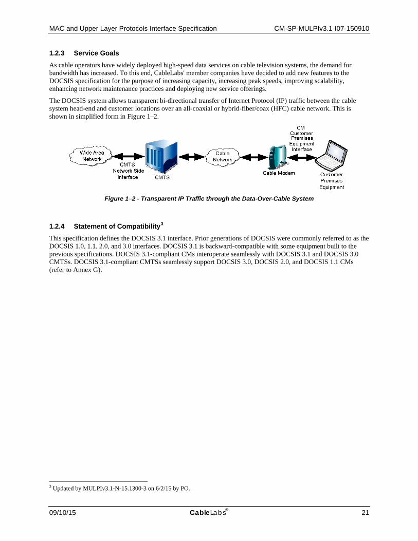
MAC and Upper Layer Protocols Interface Specification CM-SP-MULPIv3.1-I07-150910
09/10/15 CableLabs 21
1.2.3 Service Goals As cable operators have widely deployed high-speed data services on cable television systems, the demand for bandwidth has increased. To this end, CableLabs' member companies have decided to add new features to the DOCSIS specification for the purpose of increasing capacity, increasing peak speeds, improving scalability, enhancing network maintenance practices and deploying new service offerings.
The DOCSIS system allows transparent bi-directional transfer of Internet Protocol (IP) traffic between the cable system head-end and customer locations over an all-coaxial or hybrid-fiber/coax (HFC) cable network. This is shown in simplified form in Figure 1–2.
Figure 1–2 - Transparent IP Traffic through the Data-Over-Cable System
1.2.4 Statement of Compatibility3 This specification defines the DOCSIS 3.1 interface. Prior generations of DOCSIS were commonly referred to as the DOCSIS 1.0, 1.1, 2.0, and 3.0 interfaces. DOCSIS 3.1 is backward-compatible with some equipment built to the previous specifications. DOCSIS 3.1-compliant CMs interoperate seamlessly with DOCSIS 3.1 and DOCSIS 3.0 CMTSs. DOCSIS 3.1-compliant CMTSs seamlessly support DOCSIS 3.0, DOCSIS 2.0, and DOCSIS 1.1 CMs (refer to Annex G).
3 Updated by MULPIv3.1-N-15.1300-3 on 6/2/15 by PO.

CM-SP-MULPIv3.1-I07-150910 Data-Over-Cable Service Interface Specifications
22 CableLabs 09/10/15
1.2.5 Reference Architecture
RxRx
TxTx FiberNodeFiber
Node
M-CMTS Core
EQAM
UpstreamReceiver
DOCSIS Timing Server
Wide Area Network
Network Side Interface (NSI)
Operations Support System Interface (OSSI)
Cable Modem to CPE Interface
(CMCI)
Downstream External Phy
Interface (DEPI)
DOCSIS Timing Interface (DTI)
Downstream RF Interface
( DRFI)
Cable Modem
(CM)
Operations Support System
Physical Layer Interface (PHY)
Downstream RF Network
Upstream RF Network
Opt.Tx
Opt.Rx
FiberNode
M-CMTS
I-CMTS / CCAP
Distribution Hub or Headend
CoaxDistribution
FiberDistribution
NOTE: Gray-shaded areas represent related functionality, but are out of scope of this document.
MAC & Upper LayerProtocols Interface (MULPI)& Security Interface (SEC)
Customer Premises
Equipment
Figure 1–3 - Data-Over-Cable Reference Architecture
The reference architecture for data-over-cable services and interfaces is shown in Figure 1–3.
1.2.6 DOCSIS 3.1 Documents A list of the specifications in the DOCSIS 3.1 series is provided in Table 1–1. For further information, please refer to http://www.cablemodem.com.
Table 1–1 - DOCSIS 3.1 Series of Specifications
Designation Title CM-SP-PHYv3.1 Physical Layer Specification
CM-SP-MULPIv3.1 Media Access Control (MAC) and Upper Layer Protocols Interface Specification
CM-SP-CM-OSSIv3.1 Cable Modem Operations Support System Interface-Specification
CM-SP-CCAP-OSSIv3.1 CCAP Operations Support System Interface-Specification
CM-SP-SECv3.1 Security Specification
CM-SP-CMCIv3.0 Cable Modem CPE Interface Specification
This specification defines the interface for MAC and Upper Layer Protocols.

MAC and Upper Layer Protocols Interface Specification CM-SP-MULPIv3.1-I07-150910
09/10/15 CableLabs 23
Related DOCSIS specifications are listed in Table 1–2.
Table 1–2 - DOCSIS 3.1 Related Specifications
Designation Title CM-SP-eDOCSIS eDOCSIS™ Specification
CM-SP-DRFI Downstream Radio Frequency Interface Specification
CM-SP-DTI DOCSIS Timing Interface Specification
CM-SP-DEPI Downstream External PHY Interface Specification
CM-SP-DSG DOCSIS Set-Top Gateway Interface Specification
CM-SP-ERMI Edge Resource Manager Interface Specification
CM-SP-M-OSSI M-CMTS Operations Support System Interface Specification
CM-SP-L2VPN Layer 2 Virtual Private Networks Specification
CM-SP-TEI TDM Emulation Interfaces Specification
1.3 Requirements
Throughout this document, the words that are used to define the significance of particular requirements are capitalized. These words are:
"MUST" This word means that the item is an absolute requirement of this specification. "MUST NOT" This phrase means that the item is an absolute prohibition of this specification. "SHOULD" This word means that there may exist valid reasons in particular circumstances to ignore
this item, but the full implications should be understood and the case carefully weighed before choosing a different course.
"SHOULD NOT" This phrase means that there may exist valid reasons in particular circumstances when the listed behavior is acceptable or even useful, but the full implications should be understood and the case carefully weighed before implementing any behavior described with this label.
"MAY" This word means that this item is truly optional. For example, one vendor may choose to include the item because a particular marketplace requires it or because it enhances the product; another vendor may omit the same item.
This document defines many features and parameters, and a valid range for each parameter is usually specified. Equipment (CM and CMTS) requirements are always explicitly stated. Equipment must comply with all mandatory (MUST and MUST NOT) requirements to be considered compliant with this specification. Support of non-mandatory features and parameter values is optional.
1.4 Conventions
In this specification the following convention applies any time a bit field is displayed in a figure. The bit field should be interpreted by reading the figure from left to right, then from top to bottom, with the MSB being the first bit so read and the LSB being the last bit so read.
1.5 Organization of Document
Section 1 provides an overview of the DOCSIS 3.1 series of specifications including the DOCSIS reference architecture and statement of compatibility.
Sections 2-4 include the references, terms, and acronyms used throughout this specification.

CM-SP-MULPIv3.1-I07-150910 Data-Over-Cable Service Interface Specifications
24 CableLabs 09/10/15
Section 5 provides a technical overview and lists the key features of DOCSIS 3.1 technology for the functional area of this specification.
Sections 6-12 and the annexes contain the normative material.
The appendices contain informative material that provides more detailed explanations and examples of certain aspects of this specification.

MAC and Upper Layer Protocols Interface Specification CM-SP-MULPIv3.1-I07-150910
09/10/15 CableLabs 25
2 REFERENCES
2.1 Normative References
In order to claim compliance with this specification, it is necessary to conform to the following standards and other works as indicated, in addition to the other requirements of this specification. Notwithstanding, intellectual property rights may be required to use or implement such normative references.
[CANN DHCP-Reg] CableLabs DHCP Options Registry Specification, CL-SP-CANN-DHCP-Reg-I11-150515, May 5, 2015, Cable Television Laboratories, Inc.
[DOCSIS DEPI] DOCSIS Downstream External-PHY Interface, CM-SP-DEPI-I08-100611, June 11, 2010, Cable Television Laboratories, Inc.
[DOCSIS DRFI] DOCSIS Downstream Radio Frequency Interface, CM-SP-DRFI-I14-131120, November 20, 2013, Cable Television Laboratories, Inc.
[DOCSIS DSG] DOCSIS Set-Top Gateway (DSG) Specification, CM-SP-DSG-I24-130808, August 8, 2013, Cable Television Laboratories, Inc.
[DOCSIS DTI] DOCSIS Timing Interface, CM-SP-DTI-I06-150305, March 5, 2015, Cable Televisions Laboratories, Inc.
[DOCSIS eDOCSIS] eDOCSIS Specification, CM-SP-eDOCSIS-I28-150305, March 5, 2015, Cable Television Laboratories, Inc.
[DOCSIS L2VPN] DOCSIS Business Services over DOCSIS, Layer 2 Virtual Private Networks, CM-SP-L2VPN-I15-150528, May 28, 2015, Cable Television Laboratories, Inc.
[DOCSIS MULPIv3.0]
DOCSIS 3.0, MAC and Upper Layer Protocols Interface Specification, CM-SP-MULPIv3.0-I28-150827, August 27, 2015, Cable Television Laboratories, Inc.
[DOCSIS OSSIv2.0] DOCSIS 2.0, Operations Support System Interface Specification, CM-SP-OSSIv2.0-C01-081104, November 4, 2008, Cable Television Laboratories, Inc.
[DOCSIS OSSIv3.0] DOCSIS 3.0, Operations Support System Interface Specification, CM-SP-OSSIv3.0-I27-150827, August 27, 2015, Cable Television Laboratories, Inc.
[DOCSIS PHYv3.0] DOCSIS 3.0, Physical Layer Specification, CM-SP-PHYv3.0-I12-150305, March 5, 2015, Cable Television Laboratories, Inc.
[DOCSIS PHYv3.1] DOCSIS 3.1, Physical Layer Specification, CM-SP-PHYv3.1-I07-150910, September 10, 2015, Cable Television Laboratories, Inc.
[DOCSIS RFIv1.1] DOCSIS 1.1, Radio Frequency Interface Specification, CM-SP-RFIv1.1-C01-050907, September 7, 2005, Cable Television Laboratories, Inc.
[DOCSIS RFIv2.0] DOCSIS 2.0, Radio Frequency Interface Specification, CM-SP-RFIv2.0-C02-090422, April 22, 2009, Cable Television Laboratories, Inc.
[DOCSIS SECv3.0] DOCSIS 3.0, Security Specification, CM-SP-SECv3.0-I15-130808, August 8, 2013, Cable Television Laboratories, Inc.
[DOCSIS SECv3.1] DOCSIS 3.1, Security Specification, CM-SP-SECv3.1-I04-150910, September 10, 2015, Cable Television Laboratories, Inc.
[IEEE 802.1D] IEEE 802.1D-2004, IEEE standard for local and metropolitan area networks--Media access control (MAC) Bridges (Incorporates IEEE 802.1t-2001 and IEEE 802.1w).
[IEEE 802.1ad] IEEE Std. 802.1ad-2005, IEEE Standard for Local and Metropolitan Area Networks – Virtual Bridged Local Area Networks Amendment 4: Provider Bridges, May 2006. Former amendment to 802.1Q, now part of 802.1Q-2011.
[IEEE 802.1Q] IEEE Std. 802.1Q-2011, IEEE Standard for Local and Metropolitan Area Networks - Media Access Control (MAC) Bridges and Virtual Bridge Local Area Networks, August 2011.

CM-SP-MULPIv3.1-I07-150910 Data-Over-Cable Service Interface Specifications
26 CableLabs 09/10/15
[IEEE 802.1ah] IEEE Std. 802.1ah-2008, IEEE Standard for Local and Metropolitan Area Networks – Virtual Bridged Local Area Networks – Amendment 6: Provider Backbone Bridges, January 2008. Former amendment to 802.1Q, now part of 802.1Q-2011. [802.1Q].
[IEEE 802.3as] IEEE Std. 802.3as-2006, IEEE Standard for Information technology – Telecommunications and information exchange between systems – Local and metropolitan area networks – Specific requirements Part 3: Carrier Sense Multiple Access with Collision Detection (CSMA/CD) Access Method and Physical Layer Specifications.
[IEEE 1588-2008] IEEE Std. 1588-2008 (Revision of IEEE Std 1588-2002), IEEE Standard for a Precision Clock Synchronization Protocol for Networked Measurement and Control Systems, July 24 2008.
[ISO/IEC 8802-2] ISO/IEC 8802-2:1998, Information technology, Telecommunications and information exchange between systems, Local and metropolitan area networks, Specific requirements. Part 2: Logical link control.
[ISO/IEC 8802-3] ISO/IEC 8802-3:2000, Information technology, Telecommunications and information exchange between systems, Local and metropolitan area networks, Specific requirements, Part 3: Carrier sense multiple access with collision detection (CSMA/CD) access method and physical layer specifications.
[ISO/IEC 8825-1] ISO/IEC 8825-1:2008, Information technology, ASN.1 encoding rules: Specification of Basic Encoding Rules (BER), Canonical Encoding Rules (CER) and Distinguished Encoding Rules (DER), Ed. #4.
[ISO/IEC10038] ISO/IEC 10038 (ANSI/IEEE Std 802.1D): 1993, Information technology -Telecommunications and information exchange between systems - Local area networks - Media access control (MAC) bridges.
[ITU-T J.83A] Annex A of ITU-T Recommendation J.83 (12/2007), Digital multi-program systems for television, sound and data services for cable distribution.
[ITU-T J.83B] Annex B of ITU-T Recommendation J.83 (12/2007), Digital multi-program systems for television, sound and data services for cable distribution.
[ITU-T X.25] ITU-T Recommendation X.25 (9/98), Interface between Data Terminal Equipment (DTE) and Data Circuit-terminating Equipment (DCE) for terminals operating in the packet mode and connected to public data networks by dedicated circuit.
[PKT-MGCP] PacketCable Network-Based Call Signaling Protocol Specification, PKT-SP-EC-MGCP-C01-071129, November 29, 2007, Cable Television Laboratories, Inc.
[RFC 768] IETF RFC 768/STD0006, J. Postel, User Datagram Protocol, August 1980. [RFC 868] IETF RFC 868/STD0026, J. Postel, K. Harrenstien, Time Protocol, May 1983. [RFC 1042] IETF RFC 1042, J. Postel, J.K. Reynolds, Standard for the transmission of IP datagrams
over IEEE 802 networks, February 1988. [RFC 1112] IETF RFC 1112/STD0005, S.E. Deering, "Host extensions for IP multicasting", August
1989 [RFC 1157] IETF RFC 1157, J.D. Case, M. Fedor, M.L. Schoffstall, J. Davin, Simple Network
Management Protocol (SNMP), May 1990. [RFC 1191] IETF RFC 1191, J. Mogul, S. Deering, Path MTU Discovery, November 1990. [RFC 1350] IETF RFC 1350/STD0033, K. Sollins, The TFTP Protocol (Revision 2), July 1992. [RFC 1493] IETF RFC 1493, E. Decker, P. Langille, A. Rijsinghani, K. McCloghrie, Definitions of
Managed Objects for Bridges, July 1993. [RFC 1700] IETF RFC 1700, J Reynolds, J. Postel, Assigned Numbers, October 1994. [RFC 1812] IETF RFC 1812, F. Baker, Ed., Requirements for IP Version 4 Routers, June 1995. [RFC 1945] IETF RFC 1945, T. Berners-Lee, R. Fielding, H. Frystyk, "Hypertext Transfer Protocol --
HTTP/1.0," May 1996.

MAC and Upper Layer Protocols Interface Specification CM-SP-MULPIv3.1-I07-150910
09/10/15 CableLabs 27
[RFC 1981] IETF RFC 1981, J. McCann, S. Deering, J. Mogul, Path MTU discovery for IP version 6, August 1996.
[RFC 2104] IETF RFC 2104, H. Krawczyk, M. Bellare, R. Canetti, HMAC: Keyed-Hashing for Message Authentication, February 1997.
[RFC 2131] IETF RFC 2131, R. Droms, Dynamic Host Configuration Protocol, March 1997. [RFC 2132] IETF RFC 2132, S. Alexander, R. Droms, DHCP Options and BOOTP Vendor Extensions,
March 1997. [RFC 2236] IETF RFC 2236, Internet Group Management Protocol, Version 2, November 1997. [RFC 2309] IETF RFC 2309, Recommendations on Queue Management and Congestion Avoidance in
the Internet, April 1998. [RFC 2348] IETF RFC 2348, G. Malkin, A. Harkin, TFTP Blocksize Option, May 1998. [RFC 2460] IETF RFC 2460, S. Deering, R. Hinden, Internet Protocol, Version 6 (IPv6), Specification,
December 1998. [RFC 2461] IETF RFC 2461, T. Narten, E. Nordmark, W. Simpson, Neighbor Discovery for IP Version
6 (IPv6), December 1998. [RFC 2462] IETF RFC 2462, S. Thomson, T. Narten, IPv6 Stateless Address Autoconfiguration,
December 1998. [RFC 2464] IETF RFC 2464, N, Crawford, Transmission of IPv6 Packets over Ethernet Networks,
December 1998. [RFC 2474] IETF RFC 2474, K. Nichols, S. Blake, F. Baker, D. Black, Definition of the Differentiated
Services Field (DS Field) in the IPv4 and IPv6 Headers, December 1998. [RFC 2616] IETF RFC 2616, R. Fielding, et al., "Hypertext Transfer Protocol -- HTTP/1.1", June 1999. [RFC 2669] IETF RFC 2669, M. St. Johns, Ed, DOCSIS Cable Device MIB Cable Device Management
Information Base for DOCSIS compliant Cable Modems and Cable Modem Termination Systems, August 1999.
[RFC 2710] IETF RFC 2710, Multicast Listener Discovery (MLD) for IPv6, MLD v1, October 1999. [RFC 2786] IETF RFC 2786, M. St. Johns, Diffie-Helman USM Key Management Information Base
and Textual Convention, March 2000. [RFC 3032] IETF RFC 3032, MPLS Label Stack Encoding. E. Rosen, D. Tappan, G. Fedorkow, Y.
Rekhter, D. Farinacci, T. Li, A. Conta, January 2001. [RFC 3046] IETF RFC 3046, M. Patrick, DHCP Relay Agent Information Option, January 2001. [RFC 3203] IETF RFC 3203, Y. T'Joens, C. Hublet, P. DeSchrijver, DHCP reconfigure extension,
December 2001. [RFC 3219] IETF RFC 3219, J. Rosenberg, H. Salama, M. Squire, Telephony Routing over IP (TRIP),
January 2002. [RFC 3256] IETF RFC 3256, D. Jones, R. Woundy, The DOCSIS (Data-Over-Cable Service Interface
Specifications) Device Class DHCP (Dynamic Host Configuration Protocol) Relay Agent Information Sub-option, April 2002.
[RFC 3315] IETF RFC 3315, R. Droms, Ed., J. Bound, B. Volz, T. Lemon, C. Perkins, M. Car, Dynamic Host Configuration Protocol for IPv6 (DHCPv6), July 2003.
[RFC 3376] IETF RFC 3376, B. Cain, S. Deering, I. Kouvelas, B. Fenner, A.Thyagarajan, Internet Group Management Protocol, Version 3, October 2002.
[RFC 3495] IETF RFC 3495, B. Beser, P. Duffy, Ed., Dynamic Host Configuration Protocol (DHCP) Option for CableLabs Client Configuration, March 2003.
[RFC 3513] IETF RFC 3513, R. Hinden, S. Deering, Internet Protocol Version 6 (IPv6) Addressing Architecture, April 2003.

CM-SP-MULPIv3.1-I07-150910 Data-Over-Cable Service Interface Specifications
28 CableLabs 09/10/15
[RFC 3633] IETF RFC 3633, O. Troan, R. Droms, IPv6 Prefix Options for Dynamic Host Configuration Protocol (DHCP) version 6, December 2003.
[RFC 3810] IETF RFC 3810, R. Vida, Ed., L. Costa, Ed. Multicast Listener Discovery Version 2 (MLDv2) for IPv6, June 2004.
[RFC 4361] IETF RFC 4361, T. Lemon, B. Sommerfeld, Node-specific Client Identifiers for Dynamic Host Configuration Protocol Version Four (DHCPv4), February 2006.
[RFC 4601] IETF RFC 4601, B. Fenner, M. Handley, H. Holbrook, I. Kouvelas, "Protocol Independent Multicast - Sparse Mode (PIM-SM): Protocol Specification (Revised)", August 2006.
[RFC 4604] IETF RFC 4604, H. Holbrook, B. Cain, B. Haberman, "Using IGMPv3 and MLDv2 for Source-Specific Multicast", August 2006.
[RFC 4605] IETF RFC 4605, B. Fenner, H. He, B. Haberman, H. Sandick, "IGMP/MLD-based Multicast Forwarding ("IGMP/MLD Proxying")" August 2006.
[RFC 4607] IETF RFC 4607, H. Holbrook, B. Cain," Source-Specific Multicast for IP" August 2006. [RFC 4649] IETF RFC 4649, B. Volz, "Dynamic Host Configuration Protocol for IPv6 (DHCPv6)
Relay Agent Remote-ID Option" August 2006. [RFC 4861] IETF RFC 4861, T. Narten, E. Nordmark, W. Simpson, H. Soliman, Neighbor Discovery
for IP Version 6 (IPv6), September 2007. [RFC 4862] IETF RFC 4862, S. Thomson, T. Narten, T. Jinmei, IPv6 Stateless Address
Autoconfiguration, September 2007. [RFC 5460] IETF RFC 5460, M. Stapp, "DHCPv6 Bulk Leasequery" February, 2009. [RFC 5462] IETF RFC 5462, Multiprotocol Label Switching (MPLS) Label Stack Entry: "EXP" Field
Renamed to "Traffic Class" Field. L. Andersson, R. Asati, February 2009. [SHA] FIPS PUB 180-1, Secure Hash Standard, 1993 May 11.
2.2 Informative References
This specification uses the following informative references.
[C-DOCSIS] Data-Over-Cable Interface Specifications, C-DOCSIS System Specification, CM-SP-CDOCSIS-I02-150305, March 5, 2015, Cable Television laboratories, Inc.
[DOCSIS BPI+] Data-Over-Cable Service Interface Specifications, Baseline Privacy Plus Interface Specification, CM-SP-BPI+-C01-081104, November 4, 2008, Cable Television Laboratories, Inc.
[DOCSIS CMCIv3.0]
DOCSIS 3.0, Cable Modem to Customer Premise Equipment Interface Specification, CM-SP-CMCIv3.0-I02-140729, July 29, 2014, Cable Television Laboratories, Inc.
[DOCSIS NSI] CMTS Network Side Interface, SP-CMTS-NSI-I01-960702, July 2, 1996, Cable Television Laboratories, Inc.
[DOCSIS CCAP-OSSIv3.1]
DOCSIS 3.1 CCAP Operations Support System Interface Specification, CM-SP-CCAP-OSSIv3.1-I05-150910, September 10, 2015, Cable Television Laboratories, Inc.
[DOCSIS CM-OSSIv3.1]
DOCSIS 3.1 Cable Modem Operations Support System Interface Specification, CM-SP-CM-OSSIv3.1-I05-150910, September 10, 2015, Cable Television Laboratories, Inc.
[DOCSIS OSSIv3.1]
Refers to both [DOCSIS CCAP-OSSIv3.1] and [DOCSIS CM-OSSIv3.1].
[DPoE-DEMARCv1.0]
DOCSIS Provisioning of EPON, DPoE Demarcation Device Specification, DPoE-SP-DEMARCv1.0-I04-140807, August 7, 2014, Cable Television Laboratories, Inc.
[DPoE-IPNEv2.0] DOCSIS Provisioning of EPON, DPoE IP Network Element Requirements, DPoE-SP-IPNEv2.0-I05-150611, June 11, 2015, Cable Television Laboratories, Inc.

MAC and Upper Layer Protocols Interface Specification CM-SP-MULPIv3.1-I07-150910
09/10/15 CableLabs 29
[DPoE-MULPIv2.0]
DOCSIS Provisioning of EPON, DPoE MAC and Upper Layer Protocols Requirements, DPoE-SP-MULPIv2.0-I08-150611, June 11, 2015, Cable Television Laboratories, Inc.
[draft-baker-aqm] IETF Recommendations Regarding Active Queue Management", Fred Baker, Gorry Fairhurst, 2015-02-25, draft-ietf-aqm-recommendation-11.txt.
[ITU-T Z.100] ITU-T Recommendation Z.100 (12/2011), Formal description techniques (FDT) – Specification and Description Language (SDL), 08/2002.
[PCMM] PacketCable Multimedia Specification, PKT-SP-MM-I06-110629, June 29, 2011, Cable Television Laboratories, Inc.
[PKT-DQoS] PacketCable Dynamic Quality-of-Service Specification, PKT-SP-DQoS-C01-071129, November 29, 2007, Cable Television Laboratories, Inc.
[RFC 2212] IETF RFC 2212, S. Shenker, C. Partridge, R. Guerin, Specification of Guaranteed Quality of Service, September 1997.
[RFC 3168] IETF RFC 3168, K. Ramakrishnan, S. Floyd, D. Black, The Addition of Explicit Congestion Notification (ECN) to IP, September 2001.
[RFC 3260] IETF RFC 3260, D. Grossman, New Terminology and Clarifications for Diffserv, April 2002. [RFC 4291] IETF RFC 4291, R. Hinden, S. Deering, IP Version 6 Addressing Architecture, February 2006.
2.3 Reference Acquisition
• American National Standards Institute: http://www.ansi.org/standards_activities • Cable Television Laboratories, Inc., 858 Coal Creek Circle, Louisville, CO 80027;
Phone +1-303-661-9100, Fax +1-303-661-9199; http://www.cablelabs.com/ • Internet Engineering Task Force (IETF): http://www.ietf.org • International Organization for Standardization (ISO): http://www.iso.org/iso/en/xsite/contact/contact.html • ITU-T Recommendations: http://www.itu.int/ITU-T/publications/recs.html • Federal Information Processing Standards Publications: http://www.itl.nist.gov/fipspubs/by-num.htm
CM-SP-MULPIv3.1-I07-150910 Data-Over-Cable Service Interface Specifications
30 CableLabs 09/10/15
3 TERMS AND DEFINITIONS4 This specification uses the following terms:
Active Codes The set of spreading codes which carry information in an S-CDMA upstream. The complementary set, the unused codes, are idle and are not transmitted. Reducing the number of active codes below the maximum value of 128 may provide advantages including more robust operation in the presence of colored noise.
Active Queue Management AQM schemes attempt to maintain low queue occupancy (within Downstream and Upstream service flows) while supporting the ability to absorb a momentary traffic burst.
Address Resolution Protocol
A protocol of the IETF for converting network addresses to 48-bit Ethernet addresses.
Advanced Time Division Multiple Access
DOCSIS 2.0 or later TDMA mode (as distinguished from DOCSIS 1.x TDMA).
Allocation A group of contiguous minislots in a MAP which constitute a single transmit opportunity.
American National Standards Institute
A U.S. standards body.
Backup Primary Downstream Channel
A Primary-Capable Downstream Channel which is assigned to this CM as a Non-Primary Downstream Channel but which is designated to become the new Primary Downstream Channel if the currently assigned Primary Downstream Channel is no longer usable by this CM.
Bandwidth Allocation Map The MAC Management Message that the CMTS uses to allocate transmission opportunities to CMs.
BITS Encoding An octet string using a BITS encoding represents a zero-indexed linear array of 8*N bits, with the most significant bit of each byte representing the lowest-indexed bit. Bit positions increase from left to right. For example, bit position 0 is the most significant bit of the most significant (leftmost) byte, encoded as hex 0x80. Unspecified bit positions are assumed as zero. Unimplemented bit positions are ignored.
Bonded Channel Set An identified set of upstream or downstream channels among which a stream of packets is distributed.
Bonding Group A list of channels providing a means to identify the specific channels bonded together.
Border Gateway Protocol An inter-autonomous system routing protocol.
Bridged Network A set of IEEE 802 LANs interconnected by IEEE 802.1D MAC bridges.
Bridging CMTS A CMTS that makes traffic forwarding decisions between its Network System Interfaces and MAC Domain Interfaces based upon the Layer 2 Ethernet MAC address of a data frame.
Burst A single continuous RF signal from the upstream transmitter, from transmitter on to transmitter off.
Byte A contiguous sequence of eight bits. An octet.
Cable Modem A modulator-demodulator at subscriber locations intended for use in conveying data communications on a cable television system.
4 Updated per MULIv3.1-N-15.1328 and 15.1347-2 on 8/20/15 by PO.

MAC and Upper Layer Protocols Interface Specification CM-SP-MULPIv3.1-I07-150910
09/10/15 CableLabs 31
Cable Modem Service Group
In the HFC plant topology, the complete set of downstream and upstream channels within a single CMTS that a single Cable Modem could potentially receive or transmit on. In most HFC deployments, a CM-SG corresponds to a single Fiber Node. Usually, a CM-SG serves multiple CMs.
Cable Modem Termination System
Cable modem termination system, located at the cable television system head-end or distribution hub, which provides complementary functionality to the cable modems to enable data connectivity to a wide-area network.
Cable Modem Termination System - Network Side Interface
The network side interface, defined in [DOCSIS NSI], between a CMTS and the equipment on its network side.
Capture Bandwidth The sum of the Tuning Bands in the TB List in MHz.
Ceiling (ceil) A mathematical function that returns the lowest-valued integer that is greater than or equal to a given value.
Channel See Radio Frequency Channel.
Channel Bonding A logical process that combines the data packets received on multiple independent channels into one higher-speed data stream. Channel bonding can be implemented independently on upstream channels or downstream channels.
Chip Each of the 128 bits comprising the S-CDMA spreading codes.
Classifier A set of criteria used for packet matching according to TCP, UDP, IP, LLC, and/or 802.1P/Q packet fields. A classifier maps each packet to a Service Flow. A Downstream Classifier is used by the CMTS to assign packets to downstream service flows. An Upstream Classifier is used by the CM to assign packets to upstream service flows.
CMCI Port Physical interface of the CM to which a CPE device can attach.
Codeword An element of an error-correcting code used to detect and correct transmission errors, see http://mathworld.wolfram.com/Error-CorrectingCode.html
Continuous Concatenation and Fragmentation
Method of packing data into segments for upstream transmission in Multiple Transmit Channel Mode.
Converged Interconnect Network
The network (generally gigabit Ethernet) that connects an M-CMTS Core to an EQAM.
CPE Interface An interface that is either a CMCI Port or a Logical CPE interface.
Customer Premises Equipment
Equipment at the end user's premises; may be provided by the end user or the service provider.
Data Link Layer Layer 2 in the Open System Interconnection (OSI) architecture; the layer that provides services to transfer data over the transmission link between open systems.
Data Rate Throughput, data transmitted in units of time usually in bits per second (bps).
Decibel-Millivolt A dB measurement system wherein 0 dBmV is defined as 1 millivolt over 75 ohms.
Decibels A unit to measure the relative levels of current, voltage or power. An increase of 3 dB indicates a doubling of power, an increase of 10 dB indicates a 10x increase in power, and an increase of 20 dB indicates a 100x increase in power.
Diplexer A passive device that implements frequency domain multiplexing.
DOCSIS 1.x Abbreviation for "DOCSIS 1.0 or 1.1".
DOCSIS 2.0 Mode This mode is not relevant for DOCSIS3.1 CM.

CM-SP-MULPIv3.1-I07-150910 Data-Over-Cable Service Interface Specifications
32 CableLabs 09/10/15
Downstream In cable television, the direction of transmission from the headend to the subscriber.
Downstream Bonded Service Flow
A downstream Service Flow assigned to a Downstream Bonding Group.
Downstream Bonding Group
A subcomponent object of a MAC Domain that distributes packets from an assigned set of Downstream Bonding Service Flows to an associated set of Downstream Channels of that MAC Domain.
Downstream Channel Physical layer characteristics and MAC layer parameters and functions associated to a DOCSIS forward channel.
Downstream Channel Identifier
An 8-bit identifier that distinguishes a Downstream Channel within a MAC Domain. DCID values may be assigned locally by the CMTS or externally by CMTS configuration.
Downstream Interface As a term, refers to either a Downstream Channel (DC) or a Downstream Bonding Group (DBG). A DI is not a separate object in the object model.
Downstream M-CMTS Channel
An object representing the M-CMTS DEPI session (see [DOCSIS DEPI]) that carries the DOCSIS MAC-Layer contents of a single Downstream RF Channel.
Downstream RF Channel The CMTS object representing the physical transmission of the MAC-Layer contents of a DOCSIS downstream RF signal at a single center frequency. A DRF object implements the functions of: FEC Encoding, MPEG2 Convergence, QAM modulation, and Physical RF transmission.
Downstream Service Extended Header
A DOCSIS extended header that contains a Downstream Service ID (DSID).
Downstream Service Group The complete set of Downstream Channels (DCs) from a single CMTS that could potentially reach a single Cable Modem. A DS-SG corresponds to a broadband forward carrier path signal from one CMTS. In an HFC deployment, a DS-SG corresponds to the downstream fiber transmission from one CMTS to one or more Fiber Nodes.
Downstream Service Identifier
A 20-bit value in a DOCSIS extended header that identifies a stream of packets distributed to the same cable modem or group of cable modems. The DSID value is unique within a MAC Domain. For sequenced packets, the DSID identifies the resequencing context for downstream packet bonding in the CM.
Dual Stack Management See Dual Stack Management Mode.
Dual Stack Management Mode
A mode of DOCSIS cable modem operation in which the modem is manageable simultaneously via both IPv4 and IPv6 addresses.
Duplicate Address Detection
Defined in the IETF. Reference [RFC 4862].
Dynamic Host Configuration Protocol
An Internet protocol used for assigning network-layer (IP) addresses.
Dynamic Range The ratio between the greatest signal power that can be transmitted over a multichannel analog transmission system without exceeding distortion or other performance limits, and the least signal power that can be utilized without exceeding noise, error rate or other performance limits.
Edge Quadrature Amplitude Modulator
In the M-CMTS architecture, a network element that terminates DEPI sessions and implements the physical Downstream RF Channel for those sessions. The EQAM terminates Downstream M-CMTS Channels and forwards their DOCSIS MAC-Layer contents to Downstream RF Channels.
Egress Interface A CPE interface through which the cable modem transmits traffic.

MAC and Upper Layer Protocols Interface Specification CM-SP-MULPIv3.1-I07-150910
09/10/15 CableLabs 33
End User A human being, organization, or telecommunications system that accesses the network in order to communicate via the services provided by the network.
Energy Management Identifier (EM-ID)
A 16-bit unsigned integer used to identify one or more CMs that may be addressed by a single Energy Management message directive. A CM may be assigned multiple EM-IDs: one for the modem itself, one or more for multicast groupings, and one for an all-CMs broadcast. A CM responds to the first matching EM-ID that it sees within a PLC frame.
Epoch Time The time elapsed since 1 January 1970 00:00:00. This is usually expressed in seconds.
Fiber Node In HFC, a point of interface between a fiber trunk and the coaxial distribution.
Flooding An operation of an L2 Bridge in which it replicates an L2PDU addressed to a group MAC or unlearned individual MAC address to all Bridge Ports other than the L2PDU's ingress port.
Floor A mathematical function that returns the highest-valued integer that is less than or equal to a given value.
Forward Error Correction FEC enables the receiver to detect and fix errors to packets without the need for the transmitter to retransmit packets.
Frame See MAC frame, S-CDMA frame, and MPEG frame.
Group Delay The difference in transmission time between the highest and lowest of several frequencies through a device, circuit or system.
Group Service Flow Group Service Flow, a downstream Service Flow for packets forwarded to hosts reached through a group of Cable Modems. A GSF may be either a Bonded GSF (B-GSF) or a Non-Bonded GSF (NB-GSF).
Guard Time The term guard time, measured in modulation symbols, is similar to the guard band, except that it is measured from the end of the last symbol of one burst to the beginning of the first symbol of the preamble of an immediately following burst. Thus, the guard time is equal to the guard band – 1.
HD-timestamp (HD-TS) 64-bit timestamp as defined for use in an ODFM downstream channel; Consists of high-order epoch bits that provide the time that has passed since a point in time (yet to be determined), an embedded legacy timestamp, and extra bits for added precision
Head-end The central location on the cable network that is responsible for injecting broadcast video and other signals in the downstream direction.
Header Protocol control information located at the beginning of a protocol data unit.
Hertz A unit of frequency equivalent to one cycle per second. See also kilohertz (kHz) and megahertz (MHz).
Hybrid Fiber/Coaxial System
A broadband bidirectional shared-media transmission system using fiber trunks between the head-end and the fiber nodes, and coaxial distribution from the fiber nodes to the customer locations.
Identity Association for Prefix Delegation
A collection of prefixes assigned to the requesting router in DHCPv6 [RFC 3633].
Individual MAC Address An IEEE 6-byte MAC address with the first transmitted bit (the group bit) set to 0, indicating that the address refers to a single MAC host. For the Ethernet MAC addresses of DOCSIS, the group bit is the least significant bit of the first byte of the MAC address.

CM-SP-MULPIv3.1-I07-150910 Data-Over-Cable Service Interface Specifications
34 CableLabs 09/10/15
Individual Service Flow Downstream Service Flow for packets forwarded to hosts reached through an individual Cable Modem. An ISF may be either a Bonded ISF (B-ISF), or a Non-Bonded ISF (NB-ISF).
Information Element The fields that make up a MAP and define individual grants, deferred grants, etc.
Institute of Electrical and Electronics Engineers
A voluntary organization which, among other things, sponsors standards committees and is accredited by the American National Standards Institute.
Integrated Cable Modem Termination System
A CMTS wherein all components are integrated into a single chassis as opposed to a modular CMTS.
Interior Gateway Protocol A routing protocol used to exchange routing information among routers within a single Autonomous System, like RIP, OSPF and IS-IS.
International Electrotechnical Commission
An international standards body.
Internet Control Message Protocol
An Internet network-layer protocol.
Internet Engineering Task Force
A body responsible, among other things, for developing standards used in the Internet.
Internet Group Management Protocol
A network-layer protocol for managing multicast groups on the Internet.
Internet Protocol The computer network protocol (analogous to written and verbal languages) that all machines on the Internet must know so that they can communicate with one another. IP is a layer 3 (network layer) protocol in the OSI model. The vast majority of IP devices today support IP version 4 (IPv4) defined in RFC-791, although support for IP version 6 (IPv6, RFC-2460) is increasing.
Interval Usage Code A field in MAPs and UCDs to link burst profiles to grants.
IPv6 Router Advertisement ICMPv6 datagram transmitted by a router to advertise its presence along with various link and Internet parameters. Refer to [RFC 4861].
Latency The time taken for a signal element to pass through a device.
Layer A subdivision of the Open System Interconnection (OSI) architecture, constituted by subsystems of the same rank.
Layer 2 Protocol Data Unit A sequence of bytes consisting of a destination MAC address, a source MAC address, optional Tag Headers, Ethertype/Length, L2 Payload, and CRC.
Layer 2 Virtual Private Network
A set of LANs and the L2 Forwarders between them that enable hosts attached to the LANs to communicate with L2PDUs. A single L2VPN forwarding L2PDUs based only on the Destination MAC address of the L2PDU, transparent to any IP or other Layer 3 address. A cable operator administration domain supports multiple L2VPNs, one for each subscriber enterprise to which Transparent LAN Service is offered.
Learning An operation of a layer 2 Bridge by which it associates the Source MAC address of an incoming L2PDU with the bridge port from which it arrived.
Link Layer See Data Link Layer.
Load Balancing Group A full or partial subset of a MAC Domain Cable Modem Service Group (MD-CM-SG) to which a CM is administratively assigned. LBGs contain at least one upstream channel and at least one downstream channel.

MAC and Upper Layer Protocols Interface Specification CM-SP-MULPIv3.1-I07-150910
09/10/15 CableLabs 35
Local Area Network A non-public data network in which serial transmission is used for direct data communication among data stations located on the user's premises.
Local Log A volatile or nonvolatile log stored within a network element.
Logical (Upstream) Channel
A MAC entity identified by a unique channel ID and for which bandwidth is allocated by an associated MAP message. A physical upstream channel may support multiple logical upstream channels. The associated UCD and MAP messages completely describe the logical channel.
Logical CPE Interface Logical interface between the embedded cable modem and an eSAFE.
Logical Link Control A sub-layer of the second layer (Data Link Layer) in the Open Systems Interconnection seven-layer model for communications protocols standardized by the International Organization for Standardization (ISO), that is responsible for multiplexing transmitted messages, demultiplexing received messages, and providing message flow control.
MAC Domain A subcomponent of the CMTS that provides data forwarding services to a set of downstream and upstream channels.
MAC Domain Cable Modem Service Group
The subset of a CM-SG which is confined to the DCs and UCs of a single MAC domain. An MD-CM-SG differs from a CM-SG only if multiple MAC domains are assigned to the same CM-SGs.
MAC Domain Downstream Service Group
The subset of a Downstream Service Group (DS-SG) which is confined to the Downstream Channels of a single MAC domain. An MD-DS-SG differs from a DS-SG only when multiple MAC domains are configured per DS-SG.
MAC Domain Interface The interface of a MAC Domain to a CMTS Forwarder.
MAC Domain Upstream Service Group
The subset of an Upstream Service Group (US-SG) which is confined to the Upstream Channels of a single MAC Domain. An MD-US-SG differs from a US-SG only when multiple MAC domains are defined per US-SG.
MAC Frame MAC header plus optional protocol data unit.
MAP See Bandwidth Allocation Map.
MDF-capable CM A CM that reports an MDF capability of 1 or 2 in the Modem Capabilities encoding.
MDF-disabled An MDF-capable CM is said to be MDF-disabled when the CMTS sets the value of 0 for the MDF capability in the Modem Capabilities encoding of the REG-RSP(-MP).
MDF-enabled A CM is said to be MDF-enabled when the CMTS returns the value of 1 or 2 for the MDF capability in the Modem Capabilities encoding of the REG-RSP(-MP).
MDF-incapable CM A CM that reports an MDF capability of 0 or does not report an MDF capability in the Modem Capabilities encoding.
Media Access Control The part of the data link layer that supports topology-dependent functions and uses the services of the Physical Layer to provide services to the logical link control (LLC) sublayer.
Media Access Control Address
The hardware address of a device connected to a shared medium.
Media Access Control Frame
MAC header plus optional PDU.

CM-SP-MULPIv3.1-I07-150910 Data-Over-Cable Service Interface Specifications
36 CableLabs 09/10/15
Media Access Control sublayer
A sub-layer of the second layer (Data Link Layer) in the Open Systems Interconnection sublayer seven-layer model for communications protocols standardized by the International Organization for Standardization (ISO), that is responsible for determining which transmitter is allowed access to the communication medium and uses the services of the Physical Layer to provide services to the Logical Link Control (LLC) sublayer.
Megahertz One million cycles per second.
Micro-reflections Echoes in the forward transmission path due to impedance mismatches between the physical plant components. Micro-reflections are distinguished from discrete echoes by having a time difference (between the main signal and the echo) on the order of 1 microsecond. Micro-reflections cause departures from ideal amplitude and phase characteristics for the transmission channel.
Microsecond (µs) One millionth of a second.
Millisecond (ms) One thousandth of a second.
Minislot A "minislot" is an integer multiple of 6.25-microsecond increments.
Modular Cable Modem Termination System
A CMTS composed of discrete functional blocks linked together using Gigabit Ethernet links.
Modulation Rate The signaling rate of the upstream modulator (1280 to 5120 kHz). In S-CDMA, the chip rate. In TDMA, the channel symbol rate.
Moving Picture Experts Group
A voluntary body which develops standards for digital compressed moving pictures and associated audio.
Multicast Client An entity with a unique MAC address that receives multicast packets.
Multicast Downstream Service Identifier Forwarding Capable Cable Modem
A cable modem that reports a nonzero value for the Multicast DSID Forwarding capability in the REG-REQ message.
Multiple Outstanding Requests
The ability of the cable modem to make additional bandwidth request for new packets for a service flow while one or more previous requests for older packets remain unfulfilled.
Multiple System Operator A corporate entity that owns and/or operates more than one cable system.
Multiple Transmit Channel Mode
Upstream operation of the cable modem and cable modem termination system MAC layer using continuous concatenation and fragmentation to segment traffic and queue-depth based requesting.
Nanosecond (ns) One billionth of a second.
National Cable Telecommunications Association
A voluntary association of cable television operators which, among other things, provides guidance on measurements and objectives for cable television systems in the USA.
Network Layer Layer 3 in the Open Systems Interconnection (OSI) architecture; the layer that provides services to establish a path between open systems.
Network Management The functions related to the management of data link layer and physical layer resources and their stations across the data network supported by the hybrid fiber/coax system.
Non-bonded Service Flow A Service Flow assigned to a single channel, rather than a Bonding Group.
Non-primary Downstream Channel
A Downstream Channel received by a cable modem which is not its Primary Downstream Channel.

MAC and Upper Layer Protocols Interface Specification CM-SP-MULPIv3.1-I07-150910
09/10/15 CableLabs 37
Notification Information emitted by a managed object relating to an event that has occurred within the managed object.
Open Systems Interconnection
A framework of ISO standards for communication between different systems made by different vendors, in which the communications process is organized into seven different categories that are placed in a layered sequence based on their relationship to the user. Each layer uses the layer immediately below it and provides a service to the layer above. Layers 7 through 4 deal with end-to-end communication between the message source and destination, and layers 3 through 1 deal with network functions.
Packet Identifier A unique integer value used to identify elementary streams of a program in a single or multi-program MPEG-2 stream.
Partial Service A modem is in a partial service mode of operation any time it is operating with a subset of the channels in the RCS and/or TCS because a channel has become unusable, either due to an inability to acquire a channel or because communication on a channel was lost during normal operation.
Payload Header Suppression
Transmitting or forwarding the data payload of a DOCSIS MAC frame without including header fields of the various protocol layers above the DOCSIS MAC layer. Suppression of header fields is selectable in DOCSIS.
Physical Layer Layer 1 in the Open System Interconnection (OSI) architecture; the layer that provides services to transmit bits or groups of bits over a transmission link between open systems and which entails electrical, mechanical and handshaking procedures.
Physical Media Dependent Sublayer
A sublayer of the Physical Layer which is concerned with transmitting bits or groups of bits over particular types of transmission link between open systems and which entails electrical, mechanical and handshaking procedures.
Pre-3.0 DOCSIS Versions of CableLabs Data-Over-Cable-Service-Interface-Specifications (DOCSIS) specifications prior to the DOCSIS 3.0 suite of specifications.
Primary Channel See Primary Downstream Channel.
Primary Downstream Channel
Prior to Registration, a Primary-Capable Downstream Channel on which the CM has achieved timing lock and successfully received an MDD message containing ambiguity resolution TLVs. After Registration, the channel on which the CM acquires timing from the assigned list of Primary Downstream Channels in the Simplified RCC Encodings.
Primary Service Flow The first service flow, in each direction, defined in the CM configuration file.
Primary-Capable Downstream Channel
A Downstream Channel which carries timestamp information (SYNC messages for SC-QAM or Timestamp Message Block and explicit primary-capability indicator for OFDM), MDD messages containing ambiguity resolution TLVs, as well as UCD and MAP messages for at least one upstream channel in each of the MD-CM-SGs that the downstream channel reaches.
Protocol A set of rules and formats that determines the communication behavior of layer entities in the performance of the layer functions.
QAM channel Analog RF channel that uses quadrature amplitude modulation (QAM) to convey information.
Quadrature Amplitude Modulation (QAM)
A method of modulating digital signals onto a radio-frequency carrier signal involving both amplitude and phase coding.
Quadrature Phase Shift Keying
A method of modulating digital signals onto a radio-frequency carrier signal using four phase states to code two digital bits.
CM-SP-MULPIv3.1-I07-150910 Data-Over-Cable Service Interface Specifications
38 CableLabs 09/10/15
Quality of Service Parameter Set
The set of Service Flow Encodings that describe the Quality of Service attributes of a Service Flow or a Service Class.
Queue-depth Based Request
Request in multiples of bytes based on the CM's queue depth and QoS parameters for a specific service flow. This request does not include any estimation of physical layer overhead.
Radio Frequency In cable television systems, this refers to electromagnetic signals in the range 5 to 1000 MHz.
Radio Frequency Channel The frequency spectrum occupied by a signal. Usually specified by center frequency and bandwidth parameters.
Radio Frequency Interface Term encompassing the downstream and the upstream radio frequency interfaces.
Ranging Request Messages Any of the ranging request messages, Due to usage in the DRW section
Ranging SID The SID used for ranging on a specific channel.
Receive Channel Configuration
The CMTS send the RCC encoding in the REG-RSP message. The RCC contains TLVs to initially configure a CM's Receive Channels (RCs) and Receive Modules (RMs).
Receive Channel Profile The RCP describes a logical representation of the DOCSIS 3.0 CM's downstream physical layer in terms of Receive Channels (RCs) and Receive Modules (RMs). A Cable Modem reports its ability to receive multiple channels with one or more RCP Encodings in a REG-REQ-MP message.
Receive Channel Set The set of downstream channels assigned to an individual CM is called its Receive Channel Set, and is explicitly configured by the CMTS using the RCC encodings.
Receive Module A component in the CM physical layer implementation shared by multiple Receive Channels.
Request for Comments A technical policy document of the IETF. These documents can be accessed on the World Wide Web at http://www.rfc-editor.org/.
Resequencing Channel List This is a list of channels on which the CM receives packets labeled with that DSID.
Resequencing Context A CM Resequencing Context, identified by a Resequencing DSID, is the set of Downstream Resequencing Channel List, Sequence Change Count, and DSID Resequencing Wait Time. Downstream packets containing a Resequencing DSID and a sequence number are delivered, resequenced and forwarded according to the attributes of the Resequencing Context.
Resequencing Downstream Service Identifier
A downstream service identifier for which the CMTS signals packet resequencing attributes.
Routing CMTS A CMTS that makes traffic forwarding decisions between its Network System Interfaces and MAC Domain Interfaces based upon the Layer 3 (network) address of a packet.
S-CDMA Frame A two dimensional representation of minislots, where the dimensions are codes and time. An S-CDMA frame is composed of p active codes in the code dimension and K spreading intervals in the time dimension. Within the S-CDMA frame, the number of minislots is determined by the number of codes per minislot I and p, the number of active codes in the S-CDMA frame. Each S-CDMA frame thus contains s minislots, where s=p/c, and each minislot contains c*K information (QAM) symbols.
Security Association The set of security information shared by two devices in order to support secure communications between the devices across a network.

MAC and Upper Layer Protocols Interface Specification CM-SP-MULPIv3.1-I07-150910
09/10/15 CableLabs 39
Security Association Identifier
A 14-bit handle used to identify a Security Association between a CM and a CMTS.
Segment A contiguous burst of upstream data traffic (data IUCs) allocated using a single grant element in a MAP message.
Segment Header OFF Mode of Upstream Operation where segment headers are not used for any segment. This mode is provisioned per upstream service flow and prohibits fragmenting a packet across segment boundaries.
Segment Header ON Mode of Upstream Operation where segment headers are used for each segment. This mode is provisioned per upstream service flow.
Selectable Active Codes A methodology to determine the set of active codes and its complement, the set of unused codes. In SAC mode 1, a consecutive set of codes starting with code 0 are unused. In SAC mode 2, the active codes are selectable via a 128-bit string.
Service Class A set of queuing and scheduling attributes that is named and that is configured at the CMTS. A Service Class is identified by a Service Class Name. A Service Class has an associated QoS Parameter Set.
Service Class Name An ASCII string by which a Service Class may be referenced in modem configuration files and protocol exchanges.
Service Flow A MAC layer transport service which provides unidirectional transport of packets from the upper layer service entity to the RF and shapes, polices, and prioritizes traffic according to QoS traffic parameters defined for the Flow.
Service Flow Identifier An identifier assigned to a service flow by the CMTS. [32 bits].
Service Group A SG is formally defined as the complete set of upstream and downstream channels that can provide service to a single subscriber device. This includes channels from different DOCSIS MAC Domains and even different CMTSs as well as video EQAMs.
Service Identifier A Service Flow Identifier assigned by the CMTS (in addition to a Service Flow Identifier) to an Active or Admitted Upstream Service Flow. [14 bits] (SID).
SID Cluster A group of SIDs containing one and only one SID for each upstream channel within an upstream bonding group and treated the same from a request/grant perspective.
SID Cluster Group The set of all SID Clusters associated with a specific service flow.
Simple Network Management Protocol
A network management protocol of the IETF.
Spreader-Off S-CDMA Burst
A transmission from a single CM in a spreader-off frame on an S-CDMA channel defined by the time in which the cable modem's transmitter turns on to the time it turns off. There will generally be several spreader off bursts in a spreader-off frame.
Spreading Codes The set of 128 binary sequences of 128 bits each which may be used to carry information in the S-CDMA upstream. The spreading codes are orthogonal, meaning their cross-correlation is zero. Each code carries a single QAM symbol of information when the code's amplitude and phase are modulated.
Spreading Interval Time to transmit a single complete S-CDMA spreading code, equal to the time to transmit 128 chips. Also, time to transmit a single information (QAM) symbol on an S-CDMA channel.
Sublayer A subdivision of a layer in the Open System Interconnection (OSI) reference model.
Subnetwork Subnetworks are physically formed by connecting adjacent nodes with transmission links.

CM-SP-MULPIv3.1-I07-150910 Data-Over-Cable Service Interface Specifications
40 CableLabs 09/10/15
Subscriber See end user.
Subsystem An element in a hierarchical division of an Open System that interacts directly with elements in the next higher division or the next lower division of that open system.
SYNC message MAC Management Message used in SC-QAM channel timing.
Synchronous-Code Division Multiple Access
A multiple access physical layer technology in which different transmitters can share a channel simultaneously. The individual transmissions are kept distinct by assigning each transmission an orthogonal "code." Orthogonality is maintained by all transmitters being precisely synchronized with one another.
syslog A protocol that provides the transport of event notification messages across IP networks.
Tag Header A 16-bit Tag Protocol ID (0x8100) followed by a 16-bit Tag Control field. The Tag Control field consists of a 3-bit User Priority field, a 1-bit Canonical Format Indicator, and a 12-bit VLAN ID [IEEE 802.1D].
Tick 6.25-microsecond time intervals that are the reference for upstream minislot definition and upstream transmission times.
Time Division Multiple Access
A digital technology that enables a large number of users to access, in sequence, a single radio frequency channel without interference by allocating unique time slots to each user within each channel.
Timestamp (TS) 32-bit DOCSIS timestamp; used in many places and carried in a SYNC message. The units are (1 / 10.24 MHz) = 97.65625 ns
Timing Reference A hardware-based timing mechanism; usually employing a phase-locked loop; that provides timing for a device.
Timing Synchronization A state that has been achieved when two devices have coordinated their timing references; may be achieved by periodic exchange of timing synchronization messages.
Timing Synchronization Message
A term used to describe either the SYNC message or the DOCSIS Extended Timestamp message in contexts where either term may be applicable.
Traffic Segmentation Dividing upstream traffic into one or more segments on one or more upstream channels.
Transmission Control Protocol
A transport-layer Internet protocol which ensures successful end-to-end delivery of data packets without error.
Transmit Channel Configuration
TLV settings in Registration and DBC MAC Management Messages that define operations such as addition, deletion, change, replacement, or re-ranging of one or more upstream channels in the Transmit Channel Set of a cable modem.
Transmit Channel Set The set of upstream channels that a cable modem is configured to use for upstream transmission. Each upstream service flow of the cable modem may be associated with some or all of the channels in the Transmit Channel Set (TCS). The TCS of a cable modem is conveyed from a CMTS to a cable modem through the Transmit Channel Configuration (TCC) field in the Registration Response message.
Trap An unconfirmed SNMP message for asynchronous notification of events from an SNMP entity.
Trivial File Transfer Protocol
An Internet protocol for transferring files without the requirement for user names and passwords that is typically used for automatic downloads of data and software.
Type/Length/Value An encoding of three fields, in which the first field indicates the type of element, the second the length of the element, and the third field the value of the element.

MAC and Upper Layer Protocols Interface Specification CM-SP-MULPIv3.1-I07-150910
09/10/15 CableLabs 41
Upstream The direction from the subscriber location toward the head-end.
Upstream Bonded Service Flow
An upstream Service Flow assigned to an Upstream Bonding Group.
Upstream Bonding Group A subcomponent object of a MAC Domain that collects and resequences/reassembles Upstream Segments from a UBSF from an administered set of UCs.
Upstream Channel Physical layer characteristics and MAC layer parameters and functions associated to a DOCSIS reverse channel.
Upstream Channel Bonding
The ability of the cable modem and cable modem termination system to support allocating traffic for a single Service Flow across two or more upstream channels.
Upstream Channel Descriptor
The MAC Management Message used to communicate the characteristics of the upstream physical layer to the cable modems.
Upstream Channel Identifier
An 8-bit identifier that distinguishes an Upstream Channel within a MAC Domain.
Upstream Drop Classifier A set of matching criteria that the CM applies to each packet in order to determine whether to filter (drop) upstream traffic.
Upstream Interface A term that refers to either an Upstream Channel or Upstream Bonding Group.
Upstream Physical Channel A set of Upstream Channels received at the same Upstream RF Interface Port with overlapping frequency. Assigned ifType docsCableUpstream (129).
Upstream RF Interface Port
A physical RF connector that receives multiple Upstream Physical Channels at different upstream frequencies.
Upstream Service Group The complete set of Upstream Channels (UCs) within a single CMTS potentially reachable by the transmission of a single Cable Modem. In an HFC deployment, a US-SG corresponds to the physical combining of the upstream reverse carrier path signal from one or more Fiber Nodes reaching a single CMTS.
Virtual Local Area Network
A subset of the LANs of an IEEE 802.1 Bridged Network to which a VLAN Identifier (VLAN ID) is assigned. An L2VPN may consist of several VLANs, each with different VLAN IDs, and even of VLANs on different IEEE 802.1 Bridged Networks with the same VLAN ID.
CM-SP-MULPIv3.1-I07-150910 Data-Over-Cable Service Interface Specifications
42 CableLabs 09/10/15
4 ABBREVIATIONS AND ACRONYMS This specification uses the following terms:
ANSI American National Standards Institute
APM Alternate Provisioning Mode
AQM Active Queue Management
AQP ASF QoS
ARP Address Resolution Protocol
ASCII American Standard Code for Information Interchange
ASF Aggregate Service Flow
ASM Any Source Multicast
ASN.1 Abstract Syntax Notation 1
A-TDMA Advanced Time Division Multiple Access
ATM Asynchronous Transfer Mode
BC Boundary Clock
BGP Border Gateway Protocol
BPI Baseline Privacy Interface
BPI+ Baseline Privacy Interface Plus
BPKM Baseline Privacy Key Management
CableLabs Cable Television Laboratories, Inc.
CBR Constant Bit Rate
CCF Continuous Concatenation and Fragmentation
CCITT International Telegraph and Telephone Consultative Committee (see also ITU-T)
CIN Converged Interconnect Network
CM Cable Modem
CMCI Cable Modem to Customer Premises Equipment Interface
CMIM Cable Modem Interface Mask
CM-SG Cable Modem Service Group
CMTS Cable Modem Termination System
CPE Customer Premises Equipment
CRC Cyclic Redundancy Check
CVC Code Verification Certificate
DA Destination Address
DAD Duplicate Address Detection
dB Decibel
DBC Dynamic Bonding Change
DBG Downstream Bonding Group
DC Downstream Channel

MAC and Upper Layer Protocols Interface Specification CM-SP-MULPIv3.1-I07-150910
09/10/15 CableLabs 43
DCC Dynamic Channel Change
DCI Device Class Identifier
DCID Downstream Channel Identifier
DCS Downstream Channel Set
DEPI Downstream External-PHY Interface
DER Distinguished Encoding Rules
DES Data Encryption Standard
DHCP Dynamic Host Configuration Protocol
DHCPv4 IPv4 version of the Dynamic Host Configuration Protocol
DHCPv6 IPv6 version of the Dynamic Host Configuration Protocol
DIX Digital Intel Xerox
DLS DOCSIS Light Sleep
DMAC Destination Media Access Control address
DMPI DOCSIS MAC-PHY Interface
DOCSIS Data-Over-Cable Service Interface Specifications
DPD Downstream Profile Descriptor
DPM Dual-stack Provisioning Mode
DPV DOCSIS Path Verify
DRFI Downstream Radio Frequency Interface
DS Downstream
DSCP Differentiated Services Code Point
DS-EH/DS EHDR Downstream Service Extended Header
DSG DOCSIS Set-top Gateway
DSID Downstream Service Identifier
DS-SG Downstream Service Group
DTI DOCSIS Time Interface
DTP DOCSIS Time Protocol
DUID DHCP Unique Identifier
DUT Downstream Unencrypted Traffic
E-PHY External PHY
EAE Early Authentication and Encryption
eCM Embedded Cable Modem
EEE Energy Efficient Ethernet
EH Extended Header
EHDR Extended MAC Header
EM Energy Management
EM-ID Energy Management Identifier
EMM Energy Management Message
CM-SP-MULPIv3.1-I07-150910 Data-Over-Cable Service Interface Specifications
44 CableLabs 09/10/15
EM MB Energy Management Message Block
eMTA Embedded Multimedia Terminal Adapter
ePS Embedded Portal Services
EQAM Edge QAM
ERMI Edge Resource Manager Interface
eRouter Embedded Router
eSAFE Embedded Service/Application Functional Entity
EUI-64 64-bit Extended Unique Identifier
FC Frame Control
FCRC Fragment Cyclic Redundancy Check
FEC Forward Error Correction
FHCS Fragment Header Checksum
FIPS Federal Information Processing Standard
FN Fiber Node
FTP File Transfer Protocol
GARP Generic Attribute Registration Protocol
GCR Group Classifier Rule
GMAC Group Media Access Control
GQC Group QoS Configuration
GSF Group Service Flow
HCS Header Check Sequence
HFC Hybrid Fiber-Coaxial
HMAC Keyed-Hash Message Authentication Code
HQoS Hierarchical QoS
IA_PD Identity Association for Prefix Delegation
IATC Interface Aggregate Traffic Class
ICMP Internet Control Message Protocol
ICMPv4 IPv4 version of the Internet Control Message Protocol
ICMPv6 IPv6 version of the Internet Control Message Protocol
I-CMTS Integrated Cable Modem Termination System
IE Information Element
IEC International Electrotechnical Commission
IEEE Institute of Electrical and Electronics Engineers
IETF Internet Engineering Task Force
IGMP Internet Group Management Protocol
IGP Interior Gateway Protocol
IP Internet Protocol
IPDR Internet Protocol Detail Record

MAC and Upper Layer Protocols Interface Specification CM-SP-MULPIv3.1-I07-150910
09/10/15 CableLabs 45
IPv4 Internet Protocol version 4
IPv6 Internet Protocol version 6
IRT Initial Retransmission Time
ISF Individual Service Flow
ISO International Standards Organization
ITU International Telecommunications Union
ITU-T Telecommunication Standardization Sector of the International Telecommunication Union
IUC Interval Usage Code
kbps Kilobits per second
L2 Layer 2
L2PDU Layer 2 Protocol Data Unit
L2VPN Layer 2 Virtual Private Network
LAN Local Area Network
LBG Load Balancing Group
LDCP Low Density Parity Check
LLC Logical Link Control
LSB Least Significant Bit
M/N Relationship of integer numbers M,N that represents the ratio of the downstream symbol clock rate to the DOCSIS master clock rate
MAC Media Access Control
Mbps Megabits per second
M-CMTS Modular Cable Modem Termination System
M-CVC Manufacturer's Code Verification Certificate
MC MB Message Channel Message Block
MD Media Access Control Domain
MD-CM-SG Media Access Control Domain Cable Modem Service Group
MD-DS-SG Media Access Control Domain Downstream Service Group
MD-DS-SG-ID Media Access Control Domain Downstream Service Group Identifier
MDD MAC Domain Descriptor
MDF Multicast DSID Forwarding
MD-US-SG Media Access Control Domain Upstream Service Group
MD-US-SG-ID Media Access Control Domain Upstream Service Group Identifier
MER Modulation Error Ratio
MIB Management Information Base
MIC Message Integrity Check
MLD Multicast Listener Discovery
MMM MAC Management Message
MPEG Moving Picture Experts Group

CM-SP-MULPIv3.1-I07-150910 Data-Over-Cable Service Interface Specifications
46 CableLabs 09/10/15
MRC Maximum Retransmission Count
MRD Maximum Retransmission Duration
MRT Maximum Retransmission Time
MSAP Media Access Control Service Access Point
MSB Most Significant Bit
MSC Maximum Scheduled Codes
MSM Maximum Scheduled Minislots
MSO Multiple Systems Operator
MTA Multimedia Terminal Adapter
MTU Maximum Transmit Unit
MULPI MAC and Upper Layer Protocols Interface
NACO Network Access Control Object
NCP Next Codeword Pointer
NIC Network Interface Card
ND Neighbor Discovery
NDIS Network Driver Interface Specification
NSI Network-Side Interface
OC Ordinary Clock
OCD OFDM Channel Descriptor
OFDM Orthogonal Frequency Division Multiplexing
OFDMA Orthogonal Frequency Division Multiplexing with Multiple Access
OID Object Identifier
ONU Optical Network Unit
OSI Open Systems Interconnection
OSSI Operations System Support Interface
OUDP OFDMA Upstream Data Profile
OUI Organizationally Unique Identifier
PDU Protocol Data Unit
PER Packet Error Rate
PHS Payload Header Suppression
PHY Physical Layer
PID Packet Identifier
PIM Protocol Independent Multicast
PLC PHY Link Channel
PMD Physical Media Dependent sublayer
PNM Proactive Network Maintenance
PoE Power over Ethernet
ppm Parts per Million

MAC and Upper Layer Protocols Interface Specification CM-SP-MULPIv3.1-I07-150910
09/10/15 CableLabs 47
PUSI Payload Unit Start Indicator
QAM Quadrature Amplitude Modulation
QoS Quality of Service
QPSK Quadrature Phase Shift Keying
RA Router Advertisement
RCC Receive Channel Configuration
RCID Receive Channel Identifier
RCP Receive Channel Profile
RCP-ID Receive Channel Profile Identifier
RCS Receive Channel Set
RF Radio Frequency
RFC Request For Comments
RFI Radio Frequency Interface
RM Receive Module
RS Router Solicitation
RSA Rivest, Shamir, Adleman
RSVP Resource Reservation Protocol
RTP Real-time Transport Protocol
SA Source Address
SA Security Association
SAC Selectable Active Codes
SAID Security Association Identifier
SAV Source Address Verification
SC SID_Cluster
S-CDMA Synchronous Code Division Multiple Access
SC-QAM Single-Carrier QAM
SDL Specification and Description Language
SF Service Flow
SFID Service Flow Identifier
SG Service Group
SHA Secure Hash Algorithm
SID Service Identifier
SLAAC Stateless Address Autoconfiguration
SM Station Maintenance
SNAP Subnetwork Access Protocol
SNMP Simple Network Management Protocol
SPI Serial Peripheral Interface
SSM Source Specific Multicast

CM-SP-MULPIv3.1-I07-150910 Data-Over-Cable Service Interface Specifications
48 CableLabs 09/10/15
STB Set-top Box
TCC Transmit Channel Configuration
TCP Transmission Control Protocol
TCS Transmit Channel Set
TDMA Time Division Multiple Access
TEI TDM Emulation Interface
TEK Traffic Encryption Key
TFTP Trivial File Transfer Protocol
TLV Type/Length/Value
ToD Time of Day
TOS Type of Service
TR MB Trigger Message Block
TRO True Ranging Offset
TS MB Timestamp Message Block
TWTT Two-Way Time Transfer
UBG Upstream Bonding Group
UCD Upstream Channel Descriptor
UCID Upstream Channel Identifier
UDC Upstream Drop Classifier
UDP User Datagram Protocol
UGS Unsolicited Grant Service
UNI Unidirectional
URFI Upstream RF Interface
US Upstream
US-SG Upstream Service Group
UTC Coordinated Universal Time
VLAN Virtual Local Area Network
VoIP Voice over IP

MAC and Upper Layer Protocols Interface Specification CM-SP-MULPIv3.1-I07-150910
09/10/15 CableLabs 49
5 OVERVIEW AND THEORY OF OPERATIONS
5.1 MULPI Key Features5
DOCSIS 3.1 introduces a number of features that build upon what was present in previous versions of DOCSIS, in particular a new generation wideband PHY based on Orthogonal Frequency Division Multiplexing (OFDM) and a new and improved Forward Error Correction (FEC) using Low Density Parity Check (LDPC). This specification includes the following key new features for the MAC and Upper Layer Protocols Interface.
Support for a new DOCSIS 3.1 PHY: Ability to find, configure, initialize, optimize and manage DOCSIS 3.1 PHY channels while maintaining backwards compatibility to DOCSIS 3.0 and older DOCSIS modems and CMTS. In general, DOCSIS 3.1 CM interoperates with DOCSIS 3.0 CMTS, while DOCSIS 3.1 CMTS is expected to support ≥ DOCSIS 1.1 CMs (there are exceptions).
On the downstream:
• Variable bit loading and multi-profile DS support: In order to leverage this new PHY to its maximum benefit, DOCSIS 3.1 will allow different subcarriers to use different modulation orders. This is referred to as variable bit loading on the channel. A downstream profile will define the modulation order (i.e., bit loading) on each carrier. In order to account for varying downstream plant conditions across different devices, MULPI provides for defining multiple downstream profiles, where each profile can be tuned to account for specific plant conditions. By optimizing the downstream profiles, this will allow a downstream channel to be able to operate with lower SNR margin, potentially allowing a channel to operate at an overall higher throughput.
• Downstream Convergence Layer: For OFDM downstream channels, DOCSIS 3.1 no longer uses MPEG-2 as the convergence layer between the MAC and the PHY as was the case in DOCSIS 3.0. In DOCSIS 3.1, the MAC frames are simply encoded in FEC codewords and transmitted by the PHY. DOCSIS 3.1 also introduces the concept of a PHY Link Channel (PLC), which is a signaling sub-channel with information to acquire and maintain lock on downstream OFDM signal. There is also the new concept of a Next Codeword Pointer (NCP), where the CMTS tells the modems which codewords to decode [DOCSIS PHYv3.1].
• OFDM bonding on the downstream: DOCSIS bonding has provided a mechanism to allow DOCSIS systems to scale over time. DOCSIS 3.0 modems have grown from 4 channel devices to 24-32 QAM channels today. This critical DOCSIS feature will also allow wideband DOCSIS 3.1 PHY channels to be bonded together, providing a clear roadmap to a 10 Gbps system in the downstream.
• OFDM + legacy bonding: DOCSIS channel bonding also supports a mix of new OFDM channels with older legacy SC-QAM channels. This is a critical component to the DOCSIS migration story. Initially, there will be large numbers of legacy SC-QAM channels available and relatively smaller amount of spectrum for OFDM channels. Over time, more spectrum can be devoted to OFDM as DOCSIS 3.1 penetrations increase. Then legacy SC-QAM can be ramped down as older DOCSIS modems are removed. Thus, bonding of OFDM and SC-QAM is critical to maximizing the operator's spectrum usage and avoiding the "spectrum tax".
On the upstream:
• Variable bit loading and multi-profile US: For DOCSIS 3.1 OFDMA Channels, a minislot is no longer defined as a function of time ticks, but a set of symbols and subcarriers. Similar to the downstream, DOCSIS 3.1 allows different modulations across minislots while maintaining same modulation within the same minislot. It uses IUCs to allow different modems to transmit with different modulations in the upstream under CMTS control. DOCSIS 3.1 introduces a new US frame structure where multiple modems may transmit at the same time but on different frequencies.
• Probing: The CMTS periodically commands the modems to send upstream probes to check the quality of the upstream OFDMA signal.
• OFDMA bonding: In the Upstream, DOCSIS 3.1 has adopted the US channel bonding process from DOCSIS 3.0, which uses Segments with Continuous Concatenation and Fragmentation, or CCF. DOCSIS 3.1 supports bonding between OFDM channels, SC-QAM (DOCSIS 3.0) channels, and between each type of channel. This gives flexibility to the CMTS scheduler for optimizing the service to the different versions of CMs on a plant.
5 Updated by MULPIv3.1-N-14.1157-1 on 12/1/14 by PO.

CM-SP-MULPIv3.1-I07-150910 Data-Over-Cable Service Interface Specifications
50 CableLabs 09/10/15
• OFDMA + legacy bonding and time share: DOCSIS US channel bonding also supports a mix of new OFDMA channels with older legacy SC-QAM channels. DOCSIS 3.1 also allows simultaneous Time and Frequency Division Multiplexing, i.e.,
• OFDMA and SC-QAM can simultaneously operate on separate frequencies • OFDMA and SC-QAM can also operate on the same frequencies, divided in time
This allows for the use of OFDM across entire spectrum, while maintaining backward compatibility.
Figure 5–1 - Example view of DS and US Channels, and DS Profiles6
DOCSIS 3.1 introduces a range of new MAC features:
• Energy Management: DOCSIS 3.1 defines wide OFDM channels in the both the upstream and downstream directions. As a result, modems will be using a much smaller number of channels when compared to DOCSIS 3.0 modems using single carrier QAM channels. As a result, a DOCSIS 3.1 modem would not realize as much power savings as a DOCSIS 3.0 modem if it utilized only the DOCSIS 1x1 energy management mode. Therefore, for DOCSIS 3.1, a new form of energy management is introduced for OFDM channels called DOCSIS Light Sleep (DLS) mode. DLS defines a reduced transmit and receive mode on a channel that uses less bandwidth and less power. Upstream ranging is maintained while in DLS mode.
• HQoS: HQoS is essentially a CMTS only feature. Cable Modems will not be aware of HQoS, other than conveying HQoS information from CM configuration file into Registration Request without the need for interpretation of transported information. HQoS provides an optional, intermediate level in the scheduling hierarchy between Service Flows and channels/BGs, and introduce aggregate QoS treatment. HQoS provides either aggregating unicast Service Flows associated with a single CM, or aggregating Service Flows associated with multiple CMs but typically sharing some common property.
• AQM: Active queue management (AQM) is a new feature in DOCSIS 3.1. AQM schemes attempt to maintain low queue occupancy (within Downstream and Upstream service flows) while supporting the ability to absorb a momentary traffic burst by communicating early to transport layers (typically by means of packet drops or Explicit Congestion Notification (ECN)) when they start to force higher queue occupancy. See [RFC 2309] as a reference for a description of AQM.
• Enhanced Support for Timing Protocols: With the goal to provide precise frequency and time to external system that is connected to the network port of a DOCSIS CM, DOCSIS 3.1 introduces a new DOCSIS Time Protocol which allows the CM to synchronize accurately to the timing and frequency system on the CMTS, and then the CM can act as a source for devices behind it. Along with the tighter timing requirements, the DOCSIS timestamp resolution also increases from 32 bits to 64 bits in DOCSIS 3.1.
6 Figure updated per MULPIv3.1-15.1334-2 on 8/20/15 by PO.

MAC and Upper Layer Protocols Interface Specification CM-SP-MULPIv3.1-I07-150910
09/10/15 CableLabs 51
Removal of legacy features: DOCSIS 3.1 removes many legacy features which are no longer relevant in a DOCSIS Access Network. These include Payload Header Suppression (PHS), use of the legacy request mechanism, use of many US Extended Headers, and the use of many messages such as UCI, UCC, TST-REQ, and also deprecates the use of the DCC message, except for the use with Initialization Technique 0 (Re-Init-MAC). The support for S-CDMA operation has been made optional for the CMTS and the CM.
DOCSIS 3.0 introduced a number of features which still apply to DOCSIS 3.1 devices.
• Downstream Channel Bonding with Multiple Receive Channels: DOCSIS 3.0 introduces the concept of a CM that receives simultaneously on multiple receive channels. Downstream Channel Bonding refers to the ability (at the MAC layer) to schedule packets for a single service flow across those multiple channels. Downstream Channel Bonding offers significant increases in the peak downstream data rate that can be provided to a single CM.
• Upstream Channel Bonding with Multiple Transmit Channels: DOCSIS 3.0 introduced the concept of a CM that transmits simultaneously on multiple transmit channels. Upstream Channel Bonding refers to the ability to schedule the traffic for a single upstream service flow across those multiple channels. Upstream Channel Bonding offers significant increases in the peak upstream data rate that can be provided to a single CM. DOCSIS 3.0 also introduces other enhancements in the upstream request-grant process that improve the efficiency of the upstream link.
• IPv6: DOCSIS 3.0 introduced built-in support for the Internet Protocol version 6. DOCSIS 3.0 CMs can be provisioned with an IPv4 management address, an IPv6 management address, or both. Further, DOCSIS 3.0 CMs can provide transparent IPv6 connectivity to devices behind the cable modem (CPEs), with full support for Quality of Service and filtering.
• Source-Specific Multicast: DOCSIS 3.0 supported delivery of Source-Specific IP Multicast streams to CPEs. Rather than extend the IP multicast protocol awareness of cable modems to support enhanced multicast control protocols, DOCSIS 3.0 took a different approach. All awareness of IP multicast is moved to the CMTS, and a new DOCSIS-specific layer 2 multicast control protocol between the CM and CMTS is defined which works in harmony with downstream channel bonding and allows efficient and extensible support for future multicast applications.
• Multicast QoS: DOCSIS 3.0 defined a standard mechanism for configuring the Quality of Service for IP multicast sessions. It introduces the concept of a "Group Service Flow" for multicast traffic that references a Service Class Name that defines the QoS parameters for the service flow.
5.2 Technical Overview
This specification defines the MAC layer protocols of DOCSIS 3.1 as well as requirements for upper layer protocols (e.g., IP, DHCP, etc.). DOCSIS 3.0 introduced new MAC layer features beyond what were present in earlier versions of DOCSIS. DOCSIS 3.1 introduces primarily a new PHY layer feature to further increase the peak downstream and upstream data rates with a few MAC enhancements.
DOCSIS 3.0 defined a mechanism to increase the peak rate of upstream and downstream forwarding between the CMTS and a CM by utilizing multiple independent physical layer channels. This feature is termed channel bonding. Due to the inherent differences in the MAC layer definition for upstream transmission relative to downstream, the bonding mechanisms are themselves quite different in the two directions. This specification defines the requirements for CMs and CMTSs to support both upstream and downstream channel bonding.
DOCSIS 3.0 introduced a number of enhancements to the operation of upstream request and grant scheduling, including the ability to request in terms of bytes instead of minislots and to have multiple outstanding requests per upstream service flow. The set of upstream enhancements introduced with DOCSIS 3.0 is collectively called the "Multiple Transmit Channel Mode" of operation on the CM.
Additionally, DOCSIS 3.0 introduced enhancements to the way that IP multicast is handled. DOCSIS 1.1 and 2.0 required that cable modems actively participate in tracking layer-3 IP multicast group membership. DOCSIS 3.0, in contrast, provided a CMTS controlled layer-2 multicast forwarding mechanism. DOCSIS 3.0 also introduced the ability for cable operators to configure Quality of Service guarantees for multicast traffic. These features can be used to reliably deliver source-specific as well as any-source multicast sessions to clients behind the cable modem.

CM-SP-MULPIv3.1-I07-150910 Data-Over-Cable Service Interface Specifications
52 CableLabs 09/10/15
DOCSIS 3.0 also introduced full support for IPv6, including the provisioning and management of a cable modem with an IPv6 address, and the ability to manage and transport IPv6 traffic.
This specification also includes MAC layer protocol definitions for support of additional DOCSIS 3.1 features defined in the other DOCSIS specifications: [DOCSIS SECv3.0], [DOCSIS PHYv3.1], and [DOCSIS OSSIv3.1].
5.2.1 CMTS and CM Models
5.2.1.1 CMTS Model A CMTS is considered to be a DOCSIS network element that forwards packets between one or more Network Side Interface (NSI) ports (defined in [DOCSIS NSI]) and DOCSIS RF Interface (RFI) ports (defined in [DOCSIS DRFI] and [DOCSIS PHYv3.1]). DOCSIS defines two types of CMTS:
• An "Integrated" CMTS that directly implements the NSI and RFI ports in a single network element; and • A "Modular" CMTS that implements the NSI and Upstream RF Interfaces in a "Modular CMTS Core" network
element and Downstream RF interfaces on an External PHY (E-PHY) element.
This section gives an overview of the CMTS model.
5.2.1.1.1 CMTS Types
5.2.1.1.1.1 Integrated CMTS
An Integrated CMTS implements a single OSSI entity (SNMP agent, IPDR exporter) for cable operator configuration and management of the Downstream RF Interfaces (DRFIs) and Upstream RF Interfaces (URFIs) of the CMTS. Requirements for the DRFI and the URFI are found in [DOCSIS PHYv3.1].
Figure 5–2 - Integrated CMTS Network Diagram
5.2.1.1.1.2 Modular CMTS
Figure 5–3 depicts a Modular CMTS (M-CMTS) network diagram. The M-CMTS Core implements the Network Side Interfaces and the Upstream RF Interfaces of a CMTS. The M-CMTS Core tunnels the contents of downstream DOCSIS channels across a Converged Interconnect Network (CIN) to one or more Edge QAMs (EQAMs) using the DOCSIS-standardized Downstream External Physical Interface [DOCSIS DEPI]. The M-CMTS Core and all EQAMs are synchronized by a DOCSIS Timing Server using a standardized DOCSIS Timing Interface [DOCSIS DTI].
RegionalNetwork
Integrated CMTS
DRFI DRFI URFI URFIURFI URFI
NSI
OSSIAgent

MAC and Upper Layer Protocols Interface Specification CM-SP-MULPIv3.1-I07-150910
09/10/15 CableLabs 53
Figure 5–3 - Modular CMTS Network Diagram
The only difference between the data forwarding models for an I-CMTS and an M-CMTS Core is how the contents of a downstream channel are transmitted. On an M-CMTS, the contents of a downstream channel are encapsulated into a DEPI Tunnel for transmission over the CIN to an EQAM, which are then modulated and transmitted by the Downstream RF port. In contrast, on an I-CMTS, the contents of a downstream channel are directly modulated and transmitted by the Downstream RF port.
In this specification, the term "CMTS" will refer to operation of both an Integrated CMTS and a Modular CMTS Core.
Converged Interconnect Network (CIN)
RegionalNetwork
M-CMTS Core
DRFI DRFI URFI URFIURFI URFI
NSI
OSSIAgent
Edge QAM (EQAM)
DEPI
DOCSISTimingServer
DTI
DTI

CM-SP-MULPIv3.1-I07-150910 Data-Over-Cable Service Interface Specifications
54 CableLabs 09/10/15
5.2.1.1.2 CMTS Internal Forwarding Model
Figure 5–4 depicts the logical operational model of internal packet forwarding within a CMTS.
Figure 5–4 - CMTS Internal Forwarding Model
The CMTS internal forwarding model consists of two types of sub-components:
• CMTS Forwarders which forward packets with layer 2 bridging or layer 3 routing; and • MAC Domains which manage and forward data to and from cable modems reached by a set of downstream and
upstream channels.
A CMTS Forwarder is responsible for forwarding packets between a Network Side Interface and the MAC Domains. In DOCSIS 3.0 the MAC Domain is not considered to forward data packets from its upstream to its own downstream channels; all upstream data packets are considered to be delivered to a CMTS Forwarder. DOCSIS 3.0 leaves most details of CMTS Forwarder operation to CMTS vendor-specific implementation. DOCSIS versions 1.0, 1.1, and 2.0 required that the CMTS permit IPv4 communication across the NSI port to CPE host(s) attached to CMs, along with IPv4 management of the CMTS and CMs themselves. DOCSIS 3.0 adds the requirement to manage CMs with IPv6, as well as to provide IPv6 connectivity across an NSI port to CPE IPv6 hosts. DOCSIS does not specify whether the CMTS implements layer 2 or layer 3 forwarding of the IPv4 and IPv6 protocols, or prevent one protocol from being bridged and the other protocol from being routed. In addition, the DOCSIS Layer 2 Virtual Private Networking specification [DOCSIS L2VPN] standardizes transparent layer 2 forwarding between NSI ports and CM CPE interfaces, and requires the implementation of an "L2VPN" CMTS Forwarder that is distinct from the "non-L2VPN" CMTS Forwarders for IPv4/IPv6 bridging or routing.
5.2.1.1.3 CMTS MAC Domain
A DOCSIS MAC Domain is a logical sub-component of a CMTS that is responsible for implementing all DOCSIS functions on a set of downstream channels and upstream channels. A CMTS MAC Domain contains at least one downstream channel and at least one upstream channel.
IPv4 Forwarder
DRFI DEPI URFI URFIURFI URFI
NSI
IPv6 Forwarder L2VPN Forwarder
CMTS
Regional Network
MAC Domain 1
D1 U1 U2
EQAM
MAC Domain 2
D2 U3 U4
DRFI
MAC and Upper Layer Protocols Interface Specification CM-SP-MULPIv3.1-I07-150910
09/10/15 CableLabs 55
A MAC Domain is responsible for sending and receiving all MAC Management Messages (MMMs) to and from a set of CMs that are registered on that MAC Domain. A CM is registered to only a single MAC Domain at any given time.
A MAC Domain provides layer 2 data transmission services between the CMTS Forwarders and the set of CMs registered to that MAC Domain.
The MAC Domain classifies downstream packets into downstream "service flows" based on layer 2, 3, and 4 information in the packets. The MAC Domain schedules the packets for each downstream service flow to be transmitted on its set of downstream channels.
In the upstream direction, the MAC Domain indicates to a CMTS Forwarder component when a Layer 2 packet has been received from a particular CM. Each CMTS Forwarder component is responsible for forwarding and replicating (if necessary) Layer 2 packets between the MAC Domains and the NSI port(s) of a CMTS. All upstream DOCSIS Layer 2 packets are delivered to a CMTS Forwarder subcomponent; the MAC Domain does not directly forward Layer 2 packets from upstream to downstream channels. Since the CMTS Forwarder is responsible for building the Layer 2 Ethernet header of downstream Data PDU packets, the IPv4 ARP and IPv6 ND protocols are considered to be implemented within the CMTS Forwarder.
5.2.1.1.3.1 Downstream Data Forwarding in a MAC Domain
A MAC Domain provides downstream DOCSIS data forwarding service using the set of downstream channels associated with the MAC Domain. Each downstream channel in a MAC Domain is assigned an 8-bit Downstream Channel ID (DCID).
A downstream channel itself is defined as either:
• A "Downstream (RF) Channel", representing a single-channel downstream RF signal on a Downstream RF Port of an Integrated CMTS; or
• A "Downstream M-CMTS Channel", representing a single-channel downstream RF signal at a remote Edge QAM that is reached via a DEPI tunnel from an M-CMTS Core.
For DOCSIS 3.1, a single channel downstream RF signal could be either an OFDM channel or a SC-QAM channel. At an M-CMTS Core, the term "Downstream M-CMTS Channel" refers to the origination of a DEPI session. At an EQAM, the term "Downstream M-CMTS Channel" refers to the termination of a DEPI session.
5.2.1.1.3.2 Upstream Data Forwarding in a MAC Domain
An "upstream channel" can be used to refer to either:
• A "Physical Upstream Channel"; or • A "Logical Upstream Channel" of a Physical Upstream Channel.
A "Physical Upstream Channel" is defined as the DOCSIS RF signal at a single center frequency in an upstream carrier path. For DOCSIS 3.1 this may be either an OFDMA channel or a SC-QAM channel.
Multiple "Logical Upstream Channels" can share the center frequency of a Physical Upstream Channel, but operate in different subsets of the time domain. Transmit opportunities for each Logical Upstream Channel are independently scheduled by the CMTS.
For DOCSIS 3.1, the OFDMA channel spectrum could overlap with the SC-QAM frequencies; and the CMTS could multiplex between these Physical Upstream channels in the time domain.
A MAC Domain provides upstream DOCSIS data forwarding service using the set of logical upstream channels associated with the MAC Domain. Each logical upstream channel in a MAC Domain is assigned an 8-bit Upstream Channel ID (UCID).
All logical upstream channels operating at the same frequency on an Upstream RF Interface port are contained in the same MAC Domain.

CM-SP-MULPIv3.1-I07-150910 Data-Over-Cable Service Interface Specifications
56 CableLabs 09/10/15
5.2.1.2 CM Model A CM is a DOCSIS network element that forwards (bridges) layer-2 traffic between a Radio Frequency Interface (RFI) and one or more Customer Premises Equipment ports.
5.2.2 Downstream Convergence Layer
5.2.2.1 Control Channel
5.2.2.1.1 PLC
The PHY Link Channel (PLC) is a narrowband signaling channel located within the downstream OFDM channel. PLC has been designed to enable "blind" channel acquisition, to provide downstream timing reference and scattered pilot pattern synchronization as well as to aid in energy management protocol and PNM symbol capture triggering.
When a CM acquires an OFDM channel, in the first step it acquires the PLC. In the second step, the CM acquires the complete OFDM channel based on the channel parameters obtained from the PLC. Several PLC features enable effective "blind" PLC acquisition. PLC has a fixed frame structure consisting of 128 symbols and 8 or 16 subcarriers, depending on the FFT size. PLC frame structure includes a preamble of 8 symbols and 120 data symbols. The PLC preamble is BPSK modulated and contains a well-known data pattern. The data symbols of the PLC are modulated in 16-QAM, protected with robust LDPC (384,288) FEC and block interleaver. The PLC is placed at the center of a 6 MHz block of active frequency range. To enable rapid frequency scanning when the CM is acquiring the PLC, the 6 MHz block of spectrum containing the PLC is placed on 1 MHz grid. The details of PLC frame structure and rules for frequency location of the PLC are explained in [DOCSIS PHYv3.1]
The data portion of the PLC consists of self-contained Message Blocks (MBs). This specification defines 4 types of message blocks (Timestamp, Trigger, Energy Management and Message Channel) as well as a generic format for MBs that may be defined in the future. The formats and the usage of the PLC Message Blocks are explained in Section 6.5.1. The PLC has an effective throughput of about 1 Mb/s.
The Message Channel MBs carries OCD Messages which describe the OFDM channel parameters as well as Downstream Profile Descriptor (DPD) messages for profile A and the NCP profile. The second step in CM OFDM channel acquisition is based on the parameters contained in these messages.
The PLC is generally considered a part of the downstream convergence layer.
5.2.2.1.2 NCP
The Next Codeword Pointer (NCP) is a portion of the downstream OFDM channel which is dedicated to carry information about the mapping of FEC codewords to subcarriers within a symbol. NCP is generally considered a part of the Downstream Convergence Layer. [DOCSIS PHYv3.1] includes a detailed description of the NCP. The NCP references in the MULPI specification are limited to the DPD message which is also used to specify a profile for NCP as well as to performance monitoring and failure reporting protocol.
5.2.2.2 Profiles
5.2.2.2.1 Multiple Downstream Profile Support in OFDM Channels
In order to leverage this new PHY to its maximum benefit, DOCSIS 3.1 allows different subcarriers to use different modulation orders. This is referred to as variable bit-loading on the channel. A downstream profile defines the modulation order (i.e., bit loading) on each carrier. In order to account for varying downstream plant conditions across different devices, MULPI provides for defining multiple downstream profiles, where each profile can be tuned to account for specific plant conditions. By optimizing the downstream profiles, this allows a downstream channel to operate with lower SNR margin, potentially allowing a channel to operate at an overall higher throughput.
Within the DOCSIS 3.1 MAC Domain, the Convergence Layer between the MAC and PHY maps packets to the appropriate profile. An example implementation of the downstream convergence layer for DOCSIS 3.1 and its association with the stages before and after it is shown in Figure 5–5. This block diagram is intended to demonstrate functionality; while it represents one style of implementation, there are no requirements that an implementation

MAC and Upper Layer Protocols Interface Specification CM-SP-MULPIv3.1-I07-150910
09/10/15 CableLabs 57
needs to adhere directly to this example. Operation of the Convergence Layer is discussed in more detail in [DOCSIS PHYv3.1].
Figure 5–5 - Downstream Convergence Layer Block Diagram
5.2.3 OFDMA Upstream OFDMA is a new type of upstream channel for DOCSIS 3.1. OFDMA upstream channels can span more spectrum than TDMA or S-CDMA upstream channels. OFDMA upstream channels use LDPC for Forward Error Correction and have other attributes specific to Orthogonal Frequency Division Multiplexing technology. OFDMA channels utilize a framing structure consisting of a number of symbols in time and a number of subcarriers in frequency. Some of the subcarriers are excluded and never used on the channel. Other subcarriers are not used for transporting MAC-layer data but are used for physical layer monitoring. Subcarriers used for transporting MAC-layer data are grouped in sets of 8 (50 kHz subcarrier spacing) or 16 (25 kHz subcarrier spacing) contiguous subcarriers in the frequency dimension and K symbols in the time dimension to create minislots in a frame structure.
On TDMA and S-CDMA upstream channels with Multiple Transmit Channel Mode, the CMTS can create 5 profiles that are used for data transmissions. These profiles define the modulation rate and Reed-Solomon codeword size to be used any time a transmission is made with that profile. With OFDMA upstream channels, the LDPC codeword sizes are fixed. For OFDMA channels, the number of data profiles is expanded to 7 and the profile describes the modulation rate and pilot pattern on a minislot by minislot basis for a frame. Thus, a single OFDMA data profile can use different modulation rates for different minislots within a frame.
For TDMA and S-CDMA upstream channels, a ranging burst uses all of the spectrum defined for the channel and is used to adjust a CM’s transmit timing, power, and pre-equalization. With OFDMA upstream channels, ranging uses a subset of the spectrum defined for the channel. In order to properly adjust the CM’s transmit pre-equalizer for every non-excluded subcarrier, the CMTS needs to receive a transmission with a known pattern on every non-excluded subcarrier. For OFDMA upstream channels, this known pattern is provided by probing. A probe is a wide-band physical-layer signal that the CM sends in response to a special probe bandwidth allocation. Probing is used whenever the CMTS needs to evaluate the CM’s transmit pre-equalization.

CM-SP-MULPIv3.1-I07-150910 Data-Over-Cable Service Interface Specifications
58 CableLabs 09/10/15
5.2.4 QoS This section provides an overview of the QoS protocol mechanisms and their part in providing end-to-end QoS.
Some of the Quality of Service related features described in this specification include:
• Packet Classification and Flow Identification • Service Flow QoS Scheduling with a set of QoS Parameters, including:
• Traffic Priority • Token Bucket Rate Shaping/Limiting • Reserved (Guaranteed) Data Rate • Latency and Jitter Guarantees • Both Static and Dynamic QoS Establishment • Two-Phase Activation Model for Dynamic QoS
The majority of the QoS features in this specification were originally defined in [DOCSIS RFIv1.1]. This version of DOCSIS introduces a new feature to control prioritized data forwarding through the CM. This version of DOCSIS also defines a mechanism to configure QoS for downstream multicast traffic.
The various DOCSIS protocol mechanisms described in this document can be used to support Quality of Service (QoS) for both upstream and downstream traffic through the CM and the CMTS.
The principal mechanism for providing QoS is to classify packets traversing the DOCSIS RF interface into a Service Flow and then to schedule those Service Flows according to a set of QoS parameters. A Service Flow is a unidirectional flow of packets that is provided a particular Quality of Service.
The requirements for Quality of Service include:
• A configuration and registration function for pre-configuring per-CM QoS Service Flows and traffic parameters.
• A signaling function for dynamically establishing QoS-enabled Service Flows and traffic parameters. • CMTS MAC scheduling of downstream and upstream Service Flows based on QoS parameters for the Service
Flow. • CM and CMTS traffic-shaping, traffic-policing, and traffic-prioritization based on QoS parameters for the
Service Flow. • Classification of packets arriving from the upper layer service interface to a specific active Service Flow. • Grouping of Service Flow properties into named Service Classes, so upper layer entities and external
applications (at both the CM and CMTS) can request Service Flows with desired QoS parameters in a globally consistent way.
• Assignment of Service Flows to particular upstream or downstream channels that reach the CM based on elements of the QoS parameter set for the Service Flow.
The primary purpose of the Quality of Service features defined here is to define transmission ordering and scheduling on the Radio Frequency Interface. However, these features often need to work in conjunction with mechanisms beyond the RF interface in order to provide end-to-end QoS or to police the behavior of cable modems. Specifically, the following behaviors are required in DOCSIS 3.0:
• In the upstream and downstream direction the CMTS can be configured to overwrite the DiffServ Field setting. • The queuing of downstream PDU packets may be prioritized at the CMCI output of the CM by the Traffic
Priority.
Additional behaviors are permitted, for example:
• The queuing of packets at the CMTS in the upstream and downstream directions may be based on the DiffServ Field.
• Downstream packets can be reclassified by the CM to provide enhanced service onto the subscriber-side network.

MAC and Upper Layer Protocols Interface Specification CM-SP-MULPIv3.1-I07-150910
09/10/15 CableLabs 59
Service Flows exist in both the upstream and downstream direction, and may exist without actually being activated to carry traffic. Service Flows have a 32-bit Service Flow Identifier (SFID) assigned by the CMTS. All Service Flows have an SFID; active and admitted upstream Service Flows are also assigned a 14-bit Service Identifier (SID) or one or more SID Clusters (which comprise a SID Cluster Group).
At least two Service Flows must be defined in each Configuration file: one for upstream and one for downstream service. The first upstream Service Flow describes the Primary Upstream Service Flow, and is the default Service Flow used for otherwise unclassified traffic, including both MAC Management Messages and Data PDUs. Similarly, the first downstream Service Flow describes the Primary Downstream Service Flow, which is the default Service Flow in the downstream direction. Additional Service Flows can be defined in the Configuration file to provide additional QoS services.
Incoming packets are matched to a Classifier that determines to which QoS Service Flow the packet is forwarded. The Classifier can examine the LLC header of the packet, the IP/TCP/UDP header of the packet or some combination of the two. If the packet matches one of the Classifiers, it is forwarded to the Service Flow indicated by the SFID attribute of the Classifier. If the packet is not matched to a Classifier, it is forwarded on the Primary Service Flow.
5.2.4.1 Individual and Group Service Flows Downstream Service Flows may be distinguished by whether they provide service to an individual CM or a group of CMs:
• Individual Service Flows are defined as Service Flows created by the Registration process of a single CM or a Dynamic Service Addition process to a single CM.
• Group Service Flows are created by the CMTS and may or may not be communicated to the CM.
A CMTS classifies packets offered for forwarding by an individual CM to an Individual Service Flow.
Individual Service Flows (and their classifiers) apply to only packets forwarded by the CMTS to hosts (embedded or non-embedded) reachable through a single CM. Individual Service Flow traffic is usually addressed to a unicast Destination MAC Address learned by the CMTS as reachable through that CM. Note, however, that with Layer 2 Virtual Private Network service [DOCSIS L2VPN], traffic with a non-unicast Destination MAC Address will also be forwarded through a single CM by requiring such traffic to be encrypted in the BPI Primary SAID of the CM.
Group Service Flows are intended primarily for traffic with a non-unicast Destination MAC Address, such as ARP broadcasts and downstream IP multicasts. A CMTS could send a downstream packet with a unicast Destination MAC Address on a Group Service Flow. One example is when the CMTS does not know to which CM the single Destination MAC Address is attached.
5.2.4.2 Hierarchical QoS HQoS provides an optional, intermediate level in the scheduling hierarchy between Service Flows and channels/BGs, and introduces aggregate QoS treatment. HQoS provides either aggregating unicast Service Flows associated with a single CM, or aggregating Service Flows associated with multiple CMs but typically sharing some common property. HQoS is essentially a CMTS only feature. Cable Modems will not be aware of HQoS, other than conveying HQoS information from CM configuration file into Registration Request without the need for interpretation of transported information.
5.2.4.3 AQM DOCSIS 3.1 provides Active Queue Management by default on all upstream Best Effort and Non-Real-Time Polling Service Flows, and on all Downstream Service Flows. Active Queue Management significantly reduces buffering latency in the CM (for upstream) and CMTS (for downstream) during heavy traffic loads, without significantly impacting throughput.

CM-SP-MULPIv3.1-I07-150910 Data-Over-Cable Service Interface Specifications
60 CableLabs 09/10/15
5.2.4.4 Channel Bonding
5.2.4.4.1 Downstream Channel Bonding
In order to provide increased peak downstream data rates to customers, while maintaining interoperability with legacy CMs, DOCSIS 3.0 introduced a mechanism by which the CMTS dynamically distributes downstream packets over a set of downstream channels for delivery to a single CM. For DOCSIS 3.1, a downstream channel in the set could be a 6 MHz or 8 MHz (depending on region) MPEG Transport channel, consistent with those used in previous versions of DOCSIS or could be an OFDM channel. Each packet is tagged with a sequence number so that proper data sequencing is not lost if there are differences in latency between the channels in the set. The CM, in turn, has multiple channel receivers and is tuned to receive all of the channels in the set. The CM re-sequences the downstream data stream to restore the original packet sequence before forwarding the packets to its CPE port(s).
The term "downstream channel bonding" means the distribution of packets from the same service flow over different downstream channels. A "Downstream Bonding Group" (DBG) refers to the group of Downstream Channels over which the CMTS distributes the packets of a downstream service flow. The term "Downstream Bonding Group" is intended to refer to a set of two or more downstream channels, although during transition periods only a single channel may be defined or operational in a Downstream Bonding Group. Downstream Bonding Groups may either be statically provisioned by an operator or dynamically determined by the CMTS, and need not be composed of adjacent RF channels.
In typical deployments there will be multiple CMs tuned to the same Downstream Bonding Group. By distributing the downstream data traffic dynamically across the channels of that Bonding Group, the CMTS can ensure that the maximum gains from statistical multiplexing are achieved.
It is expected that deployments may have several downstream channels reaching a fiber node, and that multiple (possibly overlapping) Downstream Bonding Groups will be defined, with CMs tuned to one or more of these Bonding Groups.
Further, each of the downstream channels in the set is capable of being configured to simultaneously support legacy DOCSIS 2.0 and DOCSIS 1.1 CMs. The population of legacy CMs on a particular fiber node can then be dynamically balanced across the Downstream Bonding Group with each CM receiving a single channel at a time, in order to maintain the best service quality.
While DOCSIS 3.0 modems share multiple SC-QAM channels in a Downstream Bonding Group, DOCSIS 3.1 modems can share both SC-QAM and OFDM channels in its Downstream Bonding Group. This allows the CMTS to ensure maximum gains are achieved.
The CMTS is said to "assign" a downstream Service Flow to either a single downstream channel or to a Downstream Bonding Group. A cable operator can control the assignment of service flows to with a flexible "attribute" based assignment algorithm that is described in Section 8.1.1.
The term "Downstream Channel Set" (DCS) applies only in the CMTS and refers to an identified set of one or more channels over which packets of a service flow are scheduled. A DCS is either a single Downstream Channel or a multiple-channel Downstream Bonding Group. Each DCS to which the CMTS schedules packets is assigned a 16-bit Downstream Channel Set ID (DCS ID) by the CMTS. So a downstream Service Flow is considered to be "assigned" to a single DCS at any given point in time. A downstream Service Flow assigned to a DCS representing the multiple channels of a DBG is called a "bonded" downstream service flow. A downstream Service flow assigned to a DCS consisting of a single downstream channel is called a "non-bonded" Service Flow.
Because different downstream channels can have different latencies to the CM, packets of a bonded service flow distributed simultaneously across multiple channels can arrive at the CM out of order. DOCSIS 3.0 introduces the concept of a "packet sequence number" that is added to the frames of packets distributed over multiple channels. The packet sequence number is included in the 5-byte length version of a new Downstream Service Extended header (DS-EHDR) defined for DOCSIS 3.0. Downstream frames that include the 5-byte DS-EHDR are called "sequenced" frames.
A CM is expected to resequence only the frames that it will forward to CPEs; the CM does not resequence all packets transmitted downstream on a bonding group. Accordingly, a separate packet sequence number space is required for each individual CM that receives sequenced packets, and indeed for each unique set of CMs receiving the sequenced frames of a multicast session.

MAC and Upper Layer Protocols Interface Specification CM-SP-MULPIv3.1-I07-150910
09/10/15 CableLabs 61
A downstream sequence of packets is identified at the CMTS and CM by a 20-bit "Downstream Service ID" (DSID). The DSID identifies the CM or set of CMs intended to receive a downstream sequenced packet stream. The CMTS inserts a 5-byte Downstream Service Extended Header (DS EHDR) on each sequenced downstream packet to provide the DSID value and the packet's sequence number specific to that DSID. The use of a DSID to identify a particular packet stream sequence allows DOCSIS 3.0 CMs to filter downstream packets based on the DSID value and resequence only those packets intended to be forwarded through the CM.
The particular set of downstream channels on which a CM receives distributed sequenced packets with a DSID label is called the Resequencing Channel Set of the DSID at that CM.
The stream of packets identified by a DSID is independent of a CMTS service flow. For example, the CMTS may utilize a single sequence number space (and one DSID) for one or more Service Flows forwarded to the same CM. Alternatively, the CMTS may classify different IP multicast sessions to the same Group Service Flow, in which case packets transmitted from the same group service flow could be transmitted with different DSIDs.
The set of downstream channels assigned to an individual CM is called its Receive Channel Set, and is explicitly configured by the CMTS. The CMTS assigns a CM's bonded service flows to Downstream Bonding Groups that have channels in the CM's Receive Channel Set.
The CMTS assigns a Receive Channel Set to a CM by sending the CM a Receive Channel Configuration. The Receive Channel Set is the complete list of Downstream Channels that were defined in the Receive Channel Configuration.
The CMTS controls the Receive Channel Set for each CM, and in doing so, can optimally support deployments where the aggregate data capacity needed (in terms of numbers of downstream channels) exceeds the number of channels that a single CM can receive. In this situation, the CMs can be dynamically balanced across the available downstream channels by manipulation of their respective Receive Channel Sets. For example, a particular fiber node could be configured to carry six downstream channels, yet each individual CM might only have the capability to receive four downstream channels simultaneously. By dynamically balancing the load (via Receive Channel Set assignments), the CMTS can provide the aggregate data capacity of all 6 downstream channels.
To support future CM hardware designs and limitations, DOCSIS 3.0 and later provides a flexible means for a CM to advertise its receiver characteristics (Receive Channel Profiles) and any limitations on Receive Channel Set assignment.
5.2.4.4.2 Upstream Channel Bonding
Cable operators would like to be able to provide higher upstream bandwidth per user in order to compete with FTTx offerings and provide services to small businesses.
Cable provides increased upstream throughput from a single user or group of users through transmission on multiple upstream channels simultaneously. This concept of a CM transmitting on multiple upstream channels simultaneously is referred to as Upstream Channel Bonding, in that the smaller bandwidth upstream channels can be bonded together to create a larger bandwidth pipe.
The actual bonding process is controlled by the CMTS as part of the scheduling process via grants. The CM makes a request for bandwidth for a given service flow on one of the service flow's associated upstream channels. The CMTS then chooses whether to grant the request on one or more of the channels associated with that service flow. The CMTS is responsible for allocating the bandwidth across the individual upstream channels. This centralized control allows the system the best statistical multiplexing possible and allows the CMTS to do real-time load balancing of the upstream channels within a bonding group. When the CM receives grants over multiple channels, it divides its transmission according to the transmit time for each grant and the size of each grant. The CM places an incrementing sequence number in the traffic transmitted in each grant. The grants may be staggered in time across any or all of the channels and may require the CM to transmit on all bonded upstream channels simultaneously. The CMTS then uses the sequence number in the traffic to reconstruct the original data stream.
This mechanism for upstream channel bonding requires that the upstream channels be synchronized to a master clock source as discussed in Section 7.1. This synchronization requirement simplifies the clock domains and timing recovery in the CM. Other than this synchronization requirement, no other requirements are placed on the physical layer parameters of any of the channels within the Upstream Bonding Group. The individual channels can be any

CM-SP-MULPIv3.1-I07-150910 Data-Over-Cable Service Interface Specifications
62 CableLabs 09/10/15
mix of modulation types, symbol rates, TDMA, S-CDMA or OFDMA as specified in the DOCSIS 3.1 Physical Layer specification [DOCSIS PHYv3.1], and can be any mix of adjacent or non-adjacent upstream channels.
5.2.4.4.2.1 Traffic Segmentation Overview
The upstream channels within the bonding group may have very different physical-layer characteristics. One channel may be 1280 ksps with QPSK data regions and TDMA framing while another may be 5.12 Msps with 64-QAM data regions and S-CDMA framing. The CMTS decides how to segment the bandwidth based on the bandwidth requested by the CM and the other traffic on the upstream channels. Figure 5–6 shows an example of four upstream TDMA channels with varying minislot sizes. Each row in the figure represents bandwidth across a single upstream channel. The vertical lines demarcate the minislot boundaries.
The letters and shadings in the figure represent the service flow to which the block of bandwidth has been allocated by the CMTS. Blocks E and D represent small grants to different flows supporting voice service. In this example, the CMTS chooses to grant A's request by using bandwidth on only Channels #1 and #2. Similarly the CMTS chooses to grant B's request by using only Channels #3 and #4. The CMTS chooses to grant C's request spread across all four upstream channels.
Figure 5–6 - Segmentation Example
Each contiguous group of minislots assigned to the same service flow on the same channel in the figure becomes a segment. Thus the grant to service flow B consists of 2 segments and the grant to service flow C consists of 4 segments. Since the grant to service flow A on Channel #1 consists of two portions separated by the grant to service flow E, the overall grant to service flow A consists of 3 segments: two on Channel #1 and one on Channel #2. Each of these segments is treated like a legacy grant from the standpoint of physical layer overhead. Each segment will need a preamble at the beginning and, if TDMA transmission is used, guard time at the end. The physical layer properties of each segment are specified by the channel's physical parameters and the segment's burst parameters. The set of channels over which the CMTS may segment bandwidth for a given service flow is called the service flow's Upstream Bonding Group. The Upstream Bonding Group is used by the CMTS to know on which channels it may allocate grants to a service flow. The Upstream Bonding Group is also used by the CM to know on which channels it may send requests and on which channels it must look for grants for a given service flow.
5.2.4.4.2.2 Request/Grant Process
The request/grant mechanism for DOCSIS 3.1 upstream channel bonding is the same as DOCSIS 3.0. Prior to DOCSIS 3.0, CMs requested for individual packets or groups of packets and required a tight coupling between request and grants. DOCSIS 3.0 introduced a packet streaming protocol called Continuous Concatenation and Fragmentation (CCF) that allows a looser coupling between requests and grants and enables the CM to have multiple requests outstanding simultaneously. The CM requests bandwidth based on per-flow requirements such as queue-depth and QoS parameters. The CM may send bandwidth requests on any channel associated with the service
Upstream Channel #1
Upstream Channel #2
Upstream Channel #3
Upstream Channel #4
Time Increasing
A A D CE
A C
B C
B C

MAC and Upper Layer Protocols Interface Specification CM-SP-MULPIv3.1-I07-150910
09/10/15 CableLabs 63
flow and the CMTS may grant such a request on any combination of channels within the Upstream Bonding Group associated with the service flow.
When the CM transmits traffic for a service flow in a segment, it usually includes a segment header which contains a segment sequence number. The CMTS uses the segment sequence number to know the segment ordering for reassembling the service flow traffic stream.
5.2.4.5 Upstream Time and Frequency Multiplexing In addition to upstream channel bonding, DOCSIS 3.1 also supports simultaneous Time and Frequency Division Multiplexing (TaFDM) between SC-QAM and OFDMA channels. This implies both:
• OFDMA and SC-QAM can simultaneously operate on separate frequencies • OFDMA and SC-QAM can also operate on the same frequencies, divided in time
This allows for the use of OFDMA across the entire spectrum, while maintaining backward compatibility with legacy DOCSIS SC-QAM channels. The figure below provides an example of how TaFDM can operate with an OFDMA channel sharing the same spectrum as four SC-QAM channels.
Figure 5–7 - Upstream Time and Frequency Multiplexing
TaFDM requires coordination between the SC-QAM and OFDMA upstream schedulers. Switching between SC-QAM and OFDMA only occurs on OFDMA Frame boundaries. The example above shows six different OFDMA Frame intervals. Frame interval 1 demonstrates Frequency Division Multiplexing (FDM) only with the four SC-QAM channels transmitting and the OFDMA channel utilizing other available spectrum.
Frame interval 6 shows the opposite extreme of Time Division Multiplexing (TDM) where the OFDMA channel has been given access to the entire upstream spectrum. This mode is important as it allows the OFDMA channel to transmit at potentially much higher capacity than just SC-QAM (e.g., 4096-QAM vs. 64-QAM). Also notice that this is more efficient with the upstream RF spectrum as the guard bands are eliminated as well.
Frame intervals 2 to 5 show a mix of Time and Frequency Division Multiplexing (TaFDM). The upstream schedulers can decide individually for each SC-QAM whether to use this Frame interval for OFDMA transmissions or SC-QAM transmissions. This flexibility provides finer bandwidth capacity granularity than either FDM or TDM by themselves.
OFDMA 1
OFDMA 1 (con’t)
OFDMA 1
SC-QAM 4
SC-QAM 3
SC-QAM 2
Time
Freq
uenc
y
SC-QAM channels
OFDMA channel
SC-QAM 1
OFDMA Frame Boundaries1 2 43 5 6
Guard Band, unused
CM-SP-MULPIv3.1-I07-150910 Data-Over-Cable Service Interface Specifications
64 CableLabs 09/10/15
An example of this is shown above in Frame interval 4 for SC-QAM #4. This SC-QAM allocation could be more than 1000 bytes for a 6.4MHz channel operating at 64-QAM. However, the CMTS may not have sufficient 3.0 traffic to fill this entire allocation (e.g., a single 64B packet). The CMTS can utilize the remainder of this SC-QAM allocation by filling it with DOCSIS 3.1 traffic and using upstream bonding with the OFDMA channel. The combination of upstream bonding AND TaFDM allows the CMTS to fully utilize the entire upstream spectrum at maximum capacity while maintaining backwards compatibility with 3.0.
Note that a guard band is needed between OFDMA and SC-QAM channels in both the Time and the Frequency Domain. While SC-QAM channels can effectively run adjacent to each other, OFDMA will require some guard band in the Frequency domain to separate itself from the SC-QAM channels. Similarly, the SC-QAM channels will need to maintain a guard band in time with respect to the OFDMA channel. Since the OFDMA Frame interval may not be an integer number of SC-QAM minislots, the SC-QAM scheduler must account for any differences.
5.2.4.6 Autonomous Load Balancing Similar to DOCSIS 3.0 CMTS, the DOCSIS 3.1 CMTS supports autonomous load balancing of CMs. In DOCSIS 2.0 a mechanism was defined in which the CMTS could be configured with certain load balancing group information which would be used by the CMTS in order to balance load across a number of channels in the case where multiple channels reached a population of CMs. The load balancing group information described certain aspects of the plant topology that were necessary for the CMTS to perform the balancing operation.
In DOCSIS 3.0, the CMTS is configured with detailed plant topology information, and the initialization procedure of the CM is designed such that the CMTS can locate (resolve) the CM's location in the plant topology. This is necessary for the support of channel bonding. Further, it is expected that most deployments will be configured such that multiple channels reach a population of CMs, so that the benefits of channel bonding can be realized. This leads to two important distinctions between the load balancing operations of DOCSIS 2.0 CMTSs and the load balancing operations of DOCSIS 3.0 and DOCSIS 3.1 CMTSs:
1. Balancing of pre-3.0 DOCSIS CMs: With a DOCSIS 3.0 CMTS, DOCSIS 2.0 and DOCSIS 1.1 CMs can be load balanced across the channels that physically reach those CMs. This would typically include the upstream channels and primary-capable downstream channels used by DOCSIS 3.0 CMs for channel bonding. The plant topology information used for channel bonding for DOCSIS 3.0 CMs is normally used for load balancing of pre-3.0 DOCSIS CMs. With a DOCSIS 2.0 CMTS, since complete plant topology information is not available, and the CMTS does not attempt to resolve the topological location of CMs, certain topologies require the operator to configure (either via the CM configuration file, or the CMTS directly) a priori information regarding a CM's expected plant location.
2. Balancing of DOCSIS 3.0 CMs: In certain deployments, there may be more channels that physically reach a set of DOCSIS 3.0 CMs than any individual CM can simultaneously receive. In this case, the DOCSIS 3.0 CMTS will balance the population of DOCSIS 3.0 CMs across the available channels by assigning each CM an appropriate subset of the channels upon which to operate. A DOCSIS 2.0 CMTS will treat DOCSIS 3.0 CMs just like DOCSIS 2.0 CMs, assigning a single upstream and a single downstream channel.
3. Balancing of DOCSIS 3.1 CMs: With the wideband DOCSIS 3.1 OFDMA channels, DOCSIS 3.1 modems could have access across the entire usable upstream spectrum. This gives the DOCSIS 3.1 CMTS more freedom to balance the load across one or two high bandwidth OFDMA channels. Alternatively, the DOCSIS 3.1 CMTS might choose to also distribute some of the DOCSIS 3.1 modem load onto SC-QAM channels with 3.0, 2.0 and 1.1 modems.
As in earlier DOCSIS specifications, the definition of "balanced" load is left to the CMTS vendor, and the algorithm by which the CMTS attempts to achieve and maintain this balance is similarly left to the CMTS vendor.
5.2.5 Multicast Operation DOCSIS provides support for IP Multicast with features such as Source Specific Multicast [RFC 4607], Quality of Service support for multicast traffic, IPv6 multicast, and bonded multicast. These enhanced IP Multicast features enable cable operators to offer various IP Multicast-based multimedia services, such as Internet Protocol Television (IPTV), over the DOCSIS network. The following features were added in DOCSIS 3.0 while maintaining backwards compatibility with the DOCSIS 2.0 multicast mode of operation:

MAC and Upper Layer Protocols Interface Specification CM-SP-MULPIv3.1-I07-150910
09/10/15 CableLabs 65
• Forwarding of Source Specific Multicast (SSM) traffic for IGMPv3 [RFC 3376] and MLDv2 [RFC 3810] CPE devices.
• Support for bonded multicast traffic. • Provisioning of Quality of Service (QoS) for multicast traffic. • Support for IPv6 multicast traffic including Neighbor Discovery (ND), Router Solicitation (RS), etc. • Explicit tracking of CPEs joined to a multicast group at the CMTS to aid load balancing, usage tracking, billing,
etc.
DOCSIS 3.0 simplified the operation of a Cable Modem (CM) by removing the IGMP snooping requirement of DOCSIS 1.1 and 2.0 (in some cases), instead of extending the use of IGMP snooping to support the above mentioned new features. The CM transparently forwards IGMP/MLD messages received from clients to the CMTS. A new CMTS-initiated layer-2 control mechanism is defined that configures the forwarding of downstream multicast packets to specific interfaces on the CM. The CMTS labels all multicast packets with a DSID (see Section 7.4). From the CMTS perspective, a DSID identifies a set of CMs intended to receive the same multicast packets. The CMTS communicates to a CM a DSID and associated group forwarding attributes, such as the set of CM interfaces to which these DSID-labeled multicast packets need to be forwarded. The same mechanism of DSID based filtering and forwarding is used for pre-registration as well as post-registration well-known IPv6 multicast traffic, such as Neighbor Discovery (ND) and Router Solicitation (RS). The CMTS can optionally encrypt multicast packets belonging to a particular multicast session using a Security Association (SA) communicated to a CM. Refer to Section 9.2, for further details.
QoS support for Multicast traffic is provided by leveraging already defined DOCSIS QoS constructs such as Service Flows and Classifiers. Refer to Section 7.5, for further details.
With DOCSIS 3.1 no additional multicast features were added. With DOCSIS 3.1 the existing multicast features can now operate with both 3.0 channels and DOCSIS 3.1 OFDM channels. Additional rules to control multicast forwarding when multiple DOCSIS 3.1 profiles are in use have been added.
5.2.6 Network and Higher Layer Protocols At the Network Layer DOCSIS requires the use of Internet Protocol version 4 and version 6 for transporting management and data traffic across the HFC link between the CMTS and the CM.
As described above the CMTS could perform MAC Layer bridging or Network Layer routing of data traffic, while the CM only performs MAC layer bridging of data traffic. However both CMTS and CM are Network Layer and Transport Layer aware. Specifically, the CM and CMTS support classifying user traffic, based on Network Layer and Transport Layer criteria, for purposes of providing Quality of Service and packet filtering.
Additionally, DOCSIS requires use of the following Higher Layer Protocols for operation and management of the CM and CMTS:
• Simple Network Management Protocol (SNMP) • Trivial File Transfer Protocol (TFTP), which is used by the modem for downloading operational software and
configuration information. • Dynamic Host Configuration Protocol (DHCP) v4 and v6, frameworks for passing configuration information to
hosts on a TCP/IP network.
5.2.7 CM and CPE Provisioning and Management
5.2.7.1 Initialization, Provisioning and Management of CMs During initialization, the CM goes through a number of steps before becoming fully operational on the DOCSIS network. The full initialization sequence is detailed in Section 10, but at a high level comprises four fundamental stages: 1) topology resolution and physical layer initialization, 2) authentication and encryption initialization, 3) IP initialization, and 4) registration (MAC layer initialization).
In the first stage, topology resolution and physical layer initialization, the CM acquires a single downstream channel (either via a stored last-known-good channel, or by scanning the downstream channel map) and receives broadcast

CM-SP-MULPIv3.1-I07-150910 Data-Over-Cable Service Interface Specifications
66 CableLabs 09/10/15
information from the CMTS that provides it with enough information to identify what set of downstream channels are available to it, as well as what upstream channels might be available. The CM then attempts to initialize the upstream physical layer by "ranging" on a selected upstream channel. Via a series of attempts and alternative channel selections, the CM succeeds in contacting the CMTS and completing the ranging process. At this point, the CMTS has located the CM in the plant topology (i.e., is aware of what downstream channels and upstream channels physically reach the CM) and has established two way communication via a single downstream/upstream channel pair. While this section has referred to the first stage in terms of physical layer initialization, a provisional MAC layer initialization has been performed, with the full initialization of the MAC layer being deferred to the final stage.
The second stage, authentication and encryption initialization, involves the CM sending its X.509 digital certificate (including the CM's RSA public key) to the CMTS for validation. If the CM has sent a valid certificate, the CMTS will respond with a message that triggers the exchange of AES (or DES) encryption keys that are used to encrypt the upstream and downstream data transmissions from this point forward. This "Early Authentication and Encryption" can be disabled. If so, the CM will attempt authentication and encryption initialization after the registration stage. The details of the authentication and encryption initialization process are provided in [DOCSIS SECv3.0].
In the third stage, IP initialization, the CM acquires an IP address in the cable operator address space, as well as the current time-of-day, and a binary configuration file. DOCSIS 3.0 defines use of IP version 4 and IP version 6 and four provisioning modes: IPv4 Only, IPv6 Only, Alternate, and Dual-stack. For IPv4 Only provisioning, the CM uses DHCPv4 to acquire an IPv4 address and operational related parameters. To facilitate compatibility with existing provisioning systems, this process is identical to the DOCSIS 2.0 CM provisioning process. For IPv6 Only provisioning, the CM uses DHCPv6 to acquire an IPv6 address and operational parameters. The CM uses the IPv6 address to obtain the current time-of-day and a configuration file. For Alternate Provisioning Mode (APM) the CM combines the first two provisioning modes, IPv6 Only and IPv4 Only, in sequential order, attempting IPv6 provisioning first and, if this fails, attempting IPv4 provisioning next. In the first three provisioning modes, IPv6 Only, IPv4 Only, and APM, the CM operates with only one IP address type (v4 or v6) at any given time, and thus these modes are called single-stack modes. For Dual-stack Provisioning Mode (DPM), the CM acquires both IPv6 and IPv4 addresses and parameters through DHCPv6 and DHCPv4 almost simultaneously, prioritizing the use of the IPv6 address for time-of-day and configuration file acquisition. In this mode, the CM makes both the IPv4 and the IPv6 addresses available for management.
The fourth stage, registration, involves a three-way handshake between the CM and the CMTS in which the CM passes certain contents of the configuration file to the CMTS, the CMTS validates the contents, reserves or activates MAC layer resources based on the service provisioning information that it received, and communicates MAC layer identifiers back to the CM. Once the CM acknowledges receipt of the CMTS's response, the MAC layer initialization is complete.
After the CM completes initialization, it is a manageable network element in the operator's IP network. The CM supports SNMP (as mentioned above), and responds to queries directed to the IP (v4 or v6) address that it acquired during initialization. DOCSIS 3.1 also supports a dual-stack operational mode in which the CM is manageable via both IPv4 and IPv6 addresses simultaneously. This mode is initialized (i.e., the CM acquires a second IP address) after the CM is operational. This feature is also intended to help provide a streamlined migration from IPv4 to IPv6 in DOCSIS networks. 7
5.2.7.2 Initialization, Provisioning and Management of CPEs DOCSIS assumes the use of DHCP for provisioning of CPE devices. To that end the CMTS supports a DHCP relay agent which allows the operator to associate a CPE IP Address request with the subscriber Cable Modem MAC Address. This feature is also used as the basis of a mechanism that prevents spoofing of IP Addresses.
DOCSIS 3.0 gives operator the option to provision CPE devices with an IPv4 or an IPv6 or both types of IP Addresses simultaneously.
5.2.8 Enhanced Support for Timing Protocol The DOCSIS Time Protocol (DTP) is a set of techniques coupled with extensions to the DOCSIS signaling messages which allow the timing and frequency system of DOCSIS to be interfaced to external timing protocols
7 Updated by MULPIv3.1-N-15.1269-1 on 3/9/15 by PO.
MAC and Upper Layer Protocols Interface Specification CM-SP-MULPIv3.1-I07-150910
09/10/15 CableLabs 67
with high accuracy. The primary application of DTP is to provide precise frequency and time to an external system that is connected to the network port of a DOCSIS CM.
When the CMTS has a legitimate frequency and time source, such as PTP or DTI, DTP allows the source to be accurately replicated at the egress port of the CM. This is accomplished by combining a set of native DOCSIS protocols such as downstream frequency recovery and time synchronization with DTP signaling and DTP math to allow compensation for asymmetry in network and processing delays.
DTP relies on the DOCSIS 3.1 Extended Timestamp which provides higher accuracy and a notion of absolute time, as opposed to the 32-bit timestamp which only conveys a relative notion of time. DTP defines five categories of system timing accuracy with time synchronization error between two CMs in range from 100 to 3000 ns.
The DTP concepts and operation are described in Section 10.8.
5.2.9 Energy Management DOCSIS 3.0 introduced Energy Management (EM) 1x1 mode, where the CM uses a single upstream and a single SC-QAM downstream channel. The CM monitors HFC network usage, compares it to the EM entry and exit thresholds. The CM requests entry into and exit out of the EM 1x1 mode via EM-REQ messages. The CMTS then commands the CM to enter and exit the EM mode, adjusts the RCS and/or the TCS, via DBC messages. Since the definition of EM 1x1 mode is tied to the CM’s primary downstream type (i.e., SC-QAM), it is possible that a DOCSIS 3.1 CM can operate under the EM 1x1 mode with an SC-QAM downstream channel and an OFDMA upstream channel.
In DOCSIS 3.1, OFDM channels are wider than the legacy SC-QAM channels. EM 1x1 will likely not realize as much power savings for DOCSIS 3.1 CMs as for DOCSIS 3.0 CMs. With the possibility that much greater power consumption is required at the CM receiver, DOCSIS 3.1 needs a new power saving method in addition to the EM 1x1 mode.
DOCSIS 3.1 introduces a new energy management feature that is applicable to CMs whose primary downstream is an OFDM channel. In DOCSIS Light Sleep (DLS) mode, reduced power consumption is achieved at the CM by periodically shutting down the receiver circuitry during sleep. The sleep time can range up to 200 msec.
The CM implements multiple states to represent different stages of "awareness". When the CM is sleeping, it does not need to listen to the OFDM data channel or the PLC. Periodically as instructed by the CMTS, the CM enables the receiver circuitry to read control messages on the PLC, where the instructions for the CM to return to sleep or to wake the data channel are sent. Some DOCSIS 3.1 CMs may have a PLC receiver that requires only a subset of the circuitry needed for receiving the entire OFDM channel. This implementation may further reduce power consumption.
The CM maintains timing accuracy while sleeping – this allows for easy re-powering of the upstream channel so that the CM can transmit without having to re-range.
As in the EM 1x1 mode, the CM operates in DLS mode during "idle" times when the data rate demand is relatively low. The CM exits DLS mode, potentially with larger RCS and/or TCS, once higher rates are required.
5.2.10 Relationship to the Physical HFC Plant Topology The basic connectivity principles for upstream and downstream connectivity between a CMTS and a CM are explained in the MAC Service Definition Appendix. This section explains how DOCSIS relates the HFC Plant Topology to CM Service Groups, MAC Domains, and Bonding Groups.
5.2.10.1 RF Topology Configuration CMTSs and CMs are interconnected by an RF combining and splitting network. A CMTS downstream channel is said to "reach" a CM when its downstream RF signal can be received by the CM. A CMTS upstream channel is said to "reach" a CM if the CMTS can receive the upstream transmission by that CM.
In most CMTS field deployments, the RF interconnection network is a Hybrid Fiber/Coax (HFC) network. An HFC network features a star wiring topology in which long distance fibers from a single head-end or hub location are distributed to fiber nodes throughout a geographic region. A fiber node usually terminates one or more downstream

CM-SP-MULPIv3.1-I07-150910 Data-Over-Cable Service Interface Specifications
68 CableLabs 09/10/15
forward carrier paths from the head-end and originates one or more upstream reverse carrier path(s) to the head end. The fiber node connects the upstream and downstream signals from the fiber onto several coaxial cable segments (typically 2 to 4 segments). Multiple Cable Modems connect their single RF Port to the coax segment. The important topological feature of HFC networks is that all CMs connected to the same coax segment of a fiber node reach the same set of downstream and upstream channels on the CMTS(s) at the head-end.
The CMTS is configured with the physical topology of the plant. An operator configures the list of fiber nodes in the plant and configures which fiber nodes are reached by each downstream and upstream channel. A CMTS supports non-volatile configuration of a printable text name for each fiber node.
The operator also configures the set of MAC Domains in the CMTS, and assigns each downstream and upstream channel to a MAC Domain. The CMTS automatically determines the MD-CM-SGs from the topology configuration of the operator.
Figure 5–8 depicts an example RF splitting/combining network to three fiber nodes. In this example, all channels are assumed to be configured to the same MAC Domain. Although the downstream connectivity is not typical, it has been chosen to demonstrate the flexibility of the topology configuration introduced with DOCSIS 3.0.
Figure 5–8 - CM Topology Configuration Example
In Figure 5–8, the CMTS implements six downstream channels organized as two Downstream RF channels per Downstream RF Port. The D1/D2 RF port is split three ways to reach to all three fiber nodes, nodes "FN-A", "FN-B", and "FN-C". The D3/D4 port reaches only the fiber node named "FN-A". The D5/D6 port reaches only fiber node named "FN-B".
The upstream from FN-A is connected to a single upstream RF port to which are attached receivers for separate upstream channels U1 and U2. For FN-B and FN-C, however, the signals from their upstream fiber are electrically
CM Service Groups
CM1
CM2
CM3
RF
RF
RF
D1
D2
D3
D4
D5
D6
RF
RF
RF
FN A
FN B
FN C
U1
U2
U3
U4
U5
U6
Topology ConfigurationD1, D2: CM-SG- A, CM-SG- B, CM-SG-CD3, D4: CM-SG-AD5, D6: CM-SG-BU1, U2: CM-SG-AU3, U4: CM-SG- B, CM-SG-CU5, U6: CM-SG- B, CM-SG-C
CM-SG-A:D1/D2/D3/D4U1/U2
CM-SG-A:D1/D2/D3/D4U1/U2
CM-SG-B:D1/D2/D5/D6U3/U4/U5/U6
CM-SG-B:D1/D2/D5/D6U3/U4/U5/U6
CM-SG-C:D1/D2U3/U4/U5/U6
CM-SG-C:D1/D2U3/U4/U5/U6
CMTS or EQAM:
…
…
…
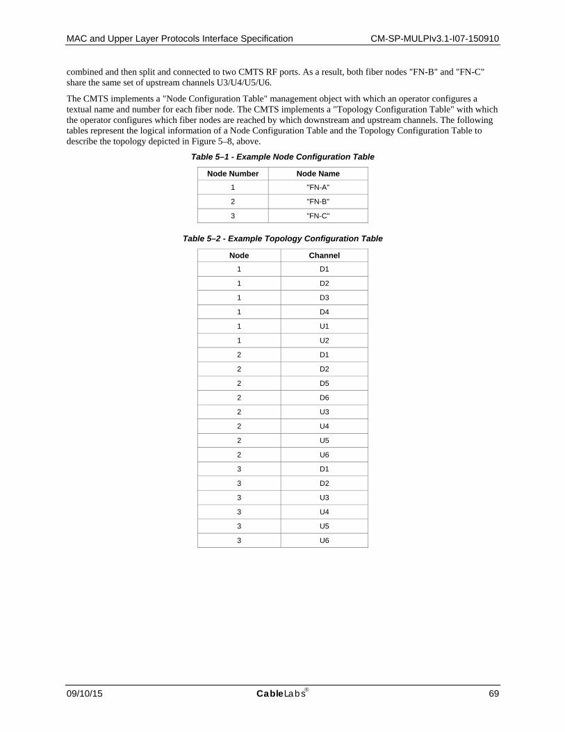
MAC and Upper Layer Protocols Interface Specification CM-SP-MULPIv3.1-I07-150910
09/10/15 CableLabs 69
combined and then split and connected to two CMTS RF ports. As a result, both fiber nodes "FN-B" and "FN-C" share the same set of upstream channels U3/U4/U5/U6.
The CMTS implements a "Node Configuration Table" management object with which an operator configures a textual name and number for each fiber node. The CMTS implements a "Topology Configuration Table" with which the operator configures which fiber nodes are reached by which downstream and upstream channels. The following tables represent the logical information of a Node Configuration Table and the Topology Configuration Table to describe the topology depicted in Figure 5–8, above.
Table 5–1 - Example Node Configuration Table
Node Number Node Name 1 "FN-A"
2 "FN-B"
3 "FN-C"
Table 5–2 - Example Topology Configuration Table
Node Channel 1 D1
1 D2
1 D3
1 D4
1 U1
1 U2
2 D1
2 D2
2 D5
2 D6
2 U3
2 U4
2 U5
2 U6
3 D1
3 D2
3 U3
3 U4
3 U5
3 U6

CM-SP-MULPIv3.1-I07-150910 Data-Over-Cable Service Interface Specifications
70 CableLabs 09/10/15
For convenience, the "Channel" column of the example Topology Configuration Table above refers to the name from Figure 5–9 to identify a channel. In actual practice, a channel is identified with an interface index with SNMP or with a (MAC Domain, channel ID) or other vendor-specific syntax to identify the channel with a CMTS vendor's command line interface.
5.2.10.2 Frequency Assignment The topology database is configured at the CMTS to enable it to maintain frequency isolation for multiple channels reaching the same fiber node. During configuration, the CMTS will enforce that RF Channels reaching the same fiber node have different frequencies.
The CMTS uses the topology configuration to determine which channels can reach a CM for channel bonding, load balancing, and multicast replication. Figure 5–9 below shows a Frequency/Space diagram that depicts the reachability of downstream and upstream channels. This figure represents the same topology configuration as Figure 5–8. In this figure, each vertical column on the left side of the figure (denoted by the labels DF1, DF2, DF3, DF4) represents a downstream frequency, while each vertical column on the right side of the figure (denoted by the labels UF1, UF2, UF3, UF4) represents an upstream frequency. Each rectangle (D1-D6 and U1-U6) represents a channel.
Figure 5–9 - Frequency Space Diagram
5.2.11 Cable Modem Service Group (CM-SG) A "Cable Modem Service Group" (CM-SG) is formally defined as the complete set of CMTS channels—both upstream and downstream—that reach a single cable modem. In an HFC deployment, all CMs reached by the same fiber node are reached by the same set of channels. Furthermore, in most HFC deployments, each fiber node has a different set of either upstream or downstream channels that reach it. Thus, a CM-SG usually corresponds to the channels reaching a single fiber node, and the term "CM-SG" can generally be considered synonymous with "fiber node". In Figure 5–9, for example, each of the fiber nodes FN-A, FN-B, and FN-C is a distinct CM-SG.
If two fiber nodes however, are reached by exactly the same set of downstream and upstream channels, then the CM-SG consisting of that set of channels is considered to contain both fiber nodes. An example of a CM-SG that contains two fiber nodes is depicted in the frequency/space below:
Downstream Frequencies Upstream Frequencies
Fiber Node FN-A
Fiber Node FN-B
Fiber Node FN-C
DF1 DF2 DF3 DF4 UF1 UF2 UF3 UF4
U1
U2
U3
U4
U5
U6
D1
D2
D3
D4
D5
D6
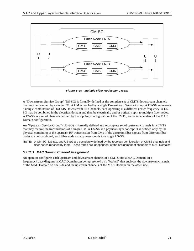
MAC and Upper Layer Protocols Interface Specification CM-SP-MULPIv3.1-I07-150910
09/10/15 CableLabs 71
Figure 5–10 - Multiple Fiber Nodes per CM-SG
A "Downstream Service Group" (DS-SG) is formally defined as the complete set of CMTS downstream channels that may be received by a single CM. A CM is reached by a single Downstream Service Group. A DS-SG represents a unique combination of DOCSIS Downstream RF Channels, each operating at a different center frequency. A DS-SG may be combined in the electrical domain and then be electrically and/or optically split to multiple fiber nodes. A DS-SG is a set of channels defined by the topology configuration of the CMTS, and is independent of the MAC Domain configuration.
An "Upstream Service Group" (US-SG) is formally defined as the complete set of upstream channels in a CMTS that may receive the transmissions of a single CM. A US-SG is a physical-layer concept; it is defined only by the physical combining of the upstream RF transmission from CMs. If the upstream fiber signals from different fiber nodes are not combined, each fiber node usually corresponds to a single US-SG.
NOTE: A CM-SG, DS-SG, and US-SG are completely defined by the topology configuration of CMTS channels and fiber nodes reached by them. These terms are independent of the assignment of channels to MAC Domains.
5.2.11.1 MAC Domain Channel Assignment An operator configures each upstream and downstream channel of a CMTS into a MAC Domain. In a frequency/space diagram, a MAC Domain can be represented by a "barbell" that encloses the downstream channels of the MAC Domain on one side and the upstream channels of the MAC Domain on the other side.
CM-SG
D1
Fiber Node FN-A
CM1 CM2 CM3
Fiber Node FN-B
CM4 CM5 CM6
D2 U
2U1

CM-SP-MULPIv3.1-I07-150910 Data-Over-Cable Service Interface Specifications
72 CableLabs 09/10/15
Figure 5–11 below shows a typical topology with three fiber nodes and two MAC Domains.
Figure 5–11 - Example MAC Domain Channel Assignment
In this example, downstream channels D1 and D2 reach both FN-A and FN-B, while downstream channels D3/D4 reach only FN-A and D5/D6 reach only FN-B. MAC Domain 1, which includes D1/D2, reaches both fiber node FN-A and FN-B. MAC Domain 1 consists of all of the channels D1/D2/D3/D4/D5/D6/U1/U2. Notice that the CMs in FN-A can reach only the channels D1/D2/D3/D4/U1/U2, while the CMs in FN-B reach a different set of channels D1/D2/D5/D6/U1/U2.
A "MAC Domain CM Service Group" (MD-CM-SG) is the set of downstream and upstream channels from the same MAC Domain, all of which reach a single CM. An MD-CM-SG corresponds to a general load balancing group because it forms the set of channels among which a non-bonding CM can be moved while remaining registered in the same MAC Domain. For bonding CMs, an MD-CM-SG represents the set of channels among which traffic on bonded service flows can be scheduled while the CM remains registered to the same MAC Domain.
The channels configured for MAC Domain 2 are D7/D8/U3/U4. These channels reach only fiber node FN-C. MAC Domain 2 has only one MD-CM-SG, with channels D7/D8/U3/U4.
Because a MAC Domain defines a separate address space for many DOCSIS protocol elements (e.g., DSIDs, SAIDs, etc.), an operator should define separate MAC Domains that serve disjoint subsets of fiber nodes rather than a single MAC Domain for all fiber nodes.
A CMTS implementation may restrict the configuration of the downstream channels and upstream channels in the same MAC Domain.
DOCSIS 3.0 introduced a mechanism whereby the CMTS determines the MD-CM-SG of a CM when it registers (see Section 10). If each MD-CM-SG corresponds to a single fiber node, the CMTS can thereby determine the fiber node that reaches each registered CM. An MD-CM-SG always contains at least one fiber node.
D1
MAC Domain 1
MAC Domain 2
D2
D3
D4
D5
D6
U1
U2
Fiber Node FN-AMD-CM-SG 1A
CM1 CM2 CM3
Fiber Node FN-BMD-CM-SG 1B
CM4 CM5 CM6
Fiber Node FN-CMD-CM-SG 2
CM7 CM8 CM9
D7
D8
U3
U4

MAC and Upper Layer Protocols Interface Specification CM-SP-MULPIv3.1-I07-150910
09/10/15 CableLabs 73
5.2.11.2 Multiple MAC Domains per Fiber Node For simplicity, it is recommended that all DOCSIS channels from a CMTS reaching a fiber node be configured into the same MAC Domain. It may be desired, however, to define separate sets of downstream and upstream channels that reach the same fiber node into different MAC Domains in order to provide separate services. For example, business customers or set-top-box CMs may be desired to have entirely separate service from residential high-speed-data CMs, and may be configured onto separate MAC Domains.
Figure 5–12 shows an example of two MAC Domains implemented on the different downstream and upstream channels that reach the same set of fiber nodes.
Figure 5–12 - Multiple MAC Domains per Fiber Node
In the above example, the topology is such that downstream channels D1 and D2 reach both FN-A and FN-B. Upstream channel U1 is reached by FN-A and FN-B, but U2 is reached only by FN-A and U3 only by FN-B. The operator desires that set-top boxes in both fiber nodes use the "high split" (2 FNs per channel) channels D1 and U1, and for residential CMs in both fiber nodes to use the "low split" (1 FN per channel) channels D2, U2, and U3.
The operator configures MAC Domain 1 to contain channels D1 and U1, and for MAC Domain 2 to contain channels D2, U2, and U3. This causes the formation of three "MAC Domain CM Service Groups". MD-CM-SG 1 consists of the channels D1/U1, i.e., the channels of MAC Domain 1, which reaches two fiber nodes. Note that when a set-top-box registers on MAC Domain 1, the CMTS cannot tell whether the CM is physically connected in FN-A or FN-B. MD-CM-SG 2A consists of channels D2/U2, i.e., the channels in MAC Domain 2 that reach fiber node A. MD-CM-SG 2B consists of channels D2/U3, i.e., the channels in MAC Domain 2 that reach fiber node B.
5.2.11.3 MAC Domain Downstream and Upstream Service Groups The term "MAC Domain Downstream Service Group" (MD-DS-SG) refers to the set of downstream channels from the same MAC Domain that reaches a fiber node. In many cases, an operator will configure all downstream channels reaching a fiber node to the same MAC Domain, in which case an MD-DS-SG corresponds to a DS-SG from the topology configuration.
In general, an MD-DS-SG may contain downstream channels that are shared by multiple MD-CM-SGs, each of which has a different upstream channel. In the example shown in Figure 5–12, MAC Domain 2 has only a single MD-DS-SG (containing D2), which contains the downstream channels of two MD-CM-SGs.
MAC Domain 1: D1/U1
MAC Domain 2: D2/U2/U3
Fiber Node A
CM1 CM2 CM3MD-CM-SG 2A
Fiber Node B
CM4 CM5 CM6MD-CM-SG 2B
MD-CM-SG 1
D1
D2
U3
U2
U1

CM-SP-MULPIv3.1-I07-150910 Data-Over-Cable Service Interface Specifications
74 CableLabs 09/10/15
The term "MAC Domain Upstream Service Group" (MD-US-SG) refers to the set of upstream channels from the same MAC Domain that is reached by a single CM. In the common case where all of the upstream channels reached by a fiber node are configured in the same MAC Domain, an MD-US-SG corresponds to a US-SG defined by the topology configuration.
In general, an MD-US-SG may contain upstream channels shared by multiple MD-CM-SGs, each of which has a different set of downstream channels. In the example shown in Figure 5–11, MAC Domain 1 has a single MD-US-SG (containing U1/U2) which contains the upstream channels of two MD-CM-SGs.
5.2.11.4 Channel Bonding Topology Considerations A "Provisioned" Bonding Group is a configured set of downstream or upstream channels on the same MAC Domain that reach at least one fiber node in common. Figure 5–13 takes the Service Groups and MAC Domains defined in earlier figures and overlays a variety of provisioned Downstream Bonding Groups (DBG) and Upstream Bonding Groups (UBG). In addition to provisioned bonding groups, a CMTS may dynamically create downstream or upstream bonding groups.
Because a single CM must be able to reach all channels of a bonding group, a CMTS SHOULD restrict configuration of provisioned bonding groups such that all channels reach at least one fiber node in common.
Figure 5–13 - Bonding Group Example
The Downstream Bonding Groups depicted include DBG1{D1, D2}, DBG2{D1, D2, D3, D4}, DBG3{D3, D4}, DBG4{D1, D2, D5, D6}, DBG5{D5, D6}, and DBG6{D7, D8}. The Upstream Bonded Channel Sets depicted include UBG1{U1, U2}, UBG2{U3, U4}, and UBG3{U5, U6}.
A CMTS may restrict the set of channels assigned to a Bonding Group based on vendor implementation. For example, a CMTS may require that bonded RF channels reside on RF ports of the same line card or even on the same RF Port.
D2
D1
D4
D3
D6
D5
U3
Fiber Node FN-A
D8
D7
U1
U5
DBG1
DBG2
DBG3
DBG4
DBG5
DBG6
CM1 CM2 CM3
Fiber Node FN-B
CM4 CM5 CM6
Fiber Node FN-C
CM7 CM8 CM9
U2
U4
U6
UBG1
UBG2
UBG3
MAC Domain 1
MAC Domain 2

MAC and Upper Layer Protocols Interface Specification CM-SP-MULPIv3.1-I07-150910
09/10/15 CableLabs 75
For downstream multicast forwarding, an important concept is a "Downstream Channel Set" (DCS). A DCS is either a single downstream channel or a downstream bonding group. A downstream multicast session is said to be replicated onto a DCS, i.e., it is transmitted either on a single downstream channel or transmitted on the multiple channels of a downstream bonding group. In the example of Figure 5–13, there are a total of 14 DCSs: eight individual downstream channels and six downstream bonding groups. A downstream multicast session can be replicated on any or all of the 14 DCSs of the example topology.
5.2.12 CMTS Downstream Service Model Example The model for downstream forwarding with bonding groups is an extension of the MAC service model for the CMTS. The model remains that downstream bonded service is offered by MAC Domains, and that the "CMTS Forwarder" is responsible for forwarding packets from a Network Side Interface (NSI) to the MAC Service Access Point (MSAP) of one or more MAC Domains.
An example DOCSIS Downstream Service Model is depicted in Figure 5–14 below.
Figure 5–14 - CMTS Downstream Service Model
This is a conceptual model that describes operations of internal functions in the CMTS and CM that result in external behavior on the interfaces of the products. It is intended to clarify interpretation of normative requirements of external behavior on RF interface and OSSI interface. This model is not intended to describe or restrict the implementation of these functions in actual products. A product may have internal implementation in any manner consistent with the normative requirements of external behavior.
In the model, a "CMTS Forwarder" subcomponent is modeled as having already constructed a layer 2 Ethernet Packet PDU for downstream transmission and delivered it to a MAC Domain's MAC Service Access Point for downstream forwarding service. Furthermore, the CMTS Forwarder has determined whether the packet is to be forwarded to a single CM or to multiple CMs, and if to a single CM, the service request includes an internal identifier of the CM.
CMTS Downstream Service Model
D 2
D 1
D 4
D 3
D 6
D 5
U 2
FN-A
D 8
D 7
U 1
U 3
MAC Domain 1
D1 D2 D3 D5 D4 U1 D6
U2
DBG2 DBG3
D7 D8 U3
DBG6
MAC Domain 2 DBG4 DBG5
DBG1
DBG2
DBG3 DBG4
DBG6
CMTS Forwarder Regional Network
NSIMSAP1 MSAP2
CM1 CM2 CM3
FN-B CM4
CM5 CM6
FN-C CM7
CM8 CM9
CMTS
DBG1
DBG5

CM-SP-MULPIv3.1-I07-150910 Data-Over-Cable Service Interface Specifications
76 CableLabs 09/10/15
Operation of IP layer 3 forwarding, as well as IGMP and IP multicast forwarding, is modeled as an operation of the CMTS Forwarder, not of the MAC Domain.
The semantics of the MAC Domain's MAC Layer service primitives are different for unicast traffic intended to an individual CM, and multicast traffic intended for delivery to a group of CMs. The MAC service level primitives are described in Appendix I. For traffic to an individual CM, the CMTS Forwarder is considered to identify the CM when it provides the packet to the MAC Domain. For traffic to a group of CMs, the CMTS Forwarder is considered to identify the Downstream Channel Set on which the MAC Domain is to transmit the packet.
The CMTS Forwarder is responsible for determining which MAC Domains and which Downstream Channel Sets reach the desired hosts of a multicast downstream packet. Desired hosts include embedded CM hosts and CPE hosts reachable through a CM's CMCI interface. The CMTS Forwarder is responsible for determining how downstream multicast packets are replicated to the multiple downstream channel sets of each MAC Domain.

MAC and Upper Layer Protocols Interface Specification CM-SP-MULPIv3.1-I07-150910
09/10/15 CableLabs 77
6 MEDIA ACCESS CONTROL SPECIFICATION
6.1 Introduction
6.1.1 Overview This section describes version 3.1 of the DOCSIS MAC protocol. Some of the highlights of the DOCSIS MAC protocol include:
• Bandwidth allocation controlled by CMTS • A stream of minislots in the upstream • Dynamic mix of contention- and reservation-based upstream transmit opportunities • Bandwidth efficiency through support of variable-length packets • Extensions provided for future support of ATM or other Data PDU • Quality-of-service including:
• Support for Bandwidth and Latency Guarantees • Packet Classification • Dynamic Service Establishment
• Extensions provided for security at the data link layer • Support for a wide range of data rates • Logical combining of multiple channels for increased throughput (channel bonding)
6.1.2 Definitions
6.1.2.1 MAC-Sublayer Domain A MAC-sublayer domain is a collection of upstream and downstream channels for which a single MAC Allocation and Management protocol operates. Its attachments include one CMTS and some number of CMs. The CMTS MUST service all of the upstream and downstream channels; each CM can access one or more logical upstream channels and one or more downstream channels. The CMTS MUST discard any packets received that have a source MAC address that is not a unicast MAC address. The upstream channels can be any combination of DOCSIS 1.x, 2.0, or 3.x formats. A single upstream channel can transport DOCSIS 1.x, 2.0, and 3.x bursts.
6.1.2.2 MAC Service Access Point A MAC Service Access Point (MSAP) is an attachment to a MAC-sublayer domain (refer to Section 9.1.1).
6.1.2.3 Service Flows The concept of Service Flows is central to the operation of the MAC protocol. Service Flows provide a mechanism for upstream and downstream Quality of Service management. In particular, Service Flows are integral to bandwidth allocation.
A Service Flow ID defines a particular unidirectional mapping between a CM and the CMTS. Active Upstream Service Flow IDs also have associated Service IDs or SIDs. Upstream bandwidth is allocated to SIDs, and hence to CMs, by the CMTS. Service IDs provide the mechanism by which upstream Quality of Service is implemented.
The CMTS assigns one or more SFID to each CM, corresponding to the Service Flows required by the CM. This mapping can be negotiated between the CMTS and the CM during CM registration or via dynamic service establishment (refer to Section 11.2).
For example, in a basic CM implementation, two Service Flows (one upstream, one downstream) could be used to offer best-effort IP service. However, the Service Flow concept allows more complex CMs to be developed with support for multiple service classes while supporting interoperability with more basic modems. With these more complex modems, it is possible that certain Service Flows will be configured in such a way that they cannot carry all
CM-SP-MULPIv3.1-I07-150910 Data-Over-Cable Service Interface Specifications
78 CableLabs 09/10/15
types of traffic. That is, they can have a maximum packet size limitation or be restricted to small fixed size unsolicited grants. Furthermore it might not be appropriate to send other kinds of data on Service Flows that are being used for Constant Bit Rate (CBR)-type applications.
Even in these complex modems, it is necessary to be able to send certain upstream packets needed for MAC management, SNMP management, key management, etc. For the network to function properly, all CMs MUST support at least one upstream and one downstream Service Flow. These Service Flows are referred to as the upstream and downstream Primary Service Flows. The Primary Service Flows needs to always be provisioned to allow the CM to request and to send the largest possible unconcatenated MAC frame (refer to Section 6.2.2).
The CM and CMTS MUST immediately activate the Primary Service Flows at registration time. The CM and CMTS MUST always use the Ranging SID(s) for periodic ranging after registration when in Multiple Transmit Channel Mode, and the Primary SID when not in Multiple Transmit Channel Mode. The Primary Service Flows can be used for traffic. All unicast Service Flows use the security association defined for the Primary Service Flow (refer to [DOCSIS SECv3.0]).
The CMTS MUST ensure that all Service Flow IDs are unique within a single MAC-sublayer domain. An active/admitted service flow maps to one or more SIDs. SIDs are unique per logical upstream channel. The length of the Service Flow ID is 32 bits. The length of the Service ID is 14 bits (although the Service ID is sometimes carried in the low-order bits of a 16-bit field).
Unicast flows on different logical upstreams that are attached to a single MAC-sublayer domain MAY be assigned the same SID by the CMTS, as long as the SFIDs are unique.
6.1.2.4 Upstream Intervals, Minislots and 6.25-Microsecond Increments The upstream transmission time-line is divided into intervals by the upstream bandwidth allocation mechanism. Each interval is an integral number of minislots. A "minislot" is the unit of granularity for upstream transmission opportunities. There is no implication that any PDU can actually be transmitted in a single minislot. Each interval is labeled with a usage code which defines both the type of traffic that can be transmitted during that interval and the physical-layer modulation encoding. The usage code values are defined in Table 6–28 - Allocation MAP Information Elements (IE) and their allowed use is defined in Section 6.4. The binding of these values to physical-layer parameters is defined in Table 6–25.
6.1.2.4.1 TDMA mode
For DOCSIS 1.x channels, a minislot is a power-of-two multiple of 6.25 microsecond increments, limited to 2, 4, 8, 16, 32, 64, or 128 times 6.25 microseconds. For DOCSIS 2.0 and 3.0 TDMA, a minislot is a power-of-two multiple of 6.25 microsecond increments limited to 1, 2, 4, 8, 16, 32, 64, or 128 times 6.25 microseconds. The relationship between minislots, bytes, and time ticks is described further in Section 7.1.4.1.
6.1.2.4.2 S-CDMA mode
For DOCSIS 2.0 and 3.0 S-CDMA channels, a minislot is not restricted to be a power-of-two multiple of 6.25 microsecond increments. Instead a minislot is a unit of capacity that is dependent on the modulation rate, number of spreading codes, and number of spreading intervals configured for the upstream channel. (This relationship holds true on an S-CDMA channel even if the burst parameters for a particular IUC have the spreader disabled.) While the channel can be configured such that the time duration of a minislot is a power-of-two multiple of 6.25 microsecond increments, there is no special significance to 6.25 microsecond time ticks for S-CDMA channels. The relationship between minislots and S-CDMA framing is described further in [DOCSIS PHYv3.1]. The relationship between minislots, bytes, and time ticks is described further in Section 7.1.4.2.
6.1.2.4.3 OFDMA mode
For DOCSIS 3.1 channels, a minislot is not restricted to be a power-of-two multiple of 6.25 microsecond increments. Instead a minislot is a unit of capacity that is dependent on the number of subcarriers per minislot and the number of symbols in the OFDMA frame. The modulation rate on an OFDMA channel can vary from one minislot to the next and is dependent on the specific subcarriers contained within the minislot. While the channel can be configured such that the time duration of a minislot is a power-of-two multiple of 6.25 microsecond increments, there is no special significance to 6.25 microsecond time ticks for OFDMA channels. The relationship between

MAC and Upper Layer Protocols Interface Specification CM-SP-MULPIv3.1-I07-150910
09/10/15 CableLabs 79
minislots and OFDMA framing is described further in [DOCSIS PHYv3.1]. The relationship between minislots, bytes, and time ticks is described further in Section 7.1.4.3.
6.1.2.5 MAC Frame A MAC Frame is a unit of data exchanged between two (or more) entities at the Data Link Layer. A MAC frame consists of a MAC Header (beginning with a Frame Control byte; see Figure 6–2), and can incorporate a variable-length data PDU. The variable-length PDU includes 48-bit source and destination MAC addresses, data, and a CRC. In special cases, the MAC Header can encapsulate multiple MAC frames (see Section 6.2.4.6) into a single MAC frame. The MAC layer definition of a frame is different from any physical layer or transmission convergence layer definition of a frame.
6.1.2.6 Logical Upstream Channels8 The MAC layer deals with logical upstreams. A logical upstream is identified with an upstream channel ID which is unique within the MSAP. A logical upstream consists of a contiguous stream of minislots which are described by UCD messages and allocated by MAP messages associated with a channel ID. A CM operating with Multiple Transmit Channel Mode disabled can only register to operate on a single logical upstream channel. A CM in Multiple Transmit Channel Mode of operation can register to operate on one or more logical upstream channels.
There are five distinct types of logical upstreams:
1. Type 1: DOCSIS 1.x upstreams that support no DOCSIS 2.0 TDMA features.
2. Type 2: Mixed upstreams that support DOCSIS 1.x and DOCSIS 2.0 TDMA bursts.
3. Type 3: DOCSIS 2.0 upstreams, which cannot support DOCSIS 1.x CMs and include the following two subtypes:
a. Type 3A: DOCSIS 2.0 TDMA upstreams.
b. Type 3S: DOCSIS 2.0 S-CDMA upstreams.
4. Type 4: DOCSIS 3.0 upstreams, some of which cannot support Pre-3.0 DOCSIS CMs and include the following four subtypes:
a. Type 4A: The TDMA upstream is described by Type 29 UCDs for 2.0 CMs using IUCs 9, 10, and 11 for data grants and by Type 35 UCDs for 3.0 CMs using IUCs 5, 6, 9, 10, and 11 for data grants.
b. Type 4S: The S-CDMA upstream is described by Type 29 UCDs for 2.0 CMs using IUCs 9, 10, and 11 for data grants and by Type 35 UCDs for 3.0 CMs using IUCs 5, 6, 9, 10, and 11 for data grants.
c. Type 4AR: The DOCSIS 3.0 TDMA upstream is described by Type 35 UCDs for 3.0 CMs using IUCs 5, 6, 9, 10, and 11 for data grants. These channels are restricted to only DOCSIS 3.0 CMs.
d. Type 4SR: The DOCSIS 3.0 S-CDMA only upstream is described by Type 35 UCDs for 3.0 CMs using IUCs 5, 6, 9, 10, and 11 for data grants. These channels are restricted to only DOCSIS 3.0 CMs and have the option of using Selectable Active Codes Mode 2 and Code Hopping Mode 2 (see Section 6.4.3, and [DOCSIS PHYv3.1]).
5. Type 5: DOCSIS 3.1 OFDMA upstreams.
All valid logical upstreams fall into one of these 9 categories: Type 1, Type 2, Type 3A, Type 3S, Type 4A, Type 4S, Type 4AR, Type 4SR, or Type 5.
A CM operating in Multiple Transmit Channel Mode can use any of these logical channel types. However, when selecting the first upstream channel to use, the CM preferentially makes the selection based on the requirements in Section 10.2.3.
DOCSIS 2.0 introduced the possibility for multiple logical upstreams to share the same spectrum. When this occurs the logical upstreams sharing the same spectrum are time domain multiplexed and only one is active at any time, with the exception that it is possible for the Broadcast Initial Maintenance regions to be simultaneous. When a
8 Updated by MULPIv3.1-N-14.1157-1 on 12/1/14 by PO.

CM-SP-MULPIv3.1-I07-150910 Data-Over-Cable Service Interface Specifications
80 CableLabs 09/10/15
logical upstream channel is inactive, its minislots are allocated to the NULL SID by its associated MAP messages. Having multiple logical upstreams that share the same spectrum is the only way to have modems operating with one modulation technology (TDMA, S-CDMA, OFDMA) share the same upstream spectrum with modems using a different modulation technology. Also, having multiple logical upstreams that share the same spectrum is the only way to have modems operating in S-CDMA mode with Selectable Active Codes Mode 2 enabled share the same upstream spectrum with other modems operating in S-CDMA mode without Selectable Active Codes Mode 2 enabled. Thus, it is possible in DOCSIS 3.1 to have four logical channels in the same upstream spectrum: one for a DOCSIS 3.0 (or later) operation with Selectable Active Codes Mode 2 enabled, one for DOCSIS 3.0 (or later) operation with Selectable Active Codes Mode 2 disabled, one for modems operating in TDMA mode, and one for DOCSIS 3.1 OFDMA operation.
The CMTS MUST support the logical upstream channel Type 1, Type 2, Type 3A, and Type 5 individually. The CMTS MAY support the logical upstream channel Type 3S, Type 4S, and Type 4SR individually. If the CMTS supports Selectable Active Codes Mode 2 [DOCSIS PHYv3.1], the CMTS MUST support the Type 4S and Type 4SR logical channel individually. The CMTS MAY support the channel Type 4A and Type 4AR individually. If the CMTS supports assignment of advanced burst profiles for data associated with IUCs 5, 6, 9, 10, or 11, the CMTS MUST support the Type 4A and the Type 4AR logical channel individually.
On one physical channel per upstream RF interface port, the CMTS MUST support a combination of two TDMA logical channels (including Types 1, 2, 3A, 4A, and 4AR) of those types that it supports individually where those logical channels share the same upstream spectrum and utilize the same modulation rate.
On every physical channel per upstream RF interface port, the CMTS SHOULD support the above combinations of two logical channels of those types that it supports individually where those logical channels share the same upstream spectrum and utilize the same modulation rate.
The CMTS MAY support combinations of TDMA and S-CDMA logical channels.
The CMTS MAY support other combinations of logical channels sharing the same upstream spectrum, including combinations of any of the nine categories of logical upstream channels types, combinations of three or more logical channels sharing the same spectrum, more than one combination per upstream RF interface port, and combinations of logical channels with different modulation rates.
The support for S-CDMA operation is optional for the CMTS and for the CM. Any S-CDMA related requirements within this specification therefore are dependent on the CMTS or the CM supporting S-CDMA or associated features.
6.1.2.6.1 Type 3 Logical Upstreams
Type 3 Logical Upstreams have operational parameters in their associated UCD messages that prevent the operation of DOCSIS 1.x CMs. See Section 6.4.3 for a detailed description of which parameter values make a channel a Type 3A or 3S Upstream. The UCD messages for Type 3 Logical Upstreams use a different MAC management message type (see Section 6.4.1) than do UCD messages for channels that can support 1.x CMs. This prevents 1.x CMs from attempting to use Type 3 Upstreams or from being confused by UCD messages for those channels. A logical upstream is a Type 3A upstream if and only if it is described by a Type 29 UCD with version 3, does not contain burst profiles for IUC 5 and 6, and is a DOCSIS 2.0 TDMA upstream. A logical upstream is a Type 3S upstream if and only if it is described by a Type 29 UCD with version 3, does not contain burst profiles for IUC 5 and 6, and is an S-CDMA upstream without Selectable Active Codes Mode 2.
6.1.2.6.2 Type 4 Logical Upstreams
Type 4 Logical Upstreams are identified by UCD Type 35 and can additionally have UCD Type 29. The presence of UCD Type 29 allows use of these logical upstream channels by DOCSIS 2.0 CMs. If the UCD Type 29 is not present, the channel is restricted to use by DOCSIS 3.0 CMs only.
This channel type allows the operator to define burst profiles for five data IUCs (5, 6, 9, 10 and 11) for use by DOCSIS 3.0 CMs. The CMTS is free to select, using proprietary criteria, the most appropriate data IUC for each data burst for 3.0 CMs operating in Multiple Transmit Channel Mode. If UCD Type 29 is present, the operator should configure IUCs 9 and 10 to be appropriate for short and long data bursts for DOCSIS 2.0 CMs.

MAC and Upper Layer Protocols Interface Specification CM-SP-MULPIv3.1-I07-150910
09/10/15 CableLabs 81
Additionally, Type 4SR logical upstreams allow the use of Selectable Active Codes Mode 2 and Code Hopping Mode 2 (see Section 6.4.3 and [DOCSIS PHYv3.1]).
6.1.2.6.3 Type 5 Logical Upstreams
Type 5 Logical Upstreams are identified by UCD Type 51 and contain parameters for OFDMA operation. This channel type is restricted for use by DOCSIS 3.1 and later CMs.
6.1.3 Future Use A number of fields are defined as being "for future use" or Reserved in the various MAC frames described in this document. These fields will not be interpreted or used in any manner by this version (3.1) of the MAC protocol.
The CMTS MUST transmit all Reserved or "for future use" fields as zero. The CM MUST silently ignore all Reserved or "for future use" fields.
The CM MUST transmit all Reserved or "for future use" fields as zero. The CMTS MUST silently ignore all Reserved or "for future use" fields.
6.2 MAC Frame Formats
6.2.1 Generic MAC Frame Format A MAC frame is the basic unit of transfer between MAC sublayers at the CMTS and the cable modem. The same basic structure is used in both the upstream and downstream directions. MAC frames are variable in length. The term "frame" is used in this context to indicate a unit of information that is passed between MAC sublayer peers. This is not to be confused with the term "framing" that indicates some fixed timing relationship.
There are three distinct regions to consider, as shown in Figure 6–1. Preceding the MAC frame is either PMD sublayer overhead (upstream) or MAC frames are mapped onto a stream of DOCSIS 3.1 FEC codewords (downstream). The first part of the MAC frame is the MAC Header. The MAC Header uniquely identifies the contents of the MAC frame. Following the header is the optional Data PDU region. The format of the Data PDU and whether it is even present is described in the MAC Header.
Figure 6–1 - Generic MAC Frame Format
PMD Overhead(upstream)
Data PDU(optional)
(See Figure 6-4)
PMD Overhead(downstream)
MAC Header(See Figure 6-3)
MAC Frame
CM-SP-MULPIv3.1-I07-150910 Data-Over-Cable Service Interface Specifications
82 CableLabs 09/10/15
6.2.1.1 PMD Overhead In the upstream direction, the PHY layer indicates the start of the MAC frame to the MAC sublayer. From the MAC sublayer's perspective, it only needs to know the total amount of overhead so it can account for it in the Bandwidth Allocation process. More information on this may be found in the PMD Sublayer section of [DOCSIS PHYv3.1].
The FEC overhead is spread throughout the MAC frame and is assumed to be transparent to the MAC data stream. The MAC sublayer does need to be able to account for the overhead when doing Bandwidth Allocation. More information on this may be found in the Upstream Bandwidth Allocation section of this document (refer to Section 7.2.1).
The layering of MAC frames over MPEG in the downstream SC-QAM channel is described in [DOCSIS DRFI].
6.2.1.2 Ordering of Bits and Octets For the SC-QAM upstream channel, within an octet, the least-significant bit is the first transmitted to the PHY. This follows the convention used by Ethernet and [ISO/IEC 8802-3]. This is often called bit-little-endian order.
For both the SC-QAM and OFDM downstream channel and for the OFDMA upstream channel, the MPEG transmission convergence sublayer for SC-QAM and the PHY-MAC convergence sublayer for OFDM present an octet-wide interface to the MAC, so the MAC sublayer does not define the bit order between the MAC and PHY.
Within the MAC layer, when numeric quantities are represented by more than one octet (i.e., 16-bit and 32-bit values), the octet containing the most-significant bits is the first transmitted on the wire. This is sometimes called byte-big-endian order.
This specification uses the following textual conventions:
• When tables describe bit fields within an octet, the most significant bits are topmost in the table. For example, in Table 6–2, FC_TYPE occupies the two most-significant bits and EHDR_ON occupies the least-significant bit.
• When figures depict bit positions within an octet, the most significant bits are leftmost in the figure. For example, see the locations of the FC_TYPE and EHDR_ON bits in Figure 6–2.
• When bit-strings are presented in text, the most significant bit is leftmost in the string. • Unless explicitly indicated otherwise, when bits are enumerated in a bit-field, the least significant bit of the bit-
field is bit # 0. The exceptions are certain fields that utilize the BITS Encoding convention. • When message formats are presented in figures, the message octets are shown in the order in which they are
transmitted on the wire, beginning with the field in the upper left and reading left-to-right, one row at a time. For example, in Figure 6–12, the FC byte is transmitted first, followed by the MAC PARM and LEN fields. As mentioned above, the LEN field is transmitted with most-significant octet first, and each octet is transmitted with least-significant bit first.
6.2.1.2.1 Representing Negative Numbers
Signed integer values MUST be transmitted and received by the CM and CMTS in two's complement format.
6.2.1.2.2 Type-Length-Value Fields
Many MAC messages incorporate Type-Length-Value (TLV) fields. Except for the cases of Primary Service Flow selection and MIC calculation among the TLVs encoded in a CM Configuration File, TLV fields are unordered lists of TLV-tuples. Some TLVs are nested (see Annex C). The CM or CMTS MUST set all TLV Length fields, except for EH_LEN (see Section 6.2.6), to be greater than zero. Unless otherwise specified, Type is one byte and Length is one byte.
Using this encoding, new parameters may be added which some devices cannot interpret. A CM or CMTS which does not recognize a parameter type MUST skip over this parameter and not treat the event as an error condition.

MAC and Upper Layer Protocols Interface Specification CM-SP-MULPIv3.1-I07-150910
09/10/15 CableLabs 83
6.2.1.3 MAC Header Format The CM or CMTS MUST use the MAC Header format as shown in Figure 6–2.
Figure 6–2 - MAC Header Format
NOTE: While Figure 6–2 shows an extended header length of 0-24 bytes, the extended header length can range from 0-240 bytes in the MAC Header format compliant with pre-DOCSIS 3.1 specifications.
The CM MUST comply with Table 6–1 for all MAC Headers. The CMTS MUST comply with Table 6–1 for all MAC Headers. The Frame Control (FC) field is the first byte and uniquely identifies the rest of the contents within the MAC Header. The FC field is followed by 3 bytes of MAC control; an optional Extended Header field (EHDR); plus a Header Check Sequence (HCS) to ensure the integrity of the MAC Header.
Table 6–1 - Generic MAC Header Format
MAC Header Field Usage Size FC Frame Control: Identifies type of MAC Header 8 bits
MAC_PARM Parameter field whose use is dependent on FC: if EHDR_ON=1; used for EHDR field length (ELEN) else if for concatenated frames (see Table 6–13) used for MAC frame count else (for Queue-Depth based requests only) indicates the number of bytes requested in units of N bytes.
8 bits for all headers except for the Queue-Depth based request header in which this field is 16 bits.
LEN The length of the MAC frame. The length is defined to be the sum of the number of bytes in the extended header (if present) and the number of bytes following the HCS field
16 bits
EHDR Extended MAC Header (where present; variable size). 0-24 bytes 0-240 bytes (pre-DOCSIS 3.1)
HCS MAC Header Check Sequence 2 bytes
Length of a MAC Header 6 bytes + EHDR
FC Field: The FC field is broken down into the FC_TYPE sub-field, FC_PARM sub-field and an EHDR_ON indication flag. The CM MUST comply with the FC field in Table 6–2. The CMTS MUST comply with the FC field in Table 6–2 for the FC field.
Table 6–2 - FC Field Format
FC Field Usage Size FC_TYPE MAC Frame Control Type field:
00: Packet PDU MAC Header 01: Reserved for future definition 10: Isolation Packet PDU MAC Header 11: MAC Specific Header
2 bits
FC_PARM Parameter bits use dependent on FC_TYPE. 5 bits
EHDR_ON When = 1, indicates that EHDR field is present. [Length of EHDR (ELEN) determined by MAC_PARM field]
1 bit
FC (1byte)
MAC_PARM (1-2 bytes)
LEN (SID) (2 bytes)
EHDR (0-24 bytes)
HCS(2 bytes)
FC TYPE(2 bits)
FC PARM(5 bits)
EHDR_ON(1 bit)

CM-SP-MULPIv3.1-I07-150910 Data-Over-Cable Service Interface Specifications
84 CableLabs 09/10/15
The FC_TYPE sub-field includes the two MSBs of the FC field. These bits MUST always be interpreted by CMs and CMTSs in the same manner to indicate one of three defined MAC frame formats. These types include: MAC Header with Packet PDU; MAC Header with packet PDU Isolation from Pre-3.0 DOCSIS cable modems; or a MAC Header used for specific MAC control purposes. These types are spelled out in more detail in the remainder of this section.
The five bits following the FC_TYPE sub-field is the FC_PARM sub-field. The use of these bits is dependent on the type of MAC Header. The LSB of the FC field is the EHDR_ON indicator. If this bit is set, then an Extended Header (EHDR) is present. The EHDR provides a mechanism to allow the MAC Header to be extensible in an inter-operable manner.
NOTE: The Transmission Convergence Sublayer stuff-byte pattern is defined to be a value of 0xFF, which precludes the use of FC byte values which have FC_TYPE = '11' and FC_PARM = '11111'.
MAC_PARM: The MAC_PARM field of the MAC Header serves several purposes depending on the FC field. If the EHDR_ON indicator is set, then the MAC_PARM field MUST be used by the CM and CMTS as the Extended Header length (ELEN). The EHDR field may vary from 0 to 24 bytes in MAC frames transmitted by DOCSIS 3.1 devices and from 0-240 bytes in frames transmitted by pre-DOCSIS 3.1 devices. If this is a Request MAC Header (REQ), (see Section 6.2.4.3), then the MAC_PARM field represents the amount of bandwidth being requested. In all other cases, the MAC_PARM field is reserved for future use.
LEN (SID): The third field has two possible uses. In most cases, it indicates the length (LEN) of this MAC frame. In one special case, the Request MAC Header, it is used to indicate the cable modem's Service ID since no PDU follows the MAC Header.
EHDR: The Extended Header (EHDR) field provides extensions to the MAC frame format. It is used to implement data link security as well as frame fragmentation, and can be extended to add support for additional functions in future releases.
HCS: The HCS field is a 16-bit CRC that ensures the integrity of the MAC Header, even in a collision environment. The CM or CMTS MUST include the entire MAC Header, starting with the FC field and including any EHDR field that may be present for HCS field coverage. The HCS is calculated using CRC-CCITT (x16 + x12 + x5 + 1) as defined in [ITU-T X.25].
6.2.1.4 Data PDU The MAC Header may be followed by a Data PDU. The type and format of the Data PDU is defined in the Frame Control field of the MAC Header. The FC field explicitly defines a Packet Data PDU, an ATM Data PDU, an Isolation Packet Data PDU, and a MAC-Specific Frame. All CMs MUST use the length in the MAC Header to skip over any reserved data.
6.2.2 Packet-Based MAC Frames
6.2.2.1 Packet PDU and Isolation Packet PDU9 The CM or CMTS MAC sublayer MUST support both, a variable-length Ethernet/[ISO/IEC 8802-3]-type Packet Data PDU MAC Frame and a variable-length Ethernet/[ISO/IEC 8802-3]-type Isolation Packet Data PDU MAC Frame. The Isolation Packet Data PDU MAC Frame is used to prevent certain downstream packets from being received and forwarded by Pre-3.0 DOCSIS cable modems, as described in Section 6.2.6.4.1. Both the Packet PDU and the Isolation Packet PDU can be used to send packets of any type (unicast, multicast, and broadcast). The Packet PDU MUST be passed across the network in its entirety, including its original CRC. A unique Packet MAC Header is appended to the beginning. The CM MUST comply with Figure 6–3 and Table 6–3 for Packet PDUs and Isolation Packet PDUs. The CMTS MUST comply with Figure 6–3 and Table 6–3 for Packet PDUs and Isolation Packet PDUs.
9 Updated by MULIv3.1-14.1204-1 on 12/2/14 by PO.

MAC and Upper Layer Protocols Interface Specification CM-SP-MULPIv3.1-I07-150910
09/10/15 CableLabs 85
Figure 6–3 - Packet PDU or Isolation Packet PDU MAC Frame Format [IEEE 802.3as]
Table 6–3 - Packet PDU or Isolation Packet PDU MAC Frame Format
Field Usage Size FC FC_TYPE = 00; Packet PDU MAC Header
FC_TYPE = 10; Isolation Packet PDU MAC Header FC_PARM[4:0] = 00000 or 00001;other values reserved for future use and ignored EHDR_ON = 0 if there is no extended header, 1 if there is an EHDR
8 bits
MAC_PARM MAC_PARM = x; MUST be set to zero if there is no EHDR; otherwise set to length of EHDR
8 bits
LEN LEN = n+x; length of Packet PDU in bytes + length of EHDR 16 bits
EHDR Extended MAC Header, if present (0-24) bytes in DOCSIS 3.1 (0-240) bytes in pre-DOCSIS 3.1
HCS MAC Header Check Sequence 16 bits
Packet Data Packet PDU:
DA - 48 bit Destination Address SA - 48 bit Source Address Type/Len - 16 bit Ethernet Type or [ISO/IEC 8802-3] Length Field User Data (variable length, 0-1982 bytes in DOCSIS 3.1, 0-1500 bytes in pre-DOCSIS 3.1) CRC - 32-bit CRC over packet PDU (as defined in Ethernet/[ISO/IEC 8802-3])
n bytes
Length of Packet PDU or Isolation Packet PDU MAC frame 6 + x + n bytes
FC_PARM value of '00001' is used to identify delayed and duplicated multicast and broadcast packet PDU frames sent by the CMTS on OFDM channels to CMs in DLS mode. When not operating in DOCSIS Light Sleep Mode, a CM discards all PDUs with FC_Parm '00001'. For more information refer to Section 11.7.4. In all other cases, the value of '00000' is used for packet PDU MAC frames.
Under certain circumstances it may be necessary to transmit a packet PDU MAC frame without an actual PDU. This is done so that the extended header can be used to carry certain information about the state of the service flow, e.g., a 5-byte Downstream Service Extended Header containing the current Sequence Number for a particular DSID (also known as a "null packet"), or a Service Flow Extended Header containing the number of active grants for a UGS-AD service flow. Such a frame will have the length field in the MAC header set to the length of the extended header and will have no packet data, and therefore no CRC.
6.2.3 MAC Frames with FC_TYPE 0x01 The FC_TYPE 0x01 is reserved for future definition. This PDU MUST be silently discarded by CMs and CMTSs compliant with this version (DOCSIS 3.1) of the specification. DOCSIS-compliant version 3.1 CM and CMTS implementations MUST use the length field to skip over MAC Frames with FC-TYPE 0x01.
FC (1byte)
MAC_PARM (1byte)
LEN (2 bytes)
EHDR (0-24 bytes)
HCS(2 bytes)
Packet PDU1
(0,18-2000 bytes)
DA(6 bytes)
SA(6 bytes)
Type/LEN(2 bytes)
User Data(0-1982 bytes)
CRC(4 bytes)
FC TYPE=00 or 10
FC PARM = 00000 or 00001 EHDR_ON
1 Packet PDU length is increased to 2000 B to conform with IEEE 802.3as.

CM-SP-MULPIv3.1-I07-150910 Data-Over-Cable Service Interface Specifications
86 CableLabs 09/10/15
6.2.4 MAC-Specific Headers Several MAC Headers are used for very specific functions. These functions include support for downstream timing and upstream ranging/power adjustment, requesting bandwidth, fragmentation and concatenating multiple MAC frames.
Table 6–4 describes FC_PARM usage within the MAC Specific Header.
Table 6–4 - MAC-Specific Headers and Frames
FC_PARM Header/Frame Type
00000 Timing Header
00001 MAC Management Header
00010 Request Frame
00011 Fragmentation Header
00100 Queue Depth-based Request Frame
11100 Concatenation Header
6.2.4.1 Timing Header A specific MAC Header is identified to help support the timing and adjustments required. In the downstream, this MAC Header MUST be used by the CMTS on SC-QAM channels to transport the Global Timing Reference to which all cable modems synchronize. In the upstream, this MAC Header MUST be used by the CM as part of the Ranging message needed for a cable modem's timing and power adjustments. The Timing MAC Header is followed by a Packet Data PDU. The CM MUST comply with Figure 6–4 and Table 6–5 for Timing Headers. The CMTS MUST comply with Figure 6–4 and Table 6–5 for Timing Headers.
Figure 6–4 - Timing MAC Header
Table 6–5 - Timing MAC Header Format
Field Usage Size FC FC_TYPE = 11; MAC Specific Header
FC_PARM[4:0] = 00000; Timing MAC Header EHDR_ON = 0; Extended header prohibited for SYNC and RNG-REQ
8 bits
MAC_PARM Reserved for future use 8 bits
LEN LEN = n; Length of Packet PDU in bytes 16 bits
EHDR Extended MAC Header not present 0 bytes
HCS MAC Header Check Sequence 2 bytes
Packet Data MAC Management Message: SYNC message (downstream only) RNG-REQ (upstream only)
n bytes
Length of Timing Message MAC frame 6 + n bytes
FC (1byte)
MAC_PARM (1byte)
LEN (2 bytes)
HCS(2 bytes)
FC TYPE= 11
FC PARM= 00000
EHDR_ON= 0
Packet PDU(various lengths)
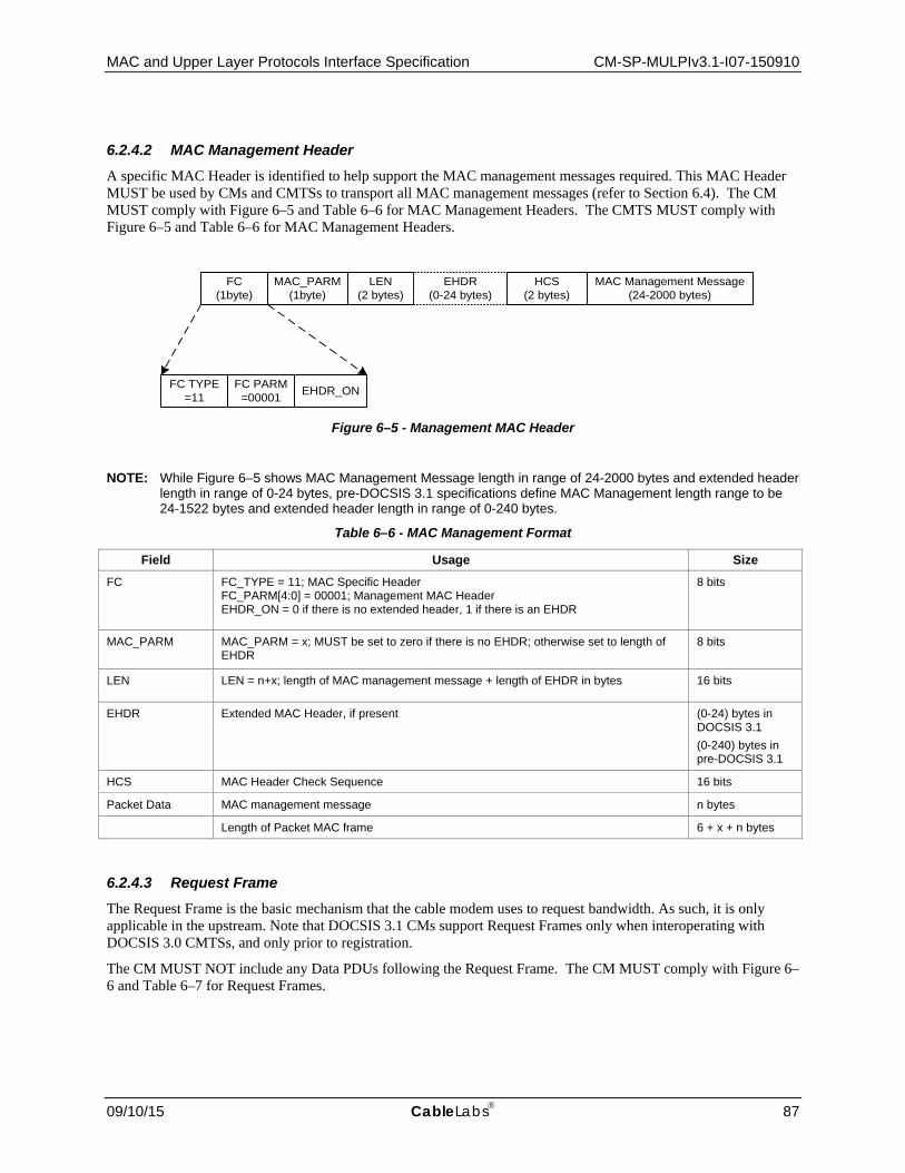
MAC and Upper Layer Protocols Interface Specification CM-SP-MULPIv3.1-I07-150910
09/10/15 CableLabs 87
6.2.4.2 MAC Management Header A specific MAC Header is identified to help support the MAC management messages required. This MAC Header MUST be used by CMs and CMTSs to transport all MAC management messages (refer to Section 6.4). The CM MUST comply with Figure 6–5 and Table 6–6 for MAC Management Headers. The CMTS MUST comply with Figure 6–5 and Table 6–6 for MAC Management Headers.
Figure 6–5 - Management MAC Header
NOTE: While Figure 6–5 shows MAC Management Message length in range of 24-2000 bytes and extended header length in range of 0-24 bytes, pre-DOCSIS 3.1 specifications define MAC Management length range to be 24-1522 bytes and extended header length in range of 0-240 bytes.
Table 6–6 - MAC Management Format
Field Usage Size FC FC_TYPE = 11; MAC Specific Header
FC_PARM[4:0] = 00001; Management MAC Header EHDR_ON = 0 if there is no extended header, 1 if there is an EHDR
8 bits
MAC_PARM MAC_PARM = x; MUST be set to zero if there is no EHDR; otherwise set to length of EHDR
8 bits
LEN LEN = n+x; length of MAC management message + length of EHDR in bytes 16 bits
EHDR Extended MAC Header, if present (0-24) bytes in DOCSIS 3.1 (0-240) bytes in pre-DOCSIS 3.1
HCS MAC Header Check Sequence 16 bits
Packet Data MAC management message n bytes
Length of Packet MAC frame 6 + x + n bytes
6.2.4.3 Request Frame The Request Frame is the basic mechanism that the cable modem uses to request bandwidth. As such, it is only applicable in the upstream. Note that DOCSIS 3.1 CMs support Request Frames only when interoperating with DOCSIS 3.0 CMTSs, and only prior to registration.
The CM MUST NOT include any Data PDUs following the Request Frame. The CM MUST comply with Figure 6–6 and Table 6–7 for Request Frames.
FC (1byte)
MAC_PARM (1byte)
LEN (2 bytes)
EHDR (0-24 bytes)
HCS(2 bytes)
MAC Management Message(24-2000 bytes)
FC TYPE=11
FC PARM=00001 EHDR_ON

CM-SP-MULPIv3.1-I07-150910 Data-Over-Cable Service Interface Specifications
88 CableLabs 09/10/15
Figure 6–6 - Request Frame Format
Table 6–7 - Request Frame (REQ) Format
Field Usage Size FC FC_TYPE = 11; MAC-Specific Header
FC_PARM[4:0] = 00010; MAC Header only; no data PDU following EHDR_ON = 0; No EHDR allowed
8 bits
MAC_PARM REQ, total number of minislots requested 8 bits
SID Service ID used for requesting bandwidth. For valid SID ranges, see Section 7.2.1.2. 16 bits
EHDR Extended MAC Header not allowed 0 bytes
HCS MAC Header Check Sequence 2 bytes
Length of a REQ MAC Header 6 bytes
Because the Request Frame does not have a Data PDU following it, the LEN field is not needed. The CM MUST replace the LEN field with a SID. The SID uniquely identifies a particular Service Flow within a given CM.
The CM MUST specify the bandwidth request, REQ, in minislots. The CM MUST indicate the current total amount of bandwidth requested for this service queue including appropriate allowance for the PHY overhead in the MAC_PARM field.
The Request Frame is for pre-3.0 DOCSIS support and MUST NOT be used by CMs operating in Multiple Transmit Channel Mode. CMs operating in Multiple Transmit Channel Mode MUST use queue depth based requests as defined in Section 6.2.4.5.
6.2.4.4 Fragmentation Header The use of fragmentation MAC Frames by DOCSIS 3.1 CMs is deprecated.
The Fragmentation MAC Header provides the basic mechanism to split a larger MAC PDU into smaller pieces that are transmitted individually and then re-assembled at the CMTS. As such, Fragmentation is only applicable in the upstream. The CMTS MUST comply with Figure 6–7 and Table 6–8 for Fragmentation MAC Headers.
A CMTS MUST support fragmentation. To decrease the burden on the CMTS and to reduce unnecessary overhead, fragmentation headers MUST NOT be used by a CM on unfragmented frames.
Figure 6–7 - Fragmentation MAC Header Format
FC (1 byte)
MAC_PARM (1 byte)
SID (2 bytes)
HCS(2 bytes)
FC TYPE= 11
FC PARM= 00010
EHDR_ON= 0
FC (1 byte)
MAC_PARM (1 byte)
LEN (2 bytes)
EHDR(6 bytes)
FC TYPE= 11
FC PARM= 00011
EHDR_ON= 1
HCS(2 bytes)
FragmentData
FCRC(4 bytes)
EH_TYPE= 0011
EH_LEN= 0101
EH_VALUE(5 bytes)

MAC and Upper Layer Protocols Interface Specification CM-SP-MULPIv3.1-I07-150910
09/10/15 CableLabs 89
Table 6–8 - Fragmentation MAC Frame (FRAG) Format
Field Usage Size
FC FC_TYPE = 11; MAC-Specific Header FC_PARM [4:0] = 00011; Fragmentation MAC Header EHDR_ON = 1; Fragmentation EHDR follows
8 bits
MAC_PARM ELEN = 6 bytes; length of Fragmentation EHDR 8 bits
LEN LEN = length of fragment payload + EHDR length + FCRC length 16 bits
EHDR Refer to Section 6.2.6.6 6 bytes
HCS MAC Header Check Sequence 2 bytes
Fragment Data Fragment payload; portion of total MAC PDU being sent n bytes
FCRC CRC - 32-bit CRC over Fragment Data payload (as defined in Ethernet/[ISO/IEC 8802-3]) 4 bytes
Length of a MAC Fragment Frame 16 + n bytes
The Fragmentation MAC Frame is defined for use by pre-3.0 DOCSIS CMs. The Fragmentation MAC Frame MUST NOT be transmitted by a DOCSIS 3.1 CM.
6.2.4.5 Queue-depth Based Request Frame The Queue-depth Based Request Frame is the mechanism that a cable modem uses to request bandwidth in terms of bytes, not including or assuming any physical layer overhead FEC, physical layer padding. The Queue-depth Based Request Frame is only applicable in the upstream. The CM MUST NOT include any Data PDUs following the Queue-depth Based Request Frame. The CM MUST comply with Figure 6–8 and Table 6–9 for Queue-depth Based Request Frames.
Figure 6–8 - Queue-depth Based Request Frame Format
Table 6–9 - Queue-depth Based Request Frame Format
Field Usage Size
FC FC_TYPE = 11; MAC-Specific Header FC_PARM[4:0] = 00100; MAC Header only; no data PDU following EHDR_ON = 0; No EHDR allowed
1 byte
MAC_PARM Total number of bytes requested in units of N bytes, where N is a parameter of the service flow for which this request is being made
2 bytes
SID Service ID (0...0x3DFF) 2 bytes
EHDR Extended MAC Header not allowed 0 bytes
HCS MAC Header Check Sequence 2 bytes
Length of a Queue-depth Based REQ MAC Header 7 bytes
FC (1 byte)
MAC_PARM(2 bytes)
SID(2 bytes)
HCS( 2 bytes)
FC TYPE= 11
FC PARM=00100
EHDR_ON= 0

CM-SP-MULPIv3.1-I07-150910 Data-Over-Cable Service Interface Specifications
90 CableLabs 09/10/15
Because the Queue-depth Based Request Frame does not have a Data PDU following it, the LEN field is not needed. The CM MUST replace the LEN field with a SID. The SID uniquely identifies a particular Service Flow within a given CM.
6.2.4.6 Concatenation Header A specific MAC Header is defined to allow multiple MAC frames to be concatenated by pre-DOCSIS 3.1 CMs.
The concatenation header is not used by DOCSIS 3.1 CMs.
A CMTS MUST comply with Figure 6–9 and Table 6–10 for Concatenation MAC Headers.
Figure 6–9 - Concatenation MAC Header Format
Table 6–10 - Concatenated MAC Frame Format
Field Usage Size
FC FC_TYPE = 11; MAC Specific Header FC_PARM[4:0] = 11100; Concatenation MAC Header EHDR_ON = 0; No EHDR with Concatenation Header
8 bits
MAC_PARM CNT, number of MAC frames in this concatenation CNT = 0 indicates unspecified number of MAC frames
8 bits
LEN LEN = x +... + y; length of all following MAC frames in bytes 16 bits
EHDR Extended MAC Header MUST NOT be used 0 bytes
HCS MAC Header Check Sequence 2 bytes
MAC frame 1 First MAC frame: MAC Header plus OPTIONAL data PDU x bytes
MAC frame n Last MAC frame: MAC Header plus OPTIONAL data PDU y bytes
Length of Concatenated MAC frame 6 + LEN bytes
The MAC_PARM field in the Concatenation MAC header provides a count of MAC frames as opposed to EHDR length or REQ amount as used in other MAC headers. If the field is non-zero, then it indicates the total count of MAC Frames (CNT) in this concatenation burst.
The Concatenation Frame is for use by pre-DOCSIS 3.1 CMs. The Concatenation Frame MUST NOT be transmitted by a DOCSIS 3.1 CM.
FC (1 byte)
MAC_PARM(1 byte)
LEN(2 bytes)
HCS( 2 bytes)
FC TYPE= 11
FC PARM=11100
EHDR_ON= 0
MAC and Upper Layer Protocols Interface Specification CM-SP-MULPIv3.1-I07-150910
09/10/15 CableLabs 91
6.2.5 Extended MAC Frame Length10 Previous versions of DOCSIS specifications defined Packet PDU and MAC Management Message formats with length up to 1522 bytes. DOCSIS 3.1 introduces support for extended packet sizes to comply with the requirements of [IEEE 802.3as], which defines Ethernet frame formats up to 2000 bytes. Similarly, the supported length of MAC Management Messages is extended to 2000 bytes. Consequently, the maximum size of a DOCSIS MAC frame can reach the length of 2030 bytes, after accounting for the DOCSIS header including the maximum permitted size of the extended header as defined in Section 6.2.6.
The CMTS MUST support forwarding of Packet PDUs with length up to 2000 bytes. The CM MUST support forwarding of Packet PDUs with length up to 2000 bytes. These requirements are applicable to packets transmitted on OFDM channels as well as on SC-QAM channels. A CM MUST support reception of MAC management messages up to 2000 bytes long. A CMTS MUST support reception of MAC management messages up to 2000 bytes long.
While this specification defines DOCSIS MAC frame formats with a length up to 2030 bytes, it does not explicitly prevent a future definition of DOCSIS MAC frame formats with lengths extending beyond this value. The CMTS MUST be capable of discarding DOCSIS MAC frames that are longer than the maximum size it supports. The CM MUST be capable of discarding DOCSIS MAC frames that are longer than the maximum size it supports.
The CM MUST NOT transmit Packet PDUs longer than 1522 bytes prior to becoming operational.
The CM’s extended length PDU support is subject to capability negotiation during registration as explained in Section 6.4.8.3.1 and the Modem Capabilities Encoding subsection of Annex C. The CM advertises its support for extended packet length through TLV 5.48. This TLV communicates the CM’s ability to forward upstream and downstream packet PDUs of a maximum supported length as well as the maximum length the CM supports to its internal stack.
Subject to administrative controls defined in [DOCSIS OSSIv3.1], the CMTS is able to restrict the size of upstream Packet PDUs that can be transmitted by the CM through TLV 5.48. The CM MUST NOT forward upstream Packet PDUs with lengths longer than the value allowed by the CMTS.
After registration, the CMTS MUST ensure that Packet PDUs with extended lengths are only sent to those CMs which are capable of processing packets of a given length. The CMTS MUST NOT transmit broadcast or multicast MAC Management Messages with lengths beyond 1522 on SC-QAM channels due to backward compatibility considerations such as SC-QAM channels shared with legacy CMs. Since all DOCSIS 3.1 CM are capable of supporting MAC Management Messages with lengths up to 2000 bytes, the CMTS MAY broadcast or multicast MAC Management Messages with lengths up to 2000 bytes on OFDM channels.
A CM MAY transmit MAC Management Messages with lengths up to 2000 bytes on any upstream channel when registering with DOCSIS 3.1 CMTSs. The CM MUST NOT transmit MAC Management Messages longer than 1522 bytes on any upstream channel when interoperating with DOCSIS 3.0 CMTSs.
6.2.6 Extended MAC Headers Every MAC Header, except the Timing and Queue-depth Based Request Frame, has the capability of defining an Extended Header field (EHDR). The CM or CMTS MUST indicate the presence of an EHDR field by the EHDR_ON flag in the FC field being set. Whenever this bit is set, then the CM or CMTS MUST use the MAC_PARM field as the EHDR length (ELEN). The minimum defined EHDR is 1 byte. The maximum EHDR length is 24 bytes.
A CMTS and CM MUST support extended headers.
The CM MUST comply with Figure 6–10 and Table 6–11 for MAC Headers with an Extended Header. The CMTS MUST comply with Figure 6–10 and Table 6–11 for MAC Headers with an Extended Header.
The CM MUST NOT use Extended Headers in Queue-depth Based Request Frames. The CM and CMTS MUST NOT use Extended Headers in Timing MAC Headers.
10 Updated by MULPIv3.1-N-14.1211-5 on 12/4/15.

CM-SP-MULPIv3.1-I07-150910 Data-Over-Cable Service Interface Specifications
92 CableLabs 09/10/15
Figure 6–10 - Extended MAC Format
NOTE: EHDR length range is 1-240 bytes in pre-DOCSIS 3.1 Extended MAC Format.
Table 6–11 - Example Extended Header Format
Field Usage Size
FC FC_TYPE = XX; Applies to all MAC Headers FC_PARM[4:0] = XXXXX; dependent on FC_TYPE EHDR_ON = 1; EHDR present this example
8 bits
MAC_PARM ELEN = x; length of EHDR in bytes 8 bits
LEN LEN = x + y; length of EHDR plus optional data PDU in bytes 16 bits
EHDR Extended MAC Header present in this example x bytes
HCS MAC Header Check Sequence 2 bytes
PDU OPTIONAL data PDU y bytes
Length of MAC frame with EHDR 6 + x + y bytes
Since the EHDR increases the length of the MAC frame, the CM or CMTS MUST increase the value of the LEN field to include both the length of the Data PDU and the length of the EHDR.
The EHDR field consists of one or more EH elements. The size of each EH element is variable. The CM or CMTS MUST set the first byte of the EH element to contain a type and a length field. Every CM MUST use this length to skip over any unknown EH elements. The CM MUST comply with Table 6–12 for EH elements. The CMTS MUST comply with Table 6–12 for EH elements.
Table 6–12 - EH Element Format
EH Element Fields Usage Size
EH_TYPE EH element Type Field 4 bits
EH_LEN Length of EH_VALUE 4 bits
EH_VALUE EH element data 0-15 bytes
The CM MUST support the types of EH element defined in Table 6–13. The CMTS MUST support the types of EH element defined in Table 6–13. The CM MUST comply with Table 6–13 for Extended Header Types. The CMTS MUST comply with Table 6–13 for Extended Header Types. Reserved and extended types are undefined at this point and MUST be ignored by CMs and CMTSs.
The first ten EH element types are intended for one-way transfer between the cable modem and the CMTS. The next five EH element types are for end-to-end usage within a MAC-sublayer domain. Thus, the information attached to EHDR elements 10-14 on the upstream MUST also be left attached by the CMTS when the information is forwarded within a MAC-sublayer domain. The final EH element type is an escape mechanism that allows for more types and longer values, and MUST be used by CMs and CMTSs as shown in Table 6–13.
FC (1 byte)
MAC_PARM (1 byte)
LEN (2 bytes)
EHDR(1-24 bytes)
FC TYPE= xx
FC PARM(reserved)
EHDR_ON= 1
HCS(2 bytes)
Data PDU(optional)
EH_TYPE(4 bits)
EH_LEN(4 bits)
EH_VALUE(0-15 bytes) repeat

MAC and Upper Layer Protocols Interface Specification CM-SP-MULPIv3.1-I07-150910
09/10/15 CableLabs 93
Table 6–13 - Extended Header Types11
EH_TYPE EH_LEN EH_VALUE
0 0 Null configuration setting; may be used to pad the extended header. The EH_LEN is zero, but the configuration setting may be repeated.
1 3 Request: minislots requested (1 byte); SID (2 bytes) [CMCMTS]
2 2 Deprecated in DOCSIS 3.1.
3 (= BP_UP) 4 Upstream Privacy EH Element [DOCSIS SECv3.0]
5 Upstream Privacy with Fragmentation EH Element (see [DOCSIS SECv3.0] and Section 7.2.5)
4 (= BP_DOWN) 4 Downstream Privacy EH Element [DOCSIS SECv3.0]
5 1 Deprecated (was Service Flow EH Element; Payload Header Suppression Header Downstream in DOCSIS 3.0 and earlier versions)
6 1 Deprecated in DOCSIS 3.1. In pre-DOCSIS 3.1 formats Service Flow EH Element; Payload Header Suppression Header Upstream
2 Service Flow EH Element; Reserved (deprecated Payload Header Suppression Header Upstream in DOCSIS 3.0 and earlier versions) (1 byte), Unsolicited Grant Synchronization Header (1 byte)
7 (= BP_UP2) 3 Upstream Privacy EH version 2 Element with no piggyback request
8 varies Downstream Service EH Element
9 5 DOCSIS Path Verify EH Element
10 - 14 Reserved [CM <-> CM]
15 XX Extended EH Element: EHX_TYPE (1 byte), EHX_LEN (1 byte), EH_VALUE (length determined by EHX_LEN)
Note An Upstream Privacy with Fragmentation EH Element only occurs within a Fragmentation MAC-Specific Header. (Refer to Section 6.2.6.4)
6.2.6.1 Piggyback Requests Several Extended Headers can be used to request bandwidth for subsequent transmissions. These requests are generically referred to as "piggyback requests". They are extremely valuable for performance because they are not subject to contention as Request Frames generally are (refer to Section 7.2.2).
Requests for additional bandwidth can be included in Request, Upstream Privacy, and Upstream Privacy with Fragmentation Extended Header elements, as well as in Segment Headers.
6.2.6.2 Request Extended Header The Request Extended Header (EH_TYPE=1) is used to piggyback bandwidth requests on packets that do not have the Baseline Privacy extended headers. In that case, when operating with Multiple Transmit Channel Mode disabled, the CM MUST use either the Request Extended Header with EH_LEN=3 or the BP_UP Extended Header to send piggyback requests. When the CM is operating with Multiple Transmit Channel Mode enabled and segment headers are disabled, the CM MUST NOT use piggyback requests. When the CM is operating with Multiple Transmit Channel Mode enabled and segment headers are enabled, the CM MUST only use the request field in the segment header to send a piggyback request.
6.2.6.3 Fragmentation Extended Header Pre-3.0 DOCSIS fragmented packets use a combination of the Fragmentation MAC header and a modified version of the Upstream Privacy Extended header. Section 6.2.6.4 describes the Fragmentation MAC header. The Upstream Privacy Extended Header with Fragmentation, also known as the Fragmentation Extended Header, transmitted by
11 Table updated per MULPIv3.1-N-14.1204-1 on 12/2/14 by PO.

CM-SP-MULPIv3.1-I07-150910 Data-Over-Cable Service Interface Specifications
94 CableLabs 09/10/15
the CM MUST comply with Table 6–14. CMs operating in Multiple Transmit Channel Mode MUST NOT use fragmentation extended headers.
Table 6–14 - Fragmentation Extended Header Format
EH Element Fields Usage Size
EH_TYPE Upstream Privacy EH element = 3 4 bits
EH_LEN Length of EH_VALUE = 5 4 bits
EH_VALUE Key_seq; same as in BP_UP 4 bits
Ver = 1; version number for this EHDR 4 bits
BPI_ENABLE If BPI_ENABLE=0, BPI disabled If BPI_ENABLE=1, BPI enabled
1 bit
Toggle bit; same as in BP_UP [DOCSIS SECv3.0] 1 bit
SID; Service ID associated with this fragment 14 bits
REQ; number of minislots for a piggyback request 8 bits
Reserved; set to zero 2 bits
First_Frag; set to one for first fragment only 1 bit
Last_Frag; set to one for last fragment only 1 bit
Frag_seq; fragment sequence count, incremented for each fragment. 4 bits
6.2.6.4 Service Flow Extended Header The Service Flow EH Element is used to pass status information regarding Service Flow scheduling between the CM and CMTS. In previous version of this specification Service Flow EH Element was also used to signal information related to Payload Header Suppression. While PHS is deprecated in DOCSIS 3.1 the specification continues to rely on Unsolicited Grant Synchronization Header.
6.2.6.4.1 Payload Header Suppression Header
Payload Header Suppression Header is deprecated in DOCSIS 3.1.
6.2.6.4.2 Unsolicited Grant Synchronization Header
The Unsolicited Grant Synchronization Header may be used to pass status information regarding Service Flow scheduling between the CM and CMTS. It is currently only defined for use in the upstream with Unsolicited Grant and Unsolicited Grant with Activity Detection scheduling services. (Refer to Section 7.2.3.3.)
This extended header is similar to the deprecated Payload Suppression EHDR except that the EH_LEN is 2, and the EH_VALUE has one additional byte which includes information related to Unsolicited Grant Synchronization. For all other Service Flow Scheduling Types, the field SHOULD NOT be included by the CM in the Extended Header Element. The CMTS MAY ignore this field.
Table 6–15 - Unsolicited Grant Synchronization EHDR Sub-Element Format
EH Element Fields Usage Size
EH_TYPE Service Flow EH_TYPE = 6 4 bits
EH_LEN Length of EH_VALUE = 2 4 bits

MAC and Upper Layer Protocols Interface Specification CM-SP-MULPIv3.1-I07-150910
09/10/15 CableLabs 95
EH Element Fields Usage Size
EH_VALUE 0 Indicates no payload header suppression on current packet. 8 bits (always present)
1-254 Reserved for future use.
Queue Indicator 1 bit
Active Grants 7 bits
6.2.6.5 BP_UP2 Extended Header The BP_UP2 EHDR is used when Baseline Privacy is enabled. When segment headers are enabled for a given service flow, the CM MUST use the piggyback opportunity in the segment header for any piggyback requests for that service flow. If segment headers are not enabled for a service flow, the CM is not permitted to create piggyback requests for that service flow. Thus, a piggyback field is not needed in the BP_UP2 EHDR for any service flows. The CM operating with Baseline Privacy Enabled MUST use the BP_UP2 EHDR with a length of 3 for all service flows. The CM MUST comply with Table 6–16 for the BP_UP2 EHDR with length of 3.
Table 6–16 - BP_UP2 EHDR with Length 3
EH Element Fields
Usage Size
EH_TYPE Upstream Privacy EH_TYPE = 7 4 bits
EH_LEN Length of EH_VALUE = 3 4 bits
EH_VALUE Key_seq; same as in BP_UP 4 bits
Ver = 1; version number for this EHDR 4 bits
BPI_ENABLE If BPI_ENABLE=0, BPI disabled If BPI_ENABLE=1, BPI enabled
1 bit
Toggle bit; same as in BP_UP [DOCSIS SECv3.0] 1 bit
Reserved, set to zero 14 bits
6.2.6.6 Downstream Service Extended Header The Downstream Service Extended Header (DS EHDR) communicates to the CM information on how to process downstream packets. The DS EHDR contents vary depending on the EH_LEN, which may be one, three, or five bytes. The CMTS MUST comply with Table 6–17, Table 6–18, and Table 6–19 for DS EHDRs. This header is ignored by CMs which do not implement Downstream Channel Bonding.
Table 6–17 - One-byte DS EHDR Sub-Element Format
EH Element Fields Usage Size EH_TYPE Downstream Service EH_TYPE = 8 4 bits
EH_LEN 1 4 bits
EH_VALUE Traffic Priority 3 bits
Reserved 5 bits
Table 6–18 - Three-byte DS EHDR Sub-Element Format
EH Element Fields Usage Size EH_TYPE Downstream Service EH_TYPE = 8 4 bits
EH_LEN 3 4 bits
EH_VALUE Traffic Priority 3 bits

CM-SP-MULPIv3.1-I07-150910 Data-Over-Cable Service Interface Specifications
96 CableLabs 09/10/15
EH Element Fields Usage Size Reserved 1 bit
Downstream Service ID (DSID) 20 bits
Table 6–19 - Five-byte DS-EHDR Sub-Element Format
EH Element Fields Usage Size EH_TYPE Downstream Service EH_TYPE = 8 4 bits
EH_LEN 5 4 bits
EH_VALUE Traffic Priority 3 bits
Sequence Change Count 1 bit
Downstream Service ID (DSID) 20 bits
Packet Sequence Number 16 bits
When the CMTS classifies a packet to a service flow with a nonzero Traffic Priority (see the subsection Traffic Priority in Annex C), it MUST add a DS EHDR and set the Traffic Priority sub-element to the value of the service flow's Traffic Priority parameter.
When the CMTS transmits a packet from a Group Service Flow assigned to a single downstream channel (i.e., non-bonded) it MUST include a three-byte DS EHDR with a DSID. Refer to Section 9.2.2.
When the CMTS transmits a packet from a Service Flow assigned to a Downstream Bonding Group, the CMTS MUST include a five-byte DS EHDR (except if there is a vendor-specific configuration to permit the Service Flow to send non-sequenced packets). The DSID in a five-byte DS EHDR is a Resequencing DSID, which identifies a resequencing context. The Packet Sequence Number identifies the sequence number of a packet within the resequencing context identified by the DSID.
A Sequenced Null Packet is defined as a variable-length packet-based MAC frame (Section 6.2.2.1) which includes a five-byte Downstream Service EHDR, does not include any other Extended Header, and has a Packet PDU length of zero. A CMTS MAY send Sequenced Null Packets. A CM MUST accept Sequenced Null Packets.
For a Resequencing DSID, a packet received with a 3-byte DS EHDR MUST be processed by the CM as a non-sequenced packet. For a non-resequencing DSID, a packet received with 5-byte DS EHDR MUST be processed by the CM as a non-sequenced packet. A packet received with a 2-byte DS EHDR MUST be treated by the CM identically to the 1-byte DS EHDR (the extra byte is ignored). A packet received with a 4-byte DS EHDR MUST be treated by the CM identically to the 3-byte DS EHDR (the extra byte is ignored). A packet received with a 6-byte or greater DS EHDR MUST be treated by the CM identically to the 5-byte DS EHDR (the extra byte(s) are ignored).
6.2.6.7 DPV Extended Header Table 6–20 - DPV Extended Header Format
EH Element Fields Usage Size EH_TYPE DPV EHDR = 9 4 bits
EH_LEN Length of EH_VALUE = 5 bytes 4 bits
EH_VALUE Start Reference Point 8 bits
Timestamp Start 32 bits

MAC and Upper Layer Protocols Interface Specification CM-SP-MULPIv3.1-I07-150910
09/10/15 CableLabs 97
Start Reference Point This is the DPV Reference Point that the DPV measurement originates from (see Section 10.6.2).
Timestamp Start This is the local timestamp at the sender when the DPV packet gets injected into the data stream and departs from the DPV reference point.
The CMTS MAY support the generation of the DPV Extended Header. The CMTS MAY place a DPV EHDR on any packet within any DSID or any Service Flow. The CMTS MUST comply with Table 6–20 for DPV EHDRs. A Modular CMTS Core MAY choose to place a DPV EHDR on any packet within any DEPI flow. This may be done in order to compare the average latency between different Service Flows and/or DEPI flows.
The CM MAY support the generation of the DPV Extended Header.
The CMTS and CM are not required to take any action upon receiving a DPV EHDR other than silently discarding it.
6.2.6.8 Ordering of extended headers in upstream DOCSIS DOCSIS 3.1 imposes strict requirements on the order of transmission of extended header elements in MAC headers. The DOCSIS Security specification [DOCSIS SECv3.0] already requires that the CM must make the Baseline Privacy Extended Header element the first Extended Header in an upstream frame.
While the presence of each extended header element is optional, the CM enforces the ordering of extended header elements as mandated below.
The CM MUST make the BP_UP2 EHDR element the first extended header element in an upstream frame.
When the BP_UP2 EHDR is present, the CM MUST make the Unsolicited Grant Synchronization EHDR element the second extended header element in an upstream frame.
When the BP_UP2 EHDR is not present, the CM MUST make the Unsolicited Grant Synchronization EHDR element the first extended header element in an upstream frame.
When an Unsolicited Grant Synchronization EHDR element is present, the CM MUST place DPV extended header element immediately after Unsolicited Grant Synchronization EHDR element.
When a BP_UP2 EHDR element is present and Unsolicited Grant Synchronization EHDR element is not present, the CM MUST place DPV extended header element immediately after BP_UP2 EHDR element.
The CM MUST place any other extender header elements after BP_UP2 EHDR, UGS EHDR and DPV EHDR elements.
The CM MUST NOT insert Null EHDR elements before or between other EHDR elements. The CM MAY place Null EHDR elements at the end of the extended header up to a total extended header length of 24 bytes.
6.3 Segment Header Format
The CM MUST use a Segment Header when transmitting packets in Multiple Transmit Channel Mode for service flows where use of the segment header is enabled. For these service flows, a Segment Header must appear at the beginning of any transmission made with IUCs 5, 6, 9, 10, or 11. Figure 6–11 shows the segment header format. The segment header is 8 bytes in length. Table 6–21 describes the segment header fields. The CM MUST comply with Figure 6–11 and Table 6–21 for segment headers.
PFI
(1 bit) R
(1 bit) Pointer Field
(14 bits) Sequence #
(13 bits) SC
(3 bits) Request (2 Bytes)
HCS (2 Bytes)
Figure 6–11 - Segment Header Format

CM-SP-MULPIv3.1-I07-150910 Data-Over-Cable Service Interface Specifications
98 CableLabs 09/10/15
Table 6–21 - Segment Header Fields
Field Usage Size PFI Pointer Field Indicator. This bit is set to a one, to indicate that the pointer field is relevant. When
cleared to a zero, this bit indicates that there is no DOCSIS MAC frame starting within this segment and the pointer field is ignored.
1 bit
R Reserved. This field should be set to a zero by the CM. 1 bit
Pointer Field When the PFI bit is a one, the value in this field is the number of bytes past the end of the segment header that the receiver will skip when looking for a DOCSIS MAC Header. Thus, a value of zero in the pointer field with the PFI set to one would designate a DOCSIS MAC header beginning just after the segment header.
14 bits
Sequence # Sequence number that increments by 1 for every segment of a particular service flow. 13 bits
SC SID Cluster ID of the SID Cluster associated with the Request field of the segment header. The valid SID Cluster ID range is 0 to M-1, where M is the number of SID Clusters per Service Flow supported by the CM.
3 bits
Request The total number of bytes requested in units of N bytes where N is a parameter of the service flow for which the request is being made. See the subsection Multiplier to Number of Bytes Requested in Annex C.
2 bytes
HCS MAC Header Check Sequence. Similar to HCS used on all MAC headers and is calculated over all other fields in the segment header.
2 bytes
The HCS field is a 16-bit CRC that ensures the integrity of the segment header, even in a collision environment. The CM MUST include all fields within the segment header for the HCS field coverage except the HCS field itself. The HCS is calculated using CRC-CCITT (x16 + x12 + x5 + 1) as defined in [ITU-T X.25].
For segment header ON operation, the CM may use the piggyback field in the segment header to make piggyback requests for the service flow and MUST NOT use any request EHDR fields within the segment payload.
6.4 MAC Management Messages
6.4.1 MAC Management Message Header12 CMs and CMTSs MUST encapsulate MAC Management Messages in an LLC unnumbered information frame per [ISO/IEC 8802-2], which in turn is encapsulated within the cable network MAC framing, as shown in Figure 6–12. Figure 6–12 shows the MAC Header and the MAC Management Message Header fields which are common across all MAC Management Messages.
The CMTS MUST use a unique MAC address for each MAC Domain interface. This address is used by the CMTS as the Source Address for all MAC Management Messages for the MAC Domain. Since the CM is required to use the Source Address of the MDD messages to identify channels associated with the MAC Domain of its Primary DS channel, topology resolution (Section 10.2.3.2) could fail if multiple MAC Domains use the same MAC address and have DS channels which reach the same CM.
The CMTS MUST NOT add a Downstream Service EHDR to the following MAC Management Message types: SYNC, UCD (types 2, 29, 35 or 51), MAP, DCD, MDD, OCD, DPD. The CMTS MAY add a three-byte Downstream Service EHDR to any other type of MAC Management Message. If this EHDR is present, the CM MUST filter the MAC Management Message in accordance with the rules of Section 9.2.2.4. The CM MUST NOT forward MAC Management Messages to any interface or eSAFE.
DOCSIS 3.1 does not define support for sequenced downstream MAC Management Messages. A CMTS MUST NOT transmit a MAC Management Message with a five-byte Downstream Service Extended Header. A CM MUST silently discard a MAC Management Message containing a five-byte Downstream Service Extended Header. This does not preclude future versions of this specification from defining sequenced MAC Management Messages using a five-byte Downstream Service Extended Header.
12 MULPIv3.1-N-14.1211-5 on 12/4/14 by PO.

MAC and Upper Layer Protocols Interface Specification CM-SP-MULPIv3.1-I07-150910
09/10/15 CableLabs 99
The CMTS MUST NOT add a Service Flow EHDR to MAC Management Messages. The CM MUST NOT add a Service Flow EHDR to MAC Management Messages.
See [DOCSIS SECv3.0] for rules governing the use of the Baseline Privacy EHDR on MAC Management Messages.
Unless otherwise specified, a CMTS can transmit and a CM MUST accept a downstream MAC Management Message to the CM's individual MAC address on any downstream channel received by the CM.
Unless otherwise specified, a CM can send, and a CMTS MUST accept, an upstream MAC Management Message on any upstream channel transmitted by the CM.
Figure 6–12 - MAC Header and MAC Management Message Header Fields
The fields of the MAC Management Message Header shown in Figure 6–12 are defined below:
FC, MAC PARM, LEN, HCS, Common MAC frame header: Refer to Section 6.2.1.3 for details. All messages use a MAC-specific header.
Destination Address (DA): MAC management frames will be addressed to a specific CM unicast address or to the DOCSIS management multicast address. These DOCSIS MAC management addresses are described in Annex A.
Source Address (SA): The MAC address of the source CMTS MAC Domain Interface or source CM.
Msg Length: Length of the MAC message from DSAP to the end of the payload.
DSAP: The LLC null destination SAP (00) as defined by [ISO/IEC 8802-2]. Set to 0 for this version for all messages other than the RNG-REQ, INIT-RNG-REQ and B-INIT-RNG-REQ messages. See Section 6.4.5.
SSAP: The LLC null source SAP (00) as defined by [ISO/IEC 8802-2]. Set to 0 for this version for all messages other than the RNG-REQ, INIT-RNG-REQ and B-INIT-RNG-REQ messages. See Section 6.4.5.
Control: Unnumbered information frame (03) as defined by [ISO/IEC 8802-2].
Type and Version: Each field is one octet. The Type field is used to indicate the MMM message number. The Version field is used to indicate the version of DOCSIS for which the MMM applies. Refer to Table 6–22 for the definitions of the Type and Version fields.

CM-SP-MULPIv3.1-I07-150910 Data-Over-Cable Service Interface Specifications
100 CableLabs 09/10/15
Messages with a version number of 1 are understood by all CMs and CMTSs compliant with all versions of the DOCSIS specification. Messages with a version number of 2 are understood by DOCSIS 1.1, 2.0, 3.0, and 3.1 equipment. Messages with a version number of 3 are understood by DOCSIS 2.0, 3.0, and 3.1 equipment. Messages with a version number of 4 are understood by DOCSIS 3.0 and 3.1 equipment. DOCSIS 3.0 compliant CMs and CMTSs silently discard any message with version number greater than 4. Messages with a version number of 5 are understood by DOCSIS 3.1 equipment. DOCSIS 3.1 CMs MUST silently discard any message with version number greater than 5. DOCSIS 3.1 CMTSs MUST silently discard any message with version number greater than 5.
Multipart: This field is one octet. This field is used to align the message payload on a 32-bit boundary. This field was formerly marked as reserved and is set to 0 for versions 1 through 4 of all DOCSIS MAC management messages other than the RNG-REQ and INIT-RNG-REQ messages (See Section 6.4.5). For version 5 and above messages, this field is used to manage multipart messaging as follows:
Bits 7:4 Number of Fragments: Fragmentation allows the MMM TLV parameters to be spread across more than one DOCSIS MAC Frame, thus allowing the total size of the MMM to exceed the maximum payload of a single MAC management frame. The value of this field represents the number of MMM frames that a unique and complete set of TLV parameters is spread across to constitute the complete MMM message. This field starts counting at 0. Thus, the numerical value in this field is one less than the actual number of fragments.
This field is a 4-bit unsigned integer.
Bits 3:0 Fragment Sequence Number: This field indicates the position of this fragment in the sequence that constitutes the complete MMM. Fragment sequence numbers start with the value of 0 and increase by 1 for each fragment in the sequence. Thus, the first MMM message fragment has a fragment sequence number of 0 and the last MMM message fragment has a fragment sequence number equal to the 'number of fragments minus 1'. This field is a 4-bit unsigned integer.
When using Multipart MMMs, the CMTS MUST adhere to the following requirements:
• Send the message fragments in order of increasing sequence numbers, • Do not use a Fragment Sequence Number that is greater than the number of fragments, • Repeat any fixed fields (non-TLV-encoded fields) of an MMM in each fragment after the MMM header.
• As an example, in a version 5 UCD message, the Upstream channel ID, Configuration Change Count, Minislot Size, and Downstream channel ID fields would be repeated in each fragment of a multipart UCD.
When using Multipart MMMs, the CM MUST adhere to the following requirements:
• Send the message fragments in order of increasing sequence numbers, • Do not use a Fragment Sequence Number that is greater than the Number of Fragments, • Repeat any fixed fields (non-TLV-encoded fields) of an MMM in each fragment after the MMM header.
Each MMM fragment is a complete DOCSIS frame with its own CRC. Other than the fragment sequence number, the framing of one MMM fragment is independent of the framing of another MMM fragment. This potentially allows the receiver to process fragments as they are received rather than reassembling the entire payload.
Some MMM with versions 1 through 4 have their own multipart fields. Note that these earlier version MMM start counting from the value of 1 whereas the version 5 multipart MMM starts counting from 0. Thus, a value of 0x00 in a version 5 Multipart field indicates that the MMM is not fragmented.

MAC and Upper Layer Protocols Interface Specification CM-SP-MULPIv3.1-I07-150910
09/10/15 CableLabs 101
Table 6–22 - MAC Management Message Types
Type Version A* Message Name Message Description
1 1 M SYNC Timing Synchronization
2 29 35 51
1 3 4 5
M UCD Upstream Channel Descriptor • A UCD for a DOCSIS 3.1 Only channel (OFDM) uses a type of 51 and a
version of 5. • A UCD for a DOCSIS 3.0 Only channel uses a type of 35 and a version
of 4. • A UCD for a DOCSIS 2.0/3.0 Only Channel uses a type of 29 and a
version of 3. • All other UCDs use a type of 2 and a version of 1.
3 3
1 5
M MAP Upstream Bandwidth Allocation • A Map of version 1 is understood by DOCSIS 3.1/3.0/2.0/1.1/1.0
equipment. • A Map of version 5 is understood by DOCSIS 3.1 equipment only. (If the
CAT field is 0x1, this is a P-MAP)
4 4
1 5
U RNG-REQ Ranging Request • A RNG-REQ for DOCSIS 3.1 : When sending a RNG-REQ to a
DOCSIS 3.1 CMTS, a DOCSIS 3.1 CM uses a type of 4 and a version of 5.
• All other RNG-REQs use a type of 4 and a version of 1
5 5
1 5
U RNG-RSP Ranging Response • A RNG-RSP of version 1 is understood by DOCSIS 3.1/3.0/2.0/1.1/1.0
equipment. • A RNG-RSP of version 5 is understood by DOCSIS 3.1 equipment only.
6 1 U REG-REQ Registration Request
7 1 U REG-RSP Registration Response
8 1 x Reserved (deprecated)
9 1 x Reserved (deprecated)
10 1 x Reserved (deprecated)
11 1 x Reserved (deprecated)
12 1 U BPKM-REQ Privacy Key Management Request • [DOCSIS SECv3.0]
13 1 U BPKM-RSP Privacy Key Management Response • [DOCSIS SECv3.0]
14 2 U REG-ACK Registration Acknowledge
15 2 U DSA-REQ Dynamic Service Addition Request
16 2 U DSA-RSP Dynamic Service Addition Response
17 2 U DSA-ACK Dynamic Service Addition Acknowledge
18 2 U DSC-REQ Dynamic Service Change Request
19 2 U DSC-RSP Dynamic Service Change Response
20 2 U DSC-ACK Dynamic Service Change Acknowledge
21 2 U DSD-REQ Dynamic Service Deletion Request
22 2 U DSD-RSP Dynamic Service Deletion Response
23 2 U DCC-REQ Dynamic Channel Change Request
24 2 U DCC-RSP Dynamic Channel Change Response

CM-SP-MULPIv3.1-I07-150910 Data-Over-Cable Service Interface Specifications
102 CableLabs 09/10/15
Type Version A* Message Name Message Description
25 2 U DCC-ACK Dynamic Channel Change Acknowledge
26 2 x Reserved (deprecated)
27 2 x Reserved (deprecated)
28 2 x Reserved (deprecated)
29 3 M (See entry for UCD above)
30 3 U INIT-RNG-REQ Initial Ranging Request
31 3 U TST-REQ Test Request Message
32 3 M DCD Downstream Channel Descriptor
33 4 M MDD MAC Domain Descriptor
34 34
4 5
U B-INIT-RNG-REQ Bonded Initial Ranging Request • A B-INIT-RNG-REQ for DOCSIS 3.1: When sending a B-INIT-RNG-
REQ to a DOCSIS 3.1 CMTS, a DOCSIS 3.1 CM uses a type of 34 and a version of 5.
• All other B-INIT-RNG-REQs use a type of 34 and a version of 3
35 4 U (See entry for UCD above)
36 4 U DBC-REQ Dynamic Bonding Change Request
37 4 U DBC-RSP Dynamic Bonding Change Response
38 4 U DBC-ACK Dynamic Bonding Change Acknowledge
39 4 U DPV-REQ DOCSIS Path Verify Request
40 4 U DPV-RSP DOCSIS Path Verify Response
41 4 U CM-STATUS Status Report
42 4 U CM-CTRL-REQ CM Control
43 4 U CM-CTRL-RSP CM Control Response
44 4 U REG-REQ-MP Multipart Registration Request
45 4 U REG-RSP-MP Multipart Registration Response
46 4 U EM-REQ Energy Management Request
47 4 U EM-RSP Energy Management Response
48 4 U CM-STATUS-ACK Status Report Acknowledge
-- -- -- O-INIT-RNG-REQ OFDM Initial Ranging Request • This message does not use the standard MAC Management Message
format but uses a condensed version to conserve bandwidth on the OFDMA channel
49 5 M OCD OFDM Channel Descriptor
50 5 M DPD Downstream Profile Descriptor
51 5 M (See entry for UCD above)
52 5 U ODS-REQ OFDM Downstream Spectrum Request
53 5 U ODS-RSP OFDM Downstream Spectrum Response
54 5 U OPT-REQ OFDM Downstream Profile Test Request
55 5 U OPT-RSP OFDM Downstream Profile Test Response
56 5 U OPT-ACK OFDM Downstream Profile Test Acknowledge
57 5 U DTP-REQ DOCSIS Time Protocol Request
58 5 U DTP-RSP DOCSIS Time Protocol Response

MAC and Upper Layer Protocols Interface Specification CM-SP-MULPIv3.1-I07-150910
09/10/15 CableLabs 103
Type Version A* Message Name Message Description
59 5 U DTP-ACK DOCSIS Time Protocol Acknowledge
60 5 U DTP-INFO DOCSIS Time Protocol Information
57–255 Reserved for future use
Table Notes: A*: Ethernet Destination MAC Address Type M = Multicast message U = Unicast message x = not used in DOCSIS 3.1
RSVD: 1 octet. This field is used to align the message payload on a 32-bit boundary. Set to 0 for this version of DOCSIS for all messages other than the RNG-REQ and INIT-RNG-REQ. See Section 6.4.5.
Management Message Payload: Variable length. As defined for each specific management message.
CRC: Covers message including header fields (DA, SA,...). Polynomial defined by [ISO/IEC 8802-3].
A CMTS or CM MUST support the MAC management message types listed in Table 6–22.
6.4.2 Time Synchronization (SYNC) Time Synchronization (SYNC) MUST be transmitted by CMTS at a periodic interval to establish MAC sublayer timing. The CMTS MUST format this message to use an FC field with FC_TYPE = MAC Specific Header and FC_PARM = Timing MAC Header, followed by a Packet PDU in the format shown in Figure 6–13.
The CMTS MUST transmit SYNCs on Primary-Capable DS Channels. The CMTS MUST NOT transmit SYNCs on non-Primary Capable DS Channels.
Figure 6–13 - Format of Packet PDU Following the Timing Header
The parameters shall be as defined below:
CMTS Timestamp: The count state of an incrementing 32-bit binary counter clocked with the CMTS 10.24 MHz master clock.
The CMTS timestamp represents the count state at the instant that the first byte (or a fixed time offset from the first byte) of the Time Synchronization MAC Management Message is transferred from the Downstream Transmission Convergence Sublayer to the Downstream Physical Media Dependent Sublayer as described in [DOCSIS DRFI]. The CMTS MUST NOT allow a SYNC message to cross an MPEG packet boundary.
6.4.3 Upstream Channel Descriptor (UCD) An Upstream Channel Descriptor MUST be transmitted by the CMTS at a periodic interval to define the characteristics of a logical upstream channel (Figure 6–14). A separate message MUST be transmitted by the CMTS for each logical upstream that is currently available for use. The CMTS MUST send UCD messages for a given upstream channel on the same downstream channel(s) that it sends the MAP messages for that upstream channel.
CMTS Timestamp
MAC Management Message Header
Octets

CM-SP-MULPIv3.1-I07-150910 Data-Over-Cable Service Interface Specifications
104 CableLabs 09/10/15
The following table describes the linkage between channel types, UCD types, logical channel types, burst descriptor types, and the DOCSIS modes in which a CM is able to use the channel. The table also indicates the sections of the specification in which the particular item is detailed.
Table 6–23 - Linkage Between Channel Types
Upstream Channel
Type
Channel Description
UCD Type/Version (Section 6.4.3)
Logical Channel Types (Section 6.1.2.6)
Burst Descriptors (Section 6.4.3)
Usable by CMs in DOCSIS
Operational Mode Type 1 DOCSIS 1.x PHY
Channel 2/1 Type 1 DOCSIS 1.x only (Type
4) DOCSIS 1.x, 2.0, 3.0, and 3.1
Type 2 Mixed DOCSIS 1.x/2.0 TDMA PHY channel
2/1 Type 2 DOCSIS 1.x and 2.0 (Type 4 for 1.x and Type 5 for 2.0 TDMA)
DOCSIS 1.x, 2.0, 3.0, and 3.1
Type 3 DOCSIS 2.0 PHY channel
29/3 Type 3A (2.0 TDMA) or Type 3S (2.0 S-CDMA)
DOCSIS 2.0 (Type 5) DOCSIS 2.0 and 3.0, and 3.1
Type 4 DOCSIS 3.0 PHY channel
35/4 and 29/3 Type 4A (2.0 or 3.0 TDMA) or Type 4S (2.0 or 3.0 S-CDMA)
DOCSIS 2.0 (Type 5) DOCSIS 3.1, 3.0 and 2.0
35/4 Type 4AR (3.0 TDMA) or Type 4SR (3.0 S-CDMA)
DOCSIS 2.0 (Type 5) DOCSIS 3.0, and 3.1
Type 5 DOCSIS 3.1 PHY channel
51/5 Type 5 (3.1 OFDMA) DOCSIS 3.1 (Type 23) DOCSIS 3.1
The MAC management header for this message has 4 possible values for the Type field and for the Version field. For a Type 5 channel, the CMTS MUST use a value of 51 for the Type field and use a value of 5 for the Version field. For a Type 4 channel, the CMTS MUST use a value of 35 for the Type field and use a value of 4 for the Version field. For Type 3 channels, the CMTS MUST use a value of 29 for the Type field and a value of 3 for the Version field. For Type 1 and Type 2 channels, the CMTS MUST use a value of 2 for the Type field and a value of 1 for the Version field.
Depending on the IUC UCD message Type, and Channel Type, burst descriptors can be encoded as either Type 4, Type 5, or Type 23 TLVs. A CMTS MUST NOT use Type 5 TLVs to encode IUCs 1-6 in a UCD with a message Type of 2. If a Type 2 UCD describes a mixed 1.x/2.0 PHY logical channel, the CMTS MUST additionally contain Type 5 TLV burst descriptors for IUCs 9 and/or 10 and/or 11 providing advanced TDMA data opportunities in the UCD. Advanced TDMA burst descriptor attributes are those that can be included in a Type 5 burst descriptor but cannot be included in a Type 4 burst descriptor. A CMTS MUST use only Type 5 TLVs to encode burst profiles in a UCD with a message Type of 29. A CMTS MUST use only Type 5 TLVs to encode burst profiles in a UCD with a message Type of 35. A CMTS MUST use only Type 23 TLVs to encode burst profiles in a UCD with a message Type of 51.
A Type 29 UCD transmitted by a CMTS MUST contain a Type 5 burst descriptor for ranging, a Type 5 burst descriptor for requests, and a Type 5 burst descriptor for data.
In a Type 29 UCD a CMTS MUST NOT include burst descriptors for IUCs 5 or 6 in a UCD message for a Type 3 Upstream Channel.
In a Type 35 UCD a CMTS MUST include burst descriptors for data grants corresponding to IUCs 5, 6, 9, and 10.
For a Type 35 UCD, the CMTS MAY include:
• Burst attributes that enable SAC Mode 2 and Code Hopping Mode 2. • Burst attributes associated with IUC 11 that are not intended for UGS.
To make use of the UCD possibilities enumerated above, the channel described by the Type 35 UCD can only be used by DOCSIS 3.0 CMs.
A channel could be shared by DOCSIS 3.0 and DOCSIS 2.0 CMs using a UCD of Type 29 and a UCD of Type 35 to describe the same channel corresponding to the same Upstream Channel ID. However, only one set of MAPs pertaining to the UCID is generated and grants are allocated in the MAP. The purpose of this multiple UCD to

MAC and Upper Layer Protocols Interface Specification CM-SP-MULPIv3.1-I07-150910
09/10/15 CableLabs 105
UCID mapping is for conservation of a logical channel in the case DOCSIS 2.0 CMs and DOCSIS 3.0 CMs operate in the same frequency channel. Because a UCD of Type 29 is not allowed to have burst descriptors for IUC 5 and 6, using a Type 29 UCD for both DOCSIS 2.0 and 3.0 CMs restricts the DOCSIS 3.0 CMs operating in Multiple Transmit Channel Mode from being commanded to use burst profiles for data transmissions from up to five assigned burst profiles in the UCD message (IUC 5, 6, 9, 10, and 11). Assigning the DOCSIS 2.0 CMs and 3.0 CMs to separate logical channels is a solution subject to disadvantages of loss of statistical multiplexing gain and consumption of a logical channel resource at the CMTS.
For a channel that is described using a UCD of Type 29 and a UCD of Type 35 the CMTS MUST send UCDs that comply with the following:
• Transmission parameters like Minislot size, Modulation rate, Preamble pattern etc. are identical in each of the UCDs in the set.
• Burst attributes corresponding to the same IUC are identical in each of the UCDs in the set (if the corresponding burst profile is present in both UCDs).
• The Configuration Change Count of each UCD is identical and matches the UCD Configuration Change Count in the MAP.
• The UCD29 includes a Type 22 TLV with a value of 1. • The UCD35 includes a Type 20 TLV with a value of 0 or 1.
When a CM is commanded to another upstream channel without specific UCD configuration information (e.g., in the case of upstream channel override or in the case of a DCC or DBC request without UCD configuration information), the CM MUST look for UCDs containing the assigned UCID in the active downstreams and select from the existing UCDs the UCD with the highest Type value consistent with the CM's capability. In other words, the CM does not necessarily use the first UCD corresponding to the assigned UCID that it sees. After receiving UCD messages, the CM MUST use the TLV22 bitmap in the UCD (if present) to check if there is another UCD for this UCID with a higher Type value consistent with the CM's capability. In the case when UCD configuration information is provided in the DCC or DBC Request, the CM uses the UCD configuration information immediately. Similarly, if a CM is acquiring a UCD in preparation for ranging on a saved upstream channel, after a reinitialize MAC event, the CM MUST obtain the UCD containing the saved UCID with the highest Type value consistent with the CM's capability.
For interoperability, a CMTS SHOULD provide:
• Burst descriptors for IUCs 1, 5, and 6 in a Type 2 UCD describing a Type 1 channel. • Burst descriptors for IUCs 1, 5, 6, 9, and 10 in a Type 2 UCD describing a Type 2 channel. • Burst descriptors for IUCs 1, 9, and 10 in a Type 29 UCD.
Type 4 burst descriptors indicate that the preamble of the burst is in accordance to DOCSIS 1.x specifications while Type 5 burst descriptors indicate that the preamble of the burst is in accordance to DOCSIS 2.0 preambles. In particular, preambles for bursts described by Type 4 burst descriptors are sent using the same modulation as that described for the burst. Preambles for bursts described by Type 5 burst descriptors are sent using either QPSK0 or QPSK1 constellations.
A CMTS MUST consider an upstream as a Type 4 Upstream if:
• The Selectable Active Codes Mode 2 and Code Hopping Mode 2 features are enabled, • IUCs 5 and 6, are associated with Type 5 burst descriptors, or • Burst attributes associated with IUC 11 are not intended for UGS (though a CMTS can provide UGS
opportunities using IUC 11 on a Type 4 Upstream).
A CMTS MUST consider an upstream as a Type 5 Upstream if the channel is an OFDMA channel.
The CMTS MUST NOT consider an upstream as a Type 1 or Type 2 Upstream if any of the following is true about the channel wide parameters:
• S-CDMA mode is enabled, • The Minislot size is 1 time tick, or

CM-SP-MULPIv3.1-I07-150910 Data-Over-Cable Service Interface Specifications
106 CableLabs 09/10/15
• The value of the Modulation Rate parameter is 32.
The CMTS MUST NOT consider an upstream as a Type 1 or Type 2 Upstream if any of the following is true about any of IUCs 1-4:
• A modulation type other than QPSK or 16-QAM is used, • The FEC Error Correction (T) parameter is greater than 10, • Any portion of the extended preamble is used, or • Any attribute from Table 6–25 with a Type greater than 11 is present in the descriptor.
A CM MUST be able to recognize Channel Parameter TLVs with Type 20 and 21 even if the CM is not capable of Selectable Active Codes mode 2 and Code Hopping mode 2. If a CM does not support Selectable Active Codes mode 2 and Code Hopping mode 2, then the CM MUST NOT use a UCD that indicates that these features are active.
To provide for flexibility, the message parameters following the Downstream Channel ID MUST be encoded by the CMTS in a type/length/value (TLV) form in which the type and length fields are each 1 octet long.
Figure 6–14 - Upstream Channel Descriptor
A CMTS MUST generate UCDs in the format shown in Figure 6–14, including all of the following parameters:
Configuration Change Count: Incremented by one (modulo the field size) by the CMTS whenever any of the values of this channel descriptor change, excluding the S-CDMA or OFDMA snapshot TLV. If the value of this count in a subsequent UCD remains the same, the CM can quickly decide that the channel operating parameters have not changed, and may be able to disregard the remainder of the message. This value is also referenced from the MAP.
NOTE: The periodic update of the snapshot association does not represent a change in the operating parameters of the channel; hence the UCD configuration change count will not be incremented.
Minislot Size: The size T of the Minislot for this upstream channel in units of the Timebase Tick of 6.25 microseconds. For channels that can support DOCSIS 1.x CMs, the allowable values are T = 2M, M = 1,...7. That is, T = 2, 4, 8, 16, 32, 64 or 128. For DOCSIS 2.0- or 3.0-only Channels, the relationship between M and T remains the same; but the allowable values are M = 0,1,… 7, with T = 1, 2, 4, 8, 16, 32, 64, or 128. If the value of T is 1, then the channel will be treated as a DOCSIS 2.0/3.0-only Channel. On S-CDMA and OFDMA channels, this parameter will not have any effect.
Upstream Channel ID: The identifier of the upstream channel to which this message refers. This identifier is arbitrarily chosen by the CMTS at startup, and is only unique within the MAC-Sublayer domain.
NOTE: Upstream Channel ID = 0 is reserved for network management purposes [DOCSIS OSSIv3.0].
MAC ManagementMessage Header
Upstreamchannel ID
ConfigurationChange Count
Mini-SlotSize
Downstreamchannel ID
TLV-encoded information for the overall channel
TLV-encoded Burst Description
TLV-encoded information for the subsequent burst descriptors
Octets

MAC and Upper Layer Protocols Interface Specification CM-SP-MULPIv3.1-I07-150910
09/10/15 CableLabs 107
Downstream Channel ID: The identifier of the downstream channel on which this message has been transmitted. This identifier is arbitrarily chosen by the CMTS at startup, and is only unique within the MAC-Sublayer domain.
NOTE: Downstream Channel ID = 0 is reserved for network management [DOCSIS OSSIv3.0].
All other parameters are coded as TLV tuples. The Type values used by the CMTS MUST be those defined in Table 6–24, for channel parameters, and Table 6–25, for upstream physical layer burst attributes. The CMTS MUST place burst descriptors (Type 4 and/or Type 5 or Type 23) that appear in the UCD message after all other channel-wide parameters.
Table 6–24 - Channel TLV Parameters13
Name Type (1 byte)
Length (1 byte)
Value (Variable length)
Applicable to Channel
Types3 Modulation Rate 1 1 Multiples of base rate of 160 kHz. For TDMA channels, valid Values are
1, 2, 4, 8, 16, or 32. A value of 32 means that this is a DOCSIS 2.0/3.0 Only Upstream. If S-CDMA mode is enabled then the only valid Values for this parameter are 8, 16 and 32.
T, S
Frequency 2 4 Upstream center frequency (Hz). T, S
Preamble Pattern 3 1-128 The Value field defines the first portion of the Preamble Superstring. If there is no Extended Preamble Pattern parameter, then this parameter defines the entire Preamble Superstring. All burst-specific preamble values are chosen as bit-substrings of the Preamble Superstring. For OFDMA, the Preamble Pattern only applies to Initial Ranging and Fine Ranging bursts. The first byte of the Value field contains the first 8 bits of the superstring, with the first bit of the preamble superstring in the MSB position of the first Value field byte, the eighth bit of the preamble superstring in the LSB position of the first Value field byte; the second byte in the Value field contains the second eight bits of the superstring, with the ninth bit of the superstring in the MSB of the second byte and sixteenth bit of the preamble superstring in the LSB of the second byte, and so forth.
T, O
Burst Descriptor (DOCSIS 1.x)
4 n May appear more than once; described below. T, S
Burst Descriptor (DOCSIS 2.0/3.0)
5 n May appear more than once; described below. T, S
Extended Preamble Pattern
6 1-64 512 Bit Preamble Superstring extension. The Value field is concatenated to the end of the Value field of the Preamble Pattern to complete the Preamble Superstring. This Parameter will not be included unless the length of the Preamble Pattern parameter is 128 bytes. Therefore the MSB of the first byte of the Value field of this parameter always follows the LSB of the 128th byte of the Value field of the Preamble Pattern parameter in the Preamble Superstring.
T, S
S-CDMA Mode Enable1
7 1 1 = on; 2 = off. If parameter is on, the upstream will operate in S-CDMA mode. Otherwise it operates in TDMA mode.
T, S
S-CDMA Spreading Intervals per frame
8 1 Number of consecutive spreading intervals mapped onto a two-dimensional frame. (Value is 1 through 32). The CMTS MUST include this TLV only if S-CDMA Mode is enabled for the channel.
S
S-CDMA Codes per Minislot
9 1 Number of consecutive codes mapped into a two-dimensional minislot. (Value is 2 through 32). The CMTS MUST include this TLV if and only if S-CDMA Mode is enabled for the channel.
S
13 Table updated per MULPIv3.1-N-14.1211-5 on 12/4/14, MULPIv3.1-N-14.1213-2 on 12/5/14 by PO, MULPIv3.1-N-15.1334-
2 and MULPIv3.1-N-15.1338-1 on 8/20/15 by PO.

CM-SP-MULPIv3.1-I07-150910 Data-Over-Cable Service Interface Specifications
108 CableLabs 09/10/15
Name Type (1 byte)
Length (1 byte)
Value (Variable length)
Applicable to Channel
Types3 S-CDMA Number of Active Codes
10 1 Number of codes available to carry data payload. (Value is 64 through 128). This value is a multiple of Codes per Minislot (TLV type 9). The CMTS MUST include this TLV if and only if S-CDMA Mode is enabled for the channel.
S
S-CDMA Code Hopping Seed
11 2 15-bit seed to initialize code hopping sequence. The value is left-justified in the 2-byte field. Set seed = 0 to disable code hopping. The CMTS MUST include this TLV if and only if S-CDMA Mode is enabled for the channel.
S
S-CDMA US ratio numerator 'M'
12 2 The numerator (M) of the M/N ratio relating the downstream symbol clock to the upstream modulation clock. The CMTS MUST include this TLV if and only if S-CDMA Mode is enabled for the channel. The value of M specified in [DOCSIS DRFI] is used.
S
S-CDMA US ratio denominator 'N'
13 2 The denominator (N) of the M/N ratio relating the downstream symbol clock to the upstream modulation clock. The CMTS MUST include this TLV if and only if S-CDMA Mode is enabled for the channel. The value of N specified in [DOCSIS DRFI] is used.
S
S-CDMA Timestamp Snapshot2
14 9 Snapshot of the timestamp, minislot, and S-CDMA frame taken at an S-CDMA frame boundary at the CMTS. A new value is sampled and sent with each UCD message. Refer to [DOCSIS PHYv3.1]. The CMTS MUST include this TLV if and only if S-CDMA Mode is enabled for the channel. When the primary downstream is OFDM, the 32-bits for the timestamp value in the S-CDMA timestamp snapshot is taken from the 32 bits in the Extended Timestamp structure for DOCSIS 3.1 that correspond to the "DOCSIS 3.0 Timestamp."
S
Maintain Power Spectral Density
15 1 1=on; 2=off. If this value is on and the modulation rate is different from the previous UCD, the CM MUST change its transmit power level to keep the power spectral density as close as possible to what it was prior to the modulation rate change unless it is operating in Multiple Transmit Channel Mode. If this value is off or this parameter is omitted, then the CM maintains the same power level that it was using prior to the modulation rate change. If the CM is operating in Multiple Transmit Channel Mode, it MUST ignore this TLV and behave as if the TLV was set to off. In any case the effect of this parameter only lasts until the CM receives a power adjustment in a RNG-RSP.
T, S
Ranging Required 16 1 0= no ranging required 1= unicast initial ranging required 2= broadcast initial ranging required 3= probing required (Only applicable for OFDMA channels) If this value is non-zero and the UCD change count does not match the UCD currently in effect, the CM MUST perform ranging as specified by this TLV before using a data grant or request opportunity with the new UCD parameters. If ranging is required, and the CM is already registered, then it MUST maintain its SIDs and not re-register. If this value is 0 or this TLV is omitted, no ranging is required.
T, S, O
S-CDMA Maximum Scheduled Codes enabled
17 1 1=Maximum Scheduled Codes is enabled. 2=Maximum Scheduled Codes is disabled. CMs that implement the S-CDMA Maximum Scheduled Codes MUST set the RSVD field in the Ranging Requests as described in Section 6.4.5.
S
Ranging Hold-Off Priority Field
18 4 Bit Field with values representing device classes, as defined in the subsection Ranging Hold-Off Support in Annex C that should temporarily inhibit Initial Ranging. The CMTS may include this TLV in the UCD message. The CM uses this TLV as described in Section 10.2.3.3.
T, S, O

MAC and Upper Layer Protocols Interface Specification CM-SP-MULPIv3.1-I07-150910
09/10/15 CableLabs 109
Name Type (1 byte)
Length (1 byte)
Value (Variable length)
Applicable to Channel
Types3 Channel Class ID 19 4 Bit Field with values representing device classes as defined in the
subsection Ranging Hold-Off Support in Annex C that are allowed to use the channel. The CMTS may include this TLV in the UCD message. The CM uses this TLV as described in Section 10.2.3.3.
T, S, O
S-CDMA selection mode for active codes and code hopping
20 1 0 = Selectable active codes mode 1 enabled and code hopping disabled. 1 = Selectable active codes mode 1 enabled and code hopping mode 1 enabled. 2 = Selectable active codes mode 2 enabled and code hopping mode 2 enabled. 3 = Selectable active codes mode 2 enabled and code hopping disabled. The set of active codes is selectable via TLV type 21. The CMTS MUST NOT include this TLV in a Type 2, 29 or 51 UCD. The CMTS MUST include this TLV in a Type 35 UCD if S-CDMA Mode is enabled. The CM MUST ignore this TLV in a Type 2, 29, or 51 UCD, or in a Type 35 UCD where S-CDMA Mode is disabled.
S
S-CDMA selection string for active codes
21 16 128-bit string indicating which codes are active. The first element in the string corresponds to code 0 (the all-ones code), and the last element in the string corresponds to code 127. A "1" element in the string indicates an active code, and a "0" indicates an unused code. The CMTS sets the number of ones in the string equal to the S-CDMA Number of Active Codes (TLV type 10). The CMTS MUST include this TLV if TLV encoding type 20 is included in the UCD and has value equal to 2 or 3. The CMTS MUST NOT include this TLV in a Type 2, Type 29, or Type 51 UCD. The CM MUST ignore this TLV in a Type 2, Type 29, or Type 51 UCD.
S
Higher UCD for the same UCID present bitmap
22 1 Bit 0: 1 if UCD35 is present for this UCID; 0 if UCD35 is not present Bits 1-7: Reserved for future use, set to 0; Not applicable to an OFDMA channel.
T, S
Burst Descriptor (DOCSIS 3.1)
23 n May appear more than once; described below. O
UCD Change Indicator Bitmask
24 2 If an individual bit is set to 0, this indicates that no change in the UCD is made regarding the particular aspect indicated by the bit compared to the UCD with the previous Configuration Change Count. If an individual bit is set to 1, the following is indicated: Bit #0 UCD contains changes in the Subcarrier Exclusion Band TLV Bit #1 UCD contains changes in the Unused Subcarrier Specification TLV Bit #2 UCD contains changes in Channel TLV Parameters other than Subcarrier Exclusion Band and Unused Subcarrier Specification TLVs. Bit #3 UCD contains changes in the burst attributes associated with IUC 5 Bit #4 UCD contains changes in the burst attributes associated with IUC 6 Bit #5 UCD contains changes in the burst attributes associated with IUC 9 Bit #6 UCD contains changes in the burst attributes associated with IUC 10 Bit #7 UCD contains changes in the burst attributes associated with IUC 11 Bit #8 UCD contains changes in the burst attributes associated with IUC 12 Bit #9 UCD contains changes in the burst attributes associated with IUC 13 Bit #10 UCD contains changes in the burst attribute TLVs for IUC3 or IUC4 All other bits are reserved. These bits remain the same until the next increment of the UCD Configuration Change Count. The CMTS MUST include the UCD Change Indicator Bitmask in all UCD messages describing an OFDMA channel. When the CM has already incorporated a UCD for an Upstream Channel ID and sees an increment of the UCD Configuration Change Count, the
O

CM-SP-MULPIv3.1-I07-150910 Data-Over-Cable Service Interface Specifications
110 CableLabs 09/10/15
Name Type (1 byte)
Length (1 byte)
Value (Variable length)
Applicable to Channel
Types3 CM MAY use the UCD Change Indicator Bitmask information to ignore aspects of UCD configuration change that are indicated as unchanged. The CM MUST NOT use the information in the UCD Change Indicator Bitmask if the CM missed receiving a UCD with the previous Configuration Change Count value.
OFDMA Timestamp Snapshot2
25 9 Snapshot of the timestamp and minislot taken at an OFDMA frame boundary at the CMTS. The 5 most significant bytes encode a 4-bit reserved field, the 32-bit timestamp that corresponds to the "DOCSIS 3.0 Timestamp" in the Extended Timestamp structure, and the 4 most significant bits of the "divide by 20" portion of the Extended Timestamp structure as shown in Figure 6–15 below : The 4 least significant bytes encode the minislot count. The minislot count in the snapshot is the minislot that covers the used subcarriers lowest in frequency in the frame, whether that minislot is allocated to OFDMA transmission or not, at the time of the snapshot. A new value is sampled and sent with each UCD message. The CMTS MUST include the OFDMA Timestamp Snapshot TLV if and only if this UCD is describing an OFDMA channel.
O
OFDMA Cyclic Prefix Size
26 1 1: 96 samples 2: 128 samples 3: 160 samples 4: 192 samples 5: 224 samples 6: 256 samples 7: 288 samples 8: 320 samples 9: 384 samples 10: 512 samples 11: 640 samples
O
OFDMA Rolloff Period Size
27 1 This parameter applies to all IUC transmissions except for IUC 3 (Initial Ranging). Rolloff period size for Initial Ranging is based on the Cyclic Prefix Size and is specified in [DOCSIS PHYv3.1]. 1: 0 samples 2: 32 samples 3: 64 samples 4: 96 samples 5: 128 samples 6: 160 samples 7: 192 samples 8: 224 samples
O
Subcarrier Spacing 28 1 1: 25 kHz (corresponds to 4096 subcarriers and 16 subcarriers per minislot) 2: 50 kHz (corresponds to 2048 subcarriers and 8 subcarriers per minislot)
O
Center Frequency of Subcarrier 0
29 4 Center frequency in Hz of lowest frequency subcarrier in the IDFT block (subcarrier 0) Value is a multiple of 25 kHz or 50 kHz, respectively, for Subcarrier Spacing of 25 kHz or 50 kHz, as required in [DOCSIS PHYv3.1].
O
Subcarrier Exclusion Band
30 4*n For each of n exclusion bands, 4 bytes contain starting and ending subcarrier information: starting subcarrier index of exclusion band (2 most significant bytes) | ending subcarrier index of exclusion band (2 least significant bytes). See Section 6.4.3.2 for an encoding example. The starting and ending subcarrier index are identical for a single excluded subcarrier. The CMTS MUST list as excluded subcarriers 0 through 73 and 1974 through 2047 for the 2K FFT. The CMTS MUST list as
O

MAC and Upper Layer Protocols Interface Specification CM-SP-MULPIv3.1-I07-150910
09/10/15 CableLabs 111
Name Type (1 byte)
Length (1 byte)
Value (Variable length)
Applicable to Channel
Types3 excluded subcarriers 0 through 147 and 3948 through 4095 for the 4K FFT.
Unused Subcarrier Specification
31 4*n For each of n unused subcarrier bands, 4 bytes contain starting and ending subcarrier information: starting subcarrier index of unused subcarrier band (2 most significant bytes) | ending subcarrier index of unused subcarrier band (2 least significant bytes). See Section 6.4.3.2 or an encoding example. The starting and ending subcarrier index are identical for a single unused subcarrier. The CMTS MUST specify subcarriers in the OFDMA channel, which are not in exclusion bands or minislots, to be unused carriers in order to have unambiguous mapping of minislots to subcarriers.
O
Symbols in OFDMA frame
32 1 Number of symbols in time in an OFDMA frame (6-36). O
Randomization Seed
33 3 23-bit randomization seed for the OFDMA channel. The value is left-justified in the 3-byte field. This parameter is not valid for SC-QAM channels.
O
Table Notes: 1. CM MUST assume S-CDMA mode is off if TLV is not present. 2. A change solely in this parameter for a particular UCD does not represent a change in overall channel operating
parameters, hence the UCD channel change count will not be implemented. 3. For Applicable Channel Type, T= TDMA (or A-TDMA), S= S-CDMA, and O=OFDMA.
Figure 6–15 - OFDMA Timestamp Snapshot subTLV relationship to the Extended Timestamp
Burst Descriptors are composed of an upstream Interval Usage Code, followed by TLV encodings that define the physical-layer characteristics that are to be used during that interval. The upstream interval usage codes are defined in the MAP message section of this specification (see Section 6.4.4 and Table 6–28). The CMTS MUST comply with Figure 6–16 for Burst Descriptors.
Figure 6–16 - Top-Level Encoding for Burst Descriptors
Type = 4, 5, or 23Burst descriptor
Length(n) Interval Usage Code
0 8 16 24 31
TLV codes for PHY parameters(n-1)

CM-SP-MULPIv3.1-I07-150910 Data-Over-Cable Service Interface Specifications
112 CableLabs 09/10/15
In Figure 6–16:
Burst Descriptor: Type 4 Burst Descriptors intended for DOCSIS 1.x and/or DOCSIS 2.0/3.0 modems; Type 5 for Burst Descriptors intended for DOCSIS 2.0/3.0 modems only; Type 23 for Burst Descriptors intended for DOCSIS 3.1 modems only.
Length: The number of bytes in the overall object, including the IUC and the embedded TLV items.
IUC: Interval Usage code, defined in Table 6–28. The IUC is coded on the 4 least-significant bits. The 4 most-significant bits are unused (=0).
TLV items: TLV parameters as described in Table 6–25.
Three different type values are used to describe Burst Descriptors. Type 4 Burst Descriptors are understood by all modems and are only be used to describe IUCs 1 through 6 from Table 6–28. Type 5 Burst Descriptors are understood by DOCSIS 2.0 or 3.0 modems. A type 5 burst descriptor MUST be used by a CMTS to describe any IUC if any of the following is true: a modulation type other than QPSK or 16-QAM is used, the FEC Error Correction (T) attribute is greater than 10, any portion of the Extended Preamble is used, or any attribute from Table 6–25 with a type greater than 11 is present in the descriptor. Type 5 burst descriptors MUST NOT be used by the CMTS to describe IUC 5 or IUC 6 in a Type 2 UCD. Type 23 burst descriptors are not understood by pre-DOCSIS 3.1 CMs.
A Burst Descriptor MUST be included by the CMTS for each Interval Usage Code that is to be used in the allocation MAP. The Interval Usage Code used by the CMTS MUST be one of the values from Table 6–28.
Within each Burst Descriptor is an unordered list of Physical-layer attributes, encoded as TLV values. These attributes are shown in Table 6–25. The CMTS MUST ensure that the set of burst attributes for all the burst descriptors in the UCD allow any CM not operating in Multiple Transmit Channel Mode on the upstream to be able to request enough minislots to be able to transmit a maximum size PDU (see Section 6.2.2).
Table 6–25 - Upstream Physical-Layer Burst Attributes14
Name Type (1 byte)
Length (1 byte)
Value (Variable Length)
Modulation Type 1 1 1 = QPSK 2 = 16-QAM 3 = 8-QAM 4 = 32-QAM 5 = 64-QAM 6 = 128-QAM (S-CDMA only) 7 = Reserved for C-DOCSIS (Annex L) Values greater than 2 are not used in a descriptor encoded in a type 4 Burst Descriptor. This parameter is not valid for OFDMA channels.
Differential Encoding
2 1 1 = on, 2 = off (see [DOCSIS PHYv3.1]). This parameter is not valid for OFDMA channels.
Preamble Length 3 2 Up to 1536 bits for a type 5 Burst Descriptor. Up to 1024 bits for a type 4 Burst Descriptor. Up to 512 bits for a Type 23 Burst Descriptor. If this descriptor is encoded in a type 4 TLV, then the substring of the Preamble Superstring defined by this parameter and the Preamble Value Offset MUST NOT include any bits from the Extended Preamble Pattern. The value MUST be an integer number of symbols (see [DOCSIS PHYv3.1]). For OFDMA channels, see Subcarriers for Initial Ranging TLV and Subcarriers for Fine Ranging TLV for restrictions on the preamble length for those burst profiles.
Preamble Value Offset
4 2 Identifies the bits to be used in the preamble. This is specified as a starting offset into the Preamble Super string. That is, a value of zero means that the first bit of the preamble for this burst type is the value of the first bit of the Preamble Superstring. A value of 100 means that the preamble is to use the 101st and succeeding bits from the Preamble Superstring. This value is a multiple of the symbol size. The first bit of the preamble is the first bit into the symbol mapper, and is in the first symbol of the burst (see [DOCSIS PHYv3.1]).
14 Table updated by MULPIv3.1-N-14.1168-1 and MULPIv3.1-N-14.1194-1 on 12/1/14 by PO, updated by MULPIv3.1-N-15-
1340-1 on 8/21/15 by PO.

MAC and Upper Layer Protocols Interface Specification CM-SP-MULPIv3.1-I07-150910
09/10/15 CableLabs 113
Name Type (1 byte)
Length (1 byte)
Value (Variable Length)
FEC Error Correction (T)
5 1 0-16 for descriptors encoded in a type 5 Burst Descriptor. 0-10 for descriptors encoded in a type 4 Burst Descriptor. (0 implies no FEC. The number of codeword parity bytes is 2*T). This parameter is not valid for OFDMA channels.
FEC Codeword Information Bytes (k)
6 1 Fixed: 16 to 253 (assuming FEC on). Shortened: 16 to 253 (assuming FEC on). (Not used if no FEC, T=0.) This parameter is not valid for OFDMA channels.
Scrambler Seed 7 2 The 15-bit seed value left justified in the 2 byte field. Bit 15 is the MSB of the first byte and the LSB of the second byte is not used. (Not used if scrambler is off). This parameter is not valid for OFDMA channels.
Maximum Burst Size
8 1 The maximum number of minislots that can be transmitted during this burst type. Absence of this configuration setting implies that the burst size is limited elsewhere. The CMTS MUST include this TLV with a value greater than zero when the interval type is Short Data Grant (IUC 5) or Advanced PHY Short Data Grant (IUC 9) for Type 2 or Type 29 UCDs (see Section 7.2.1.2.5). If the CMTS needs to limit the maximum length of concatenated frames it should use this configuration setting to do so. This parameter is not valid for OFDMA channels.
Guard Time Size 9 1 For TDMA channels, the number of modulation intervals measured from the end of the last symbol of one burst to the beginning of the first symbol of the preamble of an immediately following burst. In Type 4 Burst Descriptors, the CMTS MUST choose the parameters such that the number of bytes that fit into any valid number of minislots will not change if the guard time is increased by 1. For S-CDMA and OFDMA channels, there is no guard time, and hence the CM MUST ignore this value. This TLV will not be present for S-CDMA or OFDMA channels.
Last Codeword Length
10 1 1 = fixed; 2 = shortened. This parameter is not valid for OFDMA channels.
Scrambler on/off 11 1 1 = on; 2 = off. This parameter is not valid for OFDMA channels.
R-S Interleaver Depth (Ir)
12 1 Reed-Solomon block interleaving depth. A depth of 0 indicates Dynamic Mode; a depth of 1 indicates RS Interleaving Disabled (see [DOCSIS PHYv3.1]) (0 through floor [2048/(K+2T)]). This TLV MUST be present for burst descriptors encoded in type 5 Burst Descriptors on DOCSIS 2.0/3.0 TDMA channels. This TLV MUST NOT be present for S-CDMA channels or in descriptors encoded in a type 4 Burst Descriptor. This parameter is not valid for OFDMA channels.
R-S Interleaver Block Size (Br)
13 2 Reed-Solomon block interleaving size in Dynamic Mode. (2*Nr through 2048 where Nr=k+2T). This TLV MUST be present in burst descriptors encoded in type 5 Burst Descriptors for DOCSIS 2.0/3.0 TDMA channels. This TLV MUST NOT be present on S-CDMA channels or in descriptors encoded in a type 4 Burst Descriptor. This parameter is not valid for OFDMA channels.
Preamble Type 14 1 1 = QPSK0 2 = QPSK1 (Reference [DOCSIS PHYv3.1]). This TLV MUST NOT be present in descriptors encoded in a type 4 Burst Descriptor. This parameter is not valid for OFDMA channels.
S-CDMA Spreader on/off
15 1 1 = on; 2 = off. This TLV MUST be present for S-CDMA channels. This TLV MUST NOT be present for non-S-CDMA channels or in descriptors encoded in a type 4 Burst Descriptor.
S-CDMA Codes per Subframe
16 1 Number of codes per sub-frame used in the S-CDMA framer (1 through 128). This TLV MUST be present for S-CDMA channels. This TLV MUST NOT be present for non-S-CDMA channels or in descriptors encoded in a type 4 Burst Descriptor.
S-CDMA Framer Interleaving Step Size
17 1 Size of interleaving steps used in S-CDMA framer (1 through 31). This TLV MUST be present for S-CDMA channels. This TLV MUST NOT be present for non-S-CDMA channels or in descriptors encoded in a type 4 Burst Descriptor.

CM-SP-MULPIv3.1-I07-150910 Data-Over-Cable Service Interface Specifications
114 CableLabs 09/10/15
Name Type (1 byte)
Length (1 byte)
Value (Variable Length)
TCM Encoding 18 1 1 = on; 2 = off. This TLV MUST be present for S-CDMA channels. This TLV MUST NOT be present for non-S-CDMA channels or in descriptors encoded in a type 4 Burst Descriptor.
Subcarriers (Nir) Initial Ranging
19 2 Number (even number only) of subcarriers for Initial Ranging; subtracting Nir from total number of subcarriers in the minislot grant for initial ranging results in the total number of guard subcarriers [DOCSIS PHYv3.1]. This parameter is only valid for OFDMA channels. For OFDMA channels, the preamble length is a multiple (1…8) of Nir.
Subcarriers (Nfr) Fine Ranging
20 2 Number (even number only) of subcarriers for Fine Ranging; subtracting Nfr from total number of subcarriers in the minislot grant for fine ranging results in the total number of guard subcarriers [DOCSIS PHYv3.1]. This parameter is only valid for OFDMA channels. For OFDMA channels, the preamble length is equivalent to Nfr.
OFDMA Profile 21 2*n This TLV only applies to the Data Profile IUCs: 5, 6, 9, 10, 11, 12, and 13. Profile information on minislot basis for n minislots or n groups of consecutive minislots in an OFDMA frame; for each minislot or group of consecutive minislots in order (lowest to highest in the OFDMA frame), two bytes encode the following information: The first byte contains the data bit-loading and pilot profile information, where the 4 MSBs encode the modulation order index (1 through 12, see below) and 4 LSBs encode the pilot pattern index (1 through 14, as specified in [DOCSIS PHYv3.1]). The second byte contains the additional number of minislots in the group of consecutive minislots (without crossing an OFDMA frame boundary) that have identical bit-loading and pilot pattern index as indicated in the first byte. The second byte takes on the value of 0 if the following minislot has different bit-loading or different pilot pattern. This TLV allows for defining bit loading and pilot pattern for a maximum of 126 groups of consecutive minislots among the maximum 237 minislots across the upstream channel. (See Section 6.4.3.4.1 for an example of the OFDMA Profile TLV encoding.) The following is the modulation order indexing that is encoded in the 4 bits for subcarrier bit-loading in the first byte: 0= no bit-loading (for the case of Zero Valued Minislots; see [DOCSIS PHYv3.1])* 1 = BPSK 2 = QPSK 3 = 8-QAM 4 = 16-QAM 5 = 32-QAM 6 = 64-QAM 7 = 128-QAM 8 = 256-QAM 9 = 512-QAM 10 = 1024-QAM 11 = 2048-QAM 12 = 4096-QAM *Note: When the bit-loading is equal to 0, the CMTS MUST set the pilot pattern index to 0. A pilot pattern index equal to 0 is applicable only for Zero Valued Minislots and means there are no pilots in this minislot. Zero Valued Minislots contain no data or pilots.
OFDMA IR Power Control
22 2 This TLV applies only to Initial Maintenance (IUC3) and only for CMs using Broadcast Initial Maintenance on OFDMA channels prior to registration. The CMTS SHOULD include this TLV for OFDMA channels. The CMTS MUST NOT include this TLV for TDMA and S-CDMA channels. The first byte, OFDMA Broadcast IR Starting Power Level, specifies the starting power level in dBmV/1.6MHz to be used when ranging for the first time on an OFDMA upstream channel using a Broadcast Initial Maintenance Region. The second byte, step size, specifies the increment in power level to be used for each ranging retry for broadcast initial ranging. Both values are unsigned and in units of ¼ dB.

MAC and Upper Layer Protocols Interface Specification CM-SP-MULPIv3.1-I07-150910
09/10/15 CableLabs 115
6.4.3.1 Example of UCD Encoded TLV Data An example of UCD encoded TLV data is given in Figure 6–17.
Figure 6–17 - Example of UCD Encoded TLV Data
6.4.3.2 Example of UCD Encoding of Channel parameters for OFDMA Channels Table 6–26 - Example UCD Channel Encodings for an OFDMA Channel
Type Length Value 28 (Subcarrier Spacing) 1 2
30 (Subcarrier Exclusion Band) 16 0 | 2 30 | 30 32 | 33 61 | 2047
31 (Unused Subcarrier Specification) 24 3 | 3 20 | 20 29 | 29 31 | 31 34 | 35 60 | 60
32 (Symbols in OFDMA frame) 1 12
As an example, Table 6–26 shows only the Channel Parameter TLVs in a UCD that supply the information for the CM to derive an unambiguous subcarrier to minislot mapping for the OFDMA channel illustrated in Figure 6–18. Note that the figure is for the purpose of example only and does not reflect a realistic OFDMA channel configuration. Other essential TLVs contained in the UCD are not shown in this example. From this information, the position of minislots in the OFDMA frame can be determined and projected into the future. The OFDMA Timestamp Snapshot TLV, not shown in this example, allows the CMTS to convey to the CM unambiguous minislot numbering of the mapped-out minislot positions in the OFDMA frames. According to the subcarrier numbering convention, the first (lowest in spectral frequency) subcarrier in the OFDMA band is numbered 0. Note that the Subcarrier Exclusion Band and Unused Subcarrier TLVs identify every subcarrier that is excluded or
Type1
Type2
Type3
Type6
Type4
Type4
Type5
Type5
Length1
Length4
Length1-128
Length1-64
LengthN
LengthN
LengthN
LengthN
ModulationRate
Frequency
PreamblePattern
Extended PreamblePattern
First Burst Descriptor
Third Burst Descriptor
Fourth Burst Descriptor
Second Burst Descriptor

CM-SP-MULPIv3.1-I07-150910 Data-Over-Cable Service Interface Specifications
116 CableLabs 09/10/15
unused. All other subcarriers are mapped to minislots where minislots are composed of contiguous subcarriers in an OFDMA frame. In the example, there are 8 contiguous subcarriers per minislot.

MAC and Upper Layer Protocols Interface Specification CM-SP-MULPIv3.1-I07-150910
09/10/15 CableLabs 117
Figure 6–18 - Example Minislot Mapping for OFDMA

CM-SP-MULPIv3.1-I07-150910 Data-Over-Cable Service Interface Specifications
118 CableLabs 09/10/15
6.4.3.3 Subcarrier to Minislot Mapping for OFDMA Channels The CM MUST derive a subcarrier to minislot mapping from the total number of available subcarriers, number of subcarriers per minislot as indicated by the Subcarrier Spacing TLV value, exclusion bands, and unused subcarriers specified in the UCD message.
The CMTS MUST specify all exclusion bands and unused subcarriers that are not intended to be included within a minislot. All subcarriers that are not part of exclusion bands or unused subcarriers are assumed to be part of minislots that are composed of Q contiguous subcarriers, where Q equals 8 or 16 depending on the Subcarrier Spacing TLV. Thus, there should be no ambiguity in how the CM maps subcarriers to minislots. The CM MUST NOT use the UCD if there is ambiguity in the subcarrier to minislot mapping.
6.4.3.4 Required Burst Attributes on OFDMA Channels15 The CMTS MUST include the following burst attributes for various IUCs that can have burst descriptors in a Type 51 UCD:
IUC 1 and IUC 2: no burst attributes specific to IUC 1 and IUC 2 are included in the UCD.
IUC 3: Preamble Length, Preamble Value Offset, Nir.
Note: Including OFDMA IR Power Control is recommended but not mandatory.
IUC 4: Preamble Length, Preamble Value Offset, Nfr.
IUC 5, 6, 9, 10, 11, 12, 13: OFDMA Profile. (Not all data IUCs are required in a Type 51 UCD. IUC 13 is required per Section 10.5.1 Assignment of OFDMA Upstream Data Profile (OUDP) IUCs.)
Probes: There is no IUC associated with probes; other parameters specific to probe transmissions are defined in [DOCSIS PHYv3.1] and the P-MAP message or are incorporated in UCD channel parameters.
6.4.3.4.1 Example of OFDMA Profile Encoding
Using the artificial example of Figure 6–18 and assuming the minislot mapping for an OFDMA channel shown there, assume this bit loading and pilot pattern for data IUC5:
• There are six minislots across the band. • The first two minislots in an OFDMA frame (starting lowest in spectral frequency) use 64-QAM and
pilot pattern 2. • The third minislot in an OFDMA frame uses 256-QAM and pilot pattern 1. • The fourth through sixth minislot in an OFDMA frame use 1024-QAM and pilot pattern 2.
Thus the entire encoding for the burst descriptor associated with IUC5 is as follows:
Table 6–27 - Example OFDMA Profile Encoding for Data IUC5
Type Length Value 23 (Burst Descriptor DOCSIS 3.1) 9 (1 byte for IUC number | 8 bytes for
OFDMA Profile Encoding 5 (data IUC number) | OFDMA Profile Encoding
23.21 (OFDMA Profile) 6 0x62 | 0x01 0x81 | 0x00 0xA2 | 0x02
6.4.4 Upstream Bandwidth Allocation Map (MAP)16 There are two versions of MAP messages. MAP messages with a version number of 1 are understood by DOCSIS 1.0, 1.1, 2.0, 3.0, and 3.1 equipment and are used for bandwidth allocation on TDMA and S-CDMA upstream channels. MAP messages with a version number of 5 are understood only by DOCSIS 3.1 equipment and are used 15 Updated by MULPIv3.1-N-14.1194-1 on 12/2/14 by PO. 16 Updated per MULPIv3.1-N-14.1192-1 on 12/2/14 by PO.

MAC and Upper Layer Protocols Interface Specification CM-SP-MULPIv3.1-I07-150910
09/10/15 CableLabs 119
for bandwidth allocation on OFDMA upstream channels. OFDMA channels are allocated into probe frames and non-probe frames. OFDMA bandwidth allocation for non-probe frames is very similar to Version 1 MAPs. OFDMA bandwidth allocation for probe frames uses a different substructure, called a Probe MAP (P-MAP), for allocating symbols to probes. The CMTS switches between MAP and P-MAP substructures as needed for bandwidth allocation on OFDMA channels. The CMTS MUST NOT fragment MAP messages or P-MAP messages regardless of the message version.
A CMTS MUST generate Version 1 MAPs in the format shown in Figure 6–19.
Figure 6–19 - Version 1 MAP Format
A CMTS MUST generate Version 5 MAPs for non-probe frames in the format shown in Figure 6–20.

CM-SP-MULPIv3.1-I07-150910 Data-Over-Cable Service Interface Specifications
120 CableLabs 09/10/15
Figure 6–20 - Version 5 MAP Format for Non-Probe Frames
The parameters of version 1 MAP messages and version 5 MAP messages for non-probe frames that are transmitted by a CMTS MUST include:
Upstream Channel ID: The identifier of the upstream channel to which this message refers.
UCD Count: Matches the value of the Configuration Change Count of the UCD which describes the burst parameters which apply to this MAP. See Section 11.1.
Number of Elements: Number of information elements in the MAP. This field is 8 bits in version 1 MAPs and 9 bits in version 5 MAPs. For MAPs covering non-probe frames, the maximum value of this field is 240 in version 1 MAPs and 490 for version 5 (CAT=0) MAPs. For MAPs covering probe frames (version 5, CAT=1), the maximum value of this field is 128.
Reserved: Reserved field for 32-bit boundary alignment. This field is an 8 bit field in version 1 MAPs and a 3 bit field in version 5 MAPs.
Channel Allocation Type (CAT): Set to 0 to signify that the information elements contained in the MAP describe transmit opportunities other than probe opportunities. This field is not present in Version 1 MAPs.
Alloc Start Time: Effective start time from CMTS initialization (in minislots) for assignments within this map.
Ack Time: Latest time, from CMTS initialization (in minislots) processed in the upstream. This time is used by the CMs for collision detection purposes. See Section 7.2.2.
Ranging Backoff Start: Initial back-off window for initial ranging contention, expressed as a power of two. Values range 0-15 (the highest order bits are unused and set to 0).
Ranging Backoff End: Final back-off window for initial ranging contention is expressed as a power of two. Values range 0-15 (the highest order bits are unused and set to 0).
Data Backoff Start: Initial back-off window for contention data and requests, expressed as a power of two. Values range 0-15 (the highest order bits are unused and set to 0). See Section 7.2.2.1.2, for an explanation of how this value is used by DOCSIS 3.0 CMs operating in Multiple Transmit Channel Mode to determine backoff on a bonding group.
Data Backoff End: Final back-off window for contention data and requests, expressed as a power of two. Values range 0-15 (the highest order bits are be unused and set to 0). See Section 7.2.2.1.2 for an explanation of how this

MAC and Upper Layer Protocols Interface Specification CM-SP-MULPIv3.1-I07-150910
09/10/15 CableLabs 121
value is used by DOCSIS 3.0 CMs operating in Multiple Transmit Channel Mode to determine backoff on a bonding group.
MAP Information Elements: Describe the specific usage of upstream intervals as detailed below:
The CMTS MUST comply with Figure 6–21 and Table 6–28 for MAP Information Elements. Values for IUCs are defined in Table 6–28 and are described in detail in Section 7.2.2.1.2.
NOTE: Refer to Section 7.2.1.1, The Allocation MAP MAC Management Message, for the relationship between Alloc Start/Ack Time and the timebase.
Figure 6–21 - MAP Information Element Structure
Table 6–28 - Allocation MAP Information Elements (IE)17
IE Name1 Interval Usage Code (IUC)
(4 bits)
SID (14 bits)
Minislot Offset (14 bits)
Request6 1 any Starting offset of REQ region.
Request_2 (for SC-QAM channel refer to Annex A for multicast definition)
2 Well-known multicast (for SC-QAM channel); 0x3ff0 (for OFDMA channel)
Starting offset of REQ_2 region (well-known multicasts define start intervals for upstream channel types 1-4, start intervals defined by [DOCSIS PHYv3.1] for upstream channel type 5).
Initial Maintenance2 3 broadcast or unicast
Starting offset of MAINT region (used in Initial or Periodic Ranging).
Station Maintenance 4 unicast3 Starting offset of MAINT region (used in Periodic Ranging).
17 Updated by MULPIv3.1-N-15.1269-1 on 3/9/15 by PO.
Octets
SID IUC offset = 0
SID IUC offset
First interval
Second interval
Last interval
End-of-list (Null IE)
Acknowledgements and Data Grants
Pending
SID IUC offset
SID = 0 IUC=7 offset = map length
SID IUC offset = map length
SID IUC offset = map length

CM-SP-MULPIv3.1-I07-150910 Data-Over-Cable Service Interface Specifications
122 CableLabs 09/10/15
IE Name1 Interval Usage Code (IUC)
(4 bits)
SID (14 bits)
Minislot Offset (14 bits)
Data Profile IUC5 (also called Short Data Grant)4
5 unicast Starting offset of Data Grant assignment; if inferred length = 0, then it is a Data Grant pending.
Data Profile IUC6 (also called Long Data Grant)
6 unicast Starting offset of Data Grant assignment; if inferred length = 0, then it is a Data Grant Pending.
Null IE 7 zero Ending offset of the previous grant. Used to bound the length of the last actual interval allocation.
Reserved 8 unicast Reserved. NOTE: Was Data Ack for TDMA and S-CDMA upstream channels
in previous generations of DOCSIS Data Profile IUC9 (also called Advanced PHY Short5 Data Grant)
9 unicast Starting offset of Data Grant assignment; if inferred length = 0, then it is a Data Grant pending.
Data Profile IUC10 (also called Advanced PHY Long Data Grant)
10 unicast Starting offset of Data Grant assignment; if inferred length = 0, then it is a Data Grant pending.
Data Profile IUC11 (also called Advanced PHY Unsolicited Grant)
11 unicast Starting offset of Data Grant assignment; if inferred length = 0, then it is a Data Grant pending.
Data Profile IUC12 12 unicast Starting offset of Data Grant assignment; if inferred length = 0, then it is a Data Grant pending.
Data Profile IUC13 13 unicast Starting offset of Data Grant assignment; if inferred length = 0, then it is a Data Grant pending.
Reserved 14 any Reserved.
Expansion 15 expanded IUC # of additional 32-bit words in this IE.
Table Notes: 1. Each IE is a 32-bit quantity, of which the most significant 14 bits represent the SID, the middle 4 bits the IUC, and the low-
order 14 bits the minislot offset. 2. The CMTS MUST NOT use a unicast SID with an initial maintenance IUC on any upstream that is not a Type 3, 4, or 5
Upstream Channel. 3. The SID used by the CM in the Station Maintenance IE MUST be a Temporary SID, or the Ranging SID that was assigned in
the REG-RSP message to the CM. For Pre-3.0 DOCSIS CMs, this MUST be the Primary SID or the Temporary SID (see Section 7.2.1.2.4).
4. The distinction between long and short data grants is related to the amount of data that can be transmitted in the grant. A short data grant interval may use FEC parameters that are appropriate to short packets while a long data grant may be able to take advantage of greater FEC coding efficiency. For Multiple Transmit Channel Mode, the CM does not make any assumptions on the burst descriptor to use based on the request size, and the CMTS does not necessarily grant opportunities using burst descriptors based on the amount requested or size of granted segments.
5. The Advanced PHY types are provided for channels carrying a combination of DOCSIS 1.x and DOCSIS 2.0/3.0/3.1 bursts and also for channels carrying DOCSIS 2.0/3.0/3.1 bursts only.
6. The CMTS MUST ensure that the Request IE is large enough to hold a Queue-Depth based request. Since the Queue-Depth based request and Pre-3.0 DOCSIS request frames are of different sizes, the PHY parameters for IUC1 and IUC2 need to be carefully chosen so that the same number of minislots is required to hold both frame sizes.
For allocating bandwidth in OFDMA probe frames, the CMTS MUST generate Version 5 MAPs in the format shown in Figure 6–22.

MAC and Upper Layer Protocols Interface Specification CM-SP-MULPIv3.1-I07-150910
09/10/15 CableLabs 123
Figure 6–22 - Version 5 MAP Format for probe frames (P-MAPs)
The parameters of probe frame MAP messages transmitted by a CMTS MUST include:
Upstream Channel ID: This 8-bit field is the identifier of the upstream channel to which this message refers.
UCD Count: Matches the value of the Configuration Change Count of the UCD which describes the burst parameters which apply to this map. See Section 11.1.
Number of Elements: This 9-bit field is the number of information elements in the P-MAP. The maximum value for this field is 128 for P-MAPs.
Reserved: Reserved field for 32-bit boundary alignment. This field is a 3-bit field in version 5 P-MAPs.
Channel Allocation Type (CAT): Set to 1 in all P-MAPs to designate this MAP as describing probe transmit opportunities. This field is 4 bits.
Alloc Start Time: Effective start time from CMTS initialization (in minislots) for assignments within this map. This is the first minislot of the first probe frame described in the P-MAP.
Probe Information Elements (P-IE): Describe the specific usage of symbols within a probe frame as detailed below:
The CMTS MUST comply with Figure 6–23 and Table 6–29 for Probe Information Elements.
NOTE: Refer to Section 7.2.1.1, The Allocation MAP MAC Management Message, for the relationship between Alloc Start Time and the timebase.
Figure 6–23 - Probe Information Element Structure
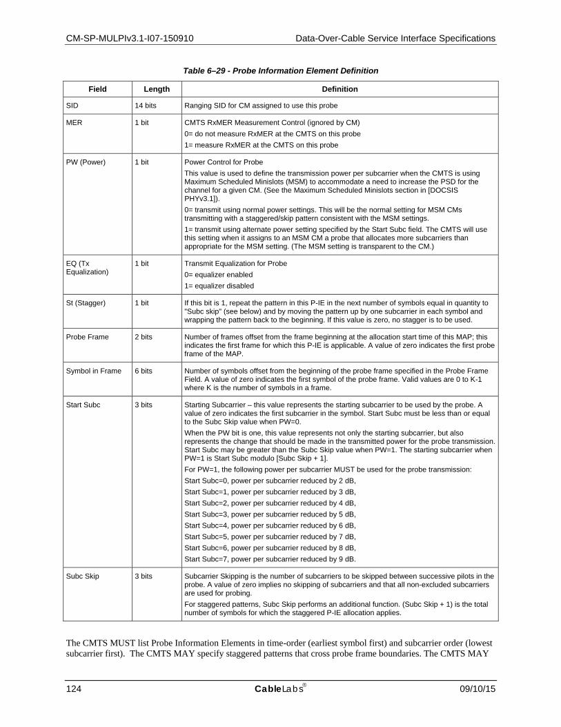
CM-SP-MULPIv3.1-I07-150910 Data-Over-Cable Service Interface Specifications
124 CableLabs 09/10/15
Table 6–29 - Probe Information Element Definition
Field Length Definition
SID 14 bits Ranging SID for CM assigned to use this probe
MER 1 bit CMTS RxMER Measurement Control (ignored by CM) 0= do not measure RxMER at the CMTS on this probe 1= measure RxMER at the CMTS on this probe
PW (Power) 1 bit Power Control for Probe This value is used to define the transmission power per subcarrier when the CMTS is using Maximum Scheduled Minislots (MSM) to accommodate a need to increase the PSD for the channel for a given CM. (See the Maximum Scheduled Minislots section in [DOCSIS PHYv3.1]). 0= transmit using normal power settings. This will be the normal setting for MSM CMs transmitting with a staggered/skip pattern consistent with the MSM settings. 1= transmit using alternate power setting specified by the Start Subc field. The CMTS will use this setting when it assigns to an MSM CM a probe that allocates more subcarriers than appropriate for the MSM setting. (The MSM setting is transparent to the CM.)
EQ (Tx Equalization)
1 bit Transmit Equalization for Probe 0= equalizer enabled 1= equalizer disabled
St (Stagger) 1 bit If this bit is 1, repeat the pattern in this P-IE in the next number of symbols equal in quantity to "Subc skip" (see below) and by moving the pattern up by one subcarrier in each symbol and wrapping the pattern back to the beginning. If this value is zero, no stagger is to be used.
Probe Frame 2 bits Number of frames offset from the frame beginning at the allocation start time of this MAP; this indicates the first frame for which this P-IE is applicable. A value of zero indicates the first probe frame of the MAP.
Symbol in Frame 6 bits Number of symbols offset from the beginning of the probe frame specified in the Probe Frame Field. A value of zero indicates the first symbol of the probe frame. Valid values are 0 to K-1 where K is the number of symbols in a frame.
Start Subc 3 bits Starting Subcarrier – this value represents the starting subcarrier to be used by the probe. A value of zero indicates the first subcarrier in the symbol. Start Subc must be less than or equal to the Subc Skip value when PW=0. When the PW bit is one, this value represents not only the starting subcarrier, but also represents the change that should be made in the transmitted power for the probe transmission. Start Subc may be greater than the Subc Skip value when PW=1. The starting subcarrier when PW=1 is Start Subc modulo [Subc Skip + 1]. For PW=1, the following power per subcarrier MUST be used for the probe transmission: Start Subc=0, power per subcarrier reduced by 2 dB, Start Subc=1, power per subcarrier reduced by 3 dB, Start Subc=2, power per subcarrier reduced by 4 dB, Start Subc=3, power per subcarrier reduced by 5 dB, Start Subc=4, power per subcarrier reduced by 6 dB, Start Subc=5, power per subcarrier reduced by 7 dB, Start Subc=6, power per subcarrier reduced by 8 dB, Start Subc=7, power per subcarrier reduced by 9 dB.
Subc Skip 3 bits Subcarrier Skipping is the number of subcarriers to be skipped between successive pilots in the probe. A value of zero implies no skipping of subcarriers and that all non-excluded subcarriers are used for probing. For staggered patterns, Subc Skip performs an additional function. (Subc Skip + 1) is the total number of symbols for which the staggered P-IE allocation applies.
The CMTS MUST list Probe Information Elements in time-order (earliest symbol first) and subcarrier order (lowest subcarrier first). The CMTS MAY specify staggered patterns that cross probe frame boundaries. The CMTS MAY

MAC and Upper Layer Protocols Interface Specification CM-SP-MULPIv3.1-I07-150910
09/10/15 CableLabs 125
leave any number of probe symbols unallocated. The CMTS MUST NOT allocate bandwidth such that there are more than k P-IEs outstanding per CM and per individual OFDMA channel where k is the number of symbols in the OFDMA frame.
A CM MUST be capable of storing k P-IEs per OFDMA channel. The CM MUST NOT transmit in any excluded subcarrier. When a probe staggered pattern lands on an excluded subcarrier, the CM MUST skip that point in the pattern and continue the pattern as if it had transmitted in the excluded subcarrier.
All P-IEs in the same P-MAP to the same SID are considered as one probe.
The following graphic and table in Figure 6–24 show example Probe frames and the corresponding P-IEs for those probe frames. In this example, there are 7 symbols per frame in the time domain and 16 subcarriers in the frequency domain with one of those subcarriers (shown in black in Figure 6–24) representing an excluded subcarrier. Unallocated probe symbols are shown in white. This example could be extended to any number of subcarriers. In this example, the CMTS is intending to repeat the probe pattern for the blue, green, yellow, and salmon CMs so that the CMTS receives two probe symbols per subcarrier from each of these CMs in the set of probe frames. For the medium gray CM, the CMTS wants all subcarriers probed simultaneously. In this example, the CMTS does not need to probe more than the 7 CMs shown and decides to leave unallocated the 3 probe symbols (shown in white) in the second frame. Note that when the CMTS assigns multiple probing opportunities to a CM in the same OFDMA frame (as in the repeated probe pattern for the blue, green, yellow, and salmon CMs), the CMTS uses the same PW, St, Start Subc, and Subc Skip values, as per [DOCSIS PHYv3.1].
Figure 6–24 - Sample Probe Frame and P-IEs
Additional Probe Examples:
For the examples below, subcarriers 0-144 are excluded subcarriers.
• Example 1A. PW=0, ST=0, Start Subc=0, Subc Skip=2 CM transmits on subcarriers 147, 150, 153, … with normal power setting.
• Example 1B. PW=1, ST=0, Start Subc=0, Subc Skip=2 CM transmits on subcarriers 147, 150, 153, … with power reduced by 2dB.
• Example 2A. PW=0, ST=0, Start Subc=1, Subc Skip=2 CM transmits on subcarriers 145, 148, 151, … with normal power setting.

CM-SP-MULPIv3.1-I07-150910 Data-Over-Cable Service Interface Specifications
126 CableLabs 09/10/15
• Example 2B. PW=1, ST=0, Start Subc=1, Subc Skip=2 CM transmits on subcarriers 145, 148, 151, … with power reduced by 3dB.
• Example 3A. PW=0, ST=1, Start Subc=1, Subc Skip=2 CM transmits on subcarriers 145, 148, 151, … with normal power setting in this symbol. CM transmits on subcarriers 146, 149, 152,… with normal power setting in the next symbol. CM transmits on subcarriers 147, 150, 153… with normal power setting in the subsequent symbol.
• Example 3B. PW=1, ST=1, Start Subc=1, Subc Skip=2 CM transmits on subcarriers 145, 148, 151, … with power reduced by 3dB in this symbol. CM transmits on subcarriers 146, 149, 152,… with power reduced by 3dB in the next symbol. CM transmits on subcarriers 147, 150, 153… with power reduced by 3dB in the subsequent symbol.
• Example 4A. PW=0, ST=0, Start Subc=6, Subc Skip=2 Not allowed.
• Example 4B. PW=1, ST=0, Start Subc=6, Subc Skip=2 CM transmits on subcarriers 147, 150, 153, … with power reduced by 8dB.
• Example 5A. PW=0, ST=0, Start Subc=4, Subc Skip=2 Not allowed.
• Example 5B. PW=1, ST=0, Start Subc=4, Subc Skip=2 CM transmits on subcarriers 145, 148, 151, … with power reduced by 6dB.
• Example 6A. PW=0, ST=1, Start Subc=4, Subc Skip=2 Not allowed.
• Example 6B. PW=1, ST=1, Start Subc=4, Subc Skip=2 CM transmits on subcarriers 145, 148, 151, … with power reduced by 6dB in this symbol. CM transmits on subcarriers 146, 149, 152,… with power reduced by 6dB in the next symbol. CM transmits on subcarriers 147, 150, 153… with power reduced by 6dB in the subsequent symbol.
6.4.4.1 Upstream Quiet Probe Measurement For Proactive Network Maintenance (PNM) and upstream profile evaluation, the CMTS MUST provide the capability to measure the upstream channel during "quiet" symbol times when no CM is actively transmitting, permitting accurate measurement of the underlying noise, intermods and ingress. In order to facilitate this condition, the CMTS MAY use a well-known ranging SID, denoted the "idle SID". that is not assigned to any CM on that OFDMA channel. When the CMTS needs to measure the quiet time, it allocates one or more "quiet" probe symbols in a P-MAP to the idle SID. The quiet symbols normally include all subcarriers across the upstream OFDMA channel.
6.4.5 Ranging Request Messages18 Ranging Request messages are transmitted by a CM at initialization on an upstream and periodically (for upstream Types 1-4) on request from the CMTS to determine network delay and request power adjustment. There are four types of Ranging Request messages: RNG-REQ, INIT-RNG-REQ, B-INIT-RNG-REQ, and O-INIT-RNG-REQ. The O-INIT-RNG-REQ is a special MAC frame that does not have the MAC Management Message format and is used only for initial ranging on OFDMA (Type 5) channels. This special MAC frame reduces the size of the initial maintenance regions on OFDMA channels. Table 6–30 shows when each type of message is used. The DOCSIS 3.1 CM never sends an INIT-RNG-REQ message; however, the INIT-RNG-REQ is in the specification for CMTS operation with legacy CMs.
6.4.5.1 Ranging Request Messages Sent to a DOCSIS 3.1 CMTS19 The CM determines the DOCSIS version of the CMTS by the MDD TLV. The CM transmits ranging request messages to a DOCSIS 3.1 CMTS with version numbers in the MAC Management Header according to the following rules:
18 Section updated per MULPIv3.1-N-14.1211-5 on 12/4/14 by PO, MULPIv3.1-N-15.1269-1 on 3/9/15 by PO. 19 Modified by MULPIv3.1-N-15-1294-2 on 6/1/15 by PO, formatting change per MULPIv3.1-15.1334-2 on 8/20/15 by PO.

MAC and Upper Layer Protocols Interface Specification CM-SP-MULPIv3.1-I07-150910
09/10/15 CableLabs 127
• A CM transmitting a B-INIT-RNG-REQ to a DOCSIS 3.1 CMTS MUST use a version number of 5 in the MAC Management Header of the B-INIT-RNG-REQ to notify the CMTS that this CM is a DOCSIS 3.1 CM and will use Queue-depth based requesting with the CM's first bandwidth request and will use the 9-bit power reporting.
• A CM transmitting a RNG-REQ to a DOCSIS 3.1 CMTS MUST use a version number of 5 in the MAC Management Header of the RNG-REQ to notify the CMTS that the CM is using the 9-bit power reporting in this message.
The CM follows the initialization of Type 5 upstream channels according to the following rules:
• When initializing on the first upstream channel, the CM MUST transmit an O-INIT-RNG-REQ in an Initial Maintenance opportunity. The CM MUST then transmit a B-INIT-RNG-REQ in its first unicast Station Maintenance region after receiving a RNG-RSP message from the CMTS. The CM then transmits RNG-REQ messages in subsequent Station Maintenance opportunities.
• When initializing on a secondary upstream channel in an Initial Maintenance opportunity, the CM MUST transmit an O-INIT-RNG-REQ. The CM then transmits RNG-REQ messages in subsequent Station Maintenance opportunities.
• When initializing on a secondary upstream channel in a Station Maintenance opportunity, the CM MUST transmit a RNG-REQ. The CM then transmits RNG-REQ messages in subsequent Station Maintenance opportunities.
The CM follows the initialization of Type 1, 2, 3, and 4 upstream channels according to the following rules:
• When initializing on the first upstream channel, the CM MUST transmit a B-INIT-RNG-REQ in an Initial Maintenance opportunity. The CM then transmits RNG-REQ messages in subsequent Station Maintenance opportunities.
• When initializing on a secondary upstream channel in an Initial or Station Maintenance opportunity, the CM MUST transmit a RNG-REQ. The CM then transmits RNG-REQ messages in subsequent Station Maintenance opportunities.
For all types of upstream channels, the CM MUST transmit a RNG-REQ message when it receives unicast ranging opportunities. On Type 5 upstream channels, probing is used for adjusting transmission parameters. For a Type 5 upstream channel, a CM MUST transmit a probe when it receives unicast probing opportunities.
Table 6–30 - CM Ranging Request Type Usage
Ranging Situation Channel Type 1, 2, 3, 4 5
CM initializing on first channel, and transmitting in a broadcast Initial Maintenance opportunity.
B-INIT-RNG-REQ
O-INIT-RNG-REQ
CM initializing on secondary channel, and transmitting in a broadcast or unicast Initial Maintenance opportunity.
RNG-REQ O-INIT-RNG-REQ
CM transmitting in a Station Maintenance opportunity. RNG-REQ B-INIT-RNG-REQ or RNG-REQ (see note 4)
Table Notes: 1. Initializing on a channel refers to the CM's first ranging request attempt during initialization and all subsequent ranging
request transmissions on that channel prior to receiving a ranging response message. 2. First channel refers to the channel (or multiple channels in failure scenarios) on which the CM attempts to range prior to
receiving the first ranging response during initialization. 3. Secondary channel refers to any channel on which the CM attempts to range after receiving a ranging response on a
different channel, except where that ranging response contained an Upstream Channel ID Override. 4. For Type 5 upstreams (OFDMA channels), the CM sends a B-INIT-RNG-REQ in the first Station Maintenance region
when initializing on the first upstream channel. Station Maintenance opportunities are used for fine ranging and can be used in addition to probes for periodic ranging. For periodic maintenance (station maintenance opportunities received after ranging complete), the CM sends RNG-REQ in the Station Maintenance Region.
If Upstream Transmit Power Reporting is enabled in a DOCSIS 3.1 MDD message (see Section 6.4.28.1.12), the CM MUST use the SSAP and DSAP fields of the MAC Management Message Header of Version 5 RNG-REQ and B-INIT-RNG-REQ messages to report its Transmit Power Level, P1.6r_n, for the upstream channel on which the

CM-SP-MULPIv3.1-I07-150910 Data-Over-Cable Service Interface Specifications
128 CableLabs 09/10/15
message is transmitted. The power level MUST be expressed by the CM as a 9 bit value in units of ¼ dB with bit 0 of the SSAP field representing the least significant bit and bit 0 of the DSAP field indicating the most significant bit of the Transmit Power Level. If Power Reporting TLV is not present in the MDD messages or if Power Reporting is disabled by the Power Reporting TLV, then the CM MUST NOT report its Power Level in the SSAP and DSAP fields of the Version 5 Ranging Request Messages.
If the CM has been properly commanded by the CMTS to adjust the transmitter parameters on one of its channels, it will find a Reconfiguration Time [DOCSIS PHYv3.1] in order to make the adjustment (see Section 10.3). If the CM has been properly commanded by the CMTS to adjust its dynamic range window it will wait for a Global Reconfiguration Time [DOCSIS PHYv3.1] to make the adjustment.
If the CM is reporting Transmit Power Level using the SSAP and DSAP fields, it MUST set the RSVD field to zero. In this case, the CMTS MUST ignore any information in the RSVD field. The CMTS calculates the value for P1.6hi for the CM's Transmit Channel Set and sends that value to the CM in the TCC encodings of the REG-RSP-MP or the DBC-REQ message. The CM also calculates the value for P1.6hi for the Transmit Channel Set. In the unlikely event that the CM and CMTS calculate different values for P1.6hi the CM MUST log an event indicating the error condition.
The CMTS uses the Commanded Power TLV of the RNG-RSP Message to manage the CM's Dynamic Range Window as well as the transmit power level for all of its channels. The CM performs the commanded adjustments even if the commanded adjustment would cause the transmit power level to lie outside of the Dynamic Range Window (DRW). If a commanded adjustment causes the Transmit Power Level P1.6r_n to lie outside the DRW the CM indicates the condition by setting bit 15 or 14 of the SID field of the RNG-REQ messages for that channel as long as the condition persists.
Bits 15 and 14 of SID field:
Bit 15 – The commanded power level P1.6r_n is higher than the value corresponding to the top of the DRW.
Bit 14 – The commanded power level P1.6r_n is lower than the value corresponding to the bottom of the DRW.
6.4.5.2 Ranging Request Messages Sent to a DOCSIS 3.0 CMTS20 The CM determines the DOCSIS version of the CMTS by the MDD TLV. The CM transmits ranging request messages with version numbers in the MAC Management Header according to the following rules:
• A CM transmitting a B-INIT-RNG-REQ to a DOCSIS 3.0 CMTS MUST use a version number of 4 in the MAC Management Header of the B-INIT-RNG-REQ.
• A CM transmitting a RNG-REQ to a DOCSIS 3.0 CMTS MUST use a version number of 1 in the MAC Management Header of the RNG-REQ.
If Upstream Transmit Power Reporting is enabled in a DOCSIS 3.0 MDD message, the CM MUST use the SSAP field of the MAC Management Message Header of RNG-REQ and B-INIT-RNG-REQ messages to report its Transmit Power Level, Pr, for the upstream channel on which the message is transmitted. The power level MUST be expressed by the CM in units of ¼ dB. If the Power Reporting TLV is not present in the DOCSIS 3.0 MDD messages or if Power Reporting is disabled by the Power Reporting TLV, then the CM MUST NOT report its Power Level in the SSAP field of the ranging messages.
If the CM has been properly commanded by the CMTS to adjust the transmitter parameters on one of its channels, it will find a Reconfiguration Time [DOCSIS PHYv3.0] in order to make the adjustment (see Section for a Global Reconfiguration Time [DOCSIS PHYv3.0] to make the adjustment.
If the CM is reporting Transmit Power Level using the SSAP field, it MUST set the RSVD field to zero. In this case, the CMTS MUST ignore any information in the RSVD field. If the CM detects an error condition with respect to its dynamic range window and a received RNG-RSP message, the CM MUST set bits 15 and 14 of the SID field in subsequent RNG-REQ messages of the affected channel or channels, until the error is cleared as follows:
20 Added by MULPIv3.1-N-15-1294-2 on 6/1/15 by PO.

MAC and Upper Layer Protocols Interface Specification CM-SP-MULPIv3.1-I07-150910
09/10/15 CableLabs 129
Bits 15 to 14 of SID field:
00 = No error condition.
01 = Power Adjustment not applied - Commanded power adjustment would cause Pr to be outside of the 12dB dynamic range window. This error condition only applies to the channel which received the ignored power adjustment and would be indicated in RNG-REQ messages for that channel until the condition was cleared.
10 = The current value for Pr is more than 3dB below the top of the dynamic range window for all channels. Spurious and noise requirements are relaxed for modem operating in this condition [DOCSIS PHYv3.0]. This error condition would apply to all channels in the TCS and would be indicated in RNG-REQ messages for all channels until the condition was cleared.
11 = Maximum Scheduled Codes Unnecessary - MSC and Power Headroom were sent in RNG-RSP, but current Pr is sufficient to allow use of all codes. Note: The CM does not ignore MSC setting in RNG-RSP, but just indicates a possible error condition with this encoding. This error condition only applies to the channel which received the RNG-RSP with un-needed MSC encodings and would be indicated in RNG-REQ messages for that channel until the condition was cleared.
6.4.5.3 Ranging Request Messages with Maximum Scheduled Codes21 Maximum Scheduled Codes can be enabled and included in RNG-REQ messages sent to either a DOCSIS 3.1 CMTS or a DOCSIS 3.0 CMTS. If the CM is reporting its Transmit Power in the RNG-REQ messages and Maximum Scheduled Codes (MSC) is enabled in the CMTS, the CMTS is in full control of the MSC feature. In this case, if the CMTS needs to command an increase in the Transmit Power Level which would result in the CM having a non-zero power shortfall, the CMTS MUST proactively send Maximum Scheduled Codes and Power Headroom in the RNG-RSP message.
If Upstream Transmit Power Reporting is not enabled in the MDD message, the CM MUST set the RSVD field of the MAC Management Message Header to report support for S-CDMA MSC if and only if MSC has been enabled in the UCD for this channel. In this case, the CM MUST report the maximum ratio of number of active codes to Maximum Scheduled Codes that the CM can support. The CMTS will use this value in calculating an appropriate value for Maximum Scheduled Codes to assign to the CM. The CM MUST support a Maximum Ratio of 32.
When the CM reports MSC information, the CM MUST also report its current transmit power shortfall (in dB). The CM power shortfall is the difference between the current target transmit power of the ranging request and the maximum SCDMA spreader-on transmit power of P1.6hi or Phi. The CM MUST report a power shortfall of 0 if the current target transmit power of the ranging request is less than or equal to the P1.6hi value. The CM MUST report a power shortfall of 0 if the current target transmit power of the ranging request is less than or equal to the Phi value. This value will be used by the CMTS for calculating appropriate values for S-CDMA Maximum Scheduled Codes and S-CDMA Power Headroom for the CM.
The format of the RSVD field for conveying its current transmit power shortfall when MSC is supported by the CMTS is:
Bit 7: 1= S-CDMA Maximum Scheduled Codes Supported
Bits 6 to 5: CM Maximum Ratio of 00 = 2 01 = 8
10 = 16 11 = 32
Bit 4 to 0: CM power shortfall (1/4 dB)
21 Modified by MULPIv3.1-N-15-1294-2 on 6/11/15 by PO.

CM-SP-MULPIv3.1-I07-150910 Data-Over-Cable Service Interface Specifications
130 CableLabs 09/10/15
6.4.5.3 Ranging Request (RNG-REQ) The RNG-REQ message transmitted by the CM MUST use an FC_TYPE = MAC Specific Header and FC_PARM = Timing MAC Header, followed by a Packet PDU in the format shown in Figure 6–25.
Figure 6–25 - RNG-REQ Format
The parameters of RNG-REQ messages transmitted by the CM MUST be as follows:
SID: For RNG-REQ messages transmitted in Broadcast Initial Maintenance intervals:
• Initialization SID if modem is attempting to join the network. • Initialization SID if modem has not yet registered and is changing upstream, downstream, or both downstream
and upstream channels as directed by a downloaded parameter file. • Primary SID (previously assigned in REG-RSP) for Pre-3.0 DOCSIS operation, if modem is registered and is
changing upstream channels, or if the CM is redoing initial ranging as a result of a DCC, UCC, or UCD change (see Sections 6.4.3 and 11.1).
For RNG-REQ messages transmitted in Unicast Initial Maintenance or Station Maintenance intervals:
• Temporary SID if modem has not yet registered. • Ranging SID if one has been assigned by the CMTS to the CM for this channel. • Primary SID (previously assigned in REG-RSP) for Pre-3.0 DOCSIS operation, if modem is registered or is
redoing initial ranging as a result of DCC, UCC, or UCD change.
This is a 16-bit field of which the lower 14 bits define the SID.
Downstream Channel ID: The identifier of the downstream channel on which the CM is receiving the UCDs and MAPs which describe this upstream. This is an 8-bit field.
Reserved Field: (This previously was Pending Till Complete.) The CM sends a value of 0 in this field.
6.4.5.4 Initial Ranging Request (INIT-RNG-REQ)22 The INIT-RNG-REQ message transmitted by legacy CMs uses an FC_TYPE = MAC Specific Header and FC_PARM = Timing MAC Header, followed by a Packet PDU in the format shown in Figure 6–26. The INIT-RNG-REQ differs from the RNG-REQ in that it has an upstream channel ID in place of the Reserved field in a RNG-REQ.
22 Modified by MULPIv3.1-14.1211-5 on 12/4/14 by PO.

MAC and Upper Layer Protocols Interface Specification CM-SP-MULPIv3.1-I07-150910
09/10/15 CableLabs 131
Figure 6–26 - INIT-RNG-REQ Format
The parameters of the INIT-RNG-REQ message transmitted by legacy CMs are as follows:
SID: This is a 16-bit field of which the lower 14 bits define the SID [DOCSIS CMCIv3.0].
Downstream Channel ID: The identifier of the downstream channel on which the CM is receiving the UCDs and MAPs which describe this upstream. This is an 8-bit field.
Upstream Channel ID: The Upstream Channel ID from the UCD the CM is using to transmit this INIT-RNG-REQ. In the case where multiple logical upstreams are sharing the same spectrum, and the Broadcast Initial Ranging Opportunities of some of these logical channels are aligned, the Upstream Channel ID allows the CMTS to know which logical channel the CM is using.
6.4.5.5 Bonded Initial Ranging Request (B-INIT-RNG-REQ)23 The B-INIT-RNG-REQ message transmitted by a CM MUST use an FC_TYPE = MAC Specific Header and FC_PARM = Timing MAC Header, followed by a Packet PDU in the format shown in Figure 6–27.
The B-INIT-RNG-REQ differs from the INIT-RNG-REQ in that it includes the MD-DS-SG-ID used for downstream topology resolution and a set of Capability Flags in place of the SID. A CM MUST only use this message for the first channel it ranges on. When ranging for the first time on all succeeding channels in an Initial Maintenance opportunity, the CM uses the RNG-REQ message (see Section 6.4.5.4) for channel Types 1, 2, 3, and 4 or the O-INIT-RNG-REQ message for channel Type 5. On a Type 5 channel, the CM uses B-INIT-RNG-REQ message as specified in Table 6–30.
Figure 6–27 - B-INIT-RNG-REQ Format
The parameters of the B-INIT-RNG-REQ message transmitted by the CM MUST be as follows:
Capability Flags: Used to convey modem capabilities that are needed prior to registration by the CMTS. It is an 8-bit field as defined in Section 6.4.5.5.1.
MD-DS-SG-ID: The identifier of the MAC Domain Downstream Service Group obtained from downstream ambiguity resolution. This is an 8-bit field. The value zero indicates that the MD-DS-SG-ID could not be determined.
23 Modified by MULPIv3.1-14.1211-5 on 12/4/14 by PO.
MAC Management Message Header
Octets
SID Downstream Channel ID
Upstream Channel ID
MAC Management Message Header
Octets
Capability Flags
Downstream Channel ID
Upstream Channel IDMD-DS-SG-ID

CM-SP-MULPIv3.1-I07-150910 Data-Over-Cable Service Interface Specifications
132 CableLabs 09/10/15
Downstream Channel ID: The identifier of the downstream channel on which the CM is receiving the UCDs and MAPs which describe this upstream. This is an 8-bit field.
Upstream Channel ID: The Upstream Channel ID from the UCD the CM is using to transmit this B-INIT-RNG-REQ. In the case where multiple logical upstreams are sharing the same spectrum, and the Broadcast Initial Ranging Opportunities of some of these logical channels are aligned, the Upstream Channel ID allows the CMTS to know which logical channel the CM is using.
If the MD-DS-SG-ID is unrecognized, the CMTS MUST silently ignore the B-INIT-RNG-REQ.
6.4.5.5.1 Capability Flags
A CM MUST indicate certain capabilities to the CMTS prior to registration via the Capability Flags field. The format of the Capability Flags field used by the CM MUST be as follows:
Table 6–31 - Capability Flags Encoding
Bit 7: 1: Pre-3.0 DOCSIS fragmentation is supported prior to registration 0: Pre-3.0 DOCSIS fragmentation is not supported prior to registration
Bit 6: 1: Early Authentication and Encryption Supported 0: Early Authentication and Encryption Not Supported
Bits 5 to 0: Reserved
A CM MAY indicate support for pre-3.0 DOCSIS fragmentation prior to registration.
A CM MUST indicate support for Early Authentication and Encryption.
6.4.5.6 OFDMA Initial Ranging Request (O-INIT-RNG-REQ) The O-INIT-RNG-REQ message is transmitted only in Initial Maintenance Regions and only on OFDMA upstream channels. This message does not use the standard MAC Frame format but uses a condensed format to conserve bandwidth on the OFDMA channel. The O-INIT-RNG-REQ transmitted by a CM MUST use the format shown in Figure 6–28.
Figure 6–28 - O-INIT-RNG-REQ Format
The parameters of the O-INIT-RNG-REQ message transmitted by the CM MUST be as follows:
MAC Address: MAC address of the CM. This is a 6-byte field.
Downstream Channel ID: The identifier of the downstream channel on which the CM is receiving the UCDs and MAPs which describe this upstream. This is an 8-bit field.
CRC-24: CRC-24 over the MAC Address and DS-CHAN-ID. CRC-24 defined in [DOCSIS PHYv3.1]. This is a 3-byte field.
6.4.6 Ranging Response (RNG-RSP) A Ranging Response MUST be transmitted by a CMTS in response to received RNG-REQ, INIT-RNG-REQ, B-INIT-RNG-REQ, O-INIT-RNG-REQ, or probe. The state machines describing the ranging procedure appear in Section 10.2.3.4. In that procedure it may be noted that, from the point of view of the CM, reception of a Ranging Response is stateless. In particular, the CM MUST be prepared to receive a Ranging Response at any time, not just following a Ranging Request or probe.
To provide for flexibility, the message parameters following the Upstream Channel ID MUST be encoded by the CMTS in a type/length/value (TLV) form.

MAC and Upper Layer Protocols Interface Specification CM-SP-MULPIv3.1-I07-150910
09/10/15 CableLabs 133
Figure 6–29 - Ranging Response
A CMTS MUST generate Ranging Responses in the form shown in Figure 6–29, including all of the following parameters as defined below:
SID: If the modem is being instructed by this response to move to a different channel, this is the initialization SID. If this is a response to an initial ranging request (whether RNG-REQ, INIT-RNG-REQ, or B-INIT-RNG-REQ), this is the assigned temporary SID. Otherwise, this is the SID from the corresponding RNG-REQ to which this response refers.
Upstream Channel ID: The identifier of the upstream channel on which the CMTS received the RNG-REQ, INIT-RNG-REQ, or B-INIT-RNG-REQ to which this response refers. On the first ranging response received by the CM after initializing or reinitializing its MAC, this channel ID may be different from the channel ID the CM used to transmit the range request. Thus, the CM MUST use this channel ID for the rest of its transactions, not the channel ID from which it initiated the range request.
All other parameters, when present, MUST be coded as TLV tuples and used by the CMTS, as defined below:
Ranging Status: Used to indicate whether upstream messages are received within acceptable limits by CMTS.
Timing Adjust, Integer Part: The amount by which to change the Ranging Offset of the burst transmission so that bursts arrive at the expected minislot time at the CMTS. The units are (1 / 10.24 MHz) = 97.65625 ns for TDMA and S-CDMA channels and units of (1/204.8 MHz) =4.8828125ns for OFDMA channels. A negative value implies the Ranging Offset is to be decreased, resulting in later times of transmission at the CM (see Section 6.4.20 and Section 6.2).
Power Adjust Information: Specifies the relative change in transmission power level that the CM is to make in order that transmissions arrive at the CMTS at the desired power.
Frequency Adjust Information: Specifies the relative change in transmission frequency that the CM is to make in order to better match the CMTS. (This is fine-frequency adjustment within a channel, not re-assignment to a different channel.)
CM Transmitter Equalization Information: This provides the equalization coefficients for the pre-equalizer.
Downstream Frequency Override: An optional parameter. The downstream frequency with which the modem should redo initial ranging. (See Section 6.4.6.5.)
Upstream Channel ID Override: An optional parameter. The identifier of the upstream channel with which the modem should redo initial ranging. (See Section 6.4.6.5.)
Timing Adjust, Fractional Part: Higher resolution timing adjust offset to be appended to Timing Adjust, Integer Part. For TDMA and S-CDMA channels, the units are (1 / (256*10.24 MHz)) = 0.38 ns. For OFDMA channels, the units are 1/(256*204.8MHz)=19.0734 ps. This parameter provides finer granularity timing offset information. This TLV is a mandatory parameter for timing adjustments on S-CDMA channels. This TLV is an optional parameter for timing adjustments on TDMA and OFDMA channels. A CM whose timing is locked to the downstream symbol
MAC Management Message Header
Octets
SID UpstreamChannel ID
TLV-encoded information

CM-SP-MULPIv3.1-I07-150910 Data-Over-Cable Service Interface Specifications
134 CableLabs 09/10/15
clock MUST apply the fractional part timing adjustment if this TLV is present, whether the channel is TDMA,S-CDMA, or OFDMA.
S-CDMA Maximum Scheduled Codes: The value that the CMTS uses to limit the number of codes scheduled to a CM in an S-CDMA frame. CMs that implement the S-CDMA Maximum Scheduled Codes use this value to limit the maximum size of a concatenated burst in an S-CDMA Frame.
S-CDMA Power Headroom: CMs that implement the S-CDMA Maximum Scheduled Codes use this value to control transmit power as per [DOCSIS PHYv3.1] when Maximum Scheduled Codes is Enabled.
Upstream Channel Adjustments: A CMTS can send this TLV to move a CM to another upstream channel as a part of upstream ambiguity resolution, and to adjust more than one upstream channel with a single RNG-RSP message when a modem has Multiple Transmit Channel Mode enabled.
T4 Timeout Multiplier: A CMTS can send this TLV to increase the value of the T4 timeout for CMs that have Multiple Transmit Channel Mode enabled.
The CM MUST apply the parameters of the RNG-RSP message within 50ms of receipt unless a Global Reconfiguration Time [DOCSIS PHYv3.1] is needed. If the Global Reconfiguration Time [DOCSIS PHYv3.1] is needed, the CM MUST apply the parameters of the RNG-RSP message prior or during the Global Reconfiguration Time.
6.4.6.1 Encodings The type values used by the CMTS in the RNG-RSP MUST comply with Table 6–32 and Figure 6–30. These are unique within the ranging response message but not across the entire MAC message set. The type and length fields used by the CMTS in the RNG-RSP MUST each be 1 octet in length.
Table 6–32 - Ranging Response Message Encodings with 1 byte Length Field24
Name Type (1 byte)
Length (1 byte)
Value (Variable Length)
Timing Adjust, Integer Part
1 4 TX timing offset adjustment (signed 32-bit, units of (6.25 microsec/64) for TDMA and S-CDMA channels, units of (1/204.8 MHz) for OFDMA channels).
Power Level Adjust 2 1 TX Power offset adjustment (signed 8-bit, 1/4-dB units). After receiving the REG-RSP-MP the CM MUST NOT adjust its transmit power based on the RNG-RSP Power Level Adjust TLV. After sending the REG-RSP-MP, the CMTS MUST NOT adjust the transmit power level of CMs which are sending version 5 RNG-REQ messages with the RNG-RSP Power Level Adjust TLV.
Offset Frequency Adjust
3 2 TX frequency offset adjustment (signed 16-bit, Hz units). For an OFDMA channel, the CM MUST ignore the TX frequency offset adjustment.
Transmit Equalization Adjust
4 n TX equalization data to be convolved with current values (refer to [DOCSIS PHYv3.1]). The CMTS MUST NOT include this TLV in a RNG-RSP that includes a type 9 TLV. This TLV is for S-CDMA and TDMA channels only.
Ranging Status 5 1 1 = continue, 2 = abort, 3 = success.
Downstream frequency override
6 4 For SC-QAM channels, the frequency in this TLV is the center frequency of the SC-QAM channel. For OFDM channels, the frequency in this TLV is the center frequency of the lowest subcarrier of the 6 MHz encompassed spectrum containing the PHY Link Channel (PLC) at its center.
Upstream channel ID override
7 1 Identifier of the new upstream channel.
Timing Adjust, Fractional Part
8 1 TX timing fine offset adjustment. 8-bit unsigned value specifying the fine timing adjustment in units of 1/(256*10.24 MHz) for S-CDMA and TDMA or 1/(256*204.8MHz) for OFDMA.
24 Table updated per MULPIv3.1-14.1193-1 on 12/2/14, MULPIv3.1-14.1221-5 on 12/4/14 by PO, by MULPIv3.1-N-15.1269-1
on 3/9/15 by PO, and MULPIv3.1-N-15-1294-2 on 6/11/15 by PO.

MAC and Upper Layer Protocols Interface Specification CM-SP-MULPIv3.1-I07-150910
09/10/15 CableLabs 135
Name Type (1 byte)
Length (1 byte)
Value (Variable Length)
Transmit Equalization Set
9 n TX equalization data to be loaded in place of current values (refer to [DOCSIS PHYv3.0]). The CMTS MUST NOT include this TLV in a RNG-RSP to a DOCSIS 1.x CM. The CMTS MUST NOT include this TLV in a RNG-RSP that includes a type 4 TLV.
S-CDMA Maximum Scheduled Codes
10 1 A CMTS may send this TLV only if a CM indicated that it supports the S-CDMA Maximum Scheduled Codes. A value of 0 means no code limit. Other possible values range from 4 to number_active_codes inclusive. Maximum Scheduled codes is an integer multiple of codes_per_minislot. The CMTS MUST NOT include this TLV if S-CDMA mode is disabled. Absence of this TLV indicates that Maximum Scheduled Codes is inactive for this CM, which MUST then use the S-CDMA Number of Active Codes.
S-CDMA Power Headroom
11 1 A CMTS sends this TLV to a CM in conjunction with TLV-10. The CMTS MUST NOT include this TLV if S-CDMA mode is disabled. The units are dB. The range of this TLV is from 0 to 4*10log
Note: A value of 0 for TLV-10 restricts the range to 0 for TLV-11.
Upstream Channel Adjustments
12 n A CMTS may send one or more sets of this TLV to allow for adjustments to channels other than the one provided in the RNG-RSP message, or for use in ambiguity resolution.
Upstream Channel ID 12.1 1 The ID of the channel.
Temp SID 12.2 2 SID to be used on the new channel.
Initialization Technique
12.3 1 1 = (All upstream channel types) Perform broadcast initial ranging (IUC3) 2 = (S-CDMA and TDMA channels only) Perform unicast ranging (IUC3 or IUC4) 3 = (S-CDMA and TDMA channels only) Perform either broadcast (IUC3) or unicast (IUC3 or IUC4) ranging 4 = Reserved 5 = (OFDMA upstreams only) Perform probing 6 = (OFDMA channels only) Perform unicast initial ranging (IUC3) 7 = (OFDMA channels only) Perform station ranging (IUC4) 0, 8 – 255: reserved
Ranging Parameters 12.4 n Contains sub-TLVs for ranging adjustments.
Deprecated 12.4.1 1 Deprecated
Timing Offset, Integer Part
12.4.2 4 TX timing offset adjustment (signed 32-bit, units of (6.25 microsec/64)) for TDMA and S-CDMA channels, units of (1/204.8 MHz) for OFDMA channels.
Timing Offset, Fractional Part
12.4.3 1 TX timing fine offset adjustment. 8-bit unsigned value specifying the fine timing adjustment in units of 1/(256*10.24 MHz) for S-CDMA and TDMA or 1/(256*204.8 MHz) for OFDMA.
Power Offset 12.4.4 1 TX Power offset adjustment (signed 8-bit, 1/4-dB units). After receiving the REG-RSP-MP the CM MUST NOT adjust its transmit power based on the RNG-RSP Power Offset TLV. After sending the REG-RSP-MP, the CMTS MUST NOT adjust the transmit power level of CMs which are sending version 5 RNG-REQ messages with the Power Offset TLV.
Frequency Offset 12.4.5 2 TX frequency offset adjustment (signed 16-bit, Hz units). This TLV is not applicable for OFDMA channels.
Ranging Status 12.4.6 1 = continue, 2 = abort, 3 = success. The Ranging Status sub-TLV is not applicable during US Ambiguity Initial Ranging and is only used after Registration.
T4 Timeout Multiplier 13 1 Multiplier of the default T4 Timeout as defined earlier in this section. If omitted the default as defined in Annex B is used. The valid range is 1-10.
CodecsScheduledMaximum
CodecsActiveNumber__
__
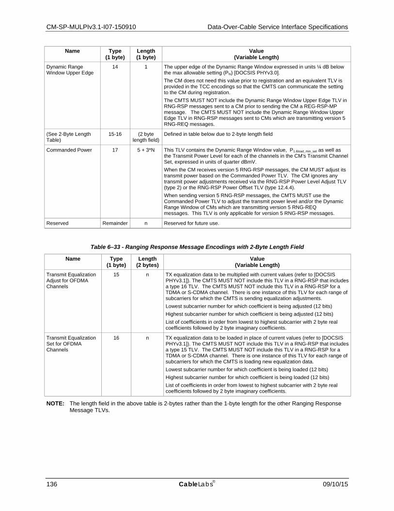
CM-SP-MULPIv3.1-I07-150910 Data-Over-Cable Service Interface Specifications
136 CableLabs 09/10/15
Name Type (1 byte)
Length (1 byte)
Value (Variable Length)
Dynamic Range Window Upper Edge
14 1 The upper edge of the Dynamic Range Window expressed in units ¼ dB below the max allowable setting (Phi) [DOCSIS PHYv3.0]. The CM does not need this value prior to registration and an equivalent TLV is provided in the TCC encodings so that the CMTS can communicate the setting to the CM during registration. The CMTS MUST NOT include the Dynamic Range Window Upper Edge TLV in RNG-RSP messages sent to a CM prior to sending the CM a REG-RSP-MP message. The CMTS MUST NOT include the Dynamic Range Window Upper Edge TLV in RNG-RSP messages sent to CMs which are transmitting version 5 RNG-REQ messages.
(See 2-Byte Length Table)
15-16 (2 byte length field)
Defined in table below due to 2-byte length field
Commanded Power 17 5 + 3*N This TLV contains the Dynamic Range Window value, P1.6load_min_set as well as the Transmit Power Level for each of the channels in the CM's Transmit Channel Set, expressed in units of quarter dBmV. When the CM receives version 5 RNG-RSP messages, the CM MUST adjust its transmit power based on the Commanded Power TLV. The CM ignores any transmit power adjustments received via the RNG-RSP Power Level Adjust TLV (type 2) or the RNG-RSP Power Offset TLV (type 12.4.4). When sending version 5 RNG-RSP messages, the CMTS MUST use the Commanded Power TLV to adjust the transmit power level and/or the Dynamic Range Window of CMs which are transmitting version 5 RNG-REQ messages. This TLV is only applicable for version 5 RNG-RSP messages.
Reserved Remainder n Reserved for future use.
Table 6–33 - Ranging Response Message Encodings with 2-Byte Length Field
Name Type (1 byte)
Length (2 bytes)
Value (Variable Length)
Transmit Equalization Adjust for OFDMA Channels
15 n TX equalization data to be multiplied with current values (refer to [DOCSIS PHYv3.1]). The CMTS MUST NOT include this TLV in a RNG-RSP that includes a type 16 TLV. The CMTS MUST NOT include this TLV in a RNG-RSP for a TDMA or S-CDMA channel. There is one instance of this TLV for each range of subcarriers for which the CMTS is sending equalization adjustments. Lowest subcarrier number for which coefficient is being adjusted (12 bits) Highest subcarrier number for which coefficient is being adjusted (12 bits) List of coefficients in order from lowest to highest subcarrier with 2 byte real coefficients followed by 2 byte imaginary coefficients.
Transmit Equalization Set for OFDMA Channels
16 n TX equalization data to be loaded in place of current values (refer to [DOCSIS PHYv3.1]). The CMTS MUST NOT include this TLV in a RNG-RSP that includes a type 15 TLV. The CMTS MUST NOT include this TLV in a RNG-RSP for a TDMA or S-CDMA channel. There is one instance of this TLV for each range of subcarriers for which the CMTS is loading new equalization data. Lowest subcarrier number for which coefficient is being loaded (12 bits) Highest subcarrier number for which coefficient is being loaded (12 bits) List of coefficients in order from lowest to highest subcarrier with 2 byte real coefficients followed by 2 byte imaginary coefficients.
NOTE: The length field in the above table is 2-bytes rather than the 1-byte length for the other Ranging Response Message TLVs.

MAC and Upper Layer Protocols Interface Specification CM-SP-MULPIv3.1-I07-150910
09/10/15 CableLabs 137
6.4.6.2 Example of TLV Data An example of TLV data is given in Figure 6–30.
Figure 6–30 - Example of TLV Encoded Data
6.4.6.3 Transmit Equalization Encodings for S-CDMA and TDMA Channels
Figure 6–31 - Equalization Coefficient Encodings for S-CDMA and TDMA Channels
The number of taps per modulation interval T signaled by the CMTS MUST be either 1, 2, or 4. The main tap location refers to the position of the zero delay tap, between 1 and N. For a T-spaced equalizer, the number of taps per modulation interval field MUST be set to "1" by the CMTS. The total number of taps signaled by the CMTS MAY range up to 64. Each tap consists of a real and imaginary coefficient entry in the table.
If more than 255 bytes are needed to represent equalization information, then several type 4 or 9 elements may be used. Data MUST be treated by the CM and CMTS as if byte-concatenated, that is, the first byte after the length field of the second type 4 or 9 element is treated as if it immediately followed the last byte of the first type 4 or 9 element.
Type 1 Length 4
Type 2 Length 1
Type 3 Length 2
Type 4 Length x
Type 5 Length 1
Power adjust
Ranging status
Timing adjust
Frequency adjust information
X bytes of CM transmitter equalization information
Type4 or 9 Length Main Tap
LocationNumber of ForwardTaps per Symbol
Number of ForwardTaps (N) Reserved
First Coefficient F1 (real) First Coefficient F1 (imag)
Last Coefficient FN (real) Last Coefficient FN (imag)≈

CM-SP-MULPIv3.1-I07-150910 Data-Over-Cable Service Interface Specifications
138 CableLabs 09/10/15
6.4.6.4 Transmit Equalization Encodings for OFDMA Channels
Figure 6–32 - Equalization Coefficient Encodings for OFDMA Channels
To reduce the number of coefficients sent, it is intended that the range encompassed by the lowest subcarrier number and highest subcarrier number not include exclusion bands that are below and above the active subcarriers in the OFDMA channel. For subcarriers in exclusion bands that exist among active subcarriers, the CMTS MUST set the real and imaginary coefficients to 0.
6.4.6.5 RNG-RSP Channel Overrides The RNG-RSP message allows the CMTS to instruct the modem to move to a new downstream and/or upstream channel and to repeat initial ranging. However, the CMTS may do this only in response to an initial ranging request from a modem that is attempting to join the network, or in response to any of the unicast ranging requests that take place immediately after this initial ranging and up to the point where the modem successfully completes periodic ranging. After transmitting the first RNG-RSP with Ranging Status equal to Success(3) to an initializing CM, the CMTS MUST NOT send the CM an upstream or downstream channel override in a RNG-RSP message. If a downstream frequency override is specified in the RNG-RSP, the modem MUST reinitialize its MAC (see Section 10.2.1) using initial ranging with the specified downstream center frequency as the first scanned channel. The CM MUST scan for both downstream channel types.
If an upstream channel ID override is specified in the RNG-RSP, the modem MUST reinitialize its MAC (see Section 10.2.1) using initial ranging with the upstream channel specified in the RNG-RSP for its first attempt and the same downstream frequency on which the RNG-RSP was received.
If both downstream frequency and upstream channel ID overrides are present in the RNG-RSP, the modem MUST reinitialize its MAC (refer to Section 10.2.1) using initial ranging with the specified downstream frequency and upstream channel ID for its first attempt.
Note that when a modem with an assigned temporary SID is instructed to move to a new downstream and/or upstream channel and to redo initial ranging, the modem MUST consider the temporary SID to be de-assigned. The modem MUST redo initial ranging using the Initialization SID.
Configuration file settings for upstream channel ID and downstream frequency(s) are optional, but if specified in the config file they take precedence over the ranging response parameters.
6.4.6.6 Upstream Channel Adjustments A CMTS sends this TLV for use in upstream ambiguity resolution and for post registration ranging adjustments to one or more upstream channels other than the upstream channel indicated by the Upstream Channel ID encoded in the body of the RNG-RSP message prior to the TLV encodings.
≈
Type15 or 16 Length (2 bytes)
Lowest subcarrier number for this TLV (12 bits)
Highest subcarrier number for this TLV (12 bits)
First Coefficient F1 (real) First Coefficient F1 (imag)
Last Coefficient FN (real) Last Coefficient FN (imag)

MAC and Upper Layer Protocols Interface Specification CM-SP-MULPIv3.1-I07-150910
09/10/15 CableLabs 139
During upstream ambiguity resolution, the CMTS MUST include no more than one Upstream Channel Adjustment TLV. The CMTS MUST include the Upstream Channel ID and Initialization Technique sub-TLVs. The CMTS MUST include the Temp SID TLV when the Initialization Technique includes "unicast ranging" (techniques 2, 3, 5, 6, and 7). The CMTS MUST NOT include the Temp SID TLV when the Initialization Technique is "broadcast initial ranging" (technique 1). The CMTS MUST NOT send a Downstream Frequency Override TLV when an Upstream Channel Adjustment TLV is present. The CMTS MUST NOT send an Upstream Channel ID Override TLV when an Upstream Channel Adjustment TLV is present. The CMTS MAY send Ranging Parameter sub-TLVs to speed up upstream ambiguity resolution. During upstream ambiguity resolution, the CMTS MUST NOT include Ranging Response parameter adjustments (adjustments specified in TLVs 1 through 4 and 8 through 11) in the RNG-RSP containing the Upstream Channel Adjustment TLV. The CMTS MUST NOT include the Ranging Status sub-TLV in the Upstream Channel Adjustment TLVs during upstream ambiguity resolution.
The CMTS MUST NOT include this TLV in a RNG-RSP message between the completion of US Ambiguity Initial Ranging and receiving a REG-ACK. During this period the CM will only have a single US channel and should not be moved to other US channels via this method.
After registration, the CMTS MAY include one or more Upstream Channel Adjustment TLVs in a RNG-RSP message during periodic station maintenance to adjust multiple US channels with a single RNG-RSP message. In this case, the Temp SID and Initialization Technique sub-TLVs MUST NOT be present. The Upstream Channel ID field will represent the UCID of the channel to be adjusted, and the Ranging Parameters field will indicate what adjustments are to be made to that channel. The presence of Upstream Channel Adjustments for a particular upstream channel will reset the T3 timer, if active, for that channel. If the CMTS does not include the Ranging Status sub-TLV in the Upstream Channel Adjustment TLVs, the CM MUST consider the Ranging Status to be unchanged.
Prior to the completion of US Ambiguity Initial Ranging, the CM MUST change US channels in accordance with the parameters in this TLV. If the Ranging Parameter sub-TLVs (12.4.1 through 12.4.6) are used, the CM MUST apply the offsets as referenced to the current values for the channel on which the RNG-REQ message was sent. After completion of US Ambiguity Initial Ranging and prior to sending the REG-ACK, the CM MUST ignore an Upstream Channel Adjustment TLV if present in a RNG-RSP. After sending the REG-ACK, the CM assumes that the Upstream Channel Adjustments TLV indicates changes to be made to upstream channels other than the upstream channel indicated in the body of the RNG-RSP message prior to the TLV encodings, and MUST adjust transmissions on those upstream channels according to the TLV parameters. As a result, if the CM receives US Channel Adjustments with an unknown US Channel ID after registration, it MUST ignore that TLV.
6.4.6.7 T4 Timeout Multiplier In Multiple Transmit Channel Mode the CMTS MAY increase the value of the T4 timeout by means of the T4 Timeout Multiplier in order to reduce CMTS overhead associated with scheduling RNG-REQ slots and processing RNG-RSP messages. The CM MUST set its T4 timeout to the value of the multiplier times the default T4 timeout in Annex B. If a RNG-RSP does not contain a T4 Timeout Multiplier value then the CM MUST use the default T4 timeout as defined in Annex B. If the CMTS includes a T4 Timeout Multiplier in the RNG-RSP, the CMTS MUST set it to be in the valid range of 1-10. In order to allow for future updates, the CM does not enforce the valid range.
If the CMTS sets the T4 Timeout Multiplier to any value other than the default then it MUST send the T4 Timeout Multiplier value in every RNG-RSP. When reducing the value of the T4 Timeout Multiplier, the CMTS SHOULD start scheduling a few RNG-REQ slots at the shorter interval before sending a RNG-RSP with the shorter timeout. When increasing the value of the T4 Timeout Multiplier, the CMTS SHOULD continue scheduling a few RNG-REQ slots at the shorter interval even after the RNG-RSP with the longer value is transmitted.
6.4.6.8 Commanded Power The CMTS uses the Commanded Power TLV after Registration to control the Dynamic Range Window and the transmit power level for all of the upstream channels in the CM's Transmit Channel Set. The Commanded Power TLV contains two sub-TLVs.

CM-SP-MULPIv3.1-I07-150910 Data-Over-Cable Service Interface Specifications
140 CableLabs 09/10/15
Table 6–34 - Commanded Power Sub-TLVs25
Name Type (1 byte)
Length (1 byte)
Value (Variable Length)
Commanded Power 17 5 + 3*N
Dynamic Range Window (P1.6load_min_set)
17.1 1 (P1.6load_min_set)
List of Upstream Channel IDs and Corresponding Transmit Power Levels
17.2 3*N Values for each channel in the TCS: Bits 23 to 16: UCID Bits 15 to 0: Transmit Power Level (quarter dBmV)
If a RNG-RSP containing the Commanded Power TLV has a Status other than SUCCESS, that Status indication applies only to the Upstream Channel ID to which the RNG-RSP was sent and does not affect the Status of any other upstream channels.
The CMTS is required to adjust a CM's transmit power with the Commanded Power TLV when a CM is initializing channels during Registration or a DBC transaction, but the CMTS might not have knowledge of the transmit power level for all of the channels in the TCS at that time. When the CMTS constructs the Commanded Power TLV in this case, it SHOULD set the Transmit Power Level of any channels for which the CM's transmit power level is unknown to zero. If the CM receives a RNG-RSP with a Commanded Power TLV for which the Transmit Power Level is zero for any of its channels, it MUST ignore the commanded power level for those channels and continue the ranging process using transmit power levels as permitted by the Dynamic Range Window.
6.4.7 Registration Request Messages The CM transmits a Registration Request message after receipt of a CM configuration file as specified in Section 10.2. There are two types of Registration Request messages: the single frame Registration Request message (referred to as REG-REQ), and the Multipart Registration Request message (referred to as REG-REQ-MP). The CM transmits a REG-REQ-MP message instead of a REG-REQ. This specification will use the terms "REG-REQ" and "REG-REQ-MP" when it is important to make a distinction between the two, and the term "Registration Request" when such a distinction is not necessary.
Registration Requests can contain many different TLV parameters, some of which are set by the CM according to its configuration file and some of which are generated by the CM itself. If found in the Configuration File, the CM MUST include the following Configuration Settings in the Registration Request:
Configuration File Settings:
• All configuration settings included in the pre-3.0 DOCSIS CMTS MIC calculation as specified in the subsection CMTS MIC Calculation in Annex D.
• All TLVs selected by the E-MIC Bitmap (if the Extended CMTS MIC Encoding TLV is present in the configuration file).
The following "allowed unprotected" TLVs: • Downstream Channel List • CMTS MIC Configuration Setting • Channel Assignment Configuration Settings • Upstream Drop Classifier Group ID • Energy Management Parameter Encoding
The CM MUST forward DOCSIS Extension Field configuration settings to the CMTS in the same order in which they were received in the configuration file to allow the message integrity check to be performed.
The CM MUST NOT include the Configuration Settings not in the above list in the Registration Request message.
25 Table modified by MULPIv3.1-N-14.1211.5 on 12/4/14 by PO.

MAC and Upper Layer Protocols Interface Specification CM-SP-MULPIv3.1-I07-150910
09/10/15 CableLabs 141
The CM MUST include the Vendor ID Configuration Setting (Vendor ID of CM) registration parameters in the Registration Request.
The CM MUST include the Modem Capabilities Encodings registration parameter in the Registration Request. The CM MUST specify all of its Modem Capabilities in its Registration Request, subject to the restrictions in the subsection Modem Capabilities Encoding in Annex C. The CMTS MUST NOT assume any Modem Capability which is defined, but not explicitly indicated in the CM's Registration Request.
The CM MUST include one or more Receive Channel Profile Encodings registration parameters in the REG-REQ-MP.
The CM MAY include the following registration parameters in the Registration Request:
• Modem IP Address • Vendor-specific Capabilities
The Vendor-specific Capabilities field is for vendor-specific information not included in the configuration file.
6.4.7.1 Registration Request (REG-REQ)
Figure 6–33 - Registration Request (REG-REQ)
A legacy CM generates Registration Requests in the form shown in Figure 6–33, including the following parameters:
SID: Temporary SID for this CM.
All other parameters are coded as TLV tuples as defined in Annex C.
MAC Management Message Header
Octets
SID
TLV-encoded information

CM-SP-MULPIv3.1-I07-150910 Data-Over-Cable Service Interface Specifications
142 CableLabs 09/10/15
6.4.7.2 Multipart Registration Request (REG-REQ-MP)
Figure 6–34 - Multipart Registration Request (REG-REQ-MP)
A CM MUST generate Multipart Registration Requests in the form shown in Figure 6–34, including the following parameters:
SID: Temporary SID for this CM.
Number of Fragments: Fragmentation allows the REG-REQ-MP TLV parameters to be spread across more than one DOCSIS MAC Frame, thus allowing the total size of the REG-REQ-MP to exceed the maximum payload of a single MAC management frame. The value of this field represents the number of REG-REQ-MP MAC management frames that a unique and complete set of REG-REQ-MP TLV parameters are spread across to constitute the complete REG-REQ-MP message. This field is an 8-bit unsigned integer.
Fragment Sequence Number: This field indicates the position of this fragment in the sequence that constitutes the complete REG-REQ-MP message. Fragment Sequence Numbers start with the value of 1 and increase by 1 for each fragment in the sequence. Thus, the first REG-REQ-MP message fragment has a Fragment Sequence Number of 1 and the last REG-REQ-MP message fragment has a Fragment Sequence Number equal to the Number of Fragments. The CM MUST NOT fragment any top level TLVs of a REG-REQ-MP. Each REG-REQ-MP message fragment is a complete DOCSIS frame with its own CRC. Other than the Fragment Sequence Number, the framing of one REG-REQ-MP message fragment is independent of the framing of another REG-REQ-MP message fragment. This potentially allows the CMTS to process fragments as they are received rather than reassembling the entire payload. This field is an 8-bit unsigned integer.
All other parameters are coded as TLV tuples as defined in Annex C.
The CMTS MUST be capable of receiving a REG-REQ-MP containing a total MAC Management payload size of at least 16000 bytes.
The MAC Management Message Type value, Number of Fragments field, and Fragment Sequence Number field distinguish the REG-REQ-MP from the REG-REQ. In all other respects, the REG-REQ-MP is identical to the REG-REQ (Section 6.4.7.1).
6.4.8 Registration Response Messages26 There are two types of Registration Response messages: the single frame Registration Response message (referred to as REG-RSP), and the Multipart Registration Response message (referred to as REG-RSP-MP). This specification will use the terms "REG-RSP" and "REG-RSP-MP" when it is important to make a distinction between the two, and the term "Registration Response" when such a distinction is not necessary.
26 Updated per MULPIv3.1-N-14.1204-1, and MULPIv3.1-N-14.1212-2 on 12/2/14 by PO.
MAC Management Message Header
Octets
SID Number of fragments
TLV-encoded information
Fragment Sequence Num.
MAC and Upper Layer Protocols Interface Specification CM-SP-MULPIv3.1-I07-150910
09/10/15 CableLabs 143
The CMTS transmits a Registration Response or Multipart Registration Response after receipt of a CM Registration Request or Multipart Registration Request (respectively).
If the REG-REQ or REG-REQ-MP was successful, and contained Service Flow Parameters or Classifier Parameters, the CMTS MUST format the REG-RSP or REG-RSP-MP to contain, for each of these:
Service Flow Parameters: All the Service Flow Parameters from the REG-REQ or REG-REQ-MP, plus the Service Flow ID assigned by the CMTS. Every Service Flow that contained a Service Class Name that was admitted/activated, is expanded into the full set of TLVs defining the Service Flow. Every upstream Service Flow that was admitted/activated, has a Service Identifier assigned by the CMTS. A Service Flow that was only provisioned will include only those QoS parameters that appeared in the REG-REQ or REG-REQ-MP, plus the assigned Service Flow ID.
Classifier Parameters: All of the Classifier Parameters from the corresponding REG-REQ or REG-REQ-MP, plus the Classifier Identifier assigned by the CMTS.
Energy Management DOCSIS Light-Sleep (DLS) Mode EM-IDs: Any EM-IDs that may be assigned by the CMTS to the CM at registration time for use in the DLS protocol.
If the REG-REQ or REG-REQ-MP failed due to Service Flow Parameters or Classifier Parameters and the Response is not one of the major error codes in Annex C, the CMTS MUST format the REG-RSP or REG-RSP-MP to contain at least one of the following:
Service Flow Error Set: A Service Flow Error Set and identifying Service Flow Reference is included for at least one failed Service Flow in the corresponding REG-REQ or REG-REQ-MP. Every Service Flow Error Set includes at least one specific failed QoS Parameter of the corresponding Service Flow.
Classifier Error Set: A Classifier Error Set and identifying Classifier Reference and Service Flow Reference is included for at least one failed Classifier in the corresponding REG-REQ or REG-REQ-MP. Every Classifier Error Set includes at least one specific failed Classifier Parameter of the corresponding Classifier.
Service Class Name expansion always occurs at admission time. Thus, if a REG-REQ or REG-REQ-MP contains a Service Flow Reference and a Service Class Name for deferred admission/activation, the CMTS MUST NOT include any additional QoS Parameters except the Service Flow Identifier in the REG-RSP or REG-RSP-MP (refer to Section 7.5).
If the CMTS is returning a non-zero value for the Multiple Transmit Channel Support modem capability encoding to put the modem into a Multiple Transmit Channel Mode of operation, the REG-RSP or REG-RSP-MP MUST include:
• The Transmit Channel Configuration • The Service Flow SID Cluster Assignment
If the CMTS is returning a non-zero value for the Multiple Receive Channel Support modem capability encoding to put the modem into a Multiple Receive Channel mode of operation, the REG-RSP or REG-RSP-MP MUST include:
• The Receive Channel Configuration • DSID Encodings
All other parameters are coded TLV tuples:
Security Association Encodings: In certain cases a REG-RSP or REG-RSP-MP transmitted by a CMTS can also contain Security Association Encodings (refer to Sections 9.2.3, 9.2.4, and the subsection in Annex C).
Modem Capabilities: The CMTS response to the capabilities of the modem.
Vendor Specific Data: As defined in the subsection Vendor Specific Information of Annex C.
• Vendor ID Configuration Setting (vendor ID of the CMTS) • Vendor-specific extensions

CM-SP-MULPIv3.1-I07-150910 Data-Over-Cable Service Interface Specifications
144 CableLabs 09/10/15
6.4.8.1 Registration Response (REG-RSP)27 A Registration Response MUST be transmitted by the CMTS in response to a received REG-REQ.
To provide for flexibility, the message parameters following the Response field MUST be encoded by the CMTS in a TLV format.
Figure 6–35 - Registration Response Format
A CMTS MUST generate Registration Responses in the form shown in Figure 6–35, including both of the following parameters:
SID from Corresponding REG-REQ: SID from corresponding REG-REQ to which this response refers (this acts as a transaction identifier).
Response:
This field contains one of the Confirmation Codes in Annex C.
6.4.8.2 Multipart Registration Response (REG-RSP-MP)28 A Multipart Registration Response MUST be transmitted by the CMTS in response to a received REG-REQ-MP.
To provide for flexibility, the message parameters following the Response field MUST be encoded by the CMTS in a TLV format.
Figure 6–36 - Multipart Registration Response Format
27 MULPI3.1-N-14.1212-2 on 12/4/14 by PO. 28 MULPI3.1-N-14.1212-2 on 12/5/14 by PO.
MAC Management Message Header
Octets
SID from correspondingREG-REQ
TLV-encoded information
Response
MAC Management Message Header
Octets
SID from correspondingREG-REQ-MP
TLV-encoded information
Response Number of fragments
Fragment Sequence Num

MAC and Upper Layer Protocols Interface Specification CM-SP-MULPIv3.1-I07-150910
09/10/15 CableLabs 145
A CMTS MUST generate Multipart Registration Responses in the form shown in Figure 6–36, including the following parameters:
SID from Corresponding REG-REQ-MP: SID from corresponding REG-REQ-MP to which this response refers (this acts as a transaction identifier).
Response:
This field contains one of the Confirmation Codes in Annex C.
Number of fragments: Fragmentation allows the REG-RSP-MP TLV parameters to be spread across more than one DOCSIS MAC Frame, thus allowing the total size of the REG-RSP-MP to exceed the maximum payload of a single MAC management frame. The value of this field represents the number of REG-RSP-MP MAC management frames that a unique and complete set of REG-RSP-MP TLV parameters are spread across to constitute the REG-RSP-MP message. This field is an 8-bit unsigned integer. The number of fragments in the REG-RSP-MP can differ from the number of fragments in the REG-REQ-MP to which this response refers.
Fragment Sequence Number: This field indicates the position of this fragment in the sequence that constitutes the complete REG-RSP-MP message. Fragment Sequence Numbers start with the value of 1 and increase by 1 for each fragment in the sequence. Thus, the first REG-RSP-MP message fragment has a Fragment Sequence Number of 1 and the last REG-RSP-MP message fragment has a Fragment Sequence Number equal to the Number of Fragments. The CMTS MUST send the message fragments in order of increasing sequence numbers. The CMTS MUST NOT fragment any top level TLVs across message fragments of a REG-RSP-MP. Each REG-RSP-MP message fragment is a complete DOCSIS frame with its own CRC. Other than the Fragment Sequence Number, the framing of one REG-RSP-MP message fragment is independent of the framing of another REG-RSP-MP message fragment. This potentially allows the CM to process fragments as they are received rather than reassembling the entire payload. This field is an 8-bit unsigned integer.
All other parameters are coded as TLV tuples as defined in Annex C.
The CM MUST be capable of receiving a REG-RSP-MP containing a total MAC Management payload size of at least 16000 bytes.
The MAC Management Message Type value, Number of Fragments field, and Fragment Sequence Number field distinguish the REG-RSP-MP from the REG-RSP. In all other respects, the REG-RSP-MP is identical to the REG-RSP (Section 6.4.8.1).
6.4.8.3 Encodings29 The type values used by the CMTS MUST be those shown below. These are unique within the Registration Response message but not across the entire MAC message set. The type and length fields used by the CMTS MUST each be 1 octet.
6.4.8.3.1 Modem Capabilities
This field defines the CMTS response to the modem capability field in the Registration Request. The CMTS MUST respond to the modem capability to indicate whether they may be used. If the CMTS is setting a capability to "on" (indicating that it may be used), unless explicitly indicated otherwise in the Modem Capabilities Encoding subsections of Annex C, the CMTS MUST return the capability TLV to the CM with the same value as the CM included in the Registration Request. If the CMTS does not recognize a modem capability, it MUST return the TLV with the value zero ("off") in the Registration Response. The CMTS MUST NOT include a capability in the Registration Response that was not present in the corresponding Registration Request.
Only capabilities set to "on" in the Registration Request may be set "on" in the Registration Response as this is the handshake indicating that they have been successfully negotiated. Capabilities set to "off" in the Registration Request MUST also be set to "off" in the Registration Response by the CMTS.
Encodings are as defined for the Registration Request.
29 MULPI3.1-N-14.1212-2 deleted Section 6.4.8.3.2 on 12/5/14 by PO.
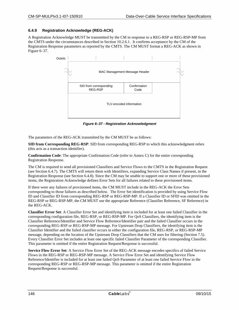
CM-SP-MULPIv3.1-I07-150910 Data-Over-Cable Service Interface Specifications
146 CableLabs 09/10/15
6.4.9 Registration Acknowledge (REG-ACK) A Registration Acknowledge MUST be transmitted by the CM in response to a REG-RSP or REG-RSP-MP from the CMTS under the circumstances described in Section 10.2.6.1. It confirms acceptance by the CM of the Registration Response parameters as reported by the CMTS. The CM MUST format a REG-ACK as shown in Figure 6–37.
Figure 6–37 - Registration Acknowledgment
The parameters of the REG-ACK transmitted by the CM MUST be as follows:
SID from Corresponding REG-RSP: SID from corresponding REG-RSP to which this acknowledgment refers (this acts as a transaction identifier).
Confirmation Code: The appropriate Confirmation Code (refer to Annex C) for the entire corresponding Registration Response.
The CM is required to send all provisioned Classifiers and Service Flows to the CMTS in the Registration Request (see Section 6.4.7). The CMTS will return them with Identifiers, expanding Service Class Names if present, in the Registration Response (see Section 6.4.8). Since the CM may be unable to support one or more of these provisioned items, the Registration Acknowledge defines Error Sets for all failures related to these provisioned items.
If there were any failures of provisioned items, the CM MUST include in the REG-ACK the Error Sets corresponding to those failures as described below. The Error Set identification is provided by using Service Flow ID and Classifier ID from corresponding REG-RSP or REG-RSP-MP. If a Classifier ID or SFID was omitted in the REG-RSP or REG-RSP-MP, the CM MUST use the appropriate Reference (Classifier Reference, SF Reference) in the REG-ACK.
Classifier Error Set: A Classifier Error Set and identifying item is included for at least one failed Classifier in the corresponding configuration file, REG-RSP, or REG-RSP-MP. For QoS Classifiers, the identifying item is the Classifier Reference/Identifier and Service Flow Reference/Identifier pair and the failed Classifier occurs in the corresponding REG-RSP or REG-RSP-MP message. For Upstream Drop Classifiers, the identifying item is the Classifier Identifier and the failed classifier occurs in either the configuration file, REG-RSP, or REG-RSP-MP message, depending on the location of the Upstream Drop Classifiers that the CM uses for filtering (Section 7.5). Every Classifier Error Set includes at least one specific failed Classifier Parameter of the corresponding Classifier. This parameter is omitted if the entire Registration Request/Response is successful.
Service Flow Error Set: A Service Flow Error Set of the REG-ACK message encodes specifics of failed Service Flows in the REG-RSP or REG-RSP-MP message. A Service Flow Error Set and identifying Service Flow Reference/Identifier is included for at least one failed QoS Parameter of at least one failed Service Flow in the corresponding REG-RSP or REG-RSP-MP message. This parameter is omitted if the entire Registration Request/Response is successful.
MAC Management Message Header
Octets
SID from correspondingREG-RSP
TLV-encoded information
Confirmation Code

MAC and Upper Layer Protocols Interface Specification CM-SP-MULPIv3.1-I07-150910
09/10/15 CableLabs 147
TCC Error Set: A TCC Error Set and identifying TCC Reference is included for at least one failed TCC in the corresponding REG-RSP. Every TCC Error Set includes at least one specific failed parameter of the corresponding TCC. It does not need to include every failed parameter of the corresponding TCC. This parameter is omitted if the entire Registration Request/Response is successful (see the Transmit Channel Configuration (TCC) subsection in Annex C.
RCC Error Set: An RCC Error Set is included to report an error in an RCC encoding in the corresponding REG-RSP. Every RCC Error Set includes at least one specific failed parameter of the corresponding RCC. It does not need to include every failed parameter of the corresponding RCC. This parameter is omitted if the entire Registration Request/Response is successful (see the subsection CM Receive Channel (RCP/RCC) Encodings in Annex C).
In the case where the CM is unable to acquire one or more of the upstream and/or downstream channels assigned via the TCC and/or RCC encodings (respectively), the CM needs to report back to the CMTS the list of channels that it was unable to acquire so that the CMTS can take appropriate action. If the CM is unable to acquire one or more of the downstream channels assigned to it in the RCC, the CM MUST include an RCC encoding with a Partial Service Downstream Channels TLV in the REG-ACK, which includes a list of the downstream channels that could not be acquired. If the CM is unable to acquire one or more of the upstream channels assigned to it in the TCC, the CM MUST include a TCC encoding with a TCC Error Encoding for each upstream channel it was unable to acquire in the REG-ACK, corresponding to the TCC encoding that assigned that upstream channel in the REG-RSP. This is because each TCC encoding describes the actions to take for a single upstream channel. Note that this is different from the case of reporting an error in the encoding, where only a single error needs to be reported (even if multiple errors exist).
When the REG-RSP-MP contains Simplified Receive Channel Configuration encodings, the CM MUST include the Primary Downstream Channel encoding in the REG-ACK.
Per Service Flow acknowledgment is necessary not just for synchronization between the CM and CMTS, but also to support use of the Service Class Name (refer to Section 7.5). Since the CM may not know all of the Service Flow parameters associated with a Service Class Name when making the Registration Request, it may be necessary for the CM to send a REG-ACK with error sets if it has insufficient resources to actually support this Service Flow.
6.4.10 Upstream Channel Change Request (UCC-REQ) The Upstream Channel Change (UCC) feature is not required for DOCSIS 3.1, thus there is no need to support a UCC-REQ message from a DOCSIS 3.1 CMTS. The CM MUST ignore a UCC-REQ message received from a CMTS.
6.4.11 Upstream Channel Change Response (UCC-RSP) The Upstream Channel Change (UCC) feature is not required for DOCSIS 3.1, thus there is no need to support a UCC-REQ message from a DOCSIS 3.1 CMTS. Refer to Section 6.4.10.
6.4.12 Dynamic Service Addition – Request (DSA-REQ)30 A Dynamic Service Addition Request MAY be sent by a CM or CMTS to create a new Service Flow.
30 Updated per MULPIv3.1-N-14.1204-1 on 12/2/14 by PO.
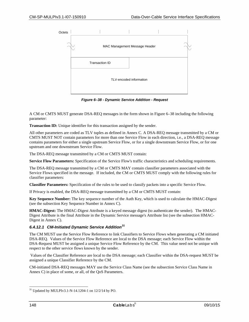
CM-SP-MULPIv3.1-I07-150910 Data-Over-Cable Service Interface Specifications
148 CableLabs 09/10/15
Figure 6–38 - Dynamic Service Addition - Request
A CM or CMTS MUST generate DSA-REQ messages in the form shown in Figure 6–38 including the following parameter:
Transaction ID: Unique identifier for this transaction assigned by the sender.
All other parameters are coded as TLV tuples as defined in Annex C. A DSA-REQ message transmitted by a CM or CMTS MUST NOT contain parameters for more than one Service Flow in each direction, i.e., a DSA-REQ message contains parameters for either a single upstream Service Flow, or for a single downstream Service Flow, or for one upstream and one downstream Service Flow.
The DSA-REQ message transmitted by a CM or CMTS MUST contain:
Service Flow Parameters: Specification of the Service Flow's traffic characteristics and scheduling requirements.
The DSA-REQ message transmitted by a CM or CMTS MAY contain classifier parameters associated with the Service Flows specified in the message. If included, the CM or CMTS MUST comply with the following rules for classifier parameters:
Classifier Parameters: Specification of the rules to be used to classify packets into a specific Service Flow.
If Privacy is enabled, the DSA-REQ message transmitted by a CM or CMTS MUST contain:
Key Sequence Number: The key sequence number of the Auth Key, which is used to calculate the HMAC-Digest (see the subsection Key Sequence Number in Annex C).
HMAC-Digest: The HMAC-Digest Attribute is a keyed message digest (to authenticate the sender). The HMAC-Digest Attribute is the final Attribute in the Dynamic Service message's Attribute list (see the subsection HMAC-Digest in Annex C).
6.4.12.1 CM-Initiated Dynamic Service Addition31 The CM MUST use the Service Flow Reference to link Classifiers to Service Flows when generating a CM initiated DSA-REQ. Values of the Service Flow Reference are local to the DSA message; each Service Flow within the DSA-Request MUST be assigned a unique Service Flow Reference by the CM. This value need not be unique with respect to the other service flows known by the sender.
Values of the Classifier Reference are local to the DSA message; each Classifier within the DSA-request MUST be assigned a unique Classifier Reference by the CM.
CM-initiated DSA-REQ messages MAY use the Service Class Name (see the subsection Service Class Name in Annex C) in place of some, or all, of the QoS Parameters.
31 Updated by MULPIv3.1-N-14.1204-1 on 12/2/14 by PO.
MAC Management Message Header
Octets
Transaction ID
TLV-encoded information

MAC and Upper Layer Protocols Interface Specification CM-SP-MULPIv3.1-I07-150910
09/10/15 CableLabs 149
6.4.12.2 CMTS-Initiated Dynamic Service Addition CMTS-initiated DSA-Requests MUST use the Service Flow ID to link Classifiers to Service Flows. Service Flow Identifiers are unique within the MAC domain. CMTS-initiated DSA-Requests for Upstream Service Flows MUST also include a Service ID.
CMTS-initiated DSA-Requests which include Classifiers, MUST assign a unique Classifier Identifier on a per Service Flow basis.
CMTS-initiated DSA-Requests for named Service Classes MUST include the QoS Parameter Set associated with that Service Class.
CMTS-initiated DSA-Requests sent to a CM in a Multiple Transmit Channel Mode of operation MUST include Service Flow SID Cluster Assignments.
6.4.13 Dynamic Service Addition – Response (DSA-RSP)32 A Dynamic Service Addition Response MUST be generated in response to a received DSA-Request by a CM or CMTS. The format of a DSA-RSP used by a CM or CMTS MUST be as shown in Figure 6–39.
Figure 6–39 - Dynamic Service Addition - Response
The parameters of DSA-RSP transmitted by a CM or CMTS MUST be as follows:
Transaction ID: Transaction ID from corresponding DSA-REQ.
Confirmation Code: The appropriate Confirmation Code (the Confirmation Code subsection in Annex C) for the entire corresponding DSA-Request.
All other parameters are coded as TLV tuples as defined in Annex C.
If the transaction is successful, the DSA-RSP contains one or more of the following:
Classifier Parameters: The CMTS MUST include the complete specification of the Classifier in the DSA-RSP, including a newly assigned Classifier Identifier. The CM MUST NOT include the specification of the Classifier in the DSA-RSP.
Service Flow Parameters: The CMTS MUST include the complete specification of the Service Flow in the DSA-RSP, including a newly assigned Service Flow Identifier and an expanded Service Class Name if applicable. The CM MUST NOT include the specification of the Service Flow in the DSA-RSP.
If the transaction is unsuccessful due to Service Flow Parameters or Classifier Parameters and the Confirmation Code is not one of the major error codes in the Confirmation Code subsection in Annex C, the DSA-RSP transmitted by the CM or CMTS MUST contain at least one of the following:
32 Updated per MULPIv3.1-N- N-14.1204-1 on 12/2/14 by PO.
MAC Management Message Header
Octets
Transaction ID
TLV-encoded information
Confirmation Code

CM-SP-MULPIv3.1-I07-150910 Data-Over-Cable Service Interface Specifications
150 CableLabs 09/10/15
Service Flow Error Set: A Service Flow Error Set and identifying Service Flow Reference/Identifier is included for at least one failed Service Flow in the corresponding DSA-REQ. Every Service Flow Error Set includes at least one specific failed QoS Parameter of the corresponding Service Flow. This parameter is omitted if the entire DSA-REQ is successful.
Classifier Error Set: A Classifier Error Set and identifying Classifier Reference/Identifier and Service Flow Reference/Identifier pair is included for at least one failed Classifier in the corresponding DSA-REQ. Every Classifier Error Set includes at least one specific failed Classifier Parameter of the corresponding Classifier. This parameter is omitted if the entire DSA-REQ is successful.
If Privacy is enabled, the DSA-RSP message transmitted by the CM or CMTS MUST contain:
Key Sequence Number: The key sequence number of the Auth Key, which is used to calculate the HMAC-Digest (see the Key Sequence Number subsection in Annex C).
HMAC-Digest: The HMAC-Digest Attribute is a keyed message digest (to authenticate the sender). The HMAC-Digest Attribute is the final Attribute in the Dynamic Service message's Attribute list (see the HMAC-Digest subsection in Annex C).
6.4.13.1 CM-Initiated Dynamic Service Addition33 The CMTS's DSA-Response for Service Flows that are successfully added MUST contain a Service Flow ID. The CMTSs DSA-Response for successfully Admitted or Active upstream QoS Parameter Sets MUST also contain a Service ID.
If the corresponding DSA-Request uses the Service Class Name (see the Service Class Name subsection in Annex C) to request service addition, the CMTS's DSA-Response MUST contain the QoS Parameter Set associated with the named Service Class. If the Service Class Name is used in conjunction with other QoS Parameters in the DSA-Request, the CMTS MUST accept or reject the DSA-Request using the explicit QoS Parameters in the DSA-Request. If these Service Flow Encodings conflict with the Service Class attributes, the CMTS MUST use the DSA-Request values as overrides for those of the Service Class.
If the transaction is successful, the CMTS MUST assign a Classifier Identifier to each requested Classifier. The CMTS MUST use the original Classifier Reference(s) and Service Flow Reference(s) to link the successful parameters in the DSA-RSP. If the CM received TCC Encodings in the Registration Response, the CMTS MUST include Service Flow SID Cluster Assignments.
If the transaction is unsuccessful, the CMTS MUST use the original Classifier Reference(s) and Service Flow Reference(s) to identify the failed parameters in the DSA-RSP.
6.4.13.2 CMTS-Initiated Dynamic Service Addition If the transaction is unsuccessful, the CM MUST use the Classifier Identifier(s) and Service Flow Identifier(s) to identify the failed parameters in the DSA-RSP.
6.4.14 Dynamic Service Addition – Acknowledge (DSA-ACK) A Dynamic Service Addition Acknowledge MUST be generated by a CM or CMTS in response to a received DSA-RSP. The format of a DSA-ACK transmitted by a CM or CMTS MUST be as shown in Figure 6–40.
33 Updated per MULPI-3.1-N-14.1204-1 on 12/2/14 by PO.

MAC and Upper Layer Protocols Interface Specification CM-SP-MULPIv3.1-I07-150910
09/10/15 CableLabs 151
Figure 6–40 - Dynamic Service Addition - Acknowledge
The parameters of a DSA-ACK transmitted by a CM or CMTS MUST be as follows:
Transaction ID: Transaction ID from corresponding DSA-Response.
Confirmation Code: The appropriate Confirmation Code (the Confirmation Code subsection in Annex C) for the entire corresponding DSA-Response. 34
All other parameters are coded TLV tuples.
Service Flow Error Set: The Service Flow Error Set of the DSA-ACK message encodes specifics of failed Service Flows in the DSA-RSP message. A Service Flow Error Set and identifying Service Flow Reference/Identifier is included for at least one failed QoS Parameter of at least one failed Service Flow in the corresponding DSA-REQ. This parameter is omitted if the entire DSA-REQ is successful.
If Privacy is enabled, the DSA-RSP message transmitted by the CM or CMTS MUST contain:
Key Sequence Number: The key sequence number of the Auth Key, which is used to calculate the HMAC-Digest (see the Key Sequence Number subsection in Annex C).
HMAC-Digest: The HMAC-Digest Attribute is a keyed message digest (to authenticate the sender). The HMAC-Digest Attribute is the final Attribute in the Dynamic Service message's Attribute list (see the HMAC-Digest subsection in Annex C).
6.4.15 Dynamic Service Change – Request (DSC-REQ) A Dynamic Service Change Request MAY be sent by a CM or CMTS to dynamically change the parameters of an existing Service Flow. If a CMTS sends a DSC-REQ message changing an Upstream Drop Classifier, then conceptually the Upstream Drop Classifier is associated with a NULL Service Flow that is not signaled in the DSC-REQ message. DSCs transmitted by a CM or CMTS that are changing classifiers MUST carry the entire classifier TLV set for that new classifier.
34 The confirmation code is necessary particularly when a Service Class Name (refer to Section 7.5.3) is used in the DSA-
Request. In this case, the DSA-Response could contain Service Flow parameters that the CM is unable to support (either temporarily or as configured).
MAC Management Message Header
Octets
Transaction ID
TLV-encoded information
Confirmation Code

CM-SP-MULPIv3.1-I07-150910 Data-Over-Cable Service Interface Specifications
152 CableLabs 09/10/15
Figure 6–41 - Dynamic Service Change - Request
A CM or CMTS MUST generate DSC-REQ messages in the form shown in Figure 6–41 including the following parameters as described below:
Transaction ID: Unique identifier for this transaction assigned by the sender.
All other parameters are coded as TLV tuples as defined in Annex C. A DSC-REQ message transmitted by a CM or CMTS MUST NOT carry parameters for more than one Service Flow in each direction, i.e., a DSC-REQ message contains parameters for either a single upstream Service Flow, or for a single downstream Service Flow, or for one upstream and one downstream Service Flow.
A DSC-REQ transmitted by a CM or CMTS MUST contain at least one of the following:
Service Flow Parameters: Specification of the Service Flow's new traffic characteristics and scheduling requirements. The Admitted and Active Quality of Service Parameter Sets in this message replace the Admitted and Active Quality of Service Parameter Sets currently in use by the Service Flow. If the DSC message is successful and it contains Service Flow parameters, but does not contain replacement sets for both Admitted and Active Quality of Service Parameter Sets, the omitted set(s) are set to null. If Service Flow Parameters are included, they contain a Service Flow Identifier.
Not all Service Flow Parameters are permitted to be changed via a DSC-REQ message. Reference values and Identifiers (TLVs 24/25.1-3) are unique to a Service Flow, and as such cannot be modified by a CM or CMTS in a DSC-REQ. In addition, the following Service Flow Parameter TLVs MUST NOT be modified by a CM or CMTS via a DSC-REQ:
• Service Flow Scheduling Type (TLV 24.15). • Bit 9 (Segment Header on/off) of the Request/Transmission Policy (TLV 24.16). • Multiplier to Number of Bytes Requested (TLV 24.26).
Support for changes to the following Service Flow Parameter TLVs via a DSC-REQ is optional in a receiving CM or CMTS:
• Service Class Name (TLV 24/25.4) (only if all the parameters that differ in the new class are allowed to change).
• Service Flow Required Attribute Mask (TLV 24/25.31). • Service Flow Forbidden Attribute Mask (TLV 24/25.32). • Service Flow Attribute Aggregation Rule Mask (TLV 24/25.33). • Application Identifier (TLV 24/25.34). • Vendor Specific QoS Parameters (TLV 24/25.43).
MAC Management Message Header
Octets
Transaction ID
TLV-encoded information

MAC and Upper Layer Protocols Interface Specification CM-SP-MULPIv3.1-I07-150910
09/10/15 CableLabs 153
If changes to these parameters are specified in a DSC-REQ, the receiving CM or CMTS MAY implement the change. Since support for these changes is optional, they might be rejected by the receiving entity. Changes to all other Service Flow Parameters via a DSC-REQ message MUST be supported by both CMs and CMTSs.
Classifier Parameters: Specification of the rules to be used to classify packets into a specific service flow - this includes the Dynamic Service Change Action TLV which indicates whether this Classifier should be added, replaced or deleted from the Service Flow (see subsection in Dynamic Service Change Action in Annex C). If included, the Classifier Parameters contains the Dynamic Change Action TLV, a Classifier Reference/Identifier and a Service Flow Identifier.
Not all Classifier Parameters are permitted to be changed via a DSC-REQ message. Reference values and Identifiers (TLVs 22/23/60.1-4) are unique to a Classifier, and as such cannot be modified by a CM or CMTS in a DSC-REQ. If changes are specified to Vendor Specific QoS Parameters (TLV 22/23/60.43) in a DSC-REQ, the receiving CM or CMTS MAY implement the change. Since support for changes to these parameters is optional, they might be rejected by the receiving entity. Changes to all other Classifier Parameters via a DSC-REQ message MUST be supported by both CMs and CMTSs.
If Privacy is enabled, a DSC-REQ transmitted by the CM or CMTS MUST also contain:
Key Sequence Number: The key sequence number of the Auth Key, which is used to calculate the HMAC-Digest (refer the Key Sequence Number subsection in Annex C).
HMAC-Digest: The HMAC-Digest Attribute is a keyed message digest (to authenticate the sender). The HMAC-Digest Attribute is the final Attribute in the Dynamic Service message's Attribute list (refer to the HMAC-Digest subsection in Annex C).
6.4.16 Dynamic Service Change – Response (DSC-RSP)35 A Dynamic Service Change Response MUST be generated by a CM or CMTS in response to a received DSC-REQ.
Figure 6–42 - Dynamic Service Change - Response
A CM or CMTS MUST generate DSC-RSP messages in the form shown in Figure 6–42 including the following parameters as described below:
Transaction ID: Transaction ID from the corresponding DSC-REQ.
Confirmation Code: The appropriate Confirmation Code (refer to the subsection Confirmation Code in Annex C) for the corresponding DSC-Request.
All other parameters are coded as TLV tuples as defined in Annex C.
35 Updated per MULPIv3.1-N-14.1204-1 on 12/2/14 by PO.
MAC Management Message Header
Octets
Transaction ID
TLV-encoded information
Confirmation Code

CM-SP-MULPIv3.1-I07-150910 Data-Over-Cable Service Interface Specifications
154 CableLabs 09/10/15
If the transaction is successful, the DSC-RSP contains one or more of the following:
Classifier Parameters: The CMTS MUST include the complete specification of the Classifier in the DSC-RSP, including a newly assigned Classifier Identifier for new Classifiers. The CM MUST NOT include the specification of the Classifier in the DSC-RSP.
Service Flow Parameters: The CMTS MUST include the complete specification of the Service Flow in the DSC-RSP, including an expanded Service Class Name if applicable. The CMTS MUST include a SID in the DSC-RSP if a Service Flow Parameter Set contained an upstream Admitted QoS Parameter Set and this Service Flow does not have an associated SID. If a Service Flow Parameter set contained a Service Class Name and an Admitted QoS Parameter Set, the CMTS MUST include the QoS Parameter Set corresponding to the named Service Class in the DSC-RSP. If specific QoS Parameters were also included in the Service Flow request which also included a Service Class Name, the CMTS MUST include these QoS Parameters in the DSC-RSP instead of any QoS Parameters of the same type of the named Service Class. The CM MUST NOT include the specification of the Service Flow in the DSC-RSP.
If the transaction is unsuccessful due to Service Flow Parameters or Classifier Parameters and the Confirmation Code is not one of the major error codes in Annex C, the DSC-RSP transmitted by the CM or CMTS MUST contain at least one of the following:
Classifier Error Set: A Classifier Error Set and identifying Classifier Reference/Identifier and Service Flow Reference/Identifier pair is included for at least one failed Classifier in the corresponding DSC-REQ. Every Classifier Error Set includes at least one specific failed Classifier Parameter of the corresponding Classifier. This parameter is omitted if the entire DSC-REQ is successful.
Service Flow Error Set: A Service Flow Error Set and identifying Service Flow ID is included for at least one failed Service Flow in the corresponding DSC-REQ. Every Service Flow Error Set includes at least one specific failed QoS Parameter of the corresponding Service Flow. This parameter is omitted if the entire DSC-REQ is successful.
Regardless of success or failure, if Privacy is enabled for the CM the DSC-RSP transmitted by a CM or CMTS MUST contain:
Key Sequence Number: The key sequence number of the Auth Key, which is used to calculate the HMAC-Digest (refer to the Key Sequence Number subsection of Annex C.
HMAC-Digest: The HMAC-Digest Attribute is a keyed message digest (to authenticate the sender). The HMAC-Digest Attribute is the final Attribute in the Dynamic Service message's Attribute list (see the subsection HMAC-Digest in Annex C).
6.4.17 Dynamic Service Change – Acknowledge (DSC-ACK) A Dynamic Service Change Acknowledge MUST be generated by a CM or CMTS in response to a received DSC-RSP.
Figure 6–43 - Dynamic Service Change - Acknowledge
MAC Management Message Header
Octets
Transaction ID
TLV-encoded information
Confirmation Code

MAC and Upper Layer Protocols Interface Specification CM-SP-MULPIv3.1-I07-150910
09/10/15 CableLabs 155
A CM or CMTS MUST generate DSC-ACK messages in the form shown in Figure 6–43 including the following parameters as described below:
Transaction ID: Transaction ID from the corresponding DSC-REQ.
Confirmation Code: The appropriate Confirmation Code (the subsection Confirmation Code in Annex C) for the entire corresponding DSC-Response. 36
All other parameters are coded TLV tuples.
Service Flow Error Set: The Service Flow Error Set of the DSC-ACK message encodes specifics of failed Service Flows in the DSC-RSP message. A Service Flow Error Set and identifying Service Flow Identifier is included for at least one failed QoS Parameter of at least one failed Service Flow in the corresponding DSC-REQ. This parameter is omitted if the entire DSC-REQ is successful.
If Privacy is enabled, the DSC-ACK message transmitted by the CM or CMTS MUST contain:
Key Sequence Number: The key sequence number of the Auth Key, which is used to calculate the HMAC-Digest (see the subsection Key Sequence Number in Annex C).
HMAC-Digest: The HMAC-Digest Attribute is a keyed message digest (to authenticate the sender). The HMAC-Digest Attribute is the final Attribute in the Dynamic Service message's Attribute list (see the subsection HMAC-Digest in Annex C).
6.4.18 Dynamic Service Deletion – Request (DSD-REQ) A DSD-Request MAY be sent by a CM or CMTS to delete a single existing Upstream Service Flow and/or a single existing Downstream Service Flow.
Figure 6–44 - Dynamic Service Deletion - Request
A CM or CMTS MUST generate DSD-REQ messages in the form shown in Figure 6–44 including the following parameters as described below:
Service Flow Identifier: If this value is non-zero, it is the SFID of a single Upstream or single Downstream Service Flow to be deleted. If this value is zero, the Service Flow(s) to be deleted will be identified by SFID(s) in the TLVs. If this value is non-zero, any SFIDs included in the TLVs are ignored.
Transaction ID: Unique identifier for this transaction assigned by the sender. 36 The Confirmation Code and Service Flow Error Set are necessary particularly when a Service Class Name is (refer to Section
7.5.3) used in the DSC-Request. In this case, the DSC-Response could contain Service Flow parameters that the CM is unable to support (either temporarily or as configured).
MAC Management Message Header
Octets
Transaction ID
TLV-encoded information
Reserved
SFID
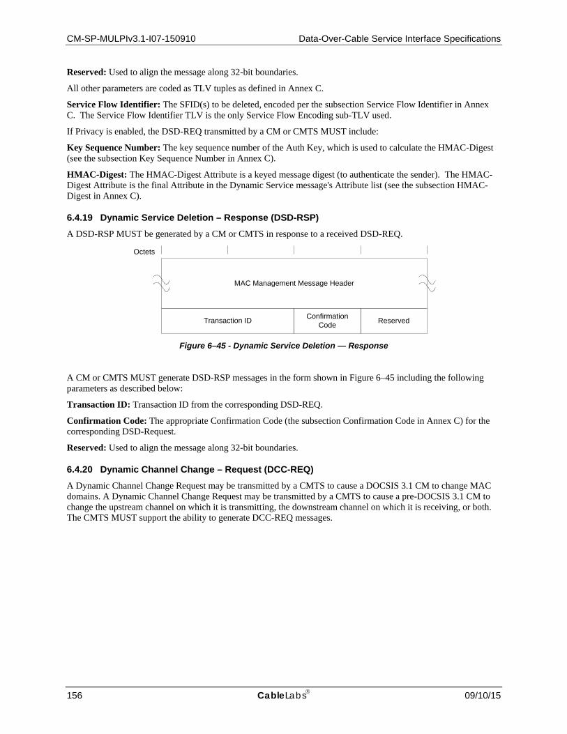
CM-SP-MULPIv3.1-I07-150910 Data-Over-Cable Service Interface Specifications
156 CableLabs 09/10/15
Reserved: Used to align the message along 32-bit boundaries.
All other parameters are coded as TLV tuples as defined in Annex C.
Service Flow Identifier: The SFID(s) to be deleted, encoded per the subsection Service Flow Identifier in Annex C. The Service Flow Identifier TLV is the only Service Flow Encoding sub-TLV used.
If Privacy is enabled, the DSD-REQ transmitted by a CM or CMTS MUST include:
Key Sequence Number: The key sequence number of the Auth Key, which is used to calculate the HMAC-Digest (see the subsection Key Sequence Number in Annex C).
HMAC-Digest: The HMAC-Digest Attribute is a keyed message digest (to authenticate the sender). The HMAC-Digest Attribute is the final Attribute in the Dynamic Service message's Attribute list (see the subsection HMAC-Digest in Annex C).
6.4.19 Dynamic Service Deletion – Response (DSD-RSP) A DSD-RSP MUST be generated by a CM or CMTS in response to a received DSD-REQ.
Figure 6–45 - Dynamic Service Deletion — Response
A CM or CMTS MUST generate DSD-RSP messages in the form shown in Figure 6–45 including the following parameters as described below:
Transaction ID: Transaction ID from the corresponding DSD-REQ.
Confirmation Code: The appropriate Confirmation Code (the subsection Confirmation Code in Annex C) for the corresponding DSD-Request.
Reserved: Used to align the message along 32-bit boundaries.
6.4.20 Dynamic Channel Change – Request (DCC-REQ) A Dynamic Channel Change Request may be transmitted by a CMTS to cause a DOCSIS 3.1 CM to change MAC domains. A Dynamic Channel Change Request may be transmitted by a CMTS to cause a pre-DOCSIS 3.1 CM to change the upstream channel on which it is transmitting, the downstream channel on which it is receiving, or both. The CMTS MUST support the ability to generate DCC-REQ messages.
MAC Management Message Header
Octets
Transaction ID Confirmation Code Reserved

MAC and Upper Layer Protocols Interface Specification CM-SP-MULPIv3.1-I07-150910
09/10/15 CableLabs 157
Figure 6–46 - Dynamic Channel Change Request
A CMTS MUST generate DCC-REQ messages in the form shown in Figure 6–46 including the following parameters:
Transaction ID: A 16-bit unique identifier for this transaction assigned by the CMTS.
The following parameters are coded as TLV tuples:
Upstream Channel ID: The identifier of the upstream channel to which the CM is to switch for upstream transmissions.
Downstream Parameters: The frequency and other related parameters of the downstream channel to which the CM is to switch for downstream reception.
Initialization Technique: Directions for the type of initialization, if any that the CM should perform once synchronized to the new channel(s).
UCD Substitution: Provides a copy of the UCD for the new channel. This TLV occurs as many times as necessary to contain one UCD.
SAID Substitution: A pair of Security Association Identifiers (SAID) which contain the current SAID and the new SAID for the new channel. This TLV occurs once if the SAID requires substitution.
Service Flow Substitution: A group of sub-TLVs which allows substitution in a Service Flow of the Service Flow Identifier and Service Identifier. This TLV is repeated for every Service Flow which has parameters requiring substitution.
If Privacy is enabled, a DCC-REQ generated by a CMTS MUST also contain:
Key Sequence Number: The key sequence number of the Auth Key, which is used to calculate the HMAC-Digest (see the subsection Key Sequence Number in Annex C).
HMAC-Digest: The HMAC-Digest Attribute is a keyed message digest (to authenticate the sender). The HMAC-Digest Attribute is the final Attribute in the Dynamic Channel Change message's Attribute list (see the subsection HMAC-Digest in Annex C).
6.4.20.1 Encodings The type values used by the CMTS in a DCC-REQ MUST be those shown below. These are unique within the Dynamic Channel Change Request message, but not across the entire MAC message set.
6.4.20.1.1 Upstream Channel ID
When present, this TLV specifies the new upstream channel ID that the CM MUST use when performing a Dynamic Channel Change. It is an override for the current upstream channel ID. The CMTS SHOULD ensure that the
MAC Management Message Header
Octets
Transaction ID
TLV-encoded information

CM-SP-MULPIv3.1-I07-150910 Data-Over-Cable Service Interface Specifications
158 CableLabs 09/10/15
Upstream Channel ID for the new channel is different than the Upstream Channel ID for the old channel. This TLV MUST be included by the CMTS if the upstream channel is changed, even if the UCD substitution TLV is included.
Type Length Value 1 1 0-255: Upstream Channel ID
If this TLV is missing, the CM MUST NOT change its upstream channel ID. The CMTS MAY include this TLV. The CM MUST observe this TLV.
6.4.20.1.2 Downstream Parameters
When present, this TLV specifies the operating parameters of the new downstream channel. The value field of this TLV contains a series of sub-types.
Type Length Value 2 n List of subtypes
The CMTS MUST include this TLV when specifying a downstream channel change. If this TLV is missing, the CM MUST NOT change its downstream parameters.
6.4.20.1.2.1 Downstream Frequency
This TLV specifies the new receive frequency that the CM MUST use when performing a Dynamic Channel Change. It is an override for the current downstream channel frequency. This is the center frequency of the downstream channel in Hz and is stored as a 32-bit binary number. The downstream frequency included by the CMTS MUST be a multiple of 62,500 Hz.
Subtype Length Value 2.1 4 Rx Frequency
The CMTS MUST include this sub-TLV if moving the CM to an SC-QAM downstream. The CM MUST observe this sub-TLV.
6.4.20.1.2.2 Downstream Modulation Type
This TLV specifies the modulation type that is used on the new downstream channel.
Subtype Length Value 2.2 1 0 = 64-QAM
1 = 256-QAM 2 = Reserved for C-DOCSIS (Annex L)
3 - 255: reserved
The CMTS SHOULD include this sub-TLV if moving the CM to an SC-QAM downstream. The CM SHOULD observe this sub-TLV.
6.4.20.1.2.3 Downstream Symbol Rate
This TLV specifies the symbol rate that is used on the new downstream channel.

MAC and Upper Layer Protocols Interface Specification CM-SP-MULPIv3.1-I07-150910
09/10/15 CableLabs 159
Subtype Length Value 2.3 1 0 = 5.056941 Msym/sec
1 = 5.360537 Msym/sec
2 = 6.952 Msym/sec
3 - 255: reserved
The CMTS SHOULD include this sub-TLV if moving the CM to an SC-QAM downstream. The CM SHOULD observe this sub-TLV.
6.4.20.1.2.4 Downstream Interleaver Depth
This TLV specifies the parameters "I" and "J" of the downstream interleaver.
Subtype Length Value 2.4 2 I: 0-255
J: 0-255
The CMTS SHOULD include this sub-TLV if moving the CM to an SC-QAM downstream. The CM SHOULD observe this sub-TLV.
6.4.20.1.2.5 Downstream Channel Identifier
This TLV specifies the 8-bit downstream channel identifier of the new downstream channel.
Subtype Length Value 2.5 1 0-255: Downstream Channel ID.
The CMTS SHOULD include this sub-TLV. The CM SHOULD observe this sub-TLV.
6.4.20.1.2.6 SYNC Substitution
When present, this TLV allows the CMTS to inform the CM to wait or not wait for a SYNC message before proceeding. The CMTS MUST have synchronized timestamps between the old and new channel(s) if it instructs the CM not to wait for a SYNC message before transmitting on the new channel. Synchronized timestamps implies that the timestamps are derived from the same clock and contain the same value.
Type Length Value 2.6 1 0 = acquire SYNC message on the new downstream channel before proceeding
1 = proceed without first obtaining the SYNC message
2 - 255: reserved
If this TLV is absent, the CM MUST wait for a SYNC message on the new channel before proceeding. If the CM has to wait for a new SYNC message when changing channels, then operation may be suspended for a time up to the "SYNC Interval" (see Annex B) or longer if the SYNC message is lost or is not synchronized with the old channel(s). The CM MUST observe this TLV.
6.4.20.1.2.7 OFDM Block Frequency
When present, this TLV tells the CM where to look for the PLC of the OFDM channel to which it will move.

CM-SP-MULPIv3.1-I07-150910 Data-Over-Cable Service Interface Specifications
160 CableLabs 09/10/15
Type Length Value 2.7 4 Assigned center frequency of the lowest subcarrier of the 6 MHz encompassed
spectrum containing the, PLC at its center, in Hz for this OFDM channel
The CMTS MUST include the OFDM Block Frequency sub-TLV if moving the CM to an OFDM downstream. The CM MUST observe the OFDM Block Frequency sub-TLV.
6.4.20.1.3 Initialization Technique
This TLV allows the CMTS to direct the CM to reinitialize its MAC when moving a CM to a different MAC domain. While changing the MAC domain of a D-3.1 CM, CMTS MUST use initialization technique 0 (re-initialize the MAC) and include this TLV. The CMTS MUST use initialization technique 0 (re-initialize the MAC) when changing the downstream channel of a DOCSIS 3.0 CM operating in Multiple Receive Channel Mode. The CMTS MUST use initialization technique 0 (re-initialize the MAC) when changing the upstream channel of a DOCSIS 3.0 CM to which a Transmit Channel Configuration was assigned during registration.
The CM MUST observe this TLV. The CM MUST first select the new upstream and downstream channels based upon the Upstream Channel ID TLV (Section 6.4.20.1.1) and either the Downstream Frequency TLV (Section 6.4.20.1.2.1) or the OFDM Block Frequency TLV (Section 6.4.20.1.2.7).
For operation with pre-DOCSIS 3.0 CMs, the CMTS MAY include this TLV. The CMTS can make the initialization decision based upon its knowledge of the differences between the old and new MAC domains and the PHY characteristics of their upstream and downstream channels.
Typically, if the move is between upstream and/or downstream channels within the same MAC domain, then the connection profile values may be left intact. If the move is between different MAC domains, then a complete initialization may be performed.
If a complete reinitialization is not required, some re-ranging may still be required. For example, areas of upstream spectrum are often configured in groups. A DCC-REQ to an adjacent upstream channel within a group may not warrant re-ranging. Alternatively, a DCC-REQ to a non-adjacent upstream channel might require unicast initial ranging, whereas a DCC-REQ from one upstream channel group to another might require broadcast initial ranging. Re-ranging may also be required if there is any difference in the PHY parameters between the old and new channels.
Type Length Value 3 1 0 = Reinitialize the MAC
1 = Perform broadcast initial ranging on new channel before normal operation
2 = Perform unicast ranging on new channel before normal operation
3 = Perform either broadcast or unicast ranging on new channel before normal operation
4 = Use the new channel(s) directly without reinitializing or ranging
5 - 255: reserved
6.4.20.1.4 UCD Substitution
When present, this TLV allows the CMTS to send an Upstream Channel Descriptor message to the CM. This UCD message is intended to be associated with the new upstream and/or downstream channel(s). The CM stores this UCD message in its cache, and uses it after synchronizing to the new channel(s).
Type Length Value 4 n UCD for the new upstream channel

MAC and Upper Layer Protocols Interface Specification CM-SP-MULPIv3.1-I07-150910
09/10/15 CableLabs 161
This TLV includes all parameters for the UCD message as described in Section 6.4.3 except for the MAC Management Message Header. The CMTS MUST ensure that the change count in the UCD matches the change count in the UCDs of the new channel(s). The CMTS SHOULD ensure that the Upstream Channel ID for the new channel is different than the Upstream Channel ID for the old channel. If the Upstream Channel IDs for the old and new channels are identical, the CMTS MUST include this TLV. The Ranging Required parameter in the new UCD does not apply in this context, since the functionality is covered by the Initialization Technique TLV.
If the length of the UCD exceeds 254 bytes, the UCD MUST be fragmented by the CMTS into two or more successive Type 4 elements. Each fragment generated by the CMTS, except the last, MUST be 254 bytes in length. The CM reconstructs the UCD Substitution by concatenating the contents (Value of the TLV) of successive Type 4 elements in the order in which they appear in the DCC-REQ message. For example, the first byte following the length field of the second Type 4 element is treated as if it immediately follows the last byte of the first Type 4 element.
If the CM has to wait for a new UCD message when changing channels, then operation may be suspended for a time up to the "UCD Interval" (Annex B) or longer if the UCD message is lost.
6.4.20.1.5 Security Association Identifier (SAID) Substitution
When present, this TLV allows the CMTS to replace the Security Association Identifier (SAID) in the current Service Flow with a new Security Association Identifier. The CMTS MUST ensure that the baseline privacy keys associated with the SAID remain the same.
Type Length Value 6 4 Current SAID (lower-order 14 bits of a 16-bit field), new SAID (lower-order 14 bits of
a 16-bit field)
If this TLV is absent, the current Security Association Identifier assignment is retained. The CMTS MAY include this TLV.
6.4.20.1.6 Service Flow Substitutions
When present, this TLV allows the CMTS to replace specific parameters within the current Service Flows on the current channel assignment with new parameters for the new channel assignment. One TLV is used for each Service Flow that requires changes in parameters. The CMTS may choose to do this to help facilitate setting up new QoS reservations on the new channel before deleting QoS reservations on the old channel. The CM does not have to simultaneously respond to the old and new Service Flows.
This TLV allows resource assignments and services to be moved between two independent ID value spaces and scheduling entities by changing the associated IDs and indices. ID value spaces that may differ between the two channels include the Service Flow Identifier and the Service ID. This TLV does not allow changes to Service Flow QoS parameters.
The Service Class Names used within the Service Flow ID should remain identical between the old and new channels.
Type Length Value 7 n list of subtypes
If this TLV is absent for a particular Service Flow, then current Service Flow and its attributes are retained. The CMTS MAY include this TLV.
6.4.20.1.6.1 Service Flow Identifier Substitution
This TLV allows the CMTS to replace the current Service Flow Identifier (SFID) with a new Service Flow Identifier. Refer to the subsection Service Flow Identifier in Annex C for usage details.

CM-SP-MULPIv3.1-I07-150910 Data-Over-Cable Service Interface Specifications
162 CableLabs 09/10/15
This TLV MUST be included in the DCC-REQ by the CMTS if any other Service Flow subtype substitutions are made. If this TLV is included and the Service Flow ID is not changing, then the current and new Service Flow ID will be set to the same value.
Subtype Length Value 7.1 8 current Service Flow ID, new Service Flow ID
6.4.20.1.6.2 Service Identifier Substitution
When present, this TLV allows the CMTS to replace the Service Identifier (SID) in the current upstream Service Flow with a new Service Identifier. Refer to see the subsection Service Identifier in Annex C for usage details.
Subtype Length Value 7.2 4 current SID (lower-order 14 bits of a 16-bit field), new SID
(lower-order 14 bits of a 16-bit field)
If this TLV is absent, the current Service Identifier assignments are retained. The CMTS MAY include this TLV.
6.4.20.1.6.3 Unsolicited Grant Time Reference Substitution
When present, this TLV allows the CMTS to replace the current Unsolicited Grant Time Reference with a new Unsolicited Grant Time Reference. Refer to the subsection Unsolicited Grant Time Reference in Annex C for usage details.
This TLV is useful if the old and new upstream use different time bases for their time stamps. This TLV is also useful if the Unsolicited Grant transmission window is moved to a different point in time. Changing this value may cause operation to temporarily exceed the jitter window specified by see the subsection Tolerated Grant Jitter in Annex C.
Subtype Length Value 7.5 4 new reference
If this TLV is absent, the current Unsolicited Grant Time Reference is retained. The CMTS MAY include this TLV.
6.4.20.1.7 CMTS MAC Address
When present, this TLV allows the current CMTS to send the MAC address of the destination CMTS corresponding to the target downstream frequency.
Type Length Value 8 6 MAC Address of Destination CMTS
The CMTS MUST include this TLV if the CM is changing downstream channels and UCD substitution is specified or if the CM is changing downstream channels and using initialization technique 4.
6.4.21 Dynamic Channel Change – Response (DCC-RSP) A Dynamic Channel Change Response MUST be transmitted by a CM in response to a received Dynamic Channel Change Request message to indicate that it has received and is complying with the DCC-REQ. The format of a DCC-RSP message transmitted by a CM MUST be as shown in Figure 6–47.

MAC and Upper Layer Protocols Interface Specification CM-SP-MULPIv3.1-I07-150910
09/10/15 CableLabs 163
Before it begins to switch to a new upstream or downstream channel, a CM MUST transmit a DCC-RSP (depart) on its existing upstream channel. When a CM receives a DCC-REQ message with an initialization technique other than re-initialize the MAC, the CM MUST respond with a DCC-RSP message on that channel indicating that the initialization technique is not valid.
A CM MAY ignore a DCC-REQ message while it is in the process of performing a channel change.
The full procedure for changing channels is described in Section 11.4.
Figure 6–47 - Dynamic Channel Change Response
The parameters of a DCC-RSP transmitted by a CM MUST be as follows:
Transaction ID: A 16-bit Transaction ID from the corresponding DCC-REQ.
Confirmation Code: An 8-bit Confirmation Code as described in Annex C.
The following parameters are optional and are coded as TLV tuples.
CM Jump Time: Timing parameters describing when the CM will make the jump.
Regardless of success or failure, if Privacy is enabled for the CM, the CM MUST include in the DCC-RSP:
Key Sequence Number: The key sequence number of the Auth Key, which is used to calculate the HMAC-Digest (see the subsection Key Sequence Number in Annex C).
HMAC-Digest: The HMAC-Digest Attribute is a keyed message digest (to authenticate the sender). The HMAC-Digest Attribute is the final Attribute in the Dynamic Channel Change message's Attribute list (see the subsection HMAC-Digest in Annex C).
6.4.21.1 Encodings A pre-DOCSIS 3.1 CM might use the type values shown below. These are unique within the Dynamic Channel Change Response message, but not across the entire MAC message set.
6.4.21.1.1 CM Jump Time
When present, this TLV allows the CM to indicate to the CMTS when the CM plans to perform its jump and be disconnected from the network. With this information, the CMTS MAY take preventative measures to minimize or to eliminate packet drops in the downstream due to the channel change.
Type Length Value 1 n List of subtypes
MAC Management Message Header
Octets
Transaction ID
TLV-encoded information
Confirmation Code

CM-SP-MULPIv3.1-I07-150910 Data-Over-Cable Service Interface Specifications
164 CableLabs 09/10/15
The time reference and units of time for these sub-TLVs is based upon the same 32 -bit time base used in the SYNC message on the current downstream channel. This timestamp is incremented by a 10.24 MHz clock
The CMTS SHOULD observe this TLV.
6.4.21.1.1.1 Length of Jump
This TLV indicates to the CMTS the length of the jump from the previous channel to the new channel. Specifically, it represents the length of time that the CM will not be able to receive data in the downstream.
Subtype Length Value 1.1 4 length (based upon timestamp)
The CM includes this sub-TLV if the CM Jump Time TLV is included in the DCC-RSP.
6.4.21.1.1.2 Start Time of Jump
When present, this TLV indicates to the CMTS the time in the future that the CM is planning on making the jump.
Subtype Length Value 1.2 8 start time (based upon timestamp), accuracy of start time (based upon
timestamp)
The 32-bit, 10.24 MHz time base rolls over approximately every 7 minutes. If the value of the start time is less than the current timestamp, the CMTS will assume one roll-over of the timestamp counter has occurred. The accuracy of the start time is an absolute amount of time before and after the start time.
The potential jump window is from (start time - accuracy) to (start time + accuracy + length).
The CM includes this TLV if the CM Jump Time TLV is included in the DCC-RSP.
6.4.22 Dynamic Channel Change – Acknowledge (DCC-ACK) A Dynamic Channel Change Acknowledge MUST be transmitted by a CMTS in response to a received Dynamic Channel Change Response message on the new channel with its Confirmation Code set to arrive(1). The format of a DCC-ACK message transmitted by a CMTS MUST be as shown in Figure 6–48.
Figure 6–48 - Dynamic Channel Change Acknowledge
The parameters of a DCC-ACK transmitted by a CMTS MUST be as follows:
MAC Management Message Header
Octets
Transaction ID
TLV-encoded information

MAC and Upper Layer Protocols Interface Specification CM-SP-MULPIv3.1-I07-150910
09/10/15 CableLabs 165
Transaction ID: A 16 bit Transaction ID from the corresponding DCC-RSP.
If Privacy is enabled, the DCC-ACK message transmitted by the CMTS MUST contain:
Key Sequence Number: The key sequence number of the Auth Key, which is used to calculate the HMAC-Digest (see the subsection Key Sequence Number in Annex C).
HMAC-Digest: The HMAC-Digest Attribute is a keyed message digest (to authenticate the sender). The HMAC-Digest Attribute is the final Attribute in the Dynamic Channel Change message's Attribute list (see the subsection HMAC-Digest in Annex C).
6.4.23 Device Class Identification Request (DCI-REQ) The Device Class Identification Request (DCI-REQ) message is not required for DOCSIS 3.1. Hence when a DOCSIS 3.1 CM is registered with a DOCSIS 3.1 CMTS, it is not required to send DCI-REQ after ranging complete, so there is no need to support DCI-RSP messages from a DOCSIS 3.1 CMTS.
6.4.24 Device Class Identification Response (DCI-RSP) The Device Class Identification Request (DCI-REQ) message is not required for DOCSIS 3.1. Hence when a DOCSIS 3.1 CM is registered with a DOCSIS 3.1 CMTS, it is not required to send DCI-REQ after ranging complete, so there is no need to support DCI-RSP messages from a DOCSIS 3.1 CMTS.
6.4.25 Upstream Transmitter Disable (UP-DIS) The Upstream Transmitter Disable (UP-DIS) message is not required for DOCSIS 3.1, hence there is no need for a DOCSIS 3.1 CMTS to send this type of message to DOCSIS 3.1 CM. If received, the CM MUST ignore UP-DIS message.
6.4.26 Test Request (TST-REQ) Test Request (TST-REQ) is not required for DOCSIS 3.1, hence there is no need for a DOCSIS 3.1 CMTS to send this type of message to DOCSIS 3.1 CM. If received, the CM MUST ignore TST-REQ message.
6.4.27 Downstream Channel Descriptor (DCD) The format and usage of the DCD message is defined in [DOCSIS DSG].
6.4.28 MAC Domain Descriptor (MDD)37 A CMTS MUST transmit an MDD message periodically on every downstream channel in the MAC Domain. The CMTS MUST observe the MDD Interval specified in Annex B. The CMTS MUST transmit a separate MDD message for every downstream channel. The CMTS MUST NOT transmit an MDD message with a total Management Message Payload size of more than 8000 bytes.
The MDD is intended primarily for use by the CM during initialization (see Section 10.2). It also includes parameters related to CM-STATUS reporting which may be useful after registration. During initialization, the CM MUST use the first valid complete MDD (i.e., with all fragments present) received on its selected candidate Primary Downstream Channel as its source for all parameters to be learned from MDD TLVs. All fragments collected need to have the same source MAC address and the same change count. If a CM collects an MDD fragment for the same MAC domain with a change count that is different from that of the fragments already collected, then it MUST discard all previously collected fragments and resume collecting only fragments with the new change count. Also, during initialization, the CM MUST ignore any MDD TLV parameters received in MDD messages on downstream channels other than its selected candidate Primary Downstream Channel.
After registration, the CM MUST use the TLVs applicable to CM-STATUS reporting to control its CM-STATUS reporting as specified in Section 6.4.34. The CM MUST NOT modify anything other than its CM-STATUS reporting behavior in response to changes in the MDD message in the absence of other stimulus. For example, the CM does not delete a channel from its Receive Channel Set if that channel is no longer listed in the MDD. However,
37 Updated per MULPIv3.1-N-15.1333-1 on 8/20/15 by PO.

CM-SP-MULPIv3.1-I07-150910 Data-Over-Cable Service Interface Specifications
166 CableLabs 09/10/15
during registration or while processing a dynamic bonding change containing a Simplified RCC Encoding, the CM uses the Downstream Active Channel List TLVs from the most recent MDD message to acquire downstream channels.
The CM MUST ignore any MDD messages received with a source MAC address that is different than the MAC domain address learned during initialization. The CM MUST ignore any changes resulting in a new change count for an MDD message on any of its non-primary channels.
Figure 6–49 - MAC Domain Descriptor
A CMTS MUST generate the MDD message in the format shown in Figure 6–49, including the following parameters as defined below:
Configuration Change Count: The CMTS increments this field by 1 whenever any of the values in this message change relative to the values in the previous MDD message sent on this downstream channel.
Number of Fragments: Fragmentation allows the MDD TLV parameters to be spread across more than one DOCSIS MAC Frame, thus allowing the total number of MDD TLV parameters to exceed the maximum payload of a single MAC management frame (subject to the constraint stated above). The value of this field represents the number of MDD MAC management frames that a unique and complete set of MDD TLV parameters are spread across to constitute the MDD message. This field is an 8-bit unsigned integer.
Fragment Sequence Number: This field indicates the position of this fragment in the sequence that constitutes the complete MDD message. Fragment Sequence Numbers start with the value of 1 and increase by 1 for each fragment in the sequence. Thus, the first MDD message fragment has a Fragment Sequence Number of 1 and the last MDD message fragment has a Fragment Sequence Number equal to the Number of Fragments. The CMTS MUST NOT fragment any top level TLVs of an MDD. Each MDD message fragment is a complete DOCSIS frame with its own CRC. Other than the Fragment Sequence Number, the framing of one MDD message fragment is independent of the framing of another MDD message fragment. This potentially allows the cable modem to process fragments as they are received rather than reassembling the entire payload. This field is an 8-bit unsigned integer.
Current Channel DCID: The identifier of the downstream channel on which this message is being transmitted.
All other parameters are encoded as TLV tuples, where the type and length fields are each one octet.
6.4.28.1 MDD TLV Encodings The CMTS MUST use the type values defined in this section. These are unique within the MDD message, but not across the entire MAC message set. Unless explicitly indicated otherwise, each of these TLVs MUST be included by the CMTS exactly once in each MDD message on a primary-capable downstream channel.
6.4.28.1.1 Downstream Active Channel List TLV
Each instance of this TLV represents one downstream channel in the MAC Domain. The CMTS MAY include this TLV more than once in a given MDD message.
MAC Management Message Header
Octets
TLV-encoded information
Number of Fragments
Fragment Sequence Number
Configuration Change Count
Current Channel DCID

MAC and Upper Layer Protocols Interface Specification CM-SP-MULPIv3.1-I07-150910
09/10/15 CableLabs 167
When sending this message on a primary-capable downstream channel, the CMTS MUST include a Downstream Active Channel List TLV for every downstream channel in every MD-DS-SG that contains the current channel.
When sending this message on a non-primary-capable downstream, the CMTS MAY include a Downstream Active Channel List TLV for any primary-capable downstream channel in any MD-DS-SG that contains the current channel. The CMTS SHOULD NOT include a Downstream Active Channel List TLV for non-primary-capable downstreams in a MDD message on a non-primary-capable downstream. The intent is to allow CMs optionally to use the channel list to speed scanning for a primary-capable channel.
The CMTS MUST comply with Table 6–35 and Table 6–36 for the Downstream Active Channel List TLV.
Table 6–35 - Field definitions for Downstream Active Channel List TLV
Type Length Value 1 Total number of bytes
(including type and length) contained in all sub-TLVs
Contains sub-TLVs as defined in Table 6–36. Each sub-TLV has a one-byte "type" field and one-byte "length" field.
Table 6–36 - Sub-TLVs for Downstream Active Channel List TLV
Type Length Value 1.1 1 Channel ID: 1 byte. The Downstream Channel ID of the channel being listed.
1.2 4 Frequency: 4 bytes. The center frequency of the downstream channel (Hz). For an OFDM channel, this TLV is the center frequency of the lowest sub-carrier of the 6 MHz encompassed spectrum containing the PLC at its center. This TLV is intended only to assist CMs in speeding the acquisition of new channels prior to the completion of registration.
1.3 1 Modulation Order/Annex: 1 byte. The CMTS MAY include this TLV. This TLV contains two 4-bit fields: Bits 7 – 4: J.83 Annex: 0 = J.83 Annex A 1 = J.83 Annex B 2 = J.83 Annex C 3 – 15 = Reserved Bits 3 – 0: Modulation Order: 0 = 64-QAM 1 = 256-QAM 2 = Reserved for C-DOCSIS (Annex L) 3 – 15 = Reserved This TLV is intended only to assist CMs in speeding the acquisition of new channels prior to the completion of registration. This TLV is not present on an OFDM channel.
1.4 1 Primary capable: 1 byte. 0 = channel is not primary-capable 1 = channel is primary-capable 2 – 255 = Reserved. This TLV is intended only to assist CMs in speeding the acquisition of new channels prior to the completion of registration.
1.5 2 CM-STATUS Event Enable Bitmask: 2 bytes. Each bit in this field represents the enable/disable for a particular event for which status may be reported via the CM-STATUS message. If a bit is 1, CM-STATUS reporting is enabled for the corresponding event. The CMTS MAY include this TLV. If a bit is zero, CM-STATUS reporting is disabled for the corresponding event. If the TLV is omitted then all events are disabled. The details of CM-STATUS message functionality are described in Section 10.6.4. The following bit fields are defined: 0 - Reserved (unused) 1 - MDD timeout 2 - QAM/FEC lock failure 3 - Reserved (used for non-channel-specific events) 4 - MDD Recovery 5 - QAM/FEC Lock Recovery 6 – 8 - Reserved (used for upstream specific events) 9 – 10 - Reserved (used for non-channel-specific events 11 – 15 - reserved for future use

CM-SP-MULPIv3.1-I07-150910 Data-Over-Cable Service Interface Specifications
168 CableLabs 09/10/15
Type Length Value 1.6 1 MAP and UCD Transport Indicator: 1 byte.
0 = channel cannot carry MAPs and UCDs for the MAC domain for which the MDD is sent 1 = channel can carry MAPs and UCDs for the MAC domain for which the MDD is sent 2 – 255 = Reserved This TLV tells CMs which downstream channels might contain MAPs and UCDs for the MAC domain for which the MDD is sent.
1.7 1 OFDM PLC parameters: Bit 7 - Reserved Bit 6 - Sub carrier spacing: 0 = 25Khz 1 = 50KHz Bits 5 – 3:Cyclic Prefix 0 = 0.9375 μs (192 * Ts) 1 = 1.25 μs (256 * Ts) 2 = 2.5 μs (512 * Ts) 3 = 3.75 μs (768 * Ts) 4 = 5 μs (1024 * Ts) 5 – 7 = Reserved Bits 2 - 0: Tukey raised cosine window, embedded into cyclic prefix 0 = 0 μs (0 * Ts) 1 = 0.3125 μs (64 * Ts) 2 = 0.625 μs (128 * Ts) 3 = 0.9375 μs (192 * Ts) 4 = 1.25 μs (256 * Ts) 5 – 7 = Reserved This TLV is intended only to assist the CM in acquisition of the OFDM PLC. The CMTS MUST include this TLV for each OFDMA downstream channel. This TLV is not present for an SC-QAM channel.
6.4.28.1.2 MAC Domain Downstream Service Group (MD-DS-SG) TLV
When Downstream Channel Bonding is enabled in a MAC Domain, the CMTS MUST transmit one or more instances of this TLV on the primary-capable downstream channels of the MAC Domain. When Downstream Channel Bonding is not enabled in a MAC Domain, the CMTS MAY omit this TLV. When present, CMTS MUST insert this TLV once for each MD-DS-SG reached by this primary-capable downstream channel. The CMTS MUST NOT transmit this TLV on non-primary capable downstream channels. Within each MD-DS-SG encoding, the CMTS SHOULD list only those downstream channels which are relevant to the CM downstream ambiguity process described in Section 10.2.3.
The CMTS MUST comply with Table 6–37 and Table 6–38 for the MAC Domain Downstream Service Group TLV.
Table 6–37 - MAC Domain Downstream Service Group TLV
Type Length Value 2 Total number of bytes (including type and
length) contained in all sub-TLVs Contains sub-TLVs as defined in Table 6–38. Each sub-TLV has a one-byte "type" field and one-byte "length" field.
Table 6–38 - Sub-TLVs for MAC Domain Downstream Service Group TLV
Type Length Value 2.1 1 MD-DS-SG identifier (MD_DS_SG_ID): a one-byte value used by the
CMTS to identify an MD-DS-SG. For usage details, see Section 10.2.3.
2.2 N (where N = 1 byte for each downstream channel being listed)
Each byte of this field contains a downstream channel ID (DCID) for a different downstream channel which is part of this MD-DS-SG.

MAC and Upper Layer Protocols Interface Specification CM-SP-MULPIv3.1-I07-150910
09/10/15 CableLabs 169
6.4.28.1.3 Downstream Ambiguity Resolution Frequency List TLV
This TLV lists downstream frequencies to be used for CM-SG ambiguity resolution per Section 10.2.3. The CMTS MUST include this TLV when sending an MDD message on a primary-capable downstream channel if either Upstream Channel Bonding or Downstream Channel Bonding is enabled for the MAC Domain and this MDD message contains more than one instance of the MD-DS-SG TLV (TLV 2). The CMTS is not required to include this TLV if only one instance of the MD-DS-SG TLV is present.
When this TLV is present, the CMTS MUST list at least one frequency. This TLV indicates to the modem which frequencies it should attempt to receive for downstream service group resolution and in what order. In some topologies, service group resolution efficiency may be improved if the CMTS lists first those frequencies which are most likely to resolve ambiguity. See Section 10.2.3 for details on the service group resolution process. When sending an MDD message on a non-primary-capable downstream channel, the CMTS MUST NOT include this TLV.
The CMTS MUST comply with Table 6–39 for the Downstream Ambiguity Resolution Frequency List TLV.
Table 6–39 - Downstream Ambiguity Resolution Frequency List TLV
Type Length Value
3 N (where N = 4 bytes times number of frequencies listed)
Consists of concatenated 4-byte fields. Each 4-byte field contains a center frequency in Hz. For OFDM, the TLV contains the center frequency of the lowest sub-carrier of the 6 MHz encompassed spectrum containing the PLC at its center. For SC-QAM, the CMTS MUST provide a value which is a multiple of 62,500 Hz. For OFDM, the CMTS MUST provide a value for the center frequency of the lowest sub-carrier which is an integer when measured in units of MHz. The CM uses these frequencies for downstream CM-SG ambiguity resolution per Section 10.2.3.
6.4.28.1.4 Receive Channel Profile Reporting Control TLV
This TLV controls the reporting of Receive Channel Profiles by CMs in the REG-REQ-MP message. See Section 8.2.4 for details on Receive Channel Profiles. When sending an MDD message on a primary-capable downstream channel, the CMTS MUST include this TLV. The CMTS MUST comply with Table 6–40 and Table 6–41. When sending an MDD on a non-primary-capable downstream channel, the CMTS MUST NOT include this TLV.
Table 6–40 - Receive Channel Profile Reporting Control TLV
Type Length Value 4 Total number of bytes (including type and
length) contained in all sub-TLVs Contains sub-TLVs as defined in Table 6–41. Each sub-TLV has a one-byte "type" field and one-byte "length" field.
Table 6–41 - Sub-TLVs for Receive Channel Profile Reporting Control TLV
Type Length Value 4.1 1 RCP SC-QAM Center Frequency Spacing. 1 byte:
0 = CM MUST report only Receive Channel Profiles assuming 6 MHz center frequency spacing. 1 = CM MUST report only Receive Channel Profiles assuming 8 MHz center frequency spacing. 2 – 255 = Reserved.
4.2 1 Verbose RCP reporting. 1 byte: 0 = CM MUST NOT provide verbose reporting of all its Receive Channel Profile(s) (both standard profiles and manufacturer's profiles). 1= CM MUST provide verbose reporting of Receive Channel Profile(s) (both standard profiles and manufacturer's profiles). 2 – 255 = Reserved.

CM-SP-MULPIv3.1-I07-150910 Data-Over-Cable Service Interface Specifications
170 CableLabs 09/10/15
Type Length Value 4.3 1 Fragmented RCP transmission. 1 byte:
0 = Reserved 1= CM MAY transmit Receive Channel Profile (s) requiring fragmentation (RCPs in excess of 255 bytes) in addition to those that do not. 2 – 255 = Reserved. If this sub-TLV is absent from the MDD message, then the CM MUST NOT transmit RCPs requiring fragmentation. Note: At a minimum, CLAB-6M-004 will always be sent for 6MHz center frequency spacing and CLAB-8M-004 will be sent for 8MHz center frequency spacing.
6.4.28.1.5 IP Initialization Parameters TLV
This TLV is used to communicate to the CM certain parameters related to the initialization of the CM's IP-layer services. When sending an MDD message on a primary-capable downstream channel, the CMTS MUST include this TLV. The CMTS MUST comply with Table 6–42 and Table 6–43. When sending an MDD on a non-primary-capable downstream channel, the CMTS MUST NOT include this TLV.
Table 6–42 - IP Initialization Parameters TLV
Type Length Value 5 Total number of octets (including type and
length) contained in all sub-TLVs Contains sub-TLVs as defined in Table 6–43. Each sub-TLV has a one-octet "type" field and one-octet "length" field.
Table 6–43 - Sub-TLVs for IP Initialization Parameters TLV
Type Length Value 5.1 1 IP Provisioning Mode (see Section 10.2.5):
0 = IPv4 Only 1 = IPv6 Only 2 = Alternate (APM) 3 = Dual-stack (DPM) 4 – 255 = Reserved The CMTS MUST include this sub-TLV. The CM uses this sub-TLV as defined in Section 10.2.5.
5.2 3 Pre-Registration DSID. Three bytes: bits 23 – 20: Reserved (set to zero). bits 19 – 0: DSID value to be used by the CM for filtering and forwarding Downstream Link-Local Multicast used for IPv6 stack initialization and Neighbor Solicitation prior to registration (see Section 9.2.2). If the CMTS transmits any other IP Initialization Parameter sub-TLVs with a value other than zero and the CMTS enables Multicast DSID Forwarding to any CM on the MAC domain, then the CMTS MUST include this sub-TLV. If the CMTS disables Multicast DSID Forwarding for all CMs in the MAC domain, the CMTS MUST NOT include this sub-TLV.
6.4.28.1.6 Early Authentication and Encryption (EAE) Enable/Disable TLV
This TLV is used to indicate whether the CM is required to perform early authentication and encryption for security purposes. When sending the MDD on a primary-capable downstream channel, the CMTS MUST include this TLV. When sending the MDD on a non-primary-capable downstream channel, the CMTS MUST NOT include this TLV.
The CMTS MUST comply with Table 6–44. See [DOCSIS SECv3.0] for additional details.

MAC and Upper Layer Protocols Interface Specification CM-SP-MULPIv3.1-I07-150910
09/10/15 CableLabs 171
Table 6–44 - Early Authentication and Encryption (EAE) Enable/Disable TLV
Type Length Value 6 1 One byte:
0 = early authentication and encryption disabled; 1= early authentication and encryption enabled; 2 – 255 = Reserved.
6.4.28.1.7 Upstream Active Channel List TLV
Each instance of this TLV represents one active upstream channel in the MAC Domain. The CMTS MAY include this TLV more than once in a given MDD message.
When sending the MDD on a primary-capable downstream channel, the CMTS MUST include an instance of this TLV for every active upstream channel in each MD-CM-SG that includes this downstream channel. When sending the MDD on a non-primary-capable downstream channel, the CMTS MUST NOT include this TLV.
The CMTS MUST comply with Table 6–45 and Table 6–46.
Table 6–45 - Field definitions for Active Upstream Channel List TLV
Type Length Value 7 Total number of bytes (including type and
length) contained in all sub-TLVs Contains sub-TLVs as defined in Table 6–46. Each sub-TLV has a one-byte "type" field and one-byte "length" field.
Table 6–46 - Sub-TLVs for Active Upstream Channel List TLV38
Type Length Value 7.1 1 The upstream channel ID for a channel being listed.
7.2 2 CM-STATUS Event Enable Bitmask: 2 bytes. Each bit in this field represents the enable/disable for a particular event for which status may be reported via the CM-STATUS message. If a bit is 1, CM-STATUS reporting is enabled for the corresponding event. The CMTS MAY include this TLV. If a bit is zero, CM-STATUS reporting is disabled for the corresponding event. If the TLV is omitted, then all events listed below are disabled. The details of CM-STATUS message functionality are described in Section 10.6.4. The following bit fields are defined: 0 = Reserved (unused) 1 – 2 = Reserved (used for downstream specific events) 3 = Reserved (used for non-channel-specific events) 4 – 5 = Reserved (used for downstream specific events) 6 = T4 timeout 7 = T3 re-tries exceeded 8 = Successful ranging after T3 re-tries exceeded 9 – 10 = Reserved (used for non-channel-specific events) 11 – 15 = Reserved for future use
7.3 1 Upstream Channel Priority The value of this TLV indicates the relative priority of an upstream channel. The CM assigns this priority to the channel for its initial upstream selection algorithm. Valid values for this TLV are 0 to 7, with 7 representing the highest priority and 0 representing the lowest priorty.This TLV is controlled by operator configuration. The CMTS MAY include this TLV. If this TLV is not present, the value is assumed to be zero.
7.4 N (where N = 1 byte for each downstream channel being listed)
Downstream Channel(s) on which MAPs and UCDs for this Upstream Channel are sent Each byte of this field contains a downstream channel ID (DCID) on which MAPs and UCDs for this upstream channel will be sent. The CMTS MUST include this TLV for each upstream channel.
38 Table updated per MULPIv3.1-N-15.1139-2 on 8/21/15 by PO.
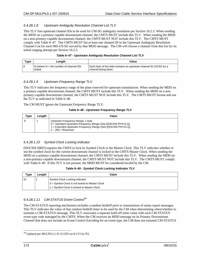
CM-SP-MULPIv3.1-I07-150910 Data-Over-Cable Service Interface Specifications
172 CableLabs 09/10/15
6.4.28.1.8 Upstream Ambiguity Resolution Channel List TLV
This TLV lists upstream channel IDs to be used for CM-SG ambiguity resolution per Section 10.2.3. When sending the MDD on a primary-capable downstream channel, the CMTS MUST include this TLV. When sending the MDD on a non-primary-capable downstream channel, the CMTS MUST NOT include this TLV. The CMTS MUST comply with Table 6–47. The CMTS MUST list at least one channel ID in the Upstream Ambiguity Resolution Channel List for each MD-US-SG served by that MDD message. The CM will choose a channel from this list for its initial ranging attempt per Section 10.2.3.
Table 6–47 - Upstream Ambiguity Resolution Channel List TLV
Type Length Value 8 N (where N = the number of channel IDs
listed) Each byte of this field contains an upstream channel ID (UCID) for a channel being listed.
6.4.28.1.9 Upstream Frequency Range TLV
This TLV indicates the frequency range of the plant reserved for upstream transmission. When sending the MDD on a primary-capable downstream channel, the CMTS MUST include this TLV. When sending the MDD on a non-primary-capable downstream channel, the CMTS MUST NOT include this TLV. The CMTS MUST format and use the TLV as indicated in Table 6–48.
The CM MUST ignore the Upstream Frequency Range TLV.
Table 6–48 - Upstream Frequency Range TLV
Type Length Value 9 1 Upstream Frequency Range: 1 byte.
0 = Standard Upstream Frequency Range (See [DOCSIS PHYv3.1]) 1 = Extended Upstream Frequency Range (See [DOCSIS PHYv3.1]) 2 – 255 = Reserved
6.4.28.1.10 Symbol Clock Locking Indicator
[DOCSIS DRFI] requires the CMTS to lock its Symbol Clock to the Master Clock. This TLV indicates whether or not the symbol clock for the current downstream channel is locked to the CMTS Master Clock. When sending the MDD on a primary-capable downstream channel, the CMTS MUST include this TLV. When sending the MDD on a non-primary-capable downstream channel, the CMTS MUST NOT include this TLV. The CMTS MUST comply with Table 6–49. If this TLV is not present, the MDD MUST be considered invalid by the CM.
Table 6–49 - Symbol Clock Locking Indicator TLV
Type Length Value 10 1 Symbol Clock Locking Indicator
0 = Symbol Clock is not locked to Master Clock 1 = Symbol Clock is locked to Master Clock
6.4.28.1.11 CM-STATUS Event Control39
The CM-STATUS reporting mechanism includes a random holdoff prior to transmission of status report messages. This TLV indicates the value of that random holdoff timer to be used by the CM when determining when/whether to transmit a CM-STATUS message. This TLV associates a separate hold-off timer value with each CM-STATUS event type code managed by the CMTS. When the CM receives an MDD message on its Primary Downstream Channel that does not include an Event Control Encoding for an event type, the CM does not transmit CM-STATUS
39 Updated per MULPIv3.1-N-15.l293 on 6/1/15 by PO.
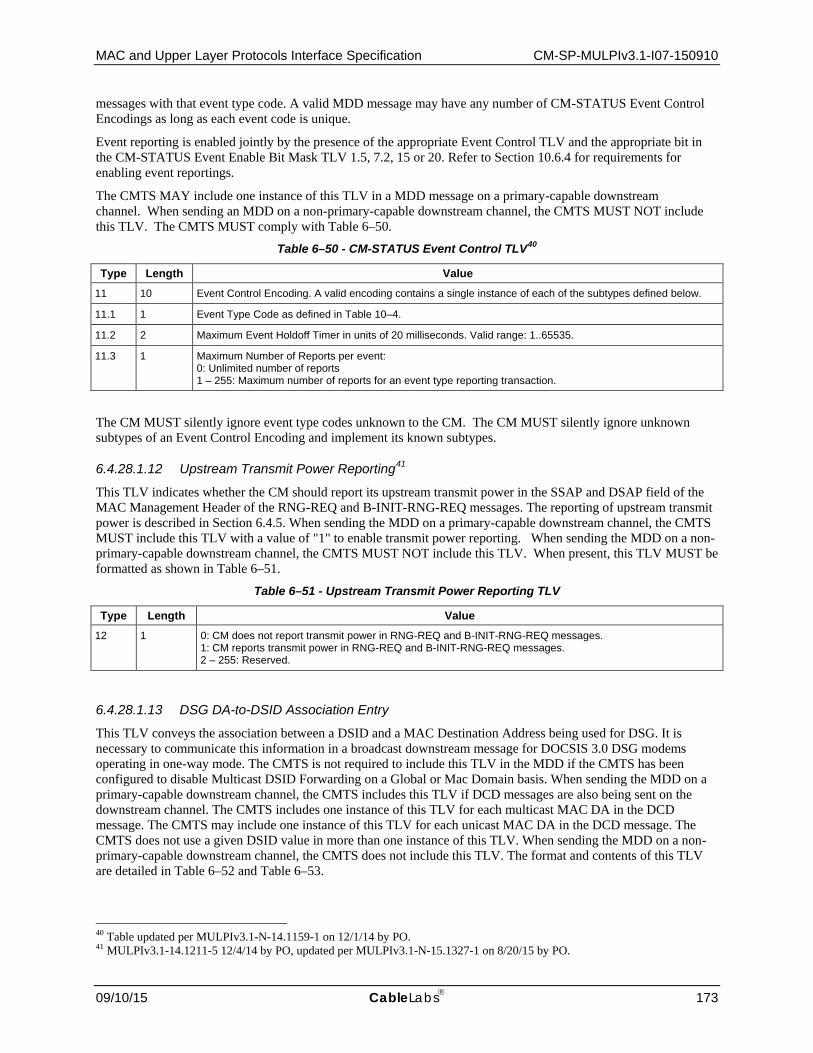
MAC and Upper Layer Protocols Interface Specification CM-SP-MULPIv3.1-I07-150910
09/10/15 CableLabs 173
messages with that event type code. A valid MDD message may have any number of CM-STATUS Event Control Encodings as long as each event code is unique.
Event reporting is enabled jointly by the presence of the appropriate Event Control TLV and the appropriate bit in the CM-STATUS Event Enable Bit Mask TLV 1.5, 7.2, 15 or 20. Refer to Section 10.6.4 for requirements for enabling event reportings.
The CMTS MAY include one instance of this TLV in a MDD message on a primary-capable downstream channel. When sending an MDD on a non-primary-capable downstream channel, the CMTS MUST NOT include this TLV. The CMTS MUST comply with Table 6–50.
Table 6–50 - CM-STATUS Event Control TLV40
Type Length Value 11 10 Event Control Encoding. A valid encoding contains a single instance of each of the subtypes defined below.
11.1 1 Event Type Code as defined in Table 10–4.
11.2 2 Maximum Event Holdoff Timer in units of 20 milliseconds. Valid range: 1..65535.
11.3 1 Maximum Number of Reports per event: 0: Unlimited number of reports 1 – 255: Maximum number of reports for an event type reporting transaction.
The CM MUST silently ignore event type codes unknown to the CM. The CM MUST silently ignore unknown subtypes of an Event Control Encoding and implement its known subtypes.
6.4.28.1.12 Upstream Transmit Power Reporting41
This TLV indicates whether the CM should report its upstream transmit power in the SSAP and DSAP field of the MAC Management Header of the RNG-REQ and B-INIT-RNG-REQ messages. The reporting of upstream transmit power is described in Section 6.4.5. When sending the MDD on a primary-capable downstream channel, the CMTS MUST include this TLV with a value of "1" to enable transmit power reporting. When sending the MDD on a non-primary-capable downstream channel, the CMTS MUST NOT include this TLV. When present, this TLV MUST be formatted as shown in Table 6–51.
Table 6–51 - Upstream Transmit Power Reporting TLV
Type Length Value 12 1 0: CM does not report transmit power in RNG-REQ and B-INIT-RNG-REQ messages.
1: CM reports transmit power in RNG-REQ and B-INIT-RNG-REQ messages. 2 – 255: Reserved.
6.4.28.1.13 DSG DA-to-DSID Association Entry
This TLV conveys the association between a DSID and a MAC Destination Address being used for DSG. It is necessary to communicate this information in a broadcast downstream message for DOCSIS 3.0 DSG modems operating in one-way mode. The CMTS is not required to include this TLV in the MDD if the CMTS has been configured to disable Multicast DSID Forwarding on a Global or Mac Domain basis. When sending the MDD on a primary-capable downstream channel, the CMTS includes this TLV if DCD messages are also being sent on the downstream channel. The CMTS includes one instance of this TLV for each multicast MAC DA in the DCD message. The CMTS may include one instance of this TLV for each unicast MAC DA in the DCD message. The CMTS does not use a given DSID value in more than one instance of this TLV. When sending the MDD on a non-primary-capable downstream channel, the CMTS does not include this TLV. The format and contents of this TLV are detailed in Table 6–52 and Table 6–53.
40 Table updated per MULPIv3.1-N-14.1159-1 on 12/1/14 by PO. 41 MULPIv3.1-14.1211-5 12/4/14 by PO, updated per MULPIv3.1-N-15.1327-1 on 8/20/15 by PO.

CM-SP-MULPIv3.1-I07-150910 Data-Over-Cable Service Interface Specifications
174 CableLabs 09/10/15
Table 6–52 - DSG DA-to-DSID Association Entry TLV
Type Length Value 13 Total number of bytes (including type and
length) contained in all sub-TLVs Contains sub-TLVs as defined in Table 6–53. Each sub-TLV has a one-byte "type" field and one-byte "length" field. Each sub-TLV appears exactly once.
Table 6–53 - Sub-TLVs for DSG DA-to-DSID Association Entry TLV
Type Length Value 13.1 6 DA: the 48-bit MAC DA to which this association applies.
13.2 3 Bits 23-20: Reserved. Bits 19-0: the 20-bit DSID associated with the DA contained in sub-TLV 13.1.
6.4.28.1.14 CM-STATUS Event Enable for Non-Channel-Specific Events
The CMTS MAY include one instance of this TLV in a MDD message on a primary-capable downstream channel. When sending an MDD on a non-primary-capable downstream channel, the CMTS MUST NOT include this TLV.
Table 6–54 - CM-STATUS Event Enable for Non-Channel-Specific Events TLV
Type Length Value 15 2 CM-STATUS Event Enable Bitmask for Non-Channel-Specific Events; 2 bytes.
Each bit in this field represents the enable/disable for a particular non-channel-specific event for which status may be reported via the CM-STATUS message. If a bit is 1, CM-STATUS reporting is enabled for the corresponding event. If a bit is zero, CM-STATUS reporting is disabled for the corresponding event. If the TLV is omitted, then all events listed below are disabled. The details of CM-STATUS message functionality are described in Section 10.6.4. The following bits are defined: 0 - Reserved (unused) 1 – 2 - Reserved (used for downstream specific events) 3 - Sequence out-of-range 4 – 5 - Reserved (used for downstream specific events) 6 – 8 - Reserved (used for upstream specific events) 9 - CM operating on battery backup 10 - CM returned to A/C power 11 - CM MAC Address Removal 12 – 15 - Reserved for future use
6.4.28.1.15 Extended Upstream Transmit Power Support
This encoding within the MDD message signals whether or not modems may transmit at power levels greater than the default Pmax values defined in [DOCSIS PHYv3.1] prior to registration (post registration behavior is controlled via the Extended Upstream Transmit Power capability as defined in the subsection Extended Upstream Transmit Power Capability in Annex C). By default, the CMTS MUST set this TLV to On unless a mechanism is provided to administratively configure this setting on and off. When this TLV is present and set to On, the CM is permitted to exceed the default Pmax values as specified in [DOCSIS PHYv3.1] prior to registration.
The CMTS MUST include one instance of this TLV in an MDD message on a primary-capable downstream channel. When sending an MDD on a non-primary-capable downstream channel, the CMTS MUST NOT include this TLV.

MAC and Upper Layer Protocols Interface Specification CM-SP-MULPIv3.1-I07-150910
09/10/15 CableLabs 175
Table 6-55 - Extended Upstream Transmit Power Support
Type Length Value 16 1 Extended Upstream Transmit Power Support: 1 byte.
0 = Extended Upstream Transmit Power Support Off 1 = Extended Upstream Transmit Power Support On 2 – 255 = Reserved
6.4.28.1.16 CMTS DOCSIS Version
This encoding within the MDD message signals the version of DOCSIS being supported by the CMTS. A CMTS compliant to this specification MUST report a CMTS Major DOCSIS Version of 3 and a CMTS Minor DOCSIS Version of 1. If this TLV is absent in an MDD message on a primary-cable downstream channel, then the CM MUST assume a CMTS Major DOCSIS Version of 3 and a CMTS Minor DOCSIS Version of 0.
The CMTS MUST include one instance of this TLV in an MDD message on a primary-capable downstream channel. The CMTS is expected to transmit the same value of this TLV on all primary-capable channels of a downstream service group. When sending an MDD on a non-primary-capable downstream channel, the CMTS MUST NOT include the CMTS DOCSIS Version TLV.
Table 6–56 - CMTS DOCSIS Version TLV
Type Length Value 17 N CMTS DOCSIS Version
Table 6–57 - Sub-TLVs for CMTS DOCSIS Version TLV
Type Length Value 17.1 1 CMTS Major DOCSIS Version
17.2 1 CMTS Minor DOCSIS Version
6.4.28.1.17 CM Periodic Maintenance Timeout Indicator
This encoding within the MDD message instructs the modem as to the Periodic Maintenance timeout behavior for OFDMA channels. The CMTS sets this TLV based on its Periodic Maintenance implementation. The CMTS sets a value of "use Unicast Ranging opportunity" to indicate that the CM is required to utilize the T4 timer and to increment the T3 retry counter for unicast ranging events. The CMTS sets a value of "use Probe opportunity" to indicate that the CM is required to utilize the T4 timer and to increment the T3 retry counter for probe events. The CMTS sets a value of "use Unicast Ranging or Probe opportunity" to indicate that the CM is required to utilize the T4 timer and to increment the T3 retry counter for unicast ranging and/or Probe events. Note that the CM Periodic Maintenance Timeout Indicator only applies to the T4 timer and the T3 retry counter. The CM uses the T3 timer for all unicast ranging events because the CM inhibits transmission of Probes and Ranging Requests until either the CM receives a Ranging Response for that channel and applies the adjustments or the duration of the T3 timer has elapsed with no Ranging Response received.
The CMTS MUST include one instance of the CM Periodic Maintenance Timeout Indicator TLV in an MDD message on a primary-capable downstream channel. When sending an MDD on a non-primary-capable downstream channel, the CMTS MUST NOT include the CM Periodic Maintenance Timeout Indicator TLV.

CM-SP-MULPIv3.1-I07-150910 Data-Over-Cable Service Interface Specifications
176 CableLabs 09/10/15
Table 6–58 - CM Periodic Maintenance Timeout Indicator
Type Length Value 18 1 CM Periodic Maintenance Timeout Indicator: 1 byte.
0 = use Unicast Ranging opportunity 1 = use Probe opportunity 2 = use Unicast Ranging or Probe opportunity 3 – 255 = Reserved
6.4.28.1.18 DLS Broadcast and Multicast Delivery Method TLV
This encoding within the MDD message communicates the method of broadcast and multicast delivery to CMs in DLS mode. The available methods are described in Section 11.7.4.5.
The CMTS MUST include one instance of DLS Broadcast and Multicast Delivery Method TLV in an MDD message on a primary-capable OFDM downstream channel. When sending an MDD on a non-primary-capable OFDM downstream channel or any SC-QAM downstream channel, the CMTS MUST NOT include DLS Broadcast and Multicast Delivery Method TLV.
Table 6–59 - DLS Broadcast and Multicast Delivery Method
Type Length Value 19 1 DLS Broadcast and Multicast Delivery Method: 1 byte.
1 = delayed selected multicast method 2 = selectively replicated multicast method All other values = Reserved
6.4.28.1.19 CM-STATUS Event Enable for DOCSIS 3.1 Specific Events
The CMTS MAY include one instance of this TLV in a MDD message on a primary-capable downstream channel. When sending an MDD on a non-primary-capable downstream channel, the CMTS MUST NOT include this TLV.
Table 6–60 - CM-STATUS Event Enable for DOCSIS 3.1 Events TLV42
Type Length Value 20 4 CM-STATUS Event Enable Bitmask for DOCSIS 3.1 Events; 4 bytes.
Each bit in this field represents the enable/disable for a particular event for which status may be reported via the CM-STATUS message. If a bit is 1, CM-STATUS reporting is enabled for the corresponding event. If a bit is zero, CM-STATUS reporting is disabled for the corresponding event. If the TLV is omitted, then all events listed below are disabled. The details of CM-STATUS message functionality are described in Section 10.6.4. The following bits are defined: 0 - Downstream OFDM Profile Failure 1 - Primary Downstream Channel Change 2 - DPD Mismatch 3 - Invalid DPD message 4 - NCP Profile Failure 5 - Loss of FEC lock on PLC 6 - NCP Profile Recovery 7 - FEC Recovery on PLC 8 - FEC Recovery on OFDM Profile 9 - OFDMA Profile Failure 10 - MAP Storage Overflow Indicator 11 - MAP Storage Almost Full Indicator 12 – 31 - Reserved for future use
42 MULPIv3.1-14.1211-5 on 12/4/14 by PO, table modified by MULPIv3.1-N-15.1293-1 on 6/1/15 by PO.

MAC and Upper Layer Protocols Interface Specification CM-SP-MULPIv3.1-I07-150910
09/10/15 CableLabs 177
6.4.29 Dynamic Bonding Change Request (DBC-REQ) A Dynamic Bonding Change Request message is transmitted by the CMTS in order to change upstream and/or downstream bonding parameters, or downstream multicast parameters. Only one DBC transaction per CM can be in the process at any time. The CMTS MUST wait for any ongoing transaction for a particular CM to be finished before a new transaction can be initiated with that CM. The DBC-REQ message is formatted as shown in Figure 6–50.
Figure 6–50 - Dynamic Bonding Change Request Message
The Parameters for a DBC-REQ transmitted by a CMTS MUST be as follows:
Transaction ID: Unique identifier for this transaction assigned by the CMTS.
Number of Fragments: Fragmentation allows the DBC-REQ TLV parameters to be spread across more than one DOCSIS MAC Frame, thus allowing the total number of DBC-REQ TLV parameters to exceed the maximum payload of a single MAC management frame. The value of this field represents the number of DBC-REQ MAC management frames that a unique and complete set of DBC-REQ TLV parameters are spread across to constitute the DBC-REQ message. This field is an 8-bit unsigned integer. The default value for this field is 1.
Fragment Sequence Number: This field indicates the position of this fragment in the sequence that constitutes the complete DBC-REQ message. Fragment Sequence Numbers start with the value of 1 and increase by 1 for each fragment in the sequence. Thus, the first DBC-REQ message fragment would have a Fragment Sequence Number of 1 and the last DBC-REQ message fragment would have a Fragment Sequence Number equal to the Number of Fragments. The CM is not required to reorder DBC message fragments. The CMTS MUST ensure that the message fragments arrive in order at the CM either by sending all message fragments on a single downstream or by transmitting fragments such that individual channel latencies do not affect fragment order. The CMTS MUST NOT fragment within any top level TLVs. Each DBC-REQ message fragment is a complete DOCSIS frame with its own CRC. Other than the Fragment Sequence Number, the framing of one DBC-REQ message fragment is independent of the framing of another DBC-REQ message fragment. This field is an 8-bit unsigned integer. The default value for this field is 1.
All other parameters are coded as TLV tuples as defined in Annex C. A DBC-REQ transmitted by a CMTS MUST contain at least one of the following:
Transmit Channel Configuration: Specification of the rules to be used to make changes to a Transmit Channel Set (see the subsection Transmit Channel Configuration (TCC) in Annex C).
Service Flow SID Cluster Assignments: Specification of the rules to be used to make changes to a Service Flow Cluster Assignments (see the subsection Service Flow SID Cluster Assignments in Annex C).
Receive Channel Configuration: Specification of the rules to be used to make changes to a Receive Channel Set (see the subsection CM Receive Channel (RCP/RCC) Encodings in Annex C).
MAC Management Message Header
Octets
Transaction ID
TLV-encoded information
Number of Fragments
Fragment Sequence Number

CM-SP-MULPIv3.1-I07-150910 Data-Over-Cable Service Interface Specifications
178 CableLabs 09/10/15
DSID Encodings: Specification of the rules to be used to make changes to a DSID (see the subsection DSID Encodings in Annex C).
Security Association Encodings: Specification of the rules to be used to make changes to a SAID (see the subsection DSID Encodings in Annex C).
Energy Management Mode Indicator: Specification of which Energy Management Mode the CM is to use going forward (see the subsection Energy Management Mode Indicator in Annex C).
If Privacy is enabled, the CMTS MUST also format the DBC-REQ message to contain:
Key Sequence Number: The key sequence number of the Auth Key, which is used to calculate the HMAC-Digest (see the subsection Key Sequence Number in Annex C).
HMAC-Digest: The HMAC-Digest Attribute is a keyed message digest (to authenticate the sender). The HMAC-Digest Attribute is the final Attribute in the DBC-REQ message's Attribute list (see the subsection HMAC-Digest in Annex C.) In the case of a fragmented DBC-REQ message, the HMAC-Digest appears only once as the final Attribute in the last fragment of the DBC-REQ message.
6.4.30 Dynamic Bonding Change Response (DBC-RSP)43 The CM MUST transmit a Dynamic Bonding Change Response in response to a received Dynamic Bonding Change Request (DBC-REQ) message. The DBC-RSP message transmitted by a CM MUST be formatted as shown in Figure 6–51.
Figure 6–51 - Dynamic Bonding Change Response Message
The parameters of the DBC-RSP transmitted by a CM MUST be as follows:
Transaction ID: Transaction ID from the corresponding DBC-REQ.
Confirmation Code: An 8-bit Confirmation Code. The valid codes are defined in the subsection Confirmation Code in Annex C.
All other parameters are encoded as TLV tuples as defined in Annex C.
If the transaction is unsuccessful due to TCC Encodings or RCC Encodings, and the Confirmation Code is not one of the major error codes in Annex C, the DBC-RSP transmitted by the CM MUST contain at least one of the following as defined below:
TCC Error Set: A TCC Error Set and identifying TCC Reference is included for at least one failed TCC in the corresponding DBC-REQ. Every TCC Error Set includes at least one specific failed parameter of the corresponding TCC. It does not need to include every failed parameter of the corresponding TCC. This parameter is omitted if the entire DBC-REQ is successful (see the subsection Transmit Channel Configuration (TCC) in Annex C).
43 Updated per MULPIv3.1-N-15.1269-1 on 3/9/15 by PO.
MAC Management Message Header
Octets
Transaction ID
TLV-encoded information
Confirmation Code

MAC and Upper Layer Protocols Interface Specification CM-SP-MULPIv3.1-I07-150910
09/10/15 CableLabs 179
RCC Error Set: An RCC Error Set. This parameter is included to report an error in an RCC encoding in the corresponding DBC-REQ. Every RCC Error Set includes at least one specific failed parameter of the corresponding RCC. It does not need to include every failed parameter of the corresponding RCC. This parameter is omitted if the entire DBC-REQ is successful (see the subsection CM Receive Channel (RCP/RCC) Encodings in Annex C).
In the case where the CM is unable to acquire one or more of the upstream and/or downstream channels assigned via the TCC and/or RCC encodings (respectively), the CM needs to report back to the CMTS the list of channels that it was unable to acquire so that the CMTS can take appropriate action. If the CM is unable to acquire one or more of the downstream channels assigned to it in the RCC, the CM MUST include an RCC encoding with a Partial Service Downstream Channels TLV in the DBC-RSP, which includes a list of the downstream channels that could not be acquired. If the CM is unable to acquire one or more of the upstream channels assigned to it in the TCC, the CM MUST include a TCC encoding with a TCC Error Encoding for each upstream channel it was unable to acquire in the DBC-RSP, corresponding to the TCC encoding that assigned that upstream channel in the DBC-REQ. This is because each TCC encoding describes the actions to take for a single upstream channel. Note that this is different from the case of reporting an error in the encoding, where only a single error needs to be reported (even if multiple errors exist).
When the DBC-REQ contains Simplified Receive Channel Configuration encodings, the CM MUST include the Primary Downstream Channel encoding in the DBC-RSP.
Regardless of success or failure, if Privacy is enabled for the CM, the DBC-RSP message transmitted by the CM MUST contain:
Key Sequence Number: The key sequence number of the Auth Key, which is used to calculate the HMAC-Digest (see the subsection Key Sequence Number in Annex C).
HMAC-Digest: The HMAC-Digest Attribute is a keyed message digest (to authenticate the sender). The HMAC-Digest Attribute is the final Attribute in the DBC-RSP message's Attribute list (see the subsection HMAC-Digest in Annex C).
6.4.31 Dynamic Bonding Change Acknowledge (DBC-ACK) The Dynamic Bonding Change Acknowledge MUST be transmitted by a CMTS in response to a received Dynamic Bonding Change Response (DBC-RSP) message from a CM. The DBC-ACK message is formatted as shown in Figure 6–52.
Figure 6–52 - Dynamic Bonding Change Acknowledge Message
The parameters of a DBC-ACK message transmitted by a CMTS MUST be as follows:
Transaction ID: Transaction ID from the corresponding DBC-REQ.
If Privacy is enabled, the DBC-ACK message transmitted by the CMTS MUST contain:
MAC Management Message Header
Octets
Transaction ID
TLV-encoded information
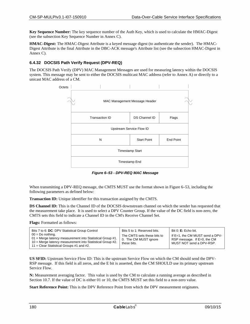
CM-SP-MULPIv3.1-I07-150910 Data-Over-Cable Service Interface Specifications
180 CableLabs 09/10/15
Key Sequence Number: The key sequence number of the Auth Key, which is used to calculate the HMAC-Digest (see the subsection Key Sequence Number in Annex C).
HMAC-Digest: The HMAC-Digest Attribute is a keyed message digest (to authenticate the sender). The HMAC-Digest Attribute is the final Attribute in the DBC-ACK message's Attribute list (see the subsection HMAC-Digest in Annex C).
6.4.32 DOCSIS Path Verify Request (DPV-REQ) The DOCSIS Path Verify (DPV) MAC Management Messages are used for measuring latency within the DOCSIS system. This message may be sent to either the DOCSIS multicast MAC address (refer to Annex A) or directly to a unicast MAC address of a CM.
Figure 6–53 - DPV-REQ MAC Message
When transmitting a DPV-REQ message, the CMTS MUST use the format shown in Figure 6–53, including the following parameters as defined below:
Transaction ID: Unique identifier for this transaction assigned by the CMTS.
DS Channel ID: This is the Channel ID of the DOCSIS downstream channel on which the sender has requested that the measurement take place. It is used to select a DPV Counter Group. If the value of the DC field is non-zero, the CMTS sets this field to indicate a Channel ID in the CM's Receive Channel Set.
Flags: Formatted as follows:
Bits 7 to 6: DC: DPV Statistical Group Control 00 = Do nothing. 01 = Merge latency measurement into Statistical Group #1. 10 = Merge latency measurement into Statistical Group #2. 11 = Clear Statistical Groups #1 and #2.
Bits 5 to 1: Reserved bits. The CMTS sets these bits to 0. The CM MUST ignore these bits.
Bit 0: E: Echo bit. If E=1, the CM MUST send a DPV-RSP message. If E=0, the CM MUST NOT send a DPV-RSP.
US SFID: Upstream Service Flow ID: This is the upstream Service Flow on which the CM should send the DPV-RSP message. If this field is all zeros, and the E bit is asserted, then the CM SHOULD use its primary upstream Service Flow.
N: Measurement averaging factor. This value is used by the CM to calculate a running average as described in Section 10.7. If the value of DC is either 01 or 10, the CMTS MUST set this field to a non-zero value.
Start Reference Point: This is the DPV Reference Point from which the DPV measurement originates.
Transaction ID
Upstream Service Flow ID
DS Channel ID Flags
N Start Point End Point
Timestamp Start
Timestamp End
MAC Management Message Header
Octets

MAC and Upper Layer Protocols Interface Specification CM-SP-MULPIv3.1-I07-150910
09/10/15 CableLabs 181
End Reference Point: This is the DPV Reference Point at which the DPV measurement terminates.
Timestamp Start: If the CMTS owns the Start Reference Point, it will place a copy of its local DOCSIS timestamp in this field. Otherwise, the CMTS sets this field to all zeros.
Timestamp End: This value is initialized to all zeros by the CMTS.
The multicast version of the DPV-REQ message is useful when all CMs are passively logging latency measurements without sending a DPV-RSP (E bit not asserted). A multicast message also ensures that all CMs receive the same messages so that CMTS to CM latencies can be more accurately compared.
The CMTS should be cautious about asserting the E bit when sending a multicast DPV-REQ as this will cause all CMs to simultaneously attempt to send a DPV-RSP. This may be a useful technique for measuring upstream access latency during congestion, but there will be an impact to the operational capability of the upstream. The CMTS can use a 3-byte Downstream Service Extended Header (see Section 6.2.6.6) to limit the number of CMs that would receive and potentially respond to a multicast DPV-REQ.
The CMTS MAY support the generation of the DPV-REQ message in the downstream direction. The CM MUST support the reception of the DPV-REQ message in the downstream direction.
6.4.33 DOCSIS Path Verify Response (DPV-RSP) The DPV MAC Management Messages are used for estimating latency and skew within the DOCSIS system. The CM MUST comply with Figure 6–54 for DPV Response messages. This message is sent by the CM to the unicast MAC address of the CMTS.
Figure 6–54 - DPV-RSP MAC Message
The CM MUST copy the values of all fields from the DPV-REQ into the identical fields in the DPV-RSP message with the exception of the following cases:
Timestamp Start: If the CM owns the Start Reference Point, it MUST place a copy of its local DOCSIS timestamp in this field. Otherwise, this value is copied from the identical field in the DPV-REQ message.
Timestamp End: If the CM owns the End Reference Point, it MUST place a copy of its local DOCSIS timestamp in this field. Otherwise, this value is copied from the identical field in the DPV-REQ message.
The CM MUST support the generation of the DPV-RSP message in the upstream direction. The CMTS MAY support the reception of the DPV-RSP message in the upstream direction.
Transaction ID
Upstream Service Flow ID
DS Channel ID Flags
N Start Point End Point
Timestamp Start
Timestamp End
MAC Management Message Header
Octets

CM-SP-MULPIv3.1-I07-150910 Data-Over-Cable Service Interface Specifications
182 CableLabs 09/10/15
6.4.34 Status Report (CM-STATUS) A CM MUST generate the CM-STATUS message compliant with Figure 6–55, including the Transaction ID and Event Type. The inclusion of these parameters in the beginning of the message body allows the CMTS to quickly filter events without parsing through the TLV structure.
Figure 6–55 - CM-STATUS Report
Transaction ID: This is a 2-byte value that identifies a reported transition of the event from off to on. Upon MAC Initialization, the CM MUST report the first CM-STATUS Transaction ID for each event type as 1. The CM MUST NOT use a Transaction ID value of 0 (zero). This ensures that the CMTS can always reset its last received Transaction ID to 0 and be assured of processing the next CM-STATUS message. When incrementing a value of 65535, the CM wraps around to a value of 1.
Event Type Code: This field contains a unique code which describes the event condition. Refer to Table 10–4. The CM MUST include this field.
6.4.34.1 CM-STATUS TLV Encodings Table 6–61 - CM-STATUS TLV Encodings
Type Length Value 1 N Status Event
This TLV is repeated for each error event that is being reported by the CM.
1.2 1-80 Event Description This is an optional vendor-specific text string containing details on the failure. The CM MAY include this TLV.
1.4 1 Downstream Channel ID This is the channel on which the error was detected. It is the same channel ID advertised for the failed channel in MDD messages. The CM-STATUS message includes one instance of this encoding for each channel for which the event type is considered to be "on". This TLV is included for certain status events as indicated in Table 10–4.
1.5 1 Upstream Channel ID This is the channel on which the error was detected. The CM-STATUS message includes one instance of this encoding for each channel for which the event type is considered to be "on". This TLV is included for certain status events as indicated in Table 10–4.
1.6 3 DSID This is the value of the DSID on which the error occurred. The CM-STATUS message includes one instance of this encoding for each DSID for which the event type is considered to be "on". This TLV is included for certain status events as indicated in Table 10–4.
MAC Management Message Header
Octets
Transaction ID
TLV-encoded information
Event Type

MAC and Upper Layer Protocols Interface Specification CM-SP-MULPIv3.1-I07-150910
09/10/15 CableLabs 183
Type Length Value 1.7 6 MAC Address
Binary encoded value of the MAC address that has been deleted by the CM due to the event type 11 – MAC removal event Table 10–4. Note: If multiple MAC addresses have been deleted they will be reported with multiple Type 1 Sub-type 7
Status Events. 1.8 1 Downstream OFDM Profile ID
This is the Profile on which the error was detected. It is the same profile ID advertised for the failed channel in DBC message. The CM-STATUS message includes one instance of this encoding for each profile for which the event type is considered to be "on". This TLV is included for certain status events as indicated in Table 10–4.
1.9 1 Upstream OFDMA Profile ID This is the Profile on which the error was detected. It is the same profile ID advertised for the failed channel in DBC message. The CM-STATUS message includes one instance of this encoding for each profile for which the event type is considered to be "on". This TLV is included for certain status events as indicated in Table 10–4.
6.4.35 CM Control Request (CM-CTRL-REQ) The CM-CTRL-REQ command is used to enforce specific CM actions. It is a replacement to the DOCSIS 2.0 UP-DIS management message. The CMTS MUST support the CM-CTRL-REQ message. The CM MUST support the CM-CTRL-REQ message.
Figure 6–56 - CM-CTRL-REQ
A CMTS MUST generate the CM-CTRL-REQ message compliant with Figure 6–56 including the following parameter:
Transaction ID: A 16-bit unique identifier for this transaction assigned by the CMTS.
The CM MUST accept a CM-CTRL-REQ message on any available downstream.
6.4.35.1 CM-CTRL-REQ TLV Encodings The CMTS MUST use the TLV encodings described in Table 6–62. The CM MUST support each action defined by the TLV encodings described in Table 6–62. The CM MUST NOT act upon unknown TLVs in a CM-CTRL-REQ message.
MAC Management Message Header
Octets
Transaction ID
TLV-encoded information

CM-SP-MULPIv3.1-I07-150910 Data-Over-Cable Service Interface Specifications
184 CableLabs 09/10/15
Table 6–62 - CM-CTRL-REQ TLV Encodings
Type Length Value 1 1 Upstream Channel RF Mute
This field contains the Channel ID of the upstream to mute or un-mute. A value of 0 will mute or un-mute all channels. The mute operation is a low level disabling of the physical layer transmitter that is currently using the channel ID. It will not directly change the MAC layer state, although if the mute period is long enough the MAC layer will experience T4 timeout as if the channel has become physically unavailable. If all channels are muted and the CM encounters a condition which leads it to the Re-Init MAC state, the CM MUST defer re-initialization and remain muted until the mute timer expires, an un-mute command is received, or a Lost SYNC event occurs, at which point it performs a re-init MAC and is no longer muted.
2 4 RF Mute Timeout Interval For the RF Mute operation, this field controls the length of time that the upstream channel(s) are muted. This field is a 32-bit unsigned integer in units of milliseconds. The CMTS MUST include the RF Mute Timeout Interval TLV when the Upstream Channel RF Mute TLV is included in the CM-CTRL-REQ message. A timeout of 0x00000000 is an indication to un-mute the channel(s) immediately. A timeout of 0xFFFFFFFF is an indication to mute the channel(s) indefinitely.
3 1 CM Reinitialize A value of 1 instructs the CM to reinitialize its MAC with a CM Initialization Reason of CM_CTRL_INIT and will begin a new registration process. Any value other than 1 is ignored.
4 1 Disable Forwarding A value of 1 will disable forwarding of data PDUs in both the upstream and downstream direction. A value of 0 will enable forwarding of data PDUs in both the upstream and downstream direction. Any value other than 0 or 1 will be ignored.
5 7 Override for the Downstream Status Event Enable Bitmask.
5.1 1 Downstream Channel ID.
5.2 2 Downstream Status Event Enable Bitmask (see Section 6.4.28).
6 7 Override for the Upstream Status Event Enable Bitmask.
6.1 1 Upstream Channel ID.
6.2 2 Upstream Status Event Enable Bitmask (see Section 6.4.28).
7 2 Override for the CM-STATUS Event Enable Bitmask for Non-Channel-Specific Events (see Section 6.4.28).
8 4 Override for the CM-STATUS Event Enable Bitmask for DOCSIS 3.1 Specific Events (see Section 6.4.28).
The CM uses the CM-CTRL-REQ to enforce specific CM actions according to the requirements specified in Section 10.6.4.
6.4.36 CM Control Response (CM-CTRL-RSP)44 The CM-CTRL-RSP message is used to confirm receipt of a CM-CTRL-REQ message. Unless the CM has encountered a condition which leads it to the re-init MAC state, the CM MUST send a CM-CTRL-RSP message every time it receives a CM-CTRL-REQ message prior to performing the action described in the CM-CTRL-REQ message.
Unless the CM immediately performs a MAC re-init, the CMTS SHOULD consider a previously transmitted CM-CTRL-REQ message to be lost if the CMTS has not received a CM-CTRL-RSP message from the CM within 5 seconds.
44 Updated per MULPIv3.1-N-15.1327-1 on 8/20/15 by PO.

MAC and Upper Layer Protocols Interface Specification CM-SP-MULPIv3.1-I07-150910
09/10/15 CableLabs 185
Figure 6–57 - CM-CTRL-RSP
A CM MUST generate the CM-CTRL-RSP message compliant with Figure 6–57 including the following parameter:
Transaction ID: A 16-bit unique identifier for this transaction from the corresponding CM-CTRL-REQ message.
The TLVs in the CM-CTRL-RSP are the same top-level TLVs that are used in the CM-CTRL-REQ message, except that they are all of length 1 and can only have values of 0 or 1. The CM MUST include every top-level TLV from the CM-CTRL-REQ message in the CM-CTRL-RSP. Each TLV included by the CM in the CM-CTRL-RSP MUST have a length of 1 and either a value of 0 if the CM will apply the TLV (success) or a value of 1 if the CM cannot apply the TLV (fail). The CM MUST include unknown TLVs from the CM-CTRL-REQ message in the CM-CTRL-RSP using a value of 1 (fail).
6.4.37 Energy Management Request (EM-REQ) The Energy Management Request message is transmitted by the CM to request transition into or out of a low power mode of operation.
Figure 6–58 - Energy Management Request Message
The parameters of the EM-REQ message include:
Transaction ID: Unique identifier for this transaction assigned by the CM.
Requested Power Mode: The power mode that is requested.
MAC Management Message Header
Octets
Transaction ID
TLV-encoded information

CM-SP-MULPIv3.1-I07-150910 Data-Over-Cable Service Interface Specifications
186 CableLabs 09/10/15
(0): Normal Operation
(1): Energy Management 1x1 Mode
(2): DOCSIS Light Sleep Mode
(3-255): Reserved/Unused
Upon transmitting an EM-REQ message, the CM MUST initiate an EM-REQ retry timer based on a randomized binary exponential backoff with an initial back-off value of 1 second and final back-off value of 16 seconds, where the EM-REQ retry timer value is chosen using a uniform distribution in the range ±0.5 second from the back-off value, If CM does not receive an EM-RSP before expiration of the EM-REQ retry timer, and provided the conditions that initiated the EM-REQ are still valid, the CM MUST log an event in the local log and resend the EM-REQ message with the same Transaction ID. If the CM receives no response to the EM-REQ after five retries, the CM MUST log a warning message and discontinue transmitting EM-REQ messages for the duration of Energy Management Cycle Period (see the section on Energy Management Cycle Period in Annex C).
If an EM-RSP message is received with a Response Code of (1) "Reject Temporary", the CM MUST suppress transmission of another EM-REQ message for at least the amount of time indicated in the Hold-Off Timer parameter (or the Energy Management Cycle Period, if the Hold-Off Timer value is not provided).
If an EM-RSP message is received with one of the "Reject Permanent" Response Codes, the CM MUST NOT transmit any future EM-REQ messages until after a MAC re-initialization occurs.
The CM MUST evaluate the Energy Management Cycle Period as per the section on Energy Management Cycle Period in Annex C to determine if sufficient time has elapsed before sending an EM-REQ message to enter Energy Management 1x1 Mode.
6.4.38 Energy Management Response (EM-RSP) The Energy Management Response message is sent by the CMTS in response to an Energy Management Request message from the CM. This message dictates if the CM is allowed to enter the selected power mode and, in some cases, defines the time duration before a follow-up EM-REQ message is allowed. The CMTS MUST send an EM-RSP message in response to an EM-REQ message from a CM.
Figure 6–59 - Energy Management Response Message
The parameters of the EM-RSP message include:
Transaction ID: This value MUST match the Transaction ID that was transmitted in the EM-REQ message.
Response Code: Enumerated value consisting of the following:
(0) – OK
(1) – Reject Temporary

MAC and Upper Layer Protocols Interface Specification CM-SP-MULPIv3.1-I07-150910
09/10/15 CableLabs 187
(2) – Reject Permanent, Requested Low Power Mode(s) Not Supported
(3) – Reject Permanent, Requested Low Power Mode(s) Disabled
(4) – Reject Permanent, Other
(5-255) – Reserved/unused
The CM MUST ignore an EM-RSP message containing a "Reserved" Response Code.
6.4.38.1 EM-RSP TLV-Encodings
6.4.38.1.1 Hold-Off Timer
This TLV specifies the amount of time to delay in seconds before transmitting an EM-REQ message again.
Type Length Value 1 2 Minimum time (in seconds) before transmitting another EM-REQ message
This parameter is only applicable if the EM-RSP message includes a Response Code of (1) "Reject Temporary". This value corresponds to the minimum amount of time the CM waits before transmitting another EM-REQ message. If this TLV is not present, the CM utilizes the Energy Management Cycle Period to defer sending another EM-REQ (see Energy Management Cycle Period in Annex C).
6.4.39 Status Report Acknowledge (CM-STATUS-ACK) The Status Report Acknowledge (CM-STATUS-ACK) message is sent by the CMTS in response to a Status Report (CM-STATUS) message from the CM. The CM-STATUS-ACK message indicates that the CMTS has received the CM-STATUS message. Upon receiving a CM-STATUS-ACK message, the CM will cease retransmitting CM-STATUS messages with the same transaction number for the same event ID. If a CM receives a CM-STATUS-ACK message for any inactive event, then the CM MUST silently discard the message.
Figure 6–60 - CM STATUS-ACK message
Transaction ID: The CMTS MUST fill this value with the Transaction ID that was transmitted in the CM-STATUS message. Refer to definition of CM-STATUS message (section 6.4.34) for further description of this parameter.
Event Type: The CMTS MUST fill value with the Event Type that was transmitted in the CM-STATUS message. Refer to definition of CM-STATUS message (section 6.4.34) for further description of this parameter.
6.4.40 OFDM Channel Descriptor (OCD)45 An OFDM Channel Descriptor allows the CMTS to communicate the parameters of the Downstream OFDM channel to cable modems. OCD describes the downstream direction only. OCD is used for parameters that are common for all profiles and are static assignments.
45 MULPIv3.1-N-14.1213-2 on 12/5/14 by PO, modified per MULPIv3.1-N-15.1265-1 on 3/9/15 by PO, modified per
MULPIv3.1-N-15.1346-3 on 8/21/15 by PO.
MAC Management Message Header
Octets
Transaction ID Event Type

CM-SP-MULPIv3.1-I07-150910 Data-Over-Cable Service Interface Specifications
188 CableLabs 09/10/15
Figure 6–61 - OFDM Channel Descriptor
A CMTS MUST generate the OCD message in the format shown in Figure 6–61, including the following parameters as defined below:
Downstream Channel ID: The identifier of the downstream channel for which profile is described. This is an 8-bit field. This ID is part of the same number space used for SC-QAM channels.
Configuration Change Count: The parameter that identifies the generation of current generation of an OFDM channel descriptor. The CMTS increments this field by 1 (modulo the field size) whenever any of the values in this message change relative to the values in the previous OCD message sent on this downstream channel. The Configuration Change Count may be referenced in other messages. This is an 8-bit field.
The CMTS MUST transmit the OCD message on the PLC associated with the downstream channel described by the OCD message. The CMTS MUST NOT transmit the OCD message on the PLC associated with other downstream channels. The CMTS MUST NOT transmit the OCD message on Profile A of the main data channel described by the message. The CMTS MUST NOT transmit the OCD message on SC-QAM channels.
The CM can tell the downstream channel ID of an OFDM channel by looking at the downstream channel ID of the OCD message on the PLC.
The CMTS MUST NOT change any parameters in the OCD message while the channel is included in the Receive Channel Set of any CM (including CMs currently in partial service mode due to lack of connectivity on this channel). CMs are not expected to monitor the OCD message for changes or to behave gracefully in the event of changes to the downstream channel parameters described in the OCD message. The CMTS MUST observe the OCD/DPD PLC Interval specified in Annex B for the transmission of OCD messages on the PLC.
The OCD message uses the TLVs in Table 6–63.
Table 6–63 - Parameters carried by the OCD46
Name Type (1 byte)
Length (1 byte)
Value (Variable Length)
Discrete Fourier Transform size
0 1 The size of the DFT defining the OFDM transmission. 0 = 4096 subcarriers at 50 kHz spacing 1 = 8192 subcarriers at 25 kHz spacing 2 – 255 are reserved
Cyclic prefix 1 1 This is the length of the cyclic prefix. The sample number given is with reference to a sample rate of 204.8 M samples/s. 0 = 0.9375 µs with 192 samples 1 = 1.25 µs with 256 samples 2 = 2.5 µs with 512 samples 3 = 3.75 µs with 768 samples 4 = 5.0 µs with 1024 samples
46 Table updated per MULPIv3.1-N-15.1261-1 on 3/9/15 by PO, modified per MULPIv3.1-N-15.1347-2 on 8/21/15 by PO.
MAC Management Message Header
Octets
Downstream Channel ID
ConfigurationChange Count
TLV encoded information
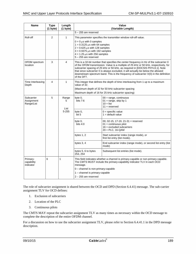
MAC and Upper Layer Protocols Interface Specification CM-SP-MULPIv3.1-I07-150910
09/10/15 CableLabs 189
Name Type (1 byte)
Length (1 byte)
Value (Variable Length)
5 – 255 are reserved
Roll-off 2 1 This parameter specifies the transmitter window roll-off value. 0 = 0 µs with 0 samples 1 = 0.3125 µs with 64 samples 2 = 0.625 µs with 128 samples 3 = 0.9375 µs with 192 samples 4 = 1.25 µs with 256 samples 5 – 255 are reserved
OFDM spectrum location
3 4 This is a 32-bit number that specifies the center frequency in Hz of the subcarrier 0 of the OFDM transmission. Value is a multiple of 25 kHz or 50 kHz, respectively, for subcarrier spacing of 25 kHz or 50 kHz, as required in [DOCSIS PHYv3.1]. Note that since subcarrier 0 is always excluded, it will actually be below the allowed downstream spectrum band. This is the frequency of subcarrier X(0) in the definition of the DFT.
Time Interleaving Depth
4 1 This integer that defines the depth of time interleaving from 1 up to a maximum value of 32. (Maximum depth of 32 for 50 kHz subcarrier spacing Maximum depth of 16 for 25 kHz subcarrier spacing)
Subcarrier Assignment Range/List
5 Range 5
List 5-255
byte 0, bits 7:6
00 = range, continuous 01 = range, skip by 1 10 = list 11 = reserved
byte 0, bit 5
0 = specific value 1 = default value
byte 0, bits 4:0
00, 02-15, 17-19, 21-31 = reserved 01 = continuous pilot 16 = excluded subcarriers 20 = PLC, 16-QAM
bytes 1, 2 Start subcarrier index (range mode), or first list entry (list mode).
bytes 3, 4 End subcarrier index (range mode), or second list entry (list mode)
bytes 5, 6 to bytes 253, 254
Subsequent list entries (list mode).
Primary-capability indicator
6 1 This field indicates whether a channel is primary-capable or non-primary-capable. The CMTS MUST include the primary-capability indicator TLV in each OCD message. 0 – channel is non-primary-capable 1 – channel is primary-capable 2 – 255 are reserved
The role of subcarrier assignment is shared between the OCD and DPD (Section 6.4.41) message. The sub-carrier assignment TLV for OCD defines:
1. Exclusion of subcarriers
2. Location of the PLC
3. Continuous pilots
The CMTS MAY repeat the subcarrier assignment TLV as many times as necessary within the OCD message to complete the description of the entire OFDM channel.
For a discussion on how to use the subcarrier assignment TLV, please refer to Section 6.4.41.1 in the DPD message description.

CM-SP-MULPIv3.1-I07-150910 Data-Over-Cable Service Interface Specifications
190 CableLabs 09/10/15
The CMTS MUST include the assignment of subcarriers 0 through 147 and 3948 through 4095 to excluded subcarriers in the OCD for downstream channels with a 4K FFT. The CMTS MUST include the assignment of subcarriers 0 through 295 and 7896 through 8191 to excluded subcarriers in the OCD for downstream channels with an 8K FFT.
The CMTS MUST include all continuous pilots (including those required around the PLC) in the OCD assignment.
6.4.41 Downstream Profile Descriptor (DPD)47 A Downstream Profile Descriptor allows the CMTS to communicate the parameters of Downstream Profiles to cable modems. There is one DPD message per profile. The DPD can be changed dynamically.
Figure 6–62 - Downstream Profile Descriptor
A CMTS MUST generate the DPD message in the format shown in Figure 6–62, including the following parameters as defined below:
Downstream Channel ID: The identifier of the downstream channel for which profile is described. This is an 8-bit field. This ID is part of the same number space used for SC-QAM channels.
Profile Identifier: The parameter that identifies the profile described by this message. This is an 8-bit field. Profile Identifiers 0 through 15 are used for the maximum 16 CMTS profiles per downstream channel. Profile Identifier 0 is commonly referred to as Profile A. Profile Identifiers 1, 2, and 3 are commonly referred to as Profiles B, C, and D. Profiles Identifier 16 through 254 are reserved. Profile Identifier 255 is used for the NCP profile.
Configuration Change Count: The parameter that identifies the current generation of a profile. The CMTS increments this field by 1 (modulo the field size) whenever any of the values in this message change relative to the values in the previous DPD message sent on this downstream channel. Configuration Change Count may be referenced in other messages. The least significant bit of the Configuration Change Count is carried in the NCP (even/odd bit). This is an 8-bit field.
All other parameters of DPD message are coded as TLV tuples as defined in Table 6–64 and Table 6–65.
On profile A of each OFDM Channel, the CMTS MUST periodically transmit DPD messages for each profile of that channel. The CMTS MUST transmit DPD messages describing profile A and the NCP profile of an OFDM Channel on the PLC associated with that OFDM channel. The CMTS MUST NOT transmit the DPD messages on SC-QAM channels.
The CMTS MUST observe the OCD/DPD PLC Interval specified in Annex B for the transmission of DPD messages on the PLC. The CMTS MUST observe the DPD Profile A Interval specified in Annex B for transmission of DPD messages on the Profile A of OFDM channel.
DPD is used for dynamic assignments of subcarriers. The subcarrier assignment TLV for OCD defines for both data fields and NCP field: 47 MULPIv3.1-14.1211-5 on 12/4/14 by PO, MULPIv3.1-15.1346-3 and MULPIv3.1-15.1347-2 on 8/21/15 by PO.
Profile Identifier
MAC Management Message Header
Octets
Downstream Channel ID
ConfigurationChange Count
TLV encoded information
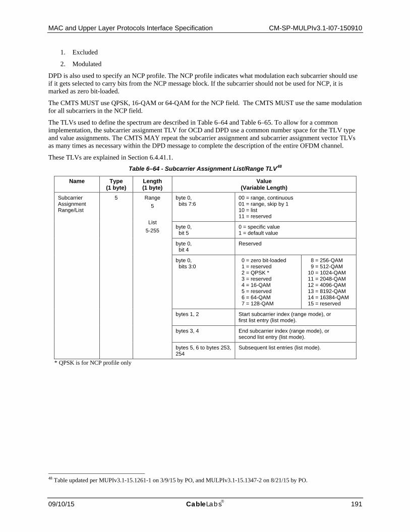
MAC and Upper Layer Protocols Interface Specification CM-SP-MULPIv3.1-I07-150910
09/10/15 CableLabs 191
1. Excluded
2. Modulated
DPD is also used to specify an NCP profile. The NCP profile indicates what modulation each subcarrier should use if it gets selected to carry bits from the NCP message block. If the subcarrier should not be used for NCP, it is marked as zero bit-loaded.
The CMTS MUST use QPSK, 16-QAM or 64-QAM for the NCP field. The CMTS MUST use the same modulation for all subcarriers in the NCP field.
The TLVs used to define the spectrum are described in Table 6–64 and Table 6–65. To allow for a common implementation, the subcarrier assignment TLV for OCD and DPD use a common number space for the TLV type and value assignments. The CMTS MAY repeat the subcarrier assignment and subcarrier assignment vector TLVs as many times as necessary within the DPD message to complete the description of the entire OFDM channel.
These TLVs are explained in Section 6.4.41.1.
Table 6–64 - Subcarrier Assignment List/Range TLV48
Name Type (1 byte)
Length (1 byte)
Value (Variable Length)
Subcarrier Assignment Range/List
5 Range 5
List 5-255
byte 0, bits 7:6
00 = range, continuous 01 = range, skip by 1 10 = list 11 = reserved
byte 0, bit 5
0 = specific value 1 = default value
byte 0, bit 4
Reserved
byte 0, bits 3:0
0 = zero bit-loaded 1 = reserved 2 = QPSK * 3 = reserved 4 = 16-QAM 5 = reserved 6 = 64-QAM 7 = 128-QAM
8 = 256-QAM 9 = 512-QAM 10 = 1024-QAM 11 = 2048-QAM 12 = 4096-QAM 13 = 8192-QAM 14 = 16384-QAM 15 = reserved
bytes 1, 2 Start subcarrier index (range mode), or first list entry (list mode).
bytes 3, 4 End subcarrier index (range mode), or second list entry (list mode).
bytes 5, 6 to bytes 253, 254
Subsequent list entries (list mode).
* QPSK is for NCP profile only
48 Table updated per MUPIv3.1-15.1261-1 on 3/9/15 by PO, and MULPIv3.1-15.1347-2 on 8/21/15 by PO.

CM-SP-MULPIv3.1-I07-150910 Data-Over-Cable Service Interface Specifications
192 CableLabs 09/10/15
Table 6–65 - Subcarrier Assignment Vector TLV49
Name Type (1 byte)
Length (2 bytes)
Value (Variable Length)
Subcarrier Assignment Vector
6 2 + ceiling(N/2)
bytes 0, 1 bit 15: 0 => N is even 1 => N is odd. Ignore last 4 bits. bits 14-13: reserved bit 12-0: subcarrier start
bytes 2+ bits 7-4: Zth subcarrier bits 3-0: Z+1 subcarrier
0 = zero bit-loaded 1 = cont. pilot* 2 = QPSK ** 3 = reserved 4 = 16-QAM 5 = reserved 6 = 64-QAM 7 = 128-QAM
8 = 256-QAM 9 = 512-QAM 10 = 1024-QAM 11 = 2048-QAM 12 = 4096-QAM 13 = 8192-QAM 14 = 16384-QAM 15 = reserved
* Continuous Pilots are assigned in the OCD and are not profile dependent. The "cont. pilot" setting in the DPD Subcarrier Assignment Vector TLV is merely a reminder of the continuous pilots assigned in the OCD.
** QPSK is for NCP profile only
6.4.41.1 Subcarrier Assignment The OFDM spectrum is illustrated in Figure 6–63 and is described by two messages OCD and DPD. On the left is subcarrier(0) which is the first numbered subcarrier and is typically an excluded carrier. The outer 6.4 MHz past each end of the 192 MHz maximum spectrum is always excluded. There are fixed pilot tones described by OCD and DPD and scattered pilots are that algorithmically described and not described by OCD and DPD. The PLC is located in the center of a 6 MHz encompassed spectrum which contains no excluded subcarriers and uses a defined pattern of continuous pilots [DOCSIS PHYv3.1] The center of the lowest subcarrier of the 6 MHz encompassed spectrum containing the PLC at its center is on a 1 MHz grid. There are data subcarriers that carry DOCSIS frames. Some subcarriers are zero bit-loaded on a per profile basis. There are also NCP subcarriers that point to codeword locations. Although the NCP channel is shown at the top end of the spectrum, it is actually spread through the spectrum as it is frequency and time interleaved along with the data carriers.
Figure 6–63 - OFDM Channel with PLC After Interleaving
The OCD message generally assigns static functions like PLC usage, excluded subcarriers, and continuous pilots. Any subcarrier that has not been defined as an excluded subcarrier, PLC subcarrier, or continuous pilot is considered as an active data subcarrier. The DPD message defines the active data subcarriers with bit-loading values. These values can change from one profile to another.
49 Table updated per MUPIv3.1-15.1261-1 on 3/9/15 by PO.

MAC and Upper Layer Protocols Interface Specification CM-SP-MULPIv3.1-I07-150910
09/10/15 CableLabs 193
The same list/range TLV structure is used for the subcarrier assignment in both the OCD and DPD messages although the usage is unique to each message. The DPD message also has an alternate method of describing spectrum usage based upon a vector structure.
When the subcarrier assignment TLV is used in range mode, the length of the value field is 5 bytes. When the subcarrier assignment TLV is used as a list, the length is variable up to a maximum of 255 bytes. The number of list entries is (length – 1) / 2. Thus, the maximum number of list entries is 127 entries.
A range is defined by a starting subcarrier index and an ending subcarrier index. The ending subcarrier index can equal the beginning subcarrier index, but cannot be less.
A continuous range means that the subcarrier assignment applies to all subcarriers within the specified range. A range with a skip value of one means that one subcarrier is skipped and that every second subcarrier will be assigned, beginning with the start subcarrier. The skip range is intended to be used to define mixed modulation profiles.
A list entry is one or more discrete subcarrier indexes.
6.4.41.1.1 Default and Specific Values
The subcarrier assignment range/list TLV has a default mode. Subcarriers can be assigned a default value that can then subsequently be over-written with a specific value. For example, the subcarrier TLV could be issued once with all active data subcarriers set to a default modulation. The TLV could be issued again with discrete active data subcarriers listed that might use a different modulation. This dual assignment is unique within each of the OCD and DPD messages since OCD and DPD assign different functions to different subcarriers.
The use of a default value and specific value introduces multiple assignment of a subcarrier. The use of two messages also introduces the possibility of multiple assignments. The following requirements remove all ambiguity.
The subcarrier assignments defined by NCP and by scattered subcarriers have a higher precedence than subcarrier assignments in the OCD and DPD messages.
• The CMTS MUST assign at least one "default" or "specific" function to each subcarrier. • The CMTS MUST NOT assign more than one "default" function per subcarrier per message. • The CMTS MUST NOT assign more than one "specific" function per subcarrier per message. • The CM MUST give first precedence to "specific" assignments of subcarriers by the OCD message. • The CM MUST give second precedence to "default" assignments of subcarriers by the OCD message. • The CM MUST give third precedence to "specific" assignments of subcarriers by the DPD message. • The CM MUST give fourth precedence to "default" assignments of subcarriers by the DPD message.
These provisions define TLV precedence explicitly and thus do not require TLVs to be transmitted in any defined order.
6.4.41.1.2 Subcarrier Assignment Vector
Subcarriers may also be assigned directly with a vector. A vector contains a starting subcarrier number and then a series of 4-bit modulation assignments. Note that the length field of the Subcarrier Assignment Vector is two bytes instead of one byte. When evaluating rules, assignments by the vector TLV are considered "specific" assignments.
If the number of subcarriers described in the subcarrier assignment vector is an odd number, then the CMTS MUST assert the odd bit identifier and use a value of zero in the four least significant bits of the last byte of the vector. If the Subcarrier Assignment Vector is set to odd, the CM MUST ignore the four least significant bits of the last byte of the vector.
6.4.41.1.3 Example Subcarrier Assignment
The following is an example of how the OCD and DPD messages would be used to define an OFDM spectrum.

CM-SP-MULPIv3.1-I07-150910 Data-Over-Cable Service Interface Specifications
194 CableLabs 09/10/15
OCD Operation:
1. The location of the set of PLC subcarriers is designated. This is typically done with one range.
2. Excluded subcarriers are identified. This is typically done with one or more ranges.
3. Discrete continuous pilots are identified. This is typically done with one or more lists. (Alternatively, continuous pilot assignment can also be done in the DPD vector).
DPD Operation:
1. Default modulation is assigned to active data subcarriers. This is typically done with one range and a default setting. This step may be skipped.
2. Specific modulation is assigned to active data subcarriers if they differ from the default. This is typically done with one or more ranges, one or more lists, or as part of a vector.
3. Zero bit-loaded subcarriers are assigned. This typically is done with one or more ranges, a list, or as part of a vector.
6.4.42 OFDM Downstream Spectrum Request Message (ODS-REQ) The ODS-REQ message is composed of a MAC Management Message header and an 8-bit downstream channel ID payload, as shown in Figure 6–64. The CMTS MUST use the ODS-REQ message format defined in Figure 6–64. The ODS-REQ is a version 5 MAC Management Message.
Figure 6–64 - OFDM Downstream spectrum request message (ODS-REQ)
The parameters of the ODS-REQ message include:
Downstream Channel ID: This is the downstream OFDM channel on which the CM is to collect MER statistics.
6.4.43 OFDM Downstream Spectrum Response (ODS-RSP) The ODS-RSP message is composed of a MAC Management Message header, a Downstream Channel ID, and TLV encoded information, as shown in Figure 6–65. The CM MUST use the ODS-RSP-MP message format defined in Figure 6–65. The ODS-RSP is a version 5 MAC Management Message and uses the multi-part facility of the version 5 MMM header.
Figure 6–65 - OFDM Downstream spectrum response message (ODS-RSP)
8Bit 16 24 310
DownstreamChannel ID
MAC Management Message Header
MAC Management Message Header
Downstream Channel ID
Bit 0 8 16 24 31
TLV encoded information
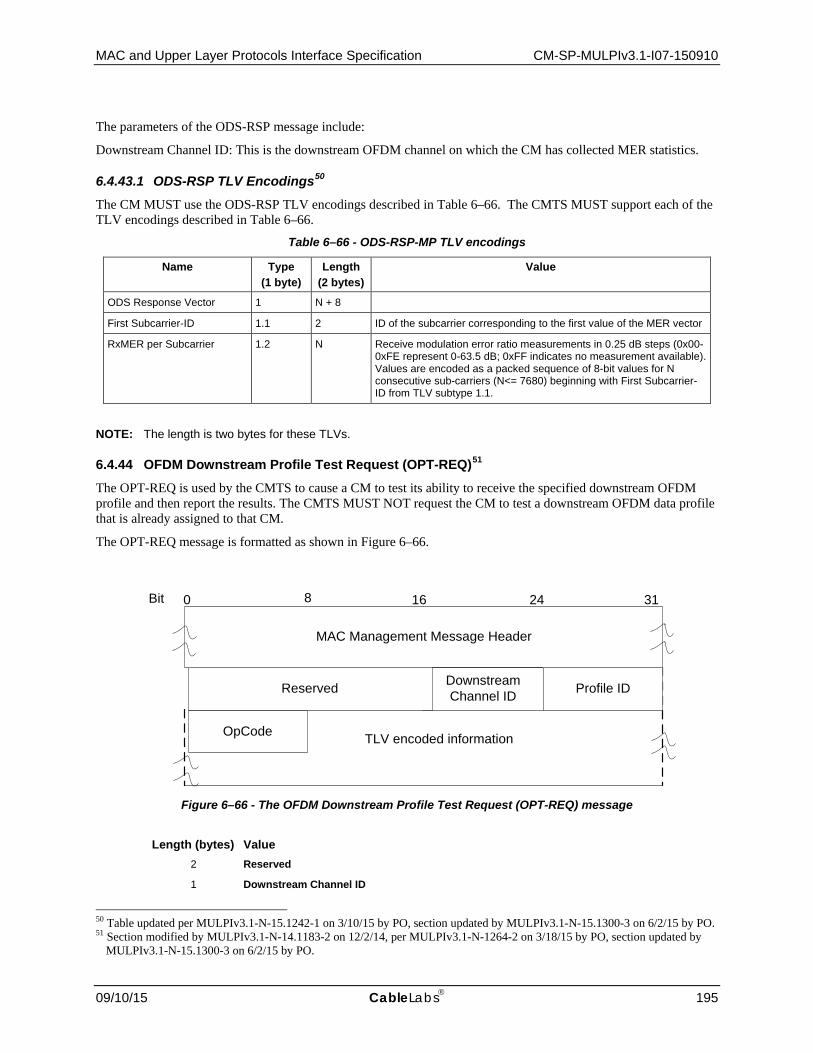
MAC and Upper Layer Protocols Interface Specification CM-SP-MULPIv3.1-I07-150910
09/10/15 CableLabs 195
The parameters of the ODS-RSP message include:
Downstream Channel ID: This is the downstream OFDM channel on which the CM has collected MER statistics.
6.4.43.1 ODS-RSP TLV Encodings50 The CM MUST use the ODS-RSP TLV encodings described in Table 6–66. The CMTS MUST support each of the TLV encodings described in Table 6–66.
Table 6–66 - ODS-RSP-MP TLV encodings
Name Type (1 byte)
Length (2 bytes)
Value
ODS Response Vector 1 N + 8
First Subcarrier-ID 1.1 2 ID of the subcarrier corresponding to the first value of the MER vector
RxMER per Subcarrier 1.2 N Receive modulation error ratio measurements in 0.25 dB steps (0x00-0xFE represent 0-63.5 dB; 0xFF indicates no measurement available). Values are encoded as a packed sequence of 8-bit values for N consecutive sub-carriers (N<= 7680) beginning with First Subcarrier-ID from TLV subtype 1.1.
NOTE: The length is two bytes for these TLVs.
6.4.44 OFDM Downstream Profile Test Request (OPT-REQ)51 The OPT-REQ is used by the CMTS to cause a CM to test its ability to receive the specified downstream OFDM profile and then report the results. The CMTS MUST NOT request the CM to test a downstream OFDM data profile that is already assigned to that CM.
The OPT-REQ message is formatted as shown in Figure 6–66.
Figure 6–66 - The OFDM Downstream Profile Test Request (OPT-REQ) message
Length (bytes) Value
2 Reserved
1 Downstream Channel ID
50 Table updated per MULPIv3.1-N-15.1242-1 on 3/10/15 by PO, section updated by MULPIv3.1-N-15.1300-3 on 6/2/15 by PO. 51 Section modified by MULPIv3.1-N-14.1183-2 on 12/2/14, per MULPIv3.1-N-1264-2 on 3/18/15 by PO, section updated by
MULPIv3.1-N-15.1300-3 on 6/2/15 by PO.
8Bit 16 24 310
DownstreamChannel ID
MAC Management Message Header
TLV encoded information
Profile ID
OpCode
Reserved

CM-SP-MULPIv3.1-I07-150910 Data-Over-Cable Service Interface Specifications
196 CableLabs 09/10/15
Length (bytes) Value 1 Profile ID – the ID of the profile that is being tested
1 OpCode: 1 – Start 2 – Abort All other values reserved
6.4.44.1 OPT-REQ TLV Encodings The CM MUST support the OPT-REQ TLV encodings described in Table 6–67. The CMTS MUST support the OPT-REQ TLV encodings described in Table 6–67.
Table 6–67 - OPT-REQ TLV encodings52
Name Type (1 byte)
Length (1 byte)
Value
Requested Statistics 1 1 BITS encoding that commands the CM to include Statistics in its OPT-RSP message. The specified Statistics are requested when the bit is set to 1 and not requested when the bit is set to zero. Bit 0 - RxMER Statistics for Candidate Profile Bit 1 - RxMER Pass Fail for Candidate Profile Bit 2 - SNR Margin for Candidate Profile Bit 3 - Codeword Statistics for Candidate Profile Bit 4 - Codeword Pass Fail for Candidate Profile Bit 5 - NCP Field statistics Bit 6 - NCP CRC Pass Fail Bits 7 - Reserved The CMTS MUST include this TLV in a request with an opcode of Start. The CMTS MUST NOT include this TLV in a request with an opcode of Abort. The CM MUST ignore this TLV in any request that does not have an opcode of Start.
RxMER Thresholding Parameters
2 The CMTS uses this TLV to communicate the RxMER Thresholding Parameters. The CMTS MAY include this TLV in a request with an opcode of Start. The CMTS MUST NOT include this TLV in a request with an opcode of Abort. The CM MUST ignore this TLV in any request that does not have an opcode of Start.
52 Table updated per MULPIV3.1-N-14.1183-2 on 12/5/14 by PO, revised per MULPIv3.1-N-15.1264-2 on 3/9/15 by PO.

MAC and Upper Layer Protocols Interface Specification CM-SP-MULPIv3.1-I07-150910
09/10/15 CableLabs 197
Name Type (1 byte)
Length (1 byte)
Value
Modulation Order 2.1 1 0 - 1 = reserved 2 = QPSK 3 = reserved 4 = 16-QAM 5 = reserved 6 = 64-QAM 7 = 128-QAM 8 = 256-QAM 9 = 512-QAM 10 = 1024-QAM 11 = 2048-QAM 12 = 4096-QAM 13 = 8192-QAM 14 = 16384-QAM 15 – 255 = reserved If the RxMER Thresholding Parameters TLV is present, the CMTS MUST include this sub-TLV once for each modulation order in the profile.
RxMER Target 2.2 1 The required value for the profile RxMER (refer to OPT-RSP) in units of 0.25dB (0xFF is 63.75dB). This is the required RxMER value that the CM uses to calculate the SNR margin for the profile. If the RxMER Thresholding Parameters TLV is present, the CMTS MUST include this sub-TLV once for each modulation order in the profile.
RxMER Margin 2.3 1 The CM reports the number of subcarriers whose measured RxMER is at least this value below the target RxMER for the bitloading of the given subcarrier in the OPT-RSP message. The value is in units of ¼ dB. If the RxMER Thresholding Parameters TLV is present, the CMTS MUST include this sub-TLV once for each modulation order in the profile.
Average SNR Target 3 1 The required value for average SNR Target (refer to OPT-RSP) in units of 0.25dB (0xFF is 63.75dB). This value is used in the determination of the SNR margin see [DOCSIS PHYv3.1]. The CMTS MUST include this TLV in a request with an opcode of Start and with the SNR Margin requested in TLV 1. The CMTS MUST NOT include this TLV in a request with an opcode of Abort. The CM MUST ignore this TLV in any request that does not have an opcode of Start.
Max Duration 4 4 Maximum # of milliseconds before the CM MUST abort testing and attempt to send an OPT-RSP with a Maximum Duration Expired Status. The CMTS SHOULD include this TLV in a request with an opcode of Start. The CMTS MUST NOT include this TLV in a request with an opcode of Abort. The CM MUST ignore this TLV in any request that does not have an opcode of Start.
Data Profile Testing Parameters
5
Codeword Count (Nc) 5.1 4 Number of BCH codewords to be examined. When either Nc or more codewords have been received, or Ne or more codeword errors have occurred, since the start of the test, the CM MUST abort the test and attempt to send an OPT-RSP with a Complete status. The CMTS MUST include this TLV in an OPT-REQ with an opcode of Start. The CMTS MUST NOT include this TLV in a request with an opcode of Abort. The CM MUST ignore this TLV in any request that does not have an opcode of Start.

CM-SP-MULPIv3.1-I07-150910 Data-Over-Cable Service Interface Specifications
198 CableLabs 09/10/15
Name Type (1 byte)
Length (1 byte)
Value
Maximum Uncorrectable Codeword Count (Ne)
5.2 4 Maximum number of codewords which are allowed to fail BCH decoding. When either Nc or more codewords have been received, or Ne or more codeword errors have occurred, since the start of the test, the CM MUST abort the test and attempt to send an OPT-RSP with a Complete status. The CMTS MUST include this TLV in an OPT-REQ with an opcode of Start. The CMTS MUST NOT include this TLV in a request with an opcode of Abort. The CM MUST ignore this TLV in any request that does not have an opcode of Start.
Codeword Tagging Enable
5.3 1 Indicates whether Codeword Tagging is in use for this test. Bit 0: Enable Codeword Tagging 0 - Codeword Tagging is disabled. The CM MUST report codeword counts that include all codewords received on the profile in question for the duration of the test. 1 - Codeword Tagging is enabled. The CM MUST report codeword counts that include only codewords received on the profile in question for the duration of the test for which the "T" bit is set to 1 in the NCP pointing to the codeword. The location of the "T" bit is specified in [DOCSIS PHYv3.1]. Bits 7 – 1: Reserved The CMTS MAY include this TLV in an OPT-REQ with an opcode of Start. The CMTS MUST NOT include this TLV in a request with an opcode of Abort. The CM MUST ignore this TLV in any request that does not have an opcode of Start. A CM is expected to be capable of performing a single test at a time with Codeword Tagging enabled. After sending an OPT-REQ with Codeword Tagging enabled, the CMTS MUST NOT send another OPT-REQ with Codeword Tagging enabled until the test commanded by the first such OPT-REQ has ended. A test ends when the CMTS receives a corresponding OPT-RSP, when an OPT-RSP Timer timeout occurs, or when the CMTS sends an OPT-REQ with an opcode of Abort. If this TLV is not present, the CM MUST perform testing with Codeword Tagging disabled (equivalent to this TLV being present with a value of 0x00).
NCP Profile Testing Parameters
6
NCP field Count (NFc) 6.1 4 Number of NCP fields to be examined. When either NFc or more NCP fields have been received, or NFe or more NCP fields fail the NCP CRC check have occurred, since the start of the test, the CM MUST abort the test and attempt to send an OPT-RSP with a Complete status. The CMTS MAY include this TLV in an OPT-REQ with an opcode of Start. The CMTS MUST NOT include this TLV in a request with an opcode of Abort. The CM MUST ignore this TLV in any request that does not have an opcode of Start. The CMTS MUST include this TLV in an OPT-REQ that includes Maximum NCP CRC Failure Count.
Maximum NCP CRC Failure Count (NFe)
6.2 4 Maximum number of NCP fields which are allowed to fail the NCP CRC check. When either NFc or more NCP fields have been received, or NFe or more NCP fields fail the NCP CRC check have occurred, since the start of the test, the CM MUST abort the test and attempt to send an OPT-RSP with a Complete status. The CMTS MAY include this TLV in an OPT-REQ with an opcode of Start. The CMTS MUST NOT include this TLV in a request with an opcode of Abort. The CM MUST ignore this TLV in any request that does not have an opcode of Start. The CM MUST ignore this TLV if an OPT-REQ does not also include NCP field Count TLV.

MAC and Upper Layer Protocols Interface Specification CM-SP-MULPIv3.1-I07-150910
09/10/15 CableLabs 199
6.4.45 OFDM Downstream Profile Test Response (OPT-RSP)53 The OPT-RSP is used by the CM first to acknowledge an OPT-REQ request and, if the request was to start a test, then another OPT-RSP will be sent to report the results. The normal transaction message flow is shown in Figure 10–38. However, there might be reasons (operator intervention, fault management, etc.) why the CMTS may wish to abort the CM's testing of a profile once it has started. In this case the message exchange would proceed as in Figure 10–39.
The OPT-RSP is used in two ways. First, the OPT-RSP is used to provide rapid acknowledgement and a preliminary status (Testing, Profile Already Testing from Another Request, or No Free Profile Resource, ) to the CMTS. The CMTS uses the OPT-RSP Timer and OPT Test Timer (Annex B), when waiting for OPT-RSP messages from the CM.
If the CM sends a preliminary status of Testing, then the CM sends a second OPT-RSP with a status of Complete, or Max Duration Expired or Aborted.
Figure 6–67 - The OFDM Profile Test Response (OPT-RSP) message
Length (bytes) Value
2 Reserved
1 Downstream Channel ID the channel for which the profile is being tested
1 Profile ID – the ID of the profile that is being tested
1 Status: 1 - Testing 2 - Profile Already Testing from Another Request 3 - No Free Profile Resource on CM 4 - Max Duration Expired 5 - Aborted 6 - Complete 7 - Profile already assigned to the CM All other values reserved
53 Section modified by MULPIv3.1-14.1183-2 on 12/2/14, MULPIv3.1-14.1183-2 on 12/5/14 by PO, and MULPIv3.1-N-
15.1264-2 on 3/9/15 by PO.
MAC Management Message Header
Bit 0 8 1 6
2 4
3 1
TLV encoded information
Downstream Channel ID Profile ID
Status
Reserved

CM-SP-MULPIv3.1-I07-150910 Data-Over-Cable Service Interface Specifications
200 CableLabs 09/10/15
6.4.45.1 OPT-RSP TLV Encodings54 When it receives an OPT-REQ message that results in an OPT-RSP with a Status of Complete, or Max Duration Expired, or Aborted, the CM MUST include the OPT-RSP TLVs corresponding to the TLVs that were received in the OPT-REQ message. The CM MUST NOT include any TLVs in an OPT-RSP with a Status of Testing, Profile Already Testing from Another Request, or No Free Profile Resource on CM. The CMTS MUST ignore any TLVs in an OPT-RSP with a Status of Testing, Profile Already Testing from Another Request, or No Free Profile Resource on CM.
An OPT-RSP from the CM to the CMTS after the completion of a test cycle contains the following TLVs:
Table 6–68 - OPT-RSP TLV encodings55
Name Type (1 byte)
Length (2 byte)
Value
RxMER and SNR Margin Data
1
RxMER per Subcarrier 1.1 N Integer modulation error ratio measurements in 0.25 dB steps (0x00-0xFE represent 0-63.5 dB; 0xFF indicates no measurement available). These are encoded as a packed sequence of 8-bit values for N consecutive sub-carriers (N ≤ 7680) from lowest active subcarrier to the highest active subcarrier, including all the subcarriers in between. The CM MUST include this TLV in any OPT-RSP with a Status of Complete or Incomplete if requested by the CMTS in the corresponding OPT-REQ. Note that the vector includes values for excluded subcarriers. The CMTS ignores these values.
Pass/Fail for RxMER per Subcarrier
1.2 N Pass Fail indication for each subcarrier's RxMER (1 bit for each subcarrier). A value of 1 indicates that the measured MER ≥ target value in the OPT-REQ. A value of 0 indicates that the measured MER < target value in the OPT-REQ. These are encoded as a sequence of 1-bit values for N consecutive subcarriers (N ≤ 7680) from lowest active subcarrier to the highest active subcarrier, including all the subcarriers in between. The CM MUST include this TLV in any OPT-RSP with a Status of Complete or Incomplete if requested by the CMTS in the corresponding OPT-REQ. Note that the vector includes values for excluded subcarriers. The CMTS ignores these values.
Number of subcarriers whose RxMER is RxMER Margin below the RxMER Target
1.3 2 The number of subcarriers (≤ 7680) whose RxMER is ≥ the RxMER Margin below the RxMER target for the bitloading of the given subcarrier. The CM MUST include this TLV in any OPT-RSP with a Status of Complete or Incomplete, if the RxMER Target and the RxMER Margin are included by the CMTS in the corresponding OPT-REQ.
SNR Margin 1.4 1 The SNR margin of the candidate data profile (signed integer), in units of 0.25dB, calculation is as defined in [DOCSIS PHYv3.1]. The CM MUST include this TLV in any OPT-RSP with a Status of Complete or Incomplete if requested by the CMTS in the corresponding OPT-REQ.
Data Profile Codeword Data
2
54 Section modified by MULPIv3.1-14.1211-5 on 12/2/14, MULPIv3.1-N-14.1183-2 on 12/5/14 by PO, and MULPIv3.1-N-
15.1264-2 on 3/9/15 by PO. 55 Table updated per MULPIv3.1-N-15.1241-1 on 3/11/15, and per MULPIv3.1-N-1264-2 on 3/18/15 by PO.

MAC and Upper Layer Protocols Interface Specification CM-SP-MULPIv3.1-I07-150910
09/10/15 CableLabs 201
Name Type (1 byte)
Length (2 byte)
Value
Codeword Count 2.1 4 Unsigned integer count of codewords that were examined during testing. If Codeword Tagging is disabled, this count includes all codewords received on the profile in question for the duration of the test. If Codeword Tagging is enabled, this count includes only codewords received on the profile in question for the duration of the test for which the "T" bit was set in the NCP pointing to the codeword. The location of the "T" bit is specified in [DOCSIS PHYv3.1]. The CM MUST include this TLV in any OPT-RSP with a Status of Complete or Incomplete if requested by the CMTS in the corresponding OPT-REQ.
Corrected Codeword Count
2.2 4 Unsigned integer count of codewords that failed pre-decoding LDPC syndrome check and passed BCH decoding. If Codeword Tagging is disabled, this count includes all codewords received on the profile in question for the duration of the test. If Codeword Tagging is enabled, this count includes only codewords received on the profile in question for the duration of the test for which the "T" bit was set in the NCP pointing to the codeword. The location of the "T" bit is specified in [DOCSIS PHYv3.1]. The CM MUST include this TLV in any OPT-RSP with a Status of Complete or Incomplete if requested by the CMTS in the corresponding OPT-REQ.
Uncorrectable Codeword Count
2.3 4 Unsigned integer count of codewords that failed BCH decoding. If Codeword Tagging is disabled, this count includes all codewords received on the profile in question for the duration of the test. If Codeword Tagging is enabled, this count includes only codewords received on the profile in question for the duration of the test for which the "T" bit was set in the NCP pointing to the codeword. The location of the "T" bit is specified in [DOCSIS PHYv3.1]. The CM MUST include this TLV in any OPT-RSP with a Status of Complete or Incomplete if requested by the CMTS in the corresponding OPT-REQ.
NCP FieldsData 3
NCP Fields Count 3.1 4 Unsigned integer count of NCP Fields that were examined during testing. The CM MUST include this TLV in any OPT-RSP with a Status of Complete or Incomplete if requested by the CMTS in the corresponding OPT-REQ.
NCP CRC Failure Count 3.2 4 Unsigned integer count of NCP Fields that failed the NCP CRC check. The CM MUST include this TLV in any OPT-RSP with a Status of Complete or Incomplete if requested by the CMTS in the corresponding OPT-REQ.
Note: An algorithm for the CM to estimate the RxMER value needed to reach 10-5 CER on the candidate profile and calculate the SNR Margin is defined in [DOCSIS PHYv3.0].
6.4.46 OFDM Downstream Profile Test Acknowledge (OPT-ACK)56 The OPT-ACK message is sent from the CMTS to the CM to acknowledge the successful receipt of an OPT-RSP message with a Status of Complete or Incomplete that carries profile test metrics that were collected by the CM.
Figure 6–68 - The OFDM Profile Test Acknowledge (OPT-ACK) message
56 MULPIv3.1-N-14.1183-2 on 12/5/14 by PO.
MAC Management Message Header
Bit 0 816
24
31
DownstreamChannel ID Profile IDReserved
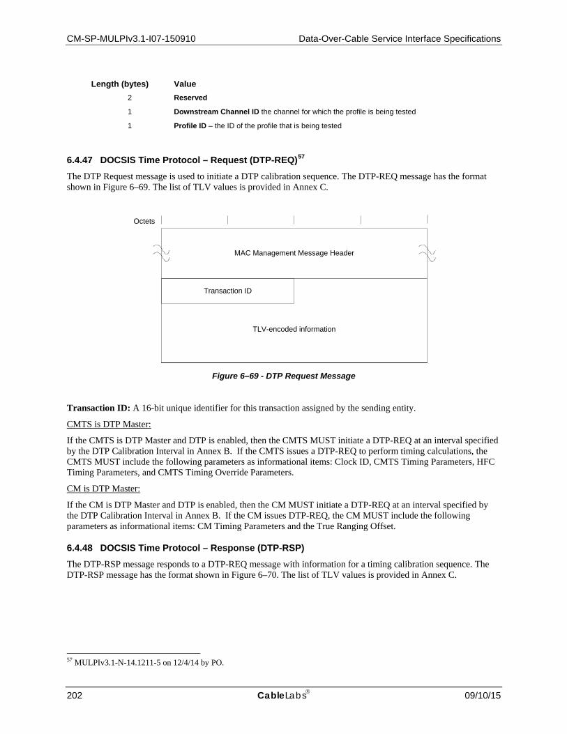
CM-SP-MULPIv3.1-I07-150910 Data-Over-Cable Service Interface Specifications
202 CableLabs 09/10/15
Length (bytes) Value
2 Reserved
1 Downstream Channel ID the channel for which the profile is being tested
1 Profile ID – the ID of the profile that is being tested
6.4.47 DOCSIS Time Protocol – Request (DTP-REQ)57 The DTP Request message is used to initiate a DTP calibration sequence. The DTP-REQ message has the format shown in Figure 6–69. The list of TLV values is provided in Annex C.
Figure 6–69 - DTP Request Message
Transaction ID: A 16-bit unique identifier for this transaction assigned by the sending entity.
CMTS is DTP Master:
If the CMTS is DTP Master and DTP is enabled, then the CMTS MUST initiate a DTP-REQ at an interval specified by the DTP Calibration Interval in Annex B. If the CMTS issues a DTP-REQ to perform timing calculations, the CMTS MUST include the following parameters as informational items: Clock ID, CMTS Timing Parameters, HFC Timing Parameters, and CMTS Timing Override Parameters.
CM is DTP Master:
If the CM is DTP Master and DTP is enabled, then the CM MUST initiate a DTP-REQ at an interval specified by the DTP Calibration Interval in Annex B. If the CM issues DTP-REQ, the CM MUST include the following parameters as informational items: CM Timing Parameters and the True Ranging Offset.
6.4.48 DOCSIS Time Protocol – Response (DTP-RSP) The DTP-RSP message responds to a DTP-REQ message with information for a timing calibration sequence. The DTP-RSP message has the format shown in Figure 6–70. The list of TLV values is provided in Annex C.
57 MULPIv3.1-N-14.1211-5 on 12/4/14 by PO.
MAC Management Message Header
Octets
Transaction ID
TLV-encoded information
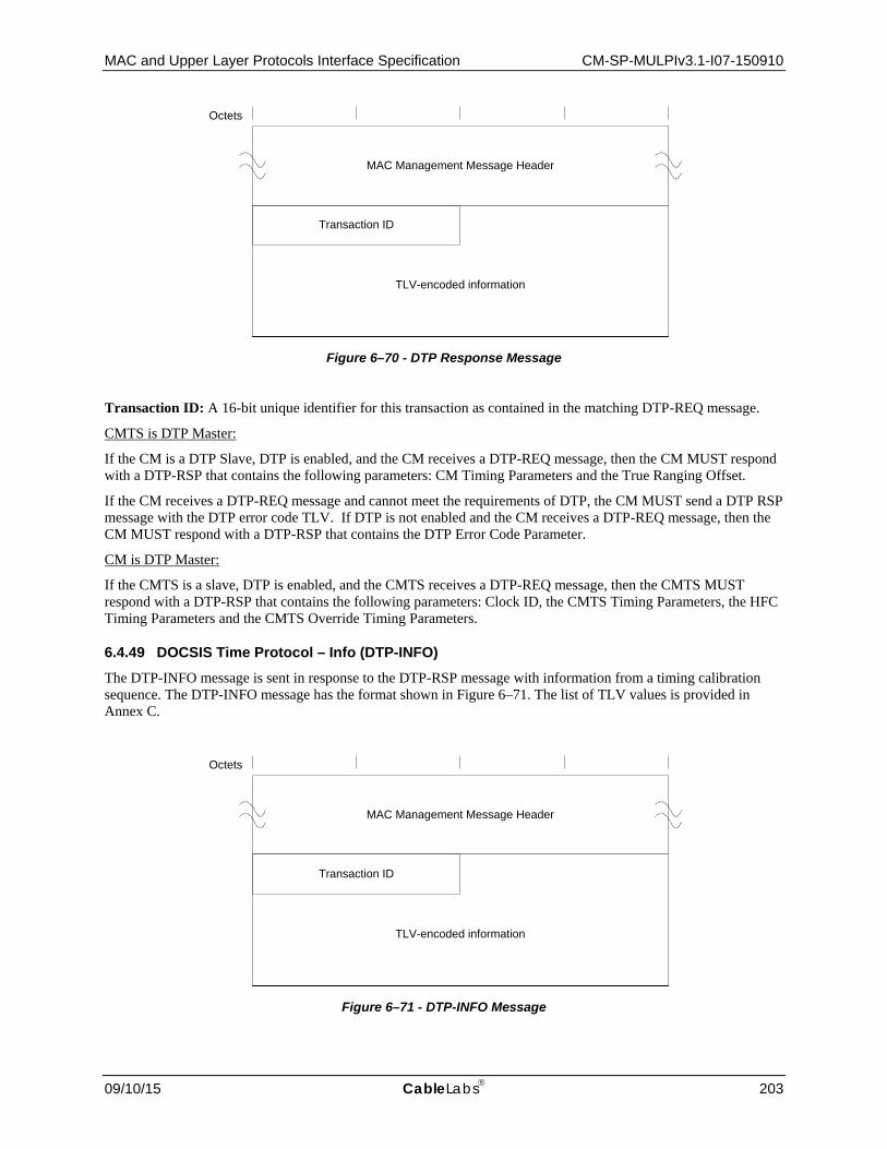
MAC and Upper Layer Protocols Interface Specification CM-SP-MULPIv3.1-I07-150910
09/10/15 CableLabs 203
Figure 6–70 - DTP Response Message
Transaction ID: A 16-bit unique identifier for this transaction as contained in the matching DTP-REQ message.
CMTS is DTP Master:
If the CM is a DTP Slave, DTP is enabled, and the CM receives a DTP-REQ message, then the CM MUST respond with a DTP-RSP that contains the following parameters: CM Timing Parameters and the True Ranging Offset.
If the CM receives a DTP-REQ message and cannot meet the requirements of DTP, the CM MUST send a DTP RSP message with the DTP error code TLV. If DTP is not enabled and the CM receives a DTP-REQ message, then the CM MUST respond with a DTP-RSP that contains the DTP Error Code Parameter.
CM is DTP Master:
If the CMTS is a slave, DTP is enabled, and the CMTS receives a DTP-REQ message, then the CMTS MUST respond with a DTP-RSP that contains the following parameters: Clock ID, the CMTS Timing Parameters, the HFC Timing Parameters and the CMTS Override Timing Parameters.
6.4.49 DOCSIS Time Protocol – Info (DTP-INFO) The DTP-INFO message is sent in response to the DTP-RSP message with information from a timing calibration sequence. The DTP-INFO message has the format shown in Figure 6–71. The list of TLV values is provided in Annex C.
Figure 6–71 - DTP-INFO Message
MAC Management Message Header
Octets
Transaction ID
TLV-encoded information
MAC Management Message Header
Octets
Transaction ID
TLV-encoded information

CM-SP-MULPIv3.1-I07-150910 Data-Over-Cable Service Interface Specifications
204 CableLabs 09/10/15
Transaction ID: A 16-bit unique identifier for this transaction as contained in the corresponding DTP-RSP message.
CMTS is DTP Master:
If the CMTS is a DTP Master DTP is enabled, and the CMTS receives a DTP-RSP message, the CMTS MUST respond with a DTP-INFO that contains the Timing Adjust parameter.
CM is DTP Master:
If the CM is a DTP Master, DTP is enabled, and the CM receives a DTP-RSP message, the CM MUST respond with a DTP-INFO that contains the following parameters as informational items: Timing Adjust and HFC Timing Parameters.
6.4.50 DOCSIS Time Protocol – Acknowledge (DTP-ACK) The DTP-ACK message has the format shown in Figure 6–72. The list of TLV values is provided in Annex C.
MAC Management Message Header
Octets
Transaction ID
Figure 6–72 - DTP Acknowledge Message
Transaction ID: A 16-bit unique identifier for this transaction as contained in the corresponding DTP-INFO message.
CMTS is DTP Master:
If the CM is a DTP Slave, DTP is enabled, and the CM receives a DTP-INFO message, the CM MUST respond with a DTP-ACK message.
CM is DTP Master:
If the CMTS is a DTP Slave, DTP is enabled, and the CMTS receives a DTP-INFO message, the CMTS MUST respond with a DTP-ACK message.
6.5 PHY Link Channel58
The PHY Link Channel (PLC) relative to the OFDM channel is shown in Figure 6–73.
58 MULPI3.1-N-15.1346-3 on 8/21/15 by PO.

MAC and Upper Layer Protocols Interface Specification CM-SP-MULPIv3.1-I07-150910
09/10/15 CableLabs 205
Figure 6–73 - OFDM Channel with PLC Prior to Interleaving
The PHY Link Channel (PLC) is located in the downstream convergence layer. It is used for several tasks:
• Timestamp • Energy management • Message channel for bringing new CMs on line. • Trigger message for synchronizing an event between the CMTS and CM.
The CMTS MUST assign a unique PLC to each OFDM channel. If there is more than one OFDM channel, the CM will be directed as to which PLC will be the primary PLC for the CM. When the CM initializes, it first locates a PLC. It then acquires just enough configuration information to join a primary downstream profile in the main OFDM channel. From there, it receives further configuration information.
The PLC carries MAC Management Messages which are intended to aid the CM in OFDM channel acquisition. Once the CM has acquired the OFDM channel, the CM does not need to look at MAC Management Messages sent on the PLC unless the CM is required to reacquire the channel for some reason. In order to guarantee that a CM receives all necessary MAC Management Messages, the CMTS MUST ensure that any MAC Management Messages other than OCD messages that are sent on the PLC are additionally sent on the OFDM data channel.
The description of the RF parameters and CRC-24-D is in [DOCSIS PHYv3.1].

CM-SP-MULPIv3.1-I07-150910 Data-Over-Cable Service Interface Specifications
206 CableLabs 09/10/15
6.5.1 PLC Structure The structure of the PLC frame is shown in Figure 6–74.
Figure 6–74 - PLC Frame
There is a preamble of 8 symbols at the beginning of a PLC Frame that consists of a field of fixed pilots. There is no separate preamble for the OFDM data channel. The CM searches for the preamble and the adjacent pilots to lock onto the PLC. Even though the PLC frame starts with a preamble, this specification uses a convention where symbols are numbered starting with the first symbol after the PLC preamble. Symbol Number 0 identifies the first symbol after the PLC preamble.
The data portion of the PLC consists of self-contained message blocks (MB). This specification defines four types of message blocks:
• Timestamp Message Block (TS MB) • Energy Management Message Block (EM MB) • Message Channel Message Block (MC MB) • Trigger Message Block (TR MB)
Each MB has a one one-byte header that consists of a type field followed by configuration bits followed by a data field. The timestamp, energy management and trigger message blocks contain a CRC referred to as a CRC-24-D. The CRC for the message channel is contained directly on the packets within the message channel rather than on the message block structure itself.
Future version of this specification may define additional types of message blocks. A common format for all future message block types has been established in Section 6.5.6.
All message blocks are then mapped into a shared set of consecutive FEC codewords. Thus, the contents of the TS and EM message blocks will be slightly delayed by the FEC codeword size and how that FEC codeword is mapped to the underlying symbols.
The PLC frame is a total of 128 symbols in length that includes the 8 symbol preamble. A calculation of data capacity and frame duration is shown in Table 6–69.

MAC and Upper Layer Protocols Interface Specification CM-SP-MULPIv3.1-I07-150910
09/10/15 CableLabs 207
Table 6–69 - PLC Frame Length Including Preamble
FFT Size
Symbol Time
PLC Frame Data Capacity
Frame Time (ms) based upon Cyclic Prefix (μs)
Sub carriers
FEC Blocks
Raw Bytes
Payload Bytes Min Max 0.9375 μs 1.25 μs 2.5 μs 3.75 μs 5.0 μs
4K 20 μs 8 10 480 360 0.9 1.1 2.68 2.72 2.88 3.04 3.20
8K 40 μs 16 20 960 720 1.0 1.1 5.24 5.28 5.44 5.60 5.76
6.5.2 Timestamp Message Block The timestamp MB contains the eight-byte DOCSIS timestamp. The TS MB MUST be the first MB sent by the CMTS on the PLC after the preamble. The TS MB MUST appear in every PLC frame sent by the CMTS. The timestamp references the end of the last symbol of the preamble at the start of the PLC frame that contains the timestamp.
Timestamp Reference Point is defined by [DOCSIS PHYv3.1]. The CMTS MUST locate the timestamp MB directly after the preamble on a PLC. The CMTS MUST transmit the Timestamp MB exactly once in every PLC frame.
Figure 6–75 - Timestamp Message Block
The timestamp message block is shown in Figure 6–75 and described in Table 6–70.
Table 6–70 - Timestamp MB Field Description
Field Size Value Description Type 4 bits 1 Timestamp MB
R 4 bits 0 Reserved
Timestamp 8 bytes Extended Timestamp
CRC 3 bytes CRC-24-D CRC field is computed over the entire message block except the CRC field itself, and included in the defined format to allow validation of the integrity Message Block Type and Message Body Size
The timestamp is further described in Section 7.1.5.

CM-SP-MULPIv3.1-I07-150910 Data-Over-Cable Service Interface Specifications
208 CableLabs 09/10/15
6.5.3 Energy Management Message Block The energy management message block (EM MB) contains messages that manage the DOCSIS Light Sleep (DLS) Mode.
The EM MB contains one or more EM Messages (EMMs). Each EMM is associated with an EM group. An EMM consists of an EM-ID and a Sleep Time. The EM-ID identifies a CM or a group of CMs. The Sleep Time is assigned a point in the future where the CM(s) are to wake up and listen to the PLC for a new EMM.
The CMTS MAY insert zero, one or more EM MBs into the PLC frame. If the EM MBs are included, the CMTS MUST locate the first EM MB directly after the TS MB or directly after TR MB, if TR MB is included. The CMTS MUST insert subsequent EM MBs directly after the first EM MB.
For the sleep time reference field in the EM MB, the CMTS MUST point to the Timestamp Reference Point of the future PLC frame that contains the next EM MB that is to be received by the CMs in the corresponding DLS Group.
Figure 6–76 - Energy Management Message Block
The energy management message block is shown in Figure 6–76 and explained in Table 6–71.
Table 6–71 - Energy Management MB Field Description
Field Size Value Description Type 4 bits 2 Energy Management MB Type
List Size 4 bits The number of EMMs in the block. Note that a value of zero signifies a Message Block with 16 EMMs.
S 1 bit 0 – Resume multistate operation 1 – Suspend multistate operation
Suspend Request. This field allows the CMTS to instruct CMs to suspend multi-sub-state DLS operation and remain in DLS-2 sub-state.

MAC and Upper Layer Protocols Interface Specification CM-SP-MULPIv3.1-I07-150910
09/10/15 CableLabs 209
Field Size Value Description EM-ID 15 bits Energy Management Identifier.
Sleep Time 32 bits This is the timestamp value reference to the beginning of the preamble for the PLC frame that the CM would wake up and start receiving on the PLC. Note that the 4 byte value in the EMM corresponds to the DOCSIS 3.0 Timestamp, as shown in Figure 7–1.
CRC 3 bytes CRC-24-D CRC field is computed over the entire message block except the CRC field itself, and included in the defined format to allow validation of the integrity Message Block Type and Message Body Size.
The energy management technique is described in Section 11.7.
6.5.4 Message Channel Message Block The message channel connects the CMTS MAC to the CM MAC. The contents of the message block contain properly formatted DOCSIS MAC Management Messages.
The CMTS MUST transmit the Message Channel MB as the last MB in the PLC Frame unless other Message Blocks occupy the entire payload of the PLC. The message channel MB continues to the end of the frame.
The MMM messages are segmented across successive message blocks. If the CMTS has no messages to send in the MC, the CMTS MUST fill the MC MB with the specified idle pattern. Packets can be sent back to back without an idle pattern in between them.
Figure 6–77 - Message Channel Message Block
The message channel message block is shown in Figure 6–77 and described in Table 6–72.
Table 6–72 - Message Channel MB Field Description
Field Size Value Description Type 4 bits 3 Message Channel MB
R 3 bits 0 Reserved
S 1 bit 0 1
Packet Start Pointer field is not present Packet Start Pointer field is present

CM-SP-MULPIv3.1-I07-150910 Data-Over-Cable Service Interface Specifications
210 CableLabs 09/10/15
Field Size Value Description Packet Start Pointer 2 bytes Byte offset to the start of the first part of a new message. A value of 0x00
indicates the next byte is the beginning of a new packet.
Message Channel Variable Contains MMM segment or a 0xFF fill pattern
Note: The minimum length of the MC MB is one byte when the MC MB includes no Message Channel field.
6.5.5 Trigger Message Block The Trigger MB provides a mechanism for synchronizing an event at the CMTS and CM. The CMTS inserts a TR MB into the PLC and performs an action at a specific time aligned with the PLC frame. When the CM detects the TR MB, it performs an action at the same relative specified time aligned with the PLC frame received at the CM.
Figure 6–78 - Trigger Message Block
The trigger message block is shown in Figure 6–78 and described in Table 6–73.
Table 6–73 - Trigger MB Field Description
Field Size Value Description Message Block Type 4 bits 4 Trigger MB
Trigger Type 4 bits 1 Identifies type of action to perform
Transaction ID 1 byte Increments on each TR MB sent
Trigger Group 2 bytes Group for unicast, multicast and broadcast triggers
Frame Delay 1 byte 2 to 31 How many frames to wait before performing action
Symbol Select 1 byte 0 to 127 Which symbol in PLC frame to perform action upon
CRC 3 bytes CRC-24-D CRC field is computed over the entire message block except the CRC field itself, and included in the defined format to allow validation of the integrity Message Block Type and Message Body Size.

MAC and Upper Layer Protocols Interface Specification CM-SP-MULPIv3.1-I07-150910
09/10/15 CableLabs 211
The Trigger Type field identifies the type of measurement to be performed. Value is unsigned integer from 0 to 15, with default = 1.
The Transaction Identifier field increments by one on each trigger message that is sent, rolling over at value 255. Value is unsigned integer from 0 to 255.
The Trigger Group field identifies which group of CMs should respond to the trigger message. A CM responds to the trigger message if it has been configured as trigger-enabled and it has membership in the specified Trigger Group. If the CM has not been configured as trigger-enabled, it does not respond to trigger messages.
The Frame Delay field tells the CM how many frames to wait before performing the specified action. Frame Delay = 1 (not permitted) would indicate to perform the action in the next PLC frame after the frame containing the TR MB; Frame Delay = 2 indicates to perform the action in the second PLC frame after the TR MB; etc. The value is an unsigned integer from 2 to 31, with default = 2. Values 0 and 1 are not permitted as they may not give the CM adequate time to prepare for the action. The CMTS MUST specify a Frame Delay value of 2 or more for a channel with an 8K FFT and 4 or more for a channel with a 4K FFT.
The Symbol Select field tells the CM which symbol in the specified PLC frame to perform the action upon. Symbol Select = 0 indicates to perform the action on the OFDM symbol aligned with the first symbol after the PLC preamble which corresponds to the first PLC data symbol; Symbol Select = 1 indicates to perform the action on the OFDM symbol aligned with the second symbol after PLC preamble which corresponds to the second PLC data symbol; Symbol Select = 120 indicates to perform the action on the OFDM symbol aligned with the first symbol of the PLC preamble,; and so on. The value is an unsigned integer from 0 to 127. In addition to selecting a symbol, this parameter by convention points to the time instant at the beginning of the selected symbol.
When commanded to do so via a management object, the CMTS MUST insert a single TR MB into the PLC. The CMTS MUST position the trigger MB in the PLC frame immediately after the timestamp MB but before any EM MBs, and before the MC MB. The CMTS MUST increment the Transaction ID field in each successive TR MB it sends. The CMTS MUST transmit either 0 or 1 TR MB in a PLC frame.
When trigger-enabled via a management object, the CM MUST detect the TR MB.
For a Downstream Symbol Capture measurement, the following CMTS requirements apply:
• The CMTS MUST set Trigger Type = 1. • The CMTS MUST capture and report the downstream symbol specified in the TR MB. • The CMTS MUST report the timestamp from the PLC frame pointed to by the trigger message. • The CMTS MUST report the Transaction ID.
For a Downstream Symbol Capture measurement, the following CM requirements apply:
• When not in an Energy Management Mode or not operating on battery power, the CM MUST capture and report the downstream symbol specified in the TR MB if it is trigger-enabled and a member of the Trigger Group specified in the TR MB.
• The CM MUST report the Transaction ID.
6.5.5.1 Application of Trigger Message Block This section is informational. It describes how the TR MB message is used.
In order for a CM to respond to the TR MB, the CM is first awakened if it is in sleep mode. The CM is configured to enable triggering. The CM is configured to belong to a Trigger Group. The CMTS inserts a single trigger message per measurement including a Trigger Group parameter associated with the group of CMs that are intended to perform the measurement. The message is acted upon only by those CMs which are trigger-enabled and reside in the appropriate Trigger Group; unicast, multicast and broadcast groups are supported.
The initial application of the TR MB is to enable a Downstream Symbol Capture measurement per [DOCSIS PHYv3.1] section 9.3.1. The goal of this measurement is to capture the same OFDM symbol at the CMTS and CM. The captured symbol is a normal symbol (not a special test symbol or altered in any way) carrying downstream QAM data traffic. The entire OFDM symbol is captured across all subcarriers, in the form of I and Q samples, at the

CM-SP-MULPIv3.1-I07-150910 Data-Over-Cable Service Interface Specifications
212 CableLabs 09/10/15
CMTS and CM. The PLC frame is used only as a timing mechanism to define the location of the desired symbol in the downstream OFDM symbol stream. For Downstream Symbol Capture, the Trigger Type parameter is set to 1.
An OSS management station initiates the measurement via a write to a CMTS management object. The CMTS inserts the TR MB in the PLC of the specified OFDM downstream channel, waits the number of PLC frames defined by the Frame Delay parameter, and captures the OFDM symbol specified by the Symbol Select parameter. This capture will result in a number of frequency-domain data points equal to the FFT length in use (4096 or 8192), 16 bits in width for each of I&Q, with LSBs padded with zeros if required.
A trigger-enabled CM addressed by the Trigger Group parameter detects the presence of the TR MB in the PLC, waits the number of PLC frames defined by the Frame Delay parameter, and captures the OFDM symbol specified by the Symbol Select parameter. This capture will result in a number of time-domain data points equal to the FFT length in use (4096 or 8192), 16 bits in width for each of I&Q, with LSBs padded with zeros if required.
The CMTS captures the 8-byte extended timestamp value present in the PLC frame in which the OFDM symbol was captured, and returns it to the management station along with the captured OFDM symbol samples; this aids in identifying the captured data, and permits comparing the capture time with other timestamped events such as burst noise and FEC errors. The CMTS and CM both return the Transaction ID to the management station along with the captured data; this provides a mechanism for grouping CMTS and CM data from the same symbol for analysis, and for detecting missed captures. If no data was successfully captured by the CMTS and/or a CM, that condition is reported to the management station in lieu of data, along with the Transaction ID if available. The data is stored locally in the CMTS and CM, and returned to the management station based on a command issued by the management station to a management object in the CMTS and CM.
The OSSI specification should limit how many Trigger messages can be sent before the captured data is read out from the CM by the OSS, in order to limit CM memory requirements. The recommended initial default value is a maximum of one capture at a time in a given CM. If a new Trigger message arrives before the previous captured data has been read out, the CM ignores the new trigger and reports that condition via a management object.
6.5.6 Future Use Message Blocks This specification defines formats of four message block types for the PLC. Other types of Message Blocks may be defined in the future. In order to make the PLC protocol extensible, Cable Modems compliant with this version of specification need to be able to skip and ignore Message Blocks they don't support. For this purpose a generic format has been defined for Message Block with types 5 through 15. This format is presented on Figure 6–79.
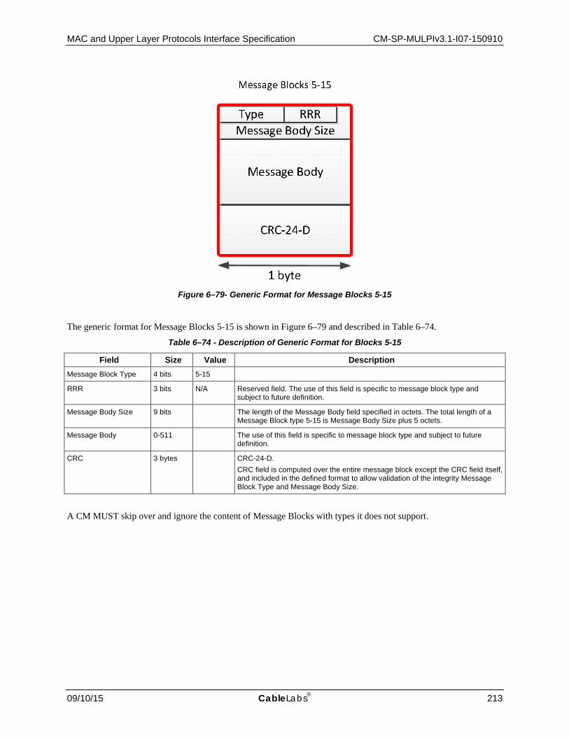
MAC and Upper Layer Protocols Interface Specification CM-SP-MULPIv3.1-I07-150910
09/10/15 CableLabs 213
Figure 6–79- Generic Format for Message Blocks 5-15
The generic format for Message Blocks 5-15 is shown in Figure 6–79 and described in Table 6–74.
Table 6–74 - Description of Generic Format for Blocks 5-15
Field Size Value Description Message Block Type 4 bits 5-15
RRR 3 bits N/A Reserved field. The use of this field is specific to message block type and subject to future definition.
Message Body Size 9 bits The length of the Message Body field specified in octets. The total length of a Message Block type 5-15 is Message Body Size plus 5 octets.
Message Body 0-511 The use of this field is specific to message block type and subject to future definition.
CRC 3 bytes CRC-24-D. CRC field is computed over the entire message block except the CRC field itself, and included in the defined format to allow validation of the integrity Message Block Type and Message Body Size.
A CM MUST skip over and ignore the content of Message Blocks with types it does not support.

CM-SP-MULPIv3.1-I07-150910 Data-Over-Cable Service Interface Specifications
214 CableLabs 09/10/15
7 MEDIA ACCESS CONTROL PROTOCOL OPERATION
7.1 Timing and Synchronization
One of the major challenges in designing a MAC protocol for a cable network is compensating for the delays involved. These delays can be an order of magnitude larger than the transmission burst time in the upstream. To compensate for these delays, the cable modem needs to be able to time its transmissions precisely to arrive at the CMTS at the start of the assigned minislot.
To accomplish this, two pieces of information are needed by each cable modem:
• a global timing reference sent downstream from the CMTS to all cable modems, and • a timing offset, calculated by the CMTS during a ranging process, for each cable modem.
7.1.1 Global Timing Reference DOCSIS 3.0 and DOCSIS 3.1 CMTSs provide a timing reference on certain downstream channels. Downstream channels providing this timing reference are called "primary capable" and noted as such in the MAC Domain Descriptor MAC Management Message carried on that downstream channel. The physical layer provides the clock frequency information. Timestamps (coupled with UCD timestamp snapshots for S-CDMA and OFDMA upstream channels) provide the phase information. Timestamps are carried in two different structures: SYNC messages and Timestamp Message Blocks. SYNC messages are transmitted on SC-QAM downstreams and contain a 4-byte Timestamp while Timestamp Message Blocks are transmitted on the PLC on OFDM downstreams and carry an 8-byte Extended Timestamp.
It is intended that the nominal interval between synchronization messages be tens of milliseconds and the nominal interval between UCD messages be no more than 2 seconds. This imposes relatively little downstream overhead while letting cable modems acquire their global timing synchronization quickly.
For DOCSIS 3.0 and DOCSIS 3.1 CMs, the CMTS conveys the global timing reference to a CM on the CM's Primary Downstream Channel. The CM MUST use a single synchronization timebase obtained on its Primary Downstream Channel for upstream burst timing for all of the upstream channels that the CM is using. A cable modem MUST NOT use an upstream channel until it has successfully synchronized to its Primary Downstream Channel as defined in Section 10.2.1.
7.1.2 CM Synchronization The cable modem achieves MAC synchronization once it has received at least two timing synchronization messages, received one UCD message, has locked to the downstream symbol clock, and has verified that its clock tolerances are within specified limits (as defined in [DOCSIS PHYv3.1]). The cable modem MUST lock to the downstream symbol clock on its Primary Downstream Channel using the M and N integer frequency ratio values specified in [DOCSIS DRFI] as the source for upstream burst timing, regardless of whether its upstream channels are using TDMA, S-CDMA, OFDMA, or any combination of these three types.
7.1.3 Ranging Ranging is the process of acquiring the correct timing offset such that the cable modem's transmissions are aligned to the correct minislot boundary. The timing delays through the PHY layer of the CM and CMTS MUST be relatively constant with the exception of the timing offsets specified in [DOCSIS PHYv3.1], related to modulation rate changes to accommodate a Pre-3.0 DOCSIS upstream receiver implementation. For TDMA, any variation in the PHY delays MUST be accounted for by the CMTS in the guard time of the upstream PMD overhead.
7.1.3.1 Broadcast Initial Ranging First, a cable modem MUST synchronize to the downstream as described in Section 7.1.2, and learn the upstream channel characteristics through the Upstream Channel Descriptor MAC management message. At this point, the cable modem MUST scan the Bandwidth Allocation MAP message to find a Broadcast Initial Maintenance Region (refer to Section 7.2.1.2.3). The CMTS MUST schedule Broadcast Initial Maintenance regions large enough to

MAC and Upper Layer Protocols Interface Specification CM-SP-MULPIv3.1-I07-150910
09/10/15 CableLabs 215
account for the worst case round-trip plant delay. On OFDMA and S-CDMA channels, the CMTS MUST schedule Broadcast Initial Maintenance transmit opportunities such that they align with the channel's frames and span an integral number of frames (refer to [DOCSIS PHYv3.1]). The type of message transmitted in the Broadcast Initial Ranging region depends on the upstream channel type and other factors described in the following subsections.
7.1.3.1.1 Broadcast Initial Ranging on SC-QAM Upstreams
For TDMA and S-CDMA upstream channels, the cable modem MUST transmit either a Bonded Initial Ranging Request message (B-INIT-RNG-REQ), or a Ranging Request message (RNG-REQ) in a Broadcast Initial Maintenance region. The CM MUST transmit a B-INIT-RNG-REQ if the CM is ranging for the first time after power-up or reinitialization on the first upstream channel (see Section 10.2.3). If the condition for transmitting a B-INIT-RNG-REQ is not met, the CM MUST transmit a RNG-REQ. The CM sets the SID field in the RNG-REQ as defined in Section 6.4.5. The CM MUST set its initial timing offset to the amount of internal fixed delay equivalent to putting this CM next to the CMTS (i.e., no plant delay). This amount includes delays introduced through a particular implementation and the downstream PHY interleaving latency.
Once the CMTS has successfully received the RNG-REQ, INIT-RNG-REQ, or B-INIT-RNG-REQ message, it MUST return a Ranging Response message addressed to the individual cable modem. Within the Ranging Response message MUST be a temporary SID assigned to this cable modem (unless the CM has retained a previous Primary SID during a UCC, DCC, or UCD change, or a Ranging SID through registration or DBC messaging) until it has completed the registration process. The message from the CMTS MUST also contain information on RF power level adjustment and offset frequency adjustment as well as any timing offset corrections. Ranging adjusts each CM's timing offset such that it appears to be located right next to the CMTS.
7.1.3.1.2 Broadcast Initial Ranging on OFDMA Upstreams59
For OFDMA upstream channels, the Broadcast Initial Maintenance region occupies a much larger percentage of the available spectrum. In order to reduce the size of this region, the burst sent in Broadcast Initial Maintenance regions on OFDMA upstream channels is a specialized shortened message called the OFDMA Initial Ranging Request message (O-INIT-RNG-REQ). The cable modem MUST transmit an OFDMA Initial Ranging Request message (O-INIT-RNG-REQ) in a Broadcast Initial Maintenance region on an OFDMA upstream channel. The CM MUST set its initial timing offset to the amount of internal fixed delay equivalent to putting this CM next to the CMTS (i.e., no plant delay). This amount includes delays introduced through a particular implementation and the downstream PHY interleaving latency.
Once the CMTS has successfully received the O-INIT-RNG-REQ message, it MUST return a Ranging Response message addressed to the individual cable modem. Within the Ranging Response message sent by the CMTS MUST be a SID assigned to this cable modem. If the CMTS previously assigned a Primary SID during a UCC, DCC, or UCD change or a Ranging SID through registration or DBC messaging, and the SID is still valid, the CMTS MUST use this previously assigned SID. If the CMTS does not have a valid SID assigned to the cable modem, the CMTS MUST assign a temporary SID to this cable modem until it has completed the registration process. The Ranging Response message from the CMTS MUST also contain information on RF power level adjustment and offset frequency adjustment as well as any timing offset corrections. Ranging adjusts each CM's timing offset such that it appears to be located right next to the CMTS.
7.1.3.2 Unicast Initial Ranging The next phase of ranging depends on the upstream channel type as detailed in the following subsections.
7.1.3.2.1 Unicast Initial Ranging on SC-QAM Upstreams
After receiving a Ranging Response message after transmitting in a Broadcast Initial Maintenance region on an SC-QAM upstream, the cable modem MUST now wait for an individual Station Maintenance or Unicast Initial Maintenance region assigned to its temporary SID (or previous primary SID if ranging as a result of a UCC, DCC, or UCD change, or Ranging SID if one has been assigned). The CM MUST now transmit a Ranging Request (RNG-REQ) message at this time using the temporary SID (or primary/Ranging SID, as appropriate) along with any power level and timing offset corrections. 59 MULPIv3.1-N-15.1295-1 on 6/2/15 by PO.

CM-SP-MULPIv3.1-I07-150910 Data-Over-Cable Service Interface Specifications
216 CableLabs 09/10/15
The CMTS MUST return another Ranging Response message to the cable modem with any additional fine tuning required. The ranging request/response steps MUST be repeated by the CM and CMTS, until the response contains a Ranging Successful notification or the CMTS aborts ranging. Once successfully ranged, the cable modem MUST join normal data traffic in the upstream. See Section 10, for complete details on the entire initialization sequence. In particular, state machines, the applicability of retry counts, and timer values for the ranging process are defined in Section 10.3.
NOTE: The burst type to use for any CM transmission is defined by the Interval Usage Code (IUC). Each IUC is mapped to a burst type in the UCD message.
7.1.3.2.2 Unicast Initial Ranging on OFDMA Upstreams60
After receiving a Ranging Response message after transmitting in a Broadcast Initial Maintenance region on an OFDMA upstream, the cable modem MUST now wait for an individual Station Maintenance region assigned to its temporary SID (or previous primary SID if ranging as a result of a UCC, DCC, or UCD change, or Ranging SID if one has been assigned). The CM MUST transmit a B-INIT-RNG-REQ if the CM is ranging for the first time after power-up or reinitialization on the first upstream channel (see Section 10.2.3). A CM MUST transmit a RNG-REQ if the CM is not ranging for the first time following initialization after power-up or reinitialization on the first upstream channel. The CM sets the SID field in the RNG-REQ as defined in Section 6.4.5. The CM MUST now transmit the B-INIT-RNG-REQ or RNG-REQ message in the unicast Station Maintenance opportunity for the temporary SID (or primary/Ranging SID, as appropriate) along with any power level and timing offset corrections.
If the first ranging request message that the CMTS receives from a CM after assigning the CM a temporary SID is not a B-INIT-RNG-REQ, the CMTS MUST send a RNG-RSP message to the CM with the ranging status set to "abort". Otherwise, the CMTS MUST return another Ranging Response message to the cable modem with any additional fine tuning required. The ranging request/response steps MUST be repeated by the CM and CMTS, until the response contains a Ranging Successful notification or the CMTS aborts ranging. (For OFDMA channels, probing opportunities will also be available during the initial ranging process. These probing opportunities are used to adjust the Transmit Equalizer Coefficients. A Ranging Response message MUST be transmitted by the CMTS in response to an upstream probe.) Once successfully ranged, the cable modem MUST join normal data traffic in the upstream. See Section 10, for complete details on the entire initialization sequence. In particular, state machines, the applicability of retry counts, and timer values for the ranging process are defined in Section 10.3.
7.1.4 Timing Units and Relationships The SYNC message conveys a time reference with a resolution of 6.25/64 microseconds (10.24 MHz) to allow the CM to track the CMTS clock with a small phase offset. Since this timing reference is decoupled from particular upstream channel characteristics, a single SYNC time reference may be used for all upstream channels associated with the downstream channel. The SYNC message is used by CMs whose primary downstream channel is SC-QAM.
OFDM downstream channels contain an Extended Timestamp described in section 7.1.5 which is used for synchronization by CMs whose primary downstream channel is OFDM.
The bandwidth allocation MAP uses time units of "minislots." A minislot represents the time needed for CM transmission of a fixed number of symbols. A minislot is the unit of granularity for upstream transmission opportunities; there is no implication that any PDU can actually be transmitted in a single minislot.
7.1.4.1 TDMA Timing Units and Relationships
7.1.4.1.1 Minislot Capacity
On TDMA channels, the size of the minislot, expressed as a multiple of the SYNC time reference, is carried in the Upstream Channel Descriptor. The example in Table 7–1 relates minislots to the SYNC time ticks (assuming QPSK modulation).
60 MULPIv3.1-14.1211-5 on 12/4/14 by PO, MULPIv3.1-N-15.1295-1 on 6/2/15 by PO.

MAC and Upper Layer Protocols Interface Specification CM-SP-MULPIv3.1-I07-150910
09/10/15 CableLabs 217
Table 7–1 - Example Relating Minislots to Time Ticks
Parameter Example Value
Time tick 6.25 microseconds
Bytes per minislot 16 (nominal, when using QPSK modulation)
Symbols/byte 4 (assuming QPSK)
Symbols/second 2560000
Minislots/second 40000
Microseconds/minislot 25
Ticks/minislot 4
NOTE: The symbols/byte is a characteristic of an individual burst transmission, not of the channel. A minislot in this instance could represent a minimum of 16 or a maximum of 48 bytes, depending on the modulation choice.
If an upstream channel is a Type 3a or 4a channel, the Minislot Size field (M) of the UCD MAY be assigned the value 0 by the CMTS for a 5.12 Msps channel, in which case the minislot size is 1 Timebase Tick. If a channel is to be accessible to DOCSIS 1.x Cable Modems, the CMTS MUST follow the DOCSIS 1.x requirements for timing units and relationships for that UCD.
7.1.4.1.2 Minislot Numbering
The MAP counts minislots in a 32-bit counter that normally counts to (2(26-M) - 1) and then wraps back to zero. The CMTS MUST match the least-significant bits (i.e., bit 0 to bit 25-M) of the minislot counter to the most-significant bits (i.e., bit 6+M to bit 31) of the SYNC timestamp counter. That is, minislot N begins at timestamp reference (N*T*64), where T = 2M is the UCD multiplier that defines the minislot (i.e., the number of timeticks per minislot). Note: The unused upper bits of the 32-bit minislot counter (i.e., bit 26-M to bit 31) are unused and MUST be ignored by the CM.
7.1.4.2 S-CDMA Timing Units and Relationships
7.1.4.2.1 Minislot Capacity
On S-CDMA channels, the size of the minislot is dependent on the modulation rate, the codes per minislot, and the spreading intervals per frame, which are all carried in the Upstream Channel Descriptor. The timing units and relationships for S-CDMA are covered in detail in [DOCSIS PHYv3.1]. An example of the timing relationships (assuming 64-QAM modulation) is shown in Table 7–2.
Table 7–2 - Example of Minislot Capacity in S-CDMA mode
Parameter Example Value
Spreading intervals per frame 10
Active code length 128
Codes per minislot 4
Minislots per frame 32
Symbols per minislot 40
Bytes per minislot 30 (nominal, when using 64-QAM modulation)
Bits/symbol 6 (assuming 64-QAM)
Symbols/second 5120000
Minislots/second 128000
Microseconds/minislot 250

CM-SP-MULPIv3.1-I07-150910 Data-Over-Cable Service Interface Specifications
218 CableLabs 09/10/15
NOTE: The S-CDMA the value of Microseconds/minislot in Table 7–2 is not equal to the inverse of Minislots/second since S-CDMA minislots are the same length as the frames and are sent out in parallel.
7.1.4.2.2 Minislot Numbering
Minislot numbering in S-CDMA mode is described in detail in [DOCSIS PHYv3.1].
7.1.4.3 OFDMA Timing Units and Relationships
7.1.4.3.1 Minislot Capacity
On OFDMA channels, the size of the minislot in total symbols is fixed for the channel. The size is specified by the number of symbols in a frame combined with the number of subcarriers per minislot. The bit loading and pilot pattern are variable per minislot based on the minislot location in the frame and the burst profile being used. Thus, the minislot capacity is profile dependent.
7.1.4.3.2 Minislot Numbering
Minislot numbering in OFDMA mode is described in detail in [DOCSIS PHYv3.1].
7.1.5 Extended Timestamp DOCSIS 3.1 introduces an eight-byte extended timestamp. The value of the timestamp is referenced to the end of the PLC preamble.
The DOCSIS Extended Timestamp has two additional features when compared to the original DOCSIS timestamp.
• The extended timestamp is now an absolute timestamp rather than a relative timestamp • The extended timestamp has a higher degree of precision
The extended timestamp has the concept of Epoch. Epoch refers to a point in time where the timestamp begins to count. The DOCSIS extended timestamp uses the same start time as [IEEE 1588-2008] which is Midnight, January 1, 1970. The DOCSIS extended timestamp uses the same method for counting as [IEEE 1588-2008]. This method is known as TAI (International Atomic Time). TAI moves forward monotonically and does not adjust for leap seconds. This differs from protocols such as Unix time that are adjusted for leap seconds.
Where the DOCSIS extended timestamp and [IEEE 1588-2008] differ is their time base. [IEEE 1588-2008] is based upon a 1 ns clock. The DOCSIS extended timestamp is based upon the OFDM clock rate of 204.8 MHz. This is done so that the timestamp will accurately reflect the timing of the OFDM channel.
There are four additional lower bits that allow either a higher clock resolution or the ability to communicate phase information within the 204.8 MHz clock. In a standalone CMTS system, these bits may be set to zero. In a system where the CMTS is synchronized to a network clock, these lower four bits may represent the phase of the network clock with respect to the DOCSIS clock.
The next five bits of the DOCSIS extended timestamp is used to divide the 204.8 MHz clock by 20 to produce a 10.24 MHz clock. These five bits are constructed such that field should count from a value of 0b00000 to 0b10011 and then reset to 0b00000.
The 10.24 MHz clock is then used to drive the remaining higher order bits. These bits include a 32-bit field that is compatible with the regular DOCSIS four-byte timestamp. The highest 23 bits extend the timestamp to a count high enough that the timestamp can be referenced to a known point in time.

MAC and Upper Layer Protocols Interface Specification CM-SP-MULPIv3.1-I07-150910
09/10/15 CableLabs 219
Figure 7–1 - Extended Timestamp Structure
7.1.6 Timestamp Rules for Systems with both Primary Capable OFDM Channels and Primary Capable SC-QAM Channels61
SC-QAM channels use the SYNC message to convey timestamp information and OFDM channels use the Timestamp Message Block to convey timestamp information. When a CMTS supports both primary capable SC-QAM and OFDM downstream channels simultaneously, the CMTS MUST ensure that the timestamp message sent on the SYNC messages is derived from the same source as the 32-bit "D3.0 Timestamp" contained within the Timestamp Message Block on the OFDM downstream channels. In other words, if the two timestamps are sampled at the same time, the values would be identical. This ensures that CMs using either source will derive the same notion of upstream time. The CMTS MUST insert timestamp information in all downstream OFDM channels. As a result all downstream OFDM channels meet one of the necessary conditions of the "primary-capable downstream channel" definition. If the OFDM channel additionally contains OCD messages explicitly indicating primary-capability, MDD messages containing ambiguity resolution TLVs and UCD and MAP messages for at least one upstream channel in each of the MD-CM-SGs that the downstream channel reaches, the OFDM channel is "primary capable".
7.2 Upstream Data Transmission
7.2.1 Upstream Bandwidth Allocation The CMTS allocates bandwidth for one or more upstream channels. Bandwidth allocated to one CM may be allocated across multiple channels upon which the CM can transmit.
An upstream channel is modeled as a stream of minislots. The CMTS MUST generate the time reference for identifying these slots. The CMTS MUST also control access to these slots by the cable modems. For example, the CMTS may grant some number of contiguous slots to a CM for it to transmit a data PDU. The CM MUST time its transmission so that the CMTS receives the CM's transmission in the time reference specified. This section describes the elements of the protocol used in requesting, granting, and using upstream bandwidth. The basic mechanism for assigning bandwidth management is the allocation MAP (refer to Figure 7–2).
The allocation MAP is a MAC Management Message which is transmitted by the CMTS on the downstream channel and which describes, for some interval, the uses of the upstream minislots. A given MAP may describe some slots as grants in which particular CMs may transmit data, other slots as available for contention transmission, and other slots as an opportunity for new CMs to join the link.
Many different scheduling algorithms may be implemented in the CMTS by different vendors; this specification does not mandate a particular algorithm. Instead, it describes the protocol elements by which bandwidth is requested and granted.
61 MULPI3.1-N-15.1347-2 on 8/21/15 by PO.

CM-SP-MULPIv3.1-I07-150910 Data-Over-Cable Service Interface Specifications
220 CableLabs 09/10/15
Figure 7–2 - Allocation Map
The bandwidth allocation includes the following basic elements:
• Each CM has one or more (14-bit) Service Identifiers (SIDs) as well as a 48-bit (MAC) address. • Upstream bandwidth is divided into a stream of minislots. Each minislot is numbered relative to a master clock
reference maintained by the CMTS. The master reference is distributed to the CMs by means of SYNC and UCD messages (See [DOCSIS PHYv3.1]).
• CMs may issue requests to the CMTS for upstream bandwidth.
The CMTS MUST transmit allocation MAP PDUs on the downstream channel defining the allowed usage of all minislots. Minislot regions that are not allocated to any transmit opportunities are described by an IE in the MAP assigned to the NULL SID (0x0000). The MAP is described in Section 7.2.1.1.
The CMTS scheduler allocates bandwidth on the individual channels based on the available bandwidth on all of the bonded upstream channels. The CMTS MUST be capable of receiving a request on any channel within the upstream bonding group. The CMTS MUST be capable of granting bandwidth in response to that request on any channel within the upstream bonding group. In this manner, the CMTS MAY dynamically distribute upstream traffic across multiple channels. Similarly, the CMTS MAY consider the physical layer parameters on each of the upstream channels and the requested number of bytes to determine the optimal allocations across channels.
The CMTS generates MAPs to send grants to the CM. Because the upstream parameters of each channel may be very different from each other, the allocation start times of the MAPs may be different from each other as well.
Because the allocation start times and acknowledgment times may vary widely, a CM MUST wait until the acknowledgment time for all upstream channels associated with a given service flow is past the time of request before determining if a re-request is necessary.
CMTSs MAY ignore part or all of an upstream bandwidth request. Note that ignoring a request from a CM in Multiple Transmit Channel Mode could result in additional performance degradation (relative to Pre-3.0 DOCSIS) because the CM in Multiple Transmit Channel Mode may take longer to detect lost requests if there are multiple outstanding requests.
7.2.1.1 The Allocation MAP MAC Management Message The allocation MAP is a varying-length MAC Management Message that is transmitted by the CMTS to define transmission opportunities on the upstream channel. It includes a fixed-length header followed by a variable number of Information Elements (IEs) or Probe Information Elements (P-IEs) in the format shown in Section 6.4.4. Each IE defines the allowed usage for a range of minislots. Each P-IE defines the allowed usage for symbols within an OFDMA probe frame and is described further in Section 6.4.4.
NOTE: For TDMA channels, it should be understood by both CM and CMTS that the lower (26-M) bits of alloc start and ack times MUST be used as the effective MAP start and ack times, where M is defined in Section 7.1.4.1.2. The relationship between alloc start/ack time counters and the timestamp counter is further described in Section 7.1.4. For S-CDMA channels the alloc start/ack time counters are defined in minislots

MAC and Upper Layer Protocols Interface Specification CM-SP-MULPIv3.1-I07-150910
09/10/15 CableLabs 221
which are related to the timestamp counter, frame counter, and S-CDMA timestamp snapshot as described in Section 6.4.3. For OFDMA channels, the alloc start time counter is defined in minislots which are related to the timestamp counter, frame counter, and OFDMA timestamp snapshot as described in Section 6.4.3.
7.2.1.2 Information Elements Each IE consists of a 14-bit Service ID (SID), a 4-bit type code (IUC), and a 14-bit starting offset as defined in Section 6.4.4. Since all CMs MUST scan all IEs, it is critical that IEs be short and relatively fixed format. IEs within the MAP are strictly ordered by starting offset. For most purposes, the duration described by the IE is inferred by the difference between the IE's starting offset and that of the following IE. For this reason, the CMTS MUST terminate the list with a Null IE (refer to Table 6–28).
Five types of Service IDs are defined:
1. 0x3FFF - Broadcast, intended for all stations;
2. 0x3E00-0x3FFE - Multicast, purpose is defined administratively. Refer to Annex A.
3. 0x2000-0x3DFF - Expanded Unicast, intended for a particular CM or a particular service within that CM, when supported by both the CM and CMTS;
4. 0x0001-0x1FFF - Unicast, intended for a particular CM or a particular service within that CM;
5. 0x0000 - Null Address, addressed to no station.
A CM MUST support the Expanded Unicast SID space. A CMTS MAY support the Expanded Unicast SID space.
Unicast SIDs (including Expanded Unicast SIDs) assigned by the CMTS MUST be unique on a given logical upstream. The CMTS MAY support unicast SID assignments which are not unique within a single MAC-sublayer domain as long as they are unique on a given logical upstream.
All of the Information Elements defined below MUST be supported by conformant CMs. Conformant CMTSs MAY use any of these Information Elements when creating Bandwidth Allocation MAPs.
7.2.1.2.1 The Request IE
The Request IE provides an upstream interval in which requests may be made for bandwidth for upstream data transmission. The character of this IE changes depending on the class of Service ID. If broadcast, this is an invitation for CMs to contend for requests. Section 7.2.2 describes which contention transmit opportunity may be used. If unicast, this is an invitation for a particular CM to request bandwidth. Unicasts may be used as part of a Quality of Service scheduling scheme (refer to Section 7.2.3). Packets transmitted in this interval by the CM MUST use either the Request MAC Frame format (refer to Section 6.2.4.3) or the Queue-depth Based Request Format (refer to Section 6.2.4.5).
The Priority Request SIDs are defined in the subsection Priority Request Service IDs of Annex A. These allow contention for Request IEs to be limited to service flows of a given Traffic Priority. (Refer to the Traffic Priority subsection of Annex C.)
The CMTS MUST allocate request opportunities in multiples of the number of minislots required to transmit a request on the given channel. For example, if channel one requires 2 minislots per request, then the CMTS allocates request regions in multiples of 2 minislots. A request region of 5 minislots would be illegal on this channel.
For OFDMA channels, there may be one or more request opportunities in a single minislot depending on the minislot size. Each request opportunity occupies a fixed number of symbols, N, and is called a subslot. The value of N is based on the number of subcarriers per minislot as described in Section 8.2.3 of[DOCSIS PHYv3.1]. The number of request opportunities within an OFDMA minislot is given by floor(K/N) where K is the number of symbols per frame as specified in [DOCSIS PHYv3.1]. For minislot sizes of 8 subcarriers, the subslot size is 4 symbols. For minislot sizes of 16 subcarriers, the subslot size is 2 symbols. Each request opportunity starts on a symbol boundary and each opportunity must be fully contained within the minislot. Partial request opportunities MUST NOT be considered as transmit opportunities by the CM on OFDMA channels. When a request opportunity is assigned to a unicast SID, the entire minislot is allocated, but the CM only transmits in one of the subslots within the allocated minislot. The CM MUST transmit in the subslot determined by (minislot number) modulo (number of subslots per minislot) plus one. For example, if there are 4 subslots per minislot and the CM is allocated minislot

CM-SP-MULPIv3.1-I07-150910 Data-Over-Cable Service Interface Specifications
222 CableLabs 09/10/15
number 543 to one of its unicast SIDs, the CM transmits its bandwidth request in the 4th subslot in that minislot. Allocations to multicast SIDs (request/priority etc.) are treated like broadcast opportunities from a backoff and request subslot perspective.
7.2.1.2.2 The Request_2 IE
The Request_2 IE provides a second type of upstream interval in which requests for bandwidth may be transmitted. The Request_2 IE replaces the Request/Data IE used in previous generations of DOCSIS.
This region is primarily used in support of the Maximum Scheduled Codes feature on Type 3S and Type 4S upstreams as described in [DOCSIS PHYv3.1].
For OFDMA channels, request subslots are allocated for Request_2 IEs. The subslot parameters are the same as those of the Request IE. (See Section 7.2.1.2.1 for details.)
7.2.1.2.3 The Initial Maintenance IE
The Initial Maintenance IE, when used with the Broadcast SID, provides an interval in which new stations may join the network. A long interval, equivalent to the maximum round-trip propagation delay plus the transmission time of a Ranging Request (RNG-REQ) message (see Section 7.1.3), MUST be provided by the CMTS to allow new stations to perform initial ranging. Packets transmitted by the CM in this interval MUST use one of the ranging request message formats (refer to Section 7.1.3).
On Type 3, Type 4, and Type 5 Upstream Channels, the Initial Maintenance IE MAY be used by the CM and CMTS with a unicast SID. This is done to provide Unicast Initial Maintenance opportunities in place of Station Maintenance opportunities at the discretion of the CMTS. This may be useful if the first unicast ranging opportunity on an S-CDMA channel needs to have Spreader Off just like initial maintenance, but it is not desirable to impose the overhead of having the Spreader Off on routine Station Maintenance. Unicast Initial Maintenance Opportunities only need to be large enough to allow transmission of the ranging request. The CMTS MUST NOT provide unicast Initial Maintenance opportunities on any logical upstream which is not a Type 3, Type 4, or Type 5 upstream. Packets transmitted by the CM in Initial Maintenance IE MUST use the Ranging Message formats per Section 6.4.5. Refer to Section 7.2.1.9 for details on Initial Maintenance IE mapping for OFDMA upstream channels.
7.2.1.2.4 The Station Maintenance IE62
For non-OFDMA upstream channels, the Station Maintenance IE provides an interval in which stations are expected to perform some aspect of routine network maintenance such as ranging. The CMTS sends a unicast station maintenance IE to CMs periodically in order to ensure CM upstream transmit signal fidelity. Parameters such as power level, transmit timing, transmit frequency, and pre-equalization coefficients can be adjusted in periodic ranging. For Upstream Type 1, Type 2, Type 3, and Type 4, packets transmitted by the CM in this interval MUST use the RNG-REQ MAC Management Message format (see Section 6.4.5).
For OFDMA (Type 5) upstream channels, the Station Maintenance IE provides an opportunity for fine ranging a CM. The CMTS provides these opportunities after Initial Ranging to fine tune the timing and power adjustments. Probing is used on OFDMA channels to provide the routine network maintenance. The CMTS MAY provide the CM Station Maintenance opportunities on upstream OFDMA channels in addition to probing opportunities. For Upstream Type 5, packets transmitted by the CM in this interval MUST use either the B-INIT-RNG-REQ or RNG-REQ MAC Management message format (see Section 6.4.5).
7.2.1.2.5 Short and Long Data Grant IEs (also known as Data Profiles IUC5 and IUC6)
The Short and Long Data Grant IEs provide an opportunity for a CM to transmit one or more upstream PDUs. These IEs are issued either in response to a request from a station, or because of an administrative policy providing some amount of bandwidth to a particular station (see class-of-service discussion below). These IEs MAY also be used by the CMTS with an inferred length of zero minislots (a zero length grant), to indicate that a request has been received and is pending (a Data Grant Pending).
62 MULPIv3.1-15.1334-2 on 8/20/15 by PO.

MAC and Upper Layer Protocols Interface Specification CM-SP-MULPIv3.1-I07-150910
09/10/15 CableLabs 223
When Multiple Transmit Channel Mode is not being used, Short Data Grants are used with intervals less than or equal to the maximum burst size for this IUC specified in the Upstream Channel Descriptor. If Short Data burst profiles are defined in the UCD, then all Long Data Grants MUST be for a larger number of minislots than the maximum for Short Data. The distinction between Long and Short Data Grants may be exploited in physical-layer forward-error-correction coding; otherwise, it is not meaningful to the bandwidth allocation process.
With Multiple Transmit Channel Mode, the CM makes requests in number of bytes excluding any physical layer overhead. Therefore, when granting a request, the CMTS assigns a burst profile to the grant. This is indicated by the IUC associated with the IE in the MAP message for the particular grant. When requesting bandwidth while operating in Multiple Transmit Channel Mode, the CM is not constrained by the Maximum Burst Size for Short Data. The CMTS is also not constrained by the Maximum Burst Size for Short Data when granting bandwidth to a CM operating in Multiple Transmit Channel Mode.
If this IE is a Data Grant Pending (a zero length grant), it MUST follow the NULL IE in a MAP transmitted by the CMTS. This allows cable modems to process all actual allocations first, before scanning the MAP for data grants pending.
For Multiple Transmit Channel Mode, the CM MUST be capable of using burst profiles corresponding to Short and Long Data Grants (i.e., IUC 5 and 6) with advanced PHY burst profiles.
7.2.1.2.6 Data Acknowledge IE
The Data Acknowledge IE is deprecated in this version of the DOCSIS specification.
7.2.1.2.7 Expansion IE
The Expansion IE provides for extensibility, if more than 16 IUCs or 32 bits are needed for future IEs.
7.2.1.2.8 Null IE
A Null IE terminates all actual allocations in the IE list. It is used to infer a length for the last interval. All Data Grant Pending IEs (Data Grants with an inferred length of 0) follow the Null IE.
7.2.1.2.9 Advanced PHY Short and Long Data Grant IEs (also known as Data Profiles IUC9 and IUC10)
These IEs are the Advanced PHY channel equivalent of the Short and Long Data Grant IEs in Section 7.2.1.2.5. In addition, these IEs allow DOCSIS 2.0 modems operating in DOCSIS 2.0 TDMA mode to share the same upstream channel with DOCSIS 1.x modems. Modems registered in DOCSIS 1.x mode MUST NOT use these intervals.
For upstream channels supporting a mixture of DOCSIS 1.x and DOCSIS 2.0 TDMA CMs, the CMTS MUST use the SID in the request and the operational state of the CM to distinguish between requests for IUC 5 and 6 data grants and requests for IUC 9 and 10 data grants. (Refer to Section 10.2.6). Once this distinction has been made, the CMTS then uses the request size to distinguish between a long grant and a short grant.
Once a CMTS has received a REG-ACK from a 2.0 CM on a Type 2 channel, the CMTS MUST NOT send data grants using IUCs 5 or 6 if either IUC 9 or 10 is defined for that upstream channel. This restriction allows the 2.0 CM to only support 7 burst profiles simultaneously.
With Multiple Transmit Channel Mode, the CM makes requests in number of bytes excluding any physical layer overhead. Therefore, when granting a request, the CMTS assigns a burst profile to the grant. This is indicated by the IUC associated with the IE in the MAP message for the particular grant.
7.2.1.2.10 Advanced PHY Unsolicited Grant IE (also known as Data Profile IUC11)
This IE can be used by the CMTS to make unsolicited grants of bandwidth to DOCSIS 2.0 CMs. If a significant portion of the traffic for an upstream is going to consist of unsolicited grants of a particular size, this IE provides a way for the CMTS to provide a set of physical layer parameters (such as code word length and FEC length) well-tailored to that traffic, without compromising the general usefulness of the Advanced PHY Short or Advanced PHY Long Data Grant IEs. It is never used by the CM to calculate the size of a bandwidth request. The CMTS MUST NOT use it to make grants to DOCSIS 1.x CMs.

CM-SP-MULPIv3.1-I07-150910 Data-Over-Cable Service Interface Specifications
224 CableLabs 09/10/15
For Multiple Transmit Channel Mode, the CMTS MAY allocate this IE for any data grant. For Multiple Transmit Channel Mode, the CM MUST use the burst profile associated with this IE regardless of whether or not the grant is unsolicited.
7.2.1.2.11 Data Profiles IUC12 and IUC13 IEs
These IEs are only applicable to Type 5 Upstream Channels. The CMTS uses Data Profiles IUC12 and IUC13 IEs to grant bandwidth to CMs assigned to IUC12 or IUC13 respectively. Operation on a Type 5 upstream channel uses Multiple Transmit Channel Mode.
7.2.1.2.12 Probe IE
This IE is used by the CMTS to assign probe opportunities in probe frames on OFDMA channels. This IE is always unicast and can only appear in a P-MAP. The CM transmits a probe signal (see [DOCSIS PHYv3.1]) in the allocated region.
7.2.1.3 Requesting with Multiple Transmit Channel Mode Disabled This section applies to bandwidth requests when Multiple Transmit Channel Mode is disabled, such as when a 3.0 CM is operating on a Pre-3.0 DOCSIS CMTS, or a Pre-3.0 DOCSIS CM that does not support Multiple Transmit Channel Mode is operating on a DOCSIS 3.0 or 3.1 CMTS.
Requests refer to the mechanism that a CM uses to indicate to the CMTS that it needs upstream bandwidth allocation. A Request transmitted by a CM MAY come as a stand-alone Request Frame transmission (refer to Section 6.2.4.3) or as a piggyback request in the EHDR of another Frame transmission (refer to Section 6.2.6).
Request Frames transmitted by a CM MUST be sent during one of the following intervals:
• Request IE • Request_2 IE • Short Data Grant IE * • Long Data Grant IE * • Adv PHY Short Data Grant IE * • Adv PHY Long Data Grant IE * • Adv PHY Unsolicited Grant IE *
NOTE: *A request frame could be transmitted during these IEs for the case where Multiple Transmit Channel Mode is disabled for the CM, fragmentation is disabled for a service flow, and the CM receives a grant too small to contain the CM's transmission. In this case, the CM may send a request frame in the granted allocation to re-request for the bandwidth.
A piggyback request transmitted by a CM MUST be sent in one of the following Extended Headers:
• Request EH element • Upstream Privacy EH element • Upstream Privacy EH element with Fragmentation
A request transmitted by a CM MUST include:
• The Service ID making the request • The number of minislots requested
The CM MUST request the number of minislots needed to transmit an entire frame, or a fragment containing the entire remaining portion of a frame that a previous grant has caused to be fragmented. The frame may be a single MAC frame, or a MAC frame that has been formed by the concatenation of multiple MAC frames (see Section 6.2.4.6). The request from the CM MUST be large enough to accommodate the entire necessary physical layer overhead (see [DOCSIS PHYv3.1], upstream) for transmitting the MAC frame or fragment. The CM MUST NOT make a request that would violate the limits on data grant sizes in the UCD message (see Section 6.4.3) or any limits established by QoS parameters associated with the Service Flow.

MAC and Upper Layer Protocols Interface Specification CM-SP-MULPIv3.1-I07-150910
09/10/15 CableLabs 225
The CM MUST NOT request more minislots than are necessary to transmit the MAC frame. This means that if the CM is using Short and Long Data IUCs to transmit data and the frame can fit into a Short Data Grant, the CM MUST use the Short Data Grant IUC attributes to calculate the amount of bandwidth to request and make a request less than or equal to the Short Data maximum Burst size. If the CM is using Advanced PHY Short and Long Data IUCs to transmit data and the frame can fit into an Advanced PHY Short Data Grant, the CM MUST use the Advanced PHY Short Data Grant IUC attributes to calculate the amount of bandwidth to request and make a request less than or equal to the Advanced PHY Short Data maximum Burst size.
The CM MUST have only one request outstanding at a time per Service ID. If the CMTS does not immediately respond with a Data Grant, the CM is able to unambiguously determine that its request is still pending because the CMTS MUST continue to issue a Data Grant Pending in every MAP that has an ACK Time indicating the request has already been processed until the request is granted or discarded.
7.2.1.4 Requesting with Multiple Transmit Channel Mode Enabled This section applies to bandwidth requests when Multiple Transmit Channel Mode is enabled.
As required in Section 6.2.4.3, when the CM is operating in Multiple Transmit Channel Mode, it does not use the Request Frame (bandwidth request in minislots), but rather it uses the Queue-Depth Based Request Frame (bandwidth request in bytes).
Request transmission is controlled by the Request/Transmission Policy parameter on a service flow by service flow basis. For a CM operating in Multiple Transmit Channel Mode, Section 8.3.2 describes that one of the bits of the R/T Policy is used to configure each service flow into one of two modes: Segment Header ON and Segment Header OFF. The requirements for request transmission for a service flow depend on which of these two modes is selected.
7.2.1.4.1 Request Mechanisms for Segment Header OFF Service Flows
As described in Section 8.3.2.2, Segment Header Off operation is only defined for service flows that have a scheduling type of UGS or UGS-AD, and as indicated in Section 7.2.3, UGS and UGS-AD service flows are required to have an R/T Policy which prohibits the use of contention request opportunities, request_2 opportunities, and piggyback requests. As such, the only defined request mechanism for Segment Header Off service flows is the Queue-depth Based Request Frame transmission used to restart grants during a period of rtPS for a UGS-AD service flow (Section 7.2.3.3). The CM MUST be capable of sending a Queue-depth Based Request Frame for a UGS-AD service flow with Segment Headers OFF during a unicast Request IE interval. When sending a Queue-depth Based Request Frame for a UGS-AD service flow, the CM MUST set the number of bytes requested to a non-zero value. Since the CMTS is required to provide fixed-size grants based on the UGS Grant Size parameter, the actual number of bytes requested is irrelevant.
Piggyback requesting for CMs in Multiple Transmit Channel mode is only defined for Segment Header ON operation.
7.2.1.4.2 Request Mechanisms for Segment Header ON Service Flows
For a service flow configured for Segment Header ON operation, the CM can send a Request as a stand-alone Queue-depth Based Request Frame transmission (refer to Section 6.2.4.5) or (unless disabled by the R/T Policy) as a piggyback request in a segment header of another Frame transmission (refer to Section 6.2.6).
The CM MUST be capable of sending a Queue-depth Based Request Frame to request bandwidth for a Segment Header ON service flow during both of the following intervals:
• Request IE • Request_2 IE

CM-SP-MULPIv3.1-I07-150910 Data-Over-Cable Service Interface Specifications
226 CableLabs 09/10/15
A Queue-depth Based Request Frame transmitted by a CM MUST include:
• The Service ID making the request. Prior to SID assignment in a Registration Response Message (when initializing) or DBC (when changing channels), this Service ID is the temporary SID assigned in the Ranging Response Message. After SID assignment, this Service ID is one of the assigned SIDs corresponding to the service flow making the request.
• The number of bytes requested with respect to the request byte multiplier for that service flow.
Piggyback requests for a Segment Header ON service flow transmitted by a CM MUST only be sent in the Segment Header Request field of the Segment Header.
A piggyback request transmitted in the Segment Header Request field by a CM MUST include:
• SID Cluster ID associated with the request or the temporary SID when used prior to registration. • The number of bytes requested with respect to the request byte multiplier for that service flow.
The CM MUST NOT make a request that would violate limits established by QoS parameters associated with the Service Flow.
The CM MUST NOT request more bytes than are necessary (other than additional bytes required due to the request multiplier) to transmit the data currently queued. In the case where a previous outstanding request was rounded up due to the request multiplier, the CM is not required to decrement a new request by the previous round up amount.
The CM MAY have multiple requests outstanding at a time per Service Flow. If the CMTS does not immediately respond with a Data Grant, the CM is able to unambiguously determine whether its request is still pending by examining MAP messages as discussed in Section 7.2.1.4.2.1.
7.2.1.4.2.1 Queue-Depth Based Request Mechanisms
One mechanism for requesting more upstream bandwidth is to allow the cable modem to request for all the upstream bandwidth it currently needs based on the packets it has ready for upstream transmission. This scheme allows the modem to send up a request based on queue depth where the queue would include all upstream packets and their known MAC headers. This mechanism requires the Continuous Concatenation and Fragmentation feature (discussed in Section 7.2.4) because the CMTS does not know the individual packet boundaries and cannot grant fractions of the request without inadvertently crossing packet boundaries.
When requesting for queue depth, the CM takes into account all packets it wants to transmit and the amount of bandwidth required. This amount of bandwidth includes all known MAC-layer overhead. With Continuous Concatenation and Fragmentation, the CM does not know how many segments the CMTS may use to fragment the grant. For this reason, the CM's bandwidth requests MUST NOT include any estimation for segment headers. The CMTS MUST add the necessary additional bandwidth to compensate for the segment headers when it sends the grant. This is similar to the bandwidth adjustment the CMTS makes when using multiple grant mode of Pre-3.0 DOCSIS Fragmentation.
The CM sends the request for the bandwidth needed for a given service flow on any upstream channel available to the service flow. The CMTS can choose to grant the bandwidth on the upstream channel upon which it received the request, on any other upstream channel associated with the service flow, or on any combination of channels associated with the service flow.
In order to provide maximum flexibility in SID assignment on upstream channels, a new term, SID Cluster, is used to define a group of SIDs that contains one SID for each upstream channel associated with a particular Service Flow that is treated the same from a request/grant perspective. An example SID Cluster is shown in the table below.
Table 7–3 - Example SID Cluster
SID Cluster US#1 SID US#2 SID US#3 SID US#4 SID Cluster_0 58 479 85 1001
A SID Cluster is assigned to a specific service flow on a CM. Whenever the service flow uses a SID Cluster to make a request and a SID is included in the request, the CM MUST use the SID appropriate for the upstream channel on

MAC and Upper Layer Protocols Interface Specification CM-SP-MULPIv3.1-I07-150910
09/10/15 CableLabs 227
which it is transmitting the request. In the example configuration above, the CM would use SID 479 when sending a bandwidth request on upstream #2. Similarly, whenever the CMTS grants a request that is part of a SID Cluster, it MUST grant the request using the SID corresponding to that SID Cluster on the selected upstream channel. In the example given earlier, if the CMTS chose to use US#3 to grant the request from SID 479 on US#2, the CMTS would place a grant to SID 85 in the MAP for US#3.
The CMTS sends grants spread across channels using individual MAPs for each channel. Should the CMTS decide not to grant all of the bandwidth requested, the CMTS sends a grant-pending in the MAPs for at least one channel until all received requests for that SID Cluster are fulfilled. This is similar to multi-grant mode fragmentation in DOCSIS 1.1. More specifically, when a CMTS issues a grant pending to a CM, the CMTS MUST continue to issue a Data Grant Pending in each non-probe MAP on at least one upstream channel associated with the requesting service flow of the CM that has an ACK Time later than the time of the request until the request is granted or discarded. If a CMTS is issuing a Data Grant Pending for a request by a CM on a channel different than the channel on which the request was made, the CMTS MUST include the Data Grant Pending beginning with the first MAP on the channel with an ACK time greater than the translated time of the request.
NOTE: The CMTS may send Data Grants Pending in MAPs prior to those with ACK times greater than the translated time of the request.
In translating the time of the request made on one channel to the time on other channels, the CMTS MUST perform the translation such that the minislot count on another channel begins at the exact same time as the beginning minislot of the request on the channel on which it was made, and if there is no minislot that begins at the exact time, the next earliest minislot on the other channel is selected. For example, when the CM makes a request on a channel at time T corresponding to minislot M0, for each other channel i, the CMTS translates M0 to the minislot count that begins exactly at the time T, and if there is no minislot beginning exactly at time T, the CMTS translates to Mi equal to the minislot count of the next earliest minislot on channel i that begins before time T.
Alternatively, the CMTS may choose not to send grants pending and allow the CM to re-request for the remainder of the needed bandwidth. This method is similar to the piggyback mode of fragmentation in DOCSIS 1.1. Note that the piggyback mode can add significant latency compared to operation using the multi-grant mode.
The CMTS MUST base ACK times in a MAP on requests originally received on the channel associated with the MAP and no other channels, even if the grants are made on different channels than the channel on which the requests were received. In the absence of received upstream requests or transmissions, the ACK time still needs to be moved forward in time to ensure that CMs can learn the status of outstanding requests that might have been lost.
When the CM makes a request, it MUST remember the minislot count on the requesting channel and the minislot count on all other channels within the bonding group that starts at the exact time of the request on the requesting channel, and if there is no minislot that begins at the exact time, then the next later minislot count is remembered. For example, when the CM makes a request on a channel at time T corresponding to minislot M0, for each other channel i the CM remembers the minislot count that begins exactly at the time T, and if there is no minislot beginning exactly at time T, the CM remembers Mi equal to the minislot count of the next later minislot on channel i that begins after time T. The CM MUST look for grants to the requesting SID Cluster on all channels associated with the Service Flow. If the acknowledgment time in the MAPs for all channels associated with the Service Flow exceed the time of the request and no grants pending for the requesting SID Cluster are present in any of those same MAPs, the CM MUST re-request for any ungranted portion of the original request(s). When the CM makes this re-request, it MAY include in the request bandwidth for any new packets requiring transmission.
A CM is allowed to have multiple outstanding requests for a given SID Cluster and can have more than one SID Cluster assigned to the service flow when the service flow is provisioned. Once the CM transmits a request for a service flow, the request/transmission policy for that flow controls whether the CM can make another request for that flow prior to receiving an acknowledgement in the form of a grant or grant-pending. If the request/transmission policy prohibits multiple outstanding requests in contention, the CM MUST NOT request additional bandwidth in contention until all outstanding requests have been granted or expired. The CM MAY piggyback requests for additional bandwidth, even though the CMTS has not fulfilled all previous requests. For example, the CM requests 16 Kbytes in its initial request. The CMTS decides to grant the CM's request with 2 sets of grants of 8 Kbytes each plus segment overhead with the two sets of grants being spaced out in time and appearing in separate MAPs. Once the CM receives the first grant, it can now piggyback request for any new packets that have arrived since the CM
CM-SP-MULPIv3.1-I07-150910 Data-Over-Cable Service Interface Specifications
228 CableLabs 09/10/15
made the original request. If the request/transmission policy allows multiple outstanding requests in contention, the CM MAY use contention opportunities to request bandwidth for new packets at any time.
When multiple outstanding contention requests are allowed for a service flow and an additional outstanding contention request is made (see Section 7.2.2.1, regarding collision resolution and contention backoff) the CM MUST increment backoff exponent counts on each channel associated with the service flow (unless the value of Data Backoff End in the MAP message for an upstream channel has already been reached).
When multiple outstanding contention requests are allowed for a service flow, the CM MUST consider a re-request in a contention opportunity due to a previously lost contention request as a retry of a previous request. In other words, the count of request attempts is incremented in this case and results in an increase in the size of the backoff window unless the value of Data Backoff End in the MAP message has already been reached on all upstream channels associated with the service flow (see Section 7.2.2.1, regarding collision resolution and contention backoff). This applies even if additional bandwidth is being requested in the re-request.
More than one SID Cluster can be assigned to a service flow. The CMTS MUST always grant or send grants pending using the same SID Cluster as the request. The CM MUST stop requesting on a given SID Cluster and switch to another SID Cluster when any one of the following limits is reached (see Annex C for details on the TLVs):
1. Maximum Requests per SID Cluster – This is the maximum number of requests that can be made using the SID Cluster. Both new requests and re-requests, even for the same bandwidth, increment the count of the number of requests made.
2. Maximum Outstanding Bytes per SID Cluster – This is the total size, in bytes, for which there can be outstanding requests using the SID Cluster. Requests for previously unrequested bandwidth increase the outstanding byte count by the total request size, while re-requests increase the count by only the number of newly requested bytes. Grants received for the SID Cluster decrease the count. This is a soft limit, which means that the last request can push the count over the limit, but once the limit has been exceeded, no more requests can be made on this SID Cluster until the SID Cluster has been cleared (all outstanding requested bytes have been granted or outstanding requests have timed out) and operation has switched back to this SID Cluster.
3. Maximum Total Bytes Requested per SID Cluster – This is the total number of bytes that can be requested using the SID Cluster. Requests for previously unrequested bandwidth increase the total byte count by the entire request size, while re-requests increase the count by only the number of newly requested bytes. This is a soft limit, which means that the last request can push the count over the limit, but once the limit has been exceeded, no more requests can be made on this SID Cluster until the SID Cluster has been cleared (all outstanding requested bytes have been granted or outstanding requests have timed out) and operation has switched back to this SID Cluster.
4. Maximum Time in the SID Cluster – This is the total time, in milliseconds, that a service flow can continue to use the SID Cluster for requests. The start time is initialized to 0 at the time of the first request and is checked before each subsequent request. It should be noted that the final request might actually occur later than this deadline due to the delay between when the limit is checked and when the request is actually made. Once this deadline is reached, no more requests can be made using the SID Cluster.
For all the above SID Cluster switchover criteria, if the service flow has only one SID Cluster and this criterion limit is met, the CM MUST stop making requests and not request again until the SID Cluster has been cleared (any outstanding requested bytes have been granted or outstanding requests have timed out).
The CM MUST NOT request for a given service flow by using more than one SID Cluster at a time. The CM can switch to a different SID Cluster at any time but is required to stop requesting with the current SID Cluster under the conditions given above. Once a CM has stopped using a particular SID Cluster, the CM MUST NOT use the SID Cluster again for requesting until all remaining requests for that SID Cluster have been satisfied. Should the acknowledgment times exceed the requesting time on all channels within the bonding group and there are no grants pending present in the current MAPs, and if the request is still unfulfilled, the CM re-requests for any ungranted bandwidth on that SID Cluster using any of the SID Clusters available for requesting. When switching to a new SID Cluster, the counts corresponding to the first three limits are initialized to 0. When switching to a new SID Cluster, the count corresponding to the Maximum Time in the SID Cluster is set to zero at the time of the first request with the new SID Cluster.

MAC and Upper Layer Protocols Interface Specification CM-SP-MULPIv3.1-I07-150910
09/10/15 CableLabs 229
Because the CMTS can use multiple sets of grants to grant the bandwidth from a single request, situations may arise where the CM and CMTS get temporarily out of alignment as requests are lost due to upstream burst errors and collisions, and MAPs are lost due to downstream errors. Similar to Pre-3.0 DOCSIS systems, the CM MUST use the acknowledgment time of the requests to decide if the CMTS should have received its request before the CM decides to re-request. Whenever the CM receives a grant-pending for the requesting SID Cluster in the MAP on any channel within the upstream bonding group, the CM MUST NOT re-request for bandwidth for this SID Cluster. Depending on the Request/Transmission Policy Parameters for the service flow, the CM MAY be able to request for new bandwidth ready for upstream transmission for the service flow. Once the CM receives MAPs on all channels within the bonding group with the MAPs containing acknowledgment times and no grants pending for a given SID Cluster, and depending on the Request/Transmission Policy Parameters, the CM MAY re-request using piggyback opportunities or contention opportunities for any untransmitted packets whose request time is earlier than the acknowledgment time in the current MAPs. Note that requests whose request time is later than the acknowledgment time can still be in-transit or awaiting processing by the CMTS. The CM MUST wait for the acknowledgment time to be past the requesting time on all channels, within the bonding group, before determining if a re-request is needed. This requirement allows independent operation of CMTS upstream channel schedulers.
As an example of operation during a lost MAP, consider a CM sending a request for 16 Kbytes in its initial request. The CMTS receives the request and sends a set of MAPs (one MAP message for each upstream channel) containing a set of grants for that CM. One of the MAPs is errored due to burst noise so the CM discards the MAP message. Meanwhile, the CM receives unerrored MAPs for the other upstream channels. The CM transmits according to the grants in the correctly-received MAPs. Because the CM has not received a MAP for one of the channels with that MAP containing an acknowledgment time past the time of request, the CM is unable at this point to determine if all of its requests will be granted. The next set of MAPs arrives, and the CM sees that the acknowledgment time on all channels is past the time of request and there are no grants pending for the requesting SID Cluster. The CM knows from this that the CMTS has no outstanding requests for this SID Cluster. However, the CM still has data remaining to be sent from the original 16 Kbyte request. The CM sends a new request for the remainder of the 16 Kbytes plus any new traffic that is ready to be sent upstream for that service flow.
A potential error condition can occur where the CM stops receiving MAPs for one or more upstream channels but continues receiving MAPs for other channels within a service flow's bonding group. The period of time not covered by MAP elements for a channel is considered by the CM as the "unmapped" time for that channel. If the unmapped time on a channel exceeds 1 second, the CM MUST ignore the request time for outstanding requests on that channel (for the purposes of re-requesting) until the CM once again receives MAPs for that channel. This allows the CM to continue requesting for bandwidth on the other channels within a service flow's bonding group when the CM stops receiving MAPs for just some of the channels within the bonding group.
As an example, consider the case where the CM transmits a request for Service Flow A and the time of that request is minislot 100 on upstream channel 1, minislot 250 on upstream channel 2, and minislot 175 on upstream channel 3. Before the CM's request is fully granted, the CM stops receiving MAPs for channel 3 but continues receiving MAPs on channels 1 and 2. The last MAP received for channel 3 had an acknowledgment time of 100. The CM detects that the unmapped time on channel 3 has exceeded 1 second, that it still has not received any MAPs for channel 3, and that the request has not yet been fully granted. The last MAPs received for channels 1 and 2 had acknowledgment times of 790 and 900 respectively. The CM now re-requests for the ungranted portion of the request.
7.2.1.4.2.2 Piggyback Requesting
Piggyback Requesting refers to the use of an extended header of a unicast data transmission for requesting additional bandwidth. The request in effect "piggybacks" on top of a data transmission.
Piggyback requesting is controlled by a bit in the R/T Policy parameter for each upstream service flow (see the subsection Request/Transmission Policy in Annex C).
Piggyback requesting is performed on a per-service flow basis such that the CM can only piggyback a request for bandwidth on the same service flow for which it is transmitting data.
When a grant pending for one of the CM's SID Clusters occurs in the MAP for any channel within the upstream bonding group, for the service flow associated with that SID Cluster the CM MUST NOT request bandwidth for packets for which the CM previously sent requests using this SID Cluster. The CM MAY piggyback request for packets for which it has not previously sent a request using this SID Cluster or for packets that were requested on

CM-SP-MULPIv3.1-I07-150910 Data-Over-Cable Service Interface Specifications
230 CableLabs 09/10/15
another SID Cluster and can be re-requested on this new SID Cluster (per the criteria for re-requesting in Section 7.2.1.4.2.1).
When the CM receives a non-probe MAP without a grant pending for the requesting SID Cluster for every channel within the upstream bonding group, the CM MAY re-request for previously requested bandwidth where the request time is earlier than the acknowledgment time in the MAP for all channels within the bonding group. The CM MAY also include in this request the bandwidth for any newly arrived packets.
7.2.1.5 Information Element Feature Usage Summary The following table summarizes what types of frames the CM can transmit using each of the MAP IE types that represent transmit opportunities in non-probe frames. The CM MUST support the requirements as indicated in Table 7–4 and Table 7–5, following the definitions below:
• A "MUST" entry in the table means that, if appropriate, a compliant CM implementation has to be able to transmit that type of frame in that type of opportunity.
• A "MAY" entry means that compliant CM implementation does not have to be able to transmit that type of frame in that type of opportunity but that it is legal for it to do so, if appropriate.
• A "MUST NOT" entry means that a compliant CM will never transmit that type of frame in that type of opportunity.
When operating in Multiple Transmit Channel Mode on an S-CDMA or TDMA channel, the CM MUST be able to use the burst profile indicated by the transmission opportunity's IUC, which can correspond to IUC = 1, 2, 3, 4, 5, 6, 9, 10, or 11. This implies that the CM MUST be capable of simultaneously storing nine burst profiles per upstream S-CDMA or TDMA channel. When operating on an OFDMA channel, the CM MUST be able to use IUCs = 1, 2, 3, and 4, and up to two assigned burst profiles from the set of IUC = 5, 6, 9, 10, 11, 12, and 13.
Table 7–4 - IE Feature Compatibility Summary for Multiple Transmit Channel Mode
Information Element Transmit Request Frame Transmit RNG-REQ Transmit Any other MAC Frame
Request IE MUST MUST NOT MUST NOT
Request_2 IE MUST MUST NOT MUST NOT
Initial Maintenance IE MUST NOT MUST MUST NOT
Station Maintenance IE MUST NOT MUST MUST NOT
Data Profile IUC5 IE (Short Data Grant IE)
MAY (Segment HDR OFF only) MUST NOT MUST for TDMA or S-CDMA; MUST when so provisioned for OFDMA
Data Profile IUC6 IE (Long Data Grant IE)
MAY (Segment HDR OFF only) MUST NOT MUST for TDMA or S-CDMA; MUST when so provisioned for OFDMA
Data Profile IUC9 IE (Adv PHY Short Data Grant IE)
MAY (Segment HDR OFF only) MUST NOT MUST for TDMA or S-CDMA; MUST when so provisioned for OFDMA
Data Profile IUC10 IE (Adv PHY Long Data Grant IE)
MAY (Segment HDR OFF only) MUST NOT MUST for TDMA or S-CDMA; MUST when so provisioned for OFDMA
Data Profile IUC11 IE (Adv PHY Unsolicited Grant IE)
MAY (Segment HDR OFF only) MUST NOT MUST for TDMA or S-CDMA; MUST when so provisioned for OFDMA
Data Profile IUC12 IE MAY (Segment HDR OFF only) MUST NOT MUST when so provisioned
Data Profile IUC13 IE MAY (Segment HDR OFF only) MUST NOT MUST when so provisioned
There are no restrictions on combination of Data Profile IUCs usable by the CM and the set of SIDs assigned to CM’s Service Flows. CMTS can send data grants to any of CM’s SIDs for a given channel using any of the Data Profile IUCs appropriate for the channel for which grants are issued.

MAC and Upper Layer Protocols Interface Specification CM-SP-MULPIv3.1-I07-150910
09/10/15 CableLabs 231
Table 7–5 - IE Feature Compatibility Summary for Pre-3.0 DOCSIS Operation
Information Element Transmit Request Frame
Transmit Concatenated MAC Frame
Transmit Fragmented MAC Frame
Transmit RNG-REQ
Transmit Any other MAC
Frame
Request IE MUST MUST NOT MUST NOT MUST NOT MUST NOT
Request_2 IE MUST MUST NOT MUST NOT MUST NOT MUST NOT
Initial Maintenance IE MUST NOT MUST NOT MUST NOT MUST MUST NOT
Station Maintenance IE MUST NOT MUST NOT MUST NOT MUST MUST NOT
Short Data Grant IE MAY MUST MUST MUST NOT MUST
Long Data Grant IE MAY MUST MUST MUST NOT MUST
Adv PHY Short Data Grant IE MAY MUST MUST MUST NOT MUST
Adv PHY Long Data Grant IE MAY MUST MUST MUST NOT MUST
Adv PHY Unsolicited Grant IE MAY MUST MUST MUST NOT MUST
For OFDMA probe frames, only probes can be transmitted in the probe frame opportunities specified in the MAP.
7.2.1.6 Map Transmission and Timing63 The allocation MAP MUST be transmitted by the CMTS in time to propagate across the physical cable and be received and handled by the receiving CMs. As such, it MAY be transmitted by the CMTS considerably earlier than its effective time. The components of the delay are:
• Worst-case round-trip propagation delay — can be network-specific, but on the order of hundreds of microseconds;
• Queuing delays within the CMTS — implementation-specific; • Processing delays within the CMs — the CMTS MUST allow a minimum processing time by each CM as
specified in Annex B (CM MAP Processing Time) which has to include any upstream delays caused by upstream interleaving, OFDMA framing, or S-CDMA framing;
• Downstream delays caused by the PMD-layer framer and the FEC interleaver.
Within these constraints, vendors might wish to minimize this delay so as to minimize latency of access to the upstream channel.
The CMTS MAY vary the number of minislots described from MAP to MAP. At minimum, a MAP transmitted by a CMTS MAY describe a single minislot. This would be wasteful in both downstream bandwidth and in processing time within the CMs. At maximum, a MAP transmitted by a CMTS MAY stretch to tens of milliseconds. Such a MAP would provide poor upstream latency. CMTS allocation algorithms MAY vary the size of the maps over time to provide a balance of network utilization and latency under varying traffic loads.
At minimum, a non-probe MAP transmitted by a CMTS MUST contain two Information Elements: one to describe an interval and a null IE to terminate the list. At a maximum, a MAP transmitted by a CMTS for a Type 1, Type 2, Type 3, or Type 4 upstream MUST be bounded by a limit of 240 information elements. At a maximum, a MAP transmitted by a CMTS for a Type 5 upstream MUST be bounded by a limit of 490 information elements for non-probe MAPs. At a minimum, a probe MAP transmitted by a CMTS MUST contain at least one Probe Information Element. At a maximum, a probe MAP transmitted by a CMTS MUST be bounded by a limit of 128 information elements. (Note that the CM is only required to store K probe IEs at any given time. See section 6.4.4 for details.) MAPs are also bounded in that a MAP transmitted by a CMTS MUST NOT describe more than 4096 minislots into the future for a TDMA or S-CDMA upstream channel. For an OFDMA upstream channel, the CMTS MUST NOT
63 Section updated per MULPIv3.1-N-14.1211-5 on 12/4/14 by PO.

CM-SP-MULPIv3.1-I07-150910 Data-Over-Cable Service Interface Specifications
232 CableLabs 09/10/15
describe more than the equivalent of 20 milliseconds into the future. The latter limit is intended to bound the number of future minislots that each CM is required to track. A CM MUST be able to support multiple outstanding MAPs for each channel. Even though multiple MAPs can be outstanding, for an upstream channel the sum of the number of minislots the MAPs transmitted by a CMTS describe MUST NOT exceed 4096 for TDMA and S-CDMA upstream channels and the equivalent of 20 milliseconds for OFDMA upstream channels. For OFDMA upstream channels, MAP Information Elements can allocate bandwidth for a very small amount of spectrum. For OFDMA upstream channels, the CM MUST be capable of storing at least 1596 Information Element Equivalents per upstream channel. An Information Element Equivalent is an Information Element needed by that CM or the MAP overhead information needed by the CM which consumes two Information Element Equivalents per MAP. The CM MUST have a MAP Storage Overflow Indicator to send a CM-STATUS message to the CMTS when the incoming MAPs contain more elements than the CM needs for future use and can store. It is recommended that the CM also have a MAP Storage Almost Full Indicator to send a CM-STATUS message to the CMTS when the CM’s internal storage capacity for MAPs is approximately 90% full.
In MAPs, the CMTS MUST NOT make a data grant greater than 255 minislots to any assigned Service ID. This puts an upper bound on the grant size the CM has to support.
The set of all MAPs transmitted by the CMTS, taken together, MUST describe every minislot in the upstream channel, whether there is an allocation of an actual transmission opportunity or whether there is an allocation of idle time. If a CM fails to receive a MAP describing a particular interval, it MUST NOT transmit during that interval.
7.2.1.7 Protocol Example This section illustrates the interchange between the CM and the CMTS when the CM has data to transmit (Figure 7–3). Although the diagram and description are focused on a single upstream channel, DOCSIS 3.1 operation allows a request to be made on any of multiple upstream channels and the subsequent grants from the CMTS to be one or more transmission opportunities on one or more upstream channels independent of the channel upon which the request was received. Suppose a given CM has a data PDU available for transmission.
Figure 7–3 - Protocol Example
Description steps:
1. At time t1, the CMTS transmits a MAP whose effective starting time is t3. Within this MAP is a Request IE which will start at t5. The difference between t1 and t3 is needed to allow for all the delays discussed in Section 7.2.1.6.
2. At t2, the CM receives this MAP and scans it for request opportunities. In order to minimize request collisions, it calculates t6 as a random offset based on the Data Backoff Start value in the most recent Map (see Section 7.2.2.1, also the multicast SID definitions in the subsection Well-Known Multicast Service IDs in Annex A.
3. At t4, the CM transmits a request for as much bandwidth as needed to accommodate the PDU. Time t4 is chosen based on the ranging offset (see Section 7.1.3) so that the request will arrive at the CMTS at t6.
CMTS
CM
Map PDU Request Map PDU data PDU
t1 t6t3 t5 t7 t9 t11
t4t2 t8 t10
slots mapped by first Map PDU second Map

MAC and Upper Layer Protocols Interface Specification CM-SP-MULPIv3.1-I07-150910
09/10/15 CableLabs 233
4. At t6, the CMTS receives the request and schedules it for service in the next MAP. (The choice of which requests to grant will vary with the class of service requested, any competing requests, and the algorithm used by the CMTS.)
5. At t7, the CMTS transmits a MAP whose effective starting time is t9. Within this MAP, a data grant for the CM will start at t11.
6. At t8, the CM receives the MAP and scans for its data grant.
7. At t10, the CM transmits its data PDU so that it will arrive at the CMTS at t11. Time t10 is calculated from the ranging offset as in step 3.
Steps 1 and 2 need not contribute to access latency if CMs routinely maintain a list of request opportunities.
At Step 3, the request might collide with requests from other CMs and be lost. The CMTS cannot directly detect the collision. The CM determines that a collision (or other reception failure) occurred when the next MAP with an ACK time indicating that the request would have been received and processed fails to include an acknowledgment of the request. The CM then performs a back-off algorithm and retry (refer to Section 7.2.2.1).
At Step 4, the CMTS scheduler can choose not to accommodate the request within the next MAP. If so, the CMTS MUST reply with a Data Grant Pending in that MAP or discard the request by giving no grant at all. The CMTS MUST continue to send a Data Grant Pending until the request can be granted or is discarded. This signals to the CM that the request is still pending. If the CM is operating in Multiple Transmit Channel Mode and is receiving a Data Grant Pending, it MUST NOT send requests for bandwidth that has already been requested for that service flow. If the CM is not operating in Multiple Transmit Channel Mode and is receiving a Data Grant Pending, it MUST NOT send requests for that service queue.
7.2.1.8 MAP Generation Examples - Two Logical Upstreams
7.2.1.8.1 S-CDMA and TDMA logical channel combination
This section illustrates the timing requirements for scheduling an S-CDMA and a TDMA logical channel on the same physical channel.
For simplicity it is assumed that:
• The duration of the S-CDMA frames is an integral multiple of the duration of the TDMA minislots; • Both TDMA and S-CDMA maps begin and end on frame boundaries; • For the duration of the example there are no S-CDMA bursts with the Spreader Off, and there are no Broadcast
Initial Ranging regions where both channels are active.
Figure 7–4 - Logical S-CDMA and TDMA channels
Description:
1. The example begins at T1 and the first MAP discussed takes effect at T3.
2. At time T1, the CMTS transmits an S-CDMA map whose effective starting time is T3 and end time is T7.
3. At time T2, the CMTS transmits a TDMA map whose effective starting time is T4 and end time is T8.
TDMA Mini-slots
TDMAlogical channel
T1 T2
Null SID
NullSID
NullSID
NullSID
S-CDMAlogical channel
T4
T3
T5 T6
T7
T8
Minislot countnull grantTDMA grant
S-CDMA frameFrame bounderies
Null SID

CM-SP-MULPIv3.1-I07-150910 Data-Over-Cable Service Interface Specifications
234 CableLabs 09/10/15
4. At time T3 the S-CDMA map has three frames of S-CDMA grants. The CMTS upstream scheduler must not allow TDMA transmissions to occur at the same time. To prevent the two channels from interfering with each other, the scheduler will mute the TDMA upstream (by granting minislots to the NULL SID for the TDMA channel) during the time S-CDMA is active.
5. At time T4, on a frame boundary, the TDMA channel becomes active. In this example it has one empty minislot (NULL SID) to guarantee sufficient guard time for the following TDMA burst. Then it proceeds with usable TDMA grants. At the same time the S-CDMA upstream is muted by granting minislots to the NULL SID in every frame.
6. At T5 and T6 the TDMA logical channel and S-CDMA logical channel transmit the next map for the upstream. Note that the figure above does not continue to detail the complete maps beginning at T7 and T8.
7. At time T7 the S-CDMA map sends a group of S-CDMA grants in a frame.
NOTE: When switching from TDMA to S-CDMA there is no requirement for additional guard time.
7.2.1.8.2 OFDMA and TDMA logical channel combination
This section illustrates the timing requirements for scheduling an OFDMA and a TDMA logical channel sharing the same physical spectrum.
For simplicity it is assumed that:
• The duration of the OFDMA frames is an integral multiple of the duration of the TDMA minislots; • Both TDMA and OFDMA maps begin and end on frame boundaries; • For the duration of the example there are no Broadcast Initial Ranging regions where both channels are active.
Figure 7–5 - Logical OFDMA and TDMA channels
Description:
1. The example begins at T1 and the first MAP discussed takes effect at T3.
2. At time T1, the CMTS transmits an OFDMA map whose effective starting time is T3 and end time is T7.
3. At time T2, the CMTS transmits a TDMA map whose effective starting time is T4 and end time is T8.
4. At time T3 the OFDMA map has three frames of OFDMA grants. The CMTS upstream scheduler must not allow TDMA transmissions to occur at the same time. To prevent the two channels from interfering with each other the scheduler will mute the TDMA upstream (by granting minislots to the NULL SID for the TDMA channel) during the time OFDMA is active.
5. At time T4, on a frame boundary, the TDMA channel becomes active. In this example it has one empty minislot (NULL SID) to guarantee sufficient guard time for the following TDMA burst. Then it proceeds with usable TDMA grants. At the same time the OFDMA upstream is muted (for those subcarriers overlapping and immediately surrounding the TDMA frequencies) by granting minislots to the NULL SID in every frame.
6. At T5 and T6 the TDMA logical channel and OFDMA logical channel transmit the next map for the upstream. Note that the figure above does not continue to detail the complete maps beginning at T7 and T8.

MAC and Upper Layer Protocols Interface Specification CM-SP-MULPIv3.1-I07-150910
09/10/15 CableLabs 235
7. At time T7 the OFDMA map sends a group of OFDMA grants in a frame.
NOTE: When switching from TDMA to OFDMA there is no requirement for additional guard time.
7.2.1.9 MAP Generation for Initial Ranging Regions on OFDMA Upstream Channels The Initial Maintenance Region on an OFDMA upstream can be several minislots in height and will be some number of OFDMA frames in length. The actual burst transmitted in the region will be much shorter than the allocated region and will follow the parameters of the Initial Ranging on OFDMA channels outlined in the PHY Specification. When allocating bandwidth, the CMTS assigns IUC3 to the broadcast SID, 0x3FFF, for the minislots in the first frame containing the Initial Maintenance Region. In subsequent frames, the CMTS assigns IUC3 to the null SID, 0x0000, for the minislots containing the Initial Maintenance Region.
The CM using an Initial Maintenance Region counts each IUC3 region to SID 0x3FFF as a transmit opportunity for backoff purposes. The CM ignores the IUC3 regions to SID 0x0000, but continues transmitting the O-INIT-RNG-REQ in these regions until the packet is transmitted completely.
Figure 7–6 shows an example of the mapping for an Initial Maintenance Region. Figure 7–7 shows the MAP elements for MAP #1 shown in Figure 7–6.
Figure 7–6 - Example Initial Ranging Region on an OFDMA Channel
time
MAP #1 MAP #2 MAP #3K symbols
subc
arrie
r gro
ups
* For illustrative purposes only. In real life, there will be many more slots/frame.
Example grants:Grant A: slots 4-6Grant B: slots 13-20Grant C: slots 27-34Grant D: slot 53-54Grant E: slots 62-80Initial Ranging Reg.
frame M frame M+1 frame M+2 frame M+3 frame M+4 frame M+5
0123456
...1415*
1617...
27...
26
...31
...47
...52
...63
...79
...87
32...
48...
53...
64...
80...
Allocate IUC 3 to SID
3FFF for 3 minislots
Allocate IUC 3 to SID zero
for 3 minislots
Allocate IUC 3 to SID zero
for 3 minislots
Allocate IUC 3 to SID zero
for 3 minislots

CM-SP-MULPIv3.1-I07-150910 Data-Over-Cable Service Interface Specifications
236 CableLabs 09/10/15
Figure 7–7 - Example MAP for Initial Ranging Region on an OFDMA Channel
7.2.2 Upstream Transmission and Contention Resolution The CMTS controls assignments on the upstream channel through the MAP and determines which minislots are subject to collisions. The CMTS MAY provide broadcast/multicast request opportunities, which might be subject to collision.
This section provides an overview of upstream transmission and contention resolution. For simplicity, it refers to the decisions a CM makes, however, this is just a pedagogical tool. Since a CM can have multiple upstream Service Flows (each with its own SID or SID Cluster(s)) it makes these decisions on a per Service Flow or per SID Cluster basis. Refer to Appendix II for a state transition diagram and more detail.
7.2.2.1 Contention Resolution Overview The mandatory method of contention resolution which MUST be supported by the CM is based on a truncated binary exponential back-off, with the initial back-off window and the maximum back-off window controlled by the CMTS. The values are specified as part of the Bandwidth Allocation Map (MAP) MAC message. These values represent a power-of-two value. For example, a value of 4 indicates a window between 0 and 15; a value of 10 indicates a window between 0 and 1023.
For Multiple Transmit Channel Mode, the back-off window values are calculated from the MAPs of the individual channels over which a service flow can be sent.
time
MAP #1K symbols
subc
arrie
r gro
ups
frame M frame M+1
0123456
...1415*
1617...
26
Allocate IUC 3 to SID
3FFF for 3 minislots
Allocate IUC 3 to SID zero
for 3 minislots
Example grants:Grant A: slots 4-6Grant B: slots 13-20Initial Ranging Reg.
SID IUC OFFSET0 (unused) 00x6
A 40x60x3FFF 70x3
0 (unused) 100x6B 130xA
0 (unused) 210x60 230x3
0 (unused) 260x60 270x7
MAP #1 Elements

MAC and Upper Layer Protocols Interface Specification CM-SP-MULPIv3.1-I07-150910
09/10/15 CableLabs 237
7.2.2.1.1 Contention Resolution with Multiple Transmit Channel Mode Disabled
Every time a CM wants to transmit in a contention region, it MUST enter the contention resolution process by setting its internal backoff window equal to the Data Backoff Start defined in the MAP currently in effect.
NOTE: The MAP currently in effect is the MAP whose allocation start time has occurred but which includes IEs that have not occurred.
The CM MUST randomly select a number within its back-off window. This random value indicates the number of contention transmit opportunities which the CM MUST defer before transmitting. A CM MUST only consider contention transmit opportunities for which this transmission would have been eligible. These are defined by either Request IEs or Request_2 IEs in the MAP.
Note that each IE can represent multiple transmission opportunities.
As an example, consider a CM whose Data Backoff Start is 4 (resulting in an initial back-off window of 0 to 15) and it randomly selects the number 11. The CM defers a total of 11 contention transmission opportunities. If the first available Request IE is for 6 requests, the CM does not use these request opportunities and has 5 more opportunities to defer. If the next Request IE is for 2 requests, the CM has 3 more to defer. If the third Request IE is for 8 requests, the CM defers for 3 more request opportunities and transmits on the fourth request opportunity within this Request IE.
After a contention transmission, the CM waits for a Data Grant or Data Grant Pending in a subsequent MAP. Once one of these is received, the contention resolution is complete. The CM determines that the contention transmission was lost when it finds a MAP without a Data Grant or Data Grant Pending for it, and with an Ack time more recent than the time of transmission. The CM MUST now increase its back-off window by a factor of two, as long as it is less than the maximum back-off window. The CM MUST randomly select a number within its new back-off window and repeat the deferring process described above.
This re-try process continues until the maximum number of retries (16) has been reached, at which time the PDU MUST be discarded by the CM.
NOTE: The maximum number of retries is independent of the initial and maximum back-off windows that are defined by the CMTS.
If the CM receives a unicast Request or Data Grant at any time while deferring for this SID, it MUST stop the contention resolution process and use the explicit transmit opportunity.
The CMTS has much flexibility in controlling the contention resolution. At one extreme, the CMTS can choose to set up the Data Backoff Start and End to emulate an Ethernet-style back-off with its associated simplicity and distributed nature, but also its fairness and efficiency issues. This would be done by setting Data Backoff Start = 0 and End = 10 in the MAP. At the other end, the CMTS can make the Data Backoff Start and End identical and frequently update these values in the MAP so all cable modems are using the same, and hopefully optimal, back-off window.
A CM transmitting a RNG-REQ in the Initial Maintenance IE MUST perform truncated binary exponential backoff using the Ranging Backoff Start and Ranging Backoff End to control the backoff window. The algorithm works similarly to data transmissions, except for the calculation of transmit opportunities which is described in Section 7.2.2.2.
7.2.2.1.2 Contention Resolution with Multiple Transmit Channel Mode Enabled
Contention bandwidth requesting in Multiple Transmit Channel Mode is similar to that described above. However, for Multiple Transmit Channel Mode, whenever a service flow is associated with more than one upstream channel, the CM counts the request opportunities in time-order across channels associated with the service flow.
For Multiple Transmit Channel Mode, the CM MUST defer request opportunities across all channels (TDMA, S-CDMA, or OFDMA) associated with the service flow according to the following rules:
1. The CM maintains a data contention backoff window for every service flow. When a switch of SID Cluster occurs, the CM retains current backoff parameter state for each channel over which the service flow operates.

CM-SP-MULPIv3.1-I07-150910 Data-Over-Cable Service Interface Specifications
238 CableLabs 09/10/15
2. When the CM initiates a contention request for a bonded service flow, it computes the sum N of the backoff windows defined by the MAPs for all upstream channels associated with the service flow. The backoff window on each channel is equivalent to 2**Data_Backoff_Start - 1. The CM randomly selects an integer in the range from 0 to N multiplied by the Multiplier to Contention Request Backoff Window (see the subsection Multiplier to Contention Request Backoff Window in Annex C) for the service flow.
3. The CM orders contention request opportunities across the channels associated with the service flow in time order and transmits its contention request for the service flow after deferring the computed number of opportunities. Whenever the start times of request opportunities on two or more upstream channels align, the CM can pick the ordering of these opportunities as long as all opportunities are counted against the CM's randomly selected backoff value.
4. After a contention transmission, the CM waits for a Data Grant or Data Grant Pending in a subsequent MAP. Once either is received, the contention resolution is complete for the case when the CM is not allowed to send requests in contention when there are requests outstanding. The CM determines that the contention transmission was lost when all MAPs for the upstream channels over which the service flow operates do not have a Data Grant or Data Grant Pending for the requesting SID Cluster and have an Ack time more recent than the time of transmission.
5. When the CM determines from the MAPs that a contention request was lost, the CM increments the exponent count by one for each of the upstream channels associated with the service flow provided that the Data Backoff End limit has not been reached. If the exponent count already had reached Data Backoff End on a particular channel, then the exponent is not incremented. The CM calculates the sum of the backoff windows over all the channels, performs the backoff as in Rule 2, and transmits the request using the randomly selected opportunity.
6. As long as the contention has not been resolved, this retry process continues until the maximum number of consecutive contention retries(16) has been reached, at which time the CM discards from the head of the upstream transmit queue those packets corresponding to the last request transmitted for the service flow. The maximum number of retries is independent of the initial and maximum back-off windows that are defined by the CMTS. When counting request retries for modifying the backoff windows, the CM MUST only count requests sent in contention regions. Thus, in the case that only one outstanding contention request is allowed for the service flow, requests sent in piggyback mode and lost due to noise will not impact the backoff window used by the CM for sending contention requests. In the case of multiple outstanding contention requests, the CM might not know which requests were lost and which were not. So when it is not clear whether a contention request versus piggyback request was lost, the CM MUST assume that a contention request was lost, which will impact the backoff window for the next contention request.
If the CM receives a unicast Request opportunity or Data Grant at any time while deferring for this SID Cluster, it MUST stop the contention resolution process and use the explicit transmit opportunity.
While a CM is still attempting to resolve contention for a particular request, the CM MUST ignore changes in values of backoff parameters in MAP messages associated with upstream channels used by the service flow. For any new request that is not a retry, the CM MUST use the backoff parameters in the most recently received non-probe MAPs in computing the sum of the backoff windows.
If the CMTS permits multiple outstanding contention requests for the service flow, the CM can transmit additional contention requests. The SID associated with the request can be the same SID or different SID of the service flow's SID Cluster depending on the channel upon which the request is made.
For Multiple Transmit Channel Mode, the CM MUST order request opportunities across all channels associated with the service flow in time order according to the following rules:
1. Whenever the start times of TDMA request opportunities on two or more upstream channels are identical, the CM can select the ordering among these opportunities.
2. When the channels associated with a service flow have burst profiles that employ upstream interleaving with different latencies or there are some channels that do employ interleaving and others that do not, the CM can select an ordering that reflects when bytes are presented to the physical layer instead of when the request burst is transmitted.

MAC and Upper Layer Protocols Interface Specification CM-SP-MULPIv3.1-I07-150910
09/10/15 CableLabs 239
3. Whenever multiple contention request opportunities are located in the same S-CDMA frame or when multiple contention request opportunities are located in overlapping S-CDMA frames that are on two or more upstream channels, the CM can select the ordering among these opportunities.
4. When different channels have different S-CDMA frame sizes (in symbols), the CM can select an ordering that reflects when bytes are presented to the PHY instead of when the request burst is transmitted.
5. If S-CDMA frames containing contention opportunities overlap in time with TDMA contention opportunities on other channels, the CM can select the ordering of these opportunities. In this specific case, an additional allowance is provided for the TDMA contention opportunities in relation to the S-CDMA opportunities on other channels whereby the CM can select how a TDMA opportunity is ordered with respect to S-CDMA contention opportunities in the S-CDMA frame that overlaps the TDMA opportunity or the frame just before or the frame just after.
6. Whenever multiple contention request opportunities are located in the same OFDMA frame or when multiple contention request opportunities are located in overlapping OFDMA frames that are on two or more upstream channels, the CM can select the ordering among these opportunities.
7. When different channels have different OFDMA frame sizes (in symbols), the CM can select an ordering that reflects when bytes are presented to the PHY instead of when the request burst is transmitted.
8. If OFDMA frames containing contention opportunities overlap in time with TDMA contention opportunities on other channels, the CM can select the ordering of these opportunities. In this specific case, an additional allowance is provided for the TDMA contention opportunities in relation to the OFDMA contention opportunities on other channels whereby the CM can select how a TDMA opportunity is ordered with respect to OFDMA contention opportunities in the OFDMA frame that overlaps the TDMA opportunity or the frame just before or the frame just after.
9. If OFDMA frames containing contention opportunities overlap in time with S-CDMA frames containing contention opportunities on other channels, the CM can select the ordering of these opportunities. In this specific case, an additional allowance is provided for the contention opportunities in the OFDMA frame in relation to the contention opportunities in the S-CDMA frame that overlaps the OFDMA frame, or the frame just before or the frame just after.
10. TDMA contention opportunities on a channel shall be deferred in time order, although not necessarily consecutively due to opportunities on other channels.
11. S-CDMA contention opportunities in a later S-CDMA frame shall not be ordered prior to contention opportunities in an earlier S-CDMA frame on the same channel.
12. OFDMA contention opportunities in a later OFDMA frame shall not be ordered prior to contention opportunities in an earlier OFDMA frame on the same channel.
13. For OFDMA channels with multiple contention opportunities per minislot, the contention opportunities for lower numbered minislots are ordered prior to contention opportunities in higher numbered minislots.
A CM transmitting a RNG-REQ, B-INIT-RNG-REQ, or O-INIT-RNG-REQ in the Initial Maintenance IE MUST perform truncated binary exponential backoff on the single channel itself using the Ranging Backoff Start and Ranging Backoff End of the MAP associated with the channel to control the backoff window. Contention resolution on a single channel is performed as described in the section applying to Pre-3.0 DOCSIS operation (Section 7.2.2.1.1).
7.2.2.2 Transmit Opportunities64 A Transmit Opportunity is defined as any minislot in which a CM may be allowed to start a transmission. Transmit Opportunities typically apply to contention opportunities and are used to calculate the proper amount to defer in the contention resolution process.
The number of Transmit Opportunities associated with a particular IE in a MAP is dependent on the total size of the region as well as the allowable size of an individual transmission. As an example, assume a contention REQ IE
64 Updated by MULPIv3.1-N-15.1269-1 on 3/9/15 by PO

CM-SP-MULPIv3.1-I07-150910 Data-Over-Cable Service Interface Specifications
240 CableLabs 09/10/15
defines a region of 12 minislots. For an S-CDMA or TDMA channel, if the UCD defines a REQ Burst Size that fits into a single minislot then there are 12 Transmit Opportunities associated with this REQ IE, that is, one for each minislot. If the UCD defines a REQ that fits in two minislots, then there are six Transmit Opportunities and a REQ can start on every other minislot. For OFDMA channels, if the UCD defines a REQ that fits in 1/8 of a minislot, then there are 96 Transmit Opportunities associated with this 12 minislot REQ IE, and a REQ can start every N/8 symbols where N is the number of symbols per minislot.
As another example for an S-CDMA or TDMA channel, assume a Request_2 IE that defines a 24 minislot region. If it is sent with a SID of 0x3FF4 (refer to Annex A), then a CM can potentially start a transmission on every fourth minislot; so this IE contains a total of six Transmit Opportunities (TX OP). Similarly, a SID of 0x3FF6 implies four TX OPs; 0x3FF8 implies three TX OPs; and 0x3FFC implies two TX OPs.
For a Broadcast Initial Maintenance IE, a CM MUST start its transmission in the first minislot of the region; therefore it has a single Transmit Opportunity. The remainder of the region is used to compensate for the round-trip delays since the CM has not yet been ranged.
Probe IEs, Station Maintenance IEs, Short/Long Data Grant IEs, Adv PHY Short/Long Data Grant IEs, Adv PHY Unsolicited Grant IEs, unicast Initial Maintenance, and unicast Request IEs are unicast and thus are not typically associated with contention Transmit Opportunities. They represent a single dedicated, or reservation based, Transmit Opportunity.
This is summarized in Table 7–6:
Table 7–6 - Transmit Opportunity Summary
Interval SID Type Transmit Opportunity
Request Broadcast # minislots required for a Request in the case of a TDMA or S-CDMA channel, or the number of symbols required for a request in the case of an OFDMA channel
Request Multicast # minislots required for a Request in the case of a TDMA or S-CDMA channel, or the number of symbols required for a request in the case of an OFDMA channel
Request_2 Broadcast Not allowed
Request_2 Specific SID: 0x3FF0 Not allowed for TDMA or S-CDMA channels; for OFDMA channels, the number of symbols required for a request (a request subslot)
Request_2 Well-known Multicast As defined by SID in Annex A.2.2 for TDMA or S-CDMA channels; not allowed for an OFDMA channel
Request_2 Multicast Not allowed
Initial Maint. Broadcast Entire interval is a single transmit opportunity
NOTE: Transmit Opportunity should not be confused with Burst Size. Burst Size requirements are specified in Table 6–25.
For Multiple Transmit Channel Mode, the CM MUST place traffic into segments based on the start time of each segment. Traffic at the head of the service flow queue MUST be placed into the segment which is transmitted first with the following exceptions:
• Whenever the start times of TDMA transmit opportunities on two or more upstream channels are identical, the CM can select the ordering among these opportunities.
• When multiple channels are associated with a service flow and have burst profiles that employ interleaving with different latencies or there are some channels that do employ interleaving and others that do not, the CM can select an ordering that reflects when bytes are presented to the physical layer instead of when the data burst is transmitted.
• Whenever transmit opportunities for a service flow are located in overlapping S-CDMA frames that are on two or more upstream channels, the CM can select the ordering among these opportunities.
• Whenever transmit opportunities for a service flow are located in overlapping OFDMA frames that are on two or more upstream channels, the CM can select the ordering among these opportunities.

MAC and Upper Layer Protocols Interface Specification CM-SP-MULPIv3.1-I07-150910
09/10/15 CableLabs 241
• When different channels have different S-CDMA frame sizes (in symbols), the CM may select an ordering that reflects when bytes are presented to the PHY layer instead of when the burst is transmitted.
• When different channels have different OFDMA frame sizes (in symbols), the CM can select an ordering that reflects when bytes are presented to the PHY layer instead of when the burst is transmitted.
• If S-CDMA frames containing transmission opportunities for a service flow overlap in time with TDMA transmission opportunities on other channels, the CM can select the ordering of these opportunities. In this specific case, an additional allowance is provided for the TDMA opportunities in relation to the S-CDMA opportunities on other channels whereby the CM can select how a TDMA opportunity is ordered with respect to S-CDMA opportunities in the S-CDMA frame that overlaps the TDMA opportunity or the frame just before or the frame just after.
• If OFDMA frames containing transmission opportunities for a service flow overlap in time with TDMA transmission opportunities on other channels, the CM can select the ordering of these opportunities. In this specific case, an additional allowance is provided for the TDMA opportunities in relation to the OFDMA opportunities on other channels whereby the CM can select how a TDMA opportunity is ordered with respect to OFDMA opportunities in the OFDMA frame that overlaps the TDMA opportunity or the frame just before or the frame just after.
• If S-CDMA frames containing transmission opportunities for a service flow overlap in time with OFDMA transmission opportunities on other channels, the CM can select the ordering of these opportunities. In this specific case, an additional allowance is provided for the OFDMA opportunities in relation to the S-CDMA opportunities on other channels whereby the CM can select how an OFDMA opportunity is ordered with respect to S-CDMA opportunities in the S-CDMA frame that overlaps the OFDMA opportunity or the frame just before or the frame just after.
• TDMA transmit opportunities on a channel shall be used for segmentation in time order. • S-CDMA transmission opportunities in a later S-CDMA frame shall not be ordered prior to transmission
opportunities in an earlier S-CDMA frame on the same channel. • OFDMA transmission opportunities in a later OFDMA frame shall not be ordered prior to transmission
opportunities in an earlier OFDMA frame on the same channel.
7.2.2.3 CM Bandwidth Utilization The following rules govern the response a CM makes when processing MAPs:
NOTE: These standard behaviors can be overridden by the CM's Request/Transmission Policy (see the subsection Request/Transmission Policy in Annex C).
1. When a CM has data to send, it MUST first use any available Data Grants assigned to the Service Flow or Class of Service if it is allowed to do so. If there are no Data Grants, the CM MUST then use an available unicast request opportunity. If there are no unicast request opportunities, then the CM can use broadcast/multicast request opportunities for which it is eligible while complying with the contention backoff requirements in Section 7.2.2.1. The intent is that the CM use Data Grants to send data when it is able to do so, and if it needs to request, then it looks for a non-contention request, if available, to make a request before resorting to request opportunities in contention. The use of piggybacked requests relative to other types of requests is left unspecified, except for requirements in Section 7.2.5.
2. For Multiple Transmit Channel Mode, a CM MUST NOT have more requests outstanding per SID Cluster than the Maximum Requests per SID Cluster, which is a parameter that can be included in the registration response message. When Multiple Transmit Channel Mode is disabled, a CM MUST NOT have more than one Request outstanding at a time for a particular Service ID.
3. When Multiple Transmit Channel Mode is disabled, if a CM has a Request outstanding it MUST NOT use intervening contention intervals for that Service ID.
4. When operating with a DOCSIS 3.1 CMTS and prior to receiving a Registration Response Message, the CM MUST NOT have more than one Request outstanding.

CM-SP-MULPIv3.1-I07-150910 Data-Over-Cable Service Interface Specifications
242 CableLabs 09/10/15
7.2.3 Upstream Service Flow Scheduling Services The following sections define the basic upstream Service Flow scheduling services and list the QoS parameters associated with each service. A detailed description of each QoS parameter is provided in Annex C. The section also discusses how these basic services and QoS parameters can be combined to form new services, such as, Committed Information Rate (CIR) service.
Scheduling services are designed to improve the efficiency of the poll/grant process. By specifying a scheduling service and its associated QoS parameters, the CMTS can anticipate the throughput and latency needs of the upstream traffic and provide polls and/or grants at the appropriate times.
Each service is tailored to a specific type of data flow as described below. The basic services comprise: Unsolicited Grant Service (UGS), Real-Time Polling Service (rtPS), Unsolicited Grant Service with Activity Detection (UGS-AD), Non-Real-Time Polling Service (nrtPS) and Best Effort service. Table 7–7 shows the relationship between the scheduling services and the related QoS parameters.
7.2.3.1 Unsolicited Grant Service The Unsolicited Grant Service (UGS) is designed to support real-time service flows that generate fixed size data packets on a periodic basis, such as Voice over IP. UGS offers fixed size grants (in bytes) on a real-time periodic basis, which eliminate the overhead and latency of CM requests and assure that grants will be available to meet the flow's real-time needs. The CMTS MUST provide fixed size data grants at periodic intervals to the Service Flow. In order for this service to work correctly, the Request/Transmission Policy setting (see the subsection Request/Transmission Policy in Annex C) must be such that the CM is prohibited from using any contention request or Request_2 opportunities and the CMTS should not provide any unicast request opportunities. The Request/Transmission Policy must also prohibit piggyback requests. The CMTS MUST reject a UGS Service Flow for which the Request/Transmission Policy contains the value zero for any of the bits 0-4. This will result in the CM only using unsolicited data grants for upstream transmission. All other bits of the Request/Transmission Policy are not relevant to the fundamental operation of this scheduling service and should be set according to network policy. The key service parameters are the Unsolicited Grant Size, the Nominal Grant interval, the Tolerated Grant Jitter and the Request/Transmission Policy. (Refer to Appendix III.)
The Unsolicited Grant Synchronization Header (UGSH) in the Service Flow EH Element (refer to Section 6.2.6.4.2) is used to pass status information from the CM to the CMTS regarding the state of the UGS Service Flow. The most significant bit of the UGSH is the Queue Indicator (QI) flag. When the QI flag is set it indicates a rate overrun condition for the Service Flow. When the QI flag is clear it indicates a rate non-overrun condition for the Service Flow. The QI flag allows the CMTS to provide a dynamic rate-compensation function by issuing additional grants.
The CM MUST set the QI flag when it detects that the packet reception rate is greater than the upstream transmission rate. The CM MUST clear the QI flag when it detects that the packet reception rate is equal to or less than the upstream transmission rate and the queued packet backlog is cleared.
The number of packets already queued for upstream transmission is a measure of the rate differential between received and transmitted packets. The CM SHOULD set the QI flag when the number of packets queued is greater than the number of Grants per Interval parameter of the Active QoS set. The CM SHOULD clear the QI flag when the number of packets queued is less than or equal to the number of Grants per Interval parameter of the Active QoS set. The QI flag of each packet MAY be set by the CM either at the time the packet is received and queued or at the time the packet is dequeued and transmitted.
The CM MAY set/clear the QI flag using a threshold of two times the number of Grants per Interval parameter of the Active QoS set. Alternatively, the CM MAY provide hysteresis by setting the QI flag using a threshold of two times the number of Grants per Interval, then clearing it using a threshold of one times the number of Grants per Interval.
The CMTS MUST NOT allocate more grants per Nominal Grant Interval than the Grants Per Interval parameter of the Active QoS Parameter Set, excluding the case when the QI bit of the UGSH is set. In this case, the CMTS SHOULD grant up to 1% additional bandwidth for clock rate mismatch compensation. If the CMTS grants additional bandwidth, it MUST limit the total number of bytes forwarded on the flow during any time interval to Max(T), as described in the expression:
Max(T) = T * (R*1.01) + 3B

MAC and Upper Layer Protocols Interface Specification CM-SP-MULPIv3.1-I07-150910
09/10/15 CableLabs 243
Where Max(T) is the maximum number of bytes transmitted on the flow over a time T (in units of seconds), R = (grant_size * grants_per_interval)/nominal_grant_interval, and B = grant_size*grants_per_interval.
The active grants field of the UGSH is ignored with UGS service. The CMTS policing of the Service Flow remains unchanged.
UGS services can be configured for either segment header-on or segment header-off.
As described in Section 8.3.2.2, the CMTS will generally not allocate bandwidth on more than one upstream channel for a UGS flow with Segment Header OFF. An exception to this might be a UGS flow for which unambiguous grant ordering is enforced by the selection of a Nominal Grant Interval that is less (by some margin) than the Tolerated Grant Jitter. In such a service flow, packet ordering can be assured without the need and overhead of segment headers.
7.2.3.2 Real-Time Polling Service The Real-Time Polling Service (rtPS) is designed to support real-time service flows that generate variable size data packets on a periodic basis, such as MPEG video. The service offers real-time, periodic, unicast request opportunities, which meet the flow's real-time needs and allow the CM to specify the size of the desired grant. This service requires more request overhead than UGS, but supports variable grant sizes for optimum data transport efficiency.
The CMTS MUST provide periodic unicast request opportunities. In order for this service to work correctly, the Request/Transmission Policy setting (see the subsection Request/Transmission Policy in Annex C) should be such that the CM is prohibited from using any contention request or Request_2 opportunities. The Request/Transmission Policy should also prohibit piggyback requests. The CMTS MUST reject an rtPS Service Flow for which the Request/Transmission Policy contains the value zero for any of the bits 0-4. The CMTS MAY issue unicast request opportunities as prescribed by this service even if a grant is pending. This will result in the CM using only unicast request opportunities in order to obtain upstream transmission opportunities (the CM could still use unsolicited data grants for upstream transmission as well). All other bits of the Request/Transmission Policy are not relevant to the fundamental operation of this scheduling service and should be set according to network policy. The key service parameters are the Nominal Polling Interval, the Tolerated Poll Jitter and the Request/Transmission Policy.
7.2.3.3 Unsolicited Grant Service with Activity Detection The Unsolicited Grant Service with Activity Detection (UGS-AD) is designed to support UGS flows that may become inactive for substantial portions of time (i.e., tens of milliseconds or more), such as Voice over IP with silence suppression. The service provides Unsolicited Grants when the flow is active and unicast polls when the flow is inactive. This combines the low overhead and low latency of UGS with the efficiency of rtPS. Though UGS-AD combines UGS and rtPS, only one scheduling service is active at a time.
The CMTS MUST provide periodic unicast grants, when the flow is active. The CMTS MUST revert to providing periodic unicast request opportunities when the flow is inactive. The CMTS can detect flow inactivity by detecting unused grants. However, the algorithm for detecting a flow changing from an active to an inactive state is dependent on the CMTS implementation. In order for this service to work correctly, the Request/Transmission Policy setting (see the subsection Request/Transmission Policy in Annex C) must be such that the CM is prohibited from using any contention request or Request_2 opportunities. The Request/Transmission Policy must also prohibit piggyback requests. The CMTS MUST reject a UGS-AD Service Flow for which the Request/Transmission Policy contains the value zero for any of the bits 0-4. This results in the CM using only unicast request opportunities in order to obtain upstream transmission opportunities. However, the CM will use unsolicited data grants for upstream transmission as well. All other bits of the Request/Transmission Policy are not relevant to the fundamental operation of this scheduling service and should be set according to network policy. The key service parameters are the Nominal Polling Interval, the Tolerated Poll Jitter, the Nominal Grant Interval, the Tolerated Grant Jitter, the Unsolicited Grant Size and the Request/Transmission Policy.
In UGS-AD service, when restarting UGS after an interval of rtPS, the CMTS SHOULD provide additional grants in the first (and/or second) grant interval such that the CM receives a total of one grant for each grant interval from the time the CM requested restart of UGS, plus one additional grant. (Refer to Appendix III.) Because the Service Flow is provisioned as a UGS flow with a specific grant interval and grant size, when restarting UGS with MTC mode disabled, the CM MUST NOT request a different sized grant than the already provisioned UGS flow. When MTC

CM-SP-MULPIv3.1-I07-150910 Data-Over-Cable Service Interface Specifications
244 CableLabs 09/10/15
mode is enabled, the CM is allowed to send any non-zero value for the request. As with any Service Flow, changes can only be requested with a DSC command. If the restarted activity requires more than one grant per interval, the CM MUST indicate this in the Active Grants field of the UGSH beginning with the first packet sent.
The Service Flow Extended Header Element allows for the CM to dynamically state how many grants per interval are required to support the number of flows with activity present. In UGS-AD, the CM MAY use the Queue Indicator Bit in the UGSH. The remaining seven bits of the UGSH define the Active Grants field. This field defines the number of grants within a Nominal Grant Interval that this Service Flow currently requires. When using UGS-AD, the CM MUST indicate the number of requested grants per Nominal Grant Interval in this field. The Active Grants field of the UGSH is ignored with UGS without Activity Detection. This field allows the CM to signal to the CMTS to dynamically adjust the number of grants per interval that this UGS Service Flow is actually using. The CM MUST NOT request more than the number of Grants per Interval in the ActiveQoSParameterSet.
If the CMTS allocates additional bandwidth in response to the QI bit, it MUST use the same rate limiting formula as UGS, but the formula only applies to steady state periods where the CMTS has adjusted the Grants per Interval to match the Active Grants requested by the CM.
When the CM is receiving unsolicited grants and it detects no activity on the Service Flow, it MAY send one packet with the Active Grants field set to zero grants and then cease transmission. Because this packet might not be received by the CMTS, when the Service Flow goes from inactive to active the CM MUST be able to restart transmission with either polled requests or unsolicited grants.
7.2.3.4 Non-Real-Time Polling Service The Non-Real-Time Polling Service (nrtPS) is designed to support non real-time service flows that require variable size data grants on a regular basis, such as high bandwidth FTP. The service offers unicast polls on a regular basis which assures that the flow receives request opportunities even during network congestion. The CMTS typically polls nrtPS service flows on an (periodic or non-periodic) interval on the order of one second or less.
The CMTS MUST provide timely unicast request opportunities. In order for this service to work correctly, the Request/Transmission Policy setting (see the subsection Request/Transmission Policy in Annex C) should be such that the CM is allowed to use contention request opportunities. The CMTS MUST reject an nrtPS Service Flow for which the Request/Transmission Policy contains the value one for any of the bits 0-2. This will result in the CM using contention request opportunities as well as unicast request opportunities and unsolicited data grants. All other bits of the Request/Transmission Policy are not relevant to the fundamental operation of this scheduling service and should be set according to network policy. The key service parameters are Nominal Polling Interval, Minimum Reserved Traffic Rate, Maximum Sustained Traffic Rate, Request/Transmission Policy and Traffic Priority.
7.2.3.5 Best Effort Service The intent of the Best Effort service is to provide efficient service to best effort traffic. In order for this service to work correctly, the Request/Transmission Policy setting should be such that the CM is allowed to use contention request opportunities. The CMTS MUST reject a Best Effort Service Flow for which the Request/Transmission Policy contains the value one for any of the bits 0-2. This will result in the CM using contention request opportunities as well as unicast request opportunities and unsolicited data grants. All other bits of the Request/Transmission Policy are not relevant to the fundamental operation of this scheduling service and should be set according to network policy. The key service parameters are the Minimum Reserved Traffic Rate, the Maximum Sustained Traffic Rate, and the Traffic Priority.
7.2.3.6 Other Services
7.2.3.6.1 Committed Information Rate (CIR)
A Committed Information Rate (CIR) service can be defined a number of different ways. For example, it could be configured by using a Best Effort service with a Minimum Reserved Traffic Rate or an nrtPS with a Minimum Reserved Traffic Rate.

MAC and Upper Layer Protocols Interface Specification CM-SP-MULPIv3.1-I07-150910
09/10/15 CableLabs 245
7.2.3.7 Parameter Applicability for Upstream Service Scheduling Table 7–7 summarizes the relationship between the scheduling services and key QoS parameters. A detailed description of each QoS parameter is provided in the subsection Quality-of-Service-Related Encodings in Annex C.
Table 7–7 - Parameter Applicability for Upstream Service Scheduling
Service Flow Parameter Best Effort Non-Real-Time Polling
Real-Time Polling
Unsolicited Grant
Unsolicited Grant with
Activity Det. Miscellaneous
Traffic Priority Optional Default = 0
Optional Default = 0
N/A1 N/A N/A
Max Concatenated Burst Optional Optional Optional N/A N/A
Upstream Scheduling Service Type Optional Default = 2
Mandatory Mandatory Mandatory Mandatory
Request/Transmission Policy Optional Default = 0
Mandatory Mandatory Mandatory Mandatory
Maximum Rate Max Sustained Traffic Rate Optional
Default = 0 Optional Default = 0
Optional Default = 0
N/A N/A
Max Traffic Burst Optional Dflt = 3044
Optional Dflt = 3044
Optional Dflt = 3044
N/A N/A
Minimum Rate Min Reserved Traffic Rate Optional
Default = 0 Optional Default = 0
Optional Default = 0
N/A N/A
Assumed Minimum Packet Size Optional2 Optional3 Optional3 Optional3 Optional3
Grants Unsolicited Grant Size N/A N/A N/A Mandatory Mandatory
Grants per Interval N/A N/A N/A Mandatory Mandatory
Nominal Grant Interval N/A N/A N/A Mandatory Mandatory
Tolerated Grant Jitter N/A N/A N/A Mandatory Mandatory
Polls Nominal Polling Interval N/A Optional3 Mandatory N/A Optional2
Tolerated Poll Jitter N/A N/A Optional3 N/A Optional3
Active Queue Management Disable AQM Optional
Default = 0 Optional Default = 0
N/A N/A N/A
AQM Latency Target Optional Default = 10 ms
Optional Default = 10 ms
N/A N/A N/A
Table Notes: 1. N/A means not applicable to this service flow scheduling type. If included in a request for a service flow of this service flow
scheduling type, this request MUST be denied. 2. Default is same as Nominal Grant Interval. 3. Default is CMTS-specific.

CM-SP-MULPIv3.1-I07-150910 Data-Over-Cable Service Interface Specifications
246 CableLabs 09/10/15
7.2.3.8 CM Transmit Behavior In order for these services to function correctly, all that is required of the CM in regards to its transmit behavior for a service flow, is for it to follow the rules specified in Section 7.2.2, and the Request/Transmission Policy specified for the service flow.
7.2.4 Continuous Concatenation and Fragmentation CMs in Multiple Transmit Channel Mode generally use Continuous Concatenation and Fragmentation (CCF) to fill data grants. CCF treats each service flow at the CM as a continuous stream of data regardless of the channel on which that data is transmitted. Each service flow is a different stream. When in Multiple Transmit Channel Mode, the CM MUST NOT use Pre-3.0 DOCSIS concatenation or Pre-3.0 DOCSIS fragmentation for any upstream service flow. When in Multiple Transmit Channel Mode, the CM MUST use CCF for upstream service flows configured for segment-header-on operation. CCF operates on a segment basis where a segment is an individual data grant to a service flow. CCF packs the grants with data in a streaming manner. The segmentation with CCF is performed on a per-service flow basis.
With CCF, a segment header at the beginning of each segment contains a pointer to the beginning of the first MAC header contained in the segment. This is similar to the use of the MPEG pointer for locating the MAC frame boundaries in the downstream. Also contained in the segment header is a sequence number to show where the payload of this segment should be placed at the CMTS relative to payloads for other segments for this service flow. Due to varying propagation delays and overlapping segments on different channels, the segments are not guaranteed to arrive in order at the CMTS MAC. After the segment header, the CM places the next MAC bytes to be transmitted regardless of packet boundaries (there is no concatenation header or fragment header inserted with the data). The CM MUST fill each segment in the order of the rules given in Section 7.2.2. The CM MUST increment the sequence number in the segment header according to the order the CM is filling the segments for the service flow. As long as the CM has upstream traffic for a given service flow, it MUST completely fill each segment with the upstream traffic. Once the CM has partially filled a segment and there is no other MAC data available for transmission for that service flow, the CM MUST pad the remainder of the segment according to the rules specified in the FEC coding portions of the [DOCSIS PHYv3.1].
Figure 7–8 shows an example of CCF with segment headers.
Figure 7–8 - CCF Using Segment Headers
The pointer field in the segment header allows the CMTS to find the packet boundaries in the event of a lost segment. The pointer in the segment header in grant 1 would point to the first byte after the segment header. The pointer in the segment header in grant 2 would point to the DOCSIS header of packet 3. The pointer in the segment
Grant 2
Grant 3
D1 P1 D2 P2 D3 P3 D4 P4 D5 P5 D6 P6
D1 P1 D2
P2B D3 P3 D4 P4
P5
D7 P7
P2A
S
S
D5
S D6 P6 D7 P7A
P7B
Packets in Service Flow Queue at CM
Grant 1
Key:Dn = DOCSIS Header for packet nPn = Payload + CRC for packet nS = DOCSIS Segmentation Header

MAC and Upper Layer Protocols Interface Specification CM-SP-MULPIv3.1-I07-150910
09/10/15 CableLabs 247
header in grant 3 would point to the DOCSIS header of packet 6. Thus, if any segment is lost, the CMTS can still find the packet boundaries in the remaining segments. The CMTS MAC uses the grant size to determine how many MAC bytes to extract from each grant.
7.2.5 Pre-3.0 DOCSIS Concatenation and Fragmentation As required of CMTSs for backward compatibility described in Annex G, Pre-3.0 DOCSIS Concatenation and Fragmentation requirements are specified in [DOCSIS MULPIv3.0] Section titled "Pre-3.0 DOCSIS Concatenation and Fragmentation." Pre-3.0 DOCSIS Concatenation and Fragmentation support is not required of the CM.
7.3 Upstream – Downstream Channel Association within a MAC Domain
7.3.1 Primary Downstream Channels65 During initialization, the CM MUST select a single downstream channel with which to attempt initial ranging. This downstream channel is known as the CM's candidate Primary Downstream Channel. Over the course of normal operation, the CM's Primary Downstream Channel may be changed several times by the CMTS.
For pre-3.1 DOCSIS CMs, the CM receives SYNC messages only on its Primary Downstream Channel. The CM MUST ignore SYNC messages received on any downstream channel other than its Primary Downstream Channel.
For a DOCSIS 3.1 CM that is using an OFDM downstream channel as its candidate Primary Downstream Channel, the CM locates the preamble of the PHY Link Channel (PLC) of its Primary OFDM Downstream Channel, and then receives the DOCSIS Time Stamp, the OFDM channel definition, and the Profile A definition from the PLC. Once it has gathered this information, the CM will find the MDD message as well as MAPs and UCDs for associated upstream channel on Profile A of the Primary OFDM Downstream.
The CM receives and parses the MDD message from its Primary Downstream Channel for information to perform operations including plant topology resolution and initial upstream channel selection (see Section 10.2).
A CM MUST change its candidate Primary Downstream Channel in response to a Downstream Frequency Override encoding in a RNG-RSP. A CM MUST change its Primary Downstream Channel in response to the Dynamic Bonding Change mechanism as described in Section 11.5.
During initialization, the CM is required to receive only those MAPs and UCDs which are sent on its Primary Downstream Channel. For this reason, it is necessary for the Primary Downstream Channel to carry UCDs and MAPs for the upstream channel(s) upon which the CM will attempt initial ranging. Upon transmission of a REG-ACK message with a confirmation code of success(0), the CM MUST be capable of receiving MAPs and UCDs on all of the Downstream Channels in its Receive Channel Set. The CM uses the TLV 7.4 in the MDD message, the Downstream Channel(s) on which MAPs and UCDs for this Upstream Channel are sent in the Active Upstream Channel List, to identify which Downstream Channels in its Receive Channel Set carry the UCDs and MAPs for each upstream channel in its Transmit Channel Set. In the event that a particular Downstream Channel, upon which the CM is receiving UCDs and MAPs, becomes unavailable (e.g., via DBC or channel failure), or if the CM detects that UCDs and MAPs are no longer available on that channel, the CM MUST select a different Downstream Channel in its Receive Channel Set as the source for those UCDs and MAPs, if they are available. When selecting a different Downstream Channel in its Receive Channel Set, the CM uses the TLV 7.4 in the current MDD message to determine the potential source(s) for MAPs and UCDs.
The CM supports all post-DOCSIS 3.0 upstream channel types regardless of the type of the primary downstream channel. The CM MUST support both SC-QAM upstream channels and OFDMA upstream channels when using a SC-QAM primary downstream channel. The CM MUST support both SC-QAM upstream channels and OFDMA upstream channels when using an OFDM primary downstream channel.
As defined in Section 9.1, the CM forwards broadcast data packets which are non-sequenced and unlabeled (i.e., broadcast data packets that do not have a DSID) that are received on its Primary Downstream Channel, and discards any such packets received on a channel other than the CM's Primary Downstream Channel.
65 Modified by MULPIv3.1-N-15.1339-2 and MULPIv3.1-N-15.1347 on 8/21/15 by PO.

CM-SP-MULPIv3.1-I07-150910 Data-Over-Cable Service Interface Specifications
248 CableLabs 09/10/15
For Integrated CMTS implementations with four or fewer downstream single-channel QAM (SC-QAM) channels per RF port, the CMTS MUST support configuring all SC-QAM downstream channels to be primary-capable. For Integrated CMTS implementations with greater than four SC-QAM downstream channels per RF port, the CMTS MUST support configuring a minimum of 4 downstream channels to be primary-capable.
The CMTS transmits the following information on each pre-3.1 DOCSIS Primary-Capable Downstream Channel:
• SYNC messages; • MDD messages containing all of the TLVs required for a Primary-Capable Channel per Section 6.4.28; • UCDs and MAPs for each upstream channel listed in the MDD Upstream Ambiguity Resolution Channel List.
NOTE: Pre-3.0 DOCSIS CMs are unable to use non-primary-capable downstream channels. As a result, a CMTS is not required to support functionality that is needed for pre-3.0 DOCSIS CMs (such as DES encryption) on these downstream channels.
The CMTS transmits the following information on the PHY Link Channel (PLC) of each DOCSIS 3.1 Primary-Capable OFDM Downstream Channel:
• PLC Preamble; • DOCSIS Extended Timestamp messages; • Energy Management message blocks (if configured and enabled); • Message channel blocks containing the OCD message with explicit indication that the channel is primary-
capable and the DPD message with Profile A definition.
Of these messages, only the PLC Preamble and DOCSIS Extended Timestamp are required to be transmitted every PLC frame. The other messages are inserted as needed.
The CMTS transmits the following information on Profile A of the data channel of each DOCSIS 3.1 Primary-Capable OFDM Downstream Channel:
• OFDM channel Descriptor message and the definition for all downstream profiles that are used on the OFDMA downstream channel;
• MDD messages containing all of the TLVs required for a Primary-Capable Channel per Section 6.4.28; • UCDs and MAPs for each upstream channel listed in the MDD Upstream Ambiguity Resolution Channel List.
The CMTS does not transmit Timing Synchronization messages on SC-QAM downstream channels that are not configured as Primary-Capable.
The CMTS does not transmit Energy Management message blocks on PLC sub-channel of OFDM downstream channels that are not configured as Primary-Capable.
7.3.1.1 Backup Primary Downstream Channel When registering a DOCSIS 3.1 CM, the CMTS will assign one primary capable downstream channel as the CM's primary downstream and might assign one or more other primary-capable downstream channels as backup primary channel(s) in the Receive Channel Configuration (RCC). When this happens, the CM would attempt to utilize one of the backup primary channel(s) as its new primary downstream channel if the original primary channel is no longer usable. The CM would communicate this event occurrence via a CM-STATUS message transmission to the CMTS.
All DOCSIS 3.1 CMs MUST be capable of configuring all downstream channel receivers as primary, i.e., timing may be driven out of any downstream receiver whether SC-QAM or OFDM.
When registering a DOCSIS 3.1 CM, the CMTS SHOULD assign at least one backup primary downstream channel to the CM in addition to the CM's primary downstream channel. The CMTS MAY assign multiple backup primary channels in the Primary Downstream Channel Assignment encoding in the Simplified RCC encodings. Since DOCSIS 3.0 CMs do not use the Simplified RCC encodings, they cannot be assigned any backup primary downstream channels.
The CMTS MUST indicate that a Backup Primary Downstream Channel is Primary-capable (MDD TLV Type 1.4) on the Primary channel's MDD (Downstream Active Channel List TLV) before including the Backup Primary
MAC and Upper Layer Protocols Interface Specification CM-SP-MULPIv3.1-I07-150910
09/10/15 CableLabs 249
Downstream Channel in the Primary Downstream Channel Assignment encoding in the Simplified RCC encodings assigned to the CM.
7.3.2 MAP and UCD Messages66 UCD and MAP messages for a given upstream channel may be sent on any downstream channel in the MAC Domain, regardless of whether or not the channel is a Primary-Capable Downstream Channel. UCD and MAP messages for a given upstream channel may be sent on more than one downstream channel. A CMTS communicates which downstream channels carry MAPs and UCD messages for each upstream channel in the Upstream Active Channel List in the MDD message. A CMTS MUST transmit MAP and UCD messages for each upstream channel in a CM's Transmit Channel Set on at least one downstream channel in that CM's Receive Channel Set. If MAPs and UCDs are sent on an OFDM Downstream Channel, the CMTS MUST send these messages only on the Profile A of that channel. The CMTS MUST ensure that the UCDs and MAPs for a given upstream channel are identical on all downstream channels on which they are transmitted.
Since each CM is only required to receive MAP messages for a particular upstream channel on a single downstream channel, the CMTS MUST transmit all of the MAPs for a given upstream channel on each of the downstream channels on which those MAPs are carried. The CMTS MUST transmit all UCDs for a particular upstream channel on each of the downstream channels on which the MAPs for that upstream channel are transmitted. On each Primary-Capable Downstream Channel, the CMTS MUST transmit UCDs and MAPs for each upstream channel listed in the Upstream Ambiguity Resolution Channel List TLV contained in the MDD on that downstream channel.
7.3.3 Multiple MAC Domains The CMTS might operate in a configuration in which downstream channels are shared across multiple MAC domains. If a downstream channel is shared between multiple MAC domains, the CMTS MUST ensure that the downstream channel is primary-capable in only one of the MAC domains.
On a given downstream channel, the CMTS MUST ensure that MAPs and UCDs are transmitted for only a single MAC domain. If a downstream channel is primary capable and shared across multiple MAC domains, the CMTS MUST include the MAP and UCD Transport Indicator TLV in the MDD message.
If the MAP and UCD Transport Indicator TLV is present in the MDD message, the CM MUST restrict the set of channels on which it receives MAPs and UCDs to those indicated by the MAP and UCD Transport Indicator TLV. If the MAP and UCD Transport Indicator TLV is not present in the MDD message, the CM can receive MAPs and UCDs from any of the Downstream Channels in its Receive Channel Set per Section 7.3.1.
7.4 DSID Definition67
A DSID is a 20-bit value contained in a Downstream Service Extended Header (DS EHDR) on a frame that identifies a stream of packets to a set of CMs (see Section 6.2.6.6). The CM uses the DSID for purposes of downstream resequencing, filtering, and forwarding. A DSID value communicated to the CM by the CMTS is said to be "known" by the CM. Any DSID value not communicated to a CM is considered to be "unknown" by the CM.
The CMTS inserts a Downstream Service Extended Header (DS EHDR) on each sequenced downstream packet to provide the DSID value and the packet's sequence number specific to that DSID. The use of a DSID to identify a particular packet stream sequence allows DOCSIS 3.0 CMs to filter downstream packets based on the DSID value and resequence only those packets intended to be forwarded through the CM.
The CMTS labels all packets of a multicast session with a DSID, and communicates that DSID to the set of CMs that are intended to forward that session. DOCSIS 3.0 CMs will only forward multicast traffic that is labeled with a known DSID. In order to reach all the intended recipients, the CMTS replicates a multicast packet as necessary among the downstream channels of a MAC Domain. The CMTS inserts a DS EHDR on multicast packets to provide the DSID which identifies the CM or set of CMs that will forward a particular replication of a multicast session.
66 Updated per MULPIv3.1-N-15.1253-1 on 3/10/15 by PO, and MULPIv3.1-N-15.1339-2 on 8/20/15 by PO. 67 Updated by MULPIv3.1-N-14.1204-1 on 12/2/14 by PO.
CM-SP-MULPIv3.1-I07-150910 Data-Over-Cable Service Interface Specifications
250 CableLabs 09/10/15
A DSID used to provide sequenced delivery of packets, and hence to identify a resequencing context in the CM, is termed a Resequencing DSID. A DSID used to label multicast packets is termed a Multicast DSID. A DSID can be used simultaneously for both purposes (e.g., sequenced multicast delivery).
The stream of packets identified by a DSID is independent of a CMTS service flow. For example, the CMTS may transmit packets labeled with the same DSID for one or more Individual Service Flows forwarded to the same CM. Alternatively, the CMTS may classify different IP multicast sessions each with different DSIDs to the same "Group" Service Flow (see Section 7.5.8).
A CMTS communicates DSIDs to CMs with the following messages:
• The MDD message contains a "Pre Registration DSID" intended for pre-registration downstream multicasts, see Section 6.4.28.1.5;
• The REG-RSP or REG-RSP-MP message contains DSID Encodings that define an initial set of DSIDs to be recognized by the CM (see subsection RCC Error Encodings in Annex C);
• The DBC-REQ message dynamically updates the set of DSIDs recognized by the CM after registration (add, delete, or modify), see Section 11.4.1.2.
The CMTS MUST assign DSID values uniquely per MAC Domain. This simplifies operational reporting of DSIDs by the CMTS. DSID values are intended to be internally assigned by the CMTS, and not externally assigned by an OSSI application.
The CM MUST report the total number of DSIDs it supports for filtering purposes (see the subsection Total Downstream Service ID (DSID) Support in Annex C). The CM also MUST report the number of Resequencing DSIDs (see subsection Resequencing Downstream Service ID (DSID) Support in Annex C). and the number of Multicast DSIDs supported (see subsection Multicast Downstream Service ID (DSID) Support in Annex C).
The CM MUST report at least 32 Total DSIDs, 16 Resequencing DSIDs, and 16 Multicast DSIDs. If the CM reports values larger than the minimum for any of the DSID capabilities, the Total DSIDs may be less than the sum of the Resequencing DSIDs and Multicast DSIDs to allow for CM optimization of resource utilization.
The CMTS MUST NOT signal a CM to add more DSIDs than the CM reports in the Total Downstream Service ID Support capability encoding (see subsection Total Downstream Service ID (DSID) Support in Annex C). The CMTS MUST NOT signal a CM to add more Resequencing DSIDs than the CM reports in the Resequencing Downstream Service ID Support capability (see subsection Resequencing Downstream Service ID (DSID) Support in Annex C). The CMTS MUST NOT signal a CM to add more Multicast DSIDs than the CM reports in the Multicast Downstream Service ID (DSID) Support capability encoding (see subsection Multicast Downstream Service ID (DSID) Support in Annex C).
7.5 Quality of Service
7.5.1 Concepts
7.5.1.1 Service Flows A Service Flow is a MAC-layer transport service that provides unidirectional transport of packets either to upstream packets transmitted by the CM or to downstream packets transmitted by the CMTS.68 A Service Flow is characterized by a set of QoS Parameters such as latency, jitter, and throughput assurances. In order to standardize operation between the CM and CMTS, these attributes include details of how the CM requests upstream minislots and the expected behavior of the CMTS upstream scheduler.
68 A Service Flow, as defined here, has no direct relationship to the concept of a "flow" as defined by the IETF's Integrated
Services (intserv) Working Group [RFC-2212]. An intserv flow is a collection of packets sharing transport-layer endpoints. Multiple intserv flows can be served by a single Service Flow. However, the Classifiers for a Service Flow may be based on 802.1P/Q criteria, and so may not involve intserv flows at all.

MAC and Upper Layer Protocols Interface Specification CM-SP-MULPIv3.1-I07-150910
09/10/15 CableLabs 251
A Service Flow is partially characterized by the following attributes.69
ServiceFlowID: exists for all service flows
SID Cluster Group: defines the set of SID Clusters assigned to a service flow. It only exists for admitted or active upstream service flows.
ProvisionedQosParamSet: defines a set of QoS Parameters which appears in the configuration file and is presented during registration. This may define the initial AuthorizedQoSParamSet allowed by the authorization module. The ProvisionedQosParamSet is defined once when the Service Flow is created via registration.70
AuthorizedQoSParamSet: defines a set of QoS Parameters which define the maximum collection of resources that a particular flow is authorized to use. Any subsequent flow requests will be compared against the AuthorizedQoSParamSet. The AuthorizedQoSParamSet is communicated to the CMTS through a means other than the configuration file.
AdmittedQosParamSet: defines a set of QoS parameters for which the CMTS (and possibly the CM) are reserving resources. The principal resource to be reserved is bandwidth, but this also includes any other memory or time-based resource required to subsequently activate the flow.
ActiveQosParamSet: defines set of QoS parameters defining the service actually being provided to the Service Flow. Only an Active Service Flow may forward packets.
A Service Flow exists when the CMTS assigns a Service Flow ID (SFID) to it. The SFID serves as the principal identifier in the CM and CMTS for the Service Flow. A Service Flow which exists has at least an SFID, and an associated Direction.
The Authorization Module is a logical function within the CMTS that approves or denies every change to QoS Parameters and Classifiers associated with a Service Flow. As such it defines an "envelope" that limits the possible values of the AdmittedQoSParameterSet and ActiveQoSParameterSet.
The relationship between the QoS Parameter Sets is as shown in Figure 7–9 and Figure 7–10. The ActiveQoSParameterSet is always a subset of the AdmittedQoSParameterSet which is always a subset of the AuthorizedQoSParamSet. To say that QoS Parameter Set A is a subset of QoS Parameter Set B, the following MUST be true for all QoS Parameters in A and B:
• If a smaller QoS parameter value indicates fewer resources (e.g., Maximum Traffic Rate), A is a subset of B if the parameter in A is less than or equal to the same parameter in B.
• If a larger QoS parameter value indicates fewer resources (e.g., Tolerated Grant Jitter), A is a subset of B if the parameter in A is greater than or equal to the same parameter in B.
• If the QoS parameter specifies a periodic interval (e.g., Nominal Grant Interval), A is a subset of B if the parameter in A is an integer multiple of the same parameter in B.
• If the QoS parameter is not quantitative (e.g., Service Flow Scheduling Type), A is a subset of B if the parameter in A is equal to the same parameter in B.
In the dynamic authorization model, the authorized envelope (the AuthQosParamSet) is determined by the Authorization Module. In the provisioned authorization model, the authorized envelope is determined by the ProvisionedQoSParameterSet (refer to Section 7.5.4).
69 Some attributes are derived from the attribute list. The Service Class Name is an attribute of the AuthorizedQoSParamSet. The
activation state of the Service Flow is determined by the ActiveQoSParamSet. If the ActiveQoSParamSet is null then the service flow is inactive.
70 The ProvisionedQoSParamSet is null when a flow is created dynamically.

CM-SP-MULPIv3.1-I07-150910 Data-Over-Cable Service Interface Specifications
252 CableLabs 09/10/15
Figure 7–9 - Provisioned Authorization Model "Envelopes"
Figure 7–10 - Dynamic Authorization Model "Envelopes"
It is useful to think of four states of Service Flows:
Provisioned: A Service Flow in this state is known via provisioning through the configuration file, its AdmittedQoSParamSet and ActiveQoSParamSet are both null.
Authorized: A Service Flow in this state is known to the CMTS via an outside communication mechanism, its AdmittedQoSParamSet and ActiveQoSParamSet are both null. Authorized service flows are not normally communicated to the CM.
Admitted: A Service Flow in this state has resources reserved by the CMTS for its AdmittedQoSParamSet, but these parameters are not active (its ActiveQoSParamSet is null). Admitted Service Flows may have been provisioned or may have been signaled by some other mechanism. Generally, Admitted Service Flows have associated Classifiers, however, it is possible for Admitted Service Flows to use policy-based classification.
Active: A Service Flow in this state has resources committed by the CMTS for its QoS Parameter Set, (e.g., is actively sending MAPs containing unsolicited grants for a UGS-based service flow). Its ActiveQoSParamSet is non-null. Generally, Active Service Flows have associated Classifiers, however, it is possible for Active Service Flows to use policy-based classification. Primary Service Flows may have associated Classifiers(s), but in addition to any packets matching such Classifiers, all packets that fail to match any Classifier will be sent on the Primary Service Flow for that direction.
AuthQosParamSet = ProvisionedQosParamSet(SFID)
AdmittedQosParamSet(SFID & SID)
ActiveQosParamSet(SFID & Active SID)
AuthQosParamSet(CMTS only, not known by CM)
AdmitQosParamSet(SFID & SID)
ActiveQosParamSet(SFID & Active SID)
ProvQosParamSet(SFID)

MAC and Upper Layer Protocols Interface Specification CM-SP-MULPIv3.1-I07-150910
09/10/15 CableLabs 253
An inactive service flow may or may not have associated Classifiers. If an inactive service flow has associated Classifiers, the Classifiers MUST NOT be used by a CM or CMTS to classify packets onto the flow, regardless of Classifier Activation State.
7.5.1.2 Classifiers A Classifier is a set of matching criteria applied to each packet entering the cable network which consists of some packet matching criteria (destination IP address, for example) and a classifier priority. A QoS Classifier additionally consists of a reference to a service flow. If a packet matches the specified packet matching criteria of a QoS Classifier, it is then delivered on the referenced service flow. An Upstream Drop Classifier is a Classifier created by the CM to filter upstream traffic. If a packet matches the specified packet matching criteria of an Upstream Drop Classifier, it is then dropped.
7.5.1.2.1 Upstream and Downstream QoS Classifiers
Several QoS Classifiers may all refer to the same Service Flow. The classifier priority is used for ordering the application of Classifiers to packets. Explicit ordering is necessary because the patterns used by Classifiers may overlap. The priority need not be unique, but care must be taken within a classifier priority to prevent ambiguity in classification (refer to Section 7.5.6.1). Downstream Classifiers are applied by the CMTS to packets it is transmitting, and Upstream Classifiers are applied at the CM and may be applied at the CMTS to police the classification of upstream packets. Figure 7–11 illustrates the mapping discussed above.
Figure 7–11 - Classification within the MAC Layer
The highest priority Classifier MUST be applied by the CM or CMTS first. If a Classifier is found that has at least one relevant parameter and all parameters which are relevant match the packet, the CM or CMTS MUST forward the packet to the corresponding Service Flow (irrelevant parameters - as defined in Annex C in the subsection Packet Classification Encodings - have no impact on packet classification decisions). If a Classifier contains no relevant parameters for a given packet (i.e., all parameters are irrelevant), then that packet cannot match the Classifier, and the CM or CMTS MUST NOT forward the packet to the corresponding Service Flow. If a packet does not match any Classifier and as a result has not been classified to any other flow, then it MUST be classified by the CM or CMTS to the Primary Service Flow.
Upper Layer Entity (e.g. bridge, router) Upper Layer Entity
RF
(Optional)Ingress
Classifier
UpstreamClassifier
CM
DownstreamClassifier
CMTS
UpstreamClassifier
DownstreamService Flows
MACMgmtMsgs
Primary DS SF
DS SF #m
Downstream
MACMgmtMsgs
Primary US SF
US SF #n
Upstream Service Flows
...
DS SF #2
UpstreamUS SF #2
...

CM-SP-MULPIv3.1-I07-150910 Data-Over-Cable Service Interface Specifications
254 CableLabs 09/10/15
The packet classification table contains the following fields:
Priority: determines the search order for the table. Higher priority Classifiers are searched before lower priority Classifiers.
IP Classification Parameters: zero or more of the IP classification parameters (IP TOS Range/Mask, IP Protocol, IP Source Address/Mask, IP Destination Address/Mask, TCP/UDP Source Port Start, TCP/UDP Source Port End, TCP/UDP Destination Port Start, TCP/UCP Destination Port End).
LLC Classification Parameters: zero or more of the LLC classification parameters (Destination MAC Address, Source MAC Address, Ethertype/SAP).
IEEE 802.1P/Q Parameters: zero or more of the IEEE classification parameters (802.1P Priority Range, 802.1Q VLAN ID).
Cable Modem Interface Mask (CMIM): a bit mask representing the interfaces of the CM from which the CM is to classify traffic. This is a packet matching criterion in DOCSIS 3.0.
Service Flow Identifier: identifier of a specific flow to which this packet is to be directed.
Classifiers can be added to the table either via management operations (configuration file, registration) or via dynamic operations (dynamic signaling, DOCSIS MAC sublayer service interface). SNMP-based operations can view Classifiers that are added via dynamic operations, but cannot modify or delete Classifiers that are created by dynamic operations. The format for classification table parameters defined in the configuration file, registration message, or dynamic signaling message is contained in Annex C.
Attributes of QoS Classifiers include an activation state (see the subsection Classifier Activation State in Annex C). The 'inactive' setting may be used to reserve resources for a classifier which is to be activated later. The actual activation of the classifier depends both on this attribute and on the state of its service flow. If the service flow is not active then the classifier is not used, regardless of the setting of this attribute.
7.5.1.2.2 Upstream Drop Classifiers
DOCSIS 3.0 expanded the concept of classifiers to replace legacy IP and LLC filtering of upstream traffic. An Upstream Drop Classifier is a Classifier created by the CM to filter upstream traffic. If a packet matches the specified packet matching criteria of an Upstream Drop Classifier, it is then dropped.
Unlike QoS Classifiers, Upstream Drop Classifiers do not refer to a Service Flow.
The CM performs all upstream IP protocol and LLC packet classification using Upstream Drop Classifiers. The CM reports support for Upstream Drop Classifiers in the modem capabilities encoding by sending the number of Upstream Drop Classifiers supported in the registration request (see the section Upstream Drop Classifier Support in Annex C). Upstream Drop Classifiers are always enabled on DOCSIS 3.1 CMs, regardless of the value returned by the CMTS in the Upstream Drop Classifier Support Modem Capability.
Upstream Drop Classifiers can be enabled or disabled on DOCSIS 3.0 CMs. For DOCSIS 3.0 CMs, the CMTS enables Upstream Drop Classification by returning the Modem Capability Upstream Drop Classifier Support TLV with a non-zero value in the registration response. For DOCSIS 3.0 CMs, the CMTS enables IP filtering (and disables Upstream Drop Classification) by returning the Modem Capability Upstream Drop Classifier Support TLV with a value of zero in the registration response. The CMTS MUST allow the enabling or disabling of Upstream Drop Classification on DOCSIS 3.0 CMs in the registration response for modems capable of using Upstream Drop Classifiers.
If Upstream Drop Classifiers are present in the configuration file, the CM MUST NOT include the Upstream Drop Classifier TLVs from the configuration file in the registration request message unless explicitly instructed to do otherwise via the extended MIC (see the subsection Extended CMTS MIC Bitmap Section in Annex C).
The CM MUST process packets using Upstream Drop Classifiers. A CM with Upstream Drop Classification enabled will not instantiate legacy IP filters.
If the configuration file contains Upstream Drop Classifier Group ID(s), the CM MUST include the Upstream Drop Classifier Group ID(s) in the REG-REQ-MP message. If the configuration file contains Upstream Drop Classifier
MAC and Upper Layer Protocols Interface Specification CM-SP-MULPIv3.1-I07-150910
09/10/15 CableLabs 255
Group ID(s) and the registration response message contains Upstream Drop Classifiers, the CM MUST filter packets using the Upstream Drop Classifiers provided in the registration response message.
If the configuration file contains no Upstream Drop Classifier Group ID(s), the CM MUST filter packets using the Upstream Drop Classifiers provided in the configuration file. When the CM processes packets using the Upstream Drop Classifiers provided in the configuration file, the CM uses Classifier References as the Classifier IDs.
If the configuration file contains both Upstream Drop Classifier Group ID(s) and Upstream Drop Classifiers and the registration response message contains Upstream Drop Classifiers, the CM MUST filter packets using the Upstream Drop Classifiers provided in the registration response message. If the configuration file contains both Upstream Drop Classifier Group ID(s) and Upstream Drop Classifiers and the registration response message contains no Upstream Drop Classifiers, the CM MUST process packets using the Upstream Drop Classifiers provided in the configuration file.
Like QoS Classifiers, Upstream Drop Classifiers can contain a classifier Rule Priority value. The classifier Rule Priority is used for ordering the application of all Classifiers, including both Upstream (QoS) Classifiers and Upstream Drop Classifiers. Explicit ordering is necessary because the patterns used by Upstream (QoS) Classifiers and Upstream Drop Classifiers can overlap. The priorities need not be unique, but care must be taken within a classifier priority to prevent ambiguity in classification.
An Upstream Drop Classifier is not associated with a Service Flow. The CMTS MUST NOT associate SF encodings to an Upstream Drop Classifier in a REG-RSP, REG-RSP-MP, or DSC-REQ message.
7.5.2 Object Model The major objects of the architecture are represented by named rectangles in Figure 7–12. Each object has a number of attributes; the attribute names which uniquely identify the object are underlined. Optional attributes are denoted with brackets. The relationship between the number of objects is marked at each end of the association line between the objects. For example, a Service Flow may be associated with from 0 to 65535 Classifiers, but a Classifier is associated with exactly one Service flow.
The Service Flow is the central concept of the MAC protocol. It is uniquely identified by a 32-bit Service Flow ID (SFID) assigned by the CMTS. Service Flows may be in either the upstream or downstream direction. A unicast Service Identifier (SID) is a 14-bit index, assigned by the CMTS, which is associated with one and only one Admitted Upstream Service Flow per logical upstream channel. A SID may be a part of a SID cluster (see Section 7.2.1.4.2.1).
Typically, an outgoing user data packet is submitted by an upper layer protocol (such as the forwarding bridge of a CM) for transmission on the Cable MAC interface. The packet is compared against a set of Classifiers. The matching Classifier for the packet identifies the corresponding Service Flow via the Service Flow ID (SFID). In the case where more than one Classifier matches the packet, the highest Priority Classifier is chosen.
The Service Class is an object that MUST be implemented at the CMTS. It is referenced by an ASCII name which is intended for provisioning purposes. A Service Class is defined in the CMTS to have a particular QoS Parameter Set. A Service Flow may contain a reference to the Service Class Name that selects all of the QoS parameters of the Service Class. The Service Flow QoS Parameter Sets may augment and even override the QoS parameter settings of the Service Class, subject to authorization by the CMTS (refer to the subsection Common Upstream and Downstream Quality-of-Service Parameter Encodings in Annex C).
If a packet has already been determined by upper layer policy mechanisms to be associated with a particular Service Class Name/Priority combination, that combination associates the packet with a particular Service Flow directly (refer to Section 7.5.6.1). The upper layer may also be aware of the particular Service Flows in the MAC Sublayer, and may have assigned the packet directly to a Service Flow. In these cases, a user data packet is considered to be directly associated with a Service Flow as selected by the upper layer. This is depicted with the dashed arrow in Figure 7–12. (Refer to Appendix I.)
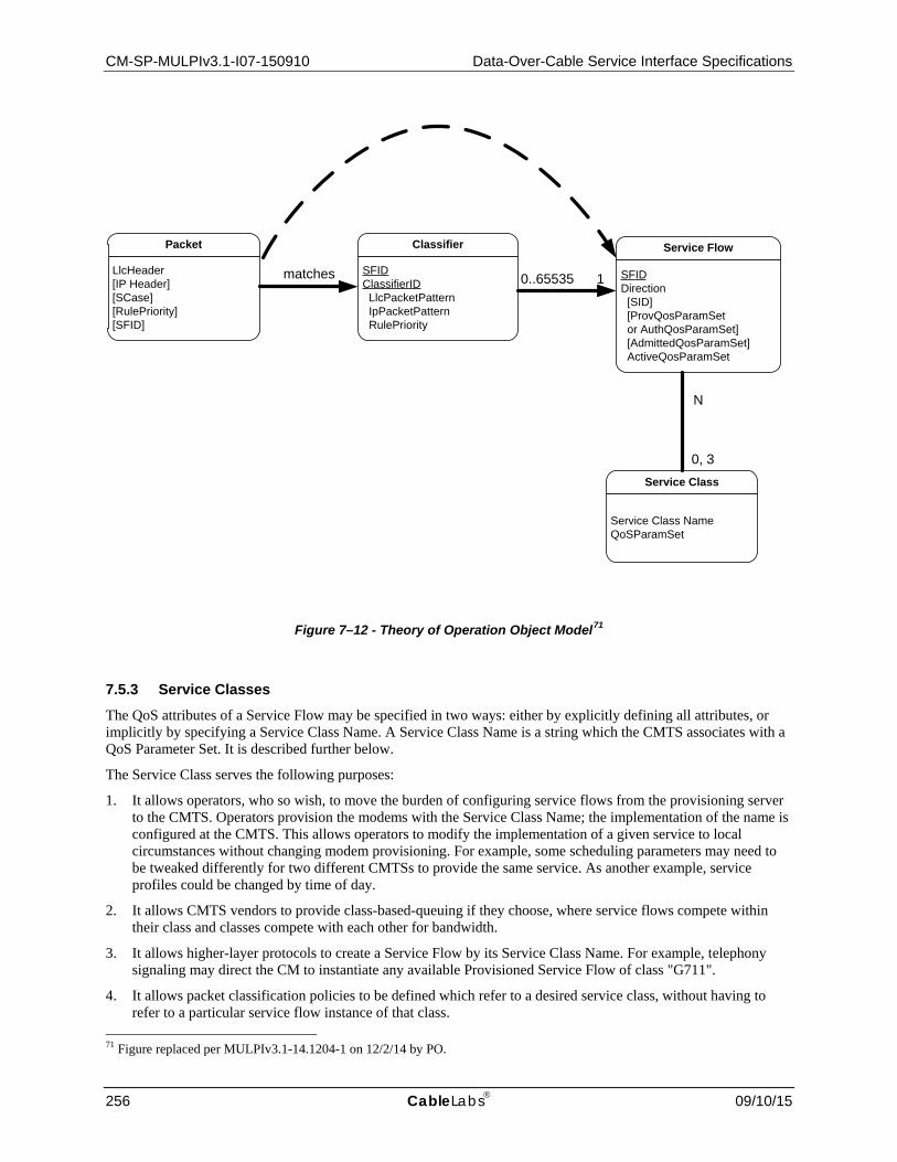
CM-SP-MULPIv3.1-I07-150910 Data-Over-Cable Service Interface Specifications
256 CableLabs 09/10/15
Figure 7–12 - Theory of Operation Object Model71
7.5.3 Service Classes The QoS attributes of a Service Flow may be specified in two ways: either by explicitly defining all attributes, or implicitly by specifying a Service Class Name. A Service Class Name is a string which the CMTS associates with a QoS Parameter Set. It is described further below.
The Service Class serves the following purposes:
1. It allows operators, who so wish, to move the burden of configuring service flows from the provisioning server to the CMTS. Operators provision the modems with the Service Class Name; the implementation of the name is configured at the CMTS. This allows operators to modify the implementation of a given service to local circumstances without changing modem provisioning. For example, some scheduling parameters may need to be tweaked differently for two different CMTSs to provide the same service. As another example, service profiles could be changed by time of day.
2. It allows CMTS vendors to provide class-based-queuing if they choose, where service flows compete within their class and classes compete with each other for bandwidth.
3. It allows higher-layer protocols to create a Service Flow by its Service Class Name. For example, telephony signaling may direct the CM to instantiate any available Provisioned Service Flow of class "G711".
4. It allows packet classification policies to be defined which refer to a desired service class, without having to refer to a particular service flow instance of that class.
71 Figure replaced per MULPIv3.1-14.1204-1 on 12/2/14 by PO.
LlcHeader[IP Header][SCase][RulePriority][SFID]
Packet
SFIDClassifierID LlcPacketPattern IpPacketPattern RulePriority
Classifier
SFIDDirection [SID] [ProvQosParamSet or AuthQosParamSet] [AdmittedQosParamSet] ActiveQosParamSet
Service Flow
Service Class NameQoSParamSet
Service Class
matches 0..65535 1
0, 3
N

MAC and Upper Layer Protocols Interface Specification CM-SP-MULPIv3.1-I07-150910
09/10/15 CableLabs 257
NOTE: The Service Class is optional: the flow scheduling specification may always be provided in full; a service flow may belong to no service class whatsoever. CMTS implementations MAY treat such "unclassed" flows differently from "classed" flows with equivalent parameters.
Any Service Flow MAY have each of its QoS Parameter Sets specified in any of three ways:
1. By explicitly including all traffic parameters;
2. By indirectly referring to a set of traffic parameters by specifying a Service Class Name;
3. By specifying a Service Class Name along with modifying parameters.
The Service Class Name is "expanded" to its defined set of parameters at the time the CMTS successfully admits the Service Flow. The Service Class expansion can be contained in the following CMTS-originated messages: Registration Response, DSA-REQ, DSC-REQ, DSA-RSP and DSC-RSP. In all of these cases, the CMTS MUST include a Service Flow Encoding that includes the Service Class Name and the QoS Parameter Set of the Service Class. If a CM-initiated request contained any supplemental or overriding Service Flow parameters, a successful response from the CMTS MUST also include these parameters.
When a Service Class name is given in an admission or activation request, the returned QoS Parameter Set may change from activation to activation. This can happen because of administrative changes to the Service Class' QoS Parameter Set at the CMTS.
The CMTS MAY change the QoS parameters of all downstream service flows (including both Individual and Group Service Flows) derived from a Service Class when the QoS parameters of the Service Class are changed. The CMTS MAY change the QoS parameters of all upstream service flows derived from a Service Class when those QoS parameters of the Service Class are changed. QoS parameters for downstream service flows, or CMTS-enforced QoS parameters for upstream service flows, can be changed locally at the CMTS, without sending a Dynamic Service Change message to the affected CM. In order to change the CM-enforced QoS parameters of an upstream service flow, it is necessary for the CMTS to send a Dynamic Service Change message to the affected CM.
The CM-enforced QoS parameters of an upstream service flow include:
• Upstream Maximum Sustained Traffic Rate. • Maximum Traffic Burst. • Maximum Concatenated Burst. • Service Flow Scheduling Type.
All other QoS parameters are CMTS-enforced.
When a CM uses the Service Class Name to specify the Admitted QoS Parameter Set, the expanded set of TLV encodings of the Service Flow will be returned to the CM in the response message (REG-RSP, REG-RSP-MP, DSA-RSP, or DSC-RSP). Use of the Service Class Name later in the activation request may fail if the definition of the Service Class Name has changed and the new required resources are not available. Thus, the CM SHOULD explicitly request the expanded set of TLVs from the response message in its later activation request.
7.5.4 Authorization Every change to the Service Flow QoS Parameters MUST be approved by an authorization module at the CMTS. This includes every REG-REQ REG-REQ-MP, or DSA-REQ message to create a new Service Flow, and every DSC-REQ message to change a QoS Parameter Set of an existing Service Flow. Such changes include requesting an admission control decision (e.g., setting the AdmittedQoSParamSet) and requesting activation of a Service Flow (e.g., setting the ActiveQoSParameterSet). Reduction requests regarding the resources to be admitted or activated are also checked by the authorization module, as are requests to add or change the Classifiers.
In the static authorization model, the authorization module receives all registration messages, and stores the provisioned status of all Service Flows in the Provisioned state. Admission and activation requests for these provisioned service flows will be permitted, as long as the Admitted QoS Parameter Set is a subset of the Provisioned QoS Parameter Set, and the Active QoS Parameter Set is a subset of the Admitted QoS Parameter Set. Requests to change the Provisioned QoS Parameter Set will be refused, as will requests to create new dynamic

CM-SP-MULPIv3.1-I07-150910 Data-Over-Cable Service Interface Specifications
258 CableLabs 09/10/15
Service Flows. This defines a static system where all possible services are defined in the initial configuration of each CM.
In the dynamic authorization model, the authorization module not only receives all registration messages, but may also communicate through a separate interface to an independent policy server. This policy server may provide to the authorization module advance notice of upcoming admission and activation requests, and may specify the proper authorization action to be taken on those requests. Admission and activation requests from a CM are then checked by the authorization module to ensure that the ActiveQoSParameterSet being requested is a subset of the AuthorizedQosParamSet. Admission and activation requests from a CM that are signaled in advance by the external policy server are permitted. Admission and activation requests from a CM that are not pre-signaled by the external policy server may result in a real-time query to the policy server, or may be refused.
During registration, the CM MUST send to the CMTS the authenticated set of TLVs derived from its configuration file which defines the Provisioned QoS Parameter Set. Upon receipt and verification at the CMTS, these are handed to the Authorization Module within the CMTS. The CMTS MUST be capable of caching the Provisioned QoS Parameter Set, and be able to use this information to authorize dynamic flows which are a subset of the Provisioned QoS Parameter Set. The CMTS SHOULD implement mechanisms for overriding this automated approval process (such as described in the dynamic authorization model). For example:
• Deny all requests whether or not they have been pre-provisioned; • Define an internal table with a richer policy mechanism but seeded by the configuration file information; • Refer all requests to an external policy server.
7.5.5 States of Service Flows It is useful to think about four states of Service Flows. This section describes these four states of Service Flows in more detail. However, it is important to note that there are more than just these basic states.
7.5.5.1 Deferred Service Flows A service flow may be authorized in an inactive state for subsequent admittance and activation. There are two states of deferred flows – Provisioned and Authorized.
As a result of external action beyond the scope of this specification (e.g., [PKT-MGCP]), the CM MAY choose to authorize and/or activate a deferred service flow by passing the Service Flow ID and the associated QoS Parameter Sets. The CM MUST also provide any applicable Classifiers. If authorized and resources are available, the CMTS MUST respond by assigning a SID or SID Cluster(s) for an upstream Service Flow.
As a result of external action beyond the scope of this specification (e.g., [PKT-MGCP]), the CMTS MAY choose to admit and/or activate a deferred service flow by passing the Service Flow ID as well as the SID or SID Cluster(s) and the associated QoS Parameter Sets. The CMTS MUST also provide any applicable Classifiers.
7.5.5.1.1 Provisioned Service Flows
A Service Flow may be created in the Provisioned state but not immediately activated. That is, the description of any such service flow in the TFTP configuration file contains an attribute which provisions but defers activation and admission. During Registration, the CMTS assigns a Service Flow ID for such a service flow but does not reserve resources. The CMTS MAY also require an exchange with a policy module prior to admission. The CMTS may deactivate the Service Flow, but SHOULD NOT delete the Service Flow during the CM registration epoch. Such a Service Flow in the Provisioned state MAY be activated and deactivated by the CMTS many times (through DSC exchanges). In all cases, the original Service Flow ID MUST be used by the CMTS when reactivating the service flow.
7.5.5.1.2 Authorized Service Flows
A Service Flow may be created in the Authorized state but not immediately activated. That is, the description of any such service flow is passed to the CMTS, which authorizes but defers activation and admission (refer to the subsection Quality of Service Parameter Set Type in Annex C). The CMTS internally MUST assign a Service Flow ID for such a service flow but does not admit resources. The CMTS MAY also require an exchange with a policy

MAC and Upper Layer Protocols Interface Specification CM-SP-MULPIv3.1-I07-150910
09/10/15 CableLabs 259
module prior to admission. The CMTS MAY create, admit, activate, deactivate, de-admit, and delete Service Flows which are created in the Authorized state.
7.5.5.2 Admitted Service Flows This protocol supports a two-phase activation model which is often utilized in telephony applications. In the two-phase activation model, the resources for a "call" are first "admitted," and then once the end-to-end negotiation is completed (e.g., called party's gateway generates an "off-hook" event) the resources are "activated." Such a two-phase model serves the purposes of: a) conserving network resources until a complete end-to-end connection has been established; b) performing policy checks and admission control on resources as quickly as possible, and, in particular, before informing the far end of a connection request; and c) preventing several potential theft-of-service scenarios.
For example, if an upper layer service were using unsolicited grant service, and the addition of upper-layer flows could be adequately provided by increasing the Grants Per Interval QoS parameter, then the following might be used. When the first upper-layer flow is pending, the CM issues a DSA-Request with the Admit Grants Per Interval parameter equal one, and the Activate Grants Per Interval parameter equal zero. Later when the upper-layer flow becomes active, it issues a DSC-Request with the instance of the Activate Grants-per-Interval parameter equal to one. Admission control was performed at the time of the reservation, so the later DSC-Request, having the Activate parameters within the range of the previous reservation, is guaranteed to succeed. Subsequent upper-layer flows would be handled in the same way. If there were three upper-layer flows establishing connections, with one flow already active, the Service Flow would have Admit(ted) Grants-per-Interval equal four, and Active Grants-per-Interval equal one.
An activation request of a Service Flow where the new ActiveQoSParamSet is a subset of the AdmittedQoS-ParamSet and no new classifiers are being added MUST be allowed by the CMTS (except in the case of catastrophic failure). An admission request where the AdmittedQoSParamSet is a subset of the previous AdmittedQoSParamSet, so long as the ActiveQoSParamSet remains a subset of the AdmittedQoSParameterSet, MUST succeed at the CMTS.
A Service Flow that has resources assigned to its AdmittedQoSParamSet, but whose resources are not yet completely activated, is in a transient state. A time out value MUST be enforced by the CMTS that requires Service Flow activation within this period (see subsection Timeout for Admitted QoS Parameters in Annex C). If Service Flow activation is not completed within this interval, the assigned resources in excess of the active QoS parameters MUST be released by the CMTS.
It is possible in some applications that a long-term reservation of resources is necessary or desirable. For example, placing a telephone call on hold should allow any resources in use for the call to be temporarily allocated to other purposes, but these resources must be available for resumption of the call later. The AdmittedQoSParamSet is maintained as "soft state" in the CMTS; this state needs to be refreshed periodically for it to be maintained without the above timeout releasing the non-activated resources. This refresh MAY be signaled by the CMTS with a periodic DSC-REQ message with identical QoS Parameter Sets, or be signaled by some internal mechanism within the CMTS outside of the scope of this specification (e.g., by the CMTS monitoring RSVP refresh messages). Every time a refresh is signaled to the CMTS, the CMTS MUST refresh the "soft state."
7.5.5.3 Active Service Flows A Service Flow that has a non-NULL set of ActiveQoSParameters is said to be in the Active state. It is requesting and being granted bandwidth for transport of data packets. A Service Flow in the Admitted state may be made active by providing an ActiveQoSParameterSet, signaling the resources actually desired at the current time. This completes the second stage of the two-phase activation model (refer to Section 7.5.5.2).
A newly created Service Flow may immediately transition to the Active state. This is the case for the Primary Service Flows. It is also typical of Service Flows for monthly subscription services, etc. These Service Flows are established at registration time and MUST be authorized by the CMTS based on the CMTS MIC. These Service Flows MAY also be authorized by the CMTS authorization module.
Alternatively, a dynamically created Service Flow may immediately transition to the Active State. In this case, two-phase activation is skipped and the Service Flow is available for immediate use upon authorization.

CM-SP-MULPIv3.1-I07-150910 Data-Over-Cable Service Interface Specifications
260 CableLabs 09/10/15
7.5.6 Service Flows and Classifiers The basic model is that the Classifiers associate packets into exactly one Service Flow. The Service Flow Encodings provide the QoS Parameters for treatment of those packets on the RF interface. These encodings are described in the subsection Quality-of-Service-Related Encodings in Annex C.
In the upstream direction, the CM MUST classify upstream packets to Active Service Flows. The CMTS MUST classify downstream traffic to Active Downstream Service Flows. There MUST be a default downstream service flow for otherwise unclassified broadcast and multicast traffic.
The CMTS polices packets in upstream Service Flows to ensure the integrity of the QoS Parameters and the packet's TOS value. When the rate at which packets are sent is greater than the policed rate at the CMTS, then these packets MAY be dropped by the CMTS (see subsection Maximum Sustained Traffic Rate in Annex C.) When the value of the TOS byte is incorrect, the CMTS (based on policy) MUST police the stream by overwriting the TOS byte (see subsection IP Type Of Service (DSCP) Overwrite in Annex C).
It may not be possible for the CM to forward certain upstream packets on certain Service Flows. In particular, a Service Flow using unsolicited grant service with fragmentation disabled or segment header off operation cannot be used to forward packets larger than the grant size. If a packet is classified to a Service Flow on which it cannot be transmitted, the CM MUST either transmit the packet on the Primary Service Flow or discard the packet depending on the Request/Transmission Policy of the Service Flow to which the packet was classified.
MAC Management Messages may only be matched by a classifier that contains "Ethertype/DSAP/MacType" parameter encoding (see the subsection Ethertype/DSAP/MacType in Annex C) and when the "type" field of the MAC Management Message Header (Section 6.4.1) matches that parameter. One exception is that the Primary SID (Multiple Transmit Channel Mode disabled) or the Ranging SID (Multiple Transmit Channel Mode enabled) MUST be used for periodic ranging, even if a classifier matches the upstream RNG-REQ message of periodic ranging. In the absence of any classifier matching a MAC Management Message, it SHOULD be transmitted by a CM or CMTS on the Primary Service Flow. Other than those MAC message types precluded from classification in the subsection Ethertype/DSAP/MacType in Annex C, a CM or CMTS MAY forward an otherwise unclassified MAC message on any Service Flow in an implementation-specific manner.
Although MAC Management Messages are subject to classification, they are not considered part of any service flow. Transmission of MAC Management Messages MUST NOT influence any QoS calculations of the Service Flow to which they are classified by the CM or CMTS. Delivery of MAC Management Messages is implicitly influenced by the attributes of the associated service flow.
7.5.6.1 Policy-Based Classification and Service Classes72 As noted in is a variety of ways in which packets may be enqueued for transmission at the MAC Service Interface. There are general transit packets of which nothing is known until they are parsed by the MAC Classification rules. Another useful category is traffic to which policies are applied by a higher-layer entity and then passed to the MAC for further classification to a particular service flow.
Policy-based classification is, in general, beyond the scope of this specification. One example might be the docsDevFilterIpPolicyTable defined in the Cable Device MIB [RFC 2669]. Such policies may tend to be longer-lived than individual service flows and MAC classifiers and so it is appropriate to layer the two mechanisms, with a well-defined interface between policies and MAC Service Flow Classification.
The interface between the two layers is the addition of two parameters at the MAC transmission request interface. The two parameters are a Service Class Name and a Rule Priority that is applied to matching the service class name. The Policy Priority is from the same number space as the Packet Classifier Priority of the packet-matching rules used by MAC classifiers. The MAC Classification algorithm is now: MAC_DATA.request (PDU, ServiceClassName, RulePriority) TxServiceFlowID= FIND_FIRST_SERVICE_FLOW_ID (ServiceClassName) SearchID = SEARCH_CLASSIFIER_TABLE (All Priority Levels) IF (SearchID not NULL and Classifier.RulePriority >= MAC_DATA.RulePriority) TxServiceFlowId = SearchID
72 Updated per MULPIv3.1-14.1204-1 on 12/2/14 by PO.

MAC and Upper Layer Protocols Interface Specification CM-SP-MULPIv3.1-I07-150910
09/10/15 CableLabs 261
IF (TxServiceFlowID = NULL) TRANSMIT_PDU (PrimaryServiceFlowID) ELSE TRANSMIT_PDU (TxServiceFlowID)
While Policy Priority competes with Packet Classifier Priority and its choice might in theory be problematic, it is anticipated that well-known ranges of priorities will be chosen to avoid ambiguity. In particular, classifiers that are dynamically-added by the CM or CMTS MUST use the priority range 64-191. Classifiers created as part of registration, as well as policy-based classifiers, may use zero through 255, but the CM and CMTS SHOULD avoid the dynamic range.
7.5.7 General Operation The CMTS MUST reject a Service Flow if the CMTS does not have the capability to support the Quality of Service parameters for the flow. For example, if the CMTS only supports certain Grant Intervals for Unsolicited Grant Service, it is required to reject a Service Flow request for a Grant Interval other than a supported value.
7.5.7.1 Static Operation Static configuration of QoS Classifiers, Upstream Drop Classifiers, and Service Flows uses the Registration process. A provisioning server provides the CM with configuration information. The CM passes this information to the CMTS in a Registration Request. The CMTS adds information and replies with a Registration Response. The CM sends a Registration Acknowledge to complete registration.
Figure 7–13 - Registration Message Flow
A TFTP configuration file consists of one or more instances of QoS Classifiers, Upstream Drop Classifiers, and Service Flow Encodings. QoS and Upstream Drop Classifiers are loosely ordered by 'priority'. Each QoS Classifier refers to a Service Flow via a 'service flow reference'. Several QoS Classifiers may refer to the same Service Flow. Additionally, more than one QoS Classifier or Upstream Drop Classifier may have the same priority, and in this case, the particular classifier used is not defined. Upstream Drop Classifiers do not refer to a particular configured Service Flow, instead they drop packets.
Service Flow Encodings contain either a full definition of service attributes (omitting defaultable items if desired) or a service class name. A service class name is an ASCII string which is known at the CMTS and which indirectly specifies a set of QoS Parameters. (Refer to Section 7.5.3 and Error Message subsection in Annex C.)
NOTE: At the time of the TFTP configuration file, Service Flow References exist as defined by the provisioning server. Service Flow Identifiers do not yet exist because the CMTS is unaware of these service flow definitions.
TFTP ConfigurationProvisioning Server
CM
CMTS
Registration Request
Registration Response
Registration Ack

CM-SP-MULPIv3.1-I07-150910 Data-Over-Cable Service Interface Specifications
262 CableLabs 09/10/15
The Registration Request packet contains Downstream Classifiers (if to be immediately activated) and all Inactive Service Flows. The configuration file, and thus the Registration Request generally does not contain a Downstream Classifier if the corresponding Service Flow is requested with deferred activation. This allows for late binding of the Classifier when the Flow is activated.
The Registration Response sets the QoS Parameter Sets according to the Quality of Service Parameter Set Type in the Registration Request.
The Registration Response preserves the Service Flow Reference attribute, so that the Service Flow Reference can be associated with SFID and/or SID Cluster (SID when no TCC encoding is included in the Registration Response).
The SFID is chosen by the CMTS to identify a downstream or upstream service Flow that has been authorized but not activated. A DSC-Request from a modem to admit or activate a Provisioned Service Flow contains its SFID. If it is a downstream Flow then the Downstream Classifier is also included.
7.5.7.2 Dynamic Service Flow Creation — CM Initiated Service Flows may be created by the Dynamic Service Addition process, as well as through the Registration process outlined above. The Dynamic Service Addition may be initiated by either the CM or the CMTS, and may create one upstream and/or one downstream dynamic Service Flow(s). A three-way handshake is used to create Service Flows. The CM-initiated protocol is illustrated in Figure 7–14 and described in detail in Section 11.2.2.1.
Figure 7–14 - Dynamic Service Addition Message Flow - CM Initiated
A DSA-Request from a CM contains Service Flow Reference(s), QoS Parameter set(s) (marked either for admission-only or for admission and activation) and any required Classifiers. A CM-initiated DSA-Request does not contain Upstream Drop Classifiers.
7.5.7.3 Dynamic Service Flow Creation — CMTS Initiated A DSA-Request from a CMTS contains Service Flow Identifier(s) for one upstream and/or one downstream Service Flow, possibly one or more SID Cluster Encodings, set(s) of active or admitted QoS Parameters, and any required Classifier(s). A CMTS-initiated DSA-Request does not contain Upstream Drop Classifiers. The protocol is as illustrated in Figure 7–15, and is described in detail in Section 11.2.2.2.
CMTSDSA-Acknowledge
DSA-Request
DSA-ResponseCM

MAC and Upper Layer Protocols Interface Specification CM-SP-MULPIv3.1-I07-150910
09/10/15 CableLabs 263
Figure 7–15 - Dynamic Service Addition Message Flow - CMTS Initiated
7.5.7.4 Dynamic Service Flow Modification and Deletion In addition to the methods presented above for creating service flows, protocols are defined for modifying and deleting service flows (refer to Section 11.2.3 and Section 11.2.4).
Both provisioned and dynamically created Service flows are modified with the DSC message, which can change the Admitted and Active QoS Parameter sets of the flow. The CM initiated and CMTS initiated DSC can perform the following actions:
• Add, replace, or delete QoS classifiers.
The CMTS-initiated DSC can also add, replace, or delete Upstream Drop Classifiers. The CMTS MUST reject a CM-initiated DSC containing a DSC action to add, replace, or delete an Upstream Drop Classifier. The DSC cannot be used to change Service Flow SID Clusters. The CM MUST reject a CMTS-initiated DSC which attempts to change Service Flow SID Clusters.
A successful DSC transaction changes a Service Flow's QoS parameters by replacing both the Admitted and Active QoS parameter sets. If the message contains only the Admitted set, the Active set is set to null and the flow is deactivated. If the message contains neither set ('000' value used for Quality of Service Parameter Set type, see the subsection Quality of Service Parameter Set Type in Annex C) then both sets are set to null and the flow is de-admitted. When the message contains both QoS parameter sets, the Admitted set is checked first and, if admission control succeeds, the Active set in the message is checked against the Admitted set in the message to ensure that it is a subset (see Section 7.5.1.1). If all checks are successful, the QoS parameter sets in the message become the new Admitted and Active QoS parameter sets for the Service Flow. If either of the checks fails, the DSC transaction fails and the Service Flow QoS parameter sets are unchanged.
The DSD cannot be used to delete Upstream Drop Classifiers.
7.5.8 QoS Support for Joined IP Multicast Traffic This section describes a standard configuration and implementation of QoS for downstream IP multicast traffic that is joined dynamically by a multicast host or statically joined via CMTS configuration. The mechanism for providing QoS to a group of CMs is similar to the mechanism for providing it to an individual CM: the highest priority classifier that matches a downstream packet identifies the service flow for scheduling the packet. In the case of multicast traffic, the classifiers are called "Group Classifier Rules" (GCRs), and the service flows are called Group Service Flows (GSFs). GCRs and GSFs are associated with a Downstream Channel Set (DCS), which is either a single downstream channel or a downstream bonding group of multiple downstream channels. A MAC Domain is considered to have Individual Classifier Rules and Individual Service Flows associated with an individual Cable Modem as well as Group Classifier Rules (GCRs) and Group Service Flows (GSFs) associated with a Downstream
CMTS
DSA-Acknowledge
DSA-Request
DSA-Response
CM

CM-SP-MULPIv3.1-I07-150910 Data-Over-Cable Service Interface Specifications
264 CableLabs 09/10/15
Channel Set (DCS). GCRs and GSFs have the same attributes and are described in the same MIB tables as Individual Classifier Rules and Individual Service Flows.
This section describes QoS only for joined IP multicast sessions. This includes dynamically joined sessions using multicast management protocol such as IGMP/MLD as well as statically joined sessions using Static Multicast Session Encodings in REG-REQ(-MP) (see the subsection CMTS Static Multicast Session Encoding in Annex C). The mechanism by which the CMTS provides QoS for other downstream broadcast and layer 2 multicast traffic is CMTS vendor specific, although certain CMTS requirements for this traffic are described below.
7.5.8.1 IP Multicast QoS Overview An object model diagram that describes multicast QoS operation is depicted in Figure 7–16.
Figure 7–16 - IP Multicast QoS Object Model Diagram
The operational model of the CMTS as described in Appendix I is that a CMTS Forwarder submits a MAC_DATA_GROUP.request primitive to a MAC Domain in order to replicate a downstream multicast frame on a Downstream Channel Set of the MAC Domain:
MAC_DATA_GROUP.request(MAC frame, DCSid, DSID)
Where:
• MAC frame consists of the layer 2 Ethernet MAC packet from Destination Address through CRC;
LlcHeader[IP Header][SCase][RulePriority][SFID]
Packet
SFIDClassifierID LlcPacketPattern IpPacketPattern RulePriority
Classifier
SFIDDirection [SID] [ProvQosParamSet or AuthQosParamSet] [AdmittedQosParamSet] ActiveQosParamSet
Service Flow
Service Class NameQoSParamSet
Service Class
matches 0..65535 1
0, 3
N

MAC and Upper Layer Protocols Interface Specification CM-SP-MULPIv3.1-I07-150910
09/10/15 CableLabs 265
• DCSid is an index of a Downstream Channel Set that corresponds to either a single downstream channel or a downstream bonding group of multiple channels;
• DSID is a Downstream Service Identifier that identifies the group of Cable Modems to which the CMTS Forwarder is transmitting the packet.
Because the CMTS Forwarder supplies a MAC frame to the MAC Domain, it is considered to have mapped the IP destination group address into the standardized layer 2 Ethernet group MAC address for that IP destination group.
As depicted in Figure 7–16, each DCS is considered to have one or more Group Classifier Rule (GCR) objects associated with it. GCRs are considered to be classifiers of the MAC Domain with the same attributes as the classifiers defined for individual cable modems. Different DCSs have different sets of GCRs.
The DSID is intended to identify the combination of a specific IP multicast session and DCS. The CMTS assigns a different DSID to the same multicast session replicated on different DCSs. The CMTS assigns a different DSID to each different multicast session replicated to the same DCS. A DSID value is unique per MAC Domain (i.e., the CMTS can re-use the same DSID value for two different multicast sessions being transmitted on two different MAC domains).
When the CMTS Forwarder requests a MAC Domain to transmit a joined IP multicast session packet on a particular DCS, the MAC Domain compares the packet against the list of Group Classifier Rules (GCRs) associated with the DCS of the request.
Each GCR refers to a single Group Service Flow (GSF) instantiated on the DCS. A Group Service Flow is a downstream Service flow with the same QoS Parameter Sets as an Individual Service Flow (ISF) created for an individual cable modem. A GSF is always active; its Provisioned, Admitted, and Active QoS Parameter Sets are the same set. GSFs are not communicated to CMs. A GSF is intended to be assigned to the same DCS for the duration of its lifetime. A GSF is not considered to be autonomously load balanced to other DCSs. When the CMTS changes the replication of a particular IP multicast session to a different DCS, the session is considered to be scheduled on a different GSF for the new DCS.
GCRs, like individual classifier rules, have a rule priority. If the multicast packet matches more than one GCR then the CMTS uses the GCR with highest rule priority to select the GSF for transmitting the packet. If more than one matching GCRs have the same highest rule priority, the GCR used by the CMTS is vendor-specific.
If the packet does not match any GCR, the CMTS forwards it to a Default Group Service Flow that is instantiated with QoS parameters from the identified Default Group Service Class for the CMTS.
The Group Service Flow identified for a downstream packet controls the QoS and provides the statistics for accounting for the transmission of the packet in the MAC Domain.
7.5.8.2 Group Configuration and Group QoS Configuration Tables For IP Multicast QoS, a cable operator controls the creation of GCRs and GSFs by configuring entries in Group Configuration (GC) and Group QoS Configuration (GQC) tables. These tables only configure the QoS for IP Multicast sessions; they do not control how CMTS replicates IP Multicast Sessions on DCSs. Replication of IP Multicast sessions is determined based on joiners to IP Multicast Sessions. Configuration of how the CMTS replicates to DCSs (e.g., whether the CMTS replicates certain sessions to downstream bonding groups or to a single downstream channel) is vendor-specific.
The object model representation of the Multicast QoS configuration and the associated reporting objects are defined in Multicast QoS Configuration section of the Multicast Requirements Annex in [DOCSIS OSSIv3.0]. Several new objects have been defined to allow the Operator to configure and determine the replication of each Multicast group that is forwarded on a given DCS. These objects include:
• Group Configuration: An object that defines the matching criteria for multicast sessions that have been configured for specific QoS treatment. This object is used to define the Group Classifier Rules (GCR) that will place traffic on a given Group Service Flow (GSF). The object also defines if encryption is needed for a given multicast session.
• Group QoS Config: An object to assign the specific QoS attributes of a Group Service Flow (GSF) that uses Service Class Names to define the specific QoS treatment that a given multicast session requires.
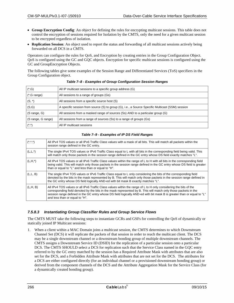
CM-SP-MULPIv3.1-I07-150910 Data-Over-Cable Service Interface Specifications
266 CableLabs 09/10/15
• Group Encryption Config: An object for defining the rules for encrypting multicast sessions. This table does not control the encryption of sessions required for Isolation by the CMTS, only the need for a given multicast session to be encrypted regardless of isolation.
• Replication Session: An object used to report the status and forwarding of all multicast sessions actively being forwarded on all DCS in a CMTS.
Operators can configure the rules for QoS, and Encryption by creating entries in the Group Configuration Object. QoS is configured using the GC and GQC objects. Encryption for specific multicast sessions is configured using the GC and GroupEncryption Objects.
The following tables give some examples of the Session Range and Differentiated Services (ToS) specifiers in the Group Configuration object.
Table 7–8 - Examples of Group Configuration Session Ranges
(*,G) All IP multicast sessions to a specific group address (G)
(*,G range) All sessions to a range of groups (Gs)
(S, *) All sessions from a specific source host (S)
(S,G) A specific session from source (S) to group (G), i.e., a Source Specific Multicast (SSM) session
(S range, G) All sessions from a masked range of sources (Ss) AND to a particular group (G)
(S range, G range) All sessions from a range of sources (Ss) to a range of groups (Gs)
(*,*) All IP multicast sessions
Table 7–9 - Examples of IP DS Field Ranges
(*,*,*) All IPv4 TOS values or all IPv6 Traffic Class values with a mask of all bits. This will match all packets within the session range defined in the GC entry.
(L,L,*) The single IPv4 TOS values or IPv6 Traffic Class equal to L with all bits in the corresponding field being valid. This will match only those packets in the session range defined in the GC entry whose DS field exactly matches "L".
(L,H,*) All IPv4 TOS values or all IPv6 Traffic Class values within the range of L to H with all bits in the corresponding field being valid. This will match only those packets in the session range defined in the GC entry whose DS field is greater than or equal to "L" and less than or equal to "H".
(L,L, B) The single IPv4 TOS values or IPv6 Traffic Class equal to L only considering the bits of the corresponding field denoted by the bits in the mask represented by B. This will match only those packets in the session range defined in the GC entry whose DS field logically AND-ed with bit mask B exactly matches "L".
(L,H, B) All IPv4 TOS values or all IPv6 Traffic Class values within the range of L to H only considering the bits of the corresponding field denoted by the bits in the mask represented by B. This will match only those packets in the session range defined in the GC entry whose DS field logically AND-ed with bit mask B is greater than or equal to "L" and less than or equal to "H".
7.5.8.3 Instantiating Group Classifier Rules and Group Service Flows The CMTS MUST take the following steps to instantiate GCRs and GSFs for controlling the QoS of dynamically or statically joined IP Multicast sessions:
1. When a client within a MAC Domain joins a multicast session, the CMTS determines to which Downstream Channel Set (DCS) it will replicate the packets of that session in order to reach the multicast client. The DCS may be a single downstream channel or a downstream bonding group of multiple downstream channels. The CMTS assigns a Downstream Service ID (DSID) for the replication of a particular session onto a particular DCS. The CMTS SHOULD select a DCS for replication such that the Service Class named in the GQC entry referred to by the GC entry matched by the session has a Required Attribute Mask with attributes that are also set for the DCS, and a Forbidden Attribute Mask with attributes that are not set for the DCS. The attributes for a DCS are either configured directly (for an individual channel or a provisioned downstream bonding group) or derived from the component channels of the DCS and the Attribute Aggregation Mask for the Service Class (for a dynamically created bonding group).

MAC and Upper Layer Protocols Interface Specification CM-SP-MULPIv3.1-I07-150910
09/10/15 CableLabs 267
2. The CMTS determines the set of GC entries whose Session Range matches the new (S, G) session. If more than one GC entry matches, the CMTS selects the GC entry with the highest Rule Priority. If more than one matching GC entry has the same highest Rule Priority, then all the GC entries matching the highest Rule Priority are selected for instantiating GCRs and GSFs. If no GC entry has a Session Range that matches the new session, the CMTS does not create any new Group Classifier Rule (GCR) or Group Service Flow (GSF) for the session; in this case the packets of the session are transmitted using the default GSF for the DCS, as described below. The CMTS creates GCR and GSF entries only when there is a reference to a valid (non zero) GQC entry from the GC entry which matches a session. However, irrespective of whether GCR and GSF entries are created for the matched session or not, the encryption rules are applied to the session if there are references in the matched GC entry to valid encryption rules.
3. When a matching GC entry is selected for the first joiner of a session on the DCS, the CMTS may instantiate a Group Classifier Rule (GCR) for classifying the session's packets, based on whether the QoS Control of the selected GC entry is "Single-Session" or "Aggregate-Session":
• For a QoS Control of "Single-Session", the CMTS always creates a GCR with the specific Group (G) destination IP address as a criterion. If the session was joined with a protocol supporting Source Specific Multicast (SSM), the GCR also contains the particular Source (S) IP address. A single-session GQC entry thus creates a single-session GCR. When other unique (S, G) sessions are joined that match the session range of the single-session GC entry, the CMTS creates a separate GCR for each session. The CMTS creates only a single-session GCR and GSF for all CMs with joiners reached by the same session on the same DCS.
• For a QoS Control of "Aggregate-Session", the CMTS creates a GCR with the same session range (e.g., S-range, G-range) criteria as the GC entry itself, if such a GCR has not already been created on a DCS. The GCR created by an "Aggregate-Session" GC entry classifies an aggregate of multiple multicast sessions. The CMTS creates at most one Aggregate-Session GCR and GSF on a DCS for each Aggregate-Session GC entry.
In both cases, the instantiated GCR uses the same Rule Priority as specified for the Rule Priority of the selected GC entry itself.
The CMTS may implement vendor-specific configuration that controls the mapping of Source Specific Multicast (SSM) network sessions to multicast joins performed with an Any Source Multicast (ASM) protocol (i.e., that requests joining a session identified only by its destination group address). This vendor-specific configuration can also determine which GC entries with explicit source addresses apply to ASM joins.
4. The CMTS then may create a Group Service Flow (GSF) for the new session replication. The Service Class named in a GQC entry provides the template for the QoS parameters assigned to the GSF. A valid GQC entry references an existing Service Class Name in the CMTS Service Class Table. Typical QoS parameters for a GSF include Minimum Reserved Traffic Rate and the Maximum Sustained Traffic Rate. A Group Service Flow is assigned to a single DCS, and remains assigned to that DCS for the duration of its instantiation. If the attribute mask for a DCS does not match all required attributes or does match any forbidden attribute of the Service Class of the GSF, the CMTS MUST log an event and update the MIB to report an "attribute assignment failure" event when it creates the GSF. If the individual channel Service Flow Attribute Masks or the Aggregate Service Flow Attribute Masks are changed, and these changes conflict with the Service Flow Attribute Masks defined in the SCN, the CMTS MUST note the error in the event log. In this case, the CMTS may need to move the replication to in order to satisfy the defined Service Flow Attribute Masks defined in the SCN. The QoS Control of the GQC entry determines how the CMTS instantiates GSFs for the GQC entry:
• For a QoS Control of "Single-Session", the CMTS creates a GSF on a DCS for each single session, that is, each unique combination of source IP address S (for an SSM session) and destination group IP address G.
• When a single GC entry that matches a range of multicast sessions references a GQC entry with a QoS Control of "Aggregate-Session", the CMTS creates a GSF on a DCS for the first multicast session matching that GC entry. When another session matches the same Aggregate-Session GC entry, the CMTS does not create another GSF and does not create another GCR for the existing GSF. In this case, the CMTS associates a single GSF and a single GCR for all multicast sessions matching an

CM-SP-MULPIv3.1-I07-150910 Data-Over-Cable Service Interface Specifications
268 CableLabs 09/10/15
Aggregate-Session GC entry Thus, all the multicast sessions that match a GC entry (e.g., S-range, G-range) share the same bandwidth allocated for the GSF, instead of creating a separate GSF for each multicast session that matches a GQC entry.
• When multiple GC entries refer to the same GQC entry with QoS Control of "Aggregate-Session", the CMTS creates only one GSF. For the first multicast session matching a GC entry, the CMTS creates a GSF and a GCR corresponding to the matched GC entry. For subsequent multicast session matching another GC entry that references the same GQC entry, the CMTS creates a new GCR entry and associates the GCR entry with the existing GSF.
5. The CMTS will maintain GCRs and GSFs on a DCS for as long as it replicates multicast sessions that use them. The CMTS may discontinue replication of a session onto a DCS either because the last joiner has left, or because it elects to replicate the session to a different DCS. When the CMTS discontinues forwarding of a multicast session to a DCS, it deletes any Single-Session GCR and single-session GSF it had created for the multicast session. When the CMTS discontinues forwarding of the last of the multicast sessions for which it had created an Aggregate-Session GCR, the CMTS deletes the Aggregate-Session GCR. When the CMTS deletes the last GCR that refers to an Aggregate-Session GSF, it deletes the aggregate-session GSF itself.
6. A CMTS may create GCRs and GSFs for IP Multicast sessions in a vendor-specific manner. The CMTS will assign the rule priority attribute of a vendor-specific GCR to be in the range 64 to 191. This permits GCRs instantiated from the operator-configured GC entry to have either a lower priority (0 to 63) or higher priority (192 to 255) than the vendor-specific GCR entries.
Cable operators need to take great care when assigning the bandwidth attributes of Group Service Flows for aggregate sessions to avoid service flows that do not provide enough or reserve too much bandwidth for the aggregate sessions. When the bandwidth of each multicast session to be aggregated is known, the cable operator can configure AggregateSessionLimit to control the maximum bandwidth of the aggregate GSF. When the bandwidth of each multicast session to be aggregated is not known, the cable operator can configure the downstream maximum sustained traffic rate (see the subsection Maximum Sustained Traffic Rate of Annex C) of the aggregate GSF.
When a client joins an IP Multicast Session, there may be insufficient resources to schedule traffic from the session on a GSF (Single-Session or Aggregate-Session). The CMTS behavior in this case is vendor-specific.
CMTS operation concerning invalid GC and GQC entries is vendor-specific. The CMTS may prevent the creation of an invalid GC or GQC entry, e.g., one that contains a name for a Service Class that does not exist. The CMTS may prevent the deletion of configuration objects that would result in "dangling references", e.g., the deletion of a Service Class referenced by a GQC entry.
7.5.8.3.1 Examples of GCR and GSF Instantiation
Example 1: This first example covers classifying multiple multicast sessions matching two different GC entries into a single shared GSF (two GC entries referencing a single GQC entry of type "Aggregate-Session").
In this example, a stockbroker "Broker A" has contracted with the cable operator to provide pushed multicast stock quotes. Each stock symbol issue has a separate IP multicast destination group, and there are potentially hundreds of such groups. The broker has identified two IP multicast source hosts S1 and S2 that generate these stock quotes. The cable operator has agreed to provide at least 20 Kbps of bandwidth but no more than 100 Kbps for the aggregate of 10 multicast sessions.
The operator configures two GC entries. Each GC entry applies to all MAC Domains, and to all Downstream Channel Sets of those MAC Domains. Entry GC1 contains the IP multicast session range (S1,*), IP DS Range (0x00,0xFF,0xFF) to match all markings. Entry GC2 contains the session range (S2, *), IP DS Range (0x00,0xFF,0xFF) to match all markings. Both GC1 and GC2 refer to a GQC1 entry with QoS Control "Aggregate-Session", AggregateSessionLimit of 10, and Service Class named "BrokerMcast".
Group Config Entries: GC1: Session Range=(S1, *), IP DS Range=(0x00,0xFF,0xFF), GroupQoSConfigId=GQC1 GC2: Session Range=(S2, *), IP DS Range=(0x00,0xFF,0xFF), GroupQoSConfigId=GQC1

MAC and Upper Layer Protocols Interface Specification CM-SP-MULPIv3.1-I07-150910
09/10/15 CableLabs 269
Group QOS Config Entry: GQC1: QoS Control=Aggregate-Session, AggregateSessionLimit =10, SCN="BrokerMcast"
The operator configures the Service Class Table with a class named "BrokerMcast" with a Minimum Reserved Traffic Rate of 20 Kbps and a Maximum Sustained Traffic Rate of 100 Kbps.
ServiceClassTable Entry: BrokerMcast: MinReserved=20000 bps, MaxSustained = 100000 bps.
When the first joiner of any multicast session from S1, say (S1, G1), joins on a particular MAC domain, the CMTS selects the Downstream Channel Set to reach that joiner, creates GSF1 on that DCS, and has GCR1 that references GSF1. GCR1 has the same (S1,*) classification criteria as GC1:
GCR1: (S1,*) GSF1
When a joiner to a second multicast session from S1, say (S1, G2), joins on the MAC domain and the CMTS elects to distribute the session to the same DCS, the CMTS does not create any new GCR—it keeps GCR1—and it does not create any new GSF—it keeps GSF1. This is because GC1 references a GQC entry of type "Aggregate-Session".
When the first joiner for any multicast session from S2, say (S2, G20), joins on the MAC domain and the CMTS elects to distribute the session to the same DCS, the CMTS does not create a new GSF, but it does create a new GCR2 that references the same GSF1 it created earlier. This is because the GC1 and GC2 both reference the same GQC entry, GQC 1. GCR2 also uses the same wild-card criteria as GC2:
GCR2: (S2,*) GSF1
The MAC Domain has two GCRs—GCR1 and GCR2—that each reference the same GSF—GSF1.
Since GQC 1 entry specified AggregateSessionLimit of 10, only 10 multicast sessions matching GCR1 and GCR2 can be transmitted simultaneously using GSF1.
Example 2: This second example covers classifying multiple multicast sessions matching two different GC entries into two separate shared GSFs (two GC entries referencing two different GQC entries of type "Aggregate-Session").
The cable operator from Example 1 contracts with two additional stockbrokers "Broker B" and "Broker C" for the same IP multicast push service. Broker B has a single IP multicast source S3, and Broker C has a single IP multicast source S4. Each broker is promised the same QoS service level agreement, namely at least 20 kbps and at most 100 kbps for the aggregate of 10 joined multicast sessions for each broker.
The operator configures two GC entries corresponding to each broker's IP multicast sources S3 and S4 with IP DS Range of (0x00,0xFF,0xFF) to match all IP class markings. Each GC entry references a separate GQC entry with QoS Control of "Aggregate-Session", because a separate shared GSF needs to be created for each GC entry. This allows each GSF to meet the QoS service level agreement with the individual broker. Both the GQC entries have AggregateSessionLimit of 10 and reference the same Service Class as Example 1:
Group Config Table Entries: GC3: Session Range=(S3, *), IP DS Range (0x00,0xFF,0xFF), GroupQoSConfigId=GQC2 GC4: Session Range=(S4, *), IP DS Range (0x00,0xFF,0xFF), GroupQoSConfigId=GQC3
Group QoS Config Table Entries: GQC2: QoS Control=Aggregate-Session, AggregateSessionLimt =10, SC="BrokerMcast" GQC 3: QoS Control=Aggregate-Session, AggregateSessionLimt =10 SC="BrokerMcast"
When the first joiner joins any session from S3, for example (S3,G3), the CMTS creates GCR3 using the same wild-card range criteria as GC3. The CMTS also creates a new GSF2 for the aggregate set of 10 multicast sessions from S3 and has GCR3 point to GSF2:
GCR3: (S3,*) GSF2

CM-SP-MULPIv3.1-I07-150910 Data-Over-Cable Service Interface Specifications
270 CableLabs 09/10/15
When the first joiner joins any session from S4, for example (S4, G4), the CMTS creates GCR4 with the same wild-card range criteria of GC4, and has it reference a newly created GSF3 for the aggregate of 10 multicast sessions from S4:
GCR4: (S4,*) GSF3
In this case, the QoS received by Broker B's multicast sessions (from S3) is independent of the QoS received by Broker C's sessions (from S4) because they each have a separate GSF on the Downstream Channel Set. This is required as the cable operator needs to honor the QoS service level agreement established with each broker.
Also note that since both GQC 2 and GQC 3 specified AggregateSessionLimit of 10, only 10 multicast sessions matching GCR3 can be simultaneously transmitted using GSF2, and only 10 multicast sessions matching GCR4 can be simultaneously transmitted using GSF3.
All of the GCRs—GCR1, GCR2, GCR3, and GCR4—are "Aggregate-Session" GCRs because their classifier criteria matches a range of multiple (S, G) IP sessions. All of the GSFs—GSF1, GSF2, GSF3—are "Aggregate-Session" GSFs because they transmit multiple IP multicast sessions, using three separate, shared GSFs. If any IP multicast session that is being transmitted on a shared GSF, sends excessive traffic, all of the IP multicast sessions sharing that particular GSF can be affected. In this case, however, the QoS received by the IP multicast sessions aggregated on other shared GSFs would not be affected.
Example 3: This third example covers creating a separate, dedicated GSF for individual IP Multicast session: (a GC entry referencing a Single Session GQC Entry).
In this example, each IP multicast session represents a switched broadcast IP Video transmission, e.g., a standard definition MPEG-2 stream of approximately 3.75 Mbps, originated by a cable operator-provided IP Video server S6. Once an IP video stream has been assigned to a particular Downstream Channel Set, it must not be affected by any other unicast or multicast traffic. This is a requirement for "Single-Session" QoS, where each individual session has its own GCR and GSF.
The operator configures the IP DS Range to (0x00,0xFF,0xFF) to match all class markings, since IP Class markings are not required for this service definition. The GC entry references a GQC entry with QoS Control of "Single-Session" and Service Class named "Mpeg2SD".
Group Config Table Entry: GC5: Session Range=(S6, *), IP DS Range (0x00,0xFF,0xFF), GroupQoSConfigId=GQC4
Group QoS Config Table Entry: GQC 4: QoS Control="Single-Session", SC="Mpeg2SD"
The operator configures the Service Class Table with a class named "Mpeg2SD" with both the Minimum Reserved Rate and Max Sustained Rate to be 4 Mbps and Max Burst size to be 1000000 bytes (1 Mbyte).
The Service Class Table Entry: Mpeg2SD: MinReserved=4000000 bps, MaxSustained=4000000 bps, MaxBurst=1000000 bytes.
When the first host joins an individual session matching (S6,*), for example (S6, G5), the CMTS creates a new Group Classifier Rule GCR5 and a new Group Service Flow GSF4 on the Downstream Channel Set. The GCR matches the single session of the GC entry, namely (S6, G5):
GCR5: (S6, G5) -> GSF4
When a host joins a second session from S6, for example (S6, G6), the CMTS creates a new Single-Session GCR6 and it creates a new GSF5 for the session because the GC entry references a GQC entry of type "Single-Session":
GCR6: (S6, G6) -> GSF5
NOTE: Two important differences between this example and from the two "Aggregate-Session" examples: each instantiated GCR has criteria that matched the particular, specific session joined; and each instantiated GCR references a newly-created GSF for the particular, specific session.

MAC and Upper Layer Protocols Interface Specification CM-SP-MULPIv3.1-I07-150910
09/10/15 CableLabs 271
Example 4: This fourth example covers classifying multiple multicast sessions with the same Session Range but different IP DS Ranges into two separate shared GSFs (two GC entries with same Session range but different IP DS Ranges referencing two different Aggregate-Session GQC entries).
Similar to Example 1, this example has a stockbroker "Broker A" who contracted with the cable operator to provide pushed multicast stock quotes and multicast IPTV NEWS feeds. Each stock issue has a separate IP multicast destination group, and there are potentially hundreds of such groups. Each IPTV NEWS feed also has a separate destination group, and there are potentially tens of such groups. The source of both the stock quote sessions and the IPTV NEWS sessions is not known but the server will mark the IPTV service and stock quote sessions with different IPv4 TOS values to distinguish them. The stock quote service will be marked with an IPv4 TOS value of 1 and the IPTV NEWS feed will be marked with an IPv4 TOS value of 2. All other IPv4 TOS values are not expected but the operator has agreed to put those flows into their default class of service. The cable operator has agreed to provide at least 20 Kbps of bandwidth on each downstream channel for the aggregate of all stock quote related multicast sessions, but no more than 100 Kbps for the aggregate of all stock quote related sessions. The cable operator has agreed to provide at least 4Mbps of bandwidth on each downstream channel for the aggregate of all IPTV NEWS related sessions, but no more than 10Mbps for the aggregate of all IPTV NEWS related sessions.
The operator configures two GC entries. Each GC entry applies to all MAC Domains, and to all Downstream Channel Sets of those MAC Domains and applies to all IP multicast sessions (*,*) as the group and source are unknown to the operator. Entry GC6 contains IP DS Range (1,1,0xFF) and references a GQC entry with QoS Control of "Aggregate-Session" and Service Class of "Broker Stock". Entry GC7 contains IP DS Range (2,2,0xFF) to map all other IPv4 TOS values and references a GQC entry with QoS Control "Aggregate-Session", and a different Service Class - "Broker IPTV".
Group Config Table Entries: GC6: Session Range=(*, *), IP DS Range= (1,1,0xFF), GroupQosConfigId=GQC5 GC7: Session Range=(*, *), IP DS Range = (2,2,0xFF), GroupQosConfigId=GQC6
Group QoS Config Table Entries: GQC5: QoS Control=Aggregate-Session, SC="BrokerStock GQC6: QoS Control=Aggregate-Session, SC="BrokerIPTV"
The operator configures two new Service Classes in the Service Class Table. The first is "BrokerStock" with a Minimum Reserved Traffic Rate of 20 Kbps and a Maximum Sustained Traffic Rate of 100 Kbps. The second is "BrokerIPTV" with a Minimum Reserved Traffic Rate of 4Mbps and a Maximum Sustained Traffic Rate of 10Mbps.
ServiceClassTable: BrokerStock: MinReserved=20000 bps, MaxSustained = 100000 bps. BrokerIPTV: MinReserved=4000000 bps, MaxSustained = 10000000 bps.
When the first joiner of any session from any source, say S7, joins any group on a particular MAC domain, the CMTS selects the Downstream Channel Set to reach that joiner, creates GSF6 and GSF7 on that DCS, and has GCR7 reference GSF6, and GCR8 reference GSF7. GCR7 and GCR8 have the same (*,*) criteria as GC6 but different IP DS criteria:
GCR7: (*,*) IP DS (1,1,0xFF) GSF6
GCR8: (*,*) IP DS (2,2,0xFF) GSF7
When a joiner to a second session from any source joins any group on the MAC domain and the CMTS elects to distribute the session to the same DCS, the CMTS does not create any new GCR—it keeps GCR7 and GCR8—and it does not create any new GSF—it keeps GSF6 and GSF7. This is because GC6 and GC7 reference GQC entries of type "Aggregate-Session".
IP Multicast packets forwarded by the CMTS to any MAC domain for any session will use GCR7 if the IP DS field is set to 1 and hence will be transmitted using GSF6. IP Multicast packets forwarded by the CMTS to any MAC domain for any session with IP DS field = 2 will instead use GCR8 and hence be transmitted using GSF7. IP

CM-SP-MULPIv3.1-I07-150910 Data-Over-Cable Service Interface Specifications
272 CableLabs 09/10/15
Multicast packets that do not contain an IP DS field of 1 or 2 will be forwarded using the default GSF since no GCR is defined for those IP DS field values.
NOTE: Since no AggregateSessionLimit is specified for GQC entries in this example, there is no limit on how many multicast sessions are transmitted simultaneously using GSF6 and GSF7.
An important difference between this example and the previous examples is that this example shows multiple GC entries with the same Session Range (*,*) but different IP DS Ranges. This tells the CMTS to create multiple GCRs for a single join, one for each different IP DS range. Because only IP DS 1 and 2 were configured in the GQC table, all other IP DS values will go to the default GSF.
Example 5: This fifth example covers classifying multicast sessions matching two GC entries with the same Session range but different IP DS Range into separate Single Session GSFs (two GC entries with same Session range but different IP DS Ranges referencing two different Single-Session GQC entries).
Similar to example 3 in this example, each IP multicast session represents a switched broadcast IP Video transmission, e.g., a standard definition MPEG-2 stream of approximately 3.75 Mbps or a high definition MPEG-2 stream of approximately 8Mbps, originated by a cable operator-provided IP Video server S8. Once an IP video stream has been assigned to a particular Downstream Channel Set, it must not be affected by any other unicast or multicast traffic. This is a requirement for "single-session" QOS, where each individual session has its own GCR and GSF. However there is one twist to this example: the cable operator wants high definition TV, labeled by the server with an IP TOS value of 255, to be guaranteed higher bandwidth than standard definition TV as it requires more bandwidth for the higher quality. The cable operator has identified one IP multicast source host S8 for bother standard definition and high definition TV streams.
The operator configures two GC entries. Each GC entry applies to all MAC Domains, and to all Downstream Channel Sets of those MAC Domains. Entry GC8 contains the IP multicast session range (S8,*), with IP DS Range (0,254,255) and references GQC 7 with QoS Control "Single-Session", Service Class "Mpeg2SD". Entry GC9 contains the same session range (S8, *), but contains IP DS Range of (255,255,255) to recognize the High definition TV flows and references GQC 8 with QoS Control "Single-Session", Service Class = " Mpeg2HD".
Group Config Table Entries: GC8: Session Range=(S8, *) IP DS Range=(0,254,255), GroupQoSConfigId=GQC7 GC9: Session Range=(S8, *) IP DS Range=(255,255,255), GroupQoSConfigId=GQC8
Group Qos Config Table Entries: GQC7: QoS Control="Single-Session", SC=" Mpeg2SD" GQC8: QoS Control="Single-Session", SC=" Mpeg2HD"
The operator uses the "Mpeg2SD" Service Class defined in Example 3 above and configures a new Service Classes in the Service Class Table for the High definition TV streams. The new Service Class is "Mpeg2HD" and has a Minimum Reserved Traffic Rate of 8Mbps, a Maximum Sustained Traffic Rate of 16Mbps, and a Maximum Burst Size of 1MBytes.
ServiceClassTable:
Mpeg2HD: MinReserved=8000000 bps, MaxSustained=16000000 bps, MaxBurst=1000000 bytes.
When the first joiner of any session from S8, say (S8, G9), joins on a particular MAC domain, the CMTS selects the Downstream Channel Set to reach that joiner, creates GSF8 and GSF9 on that DCS, and has GCR9 reference GSF8, and GCR10 reference GSF9. GCR9 and GCR10 have the same specific (S8,G9) criteria but different IP DS criteria, since GC8 and GC9 referenced GQC entries of type "Single-Session":
GCR9: (S8,G9) IP DS (0,254,255) GSF8
GCR10: (S8,G9) IP DS (255,255,255) GSF9
When a joiner to a second session from S8, say (S8,G10), joins on the MAC domain and the CMTS elects to distribute the session to the same DCS, the CMTS creates a new set of GCRs and GSFs for the new group (G10). This is because GC8 and GC9 referenced GQC entries of type "Single-Session":
GCR11: (S8,G10) IP DS (0,254,255) GSF10
MAC and Upper Layer Protocols Interface Specification CM-SP-MULPIv3.1-I07-150910
09/10/15 CableLabs 273
GCR12: (S8,G10) IP DS (255,255,255) GSF11
IP Multicast packets forwarded by the CMTS to any MAC domain for session (S8,G10) will use GCR11 if the IP DS field is set to any value other than 255 and hence will be transmitted using GSF10. IP Multicast packets forwarded by the CMTS to any MAC domain for session the same session (S8,G10) but with IP DS field = 255 will instead use GCR12 and hence be transmitted using GSF11.
NOTE: Like Example 4, this example has multiple GCs with the same Session Range but different IP DS Ranges causing a single join to create multiple GCRs, one for each IP DS Range.
NOTE: The two important differences between this example and the Aggregate-Session example #4 are:
• Each instantiated GCR has criteria that matches the particular, specific session joined; • Each instantiated GCR references a newly-created separate, single-session GSF for the particular,
specific session.
Example 6: This sixth example covers classifying multicast sessions, matching one Single Session GC entry with a specific IP DS field range into a separate Single-Session GSFs, leaving the other remainder multicast sessions to use the default GSF (single GC entry with a specific IP DS field referencing a "Single-Session" GSF).
In this example, each multicast session represents an IPTV feed. The operator has configured their local content servers to use IPv6 Traffic Class = 6. Each stream from their local server is approximately 3.75 Mbps, but they come from various servers so the source is unknown. Once an IP video stream has been assigned to a particular Downstream Channel Set, it must not be affected by any other unicast or multicast traffic. This is a requirement for "single-session" QOS, where each individual session has its own GCR and GSF. The operator also wishes to treat other multicast traffic as best effort without guarantee. The operator has configured their network such that other multicast traffic will never arrive at the CMTS with an IPv6 Traffic Class = 6.
The operator configures one GC entry for its local IPTV sessions. The GC entry applies to all MAC Domains, to all Downstream Channel Sets of those MAC Domains, and to all IP multicast sessions, as the group and source are unknown to the operator. Entry GC10 contains IP DS Range (6,6,255) and references the GQC9 with QoS Control "Single-Session", and Service Class "Mpeg2SD".
Group Config Table Entries: GC10: Session Range=(*, *), IP DS Range = (6,6,255), GroupQosConfigId=GQC9
GroupQosTable: GQC9: QoS Control="Single-Session", SC="Mpeg2SD"
By creating no other GC entries the operator configures the CMTS to use a default, best effort GSF for all other IP DS field values.
The operator uses the service class "Mpeg2SD" defined in example 3 above for its guaranteed IPTV service. When the first joiner of any session from any source say S9, joins a particular group, say G10, on a particular MAC domain, the CMTS selects the Downstream Channel Set to reach that joiner, creates GSF12 on that DCS, and has GCR13 reference GSF12. The GCR 13 has a specific (S9, G10) criteria as GC 10 references GQC entry of type "Single-Session":
GCR13: (S9,G10) IP DS (6,6,255) GSF12
When a joiner to a second session from any source, say S10, joins a particular group, say G11 on the MAC domain and the CMTS elects to distribute the session to the same DCS, the CMTS creates a separate GSF13 on that DCS, and has GCR14 reference GSF13. The GCR 14 has a specific (S10, G11) criteria as GC10 references a GQC entry of type "Single-Session".
GCR14: (S10,G11) IP DS (6,6,255) GSF13
IP Multicast packets forwarded by the CMTS to any MAC domain for session (S9,G10) will use GCR13 only if the IP DS field is set to 6 and hence will be transmitted using the appropriate GSF for that session. IP Multicast packets forwarded by the CMTS to any MAC domain for session (S9,G10) but with IP DS field not equal to 6 will instead be forwarded using the default GSF since no GCR is defined for those IP DS field values.

CM-SP-MULPIv3.1-I07-150910 Data-Over-Cable Service Interface Specifications
274 CableLabs 09/10/15
7.5.8.4 Default Group Service Flows A CMTS MUST identify one of its Service Classes as the Default Group Service Class. When the CMTS replicates a multicast packet to a Downstream Channel Set on which the packet matches no Group Classifier Rule, the CMTS MUST transmit the packet on a Group Service Flow instantiated using the Default Group Service Class.
The CMTS MUST replicate unmatched IP multicast traffic only to a Downstream Channel Set that comprises an individual downstream channel. The CMTS does not replicate unmatched IP multicast traffic to downstream bonding groups. The Maximum Sustained Traffic Rate limit on the Default Group Service Class restricts the total amount of unclassified multicast traffic on each downstream channel. The CMTS MUST create a Default Group Service Flow on each of its downstream channels.
Because unmatched IP multicast traffic is required to be transmitted as non-bonded, the replication of a particular IP multicast session to a downstream bonding group requires the operator to either configure a GQC entry that matches the bonded multicast session or the CMTS to instantiate a GCR that matches the bonded multicast session in a vendor-specific manner.
7.5.8.5 Service Class QoS Parameter Changes The CMTS MAY dynamically change the QoS parameters of all Group Service Flows derived from a Service Class when the QoS parameters of the Service Class are changed.
7.5.8.6 Group QoS Configuration Changes Because the GC and GQC tables are the only mechanism for controlling the instantiation of GCRs and GSFs, when a GC or GQC entry is added, modified or deleted, the CMTS MUST dynamically implement changes to the GCR(s) and GSF(s) instantiated from that GC or GQC entry, as follows:
• For each replication of an IP multicast session on a DCS which matches a GC entry that references a valid GQC entry of type Aggregate, the CMTS MUST ensure that there exists a GCR that classifies the range of (S,G) from the matching GC entry to a GSF corresponding to the referenced aggregate type GQC entry.
• For each replication of an IP multicast session on a DCS which matches a GC entry that references a valid GQC entry of type Single, the CMTS MUST ensure that there exists a GCR that classifies the specific (S,G) onto a specific GSF corresponding to the referenced single type GQC entry.
• All GCRs which are not required to exist MUST be deleted. • All GSFs which are not required to exist MUST be deleted.
NOTE: GCRs and GSFs may be created or deleted due to the following changes to the QoS configuration tables : adding a GC entry; deleting a GC entry; modifying the GC entry by changing the (S,G) range, the priority, or other attributes; changing GQC entry reference; changing GQC QoS type; etc.
The time-frame for implementing changes to the GCRs and GSFs is not specified.
For Aggregated sessions the CMTS MUST assign sessions to a DCS such that number of sessions matching a GC entry referring to an Aggregate GQC entry does not exceed the Aggregate Session limit.
NOTE: Sessions may be dropped from a DCS by changing the AggregateSessionLimit and also perhaps due to the changes as noted above. The sessions which the CMTS chooses to keep or drop when the Aggregate Session limit is decreased are vendor-specific.
7.5.9 Other Multicast and Broadcast Traffic The Group QoS Configuration Table specifies how QoS is provided to downstream multicast traffic only for joined IP Multicast sessions. The QoS provided to all other downstream broadcast and multicast traffic is not configured with the GQC Table.
Examples of traffic which are not configured with a GQC table include:
• Locally generated IP multicasts (e.g., multicast packets generated by the RIPv2 and OSPF routing protocols); • DSG tunnel traffic; • layer 3 broadcasts (e.g., DHCP broadcasts);

MAC and Upper Layer Protocols Interface Specification CM-SP-MULPIv3.1-I07-150910
09/10/15 CableLabs 275
• layer 2 broadcasts (e.g., ARP); and • layer 2 multicasts (e.g., Spanning Tree Protocol).
The CMTS MUST transmit and account for all layer 2 multicast and broadcast traffic with some Group Service Flow. The CMTS MAY define Group Classifier Rules that classify multicast and broadcast traffic other than for joined IP multicast traffic.
7.5.10 Hierarchical QoS DOCSIS 3.1 defines the framework for hierarchical QoS (HQoS) which enables operators to define QoS policies on an aggregation of Service Flows. Hierarchical QoS is defined as a strict tree structure where the bonding group's or channel's capacity is typically the root (or "parent") node. The word "strict" means that for a given child node there can be one and only one parent. Hierarchical organizations needed to enable work conserving implementation of the bandwidth schedulers on the CMTS.
The key constructs of HQoS include: Aggregate Service Flow (ASF), ASF QoS Profile, Interface Aggregate Traffic Class (IATC) and IATC Profile. These constructs and their interaction are explained further in this section.
7.5.10.1 CMTS and CM Roles HQoS is defined as a feature which requires implementation only on the CMTS. The CMTS manages HQoS including Service Flow to ASF mapping as well as Service Flow to IATC mapping. All aggregate QoS policy enforcement functions, including the real time traffic scheduling and queuing are performed only by the CMTS. CMTS provides all Network Management capabilities necessary for configuration and status reporting related to HQoS, including all aggregate QoS parameter configuration.
In general, CMs are not aware of HQoS. CM's role in HQoS is limited to necessary "opaque" protocol support. A CM conveys HQoS information from CM configuration file into Registration Request without the need for interpretation of transported information. DOCSIS protocol support for HQoS is limited to CM configuration file and Registration Request Message. CMs need only implement certain QoS functions related to upstream bandwidth request policing on per SF basis only, without any HQoS considerations.
7.5.10.2 Aggregate Service Flow An Aggregate Service Flow (ASF) is a grouping of one or more Service Flows mapped to a single CM. The DOCSIS Network supports a hierarchical, two-layered subscriber QoS model through the concept of an ASF, which is defined as a MAC-layer transport service that provides unidirectional transport of frames, transmitted in the upstream direction by a CM, or in the downstream direction by the CMTS. All Service Flows grouped into an ASF are mapped to the same bonding group or a downstream or upstream channel. The concept of an ASF has been originally introduced in DPoE specifications.
ASFs are instantiated on the CMTS based on the definition from the CM configuration file. This specification does not define other methods for creation of ASFs.
The CMTS SHOULD provide support for ASFs. The CMTS SHOULD support at least one ASF instance per CM.
7.5.10.2.1 Relationship between Service Flow and ASF
A Service Flow may be associated with zero or one ASF instance. Any SF not associated with ASF must be directly mapped to a channel or a bonding group. An ASF may group SFs with different QoS parameters, for example maximum sustained rate or traffic priority.
Dynamically provisioned service flows, for example those Service Flows which are created through the PCMM interface, may be matched to an ASF by means of the defined Service Flow matching criteria described in Annex C.

CM-SP-MULPIv3.1-I07-150910 Data-Over-Cable Service Interface Specifications
276 CableLabs 09/10/15
Figure 7–17 - Relationship of Upstream Classifiers, Service Flows, ASFs and L2VPN
Figure 7–18 - Relationship of Downstream Classifiers, Service Flows, ASFs and L2VPN
7.5.10.2.2 ASF QoS Profile
ASFs serve as an implementation tool for service layer agreements with two levels of QoS parameters. ASFs provide the outer QoS envelope, while Service Flows define QoS parameters for more granular, individual services
L 2 VPN Encoding ( TLV 43 . 5 )
Service Flow Reference
QoS - Parameters ( Optional ) ASF Reference Type – 24 . 36
. L2 VPN Encoding Type – 43.5
.
Service Flow Encoding ( US )
( TLV 24 ) Classifier ID
Classification Criteria …
Service Flow Reference
Classifier Encoding ( US )
( TLV 22 )
N 1
VPN ID ( 43 . 5 . 1 ) Encapsulation ( 43 . 5 . 2 )
...
1
1
Aggregate Service Flow ( ASF ) Encoding ( TLV 70 )
ASF Reference Type – 70 . 1 ASF QoS Profile Name Type – 70 . 4
N 1
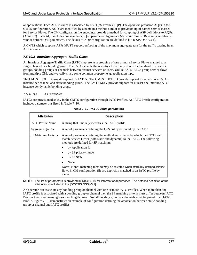
MAC and Upper Layer Protocols Interface Specification CM-SP-MULPIv3.1-I07-150910
09/10/15 CableLabs 277
or applications. Each ASF instance is associated to ASF QoS Profile (AQP). The operators provision AQPs in the CMTS configuration. AQPs are identified by a name in a method similar to provisioning of named service classes for Service Flows. The CM configuration file encodings provide a method for coupling of ASF definitions to AQPs. (Annex C). Each AQP includes one mandatory QoS parameter: Aggregate Maximum Traffic Rate and a number of vendor defined QoS parameters. The details of AQP configuration are defined in [DOCSIS OSSIv3.1].
A CMTS which supports ASFs MUST support enforcing of the maximum aggregate rate for the traffic passing in an ASF instance.
7.5.10.3 Interface Aggregate Traffic Class An Interface Aggregate Traffic Class (IATC) represents a grouping of one or more Service Flows mapped to a single channel or a bonding group. The IATCs enable the operators to virtually divide the bandwidth of service groups, bonding groups or channels between distinct services or users. Unlike ASFs IATCs group service flows from multiple CMs and typically share some common property, e. g. application type.
The CMTS SHOULD provide support for IATCs. The CMTS SHOULD provide support for at least one IATC instance per channel and static bonding group. The CMTS MAY provide support for at least one Interface ATC instance per dynamic bonding group.
7.5.10.3.1 IATC Profiles
IATCs are provisioned solely in the CMTS configuration through IATC Profiles. An IATC Profile configuration includes parameters as listed in Table 7–10.
Table 7–10 - IATC Profile parameters
Attributes Description
IATC Profile Name A string that uniquely identifies the IATC profile.
Aggregate QoS Set A set of parameters defining the QoS policy enforced by the IATC.
SF Matching Criteria A set of parameters defining the method and criteria by which the CMTS can match Service Flows (both static and dynamic) to the IATC. The following methods are defined for SF matching: • by Application Id • by SF priority range • by SF SCN • None Note: "None" matching method may be selected when statically defined service flows in CM configuration file are explicitly matched to an IATC profile by name.
NOTE: The list of parameters is provided in Table 7–10 for informational purposes. The detailed definition of the attributes is included in the [DOCSIS OSSIv3.1].
An operator can associate any bonding group or channel with one or more IATC Profiles. When more than one IATC profile is associated with a bonding group or channel then the SF matching criteria must differ between IATC Profiles to ensure unambiguous matching decision. Not all bonding groups or channels must be paired to an IATC Profile. Figure 7–19 demonstrates an example of configuration defining the association between static bonding group or channel and IATC profiles.

CM-SP-MULPIv3.1-I07-150910 Data-Over-Cable Service Interface Specifications
278 CableLabs 09/10/15
IATC ProfilesBonding Groups or Channels
BG 1
BG 2
Chan 1
Chan 2
Profile 1 SD Video
Profile 3 HSD
Profile 2 HD Video
Profile 4 Voice
QoS Parameters
SF Matching Criteria
Figure 7–19 - Association of Bonding Groups or Channels to IATC
The IATC provisioning method described above can be deployed for those Bonding Groups or channels that are created statically. DOCSIS allows CMTS's support for the dynamic creation of upstream or downstream bonding groups. Yet, this function is largely left to CMTS vendor definition because DOCSIS does not define a specific method or standard configuration of dynamic bonding groups. Consistently, the method for provisioning and coupling of IATCs to dynamically created bonding groups is outside of the scope of this specification.
7.5.10.3.2 Mapping of Service Flows to IATCs
In the absence of H-QoS settings the CMTS maps Service Flows to bonding groups or individual channels. With HQoS, the SF mapping process needs to include one additional step: a decision whether to assign a SF to an IATC and which IATC to select. Operators will be able to control SF to IATC association via several matching methods. Those methods are defined as part of IATC Profile configuration and listed in Table 7–10.
An alternative mechanism permits the explicit association of SFs provisioned via CM configuration file to IATC Profiles by IATC Profile name. The SF encodings in the CM configuration file are augmented with IATC name for this purpose as explained in the section that describes Service Flow to IATC Profile Name Reference in Annex C.
7.6 Packet Queuing
7.6.1 Downstream Traffic Priority The downstream Traffic Priority parameter is an explicit tag that will allow the CM to support multiple prioritized egress queues at its CMCI port. DOCSIS 3.0 defines a Downstream Service Extended Header (DS EHDR) element (refer to Section 6.2.6.6) in which the first three bits of the EH_VALUE indicate the Traffic Priority of the packet. If the Traffic Priority takes the default value of 0, the CMTS is not required to include the DS EHDR on packets that do not require a DSID label.
The CM MUST support a minimum of two egress queues per CMCI port. The egress queue for a particular packet is selected by the Traffic Priority sub-element in the DS EHDR of the packet. If the DS EHDR is missing then the CM MUST assume the packet has the Default Priority of zero.
The CM MUST NOT transmit downstream packets of lower Traffic Priority while there are packets of higher Traffic Priority ready to transmit on the CMCI.
7.6.1.1 Traffic Priority Ordering and Mapping to CM Output Queues Table 7–11 indicates the CM output queue to which a packet MUST be assigned based on the number of CM output queues supported by the CM implementation and the Traffic Priority indicated in the DS EHDR of the packet. The CM output queues are numbered in order of increasing priority with 0 as the lowest priority and 7 as the highest priority. If the DS EHDR is not present in the packet, a Traffic Priority of 0 is used.

MAC and Upper Layer Protocols Interface Specification CM-SP-MULPIv3.1-I07-150910
09/10/15 CableLabs 279
Table 7–11 - Mapping of Traffic Priority to CM output queue
Number of CM output queues 2 3 4 5 6 7 8
Traf
fic P
riorit
y 0 (Default) 0 0 0 0 0 0 0
1 0 0 0 0 0 0 1
2 0 0 1 1 1 1 2
3 0 0 1 1 2 2 3
4 1 1 2 2 3 3 4
5 1 1 2 3 4 4 5
6 1 2 3 4 5 5 6
7 1 2 3 4 5 6 7
7.6.2 Active Queue Management Active Queue Management (AQM) schemes attempt to maintain low queue occupancy while supporting the ability to absorb a momentary traffic burst by communicating early to transport layers (typically by means of packet drops or Explicit Congestion Notification) when they start to force higher queue occupancy. See [RFC 2309] and [draft-baker-aqm] as references for a more detailed description of AQM.
7.6.2.1 CM AQM Requirements AQM operation on the CM is independent of the DOCSIS version of the CMTS and AQM algorithm operation of the CMTS.
The CM MUST always enable the AQM algorithm defined below on each Best Effort and Non-Real-Time Polling Service Upstream Service Flow queue, unless provisioned otherwise by TLV as defined in the CM AQM Requirements section in Annex C.
The CM MUST operate the AQM independently on each Upstream Service Flow.
The CM MUST support the ability to disable AQM on a per-Upstream Service Flow basis.
The CM MAY support additional vendor-specific AQM algorithms that are selectable and configurable via the configuration file TLVs 43 and/or 24.43.
The CM MUST disable the AQM algorithm on all upstream service flow queues when it is placed into DOCSIS Light Sleep (DLS) Mode and when it is operating in DLS Mode. Unless provisioned otherwise, the CM re-enables the AQM algorithm defined below on each Best Effort and Non-Real-Time Polling Service Upstream Service Flow queue upon exiting DLS Mode. When it exits DLS mode and re-enables the AQM algorithm, the CM MUST reset the AQM state information to the initial state (see the subsection PIE AQM Control Path in Annex M).
7.6.2.1.1 Active Queue Management Algorithm
The AQM algorithm manages queuing latency in an upstream Service Flow by predicting the queuing latency of each packet that arrives at the Service Flow buffer and using the predicted latency as an input to a control law that determines whether to enqueue the packet or drop the packet.
The CM MUST implement the AQM algorithm defined in Annex M.
New AQM algorithms may be developed in the future, and as a result, it may be necessary or desired to update the AQM algorithm on deployed CMs. Hence it is recommended that CMs provide the capability to use new algorithms via the Secure Software Download mechanism.
7.6.2.2 CMTS AQM Requirements The CMTS MUST support a default AQM scheme defined by the vendor.

CM-SP-MULPIv3.1-I07-150910 Data-Over-Cable Service Interface Specifications
280 CableLabs 09/10/15
The CMTS SHOULD support a published AQM algorithm as the default AQM. An AQM algorithm description that is publicly accessible allows for wider evaluation by the industry and networking community.
The CMTS default AQM scheme MUST bound the median downstream packet forwarding latency in individual Service Flows.
The CMTS default AQM scheme SHOULD allow each downstream Service Flow to attain and maintain a steady transfer rate at the Peak Traffic Rate before the Maximum Traffic Burst has been used.
The CMTS default AQM scheme SHOULD allow each downstream Service Flow to attain and maintain a steady transfer rate at the Maximum Sustained Traffic Rate after the Maximum Traffic Burst has been used.
The CMTS default AQM scheme MUST NOT use packet payload information which could identify the applications which are using the Service Flows.
The CMTS default AQM scheme MUST work without manual tuning by the operator.
The CMTS MUST support a configurable mechanism to control aspects of the AQM algorithm that affect trade-offs with other QoS requirements.
The CMTS MUST be able to control AQM on a per-Service-Flow basis, including the ability to disable AQM.
The CMTS default AQM scheme SHOULD comply with [draft-baker-aqm].
The CMTS SHOULD minimize the number of buffered packets during the transition from Peak Traffic Rate to Maximum Sustained Traffic Rate.
The CMTS SHOULD bound packet loss to an acceptable level for each of the Service Flows.
The CMTS SHOULD adequately handle a variety of congestion avoidance methods that may be in use by transports and applications, such as TCP-Reno, TCP-CUBIC, TCP-SACK, LEDBAT, and RMCAT.
The CMTS SHOULD disable or otherwise reset the AQM scheme for CMs operating in DOCSIS Light Sleep Mode.
7.7 Data Link Encryption Support
The procedures to support data link encryption are defined in [DOCSIS SECv3.0]. The interaction between the MAC layer and the security system is limited to the items defined below.
7.7.1 MAC Messages73 MAC Management Messages MUST NOT be encrypted, except for certain cases where such a frame is included in a Pre-3.0 DOCSIS fragmented concatenated burst on the upstream (refer to Section 7.7.3). For Multiple Transmit Channel Mode operation when EAE is enabled, MAC Management Messages other than the REG-REQ-MP message MUST NOT be encrypted. When EAE is enabled, REG-REQ-MP messages are encrypted.
7.7.2 Framing When encryption is applied to a data PDU, the CM MUST include the Privacy EH element [DOCSIS SECv3.0] as the first EH element of the Extended Header field (EHDR). When encryption is applied to a data PDU, the CMTS MUST include the Privacy EH element [DOCSIS SECv3.0]as the first EH element of the Extended Header field (EHDR).
7.7.3 Multiple Transmit Channel Mode Operation and Packet Encryption For Multiple Transmit Channel Mode Operation, when enabled for a service flow, encryption MUST be performed on data PDUs prior to Continuous Concatenation and Fragmentation at the CM. At the CMTS, packets MUST be reassembled prior to any decryption.
73 Updated by MULPIv3.1-N-15.1269-1 on 3/9/15 by PO.

MAC and Upper Layer Protocols Interface Specification CM-SP-MULPIv3.1-I07-150910
09/10/15 CableLabs 281
7.8 Downstream Profiles74
DOCSIS 3.1 introduces the concept of downstream profiles for OFDM channels. A profile is a list of modulation orders that are defined for each of the subcarriers within an OFDM channel, as defined by the Downstream Profile Descriptor (DPD, see Section 6.4.41). The CMTS can define multiple profiles for use in an OFDM channel, where the profiles differ in the modulation orders assigned to each subcarrier. The CMTS can assign different profiles for different groups of CMs.
For convenience, each profile is assigned a letter: Profile A, Profile B, and so on. In this specification, Profile A denotes the common profile that all CMs can receive and decode. A modem uses Profile A when it first initializes. Each OFDM channel has its own unique set of profiles. Thus, Profile A on OFDM channel 1 will be different from Profile A on OFDM channel 2. In the DOCSIS protocol encodings, Profile Identifier 0 is commonly referred to as Profile A. Profile Identifiers 1, 2, and 3 are commonly referred to as Profiles B, C, and D, respectively.
Any profile can be used to send MMMs. The CMTS is responsible for making sure that MMMs are transmitted on appropriate profiles, so that a CM can receive them. The CMTS MUST ensure that the CM does not receive duplicate MMMs on a single OFDM channel. One way the CMTS can satisfy this requirement is to transmit all broadcast and multicast MMMs on Profile A.
The parameters that describe the OFDM downstream channel and each profile on that channel are defined in OFDM Channel Descriptor (OCD) and Downstream Profile Descriptor (DPD) messages, respectively. See Sections 6.4.40 and 6.4.41 for details.
The CMTS transmits the OCD message on the PHY Link Channel (PLC) and Profile A. The CMTS transmits the DPD message for each profile it supports on Profile A of the OFDM channel. The CMTS also transmits the DPD for Profile A on the PLC (see Section6.4.41).
There is also a dedicated profile for NCP, the Next Codeword Pointer. The NCP profile indicates which subcarriers are usable for NCP and what modulation on each subcarrier is to be used.
7.8.1 CM and CMTS Profile Support The latency incurred by the codeword builder of the MAC-PHY Convergence Layer (see [DOCSIS PHYv3.1]) increases as the number of profiles supported by the CMTS increases on this channel, and as the OFDM channel bandwidth decreases. As such, the number of profiles supported by the CMTS can be defined according to the latency budgets at the codeword builder, as well as the available bandwidth for an OFDM channel.
Table 7–12 - Codeword Builder Latency
Total CMTS Profiles
Minimum Profiles per Latency Target
Max Latency (us) based upon OFDM Channel Bandwidth (MHz)
24 48 96 192
4 1 600 400 200 200
3 800 400 200 200
8 2 800 400 200 200
6 2400 1600 800 400
16 4 1600 1200 800 400
12 3200 2400 1600 800
The CMTS MUST support at least four downstream profiles per CM. The CMTS SHOULD support at least four downstream profiles for a 24 MHz OFDM channel with the suggested codeword maximum latency targets defined in Table 7–12. The CMTS SHOULD support sixteen profiles for a 192 MHz OFDM channel with the suggested codeword maximum latency targets defined in Table 7–12. These latency values are internal and are not testable. They are suggested as part of an overall latency budget.
74 Refs corrected per MULPIv3.1-14.1211-5 on 12/4/14 by PO.

CM-SP-MULPIv3.1-I07-150910 Data-Over-Cable Service Interface Specifications
282 CableLabs 09/10/15
The CMTS can assign a transition profile in order to test the ability of a CM to receive a new set of profile parameters for an OFDM channel. A transition profile assigned to a CM is not used by the CMTS to send DS traffic to that modem. The CM reports its reception conditions of the transition profiles to the CMTS using the protocol described in Section 10.4.1. The CMTS can use the transition profile in a variety of ways. For example, based on the values reported, the CMTS can decide to assign additional profiles to a CM after registration, or change the definition of an existing profile.
The CM MUST support at least downstream four profiles and a transition profile for each OFDM channel.
After CM registration, the CMTS uses any DS profile assigned to the CM to send downstream traffic. The CM MUST forward traffic received on all of its assigned DS profiles. The CM MUST NOT forward any DS traffic sent over the profiles it is not assigned to receive.
7.8.2 Changes to the Profiles Changes to operating conditions can occur due to changes in the PHY characteristics of the HFC network, CMs leaving or joining the network, or as a result of administrative controls, etc. The CMTS can react to these changes by changing the DS profiles.
Section 11.8 describes the process for the CMTS to change profile definitions.
Section 11.5 describes the process for the CMTS to change the set of profiles that the CM currently receives on.
7.8.3 Service Flow to Profile Mapping75 For a bonded downstream service flow, the CMTS can transmit the packets belonging to that service flow on more than one channel. For bonded downstream service flows, the CM performs the resequencing operations across the different channels and does not resequence over multiple profiles within the same OFDM channel. The CMTS MUST transmit the packets of a downstream service flow in a single profile in an OFDM channel. The CMTS MUST transmit the packets associated with a resequencing DSID on a single profile on an OFDM channel. This requirement implies that all Service Flows associated with a resequencing DSID have to be mapped to a single OFDM profile on an OFDM channel.
7.9 CM Downstream MER Reporting Protocol
DOCSIS 3.1 introduces the concept of multiple Modulation and Coding Schemes to the downstream OFDM channel PHY. The CMTS broadcasts the settings for each of the current downstream channel's profiles to all cable modems that are listening to the current downstream channel. Each CM uses this information to determine which (potentially more than one) of the published profiles it is able to utilize, and the CMTS uses this information to transmit data to the CM as efficiently as possible. In order for the MSO to properly configure the profile settings for all the subcarriers, the MSO needs to understand the Modulation Error Ratio (MER) values for each OFDM subcarrier as reported by each CM.
This section describes how the CMTS collects the MER values for each subcarrier, for each OFDM channel, for each CM. This section intentionally leaves two features open for CMTS vendor differentiation:
• When the message transaction occurs • Whether and how the collected MER values are used to automatically create the downstream profiles broadcast
by the CMTS.
7.9.1 Calculations76 The following calculations determine value ranges and parameter sizes:
• For 20μs symbol time: 192 MHz OFDM block / 50 kHz subcarrier = 3840 subcarriers • For 40μs symbol time: 192 MHz OFDM Block / 25 kHz subcarrier = 7680 subcarriers
75 Revised per MULPIv3.1-14.1200-1 on 12/2/14 by PO. 76 Revised per MULPIv3.1-N-14.1169-1 on 12/1/14 by PO.

MAC and Upper Layer Protocols Interface Specification CM-SP-MULPIv3.1-I07-150910
09/10/15 CableLabs 283
• log2(7680) ~ 13 bits for a subcarrier ID (round up to 16 bits)
Assuming a 192 MHz FFT, the complete report for a CM requires two (for a channel with 50 kHz subcarriers) or four (for a channel with 25 kHz subcarriers) OFDM-Downstream-Response message fragments.
7.9.2 Message Flow77 Figure 7–20 depicts the downstream MER reporting process. At a (vendor-proprietary) time of its choosing, the CMTS individually polls each DOCSIS 3.1 CM for each OFDM channel's downstream spectrum MER characteristics. To do this, the CMTS issues an OFDM-Downstream-Spectrum-Request (ODS-REQ) message to the CM. The CM provides the downstream spectrum MER characteristics in one or more OFDM-Downstream-Spectrum-Response (ODS-RSP) messages associated with this DS channel. In order for this mechanism to function properly, the following requirements apply:
• The CMTS MUST NOT send an ODS-REQ to a CM prior to the CM completing registration. (Waiting for MER testing until after registration allows the CM to come on-line more quickly and avoids potential conflicts with the registration process.)
• The CMTS MUST save the reported MER vector(s) for each CM for later display and/or processing. • The CM MUST report subcarrier MER in the range of 0-63.5 dB. Any measured values below 0 dB are
reported as 0 dB. Any measured values above 63.5 dB are reported as 63.5 dB. • The CM MUST report subcarrier MER values with 0.25 dB precision (resolution). • The CM MUST report subcarrier MER values with 1.0 dB accuracy.
If an OFDM subcarrier does not have a valid MER measurement (e.g., excluded subcarriers), the CM MUST report an MER value of 0xFF for that subcarrier.
Figure 7–20 - OFDM-Downstream Spectrum Reporting Transaction
77 Revised per MULPIv3.1-N-15.1242-1 pm 3/10/15 by PO.
CMCMTS
CM Measures the MER for each of its subcarriers
ODS-REQ (DCID)
CMTS need not run a timer here; If no
response, the transaction can be retried when
convenient.
ODS-RSP (MER vector)
CMTS remembers or records MER vector for
processing later.

CM-SP-MULPIv3.1-I07-150910 Data-Over-Cable Service Interface Specifications
284 CableLabs 09/10/15
8 CHANNEL BONDING Channel bonding refers to the scheduling of information in DOCSIS service flows over multiple channels concurrently. The bonded channels may be SC-QAM only, OFDM/OFDMA only or a mixture of SC-QAM and OFDM/OFDMA channels. In the downstream direction, the CMTS distributes individual packets over multiple channels, and usually includes a Downstream Service Extended Header that contains a packet sequence number that permits the CM to resequence out-of-order packets. In the upstream direction, the CM continuously concatenates and fragments a stream of packets into a set of "segments" and distributes those segments over the grants scheduled by the CMTS for the service flow. Each segment has a sequence number to permit the CMTS to re-order segments received out of order. A service flow which has information scheduled over multiple channels is called a "bonded" service flow. A set of channels over which the CMTS schedules the information of a service flow is called a "bonding group".
8.1 Upstream and Downstream Common Aspects
8.1.1 Service Flow Assignment The CMTS MUST assign Service Flows to either individual upstream or downstream channels, or to upstream or downstream bonding groups. This assignment can be dynamic in that, at any point in time, the CMTS can reassign a Service Flow to a different channel or bonding group following the guidelines in this section.
When a service flow is assigned to a bonding group, the CMTS MUST assign the service flow to all channels of the bonding group. When a service flow with resequencing enabled is assigned to a downstream bonding group, the CMTS MUST label the packets of the service flow with a DSID whose Resequencing Channel List is set to contain all channels of the bonding group. When a service flow is assigned to an upstream bonding group, the CMTS MUST assign SIDs for all channels of the bonding group. These requirements apply to the administrative assignment of service flows to bonding groups and are not intended to imply requirements on the CMTS scheduler, e.g., the CMTS is not required to schedule traffic on all channels of the bonding group.
DOCSIS 3.0 introduces the concept of assigning Service Flows to channels or bonding groups based on binary attributes. Some of these binary attributes are defined below, while others are left for operator definition. The specification-defined attributes have specific default values based on the characteristics of the channel or bonding group. The operator-defined attributes default to zero. The operator can configure a Provisioned Attribute Mask for each channel and provisioned bonding group to assign values for the operator-defined binary attributes and/or to override the default values of the specification-defined attributes. The operator may configure, in the CM configuration file, a Required Attribute Mask and a Forbidden Attribute Mask for a service flow. Additionally, in a CM-Initiated Dynamic Service Request, the CM could include a Required Attribute Mask and a Forbidden Attribute Mask for a service flow. The CMTS attempts to assign service flows to channels or bonding groups such that all required attributes are present and no forbidden attributes are present. The attribute based assignment applies both to the initial assignment of the Service Flow, as well as to any subsequent reassignment. Attribute-based assignment applies to both Individual Service Flows and Group Service Flows. The CMTS may use other mechanisms for assigning service flows to channels or bonding groups, such as the application ID or other service flow parameters.
The cable operator determines a set of attributes of interest that can be applied to an upstream or downstream channel or bonding group. Examples of binary attributes of a downstream interface include:
• Bonded, whether or not the downstream interface represents a bonding group; • High Availability, e.g., the existence of spare hardware that can automatically take over for a failed channel; • M-CMTS, whether the channel is an M-CMTS DEPI tunnel or an integrated RF channel; • Low Latency, e.g., whether the channel has a lower than usual latency due to a lower interleaver delay; • DSG, i.e., intended as a single downstream channel on which to put all DSG CMs; • IPVideo, i.e., intended as a DBG on which to put all IP Video; • Business, i.e., intended for business committed information rate service; and • Synchronized, i.e., whether the channel is synchronized to the upstream master clock.

MAC and Upper Layer Protocols Interface Specification CM-SP-MULPIv3.1-I07-150910
09/10/15 CableLabs 285
Examples of upstream interface attributes are:
• Bonded, whether or not the upstream interface represents a bonding group; • High Availability; e.g., the existence of spare hardware that can automatically take over for a failed channel; • Low Latency, e.g., whether the channel has a lower than usual latency due to CMTS scheduling policy; • High Robustness, e.g., modulation and/or FEC parameters that provide for low packet error rate.
Associated with each channel or provisioned bonding group is a "Provisioned Attribute Mask" with a 1 or 0 in each bit position of a 32-bit integer. The Attribute Masks follow the BITS Encoding convention where the most significant bit of the Mask is considered bit 0. The specification-defined attributes are bits 0 through 15 of the Attribute masks. The remaining bits are left for operator-definition.
To assist with initial deployments of DOCSIS 3.0, to simplify configuration and in order to allow for consistent configurations across different vendor CMTSs, the specification-defined attribute bits and their default values are defined below.
Bit position (0): bonded
Resource Default value DS channel The CMTS MUST set this bit to zero for all individual Downstream Channels.
DSBG The CMTS MUST set this bit to one for all Downstream Bonding Groups.
US channel The CMTS MUST set this bit to zero for all individual Upstream Channels.
USBG The CMTS MUST set this bit to one for all Upstream Bonding Groups.
Bit position (1): Low Latency
Resource Default value DS channel The CMTS SHOULD set this bit to one when the corresponding channel is configured to provide relatively low
latency service.
DSBG The CMTS SHOULD set this bit to one when all channels in the bonding group provide relatively low latency service, and the CMTS can communicate a DSID Resequencing Wait Time less than the maximum DSID Resequencing Wait Time (see Annex B).
US channel The CMTS SHOULD set this bit when a channel provides relatively low latency service.
USBG The CMTS SHOULD set this bit to one when all channels in the bonding group provide relatively low latency service.
The term "relatively low latency service" is left for vendor definition.
Bit position (2): High Availability
Resource Default value DS channel The CMTS SHOULD set this bit to one when the corresponding channel provides High Availability features.
DSBG The CMTS SHOULD set this bit to one when all of the corresponding channels provide High Availability features.
US channel The CMTS SHOULD set this bit to one when the corresponding channel provides High Availability features.
USBG The CMTS SHOULD set this bit to one when all of the corresponding channels provide High Availability features.
The definition of what constitutes "High Availability features" is vendor-specific.
Bit positions (3..15): reserved for future use (default value 0).
Each Service Flow is optionally configured with the following TLV parameters:
• Service Flow Required Attribute Mask; • Service Flow Forbidden Attribute Mask; and

CM-SP-MULPIv3.1-I07-150910 Data-Over-Cable Service Interface Specifications
286 CableLabs 09/10/15
• Service Flow Attribute Aggregation Rule Mask.
When present in a Service Flow encoding in the CM configuration file, these TLVs are sent in the Registration Request. These parameters also could be present in a Dynamic Service message originated by the CM. When these parameters are not present in the service flow encoding, then attribute-based assignment does not apply and the CMTS may assign the flow to a channel or bonding group as it sees fit.
Attribute based assignment means that the CMTS assigns Service Flows to interfaces such that all required attributes are present and all forbidden attributes are absent.
In the case of assignment to an individual upstream or downstream channel, the CMTS assigns a Service Flow to a channel for which all of the Required attributes are present, and all the Forbidden attributes are absent. The Service Flow Attribute Aggregation Rule Mask is ignored. When assigning a Service Flow to an individual channel, and a Required Attribute Mask is defined for a Service Flow, the CMTS MUST assign the Service Flow to a channel which has a 1 bit in all positions of its Provisioned Attribute Mask corresponding to 1 bits in the Service Flow Required Attribute Mask, if such a channel is available to be included in the CM's Receive Channel Set. When assigning a Service Flow to an individual channel, and a Forbidden Attribute Mask is defined for a Service Flow, the CMTS MUST assign the Service Flow to a channel which has a 0 bit in all positions of its Provisioned Attribute Mask corresponding to a 1 bit in the Forbidden Attribute Mask, if such a channel is available to be included in the CM's Receive Channel Set. If no channel is available which satisfies the Service Flow Required Attribute Mask and Service Flow Forbidden Attribute Mask for the Service Flow, the CMTS is free to assign the Service Flow to any channel in the MD-CM-SG of the CM.
In the case of assignment to a provisioned upstream or downstream bonding group, the operation is identical to the case of assignment to an individual upstream or downstream channel. The CMTS assigns a Service Flow to a bonding group for which all of the Required attributes are present, and all the Forbidden attributes are absent. The Service Flow Attribute Aggregation Rule Mask is ignored. When assigning a Service Flow to a provisioned bonding group, and a Required Attribute Mask is defined for a Service Flow, the CMTS MUST assign the Service Flow to a bonding group which has a 1 bit in all positions of its Provisioned Attribute Mask corresponding to 1 bits in the Service Flow Required Attribute Mask, if such a bonding group is available to be included in the CM's Receive Channel Set. When assigning a Service Flow to a provisioned bonding group, and a Forbidden Attribute Mask is defined for a Service Flow, the CMTS MUST assign the Service Flow to a bonding group which has a 0 bit in all positions of its Provisioned Attribute Mask corresponding to a 1 bit in the Forbidden Attribute Mask, if such a bonding group is available to be included in the CM's Receive Channel Set. If no bonding group is available which satisfies the Service Flow Required Attribute Mask and Service Flow Forbidden Attribute Mask for the Service Flow, the CMTS is free to assign the Service Flow to any bonding group in the MD-CM-SG of the CM. Alternatively, the CMTS could dynamically create a bonding group which satisfies the Attribute Masks for the Service Flow.
The CMTS MAY support the dynamic creation of upstream or downstream bonding groups. In the case of assignment to a dynamically created upstream or downstream bonding group, the CMTS MUST assign a Service Flow to a Dynamic Bonding Group based on the values of the Service Flow Attribute Aggregation Rule Mask and the Provisioned Attribute Masks of the individual channels of the bonding group. To perform the comparison, the bits corresponding to a particular attribute on all candidate channels are logically combined via either an AND operation or an OR operation, depending on the setting of the Service Flow Attribute Aggregation Rule Mask. The exception to this is the "bonded" attribute bit, for which the result of the combination is defined to always be 1 (regardless of the setting of the Service Flow Attribute Aggregation Rule Mask). The result of the combination is then compared with the Service Flow Required Attribute Mask and the Service Flow Forbidden Attribute Mask. If the Service Flow Required Attribute Mask has a 1 in a particular bit position, the CMTS MUST assign the Service Flow to a Bonding Group for which the combination result also has a 1 in the corresponding bit position. If the Service Flow Forbidden Attribute Mask has a 1 in a particular bit position, the CMTS MUST assign the Service Flow to a Bonding Group for which the combination result has a 0 in the corresponding bit position. If no dynamic bonding group can be created, and no existing bonding group is available to satisfy the Service Flow Required Attribute Mask and Service Flow Forbidden Attribute Mask for the Service Flow, the CMTS is free to dynamically create any bonding group, or assign the Service Flow to any existing bonding group (provisioned or dynamically created) in the MD-CM-SG of the CM.
If the CMTS does not assign a Service Flow such that Required and Forbidden Attributes are met, it MUST log an event and update the MIB to report the attribute assignment failure. If a CMTS configuration change results in

MAC and Upper Layer Protocols Interface Specification CM-SP-MULPIv3.1-I07-150910
09/10/15 CableLabs 287
Service Flows being assigned to channels or bonding groups that do not match their Required and Forbidden Attributes, the CMTS MUST log an event and update the MIB to report the mismatch.
The operator is responsible for defining the Provisioned Attribute Mask for provisioned bonding groups. In particular, the operator is responsible for interpreting how the attributes of individual interfaces aggregate to the attribute of the bonding group. For example, a bonding group may be configured with a "High Availability" attribute only when all of its component channels have "High Availability", but a bonding group may also be configured with "High Latency" when any of its channels have "High Latency".
Although the attributes are defined as binary values, an attribute mask bit position may represent a particular range of a variable. For example, one attribute bit position may represent the attribute "Intended for maximum rates exceeding 50 Mbps", and only bonding groups with sufficient capacity to meet that maximum rate will have that attribute set in the bonding group's Provisioned Attribute Mask.
The following table summarizes the CMTS assignment of rules for the various combinations of corresponding bits in the Service Flow Required Attribute Mask, the Service Flow Forbidden Attribute Mask, and the Service Flow Attribute Aggregation Rule Mask for dynamically created bonding groups.
Table 8–1 - Attribute Mask Summary Table for Attribute Bits Other than the "Bonded" Attribute
SF Required Attribute
Mask SF Forbidden Attribute Mask
SF Attribute Aggregation Rule Mask
(1=AND, 0=OR) Interpretation
0 0 0 Don't care
0 0 1 Don't care
0 1 0 No channels can have this attribute turned on (default if Forbidden bit is set and Rule is unspecified)
0 1 1 At least one channel has this attribute turned off
1 0 0 At least one channel has this attribute turned on
1 0 1 All channels have this attribute turned on (default if Required bit is set and Rule is unspecified)
1 1 0 Not allowed
1 1 1 Not allowed
Table 8–2 - Attribute Mask Summary Table for the "Bonded" Attribute Bit
SF Required Attribute
Mask SF Forbidden Attribute Mask
SF Attribute Aggregation Rule Mask
(1=AND, 0=OR) Interpretation
0 0 X This Service Flow can be assigned to an individual channel or to a bonding group.
1 0 X This Service Flow can be assigned to a bonding group (static or dynamic).
0 1 X This Service Flow cannot be assigned to a bonding group (static or dynamic).
1 1 X Not allowed
The Service Flow Attribute Aggregation Rule Mask does not apply to the "bonded" attribute bit. The Service Flow Required Attribute Mask and Service Flow Forbidden Attribute Mask directly control whether the service flow is assigned to a bonding group (static or dynamic) or to an individual channel.
8.1.2 CMTS Bonding and Topology Requirements The CMTS MUST permit Downstream Channels reaching the same CM-SG to be configured into separate MAC Domains. The CMTS MUST permit Upstream Channels reaching the same CM-SG to be configured into separate

CM-SP-MULPIv3.1-I07-150910 Data-Over-Cable Service Interface Specifications
288 CableLabs 09/10/15
MAC Domains. This permits an operator to segregate tiers of service (e.g., DSG CMs or business service CMs) to entirely separate MAC Domains.
The CMTS MUST enforce that Downstream RF Channels reaching the same CM-SG are configured to different frequencies.
The CMTS MUST enforce that Upstream physical Channels reaching the same CM-SG are assigned to different frequencies with the exception that DOCSIS 3.1 OFDM upstream channels may be assigned to frequencies shared with non OFDM upstream channels.
The CMTS MUST enforce that all Downstream Channels in a Downstream Bonding Group are from the same MAC Domain. The CMTS MUST enforce that all Upstream Channels in an Upstream Bonding Group are from the same MAC Domain.
The CMTS MUST support provisioned downstream bonding groups containing at least 1 channel consisting of any combination of SC-QAM and OFDM channels in the range of 0 to 24 SC-QAM channels and 0 to 2 OFDM channels. The CMTS MAY support provisioned downstream bonding groups containing a larger number of channels. The CMTS MUST support bonding between SC-QAM and OFDM downstream channels. The CMTS MAY support dynamically created downstream bonding groups.
The CMTS MUST support provisioned upstream bonding groups containing at least 1 channel consisting of any combination of SC-QAM and OFDMA channels in the range of 0 to 8 SC-QAM channels and 0 to 2 OFDMA channels. The CMTS MAY support provisioned upstream bonding groups containing a larger number of channels. The CMTS MUST support bonding between SC-QAM and OFDMA upstream channels. The CMTS MAY support dynamically created upstream bonding groups.
The CMTS MUST support Time and Frequency Division Multiplexing (TaFDM) (see Section 5.2.4.5) between SC-QAM and OFDMA upstream channels.
To efficiently utilize downstream bandwidth across cable modems with different receive channel capabilities and/or bonding groups of different sizes, the operator may wish to assign individual downstream channels to multiple, overlapping Downstream Bonding Groups. With this configuration, when a channel is associated with multiple bonding groups, its bandwidth is available for use by the CMTS to carry traffic for any of the bonding groups with which it is associated.
While the CMTS is expected to manage bandwidth efficiently over overlapping bonding groups, it should be recognized that managing bandwidth in this configuration is unique to cable and may require the use of complex algorithms, especially when the number of overlapping bonding groups becomes large. For this reason, this specification places no requirements on how the CMTS should allocate the channel bandwidth among multiple overlapping bonding groups. A CMTS vendor may choose an algorithm that simplifies the scheduling, load balancing and management of overlapping bonding channels by placing vendor-specific limitations on the bonding group to channel assignment.
The CMTS SHOULD support the ability to include each SC-QAM downstream channel in at least four provisioned downstream bonding groups simultaneously. The CMTS MAY support the ability to include the same downstream channel in more than four provisioned downstream bonding groups simultaneously.
The CMTS SHOULD support the ability to include each OFDM downstream channel in at least two provisioned downstream bonding groups simultaneously. The CMTS MAY support the ability to include the same downstream channel in more than two provisioned downstream bonding groups simultaneously.
8.2 Downstream Channel Bonding
8.2.1 Multiple Downstream Channel Overview Prior to DOCSIS 3.0, downstream data service was provided to a Cable Modem on a single downstream channel. DOCSIS 3.0 expanded the downstream service offering by requiring DOCSIS 3.0 CMs to be capable of receiving multiple downstream channels simultaneously. DOCSIS 3.1 extends this further by requiring DOCSIS 3.1 CMs to be capable of receiving multiple downstream 3.0 channels simultaneously with DOCSIS 3.1 channels.

MAC and Upper Layer Protocols Interface Specification CM-SP-MULPIv3.1-I07-150910
09/10/15 CableLabs 289
The CMTS can assign individual downstream service flows to particular downstream channels. For example, a CMTS may assign a video-over-IP service flow to a downstream channel with deeper interleaving for higher reliability, while also assigning a VOIP flow destined for the same modem to a different downstream channel with shallower interleaving for low latency.
DOCSIS 3.0 and 3.1 also support the concept of "Downstream Channel Bonding", in which independent streams of packets are distributed across the multiple downstream channels of a Downstream Bonding Group. With DOCSIS 3.1 the Downstream Bonding Group can be comprised of SC-QAM and OFDM channels. Downstream Channel Bonding allows a DOCSIS 3.1 CM to forward data at greater than the throughput of a single downstream channel (whether SC-QAM or OFDM). The ability to combine SC-QAM and OFDM channels enables the system to support high peak rates by combining the spectrum assigned to different generations of DOCSIS CMs rather than needing to assign sufficient spectrum to meet the peak rate of each generation (thus avoiding the "spectrum tax"). Downstream Channel Bonding can reduce the delay of individual downstream packets. Downstream Channel Bonding can reduce the admission failures of large-bandwidth flows like HDTV by allowing the flow to share bandwidth across multiple downstream channels, rather than having to be admitted completely to a single channel.
The CMTS makes the decision whether to assign each downstream service flow either to a bonding group or to a single downstream channel. A downstream service flow assigned to a bonding group is called a "downstream bonded service flow". A downstream service flow assigned to a single channel is called a "downstream non-bonded service flow". The CMTS is free to assign some downstream service flows as bonded and some service flows as non-bonded. The CMTS is free to change the scheduling of a given downstream service flow between bonded and non-bonded, although certain requirements apply for communicating the channel set for sequenced packets to the CM.
With bonded service flows, the CMTS transmits the packets onto the multiple channels of a Downstream Bonding Group. The CMTS transmits each complete packet on a single channel. By default, packets of a bonded service flow are sequenced in order to guarantee in-order forwarding by the CM. In the absence of explicit, vendor-specific configuration to the contrary, the CMTS MUST transmit the packets of each bonded Service Flow with a 5-byte DS EHDR. The CMTS MAY support a vendor-defined configuration option to schedule certain service flows, e.g., for VOIP, as distributed over the multiple channels of a bonding group without sequencing the packets. When this option is applied, the order in which packets received on different downstream channels are forwarded by the CM is not guaranteed.
The CMTS MAY sequence the packets of non-bonded service flows; this can prevent out-of-order delivery when moving a service flow to a different channel for load balancing purposes.
8.2.2 CMTS Downstream Bonding Operation A Downstream Bonding Group is a set of Downstream Channels on which the CMTS distributes packets. Downstream Bonding Groups may either be statically configured or dynamically determined by the CMTS. The CMTS MUST support the static configuration and modification of Downstream Bonding Groups. The CMTS MAY support the dynamic creation and/or modification of Downstream Bonding Groups.
To facilitate resequencing operations, the CMTS communicates to the CM a Downstream Resequencing Channel List for each Resequencing DSID. The Downstream Resequencing Channel List contains a list of channels on which the CM receives packets labeled with that DSID. In many cases it is identical to the channels in a Downstream Bonding Group. If there is no Downstream Resequencing Channel List for a Resequencing DSID, the CM receives packets labeled with that DSID on any channel in the Receive Channel Set. If the CMTS explicitly communicates a Downstream Resequencing Channel List for a Resequencing DSID to the CM, the CMTS MUST limit distribution of packets labeled with that DSID to the channels in the Downstream Resequencing Channel List. If the CMTS does not explicitly communicate a Downstream Resequencing Channel List for a Resequencing DSID the CMTS MUST distribute packets labeled with that DSID on the channels in the Receive Channel Set of CMs receiving that DSID.
The CMTS MAY dynamically change the assignment of a Service Flow to a different Downstream Channel or Bonding Group at any time. The CMTS MAY change a downstream Service Flow's assignment without notifying the CM(s) as long as the new channels are included in the Downstream Resequencing Channel List of the Resequencing DSID used for the packets of the Service Flow.

CM-SP-MULPIv3.1-I07-150910 Data-Over-Cable Service Interface Specifications
290 CableLabs 09/10/15
The CMTS MUST enforce that all Downstream Channels of a Downstream Bonding Group are contained within the same MAC Domain Downstream Service Group. A CMTS MUST permit configuration of a Downstream Channel as a member of multiple Downstream Bonding Groups. A CMTS MAY restrict the assignment of Downstream Channels to specific Downstream Bonding Groups based on vendor product implementation. For example, a CMTS product implementation may restrict the set of Downstream Channels that may be bonded in a given Downstream Bonding Group to only the subset of channels on a single line card.
8.2.3 Sequenced Downstream Packets When packets are transmitted with a Resequencing DSID, they are called "sequenced" downstream packets. A CMTS transmits sequenced downstream packets with a five-byte Downstream Service Extended Header (DS EHDR). Each DS EHDR of a sequenced downstream packet defines the following fields relevant to the resequencing operation (Section 6.2.6.6, 5 byte EHDR):
• A 20-bit Downstream Service ID (DSID); • A 1-bit Sequence Change Count; and • A 16-bit Packet Sequence Number.
The DSID and the Sequence Change Count define a number space of Packet Sequence Numbers. The Packet Sequence Number identifies a packet's position within a sequence.
Ideally, the CMTS would always transmit packets in order of increasing Packet Sequence Number (i.e., it would always send a higher-numbered packet after or simultaneously with a lower-numbered packet, regardless of which channel(s) the packets are being released on). In practice, the CMTS cannot precisely meet this goal, so it is allowed to send higher-numbered packets earlier than lower-numbered packets on different channels by some amount (specified below). On any individual channel, the CMTS transmits sequenced packets in order of increasing sequence number. The only exception to this is for an OFDM channel on which the CMTS is moving traffic from one profile to another when packets may be sent out of sequence for a short period.
The CMTS MUST transmit sequenced downstream packets with a Resequencing DSID (see the section Resequencing DSID in Annex C) signaled to the CM or CMs intended to forward the sequenced packets.
A CMTS MAY initially use either Sequence Change Count zero (0) or one (1) in the DS EHDR of a newly created Resequencing DSID. The CMTS MUST use a Packet Sequence Number of zero (0) in the DS EHDR of the first packet transmitted on a newly created Resequencing DSID.
The CMTS MAY change the Sequence Change Count with any packet in a sequence. The CMTS MUST continue to transmit with the same Sequence Change Count for at least the Sequence Hold timeout (Annex B). The CMTS MUST use a Packet Sequence Number of zero (0) in the DS EHDR of the first packet transmitted with the new Sequence Change Count. After receiving a sequenced packet with a new Sequence Change Count a CM MAY discard sequenced packets with the previous Sequence Change Count for a period no longer than the Sequence Hold timeout defined in Annex B. If a packet is received after the expiration of the Sequence Hold timeout with the alternate Sequence Change Count, the CM MUST consider it to be another change event.
8.2.3.1 Downstream Sequencing Once released from the CMTS, packets may experience varying delays before reaching the CM. This is particularly true in an M-CMTS system, where the packet traverses the CIN and EQAM. Packets are assumed to remain in order within a particular downstream channel, but packets on different channels may experience different delays. It can also occur with multi-profile operation within DOCSIS OFDM channels and between SC-QAM and OFDM channels due to significantly different data rates. Hence, by the time packets arrive at the CM, lower-numbered packets may have been further delayed relative to higher-numbered packets on different channels. The amount of time that a higher-numbered packet is received earlier than a lower-numbered packet is called "skew" and is described in detail in Section 8.2.3.2.
The CM is responsible for receiving the packets of the stream on its multiple downstream channels, then putting packets back in the proper order as indicated by the Packet Sequence Numbers. This operation is termed "resequencing." Because packets may be received out of order across channels, the CM will have to be prepared to store higher-numbered packets for some amount of time while waiting for lower-numbered packets to arrive. The

MAC and Upper Layer Protocols Interface Specification CM-SP-MULPIv3.1-I07-150910
09/10/15 CableLabs 291
amount of storage needed is bounded by the address space of the Packet Sequence Number. This means that the maximum skew experienced will be a function of the overall data rate (# of SC-QAM and OFDM channels, individual channel data rates) and whether this is an M-CMTS system. This means that for a given skew, it may not be possible to sustain full capacity of the system for a single DSID with small packets.
Since the CM's storage space is limited, at any given moment it will have a limited range of sequence numbers it can consider "in range" as defined below. On occasion, the CM may receive one or more "out of range" sequence numbers. This could occur due to PHY-layer errors or bursts of errors, a temporary "excessive skew" event in the path between CMTS and CM, or other reasons. The CM MUST discard these packets. The CM discards these packets in order to have enough room to store packets with in-range sequence numbers. If the CM has not received an "in range" packet for more than two minutes for a particular DSID and has discarded more than 1000 "out of range" packets for that DSID, the CM MUST discard the current Next Expected Packet Sequence Number and attempt to establish a new value for the Next Expected Packet Sequence Number based on actual received Packet Sequence Numbers.
When the CM discards an "out of range" packet, it prepares a CM-STATUS message to indicate the event. If an "in range" packet is received prior to sending the CM-STATUS message, the CM does not transmit the message. This is described in Section 6.4.34.
A CM may be asked to perform resequencing on more than one stream of packets at a time. Each stream is identified by a DSID, Section 7.4. Packet Sequence Numbering is per-DSID, and packets with different DSIDs may arrive and/or be forwarded by the CM in any order relative to each other. Thus, the CM operates a fully independent resequencing context and associated state machine for each DSID. As described in Section 7.4, the CM is required to support at least 16 resequencing contexts.
All mathematical operations on Packet Sequence Number are defined to be unsigned and modulo the field size (i.e., modulo 216). In particular, modulo arithmetic is used when comparing two Packet Sequence Numbers. A 16-bit value A is greater than a 16-bit value B if [ (A – B) mod 216 ] < 215. A 16-bit value A is less than a 16-bit value B if [ (A – B) mod 216 ] >= 215.
Packet Sequence Numbers and Sequence Change Counts are defined per DSID and hence are only meaningful in the context of a single DSID.
The CMTS MUST assign Packet Sequence Numbers to packets from the same Service Flow being transmitted using the same DSID in the order that these packets were classified to the Service Flow. The CMTS MUST increment Packet Sequence Numbers by 1 for each packet transmitted using the DSID. All sequenced packets transmitted with the same DSID on a particular downstream channel MUST be transmitted by the CMTS with strictly increasing Packet Sequence Numbers. The CMTS MUST transmit sequenced packets only on channels included in the Downstream Resequencing Channel List for the DSID.
Due to differences in internal CMTS transmission latency for different downstream channels, the CMTS may initially transmit sequenced packets on a set of downstream channels already slightly out of order. The CMTS SHOULD start transmission to a downstream interface of sequenced packets with the same DSID with no more than the "Default" CMTS Skew between an earlier higher packet sequence number and a later lower packet sequence number. The CMTS MUST start transmission to a downstream interface of sequenced packets with the same DSID with no more than the "Maximum" CMTS Skew between an earlier higher packet sequence number and a later lower packet sequence number. Default and Maximum CMTS Skew are defined in Annex B.
The CM MUST forward packets from the resequencing operation for further processing in order of increasing Packet Sequence Number.
For a particular DSID, the CM's Next Expected Packet Sequence Number is defined as the sequence number which is one greater than the Packet Sequence Number of the last packet forwarded for further processing. For a newly created Resequencing DSID without associated multicast encodings, the CM MUST initialize its Next Expected Packet Sequence Number to zero. When the CM first begins receiving a Resequencing DSID with associated multicast encodings, or in the event of a change in Sequence Change Count (Section 8.2.3) on a DSID the CM is already receiving, the CM MUST choose an initial value for Next Expected Packet Sequence Number based on actual received Packet Sequence Numbers. The algorithm for choosing this initial value is vendor-specific. When choosing an initial value for Next Expected Packet Sequence Number, the CM MAY discard otherwise valid packets and/or delay forwarding of packets on the DSID for the duration of Max_Resequencing_Wait from the time it first

CM-SP-MULPIv3.1-I07-150910 Data-Over-Cable Service Interface Specifications
292 CableLabs 09/10/15
begins receiving packets on the DSID (in the case of a new DSID) or from the time it first receives a packet with the new Sequence Change Count (in the case of a change in Sequence Change Count). If the CM discards packets when choosing an initial value for Next Expected Packet Sequence Number, it MUST NOT generate CM-STATUS messages or increment any MIB error counters based on these discards. Certain Resequencing DSIDs might be created during Registration specifically for a single CM, yet contain multicast encodings for use with individually-directed multicast packets (see Section 9.2.2.5). Although the CMTS does not explicitly indicate to the CM that such a DSID has been created exclusively for the CM, the first packet labeled with this type of DSIDs will be given sequence number zero (0). In order to provide reliable service (particularly for eSAFE provisioning traffic), the CM SHOULD minimize any packet loss when choosing an initial value for Next Expected Packet Sequence Number for DSIDs that are communicated to the CM during Registration.
The CM MUST define a Resequencing Window Size which is equal to 215. This pertains to both a given DSID or the combination of all DSIDs supported by the CM. The Resequencing Window Size has units of packets and approximately represents the number of packets the CM is able to simultaneously store for resequencing on a particular DSID. The vendor may define this parameter based on various device-specific characteristics such as maximum throughput supported, number of downstream channels supported, etc. For example, for a device which supports P packets per second on each downstream channel and has D downstream channels, the Resequencing Window Size could be chosen as (P * Max_Resequencing_Wait * D). Max_Resequencing_Wait refers to the maximum value of DSID Resequencing Wait Time as described in Annex B.
The CM MUST store a received DSID-labeled packet with a Packet Sequence Number which is greater than or equal to the Next Expected Packet Sequence Number for the DSID and less than or equal to the Next Expected Packet Sequence Number plus the Resequencing Window Size for the DSID. Such a Packet Sequence Number is defined to be "in-range".
If the Packet Sequence Number of a received in-range DSID-labeled packet is equal to the Next Expected Packet Sequence Number, the CM SHOULD immediately forward it for further processing and increment the Next Expected Packet Sequence Number by 1. If the Next Expected Packet Sequence Number now matches the Packet Sequence Number of another stored packet, the CM SHOULD immediately forward this packet for further processing as well, and again increment its Next Expected Packet Sequence Number. This process repeats until the CM's Next Expected Packet Sequence Number does not match the Packet Sequence Number of any currently stored packet.
If the Packet Sequence Number of a received in-range DSID-labeled packet is not equal to the Next Expected Packet Sequence Number, the CM determines that some sequence numbers are "missing." Missing sequence numbers are those which are less than the Packet Sequence Number of the packet just received, greater than or equal to the Next Expected Packet Sequence Number, and not already received and stored by the CM. The CM MUST wait at least the DSID Resequencing Wait Time for a missing sequence number to arrive. This interval begins at the time of completion of arrival of the packet which first caused the missing packet to be identified as missing. The CM is allowed to wait longer than the DSID Resequencing Wait Time, but it SHOULD minimize the amount of time it waits beyond the specified value. If a packet is received, and the CM waited longer than the Resequencing Warning Threshold but less than the DSID Resequencing Wait Time, the CM increments a Resequencing Warning Counter.
If the CM waits the required interval for a missing sequence number and the missing sequence number does not arrive, the CM declares the missing sequence number to be "lost."
When the Next Expected Packet Sequence Number is declared lost, the CM MUST perform the following sequence of actions:
1. Increment the Next Expected Packet Sequence Number until it is not a number which has been declared lost.
2. If the new value of Next Expected Packet Sequence Number matches the Packet Sequence Number of a currently stored packet, forward this packet for further processing and return to step 1, otherwise end.
The CM associates a Downstream Resequencing Channel List with each Resequencing DSID. This may be explicitly signaled in a Downstream Resequencing Channel List subtype encoding of the Resequencing Encoding of a DSID Encoding. If it is not explicitly signaled, it is set equal to the Receive Channel Set of the CM. Per Section 9.1.2.2, the CM will drop a DSID-labeled packet arriving on a downstream channel which is not part of the Downstream Resequencing Channel List associated with that DSID.

MAC and Upper Layer Protocols Interface Specification CM-SP-MULPIv3.1-I07-150910
09/10/15 CableLabs 293
Whenever the CM has stored a sequenced packet on all active channels of the Downstream Resequencing Channel List of a Resequencing DSID, the CM declares all sequence numbers lower than the lowest stored sequence number to be lost. This is termed "rapid loss detection." When packets are declared lost in this manner, the CM MUST set its Next Expected Packet Sequence Number equal to the lowest stored sequence number. The CM MUST then forward stored packets in order and increment the Next Expected Packet Sequence number accordingly until the Next Expected Packet Sequence Number does not match the sequence number of a currently stored packet. The CMTS MAY transmit a "Sequenced Null Packet" (Section 6.2.6.6, DS-EHDR) on an otherwise idle downstream channel to facilitate rapid loss detection.
8.2.3.2 Skew Requirements In downstream channel bonding, there are multiple physical paths between the CMTS and a given CM. These paths may have different delays. This delay variation results in "skew" across the CM's received channels.
For purposes of this section, each possible path from the CMTS bonding distribution point to the CM's RF input is modeled as consisting of multiple components:
1. CMTS internal MAC layer queuing/processing delays; (e.g., 3.0 msec in DOCSIS 3.0)
2. CIN delay and EQAM internal queuing/processing delays for M-CMTS; (e.g., 4.5 msec in DOCSIS 3.0)
3. downstream interleaver delay; (e.g., up to 10.5 msec in DOCSIS 3.0)
4. differences in channel data rates (especially between SC-QAM and OFDM channels);
5. delay introduced by the DOCSIS 3.1 OFDM PHY Burst Builder;
6. physical delays (e.g., propagation delay, group delay) on the HFC plant itself.
Of these components, items 1 through 5 can vary significantly across channels and/or from one packet to the next; hence, only these items contribute to skew. Only the physical HFC plant delay from the CMTS or EQAMs to a given CM may be considered fixed (i.e., any variations are on the order of microseconds and are small compared to the total skew).
The following requirements are used to bound the bonding skew budget:
• The maximum and default DSID Resequencing Wait Time are defined in Annex B. • The CMTS can define a smaller DSID Resequencing Wait Time for particular DSIDs corresponding to
total skew in order to support lower latency services on those DSIDs. • The CM will be able to support a different DSID Resequencing Wait Time for each DSID. (see
subsection DSID Resequencing Wait Time in Annex C) • Each CM MUST support a Resequencing Window of 32K packets shared across all DSIDs.
Here is an example of worst case bonding skew budgets:
• A 10 msec max delay path for a M-CMTS system with external SC-QAM and integrated OFDM channels that consists of:
• CMTS MAC Layer Skew (5 msec, slightly more than DOCSIS 3.0 for additional processing of mixed SC-QAM and OFDM system).
• CIN and EQAM variations for external SC-QAM (4.5 msec, the same as DOCSIS 3.0); • PHY Layer variations between SC-QAM and OFDM channels excluding Burst Builder (0.5 msec)
The above example assumes the SC-QAM is external to CMTS in EQAM and OFDM is internal to CMTS. Because the OFDM path is not the worst case, the Burst Builder delay is not a factor. Here's another example:
• A 3.4 to 6.4 msec max delay for OFDM channels in an I-CMTS system that consists of: • CMTS MAC layer Skew (3 msec, the same as DOCSIS 3.0); • Burst Builder delays (0.2 msec to 3.2 msec dependent on channel width and total # of profiles see
Table 7–12; • 0.2 msec OFDM PHY variations

CM-SP-MULPIv3.1-I07-150910 Data-Over-Cable Service Interface Specifications
294 CableLabs 09/10/15
Earlier 3.0 systems were specified to handle maximum traffic of minimum sized Ethernet 64B packets to a single CM. As additional 3.0 bonded channels were added, packet buffer requirements in the CM increased proportionately. The significantly higher data rates for DOCSIS 3.1 might add a significant cost burden on CPE devices to continue this practice. This is why the 32K packet limit on the Resequencing Window is introduced.
This means that the combination of DSID Resequencing Wait Time, available MAC bandwidth across all channels and Max bonding skew could require a packet size larger than 64 bytes to sustain 100% of the downstream capacity to a single CM. The table below gives several examples of these combinations to source 100% to a single CM.
Table 8–3 - Skew Examples
SC-QAM Only
SC-QAM + OFDM OFDM Only
3.1 2nd gen
3.1 10G
SC-QAM chan 24 24 24 0 0 0
OFDM chan 0 1 2 2 4 6
Total MAC BW 0.9 Gbps 2.6 4.3 3.4 6.8 10.2
Max Skew BW 0.862 Gbps 2.562 4.262 1.7 5.1 8.5
Max Skew (ms) 13 8 13 4.5 10 10 4 8 3 8
Avg Pkt Size (B) 64 64 116 64 152 64 64 144 84 248
From the example above, the following configurations can support full 100% 64B Ethernet packets to a single CM with 8 msec bonding skew:
1. 24 SC-QAM channels bonded together
2. 24 SC-QAM and 1 OFDM channels bonded together
3. 2 OFDM channels bonded together
The only initial DOCSIS 3.1 scenario from the above table that does not support full 64B packets to a single CM with 8 msec skew is bonding of 24 SC-QAM with 2 OFDM. An Ethernet packet size of 152B is needed in order for a single CM to sink 100% of downstream traffic with 10 msec bonding skew. Alternatively, a CM could sink 100% of 64B packets provided the bonding skew is reduced to 4.5 msec.
The remaining columns show how these requirements scale as future DOCSIS 3.1 CM migrate to 10Gbps per second systems. Bonding 4 OFDM channels requires 144B packets for full bandwidth with 8 msec skew while 100% 64B packets can be supported with~ 4 msec bonding skew. A future 10Gbps system with six OFDM bonded channels would need 84B Ethernet packets to fill a single CM with ~3 msec bonding skew OR 250B packets with 8 msec bonding skew. Again, these are example situations to illustrate how the various parameters work with each other.
Because of skew, a packet transmitted by the CMTS with a lower Packet Sequence Number may arrive at the CM later than a packet with a higher Packet Sequence Number. Such packets are called "out of order" sequenced packets. The difference between the arrival times of these packets at the output of the CM's deinterleaver is termed "CM Skew". CM Skew is defined to be the difference in the completion of arrival of all symbols of out-of-order sequenced packets at the Downstream RF input interface of the CM, plus the difference in the end-to-end delay of the downstream interleaver on different downstream channels.
Due to differences in internal CMTS transmission latency for different downstream channels, the CMTS may initially transmit bonded packets on a set of downstream channels already slightly out of order. "CMTS Skew" is defined as the interval between the start of transmission of out-of-order sequenced packets as measured at the set of CMTS [DOCSIS DRFI] and [DOCSIS DEPI] interfaces.
The DSID Resequencing Wait Time is a per-DSID signaled value from the CMTS to the CM (see the subsection Resequencing Downstream Service ID (DSID) Support in Annex C). It indicates how long a CM will wait for "missing" out-of-order packets to arrive. Its use is detailed in Section 8.2.3.1. The CMTS selects the DSID Resequencing Wait Time for each DSID based on the expected maximum value of the CM skew for the DSID. Each DSID may have a different DSID Resequencing Wait Time due to differing downstream channels in the various

MAC and Upper Layer Protocols Interface Specification CM-SP-MULPIv3.1-I07-150910
09/10/15 CableLabs 295
bonded channel sets, as well as differing CIN delays from different DEPI flows. When the Resequencing Channel List for the DSID changes, it is possible that the DSID Resequencing Wait Time will change as well. The CMTS may use the DOCSIS Path Verify (Section 10.7.1) mechanism as a tool for determining an appropriate DSID Resequencing Wait Time value. The DSID Resequencing Wait Time value may change over time, e.g., due to changes in loading in the CIN, reconfiguration of the CIN, or other changes in plant conditions. The CMTS may discover these changes based on DPV measurements or as a result of provisioning changes by the operator. The CMTS MUST select a value for DSID Resequencing Wait Time that is within the range specified in TLVs in Annex C.
NOTE: A larger DSID Resequencing Wait Time may translate into increased latency at the CM and reduced system performance. Hence, it is desirable to keep skew to a minimum. In an M-CMTS, the operator should ensure that packets from any given service flow receive similar QoS treatment in the CIN, especially if these packets are sent on different DEPI flows. This will minimize the skew contribution of the CIN.
8.2.3.3 Resequencing DSID Signaling The Downstream Resequencing Encoding of a DSID Encoding (see the subsection Downstream Resequencing Encodings in Annex C) defines the following attributes for a DSID:
• Resequencing Enabled; • Downstream Resequencing Channel List; • DSID Resequencing Wait Time; • Resequencing Warning Threshold; • CM-STATUS holdoff timer for out-of-range events.
The Resequencing Enabled subtype indicates whether the DSID requires a resequencing context in the CM. The Downstream Resequencing Channel List provides a list of Downstream Channel IDs on which the CM resequencing context performs rapid loss detection. The DSID Resequencing Wait Time is used by the CM to determine when packets are "lost" as described in Section 8.2.3.1. The Resequencing Warning Threshold is used as a threshold for counting and reporting. The CM-STATUS Maximum Holdoff Timer parameter controls the reporting of packets with out-of-range sequence numbers as described in Section 6.4.34.
The CMTS MUST receive confirmation (via REG-ACK or DBC-RSP) that a CM has added the DSID before transmitting packets labeled with a Resequencing DSID that does not have associated multicast subtype encodings.
8.2.4 Cable Modem Physical Receive Channel Configuration A Cable Modem reports its ability to receive multiple channels using the CM capabilities TLV (Type 5) subtypes 29, 49, 54, and 55. A DOCSIS 3.1 CM is capable of receiving channels anywhere on the RF spectrum it supports so the concept or a receive module is no longer required. The CMTS reads the DOCSIS 3.1 CM receive capabilities or the DOCSIS 3.0 CM RCP and initially configures a CM's Receive Channels, Receive Modules (for DOCSIS 3.0 CMs only) and Receive OFDM Channels with a Receive Channel Configuration (RCC) Encoding in the REG-RSP-MP Message. This section defines the applicable terms and outlines the mechanism by which this process takes place.
8.2.4.1 Receive Channels The term "Receive Channel" refers to the component of a Cable Modem that receives a single SC-QAM Downstream Channel on a single center frequency. A CM is considered to implement a fixed number of Receive Channels, each of which is identified within the CM by a Receive Channel Identifier. The CMTS assigns one or more of its Downstream Channels to the Receive Channels of a CM by assigning the center frequency of the Receive Channel in a Receive Channel Configuration Encoding. The CMTS MUST assign the Receive Channels of a CM to the Downstream Channels which are in a single MAC Domain.

CM-SP-MULPIv3.1-I07-150910 Data-Over-Cable Service Interface Specifications
296 CableLabs 09/10/15
A Receive Channel Profile communicated from a DOCSIS 3.0 CM to CMTS defines the following attributes of each Receive Channel:
• Index, a 1-based index that identifies the Receive Channel (required); • Connection Capability, a bit map that provides the set of one or more higher level Receive Modules to which
the Receive Channel can connect; • Connected Offset, for the case when the Receive Channel connects to a single Receive Module (e.g., a
demodulator group) that defines a block of adjacent channels, this attribute defines the 1-based offset of the Receive Channel within that block;
• Primary Downstream Channel Capability, a boolean that indicates whether the Receive Channel is capable of providing the DOCSIS master clock reference to the CM;
• Vendor-specific Capabilities (optional).
For a DOCSIS 3.1 CM, the CMTS uses the following modem capabilities to determine the receive channel capabilities:
• Number of SC-QAM channels the CM is capable of receiving; • Number of OFDM channels the CM is capable of receiving; • Downstream Lower Band Edge; • Downstream Upper Band Edge.
A Receive Channel Configuration communicated from CMTS to CM assigns the following attributes to a Receive Channel:
For DOCSIS 3.0 CM only:
• Center Frequency Assignment, the center frequency defining the single DOCSIS downstream channel for the Receive Channel (required);
• Primary Downstream Channel Indicator, an integer priority value that, if set to 1, indicates that the CMTS assigns the Receive Channel to provide master clock reference timing to the CM; if omitted or set to zero, then the channel is simply a non-primary downstream channel (optional)Connection Assignment, the single member from the set of higher level Receive Modules described in a Connection Capability RCP encoding to which the CMTS assigns the Receive Channel to actually connect;
• Vendor-specific Configuration (optional).
For DOCSIS 3.1 CM only:
• Primary Downstream Channel Assignment, a list of primary-capable channel IDs; • Downstream Channel Assignment, a list of downstream channel IDs; • Downstream Profile Assignment, a list of OFDM downstream channel IDs and their associated profiles; • Vendor-specific Configuration (optional).
8.2.4.2 Receive Modules The term "Receive Module" refers to a component in the DOCSIS 3.0 CM physical layer implementation shared by multiple SC-QAM Receive Channels. Examples of Receive Modules include analog tuners, intermediate frequency down-converters, analog-to-digital converters, digital sample buses, and digital signal processing modules. A Receive Module in a Receive Channel Profile represents the constraints on channel assignment caused by the common component. The purpose for identifying the Receive Modules in a Receive Channel Profile is to communicate those constraints to the CMTS, and to permit the CMTS to reconfigure the frequencies of Receive Channels while minimizing the disruption of data received by the DOCSIS 3.0 CM.
Whenever the CM is forced to reconfigure a shared physical layer component during normal operation, a disruption may occur on all receive channels sharing that component. The reconfiguration may cause a data error on any packets being received through the shared component. For example, a reconfiguration to a shared component
MAC and Upper Layer Protocols Interface Specification CM-SP-MULPIv3.1-I07-150910
09/10/15 CableLabs 297
serving the CM's Primary Downstream Channel may cause the CM to lose DOCSIS master clock synchronization, possibly forcing re-ranging on the upstream channels.
A goal of DOCSIS downstream channel bonding is to permit the CMTS to rapidly change the assignment of a CM's receive channels (e.g., for load balancing or IP television channel changes) with minimal packet loss. In some cases the CMTS can change a CM's Receive Channel Set without forcing the CM to reconfigure a shared physical component.
A shared physical component causes a dependency on the group of receive channels sharing that component. For example, an analog tuner component forces all receive channels sharing that tuner to have center frequencies within the range of the tuner.
A Receive Channel is said to "connect" to a Receive Module when it uses the shared component. Depending on the CM implementation and the type of physical component, the connection from a Receive Channel to a Receive Module is either fixed or configurable. If the connection is fixed, the CM communicates the fixed connection in the RCP. In this case, the Connection Capability attribute of the Receive Channel indicates a single Receive Module. If the connection is configurable, the CM communicates in the RCP the set of multiple Receive Modules to which a Receive Channel is capable of connecting. In this case, the Connection Capability attribute of the Receive Channel indicates more than one Receive Module. When a connection is configurable, the CMTS in the RCC assigns the Receive Channel to connect to one particular Receive Module. A Receive Module may have no Receive Channels connected to it.
The following are examples of a Receive Module in a CM:
• A limited capture bandwidth analog tuner; • An A/D converter for an adjacent band of channels; • A multiple-channel digital signal processing block; • A single CM chip within a subscriber device that contains multiple CM chips.
The first three examples require the CMTS to assign the set of Receive Channels to a limited range of center frequencies. The last example requires the CMTS to limit downstream channel bonding to only the Receive Channels of the same CM chip.
A Receive Channel Profile communicated from a DOCSIS 3.0 CM to CMTS defines one or more of the following capability attributes of a Receive Module:
• Index, a 1-based index to identify the Receive Module (required); • Number of Adjacent Channels, when the Receive Module describes a component that serves a block of adjacent
channels, e.g., for an analog tuner or a demodulator group, this attribute defines the number of such adjacent channels;
• Channel Block Range, when the adjacent channel block for the Receive Module described above is limited to a subset of the full DOCSIS frequency range (e.g., for an analog tuner), this configuration provides the minimum center frequency of the first channel in the block and the maximum center frequency of the last channel in the block;
• Resequencing Capable Subset, the set of Receive Channels that may be defined in the same Resequencing Channel List of a DSID for downstream channel bonding;
• Common Physical Layer Parameters, the set of physical layer parameters such as modulation type or interleaver that are shared by all Receive Channels connected to the Receive Module;
• Connection Capability, a bit map that provides the set of one or more higher level Receive Modules to which this Receive Module can connect;
• Vendor-specific capabilities (optional).
A Receive Channel Configuration communicated from CMTS to a DOCSIS 3.0 CM assigns one or more of the following attributes to a Receive Module:
• First Channel Center Frequency, for a Receive Module defining a block of adjacent channels, this parameter assigns the center frequency of the lowest-frequency channel of the block;
CM-SP-MULPIv3.1-I07-150910 Data-Over-Cable Service Interface Specifications
298 CableLabs 09/10/15
• Connection Assignment, the single member from the set of higher level Receive Modules described in a Connection Capability RCP encoding to which the CMTS assigns the Receive Channel to actually connect;
• Vendor-specific Configuration, corresponding to vendor-specific capabilities.
A CMTS is expected, but not necessarily required, to assign Receive Channels connected to a Receive Module that defines a block of adjacent channels to center frequencies located at an integral number of channel widths from the first channel center frequency of the block.
8.2.4.2.1 Receive Module Interconnection
Some DOCSIS 3.0 CM architectures may support the concept of a programmable interconnection between a Receive Channel and a Receive Module. For example, a Receive Channel may be programmed to be connected to only one of several different A/D converters. Furthermore, a Receive Module itself (e.g., an A/D converter) may be programmed to be connected to one of several different "higher level" Receive Modules (e.g., one of a set of analog tuners with fixed frequency ranges). In other cases, a Receive Channel will have a fixed interconnection to a Receive Module (e.g., the third channel of a digital signal processing component encompassing four adjacent channels).
Receive Channels connect to Receive Modules, and Receive Modules can connect to an arbitrary number of "higher level" Receive Modules (i.e., Receive Modules closer to the RF interface connector).
In a Receive Channel Configuration, the CMTS configures Receive Channels to frequencies and assigns the connections between Receive Channels and Receive Modules such that all of the constraints of the Receive Module are met.

MAC and Upper Layer Protocols Interface Specification CM-SP-MULPIv3.1-I07-150910
09/10/15 CableLabs 299
Figure 8–1 depicts the interconnection between Receive Channels and Receive Modules in a Receive Channel Profile:
Figure 8–1 - Interconnection between Receive Channels and Receive Modules
In a Receive Channel Profile, a Receive Channel is considered to be a physical layer component at the "lowest" level (i.e., the farthest from the RF connector). Each Receive Channel delivers a sequence of DOCSIS MAC frames from a single center frequency. A Receive Channel Profile describes a fixed number of Receive Channels, numbered consecutively from 1.
In a Receive Channel Profile, any layers of Receive Modules above the Receive Channels are optional. A multiple-channel DOCSIS 3.0 CM may be implemented with Receive Channels that have no dependencies on other channels. Such a CM would not describe any Receive Modules, and the Receive Channels would be considered to connect directly to the physical RF port of the CM.
When Receive Modules are present, the interconnection between Receive Channels and Receive Modules may either be fixed by the CM implementation or configurable by the CMTS. If the interconnection is configurable, the particular Receive Module to which an individual Receive Channel is connected may affect the dependency between the channels in the CM. For example, if a Receive Channel can be configured to one of multiple Receive Modules, the choice of a particular Receive Module could limit the set of frequencies to which the Receive Channel can be moved without disrupting other channels.
MAC Layer
RF Port
optional
Receive Module 1 Receive Module K
Interconnect
Receive Module K+1
Receive Module K+1+L
Interconnect
Receive Channel 1
Receive Channel 2
Receive Channel N
...
...
...
...

CM-SP-MULPIv3.1-I07-150910 Data-Over-Cable Service Interface Specifications
300 CableLabs 09/10/15
8.2.4.3 Receive Channel Profile A Receive Channel Profile is an encoding that represents the Receive Channels and Receive Modules (if any) of the CM. A CM registering on a DOCSIS 3.0 CMTS MUST communicate to the CMTS one or more Receive Channel Profile (RCP) Encodings within its Registration Request, using the TLV structure as defined in the subsection CM Receive Channel (RCP/RCC) Encodings in Annex C. A CM registering on a DOCSIS 3.1 CMTS MUST NOT communicate its receive capabilities using RCP encodings.
A Receive Channel Profile is defined for operation with either 6 MHz or 8 MHz center frequency spacing for SC-QAM. The CMTS advertises in its periodic MAC Domain Descriptor (MDD) messages a Receive Channel Profile Reporting Control TLV (see Section 6.4.28.1.4) that controls how the CM reports RCPs in its REG-REQ message. One subtype of this TLV is the RCP Center Frequency subtype that controls whether the CM should report RCPs based on 6 MHz or 8 MHz center frequency spacing for SC-QAM. When the CM registers with the DOCSIS 3.0 CMTS, it sends only the Receive Channel Profiles defined for the requested spacing. The CM MUST communicate to the CMTS all of the Standard Receive Channel Profiles (see Annex E) that are defined for the requested spacing and that are supported by the CM.
A Receive Channel Profile is identified with a globally unique five-byte Receive Channel Profile Identifier (RCP-ID) consisting of two parts:
• The 3-byte Organization Unique Identifier (OUI) assigned to the CM manufacturer by the IEEE; and • A 2-byte Manufacturer Receive Channel Profile Identifier assigned by the CM manufacturer uniquely to the
profile.
The CMTS advertises in its MDD message that contains a Verbose RCP Reporting subtype Section 6.4.28, MAC Domain Descriptor, to request that the CM report a verbose description of the RCPs. The verbose description contains complete sub-type encodings to describe Receive Channels and Receive Modules. If a verbose description is not requested, the CM reports only the Receive Channel Profile Identifiers.
In order to reduce cable operator configuration requirements, a CM MAY report a manufacturer-specific RCP-ID using the 3-byte OUI and 2-byte RCP Profile Identifier assigned by a CM silicon manufacturer.
If a CM advertising "DOCSIS 3.1" in the DOCSIS Version Capability (see the subsection DOCSIS Version in Annex C) communicates an RCP to the CMTS, the CMTS MUST reject the registration.
8.2.4.3.1 Standard Receive Channel Profiles
In order to avoid requiring CMTS software to support an increasing number of arbitrarily complex RCPs, DOCSIS defines the concept of a Standard RCPs. A Standard RCP represents a well-known virtual model of Receive Channels and Receive Modules that describes a useful minimum feature set for a class of multiple-channel DOCSIS subscriber devices.
The Standard RCPs defined by an organization are assigned identifiers with the organization's OUI. See Annex E for the definition of the set of DOCSIS Standard RCPs at the time of release of this specification. New Standard RCPs may be defined at any time, independent of the revision process of this specification. Refer to the CableLabs web site for a list of Standard RCPs defined by CableLabs. Other organizations may define additional Standard RCPs.
For example, CLAB-6M-004A describes four Receive Channels of 6 MHz width assigned by the CM to a single Receive Module that restricts the assignment of the Receive Channels to fall within a 60 MHz bandwidth (i.e., a range of 10 adjacent channels). This is depicted in Figure 8–2.

MAC and Upper Layer Protocols Interface Specification CM-SP-MULPIv3.1-I07-150910
09/10/15 CableLabs 301
Figure 8–2 - Standard Receive Channel Profile CLAB-6M-004A
A CM can support multiple RCPs, including Manufacturer RCPs and Standard RCPs. The CM SHOULD include all supported RCPs (with the relevant center frequency spacing) in its Registration Request to the DOCSIS 3.0 CMTS. A DOCSIS 3.1 CM supports mandatory RCPs per Annex E.
8.2.4.4 RCP DOCSIS 3.0 Backwards Compatibility The downstream spectrum lower band edge of the DOCSIS 3.1 CM [DOCSIS PHYv3.1] can be different than the DOCSIS 3.0 CM. The shift in downstream lower band edge affects the DOCSIS 3.1 CM registering with DOCSIS 3.0 CMTS. Hence, while registering with DOCSIS 3.0 CMTS, DOCSIS 3.1 CM MUST send standard RCPs defined in Annex E, including the RCPs with lower band edge with higher frequency. Additionally, to indicate the actual downstream lower band edge supported by DOCSIS 3.1 CM, CM capability TLV 5.54 can be used. If the DOCSIS 3.1 CM cannot lock to a downstream channel because the channel is out of its allowable downstream bandwidth range, the CM MUST consider the channel as unreachable.
8.2.4.5 Receive Channel Configuration When registering a DOCSIS 3.0 CM, the CMTS MUST select one of the RCPs in the Registration Request for configuring the CM. The CMTS returns, in a Registration Response to a CM, a "Receive Channel Configuration" (RCC) Encoding that contains TLVs to configure the Receive Channels and Receive Modules of the selected RCP.
When registering a DOCSIS 3.1 CM, the CMTS returns in a Registration Response to a CM, a "Receive Channel Configuration" (RCC) Encoding that contains TLVs to configure the Receive Channels and Receive OFDM Channels. The CMTS MUST send an RCC that matches the CM receive capabilities as reported in the CM capabilities encoding "Downstream Lower Band Edge Support", "Downstream Upper Band Edge Support", "Multiple Receive OFDM Channel Support" and "Multiple Receive SC-QAM Channel Support". The CMTS MUST use the "Simplified Receive Channel Configuration" encoding to configure the Receive Channels. The CM ignores all other RCC encodings when registering on a DOCSIS 3.1 CMTS.
The subsection CM Receive Channel (RCP/RCC) Encodings in Annex C describes the TLVs of an RCC. In the case of a DOCSIS 3.0 CM, the RCC provides the particular RCP-ID that the CMTS selected for configuring the CM.
For example, the RCC for the Standard RCP CLAB-SC6M-024-OFDM-02 may configure:
• The center frequency of Receive Channels 1 through 24 (modulation, annex, and interleaver depth are optional); and
• The Starting Center Frequency of Receive Module 1, i.e., where the 10-channel adjacent channel group is placed in the downstream spectrum.
• The center frequency of the lowest subcarrier for the OFDM channels. • The primary and optionally backup downstream channels.
Receive Module 1[ AdjacentChannels: 10 ]
Receive Channel
1
Receive Channel
2
Receive Channel
3
Receive Channel
4

CM-SP-MULPIv3.1-I07-150910 Data-Over-Cable Service Interface Specifications
302 CableLabs 09/10/15
For DOCSIS 3.0 registration, a CMTS is not required to select a Manufacturer RCP for the RCC. The CMTS is permitted to always select a Standard RCP for configuration. If the DOCSIS 3.0 CM reports an RCP that is supported by the CMTS, the CMTS MUST send an RCC encoding in the Registration Response. If the DOCSIS 3.0 CM does not send a Verbose RCP and the CMTS does not recognize any of the RCP-IDs advertised by the DOCSIS 3.0 CM, the CMTS MUST NOT send an RCC in the REG-RSP-MP.
If the CM does not receive an RCC encoding in the Registration Response, it MUST set itself to use the DS channel (whether SC-QAM or OFDM) on which it is operating during the registration process.
When autonomous load balancing is disabled for a CM, the CMTS is required to assign the CM an RCC in which the Primary Downstream Channel matches the CM's candidate Primary Downstream Channel as defined in Section 11.6.2. When autonomous load balancing is enabled for a CM, a valid RCC need not contain the CM's candidate Primary Downstream Channel. The CMTS MUST NOT send an RCC containing any SC-QAM Receive Channel or OFDM Channel which is in a different MAC Domain than the CM's candidate Primary Downstream Channel.
An "active" Receive Channel or OFDM Channel is defined to be one configured with a Receive Channel Center Frequency encoding (DOCSIS 3.0 CM or Simplified Receive Channel Configuration encoding (DOCSIS 3.1 CM) in an RCC. The CMTS MUST NOT transmit an invalid RCC encoding.
For a DOCSIS 3.0 CM, a valid RCC is one that meets the following requirements:
• It contains exactly one RCP-ID. • Any Receive Module configuration is for a Receive Module Index defined for the selected RCP (see Annex C). • Any Receive Channel configuration is for a Receive Channel Index defined for the selected RCP (see Annex
C). • Any Receive Module First Channel Center Frequency Assignment (see Annex C) defines a frequency within
the minimum and maximum range of center frequencies configured for any Receive Module to which the Receive Channel connects.
• A Receive Channel Connectivity Assignment Encoding (see Annex C) exists in the RCC for each Receive Channel Connectivity Capability encoding in the RCP when the Receive Channel is configured as active.
• A Receive Module Connectivity Assignment Encoding (see Annex C) exists in the RCC for each Receive Module Connectivity Capability encoding in the RCP when the RM connects directly or indirectly (via other RMs) from any active Receive Channel.
• Any Receive Module Connectivity Assignment Encoding (see Annex C) in the RCC connects a Receive Module to exactly one of the choices described in the Receive Module Connectivity Capability encoding of the RCP.
• Any Receive Channel Connectivity Assignment Encoding (see Annex C) in the RCC connects a Receive Module to exactly one of the choices described in the Receive Channel Connectivity Capability encoding of the RCP.
• A Receive Module First Channel Center Frequency Assignment (see Annex C) exists for a Receive Module that reports an Adjacent Channel capability and is connected to an active Receive Channel.
• Any Receive Channel Center Frequency Encoding matches any Receive Channel Connected Offset for an active Receive Channel connected to a Receive Module with Adjacent Channels (see Annex C).
• Any Receive Channel Center Frequency Encoding is within the range defined by DOCSIS, and on a channel configured for a Downstream Channel on the CMTS.
• When the CMTS knows the MAC Domain Downstream Service Group (MD-DS-SG) for a CM, any Receive Channel Center Frequency Encoding communicated to that CM corresponds to a Downstream Channel configured to reach that MD-DS-SG (see Annex C).
• Exactly one Receive Channel is configured with the Receive Channel Primary Downstream Channel Indicator set to 1 (see Annex C).
• The physical layer parameters of all downstream channels assigned to Receive Channels connected to the same Receive Module match any Receive Module Common Physical Layer Parameter encoding in the RCP for that Receive Module (see Annex C).

MAC and Upper Layer Protocols Interface Specification CM-SP-MULPIv3.1-I07-150910
09/10/15 CableLabs 303
• No Receive Channel is configured with the Receive Channel Primary Downstream Channel Indicator (see Annex C) set to a value other than one.
For a DOCSIS 3.1 CM, a valid RCC is one that meets the following requirements:
• The Primary DS Channel assignment encoding contains at least one DS channel ID, whether SC-QAM or OFDM.
• The total number of SC-QAM Receive Channels encoded in DS Channel assignment is not greater than "Multiple Receive SC-QAM Channel Support" encoding, as appears in the CM capabilities.
• The total number of OFDM Receive channels encoded in DS Channel assignment is not greater than "Multiple Receive OFDM Channel Support" encoding, as appears in the CM capabilities.
• There is exactly one entry in the OFDM downstream profile assignment encoding for each OFDM Receive channel encoded in DS Channel assignment.
If an RCC is invalid, the CM rejects the REG-RSP, REG-RSP-MP, or DBC-REQ message that contains the invalid RCC.
8.2.4.5.1 Static Receive Module Assignments
The placement of Receive Modules in the downstream spectrum and the interconnection between Receive Channels and Receive Modules can require arbitrary complexity in the CMTS. To avoid this, the CMTS MAY support the static configuration of the parameters and interconnections of a Receive Module.
[DOCSIS OSSIv3.0] defines the objects for configuring static Receive Module assignments.
A CMTS MAY limit RCC assignments to only the Receive Modules statically configured by the cable operator. For example, a CMTS may require a cable operator to statically configure the starting center frequency of the Receive Modules for all RCPs of interest.
A static Receive Module assignment may not assign all Receive Module parameters. For example, it may assign the interconnections between Receive Channels and Receive Modules, but not assign the first Receive Channel Frequency of a Receive Module.
A cable operator may configure multiple static Receive Modules for the same RCP-ID. In this case, the CMTS selects any one of the relevant static Receive Modules.
8.2.5 QoS for Downstream Channel Bonding While the CMTS is required to maintain the DOCSIS Quality of Service for a Bonded Service Flow, the actual output data burst size for a Bonded Service Flow at the CMCI port may differ from the Maximum Traffic Burst QoS parameter for the flow. This is a result of CMTS packet distribution process, the CM resequencing operation, and (in the case of an M-CMTS), variable delays in the CIN. The CM is required to wait for late arriving packets, and once the CM completes resequencing a set of received packets (either by receiving the next expected packet or by expiry of its resequencing timer) it may release the set of packets in a single burst, see the Maximum Traffic Burst section in Annex C.
8.3 Upstream Channel Bonding
An upstream bonding group consists of two or more upstream channels over which a service flow may be transmitted. A service flow may be assigned to a single upstream channel or an upstream bonding group.
Multiple Transmit Channel Mode (MTC Mode) provides mechanisms and capabilities that enable Upstream Channel Bonding. If a CM is operating in MTC Mode, all of its service flows, whether assigned to a single channel or to an upstream bonding group, operate with the mechanisms that are supported in MTC Mode (see subsection Multiple Transmit SC-QAM Channel Support in Annex C). Compared to pre-3.0 DOCSIS operation, request mechanisms, grant mechanisms, and grant-filling mechanisms are different for MTC Mode operation. In MTC Mode, CMs make queue-depth based requests for a service flow, and the CMTS decides how to allocate grants to that service flow over the upstream channels usable for that service flow. Request mechanisms are described in Section 7.2.1.4.

CM-SP-MULPIv3.1-I07-150910 Data-Over-Cable Service Interface Specifications
304 CableLabs 09/10/15
8.3.1 Granting Bandwidth The CMTS scheduler allocates bandwidth on the individual channels based on the available bandwidth on all of the bonded upstream channels. Requests transmitted on any individual channel may be allocated bandwidth on any combination of upstream channels within the bonding group associated with the requesting service flow. In this manner, the CMTS can perform real-time load balancing of the upstream channels. Similarly, the CMTS can consider the physical layer parameters on each of the upstream channels and the requested number of bytes to figure out the optimal allocations across channels.
8.3.2 Upstream Transmissions with Upstream Channel Bonding For upstream channel bonding, the CM uses segmentation with Continuous Concatenation and Fragmentation (CCF) to fill the grants allocated to each service flow. The CM MUST NOT combine different service flows within a segment. CCF uses a segment header to aid the CMTS in reconstructing the original data sent for each service flow. For some unsolicited grant services the CM does not need to fragment, so a segment header is not needed to aid in reassembly for these services. In order to reduce the overhead for these services, the use of segment headers is enabled or disabled on a per service flow by using the Request/Transmission Policy.
Regardless of whether Segment Headers are enabled or disabled for a service flow, the CMTS MAY allocate SIDs for more than one upstream channel in the SID cluster associated with the service flow. Regardless of whether Segment Headers are enabled or disabled for a service flow, the CM MUST be prepared to transmit on any upstream channel for which a SID has been allocated by the CMTS in the SID cluster.
8.3.2.1 Segment Header ON Operation Each service flow for Multiple Transmit Channel Mode operation is provisioned for either Segment Header ON operation or Segment Header OFF operation. With Segment Header On operation, the CM MUST place the 8-byte segment header at the beginning of every segment for the service flow. For the first segment transmitted on a given Service Flow after that flow is configured with a non-null AdmittedQosParamSet, the CM MUST set the Sequence Number field of the Segment Header to zero. The segment header format is defined in Section 6.3.
When the CM makes a bandwidth request, it MUST NOT include the segment header overhead in its request, since the CM has no idea how many grants the CMTS may use (and thus how many segment headers to assume) in granting the request. The CMTS MUST account for the segment overhead when granting requests to service flows provisioned for Segment Header ON operation.
8.3.2.2 Segment Header OFF Operation For service flows with Segment Header OFF, the CM MUST NOT use the fragmentation portion of CCF. For service flows with Segment Header OFF, the CM MUST NOT use the concatenation portion of CCF. Thus, all segments transmitted by the CM for these service flows MUST contain only a single complete packet. If a segment is lost, the CMTS MAC will know that the next segment boundary aligns with a packet boundary and can continue processing the received packets for that service flow.
In the absence of explicit, vendor-specific configuration to the contrary, the CMTS MUST NOT allocate bandwidth on more than one upstream channel for a given Segment Header OFF service flow. The reason for this restriction is that the packet ordering across channels cannot generally be guaranteed without segment headers.
Note that segment-header-off operation is permitted only for unsolicited grant services. Unsolicited grant services can be configured for either Segment Header ON or Segment Header OFF operation. If a CMTS receives a Registration Request message with a Service Flow configured with Segment Header OFF from a CM that will be operating in Multiple Transmit Channel Mode, the CMTS MUST reject the Registration Request if the service flow is neither UGS nor UGS-AD. If a CMTS receives a DSA Request message with a Service Flow configured with Segment Header OFF for a CM that is operating in Multiple Transmit Channel Mode, the CMTS MUST reject the DSA Request if the service flow is neither UGS nor UGS-AD.
For a Service Flow with Segment Header Off, piggyback requesting is not allowed since the scheduling type is either UGS or UGS-AD.

MAC and Upper Layer Protocols Interface Specification CM-SP-MULPIv3.1-I07-150910
09/10/15 CableLabs 305
8.3.3 Dynamic Range Window78 The Dynamic Range Window defines a 12dB range of Transmit Power Levels for the CM to use for each of the channels in its Transmit Channel Set. The DRW is controlled by the CMTS and communicated to the CM in the RNG-RSP or in the TCC encodings of the REG-RSP-MP or the DBC-REQ message.
8.3.3.1 Dynamic Range Window When Operating With a DOCSIS 3.1 CMTS79 The top of the DRW is defined as P1.6hi – P1.6load_min_set [DOCSIS PHYv3.1].
The CMTS manages the Dynamic Range Window for the modem, ensuring that the CM is not ranged at a value that would result in a violation of the Dynamic Range Window. If the CMTS commands the modem to use a transmit power level P1.6r_n, that would result in a violation of the Dynamic Range Window, the CM performs the commanded adjustment and indicates an error in the Bit 15 or 14 of the SID field of the RNG-REQ Messages.
8.3.3.1.1 Channels Added During Registration80
The CMTS is required to send a value for the Dynamic Range Window in the Registration Response message. The CM MUST use the Dynamic Range Window value sent in the Registration Response. When the CM receives the REG-RSP-MP, it determines which upstream channels it will be using and determines P1.6hi for the Transmit Channel Set. The CM determines what per-channel transmit power level to use after applying any power offsets commanded by the TCC encoding.
If the CMTS has commanded the CM to adjust the Dynamic Range Window, it will wait for a Global Reconfiguration Time [DOCSIS PHYv3.1] prior to beginning the ranging process (or sending the REG-ACK if the Initialization Technique for all the channels is "Use Directly").
If Power Offset TLVs were provided in the TCC encodings the following rules apply:
• If the Initialization Technique for any channel requires ranging, the CM MUST begin ranging using the Transmit Level determined by applying the commanded offset.
• If the Initialization Technique is "Use Directly" for any channels in the TCS, the CM MUST use the Transmit Levels determined by applying the commanded offsets. If a Global Reconfiguration Time is needed in order to apply a commanded Transmit Level, the CM will wait for a Global Reconfiguration Time [DOCSIS PHYv3.1] before using the channel.
If no Power Offset TLVs were provided, the CM begins ranging using Power Level values stored in non-volatile memory if values exist for the channels and if those values lie within the Dynamic Range Window. On those channels for which no Power Offset TLV is provided and no valid value is stored in non-volatile memory, the CM set its Transmit Level at the bottom of the Dynamic Range Window and begins ranging with that value. If the modem undergoes T3 timeouts during initial ranging it adjusts its Transmit Levels in a vendor-specific manner and attempts to range using other Transmit levels within the Dynamic Range Window, leaving no power level range greater than 3dB untried until it receives a RNG-RSP, Section 10.2.3.4.1.
Prior to the receipt of a RNG-RSP, while initializing on an upstream channel added by a REG-RSP-MP, the CM MUST NOT set its Transmit Level to a value that would lie outside the Dynamic Range Window. If the modem is able to use some, but not all, of the upstream channels, and at least one of those channels is a channel that is associated with the Primary US Service Flow, the CM registers in partial-service mode.
In the event that the CM is unable to acquire some of the channels and goes into partial-service mode, the CM MUST maintain the P1.6hi value that it calculated based on the Transmit Channel Set.
The CMTS calculates P1.6hi based on the Transmit Channel Set and sends the P1.6hi value to the CM in the TCC encodings of the REG-RSP-MP. The CMTS MUST continue to use the value that it calculated for P1.6hi for the CM's Transmit Channel Set unless it explicitly changes the Transmit Channel Set in a DBC-REQ message.
78 Updated per MULPIv3.1-N-14.1211-5 on 12/4/14 by PO. 79 MULPIv3.1-N-15.1294-2 on 6/1/15 by PO. 80 Updated per MULPIv3.1-N-14.1211-5 on 12/4/14 by PO, updated per MULPIv3.1-N-15.1294-2 6/1/15 by PO.

CM-SP-MULPIv3.1-I07-150910 Data-Over-Cable Service Interface Specifications
306 CableLabs 09/10/15
8.3.3.1.2 Channels Added by a DBC-REQ81
If the CMTS provides a Dynamic Range Window value in the DBC-REQ message, the CM MUST use that value. If no Dynamic Range Window value is provided in the DBC-REQ, the CM continues to use the value that it had been using. When the CM receives the DBC-REQ, it determines which upstream channels it will be using based on the TCC encoding and determines P1.6hi for the Transmit Channel Set. The CM determines what per-channel transmit power level to use on each channel in the new TCS after applying any power offsets commanded by the TCC encoding.
If the CMTS has commanded the CM to adjust the Dynamic Range Window, the CM waits for a Global Reconfiguration Time [DOCSIS PHYv3.1] prior to beginning the ranging process if ranging is required for any of the channels.
If Power Offset TLVs were provided in the TCC encodings, the following rules apply:
• If the Initialization Technique for any channel requires ranging, the CM MUST begin ranging using the Transmit Level determined by applying the commanded offset.
• If the Initialization Technique is "Use Directly" for any channels being added to the TCS, the CM MUST use the Transmit Levels determined by applying the commanded offsets. The CM begins using those channels immediately unless the Transmit Level for a particular channel lies outside the current Dynamic Range Window, in which case it waits for a Global Reconfiguration Time [DOCSIS PHYv3.1] before using the affected channel.
• If the Initialization Technique is "Use Directly" for any channels the CM is already using, the CM continues uninterrupted use of the channels, meaning that any Transmit Level adjustments resulting from applying the Power Offsets would be handled the same as adjustments provided in a RNG-RSP.
If no Power Offset TLVs were provided, the CM begins ranging using Power Level values stored in non-volatile memory if values exist for the channels and if those values lie within the Dynamic Range Window. On those channels for which no Power Offset TLV is provided and no valid value is stored in non-volatile memory, the CM sets its Transmit Level at the bottom of the Dynamic Range Window and begin ranging with that value. If the modem undergoes T3 timeouts during initial ranging, it adjusts its Transmit Levels in a vendor-specific manner and attempts to range using other Transmit Levels within the Dynamic Range Window, leaving no power level range greater than 3dB untried until it receives a RNG-RSP, Section 10.2.3.4.1.
Prior to the receipt of a RNG-RSP, while initializing on a channel added by a DBC-REQ, the CM MUST NOT set its Transmit Level to a value that would lie outside the Dynamic Range Window. If the modem is able to use some, but not all, of the channels, and at least one of those channels is a channel that is associated with the Primary US Service Flow, the CM enters partial-service mode.
In the event that the CM operates in partial-service mode, the CM MUST maintain the P1.6hi values that it calculated based on the Transmit Channel Set.
8.3.3.1.3 Channels Deleted by a DBC-REQ82
A DBC-REQ that deletes channels from the CM's Transmit Channel Set could result in an increase in P1.6hi. When sending a DBC-REQ to remove channels from the CM's TCS, the CMTS SHOULD adjust the Dynamic Range Window, and or any CM upstream transmit power levels so that there is no violation of the Dynamic Range Window unless for proprietary reasons it chooses to allow a temporary violation of the DRW.
8.3.3.1.4 UCD Changes Burst Profiles Resulting in New Value for P1.6hi 83
If the CM receives a new UCD with parameter changes such that P1.6hi for the transmit channel set is changed, the CM MUST NOT autonomously adjust its Reported Transmit Power (P1.6r) for any channel. If a change in P1.6hi due to a UCD change causes P1.6r to lie outside the DRW for any channel, the CM MUST report the error condition using bits 15 or 14 of the SID field in subsequent RNG-REQ messages for the affected channel, or channels, until the error condition is cleared. 81 Revised per MULPIv3.1-14.1211-5 on 12/4/14 by PO. 82 Revised per MULPIv3.1-14.1211-5 on 12/4/14 by PO. 83 Revised per MULPIv3.1- 14.1172-1 on 12/2/14 by PO, updated by MULPIv3.1-N-15.1269-1 on 3/9/15 by PO.

MAC and Upper Layer Protocols Interface Specification CM-SP-MULPIv3.1-I07-150910
09/10/15 CableLabs 307
8.3.3.2 Dynamic Range Window When Operating With a DOCSIS 3.0 CMTS84 The top of the DRW is defined as Phi - Pload_min_set [DOCSIS PHYv3.0]. The CMTS manages the Dynamic Range Window for the modem. If the CMTS commands the modem to do something which would result in a violation of the Dynamic Range Window, the CM will reject or ignore the command.
The following sections provide the requirements for CM behavior when operating with a DOCSIS 3.0 CMTS that supersede the requirements for CM behavior when operating with a DOCSIS 3.1 CMTS.
8.3.3.2.1 Channels Added During Registration
The CMTS sends a value for the Dynamic Range Window in the Registration Response message. The CM uses the Dynamic Range Window value sent in the Registration Response. When the CM receives the REG-RSP-MP, it determines which upstream channels it will be using and determines Phi for each of the channels in the Transmit Channel Set. The CM determines what per-channel transmit power level to use after applying any power offsets commanded by the TCC encoding. If the Dynamic Range Window value communicated to the CM in the TCC encodings would cause the transmit level for any of the channels in the Transmit Channel Set to lie outside the Dynamic Range Window, the CM MUST re-initialize the MAC with an Initialization Reason of DYNAMIC-RANGE-WINDOW-VIOLATION (19).
The CM MUST NOT at any time set its Transmit Level to a value that would lie outside the Dynamic Range Window. If the modem is able to use some, but not all of the channels in the Transmit Channel Set and at least one of those channels is a channel that is associated with the Primary US Service Flow, the CM registers in partial-service mode. In the event that the CM operates in partial-service mode, the CM MUST maintain the Phi value that it calculated based on the number of channels in the Transmit Channel Set.
8.3.3.2.2 Channels Added by a DBC-REQ
If the CMTS provides a Dynamic Range Window value in the DBC-REQ message, the CM uses that value. If no Dynamic Range Window value is provided in the DBC-REQ, the CM continues to use the value that it had been using. When the CM receives the DBC-REQ, it determines which upstream channels it will be using based on the TCC encodings and determines Phi for each channel in the Transmit Channel Set. The CM determines what per-channel transmit power level to use on each channel in the new TCS after applying any power offsets commanded by the TCC encoding.
The CM MUST NOT at any time set its Transmit Level to a value that would lie outside the Dynamic Range Window. If the modem is able to use some, but not all of the channels in the Transmit Channel Set and at least one of those channels is a channel that is associated with the Primary US Service Flow, the CM enters partial-service mode. In the event that the CM operates in partial-service mode, the CM MUST maintain the Phi values that it calculated based on the number of channels in the Transmit Channel Set.
8.3.3.2.3 Channels Deleted by a DBC-REQ
A DBC-REQ from a DOCSIS 3.0 CMTS that deletes channels from the CM's Transmit Channel Set could result in an increase in Phi for the remaining channels. When the CM receives a DBC-REQ that deletes some of the upstream channels, the modem recalculates Phi based on the remaining channels in the Transmit Channel Set. If the Dynamic Range Window value communicated to the CM in the DBC-REQ would cause the Transmit Level for any of the channels in the commanded Transmit Channel Set to lie outside the Dynamic Range Window, the CM MUST send a DBC-RSP with a Confirmation Code of reject-dynamic-range-window-violation (210) and continue operation with the unmodified Transmit Channel Set.
8.3.3.2.4 UCD Changes Burst Profiles Resulting in New Value for Phi
If the CM receives a new UCD with burst profile changes such that Phi for the channel is changed, the CM MUST adjust its Reported Transmit Power (Pr) for the channel by an amount equal to the change in Phi such that PloadTheT [DOCSIS PHYv3.0] is maintained. By definition, this adjustment in Pr will result in the CM maintaining the same delta with respect to the top of the Dynamic Range Window as the CM was using prior to the UCD change.
84 Added per MULPIv3.1-N-15.1294-1 on 6/2/15 by PO.

CM-SP-MULPIv3.1-I07-150910 Data-Over-Cable Service Interface Specifications
308 CableLabs 09/10/15
8.3.3.2.5 Power Offset in RNG-RSP Causing Dynamic Range Window Violation
If the CM receives a RNG-RSP with a Power Level Adjust TLV or a Power Offset TLV that would cause a violation of the Dynamic Range Window, the CM MUST ignore the commanded adjustment and indicate an error condition in Bits 15 to 14 of the SID field of the RNG-REQ message.
8.4 Partial Service
Whenever one or more channels in the Transmit Channel Set (TCS) and/or the Receive Channel Set (RCS) are unusable, that CM is said to be operating in a "partial service" mode of operation in the upstream and/or downstream respectively. A channel is deemed to be unusable when the CM is unable to acquire one or more channels during registration and/or DBC, or if a CM lost an upstream and/or downstream channel during normal operation. It is intended to be a temporary mode of operation where services may not operate normally, and which can be resolved via several means.
The CM signals that it is in a partial service mode of operation to the CMTS via the appropriate means:
• The REG-ACK if the channel is not acquired during registration. • The DBC-RSP if the channel is not acquired during Dynamic Bonding Change. • The CM-STATUS message, if a channel becomes unusable during normal operation.
When an upstream channel is unusable, the CM MUST NOT use any request, data, or broadcast initial maintenance opportunities. The CM MUST respond to any unicast ranging opportunities on an unusable upstream channel in order to attempt to establish or re-establish communications on that channel. The CM is no longer in a partial service mode of operation in the upstream when there are no unusable upstream channels. This occurs when the CM receives a RNG-RSP(success) for all of the channels in the TCS, or unusable upstream channels are removed from the TCS via DBC messaging such that the CM is no longer operating with a subset of its TCS.
When a non-primary downstream channel is unusable, the CM MUST continue to attempt to acquire those downstream channels. Note that if the CM is unable to acquire the primary downstream channel during registration or DBC, the CM will immediately perform a MAC re-init. Also note that if the CM loses the primary downstream channel during normal operations, it will cease transmitting on all upstream channels, but will attempt to establish a primary downstream channel from the list of candidate primary downstream channels in the Receive Channel Configuration in priority order until another timeout (such as for periodic ranging) causes a re-init MAC operation. The CM is no longer in a partial service mode of operation in the downstream when there are no unusable downstream channels. This occurs when the CM is able to acquire or re-acquire all of the channels in the RCS, or unusable downstream channels are removed from the RCS via DBC messaging such that the CM is no longer operating with a subset of its RCS.
When the CMTS is aware that an upstream channel is unusable, the CMTS MUST NOT provide unicast transmission opportunities for the CM other than ranging opportunities for that upstream channel. Likewise, when the CMTS is notified by the CM that a downstream channel is unusable, the CMTS MUST NOT transmit unicast packets destined for that CM or its CPEs on that downstream channel. When the CM is operating on only a subset of its TCS and/or RCS, the CMTS SHOULD attempt to meet minimum QoS guarantees and maintain poll/grant intervals, but is not required to do so. The CMTS MUST attempt to resolve partial service situations, such as by providing the CM opportunities to acquire or re-acquire the affected channels, or via DBC messaging.
MAC and Upper Layer Protocols Interface Specification CM-SP-MULPIv3.1-I07-150910
09/10/15 CableLabs 309
9 DATA FORWARDING This section defines the rules and requirements for CM and CMTS forwarding in the DOCSIS 3.0 Network. There are primarily 3 types of packets that a DOCSIS network is concerned with forwarding: broadcast (IPv4 packets destined for all hosts), multicast (IPv4 or IPv6 packets sent to a group of hosts) or unicast (IPv4 or IPv6 packets destined for a single host). An IPv6 anycast address is syntactically indistinguishable from a unicast address. Therefore, throughout the rest of this document references to unicast addresses also apply to anycast addresses. This specification has been limited to focus on IPv4 and IPv6 network layer protocols. Other protocols could be supported, but their operation is not specified.
The DOCSIS 3.0 CMTS uses the DSID (see Section 0,) as a labeling technique to differentiate certain traffic types and to prevent modems and hosts from receiving packets that they are not intended to receive. The CMTS communicates the appropriate DSID label to each CM. In some instances, the CM uses the DSID to forward packets destined for the CM and any devices behind the CM.
9.1 General Forwarding Requirements
The data-over-cable system transmits Internet Protocol version 4 and/or version 6 (IPv4 and/or IPv6) packets transparently between the head-end and the subscriber location.
Conceptually, the CMTS forwards data packets at two abstract interfaces: between the CMTS-RFI and the CMTS-NSI, and between the upstream and downstream channels. The CMTS uses any combination of link-layer (bridging) and network-layer (routing) semantics at each of these interfaces. The methods used at the two interfaces need not be the same. A CMTS using link layer forwarding is known as a bridging CMTS. A CMTS using network layer forwarding is known as a routing CMTS.
Data forwarding through the CM is link-layer transparent bridging. Forwarding rules are similar to [IEEE 802.1D] with modifications to allow for the support of multiple network layers. Provisions exist in this specification for frames to be passed from a higher-layer entity (such as the SNMP agent or DHCP client within the CM) to be forwarded by the cable modem.
CMs MAY support the [IEEE 802.1D] spanning tree protocol of [ISO/IEC10038] with the modifications described in Annex K. The CM MUST include the ability to filter (and disregard) [IEEE 802.1D] Bridge Protocol Data Units (BPDUs). A bridging CMTS SHOULD support the [IEEE 802.1D] spanning tree protocol of [ISO/IEC10038] with the modifications described in Annex K. The CMTS MUST include the ability to filter (and disregard) [IEEE 802.1D] BPDUs.
In addition to the transport of user data, there are several network management and operation capabilities which depend upon the network layer. These include:
• SNMP (Simple Network Management Protocol) • TFTP (Trivial File Transfer Protocol), which is used by the modem for downloading operational software and
configuration information. • DHCP (Dynamic Host Configuration Protocol) v4 and v6, frameworks for passing configuration information to
hosts on a TCP/IP network. • HTTP (HyperText Transfer Protocol), which is optionally used by the modem for downloading operational
software.
Certain management functions also use IP. These management functions include, for example, supporting spectrum management.

CM-SP-MULPIv3.1-I07-150910 Data-Over-Cable Service Interface Specifications
310 CableLabs 09/10/15
The protocol stacks at the CM and CMTS RF interfaces are shown in Figure 9–1.
Figure 9–1 - DOCSIS Protocol Stacks
9.1.1 CMTS Forwarding Rules
9.1.1.1 General CMTS Forwarding Data forwarding through the CMTS MUST be transparent bridging, network-layer forwarding (routing, IP switching), or a combination of the two. The CMTS MUST provide IP (v4 and v6) connectivity between hosts attached to cable modems, and do so in a way that meets the expectations of Ethernet-attached customer equipment. For IPv6, the CMTS is not required to deliver traffic between hosts attached to different cable modems using link-local scope addresses.
The CMTS SHOULD replicate broadcast packets on all primary-capable Downstream Channels of a MAC Domain. A CMTS may provide a proxy ARP service to avoid forwarding ARP (see [DOCSIS SECv3.0]) messages. A proxy ARP service on the CMTS reduces the possibility of potential denial of service attacks because the ARP messages are not forwarded to hosts (untrusted entities). The implementation of the proxy ARP service is vendor dependent.
For IPv6 the CMTS SHOULD either forward Neighbor Discovery (ND) packets [RFC 4861] on primary-capable Downstream Channels of the MAC domain or facilitate ND-based services (also known as "proxy ND service") to avoid forwarding ND messages. A proxy ND service on the CMTS reduces the possibility of potential denial of service attacks because the ND messages are not forwarded to hosts (untrusted entities). The implementation of the proxy ND service is vendor dependent.
Because the CMTS is not required to track MLD messages forwarded by CMs that are not MDF-enabled, the CMTS may have incomplete knowledge of solicited node multicast addresses in use on the CMTS RFI at any time. For example, an initializing CM could send two MLD membership reports for Solicited Node Multicast Groups prior to being considered MDF-enabled by the CMTS. Additionally, MDF-disabled CMs or MDF-incapable CMs may indicate support for IPv6, and as such may operate in IPv6 provisioning mode and/or may support IPv6 eSAFEs/CPEs. When the CMTS needs to transmit a packet addressed to a solicited node multicast address, and if the CMTS does not know which primary downstream(s) to use, the CMTS MUST transmit the packet on every primary capable downstream that is in the link-local scope of the packet.
UDP
Forwarding 802.2 LLC
CMTS Stack CM Stack
Cable Network Transmission
CMTS NSI Interface to/from Network
Equipment
CMCI Interface to/from
Customer Premises
Equipment
Cable MAC
Link Security
PHY Layer
DS TC Layer
DataLink
Layer
IPv4
Upstrm Cable PMD
IPv6, ICMPv6
SNMPSNMP
Host Layers
Cable PMD
DHCPv4 DHCPv6
UDP/(TCP)
Transparent Bridging802.2 LLC
Cable MAC
Link Security
802.3 PHY
DS TC Layer
802.2 LLC
IPv4
Upstrm Cable PMD
IPv6, ICMPv6
Cable PMD
802.3 MAC
TFTP DHCPv4
DHCPv6
Time Prtcl Syslog HTTP

MAC and Upper Layer Protocols Interface Specification CM-SP-MULPIv3.1-I07-150910
09/10/15 CableLabs 311
A CMTS that supports routing of IPv6 traffic is not required to support advertisement of not on-link [RFC 4861] prefix assignment, which eliminates the use of ND for non-link-local scope address resolution.
If the CMTS transparently bridges data, the CMTS MUST pad out the PDU and recompute the CRC for PDUs less than 64 bytes to be forwarded from the upstream RFI. The CMTS and CM MAY support the forwarding of other network layer protocols other than IP. If the forwarding of other network layer protocols is supported, the ability to restrict the network layer to IPv4 and IPv6 MUST be supported by the CMTS.
At the CMTS, if link-layer forwarding is used, then it MUST conform to the following general [IEEE 802.1D] rules:
• The CMTS MUST NOT duplicate link-layer frames. • The CMTS MUST deliver link-layer frames on a given Service Flow, Section 6.1.2.3, in the order they are
received subject to the skew requirements in Section 8.2.3.2.
The address-learning and -aging mechanisms used are vendor-dependent.
If network-layer forwarding is used, then the CMTS SHOULD conform to IETF Router Requirements [RFC 1812] with respect to its CMTS-RFI and CMTS-NSI interfaces.
A bridging CMTS applies appropriate DSID labeling and forwarding of the packets received from the NSI interface according to the rules in Section 9.1.1.2, DSID labeling and pre-registration multicast. The NSI-side router generates the IPv6 Router Advertisement (RA) message to the RFI interface for appropriate DSID labeling and forwarding by the bridging CMTS.
A bridging CMTS MUST forward the packets destined to the well-known IPv6 MAC addresses (see Annex A) to the NSI-side router for processing.
A routing CMTS applies appropriate DSID labeling and forwarding of the packets received from the NSI interface according to the rules in Section 9.1.1.2, DSID labeling and pre-registration multicast. When the routing CMTS forwards well-known IPv6 multicast packets from the NSI to RFI, the CMTS terminates and applies appropriate processing for these packets. The routing CMTS generates the RA message [RFC 4861] for appropriate DSID labeling and forwarding to the RF interface.
The CMTS MUST discard IPv6 RA messages received on its RF interface.
A routing CMTS SHOULD support Path MTU Discovery as described in [RFC 1191] for IPv4 and [RFC 1981] for IPv6.
9.1.1.2 DSID Labeling In addition to its forwarding responsibilities, the CMTS labels packets it forwards to the CM with a DSID according to the following rules:
• The CMTS SHOULD NOT label broadcast packets (addressed to a MAC destination of FF:FF:FF:FF:FF:FF) with a DSID.
• The CMTS labels multicast packets according to the rules specified in Section 9.2.2.2. • The CMTS MAY label traffic bearing an individual MAC destination address with a DSID to indicate its
resequencing context. The CMTS SHOULD NOT label traffic bearing an individual MAC destination address with a DSID if that traffic is not sequenced.
However, in cases such as virtual private networks, the above rules need not apply, and the CMTS MAY label traffic with a DSID to limit the interpretation of layer 2 MAC addresses to a "virtual LAN" of CMs on the RF MAC interface.
9.1.2 CM Address Acquisition, Filtering and Forwarding Rules The CM MUST support forwarding of IP traffic (both IPv4 and IPv6). CMs and CMTSs operate as IP and LLC hosts as defined by [IEEE 802.1D] for communication over the cable network.
The term "CPE MAC addresses" used in this section includes MAC addresses of both connected CPE devices and eSAFEs. The term "CMCI port" describes physical interfaces to which connected CPE devices can attach. The term

CM-SP-MULPIv3.1-I07-150910 Data-Over-Cable Service Interface Specifications
312 CableLabs 09/10/15
"Logical CPE Interface" refers to an interface between the CM and an eSAFE. The term "CPE port" refers to an interface that is either a CMCI port or a Logical CPE Interface.
Data forwarding through the CM is link-layer bridging with the rules specified in the following subsections.
9.1.2.1 MAC Address Acquisition The CM maintains a forwarding database (bridging table) including entries for the CM's own MAC address and CPE MAC addresses.
The CM MUST acquire CPE Ethernet MAC addresses, either from the provisioning process or from learning, until the CM acquires its maximum number of CPE MAC addresses (the lesser of the Max CPE from the config file, Max CPE or a device-dependent value), see subsection Maximum Number of CPEs in Annex C. Once the CM acquires its maximum number of CPE MAC addresses, then newly discovered CPE MAC addresses MUST NOT replace previously acquired addresses. The CM MUST support acquisition of at least 64 CPE MAC addresses.
The CM MUST NOT learn any MAC addresses for its forwarding database prior to registration. The CM MUST allow configuration of CPE MAC addresses during the provisioning process (up to its maximum number of CPE addresses) to support configurations in which learning is not practical, nor desired. The CM MUST give provisioned addresses precedence over learned addresses when adding entries to the forwarding database. The CM MUST NOT age out CPE MAC addresses. The CM MUST place all acquired CPE MAC addresses in its forwarding database [RFC 1493].
In order to allow modification of user MAC addresses or movement of the CM, addresses are not retained in non-volatile storage. On a CM reset (e.g., power cycle), the CM MUST discard all provisioned and learned addresses.
In addition, a CM can be configured such that it will discard any dynamically learned MAC addresses associated with a CMCI port if it has determined that the link has been lost for that port or that the port has been disabled (interface status changed from 'UP' to 'DOWN'). This behavior is controlled via the MAC Address Learning configuration file TLV as defined in (see subsection MAC Address Learning Control Encoding in Annex C). When the MAC Address Learning Control sub-TLV is set to 'Remove', if the CM determines that a CMCI link has been lost or that the interface has been administratively disabled, the CM MUST initiate the MAC Address Learning Holdoff timer and perform the following for dynamically learned MAC addresses associated with the CMCI.
• If the link is re-established on the interface or the interface status is transitioned back to 'UP' before the timer expires, the modem clears the timer and no further action is taken.
• If the timer expires without re-establishing link or without the interface status transitioning back to 'UP', the CM removes all learned MAC addresses associated with the interface on which link was lost, and transmits a CM-Status Message indicating the MAC addresses that were removed (if such reporting has been enabled).
Once a MAC address has been removed, the CM is able to continue acquiring MAC addresses up to the maximum permitted as noted above. The MAC address learning configuration TLV is not applicable to a statically provisioned MAC address or eSAFE MAC addresses, and therefore does not affect the learning and retention of those addresses in any way.
9.1.2.2 CM Filtering Rules The CM MUST discard frames that are received with CRC or frame format errors. The CM MUST discard packets based on the configurable filtering mechanisms defined in [DOCSIS OSSIv2.0] and Section 7.5.1.2.2.
Filtering downstream frames received on any of the downstream channels in the CM's Receive Channel Set conforms to the following specific rules:
• The CM MUST discard frames with an unknown SAID. • The CM MUST discard unicast frames addressed to unknown destination MAC addresses (MAC addresses not
contained in the CM's forwarding database), even if the SAID is known. The CM MUST NOT generate a TEK Invalid (see [DOCSIS SECv3.0]) or report a CRC error in this case.
• If Multicast DSID Forwarding is enabled (see subsection Multicast DSID Forwarding in Annex C), the CM MUST discard all packets (unicast, multicast, and broadcast) with a DS EHDR containing an unknown DSID value (even if the MAC destination address or SAID is known). The CM MUST NOT generate a TEK Invalid

MAC and Upper Layer Protocols Interface Specification CM-SP-MULPIv3.1-I07-150910
09/10/15 CableLabs 313
[DOCSIS SECv3.0] due to a key sequence error or report a CRC error in this case. Additional CM requirements for the forwarding of unicast, multicast and broadcast packets that apply when MDF is disabled are detailed in Annex G.
• The CM MUST discard all DSID labeled packets which are labeled with a Resequencing DSID and received on a downstream channel not in the Downstream Resequencing Channel List associated with the DSID.
• The CM MUST discard multicast frames from source addresses which are provisioned or learned as supported CPE devices.
• The CM MUST discard broadcast frames from source addresses which are provisioned or learned as supported CPE devices.
• The CM MUST discard broadcast frames not labeled with a DSID which are received on any channel other than the CM's Primary Downstream Channel.
Forwarding of frames received from any CPE port to the RFI conforms to the following specific rules:
• The CM MUST NOT transmit upstream frames from source MAC addresses other than those provisioned or learned as supported CPE devices;
• The CM MUST NOT transmit upstream IPv6 Router Advertisements (RAs) received on any interface.
9.1.2.3 CM Forwarding Rules The CM MUST NOT duplicate link-layer frames.
9.1.2.3.1 CM Pre-Operational Forwarding Behavior
Prior to becoming operational as in Figure 10–1, the CM operates per the following rules:
• The CM MUST forward to its IP stack all unicast frames that are received on the Primary Downstream Channel and addressed to the CM's MAC address;
• The CM MUST forward from its IP stack to the RF interface the multicast traffic that is necessary for completing the registration process;
• The CM MUST NOT send any DHCPv4 DHCPDISCOVER or DHCPREQUEST, DHCPv6 Solicit or Request, TFTP-RRQ, HTTP Request, Time Protocol Request, or IPv6 Router Solicitation messages to any interface except the RF Interface;
• The CM MUST NOT accept any DHCPv4 DHCPOFFER or DHCPACK, DHCPv6 Advertise or Reply, TFTP-DATA, HTTP Response, Time Protocol Response, or IPv6 Router Advertisements (RAs) from the CMCI ports;
• The CM MUST NOT forward any packets from the RF interface to any CPE port; • The CM MUST NOT forward any packets from any CPE port to the RF Interface.
9.1.2.3.2 CM Operational Forwarding Behavior
Once the CM is operational as in Figure 10–1, CM forwarding in the upstream and downstream directions conforms to the following rules:
• The CM MAY perform one or more frame/packet processing functions on frames received from the CPE port prior to classifying them to a Service Flow. Example frame/packet processing functions include: DOCSIS protocol filtering as specified in [DOCSIS OSSIv3.0], a policy-based filtering service as described in Section 7.5.6.1, and the MacService Definition Appendix, and priority-based queuing to support 802.1P/Q services. Unless specified otherwise, the CM MUST transmit upstream link-layer frames in the order that they are received on a given Service Flow. The CM SHOULD support a mechanism by which TCP ACK frames are prioritized or filtered in order to increase TCP session throughput.
• Unless specified otherwise, the CM MUST deliver downstream sequenced link-layer frames for a particular DSID in the order indicated by the Packet Sequence Number (see Section 8.2.3.1). The CM MUST deliver downstream non-sequenced link-layer frames of the same traffic priority in the order that they are received on a

CM-SP-MULPIv3.1-I07-150910 Data-Over-Cable Service Interface Specifications
314 CableLabs 09/10/15
given downstream channel. Relative packet ordering of such frames received on different downstream channels is not specified (see Section 8.2.1).
• The CM MAY perform one or more frame/packet processing functions on frames received from the RF port prior to transmitting them on the CPE port. Example frame/packet processing functions include: DOCSIS protocol filtering as specified in [DOCSIS OSSIv3.0], a policy-based filtering service as described in Section 7.5.6.1, and MacService Definition Appendix, and priority-based queuing to support 802.1P/Q services.
• The CM MUST NOT forward frames between the RF port and CPE ports if the CM config file sets Network Access Control Object (NACO) to 0. The CM MUST forward frames between the CPE ports and CM IP stack even if NACO is 0. The CM MUST forward frames between the RF port and CM IP stack even if NACO is 0.
Forwarding of non-DSID labeled downstream frames received on any of the downstream channels in the CM's Receive Channel Set conforms to the following specific rules:
• The CM MUST forward unicast frames addressed to the CM's MAC address to the CM's IP stack; • The CM MUST forward unicast frames addressed to learned MAC addresses to the CPE port on which the
address was learned; • The CM MUST forward unicast frames addressed to provisioned MAC addresses to all CPE ports, until that
MAC address is learned on a particular CPE port; • The CM MUST forward broadcast frames not labeled with a DSID which are received on the Primary
Downstream Channel to the CPE ports and the CM IP stack.
Forwarding of DSID-labeled downstream frames received on any of the downstream channels in the CM's Receive Channel Set conforms to the following specific rules:
• The CM MUST forward unicast packets which are labeled with a known DSID and addressed to the CM's MAC address to the CM's IP stack;
• The CM MUST forward unicast packets labeled with a known DSID to the CPE port on which the destination MAC address was learned;
• The CM MUST forward unicast frames which are labeled with a known DSID and addressed to provisioned MAC addresses to all CPE ports, until that MAC address is learned on a particular CPE port;
• A CM MUST forward broadcast packets labeled with a known DSID to only the union of: all interfaces identified in the Multicast CM Interface Mask associated with that DSID; and all interfaces identified by the list of client MAC addresses associated with that DSID.
Forwarding of frames received from any CPE port conforms to the following specific rules:
• The CM MUST forward frames addressed to unknown destination MAC addresses only to the RF Interface; • The CM MUST forward broadcast frames to all ports (including the CM IP stack) except the port which
received the frame; • The CM MUST forward frames addressed to known destination MAC addresses to the port on which the
destination address was learned; • The CM MUST NOT accept any DHCPv4 DHCPOFFER or DHCPACK, DHCPv6 Advertise or Reply, TFTP-
DATA, HTTP Response, Time Protocol Response, or IPv6 Router Advertisements (RAs) from any of the CPE ports for the purposes of configuration, secure software download, or address renewal.
Forwarding of frames received from any CMCI port(s) conforms to the following specific rules:
• The CM MUST forward multicast frames to the RF port, the CM IP stack, and all CMCI ports except the port which received the frame;
• The CM MUST NOT forward multicast frames to any Logical CPE Interfaces.
Forwarding of frames received from any Logical CPE Interface conforms to the following specific rules:
• The CM MUST forward multicast frames to the RF port; • The CM MUST NOT forward multicast frames to any ports other than the RF port.

MAC and Upper Layer Protocols Interface Specification CM-SP-MULPIv3.1-I07-150910
09/10/15 CableLabs 315
Forwarding of frames being sent by the CM IP stack conforms to the following specific rules:
• The CM MUST forward frames addressed to unknown destinations only to the RF port; • The CM MUST forward broadcast frames to all ports; • The CM MUST forward multicast frames to the RF port; • The CM MUST NOT forward multicast frames to any ports other than the RF port. • The CM MUST forward frames to the port on which the destination address was learned; • The CM MUST NOT forward any DHCPv4 DHCPDISCOVER or DHCPREQUEST, DHCPv6 Solicit or
Request, TFTP-RRQ, HTTP Request, Time Protocol Request, or Router Solicitation messages to any ports except the RF port.
9.2 Multicast Forwarding
The Multicast DSID Forwarding (MDF) architecture and requirements as defined in DOCSIS 3.0 applies to DOCSIS 3.1 CMs and CMTSs as well.
DOCSIS 3.1 provides support for wide band OFDM channels with each channel supporting multiple cable modem profiles. This requires additional rules for multicast forwarding as cable modems may be operating on different profiles when they join a multicast group. To maintain efficiency a multicast group should only be sent on one of the profiles so that rules are required to transition a multicast session to a profile which is accessible to all of the group members.
9.2.1 Introduction Multicast Forwarding Multicast can provide significant bandwidth savings in a network. Multicast is especially attractive in the cable network because of the broadcast nature of the cable downstream. In addition to providing end to end bandwidth savings, the cable RF network can be used effectively to distribute multicast streams to multiple downstream devices. With the introduction of channel bonding in DOCSIS 3.0 the potential scope of multicast applications in the cable network is much greater than with earlier DOCSIS implementations.
DOCSIS 3.0 defines a flexible infrastructure for multicast that can accommodate a wide range of new protocols and services. For example, this specification supports both the traditional form of IP Multicast referred to as "Any Source Multicast" (ASM) (as defined in [RFC 1112]), as well as "Source Specific Multicast" (SSM). SSM is particularly relevant for broadcast-type IP multicast applications as it offers additional security due to the single source nature of SSM. IGMPv3 [RFC 3376] and MLDv2 [RFC 3810] are required for SSM. In addition, there is a potential to leverage this infrastructure in conjunction with technologies such as PacketCable Multimedia [PCMM] for offering new applications or services. This infrastructure can also be used to offer Layer 2 Virtual Private Networking [DOCSIS L2VPN] services.
DOCSIS 1.1/2.0 relied on the snooping of IGMPv2 messaging by the CM. By snooping in the CM, the ability to move to newer multicast technologies was limited. In order to enable the flexibility and scalability to support a large array of multicast protocols, DOCSIS 3.0 defines the cable modem to be multicast protocol agnostic and introduces centralized control at the CMTS. This approach simplifies the cable modem operation and reduces the overall cost of deploying multicast solutions. However, in order to ensure that a DOCSIS 3.0 cable modem can operate in a Pre-3.0 DOCSIS environment, the CM is still required to snoop IGMPv2 messages when operating with a Pre-3.0 DOCSIS CMTS.
The Multicast Model, shown in Figure 9–2 contains various entities that control the multicast subsystem at the CMTS such as IGMP and MLD for dynamic operation, and configuration through CLI or SNMP for static operation. Other entities may include PIM [RFC 4601] and 802.1Q, GARP/GMRP [IEEE 802.1D]. These entities can trigger the CMTS to signal a DSID along with a set of group forwarding attributes to specific CMs based on events such as IGMP joins.
A CMTS-initiated control mechanism replaces the IGMPv2 snooping and the associated multicast filtering in the cable modem in earlier DOCSIS versions, as indicated by the control path in Figure 9–2. From the CMTS perspective, a DSID identifies a subset of CMs intended to receive the same Multicast session. From the CM perspective, the DSID is a filtering and forwarding criterion for multicast packets. The group forwarding attributes
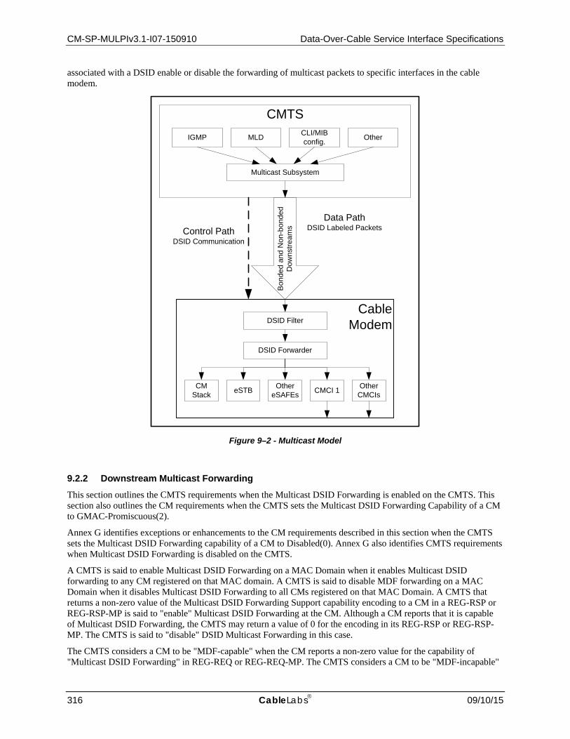
CM-SP-MULPIv3.1-I07-150910 Data-Over-Cable Service Interface Specifications
316 CableLabs 09/10/15
associated with a DSID enable or disable the forwarding of multicast packets to specific interfaces in the cable modem.
Figure 9–2 - Multicast Model
9.2.2 Downstream Multicast Forwarding This section outlines the CMTS requirements when the Multicast DSID Forwarding is enabled on the CMTS. This section also outlines the CM requirements when the CMTS sets the Multicast DSID Forwarding Capability of a CM to GMAC-Promiscuous(2).
Annex G identifies exceptions or enhancements to the CM requirements described in this section when the CMTS sets the Multicast DSID Forwarding capability of a CM to Disabled(0). Annex G also identifies CMTS requirements when Multicast DSID Forwarding is disabled on the CMTS.
A CMTS is said to enable Multicast DSID Forwarding on a MAC Domain when it enables Multicast DSID forwarding to any CM registered on that MAC domain. A CMTS is said to disable MDF forwarding on a MAC Domain when it disables Multicast DSID Forwarding to all CMs registered on that MAC Domain. A CMTS that returns a non-zero value of the Multicast DSID Forwarding Support capability encoding to a CM in a REG-RSP or REG-RSP-MP is said to "enable" Multicast DSID Forwarding at the CM. Although a CM reports that it is capable of Multicast DSID Forwarding, the CMTS may return a value of 0 for the encoding in its REG-RSP or REG-RSP-MP. The CMTS is said to "disable" DSID Multicast Forwarding in this case.
The CMTS considers a CM to be "MDF-capable" when the CM reports a non-zero value for the capability of "Multicast DSID Forwarding" in REG-REQ or REG-REQ-MP. The CMTS considers a CM to be "MDF-incapable"
CMTS
Bon
ded
and
Non
-bon
ded
Dow
nstre
amsControl Path
DSID Communication
Data PathDSID Labeled Packets
IGMP MLD CLI/MIB config. Other
Multicast Subsystem
CableModem
DSID Forwarder
CM Stack eSTB Other
eSAFEs CMCI 1 Other CMCIs
DSID Filter

MAC and Upper Layer Protocols Interface Specification CM-SP-MULPIv3.1-I07-150910
09/10/15 CableLabs 317
when the CM reports a zero value for the capability of "Multicast DSID Forwarding" in REG-REQ or REG-REQ-MP.
An MDF-capable CM is considered to operate in one of the following three modes of operation based on the value set by the CMTS in REG-RSP or REG-RSP-MP for the Multicast DSID Forwarding (MDF) Capability, see Annex C:
• When the CMTS sets the value of 0 for MDF capability, the CM is considered to operate in "MDF-disabled Mode." The CM and CMTS requirements for this mode of operation are detailed in the subsection MDF of Annex G.
• When the CMTS confirms the value of 1 for MDF capability, the CM is considered to operate in "GMAC-Explicit MDF Mode." The CMTS requirements for this mode of operation are detailed in the subsection GMAC-Explicit Multicast DSID Forwarding Mode of Annex G.
• When the CMTS sets or confirms the value of 2 for MDF capability, the CM is considered to operate in "GMAC-Promiscuous MDF Mode." GMAC-Promiscuous MDF Mode means that the CM has the ability to "promiscuously" accept and forward all GMAC addresses with known DSID labels. DOCSIS 3.0 CMs and later are required to implement and advertise the capability of MDF=2. The requirements for both CM and CMTS for GMAC-Promiscuous MDF Mode are detailed in the following sections.
There are two main classes of IP multicast traffic that need to be forwarded by the DOCSIS 3.0 CMTS: traffic associated with the well-known IPv6 groups see Annex A when IPv6 forwarding is configured and user-joined multicast. User-joined multicast is defined as multicast traffic that is based on IGMP or MLD protocols where clients and routers have defined messages that are used to start and stop the reception of multicast traffic.
Downstream multicast packet forwarding at the CM is achieved by filtering and forwarding packets based on DSIDs. This involves the following three high level functions:
1. Labeling multicast packets with a DSID by the CMTS;
2. Communicating DSIDs and associated group forwarding attributes to a CM by the CMTS;
3. Filtering and forwarding of DSID labeled multicast packets by the CM.
The term "IP Multicast Session" is used to refer to both ASM IP multicast groups and SSM IP multicast channels. The term JoinMulticastSession is used to refer to an IGMP/MLD message element that indicates a "join to an ASM IP multicast group" or a "subscribe to an SSM IP multicast channel". The term LeaveMulticastSession is used to refer to an IGMP/MLD message element that indicates a "leave from an ASM IP multicast group" or an "unsubscribe from an SSM IP multicast channel". The term "Multicast Client" refers to an entity with a unique MAC address that receives multicast packets (e.g., CM IP Host stack, e-SAFE devices, or CPE devices connected to the CM).
9.2.2.1 Examples of Downstream Multicast Forwarding using DSIDs DOCSIS 3.0 introduced the capability of CMs to receive multiple Downstream Channels (DCs) and therefore to receive multicast session traffic distributed by a CMTS on a Downstream Bonding Group (DBG) of multiple channels. CMs incapable of receiving multiple Downstream Channels can receive multicast traffic on only a single Downstream Channel. Because DOCSIS 3.0 supports MAC domains of multiple downstream channels with a mixture of both single-receive-channel and multiple-receive-channel CMs, it poses the special problem of avoiding the duplicate delivery of downstream multicast traffic. For example, when a multicast session is replicated to separate downstream channels in order to reach DOCSIS 2.0 CMs on each channel, a DOCSIS 3.0 CM that receives both channels needs to avoid delivering both copies of the packet to its CPE interface.
An important concept with Multicast DSID-based Forwarding is the Downstream Channel Set (DCS). A Downstream Channel Set is defined as either: a single Downstream Channel (DC) or a Downstream Bonding Group (DBG) of more than one channel. Each Downstream Channel Set is composed of downstream channels in a single MAC Domain. With DOCSIS 3.0, the CMTS forwards IP Multicast packets received on a Network System Interface (NSI) to one or more Downstream Channel Sets of a CMTS MAC Domain.
For purposes of downstream DSID-based Multicast Forwarding, a "bonding CM" is considered to be one that has a non-zero Multiple Receive Channel Support capability set by the CMTS as described in the subsection Multiple

CM-SP-MULPIv3.1-I07-150910 Data-Over-Cable Service Interface Specifications
318 CableLabs 09/10/15
Receive SC-QAM Channel Support in Annex C. A "nonbonding CM" is considered to be one that has the Multiple Receive Channel Support capability set to zero by the CMTS.
Multicast DSID-based Forwarding avoids undesired duplicate delivery of IP multicast session traffic by using the DSID label to distinguish each replication of an IP multicast session to a particular set of CMs.
The example in Figure 9–3 depicts the use of DSIDs to prevent duplicate delivery of two non-bonded multicast sessions by a bonding CM to its CPE(s):
Figure 9–3 - DSIDs prevent duplication of non-bonded replications
Figure 9–3 depicts a CMTS that receives a multicast session and replicates it on downstream channel DC1 to reach nonbonding CM1 and replicates it to downstream channel DC2 to reach nonbonding CM2. The Ethernet Packet PDUs transmitted on each downstream channel are identical, i.e., they have the same layer 2 Group MAC destination address and the same layer 3 IP contents. The only difference is in the Downstream Service Extended Header (DS-EHDR) that the CMTS prepends on the MAC frames on each channel. The CMTS labels the DS-EHDR of the replicated frames on DC1 with DSID1 and labels the DS-EHDR of the replicated frames on DC2 with DSID2. The nonbonding CMs ignore the DSID label, and forward the replication received on their (single) Primary Downstream Channel. The CMTS instructs bonding CM3, however, to forward multicast traffic labeled only with DSID1, and does not inform CM3 of the value of DSID2 at all. CM3 therefore forwards the replicated traffic on DC1 (and labeled with DSID1) and discards the replicated traffic on DC2 because it is labeled with the unknown label DSID2.
The CMTS uses DSIDs in a similar way to restrict forwarding of source-specific multicast sessions through only the CMs with multicast clients that have joined the SSM session. An SSM session is identified by the pair (S,G) for a multicast source S sending to an IP multicast group G. Because DOCSIS 1.1/2.0 CMs filter downstream multicast traffic based only on the destination group G, they forward multicast traffic for both (S1,G) and (S2,G) to their CPE ports. CMs capable of Multicast DSID-based Forwarding (MDF), however, can use DSID filtering to limit forwarding to a single (S,G) session. This is depicted in Figure 9–4 below.
CMTS
NonBonding CM1
NonBonding CM2
BondingCM3
(DSID1 only)
DSI
D 1
DSI
D 2
DC1 DC2
Multicast session

MAC and Upper Layer Protocols Interface Specification CM-SP-MULPIv3.1-I07-150910
09/10/15 CableLabs 319
Figure 9–4 - DSIDs separate Source-Specific Multicast Sessions
In the example in Figure 9–4, the CMTS receives two SSM sessions, (S1,G) and (S2,G), and replicates them both to the downstream bonding group consisting of both DC1 and DC2. By assigning a different DSID to each session, it is able to configure CM1 and CM2 to forward traffic only for the particular SSM session joined by the CPE reached through the CM. The CMTS signals CM1 to recognize DSID3 but not DSID4, and the CMTS signals CM2 to recognize DSID4 but not DSID3. Each CM forwards the proper SSM session traffic and filters the other SSM session traffic based on the DSID.
9.2.2.2 Labeling Multicast Packets with DSIDs The CMTS MUST label all downstream multicast packets with a DSID. Packets with a known DSID are received by the CM and forwarded to the set of interfaces associated with the DSID. A routing CMTS MUST label traffic for different "IP multicast SSM Channels" or "IP multicast ASM Groups" with different DSIDs, with the exception of well-known IPv6 multicast traffic (refer to the subsection Well-known IPv6 Addresses in Annex A). Thus, with Multicast DSID-based Forwarding, each replication of an (S,G) IP multicast session to a particular DCS is assigned a unique DSID label within a MAC Domain.
A bridging CMTS SHOULD label traffic for different "IP multicast SSM Channels" or "IP multicast ASM Groups" with different DSIDs. If the bridging CMTS is not capable of isolating multicast traffic based on layer-3 information (such as an ASM Group, or SSM channel) then the bridging CMTS MUST use different DSIDs for multicast traffic with different destination GMAC addresses.
DSID labeling enables differentiation of multiple replications of an IP Multicast Session (bonded or non-bonded) on downstream channel sets (refer to the subsection Databases in Appendix I, Definition of DCS). Hence, it is possible that the CMTS assigns multiple DSIDs to an IP Multicast Session. Non-bonded multicast packets contain a DSID in the DOCSIS header without a sequence number. To prevent a CM from receiving duplicate packets, the CMTS MUST NOT replicate multicast packets labeled with the same DSID on different downstream channel sets that reach the same CM.
The CMTS typically signals only one DSID out of the set of DSIDs that are being used for the replications of a specific IP Multicast Session to the CM. The CMTS has the option to signal multiple DSIDs for the same IP Multicast Session to a CM. However, the CMTS needs to ensure that it does not replicate the IP Multicast session
CMTS
Bonding CM1(DSID3 only)
Bonding CM2(DSID4 only)D
SID
3 +
DSI
D4
DSI
D3
+ D
SID
4
DC1 DC2
Session (S1,G)
CPE joining (S1,G)
Session (S2,G)
CPE joining (S2,G)
(S1,G) replicated on (DC1,DC2) with DSID3(S2,G) replicated on (DC1,DC2) with DSID4

CM-SP-MULPIv3.1-I07-150910 Data-Over-Cable Service Interface Specifications
320 CableLabs 09/10/15
with those DSIDs concurrently on the downstream channel sets reached by the CM. This prevents duplicate delivery of packets to the CM. For example, the CMTS may communicate two DSIDs to the CM, one DSID used for forwarding the stream bonded and another used for forwarding the stream non-bonded, but the CMTS uses only one of those two DSIDs for labeling multicast packets received by a CM. This enables the CMTS to switch a multicast session from bonded to non-bonded without having to incur delay in communicating a DSID.
In order to achieve bandwidth efficiencies, the CMTS SHOULD minimize the number of copies of a multicast packet that need to be delivered on the overall set of downstream channel sets.
9.2.2.2.1 Mixed CM environment
DOCSIS 3.0 networks may contain a mix of DOCSIS 3.0 cable modems and Pre-3.0 DOCSIS cable modems. Pre-3.0 DOCSIS CMs do not support downstream channel bonding. However, the CMTS may need to transmit multicast packets to Multicast Clients behind the Pre-3.0 DOCSIS CMs. A CMTS MUST replicate multicast traffic intended for CMs that do not support Multiple Receive Channels (e.g., DOCSIS 2.0) as non-bonded. It is possible that a given multicast packet is replicated multiple times on a single downstream channel: once non-bonded to be received by CMs that are not receiving multiple downstream channels, and one or more times bonded to be received by CMs that are receiving multiple downstream channels.
DSID labeling can ensure that a DOCSIS 3.0 CM does not forward duplicate packets. However, because Pre-3.0 DOCSIS CMs ignore the DSID label on the packet, it is possible that Pre-3.0 DOCSIS CMs receive bonded copies of DSID labeled packets. This may result in Pre-3.0 DOCSIS CMs receiving partial as well as duplicate copies of bonded packets. The CMTS MUST isolate bonded multicast traffic from non-bonded replication on the same downstream channel by transmitting these bonded multicast packets with the Isolation Packet PDU MAC Header (the FC_Type field of the DOCSIS frame set to binary 10). Note that the CMTS MAY transmit bonded multicast traffic with the Packet PDU MAC Header (FC_Type set to 00) when such traffic does not overlap with a non-bonded replication of the multicast session on the same downstream channel. For the replication of non-bonded multicast traffic to CMs with a Frame Control Type Forwarding Capability of 0 (i.e., cannot forward FC_TYPE 10), the CMTS MUST transmit the non-bonded multicast traffic with the Packet PDU MAC Header (the FC_Type field set to binary 00). Because the CMTS does not know of the CM's capabilities until the CM registers, the CMTS MUST NOT isolate pre-registration IPv6 multicast traffic (Section 9.2.2.2) with the Isolation Packet PDU MAC Header (FC_Type 10).
9.2.2.2.2 Pre-Registration DSID
The Pre-Registration DSID is the DSID for labeling multicast packets used by a CM prior to its completion of the registration process; these multicast packets used for DHCPv6, Neighbor Solicitation (DAD), and IPv6 Router Advertisements (RAs), are received only by a CM's IP stack. The CMTS MUST label all link local multicast traffic (as detailed in Annex A) with the Pre-Registration DSID.
9.2.2.2.3 Upstream Multicast Traffic from a Multicast Client
According to the requirements in Section 9.1.2.3, when a CM receives upstream multicast packets on its CMCI interface, it forwards packets on its RF Port, the CM IP stack and all of its CMCI ports, except the one from which it received the packets. Additionally, as specified in Section 9.1.2.2, when the CM receives DSID labeled downstream multicast packets, it filters packets from a source MAC addresses which are provisioned or learned as supported CPE devices. Therefore, when forwarding upstream multicast packets to downstream channel sets on the MAC Domain, if the DSID used for those multicast packets is known to the CM from which the packets were received the CMTS MUST NOT alter the source MAC address on those packets. This prevents duplicate delivery of packets to multicast clients behind the CM including the original sender.
9.2.2.3 Communicating DSIDs and group forwarding attributes to a CM The CMTS is responsible for signaling to the CM a DSID that the multicast traffic is labeled with. The CMTS advertises the Pre-registration DSID value in the MDD message (Section 6.4.28.1.5). The CMTS also communicates DSID values to the CM during the registration process in a REG-RSP message and dynamically using the DBC message after registration.

MAC and Upper Layer Protocols Interface Specification CM-SP-MULPIv3.1-I07-150910
09/10/15 CableLabs 321
The CMTS transmits the Pre-registration DSID in the MDD message. The CMTS MUST assign a unique Pre-registration DSID per downstream channel in the MAC domain.
A CMTS is responsible sending one copy of the IPv6 Well Known (see the subsection Well-known IPv6 Addresses in Annex A) and Solicited node traffic to CM and associated CPE devices that require such traffic, which is necessary for DHCPv6, Neighbor Solicitation (DAD), and IPv6 Router Advertisements (RAs) after registration. The CMTS has the option of continuing to use the Pre-registration DSID for CMs in the operational state or assigning a new DSID for this multicast traffic. In either case, the CMTS MUST include the DSID values for post registration well-known IPv6 traffic for any CM in which Multicast DSID Forwarding has been enabled in the REG-RSP(-MP) message. To ensure receipt by all devices, including CMs operating in Energy Management 1x1 Mode (see Section 11.7.2), the CMTS MUST use a non-bonded DSID for this multicast traffic. The CMTS MUST NOT assign a new DSID when it receives a MLD Membership Report for the Solicited Node Address from an IPv6 node that is initializing it's stack (traffic associated Neighbor Discovery and Duplicate Address Detection). This allows the CMTS to use the same DSID for all IPv6 provisioning traffic, and does not generate a new DSID for each SN address.
The CMTS MUST communicate in the REG-RSP-MP the set of DSIDs for multicast packets to be forwarded by that CM immediately after the registration process.
A CM may have several logical and physical interfaces to internal and external multicast clients. The internal CM IP stack is considered to be a multicast client. Each embedded Service Application Functional Entity (eSAFE) is a potential multicast client connected via a separate logical CPE interface. Each external CPE port is a separate interface to a potential multicast client. For the purpose of IP multicast forwarding, a CM can be thought of as a bridge with one port connecting to the CMTS and up to 16 non-CMTS facing ports connecting to Multicast Clients. These non-CMTS facing ports are henceforth called CMIM-Interfaces because they are enumerated via the CM Interface Mask (CMIM) (see the subsection CM Interface Mask (CMIM) Encoding in Annex C). The group forwarding attributes associated with a DSID determine a set of interfaces on which the CM forwards downstream multicast packets labeled with that DSID value.
DSID based filtering and forwarding for downstream multicast is triggered by a "JoinMulticastSession" message sent by a Multicast Client, like an IGMP version 2 or 3, or an MLD version 1 or 2 membership report. When the CMTS receives a "JoinMulticastSession" message, it initiates a DBC message to the CM from which the "JoinMulticastSession" was received. The DBC message contains the DSID used for labeling packets belonging to the IP Multicast Session as well as the CMIM and/or Client MAC address(es) of Multicast Client(s) where the multicast packets are to be forwarded. The DBC message optionally contains a SAID if the IP Multicast Session is encrypted. The CM responds to this DBC message after configuring appropriate forwarding rules for the session. After registration of a CM, the CMTS MUST communicate changes to the set of DSIDs used for multicast packets to be forwarded by that CM using DBC messages.
The CMTS tracks the multicast forwarding state established on the CMs via DBC messages and appropriately updates them when Multicast Clients join and leave IP Multicast Sessions. CMs are not aware of the methods used to determine which DSID, downstream channel(s), or Multicast Client MAC addresses are used for transporting a specific IP Multicast Session. These methods are the same whether the CM is in a bonded or non-bonded configuration. The details of processing "JoinMulticastSession" and "LeaveSession" messages depends on the actual protocol used (e.g., IGMPv2 or IGMPv3) and is explained in Section 9.2.5.
9.2.2.4 DSID based Filtering and Forwarding by a Cable Modem A CM MUST NOT forward downstream multicast packets based on snooped IGMP v2/v3 messages.
Since all multicast traffic that is meant to be forwarded by the CM is labeled with a DSID, the CM MUST discard any multicast packets without a DSID label. The CM discards any packet with an unknown DSID. The CM performs filtering and forwarding of downstream multicast traffic based on DSID values; it does not perform destination GMAC address filtering. The CM MUST NOT discard a multicast packet based on its destination GMAC address. A CM MUST support DSID based multicast forwarding for at least as many DSIDs as reported by the Multicast Downstream Service ID Support Capability subsection in Annex C.
A mechanism is defined to control multicast packet replication within the CM, as the CM may support multiple egress interfaces. For each DSID, the CMTS specifies the CMIM and/or client MAC addresses of the Multicast Clients intended to receive that IP Multicast Session.

CM-SP-MULPIv3.1-I07-150910 Data-Over-Cable Service Interface Specifications
322 CableLabs 09/10/15
In order to successfully obtain its IP address and register, the CM needs to receive certain multicast packets such as those used for DHCPv6, router discovery and duplicate address detection (see the subsection Well-known IPv6 Addresses in Annex A). Prior to registration, the CM MUST forward to its internal IPv6 and higher stacks all multicast packets received on the RF interface and labeled with the Pre-registration DSID signaled in the MDD message. Prior to registration, the CM MUST discard multicast traffic that is not labeled with the Pre-registration DSID.
The CM only forwards packets labeled with the Pre-registration DSID until it receives a REG-RSP message. The CM MUST discard the Pre-registration DSID prior to adding the DSIDs communicated in the REG-RSP.
The CMTS communicates client MAC addresses based on IGMP/MLD join messages for a particular IP Multicast Session to a CM in a DBC-REQ Message. The CM builds a list of client MAC addresses per DSID using these client MAC addresses. The CM MUST support all learned CPE MAC addresses (see Section 9.1.2.1) in its client MAC address list associated with each supported Multicast DSID. In other words, if the number of CPE MAC addresses learned by the CM is 4, then the CM needs to support forwarding of multicast sessions to all 4 CPEs for every Multicast DSID it supports. Thus, if the total number of Multicast DSIDs supported by the CM is 16 then the total number of multicast sessions forwarded by the CM will be 16*4=64.
The CMTS may communicate the CM Interface Mask (CMIM) for static (un-joined) multicast services in which case the Multicast Clients (e.g., embedded STBs) do not explicitly send a "JoinMulticastSession" message. The CM uses the CMIM and client MAC addresses to deduce the set of egress interfaces to which the DSID-labeled multicast traffic is forwarded. If the CMTS signals both the CMIM and Client MAC Address for a DSID then the CM does a logical 'OR' operation.
A CM MUST replicate a DSID labeled multicast packet to only the union of all interfaces identified in the Multicast CM Interface Mask associated with that DSID and all interfaces identified by the list of client MAC addresses associated with that DSID. The upper bound for this union for a DSID is all CM egress interfaces. The CM does not forward multicast packets labeled with a known DSID for which it has no interface defined on which to forward these packets.
A CM MUST replicate a DSID labeled multicast packet only once on each interface. If no Multicast CM Interface Mask or Client MAC Address is configured for the DSID, the CM MUST discard multicast packets labeled with that DSID.
9.2.2.5 Individually Directed Multicast Individually directed multicast refers to the ability in the DOCSIS network to send a multicast packet on the downstream and ensure that it is forwarded by only one CM rather than the full set of CMs with Multicast Clients that have joined an IP Multicast Session. One potential usage scenario is for IGMPv2/MLDv1 Leave Processing as specified in Section 9.2.5.4.
If the CMTS intends to direct multicast packets to a single CM it should use an individual DSID known only to that CM for such packets.
9.2.3 Downstream Multicast Traffic Encryption
9.2.3.1 Multicast Encryption Overview When a CMTS encrypts downstream multicast traffic associated with an IP Multicast Session intended to be received and/or forwarded by a group of CMs, it does so with a Security Association (SA) previously signaled to those CMs. This type of Security Association ID (SAID) is defined as Per-Session SAID. A Security Association is said to be "known" at a CM when the CMTS has communicated that SAID in a Security Association Encoding of a MAC Management Message sent to the CM.
A Security Association is not considered to be dedicated to either unicast or broadcast (including multicast) traffic. The CMTS MAY transmit multicast traffic intended for forwarding by a group of CMs with any SA known by those CMs. A Per-Session SAID is unique per a MAC Domain Downstream Service Group (MD-DS-SG).
As described in DOCSIS 3.0 Security Specifications [DOCSIS SECv3.0], when a CM first authenticates with the CMTS the CMTS provides in its BPI Authorization Response message a Primary SA and (if supported by the CMTS) zero or more Static SAs. A CM's initial BPI authentication may occur immediately after initial ranging in a

MAC and Upper Layer Protocols Interface Specification CM-SP-MULPIv3.1-I07-150910
09/10/15 CableLabs 323
process called Early Authentication and Encryption (EAE) [DOCSIS SECv3.0]. If a CM does not perform EAE, it performs its initial BPI authentication immediately after it registers with the CMTS. The Primary SA and Static SAs (if any) established at BPI authentication remain in effect as long as the CM remains authenticated with the CMTS.
DOCSIS versions 1.1 and 2.0 used a mechanism that mapped IPv4 multicast destination addresses to a "dynamic" type Security Association. This mechanism is described in DOCSIS 2.0 BPI Specification [DOCSIS BPI+] and calls for a CM that recognized an upstream IGMPv2 membership report to send an SA Map Request message to the CMTS. The CMTS responded with an SA Map Reply message that provided an SAID of a "dynamic" type Security Association. The CM then initiated a TEK transaction to obtain the keying material for that dynamic SA.
DOCSIS 3.0 introduces a new mechanism for communicating dynamic SAs for multicast traffic instead of using the SA Map Request and SA Map Reply messages of DOCSIS 1.1/2.0. DOCSIS 3.0 calls for the CMTS to signal to the CM the dynamic Security Association for encrypting downstream multicast traffic in the same MAC Management Message with which it communicates the DSID to the CM for that multicast traffic (see Section 6.4.29).
The CMTS communicates a dynamic Security Association to a CM with a Security Association Encoding (see the subsection Security Association Encoding in Annex C) within a Registration Response (REG-RSP) or Dynamic Bonding Change Request (DBC-REQ) message. Although dynamic Security Associations are primarily intended for encrypting downstream multicast traffic, there is no requirement that they do so. A CMTS MAY encrypt unicast, broadcast, or multicast traffic with a Primary, Static, or Dynamic SA. A CM is expected to decrypt unicast, broadcast, or multicast traffic with the appropriate known SA, regardless of the SA type.
The encryption for multicast sessions can be configured in the Group Encryption Configuration object which is referenced from the Group Configuration Object. The GC entry for a multicast session if configured, points to an entry in the Group Encryption Table. This encryption applies only to joined IP multicast sessions. This includes dynamically joined sessions using multicast management protocol such as IGMP/MLD as well as statically joined sessions using Static Multicast Session Encodings in REG-REQ(-MP) (see the subsection CMTS Static Multicast Session Encoding in Annex C). The mechanism by which the CMTS provides encryption for other downstream broadcast and layer 2 multicast traffic is CMTS vendor specific.
Whenever there is a change to the encryption properties configured for a session then the CMTS SHOULD signal the required SAIDs using DBC messages to all the CMs which are listening to that Multicast session.
9.2.3.2 Dynamic Multicast Encryption The message exchange between the CMTS and the CM for the signaling and initialization of multicast traffic encryption varies depending on the type of multicast session, the capabilities of the modem and the multicast forwarding mode selected by the CMTS. The signaling of Security Associations for encrypted dynamic multicast sessions is described in [DOCSIS SECv3.1].
9.2.3.3 DSIDs and SAIDs In general, the set of DSIDs and SAs known at a CM are considered to be independent. The CM is not expected to associate an SA with a DSID. Unless specified otherwise, the CMTS MAY transmit encrypted downstream multicast traffic intended for forwarding by a set of one or more CMs with any combination of an SA known by the CMs and labeled with a DSID known by the CMs. A CM MUST decrypt downstream multicast traffic encrypted with an SA known by the CM and labeled with a DSID known by the CM. A CM silently ignores downstream multicast packets with a known SAID and labeled with an unknown DSID. For example, the CM does not report a key sequence error or CRC error in this case.
When the CMTS replicates a downstream multicast packet onto multiple downstream channel sets of a MAC domain, it labels the replication on each downstream channel set with a different DSID. When the CMTS is configured to map a downstream IP Multicast Session to a specific SA, the CMTS MUST encrypt all replications of the session with that same specified SA.
As detailed in the subsection GMAC-Promiscuous Override in Annex G, a CMTS that elects to override a Pre-3.0 DOCSIS CM's DSID Multicast Forwarding mode from GMAC-Explicit(1) to GMAC-Promiscuous(2) has additional requirements for encrypting the multicast traffic that reaches the overridden CM.

CM-SP-MULPIv3.1-I07-150910 Data-Over-Cable Service Interface Specifications
324 CableLabs 09/10/15
9.2.3.4 Pre-Registration Multicast Encryption Before a CM registers, it receives layer 2 multicasts for DHCP /ARP for IPv4 or DHCPv6/Neighbor Discovery for IPv6. The CMTS labels multicast traffic intended for reception by CMs before registration with a Pre-Registration DSID advertised in the MAC Domain Descriptor (MDD) message.
A CM that performs Early Authentication and Encryption (EAE) is provided with at least a Primary SAID and, at the CMTS's option, may also be provided with zero or more Static SAIDs as defined in DOCSIS 3.0 Security Specifications [DOCSIS SECv3.0]. A CMTS does not encrypt multicast traffic intended to be received by a CM before it completes registration using a Primary or Static SA known at the CM from Early Authentication and Encryption. A CM MUST decrypt downstream multicast traffic received with the Pre-Registration DSID and a known Primary or Static SA prior to its completion of registration.
9.2.4 Static Multicast Session Encodings The cable operator can configure the cable modem to join IP multicast sessions during registration. Such multicast sessions are called Static Multicast Sessions. The cable operator configures such static multicast sessions using the CMTS Static Multicast Session Encodings (see the subsection CMTS Static Multicast Session Encoding in Annex C).
The CMTS MUST communicate in its REG-RSP the DSID used to label packets of the multicast session described by the Static Multicast Group and Source Encoding subtypes in the CMTS Static Multicast Session Encoding. The CMTS MUST include in the DSID Encodings sent in the REG-RSP, a Multicast CMIM subtype with the value of Static Multicast CMIM Encoding it received in the REG-REQ. If the static multicast session is encrypted, the CMTS also communicates in the REG-RSP message the session's SA Descriptor [DOCSIS SECv3.0].
If the CMTS disables Multicast DSID Forwarding for a CM, the CMTS MUST ignore the CMTS Static Multicast Session Encodings received in the REG-REQ. This implies that the CMTS does not communicate DSIDs and SAIDs to the CM for those CMTS Static Multicast Session Encodings and does not create a multicast replication entry for this CM.
The cable operator can also configure the cable modem to join layer 2 multicast sessions using the Static Multicast MAC Address TLV (see the subsection Static Multicast MAC Address in Annex C).
9.2.5 IGMP and MLD Support
9.2.5.1 Motivation behind taking CM out of IGMP Control Plane In DOCSIS 1.1 and 2.0, the cable modem is required to provide IGMP version 2 type snooping functionality in which the CM intercepts IGMP membership reports and establishes forwarding of multicast packets appropriately. Two modes, active and passive are defined. IGMP timers and requirements are specified in [DOCSIS RFIv2.0]. This model has a set of downsides similar to a general purpose Ethernet environment where there is no well-defined single point of control.
In the DOCSIS environment the CMTS is a well-defined single point of control. Hence, it is desirable that a CMTS control the multicast operations of CMs. This alleviates the need to perform any IPv4 or IPv6 specific multicast operations in the CM and simplifies filtering and forwarding functionality.
Removing the IGMP control plane from the CM offers wide range of benefits as follows:
• Ensures well defined and consistent multicast forwarding behavior in the CM. • Simplifies the CM since protocol specific knowledge for technologies such as ASM and SSM for IPv4 and
IPv6, including the protocols IGMPv3 and MLDv2, is no longer required. • Easier to incorporate multicast protocol changes since they only affect the CMTS and not the CMs. • Other multicast protocols like PIM can be supported in the future by utilizing the same CMTS to CM signaling
without affecting the CMs. • It is easier to solve issues related to MAC level aliasing, access and admission control from the CMTS.

MAC and Upper Layer Protocols Interface Specification CM-SP-MULPIv3.1-I07-150910
09/10/15 CableLabs 325
9.2.5.2 IP multicast service model support IGMP for IPv4 and MLD for IPv6 are the two IETF standards based protocols by which CPE devices signal membership for IP multicast Session. While originally intended to be used only by host-type CPEs, they can also be used by router-type CPE devices or CM co-located routers by using IGMP/MLD proxy-routing [RFC 4605]. IGMP and MLD are the only two CPE multicast membership protocols required to be supported by the CMTS. The CMTS MUST support IGMPv3 [RFC 3376] and MLDv2 [RFC 3810].
The membership reports are passed transparently by the CM towards the CMTS. The CMTS operates as an IGMP/MLD querier, and as an IPv4/IPv6 multicast router (for a routing CMTS) or snooping switch (for a bridging CMTS). In IPv4 and IPv6 multicast, two service models exist, both of which are supported by DOCSIS 3.0. The "Any Source Multicast" (ASM) model as defined in [RFC 1112] (for IPv4 but as well applicable to IPv6), and the "Source Specific Multicast" (SSM) model as defined in [RFC 4607]. In ASM, clients send IGMPv2/v3 or MLDv1/v2 membership reports to "join to an ASM IP multicast group (G)" indicating that they want to receive multicast traffic with any IP source address and the IP multicast destination address G. In SSM, clients send IGMPv3 or MLDv2 membership reports to "subscribe to an SSM IP multicast channel (S,G)" indicating that they want to receive multicast traffic with the IP source address S and the IP multicast destination address G. A CMTS MUST support ASM (Any Source Multicast) as specified in [RFC 1112] and SSM (Source Specific Multicast) as specified in [RFC 4607] for both IPv4 and IPv6. The MAC address format defined in [RFC 2464] is used for IPv6 multicast.
In IGMPv2/MLDv1 [RFC 2236] [RFC 2710], each membership report packet contains exactly one JoinMulticastSession for one ASM IP multicast group. Each IGMPv2/MLDv1 membership leave contains exactly one LeaveMulticastSession for one ASM IP multicast group. In IGMPv3/MLDv2 each membership report contains one or more JoinMulticastSession and/or LeaveMulticastSession for ASM IP multicast groups [RFC 1112] and/or SSM IP multicast channels [RFC 4607]. Whether or not a particular message element is for an ASM IP multicast group or an SSM IP multicast channel is determined by the multicast group (G) as defined in [RFC 1112] and [RFC 4607]. A CMTS MUST forward downstream IPv4 multicast traffic to CPE devices joined through IGMP version 3 [RFC 3376] "JoinMulticastSession" message element. Note: Support for IGMP version 3 includes backward compatibility for IGMP version 2 [RFC 2236]. A CMTS MUST forward downstream IPv6 multicast traffic to CPE devices joined through MLD version 2 [RFC 3810]. Note: Support for MLD version 2 includes backward compatibility for MLD version 1 [RFC 2710] "JoinMulticastSession" message element.
9.2.5.3 IGMP and MLD membership handling Multicast Clients send triggered IGMP/MLD membership reports when they want to start or stop receiving an IP Multicast Session. When the CMTS processes these triggered membership reports, the CMTS sends DBC messages to control forwarding of multicast packets by a CM.
When the CMTS receives a JoinMulticastSession message in an IGMP/MLD membership report from the first Multicast Client behind a CM, the CMTS MUST verify if the CM is authorized to receive the IP Multicast Session requested to be joined in the JoinMulticastSession message as described in Section 9.2.7 (IP Multicast Join Authorization). If the CM is authorized, the CMTS MUST send a DBC message to add the DSID along with an SAID (if the session is encrypted) and the Client MAC Address and/or CMIM. If the CM is not authorized, the CMTS MUST NOT send a DBC message to the CM adding the DSID and associated attributes.
When the CMTS receives a subsequent JoinMulticastSession message for the same IP Multicast Session in an IGMP/MLD membership report from a different Multicast Client behind the CM, the CMTS MUST send a DBC message to add the Client MAC Address and/or CMIM for the DSID already communicated to the CM.
Multicast Clients also send periodic IGMP/MLD membership reports when they respond to general queries from the CMTS. These periodic membership reports are important for the CMTS for efficient bandwidth utilization. They are used to overcome the loss of triggered membership reports that would have indicated that a Multicast Client wants to stop receiving an IP Multicast Session. Such a loss may happen if a Multicast Client crashes or reboots or if these membership reports are lost due to problems in the home network. The CMTS MUST track periodic membership reports received from Multicast Clients and time them out as specified in the IGMP/MLD protocol specifications for the IGMP/MLD querier.
When Multicast Clients use IGMPv2/MLDv1 membership reports, they suppress their periodic reports in the presence of simultaneously seen membership reports for the same session from another Multicast Client. This can

CM-SP-MULPIv3.1-I07-150910 Data-Over-Cable Service Interface Specifications
326 CableLabs 09/10/15
cause problems with the above mentioned tracking of these membership reports. The CMTS MUST NOT reflect IGMP and MLD membership reports received on the upstream to downstream channel sets.
NOTE: This requirement applies even in the mixed mode environment for DOCSIS 3.0 CMs and Pre-3.0 DOCSIS CMs.
This avoids the report suppression problem and enables tracking of membership reports on a per-CM and per-CMIM-Interface basis. In addition, report suppression helps to provide privacy for membership reports. Reflecting the membership reports to other CMIM-Interfaces and CMs would permit eavesdropping on foreign Multicast Client's join activities.
Membership report suppression does not occur with IGMPv3 and MLDv2. Each Multicast Client interested in an IP Multicast Session will generate membership reports independent of membership reports from other Multicast Clients. Due to this, the CMTS can track IGMPV3/MLDv2 memberships on a per Multicast Client basis. This also simplifies IGMPv3/MLDv2 leave processing.
When the routing CMTS determines that there are no Multicast Clients for an IP Multicast Session behind a CM, the CMTS MUST send a DBC message to delete the DSID associated with that IP Multicast Session. If the bridging CMTS is using a single DSID to forward multiple IP Multicast Sessions, the bridging CMTS MUST send the DBC message to delete the DSID only after all Multicast Clients joined to all IP Multicast Sessions associated with that DSID have either left or not responded to membership reports. When the CMTS determines that a Multicast Client has left an IP Multicast Session, but this is not the last client of this IP Multicast Session behind this CM, the CMTS MUST send a DBC message for the DSID associated with the IP Multicast Session to either remove the Multicast Client's MAC address from the client MAC address list or to update the CMIM, if there is a change in the CMIM.
The CMTS SHOULD NOT forward traffic for an IP Multicast Session on a downstream channel set if no multicast clients are joined to that session on that downstream channel set (subject to any administrative controls).
The CMTS SHOULD NOT send group-specific or group-source-specific IGMPv3/MLDv2 queries in response to IGMPv3/MLDv2 membership reports indicating a leave.
9.2.5.4 IGMPv2/MLDv1 Leave Processing If there are multiple Multicast Clients on the same egress interface of the CM, periodic IGMPv2/MLDv1 membership reports are subject to suppression. Hence the CMTS needs to send an IGMPv2/MLDv1 group specific query as part of IGMPv2/MLDv1 leave processing ([RFC 2236] and [RFC 2710]) to determine if there are any remaining Multicast Clients joined to the same IP Multicast Session. When IGMPv2/MLDv1 leave is received from a Multicast Client behind a CM, it is sufficient to send the IGMPv2/MLDv1 group specific query as an individually directed multicast packet to a specific CM. This minimizes the load on other CMs and is highly desirable from the perspective of maintaining the privacy of IGMPv2/MLDv1 leaves and joins. If the CMTS determines that it needs to send an IGMPv2/MLDv1 group specific query after an IGMPv2/MLDv1 leave is received, the CMTS SHOULD send this query such that it is forwarded only by the CM from which the leave was received by using an individual DSID known only to that CM.
9.2.5.5 IGMP and MLD version and query support For each CM, the CMTS MUST maintain a highest supported version of IGMP and MLD. The CMTS MUST maintain the IGMP version as v3 for MDF-enabled CMs. The CMTS MUST maintain the MLD version as v2 for MDF-enabled CMs. When the CMTS receives IGMP or MLD membership reports from a CM with a version higher than the maintained version for the CM, then CMTS MUST ignore such reports. As an exception, the CMTS is not required to ignore MLD Membership Reports for Link-Scope Multicast Groups (e.g., Solicited Node Multicast) from a CM with an MLD version of "none" (the MDF Mode 0 section of Annex G). For example, if IGMP version for a CM is v2, then IGMPv1 and IGMPv2 membership reports are accepted and IGMPv3 membership reports are silently ignored.
CMTS MAY support mechanisms by which the IGMP or MLD version maintained for a CM can be changed, however these mechanisms are outside the scope of this specification. This mechanism can be used to disable forwarding of multicast traffic through the CM by setting the maintained version to "none", or to work around potential IGMPv3/MLDv2 query compatibility issues in older CPEs by setting the maintained version to "IGMPv2" or "MLDv1".
MAC and Upper Layer Protocols Interface Specification CM-SP-MULPIv3.1-I07-150910
09/10/15 CableLabs 327
9.2.5.6 Separation of Query Domains In a mixed-mode cable environment where CMs in DOCSIS 3.0 mode co-exist with Pre-3.0 DOCSIS CMs, it is important to control which IGMP messages are being forwarded to the CPEs behind the CMs.
It is necessary to prevent forwarding of IGMPv3 membership queries by DOCSIS 1.1/2.0 CMs. DOCSIS 1.1 /2.0 CMs are only capable of snooping IGMPv1/v2 messages. If an IGMPv3 membership query would be forwarded to the IGMPv3 capable CPE behind a DOCSIS 2.0/1.1 CM, the CPE would respond with an IGMPv3 membership report. This IGMPv3 membership report would not be recognized by the 1.1/2.0 CM and hence the CM would not be able to properly forward the multicast packets to the CPE. It is also important that the initial join (unsolicited membership report) sent by the CPE also uses IGMPv2. This needs to be controlled by the multicast application and is outside the scope of this specification.
On the other hand, if the cable operator wishes to support IGMPv3 and SSM to the CPEs behind 3.0 CMs, the CMTS has to ensure that only IGMPv3 messages are forwarded to the CPE network and IGMPv2 messages are blocked. This is because of the Host Compatibility Mode defined in IGMPv3 [RFC 3376] which requires a host to switch to the older version of IGMP whenever it receives a query based on the older version.
The CMTS MUST define two separate sets of DSIDs, one for IGMPv2 and another for IGMP v3. These DSIDs are used for the general query messages being sent in the downstream. To enable CMs to receive and forward the IGMP general query messages to all CPE interfaces, the CMTS MUST signal to the CM in the Registration Response a DSID with an appropriate CMIM. In order to prevent forwarding of both IGMPv2 and IGMPv3 General Queries by a single CM, a CMTS MUST NOT signal DSIDs associated with both IGMPv2 and IGMPv3 to a CM at the same time. The CMTS MUST NOT use the same IGMPv2 DSID for IGMPv2 queries being sent on different downstream channel sets. The CMTS MUST NOT use the same IGMPv3 DSID for IGMPv3 queries being sent on different downstream channel sets. Since the IGMPv3 queries are meant to be forwarded by 3.0 CMs only, the CMTS MUST isolate IGMPv3 general query packets from Pre-3.0 DOCSIS CMs by transmitting the IGMPv3 general query packets with the Isolation Packet PDU MAC Header (setting the FC_Type field to 10).
To enable CMs to receive and forward the MLD general query messages to all CPE interfaces, the CMTS MUST signal to the CM in the Registration Response a DSID with an appropriate CMIM. As Pre-3.0 DOCSIS CMs do not support IPv6, there is no DOCSIS 3.0 requirement that the CMTS separate MLDv1 and MLDv2 general queries with a DSID. However, CMTS vendors MAY decide to provide a similar DSID separation of MLDv1 and MLDv2 general queries, as is defined for IGMPv2 and IGMPv3. If the CMTS supports such separation of MLD general queries then the CMTS MUST define two separate sets of DSIDs, one for MLDv1 and another for MLDv2 general query messages. The CMTS MUST NOT use the same MLDv1 DSID for MLDv1 queries being sent on different downstream channel sets within the same MAC domain. The CMTS MUST NOT use the same MLDv2 DSID for MLDv2 queries being sent on different downstream channel sets within the same MAC domain. Since the MLD queries are meant to be forwarded by 3.0 CMs only, the CMTS MUST isolate MLDv1 and MLDv2 general query packets from Pre-3.0 DOCSIS CMs by transmitting the MLD general query packets with the Isolation Packet PDU MAC Header (setting the FC-Type field to 10).
9.2.6 Encrypted Multicast Downstream Forwarding Example This example involves the forwarding of an encrypted multicast session to two multicast clients behind a CM. Refer to Figure 9–5:
1. Multicast traffic labeled with DSID1 is not forwarded through the CM to any of the clients.
2. The Multicast Client 1 on Interface A sends out a "JoinMulticastSession" when it wants to join an IP Multicast Session.
3. The CM forwards the "JoinMulticastSession" upstream to the CMTS like any other data packet without snooping.
4. Assuming the CMTS accepts the joiner, the CMTS selects a DSID and sends a DBC-REQ message that includes the DSID, a client MAC address and a SAID, since the multicast session is encrypted. Note: the address in the Client MAC address list is the source address in the "JoinMulticastSession" (i.e., the MAC address of the Multicast Client 1). The CMTS may start sending traffic for that IP Multicast Session labeled with this DSID prior to sending the DBC-REQ message.

CM-SP-MULPIv3.1-I07-150910 Data-Over-Cable Service Interface Specifications
328 CableLabs 09/10/15
5. Upon successful reception of a DBC message, the CM adds the DSID to its filter table. In addition, it associates the client MAC address with this DSID in order to correctly forward multicast packets only to the subscribing Multicast Clients. The CM sends DBC-RSP message to the CMTS with appropriate confirmation/error codes.
6. CMTS sends a DBC-ACK message after it successfully receives DBC-RSP message from the CM.
7. Since the IP Multicast Session is encrypted, the CM sends the TEK-REQ/BPKM Key Request to the CMTS to obtain the TEK key associated for the SAID.
8. The CMTS sends TEK key material to the CM in the BPKM Key Reply message.
9. When a packet for the IP Multicast Session arrives at the CMTS, the CMTS labels it with the correct DSID, encrypts the packet with the SAID, and then forwards it downstream.
10. When the multicast packet arrives at the CM, the CM decrypts the packet and only forwards it to interface A on which the Multicast Client 1 is connected (since only Multicast Client 1 is associated with the DSID signaled to the CM).
11. The Multicast Client 2 on Interface B of the CM sends out a "JoinMulticastSession" when it wants to join the same IP Multicast Session.
12. The CM forwards the "JoinMulticastSession" upstream to the CMTS like any other data packet without snooping.
13. Assuming the CMTS accepts the joiner, the CMTS sends a DBC-REQ message that includes the existing DSID for the IP Multicast Session, the second Multicast Client MAC address and the same SAID used for encrypting the Multicast Session. Note: the additional Client MAC address is the source MAC address from the "JoinMulticastSession" (i.e., the MAC address of the Multicast Client 2).
14. The CM already has the DSID in its filter table. It associates the new client MAC address with this DSID in order to correctly forward multicast packets to the new client.
15. The CMTS continues to forward the packets of the IP Multicast Session downstream with the correct DSID label and encrypted with the SAID.
16. When the multicast packet arrives at the CM, the CM decrypts the packet and replicates it to interfaces A and B so that both the clients receive the packet.
17. The CM sends a DBC-RSP confirming that it received the DBC-REQ.
18. The CMTS responds to this message with a DBC-ACK.
19. When Multicast Client 1 decides to leave the multicast group, it sends a "LeaveMulticastSession."
20. The CM forwards the "LeaveMulticastSession" upstream to the CMTS like any other user data packet without snooping.
21. CMTS receives the "LeaveMulticastSession" from Multicast client 1 and sends a DBC-REQ to the CM deleting the MAC address of Multicast Client 1 from the client MAC address list associated with the DSID.
22. Upon receiving the DBC-REQ, the CM removes the MAC address of Multicast Client 1 from the client MAC address list associated with the DSID.
23. The CMTS continues to forward the packets of the IP Multicast Session downstream with the correct DSID label and encrypted with the SAID.
24. When the multicast packet arrives at the CM, the CM only forwards that packet to interface B; so that only Multicast Client 2 receives the packet.
25. CM sends a DBC-RSP confirming that it received the DBC-REQ.
26. The CMTS responds to this message with a DBC-ACK.
27. The second Multicast Client leaves the network without sending a "LeaveMulticastSession".

MAC and Upper Layer Protocols Interface Specification CM-SP-MULPIv3.1-I07-150910
09/10/15 CableLabs 329
28. After some time, the Membership Timer expires and the CMTS determines that the Multicast Client 2 has left the IP Multicast Session. The CMTS determines this as it did not receive membership reports from Multicast Client 2 during the Membership Timer Interval.
29. The CMTS determines that there are no Multicast Clients connected to the CM that are intended to receive the IP Multicast Session. Hence the CMTS sends a DBC-REQ to the delete the DSID from the CM.
30. When the CM receives the DBC-REQ deleting the DSID, it removes the DSID from its filter table.
31. Now when multicast packets arrive at the CM, they will be discarded as the DSID does not match with the set of known DSIDs in the CM.
32. CM then sends a DBC-RSP confirming that it received the DBC-REQ.
33. The CMTS responds to this message with a DBC-ACK.
34. The CMTS continues to forward the packets of the IP Multicast Session downstream with correct DSID label to other CMs.

CM-SP-MULPIv3.1-I07-150910 Data-Over-Cable Service Interface Specifications
330 CableLabs 09/10/15
Figure 9–5 - Example - Encrypted Downstream Multicast Forwarding
CMTS CM Client 2on Interface B
JoinMulticastSession ( group -address )
JoinMulticastSession ( group -address )
DBC-REQ ( Add DSID1, Add Client MAC Address, Add SAID,
SA descriptor )DBC-RSP ( Confirmation Code )
LeaveMulticastSession( group -address )
LeaveMulticastSession ( group -address )
DBC-REQ ( DSID1 Change, Delete Client MAC Address )
DBC-RSP ( Confirmation Code )
Multicast (DSID1)
23
4
5
6
8
10
BPKM Key Request
BPKM Key Reply ( TEK )
7
1
Client 1on Interface A
JoinMulticastSession ( group -address )
JoinMulticastSession ( group -address )
DBC-REQ ( DSID1 Change,Add Client MAC Address )
DBC-RSP ( Confirmation Code )
Multicast
DBC-REQ ( Delete DSID1, Delete SAID )
DBC-RSP ( Confirmation Code )
1112
13
1516
18
1920
21
22
25
29
DBC-ACK ( Confirmation Code )
DBC-ACK ( Confirmation Code )
DBC-ACK ( Confirmation Code )
DBC-ACK ( Confirmation Code )
CPE2 exits the network without having sent a LeaveGroup. Eventually the Membership Timer will expire and the CMTS will remove that CPE
from the client list. In this case, it’s the last CPE in the group, so the DSID is removed as well.
Multicast (DSID1)
Multicast (DSID1)
Multicast
14
Multicast (DSID1)23 24
27
Client 2 exits the network without having sent a
LeaveMulticastSession.28
Eventually the Membership Timer will expire and the CMTS will remove that CPE from the client list. In this case, it’s the last client in the group, so the
DSID is removed as well.
Multicast (DSID1)
30
9
17
26
31
33
32
Multicast (DSID1)34

MAC and Upper Layer Protocols Interface Specification CM-SP-MULPIv3.1-I07-150910
09/10/15 CableLabs 331
9.2.7 IP Multicast Join Authorization DOCSIS 3.0 introduces an IP Multicast Join Authorization feature that allows operators to control which IP multicast sessions may be joined by multicast clients reached through a CM. The set of IP multicast clients reached through a CM includes the CM IP host stack itself. This feature controls only the joining of downstream IP multicast sessions; it does not control the ability of any client to transmit IP multicast traffic upstream.
The CMTS enforces IP Multicast join authorization by signaling or not signaling Multicast DSIDs and/or per-session Security Associations. CMTS requirements in this section for enforcing IP Multicast Join Authorization for CMs that do not implement Multicast DSID Forwarding (e.g., all CM versions before DOCSIS 3.0) and for MDF-disabled CMs require that the operator enable BPI for all such CMs and that the CMTS Group Configuration management table enable per-session encryption. However, it is not necessary to use per-session encryption for enforcing IP Multicast Join Authorization for MDF-enabled CMs because the CMTS controls multicast forwarding by the MDF-enabled CMs by simply signaling or not signaling a DSID used for labeling packets of a multicast session.
The CMTS MUST implement a management object that globally enables or disables IP Multicast Join Authorization Enforcement. When IP Multicast Join Authorization Enforcement is globally enabled, the CMTS MUST NOT enable Multicast DSID Forwarding through a CM for an IP Multicast session that is unauthorized by the IP Multicast Join Authorization feature. When IP Multicast Join Authorization Enforcement is globally disabled, the CMTS MUST authorize all IP multicast joins for all CMs.
The CMTS MUST authorize the following IP multicast sessions to be joined by IP multicast clients reached through a CM:
• IP multicast sessions identified by a Static IP Multicast Session Encoding (see the subsection CMTS Static Multicast Session Encoding in Annex C) in the CM's registration request;
• IPv4 or IPv6 multicast sessions which map to a layer 2 Ethernet multicast MAC address identified in a Static Multicast MAC Address Encoding in the CM's registration request;
• An IP multicast session for which the highest priority matching "IP Multicast Join Authorization Session Rule" associated with the CM has a "permit" action;
• An IP multicast session that does not match any "IP Multicast Join Authorization Session Rule" associated with a CM when the management object "Default IP Multicast Join Authorization Action" is set to "permit".
The CMTS MUST NOT authorize any IP multicast session not explicitly required to be authorized (as identified in the bulleted list above).
The sessions identified in the first three bullets above are still authorized even if the highest priority matching "IP Multicast Join Authorization Session Rule" associated with the CM has a "deny" action for those sessions.
In order to support the necessary Neighbor Discovery and Duplicate Address detection requirements that IPv6 nodes have, the well-known IPv6 addresses and Solicited Node Address traffic are exempt from Multicast Join Authorization enforcement by the CMTS.
The CMTS MUST ignore an IP multicast join request that is not authorized. The CMTS MUST NOT start a new replication or create management objects for an unauthorized join request. The CMTS MUST NOT signal a Multicast DSID to a CM for an IP multicast session that is unauthorized when IP Multicast Join Authorization Enforcement is enabled. The CMTS MUST NOT signal to a CM any security association encrypting an IP multicast session when that session is not authorized for the CM.
DOCSIS 3.0 deprecates the CMTS management object "BPI2 CMTS Multicast Authorization Table", which statically authorizes particular SAIDs to particular CMs. It is replaced with the IP Multicast Join Authorization feature of DOCSIS 3.0. When an operator desires to encrypt IP multicast sessions that are statically joined by CMs, the operator includes a Static IP Multicast Session Encoding in the CM configuration file.
9.2.7.1 Maximum Multicast Sessions The IP Multicast Join Authorization feature permits an operator to configure the maximum number of multicast sessions joined by clients reached through a CM. Since the CMTS maintains a database of each client for each

CM-SP-MULPIv3.1-I07-150910 Data-Over-Cable Service Interface Specifications
332 CableLabs 09/10/15
session on each cable modem, limiting the number of sessions for any one CM can prevent a denial of service attack by a malicious CPE that attempts to exhaust those CMTS resources.
An operator configures a Maximum Multicast Sessions Encoding in the CM configuration file (see the subsection CMTS Static Multicast Session Encoding in Annex C,) and the CM includes this encoding in its REG-REQ(-MP) message to the CMTS. This encoding, if specified, limits the maximum number IP multicast sessions that can be dynamically joined (with IGMP or MLD) by clients reached through the CM. The maximum multicast sessions encoding does not restrict the number of statically joined IP multicast sessions. The CMTS MUST NOT authorize multicast session join requests that exceed the limit signaled in the Maximum Multicast Sessions Encoding value. A Maximum Multicast Sessions Encoding value of 0 indicates that no dynamic joins are permitted. A Maximum Multicast Sessions Encoding value of 65535 (the largest valid value) indicates that the CMTS permits any number of sessions to be joined by clients reached through the CM.
If a CM registers with no Maximum Multicast Sessions Encoding, the CMTS MUST use the value of a "Default Maximum Multicast Sessions" management object to indicate the maximum number of sessions permitted to be dynamically joined by clients reached through the CM. A Default Maximum Multicast Sessions object value of 65535 (the largest valid value) configures the CMTS to permit any number of sessions to be joined by clients reached through a CM that does not have an individually configured Maximum Multicast Session Encoding.
9.2.7.2 Session Rules DOCSIS 3.0 introduced the concept of IP Multicast Join Authorization Session Rules, which are called simply "session rules" in this section. A session rule applies to a range of IP multicast sessions, and identifies whether a multicast client reached through a CM is permitted or denied authorization to join a session within that range.
A session rule can be considered to be a tuple with the members (S prefix, G prefix, priority, action). A session rule applies to a range of IP multicast sessions with sources within the "S prefix" range, and destination groups within the "G prefix" range. Both "S prefix" and "G prefix" in a session rule are an IP prefix consisting of an IP address and a "prefix length" with a number of bits from the left. Because more than one session rule can match a particular session, each session rule has a "rule priority" attribute. When a requested IP multicast session for (S,G) matches more than one session rule, the rule with the highest rule priority takes effect. A session rule identifies an authorization "action" that either permits or denies authorization to a particular (S,G) session that matches the rule.
A CMTS MUST implement a management object for a "Default IP Multicast Join Authorization Action" with values of "permit" or "deny". When a session join request does not match any session rule, the CMTS MUST authorize the join request when the Default IP Multicast Join Authorization Action is "permit". When a session join request does not match any session rule, the CMTS does not authorize the join request when the Default IP Multicast Join Authorization Action is "deny".
In general, an operator selects one of two modes of operation:
• A default to "permit" authorization with session rules that "deny" ranges of session; and • A default to "deny" authorization with session rules that "permit" ranges of sessions.
A CMTS associates session rules to a CM with two mechanisms:
• IP Multicast Profiles; and • Static IP Multicast Session Rules.
The IP Multicast Join Authorization Encoding in a CM configuration file specifies both mechanisms to the CMTS. The CMTS searches all session rules associated with a CM to find the highest priority rule matching an IP multicast join request.
9.2.7.2.1 IP Multicast Profiles
At the CMTS, an operator configures a named "IP Multicast Profile" with a set of IP Multicast Join Authorization Session Rules.
The IP Multicast Join Authorization Encoding in the CM configuration file in Annex C provides the name of one or more IP Multicast Profiles. The CMTS associates with the CM the union of all session rule sets configured for the IP

MAC and Upper Layer Protocols Interface Specification CM-SP-MULPIv3.1-I07-150910
09/10/15 CableLabs 333
Multicast Profiles named in this encoding. The CMTS MUST support at least 2 Join Authorization Rules per IP Multicast profile and SHOULD support at least 16 Join Authorization Rules per IP Multicast profile.
9.2.7.2.2 Static IP Multicast Join Authorization Rules
The IP Multicast Join Authorization Encoding also can contain explicit, static IP Multicast Join Authorization Rules. The CMTS associates with the CM all static session rules defined in the encoding.
9.2.7.3 CM Configuration File An IP Multicast Join Authorization Encoding (Annex C) in the CM configuration file and CM registration request determines the set of IP Multicast Join Authorization Session Rules associated with the CM. Because the IP Multicast Join Authorization encoding is a subtype of the TLV-43 DOCSIS Extension Information encoding, CMs operating at all DOCSIS versions will include the encoding in a registration request message to the CMTS.
The IP Multicast Join Authorization Encoding includes subtypes that define:
• An "IP Multicast Profile Name" that identifies a list of multicast session rules configured in the CMTS; • "Static IP Multicast Session Rules", each of which directly defines a single IP multicast session rule; and/or • The "Maximum Multicast Sessions" permitted to be dynamically joined by clients reached through the CM.
9.2.7.3.1 IP Multicast Profile Name Subtype
A CMTS MUST accept an IP Multicast Profile Name subtype in an IP Multicast Join Authorization Encoding as identifying a set of session rules configured at the CMTS to be associated with the CM. The CMTS MUST accept at least 16 IP Multicast Profile Name encodings for a single CM. The total number of IP Multicast Profiles supported in a CMTS is vendor specific. If a CM registers with more IP Multicast Profile Names than are supported by the CMTS, the CMTS MUST ignore the additional profiles, as ordered in the REG-REQ(-MP). If the REG-REQ (-MP) message does not contain a Multicast Profile Name sub-encoding, then the CMTS MUST associate with the CM a configured Default Multicast Profile Name List.
In order to avoid requiring an operator to simultaneously update the configuration of all CMTSs and CMs in a region, a CMTS MUST support registration of CMs that reference an IP Multicast Profile Name that is not yet configured in the CMTS. When a CM registers with an unconfigured IP Multicast Profile Name, the CMTS MUST automatically create an IP Multicast Profile with that profile name and containing no session rules. When the CMTS automatically creates an IP Multicast Profile, the CMTS MUST signal an "informational" severity log message.
9.2.7.3.2 Static IP Multicast Session Rule Subtype
A CMTS MAY accept Static IP Multicast Session Rule subtypes in an IP Multicast Join Authorization Encoding as defining session rules associated with the CM. If a CMTS does not accept Static IP Multicast Session Rule subtypes, the CMTS MUST silently ignore the encoding. If supported, the CMTS MUST support at least 16 IP Multicast Join Authorization Static Session Rules for each CM.
If supported, the CMTS maintains a management object that reports for each CM an IP Multicast Static Session Rule List learned from that CM in its REG-REQ(-MP). The CMTS MAY recognize when multiple CMs report the same contents of IP Multicast Join Authorization Static Session Rules, and so can refer to the same Static Session Rule List ID. The CMTS assigns an IP Multicast Join Authorization Static Session Rule List Identifier to each unique set of IP Multicast Join Authorization Static Session Rules. The minimum number of different IP Multicast Join Authorization Static Session Rule lists supported by a CMTS is vendor-specific.
9.2.7.4 Matching Session Rules The CMTS MUST associate with a CM all session rules in the IP Multicast Profile Name encodings referenced in the CM's registration request. In addition, if the CMTS accepts Static IP Multicast Join Authorization Session Rule subtypes, the CMTS MUST also associate with the CM the static session rules signaled in the CM's registration request. The CMTS matches the requested IP multicast session with one or more session rules when the source S is within the source prefix and the group G is within the group prefix of the session rule. When more than one session

CM-SP-MULPIv3.1-I07-150910 Data-Over-Cable Service Interface Specifications
334 CableLabs 09/10/15
rule is matched, the CMTS selects the matching session rule with the highest rule priority. The CMTS uses the "action" of the highest priority matching session rule to determine whether the session is authorized. If no session rule matches the join request, the CMTS uses the configured Default IP Multicast Join Authorization Action. If more than one matching session rule has the same highest priority, the particular session rule selected by the CMTS is vendor-specific.
A CMTS receives join requests that are for either source-specific-multicast (SSM) sessions or for any-source-multicast (ASM) sessions. The CMTS MUST match a join request for an SSM session (S,G) to a session rule when both the source S matches the S prefix and the destination group G matches the G prefix of the session rule.
A CMTS MUST match a join request for an Any-Source-Multicast (ASM) group to (G) to a session rule that contains a G prefix field that includes the requested group G and an S prefix field of the session rule matches all sources (i.e., a source prefix length of zero bits). A CMTS MAY map ASM membership reports received from IP multicast clients to SSM sessions received on a network system interface. If the CMTS maps an ASM join request to (G) to an SSM session (S,G), the CMTS MUST match only session rules for which the mapped-to SSM session source S is within the S prefix field of the session rule.
9.2.7.5 IP Multicast Profile Changes A CMTS MUST support changes to the set of session rules associated with an IP Multicast Profile while a CM remains registered that references that IP Multicast Profile Name. A CMTS MUST apply an updated IP Multicast Profile to subsequent join requests from clients reached through a CM that references the profile. For example, when a CMTS is configured to add new session rules to an IP Multicast Profile, the CMTS includes those rules for subsequent join requests from an already-registered CM that referenced the IP Multicast Profile Name.
When the CMTS configuration of session rules for an IP Multicast Profile changes such that all IP multicast sessions forwarded through a CM using a Multicast DSID are no longer authorized, the CMTS SHOULD dynamically delete on the CM that Multicast DSID and/or security association for the session. A CMTS deletes a security association on an MDF-enabled CM by sending a DBC-REQ to delete the security association. A CMTS deletes a security association on an MDF-disabled or MDF-incapable CM by sending a TEK Invalid BPI key management message [DOCSIS SECv3.0].
When the CMTS configuration of session rules for an IP Multicast Profile changes such that no CMs reached by a particular replication of an IP multicast session on a downstream channel set remain authorized, the CMTS SHOULD discontinue the replication of the IP multicast session on that downstream channel set.
The CMTS MUST support deletion of an IP Multicast Profile while a CM remains registered that references the profile. The CMTS MUST NOT match session rules for a deleted profile for IP multicast sessions subsequently joined by CMs referencing the deleted profile. When the deletion of an IP Multicast Profile results such that all IP multicast sessions forwarded through a CM using a Multicast DSID are no longer authorized, the CMTS SHOULD dynamically delete on the CM that Multicast DSID and/or security association for the session.
When the deletion of an IP Multicast Profile results such that no CMs reached by a particular replication of an IP multicast session on a downstream channel set remain authorized, the CMTS SHOULD discontinue the replication of the IP multicast session on that downstream channel set.
9.2.8 Multicast in a DOCSIS 3.1 OFDM Channel with Multiple Downstream Profiles DOCSIS 3.1 introduces the concept of multiple downstream profiles within a given OFDM channel. Each profile is its own separate logical path to the CM. There is typically one profile assigned that all CM can hear that contains the broadcast messages such as MMM. A CM may be actively receiving packets on multiple different profiles in addition to this common profile. However there may be some profiles that the CM cannot hear. This introduces similar issues and constraints as discussed previously for DOCSIS 3.0 multi-channel systems.
A CM MUST be able to receive multicast packets on any active profile. The CMTS decides which profile to use for a given multicast packet.
The CMTS SHOULD attempt to maximize link utilization by only sending packets to a multicast group on a single profile. The CMTS SHOULD use the highest bandwidth profile common to the CMs which are members of the multicast group. When a CM joins a multicast group the CMTS determines if the new CM can support the existing profile in use for the session. If not then the CMTS will have to move the session to a lower common profile which

MAC and Upper Layer Protocols Interface Specification CM-SP-MULPIv3.1-I07-150910
09/10/15 CableLabs 335
all group members can support or be forced to replicate the multicast on multiple profiles. When a CM leaves a multicast group the CMTS determines if the remaining group members can support a higher bandwidth profile than is currently in use for the session; if yes, then the CMTS MAY move the session to the higher bandwidth profile.
The CMTS MUST use DSID and sequence numbers to prevent duplicate packets from being received as multicast sessions are moved between different profiles.

CM-SP-MULPIv3.1-I07-150910 Data-Over-Cable Service Interface Specifications
336 CableLabs 09/10/15
10 CABLE MODEM - CMTS INTERACTION
10.1 CMTS Initialization
The mechanism utilized for CMTS initialization is described in [DOCSIS OSSIv3.0]. The CMTS meets the following criteria for system interoperability.
• The CMTS MUST be able to reboot and operate in a stand-alone mode using configuration data retained in non-volatile storage.
• If valid parameters are not available from non-volatile storage or via another mechanism, the CMTS MUST NOT generate any downstream messages (including SYNCs and UCDs). This will prevent CMs from transmitting.
• The CMTS MUST provide the information defined in Section 6 to CMs for each upstream channel.
10.2 Cable Modem Initialization and Reinitialization
A cable modem MUST initialize or reinitialize as shown in Figure 10–1. This figure shows the overall flow between the stages of initialization in a CM. The more detailed finite state machine representations of the individual stages (including error paths) are shown in the subsequent figures. Timeout values are defined in Annex B.
Downstream Sync
Established
RegistrationComplete
Scan forDownstream
Channel
Registerwith
CMTS
Operational
Resolve CM-SG & Range
CM-SG Resolution Complete
End
Establish IP Connectivity
IP Connectivity Failed
IP Connectivity Successful
SEC:EAE
SEC: EAE Complete
or EAE Disabled
CM Initialization or Reinit MAC
Begin
1
1
ContinueDownstream
Scanning
Continue Downstream
ScanningBegin
EAE Disabled & Baseline
Privacy Enabled?
Baseline Privacy Initialization
Yes
Baseline Privacy
Initialized
No
Figure 10–1 - Cable Modem Initialization Overview
The procedure for initializing a cable modem and for a CM to reinitialize its MAC can be divided into the following phases:
• Scanning and synchronization to downstream (including scanning continuation when necessary). • Service group determination and ranging. • Authentication.

MAC and Upper Layer Protocols Interface Specification CM-SP-MULPIv3.1-I07-150910
09/10/15 CableLabs 337
• Establish IP connectivity. • Registration.
Each CM contains the following information when shipped from the manufacturer:
• A unique IEEE 802 48-bit MAC address which is assigned during the manufacturing process. This is used to identify the modem to the various provisioning servers during initialization.
• Security information as defined in [DOCSIS SECv3.0] (e.g., X.509 certificate) used to authenticate the CM to the security server and authenticate the responses from the security and provisioning servers.
10.2.1 Scan for Downstream Channel
Figure 10–2 - Scan for Downstream Channel
On initial power-on the CM MUST set its CM initialization reason to POWER_ON. On initialization or a "Reinitialize MAC" operation, the cable modem MUST acquire a Primary-Capable downstream channel. The CM
Scan for Downstream Channel Begin
PLC Found?
Select next untried DS OFDM channel PLC frequency
Create ordered list of DS OFDM channel PLC
frequencies
PLC frequency list exhausted?
No
Scan for SC-QAM downstream channel
Yes
Remove all frequencies covered by this channel
from PLC list
End
Invalid DS Channel
Valid DS Channel
No
Yes Gather DS Channel Parameters from PLC
Downstream Sync
Established
Yes

CM-SP-MULPIv3.1-I07-150910 Data-Over-Cable Service Interface Specifications
338 CableLabs 09/10/15
MUST have non-volatile storage in which the last operational parameters are stored. Unless directed otherwise, the CM MUST first try to re-acquire the downstream channel from non-volatile storage. If this fails, the CM MUST begin to continuously scan the channels of the entire downstream frequency band of operation until it finds a valid primary downstream signal.
A downstream signal is considered to be valid for use as a CM's Primary Downstream Channel when the modem has achieved the following steps:
• For an OFDM channel, successful FEC decode of the Profile A data stream [DOCSIS PHYv3.1]; or, for an SC-QAM channel, synchronization of the Physical Media Dependent and Transmission Convergence sublayers as defined in [DOCSIS PHYv3.1];
• recognition of DOCSIS Timing messages.
A CM MUST show a preference for locating a downstream OFDM channel over a downstream SC-QAM channel. Figure 10–2 shows the scanning for SC-QAM downstreams occurring only after all possible OFDM frequencies have been exhausted. In practice, this process might be done in parallel on some CMs so long as the CM chooses an OFDM primary downstream (if available) over a SC-QAM primary downstream. While scanning, it is desirable to give an indication to the user that the CM is doing so (see [DOCSIS OSSIv3.0]).
The Downstream Active Channel List TLV (if provided) from an MDD message received on a non-primary-capable downstream channel may be used by the CM as a "hint" in locating a primary-capable downstream channel.
The CM will generate a list of possible frequencies at which the PLC of an OFDM downstream channel may be located. While a primary capable channel has not been found and the list of candidate PLC frequencies is not exhausted, the CM will tune to an untried frequency and attempt to locate a PLC preamble. If a PLC preamble is found, then the CM will gather the downstream channel parameters from the PLC. If the CM considers the OFDM downstream channel invalid, then the CM removes all frequencies from the PLC frequency list (see Section 10.2.1.2) that are within the band edges of the downstream OFDM channel. The CM will then attempt the next frequency on which the PLC of a different OFDM downstream channel may be located. If the PLC frequency list is exhausted, then the CM will scan for a SC-QAM channel as its primary downstream channel.
Once a candidate Primary Downstream Channel has been identified, the CM SHOULD remember where it left off in the scanning process so that it may continue where it left off, if necessary.

MAC and Upper Layer Protocols Interface Specification CM-SP-MULPIv3.1-I07-150910
09/10/15 CableLabs 339
10.2.1.1 Gather Downstream Channel Parameters from PLC85
DOCSIS Timestamp found within frame?
Valid OCD acquired?
Search for DOCSIS Timestamp at beginning of PLC Frame
Acquire valid OCD from PLC frames
Parameters acquired?
Profile A data stream acquired?
Yes
Yes
No
No
Gather downstream channel parameters from PLC
Acquire valid DPD for Profile A from PLC frames
Acquire valid DPD for NCP Profile from PLC frames
Valid DPD for Profile A acquired?
Gather Profile A Parameters
Valid DPD for NCP Profile acquired?
Invalid DS Channel
Valid DS Channel
End
Yes
Yes
Acquire Profile A data stream
Yes
No
No
No
No
Yes
OCD indicates primary-capable
channel?
Yes
No
Figure 10–3 - Gather Downstream Channel Parameters from PLC
85 MULPIv3.1-N-15.1347-2 on 8/21/15 by PO.
CM-SP-MULPIv3.1-I07-150910 Data-Over-Cable Service Interface Specifications
340 CableLabs 09/10/15
The CM will read the Timestamp Message Block of the PLC for a DOCSIS timestamp. If the DOCSIS timestamp is found, the CM will then read the Message Channel Message Block of multiple PLC frames for a valid OCD message which contains channel parameters of the entire OFDM downstream channel and indicates that the channel is primary-capable. If a CM receives a valid OCD message but the message indicates that the channel is not primary-capable, the CM considers the OFDM channel invalid. If the CM receives a valid OCD message, the CM will read the Message Channel Message Block of multiple PLC frames for a valid DPD for Profile A parameters and for a valid DPD for the NCP Profile parameters. If both DPD messages are valid, the CM will attempt to acquire the Profile A data from the OFDM channel. If the CM successfully decodes data from Profile A, the CM considers this OFDM Downstream channel valid.
The CM considers this OFDM Downstream Channel invalid if any of the following is true: • The DOCSIS timestamp was not found; • The OCD message was not acquired or if the OCD message indicates that the channel is non-primary-
capable; • Profile A parameters were not acquired; • NCP parameters were not acquired; • Profile A could not be decoded on the OFDM channel.
If the CM does not receive a valid OCD message prior to the expiration of the OCD/DPD PLC Timeout (Annex B), the CM considers the OFDM downstream channel to be invalid. If the CM does not receive a valid DPD message prior to the expiration of the OCD/DPD PLC Timeout (Annex B), the CM considers the OFDM downstream channel to be invalid.
10.2.1.2 Remove All Frequencies Covered by this Channel from the PLC List There is one PLC per OFDM channel and the 6 MHz encompassed spectrum containing the PLC at its center can be located on any one MHz boundary. However, the edges and exclusion bands of the OFDM channels are not known in advance and can be placed anywhere with a 25 kHz resolution. In order to scan for a PLC, the CM starts by scanning every one MHz. If the CM finds the 6 MHz encompassed spectrum containing the PLC at its center at a particular frequency, the CM reads an OCD message within the PLC and learns the upper and lower frequency boundaries of the OFDM channel. If for some reason, the CM considers the OFDM channel to be invalid, the CM can rule out all frequencies between the upper and lower boundary frequencies as a possible PLC frequency because it has already read the one PLC that goes with the channel that uses those frequencies.
10.2.2 Continue Downstream Scanning When the CM determines that the current candidate primary channel is unsuitable, the CM MUST resume scanning downstream spectrum for a suitable candidate downstream channel. The CM SHOULD continue to scan the previously unscanned spectrum.
10.2.3 Service Group Discovery and Initial Ranging86 The CMTS needs to determine the service group of a DOCSIS 3.0 or later CM for channel bonding and load balancing purposes. As described in Figure 10–4, the CM MUST attempt to determine its MAC Domain Downstream Service Group ID (MD-DS-SG-ID) if an MDD is present on the downstream.
During initialization, DOCSIS 3.1 CM looks for the MDD on its primary channel to determine if the CMTS is a DOCSIS 3.1 CMTS. The MDD of all primary capable downstream channels from a DOCSIS 3.1 CMTS will include a CMTS Version Number TLV. If the CMTS Version Number TLV is present and the version is DOCSIS 3.1, then the CM knows that it is operating with a DOCSIS 3.1 CMTS. If there is no CMTS Version Number TLV in the MDD, then the CM MUST assume that the CMTS is version 3.0.
If the DOCSIS 3.1 CM performs initial broadcast ranging with a DOCSIS 3.1 CMTS on an OFDMA upstream channel, then the CM's use of an O-INIT-RNG-REQ message will signal to the CMTS that the CM is a DOCSIS 3.1 CM. The CM will send a version 5 B-INIT-RNG-REQ at the first fine ranging burst. Following ranging, subsequent bandwidth requests will use the queue-depth-based method of CCF.
86 Updated by MULPIv3.1-N-15.1254-1 on 3/10/15 by PO.

MAC and Upper Layer Protocols Interface Specification CM-SP-MULPIv3.1-I07-150910
09/10/15 CableLabs 341
If the DOCSIS 3.1 CM performs initial broadcast ranging to a DOCSIS 3.1 CMTS using an SC-QAM upstream channel, then the CM will use a broadcast initial maintenance opportunity to send a version 5 B-INIT-RNG-REQ. This version 5 B-INIT-RNG-REQ signals to the CMTS that the CM is a DOCSIS 3.1 CM and the CMTS immediately begins using queue-depth-based requests for this CM based on Segment Header On operation. The CM will begin issuing queue-depth-based bandwidth requests for CCF following the reception of the RNG-RSP in response to the version 5 B-INIT-RNG-REQ. The Queue-depth Based Request Frame transmitted by a CM includes the temporary SID assigned in the Ranging Response Message and the number of bytes requested using a request byte multiplier of 4. The Segment Header used by the CM when transmitting packets prior to registration contains a SID Cluster field of 0.
All pre-3.1 DOCSIS CMs continue to use non-queue-depth-based bandwidth requests pre-registration. DOCSIS 3.0 CMs might switch to use queue-depth-based request messages as part of the CCF protocol if the MTC mode is enabled at registration.
If the CM can determine its MD-DS-SG-ID, then the CM MUST provide the MD-DS-SG-ID it has selected to the CMTS in the Bonded Initial Ranging Request (B-INIT-RNG-REQ) message. If the CM could not determine its MD-DS-SG-ID then it MUST send a B-INIT-RNG-REQ with the MD-DS-SG-ID set to zero. If the CMTS DOCSIS Version is 3.0, the CM MUST transmit version 4 B-INIT-RNG-REQ messages. If the CMTS is Version 3.1, the CM transmits version 5 B-INIT-RNG-REQ messages. The CMTS replies to the B-INIT-RNG-REQ with a RNG-RSP message. In order to resolve the upstream service group (MD-US-SG) associated with this CM, the CMTS may include an Upstream Channel Adjustment in this RNG-RSP message. If this occurs, the CM MUST tune to the new channel and sends a Ranging Request (RNG-REQ) message. The CMTS responds with a RNG-RSP message, possibly including another Upstream Channel Adjustment.
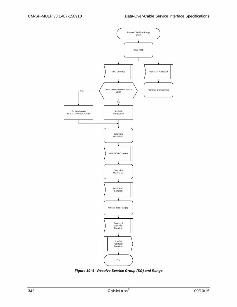
CM-SP-MULPIv3.1-I07-150910 Data-Over-Cable Service Interface Specifications
342 CableLabs 09/10/15
Figure 10–4 - Resolve Service Group (SG) and Range
DetermineMD-DS-SG
MD-DS-SG Complete
Read MDD
MDD Collected
DetermineMD-US-SG
MD-US-SGComplete
Set D3.0Initialization
Ranging &Auto Adj.Complete
MDD NOT Collected
CM-SG ResolutionComplete
End
Resolve CM-SG & RangeBegin
Unicast Initial Ranging
CMTS Version Number TLV in MDD?
No
Set Initializationper CMTS Version number
Yes Continue DS Scanning

MAC and Upper Layer Protocols Interface Specification CM-SP-MULPIv3.1-I07-150910
09/10/15 CableLabs 343
10.2.3.1 Read MAC Domain Descriptor (MDD)87 A CMTS periodically transmits a MAC Domain Descriptor (MDD) MAC management message on all DOCSIS 3.0 or later Downstream Channels of a MAC Domain. On non-Primary-Capable Channels, the CMTS transmits a MDD message that contains at least the MDD Header with the Downstream Channel ID on which the MDD is sent. On Primary-Capable Channels, the CMTS transmits a MDD message which contains the MDD header as well as TLVs and sub-TLVs containing the following information:
• Information for each Downstream Service Group comprised of the MD-DS-SG-ID along with the set of DCIDs that comprise the MD-DS-SG;
• Channel parameters (e.g., frequency, modulation) for each downstream channel in the MAC Domain as well as an indication of whether that channel is Primary Capable;
• Upstream Active Channel List; • Upstream Ambiguity Resolution Channel List; • Upstream Frequency Range; • Downstream Ambiguity Resolution Frequency List containing a list of downstream frequencies that the CM
uses to resolve the MD-DS-SG-ID; • Other information which is not relevant for the service group determination but which is utilized in later stages
of the initialization process.
In certain circumstances, the CM could receive multiple MDD messages with different source MAC addresses, in which case the CM MUST attempt to use the MDD message, which is valid for a primary-capable downstream channel. The CM collects MDD messages with the source MAC address learned from the SYNC message on SC-QAM channels and from OCD messages on OFDM channels.
If, for any reason, the MDD message becomes too long to fit within a single MAC management message, the CMTS fragments the MDD message as described in Section 6.4.28.
The CM MUST attempt to read the MDD message from the downstream channel as shown in Figure 10–5.
1. The CM starts its Lost MDD timeout Timer.
2. The CM waits for the arrival of MDD message fragments.
3. If the MAC address of the CMTS MAC Domain is not already known, then the CM stores the source MAC address of the received MDD fragment as the MAC address of the MAC domain and adds the fragment to the collection of fragments. At this point the MAC address of the CMTS MAC domain is considered to be known.
4. If the MAC address of the CMTS MAC Domain is already known, then upon receiving an MDD message fragment, the CM compares the source MAC address of the newly collected MDD fragment against the known MAC address of the MAC Domain. If the MAC addresses do not match, then the CM discards the fragment and awaits another fragment. If the MAC addresses match, then the fragment is added to those already collected.
5. Any time that the CM collects another MDD fragment, the CM MUST first check to see whether the change count has been incremented. If the change count has been incremented, then the CM MUST discard all collected fragments with the old change count. In either case, the CM then checks to determine whether the entire MDD message has been collected. If it has then the CM ends this process. If all of the fragments of the MDD message have not been collected, then the CM returns to step 2.
6. If the Lost MDD timeout Timer expires before the entire MDD message has been collected then the CM informs the calling process of the failure to collect an MDD and exits this process.
If no MDDs are detected on the candidate Primary Downstream Channel, then the CM MUST abort the attempt to utilize the current downstream channel, remove all frequencies covered by this channel from the PLC list (see Section 10.2.1.2) and Continue Downstream Scanning for a new candidate Primary Downstream Channel.
87 MULPIv3.1-N-15.1347-2 on 8/21/15 by PO.
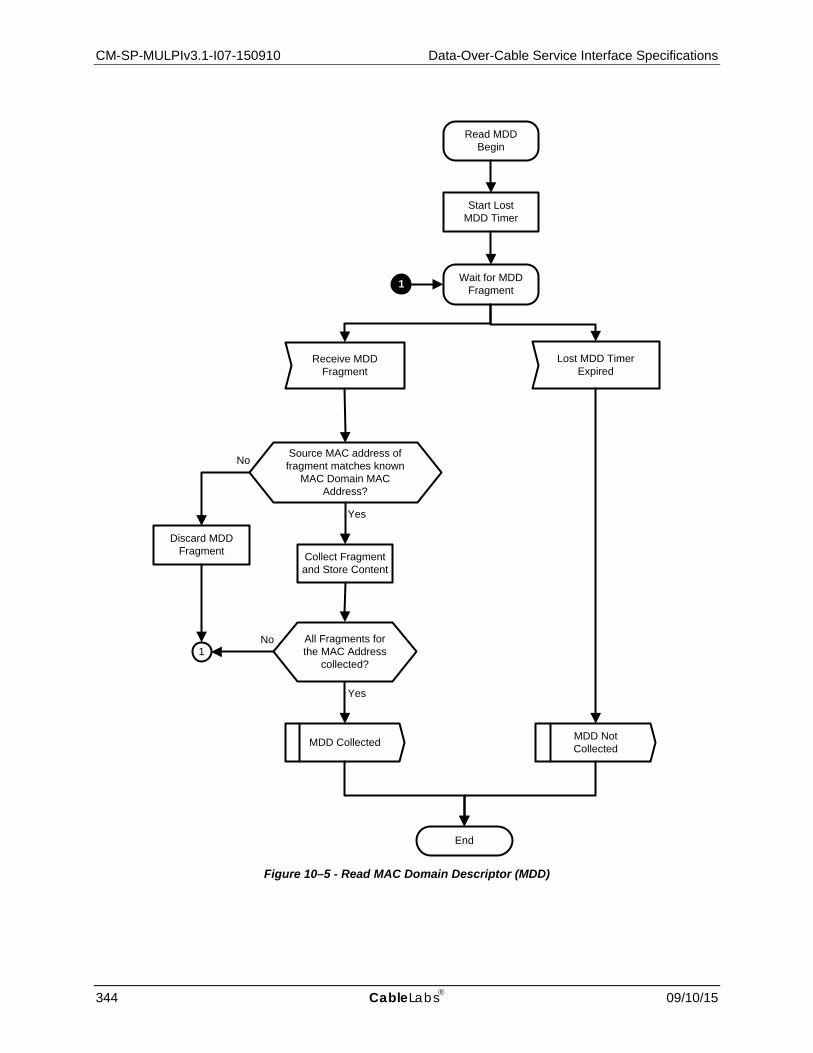
CM-SP-MULPIv3.1-I07-150910 Data-Over-Cable Service Interface Specifications
344 CableLabs 09/10/15
Figure 10–5 - Read MAC Domain Descriptor (MDD)
Read MDDBegin
Start LostMDD Timer
Wait for MDD Fragment
Receive MDD Fragment
1
Collect Fragment and Store Content
MDD Collected MDD Not Collected
Lost MDD Timer Expired
End
Yes
Discard MDD Fragment
No
No1
Source MAC address of fragment matches known
MAC Domain MAC Address?
All Fragments for the MAC Address
collected?
Yes

MAC and Upper Layer Protocols Interface Specification CM-SP-MULPIv3.1-I07-150910
09/10/15 CableLabs 345
10.2.3.2 Determination of MD-DS-SG
Figure 10–6 - Determine MD-DS-SG
The CM MUST attempt to determine its MD-DS-SG according to Figure 10–6. This process is described as follows:
NOTE: The CM keeps track of the "list of currently visible DCIDs" by accumulating a list of all DCID values within the MAC Domain of the primary Downstream Channel that it encounters while following the process described in Figure 10–6. This "list of currently visible DCIDs" is used to determine the proper MD-DS-SG for the CM.
1. If the Primary Downstream Channel's MDD message did not contain at least one MAC Domain Downstream Service Group (MD-DS-SG) TLV, then the CM sets its MD-DS-SG ID to zero and exits downstream service group resolution.
2. The CM stores the frequency of the current (primary) DS channel. Then the CM reads the current DCID from the MDD message and adds the DCID to the list of currently visible DCIDs.
Determine MD-DS-SG
No
Yes
MD-DS-SG Info Present?
Save Frequency of current primary DS
channel
Add current DS channel’s DCID to list
of currently visible DCIDs
Compare list of currently visible DCIDs
to MD-DS-SG lists
No
Yes
Unique match?
Note MD-DS-SG-ID
Retune to saved primary DS channel
frequency
MD-DS-SG complete
End
DS Ambiguity Frequency list
present?
Choose next frequency from DS
Ambiguity Frequency List
Yes
Out of frequencies?
Compare visible DCIDs and absent frequencies
to MD-DS-SG lists
Yes
Unique match?
Yes
Set MD-DS-SG-ID = 0
No
Set MD-DS-SG-ID = 0No
Tune to DS frequency
No
Decode DS Data and Get
DCID
Valid DS Chl Invalid DS Channel
1
2
Add this frequency to absent frequencies list
1 2
3
3

CM-SP-MULPIv3.1-I07-150910 Data-Over-Cable Service Interface Specifications
346 CableLabs 09/10/15
3. The CM constructs a list of "candidate" MD-DS-SGs. A "candidate" MD-DS-SG is one which is listed in the Primary Downstream Channel's MDD and which contains the current channel's DCID.
4. If the list of "candidate" MD-DS-SGs contains a single element, then the MD-DS-SG ID is noted and MD-DS-SG resolution is complete.
5. If there is not a unique match but the CM finds that the Downstream Ambiguity Resolution Frequency List TLV is not present in the Primary Downstream Channel's MDD message, then the CM sets its MD-DS-SG ID to zero and exits downstream service group resolution.
6. If the Downstream Ambiguity Resolution Frequency List TLV is present in the MDD message and if the list of candidate MD-DS-SGs contains more than one MD-DS-SG, then the CM tunes to the next frequency listed in the Downstream Ambiguity Resolution Frequency List TLV. The CM uses the Downstream Active Channel List TLV in the MDD message to determine the type of channel represented by the channel frequency. The CM attempts to acquire the channel and read a DCID on the channel. For an SC-QAM channel, the DCID is found by reading an MDD message; for an OFDMA channel, the DCID is found by reading the OCD message on the PLC. If the CM successfully acquires the next frequency and determines its DCID, the CM adds the new DCID to the "list of currently visible DCIDs". The CM then constructs a new list of "candidate" MD-DS-SGs. In this case, a "candidate" MD-DS-SG is one which is listed in the original channel's MDD and which contains all of the DCIDs from the "list of currently visible DCIDs". If this "candidate" list contains a single entry then the MD-DS-SG-ID is noted, the CM retunes the receiver to the original primary downstream frequency, and MD-DS-SG resolution is complete.
7. If the DCID is not successfully obtained on the new channel, the CM adds the frequency to its "absent frequencies list." If the Downstream Ambiguity Resolution Frequency List contains more frequencies, then the CM repeats step 6; otherwise, it continues to step 8.
8. If the CM runs out of frequencies in the Downstream Ambiguity Resolution Frequency List TLV, but the candidate list of MD-DS-SGs still contains more than one element, the CM attempts to narrow the list further by incorporating the "absent frequencies list." Any candidate MD-DS-SG containing a channel at a frequency included in the "absent frequencies list" is eliminated from the candidate MD-DS-SG list. After this step, if the candidate list of MD-DS-SGs contains exactly one element, the MD-DS-SG ID is noted, the CM retunes the receiver to the original primary downstream frequency, and MD-DS-SG resolution is complete. If the CM fails to retune the receiver to the original primary downstream frequency then the CM MUST continue scanning the downstream spectrum for a new candidate primary downstream channel.
9. If the candidate list of MD-DS-SGs does not contain exactly one element after step 8 has been completed, then the CM exits downstream service group resolution and sets its MD-DS-SG ID to zero.

MAC and Upper Layer Protocols Interface Specification CM-SP-MULPIv3.1-I07-150910
09/10/15 CableLabs 347
10.2.3.3 Determination of MD-US-SG88
Figure 10–7 - Determine MD-US-SG
The following sections and Figure 10–7 explain the steps that a CM MUST perform in order to resolve MD-US-SG resolution.
The CM MUST store the UCID and the transmit power level of all the US channels in its latest operational Transmit Channel Set in non-volatile memory.
Refer to Figure 10–7:
1. Based on the MDD message received on its Primary Downstream Channel, the CM creates a "Candidate UCID list" by randomly ordering the list of UCIDs in the Upstream Ambiguity Resolution Channel List. In order to create the randomized UCID list, the CM sorts the UCIDs in the Upstream Ambiguity List into groups according to the Upstream Channel Priority values. The CM then randomizes the UCIDs in each group. If any of the upstream channel UCIDs in the randomized UCID groups are stored in non-volatile memory as the last operational transmit channel set, then the CM SHOULD move these UCIDs to the front of their respective groups while maintaining their random ordering relative to each other. The CM then creates the randomized UCID list by concatenating the randomized UCID groups according to their relative priorities. In addition, if a specific UCID was sent in an Upstream Channel ID Override TLV in a RNG-RSP message, an Upstream Channel ID Configuration TLV in the CM Configuration File, or an Upstream Channel ID TLV in a DCC-REQ message, the CM adds this UCID to the head of the "Candidate UCID List".
88 Revised per MULPIv3.1-N-14.1194-1 on 12/2/14 by PO.
Determine MD-US-SG Begin
Randomize prioritized UCIDs from MDD
Ambiguity Resolution List
Collect UCDs
If Necessary, add specific UCIDs to head of Candidate UCID list
Choose Next UCID in Candidate UCID List
1
Out of UCIDs?
Continue DS Scanning
YES
Ranging Holdoff
Ranging Inhibited
Ranging Allowed
No
Tune to Channel corresponding to
chosen UCID
Bonded Initial Ranging
1
BondedINIT-RNG
Fail
BondedINIT-RNG success
1 Continue US Ambiguity Initial
Ranging
US Ambiguity Range Done
End
MD-US-SG Complete

CM-SP-MULPIv3.1-I07-150910 Data-Over-Cable Service Interface Specifications
348 CableLabs 09/10/15
2. The CM now reads UCD messages and finds the PHY parameters for the upstream channels with UCIDs listed in the "candidate UCID List". If timer T1 expires and the CM has not received any valid UCD messages it MUST continue scanning.
3. Taking the UCID at the head of the candidate UCID list, the CM performs Ranging Holdoff processing and configures the transmitter for that channel and attempts Bonded Initial Ranging. If the channel was stored in non-volatile memory then the CM SHOULD transmit using the stored transmit power level for that channel. If the channel was not stored in non-volatile memory and the channel is OFDMA, the CM MUST transmit using the OFDMA Broadcast IR Starting Power Level specified in TLV 22 of the UCD when this TLV is present. If this ranging process fails, then the CM repeats the process with the next UCID in the ordered list.
4. Once Bonded Initial Ranging succeeds, the CM continues upstream ambiguity resolution initial ranging as directed by the CMTS.
10.2.3.3.1 Ranging Holdoff
Figure 10–8 - Ranging Holdoff
Yes
Does UCD for channel contain a
TLV-19 inhibiting usage of channel?
Does UCD For channel contain a TLV-18 inhibiting initial
Ranging?
No
Start Timer T17
Yes
Wait for UCD change
UCD with incremented change count
Lost SYNC T17 timeout
Reinit MAC
No
Ranging HoldoffBegin
Ranging Allowed
RangingInhibited
End
MAC and Upper Layer Protocols Interface Specification CM-SP-MULPIv3.1-I07-150910
09/10/15 CableLabs 349
The CM MUST check for ranging holdoff direction per Figure 10–8 prior to sending an initial ranging request message when it performs initial maintenance for any of the following reasons:
• Power on initialization. • Reinitialize MAC event, except when triggered by a DCC-REQ with an initialization technique of zero. • Upstream Channel ID Configuration Setting in configuration file. • Downstream Frequency Configuration Setting in configuration file. • Upstream Channel Id Override in RNG-RSP. • Downstream Frequency Override in RNG-RSP. • UCD change prior to having sent at least one initial ranging request message (can restart the T17 timer as
described below).
The CM MUST NOT check for ranging holdoff direction when it performs initial maintenance for any other reason. Some examples of this include:
• DBC-REQ. • UCD change with ranging required TLV after having sent at least one initial ranging request message. • REG-RSP (with TCC). • RNG-RSP with Upstream Channel Adjustment TLV.
The following rules describe the ranging holdoff operation:
1. After selecting an upstream channel for initial ranging, the CM MUST extract the parameters for this upstream from the UCD. If the UCD message contains a Type 19 TLV, the CM MUST (except as described above) perform a bitwise AND of its Ranging Class ID with the TLV 19 Value. If the result of the bitwise AND is zero, the CM MUST consider the channel unusable and try other channels until it finds a usable channel.
2. If the UCD contains a Type 18 TLV, the CM MUST (except as described above) perform a bitwise AND of its Ranging Class ID with the TLV-18 Value. If the result of the bitwise AND is equal to the CM's Ranging Class ID, the CM MUST inhibit initial ranging and start the T17 timer. If the UCD Change Count in the UCD message for the channel is incremented while the T17 timer is active, the CM will re-inspect the TLV-18 and TLV-19 value and re-start the T17 timer if necessary. If the T17 timer expires or the TLV-18 value is updated to permit ranging for the CMs Ranging Class, the CM will resume the ranging process. If the CM should undergo a Lost SYNC event while waiting for T17, it MUST reinitialize the MAC with a CM Initialization Reason of T17_LOST_SYNC.
3. After having transmitted at least one Initial Maintenance RNG-REQ message, the CM MUST ignore TLV-18 or TLV-19 values in any new UCD message for the channel even if the new UCD contains a Ranging Required TLV.
10.2.3.3.2 Bonded Initial Ranging89
If the upstream channel is an SC-QAM channel then the CM proceeds to follow Figure 10–10 for bonded initial ranging on an SC-QAM channel. If the upstream channel is an OFDMA upstream channel, the CM starts timer T2 and waits for an OFDMA initial ranging opportunity. If the T2 timer expires then Bonded Initial Ranging has failed and this process ends.
If a MAP is found with an OFDMA initial ranging opportunity then the CM sends an O-INIT-RNG-REQ message and starts timer T3 before awaiting the response. Section 10.2.3.4.1 contains the specification for the starting power level to be used by the CM. If the T3 timer expires and all retries have been exhausted then Bonded Initial Ranging has failed and this process ends. If the retries have not been exhausted then the retry count is incremented, power is adjusted according to Section 10.2.3.4.1, and the CM goes back to start timer T2 and wait for another OFDMA initial ranging opportunity.
If the RNG-RSP is received and the ranging response is Abort then the CM will abandon this process and continue scanning to find another primary downstream channel. 89 Revised per MULPIv3.1-14.1172-1 on 12/2/14 by PO, updated by MULPIv3.1-N-15.1269-1 on 3/9/15 by PO.

CM-SP-MULPIv3.1-I07-150910 Data-Over-Cable Service Interface Specifications
350 CableLabs 09/10/15
If the RNG-RSP is received and the ranging response is not Abort, then the CM starts timer T-OFSM and waits for a fine ranging opportunity. If the T-OFSM timer expires then Bonded Initial Ranging has failed and this process ends.
If a MAP is found with a fine ranging opportunity then the CM sends a B-INIT-RNG-REQ message with the message version set to 5, restarts timer T3, and waits for a RNG-RSP. If the T3 timer expires and all retries have been exhausted then Bonded Initial Ranging has failed and this process ends. If the retries have not been exhausted then the retry count is incremented and the CM goes back to start timer T3 and continue waiting for the RNG-RSP.
If the RNG-RSP is received and the ranging response is Abort then the CM will abandon this process and continue scanning to find another primary downstream channel. If the RNG-RSP is received and the ranging response is not ABORT, then the CM considers initial ranging to be successful.

MAC and Upper Layer Protocols Interface Specification CM-SP-MULPIv3.1-I07-150910
09/10/15 CableLabs 351
Figure 10–9 - Bonded Initial Ranging
Bonded Initial Ranging Begin
SC-QAM Bonded Initial Ranging
YesNo
Wait for OFDMA broadcast initial ranging opportunity
MAP with OFDMA Initial
Ranging Opportunity
O-INIT-RNG-REQ
Start Timer T3
Awaiting RNG-RSP
T3 timeout
Adjust power
Yes
Bonded INIT-RNG Success
Bonded INIT-RNG
Fail
End
RNG-RSP
No
Increment Retry Count
No
Continue Downstream
Scanning
Yes
1
1
Awaiting RNG-RSP
T3 timeout RNG-RSP
B-INIT-RNG-REQ
Start Timer T3
Wait for unicast Fine Ranging opportunity
MAP with Unicast Ranging Opportunity
Timeout T-OFSM
Timeout T2
2
2
2
3
3
US Channel Is SC-QAM?
ExceededRetries?
Ranging Status is Abort”?
Yes
No
Increment Retry Count
5
2
ExceededRetries?
5
2
No
Yes
3
Ranging Status is Abort”?
4
4
Start Timer T2
Start Timer T-OFSM

CM-SP-MULPIv3.1-I07-150910 Data-Over-Cable Service Interface Specifications
352 CableLabs 09/10/15
Figure 10–10 - SC-QAM Bonded Initial Ranging
Once an SC-QAM candidate upstream channel has been chosen for upstream ambiguity resolution, the CM MUST attempt SC-QAM Bonded Initial Ranging as shown in Figure 10–10 and as described below:
1. The CM MUST start timer T2 and wait for an opportunity to transmit a B-INIT-RNG-REQ message to the CMTS with the MD-DS-SG-ID that was determined in Section 10.2.3.2 if the MD-DS-SG-ID could be determined, or an MD-DS-SG-ID of zero if an MD-DS-SG-ID could not be determined. The CM starts the T3 timer upon transmission of the B-INIT-RNG-REQ message and then waits for a response.
2. If the CM receives a RNG-RSP message with a Ranging Status other than Abort, then Bonded Initial Ranging is considered successful and the CM proceeds to the operations described in Section 10.2.3.3.3. If the CM receives a RNG-RSP message with a Ranging Status of Abort, the CM continues scanning for a new downstream channel (Section 10.2.1.1).
3. If timer T3 expires before receiving a RNG-RSP message and the retry limit has not been exceeded, then the CM MUST adjust power and return to step 1.
4. If timer T3 expires before receiving a RNG-RSP message and the retry limit has been exceeded, then the CM considers the bonded initial ranging process on the current UCID to have failed.
Awaiting RNG-RSP
T3 timeout
Adjust power
ExceededRetries?
Yes
Bonded INIT-RNG Success
Bonded INIT-RNG
Fail
End
RNG-RSP
B-INIT-RNG-REQ
No
Increment Retry Count
SC-QAM Bonded Initial Ranging Begin
Start Timer T3
Ranging Status is “Abort”?
No
ContinueDownstream
Scanning
Yes
Wait for broadcast maintenance opportunity
MAP with Broadcast Initial Ranging
OpportunityTimeout T2
1
1
2
2
Start Timer T2
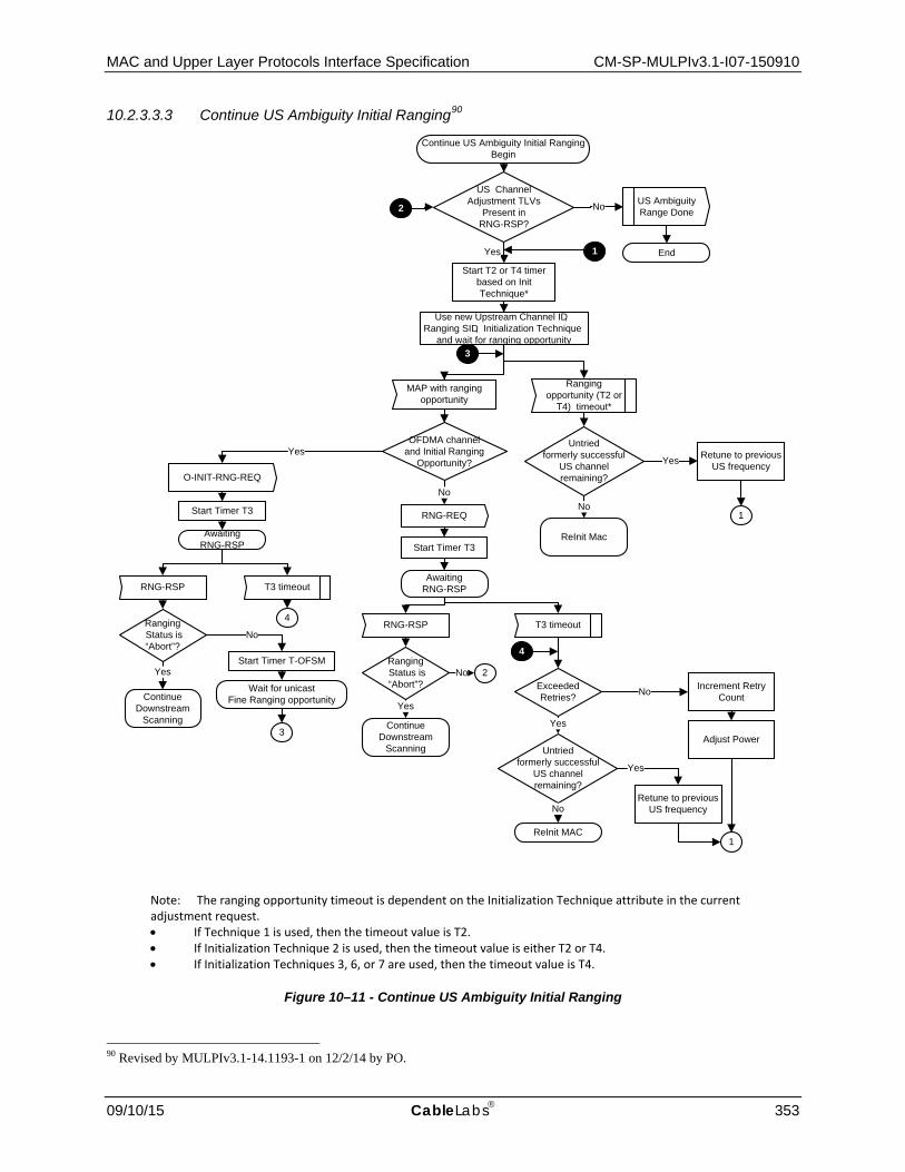
MAC and Upper Layer Protocols Interface Specification CM-SP-MULPIv3.1-I07-150910
09/10/15 CableLabs 353
10.2.3.3.3 Continue US Ambiguity Initial Ranging90
T3 timeout
Adjust Power
No
End
RNG-RSP
RNG-REQ
Yes
US Channel Adjustment TLVs
Present in RNG-RSP?
Use new Upstream Channel ID ,Ranging SID , Initialization Technique
and wait for ranging opportunity
US AmbiguityRange DoneNo
Retune to previous US frequency
Exceeded Retries? No
Yes
Yes
Increment Retry Count
Continue US Ambiguity Initial RangingBegin
Awaiting RNG-RSP
Untriedformerly successful
US channel remaining?
ReInit MAC
No
Start Timer T3
1
1
Ranging Status is “Abort”?
ContinueDownstream
Scanning
Yes
MAP with ranging opportunity
Ranging opportunity (T2 or
T4) timeout*
Retune to previous US frequency
1
Start T2 or T4 timer based on Init Technique*
Untriedformerly successful
US channel remaining?
Yes
ReInit Mac
No
2
2
OFDMA channel and Initial Ranging
Opportunity?
NoO-INIT-RNG-REQ
Yes
Start Timer T3
Awaiting RNG-RSP
T3 timeoutRNG-RSP
3
NoRanging Status is “Abort”?
ContinueDownstream
Scanning
Yes
Wait for unicast Fine Ranging opportunity
Start Timer T-OFSM
3
4
4
Note: The ranging opportunity timeout is dependent on the Initialization Technique attribute in the current adjustment request. • If Technique 1 is used, then the timeout value is T2.• If Initialization Technique 2 is used, then the timeout value is either T2 or T4.• If Initialization Techniques 3, 6, or 7 are used, then the timeout value is T4.
Figure 10–11 - Continue US Ambiguity Initial Ranging
90 Revised by MULPIv3.1-14.1193-1 on 12/2/14 by PO.

CM-SP-MULPIv3.1-I07-150910 Data-Over-Cable Service Interface Specifications
354 CableLabs 09/10/15
Once Bonded Initial Ranging has succeeded, the CM MUST continue the process of initial ranging on each channel as controlled by the CMTS as shown in Figure 10–11.
1. If the RNG-RSP message received during Bonded Initial Ranging (see Section 10.2.3.3.2) contains Upstream Channel Adjustment TLVs and the new upstream channel is OFDMA, the CM's action depends on the Initialization Technique. If the Initialization Technique is 1 (broadcast initial ranging) or the Initialization Technique is 6 (unicast initial ranging), the CM uses the Upstream Channel Adjustment TLVs and performs initial ranging (O-INIT-RNG-REQ) using the new Upstream Channel ID. After receiving a RNG-RSP to the O-INIT-RNG-REQ, the CM then waits for a unicast station maintenance opportunity. If the RNG-RSP message received during Bonded Initial Ranging (see Section 10.2.3.3.2) contains Upstream Channel Adjustment TLVs and the new upstream channel is SC-QAM or the new upstream channel is OFDMA with an Initialization Technique of 7 and the CM is assigned a unicast station maintenance opportunity, then the CM uses the Upstream Channel Adjustment TLVs and performs ranging (RNG-REQ) using the new Upstream Channel ID and corresponding UCD, Temp SID (if present) and Initialization Technique. To speed up the ranging process, additional ranging parameter offsets may also be included. The CMTS may respond to successive ranging request messages with a series of RNG-RSP messages containing different Upstream Channel Adjustment TLVs as it attempts to assign a MD-US-SG-ID to the CM.
2. If any Upstream Channel Adjustment is unsuccessful, then the CM tries to use initial ranging on an upstream channel that the CM had previously successfully ranged upon. The act of initial ranging on a previous channel tells the CMTS that the Upstream Channel Adjustment was unsuccessful.
3. If initial ranging on that previous channel is no longer successful, then the CM tries initial ranging on any other previously successful upstream channel. When all previously successful upstream channels have been tried without success, the CM reinitializes the MAC with a CM Initialization Reason of ALL_US_FAILED.
10.2.3.4 Ranging and Automatic Adjustments The ranging and adjustment process is fully defined in Section 6 and in the following sections. The CM performs the ranging and adjustment process defined by the message sequence charts and the finite state machine on the following pages. The CMTS performs the ranging and adjustment process defined by the message sequence charts and the finite state machine on the following pages
NOTE: MAPs are transmitted as described in Section 6.

MAC and Upper Layer Protocols Interface Specification CM-SP-MULPIv3.1-I07-150910
09/10/15 CableLabs 355
CMTS CM
(time to send the Initial Maintenance opportunity)
send map containing Initial Maintenance information element with a broadcast/multicast Service ID
-----------MAP------------>
<---------RNG-REQ or INIT-RNG-REQ or B-INIT-RNG-REQ-------
transmit ranging packet in contention mode with Service ID parameter = 0
(receive recognizable ranging packet)
allocate temporary Service ID
send ranging response ---------RNG-RSP------>
add temporary Service ID to poll list store temporary Service ID and adjust other parameters
(time to send the next map)
send map with Station Maintenance information element or Unicast Initial Maintenance element to modem using temporary SID
-----------MAP------------> Recognize own temporary Service ID in map
<--------RNG-REQ------ reply to Station Maintenance opportunity poll or Unicast Initial Maintenance opportunity poll
send ranging response ---------RNG-RSP------>
adjust local parameters
(time to send an Initial Maintenance opportunity) send MAP containing Initial Maintenance information element with a broadcast/multicast Service ID
send periodic transmit opportunity to broadcast address
------------MAP----------->
Figure 10–12 - Ranging and Automatic Adjustments Procedure for SC-QAM Upstreams
NOTE: The CMTS MUST allow the CM at least the CM Ranging Response time (Annex B) to process the previous RNG-RSP (i.e., to modify the transmitter parameters) before sending the CM a unicast ranging opportunity.

CM-SP-MULPIv3.1-I07-150910 Data-Over-Cable Service Interface Specifications
356 CableLabs 09/10/15
Figure 10–13 - Ranging and Automatic Adjustments Procedure for OFDMA Upstreams
NOTE: The CMTS MUST allow the CM at least the sum of the CM Ranging Response time (Annex B) and the T3 time (Annex B) to wait for and process the previous RNG-RSP (i.e., to modify the transmitter parameters) before sending the CM a unicast ranging or probe opportunity.
CMTS CM
[time to send the Initial Maintenance opportunity]
[receive recognizable ranging packet] Allocate temporary Service ID Send ranging response Allocate station maintenance opp to CM
-----------MAP------------> <---- O-INIT-RNG-REQ-- ---------RNG-RSP--- ----------MAP----------
Transmit O-INIT-RNG-REQ in contention mode Store temporary Service ID and adjust other parameters
<---------RNG-REQ or INIT-RNG-REQ or B-INIT-RNG-REQ-------
transmit ranging packet in unicast station maintenance opportunity with Service ID parameter = temporary SID
[receive recognizable ranging packet]
send ranging response ---------RNG-RSP------>
add temporary Service ID to poll list store temporary Service ID and adjust other parameters
[time to send the next map]
send map with Station Maintenance information element or Unicast Initial Maintenance element to modem using temporary SID
-----------MAP------------> Recognize own temporary Service ID in map
<--------RNG-REQ------ reply to Station Maintenance opportunity poll or Unicast Initial Maintenance opportunity poll
send ranging response ---------RNG-RSP------>
adjust local parameters
[time to send an Initial Maintenance opportunity] send MAP containing Initial Maintenance information element with a broadcast/multicast Service ID
send periodic transmit opportunity to broadcast address
------------MAP----------->
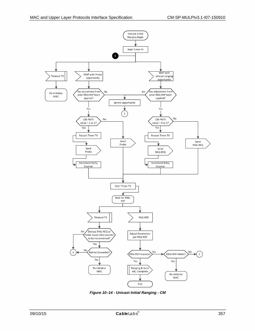
MAC and Upper Layer Protocols Interface Specification CM-SP-MULPIv3.1-I07-150910
09/10/15 CableLabs 357
Figure 10–14 - Unicast Initial Ranging - CM

CM-SP-MULPIv3.1-I07-150910 Data-Over-Cable Service Interface Specifications
358 CableLabs 09/10/15
10.2.3.4.1 Adjust Transmit Parameters91
Upon receipt of a RNG-RSP message, the CM MUST reduce or increase the power by the specified amount in RNG-RSP messages.
Adjustment of local parameters (e.g., transmit power) in a CM as a result of the non-receipt of a RNG-RSP is considered to be implementation-dependent with the following restrictions (refer to Section 6.4.6):
• The CM MUST ensure that all transmit parameters are within the approved range at all times. • For ranging prior to starting registration, the CM MUST start power adjustments according to the following:
• If a valid power level for the upstream channel is available from non-volatile storage, then the CM MUST use this value as a starting point.
• If a valid power level for the upstream channel is not available from non-volatile storage and the channel is OFDMA and TLV 22 is specified in the UCD for the channel, the CM MUST start power adjustments from the OFDMA Broadcast IR Starting Power Level specified in the TLV.
• If a valid power level for the upstream channel is not available from non-volatile storage and the channel is SC-QAM or is OFDMA with no TLV 22 in the UCD, the CM SHOULD start power adjustments from the minimum value.
• If Channels are being added to the TCS, and no Power Offset TLVs are present in the TCC encodings, then the CM MUST start power adjustment from the minimum value allowed by the Dynamic Range Window, unless a valid power is available from non-volatile storage for an upstream channel. If a valid power level for an upstream channel is available from non-volatile storage, then the CM MUST use this value as a starting point. A power level stored in non-volatile storage for the upstream channel is considered to be valid if it lies within the Dynamic Range Window.
• During initialization, prior to starting registration, the CM MUST cover its entire dynamic range within 16 retries leaving no power interval greater than 12dB untried when ranging on an SC-QAM channel or an OFDMA channel when no TLV 22 is specified. When specifying TLV 22 in a UCD for OFDMA channels, the CMTS SHOULD ensure that the TLV 22 parameters allow the CM to cover the range from the starting power level to the top of the CM’s dynamic range within 16 retries leaving no power interval greater than 12dB untried.
NOTE: The CMTS MAY specify TLV 22 with parameters that prevent the CM from transmitting above a given power level.
• During initial ranging on channels being added by TCC encodings the CM MUST cover the entire Dynamic Range Window within 16 retries, leaving no power interval greater than 6dB untried.
10.2.3.5 CMTS Determination of Cable Modem Service Group and Initial Ranging The CMTS MUST attempt to determine the CM-SG of a CM according to Figure 10–15. After determining the service group of a CM, the CMTS MUST perform Initial Ranging according to Figure 10–16.
91 Revised per MULPIv3.1-N-14.1194-1 on 12/2/14 by PO.

MAC and Upper Layer Protocols Interface Specification CM-SP-MULPIv3.1-I07-150910
09/10/15 CableLabs 359
Start CM-SG Determination
(CMTS)
O-INIT-RNG-REQ
Attempt to resolve MD-CM-SG
RNG-RSP (Continue)
CM Unknown
RNG-REQ, INIT-RNG-REQ, or B-INIT-RNG-REQ
Wait a minimum of T3
MAP with Station Maintenance Ranging Opportunity for CM
1
1
MD-CM-SG Unknown
MD-CM-SG Known
No Yes
Add CM to poll list for future MAPs
(Note 1)
RNG-RSP(continue)
Unicast Initial Ranging
MD-CM-SG Unique?
MD-CM-SG Resolved?
Range Request Message version?
Provide data grants using CCF
Provide data grants using legacy grants
Version 5 Version 4
No
Yes
Figure 10–15 - CM-SG Determination - CMTS
Figure Note: The poll list is a list of CMs that are currently performing unicast initial ranging. The CMTS SHOULD provide CMs in the poll list frequent unicast ranging opportunities. For a RNG-REQ message from a DOCSIS 3.0 or prior CM, if pending-till-complete was nonzero, the CMTS SHOULD hold off the station maintenance opportunity accordingly unless needed, for example, to adjust the CM's power level. If opportunities are offered prior to the pending-till-complete expiry, the CMTS MUST NOT use the "good-enough" test which follows receipt of a RNG-REQ to judge the CM's transmit equalization until pending-till-complete expires.
CM-SP-MULPIv3.1-I07-150910 Data-Over-Cable Service Interface Specifications
360 CableLabs 09/10/15
A CMTS is said to consider a CM to be "known" when it provides unicast ranging opportunities to the CM. The CMTS initially considers a CM's MAC address to be unknown, represented by the "CM unknown" state of Figure 10–15. While in the "CM unknown" state, upon the receipt of a B-INIT-RNG-REQ, an INIT-RNG-REQ, or a RNG-REQ where the DCID, UCID, and MD-DS-SG-ID (if present and non-zero) are associated with one and only one MD-CM-SG, the MD-CM-SG is considered to be "Unique" and thus "Known" by the CMTS. It is CMTS vendor-specific whether, or to what degree, the CMTS attempts to determine the MD-CM-SG of CMs for which the MD-CM-SG is not "Unique" based the information available in the B-INIT-RNG-REQ, INIT-RNG-REQ, or RNG-REQ, i.e., the SDL procedure named "Attempt to resolve MD-CM-SG" is vendor-specific. If the CMTS does not support such MD-CM-SG determination, or cannot determine the MD-CM-SG of a CM, it considers the MD-CM-SG to be "unknown" for the CM.
The "Attempt to resolve MD-CM-SG" procedure might proceed as follows. The MD-DS-SG of the ranging CM might be uniquely determined by the MD-DS-SG-ID in the B-INIT-RNG-REQ, by the Downstream Channel ID (DCID) in the INIT-RNG-REQ or RNG-REQ message, or by the particular Upstream Channel from which the B-INIT-RNG-REQ, INIT-RNG-REQ or RNG-REQ was received. If the MD-DS-SG has not been uniquely determined, the CMTS can send a RNG-RSP to the CM to override the downstream frequency to one for which the CMTS can reduce the set of possible MD-DS-SGs for the CM. At that point, if the CMTS receives a B-INIT-RNG-REQ, an INIT-RNG-REQ, or a RNG-REQ message from the CM, it notes the MD-DS-SG-ID and/or DCID reported in the new B-INIT-RNG-REQ, INIT-RNG-REQ, or RNG-REQ and continues checking whether the MD-DS-SG is unique. Note that if the CMTS receives a B-INIT-RNG-REQ, an INIT-RNG-REQ, or a RNG-REQ with a DCID corresponding to a downstream frequency other than the requested override frequency, it indicates either that the CM was unable to detect an acceptable downstream channel at that frequency or that the CM was reset from a power-on condition. To avoid this ambiguity, a cable operator can implement a downstream RF topology where each CM is reached by a valid DOCSIS downstream channel at every frequency used by any DOCSIS downstream channel in the MAC Domain.
Once the MD-DS-SG is uniquely determined, the CMTS can proceed to check if the MAC Domain Upstream Service Group (MD-US-SG) is also unique.
If the combination of MD-DS-SG and the particular Upstream Channel from which the B-INIT-RNG-REQ/ INIT-RNG-REQ/RNG-REQ was received does not determine the MD-US-SG, the CMTS can send a RNG-RSP to continue ranging and use the Upstream Channel Adjustment TLV to override the Upstream Channel ID (UCID). In the RNG-RSP to a CM which sent a B-INIT-RNG-REQ, the CMTS MAY also use the Upstream Channel Adjustment TLV to specify the initialization technique for the CM to use on the overridden UCID. At that point, if the CMTS receives an INIT-RNG-REQ or RNG-REQ from an upstream channel on the frequency of the overridden UCID, the CMTS adds the UCID of the actual upstream channel from which the INIT-RNG-REQ or RNG-REQ was received to a known set of Upstream Channels reaching the CM, and continues checking whether the MD-US-SG is uniquely determined. If the CMTS receives an INIT-RNG-REQ/RNG-REQ from a different frequency than the overridden UCID, it indicates that the CM was unable to range on the overridden UCID's frequency. One possibility is that the CM is in an MD-US-SG that omits any Upstream Channel on the overridden UCID's frequency.
While performing a RNG-RSP downstream frequency override or RNG-RSP Upstream Channel Adjustment override, if the CMTS receives no ranging request, it can remove the CM from its set of known CMs.

MAC and Upper Layer Protocols Interface Specification CM-SP-MULPIv3.1-I07-150910
09/10/15 CableLabs 361
Wait T3 (minimum)
Retries Exhausted?
RNG-RSP (Continue)
Wait for polled RNG-REQ
RNG-REQ
Remove CM from poll list
1
1
OFDMA Upstream?
RNG-RSP (Success)
RNG-RSP(abort)
Unicast Initial Ranging
RNG-REQNot
received
End
Good Enough?(Note 2)
Yes
No
No
Start T9
Yes
RetriesExhausted?
RNG-RSP(continue)
No
Yes
No
Yes
MAP with ProbeOpportunity
RNG-REQRNG-REQ
Notreceived
Retries Exhausted?
2
2
Good Enough?(Note 2)
No
RNG-RSP (Success)
Start T9
Yes
3
3
Note 2: Means ranging/probing is within the tolerable limits of the CMTS.
No
Yes
3
Figure 10–16 - Unicast Initial Ranging – CMTS
10.2.4 Authentication Once a CM has completed ranging, if Early Authentication and Encryption (EAE) is enabled in the MDD the CM will initiate EAE before continuing with the initialization process. EAE helps prevent unauthorized CMs from accessing IP provisioning servers and provides confidentiality/privacy for IP provisioning messages between the CM and CMTS. See [DOCSIS SECv3.0] for details.

CM-SP-MULPIv3.1-I07-150910 Data-Over-Cable Service Interface Specifications
362 CableLabs 09/10/15
10.2.5 Establishing IP Connectivity The CM performs IP provisioning in one of four modes: IPv4 Only, IPv6 Only, Alternate Provisioning Mode (APM), and Dual-stack Provisioning Mode (DPM). The CM determines the IP provisioning mode via the CmMdCfg management object defined in [DOCSIS OSSIv3.0], CM Provisioning Objects section, Object Model diagram.
If the management object is set to 'honor MDD', the default setting, the CM determines the IP provisioning mode by the absence of the MDD message or by the TLVs in the MDD message (see Section 6.4.28). The CM MUST use the provisioning mode directed by the MDD IP Provisioning Mode TLV, except where the IP Provisioning Mode Override feature is specifically configured to override the MDD TLV 5.1 encoding. See Section 10.2.5.2.4 for details.
As shown in Figure 10–1, the IP provisioning process begins after the completion of ranging, or EAE if enabled, and ends with an IP provisioning success or failure, i.e., with the CM in either IP Connectivity Successful or IP Connectivity Failed state. As shown in Figure 10–1, if the CM finishes IP provisioning successfully, it proceeds with registration; and if it does not, it continues scanning for a new downstream channel.
The Cable Modem performing IP provisioning MUST follow the operational flow of Figure 10–17 through Figure 10–23 to arrive at an IP Connectivity Successful or IP Connectivity Failed state. Figure 10–17 shows the selection of the provisioning modes. Figure 10–18 through Figure 10–21 show the steps the CM takes in each of the provisioning modes. Figure 10–22 shows the steps the CM takes to obtain time and a configuration file. Figure 10–23 shows the process the CM follows for acquiring an IPv6 address. The acquisition of an IPv4 address, done through DHCPv4, is shown as part of Figure 10–18, Figure 10–20, and Figure 10–21.
Once the CM is registered, any applications and services running on the CM, such as SNMP, use the IP version (v4 or v6) through which the CM obtains the configuration file used for registration, unless the CM is directed to use DPM. When the CM uses DPM, the applications and services running on the CM use both IP versions.
Figure 10–17 - Establish IP Connectivity
Establish IPConnectivity Begin
IPv4 Only AlternateIPv6 Only Dual-stack
DetermineProvisioning Mode
Dual-stackProvisioning
Mode
AlternateProvisioning
Mode
IPv4 OnlyProvisioning
Mode
IPv6 OnlyProvisioning
Mode

MAC and Upper Layer Protocols Interface Specification CM-SP-MULPIv3.1-I07-150910
09/10/15 CableLabs 363
Figure 10–18 - IPv4 Only Provisioning Mode
IP ConnectivitySuccessful
TFTPSuccesful?
Perform DHCPv4
DHCPv4Succesful?
NoYes
Perform ToD& TFTP
No
IP ConnectivityFailed
Yes
IPv4 OnlyProvisioning
Mode
Establish IPConnectivity End

CM-SP-MULPIv3.1-I07-150910 Data-Over-Cable Service Interface Specifications
364 CableLabs 09/10/15
Figure 10–19 - IPv6 Only Provisioning Mode
IP ConnectivitySuccessful
TFTPSuccesful?
IPv6 AddressAcq Succesful
?No
Yes
Perform ToD& TFTP
No
IP ConnectivityFailed
Yes
Acquire IPv6Address
IPv6 OnlyProvisioning
Mode
Establish IPConnectivity End

MAC and Upper Layer Protocols Interface Specification CM-SP-MULPIv3.1-I07-150910
09/10/15 CableLabs 365
Figure 10–20 - Alternate Provisioning Mode
IP ConnectivitySuccessful
Acquire IPv6Address
IPv6 AddressAcq. Succesful
?
TFTPSuccesful?
Perform DHCPv4
DHCPv4Succesful?No
Yes
Perform ToD& TFTP (IPv6)
No
Yes
No
IP ConnectivityFailed
Yes
TFTPSuccesful?
No
Yes
Perform ToD& TFTP (IPv4)
AlternateProvisioning
Mode
Establish IPConnectivity End

CM-SP-MULPIv3.1-I07-150910 Data-Over-Cable Service Interface Specifications
366 CableLabs 09/10/15
Figure 10–21 - Dual-stack Provisioning Mode
IP ConnectivitySuccessful
TFTPSuccesful?
DHCPv4Succesful?
NoYes
Perform ToD& TFTP (IPv4)
Acquire IPv6Address
IPv6 AddressAcq. Succesful
? No
Yes
TFTPSuccesful?
Perform ToD& TFTP (IPv6)
No
Yes
Initiate DHCPv4
No
IP ConnectivitySuccessful
IP ConnectivityFailed
Yes
Dual-stackProvisioning
Mode
Establish IPConnectivity End
Awaiting DHCPv4 Completion

MAC and Upper Layer Protocols Interface Specification CM-SP-MULPIv3.1-I07-150910
09/10/15 CableLabs 367
Time of Day Response Timeout
Request Config File
Config file receivedTimeout
Retries exceeded?
Wait for Time of Day
Response
Wait for Successful
TFTP
Time of Day Retries are asynchronous with Establishment of IP
Connectivity
Time of Day Request
ToD and TFTP End
TFTPFailed
TFTPSuccessful
ToD & TFTPBegin
Increment Retry Counter
Valid ConfigFile?
AdditionalTFTP Servers?
Yes
No
No Yes
Yes
No
Figure 10–22 - ToD and TFTP

CM-SP-MULPIv3.1-I07-150910 Data-Over-Cable Service Interface Specifications
368 CableLabs 09/10/15
Figure 10–23 - IPv6 Address Acquisition
DHCPv6 successful?
Yes
No
No
DADResponse received?
Yes
No
RAreceived?No
Yes
DADResponse received?
Yes
End
IPv6 Address Acquisition
Failed
IPv6 Address Acquisition Successful
Initiate DAD on DHCP address
Perform DHCPv6
Select link-local address
Initiate DAD on link-local address
Obtain router advertisment
Acquire IPv6 Address Begin

MAC and Upper Layer Protocols Interface Specification CM-SP-MULPIv3.1-I07-150910
09/10/15 CableLabs 369
10.2.5.1 Establish IPv4 Network Connectivity This section describes how the CM is provisioned with an IPv4 address and associated parameters. The requirements in this section apply to CMs using IPv4 provisioning. A CM uses IPv4 provisioning when the MDD indicates IPv4 Only provisioning or DPM, or when the MDD indicates APM and IPv6 provisioning fails, or when a CM supporting IP Provisioning Mode Override is configured with IPv4 Only provisioning. See [DOCSIS OSSIv3.0] CM Provisioning Objects section.
The CM MUST use DHCPv4 [RFC 2131] in order to obtain an IP address and other parameters needed to establish IP connectivity in the following cases:
• The MDD indicates IPv4 Only provisioning • The MDD indicates DPM • The MDD indicates APM and IPv6 provisioning fails • The IP Provisioning Mode Override was configured to override the MDD
Figure 10–24 shows the DHCPv4 message sequence.
Figure 10–24 - IPv4 Provisioning Message Flow
The CM may receive multiple DHCPOFFER messages in response to its DHCPDISCOVER message. If a received DHCPOFFER message does not include all of the required DHCPv4 fields and options as described in Section 10.2.5.1.1, the CM MUST discard the DHCPOFFER message and wait for another DHCPOFFER message. If none of the received DHCPOFFER messages contain all the required DHCPv4 fields and options, the CM retransmits the DHCPDISCOVER message.
The backoff values for retransmission of DHCPDISCOVER messages SHOULD be chosen according to a uniform distribution between the minimum and maximum values in the rows of Table 10–1.
Table 10–1 - DHCP Backoff Distribution Values
Backoff Number Minimum (seconds) Maximum (seconds) 1 3 5
2 7 9
3 15 17
CMTS DHCP Server
DHCPv4 DHCPDISCOVER
DHCPOFFER
DHCPREQUEST
DHCPACK
DHCPOFFER
DHCPREQUEST
CM
DHCPDISCOVER
DHCPACK

CM-SP-MULPIv3.1-I07-150910 Data-Over-Cable Service Interface Specifications
370 CableLabs 09/10/15
Backoff Number Minimum (seconds) Maximum (seconds) 4 31 33
5 63 65
The CM SHOULD also implement a different retransmission strategy for the RENEWING and REBINDING states, as recommended in [RFC 2131], which is based on one-half of the remaining lease time.
The CM MUST limit the number of retransmissions to five or fewer for the DHCPDISCOVER and DHCPREQUEST messages.
[RFC 3203] describes an extension to DHCPv4 that allows a DHCP server to send a FORCERENEW message that forces a client to renew its lease. The CM MUST ignore all received FORCERENEW messages.
10.2.5.1.1 DHCPv4 Fields Used by the CM
The following fields MUST be present in the DHCPDISCOVER and DHCPREQUEST messages from the CM:
• The hardware type (htype) MUST be set to 1; • The hardware length (hlen) MUST be set to 6; • The client hardware address (chaddr) MUST be set to the 48 bit MAC address associated with the RF interface
of the CM; • The client identifier option MUST be included, using the format defined in [RFC 4361]; • The parameter request list option MUST be included. The following option codes (defined in [RFC 2132] and
[RFC 4361]) MUST be included in the list: • Option code 1 (Subnet Mask) • Option code 2 (Time Offset) • Option code 3 (Router Option) • Option code 4 (Time Server Option) • Option code 7 (Log Server Option) • Option code 125 (DHCPv4 Vendor-Identifying Vendor-specific Information Option)
• Option code 60 (Vendor Class Identifier) — the following ASCII-encoded string MUST be present in Option code 60: DOCSIS 3.1:
• Option code 125 (DHCPv4 Vendor- Identifying Vendor-specific Information Options for DOCSIS 3.1 defined in [CANN DHCP-Reg] - and include the following sub-options in there:
1. Sub-option code 1, the DHCPv4 Option Request option. The following option code MUST be included in the DHCPv4 Option Request option:
2. Sub-option code 2, DHCPv4 TFTP Servers Option.
3. Sub-option code 5, Modem Capabilities Encoding for DHCPv4.
The following fields are expected in the DHCPOFFER and DHCPACK messages returned to the CM. The CM MUST configure itself with the listed fields from the DHCPACK:
• The IP address to be used by the CM (yiaddr) (critical). • The IP addresses of the TFTP servers for use in the next phase of the boot process (DHCPv4 TFTP Servers
option defined in [CANN DHCP-Reg] or siaddr) (critical). • The name of the CM configuration file to be read from the TFTP server by the CM (file) (critical). • The subnet mask to be used by the CM (Subnet Mask, option 1) (non-critical). • The time offset of the CM from UTC (Time Offset, option 2). This is used by the CM to calculate a time for
use in error logs (non-critical).

MAC and Upper Layer Protocols Interface Specification CM-SP-MULPIv3.1-I07-150910
09/10/15 CableLabs 371
• A list of addresses of one or more routers to be used for forwarding IP traffic originating from the CM's IP stack (Router Option, option 3). The CM is not required to use more than one router IP address for forwarding (non-critical).
• A list of ToD servers from which the current time may be obtained (Time Server Option, option 4) (non-critical).
• A list of syslog servers to which logging information may be sent (Log Server Option, option 7); see [DOCSIS OSSIv2.0] (non-critical).
If a critical field is missing or invalid in the DHCPACK received during initialization, the CM MUST:
1. Log an error;
2. Proceed as if the acquisition of the IPv4 address through DHCPv4 has failed; reference Figure 10–18, Figure 10–20, and Figure 10–21.
If a non-critical field is missing or invalid in the DHCPACK received during initialization, the CM MUST log a warning, ignore the field and continue the IPv4 provisioning process.
If the yiaddr field is missing or invalid in the DHCPACK received during a renew or rebind operation, the CM MUST log an error and reinitialize its MAC with a CM Initialization Reason of BAD_DHCP_ACK.
If any other critical or non-critical field is missing or is invalid in the DHCPACK received during a renew or rebind operation, the CM MUST log a warning, ignore the field if it is invalid, and remain operational.
10.2.5.1.2 Use of T1 and T2 Timers
The CM MUST initiate the lease renewal process when timer DHCP-T1 expires. The CM MUST initiate the lease rebinding process when timer DHCP-T2 expires. Timers DHCP-T1 and DHCP-T2 are called T1 and T2, respectively, in the DHCP specifications. If the DHCP server sends a value for DHCP-T1 to the CM in a DHCP message option, the CM MUST use that value. If the DHCP server does not send a value for DHCP-T1, the CM MUST set DHCP-T1 to one half of the duration of the lease [RFC 2131]. If the DHCP server sends a value for DHCP-T2 to the CM in a DHCP message option, the CM MUST use that value. If the DHCP server does not send a value for DHCP-T2, the CM MUST set DHCP-T2 to seven-eighths of the duration of the lease [RFC 2131].
10.2.5.1.2.1 DHCPv4 Renew Fields Used by the CM92
It is possible during the DHCPv4 renew operation that the CM will receive updated fields in the DHCPACK message.
If any of the IP address (yiaddr), the Subnet Mask, or the Next Hop Router (router option) are different in the DHCPACK than the current values used by the CM, the CM MUST follow one of the following two:
• Change to using the new values without reinitializing the CM, or • Reinitialize MAC with a CM Initialization Reason of BAD_DHCP_ACK.
If the Config File Name or the SYSLOG server address are different in the DHCPACK than the current values used by the CM, the CM MUST ignore the new fields.
If the Time Offset value is different in the DHCPACK than the current value used by the CM, the CM MUST update the internal representation of time based on the new Time Offset value.
If the Time server address is different in the DHCPACK than the current value used by the CM, the CM MUST update the time server address with the new value. This will cause the CM to use the new address(es) on future ToD requests (if any).
92 Updated by MULPIv3.1-N-15.1262-1 on 3/9/15 by PO.

CM-SP-MULPIv3.1-I07-150910 Data-Over-Cable Service Interface Specifications
372 CableLabs 09/10/15
10.2.5.1.3 CMTS Requirements
In order to assist the DHCP server in differentiating between a DHCPDISCOVER sent from a CM and a DHCPDISCOVER sent from a CPE:
• The CMTS DHCPv4 relay agent MUST support the DHCP Relay Agent Information Option (RAIO) [RFC 3046]. Specifically, the CMTS DHCPv4 relay agent MUST add an RAIO to the DHCPDISCOVER message before relaying the message to a DHCP server. The RAIO MUST include the 48 bit MAC address of the RF-side interface of the CM generating or bridging the DHCPDISCOVER in the agent remote ID sub-option field [RFC 3046].
• If the CMTS is a router, the CMTS DHCPv4 relay agent MUST use a giaddr field to differentiate between CM and CPE clients if they are to be provisioned in different IP subnets. The DHCPv4 relay agent in a bridging CMTS MAY provide this function.
The CMTS DHCPv4 Relay Agent MUST include the DHCPv4 Relay Agent CMTS Capabilities option, containing the value "3.1" for the CMTS DOCSIS Version Number [CANN DHCP-Reg].
The CMTS DHCPv4 relay agent MAY support the DHCP Relay Agent Service Class Information sub option [CANN DHCP-Reg].
10.2.5.2 Establish IPv6 Network Connectivity This section describes how the CM is provisioned with an IPv6 address and associated configuration parameters. The requirements in this section apply only to CMs instructed to use IPv6 provisioning. A CM uses IPv6 provisioning when the MDD indicates IPv6 Only provisioning, DPM, APM, or supports IP Provisioning Mode Override and has been configured to override the MDD setting with IPv6 Only mode.
Figure 10–25 illustrates the message flows in IPv6 provisioning.
Figure 10–25 - IPv6 Provisioning Message Flow
The CM establishes IPv6 connectivity including assignment of:
• Link-local address
CMTS DHCP Server
DHCPv6 RELAY - FORW
RELAY - REPL
NS (DAD)
RA
CM
No response expected to DAD
Link- local address assignment
Routerdiscovery
RS
SOLICIT
ADVERTISE
REQUEST
REPLY
NS (DAD)No response expected to DAD
RELAY - FORW
RELAY - REPL
These messages are used only if Rapid
Commit is not used
MLD Report (Solicited Node Multicast Address)
MLD Report (Solicited Node Multicast Address)

MAC and Upper Layer Protocols Interface Specification CM-SP-MULPIv3.1-I07-150910
09/10/15 CableLabs 373
• Default router • IPv6 management address • Other IPv6 configuration
These steps are described in the following subsections.
10.2.5.2.1 Obtain Link-Local Address
The CM MUST construct a link-local address for its management interface according to the procedure in [RFC 4862]. The CM MUST use the EUI-64 (64-bit Extended Unique Identifier) as a link-local address for its management interface as described in [RFC 3513]. The CM management interface MUST join the all-nodes multicast address and the solicited-node multicast address of the constructed link-local address [RFC 4862]. When joining the solicited-node multicast address of the constructed link-local address, the CM MUST immediately report this address in an unsolicited MLD Report; the all-nodes multicast address is not reported [RFC 2710]. The CM MUST use Duplicate Address Detection (DAD), as described in [RFC 4862], to confirm that the constructed link-local address is not already in use. If the CM determines that the constructed link-local address is already in use, the CM MUST report the event in its local log, reinitialize its MAC with a CM Initialization Reason of LINK_LOCAL_ADDRESS_IN_USE and resume scanning to find another downstream channel. If a CM fails Duplicate Address Detection the CM MUST NOT assign the tentative EUI-64 address to the interface.
If the link-local address used by a CM as a source IPv6 address is not constructed from the CM's MAC address, the CMTS MUST report the event in its local log and deny the CM's attempt to register. A CMTS that acts as a proxy for ND MUST send a NA message in response to a NS from a CM if it detects that another CM has already assigned the target address on the link. When the CMTS sends the NA message, it MUST log the event and prevent registration by the CM with the duplicate address. A CMTS that acts as a proxy for ND MUST NOT forward any Neighbor Discovery Packets received on an upstream channel to any downstream channel.
10.2.5.2.2 Obtain Default Routers
The CM MUST perform router discovery as specified in [RFC 4861]. The CM identifies neighboring routers and default routers from the received RAs. If the CM does not receive a properly formatted response to the Router Solicitation message within the retransmission requirements defined in [RFC 4861], the CM MUST proceed as if IPv6 Address Acquisition has failed.
10.2.5.2.3 Obtain IPv6 Management Address and Other Configuration Parameters
A CM MUST examine the contents of RAs that it receives. The CM obeys the following rules:
• If the M bit in the RA is set to 1, the CM MUST use DHCPv6 to obtain its management address and other configuration information (and ignore the O bit);
• If there are no prefix information options in the RA, the CM MUST NOT perform SLAAC; • If the RA contains a prefix advertisement with the A bit set to 0, the CM MUST NOT perform SLAAC on that
prefix.
The CM sends a DHCPv6 Solicit message as described in [RFC 3315]. The Solicit message MUST include:
• A Client Identifier option containing the DUID (DHCP Unique Identifier) for this CM as specified by [RFC 3315]. The CM can choose any one of the rules to construct the DUID according to section 9.1 of [RFC 3315];
• An IA_NA (Identity Association for Non-temporary Addresses) option to obtain its IPv6 management address; • A Vendor Class option containing 32-bit number 4491 (the Cable Television Laboratories, Inc. enterprise
number) and the string "docsis 3.1"; • A Vendor-specific option containing:
1. TLV5 option (reference [CANN DHCP-Reg] ) containing the encoded TLV5s describing the capabilities of CM information option in Annex C.1.3.1;
2. Device ID option containing the MAC address of the HFC interface of the CM;

CM-SP-MULPIv3.1-I07-150910 Data-Over-Cable Service Interface Specifications
374 CableLabs 09/10/15
3. ORO option requesting the following vendor-specific options:
a. Time Protocol Servers
b. Time Offset
c. TFTP Server Addresses
d. Configuration File Name
e. SYSLOG Server Addresses
• A Rapid Commit option indicating that the CM is willing to perform a 2-message DHCPv6 message exchange with the server.
The CM MUST use the following values for retransmission of the Solicit message (see [RFC 3315] for details):
• IRT (Initial Retransmission Time) = SOL_TIMEOUT • MRT (Maximum Retransmission Time) = SOL_MAX_RT • MRC (Maximum Retransmission Count) = 4 • MRD (Maximum Retransmission Duration) = 0
The CM MUST use the values for retransmission of the Request message defined in [RFC 3315].
If the number of retransmissions is exhausted before the CM receives an Advertise or Reply message from a DHCP server, the CM MUST consider IPv6 address acquisition to have failed.
The CM MUST support the Reconfigure Key Authentication Protocol as described in [RFC 3315].
The DHCPv6 server may be configured to use a 2 message Rapid Commit sequence. The DHCP server and CM follow [RFC 3315] in the optional use of the Rapid Commit message exchange.
The DHCPv6 server responds to Solicit and Request messages with Advertise and Reply messages (depending on the use of Rapid Commit). The Advertise and Reply messages may include other configuration parameters, as requested by the CM or as configured by the administrator to be sent to the CM. If any of the following options is absent from the Advertise message, the CM MUST discard the message and wait for other Advertise messages. If any of the following options is absent from the Reply message, the CM MUST consider IPv6 address acquisition to have failed:
• The IA_NA option received from the CM, containing the IPv6 management address for the CM. • A Vendor-specific Information option containing the following sub-options (refer to [CANN DHCP-Reg]):
1. Time Protocol Servers option
2. Time Offset option
3. TFTP Server Addresses option
4. Configuration File Name option
5. Syslog Server Addresses option
The CM management interface MUST join the all-nodes multicast address and the solicited-node multicast address of the IPv6 address acquired through DHCPv6 [RFC 4862]. When joining the solicited-node multicast address of the IPv6 address acquired through DHCPv6, the CM MUST immediately report this address in an unsolicited MLD Report; the all-nodes multicast address is not reported [RFC 2710]. The CM MUST perform a Duplicate Address Detection with the IPv6 address acquired through DHCPv6. If the CM determines through DAD the IPv6 address assigned through DHCPv6 is already in use by another device, the CM MUST send a DHCP Decline message to the DHCP server indicating that it has detected that a duplicate IP address exists on the link. The CM MUST NOT continue using this IP address. The CM MUST log an error and consider the IPv6 address acquisition to have failed.

MAC and Upper Layer Protocols Interface Specification CM-SP-MULPIv3.1-I07-150910
09/10/15 CableLabs 375
10.2.5.2.4 IP Provisioning Mode Override
This section describes optional IP Provisioning Mode Override capabilities. The IpProvMode and associated attributes are described in more detail in [DOCSIS OSSIv3.0] CM Provisioning Objects section. The IpProvMode attribute describes the IP provisioning mode in which the CM will operate, regardless of the IP Provisioning Mode communicated in the MDD message by the CMTS. If the IpProvMode changes, then the IP provisioning mode changes only when the CM has re-initialized. The CM MUST reset when the IpProvMode attribute value changes and the IpProvModeResetOnChange attribute is set to 'true'. The CM MUST NOT reset when the IpProvMode attribute value changes and the IpProvModeResetOnChange attribute is set to 'false'. The CM MUST reset after the expiration of the hold off timer defined by the IpProvModeResetOnChangeHoldOffTimer attribute. The CMTS MUST facilitate successful IP address acquisition independently of the MDD TLV 5.1 setting of the CMTS.
It is desirable for the CM to notify the DHCP server before an SNMP-initiated reset, in case the reset results in an IP mode change. Under these circumstances, the CM will release the IPv4 address, IPv6 address, or both depending on the current IP provisioning mode.
A CM with an unexpired IPv4 address MUST send a DHCPRELEASE message as described in [RFC 2131] immediately prior to any of the following events:
• A reset caused by a set to the IpProvMode or associated attributes [DOCSIS OSSIv3.0]. • A reset caused by a set to the docsDevResetNow attribute.
A CM with an unexpired IPv6 address MUST send a RELEASE message as described in [RFC 3315] immediately prior to any of the following events:
• A reset caused by a set to the IpProvMode or associated attributes [DOCSIS OSSIv3.0]. • A reset caused by a set to the docsDevResetNow attribute.
The IpProvModeStorageType tells the CM how long the IP Provisioning Mode is to persist. When the IpProvModeStorageType is set to 'nonVolatile' the CM MUST persist the value of IpProvMode across all resets. When the IpProvModeStorageType attribute is set to 'volatile' the CM MUST persist the value of IpProvMode across only a single reset. Subsequent resets result in the default value of 'honorMdd'. Operators are cautioned with the use of the non-volatile storage type in conjunction with the IPv6-only mode. The combination of IPv6-only mode with the non-volatile storage type has the potential to result in unreachable CMs whenever the CM is moved to another MAC domain or an entirely different CMTS.
When the CM resets per the IpProvMode, the CM MUST provide an Initialization Reason code of 'IP_PROV_MODE_OVERRIDE'.
References: CM Initialization Reason section in Annex C.
10.2.5.2.4.1 Use Case Examples
Because the IP Provisioning Mode Override is controlled via MIB Objects defined in [DOCSIS OSSIv3.0], it can be set either via SNMP or by using TLV-11 varbinds in the CM configuration file. As noted above, because the IP Provisioning Mode Override is set after the CM obtains its IP address, changes to the IpProvMode only take effect after the CM has been reset. MSOs have a choice in resetting the CM either by setting the docsDevResetNow attribute or by setting the IpProvModeResetOnChange attribute to 'true'. Resetting a CM while it is operational could result in service impacts to customers. However, resetting during CM provisioning may reduce the impact to subscribers, while increasing MSO assurance as to the state of the CM. Resetting after the CM has reached operational status may be preferred by some organizations under specific deployment scenarios. Implementers are encouraged to consider the following:
When configuring the IpProvMode via the CM configuration file, IpProvModeResetOnChange is typically set to 'true'. This will cause the CM to reset prior to reaching an operational state, offering MSOs assurance as to the state of the subscriber CM, while minimizing customer impacts. The CM will retain the value of IpProvMode through reset, but will revert the value of IpProvModeResetOnChange to the default of 'false'.
NOTE: The operator will not set the value of ResetOnChange to 'true' except in conjunction with a planned change to IpProvMode to minimize the chance of service disruption if the CM is updated later using SNMP.

CM-SP-MULPIv3.1-I07-150910 Data-Over-Cable Service Interface Specifications
376 CableLabs 09/10/15
When configuring the IpProvMode via SNMP SET after the CM has reached operational state, the value of IpProvModeResetOnChange should remain in the default of 'false'. In such instances, the operator will reset the CM during a maintenance window. The operator may choose to reset the CM via either setting the value of ResetOnChange to 'true' or may use docsDevResetNow to reset the CM. By delaying the CM reset to occur within a maintenance window or when no active services are found to be in operation, this approach can successfully mitigate subscriber service disruptions.
NOTE: The operator may use SNMP to SET the attribute ResetOnChange to 'false' prior to changing the IpProvMode to minimize the chance of service disruption if the CM was previously configured with ResetOnChange to 'true'.
Table 10–2 - MDD Override and Reset on Change Behavior Matrix
MDD Override Reset on Change Result Suggested? Default Honor False (No Reset) Honor MDD N/A
Bootfile v4 or v6 True (Reset) Reboot into new mode (v4 or v6) Yes
Bootfile v4 or v6 False (No Reset) No Reset / Wait for docsdevreset No
SNMP v4 or v6 True (Reset) Automatic Reset (Service Affecting) No
SNMP v4 or v6 False (No Reset) No Reset / Wait for docsdevreset Yes
10.2.5.2.5 Use of T1 and T2 Timers
The CM MUST initiate the lease renewal process when timer DHCP-T1 expires. The CM MUST initiate the lease rebinding process when timer T2 expires. Timers DHCP-T1 and DHCP-T2 are called T1 and T2, respectively, in the DHCP specifications. If the DHCP server sends a value for DHCP-T1 to the CM in a DHCP message option, the CM MUST use that value. If the DHCP server does not send a value for DHCP-T1, the CM MUST set DHCP-T1 to 0.5 of the duration of the lease [RFC 2131]. If the DHCP server sends a values for DHCP-T2 to the CM in a DHCP message options, the CM MUST use that value. If the DHCP server does not send a value for DHCP-T2, the CM MUST set DHCP-T2 to 0.875 of the duration of the lease [RFC 3315].
10.2.5.2.5.1 DHCPv6 Renew Fields Used by the CM
It is possible during the DHCPv6 renew operation that the CM will receive updated fields in the DHCP Reply message.
If the CM IPv6 Management Address (IA_NA option) is different in the DHCP Reply than the current value used by the CM, the CM MUST follow one of the following two:
• Change to using the new IPv6 Management Address without reinitializing the CM, or • Reinitialize MAC with a CM Initialization Reason of DHCPv6_BAD_REPLY.
If the following values, TFTP configuration file name (Vendor Specific Option), the Syslog servers (Vendor Specific Option) or the Reconfigure Accept option are different in the DHCP Reply than the current values used by the CM, the CM MUST ignore the new fields.
If the Time Offset Option value is different in the DHCP Reply than the current value used by the CM, the CM MUST update the internal representation of time based on the new Time Offset value.
If the Time Protocol Servers option in the DHCP Reply is different than the current value used by the CM, the CM MUST use the new address(es) on future ToD requests (if any).
During DHCPv6 Renew or Rebind, the CM MUST remain operational through changes, deletions or additions of any other options in the DHCPv6 Reply messages.

MAC and Upper Layer Protocols Interface Specification CM-SP-MULPIv3.1-I07-150910
09/10/15 CableLabs 377
10.2.5.2.6 CMTS Requirements
The CMTS DHCPv6 relay agent MUST send the following DHCPv6 options to the DHCPv6 server, in any Relay-Forward messages used to forward messages from the CM to the northbound router for a bridging CMTS and to the DHCPv6 server for a routing CMTS:
• Interface-ID option [RFC 3315]; • CMTS Capabilities option, containing the value "3.1" for the CMTS DOCSIS Version Number, [CANN
DHCP-Reg]; • CM MAC address option, [CANN DHCP-Reg]; • Remote-ID option, [RFC 4649].
The CMTS MUST set the Remote-ID option to the 48 bit MAC address of the RF-side interface of the CM generating or bridging the DHCPDISCOVER sent in the CL_Option_Device_ID sub-option field, as defined in [CANN DHCP-Reg].
In order to refresh its DHCP state information, the CMTS SHOULD support Bulk Leasequery operation [RFC 5460]. Specifically, the CMTS SHOULD support query-by-remote-ID query type to query the DHCP server regarding leases assigned to devices behind a specific CM identified by its 48-bit MAC address.
10.2.5.2.7 Prefix Stability at the CMTS
Many customers are interested in maintaining a stable IPv6 prefix to minimize renumbering in their LAN. This functionality is desired regardless of topology changes such as node splits or load-balancing events in the operators' network. When a node split or load-balancing event occurs, subscriber CM and CPE devices could be moved from one CMTS in the operators' network to another. In such a scenario, the CMTS' routing tables need to be updated in a timely manner to maintain IP connectivity to the customer network.
This section defines routing CMTS requirements to dynamically update CMTS routing and forwarding tables as result of a customer move from one CMTS to another while maintaining the same IPv6 prefix. Such functionality could be configurable on a per-prefix-range or per-customer basis; however, this configuration is outside the scope of this document.
The CMTS acts as a DHCPv6 Relay Agent, observing all messages between CPEs and the DHCPv6 server. As such, the CMTS observes IA_PD assignments in DHCPv6 Relay message and installs an entry for each IA_PD observed in its routing and forwarding tables. This behavior is referred to as 'DHCP snooping'. When installing an entry in the routing and forwarding tables for the observed IA_PD assignments, the routing CMTS MUST map the IA_PD to the CM transmitting the request. The routing CMTS MUST purge the IA_PD entry and the route to the prefix upon IA_PD lease expiration.
Whenever the routing CMTS receives an IGP or BGP route addition for a route it has previously learned via DHCP snooping, the routing CMTS MUST check whether the CM associated with the route is online and:
• If the CM is online, the routing CMTS MUST retain its existing route and mapping between IA_PD and CM.
• If the CM is offline, the routing CMTS MUST purge the IA_PD entry for the CM and the associated route.
Effectively, the routing CMTS prefers 'snooped' routes for PD prefixes to those learned via dynamic routing protocols including BGP or any IGP.
From the packet forwarding perspective, the routing CMTS considers the CPE reachable as long as the following is true:
• The lease time (valid lifetime) of the corresponding PD prefix has not expired at the CMTS. • The corresponding CM is online. • The next-hop CPE address is resolved.
Some network configurations will allow CMTSs to advertise aggregate routes (e.g., multiple PDs). In such cases, the CMTS identifies the individual PDs associated with each CM before making any purge or add decisions as described above.
CM-SP-MULPIv3.1-I07-150910 Data-Over-Cable Service Interface Specifications
378 CableLabs 09/10/15
The routing CMTS implementation MUST also provide a mechanism to manually clear CPE delegated routes. This deletion could be based on a CM MAC address, IPv6 Prefix or downstream interface. Such a command is useful in the case where a CMTS cannot always see the new route coming from another CMTS, for example if BGP route reflection is used.
The following example describes how CMTS Prefix Stability could function on a DOCSIS network. The CM is first provisioned on CMTS1. The CPE router (i.e., eRouter or standalone router behind the CM) requests a prefix from the DHCPv6 Server. CMTS1 'snoops' the reply from the DHCPv6 server, maps the prefix to the CM, and creates an entry in its forwarding/routing tables, mapping the delegated prefix to the CM. CMTS1 advertises this prefix route via an IGP or BGP. Following a node split, the CM and CPE router are moved to CMTS2. CMTS2 sends an IPv6 RA, which triggers the CPE router to request a new IA_NA and renew its IA_PD prefix. CMTS2 'snoops' this DHCPv6 exchange, maps the IA_PD delegation to the CM, and installs the route to the prefix. Both CMTS1 and CMTS2 receive each other's IGP/BGP updates advertising the route. Both the CMTSs check whether the CM is online. CMTS1 finds that the CM offline, and prunes its entries to the IA_PD from its routing/forwarding tables. CMTS2 finds that the CM is online, so it maintains the route to the prefix.
10.2.5.3 Alternate Provisioning Mode (APM) Operation When provisioning in Alternate Provisioning Mode, the CM tries to provision using IPv6 first. If IPv6 provisioning is unsuccessful, either because IPv6 Address acquisition or the TFTP configuration file download fails, the CM abandons IPv6 provisioning and attempts provisioning using IPv4. Figure 10–20 shows the process flow for APM.
If the CMTS has directed the CM to use APM and the IPv6 provisioning process fails, the CM MUST stop the IPv6 provisioning process.
If the CMTS has directed the CM to use APM and the IPv6 provisioning process fails, the CM MUST discard any provisioning information obtained up to that point in the provisioning process;
If the CMTS has directed the CM to use APM and the IPv6 provisioning process fails, the CM MUST release any IP addresses assigned up to that point in the provisioning process.
If the CMTS has directed the CM to use APM and the IPv6 provisioning process fails, the CM MUST note the event that IPv6 provisioning has failed in the Local Event Log.
If the CMTS has directed the CM to use APM and the IPv6 provisioning process fails, the CM MUST restart IP provisioning with the IPv4 provisioning mechanism described in Section 10.2.5.1. If the subsequent IPv4 provisioning fails, the CM MUST note the event that IPv4 provisioning has failed in the Local Event Log, and scan for another downstream channel.
10.2.5.4 Dual-stack Provisioning Mode (DPM) In Dual-stack Provisioning Mode (DPM), the CM attempts to acquire both IPv6 and IPv4 addresses and parameters through DHCPv6 and DHCPv4 almost simultaneously. For the acquisition of time-of-day and the download of a configuration file the CM prioritizes the use of the IPv6 address over the IPv4 address. If the CM cannot obtain an IPv6 address, or if it cannot download a configuration file using IPv6, it tries downloading it using IPv4. In this mode, the CM makes both the IPv4 and the IPv6 addresses, if successfully acquired, available for management. Figure 10–21 shows the process flow for DPM.
When the CM is configured for DPM, its DHCPv4 and DHCPv6 clients operate independently. For example, the lease times for the IPv4 and IPv6 addresses may be different, and the DHCP clients need not attempt to extend the leases on the IP addresses simultaneously.
If the CM is directed through the MDD message to operate in Dual-stack mode, the CM MUST perform IPv6 network connectivity as specified in Section 10.2.5.2. The CM MUST also perform IPv4 network connectivity as specified in Section 10.2.5.1. The CM MAY perform IPv4 network connectivity in parallel or after it has successfully obtained an IPv6 address. However, the CM MUST initiate the establishment of IPv4 network connectivity before attempting to acquire the current time of day with ToD over IPv6.
The CM MUST attempt to download a configuration file with IPv6 first. If the CM fails to acquire an IPv6 address, the CM MUST use TFTP over IPv4 for the download of a configuration file and log the event. If after acquiring an IPv6 address the CM fails to download a configuration file with TFTP over IPv6, the CM MUST log the event and

MAC and Upper Layer Protocols Interface Specification CM-SP-MULPIv3.1-I07-150910
09/10/15 CableLabs 379
attempt downloading a configuration file using TFTP over IPv4. If this attempt fails, the CM MUST log the event and scan for another downstream channel.
10.2.5.5 Establish Time of Day The CM acquires time of day for the purpose of time stamping warning and error logs and messages, and may also acquire it for the correct operation of some eSAFE devices. The CM acquisition of time is not required for successful CM provisioning.
The CM MUST attempt to obtain the current date and time by using the Time Protocol [RFC 868], as shown in Figure 10–22. If the Time Server Option field is missing or invalid, the CM MUST initialize the current time to Jan 1, 1970, 0h00. In this case the CM MUST ignore the value, if any, of the Time Offset option.
The CM MUST use its DHCP-provided IP address for exchange of messages with the Time Protocol server. The CM MUST transmit the request using UDP [RFC 768]. The CM MUST listen for the response on the same UDP port as is used to transmit the request. The CM MUST combine the time retrieved from the server (which is UTC) with the time offset received from the DHCP server to create a notional "local" time.
The DHCP server may return multiple IP addresses of Time Protocol servers. The CM MUST attempt to obtain time of day from all the servers listed until it receives a valid response from any of the servers. The CM MUST contact the servers in batches of tries with each batch consisting of one try per server and each successive try within a batch at most one second later than the previous try and in the order listed by the DHCP message. If the CM fails to acquire time after any batch of tries, it MUST retry a similar batch using a truncated randomized binary exponential backoff with an initial backoff of 1 second and a maximum backoff of 256 seconds.
If a CM is unable to establish time of day before registration it MUST log the failure in the local log and, if configured for it, to syslog and SNMP trap servers. If the CM does not obtain ToD in the initial request against the first server, the CM MUST initialize the current time to Jan 1, 1970, 0h00, and then subsequently initialize its current time once it receives a response from a Time Server.
Once the CM acquires time, it MUST stop requesting, unless any of its ToD related parameters (such as time offset or server address) are modified. If the CM's ToD related parameters are modified, the CM MAY re-request ToD from the Time Protocol server(s). Note that other external specifications could require the CM to perform this optional function.
10.2.5.6 Transfer Operational Parameters93 After the CM has attempted to obtain the time of day, the CM MUST download a configuration file using Trivial File Transfer Protocol (TFTP) [RFC 1350], as shown in Figure 10–22.
When using DHCPv4, if there are one or more addresses in the DHCPv4 TFTP Servers option in the DHCPACK, the CM MUST utilize the addresses listed in this option sequentially to obtain a configuration file and ignore the siaddr field. If there are no addresses provided in the DHCPv4 TFTP Servers option in the DHCPACK, the CM MUST use the address in siaddr to obtain a configuration file. The CM MUST use the name in the file field of the DHCPACK message to identify the configuration file to be downloaded.
When using DHCPv6, the CM MUST sequentially utilize the list of addresses in the TFTP Server Addresses option in the DHCPv6 Reply messages and MUST use the name in the Configuration File Name option in the Vendor Specific Information Options in the DHCPv6 Reply messages to identify the configuration file to be downloaded.
The CM follows the guidelines below in order to obtain a configuration file from the TFTP server:
• The CM MUST include the TFTP Blocksize option [RFC 2348] when requesting the configuration file. • The CM MUST request a blocksize of 1448 if using TFTP over IPv4. The CM MUST request a blocksize of
1428 if using TFTP over IPv6. • The CM MUST initiate a configuration file download by sending a TFTP Read Request message for the
configuration file using the TFTP Server address(es) obtained in the TFTP Servers Option or SIADDR, thus establishing a connection with the server [RFC 1350]. When multiple TFTP Servers are present in the TFTP
93 Updated by MULPIv3.1-15.1273-1 on 6/2/15 by PO.

CM-SP-MULPIv3.1-I07-150910 Data-Over-Cable Service Interface Specifications
380 CableLabs 09/10/15
Servers Option, the CM progresses sequentially through the list of server IP addresses, attempting to successfully download a configuration file from each IP address until all retries and backoffs are exhausted for each of the server IP addresses.
• If the CM receives no response to the TFTP Read Request message, the CM MUST resend the TFTP Read Request up to TFTP Request Retries limit as defined in Annex B.
• The CM MUST use an adaptive timeout between retries based on a binary exponential backoff with an initial backoff value of TFTP Backoff Start and final backoff value of TFTP Backoff End as defined in Annex B.
• The CM MUST log an event in the local log for each failed attempt. • If the CM receives no response to the TFTP Read Request after all of the TFTP Request Retries (see Annex B),
the CM MUST restart the configuration file download process on the next server in the list of servers. • The CM MUST attempt to download a configuration file from the first entry in the DHCPv4 TFTP Servers
option list and exhaust all backoffs and retries before moving to the next entry in the list until successful reception of a configuration file.
• If the CM cannot download a valid configuration file from a TFTP server, either because the CM receives a TFTP error message from the TFTP server or because the configuration file downloaded is invalid as defined in Section 10.2.5.7, the CM MUST retry the configuration file download process up to the TFTP Download Retries after waiting TFTP Wait time (see Annex B) without performing the TFTP Read Request Retries in Annex B.
The CM follows these general guidelines when provisioned for IPv6 operation:
• If the CM reaches the end of the TFTP Server Addresses option list before a successful download of a configuration file, the CM will declare IP Connectivity has failed.
• If the CM cannot download a valid configuration file, after all of the TFTP Download Retries (see Annex B), the CM MUST restart the configuration file download process on the next server in the list of servers.
If the CM receives an ICMP Destination Unreachable message for the current TFTP server at any time during the configuration file download process, the CM MUST terminate the configuration file download on the TFTP server whose address is included in the ICMP Destination Unreachable message without performing the TFTP Read Request Retries or the TFTP Download Retries (Annex B). The CM MUST restart the configuration file download process on the next server in the list of servers.
If the CM reaches the end of the TFTP Server Addresses option list before a successful download of a configuration file, the CM MUST declare IP Connectivity has failed and log an event.
10.2.5.7 Configuration File Processing94 After downloading the configuration file and prior to completing IP Provisioning, the CM performs several processing steps with the configuration file.
If a modem downloads a configuration file containing an Upstream Channel ID Configuration Setting (see Annex C) different from what the modem is currently using, the modem MUST NOT send a Registration Request message to the CMTS. Likewise, if a modem downloads a configuration file containing a Single Downstream Channel Frequency (see Annex C) and/or Downstream Frequency Range (see Annex C) that does not include the downstream frequency the modem is currently using, or a Downstream Frequency Configuration Setting (see Annex C) different from what the modem is currently using and no Downstream Channel List, the modem MUST NOT send a Registration Request message to the CMTS. In either case, the modem MUST redo initial ranging using the configured upstream channel and/or downstream frequency(s) per Section 10.2.3.
The CM performs additional operations to verify the validity of a configuration file, and MUST reject a configuration file that is invalid. An invalid configuration file is a file with any of these characteristics:
• Lacks one or more mandatory items, as defined in the subsection Configuration File Settings in Annex D. • Has an invalid MIC, as defined in the subsection CM MIC Calculation in Annex D.
94 Updated per MULPIv3.1-14.1212-2 on 12/5/14 by PO.

MAC and Upper Layer Protocols Interface Specification CM-SP-MULPIv3.1-I07-150910
09/10/15 CableLabs 381
• Has one or more TLV-11 encodings that cannot be processed and cause rejection of the file, as defined in [DOCSIS OSSIv3.0].
• Contains a TLV-53 encoding, SNMPv1v2c Coexistence Configuration, that causes rejection of the file, as defined in Annex C.
• Contains a TLV-54 encoding, SNMPv3 Access View Configuration, that causes rejection of the file, as defined in Annex C.
• Contains a TLV-60 encoding, Upstream Drop Classifiers, that has an invalid value or length. • Contains an Enable 2.0 Mode TLV • Contains a Class of Service encoding.
The CM MUST NOT reject a configuration file unless it is considered as invalid under conditions specified above. The CM MUST continue with Registration Request under conditions other than specified above.
10.2.5.8 Post-registration Failures to Renew IP Addresses95 If the CM is configured to provision in IPv4 Only or IPv6 Only mode, and it fails to renew its IP address it MUST reinitialize the MAC with a CM Initialization Reason of BAD_DHCP_ACK (for IPv4) or DHCPv6_BAD_REPLY (for IPv6).
If a CM is configured to use APM and the CM fails to renew its IP address, the CM MUST note the event in the Local Event Log. Failure to renew the IP address is a critical event. After noting the failure in the Local Event Log, the CM MUST reinitialize the MAC with a CM Initialization Reason of BAD_DHCP_ACK (for IPv4) or DHCPv6_BAD_REPLY (for IPv6).
If a CM is configured to use DPM and the CM fails to renew one of its IP addresses, the CM MUST note the event in the Local Event Log. Failure to renew an IP address when the other IP address is active is not a critical event. In this case, after noting the failure in the Local Event Log, the CM MUST continue to operate with the remaining IP address. On the other hand, failure to renew an IP address is a critical event when the other IP address has already expired. When a CM operating in DPM fails to successfully renew its only remaining IP address, the CM MUST reinitialize the MAC with a CM Initialization Reason of BAD_DHCP_ACK (for IPv4) or DHCPv6_BAD_REPLY (for IPv6).
10.2.6 Registration with the CMTS
10.2.6.1 Cable Modem Requirements96 Once the CM establishes IP Connectivity, and unless directed to a different Primary Downstream Channel via the configuration file (see Annex C.1.1.1 and C.1.1.22), the CM MUST register with the CMTS per Figure 10–26 through Figure 10–32. In this section, the term Registration Request refers to the REG-REQ-MP MAC Management Message. The term Registration Response refers to the REG-RSP-MP MAC Management Message.
1. The CM creates a Registration Request message which includes all its CM capabilities and the CM Receive Channel Profile(s). The CM sends the REG-REQ-MP message to the CMTS, starts timer T6, and then awaits a response.
2. If the CM receives a fragment of a REG-RSP-MP message, the CM returns to the Waiting for REG-RSP-MP state and waits for the next fragment. Once the CM has received all the REG-RSP-MP fragments, it stops the T6 timer. If the T6 timer expires before all fragments of the REG-RSP-MP are received, the CM retransmits the REG-REQ-MP. Upon reaching the retransmission limit Annex B, the CM will perform a MAC reinitialization with a CM Initialization Reason of T6_EXPIRED.
3. If the CM receives all the REG-RSP-MP fragments before timer T6 expires, and the response is not equal to "okay", the CM will send a REG-ACK with the appropriate error sets and then perform a MAC reinitialization with a CM Initialization Reason of REG_RSP_NOT_OK.
95 Updated per MULPIv3.1-N-15.1262-1 on 3/9/15 by PO. 96 Updated per MULPIv3.1-N-15.1262-1 on 3/9/15 by PO.

CM-SP-MULPIv3.1-I07-150910 Data-Over-Cable Service Interface Specifications
382 CableLabs 09/10/15
4. The CM checks the Registration Response and verifies that all parameters can be supported. After processing the Registration Response, the CM MUST NOT transmit upstream traffic until it sends the REG-ACK. If one or more parameters cannot be supported, the CM sends a REG-ACK with the appropriate error sets of the unsupported parameters.
As a part of verifying all parameters, the CM checks that the RCC and TCC encodings are consistent with the CM's hardware capabilities. If the RCC or TCC encodings are not consistent, the CM sends a REG-ACK with an error code of "reject-bad-rcc" or "reject-bad-tcc" encodings (the subsection Confirmation Code in Annex C). The CM will then perform a MAC reinitialization with a CM Initialization Reason of BAD_RCC_TCC after sending the REG-ACK message.
5. The CM will attempt to acquire all the receive channels in the RCC. The CM transitions to the AcquireDS(RC_QAM) subroutine for each SC-QAM downstream receive channel and the AcquireDS(RC_OFDM) subroutine for each OFDM downstream receive channel. The CM attempts both timing and channel acquisition of the Primary and Backup Primary Downstream Channels. The CM attempts channel acquisition of the non-primary downstream receive channels.
If RCC encodings are not present in the Registration Response, the CM MUST re-initialize the MAC with a CM Initialization Reason of REG_RSP_MISSING_RCC. If the downstream acquisition fails on the primary downstream channel, the CM aborts all other receive channel acquisition processes and saves the "Failed Primary DS" state information. The CM then performs a MAC reinitialization with a CM Initialization Reason of FAILED_PRIM_DS.
If the downstream acquisition was successful on the primary downstream but failed on one of the other downstream channels in the RCC encodings, the CM begins operating in a partial service mode of operation in the downstream, sets the REG-ACK error code to "partial-service" (the subsection Confirmation Code in Annex C) and proceeds to acquire the transmit channels.
If the downstream acquisition was successful on all the downstream channels in the RCC encodings, the CM proceeds to acquire the transmit channels.
6. The CM transitions to the AcquireUS(TC) subroutine. If the TCC Upstream Channel Action (refer to Annex C.1.5.1.2) is equal to "no action," the upstream channel is the channel on which the Registration Request message was sent and the CM continues to range with the Temporary SID becoming the Ranging SID. Otherwise, the CM attempts ranging on all the upstream channels, per the Ranging SID and TCC initialization technique encodings. If the CMTS does not explicitly include the channel on which the Registration Request message was sent in the TCC Encodings with a TCC Upstream Channel Action of "no action," "change," "delete," or "replace", or implicitly includes the channel on which the Registration Request message was sent in the TCC Encodings with a TCC Upstream Channel Action of "re-range", the CM considers the Registration Response to be invalid. If the CMTS does not include a TCC encoding with an Upstream Channel Action of Re-range in the Registration Response when the Receive Channel Center Frequency Assignment (subtype 49.5.4) of the Primary Downstream is not the same as the Receive Module First Channel Center Frequency (subtype 49.4.4) of the Receive Module containing the Primary Downstream and one of the upstream channels assigned in the TCC encoding is an S-CDMA channel or an OFDMA channel, the CM rejects the Registration Response and performs a MAC reinitialization with a CM Initialization Reason of BAD_RCC_TCC.
If TCC encodings are not present in the Registration Response, the CM MUST re-initialize the MAC with a CM Initialization Reason of REG_RSP_MISSING_TCC. If Multiple Transmit Channel Support is zero (disabled), the CM re-initializes the MAC with a CM Initialization Reason of REG_RSP_MTC_NOT_ENABLED. If the "Acquire CM Transmit Channels" subroutine fails to range on all the upstream channels in the TCS, the CM performs a MAC reinitialization with a CM Initialization Reason of TCS_FAILED_ON_ALL_US.
If the CM is able to successfully range on one or more (but not all) of the upstream channels in the TCS, the CM will operate in a partial service mode in the upstream. In this case, the CM will set the REG-ACK error code to "partial-service." (the subsection Confirmation Code in Annex C). If the CM is able to successfully range on all of the upstream channels in the TCS, the CM will set the REG-ACK confirmation code to "okay".
If the CM is registering on a DOCSIS 3.0 CMTS and the CM is able to successfully range on one or more (but not all) of the upstream channels in the TCS, the CM will start Multiple Transmit Channel Mode (refer to Annex C.1.3.1.24) in a partial service mode of operation in the upstream. In this case, the CM will set the REG-
MAC and Upper Layer Protocols Interface Specification CM-SP-MULPIv3.1-I07-150910
09/10/15 CableLabs 383
ACK error code to "partial-service." (the subsection Confirmation Code in Annex C). If the CM is registering on a DOCSIS 3.0 CMTS and the CM is able to successfully range on all of the upstream channels in the TCS, the CM will start Multiple Transmit Channel Mode (refer to Annex C.1.3.1.24). In this case, the CM will set the REG-ACK confirmation code to "okay".
If the "Acquire CM Transmit Channels" subroutine returns a TCS Success or a TCS Partial Service, the CM proceeds to the "CM Complete Registration" process.
7. In the CM Complete Registration state, the CM sets up the service flows, assigns SID Clusters for available transmit channels, and activates all operational parameters.
The CM can create the primary upstream service flow if and only if it successfully ranges on at least one of the upstream channels defined in the SID-to-Channel Mapping SID Cluster encoding.
If the CM can create the primary upstream service flow, the CM sends the REG-ACK message to the CMTS and starts the T10 transaction timer. If the CM cannot create the primary upstream service flow, then the CM will not send a REG-ACK and will perform a MAC reinitialization with a CM Initialization Reason of NO_PRIM_SF_USCHAN.
8. The CM completes registration and transitions to the REG-HOLD1 state. If the CM receives a Registration Response message while in the REG-HOLD1 state prior to the expiration of the T18 timer, (e.g., due to the CMTS not receiving the REG-ACK), the CM retransmits the REG-ACK, starts the T10 timer, and re-enters the REG-HOLD1 state. If the CM receives another Registration Response message while in the REG-HOLD1 state prior to the expiration of the T10 Timer, (e.g., due to the CMTS not receiving the REG-ACK), the CM retransmits the REG-ACK, re-starts the T10 timer, and re-enters the REG-HOLD1 state.

CM-SP-MULPIv3.1-I07-150910 Data-Over-Cable Service Interface Specifications
384 CableLabs 09/10/15
Register with CMTSBegin
SendREG-REQ-MP
Start Timer T6
REG-RSP-MP T6 Timeout
Acquire CM ReceiveChannels
RCS SuccessRCS Primary DS Fail
Waiting forREG-RSP-MP
CM Complete Registration
End
Acquire CM Transmit Channels
TCS SuccessTCS Partial Service
RCS Partial Service
TCS Fail on All Upstreams
Reinit MAC
Start “Initializing Channel Timeout”
Timer
REG-ACK with
error sets
Received all REG-RSP-MP
Fragments?No
2
1
1 2
REG-RSP-MP ok?
CM supports all parameters in REG-
RSP-MP?
Retries exhausted?
No
Yes
Yes
Yes
No Yes
No
2
2
Increment Retry Counter
Figure 10–26 - CM Register with CMTS - Begin

MAC and Upper Layer Protocols Interface Specification CM-SP-MULPIv3.1-I07-150910
09/10/15 CableLabs 385
Figure 10–27 - CM Acquires Receive Channels
RCS Success
AcquireDS(RC_QAM)
DSAcquisitionFail(RC)
DSAcquisitionSuccess(RC)
Acquire CM Receive Channels
Begin
End
For each Receive Channel (RC) in RCC with a new frequency (i.e. a frequency not already in use by the CM), start appropriate AcquireDS(RC) process
Yes
Yes
No
Abort other channel AcquireDS(RC)
processes
RCS Partial Service
Set REG-ACK code to BAD-RCS
No
No
Await Acquisition Results
Set REG-ACK code to SUCCESS
RCS Primary DS Fail
Save “RCS Primary DS Fail” state information in non-volatile memory
SC_QAM or OFDM
Downstream?
AcquireDS(RC_OFDM)
SC_QAM OFDM
Is this the primary downstream
channel?
AcquireDS status received for
all new frequencies?
Allchannels
successful?
Yes

CM-SP-MULPIv3.1-I07-150910 Data-Over-Cable Service Interface Specifications
386 CableLabs 09/10/15
Attempt FEC Lock on new downstream
channel
Downstream Acquisition successful?
Yes
No
Acquire DS(RC_QAM)Begin
Attempt MPEG Lock on new downstream
channel
Is this the Primary Downstream or the
Backup Primary Downstream?
DSAcquisition Fail(RC)
DSAcquisition Success(RC)
End
Attempt SYNC Lock
Yes
No
Figure 10–28 - CM Acquires SC-QAM Downstream Channel

MAC and Upper Layer Protocols Interface Specification CM-SP-MULPIv3.1-I07-150910
09/10/15 CableLabs 387
DOCSIS Timestamp found within frame?
Valid OCD acquired?
Search for DOCSIS Timestamp at beginning of PLC Frame
Acquire valid OCD from PLC frames
Parameters acquired?
Profile A data stream acquired?
Yes
Yes
No
No
Acquire DS(RC_OFDM)Begin
Acquire valid DPD for Profile A from PLC frames
Acquire valid DPD for NCP Profile from PLC frames
Valid DPD for Profile A acquired?
Gather Profile A Parameters
Valid DPD for NCP Profile acquired?
DSAcquisition Fail(RC)
DSAcquisition Success(RC)
End
Yes
Yes
Acquire Profile A data stream
Yes
No
No
No
No
Yes
Is this the Primary Downstream or the Backup Primary Downstream?
Yes
No
If this is the Primary Downstream or the Backup Primary Downstream, does the OCD indicate primary-
capable channel?
Yes
No
Figure 10–29 - CM Acquires OFDM Downstream Channel

CM-SP-MULPIv3.1-I07-150910 Data-Over-Cable Service Interface Specifications
388 CableLabs 09/10/15
Figure 10–30 - CM Acquires Transmit Channels
For each Transmit Channel (TC) in TCC, start AcquireUS(TC) processAcquireUS(TC)
Acquire CM Transmit Channels Begin
Await Acquisition Results
USAquisition Success(TC)
USAquisition Fail(TC)
AcquireUS complete for all new channels?
Acquisition successful for all channels?
Is there a valid transmit channel?
Is the CMTS version DOCSIS 3.1?
Is Multiple Transmit Channel Mode enabled?
Set REG-ACK code to SUCCESS
Set REG-ACK Code to “partial-service”
Start Multiple Transmit Channel
Mode
Start Multiple Transmit Channel
Mode
TCS Success TCS Partial ServiceTCS Fail
End
Yes
Yes
No
Yes
No
Yes
No
Yes
No
Initializing Channel Timeout Expiry
No
Is the CMTS version DOCSIS 3.1?
Is Multiple Transmit Channel Mode enabled?
No
Yes
No
Yes

MAC and Upper Layer Protocols Interface Specification CM-SP-MULPIv3.1-I07-150910
09/10/15 CableLabs 389
Program Ranging SID for new channel.
Store MAPs and UCDs for new channel.
US Acquisition Success(TC)
Yes
End
Able tofind MAPs and UCDs for new
channel?No
No
AcquireUS(TC)Begin
US Acquisition Fail(TC)
Yes
Perform Ranging perTCC Initialization
Technique
Able to Range on new channel?
TCC Actionequal
“no action”?
No
Yes
Figure 10–31 - CM Acquires Upstream Channel

CM-SP-MULPIv3.1-I07-150910 Data-Over-Cable Service Interface Specifications
390 CableLabs 09/10/15
Figure 10–32 - CM Completes Registration
REG-ACK
Setup Service Flows, SID Clusters, and Activate Operational
Parameters
Start T10 Timer
CM Complete Registration Begin
Reinit MAC1
RegistrationComplete
REG-HOLD1
T10 Timeout REG-RSP
End
End
1
Can CM Create Upstream
Primary SF?
Yes
No
T18 Timeout

MAC and Upper Layer Protocols Interface Specification CM-SP-MULPIv3.1-I07-150910
09/10/15 CableLabs 391
10.2.6.2 CMTS Requirements97 In this section, the term Registration Request refers to either the REG-REQ MAC Management Message or the REG-REQ-MP MAC Management Message. The term Registration Response refers to either the REG-RSP MAC Management Message or the REG-RSP-MP MAC Management Message. If the CM sent a REG-REQ message, the CMTS responds with a REG-RSP message. If the CM sent a REG-REQ-MP message, the CMTS responds with a REG-RSP-MP message.
As a result of the DOCSIS 3.1 initial ranging procedure with a DOCSIS 3.1 CMTS (see Section 10.2.3), all CMs will utilize queue-depth-based requesting before the REG-REQ-MP is transmitted by the CM and received by the CMTS.
For a DOCSIS 3.1 CM, the request mechanism is based on the version of the CMTS it works with. A DOCSIS 3.1 CM connecting to a DOCSIS 3.1 CMTS supports queue-depth-based requesting beginning with its very first bandwidth request (see Section 10.2.3). When a DOCSIS 3.1 CM connects to a DOCSIS 3.0 CMTS, the non-queue-depth-based request/grant mechanism will be used pre-registration and the CM uses Queue-depth based requesting to transmit data after registration enables Multiple Transmit Channel Mode.
The CMTS MUST perform the CM registration process as shown in Figure 10–33 though Figure 10–35.
1. The CMTS waits for the REG-REQ or REG-REQ-MP message. If timer T9 expires, the CMTS de-assigns the temporary SID for the CM and makes some provision for aging out the temporary SID.
2. If the CMTS receives a fragment of a REG-REQ-MP message, the CMTS returns to the Waiting for REG-REQ or REG-REQ-MP state and waits for the next fragment. Once the CMTS has received a REG-REQ or all REG-REQ-MP message fragments, it stops the T9 timer and proceeds with MIC calculations. Note that the CMTS is required to send multipart registration response messages in response to receiving multipart registration request messages (refer to Section 6.4.8.2).
3. The CMTS performs the MIC procedures defined in the subsection CMTS MIC Calculation of Annex D. If MIC verification fails, the CMTS responds with an Authentication Failure in the REG-RSP.
4. If the TFTP Server Timestamp field is present, the CMTS checks if the time is different from its local time by more than CM Configuration Processing Time (refer to Annex B). If the time is different, then the CMTS MUST indicate Authentication Failure in the Response field of the Registration Response. The CMTS SHOULD also log an entry listing the CM MAC address from the message.
5. If the TFTP Server Provisioned Modem Address field is present, the CMTS checks if the Provisioned Modem Address matches the requesting modem's actual address. If the addresses do not match, the CMTS MUST indicate Authentication Failure in the Response field of the Registration Response. The CMTS SHOULD also log an entry listing the CM MAC address from the message.
6. If the CMTS cannot support the requested services, it sends the Registration Response with the appropriate non-zero confirmation code (the subsection Confirmation Code in Annex C), and terminates processing of the Registration Request.
If the Registration Request contained Service Flow encodings, the CMTS verifies the availability of the Quality of Service requested in the provisioned Service Flow(s). If the CMTS is unable to provide the Service Flow(s), the CMTS MUST respond with either a reject-temporary or reject-permanent (the subsection Confirmation Code in Annex C) and the appropriate Service Flow response codes.
When the CMTS sends a REG-RSP with a non-zero confirmation code and the CM is not expected to send a REG-ACK, the CMTS will return to the Waiting for REG-REQ state. Otherwise, if the CMTS sends the REG-RSP or REG-RSP-MP with a non-zero confirmation code, the CMTS waits for the REG-ACK from the CM.
Note that the CM will send the REG-ACK if: a) the CM sent a REG-REQ-MP; b) the REG-RSP contained QoS (Service Flow) encodings; c) the CM is operating on a Type 3 or Type 4 upstream channel; or d) the CM is operating on a Type 2 channel, and "DOCSIS 2.0 Mode" is not disabled in the CM config file. If none of those conditions are true, then the CM will not send the REG-ACK.
97 Updated by MULPIv3.1-N-15.1269-1 on 3/9/15 by PO.

CM-SP-MULPIv3.1-I07-150910 Data-Over-Cable Service Interface Specifications
392 CableLabs 09/10/15
7. The CMTS then verifies the availability of all Modem Capabilities requested. If unable or unwilling to provide the Modem Capability requested, the CMTS turns off (sets to 0) that Modem Capability (refer to Section 6.4.8.3.1) in the Registration Response.
8. For a DOCSIS 3.0 CM, the CMTS will check the Receive Channel Profile (RCP) in the received REG-REQ-MP. If the CM indicated support for multiple downstream receive channels in a REG-REQ-MP that did not include an RCP, the CMTS returns a REG-RSP-MP with "Missing RCP error" (the subsection Confirmation Code in Annex C), and terminates processing of the REG-REQ-MP. The CMTS then waits for the REG-ACK from the CM.
For a DOCSIS 3.1 CM, instead of sending an RCP, the CMTS looks at the CM capability field to determine the receiver capabilities of the CM.
If the CMTS receives a REG-REQ message (as opposed to a REG-REQ-MP), the CMTS SHOULD disable Multiple Receive Channel mode by returning a value of zero for Multiple Receive Channel Support in the REG-RSP.
9. If the CM that is registering is a DOCSIS 3.1 CM, then the CM will include capability encodings to tell the CMTS how many channels of each type it can support. The CMTS MUST enable MRC mode for a DOCSIS 3.1 CM. The CMTS MUST populate a Simplified Receive Channel Configuration (RCC) Encoding in the Registration Response. Furthermore, if one or more OFDM downstream channels are assigned to the CM, then the CMTS MUST assign at least OFDM Profile A for each assigned OFDM channel.
If the CM that is registering is a DOCSIS 3.0 CM, the CMTS enables Multiple Receive Channel Mode by confirming the value in the REG-REQ-MP. If the CMTS enables Multiple Receive Channel Mode, the CMTS MUST populate a Receive Channel Configuration (RCC) Encoding in the REG-RSP. The RCC encoding configures the CM's physical layer components to specific downstream frequencies. Furthermore, if the Receive Channel Center Frequency Assignment (subtype 49.5.4) of the Primary Downstream is not the same as the Receive Module First Channel Center Frequency (subtype 49.4.4) of the Receive Module containing the Primary Downstream and the TCC encoding contains at least one SCDMA channel, the CMTS includes a TCC encoding with an Upstream Channel Action of Re-range in the Registration Response.
10. If a DOCSIS 3.1 CM is registering, then the CMTS has begun using queue-depth-based requests. The CMTS MUST confirm MTC mode for a DOCSIS 3.1 CM. The CMTS MUST populate a Transmit Channel Configuration (TCC) Encoding in the Registration Response. Furthermore, if one or more OFDMA upstream channels are assigned to the DOCSIS 3.1 CM, then the CMTS MUST assign at least one OFDMA upstream data profile for each assigned OFDMA channel.
The CMTS enables Multiple Transmit Channel Mode by confirming the value in the REG-REQ-MP for DOCSIS 3.0 CMs. If the CM does not support Multiple Receive Channel mode or the CMTS disabled Multiple Receive Channel mode in Step 8 or 9, the CMTS is required to disable Multiple Transmit Channel mode (see the section SC-QAM Multiple Receive Channel Support in Annex C). If the CM included a Multiple Transmit Channel Support TLV with a value of 0, the CMTS returns a value of 0 for Multiple Transmit Channel Support in the Registration Response, disabling Multiple Transmit Channel Mode.
If the CMTS enables Multiple Transmit Channel Mode, the CMTS MUST include TCC encodings in the REG-RSP-MP. A TCC encoding defines the CM operations to be performed on an upstream channel in the Transmit Channel Set. When the CMTS sends a TCC encoding in the REG-RSP-MP, the CMTS MUST subsequently use DBC signaling (as opposed to DCC or UCC messaging) to make changes to the TCS. When the CMTS does not assign a Transmit Channel Configuration during registration, the CMTS may use DCC signaling to change to the upstream channel.
The CMTS MUST also include Service Flow SID Cluster Assignments in the REG-RSP-MP. When Service Flow SID Cluster assignments are included in the REG-RSP-MP, the CMTS MUST NOT include a SID assignment under the Service Flow encodings portion of the REG-RSP-MP. If Multiple Transmit Channel Mode is disabled and TCC/SF SID Cluster Assignment encodings are included in the REG-RSP-MP, the CMTS MUST include only a single Service Flow SID Cluster assignment corresponding to the single channel in the TCC. In this case, the CMTS MUST set the Ranging SID to be the same as the SID corresponding to the Primary Upstream Service Flow.

MAC and Upper Layer Protocols Interface Specification CM-SP-MULPIv3.1-I07-150910
09/10/15 CableLabs 393
When the CMTS includes TCC encodings in the REG-RSP-MP, the CMTS MUST include the upstream channel on which the CM transmitted the Registration Request message in the TCC encodings explicitly with a TCC Upstream Channel Action of "no action," "change," or "delete" or implicitly with an Upstream Channel Action of "re-range. " If the CM is to continue transmitting on the upstream channel on which it transmitted the Registration Request message and to continue ranging with the temporary SID becoming the Ranging SID, the CMTS includes the upstream channel in the TCC encodings with a TCC Upstream Channel Action (refer to Upstream Channel Action section of Annex C) equal to "no action." If the CM is to continue transmitting on the upstream channel on which it transmitted the Registration Request message using a new Ranging SID, the CMTS includes the upstream channel in the TCC encodings with a TCC Upstream Channel Action equal to "change." If the upstream channel on which the CM transmitted the Registration Request message is not to be a part of the TCC, the CMTS includes this channel in the TCC encodings and uses a TCC Upstream Channel Action of "delete."
If the CMTS makes a change to the CM's Primary Downstream Channel, the CMTS MUST include a TCC encoding with an Upstream Channel Action of Re-range in the Registration Response. If the CMTS makes a change which affects the CM's Primary Downstream Channel and the TCC encoding contains at least one S-CDMA or OFDMA channel, the CMTS MUST include a TCC encoding with an Upstream Channel Action of Re-range in the Registration Response. This means that the CMTS cannot change the Primary Downstream Channel in the RCC during registration unless a TCC encoding has also been included in the REG-RSP-MP.
If the CM did not send a Multiple Transmit Channel Support capability in the Registration Request, or the CMTS did not enable Multiple Receive Channel mode, the CMTS MUST NOT send TCC encodings in the Registration Response. In this case, the CMTS MUST NOT use DBC signaling to change upstream channels.
11. If the CMTS has enabled Multicast DSID Forwarding on the CM, the CMTS assigns the appropriate DSIDs and Security Associations (SAIDs) to the static multicast flows (refer to Section 9).
12. The CMTS creates all requested services, assigns Service Flows to channel sets and assigns Service Flow IDs, as appropriate. If the CMTS includes TCC Encodings in the Registration Response, the CMTS populates the Service Flow SID Cluster assignments in the REG-RSP-MP; if the "Initializing Channel Timeout" is different than the default value, the CMTS will populate the timer in the REG-RSP-MP.
13. If the CMTS includes a TCC in the REG-RSP-MP, the CMTS starts the "Initializing Channel Timeout" timer and sends the REG-RSP-MP with a confirmation code of okay(0). If no TCC is included, the CMTS starts the T6 timer and sends the Registration Response with a confirmation code of okay(0).
If the Registration Response was sent with a confirmation code of okay(0) and the CM is expected to send a REG-ACK, the CMTS waits for the REG-ACK. If the CM is not expected to send a REG-ACK, the CMTS does not wait for the REG-ACK.
Note that the CM will send a REG-ACK if: a) the CM sent a REG-REQ-MP; b) the REG-RSP contained QoS (Service Flow) encodings; c) the CM is operating on a Type 3 or Type 4 upstream channel; or d) the CM is operating on a Type 2 channel, and "DOCSIS 2.0 Mode" is not disabled in the CM config file. If none of those conditions are true, then the CM will not send the REG-ACK.
14. Once the CMTS sends the Registration Response with MTC mode enabled, it waits for a Queue-depth based bandwidth request from the CM.
If Multiple Transmit Channel Mode is enabled and the CMTS receives a non-Queue-depth Based Request while waiting for the REG-ACK, the CMTS MUST ignore the request and wait for a Queue-depth Based Request from the CM. This might result in the CM re-initializing its MAC if the REG-RSP was lost.
15. If the CMTS receives a Queue-depth Based Request and Multiple Transmit Channel Mode is enabled, the CMTS grants bandwidth to the CM using Multiple Transmit Channel Mode (see subsection Multiple Transmit SC-QAM Channel Support in Annex C). If the T6 timer expires while the CMTS is waiting for a REG-ACK after receiving the Queue-depth based request, the CMTS re-starts the T6 timer and re-sends the REG-RSP-MP message.
16. If the CMTS included a TCC in the REG-REQ-MP and the "Initializing Channel Timeout CMTS" timer expires, the CMTS clears any reassembly buffers, restarts the T6 timer, and sends another Registration Response message. If no TCC was included, the T6 timer expires, and all the Registration Response retries have

CM-SP-MULPIv3.1-I07-150910 Data-Over-Cable Service Interface Specifications
394 CableLabs 09/10/15
not been exhausted, the CMTS clears any reassembly buffers, restarts the T6 timer, and sends another Registration Response message. If the Registration Response retries have been exhausted, the CMTS destroys all services and Registration ends unsuccessfully.
NOTE: If the CMTS was using the "Initializing Channel Timeout CMTS" while waiting for the first REG-ACK, it still uses the T6 timer while waiting for a REG-ACK message from re-transmitted Registration Response messages.
17. Once the CMTS receives the REG-ACK message from the CM, it checks the message for error sets. If the REG-ACK includes only partial service as the error set, the CMTS may initiate action on the "partial service" using DBC signaling. The CMTS may try to reacquire failed channels, move the CM to other downstream or upstream channels, or other CMTS specific alternatives. If the REG-ACK contains error sets other than partial service, the CMTS destroys all services and Registration ends unsuccessfully.
18. If the REG-ACK contains no error sets, DOCSIS 2.0 mode has been enabled (see Subscriber Management Control Max CPE IPv6 Addresses in Annex C), Multiple Transmit Channel Mode is disabled, and the upstream is a Type 2 or Type 4 channel, the CMTS MUST begin to use IUCs 9, 10 and 11 for all grants to the CM.
10.2.6.3 CMTS Requirements For Pre-DOCSIS 3.0 CMs The DOCSIS 2.0 CM with IPv6 support is required to register with both DOCSIS 3.1 and pre-DOCSIS 3.1 CMTS platforms. When the DOCSIS 2.0 CM with IPv6 support registers with a DOCSIS 2.0 CMTS, registration follows [DOCSIS RFIv2.0]. When a DOCSIS 2.0 CM with IPv6 support registers with a DOCSIS 3.1 CMTS, registration may follow either [DOCSIS RFIv2.0] or this specification. When a large number of TLV encodings for IPv6 classifiers and UDCs are included in the configuration file, a DOCSIS 2.0 CM with IPv6 support might reach the REG-REQ/REG-RSP message size limit of 1500 bytes imposed by [DOCSIS RFIv2.0] which can result in registration failure. As a result, the DOCSIS 2.0 CM with IPv6 support needs to support the ability to use the registration message fragmentation methods defined in this specification] when registering with a DOCSIS 3.1 CMTS.
A DOCSIS 3.1 CMTS MUST support the reception of a REG-REQ-MP message from a DOCSIS 2.0 CM with IPv6 support. A DOCSIS 3.1 CMTS MUST permit registration of a DOCSIS 2.0 CM with IPv6 support using either a REG-REQ or REG-REQ-MP message. When the CMTS receives a REG-REQ-MP message from a DOCSIS 2.0 CM that supports IPv6, the CMTS MUST respond with a REG-RSP-MP message. When the CMTS receives a REG-REQ message from a DOCSIS 2.0 CM with IPv6 support, the CMTS MUST use a REG-RSP message when registering that CM. The CMTS MUST NOT respond with a REG-RSP-MP message when a DOCSIS 2.0 CM with IPv6 support sends a REG-REQ message for registration.
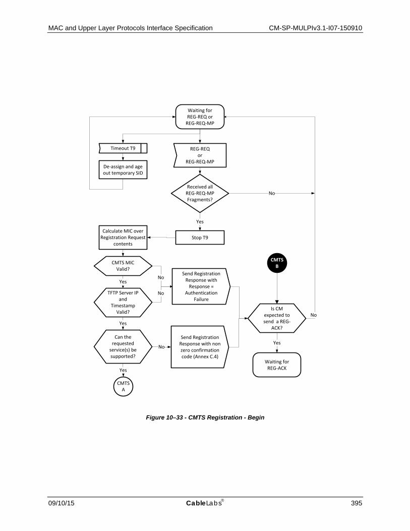
MAC and Upper Layer Protocols Interface Specification CM-SP-MULPIv3.1-I07-150910
09/10/15 CableLabs 395
Stop T9
YesNo
Calculate MIC over Registration Request
contents
REG-REQ or
REG-REQ-MP
Send Registration Response with
Response = Authentication
Failure
Send Registration Response with non zero confirmation code (Annex C.4)
No
Received all REG-REQ-MP Fragments?
De-assign and age out temporary SID
No
Timeout T9
No
Yes
Yes
No
Yes
Yes
CMTSA
Waiting for REG-REQ or
REG-REQ-MP
Waiting for REG-ACK
Can the requested
service(s) be supported?
TFTP Server IP and
Timestamp Valid?
CMTS MIC Valid?
Is CM expected to send a REG-
ACK?
CMTSB
Figure 10–33 - CMTS Registration - Begin
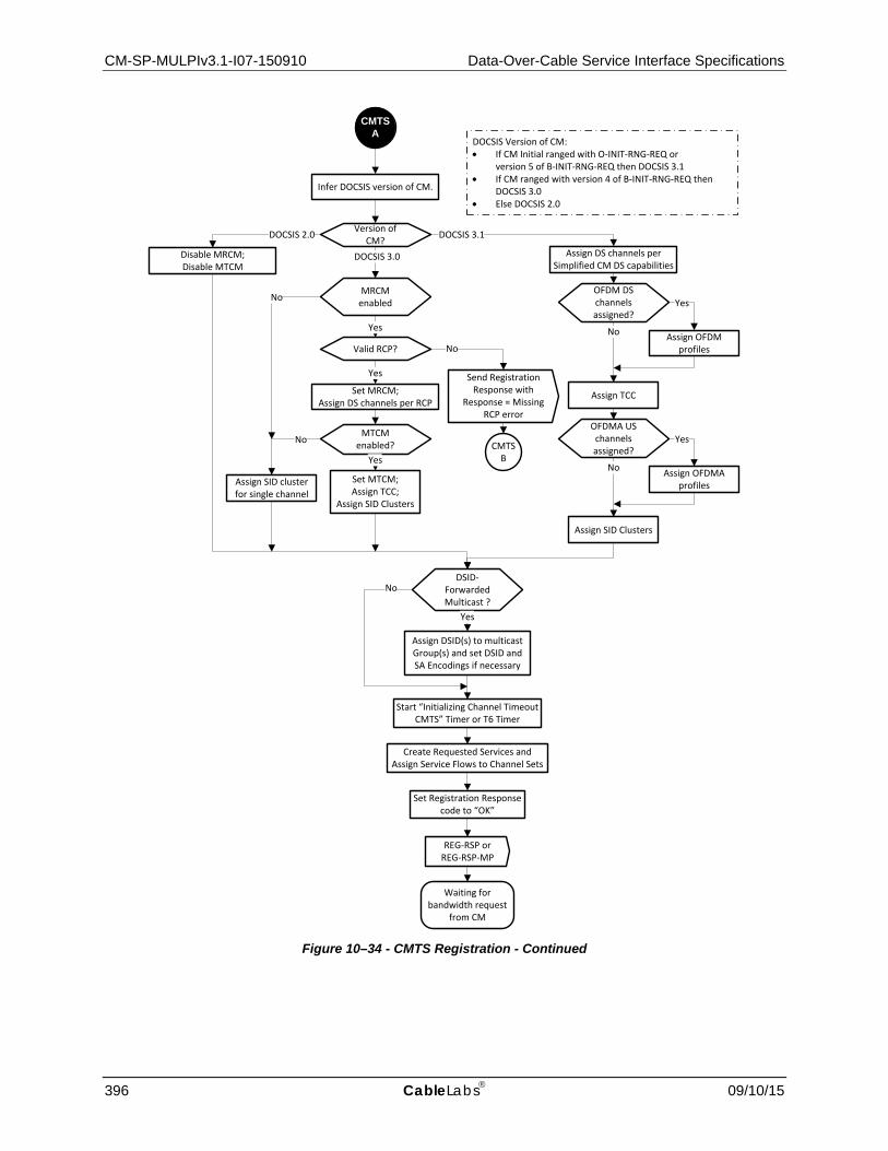
CM-SP-MULPIv3.1-I07-150910 Data-Over-Cable Service Interface Specifications
396 CableLabs 09/10/15
CMTS A
Version of CM?
DOCSIS 3.0
DOCSIS 3.1
Set MRCM;Assign DS channels per RCP
DOCSIS 2.0
Assign DS channels per Simplified CM DS capabilities
Infer DOCSIS version of CM.
Disable MRCM; Disable MTCM
MRCM enabled
Send Registration Response with
Response = Missing RCP error
No
CMTSB
Yes
OFDM DS channels assigned?
No
Yes
Assign OFDM profiles
Assign TCC
MTCM enabled?
Set MTCM;Assign TCC;
Assign SID Clusters
Yes
NoOFDMA US channels assigned?
No
Yes
Assign OFDMA profiles
Assign SID Clusters
Valid RCP?
Yes
No
Assign SID cluster for single channel
DSID-Forwarded Multicast ?
Assign DSID(s) to multicast Group(s) and set DSID and SA Encodings if necessary
Yes
Start “Initializing Channel Timeout CMTS” Timer or T6 Timer
No
Create Requested Services and Assign Service Flows to Channel Sets
Set Registration Response code to “OK”
REG-RSP orREG-RSP-MP
Waiting for bandwidth request
from CM
DOCSIS Version of CM:• If CM Initial ranged with O-INIT-RNG-REQ or
version 5 of B-INIT-RNG-REQ then DOCSIS 3.1• If CM ranged with version 4 of B-INIT-RNG-REQ then
DOCSIS 3.0• Else DOCSIS 2.0
Figure 10–34 - CMTS Registration - Continued

MAC and Upper Layer Protocols Interface Specification CM-SP-MULPIv3.1-I07-150910
09/10/15 CableLabs 397
Figure 10–35 - CMTS Registration - End
Waiting for bandwidth request
from CM
Queue-depth Based Request
Timeout T6Or “Initializing
Channel Timeout”Non-Queue-depth Based
Request
No
Version of CM?
Pre-3.1 DOCSIS
DOCSIS 3.1
Queue-depth Based Request
MTCM enabled?
MTCM enabled?
CMTS C
CMTS C
Yes No
Continue existing granting process
(legacy)
No
Waiting for REG-ACK
Yes
REG-ACKExpected?
YesNo
Timeout T6 REG-ACK
Begin granting using CCF
Registration Complete
Waiting for REG-REQ or
REG-REQ-MP
CMTS D
CMTS D
Retries Exhausted?
Destroy Services
Yes Clear any reassembly buffer
Start T6 Timer
REG-RSP orREG-RSP-MP
No
CMTS C
REG-ACK ContainsError Sets or PartialService Encodings?
Partial Service
Encodings?
Yes
CMTS and CM in Partial Service Mode
Yes
No
CMTS initiates action on partial
service as applicable
DOCSIS 2.0 Enabled AND Type 2 or 4 US
channel AND MTCM disabled?
No
Begin using IUCs9, 10, and 11
Yes
DOCSIS 3.1 CM uses queue-dept-based-requesting immediately after Initial Ranging.

CM-SP-MULPIv3.1-I07-150910 Data-Over-Cable Service Interface Specifications
398 CableLabs 09/10/15
10.2.6.3.1 Channel Assignment During Registration
The Registration Request message can have a number of TLVs which will influence the selection of downstream and upstream channels that the CMTS assigns to CMs operating in Multiple Receive Channel (MRC) mode in the Registration Response. Additionally, some of these TLVs will cause the CMTS to re-direct CMs not operating in MRC mode to an alternate channel pair after Registration completes (via DCC or CM reboot).
To avoid potential conflicts between these TLVs there is a defined precedence order for handling of them by the CMTS. The CMTS MUST follow this precedence order for CMs operating in MRC mode:
1. TLV 56 Channel Assignment (see the subsection Channel Assignment Configuration Settings in Annex A) and TLV 48 RCPs (see the subsection CM Receive Channel (RCP/RCC) Encodings in Annex C):
As described in Section 8.2.4, the CMTS is required to select an RCP from those advertised by the CM, and generate a corresponding RCC that configures the CM's receivers. When the Channel Assignment TLV is present, the CMTS is additionally required (see the subsection Channel Assignment Configuration Settings in Annex C) to select an RCS and TCS that match the channel(s) indicated in the Channel Assignment TLV. If either or both of these cannot be achieved, the CMTS is required to reject the registration of the CM.
2. TLV 43.11 Service Type Identifier (see the subsection Service Type Identifier in Annex C):
When the Service Type Identifier is present in the configuration file, the CMTS is required to select an RCS and TCS from a Restricted Load Balancing Group or MAC Domain that is available to the CM and that offers the signaled Service Type, if such RCS and TCS exist. If an RCS and/or TCS do not exist that provide the signaled Service Type the CMTS can assign an RCS and/or TCS that do not offer the signaled Service Type.
3. TLV 43.3 Load Balancing Group ID (see the subsection CM Load Balancing Group ID in Annex C):
If the Service Type Identifier is not present in the Registration Request, the CMTS examines the Load Balancing Group ID, if present. If the available choices for RCS and TCS include channels associated with the signaled Load Balancing Group, the CMTS is required to assign the CM to the signaled Load Balancing Group. If these conditions cannot be met, the CMTS can disregard the Load Balancing Group ID. If the Load Balancing Group ID and Service Type Identifier both appear in the same configuration file, the CMTS is free to ignore the Load Balancing Group ID.
4. TLVs 24/25.31-33 Service Flow Attribute Masks (see the subsections Service Flow Required Attribute Mask through Service Flow Attribute Aggregation Rule Mask in Annex C):
If there are multiple RCSs and/or TCSs available that meet the requirements of the Service Type Identifier (if present) and Load Balancing Group ID (if present), the CMTS is required to select an RCS and/or TCS that meet the Required and Forbidden Attribute Masks of the Service Flows requested in the configuration file. If an RCS and/or TCS are not available that meet these criteria, the CMTS is free to choose an alternative RCS and/or TCS from among those previously identified.
5. TLV 43.9 CM Attribute Masks (Annex C):
If there are multiple RCSs and/or TCSs available that meet the requirements of the Service Type Identifier (if present), Load Balancing Group ID (if present), and Service Flow Attribute Masks (if present), the CMTS can select an RCS and/or TCS that meet the CM Required and Forbidden Attribute Masks requested in the configuration file.
The CMTS MUST follow this precedence order for CMs not operating in MRC mode:
1. TLV 43.11 Service Type Identifier (Annex C):
When the Service Type Identifier is present in the configuration file, the CMTS is required to select an upstream and downstream channel from a Restricted Load Balancing Group or MAC Domain that is available to the CM and that offers the signaled Service Type, if such channels exist. If an upstream and downstream channel do not exist that provide the signaled Service Type the CMTS can assign an upstream and/or downstream channel that do not offer the signaled Service Type.
2. TLV 43.3 Load Balancing Group ID (Annex C):

MAC and Upper Layer Protocols Interface Specification CM-SP-MULPIv3.1-I07-150910
09/10/15 CableLabs 399
After meeting the requirements for Service Type Identifier, the CMTS examines the Load Balancing Group ID, if present. If the available choices for upstream and downstream channel include a channel pair associated with the signaled Load Balancing Group, the CMTS is required to assign the CM to the signaled Load Balancing Group. If these conditions cannot be met, the CMTS can disregard the Load Balancing Group ID.
3. TLV 43.9 CM Attribute Masks (Annex C):
If there are multiple upstream and/or downstream channels available that meet the requirements of the Service Type Identifier (if present) and Load Balancing Group ID (if present), the CMTS is required to select an upstream and/or downstream channel that meet the CM Required and Forbidden Attribute Masks requested in the configuration file. If an upstream and/or downstream channel are not available that meet these criteria, the CMTS is free to choose an alternative upstream and/or downstream channel. If an upstream and/or downstream channel are not available that meet these criteria, the CMTS can disregard the CM Attribute Masks.
4. TLVs 24/25.31-33 Service Flow Attribute Masks (see Annex C):
If there are multiple upstream and/or downstream channels available that meet the requirements of the Service Type Identifier (if present), Load Balancing Group ID (if present), and CM Attribute Masks (if present), the CMTS is required to select an upstream and/or downstream channel that meet the Service Flow Required and Forbidden Attribute Masks requested in the configuration file. If an upstream and/or downstream channel are not available that meet these criteria, the CMTS is free to choose an alternative upstream and/or downstream channel from among those already identified.
Note that the operator may configure the CMTS (via network management mechanisms) to restrict a particular CM to a certain Service Type ID and/or Restricted Group ID. If such a configuration is made, both the Service Type ID and Restricted Group ID configuration file TLVs are ignored by the CMTS.
If the TLVs present in the Registration Request message require the CMTS to move the CM to a different MAC Domain, the CMTS will need to force the CM to re-initialize in the new MAC Domain. While the exact mechanism is left to the vendor, the CMTS SHOULD minimize the time it takes for the CM to be redirected to the new MAC Domain. Examples of potential mechanisms are: the CMTS could allow the CM to complete registration (possibly with forwarding disabled) and then immediately send a DCC-REQ to the CM; the CMTS could send a Registration Response with a reject confirmation code or a RNG-RSP Abort, forcing the CM to re-initialize, then upon the subsequent ranging request, perform a downstream frequency override. In certain plant topologies, the CMTS may not be able to precisely determine a CM's initial location. This may occur when the CMTS has identified the MD-CM-SG of the CM in the original MAC Domain, but that MD-CM-SG identifies a set of fiber nodes rather than a single fiber node. In this situation, it may not be possible for the CMTS to identify the downstream frequency which will reach the CM in the desired new MAC Domain. The CMTS may need to make more than one attempt to direct the CM to the appropriate MAC Domain.
10.2.7 Baseline Privacy Initialization Following registration, if the CM is provisioned to run Baseline Privacy and EAE was not enabled, the CM MUST initialize Baseline Privacy operations, as described in [DOCSIS SECv3.0].
10.2.8 Service IDs During CM Initialization98 After completion of the Registration process (Section 10.2.6), the CM will have been assigned Service IDs (SIDs) to match its provisioning. However, the CM needs to complete a number of protocol transactions prior to that time (e.g., Ranging, DHCP, etc.), and requires a temporary Service ID in order to complete those steps.
On reception of an Initial Ranging Request, the CMTS MUST allocate a temporary SID and assign it to the CM for initialization use. The CMTS MUST inform the CM of this assignment in the Ranging Response. The CMTS MAY monitor use of this SID and restrict traffic to that needed for initialization.
The CMTS MUST assign a temporary SID from the unicast SID space (see Section 7.2.1.2, Information Elements), for any CM that did not begin the initial ranging process with a B-INIT-RNG-REQ message. Any CM that began the initial ranging process with a B-INIT-RNG-REQ or O-INIT-RNG-REQ message is known at the time of initial ranging to support the expanded SID space and the CMTS MAY assign the CM a temporary SID from the expanded 98 Updated by MULPIv3.1-N-15.1254-1 on 3/10/15 by PO.

CM-SP-MULPIv3.1-I07-150910 Data-Over-Cable Service Interface Specifications
400 CableLabs 09/10/15
SID space. CMs MUST support the capability to transmit unicast traffic on the expanded SID space (see the subsection Expanded Unicast SID Space in Annex C). If a CM supports the above capability the CMTS MAY assign SID numbers from the expanded unicast SID space in the Registration Response.
Upon receiving a Ranging Response addressed to it, the CM MUST use the assigned temporary SID for further initialization transmission requests until the Registration Response is received. The CM MUST request the number of bytes using a request byte multiplier of 4 until the Registration Response is received. Prior to the receipt of the Registration Response message, the CM MUST use a value of 0 in the SID Cluster ID field of the Segment Header. Prior to the receipt of the Registration Response message, the CM operates using only the temporary SID; therefore, there are no SID Cluster Switchover Criteria.
Upon receiving a Ranging Response instruction to move to a new downstream frequency and/or upstream channel ID, the CM MUST consider any previously assigned temporary SID to be deassigned and obtain a new temporary SID via the Upstream Channel Adjustment TLV or via initial ranging.
It is possible that the Ranging Response may be lost after transmission by the CMTS. The CM recovers by timing out and re-issuing its Initial Ranging Request. Since the CM is uniquely identified by the source MAC address in the Ranging Request, the CMTS MAY immediately re-send the temporary SID that had previously been assigned to this CM. If the CMTS instead assigns a different temporary SID to this CM, the CMTS MUST make some provision for aging out the original temporary SID that went unused.
When assigning SIDs to provisioned Service Flows during registration, the CMTS may re-use the temporary SID, assigning it to one of the Service Flows requested. If so, it MUST continue to allow initialization messages on that SID, since the Registration Response could be lost in transit. If the CMTS assigns all-new SIDs, it MUST age out the temporary SID. The aging-out MUST allow sufficient time to complete the registration process in case the Registration Response is lost in transit.
10.3 Periodic Maintenance99
Remote RF signal level adjustment at the CM is performed through a periodic maintenance function using the unicast RNG-REQ MAC Management messages, probes, and RNG-RSP MAC messages. This is shown in Figure 10–36 and Figure 10–37. Note that each figure represents the operation for a single upstream channel on a CM.
The CMTS MUST provide each upstream SC-QAM channel in the CM's TCS a Periodic Ranging opportunity at least once every T4 seconds. The CMTS MUST send out Periodic Ranging opportunities at an interval sufficiently shorter than T4 so that a MAP could be missed without the CM timing out. The size of this "subinterval" is CMTS-dependent.
For OFDMA channels, the CMTS requirements for Periodic Maintenance depend on the CM Periodic Maintenance Timeout Indicator TLV, which the CMTS places in the MDD:
• When the CMTS specifies the CM Periodic Maintenance Timeout Indicator TLV to be "use Unicast Ranging opportunity", the CMTS MUST provide each CM with a Periodic Ranging opportunity at least once every T4 seconds on each of the OFDMA channels in the CM's TCS.
• When the CMTS specifies the CM Periodic Maintenance Timeout Indicator TLV to be "use Probe opportunity", the CMTS MUST provide each CM with a Probe opportunity at least once every T4 seconds on each of the OFDMA channels in the CM's TCS.
• When the CMTS specifies the CM Periodic Maintenance Timeout Indicator TLV to be "use Unicast Ranging or Probe opportunity", the CMTS MUST provide each CM with a Probe or Unicast Ranging opportunity at least once every T4 seconds on each of the OFDMA channels in the CM's TCS.
The CMTS MUST send out the above referenced opportunities at an interval sufficiently shorter than T4 so that a CM does not timeout even if a MAP is missed. The size of the referenced "subinterval" is CMTS dependent. For the CM Periodic Maintenance Timeout Indicator TLV of "use Probe opportunity", the CMTS MAY send out Ranging opportunities, in addition to Probes, for OFDMA channels as part of periodic maintenance. These ranging opportunities allow the CM to communicate to the CMTS the CM's transmit power and error conditions as part of a RNG-REQ message.
99 MULPIv3.1-N-14.1211-5 on 12/4/14 by PO.

MAC and Upper Layer Protocols Interface Specification CM-SP-MULPIv3.1-I07-150910
09/10/15 CableLabs 401
The CMTS SHOULD NOT assign probe or unicast ranging opportunities to a CM such that the start time of those allocations occurs within 50 msec (plus downstream interleaver delay) after transmission of a Range Response to the same CM, or while the CMTS is awaiting or processing a previously allocated probe or unicast ranging opportunity to that CM on that channel.
After sending a probe or a ranging request, the CM MUST inhibit transmission of probes and ranging requests until either the CM receives a ranging response for that channel or the duration of the T3 timer has elapsed with no ranging response received. If a ranging response is received for that channel, the CM continues inhibiting transmission of probes and ranging requests until it has applied any adjustment in the RNG-RSP.
A CM which is not in Multiple Transmit Channel Mode MUST reinitialize its MAC with a CM Initialization Reason of T4_EXPIRED after T4 seconds have elapsed without receiving a Periodic Ranging opportunity.
When a CM is in Multiple Transmit Channel Mode and an upstream channel in the TCS incurs a T4 timeout or a number of T3 timeouts in excess of the Invited Ranging Retries, then that upstream channel is considered unusable for request or data transmissions, and the CM enters a partial service mode in the upstream (see Section 8.4).
If all the upstream channels associated with the Primary Upstream Service Flow are unusable the CM MUST reinitialize its MAC with a CM Initialization Reason of NO_PRIM_SF_USCHAN. This is true even when there is a viable upstream remaining in the TCS and that upstream is not associated with the Primary Upstream Service Flow.
If there is at least one usable upstream channel associated with the Primary Upstream Service Flow, the CM MUST NOT reinitialize its MAC due to the loss of the other channels.
Upon receiving a RNG-RSP, the CM MUST use the first usable Reconfiguration Time, or Global Reconfiguration Time (in the case of a dynamic range window adjustment), to adjust its transmitter parameters in accordance with the RNG-RSP.
If an upstream channel has been suspended by receiving a RNG-RSP with a ranging status of CONTINUE, the CM MUST NOT transmit anything other than RNG-REQs or Probes on that upstream channel, until such time as it receives a RNG-RSP with a ranging status of SUCCESS for the upstream channel in question.
The CMTS SHOULD NOT send a ranging status of CONTINUE in a RNG-RSP unless the ranging parameters measured on the corresponding RNG-REQ or probe are insufficient for the CMTS to guarantee proper reception of all burst types available to that CM. Additionally, upon sending a RNG-RSP with ranging status of CONTINUE, the CMTS SHOULD schedule another Periodic Maintenance opportunity for the CM on that upstream channel quickly so that the CM can return to a ranging status of SUCCESS as quickly as possible.
As described in Section 10.6.1, during normal operation in the S-CDMA mode, if a CM temporarily loses synchronization to the downstream signal, it is required to perform a ranging process before returning to normal operation. To facilitate this recovery, if the CMTS does not receive a RNG-REQ message from a CM during a Station Maintenance interval, the CMTS MAY schedule unicast Initial Maintenance opportunities, or temporarily reduce the time between unicast spreader-off Station Maintenance opportunities.

CM-SP-MULPIv3.1-I07-150910 Data-Over-Cable Service Interface Specifications
402 CableLabs 09/10/15
CMTS Periodic Ranging of CM Begin
US channel SC-QAM
Idle
CM Periodic Ranging
Subinterval Expiry
Perform Periodic
Ranging by Fine Ranging?
No
Schedule Probe Opportunity
Schedule Unicast Ranging
Opportunity
No
Probe
Yes
RNG-REQNo Response from CM
Retries Exceeded?
No
1
1
Good Enough?
RNG-RSP(success)
RNG-RSP(continue)
No
Retries Exceeded?
No
RNG-RSP(abort)
Yes
Schedule Unicast Ranging
Opportunity
1
Any UC for primary US SF stable?
Yes
CMTS either removes UC from
TCS or attempts to recover the UC
(see Note 3 below)
Yes
Deregister CM
No
End
On periodic timer add CM to poll list
Yes
MAP will be sent per allocation algorithm and
pending till complete(see Note 1 below)
Figure Notes: 1. For a RNG-REQ message from a DOCSIS 3.0 or prior CM, If pending-till-complete was nonzero, the CMTS SHOULD hold
off the station maintenance opportunity accordingly unless needed, for example, to adjust the CM's power level. If opportunities are offered prior to the pending-till-complete expiry, the "good-enough" test which follows receipt of a RNG-RSP MUST NOT judge the CM's transmit equalization until pending-till-complete expires.
2. "Good Enough" means Ranging Request is within the tolerance limits of the CMTS for power, timing, frequency, and transmit equalization (if supported).
3. If the CMTS determines that there are still usable upstream channels in the CM's TCS associated with the Primary Service Flow, then it can attempt to recover using any method at its disposal. For example, the CMTS could re-range the unusable upstream channel by providing unicast maintenance opportunities; instruct the CM (via DBC-REQ) to alter its TCS to remove the unusable upstream channel; instruct the CM (via CM-CTRL-REQ message) to reinitialize its MAC.
Figure 10–36 - Periodic Ranging - CMTS View

MAC and Upper Layer Protocols Interface Specification CM-SP-MULPIv3.1-I07-150910
09/10/15 CableLabs 403
Figure 10–37 - Periodic Ranging - CM View
10.4 OFDM Profile Usability Testing Process
Prior to Registration, a CM only has one downstream profile (Profile A) and one upstream profile (IUC 13) available to it. To maximize capacity and for other reasons the CMTS needs a way to test the physical layer performance of a given CM on a downstream or upstream profile so that it can determine what profiles can successfully be assigned to a given modem. To this end, this specification includes separate mechanisms for the CMTS to trigger the CM to perform downstream and upstream profile testing.
10.4.1 Downstream Profile Usability Testing Process100 The design goal of the downstream profile testing process is to enable rapid determination of the usability by a given CM of profiles already being made available in the downstream via DPD messages. The optimization of the profiles themselves to best serve a given population of CMs is outside the scope of this specification.
The downstream profile usability testing mechanism offloads as much processing as possible to the CM. After performing tests as instructed, the CM reports to the CMTS a summary of relevant statistics from its testing.
100 Modified by MULPIv3.1-N-14.1183-2 on 12/5/14 by PO, by MULPIv3.1-N-15.1269-1 on 3/9/15 by PO.

CM-SP-MULPIv3.1-I07-150910 Data-Over-Cable Service Interface Specifications
404 CableLabs 09/10/15
The CMTS transmits an OPT-REQ to instruct a given modem to begin a testing process for a profile. After transmitting an OPT-REQ, if the profile to be tested is not already in use or does not carry much traffic, the CMTS MUST begin transmitting test codewords on the profile(s) specified therein.
Upon receipt of an OPT-REQ requesting testing, the CM MUST start a profile-testing timer for the allowed maximum duration. Then the CM performs downstream codeword measurements.
While performing downstream profile usability testing, the CM MUST NOT interfere with other profiles operation.
Upon either evaluating >= Nc codewords or encountering >= Ne uncorrectable codewords, the CM MUST transmit an OPT-RSP containing the results of its testing. To perform this measurement, the CM reads the running counters for codewords and uncorrectable codewords, waits a short time, reads the counters again, and computes the difference in the counter values. The CM reports the results when at least Nc codewords or at least Ne errors have occurred, whichever comes first. If the profile-testing timer expires before profile testing completes the CM MUST transmit an OPT-RSP with the Status set to "Max Duration Expired". The CM MUST ensure that the OPT-RSP message includes all results measured or calculated during the elapsed test period.
As an example, if the desired CER_threshold = 1e-3, and Ne = 10 errors is chosen as a threshold for minimal statistical reliability, then Nc = Ne/CER_threshold = 1e4 codewords need to be examined. On a 2 Gbps downstream channel, a CMTS desiring to use no more than 1% of the channel for test codewords could send in excess of 1e3 test codewords per second, and so the Max Duration parameter could be set to 10 seconds. To prevent the test from taking more time than necessary, the CM can monitor the counters at a shorter interval (say, once per second) and end the test as soon as either Nc or Ne is exceeded.
Upon receipt of the OPT-RSP it is up to the CMTS to determine which of the tested profiles it wants the CM to use. If the CMTS determines that it wants the CM to switch from its current profile, the CMTS sends the CM a DBC message with RCC encodings commanding the use of the desired profile.
Figure 10–38 - Typical OFDM Profile Test Transaction
CMTS CM
OPT-REQ ( DCID, Profile ID, OpCode = Start,TLVs: Max Duration, Min Codewords, Threshold(s) )
OPT-RSP ( DCID, Profile ID, Status = Testing )
CM Begins Testing the profile;CM Acknowledges Request
Time Passes...CM finishes testing profile;
CM Sends Test results to CMTS
OPT-RSP ( DCID, Profile ID, Status = Complete,TLVs: Codeword Count, Statistics )
CMTS acknowledges receipt of results
OPT-ACK( DCID, Profile ID, Status )
OPT-RSP Timer
running
OPT-ACK Timer
running
OPT-Testing Timer
running

MAC and Upper Layer Protocols Interface Specification CM-SP-MULPIv3.1-I07-150910
09/10/15 CableLabs 405
Figure 10–38 shows the message exchange for a typical OFDM Profile Test Transaction. However, there might be reasons (operator intervention, fault management, etc.) why the CMTS may wish to abort the CM's testing of a profile once it has started. In this case the message exchange would proceed as in Figure 10–39.
Figure 10–39 - Aborted OFDM Profile Test Transaction
CMTS CM
OPT-REQ ( DCID, Profile ID, OpCode = Start,TLVs: Max Duration, Min Codewords, Threshold(s) )
OPT-RSP ( DCID, Profile ID, Status = Testing )
CM Begins Testing the profile;CM Acknowledges Request
Time Passes...CMTS Signals CM to Abort the profile test
OPT-RSP ( DCID, Profile ID, Status = Aborted,TLVs: Codeword Count, Statistics )
CMTS acknowledges receipt of results
OPT-ACK( DCID, Profile ID, Status )
OPT-REQ ( DCID, Profile ID, OpCode = Abort )
CM Aborts Profile testing;CM Sends Test Result to CMTS
OPT-RSP Timer
running
OPT-ACK Timer
running
OPT-Testing Timer
running
OPT-RSP Timer
running

CM-SP-MULPIv3.1-I07-150910 Data-Over-Cable Service Interface Specifications
406 CableLabs 09/10/15
Figure 10–40 - CM OPT State Machine - OPT Idle
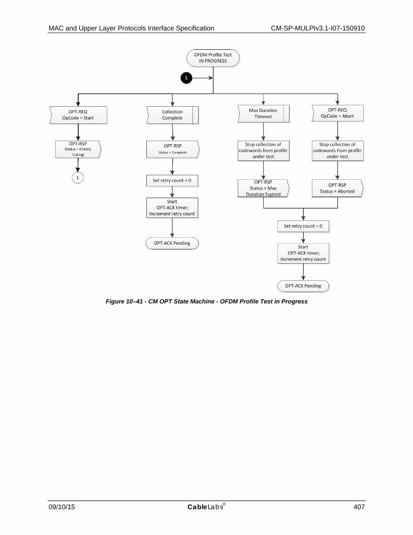
MAC and Upper Layer Protocols Interface Specification CM-SP-MULPIv3.1-I07-150910
09/10/15 CableLabs 407
Figure 10–41 - CM OPT State Machine - OFDM Profile Test in Progress

CM-SP-MULPIv3.1-I07-150910 Data-Over-Cable Service Interface Specifications
408 CableLabs 09/10/15
Figure 10–42 - CM OPT State Machine - OPT-ACK Pending
One instance of CM OPT State Machine depicted in Figure 10–40 may be active for each set of profile resources that is not in use. This means that a CM might have as many as four instances per downstream OFDM channel if the CM is currently only using Profile A for downstream reception.
This state machine assumes that the CM has an asynchronous task which is capable of collecting, counting, and analyzing codeword samples. This task should be capable of operating on multiple profiles simultaneously and independently if requested to do so. However, it is not expected to perform testing with Codeword Tagging enabled (see Section 6.4.44) on more than one profile simultaneously. The codeword sampling task will collect codeword samples and generate to the proper CM OPT State Machine instance an internal signal of either "Collection Complete" if it successfully collected the requested number of codewords or, "Max Duration Timeout" if it timed-out, or "Aborted" if the CMTS aborted the profile test.
The CM state machine has three states, the "OPT Idle" state, the "OFDM Profile Test In progress" state, and the "OPT-ACK Pending" state.
The CM state machine begins in the "OPT Idle" state.
If the CM is in the "OPT Idle" state and it receives an OPT-REQ from the CMTS to start testing a profile on the channel, then the CM checks to ensure that the resources to test another profile are available. If resources are not available or if Codeword Tagging is enabled but the CM already has another test in progress with Codeword Tagging enabled, then the CM responds with an OPT-RSP with a Status of "No Free Profile Resource on CM" and the OPT State Machine returns to the "OPT idle" state. If resources are free, then the CM sends an OPT-RSP with a Status of "Testing" and begins collecting and decoding codewords for the profile under test. The CM will continue to collect samples in the background. The OPT State machine starts the Maximum Duration Timer and transitions to the "OFDM Profile Test In Progress" state with the collection process occurring in the background.
MAC and Upper Layer Protocols Interface Specification CM-SP-MULPIv3.1-I07-150910
09/10/15 CableLabs 409
If the OPT State Machine is in the "OFDM Profile Test In Progress" state and the CM receives an OPT-REQ for the same Profile on the same channel with an OpCode of "Start", then this is a retransmission of the original request. The OPT State Machine retransmits the OPT-RSP message with the status of "Already Testing". The OPT State Machine remains in the "OFDM Profile Test In Progress" state.
While the OPT State Machine is in the "OFDM Profile Test In Progress" state then:
• If the codeword sampling task returns a signal indicating "Collection Complete", then the OPT State Machine processes the metrics and sets the OPT-RSP Status to "Complete";
• If the codeword sampling task returns a signal indicating "Maximum Duration Timeout", then the OPT State Machine processes the metrics, signals the CM collection process to stop collecting and decoding codewords for the profile under test and sets the OPT-RSP Status to "Maximum Duration Expired";
• If the CM receives an OPT-REQ for the same Profile on the same channel with an OpCode of "Abort", then the OPT State Machine processes the metrics, signals the CM collection process to stop collecting and decoding codewords for the profile under test and sets the OPT-RSP Status to "Aborted".
In all three cases, the CM constructs an OPT-RSP message with the assigned Status and the compiled metrics encoded in TLVs and sends the OPT-RSP message. The OPT State Machine sets the retry count to 0, starts the "OPT-ACK timer", and transitions to the "OPT-ACK Pending" state.
If the OPT State Machine is in the "OPT-ACK Pending" state and it receives OPT-REQ for the same Profile on the same channel and an OpCode of "Start" then the OPT State Machine retransmits the acknowledgement OPT-RSP message with the preliminary status of "Already Testing". The OPT State Machine remains in the "OPT-ACK Pending" state.
If the OPT State Machine is in the "OPT-ACK Pending" state and the "OPT-ACK timer" expires, the CM will check to see if the retry count exceeded the "OPT Retry Count". If the "OPT Retry Count" is exceeded, then the OPT State Machine generates an error signal "OPT-ACK not received" and returns to the "OPT Idle" state. If the "OPT Retry Count" is not exceeded, then the OPT State Machine proceeds to resend the OPT-RSP message, starts the "OPT-ACK timer", increments the retry count, and remains in the "OPT-ACK Pending" state.
If the OPT State Machine is in the "OPT-ACK Pending" state and the CM receives the OPT-ACK message for the same Profile on the same channel, then the OPT State Machine clears the OPT-ACK timer and returns to the "OPT Idle" state.
10.4.1.1 MAC LFSR Frame101 When a CMTS establishes a new profile it can test that profile’s suitability to different modems using the OPT-REQ message. However, before at least a single CM can be confirmed as capable of receiving this new profile, and has it assigned as one of its working profiles, no regular traffic will be scheduled to that profile. Even when some CMs are confirmed as capable of receiving the new profile, and start receiving traffic on it, that traffic rate may be low, which may result in profile testing being very lengthy. Accordingly, there is a need for the CMTS to generate synthetic traffic for the purpose of testing a transition profile. CMTS generated synthetic traffic is also required for OFDM channel MER measurements by test equipment.
Unfortunately, a simple null payload for the PHY layer (a sequence of 0xFF bytes) is inadequate for CM profile testing or test equipment MER measurements. Since the DS OFDM channel randomizer resets every frame (synchronized to the PLC preamble), the randomized null payload sequence length for every subcarrier is only 128 values. Such a sequence does not exercise all the constellation points of the deeper modulation schemes available on the OFDM channel. To enable more accurate MER measurements of the test profile, the payload of the traffic used during profile testing has to be somewhat random.
The 30 bit linear feedback shift register (LFSR) illustrated in Figure 10–43 is used for generation of pseudo random synthetic data. The LFSR can be initialized to any number other than all-1s, and then be left free-running without re-initialization (to prevent shortening the bit sequence). The serial bit stream from the LFSR is packed into bytes MSB first. Groups of 2000 bytes are encapsulated into MAC LFSR Frames as illustrated in Figure 10–44.
101 Section added per MULPIv3.1-N-14.1149-2 on 12/1/14 by PO.

CM-SP-MULPIv3.1-I07-150910 Data-Over-Cable Service Interface Specifications
410 CableLabs 09/10/15
D 1
D 2
D 3
D 4
D 27
D 28
D 29
D 30
D 5
D 6
D 7
Figure 10–43 - Linear Feedback Shift Register for Synthetic Data Generation
Note that while a different pseudo random LFSR payload is encapsulated on different MAC LFSR frames, the header does not vary between MAC LFSR frames. The "well-known" MAC LFSR DSID of 0xFFFFF is used to isolate the MAC LFSR Frames from other traffic. The CMTS MUST NOT assign this well-known DSID to any downstream service flow. Since this DSID is not communicated to any CM, the CM discards MAC LFSR frames without trying to interpret the payload.
10 2000
header bytes LFSR bytes
MAC LFSR Frame
FC01
MAC_PARM
04
LEN07D4
EHDR830FFFFF HCS
Figure 10–44 - MAC LFSR Frame
Consecutive MAC LFSR frames transmitted by the CMTS on any particular profile do not have to hold an uninterrupted LFSR bit stream. This enables the CMTS to use a single LFSR mechanism for generation of pseudo random data for multiple profiles and OFDM channels. A device that analyzes LFSR MAC Frame payload is required to resynchronize to the LFSR sequence every frame. The rate of MAC LFSR frames used for OPT profile testing by a CM is left for vendor-specific implementation. The CMTS MUST support generation of MAC LFSR frames on at least one profile at a rate approaching the maximum capacity of that OFDM channel and that profile.
NOTE: This is for testing purposes.
10.5 Upstream OFDMA Data Profile Assignment and Testing 102
10.5.1 Assignment of OFDMA Upstream Data Profile (OUDP) IUCs It is intended that the Burst Descriptor associated with Data Profile IUC 13 be configured as a robust OFDMA profile usable by any DOCSIS 3.1 CM served by that upstream channel. The CMTS MUST use Data Profile IUC 13 for all OFDMA data grants to modems which have not completed registration. The CM MUST be capable of transmitting data using the OFDMA Burst Descriptor for IUC 13 prior to registration.
During or after modem registration, the CMTS has the option of assigning the modem to use any data profile specified in the UCD. Typically the Burst Descriptors for data profiles other than IUC 13 will be configured for higher performance than IUC 13, although not all of these Burst Descriptors will be usable by all modems. The CMTS MUST assign the CM either one or two Assigned OUDP IUCs for each OFDMA channel in the modem's
102 Section numbering level changed per MULPIv3.1-N-14.12115 on 12/4/14 by PO.

MAC and Upper Layer Protocols Interface Specification CM-SP-MULPIv3.1-I07-150910
09/10/15 CableLabs 411
Transmit Channel Set. This is done using the Assigned OUDP IUC TLV (see Section C.1.5.1.11) within the TCC encodings. These encodings can be sent during Registration, and can be changed after Registration using a DBC transaction.
After registration, the CMTS MUST grant OFDMA bandwidth for data transmissions to a CM using one of the CM's Assigned OUDP IUCs. The CMTS MUST NOT grant data bandwidth to a CM using an OFDMA Upstream Data Profile IUC not specified as one of that CM's Assigned OUDP IUCs.
Upon successful completion of a transaction assigning one or two Assigned OUDP IUCs to a CM, that CM MUST be capable of transmitting data using the assigned IUCs.
10.5.1.1 Upstream Profile Testing Because it is expected that not all upstream data profiles will be usable by all modems, a CMTS might wish to evaluate a modem's performance using a particular profile before assigning that profile to be used for "live" traffic. A CMTS performs such an evaluation in vendor-specific ways. This specification provides various tools to aid the CMTS in gathering information about upstream profile performance. These tools are based on two types of upstream transmissions: upstream probes, and upstream Data Profile Testing bursts.
10.5.1.2 Upstream Probes and RxMER Measurements A CMTS uses upstream probes for ranging-related functions such as determining transmit pre-equalizer coefficients [DOCSIS PHYv3.1]. A CMTS also has the option of using an upstream probe to take an RxMER measurement. To do this, the CMTS grants P-IEs in a P-MAP message (Section 6.4.4) with the "MER" bit set. When the CMTS receives the probe transmission corresponding to such a grant, it performs the RxMER measurement and uses the results to populate the MIB object [DOCSIS OSSIv3.1].
10.5.1.3 Upstream Data Profile Testing Bursts Some types of upstream profile performance measurements cannot be performed using probe bursts. For example, a CMTS might wish to gather information on FEC performance or count CRC errors for a particular profile. Probe bursts cannot be used for these purposes since they carry no information. To enable a CMTS to make these types of measurements, this specification provides a means of sending/receiving upstream Data Profile Testing bursts.
To command a CM to send an upstream Data Profile Testing burst, the CMTS first uses TCC encodings (see the section OFDMA Upstream Data Profile in Annex C) (OUDP) Testing SID) to assign a Data Profile Testing SID to the modem on one or more upstream channels. (This step can be performed any time TCC encodings are sent, including at Registration or as part of a DBC transaction.) The CMTS then sends a grant to a Data Profile Testing SID. The IUC of this grant MUST be an Assigned OUDP IUC currently assigned to the modem at the time of the grant.
The modem MUST respond to a valid grant to any of its Data Profile Testing SIDs by sending a Data Profile Testing burst in the grant. The following requirements apply to the Data Profile Testing burst:
• The modem MUST use Segment Header ON format with a valid segment header as described in Section 6.3. • The modem MUST transmit a value of zero in the Request field of the segment header. • In the remainder of the grant following the segment header, the CM MUST use valid Packet Data PDU MAC
Frames (Section 6.2) which meet the following criteria: • Valid DOCSIS header with no Extended Headers; • Data PDU field contains an Ethernet packet with a total length of 64 bytes including all Ethernet
headers and CRC (total length including DOCSIS header is 70 bytes); • Ethernet DA = CMTS DA (same as used by the modem when transmitting MMMs) • Ethernet SA = CM SA (same as used by the modem when transmitting MMMs) • Valid Ethernet length value in Type/Length field • Counting pattern in payload bytes beginning with 0x01, continuing with 0x02, 0x03, etc., and ending
with 0x2E (count is re-started at 0x01 in each successive packet) • Valid 4-byte Ethernet CRC.

CM-SP-MULPIv3.1-I07-150910 Data-Over-Cable Service Interface Specifications
412 CableLabs 09/10/15
• The CM MUST fill the grant with DOCSIS frames. The method of determining whether the grant is "full" is as follows: the modem treats all grants to its Data Profile Testing SID(s) as grants to a single CCF flow existing across all OFDMA channels to which a Data Profile Testing SID has been assigned. The CM performs continuous concatenation and fragmentation in accordance with Section 7.2.4. If a packet is fragmented at the end of any given Data Profile Testing burst, that packet is continued at the start of the next Data Profile Testing burst.
NOTE: If the CMTS implements a fragment reassembly algorithm which discards fragments due to timeouts, long intervals between grants to a modem's Data Profile Testing SID(s) may result in fragment sequence reassembly errors being detected by the CMTS. This might impact the CMTS's evaluation of test burst performance.
• With an upstream testing scheme in which the CMTS conducts two consecutive tests (for example, on two different channels in the same modem), there is a strong possibility that the last fragment send as part of the first test will be reassembled with a first fragment embedded in the first segment sent as part of the second test. If this reassembled packet generates a CRC error, it is not possible to tell which of the two reassembled segments contained the error. This might impact the CMTS's evaluation of test burst performance.
10.6 Fault Detection and Recovery
Fault detection and recovery occurs at multiple levels.
• At the physical level, FEC is used to correct errors where possible — refer to [DOCSIS PHYv3.1] for details. • At the Transmission Convergence layer, the CM can use the continuity counter and Payload Unit Start Indicator
(PUSI) to detect and recover from lost MPEG packets for SC-QAM channels [DOCSIS DRFI]. • The MAC protocol protects against errors through the use of checksum fields across both the MAC Header and
the data portions of the packet, refer to Section 10.6.2 for details. • All MAC management messages are protected with a CRC covering the entire message, as defined in Section 6.
The CMTS MUST discard any message with a bad CRC. The CM MUST discard any message with a bad CRC. Table 10–3 shows the recovery process taken following the loss of a specific type of MAC message.
• At the network layer and above, the MAC Sublayer considers messages to be data packets protected by the CRC field of the data packet; any packets with bad CRCs are discarded. Recovery from these lost packets is in accordance with the upper layer protocol.
[DOCSIS OSSIv3.0] contains a list of error codes with more useful information as to the failure of the PHY and MAC layers. Refer to Section 10.6.2 for additional information.
Table 10–3 - Recovery Process on Loss of Specific MAC Messages103
Message Name
Action Following Message Loss
SYNC The CM can lose SYNC messages on the SC-QAM primary downstream for a period of the Lost SYNC interval (see Annex B) before it has lost synchronization with the network. If the Lost SYNC Interval has elapsed without a valid SYNC message, the CM MUST suspend use of all upstream channels and try to re-establish synchronization again as described in Section 10.6.1.
MDD Prior to registration, the CM uses the presence or absence of the MDD message to determine the appropriate initialization sequence as described in Section 10.2.3 After registration, the absence of an MDD message on a non-primary channel will be reported by the CM in a CM-STATUS message as specified in Section 6.4.34.
UCD During CM initialization the CM has to receive a usable UCD before transmitting on the upstream channel. When in the "Collect UCDs" or "Obtain Upstream Parameters" state of the CM initialization process, if the CM does not receive a usable UCD within the T1 timeout period, the CM will continue scanning for a usable downstream channel. After having received a usable UCD for an upstream channel, whenever the CM receives a MAP with a UCD Count for that upstream channel that does not match the Configuration Change Count of the last UCD received, the CM suspends use of the corresponding upstream and begins looking for all UCD types for this upstream.
103 Table updated per MULPIv3.1-N-15.1346-3 on 8/21/15 by PO.

MAC and Upper Layer Protocols Interface Specification CM-SP-MULPIv3.1-I07-150910
09/10/15 CableLabs 413
Message Name
Action Following Message Loss
MAP A CM is not allowed to transmit on an upstream channel without a valid upstream bandwidth allocation. If a MAP is missed due to error, the CM is not allowed to transmit on the corresponding channel for the period covered by the MAP.
RNG-RSP If a CM fails to receive a valid ranging response within a defined time out period (T3) after transmitting a request, the CM retries the request a number of times defined in Annex B as specified in Section 10.2.3.4. Failure to receive a valid ranging response after the requisite number of attempts causes the modem to declare the channel unusable as specified in Section 10.2.3.4.
REG-RSP If a CM fails to receive a valid registration response within a defined time out period (T6) after transmitting a request, the CM retries the request a number of times defined in Annex B as specified in Section 10.2.6. Failure to receive a valid registration response after the requisite number of attempts causes the modem to reinitialize MAC with a CM Initialization Reason of T6_EXPIRED as specified in Section 10.2.6.
TIMESTAMP The CM can lose TIMESTAMP message blocks on the OFDM downstream PLC for a period of the Lost SYNC interval (see Annex B). If the Lost SYNC Interval has elapsed without a valid TIMESTAMP message block and the channel is a primary channel, the CM MUST switch to the backup primary channel or, in case it cannot switch to the backup channel, suspend use of all upstream channels and try to re-establish synchronization again as described in Section 10.6.1.
OCD During CM initialization the CM has to receive a usable OCD configure the downstream can receive data. When in the "Obtain Downstream Parameters" state of the CM initialization process, if the CM does not receive a usable OCD within the OCD/DPD PLC Timeout (refer to Section 10.2.1.1) the downstream is regarded as invalid.
DPD During CM initialization, the CM has to receive a valid DPD for profile A and a valid DPD for the NCP Profile in order to configure the downstream channel to receive data. When in the "Obtain Downstream Parameters" state of the CM initialization process, if the CM does not receive a valid DPD for Profile A and a valid DPD for the NCP Profile within the OCD/DPD PLC Timeout (refer to Section 10.2.1.1), the downstream channel is regarded as invalid. For a profile other than Profile A or the NCP Profile, if the DPD is not received within the DPD Profile A Timeout then the associated profile is not used and the CM registers in partial channel mode.
10.6.1 CM Downstream Channel Lost Lock Handling104 A Downstream Channel signal is considered to be valid when the modem has achieved the following steps:
On a SC-QAM channel:
• Synchronization of the QAM symbol timing; • Synchronization of the FEC framing; • Synchronization of the MPEG packetization; • For a Primary Downstream Channel, recognition of SYNC downstream MAC messages.
On an OFDM channel:
• Acquisition of downstream clock timing from the downstream traffic (pilots, preambles, or mixed pilots, preambles and data);
• Reception of Extended TIMESTAMP, OCD and DPD (for profile A and NCP) in the PLC with an acceptable error rate;
• Reception of NCP blocks with an acceptable error rate; • FEC decoding with profile A has an acceptable error rate.
A Lost Lock event is detected when any of the following happens:
On an SC-QAM channel:
1. Loss of synchronization of the QAM symbol timing;
2. Loss of synchronization of the FEC framing;
3. Loss of synchronization of the MPEG packetization; 104 Modified per MULPIv3.1-N-15.1299-1 on 6/2/15 by PO.

CM-SP-MULPIv3.1-I07-150910 Data-Over-Cable Service Interface Specifications
414 CableLabs 09/10/15
On an OFDM channel:
1. Pilot detection error. An indication of it may be a low SNR. This may also include indications such as loss of symbol lock, loss of lock on FFT sample clock, etc.;
2. Loss of Preamble synchronization;
3. PLC FEC error. The unreliable codeword ratio over limit - limit is vendor specific;
4. NCP CRC error. The CRC error rate over limit - limit is vendor specific;
5. Profile A Data FEC error. For LDPC + BCH, the error rate over limit or iteration number too high - limit is vendor specific.
When the CM gets a Lost Lock event, it MUST follow the recovery procedure as shown in Figure 10–45.
If a Lost Lock event is detected on a channel that the CM is using for receipt of MAPs and UCDs, the CM SHOULD attempt to receive these messages from another channel.
When loss of lock is detected on a primary downstream channel, the CM MUST attempt to switch to a Backup Primary Channel if a Backup Primary Channel has been assigned and is available. REQ23789 If it cannot switch to a Backup Primary Channel, the CM MUST attempt to re-establish synchronization until the operation of Periodic Ranging, as specified in Figure 10–37, calls for a "Reinitialize MAC" operation after the expiration of the T4 Timer or 17 expirations of T3 Timer on all upstream channels in the CM's TCS.
When loss of lock is detected on an OFDM channel, it is possible that the channel is still partially functional and receives data. So, in case of high FEC errors detected in PLC, NCP or Profile A (cases 3 to 5 as described above), the CM MUST attempt to continue using the channel and enter a Partial Channel Mode as described in Section 10.6.3.
If the upstream communication is available, the CM MUST send out a CM-STATUS message to inform the CMTS of the Lost Lock event, as specified in Section 10.6.4. If CMTS becomes aware of an interruption of a CM's Primary Downstream Channel (via a CM-STATUS message from the affected CM or from another CM), the CMTS MAY send a DBC-REQ to the CM to reprogram the downstream channel set if it wishes to do so.

MAC and Upper Layer Protocols Interface Specification CM-SP-MULPIv3.1-I07-150910
09/10/15 CableLabs 415
0
Operational
Lostlock event
Primary channel?
no
yes
no
Lostlock error cases:• Case 1: Pilot detection error• Case 2: Loss of Preamble synchronization• Case 3: PLC FEC error over threshold• Case 4: NCP FEC error over threshold • Case 5: Profile A Data FEC error over
threshold
Backup Primary avail?
Switch to backup channel (clock recovery
and timestamp)
yes
Wait for ranging success for all US
channels
Partial service mode
yes
no
Reacquire Primary DS
Switch MAP reception channel if
CM are receiving MAPs using this
channel
Success?
yes
0
0
OFDM channel Case 3 - 5 ?
Partial channel mode
yes
0
yes
OFDM channel Case 3-5?
no
yes
Continue monitoring the
channel status / possible error
reproting
Channel recovered
?
no
Send STATUS Report
Switch successful?
no
Primary Channel Interruption Handling
Send STATUS Report
Figure 10–45 - Lost Lock Procedure
10.6.1.1 Primary Downstream Channel Interruption105 An interruption of the Primary Downstream Channel occurs when all of the following conditions are met:
1. The interruption occurs on a downstream that is valid before and after the loss;
105 Modified by MULPIv3.1-15.1295-1 on 6/2/15 by PO.

CM-SP-MULPIv3.1-I07-150910 Data-Over-Cable Service Interface Specifications
416 CableLabs 09/10/15
2. The interruption is defined as an instantaneous loss of signal and after a predetermined delay, an instantaneous return to the original signal fidelity;
3. The restored downstream signal is the original signal transmitted from the original source;
4. The carrier frequency or subcarrier frequencies, physical plant, and path delays remain the same before and after the interruption;
5. For an SC-QAM channel, there are no changes in any downstream signaling parameter, including the modulation and the M/N ratio, from before to after the interruption;
6. For an OFDM channel, there are no changes in OFDM parameters as specified in the OCD and DPD messages that are associated with this channel.
When a CM in the Operational state receives an interruption of the Primary Downstream Channel for less than or equal to 5 msec:
• The CM MUST recover from the outage such that its fixed timing error on S-CDMA channels is not greater than 2% of the nominal modulation interval (in addition to the allowed jitter defined in [DOCSIS PHYv3.1]).
• The CM MUST recover from the outage such that the first upstream transmission on TDMA channels after the CM resumes normal operation is performed within an accuracy of 250 nanoseconds plus 0.5 symbols (refer to [DOCSIS PHYv3.1]).
• The CM MUST recover from the outage such that the first upstream transmission on OFDMA channels after the CM resumes normal operation is performed within an accuracy as specified in [DOCSIS PHYv3.1].
On all upstream channels, the CM MUST continue with normal operation within 2 sec from the end of the interruption. The CM is not required to continue normal operation if it receives a second interruption of downstream signal prior to the first receipt of a RNG-RSP with status "success".
When a CM in the Operational state receives an interruption of Primary Downstream Channel signal greater than 5 msec but less than the Lost Sync Interval (see Annex B), the CM MAY continue with normal operation as long as it recovers within 2 seconds:
• with a fixed timing error not greater than 2% of the nominal modulation interval (in addition to the allowed jitter defined in [DOCSIS PHYv3.1]) on S-CDMA channels
• within the timing accuracy specified in [DOCSIS PHYv3.1] on TDMA channels • within the timing accuracy specified in [DOCSIS PHYv3.1] on OFMDA channels
If the CM cannot recover according to the preceding recovery time, timing and jitter specifications, the CM MUST re-acquire upstream timing to an accuracy of at least 1 usec, be ready to respond to a ranging opportunity within 2 sec, and receive a RNG-RSP message with status "success" for a particular channel before resuming its upstream transmission on that channel. For the ranging process, the CM MUST use Broadcast or Unicast Initial Maintenance intervals, or Station Maintenance intervals. However, a CM MUST NOT use spreader-on Station Maintenance on S-CDMA channels. For the ranging process, the CM MUST use the appropriate Ranging SID in the RNG-REQ message and use its known timing offset when using Station Maintenance intervals.
A CMTS MUST process INIT-RNG-REQ messages with a Ranging SID from any CM that is in normal operation. A CMTS MUST process an O-INIT-RNG-REQ from any CM that is in normal operation. If the Ranging SID used by the CM in INIT-RNG-REQ is no longer valid, the CMTS SHOULD send a RNG-RSP message to the CM with the ranging status set to "abort".
In all cases, after the first successful ranging opportunity subsequent to the interruption, the CM MUST meet the timing requirements specified in [DOCSIS PHYv3.1].
10.6.1.2 Primary Downstream Channel Redundancy106 If the CM loses its Primary Downstream channel and then it successfully acquires master clock reference timing from a backup primary downstream channel, the CM MUST NOT transmit on any channel until it has adjusted for any timing skew between the originally designated Primary Downstream and Backup Primary downstream channel 106 Revised per MULPIv3.1-N- 14.1193-1 on 12/2/14, and MULPIv3.1-N-14.1205-1 on 12/4/12 by PO.

MAC and Upper Layer Protocols Interface Specification CM-SP-MULPIv3.1-I07-150910
09/10/15 CableLabs 417
transmissions. Unlike a DCC (see Sections 6.4.20.1.3 and 11.4.1) or DBC (see Section 11.5.1.1) transaction, the CMTS will not be directly involved in deciding the initialization technique to use when the primary downstream channel is changed. Therefore, the CM MAY use broadcast or unicast ranging to re-range on each upstream channel (using spreader-off ranging for an S-CDMA upstream channel).
If the CM has predetermined the skew between the timestamps of the Primary Downstream and backup primary downstream channel(s) before the Primary Downstream channel fails, the CM MAY restore communication in a manner like a Primary Downstream Channel Interruption described in Section 10.6.1.1 after adjusting the timing offset for the known skew between the downstream channels. If the CM determines that the timestamp received on the Backup Primary Downstream Channel is suitable for use for upstream transmissions (e.g. the Primary Downstream and Backup Primary Downstream are both SC-QAM channels with the same configuration (modulation, interleaver, etc.) or both OFDM channels with the same configuration [FFT size and cyclic prefix]), the CM MAY use station maintenance to re-range the upstream channels. If the CM determines that the timestamp received on the Backup Primary Downstream Channel is not suitable for using for upstream transmissions, it MUST use broadcast initial maintenance to re-range the upstream channels. For the ranging process, the CM MUST use the appropriate Ranging SID in the RNG-REQ message. The CM MUST use the known timing offset when using Station Maintenance intervals. The CM MUST NOT use the known timing offset when using Broadcast Maintenance intervals. Note, while re-ranging is occurring, any grants to the impacted channel(s) are discarded.
If the CM loses its Primary Downstream channel and it cannot successfully acquire master clock reference timing from a Backup Primary Downstream Channel prior to a T4 timeout on all upstream channels associated with the primary upstream service flow, then the CM MUST reinitialize its MAC with a CM Initialization Reason of NO_PRIM_SF_USCHAN.
If a CM is using one of the Backup Primary Downstream Channels as its Primary Downstream Channel and the originally designated Primary Downstream Channel becomes usable again, the CM MUST NOT automatically switch its Primary Downstream from the Backup Primary Downstream that it is currently using. However, the originally designated Primary Downstream Channel can be a candidate to become the Primary Downstream Channel if the Backup Primary Downstream Channel subsequently becomes unsuitable.
If a CM is using one of the Backup Primary Downstream Channels as its Primary Downstream Channel and the Primary Downstream Channel becomes unsuitable, then the CM MUST attempt to reacquire a Primary Downstream Channel beginning with the channel of highest priority (as designated in the Simplified Receive Channel Configuration, Primary Downstream Channel Assignment (TLV 49.6.1) of the most recently received RCC).
10.6.2 MAC Layer Error-Handling This section describes the procedures that are required when an error occurs at the MAC framing level.
The most obvious type of error occurs when the HCS on the MAC Header fails. This can be a result of noise on the HFC network or possibly by collisions in the upstream channel. Framing recovery on the downstream channel is performed by the MPEG transmission convergence sublayer. In the upstream channel, framing is recovered on each transmitted burst, such that framing on one burst is independent of framing on prior bursts. Hence, framing errors within a burst are handled by simply ignoring that burst; i.e., errors are unrecoverable until the next burst.
A second type of error, which applies only to the upstream, occurs when the Length field is corrupted and the MAC thinks the frame is longer or shorter than it actually is. Synchronization will recover at the next valid upstream data interval.
The CM MUST verify the HCS of every received MAC Frame. When a bad HCS is detected, the CM MUST discard the MAC Header and any payload. The CMTS MUST verify the HCS of every received MAC Frame. When a bad HCS is detected, the CMTS MUST discard the MAC Header and any payload.
For Packet PDU transmissions, a bad CRC may be detected. Since the CRC only covers the Data PDU and the HCS covers the MAC Header; the MAC Header is still considered valid. The CMTS MUST verify the CRC of every received Packet PDU or Isolation Packet PDU MAC Frame. When a bad CRC is detected, the CMTS MUST discard the PDU portion of the Packet PDU or Isolation Packet PDU MAC Frame. The CM MUST verify the CRC of every received Packet PDU or Isolation Packet PDU MAC Frame. When a bad CRC is detected, the CM MUST discard the PDU portion of the Packet PDU or Isolation Packet PDU MAC Frame.

CM-SP-MULPIv3.1-I07-150910 Data-Over-Cable Service Interface Specifications
418 CableLabs 09/10/15
Requirements for reporting of Error Codes and Messages by the CM and CMTS are described in [DOCSIS OSSIv3.0].
10.6.2.1 Error Recovery During Pre-3.0 DOCSIS Fragmentation There are some special error handling considerations for fragmentation. Each fragment has its own fragmentation header complete with a Fragment Header Checksum (FHCS) and its own FCRC. There may be other MAC headers and CRCs within the fragmented payload. However, only the FHCS and the FCRC are used for error detection during fragment reassembly.
If the FHCS fails the CMTS MUST discard that fragment. If the FHCS passes but the FCRC fails, the CMTS MUST discard that fragment. The CMTS MAY process any requests in the fragment header of a fragment that was discarded for an FCRC failure. The CMTS SHOULD process such a request if it is performing fragmentation in Piggyback Mode (refer to Section 7.2.5). This allows the remainder of the frame to be transmitted by the CM as quickly as possible.
If a CMTS is performing fragmentation in Multiple Grant Mode (refer to Section 7.2.5), it SHOULD complete all the grants necessary to fulfill the CM's original request even if a fragment is lost or discarded. This allows the remainder of the frame to be transmitted by the CM as quickly as possible.
If any fragment of a non-concatenated MAC frame is lost or discarded the CMTS MUST discard the rest of that frame. If a fragment of a concatenated MAC frame is lost or discarded, the CMTS MAY forward any frames within the concatenation that have been received correctly or discard all the frames in the concatenation.
A CMTS MUST terminate fragment reassembly if any of the following occurs for any fragment on a given SID:
• The CMTS receives a fragment with the L bit set. • The CMTS receives an upstream fragment, other than the first one, with the F bit set. • The CMTS receives a packet PDU frame with no fragmentation header. • The CMTS deletes the SID for any reason.
In addition, the CMTS MAY terminate fragment reassembly based on implementation dependent criteria such as a reassembly timer. When a CMTS terminates fragment reassembly, it MUST dispose of (either by discarding or forwarding) the reassembled frame(s).
10.6.2.2 Error Recovery During Segmentation with Segment Headers On There are some special error handling considerations for segmentation with Segment Headers On. Each segment has its own segment header complete with an HCS. If the HCS for a segment fails, the CMTS MUST discard that segment. If the HCS passes for a segment, the CMTS may process any bandwidth request in the segment header prior to reordering the segments and reassembling the received packet stream.
The CMTS uses the sequence number in the segment header to know the order of the segment relative to other segments for that service flow. Once the CMTS receives a higher sequence number on each of the active upstream channels associated with a service flow, the CMTS knows that any missing lower sequence numbers have been lost. Once the CMTS has placed the received segments in the proper order, it uses the pointer field in the segment headers to find the first MAC frame header (if present) in the segment. The CMTS uses the length fields in the DOCSIS headers along with the HCS to determine if the DOCSIS Header or packet payload is spanning the segment boundary. Once the packet payload is identified, the CRC is verified.
Should the HCS in a packet header within a segment fail, the CMTS MAY discard the remainder of that segment and begin processing with the next DOCSIS header in a subsequent segment. The CMTS MUST discard any partial packets during this process if the remaining pieces cannot be determined. The CMTS MUST forward any complete packets in the correct order according to the sequence number in the segment headers.
In addition, the CMTS MAY restart the segment reassembly process based on implementation dependent criteria such as a reassembly timer.

MAC and Upper Layer Protocols Interface Specification CM-SP-MULPIv3.1-I07-150910
09/10/15 CableLabs 419
10.6.3 Partial Channel Mode of OFDM Downstream Channel Partial channel mode of operation occurs whenever one or more profiles on an OFDM downstream channel are unusable. A profile is deemed to be unusable when an operational CM is unable to receive data correctly from one or more provisioned profiles or from the PLC. The CM signals to the CMTS that the CM is in a partial channel mode of operation via the CM-STATUS message if a provisioned profile becomes unusable during normal operation.
On an operational OFDM channel, the CM should be able to receive data from all of the provisioned profiles. However, in certain situations, the modem may not be able to receive data correctly from one or more of these profiles. The modem enters a Partial Channel Mode when it matches all of the following conditions:
• The modem cannot receive data correctly from one or more provisioned profiles. • The modem can receive data on at least one of the provisioned profiles. • The modem is able to detect pilots and synchronize on the preambles correctly. In certain situations, the CM detects errors on the PLC channel. If the CM detects loss of FEC lock on the PLC of its primary downstream channel, the CM follows the procedure described in Section 10.6.1 to switch to a backup primary downstream channel. If the CM detects loss of FEC lock on the PLC of a non-primary downstream channel and can receive data on at least one of the provisioned profiles, the CM enters Partial Channel Mode.
When an operational CM enters Partial Channel Mode, the CM MUST report the error condition to the CMTS via CM-STATUS message transaction using event codes accordingly as defined in Section 10.6.4.1.2. In Partial Channel Mode, the CM MUST continue monitoring the status of the data reception on each profile. Whenever the following status changes, the CM MUST send an additional CM-STATUS report to the CMTS for the change:
• Loss of data reception on a profile that previously receives data correctly. • Resume correct data reception on a profile that previously reported loss of data reception. • Loss of FEC lock on the PLC of a non-primary downstream channel while the CM continues to receive data on
at least one of the provisioned profiles.
If an operational CM enters Partial Channel Mode, the CM continues to attempt to use the troubled profile. When attempting to use the troubled profile, the CM SHOULD NOT interrupt the ongoing traffic on the parts of channel that are still operational. For example, the CM can check the profile settings in the CM and make sure the profile that the CM is using matches the latest DPD. The CM only discontinues use of a profile when the profile is explicitly removed from its RCC via a DBC-REQ message from the CMTS.
The CM stays in the Partial Channel Mode until the following happens:
• All profiles return to normal working state, i.e., FEC error rate decreases to the acceptable level. The NCP and PLC also receive data correctly. In this case the CM MUST exit from the Partial Channel Mode and return to its normal operational mode, and send a CM-STATUS report to CMTS.
• Data reception is lost on all profiles. In this case, the CM MUST exit Partial Channel Mode and enter Partial Service mode. The CM MUST declare the loss of the channel by sending a CM-STATUS message to the CMTS with event code defined in Section 10.6.4.1.2.
When the CMTS receives a CM-STATUS from a CM reporting a Partial Channel Mode, the CMTS can either stop sending data for that modem to the reported profile or move the service flows for the CM to another working profile on that channel. The CMTS MUST attempt to resolve partial channel situations, such as by shifting the service flow to other profiles or other channels.
10.6.4 CM Status Report CM-STATUS messages are needed in cases where the CM detects a failure that the CMTS cannot detect directly (for example, a failure in the CIN where an M-CMTS is used), or where the CM can send valuable information to the CMTS when an error or a recovery event occurs (for example, the CM can report a T3 timeout to the CMTS). Upon receiving an error indication the CMTS is expected to take action in order to correct the error.

CM-SP-MULPIv3.1-I07-150910 Data-Over-Cable Service Interface Specifications
420 CableLabs 09/10/15
10.6.4.1 CM Requirements107 A CM MUST transmit a CM-STATUS message on any available channel when it detects an event condition listed in Table 10–4 for any object and reporting of the event type for that object is enabled on the CM. Table 10–4 describes the trigger conditions that set each event "on", and the reset conditions at which the event is considered to change to "off". An event is said to "occur" when it transitions from "off" to "on".
Some event types are for a particular downstream channel, a particular upstream channel, or a DSID. For each such event, the CM maintains a separate state variable as to whether the event condition is considered "on" or "off" for each channel or DSID.
The CM MUST NOT send a CM-STATUS message if the CM-STATUS Event Control TLV (see Section 6.4.28.1.11) in the MDD message is not specified for a particular event type. An event type cannot be enabled until the CM-STATUS Event Control TLV for the event is specified in a subsequent MDD message.
If the CM-STATUS Event Control TLV in the MDD message is specified for a particular event type, the CM MUST enable/disable event reporting for channel specific events according to the following:
1. If an Override for Status Event Enable Bitmask for a channel is specified via a unicast CM-CTRL-REQ message, then the CM enables/disables event reporting for the event type on the channel according to the bitmask specified in the CM-CTRL-REQ message.
2. If an Override for Status Event Enable Bitmask is not specified via a unicast CM-CTRL-REQ message, the CM discards any previously received Override for that channel, and reverts back to the CM-STATUS Event Enable Bitmask provided in the MDD message.
If the CM-STATUS Event Control TLV in the MDD message is specified for a particular event type, the CM MUST enable/disable event reporting for non-channel specific events according to the following:
1. If an Override for the CM-STATUS Event Enable Bitmask for Non-Channel-Specific Events is specified via a unicast CM-CTRL-REQ message, then the CM enables/disables the event reporting for the event type according to the bitmask specified in the CM-CTRL-REQ message.
2. If an Override for the CM-STATUS Event Enable Bitmask for Non-Channel-Specific Events is not specified via a unicast CM-CTRL-REQ message, the CM discards any previously received Override for the CM-STATUS Event Enable Bitmask for Non-Channel-Specific Events, and reverts back to the CM-STATUS Event Enable Bitmask for Non-Channel-Specific Events provided in the MDD message.
The CM MUST NOT send a CM-STATUS message for an event type for which the reporting has been disabled. The CM MUST NOT send a CM-STATUS message prior to becoming operational.
The CM-STATUS-ACK capability is confirmed in the registration process.
The CM MUST cease transmission of the CM-STATUS message with the corresponding event type and Transaction ID when the CM receives a CM-STATUS-ACK message.
A Primary Channel MDD Timeout event is said to occur if the Lost MDD Timeout has passed without receipt of a valid MDD message on the CM's Primary Downstream Channel. During a Primary Channel MDD Timeout event, the CMTS is unable to control CM-STATUS reporting of the affected CM. Therefore, during a Primary Channel MDD Timeout event, the CM MUST NOT send CM-STATUS messages. The CM MUST disable any event reporting and reset the state machines to IDLE. Upon receipt of a valid MDD message following a Primary Channel MDD Timeout event, the CM MUST re-process the Primary MDD message and re-enable event reporting according to the new primary MDD.
When one or more events of the same event type are "on" and enabled for reporting, the CM sends a CM-STATUS message that reports the event condition for all such events.
For each event type, the CM maintains the following state information:
• A Transaction Identifier that identifies each uniquely reported transition of one or more events of the event type from off to on.
107 Revised per MULPIv3.1-N-14.1159-1 on 12/1/14 by PO.
MAC and Upper Layer Protocols Interface Specification CM-SP-MULPIv3.1-I07-150910
09/10/15 CableLabs 421
• A Maximum Holdoff Timer value that controls how often repeated CM-STATUS messages for the same Transaction Identifier are sent.
• A Maximum Reports Count that controls how many CM-STATUS messages for the same Transaction Identifier are transmitted by the CM. A Maximum Reports Count of zero signals that the CM continues sending CM-STATUS messages as long as the event condition is "on" and is enabled for reporting.
• A "ReportsLeft" counter of the number of reports of an event type's Transaction Identifier left to be reported to the CMTS.
The CM updates its Maximum Holdoff Timer and Maximum Reports Count for an event type when the CM-STATUS Event Control Encoding in the CM's primary channel MDD changes these values.
For each event type, the CM MUST maintain a CM-STATUS Process State Machine described by the SDL description below that controls the timing and number of CM-STATUS report messages sent by the CM for the event type. Each CM-STATUS message reports a single event type condition for all relevant, downstream channels, upstream channels, or DSIDs. For the "Sequence Out of Range" event type for DSIDs, the Maximum Holdoff Timer can be overridden for an individual DSID by the CMTS (see the subsection CM-STATUS Maximum Event Hold-Off Timer for Sequence Out-of-Range Event in Annex C). In this case, the CM implements a separate CM-STATUS Process State Machine for each event corresponding to the Sequence Out of Range event type for a DSID with an overridden Maximum Holdoff Timer.

CM-SP-MULPIv3.1-I07-150910 Data-Over-Cable Service Interface Specifications
422 CableLabs 09/10/15
10.6.4.1.1 CM-STATUS State Diagram
Figure 10–46 - CM-STATUS Event Type State Machine108
108 Figure updated per MULPIv3.1-N-14.1159-1 on 12/1/14 by PO.
Idle
4
Any event for this event type transitions from
“off” to “on”
Start holdoff timer.
Sending
Event Type Holdoff
Changed
Holdoff timer for this event type expires
4
If FirstReport is True, increment Transaction ID with wraparound
(skipping 0) and set FirstReport=False
If ReportsLeft is nonzero, decrement ReportsLeft
Set holdoff timer value to Maximum Holdoff for this
event type
Event Type Reporting disabled
Maximum Reports for this event type has been changed
Yes
No
No
Yes
Yes
Any event for this event type
transitions from “off” to “on”
Event type reporting transitions from
“disabled” to “enable”
No
ReportsLeft decremented from 1 to 0 ?
Is any event for this event
type still “on” ?
1
1
1
1
3
3
2
CM-STATUS EventBegin
Set ReportsLeft to MDD’s Maximum Reports for this event type. Set holdoff
timer value to random interval up to Maximum Holdoff for this event type.
Set FirstReport=True
2
2
Set holdoff timer value to random interval up to
Maximum Holdoff for this event type.
Is the event for this event type “on”
ANDIs the event type
reporting of this event enabled ?
1
CM-STATUS-ACK(With matching Transaction ID and event ID)
CM_STATUS (Transaction ID,
event ID)

MAC and Upper Layer Protocols Interface Specification CM-SP-MULPIv3.1-I07-150910
09/10/15 CableLabs 423
Operation of the CM-STATUS Event Type State Machine is described below.
The CM is considered to be in one of two stable states for each CM-STATUS event type: IDLE or SENDING. The state machine starts in the IDLE state with the Transaction Identifier variable set to 0.
When an event occurs (i.e., transitions to 'on') in the IDLE state, or when the event type reporting transitions from "disabled" to "enable" in the IDLE state, the CM sets the ReportsLeft variable to the Maximum Reports setting for the event type, selects an initial report holdoff timer value randomly between 0 and the value specified by the Maximum Holdoff for the event type, and sets the "FirstReport" control variable to True. The granularity of the holdoff timer should be as fine as possible, but no less than 20 milliseconds. If the event type was off or the reporting of the event type was off then the state machine transitions back to Idle. If the event type reporting for that event is enabled and an event for this event type has been "on", then the machine continues. If the CM-STATUS-ACK Reports Event Control is active for this event type and the CM-STATUS-ACK capability is confirmed, then the CM sets the ReportsLeft variable to 0 otherwise the ReportsLeft remains at its original setting.
The CM starts the holdoff timer and enters the SENDING state for the event type, and remains in the SENDING state whenever the holdoff timer is running. The initial choice of a random holdoff timer interval is intended to prevent the flooding of CM-STATUS messages in cases where a failure has affected a large number of CMs.
When the holdoff timer expires in the SENDING state, the CM first verifies that at least one event for the event type remains on. If not, the CM returns the event type to the IDLE state without sending a CM-STATUS message and possibly without having incremented the Transaction Identifier for the event type. If any event remains "on", the CM checks whether the CM-STATUS message it is about to send is the first report of a new transaction. If so, the CM clears its "FirstReport" control flag and increments the Transaction Identifier for the first CM-STATUS report of a new Transaction. The CM wraps the 16-bit Transaction Identifier from 65535 back to 1, skipping 0 when it wraps around. If it is not the first report of a new report transaction, the CM leaves the Transaction Identifier variable for the event type unchanged. The CM then sends the CM-STATUS message, including separate Event Encoding TLVs for each enabled event of the event type.
After the CM transmits the CM-STATUS message, it checks whether the ReportsLeft variable is already zero, indicating that Maximum Reports for the event type was also zero, which means that reports are sent until disabled or until acknowledged. If Reports left wasn't already zero, the CM decrements the ReportsLeft variable for the event type. If it decrements ReportsLeft from one to zero in this case, all CM-STATUS messages for a transaction have been sent, and the CM returns to the IDLE state for the event type. Otherwise, i.e., when an additional CM-STATUS report for the transaction is required, the CM re-starts the holdoff timer to the Maximum Holdoff Timer value for the event type, and returns to the SENDING state. Thus, for a single event type transaction reported from the IDLE state, the first CM-STATUS report is sent with a random holdoff timer, and all subsequent reports from the SENDING state are sent with the fixed, maximum timer for the event type.
Note that other events of the same event type may turn "on" while awaiting the sending of a CM-STATUS report for an original event that causes the IDLE to SENDING transition. Furthermore, the original event may turn "off" and then back "on" while awaiting the sending of the first CM-STATUS message. When any event of the event type transitions from "off" to "on" while in the sending state, the CM sets the ReportsLeft counter for the event type back to its Maximum Reports value and sets the FirstReport flag to True. When the current holdoff timer for the SENDING state expires, this will cause the CM to increment the Transaction Identifier.
While the CM is in the SENDING state for a particular event type, if the CMTS disables CM-STATUS reporting for the event type, the CM transitions to the IDLE state.
If the CM detects in its primary MDD that the Maximum Holdoff for an event type has changed while it is in the SENDING state for that event, it recalculates its current holdoff timer to a random interval up to the new maximum holdoff value and resumes waiting for the new holdoff timer in the SENDING state. The ReportsLeft variable is not changed in this case.
While the CM is in the SENDING State for a particular event type, if the CM receives a CM-STATUS-ACK message with a matching transaction ID and event type, then the CM transitions to IDLE.
Each CM-STATUS message contains event reports of a single event type code.
Additionally, to enable the reporting when the CM removes CPE MAC address entries in the CM forwarding database, the CM will use a CM-Status message with event code 11 ('Remove Event') to inform the CMTS of the

CM-SP-MULPIv3.1-I07-150910 Data-Over-Cable Service Interface Specifications
424 CableLabs 09/10/15
MAC address(es) that it has removed. When the CMTS receives a MAC 'Removal Event' in a CM-Status message, the CMTS MUST remove all associations between the CM and the referenced MAC Address(es) in the CM-Status message and adjust the IP address counts maintained to enforce the limits defined by Subscriber Management Control TLV (see subsection Subscriber Management Control in Annex C) and Subscriber Management MIB. The CMTS can also perform additional cleanup for any ARP/ND cache entries if needed.
10.6.4.1.2 Event Codes
As described above, reporting for each of these events is controlled by CM-STATUS Event Enable Bitmask and CM-STATUS Event Control TLV in the MDD message and CM-CTRL-REQ message.
The CM power events (Codes 9 and 10) are only applicable to CMs with battery backup capability. These events are used to signal the CMTS when the CM is operating on battery power. If the CMTS receives a CM-STATUS message with "CM operating on battery backup" indicated, the CMTS MUST reduce the CM's operation to its primary downstream channel (SC_QAM or OFDM) and a single upstream channel via DBC messaging (if necessary). This is because the CM's battery life will be shortened while transmitting or receiving on multiple channels. If the CMTS receives a CM-STATUS message with " CM returned to A/C power " indicated, the CMTS SHOULD attempt to restore the CM's operation to its prior or other appropriate Receive Channel Set and Transmit Channel Set via DBC messaging (as needed). The CMTS attempts to restore any channels that were previously removed from the CM's RCS/TCS due to a "CM operating on battery backup" event.
For more details, see Appendix V. Table 10–4 lists the CM-STATUS message codes.
Table 10–4 - CM-STATUS Event Type Codes and Status Events
Event Type Code
Event Condition
Status Report Events Parameters Reported
Trigger Event to "on" Reset Event to "off" Downstream
Channel ID
Upstream Channel
ID DSID MAC
Address
OFDM/ OFDMA Profile ID
0 Reserved
1 Secondary Channel MDD timeout
Lost MDD Timer expiry of a secondary channel advertised as active in the primary channel MDD.
Receipt of MDD; OR removal of the channel from the active channel list in the primary channel MDD; OR removal of the channel from the CM's Receive Channel Set via DBC-REQ.
The CM MUST report the Channel ID upon which the trigger event occurred.
N/A N/A N/A N/A
2 QAM/FEC lock failure
Loss of QAM or FEC lock on one of the downstream channels advertised as active in the primary channel MDD.
Re-establishment of QAM/FEC lock; OR removal of the channel from the active channel list in the primary channel MDD; OR removal of the channel from the CM's Receive Channel Set via DBC-REQ.
The CM MUST report the Channel ID upon which the trigger event occurred.
N/A N/A N/A N/A
3 Sequence out-of-range
Receipt of a packet with an out-of-range sequence number for a particular DSID.
Receipt of a packet with an in-range sequence number; OR change in the Sequence Change Count.
N/A N/A The CM MUST report the DSID upon which the trigger event occurred.
N/A N/A

MAC and Upper Layer Protocols Interface Specification CM-SP-MULPIv3.1-I07-150910
09/10/15 CableLabs 425
Event Type Code
Event Condition
Status Report Events Parameters Reported
Trigger Event to "on" Reset Event to "off" Downstream
Channel ID
Upstream Channel
ID DSID MAC
Address
OFDM/ OFDMA Profile ID
4 Secondary Channel MDD Recovery
Receipt of an MDD on a Secondary channel advertised as active in the most recent primary channel MDD.
MDD timeout event on the channel; OR removal of the channel from the active channel list in the primary channel MDD; OR removal of the channel from the CM's Receive Channel Set via DBC-REQ.
The CM MUST report the Channel ID upon which the trigger event occurred.
N/A N/A N/A N/A
5 QAM/FEC Lock Recovery
Successful QAM/FEC lock on a channel advertised as active in the most recent primary channel MDD.
Loss of QAM/FEC lock; OR removal of the channel from the active channel list in the primary channel MDD; OR removal of the channel from the CM's Receive Channel Set via DBC-REQ.
The CM MUST report the Channel ID upon which the trigger event occurred.
N/A N/A N/A N/A
6 T4 timeout
Expiration of the T4 timeout on the CM.
Receipt of maintenance opportunity (initial maintenance or station maintenance); OR removal of the channel from the active channel list in the primary channel MDD; OR removal of the channel from the CM's Transmit Channel Set via DBC-REQ.
N/A The CM MUST report the Channel ID upon which the trigger event occurred.
N/A N/A N/A
7 T3 retries exceeded
The number of T3 retries as specified in Annex B is exceeded.
Receipt of RNG-RSP message; OR removal of the channel from the active channel list in the primary channel MDD; OR removal of the channel from the CM's Transmit Channel Set via DBC-REQ.
N/A The CM MUST report the Channel ID upon which the trigger event occurred.
N/A N/A N/A
8 Successful ranging after T3 retries exceeded
Successful ranging on a channel for which T3 retries exceeded event had been reported.
The number of T3 retries as specified in Annex B is exceeded; OR removal of the channel from the active channel list in the primary channel MDD; OR removal of the channel from the CM's Transmit Channel Set via DBC-REQ.
N/A The CM MUST report the Channel ID upon which the trigger event occurred.
N/A N/A N/A

CM-SP-MULPIv3.1-I07-150910 Data-Over-Cable Service Interface Specifications
426 CableLabs 09/10/15
Event Type Code
Event Condition
Status Report Events Parameters Reported
Trigger Event to "on" Reset Event to "off" Downstream
Channel ID
Upstream Channel
ID DSID MAC
Address
OFDM/ OFDMA Profile ID
9 CM operating on battery backup
CM detects loss of A/C Power for more than 5 seconds and the CM is operating on battery backup.
CM detects the presence of A/C Power and has returned from backup battery to operating on A/C power.
N/A N/A N/A N/A N/A
10 CM returned to A/C power
CM detects the presence of A/C Power for more than 5 seconds and has returned from backup battery to operating on A/C power.
CM detects loss of A/C Power and the CM is operating on battery backup.
N/A N/A N/A N/A N/A
11 MAC Removal Event
The CM has determined that one or more MAC addresses need to be removed due to a specific CMCI port transition. (ifOperStatus transitions from 'UP' to 'DOWN')
The CM has determined that specific CMCI port is operational (ifOperStatus = 'UP'). Note: Because this event is set to "off" by the link state transitioning to UP, it is possible that no CM-STATUS message will be sent due to the "Maximum Event Holdoff Timer". In order to ensure that a CM-STATUS message is sent, the "Maximum Event Holdoff Timer" for this event should be set to 20 msec.
N/A N/A N/A MAC address that has been removed
N/A
12-15 Reserved for future use
16 DS OFDM profile failure
Loss of FEC lock on one of the assigned downstream OFDM profiles of a channel
Re-establishment of FEC lock for that OFDM profile; OR removal of the channel from the active channel list in the primary channel MDD; OR removal of the channel from the CM's Receive Channel Set via DBC-REQ
The CM MUST report the Channel ID upon which the trigger is based.
N/A N/A N/A The CM MUST report the OFDM Profile ID upon which the trigger occurred.
17 Primary Downstream Change
Loss of Primary Downstream followed by successful acquisition of a backup primary downstream channel as the new primary downstream channel
N/A The CM MUST report its new Primary Downstream Channel ID
N/A N/A N/A N/A

MAC and Upper Layer Protocols Interface Specification CM-SP-MULPIv3.1-I07-150910
09/10/15 CableLabs 427
Event Type Code
Event Condition
Status Report Events Parameters Reported
Trigger Event to "on" Reset Event to "off" Downstream
Channel ID
Upstream Channel
ID DSID MAC
Address
OFDM/ OFDMA Profile ID
18 DPD Mismatch
The CM detect the mismatch between the LSB of DPD change count and NCP odd/even bit
Reacquire the DPD or NCP and re-establish the sync; OR Removal of the channel from the CM’s Receive Channel Set via DBC-REQ
The CM MUST report the Channel ID upon which the trigger is based.
N/A N/A N/A The CM MUST report the OFDM Profile ID upon which the trigger occurred.
19 Invalid DPD The CM receives a DPD and detect that some parameter is invalid or not able to support by the CM.
New Valid DPD received for the same profile; OR Removal of the channel from the CM’s Receive Channel Set via DBC-REQ.
The CM MUST report the Channel ID upon which the trigger is based.
N/A N/A N/A The CM MUST report the OFDM Profile ID upon which the trigger occurred.
20 NCP profile failure
Loss of FEC lock on NCP
Re-establishment of FEC lock for NCP; OR removal of the channel from the CM's Receive Channel Set via DBC-REQ
The CM MUST report the Channel ID upon which the trigger is based.
N/A N/A N/A N/A
21 Loss of FEC Lock on PLC
Loss of FEC Lock on PLC
Re-establish the OFDM FEC lock on PLC for this channel; OR removal of the channel from the CM's Receive Channel Set via DBC-REQ
The CM MUST report the Channel ID upon which the trigger is based.
N/A N/A N/A N/A
22 NCP profile recovery
FEC recovery on NCP profile
Loss of FEC lock for NCP channel; OR removal of the channel from the CM's Receive Channel Set via DBC-REQ
The CM MUST report the Channel ID upon which the trigger is based.
N/A N/A N/A N/A
23 FEC recovery on PLC channel
FEC recovery on PLC channel
Loss of FEC lock on PLC channel; OR
removal of the channel from the CM's Receive Channel Set via DBC-REQ
The CM MUST report the Channel ID upon which the trigger is based.
N/A N/A N/A N/A
24 FEC recovery on OFDM profile
FEC recovery on OFDM profile
Loss of FEC lock on this OFDM profile; OR
removal of the channel from the CM's Receive Channel Set via DBC-REQ
The CM MUST report the Channel ID upon which the trigger is based.
N/A N/A N/A The CM MUST report the OFDM Profile ID upon which the trigger occurred.

CM-SP-MULPIv3.1-I07-150910 Data-Over-Cable Service Interface Specifications
428 CableLabs 09/10/15
Event Type Code
Event Condition
Status Report Events Parameters Reported
Trigger Event to "on" Reset Event to "off" Downstream
Channel ID
Upstream Channel
ID DSID MAC
Address
OFDM/ OFDMA Profile ID
25 OFDMA Profile failure
CM not able to support certain profile because the profile is out of modem capability when it get a UCD containing profile definition changes.
OFDMA profile removed from the assigned profile list for the CM; OR
removal of the channel from the CM's Transmit Channel Set via DBC-REQ.
N/A The CM MUST report the Channel ID upon which the trigger event occurred.
N/A N/A The CM MUST report the OFDMA Profile ID upon which the trigger occurred.
26 MAP Storage overflow indicator
The MAPs received by the CM contain more information elements than the CM can support.
N/A N/A The C M MUST report the Channel ID upon which the trigger event occurred.
N/A N/A N/A
27 MAP Storage almost full indicator
The CM’s internal MAP storage capacity is filling up.
N/A N/A The CM MUST report the Channel ID upon which the trigger event occurred.
N/A N/A N/A
28-255 Reserved for future use
10.6.4.2 CMTS requirements109 If the CM does not support the CM-STATUS-ACK modem capability in its Registration Response, the CMTS MUST NOT send a CM-STATUS-ACK message to the CM.
If the CMTS receives a CM-STATUS with an event code and transaction ID for which it has already transmitted a CM-STATUS-ACK message, the CMTS MUST retransmit the CM-STATUS-ACK message.
If the CMTS receives a CM-STATUS message from the CM, the CMTS MUST:
• Transmit a CM-STATUS-ACK message with the corresponding event type and transaction ID; or • Transmit a new MDD message on the CM's primary downstream channel that modifies ether the CM-STATUS
Event Control of the corresponding event type or the CM-STATUS Event Enable Bit Masks or • Not respond to the CM-STATUS message, implicitly telling the CM to follow the Maximum Number of
Reports.
109 Revised per MULPIv3.1-N-14.1159-1 on 12/1/14 by PO.

MAC and Upper Layer Protocols Interface Specification CM-SP-MULPIv3.1-I07-150910
09/10/15 CableLabs 429
10.7 DOCSIS Path Verification
10.7.1 DPV Overview The DOCSIS Path Verify (DPV) protocol offers two modes of operation:
1. Per Path: An operational mode which will permit the measurement of latency between two particular DPV reference points. This mode uses a dedicated MAC Management Message to perform the measurement.
2. Per Packet: A diagnostics mode where the source (either the CM or CMTS) will attach a diagnostic extended header to each packet within a specified service flow. This header is intended to be intercepted by external test equipment and ignored by the rest of the system.
Messages which are inserted per path can be done so independent of the existence of data packets within that path.
The CMTS and the CM use 32-bit version (10.24 MHz time base) of the DOCSIS timestamp in DPV messages for SC-QAM and OFDM/OFDMA channels.
10.7.2 DPV Reference Points The reference points recognized by DPV are shown in Figure 10–47. The expression "DS MAC" refers to the downstream MAC processing element and the term "US MAC" refers to the upstream MAC processing element.
Figure 10–47 - DPV Reference Diagram
Each direction, downstream and upstream, has a separate set of reference points. Table 10–5 and Table 10–6 provide a more precise description of each DPV reference point.
Table 10–5 - DPV Downstream Reference Point Descriptions
Reference Point
Code Assignment
Description
-- 0 A value of 0 is reserved to indicate that a reference point is not being specified.
D1 1 A reference point in the CMTS that generally represents the input to the DOCSIS MAC. Note that the time between D1 and D2 includes time spent on a DOCSIS service flow queue including maximum rate limiting and QoS scheduling delays. This point is individually determined by the CMTS manufacturer.
D1' 2 A reference point in the CMTS that generally represents the output of the DOCSIS MAC. For Integrated CMTS and SC-QAM channels, this is prior to the R-S encoder and QAM modulator. This point is typically where SYNC insertion takes place and is generally a fixed delay (depending upon interleaver depth) from the actual RF output.
For Integrated CMTS and OFDM channels, this is after convergence layer and prior to Forward Error Correction (Refer to the Figure "Downstream PHY Processing" in [DOCSIS PHYv3.1].
For Modular CMTS and SC-QAM channels, it is located at the M-CMTS Core DEPI output. Note that M-CMTS Cores which employ internal data paths after the DOCSIS MAC circuitry may have additional latency which may become included in any measurement that starts at D2. This point is individually determined by the CMTS manufacturer. Note that the M-CMTS protocol has not been defined for OFDM channels.
CMTS
US MACU2
D1 DS MACD1'
CM
US MACU1
DS MACD2
HFC
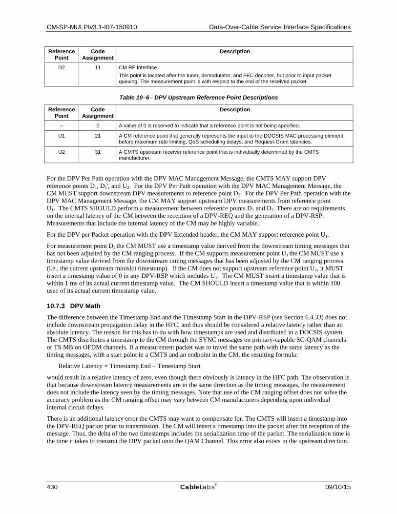
CM-SP-MULPIv3.1-I07-150910 Data-Over-Cable Service Interface Specifications
430 CableLabs 09/10/15
Reference Point
Code Assignment
Description
D2 11 CM RF Interface. This point is located after the tuner, demodulator, and FEC decoder, but prior to input packet queuing. The measurement point is with respect to the end of the received packet.
Table 10–6 - DPV Upstream Reference Point Descriptions
Reference Point
Code Assignment
Description
-- 0 A value of 0 is reserved to indicate that a reference point is not being specified.
U1 21 A CM reference point that generally represents the input to the DOCSIS MAC processing element, before maximum rate limiting, QoS scheduling delays, and Request-Grant latencies.
U2 31 A CMTS upstream receiver reference point that is individually determined by the CMTS manufacturer.
For the DPV Per Path operation with the DPV MAC Management Message, the CMTS MAY support DPV reference points D1, D1', and U2. For the DPV Per Path operation with the DPV MAC Management Message, the CM MUST support downstream DPV measurements to reference point D2. For the DPV Per Path operation with the DPV MAC Management Message, the CM MAY support upstream DPV measurements from reference point U1. The CMTS SHOULD perform a measurement between reference points D1 and D2. There are no requirements on the internal latency of the CM between the reception of a DPV-REQ and the generation of a DPV-RSP. Measurements that include the internal latency of the CM may be highly variable.
For the DPV per Packet operation with the DPV Extended header, the CM MAY support reference point U1.
For measurement point D2 the CM MUST use a timestamp value derived from the downstream timing messages that has not been adjusted by the CM ranging process. If the CM supports measurement point U1 the CM MUST use a timestamp value derived from the downstream timing messages that has been adjusted by the CM ranging process (i.e., the current upstream minislot timestamp). If the CM does not support upstream reference point U1, it MUST insert a timestamp value of 0 in any DPV-RSP which includes U1. The CM MUST insert a timestamp value that is within 1 ms of its actual current timestamp value. The CM SHOULD insert a timestamp value that is within 100 usec of its actual current timestamp value.
10.7.3 DPV Math The difference between the Timestamp End and the Timestamp Start in the DPV-RSP (see Section 6.4.33) does not include downstream propagation delay in the HFC, and thus should be considered a relative latency rather than an absolute latency. The reason for this has to do with how timestamps are used and distributed in a DOCSIS system. The CMTS distributes a timestamp to the CM through the SYNC messages on primary-capable SC-QAM channels or TS MB on OFDM channels. If a measurement packet was to travel the same path with the same latency as the timing messages, with a start point in a CMTS and an endpoint in the CM, the resulting formula:
Relative Latency = Timestamp End – Timestamp Start
would result in a relative latency of zero, even though there obviously is latency in the HFC path. The observation is that because downstream latency measurements are in the same direction as the timing messages, the measurement does not include the latency seen by the timing messages. Note that use of the CM ranging offset does not solve the accuracy problem as the CM ranging offset may vary between CM manufacturers depending upon individual internal circuit delays.
There is an additional latency error the CMTS may want to compensate for. The CMTS will insert a timestamp into the DPV-REQ packet prior to transmission. The CM will insert a timestamp into the packet after the reception of the message. Thus, the delta of the two timestamps includes the serialization time of the packet. The serialization time is the time it takes to transmit the DPV packet onto the QAM Channel. This error also exists in the upstream direction.

MAC and Upper Layer Protocols Interface Specification CM-SP-MULPIv3.1-I07-150910
09/10/15 CableLabs 431
The difference between any two relative latency measurements can be considered as a valid skew measurement. As such, skew can be measured between two flows within or across QAM Channels. This is intended to be useful for detecting congestion latency in an M-CMTS EQAM and determining its impact upon downstream resequencing.
There is no bound on the CM internal processing time between reception of the DPV-REQ message and the transmission of the DPV-RSP. As such, any round-trip latency measurement includes this implementation-specific (and possibly variable) processing time, and cannot be used to accurately compare round trip times between devices.
When the CM needs to calculate the average latency, it uses a running average. If N is held constant, the type of running average in the formula is known as an exponential moving average (EMA). An EMA places a heavier weight on more recent samples as opposed to a simple moving average (SMA) which places an equal weight on all samples. The CM MUST use the following formula for its running average latency calculations:
Average Latency' = Average Latency + Alpha * (Last Measured Latency – Average Latency)
where:
Alpha = 1 / N
Average Latency' represents the updated value of Average Latency. The value of N is supplied in the DPV-REQ message. N can be dynamically chosen by the CMTS such that Alpha is a number between 0 and 1 and represents a weighting for the current sample, relative to the weight given to the accumulated average.
10.7.4 DPV Per Path Operation The DPV Per Path feature is appropriate for sampling the latency of a particular data path and for generating long term averages. DPV Per Path measurements can be made independent of the data packet flow.
Latency measurements may be useful in the downstream direction for several applications, including the determination of the skew of a bonding group by comparing latency between different QAM Channels within the bonding group.
The DPV Per Path operation is achieved through the use of two unique MAC management messages. The first message, DPV-REQ is sent from the CMTS to the CM. The second message, DPV-RSP is sent from the CM to the CMTS. All measurements are originated by the CMTS. There is an Echo bit within the DPV-REQ header which indicates to the CM that it should generate a DPV-RSP.
When the CMTS wants to make a latency measurement, it generates a DPV-REQ MAC management message. The latency measurement is done between two reference points known as the start reference point and the end reference point. The start reference point may be any supported reference point in the downstream or upstream direction. The end reference point may be any supported reference point, but MUST be a point that occurs after the indicated start reference point.
For measurements that start and end in the downstream direction, the CM MUST maintain two independent sets of statistics per Downstream QAM Channel each of which reflect:
• Last Measured Latency: This contains the most recent latency measurement. • Minimum Latency: This contains the lowest latency value measured since the last clearing of the DPV
statistics. • Maximum Latency: This contains the highest latency value measured since the last clearing of the DPV
statistics. • Average Latency: This contains a running average of the latency value over the entire history of measurements
since the last clearing of the DPV statistics (see Section 10.7.3).
The two sets of statistics permit different downstream flows to be compared. The CMTS indicates in which statistics set a particular measurement should be included. The CMTS can also reset the statistics with the DPV-REQ message. These values MUST be readable through the CM MIB.

CM-SP-MULPIv3.1-I07-150910 Data-Over-Cable Service Interface Specifications
432 CableLabs 09/10/15
This allows the CMTS to pursue two different measurement techniques. The CMTS could send a measurement packet with the echo bit set, and perform analysis at the CMTS on each measurement. Alternatively, the CMTS could send a series of measurement packets with the echo bit not set, and have the CM perform the measurement analysis. The results could then be retrieved by the CMTS from the CM as needed.
10.7.4.1 DPV Ping A specific usage of DPV Per Path Operation is known as a "DPV Ping". A DPV Ping consists of a DPV MAC message exchange with the Echo bit asserted and with the remaining parameter values of DPV-REQ and DPV-RSP cleared except the transaction ID.
10.7.5 DPV Per Packet Operation The DPV Per Packet operation is appropriate for determining the maximum and minimum latency seen by the packets of a particular service flow. DPV Per Packet operation can only be performed when data packets are present in the service flow.
The DPV Per Packet operation is performed by having the source device generate and append a DPV Extended Header to each packet it transmits on a given service flow or flows. The receiving device is presumed to be a network sniffer or other diagnostic device. The CM DPV Per Packet operation is enabled and disabled through the CM MIB. The CMTS and CM are not required to perform any action upon the reception of the DPV extended header.
It should be noted that if the DPV extended header is enabled on a UGS flow in the upstream, that the UGS scheduling at the CMTS will have to be modified to accommodate the increased packet size. How this is achieved is outside the scope of this specification.
10.8 DOCSIS Time Protocol
10.8.1 DTP Overview The DOCSIS Time Protocol (DTP) is a set of techniques coupled with extensions to the DOCSIS signaling messages. The CMTS MAY support DTP. The CM MAY support DTP.
DTP allows the timing and frequency system of DOCSIS to be interfaced to external timing protocols with high accuracy. Once the CMTS has a legitimate frequency and time source, DTP allows the source to be replicated at the egress port of the CM. This concept is illustrated in Figure 10–48.
Figure 10–48 - DOCSIS Time Protocol System Overview
The CMTS is either self-synchronized or is synchronized to an external source. Examples of external sources for the CMTS could include [IEEE 1588-2008], Synchronous Ethernet (SyncE), DOCSIS Timing Interface (DTI), Global Positioning System (GPS), Network Time Protocol (NTP), or some combination of these protocols. Examples of external timing interfaces that the CM could support are [IEEE 1588-2008], SyncE, and NTP on its CMCI port.

MAC and Upper Layer Protocols Interface Specification CM-SP-MULPIv3.1-I07-150910
09/10/15 CableLabs 433
To ensure precise synchronization between networks, such as the NSI or DTI port on the CMTS and the CMCI port on the CM, a fixed latency path is required. Such a path is illustrated with the green blocks in Figure 10–49.
Figure 10–49 - DOCSIS Time Protocol Fixed Latency Path Example
A clocking system contains two basic components – time and frequency. There are several methods for communicating time and frequency between two systems. Protocols like [IEEE 1588-2008] can represent both time and frequency with the same protocol. DOCSIS has a native system that addresses time and frequency synchronization separately.
For the DOCSIS DTP frequency path, the CMTS PLL (Phase-Locked Loop) locks onto the frequency component of the external timing protocol. The output of the CMTS PLL is used to drive the downstream baud rate. The CM receives the baud rate frequency and locks to it with its PLL. The CM PLL then drives the frequency output on the CMCI port (Synchronous Ethernet for example).
For the DOCSIS DTP timestamp path, the CMTS synchronizes its DOCSIS Extended Timestamp to the timestamp of the external protocol. The DOCSIS Extended Timestamp is sent to the CM as part of the DOCSIS protocol where it can then be converted back to any desired format. The DTP protocol that runs between the CMTS and the CM computes the time delay in the downstream path while taking into account the asymmetry of the DOCSIS system. This delay is then added to the timestamp in the CM so that the timestamp that is sent out from the CM closely matches the timestamp received by the CMTS.
The frequency and time accuracy and synchronization internal to the CMTS and the CM is maintained by the DOCSIS System Clock and is simply referred to as "Clock" in the DTP diagrams.
10.8.2 DOCSIS and PTP Clock Types Timing protocols, [IEEE 1588-2008] in particular, define different types of network clocks. In DTP, the CMTS and the CM appear as one DOCSIS system that then interfaces to the outside world. When doing so, the DOCSIS system can assume different types of clocks.
The DOCSIS system can act as a Grandmaster Clock (GC) for a [IEEE 1588-2008] system. A GC is the first origination point of clocking. In such a system, the CMTS would originate time and frequency information. It would pass this information to the CM. The CM would generate [IEEE 1588-2008] signaling.
The DOCSIS system can act as a Boundary Clock (BC). In a BC system, there is only one Grandmaster Clock. The clock is regenerated at each participating network node. In such a system, the CMTS would synchronize to an external [IEEE 1588-2008] source. The CM would sync to the CMTS. The [IEEE 1588-2008] signaling would then be regenerated at the CM. This is the most common mode of operation.
The DOCSIS system can act as a Transparent Clock (TC). In a TC system, there can be multiple GC clocks. In such a system, the CMTS may be synchronized to any or none of the system clocks. The role of the DOCSIS system is to provide correction factors to the separate clock streams as they pass through the CMTS.
The DOCSIS system can act as an Ordinary Clock (OC). In an OC system, the system receives synchronization from a [IEEE 1588-2008] system but does generate [IEEE 1588-2008] compatible clocks. Thus, a DOCSIS system

CM-SP-MULPIv3.1-I07-150910 Data-Over-Cable Service Interface Specifications
434 CableLabs 09/10/15
where the CMTS is synchronized to an external [IEEE 1588-2008] compliant signal and then uses that to generate internal DOCSIS timing would be an OC system.
10.8.3 True Ranging Offset In all timing protocol solutions, the delay through the system has to be measured and added to the timestamp so that the timestamp value is the same at all reference points. The general approach is to measure the round trip delay of a link, account for asymmetry, and then divide by two to derive the one-way delay. Timing protocols do this with a message exchange procedure referred to as TWTT (Two-Way Time Transfer).
This information that the TWTT algorithm is seeking is already built into the DOCSIS system due to the DOCSIS ranging procedure. DTP defines the True Ranging Offset (TRO). The TRO is the measured ranging offset of the CM between two defined reference points. TRO is a measured (or derived) value that is different than the actual implemented ranging offset a CM might use in its communication with the CMTS. TRO has the following characteristic:
• The value of TRO is the equivalent to the round trip delay of the combined downstream and upstream propagation delays of the HFC plant, the CMTS and CM PHY paths.
The TRO is measured at the CM between the following two reference points:
• The value of the unadjusted CM timestamp when the first bit of a packet is transmitted in the upstream direction from the CM at a specific reference point. The measurement is made at a reference point determined by the CM manufacturer that is a fixed delay value from the actual upstream RF output.
• The value of the MAP entry for when the first bit of the same packet is expected to arrive at the CMTS.
Since the measurement is done between the downstream clock path and when an upstream packet is transmitted (after buffering), all jitter and delay from internal packet queues are eliminated from the measurement.
TRO is illustrated in the example in Section 10.8.5.
10.8.4 DTP Math A mathematical representation of the DTP math is shown in Figure 10–50.
Figure 10–50 - DTP Math and Delays
The subscripts used in describing the delays are:
• cmts, hfc, and cm indicate the three basic elements of the system • ds (downstream) and us (upstream) indicate the direction of the media

MAC and Upper Layer Protocols Interface Specification CM-SP-MULPIv3.1-I07-150910
09/10/15 CableLabs 435
• Types of delay: • i = Interface Delay. • o = Offset Delay. This is a known offset due to interleaving or some other configuration. • p = Path Delay. This is a vendor specific characterized delay of the physical circuit path. For the
CMTS and CM, this may be a measured or calibrated value that is supplied as part of calibration. For the HFC plant, this is the value that is calculated as part of the DTP calculations.
• tro = True ranging offset • adj = Adjustment required to align the CM timestamp output to the CMTS timestamp input.
The DTP True Ranging Offset is measured in the CM and communicated from the CM to the CMTS. Figure 10–50 shows TRO at the CMTS because mathematically, it represents the round trip time of the downstream and upstream path. Table 10–7 summarizes the delays in the DTP model.
Table 10–7 - DTP Delays
Delay name Description ts-cmts-in This is the timestamp received at the CMTS on the NSI or DTI port.
t-cmts-ds-i This is the circuit delay from the CMTS clock input interface (DTI or NSI) to the internal CMTS timestamp reference point. This is a manufacturer's value and is supplied by the CMTS.
t-cmts-ds-o This is the known delay contribution in the downstream CMTS PHY path that is associated with configuration elements such as interleaving. This value is known and is supplied by the CMTS.
t-cmts-ds-p This is the intrinsic path delay contribution from the CMTS timestamp reference point to the CMTS downstream PHY output. This is a measured value and supplied by the CMTS.
t-hfc-ds-o This delay represents any fixed delay elements in the HFC path that contribute to delay. One example may be a digitization circuit, optical node and amplifier circuit delays. This value may be unique per HFC path due to different path elements. This value is supplied by the CMTS. By specifying appropriate HFC downstream and upstream offset values correctly and by setting the asymmetry appropriately, the HFC downstream and upstream path delays can be assumed to be equal.
t-hfc-ds-p This is the intrinsic path delay of the fiber and coax elements of the HFC plant. The DTP algorithm calculates this value.
t-cm-ds-o This is the known delay contribution in the downstream CM PHY path that is associated with configuration elements such as interleaving. This value is known and is supplied by the CM or by a CMTS override.
t-cm-ds-p This is the intrinsic path delay contribution from the CM PHY downstream input to the CM timestamp reference point. This is a measured value and supplied by the CM or by a CMTS override.
t-cm-ds-i This is the circuit delay from the internal CM timestamp reference point to the clock output interface (CMCI). This value is manufacturer's value and is supplied by the CM or by a CMTS override.
t-cm-us-o This is the known delay contribution in the upstream CM PHY path that is associated with configuration elements such as interleaving. This value is known and is supplied by the CM or by a CMTS override.
t-cm-us-p This is the intrinsic path delay contribution from the CM timestamp reference point to the CM PHY upstream output. This is a measured value and supplied by the CM or by a CMTS override.
t-hfc-us-o This delay represents any fixed delay elements in the HFC path that contribute to delay. One example may be a digitization circuit, optical node and amplifier circuit delays. This value may be unique per HFC path due to different path elements. This value is supplied by the CMTS.
t-hfc-us-p This is the intrinsic path delay of the fiber and coax elements of the HFC plant exclusive of fixed delay elements. The DTP algorithms calculate this value. The basic DTP algorithm assumes the upstream and downstream path delay are equal by using the offset values to compensate for fixed and asymmetrical delays.
t-cmts-us-o This is the known delay contribution in the downstream CMTS PHY path that is associated with configuration elements such as interleaving. This value is known and is supplied by the CMTS.
t-cmts-us-p This is the intrinsic path delay contribution from the CMTS PHY upstream input to the CMTS timestamp reference point. This is a measured value and supplied by the CMTS.
t-cm-adj This is the value that must be added to the CM unadjusted timestamp to have the CM timestamp be equal to the CMTS timestamp in real time. This value is calculated by the DTP Master.
ts-cm-out This is the adjusted timestamp sent out of the CM on its CMCI port.

CM-SP-MULPIv3.1-I07-150910 Data-Over-Cable Service Interface Specifications
436 CableLabs 09/10/15
From Figure 10–50 and Table 10–7, it can be observed that:
t-tro = t-cmts-ds-o + t-cmts-ds-p + t-hfc-ds-o + t-hfc-ds-p + t-cm-d-o + t-cm-ds-p + t-cm-us-o + t-cm-us-p + t-hfc-us-o + t-hfc-us-p + t-cmts-us-o + t-cmts-us-p
The variables t-hfc-ds-o and t-hfc-us-o are chosen to model both fixed delays and any path asymmetry between the upstream and downstream HFC transmission paths. This allows the assumption to be made that the remaining path delay from the hfc downstream path and the hfc upstream paths are equal. Hence:
t-hfc-us-p = t-hfc-ds-p
Substituting this assumption into the above formula yields:
t-tro = t-cmts-ds-o + t-cmts-ds-p + t-hfc-ds-o +(2 * t-hfc-ds-p) + t-cm-d-o + t-cm-ds-p + t-cm-us-o + t-cm-us-p + t-hfc-us-o + t-cmts-us-o + t-cmts-us-p
Now solving for the measured downstream HFC path delay yields:
t-hfc-ds-p = (t-tro – t-cmts-ds-o – t-cmts-ds-p – t-hfc-ds-o – t-cm-d-o – t-cm-ds-p – t-cm-us-o – t-cm-us-p – t-hfc-us-o – t-cmts-us-o – t-cmts-us-p) / 2
If the timestamp at the CM is to be aligned to the timestamp at the CMTS, then:
It can be observed from the downstream path in Figure 10–50 that:
ts-cm-out - ts-cmts-in = t-cmts-ds-i + t-cmts-ds-o + t-cmts-ds-p + t-hfc-ds-o + t-hfc-ds-p + t-cm-d-o + t-cm-ds-p + t-cm-ds-i - t-cm-adj
Setting the differences between the two timestamps to zero, and solving for t-cm-adj yields:
t-cm-adj = t-cmts-ds-i + t-cmts-ds-o + t-cmts-ds-p + t-hfc-ds-o + t-hfc-ds-p + t-cm-d-o + t-cm-ds-p + t-cm-ds-i
Other variations of the circuits, delays, and formula are possible, depending upon the specific implementation of the CMTS and CM clocking circuits. However, for compatibility, the CMTS and the CM SHOULD provide parameters consistent this approach.

MAC and Upper Layer Protocols Interface Specification CM-SP-MULPIv3.1-I07-150910
09/10/15 CableLabs 437
10.8.5 DTP Example An example that shows the relationship between DTP math and the DTP True Ranging Offset is shown in Figure 10–51.
Figure 10–51 - True Ranging Offset Example
In this example, all the final values are shown. The number used are arbitrary and are for the sake of illustration. Each element (CMTS, HFC, CM) in each direction (DS, US) has both an offset (O) delay and a path delay (P). The system is fully ranged so that the CM has chosen an internal ranging offset that causes the upstream packet to be transmitted at a time that allows the packet to arrive at the CMTS at the right time.
The DTP math algorithms were run with the following results:
• True Ranging Offset as measured at CM = 7000 – 4300 = 2700 ns • t-hfc-ds-p = (2700 – (500 + 25 + 0 + 25 + 500 + 20 + 30 + 50 + 30 + 20)) / 2 = 750 ns • t-cm-adj = 0 + 500 + 25 + 750 + 0 + 25 + 500 + 0 = 1800
When observing the final results, it can be seen that the round trip delay is the same as the measured TRO.
• Round Trip Delay = 500 + 25 + 750 + 25 + 500 + 20 + 30 + 50 + 750 + 30 + 20 = 2700 ns

CM-SP-MULPIv3.1-I07-150910 Data-Over-Cable Service Interface Specifications
438 CableLabs 09/10/15
It can also be seen that the calculated offset equals the need offset.
• Offset Needed = 2000 – 200 = 1800 ns
10.8.6 DTP Signaling The goal of DTP is to generate a time adjustment (t-adj) that can be added to the native timestamp of the CM to create a timestamp that matches the CMTS timestamp in real time.
Either the CMTS or the CM can perform the DTP calculations. The entity performing the calculation is known as the DTP Master. The other entity is known as the DTP Slave. The DTP Master initiates all signaling in a DTP transaction. When the CMTS is DTP Master and thus performs the DTP calculations, the CMTS MUST initiate the DTP signaling. This is shown in Figure 10–52 when the CM is DTP Master and thus manages the DTP calculations, the CM MUST initiate the DTP signaling. This is shown in Figure 10–53. Values in italics are information values.
Figure 10–52 - CMTS is DTP Master
Figure 10–53 - CM is DTP Master
If the CM is the DTP Master and thus is doing the DTP calculations, and the CMTS provides override values for the CM timing parameters, the CM MUST use the CMTS provided timing parameters rather than CM internal timing parameters.
10.8.7 DTP Configuration CM and CMTS support for DTP varies. The CMTS and CM might support DTP Master Mode, DTP Slave Mode, or no DTP operation.
DOCSIS Time Protocol is enabled and configured via the DOCSIS Time Protocol Mode modem capability. The CM reports which DOCSIS Time Protocol Modes it supports using the DOCSIS Time Protocol Mode modem capability.
The CMTS returns the DOCSIS Time Protocol Mode in the modem capability field. If the CM reports no support for DOCSIS Time Protocol, the CMTS MUST return a value of zero in the DOCSIS Time Protocol Mode. If the CM reports support for one or both of the DOCSIS Time Protocol Modes, the CMTS can disable DOCSIS Time Protocol by overriding with a value of zero or the CMTS can enable a DOCSIS Time Protocol Mode which is

MAC and Upper Layer Protocols Interface Specification CM-SP-MULPIv3.1-I07-150910
09/10/15 CableLabs 439
supported by the modem. The CMTS MUST NOT return a value in the DOCSIS Time Protocol Mode that enables a DOCSIS Time Protocol Mode that is unsupported by the CM.
DOCSIS Time Protocol is enabled if the CMTS returns a non-zero value for the DOCSIS Time Protocol Mode.
10.8.8 DTP System Level Performance The goal of a DTP system is to enable the efficient and accurate transfer of an external timing protocol across a DOCSIS system.
Figure 10–54 - DTP System Performance
Figure 10–54 shows a DTP system that couples a timing protocol from the NSI or DTI port of the CMTS to the CMCI port of two CMs. The external timing protocol originates from a single source and is delivered over a distribution network to two separate CMTSs. Each CMTS drives a separate HFC network segment which each connect to separate CMs. These CMs forward the timing protocol to end devices.
This transfer of the external timing protocol from one source across two paths may introduce timing errors in the form of latency, jitter and skew. The latency is managed and compensated for through the DTP protocol, but there can still be a latency error between two systems. The combined system timing errors due to latency variation, jitter and skew are described in Table 10–8 below.
Table 10–8 - DTP System Parameters for Jitter and Skew
Name Description
T-cmts-error This is the variance in delay that the CMTS causes as measured from the clocking ingress port (NSI or DTI) to the CMTS DOCSIS egress.
T-cm-error This is the variation in delay that the CM introduces as measured from the CM DOCSIS ingress port to the CM CMCI egress port.
T-docsis-error This is the timing error introduced by the combination of the CMTS and CM. This value is tested with a zero length HFC plant. T-docsis-error = T-cmts-error + T-cm-error
T-source-skew This is the max allowable difference in arrival time of a reference timing source at the NSI ports of two CMTSs that exist within the same timing system.
T-hfc-error This is the latency error introduced by the modeling of the HFC plant.
T-cm-cm-skew The is the skew that can occur between two similar reference points at the timing egress points on the two CMs. T-cm-cm-skew = 2 * T-docsis-error + T-source-skew + T-hfc-error
The jitter and skew budget depend upon the desired accuracy of the DTP system. The potential sources of error and suggested target values are defined and shown in Table 10–9. In these budgets, timing error refers to operational

CM-SP-MULPIv3.1-I07-150910 Data-Over-Cable Service Interface Specifications
440 CableLabs 09/10/15
timing error that is seen within an operating period and not the timing error that may occur between system resets or during a system failure and recovery where the HFC network or the CMTS path delays may change. This is the timing error that occurs after the DTP protocol has compensated for latency. The timing error may actually be a result of the dynamic operation of the DTP protocol, the differences between the compensation in two DTP systems, as well as errors due to inaccurate characterization and measurement of the various network elements and network components.
Table 10–9 - DTP System Timing Error Budget
Parameter Level I System
Level II System
Level III System
Level IV System
Level V System
T-cmts-error ± 20 ns ± 40 ns ± 100 ns ± 200 ns ± 500 ns
T-cm-error ± 20 ns ± 40 ns ± 100 ns ± 200 ns ± 500 ns
T-docsis-error ± 40 ns ± 80 ns ± 200 ns ± 400 ns ± 1000 ns
T-source-skew 5 ns 10 ns 25 ns 50 ns 500 ns
T-hfc-error 15 ns 30 ns 75 ns 150 ns 500 ns
T-cm-cm-skew 100 ns 200 ns 500 ns 1000 ns 3000 ns
Table 10–9 provides a suggested distribution of the system timing error budget between the CMTS, the CM, the timing distribution network feeding the CMTS, and the maximum error from the model for the HFC plant. Table 10–9 also includes target latency accuracy numbers for the CMTS and CM sub-system as well as the overall system.
The values in Table 10–9 are driven by current known market requirements at the time of writing and may change as the market requirements and product capabilities evolve. This table represents a framework for relating a system solution to its various component solutions.
• Level 1 was driven by GPS location requirements • Level 2 was driven by LTE Advanced • Level 3 was driven by LTE • Level 4 was driven by classic cellular • Level 5 was driven by current DOCSIS implementation technology.
DOCSIS compliance is measured as a CMTS and CM sub-system. When DOCSIS compliance is tested, the T-source-skew and T-hfc-error are set to zero or compensated for. Compliance can be tested by observing the difference between:
1. A timestamp or the equivalent at the ingress to the CMTS and a timestamp or the equivalent at the egress of the CM.
2. A timestamp or the equivalent at the egress of CM 1 and a timestamp or the equivalent at the egress of CM 2.
The ability of a complete DOCSIS system as shown in Figure 10–54 to meet the target CM to CM skew numbers depends upon the operator's ability to properly characterized the HFC plant.
A DTP Level V system, when composed of two separate CMTS and CM paths, is required to meet the T-docsis-error requirements of a DTP Level V system 99% of the time.
A DTP Level IV system, when composed of two separate CMTS and CM paths, is required to meet the T-docsis-error requirements of a DTP Level IV system 99% of the time.
A DTP Level III system, when composed of two separate CMTS and CM paths, is required to meet the T-docsis-error requirements of a DTP Level III system 99% of the time.
A DTP Level II system, when composed of two separate CMTS and CM paths, is required to meet the T-docsis-error requirements of a DTP Level II system 99% of the time.

MAC and Upper Layer Protocols Interface Specification CM-SP-MULPIv3.1-I07-150910
09/10/15 CableLabs 441
A DTP Level I system, when composed of two separate CMTS and CM paths, is required to meet the T-docsis-error requirements of a DTP Level I system 99% of the time.

CM-SP-MULPIv3.1-I07-150910 Data-Over-Cable Service Interface Specifications
442 CableLabs 09/10/15
11 DYNAMIC OPERATIONS
11.1 Upstream Channel Descriptor Changes
Whenever the CMTS is to change any of the upstream burst characteristics specified in the Upstream Channel Descriptor (UCD) message (see Section 6.4.3), it needs to provide for an orderly transition from the old values to the new values by all CMs. Whenever the CMTS is to change any of the upstream characteristics, it MUST announce the new values in an UCD message and increment the Configuration Change Count field in that UCD message to indicate that a value has changed. However, the CMTS MUST NOT start the UCD change process on an US channel if one or more CMs using this channel are still handling a previously initiated management transaction (like previous UCD change, DBC, DCC, etc.) that involves this US.
After transmitting one or more UCD messages with the new change count value for each UCD type to be used for this US, the CMTS transmits a MAP message with a UCD Change Count matching the new Configuration Change Count.
The CMTS MUST transmit this MAP message in which the first interval is a data grant to the null Service ID of at least 1.5 ms for a TDMA channel or for the longer of 1.5 ms or the duration of 2 S-CDMA frames for an S-CDMA channel (to allow for the latency of the S-CDMA framing). The CMTS MUST transmit this MAP message in which the first interval is a data grant to the null Service ID of at least 2 ms per OFDMA channel. When the change affects an S-CDMA channel, the CMTS MUST ensure that the Start Time of the MAP with the new UCD Change Count corresponds to the beginning of an S-CDMA frame. When the change affects an OFDMA channel, the CMTS MUST ensure that the Start Time of the MAP with the new UCD Change Count corresponds to the beginning of an OFDMA frame.
The CMTS MUST allow this time for cable modems to change their PMD sublayer parameters to match the new set. This time is independent of the lead time the CMTS needed to allow for in transmitting the MAP (see Section 7.2.1.6). The CMTS MUST transmit the new UCD message early enough that the CM receives the UCD message at least the UCD Processing Time (see Annex B) prior to the time the first MAP using the new UCD parameters arrives at the CM.
With the exception of the following cases the CM MUST be able to transmit normally on the first grant following the grant to the NULL SID:
1. When the new UCD message has changed the S-CDMA Enable parameter.
2. When the new UCD message has changed the S-CDMA US Ratio Numerator or Denominator.
3. When UCD changes for multiple upstream channels within the TCS take effect within 1.5 ms of each other for S-CDMA and TDMA channels or within 2.0 ms of each other for OFDMA channels as described by the MAP messages.
4. When the new UCD message has changed the OFDMA Cyclic Prefix Size parameter.
5. When the new UCD message has changed the Subcarrier Spacing parameter for an OFDMA channel.
In cases 1, 2, 4, and 5, the CM MAY redo initial ranging to establish timing synchronization for the new mode of operation before it resumes normal transmissions. If the CM was already registered with the CMTS, and it redoes initial ranging for either of these reasons, it MUST use its Ranging SID instead of the initialization SID for the initial ranging process and not re-register. In the 3rd case, the CM MUST be able to transmit normally by a time calculated as follows [(1.5 ms * the number of US TDMA and S-CDMA channels in the TCS that have been changed within 1.5 ms of each other) + (2.0ms * the number of US OFDMA channels in the TCS that have been changed within that same time period)]. For example, if the changes for 3 TDMA channels within the TCS take effect simultaneously, the CM would have 4.5 ms to make all of the changes. If the CM receives a data grant during this reconfiguration period, it MAY ignore the grant and re-request for the bandwidth.
Additionally, using the Ranging Required parameter in the new UCD message the CMTS can force the CM to perform ranging prior to making any other transmissions using the parameters in the new UCD message. In certain cases, channel wide parameter changes (in particular, Modulation Rate or Center Frequency) may invalidate pre-equalization and synchronization parameters and normal operation may not be possible without re-ranging. If the
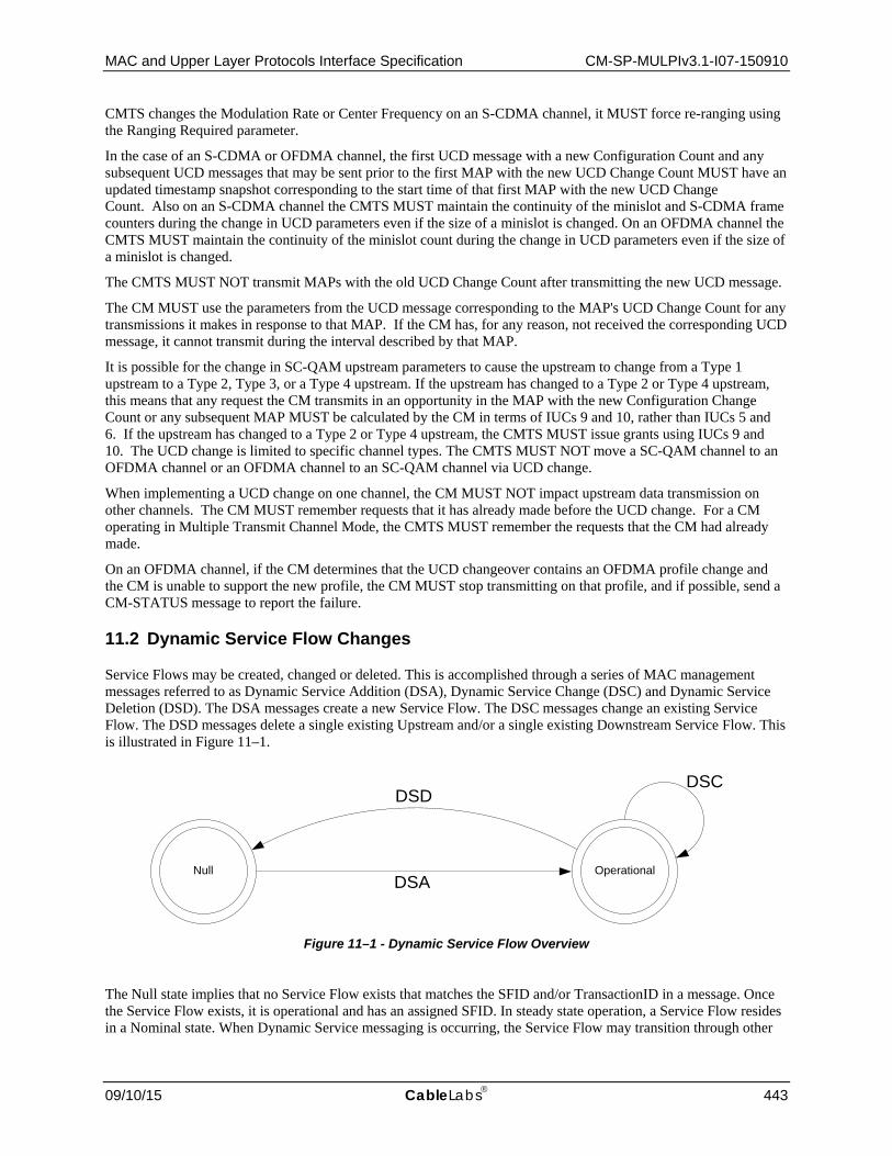
MAC and Upper Layer Protocols Interface Specification CM-SP-MULPIv3.1-I07-150910
09/10/15 CableLabs 443
CMTS changes the Modulation Rate or Center Frequency on an S-CDMA channel, it MUST force re-ranging using the Ranging Required parameter.
In the case of an S-CDMA or OFDMA channel, the first UCD message with a new Configuration Count and any subsequent UCD messages that may be sent prior to the first MAP with the new UCD Change Count MUST have an updated timestamp snapshot corresponding to the start time of that first MAP with the new UCD Change Count. Also on an S-CDMA channel the CMTS MUST maintain the continuity of the minislot and S-CDMA frame counters during the change in UCD parameters even if the size of a minislot is changed. On an OFDMA channel the CMTS MUST maintain the continuity of the minislot count during the change in UCD parameters even if the size of a minislot is changed.
The CMTS MUST NOT transmit MAPs with the old UCD Change Count after transmitting the new UCD message.
The CM MUST use the parameters from the UCD message corresponding to the MAP's UCD Change Count for any transmissions it makes in response to that MAP. If the CM has, for any reason, not received the corresponding UCD message, it cannot transmit during the interval described by that MAP.
It is possible for the change in SC-QAM upstream parameters to cause the upstream to change from a Type 1 upstream to a Type 2, Type 3, or a Type 4 upstream. If the upstream has changed to a Type 2 or Type 4 upstream, this means that any request the CM transmits in an opportunity in the MAP with the new Configuration Change Count or any subsequent MAP MUST be calculated by the CM in terms of IUCs 9 and 10, rather than IUCs 5 and 6. If the upstream has changed to a Type 2 or Type 4 upstream, the CMTS MUST issue grants using IUCs 9 and 10. The UCD change is limited to specific channel types. The CMTS MUST NOT move a SC-QAM channel to an OFDMA channel or an OFDMA channel to an SC-QAM channel via UCD change.
When implementing a UCD change on one channel, the CM MUST NOT impact upstream data transmission on other channels. The CM MUST remember requests that it has already made before the UCD change. For a CM operating in Multiple Transmit Channel Mode, the CMTS MUST remember the requests that the CM had already made.
On an OFDMA channel, if the CM determines that the UCD changeover contains an OFDMA profile change and the CM is unable to support the new profile, the CM MUST stop transmitting on that profile, and if possible, send a CM-STATUS message to report the failure.
11.2 Dynamic Service Flow Changes
Service Flows may be created, changed or deleted. This is accomplished through a series of MAC management messages referred to as Dynamic Service Addition (DSA), Dynamic Service Change (DSC) and Dynamic Service Deletion (DSD). The DSA messages create a new Service Flow. The DSC messages change an existing Service Flow. The DSD messages delete a single existing Upstream and/or a single existing Downstream Service Flow. This is illustrated in Figure 11–1.
Figure 11–1 - Dynamic Service Flow Overview
The Null state implies that no Service Flow exists that matches the SFID and/or TransactionID in a message. Once the Service Flow exists, it is operational and has an assigned SFID. In steady state operation, a Service Flow resides in a Nominal state. When Dynamic Service messaging is occurring, the Service Flow may transition through other
texttextNull OperationalDSA
DSDDSC

CM-SP-MULPIv3.1-I07-150910 Data-Over-Cable Service Interface Specifications
444 CableLabs 09/10/15
states, but remains operational. Since multiple Service Flows may exist, there may be multiple state machines active, one for every Service Flow. Dynamic Service messages only affect those state machines that match both the SFID and Transaction ID or SFID only. For a Dynamic Service Change that is modifying an Upstream Drop Classifier, the Service Flow is conceptually the NULL Service Flow and is not signaled in the message. A Transaction ID which is reused for other SFID(s) indicates that the other side terminated the previous transaction. If a Dynamic Service request message is received which refers to the same Transaction ID as one that has already been processed, but service flow(s) other than those locked in this transaction, the device MAY trigger a DSx Ended input to the state machine(s) of SF(s) involved in the previous transaction. If privacy is enabled, both the CM and CMTS MUST verify the HMAC digest on all dynamic service messages before processing them, and discard any messages that fail.
Service Flows created at registration time effectively enter the SF_operational state without a DSA transaction.
TransactionIDs are unique per transaction and are selected by the initiating device (CM or CMTS). To help prevent ambiguity and provide simple checking, the TransactionID number space is split between the CM and CMTS. The CM MUST select its TransactionIDs from the first half of the number space (0x0000 to 0x7FFF). The CMTS MUST select its TransactionIDs from the second half of the number space (0x8000 to 0xFFFF).
Each dynamic service message sequence is a unique transaction with an associated unique transaction identifier. To help support transaction identifier uniqueness between two devices in different states, the CM or CMTS initiating the transaction SHOULD change the transaction identifier for each new initiated transaction. The CM or CMTS initiating the transaction MUST wait at least T10 to re-use the transaction identifier. The DSA/DSC transactions consist of a request/response/acknowledge sequence. In the case of a DSC message that is modifying an Upstream Drop Classifier, the acknowledge is not required and its absence does not result in a failed transaction. The DSD transactions consist of a request/response sequence. The response messages transmitted by the CM or CMTS MUST contain a confirmation code of okay unless some exception condition was detected. The acknowledge messages transmitted by the CM or CMTS MUST include the confirmation code in the response unless a new exception condition arises. A more detailed state diagram, including transition states, is shown in Figure 11–2. The detailed actions for each transaction are given in the following sections.
11.2.1 Dynamic Service Flow State Transitions The Dynamic Service Flow State Transition Diagram, Figure 11–2, is the top-level state diagram and controls the general Service Flow state. As needed, it creates transactions, each represented by a Transaction state transition diagram, to provide the DSA, DSC, and DSD signaling. Each Transaction state transition diagram only communicates with the parent Dynamic Service Flow State Transition Diagram. The top-level state transition diagram filters Dynamic Service messages and passes them to the appropriate transaction based on Service Flow Identifier (SFID), Service Flow Reference number, and TransactionID.
If a single Dynamic Service message affects a pair of service flows, a single transaction is initiated which communicates with both parent Dynamic Service Flow State Transition Diagrams. In this case, both service flows MUST remain locked in the same state by the CM and CMTS until they receive the DSx Succeeded or DSx Failed input from the DSx Transaction State Transition Diagram. During that "lock interval", if a message is received which refers to only one of the two service flows, it MUST be treated by the CM and CMTS as if it refers to both service flows, so that both service flows stay in the same state. If a DSD-REQ message is received during the lock interval which refers to only one of the two service flows, the CM or CMTS MUST handle the event normally, by sending the SF Delete-Remote to the ongoing DSx Transaction and by initiating a DSD-Remote transaction. In addition, the CM or CMTS MUST initiate a DSD-Local transaction to delete the second service flow of the locked pair.
If a DSC Request is received which refers to two service flows locked in different transactions, and they are in different states, the CM or CMTS MUST reject the request without affecting the ongoing transactions.
There are six different types of transactions: locally initiated or remotely initiated for each of the DSA, DSC and DSD messages. Most transactions have three basic states: pending, holding and deleting. The pending state is typically entered after creation and is where the transaction is waiting for a reply. The holding state is typically entered once the reply is received. The purpose of this state is to allow for retransmissions in case of a lost message, even though the local entity has perceived that the transaction has completed. The deleting state is only entered if the Service Flow is being deleted while a transaction is being processed.

MAC and Upper Layer Protocols Interface Specification CM-SP-MULPIv3.1-I07-150910
09/10/15 CableLabs 445
The flow diagrams provide a detailed representation of each of the states in the Transaction state transition diagrams. All valid transitions are shown. Any inputs not shown should be handled as a severe error condition.
With one exception, these state diagrams apply equally to the CMTS and CM. In the Dynamic Service Flow Changing-Local state, there is a subtle difference in the CM and CMTS behaviors. This is called out in the state transition and detailed flow diagrams.
NOTE: The 'Num Xacts' variable in the Dynamic Service Flow State Transition Diagram is incremented every time the top-level state diagram creates a transaction and is decremented every time a transaction terminates. A Dynamic Service Flow MUST NOT return to the Null state until it's deleted and all transactions have terminated.
The inputs for the state diagrams are identified below.
Dynamic Service Flow State Transition Diagram inputs from unspecified local, higher-level entities:
• Add • Change • Delete
Dynamic Service Flow State Transition Diagram inputs from DSx Transaction State Transition diagrams:
• DSA Succeeded • DSA Failed • DSA ACK Lost • DSA Erred • DSA Ended • DSC Succeeded • DSC Failed • DSC ACK Lost • DSC Erred • DSC Ended • DSD Succeeded • DSD Erred • DSD Ended
DSx Transaction State Transition diagram inputs from the Dynamic Service Flow State Transition Diagram:
• SF Add • SF Change • SF Delete • SF Abort Add • SF Change-Remote • SF Delete-Local • SF Delete-Remote • SF DSA-ACK Lost • SF-DSC-REQ Lost • SF-DSC-ACK Lost • SF DSD-REQ Lost • SF Changed • SF Deleted
The creation of DSx Transactions by the Dynamic Service Flow State Transition Diagram is indicated by the notation:

CM-SP-MULPIv3.1-I07-150910 Data-Over-Cable Service Interface Specifications
446 CableLabs 09/10/15
DSx-[ Local | Remote ] ( initial_input )
where initial_input may be SF Add, DSA-REQ, SF Change, DSC-REQ, SF Delete, or DSD-REQ depending on the transaction type and initiator.
Figure 11–2 - Dynamic Service Flow State Transition Diagram
Null
AddingLocal Add Failed Adding
Remote
Nominal
ChangingLocal
ChangingRemote
Deleting
Deleted
DSA-REQ /DSA-Remote( DSA-REQ )DSA Ended /Add / DSA-Local( SF Add )
DSA Succeeded /DSA Succeeded /
( DSA Failed / )( Delete / SF Abort Add )(DSA Erred/)
DSA Failed /
DSC-REQ / SF DSA-ACK Lost
New DSC-REQ /SF DSC-ACK Lost
( DSC-REQ / )( DSA ACK Lost / SF DSD-REQ Lost )( DSC ACK Lost / SF DSD-REQ Lost )
( DSC-REQ / [ CMTS Only ] )( DSA ACK Lost / SF DSC-REQ Lost )( DSC ACK Lost / SF DSC-REQ Lost )
( DSD Succeeded / SF Deleted )( DSD Erred / SF Deleted )
DSD-REQ / SF Delete-Remote, DSD-Remote( DSD-REQ )
( DSA Erred / DSD-Local( SF Delete ) )( Delete / SF Delete-Local, DSD-Local( SF Delete ) )
Delete /SF Delete-Local,DSD-Local( SF Delete )
DSD Ended &&Num Xacts == 0 /
( DSC Erred / SF Delete-Local, DSD-Local( SF Delete ) )( Delete / SF Delete-Local, DSD-Local( SF Delete ) )
( DSC Erred / DSD-Local( SF Delete ) )( Delete / SF Delete-Local, DSD-Local( SF Delete ) )
Change /DSC-Local( SF Change )
( DSC Succeeded / SF Changed )( DSC Failed / SF Changed )
( DSC Succeeded / SF Changed )( DSC Failed / SF Changed )
DSC-REQ /SF Change-Remote,DSC-Remote( DSC-REQ )
DSC-REQ / SF Change-Remote,DSC-Remote( DSC-REQ ) [ CM Only ]
DSD Succeeded / SF Deleted

MAC and Upper Layer Protocols Interface Specification CM-SP-MULPIv3.1-I07-150910
09/10/15 CableLabs 447
Figure 11–3 - DSA-Locally Initiated Transaction State Transition Diagram
Begin
DSA-RSPPending Timeout T7 & Retries Available / DSA-REQ
SF Add / DSA-REQ
Timeout T7 & Retries Exhausted /
End
HoldingDown
DeletingService Flow
RetriesExhausted
(DSA-RSP / DSA Succeeded, DSA-ACK)(DSA-RSP / DSA Failed, DSA-ACK)(SF Abort Add /)
(DSA-RSP / DSA Succeeded, DSA-ACK)(DSA-RSP / DSA Failed, DSA-ACK)(SF Abort Add /)
(Timeout T10 / DSA Ended)(SF Changed / DSA Ended)(SF Change-Remote / DSA Ended)
SF Delete-Local /
DSA-RSP / DSA-ACK, DSA ACK Lost
(Timeout T10 / DSA Ended)(SF Deleted / DSA Ended)
Timeout T10 / DSA Errored,DSA Ended
SF Delete-Remote / DSA Ended
DSA-RSP / DSA ACK Lost

CM-SP-MULPIv3.1-I07-150910 Data-Over-Cable Service Interface Specifications
448 CableLabs 09/10/15
Figure 11–4 - DSA-Remotely Initiated Transaction State Transition Diagram
Begin
DSA-ACKPending
(Timeout T8 & Retries Available / DSA-RSP)(DSA-REQ & Retries Available / DSA-RSP)(DSA-REQ & Retries Exhausted /)(SF DSA-ACK Lost & Retries Available / DSA-RSP)(SF DSA-ACK Lost & Retries Exhausted / )
(DSA-REQ / DSA-RSP)(DSA-REQ / DSA Failed, DSA-RSP)
Timeout T8 & Retries Exhausted / DSA Errored, DSA Ended)(SF Delete-Remote / DSA Ended)
End
HoldingDown
DeletingService Flow
(DSA-ACK / DSA Succeeded)(DSA-ACK / DSA Failed)
(Timeout T8 / DSA Ended)(SF Changed / DSA Ended)(SF Deleted / DSA Ended)(SF Delete-Remote / DSA Ended)
SF Delete-Local /
(Timeout T10 / DSA Ended)(SF Deleted / DSA Ended)(SF Delete-Remote / DSA Ended)
(DSA-REQ / )(DSA ACK / )
(DSA-ACK / )(SF Delete-Local / )(SF Change-Remote / )

MAC and Upper Layer Protocols Interface Specification CM-SP-MULPIv3.1-I07-150910
09/10/15 CableLabs 449
Figure 11–5 - DSC-Locally Initiated Transaction State Transition Diagram
Begin
DSC-RSPPending
(Timeout T7 & Retries Available / DSC-REQ)(SF DSC-REQ Lost & Retries Available / DSC-REQ)(SF DSC-REQ Lost & Retries Exhausted / )
SF Change / DSC-REQ
Timeout T7 & Retries Exhausted /
End
HoldingDown
DeletingService Flow
(DSC-RSP / DSC Succeeded, DSC-ACK)(DSC-RSP / DSC Failed, DSC-ACK)
(Timeout T10 / DSC Ended)(SF Changed / DSC Ended)(SF Delete-Remote / DSC Ended)
SF Delete-Local /
(Timeout T10 / DSC Ended)(SF Deleted / DSC Ended)
DSC-RSP / DSC ACK Lost
DSC-RSP /DSC-ACK, DSC ACK Lost /
RetriesExhausted
(DSC-RSP / DSC Succeeded, DSC-ACK)(DSC-RSP / DSC Failed, DSC-ACK)
Timeout T10 /DSC Erred, DSC Ended
SF Delete-Remote / DSC Ended
SF Change-Remote / DSC Ended [CM Only]
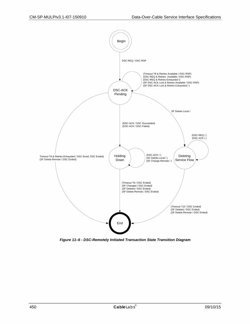
CM-SP-MULPIv3.1-I07-150910 Data-Over-Cable Service Interface Specifications
450 CableLabs 09/10/15
Figure 11–6 - DSC-Remotely Initiated Transaction State Transition Diagram
Begin
DSC-ACKPending
(Timeout T8 & Retries Available / DSC-RSP)(DSC-REQ & Retries Available / DSC-RSP)(DSC-REQ & Retries Exhausted /)(SF DSC-ACK Lost & Retries Available / DSC-RSP)(SF DSC-ACK Lost & Retries Exhausted / )
DSC-REQ / DSC-RSP
Timeout T8 & Retries Exhausted / DSC Erred, DSC Ended)(SF Delete-Remote / DSC Ended)
End
HoldingDown
DeletingService Flow
(DSC-ACK / DSC Succeeded)(DSC-ACK / DSC Failed)
(Timeout T8 / DSC Ended)(SF Changed / DSC Ended)(SF Deleted / DSC Ended)(SF Delete-Remote / DSC Ended)
SF Delete-Local /
(Timeout T10 / DSC Ended)(SF Deleted / DSC Ended)(SF Delete-Remote / DSC Ended)
(DSC-REQ / )(DSC ACK / )
(DSC-ACK / )(SF Delete-Local / )(SF Change-Remote / )

MAC and Upper Layer Protocols Interface Specification CM-SP-MULPIv3.1-I07-150910
09/10/15 CableLabs 451
Figure 11–7 - DSD-Locally Initiated Transaction State Transition Diagram
Begin
DSD-RSPPending
(Timeout T7 & Retries Available / DSD-REQ)(SF DSD-REQ Lost & Retries Available / DSD-REQ)(SF DSD-REQ Lost & Retries Exhausted / )
SF Delete / DSD-REQ
Timeout T7 & Retries Exhausted / DSD Erred, DSD Ended
End
HoldingDown
(DSD-RSP / DSD Succeeded)(SF Delete-Remote / )
Timeout T7 / DSD Ended
(DSD-RSP / DSD Succeeded )(SF Deleted / )
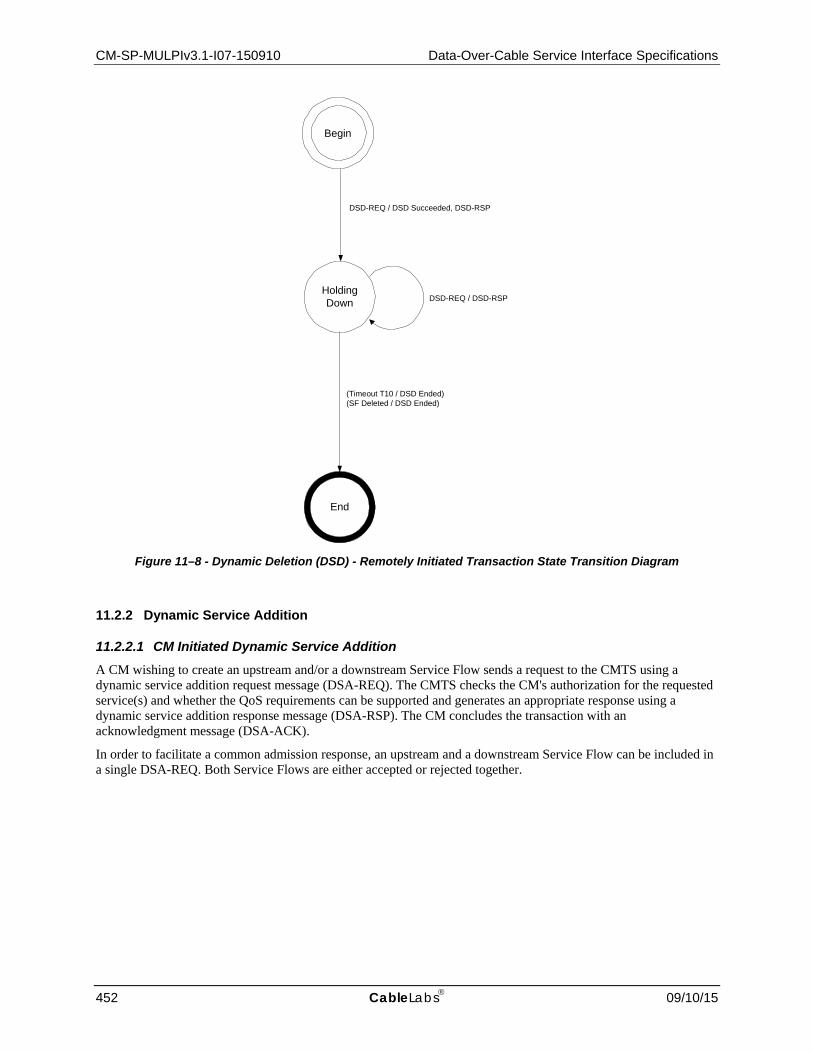
CM-SP-MULPIv3.1-I07-150910 Data-Over-Cable Service Interface Specifications
452 CableLabs 09/10/15
Figure 11–8 - Dynamic Deletion (DSD) - Remotely Initiated Transaction State Transition Diagram
11.2.2 Dynamic Service Addition
11.2.2.1 CM Initiated Dynamic Service Addition A CM wishing to create an upstream and/or a downstream Service Flow sends a request to the CMTS using a dynamic service addition request message (DSA-REQ). The CMTS checks the CM's authorization for the requested service(s) and whether the QoS requirements can be supported and generates an appropriate response using a dynamic service addition response message (DSA-RSP). The CM concludes the transaction with an acknowledgment message (DSA-ACK).
In order to facilitate a common admission response, an upstream and a downstream Service Flow can be included in a single DSA-REQ. Both Service Flows are either accepted or rejected together.
DSD-REQ / DSD Succeeded, DSD-RSP
End
HoldingDown
(Timeout T10 / DSD Ended)(SF Deleted / DSD Ended)
DSD-REQ / DSD-RSP
Begin

MAC and Upper Layer Protocols Interface Specification CM-SP-MULPIv3.1-I07-150910
09/10/15 CableLabs 453
CM CMTS
New Service Flow(s) needed
Check if resources are available
Send DSA-REQ ---DSA-REQ--> Receive DSA-REQ
Check if CM authorized for Service(s)110
Check Service Flow(s) QoS can be supported
Create SFID(s)
If upstream AdmittedQoSParamSet is non-null, Create SID or SID Cluster Group
If upstream ActiveQoSParamSet is non-null, Enable reception of data on new upstream Service Flow
Receive DSA-RSP <--DSA-RSP--- Send DSA-RSP
If ActiveQoSParamSet is non-null, Enable transmission and/or reception of data on new Service Flow(s)
Send DSA-ACK ---DSA-ACK--> Receive DSA-ACK
If downstream ActiveQoSParamSet is non-null, Enable transmission of data on new downstream Service Flow
Figure 11–9 - Dynamic Service Addition Initiated from CM
11.2.2.2 CMTS Initiated Dynamic Service Addition A CMTS wishing to establish an upstream and/or a downstream dynamic Service Flow(s) with a CM performs the following operations. The CMTS checks the authorization of the destination CM for the requested class of service and whether the QoS requirements can be supported. If the service can be supported the CMTS generates new SFID(s) with the required class of service and informs the CM using a dynamic service addition request message (DSA-REQ). The CM checks that it can support the service and responds using a dynamic service addition response message (DSA-RSP). The transaction completes with the CMTS sending the acknowledge message (DSA-ACK).
110 Note: Authorization can happen prior to the DSA-REQ being received by the CMTS. The details of CMTS signaling to
anticipate a DSA-REQ are beyond the scope of this specification.

CM-SP-MULPIv3.1-I07-150910 Data-Over-Cable Service Interface Specifications
454 CableLabs 09/10/15
CM CMTS
New Service Flow(s) required for CM
Check CM authorized for Service(s)
Check Service Flow(s) QoS can be supported
Create SFID(s)
If upstream AdmittedQoSParamSet is non-null, Create SID or SID Cluster Group
If upstream ActiveQoSParamSet is non-null, Enable reception of data on new upstream Service Flow
Receive DSA-REQ <--DSA-REQ--- Send DSA-REQ
Confirm CM can support Service Flow(s)
Add Downstream SFID (if present)
Enable reception on any new downstream Service Flow
Send DSA-RSP ---DSA-RSP--> Receive DSA-RSP
Enable transmission and reception of data on new Service Flow(s)
Receive DSA-ACK <--DSA-ACK--- Send DSA-ACK
Enable transmission on new upstream Service Flow
Figure 11–10 - Dynamic Service Addition Initiated from CMTS

MAC and Upper Layer Protocols Interface Specification CM-SP-MULPIv3.1-I07-150910
09/10/15 CableLabs 455
Dynamic Service Addition State Transition Diagrams
Figure 11–11 - DSA-Locally Initiated Transaction Begin State Flow Diagram
SF Add
DSA-LocalBegin
DSA-REQ
Start T7 Timer
Save transmittedDSA-REQ
Set DSA-REQ Retries Available to ‘DSx Request Retries”
DSA-LocalDSA-RSPPending

CM-SP-MULPIv3.1-I07-150910 Data-Over-Cable Service Interface Specifications
456 CableLabs 09/10/15
Figure 11–12 - DSA-Locally Initiated Transaction DSA-RSP Pending State Flow Diagram
DSA-LocalDSA-RSPPending
Timeout T7 SF Delete-Remote
SF Abort Add
DSA-RSP
DSA-LocalEnd
DSA-LocalDSA-RSPPending
DSA-LocalRetries
Exhausted
DSA Failed
DSA-LocalHolding Down
RetriesAvailable?
No
Yes
SavedDSA-REQ
Start T7 Timer
DecrementDSA-REQ
Retries Available
Start T10 Timer
Stop T7 Timer
DSA Ended
Stop T7 Timer
Save DSA-ACK with Condition
Code ‘reject-add-aborted’
Stop T7 Timer
Okay?
NoYes
Enable Service Flow
DSA Succeeded
Set ConditionCode to ‘reject-xxx’
Set ConditionCode to ‘okay’
DSA-ACK
Save transmitted DSA-ACK
Start T10 Timer

MAC and Upper Layer Protocols Interface Specification CM-SP-MULPIv3.1-I07-150910
09/10/15 CableLabs 457
Figure 11–13 - DSA-Locally Initiated Transaction Holding State Flow Diagram
DSA-LocalHolding Down
SF Changed,SF Change-RemoteSF Delete-Remote
Timeout T10 SF DeleteLocal
DSA-RSP
Stop T10 Timer
DSA Ended
SavedDSA-ACK
DSA-LocalEnd
DSA-LocalDeleting
Service Flow
DSA ACKLost
DSA-LocalHolding Down

CM-SP-MULPIv3.1-I07-150910 Data-Over-Cable Service Interface Specifications
458 CableLabs 09/10/15
Figure 11–14 - DSA-Locally Initiated Transaction Retries Exhausted State Flow Diagram
Timeout T10 SF Delete-Remote
SF Abort Add
DSA-RSP
DSA Failed
DSA - LocalHolding Down
Okay?
NoYes
Enable Service Flow
DSA Succeeded
Set ConditionCode to ‘reject-xxx’
Set ConditionCode to ‘okay’
DSA-ACK
Save transmitted DSA -ACK
DSA -LocalEnd
DSA Errored
DSA Ended
DSA-LocalRetries Exhausted
Stop T10 Timer
Save DSA-ACKwith ConditionCode ‘reject-add-aborted’

MAC and Upper Layer Protocols Interface Specification CM-SP-MULPIv3.1-I07-150910
09/10/15 CableLabs 459
Figure 11–15 - DSA-Locally Initiated Transaction Deleting Service Flow State Flow Diagram
SF Deleted, SF Delete-
RemoteTimeout T10 DSA-RSP
DSA - LocalEnd
DSA Ended
DSA-LocalDeleting
Service Flow
Stop T10 Timer DSA ACKLost
DSA-LocalDeleting
Service Flow

CM-SP-MULPIv3.1-I07-150910 Data-Over-Cable Service Interface Specifications
460 CableLabs 09/10/15
Figure 11–16 - DSA-Remotely Initiated Transaction Begin State Flow Diagram
DSA-RSP
DSA-RemoteBegin
DSA Failed
DSA-RemoteDSA-ACKPending
DSA-REQ
Okay?
[CM Only]Enable downstream
service flow
Yes
No
Set ConditionCode to ‘reject-
xxx’
[CMTS Only]Enable upstream
service flow
Set ConditionCode to ‘okay’
Start T8 Timer
Save transmitted DSA-RSP
Set DSA-RSP Retries Available to
‘DSx Response Retries’

MAC and Upper Layer Protocols Interface Specification CM-SP-MULPIv3.1-I07-150910
09/10/15 CableLabs 461
Figure 11–17 - DSA-Remotely Initiated Transaction DSA-ACK Pending State Flow Diagram

CM-SP-MULPIv3.1-I07-150910 Data-Over-Cable Service Interface Specifications
462 CableLabs 09/10/15
Figure 11–18 - DSA-Remotely Initiated Transaction Holding Down State Flow Diagram
DSA-RemoteHolding Down
DSA Ended
DSA-RemoteEnd
SF Changed,SF Deleted,
SF Delete-RemoteTimeout T8
SF Delete-Local,SF Change-
RemoteDSA-ACK
DSA-Remote Holding Down
Stop T8 Timer

MAC and Upper Layer Protocols Interface Specification CM-SP-MULPIv3.1-I07-150910
09/10/15 CableLabs 463
Figure 11–19 - DSA-Remotely Initiated Transaction Deleting Service State Flow Diagram
11.2.3 Dynamic Service Change111 The Dynamic Service Change (DSC) set of messages is used to modify the flow parameters associated with a Service Flow or a set of Upstream Drop Classifiers. Conceptually, Upstream Drop Classifiers are associated with a NULL Service Flow that is not signaled in the messages. Specifically, DSC can:
• Modify the Service Flow Specification or a set of Upstream Drop Classifiers • Add, Delete or Replace a Flow Classifier or a set of Upstream Drop Classifiers
A single DSC message exchange can modify the parameters of one downstream service flow and/or one upstream service flow. A single DSC message can modify multiple Upstream Drop Classifiers. If a CMTS is sending a DSC message that is modifying Upstream Drop Classifiers, it MUST NOT modify downstream or upstream Service Flow parameters. If a DSC is changing an Upstream Drop Classifier, then the term Service Flow used below, refers to the conceptual NULL Service Flow.
To prevent packet loss, any change to the bandwidth parameters of a Service Flow needs to be coordinated between the application generating the data and the DSC that modifies the Service Flow. Because MAC messages can be lost, the timing of Service Flow parameter changes can vary, and it occurs at different times in the CM and CMTS. Applications should reduce their transmitted data bandwidth before initiating a DSC to reduce the Service Flow bandwidth, and should not increase their transmitted data bandwidth until after the completion of a DSC increasing the Service Flow bandwidth.
The CMTS controls both upstream and downstream scheduling. Scheduling is based on data transmission requests and is subject to the limits contained in the current Service Flow parameters at the CMTS. The timing of Service Flow parameter changes, and any consequent scheduling changes, is independent of both direction and whether
111 Updated per MULPIv3.1-14.1204-1 on 12/2/14 by PO.
DSA-RemoteDeleting Service
Flow
DSA Ended
DSA-RemoteEnd
SF Deleted,SF Delete-Remote Timeout T10 DSA-REQ
DSA-ACK
DSA-Remote Deleting
Service Flow
Stop T10 Timer

CM-SP-MULPIv3.1-I07-150910 Data-Over-Cable Service Interface Specifications
464 CableLabs 09/10/15
there is an increase or decrease in bandwidth. The CMTS changes Service Flow parameters on receipt of a DSC-REQ (CM-initiated transaction) or DSC-RSP (CMTS-initiated transaction).
The CMTS also controls the downstream transmit behavior. The change in downstream transmit behavior is always coincident with the change in downstream scheduling (i.e., CMTS controls both and changes both simultaneously).
The CM controls the upstream transmit requests, subject to limits contained in the current Service Flow parameters at the CM. The timing of Service Flow parameter changes in the CM, and any consequent CM transmit request behavior changes, is a function of which device initiated the transaction. The CM changes Service Flow parameters on receipt of a DSC-REQ (CMTS-initiated transaction) or DSC-RSP (CM-initiated transaction).
Any service flow can be deactivated with a Dynamic Service Change command by sending a DSC-REQ message, referencing the Service Flow Identifier, and including a null ActiveQoSParameterSet. However, if a Primary Service Flow of a CM is deactivated that CM is de-registered and MUST re-register. Therefore, care should be taken before deactivating such Service Flows. If a Service Flow that was provisioned during registration is deactivated, the provisioning information for that Service Flow MUST be maintained until the Service Flow is reactivated.
A CM MUST have only one DSC transaction outstanding per Service Flow. If it detects a second transaction initiated by the CMTS, the CM MUST abort the transaction it initiated and allow the CMTS initiated transaction to complete.
A CMTS MUST have only one DSC transaction outstanding per Service Flow. If it detects a second transaction initiated by the CM, the CMTS MUST abort the transaction the CM initiated and allow the CMTS initiated transaction to complete.
NOTE: Currently anticipated applications would probably control a Service Flow through either the CM or CMTS, and not both. Therefore the case of a DSC being initiated simultaneously by the CM and CMTS is considered as an exception condition and treated as one.
11.2.3.1 CM-Initiated Dynamic Service Change A CM that needs to change a Service Flow definition performs the following operations.
The CM informs the CMTS using a Dynamic Service Change Request message (DSC-REQ). The CMTS MUST decide if the referenced Service Flow can support this modification. The CMTS MUST respond with a Dynamic Service Change Response (DSC-RSP) indicating acceptance or rejection. The CM reconfigures the Service Flow if appropriate, and then MUST respond with a Dynamic Service Change Acknowledge (DSC-ACK).
CMTS CM
Service Flow Requires Modifying
Receive DSC-REQ <--------- DSC-REQ ---------- Send DSC-REQ
Validate Request
Modify Service Flow
Send DSC-RSP ---------- DSC-RSP ---------> Receive DSC-RSP
Modify Service Flow
Receive DSC-ACK <--------- DSC-ACK ---------- Send DSC-ACK
Figure 11–20 - CM-Initiated DSC

MAC and Upper Layer Protocols Interface Specification CM-SP-MULPIv3.1-I07-150910
09/10/15 CableLabs 465
11.2.3.2 CMTS-Initiated Dynamic Service Change A CMTS initiated DSC transaction that is changing Upstream Drop Classifiers does not require the CMTS to send a DSC-ACK after receiving a DSC-RSP from the CM. This is different from a CMTS initiated DSC transaction that is modifying a Service Flow and results from the fact that the CM cannot send a DSD if the transaction fails. The following paragraphs describe the DSC Transactions for a CMTS initiated DSC that is modifying a Service Flow versus a CMTS initiated DSC transaction that is modifying an Upstream Drop Classifier.
A CMTS that needs to change a Service Flow definition performs the following operations.
The CMTS MUST decide if the referenced Service Flow can support this modification. If so, the CMTS informs the CM using a Dynamic Service Change Request message (DSC-REQ). The CM checks that it can support the service change, and MUST respond using a Dynamic Service Change Response (DSC-RSP) indicating acceptance or rejection. The CMTS reconfigures the Service Flow if appropriate, and then MUST respond with a Dynamic Service Change Acknowledgment (DSC-ACK).
CMTS CM
Service Flow Requires Modifying
Send DSC-REQ ---------- DSC-REQ ---------> Receive DSC-REQ
Modify Service Flow
Receive DSC-RSP <--------- DSC-RSP ---------- Send DSC-RSP
Modify Service Flow
Send DSC-ACK ---------- DSC-ACK ---------> Receive DSC-ACK
Figure 11–21 - CMTS-Initiated DSC Modifying a Service Flow
A CMTS that needs to change an Upstream Drop Classifier performs the following operations.
The CMTS informs the CM of the additions or modifications to the Upstream Drop Classifiers using a Dynamic Service Change Request message (DSC-REQ). The CM checks that it can support the service change, and MUST respond using a Dynamic Service Change Response (DSC-RSP) indicating acceptance or rejection. The CMTS updates any state information that it is maintaining concerning the Upstream Drop Classifiers that the CM is using. The CMTS MAY send a Dynamic Service Change Acknowledgment (DSC-ACK). The CM MUST NOT delete the Upstream Drop Classifiers in the case that it does not receive a DSC-ACK message after sending the DSC-RSP.
CMTS CM
Upstream Drop Classifiers Require Modification
Send DSC-REQ ---------- DSC-REQ ---------> Receive DSC-REQ
Add or Modify the UDCs Receive DSC-RSP <--------- DSC-RSP ---------- Send DSC-RSP
Update any state information
Figure 11–22 - CMTS-Initiated DSC Modifying an Upstream Drop Classifier

CM-SP-MULPIv3.1-I07-150910 Data-Over-Cable Service Interface Specifications
466 CableLabs 09/10/15
11.2.3.3 Dynamic Service Change State Transition Diagrams
Figure 11–23 - DSC-Locally Initiated Transaction Begin State Flow Diagram

MAC and Upper Layer Protocols Interface Specification CM-SP-MULPIv3.1-I07-150910
09/10/15 CableLabs 467
Figure 11–24 - DSC-Locally Initiated Transaction DSC-RSP Pending State Flow Diagram
SF Delete-Local DSC-RSP
Stop T7 Timer
Start T10 Timer
DSC-LocalDeleting
Service Flow
Stop T7 Timer
Restoreservice flowQoS State
DSC Failed
Set ConditionCode to 'reject-xxx'
DSC-LocalDSC-RSPPending
Okay ?
No Yes
DSCSucceeded
Set ConditionCode to 'okay'
DSC-ACK
Save transmittedDSC-ACK
Start T10 Timer
DSC-LocalHolding Down
ModifyService FlowParameters
SF DSC-REQLost
SF Change-Remote
[ CM Only ]
SF Delete-Remote
DSC-LocalEnd
Stop T7 Timer
DSC Ended
Timeout T7
RetriesAvailable
?
Yes
No
Start T10 Timer
DSC-LocalRetries Exhausted
DSC-LocalDSC-RSPPending
DecrementDSC-REQ
Retries Available
SavedDSC-REQ
Start T7 Timer
RetriesAvailable
?
No Yes
SavedDSC-REQ

CM-SP-MULPIv3.1-I07-150910 Data-Over-Cable Service Interface Specifications
468 CableLabs 09/10/15
Figure 11–25 - DSC-Locally Initiated Transaction Holding Down State Flow Diagram

MAC and Upper Layer Protocols Interface Specification CM-SP-MULPIv3.1-I07-150910
09/10/15 CableLabs 469
Figure 11–26 - DSC-Locally Initiated Transaction Retries Exhausted State Flow Diagram
DSC-LocalRetries Exhausted
DSC-RSPSF Delete-LocalSF Delete-RemoteTimeout T10
Stop T10 TimerDSC Erred
DSC Ended
DSC-LocalEnd
DSC-LocalDeleting
Service Flow
Okay ?
Yes
ModifyService Flowparameters
Set ConditionCode to 'okay'
DSC-ACK
Save transmittedDSC-ACK
DSC-LocalHolding Down
DSCSucceeded
No
Restoreservice flowQoS state
DSC Failed
Set ConditionCode to 'reject-xxx'

CM-SP-MULPIv3.1-I07-150910 Data-Over-Cable Service Interface Specifications
470 CableLabs 09/10/15
Figure 11–27 - DSC-Locally Initiated Transaction Deleting Service Flow State Flow Diagram
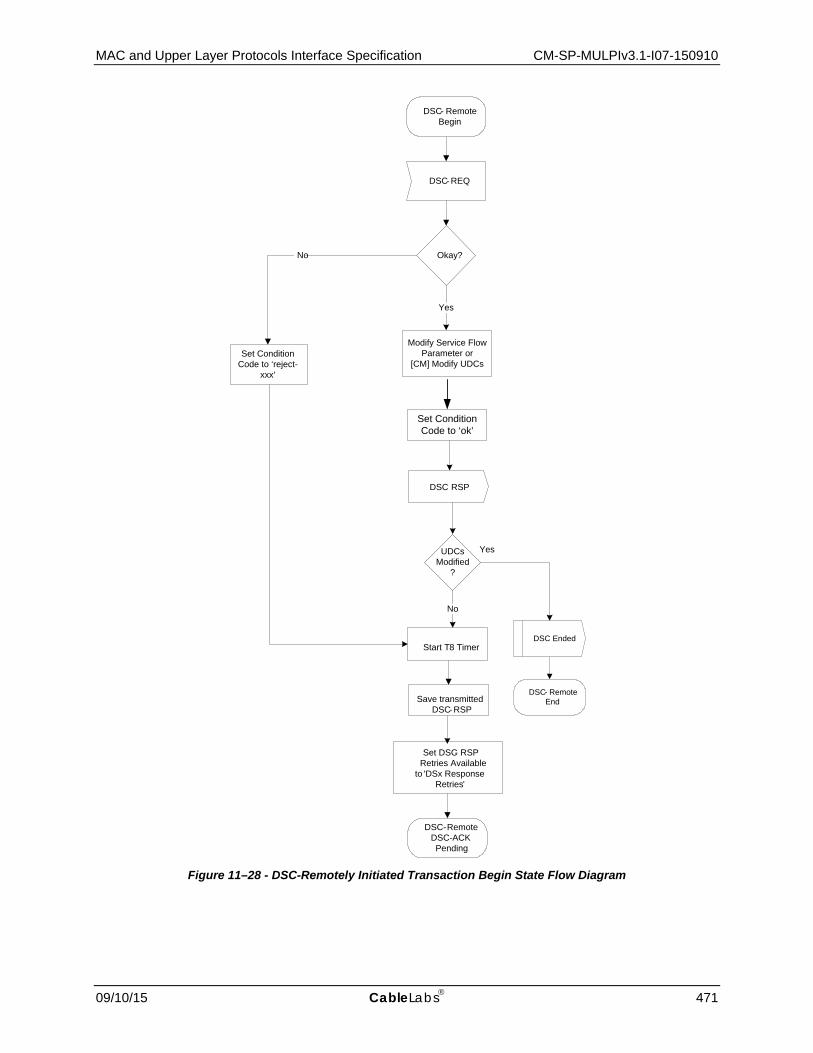
MAC and Upper Layer Protocols Interface Specification CM-SP-MULPIv3.1-I07-150910
09/10/15 CableLabs 471
Figure 11–28 - DSC-Remotely Initiated Transaction Begin State Flow Diagram
DSC- RemoteBegin
DSC-REQ
No
Set Condition Code to ‘ok’
DSC-RemoteDSC-ACKPending
Set DSC- RSP Retries Available
to 'DSx Response Retries'
DSC RSP
Start T8 Timer
Save transmittedDSC-RSP
Okay ?
Modify Service Flow Parameter or
[CM] Modify UDCs
Yes
Set Condition Code to ‘reject-
xxx’
UDCs Modified
?
No
DSC- RemoteEnd
DSC Ended
Yes

CM-SP-MULPIv3.1-I07-150910 Data-Over-Cable Service Interface Specifications
472 CableLabs 09/10/15
Figure 11–29 - DSC-Remotely Initiated Transaction DSC-ACK Pending State Flow Diagram
DSC-RemoteDSC-ACKPending
SF Delete-Local
Stop T8 Timer
Start T10 Timer
DSC-RemoteDeleting
Service Flow
DSC-ACK
Stop T8 Timer
Okay ?No
Yes
Restoreservice flow
DSC Failed
DSCSucceeded
Start T8 Timer
DSC-RemoteHolding Down
DSC-REQ SF DSC-ACKLost
SF Delete-Remote
Stop T8 Timer
Timeout T8
RetriesAvailable
?
Yes
No
DSC-RemoteDSC-ACKPending
DSC Erred
DSC-RemoteEnd
DSC Ended
DecrementDSC-RSP
Retries Available
SavedDSC-RSP
Start T8 Timer
RetriesAvailable
?
NoYes
SavedDSC-RSP
(CM Only)Enable
UpstreamService Flow
(CMTS Only)Enable
DownstreamService Flow

MAC and Upper Layer Protocols Interface Specification CM-SP-MULPIv3.1-I07-150910
09/10/15 CableLabs 473
Figure 11–30 - DSC-Remotely Initiated Transaction Holding Down State Flow Diagram
Figure 11–31 - DSC-Remotely Initiated Transaction Deleting Service Flow State Flow Diagram
DSC-RemoteHolding Down
DSC Ended
DSC-RemoteEnd
SF Changed,SF Deleted,
SF Delete-RemoteTimeout T8 DSC-ACK
DSC-Remote Holding Down
Stop T8 Timer
SF Delete-Local,SF Change-
Remote
DSC-RemoteDeleting
Service Flow
DSC Ended
DSC-RemoteEnd
SF Deleted,SF Delete-Remote Timeout T10
DSC-REQDSC-ACK
DSC-Remote Deleting
Service Flow
Stop T10 Timer

CM-SP-MULPIv3.1-I07-150910 Data-Over-Cable Service Interface Specifications
474 CableLabs 09/10/15
11.2.4 Dynamic Service Deletion112 Any service flow can be deleted with the Dynamic Service Deletion (DSD) messages. When a Service Flow (either provisioned or dynamically created) is deleted, all resources associated with it are released, including classifiers and SID Clusters. If a Primary Service Flow of a CM is deleted, that CM is de-registered and MUST re-register. However, the deletion of a provisioned Service Flow other than the Primary Service Flow MUST NOT cause a CM to re-register.
11.2.4.1 CM Initiated Dynamic Service Deletion A CM wishing to delete an upstream and/or a downstream Service Flow generates a delete request to the CMTS using a Dynamic Service Deletion-Request message (DSD-REQ). The CMTS removes the Service Flow(s) and generates a response using a Dynamic Service Deletion-Response message (DSD-RSP). Only one upstream and/or one downstream Service Flow can be deleted per DSD-Request.
CM CMTS
Service Flow(s) no longer needed
Delete Service Flow(s)
Send DSD-REQ ---DSD-REQ--> Receive DSD-REQ
Verify CM is Service Flow(s) 'owner'
Delete Service Flow(s)
Receive DSD-RSP <--DSD-RSP--- Send DSD-RSP
Figure 11–32 - Dynamic Service Deletion Initiated from CM
11.2.4.2 CMTS Initiated Dynamic Service Deletion A CMTS wishing to delete an upstream and/or a downstream dynamic Service Flow generates a delete request to the associated CM using a Dynamic Service Deletion-Request message (DSD-REQ). The CM removes the Service Flow(s) and generates a response using a Dynamic Service Deletion-Response message (DSD-RSP). Only one upstream and/or one downstream Service Flow can be deleted per DSD-Request.
CM CMTS
Service Flow(s) no longer needed
Delete Service Flow(s)
Determine associated CM for this Service Flow(s)
Receive DSD-REQ <---DSD-REQ--- Send DSD-REQ
Delete Service Flow(s)
Send DSD-RSP ---DSD-RSP--> Receive DSD-RSP
Figure 11–33 - Dynamic Service Deletion Initiated from CMTS
112 Updated per MULPIv3.1-14.1204-1 on 12/2/14 by PO.

MAC and Upper Layer Protocols Interface Specification CM-SP-MULPIv3.1-I07-150910
09/10/15 CableLabs 475
Dynamic Service Deletion State Transition Diagrams
Figure 11–34 - DSD-Locally Initiated Transaction Begin State Flow Diagram
DSD-LocalBegin
Disable ServiceFlow
SF Delete
DSD-LocalDSD-RSPPending
DSD-REQ
Start T7 Timer
Save transmittedDSD-REQ
Set DSD-REQRetries Availableto ‘DSx Request
Retries’

CM-SP-MULPIv3.1-I07-150910 Data-Over-Cable Service Interface Specifications
476 CableLabs 09/10/15
Figure 11–35 - DSD-Locally Initiated Transaction DSD-RSP Pending State Flow Diagram
DSD-LocalDSD-RSPPending
DSD-RSP
Stop T7 Timer
DSDSucceeded
Start T7 Timer
DSD-LocalHolding Down
SF DSD-REQLost
SF Delete-Remote
Stop T7 Timer
Timeout T7
RetriesAvailable
?
DSD-RemoteDSD-RSPPending
DSD Erred
DSD-LocalEnd
DSD Ended
DecrementDSD-REQ
Retries Available
SavedDSD-REQ
Start T7 Timer
RetriesAvailable
?
SavedDSD-REQ
YesYes
No
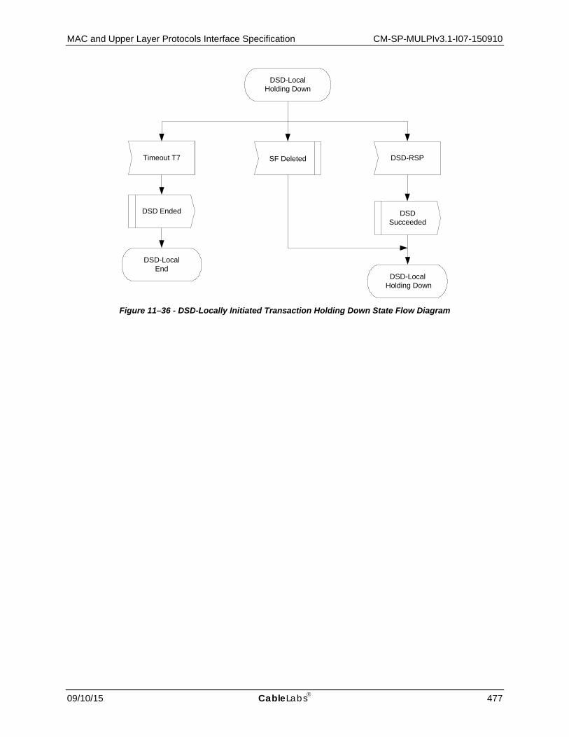
MAC and Upper Layer Protocols Interface Specification CM-SP-MULPIv3.1-I07-150910
09/10/15 CableLabs 477
Figure 11–36 - DSD-Locally Initiated Transaction Holding Down State Flow Diagram
DSD-LocalHolding Down
DSD Ended
DSD-LocalEnd
Timeout T7 SF Deleted DSD-RSP
DSD-Local Holding Down
DSD Succeeded

CM-SP-MULPIv3.1-I07-150910 Data-Over-Cable Service Interface Specifications
478 CableLabs 09/10/15
Figure 11–37 - DSD-Remotely Initiated Transaction Begin State Flow Diagram
DSD-RemoteBegin
DSD RSP
DSD-REQ
DSD-Remote Holding Down
DSD Succeeded
Disable Service
Flow
Start T10 Timer
Save transmitted DSD-RSP

MAC and Upper Layer Protocols Interface Specification CM-SP-MULPIv3.1-I07-150910
09/10/15 CableLabs 479
Figure 11–38 - DSD-Remotely Initiated Transaction Holding Down State Flow Diagram
11.3 Pre-3.0 DOCSIS Upstream Channel Changes
This section is obsoleted as UCC support is no longer needed for D31.
11.4 Dynamic Downstream and/or Upstream Channel Changes
11.4.1 DCC General Operation113 The Dynamic Channel Change (DCC) mechanism is intended for changing the MAC Domain of a DOCSIS 3.1 CM. At any time after registration that the CMTS needs to change a DOCSIS 3.1 CM's MAC domain, the CMTS MUST use the DCC-REQ message.
As required in Section 6.4.20.1.3, if the CMTS sends a DCC-REQ to change the MAC Domain of a DOCSIS 3.1 CM, the CMTS will specify the Initialization Technique TLV that reinitializes the CM MAC.
If a CM receives a DCC-REQ message with an initialization technique other than initialization technique 0 (reinitialize MAC), the CM MUST reject the DCC-REQ by sending a DCC-RSP with a confirmation code of "reject-invalid-initialization-technique" to the CMTS (refer to Annex C). The CM MUST execute the departure from the old channel before the expiry of T13. The CM MUST follow the procedure shown in Figure 11–43 when performing a dynamic channel change.
For pre-DOCSIS 3.1 CMs, the DCC mechanism is intended for the following situations:
• changing the downstream channel and/or upstream channel of a CM not operating in Multiple Receive Channel mode;
113 Updated by MULPIv3.1-N-15.1269-1 on 3/9/15 by PO.
DSD-RemoteHolding Down
DSD Ended
DSD-RemoteEnd
Timeout T10 DSD-REQ
DSD-Remote Holding Down
SavedDSD-RSP
SF Deleted
Stop T10 Timer

CM-SP-MULPIv3.1-I07-150910 Data-Over-Cable Service Interface Specifications
480 CableLabs 09/10/15
• changing the MAC Domain of a DOCSIS 3.0 CM operating in both Multiple Receive Channel mode and Multiple Transmit Channel Mode; and
• changing the upstream channel of a CM which was not assigned a Transmit Channel Configuration in the registration process and is thus not operating in Multiple Transmit Channel mode.
At any time after registration, the CMTS MAY use the DCC-REQ message to direct a pre-DOCSIS 3.1 CM not operating in Multiple Receive Channel mode to change its upstream and/or downstream channel. At any time after registration, the CMTS may use the DCC-REQ message to direct a pre-DOCSIS 3.1 CM to which a Transmit Channel Configuration was not assigned in the registration process to change its upstream channel. The CMTS MUST be capable of performing DCC operations to trigger upstream and/or downstream channel changes to pre-DOCSIS 3.1 CMs within a MAC domain and between MAC domains for pre-DOCSIS 3.1 CMs not operating in Multiple Receive Channel mode. The CMTS MUST be capable of performing DCC operations to a DOCSIS 3.0 CM operating in Multiple Receive Channel mode to force it to reinitialize in a different MAC Domain. The CMTS MUST be capable of performing DCC operations to a pre-DOCSIS 3.1 CM which has not received a Transmit Channel Configuration in the registration process to force it to change its upstream channel. For a DOCSIS 3.0 CM operating in Multiple Receive Channel mode, the CMTS will use Dynamic Bonding Change (DBC) messaging to change downstream channels within a MAC domain. For a DOCSIS 3.0 CM to which a Transmit Channel Configuration was assigned in the registration process, the CMTS uses Dynamic Bonding Change (DBC) messaging to change upstream channels within a MAC domain.
Physical layer conditions permitting, the CMTS MUST be capable of executing Dynamic Channel Changes using all Initialization Techniques for pre-DOCSIS 3.1 CMs not operating in Multiple Receive Channel mode (see Section 11.4.1.2). This may be done for load balancing (as described in Section 11.6), noise avoidance, or other reasons that are beyond the scope of this specification. In addition, the CMTS supports DCC operations triggered via external means as specified by [DOCSIS OSSIv3.0]. Figure 11–39 through Figure 11–42 show the procedure that MUST be followed by the CMTS when performing a dynamic channel change.
The DCC command can be used to change only the upstream frequency, only the downstream frequency, or both the upstream and downstream frequencies. When only the upstream or only the downstream frequency is changed, the change is within a MAC domain. When both the upstream and downstream frequencies are changed, the change may be within a MAC domain, or between MAC domains.
When moving a pre-DOCSIS 3.1 CM within a MAC domain, or when moving a pre-DOCSIS 3.1 CM to a new MAC domain with initialization technique other than zero, the CMTS MUST assign different Upstream Channel IDs for the old and new channels. In this context, the old channel refers to the channel that the CM was on before the jump, and the new channel refers to the channel that the CM is on after the jump.
If the CM has been instructed to reinitialize, then the CMTS MUST NOT wait for a DCC-RSP to occur on the new channel. If the pre-DOCSIS 3.1CM is being moved within a MAC domain, a reinitialization may not be required. If the CM is being moved between MAC domains, a reinitialization may be required.
As required in Section 6.4.20.1.3, if the CMTS sends a DCC-REQ to change the downstream of a DOCSIS 3.0 CM operating in Multiple Receive Channel Mode, the CMTS will specify the Initialization Technique TLV that will reinitialize the CM MAC. As required in Section 6.4.20.1.3, if the CMTS sends a DCC-REQ to change the upstream of a DOCSIS 3.0 CM to which a Transmit Channel Configuration was assigned in the registration process, the CMTS will specify the Initialization Technique TLV that will reinitialize the CM MAC. If the CMTS sends a DCC-REQ to change the upstream of a pre-DOCSIS 3.1 CM to which a Transmit Channel Configuration was not assigned in the registration process, the CMTS is not required to specify Initialization Technique 0 (reinitialize the MAC).
The decision to re-range is based upon the CMTS's knowledge of any path diversity that may exist between the old and new channels, or if any of the fundamental parameters of the upstream or downstream channel such as modulation rate, modulation type, or minislot size have changed.
The CMTS MUST NOT use the DCC-RSP (depart) message to remove QoS resources on the old channel. The CMTS MUST NOT wait for a DCC-RSP (arrive) message on the new channel before allowing QoS resources to be used. This provision is to allow the Unsolicited Grant Service to be used on the old and new channel with a minimum amount of disruption when changing channels. The CMTS MUST hold the QoS resources on the old channel until a time of T13 has passed after the last DCC-REQ that was sent, or until it can internally confirm the presence of the CM on the new channel assignment.

MAC and Upper Layer Protocols Interface Specification CM-SP-MULPIv3.1-I07-150910
09/10/15 CableLabs 481
If the CM is commanded to perform initial or station maintenance or to use the channel directly, the destination CMTS MUST hold the QoS resources on the new channel until a time of T15 has passed after the last DCC-REQ was sent if the CM has not yet been detected on the new channel. If the CM is commanded to reinitialize the MAC, then QoS resources are not reserved on the destination CMTS, and T15 does not apply. If in the process of a dynamic channel change with a non-zero initialization technique the CMTS detects that the CM has reinitialized the MAC before completing the channel change, the CMTS MAY de-allocate the resources that were previously allocated to the modem on the new channel before the expiration of T15.
The T15 timer represents the maximum time period for the CM to complete the move to the destination CMTS, and is based on the TLV encodings (i.e., initialization technique TLV) included in the DCC-REQ message and the local configuration of the destination CMTS.
The destination CMTS SHOULD calculate and limit T15 based on internal policy according to the guidelines in Section 11.4.1.1.
If initialization technique 1 (broadcast initial ranging) is utilized and if the CM arrives after T15 has passed, and attempts to use resources on the new channel that have been removed (ranging or requesting bandwidth on a SID that has been deleted), the CMTS MUST send a Ranging Abort to the CM in order to cause the CM to reinitialize MAC.
When a CM is moved between downstream channels on different IP subnets using initialization techniques other than technique 0 (reinitialize MAC), a network connectivity issue may occur because no DHCP process is indicated as part of the DCC operation. The CMTS SHOULD take this issue into account when sending a DCC-REQ and direct the pre-DOCSIS 3.1 CM to use the appropriate initialization technique TLV to ensure no IP connectivity loss as a result of DCC.
11.4.1.1 Derivation of T15 Timer The maximum value noted for the T15 timer denotes the maximum amount of time that the CMTS should reserve resources on the new channel. This value is not to be used to represent acceptable performance.
The equation below describes the method for calculating the value of T15.
T15 = CmJumpTime + CmtsRxRngReq
Each of the variables in the equation calculating the T15 timer is explained in the table below.
Table 11–1 - Variables Used to Calculate the T15 Timer
Variable Explanation and Value
CmJumpTime This is the CM's indication to the CMTS of when it intends to start the jump and how long it will take to jump. For a downstream change, it includes the time for the CM to synchronize to the downstream parameters on the destination channel, such as QAM symbol timing, FEC framing, and MPEG framing. It incorporates CM housecleaning on the old channel. It also incorporates one T11 period for the CM to process and receive the DCC-REQ message. This optional value is computed by the CM and returned in DCC-RSP (depart). If the CM does not specify the Jump Time TLV's, then the destination CMTS assumes that the value is 1.3 seconds. This recognizes the fact that the CM may continue to use the old channel until the expiry of the T13 timer. If the CM specifies the Jump Time TLV's, then the destination CMTS uses the specified value.
CmtsRxRngReq This variable represents the time for the CM to receive and use a ranging opportunity, and for the CMTS to receive and process the RNG-REQ. For initialization technique 4 (Use Directly), this value is two times the CMTS time period between unicast station maintenance opportunities plus 20 - 40 milliseconds for MAP and RNG-REQ transmission time and CMTS RNG-REQ processing time. For initialization technique 2 (unicast ranging), this value is two times the CMTS time period between unicast ranging opportunities plus 20 - 40 milliseconds for MAP and RNG-REQ transmission time and CMTS RNG-REQ processing time. For initialization technique 1 (broadcast initial ranging), this value is 30 seconds. Because the variables involved in initial maintenance are not strictly under the control of the CMTS, the computation of this factor is uncertain.

CM-SP-MULPIv3.1-I07-150910 Data-Over-Cable Service Interface Specifications
482 CableLabs 09/10/15
The minimum value of the T15 timer is four seconds; this was derived by quadrupling the value of the T13 timer. The maximum value of the T15 timer is 35 seconds.
11.4.1.2 Initialization Technique for DCC There are many factors that drive the selection of an initialization technique when commanding a dynamic channel change. While it is desirable to provide the minimum of interruption to existing QoS services such as voice over IP or streaming video sessions, a CM will not be able to successfully execute a channel change given an initialization technique that is unsuitable for the cable plant conditions. A CM may impair the new channel if it is commanded to use an unsuitable initialization technique. For instance, consider the use of initialization technique 4 (Use Directly) for a DCC changing an upstream channel when there is a significant difference in propagation delay between the old and new upstream channel. Not only will the CM be unable to communicate with the CMTS after the channel change, but its transmissions may also interfere with the transmissions of other CMs using the channel.
Careful consideration needs to be given to the selection of an initialization technique. Some restrictions are listed below. This list is not exhaustive, but is intended to prevent the use of a particular initialization technique under conditions where its use could prevent the CM from successfully executing the channel change. Packets may be dropped under some conditions during channel changes; applications that are running over the DOCSIS path should be able to cope with the loss of packets that may occur during the time that the CM changes channels.
The CM will not be aware of any configuration changes other than the ones that have been supplied in the DCC command, so consistency in provisioning between the old and new channels is important. Note that regardless of the initialization technique, the CPE will not be aware of any configuration changes and will continue to use its existing IP address.
11.4.1.2.1 Initialization Technique Zero (0)
The use of initialization technique 0 (reinitialize the MAC), results in the longest interruption of service. The CMTS MUST signal the use of this technique when QoS resources will not be reserved on the new channel(s), when the downstream channel of a DOCSIS 3.0 CM confirmed with Multiple Receive Channel Support is changed, or when the upstream channel of a DOCSIS 3.0 CM to which a Transmit Channel Configuration was assigned in the registration process is changed. The CMTS MUST use initialization technique 0 in DCC messages to DOCSIS 3.1 CMs. The CMTS MUST use initialization technique 0 in DCC messages to DOCSIS 3.0 CMs operating in Multiple Transmit Channel mode and Multiple Receive Channel mode.
11.4.1.2.2 Initialization Technique One (1)
The use of initialization technique 1 (broadcast initial ranging) may also result in a lengthy interruption of service. However, this interruption of service is mitigated by the reservation of QoS resources on the new channel(s). The service interruption can be further reduced if the CMTS supplies downstream parameter sub-TLV's and the UCD substitution TLV in the DCC-REQ in addition to providing more frequent initial ranging opportunities on the new channel.
11.4.1.2.3 Initialization Technique Two (2)
The use of initialization technique 2 (unicast ranging) offers the possibility of only a slight interruption of service In order to use initialization technique 2, the CMTS MUST:
• Synchronize timestamps (and downstream symbol clocks for S-CDMA support) across the downstream channels involved and specify SYNC substitution sub-TLV with a value of 1 if the downstream channel is changing.
• Include the UCD substitution in the DCC message if the upstream channel is changing.
However, the CMTS MUST NOT use initialization technique 2 if:
• The DCC-REQ message requires the CM to switch between S-CDMA and TDMA. • Propagation delay differences between the old and new channels will cause the CM burst timing to exceed the
ranging accuracy requirements of [DOCSIS PHYv3.1].

MAC and Upper Layer Protocols Interface Specification CM-SP-MULPIv3.1-I07-150910
09/10/15 CableLabs 483
• Attenuation or frequency response differences between the old and new upstream channels will cause the received power at the CMTS to be outside the limits of reliable reception.
11.4.1.2.4 Initialization Technique Three (3)114
The use of initialization technique 3 (initial ranging or periodic ranging) offers the possibility of only a slight interruption of service. This value might be used when there is uncertainty when the CM may execute the DCC command and thus a chance that it might miss station maintenance slots. However, the CMTS MUST NOT use initialization technique 3 if the conditions for using techniques 1 and 2 are not completely satisfied.
11.4.1.2.5 Initialization Technique Four (4)
The use of initialization technique 4 (use the new channel without reinitialization or ranging) results in the least interruption of service.
In order to use initialization technique 4, the CMTS MUST:
• Synchronize timestamps (and downstream symbol clocks for S-CDMA support) across the downstream channels involved and specify SYNC substitution sub-TLV with a value of 1 if the downstream channel is changing.
• Include the UCD substitution in the DCC message if the upstream channel is changing.
However, the CMTS MUST NOT use initialization technique 4 if:
• The CM is operating in S-CDMA mode and any of the following parameters are changing: • Modulation Rate • S-CDMA US ratio numerator 'M' • S-CDMA US ratio denominator 'N' • Downstream channel
• The DCC-REQ message requires the CM to switch between S-CDMA and TDMA. • Propagation delay differences between the old and new channels will cause the CM burst timing to exceed the
ranging accuracy requirements of [DOCSIS PHYv3.1]. • Attenuation or frequency response differences between the old and new upstream channels will cause the
received power at the CMTS to be outside the limits of reliable reception. • Micro-reflections on the new upstream channel will result in an unacceptable PER (greater than 1%) with the
pre-equalizer coefficients initialized according to [DOCSIS PHYv3.1].
11.4.2 DCC Exception Conditions If a CM issues a DSA-REQ or DSC-REQ for more resources, and the CMTS needs to do a DCC to obtain those resources, the CMTS will reject the DSA or DSC command without allocating any resources to the CM. The CMTS includes a confirmation code of "reject-temporary-DCC" (the subsection Confirmation Code in Annex C) in the DSC-RSP message to indicate that the new resources will not be available until a DCC is received. The CMTS will then follow the DSA or DSC transaction with a DCC transaction.
After the CM jumps to a new channel and completes the DCC transaction, the CM retries the DSA or DSC command. If the CM has not changed channels after the expiry of T14, as measured from the time that the CM received DSA-RSP or DSC-RSP from the CMTS, then the CM might retry the resource request.
If the CMTS can satisfy a CMTS-originated service flow add or change (e.g., for PacketCable Multimedia) on a different downstream or upstream channel for a pre-DOCSIS 3.1 CM not operating in Multiple Transmit Channel mode or Multiple Receive Channel mode, the CMTS SHOULD execute the DCC command first and then issue a DSA or DSC command to that CM.
If the provisioning system default is to specify the upstream channel ID, the downstream frequency, and/or a downstream channel list in the configuration file, care should be taken when using DCC, particularly when using 114 Section updated per MULPIv3.1-14.1193-1 on 12/2/14 by PO.

CM-SP-MULPIv3.1-I07-150910 Data-Over-Cable Service Interface Specifications
484 CableLabs 09/10/15
initialization technique 0 (reinitialize MAC). If a CMTS does a DCC with reinitialize, the config file could cause the CM to come back to the original channel. This would cause an infinite loop.
The CMTS MUST NOT issue a DCC command if the CMTS has previously issued a DSA, or DSC command, and that command is still outstanding. The CMTS MUST NOT issue a DCC command if the CMTS is still waiting for a DSA-ACK or DSC-ACK from a previous CM initiated DSA-REQ or DSC-REQ command.
The CMTS MUST NOT issue a DCC command if the CMTS has previously issued a DBC command, and that command is still outstanding.
The CMTS MUST NOT issue a DSA or DSC command if the CMTS has previously issued a DCC command, and that command is still outstanding.
If the CMTS issues a DCC-REQ command and the CM simultaneously issues a DSA-REQ or DSC-REQ then the CMTS command takes priority. The CMTS responds with a confirmation code of "reject-temporary" (refer to Annex C). The CM proceeds with executing the DCC command.
If the CMTS sends a DCC-REQ and does not receive a DCC-RSP within time T11, it MUST retransmit the DCC-REQ up to a maximum of "DCC-REQ Retries" (Annex B) before declaring the transaction a failure. Note that if the DCC-RSP was lost in transit and the CMTS retries the DCC-REQ, the CM may have already changed channels.

MAC and Upper Layer Protocols Interface Specification CM-SP-MULPIv3.1-I07-150910
09/10/15 CableLabs 485
11.4.3 DCC State Transition Diagrams
Figure 11–39 - Dynamically Changing Channels: CMTS View Part 1
Previous CMTS Operational
Channel Change
Required
Set DCC-REQ retry counter to 0
DCC-REQ
Start T11Start T13
Previous CMTS DCC-RSP (depart) Pending
DCC-RSP (<conf code>)
ERROR: Unknown
DCC transaction
Previous CMTS Operational
DCC CMTS A
New CMTS Operational
DCC beginning (to new CMTS),
including DCC-REQ parameters
Prepare new channel(s) with any appropriate
resource assignments
DCC-RSP (<conf code>)
ERROR: Unknown
DCC transaction
New CMTS Operational
New CMTS DCC-RSP (arrive) Pending
Note that the new CMTS is not informed of the DCC if the CM will Reset the MAC, and it will ignore other events that are sent by the old CMTS in other states.
DCC beginning (from old CMTS), including DCC-
REQ parameters
Initialization Technique = Reinitialize the MAC?
No
Yes
Other event from old CMTS
New CMTS Operational
Ignore the event.
Start T15
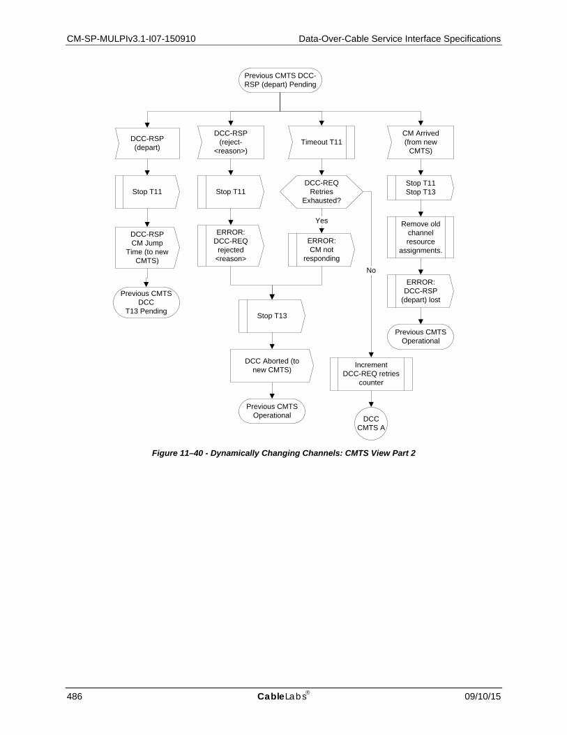
CM-SP-MULPIv3.1-I07-150910 Data-Over-Cable Service Interface Specifications
486 CableLabs 09/10/15
Figure 11–40 - Dynamically Changing Channels: CMTS View Part 2
Previous CMTS DCC-RSP (depart) Pending
DCC-RSP (reject-
<reason>)
DCC-RSP (depart)
Timeout T11
DCC-REQ Retries
Exhausted?
Increment DCC-REQ retries
counter
No
ERROR:CM not
responding
Yes
Previous CMTS Operational
ERROR: DCC-REQ rejected
<reason>
Previous CMTS DCC
T13 Pending
Stop T11 Stop T11
Stop T13
DCC CMTS A
DCC-RSP CM Jump
Time (to new CMTS)
DCC Aborted (to new CMTS)
CM Arrived (from new
CMTS)
Remove old channel resource
assignments.
Previous CMTS Operational
ERROR:DCC-RSP
(depart) lost
Stop T11Stop T13

MAC and Upper Layer Protocols Interface Specification CM-SP-MULPIv3.1-I07-150910
09/10/15 CableLabs 487
Figure 11–41 - Dynamically Changing Channels: CMTS View Part 3
Previous CMTS DCC
T13 Pending
Timeout T13CM no longer
present on old channel
Stop T13
Previous CMTS Operational
Remove old channel resource
assignments.
1
1 The mechanism to determine this event is vendor-specific.
DCC-RSP (<conf code>)
ERROR: Unknown
DCC transaction
Previous CMTS DCC
T13 Pending
CM Arrived (from new
CMTS)

CM-SP-MULPIv3.1-I07-150910 Data-Over-Cable Service Interface Specifications
488 CableLabs 09/10/15
Figure 11–42 - Dynamically Changing Channels: CMTS View Part 4
New CMTS DCC-RSP (arrive) Pending
DCC-RSP (arrive)
DCC-ACK
New CMTS DCCHold-down
Start T10
Timeout T15
Remove new channel resource
assignments.
New CMTS Operational
ERROR:CM not arriving
CM Arrived (to old CMTS)
DCC-RSP CM Jump Time (from old CMTS)
New CMTS DCC-RSP (arrive) Pending
Store Jump Time
DCC Aborted (from old CMTS)
ERROR:DCC Aborted
CM detected on new channel
1
1 Determination of this is CMTS-specific, but can include receiving RNG-REQ or bandwidth requests from the CM on the new channel.
Stop T15 Stop T15Restart T15
New CMTS DCCHold-down
Timeout T10 DCC-RSP (arrive)
DCC-ACK
New CMTS DCCHold-down
New CMTS Operational

MAC and Upper Layer Protocols Interface Specification CM-SP-MULPIv3.1-I07-150910
09/10/15 CableLabs 489
Figure 11–43 - Dynamically Changing Channels: CM View
CM Operational
DCC-REQ
No
CM Operational
DCC- RSP ( depart)
DCC-REQ valid?
Parse DCC-REQ
CM Operational
Initialization technique = re-init the
MAC?
Reset the MAC
No
Yes
Can jump be made?
Obtain Upstream Parameters
Yes
DCC- RSP ( reject-
< reason>)
No
DCC- RSP ( reject-
< reason>)
ERROR:DCC- REQ
denied
CM Operational
Yes
ERROR:Invalid Initialization
Technique
ERROR:Bad DCC
DCC-RSP <reject-invalid-init-tech>

CM-SP-MULPIv3.1-I07-150910 Data-Over-Cable Service Interface Specifications
490 CableLabs 09/10/15
11.5 Dynamic Bonding Change (DBC)
11.5.1 DBC General Operation At any time after registration, the CMTS uses the DBC command to change any combination of the following parameters in a CM:
• The receive channel set • DSID(s) or DSID associated attributes • Security association(s) for encrypting downstream traffic • The transmit channel set • Service Flow Cluster Assignments
The CMTS MUST be capable of performing DBC operations within a MAC domain. The DBC change can only occur within a MAC domain; the CMTS moves the CM between MAC domains using the DCC message. The CMTS MUST NOT initiate a DBC transaction to direct any of the CM's channels to a different MAC domain.
Multiple actions can occur within a single DBC message. If the DBC-REQ contains a change in the RCS, the CM MUST implement the downstream channel changes prior to making any other changes in the DBC-REQ message.
11.5.1.1 Changes to the Receive Channel Set The CMTS can add channels to the Receive Channel Set, delete channels from the Receive Channel Set, change channels within the Receive Channel Set of a CM, or change the downstream OFDM profile assignment by sending the CM a new Receive Channel Configuration via a DBC-REQ (see the subsection CM Receive Channel (RCP/RCC) Encodings in Annex C). If the CM receives a DBC-REQ with a Receive Channel Configuration that the CM is not capable of using, the CM MUST reject the DBC-REQ. A Receive Channel Set is the complete list of all the Downstream Channels that were included in the RCC of the DBC exchange.
Changes in the RCC that affect the CM's Primary Downstream Channel will require the CM to re-range on its upstream channels before it can continue operation. Specifically, changes to the Primary Downstream Channel itself, or changes to the Receive Module(s) to which the Primary Downstream Channel is connected (either directly or indirectly) will require the CM to re-range. If the CMTS makes a change in the CM's RCC that affects the CM's Primary Downstream Channel, the CMTS MUST signal re-ranging and include an initialization technique in the DBC-REQ for all upstream channels. This means that the CMTS cannot make changes affecting the Primary Downstream Channel using DBC unless a TCC encoding has been included in the REG-RSP-MP. If the CMTS does not include an initialization technique for each upstream channel in the transmit channel set in the DBC-REQ when the CM's primary downstream is affected, the CM MUST reject the DBC-REQ message.
Section 11.5.3 details the operation of the CMTS and CM during the DBC process. With the exception of a complete change to the receive channel set, the CMTS stops sending traffic on any channels to be deleted from the RCS. When removing channels from the RCS, the CMTS has several means of minimizing packet loss. The CMTS may choose to stop sending traffic on the downstream channels to be removed from the RCS prior to sending the DBC-REQ message. The CMTS may use a vendor-specific delay between control and data messages. In addition, the CMTS may transmit the DBC-REQ messages on the highest latency downstream channel. In the case of a complete change to the RCS, stopping traffic on the original RCS could cause an interruption in traffic that could persist for some time in the event of a lost DBC-REQ message. In this case, the CMTS has the option of duplicating traffic on the old and new RCS. The CMTS sends the DBC-REQ and waits for the DBC-RSP. Once the CMTS receives the DBC-RSP, it begins transmitting packets on the new channel set. The CMTS waits a vendor-specific time before sending the DBC-ACK to account for differences in delay between control messages and data messages and to ensure that the CM receives all data traffic sent prior to the DBC-ACK message. The CMTS then sends a DBC-ACK.
When the CM receives an invalid DBC-REQ, the CM sends a DBC-RSP rejecting the message. The CM MUST include an applicable error encoding in the DBC-RSP for at least one top-level TLV in the DBC-REQ that the CM could not implement. If the DBC-REQ message is valid, the CM then makes the receive channel set changes identified in the DBC-REQ. Once the CM has completed all attempts to acquire all new channels and deletes any channels being removed from the RCS, the CM sends a DBC-RSP and waits for a DBC-ACK. The CM MUST try

MAC and Upper Layer Protocols Interface Specification CM-SP-MULPIv3.1-I07-150910
09/10/15 CableLabs 491
acquisition of the new DS channels in the RCS for the duration of the T(dbc downstream acquisition timer) before declaring that it was unable to acquire the downstream channel; downstream acquisition consists of QAM lock, FEC lock, and synchronization of MPEG framing. The DBC-RSP will contain no errors if the CM was able to make all RCS changes, Partial Service errors if the CM was able to make some of the RCS changes, or failure if the CM was unable to make any RCS changes. When the CM receives a DBC-ACK, the CM enables rapid loss detection of all resequencing DSIDs.
If the CMTS does not receive the DBC-RSP after all the retries and the RCS changed, the CMTS either returns the traffic to the previous downstream channel(s) or stops duplicating traffic after the expiration of the Initializing Channel Timeout timer, depending on previous operation. If the CMTS does not receive the DBC-RSP after all the DBC-REQ retries and the RCC contained a change that affected the CM's primary downstream, the CMTS reinitializes the CM using the CM-CTRL-REQ message. The CMTS MUST send the CM-CTRL-REQ message on either an overlapping downstream channel or if there were no overlapping channels, on both the old and new channels to ensure that the CM received the message. The CMTS also has the option of discontinuing station maintenance for all upstream channels associated with the CM to ensure that a reinitialization occurs. If the CMTS does not receive the DBC-RSP after all the DBC-REQ retries and the new RCC did not contain a change that affected the CM's primary downstream, the CMTS MUST recover from this condition. Recovery is considered complete if the CM's receive channel set is synchronized at both the CMTS and CM. The CMTS actions may include the following for a RCS replacement:
• Initiation of a new DBC transaction to retry the errored DBC transaction, • Initiation of a new DBC transaction to undo the errored DBC transaction, or • Reinitialization of the CM using the CM-CTRL-REQ message.
In order for the CM to complete the DBC, it is necessary that the CM be able to tune to at least the Primary Downstream Channel. If the CM cannot tune to the new Primary Downstream Channel included the RCS, the CM MUST reinitialize the MAC and return to the previous primary downstream. If the CM tunes to the Primary Downstream Channel, but cannot tune to all of the new channels in the RCS, the CM logs an error and MUST send a DBC-RSP with partial service. In this case, the CM goes operational on the channels on which it is able to tune. The CMTS may attempt to remedy any partial service state by any combination of the following:
• Initiating a new DBC transaction to add missing channels, • Reinitializing the CM, or • Moving the CM to a different set of channels.
11.5.1.2 Changes to a DSID Using DBC messaging, the CMTS can change attributes of a DSID. DSID attributes that can change are:
• Resequencing Encodings: • Downstream Resequencing Channel List • DSID Resequencing Wait Time • Resequencing Warning Threshold • CM-STATUS Hold-Off Timer for Out-of-range Events: • Rapid Loss Detection configuration • Multicast Encodings • Client MAC Address • Multicast CM Interface Mask • Group MAC Address
CM-SP-MULPIv3.1-I07-150910 Data-Over-Cable Service Interface Specifications
492 CableLabs 09/10/15
11.5.1.2.1 Changes to Resequencing Encodings
11.5.1.2.1.1 Changes to the Downstream Resequencing Channel List
The CMTS can add channels to the Downstream Resequencing Channel List, delete channels from the Downstream Resequencing Channel List, or change channels within the Downstream Resequencing Channel List by replacing the CM's Downstream Resequencing Channel List with a new Downstream Resequencing Channel List.
Section 11.5.3 details the operation of the CMTS and CM during the DBC process. When no RCS changes are required, the CMTS implements changes to the Downstream Resequencing Channel List by continuing to transmit packets over the old Downstream Resequencing Channel List when sending the DBC-REQ message until the DBC-RSP message confirms that the CM has accepted the new Downstream Resequencing Channel List. Once the CMTS receives the DBC-RSP, it begins transmitting packets with the associated resequencing DSID on the new Downstream Resequencing Channel List. The CMTS waits a vendor-specific time before sending the DBC-ACK to account for differences in delay between control messages and data messages and to ensure that the CM receives all data traffic sent prior to the DBC-ACK message. The CMTS then sends a DBC-ACK.
When the CM receives the DBC-REQ, it expands the rapid loss detection of a resequencing DSID across the union of the old Downstream Resequencing Channel List and the new Downstream Resequencing Channel List and sends a DBC-RSP. The CM also expands its filters such that it discards packets received on a downstream channel not included in this union. When the CM receives a DBC-ACK, the CM waits the duration of the DSID Resequencing Wait Time and contracts the rapid loss detection to the new Downstream Resequencing Channel List. The CM then discards any DSID-labeled frames received on downstream channels not in the new Downstream Resequencing Channel List.
If the Downstream Resequencing Channel List changed with no changes to the RCS and the CMTS does not receive the DBC-RSP after all the retries, the CMTS MUST return traffic associated with the Resequencing DSID to the previous Downstream Resequencing Channel List. If the Downstream Resequencing Channel List changed with no changes to the RCS and CMTS does not receive the DBC-RSP after all the retries, the CMTS MUST recover from this condition. Recovery is considered complete if the CM's Downstream Resequencing Channel List is synchronized at both the CMTS and CM. The CMTS actions may include the following for a Downstream Resequencing Channel List replacement without an RCS replacement:
• Initiation of a new DBC transaction to delete the DSID associated with the Downstream Resequencing Channel List,
• Initiation of a new DBC transaction to retry the errored DBC transaction, • Initiation of a new DBC transaction to undo the errored DBC transaction, • Reinitialization of the CM using the CM-CTRL-REQ message.
If the CM does not receive a DBC-ACK after all the retries, the CM logs an error, goes operational, and restores rapid loss detection of the Resequencing DSID.
11.5.1.2.1.2 Changes to the DSID Resequencing Wait Time
Section 11.5.3 details the operation of the CMTS and CM during the DBC process. Skew may change due to network changes in the CIN or other circumstances on the network (Section 8.2.3.1) even when no RCS or Downstream Resequencing Channel List changes occur. Further, configuration changes at the CMTS may also have an impact on skew. The CMTS may choose to communicate this change in skew to the CM via a change in the DSID Resequencing Wait Time.
If the CMTS has been requested to perform a reconfiguration that results in a reduction in skew, the CMTS SHOULD perform the reconfiguration prior to sending any DBC-REQ message communicating a change in the DSID Resequencing Wait Time to an affected modem. The CMTS SHOULD wait a vendor-specific time before sending the DBC-REQ to the first modem to account for differences in delay between control messages and data messages and to ensure that the CM receives all data traffic sent prior to the DBC-REQ message. After sending the DBC-REQ message, the CMTS waits for the DBC-RSP message. Once the CMTS receives the DBC-RSP message, the CMTS sends a DBC-ACK message.

MAC and Upper Layer Protocols Interface Specification CM-SP-MULPIv3.1-I07-150910
09/10/15 CableLabs 493
If the CMTS has been requested to perform a reconfiguration that results in an increase in skew, the CMTS may choose to modify the DSID Resequencing Wait Time. If it modifies this parameter, the CMTS sends DBC-REQ messages to all affected modems and waits for DBC-RSP messages. The CMTS SHOULD perform the reconfiguration after the CMTS receives the DBC-RSP from all affected modems.
When the CM receives the DBC-REQ, it applies the change in the DSID Resequencing Wait Time. After it completes implementation of the modified DSID, the CM sends a DBC-RSP.
11.5.1.2.2 Changes to Multicast Encodings
The CMTS can initiate a DBC transaction to either add a multicast DSID, change attributes of an existing multicast DSID, or delete a multicast DSID. Section 11.5.3 details the operation of the CMTS and CM during the DBC process. When no RCS or Downstream Resequencing Channel List changes are required, the CMTS implements changes of some multicast DSID attributes prior to sending the DBC-REQ message and some changes after receipt of the DBC-RSP message. The CMTS sends the DBC-REQ message containing multicast encodings and waits for the DBC-RSP message. Once the CMTS receives the DBC-RSP, it sends a DBC-ACK.
Although the CMTS may forward multicast traffic labeled with the new or modified DSID at any time, the CM will not forward the packets labeled with the new or modified DSID until after it receives the DBC-REQ message containing the DSID. When the CMTS is required to start a new multicast replication for a CM joining a multicast session, the CMTS has the option of waiting to forward the multicast traffic to that CM until the DBC-RSP from the CM is received to ensure that the CM will not discard the multicast traffic because the DSID is not configured. Alternatively, the CMTS may forward multicast traffic with this DSID after sending the DBC-REQ but before receiving the DBC-RSP from the CM. By not waiting for the DBC-RSP from the CM, the CMTS can start the multicast traffic sooner which avoids any delays induced by waiting for the DBC-RSP.
When the CM receives the DBC-REQ, it implements the change in the multicast DSID attribute. After it completes implementation of the DSID modifications, the CM sends a DBC-RSP.
If the Multicast Encodings of a DSID are changed and CMTS does not receive the DBC-RSP after all the DBC-REQ retries, the CMTS does not know whether the CM has implemented the DBC or not. The CMTS MUST recover from this condition. Recovery is considered complete if the state of the Multicast DSID is synchronized at both the CMTS and the CM. The recommended CMTS recovery action for this condition is to initiate a new DBC transaction to delete the modified multicast DSID. Other CMTS actions may include the following:
• Initiation of a new DBC transaction to retry the errored DBC transaction; • Initiation of a new DBC transaction to undo the errored DBC transaction; • Reinitialization of the CM using the CM-CTRL-REQ message.
When the CM receives a DBC-REQ adding or changing a multicast DSID, the CM associates the client MAC address and Multicast CMIM encodings to a list of interfaces and forwards traffic to the appropriate interface accordingly.
When adding a multicast DSID, the CMTS MUST include a Client MAC Address Encoding and/or a Multicast CMIM in the DBC-REQ message:
• If the CMTS includes only Client MAC Address encodings, the CM MUST associate the interface(s) identified by the client MAC addresses with the DSID. The CM MUST assume that the multicast CMIM is all zeros for this DSID.
• If the CMTS includes only the Multicast CMIM, the CM MUST associate the interfaces provided in the Multicast CMIM with the DSID.
• If the CMTS includes both Client MAC Address Encodings and a Multicast CMIM, the CM MUST associate the union of the interfaces identified by the client MAC addresses and the interfaces identified in the Multicast CMIM with the DSID.
When changing attributes of an existing multicast DSID, any of the following combinations are valid:
• If the CMTS includes neither Client MAC Address Encodings nor Multicast CMIM for a particular DSID, the CM MUST keep the current association of interfaces with the DSID unchanged.

CM-SP-MULPIv3.1-I07-150910 Data-Over-Cable Service Interface Specifications
494 CableLabs 09/10/15
• If the CMTS includes only the Client MAC Address Encodings for a particular DSID, the CM updates the list of Client MAC Addresses according to the new Client MAC Address Encodings, and keeps the CMIM unchanged. The CM MUST associate the union of the interface(s) identified by the updated client MAC address(es) and the interfaces identified in the current Multicast CMIM with the DSID.
• If the CMTS includes only the Multicast CMIM for a particular DSID, the CM updates the CMIM, and keeps the list of Client MAC Addresses unchanged. The CM MUST associate the union of the interfaces of the current Client MAC Address(es) and the interfaces enabled by the new Multicast CMIM with the DSID.
• If the CMTS includes both the Client MAC Address Encodings and Multicast CMIM for a particular DSID, the CM updates the current list of Client MAC Addresses according to the new Client MAC Address Encodings and updates the CMIM. The CM MUST associate the DSID with the union of the interfaces identified by the updated Client MAC address list and the interfaces enabled by the new Multicast CMIM.
When deleting a multicast DSID, the Client MAC Address Encodings and Multicast CMIM are ignored by the CM. The CM deletes the DSID and all associated forwarding information.
The CMTS can remove Client MAC Addresses associated with a DSID in two ways. The CMTS can either send a DBC message to change the DSID with those Client MAC addresses deleted, or the CMTS can send a DBC message that deletes the DSID.
11.5.1.2.3 Changes to Rapid Loss Detection115
Using DBC messaging, the CMTS can disable the Rapid Loss detection on certain Resequencing DSIDs. This is to help the CMTS in switching a Service Flow or a set of Service Flows associated with a DSID from one DS profile to another, as described in Section 11.5.1.2.4.
In order to change the Rapid Loss Detection configuration for the DSID, the CMTS MUST include a DSID encoding with a Rapid Loss Detection Configuration sub-TLV (see the subsection, Rapid Loss Detection Configuration, in Annex C) in the DBC message.
11.5.1.2.4 Changes to Move Service Flows Between Downstream Profiles116 Note: While the following section outlines procedures for moving of a single Service Flow between downstream
OFDM profiles, it should be noted that the described mechanisms are equally applicable to moving of a set of Service Flows between OFDM profiles, for example, when multiple Service Flows are associated with a resequencing DSID.
When switching a service flow from one profile to the other on the same downstream OFDM channel, the CMTS can use DBC messaging to disable and re-enable Rapid Loss Detection. When the traffic of a service flow is moved from one profile to another, the CMTS MUST ensure that the packets are kept in sequence within the same service flow. This is a potential concern because of the fact that different packets transmitted on different profiles may experience different delay.
Depending on the nature of the service flows, different approaches need to be taken to handle this situation. It is up to the CMTS to decide which approach to take.
For service flows that are not sensitive to packet order, this does not pose an issue. There is no requirement for the CMTS or CM to take any action. The CMTS may simply stop transmitting packets using the old profile and begin transmitting packets using the new profile.
For service flows that are sensitive to packet order but do not use Resequencing DSIDs for re-sequencing, the CMTS is responsible for making sure that no packets for the service flow are sent using the new profile before all of the scheduled packets for that service flow on the old profile have been sent. The mechanisms of how this is achieved are implementation-dependent. There is no action requirement for the CM, and no signaling is required for this approach.
For service flows that are packet order sensitive and use Resequencing DSID for re-sequencing, the CMTS can choose one of the two following methods:
115 Updated per MULPIv3.1-14.1200-1 on 12/2/14 by PO. 116 Updated per MULPIv3.1-14.1200-1 on 12/2/14 by PO.

MAC and Upper Layer Protocols Interface Specification CM-SP-MULPIv3.1-I07-150910
09/10/15 CableLabs 495
• It can use the same mechanism described above, i.e., holding the packets on the new profile until the packets on the old profiles are all sent. The CMTS is responsible for making sure that no packets for the service flow are sent on the new profile before all packets for the flow that have been scheduled on the old profile have been sent. The mechanisms of how this is achieved are implementation dependent. There is no action requirement for the CM, and no signaling is required for this approach.
• It can also take advantage of the resequencing process that is already in use for the service flow to keep the packets in order. If the CMTS implements this method, the CMTS initiates a DBC transaction to disable rapid loss detection on the DSID associated with the service flow that is moved to a different profile. Once it determines that the last packet for the service flow has been transmitted, the CMTS initiates a DBC transaction to re-enable rapid loss detection for the DSID associated with the service flow. This process is shown in the Downstream Profile Descriptor Change subsection of Appendix XII.
The CMTS can disable rapid loss detection because packets may arrive out-of-order on the channel on which the Service Flow is moved during the process of moving a Service Flow between profiles. A CM is likely to discard packets received out-of-order on a channel when rapid loss detection is enabled. When rapid loss detection is disabled, the CM applies resequencing algorithm to restore the original order of packets even if packets arrive out-of-order on a particular channel.
11.5.1.3 Changes to the Security Association for encrypting downstream traffic Using DBC messaging, the CMTS can add or delete Security Associations (SA) used to encrypt downstream traffic. The CMTS is not allowed send a DBC-REQ to a CM that is not in the "Authorized" State. The CMTS is allowed send a DBC-REQ with an SA that employs a cryptographic suite unsupported by the CM. If an unauthorized CM receives a DBC-REQ with a Security Association, the CM rejects the DBC-REQ. If the CM receives a DBC-REQ with a Security Association that the CM is not capable of using, the CM rejects the DBC-REQ [DOCSIS SECv3.0].
Section 11.5.3 details the operation of the CMTS and CM during the DBC process. When changes to the security associations for encrypting downstream traffic are necessary for multicast flows, the CMTS communicates the SA changes to the CM in a DBC-REQ message and waits for the DBC-RSP message. Once the CMTS receives the DBC-RSP, it sends a DBC-ACK.
When the CM receives a DBC-REQ adding an SA for which the CM is not already running a TEK state machine and the CM supports the cryptographic suite identified, the CM adds the SA and initiates a TEK state machine for the new SA. If the CM is already running a TEK state machine for the signaled SA or the CM does not support the cryptographic suite identified in the SA, the CM rejects the DBC-REQ. When the CM receives a DBC-REQ deleting an SA, it deletes the SA and terminates the associated TEK state machine for that SAID. The CM then sends a DBC-RSP and waits for a DBC-ACK.
Although the CMTS may start encrypting traffic with this SAID at any time, the CM will not forward the packets encrypted with this SAID until it completes both the DBC transaction and TEK state machine. When the first CM on a given downstream channel or bonding group joins a multicast session, the CMTS forwards the encrypted multicast traffic upon completion of the TEK state machine to ensure that the CM will not discard the encrypted multicast traffic. Alternatively, the CMTS may forward encrypted multicast traffic after sending the DBC-REQ but prior to receipt of the DBC-RSP from the CM. By not waiting for the DBC-RSP from the CM, the CMTS can start the encrypted multicast traffic sooner which will remove any delays induced by waiting for the DBC-RSP.
If the Security Association Encodings of a DSID changed, and the CMTS does not receive the DBC-RSP after all the DBC-REQ retries, and the CMTS has not received a TEK-request from the CM, the CMTS does not know whether the CM has implemented the DBC-REQ or not. The CMTS MUST recover from this condition. The CMTS actions may include the following for addition or deletion of a Security Association: initiation of a new DBC transaction to retry the errored DBC transaction, initiation of a new DBC transaction to undo the errored DBC transaction, or reinitialization of the CM using the CM-CTRL-REQ message. Recovery is considered complete if the state of the Security Association is synchronized at both the CMTS and CM.
11.5.1.4 Changes to the Transmit Channel Set Using DBC messaging, the CMTS can add channels to the transmit channel set, delete channels from the transmit channel set, replace one channel with another, change the OFDMA profile assignment, change the Ranging SID, or change the Test SID. Multiple actions can occur within a single DBC message. Whenever the CMTS changes the

CM-SP-MULPIv3.1-I07-150910 Data-Over-Cable Service Interface Specifications
496 CableLabs 09/10/15
Transmit Channel Set, the CMTS MUST appropriately modify the SIDs associated with affected service flows. If the CM receives a DBC-REQ that causes a mismatch where one or more channels needed for a service flow are not included in the TCS, the CM MUST reject the DBC-REQ. For example, if service flow A is bonding across upstream channels 1, 2, and 3 and the CM receives a DBC-REQ to remove channel 1, and the DBC-REQ does not include the removal of SIDs associated with channel 1 for service flow A, the CM would reject the DBC-REQ message.
The CMTS MAY add channels to the TCS without specifying that these channels be used by any specific service flow. This allows the CMTS to add channels to the CM before they are actually needed to support service at that CM. If the CM receives a DBC-REQ that would result in more channels in the TCS than are needed to support the CM's service flows, the CM MUST NOT reject the DBC message due to the extra channel(s) unless the resulting TCS is inconsistent with the CM's transmit capabilities.
When the CMTS replaces a channel within the TCS, there are additional requirements beyond those of merely adding a channel combined with deleting a channel. These additional requirements exist because the service flow may be adversely affected during a channel replacement. From a process perspective, a channel replacement contains a channel deletion (the channel being replaced) and a channel addition (the replacement channel).
Section 11.5.3 details the operation of the CMTS and CM during the DBC process. In the event of a corresponding SID Cluster change, the CMTS and the CM will follow the request-grant process detailed in Section 11.5.1.5. The CMTS then sends the DBC-REQ and sends ranging opportunities where applicable on any channels being added to the TCS. The CMTS then waits for the DBC-RSP. When the CM receives the DBC-REQ, it makes the transmit channel set changes identified in the DBC-REQ by immediately deleting any channels being removed from the TCS and applying the appropriate initialization technique to any channels being added to the TCS. Once the CM has successfully added a channel to its TCS, it begins using that channel for requesting and responding to grants if that channel is used by any of the CM's service flows. Once the CM has completed all attempts to add all new channels and deletes any channels being removed from the TCS, the CM sends a DBC-RSP. The DBC-RSP will contain no errors if the CM was able to make all TCS changes, partial service if the CM was able to make some of the TCS changes, failure if the CM was unable to make any TCS changes, or rejection if the CM considers the DBC-REQ was invalid. Once the CMTS receives the DBC-RSP, it follows the process detailed in Section 11.5.1.5 before sending a DBC-ACK. The CMTS continues to accept requests and data transmissions received on deleted channels until the expiration of the T10 timer.
11.5.1.4.1 Impact of TCS Changes on Periodic Ranging
When the CMTS is removing a channel from a CM's TCS, the CMTS MUST continue sending station maintenance or Probe opportunities to the CM for the channel being removed until the CMTS receives the DBC-RSP from the CM. If the CMTS meets the maximum number of retries for invited ranging retries on the channel being removed during this period (DBC-REQ to DBC-RSP), the CMTS MUST NOT log this as an error condition because the CM may be in the process of removing this upstream channel. The purpose of the CMTS continuing to send the invited ranging opportunities is to ensure that the CM does not have a T4 expiration prior to processing the DBC-REQ message.
Similarly, when adding a new channel to the TCS with initialization technique of station maintenance or use directly, the CMTS MUST send the ranging or Probe opportunities while waiting for the DBC-RSP. These initialization techniques are used to shorten the DBC transaction time. Since these ranging opportunities can occur prior to the CM processing the DBC-REQ, the CMTS MUST NOT count these opportunities towards the Invited Ranging Retries (Annex B) prior to receiving the DBC-RSP from the CM.
11.5.1.4.2 Exception Conditions for TCS Changes
When changing the TCS, error conditions may result in the CMTS never receiving the DBC-RSP. Recovering from this condition is up to CMTS vendor implementation. For example, the CMTS actions may include the following for a channel replacement or channel add:
• If the CMTS has sent RNG-RSP success on all new channels for the CM, the CMTS may assume DBC transaction success and assume the CM is operational on the new channels and has deleted the old channels;
• If the CMTS sends RNG-RSP success on only some of the new channels, the CMTS can assume that the CM was unable to acquire the remaining channels and is in the partial service mode of operation;

MAC and Upper Layer Protocols Interface Specification CM-SP-MULPIv3.1-I07-150910
09/10/15 CableLabs 497
• If the CMTS sees the CM transmit on one or more new channels but the CM does not range successfully on any of the new channels, the CMTS knows the CM received the DBC-REQ and assumes the CM deleted the old channels, cannot use the new channels, and is in partial service mode;
• If the CMTS does not see the CM transmit on any new channel, the CMTS assumes the CM never received the DBC-REQ. The CMTS can delete the new resources and reinstate the old resources.
The CMTS may attempt to remedy any partial service state by any combination of the following:
• Sending another DBC transaction to add missing channels; • Forcing the CM to reinit MAC; • Moving the CM to a different set of channels.
If the CM fails to receive a DBC-ACK after exhausting the retries for a DBC, the CM logs the error that the DBC-ACK was not received and proceeds to operate as if the DBC-ACK was received.
11.5.1.5 Changes to the Service Flow SID Cluster Assignments Using the Service Flow SID Cluster Assignments TLV in the DBC messaging, the CMTS can assign new channels to a service flow, remove channels from a service flow, or replace one channel with another for a service flow. Multiple actions can occur within a single DBC message.
Section 11.5.3 details the operation of the CMTS and CM during the DBC process. Immediately after sending the DBC-REQ, the CMTS will start accepting bandwidth requests on new SIDs added by the Service Flow SID Cluster Assignment. If the overlap between the old and the new SID Clusters provides sufficient bandwidth as described in Section 11.5.1.5.1, the CMTS will stop granting on SIDs to be removed. If the overlap between the old and the new SID Clusters does not provide sufficient bandwidth, the CMTS will continue to grant bandwidth to the old SID Cluster. In either case, the CMTS will still accept bandwidth requests on SIDs to be removed from the old SID Cluster.
While waiting for the DBC-RSP, if the CMTS receives a bandwidth request using a SID that was newly added by the Service Flow SID Cluster Assignment, or sends a RNG-RSP with confirmation code "success" on any new channel added in the TCS, then it will:
• Begin granting bandwidth to any SIDs added by the SF SID Cluster Assignment for channels which are ranging complete;
• Stop accepting requests from any SIDs deleted by the SF SID Cluster Assignments; • Stop granting bandwidth to channels deleted from the TCS; • Stop granting to any SIDs removed by the SF SID Cluster Assignment if there is sufficient bandwidth.
When the CM receives the DBC-REQ, it stops requesting on channels removed by the Service Flow SID Cluster Assignment, but continues to transmit data in any grants on these channels. The CM starts using any new channels for requesting, prepares to receive grants for these channels, and sends a DBC-RSP. Once the CMTS receives the DBC-RSP with a confirmation code of okay or partial service, it will stop providing grants as well as accepting requests over the SIDs to be removed (if it has not done so already). Additionally, it will start providing grants using the new SIDs added by the Service Flow SID Cluster Assignment. The CMTS waits a vendor-specific time before sending the DBC-ACK to ensure that the CM is able to transmit in any grants outstanding for SIDs removed by the Service Flow SID Cluster Assignments. The CMTS then sends a DBC-ACK. When the CM receives the DBC-ACK, it removes the SIDs associated with any channels deleted by the Service Flow SID Cluster Assignment.
When the CMTS is not changing the TCS but is changing the Service Flow SID Cluster Assignment, error conditions may result in the CMTS never receiving the DBC-RSP. Recovering from this condition is up to CMTS vendor implementation. The CMTS actions may include the following for a Service Flow SID Cluster Assignment change:
• Attempting another DBC transaction; • Forcing the CM to reinit the MAC; • Initiating DSD messaging for the service flows possibly impacted.

CM-SP-MULPIv3.1-I07-150910 Data-Over-Cable Service Interface Specifications
498 CableLabs 09/10/15
If the CM fails to receive a DBC-ACK after exhausting the retries for a DBC transaction not changing the TCS, the CM logs the error that the DBC-RSP was not received. The CM MUST delete the SIDs for any Service Flow SID Cluster Assignment deletions. Thus, the CM stops responding to grants on any channels deleted by the Service Flow SID Cluster Assignment.
11.5.1.5.1 Bandwidth Sufficiency
When modifying the set of channels associated with a service flow, the CMTS determines whether or not there is sufficient bandwidth to adequately support the affected service flow during the DBC operation. The definition of sufficiency is left up to CMTS vendor implementation. Consider the following examples of a Service Flow SID Cluster Assignment change which replaces upstream channel 3 with upstream channel 9 for three service flows:
• Service flow B is bonded over upstream channels 1, 2, and 3. The CMTS looks at the quality of service parameters for service flow B and the bandwidth typically available on channels 1 and 2 to determine if there is sufficient bandwidth on these channels to adequately support the affected service flow. The CMTS sees that service flow B is best effort with no guaranteed minimum bandwidth and determines that there is sufficient bandwidth on channels 1 and 2 to meet the needs of this service flow during the DBC transaction. Hence, this would be a sufficient bandwidth case.
• Service flow C is also bonded across channels 1, 2, and 3. Service flow C has a guaranteed minimum bit rate of 5 Mbps. The CMTS determines that it needs to support this service during the DBC transaction and that there is insufficient bandwidth on channels 1 and 2 to meet the needs of this service flow. Thus, this would be an insufficient bandwidth case.
• Service flow D is a UGS service provisioned for channel 3. The CMTS determines that there is insufficient bandwidth to sustain the UGS flow during the DBC transaction because no service would be available between the time channel 3 is removed and channel 9 is actually added. Thus, this would be an insufficient bandwidth case.
This notion of sufficiency is a CMTS notion and impacts the Service Flow SID Cluster Assignment change process at the CMTS. Whenever the CMTS decides that there is insufficient bandwidth to adequately support a service flow during the replacement, the CMTS MAY send duplicate grants over the new and old channel sets during the DBC transaction. In the example of service flow D above, the CMTS would send grants on channel 9 and channel 3 during the DBC transaction to minimize the downtime of the service flow.
With TCS modifications, the CM deletes any old channels and adds any new channels upon receipt of the DBC-REQ. Receipt of the DBC-ACK for these cases serves only to stop the "DBC-ACK Timeout" timer.
11.5.1.6 Changes to the Energy Management Mode The CMTS can enable or disable an Energy Management Mode via a DBC-REQ message. If the primary downstream channel of the CM is SC-QAM, the CMTS can enable and disable Energy Management 1x1 Mode via a DBC-REQ message. If the primary downstream channel of the CM is OFDM, the CMTS can enable and disable Energy Management DOCSIS Light Sleep Mode via a DBC message. The Energy Management Modes are described in Section 11.7.
11.5.1.7 Initialization Technique for DBC There are many factors that drive the selection of an initialization technique when commanding a dynamic bonding change. While it is desirable to provide the minimum of interruption to existing QoS services such as voice over IP or streaming video sessions, a CM will not be able to successfully execute a channel change given an initialization technique that is unsuitable for the cable plant conditions. In some cases, a CM will impair the new channel given an unsuitable initialization technique. For instance, consider the use of initialization technique 4 (use the new channel(s) directly) when there is a significant difference in propagation delay between the old and new channels. Not only will the CM be unable to communicate with the CMTS on that channel after the channel change, but its transmissions may also interfere with the transmissions of other CMs using the channel.
Careful consideration needs to be given to the selection of an initialization technique. Some restrictions are listed below. This list is not exhaustive, but is intended to prevent the use of a particular initialization technique under conditions where its use could prevent the CM from successfully executing the channel change. Packets may be
MAC and Upper Layer Protocols Interface Specification CM-SP-MULPIv3.1-I07-150910
09/10/15 CableLabs 499
dropped under some conditions during channel changes; applications that are running over the DOCSIS path should be able to cope with the loss of packets that may occur during the time that the CM changes channels.
11.5.1.7.1 Initialization Technique One (1)
The use of initialization technique 1 (broadcast initial ranging) may result in a lengthy interruption of service. However, this interruption of service is mitigated by the reservation of QoS resources on the new channel(s). The service interruption can be further reduced if the CMTS supplies the UCD TLV in the DBC-REQ in addition to providing more frequent initial ranging opportunities on the new channel.
11.5.1.7.2 Initialization Technique Two (2)117
The use of initialization technique 2 (unicast ranging) offers the possibility of only a slight interruption of service for TDMA and S-CDMA upstream channels. In order to use this technique, the CMTS MUST include the UCD TLV in the DBC message if the upstream channel is changing.
However, the CMTS MUST NOT use this technique if:
• The upstream channel being initialized is OFDMA. • The DBC-REQ message contains an RCC that affected the CM's Primary Downstream Channel and that change
results in a timing change. • Propagation delay differences between the old and new channels will cause the CM burst timing to exceed the
ranging accuracy requirements of [DOCSIS PHYv3.1] and the CMTS does not compensate for this difference with the ranging offset TLVs (see the sections Timing Offset, Integer Part through Frequency Offset in Annex C on Ranging Offset TLVs).
• Attenuation or frequency response differences between the old and new upstream channels will cause the received power at the CMTS to be outside the limits of reliable reception and the CMTS does not compensate for this difference with the Power Offset TLVs (see the section on Power Offset TLV in Annex C).
11.5.1.7.3 Initialization Technique Three (3)118
The use of initialization technique 3 (broadcast or unicast ranging) offers the possibility of only a slight interruption of service for TDMA and S-CDMA upstream channels. This value might be used when there is uncertainty when the CM may execute the DBC command and thus a chance that it might miss station maintenance slots. However, the CMTS MUST NOT use this technique if the conditions for using techniques 1 and 2 are not completely satisfied.
11.5.1.7.4 Initialization Technique Four (4)
The use of initialization technique 4 (use the new channel directly) results in the least interruption of service.
In order to use this technique, the CMTS MUST:
• Synchronize timestamps and downstream symbol clocks across the Primary Downstream Channels involved. • Include the UCD TLV in the DBC message if the upstream channel is changing.
However, the CMTS MUST NOT use this technique if:
• The new channel is OFDMA. • The modulation rate changes when replacing one S-CDMA channel with another S-CDMA channel • The primary downstream channel is being changed or affected by implicit or explicit changes in the Receive
Module. • The DBC-REQ message requires the CM to switch a channel or channels between S-CDMA and TDMA. • The DBC-REQ message requires the CM to switch a channel or channels between O-FDMA and TDMA. • The DBC-REQ message requires the CM to switch a channel or channels between S-CDMA and O-FDMA.
117 Section updated per MULPIv3.1-14.1193-1 on 12/2/14 by PO. 118 Section updated per MULPIv3.1-14.1193-1 on 12/2/14 by PO.

CM-SP-MULPIv3.1-I07-150910 Data-Over-Cable Service Interface Specifications
500 CableLabs 09/10/15
• Propagation delay differences between the old and new channels will cause the CM burst timing to exceed the ranging accuracy requirements of [DOCSIS PHYv3.1] and the CMTS does not compensate for this difference with the ranging offset TLVs (Annexes Timing Offset, Fractional Part Frequency Offset on Ranging Offset TLVs).
• Attenuation or frequency response differences between the old and new upstream channels will cause the received power at the CMTS to be outside the limits of reliable reception and the CMTS does not compensate for this difference with the Power Offset TLVs (in the subsection Power Offset TLV in Annex C).
• Micro-reflections on the new upstream channel will result in an unacceptable PER (greater than 1%) with the pre-equalizer coefficients initialized according to [DOCSIS PHYv3.1].
11.5.1.7.5 Initialization Technique Five (5)119
The use of initialization technique 5 (perform probing) results in the least interruption of service for OFDMA upstream channels. In order to use this technique, the CMTS MUST include the UCD TLV in the DBC message if the upstream channel is changing.
However, the CMTS MUST NOT use this technique if:
• The new channel is TDMA or S-CDMA. • The DBC-REQ message contains an RCC that affected the CM's Primary Downstream Channel and that change
results in a timing change. • Propagation delay differences between the old and new channels will cause the CM burst timing to exceed the
ranging accuracy requirements of [DOCSIS PHYv3.1] and the CMTS does not compensate for this difference with the ranging offset TLVs (see the sections Timing Offset, Integer Part thru Frequency Offset in Annex C on Ranging Offset TLVs).
• Attenuation or frequency response differences between the old and new upstream channels will cause the received power at the CMTS to be outside the limits of reliable reception and the CMTS does not compensate for this difference with the Power Offset TLVs (see the section on Power Offset TLV in Annex C).
11.5.1.7.6 Initialization Technique Six (6)
The use of initialization technique 6 [perform unicast initial ranging (IUC3)] is intended for situations in which there is a moderate amount of ambiguity in the CM’s timing offset. For example, a CMTS adding a second OFDMA channel to a CM already knows the ranging offset for the CM’s first OFDMA channel. However, because of differing frequency characteristics, there may be some ambiguity in the timing offset for the second channel. The CMTS could use initialization technique 6 to assign the CM a smaller initial ranging region without wasting the bandwidth consumed by a broadcast ranging region. This technique results in a small interruption of service for OFDMA upstream channels. In order to use this technique, the CMTS MUST include the UCD TLV in the DBC message if the upstream channel is changing. However, the CMTS MUST NOT use this technique if the new channel is TDMA or S-CDMA.
11.5.1.7.7 Initialization Technique Seven (7)
The use of initialization technique 7 [perform station ranging (IUC4)] is intended for situations in which there is little ambiguity in the CM’s timing offset. This technique results in a small interruption of service for OFDMA upstream channels. In order to use this technique, the CMTS MUST include the UCD TLV in the DBC message if the upstream channel is changing. However, the CMTS MUST NOT use this technique if the new channel is TDMA or S-CDMA.
11.5.1.8 Fragmentation of DBC-REQ Messages If the CMTS fragments the DBC-REQ message, it MUST ensure that the fragments arrive in order at the CM, as the CM is not required to resequence out-of-order DBC-REQ message fragments. The CMTS may do so either by sending all message fragments on a single downstream or by transmitting fragments such that individual channel latencies do not affect fragment order. 119 Sections added per MULPIv3.1-14.1193-1 on 12/2/14 by PO.

MAC and Upper Layer Protocols Interface Specification CM-SP-MULPIv3.1-I07-150910
09/10/15 CableLabs 501
Upon receiving the first fragment of a DBC-REQ message, the CM starts a "DBC-REQ Timeout" timer. If the timer expires before all fragments of the DBC-REQ message have been correctly received, the CM sends a DBC-RSP with confirmation code error-DBC-REQ-incomplete, then returns to the operational state. Correct reception of the DBC-REQ message fragments could include in-order reception of all fragments.
11.5.2 Exception Conditions The CM MUST reject a message that the CM determines to be invalid or inconsistent with the CM's capabilities and service flows.
A DBC-REQ is considered invalid if any of the following apply:
• The message format does not match the format required for a DBC-REQ. • The DBC-REQ contains an RCC that affects the CM's primary downstream but does not contain an
initialization technique. • The DBC-REQ includes an RCS change without Simplified RCC Encodings but does not specify one and only
one downstream channel to be the Primary Downstream Channel. • The DBC-REQ includes an RCS change with Simplified RCC Encodings but does not specify the Primary
Downstream Channel Assignment. • The DBC-REQ includes an RCS change with Simplified RCC Encodings and an OFDM downstream channel
but does not include the Downstream Profile Assignment. • A CMTS-initiated DSA, DSC, or DCC transaction is in progress at the CM. • The DBC-REQ contains a TCC Encoding with an Upstream Channel Action of Add (1) or Replace (4), but does
not contain a UCD. • The DBC-REQ contains a TCC encoding with an Upstream Channel Action of Add(1) or Replace(4) in which
the new upstream channel is an OFDMA upstream channel, but does not include the Assigned OFDMA Upstream Data Profile IUC.
• The DBC-REQ contains Energy Management – DOCSIS Light Sleep Encodings when the CM is operating in an Energy Management Mode.
A DBC-REQ is considered inconsistent with the CM's capabilities and service flows if any of the following apply:
• Implementation of the DBC-REQ would require more downstream receivers than the CM has available. • Implementation of the DBC-REQ would require more upstream transmitters than the CM has available. • Implementation of the tuning range required by the DBC-REQ is inconsistent with the CM's capabilities. • Implementation of the DBC-REQ would require different physical-layer implementation than the CM has
available. • Implementation of the DBC-REQ would require more SID Clusters than the CM supports. • Implementation of the DBC-REQ would require more DS Resequencing DSIDs than the CM supports. • Implementation of the DBC-REQ would require more DSIDs than the CM supports. • Implementation of the DBC-REQ would require an RCS change that is inconsistent with the DS Resequencing
Channel List. • Implementation of the DBC-REQ would require a DS Resequencing Channel List change that is inconsistent
with the RCS. • Implementation of the DBC-REQ would require a TCS change that is inconsistent with the Service Flow SID
Cluster Assignment. • Implementation of the DBC-REQ would require a Service Flow SID Cluster Assignment that is inconsistent
with the TCS. • Implementation of the DBC-REQ would require more DSIDs with multicast attributes than the CM supports. • The DBC-REQ message contains a client MAC address that is not in the CM's forwarding table.
CM-SP-MULPIv3.1-I07-150910 Data-Over-Cable Service Interface Specifications
502 CableLabs 09/10/15
If the CM considers the DBC-REQ message to be valid but is unable to acquire new downstream channels in the RCS and/or new upstream channels in the TCS, the CM responds with a DBC-RSP <Partial Service>.
If the CM is unable to acquire one or more downstream channels, the CM sends a DBC-RSP <Partial Service>, and enters a partial service mode of operation in the downstream (see Section 8.4). Likewise, if the CM is unable to acquire one or more upstream channels, the CM sends a DBC-RSP <Partial Service>, and enters a partial service mode of operation in the upstream (see Section 8.4).
If a CM issues a DSA-REQ or DSC-REQ for more resources, and the CMTS needs to do a DBC to obtain those resources, the CMTS will reject the DSA or DSC command without allocating any resources to the CM. The CMTS includes a confirmation code of "reject-temporary-DBC" (the subsection Confirmation Code in Annex C) in the DSA-RSP or DSC-RSP message to indicate that the new resources will not be available until a DBC is received. The CMTS will then follow the DSA or DSC transaction (expiration of T10 transaction timer) with a DBC transaction.
The CMTS MUST NOT issue a DBC command to a CM if a DSA, DSC, or DCC transaction is still outstanding at that CM. The CMTS MUST NOT issue a DSA, DSC, or DCC command to a CM if the CMTS has previously issued a DBC command to that CM, and that command is still outstanding.
If the CMTS issues a DBC-REQ command to a CM and that CM simultaneously issues a DSA-REQ or DSC-REQ then the CMTS command takes priority. The CMTS MUST respond with a confirmation code of "reject-temporary" for the DSA-REQ or DSC-REQ, per Annex B. If the CM receives a DBC-REQ prior to receiving a DSA-RSP or DSC-RSP, the CM assumes that the CMTS will reject the DSA or DSC transaction and the CM MUST execute the DBC command.
If the CMTS sends a DBC-REQ and does not receive a DBC-RSP prior to the expiration of the Initializing Channel Timeout, it MUST retransmit the DBC-REQ up to a maximum of "DBC-REQ Retries" (Annex B) before declaring the transaction a failure. Note that if the DBC-RSP was lost in transit and the CMTS retries the DBC-REQ, the CM may have already changed channels.
If the CMTS receives a DBC-RSP with confirmation code "error-DBC-REQ-incomplete", it determines whether "DBC-REQ Retries" has been exhausted before resending the DBC-REQ or declaring the transaction a failure.
If the CM sends a DBC-RSP and does not receive a DBC-ACK from the CMTS within, "DBC-ACK Timeout," it MUST retry the DBC-RSP up to a maximum of "DBC-RSP Retries" (Annex B).
The CM MUST consider the DBC-REQ as a redundant command if the CM receives a DBC-REQ with any of the following:
• CM Receive Channel Configuration Encodings equal to the current Receive Channel Configuration. • Any DSID encoding that adds an existing DSID. • Transmit Channel Configuration Encoding that adds an upstream channel that is already present in the CM's
Transmit Channel Set.
If the CM considers the DBC-REQ to be redundant, the CM MUST NOT execute the DBC-REQ. Then the CM MUST return a DBC-RSP, with a detailed confirmation code of "reject-already-there" to the CMTS per Annex C.
If the CM does not receive a DBC-ACK after all the retries, the CM logs an error and continues normal operation.

MAC and Upper Layer Protocols Interface Specification CM-SP-MULPIv3.1-I07-150910
09/10/15 CableLabs 503
11.5.3 DBC State Transition Diagrams
11.5.3.1 CMTS DBC State Transition Diagrams The CMTS MUST support the DBC operation as shown in the State Transition diagrams in Figure 11–44 through Figure 11–47.
Figure 11–44 - CMTS DBC Request (part 1)
CMTS-DBC Transaction Idle
DBC-RSP(<conf code>)
ERROR: Unknown DBC
transaction
DBC Required
May start duplicating traffic on channel(s)
replaced within the RCS
Stop sending traffic on channel(s)
removed from RCS
Channel being deleted in
RCS?
No
Yes
Wait optional CMTS vendor specific time delay when
channel being removed from RCS.
Note: May need to add some actions when the multicast QoS is finalized.
CMTS A
Channel being replaced in
RCS?
No
Yes
For each TCS channel replacement with sufficient overlap, stop granting on any
channels to be deleted.
For each TCS channel replacement with insufficient overlap, continue granting
over the old channels in the SID Cluster. CMTS may duplicate grants for UGS
flows over both the new and old channels.
For complete TCS replacement, respond to bandwidth requests by sending grants to the new and old channels in the SID Cluster to ensure Tx_op for DBC_RSP.
TCS Changes?
Yes
No
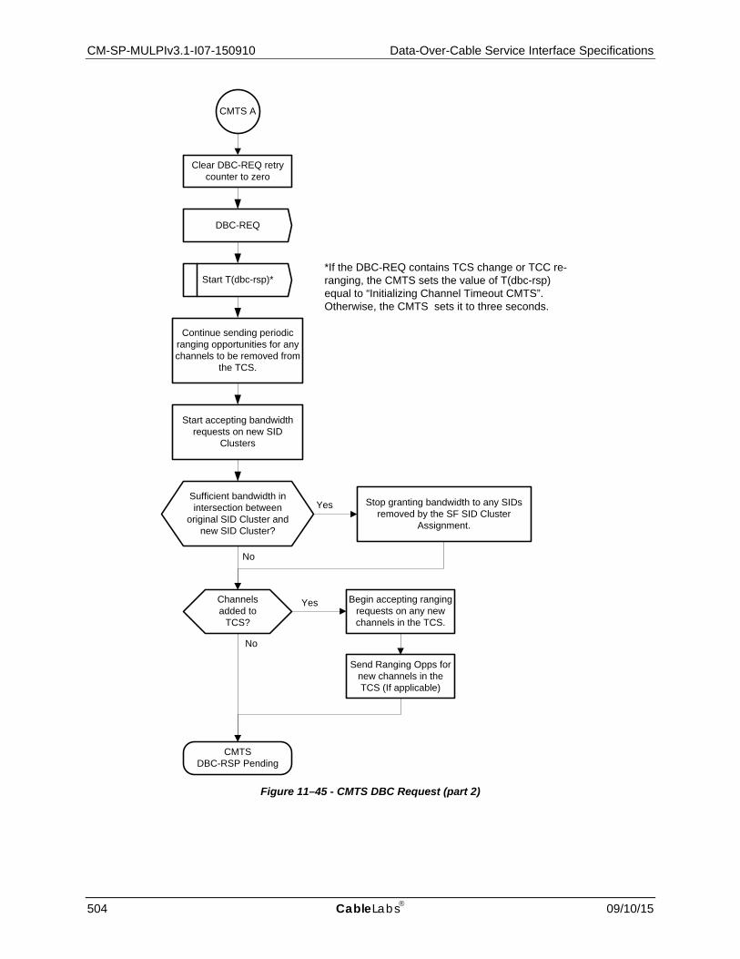
CM-SP-MULPIv3.1-I07-150910 Data-Over-Cable Service Interface Specifications
504 CableLabs 09/10/15
Figure 11–45 - CMTS DBC Request (part 2)
DBC-REQ
Clear DBC-REQ retry counter to zero
Start T(dbc-rsp)*
CMTSDBC-RSP Pending
No
YesSufficient bandwidth in intersection between
original SID Cluster and new SID Cluster?
CMTS A
Channels added to
TCS?
No
Yes Begin accepting ranging requests on any new channels in the TCS.
Continue sending periodic ranging opportunities for any channels to be removed from
the TCS.
Start accepting bandwidth requests on new SID
Clusters
Stop granting bandwidth to any SIDs removed by the SF SID Cluster
Assignment.
Send Ranging Opps for new channels in the TCS (If applicable)
*If the DBC-REQ contains TCS change or TCC re-ranging, the CMTS sets the value of T(dbc-rsp) equal to “Initializing Channel Timeout CMTS”. Otherwise, the CMTS sets it to three seconds.
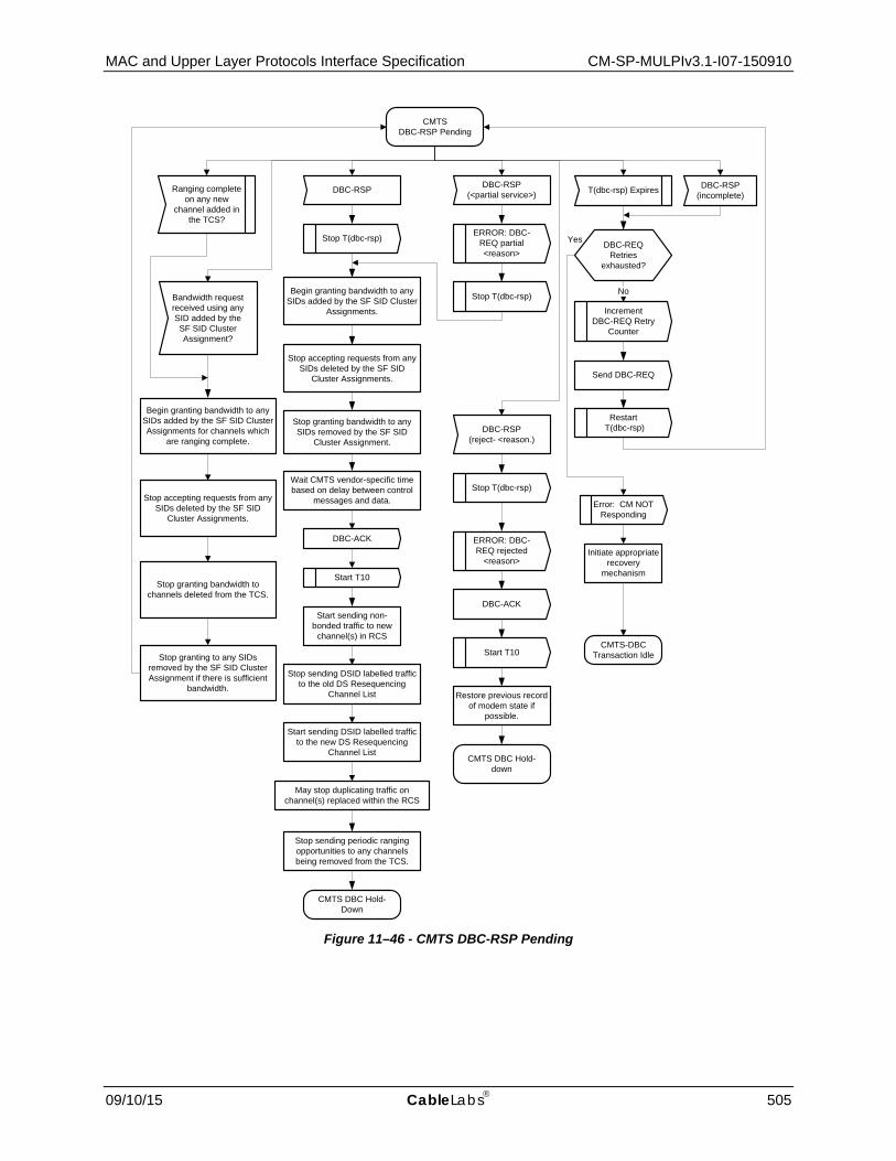
MAC and Upper Layer Protocols Interface Specification CM-SP-MULPIv3.1-I07-150910
09/10/15 CableLabs 505
Figure 11–46 - CMTS DBC-RSP Pending
DBC-RSP T(dbc-rsp) Expires
IncrementDBC-REQ Retry
Counter
Send DBC-REQ
Restart T(dbc-rsp)
Error: CM NOT Responding
CMTS DBC-RSP Pending
CMTS-DBC Transaction Idle
DBC-RSP(<partial service>)
ERROR: DBC-REQ partial <reason>
DBC-REQ Retries
exhausted?
YesStop T(dbc-rsp)
Initiate appropriate recovery
mechanism
Stop T(dbc-rsp) NoBandwidth request received using any SID added by the SF SID Cluster Assignment?
Begin granting bandwidth to any SIDs added by the SF SID Cluster Assignments for channels which
are ranging complete.
Begin granting bandwidth to any SIDs added by the SF SID Cluster
Assignments.
DBC-RSP (incomplete)
Ranging complete on any new
channel added in the TCS?
Stop accepting requests from any SIDs deleted by the SF SID
Cluster Assignments.
Stop granting bandwidth to channels deleted from the TCS.
Stop granting to any SIDs removed by the SF SID Cluster Assignment if there is sufficient
bandwidth.
Stop accepting requests from any SIDs deleted by the SF SID
Cluster Assignments.
Stop granting bandwidth to any SIDs removed by the SF SID
Cluster Assignment.
DBC-ACK
CMTS DBC Hold-Down
Start T10
Start sending non-bonded traffic to new
channel(s) in RCS
May stop duplicating traffic on channel(s) replaced within the RCS
Stop sending DSID labelled traffic to the old DS Resequencing
Channel List
Start sending DSID labelled traffic to the new DS Resequencing
Channel List
Wait CMTS vendor-specific time based on delay between control
messages and data.
Stop sending periodic ranging opportunities to any channels being removed from the TCS.
DBC-RSP(reject- <reason.)
Stop T(dbc-rsp)
ERROR: DBC-REQ rejected
<reason>
DBC-ACK
Start T10
CMTS DBC Hold-down
Restore previous record of modem state if
possible.

CM-SP-MULPIv3.1-I07-150910 Data-Over-Cable Service Interface Specifications
506 CableLabs 09/10/15
Figure 11–47 - CMTS DBC Hold-down
11.5.3.2 CM DBC State Transition Diagrams The CM MUST support the DBC operation as shown in the State Transition diagrams in Figure 11–48 through Figure 11–54.
T 10 Expires
CMTS DBC Hold- down
DBC-RSP
DBC-ACKCMTS- DBC
Transaction Idle

MAC and Upper Layer Protocols Interface Specification CM-SP-MULPIv3.1-I07-150910
09/10/15 CableLabs 507
Figure 11–48 - CM DBC-RSP (part 1)
DBC-REQ
CM Operational
Is the DBC-REQ message fragmented?
No
DBC-RSP (incomplete)
yes
Are all fragments received correctly?
“DBC-REQ Timeout” expires
No
Start “DBC-REQ Timeout” timer
Wait for fragments
DBC-REQ fragment received
ERROR: CMTS Bad
DBC <reason>
DBC-RSP (reject-
<reason>)
Parse DBC-REQ
ERROR: DBC-REQ
denied
DBC-RSP (reject-
<reason>)
Is DBC-REQ consistent with CM capabilities and service flows?
DBC-REQ Valid?
Yes
Stop requesting (contention and piggyback) on any SIDs deleted
from the Service Flow SID Cluster Assignment.
No
No
Yes
Yes
1
1
1
1
2
2
For each RC with a new frequency, start AcquireDS(RC)
processYes
If a new Primary Downstream has been signaled, start
AcquireDS(RC) process
All channels acquired
successfully ?No Yes
RCS SuccessRCS Partial Service
3
Wait for AcquireDS(RC)
DSAcquisitionFail(RC)
DSAcquisitionSuccess(RC)
CM Initialization or Reinit MAC Begin
Re-init MAC
AcquireDS complete for all
RCs?
No
Yes
New DS Resequencing Channel List?
Yes
Expand rapid loss detection of DSID to union of old and
new DS Resequencing Channel Lists
Add, delete, or modify DSID(s) per
DBC-REQ
New channels included in RCS or change of Primary
Downstream?
3
4
RCC Changed? No
Yes
Configure hardware for new RCC
No
Was a new resequencing DSID
created?
Enable rapid loss detection of
resequencing DSIDYes
No
Was there a DSID change to Rapid Loss Detection?
Change rapid loss detection settings of resequencing DSID
Yes
No
No
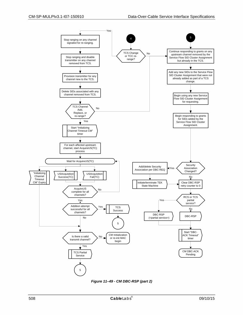
CM-SP-MULPIv3.1-I07-150910 Data-Over-Cable Service Interface Specifications
508 CableLabs 09/10/15
Figure 11–49 - CM DBC-RSP (part 2)
Add any new SIDs to the Service Flow SID Cluster Assignment that were not
already added as part of a TCS change.
NoTCS Change or TCC re-
range?
CM DBC-ACK Pending
Start “DBC-ACK Timeout”
timer
Clear DBC-RSP retry counter to 0
No
Initiate/terminate TEK State Machine
Security Association Changed?
YesAdd/delete Security Association per DBC-REQ
5
Yes
4
Begin responding to grants for SIDs added by the
Service Flow SID Cluster Assignment.
Continue responding to grants on any upstream channel removed by the
Service Flow SID Cluster Assignment but already in the TCS.
Begin using any new Service Flow SID Cluster Assignment
for requesting.
Yes
RCS or TCS partial
service?
DBC-RSP (<partial service>) DBC-RSP
Yes
No
For each affected upstream channel, start AcquireUS(TC)
process
Wait for AcquireUS(TC)
USAcquisitionFail(TC)
USAcquisitionSuccess(TC)
AcquireUS complete for all
channels?
Yes
No
Is there a valid transmit channel?
No
Yes
Addition attempt successful for all
channels?
Yes
No
CM Initialization or re-init MAC
begin
5
TCS Partial Service
5
TCS Success
YesStop ranging and disable
transmitter on any channel removed from TCS.
Provision transmitter for any channel new to the TCS.
Delete SIDs associated with any channel removed from TCS.
NoTCS Channel Add,
Replace, or re-range?
Stop ranging on any channel signaled for re-ranging.
“Initializing Channel Timeout
CM” Expiry
Start “Initializing Channel Timeout CM”
timer

MAC and Upper Layer Protocols Interface Specification CM-SP-MULPIv3.1-I07-150910
09/10/15 CableLabs 509
Figure 11–50 - CM DBC-RSP (part 3)
Add any new SIDs to the Service Flow SID Cluster Assignment that were not
already added as part of a TCS change.
NoTCS Change or TCC re-
range?
CM DBC-ACK Pending
Start “DBC-ACK Timeout”
timer
Clear DBC-RSP retry counter to 0
No
Initiate/terminate TEK State Machine
Security Association Changed?
YesAdd/delete Security Association per DBC-REQ
CM_C
Yes
CM_B
Begin responding to grants for SIDs added by the
Service Flow SID Cluster Assignment.
Continue responding to grants on any upstream channel removed by the
Service Flow SID Cluster Assignment but already in the TCS.
Begin using any new Service Flow SID Cluster Assignment
for requesting.
Yes
RCS or TCS partial
service?
DBC-RSP (<partial service>) DBC-RSP
Yes
No
For each affected upstream channel, start AcquireUS(TC)
process
Wait for AcquireUS(TC)
USAcquisitionFail(TC)
USAcquisitionSuccess(TC)
AcquireUS complete for all
channels?
Yes
No
Is there a valid transmit channel?
No
Yes
Addition attempt successful for all
channels?
Yes
No
CM Initialization or re-init MAC
begin
CM_C
TCS Partial Service
CM_C
TCS Success
YesStop ranging and disable
transmitter on any channel removed from TCS.
Provision transmitter for any channel new to the TCS.
Delete SIDs associated with any channel removed from TCS.
NoTCS Channel Add,
Replace, or re-range?
Stop ranging on any channel signaled for re-ranging.
“Initializing Channel Timeout
CM” Expiry
Start “Initializing Channel Timeout CM”
timer

CM-SP-MULPIv3.1-I07-150910 Data-Over-Cable Service Interface Specifications
510 CableLabs 09/10/15
Figure 11–51 - CM AcquireDS Procedure for SC-QAM
Attempt FEC Lock on new downstream
channel
Downstream Acquisition successful?
Yes
Yes
No
Acquire DS(RC_QAM)Begin
Attempt MPEG Lock on new downstream
channel
Is this the Primary Downstream?
DSAcquisition Fail(RC)
DSAcquisition Success(RC)
End
Yes
Yes
Downstream Acquisition successful?
Attempt SYNC Lock
Re-Init MAC
No
Yes
Is this the Backup Primary
Downstream?
Attempt SYNC Lock
Yes
No

MAC and Upper Layer Protocols Interface Specification CM-SP-MULPIv3.1-I07-150910
09/10/15 CableLabs 511
Figure 11–52 - CM AcquireDS Procedure for OFDM

CM-SP-MULPIv3.1-I07-150910 Data-Over-Cable Service Interface Specifications
512 CableLabs 09/10/15
Program Ranging SID for new channel.
Set request time for new channel.
Store MAPs and UCDs for the channel.
Yes
Perform Ranging as required (initial/station)
No
Able to find MAPs and UCDs for the
channel?
No
DBC Init Technique = 4 (use directly)?
Start
Able to range on new
channel?
Return
Begin using the channel for requesting.
Respond to grants on the channel.
Program SID Clusters for new channel.
US Acquisition Success(TC)
US Acquisition Fail(TC)
Yes
No
Yes
Figure 11–53 - CM AcquireUS Procedure

MAC and Upper Layer Protocols Interface Specification CM-SP-MULPIv3.1-I07-150910
09/10/15 CableLabs 513
Figure 11–54 - CM DBC-ACK Pending
CM DBC-ACK Pending
Stop “DBC-REQ Timeout”
timer
Error: DBC-ACK Not Received
DBC-ACK“DBC-ACK Timeout” expires
Increment DBC-RSP retry counter
Parse DBC-ACK
DBC-ACK
Valid?
Error: Bad CMTS DBC-
ACK
DBC-RSP Retries
Exhausted?
Start “DBC-ACK Timeout” timer
DBC-RSP
No
No Yes
Yes
Was Service Flow SID Cluster Assignment
changed?
Delete SIDs for any Service Flow SID Cluster
Assignment deletions.
Yes
No
CM Operational
For DSIDs in which the DS Resequencing Channel List changed, contract rapid loss
detection to the new DS Resequencing Channel List
Stop responding to grants on any SIDs deleted from the Service Flow SID Cluster
Assignment.
1
11

CM-SP-MULPIv3.1-I07-150910 Data-Over-Cable Service Interface Specifications
514 CableLabs 09/10/15
11.6 Autonomous Load Balancing
Autonomous Load Balancing is a feature of the CMTS that controls dynamic changes to the set of downstream and upstream channels used by a CM.
The CMTS uses the Dynamic Channel Change (DCC) message to control the load balancing of CMs not operating in Multiple Receive Channel mode. The CMTS can also use DCC to load balance the upstream of a CM to which a Transmit Channel Configuration was not assigned in the registration process. The CMTS uses the Dynamic Bonding Change (DBC) message to control load balancing of CMs operating in Multiple Receive Channel mode. With CMs operating in Multiple Receive Channel mode, load balancing can be performed by changing the Receive Channel Set of the CM, or by moving one or more service flows to different downstream channels within the current RCS of the CM. With CMs operating in Multiple Transmit Channel mode, load balancing can be performed by changing the Transmit Channel Set of the CM, or by moving one or more service flows to different upstream channels within the current TCS of the CM.
11.6.1 Load Balancing Groups A "Load Balancing Group" (LBG) is a set of upstream and downstream channels over which a CMTS performs load balancing for a set of CMs.
A Load Balancing Group has the following attributes:
• A set of downstream and upstream channels in the same CM Service Group (CM-SG); • A policy which governs if and when a CM or its individual service flows can be moved; and • A priority value which can be used by the CMTS in order to select which CMs to move.
The CMTS creates a Load Balancing Group for every MD-CM-SG that is instantiated by the topology configuration. This type of LBG is referred to as a "General" Load Balancing Group. Further the operator can configure "Restricted" Load Balancing Groups that contain a subset of the channels in a CM-SG to which a CM can be assigned.
The CMTS MUST support configuration of each channel (upstream and downstream) to more than one LBG (Restricted or General). The CMTS attempts to balance load among all of the channels of each LBG. In cases where a single channel (upstream or downstream) is associated with more than one LBG, the CMTS might have to consider all LBGs for which such overlaps exist in its load balancing algorithm.
During Registration, the CMTS attempts to assign each CM to a Load Balancing Group. If the operator has configured a CM to be in a Restricted Load Balancing Group, then the CMTS restricts the CM to the channels of the configured Restricted Load Balancing Group. If the operator has not configured a CM to be in a Restricted Load Balancing Group, but the CMTS can determine a General Load Balancing Group (i.e., MD-CM-SG) for the CM, the CMTS performs load balancing for the CM among the channels of the General Load Balancing Group. If the CMTS cannot determine either an assigned Restricted Load Balancing Group or the General Load Balancing Group for a registered CM, the CMTS does not perform autonomous load balancing of the CM.
The CMTS MUST NOT assign a CM to more than one Load Balancing Group.
11.6.1.1 General Load Balancing Groups The CMTS MUST implement a General Load Balancing group for every MD-CM-SG, containing all channels of that MD-CM-SG.
The CMTS attempts to identify the General Load Balancing Group (MD-CM-SG) for a CM during the topology resolution process (see Section 10.2.3).
Every CM registers into an MD-CM-SG. The DOCSIS 3.0 initialization procedure enables a CMTS to automatically determine the MD-CM-SG of a DOCSIS 3.0 CM when it initially ranges. In many plant topologies, an upstream channel is configured into a single MD-CM-SG, so the CMTS can also determine the MD-CM-SG for a pre-3.0 DOCSIS CM from its single upstream channel. The CMTS MUST support load balancing of pre-3.0 DOCSIS CMs when their General Load Balancing Group (MD-CM-SG) is determined from the upstream/downstream channel pair upon which they range and register. The CMTS MAY support automatically determining the MD-CM-SG of a pre-

MAC and Upper Layer Protocols Interface Specification CM-SP-MULPIv3.1-I07-150910
09/10/15 CableLabs 515
3.0 DOCSIS CM when its MD-CM-SG cannot be determined from the upstream/downstream channel pair. In the case where the MD-CM-SG cannot be determined, the CM is not associated with a General Load Balancing Group, and is thus not eligible to be moved during load balancing operations unless it is assigned to a Restricted Load Balancing Group.
As explained in Section 5, the set of downstream channels within a MAC Domain that reach a single CM is called an MD-DS-SG. Similarly, the set of upstream channels within a MAC Domain that reach a single CM is called an MD-US-SG.
The default load balancing policy, available initialization techniques, and enable/disable control for a General Load Balancing Group are configured for the GLBG's MAC Domain on the Fiber Node that GLBG serves. In most cases, a GLBG will serve a single Fiber Node, so this MAC Domain-Fiber Node pair maps to a single GLBG. If the GLBG serves multiple Fiber Nodes, the CMTS enforces that all are configured with the same default policy, initialization techniques, and enable/disable control.
11.6.1.2 Restricted Load Balancing Groups Restricted Load Balancing Groups are used to accommodate a topology specific or provisioning specific restriction (such as a set of channels reserved for business customers). The CMTS can associate an upstream or downstream channel with any number of Restricted Load Balancing Groups. A CM can be configured to an identified Restricted Load Balancing Group with the Service Type Identifier or the Load Balancing Group Identifier encodings in the CM configuration file (see Sections Service Type Identifier and CM Load Balancing Group ID in Annex C).
The CMTS MUST enforce that all Restricted LBGs are configured with channels within the same CM Service Group (CM-SG) (see Section 5.2.8). The CMTS SHOULD enforce that all Restricted LBGs are configured with channels within the same MAC Domain CM Service Group (MD-CM-SG). Load Balancing across MAC Domains is out of scope of this specification. The CMTS MUST enforce that a configured LBG contain both downstream and upstream channels. The CMTS MUST permit configuration of the channels of a Restricted Load Balancing Group to consist of some or all of the channels in an MD-CM-SG.
The CMTS will assign a modem to a Restricted Load Balancing Group only if it is explicitly provisioned (via CMTS management objects or configuration file TLV) to be a member of that group.
When the CMTS receives a Registration Request message, the CMTS MUST identify whether this CM has been configured to a specific Service Type or to a Restricted Load Balancing Group via CMTS management objects (see [DOCSIS OSSIv3.0]). If the CM is not assigned to a Service Type or Restricted Load Balancing Group via CMTS management objects, the CMTS MUST check for the presence of the Service Type Identifier and CM Load Balancing Group TLVs in the Registration Request message to identify assignment to a Restricted Load Balancing Group. If the CM is assigned to a Service Type or Restricted Load Balancing Group via CMTS management objects, the CMTS MUST ignore both the Service Type Identifier and the CM Load Balancing Group TLV in the Registration Request message. If the Registration Request contains a Load Balancing Group ID that is not defined on the CMTS, the CMTS MUST ignore the group ID.
If the CM has been assigned to a Restricted Load Balancing Group (either via CMTS management objects or via the config file), and the CMTS detects that the CM is registering on a channel pair that is not associated with the assigned Load Balancing Group, the CMTS MUST move the CM to an appropriate set of channels in the assigned group (either via the channel assignment in the REG-RSP-MP, or by initiating a DCC-REQ when registration completes).
11.6.2 CMTS Load Balancing Operation120 When load balancing is enabled for a particular CM, the CMTS adheres to the following restrictions:
• If the CM is assigned to a Load Balancing Group, the CMTS MUST NOT direct the CM or any of its service flows to move to a channel outside the Load Balancing Group to which it is assigned.
120 Updated per MULPIv3.1-14.1212-2 on 12/5/14 by PO.
CM-SP-MULPIv3.1-I07-150910 Data-Over-Cable Service Interface Specifications
516 CableLabs 09/10/15
• The CMTS MUST move the CM or its service flows to channels on which the CM can operate. The CMTS MUST NOT move a DOCSIS 1.1 compliant CM, or a DOCSIS 2.0 compliant CM that has 2.0 mode disabled, or a 3.0 CM with MTC Mode disabled and 2.0 mode disabled, to a Type 3 or Type 4 upstream channel. The CMTS MUST perform autonomous load balancing of CMs not operating in Multiple Receive Channel mode with a message supported by the CM, i.e., DCC-REQ (DOCSIS 1.1/2.0). The CMTS MUST be capable of performing intra-MAC Domain load balancing of CMs, operating in Multiple Receive Channel mode, either for the entire CM or any individual service flows of the CMs with a DBC message.
• As described in Section 8.1.1, the CMTS MUST ensure that the Required and Forbidden Attributes are met when moving the CM or its service flows.
• If the CMTS cannot determine a Load Balancing Group of the CM, the CMTS MUST NOT perform autonomous load balancing of the CM or any of its service flows.
The CMTS has many factors to consider when autonomously load balancing; these include primary downstream capability (and thus the availability of a DS channel for pre-3.0 DOCSIS CMs), MAP/UCD assignment to DS channels, attribute-based channel assignment, restricted load balancing groups, and multicast replication requirements. When a CM is assigned to a restricted load balancing group, the CMTS MUST give that assignment precedence over the Service Flow attribute-based channel assignment and the multicast replication requirements.
If load balancing is disabled for a CM (either system-wide, or for the load balancing group to which the CM is assigned, or via the load balancing policy assigned to the CM) the CMTS adheres to the following restrictions:
• The CMTS MUST NOT perform autonomous load balancing of the CM. • If the CM supports Multiple Receive Channel mode, the CMTS MUST assign (in Registration Response) an
RCC for which the primary DS channel is the channel upon which the Registration Response is transmitted. If a suitable RCC cannot be provided, the CMTS MUST disable Multiple Receive Channel Mode.
• If the CM supports Multiple Transmit Channel mode, the CMTS MUST assign (in Registration Response) a Transmit Channel Set containing the upstream channel upon which the CM transmitted its Registration Request.
11.6.3 Multiple Channel Load Balancing Operating in Multiple Transmit Channel and/or Multiple Receive Channel mode provides a level of load-balancing on its own. However, in cases where the number of downstream channels or upstream channels in the MD-CM-SG exceeds the number of receive channels or transmit channels for a particular CM, the CMTS performs load balancing using the Dynamic Bonding Change message.
For a CM operating in Multiple Transmit Channel mode, the CMTS performs autonomous load balancing by transmitting DBC messages that change the Transmit Channel Set of the CM and/or the SID_clusters of the CM's upstream service flows.
For a CM operating in Multiple Receive Channel mode, the CMTS performs autonomous load balancing by transmitting DBC messages that change the Receive Channel Configuration, DSIDs and/or Resequencing Channel Lists of the CM.
For a CM operating in Multiple Receive Channel mode, the CMTS can perform autonomous load balancing of a non-bonded, non-resequenced individual downstream service flow to a different downstream channel in the CM's Receive Channel Set without notifying the CM with a DBC message.
11.6.4 Initialization Techniques during Autonomous Load Balancing121 The description of a Load Balancing Group includes the initialization technique(s) that could be used when autonomously load balancing a cable modem within the group. The initialization technique definition for each Load Balancing Group is represented in the form of a bit map, with each bit representing a specific technique (bits 0-7). Initialization technique 0 is only defined for DCC (not DBC). If a Load Balancing Group is restricted to only use initialization technique 0, the CMTS will be forced to use DCC for any CM that it attempts to move.
121 Section updated per MULPIv3.1-14.1193-1 on 12/2/14 by PO.

MAC and Upper Layer Protocols Interface Specification CM-SP-MULPIv3.1-I07-150910
09/10/15 CableLabs 517
11.6.5 Load Balancing Policies Load balancing policies allow control over the behavior of the autonomous load balancing process on a per-CM basis. A load balancing policy is described by a set of conditions (rules) that govern the autonomous load balancing process for the CM. When a load balancing policy is defined by multiple rules, all of the rules apply in combination. This specification does not intend to place requirements on the specific algorithms used by the CMTS for load-balancing, nor does it make a statement regarding the definition of "balanced" load. CMTS vendors are free to develop appropriate algorithms in order to meet market and deployment needs.
Load balancing rules and the load balancing policy definition mechanism have been created to allow for specific vendor-defined load balancing actions. However, there are two basic rules that the CMTS is required to implement.
The CMTS MUST implement the following basic rules:
• Prohibit load balancing using a particular CM • Prohibit load balancing using a particular CM during certain times of the day
The policy ID value of zero is reserved to indicate the CMTS's basic load balancing mechanism, which does not need to be defined by a set of rules.
Each Load Balancing Group has a default load balancing policy. During the registration process, the CMTS MUST assign the CM a load balancing policy ID. The policy ID may be assigned to a cable modem via the cable modem config file. The CMTS MUST assign the CM the load balancing policy ID provisioned in the config file and sent in the Registration Request, if it exists. Otherwise, the CMTS MUST assign the CM the default policy ID defined for the Load Balancing Group.
The per-CM load balancing policy ID assignment can be modified at any time while the CM is in the operational state via internal CMTS processes, and potentially via CMTS management objects; however, the policy ID is always overwritten upon receipt of a Registration Request message.
11.6.6 Load Balancing Priorities A Load Balancing priority is an index that defines a rank or level of importance, which is used to apply differential treatment between CMs in the CMTS's load balancing decision process.
In general, a lower load balancing priority indicates a higher likelihood that a CM will be moved due to load balancing operations. The CMTS MAY take many factors into account when selecting a CM to move, of which priority is only one. When other factors are equal, the CMTS SHOULD preferentially move a CM with lower load balancing priority over one with higher load balancing priority.
The CMTS MUST associate each cable modem with a load balancing priority. Priority may be assigned to a cable modem via the cable modem config file. The CMTS MUST assign the CM the load balancing priority provisioned in the config file and sent in the Registration Request, if it exists. If a cable modem has not been assigned a priority, it is associated with the default (lowest) load balancing priority value of zero.
The per-CM load balancing priority assignment can be modified at any time while the CM is in the operational state via internal CMTS processes as dictated by a specific load balancing policy; or potentially via CMTS management objects; however, the priority assignment is always overwritten upon receipt of a Registration Request message.
11.6.7 Load Balancing and Multicast In order to efficiently manage multicast traffic and balance load across a Load Balancing Group, it is reasonable to expect that the CMTS might attempt to reduce the amount of duplicated multicast traffic by consolidating all members for a specific multicast group to a single downstream channel in the Load Balancing Group. This also applies to multiple profiles on an OFDM channel. More generally, a load balancing algorithm will perform more effectively if it takes into account both the unicast and multicast traffic load for each CM when making decisions on where and when to move CMs.
With CMs performing Multicast DSID Forwarding (Section 9.2), the CMTS is aware of each IP multicast session joined by CPEs behind a CM. In this case, the CMTS can maintain proper IP multicast replication when autonomously moving the received downstream channels or active OFDM profile of a CM. This is not the always

CM-SP-MULPIv3.1-I07-150910 Data-Over-Cable Service Interface Specifications
518 CableLabs 09/10/15
the case for CMs not performing Multicast DSID Forwarding, where the CMTS may be unaware of which CMs have multicast group members and which don't.
CMs not performing Multicast DSID Forwarding track IGMP messages in order to control multicast group forwarding state. The IGMP protocol requires hosts to suppress IGMP messages that are not necessary for the router to maintain multicast group membership state. The [DOCSIS RFIv2.0] and [DOCSIS RFIv1.1] specifications extend these IGMP requirements to the DOCSIS access network by requiring CMs to suppress messages that are deemed to be superfluous for the CMTS. As a result, the CMTS is not guaranteed to be aware of multicast group membership on a per-CM basis for CMs not performing Multicast DSID Forwarding. For an active multicast group, there could be any number of CMs that have group members and that are actively forwarding multicast traffic, but that have not sent a Membership Report to the CMTS. This lack of CMTS awareness can create a situation in which load balancing and multicast conflict.
If a CM with active multicast sessions is moved from its current downstream to a new downstream that is not carrying the multicast traffic, the session will be interrupted until the CM or CPE sends a Membership Report. In order to reduce the interruption of multicast service, CMs that implement active IGMP mode are recommended to send a Membership Report for all active multicast groups upon completion of a DCC or DBC operation that involves a downstream channel change.
The multicast issues are alleviated to some degree when BPI+ is enabled, and are alleviated further when multicast traffic is encrypted using dynamic security associations (see [DOCSIS SECv3.0].
When BPI+ is enabled, a CM will, upon receiving an IGMP "join" message on its CPE interface, send an SA Map Request message to the CMTS. Since this message is only sent at the moment multicast group membership begins, it does not provide any indication of ongoing membership. Because multicast group membership can be transient, the past receipt of an SA Map Request for a particular multicast group, although necessary, is not a sufficient condition to alert the CMTS that the CM currently has members for that multicast group. The absence of an SA Map Request is sufficient evidence that the CM does not have members for the multicast group.
If the multicast traffic for a particular multicast group is encrypted using a dynamic security association, the CMTS can monitor the reception of TEK Key Requests and gain knowledge of multicast group membership. Since it is optional functionality for a CM to stop the TEK state machine (and discontinue sending Key Requests) when there are no longer members for multicast groups mapped to a particular security association, the continued receipt of Key Requests by the CMTS does not necessarily indicate continued multicast group membership. The lack of continuing Key Requests, however, does indicate lack of members.
11.6.8 Externally-Directed Load Balancing The CMTS MUST support a means (via CMTS management objects) for an operator or external entity to direct the CMTS to initiate a DCC or DBC transaction with a CM. Due to the potential conflict between this functionality and the algorithms of the CMTS's own Autonomous Load Balancing functionality, the CMTS MAY reject such directions when Autonomous Load Balancing is enabled.
11.7 Energy Management Operations
11.7.1 Energy Management Features122 During registration the CM advertises the Energy Management features that are supported via the Modem Capabilities encoding. The CMTS confirms the Energy Management features that it supports (and are enabled by the network operator) in the Modem Capabilities Encoding returned in the Registration Response message. In addition to this handshake of capabilities, a configuration file encoding is provided that allows the operator to enable/disable features on a per-modem basis. The CM MUST enable only the energy management features that are both confirmed as supported in the CMTS response to CM Capabilities and enabled via the Energy Management Feature Control TLV in the CM's configuration file.
If Energy Management is enabled during registration, the CM sets the entry and exit thresholds based on the Upstream and Downstream Activity Detection Parameters in the configuration file. If the Upstream and
122 Section updated per MULPIv3.1-14.1196-1 on 12/2/14 by PO.

MAC and Upper Layer Protocols Interface Specification CM-SP-MULPIv3.1-I07-150910
09/10/15 CableLabs 519
Downstream Activity Detection Parameters are not present in the configuration file and Energy Management is enabled, the CM uses vendor-specific default values. Once the CM is operational, the operator might modify the values used for Upstream and Downstream Activity Detection Parameters via SNMP. The Upstream and Downstream Activity Detection Parameters are not intended to be set via SNMP during registration. If the configuration file contains Energy Management MIB objects in a TLV-11, the CM behavior is undefined.
DOCSIS 3.1 adds DOCSIS Light Sleep to supplement the Energy Management 1x1 Feature added to DOCSIS 3.0. The Energy Management 1x1 Mode provides a lower power mode of operation where the CM uses a single upstream channel and one single-carrier QAM downstream channel. The DOCSIS Light Sleep Mode utilizes a single OFDM downstream channel and provides a lower power mode of operation where the CM "sleeps" its receiver and transmitter for a short period of time.
Only one of these two Energy Management Modes is active at a CM at a given time and the mode selection is dependent on the type of channel specified as the CM's primary downstream channel. If the CM's primary downstream channel is a single-carrier QAM channel, the CM's Energy Management Mode is Energy Management 1x1. If the CM's primary downstream channel is an OFDM channel, the CM's Energy Management Mode is DOCSIS Light Sleep. The CMTS MUST NOT place a CM in an Energy Management Mode that is inconsistent with the CM's primary downstream channel type.
11.7.2 Entry and Exit for Energy Management Modes When an Energy Management Feature is enabled, the CM monitors RFI network usage and compares the usage to entry and exit thresholds defined for Energy Management. If the CM's primary downstream channel is an OFDM channel, the CM's Energy Management Mode will be DOCSIS Light Sleep Mode and the CM uses the DLS entry and exit thresholds. If the CM's primary downstream channel is a single carrier QAM channel, the CM's Energy Management Mode will be Energy Management 1x1 and the CM uses the Energy Management 1x1 entry and exit thresholds. The CM MUST use the Energy Management Thresholds for the Energy Management Mode corresponding to the CM's primary downstream channel type.
The CM MAY support features/methods which can temporarily disable Energy Management operation or can request to enter or exit Energy Management Mode using criteria other than defined below (e.g., as triggered by an eSAFE).
If an Energy Management Feature is enabled, the CM MUST monitor the amount of data forwarded upstream and downstream in one second intervals for purposes of triggering a transition into or out of an Energy Management Mode. For upstream monitoring, the CM MUST count data (not including MAC Management Messages) after the rate limiting operation has taken place. For downstream monitoring, the CM MUST count data corresponding to the downstream MAC interface (i.e., not including MAC Management Messages). The CM MUST initiate this activity detection functionality upon reaching the Operational state (see Section 10.2).
From the CM's perspective, entering and exiting an Energy Management Mode is controlled solely by a single TLV communicated to it by the CMTS via DBC-REQ. The CM enters an Energy Management Mode upon successful completion of a DBC transaction that included the Energy Management Indicator TLV (TLV 75) with the value "Operate in Energy Management 1x1 Mode" (1) or "Operate in DOCSIS Light Sleep Mode" (2). The CM exits an Energy Management Mode upon successful completion of a DBC transaction that included the Energy Management Indicator TLV (TLV 75) with the value "Do not operate in Energy Management Mode" (0). When in an Energy Management Mode, the CM utilizes the Upstream and Downstream Exit Bitrate and Time Thresholds as described further below. When the Energy Management Feature is enabled and the CM is not presently operating in an Energy Management Mode, the CM utilizes the Upstream and Downstream Entry Bitrate and Time Thresholds as described further below.
Figure 11–55 below illustrates the transitions into and out of the Energy Management Modes.

CM-SP-MULPIv3.1-I07-150910 Data-Over-Cable Service Interface Specifications
520 CableLabs 09/10/15
Figure 11–55 - Energy Management Modes State Diagram
The CM MUST send an EM-REQ message to request to enter an Energy Management Mode if all of the following statements are true:
• The CM is not operating in an Energy Management Mode. • The per-second upstream data rate has remained less than the threshold provided by the "Upstream Entry
Bitrate Threshold" for a number of consecutive seconds equal to the "Upstream Entry Time Threshold". • The per-second downstream data rate has remained less than the threshold provided by the "Downstream Entry
Bitrate Threshold" for a number of consecutive seconds equal to the "Downstream Entry Time Threshold". • The Energy Management Cycle Period timer is not currently running (see the Energy Management Cycle
Period section in Annex C).
The CM MUST send an EM-REQ message to request to exit the Energy Management Mode if the following statements are true:
• The CM is operating in an Energy Management Mode. • The per-second upstream data rate has remained higher than the threshold provided by the "Upstream Exit
Bitrate Threshold" for a number of consecutive seconds equal to the "Upstream Exit Time Threshold", or the per-second downstream data rate has remained higher than the threshold provided by the "Downstream Exit Bitrate Threshold" for a number of consecutive seconds equal to the "Downstream Exit Time Threshold."
In response to an EM-REQ message requesting to enter an Energy Management Mode of operation, the CMTS responds with an EM-RSP message. If the CMTS sends an EM-RSP message with a status of 'ok', the CMTS SHOULD initiate a DBC transaction that instructs the CM to switch to a TCS and RCS compatible with the desired Energy Management Mode. In the DBC-REQ message, the CMTS MUST indicate that the DBC transaction is causing the CM to enter Energy Management Mode (see Energy Management Mode Indicator section in Annex C). The CMTS is expected to load balance CMs that are operating in Energy Management Modes, to help minimize the likelihood that CMs will experience excessive congestion while in an Energy Management Mode.
When selecting a TCC/RCC appropriate for the Energy Management Mode, the CMTS MUST select channels that meet the requirements of the Attribute Masks for the existing service flows for that CM, if such channels exist in the CM's MD-CM-SG.
In some cases, adherence to Service Flow Attribute-based Assignment may not be possible when selecting a TCC/RCC for the Energy Management Mode operation. In order to resolve this conflict the CMTS MUST support one or both of the following approaches:
Not in Energy Management
Mode
In Energy Management
1x1 Mode
DBC with TLV 75 ==1
DBC with TLV 75 ==0
DS or US Exit Threshold met
/ EM-REQ*
DS and US Entry
Thresholds met/ EM-REQ*
DBC TLV 75 ==2
DBC TLV 75 ==0
In Energy Management
DLS Mode
DS or US Exit Threshold met
/ EM-REQ*
* subject to Hold-Off Timer and Energy Management Cycle Period controls

MAC and Upper Layer Protocols Interface Specification CM-SP-MULPIv3.1-I07-150910
09/10/15 CableLabs 521
• The CMTS MAY require strict adherence to the Required and Forbidden Attribute Masks and thus deny entry into the Energy Management Mode if these Masks cannot be met by the available Individual Channels in the MD-CM-SG.
• The CMTS MAY allow the CM to enter the Energy Management Mode, while not meeting all criteria for the Attribute Masks. In this case the CMTS MUST log a warning event notifying that the Attribute Masks are not being maintained.
While a CM is operating in an Energy Management Mode, the CMTS may receive or initiate a DSA request with associated Attribute Masks. It may not be possible to adhere to the requested attributes when the CM is in an Energy Management Mode. In order to resolve this conflict the CMTS SHOULD force the CM out of the Energy Management Mode if these Masks can be met by the available Individual Channels and Bonding Groups in the modem's MD-CM-SG.
While a CM is operating in an Energy Management Mode, the CMTS MAY not provide the Quality of Service guarantees defined by the Minimum Reserved Rate Service Flow QoS Parameter in excess of 200 kbps; Minimum Reserved Rates less than 200 kbps and other Quality of Service guarantees, such as UGS grants and RTPS polls, are required to be scheduled according to the Service Flow configuration. In some cases, the configuration of UGS and/or RTPS service flows (i.e., grants/polls scheduled across multiple channels) may make Energy Management Mode operation difficult, in these cases the CMTS MAY respond to the EM-REQ with an EM-RSP message containing the response code "Reject Temporary".
In response to an EM-REQ message requesting to exit Energy Management Mode of operation, the CMTS responds with an EM-RSP message. If the CMTS sends an EM-RSP message with a status of 'ok', the CMTS SHOULD initiate a DBC transaction that returns the CM to a TCS and RCS that are appropriate for the CM. The CMTS bases the channel configuration of the CM on its supported transmit channels, receive channels and the Service Flow Attribute Masks. In the DBC-REQ message, the CMTS MUST indicate that the DBC transaction is causing the CM to exit Energy Management Mode of operation (see section HMAC-Digest in Annex C).
11.7.2.1 Example Threshold Operation Figure 11–56 illustrates an example of the Energy Management Feature operation. The figure shows a graph that illustrates the time evolution of the per-second average bitrate for traffic forwarded by a CM. Overlaid on the graph are the Entry and Exit Bitrate Thresholds along with a dashed line indicating which threshold is in active use. For simplicity, the figure only shows one traffic direction (i.e., one set of thresholds and one per-second data rate trace), with the assumption that the traffic in the other direction is always below both of its thresholds.
Beneath the graph are two strips, one that illustrates the timing of the MAC Management Messages associated with the Energy Management Mode and the other that illustrates the portion of time that the CM spends in the Energy Management Mode and the portion that it spends not in an Energy Management Mode. Five enumerated reference times are called out to bring attention to certain details of the operation. At reference times 1 and 5, the CM sends an EM-REQ to enter an Energy Management Mode, which results in the CMTS initiating a DBC transaction to move the CM into an Energy Management Mode. At reference time 3, the CM sends an EM-REQ to exit the Energy Management Mode, which results in the CMTS initiating a DBC transaction to move the CM out of the Energy Management Mode. At reference times 2 and 4, no EM-REQ/RSP messages are sent, and as a result, no DBC messages are sent so the CM does not change modes.
The illustration shows an Entry Time Threshold of 5 seconds and an Exit Time Threshold of 3 seconds. These values were chosen only to keep the illustration compact, and are not to be taken as typical or recommended values for those two parameters.

CM-SP-MULPIv3.1-I07-150910 Data-Over-Cable Service Interface Specifications
522 CableLabs 09/10/15
Figure 11–56 - Example Energy Management Threshold Operation
11.7.2.2 Exiting Energy Management 1x1 Mode From the CMTS perspective, enabling support for Energy Management is performed at the MAC Domain level. At some point in time, it may be desired to disable this CMTS support for Energy Management 1x1 mode. There may be many reasons to justify disabling this support, some of which are:
• To enable detailed monitoring of upstream channel pre-equalization coefficients across all upstream channels and all CMs, which is not possible when CMs are in Energy Management 1x1 Mode,
• Service/maintenance reasons, such as: customer complaints, thresholds not set correctly, Energy Management 1x1 Mode operation problematic in some way.
The command to disable this support can happen at any time. In particular, it can happen while a subset of CMs are currently operating in Energy Management 1x1 Mode, and it can happen while EM-REQ/RSP transactions are in progress. In order to provide a deterministic exit strategy for both the CMTS and the CM base, the following operational sequence is established for when the Energy Management 1x1 Feature is disabled for a MAC Domain:
• If the Energy Management 1x1 Feature is disabled for a MAC Domain, the CMTS MUST respond to newly received EM-REQ messages whose Requested Power Mode parameter is (0): Normal Operation, with an EM-RSP message with a Response Code parameter of (1) OK, and proceed to issue a DBC transaction to bring the CM out of Energy Management 1x1 Mode.
• If the Energy Management 1x1 Feature is disabled for a MAC Domain, the CMTS MUST respond to newly received EM-REQ messages whose Requested Power Mode parameter is (1): Energy Management

MAC and Upper Layer Protocols Interface Specification CM-SP-MULPIv3.1-I07-150910
09/10/15 CableLabs 523
1x1 Mode, with an EM-RSP message with a Response Code parameter of (3) Reject Permanent, Requested Low Power Mode(s) Disabled.
Handling of EM-REQ/RSP transactions to enter Energy Management 1x1 Mode, and their related DBC transactions, that are in-progress at the moment when the Energy Management 1x1 Feature is disabled, is CMTS vendor-dependent. While the CMTS is required to complete such transactions, the CMTS may opt to respond with a rejection confirmation code, or it may opt to allow the transactions to complete successfully.
When the Energy Management 1x1 feature is disabled, the CMTS SHOULD initiate DBC transactions to instruct CMs that are currently operating in Energy Management 1x1 Mode to exit Energy Management 1x1 Mode and return to normal operation. Details will be CMTS vendor-dependent.
11.7.3 Energy Management 1x1 Feature DOCSIS CMs and CMTSs support an Energy Management Feature referred to as "Energy Management 1x1 Mode" in which the CM is instructed by the CMTS (via the Dynamic Bonding Change message) to switch to a Transmit Channel Set containing a single upstream channel and a Receive Channel Set containing a single downstream channel. This mode is applicable to CMs whose primary downstream channel is a single carrier QAM channel. It is expected that the CM will operate in Energy Management 1x1 Mode during "idle" times when the data rate demand of the user has a high likelihood of being satisfied by the available capacity on the single upstream and downstream channel pair to which it is assigned. It is also expected that once the CM requires a higher data rate than can be reliably provided on the single channel pair, the CMTS will instruct the CM to return to a larger Transmit and/or Receive Channel Set.
Because the Energy Management Mode determines the thresholds to use, the CM selects the "Entry" thresholds or the "Exit" thresholds regardless of the number of channels in its TCC or its RCC. While the expectation is that the Energy Management 1x1 Mode will occur when the RCC and TCC have a single channel, there may be instances in which the CM is in Energy Management 1x1 Mode with multiple channels in its RCC and/or TCC. When in Energy Management 1x1 Mode, the CM uses the "Exit" thresholds, regardless of the number of channels in its RCC or TCC. Likewise, when the CM is not in Energy Management 1x1 Mode, the CM uses the "Entry" thresholds, even if it happens to have only a single channel in its RCC and TCC.
11.7.3.1 Bonded Multicast and Energy Management 1x1 Mode Bonded multicast flows require the CM to be tuned to multiple downstream channels, and so conflict with entry into Energy Management 1x1 Mode. As a result, the operator is expected to configure low data rate multicast flows as non-bonded if possible in order to prevent CMs from being kept in multi-channel operation. In this context, "low data rate" multicast flows are flows for which the data rate is expected to typically be below the rate configured in the Downstream Entry Bitrate Threshold configuration file parameter for modems that would be expected to join the flow.
In the following discussion, a DSID that was provisioned as a Resequencing DSID and as a Multicast DSID is called a bonded multicast DSID (see Section 7.4).
When a CM that is configured with one or more bonded multicast DSIDs requests to enter Energy Management 1x1 Mode, the CMTS MUST resolve the conflict to ensure that the CM continues to receive multicast traffic intended for it. For example, the CMTS could resolve the conflict by rejecting the Energy Management 1x1 mode request using the "Reject Temporary" confirmation code (1), or the CMTS could resolve each bonded multicast conflict by replacing the bonded multicast DSID with a non-bonded multicast DSID or by modifying the Resequencing Channel List of the bonded multicast DSID to include only the CM's new single downstream channel.
The CMTS is required to deliver IPv6 provisioning multicasts (e.g., the all-nodes multicast and solicited-node multicasts intended for the CM, CPEs, or eSAFEs) as non-bonded multicast (see Section 9.2.2.3). This prevents disruption of the IPv6 provisioning multicasts which otherwise could interfere with the ability of DAD (Duplicate Address Detection) to detect an address conflict on the network or with other normal provisioning activities (e.g., renewal of a DHCPv6-assigned address).
Since DSG Tunnel frames are always configured as non-bonded traffic, they will not result in the CMTS rejecting a request to enter Energy Management 1x1 Mode. However, the operator will need to ensure that DSG Tunnel traffic

CM-SP-MULPIv3.1-I07-150910 Data-Over-Cable Service Interface Specifications
524 CableLabs 09/10/15
is not disrupted by a DBC operation, as discussed in the [DOCSIS DSG] "DBC Considerations for DOCSIS 3.0 DSG eCMs" and "Load Balancing Considerations" sections.
11.7.4 DOCSIS Light Sleep (DLS) Feature DOCSIS 3.1 CMs and CMTSs support an Energy Management Feature referred to as "DOCSIS Light Sleep Mode" in which the CM is instructed by the CMTS (via the Dynamic Bonding Change message) to change the Receive Channel Set to a single downstream OFDM channel. This mode is applicable to CMs whose primary downstream channel is an OFDM channel. There are no restrictions on the number of channels or the channel types in the CM's TCS during DLS mode operation. The CMTS uses the PHY Link Channel on the OFDM downstream to communicate control information that allows the CM to "sleep" its receiver and transmitter and wake at a specified time. The CMTS MUST schedule a Sleep Time pointing to a time reference less than or equal to 200 msec into the future. The CM MUST support a Sleep Time pointing to a time reference less than or equal to 200 msec into the future. The CM maintains synchronization during the sleep time. It is expected that the CM will operate in DLS Mode during "idle" times when the data rate demand of the user is relatively low. It is also expected that once the CM requires a higher data rate than can be reliably provided with DLS, the CMTS will instruct the CM to return to a larger Transmit and/or Receive Channel Set.
When the DLS Feature is enabled, the CM monitors RFI network usage and requests to enter DLS Mode of operation and exit DLS Mode using the thresholding described in Section 11.7.2.
At registration, the CM is assigned one or more Energy Management Identifiers (EM-IDs) that are used by the CMTS for communicating with the CM when it is in DLS Mode. The CMTS assigns 15-bit EM-IDs to individual CMs or to groups of CMs. A well-known value of 0x7FFF designates a broadcast EM-ID which identifies all CMs. A CM MUST support exactly 3 EM-IDs in addition to the broadcast EM-ID. The CMTS MUST ensure the uniqueness of the individual EM-IDs within each MAC Domain. After registration, the CMTS MAY change the CM's EM-IDs via the DBC message.
The CM enters and exits DLS Mode when commanded to do so by the CMTS via a DBC-REQ message. The CMTS MAY include additional DLS Parameters (TLV 80) in the DBC-REQ message each time it places a CM into DLS Mode. The EM Receive Timer Duration, Maximum Sleep Latency, and Maximum Sleep Bytes DLS Parameters included in a DBC-REQ message apply to a single entry into DLS Mode. The CM sets the EM Receive Timer Duration, the Maximum Sleep Latency, and the Maximum Sleep Bytes DLS Parameters based on the presence or absence of these DLS Parameters in the DBC-REQ message which placed the CM into DOCSIS Light Sleep Mode.
When a CM is operating in DLS Mode, the CM receives control information via the PHY Link Channel (PLC). The PLC contains Energy Management Message Blocks in addition to other information. The CM in DLS Mode listens to the PLC for an EMM addressed to one of the CM's EM-IDs. The CM can receive multiple EMMs that match one of the CM's EM-IDs. When the CM is in a substate where the CM is looking for an EMM, the CM MUST use only the first EMM in a PLC frame that matches one of the EM-IDs assigned to the CM. If a CM enters the Wake Substate due to an US exit threshold, Max Sleep Bytes, or Max Sleep Latency exceeded, the CM ignores EM MBs until its designated Sleep Time. These requirements permit the CMTS to issue EMMs with precedence defined by EMM order, which can be useful, for example, when sending an EMM for a group of CMs while temporarily excluding one or more CMs which are part of that group. The DLS substates are explained further in this section.
The CMTS MAY issue EMMs with Suspend Requests. When a CM receives an EMM with Suspend Request bit set to '1', the CM MUST transition to the Wake Substate and remain in this substate until the CM receives an EMM with the same EM-ID and Suspend Request bit set to '0'. The CMTS MUST insert a value of zero into the Sleep Time field of an EMM with Suspend Request. Upon reception of an EMM with Suspend Request bit set to '1' the CM continues looking for EMMs with the same EM-ID as the EMM which conveyed the Suspend Request. The CM ignores all EM MBs in a PLC when the first EM-ID matching one of the CM's EM-IDs is different from the EM-ID in the EMM that conveyed the Suspend Request. The CMTS can use the Suspend Request signaling to rapidly force individual CMs to Wake Substate for extended periods while continuing DLS duty cycle for other CMs in the common EM group to save energy. The CM MUST reset the state associated with the Suspend Request when it enters the DLS Mode. The CMTS MUST reset the state associated with the Suspend Request for a CM when the CM enters the DLS Mode.
EMMs are transmitted unidirectionally without any acknowledgment of their reception by the CM. A failure to receive an EMM with Suspend Request can create a situation where the CMTS expects that a CM remains in Wake

MAC and Upper Layer Protocols Interface Specification CM-SP-MULPIv3.1-I07-150910
09/10/15 CableLabs 525
Substate while the CM's may receive EMMs with other matching EM-IDs and thus continue DLS duty cycle. To minimize the occurrences of such mismatch, the CMTS SHOULD reissue EMMs with Suspend Request. The CMTS is free to select, using proprietary criteria, the most appropriate EMM retry algorithm. The EM protocol relies on the sequence in which the EMMs are placed in a PLC frame. For this reason, it's necessary to establish a rule which prevents a CM from processing EMMs out of intended order due to a data reception error. If a CM detects any MB CRC error in one of the MBs after TS MB, the CM MUST disregard any subsequent EM MBs in the PLC frame.
A CM in DLS Mode can be in one of three substates: Wake, PLC Rx, or PLC Sleep. In the Wake Substate, the CM is receiving traffic on the downstream data channel, transmitting upstream, and listening to the PLC. In the PLC Rx Substate, the CM can power down the data channel reception circuitry and transmit circuitry and only listens for control information on the PLC. In the PLC Sleep Substate, the CM does not need to listen to the PLC and may power down PLC receiver circuitry in addition to the data channel reception and transmit circuitry. The CM MUST maintain timing during all DLS Mode substates such that the CM maintains its ranging status and can wake to transmit a bandwidth request upstream at any time without first requiring a ranging cycle.
CMs require certain time interval to power down or power up its PLC receiver. While this specification does not define the duration of such interval, its duration is estimated to be on par with the Wake Advance Time. If the CMTS issues EMMs with Sleep Time duration shorter than the duration of such interval, the CM can decide not to power down its PLC receiver.
The CM MUST support EM Receive Timer. The EM Receive Timer defines how long the CM is required to continue listening on the downstream for traffic after reception of the EMM with Sleep Time with a non-zero value. The CM MUST start the EM Receive Timer at the beginning of the PLC frame that is immediately after the PLC frame that includes an EMM with a non-zero Sleep Time. The CMTS MAY communicate the EM Receive Timer to the CM in a DBC-REQ message when placing a CM into DOCSIS Light Sleep Mode. If the CMTS does not communicate the EM Receive Timer to the CM in a DBC-REQ message placing the CM into DOCSIS Light Sleep Mode, the CM MUST assume that the EM Receive Timer duration is zero. The CM sets the EM Receive Timer based on the presence or absence of the EM Receive Timer in the DBC-REQ message each time it goes into DOCSIS Light Sleep Mode.
Note, that the downstream interleaver operation results in relative delay between the Message Blocks received by the CM on the PLC and the data received on downstream data channel. The CMTS MUST account for such delay when scheduling downstream data in concert with issued EMMs.
The Wake Advance Time is defined as the time needed by the CM to power up its full channel receiver after reception of an EMM with Sleep Time of zero or an EMM with Suspend Request or after the Sleep Timer expires and no subsequent EMM are received in the first PLC frame immediately following the PLC frame pointed to by the Sleep Timer.
The CMTS and the CM start their Wake Advance Timers at the moment when the CM enters the Wake substate which is defined as the time corresponding to the start of the PLC frame that is immediately after:
1. the PLC frame that includes an EMM with Sleep Time of zero or an EMM with Suspend Request;
2. the PLC frame pointed to by the Sleep Timer, if the PLC frame pointed to by the Sleep Timer did not include an EMM for the CM.
Note, that the definition of Wake Advance Time is independent of the delays imposed by the downstream interleaver.
The CM MUST be able to receive data on the full OFDM channel after Wake Advance Time. The CMTS MUST delay the data sent to the CMs in DLS mode by Wake Advance Time.
The CM MUST support a Wake Advance Time of 30 msec. The CMTS MUST support a Wake Advance Time of 30 msec.
Figure 11–57 shows an example of the sleep cycles of the full OFDM channel receiver and the PLC receiver. The large rectangle in the figure represents an entire OFDM downstream channel. A portion of that channel is used for the PLC. The CM has a PLC receiver that is a subset of the circuitry needed for receiving the entire OFDM channel. When the CM is in the PLC Sleep Substate, it does not need to listen to the OFDM channel or the PLC. At a time T1, specified in a previous message, the CM enters the PLC Rx Substate by listening to the PLC for Energy
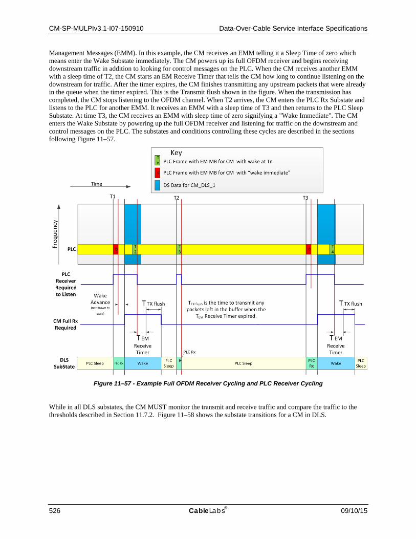
CM-SP-MULPIv3.1-I07-150910 Data-Over-Cable Service Interface Specifications
526 CableLabs 09/10/15
Management Messages (EMM). In this example, the CM receives an EMM telling it a Sleep Time of zero which means enter the Wake Substate immediately. The CM powers up its full OFDM receiver and begins receiving downstream traffic in addition to looking for control messages on the PLC. When the CM receives another EMM with a sleep time of T2, the CM starts an EM Receive Timer that tells the CM how long to continue listening on the downstream for traffic. After the timer expires, the CM finishes transmitting any upstream packets that were already in the queue when the timer expired. This is the Transmit flush shown in the figure. When the transmission has completed, the CM stops listening to the OFDM channel. When T2 arrives, the CM enters the PLC Rx Substate and listens to the PLC for another EMM. It receives an EMM with a sleep time of T3 and then returns to the PLC Sleep Substate. At time T3, the CM receives an EMM with sleep time of zero signifying a "Wake Immediate". The CM enters the Wake Substate by powering up the full OFDM receiver and listening for traffic on the downstream and control messages on the PLC. The substates and conditions controlling these cycles are described in the sections following Figure 11–57.
Figure 11–57 - Example Full OFDM Receiver Cycling and PLC Receiver Cycling
While in all DLS substates, the CM MUST monitor the transmit and receive traffic and compare the traffic to the thresholds described in Section 11.7.2. Figure 11–58 shows the substate transitions for a CM in DLS.

MAC and Upper Layer Protocols Interface Specification CM-SP-MULPIv3.1-I07-150910
09/10/15 CableLabs 527
DLS1 PLC Rx
DLS0 PLC
Sleep
DLS2 Wake
Not in EM DLS
DBC EM TLV == 2 (DLS)
DBC EM TLV == 0 (Not in
EM)
Not in Suspend Request AND TX
Complete AND no Exit Threshold Exceeded
and sufficient time before next wake
EMM with valid sleep time AND
NOT ( Max Sleep Bytes exceeded OR Max Sleep
Latency Exceeded OR Upstream Exit
Threshold Exceeded)
sleep time expired AND NOT (Max
Sleep Bytes exceeded OR Max
Sleep Latency Exceeded OR Upstream Exit
Threshold Exceeded)
Max Sleep Bytes exceeded OR Max
Sleep Latency Exceeded OR Upstream Exit
Threshold Exceeded
Any Exit Threshold Exceeded/Send EM-
REQ (Not in EM Mode) AND Stay in
DLS Wake until receive DBC EM
TLV==0
No EMM with valid sleep time OR [EMM with valid sleep time
AND (EM Receive Timer NOT expired OR TX NOT
Complete)] OR in Suspend
Request
(No EMM in current or next PLC frame) OR EMM with wake immediate
OR Max Sleep Bytes exceeded OR Max Sleep Latency Exceeded OR
Upstream Exit Threshold Exceeded
sleep time NOT expired AND
NOT (Max Sleep Bytes exceeded OR Max Sleep
Latency Exceeded OR Upstream Exit
Threshold Exceeded)
Not in Suspend Request AND TX
Complete AND no Exit Threshold Exceeded and insufficient time
before next wake
When Sleep Time expires/ Look for EMM in current or next PLC frame
Figure 11–58 - CM DLS Substate Diagram
11.7.4.1 Wake Substate When the CM receives the DBC with TLV75 instructing the CM to enter DLS Mode, the CM MUST enter the Wake Substate. In the Wake Substate, the CM transmits and receives traffic as usual. When entering the Wake Substate, the CM MUST look at the PLC for an EMM with a valid sleep time. While awaiting the EMM, the CM continues transmitting and receiving traffic. When the CM receives an EMM with a valid sleep time, the CM MUST start the EM Receive Timer at the beginning of the next PLC frame. When the EM Receive Timer expires, the CM marks the upstream queue depth for each upstream service flow. While in DLS Mode, the CM MUST stay in the Wake Substate until all upstream packets that were in the transmit queue prior to the EM Receive Timer expiring have been transmitted or discarded due to excessive bandwidth request retries. This condition where an EMM with valid sleep time was received, the EM Receive Timer expired, and all packets enqueued prior to the EM Receive Timer expiring have been transmitted or discarded is called "TX Complete". The CM keeps the time of the first packet enqueued for each upstream service flow after the EM Receive Timer has expired and compares the elapsed time to the Max Sleep Latency.
When the CM has achieved TX Complete without exceeding any DLS Exit Criteria, the CM compares the current time to the Sleep Time. If there is sufficient time for the CM to sleep the PLC Receiver and wake prior to the time specified in the sleep time, the CM transitions to the PLC Sleep Substate. If the CM determines that there is insufficient time to sleep prior to the next scheduled wake, the CM transitions to the PLC Rx Substate but does not look at the EMMs until the Sleep Time. A partial substate diagram for the DLS Wake Substate is shown in Figure 11–59. (The full CM Substate Diagram is shown in Figure 11–58.)

CM-SP-MULPIv3.1-I07-150910 Data-Over-Cable Service Interface Specifications
528 CableLabs 09/10/15
DLS1 PLC Rx
DLS0 PLC
Sleep
DLS2 Wake
Not in EM DLS
DBC EM TLV == 2 (DLS)
DBC EM TLV == 0 (Not in
EM)
Not in Suspend Request AND TX
Complete AND no Exit Threshold Exceeded
and sufficient time before next wake
Any Exit Threshold Exceeded/Send EM-
REQ (Not in EM Mode) AND Stay in
DLS Wake until receive DBC EM
TLV==0
No EMM with valid sleep time OR [EMM with valid sleep time
AND (EM Receive Timer NOT expired OR TX NOT
Complete)] OR in Suspend
Request
Not in Suspend Request AND TX
Complete AND no Exit Threshold Exceeded and insufficient time
before next wake
Figure 11–59 - Wake Substate transitions for DLS Mode
11.7.4.2 PLC Rx Substate The CM enters the PLC Rx Substate from either the Wake Substate or the PLC Sleep Substate as shown in Figure 11–60. While in the PLC Rx Substate, the CM disables the OFDM receiver. The CM does not process downstream traffic but continues to enqueue traffic for upstream transmission. The upstream traffic is enqueued but not transmitted in the PLC Rx Substate. If the time a packet has been awaiting transmission ever exceeds the Max Sleep Latency or if the number of bytes in any upstream service flow queue exceeds the Max Sleep Bytes, the CM MUST transition as quickly as possible to the Wake Substate.
The CM MUST enter the PLC Rx Substate such that the PLC Receiver is fully awake when the Sleep Time expires. When the Sleep Time expires, the CM MUST start listening to the PLC. The CM monitors the PLC for EMMs that match any of the CM's EM-IDs. If the CM does not receive an EMM matching any of the CM's EM-IDs in the current or next PLC frame, the CM MUST transition as quickly as possible to the Wake Substate.
If the CM receives an EMM instructing the CM to "Wake Immediate", the CM transitions as quickly as possible to the Wake Substate. If the CM receives an EMM with a valid sleep time, the CM transitions to the PLC Sleep Substate.
If at any time in the PLC Rx Substate, one or more of the DLS Exit Thresholds is exceeded, the CM MUST transition as quickly as possible to the Wake Substate and send to the CMTS an EM-REQ to exit DLS mode.

MAC and Upper Layer Protocols Interface Specification CM-SP-MULPIv3.1-I07-150910
09/10/15 CableLabs 529
DLS1 PLC Rx
DLS0 PLC
Sleep
DLS2 Wake
Not in Suspend Request AND TX
Complete AND no Exit Threshold Exceeded
and sufficient time before next wake
EMM with valid sleep time AND
NOT ( Max Sleep Bytes exceeded OR Max Sleep
Latency Exceeded OR Upstream Exit
Threshold Exceeded)
Max Sleep Bytes exceeded OR Max
Sleep Latency Exceeded OR Upstream Exit
Threshold Exceeded
(No EMM in current or next PLC frame) OR EMM with wake
immediate OR Max Sleep Bytes exceeded OR Max Sleep
Latency Exceeded OR Upstream Exit Threshold
Exceeded
sleep time NOT expired AND
NOT (Max Sleep Bytes exceeded OR Max Sleep
Latency Exceeded OR Upstream Exit
Threshold Exceeded)
sleep time expired AND NOT (Max
Sleep Bytes exceeded OR Max
Sleep Latency Exceeded OR Upstream Exit
Threshold Exceeded)
Not in Suspend Request AND TX
Complete AND no Exit Threshold Exceeded and insufficient time
before next wake
When Sleep Time expires/ Look for EMM in current or next PLC frame
Figure 11–60 - PLC Rx and PLC Sleep Substate transitions for DLS Mode
11.7.4.3 PLC Sleep Substate The CM enters the PLC Sleep Substate from either the Wake Substate or the PLC Rx Substate. While in the PLC Sleep Substate, the CM disables the OFDM receiver. In the PLC Sleep Substate, the CM MAY disable the PLC receiver. The CM does not process downstream traffic (data path receiver disabled) but continues to enqueue traffic for upstream transmission. The upstream traffic is enqueued but not transmitted in the PLC Sleep Substate. If the time a packet has been awaiting transmission ever exceeds the Max Sleep Latency or if the number of bytes in any upstream service flow queue exceeds the Max Sleep Bytes, the CM MUST transition as quickly as possible to the Wake Substate. The CM additionally MAY transition to the Wake Substate in order to transmit a time critical MAC Management message. When in the PLC Sleep Substate, the CM MUST NOT act on any EMMs that could be arriving on the PLC.
Before transitioning into the PLC Sleep Substate, the CM received a Sleep Time in an EM MB that triggered the transition to the PLC Sleep Substate. When that Sleep Time received in an EMM approaches, the CM MUST transition from the PLC Sleep Substate to the PLC Rx Substate such that the PLC Receiver is awake and ready to receive messages when the Sleep Time expires.
If at any time in the PLC Sleep Substate, one or more of the DLS Exit Thresholds is exceeded, the CM MUST transition as quickly as possible to the Wake Substate and send to the CMTS an EM-REQ to exit DLS mode.

CM-SP-MULPIv3.1-I07-150910 Data-Over-Cable Service Interface Specifications
530 CableLabs 09/10/15
11.7.4.4 CMTS Requirements for DLS Mode123 The CMTS MUST transmit unicast MMMs, or MAP messages with unicast ranging opportunities or with probing opportunities to a CM in DLS mode at such time when the CM is capable of receiving these messages. The CMTS can transmit unicast MMMs during the active part of CM's DLS duty cycle. Alternatively, the CMTS can issue EM Suspend Request and place the targeted CM in Wake substate when it transmits unicast MMMs or MAPs with ranging and probing grants to a CM in DLS mode.
The CMTS MUST suspend the transmission of EMMs with sufficient time advance before sending periodic multicast MMMs including UCDs, OCDs, DPDs or MDDs, whenever the CMTS changes the information conveyed in such MMMs. The CMTS MUST refrain from issuing the EMM messages for sufficient interval after transmission of such MMMs to ensure that the all CMs are able to process the messages and act upon the information conveyed in such messages. By temporarily suspending EMM transmission, the CMTS ensures that all CMs are capable to receive these messages and can take necessary actions without the added complication of simultaneous DLS operation.
The CMTS MUST ensure that the CM is not in DLS mode or remains in the Wake substate, when the CM has UGS/RTPS Service Flows in Active or Admitted state. The CMTS SHOULD ensure that the CM is not in DLS mode or remains in the Wake substate, when the CM has Service Flows in Active or Admitted state that have Quality of Service Parameters that cannot be satisfied in the DLS stateful operation. The CMTS MUST NOT instruct a CM to enter the DLS mode when the CM has UGS Service Flows in Active or Admitted state. The CMTS SHOULD NOT instruct a CM that is subscribed to a managed multicast flows to enter the DLS mode. The CMTS MUST NOT issue EMMs with a non-zero sleep time to CMs in DLS mode for whom the CMTS has received new B/W requests or has pending grants. The CMTS MUST NOT perform Upstream Data Profile Testing on CMs in DLS mode. When instructing a CM in DLS state to modify SF to downstream profile mapping, the CMTS MUST first place the CM in Wake substate and keep it in such substate until the profile modification operation is complete. The CMTS MUST NOT send an ODS-REQ or an OPT-REQ to a CM, while the CM is in DOCSIS Light Sleep(DLS) mode or the CM is in Battery Backup mode.
11.7.4.5 Multicast, Broadcast, and DLS Mode Particular handling considerations are needed for delivery of multicast and broadcast packets, which may be received by both CMs that are in the DLS mode and CMs in normal mode. This specification defines two methods for multicast and broadcast delivery: (a) delayed selected multicast (DSM) method, (b) selectively replicated multicast (SRM) method. On any channel, the CMTS MUST use exactly one of these methods for multicast and broadcast delivery: DSM, SRM. The CMTS communicates which method is used by the "DLS Broadcast and Multicast Delivery Method" TLV, Section 6.4.28.1.18, in the MDD so that the CMs know what type of filtering to employ.
Both methods require that the CMTS must identify which multicast packet can be received by CMs in DLS mode, as there may be multicast packets or streams intended only for CMs outside of the DLS mode. The specifics of an algorithm to decide which multicast packet may be received by CMs in DLS mode are left to the CMTS implementation. As a general rule the CMTS SHOULD NOT instruct CMs which are receiving managed multicast streams to enter the DLS mode.
When deploying the DSM method the CMTS delays selected multicast and all broadcast packet PDU frames and transmits those frames while the CMs are in the Wake Substate. The DSM method does not require that packet replication but impacts the delivery of broadcast and multicast packets to CMs operating outside of the DLS mode.
When the CMTS deploys the SRM method, the CMTS MUST replicate all multicast (and broadcast) packet PDU frames that can be received by CMs in DLS mode. The replicated packets are delayed until such time when they can be transmitted during the active part of the DLS duty cycle. To avoid reception of duplicate packets by CMs, the CMTS marks the replicated multicast packets with FC_PARM value of '0b00001'.
The CMTS MUST NOT transmit unicast packet PDUs with FC_PARM value '0b00001'.
When the CMTS deploys the SRM method, the CM operating in DLS mode MUST discard all multicast and broadcast packet PDU frames which include FC_PARM value of '0b0000'.
123 Section updated per MULPIv3.1-15.1302-1 on 6/2/15 by PO.

MAC and Upper Layer Protocols Interface Specification CM-SP-MULPIv3.1-I07-150910
09/10/15 CableLabs 531
Whether or not the CMTS deploys the SRM method, a CM operating outside of the DLS mode MUST discard all packet PDU frames that include FC_PARM of '0b00001'.
11.7.5 Interaction between Battery Backup and DLS Devices that support Battery Backup operation, e.g., certain EMTAs and EDVAs, are generally expected to minimize their energy consumption while operating on battery. If such a device loses power and goes into battery backup mode, the CM sends a CM-STATUS message to the CMTS indicating the CM is on Battery Backup. At this time the CMTS reduces the CM’s Receive Channel Set to the CM’s primary downstream channel and the Transmit Channel Set to a single upstream channel.
A single OFDM channel is significantly faster than a single SC-QAM channel. As a result, the power consumed by the CM to receive a single OFDM channel is expected to be correspondingly greater. This may negatively impact battery lifetime relative to SC-QAM single downstream operation. In order to preserve battery lifetime, an operator may prefer to configure such devices to use an SC-QAM primary downstream rather than an OFDM primary downstream.
If the primary downstream is an OFDM channel, the CM can further reduce energy consumption by requesting to enter DLS operation via the EM-REQ message. These two energy saving modes are signaled independently by the CM. Due to the additional latency characteristics of the DLS mode, the CM will need to exit DLS or remain in the DLS2 substate (i.e., continuously receive the OFDM Primary Downstream channel) in order to support an active voice call.
While battery backup mode is active on a CM with an OFDM primary downstream, when the CM requests to exit DLS mode, the CMTS MUST return the CM to single receive and transmit channel operation. Only when the CM indicates that it is no longer on battery backup will the CMTS return the CM's Receive Channel Set and Transmit Channel Set to a bonded configuration.
For example, an EMTA operating on a single OFDM downstream while on battery backup can request to enter DLS. Since DLS operation cannot support an active voice call, the EMTA will request to exit DLS mode at the initiation of a call, and will request to re-enter DLS upon completion of the call. If the device is reconnected to power and is no longer on battery backup, it will send a CM-STATUS message indicating this change, but it will remain in DLS mode until it requests to exit via an EM-REQ (either due to the initiation of a voice call, or thresholds exceeded) at which time the CMTS will return it to full RCS/TCS operation.

CM-SP-MULPIv3.1-I07-150910 Data-Over-Cable Service Interface Specifications
532 CableLabs 09/10/15
CM Energy Management Transitions (EMTA with Battery Backup)
EM
-RE
QD
BC
Trig
ger
CM
-STA
TUS
Nor
mal
Bon
ded
OFD
M 1
DS
Voi
ce C
all S
tate
DLS
On Battery Backup
Off Battery Backup
Exit DLS Enter DLSEnter DLS Exit DLS
Exit DLS
EM Thresholds exceeded
On Voice Call On Voice Call
DSD for UGS flow
DSA for UGS flow
DSD for UGS flow
Figure 11–61 - Example Interaction between Battery Backup and DLS mode
NOTE: The CMTS can choose to keep the CM in DLS mode, but remain in the Wake substate during active voice calls (see Section 11.7.4.4).
11.8 Downstream Profile Descriptor Changes124
Whenever the CMTS is to change profile parameters specified in the Downstream Profile Descriptor (DPD) message, it needs to provide for an orderly transition from the old values to the new values by all CMs. The CMTS needs to ensure that each CM to which this profile is assigned is either capable of receiving the new profile or is capable of switching to another profile.
Prior to a change to the Downstream Profile Descriptor, the CMTS could assume the CM will be capable of decoding data using the new profile based on the characteristics differences between the old and the new profiles. Alternatively, the CMTS could test the new profile on the relevant CM in order to assess the receive performance with the new profile. The procedure to test a profile is described in Section 10.4.1. The CMTS MUST ensure that the DPD change will not cause any CM to exceed the maximum number of profiles the CM supports (see Section 7.8.1). 124 MULPIv3.1-15.1346-3 on 8/24/15 by PO.

MAC and Upper Layer Protocols Interface Specification CM-SP-MULPIv3.1-I07-150910
09/10/15 CableLabs 533
If the downstream profile change is not for profile A or the NCP profile, then all the requirements of the process described below apply to the downstream data channel only. If the downstream profile change is for profile A or the NCP profile, then all of the CMTS requirements of the process described below apply to messages sent on both the downstream data channel and the PLC. The CM does not monitor DPD messages sent on the PLC after downstream channel acquisition.
The CMTS implements a downstream profile change as follows:
• The CMTS publishes the new profile in a DPD message. The CMTS MUST increment the Configuration Change Count field in the DPD message corresponding to the updated profile to indicate that the profile has changed.
• The CMTS transmits one or more new DPD messages with the new change count value. When the DPD change updates a profile, the CMTS can continue sending traffic with the previous profile.
• The CMTS MUST wait at least the Profile Advance Time (see Annex B) before sending traffic using the updated downstream profile. When it updates a data profile and sends data traffic using the updated downstream profile, the CMTS updates the (even/odd) Data Profile Update bit for the new DPD Configuration Change Count in the corresponding NCP message block (see the Next Codeword Pointer section in [DOCSIS PHYv3.1]. When it updates the NCP profile, the CMTS updates the (even/odd) NCP Update bit for the new DPD Configuration Change Count in the corresponding NCP message block (see the Next Codeword Pointer section in [DOCSIS PHYv3.1]. The CMTS also sets the NCP Profile Update indicator prior to a NCP bit-loading profile change (see the Next Codeword Pointer section in [DOCSIS PHYv3.1].
Because downstream messages can be incorrectly decoded by the CMs, it is recommended that the CMTS send the new DPD message more than once before applying the new DPD parameters to downstream traffic.
The CMTS MUST publish a next-active profile with at least the value "Profile Advance Time" as specified in Annex B before the odd/even bit for either the data profile update or the NCP profile update is toggled in the NCP message block header.
The CMTS MUST NOT update any other downstream profiles on a downstream channel until the "Profile Advance Time" for the current downstream profile change has expired and the corresponding Update bit for the new DPD Configuration Change Count in the corresponding NCP message block has been toggled.
If the downstream profile change is not for the NCP profile or profile A and if a CM is not capable of decoding data using the new profile, the CM MUST issue a CM-STATUS message with the DS OFDM Profile Failure Event (see Section 10.6.4.1.2). If the downstream profile change is for the NCP profile or profile A and if a CM is not capable of decoding data using the new profile and if the CM continues to receive MAPs and UCDs on another downstream channel, the CM MUST issue a CM-STATUS message with the DS OFDM Profile Failure Event (see Section 10.6.4.1.2). This enables the CMTS to make appropriate decisions such as assigning another profile to the CM.
If the downstream profile change is for the NCP profile or profile A and if a CM is not capable of decoding data using the new profile and if the CM stops receiving MAPs and UCDs, then the CM follows the error recovery procedure described in Section 10.6.
An error condition exists if the LSB of the DPD change count and the corresponding Update bit in the NCP are different. The implications and recovery mechanisms differ based on the downstream profile impacted.
• For changes to profiles other than the NCP profile or Profile A, this condition occurs when the Data Profile Update bit in the NCP changed but CM has not received a DPD message with a corresponding Change Count. This condition may happen when the CM misses one or more DPD messages. When it detects this condition, the CM MUST look for the next DPD message for the particular profile and check the change count again. This error condition is confirmed when a new DPD with the updated Change Count is not received within an DPD Profile A Interval. Packets sent on the downstream profile will be dropped while the error condition exists. The CM MUST report the error condition to the CMTS with a CM-STATUS message with the DPD Mismatch Event (Table 10–4). The CM MUST enter partial channel mode (refer to Section 10.6.3) if it is able to do so.
• For changes to Profile A, this condition occurs when the Data Profile Update bit in the NCP changed but CM has not received a DPD message with a corresponding Change Count. This condition may happen when the CM misses one or more DPD messages. When it detects this condition, the CM MUST look for the next DPD message for Profile A on the PLC and check the change count again. This error condition is confirmed when a
CM-SP-MULPIv3.1-I07-150910 Data-Over-Cable Service Interface Specifications
534 CableLabs 09/10/15
new DPD with the updated Change Count is not received within an OCD/DPD PLC Interval. Packets sent on Profile A will be dropped while the error condition exists. The CM MUST report the error condition to the CMTS with a CM-STATUS message with the DPD Mismatch Event (Table 10–4). if it is able to do so. The CM MUST enter partial channel mode (refer to Section 10.6.3) if it is able to do so.
• For changes to the NCP Profile, this condition occurs when the NCP Update bit in the NCP changed but CM has not received a DPD message with a corresponding Change Count. This condition may happen when the CM misses one or more DPD messages. When it detects this condition, the CM MUST look for the next DPD message for the NCP Profile on the PLC and check the change count again. This error condition is confirmed when a new DPD with the updated Change Count is not received within an OCD/DPD PLC Interval. Packets sent on the data channel will be dropped while the error condition exists. The CM MUST enter partial channel mode (refer to Section 10.6.3) if it is able to do so and the PLC is available. If the PLC is unavailable, the CM MUST go into Partial Service Mode (refer to Section 8.4) if it is able to do so.
Upon receiving a CM-STATUS message from the CM indicating an issue with downstream profiles or DPD messages, the CMTS MUST stop sending unicast packets on the profile on which the CM reports the issue. The CMTS MUST resolve the error condition with a minimum impact to the downstream data service. However, it is implementation dependent on how the CMTS can resolve the error condition. For example, the CMTS can use DBC to change the DS channel set for the CM or move the service flows to other profiles from which the CM is able to receive data.
MAC and Upper Layer Protocols Interface Specification CM-SP-MULPIv3.1-I07-150910
09/10/15 CableLabs 535
12 SUPPORTING FUTURE NEW CABLE MODEM CAPABILITIES
12.1 Downloading Cable Modem Operating Software
A CMTS SHOULD be capable of being remotely reprogrammed in the field via a software download over the network.
The cable modem MUST be capable of being remotely reprogrammed in the field via a software download over the network. This software download capability MUST allow the functionality of the cable modem to be changed without requiring that cable system personnel physically revisit and reconfigure each unit. It is expected that this field programmability will be used to upgrade cable modem software to improve performance, accommodate new functions and features (such as enhanced class of service support), correct any design deficiencies discovered in the software, and to allow a migration path as the Data-Over-Cable Service Interface Specification evolves.
The CM MUST implement a TFTP client compliant with [RFC 1350] for software file downloads. The CM MAY implement an HTTP client compliant with [RFC 1945] or [RFC 2616] for software file downloads. The transfer is SNMP-initiated, as described in [DOCSIS OSSIv3.0], or configuration file-initiated, as described here.
• The CM MUST include the TFTP block size option [RFC 2348] when requesting the software image file. • The CM MUST request a block size of 1448 octets if using TFTP over IPv4. • The CM MUST request a block size of 1428 octets if using TFTP over IPv6.
If the file specified in the configuration file SW Upgrade File Name TLV does not match the current software image of the CM, the CM MUST request the specified file via TFTP from the software server. The CM selects the software server as follows:
• If the CM downloads via IPv4 a configuration file which includes the Software Upgrade IPv4 TFTP Server TLV, the CM MUST use the server specified by this TLV. If the CM downloads via IPv4 a configuration file which does not include the Software Upgrade IPv4 TFTP Server TLV, the CM MUST use the IPv4 TFTP server from which it downloaded the configuration file. The CM MUST ignore the Software Upgrade IPv6 TFTP Server TLV when it downloads a configuration file using IPv4.
• If the CM downloads via IPv6 a configuration file which includes the Software Upgrade IPv6 TFTP Server TLV, the CM MUST use the server specified by this TLV. If the CM downloads via IPv6 a configuration file which does not include the Software Upgrade IPv6 TFTP Server TLV, the CM MUST use the IPv6 TFTP server from which it downloaded the configuration file. The CM MUST ignore the Software Upgrade IPv4 TFTP Server TLV when it downloads a configuration file using IPv6.
The CM performs the download after it registers and, if BPI is enabled, after it initializes baseline privacy. When performing a configuration-file-initiated software download, the CM MAY defer bridging between the RF and CPE ports until the download is complete. The CM MUST verify that the downloaded image is appropriate for itself. If the image is appropriate, the CM MUST write the new software image to non-volatile storage. Once the file transfer is completed successfully, the CM MUST restart itself with the new code image with a CM Initialization Reason of SW_UPGRADE_REBOOT.
If the CM is unable to complete the file transfer for any reason, it MUST remain capable of accepting new software downloads (without operator or user interaction), even if power or connectivity is interrupted between attempts. The CM MUST log the failure. The CM MAY report the failure asynchronously to the network manager.
Following upgrade of the operational software, the CM MAY need to follow one of the procedures described above in order to change channels to use the enhanced functionality.
If the CM is to continue to operate in the same upstream and downstream channels as before the upgrade, then it MUST be capable of inter-working with other CMs which may be running previous releases of software.
Where software has been upgraded to meet a new version of the specification, then it is critical that it MUST inter-work with the previous version in order to allow a gradual transition of units on the network.
If the CM receives an ICMP Destination Unreachable message or ICMP port unreachable message for the TFTP server at any time during the firmware download process, the CM MUST terminate the firmware download on the

CM-SP-MULPIv3.1-I07-150910 Data-Over-Cable Service Interface Specifications
536 CableLabs 09/10/15
TFTP server whose address is included in the ICMP Destination Unreachable message without performing the TFTP Read Request Retries or the TFTP Download Retries (Annex B).
12.2 Future Capabilities
If the CM indicates support for one or more CM capabilities defined in a higher-numbered version of DOCSIS, it MUST implement them in a manner that complies with the specification in which the feature is defined.

MAC and Upper Layer Protocols Interface Specification CM-SP-MULPIv3.1-I07-150910
09/10/15 CableLabs 537
Annex A Well-known Addresses (Normative)
A.1 Addresses
A.1.1 General MAC Addresses MAC addresses described here are defined using the Ethernet/ISO8802-3 [ISO/IEC 8802-3] convention as bit-little-endian.
The CMTS MUST use the "All CMs Multicast MAC Address" to address the set of all CMs; for example, when transmitting Allocation Map PDUs. The CM MUST accept all traffic received with the "All CMs Multicast MAC Address".
All CMs Multicast MAC Address: 01-E0-2F-00-00-01
The addresses in the range:
Reserved Multicast MAC Addresses: 01-E0-2F-00-00-02 through 01-E0-2F-00-00-0F
are reserved for future definition. Frames addressed to any of the "Reserved Multicast MAC Addresses" SHOULD NOT be forwarded by the CM. Frames addressed to any of the "Reserved Multicast MAC Addresses" SHOULD NOT be forwarded by the CMTS.
Well-known IPv6 Addresses
IPv6 networks communicate using several well-known addresses per [RFC 4291] described in Table A–1.
Table A–1 - Well-known IPv6 Addresses
Well-known IPv6 MAC Addresses
Well-known IPv6 Addresses Description
33-33-00-01-00-02 FF02::1:2 All DHCP relay agents and servers
33-33-00-01-00-03 FF05::1:3 All DHCP servers
33-33-FF-xx-xx-xx FF02:0:0:0:0:1:FFxx:xxxx Link-local scope solicited node multicast address
33-33-00-00-00-02 FF02::2 Link-local scope all routers multicast address
33-33-00-00-00-01 FF02::1 Link-local scope all nodes multicast address
A.2 MAC Service IDs The following MAC Service IDs have assigned meanings. Those not included in this table are available for assignment, either by the CMTS or administratively.
A.2.1 All CMs and No CM Service IDs The following Service IDs are used in MAPs for special purposes or to indicate that any CM can respond in the corresponding interval.
• 0x0000 is addressed to no CM. This address is typically used when changing upstream burst parameters so that CMs have time to adjust their modulators before the new upstream settings take effect. The CM MUST NOT transmit during any transmit opportunity that has been assigned to the 0x0000 SID. This is also the "Initialization SID" used by the CM during initial ranging.
• 0x3FFF is addressed to all CMs. It is typically used for broadcast Request intervals or broadcast Initial Maintenance intervals.

CM-SP-MULPIv3.1-I07-150910 Data-Over-Cable Service Interface Specifications
538 CableLabs 09/10/15
A.2.2 Well-Known Multicast Service IDs The following Service IDs are only used for Request_2 IEs on SC-QAM upstream channels. They indicate that any CM can respond in a given interval, but that the CM must limit the size of its transmission to a particular number of minislots (as indicated by the particular multicast SID assigned to the interval).
0x3FF1-0x3FFE is addressed to all CMs. IDs in this range are available for small data PDUs, as well as requests (used only with Request_2 IEs). The last digit indicates the frame length and transmission opportunities as follows:
0x3FF1: Within the interval specified, a transmission may start at any minislot, and must fit within one minislot.
0x3FF2: Within the interval specified, a transmission may start at every other minislot, and must fit within two minislots (e.g., a station may start transmission on the first minislot within the interval, the third minislot, the fifth, etc.).
0x3FF3: Within the interval specified, a transmission may start at any third minislot, and must fit within three minislots (e.g., starts at first, fourth, seventh, etc.).
0x3FF4: Starts at first, fifth, ninth, etc.
0x3FFD: Starts at first, fourteenth (14th), twenty-seventh (27th), etc.
0x3FFE: Within the interval specified, a transmission may start at any 14th minislot, and must fit within 14 minislots.
A.2.3 Priority Request Service IDs The following Service IDs (0x3Exx) are reserved for Request IEs (refer to Annex C.2.2.7.1).
If 0x01 bit is set, priority zero can request.
If 0x02 bit is set, priority one can request.
If 0x04 bit is set, priority two can request.
If 0x08 bit is set, priority three can request.
If 0x10 bit is set, priority four can request.
If 0x20 bit is set, priority five can request.
If 0x40 bit is set, priority six can request.
If 0x80 bit is set, priority seven can request.
Bits can be combined as desired by the CMTS upstream scheduler for any Request IUCs.
A.3 MPEG PID On SC-QAM downstream channels the CMTS MUST carry all DOCSIS data in MPEG-2 packets with the header PID field set to 0x1FFE.
A.4 Well-Known Downstream Service ID125 The following Downstream Service ID has assigned meaning and cannot be assigned to any downstream service flow or addressed to any CM.
0xFFFFF: MAC LFSR DSID used to isolate MAC LFSR Frames from other traffic.
125 Section added per MULPIv3.1-N-14.1149-2 on 12/8/14 by PO.

MAC and Upper Layer Protocols Interface Specification CM-SP-MULPIv3.1-I07-150910
09/10/15 CableLabs 539
Annex B Parameters and Constants (Normative) Table B–1 - Parameters and Constants126
System Name Parameter Description Minimum Value
Default Value
Maximum Value
CMTS Sync Interval Nominal time between transmission of SYNC messages (refer to the Time Syncronization subsection of Section 6)
200 msec
CMTS UCD Interval Time between transmission of UCD messages (refer to the UDC subsection of Section 6).
2 sec
CMTS Max MAP Pending The number of minislots that a CMTS is allowed to map into the future (refer to the subsection Map Transmission and Timing of Section 7).
4096 minislot times for TDMA and S-CDMA upstream channels; the equivalent of 20 milliseconds for OFDMA upstream channels
CMTS Ranging Interval Time between transmission of broadcast Initial Maintenance opportunities (refer to the Ranging subsection Section 7).
2 sec
CM Lost Sync Interval Time since last received SYNC message before synchronization is considered lost
600 msec
CM Contention Ranging Retries
Number of Retries on Ranging Requests sent in broadcast maintenance opportunities
16
CM, CMTS
Invited Ranging Retries
Number of Retries on Ranging Requests sent in unicast maintenance opportunities (refer to the subsection Ranging and Automatic Adjustments in Section 10).
16
CM Request Retries Number of retries on bandwidth allocation requests
16
CM CMTS
Registration Request/ Response Retries
Number of retries on Registration Requests/Responses
3
CM Data Retries Number of retries on immediate data transmission
16
CMTS CM MAP processing time
Time provided between arrival of the last bit of a MAP at a CM and effectiveness of that MAP (refer to the subsection Map Transmission and Timing of Section 7) and "Relative Processing Delays" [DOCSIS PHYv3.1])
(600 + M/5.12) µsec for operation in MTC mode for S-CDMA and TDMA channels. (600 + [(symbol duration + cyclic prefix duration) * (K+1)]) µsec for OFDMA channels. K is the number of symbols per OFDMA frame. (200 + M/5.12) µsec for operation not in MTC mode
126 Table updated per MULPIv3.1-N-14.1211-5 on 12/8/14 by PO, MULPIv3.1-N-15.1269-1 on 3/13/15 by PO, MULPIv3.1-N-
15.1346-3 on 8/21/15 by PO.

CM-SP-MULPIv3.1-I07-150910 Data-Over-Cable Service Interface Specifications
540 CableLabs 09/10/15
System Name Parameter Description Minimum Value
Default Value
Maximum Value
CMTS CM Ranging Response processing time
Minimum time allowed for a CM following receipt of a ranging response before it is expected to transmit a ranging request in a unicast opportunity
1 msec
CMTS CM Configuration The maximum time allowed for a CM, following receipt of a configuration file, to send a Registration Request to a CMTS.
30 sec
CM T1 Wait for UCD timeout 5 * UCD interval maximum value
CM T2 Wait for broadcast ranging timeout 5 * ranging interval
CM T3 Wait for ranging response 200 msec
CM T4 Wait for unicast ranging opportunity. If the pending-till-complete field was used earlier by this modem, then the value of that field must be added to this interval. The T4 multiplier may be set in the RNG-RSP message.
30 sec (T4 Multiplier of 1)
30 sec 300 sec (T4 Multiplier of 10)
CMTS T5 Wait for Upstream Channel Change response 2 sec
CM CMTS
T6 Wait for REG-RSP, REG-RSP-MP, or REG-ACK
3 sec
CM CMTS
Minislot size for 1.x channels.
Size of minislot for upstream transmission. For channels that support DOCSIS 1.x CMs.
32 modulation intervals
CM CMTS
Minislot size for DOCSIS 2.0 Only Channels.
Size of minislot for upstream transmission. For channels that do not support DOCSIS 1.x CMs.
16 symbols
CM CMTS
Timebase Tick System timing unit 6.25 µsec
CM CMTS
DSx Request Retries
Number of Timeout Retries on DSA/DSC/DSD Requests
3
CM CMTS
DSx Response Retries
Number of Timeout Retries on DSA/DSC/DSD Responses
3
CM CMTS
T7 Wait for DSA/DSC/DSD Response timeout 1 sec
CM CMTS
T8 Wait for DSA/DSC Acknowledge timeout 300 msec
CM TFTP Backoff Start Initial value for TFTP backoff 1 sec
CM TFTP Backoff End Last value for TFTP backoff 16 sec
CM TFTP Request Retries
Number of retries on TFTP request 4
CM TFTP Download Retries
Number of retries on entire TFTP downloads 3
CM TFTP Wait The wait between TFTP retry sequences 3 min
CMTS T9 Registration Timeout, the time allowed between the CMTS sending a RNG-RSP (success) to a CM, and receiving a REG-REQ or REG-REQ-MP from that same CM.
15 min 15 min
CM CMTS
T10 Wait for Transaction End timeout 3 sec

MAC and Upper Layer Protocols Interface Specification CM-SP-MULPIv3.1-I07-150910
09/10/15 CableLabs 541
System Name Parameter Description Minimum Value
Default Value
Maximum Value
CMTS T11 Wait for a DCC Response on the old channel 300 ms
CM T12 Wait for a DCC Acknowledge 300 ms
CMTS T13 Maximum holding time for QoS resources for DCC on the old channel
1 sec
CM T14 Minimum time after a DSx reject-temp-DCC and the next retry of DSx command
2 sec
CMTS T15 Maximum holding time for QoS resources for DCC on the new channel
2 sec 35 sec
CM T16 Maximum length of time CM remains in test mode after receiving TST-REQ message.
30 min.
CM T17 Maximum Time that CM MUST inhibit transmissions on a channel in response to its Ranging Class ID matching a bit value in the Ranging Hold-Off Priority Field.
300 sec
CMTS DCC-REQ Retries Number of retries on Dynamic Channel Change Request
3
CM DCC-RSP Retries Number of retries on Dynamic Channel Change Response
3
CMTS CM UCD processing time
Time between the transmission of the last bit of a UCD with a new Change Count and the transmission time of the first bit of the first MAP using the new UCD. (See the Upstream Channel Descriptor Changes subsection of Section 11).
1.5 ms * The number of TDMA and S-CDMA upstream channels modified simultaneously + 2.0 ms * The number of OFDMA channels modified simultaneously.
CMTS DBC-REQ Retries Maximum number of times the CMTS will retransmit a DBC-REQ while awaiting the DBC-RSP from the CM
6
CM DBC-REQ Timeout The amount of time that the CM waits to receive all fragments of the DBC-REQ message.
1 second
CM DBC-RSP Retries Maximum number of times the CM will retransmit a DBC-RSP while awaiting the DBC-ACK from the CMTS
6
CM DBC-ACK timeout The amount of time that the CM waits for DBC-ACK after sending DBC-RSP
300 ms
CM DBC DS Acquisition timeout
The amount of time that the CM is to continue trying to acquire downstream channels added to the RCS in a DBC-REQ message.
1 second
CMTS Sequence Hold timeout
The time that the CMTS waits before changing the Sequence Change Count for a resequencing DSID
1 second
CM DSID filter count The total number of DSID filters (Refer to the Downstream Service Extended Header subsectin of Section 6)
32
CM DSID resequencing context count
The number of DSIDs for re-sequencing 16

CM-SP-MULPIv3.1-I07-150910 Data-Over-Cable Service Interface Specifications
542 CableLabs 09/10/15
System Name Parameter Description Minimum Value
Default Value
Maximum Value
CMTS CMTS Skew Limit Maximum interval between CMTS start of transmission of out-of-order sequenced packets on different Downstream Channels, measured at the set of CMTS [DOCSIS DRFI] and [DOCSIS DEPI] interfaces.
3 msecs 5 msecs
CM DSID Resequencing Wait Time
Per-DSID value for the minimum interval a CM delays forwarding of a higher-numbered sequenced packet while awaiting the arrival of a lower-numbered sequenced packet.
8 msec 13 msec
CMTS MDD Interval Time between MDD messages on a given channel
2 sec
CM Lost MDD timeout Time to wait for a MDD before declaring MDD loss
3 * Maximum MDD Interval
CM Initializing channel timeout CM
This field defines the maximum total time that the CM can spend performing initial ranging on the upstream channels described in the TCC of a REG-RSP, REG-RSP-MP, or a DBC-REQ.
60 sec
CMTS Initializing channel timeout CMTS
This field defines the maximum total time that the CMTS waits for a REG-ACK after sending a REG-RSP-MP or waiting for a DBC-RSP after sending a DBC-REQ before retransmitting the REG-RSP-MP or DBC-REQ.
Initializing Channel Timeout CM + 3
Seconds
CM T18 This timer is started when the CM receives the first Registration Response and controls the amount of time the CM waits to possibly receive a duplicate REG-RSP-MP if the REG-ACK is lost.
Initializing Channel Timeout CM + 6
Seconds
CMTS Profile Advance Time
The time between the release of a next-active profile and the toggling of the odd/even bit in the NCP message block.
500 ms
CMTS OCD/DPD PLC Interval
DPD and OCD interval on the PLC 200 ms 250 ms
CMTS DPD Profile A Interval DPD interval on OFDM Profile A 500 ms 600 ms
CM OCD/DPD PLC Timeout
DPD and OCD interval on the PLC that CM uses for timeout purposes
5*CMTS OCD/DPD PLC Interval maximum value
CM DPD Profile A Timeout
DPD interval on OFDM Profile A that CM uses for timeout purposes 5*CMTS DPD Profile A Interval maximum value
CMTS OPT-RSP Timer The maximum time between sending an OPT-REQ and receiving an OPT-RSP with the same DS channel and profile ID.
800 ms
CMTS OPT Test Timer Maximum time between sending an OPT-REQ and receiving the OPT-RSP with a Status of either Complete or Incomplete
3 seconds
CM OPT-ACK Timer Maximum time between sending OPT-RSP with a Status of Complete or Incomplete and receiving an OPT-ACK;
800 ms
CM OPT retry count Maximum attempts to retransmit a message 3
CM T-OFSM OFDMA wait for first station maintenance opportunity timer 10 seconds

MAC and Upper Layer Protocols Interface Specification CM-SP-MULPIv3.1-I07-150910
09/10/15 CableLabs 543
System Name Parameter Description Minimum Value
Default Value
Maximum Value
CMTS CM
DTP Calibration Interval
The time interval between successive DTP calibration message sequences per CMTS-CM pair.
10 seconds Depends upon the DTP Algorithm.
CMTS CM
DTP Retry Count Maximum attempts to retransmit a message 3

CM-SP-MULPIv3.1-I07-150910 Data-Over-Cable Service Interface Specifications
544 CableLabs 09/10/15
Annex C Common TLV Encodings (Normative) Table C–1 provides a summary of the top-level TLV encodings and the messages in which they can appear. Cfg File indicates that a particular TLV is intended to appear in the CM configuration file. REG indicates that a particular TLV can appear in at least one of the following messages: REG-REQ, REG-REQ-MP, REG-RSP, REG-RSP-MP, or REG-ACK. DSx indicates that a particular TLV can appear in at least one of the following messages: DSA-REQ, DSA-RSP, DSA-ACK, DSC-REQ, DSC-RSP, DSC-ACK. DBC indicates that a particular TLV can appear in at least one of the following messages: DBC-REQ, DBC-RSP, DBC-ACK. This table is informative; detailed requirements for the placement of these TLVs in different messages are provided in the referenced sections.
Table C–1 - Summary of Top-Level TLV Encodings127
Type Description Length Cfg File REG DSx DBC DTP Section
0 Pad - x C.1.2.2
1 Downstream Frequency 4 x x C.1.1.1
2 Upstream Channel ID 1 x x C.1.1.2
3 Network Access Control Object 1 x x C.1.1.3
4 DOCSIS 1.0 Class of Service (Deprecated)
5 Modem Capabilities n x C.1.3.1
6 CM Message Integrity Check (MIC) 16 x x C.1.1.5
7 CMTS Message Integrity Check (MIC) 16 x x C.1.1.6
8 Vendor ID Encoding 3 x C.1.3.2
9 SW Upgrade Filename n x C.1.2.3
10 SNMP Write Access Control n x C.1.2.4
11 SNMP MIB Object n x C.1.2.5
12 Modem IP Address 4 x C.1.3.3
13 Service(s) Not Available Response 3 x C.1.3.4
14 CPE Ethernet MAC Address 6 x C.1.2.6
15 Telephone Settings Option (deprecated)
17 Baseline Privacy n x x C.3.1
18 Max Number of CPEs 1 x x C.1.1.7
19 TFTP Server Timestamp 4 x x C.1.1.8
20 TFTP Server Provisioned Modem IPv4 Address
4 x x C.1.1.9
21 SW Upgrade IPv4 TFTP Server 4 x C.1.2.7
22 Upstream Packet Classification n x x x C.1.1.11/C.2.1.1
23 Downstream Packet Classification n x x x C.1.1.12/C.2.1.3
24 Upstream Service Flow n x x x C.1.1.13/C.2.2.1
25 Downstream Service Flow n x x x x C.1.1.14/C.2.2.2
26 Reserved (was deprecated Payload Header Suppression in DOCSIS 3.0 and earlier versions)
C.1.1.15/C.2.3
127 Table updated per MULPIv3.1-N-14.1191-3, MULPIv3.1-N-1204-1, MULPIv3.1-N-14.1211-5, MULPIv3.1-N-14.1212-2, on
12/8/14 by PO. Table updated by MULPIv3.1-N-15.1300-3 on 6/2/15 by PO, MULPIv3.1-N-15.1301-1 on 6/2/15 by PO, MULPIv3.1-N-15.1328-1 on 8/21/15 by PO.

MAC and Upper Layer Protocols Interface Specification CM-SP-MULPIv3.1-I07-150910
09/10/15 CableLabs 545
Type Description Length Cfg File REG DSx DBC DTP Section
27 HMAC-Digest 20 x x C.1.4.1
28 Maximum Number of Classifiers 2 x x C.1.1.16
29 Privacy Enable 1 x x C.1.1.17
30 Authorization Block n x C.1.4.2
31 Key Sequence Number 1 x x C.1.4.3
32 Manufacturer Code Verification Certificate
n x C.1.2.10
33 Co-Signer Code Verification Certificate
n x C.1.2.11
34 SNMPv3 Kickstart Value n x C.1.2.9
35 Subscriber Mgmt Control 3 x x C.1.1.19.1
36 Subscriber Mgmt CPE IPv4 List n x x C.1.1.19.2
37 Subscriber Mgmt Filter Groups 8 x x C.1.1.19.4
38 SNMPv3 Notification Receiver n x C.1.2.12
39 Enable 2.0 Mode 1 x C.1.1.20
40 Enable Test Modes 1 x x C.1.1.20
41 Downstream Channel List n x x C.1.1.22
42 Static Multicast MAC Address 6 x C.1.1.23
43 DOCSIS Extension Field n x x C.1.1.18
44 Vendor Specific Capabilities n x C.1.3.5
45 Downstream Unencrypted Traffic (DUT) Filtering
n x x C.1.1.24
46 Transmit Channel Configuration (TCC)
n x x C.1.5.1
47 Service Flow SID Cluster Assignment n x x x C.1.5.2
48 Receive Channel Profile n x C.1.5.3.1
49 Receive Channel Configuration n x x C.1.5.3.1
50 DSID Encodings n x x C.1.5.3.9
51 Security Association Encoding n x x C.1.5.5
52 Initializing Channel Timeout 2 x x C.1.5.6
53 SNMPv1v2c Coexistence n x C.1.2.13
54 SNMPv3 Access View n x C.1.2.14
55 SNMP CPE Access Control 1 x C.1.2.15
56 Channel Assignment n x x C.1.1.25
57 CM Initialization Reason 1 x C.1.3.6
58 SW Upgrade IPv6 TFTP Server 16 x C.1.2.8
59 TFTP Server Provisioned Modem IPv6 Address
16 x x C.1.1.10
60 Upstream Drop Packet Classification n x x x C.2.1.2
61 Subscriber Mgmt CPE IPv6 Prefix List n x x C.1.1.19.3
62 Upstream Drop Classifier Group ID n x x C.1.1.26

CM-SP-MULPIv3.1-I07-150910 Data-Over-Cable Service Interface Specifications
546 CableLabs 09/10/15
Type Description Length Cfg File REG DSx DBC DTP Section
63 Subscriber Mgmt Control Max CPE IPv6 Addresses
n x x C.1.1.19.5
64 CMTS Static Multicast Session Encoding
n x C.1.1.27
65 L2VPN MAC Aging Encoding n x [DOCSIS L2VPN]
66 Management Event Control Encoding n x C.1.2.16
67 Subscriber Mgmt CPE IPv6 List n x x 0
68 Default Upstream Target Buffer Configuration
2 x C.1.2.17
69 MAC Address Learning Control 1 x C.1.2.18
70 Upstream Aggregate Service Flow n x x C.1.1.28/C.2.2.3
71 Downstream Aggregate Service Flow n x x C.1.1.29/C.2.2.4
72 Metro Ethernet Service Profile n x C.2.2.10
73 Network Timing Profile n x C.1.2.19
74 Energy Management Parameter Encoding
n x x C.1.1.30
75 Energy Management Mode Indicator 1 x C.1.4.4
76 CM Upstream AQM disable 1 x C.1.2.20
77 DOCSIS Time Protocol Encodings n x C.1.6
78 Energy Management Identifier List for CM
n x x C.1.1.30.4
79 UNI Control Encoding n x C.3.3
80 Energy Management – DOCSIS Light Sleep Encodings
n x C.1.4.5
81 Manufacturer CVC Chain n x C.1.2.21
82 Co-signer CVC Chain n x C.1.2.22
83 DTP Mode Configuration 1 x x C.1.1.31
201-231 eSAFE Configuration n x [DOCSIS eDOCSIS]
255 End-of-Data - x C.1.2.1
C.1 Encodings for Configuration and MAC-Layer Messaging The following type/length/value encodings MUST be used by CMs and CMTSs in both the configuration file (see Annex D), in CM Registration Requests, and in Dynamic Service Messages. All multi-octet quantities are in network-byte order, i.e., the octet containing the most-significant bits is the first transmitted on the wire.
The following configuration settings MUST be supported by all CMs which are compliant with this specification.
C.1.1 Configuration File and Registration Settings The TLVs in the following subsections are intended to be forwarded by the CM to the CMTS in the Registration Request message. Some of these TLVs require inclusion in the E-MIC Bitmap in order to be utilized by the CMTS.
C.1.1.1 Downstream Frequency Configuration Setting The frequency of the Primary Downstream Channel to be used by the CM for initialization unless a Downstream Channel List is present in the configuration file. It is an override for the CM's Primary Downstream Channel, selected during scanning. This is the center frequency of the downstream channel in Hz stored as a 32-bit binary

MAC and Upper Layer Protocols Interface Specification CM-SP-MULPIv3.1-I07-150910
09/10/15 CableLabs 547
number. For SC-QAM channels, the frequency in this TLV is the center frequency of the SC-QAM channel. For OFDM channels, the frequency in this TLV is the center frequency of the lowest subcarrier of the 6 MHz encompassed spectrum containing the PHY Link Channel (PLC) at its center. When initializing on the downstream frequency, the CM scans for both downstream channel types.
Type Length Value 1 4 Rx Frequency
Valid Range: For SC-QAM channels, the receive frequency must be a multiple of 62500 Hz. For OFDM channels, the center frequency of the lowest subcarrier of the 6 MHz encompassed spectrum containing the PLC at its center can be located on any one MHz boundary.
C.1.1.2 Upstream Channel ID Configuration Setting The upstream channel ID which the CM MUST use. The CM MUST listen on the defined downstream channel until an upstream channel description message with this ID is found. It is an override for the channel selected during initialization.
Type Length Value 2 1 Channel ID
C.1.1.3 Network Access Control Object If the value field is a 1, CPEs attached to this CM are allowed access to the network, based on CM provisioning. If the value of this field is a 0, the CM MUST continue to accept and generate traffic from the CM itself and not forward traffic from an attached CPE to the RF MAC Network. The value of this field does not affect CMTS service flow operation and does not affect CMTS data forwarding operation.
Type Length Value 3 1 1 or 0
The intent of "NACO = 0" is that the CM does not forward traffic from any attached CPE onto the cable network (a CPE is any client device attached to that CM, regardless of how that attachment is implemented). However, with "NACO = 0", management traffic to the CM is not restricted. Specifically, with NACO off, the CM remains manageable, including sending/receiving management traffic such as (but not limited to):
• ARP: allow the modem to resolve IP addresses, so it can respond to queries or send traps. • DHCP: allow the modem to renew its IP address lease. • ICMP: enable network troubleshooting for tools such as "ping" and "trace-route." • ToD: allow the modem to continue to synchronize its clock after boot. • TFTP: allow the modem to download either a new configuration file or a new software image. • SYSLOG: allow the modem to report network events. • SNMP: allow management activity • HTTP (if supported): allow the modem to download new a software image.
In DOCSIS v1.1, with NACO off, the primary upstream and primary downstream service flows of the CM remain operational only for management traffic to and from the CM. With respect to DOCSIS v1.1 provisioning, a CMTS should ignore the NACO value and allocate any service flows that have been authorized by the provisioning server.
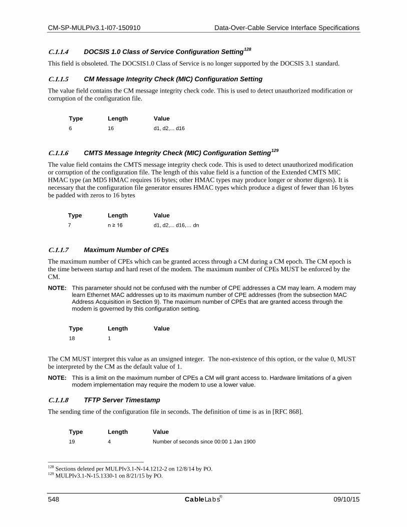
CM-SP-MULPIv3.1-I07-150910 Data-Over-Cable Service Interface Specifications
548 CableLabs 09/10/15
C.1.1.4 DOCSIS 1.0 Class of Service Configuration Setting128 This field is obsoleted. The DOCSIS1.0 Class of Service is no longer supported by the DOCSIS 3.1 standard.
C.1.1.5 CM Message Integrity Check (MIC) Configuration Setting The value field contains the CM message integrity check code. This is used to detect unauthorized modification or corruption of the configuration file.
Type Length Value 6 16 d1, d2,... d16
C.1.1.6 CMTS Message Integrity Check (MIC) Configuration Setting129 The value field contains the CMTS message integrity check code. This is used to detect unauthorized modification or corruption of the configuration file. The length of this value field is a function of the Extended CMTS MIC HMAC type (an MD5 HMAC requires 16 bytes; other HMAC types may produce longer or shorter digests). It is necessary that the configuration file generator ensures HMAC types which produce a digest of fewer than 16 bytes be padded with zeros to 16 bytes
Type Length Value 7 n ≥ 16 d1, d2,... d16,… dn
C.1.1.7 Maximum Number of CPEs The maximum number of CPEs which can be granted access through a CM during a CM epoch. The CM epoch is the time between startup and hard reset of the modem. The maximum number of CPEs MUST be enforced by the CM.
NOTE: This parameter should not be confused with the number of CPE addresses a CM may learn. A modem may learn Ethernet MAC addresses up to its maximum number of CPE addresses (from the subsection MAC Address Acquisition in Section 9). The maximum number of CPEs that are granted access through the modem is governed by this configuration setting.
Type Length Value 18 1
The CM MUST interpret this value as an unsigned integer. The non-existence of this option, or the value 0, MUST be interpreted by the CM as the default value of 1.
NOTE: This is a limit on the maximum number of CPEs a CM will grant access to. Hardware limitations of a given modem implementation may require the modem to use a lower value.
C.1.1.8 TFTP Server Timestamp The sending time of the configuration file in seconds. The definition of time is as in [RFC 868].
Type Length Value 19 4 Number of seconds since 00:00 1 Jan 1900
128 Sections deleted per MULPIv3.1-N-14.1212-2 on 12/8/14 by PO. 129 MULPIv3.1-N-15.1330-1 on 8/21/15 by PO.

MAC and Upper Layer Protocols Interface Specification CM-SP-MULPIv3.1-I07-150910
09/10/15 CableLabs 549
NOTE: The purpose of this parameter is to prevent replay attacks with old configuration files.
C.1.1.9 TFTP Server Provisioned Modem IPv4 Address The IPv4 Address of the modem requesting the configuration file.
Type Length Value 20 4 IPv4 Address
NOTE: The purpose of this parameter is to prevent IP spoofing during registration.
C.1.1.10 TFTP Server Provisioned Modem IPv6 Address The IPv6 Address of the modem requesting the configuration file.
Type Length Value 59 16 IPv6 Address
NOTE: The purpose of this parameter is to prevent IP spoofing during registration.
C.1.1.11 Upstream Packet Classification Configuration Setting This field defines the parameters associated with one entry in an upstream traffic classification list. Refer to Section C.2.1.1.
Type Length Value 22 N
C.1.1.12 Downstream Packet Classification Configuration Setting This field defines the parameters associated with one Classifier in a downstream traffic classification list. Refer to C.2.1.3.
Type Length Value 23 N
C.1.1.13 Upstream Service Flow Encodings This field defines the parameters associated with upstream scheduling for one Service Flow. Refer to Section C.2.2.1.
Type Length Value 24 N
C.1.1.14 Downstream Service Flow Encodings This field defines the parameters associated with downstream scheduling for one Service Flow. Refer to Section C.2.2.2.

CM-SP-MULPIv3.1-I07-150910 Data-Over-Cable Service Interface Specifications
550 CableLabs 09/10/15
Type Length Value 25 N
C.1.1.15 Payload Header Suppression This TLV is not needed in DOCSIS 3.1, and has been removed.
C.1.1.16 Maximum Number of Classifiers This is the maximum number of Classifiers associated with admitted or active upstream Service Flows that the CM is allowed to have. Both active and inactive Classifiers are included in the count. Upstream Drop Classifiers are not included in the count.
This is useful when using deferred activation of provisioned resources. The number of provisioned Service Flows may be high and each Service Flow might support multiple Classifiers. Provisioning represents the set of Service Flows the CM can choose between. The CMTS can control the QoS resources committed to the CM by limiting the number of Service Flows that are admitted. However, it may still be desirable to limit the number of Classifiers associated with the committed QoS resources. This parameter provides that limit.
Type Length Value 28 2 Maximum number of active and inactive Classifiers associated with admitted or
active upstream Service Flows
The default value used by the CM and CMTS MUST be 0 — no limit.
C.1.1.17 Privacy Enable This configuration setting enables/disables Baseline Privacy [DOCSIS SECv3.0] on the Primary Service Flow and all other Service Flows for this CM. If a DOCSIS 2.0 or 3.0 CM receives this setting in a configuration file, the CM is required to forward this setting as part of the Registration Request (REG-REQ or REG-REQ-MP) as specified in the Registration Request Messages subsection of Section 6, regardless of whether the configuration file is DOCSIS 1.1-style or not, while this setting is usually contained only in a DOCSIS 1.1-style configuration file with DOCSIS 1.1 Service Flow TLVs.
Type Length Value 29 1 0 — Disable
1 — Enable
The default value of this parameter used by the CM and CMTS MUST be 1 — privacy enabled.
C.1.1.18 DOCSIS Extension Field130 The DOCSIS Extension Field is used to extend the capabilities of the DOCSIS specification, through the use of new and/or vendor-specific features.
The DOCSIS Extension Field must be encoded using TLV 43 and must include the Vendor ID field (refer to Section C.1.3.1.41) to indicate whether the DOCSIS Extension Field applies to all devices, or only to devices from a specific vendor. The Vendor ID must be the first TLV embedded inside the DOCSIS Extension Field. If the first TLV inside the DOCSIS Extension Field is not a Vendor ID, then the TLV MUST be discarded by the CMTS. In this context, the Vendor ID of 0xFFFFFF is reserved to signal that this DOCSIS Extension Field contains general extension information (see Section C.1.1.18.1); otherwise, the DOCSIS Extension Field contains vendor-specific information (see Section C.1.1.18.1.11).
130 MULPIv3.1-N-15.1334-2 on 8/21/15 by PO.

MAC and Upper Layer Protocols Interface Specification CM-SP-MULPIv3.1-I07-150910
09/10/15 CableLabs 551
This configuration setting may appear multiple times. This configuration setting may be nested inside a Packet Classification Configuration Setting, a Service Flow Configuration Setting, or a Service Flow Response. The same Vendor ID may appear multiple times. However, there must not be more than one Vendor ID TLV inside a single TLV 43.
The CM MUST ignore any DOCSIS Extension Field that it cannot interpret, but still include the TLV in the REG-REQ-MP message. The CM MUST NOT initiate the DOCSIS Extension Field TLVs.
Type Length Value 43 N
C.1.1.18.1 General Extension Information
When using the DOCSIS Extension Field (TLV 43) to encode general extension information, the Vendor ID of 0xFFFFFF must be used as the first sub-TLV inside TLV 43.
Type Length Value 43 N 8, 3, 0xFFFFFF, followed by general extension information
The following sub-TLVs are defined only as part of the General Extension Information. The type values may be re-defined for any purpose as part of a Vendor Specific Information encoding.
C.1.1.18.1.1 CM Load Balancing Policy ID
The CMTS load balancing algorithm uses this config file setting as the CM load balancing policy id. If present, this value overrides the default group policy assigned by the CMTS (see the subsection Autonomous Load Balancing in Section 11). This configuration setting should only appear once in a configuration file. This configuration setting must only be used in configuration files, REG-REQ and REG-REQ-MP messages, and must not be nested inside a Packet Classification Configuration Setting, a Service Flow Configuration Setting, or a Service Flow Response.
Type Length Value 43.1 4 policy id
C.1.1.18.1.2 CM Load Balancing Priority
This config file setting is the CM load balancing priority to be used by the CMTS load balancing algorithm. If present, this value overrides the default priority assigned by the CMTS (see the subsection Autonomous Load Balancing in Section 11). This configuration setting should only appear once in a configuration file. This configuration setting must only be used in configuration files, REG-REQ, and REG-REQ-MP messages, and must not be nested inside a Packet Classification Configuration Setting, a Service Flow Configuration Setting, or a Service Flow Response.
Type Length Value 43.2 4 priority
C.1.1.18.1.3 CM Load Balancing Group ID
This config file setting is the Restricted Load Balancing Group ID defined at the CMTS. If present, this value overrides the general load balancing group. If no Restricted Load Balancing Group is defined that matches this group id, the value is ignored by the CMTS (see the subsection Autonomous Load Balancing in Section 11). This configuration setting should only appear once in a configuration file. This configuration setting must only be used in

CM-SP-MULPIv3.1-I07-150910 Data-Over-Cable Service Interface Specifications
552 CableLabs 09/10/15
configuration files, REG-REQ, and REG-REQ-MP messages, and must not be nested inside a Packet Classification Configuration Setting, a Service Flow Configuration Setting, or a Service Flow Response.
Type Length Value 43.3 4 group id
C.1.1.18.1.4 CM Ranging Class ID Extension131
This config file setting is the CM Ranging Class ID Extension to be defined by the cable operator. These bits will be prepended to the CM's default Ranging Class ID as the most significant bits of the 32 bit Ranging Class ID value. These bits will be sent in the REG-REQ-MP as part of the CM's Ranging Class ID in the modem capabilities field. If the TLV is not included in the configuration file, the CM will use zero for this value. These bits allow the user to define special device classes that could be used to give those devices, or service types, preferential treatment with respect to ranging after a massive outage. After successful registration, the CM MUST store the entire 32 bit value in non-volatile memory and use it for ranging decisions after a reboot or a re-init MAC event.
Type Length Value 43.4 2 Extended ID
C.1.1.18.1.5 L2VPN Encoding
The L2VPN Encoding parameter is a multi-part encoding that configures how the CMTS performs Layer 2 Virtual Private Network bridging for CPE packets. The subtypes of the L2VPN encoding are specified in [DOCSIS L2VPN]. The CMTS MAY support the DOCSIS Layer 2 Virtual Private Network feature as defined in [DOCSIS L2VPN]. If the L2VPN feature is not supported, the CMTS MUST ignore the information in the L2VPN configuration setting.
Type Length Value 43.5 n L2VPN Encoding subtype/length/value tuples
C.1.1.18.1.6 Extended CMTS MIC Configuration Setting
The Extended CMTS MIC Configuration Setting parameter is a multi-part encoding that configures how the CMTS performs message integrity checking. This is used to detect unauthorized modification or corruption of the CM configuration file, using techniques which are not possible using the pre-3.0 DOCSIS CMTS MIC, in particular, using more advanced hashing techniques, or requiring different TLVs to be included in the HMAC calculation. This TLV cannot be contained within an instance of TLV type 43 which contains other subtypes (excluding subtype 8).
Type Length Value 43.6 n Extended CMTS MIC Parameter Encoding subtype/length/value tuples
C.1.1.18.1.6.1 Extended CMTS MIC HMAC type
The Extended CMTS MIC HMAC type parameter is a single byte encoding that identifies the type of hashing algorithm used in the CMTS MIC hash TLV. This subtype is always included within an Extended CMTS MIC Configuration Setting TLV; the instance of the CMTS MIC Hash within the configuration file will use the HMAC technique described by the value of this TLV.
131 MULPIv3.1-N-15.1334-2 on 8/21/15 by PO.

MAC and Upper Layer Protocols Interface Specification CM-SP-MULPIv3.1-I07-150910
09/10/15 CableLabs 553
The CMTS SHOULD support a configuration that can require all REG-REQ or REG-REQ-MP messages to contain an Extended CMTS MIC Encoding with a particular CMTS MIC algorithm.
Type Length Value 43.6.1 1 Enumeration
1 - MD5 HMAC [RFC 2104] 2 - MMH16-σ-n HMAC [DOCSIS SECv3.0] 43 - vendor-specific
C.1.1.18.1.6.2 Extended CMTS MIC Bitmap
The Extended CMTS MIC Bitmap is a multi-byte encoding that is a bitmask representing specified TLV types in a CM configuration file, REG-REQ, or REG-REQ-MP message, Annex D.2. This TLV is always present, and the TLVs to be included within the digest calculation are those whose top level types correspond to bits which are set in this value. For example, to require the Downstream Frequency Configuration Setting to be included in the digest calculation, set bit 1 in the value of this TLV. This TLV uses the BITS Encoding convention where bit positions are numbered starting with bit #0 as the most significant bit.
Type Length Value 43.6.2 n BITS Encoding - Each bit position in this string represents a top-level TLV
bit position 0 is reserved and is always set to a value of 0.
C.1.1.18.1.6.3 Explicit Extended CMTS MIC Digest Subtype
This subtype explicitly provides the calculated extended MIC digest value over all TLVs reported in REG-REQ or REG-REQ-MP for which bits are set in the Extended CMTS MIC Bitmap. If the Extended CMTS MIC Bitmap indicates TLV 43 is to be included in the calculation of the Extended CMTS MIC digest, this subtype (with the value 0) is to be included in that calculation, see Annexes D.1.3 and D.2.1. A valid Explicit Extended CMTS MIC Digest does NOT contain the CM MIC value.
When this subtype is present, the CMTS MIC Configuration Setting in TLV7 is calculated using the set of TLVs as specified for DOCSIS 2.0, in Annex D.2.1.
If this subtype is omitted from an Extended CMTS MIC Encoding, the extended CMTS MIC is implicitly provided in the CMTS MIC Configuration Setting of TLV 7.
When the Explicit Extended CMTS MIC Digest Subtype is present, if the CMTS fails the Extended CMTS MIC Digest verification but passes the pre-3.0 DOCSIS CMTS MIC digest verification of TLV7, then the CMTS MUST NOT consider the CM to have failed authentication. Instead, the CMTS MUST silently ignore all TLVs in REG-REQ or REG-REQ-MP which were marked as protected by the Extended CMTS MIC Bitmap but are not included in the set of TLVs protected by the pre-3.0 DOCSIS CMTS MIC (TLV7) calculation.
Type Length Value 43.6.3 n Calculated MIC digest using the CMTS MIC HMAC Type algorithm
C.1.1.18.1.7 Source Address Verification (SAV) Authorization Encoding
This parameter configures a static range of IP addresses authorized for the Source Address Verification (SAV) enforced by the CMTS for upstream traffic from the CM (see [DOCSIS SECv3.0]). It is intended to be configured for CMs connecting to CPEs with statically configured CPE Host IP addresses or for CMs connecting to a customer premise IP router that reaches a statically assigned IP subnet.

CM-SP-MULPIv3.1-I07-150910 Data-Over-Cable Service Interface Specifications
554 CableLabs 09/10/15
This parameter is intended for the CMTS only, and is ignored by the CM. The parameter is encoded as a subtype of the DOCSIS Extension Information TLV43 encoding in order for it to be included by CMs supporting any DOCSIS version.
An IP address "prefix" is a combination of an IP address (the "prefix address") and a bit count (the "prefix length"). An IP address is said to be "within" a prefix when it matches the prefix length number of most significant bits in the prefix address. A prefix length of zero means that all IP addresses are within the prefix.
The SAV Authorization Encoding defines either or both of:
• A "SAV Group Name" that indirectly identifies an "SAV Group", which is a configured list of prefixes in the CMTS; or
• A list of "Static SAV Prefix Rules", each of which directly defines a single prefix.
The CMTS considers an upstream source IP address within any of the above mentioned prefixes to be authorized for purposes of Source Address Verification.
A valid configuration file, REG-REQ, or REG-REQ-MP message contains at most one instance of the SAV Authorization Encoding. Other restrictions on the subtypes of a valid SAV Authorization Encoding are described below. CM and CMTS operation with an invalid SAV Authorization Encoding is not specified.
Type Length Value 43.7 N Subtype encodings
C.1.1.18.1.7.1 SAV Group Name Subtype
This subtype contains an ASCII string that identifies an SAV Group Name configured in the CMTS.
Type Length Value 43.7.1 1..15 Name of an SAV Group configured in the CMTS.
A valid SAV Authorization Encoding contains zero or one instances of this subtype.
A CMTS MUST support registration of CMs that reference an SAV Group Name that does not exist in the CMTS. A CMTS MUST support creation, modification, and deletion of configured SAV Groups while CMs remain registered that reference the SAV Group Name.
C.1.1.18.1.7.2 SAV Static Prefix Rule Subtype
This subtype identifies a single static prefix within which upstream traffic from the CM is authorized for purposes of Source Address Verification. A valid SAV Authorization Encoding contains zero, one, or more instances of this subtype. A CMTS MUST support at least one SAV Static Prefix Rule for each CM.
The CMTS maintains a management object that reports for each CM the list of SAV Static Prefixes learned from that CM in its REG-REQ or REG-REQ-MP. The CMTS is expected to recognize when multiple CMs report the same list of SAV Static Prefix Rules. The CMTS assigns a "list identifier" to each unique set of SAV prefixes. The minimum number of different SAV Static Prefix lists supported by a CMTS is vendor-specific.
Type Length Value 43.7.2 N SAV Static Prefix Subtype encodings

MAC and Upper Layer Protocols Interface Specification CM-SP-MULPIv3.1-I07-150910
09/10/15 CableLabs 555
C.1.1.18.1.7.2.1 SAV Static Prefix Address Subtype
This subtype identifies an IPv4 or IPv6 address subnet authorized to contain a source IP address of upstream traffic. A valid SAV Static Prefix Rule Subtype contains exactly one instance of this subtype.
Type Length Value 43.7.2.1 4 (IPv4) or
16 (IPv6) Prefix of an IP address range authorized to contain the source IP address for upstream packets.
C.1.1.18.1.7.2.2 SAV Static Prefix Length Subtype
This subtype defines the number of most significant bits in an SAV Static Prefix Address. A valid SAV Static Prefix Rule Subtype contains exactly one instance of this subtype.
Type Length Value 43.7.2.2 1 Range 0..32 for an IPv4 SAV Static Prefix Address or 0..128 for an IPv6 SAV
Static Prefix Address. Number of most significant bits of the Static SAV Prefix Address matched to an upstream source IP address. A value of 0 means that all source addresses are authorized for SAV.
C.1.1.18.1.8 Cable Modem Attribute Masks
If specified, this TLV limits the set of channels to which the CMTS SHOULD assign the cable modem by requiring or forbidding certain binary attributes. This TLV is primarily intended for CMs not operating in Multiple Receive Channel mode. It is CMTS vendor-specific whether or not this TLV is used in channel assignment for CMs operating in Multiple Receive Channel mode. When Service Flow Attribute Masks are present in the CM configuration file as well, the CMTS will observe the precedence order defined in the subsection Channel Assignment During Registration in Section 10.
See the subsection Service Flow Assignment in Section 8 for how the Required Attribute mask, Forbidden Attribute Mask control how CMs may be assigned to particular channels.
Type Length Value 43.9 n Cable Modem Attribute Mask subtype encodings
C.1.1.18.1.8.1 Cable Modem Required Downstream Attribute Mask
If specified, this sub-TLV limits the set of downstream channels to which the CMTS assigns the cable modem requiring certain binary attributes.
Type Length Value 43.9.1 4 32-bit mask representing the set of binary channel attributes required for the CM.
C.1.1.18.1.8.2 Cable Modem Downstream Forbidden Attribute Mask
If specified, this sub-TLV limits the set of downstream channels to which the CMTS assigns the CM by forbidding certain attributes.
Type Length Value 43.9.2 4 32-bit mask representing the set of binary channel attributes forbidden for the CM.

CM-SP-MULPIv3.1-I07-150910 Data-Over-Cable Service Interface Specifications
556 CableLabs 09/10/15
C.1.1.18.1.8.3 Cable Modem Upstream Required Attribute Mask
If specified, this sub-TLV limits the set of upstream channels to which the CMTS assigns the cable modem requiring certain binary attributes.
Type Length Value 43.9.3 4 32-bit mask representing the set of binary channel attributes required for the CM.
C.1.1.18.1.8.4 Cable Modem Upstream Forbidden Attribute Mask
If specified, this sub-TLV limits the set of upstream channels to which the CMTS assigns the CM by forbidding certain attributes.
Type Length Value 43.9.4 4 32-bit mask representing the set of binary channel attributes forbidden for the CM.
C.1.1.18.1.9 IP Multicast Join Authorization Encoding
This subtype of the DOCSIS Extension Information (TLV43) encoding identifies a set of IP Multicast Join Authorization session rules. This parameter is intended for the CMTS only, and is ignored by the CM. The parameter is encoded as a subtype of the DOCSIS Extension Information TLV43 encoding in order for it to be included by CMs supporting any DOCSIS version. A CMTS uses the IP Multicast Join Authorization Encoding to authorize IP multicast session joins for all DOCSIS CM versions.
A valid CM configuration file and CM Registration Request contains zero or one instances of the IP Multicast Join Authorization Encoding. Other restrictions on the subtypes of a valid IP Multicast Join Authorization Encoding are described below. CM and CMTS operation with an invalid IP Multicast Join Authorization Encoding is not specified.
Type Length Value 43.10 N IP Multicast Join Authorization Subtype encodings
C.1.1.18.1.9.1 IP Multicast Profile Name Subtype
This subtype contains an ASCII string that identifies an IP Multicast Profile Name configured in the CMTS.
Type Length Value 43.10.1 1..15 Name of an IP Multicast Profile configured in the CMTS.
A valid IP Multicast Join Authorization Encoding contains zero, one, or more instances of this subtype.
C.1.1.18.1.9.2 IP Multicast Join Authorization Static Session Rule Subtype
This subtype statically configures a single IP multicast "session rule" that controls the authorization of a range of IP multicast sessions. A session rule identifies a CMTS join authorization action of "permit" or "deny" for the combination of a range of source addresses (an "S prefix") and destination group addresses (a "G prefix") of a multicast session.

MAC and Upper Layer Protocols Interface Specification CM-SP-MULPIv3.1-I07-150910
09/10/15 CableLabs 557
An IP address "prefix" is a combination of an IP address (the "prefix address") and a bit count (the "prefix length"). An IP address is said to be "within" a prefix when it matches the prefix length number of most significant bits in the prefix address. A prefix length of zero means that all IP addresses are within the prefix.
Type Length Value 43.10.2 N IP Multicast Join Authorization Static Session Rule subtype encodings
A valid IP Multicast Join Authorization Encoding contains zero or more instances of this subtype.
C.1.1.18.1.9.2.1 RulePriority
This attribute configures the rule priority for the static session rule. A valid IP Multicast Join Authorization Static Session Rule Encoding contains exactly one instance of this subtype.
Type Length Value 43.10.2.1 1 0..255. Higher values indicate a higher priority. If more than one session rule
matches a joined session, the session rule with the highest rule priority determines the authorization action.
C.1.1.18.1.9.2.2 Authorization Action
This attribute specifies the authorization action for a session join attempt that matches the session rule. A valid IP Multicast Join Authorization Static Session Rule Encoding has exactly one instance of this subtype.
Type Length Value 43.10.2.2 1 0 permit
1 deny 2..255 Reserved
C.1.1.18.1.9.2.3 Source Prefix Address Subtype
This subtype identifies the prefix of a range of authorized source addresses for multicast sessions. A valid IP Multicast Join Authorization Static Session Rule Subtype contains zero or one instances of this subtype. A valid IP Multicast Join Authorization Static Session Rule Subtype either includes both a Source Prefix Address Subtype and a Source Prefix Length Subtype, or omits both Source Prefix Address Subtype and Source Prefix Length subtype.
If this subtype is omitted, the session rule is considered to apply to all sources of multicast sessions.
Type Length Value 43.10.2.3 4 (IPv4) or
16 (IPv6) Prefix of an IP address range for the source of IP multicast sessions.
C.1.1.18.1.9.2.4 Source Prefix Length Subtype
This subtype defines the number of matched most significant bits in the Source Prefix Address Subtype in an IP Multicast Join Authorization Static Session Rule Subtype.
Type Length Value 43.10.2.4 1 Number of most significant bits of the Source Prefix Address matched to the source
IP address of a source-specific multicast session. The value range is 0..32 for an IPv4 Source Prefix Address or 0..128 for an IPv6 Source Prefix Address. A value of 0 means that all source addresses are matched by the rule.

CM-SP-MULPIv3.1-I07-150910 Data-Over-Cable Service Interface Specifications
558 CableLabs 09/10/15
C.1.1.18.1.9.2.5 Group Prefix Address Subtype
This subtype identifies the prefix of a range of destination IP multicast group addresses. A valid IP Multicast Join Authorization Static Session Rule Subtype contains exactly one instance of this subtype.
Type Length Value 43.10.2.5 4 (IPv4) or
16 (IPv6) Prefix of an IP address range for the destination group of IP multicast sessions.
C.1.1.18.1.9.2.6 Group Prefix Length Subtype
This subtype defines the number of matched most significant bits in the Group Prefix Address Subtype in an IP Multicast Join Authorization Static Session Rule Subtype. A valid IP Multicast Join Authorization Static Session Rule Subtype contains exactly one instance of this subtype.
Type Length Value 43.10.2.6 1 Number of most significant bits of the Group Prefix Address matched to an IP
destination group address. The value range is 0..32 for an IPv4 Group Prefix Address or 0..128 for an IPv6 Group Prefix Address. A value of 0 means that all destination group addresses are matched by this rule.
C.1.1.18.1.9.3 Maximum Multicast Sessions Encoding
This subtype, if included in an IP Multicast Join Authorization Encoding, configures the CMTS to limit the maximum number of multicast sessions authorized to be dynamically joined by clients reached through the CM.
Type Length Value 43.10.3 2 (unsigned 16 bit
integer) 0 – 65534: the maximum number of sessions permitted to be dynamically joined. A value of 0 indicates that no dynamic multicast joins are permitted. 65535: no limit to the number of multicast sessions to be joined.
C.1.1.18.1.10 Service Type Identifier
A text string identifying the type of service to which this CM is subscribed. This TLV is used by the CMTS to select the correct MAC Domain or Restricted Load Balancing Group to which the CM will be assigned. When this TLV is present in the Registration Request message, the CMTS MUST assign the CM to a MAC Domain or Restricted Load Balancing Group which offers the requested Service Type, if one is available. If no MAC Domain or Restricted Load Balancing Group is available that offers the requested Service Type, the CMTS is free to assign the CM to any available MAC Domain.
If this TLV is included in the configuration file along with the Load Balancing Group ID TLV, this TLV takes precedence. If the indicated Load Balancing Group is available to the CM and offers the requested Service Type, the CMTS MUST assign the CM to that Load Balancing Group. Otherwise, the CMTS ignores the Load Balancing Group ID TLV.
Type Length Value 43.11 1-16 Service Type Identifier

MAC and Upper Layer Protocols Interface Specification CM-SP-MULPIv3.1-I07-150910
09/10/15 CableLabs 559
C.1.1.18.1.11 DEMARC Auto-Configuration (DAC) Encoding
The DEMARC Auto-Configuration (DAC) Encoding parameter is a multi-part encoding that configures how the DPoE System performs the automated provisioning related to set up of a DEMARC management path (DAC-Path) for the purpose of automatically provisioning a DEMARC device. The subtypes of the DAC encoding are specified in [DPoE-DEMARCv1.0]. If the DAC feature is not supported, the CMTS MUST ignore the information in the DAC configuration setting.
Type Length Value
43.12 n DEMARC Auto-Configuration Encoding subtype/length/value tuples
C.1.1.18.2 Vendor Specific Information
Vendor-specific configuration information, if present, is encoded in the DOCSIS Extension Field (code 43) using the Vendor ID field (refer to Annex C.1.3.1.41) to specify which TLV tuples apply to which vendor's products.
Type Length Value 43 N per vendor definition
Example:
Configuration with vendor A specific fields and vendor B specific fields:
VSIF (43) + n (number of bytes inside this VSIF)
8 (Vendor ID Type) + 3 (length field) + Vendor ID of Vendor A
Vendor A Specific Type #1 + length of the field + Value #1
Vendor A Specific Type #2 + length of the field + Value #2
VSIF (43) + m (number of bytes inside this VSIF)
8 (Vendor ID Type) + 3 (length field) + Vendor ID of Vendor B
Vendor B Specific Type + length of the field + Value
C.1.1.19 Subscriber Management TLVs The information in these TLVs is not used by the CM; rather, the information is used by the CMTS to populate the Subscriber Management MIB for this CM.
C.1.1.19.1 Subscriber Management Control
This three byte field provides control information to the CMTS for the Subscriber Management requirements in [DOCSIS OSSIv3.0]. The first two bytes represent the number of IPv4 addresses permitted behind the CM. The third byte is used for control fields.
Type Length Value 35 3 byte 1,2 MaxCpeIPv4 (low-order 10 bits)
byte 3, bit 0: Active
byte 3, bit 1: Learnable
byte 3, bits #2-7: reserved, must be set to zero

CM-SP-MULPIv3.1-I07-150910 Data-Over-Cable Service Interface Specifications
560 CableLabs 09/10/15
C.1.1.19.2 Subscriber Management CPE IPv4 List
This field lists the IPv4 Addresses the CMTS uses as part of the total of the Max CPE IPv4 addresses in the Subscriber Management requirements in [DOCSIS OSSIv3.0].
Type Length Value 36 N (multiple of 4) Ipa1, Ipa2, Ipa3, Ipa4
C.1.1.19.3 Subscriber Management CPE IPv6 Prefix List
This field lists the provisioned CPE IPv6 Prefixes the CMTS uses as part of the total of the Max CPE IPv6 prefixes in the Subscriber Management requirements in [DOCSIS OSSIv3.0].
Type Length Value 61 N (multiple of 17) IP Prefix 1/length, IP Prefix 2/length, etc.
Out of each 17 bytes, the first 16 define the IPv6 prefix, and the 17th defines the length.
C.1.1.19.4 Subscriber Management Filter Groups
The Subscriber Management MIB allows an upstream and downstream filter group to be assigned to a CM and its associated CPE and Service/Application Functional Entities (SAFEs). These filter groups are encoded in the configuration file in a single TLV as follows:
Type Length Value 37 N (multiple of 4, minimum of 8) bytes 1,2: docsSubMgt3GrpSubFilterDs group
bytes 3,4: docsSubMgt3GrpSubFilterUs group
bytes 5,6: docsSubMgt3Grp CmFilterDs group
bytes 7,8: docsSubMgt3Grp CmFilterUs group
bytes 9,10: docsSubMgt3Grp PsFilterDs group
bytes 11,12: docsSubMgt3Grp PsFilterUs group
bytes 13,14: docsSubMgt3Grp MtaFilterDs group
bytes 15,16: docsSubMgt3Grp MtaFilterUs group
bytes 17,18: docsSubMgt3Grp StbFilterDs group
bytes 19,20: docsSubMgt3Grp StbFilterUs group
The elements: docsSubMgt3GrpSubFilterDs, docsSubMgt3GrpSubFilterUs, docsSubMgt3GrpCmFilterDs, and docsSubMgt3GrpCmFilterUs, are mandatory elements. If the length is 16, the CMTS MUST use bytes 1 and 2 to populate both the docsSubMgt3GrpSubFilterDs and docsSubMgt3GrpStbFilterDs MIB entries, and bytes 3 and 4 to populate both the docsSubMgt3GrpSubFilterUs and docsSubMgt3GrpStbFilterUs MIB entries. If the length is 12, the CMTS MUST use bytes 1 and 2 to populate the docsSubMgt3GrpSubFilterDs, docsSubMgt3GrpStbFilterDs and docsSubMgt3GrpMtaFilterDs MIB entries, and bytes 3 and 4 to populate the docsSubMgt3GrpSubFilterUs, docsSubMgt3GrpStbFilterUs and docsSubMgt3GrpMtaFilterUs MIB entries. If the length is 8, the CMTS MUST use bytes 1 and 2 to populate the docsSubMgt3GrpSubFilterDs, docsSubMgt3GrpStbFilterDs, docsSubMgt3GrpMtaFilterDs and docsSubMgt3GrpPsFilterDs MIB entries, and bytes 3 and 4 to populate the docsSubMgt3GrpSubFilterUs, docsSubMgt3GrpStbFilterUs, docsSubMgt3GrpMtaFilterUs and docsSubMgt3GrpPsFilterUs MIB entries. If the length is greater than 20, the additional bytes MUST be ignored by the CMTS.

MAC and Upper Layer Protocols Interface Specification CM-SP-MULPIv3.1-I07-150910
09/10/15 CableLabs 561
C.1.1.19.5 Subscriber Management Control Max CPE IPv6 Addresses
This field configures the maximum number of IPv6 addresses the CMTS allows forwarding traffic for the CM. This is the corresponding IPv6 version of the "Max Cpe IPv4" encoding of the Subscriber Management Control encoding (TLV 35).
Type Length Value 63 2 low-order 10 bits
C.1.1.19.6 Subscriber Management CPE IPv6 List
This field lists the Ipv6 Addresses the CMTS uses as part of the total of the Max CPE Ipv6 addresses in the Subscriber Management requirements in [DOCSIS OSSIv3.0].
Type Length Value 67 N (multiple of 16) Ipv6 Address1, Ipv6 Address2,...Ipv6AddressN
C.1.1.20 Enable 2.0 Mode132 This TLV only has relevance for pre-DOCSIS 3.1 CM. This configuration setting enables/disables DOCSIS 2.0 mode for a CM registering: 1) with a DOCSIS 2.0 CMTS; or 2) CM registering with a DOCSIS 3.0 CMTS and not operating in Multiple Transmit Channel Mode. When a CM is commanded to operate in Multiple Transmit Channel Mode according to the REG-RSP, this configuration setting does not have relevance. When a CM is not in Multiple Transmit Channel Mode, this configuration setting has relevance in that a CM has 2.0 mode enabled or not, and if 2.0 mode is enabled the CM is actually operating in 2.0 mode if the upstream channel is of type 2,3, or 4.
Type Length Value 39 1 0 - Disable
1 - Enable
C.1.1.21 Enable Test Modes This configuration setting enables/disables certain test modes for a CM which supports test modes. The definition of the test modes is beyond the scope of this specification.
If this TLV is not present, the default value used by the CM MUST be 0 – Test modes disabled.
Type Length Value 40 1 0 – Disable
1 – Enable
C.1.1.22 Downstream Channel List This is a list of receive frequencies to which the CM is allowed to tune during scanning operations. When the Downstream Channel List is provided in a configuration file, the CM MUST NOT attempt to establish communications using a downstream channel that is absent from this list unless specifically directed to do so by the CMTS. For example, the CMTS may direct the CM to use downstream channel(s) not listed in the Downstream Channel List via Registration Response, DBC Request, and/or DCC Request message. When both the Downstream 132 MULPIv3.1-N-15.1328-1 on 8/21/15 by PO.

CM-SP-MULPIv3.1-I07-150910 Data-Over-Cable Service Interface Specifications
562 CableLabs 09/10/15
Channel List and the Downstream Frequency Configuration Setting (Annex C.1.1.1) are included in the configuration file, the CM MUST ignore the Downstream Frequency Configuration Setting. This list can override the last operational channel stored in NVRAM as defined in the subsection Scan for Downstream Channel in Section 10. The CM MUST retain and employ this list of channels whenever the CM performs a re-initialize MAC or continue scanning operation. The CM MUST replace or remove the list by subsequent configuration file downloads. Upon power cycle, the CM MUST NOT enforce a previously learned downstream channel list. However, the CM MAY remember this list as an aid to downstream channel acquisition.
Type Length Value 41 N List of Allowed Rx Frequencies
The list of allowed downstream frequencies is composed of an ordered series of sub-TLVs (Single Downstream Channel, Downstream Frequency Range, and Default Scanning) as defined below. When scanning for a downstream channel (except after a power-cycle), the CM MUST scan through this ordered list and attempt to establish communications on the specified channel(s). The scanning is initialized as follows:
• If the CM is in an operational state, and then undergoes a re-initialize MAC operation (except due to a DCC or a DBC), it MUST first scan the last operational frequency and then restart scanning at the beginning of the ordered list.
• If, while scanning this ordered list, the CM fails to become operational and is forced to re-initialize MAC, the CM MUST continue scanning from the next applicable frequency in the ordered list.
• If it reaches the Default Scanning TLV (TLV 41.3) in the configuration file, the CM begins its default scanning algorithm, completing initial ranging and DHCP and receiving a new configuration file via TFTP on the first valid frequency it sees. If the new configuration file does not contain TLV 41, the CM MUST continue with registration. If the new configuration file contains TLV 41, the CM MUST confirm that the frequency of the current Primary Downstream Channel is explicitly listed in the Downstream Channel List. If the frequency of the current Primary Downstream Channel is not explicitly listed in the Downstream Channel List, the CM MUST NOT register on the current Primary Downstream Channel (SC-QAM or OFDM); instead, the CM MUST restart scanning according to the Downstream Channel List contained in the configuration file.
Upon reaching the end of the List, the CM MUST begin again with the first sub-TLV in the List. The CM MUST be capable of processing a Downstream Channel List that contains up to 16 sub-TLVs.
This configuration setting may appear multiple times. If this configuration setting appears multiple times, all sub-TLVs MUST be considered by the CM to be part of a single Downstream Channel List in the order in which they appear in the configuration file. In other words, the sub-TLVs from the first instance of this configuration setting would comprise the first entries in the ordered series; the second instance would comprise the next entries, etc.
C.1.1.22.1 Single Downstream Channel
Upon reaching this sub-TLV in the Downstream Channel List, the CM MUST attempt to acquire a downstream signal on the specified Frequency for a period of time specified by the Single Downstream Channel Timeout. If the channel is determined to be unsuitable for a Primary Downstream Channel by the CM, the CM MAY move on to the next sub-TLV in the Downstream Channel List without waiting for the Timeout to expire.
The CM MUST be capable of processing a Downstream Channel List that contains multiple Single Downstream Frequency TLVs.
Type Length Value 41.1 6 or 10 or 13
C.1.1.22.1.1 Single Downstream Channel Timeout
Timeout is specified in seconds (unsigned). A value of 0 for Timeout means no time out, i.e., the CM attempts to acquire a signal on the specified Frequency, and if unsuccessful moves immediately to the next sub-TLV in the

MAC and Upper Layer Protocols Interface Specification CM-SP-MULPIv3.1-I07-150910
09/10/15 CableLabs 563
Downstream Channel List. This is an optional parameter in a Single Downstream Channel TLV. If the Single Downstream Channel Timeout is omitted, the CM MUST use a default time out of 0.
Type Length Value 41.1.1 2 Timeout
C.1.1.22.1.2 Single Downstream Channel Frequency
Single Downstream Channel Frequency is a required parameter in each Single Downstream Channel TLV, the CM MUST ignore any Single Downstream Channel TLV which lacks this parameter. For SC-QAM, the DSFrequency must be a multiple of 62500 Hz. For SC-QAM channels, the frequency in this TLV is the center frequency of the SC-QAM channel, and for OFDM channels, the frequency in this TLV is the center frequency of the lowest sub carrier of the 6 MHz encompassed spectrum containing the PHY Link Channel (PLC) at its center.
Type Length Value 41.1.2 4 DSFrequency
C.1.1.22.1.3 Single Downstream Channel Type
The Single Downstream Channel Type provides the channel type (SC-QAM or OFDM) of the DS frequency defined in the Single Downstream Channel Frequency TLV.
This is an optional parameter in a Single Downstream Channel TLV. If the Single Downstream Channel Type is omitted, the CM scans for both channel types.
Type Length Value 41.1.3 1 0 – OFDM
1- SC-QAM 2-255 Reserved
C.1.1.22.2 Downstream Frequency Range133
Upon reaching this sub-TLV in the Downstream Channel List, the CM MUST begin scanning with DSFrequencyStart and progress in steps as indicated by DSFrequencyStepSize until reaching DSFrequencyEnd, for the channel type, if specified in the Downstream Frequency Range Channel Type TLV, and then repeat for a period of time specified by the Downstream Frequency Range Timeout. If the value of Timeout is less than the time necessary for the CM to complete one full scan of all channels in the Downstream Frequency Range, the CM MUST complete one full scan and then move on to the next sub-TLV in the Downstream Channel List. If a signal has been acquired on all available channels between DSFrequencyStart and DSFrequencyEnd (inclusive), and all channels have been determined to be unsuitable for a Primary Downstream Channel by the CM, the CM MAY move on to the next sub-TLV in the Downstream Channel List without waiting for the Timeout to expire.
The CM MUST be capable of processing a Downstream Channel List that contains multiple Downstream Frequency Range TLVs.
133 MULPIv3.1-N-14.1211-5 on 12/9/14 by PO.

CM-SP-MULPIv3.1-I07-150910 Data-Over-Cable Service Interface Specifications
564 CableLabs 09/10/15
Type Length Value 41.2 18 or 22 or 25
C.1.1.22.2.1 Downstream Frequency Range Timeout
Timeout is specified in seconds (unsigned). A value of 0 for Timeout means no time out, i.e., the CM attempts to acquire a signal once on each frequency within the defined range, and if unsuccessful moves immediately to the next sub-TLV in the Downstream Channel List. This is an optional parameter in a Downstream Frequency Range TLV. If the Downstream Frequency Range Timeout is omitted, the CM MUST use a default for Timeout of 0.
Type Length Value 41.2.1 2 Timeout
C.1.1.22.2.2 Downstream Frequency Range Start
Downstream Frequency Range Start is a required parameter in each Downstream Frequency Range TLV; the CM MUST ignore any Downstream Frequency Range TLV which lacks this parameter. Downstream Frequency Range Start must be a multiple of 62500 Hz for SC-QAM channels. The value in this TLV has to be less than 'Downstream Frequency Range End' TLV.
Type Length Value 41.2.2 4 DSFrequencyStart
C.1.1.22.2.3 Downstream Frequency Range End
Downstream Frequency Range End is a required parameter in each Downstream Frequency Range TLV; the CM MUST ignore any Downstream Frequency Range TLV which lacks this parameter. Downstream Frequency Range End must be a multiple of 62500 Hz for SC-QAM channels. The value in this TLV has to be greater than 'Downstream Frequency Range Start' TLV.
Type Length Value 41.2.3 4 DSFrequencyEnd
C.1.1.22.2.4 Downstream Frequency Range Step Size
Downstream Frequency Range Step Size is a required parameter in each Downstream Frequency Range TLV; the CM MUST ignore any Downstream Frequency Range TLV which lacks this parameter. Downstream Frequency Range Step Size specifies the increments in Hz by which the CM MUST scan through the Downstream Frequency Range.
For SC-QAM Downstream channels, the CM MUST support a minimum Frequency Step Size of 6000000 Hz in Annex B [ITU-T J.83B] plant and 8000000 Hz in Annex A [ITU-T J.83A] plant. The CM MAY support Downstream Frequency Step Sizes less than 6000000 Hz for an SC-QAM channel.
The CM MUST support a minimum Downstream Frequency Step Size of 1000000 Hz for an OFDM channel.
Type Length Value 41.2.4 4 DSFrequencyStepSize
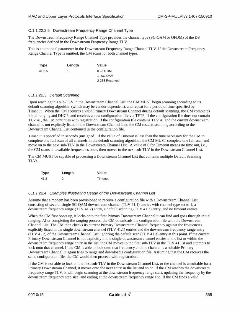
MAC and Upper Layer Protocols Interface Specification CM-SP-MULPIv3.1-I07-150910
09/10/15 CableLabs 565
C.1.1.22.2.5 Downstream Frequency Range Channel Type
The Downstream Frequency Range Channel Type provides the channel type (SC-QAM or OFDM) of the DS frequencies defined in the Downstream Frequency Range TLV.
This is an optional parameter in the Downstream Frequency Range Channel TLV. If the Downstream Frequency Range Channel Type is omitted, the CM scans for both channel types.
Type Length Value 41.2.5 1 0 – OFDM
1- SC-QAM 2-255 Reserved
C.1.1.22.3 Default Scanning
Upon reaching this sub-TLV in the Downstream Channel List, the CM MUST begin scanning according to its default scanning algorithm (which may be vendor dependent), and repeat for a period of time specified by Timeout. When the CM acquires a valid Primary Downstream Channel during default scanning, the CM completes initial ranging and DHCP, and receives a new configuration file via TFTP. If the configuration file does not contain TLV 41, the CM continues with registration. If the configuration file contains TLV 41 and the current downstream channel is not explicitly listed in the Downstream Channel List, the CM restarts scanning according to the Downstream Channel List contained in the configuration file.
Timeout is specified in seconds (unsigned). If the value of Timeout is less than the time necessary for the CM to complete one full scan of all channels in the default scanning algorithm, the CM MUST complete one full scan and move on to the next sub-TLV in the Downstream Channel List. A value of 0 for Timeout means no time out, i.e., the CM scans all available frequencies once, then moves to the next sub-TLV in the Downstream Channel List.
The CM MUST be capable of processing a Downstream Channel List that contains multiple Default Scanning TLVs.
Type Length Value 41.3 2 Timeout
C.1.1.22.4 Examples Illustrating Usage of the Downstream Channel List
Assume that a modem has been provisioned to receive a configuration file with a Downstream Channel List consisting of several single SC-QAM downstream channel (TLV 41.1) entries with channel type set to 1, a downstream frequency range (TLV 41.2) entry, a default scanning (TLV 41.3) entry, and no timeout entries.
When the CM first boots up, it locks onto the first Primary Downstream Channel it can find and goes through initial ranging. After completing the ranging process, the CM downloads the configuration file with the Downstream Channel List. The CM then checks its current Primary Downstream Channel frequency against the frequencies explicitly listed in the single downstream channel (TLV 41.1) entries and the downstream frequency range entry (TLV 41.2) of the Downstream Channel List, ignoring the default scan (TLV 41.3) entry at this point. If the current Primary Downstream Channel is not explicitly in the single downstream channel entries in the list or within the downstream frequency range entry in the list, the CM moves to the first sub-TLV in the TLV 41 list and attempts to lock onto that channel. If the CM is able to lock onto that frequency and the channel is a suitable Primary Downstream Channel, it again tries to range and download a configuration file. Assuming that the CM receives the same configuration file, the CM would then proceed with registration.
If the CM is not able to lock on the first sub-TLV in the Downstream Channel List, or the channel is unsuitable for a Primary Downstream Channel, it moves onto the next entry in the list and so on. If the CM reaches the downstream frequency range TLV, it will begin scanning at the downstream frequency range start, updating the frequency by the downstream frequency step size, and ending at the downstream frequency range end. If the CM finds a valid

CM-SP-MULPIv3.1-I07-150910 Data-Over-Cable Service Interface Specifications
566 CableLabs 09/10/15
Primary Downstream Channel within the downstream frequency range, the CM ranges and downloads a configuration file. Assuming that the configuration file has not changed, the CM continues with registration on that channel.
However, if the CM reaches the default scanning sub-TLV without successfully registering, the CM starts its "default scan" process. If during the course of its default scan, the CM finds a Primary Downstream Channel that it can lock onto, is able to complete ranging, and is able to download a configuration file, it will do so. However, at that point, the CM once again checks that the current Primary Downstream Channel is explicitly listed in the Downstream Channel List and acts accordingly.
As a second example, assume that a modem has been provisioned to receive a configuration file with a Downstream Channel List consisting of two instances of the downstream frequency range (TLV 41.2), the first entry with channel type set to 0 (OFDM) and the second entry with channel type set to 1 (SC-QAM), and no timeout entries. The CM in this case will scan through the first frequency range for OFDM channels and if no suitable Primary Downstream channel is found, then the CM will scan through the second frequency range for the SC-QAM channel.
As another, less likely example, assume that a CM has been provisioned to receive a configuration file with a Downstream Channel List containing only a default scanning (TLV 41.3) entry. When the CM first boots up, it locks onto the first Primary Downstream Channel it can find and goes through initial ranging. After completing the ranging process, the CM downloads the configuration file with the Downstream Channel List. Since the default scanning is the only parameter in the Downstream Channel List, the current Primary Downstream Channel frequency on which the CM locked is not explicitly included so the CM continues to scan according to its algorithm. The CM will not register on a channel until it receives a configuration file with a downstream frequency explicitly listed in the Downstream Channel List or a configuration file with no Downstream Channel List.
C.1.1.23 Static Multicast MAC Address134 The Static Multicast MAC Address TLV configures static multicast MAC addresses for multicast forwarding; the CM behavior based on this TLV is dependent on whether the CM has Multicast DSID Forwarding enabled (as indicated in the modem capabilities encoding of the REG-RSP or REG-RSP-MP). This object may be repeated to configure any number of static multicast MAC addresses. The CM MUST support a minimum of 16 Static Multicast MAC addresses.
If Multicast DSID Forwarding is enabled, the Static Multicast MAC Address TLV informs the CMTS of multicast MAC addresses that need to be labeled with a DSID and communicated to the CM in the REG-RSP or REG-RSP-MP message. The CM MUST NOT forward traffic based on the static multicast MAC address(es) in these encodings when Multicast DSID Forwarding is enabled. When flagged by the Extended CMTS MIC Bitmap, the CM passes this object to the CMTS in REG-REQ or REG-REQ-MP without performing any action. If this TLV is not flagged by the Extended CMTS MIC Bitmap, it will not be forwarded by the CM in the Registration Request, and so will have no effect. The CMTS MUST communicate in its REG-RSP or REG-RSP-MP one or more DSIDs for multicast sessions identified by the Static Multicast MAC Address TLV to be forwarded by that CM in this case.
When Multicast DSID Forwarding is disabled, the CM ignores this TLV and does not forward traffic based on the static multicast MAC addresses in this encoding.
When an operator desires to encrypt IP multicast sessions that map to Static Multicast MAC Address TLV, the operator must also include Static Multicast Session Encodings in the CM config file. This is because the CMTS controls the encryption based on multicast IP addresses and not based on MAC addresses.
Type Length Value 42 6 Static Multicast MAC Address
134 Updated per MULPIv3.1-N-14.1211-5 on 12/9/14 by PO.

MAC and Upper Layer Protocols Interface Specification CM-SP-MULPIv3.1-I07-150910
09/10/15 CableLabs 567
C.1.1.24 Downstream Unencrypted Traffic (DUT) Filtering Encoding This parameter enables the CM to perform Downstream Unencrypted Traffic filtering as described in the DOCSIS Layer 2 Virtual Private Network specification [DOCSIS L2VPN]. If the CM does not support the DUT Filtering Capability, it MUST ignore the DUT Filtering Encoding TLV.
Type Length Value 45 Length/value tuples are specified in [DOCSIS L2VPN]
C.1.1.25 Channel Assignment Configuration Settings This field is used to convey an assigned Transmit Channel Set and/or Receive Channel Set to be used by a CM via a config file setting which is transmitted to the CMTS in a Registration Request message. It includes two sub-TLVs, one each for transmit and receive channels respectively. There can be multiple instances of each sub-TLV in a single Channel Assignment Configuration Settings encoding, one for each transmit and/or receive channel being assigned to the CM. The list of upstream and/or downstream channels assigned represents the complete list of channels to be assigned to that modem, overriding any other channel assignments that the CMTS might have chosen to make.
If a CMTS receives this field, it MUST either assign only the complete list of assigned transmit and/or receive channels, or reject the registration attempt if it is unable to provide all of the assigned channels.
Type Length Value 56 N
C.1.1.25.1 Transmit Channel Assignment Configuration Setting
The US Channel ID to be included in the Transmit Channel Set.
Type Length Value 56.1 1 Upstream Channel ID
C.1.1.25.2 Receive Channel Assignment Configuration Setting135
The DS Channel Frequency to be included in the Receive Channel Set. For SC-QAM channels, the frequency in this TLV is the center frequency of the SC-QAM channel. For OFDM channels, the frequency in this TLV is the center frequency of the lowest subcarrier of the 6 MHz encompassed spectrum containing the PHY Link Channel (PLC) at its center.
Type Length Value 56.2 4 Rx Frequency
C.1.1.26 Upstream Drop Classifier Group ID The value of this field specifies the list of Upstream Drop Classifier Group IDs [DOCSIS OSSIv3.0]. The CMTS uses these Group IDs to instantiate UDCs in the registration response message. The CMTS SHOULD ignore an Upstream Drop Classifier Group ID with a value of zero in the registration request message.
135 Updated per MULPIv3.1-N-15.1300-3 on 6/2/15 by PO.

CM-SP-MULPIv3.1-I07-150910 Data-Over-Cable Service Interface Specifications
568 CableLabs 09/10/15
Type Length Value 62 n 1-255
C.1.1.27 CMTS Static Multicast Session Encoding The CMTS Static Multicast Session is used by the operator to provide the CMTS with the static ASM or SSM multicast sessions and associated CMIM to which the CM should be configured to forward multicast traffic. To configure static ASM sessions, the CMTS Static Multicast Session Encoding contains the Static Multicast Group Encoding and the Static Multicast CMIM Encoding. To configure static SSM sessions, the CMTS Static Multicast Session Encoding contains the Static Multicast Group Encoding, the Static Multicast Source Encoding, and the Static Multicast CMIM Encoding. When flagged by the Extended CMTS MIC Bitmap, the CM passes this object to the CMTS in REG-REQ or REG-REQ-MP without performing any action. If this TLV is not flagged by the Extended CMTS MIC Bitmap, it will not be forwarded by the CM in the Registration Request, and so will have no effect.
As described in the Static Multicast Session Encodings subsection of Section 9, the CMTS is required to communicate a DSID and associated encodings to the CM in a Registration Response message in response to CMTS Static Multicast Session Encodings present in the Registration Request.
This object may be repeated to configure any number of multicast sessions and associated CMIMs.
Type Length Value 64 N
C.1.1.27.1 Static Multicast Group Encoding
The Static Multicast Group Encoding provides the CMTS with the group address for a multicast session to which the CM will be statically joined. A valid CMTS Static Multicast Session encoding contains exactly one instance of this sub-TLV.
Subtype Length Value 64.1 4 (IPv4) or
16 (IPv6) Multicast group address
C.1.1.27.2 Static Multicast Source Encoding
The Static Multicast Source Encoding provides the CMTS with a source address for a source-specific multicast session to which the CM will be statically joined. A valid CMTS Static Multicast Session encoding may contain multiple instances of this sub-TLV.
Subtype Length Value 64.2 4 (IPv4) or
16 (IPv6) Source IP Address
C.1.1.27.3 Static Multicast CMIM Encoding
The Static Multicast CMIM Encoding provides the CMTS with the CMIM associated with the static multicast session that needs to be communicated to the CM. Each bit of CM interface mask corresponds to a logical or physical interface. Refer to Section C.1.5.4.4.2. Multicast CM Interface Mask for details on what interface each bit represents.
A valid CMTS Static Multicast Session encoding contains exactly one instance of this sub-TLV.

MAC and Upper Layer Protocols Interface Specification CM-SP-MULPIv3.1-I07-150910
09/10/15 CableLabs 569
Subtype Length Value 64.3 N Static Multicast CMIM
C.1.1.28 Upstream Aggregate Service Flow Encodings This field defines the parameters associated with the Upstream Aggregate Service Flow. Refer to Section C.2.2.3.
Type Length Value 70 N
C.1.1.29 Downstream Aggregate Service Flow Encodings This field defines the parameters associated with the Downstream Aggregate Service Flow. Refer to C.2.2.4.
Type Length Value 71 N
C.1.1.30 Energy Management Parameter Encoding This encoding identifies a set of parameters to control Energy Management features on the CM and CMTS. The CM MUST send this TLV in the Registration Request message.
Type Length Value
74 N Energy Management Parameter subtype encodings
C.1.1.30.1 Energy Management Feature Control
This parameter administratively enables or disables energy savings features for this cable modem. Each bit represents a single feature.
Type Length Value
74.1 4 Bitmask to control Energy Management features. The feature is administratively enabled when the bit is set to 1, and administratively disabled when the bit is set to 0. Bit 0: Energy Management 1x1 Feature Bit 1: Energy Management DOCSIS Light Sleep Feature Bit 2-31: Reserved
If this parameter is not included, the default value is that the features are disabled. The CM enables use of Energy Management Features only if both the Energy Management Feature Control TLV and Energy Management Modem Capability Response from the CMTS (see Section C.1.3.1.43) indicate that the feature is enabled.
C.1.1.30.2 Energy Management 1x1 Mode Encodings
This TLV encodes parameters needed to control the operation of the Energy Management 1x1 Feature.

CM-SP-MULPIv3.1-I07-150910 Data-Over-Cable Service Interface Specifications
570 CableLabs 09/10/15
Type Length Value
74.2 N Energy Management 1x1 Mode encoding parameters
C.1.1.30.3 Energy Management DOCSIS Light Sleep Mode Encodings
This TLV encodes parameters needed to control the operation of the Energy Management DOCSIS Light Sleep Feature.
Type Length Value
74.4 N Energy Management DOCSIS Light Sleep Mode encoding parameters
C.1.1.30.4 General Energy Management Mode Encodings
C.1.1.30.4.1 Downstream Activity Detection Parameters
This TLV encodes parameters needed to control Downstream Activity Detection for triggering entry into or exit from Energy Management Modes.
Type Length Value
74.[2/4].1 N Downstream Activity Detection parameters
C.1.1.30.4.1.1 Downstream Entry Bitrate Threshold
If not provided, the default value of this parameter is vendor-specific.
If this value is provided and set to zero, Activity Detection is disabled and the remaining Activity Detection Parameters are ignored.
Type Length Value
74.[2/4].1.1 4 Downstream bitrate threshold (in bps) below which the CM will request to enter an Energy Management Mode of operation
C.1.1.30.4.1.2 Downstream Entry Time Threshold
The default value of this parameter is vendor-specific.
Type Length Value
74.[2/4].1.2 2 Number of consecutive seconds that the downstream data rate needs to remain below the Downstream Entry Bitrate Threshold in order to determine that a transition to an Energy Management Mode is required. Valid range: 1 - 65535.
C.1.1.30.4.1.3 Downstream Exit Bitrate Threshold
If not provided, the default value of this parameter is vendor-specific.
Type Length Value
74.[2/4].1.3 4 Downstream bitrate threshold (in bps) above which the CM will request to leave an Energy Management Mode of operation

MAC and Upper Layer Protocols Interface Specification CM-SP-MULPIv3.1-I07-150910
09/10/15 CableLabs 571
C.1.1.30.4.1.4 Downstream Exit Time Threshold
The default value of this parameter is vendor-specific.
Type Length Value
74.[2/4].1.4 2 Number of consecutive seconds that the downstream data rate needs to remain above the Downstream Exit Bitrate Threshold in order to determine that a transition out of an Energy Management Mode is required. Valid range: 1 - 65535.
C.1.1.30.4.2 Upstream Activity Detection Parameters
This TLV encodes parameters needed to control Upstream Activity Detection for triggering entry into or exit from Energy Management 1x1 Mode.
Type Length Value
74.[2/4].2 N Upstream Activity Detection parameters
C.1.1.30.4.2.1 Upstream Entry Bitrate Threshold
If not provided, the default value of this parameter is vendor-specific.
If this value is provided and set to zero, Activity Detection is disabled and the remaining Activity Detection Parameters are ignored.
Type Length Value
74.[2/4].2.1 4 Upstream Bitrate Threshold (in bps) below which the CM will request to enter an Energy Management Mode of operation
C.1.1.30.4.2.2 Upstream Entry Time Threshold
The default value of this parameter is vendor-specific.
Type Length Value
74.[2/4].2.2 2 Number of consecutive seconds that the upstream data rate needs to remain below the Upstream Entry Bitrate Threshold in order to determine that a transition to an Energy Management Mode is required. Valid range: 1 - 65535.
C.1.1.30.4.2.3 Upstream Exit Bitrate Threshold
If not provided, the default value of this parameter is vendor-specific.
Type Length Value
74.[2/4].2.3 4 Upstream bitrate threshold (in bps) above which the CM will request to leave an Energy Management Mode of operation

CM-SP-MULPIv3.1-I07-150910 Data-Over-Cable Service Interface Specifications
572 CableLabs 09/10/15
C.1.1.30.4.2.4 Upstream Exit Time Threshold136
The default value of this parameter is vendor-specific.
Type Length Value
74.[2/4].2.4 2 Number of consecutive seconds that the upstream data rate needs to remain above the Upstream Exit Bitrate Threshold in order to determine that a transition out of an Energy Management Mode is required. Valid range: 1 - 65535.
C.1.1.30.5 Energy Management Cycle Period
This parameter specifies a minimum time period that must elapse between EM-REQ transactions in certain situations:
1. This parameter sets the minimum cycle time that a modem will use for sending requests to enter an Energy Management Mode. The CM MUST NOT request to enter an Energy Management Mode while this amount of time has yet to elapse since the last time the CM requested an Energy Management Mode and received a response indicating (0) OK or (1) Reject Temporary (with no Hold-off Timer value provided).
2. In the case that the CM fails to receive an EM-RSP message after the maximum number of retries, this parameter sets the minimum amount of time to elapse before the CM can attempt another EM-REQ transaction.
This TLV does not affect the EM-REQ message state machine and backoff/retry process. This timer begins upon completion of the EM-REQ message transmission and backoff/retry process.
If this TLV is not provided, the CM MUST use a default value of 900 seconds.
Type Length Value
74.3 2 Minimum time (in seconds) between EM-REQ transactions in certain situations.
C.1.1.31 DTP Mode Configuration137 The DTP Mode Configuration TLV defines CM configuration file encoding which specifies the provisioned DTP Mode for a CM. The configuration file can specify one of two modes: Slave Mode or Master Mode. This TLV can be present in CM Configuration file and in Registration Request message. If this TLV is present in a CM configuration file, the CM MUST include it in the Registration Request message. The CMTS MUST NOT send TLV 83 in Registration Response. The CMTS uses the information received in this TLV to set the CM’s DTP Mode via TLV 5.57.
If this TLV is not present in the CM Configuration file, the CMTS decides CM’s DTP Mode based on other criteria.
Type Length Value 83 1 0 = reserved
1 = DTP Slave Mode 2 = DTP Master Mode 3-255: Reserved
136 Updated per MULPIv3.1-N-15.1269-1 on 3/10/15 by PO. 137 Updated per MULPIv3.1-N-15.1301-1 on 6/2/15 by PO.

MAC and Upper Layer Protocols Interface Specification CM-SP-MULPIv3.1-I07-150910
09/10/15 CableLabs 573
C.1.2 Configuration-File-Specific Settings The TLVs in the following subsections are not intended to be forwarded by the CM to the CMTS in the Registration Request message. As such, they are not expected to be included in the E-MIC Bitmap.
C.1.2.1 End-of-Data Marker This is a special marker for end of data. It has no length or value fields.
Type 255
C.1.2.2 Pad Configuration Setting This has no length or value fields and is only used following the end of data marker to pad the file to an integral number of 32-bit words.
Type 0
C.1.2.3 Software Upgrade Filename This is the file name of the software upgrade file for the CM. The file name is a fully qualified directory-path name. The file is expected to reside on a TFTP server identified in a configuration setting option defined in Annex D.1.2. See also the subsection Downloading Cable Modem Operating Software in Section 12.
Type Length Value 9 N filename
C.1.2.4 SNMP Write-Access Control This object makes it possible to disable SNMP "Set" access to individual MIB objects. Each instance of this object controls access to all of the writeable MIB objects whose Object ID (OID) prefix matches. This object may be repeated to disable access to any number of MIB objects.
Type Length Value 10 N OID prefix plus control flag
Where N is the size of the ASN.1 Basic Encoding Rules [ISO/IEC 8825-1] encoding of the OID prefix plus one byte for the control flag.
The control flag may take values:
0 - allow write-access 1 - disallow write-access
Any OID prefix may be used. The Null OID 0.0 may be used to control access to all MIB objects. (The OID 1.3.6.1 will have the same effect.)
When multiple instances of this object are present and overlap, the longest (most specific) prefix has precedence. Thus, one example might be:

CM-SP-MULPIv3.1-I07-150910 Data-Over-Cable Service Interface Specifications
574 CableLabs 09/10/15
someTable: disallow write-access someTable.1.3: allow write-access
This example disallows access to all objects in someTable except for someTable.1.3.
Enhanced access control for cable modem MIB objects is provided by the SNMPv3 Access View Configuration encoding (see Annex C.1.2.14), therefore this object is deprecated. If the configuration file does not contain one or more SNMPv3 Access View Configuration encodings, the CM MAY silently ignore SNMP Write-Access Control encodings. If the configuration file contains one or more SNMPv3 Access View Configuration encodings, the CM MUST silently ignore SNMP Write-Access Control encodings.
C.1.2.5 SNMP MIB Object This object allows arbitrary SNMP MIB objects to be Set via the TFTP-Registration process.
Type Length Value 11 N variable binding
The value is an SNMP VarBind as defined in [RFC 1157]. The VarBind is encoded in ASN.1 Basic Encoding Rules, just as it would be if part of an SNMP Set request.
The cable modem MUST treat this object as if it were part of an SNMP Set Request with the following caveats:
• The request is treated as fully authorized (it cannot refuse the request for lack of privilege). • SNMP Write-Control provisions (see Annex C.1.2.4) do not apply. • No SNMP response is generated by the CM.
This object may be repeated with different VarBinds to "Set" a number of MIB objects. All such Sets MUST be treated by the CM as if simultaneous.
Each VarBind must be limited to 255 bytes.
C.1.2.6 CPE Ethernet MAC Address This object configures the CM with the Ethernet MAC address of a CPE device (see the subsection MAC Address Acquisition in Section 9). This object may be repeated to configure any number of CPE device addresses.
Type Length Value 14 6 Ethernet MAC Address of CPE
C.1.2.7 Software Upgrade IPv4 TFTP Server The IPv4 address of the TFTP server on which the software upgrade file for the CM resides (see the Downloading Cable Modem Operating Software chapter in Section 12 and Annex C.1.2.3.
Type Length Value 21 4 TFTP Server's IPv4 Address
C.1.2.8 Software Upgrade IPv6 TFTP Server The IPv6 address of the TFTP server on which the software upgrade file for the CM resides. (see the Downloading Cable Modem Operating Software chapter in Section 12 and Annex C.1.2.3.
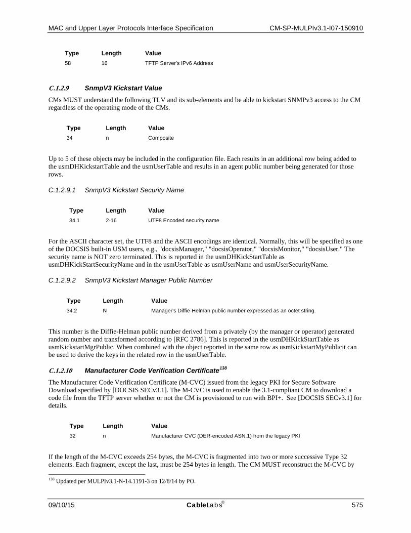
MAC and Upper Layer Protocols Interface Specification CM-SP-MULPIv3.1-I07-150910
09/10/15 CableLabs 575
Type Length Value 58 16 TFTP Server's IPv6 Address
C.1.2.9 SnmpV3 Kickstart Value CMs MUST understand the following TLV and its sub-elements and be able to kickstart SNMPv3 access to the CM regardless of the operating mode of the CMs.
Type Length Value 34 n Composite
Up to 5 of these objects may be included in the configuration file. Each results in an additional row being added to the usmDHKickstartTable and the usmUserTable and results in an agent public number being generated for those rows.
C.1.2.9.1 SnmpV3 Kickstart Security Name
Type Length Value 34.1 2-16 UTF8 Encoded security name
For the ASCII character set, the UTF8 and the ASCII encodings are identical. Normally, this will be specified as one of the DOCSIS built-in USM users, e.g., "docsisManager," "docsisOperator," "docsisMonitor," "docsisUser." The security name is NOT zero terminated. This is reported in the usmDHKickStartTable as usmDHKickStartSecurityName and in the usmUserTable as usmUserName and usmUserSecurityName.
C.1.2.9.2 SnmpV3 Kickstart Manager Public Number
Type Length Value 34.2 N Manager's Diffie-Helman public number expressed as an octet string.
This number is the Diffie-Helman public number derived from a privately (by the manager or operator) generated random number and transformed according to [RFC 2786]. This is reported in the usmDHKickStartTable as usmKickstartMgrPublic. When combined with the object reported in the same row as usmKickstartMyPublicit can be used to derive the keys in the related row in the usmUserTable.
C.1.2.10 Manufacturer Code Verification Certificate138 The Manufacturer Code Verification Certificate (M-CVC) issued from the legacy PKI for Secure Software Download specified by [DOCSIS SECv3.1]. The M-CVC is used to enable the 3.1-compliant CM to download a code file from the TFTP server whether or not the CM is provisioned to run with BPI+. See [DOCSIS SECv3.1] for details.
Type Length Value 32 n Manufacturer CVC (DER-encoded ASN.1) from the legacy PKI
If the length of the M-CVC exceeds 254 bytes, the M-CVC is fragmented into two or more successive Type 32 elements. Each fragment, except the last, must be 254 bytes in length. The CM MUST reconstruct the M-CVC by 138 Updated per MULPIv3.1-N-14.1191-3 on 12/8/14 by PO.
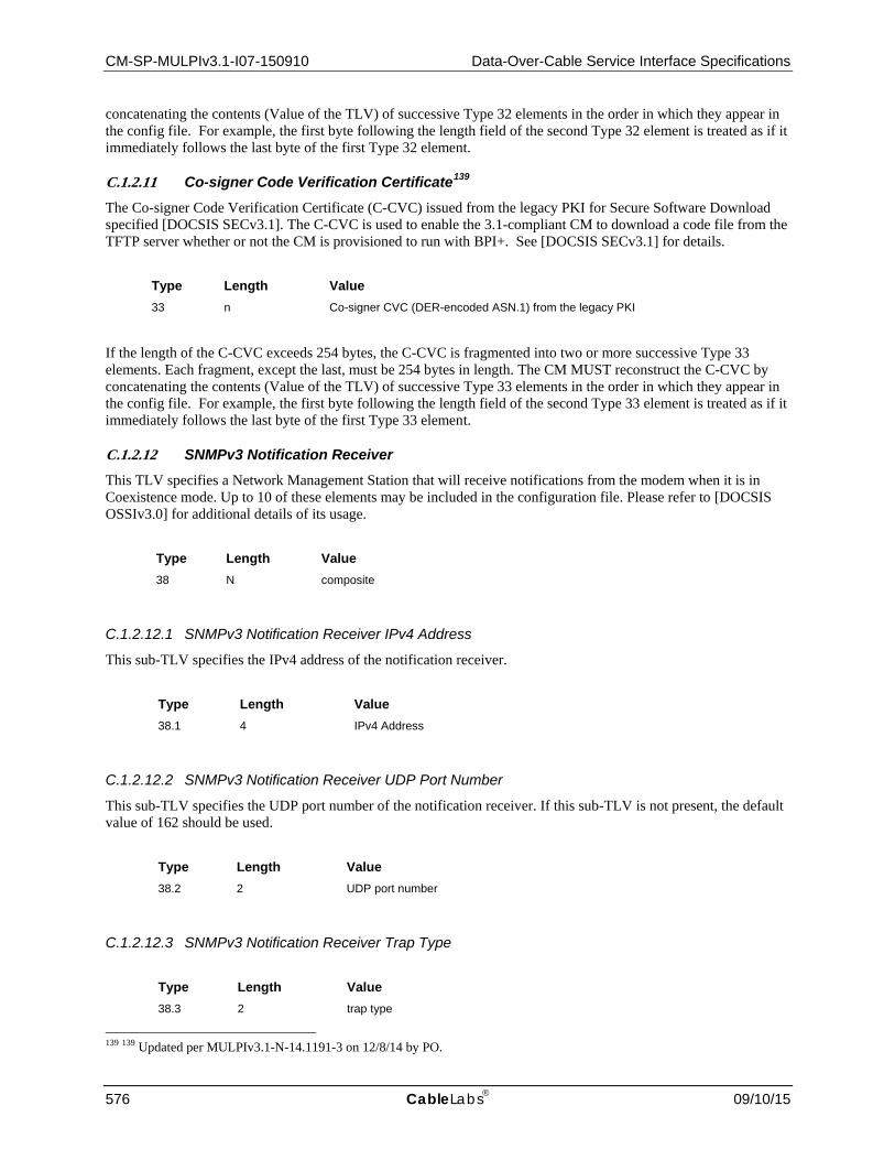
CM-SP-MULPIv3.1-I07-150910 Data-Over-Cable Service Interface Specifications
576 CableLabs 09/10/15
concatenating the contents (Value of the TLV) of successive Type 32 elements in the order in which they appear in the config file. For example, the first byte following the length field of the second Type 32 element is treated as if it immediately follows the last byte of the first Type 32 element.
C.1.2.11 Co-signer Code Verification Certificate139 The Co-signer Code Verification Certificate (C-CVC) issued from the legacy PKI for Secure Software Download specified [DOCSIS SECv3.1]. The C-CVC is used to enable the 3.1-compliant CM to download a code file from the TFTP server whether or not the CM is provisioned to run with BPI+. See [DOCSIS SECv3.1] for details.
Type Length Value 33 n Co-signer CVC (DER-encoded ASN.1) from the legacy PKI
If the length of the C-CVC exceeds 254 bytes, the C-CVC is fragmented into two or more successive Type 33 elements. Each fragment, except the last, must be 254 bytes in length. The CM MUST reconstruct the C-CVC by concatenating the contents (Value of the TLV) of successive Type 33 elements in the order in which they appear in the config file. For example, the first byte following the length field of the second Type 33 element is treated as if it immediately follows the last byte of the first Type 33 element.
C.1.2.12 SNMPv3 Notification Receiver This TLV specifies a Network Management Station that will receive notifications from the modem when it is in Coexistence mode. Up to 10 of these elements may be included in the configuration file. Please refer to [DOCSIS OSSIv3.0] for additional details of its usage.
Type Length Value 38 N composite
C.1.2.12.1 SNMPv3 Notification Receiver IPv4 Address
This sub-TLV specifies the IPv4 address of the notification receiver.
Type Length Value 38.1 4 IPv4 Address
C.1.2.12.2 SNMPv3 Notification Receiver UDP Port Number
This sub-TLV specifies the UDP port number of the notification receiver. If this sub-TLV is not present, the default value of 162 should be used.
Type Length Value 38.2 2 UDP port number
C.1.2.12.3 SNMPv3 Notification Receiver Trap Type
Type Length Value 38.3 2 trap type
139 139 Updated per MULPIv3.1-N-14.1191-3 on 12/8/14 by PO.

MAC and Upper Layer Protocols Interface Specification CM-SP-MULPIv3.1-I07-150910
09/10/15 CableLabs 577
This sub-TLV specifies the type of trap to send. The trap type may take values:
1 = SNMP v1 trap in an SNMP v1 packet 2 = SNMP v2c trap in an SNMP v2c packet 3 = SNMP inform in an SNMP v2c packet 4 = SNMP v2c trap in an SNMP v3 packet 5 = SNMP inform in an SNMP v3 packet
C.1.2.12.4 SNMPv3 Notification Receiver Timeout
This sub-TLV specifies the timeout value to use when sending an Inform message to the notification receiver.
Type Length Value 38.4 2 time in milliseconds
C.1.2.12.5 SNMPv3 Notification Receiver Retries
This sub-TLV specifies the number of times to retry sending an Inform message if an acknowledgement is not received.
Type Length Value 38.5 2 number of retries
C.1.2.12.6 SNMPv3 Notification Receiver Filtering Parameters
This sub-TLV specifies the ASN.1 formatted Object Identifier of the snmpTrapOID value that identifies the notifications to be sent to the notification receiver. SNMP v3 allows the specification of which Trap OIDs are to be sent to a trap receiver. This object specifies the OID of the root of a trap filter sub-tree. All Traps with a Trap OID contained in this trap filter sub-tree MUST be sent by the CM to the trap receiver. This object starts with the ASN.1 Universal type 6 (Object Identifier) byte, then the ASN.1 length field, then the ASN.1 encoded object identifier components.
Type Length Value 38.6 N filter OID
C.1.2.12.7 SNMPv3 Notification Receiver Security Name
This sub-TLV specifies the V3 Security Name to use when sending a V3 Notification. This sub-TLV is only used if Trap Type is set to 4 or 5. This name must be a name specified in a config file TLV Type 34 as part of the Diffie-Helman (DH) Kickstart procedure. The notifications will be sent using the Authentication and Privacy Keys calculated by the modem during the DH Kickstart procedure.
This sub-TLV is not required for Trap Type = 1, 2, or 3 above. If it is not supplied for a Trap type of 4 or 5, then the V3 Notification will be sent in the noAuthNoPriv security level using the security name "@config".
Type Length Value 38.7 N security name

CM-SP-MULPIv3.1-I07-150910 Data-Over-Cable Service Interface Specifications
578 CableLabs 09/10/15
C.1.2.12.8 SNMPv3 Notification Receiver IPv6 Address
This sub-TLV specifies the IPv6 address of the notification receiver.
Type Length Value 38.8 16 IPv6 Address
C.1.2.13 SNMPv1v2c Coexistence Configuration This object specifies the SNMPv1v2c Coexistence Access Control configuration of the CM. This object does not preclude using TLV-11 to configure directly SNMPv3 tables. The CM MUST support a minimum of 10 SNMPv1v2c Coexistence TLVs. This TLV creates entries in SNMPv3 tables as specified in [DOCSIS OSSIv3.0].
If the configuration file contains SNMPv1v2 Coexistence Configuration encodings, the CM MUST reject the configuration file if the SNMPv1v2c Community Name and SNMPv1v2c Transport Address Access sub-TLVs are not present. The CM MUST support multiple instances of sub-TLV 53.2 SNMPv1v2c Transport Address Access. The CM MUST reject a config file if a TLV includes repeated sub-TLVs other than sub-TLV 53.2. The CM MUST reject the config file if a CM created entry in a SNMP table is rejected for syntax conflicts or reaches the limit in the number of entries the CM support for that table or the mapped SNMPv3 entry already exist. The CM MUST reject the config file if the TLV has an invalid length, or if any of the sub-TLVs have an invalid length or value.
Type Length Value 53 N Composite
NOTE: The number of entries a CM can support in SNMPv3 tables is independent of the number of TLVs the CM must support to be processed as SNMP tables entries.
C.1.2.13.1 SNMPv1v2c Community Name
This sub-TLV specifies the Community Name (community string) used in SNMP requests to the CM.
Type Length Value 53.1 1..32 Text
C.1.2.13.2 SNMPv1v2c Transport Address Access
This sub-TLV specifies the Transport Address and Transport Address Mask pair used by the CM to grant access to the SNMP entity querying the CM. The CM MUST reject a config file if a sub-TLV Transport Address Access has more than one sub-TLV 53.2.1 or 53.2.2.
Type Length Value 53.2 n Variable
C.1.2.13.2.1 SNMPv1v2c Transport Address
This sub-TLV specifies the Transport Address to use in conjunction with the Transport Address Mask used by the CM to grant access to the SNMP entity querying the CM.

MAC and Upper Layer Protocols Interface Specification CM-SP-MULPIv3.1-I07-150910
09/10/15 CableLabs 579
Type Length Value 53.2.1 6 or 18 Transport Address
NOTE: Length is 6 bytes for IPv4 and 18 bytes for IPv6. Two additional bytes are added to the IP address length for the port number. Refer to the section "SNMPv1v2c Coexistence Configuration config file TLV" in [DOCSIS OSSIv3.0] for details.
C.1.2.13.2.2 SNMPv1v2c Transport Address Mask
This sub-TLV specifies the Transport Address Mask to use in conjunction with the Transport Address used by the CM to grant access to the SNMP entity querying the CM. This sub-TLV is optional.
Type Length Value 53.2.2 6 or 18 Transport Address Mask
NOTE: Length is 6 bytes for IPv4 and 18 bytes for IPv6. Two additional bytes are added to the IP address length for the port number. Refer to the section "SNMPv1v2c Coexistence Configuration config file TLV" in [DOCSIS OSSIv3.0] for details.
C.1.2.13.3 SNMPv1v2c Access View Type
This sub-TLV specifies the type of access to grant to the community name of this TLV. Sub-TLV 53.3 is optional. If sub-TLV 53.3 is not present in TLV 53, the default value of the access type to grant to the community name specified in sub-TLV 53.1 is Read-only.
Type Length Value 53.3 1 1 Read-only
2 Read-write
C.1.2.13.4 SNMPv1v2c Access View Name
This sub-TLV specifies the name of the view that provides the access indicated in sub-TLV SNMPv1v2c Access View Type.
Type Length Value 53.4 1.32 String
C.1.2.14 SNMPv3 Access View Configuration This object specifies the SNMPv3 Simplified Access View configuration of the CM. This object does not preclude using TLV-11 to configure directly SNMPv3 tables. This TLV creates entries in SNMPv3 tables as specified in [DOCSIS OSSIv3.0].
The CM MUST reject the config file if the SNMPv3 Access View Configuration encoding is present but the SNMPv3 Access View Name sub-TLV is not present. The CM MUST support multiple TLVs with the same SNMPv3 Access View Name TLV. The CM MUST reject the config file if more than one sub-TLV is included in a TLV. The CM MUST reject the config file if a CM created entry in a SNMP table is rejected for Syntax conflicts or reaches the limit in the number of entries the CM support for that table or the mapped SNMPv3 entry already exist. The CM MUST reject the config file if the TLV has an invalid length, or if any of the sub-TLVs have an invalid length or value.
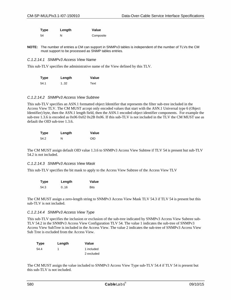
CM-SP-MULPIv3.1-I07-150910 Data-Over-Cable Service Interface Specifications
580 CableLabs 09/10/15
Type Length Value 54 N Composite
NOTE: The number of entries a CM can support in SNMPv3 tables is independent of the number of TLVs the CM must support to be processed as SNMP tables entries.
C.1.2.14.1 SNMPv3 Access View Name
This sub-TLV specifies the administrative name of the View defined by this TLV.
Type Length Value 54.1 1..32 Text
C.1.2.14.2 SNMPv3 Access View Subtree
This sub-TLV specifies an ASN.1 formatted object Identifier that represents the filter sub-tree included in the Access View TLV. The CM MUST accept only encoded values that start with the ASN.1 Universal type 6 (Object Identifier) byte, then the ASN.1 length field, then the ASN.1 encoded object identifier components. For example the sub-tree 1.3.6 is encoded as 0x06 0x02 0x2B 0x06. If this sub-TLV is not included in the TLV the CM MUST use as default the OID sub-tree 1.3.6.
Type Length Value 54.2 N OID
The CM MUST assign default OID value 1.3.6 to SNMPv3 Access View Subtree if TLV 54 is present but sub-TLV 54.2 is not included.
C.1.2.14.3 SNMPv3 Access View Mask
This sub-TLV specifies the bit mask to apply to the Access View Subtree of the Access View TLV
Type Length Value 54.3 0..16 Bits
The CM MUST assign a zero-length string to SNMPv3 Access View Mask TLV 54.3 if TLV 54 is present but this sub-TLV is not included.
C.1.2.14.4 SNMPv3 Access View Type
This sub-TLV specifies the inclusion or exclusion of the sub-tree indicated by SNMPv3 Access View Subtree sub-TLV 54.2 in the SNMPv3 Access View Configuration TLV 54. The value 1 indicates the sub-tree of SNMPv3 Access View SubTree is included in the Access View. The value 2 indicates the sub-tree of SNMPv3 Access View Sub Tree is excluded from the Access View.
Type Length Value 54.4 1 1 included
2 excluded
The CM MUST assign the value included to SNMPv3 Access View Type sub-TLV 54.4 if TLV 54 is present but this sub-TLV is not included.

MAC and Upper Layer Protocols Interface Specification CM-SP-MULPIv3.1-I07-150910
09/10/15 CableLabs 581
C.1.2.15 SNMP CPE Access Control If the value of this field is a 1, the CM MUST allow SNMP access from any CPE attached to it. If the value of this field is a 0, the CM MUST NOT allow SNMP Access from any CPE attached to it.
Type Length Value 55 1 0 Disable
1 Enable
The CM MUST disable SNMP access from CPEs connected to the cable modem unless this TLV is present in the config file with value equal to 1.
C.1.2.16 Management Event Control Encoding This TLV specifies the mechanism to individually enable DOCSIS events. The CM MUST support one or more instances of TLV 66 in the config file. The CM MUST ignore TLV 66 instances containing the same EventID value in the config file.
Type Length Value 66 4 32-bit Event ID or 0
See [DOCSIS OSSIv3.0]
C.1.2.17 Default Upstream Target Buffer Configuration This TLV controls the default size of the upstream service flow buffer when specific Buffer Control parameters (see Section C.2.2.7.11) are not provided. When included in the configuration file and not overridden by the Buffer Control TLV, the CM SHOULD set the buffer size for each Best Effort and Non-Real-Time Polling Service Flow according to the following expression. When not included in the configuration file and not overridden by the Buffer Control TLV, the CM SHOULD set the buffer size for each Best Effort and Non-Real-Time Polling Service Flow according to the expression
Buffer Size (bytes) = D * min(R,P) / 8000,
where:
D = Default Upstream Target Buffer Configuration (in milliseconds), with a default value of 250 milliseconds R = Maximum Sustained Traffic Rate (see Section C.2.2.7.2) (in bits per second) for the Service Flow P = Peak Traffic Rate (see Section C.2.2.7.10) (in bits per second) for the Service Flow
If the CM is not able to provide an upstream buffer size that matches the calculated value, it is expected to provide a buffer size as close as possible to that value. The CM MUST NOT reject a service flow as a result of being unable to provide a buffer size that matches the calculated value.
For purposes of calculating min(R,P) if either argument is not provided or is set to zero, the value infinity is used for that argument.
Type Length Value 68 2 D (in milliseconds)
This parameter only applies to service flows for which all of the following are true:
1. the upstream scheduling type is Best Effort or Non-Real-Time Polling, 2. the QoS Parameter Set for the flow does not include the Buffer Control TLV (see Section C.2.2.7.11), and 3. the QoS Parameter Set includes a non-zero Max Sustained Traffic Rate (see Section C.2.2.7.2) or a non-
zero Peak Traffic Rate (see Section C.2.2.7.10) TLV.

CM-SP-MULPIv3.1-I07-150910 Data-Over-Cable Service Interface Specifications
582 CableLabs 09/10/15
C.1.2.18 MAC Address Learning Control Encoding This encoding in the CM configuration file allows the Operator to enable the CM to remove dynamically learned MAC addresses from the CMCI. The encoding has two sub-TLVs: the first sub-TLV is an enable/disable flag; and the second is a configurable holdoff timer value. The MAC Address Learning Holdoff Timer encoding sets the amount of time in seconds that a CM will wait before removing a MAC address associated with a CMCI port from the MAC Address table after that port transitions from 'UP' to 'DOWN' state. The timer is configurable with a range of 0 to 10 seconds with a default value of 2 seconds.
Type Length Value 69 n
C.1.2.18.1 MAC Address Learning Control
This encoding enables or disables the CM MAC address removal capability as described in the subsection MAC Address Acquisition in Section 9. The default value of the MAC Address Learning Control TLV MUST be 'DoNotRemove(0)'.
Type Length Value 69.1 1 0 Do Not Remove
1 Remove
C.1.2.18.2 MAC Address Learning Holdoff Timer
The MAC Address Learning Holdoff Timer sets the amount of time that a CM will wait before removing a MAC address on a CMCI port after that port transitions from 'UP' to 'DOWN' whether through administratively setting the ifAdminState or due to loss of link on the port allowing it to learn new MAC addresses when the link is re-established. The timer is configurable with a range of 0 to 10 seconds with a default value of 2 seconds.
Type Length Value 69.2 1 0..10 Seconds
A zero value will disable the wait timer, and require the modem to remove MAC addresses immediately upon an event that would otherwise trigger the timer. Note that a value of 0 could have negative impacts in certain circumstances. For example, if a user has a loose Ethernet cable, it could cause a flood of CM-Status messages to the CMTS.
C.1.2.19 Network Timing Profile This subtype specifies a Network Timing Profile configured on the DPoE System [DPoE-MULPIv2.0] which provides a match criteria for the Timing Profile Name. EToD [IEEE 1588-2008] provisioning parameters [DPoE-IPNEv2.0] are configured via a Network Timing Profile. The Network Timing Profile TLV is referenced from the L2VPN encoding via the Network Timing Profile Reference. The CPE interfaces (CMIM) to which the Network Timing Profile applies are the interfaces (CMIM) to which the L2VPN encoding applies.
Type Length Value 73 N

MAC and Upper Layer Protocols Interface Specification CM-SP-MULPIv3.1-I07-150910
09/10/15 CableLabs 583
C.1.2.19.1 Network Timing Profile Reference
The Network Timing Profile Reference is used to associate a service (e.g., a L2VPN Service Flow) to a Network Timing Profile Name configured on the DPoE System. A valid Network Timing Profile subtype encoding contains one instance of this subtype.
Type Length Value 73.1 2 1-65536
C.1.2.19.2 Network Timing Profile Name
This subtype contains an ASCII string that identifies a Network Timing Profile Name configured on the DPoE System. A valid Network Timing Profile subtype encoding contains one instance of this subtype.
Type Length Value 73.2 2 to 16 Zero-terminated string of ASCII characters.
C.1.2.20 CM Upstream AQM Disable This TLV provides a means of disabling upstream AQM in the CM. If this TLV is included with a value of "Disable", the CM disables AQM on all applicable upstream service flows. If this TLV is absent or included with a value of "Enable", the CM enables AQM on the applicable upstream service flows per the Upstream AQM Encodings (see Section C.2.2.7.15). This TLV is not negotiated with the CMTS, and as a result can be used to disable AQM in the CM when the CM is operating on a CMTS that does not support the Upstream AQM Encodings.
Type Length Value 76 1 0 = Enable AQM
1 = Disable AQM 2-255= Reserved
C.1.2.21 Manufacturer CVC Chain140 The certificate chain from the new PKI that contains both the Manufacturer Code Verification Certificate and the certification authority (CA) certificate that issued the Manufacturer Code Verification Certificate for Secure Software Download specified by [DOCSIS SECv3.1] The Manufacturer CVC Chain TLV (M-CVC-C) is used to enable the 3.1-compliant CM to download the code file from the TFTP server whether or not the CM is provisioned to run with BPI+. See [DOCSIS SECv3.1] for details.
Type Length Value 81 N Manufacturer CVC Chain (degenerate PKCS7 signedData structure that contains the
CVC and the CVC CA certificate chain from the new PKI in the certificates field)
If the length of the M-CVC-C exceeds 254 bytes, the M-CVC-C is fragmented into two or more successive Type 81 elements. Each fragment, except the last, is 254 bytes in length. The CM MUST reconstruct the M-CVC-C by concatenating the contents (Value of the TLV) of successive Type 81 elements in the order in which they appear in the config file. For example, the first byte following the length field of the second Type 81 element is treated as if it immediately follows the last byte of the first Type 81 element.
140 Sections added per MULPIv3.1-N-14.1191-3 on 12/8/14 by PO.

CM-SP-MULPIv3.1-I07-150910 Data-Over-Cable Service Interface Specifications
584 CableLabs 09/10/15
C.1.2.22 Co-signer CVC Chain The certificate chain from the new PKI that contains both the Co-signer Code Verification Certificate and the certification authority (CA) certificate that issued the Co-signer Code Verification Certificate for Secure Software Download specified by [DOCSIS SECv3.1]. The Co-signer CVC Chain TLV (C-CVC-C) is used to enable the 3.1-compliant CM to download the code file from the TFTP server whether or not the CM is provisioned to run with BPI+. See [DOCSIS SECv3.1] for details.
Type Length Value 82 n Co-signer CVC Chain Certificate (degenerate PKCS7 signedData structure that contains the
CVC and the CVC CA certificate chain from the new PKI in the certificates field)
If the length of the C-CVC-C exceeds 254 bytes, the C-CVC-C is fragmented into two or more successive Type 82 elements. Each fragment, except the last, is 254 bytes in length. The CM MUST reconstruct the C-CVC-C by concatenating the contents (Value of the TLV) of successive Type 82 elements in the order in which they appear in the config file. For example, the first byte following the length field of the second Type 82 element is treated as if it immediately follows the last byte of the first Type 82 element.
C.1.3 Registration-Request/Response-Specific Encodings These encodings are not found in the configuration file, but are included in the Registration Request and option 125 of the DHCP request. Some encodings are also used in the Registration Response.
C.1.3.1 Modem Capabilities Encoding The value field describes the capabilities of a particular modem, i.e., implementation dependent limits on the particular features or number of features which the modem can support. It is composed from a number of encapsulated type/length/value fields. The encapsulated sub-types define the specific capabilities for the modem in question.
NOTE: The sub-type fields defined are only valid within the encapsulated capabilities configuration setting string.
Type Length Value 5 n
The set of possible encapsulated fields is described below.
The CM MUST include all these capabilities in both the Registration Request and option 125 of the DHCP request unless the description of the capability explicitly prohibits this (such as for capabilities that are not subject to negotiation). The CMTS MUST include Modem Capabilities in the Registration Response as indicated in the Registration Response Messages in Section 6.
C.1.3.1.1 Concatenation Support
If the value field is a 1, the CM requests pre-3.0 DOCSIS concatenation support from the CMTS.
Type Length Value 5.1 1 1 or 0
If the value field in REG-RSP or REG-RSP-MP is 0, the CM MUST disable concatenation.

MAC and Upper Layer Protocols Interface Specification CM-SP-MULPIv3.1-I07-150910
09/10/15 CableLabs 585
C.1.3.1.2 DOCSIS Version141
DOCSIS version of this modem.
Type Length Value 5.2 1 0: DOCSIS v1.0
1: DOCSIS v1.1 2: DOCSIS v2.0 3: DOCSIS v3.0 4: DOCSIS v3.1 5-255: Reserved
If this TLV is absent, the CMTS assumes DOCSIS v1.0 operation. A cable modem MUST include this TLV with a value of "DOCSIS v3.1". This capability is provided by the CM for the benefit of the CMTS; the operation of the CM is not affected by the value returned by the CMTS.
C.1.3.1.3 Fragmentation Support
If the value field is a 1, the CM requests pre-3.0 DOCSIS fragmentation support from the CMTS.
Type Length Value 5.3 1 1 or 0
C.1.3.1.4 Payload Header Suppression Support
If the value field is a 1, the pre-DOCSIS 3.1 CM requests payload header suppression support from the CMTS.
Type Length Value 5.4 1 1 or 0
C.1.3.1.5 IGMP Support
If the value field is a 1, the CM supports DOCSIS 1.1-compliant IGMP.
Type Length Value 5.5 1 1 or 0
NOTE: This CM capability is not subject to negotiation with the CMTS. The CM MUST include this capability in the DHCP request, but not in the Registration Request. If a CMTS does receive this capability within a Registration Request, it MUST return the capability with the same value in the Registration Response.
C.1.3.1.6 Privacy Support
The value indicates the BPI support of the CM.
Type Length Value 5.6 1 0: BPI Support 1: BPI Plus Support
141 Updated per MULPIv3.1-N-14.1212-4 on 12/8/14 by PO.

CM-SP-MULPIv3.1-I07-150910 Data-Over-Cable Service Interface Specifications
586 CableLabs 09/10/15
Type Length Value 2 - 255: Reserved
If the value field in REG-RSP or REG-RSP-MP is 0, the CM MUST NOT operate in BPI Plus mode.
C.1.3.1.7 Downstream SAID Support
This field shows the number of Downstream SAIDs that the CM can support.
Type Length Value 5.7 1 Number of Downstream SAIDs that the CM can support.
If the number of Downstream SAIDs is 0, the CM can support only one Downstream SAID.
C.1.3.1.8 Upstream Service Flow Support
This field shows the number of Upstream Service Flows that the CM supports which can be used for any Service Flow Scheduling Type.
Type Length Value 5.8 1 Number of Upstream Service Flows of all types the CM can support.
If the number of Upstream Service Flows is 0, the CM can support only one Upstream Service Flow.
NOTE: In pre-3.0 DOCSIS specifications, this capability was referred to as "Upstream SID Support." Since the number of Upstream SIDs is equivalent to the number of Upstream Service Flows in pre-3.0 DOCSIS, the revisions to this capability are fully backward compatible.
C.1.3.1.9 Optional Filtering Support
This field shows the optional filtering support in the CM. Bits are set to 1 to indicate that support for optional filtering.
Type Length Value 5.9 1 Packet Filtering Support Bitmap
bit #0: 802.1P filtering
bit #1: 802.1Q filtering
bit #2-7: reserved, MUST be set to zero
NOTE: This CM capability is not subject to negotiation with the CMTS.
The CM MUST include this capability in the DHCP request, but not in the Registration Request. If a CMTS does receive this capability within a Registration Request, it MUST return the capability with the same value in the Registration Response.
C.1.3.1.10 Transmit Pre-Equalizer Taps per Modulation Interval
This field shows the maximal number of pre-equalizer taps per modulation interval T supported by the CM. The CM MUST include this capability in the Registration Request with the value 1.
NOTE: All CMs support, at a minimum, T-spaced equalizer coefficients. Support of 2 or 4 taps per modulation interval was optional for DOCSIS 1.0 and 1.1 CMs, while DOCSIS 2.0 and 3.0 CMs are required to only

MAC and Upper Layer Protocols Interface Specification CM-SP-MULPIv3.1-I07-150910
09/10/15 CableLabs 587
support 1 tap per modulation interval. If this tuple is missing, it is implied that the CM only supports T spaced equalizer coefficients.
Type Length Value 5.10 1 1, 2 or 4
C.1.3.1.11 Number of Transmit Equalizer Taps
This field shows the number of equalizer taps that are supported by the CM. The CM MUST include this capability in the Registration Request with value 24.
NOTE: All CMs support an equalizer length of at least 8 symbols. Support of up to 64 T-spaced, T/2-spaced or T/4-spaced taps was optional for DOCSIS 1.0 and 1.1 CMs, while DOCSIS 2.0 and 3.0 CMs are required to support exactly 24 taps. If this tuple is missing, it is implied that the CM only supports an equalizer length of 8 taps.
Type Length Value 5.11 1 8 to 64
C.1.3.1.12 DCC Support
This field indicates the DCC support of the CM.
Type Length Value 5.12 1 0 = DCC is not supported
1 = DCC is supported
C.1.3.1.13 IP Filters Support
This field shows the number of IP filters that are supported by the CM.
Type Length Value 5.13 2 64-65535
NOTE: This CM capability is not subject to negotiation with the CMTS.
The CM MUST include this capability in the DHCP request, but not in the Registration Request. If a CMTS does receive this capability within a Registration Request, it MUST return the capability with the same value in the Registration Response.
C.1.3.1.14 LLC Filters Support
This field shows the number of LLC filters that are supported by the CM.
Type Length Value 5.14 2 10-65535
NOTE: This CM capability is not subject to negotiation with the CMTS.
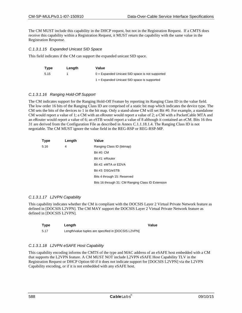
CM-SP-MULPIv3.1-I07-150910 Data-Over-Cable Service Interface Specifications
588 CableLabs 09/10/15
The CM MUST include this capability in the DHCP request, but not in the Registration Request. If a CMTS does receive this capability within a Registration Request, it MUST return the capability with the same value in the Registration Response.
C.1.3.1.15 Expanded Unicast SID Space
This field indicates if the CM can support the expanded unicast SID space.
Type Length Value 5.15 1 0 = Expanded Unicast SID space is not supported
1 = Expanded Unicast SID space is supported
C.1.3.1.16 Ranging Hold-Off Support
The CM indicates support for the Ranging Hold-Off Feature by reporting its Ranging Class ID in the value field. The low order 16 bits of the Ranging Class ID are comprised of a static bit map which indicates the device type. The CM sets the bits of the devices to 1 in the bit map. Only a stand-alone CM will set Bit #0. For example, a standalone CM would report a value of 1; a CM with an eRouter would report a value of 2; a CM with a PacketCable MTA and an eRouter would report a value of 6; an eSTB would report a value of 8 although it contained an eCM. Bits 16 thru 31 are derived from the Configuration File as described in Annex C.1.1.18.1.4. The Ranging Class ID is not negotiable. The CM MUST ignore the value field in the REG-RSP or REG-RSP-MP.
Type Length Value 5.16 4 Ranging Class ID (bitmap)
Bit #0: CM
Bit #1: eRouter
Bit #2: eMTA or EDVA
Bit #3: DSG/eSTB
Bits 4 through 15: Reserved
Bits 16 through 31: CM Ranging Class ID Extension
C.1.3.1.17 L2VPN Capability
This capability indicates whether the CM is compliant with the DOCSIS Layer 2 Virtual Private Network feature as defined in [DOCSIS L2VPN]. The CM MAY support the DOCSIS Layer 2 Virtual Private Network feature as defined in [DOCSIS L2VPN].
Type Length Value 5.17 Length/value tuples are specified in [DOCSIS L2VPN]
C.1.3.1.18 L2VPN eSAFE Host Capability
This capability encoding informs the CMTS of the type and MAC address of an eSAFE host embedded with a CM that supports the L2VPN feature. A CM MUST NOT include L2VPN eSAFE Host Capability TLV in the Registration Request or DHCP Option 60 if it does not indicate support for [DOCSIS L2VPN] via the L2VPN Capability encoding, or if it is not embedded with any eSAFE host.
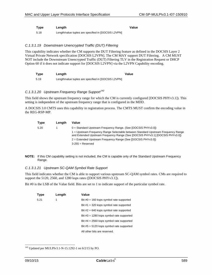
MAC and Upper Layer Protocols Interface Specification CM-SP-MULPIv3.1-I07-150910
09/10/15 CableLabs 589
Type Length Value 5.18 Length/value tuples are specified in [DOCSIS L2VPN]
C.1.3.1.19 Downstream Unencrypted Traffic (DUT) Filtering
This capability indicates whether the CM supports the DUT Filtering feature as defined in the DOCSIS Layer 2 Virtual Private Network specification [DOCSIS L2VPN]. The CM MAY support DUT Filtering. A CM MUST NOT include the Downstream Unencrypted Traffic (DUT) Filtering TLV in the Registration Request or DHCP Option 60 if it does not indicate support for [DOCSIS L2VPN] via the L2VPN Capability encoding.
Type Length Value 5.19 Length/value tuples are specified in [DOCSIS L2VPN]
C.1.3.1.20 Upstream Frequency Range Support142
This field shows the upstream frequency range for which the CM is currently configured [DOCSIS PHYv3.1]). This setting is independent of the upstream frequency range that is configured in the MDD.
A DOCSIS 3.0 CMTS uses this capability in registration process. The CMTS MUST confirm the encoding value in the REG-RSP-MP.
Type Length Value 5.20 1 0 = Standard Upstream Frequency Range. (See [DOCSIS PHYv3.0])
1 = Upstream Frequency Range Selectable between Standard Upstream Frequency Range and Extended Upstream Frequency Range (See [DOCSIS PHYv3.1] [DOCSIS PHYv3.0]) 2 = Extended Upstream Frequency Range (See [DOCSIS PHYv3.0]) 3-255 = Reserved
NOTE: If this CM capability setting is not included, the CM is capable only of the Standard Upstream Frequency Range.
C.1.3.1.21 Upstream SC-QAM Symbol Rate Support
This field indicates whether the CM is able to support various upstream SC-QAM symbol rates. CMs are required to support the 5120, 2560, and 1280 ksps rates ([DOCSIS PHYv3.1]).
Bit #0 is the LSB of the Value field. Bits are set to 1 to indicate support of the particular symbol rate.
Type Length Value 5.21 1 Bit #0 = 160 ksps symbol rate supported
Bit #1 = 320 ksps symbol rate supported
Bit #2 = 640 ksps symbol rate supported
Bit #3 = 1280 ksps symbol rate supported
Bit #4 = 2560 ksps symbol rate supported
Bit #5 = 5120 ksps symbol rate supported
All other bits are reserved.
142 Updated per MULPIv3.1-N-15.1292-1 on 6/2/15 by PO.

CM-SP-MULPIv3.1-I07-150910 Data-Over-Cable Service Interface Specifications
590 CableLabs 09/10/15
If this encoding is not included, it is assumed that the CM supports 5120, 2560, 1280, 640, 320, and 160 ksps symbol rates.
C.1.3.1.22 Selectable Active Code Mode 2 Support
This field indicates whether the CM supports Selectable Active Code (SAC) Mode 2.
Type Length Value 5.22 1 0: SAC Mode 2 is not supported
1: SAC Mode 2 is supported
2-255: Reserved
NOTE: If this CM capability setting is not included, the CM is assumed to be not capable of supporting SAC Mode 2.
C.1.3.1.23 Code Hopping Mode 2 Support
This field indicates whether the CM supports Code Hopping Mode 2.
Type Length Value 5.23 1 0: Code Hopping Mode 2 is not supported
1: Code Hopping Mode 2 is supported
2-255: Reserved
NOTE: If this CM capability setting is not included, the CM is assumed to be not capable of supporting Code Hopping Mode 2.
C.1.3.1.24 SC-QAM Multiple Transmit Channel Support
This field shows the number of upstream SC-QAM channel transmitters that the CM can support.
This number is equivalent to the number of 1.28 Msps transmitters that the CM can support. The CM MUST indicate support for 8 or more upstream SC-QAM channel transmitters.
If a CM reports a DOCSIS version (TLV 5.2) of DOCSIS 3.1 (see Annex C.1.3.1.2), the CMTS MUST confirm the encoding value in the REG-RSP-MP.
A DOCSIS-3.0 CMTS interprets this TLV as Multiple Transmit Channel Support per [DOCSIS MULPIv3.0].
Type Length Value 5.24 1 Number of upstream SC-QAM channel transmitters that the CM can support.
C.1.3.1.25 5.12 Msps Upstream Transmit SC-QAM Channel Support
This field shows the maximum number of upstream SC-QAM channels at a symbol rate of 5.12 Msps that the CM can support.
Type Length Value 5.25 1 Number of upstream SC-QAM channels at 5.12 Msps that the CM can support.

MAC and Upper Layer Protocols Interface Specification CM-SP-MULPIv3.1-I07-150910
09/10/15 CableLabs 591
If this CM capability setting is not included or the number of SC-QAM upstream channels is 0, the CM can support only one upstream SC-QAM channel at 5.12 Msps. A CM that can support N SC-QAM channels at symbol rate 5.12 Msps can support N SC-QAM channels at equal or lower symbol rates.
C.1.3.1.26 2.56 Msps Upstream Transmit SC-QAM Channel Support
This field shows the maximum number of upstream SC-QAM channels at symbol rate 2.56 Msps that the CM can support.
Type Length Value 5.26 1 Number of upstream SC-QAM channels at 2.56 Msps that the CM can support.
If this CM capability setting is not included or the number of upstream SC-QAM channels is 0, the CM can support only one upstream SC-QAM channel at 2.56 Msps. A CM that can support N SC-QAM channels at symbol rate 2.56 Msps can support N SC-QAM channels at equal or lower symbol rates.
C.1.3.1.27 Total SID Cluster Support
This field shows the total number of SID Clusters that the CM can support.
Type Length Value 5.27 1 Total number of SID Clusters supported.
The CM MUST support a total number of SID Clusters at least two times the number of Upstream Service Flows supported as reported in Annex C.1.3.1.8 plus one SID Cluster for the number of UGS or UGS-AD only Service Flows as reported in Annex C.1.3.1.36.
C.1.3.1.28 SID Clusters per Service Flow Support
This field shows the maximum number of SID Clusters that can be assigned to a service flow for this CM.
Type Length Value 5.28 1 2-8
Maximum number of SID Clusters per Service Flow
C.1.3.1.29 SC-QAM Multiple Receive Channel Support
This TLV is used by the CM to indicate that it can receive more than one downstream SC-QAM channel simultaneously. This encoding gives the maximum number of separately identified Receive SC-QAM Channels that the CM can support.
The CM MUST indicate support for 24 or more downstream SC-QAM channels.
If a CM reports a DOCSIS version (TLV 5.2) of DOCSIS 3.1 (see Annex C.1.3.1.2), the CMTS MUST confirm the encoding value in the REG-RSP-MP.
A DOCSIS-3.0 CMTS interprets this TLV as Multiple Receive Channel Support per [DOCSIS MULPIv3.0].
For DOCSIS-3.0 CMs if CM omits this encoding, or the CM return a value of zero for this encoding, then the CMTS MUST NOT return non-zero value for the SC-QAM Multiple Receive Channel Support and Multiple Transmit Channel support encoding in its REG-RSP or REG-RSP-MP message to the CM.

CM-SP-MULPIv3.1-I07-150910 Data-Over-Cable Service Interface Specifications
592 CableLabs 09/10/15
Type Length Value 5.29 1 Maximum number N of physical downstream Receive SC-QAM Channels identified
on the CM. Receive SC-QAM Channels are identified within the CM with an RCID from 1 to N.
C.1.3.1.30 Total Downstream Service ID (DSID) Support
The value of this field indicates the maximum total number of Downstream Service IDs (DSIDs) that the CM can recognize for filtering purposes.
Type Length Value 5.30 1 32-255
C.1.3.1.31 Resequencing Downstream Service ID (DSID) Support
The value of this field indicates the number of resequencing DSIDs (resequencing contexts) that the CM can support simultaneously. This number must be no higher than the maximum number of DSIDs supported (see Annex C.1.3.1.30).
Type Length Value 5.31 1 16-255
C.1.3.1.32 Multicast Downstream Service ID (DSID) Support
The value of this field indicates the number of multicast Downstream Service IDs (DSIDs) used by the CMTS to label multicast streams that the CM can support simultaneously. This number MUST be no higher than the Total DSID Support (see Section C.1.3.1.30).
Type Length Value 5.32 1 16-255
C.1.3.1.33 Multicast DSID Forwarding
The value is used by the CM to indicate its level of support for multicast DSID forwarding. A CM reports one of three levels of support for Multicast DSID Forwarding.
• No support for multicast DSID forwarding (0): A CM reports this value if it cannot forward multicast traffic based on the DSID.
• GMAC Explicit Multicast DSID Forwarding (1): A CM reports this value if it is capable of forwarding multicast traffic labeled with a known DSID but is requesting an explicit list of destination GMAC addresses.
• GMAC Promiscuous Multicast DSID Forwarding (2): A CM reports this value if it is capable of forwarding multicast traffic based only on the DSID.
Since a CM that reports support for either type of multicast DSID forwarding, GMAC explicit or GMAC promiscuous, forwards all downstream multicast traffic based on the DSID, a CM is considered to be capable of Multicast DSID forwarding if it reports a value of 1 or 2.
The CM MUST indicate support for GMAC Promiscuous Multicast DSID Forwarding.
A CMTS that returns a non-zero value of the Multicast DSID Forwarding Support capability encoding to a CM in a REG-RSP or REG-RSP-MP is said to "enable" Multicast DSID Forwarding at the CM.

MAC and Upper Layer Protocols Interface Specification CM-SP-MULPIv3.1-I07-150910
09/10/15 CableLabs 593
If a CM reports that it is capable of Multicast DSID Forwarding with the value of 1 or 2, the CMTS MAY return a value of 0 for the encoding in its REG-RSP or REG-RSP-MP in order to "disable" Multicast DSID Forwarding for a CM. If the CMTS returns a value of 0 in the REG-RSP or REG-RSP-MP, the CM MUST disable its Multicast DSID Forwarding.
The CMTS MUST NOT return a value of 1 for the Multicast DSID Forwarding Capability encoding in its REG-RSP or REG-RSP-MP message to the CM unless the CM advertised a capability of 1. If the CM advertises a capability of 1, the CMTS has the option of returning a value of 2 (see Annex G).
Type Length Value 5.33 1 0 = No support for multicast DSID forwarding
1 = Support for GMAC explicit multicast DSID forwarding 2 = Support for GMAC promiscuous multicast DSID forwarding 3 – 255 = Reserved
C.1.3.1.34 Frame Control Type Forwarding Capability
This value is used by the CM to indicate support for forwarding traffic with the Isolation PDU MAC Header (the FC_Type field with a value of 10).
Type Length Value 5.34 1 0 = Isolation Packet PDU MAC Header (FC_Type of 10) is not forwarded
1 = Isolation Packet PDU MAC Header (FC_Type of 10) is forwarded 2 – 255 = Reserved
The CM MUST indicate support for forwarding traffic with the FC_Type field set to a value of 10.
C.1.3.1.35 DPV Capability
This value is used by the CM to indicate support for the DOCSIS Path Verify Feature.
Type Length Value 5.35 1 Bit 0: U1 supported as a Start Reference Point for DPV per Path.
Bit 1: U1 supported as a Start Reference Point for DPV per Packet. Bits 2 to 7 are reserved.
C.1.3.1.36 Unsolicited Grant Service/Upstream Service Flow Support
This field shows the number of additional Service Flows that the CM supports which can be used only for Unsolicited Grant Service. This includes UGS and UGS-AD scheduling services.
Type Length Value 5.36 1 Number of additional service flows that the CM can support which can be used only for
Unsolicited Grant Service Flows
C.1.3.1.37 MAP and UCD Receipt Support
This field indicates whether or not the CM can support the receipt of MAPs and UCDs on any downstream channel, or if it can only receive MAPs and UCDs on the Primary Downstream Channel.
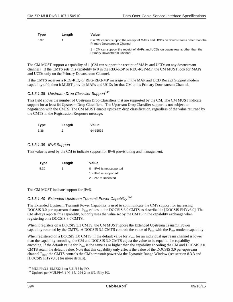
CM-SP-MULPIv3.1-I07-150910 Data-Over-Cable Service Interface Specifications
594 CableLabs 09/10/15
Type Length Value 5.37 1 0 = CM cannot support the receipt of MAPs and UCDs on downstreams other than the
Primary Downstream Channel
1 = CM can support the receipt of MAPs and UCDs on downstreams other than the Primary Downstream Channel
The CM MUST support a capability of 1 (CM can support the receipt of MAPs and UCDs on any downstream channel). If the CMTS sets this capability to 0 in the REG-RSP or REG-RSP-MP, the CM MUST look for MAPs and UCDs only on the Primary Downstream Channel.
If the CMTS receives a REG-REQ or REG-REQ-MP message with the MAP and UCD Receipt Support modem capability of 0, then it MUST provide MAPs and UCDs for that CM on its Primary Downstream Channel.
C.1.3.1.38 Upstream Drop Classifier Support143
This field shows the number of Upstream Drop Classifiers that are supported by the CM. The CM MUST indicate support for at least 64 Upstream Drop Classifiers. The Upstream Drop Classifier support is not subject to negotiation with the CMTS. The CM MUST enable upstream drop classification, regardless of the value returned by the CMTS in the Registration Response message.
Type Length Value 5.38 2 64-65535
C.1.3.1.39 IPv6 Support
This value is used by the CM to indicate support for IPv6 provisioning and management.
Type Length Value 5.39 1 0 = IPv6 is not supported
1 = IPv6 is supported 2 – 255 = Reserved
The CM MUST indicate support for IPv6.
C.1.3.1.40 Extended Upstream Transmit Power Capability144
The Extended Upstream Transmit Power Capability is used to communicate the CM's support for increasing DOCSIS 3.0 per-upstream channel Pmax values to the DOCSIS 3.0 CMTS as described in [DOCSIS PHYv3.0]. The CM always reports this capability, but only uses the value set by the CMTS in the capability exchange when registering on a DOCSIS 3.0 CMTS.
When it registers on a DOCSIS 3.1 CMTS, the CM MUST ignore the Extended Upstream Transmit Power capability returned by the CMTS. A DOCSIS 3.1 CMTS controls the value of Pmax with the Pmax modem capability.
When registered on a DOCSIS 3.0 CMTS, if the default value for Pmax for an individual upstream channel is lower than the capability encoding, the CM and DOCSIS 3.0 CMTS adjust the value to be equal to the capability encoding. If the default value for Pmax is the same as or higher than the capability encoding the CM and DOCSIS 3.0 CMTS retain the default value. Note that this capability only affects the value of the DOCSIS 3.0 per-upstream channel Pmax; the CMTS controls the CM's transmit power via the Dynamic Range Window (see section 8.3.3 and [DOCSIS PHYv3.0] for more details).
143 MULPIv3.1-15.1332-1 on 8/21/15 by PO. 144 Updated per MULPIv3.1-N- 15.1294-2 on 6/2/15 by PO.

MAC and Upper Layer Protocols Interface Specification CM-SP-MULPIv3.1-I07-150910
09/10/15 CableLabs 595
The CM MUST report the Extended Upstream Transmit Power Capability in units of one-quarter dB. A CM capability value of zero indicates that the CM does not support an extension to its Upstream Transmit Power. If a DOCSIS 3.0 CMTS returns a non-zero value that is different from the value the CM sent in the REG-REQ-MP, this indicates that the CM and CMTS are not synchronized, and the CM MUST re-initialize the MAC with Initialization Reason "REG_RSP_NOT_OK" (7). If the DOCSIS 3.0 CMTS returns a zero value, or does not include this TLV, the CM does not extend its upstream transmit power as defined in [DOCSIS PHYv3.0].
The CMTS MUST either confirm the DOCSIS 3.0 CM's capability by responding with the same value communicated by the CM or disable the Extended Upstream Transmit Power capability by responding with a value of zero. By default, the CMTS MUST confirm the value on a DOCSIS 3.0 CM, unless a mechanism is provided to administratively configure this setting on and off.
Type Length Value 5.40 1 0, 205 – 244 (units of one-quarter dB)
C.1.3.1.41 Optional 802.1ad, 802.1ah, MPLS Classification Support
This field shows the optional 802.1 ad, 802.1ah, MPLS filtering support in the CM. Bits are set to 1 to indicate that support for optional filtering.
NOTE: This CM capability is not subject to negotiation with the CMTS.
If a CMTS receives this capability within a Registration Request, it MUST return the capability with the same value in the Registration Response. If this CM capability setting is not included, the CM is assumed to be not capable of supporting [IEEE 802.1ad], [IEEE 802.1ah], and MPLS classification encodings.
Type Length Value 5.41 4 802.1ad, 802.1ah, MPLS Filtering Support Bitmap
bit #0: [IEEE 802.1ad] S-TPID bit #1: [IEEE 802.1ad] S-VID bit #2: [IEEE 802.1ad] S-PCP bit #3: [IEEE 802.1ad] S-DEI bit #4: [IEEE 802.1ad] C-TPID bit #5: [IEEE 802.1ad] C-VID bit #6: [IEEE 802.1ad] C-PCP bit #7: [IEEE 802.1ad] C-CFI bit #8: [IEEE 802.1ad] S-TCI bit #9: [IEEE 802.1ad] C-TCI bit #10: [IEEE 802.1ah] I-TPID bit #11: [IEEE 802.1ah] I-SID bit #12: [IEEE 802.1ah] I-TCI bit #13: [IEEE 802.1ah] I-PCP bit #14: [IEEE 802.1ah] I-DEI bit #15: [IEEE 802.1ah] I-UCA bit #16: [IEEE 802.1ah] B-TPID bit #17: [IEEE 802.1ah] B-TCI bit #18: [IEEE 802.1ah] B-PCP bit #19: [IEEE 802.1ah] B-DEI bit #20: [IEEE 802.1ah] B-VID bit #21: [IEEE 802.1ah] B-DA bit #22: [IEEE 802.1ah] B-SA bit #23: MPLS TC bit #24: MPLS Label

CM-SP-MULPIv3.1-I07-150910 Data-Over-Cable Service Interface Specifications
596 CableLabs 09/10/15
Type Length Value bit #25-31: reserved, to be set to zero
C.1.3.1.42 D-ONU (Optical Network Unit) Capabilities Encoding
The D-ONU Capabilities Encoding describes the capabilities of a particular D-ONU on a DPoE Network, i.e., implementation dependent limits on the particular features or number of features, which the D-ONU can support. It consists of a number of encapsulated type/length/value fields; these sub-types define the specific capabilities per [DPoE-MULPIv2.0].
Type Length Value 5.42 Length/value tuples are specified in the DPOE specifications.
C.1.3.1.43 Energy Management Capabilities
This field indicates the energy management features the CM supports. If the bit value is set, it indicates the modem is capable of supporting that energy management feature.
Type Length Value 5.44 4 Bitmask indicating Energy Management Features supported. The mode is
supported when the bit is set to 1, and not supported when the bit is set to zero. Bit 0: Energy Management 1x1 Feature Bit 1: DOCSIS Light Sleep Mode Bits 2-31: Reserved
The CM MUST report a value of 1 for Bits 0 and 1 of the Energy Management Capabilities TLV, indicating support for the Energy Management 1x1 Feature and DOCSIS Light Sleep Mode.
The CMTS MUST either confirm the CM's capability with the features that network will allow (by responding with the same bit value communicated by the CM), or disable the Energy Management feature capability by responding with a value of zero for that bit.
C.1.3.1.44 C-DOCSIS Capability Encoding
This capability field is only applicable to devices, which optionally support C-DOCSIS requirements as defined in Annex L.
The value field describes the capabilities of a particular modem, i.e., implementation dependent limits on the particular features or number of features, which the modem can support.
It consists of a number of encapsulated type/length/value fields; these sub-types define the specific capabilities.
NOTE: The sub-type fields defined are only valid within the encapsulated capabilities configuration setting string.
Type Length Value 5.45 N Sub-Type/Length/Value tuples are specified in Annex L.
C.1.3.1.45 CM-STATUS-ACK145
This field is used by the CM to indicate support for the CM-STATUS-ACK feature.
145 Updated per MULPIv3.1-N-14.1159-1 on 12/15/14 by PO.

MAC and Upper Layer Protocols Interface Specification CM-SP-MULPIv3.1-I07-150910
09/10/15 CableLabs 597
Type Length Value 5.46 1 Value indicating support for CM-STATUS-ACK feature
0: CM-STATUS-ACK not supported 1: CM-STATUS-ACK supported 2-255: Reserved
The CMTS MUST confirm the CM's capability to support CM-STATUS-ACK, unless otherwise provisioned.
C.1.3.1.46 Energy Management Preference
This is an optional field. When present, this field indicates the energy management mode preferred by the cable modem. (For example, the mode that uses the least power.) The CMTS returns this TLV in the REG-RSP-MP message if present in the REG-REQ-MP message. The CMTS MAY ignore this advice from the CM when assigning Primary and Backup Primary channels to the CM.
Type Length Value 5.47 4 Bitmask indicating Energy Management Modes preferred by the CM. The
modes have the corresponding bit set to 1. All other bits MUST be set to zero. Bit 0: Energy Management 1x1 Feature Bit 1: DOCSIS Light Sleep Mode Bits 2-31: Reserved
C.1.3.1.47 Extended Packet Length Support Capability
This field indicates the maximum length of Packet PDU supported by the CM expressed in bytes.
Type Length Value 5.48 2 Maximum length of Packet PDU supported by CM in bytes.
The CM MUST report a value of 2000 in the Extended Packet Length Support Capability TLV, indicating support for forwarding Packet PDUs up to 2000 bytes in length. The capability is applicable to Packet PDUs forwarded in either downstream or upstream direction, or to processing of Packet PDUs received by CM internal stack. If a CMTS does receive this capability within a Registration Request, it MUST return the TLV with value between 1522 and the value reported by the CM in this TLV. If the CMTS disables this capability by overriding the Extended Packet Length Support Capability with a value of 0, the CM MUST limit the size of Packet PDUs transmitted in the upstream to 1522 bytes (i.e., no packets with extended lengths are permitted in the upstream).
C.1.3.1.48 OFDM Multiple Receive Channel Support
This TLV is used by the CM to indicate the number of downstream OFDM channels that it can receive simultaneously. This encoding gives the maximum number of separately identified Receive OFDM Channels that the CM can support.
The CM MUST report a value of 2 or more for this capability. The CMTS MUST confirm the encoding value in the REG-RSP-MP.
Type Length Value 5.49 1 Maximum number N of physical downstream Receive OFDM Channels identified on the
CM. Receive OFDM Channels are identified within the CM with an RCID from 1 to N.

CM-SP-MULPIv3.1-I07-150910 Data-Over-Cable Service Interface Specifications
598 CableLabs 09/10/15
C.1.3.1.49 OFDMA Multiple Transmit Channel Support
This TLV is used by the CM to indicate the number of upstream OFDMA transmitters that the CM can support simultaneously. This encoding gives the maximum number of separately identified OFDMA Transmit Channels that the CM can support.
The CM MUST indicate support for two or more upstream OFDMA transmitters. The CMTS MUST confirm the encoding value in the REG-RSP-MP.
Type Length Value 5.50 1 Number of upstream OFDMA transmitters that the CM can support.
C.1.3.1.50 Downstream OFDM Profile Support
This value is used by the CM to indicate the number of profiles that are supported for each downstream OFDM Channel. This number indicates the total number of profiles (active and transient) that can be supported for each OFDM channel.
Type Length Value 5.51 1 Maximum number N of profiles that are supported per downstream OFDM channel.
CMs report a value of 5 (4 active + 1 transient) or more.
If the CM omits the Downstream OFDM Profile Support encoding, the CMTS MUST assume the DOCSIS 3.1 baseline compliance requirement of 5 profiles (4 active + 1 transient) per downstream OFDM channel.
C.1.3.1.51 Downstream OFDM channel subcarrier QAM modulation support
This bit field shows the QAM modulations supported by the CM on subcarriers within an OFDM downstream channel. When the CMTS receives this capability within a Registration Request, it returns the capability with the same value in the Registration Response. A CM supports QPSK, 16, 64, 128, 256, 512, 1024, 2048 and 4096 QAM modulations.
Type Length Value 5.52 2 Downstream OFDM channel subcarrier QAM modulation support bitmap
bit #0-1: reserved bit #2: QPSK bit #3: reserved bit #4: 16-QAM bit #5: reserved bit #6: 64-QAM bit #7: 128-QAM bit #8: 256-QAM bit #9: 512-QAM bit #10: 1024-QAM bit #11: 2048-QAM bit #12: 4096-QAM bit #13: 8192-QAM bit #14: 16384-QAM bit #15: reserved, set to zero
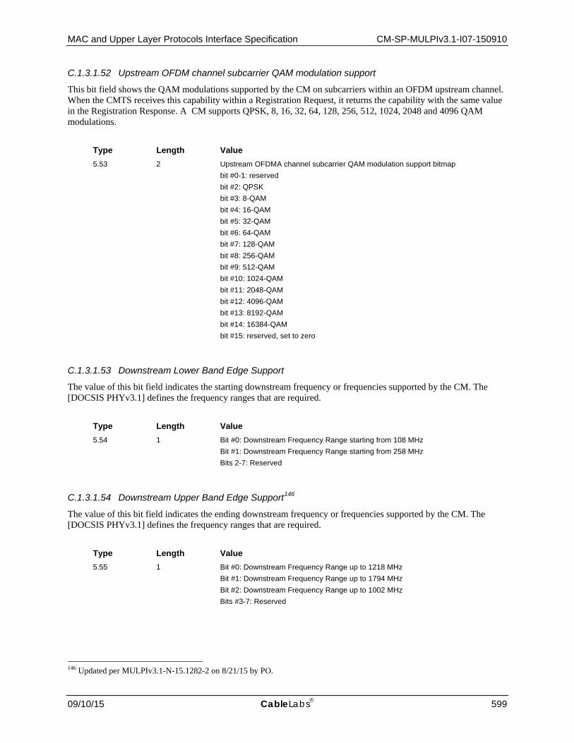
MAC and Upper Layer Protocols Interface Specification CM-SP-MULPIv3.1-I07-150910
09/10/15 CableLabs 599
C.1.3.1.52 Upstream OFDM channel subcarrier QAM modulation support
This bit field shows the QAM modulations supported by the CM on subcarriers within an OFDM upstream channel. When the CMTS receives this capability within a Registration Request, it returns the capability with the same value in the Registration Response. A CM supports QPSK, 8, 16, 32, 64, 128, 256, 512, 1024, 2048 and 4096 QAM modulations.
Type Length Value 5.53 2 Upstream OFDMA channel subcarrier QAM modulation support bitmap
bit #0-1: reserved bit #2: QPSK bit #3: 8-QAM bit #4: 16-QAM bit #5: 32-QAM bit #6: 64-QAM bit #7: 128-QAM bit #8: 256-QAM bit #9: 512-QAM bit #10: 1024-QAM bit #11: 2048-QAM bit #12: 4096-QAM bit #13: 8192-QAM bit #14: 16384-QAM bit #15: reserved, set to zero
C.1.3.1.53 Downstream Lower Band Edge Support
The value of this bit field indicates the starting downstream frequency or frequencies supported by the CM. The [DOCSIS PHYv3.1] defines the frequency ranges that are required.
Type Length Value 5.54 1 Bit #0: Downstream Frequency Range starting from 108 MHz
Bit #1: Downstream Frequency Range starting from 258 MHz Bits 2-7: Reserved
C.1.3.1.54 Downstream Upper Band Edge Support146
The value of this bit field indicates the ending downstream frequency or frequencies supported by the CM. The [DOCSIS PHYv3.1] defines the frequency ranges that are required.
Type Length Value 5.55 1 Bit #0: Downstream Frequency Range up to 1218 MHz
Bit #1: Downstream Frequency Range up to 1794 MHz Bit #2: Downstream Frequency Range up to 1002 MHz Bits #3-7: Reserved
146 Updated per MULPIv3.1-N-15.1282-2 on 8/21/15 by PO.

CM-SP-MULPIv3.1-I07-150910 Data-Over-Cable Service Interface Specifications
600 CableLabs 09/10/15
C.1.3.1.55 Diplexer Upper Band Edge Support147
The value of this modem capability indicates the diplexer upper band edge for which the CM is currently configured. [DOCSIS PHYv3.1] defines the requirements for frequency range support.
Type Length Value 5.56 1 0: Upstream Frequency Range up to 42 MHz
1: Upstream Frequency Range up to 65 MHz 2: Upstream Frequency Range up to 85 MHz 3: Upstream Frequency Range up to 117 MHz 4: Upstream Frequency Range up to 204 MHz 5-255: Reserved
C.1.3.1.56 DOCSIS Time Protocol Mode
This value is used by the CM to indicate support for DOCSIS Time Protocol. The CM MUST include this capability.
To disable DTP operation for the CM, the CMTS overrides the reported capability with a value of 0. To enable DTP Slave operation, the CMTS confirms (or overrides) the reported value with a value of 1. To enable DTP Master operation, the CMTS confirms (or overrides) the reported value with a value of 2. The CMTS MUST NOT place the CM into a DTP Mode to which it does not support.
Type Length Value 5.57 1 0 = DTP operation is not supported
1 = DTP Slave capable only 2 = DTP Master capable only 3 = DTP Master or Slave capable 4-255 = Reserved
C.1.3.1.57 DOCSIS Time Protocol Performance Support
This parameter indicates the DTP performance level of the CM as defined in Section 10, DPT System Level Performance subsection.
Type Length Value 5.58 1 0 = DTP mode is not supported
1 = DTP support for DTP Level 1 2 = DTP support for DTP Level 2 3 = DTP support for DTP Level 3 4 = DTP support for DTP Level 4 5 = DTP support for DTP Level 5 6 = DTP supported but with no specified performance 7 – 255 = Reserved
147 Updated per MULPIv3.1-N-15.1269-1 on 3/10/15 by PO, updated per MULPI3.1-N-15.1300-3 on 6/2/15 by PO.

MAC and Upper Layer Protocols Interface Specification CM-SP-MULPIv3.1-I07-150910
09/10/15 CableLabs 601
C.1.3.1.58 Pmax148
The Pmax capability exchange provides the Pmax value that will be used by the CM and the CMTS to calculate P1.6hi [DOCSIS PHYv3.1]. The CM communicates the Pmax that it supports in the Registration Request message. The CMTS sets the Pmax value to be used by the CM in the Registration Response message.
The CM is required to support a minimum Pmax value of 65 dBmV. The CM MUST report a value of Pmax that is greater than or equal to 65 dBmV. The CM may support increasing Pmax values as described in [DOCSIS PHYv3.1] for the Transmit Channel Set. The CM MUST report the Pmax Capability in units of one-quarter dBmV.
The CMTS MUST confirm the CM's capability by responding with the same value communicated by the CM. If the CMTS returns a zero value or if the TLV is absent, the CM MUST use the default Pmax value for upstream transmit power.
Type Length Value 5.59 2 0,260-320 (units of one-quarter dBmV)
C.1.3.2 Vendor ID Encoding The value field contains the vendor identification specified by the three-byte vendor-specific Organization Unique Identifier of the CM MAC address.
The Vendor ID MUST be used in a Registration Request. The Vendor ID is not used as a stand-alone configuration file element. The Vendor ID MAY be used as a sub-field of the Vendor Specific Information Field in a configuration file. When used as a sub-field of the Vendor Specific Information field, this identifies the Vendor ID of the CMs which are intended to use this information. When the vendor ID is used in a Registration Request, then it is the Vendor ID of the CM sending the request.
Type Length Value 8 3 v1, v2, v3
C.1.3.3 Modem IP Address For backwards compatibility with DOCSIS v 1.0. Replaced by 'TFTP Server Provisioned Modem IPv4 Address' (see Section C.1.1.9).
Type Length Value 12 4 IPv4 Address
C.1.3.4 Service(s) Not Available Response This configuration setting MUST be included in the Registration Response message if the CMTS is unable or unwilling to grant any of the requested classes of service that appeared in the Registration Request. Although the value applies only to the failed service class, the entire Registration Request MUST be considered to have failed (none of the class-of-service configuration settings are granted).
Type Length Value 13 3 Class ID, Type, Confirmation Code
148 Added per MULPIv3.1-N- 15.1294-2 on 6/2/15 by PO, TLV table updated by MULPIv.3.1-N-15.1318-1 on 6/8/15 by PO.

CM-SP-MULPIv3.1-I07-150910 Data-Over-Cable Service Interface Specifications
602 CableLabs 09/10/15
The Class ID is the class-of-service class from the request which is not available.
The Type is the specific class-of-service object within the class which caused the request to be rejected.
The Confirmation Code is defined in Annex C.4.
C.1.3.5 Vendor Specific Capabilities149 Vendor-specific data about the CM, that is to be included in the REG-REQ-MP, but which is not part of the configuration file, if present, MUST be encoded in the vendor-specific capabilities (VSC) (code 44) using the Vendor ID field (refer to Annex C.1.3.1.41) to specify which TLV tuples apply to which vendors' products. The Vendor ID MUST be the first TLV embedded inside VSC. If the first TLV inside VSIF is not a Vendor ID, then the TLV MUST be discarded.
This configuration setting MAY appear multiple times. The same Vendor ID MAY appear multiple times. There MUST NOT be more than one Vendor ID TLV inside a single VSC.
Type Length Value 44 n per vendor definition
Example:
Configuration with vendor A specific fields and vendor B specific fields:
VSC (44) + n (number of bytes inside this VSC) 8 (Vendor ID Type) + 3 (length field) + Vendor ID of Vendor Vendor Specific Type #1 + length of the field + Value #1 Vendor Specific Type #2 + length of the field + Value #2
C.1.3.6 CM Initialization Reason150 For debugging and system maintenance it is useful to know what caused a CM to initialize. When a CM performs a MAC initialization it has to retain the Initialization Reason. After initialization the CM will attempt to come online. When it sends a REG-REQ-MP it reports the Initialization Reason in the REG-REQ-MP using the "CM Initialization Reason" TLV. The CM MUST include this TLV in the REG-REQ-MP.
Type Length Value 57 1 Initialization Code
Table C–2 outlines the initialization reasons and the associated Initialization Codes.
Table C–2 - Initialization Reasons and Codes
Initialization Reason Initialization Code POWER-ON 1
T17_LOST-SYNC 2
ALL_US_FAILED 3
BAD_DHCP_ACK 4
LINK_LOCAL_ADDRESS_IN_USE 5
T6_EXPIRED 6
REG_RSP_NOT_OK 7
149 MULPIv3.1-N-15.1334-2 on 8/21/15 by PO. 150 MULPIv3.1-N-15.1334-2 on 8/21/15 by PO.

MAC and Upper Layer Protocols Interface Specification CM-SP-MULPIv3.1-I07-150910
09/10/15 CableLabs 603
Initialization Reason Initialization Code BAD_RCC_TCC 8
FAILED_PRIM_DS 9
TCS_FAILED_ON_ALL_US 10
MTCM_CHANGE 15
T4_EXPIRED 16
NO_PRIM_SF_USCHAN 17
CM_CTRL_INIT 18
DYNAMIC-RANGE-WINDOW-VIOLATION 19
IP_PROV_MODE_OVERRIDE 20
SW_UPGRADE_REBOOT 21
SNMP_RESET 22
REG_RSP_MISSING_RCC 23
REG_RSP_MISSING_TCC 24
REG_RSP_MTC_NOT_ENABLED 25
DHCPv6_BAD_REPLY 26
C.1.4 Dynamic-Message-Specific Encodings These encodings are not found in the configuration file, nor in the Registration Request/Response signaling. They are only found in DSA-REQ, DSA-RSP, DSA-ACK, DSC-REQ, DSC-RSP, DSC-ACK, DSD-REQ DBC-REQ, DBC-RSP, and DBC-ACK messages (see subsections Dynamic Service Addition - Request (DSA-REQ through Dynamic Service Deletion - Response (DSD-RSP in Section 6) and (see subsections Dynamic Bonding Change Request (DBC-REQ through Dynamic Bonding Change Acknowledge (DBC-ACK) in Section 6).
C.1.4.1 HMAC-Digest The HMAC-Digest setting is a keyed message digest. If privacy is enabled, the HMAC-Digest Attribute MUST be the final Attribute in the Dynamic Service message's Attribute list. For Dynamic Messages, other than the DBC-REQ message, the message digest MUST be performed over all of the Dynamic Message parameters starting immediately after the MAC Management Message Header and up to, but not including the HMAC Digest setting, in the order in which they appear within the packet. For the DBC-REQ Message, the message digest MUST be performed over all the TLV Encoded Parameters (i.e., not including fixed fields such as the Number of Fragments and Fragment Sequence Number) up to, but not including, the HMAC-Digest setting, in the order in which they appear within the re-assembled packet.
Inclusion of the keyed digest allows the receiver to authenticate the message. The HMAC-Digest algorithm, and the upstream and downstream key generation requirements are documented in [DOCSIS SECv3.0].
This parameter contains a keyed hash used for message authentication. The HMAC algorithm is defined in [RFC 2104]. The HMAC algorithm is specified using a generic cryptographic hash algorithm. Baseline Privacy uses a particular version of HMAC that employs the Secure Hash Algorithm (SHA-1), defined in [SHA].
A summary of the HMAC-Digest Attribute format is shown below. The fields are transmitted from left to right.
Type Length Value 27 20 A 160-bit (20-octet) keyed SHA hash

CM-SP-MULPIv3.1-I07-150910 Data-Over-Cable Service Interface Specifications
604 CableLabs 09/10/15
C.1.4.2 Authorization Block The Authorization Block contains an authorization "hint". The specifics of the contents of this "hint" are beyond the scope of this specification, but include [PKT-DQoS].
The Authorization Block MAY be present in CM-initiated DSA-REQ and DSC-REQ messages, and CMTS-initiated DSA-RSP and DSC-RSP messages. This parameter MUST NOT be present in CMTS-initiated DSA-REQ and DSC-REQ messages, nor CM-initiated DSA-RSP and DSC-RSP messages.
The Authorization Block information applies to the entire content of the message. Thus, only a single Authorization Block per message MAY be present. The Authorization Block, if present, MUST be passed to the Authorization Module in the CMTS. The Authorization Block information is only processed by the Authorization Module.
Type Length Value 30 n Sequence of n octets
C.1.4.3 Key Sequence Number This value shows the key sequence number of the [DOCSIS SECv3.0]. Authorization Key which is used to calculate the HMAC- Digest in case that the Privacy is enabled.
Type Length Value 31 1 Auth Key Sequence Number (0 - 15)
C.1.4.4 Energy Management Mode Indicator This encoding is included in the DBC-REQ message by the CMTS to indicate that the DBC transaction is placing the CM into or out of the energy management mode appropriate to the CM's primary downstream channel.
When set to 1, the CM MUST operate in Energy Management 1x1 Mode. When set to 0, the CM MUST exit all Energy Management Modes. The CM utilizes this indicator to determine which Activity Detection thresholds to use following the successful completion of the DBC transaction (see the subsection Entry and Exit for Energy Management Modes in Section 11). If this TLV is not included in a DBC-REQ, the CM MUST continue to operate in the energy management mode in use prior to the DBC transaction. The CM MUST NOT reject a DBC transaction based on the value of this TLV.
In order to ensure that the CM and CMTS remain in sync with respect to Energy Management 1x1 Mode, the CMTS MUST include this TLV in all DBC-REQ messages for CMs in which the Energy Management 1x1 Feature is enabled. For a CM operating in DOCSIS Light Sleep Mode, the CMTS sends a value of 2 for this parameter.
Type Length Value
75 1 Energy Management Mode Indicator. 0 = Do not operate in any Energy Management Mode 1 = Operate in Energy Management 1x1 Mode 2 = Operate in DOCSIS Light Sleep (DLS) Mode
C.1.4.5 Energy Management – DOCSIS Light Sleep Encodings The CMTS uses this TLV in a DBC-REQ message to communicate the DOCSIS Light Sleep parameters to a CM in the DBC-REQ message when it puts the CM into DLS Mode. The CMTS only includes these encodings when the CMTS puts the CM into DOCSIS Light Sleep Mode. The CMTS does not include these encodings in a DBC-REQ message sent to a CM which is operating in an Energy Management Mode.

MAC and Upper Layer Protocols Interface Specification CM-SP-MULPIv3.1-I07-150910
09/10/15 CableLabs 605
Type Length Value
80 N The DOCSIS Light Sleep parameters that a CM is to use when operating in DOCSIS Light Sleep Mode.
C.1.4.5.1 DLS EM Receive Timer Duration
The CMTS includes this sub-TLV in a DBC-REQ message to communicate the duration of the EM Receive Timer that a CM is to use when operating in DLS Mode. The EM Receive Timer is defined in the subsection DOCSIS Light Sleep (DLS) Feature of Section 11.
Type Length Value
1 1 The duration for the CM’s EM Receive Timer. The DLS Receive Timer Duration is specified in units of PLC frame intervals. The valid range is 0 to 2 with a default value of 0.
C.1.4.5.2 DLS Maximum Sleep Latency
The CMTS uses this sub-TLV in a DBC-REQ message to communicate the amount of time a CM would allow an upstream channel queue to keep packets without transitioning to a wake state that a CM is to use when operating in DLS Mode. The use of the Maximum Sleep Latency is described in the subsection DOCSIS Light Sleep (DLS) Feature of Section 11.
Type Length Value
2 1 The time (in msec.) that a CM in DLS Mode allows upstream packets to be queued without transitioning to a DLS wake state. If this TLV is not present, the CM assumes a default value of 100 msec.
C.1.4.5.3 DLS Maximum Sleep Bytes
The CMTS uses this sub-TLV in a DBC-REQ message to communicate the maximum number of bytes that a CM would allow an upstream service flow to enqueue without transitioning to a wake state that a CM is to use when operating in DLS Mode. The number of bytes includes all MAC frame data PDU bytes following the MAC header HCS and to the end of the CRC for the MAC frames enqueued for the service flow. The use of the Maximum Sleep Bytes is described in the DOCSIS Light Sleep (DLS) Feature subsection of Section 11.
Type Length Value
3 2 The maximum number of bytes that a CM in DLS Mode allows to be enqueued without transitioning to a DLS wake state. If this TLV is not present, the CM assumes a default value of 1 Kbyte.
C.1.5 Registration, Dynamic Service, and Dynamic Bonding Settings The TLVs in the following subsections may be included in Registration, Dynamic Service, or Dynamic Bonding messages. Most of these encodings report the physical capabilities and configuration of downstream receive channels and upstream transmit channels on CMs capable of multiple channel operation.
C.1.5.1 Transmit Channel Configuration (TCC) This field defines operations to be performed on an upstream channel in the Transmit Channel Set.

CM-SP-MULPIv3.1-I07-150910 Data-Over-Cable Service Interface Specifications
606 CableLabs 09/10/15
For operation with DOCSIS 3.0 CMs, it can be used in the Registration and DBC MAC Management Messages. If the CMTS confirms a Multiple Transmit SC-QAM Channel Support TLV with a value greater than zero, the CMTS is required to include the TCC TLV in the REG-RSP-MP. If the CMTS enables Multiple Receive SC-QAM Channel mode and sets the Multiple Transmit SC-QAM Channel Support TLV to zero, either by confirming a CM capability of zero or by disabling Multiple Transmit SC-QAM Channel Support for a modem which indicated support via a non-zero value, the CMTS is permitted to include the TCC TLV in the REG-RSP-MP (subsection CMTS Requirements in Section 10).
For operation with DOCSIS 3.1 CMs, it is to be used in the Registration and DBC MAC Management Messages. Since the CMTS confirms Multiple Transmit Channel Support, the CMTS is required to include the TCC TLV in the REG-RSP-MP.
If the CMTS includes the TCC TLV in the REG-RSP-MP, then it uses DBC messaging (as opposed to DCC or UCC messaging) to change the CM's upstream channel(s) within a MAC Domain. If the CMTS does not include the TCC TLV in the REG-RSP-MP, then it does not use DBC messaging to change the CM's upstream channel(s); instead, it uses only DCC or UCC messaging for this purpose. The value field of this TLV contains a series of sub-types.
Type Length Value 46 N
The CMTS MAY include this TLV multiple times within a single message. If the length of the Transmit Channel Configuration (TCC) exceeds 254 bytes, the TCC MUST be fragmented into two or more successive Type 46 elements. Each subsequent TCC fragment MUST begin with a sub-TLV which always contains a complete sub-TLV value unless specified otherwise in the description of the sub-TLV, in which case it could contain a sub-set of the octets of that sub-TLV (see Section C.1.5.1.5). In other words, a sub-TLV instance value cannot span Type 46 TLV fragments without the Type-Length encoding corresponding to that sub-TLV. If it fragments the TCC Encoding, the CMTS MUST ensure that the fragments arrive in order at the CM, as the CM is not required to resequence out-of-order TCC Encoding fragments.
C.1.5.1.1 Transmit Channel Configuration (TCC) Reference
The CMTS MUST assign a unique Transmit Channel Configuration (TCC) Reference per TCC (Type 46 TLV). The CMTS MUST encode this TLV as the first TLV in any complete Type 46 encoding. In a fragmented TCC encoding, the CMTS MUST encode the TCC Reference as the first TLV in the first fragment. In a fragmented TCC encoding, the CMTS MAY also encode the TCC Reference as the first TLV in subsequent fragments. If it encodes the TCC Reference as the first TLV in subsequent fragments of a TCC encoding, the CMTS MUST use the TCC Reference value encoded in the first fragment.
When it receives a fragmented TCC encoding, the CM MUST NOT consider the TCC encoding invalid if the TCC Reference is the first TLV in only the first fragment or if the TCC Reference is the first TLV in each of the fragments.
Type Length Value 46.1 1 0-255: TCC Reference ID
C.1.5.1.2 Upstream Channel Action
The value of this field is used by the CMTS to inform the CM of the action to be performed. These actions include adding the upstream channel to the Transmit Channel Set, changing the ranging SID associated with an upstream channel in the Transmit Channel Set, deleting the upstream channel from the Transmit Channel Set, or replacing the upstream channel within the Transmit Channel Set with a new channel.
A value of "Change" (2) is used to change the ranging SID associated with the upstream channel in the Transmit Channel Set, or to change the value of the Dynamic Range Window, to change the Testing SID associated with the upstream channel, or to change the OFDMA Upstream Data Profile IUC.

MAC and Upper Layer Protocols Interface Specification CM-SP-MULPIv3.1-I07-150910
09/10/15 CableLabs 607
A value of "Re-range" (5) is used to re-range all upstream channels that are included in both the old and the new TCC (any channels not being added, deleted, or replaced) according to the initialization technique provided (refer to Annex C.1.5.1.7). The CM does not re-range upstream channels which are being added, deleted, or replaced. This action is required when the primary downstream channel is being changed or affected by implicit or explicit changes in the Receive Module.
A value of "No Action" (0) is provided to allow the TCC to be included in a message even when the specified Upstream Channel ID is already in use by the CM. This action indicates that no changes are required for the CM to continue using the upstream channel. The CMTS MUST NOT include a TCC Encoding with an Upstream Channel Action of "No Action" in the DBC-REQ message if the DBC-REQ message includes a TCC Encoding with an Upstream Channel Action of "Re-Range".
This TLV MUST be included exactly once in the TCC.
Type Length Value 46.2 1 0 = No Action
1 = Add 2 = Change 3 = Delete 4 = Replace 5 = Re-range 6 – 255: Reserved
C.1.5.1.3 Upstream Channel ID
This TLV MUST be included exactly once in each TCC. It is the ID of the Upstream Channel being operated on. When the action is Replace (4), this ID is the channel being replaced.
When the action is Re-range (5), the value of the upstream channel MUST be 0.
When the Dynamic Range Window TLV is included in the TCC, the value of the upstream channel ID MUST be 0.
Type Length Value 46.3 1 0 = All upstream channels (used with an upstream channel action of Re-Range or
inclusion of Dynamic Range Window TLV in the TCC) 1-255 = Upstream Channel ID
C.1.5.1.4 New Upstream Channel ID
When the Upstream Channel Action is Replace (4), this TLV MUST be included exactly once in the TCC. It MUST NOT be present for any other Upstream Channel Action values. This TLV contains the Upstream Channel ID of the new channel which is replacing an existing channel.
Type Length Value 46.4 1 1-255: Upstream Channel ID
C.1.5.1.5 UCD
The CMTS includes this TLV when the Upstream Channel Action is either Add or Replace so that the CM will not have to wait for a UCD message for the new upstream channel. Including the UCD in the TCC encoding allows the CM to validate the Dynamic Range Window for the commanded TCS prior to making any changes.

CM-SP-MULPIv3.1-I07-150910 Data-Over-Cable Service Interface Specifications
608 CableLabs 09/10/15
The CMTS MUST include the UCD encoding within a TCC when the Upstream Channel Action is Add or Replace. The CMTS MUST NOT include the UCD encoding within a TCC when the Upstream Channel Action is No action, Change, Delete, or Re-range. The CM MUST observe the UCD encoding.
Type Length Value 46.5 N
This TLV includes all parameters for the UCD message as described in the subsection Upstream Channel Descriptor (UCD) in Section 6, except for the MAC Management Header. The CMTS MUST ensure that the change count in the UCD matches the change count in the UCD of the new channel. The CMTS MUST ensure that the Upstream Channel ID for the new channel is different than the Channel ID for the old channel. The Ranging Required parameter in the new UCD does not apply in this context, since the functionality is covered by the Initialization Technique TLV.
If the length of the Type 46 TLV exceeds 254 octets after adding the UCD, more than one Type 46 TLV MUST be used to encode the TCC TLV. The UCD may need to be fragmented into two or more Type 46.5 fragments encoded in successive Type 46 TLVs. Each fragment SHOULD be the largest possible that fits into the space available in its parent Type 46 TLV. The CM reconstructs the UCD Substitution by concatenating the contents (value of the TLV) of successive Type 46.5 fragments in the order in which they appear in the Type 46 TLV fragment sequence of the TCC. For example, the first byte following the length field of the second Type 46.5 fragments is treated as if it immediately follows the last byte of the first Type 46.5 fragment.
C.1.5.1.6 Ranging SID
When present, this TLV provides a SID value to be used by the CM when performing unicast ranging. The CMTS is allowed to assign the Ranging SID a value used on a SID Cluster for this upstream channel or the same value as a Testing SID for this upstream channel. The SID value provided is also used by the CM when performing probing for an OFDMA channel. The CMTS MUST include this TLV if the Upstream Channel Action is Add, Change, or Replace.
Type Length Value 46.6 2 SID to be used for ranging and probing (lower 14 bits of 16-bit field)
C.1.5.1.7 Initialization Technique151
When present, this TLV allows the CMTS to direct the CM as to what level of re-initialization it MUST perform before it can commence communications on the new channel.
The CMTS MAY include the Initialization Technique encoding within a TCC when the Upstream Channel Action is Add, Replace or Re-Range. The CMTS MUST NOT include the Initialization Technique encoding within a TCC when the Upstream Channel Action is No action, Change, or Delete. The CM MUST observe the Initialization Technique encoding if it is specified within a TCC when the Upstream Channel Action is Add, Replace or Re-Range.
When providing an initialization technique of "perform either broadcast or unicast ranging", the CMTS SHOULD provide the CM with both broadcast and unicast ranging opportunities.
Upon receipt of a TCC encoding containing an initialization technique of "perform either broadcast or unicast ranging", the CM performs ranging backoff on the broadcast ranging opportunities. However, if a unicast ranging opportunity is received while the CM is performing backoff deferral and the time of the unicast opportunity occurs before the end of the backoff window, the CM MUST instead use the unicast opportunity and perform unicast ranging. This is intended to allow the CM to use the first ranging opportunity.
151 Updated per MULPIv3.1--N-14.1193-1 on 12/8/14 by PO.

MAC and Upper Layer Protocols Interface Specification CM-SP-MULPIv3.1-I07-150910
09/10/15 CableLabs 609
If this TLV is not present, and ranging is required on a channel, the CM MUST perform broadcast initial ranging on the channel before normal operation. If performing broadcast initial ranging on a channel as a consequence of no Initialization Technique or an initialization technique of "perform broadcast initial ranging", the CM resets its timing (forget the prior values and ignore any relative ranging).
Type Length Value 46.7 1 1 = (All upstream channel types) Perform broadcast initial ranging (IUC3) on new channel
before normal operation 2 = (S-CDMA and TDMA channels only) Perform unicast ranging (IUC3 or IUC4) on new channel before normal operation. 3 = (S-CDMA and TDMA channels only) Perform either broadcast (IUC3) or unicast (IUC3 or IUC4) ranging on new channel before normal operation 4 = (S-CDMA and TDMA channels only) Use new channel directly without reinitializing or ranging 5 = (OFDMA channels only) Perform probing on new channel before normal operation 6 = (OFDMA channels only) Perform unicast initial ranging (IUC3) on new channel before normal operation 7 = (OFDMA channels only) Perform station ranging (IUC4) on new channel before normal operation 0, 8 – 255: reserved
C.1.5.1.8 Ranging Parameters152
The CMTS MUST include the Ranging Parameters TLV within the TCC when the Upstream Channel Action is Add or Replace and the Initialization Technique has a value of "2", "3", "4", "5", "6", or "7". The CMTS MUST NOT include the Ranging Parameters encoding within a TCC when the Upstream Channel Action is No action, Change, Delete, or Re-range.
The CM MUST observe this TLV. The value field of this TLV contains a series of sub-types describing parameters to be used when initializing on the channel being added or replaced.
Type Length Value 46.8 N
C.1.5.1.8.1 Ranging Reference Channel ID
This TLV MUST be included exactly once in the Ranging Parameters TLV. It provides the ID of a channel whose timing and power values are used as the references for the corresponding offsets.
If the Initialization Technique has a value of 2, 3 or 4, the CM MUST use the result of the accumulated frequency adjustments made on the channel designated as the Reference Channel to calculate proportional frequency offsets for any channels being added or replaced by the TCC.
For example, for an SC-QAM channel, if the Reference Channel UCD frequency is 10 MHz and the CM has been given ranging adjustments increasing the frequency by 100 Hz for that channel, the CM would use a scale factor of 100/10E6 for setting the Transmit Frequency Offset for the channels to be added. Continuing the example, if a channel is being added with a UCD frequency of 20 MHz, the CM would set the Initial Tx Frequency to 20 MHz + (20 MHz * 100/10E6) = 20.0002 MHz rounded to Hz for transmitting on the new channel. The CM is not expected to set its Tx Frequency to fractional Hz.
Subtype Length Value 46.8.1 1 1-255: Upstream Channel ID
152 Updated per MULPIv3.1--N-14.1193-1 on 12/8/14 by PO.

CM-SP-MULPIv3.1-I07-150910 Data-Over-Cable Service Interface Specifications
610 CableLabs 09/10/15
C.1.5.1.8.2 Timing Offset, Integer Part153
When present, this TLV provides the value, as an offset from the reference channel, to set the Ranging Offset of the burst transmission for the new channel so that bursts arrive at the expected minislots time at the CMTS. The units are (1/10.24 MHz) = 97.65625 ns. A negative value implies the Ranging Offset is to be decreased, resulting in later times of transmission at the CM. The CMTS MUST include this TLV within the TCC when the Upstream Channel Action is Add or Replace and the Initialization Technique has a value of "2", "3", "4", "5", "6", or "7". The CMTS MUST NOT include this TLV within the TCC when the Upstream Channel Action is Add or Replace and the Initialization Technique is absent or has a value of "1".
The CMTS does not include the timing offset necessary to compensate for differences in modulation rate (Timing Offset for Modulation Rate Changes Table in [DOCSIS PHYv3.1]) between the Ranging Reference Channel and the upstream channels being added or replaced in the value of this TLV. The CMTS does not include the timing offset necessary to compensate for differences in the pre-equalizer main tap location when applicable between the Ranging Reference Channel and the upstream channels being added or replaced in the value of this TLV. The CM MUST apply this TLV in addition to the timing offset necessary to compensate for differences in modulation rate and pre-equalizer main tap location when applicable between the Ranging Reference Channel and the upstream channels being added or replaced.
Subtype Length Value 46.8.2 4 TX timing offset adjustment (signed 32-bit, units of (6.25 microsec/64))
C.1.5.1.8.3 Timing Offset, Fractional Part
When present, this TLV provides a higher resolution timing adjust offset to be appended to Timing Adjust, Integer Part for the new channel, compared to the reference channel. The units are (1/(256*10.24 MHz)) = 0.3814697265625 ns. This parameter provides finer granularity timing offset information for transmission in S-CDMA mode. The CMTS MUST NOT include this TLV within the TCC when the Upstream Channel Action is Add or Replace and the Initialization Technique is absent or has a value of "1".
Subtype Length Value 46.8.3 1 TX timing fine offset adjustment. 8-bit unsigned value specifying the fine timing
adjustment in units of 1/(256*10.24 MHz).
C.1.5.1.8.4 Power Offset154
When present, this TLV provides the transmission power level, as an offset from the reference channel that the CM is to use on the new channel in order that transmissions arrive at the CMTS at the desired power. The CMTS MUST include this TLV within the TCC when the Upstream Channel Action is Add or Replace and the Initialization Technique has a value of "2", "3", "4", "5", "6", or "7".
Subtype Length Value 46.8.4 1 TX power offset adjustment (signed 8-bit, ¼-dB units)
C.1.5.1.8.5 Frequency Offset
This TLV is deprecated. The CMTS MUST NOT include this TLV in the TCC encodings. The CM MUST ignore this TLV.
153 Updated per MULPIv3.1-N-14.1193-1 on 12/8/14 by PO. 154 Updated per MULPIv3.1-N-14.1193-1 on 12/8/14 by PO.

MAC and Upper Layer Protocols Interface Specification CM-SP-MULPIv3.1-I07-150910
09/10/15 CableLabs 611
Subtype Length Value 46.8.5 2 Deprecated – formerly the TX frequency offset adjustment (signed 16-bit Hz units)
C.1.5.1.9 Dynamic Range Window155
When present, this TLV specifies the value for the top of the Dynamic Range Window (P1.6load_min_set) [DOCSIS PHYv3.1]. The CMTS MUST include this TLV in the REG-RSP-MP.
Because it is not associated with a single upstream channel, the Dynamic Range Window TLV can only be included when the Upstream Channel ID is "0." When the value of the Dynamic Range Window is changing, the Upstream Channel Action is "change." When the value of the Dynamic Range Window is included in the TCC Encodings but not changing, the Upstream Channel Action is "no action" (for example, the CMTS includes the Dynamic Range Window value in a RNG-RSP prior to registration and includes the same Dynamic Range Window in the REG-RSP-MP).
Subtype Length Value 46.9 1 Dynamic Range Window – P1.6load_min_set expressed in units of ¼ dB below P1.6hi
[DOCSIS PHYv3.1]
NOTE: During normal operation the CMTS controls the CM's Dynamic Range Window value using the RNG-RSP message. Prior to registration, the CM does not need a Dynamic Range Window value. The CM requires a value for the Dynamic Range Window when operating in Multiple Transmit Channel Mode.
C.1.5.1.10 P1.6hi156
When present, this TLV specifies the value for P1.6hi [DOCSIS PHYv3.1]. The CMTS MUST include the P1.6hi TLV in the REG-RSP-MP being sent to a DOCSIS 3.1 CM. The CMTS MUST include the P1.6hi TLV in a DBC-REQ message that modifies the TCC encodings of a DOCSIS 3.1 CM. The CMTS MUST NOT include the P1.6hi TLV in TCC encodings sent to a DOCSIS 3.0 CM.
Because it is not associated with a single upstream channel, the CMTS sets the value of the Upstream Channel ID to "0" when sending this sub-TLV in a TCC encoding. Since this sub-TLV is for informative purposes, the value of the Upstream Channel Action is irrelevant.
Subtype Length Value 46.10 1 P1.6hi expressed in units of ¼ dBmV [DOCSIS PHYv3.1]
C.1.5.1.11 Assigned OFDMA Upstream Data Profile (OUDP) IUC
When present, this TLV provides a list of IUCs that the CMTS might utilize when allocating grants to this CM. This provides the CM an indication of upstream OFDMA Data Profiles on which it needs to be prepared to transmit.
The CMTS MUST include this TLV if the Upstream Channel Action is Add or Replace and the Upstream Channel is OFDMA. To update the IUC assignment of an OFDMA upstream channel, the CMTS includes this TLV and provides an Upstream Channel Action of Change.
If the Assigned OFDMA Upstream Data Profile IUC encoding is present in the TCC encoding, the CM MUST replace the current IUC assignment with the IUC assignment provided in the encoding.
155 Updated by MULPIv3.1-N-14.1211-5 on 12/8/14 by PO, updated by MULPIv3.1-N-15.1244-1 on 3/10/15 by PO,
MULPIv3.1-15.1134-2 on 8/21/15 by PO. 156 Updated by MULPIv3.1-N-14.1211-5 on 12/8/14 by PO.

CM-SP-MULPIv3.1-I07-150910 Data-Over-Cable Service Interface Specifications
612 CableLabs 09/10/15
Type Length Value 46.11 N List of IUCs assigned for use by the CMTS for this CM. This list contains one or two IUCs.
Values: 1 to 4 – Reserved (used in MAP message) 5 – Data Profile IUC5 6 – Data Profile IUC6 7 to 8 – Reserved (used in MAP message) 9 – Data Profile IUC9 10 – Data Profile IUC 10 11 – Data Profile IUC 11 12 – Data Profile IUC 12 13 – Data Profile IUC 13 All other values reserved
C.1.5.1.12 OFDMA Upstream Data Profile (OUDP) Testing SID
When present, this TLV provides a SID value to be used by the CM when performing OUDP testing. The CMTS MUST ensure that this SID value is different from any value used in a SID Cluster on this upstream channel. The CMTS MAY include this TLV if the Upstream Channel Action is Add, Change, or Replace and the Upstream Channel is OFDMA.
Type Length Value 46.12 2 Unicast SID to be used for profile testing (lower 14 bits of 16-bit field)
C.1.5.1.13 TCC Error Encodings
This TLV is included to report the status of, or any errors with, the action directed in the TCC.
Subtype Length Value 46.254 n
C.1.5.1.13.1 Reported Parameter
The value of this parameter identifies the subtype of a TCC that is being reported. A TCC Error Set MUST have exactly one Reported Parameter TLV within a given TCC Error Encoding.
Subtype Length Value 46.254.1 n TCC subtype
If the length is one, then the value is the single-level subtype (for example, a value of 0x06 indicates the Ranging SID (Annex C.1.5.1.6). If the length is two, then the value is the multi-level subtype, with the first byte representing the TCC subtype, and the second byte representing the next level subtype (for example, a value of 0x0804 indicates the Power Offset within the Ranging Parameters (Annex C.1.5.1.8.4)).
C.1.5.1.13.2 Error Code
This parameter indicates the status of the operation. A non-zero value corresponds to the Confirmation Code as described in Annex C.4. A TCC Error Set MUST have exactly one Status Code within a given TCC Status Encoding.
Subtype Length Value 46.254.2 1 Confirmation Code

MAC and Upper Layer Protocols Interface Specification CM-SP-MULPIv3.1-I07-150910
09/10/15 CableLabs 613
C.1.5.1.13.3 Error Message
This subtype is optional in the TCC Error Set. If present, it indicates a text string to be displayed on the CMTS console and/or log that further describes a rejected TCC operation. A TCC Error Set MAY have zero or one Error Message subtypes within a given TCC Error Encoding.
Subtype Length Value 46.254.3 n Zero-terminated string of ASCII characters
C.1.5.2 Service Flow SID Cluster Assignments This TLV contains an SFID and channel-to-SID mappings within SID Clusters to be used by the service flow. When present, this TLV MUST be included by the CMTS exactly once per Service Flow.
This TLV can be used in Registration, Dynamic Service Add, and Dynamic Bonding Change MAC Management Messages. The CMTS MUST NOT include this TLV in Dynamic Service Change MAC Management Messages.
Type Length Value 47 N Service Flow SID Cluster Assignments
C.1.5.2.1 SFID
The SFID associated with the SID Cluster. This TLV MUST be included exactly once in a Service Flow SID Cluster Assignment.
Type Length Value 47.1 4 Service Flow ID
C.1.5.2.2 SID Cluster Encoding
This TLV contains a service flow identifier, the channel-to-SID mappings of the SID clusters associated to the service flow, and the service flow's SID Cluster switchover criteria. When present, this TLV MUST be included by the CMTS exactly once for each SID Cluster assigned to the service flow.
Type Length Value at N SID Cluster Encodings
C.1.5.2.2.1 SID Cluster ID
This TLV contains the SID Cluster ID in the range of 0 to 7. The CMTS MUST include this encoding exactly once per SID Cluster encoding. The CMTS MUST assign values in the range of 0 to M-1 where M is the number of SID Clusters per Service Flow supported by the CM.
Subtype Length Value 47.2.1 1 SID Cluster ID

CM-SP-MULPIv3.1-I07-150910 Data-Over-Cable Service Interface Specifications
614 CableLabs 09/10/15
C.1.5.2.2.2 SID-to-Channel Mapping
When present, this TLV MUST be included by the CMTS once per channel. This TLV contains the mapping of a channel ID to SID in the SID Cluster. The value field consists of three sub-TLVs. When this TLV is present, the CMTS MUST include each sub-TLV exactly once.
Subtype Length Value 47.2.2 10 Sub-TLVs as described below
C.1.5.2.2.3 SID-to-Channel Mapping: Upstream Channel ID
This subtype indicates the channel ID on which a SID is being mapped.
Subtype Length Value 47.2.2.1 1 Upstream Channel ID
C.1.5.2.2.3.1 SID-to-Channel Mapping: SID
This subtype gives the SID which is being mapped to the channel indicated in subtype 47.2.2.1.
Subtype Length Value 47.2.2.2 2 2-byte SID (lower 14 bits of 16-bit field)
C.1.5.2.2.3.2 SID-to-Channel Mapping: Action
This subtype indicates whether the SID indicated in subtype 47.2.2.2 is being added or deleted.
Subtype Length Value 47.2.2.3 1 Action:
1 = add
2 = delete
0, 3-255 = reserved
C.1.5.2.3 SID Cluster Switchover Criteria
This TLV contains the SID Cluster Switchover criteria for use by the service flow. The CMTS MAY include this sub-TLV. If the CMTS includes this sub-TLV, it MUST NOT repeat it more than once for a service flow. If the CMTS includes this sub-TLV, it MUST define within it at least one SID Cluster switchover criteria.
Type Length Value 47.3 N SID Cluster Switchover Criteria
C.1.5.2.3.1 Maximum Requests per SID Cluster
This is the maximum number of requests that a CM can make with a given SID Cluster before it must switch to a different SID Cluster to make further requests. The CMTS MAY include this sub-TLV. The CMTS MUST NOT include this TLV more than once within a SID Cluster Switchover Criteria sub-TLV.

MAC and Upper Layer Protocols Interface Specification CM-SP-MULPIv3.1-I07-150910
09/10/15 CableLabs 615
Type Length Value 47.3.1 1 1 – 255 requests
0 = unlimited
A value of 0 represents no limit. If not present, a default value of 0 is used.
C.1.5.2.3.2 Maximum Outstanding Bytes per SID Cluster
This is the maximum number of bytes for which a CM can have requests outstanding on a given SID Cluster. If this many bytes are outstanding and further requests are required, the CM must switch to a different SID Cluster if one is available. If a different SID Cluster is not available, then the CM will stop requesting until there are no bytes outstanding for which the acknowledgement time has not passed. The CMTS MAY include this sub-TLV. The CMTS MUST NOT include this TLV more than once within a SID Cluster Switchover Criteria sub-TLV.
Type Length Value 47.3.2 4 1 – 4294967295 bytes
0 = unlimited
A value of 0 represents no limit. If not present, a default value of 0 is used.
C.1.5.2.3.3 Maximum Total Bytes Requested per SID Cluster
This is the maximum total number of bytes a CM can have requested using a given SID Cluster before it must switch to a different SID Cluster to make further requests. The CMTS MAY include this sub-TLV. The CMTS MUST NOT include this TLV more than once within a SID Cluster Switchover Criteria sub-TLV.
Type Length Value 47.3.3 4 1 – 4294967295 bytes
0 = unlimited
A value of 0 represents no limit. If not present, a default value of 0 is used.
C.1.5.2.3.4 Maximum Time in the SID Cluster
This is the maximum time in milliseconds that a CM may use a particular SID Cluster before it must switch to a different SID Cluster to make further requests. The CMTS MAY include this sub-TLV. The CMTS MUST NOT include this TLV more than once within a SID Cluster Switchover Criteria sub-TLV.
Type Length Value 47.3.4 2 1 – 65535 milliseconds
0 = unlimited
A value of 0 represents no limit. If not present, a default value of 0 is used.
C.1.5.3 CM Receive Channel (RCP/RCC) Encodings DOCSIS 3.1 cable modems support full band capture. Full band capture simplifies the receiver topology significantly in that there is only one level of receiver and there is full flexibility in assignment of receivers to channels. For DOCSIS 3.1 operation, the CM does not include Receive Channel Profile (RCP) Encodings in the Registration Request and the CMTS includes the Simplified Receive Channel Configuration Encodings in its Registration Response/DBC-REQ messages.

CM-SP-MULPIv3.1-I07-150910 Data-Over-Cable Service Interface Specifications
616 CableLabs 09/10/15
When registering with a DOCSIS 3.0 CMTS, the CM includes one or more Receive Channel Profile (RCP) Encodings in its Registration Request to describe the physical layer components that permit it to receive multiple downstream channels. The CMTS returns to the CM in a Registration Response a Receive Channel Configuration (RCC) Encoding that configures the physical layer components to certain frequencies and, if necessary, to certain interconnections between those components.
After a CM has registered, the CMTS changes the set of downstream channels received by a CM with a Dynamic Bonding Change Request (DBC-REQ) message that contains a Receive Channel Configuration Encoding.
The Receive Channel Profile Encoding and Receive Channel Configuration Encoding contain many sub-types in common. In this annex, a Receive Channel Profile subtype is denoted as "48.x" and a Receive Channel Configuration subtype is denoted as "49.x".
Type Length Value 48 N Receive Channel Profile Subtype TLVs (only used for DOCSIS 3.0 registration and DBC)
49 N Receive Channel Configuration Subtype TLVs
The CM MUST support these TLVs. The CM MAY repeat the RCP TLV in a Registration-Request to describe multiple Receive Channel Profiles. The CMTS MUST support these TLVs. The CMTS MUST silently ignore invalid RCP encodings. The CMTS MUST silently ignore unknown RCP subtype encodings and process known RCP subtype encodings normally.
The CM MUST send RCP encodings to a DOCSIS 3.0 CMTS. The CM MUST NOT send RCP encodings to a DOCSIS 3.1 CMTS.
The CM MUST fragment an RCP encoding that exceeds 255 bytes in length (note that as per the subsection Receive Channel Profile Reporting Control TLV in Section 6, the CM only sends these fragmented RCPs if the CMTS indicates that it can support them). The CMTS MUST support reception of fragmented RCPs.
The CMTS MUST support the ability to fragment RCCs that are greater than 255 bytes in length. The CMTS MUST NOT fragment an RCC that is 255 bytes or less in length. The CM MUST support the reception of a fragmented RCC from the CMTS.
The CMTS MUST NOT transmit a fragmented RCC to a CM that advertises a Multiple Receive Channel Support capability of less than 8 (Annex C.1.3.1.29).
If an RCP is fragmented, the CM MUST fragment the RCP at sub-TLV boundaries within the Receive Channel Profile TLV, TLV 48. This means that an RCP fragment contains complete RCP sub-TLVs.
If an RCC is fragmented, the CMTS MUST fragment the RCC at sub-TLV boundaries within the Receive Channel configuration TLV, TLV 49. This means that an RCC fragment contains complete RCC sub-TLVs.
C.1.5.3.1 RCP-ID
In an RCP, the RCP-ID identifies the RCP being described. A REG-REQ-MP may have multiple RCP Encodings that describe different logical profiles for configuring the physical interface of the CM.
A Receive Channel Configuration has a single RCP-ID that assigns the CM to use a particular Receive Channel Profile that it supports. The CMTS MAY change the assigned RCP-ID for a CM in a DBC-REQ to the CM. The CM MUST support a change of RCP-ID communicated in a DBC-REQ message.
The CM MUST include the RCP-ID sub-TLV as the first sub-TLV and exactly once within each instance of TLV 48 (RCP) that it transmits. In other words, each RCP fragment will start with the RCP-ID sub-TLV, and unfragmented RCPs will also start with the RCP-ID.
The CMTS MUST include the RCP-ID sub-TLV as the first sub-TLV and exactly once within each instance of TLV 49 (RCC) that it transmits. In other words, each RCC fragment will start with the RCP-ID sub-TLV, and unfragmented RCCs will also start with the RCP-ID.

MAC and Upper Layer Protocols Interface Specification CM-SP-MULPIv3.1-I07-150910
09/10/15 CableLabs 617
Type Length Value 48.1 5 Bytes 0,1,2: Organization Unique ID
Bytes 3,4: OUI-specific profile ID
49.1 5 Assigned RCP-ID
C.1.5.3.2 RCP Name
This parameter defines a human-readable, descriptive name for the Receive Channel Profile. The RCP Name is assigned by the vendor and is not guaranteed to be globally unique. It is recommended that the vendor assign RCP Names uniquely within an OUI. The CM MAY include the RCP Name encoding in an RCP encoding.
Type Length Value 48.2 1..15 Informational DisplayString corresponding to RCP-ID
C.1.5.3.3 RCP Center Frequency Spacing
This parameter defines the interval between center SC-QAM frequencies in a Receive Module. The CM MUST include the RCP Center Frequency Spacing TLV in a verbose RCP encoding. The CM MUST NOT include the RCP Center Frequency Spacing TLV in a non-verbose RCP encoding.
Type Length Value 48.3 1 6 = 6 MHz channels
8 = 8 MHz channels
C.1.5.3.4 Receive Module Encoding
This TLV describes a Receive Module of the CM. A Receive Module is often configured to be a block of adjacent center SC-QAM channel frequencies at the center frequency spacing of the RCP.
Each Receive Module Encoding consists of multiple subtypes.
The CM MAY include the Receive Module Encoding TLV in a verbose RCP encoding. The CM MUST NOT include the Receive Module Encoding TLV in a non-verbose RCP encoding. In the RCC, the CMTS MUST include all Receive Module encodings associated with the Receive Channels configured in the RCC.
Type Length Value 48.4 N Receive Module Capability
49.4 N Receive Module Assignment
C.1.5.3.4.1 Receive Module Index
This is signaled by the CM in an RCP and the CMTS in an RCC to identify a Receive Module. This parameter is required to be present exactly once in each Receive Module Encoding. The CM MUST include exactly one Receive Module Index in a Receive Module Encoding of an RCP Encoding. The CMTS MUST include exactly one Receive Module Index in a Receive Module Encoding of an RCC Encoding. It is expected that RCPs containing OFDM Channel encoding will contain only a single receive module encoding.
Type Length Value 48.4.1 1 Receive Module index being described, starting from 1

CM-SP-MULPIv3.1-I07-150910 Data-Over-Cable Service Interface Specifications
618 CableLabs 09/10/15
Type Length Value 49.4.1 1 Receive Module index being assigned
C.1.5.3.4.2 Receive Module Adjacent Channels
This TLV is not needed in DOCSIS 3.1, and has been removed.
C.1.5.3.4.3 Receive Module SC-QAM Channel Block Range
DOCSIS defines various downstream frequency ranges over which a CM may be capable of operating. This parameter indicates the limited range of the SC-QAM channel block in terms of a minimum of the first center frequency of the channel block and a maximum of the last center frequency of the channel block. This parameter is encoded with two required subtypes.
The CM MAY include the Receive Module SC-QAM Channel Block Range TLV in a Receive Module Encoding of an RCP Encoding. For RCPs indicating an RCP SC-QAM Center Frequency Spacing of 6 MHz, the absence of this TLV is equivalent to a Receive Module Minimum SC-QAM Center Frequency of 111 MHz and a Receive Module Maximum SC-QAM Center Frequency of 999 MHz. For RCPs indicating an RCP SC-QAM Center Frequency Spacing of 8 MHz, the absence of this TLV is equivalent to a Receive Module Minimum SC-QAM Center Frequency of 112 MHz and a Receive Module Maximum SC-QAM Center Frequency of 1002 MHz.
Type Length Value 48.4.3 12 The Minimum SC-QAM Center Frequency and Maximum SC-QAM Center
Frequency subtypes as described immediately below.
C.1.5.3.4.3.1 Receive Module Minimum SC-QAM Center Frequency
Type Length Value 48.4.3.1 4 Minimum center frequency (Hz) of the first SC-QAM channel of the block
C.1.5.3.4.3.2 Receive Module Maximum SC-QAM Center Frequency
Type Length Value 48.4.3.2 4 Maximum center frequency (Hz) of the last SC-QAM channel of the block
C.1.5.3.4.4 Receive Module First SC-QAM Channel Center Frequency Assignment
This subtype is included only in a Receive SC-QAM Channel Configuration (RCC) to assign a Receive Module corresponding to a block of adjacent SC-QAM center frequencies to a particular point in the spectrum. When the Receive Module Adjacent SC-QAM Channels TLV is present in a Receive Module associated with an assigned Receive Channel, the CMTS MUST include a Receive Module First SC-QAM Channel Center Frequency Assignment TLV in its RCC to the CM. The CMTS MUST NOT assign a First SC-QAM Channel Center Frequency such that any center frequency in the channel block falls outside the frequency range limits communicated in the Receive Module SC-QAM Channel Block Range. The CMTS MUST assign the First SC-QAM Channel Center Frequency to be a multiple of 62500 Hz.
Type Length Value 49.4.4 4 Assigned center frequency of the first channel of the Receive Module SC-QAM
channel block, in Hz.
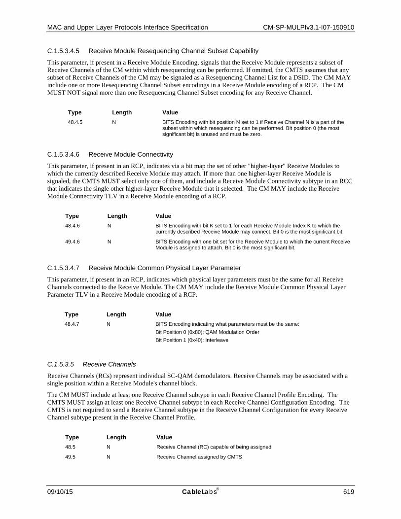
MAC and Upper Layer Protocols Interface Specification CM-SP-MULPIv3.1-I07-150910
09/10/15 CableLabs 619
C.1.5.3.4.5 Receive Module Resequencing Channel Subset Capability
This parameter, if present in a Receive Module Encoding, signals that the Receive Module represents a subset of Receive Channels of the CM within which resequencing can be performed. If omitted, the CMTS assumes that any subset of Receive Channels of the CM may be signaled as a Resequencing Channel List for a DSID. The CM MAY include one or more Resequencing Channel Subset encodings in a Receive Module encoding of a RCP. The CM MUST NOT signal more than one Resequencing Channel Subset encoding for any Receive Channel.
Type Length Value 48.4.5 N BITS Encoding with bit position N set to 1 if Receive Channel N is a part of the
subset within which resequencing can be performed. Bit position 0 (the most significant bit) is unused and must be zero.
C.1.5.3.4.6 Receive Module Connectivity
This parameter, if present in an RCP, indicates via a bit map the set of other "higher-layer" Receive Modules to which the currently described Receive Module may attach. If more than one higher-layer Receive Module is signaled, the CMTS MUST select only one of them, and include a Receive Module Connectivity subtype in an RCC that indicates the single other higher-layer Receive Module that it selected. The CM MAY include the Receive Module Connectivity TLV in a Receive Module encoding of a RCP.
Type Length Value 48.4.6 N BITS Encoding with bit K set to 1 for each Receive Module Index K to which the
currently described Receive Module may connect. Bit 0 is the most significant bit.
49.4.6 N BITS Encoding with one bit set for the Receive Module to which the current Receive Module is assigned to attach. Bit 0 is the most significant bit.
C.1.5.3.4.7 Receive Module Common Physical Layer Parameter
This parameter, if present in an RCP, indicates which physical layer parameters must be the same for all Receive Channels connected to the Receive Module. The CM MAY include the Receive Module Common Physical Layer Parameter TLV in a Receive Module encoding of a RCP.
Type Length Value 48.4.7 N BITS Encoding indicating what parameters must be the same:
Bit Position 0 (0x80): QAM Modulation Order Bit Position 1 (0x40): Interleave
C.1.5.3.5 Receive Channels
Receive Channels (RCs) represent individual SC-QAM demodulators. Receive Channels may be associated with a single position within a Receive Module's channel block.
The CM MUST include at least one Receive Channel subtype in each Receive Channel Profile Encoding. The CMTS MUST assign at least one Receive Channel subtype in each Receive Channel Configuration Encoding. The CMTS is not required to send a Receive Channel subtype in the Receive Channel Configuration for every Receive Channel subtype present in the Receive Channel Profile.
Type Length Value 48.5 N Receive Channel (RC) capable of being assigned
49.5 N Receive Channel assigned by CMTS

CM-SP-MULPIv3.1-I07-150910 Data-Over-Cable Service Interface Specifications
620 CableLabs 09/10/15
C.1.5.3.5.1 Receive Channel Index
The CM MUST include exactly one Receive Channel Index in each Receive Channel Encoding in an RCP encoding. The CMTS MUST include exactly one Receive Channel Index in each Receive Channel Encoding in an RCC encoding.
Type Length Value 48.5.1 1 RC Index within the RCP
49.5.1 1 RC Index within the RCC
C.1.5.3.5.2 Receive Channel Connectivity
This parameter, if present in an RCP, indicates via a bit map the non-null set of Receive Modules to which the Receive Channel may attach. If the Receive Channel is not connected to any Receive Module, the CM MUST omit this parameter. When present in an RCP, the CMTS MUST select a single Receive Module and include a Receive Channel Connectivity subtype in an RCC that indicates the single Receive Module that it selected. For RCPs indicating a RCP Center Frequency Spacing of 6 MHz, the absence of this TLV indicates that the Receive Channel can be assigned to any center frequency between 111 MHz and 999 MHz. For RCPs indicating a RCP Center Frequency Spacing of 8 MHz, the absence of this TLV indicates that the Receive Channel can be assigned to any center frequency between 112 MHz and 1002 MHz.
Type Length Value 48.5.2 N Receive Channel Connectivity Capability. BITS encoding with bit position K set to 1
when RC can connect to Receive Module Index K. Bit position 0 is the most significant bit.
49.5.2 N Receive Channel Connectivity Assignment. BITS encoding with only 1 bit position K set indicating the assigned connection of the RC to the Receive Module with index K. Bit position 0 is the most significant bit.
C.1.5.3.5.3 Receive Channel Connected Offset
When an RCP Receive Channel Connectivity indicates that the RC is connected to a single Receive Module corresponding to a block of channels, this parameter can be used to indicate a fixed position that this Receive Channel occupies in that Receive Module. The position of 1 indicates the first (i.e., lowest frequency) channel in the Receive Module. The CM MAY include the Receive Channel Connected Offset in a Receive Channel encoding of an RCP encoding.
Type Length Value 48.5.3 1 Assigned (1-based) position with the channel block of a single Receive Module
C.1.5.3.5.4 Receive Channel Center Frequency Assignment
The CMTS MUST include the SC-QAM Receive Channel Center Frequency Assignment TLV in a Receive Channel encoding of an RCC encoding to assign a particular center frequency to a Receive Channel. The CMTS MUST assign the Center Frequency as a multiple of 62500 Hz.
Type Length Value 49.5.4 4 Assigned center frequency of the channel, in Hz.

MAC and Upper Layer Protocols Interface Specification CM-SP-MULPIv3.1-I07-150910
09/10/15 CableLabs 621
C.1.5.3.5.5 Receive Channel Primary Downstream Channel Indicator
This subtype is included in a Receive Channel Profile (RCP) or Receive Channel Configuration (RCC) to control assignment of the CM's Primary Downstream Channel.
Type Length Value 48.5.5 1 A value of 1 indicates that the Receive Channel is capable of operating as the CM's
primary downstream channel. A value of 0 indicates that the Receive Channel is not capable of operating as the CM's primary downstream channel. The CM MUST signal at least two Receive Channel as being capable of operating as the primary downstream channel. If omitted, the default is 0.
49.5.5 1 A value of 0 indicates that the channel is not assigned to be the CM's primary downstream channel. A value of 1 indicates that the channel is assigned to be the CM's primary downstream channel. The CMTS MUST assign either a single SC-QAM Receive Channel or a single OFDM Channel as the CM's primary downstream channel. Any other value is considered invalid. If omitted, the default is 0.
C.1.5.3.5.6 Simplified Receive Channel Configuration157
This subtype is included in a Receive Channel Configuration (RCC) to control assignment of the Receive channels. The Simplified RCC subtype replaces the RCP-ID encoding, Receive Module encodings, and Receive Channel encodings that were used for DOCSIS 3.0 operation.
A CMTS registering a DOCSIS 3.1 CM MUST include the Simplified Receive Channel Configuration encoding in the REG-RSP-MP in order to configure the CM's receivers. When changing the RCC of a DOCSIS 3.1 CM, a CMTS MUST include the Simplified Receive Channel Configuration encoding in the DBC-REQ in order to configure the CM's receivers.
The CM MUST use the Downstream Active Channel List TLV in the current MDD message to obtain the parameters of the downstream channel to which the CM is assigned.
Type Length Value 49.7 N Simplified Receive Channel assignment encoding
C.1.5.3.5.6.1 Primary Downstream Channel Assignment
The Primary Downstream Channel Assignment encoding provides the CM with a priority ordered list of primary capable DS channel IDs that the CM MUST attempt to use as its primary DS channel. In case of primary downstream failure, the CM MUST attempt to use the highest priority usable DS channel ID from the list as the Back-up Primary Downstream Channel.
The CMTS MUST include this TLV in the Simplified Receive Channel.
Type Length Value 49.7.1 N A priority ordered list of N 1-byte downstream channel IDs (DCIDs). The list
represents the order in which the CM should attempt to use the specified DCIDs as primary channels.
157 Updated by MULPIv.1-N-15.1333-1 on 8/21/15 by PO.

CM-SP-MULPIv3.1-I07-150910 Data-Over-Cable Service Interface Specifications
622 CableLabs 09/10/15
C.1.5.3.5.6.2 Downstream Channel Assignment
The Downstream Channel Assignment encoding provides the CM with a list of non-primary DS channel IDs the CM should attempt to acquire.
When assigning non-primary downstream channels, the CMTS MUST include this TLV in the Simplified Receive Channel.
Type Length Value 49.7.2 N A list of N 1-byte non-primary downstream channel IDs (DCIDs).
C.1.5.3.5.6.3 Downstream Profile Assignment158
The Downstream Profile Assignment encoding provides the CM with the DS profile ID(s) and OFDM Receive channel association. The CMTS MUST assign at least one DS profile ID for each OFDM Receive Channel encoded in the Downstream Channel Assignment encodings.
The CMTS MUST include this TLV in the Simplified Receive Channel encodings if the Simplified Receive Channel encodings contain an OFDM channel. The CMTS MUST include one instance of the Downstream Profile Assignment encoding per OFDM downstream channel in the Simplified Receive Channel encodings.
Type Length Value 49.7.3 N An OFDM Receive Channel and its associated profile ID(s).
C.1.5.3.5.6.3.1 DCID
The DCID encoding provides the CM with the downstream channel ID of the OFDM channel.
The CMTS MUST include this TLV in the Simplified Receive Channel encodings if the Simplified Receive Channel encodings contain an OFDM channel.
Type Length Value 49.7.3.1 1 DCID
C.1.5.3.5.6.3.2 Profile List
The Profile List encoding provides the CM with the list of downstream profiles assigned to the OFDM downstream channel.
The CMTS MUST include this TLV in the Simplified Receive Channel encoding if the Simplified Receive Channel encodings contain an OFDM channel.
Type Length Value 49.7.3.2 N A list of N 1-byte downstream OFDM profile IDs assigned for the OFDM channel
C.1.5.3.6 Partial Service Downstream Channels
This subtype is used to provide the CMTS a list of the downstream channels that could not be acquired by the CM as a result of a REG-RSP-MP or a DBC-REQ. The CM MUST include the Partial Service Downstream Channels TLV if there were no errors in the RCC, but it was unable to acquire all of the downstream channels it was directed to by the RCC.
Type Length Value 49.6 N List of N 1-byte downstream SC-QAM channel IDs and OFDM channel IDs that
could not be acquired.
158 Updated by MULPIv3.1-N-15.1244-1 on 3/10/15 by PO.

MAC and Upper Layer Protocols Interface Specification CM-SP-MULPIv3.1-I07-150910
09/10/15 CableLabs 623
C.1.5.3.7 Primary Downstream Channel
The Primary Downstream Channel subtype provides the CMTS with the downstream channel that the CM used as its Primary Downstream Channel. If the Registration Response contains Simplified Receive Channel Configuration encodings, The CM MUST include this TLV in the REG-ACK. If the DBC-REQ contains Simplified Receive Channel Configuration encodings, the CM MUST include this TLV in the DBC-RSP message.
Type Length Value 49.8 1 Downstream channel ID of primary downstream channel.
C.1.5.3.8 Receive Channel Profile/Configuration Vendor Specific Parameters
The CM MAY include Vendor Specific Parameters in a manufacturer-specific RCP encoding. The CMTS MAY include Vendor Specific Parameters in an RCC encoding assigned to a manufacturer-specific profile.
A valid Vendor Specific Parameter Encoding is encoded as a set of subtypes with the first subtype providing the Vendor Identifier subtype (see Annex C.1.3.1.41).
Type Length Value 48.43 N Vendor Specific Parameters
49.43 N Vendor Specific Parameters
C.1.5.3.9 RCC Error Encodings
This TLV is included to report the status of, or any errors with, the actions directed in the RCC.
Type Length Value 49.254 n
C.1.5.3.9.1 RCC Error Type
The RCC Error Type identifies the RCC sub-type to which the error applies. The error being reported applies to either a Receive Module, a Receive Channel, or a Simplified Receive Channel encoding. An RCC Error Set MUST have exactly one Receive Module, Receive Channel, or Simplified Receive Channel TLV within a given RCC Error Encoding. When registering with a DOCSIS 3.1 CMTS, the CM MUST report on erroneous channels using the Simplified Receive Channel value.
Type Length Value 49.254.1 1 4 = Receive Module
5 = Receive Channel 6 = Simplified Receive channel 0-3, 7-255 = Reserved
C.1.5.3.9.2 DOCSIS 3.0 RCC Error Identifier
The DOCSIS 3.0 RCC Error Identifier identifies the Receive Module Index or Receive Channel Index on which the error is being reported. For DOCSIS 3.0 operation, an RCC Error Set MUST have exactly one Receive Module Index or Receive Channel Index TLV within a given RCC Error Encoding. This encoding is not utilized for DOCSIS 3.1 operation.
When registering with a DOCSIS 3.0 CMTS, the CM MUST report Receive Module and Receive Channel errors.

CM-SP-MULPIv3.1-I07-150910 Data-Over-Cable Service Interface Specifications
624 CableLabs 09/10/15
Subtype Length Value 49.254.2 1 Receive Module Index or Receive Channel Index
C.1.5.3.9.3 Reported Parameter
The Reported Parameter identifies the subtype of a Receive Module, Receive Channel, or Simplified Receive Channel that is being reported. An RCC Error Set MUST have exactly one Reported Parameter TLV within a given RCC Error Encoding.
Subtype Length Value 49.254.3 1 Receive Module, Receive Channel, or Simplified Receive
Channel Subtype
C.1.5.3.9.4 Error Code
This parameter indicates the status of the operation. A non-zero value corresponds to the Confirmation Code as described in Annex C.4. An RCC Error Set MUST have exactly one Error Code within a given RCC Error Encoding.
Subtype Length Value 49.254.4 1 Confirmation Code
C.1.5.3.9.5 Error Message
This subtype is optional in the RCC Error Set. If present, it indicates a text string to be displayed on the CMTS console and/or log that further describes a rejected RCC operation. An RCC Error Set MAY have zero or one Error Message subtypes within a given RCC Error Encoding.
Subtype Length Value 49.254.5 n Zero-terminated string of ASCII characters
C.1.5.4 DSID Encodings The value of this field is used by the CMTS to provide the CM with the DSID encodings assigned by the CMTS. It can be used in Registration and DBC MAC Management Messages.
Type Length Value 50 N DSID Encodings
The CMTS MAY include multiple instances of these TLVs.
C.1.5.4.1 Downstream Service Identifier (DSID)
The value of this field is used by the CMTS to provide the CM with the DSID assigned by the CMTS.
Type Length Value 50.1 3 DSID (1-1048575)
The CMTS MUST include this TLV.

MAC and Upper Layer Protocols Interface Specification CM-SP-MULPIv3.1-I07-150910
09/10/15 CableLabs 625
C.1.5.4.2 Downstream Service Identifier Action
The value of this field is used by the CMTS to inform the CM as to whether it is adding, changing, or deleting the DSID.
Type Length Value 50.2 1 0 = Add
1 = Change 2 = Delete 3 – 255: Reserved
The CMTS MUST include this sub-TLV with any DSID encoding.
C.1.5.4.3 Downstream Resequencing Encodings
The value of this field specifies the downstream resequencing encodings assigned by the CMTS.
Type Length Value 50.3 N Encoded resequencing attributes
The CMTS MUST include this TLV if adding or changing a resequencing DSID. The CMTS MUST NOT include this TLV if the DSID is a not a resequencing DSID.
C.1.5.4.3.1 Resequencing DSID
The value of this field is used by the CMTS to notify the CM that the DSID is being used for resequencing.
Subtype Length Value 50.3.1 1 1 = DSID is a resequencing DSID
0, 2 – 255: Reserved
The CMTS MUST include this sub-TLV.
C.1.5.4.3.2 Downstream Resequencing Channel List
The value of the field is used by the CMTS to provide the CM with a list of downstream channels associated with the DSID for reassembly.
Subtype Length Value 50.3.2 n DCID[1]. DCID[2], … , DCID[n]
The CMTS MAY include this sub-TLV. If rapid loss detection is desired for a subset of channels within the Receive Channel Set, the CMTS MUST include this sub-TLV. If this sub-TLV is present, the CM MUST perform rapid loss detection on the set of downstream channels indicated by this sub-TLV. If this sub-TLV is not present, the CM MUST associate all of the channels in the Receive Channel Set with the DSID for rapid loss detection.
C.1.5.4.3.3 DSID Resequencing Wait Time
The value of the field is used by the CMTS to provide the CM with the value of the DSID Resequencing Wait Time in units of 100 usec.

CM-SP-MULPIv3.1-I07-150910 Data-Over-Cable Service Interface Specifications
626 CableLabs 09/10/15
Subtype Length Value 50.3.3 1 1 - 180
The CMTS MAY include this sub-TLV. If this TLV is not included for a resequencing DSID, the CM MUST assume the maximum DSID Resequencing Wait Time value defined in Annex B.
C.1.5.4.3.4 Resequencing Warning Threshold
The usage of this field is described in the subsection Sequenced Downstream Packets in Section 8.
Subtype Length Value 50.3.4 1 0 - 179
The CMTS MAY include this sub-TLV. If included, the value of Resequencing Warning Threshold MUST be less than the value of DSID Resequencing Wait Time. If this TLV is not included for a resequencing DSID, or is included with the value 0, the CM MUST assume that threshold counting and reporting is disabled.
C.1.5.4.3.5 CM-STATUS Maximum Event Hold-Off Timer for Sequence Out-of-Range Events
The value of this field is used by the CMTS to provide the CM with the value of the hold-off timer for the out-of-range events in units of 20 msec.
Subtype Length Value 50.3.5 2 CM-STATUS Hold-off Timer for Out-of-Range Events (in 20 msec.)
The CMTS MAY include this sub-TLV. If this TLV is not included for a resequencing DSID, the CM MUST use the STATUS Backoff Timer value communicated to the CM in the MDD message.
C.1.5.4.3.6 Rapid Loss Detection Configuration
The value of this field is used by the CMTS to enable or disable rapid loss detection for the DSID on a CM.
Subtype Length Value 50.3.6 1 0: disable rapid loss detection
1: enable rapid loss detection
The CMTS MAY include the Rapid Loss Detection Configuration sub-TLV. If this TLV is not included for a resequencing DSID, the CM MUST assume that rapid loss detection is enabled for this DSID.
C.1.5.4.4 Multicast Encodings
The value of this field specifies the multicast encodings assigned by the CMTS to a DSID.
Type Length Value 50.4 N Encoded multicast attributes
C.1.5.4.4.1 Client MAC Address Encodings
The value of this field is used by the CMTS to provide the CM with the client MAC address(es) joining or leaving the multicast group.

MAC and Upper Layer Protocols Interface Specification CM-SP-MULPIv3.1-I07-150910
09/10/15 CableLabs 627
Subtype Length Value 50.4.1 N Client MAC address encodings
The CMTS MAY include multiple instances of this sub-TLV. The CMTS MUST include exactly one of the client MAC address action and client MAC address TLV encodings for each instance of this TLV. See the subsection Changes to Multicast Encodings in Section 11 for the interaction with the Multicast CMIM.
C.1.5.4.4.1.1 Client MAC Address Action
The value of this field is used by the CMTS to inform the CM as to whether it is to add or delete the client MAC address.
Subtype Length Value 50.4.1.1 1 0 = Add
1 = Delete 2 – 255: Reserved
C.1.5.4.4.1.2 Client MAC Address
The value of this field is used by the CMTS to provide the CM with the source MAC address joining or leaving the multicast group associated with the group flow label.
Subtype Length Value 50.4.1.2 6 Client MAC Address
C.1.5.4.4.2 Multicast CM Interface Mask
This field is used by the CMTS to provide a bit mask representing the interfaces of the CM to which the CM is to forward multicast traffic associated with the DSID. Each bit of CM interface mask corresponds to an interface, logical or physical. By convention, bit position 0 corresponds to the CM's IP stack, even though it is not an actual interface.
For example, a Multicast CMIM intended to match all of the external CPE interfaces of a CM has a CMIM value setting bits 1 and 5-15, i.e., an encoding of either 0x47FF or 0x47FF0000. Either value is valid.
Subtype Length Value 50.4.2 N BITS Encoded bit map with bit position K representing eCM logical interface index value K.
Bit position 0 represents the eCM "self" host itself. Bit position 0 is the most significant bit of the most significant octet. The Embedded DOCSIS specification [DOCSIS eDOCSIS] defines the interface index assignments. For information purposes, current assignments include: Bit 0 (0x80): CM's IP stack Bit 1 (0x40): primary CPE Interface (also eRouter) Bit 2 (0x20): RF interface Bits 3,4: reserved Bits 5..15 (0x07 FF): Other CPE Interfaces Bits 16-31: Logical CPE Interfaces for eSAFE hosts. Current assignments include: Bit 16 (0x00 00 80): PacketCable-EMTA Bit 17 (0x00 00 40): eSTB-IP Bit 18 (0x00 00 20): reserved Bits 19..31 (0x00 00 1F FF): Other eSAFE interfaces

CM-SP-MULPIv3.1-I07-150910 Data-Over-Cable Service Interface Specifications
628 CableLabs 09/10/15
The CMTS MAY include exactly one instance of this sub-TLV. See the subsection Changes to Multicast Encodings in Section 11 for the interaction with the Client MAC Address Encodings.
C.1.5.4.4.3 Multicast Group MAC Addresses Encodings
The value of this field is used by the CMTS to provide the CM with the multicast group MAC address(es) (GMACs) of the multicast group. In most cases, the CMTS will provide one GMAC.
Type Length Value 50.4.3 N GMAC[1], GMAC[2], … , GMAC[n]
If the CMTS has confirmed support for GMAC explicit multicast DSID filtering in the modem capabilities, the CMTS MUST include this sub-TLV. If the CMTS has confirmed support for GMAC promiscuous multicast DSID filtering in the modem capabilities, the CMTS MUST NOT include this sub-TLV.
C.1.5.4.4.4 Payload Header Suppression Encodings
Payload header suppression is deprecated as of DOCSIS 3.1.
C.1.5.5 Security Association Encoding The value of the field is used by the CMTS to provide the CM with a Security Association with which to encrypt downstream traffic. The CMTS MUST transmit valid Security Association Encodings, as described in this section. A CM MUST reject invalid Security Association Encodings.
A REG-RSP, REG-RSP-MP, or DBC-REQ message may contain any number of Security Association Encodings.
Type Length Value 51 N SA Encoding
C.1.5.5.1 SA Action
This field informs the CM as to whether it is to add or delete a Security Association. A valid Security Association Encoding contains exactly one instance of this subtype.
Subtype Length Value 51.1 1 0 = Add
1 = Delete 2 – 255: Reserved
C.1.5.5.2 SA-Descriptor
This field provides the SA-Descriptor of the Security Association to be added or deleted. A valid Security Association Encoding contains exactly one instance of this subtype.
This is a compound attribute whose sub-attributes describe the properties of a Security Association. These properties are the SAID, the SA type, and the cryptographic suite employed by the Security Association.
The SA-Descriptor and details of its sub-attributes are defined in the DOCSIS 3.0 Security Specifications [DOCSIS SECv3.0] in the BPKM Attributes section in the BPKM Protocol chapter. The CMTS MUST implement a 2 byte Length field for the SA-Descriptor (Sub-TLV 51.23). The CM MUST implement a 2 byte Length field for the SA-Descriptor (Sub-TLV 51.23). This differs from the normal MULPI requirement of a 1-byte Length field for a TLV, in order to maintain consistency with the DOCSIS 3.0 Security Specification [DOCSIS SECv3.0] which defines the Length field for the SA-Descriptor TLV to be 2 bytes long.

MAC and Upper Layer Protocols Interface Specification CM-SP-MULPIv3.1-I07-150910
09/10/15 CableLabs 629
Subtype Length (2 Octets) Value 51.23 14 SA-Descriptor Sub Attributes
C.1.5.6 Initializing Channel Timeout This field defines the maximum total time that the CM can spend performing initial ranging on the upstream channels described in the REG-RSP, REG-RSP-MP, or DBC-REQ messages. If the CM is still unsuccessful ranging on any channels when this timer expires, it MUST respond with a REG-ACK or DBC-RSP respectively with error messages. The CMTS MUST include this TLV if Broadcast Initial Maintenance is used. If this TLV is not present, the default timeout is used as defined in Annex B.
Type Length Value 52 2 1- 65535 seconds
C.1.5.7 Energy Management Identifier List for CM This is a list of identifiers that the CM will look for in the energy management message blocks of the PLC (see the subsection Energy Management Message Block in Section 6). A CMTS can assign multiple EM-IDs to a CM by adding them to the list in the REG-RSP-MP message. The CMTS can replace the list after registration via the DBC message.
Type Length Value
78 N*2 Array of "N" 2-byte values with EM-IDs assigned to this CM where N = 1 to 3. The CMTS MUST set the most significant bit of each 2-byte value to ‘0’.
C.1.6 DOCSIS Time Protocol Encodings The following encodings are only used in DOCSIS Time Protocol MAC Management Messages. In particular, these TLVs might be sent in the DTP-REQ, DTP-RSP or DTP-INFO messages. A further discussion of DTP signaling and these parameters can be found in the DTP Signaling subsection of Section 10.
Type Length Value 77 N DOCSIS Time Protocol Encodings
C.1.6.1 Clock ID The Clock ID TLV is a value assigned at the CMTS that is made available to the CM. The CMTS includes this TLV when it initiates a DTP-REQ message. The value of the Clock ID is not defined in DOCSIS. The Clock ID is derived from a higher level application and is intended to identify the source of the clock that the CMTS is using.
A value of 0 indicates that the CMTS is self-clocked (with or without DTI), meaning that the CMTS clock is not network traceable.
Type Length Value 77.1 4 Clock ID
C.1.6.2 CMTS Timing Parameters The CMTS includes the CMTS Timing Parameters when it initiates a DTP-REQ message.
C.1.6.2.1 t-cmts-ds-i Timing Value
The CMTS uses this TLV to provide the CM with the timing value.

CM-SP-MULPIv3.1-I07-150910 Data-Over-Cable Service Interface Specifications
630 CableLabs 09/10/15
Type Length Value 77.2 4 24-bit unsigned value. Timing value in nanoseconds
C.1.6.2.2 t-cmts-ds-o Timing Value
The CMTS uses this TLV to provide the CM with the timing value.
Type Length Value 77.3 4 24-bit unsigned value. Timing value in nanoseconds
C.1.6.2.3 t-cmts-ds-p Timing Value
The CMTS uses this TLV to provide the CM with the timing value.
Type Length Value 77.4 4 24-bit unsigned value. Timing value in nanoseconds
C.1.6.2.4 t-cmts-us-o Timing Value
The CMTS uses this TLV to provide the CM with the timing value.
Type Length Value 77.5 4 24-bit unsigned value. Timing value in nanoseconds
C.1.6.2.5 t-cmts-us-p Timing Value
The CMTS uses this TLV to provide the CM with the timing value.
Type Length Value 77.6 4 24-bit unsigned value. Timing value in nanoseconds
C.1.6.3 HFC Timing Parameters The CMTS includes the HFC Timing Parameters when it initiates a DTP-REQ message.
C.1.6.3.1 t-hfc-ds-o Timing Value
The CMTS uses this TLV to provide the CM with the timing value for the HFC.
Type Length Value 77.7 4 24-bit unsigned value. Timing value in nanoseconds
C.1.6.3.2 t-hfc-ds-p Timing Value
The CMTS uses this TLV to provide the CM with the timing value for the HFC.
Type Length Value 77.8 4 24-bit unsigned value. Timing value in nanoseconds
C.1.6.3.3 t-hfc-us-o Timing Value
The CMTS uses this TLV to provide the CM with the timing value for the HFC.
Type Length Value 77.9 4 24-bit unsigned value. Timing value in nanoseconds
C.1.6.3.4 t-hfc-us-p Timing Value
The CMTS uses this TLV to provide the CM with the timing value for the HFC.
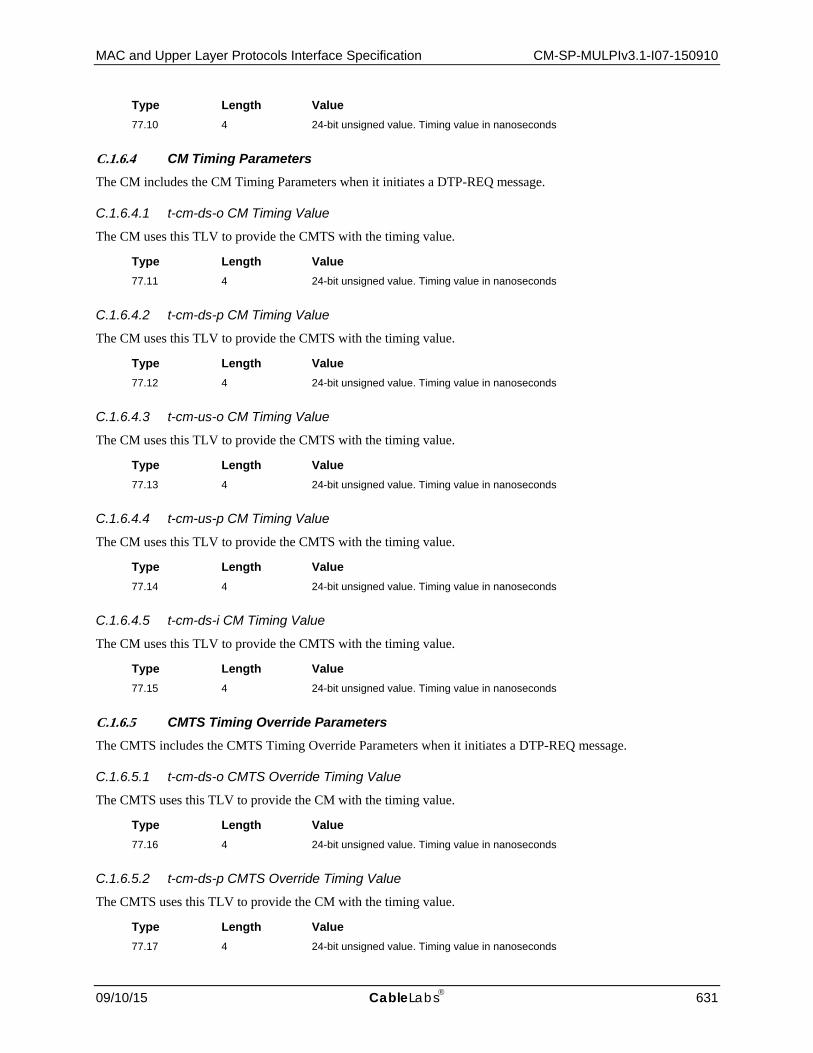
MAC and Upper Layer Protocols Interface Specification CM-SP-MULPIv3.1-I07-150910
09/10/15 CableLabs 631
Type Length Value 77.10 4 24-bit unsigned value. Timing value in nanoseconds
C.1.6.4 CM Timing Parameters The CM includes the CM Timing Parameters when it initiates a DTP-REQ message.
C.1.6.4.1 t-cm-ds-o CM Timing Value
The CM uses this TLV to provide the CMTS with the timing value.
Type Length Value 77.11 4 24-bit unsigned value. Timing value in nanoseconds
C.1.6.4.2 t-cm-ds-p CM Timing Value
The CM uses this TLV to provide the CMTS with the timing value.
Type Length Value 77.12 4 24-bit unsigned value. Timing value in nanoseconds
C.1.6.4.3 t-cm-us-o CM Timing Value
The CM uses this TLV to provide the CMTS with the timing value.
Type Length Value 77.13 4 24-bit unsigned value. Timing value in nanoseconds
C.1.6.4.4 t-cm-us-p CM Timing Value
The CM uses this TLV to provide the CMTS with the timing value.
Type Length Value 77.14 4 24-bit unsigned value. Timing value in nanoseconds
C.1.6.4.5 t-cm-ds-i CM Timing Value
The CM uses this TLV to provide the CMTS with the timing value.
Type Length Value 77.15 4 24-bit unsigned value. Timing value in nanoseconds
C.1.6.5 CMTS Timing Override Parameters The CMTS includes the CMTS Timing Override Parameters when it initiates a DTP-REQ message.
C.1.6.5.1 t-cm-ds-o CMTS Override Timing Value
The CMTS uses this TLV to provide the CM with the timing value.
Type Length Value 77.16 4 24-bit unsigned value. Timing value in nanoseconds
C.1.6.5.2 t-cm-ds-p CMTS Override Timing Value
The CMTS uses this TLV to provide the CM with the timing value.
Type Length Value 77.17 4 24-bit unsigned value. Timing value in nanoseconds

CM-SP-MULPIv3.1-I07-150910 Data-Over-Cable Service Interface Specifications
632 CableLabs 09/10/15
C.1.6.5.3 t-cm-us-o CMTS Override Timing Value
The CMTS uses this TLV to provide the CM with the timing value.
Type Length Value 77.18 4 24-bit unsigned value. Timing value in nanoseconds
C.1.6.5.4 t-cm-us-p CMTS Override Timing Value
The CMTS uses this TLV to provide the CM with the timing value.
Type Length Value 77.19 4 24-bit unsigned value. Timing value in nanoseconds
C.1.6.5.5 t-cm-ds-i CMTS Override Timing Value
The CMTS uses this TLV to provide the CM with the timing value.
Type Length Value 77.20 4 24-bit unsigned value. Timing value in nanoseconds
C.1.6.6 True Ranging Offset The CM includes the True Ranging Offset when it initiates a DTP-REQ.
Type Length Value 77.21 4 24-bit unsigned value. Timing value in nanoseconds.
C.1.6.7 Timing Adjustment The CM and CMTS include the Timing Adjustment TLV when sending a DTP-INFO message.
Type Length Value 77.22 4 24-bit unsigned value. Timing value in nanoseconds.
C.1.6.8 DTP Error Code The CM or CMTS might include the DTP Error Code to indicate an error with the DTP transaction.
Type Length Value 77.23 1 0 = reserved
1 = DTP unsupported 2 = DTP cannot be responded to at this time. 3-255: Reserved
C.2 Quality-of-Service-Related Encodings
C.2.1 Packet Classification Encodings The following type/length/value encodings MUST be used in the configuration file, registration messages, and Dynamic Service messages to encode parameters for packet classification and scheduling. All multi-octet quantities are in network-byte order, i.e., the octet containing the most-significant bits is the first transmitted on the wire.
NOTE: Unless otherwise stated, the same sub-TLV types are valid for the Upstream Packet Classification Encoding, the Upstream Drop Packet Classification Encoding, and the Downstream Packet Classification Encoding top-level TLVs. These type fields are not valid in other encoding contexts.

MAC and Upper Layer Protocols Interface Specification CM-SP-MULPIv3.1-I07-150910
09/10/15 CableLabs 633
A classifier MUST contain at least one encoding from Annex C.2.1.6, Annex C.2.1.7, Annex C.2.1.8, Annex C.2.1.9, Annex C.2.1.10, Annex C.2.1.12, Annex C.2.1.3, Annex C.2.1.4, Annex C.2.1.5, and Annex C.2.1.11.
All CMTSs MUST support classification of downstream packets based on IP v4 and IPv6 header fields (Annex C.2.1.6 and Annex C.2.1.10).
A CM MAY support the following classifier configuration settings:
• IEEE 802.1P/Q Packet Classification Encodings in Annex C.2.1.9. • [IEEE 802.1ad] S-Tag and C-Tag Frame Classification Encodings C.2.1.13. • [IEEE 802.1ad] Packet Classification Encodings Annex C.2.1.14, and • MPLS Classification Encodings Annex C.2.1.15.
Other than those classifiers noted above, all the following classifier configuration settings MUST be supported by all CMs which are compliant with this specification.
C.2.1.1 Upstream Packet Classification Encoding This field defines the parameters associated with an upstream Classifier.
Type Length Value 22 n
C.2.1.2 Upstream Drop Packet Classification Encoding This field defines the parameters associated with an Upstream Drop Classifier.
Type Length Value 60 n
C.2.1.3 Downstream Packet Classification Encoding This field defines the parameters associated with a downstream Classifier.
NOTE: The same subtype fields defined are valid for both the encapsulated upstream and downstream flow classification configuration setting string. These type fields are not valid in other encoding contexts.
Type Length Value 23 n
C.2.1.4 General Packet Classifier Encodings
C.2.1.4.1 Classifier Reference
The value of the field specifies a reference for the Classifier. This value is unique per Dynamic Service message, configuration file, or Registration Request message.
Type Length Value [22/23/60].1 1 1 - 255

CM-SP-MULPIv3.1-I07-150910 Data-Over-Cable Service Interface Specifications
634 CableLabs 09/10/15
The CM MUST use the Classifier Reference as the Classifier ID when implementing the Upstream Drop Classifiers provided in the configuration file because the CMTS does not provide a Classifier ID in the REG-RSP-MP message.
C.2.1.4.2 Classifier Identifier
The value of the field specifies an identifier for the Classifier. This value is unique to per Service Flow. The CMTS assigns the Packet Classifier Identifier.
Type Length Value [22/23/60].2 2 1 - 65535
C.2.1.4.3 Service Flow Reference
The value of the field specifies a Service Flow Reference that identifies the corresponding Service Flow.
In all Packet Classifier TLVs that occur in any message where the Service Flow ID is not known (e.g., CM-initiated DSA-REQ and REG-REQ/REG-REQ-MP) this TLV MUST be included. In all Packet Classifier TLVs that occur in a DSC-REQ and CMTS-initiated DSA-REQ messages the Service Flow Reference MUST NOT be specified.
Type Length Value [22/23].3 2 1 - 65535
C.2.1.4.4 Service Flow Identifier
The value of this field specifies the Service Flow ID that identifies the corresponding Service Flow.
In Packet Classifier TLVs where the Service Flow ID is not known, and this TLV MUST NOT be included (e.g., CM-initiated DSA-REQ and REG-REQ/REG-REQ-MP). In Packet Classifier TLVs that occur in a DSC-REQ and CMTS-initiated DSA-REQ message, the Service Flow ID MUST be specified.
Type Length Value [22/23].4 4 1 - 4,294,967,295
C.2.1.4.5 Rule Priority
The value of this field specifies the priority for the Classifier, which is used for determining the classification order. A higher value indicates higher priority.
Classifiers that appear in Configuration files and Registration messages can have priorities in the range 0 – 255. If no Rule Priority is specified in the Registration Request, the CMTS MUST use the default Rule Priority of 0. If no Rule Priority is specified in the Registration Response, the CM MUST use the default Rule Priority of 0. Classifiers that appear in the DSA/DSC message MUST have priorities in the range 64-191, with the default value 64.
The Rule Priority of the Upstream QoS Classifier and the Rule Priority of the Upstream Drop Classifier interact. If a packet matches both an Upstream QoS Classifier and an Upstream Drop Classifier, the CM MUST select the Classifier with the higher Rule Priority.
Type Length Value [22/23/60].5 1

MAC and Upper Layer Protocols Interface Specification CM-SP-MULPIv3.1-I07-150910
09/10/15 CableLabs 635
C.2.1.4.6 Classifier Activation State
The value of this field specifies whether this classifier should become active in selecting packets for the Service Flow. An inactive Classifier is typically used with an AdmittedQoSParameterSet to ensure resources are available for later activation. The actual activation of the classifier depends both on this attribute and on the state of its service flow. If the service flow is not active then the classifier is not used, regardless of the setting of this attribute.
Type Length Value [22/23].6 1 0 — Inactive
1 — Active
The default value is 1 — activate the classifier.
C.2.1.4.7 Dynamic Service Change Action
When received in a Dynamic Service Change Request, this indicates the action that should be taken with this classifier.
Type Length Value [22/23/60].7 1 0 — DSC Add Classifier
1 — DSC Replace Classifier
2 — DSC Delete Classifier
C.2.1.4.8 CM Interface Mask (CMIM) Encoding
In addition to classifying traffic based on L2/L3/L4 fields in the packet headers, upstream traffic can be classified based on which CM interface received the packet. The CM Interface Mask Encoding provides a bit mask representing the in-bound interfaces of the CM for which this classifier applies. Each bit of the CM Interface Mask corresponds to an interface, logical or physical. By convention, bit position 0 corresponds to the CM's IP stack, even though it is not an actual interface.
For example, a CMIM classifier intended to match all of the CPE ports (i.e., external interfaces) of a CM has a CMIM value setting bits 1 and 5-15, i.e., an encoding of either 0x47FF or 0x47FF0000. Either value is valid.
SubType Length Value [22/60].13 N BITS -Encoded bit map with bit position K representing CM interface index value K. Bit
position 0 is the most significant bit of the most significant octet. Refer to [DOCSIS eDOCSIS] for latest logical interface index assignments for eCMs. Bit 0 (0x80): CM's IP stack Bit 1 (0x40): primary CPE Interface (also eRouter) Bit 2 (0x20): RF interface Bits 3,4: reserved Bits 5..15 (0x07 FF): Other CPE Ports Bits 16-31: embedded logical interfaces. Currently defined interfaces include: Bit 16 (0x00 00 80): PacketCable-eMTA Bit 17 (0x00 00 40): eSTB-IP Bit 18 (0x00 00 20): reserved Bits 19..31 (0x00 00 1F FF): Other eSAFE interfaces

CM-SP-MULPIv3.1-I07-150910 Data-Over-Cable Service Interface Specifications
636 CableLabs 09/10/15
C.2.1.5 Classifier Error Encodings This field defines the parameters associated with Classifier Errors.
Type Length Value [22/23/60].8 n
A Classifier Error Encoding consists of a single Classifier Error Parameter Set which is defined by the following individual parameters: Errored Parameter, Confirmation Code, and Error Message.
The Classifier Error Encoding is returned in REG-RSP, REG-RSP-MP, DSA-RSP, and DSC-RSP messages to indicate the reason for the recipient's negative response to a Classifier establishment request in a REG-REQ, REG-REQ-MP, DSA-REQ or DSC-REQ message.
On failure, the REG-RSP, REG-RSP-MP, DSA-RSP, or DSC-RSP MUST include one Classifier Error Encoding for at least one failed Classifier requested in the REG-REQ, REG-REQ-MP, DSA-REQ, or DSC-REQ message. A Classifier Error Encoding for the failed Classifier MUST include the Confirmation Code and Errored Parameter and MAY include an Error Message. If some Classifier Sets are rejected but other Classifier Sets are accepted, then Classifier Error Encodings MUST be included for only the rejected Classifiers. On success of the entire transaction, the RSP or ACK message MUST NOT include a Classifier Error Encoding.
Multiple Classifier Error Encodings may appear in a REG-RSP, REG-RSP-MP, DSA-RSP, or DSC-RSP message, since multiple Classifier parameters may be in error. A message with even a single Classifier Error Encoding MUST NOT contain any other protocol Classifier Encodings (e.g., IP, 802.1P/Q).
A Classifier Error Encoding MUST NOT appear in any REG-REQ, REG-REQ-MP, DSA-REQ, or DSC-REQ messages.
C.2.1.5.1 Errored Parameter
The value of this parameter identifies the subtype of a requested Classifier parameter in error in a rejected Classifier request. A Classifier Error Parameter Set MUST have exactly one Errored Parameter TLV within a given Classifier Error Encoding.
Subtype Length Value [22/23/60].8.1 n Classifier Encoding Subtype in Error
If the length is one, then the value is the single-level subtype where the error was found, e.g., 7 indicates an invalid Change Action. If the length is two, then the value is the multi-level subtype where there error was found e.g., 9-2 indicates an invalid IP Protocol value.
C.2.1.5.2 Error Code
This parameter indicates the status of the request. A non-zero value corresponds to the Confirmation Code as described in Annex C.4. A Classifier Error Parameter Set MUST have exactly one Error Code within a given Classifier Error Encoding.
Subtype Length Value [22/23/60].8.2 1 Confirmation code
A value of okay (0) indicates that the Classifier request was successful. Since a Classifier Error Parameter Set applies only to errored parameters, this value MUST NOT be used.

MAC and Upper Layer Protocols Interface Specification CM-SP-MULPIv3.1-I07-150910
09/10/15 CableLabs 637
C.2.1.5.3 Error Message
This subtype is optional in a Classifier Error Parameter Set. If present, it indicates a text string to be displayed on the CM console and/or log that further describes a rejected Classifier request. A Classifier Error Parameter Set MAY have zero or one Error Message subtypes within a given Classifier Error Encoding.
SubType Length Value [22/23/60].8.3 n Zero-terminated string of ASCII characters.
NOTE: The length N includes the terminating zero. Since the entire Classifier Encoding is limited to a total length of 256 bytes (254 bytes + type + length), the maximum length of the error message string is limited by the number of other sub-TLV encodings in the Classifier Encoding.
C.2.1.6 IPv4 Packet Classification Encodings This field defines the parameters associated with Ipv4 packet classification, as well as parameters associated with TCP/UDP packet classification associated with both IPv4 and IPv6. See Annex C.2.1.10 for more details.
Type Length Value [22/23/60].9 n
C.2.1.6.1 IPv4 Type of Service Range and Mask
The values of the field specify the matching parameters for the IPv4 TOS byte range and mask. An IP packet with IPv4 TOS byte value "ip-tos" matches this parameter if (tos-low AND tos-mask) <= (ip-tos AND tos-mask) <= (tos-high AND tos-mask). If this field is omitted, then comparison of the IP packet TOS byte for this entry is irrelevant.
Type Length Value [22/23/60].9.1 3 tos-low, tos-high, tos-mask
NOTE: The value 0xFC for tos-mask will exclude the Explicit Congestion Notification [RFC 3168] bits from the comparison, and hence will result in classification based on DSCP [RFC 2474].
C.2.1.6.2 IP Protocol
The value of the field specifies the matching value for the IP Protocol field [RFC 1700]. If this parameter is omitted, then comparison of the IP header Protocol field for this entry is irrelevant.
There are two special IP Protocol field values: "256" matches traffic with any IP Protocol value, and "257" matches both TCP and UDP traffic. An entry that includes an IP Protocol field value greater than 257 MUST be invalidated for comparisons (i.e., no traffic can match this entry).
Type Length Value [22/23/60].9.2 2 prot1, prot2
Valid range: 0 - 257
C.2.1.6.3 IPv4 Source Address
The value of the field specifies the matching value for the IP source address. An IP packet with IP source address "ip-src" matches this parameter if (src AND smask) = (ip-src AND smask), where "smask" is the parameter from Annex C.2.1.6.4. If this parameter is omitted, then comparison of the IP packet source address for this entry is irrelevant.

CM-SP-MULPIv3.1-I07-150910 Data-Over-Cable Service Interface Specifications
638 CableLabs 09/10/15
Type Length Value [22/23/60].9.3 4 src1,src2,src3,src4
C.2.1.6.4 IPv4 Source Mask
The value of the field specifies the mask value for the IP source address, as described in Annex C.2.1.6.3. If this parameter is omitted, then the default IP source mask is 255.255.255.255.
Type Length Value [22/23/60].9.4 4 smask1,smask2,smask3,smask4
C.2.1.6.5 IPv4 Destination Address
The value of the field specifies the matching value for the IP destination address. An IP packet with IP destination address "ip-dst" matches this parameter if (dst AND dmask) = (ip-dst AND dmask), where "dmask" is the parameter from Annex C.2.1.6.6. If this parameter is omitted, then comparison of the IP packet destination address for this entry is irrelevant.
Type Length Value [22/23/60].9.5 4 dst1,dst2,dst3,dst4
C.2.1.6.6 IPv4 Destination Mask
The value of the field specifies the mask value for the IP destination address, as described in Annex C.2.1.6.5. If this parameter is omitted, then the default IP destination mask is 255.255.255.255.
Type Length Value [22/23/60].9.6 4 dmask1,dmask2,dmask3,dmask4
C.2.1.7 TCP/UDP Packet Classification Encodings This field defines the parameters associated with TCP/UDP packet classification.
While the TCP/UDP Packet Classification Encodings are located within the same subtype as the IPv4 Packet Classification Encodings, they apply regardless of IP version. The presence of an additional criterion from Annex C.2.1.6 would cause the classifier to match only IPv4 packets. The presence of an additional criterion from Annex C.2.1.10 would cause the classifier to match only IPv6 packets.
C.2.1.7.1 TCP/UDP Source Port Start
The value of the field specifies the low-end TCP/UDP source port value. An IP packet with TCP/UDP port value "src-port" matches this parameter if sportlow <= src-port <= sporthigh. If this parameter is omitted, then the default value of sportlow is 0. This parameter is irrelevant for non-TCP/UDP IP traffic.
Type Length Value [22/23/60].9.7 2 sportlow1,sportlow2

MAC and Upper Layer Protocols Interface Specification CM-SP-MULPIv3.1-I07-150910
09/10/15 CableLabs 639
C.2.1.7.2 TCP/UDP Source Port End
The value of the field specifies the high-end TCP/UDP source port value. An IP packet with TCP/UDP port value "src-port" matches this parameter if sportlow <= src-port <= sporthigh. If this parameter is omitted, then the default value of sporthigh is 65535. This parameter is irrelevant for non-TCP/UDP IP traffic.
Type Length Value [22/23/60].9.8 2 sporthigh1,sporthigh2
C.2.1.7.3 TCP/UDP Destination Port Start
The value of the field specifies the low-end TCP/UDP destination port value. An IP packet with TCP/UDP port value "dst-port" matches this parameter if dportlow <= dst-port <=dporthigh. If this parameter is omitted, then the default value of dportlow is 0. This parameter is irrelevant for non-TCP/UDP IP traffic.
Type Length Value [22/23/60].9.9 2 dportlow1,dportlow2
C.2.1.7.4 TCP/UDP Destination Port End
The value of the field specifies the high-end TCP/UDP destination port value. An IP packet with TCP/UDP port value "dst-port" matches this parameter if dportlow <= dst-port <= dporthigh. If this parameter is omitted, then the default value of dporthigh is 65535. This parameter is irrelevant for non-TCP/UDP IP traffic.
Type Length Value [22/23/60].9.10 2 dporthigh1,dporthigh2
C.2.1.8 Ethernet LLC Packet Classification Encodings This field defines the parameters associated with Ethernet LLC packet classification.
Type Length Value [22/23/60].10 n
C.2.1.8.1 Destination MAC Address
The values of the field specifies the matching parameters for the MAC destination address. An Ethernet packet with MAC destination address "etherdst" matches this parameter if dst = (etherdst AND msk). If this parameter is omitted, then comparison of the Ethernet MAC destination address for this entry is irrelevant.
Type Length Value [22/23/60].10.1 12 dst1, dst2, dst3, dst4, dst5, dst6, msk1, msk2, msk3, msk4, msk5, msk6
C.2.1.8.2 Source MAC Address
The value of the field specifies the matching value for the MAC source address. If this parameter is omitted, then comparison of the Ethernet MAC source address for this entry is irrelevant.

CM-SP-MULPIv3.1-I07-150910 Data-Over-Cable Service Interface Specifications
640 CableLabs 09/10/15
Type Length Value [22/23/60].10.2 6 src1, src2, src3, src4, src5, src6
C.2.1.8.3 Ethertype/DSAP/MacType
Type, eprot1, and eprot2 indicate the format of the layer 3 protocol ID in the Ethernet packet as follows:
If type = 0, the rule does not use the layer 3 protocol type as a matching criterion. If type = 0, eprot1, eprot2 are ignored when considering whether a packet matches the current rule.
If type = 1, the rule applies only to frames which contain an Ethertype value. Ethertype values are contained in packets using the DEC-Intel-Xerox (DIX) encapsulation or the [RFC 1042] Sub-Network Access Protocol (SNAP) encapsulation formats. If type = 1, then eprot1, eprot2 gives the 16-bit value of the Ethertype that the packet must match in order to match the rule.
If type = 2, the rule applies only to frames using the IEEE 802.2 encapsulation format with a Destination Service (DSAP) other than 0xAA (which is reserved for SNAP). If type = 2, the lower 8 bits of the eprot1, eprot2, MUST match the DSAP byte of the packet in order to match the rule.
If type = 3, the rule applies only to MAC Management Messages (FC field 1100001x) with a "type" field of its MAC Management Message header (6.3.1) between the values of eprot1 and eprot2, inclusive. As exceptions, the following MAC Management message types MUST NOT be classified:
Type 4: RNG-REQ Type 6: REG-REQ Type 7: REG-RSP Type 14: REG-ACK Type 30: INIT-RNG-REQ Type 34: B-INIT-RNG-REQ Type 44: REG-REQ-MP Type 45: REG-RSP-MP
If type = 4, the rule is considered a "catch-all" rule that matches all Data PDU packets. The rule does not match MAC Management Messages. The value of eprot1 and eprot2 are ignored in this case.
If the Ethernet frame contains an 802.1P/Q Tag header (i.e., Ethertype 0x8100), this object applies to the embedded Ethertype field after the 802.1P/Q header.
Other values of type are reserved. If this TLV is omitted, then comparison of either the Ethertype or IEEE 802.2 DSAP for this rule is irrelevant.
Type Length Value [22/23/60].10.3 3 type, eprot1, eprot2
C.2.1.9 IEEE 802.1P/Q Packet Classification Encodings This field defines the parameters associated with IEEE 802.1P/Q packet classification.
Type Length Value [22/23/60].11 n

MAC and Upper Layer Protocols Interface Specification CM-SP-MULPIv3.1-I07-150910
09/10/15 CableLabs 641
C.2.1.9.1 IEEE 802.1P User_Priority
The values of the field specify the matching parameters for the IEEE 802.1P user_priority bits. An Ethernet packet with IEEE 802.1P user_priority value "priority" matches these parameters if pri-low <= priority <= pri-high. If this field is omitted, then comparison of the IEEE 802.1P user_priority bits for this entry is irrelevant.
If this parameter is specified for an entry, then Ethernet packets without IEEE 802.1Q encapsulation MUST NOT match this entry. If this parameter is specified for an entry on a CM that does not support forwarding of IEEE 802.1Q encapsulated traffic, then this entry MUST NOT be used for any traffic.
Type Length Value [22/23/60].11.1 2 pri-low, pri-high
Valid Range is 0 – 7 for pri-low and pri-high.
C.2.1.9.2 IEEE 802.1Q VLAN_ID
The value of the field specifies the matching value for the IEEE 802.1Q vlan_id bits. Only the first (i.e., most-significant) 12 bits of the specified vlan_id field are significant; the final four bits MUST be ignored for comparison. If this field is omitted, then comparison of the IEEE 802.1Q vlan_id bits for this entry is irrelevant.
If this parameter is specified for an entry, then Ethernet packets without IEEE 802.1Q encapsulation MUST NOT match this entry. If this parameter is specified for an entry on a CM that does not support forwarding of IEEE 802.1Q encapsulated traffic, then this entry MUST NOT be used for any traffic.
Type Length Value [22/23/60].11.2 2 vlan_id1, vlan_id2
C.2.1.10 IPv6 Packet Classification Encodings159 This field defines the parameters associated with IPv6 packet classification. TCP/UDP Packet Classification Encodings (see Annex C.2.1.7) are defined for IPv4 or IPv6 and may be present in a Service Flow Classifier of either type. If those classifiers are present in combination with IPv6 classifier encodings, then they apply to the IPv6 classifiers. If other IPv4 classifier encodings (22/23/60.9.1 thru 22/23/60.9.6) are present in the Service Flow Classifier along with IPv6 classifier encodings, then the Service Flow Classifier is invalid. If an invalid Service Flow Classifier of this type is sent to the CMTS in a Registration Request, the CMTS MUST reject the Registration Request. If an invalid Service Flow Classifier of this type is sent to the CMTS in a DSA or DSC Request message, the CMTS MUST reject the DSA or DSC Request message. If an invalid Service Flow Classifier of this type is sent to the CM in a DSA or DSC Request message, the CM MUST reject the DSA or DSC Request message.
Type Length Value [22/23/60].12 n
C.2.1.10.1 IPv6 Traffic Class Range and Mask
The values of the field specify the matching parameters for the IPv6 Traffic Class byte range and mask. An IP packet with IPv6 Traffic Class value "ip-tc" matches this parameter if (tc-low AND tc-mask) <= (ip-tc AND tc-mask) <= (tc-high AND tc-mask). If this field is omitted, then comparison of the IPv6 packet Traffic Class byte for this entry is irrelevant.
159 Updated by MULPIv3.1-N-14.1211-5 on 12/8/14 by PO.

CM-SP-MULPIv3.1-I07-150910 Data-Over-Cable Service Interface Specifications
642 CableLabs 09/10/15
Type Length Value [22/23/60].12.1 3 tc-low, tc-high, tc-mask
NOTE: The value 0xFC for tc-mask will exclude the Explicit Congestion Notification [RFC 3168] bits from the comparison, and hence will result in classification based on DSCP [RFC 2474].
C.2.1.10.2 IPv6 Flow Label
The value of the field specifies the parameters of IPv6 flow label field in the IPv6 header. The 20 least significant bits represent the 20-bit IPv6 Flow Label while the 12 most significant bits are ignored. If this parameter is omitted, then comparison of IPv6 flow label for this entry is irrelevant.
Type Length Value [22/23/60].12.2 4 FlowLabel
C.2.1.10.3 IPv6 Next Header Type
The value of the field specifies the desired upper-layer protocol type specified in the IPv6 header or extension headers associated with the packet. If this parameter is omitted, then comparison of any IPv6 next header type value for this entry is irrelevant.
The CM and CMTS MUST recognize the following Next Header types when searching for the upper-layer header:
Header Type Description
0 Hop-by-Hop
60 Destination
43 Routing
44 Fragment
51 Authentication
50 Encapsulation
59 No
The CM and the CMTS look for the first Next Header field with a value that is not included in the above list in order to identify the Upper Layer protocol of the packet. The CMTS MUST apply the classifier rule to the packet according to the Upper Layer protocol that it identifies. The CM MUST apply the classifier rule to the packet according to the Upper Layer protocol that it identifies. If the CMTS initiates a transaction that configures a Classifier Rule with a Next Header value equal to one in the above list, the CM MUST reject that transaction. If the CM initiates a transaction that configures a Classifier Rule with a Next Header value equal to one in the above list, the CMTS MUST reject that transaction.
If a packet contains an ESP header, then it is assumed that the upper-layer header is encrypted and cannot be read. If the CM or CMTS encounters a packet with an ESP header, then it MUST NOT match the packet to the Classifier Rule unless the classifier parameter value equals 256, as explained below.
If a packet is fragmented, then a classifier might not be able to identify the upper-layer protocol of the second and following fragments.
There are two special IPv6 next header type field values: "256" that matches all IPv6 traffic, regardless of the Next Header values, and "257" that matches both TCP and UDP traffic. An entry that includes an IPv6 next header type value greater than 257 MUST be invalidated for comparisons (i.e., no traffic can match this entry).

MAC and Upper Layer Protocols Interface Specification CM-SP-MULPIv3.1-I07-150910
09/10/15 CableLabs 643
Type Length Value [22/23/60].12.3 2 nhdr
C.2.1.10.4 IPv6 Source Address
The value of the field specifies the matching value for the IPv6 source address. An IPv6 packet with IPv6 source address "ip6-src" matches this parameter if (src AND smask)= (ip6-src AND smask). "smask" is computed by setting the most significant 'n' bits of smask to 1, where 'n' is IPv6 Source Prefix Length in bits. If the IPv6 Source Address parameter is omitted, then comparison of the IPv6 packet source address for this entry is irrelevant.
Type Length Value [22/23/60].12.4 16 src
C.2.1.10.5 IPv6 Source Prefix Length (bits)
The value of the field specifies the fixed, most significant bits of an IPv6 address that are used to determine address range and subnet ID. If this parameter is omitted, then assume a default value of 128.
Type Length Value [22/23/60].12.5 1 0 - 128
C.2.1.10.6 IPv6 Destination Address
The value of the field specifies the matching value for the IPv6 destination address. An IPv6 packet with IPv6 destination address "ip6-dst" matches this parameter if (dst AND dmask)= (ip6-dst AND dmask). "dmask" is computed by setting the most significant 'n' bits of dmask to 1, where 'n' is IPv6 Destination Prefix Length in bits. If the IPv6 Destination Address parameter is omitted, then comparison of the IPv6 packet destination address for this entry is irrelevant.
Type Length Value [22/23/60].12.6 16 dst
C.2.1.10.7 IPv6 Destination Prefix Length (bits)
The value of the field specifies the fixed, most significant bits of an IPv6 address that are used to determine address range and subnet ID. If this parameter is omitted, then assume a default value of 128.
Type Length Value [22/23/60].12.7 1 0 - 128
C.2.1.11 Vendor Specific Classifier Parameters This allows vendors to encode vendor-specific classifier parameters using the DOCSIS Extension Field. The Vendor ID MUST be the first TLV embedded inside Vendor Specific Classifier Parameters. If the first TLV inside Vendor Specific Classifier Parameters is not a Vendor ID, then the TLV MUST be discarded. (Refer to Annex C.1.1.17).

CM-SP-MULPIv3.1-I07-150910 Data-Over-Cable Service Interface Specifications
644 CableLabs 09/10/15
Type Length Value [22/23/60].43 n
C.2.1.12 ICMPv4/ICMPv6 Packet Classification Encodings This field defines the parameters associated with ICMPv4/ICMPv6 packet classification.
The presence of an additional criterion from Annex C.2.1.6 would cause the classifier to match only ICMPv4 packets. The presence of an additional criterion from Annex C.2.1.10 would cause the classifier to match only ICMPv6 packets.
Type Length Value [22/23/60].16 n
C.2.1.12.1 ICMPv4/ICMPv6 Type Start
The value of the field specifies the low-end ICMPv4/ICMPv6 type value. An ICMPv4/ICMPv6 packet with type value "icmp-type" matches this parameter if typelow <= icmp-type <=typehigh. If this parameter is omitted, then the default value of typelow is 0. This parameter is irrelevant for non-ICMPv4/ICMPv6 traffic.
Type Length Value [22/23/60].16.1 1 Typelow
C.2.1.12.2 ICMPv4/ICMPv6 Type End
The value of the field specifies the high-end ICMPv4/ICMPv6 type value. An ICMPv4/ICMPv6 packet with type value "icmp-type" matches this parameter if typelow <= icmp-type <=typehigh. If this parameter is omitted, then the default value of typehigh is 255. This parameter is irrelevant for non-ICMPv4/ICMPv6 traffic.
Type Length Value [22/23/60].16.2 1 Typehigh
C.2.1.13 [IEEE 802.1ad] S-Tag and C-Tag Frame Classification Encodings This field defines the parameters associated with [IEEE 802.1ad] S-Tag and C-Tag frame classification.
Type Length Value [22/23/60].14 n
Support for any of these classifier TLVs/Sub-TLVs does not indicate device support for the forwarding behavior that might be implied by the [IEEE 802.1ad] standards.
C.2.1.13.1 [IEEE 802.1ad] 802.1 ad S-TPID
The values of the field specify the matching parameters for the [IEEE 802.1ad] S-TPID field.
If this parameter is not specified for an entry, use a default value of 0x88a8 for the [IEEE 802.1ad] S-TPID field. The default applies only if a [IEEE 802.1ad] classifier has been configured.

MAC and Upper Layer Protocols Interface Specification CM-SP-MULPIv3.1-I07-150910
09/10/15 CableLabs 645
Type Length Value [22/23/60].14.1 2 stpid (16 bits)
C.2.1.13.2 [IEEE 802.1ad] S-VID
The values of the field specify the matching parameters for the [IEEE 802.1ad] S-VID field.
Type Length Value [22/23/60].14.2 2 This TLV comprises an encoded bit map, featuring one field: svid, as shown
in the table below
Field name Description Size
Reserved Reserved, ignored on reception 4 bits
svid Encodes the S-VID field 12 bits
C.2.1.13.3 [IEEE 802.1ad] S-PCP
The values of the field specify the matching parameters for the [IEEE 802.1ad] S-PCP field.
Type Length Value [22/23/60].14.3 1 This TLV comprises an encoded bit map, featuring one field: spcp, as shown
in the table below
Field name Description Size
Reserved Reserved, ignored on reception 5 bits spcp Encodes the S-PCP field 3 bits
C.2.1.13.4 [IEEE 802.1ad] S-DEI
The values of the field specify the matching parameters for the [IEEE 802.1ad] S-DEI field.
Type Length Value [22/23/60].14.4 1 This TLV comprises an encoded bit map, featuring one field: sdei, as shown
in the table below
Field name Description Size Reserved Reserved, ignored on reception 7 bits sdei Encodes the S-DEI field 1 bit
C.2.1.13.5 [IEEE 802.1ad] C-TPID
The values of the field specify the matching parameters for the [IEEE 802.1ad] C-TPID field.
If this parameter is not specified for an entry, then use a default value of 0x8100 for the [IEEE 802.1ad] C-TPID field. The default applies only if a [IEEE 802.1ad] classifier has been configured.

CM-SP-MULPIv3.1-I07-150910 Data-Over-Cable Service Interface Specifications
646 CableLabs 09/10/15
Type Length Value [22/23/60].14.5 2 ctpid (16 bits)
C.2.1.13.6 [IEEE 802.1ad] C-VID
The values of the field specify the matching parameters for the [IEEE 802.1ad] C-VID field.
Type Length Value [22/23/60].14.6 2 This TLV comprises an encoded bit map, featuring one field: cvid, as shown in
the table below
Field name Description Size
Reserved Reserved, ignored on reception 4 bits
cvid Encodes the C-VID field 12 bits
C.2.1.13.7 [IEEE 802.1ad] C-PCP
The values of the field specify the matching parameters for the [IEEE 802.1ad] C-PCP field.
Type Length Value [22/23/60].14.7 1 This TLV comprises an encoded bit map, featuring one field: cpcp, as shown
in the table below
Field name Description Size
Reserved Reserved, ignored on reception 5 bits cpcp Encodes the C-PCP field 3 bits
C.2.1.13.8 [IEEE 802.1ad] C-CFI
The values of the field specify the matching parameters for the [IEEE 802.1ad] C-CFI field.
Type Length Value [22/23/60].14.8 1 This TLV comprises an encoded bit map, featuring one field: ccfi, as shown in
the table below
Field name Description Size Reserved Reserved, ignored on reception 7 bits ccfi Encodes the CFI field in the C-Tag TCI field 1bit
C.2.1.13.9 [IEEE 802.1ad] S-TCI
The values of the field specify the matching parameters for the [IEEE 802.1ad] S-TCI field.
Type Length Value [22/23/60].14.9 2 stci (16 bits)

MAC and Upper Layer Protocols Interface Specification CM-SP-MULPIv3.1-I07-150910
09/10/15 CableLabs 647
C.2.1.13.10 [IEEE 802.1ad] C-TCI
The values of the field specify the matching parameters for the [IEEE 802.1ad] C-TCI field.
Type Length Value [22/23/60].14.10 2 ctci (16 bits)
C.2.1.14 [IEEE 802.1ah] Packet Classification Encodings This field defines the parameters associated with [IEEE 802.1ah] packet classification, including the I-TAG, B-TAG, and B-DA/B-SA.
Type Length Value [22/23/60].15 n
Support for any of these classifier TLVs/Sub-TLVs does not indicate device support for the forwarding behavior that might be implied by the [IEEE 802.1ah] standards.
C.2.1.14.1 [IEEE 802.1ah] I-TPID
The values of the field specify the matching parameters for the [IEEE 802.1ah] I-TPID field.
If this parameter is not specified for an entry, use a default value of 0x88e7 for the [IEEE 802.1ah] I-TPID field. The default applies only if a [IEEE 802.1ah] classifier has been configured.
Type Length Value [22/23/60].15.1 2 itpid (16 bits)
C.2.1.14.2 [IEEE 802.1ah] I-SID
The values of the field specify the matching parameters for the [IEEE 802.1ah] I-SID field.
Type Length Value [22/23/60].15.2 3 isid (24 bits)
C.2.1.14.3 [IEEE 802.1ah] I-TCI
The values of the field specify the matching parameters for the [IEEE 802.1ah] I-TCI field.
Type Length Value [22/23/60].15.3 5 itci (40 bits)
C.2.1.14.4 [IEEE 802.1ah] I-PCP
The values of the field specify the matching parameters for the [IEEE 802.1ah] I-PCP field.
Type Length Value [22/23/60].15.4 1 This TLV comprises an encoded bit map, featuring one field: ipcp, as shown in

CM-SP-MULPIv3.1-I07-150910 Data-Over-Cable Service Interface Specifications
648 CableLabs 09/10/15
the table below
Field name Description Size
Reserved Reserved, ignored on reception 5 bits
ipcp Encodes the I-PCP field 3 bits
C.2.1.14.5 [IEEE 802.1ah] I-DEI
The values of the field specify the matching parameters for the [IEEE 802.1ah] I-DEI field.
Type Length Value [22/23/60].15.5 1 This TLV comprises an encoded bit map, featuring one
field: idei, as shown in the table below
Field name Description Size
Reserved Reserved, ignored on reception 7 bits
idei Encodes the I-DEI field 1 bit
C.2.1.14.6 [IEEE 802.1ah] I-UCA
The values of the field specify the matching parameters for the [IEEE 802.1ah] I-UCA field.
Type Length Value [22/23/60].15.6 1 This TLV comprises an encoded bit map, featuring one field: iuca, as shown in
the table below
Field name Description Size Reserved Reserved, ignored on reception 7 bits iuca Encodes the I-UCA field 1 bit
C.2.1.14.7 [IEEE 802.1ah] B-TPID
The values of the field specify the matching parameters for the [IEEE 802.1ah] B-TPID field.
If this parameter is not specified for an entry, then use a default value of 0x88a8 for the [IEEE 802.1ah] B-TPID field. The default applies only if a [IEEE 802.1ah] classifier has been configured.
Type Length Value [22/23/60].15.7 2 btpid (16 bits)
C.2.1.14.8 [IEEE 802.1ah] B-TCI
The values of the field specify the matching parameters for the [IEEE 802.1ah] B-TCI field.
Type Length Value [22/23/60].15.8 2 btci (16 bits)

MAC and Upper Layer Protocols Interface Specification CM-SP-MULPIv3.1-I07-150910
09/10/15 CableLabs 649
C.2.1.14.9 [IEEE 802.1ah] B-PCP
The values of the field specify the matching parameters for the [IEEE 802.1ah] B-PCP field.
Type Length Value [22/23/60].15.9 1 This TLV comprises an encoded bit map, featuring one field: bpcp, as shown in
the table below
Field name Description Size
Reserved Reserved, ignored on reception 5 bits bpcp Encodes the B-PCP field 3 bits
C.2.1.14.10 [IEEE 802.1ah] B-DEI
The values of the field specify the matching parameters for the [IEEE 802.1ah] B-DEI field.
Type Length Value [22/23/60].15.10 1 This TLV comprises an encoded bit map, featuring one field: bdei, as shown
in the table below
Field name Description Size Reserved Reserved, ignored on reception 7 bits bdei Encodes the B-DEI field 1 bit
C.2.1.14.11 [IEEE 802.1ah] B-VID
The values of the field specify the matching parameters for the [IEEE 802.1ah] Backbone VLAN ID (B-VID) field.
Type Length Value [22/23/60].15.11 2 This TLV comprises an encoded bit map, featuring one field: B-VID, as
shown in the table below
Field name Description Size Reserved Reserved, ignored on reception 4 bits
bvid Encodes the B-VID field 4 bits
C.2.1.14.12 [IEEE 802.1ah] B-DA
The value of the field specifies the matching value for the Backbone MAC Destination Address (B-DA). If this parameter is omitted, then comparison of the Backbone MAC Destination Address for this entry is irrelevant.
Type Length Value [22/23/60].15.12 6 bda (48 bits)

CM-SP-MULPIv3.1-I07-150910 Data-Over-Cable Service Interface Specifications
650 CableLabs 09/10/15
C.2.1.14.13 [IEEE 802.1ah] B-SA
The value of the field specifies the matching value for the Backbone MAC Source Address (B-SA). If this parameter is omitted, then comparison of the Backbone MAC Source Address for this entry is irrelevant.
Type Length Value [22/23/60].15.13 6 bsa (48 bits)
C.2.1.15 MPLS Classification Encodings This field defines the parameters associated with MPLS packet classification. This field matches the outermost MPLS label on the incoming packets [RFC 3203].
Type Length Value [22/23/60].17 n
Support for any of these classifier TLVs/Sub-TLVs does not indicate device support for the forwarding behavior that might be implied by the MPLS standards.
C.2.1.15.1 MPLS TC bits
The value of this field specifies the matching parameters for the MPLS Traffic Class field [RFC 5462].
Type Length Value [22/23/60].17.1 1 MPLS Traffic Class (3 least significant bits)
C.2.1.15.2 MPLS Label
The value of this field specifies the matching parameters for the MPLS Label field.
Type Length Value [22/23/60].17.2 3 MPLS Label (20 least significant bits)
C.2.2 Service Flow Encodings The following type/length/value encodings MUST be used in the configuration file, registration messages, and Dynamic Service messages to encode parameters for Service Flows. All multi-octet quantities are in network-byte order, i.e., the octet containing the most-significant bits is the first transmitted on the wire.
The following configuration settings MUST be supported by all CMs which are compliant with this specification.
C.2.2.1 Upstream Service Flow Encodings This field defines the parameters associated with upstream scheduling for a Service Flow. It is composed from a number of encapsulated type/length/value fields.
NOTE: The encapsulated upstream and downstream Service Flow configuration setting strings share the same subtype field numbering plan, because many of the subtype fields defined are valid for both types of configuration settings. These type fields are not valid in other encoding contexts.

MAC and Upper Layer Protocols Interface Specification CM-SP-MULPIv3.1-I07-150910
09/10/15 CableLabs 651
Type Length Value 24 n
C.2.2.2 Downstream Service Flow Encodings This field defines the parameters associated with downstream scheduling for a Service Flow. It is composed from a number of encapsulated type/length/value fields.
NOTE: The encapsulated upstream and downstream flow classification configuration setting strings share the same subtype field numbering plan, because many of the subtype fields defined are valid for both types of configuration settings except Service Flow encodings. These type fields are not valid in other encoding contexts.
Type Length Value 25 n
C.2.2.3 Upstream Aggregate Service Flow (ASF) This TLV defines the Upstream Aggregate Service Flow (ASF), which was introduced in the DPoEv2.0 Specifications. The Upstream Aggregate Service Flow parameter is a multi-part encoding used by the operator to configure multi-layer QoS capabilities in the upstream direction. An Upstream ASF aggregates one or more Upstream Service Flows.
A CMTS SHOULD support the Upstream Aggregate Service Flow Encoding configuration setting. A CM MUST include the Upstream Aggregate Service Flow Encoding configuration setting in the Registration Request.
Type Length Value 70 n Upstream ASF Encoding subtype/length/value tuples
The upstream ASF encoding object is intended to be similar to TLV 24 (Upstream Service Flow Encodings) and shares certain sub-TLVs as TLV 24 to describe the parameters associated with an upstream ASF.
C.2.2.4 Downstream Aggregate Service Flow (ASF) This TLV defines the Downstream Aggregate Service Flow (ASF), which was introduced in the DPoEv2.0 Specifications. The Downstream Aggregate Service Flow parameter is a multi-part encoding used by the operator to configure multi-layer QoS capabilities in the downstream direction. A Downstream ASF aggregates one or more Downstream Service Flows.
A CMTS SHOULD support the Downstream Aggregate Service Flow Encoding configuration setting. A CM MUST include the Downstream Aggregate Service Flow Encoding configuration setting in the Registration Request.
Type Length Value 71 n Downstream ASF Encoding subtype/length/value tuples
The Downstream ASF encoding object is intended to be similar to TLV 25 (Downstream Service Flow Encodings) and shares certain sub-TLVs as TLV 25 to describe the parameters associated with a Downstream ASF.

CM-SP-MULPIv3.1-I07-150910 Data-Over-Cable Service Interface Specifications
652 CableLabs 09/10/15
C.2.2.5 General Service Flow Encodings
C.2.2.5.1 Service Flow Reference
The Service Flow Reference is used to associate a packet classifier encoding with a Service Flow encoding. A Service Flow Reference is only used to establish a Service Flow ID. Once the Service Flow exists and has an assigned Service Flow ID, the Service Flow Reference MUST no longer be used. The Service Flow Reference is unique per configuration file, Registration message exchange, or Dynamic Service Add message exchange.
When this sub-TLV 1 is used within TLV 70/71, the value of the field specifies an Aggregate Service Flow Reference that identifies the Aggregate Service Flow. The ASF Reference is used to associate a Service Flow encoding with an Aggregate Service Flow encoding.
An ASF Reference is only used to establish an ASF ID. Once the Aggregate Service Flow exists and has an assigned Aggregate Service Flow ID, the ASF Reference is no longer be used. The Aggregate Service Flow Reference is unique per configuration file, Registration message exchange, or Dynamic Service Add message exchange.
Type Length Value [24/25/70/71].1 2 1 - 65535
C.2.2.5.2 Service Flow Identifier
The Service Flow Identifier is used by the CMTS as the primary reference of a Service Flow. Only the CMTS can issue a Service Flow Identifier. It uses this parameterization to issue Service Flow Identifiers in CMTS-initiated DSA-Requests and in its REG/DSA-Response to CM-initiated REG/DSA-Requests. The CM specifies the SFID of a service flow using this parameter in a DSC-REQ message. Both the CM and CMTS MAY use this TLV to encode Service Flow IDs in a DSD-REQ.
The configuration file MUST NOT contain this parameter.
Type Length Value [24/25].2 4 1 - 4,294,967,295
C.2.2.5.3 Service Identifier
The value of this field specifies the Service Identifier assigned by the CMTS to a Service Flow with a non-null AdmittedQosParameterSet or ActiveQosParameterSet. This is used in the bandwidth allocation MAP to assign upstream bandwidth. This field MUST be present in CMTS-initiated DSA-REQ or DSC-REQ messages related to establishing an admitted or active upstream Service Flow. This field MUST also be present in REG-RSP, REG-RSP-MP, DSA-RSP, and DSC-RSP messages related to the successful establishment of an admitted or active upstream Service Flow. This field MUST NOT be present in settings related to downstream Service Flows; the Service Identifier only applies to upstream Service Flows.
Even though a Service Flow has been successfully admitted or activated (i.e., has an assigned Service ID) the Service Flow ID MUST be used for subsequent DSx message signaling as it is the primary handle for a service flow. If a Service Flow is no longer admitted or active (via DSC-REQ), its Service ID MAY be reassigned by the CMTS.
SubType Length Value [24].3 2 SID (low-order 14 bits)
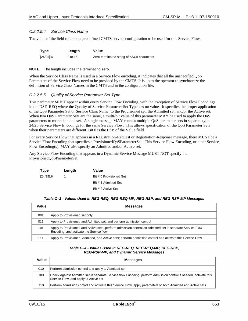
MAC and Upper Layer Protocols Interface Specification CM-SP-MULPIv3.1-I07-150910
09/10/15 CableLabs 653
C.2.2.5.4 Service Class Name
The value of the field refers to a predefined CMTS service configuration to be used for this Service Flow.
Type Length Value [24/25].4 2 to 16 Zero-terminated string of ASCII characters.
NOTE: The length includes the terminating zero.
When the Service Class Name is used in a Service Flow encoding, it indicates that all the unspecified QoS Parameters of the Service Flow need to be provided by the CMTS. It is up to the operator to synchronize the definition of Service Class Names in the CMTS and in the configuration file.
C.2.2.5.5 Quality of Service Parameter Set Type
This parameter MUST appear within every Service Flow Encoding, with the exception of Service Flow Encodings in the DSD-REQ where the Quality of Service Parameter Set Type has no value. It specifies the proper application of the QoS Parameter Set or Service Class Name: to the Provisioned set, the Admitted set, and/or the Active set. When two QoS Parameter Sets are the same, a multi-bit value of this parameter MAY be used to apply the QoS parameters to more than one set. A single message MAY contain multiple QoS parameter sets in separate type 24/25 Service Flow Encodings for the same Service Flow. This allows specification of the QoS Parameter Sets when their parameters are different. Bit 0 is the LSB of the Value field.
For every Service Flow that appears in a Registration-Request or Registration-Response message, there MUST be a Service Flow Encoding that specifies a ProvisionedQoSParameterSet. This Service Flow Encoding, or other Service Flow Encoding(s), MAY also specify an Admitted and/or Active set.
Any Service Flow Encoding that appears in a Dynamic Service Message MUST NOT specify the ProvisionedQoSParameterSet.
Type Length Value [24/25].6 1 Bit # 0 Provisioned Set
Bit # 1 Admitted Set
Bit # 2 Active Set
Table C–3 - Values Used in REG-REQ, REG-REQ-MP, REG-RSP, and REG-RSP-MP Messages
Value Messages
001 Apply to Provisioned set only
011 Apply to Provisioned and Admitted set, and perform admission control
101 Apply to Provisioned and Active sets, perform admission control on Admitted set in separate Service Flow Encoding, and activate the Service flow.
111 Apply to Provisioned, Admitted, and Active sets; perform admission control and activate this Service Flow
Table C–4 - Values Used In REG-REQ, REG-REQ-MP, REG-RSP,
REG-RSP-MP, and Dynamic Service Messages
Value Messages
010 Perform admission control and apply to Admitted set
100 Check against Admitted set in separate Service flow Encoding, perform admission control if needed, activate this Service Flow, and apply to Active set
110 Perform admission control and activate this Service Flow, apply parameters to both Admitted and Active sets

CM-SP-MULPIv3.1-I07-150910 Data-Over-Cable Service Interface Specifications
654 CableLabs 09/10/15
The value 000 is used only in Dynamic Service Change messages. It is used to set the Active and Admitted sets to Null (see the Quality of Service Subsection in Section 7).
A CMTS MUST handle a single update to each of the Active and Admitted QoS parameter sets. The ability to process multiple Service Flow Encodings that specify the same QoS parameter set is NOT required, and is left as a vendor-specific function. If a DSA/DSC contains multiple updates to a single QoS parameter set and the vendor does not support such updates, then the CMTS MUST reply with error code 2, reject-unrecognized-configuration-setting (see Annex C.4).
C.2.2.5.6 Service Flow Required Attribute Mask
This parameter is optional in upstream and downstream service flows. If specified, it limits the set of channels and bonding groups to which the CMTS assigns the service flow requiring certain cable operator-determined binary attributes. When this TLV is not present in the service flow request the CMTS defaults this value to zero.
Type Length Value [24/25].31 4 32-bit mask representing the set of binary channel attributes required for service
flow. This TLV uses the BITS Encoding convention where bit number 0 is the most significant bit of the mask.
See the subsection Service Flow Assignment in Section 8 for how the Service Flow Required Attribute mask, Service Flow Forbidden Attribute Mask, and Service Flow Attribute Aggregation Rule Mask control how service flows may be assigned to particular channels or bonding groups.
C.2.2.5.7 Service Flow Forbidden Attribute Mask
This parameter is optional in upstream and downstream service flows. If specified, it limits the set of channels and bonding groups to which the CMTS assigns the service flow by forbidding certain attributes. When this TLV is not present in the service flow request the CMTS defaults this value to zero.
Type Length Value [24/25].32 4 32-bit mask representing the set of binary channel attributes forbidden for the service
flow. This TLV uses the BITS Encoding convention where bit number 0 is the most significant bit of the mask.
See the subsection Service Flow Assignment in Section 8 for how the Service Flow Required Attribute mask, Service Flow Forbidden Attribute Mask, and Service Flow Attribute Aggregation Rule Mask control how service flows may be assigned to particular channels or bonding groups.
C.2.2.5.8 Service Flow Attribute Aggregation Rule Mask
This parameter is optional in upstream and downstream service flows. It controls, on a per-attribute basis, whether the attribute is required or forbidden on any or all channels of a bonding group that aggregates multiple channels. It can be considered to control how an "aggregate" attribute mask for the bonding group is built by either AND'ing or OR'ing the attributes of individual channels of the bonding group. When this TLV is not present in the service flow request the CMTS defaults this value to zero.
Type Length Value [24/25].33 4 32-bit mask controlling how attributes in each bit position are aggregated for bonding
groups consisting of multiple channels. A '1' in this mask for an attribute means that a bonding group attribute is considered to be the logical 'AND' of the attribute bit for each channel. A '0' in this mask for an attribute means that the bonding group is considered to have the logical 'OR' of the attribute for each channel. This TLV uses the BITS Encoding convention where bit number 0 is the most significant bit of the mask.

MAC and Upper Layer Protocols Interface Specification CM-SP-MULPIv3.1-I07-150910
09/10/15 CableLabs 655
See the subsection Service Flow Assignment in Section 8 for how the Service Flow Required Attribute mask, Service Flow Forbidden Attribute Mask, and Service Flow Attribute Aggregation Rule Mask control how service flows may be assigned to particular channels or bonding groups.
C.2.2.5.9 Application Identifier
This parameter allows for the configuration of a cable operator defined Application Identifier for service flows, e.g., an Application Manager ID and Application Type as defined in [PCMM]. This Application Identifier can be used to influence admission control or other policies in the CMTS that are outside of the scope of this specification.
Type Length Value [24/25].34 4 Application ID
C.2.2.5.10 Aggregate Service Flow Reference
The Aggregate Service Flow Reference is used to provide a reference to the higher level Aggregate Service Flow; the use of this encoding is defined Section 7, Quality of Service, and also in the DPoEv2.0 Specifications. This is used to associate a Service Flow encoding to a higher level Aggregate Service Flow encoding.
A CM MUST include the Aggregate Service Flow Reference in the Registration Request, if present. A CMTS SHOULD support the Aggregate Service Flow Reference. If not supported this TLV is ignored.
Type Length Value [24/25].36 2 Aggregate Service Flow Reference
1-65535
C.2.2.5.11 MESP Reference
The MESP Reference is used to associate a Service Flow or Aggregate Service Flow encoding with a set of Metro Ethernet Service Profile parameters described by an MESP Encoding (TLV 71). The Metro Ethernet Service Profile (MESP) Reference within TLV [24/25/70/71] is used to provide a reference to a set of QoS Parameters as defined by a particular MESP parameter set; the use of this encoding is defined in the DPoE Specifications [DPoE-MULPIv2.0].
A CMTS MAY support the MESP Reference. A CM MAY support the MESP Reference. If not supported this TLV is ignored.
Type Length Value [24/25/70/71].37 2 1-65535
The supported range is 1 – 65535 and the value 0 is reserved.
C.2.2.6 Service Flow Error Encodings This field defines the parameters associated with Service Flow Errors.
Type Length Value [24/25].5 n
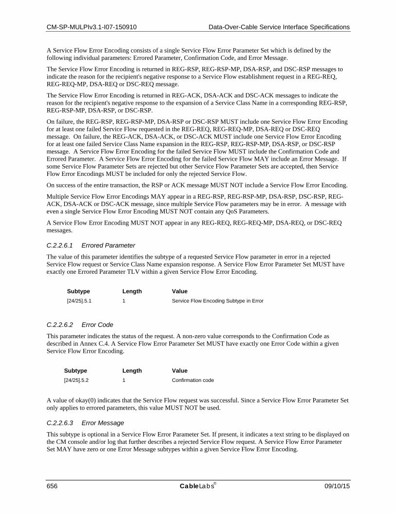
CM-SP-MULPIv3.1-I07-150910 Data-Over-Cable Service Interface Specifications
656 CableLabs 09/10/15
A Service Flow Error Encoding consists of a single Service Flow Error Parameter Set which is defined by the following individual parameters: Errored Parameter, Confirmation Code, and Error Message.
The Service Flow Error Encoding is returned in REG-RSP, REG-RSP-MP, DSA-RSP, and DSC-RSP messages to indicate the reason for the recipient's negative response to a Service Flow establishment request in a REG-REQ, REG-REQ-MP, DSA-REQ or DSC-REQ message.
The Service Flow Error Encoding is returned in REG-ACK, DSA-ACK and DSC-ACK messages to indicate the reason for the recipient's negative response to the expansion of a Service Class Name in a corresponding REG-RSP, REG-RSP-MP, DSA-RSP, or DSC-RSP.
On failure, the REG-RSP, REG-RSP-MP, DSA-RSP or DSC-RSP MUST include one Service Flow Error Encoding for at least one failed Service Flow requested in the REG-REQ, REG-REQ-MP, DSA-REQ or DSC-REQ message. On failure, the REG-ACK, DSA-ACK, or DSC-ACK MUST include one Service Flow Error Encoding for at least one failed Service Class Name expansion in the REG-RSP, REG-RSP-MP, DSA-RSP, or DSC-RSP message. A Service Flow Error Encoding for the failed Service Flow MUST include the Confirmation Code and Errored Parameter. A Service Flow Error Encoding for the failed Service Flow MAY include an Error Message. If some Service Flow Parameter Sets are rejected but other Service Flow Parameter Sets are accepted, then Service Flow Error Encodings MUST be included for only the rejected Service Flow.
On success of the entire transaction, the RSP or ACK message MUST NOT include a Service Flow Error Encoding.
Multiple Service Flow Error Encodings MAY appear in a REG-RSP, REG-RSP-MP, DSA-RSP, DSC-RSP, REG-ACK, DSA-ACK or DSC-ACK message, since multiple Service Flow parameters may be in error. A message with even a single Service Flow Error Encoding MUST NOT contain any QoS Parameters.
A Service Flow Error Encoding MUST NOT appear in any REG-REQ, REG-REQ-MP, DSA-REQ, or DSC-REQ messages.
C.2.2.6.1 Errored Parameter
The value of this parameter identifies the subtype of a requested Service Flow parameter in error in a rejected Service Flow request or Service Class Name expansion response. A Service Flow Error Parameter Set MUST have exactly one Errored Parameter TLV within a given Service Flow Error Encoding.
Subtype Length Value [24/25].5.1 1 Service Flow Encoding Subtype in Error
C.2.2.6.2 Error Code
This parameter indicates the status of the request. A non-zero value corresponds to the Confirmation Code as described in Annex C.4. A Service Flow Error Parameter Set MUST have exactly one Error Code within a given Service Flow Error Encoding.
Subtype Length Value [24/25].5.2 1 Confirmation code
A value of okay(0) indicates that the Service Flow request was successful. Since a Service Flow Error Parameter Set only applies to errored parameters, this value MUST NOT be used.
C.2.2.6.3 Error Message
This subtype is optional in a Service Flow Error Parameter Set. If present, it indicates a text string to be displayed on the CM console and/or log that further describes a rejected Service Flow request. A Service Flow Error Parameter Set MAY have zero or one Error Message subtypes within a given Service Flow Error Encoding.

MAC and Upper Layer Protocols Interface Specification CM-SP-MULPIv3.1-I07-150910
09/10/15 CableLabs 657
SubType Length Value [24/25].5.3 N Zero-terminated string of ASCII characters
NOTE: The length N includes the terminating zero.
NOTE: The entire Service Flow Encoding message MUST have a total length of less than 256 characters.
C.2.2.7 Common Upstream and Downstream Quality-of-Service Parameter Encodings The remaining Type 24 and 25 parameters are QoS Parameters. Any given QoS Parameter type MUST appear zero or one times per Service Flow Encoding.
C.2.2.7.1 Traffic Priority
The value of this parameter specifies the priority assigned to a Service Flow. The CMTS SHOULD provide differentiated service based on the value of Traffic Priority. The specific algorithm for enforcing this parameter is not mandated here. The default priority is 0.
For upstream service flows, the CMTS SHOULD use this parameter when determining precedence in request service and grant generation. For upstream service flows, the CM MUST include contention Request opportunities for Priority Request Service IDs (refer to Annex A.2.3) in its request backoff algorithm based on this priority and its Request/Transmission Policy (refer to Annex C.2.2.8.3).
For downstream service flows configured with a non-default value, the CMTS inserts this priority as a three bit tag into the Downstream Service Extended Header as defined in the subsection Downstream Service Extended Header in Section 6. The CM preferentially orders the PDU packets onto the egress queues based on this 3-bit Traffic Priority in the DS EHDR as described in the subsection Packet Queuing in Section 7.
Type Length Value [24/25].7 1 0 to 7 — Higher numbers indicate higher priority
C.2.2.7.2 Maximum Sustained Traffic Rate
This parameter is the rate parameter R of a token-bucket-based rate limit for packets. R is expressed in bits per second, and MUST take into account all MAC frame data PDU of the Service Flow from the byte following the MAC header HCS to the end of the CRC, including every PDU in the case of a Concatenated MAC Frame.
The number of bytes forwarded (in bytes) is limited during any time interval T by Max(T), as described in the expression:
Max(T) = T * (R / 8) + B, (1)
where the parameter B (in bytes) is the Maximum Traffic Burst Configuration Setting (refer to Annex C.2.2.7.3).
NOTE: This parameter does not limit the instantaneous rate of the Service Flow.
The specific algorithm for enforcing this parameter is not mandated here. Any implementation which satisfies the above equation is conformant. In particular, the granularity of enforcement and the minimum implemented value of this parameter are vendor-specific. The CMTS SHOULD support a granularity of at most 100 kbps. The CM SHOULD support a granularity of at most 100 kbps.
NOTE: If this parameter is omitted or set to zero, then there is no explicitly-enforced traffic rate maximum. This field specifies only a bound, not a guarantee that this rate is available.
C.2.2.7.2.1 Upstream Maximum Sustained Traffic Rate
For an upstream Service Flow, the CM MUST NOT request bandwidth exceeding the Max(T) requirement in expression (1) during any interval T because this could force the CMTS to fill MAPs with deferred grants.

CM-SP-MULPIv3.1-I07-150910 Data-Over-Cable Service Interface Specifications
658 CableLabs 09/10/15
The CM MUST defer upstream packets that violate expression (1) and "rate shape" them to meet the expression, up to a limit defined by the Buffer Control parameter.
The CMTS MUST enforce expression (1) on all upstream data transmissions, including data sent in contention. The CMTS MAY consider unused grants in calculations involving this parameter. The CMTS MAY enforce this limit by any of the following methods: (a) discarding over-limit requests, (b) deferring (through zero-length grants) the grant until it is conforming to the allowed limit, or (c) discarding over-limit data packets. A CMTS MUST report this condition to a policy module. If the CMTS is policing by discarding either packets or requests, the CMTS MUST allow a margin of error between the CM and CMTS algorithms.
Type Length Value 24.8 4 R (in bits per second)
C.2.2.7.2.2 Downstream Maximum Sustained Traffic Rate
For a downstream Service Flow, this parameter is only applicable at the CMTS. The CMTS MUST enforce expression (1) on all downstream data transmissions. The CMTS MUST NOT forward downstream packets that violates expression (1) in any interval T. The CMTS SHOULD "rate shape" the downstream traffic by enqueuing packets arriving in excess of expression (1), and delay them until the expression can be met.
When a CMTS implements both a Maximum Sustained Traffic Rate and a Peak Downstream Traffic Rate for a service flow, it limits the bytes forwarded in any interval T to the lesser of Max(T) defined in equation (1) and Peak(T) defined in equation (2) of Annex C.2.2.9.2.
This parameter is not intended for enforcement on the CM.
Type Length Value 25.8 4 R (in bits per second)
C.2.2.7.3 Maximum Traffic Burst
The value of this parameter specifies the token bucket size B (in bytes) for this Service Flow as described in expression (1). This value is calculated from the byte following the MAC header HCS to the end of the CRC, including every PDU in the case of a Concatenated MAC Frame.
The minimum value of B is 1522 bytes, or 2000 bytes if extended packet length is enabled for this Service Flow. If this parameter is omitted, the default value for B is 3044 bytes, or 4000 bytes if extended packet length is enabled for this Service Flow. This parameter has no effect unless a non-zero value has been provided for the Maximum Sustained Traffic Rate parameter.
Bonded downstream packets may be internally distributed across multiple channels within the CMTS after they have been scheduled according to the rate limiting algorithm in expression (1). As a result, the traffic burst observed at the CMTS output would not just be a function of the rate limiting algorithm, but would also be a function of the skew between the channels that data is sent on. Thus the observed traffic burst could exceed the Maximum Traffic Burst value.
The resequencing and reassembly operations may also impact the observed maximum traffic burst of a downstream or upstream bonded service flow. When a stream of packets are resequenced (or segments are reassembled) they can't be forwarded until all have arrived (or a timeout occurred). As a result, a period of idle time would be followed by a traffic burst even if the CMTS/CM performed perfect output shaping of the traffic as per (1).
For an upstream service flow, if B is sufficiently less than the Maximum Concatenated Burst parameter, then enforcement of the rate limit equation will limit the maximum size of a concatenated burst.

MAC and Upper Layer Protocols Interface Specification CM-SP-MULPIv3.1-I07-150910
09/10/15 CableLabs 659
Type Length Value [24/25].9 4 B (bytes)
NOTE: The value of this parameter affects the trade-off between the data latency perceived by an individual application, and the traffic engineering requirements of the network. A large value will tend to reduce the latency introduced by rate limiting for applications with burst traffic patterns. A small value will tend to spread out the bursts of data generated by such applications, which may benefit traffic engineering within the network.
C.2.2.7.4 Minimum Reserved Traffic Rate
This parameter specifies the minimum rate, in bits/sec, reserved for this Service Flow. The value of this parameter is calculated from the byte following the MAC header HCS to the end of the CRC, including every PDU in a Concatenated MAC Frame. If this parameter is omitted, then it defaults to a value of 0 bits/sec (i.e., no bandwidth is reserved for the flow by default).
How Minimum Reserved Traffic Rate and Assumed Minimum Reserved Rate Packet Size apply to a CMTS's admission control policies is vendor-specific, and is beyond the scope of this specification. The aggregate Minimum Reserved Traffic Rate of all Service Flows could exceed the amount of available bandwidth.
Unless explicitly configured otherwise, a CMTS SHOULD schedule forwarding of all service flows' traffic such that each receives at least its Minimum Reserved Traffic Rate when transmitting packets with the Assumed Minimum Reserved Rate Packet Size. If the service flow sends packets of a size smaller than the Assumed Minimum Reserved Rate Packet Size, such packets will be treated as being of the Assumed Minimum Reserved Rate Packet Size for calculating the rate forwarded from the service flow for purposes of meeting the Minimum Reserved Traffic Rate. If less bandwidth than its Minimum Reserved Traffic Rate is requested for a Service Flow, the CMTS MAY reallocate the excess reserved bandwidth for other purposes.
NOTE: The granularity of the Minimum Reserved Traffic Rate used internally by the CMTS is vendor-specific. Because of this, the CMTS MAY schedule forwarding of a service flow's traffic at a rate greater than the configured value for Minimum Reserved Traffic Rate.
This field is only applicable at the CMTS.
Type Length Value [24/25].10 4
C.2.2.7.5 Assumed Minimum Reserved Rate Packet Size
This parameter is used by the CMTS to make worst-case DOCSIS overhead assumptions. The Minimum Reserved Traffic Rate of a service flow excludes the DOCSIS MAC header and any other DOCSIS overhead (e.g., for completing an upstream minislot). Traffic with smaller packets sizes will require a higher proportion of overall channel capacity for DOCSIS overhead than traffic with larger packet sizes. The CMTS assumes that the worst-case DOCSIS overhead for a service flow will be when all traffic is as small as the size specified in this parameter.
This parameter is defined in bytes and is specified as the bytes following the MAC header HCS to the end of the CRC.
If this parameter is omitted, then the default value is CMTS implementation dependent.
Type Length Value [24/25].11 2

CM-SP-MULPIv3.1-I07-150910 Data-Over-Cable Service Interface Specifications
660 CableLabs 09/10/15
C.2.2.7.6 Timeout for Active QoS Parameters
The value of this parameter specifies the maximum duration resources remain unused on an active Service Flow. If there is no activity on the Service Flow within this time interval, the CMTS MUST change the active and admitted QoS Parameter Sets to null. The CMTS MUST signal this resource change with a DSC-REQ to the CM.
Type Length Value [24/25].12 2 seconds
This parameter MUST be enforced at the CMTS. This parameter SHOULD NOT be enforced at the CM. The parameter is processed by the CMTS for every QoS set contained in Registration messages and Dynamic Service messages. If the parameter is omitted, the default of 0 (i.e., infinite timeout) is assumed. The value specified for the active QoS set must be less than or equal to the corresponding value in the admitted QoS set which must be less than or equal to the corresponding value in the provisioned/authorized QoS set. If the requested value is too large, the CMTS MAY reject the message or respond with a value less than that requested. If the Registration or Dynamic Service message is accepted by the CMTS and acknowledged by the CM, the Active QoS Timeout timer is loaded with the new value of the timeout. The timer is activated if the message activates the associated Service Flow. The timer is deactivated if the message sets the active QoS set to null.
C.2.2.7.7 Timeout for Admitted QoS Parameters
The value of this parameter specifies the duration that the CMTS MUST hold resources for a Service Flow's Admitted QoS Parameter Set while they are in excess of its Active QoS Parameter Set. If there is no DSC-REQ to activate the Admitted QoS Parameter Set within this time interval, and there is no DSC to refresh the QoS parameter sets and restart the timeout (see the subsection Quality of Service in Section 7), the resources that are admitted but not activated MUST be released, and only the active resources retained. The CMTS MUST set the Admitted QoS Parameter Set equal to the Active QoS Parameter Set for the Service Flow and initiate a DSC-REQ exchange with the CM to inform it of the change.
Type Length Value [24/25].13 2 seconds
This parameter MUST be enforced at the CMTS. This parameter SHOULD NOT be enforced at the CM. The parameter is processed by the CMTS for every QoS set contained in Registration messages and Dynamic Service messages. If the parameter is omitted, the default of 200 seconds is assumed. A value of 0 means that the Service Flow can remain in the admitted state for an infinite amount of time and MUST NOT be timed out due to inactivity. However, this is subject to policy control by the CMTS. The value specified for the active QoS set must be less than or equal to the corresponding value in the admitted QoS set which must be less than or equal to the corresponding value in the provisioned/authorized QoS set. If the requested value is too large, the CMTS MAY reject the message or respond with a value less than that requested. If the Registration or Dynamic Service message containing this parameter is accepted by the CMTS and acknowledged by the CM, the Admitted QoS Timeout timer is loaded with the new value of the timeout. The timer is activated if the message admits resources greater than the active set. The timer is deactivated if the message sets the active QoS set and admitted QoS set equal to each other.
C.2.2.7.8 Vendor Specific QoS Parameters
This allows vendors to encode vendor-specific QoS parameters using the DOCSIS Extension Field. The Vendor ID MUST be the first TLV embedded inside Vendor Specific QoS Parameters. If the first TLV inside Vendor Specific QoS Parameters is not a Vendor ID, then the TLV MUST be discarded. (Refer to Annex C.1.1.17).
Type Length Value [24/25].43 N

MAC and Upper Layer Protocols Interface Specification CM-SP-MULPIv3.1-I07-150910
09/10/15 CableLabs 661
C.2.2.7.9 IP Type Of Service (DSCP) Overwrite
The CMTS MUST overwrite IP packets with IPv4 TOS byte or IPv6 Traffic Class value "orig-ip-tos" with the value "new-ip-tos", where new-ip-tos = ((orig-ip-tos AND tos-and-mask) OR tos-or-mask). If this parameter is omitted, then the IP packet TOS/Traffic Class byte is not overwritten.
This parameter is only applicable at the CMTS. If defined, this parameter MUST be enforced by the CMTS.
The IPv4 TOS octet as originally defined in RFC 791 has been superseded by the 6-bit Differentiated Services Field (DSField, [RFC 3260]) and the 2-bit Explicit Congestion Notification Field (ECN field, [RFC 3168]). The IPv6 Traffic Class octet [RFC 2460] is consistent with that new definition. Network operators should avoid specifying values of tos-and-mask and tos-or-mask that would result in the modification of the ECN bits.
In particular, operators should not use values of tos-and-mask that have either of the least-significant two bits set to 0. Similarly, operators should not use values of tos-or-mask that have either of the least-significant two bits set to 1.
Type Length Value 24/25.23 2 tos-and-mask, tos-or-mask
C.2.2.7.10 Peak Traffic Rate
This parameter is the rate parameter P of a token-bucket-based peak rate limiter for packets of a service flow. Configuring this peak rate parameter permits an operator to define a Maximum Traffic Burst value for the Maximum Sustained Traffic Rate much larger than a maximum packet size, but still limit the burst of packets consecutively transmitted for a service flow (refer to Annex C.2.2.7.3).
The parameter P is expressed in bits per second, and includes all MAC frame data PDU bytes scheduled on the service flow from the byte following the MAC header HCS to the end of the CRC.
The number of bytes forwarded is limited during any time interval T by Peak(T), as described in expression (2), below:
Peak(T) <= T * (P / 8) + MaxPDU (2)
where MaxPDU = 2000 bytes if extended packet length is enabled for this Service Flow or 1522 bytes if extended packet length is not enabled for this Service Flow.
C.2.2.7.10.1 Upstream Peak Traffic Rate
For an upstream Service Flow, the CM SHOULD NOT request bandwidth exceeding the Peak(T) requirement in expression (2) during any interval T because this could force the CMTS to discard packets and/or fill MAPs with deferred grants.
The CM SHOULD defer upstream packets that violate expression (2) and "rate shape" them to meet the expression, up to a limit defined by the Buffer Control parameter.
The CMTS SHOULD enforce expression (2) on all upstream data transmissions, including data sent in contention. The CMTS MAY consider unused grants in calculations involving this parameter. The CMTS MAY enforce this limit by any of the following methods: (a) discarding over-limit requests, (b) deferring (through zero-length grants) the grant until it is conforming to the allowed limit, or (c) discarding over-limit data packets. A CMTS SHOULD report this condition to a policy module. If the CMTS is policing by discarding either packets or requests, the CMTS MUST allow a margin of error between the CM and CMTS algorithms.
Type Length Value 24.27 4 Upstream Peak Traffic Rate (P), in bits per second. If omitted or zero(0), upstream
peak traffic rate is not limited.

CM-SP-MULPIv3.1-I07-150910 Data-Over-Cable Service Interface Specifications
662 CableLabs 09/10/15
C.2.2.7.10.2 Downstream Peak Traffic Rate
When this parameter P is defined for a service flow, the CMTS SHOULD enforce the number of PDU bytes scheduled on a downstream service flow for any time interval T to be limited by the expression Peak(T) as described in expression (2).
When a CMTS implements both a Maximum Sustained Traffic Rate and a Peak Downstream Traffic Rate for a service flow, it limits the bytes forwarded in any interval T to the lesser of Max(T) defined in equation (1) of Annex C.2.2.7.2 and Peak(T) defined in equation (2). The peak rate parameter P is intended to be configured to be greater than or equal to the Maximum Sustained Rate R of equation (1). Operation when the peak rate P is configured to be less than the Maximum Sustained Rate R is CMTS vendor-specific.
When the CMTS enforces the Downstream Peak Traffic Rate, it SHOULD "rate shape" the downstream traffic by delaying the forwarding of packets until the Downstream Peak Rate expression (2) can be met. The specific algorithm for enforcing this parameter, with or without concurrently enforcing the Maximum Sustained Traffic Rate parameter, is not mandated here. Any implementation which satisfies the normative requirements is conformant. In particular, the granularity of enforcement and the minimum implemented value of this parameter are vendor-specific. The CMTS SHOULD support a granularity of at most 100 kbps.
This parameter is not intended for enforcement on the CM.
If the parameter is omitted or set to zero, the CMTS MUST NOT enforce a Downstream Peak Traffic Rate for the service flow.
Type Length Value 25.27 4 Downstream Peak Traffic Rate (P), in bits per second. If omitted or zero(0),
downstream peak traffic rate is not limited.
C.2.2.7.11 Buffer Control
The Buffer Control parameters limit the maximum queue depth of a Service Flow. The service flow buffer holds the packets that are enqueued for transmission for the service flow. The size of the service flow buffer sets the maximum queue depth, an upper limit on the amount of data that can be enqueued for transmission at any time by the service flow. By providing the ability to control per-service flow buffers, the Buffer Control parameters provide a means of balancing throughput and latency in a standardized and configurable manner.
The Buffer Control parameters are expressed as the number of bytes including all MAC frame data PDU bytes following the MAC header HCS and to the end of the CRC for the MAC frames enqueued for the service flow.
The size of the service flow buffer influences a tradeoff between transmission latency for latency-sensitive UDP traffic and throughput for TCP traffic. A larger buffer may improve TCP throughput, but can cause increased latency, which may negatively impact latency-sensitive applications such as voice over IP or real-time games. Conversely, a smaller buffer may decrease transmission latency for the service flow, but may degrade TCP throughput. In the case where a service flow is intended to carry a mix of both TCP traffic and latency-sensitive UDP traffic, a careful consideration of the performance tradeoffs between the two traffic types should be made.
In order to accommodate implementation differences (e.g., varying amounts of memory available for buffering) and to allow an optimized partitioning of buffering memory based on the number of active service flows, the Buffer Control parameter is defined via three values: a minimum buffer, a maximum buffer, and a target buffer. The Minimum Buffer and Maximum Buffer provide a range of values for the size of the service flow buffer, while the Target Buffer indicates a specific desired value for the buffer.
If the Buffer Control parameters are defined for a service flow, the device selects a buffer size within the range defined by the Minimum and Maximum Buffers. The device is expected to size the service flow buffer as close as possible to the Target Buffer if it is specified. However, there may be constraints that prevent an implementation from selecting the Target Buffer. The minimum and maximum buffers can be made equal to each other in order to force a specific buffer size; however, tighter ranges are more likely to be rejected than wider ranges. A Buffer Control encoding is considered invalid if the Minimum Buffer is greater than the Maximum Buffer or if the Target

MAC and Upper Layer Protocols Interface Specification CM-SP-MULPIv3.1-I07-150910
09/10/15 CableLabs 663
Buffer is not within the range defined by the Minimum and Maximum Buffers. Operators must take this into consideration in assigning the values in the Buffer Control parameters.
Once a value for a service flow's buffer is chosen, the rate shaping operation is not to queue more bytes than this value. Over time, system parameters and constraints may change. Service flows can be created or deleted, or service flow parameters may be changed. As a result of these changes, the device can adjust the buffer size for all or a subset of service flows within the range defined by the service flow's Minimum and Maximum Buffers.
C.2.2.7.11.1 Upstream Buffer Control
The Upstream Buffer Control provides a range for the maximum number of bytes that the CM is permitted to enqueue for this upstream service flow.
The Upstream Buffer Control parameters impact upstream performance. While these parameters can be applied to any service flow scheduling type, service flows that are not best effort typically have optimized buffering implementations that make usage of the Upstream Buffer Control parameters unnecessary. As a result, these parameters are only expected to be used with best effort service flows.
The CM MUST support the Upstream Buffer Control encodings. The CM MUST ensure that the size of the buffer of the upstream service flow is within the range defined by the Minimum Buffer and Maximum Buffer parameters. The CM MUST reject an upstream service flow if it is unable to provide a buffer within the range (inclusively) of bytes defined by the Minimum Buffer and Maximum Buffer parameters. If the Maximum Buffer has a value of no limit, then there is no restriction on the maximum size of the buffer. The CM MUST NOT queue more bytes for the service flow than the value defined by the Maximum Buffer. If the Target Buffer is present and non-zero, the CM SHOULD set the size of the buffer for the upstream Service Flow to be equal to the value of the Target Buffer parameter. A CM may have implementation-specific constraints that prevent setting the size of the buffer to the Target Buffer value.
The CM MUST support a buffer of at least 24 kibibytes (KiB) per upstream service flow.
Type Length Value [24].35 N
C.2.2.7.11.2 Downstream Buffer Control
The Downstream Buffer Control provides a range for the maximum number of bytes that the CMTS is permitted to enqueue for transmission on the downstream channel.
The CMTS MAY support the Downstream Buffer Control encodings.
Type Length Value [25].35 N
C.2.2.7.11.3 Minimum Buffer
This parameter defines a lower limit for the size of the buffer that is to be provided for a service flow.
If the device is unable to provide a buffer that meets the number of bytes defined by the Minimum Buffer, the device is to reject the service flow.
If this parameter is omitted, the Minimum Buffer defaults to a value of 0 which indicates that there is no lower limit.
Type Length Value [24/25].35.1 4 0 - 4294967295 Bytes
Default = 0

CM-SP-MULPIv3.1-I07-150910 Data-Over-Cable Service Interface Specifications
664 CableLabs 09/10/15
C.2.2.7.11.4 Target Buffer
The Target Buffer defines a desired value for the size of the buffer that is to be provided for a service flow. This parameter exists for scenarios in which an ideal value for the size of the buffer has been calculated in order to optimize an application. The specific algorithm by which this parameter might be calculated is not specified here.
If this parameter is omitted or set to a value of 0, the device selects any buffer size within the range of the Minimum and Maximum Buffers, via a vendor-specific algorithm.
Type Length Value [24/25].35.2 4 0 - 4294967295 Bytes
Default = 0 (vendor-specific value)
C.2.2.7.11.5 Maximum Buffer
This parameter defines an upper limit for the size of the buffer that is to be provided for a service flow.
If this parameter is omitted, the Maximum Buffer defaults to a value of no limit.
Type Length Value [24/25].35.3 4 0 - 4294967295 Bytes
Default = no limit
C.2.2.7.12 ASF QoS Profile Name
The value of the field refers to a predefined CMTS service configuration to be used for this Aggregate Service Flow.
Type Length Value [70/71].4 2 to 16 Zero-terminated string of ASCII characters.
NOTE: The length includes the terminating zero.
ASF QoS Profile Name serves a similar purpose for ASFs as Service Class Name serves for Service Flows. However, unlike Service Class Name which provides an alternative and complementary method to provisioning of QoS parameters in CM configuration file or dynamic service messages, the ASF QoS Profile Name is the only available method for defining QoS parameters for an ASF. All ASF QoS parameters are configured on the CMTS in profiles identified by names as specified in [DOCSIS OSSIv3.1].
C.2.2.7.13 Service Flow Matching Criteria
The set of sub-TLVs for this TLV defines criteria through which the CMTS will match dynamically created Service Flows to an ASF.
Type Length Value
[70/71].38 N
C.2.2.7.13.1 Service Flow to ASF Matching by Application Id
The value of this field defines a value of an Application ID that the CMTS will use to match a Service Flow to an ASF.

MAC and Upper Layer Protocols Interface Specification CM-SP-MULPIv3.1-I07-150910
09/10/15 CableLabs 665
Type Length Value [70/71].38.1 4 Application ID
This TLV may appear more than one time in ASF encodings permitting matching of Service Flows to ASFs against multiple Application Ids.
C.2.2.7.13.2 Service Flow to ASF Matching by Service Class Name
The value of this field defines the Service Class Name that the CMTS will use to match a Service Flow to an ASF.
Type Length Value [70/71].38.2 2 to 16 Zero-terminated string of ASCII characters.
This TLV may appear more than one time in ASF encodings permitting matching of Service Flows to ASFs against multiple Service Class Names.
C.2.2.7.13.3 Service Flow to ASF Matching by Traffic Priority Range
The value of this field defines a range of values of Service Flow's Traffic Priority that the CMTS will use to match a Service Flow to an ASF.
Type Length Value [70/71].38.3 2 Traffic Priority Low, Traffic Priority High
This TLV may appear more than one time in ASF encodings permitting matching of Service Flows to ASFs against multiple ranges of Traffic Priority.
C.2.2.7.14 Service Flow to IATC Profile Name Reference
The value of the field explicitly refers the Service Flow to an IATC Profile defined in the CMTS configuration.
Type Length Value [24/25].39 2 to 16 Zero-terminated string of ASCII characters.
NOTE: The length includes the terminating zero.
C.2.2.7.15 AQM Encodings
These AQM encodings provide a means of disabling and configuring AQM parameters on a service flow basis. These parameters are only applicable to downstream service flows and to best effort and nRTP upstream service flows. The CM MUST support the AQM encodings. The CMTS MUST support the AQM encodings. The CMTS MUST include the AQM encodings in the Registration Response when present in the Registration Request.
Type Length Value [24/25].40 N AQM Encodings

CM-SP-MULPIv3.1-I07-150910 Data-Over-Cable Service Interface Specifications
666 CableLabs 09/10/15
C.2.2.7.15.1 SF AQM Disable
The SF AQM Disable encoding provides a means of disabling AQM on a particular service flow. If this TLV is included with a value of "Disable AQM on service flow", the CM (in the case of an upstream service flow) or CMTS (in case of a downstream service flow) disables AQM on the service flow. If this TLV is absent or included with a value of "Enable AQM on service flow" and the upstream service flow type is either best effort or non-real time polling, the CM enables AQM on the service flow. If this TLV is absent or included with a value of "Enable AQM on service flow" for a downstream service flow, the CMTS enables AQM on the service flow.
Type Length Value [24/25].40.1 1 0 = Enable AQM on service flow
1 = Disable AQM on service flow 2-255 = Reserved
C.2.2.7.15.2 SF AQM Latency Target
The SF AQM Latency Target encoding provides the latency target to be used for the AQM algorithm for this Service Flow. If the AQM Latency Target TLV is present in an upstream service flow encoding, the CM MUST use the provided latency target in the AQM algorithm for this service flow. If no AQM Latency Target is included, the CM MUST use a default value of 10 ms. If this TLV is present in a downstream service flow encoding, the CMTS SHOULD use the provided latency target in the downstream AQM algorithm for this service flow.
NOTE: It is recommended that an AQM Latency Target in the range 10ms - 100ms be utilized for the PIE algorithm defined in Annex M.
Type Length Value [24/25].40.2 1 AQM Latency Target (in milliseconds)
C.2.2.7.16 Data Rate Unit Setting160
The default units for the traffic rate parameters (Maximum Sustained Traffic Rate, Minimum Reserved Traffic Rate, and Peak Traffic Rate) within a Service Flow are bits per second (bps). This 'Data Rate Unit Setting' parameter indicates the base unit for the rates configured using the Maximum Sustained Traffic Rate, Minimum Reserved Traffic Rate, and Peak Traffic Rate TLVs. The value of the 'Data Rate Unit Setting' TLV overwrites the default unit (bps) for all these TLVs and allows for their interpretation in units of bps, or kbps, or Mbps or Gbps.
This TLV applies to both Upstream and Downstream Service Flow parameters. The CM MUST support this TLV and enforce the data rate unit for Upstream Service Flow. (The CM does not limit or enforce with respect to the above mentioned traffic rate parameters for downstream service flows.) The CMTS MUST support this TLV and enforce the data rate unit for both Upstream and Downstream Service Flows.
Regarding provisioned service flows, this TLV is not to be included in a CM configuration file for a pre-DOCSIS 3.1 CM or a CM operating with a DOCSIS 3.0 CMTS. Regarding dynamic service flows, a CM MUST NOT send a DSA-REQ or DSC-REQ that contains this TLV to a DOCSIS 3.0 CMTS. A CMTS MUST NOT send a DSA-REQ or DSC-REQ that contains this TLV to a pre-DOCSIS 3.1 CM.
Type Length Value [24/25].41 1 Value of '0' is bits per second (bps) default
Value of '1' is kilo-bits per second (kbps) (i.e., 1000 bps) Value of '2' is mega-bits per second (Mbps) (i.e., 1000 kbps) Value of '3' is giga-bits per second (Gbps) (i.e., 1000 Mbps) Other values are reserved
160 Updated by MULPIv3.1-15.1298-2 on 6/2/15 by PO.

MAC and Upper Layer Protocols Interface Specification CM-SP-MULPIv3.1-I07-150910
09/10/15 CableLabs 667
If this TLV is not present, a default value of 0 (i.e., units of 'bps') is used.
C.2.2.8 Upstream-Specific QoS Parameter Encodings
C.2.2.8.1 Maximum Concatenated Burst161
This parameter is deprecated for DOCSIS 3.1 CMs.
The value of this parameter specifies the maximum concatenated burst (in bytes) which a Service Flow is allowed when a pre-DOCSIS 3.1 CM is not operating in MTC Mode. This parameter is calculated from the FC byte of the Concatenation MAC Header to the last CRC in the concatenated MAC frame.
A value of 0 means there is no limit. If this parameter is omitted the default value is 1522.
This field is only applicable at the pre-DOCSIS 3.1 CM. If defined, a pre-DOCSIS 3.1 CM enforces this parameter.
NOTE: This value does not include any physical layer overhead.
Type Length Value 24.14 2
NOTE: This applies only to concatenated bursts, and only on a DOCSIS 3.0 CM which is not operating in MTC Mode. It is legal and, in fact, it may be useful to set this smaller than the maximum Ethernet packet size. Of course, it is also legal to set this equal to or larger than the maximum Ethernet packet size.
NOTE: The maximum size of a concatenated burst can also be limited by the enforcement of a rate limit, if the Maximum Traffic Burst parameter is small enough, and by limits on the size of data grants in the UCD message.
C.2.2.8.2 Service Flow Scheduling Type
The value of this parameter specifies which upstream scheduling service is used for upstream transmission requests and packet transmissions. If this parameter is omitted, then the Best Effort service MUST be assumed.
This parameter is only applicable at the CMTS. If defined, this parameter MUST be enforced by the CMTS.
Type Length Value 24.15 1 0 Reserved
1 for Undefined (CMTS implementation-dependent1)
2 for Best Effort
3 for Non-Real-Time Polling Service
4 for Real-Time Polling Service
5 for Unsolicited Grant Service with Activity Detection
6 for Unsolicited Grant Service
7 through 255 are reserved for future use
Note 1 The specific implementation dependent scheduling service type could be defined in the 24.43 Vendor Specific QoS Parameters. (Refer to Annex C.2.2.7.8.)
161 Updated by MULPIv.1-N-15.1334-2 on 8/21/15 by PO

CM-SP-MULPIv3.1-I07-150910 Data-Over-Cable Service Interface Specifications
668 CableLabs 09/10/15
C.2.2.8.3 Request/Transmission Policy
The value of this parameter specifies which IUC opportunities the CM uses for upstream transmission requests and packet transmissions for this Service Flow, whether requests for this Service Flow may be piggybacked with data, and whether data packets transmitted on this Service Flow can be concatenated, fragmented, or have their payload headers suppressed. For UGS, it also specifies how to treat packets that do not fit into the UGS grant. See the subsection Upstream Service Flow Scheduling Services in Section 7 for requirements related to settings of the bits of this parameter for each Service Flow Scheduling Type. For Continuous Concatenation and Fragmentation, it specifies whether or not segment headers are used, and what opportunities can be used for making bandwidth requests.
This parameter is required for all Service Flow Scheduling Types except Best Effort. If omitted in a Best Effort Service Flow QoS parameter Set, the default value of zero MUST be used. Bit #0 is the LSB of the Value field. Bits are set to 1 to select the behavior defined below:
Type Length Value 24.16 4 Bit #0 The Service Flow MUST NOT use "all CMs" broadcast request opportunities.
Bit #1 The Service Flow MUST NOT use Priority Request multicast request opportunities. (Refer to Annex A.2.3.)
Bit #2 The Service Flow MUST NOT use Request_2 opportunities for Requests.
Bit #3 The Service Flow MUST NOT use Request_2 opportunities for Data. 1
Bit #4 The Service Flow MUST NOT piggyback requests with data.
Bit #5 The Service Flow MUST NOT concatenate data.2
Bit #6 The Service Flow MUST NOT fragment data.
Bit #7 The Service Flow MUST NOT suppress payload headers.
Bit #8 The Service Flow MUST drop packets that do not fit in the Unsolicited Grant Size. 3,4
Bit #9 The Service Flow MUST NOT use segment headers. When set to zero, the Service Flow MUST use segment headers.5
Bit #10 The Service Flow MUST NOT use contention regions for transmitting multiple outstanding bandwidth requests.
All other bits are reserved. 1 This bit is irrelevant for a CM in Multiple Transmit Channel Mode because it does not use Request_2 for sending data. 2 This bit applies for pre-3.0 DOCSIS operation. 3 This bit only applies to Service Flows with the Unsolicited Grant Service Flow Scheduling Type. If this bit is set on any other
Service Flow Scheduling type, it MUST be ignored. 4 Packets that classify to an Unsolicited Grant Service Flow and are larger than the Grant Size associated with that Service Flow
are normally transmitted on the Primary Service Flow. This parameter overrides that default behavior. 5 Only UGS or UGS-AD Service Flows can be configured with Segment Header OFF for CMs operating in Multiple Transmit
Channel Mode. NOTE: Data grants include both short and long data grants.
C.2.2.8.4 Nominal Polling Interval
The value of this parameter specifies the nominal interval (in units of microseconds) between successive unicast request opportunities for this Service Flow on the upstream channel. This parameter is typically suited for Real-Time and Non-Real-Time Polling Service.
The ideal schedule for enforcing this parameter is defined by a reference time t0, with the desired transmission times ti = t0 + i*interval. In the CMTS, the actual poll times, t'i MUST be in the range ti <= t'i <= ti + jitter, where interval is the value specified with this TLV, and jitter is Tolerated Poll Jitter. The accuracy of the ideal poll times, ti, are measured relative to the CMTS Master Clock used to generate timestamps (refer to the subsection Timing and Synchronization in Section 7).

MAC and Upper Layer Protocols Interface Specification CM-SP-MULPIv3.1-I07-150910
09/10/15 CableLabs 669
This field is only applicable at the CMTS. If defined, this parameter MUST be enforced by the CMTS.
Type Length Value 24.17 4 Number of microseconds
C.2.2.8.5 Tolerated Poll Jitter
The values in this parameter specifies the maximum amount of time that the unicast request interval may be delayed from the nominal periodic schedule (measured in microseconds) for this Service Flow.
The ideal schedule for enforcing this parameter is defined by a reference time t0, with the desired poll times ti = t0 + i*interval. In the CMTS, the actual poll, t'i MUST be in the range ti <= t'i <= ti + jitter, where jitter is the value specified with this TLV and interval is the Nominal Poll Interval. The accuracy of the ideal poll times, ti, are measured relative to the CMTS Master Clock used to generate timestamps (refer to the subsection Timing and Synchronization in Section 7).
This parameter is only applicable at the CMTS. If defined, this parameter represents a service commitment (or admission criteria) at the CMTS.
Type Length Value 24.18 4 Number of microseconds
C.2.2.8.6 Unsolicited Grant Size
The value of this parameter specifies the unsolicited grant size in bytes. The grant size includes the entire MAC frame beginning with the Frame Control byte for Segment Header OFF operation or the first byte of the Segment Header for Segment Header ON operation, and ending at the end of the MAC frame.
This parameter is applicable at the CMTS and MUST be enforced at the CMTS.
Type Length Value 24.19 2 Number of bytes
NOTE: For UGS, this parameter should be used by the CMTS to compute the size of the unsolicited grant in minislots.
C.2.2.8.7 Nominal Grant Interval
The value of this parameter specifies the nominal interval (in units of microseconds) between successive data grant opportunities for this Service Flow. This parameter is required for Unsolicited Grant and Unsolicited Grant with Activity Detection Service Flows.
The ideal schedule for enforcing this parameter is defined by a reference time t0, with the desired transmission times ti = t0 + i*interval. The actual grant times, t'i MUST be in the range ti <= t'i <= ti + jitter, where interval is the value specified with this TLV, and jitter is the Tolerated Grant Jitter. When multiple grants per interval are requested, all grants MUST be within this interval, thus the Nominal Grant Interval and Tolerated Grant Jitter are maintained by the CMTS for all grants in this Service Flow. The accuracy of the ideal grant times, ti, are measured relative to the CMTS Master Clock used to generate timestamps (refer to the subsection Timing and Synchronization in Section 7).
This field is mandatory for Unsolicited Grant and Unsolicited Grant with Activity Detection Scheduling Types. This field is only applicable at the CMTS, and MUST be enforced by the CMTS.

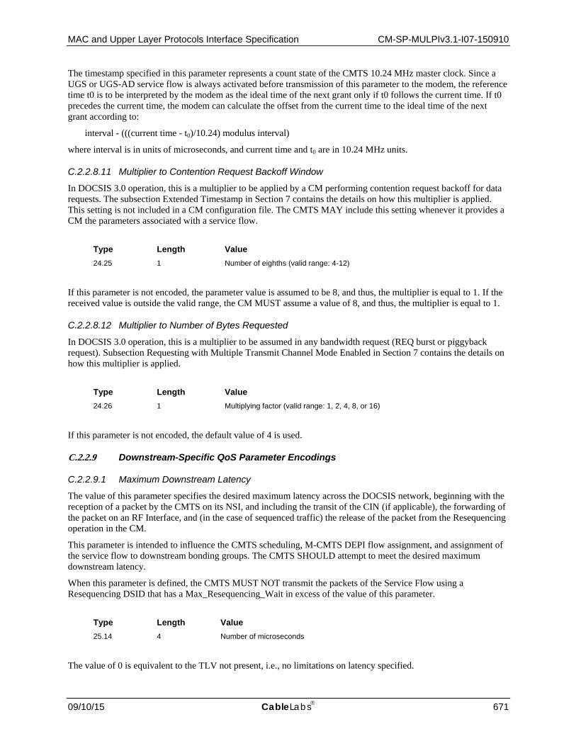


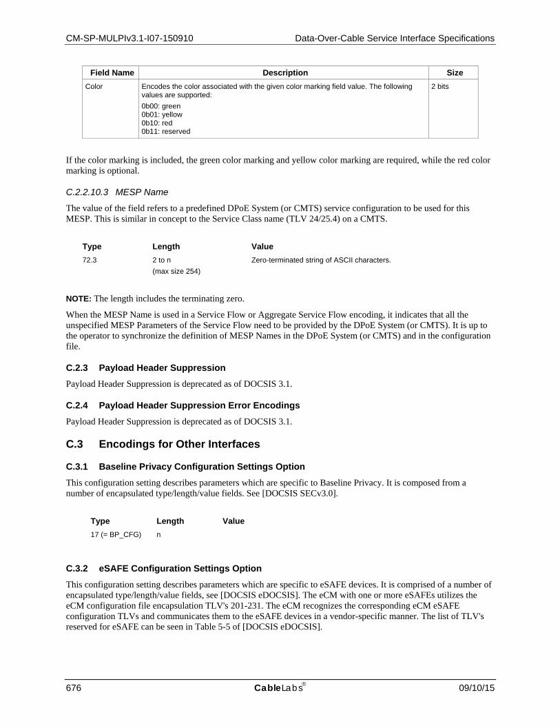


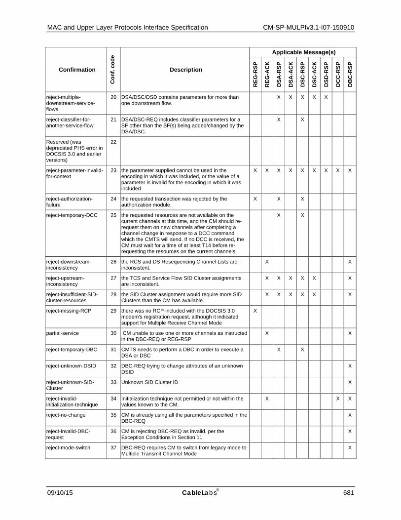


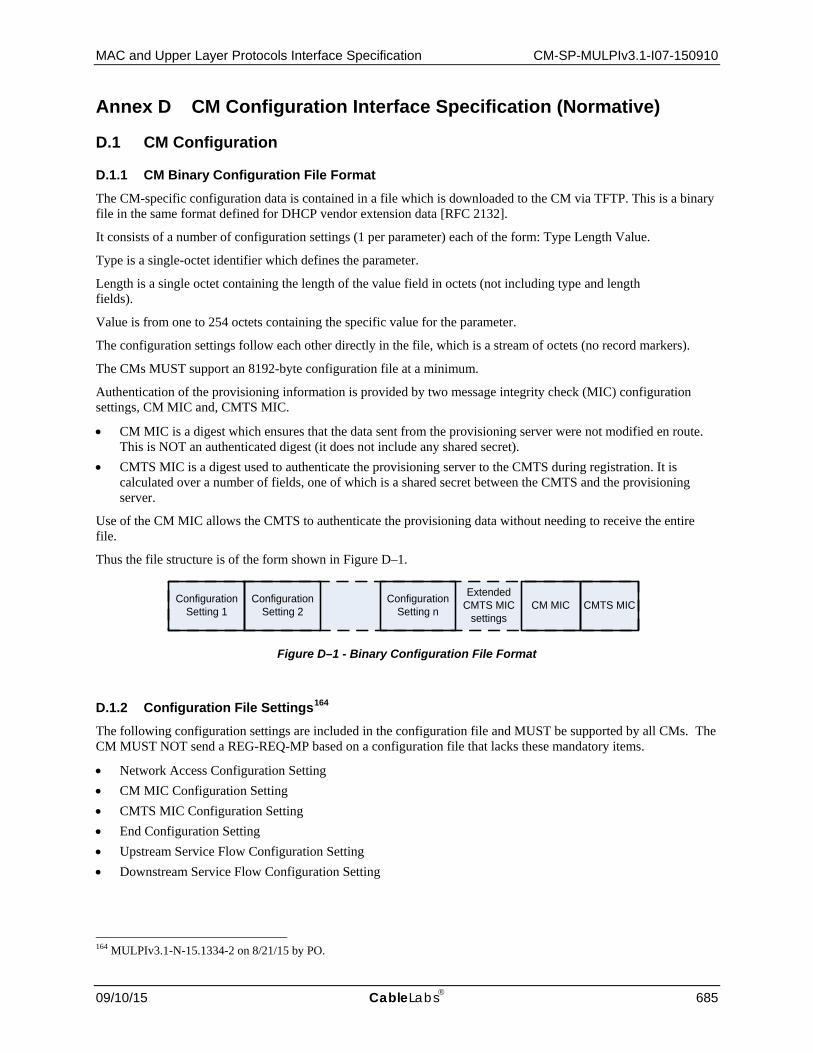


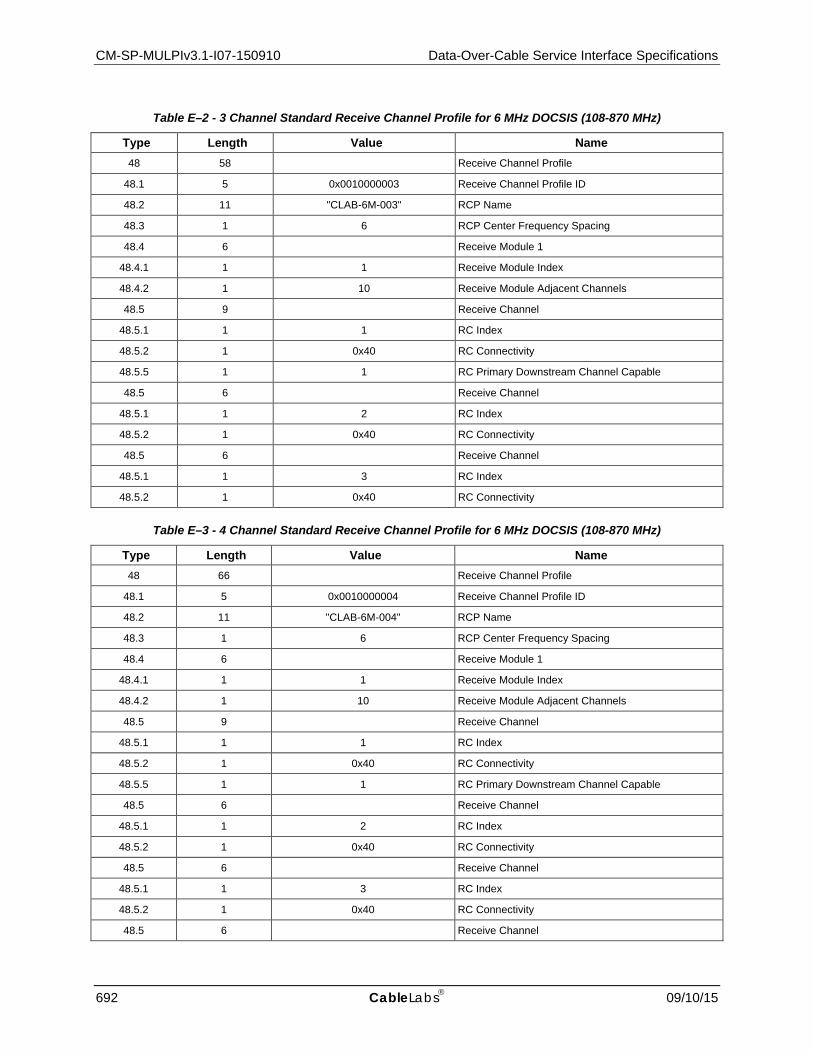

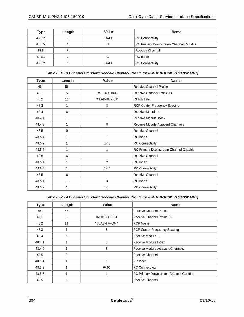


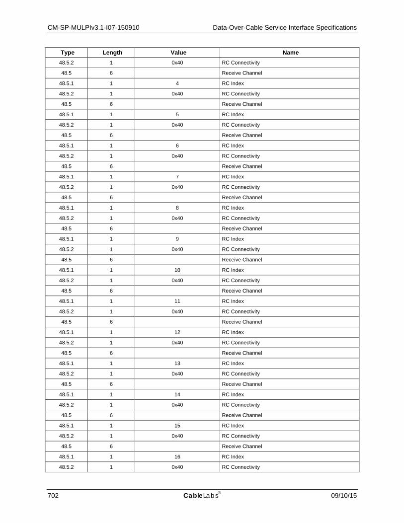


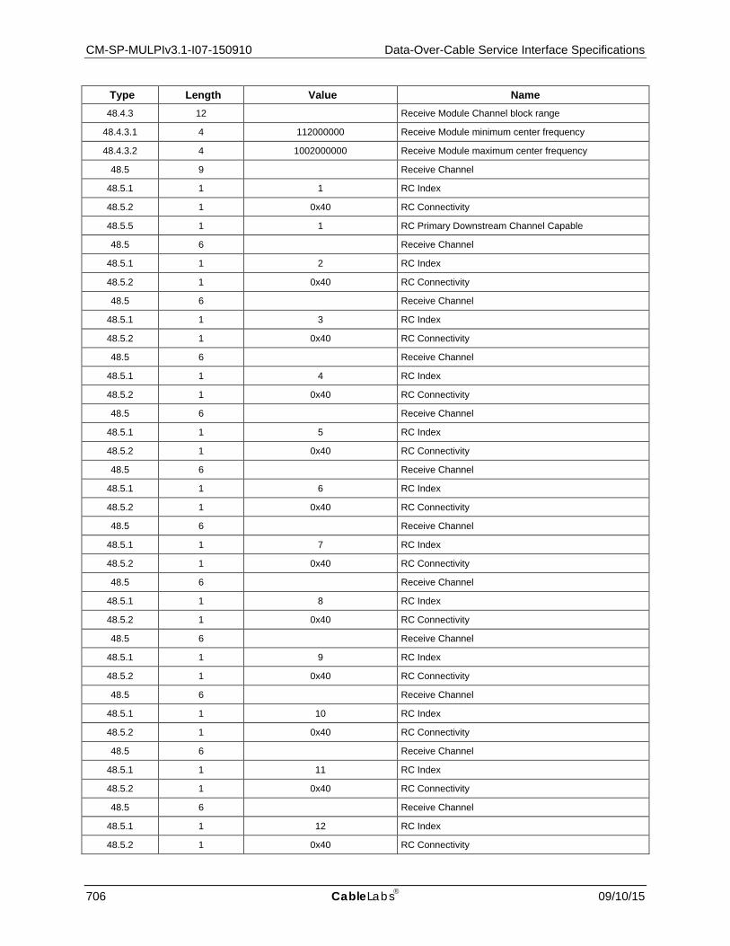


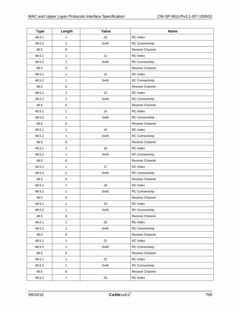


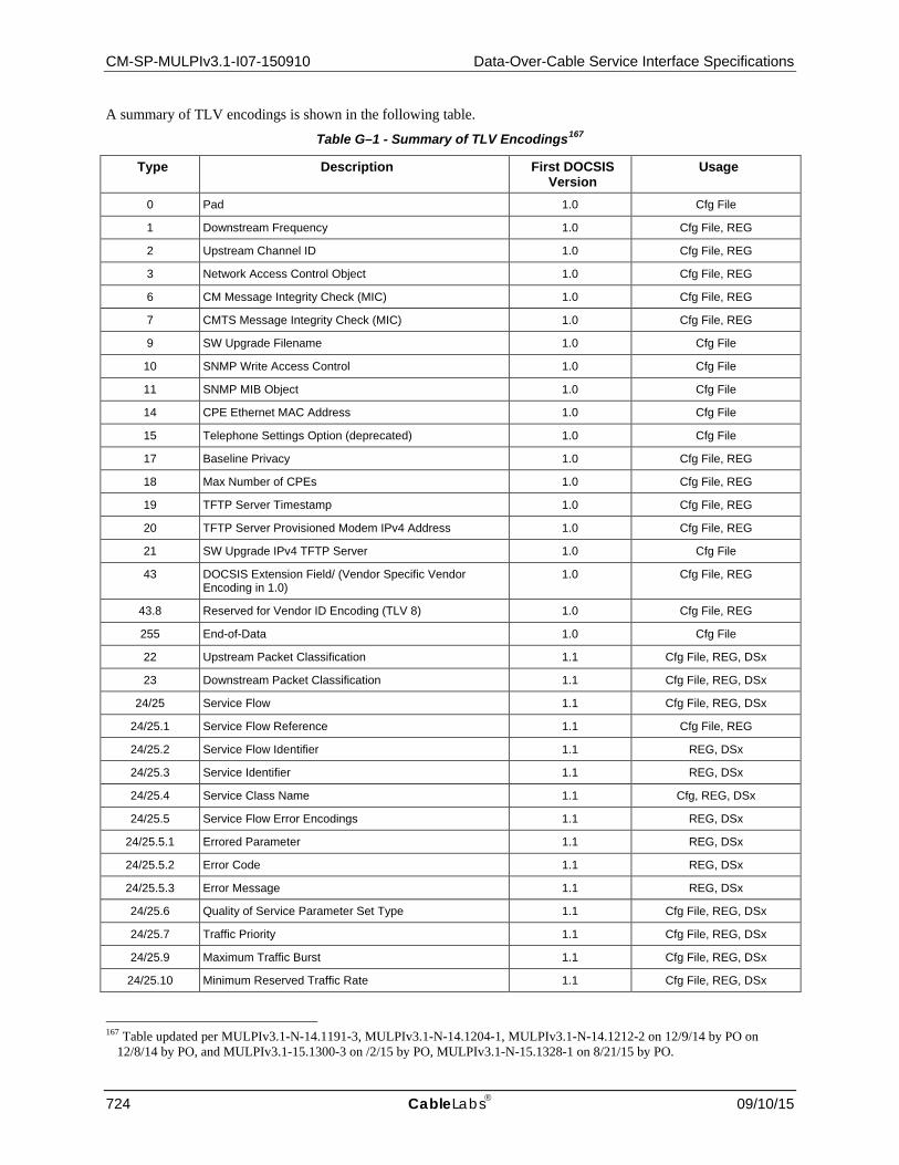


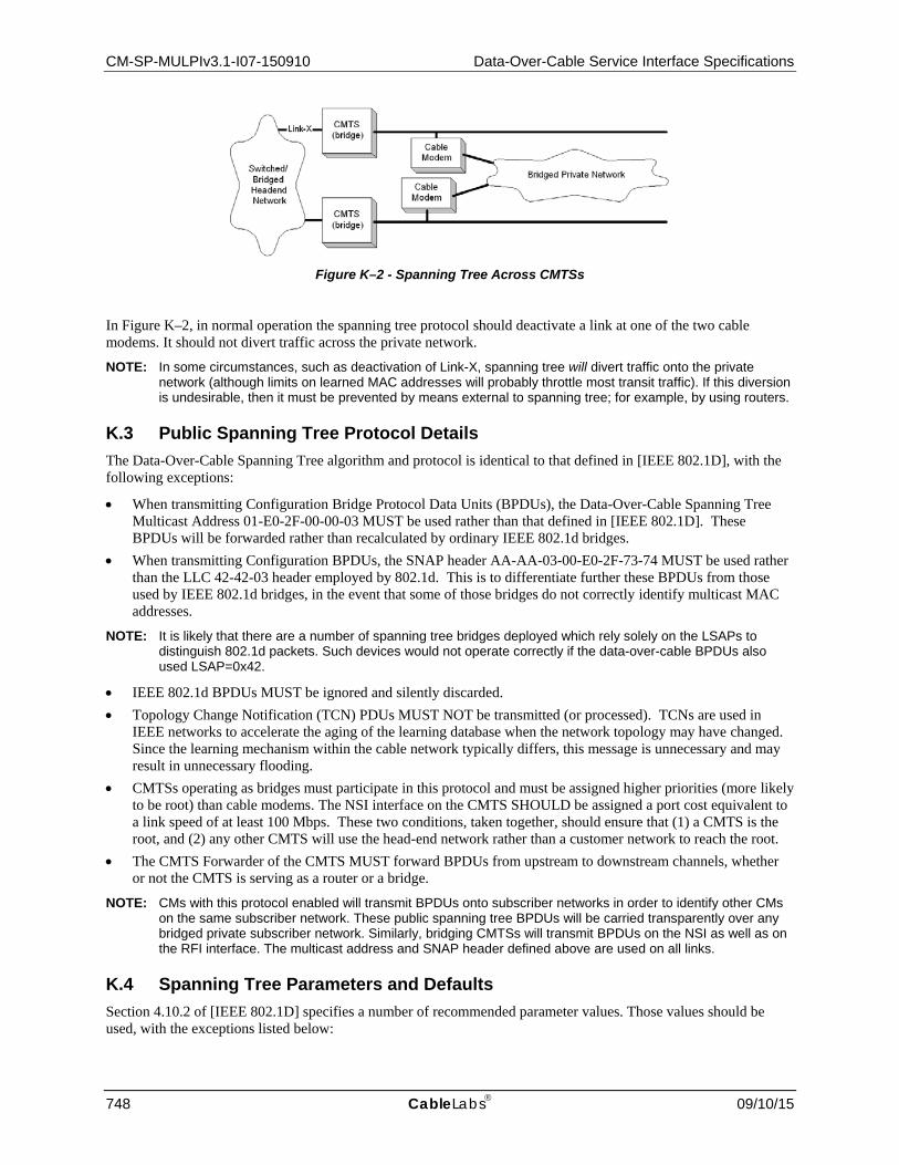


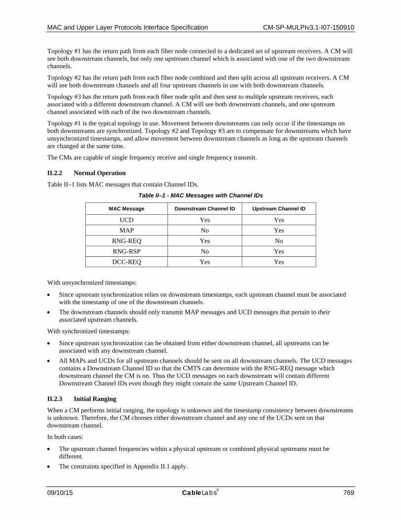


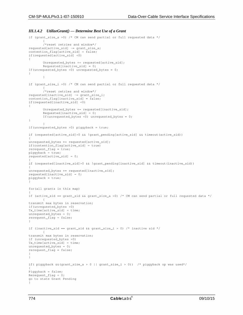


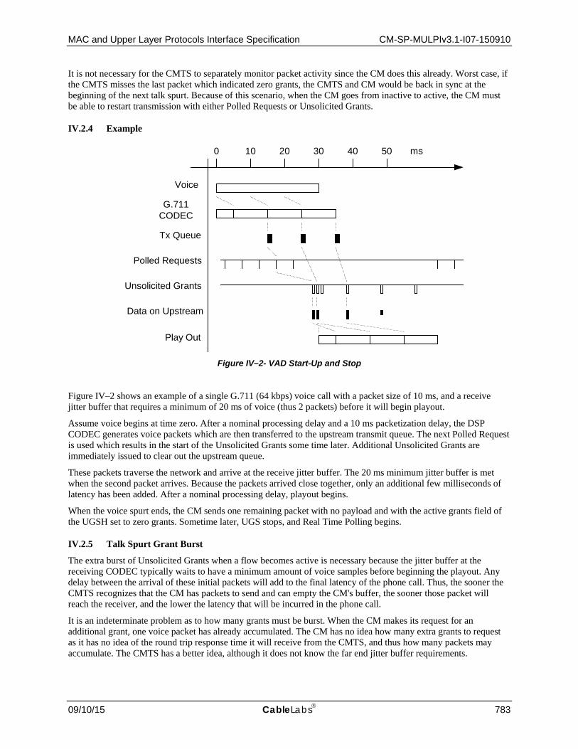
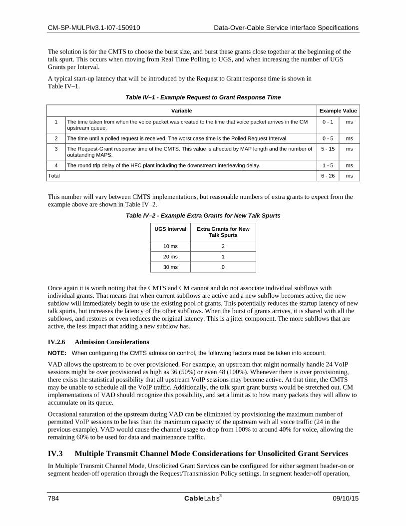


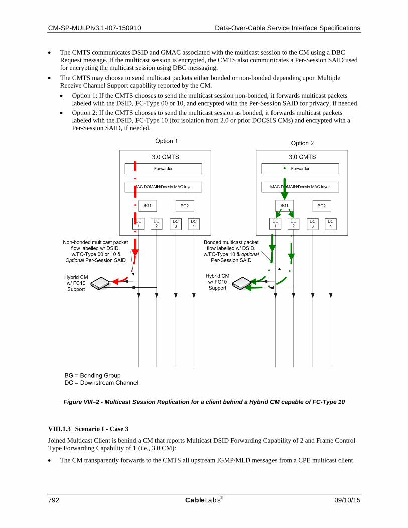


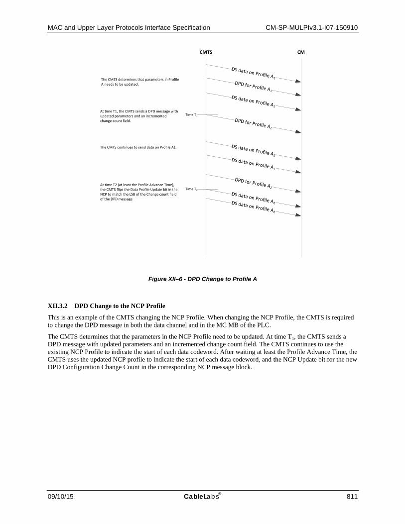


Related Documents