DOCSIS 3.0 Downstream Bonding The DOCSIS 3.0 Downstream Bonding feature helps cable operators offer new, more bandwidth-intensive services by adding one or more additional downstream quadrature amplitude modulation (QAM) channels to the standard broadband DOCSIS system. Finding Feature Information Your software release may not support all the features documented in this module. For the latest feature information and caveats, see the release notes for your platform and software release. To find information about the features documented in this module, and to see a list of the releases in which each feature is supported, see the Feature Information Table at the end of this document. Use Cisco Feature Navigator to find information about platform support and Cisco software image support. To access Cisco Feature Navigator, go to http://tools.cisco.com/ITDIT/CFN/. An account on http:// www.cisco.com/ is not required. • Hardware Compatibility Matrix for Cisco cBR Series Routers, page 1 • Information About DOCSIS 3.0 Downstream Bonding, page 2 • How to Configure RCP and RCC Encoding, page 4 • How to Configure Attribute Masks, page 13 • How to Enable Service Flow Priority in Downstream Extender Header, page 17 • Enabling Verbose Reporting for Receive Channel Profiles, page 20 • Configuration Example for an RCC Template, page 20 • Additional References, page 22 • Feature Information for DOCSIS 3.0 Downstream Bonding , page 22 Hardware Compatibility Matrix for Cisco cBR Series Routers The hardware components introduced in a given Cisco IOS-XE Release are supported in all subsequent releases unless otherwise specified. Note Cisco cBR Converged Broadband Routers Layer 2 and DOCSIS 3.0 Configuration Guide 1

Welcome message from author
This document is posted to help you gain knowledge. Please leave a comment to let me know what you think about it! Share it to your friends and learn new things together.
Transcript
DOCSIS 3.0 Downstream Bonding
The DOCSIS 3.0 Downstream Bonding feature helps cable operators offer new, more bandwidth-intensiveservices by adding one or more additional downstream quadrature amplitude modulation (QAM) channelsto the standard broadband DOCSIS system.
Finding Feature Information
Your software release may not support all the features documented in this module. For the latest featureinformation and caveats, see the release notes for your platform and software release. To find informationabout the features documented in this module, and to see a list of the releases in which each feature issupported, see the Feature Information Table at the end of this document.
Use Cisco Feature Navigator to find information about platform support and Cisco software image support.To access Cisco Feature Navigator, go to http://tools.cisco.com/ITDIT/CFN/. An account on http://www.cisco.com/ is not required.
• Hardware Compatibility Matrix for Cisco cBR Series Routers, page 1
• Information About DOCSIS 3.0 Downstream Bonding, page 2
• How to Configure RCP and RCC Encoding, page 4
• How to Configure Attribute Masks, page 13
• How to Enable Service Flow Priority in Downstream Extender Header, page 17
• Enabling Verbose Reporting for Receive Channel Profiles, page 20
• Configuration Example for an RCC Template, page 20
• Additional References, page 22
• Feature Information for DOCSIS 3.0 Downstream Bonding , page 22
Hardware Compatibility Matrix for Cisco cBR Series Routers
The hardware components introduced in a given Cisco IOS-XE Release are supported in all subsequentreleases unless otherwise specified.
Note
Cisco cBR Converged Broadband Routers Layer 2 and DOCSIS 3.0 Configuration Guide 1
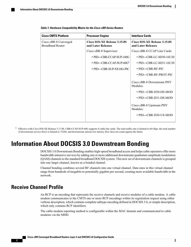
Table 1: Hardware Compatibility Matrix for the Cisco cBR Series Routers
Interface CardsProcessor EngineCisco CMTS Platform
Cisco IOS-XE Release 3.15.0Sand Later Releases
Cisco cBR-8 CCAP Line Cards:
• PID—CBR-LC-8D30-16U30
• PID—CBR-LC-8D31-16U30
• PID—CBR-RF-PIC
• PID—CBR-RF-PROT-PIC
Cisco cBR-8 Downstream PHYModules:
• PID—CBR-D30-DS-MOD
• PID—CBR-D31-DS-MOD
Cisco cBR-8 Upstream PHYModules:
• PID—CBR-D30-US-MOD
Cisco IOS-XE Release 3.15.0Sand Later Releases
Cisco cBR-8 Supervisor:
• PID—CBR-CCAP-SUP-160G
• PID—CBR-CCAP-SUP-60G1
• PID—CBR-SUP-8X10G-PIC
Cisco cBR-8 ConvergedBroadband Router
1 Effective with Cisco IOS-XE Release 3.17.0S, CBR-CCAP-SUP-60G supports 8 cable line cards. The total traffic rate is limited to 60 Gbps, the total numberof downstream service flows is limited to 72268, and downstream unicast low-latency flow does not count against the limits.
Information About DOCSIS 3.0 Downstream BondingDOCSIS 3.0 DownstreamBonding enables high-speed broadband access and helps cable operators offer morebandwidth-intensive services by adding one or more additional downstream quadrature amplitude modulation(QAM) channels to the standard broadband DOCSIS system. This new set of downstream channels is groupedinto one larger channel, known as a bonded channel.
Channel bonding combines several RF channels into one virtual channel. Data rates in this virtual channelrange from hundreds of megabits to potentially gigabits per second, creating more available bandwidth in thenetwork.
Receive Channel ProfileAn RCP is an encoding that represents the receive channels and receive modules of a cable modem. A cablemodem communicates to the CMTS one or more RCP encodings within its registration request using eitherverbose description, which contains complete subtype encoding defined in DOCSIS 3.0, or simple description,which only contains RCP identifiers.
The cable modem reporting method is configurable within the MAC domain and communicated to cablemodems via the MDD.
Cisco cBR Converged Broadband Routers Layer 2 and DOCSIS 3.0 Configuration Guide2
DOCSIS 3.0 Downstream BondingInformation About DOCSIS 3.0 Downstream Bonding
Youmust define an RCP-ID to describe the cable modem's capabilities for that RCP-ID and to input informationabout cable modems which are not defined on the system. Once configured the RCP-ID is available to theentire system since it is not meant to be card specific or mac-domain specific. The path selection moduleensures that the RCP ID is accurately transmitted as part of the RCC profile.
The CableLabs MULPI specification defines standard RCPs which are automatically created by the CMTS.
Receive Channel ConfigurationA cable modem reports its ability to receive multiple channels with one or more RCP encodings in a REG-REQor REG-REQ-MP message. Each receive channel profile describes a logical representation of the cablemodem’s downstream physical layer in terms of receive channels (RCs) and receive modules (RMs). TheCMTS initially configures the cable modem’s receive channels and receive modules with an RCC encodingin the registration response.
This feature supports any arbitrary RCP ID configuration and receive channel configuration on a Cisco cBRSeries Converged Broadband Router.
RCC TemplateYou can configure one or more RCC templates for an RCP. An RCC template configures the physical layercomponents described by an RCP, including receive modules and receive channels to specific downstreamfrequencies. The template also specifies the interconnections among receive modules, or between a receivemodule and a receive channel. An RCC template can be associated only to the cable interface (MAC domain).
A cable modem's RCP ID is matched with an RCC, when RCC templates are configured. A cable modem'sRCP ID may be matched with an RCC generated by an RCC template when RCC templates are configured.The path selection module ensures that the RCP ID that is transmitted as part of the RCC profile is accurate.
At time of registration, if there are multiple valid RCCs that can be assigned to the CM after going throughthe sequence of checks outlined in the CableLabsMULPI specifications then the RCCwith the most channelswill be the one selected. If there are multiple valid RCCs of equal size then the RCC with the least amount ofcable modems will be selected.
Channel AssignmentThe CMTS assigns a receive channel configuration encoding to a DOCSIS 3.0-certified cable modem operatingin a Multiple Receive Channel (MRC) mode during cable modem registration.
With the implementation of this feature, the DOCSIS 3.0-certified cablemodem reports its receiving capabilitiesand characteristics using the receive channel profile type, length, value (TLV) list in the registration requestmessage. Based on this report, the CMTS assigns an RCC encoding that is compatible with the reported RCP.
Cablemodems operating inMRCmode are assigned an RCC encoding associatedwith an RCP. RCC encodingsmay be derived from RCC templates or from a wideband-cable interface configuration.
An RCC encoding can also be derived from a wideband interface configuration.
Cisco cBR Converged Broadband Routers Layer 2 and DOCSIS 3.0 Configuration Guide 3
DOCSIS 3.0 Downstream BondingReceive Channel Configuration
Downstream Traffic ForwardingDOCSIS 3.0 introduces the concept of assigning downstream service flows of cable modems, which areoperating in anMRCmode, to downstream (DS) channels or bonding groups. Forwarding interfaces assignedto service flows (SFs) can be either DS channel interfaces (integrated cable interfaces) or downstream bondinggroups (wideband interfaces).
Valid interfaces that are available for SF assignment must be a subset of the cable modem’s assigned RCCencoding.
Note
Service Flow Priority in Downstream Extended HeaderStarting fromCisco IOS-XERelease 3.17.0S, the service flow priority in downstream extended header featureis supported on Cisco cBR-8 Converged Broadband Router.
The purpose of the feature is to be able to reflect the traffic priority of downstream packets into the DOCSISextended header. The priority is derived from the service flow that the packet is mapped to. Priority refers tothe service flow priority specified in the CM configuration file, or the Cisco CMTS service class configuration.
The service flow priority can be set using cable modem configuration file, or dynamic configuration.
By default, this feature is disabled on Cisco cBR-8 router, user can use cable service flow priority commandto enable this feature.
How to Configure RCP and RCC EncodingThe following tasks describe how to configure a receive channel profile and configuration encoding for areceive channel profile:
Configuring the RCP IDYou must configure the RCP IDs with the cable modem capabilities that are not defined in the CMTS. Thisis done to supplement the standard MULPI RCP IDs already created by the CMTS.
Before You Begin
Restrictions
The configurations are subject to RCC Templates and RCP Interactions as follows:
• RCC templates can only be created for an RCP that is already defined on the system. By default thesystem will contain the RCPs that are specified in the MULPI spec.
• When defining RCC templates for a particular RCP, error checking will be done to ensure that theinformation being configured in the RCC template does not violate the corresponding RCP information.For example, if the RCP information indicates that there are 2 receive modules then the RCC templateconfiguration will not allow the user to configure more than 2 modules.
Cisco cBR Converged Broadband Routers Layer 2 and DOCSIS 3.0 Configuration Guide4
DOCSIS 3.0 Downstream BondingDownstream Traffic Forwarding
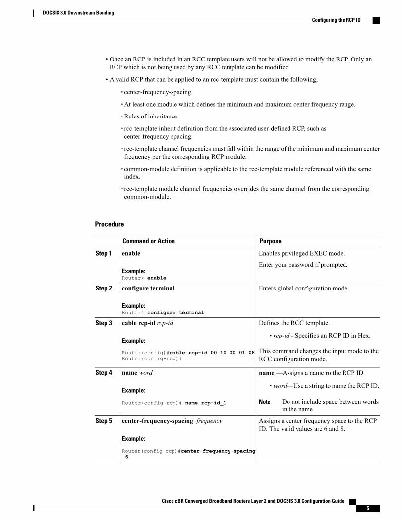
• Once an RCP is included in an RCC template users will not be allowed to modify the RCP. Only anRCP which is not being used by any RCC template can be modified
• A valid RCP that can be applied to an rcc-template must contain the following;
◦center-frequency-spacing
◦At least one module which defines the minimum and maximum center frequency range.
◦Rules of inheritance.
◦rcc-template inherit definition from the associated user-defined RCP, such ascenter-frequency-spacing.
◦rcc-template channel frequencies must fall within the range of the minimum and maximum centerfrequency per the corresponding RCP module.
◦common-module definition is applicable to the rcc-template module referenced with the sameindex.
◦rcc-template module channel frequencies overrides the same channel from the correspondingcommon-module.
Procedure
PurposeCommand or Action
Enables privileged EXEC mode.enableStep 1
Example:Router> enable
Enter your password if prompted.
Enters global configuration mode.configure terminal
Example:Router# configure terminal
Step 2
Defines the RCC template.cable rcp-id rcp-idStep 3
Example:
Router(config)#cable rcp-id 00 10 00 01 08Router(config-rcp)#
• rcp-id - Specifies an RCP ID in Hex.
This command changes the input mode to theRCC configuration mode.
name—Assigns a name ro the RCP IDname word
Example:
Router(config-rcp)# name rcp-id_1
Step 4
• word—Use a string to name the RCP ID.
Do not include space between wordsin the name
Note
Assigns a center frequency space to the RCPID. The valid values are 6 and 8.
center-frequency-spacing frequency
Example:
Router(config-rcp)#center-frequency-spacing6
Step 5
Cisco cBR Converged Broadband Routers Layer 2 and DOCSIS 3.0 Configuration Guide 5
DOCSIS 3.0 Downstream BondingConfiguring the RCP ID
PurposeCommand or Action
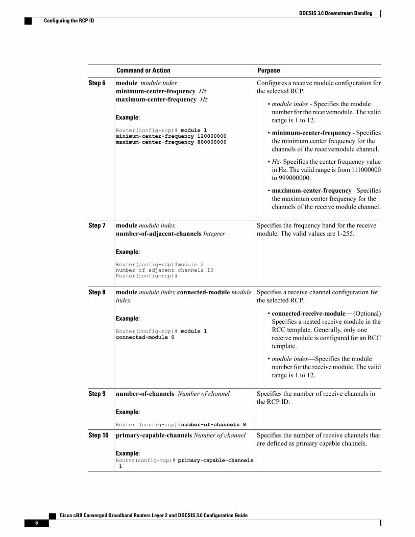
Configures a receive module configuration forthe selected RCP.
module module indexminimum-center-frequency Hzmaximum-center-frequency Hz
Step 6
• module index - Specifies the modulenumber for the receivemodule. The validrange is 1 to 12.Example:
Router(config-rcp)# module 1 • minimum-center-frequency - Specifiesthe minimum center frequency for thechannels of the receivemodule channel.
minimum-center-frequency 120000000maximum-center-frequency 800000000
• Hz- Specifies the center frequency valuein Hz. The valid range is from 111000000to 999000000.
• maximum-center-frequency - Specifiesthe maximum center frequency for thechannels of the receive module channel.
Specifies the frequency band for the receivemodule. The valid values are 1-255.
module module indexnumber-of-adjacent-channels Integrer
Example:
Router(config-rcp)#module 2
Step 7
number-of-adjacent-channels 10Router(config-rcp)#
Specifies a receive channel configuration forthe selected RCP.
module module index connected-module moduleindex
Example:
Router(config-rcp)# module 1connected-module 0
Step 8
• connected-receive-module— (Optional)Specifies a nested receive module in theRCC template. Generally, only onereceive module is configured for an RCCtemplate.
• module index—Specifies the modulenumber for the receive module. The validrange is 1 to 12.
Specifies the number of receive channels inthe RCP ID.
number-of-channels Number of channel
Example:
Router (config-rcp)#number-of-channels 8
Step 9
Specifies the number of receive channels thatare defined as primary capable channels.
primary-capable-channels Number of channel
Example:Router(config-rcp)# primary-capable-channels1
Step 10
Cisco cBR Converged Broadband Routers Layer 2 and DOCSIS 3.0 Configuration Guide6
DOCSIS 3.0 Downstream BondingConfiguring the RCP ID
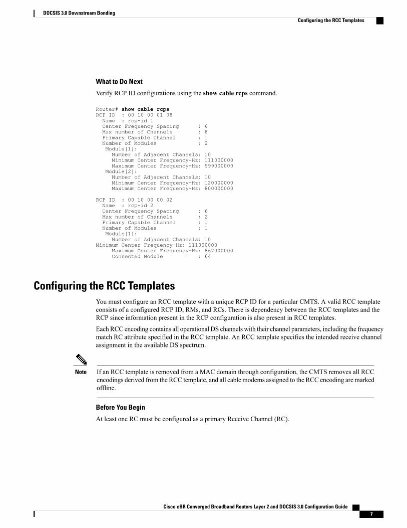
What to Do Next
Verify RCP ID configurations using the show cable rcps command.
Router# show cable rcpsRCP ID : 00 10 00 01 08Name : rcp-id 1Center Frequency Spacing : 6Max number of Channels : 8Primary Capable Channel : 1Number of Modules : 2Module[1]:Number of Adjacent Channels: 10Minimum Center Frequency-Hz: 111000000Maximum Center Frequency-Hz: 999000000
Module[2]:Number of Adjacent Channels: 10Minimum Center Frequency-Hz: 120000000Maximum Center Frequency-Hz: 800000000
RCP ID : 00 10 00 00 02Name : rcp-id 2Center Frequency Spacing : 6Max number of Channels : 2Primary Capable Channel : 1Number of Modules : 1Module[1]:Number of Adjacent Channels: 10
Minimum Center Frequency-Hz: 111000000Maximum Center Frequency-Hz: 867000000Connected Module : 64
Configuring the RCC TemplatesYou must configure an RCC template with a unique RCP ID for a particular CMTS. A valid RCC templateconsists of a configured RCP ID, RMs, and RCs. There is dependency between the RCC templates and theRCP since information present in the RCP configuration is also present in RCC templates.
Each RCC encoding contains all operational DS channels with their channel parameters, including the frequencymatch RC attribute specified in the RCC template. An RCC template specifies the intended receive channelassignment in the available DS spectrum.
If an RCC template is removed from a MAC domain through configuration, the CMTS removes all RCCencodings derived from the RCC template, and all cable modems assigned to the RCC encoding are markedoffline.
Note
Before You Begin
At least one RC must be configured as a primary Receive Channel (RC).
Cisco cBR Converged Broadband Routers Layer 2 and DOCSIS 3.0 Configuration Guide 7
DOCSIS 3.0 Downstream BondingConfiguring the RCC Templates
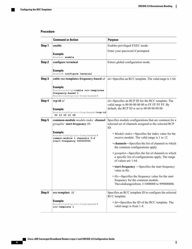
Procedure
PurposeCommand or Action
Enables privileged EXEC mode.enableStep 1
Example:Router> enable
Enter your password if prompted.
Enters global configuration mode.configure terminal
Example:Router# configure terminal
Step 2
id—Specifies an RCC template. The valid range is 1-64.cable rcc-templates frequency-based id
Example:Router(config)#cable rcc-templatesfrequency-based 1Router(config-rcc-freq-based)#
Step 3
id—Specifies an RCP ID for the RCC template. Thevalid range is 00 00 00 00 00 to FF FF FF FF. Bydefault, the RCP ID is set to 00 00 00 00 00.
rcp-id id
Example:Router(config-rcc-freq-based)#rcp-id00 10 00 01 08
Step 4
Specifies module configurations that are common for aselected set of channels assigned to the selected RCPID.
common-module module-index channelgrouplist start-frequency Hz
Example:Router(config-rcc-freq-based)#common-module 1 channels 0-6start-frequency 555000000
Step 5
• Module-index—Specifies the index value for thereceive module. The valid range is 1 to 12.
• channels—Specifies the list of channels to whichthe common configurations apply.
• grouplist—Specifies the list of channels to whicha specific list of configurations apply. The rangeof values are 1-64.
• start-frequency—Specifies the start frequencyvalue in Hz.
• Hz—Specifies the frequency value for the startfrequency for the common module.Thevalidrangeisfrom 111000000 to 999000000.
Specifies an RCC template ID to configure the selectedRCC template.
rcc-template Id
Example:Router(config-rcc-freq-based)#rcc-template 1
Step 6
• Id—Specifies the ID of the RCC template. Thevalid range is from 1-8.
Cisco cBR Converged Broadband Routers Layer 2 and DOCSIS 3.0 Configuration Guide8
DOCSIS 3.0 Downstream BondingConfiguring the RCC Templates
PurposeCommand or Action
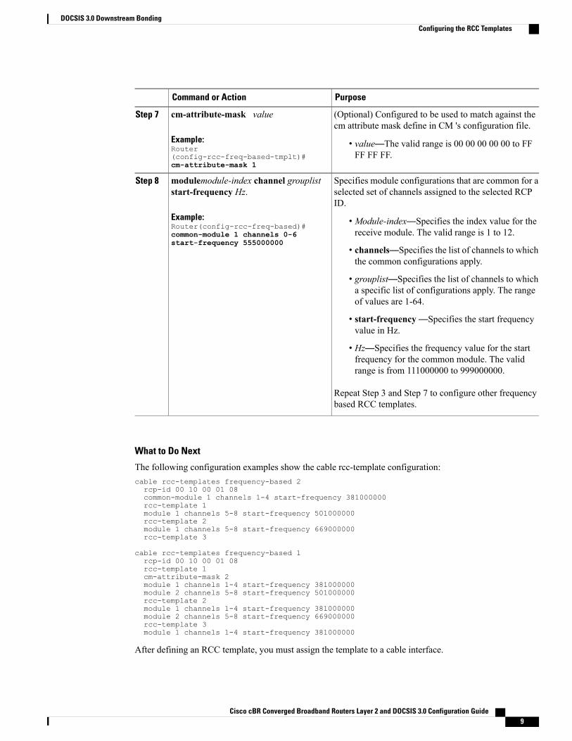
(Optional) Configured to be used to match against thecm attribute mask define in CM 's configuration file.
cm-attribute-mask value
Example:Router(config-rcc-freq-based-tmplt)#cm-attribute-mask 1
Step 7
• value—The valid range is 00 00 00 00 00 to FFFF FF FF.
Specifies module configurations that are common for aselected set of channels assigned to the selected RCPID.
modulemodule-index channel groupliststart-frequency Hz.
Example:Router(config-rcc-freq-based)#common-module 1 channels 0-6start-frequency 555000000
Step 8
• Module-index—Specifies the index value for thereceive module. The valid range is 1 to 12.
• channels—Specifies the list of channels to whichthe common configurations apply.
• grouplist—Specifies the list of channels to whicha specific list of configurations apply. The rangeof values are 1-64.
• start-frequency—Specifies the start frequencyvalue in Hz.
• Hz—Specifies the frequency value for the startfrequency for the common module. The validrange is from 111000000 to 999000000.
Repeat Step 3 and Step 7 to configure other frequencybased RCC templates.
What to Do Next
The following configuration examples show the cable rcc-template configuration:cable rcc-templates frequency-based 2rcp-id 00 10 00 01 08common-module 1 channels 1-4 start-frequency 381000000rcc-template 1module 1 channels 5-8 start-frequency 501000000rcc-template 2module 1 channels 5-8 start-frequency 669000000rcc-template 3
cable rcc-templates frequency-based 1rcp-id 00 10 00 01 08rcc-template 1cm-attribute-mask 2module 1 channels 1-4 start-frequency 381000000module 2 channels 5-8 start-frequency 501000000rcc-template 2module 1 channels 1-4 start-frequency 381000000module 2 channels 5-8 start-frequency 669000000rcc-template 3module 1 channels 1-4 start-frequency 381000000
After defining an RCC template, you must assign the template to a cable interface.
Cisco cBR Converged Broadband Routers Layer 2 and DOCSIS 3.0 Configuration Guide 9
DOCSIS 3.0 Downstream BondingConfiguring the RCC Templates
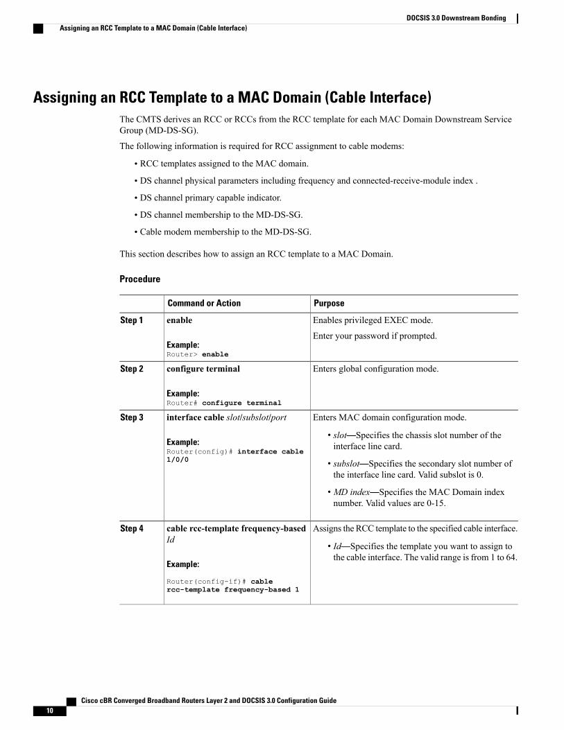
Assigning an RCC Template to a MAC Domain (Cable Interface)The CMTS derives an RCC or RCCs from the RCC template for each MAC Domain Downstream ServiceGroup (MD-DS-SG).
The following information is required for RCC assignment to cable modems:
• RCC templates assigned to the MAC domain.
• DS channel physical parameters including frequency and connected-receive-module index .
• DS channel primary capable indicator.
• DS channel membership to the MD-DS-SG.
• Cable modem membership to the MD-DS-SG.
This section describes how to assign an RCC template to a MAC Domain.
Procedure
PurposeCommand or Action
Enables privileged EXEC mode.enableStep 1
Example:Router> enable
Enter your password if prompted.
Enters global configuration mode.configure terminal
Example:Router# configure terminal
Step 2
Enters MAC domain configuration mode.interface cable slot/subslot/portStep 3
Example:Router(config)# interface cable1/0/0
• slot—Specifies the chassis slot number of theinterface line card.
• subslot—Specifies the secondary slot number ofthe interface line card. Valid subslot is 0.
• MD index—Specifies the MAC Domain indexnumber. Valid values are 0-15.
Assigns the RCC template to the specified cable interface.cable rcc-template frequency-basedId
Step 4
• Id—Specifies the template you want to assign tothe cable interface. The valid range is from 1 to 64.
Example:
Router(config-if)# cablercc-template frequency-based 1
Cisco cBR Converged Broadband Routers Layer 2 and DOCSIS 3.0 Configuration Guide10
DOCSIS 3.0 Downstream BondingAssigning an RCC Template to a MAC Domain (Cable Interface)
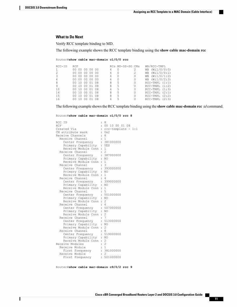
What to Do Next
Verify RCC template binding to MD.
The following example shows the RCC template binding using the show cable mac-domain rcc
Router#show cable mac-domain c1/0/0 rcc
RCC-ID RCP RCs MD-DS-SG CMs WB/RCC-TMPL1 00 00 00 00 00 4 0 2 WB (Wi1/0/0:0)2 00 00 00 00 00 4 0 2 WB (Wi1/0/0:1)3 00 00 00 00 00 4 0 0 WB (Wi1/0/1:2)4 00 00 00 00 00 4 0 0 WB (Wi1/0/2:3)8 00 10 00 01 08 8 5 0 RCC-TMPL (1:1)9 00 10 00 01 08 8 5 0 RCC-TMPL (1:2)10 00 10 00 01 08 4 5 0 RCC-TMPL (1:3)14 00 10 00 01 08 8 5 0 RCC-TMPL (2:1)15 00 10 00 01 08 8 5 0 RCC-TMPL (2:2)16 00 10 00 01 08 4 5 0 RCC-TMPL (2:3)
The following example shows the RCC template binding using the show cablemac-domain rcc id command.
Router#show cable mac-domain c1/0/0 rcc 8
RCC ID : 8RCP : 00 10 00 01 08Created Via : rcc-template - 1:1CM attribute mask : 0x2Receive Channels : 8Receive Channel : 1Center Frequency : 381000000Primary Capability : YESReceive Module Conn : 1
Receive Channel : 2Center Frequency : 387000000Primary Capability : NOReceive Module Conn : 1
Receive Channel : 3Center Frequency : 393000000Primary Capability : NOReceive Module Conn : 1
Receive Channel : 4Center Frequency : 399000000Primary Capability : NOReceive Module Conn : 1
Receive Channel : 5Center Frequency : 501000000Primary Capability : NOReceive Module Conn : 2
Receive Channel : 6Center Frequency : 507000000Primary Capability : NOReceive Module Conn : 2
Receive Channel : 7Center Frequency : 513000000Primary Capability : NOReceive Module Conn : 2
Receive Channel : 8Center Frequency : 519000000Primary Capability : NOReceive Module Conn : 2
Receive Modules : 2Receive Module : 1First Frequency : 381000000
Receive Module : 2First Frequency : 501000000
Router#show cable mac-domain c9/0/2 rcc 9
Cisco cBR Converged Broadband Routers Layer 2 and DOCSIS 3.0 Configuration Guide 11
DOCSIS 3.0 Downstream BondingAssigning an RCC Template to a MAC Domain (Cable Interface)
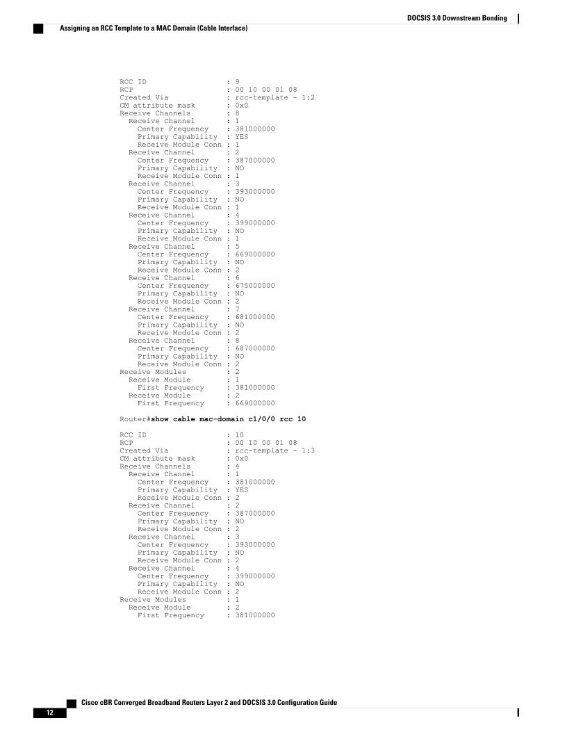
RCC ID : 9RCP : 00 10 00 01 08Created Via : rcc-template - 1:2CM attribute mask : 0x0Receive Channels : 8Receive Channel : 1Center Frequency : 381000000Primary Capability : YESReceive Module Conn : 1
Receive Channel : 2Center Frequency : 387000000Primary Capability : NOReceive Module Conn : 1
Receive Channel : 3Center Frequency : 393000000Primary Capability : NOReceive Module Conn : 1
Receive Channel : 4Center Frequency : 399000000Primary Capability : NOReceive Module Conn : 1
Receive Channel : 5Center Frequency : 669000000Primary Capability : NOReceive Module Conn : 2
Receive Channel : 6Center Frequency : 675000000Primary Capability : NOReceive Module Conn : 2
Receive Channel : 7Center Frequency : 681000000Primary Capability : NOReceive Module Conn : 2
Receive Channel : 8Center Frequency : 687000000Primary Capability : NOReceive Module Conn : 2
Receive Modules : 2Receive Module : 1First Frequency : 381000000
Receive Module : 2First Frequency : 669000000
Router#show cable mac-domain c1/0/0 rcc 10
RCC ID : 10RCP : 00 10 00 01 08Created Via : rcc-template - 1:3CM attribute mask : 0x0Receive Channels : 4Receive Channel : 1Center Frequency : 381000000Primary Capability : YESReceive Module Conn : 2
Receive Channel : 2Center Frequency : 387000000Primary Capability : NOReceive Module Conn : 2
Receive Channel : 3Center Frequency : 393000000Primary Capability : NOReceive Module Conn : 2
Receive Channel : 4Center Frequency : 399000000Primary Capability : NOReceive Module Conn : 2
Receive Modules : 1Receive Module : 2First Frequency : 381000000
Cisco cBR Converged Broadband Routers Layer 2 and DOCSIS 3.0 Configuration Guide12
DOCSIS 3.0 Downstream BondingAssigning an RCC Template to a MAC Domain (Cable Interface)
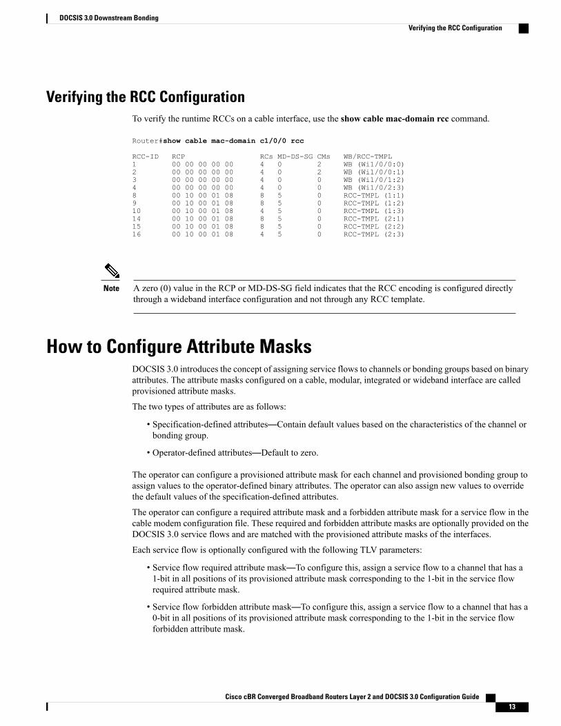
Verifying the RCC ConfigurationTo verify the runtime RCCs on a cable interface, use the show cable mac-domain rcc command.
Router#show cable mac-domain c1/0/0 rcc
RCC-ID RCP RCs MD-DS-SG CMs WB/RCC-TMPL1 00 00 00 00 00 4 0 2 WB (Wi1/0/0:0)2 00 00 00 00 00 4 0 2 WB (Wi1/0/0:1)3 00 00 00 00 00 4 0 0 WB (Wi1/0/1:2)4 00 00 00 00 00 4 0 0 WB (Wi1/0/2:3)8 00 10 00 01 08 8 5 0 RCC-TMPL (1:1)9 00 10 00 01 08 8 5 0 RCC-TMPL (1:2)10 00 10 00 01 08 4 5 0 RCC-TMPL (1:3)14 00 10 00 01 08 8 5 0 RCC-TMPL (2:1)15 00 10 00 01 08 8 5 0 RCC-TMPL (2:2)16 00 10 00 01 08 4 5 0 RCC-TMPL (2:3)
A zero (0) value in the RCP or MD-DS-SG field indicates that the RCC encoding is configured directlythrough a wideband interface configuration and not through any RCC template.
Note
How to Configure Attribute MasksDOCSIS 3.0 introduces the concept of assigning service flows to channels or bonding groups based on binaryattributes. The attribute masks configured on a cable, modular, integrated or wideband interface are calledprovisioned attribute masks.
The two types of attributes are as follows:
• Specification-defined attributes—Contain default values based on the characteristics of the channel orbonding group.
• Operator-defined attributes—Default to zero.
The operator can configure a provisioned attribute mask for each channel and provisioned bonding group toassign values to the operator-defined binary attributes. The operator can also assign new values to overridethe default values of the specification-defined attributes.
The operator can configure a required attribute mask and a forbidden attribute mask for a service flow in thecable modem configuration file. These required and forbidden attribute masks are optionally provided on theDOCSIS 3.0 service flows and are matched with the provisioned attribute masks of the interfaces.
Each service flow is optionally configured with the following TLV parameters:
• Service flow required attribute mask—To configure this, assign a service flow to a channel that has a1-bit in all positions of its provisioned attribute mask corresponding to the 1-bit in the service flowrequired attribute mask.
• Service flow forbidden attribute mask—To configure this, assign a service flow to a channel that has a0-bit in all positions of its provisioned attribute mask corresponding to the 1-bit in the service flowforbidden attribute mask.
Cisco cBR Converged Broadband Routers Layer 2 and DOCSIS 3.0 Configuration Guide 13
DOCSIS 3.0 Downstream BondingVerifying the RCC Configuration
Additionally, in a cable modem-initiated dynamic service request, the cable modem can include a requiredattribute mask and a forbidden attribute mask for a service flow. The CMTS assigns service flows to channelsor bonding groups so that all required attributes are present and no forbidden attributes are present in the cablemodem configuration file.
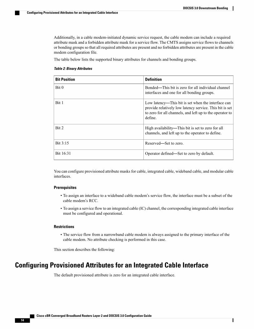
The table below lists the supported binary attributes for channels and bonding groups.
Table 2: Binary Attributes
DefinitionBit Position
Bonded—This bit is zero for all individual channelinterfaces and one for all bonding groups.
Bit 0
Low latency—This bit is set when the interface canprovide relatively low latency service. This bit is setto zero for all channels, and left up to the operator todefine.
Bit 1
High availability—This bit is set to zero for allchannels, and left up to the operator to define.
Bit 2
Reserved—Set to zero.Bit 3:15
Operator defined—Set to zero by default.Bit 16:31
You can configure provisioned attribute masks for cable, integrated cable, wideband cable, and modular cableinterfaces.
Prerequisites
• To assign an interface to a wideband cable modem’s service flow, the interface must be a subset of thecable modem’s RCC.
• To assign a service flow to an integrated cable (IC) channel, the corresponding integrated cable interfacemust be configured and operational.
Restrictions
• The service flow from a narrowband cable modem is always assigned to the primary interface of thecable modem. No attribute checking is performed in this case.
This section describes the following:
Configuring Provisioned Attributes for an Integrated Cable InterfaceThe default provisioned attribute is zero for an integrated cable interface.
Cisco cBR Converged Broadband Routers Layer 2 and DOCSIS 3.0 Configuration Guide14
DOCSIS 3.0 Downstream BondingConfiguring Provisioned Attributes for an Integrated Cable Interface
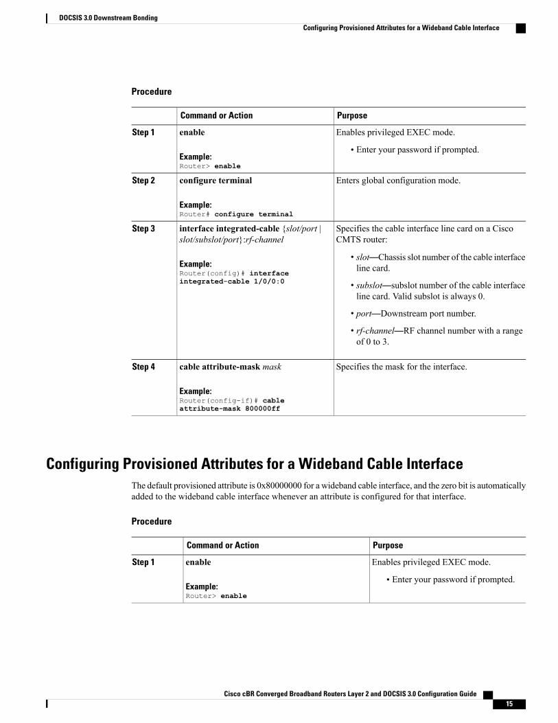
Procedure
PurposeCommand or Action
Enables privileged EXEC mode.enableStep 1
Example:Router> enable
• Enter your password if prompted.
Enters global configuration mode.configure terminal
Example:Router# configure terminal
Step 2
Specifies the cable interface line card on a CiscoCMTS router:
interface integrated-cable {slot/port |slot/subslot/port}:rf-channel
Step 3
Example:Router(config)# interfaceintegrated-cable 1/0/0:0
• slot—Chassis slot number of the cable interfaceline card.
• subslot—subslot number of the cable interfaceline card. Valid subslot is always 0.
• port—Downstream port number.
• rf-channel—RF channel number with a rangeof 0 to 3.
Specifies the mask for the interface.cable attribute-mask mask
Example:Router(config-if)# cableattribute-mask 800000ff
Step 4
Configuring Provisioned Attributes for a Wideband Cable InterfaceThe default provisioned attribute is 0x80000000 for a wideband cable interface, and the zero bit is automaticallyadded to the wideband cable interface whenever an attribute is configured for that interface.
Procedure
PurposeCommand or Action
Enables privileged EXEC mode.enableStep 1
Example:Router> enable
• Enter your password if prompted.
Cisco cBR Converged Broadband Routers Layer 2 and DOCSIS 3.0 Configuration Guide 15
DOCSIS 3.0 Downstream BondingConfiguring Provisioned Attributes for a Wideband Cable Interface
PurposeCommand or Action
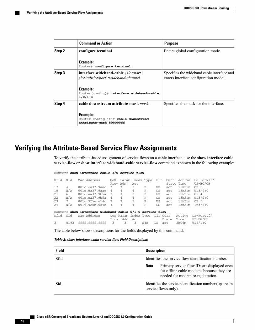
Enters global configuration mode.configure terminal
Example:Router# configure terminal
Step 2
Specifies the wideband cable interface andenters interface configuration mode:
interface wideband-cable {slot/port |slot/subslot/port}:wideband-channel
Example:Router(config)# interface wideband-cable1/0/1:4
Step 3
Specifies the mask for the interface.cable downstream attribute-mask mask
Example:Router(config-if)# cable downstreamattribute-mask 800000ff
Step 4
Verifying the Attribute-Based Service Flow AssignmentsTo verify the attribute-based assignment of service flows on a cable interface, use the show interface cableservice-flow or show interface wideband-cable service-flow command as shown in the following example:
Router# show interface cable 3/0 service-flow
Sfid Sid Mac Address QoS Param Index Type Dir Curr Active DS-ForwIf/Prov Adm Act State Time US-BG/CH
17 4 001c.ea37.9aac 3 3 3 P US act 13h21m CH 318 N/A 001c.ea37.9aac 4 4 4 P DS act 13h21m Wi3/0:021 6 001c.ea37.9b5a 3 3 3 P US act 13h21m CH 422 N/A 001c.ea37.9b5a 4 4 4 P DS act 13h21m Wi3/0:023 7 0016.925e.654c 3 3 3 P US act 13h21m CH 324 N/A 0016.925e.654c 4 4 4 P DS act 13h21m In3/0:0
Router# show interface wideband-cable 5/1:0 service-flowSfid Sid Mac Address QoS Param Index Type Dir Curr Active DS-ForwIf/
Prov Adm Act State Time US-BG/CH3 8193 ffff.ffff.ffff 3 3 3 S(s) DS act 2h06m Wi5/1:0
The table below shows descriptions for the fields displayed by this command:
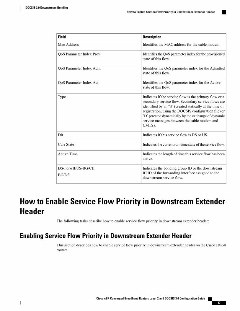
Table 3: show interface cable service-flow Field Descriptions
DescriptionField
Identifies the service flow identification number.
Primary service flow IDs are displayed evenfor offline cable modems because they areneeded for modem re-registration.
Note
Sfid
Identifies the service identification number (upstreamservice flows only).
Sid
Cisco cBR Converged Broadband Routers Layer 2 and DOCSIS 3.0 Configuration Guide16
DOCSIS 3.0 Downstream BondingVerifying the Attribute-Based Service Flow Assignments
DescriptionField
Identifies the MAC address for the cable modem.Mac Address
Identifies the QoS parameter index for the provisionedstate of this flow.
QoS Parameter Index Prov
Identifies the QoS parameter index for the Admittedstate of this flow.
QoS Parameter Index Adm
Identifies the QoS parameter index for the Activestate of this flow.
QoS Parameter Index Act
Indicates if the service flow is the primary flow or asecondary service flow. Secondary service flows areidentified by an “S” (created statically at the time ofregistration, using the DOCSIS configuration file) or“D” (created dynamically by the exchange of dynamicservice messages between the cable modem andCMTS).
Type
Indicates if this service flow is DS or US.Dir
Indicates the current run-time state of the service flow.Curr State
Indicates the length of time this service flow has beenactive.
Active Time
Indicates the bonding group ID or the downstreamRFID of the forwarding interface assigned to thedownstream service flow.
DS-ForwIf/US-BG/CH
BG/DS
How to Enable Service Flow Priority in Downstream ExtenderHeader
The following tasks describe how to enable service flow priority in downstream extender header:
Enabling Service Flow Priority in Downstream Extender HeaderThis section describes how to enable service flow priority in downstream extender header on the Cisco cBR-8routers:
Cisco cBR Converged Broadband Routers Layer 2 and DOCSIS 3.0 Configuration Guide 17
DOCSIS 3.0 Downstream BondingHow to Enable Service Flow Priority in Downstream Extender Header
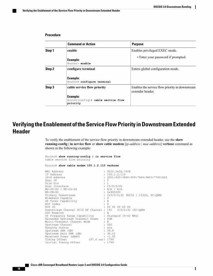
Procedure
PurposeCommand or Action
Enables privileged EXEC mode.enableStep 1
Example:Router> enable
• Enter your password if prompted.
Enters global configuration mode.configure terminal
Example:Router# configure terminal
Step 2
Enables the service flow priority in downstreamextender header.
cable service flow priority
Example:Router(config)# cable service flowpriority
Step 3
Verifying the Enablement of the Service Flow Priority in Downstream ExtendedHeader
To verify the enablement of the service flow priority in downstream extended header, use the showrunning-config | in service flow or show cable modem [ip-address | mac-address] verbose command asshown in the following example:
Router# show running-config | in service flowcable service flow priority
Router# show cable modem 100.1.2.110 verbose
MAC Address : 0025.2e2d.74f8IP Address : 100.1.2.110IPv6 Address : 2001:420:3800:909:7964:98F3:7760:ED2Dual IP : YPrim Sid : 1Host Interface : C3/0/0/U0MD-DS-SG / MD-US-SG : N/A / N/AMD-CM-SG : 0x900000Primary Downstream : In3/0/0:32 (RfId : 12320, SC-QAM)Wideband Capable : YDS Tuner Capability : 8RCP Index : 6RCP ID : 00 00 00 00 00Downstream Channel DCID RF Channel : 191 3/0/0:32 (SC-QAM)UDC Enabled : NUS Frequency Range Capability : Standard (5-42 MHz)Extended Upstream Transmit Power : 0dBMulti-Transmit Channel Mode : NUpstream Channel : US0Ranging Status : staUpstream SNR (dB) : 39.8Upstream Data SNR (dB) : 36.12Received Power (dBmV) : -1.00Timing Offset (97.6 ns): 1799Initial Timing Offset : 1799
Cisco cBR Converged Broadband Routers Layer 2 and DOCSIS 3.0 Configuration Guide18
DOCSIS 3.0 Downstream BondingVerifying the Enablement of the Service Flow Priority in Downstream Extended Header
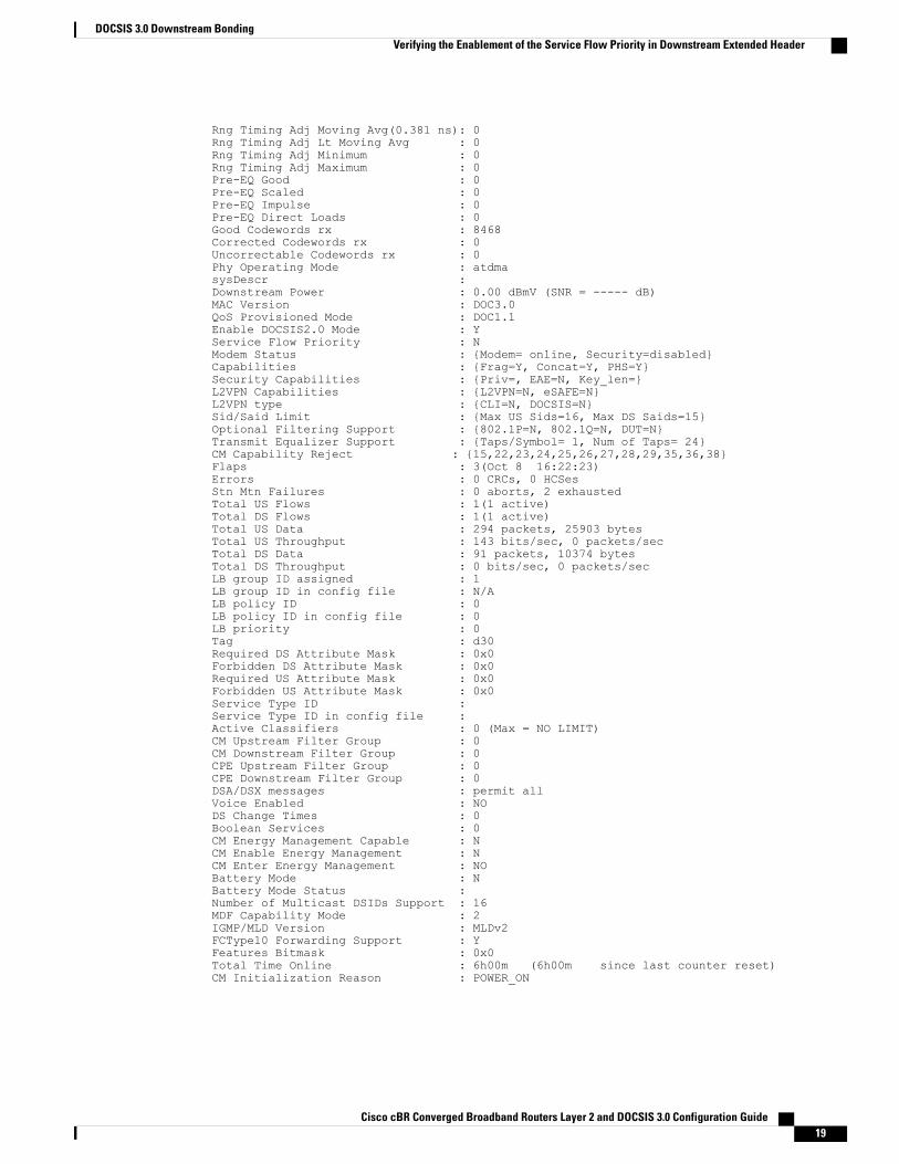
Rng Timing Adj Moving Avg(0.381 ns): 0Rng Timing Adj Lt Moving Avg : 0Rng Timing Adj Minimum : 0Rng Timing Adj Maximum : 0Pre-EQ Good : 0Pre-EQ Scaled : 0Pre-EQ Impulse : 0Pre-EQ Direct Loads : 0Good Codewords rx : 8468Corrected Codewords rx : 0Uncorrectable Codewords rx : 0Phy Operating Mode : atdmasysDescr :Downstream Power : 0.00 dBmV (SNR = ----- dB)MAC Version : DOC3.0QoS Provisioned Mode : DOC1.1Enable DOCSIS2.0 Mode : YService Flow Priority : NModem Status : {Modem= online, Security=disabled}Capabilities : {Frag=Y, Concat=Y, PHS=Y}Security Capabilities : {Priv=, EAE=N, Key_len=}L2VPN Capabilities : {L2VPN=N, eSAFE=N}L2VPN type : {CLI=N, DOCSIS=N}Sid/Said Limit : {Max US Sids=16, Max DS Saids=15}Optional Filtering Support : {802.1P=N, 802.1Q=N, DUT=N}Transmit Equalizer Support : {Taps/Symbol= 1, Num of Taps= 24}CM Capability Reject : {15,22,23,24,25,26,27,28,29,35,36,38}Flaps : 3(Oct 8 16:22:23)Errors : 0 CRCs, 0 HCSesStn Mtn Failures : 0 aborts, 2 exhaustedTotal US Flows : 1(1 active)Total DS Flows : 1(1 active)Total US Data : 294 packets, 25903 bytesTotal US Throughput : 143 bits/sec, 0 packets/secTotal DS Data : 91 packets, 10374 bytesTotal DS Throughput : 0 bits/sec, 0 packets/secLB group ID assigned : 1LB group ID in config file : N/ALB policy ID : 0LB policy ID in config file : 0LB priority : 0Tag : d30Required DS Attribute Mask : 0x0Forbidden DS Attribute Mask : 0x0Required US Attribute Mask : 0x0Forbidden US Attribute Mask : 0x0Service Type ID :Service Type ID in config file :Active Classifiers : 0 (Max = NO LIMIT)CM Upstream Filter Group : 0CM Downstream Filter Group : 0CPE Upstream Filter Group : 0CPE Downstream Filter Group : 0DSA/DSX messages : permit allVoice Enabled : NODS Change Times : 0Boolean Services : 0CM Energy Management Capable : NCM Enable Energy Management : NCM Enter Energy Management : NOBattery Mode : NBattery Mode Status :Number of Multicast DSIDs Support : 16MDF Capability Mode : 2IGMP/MLD Version : MLDv2FCType10 Forwarding Support : YFeatures Bitmask : 0x0Total Time Online : 6h00m (6h00m since last counter reset)CM Initialization Reason : POWER_ON
Cisco cBR Converged Broadband Routers Layer 2 and DOCSIS 3.0 Configuration Guide 19
DOCSIS 3.0 Downstream BondingVerifying the Enablement of the Service Flow Priority in Downstream Extended Header
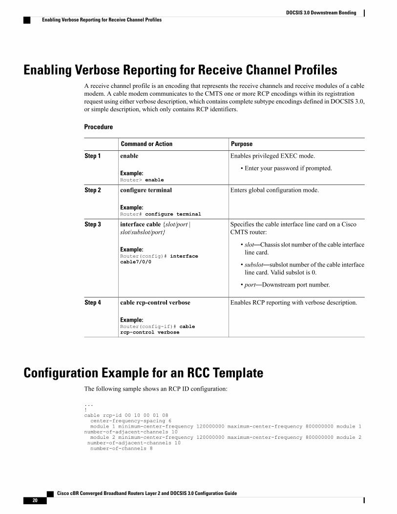
Enabling Verbose Reporting for Receive Channel ProfilesA receive channel profile is an encoding that represents the receive channels and receive modules of a cablemodem. A cable modem communicates to the CMTS one or more RCP encodings within its registrationrequest using either verbose description, which contains complete subtype encodings defined in DOCSIS 3.0,or simple description, which only contains RCP identifiers.
Procedure
PurposeCommand or Action
Enables privileged EXEC mode.enableStep 1
Example:Router> enable
• Enter your password if prompted.
Enters global configuration mode.configure terminal
Example:Router# configure terminal
Step 2
Specifies the cable interface line card on a CiscoCMTS router:
interface cable {slot/port |slot/subslot/port}
Step 3
Example:Router(config)# interfacecable7/0/0
• slot—Chassis slot number of the cable interfaceline card.
• subslot—subslot number of the cable interfaceline card. Valid subslot is 0.
• port—Downstream port number.
Enables RCP reporting with verbose description.cable rcp-control verbose
Example:Router(config-if)# cablercp-control verbose
Step 4
Configuration Example for an RCC TemplateThe following sample shows an RCP ID configuration:
...!cable rcp-id 00 10 00 01 08center-frequency-spacing 6module 1 minimum-center-frequency 120000000 maximum-center-frequency 800000000 module 1
number-of-adjacent-channels 10module 2 minimum-center-frequency 120000000 maximum-center-frequency 800000000 module 2number-of-adjacent-channels 10number-of-channels 8
Cisco cBR Converged Broadband Routers Layer 2 and DOCSIS 3.0 Configuration Guide20
DOCSIS 3.0 Downstream BondingEnabling Verbose Reporting for Receive Channel Profiles

primary-capable-channels 1!
The following sample shows an RCC template configuration:
...!cable rcc-templates frequency-based 1rcp-id 00 10 00 01 08rcc-template 1cm-attribute-mask 2module 1 channels 1-4 start-frequency 381000000module 2 channels 5-8 start-frequency 501000000rcc-template 2module 1 channels 1-4 start-frequency 381000000module 2 channels 5-8 start-frequency 669000000rcc-template 3module 1 channels 1-4 start-frequency 381000000
!
The following sample shows an RCC template configuration using the common-module option:
...!cable rcc-templates frequency-based 2
rcp-id 00 10 00 01 08common-module 1 channels 1-4 start-frequency 381000000rcc-template 1module 1 channels 5-8 start-frequency 501000000rcc-template 2module 1 channels 5-8 start-frequency 669000000rcc-template 3
!
The following sample shows the assignment of an RCC template to MAC Domain:
...!configure terminalinterface c1/0/0cable rcc-templates frequency-based 1end
...
Cisco cBR Converged Broadband Routers Layer 2 and DOCSIS 3.0 Configuration Guide 21
DOCSIS 3.0 Downstream BondingConfiguration Example for an RCC Template
Additional ReferencesTechnical Assistance
LinkDescription
http://www.cisco.com/supportThe Cisco Support website provides extensive onlineresources, including documentation and tools fortroubleshooting and resolving technical issues withCisco products and technologies.
To receive security and technical information aboutyour products, you can subscribe to various services,such as the Product Alert Tool (accessed from FieldNotices), the Cisco Technical Services Newsletter,and Really Simple Syndication (RSS) Feeds.
Access to most tools on the Cisco Support websiterequires a Cisco.com user ID and password.
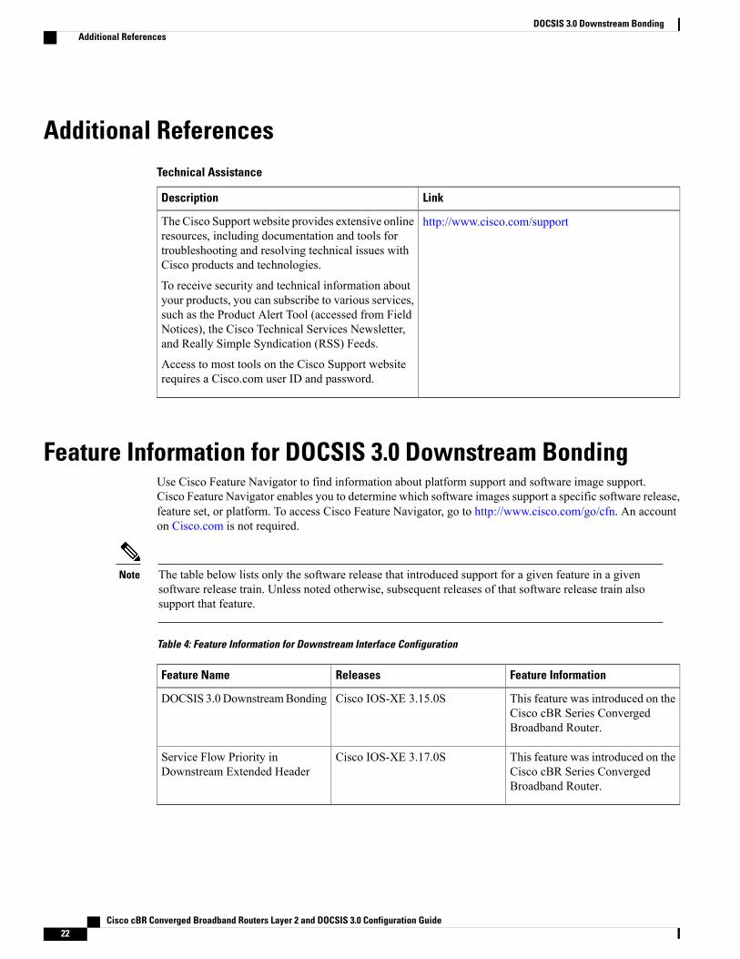
Feature Information for DOCSIS 3.0 Downstream BondingUse Cisco Feature Navigator to find information about platform support and software image support.Cisco Feature Navigator enables you to determine which software images support a specific software release,feature set, or platform. To access Cisco Feature Navigator, go to http://www.cisco.com/go/cfn. An accounton Cisco.com is not required.
The table below lists only the software release that introduced support for a given feature in a givensoftware release train. Unless noted otherwise, subsequent releases of that software release train alsosupport that feature.
Note
Table 4: Feature Information for Downstream Interface Configuration
Feature InformationReleasesFeature Name
This feature was introduced on theCisco cBR Series ConvergedBroadband Router.
Cisco IOS-XE 3.15.0SDOCSIS 3.0DownstreamBonding
This feature was introduced on theCisco cBR Series ConvergedBroadband Router.
Cisco IOS-XE 3.17.0SService Flow Priority inDownstream Extended Header
Cisco cBR Converged Broadband Routers Layer 2 and DOCSIS 3.0 Configuration Guide22
DOCSIS 3.0 Downstream BondingAdditional References
Related Documents