Doc 9981 INTERNATIONAL CIVIL AVIATION ORGANIZATION Third Edition, 2020 This edition supersedes, on 5 November 2020, all previous editions of Doc 9981. ICAO PROCEDURES FOR AIR NAVIGATION SERVICES Aerodromes

Welcome message from author
This document is posted to help you gain knowledge. Please leave a comment to let me know what you think about it! Share it to your friends and learn new things together.
Transcript
Doc 9981
INTERNATIONAL CIVIL AVIATION ORGANIZATION
Third Edition, 2020
This edition supersedes, on 5 November 2020, all previous editions of Doc 9981.
ICAO
PROCEDURES FOR AIR NAVIGATION SERVICES
Aerodromes

Doc 9981
INTERNATIONAL CIVIL AVIATION ORGANIZATION
Third Edition, 2020
This edition supersedes, on 5 November 2020, all previous editions of Doc 9981.
ICAO
PROCEDURES FOR AIR NAVIGATION SERVICES
Aerodromes
Published in separate English, Arabic, Chinese, French, Russian and Spanish editions by the INTERNATIONAL CIVIL AVIATION ORGANIZATION 999 Robert-Bourassa Boulevard, Montréal, Quebec, Canada H3C 5H7 For ordering information and for a complete listing of sales agents and booksellers, please go to the ICAO website at www.icao.int First edition 2015 Second edition 2016 Third edition 2020 Doc 9981, Procedures for Air Navigation Services — Aerodromes Order Number: 9981 ISBN 978-92-9258-964-6 © ICAO 2020 All rights reserved. No part of this publication may be reproduced, stored in a retrieval system or transmitted in any form or by any means, without prior permission in writing from the International Civil Aviation Organization.
(iii)
AMENDMENTS
Amendments are announced in the supplements to the Products and Services Catalogue; the Catalogue and its supplements are available on the ICAO website at www.icao.int. The space below is provided to keep a record of such amendments.
RECORD OF AMENDMENTS AND CORRIGENDA
AMENDMENTS CORRIGENDA
No. Date
applicable Date
entered Entered
by No. Date
of issue Date
entered Entered
by
Amendments 1-2 incorporated in this edition.
3 5/11/20; 28/11/24
— ICAO

PANS — Aerodromes (v) 5/11/20
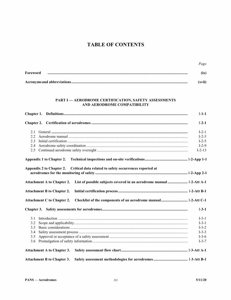
TABLE OF CONTENTS
Page Foreword ................................................................................................................................................... (ix) Acronyms and abbreviations .......................................................................................................................... (xvii)
PART I — AERODROME CERTIFICATION, SAFETY ASSESSMENTS AND AERODROME COMPATIBILITY
Chapter 1. Definitions .................................................................................................................................. I-1-1 Chapter 2. Certification of aerodromes ..................................................................................................... I-2-1 2.1 General ............................................................................................................................................... I-2-1 2.2 Aerodrome manual ............................................................................................................................. I-2-3 2.3 Initial certification .............................................................................................................................. I-2-5 2.4 Aerodrome safety coordination .......................................................................................................... I-2-9 2.5 Continued aerodrome safety oversight ............................................................................................... I-2-13 Appendix 1 to Chapter 2. Technical inspections and on-site verifications ............................................. I-2-App 1-1 Appendix 2 to Chapter 2. Critical data related to safety occurrences reported at aerodromes for the monitoring of safety ................................................................................................. I-2-App 2-1 Attachment A to Chapter 2. List of possible subjects covered in an aerodrome manual ..................... I-2-Att A-1 Attachment B to Chapter 2. Initial certification process ......................................................................... I-2-Att B-1 Attachment C to Chapter 2. Checklist of the components of an aerodrome manual ............................ I-2-Att C-1 Chapter 3. Safety assessments for aerodromes.......................................................................................... I-3-1 3.1 Introduction ........................................................................................................................................ I-3-1 3.2 Scope and applicability ....................................................................................................................... I-3-1 3.3 Basic considerations ........................................................................................................................... I-3-2 3.4 Safety assessment process .................................................................................................................. I-3-3 3.5 Approval or acceptance of a safety assessment .................................................................................. I-3-6 3.6 Promulgation of safety information .................................................................................................... I-3-7 Attachment A to Chapter 3. Safety assessment flow chart ...................................................................... I-3-Att A-1 Attachment B to Chapter 3. Safety assessment methodologies for aerodromes .................................... I-3-Att B-1
(vi) Procedures — Aerodromes
5/11/20
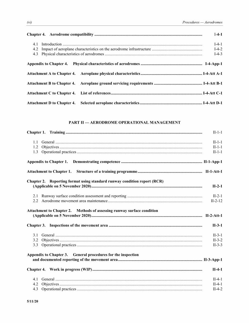
Chapter 4. Aerodrome compatibility ......................................................................................................... I-4-1 4.1 Introduction ........................................................................................................................................ I-4-1 4.2 Impact of aeroplane characteristics on the aerodrome infrastructure ................................................. I-4-2 4.3 Physical characteristics of aerodromes ............................................................................................... I-4-3 Appendix to Chapter 4. Physical characteristics of aerodromes ............................................................ I-4-App-1 Attachment A to Chapter 4. Aeroplane physical characteristics ............................................................ I-4-Att A-1 Attachment B to Chapter 4. Aeroplane ground servicing requirements ............................................... I-4-Att B-1 Attachment C to Chapter 4. List of references ......................................................................................... I-4-Att C-1 Attachment D to Chapter 4. Selected aeroplane characteristics ............................................................. I-4-Att D-1
PART II — AERODROME OPERATIONAL MANAGEMENT Chapter 1. Training ..................................................................................................................................... II-1-1 1.1 General ............................................................................................................................................... II-1-1 1.2 Objectives ........................................................................................................................................... II-1-1 1.3 Operational practices .......................................................................................................................... II-1-1 Appendix to Chapter 1. Demonstrating competence ............................................................................... II-1-App-1 Attachment to Chapter 1. Structure of a training programme ............................................................... II-1-Att-1 Chapter 2. Reporting format using standard runway condition report (RCR) (Applicable on 5 November 2020) ............................................................................................................ II-2-1 2.1 Runway surface condition assessment and reporting ......................................................................... II-2-1 2.2 Aerodrome movement area maintenance ............................................................................................ II-2-12 Attachment to Chapter 2. Methods of assessing runway surface condition (Applicable on 5 November 2020) ............................................................................................................ II-2-Att-1 Chapter 3. Inspections of the movement area ........................................................................................... II-3-1 3.1 General ............................................................................................................................................... II-3-1 3.2 Objectives ........................................................................................................................................... II-3-2 3.3 Operational practices .......................................................................................................................... II-3-3 Appendix to Chapter 3. General procedures for the inspection and documented reporting of the movement area .................................................................................. II-3-App-1 Chapter 4. Work in progress (WIP) ........................................................................................................... II-4-1 4.1 General ............................................................................................................................................... II-4-1 4.2 Objectives ........................................................................................................................................... II-4-1 4.3 Operational practices .......................................................................................................................... II-4-2
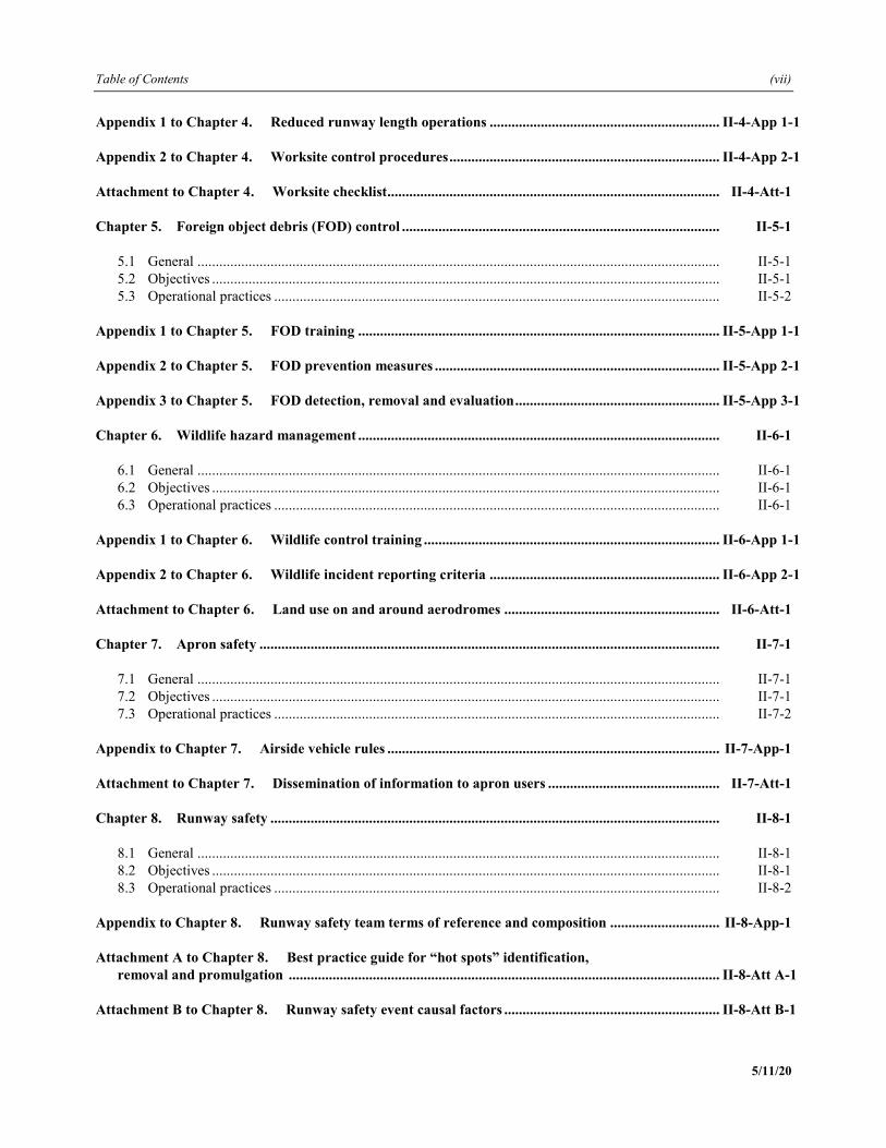
Table of Contents (vii)
5/11/20
Appendix 1 to Chapter 4. Reduced runway length operations ............................................................... II-4-App 1-1 Appendix 2 to Chapter 4. Worksite control procedures .......................................................................... II-4-App 2-1 Attachment to Chapter 4. Worksite checklist........................................................................................... II-4-Att-1 Chapter 5. Foreign object debris (FOD) control ....................................................................................... II-5-1 5.1 General ............................................................................................................................................... II-5-1 5.2 Objectives ........................................................................................................................................... II-5-1 5.3 Operational practices .......................................................................................................................... II-5-2 Appendix 1 to Chapter 5. FOD training ................................................................................................... II-5-App 1-1 Appendix 2 to Chapter 5. FOD prevention measures .............................................................................. II-5-App 2-1 Appendix 3 to Chapter 5. FOD detection, removal and evaluation ........................................................ II-5-App 3-1 Chapter 6. Wildlife hazard management ................................................................................................... II-6-1 6.1 General ............................................................................................................................................... II-6-1 6.2 Objectives ........................................................................................................................................... II-6-1 6.3 Operational practices .......................................................................................................................... II-6-1 Appendix 1 to Chapter 6. Wildlife control training ................................................................................. II-6-App 1-1 Appendix 2 to Chapter 6. Wildlife incident reporting criteria ............................................................... II-6-App 2-1 Attachment to Chapter 6. Land use on and around aerodromes ........................................................... II-6-Att-1 Chapter 7. Apron safety .............................................................................................................................. II-7-1 7.1 General ............................................................................................................................................... II-7-1 7.2 Objectives ........................................................................................................................................... II-7-1 7.3 Operational practices .......................................................................................................................... II-7-2 Appendix to Chapter 7. Airside vehicle rules ........................................................................................... II-7-App-1 Attachment to Chapter 7. Dissemination of information to apron users ............................................... II-7-Att-1 Chapter 8. Runway safety ........................................................................................................................... II-8-1 8.1 General ............................................................................................................................................... II-8-1 8.2 Objectives ........................................................................................................................................... II-8-1 8.3 Operational practices .......................................................................................................................... II-8-2 Appendix to Chapter 8. Runway safety team terms of reference and composition .............................. II-8-App-1 Attachment A to Chapter 8. Best practice guide for “hot spots” identification, removal and promulgation ...................................................................................................................... II-8-Att A-1 Attachment B to Chapter 8. Runway safety event causal factors ........................................................... II-8-Att B-1
(viii) Procedures — Aerodromes
5/11/20
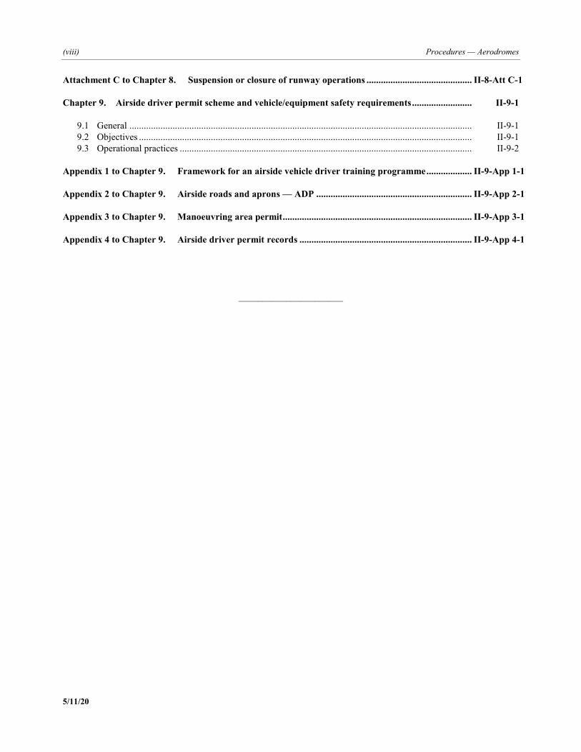
Attachment C to Chapter 8. Suspension or closure of runway operations ............................................ II-8-Att C-1 Chapter 9. Airside driver permit scheme and vehicle/equipment safety requirements ......................... II-9-1 9.1 General ............................................................................................................................................... II-9-1 9.2 Objectives ........................................................................................................................................... II-9-1 9.3 Operational practices .......................................................................................................................... II-9-2 Appendix 1 to Chapter 9. Framework for an airside vehicle driver training programme ................... II-9-App 1-1 Appendix 2 to Chapter 9. Airside roads and aprons — ADP ................................................................. II-9-App 2-1 Appendix 3 to Chapter 9. Manoeuvring area permit ............................................................................... II-9-App 3-1 Appendix 4 to Chapter 9. Airside driver permit records ........................................................................ II-9-App 4-1
______________________
PANS — Aerodromes (ix) 5/11/20
FOREWORD
1. HISTORICAL BACKGROUND 1.1 The first edition of the Procedures for Air Navigation Services — Aerodromes (PANS-Aerodromes) was prepared by the PANS-Aerodromes Study Group (PASG) and contains material that provides for the suitable and harmonized application of aerodrome Standards and Recommended Practices (SARPs) and operational procedures found in Annex 14 — Aerodromes, Volume I — Aerodrome Design and Operations. 1.2 The Air Navigation Commission, during its final review of Amendment 10 to Annex 14, Volume I, in June 2008, expressed the view that Annex 14, Volume I, was primarily a design document, and the SARPs therein were appropriate for designing new aerodromes. At existing aerodromes where full compliance with Standards cannot be achieved, alternative measures may be required in order to accommodate a specific type of aeroplane. It was suggested that a PANS-Aerodromes was needed which would include procedures on how to address such operational issues. 1.3 The Air Navigation Commission, during the seventh meeting of its 180th session on 26 February 2009, agreed to develop PANS-Aerodromes to complement Annex 14, Volume I.
2. SCOPE AND PURPOSE 2.1 Annex 14 contains specifications applicable to aerodromes, as well as certain facilities and technical services normally provided at them. To a great extent, the specifications for individual facilities have been interrelated by a reference code system as described in Annex 14, Volume I, in accordance with the characteristics of the aeroplane for which an aerodrome is intended. It is not intended that those specifications limit or regulate the operation of an aircraft. Those matters related to the possible use of the aerodrome by more demanding aircraft and related applicable approvals are left to appropriate authorities to evaluate and take into account for appropriate measures to be implemented as necessary for each particular aerodrome in order to maintain an acceptable level of safety during operations. 2.2 The PANS-Aerodromes are complementary to the SARPs contained in Annex 14, Volume I. 2.3 The PANS-Aerodromes specify, in greater detail than the SARPs, operational procedures to be applied by aerodrome operators to ensure aerodrome operational safety. PANS-Aerodromes specify procedures to be applied by both aerodrome regulators and operators for initial aerodrome certification and continuing aerodrome safety oversight as well as aerodrome compatibility studies, in particular, where full compliance with the SARPs in Annex 14, Volume I, cannot be achieved. 2.4 The PANS-Aerodromes do not substitute nor circumvent the provisions contained in Annex 14, Volume I. It is expected that infrastructure on an existing aerodrome or a new aerodrome will fully comply with the requirements in Annex 14, Volume I. The contents of PANS-Aerodromes are designed to enable the use of the procedures and methodologies described in the document to assess the operational issues faced by existing aerodromes in a changing and challenging environment and to address those issues to ensure the continued safety of aerodrome operations.
(x) Procedures — Aerodromes
5/11/20
2.5 The PANS-Aerodromes focus on the priority areas identified by the ICAO Universal Safety Oversight Audit Programme in the domains of certification of aerodromes, safety assessment and operational procedures at existing aerodromes (aerodrome compatibility). The PANS-Aerodromes also focus on aerodrome operational management and include topics that are relevant to the provision of uniform and harmonized procedures in aerodrome operations. This edition also deals with the operational requirements of fixed-wing aircraft and therefore the term “aeroplane” is deliberately used throughout the document to indicate it does not include operational requirements for helicopters. 2.6 The procedures in this document are directed mainly towards aerodrome operators and consequently do not include procedures for aerodrome control service provided by the air traffic service (ATS), which are already covered in the Procedures for Air Navigation Services — Air Traffic Management (PANS-ATM, Doc 4444).
3. STATUS 3.1 The PANS do not have the same status as SARPs. While SARPs are adopted by the Council in pursuance of Article 37 of the Convention on International Civil Aviation and are subject to the full procedure of Article 90, the PANS are approved by the Council and recommended to Contracting States for worldwide application. 3.2 While the PANS may contain material that may eventually become SARPs when it has reached the maturity and stability necessary for adoption as such, they may also comprise material prepared as an amplification of the basic principles in the corresponding SARPs and designed particularly to assist the user in the application of those SARPs. 3.3 Appendices are comprised of material grouped separately for convenience but form part of the Procedures approved by the Air Navigation Commission. 3.4 Attachments are comprised of material supplementary to the Procedures or included as a guide to their application.
4. IMPLEMENTATION The implementation of procedures is the responsibility of Member States; they are applicable to actual operations only in so far as States have enforced them. However, with a view to facilitating their processing towards implementation by States, they have been prepared in a language that will permit direct use by aerodrome and State personnel to certify, oversee and manage the operational activities of aerodromes.
5. PUBLICATION OF DIFFERENCES The PANS do not carry the status afforded to SARPs adopted by the Council as Annexes to the Convention and therefore do not fall under the obligation imposed by Article 38 of the Convention to notify differences in the event of non-implementation. However, attention of States is drawn to the provision in Annex 15 — Aeronautical Information Services, related to the publication in their aeronautical information publication (AIP) of lists of significant differences between their procedures and the related ICAO procedures.
Foreword (xi)
5/11/20
6. CONTENTS OF THE DOCUMENT 6.1 The PANS-Aerodromes consists of two parts as follows: Part I — Aerodrome certification, safety assessments and aerodrome compatibility Part II — Aerodrome operational management 6.2 Part I — Aerodrome certification, safety assessments and aerodrome compatibility describes procedures for the certification of an aerodrome, how to conduct a safety assessment and methods required to assess the compatibility of an aerodrome to accept a proposed change in operation. Part I provides the basic guidelines to States, and those operators and organizations certificating and managing aerodromes. 6.3 Part II — Aerodrome operations management provides operational procedures for the operation and management of aerodromes and related aerodrome activities. The requirements contained in this part may be applicable to the aerodrome operator and/or other relevant entities operating on the aerodrome. The procedures described in this part provide an overall framework to allow for a standardized approach to aerodrome operations. 6.4 Both parts present coverage of operational practices that are beyond the scope of Standards and Recommended Practices (SARPs) but with respect to which a measure of international uniformity is desirable.
PART I — AERODROME CERTIFICATION, SAFETY ASSESSMENTS AND AERODROME COMPATIBILITY
6.5 Part I, Chapter 1 — Definitions
Part I, Chapter 1 contains a list of terms and their technical meanings as used in this document.
6.6 Part I, Chapter 2 — Certification of aerodromes 6.6.1 Part I, Chapter 2 outlines the general principles and procedures to be followed through all of the suggested stages of certifying an aerodrome operator: the initial meeting between the State and the aerodrome operator, technical inspections of the aerodrome, approval/acceptance of all or relevant portions of the aerodrome manual, on-site verification of aerodrome operational aspects including the safety management system (SMS) of the operator, analysis of the deviations from regulatory requirements and issuance of the verification report, assessment of the corrective action plan, issuance of the certificate and continued safety oversight. 6.6.2 Appendix 1 to Part I, Chapter 2 contains a list of the main items to be inspected and/or audited in each of the technical and operational areas including the SMS of the operator. Appendix 2 concerns critical data related to safety occurrences. The attachments to Part I, Chapter 2 contain a list of possible subjects for an aerodrome manual, guidance on initial certification process and a checklist that can be used by the State to assess the acceptance of an aerodrome manual and initial certification of an aerodrome. It is appreciated that these will differ according to the legal basis of the State, but some States might find these helpful.
6.7 Part I, Chapter 3 — Safety assessments for aerodromes Part I, Chapter 3 outlines the methodologies and procedures to be followed when undertaking a safety assessment. It includes a brief description of how a safety assessment fulfils an element of the overall aerodrome operator’s SMS. An aerodrome operator’s SMS should enable the aerodrome operator to manage the safety risks it is exposed to as a consequence of the hazards it must face during the operations of the aerodrome.
(xii) Procedures — Aerodromes
5/11/20
6.8 Part I, Chapter 4 — Aerodrome compatibility 6.8.1 Part I, Chapter 4 outlines a methodology and procedure to assess the compatibility between aeroplane operations and aerodrome infrastructure and operations when an aerodrome accommodates an aeroplane that exceeds the certificated characteristics of the aerodrome. 6.8.2 This chapter addresses situations where compliance with the design provisions stipulated in Annex 14, Volume I, is either impractical or physically impossible. Where alternative measures, operational procedures and operating restrictions have been developed, these should be reviewed periodically to assess their continued validity. 6.8.3 The attachments to Part I, Chapter 4 contain selected aeroplane characteristics data. They are provided for convenience to allow the aerodrome operator to easily compare the characteristics of various commonly operated aeroplanes. However, the data will be subject to change, and accurate data should always be obtained from the aircraft manufacturers’ documentation prior to any official assessment of compatibility.
PART II — AERODROME OPERATIONAL MANAGEMENT
6.9 Structure 6.9.1 The structure of each chapter within Part II is set up with three specific sections including a general part, the objectives to be achieved, and the operating practices related to these objectives. 6.9.2 The “general” section of the chapter includes an introduction to each of the topics covered in the subsequent chapter. It also provides an overview of the general principles in order to understand the procedures that follow. 6.9.3 The “objectives” section contains the basic principles that have been defined for the topic. These basic principles have been formulated as required for global uniform application. The “objectives” cover the whole subject matter and are not broken down into the individual subsections. 6.9.4 The “operational practices” section covers the specific operational practices and the ways in which they are applied in order to achieve the basic principles defined in “objectives”.
6.10 Part II, Chapter 1 — Training
6.10.1 This chapter outlines principles, obligations, and provisions pertaining to the training of aerodrome personnel involved in aerodrome operations, including training programmes and competence checks.
6.10.2 The appendix and the attachment to Part II, Chapter 1 contain elaborated provisions on demonstrating competence, as well as on the recommended structure and basic components of a training programme.
6.11 Part II, Chapter 2 — Reporting format using standard runway condition report (RCR)
6.11.1 This chapter contains provisions for assessing and reporting the condition of a runway.
6.11.2 The attachment to Part II, Chapter 2 lists methods and techniques of assessing runway surface conditions
with different types of runway characteristics.
Foreword (xiii)
5/11/20
6.12 Part II, Chapter 3 — Inspections of the movement area
6.12.1 This chapter contains provisions pertaining to inspections of the aerodrome movement areas (including runways, taxiways, aprons, and their associated aeronautical lighting systems, markings and signs), required to ensure the safe and efficient operation of aircraft.
6.12.2 The chapter outlines different types of inspections, their frequency, and relevant variables relating to the mix of aircraft operations, pavement materials and environmental conditions.
6.12.3 The appendix to Part II, Chapter 3 elaborates on the type and content of the inspections of the movement areas, and provides provisions on general procedures and documented reporting.
6.13 Part II, Chapter 4 — Work in progress (WIP)
6.13.1 This chapter details required procedures pertaining to the planning, coordination and safe execution of construction and other heavy works on the movement areas of aerodromes when aircraft operations continue in the works area.
6.13.2 The chapter lists possible precautions and considerations to be taken in order to ensure the safety of aerodrome operations, as well as the protection and safety of the worksite and workers.
6.13.3 The appendices and attachment to this chapter contain provisions on reduced runway length operations, and examples of supporting documents and checklists.
6.14 Part II, Chapter 5 — Foreign object debris (FOD) control
6.14.1 This chapter contains procedures and processes pertaining to the control and management of foreign object debris (FOD) at aerodromes, including the establishment of FOD control programmes to address the prevention, detection, removal and evaluation of FOD, as well as related training and awareness activities.
6.14.2 The appendices to this chapter detail provisions on FOD-related training, FOD sources, methods and techniques of FOD detection, and its removal, evaluation and reporting.
6.15 Part II, Chapter 6 — Wildlife hazard management
6.15.1 This chapter contains provisions relating to the reduction of the risk to aviation safety arising from wildlife, through the proactive management and control of wildlife at aerodromes and their vicinities.
6.15.2 The chapter details provisions on the establishment of a wildlife hazard management programme (WHMP) at aerodromes and WHMP components, including: expelling and deterring wildlife, reporting and recording wildlife incidents, habitat and land use management, and personnel training.
6.16 Part II, Chapter 7 — Apron safety
6.16.1 This chapter contains provisions on apron safety, including the identification of apron hazards and mitigation of risks, personnel awareness, the required coordination between the different parties involved in apron activities, and their responsibilities.
(xiv) Procedures — Aerodromes
5/11/20
6.16.2 The appendix and attachment to this chapter deal with airside vehicle rules and the dissemination of information to apron users.
6.17 Part II, Chapter 8 — Runway safety
6.17.1 This chapter contains provisions pertaining to runway safety. The chapter deals with the prevention of runway incursions, excursions and confusion through different strategies. These include effective identification of hazards related to runway safety, risk mitigation, coordination and cooperation between different stakeholders, establishment of runway safety action plans and runway safety teams (RSTs), and the collection, sharing and exchange of safety information.
6.17.2 The appendix to Part II, Chapter 8 deals with RST composition and the terms of reference.
6.17.3 The attachments to Part II, Chapter 8 provide further detailed guidance on “hot spots”1, common causes of runway safety events, and suspension or closure of runway operations.
6.18 Part II, Chapter 9 — Airside driver permit scheme and vehicle/equipment safety requirements
6.18.1 This chapter contains provisions on the establishment and implementation of an airside driver permit
(ADP) scheme and safety requirements for vehicles and equipment operating at an aerodrome, with the objective of minimizing the risk of accidents causing injury to persons and damage to aircraft and property, arising from the use of vehicles in airside areas.
6.18.2 The appendices to Part II, Chapter 9 contain further detailed supporting provisions on the framework for an airside vehicle driver training programme, radiotelephony and record keeping.
1. Definition from Annex 14 — Aerodromes, Volume I — Aerodrome Design and Operations:
“Hot spot. A location on an aerodrome movement area with a history or potential risk of collision or runway incursion, and where heightened attention by pilots/drivers is necessary.”
Foreword (xv)
5/11/20
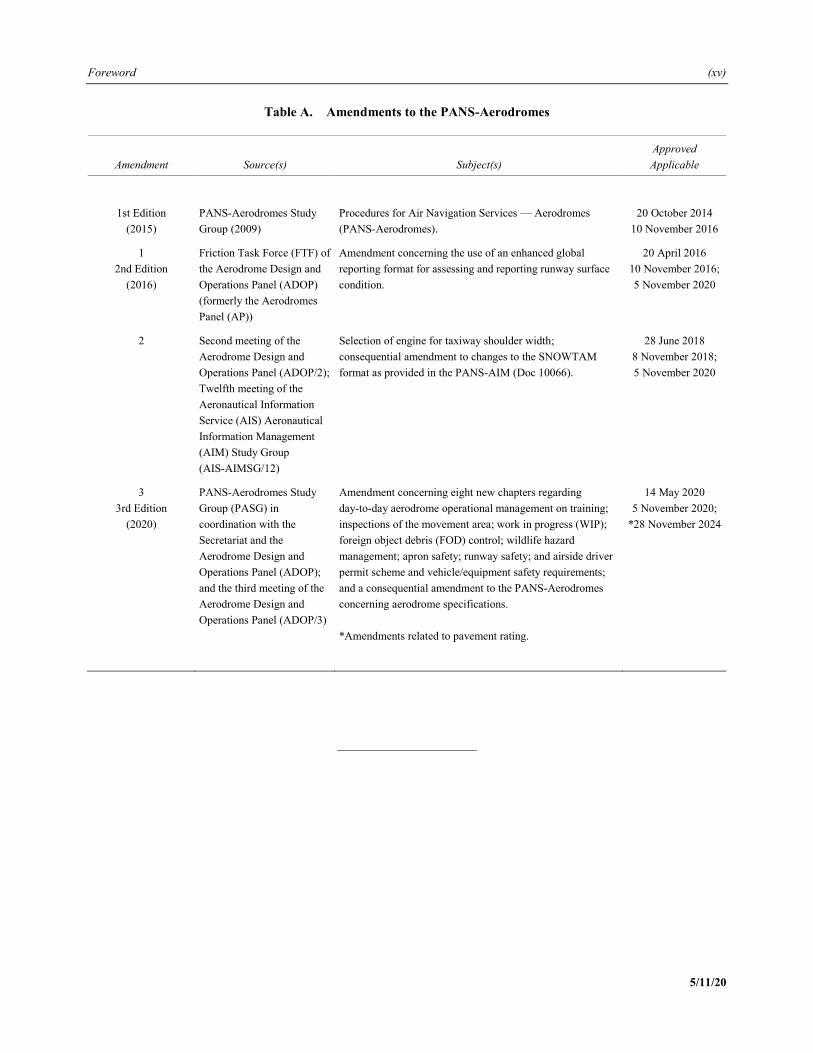
Table A. Amendments to the PANS-Aerodromes
Amendment Source(s) Subject(s) Approved Applicable
1st Edition (2015)
PANS-Aerodromes Study Group (2009)
Procedures for Air Navigation Services — Aerodromes (PANS-Aerodromes).
20 October 2014 10 November 2016
1 2nd Edition
(2016)
Friction Task Force (FTF) of the Aerodrome Design and Operations Panel (ADOP) (formerly the Aerodromes Panel (AP))
Amendment concerning the use of an enhanced global reporting format for assessing and reporting runway surface condition.
20 April 2016 10 November 2016; 5 November 2020
2 Second meeting of the Aerodrome Design and Operations Panel (ADOP/2); Twelfth meeting of the Aeronautical Information Service (AIS) Aeronautical Information Management (AIM) Study Group (AIS-AIMSG/12)
Selection of engine for taxiway shoulder width; consequential amendment to changes to the SNOWTAM format as provided in the PANS-AIM (Doc 10066).
28 June 2018 8 November 2018; 5 November 2020
3 3rd Edition
(2020)
PANS-Aerodromes Study Group (PASG) in coordination with the Secretariat and the Aerodrome Design and Operations Panel (ADOP); and the third meeting of the Aerodrome Design and Operations Panel (ADOP/3)
Amendment concerning eight new chapters regarding day-to-day aerodrome operational management on training; inspections of the movement area; work in progress (WIP); foreign object debris (FOD) control; wildlife hazard management; apron safety; runway safety; and airside driver permit scheme and vehicle/equipment safety requirements; and a consequential amendment to the PANS-Aerodromes concerning aerodrome specifications. *Amendments related to pavement rating.
14 May 2020 5 November 2020;
*28 November 2024
_____________________

PANS — Aerodromes (xvii) 5/11/20
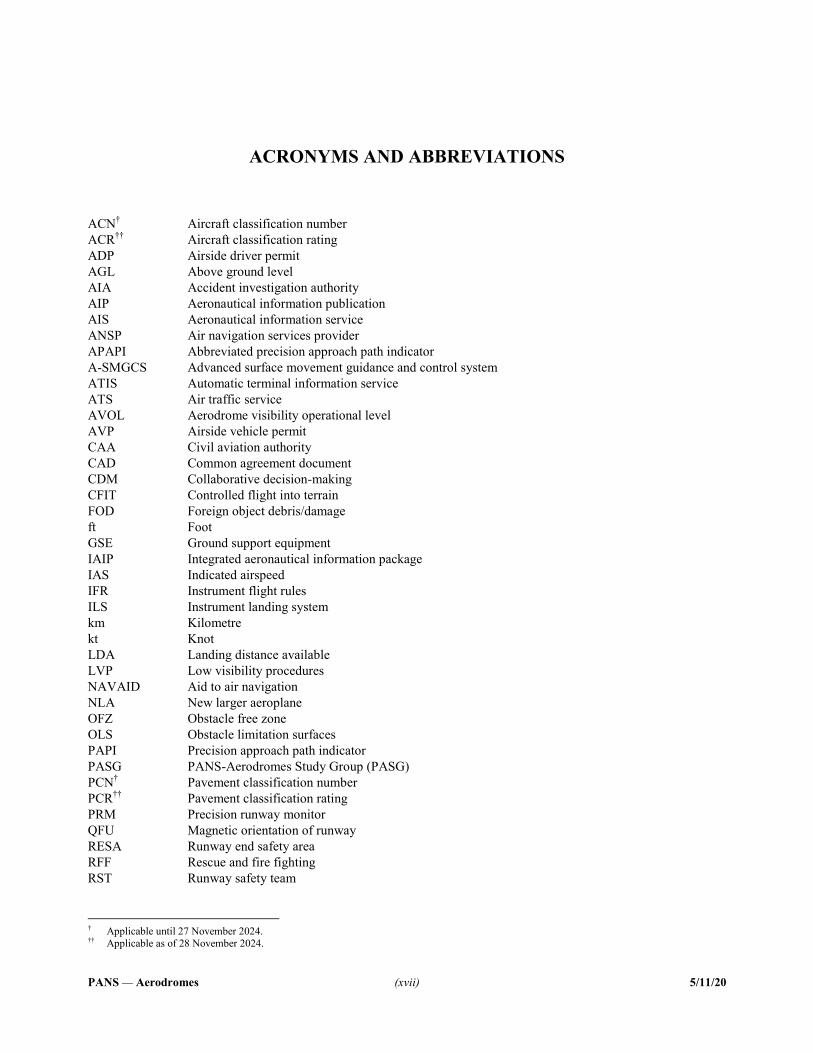
ACRONYMS AND ABBREVIATIONS
ACN† Aircraft classification number ACR†† Aircraft classification rating ADP Airside driver permit AGL Above ground level AIA Accident investigation authority AIP Aeronautical information publication AIS Aeronautical information service ANSP Air navigation services provider APAPI Abbreviated precision approach path indicator A-SMGCS Advanced surface movement guidance and control system ATIS Automatic terminal information service ATS Air traffic service AVOL Aerodrome visibility operational level AVP Airside vehicle permit CAA Civil aviation authority CAD Common agreement document CDM Collaborative decision-making CFIT Controlled flight into terrain FOD Foreign object debris/damage ft Foot GSE Ground support equipment IAIP Integrated aeronautical information package IAS Indicated airspeed IFR Instrument flight rules ILS Instrument landing system km Kilometre kt Knot LDA Landing distance available LVP Low visibility procedures NAVAID Aid to air navigation NLA New larger aeroplane OFZ Obstacle free zone OLS Obstacle limitation surfaces PAPI Precision approach path indicator PASG PANS-Aerodromes Study Group (PASG) PCN† Pavement classification number PCR†† Pavement classification rating PRM Precision runway monitor QFU Magnetic orientation of runway RESA Runway end safety area RFF Rescue and fire fighting RST Runway safety team
† Applicable until 27 November 2024. †† Applicable as of 28 November 2024.
(xviii) Procedures — Aerodromes
5/11/20
RTF Radiotelephony RVR Runway visual range SARPs Standards and Recommended Practices SMGCS Surface movement guidance and control system SMS Safety management system SSP State safety programme VASIS Visual approach slope indicator system VDGS Visual docking guidance system VFR Visual flight rules WGS-84 World Geodetic System — 1984 WHMP Wildlife hazard management programme WIP Work in progress
_____________________
PANS — Aerodromes I-1-1 5/11/20
PART I — AERODROME CERTIFICATION, SAFETY ASSESSMENTS
AND AERODROME COMPATIBILITY
Chapter 1
DEFINITIONS
When the following terms are used in this document, they have the following meanings: Advanced surface movement guidance and control system (A-SMGCS). A system providing routing, guidance and
surveillance for the control of aircraft and vehicles in order to maintain the declared surface movement rate under all weather conditions within the aerodrome visibility operational level (AVOL) while maintaining the required level of safety (Doc 9830 — Advanced Surface Movement Guidance and Control Systems (A-SMGCS) Manual).
Aerodrome infrastructure. Physical elements and related facilities of the aerodrome. Applicable regulation. Regulations applicable to the aerodrome and to the aerodrome operator that are transposed from
international specifications and other relevant regulations. Compatibility study. A study undertaken by the aerodrome operator to address the impact of introducing an aeroplane
type/model new to the aerodrome. A compatibility study may include one or several safety assessments. Critical aeroplane. The type of aeroplane which is the most demanding for the relevant elements of the physical
infrastructure and the facilities for which the aerodrome is intended. Mobile object. A movable device moving under the control of an operator, driver or pilot. Obstacle. All fixed (whether temporary or permanent) and mobile objects, or parts thereof, that: a) are located on an area intended for the surface movement of aircraft; or b) extend above a defined surface intended to protect aircraft in flight; or c) stand outside those defined surfaces and that have been assessed as being a hazard to air navigation (Annex 14
— Aerodromes, Volume I — Aerodrome Design and Operations). Promulgation. The act of formally notifying official information to the aviation community. Runway incursion. Any occurrence at an aerodrome involving the incorrect presence of an aircraft, vehicle or person
on the protected area of a surface designated for the landing and take-off of aircraft (Doc 9870 — Manual on the Prevention of Runway Incursions).
Runway/taxiway excursion. Any occurrence at any aerodrome involving the departure, wholly or partly, of an aircraft
from the runway/taxiway in use during take-off, a landing run, taxiing or manoeuvring.
I-1-2 Procedures — Aerodromes
5/11/20
Safety assessment. An element of the risk management process of an SMS that is used to assess safety concerns arising from, inter alia, deviations from standards and applicable regulations, identified changes at an aerodrome or when any other safety concerns arise.
Safety management system (SMS). A systematic approach to managing safety, including the necessary organizational
structures, accountabilities, policies and procedures (Annex 19 — Safety Management). Safety manager. The responsible individual and focal point for the implementation and maintenance of an effective
SMS. The safety manager directly reports to the accountable executive. State safety programme (SSP). An integrated set of regulations and activities aimed at improving safety (Annex 19 —
Safety Management). Technical inspection. Visual and/or instrumental verification of compliance with technical specifications related to
aerodrome infrastructure and operations.
_____________________
PANS — Aerodromes I-2-1 5/11/20
Chapter 2
CERTIFICATION OF AERODROMES
2.1 GENERAL
2.1.1 Introduction This chapter contains provisions with regard to the initial certification process and to continued oversight. General principles and procedures to be followed have been developed to assist States and aerodrome operators to meet their safety obligations.
2.1.2 Scope of certification 2.1.2.1 The scope of certification covers all relevant specifications established through the regulatory framework applicable to the aerodrome. Note.— The relevant specifications stem from Annex 14, Volume I, Standards and Recommended Practices (SARPs), as well as other relevant additional requirements. 2.1.2.2 The scope of certification includes at least the subjects below: a) compliance of the aerodrome infrastructure with the applicable regulations for the operations the aerodrome is
intended to serve; b) the operational procedures and their day-to-day application, when applicable, concerning: 1) aerodrome data and reporting; 2) access to the movement area; 3) aerodrome emergency plan; 4) rescue and fire fighting (RFF); 5) inspection of the movement area; 6) maintenance of the movement area; 7) snow and ice control, and other hazardous meteorological conditions; 8) visual aids and aerodrome electrical systems; 9) safety during aerodrome works;
I-2-2 Procedures — Aerodromes
5/11/20
10) apron management; 11) apron safety; 12) vehicles on the movement area; 13) wildlife hazard management; 14) obstacles; 15) removal of a disabled aeroplane; 16) low visibility operations; and 17) compliance of the safety management system (SMS) with applicable regulations. Note 1.— Provisions on reporting aerodrome information in 2.1.2.2 b) 1) can be found in Annex 15 and the Manual on Certification of Aerodromes (Doc 9774). Note 2.— Provisions related to the above operational procedures will be developed in subsequent editions of PANS-Aerodromes. 2.1.2.3 The aerodrome manual describes all the information, for each certified aerodrome, pertaining to the above scope of certification concerning the aerodrome site, facilities, services, equipment, operating procedures, organization and management, including its SMS. Note.— The complexity and size of the aerodrome may necessitate the SMS to be included in a separate manual.
2.1.3 Continued oversight Once the State has completed a thorough review of the compliance of an aerodrome with the applicable certification requirements, leading to the granting of the certificate to the aerodrome operator, continued oversight should be established by the State in order to ensure that compliance with regard to certification conditions and ongoing additional requirements is maintained.
2.1.4 Shared responsibilities and interfaces Depending on the requirements of the State, the aerodrome operator may not be responsible for some of the subjects detailed in the above scope of certification. In this case, the aerodrome manual should clearly define, for each of these items, which coordination and procedures have been put into place in the case of multiple responsible stakeholders. Note.— Where the aerodrome operator implements specific procedures related to other Annexes, these may be described in the aerodrome manual.
Part I — Chapter 2. Certification of aerodromes I-2-3
5/11/20
2.2 AERODROME MANUAL
2.2.1 Use of the aerodrome manual 2.2.1.1 Introduction An application for an aerodrome certificate shall be accompanied by an aerodrome manual produced in accordance with the applicable regulation. Once granted a certificate, the aerodrome operator is required to maintain the aerodrome manual in conformity with the applicable regulation and enable all aerodrome operating staff to have access to the relevant parts of the manual. Note 1.— The term “operating staff” refers to those persons, whether or not they are employed by the aerodrome operator, whose duties are concerned either with ensuring safety of aerodrome operations or require them to have access to the aerodrome movement areas and all other areas within the aerodrome perimeter. Note 2.— When considered suitable for security or management reasons, the aerodrome operator may restrict the access of some operating staff to parts of the aerodrome manual, if they are suitably briefed by other means to perform their duties adequately and this would not impair the safety of aerodrome operations. 2.2.1.2 Scope of the aerodrome manual 2.2.1.2.1 The aim and objectives of the aerodrome manual and how it is to be used by operating staff and other stakeholders should be stated in the manual. 2.2.1.2.2 The aerodrome manual contains all the relevant information to describe the management and operational structure. It is the means by which all aerodrome operating staff are fully informed as to their duties and responsibilities with regard to safety, including information and instructions related to those matters specified in the applicable regulation. It describes the aerodrome services and facilities, all operating procedures, and any restrictions in place. 2.2.1.3 Ownership of the aerodrome manual 2.2.1.3.1 The aerodrome operator is responsible for developing and maintaining the aerodrome manual, as well as providing appropriate personnel access to it. 2.2.1.3.2 It is the responsibility of the aerodrome operator to be satisfied with the appropriateness of each provision of the aerodrome manual to a particular operation and to make amendments and additions as necessary. 2.2.1.4 Format of the aerodrome manual 2.2.1.4.1 As part of the certification process, the aerodrome operator shall submit, for approval/acceptance by the State, an aerodrome manual containing, inter alia, information on how operational procedures and their safe management will be delivered. 2.2.1.4.2 The aerodrome manual accurately reflects the aerodrome’s SMS and shows, in particular, how the aerodrome intends to measure its performance against safety targets and objectives. 2.2.1.4.3 All aerodrome safety policies, operational procedures and instructions are contained in detail or cross-referenced to other formally accepted or recognized publications.
I-2-4 Procedures — Aerodromes
5/11/20
Note.— At larger aerodromes, the size and complexity of operations and related procedures may imply that these procedures cannot be included in a single document. For example, the aerodrome operator may develop and maintain an SMS manual to communicate its approach to the management of safety throughout the aerodrome. In such circumstances it is acceptable to identify within the aerodrome manual references to such provisions. It is essential that any referenced information, documentation and procedures be subjected to exactly the same systems of consultation and promulgation as the aerodrome manual. A computerized database containing the referenced procedures and information could be suitable for that purpose. For many smaller aerodromes the aerodrome manual can be both simple and brief as long as it covers procedures essential for safe day-to-day operations.
2.2.2 Contents of the aerodrome manual 2.2.2.1 The aerodrome manual shall contain, as a minimum, the following sections, including some of their requirements: a) a table of contents; b) a list of the corrigenda/amendments: this section should log the updates and/or corrections made to the
aerodrome manual; c) a distribution list; d) aerodrome administrative data: an organizational chart should be provided, as well as the aerodrome operator’s
safety responsibilities; e) a description of the aerodrome: this includes maps and charts. The physical characteristics of the aerodrome
should be documented, as well as the information regarding the RFF level, ground aids, primary and secondary electrical power systems and main obstacles. Sufficiently detailed charts of the aerodrome should also be included (showing the aerodrome’s boundaries and different areas (manoeuvring area, apron, etc.). All deviations from the regulatory provisions authorized by the State should be listed together with their validity and references to the related documents (including any safety assessments);
f) a description of the intended operations, including: 1) the critical aeroplanes the aerodrome is intended to serve; 2) the category of runway(s) provided (non-instrument, instrument including non-precision and precision); 3) the different runways and their associated levels of service; 4) the nature of aviation activities (commercial, passenger, air transport, cargo, aerial work, general aviation); 5) the type of traffic permitted to use the aerodrome (international/national, IFR/VFR, scheduled/non-
scheduled); and 6) the minimum RVR that aerodrome operations can be permitted; g) a description of each of the aerodrome operator’s procedures related to the safety of aeronautical operations at
the aerodrome. For each procedure: 1) the responsibilities of the aerodrome operator are clearly described; 2) the tasks that are to be achieved by the aerodrome operator or its subcontractors are listed; and
Part I — Chapter 2. Certification of aerodromes I-2-5
5/11/20
3) the means and procedures required to complete these tasks are described or appended, together with the necessary details such as the frequency of application and operating modes; and
h) a description of the operator’s SMS (see Note following 2.1.2.3): 1) the SMS section of the manual is developed, and the related procedures and documents are enclosed, as well
as the safety policy of the aerodrome operator signed by the accountable executive; Note.— Annex 19 specifies a framework for the implementation of an SMS at an aerodrome. 2) the aerodrome SMS should be commensurate with the size of the aerodrome and with the level and
complexity of the services provided. Note.— A list of other possible topics for inclusion in the manual is given in Attachment A to this chapter. 2.2.2.2 Responsibilities attributed to other aerodrome stakeholders should be clearly identified and listed.
2.2.3 Updating of the aerodrome manual 2.2.3.1 Responsibility for maintaining the accuracy of the aerodrome manual is clearly defined in the manual. 2.2.3.2 The manual is updated using a defined process and includes a record of all amendments, effective dates and amendment approvals. 2.2.3.3 The method of enabling all aerodrome operating staff to have access to the relevant parts of the manual is defined and can be demonstrated. Note.— A method of tracking amendments and ensuring their receipt should be established when using an electronic means of distribution. 2.2.3.4 Any amendments or additions should be communicated to the State in accordance with the continued oversight requirements established by the State.
2.3 INITIAL CERTIFICATION
2.3.1 Points to be covered 2.3.1.1 When an aerodrome operator applies for initial certification, the State shall assess the compliance of that aerodrome with the applicable certification requirements described in 2.1.2. If the aerodrome is found to be compliant, a certificate is issued. 2.3.1.2 Compliance of the aerodrome is assessed through: a) technical inspections of the infrastructure of the aerodrome and its equipment, as related to the requirements
associated with the intended operations; b) review of the aerodrome manual and supporting documentation and acceptance of its relevant safety parts; and
I-2-6 Procedures — Aerodromes
5/11/20
c) on-site verification of the aerodrome operator’s procedures, its organization and its SMS based upon the contents of the aerodrome manual.
Note 1.— Guidance on the initial certification process, including timelines, is shown at Attachment B to this chapter. Note 2.— Technical inspections are planned and conducted so that their results can be used for on-site verifications. Scope and methodologies for technical inspections and on-site verifications are detailed in Appendix 1 to this chapter.
2.3.2 Aerodrome technical inspections 2.3.2.1 The technical inspections of the aerodrome should include, as a minimum: a) an inspection of the infrastructure, obstacle limitation surfaces (OLS), visual and non-visual aids and aerodrome
equipment for the use of aeroplanes; b) an inspection of the RFF services; and c) an inspection of wildlife hazard management. Note 1.— Several options to carry out these inspections are presented below. Note 2.— The methodology for technical inspections is proposed in Appendix 1 to this chapter. Option 1: full inspections by the State 2.3.2.2 At aerodromes where an SMS is not fully operational, full inspections should be conducted by the State. 2.3.2.3 Those inspections should be conducted using checklists developed by the State (see Appendix 1 for critical areas to be inspected). 2.3.2.4 If technical inspections have previously been conducted, and depending on the changes that occurred at the aerodrome since the last inspection, the State can undertake a follow-up inspection instead of a full inspection, which should consist of: a) assessing that the conditions prevailing at the aerodrome that led to the conclusions of the previous technical
inspections are still valid; b) reviewing any new applicable regulation; and c) reviewing the implementation of the previously accepted corrective action plan. 2.3.2.5 A report of the follow-up inspection should be produced, including any deviations or observations made during the follow-up inspection. Any immediate and corrective action can be taken, if needed, during follow-up inspections. Option 2: demonstration of compliance by the operator 2.3.2.6 At aerodromes where an SMS has been fully implemented, the aerodrome operator should ensure that the requirements in the checklists provided by the State have been complied with.
Part I — Chapter 2. Certification of aerodromes I-2-7
5/11/20
Note.— According to the answers to the checklist, the aerodrome operator may need to undertake safety assessments and provide them, together with the completed checklists, to the State for acceptance. 2.3.2.7 The State should then analyse the documents completed by the applicant and conduct sample on-site checks according to this analysis. Note.— The methodology that should be used for conducting on-site checks should be the same as the one used for other on-site inspections as described in Appendix 1.
2.3.3 Approval/acceptance of the aerodrome manual 2.3.3.1 Prior to on-site verification of the aerodrome (including procedures and SMS), the aerodrome manual is reviewed by the State. Note 1.— As compliance of all safety-relevant procedures of the aerodrome operator is assessed during the on-site verification, acceptance at that stage consists of checking that all the information that should be contained in the aerodrome manual is provided. Note 2.— The information required in the aerodrome manual is given in 2.2. Note 3.— The checklist given in Attachment C to this chapter also shows the information required in the aerodrome manual and has been organized to follow the list of topics given in Attachment A to this chapter. 2.3.3.2 Prior to the approval/acceptance of the aerodrome manual, the State should verify that: a) the operator has submitted an application; b) the aerodrome manual submitted by the aerodrome operator contains all the required information; and c) all the procedures related to aerodrome certification that will be assessed by the on-site verification team are
provided in the aerodrome manual. 2.3.3.3 The State formally informs the aerodrome operator when the aerodrome manual is accepted. 2.3.3.4 The aerodrome operator should inform the State of any changes to the approved/accepted aerodrome manual between the time of the application for a certificate and the end of the on-site verification.
2.3.4 On-site verification 2.3.4.1 The scope of the on-site verification covers the subjects included in the aerodrome manual. 2.3.4.2 The on-site verification confirms that the aerodrome operations are carried out effectively in accordance with the applicable regulation and procedures described in the manual. 2.3.4.3 The on-site verification of the SMS is normally included at this stage of initial certification, but depending on the implementation status of the SMS at the aerodrome, a specific verification of the SMS can be conducted separately. Note.— Because the aerodrome operator’s SMS may not yet be fully operational, its effectiveness will be assessed during continued oversight and will constitute an important factor in deciding the continued oversight that will be carried out.
I-2-8 Procedures — Aerodromes
5/11/20
2.3.4.4 On-site verification of the SMS focuses explicitly on the components required for granting the certificate and, when applicable, covers all other requirements for an SMS. Note 1.— The minimal SMS components that are to be in operation before the certificate can be granted are described in Appendix 1. Note 2.— SMS requirements also apply to the aerodrome operator’s subcontractors in the domains within the scope of certification. 2.3.4.5 When technical inspections have been previously conducted by the State, the on-site verification takes into account the results of the previous technical inspections and the associated corrective actions, if relevant. 2.3.4.6 If the on-site verification team notices any deviations from the technical inspection reports, they are included in the team’s report. 2.3.4.7 If the aerodrome operator is not directly responsible for some of the activities within the scope of certification, the on-site verification ensures that there is appropriate coordination between the aerodrome operator and the other stakeholders. Note 1.— The methodology used to conduct on-site verifications is available in Appendix 1. Note 2.— Because the scope of certification is broad, a sampling method for verifying particular subjects may be used rather than the whole scope. 2.3.4.8 At the end of an on-site verification, a preliminary list of findings is given to the aerodrome operator. 2.3.4.9 An on-site verification report is also sent to the aerodrome operator after the classification of findings by the State.
2.3.5 Analysis of the findings and monitoring of the related corrective action plans 2.3.5.1 In case of findings, the State should require the operator to develop a corrective action plan proposing ways to eliminate or mitigate the findings, with deadlines for each subsequent action. 2.3.5.2 The State may impose immediate appropriate measures on the aerodrome operator, if necessary, until actions have been taken to remove or mitigate the findings.
2.3.6 Issuance of the certificate 2.3.6.1 When no findings are reported or once the corrective action plans are accepted, and mitigation measures are agreed upon, the State grants the aerodrome certificate to the applicant. An appendix may be attached to the certificate describing the essential conditions prevailing at the aerodrome, which may include: a) the aerodrome reference code; b) critical aeroplane type; c) the operational conditions for the accommodation of critical aeroplanes for which the facility is provided; d) RFF category;
Part I — Chapter 2. Certification of aerodromes I-2-9
5/11/20
e) the operational restrictions at the aerodrome; and f) the authorized deviations related to aerodrome compatibility described in Chapter 4, their inherent operational
conditions/restrictions and validity. Note.— In determining the duration of validity of the certificate, account may be taken of the number of technical staff required for the inspection activities, the complexity of the inspection activities to be performed including the number of aerodromes to be inspected and the maturity of the aerodrome operator’s safety management system. 2.3.6.2 The State may accept a deviation on the basis of a safety assessment if permitted by the State’s regulatory framework. Note 1.— A methodology for conducting safety assessments is available in Chapter 3. Note 2.— Accepted deviations are listed in the aerodrome manual (see 2.2.2.1 e)). 2.3.6.3 As long as the granting conditions are maintained, the validity of the certificate is either limited in time or unlimited. Note.— Unavailability or downgrading of an infrastructure, facility or service, of a temporary nature, may not necessarily invalidate the certificate of an aerodrome. 2.3.6.4 During the period of validity of the certificate, the State monitors the timely implementation of the corrective action plans within the continued oversight developed in 2.5.
2.3.7 Promulgation of the status of certification 2.3.7.1 The State shall promulgate the status of certification of aerodromes in the aeronautical information publication, including: a) aerodrome name and ICAO location indicator; b) date of certification and, if applicable, validity of certification; and c) remarks, if any. 2.3.7.2 Where safety concerns have been observed on the aerodrome, special conditions or operational restrictions may be attached to the certificate and published in the aeronautical information publication (AIP) or by NOTAM until completion of the corrective action plan. In this case, validity may be shortened to be consistent with the duration and content of the corrective action plan. Other possible measures that may be taken by the State include suspension and revocation of the certificate.
2.4 AERODROME SAFETY COORDINATION
2.4.1 Introduction This section specifies the role of the State in the coordination process and the interaction between the aerodrome operator and other stakeholders which is necessary for the safety of operations at the aerodrome.
I-2-10 Procedures — Aerodromes
5/11/20
2.4.2 Coordination affecting aerodrome safety 2.4.2.1 The State verifies that coordination exists between the aerodrome operator, aeroplane operators, air navigation service providers and all other relevant stakeholders to ensure the safety of operations. 2.4.2.2 The aerodrome operator should ensure that all users of the aerodrome, including ground-handling agencies and other organizations that perform activities independently at the aerodrome in relation to flight or aircraft handling, comply with the safety requirements of the aerodrome operator. The aerodrome operator monitors such compliance.
2.4.3 State’s feedback on occurrences 2.4.3.1 Aerodrome operators are required to report safety occurrences at their aerodromes to their State in accordance with the applicable regulation. 2.4.3.2 Aerodrome operators shall report accidents and serious incidents, including: a) runway excursions; b) undershoots; c) runway incursions; d) landing or take-off on a taxiway; and e) wildlife strike-related events. 2.4.3.3 In addition to accidents and serious incidents, aerodrome operators should report safety occurrences of the following types: a) foreign object debris/damage- (FOD) related event; b) other excursions (i.e. from a taxiway or apron); c) other incursions (i.e. on taxiway or apron); and d) ground collisions. Note.— Appendix 2 details the list of safety occurrences types and related critical data which should be reported at an aerodrome. The related tasks for reporting these occurrences and to feed the data when required are shared and coordinated between the various aerodrome stakeholders. 2.4.3.4 Aerodrome operators should ensure that analysis of safety occurrences at the aerodrome is performed by competent personnel who have been trained to perform these tasks. 2.4.3.5 Aerodrome operators should coordinate with all users of the aerodrome, including aircraft operators, ground-handling agencies, air navigation service providers and other stakeholders to improve the completeness and accuracy of the collection of safety occurrences and their related critical data. 2.4.3.6 The State should review and analyse the information provided by the operator in the occurrences reports to ensure that: a) all occurrences in 2.4.3.2 and 2.4.3.3 are adequately analysed by the aerodrome operator;
Part I — Chapter 2. Certification of aerodromes I-2-11
5/11/20
b) significant trends are identified (either on a specific aerodrome or at a national level). Further in-depth analysis on the subject should be carried out if required so that the appropriate actions can be taken; and
c) the most serious/significant occurrences should be carefully followed up by the State. 2.4.3.7 The output of these analyses can be used as input for the planning of continued oversight. Note.— Variations in the frequency of occurrences reports on a specific aerodrome, other than those occurring as a result of seasonal variations in the types and/or levels of operations, could be considered to be an indicator of a potential problem in the reporting culture on the aerodrome or a specific danger that should have been studied by the aerodrome operator. The continued oversight of the reporting processes or subjects with a high frequency of occurrence should be reinforced.
2.4.4 Management of change 2.4.4.1 As part of their SMS, aerodrome operators should have in place procedures to identify changes and to examine the impact of those changes on aerodrome operations. Note 1.— Changes on an aerodrome can include changes to procedures, equipment, infrastructures and special operations. Note 2.— Further guidance on the management of change can be found in Doc 9859 — Safety Management Manual (SMM). 2.4.4.2 A safety assessment will be carried out to identify hazards and propose mitigation actions for all changes that are found to have an impact on the aerodrome operations. Note 1.— Depending on the scope of the envisaged change as well as the level of the impact on operations, the methodology and level of detail required to carry out the required safety assessment may vary. Note 2.— The types of changes that have to be assessed are described in 2.4.4.3, and the key principles on safety assessments are available in Chapter 3 — Safety Assessments for Aerodromes. 2.4.4.3 Need for a safety assessment according to the category of changes 2.4.4.3.1 Routine tasks. Changes related to routine tasks do not have to be assessed using the safety assessment methodology developed in Chapter 3 because these tasks are established and managed through specific procedures, training, feedback and reviews. Note.— Routine tasks can be described as the actions related to an activity or service that are detailed in formal procedures, which are subject to periodic review, and for which the personnel in charge are adequately trained. These tasks may include movement area inspections, grass cutting on runway strips, sweeping of apron areas, regular and minor maintenance of runways, taxiways, visual aids, radio navigation and electrical systems. 2.4.4.3.1.1 The actions resulting from the regular assessment, feedback and review process related to these tasks should ensure that any changes related to them are managed, thus ensuring the safety of the specific task. However, a change related to a routine task for which feedback is not yet sufficient cannot be considered as sufficiently mature. Therefore, a safety assessment using the methodology developed in Chapter 3 should be carried out.
I-2-12 Procedures — Aerodromes
5/11/20
2.4.4.3.2 Specific changes. Impact on the safety of aerodrome operations may result from: a) changes in the characteristics of infrastructures or the equipment; b) changes in the characteristics of the facilities and systems located in the movement area; c) changes in runway operations (e.g. type of approach, runway infrastructure, holding positions); d) changes to the aerodrome networks (e.g. electrical and telecommunication); e) changes that affect conditions as specified in the aerodrome’s certificate; f) long-term changes related to contracted third parties; g) changes to the organizational structure of the aerodrome; and h) changes to the operating procedures of the aerodrome. Note.— When the change involves an aeroplane type/model new to the aerodrome, a compatibility study, as specified in Chapter 4, is conducted. 2.4.4.3.2.1 For any change in aerodrome operations as defined above, a safety assessment should be conducted.
2.4.5 Obstacle control 2.4.5.1 Obstacle control raises an issue for each State in regard to the responsibilities of each potential party involved. The responsibilities of those parties have to be clearly defined as follows: a) who is responsible for obstacle surveys; b) who is responsible for the surveillance of the emergence of new obstacles; and c) when obstacles are identified, who is responsible for taking action (i.e. removal, marking, lighting,
displacement, instrument procedures) and enforcing that action. 2.4.5.2 Once the responsibilities have been defined, appropriate authority should be given to the entity responsible for the enforcement action required. Note.— Guidance on the control of obstacles, roles and responsibilities of stakeholders and the practices of certain States can be found in Doc 9137 — Airport Services Manual, Part 6 — Control of Obstacles.
2.4.6 Oversight of third parties Compliance of third parties with the safety provisions established by the aerodrome operator as specified in 2.4.2.2 should be monitored using the appropriate means.
Part I — Chapter 2. Certification of aerodromes I-2-13
5/11/20
2.5 CONTINUED AERODROME SAFETY OVERSIGHT
2.5.1 General 2.5.1.1 The scope of initial certification is described in 2.3. This section describes the procedures for continued aerodrome safety oversight. Continued oversight actions may not need to be as exhaustive but should be based on principles ensuring that compliance is maintained throughout the planning of adequate oversight actions. 2.5.1.2 Specific and targeted actions, in addition to the planned activities, may be carried out by the State, for example, in relation to changes, analysis of occurrences, safety of aerodrome works, monitoring of corrective action plans, or those related to the State safety plan. States may also have to address other issues regarding aerodrome safety depending on the aerodrome organization, such as obstacle control or oversight of ground handlers. Note.— In order to have a complete perspective on aerodrome compliance, the results of those technical inspections undertaken during initial certification should be available for the team verifying the aerodrome operational procedures on site.
2.5.2 Continued oversight principles 2.5.2.1 The State should plan continued oversight actions in such a way as to ensure that each subject covered by the scope of certification is subject to oversight (see 2.1.2). Note.— The planning of continued oversight actions by the State may take into account the aerodrome safety performance and risk exposure (see 2.5.4). 2.5.2.2 The development and operation of an aerodrome’s SMS should ensure that the aerodrome operator takes appropriate actions regarding the safety on the aerodrome. Note.— When an aerodrome has a fully developed and operational SMS, the continued oversight of the aerodrome does not have to be as exhaustive as for one with a developing SMS. Oversight activities in this case should focus on the SMS itself in order to ensure that the aerodrome SMS is operating continuously and adequately. 2.5.2.3 Sample checks of the aerodrome’s compliance with certification requirements and specifications should be carried out in order to ensure the SMS has identified all deviations, if any, and adequately managed them. This also provides an indication on the level of maturity of the SMS. Consequently, a periodic audit cycle should be developed which consists of: a) at least one audit of the SMS; and b) sample checks on specific subjects. 2.5.2.4 If the SMS of the aerodrome operator is not fully implemented, specific oversight actions should target the SMS to ensure it is developing adequately and at a normal pace. In this case, the SMS should be audited as appropriate until it is considered to be sufficiently mature. Note.— The maturity of the SMS is determined by the results of the oversight actions, according to the criteria developed in Appendix 1.
I-2-14 Procedures — Aerodromes
5/11/20
2.5.3 Audit of selected items 2.5.3.1 After initial certification has taken place, continued oversight actions of a subject may not require complete audit of all subject items and may instead be on the basis of sample assessment of selected items based on risk profile. Note.— An aerodrome can be assessed through an analysis of the safety occurrences at the aerodrome, including any significant development, change or other known information that may highlight subjects of concern. 2.5.3.2 The audit of the selected items should consist of: a) a desk-based review of the appropriate documents, and b) an on-site verification. 2.5.3.3 The same checklists as those used for initial certification of the subject items should be used, but if a sampling item selection is made, only the selected checklist items should be audited.
2.5.4 Influence of aerodrome safety performance and risk exposure 2.5.4.1 The number of audits of the SMS during the period should be determined taking into account the following criteria: a) the regulator’s confidence in the operator’s SMS. This confidence is evaluated using the results of the SMS
audits or other oversight actions. For example, feedback on the operator’s occurrence reporting and management system might indicate that the analyses of the safety occurrences are not carried out as adequately as desired, or that a significant number of incidents have arisen on the aerodrome; and
b) other factors contributing to the level of risk at the aerodrome, for example, the complexity of the aerodrome,
the aerodrome's infrastructure or organization, the density of traffic, type of operations and other specific conditions.
Note.— The content of an SMS audit may be developed using the criteria in Appendix 1. 2.5.4.2 For aerodromes with a fully implemented SMS, in addition to the audit of the SMS, some sample subjects should be checked to ensure that the SMS has identified all safety-critical issues. This also helps to ensure that the SMS is operating adequately. The selection of these subjects should be determined taking into account: a) an analysis of the safety occurrences on the aerodrome; b) known information related to safety at the aerodrome that may highlight subjects of concern; c) specific subjects most significant for safety; d) the complexity of the aerodrome; e) any significant development or change to aerodrome infrastructure; and f) the subjects previously selected in order to cover all within a certain number of oversight cycles.
Part I — Chapter 2. Certification of aerodromes I-2-15
5/11/20
2.5.5 Continued oversight plans and programmes 2.5.5.1 Following the above principles, an oversight plan should be determined by the State, for each certified aerodrome and communicated to the aerodrome operator. This plan should ensure that: a) for aerodromes where an SMS is not fully functional: 1) each subject within the scope of certification appears at least once and is subject to specified oversight
actions; and 2) the SMS is audited as appropriate; Note 1.— The development of an SMS may be phased. During a phased implementation, only the elements under development within a specific phase will be assessed and reviewed. Note 2.— It may be appropriate to audit an immature SMS at least once a year. b) for the aerodromes with a fully functional SMS: 1) the SMS is audited at least once; and 2) other oversight actions on selected subjects are conducted as appropriate. 2.5.5.2 The plan and programme should be updated annually to show the oversight actions that have actually been carried out, including observations on certain actions that have not been undertaken as planned.
2.5.6 Unannounced inspections 2.5.6.1 Planning of the aerodrome audit is intended to assist the regulator and aerodrome in planning resources and manpower and in ensuring a consistent and adequate level of oversight. However, it does not prevent the State from carrying out unannounced inspections, if deemed necessary. 2.5.6.2 These inspections follow the same methodology as the scheduled audit or technical inspection as appropriate and may be carried out using the same checklists or could be aimed at a specific subject of concern.
2.5.7 Monitoring of corrective actions plans 2.5.7.1 Corrective actions plans resulting either from initial certification or from continued oversight audits or technical inspections should be monitored by the State until all items are closed to ensure that mitigating actions are carried out to the standard and timescale agreed. 2.5.7.2 The State should regularly review the status of each pending action. 2.5.7.3 When a deadline has been reached, the State should verify that the related corrective actions have been adequately implemented. 2.5.7.4 Where a corrective action plan does not result in appropriate action being taken within acceptable timelines, increased oversight can be taken by the State.
I-2-16 Procedures — Aerodromes
5/11/20
2.5.8 Increased oversight 2.5.8.1 When an aerodrome’s corrective action plan does not ensure that appropriate corrective action has been taken within acceptable timelines, and after coordination between the State and the operator, the State may decide that increased oversight of this operator is necessary. The scope of increased oversight may cover specific subjects or be all-encompassing. 2.5.8.2 The State should notify the aerodrome operator in writing: a) that it is being placed under increased oversight and outline the subjects concerned and from which date; b) the reasons for the increased oversight and what it consists of; and c) what actions are required by the aerodrome. 2.5.8.3 When an aerodrome is placed under increased oversight, the State should: a) carry out appropriate oversight actions on the subjects concerned; b) follow very carefully the implementation of the corrective actions plan; and c) allocate sufficient time/resources to the oversight of the concerned aerodrome. 2.5.8.4 The oversight actions carried out under increased oversight are the same as those carried out normally, but are more exhaustive and address all the subjects concerned. 2.5.8.5 When increased oversight is concluded on an aerodrome for a specific subject, the State should advise the aerodrome operator in writing, stating the end of the procedure and the reason. 2.5.8.6 The aerodrome certificate can be amended, suspended or revoked according to the outcome of the increased oversight.
_____________________
PANS — Aerodromes I-2-App 1-1 5/11/20
Appendix 1 to Chapter 2
TECHNICAL INSPECTIONS AND ON-SITE VERIFICATIONS
1. INTRODUCTION 1.1 The aim of this section is to list the main items to be reviewed during the initial certification. 1.2 The following list may be expanded in accordance with applicable certification requirements. 1.3 By following these lists, States should base their checks on the same items while adapting their checklists to the applicable regulation, thus harmonizing their inspections. 1.4 The oversight audit checklist can be based on the same lists.
2. TECHNICAL INSPECTIONS
2.1 Infrastructure and ground aids Initial certification of the infrastructure and ground aids includes: a) Obstacle restrictions: 1) OLS: i) the surfaces are defined; ii) as few objects as possible penetrate the OLS; iii) any obstacles that do penetrate the OLS are appropriately marked and lit. Operational restrictions may
apply as appropriate; 2) obstacle free zone (OFZ): i) these surfaces are defined when required; ii) no object penetrates the OFZ unless essential for the safety of air navigation and is frangible; 3) objects on the areas near the runway or the taxiways (runway strips, clearway, stop way, runway end safety
area, taxiway strips, radio altimeter operating area, pre-threshold area) comply with the requirements;
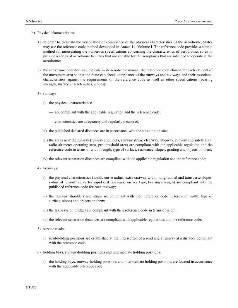
I-2-App 1-2 Procedures — Aerodromes
5/11/20
b) Physical characteristics: 1) in order to facilitate the verification of compliance of the physical characteristics of the aerodrome, States
may use the reference code method developed in Annex 14, Volume I. The reference code provides a simple method for interrelating the numerous specifications concerning the characteristics of aerodromes so as to provide a series of aerodrome facilities that are suitable for the aeroplanes that are intended to operate at the aerodrome;
2) the aerodrome operator may indicate in its aerodrome manual the reference code chosen for each element of
the movement area so that the State can check compliance of the runways and taxiways and their associated characteristics against the requirements of the reference code as well as other specifications (bearing strength, surface characteristics, slopes);
3) runways: i) the physical characteristics: — are compliant with the applicable regulation and the reference code; — characteristics are adequately and regularly measured; ii) the published declared distances are in accordance with the situation on site; iii) the areas near the runway (runway shoulders, runway strips, clearway, stopway, runway end safety area,
radio altimeter operating area, pre-threshold area) are compliant with the applicable regulation and the reference code in terms of width, length, type of surface, resistance, slopes, grading and objects on them;
iv) the relevant separation distances are compliant with the applicable regulation and the reference code; 4) taxiways: i) the physical characteristics (width, curve radius, extra taxiway width, longitudinal and transverse slopes,
radius of turn-off curve for rapid exit taxiways, surface type, bearing strength) are compliant with the published reference code for each taxiway;
ii) the taxiway shoulders and strips are compliant with their reference code in terms of width, type of
surface, slopes and objects on them; iii) the taxiways on bridges are compliant with their reference code in terms of width; iv) the relevant separation distances are compliant with applicable regulations and the reference code; 5) service roads: i) road-holding positions are established at the intersection of a road and a runway at a distance compliant
with the reference code; 6) holding bays, runway-holding positions and intermediate holding positions: i) the holding bays, runway-holding positions and intermediate holding positions are located in accordance
with the applicable reference code;
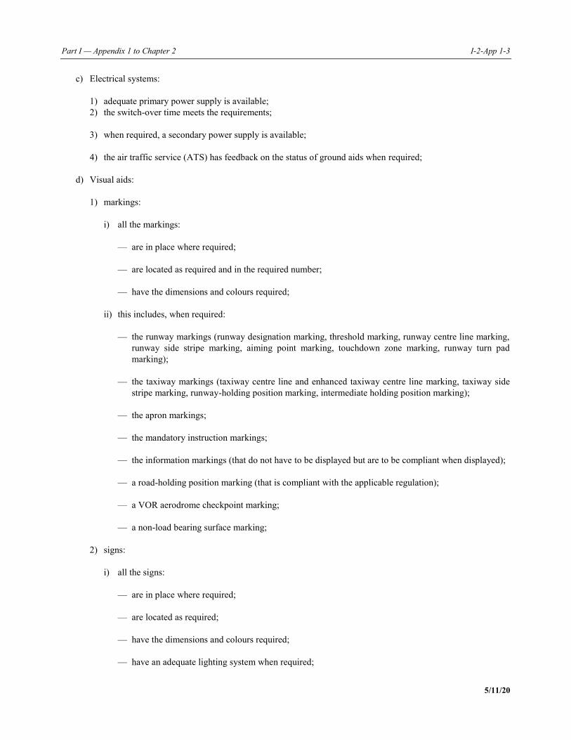
Part I — Appendix 1 to Chapter 2 I-2-App 1-3
5/11/20
c) Electrical systems: 1) adequate primary power supply is available; 2) the switch-over time meets the requirements; 3) when required, a secondary power supply is available; 4) the air traffic service (ATS) has feedback on the status of ground aids when required; d) Visual aids: 1) markings: i) all the markings: — are in place where required; — are located as required and in the required number; — have the dimensions and colours required; ii) this includes, when required: — the runway markings (runway designation marking, threshold marking, runway centre line marking,
runway side stripe marking, aiming point marking, touchdown zone marking, runway turn pad marking);
— the taxiway markings (taxiway centre line and enhanced taxiway centre line marking, taxiway side
stripe marking, runway-holding position marking, intermediate holding position marking); — the apron markings; — the mandatory instruction markings; — the information markings (that do not have to be displayed but are to be compliant when displayed); — a road-holding position marking (that is compliant with the applicable regulation); — a VOR aerodrome checkpoint marking; — a non-load bearing surface marking; 2) signs: i) all the signs: — are in place where required; — are located as required; — have the dimensions and colours required; — have an adequate lighting system when required;
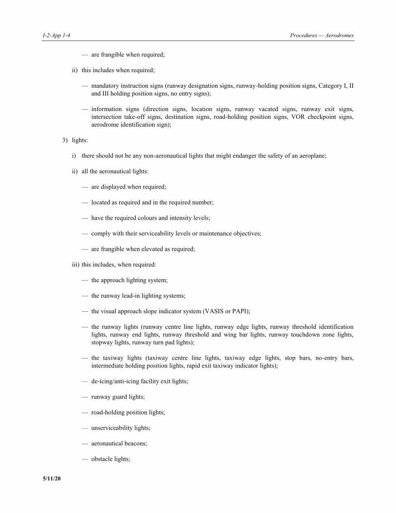
I-2-App 1-4 Procedures — Aerodromes
5/11/20
— are frangible when required; ii) this includes when required; — mandatory instruction signs (runway designation signs, runway-holding position signs, Category I, II
and III holding position signs, no entry signs); — information signs (direction signs, location signs, runway vacated signs, runway exit signs,
intersection take-off signs, destination signs, road-holding position signs, VOR checkpoint signs, aerodrome identification sign);
3) lights: i) there should not be any non-aeronautical lights that might endanger the safety of an aeroplane; ii) all the aeronautical lights: — are displayed when required; — located as required and in the required number; — have the required colours and intensity levels; — comply with their serviceability levels or maintenance objectives; — are frangible when elevated as required; iii) this includes, when required: — the approach lighting system; — the runway lead-in lighting systems; — the visual approach slope indicator system (VASIS or PAPI); — the runway lights (runway centre line lights, runway edge lights, runway threshold identification
lights, runway end lights, runway threshold and wing bar lights, runway touchdown zone lights, stopway lights, runway turn pad lights);
— the taxiway lights (taxiway centre line lights, taxiway edge lights, stop bars, no-entry bars,
intermediate holding position lights, rapid exit taxiway indicator lights); — de-icing/anti-icing facility exit lights; — runway guard lights; — road-holding position lights; — unserviceability lights; — aeronautical beacons; — obstacle lights;
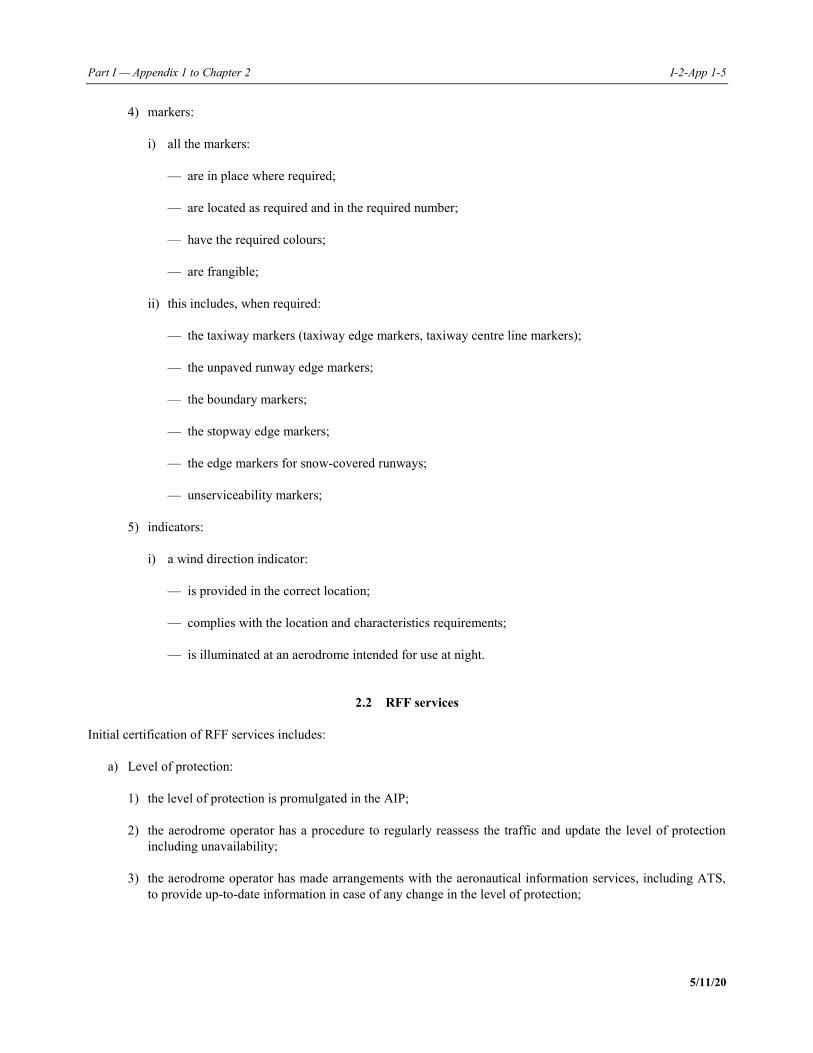
Part I — Appendix 1 to Chapter 2 I-2-App 1-5
5/11/20
4) markers: i) all the markers: — are in place where required; — are located as required and in the required number; — have the required colours; — are frangible; ii) this includes, when required: — the taxiway markers (taxiway edge markers, taxiway centre line markers); — the unpaved runway edge markers; — the boundary markers; — the stopway edge markers; — the edge markers for snow-covered runways; — unserviceability markers; 5) indicators: i) a wind direction indicator: — is provided in the correct location; — complies with the location and characteristics requirements; — is illuminated at an aerodrome intended for use at night.
2.2 RFF services Initial certification of RFF services includes: a) Level of protection: 1) the level of protection is promulgated in the AIP; 2) the aerodrome operator has a procedure to regularly reassess the traffic and update the level of protection
including unavailability; 3) the aerodrome operator has made arrangements with the aeronautical information services, including ATS,
to provide up-to-date information in case of any change in the level of protection;
I-2-App 1-6 Procedures — Aerodromes
5/11/20
b) RFF personnel: 1) the number of RFF personnel is consistent with the level of protection appropriate to the aerodrome RFF
category; Note.— Guidance on the use of a task resource analysis in determining the minimum number of RFF personnel required can be found in the Airport Services Manual (Doc 9137), Part 1 — Rescue and Fire Fighting. 2) the training of all RFF personnel is adequate and monitored; 3) the training facilities, which may include simulation equipment for training on aeroplane fires, are available; 4) the procedures that RFF personnel follow are kept up to date; c) Response: 1) the RFF service is provided with an up-to-date map of its response area, including the access roads; 2) the response time complies with the applicable regulation and is regularly tested. This check should be
formalized in the RFF procedures; 3) the RFF service has procedures that describe this response and ensure that in case of an incident/accident a
report is written and filed; 4) a communication and alerting system is provided between the fire station, the control tower and the RFF
vehicles; d) Rescue equipment: 1) the number of RFF vehicles is consistent with the applicable regulation; 2) the RFF service has a procedure describing the maintenance of the RFF vehicles and ensuring that this
maintenance is formally monitored; 3) the types and quantities of the extinguishing agents, including the reserve supply, are consistent with the
applicable regulation; 4) the protective clothing and respiratory equipment provided are consistent in quality and quantity in
accordance with the applicable regulation, and the respiratory equipment is properly checked and their quantities formally monitored;
5) specific rescue equipment is provided in adequate number and type when the area to be covered by the RFF
service includes water; 6) any other equipment required by the applicable regulation is provided in sufficient number.
2.3 Wildlife hazard management The following checks on wildlife hazard management can either be a technical inspection or included in the audit of the aerodrome operator’s procedures: a) The required equipment is provided;
Part I — Appendix 1 to Chapter 2 I-2-App 1-7
5/11/20
b) Fences are provided as required; c) The aerodrome operator has a procedure describing the actions taken for discouraging the presence of wildlife,
including: 1) who is in charge of those actions and what their training is; 2) how and when these actions are carried out, including reporting and filing of these actions; 3) what equipment is used to conduct these actions; 4) analyses of the aerodrome vicinity and the preventive actions to be taken subsequently to discourage
wildlife; 5) monitoring of these actions, including, where applicable, the conduct of appropriate wildlife assessments; 6) coordination with ATS; d) The aerodrome operator has a procedure to: 1) record and analyse the incidents involving wildlife; 2) collect the wildlife’s remains; 3) monitor the corrective actions to be taken subsequently; and 4) report to the State incidents involving wildlife.
3. ON-SITE VERIFICATION OF THE OPERATOR’S PROCEDURES AND SMS
3.1 On-site verification of the operator’s procedures On-site verification of the aerodrome operator’s procedures should include the following: a) Aerodrome data and reporting: 1) completeness, correctness and integrity of the data reported in accordance with the AIP including: i) data collection, including the status of the movement area and its facilities; ii) data validity checks; iii) data transmission; iv) changes to published data, whether permanent or not; v) checks of the information once published; vi) information update after construction works;
I-2-App 1-8 Procedures — Aerodromes
5/11/20
2) formal coordination with ATS; 3) formal coordination with the aeronautical information services; 4) publication of the required information in the aeronautical publication; 5) information published in accordance with the situation on site; b) Access to the movement area: 1) an up-to-date plan clearly showing all the access points to the movement area; 2) a procedure describing the inspection of access points and fences; Note.— Procedures for access to the manoeuvring areas are often markedly different from those for the apron areas. c) Aerodrome emergency plan: 1) an up-to-date aerodrome emergency plan; 2) regular exercises in relation to the emergency plan; 3) a procedure describing the tasks in the emergency plan; 4) the aerodrome operator regularly verifies the information in the emergency plan, including keeping an
up-to-date list of the persons and contact details in the emergency plan; 5) a procedure describing its roles and responsibilities during emergencies; 6) a procedure describing the involvement of, and coordination with, other agencies during emergencies; 7) the required minimum emergency equipment is available, including an adequately equipped emergency
operation centre and mobile command post; d) RFF: 1) a technical inspection of the various elements of the RFF services in 2.2 b) is held prior to the audit; 2) the checks that are to be done during the aerodrome operator’s on-site verification consist only of verifying
the timely implementation of the corrective action plan subsequent to the technical inspection; 3) if on-site verification reveals new deviations, they should be included in the on-site verification report; e) Inspection of the movement area: 1) a procedure to ensure there is coordination with ATS for the inspection of the movement area; 2) describe the inspections, if performed by the aerodrome operator, including: i) frequency and scope; ii) reporting, transmission and filing;
Part I — Appendix 1 to Chapter 2 I-2-App 1-9
5/11/20
iii) actions to be taken and their monitoring; 3) assess, measure and report runway surface characteristics when the runway is wet or contaminated and their
subsequent promulgation to ATS; f) Maintenance of the movement area: 1) a procedure to periodically measure the runway surface friction characteristics, assessing their adequacy and
any action required; 2) ensure there is a long-term maintenance plan, including the management of the runway surface friction
characteristics, pavement, visual aids, fencing, drainage systems and electrical systems and buildings; g) Snow and ice control, and other hazardous meteorological conditions: 1) at aerodromes subjected to snow and icing conditions: i) the aerodrome operator has a snow and ice control plan, including the means and procedures used as
well as the responsibilities and criteria for closing and reopening the runway; ii) there should be formal coordination for snow and ice removal between the aerodrome operator and ATS; 2) for other hazardous meteorological situations that may occur at the aerodrome (such as thunderstorms,
strong surface winds and gusts, sandstorms), the aerodrome operator should have procedures describing the actions that have to be taken and defining the responsibilities and criteria for suspension of operations on the runway;
3) the aerodrome operator has formal coordination with the meteorological service provider in order to be
advised of any significant meteorological conditions; h) Visual aids and aerodrome electrical systems: 1) if the aerodrome operator is responsible for the maintenance of visual aids and electrical systems,
procedures exist describing: i) the tasks — routine and emergency ones, including inspections of luminous and non-luminous aids and
their frequency and power supply maintenance; ii) reporting, transmission and filing of reports; iii) monitoring of subsequent actions; iv) coordination with ATS; 2) if the aerodrome operator is not in charge of maintenance of visual aids and electrical systems, the
organization in charge needs to be clearly identified, ensuring there are formal coordination procedures with the aerodrome operator, including agreed objectives;
3) obstacle marking is taken into account; i) Operational safety during aerodrome work: 1) when executing work on the aerodrome:
I-2-App 1-10 Procedures — Aerodromes
5/11/20
i) a procedure describing the necessary notification to the different stakeholders; ii) risk assessment of the aerodrome work; iii) roles and responsibilities of the various parties, including their relationship and the enforcement of
safety measures; iv) safety monitoring during the work; v) reopening of facilities, where relevant; vi) necessary coordination with ATS; j) Apron management. When an apron management service is provided: 1) a procedure to ensure coordination with ATS; 2) the use of acceptable aeroplanes for each parking stand formally identified; 3) a compliant apron safety line is provided; 4) general safety instructions for all the agents on the apron area; 5) the placement and pushback of the aeroplane; k) Apron safety management: 1) a procedure for the inspection of the apron area (see j)); 2) there is coordination with other parties accessing the apron, such as fuelling companies, de-icing companies
and other ground handling agencies; l) Vehicles on the movement area: 1) a procedure to ensure the vehicles on the movement area are adequately equipped; 2) the drivers have followed the appropriate training; 3) if the aerodrome operator is responsible for the training of vehicular drivers on the manoeuvring area, an
appropriate training plan, including recurrent training and awareness actions, is available; 4) if the aerodrome operator is not in charge of this training or some of this training, the service provider is
clearly identified and there is formal coordination between them; Note.— Guidance on the knowledge required by operators of vehicles can be found in Annex 14, Volume I, Attachment A, section 19. m) Wildlife hazard management. Checks on wildlife hazard management can either be a technical inspection or
included in the on-site verification of the operator’s procedures: 1) if the domain has not been inspected during the technical inspections, the on-site verification team should
check the points listed in 2.3 c);
Part I — Appendix 1 to Chapter 2 I-2-App 1-11
5/11/20
2) if a technical inspection has been carried out prior to the on-site verification, the latter consists in checking the timely implementation of the corrective action plan subsequent to the technical inspection;
3) if the on-site verification reveals new deviations, these have to be included in the on-site verification report; n) Obstacles: 1) a procedure to ensure that there is an obstacle chart; 2) a procedure for obstacle monitoring describing the checks, their frequency, filing and follow-up actions; 3) a procedure to ensure that the obstacles do not represent a danger for safety and that appropriate action is
taken when required; o) Removal of a disabled aeroplane: 1) there is a plan for the removal of a disabled aeroplane describing the role and responsibility of the
aerodrome operator, including the necessary coordination with other agencies and the means available or that can be made available;
p) Low visibility operations: 1) there is coordination between the aerodrome operator and ATS, including awareness of the status of both
low visibility procedures (LVP) and the deterioration of visual aids; 2) a procedure describing the actions to be taken when LVP is in process (vehicle control, visual range
measurement if necessary);
3.2 On-site verification of the SMS a) As a minimum, the items to be in place when granting the initial certification are: 1) safety policy: a safety policy has been endorsed by the accountable executive to reflect the organization’s
commitments regarding safety; 2) operator’s organizational structure: the aerodrome operator has appointed an accountable executive and a
safety manager; b) The safety manager should be independent from any operational task regarding aerodrome safety. The criteria
for assessing the operator’s SMS structure might be tailored to the size of the operator, notably concerning the independence of the safety manager;
c) The capability and competence of the aerodrome operator should be assessed so as to ensure sufficient
management commitment to and responsibility for safety at the aerodrome. This is usually achieved through the competence of the accountable executive;
1) responsibilities and assignments: the aerodrome operator has formally defined the responsibilities of each
staff member regarding safety as well as the lines of responsibility; 2) training: the aerodrome operator formally monitors the staff’s and subcontractors’ training, ensuring that it
is adequate, and takes action when necessary;
I-2-App 1-12 Procedures — Aerodromes
5/11/20
3) accident and incident reporting: the aerodrome operator has a procedure ensuring that: i) incidents are reported by staff and subcontractors, including a description of the actions in place in order
to be able to report them; ii) incidents are promptly analysed and the actions to be subsequently taken are monitored; iii) the reports and analyses of the incidents are filed; iv) incidents are reported to the State; v) coordination is in place with other stakeholders; 4) existing hazards at the aerodrome: a procedure in order to identify, analyse and assess hazards to the safe
operation of aeroplanes and to put in place suitable mitigating measures; 5) risk assessment and mitigation of changes: a procedure ensuring that for any change at the aerodrome, its
impact on safety is analysed, listing the subsequent hazards that could be generated. This procedure describes who conducts the analysis, when and how the hazards are monitored, what actions are subsequently taken, and the criteria leading to the analysis. These assessments are filed;
6) safety indicators: the aerodrome operator sets and monitors its own safety indicators that illustrate its safety
criteria, in order to be able to analyse the potential deficiencies; Note.— Ensure coordination with previous safety indicators as set by the State. 7) safety audits: the aerodrome operator has a safety audit programme in place which includes a training
programme for those involved; 8) safety promotion: the aerodrome operator should have a process to promote safety-related information.
______________________
PANS — Aerodromes I-2-App 2-1 5/11/20
Appendix 2 to Chapter 2
CRITICAL DATA RELATED TO SAFETY OCCURRENCES
REPORTED AT AERODROMES FOR THE
MONITORING OF SAFETY
Note.— The provisions in this appendix do not override the requirements in Annex 13 — Aircraft Accident and Incident Investigation, concerning the mandatory reporting of certain types of accidents/serious incidents and the responsibilities of the various parties involved. When safety occurrences of the following types are reported, the following critical data should be collected when relevant and feasible. This may require a collaborative effort from the aerodrome operator, ANSP or other involved parties commensurate with the severity of the potential risk attached to each occurrence.
1. Runway excursions a) type of event (lateral veer-off, overrun); b) landing/take-off; c) type of approach if it is a landing event (local time or UTC); d) date and time (local time or UTC); e) aeroplane type; f) runway: 1) dimensions (width/length); 2) slopes; 3) displaced threshold (yes/no, and if so, distance between the runway threshold and the runway edge); 4) runway end safety area (RESA) (yes/no, and if so, orientation, dimensions and structure); 5) contaminated runway (yes/no, and if so, contaminant type (slush, snow, ice, water, other (to be specified),
contaminant depth); g) wind (direction and speed); h) visibility; i) details of the exit:
I-2-App 2-2 Procedures — Aerodromes
5/11/20
1) exit speed or estimation; 2) aeroplane angle with the runway edge; 3) distance between the touchdown and the exit; 4) description of the trajectory of the aeroplane once on the runway strip and/or RESA; j) details of the location of the aeroplane once stopped. Note 1.— For overruns, information to be reported includes longitudinal position in relation to the threshold location and/or end of runway surface and lateral position in relation to runway lateral edge or runway centre line. Note 2.— Runway excursions are serious incidents, if not accidents, according to Annex 13, Attachment C. This would normally imply that the State’s accident/incident investigation authority needs to become involved, and coordination with the relevant authorities is therefore required.
2. Undershoot (land short of runway) a) type of event (land short, undershoot); b) type of approach; c) ground-based vertical guidance available and operational (instrument landing system (ILS), precision approach
path indicator (PAPI), abbreviated precision approach path indicator (APAPI)); d) date and time (local time or UTC); e) wind speed (including gusts), description (calm/variable) and direction; f) visibility; g) aeroplane type; h) runway: 1) dimensions (width/length); 2) slopes; 3) displaced threshold (yes/no, and if so, distance between the runway threshold and the runway edge); 4) RESA (yes/no, and if so, magnetic orientation of runway (QFU), dimensions and structure); 5) contaminated runway (yes/no, and if so, contaminant type (slush, snow, ice, water, other (to be specified),
contaminant depth); i) details of the undershoot (aeroplane speed at touchdown, distance between the touchdown and the runway edge,
causes of the event): 1) description of the trajectory of the aeroplane after touchdown.
Part I — Appendix 2 to Chapter 2 I-2-App 2-3
5/11/20
Note.— Undershoots are serious incidents, if not accidents, according to Annex 13, Attachment C. This would normally imply that the State’s accident/incident investigation authority needs to become involved, and coordination with the relevant authorities is therefore required.
3. Runway incursion a) entities involved (aeroplane/vehicle; aeroplane/aeroplane; aeroplane/person); b) date and time (local time or UTC); c) aeroplane type, landing/take-off, type of approach; d) vehicle type, location; e) runway: 1) dimensions (width/length); 2) slopes/line of sight; 3) displaced threshold (yes/no, and if so, distance between the runway threshold and the runway edge); 4) rapid exits; 5) wind; 6) visibility; f) details of the incursion: 1) description of the trajectories and speeds of both vehicles/aeroplanes; 2) estimated distances (horizontal and vertical) between the entities involved; 3) contaminated operational surfaces in the incursion area (yes/no, and if so, contaminant type (slush, snow,
ice, water, other (to be specified), contaminant depth). Note 1.— Runway incursions classified with severity A are serious incidents according to Annex 13, Attachment C. This would normally imply that the State’s accident/incident investigation authority needs to become involved, and coordination with the relevant authorities is therefore required. Note 2.— Guidance on prevention of runway incursions, including severity classification, is available in Doc 9870 — Manual on the Prevention of Runway Incursions).
4. Landing or take-off on a taxiway a) landing/take-off; b) type of approach when relevant;
I-2-App 2-4 Procedures — Aerodromes
5/11/20
c) date and time (local time or UTC); d) wind; e) visibility; f) aeroplane type; g) taxiway: 1) dimensions (width/length); 2) slopes; h) details of the event: 1) possible contributing factors (e.g. inadequate lighting, procedure not applied, works, inadequate or
misleading marking). Note.— Landing and take-off on taxiways are serious incidents according to Annex 13, Attachment C. This would normally imply that the State’s accident/incident investigation authority needs to become involved, and coordination with the relevant authorities is therefore required.
5. FOD-related events a) type of event; b) location (runway, orientation, or taxiway, stand), location of FOD, including where possible lateral and
longitudinal positions; c) date and time (local time or UTC); d) FOD description: 1) name (if possible); 2) shape and dimensions; 3) material; 4) colour; 5) origin (if known: lighting, infrastructure, works, animals, aeroplane, environment (wind, etc.)).
6. Other excursions (i.e. from the taxiway or apron) a) type of event; b) location;
Part I — Appendix 2 to Chapter 2 I-2-App 2-5
5/11/20
c) date and time (local time or UTC); d) aeroplane type; e) taxiway: 1) dimensions (width/length); 2) slopes; 3) if in a curved section: fillets (yes/no, and characteristics); 4) contaminated taxiway (yes/no, and if so, contaminant type (slush, snow, ice, water, other (to be specified)
and contaminant depth); f) wind (direction and speed); g) details of the exit (exit speed or estimation, aeroplane angle with the taxiway edge, in a straight or a curved
section, causes of the event); h) details of the location of the aeroplane once stopped.
7. Other incursions (i.e. on taxiway or apron) Same data as for item 2 (undershoot).
8. Birds/wildlife strike-related events To be conducted in accordance with ICAO bird strike information system (IBIS) data (ingestion, collision). If there has been no collision, and the animal was avoided, it is important to know the location of the animal at the time the avoided collision occurred.
9. Ground collisions a) type of event (ground collision); b) location: 1) apron; 2) manoeuvring area; 3) runway, taxiway; 4) contaminant (if relevant: type and depth); 5) wind (if relevant);
I-2-App 2-6 Procedures — Aerodromes
5/11/20
c) date and time (local time or UTC); d) phase of flight (e.g. taxi out, departure roll, engine start/pushback); e) aeroplane(s) involved; 1) type of aeroplane and trajectory; f) vehicle(s) involved; 1) type of vehicle and trajectory; g) material damages (to both aeroplane(s) and/or vehicle(s))/human damages and location of the damages; h) phase of operation, if ground handling is involved; i) description of the collision: 1) estimated speed of both vehicle(s) and/or aeroplane(s); 2) description of the trajectories of the aeroplane(s) and/or the vehicle(s). Note 1.— Ground collisions involving aeroplanes can be incidents, serious incidents or accidents. If classified as an incident, they are normally investigated as part of the aerodrome’s SMS. If classified as a serious incident or accident, this would normally imply that the State’s accident/incident investigation authority needs to become involved, and coordination with the relevant authorities is therefore required. Note 2.— Ground collisions not involving aeroplanes can be an incident and investigated as part of the aerodrome’s SMS.
_____________________
PANS — Aerodromes I-2-Att A-1 5/11/20
Attachment A to Chapter 2
LIST OF POSSIBLE SUBJECTS COVERED
IN AN AERODROME MANUAL
The contents of an aerodrome manual include: a) List of updates; b) Aerodrome administrative data; c) Description of the aerodrome, including dimensions and related information; d) List of authorized deviations; e) Duties, means and procedures of the applicant to ensure safety in each area include: 1) aerodrome data and reporting; 2) access to the movement area; 3) aerodrome emergency plan; 4) RFF; 5) inspection of the movement area; 6) maintenance of the movement area; 7) snow and ice control, and other hazardous meteorological conditions; 8) visual aids and aerodrome electrical systems; 9) apron management; 10) apron safety management; 11) vehicle control on the movement area; 12) wildlife hazard management; 13) obstacles; 14) removal of disabled aeroplanes;

I-2-Att A-2 Procedures — Aerodromes
5/11/20
15) dangerous goods; 16) low visibility operations; 17) protection of sites for radar, navigational aids and meteorological equipment; f) SMS.
_____________________
PANS — Aerodromes I-2-Att B-1 5/11/20
Attachment B to Chapter 2
INITIAL CERTIFICATION PROCESS
1. AERODROME CERTIFICATION SCHEME It may not be possible to certify all aerodromes at the same time since it depends on the number of aerodromes in the State. Therefore, a programme for the certification of aerodromes in the State, including the schedule, has to be prepared. The State plans a certification programme, taking into account the number of trained oversight personnel within the State, according to the following main parameters.
1.1 Scope of operations and traffic 1.1.1 An important consideration to be taken into account is the level of commercial operations. For States having a large number of aerodromes, different deadlines for certification may be established based on traffic thresholds. These criteria allow the State to certify higher traffic aerodromes with priority. 1.1.2 The number of aircraft movements may be an important parameter. This is partly taken into account with the passenger volume, but the types of aeroplanes used can have an impact on the criteria used for certification. This impact is taken into account when needed through the applicable regulation itself as some specifications may or may not apply, depending on the number of movements (e.g. RFF service).
1.2 Complexity of infrastructure design 1.2.1 The inspection of infrastructure and ground aids is often the first step of the initial certification process and contributes to the assessment of the conformity of the infrastructure, taking into account its complexity. Periodic infrastructure and ground aids inspections are also an important part of the continued oversight. 1.2.2 Issues arising from complex aerodrome design will also be dealt with through feedback obtained through the reporting of accidents/incidents occurring on the aerodrome as part of the aerodrome’s SMS.
1.3 Level/maturity of SMS implementation 1.3.1 Because the SMS requirements for the certification of the aerodrome operators may be new, this aspect of the operation may require major efforts by the aerodrome operator to achieve compliance. 1.3.2 For an aerodrome which is already certified or being certified, for which the SMS is in its initial phase, the level/maturity of SMS implementation can be expected to be effective only after a certain period of time. Consequently, initial certification of the operator’s SMS may need to be tailored to the size of the operator and the maturity of its SMS. Specific attention to the SMS during on-site verification is therefore necessary.
I-2-Att B-2 Procedures — Aerodromes
5/11/20
2. SUMMARY OF THE CERTIFICATION PROCESS 2.1 The certification process for an aerodrome that is already operational can be summarized as follows: a) as soon as an aerodrome meets the legal criteria for certification, a meeting is held between the State and the
aerodrome operator; b) during this meeting, the State presents the certification process and deadlines to the aerodrome operator. The
aerodrome operator develops the aerodrome manual as soon as it enters the initial certification process, so as to submit it no later than six months after the meeting;
c) during this six-month period the State: 1) completes the technical inspections so that the results are available for the on-site verification; and 2) assembles the on-site verification team at least two months before the deadline for submission of the
aerodrome manual and informs the aerodrome operator of the team members. Note.— The main items subject to technical inspections and the minimal checks to be performed are listed in Appendix 1. 2.2 When all the conditions have been met, the aerodrome manual is accepted/approved no later than three months after it was first submitted. This period includes any exchange of communication between the aerodrome operator and the State if needed – some information may be lacking at the beginning, thus preventing the State from accepting the manual at first. 2.3 During this period, the on-site verification team, together with the aerodrome operator, plans the time and dates of the on-site verification with the objective of allowing the aerodrome operator a four-month period to mitigate any deviations before the certification deadline. 2.4 As soon as the aerodrome manual is accepted, it is sent to the on-site verification team with all the procedures enclosed. The on-site verification and inspection reports should be sent by the State to the aerodrome operator no later than one month after the on-site verification/inspection closing meeting. 2.5 The aerodrome operator submits to the State corrective action plans no later than two months after having received the certification/inspection reports. The State and the aerodrome operator require two months minimum after the last report to agree to the corrective action plans before granting the certificate. 2.6 For aerodromes already operating, the overall process, until delivery of the certificate, could consequently last 18 months. Note.— The SMS on-site verification can be disconnected from the aerodrome operator’s on-site verification in regard to compliance with its operational procedures and in this case: — the deadline for the submission of the SMS part of the aerodrome manual can be longer, but will nevertheless
not exceed six additional months; — the deadline for the SMS on-site verification can be longer, but the SMS on-site verification will nevertheless be
conducted at least three months before the certification deadline to be in line with the required period of two months for the operator and the State to define an accepted corrective action plan.
2.7 A flow chart on the certification process is given in Figure I-2-Att B-1.
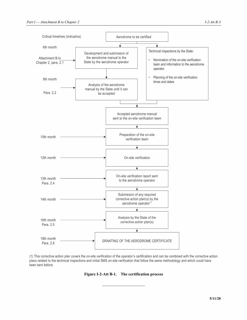
Part I — Attachment B to Chapter 2 I-2-Att B-3
5/11/20
Figure I-2-Att B-1. The certification process
_____________________
Aerodrome to be certified
Accepted aerodrome manual
sent to on-site verification teamthe
Development and submission of
the aerodrome manual to the
State by the aerodrome operator
Analysis of the aerodrome
manual by the State until it can
be accepted
Critical timelines (indicative)
Preparation of the on-site
verification team
On-site verification
On-site veri cation report sentfi
to aerodrome operatorthe
Submission of any required
corrective action plan(s) by the
aerodrome operator(1)
Analysis by the State of the
corrective action plan(s)
GRANTING THE AERODROME CERTIFICATEOF
6th month
9th month
10th month
12th month
13th month
14th month
16th month
Technical inspections by the State:
• Nomination of the on-site verification
team and information to the aerodrome
operator
• Planning of the on-site verification
times and dates
Attachment B to
Chapter 2, para. 2.1
Para. 2.2
Para. 2.4
Para. 2.5
18th month
Para. 2.6
(1) This corrective action plan covers the on-site verification of the operator’s certification and can be combined with the corrective action
plans related to the technical inspections and initial SMS on-site verification that follow the same methodology and which could have
been sent before.

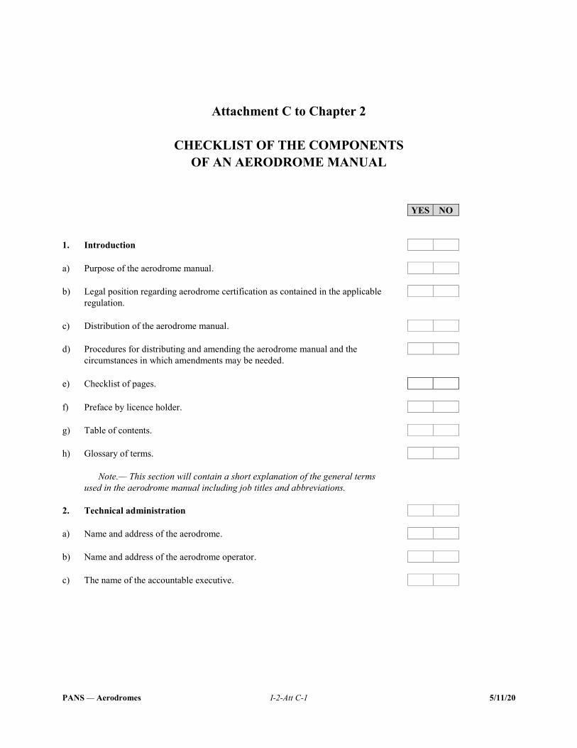
PANS — Aerodromes I-2-Att C-1 5/11/20
Attachment C to Chapter 2
CHECKLIST OF THE COMPONENTS
OF AN AERODROME MANUAL
YES NO 1. Introduction a) Purpose of the aerodrome manual. b) Legal position regarding aerodrome certification as contained in the applicable
regulation.
c) Distribution of the aerodrome manual. d) Procedures for distributing and amending the aerodrome manual and the
circumstances in which amendments may be needed.
e) Checklist of pages. f) Preface by licence holder. g) Table of contents. h) Glossary of terms.
Note.— This section will contain a short explanation of the general terms used in the aerodrome manual including job titles and abbreviations.
2. Technical administration a) Name and address of the aerodrome. b) Name and address of the aerodrome operator. c) The name of the accountable executive.
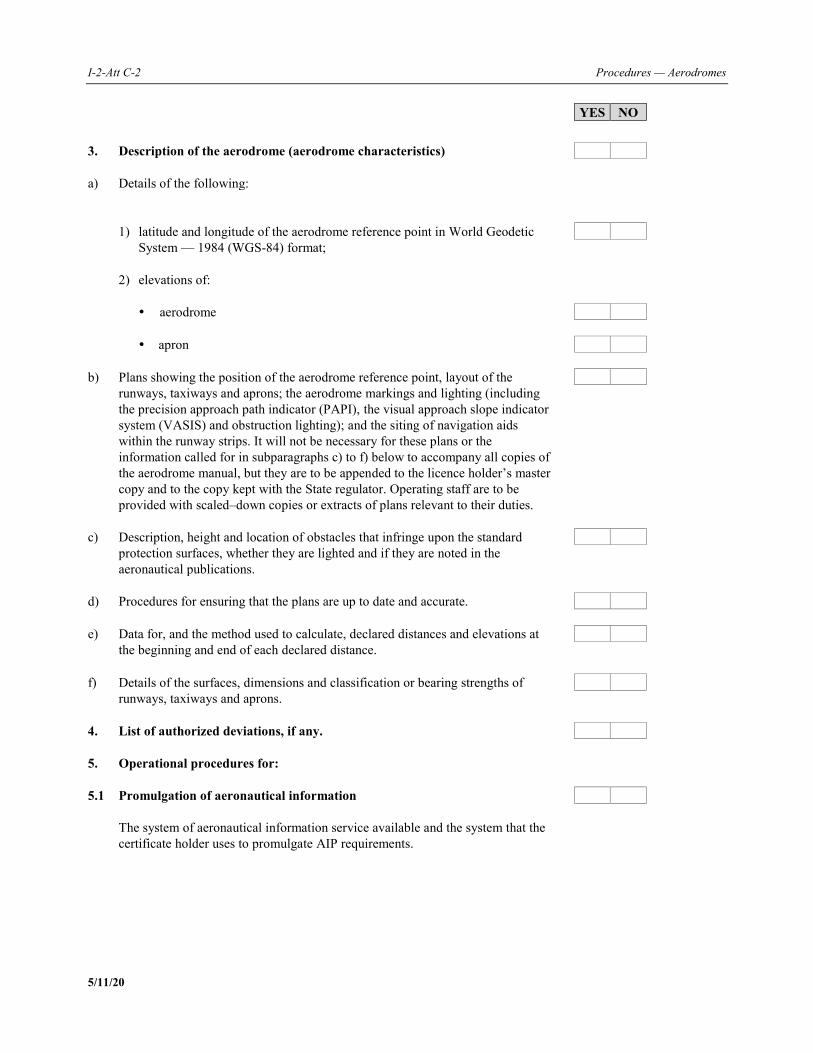
I-2-Att C-2 Procedures — Aerodromes
5/11/20
YES NO 3. Description of the aerodrome (aerodrome characteristics) a) Details of the following: 1) latitude and longitude of the aerodrome reference point in World Geodetic
System — 1984 (WGS-84) format;
2) elevations of: aerodrome apron b) Plans showing the position of the aerodrome reference point, layout of the
runways, taxiways and aprons; the aerodrome markings and lighting (including the precision approach path indicator (PAPI), the visual approach slope indicator system (VASIS) and obstruction lighting); and the siting of navigation aids within the runway strips. It will not be necessary for these plans or the information called for in subparagraphs c) to f) below to accompany all copies of the aerodrome manual, but they are to be appended to the licence holder’s master copy and to the copy kept with the State regulator. Operating staff are to be provided with scaled–down copies or extracts of plans relevant to their duties.
c) Description, height and location of obstacles that infringe upon the standard
protection surfaces, whether they are lighted and if they are noted in the aeronautical publications.
d) Procedures for ensuring that the plans are up to date and accurate. e) Data for, and the method used to calculate, declared distances and elevations at
the beginning and end of each declared distance.
f) Details of the surfaces, dimensions and classification or bearing strengths of
runways, taxiways and aprons.
4. List of authorized deviations, if any. 5. Operational procedures for: 5.1 Promulgation of aeronautical information
The system of aeronautical information service available and the system that the certificate holder uses to promulgate AIP requirements.
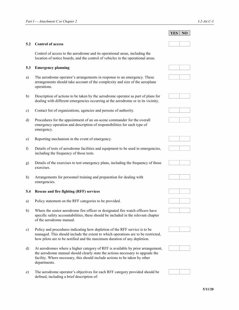
Part I — Attachment C to Chapter 2 I-2-Att C-3
5/11/20
YES NO 5.2 Control of access
Control of access to the aerodrome and its operational areas, including the location of notice boards, and the control of vehicles in the operational areas.
5.3 Emergency planning a) The aerodrome operator’s arrangements in response to an emergency. These
arrangements should take account of the complexity and size of the aeroplane operations.
b) Description of actions to be taken by the aerodrome operator as part of plans for dealing with different emergencies occurring at the aerodrome or in its vicinity.
c) Contact list of organizations, agencies and persons of authority. d) Procedures for the appointment of an on-scene commander for the overall
emergency operation and description of responsibilities for each type of emergency.
e) Reporting mechanism in the event of emergency. f) Details of tests of aerodrome facilities and equipment to be used in emergencies,
including the frequency of those tests.
g) Details of the exercises to test emergency plans, including the frequency of those
exercises.
h) Arrangements for personnel training and preparation for dealing with
emergencies.
5.4 Rescue and fire fighting (RFF) services a) Policy statement on the RFF categories to be provided. b) Where the senior aerodrome fire officer or designated fire watch officers have
specific safety accountabilities, these should be included in the relevant chapter of the aerodrome manual.
c) Policy and procedures indicating how depletion of the RFF service is to be
managed. This should include the extent to which operations are to be restricted, how pilots are to be notified and the maximum duration of any depletion.
d) At aerodromes where a higher category of RFF is available by prior arrangement,
the aerodrome manual should clearly state the actions necessary to upgrade the facility. Where necessary, this should include actions to be taken by other departments.
e) The aerodrome operator’s objectives for each RFF category provided should be
defined, including a brief description of:
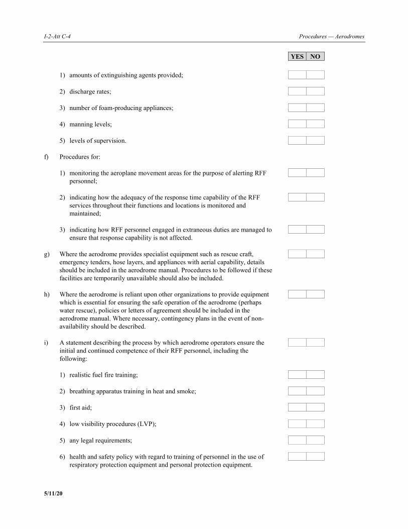
I-2-Att C-4 Procedures — Aerodromes
5/11/20
YES NO 1) amounts of extinguishing agents provided; 2) discharge rates; 3) number of foam-producing appliances; 4) manning levels; 5) levels of supervision. f) Procedures for:
1) monitoring the aeroplane movement areas for the purpose of alerting RFF personnel;
2) indicating how the adequacy of the response time capability of the RFF
services throughout their functions and locations is monitored and maintained;
3) indicating how RFF personnel engaged in extraneous duties are managed to
ensure that response capability is not affected.
g) Where the aerodrome provides specialist equipment such as rescue craft,
emergency tenders, hose layers, and appliances with aerial capability, details should be included in the aerodrome manual. Procedures to be followed if these facilities are temporarily unavailable should also be included.
h) Where the aerodrome is reliant upon other organizations to provide equipment
which is essential for ensuring the safe operation of the aerodrome (perhaps water rescue), policies or letters of agreement should be included in the aerodrome manual. Where necessary, contingency plans in the event of non-availability should be described.
i) A statement describing the process by which aerodrome operators ensure the
initial and continued competence of their RFF personnel, including the following:
1) realistic fuel fire training; 2) breathing apparatus training in heat and smoke; 3) first aid; 4) low visibility procedures (LVP); 5) any legal requirements; 6) health and safety policy with regard to training of personnel in the use of
respiratory protection equipment and personal protection equipment.
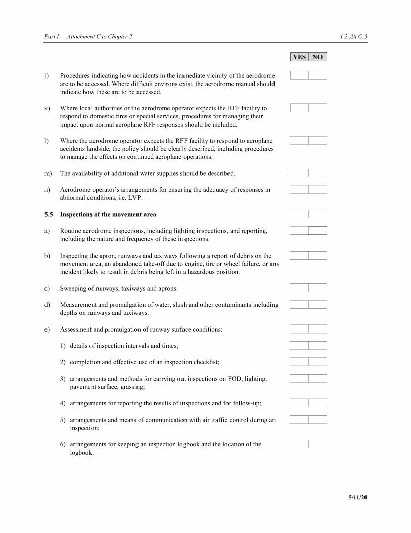
Part I — Attachment C to Chapter 2 I-2-Att C-5
5/11/20
YES NO j) Procedures indicating how accidents in the immediate vicinity of the aerodrome
are to be accessed. Where difficult environs exist, the aerodrome manual should indicate how these are to be accessed.
k) Where local authorities or the aerodrome operator expects the RFF facility to
respond to domestic fires or special services, procedures for managing their impact upon normal aeroplane RFF responses should be included.
l) Where the aerodrome operator expects the RFF facility to respond to aeroplane
accidents landside, the policy should be clearly described, including procedures to manage the effects on continued aeroplane operations.
m) The availability of additional water supplies should be described. n) Aerodrome operator’s arrangements for ensuring the adequacy of responses in
abnormal conditions, i.e. LVP.
5.5 Inspections of the movement area a) Routine aerodrome inspections, including lighting inspections, and reporting,
including the nature and frequency of these inspections.
b) Inspecting the apron, runways and taxiways following a report of debris on the
movement area, an abandoned take-off due to engine, tire or wheel failure, or any incident likely to result in debris being left in a hazardous position.
c) Sweeping of runways, taxiways and aprons. d) Measurement and promulgation of water, slush and other contaminants including
depths on runways and taxiways.
e) Assessment and promulgation of runway surface conditions: 1) details of inspection intervals and times; 2) completion and effective use of an inspection checklist; 3) arrangements and methods for carrying out inspections on FOD, lighting,
pavement surface, grassing;
4) arrangements for reporting the results of inspections and for follow-up; 5) arrangements and means of communication with air traffic control during an
inspection;
6) arrangements for keeping an inspection logbook and the location of the
logbook.
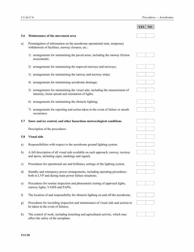
I-2-Att C-6 Procedures — Aerodromes
5/11/20
YES NO 5.6 Maintenance of the movement area
a) Promulgation of information on the aerodrome operational state, temporary withdrawals of facilities, runway closures, etc.:
1) arrangements for maintaining the paved areas, including the runway friction
assessments;
2) arrangements for maintaining the unpaved runways and taxiways; 3) arrangements for maintaining the runway and taxiway strips; 4) arrangements for maintaining aerodrome drainage; 5) arrangements for maintaining the visual aids, including the measurement of
intensity, beam spread and orientation of lights;
6) arrangements for maintaining the obstacle lighting; 7) arrangements for reporting and action taken in the event of failure or unsafe
occurrence.
5.7 Snow and ice control, and other hazardous meteorological conditions Description of the procedures. 5.8 Visual aids a) Responsibilities with respect to the aerodrome ground lighting system. b) A full description of all visual aids available on each approach, runway, taxiway
and apron, including signs, markings and signals.
c) Procedures for operational use and brilliancy settings of the lighting system. d) Standby and emergency power arrangements, including operating procedures
both in LVP and during main power failure situations.
e) Procedures for routine inspection and photometric testing of approach lights,
runway lights, VASIS and PAPIs.
f) The location of and responsibility for obstacle lighting on and off the aerodrome. g) Procedures for recording inspection and maintenance of visual aids and actions to
be taken in the event of failures.
h) The control of work, including trenching and agricultural activity, which may
affect the safety of the aeroplane.
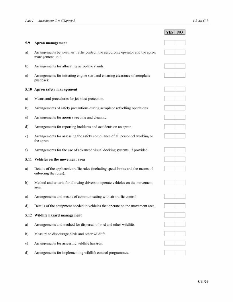
Part I — Attachment C to Chapter 2 I-2-Att C-7
5/11/20
YES NO 5.9 Apron management a) Arrangements between air traffic control, the aerodrome operator and the apron
management unit.
b) Arrangements for allocating aeroplane stands. c) Arrangements for initiating engine start and ensuring clearance of aeroplane
pushback.
5.10 Apron safety management a) Means and procedures for jet blast protection. b) Arrangements of safety precautions during aeroplane refuelling operations. c) Arrangements for apron sweeping and cleaning. d) Arrangements for reporting incidents and accidents on an apron. e) Arrangements for assessing the safety compliance of all personnel working on
the apron.
f) Arrangements for the use of advanced visual docking systems, if provided. 5.11 Vehicles on the movement area a) Details of the applicable traffic rules (including speed limits and the means of
enforcing the rules).
b) Method and criteria for allowing drivers to operate vehicles on the movement
area.
c) Arrangements and means of communicating with air traffic control. d) Details of the equipment needed in vehicles that operate on the movement area.
5.12 Wildlife hazard management a) Arrangements and method for dispersal of bird and other wildlife. b) Measure to discourage birds and other wildlife. c) Arrangements for assessing wildlife hazards. d) Arrangements for implementing wildlife control programmes.
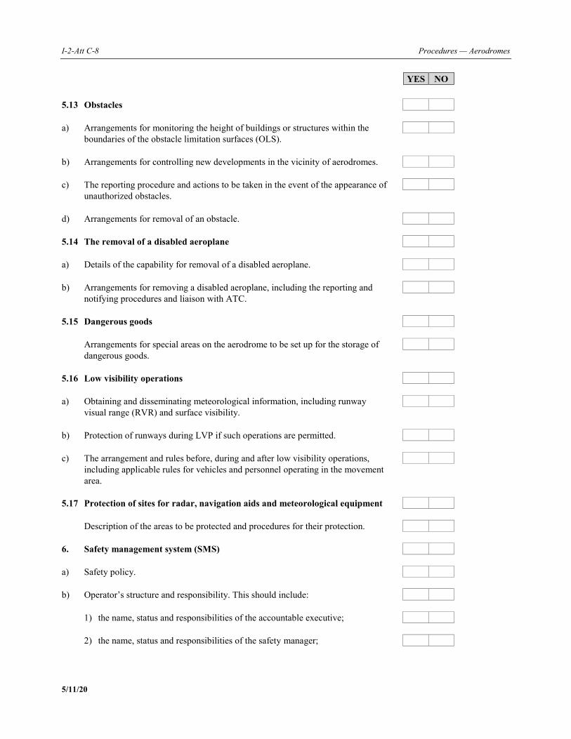
I-2-Att C-8 Procedures — Aerodromes
5/11/20
YES NO 5.13 Obstacles a) Arrangements for monitoring the height of buildings or structures within the
boundaries of the obstacle limitation surfaces (OLS).
b) Arrangements for controlling new developments in the vicinity of aerodromes.
c) The reporting procedure and actions to be taken in the event of the appearance of
unauthorized obstacles.
d) Arrangements for removal of an obstacle. 5.14 The removal of a disabled aeroplane a) Details of the capability for removal of a disabled aeroplane. b) Arrangements for removing a disabled aeroplane, including the reporting and
notifying procedures and liaison with ATC.
5.15 Dangerous goods Arrangements for special areas on the aerodrome to be set up for the storage of
dangerous goods.
5.16 Low visibility operations a) Obtaining and disseminating meteorological information, including runway
visual range (RVR) and surface visibility.
b) Protection of runways during LVP if such operations are permitted.
c) The arrangement and rules before, during and after low visibility operations,
including applicable rules for vehicles and personnel operating in the movement area.
5.17 Protection of sites for radar, navigation aids and meteorological equipment
Description of the areas to be protected and procedures for their protection. 6. Safety management system (SMS) a) Safety policy. b) Operator’s structure and responsibility. This should include:
1) the name, status and responsibilities of the accountable executive; 2) the name, status and responsibilities of the safety manager;
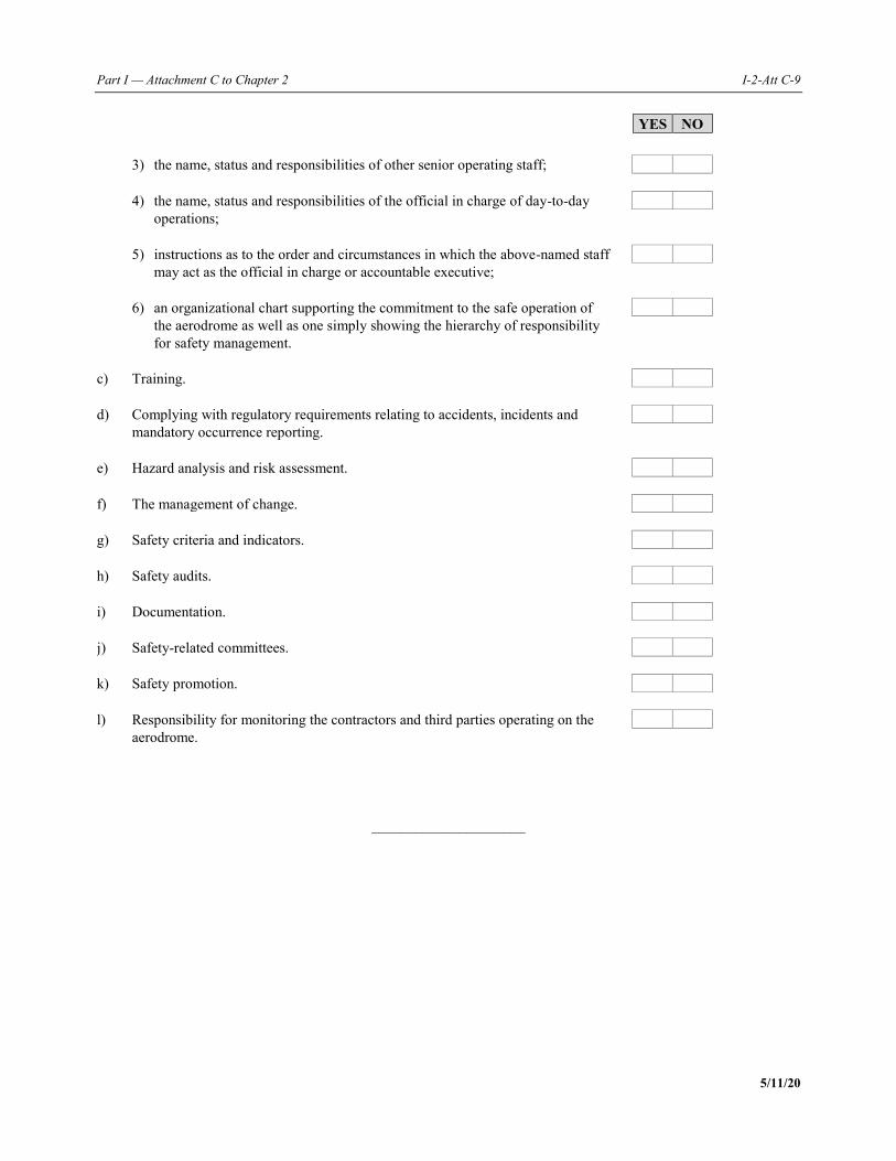
Part I — Attachment C to Chapter 2 I-2-Att C-9
5/11/20
YES NO 3) the name, status and responsibilities of other senior operating staff; 4) the name, status and responsibilities of the official in charge of day-to-day
operations;
5) instructions as to the order and circumstances in which the above-named staff
may act as the official in charge or accountable executive;
6) an organizational chart supporting the commitment to the safe operation of
the aerodrome as well as one simply showing the hierarchy of responsibility for safety management.
c) Training. d) Complying with regulatory requirements relating to accidents, incidents and
mandatory occurrence reporting.
e) Hazard analysis and risk assessment. f) The management of change. g) Safety criteria and indicators. h) Safety audits. i) Documentation. j) Safety-related committees. k) Safety promotion. l) Responsibility for monitoring the contractors and third parties operating on the
aerodrome.
_____________________

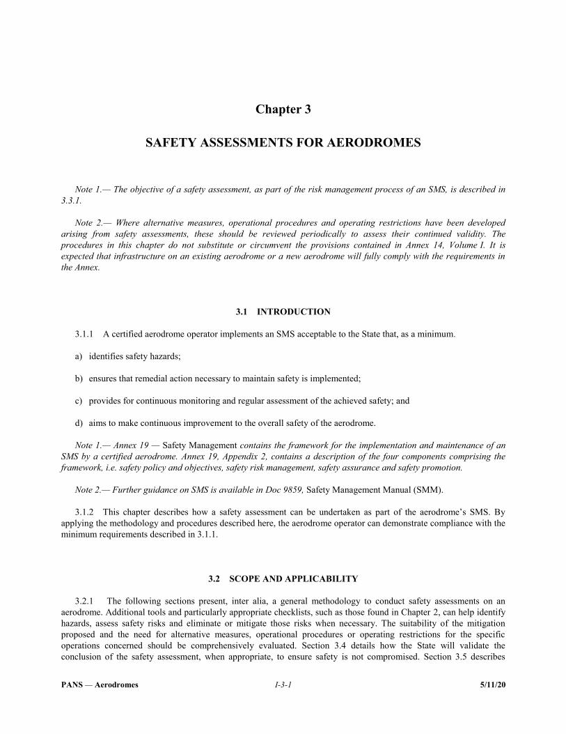
PANS — Aerodromes I-3-1 5/11/20
Chapter 3
SAFETY ASSESSMENTS FOR AERODROMES
Note 1.— The objective of a safety assessment, as part of the risk management process of an SMS, is described in 3.3.1. Note 2.— Where alternative measures, operational procedures and operating restrictions have been developed arising from safety assessments, these should be reviewed periodically to assess their continued validity. The procedures in this chapter do not substitute or circumvent the provisions contained in Annex 14, Volume I. It is expected that infrastructure on an existing aerodrome or a new aerodrome will fully comply with the requirements in the Annex.
3.1 INTRODUCTION 3.1.1 A certified aerodrome operator implements an SMS acceptable to the State that, as a minimum. a) identifies safety hazards; b) ensures that remedial action necessary to maintain safety is implemented; c) provides for continuous monitoring and regular assessment of the achieved safety; and d) aims to make continuous improvement to the overall safety of the aerodrome. Note 1.— Annex 19 — Safety Management contains the framework for the implementation and maintenance of an SMS by a certified aerodrome. Annex 19, Appendix 2, contains a description of the four components comprising the framework, i.e. safety policy and objectives, safety risk management, safety assurance and safety promotion. Note 2.— Further guidance on SMS is available in Doc 9859, Safety Management Manual (SMM). 3.1.2 This chapter describes how a safety assessment can be undertaken as part of the aerodrome’s SMS. By applying the methodology and procedures described here, the aerodrome operator can demonstrate compliance with the minimum requirements described in 3.1.1.
3.2 SCOPE AND APPLICABILITY 3.2.1 The following sections present, inter alia, a general methodology to conduct safety assessments on an aerodrome. Additional tools and particularly appropriate checklists, such as those found in Chapter 2, can help identify hazards, assess safety risks and eliminate or mitigate those risks when necessary. The suitability of the mitigation proposed and the need for alternative measures, operational procedures or operating restrictions for the specific operations concerned should be comprehensively evaluated. Section 3.4 details how the State will validate the conclusion of the safety assessment, when appropriate, to ensure safety is not compromised. Section 3.5 describes
I-3-2 Procedures — Aerodromes
5/11/20
procedures on the approval or acceptance of a safety assessment. Section 3.6 specifies how to promulgate appropriate information for use by the various aerodrome stakeholders and particularly by the pilots and aircraft operators. 3.2.2 The safety assessment process addresses the impact of a safety concern, including a change or deviation, on the safety of operations at the aerodrome and takes into consideration the aerodrome’s capacity and the efficiency of operations, as necessary.
3.3 BASIC CONSIDERATIONS 3.3.1 A safety assessment is an element of the risk management process of an SMS that is used to assess safety concerns arising from, inter alia, deviations from standards and applicable regulations, identified changes at an aerodrome specified in 2.4.4, or when any other safety concerns arise. Note.— Changes on an aerodrome can include changes to procedures, equipment, infrastructures, safety works, special operations, regulations, organization, etc. 3.3.2 When a safety concern, change or a deviation has an impact on several aerodrome stakeholders, consideration shall be given to the involvement of all stakeholders affected in the safety assessment process. In some cases, the stakeholders impacted by the change will need to conduct a separate safety assessment themselves in order to fulfil the requirements of their SMSs and coordinate with other relevant stakeholders. When a change has an impact on multiple stakeholders, a collaborative safety assessment should be conducted to ensure compatibility of the final solutions. 3.3.3 A safety assessment considers the impact of the safety concern on all relevant factors determined to be safety-significant. The list below provides a number of items that may need to be considered when conducting a safety assessment. The items in this list are not exhaustive and in no particular order: a) aerodrome layout, including runway configurations; runway length; taxiway, taxilane and apron configurations;
gates; jet bridges; visual aids; and the RFF services infrastructure and capabilities; b) types of aircraft, and their dimensions and performance characteristics, intended to operate at the aerodrome; c) traffic density and distribution; d) aerodrome ground services; e) air-ground communications and time parameters for voice and data link communications; f) type and capabilities of surveillance systems and the availability of systems providing controller support and
alert functions; g) flight instrument procedures and related aerodrome equipment; h) complex operational procedures, such as collaborative decision-making (CDM); i) aerodrome technical installations, such as advanced surface movement guidance and control systems
(A-SMGCS) or other air navigation aids; j) obstacles or hazardous activities at or in the vicinity of the aerodrome; k) planned construction or maintenance works at or in the vicinity of the aerodrome;
Part I — Chapter 3. Safety assessments for aerodromes I-3-3
5/11/20
l) any local or regional hazardous meteorological conditions (such as wind shear); and m) airspace complexity, ATS route structure and classification of the airspace, which may change the pattern of
operations or the capacity of the same airspace. Note.— Chapter 4 outlines the methodology and procedures to assess the adequacy between aeroplane operations and aerodrome infrastructure and operations. 3.3.4 Subsequent to the completion of the safety assessment, the aerodrome operator is responsible for implementing and periodically monitoring the effectiveness of the identified mitigation measures. 3.3.5 The State reviews the safety assessment provided by the aerodrome operator and its identified mitigation measures, operational procedures and operating restrictions, as required in 3.4, and is responsible for the subsequent regulatory oversight of their application. Note.— A list of references to existing studies that may assist aerodrome operators in developing their safety assessments is available in Appendix B to Circular 305 — Operation of New Larger Aeroplanes at Existing Aerodromes. New and updated references will be included in other appropriate documents as they become available. However, it is to be noted that each study is specific to a particular deviation or change; hence, caution should be exercised in considering applicability to other situations and locations. Inclusion of these references does not imply ICAO endorsement or recognition of the outcome of the studies, which remains the ultimate responsibility of the State in accordance with the Convention on International Civil Aviation.
3.4 SAFETY ASSESSMENT PROCESS
3.4.1 Introduction Note.— Guidance on continuous improvement of the SMS as part of the safety assurance component of the SMS framework is available in Doc 9859. 3.4.1.1 The primary objective of a safety assessment is to assess the impact of a safety concern such as a design change or deviation in operational procedures at an existing aerodrome. 3.4.1.2 Such a safety concern can often impact multiple stakeholders; therefore, safety assessments often need to be carried out in a cross-organizational manner, involving experts from all the involved stakeholders. Prior to the assessment, a preliminary identification of the required tasks and the organizations to be involved in the process is conducted. 3.4.1.3 A safety assessment is initially composed of four basic steps: a) definition of a safety concern and identification of the regulatory compliance; b) hazard identification and analysis; c) risk assessment and development of mitigation measures; and d) development of an implementation plan for the mitigation measures and conclusion of the assessment. Note 1.— A safety assessment process flow chart applicable for aerodrome operations is provided in Attachment A to this chapter; a generic safety risk management process can be found in Doc 9859.
I-3-4 Procedures — Aerodromes
5/11/20
Note 2.— Certain safety assessments may involve other stakeholders such as ground handlers, aeroplane operators, air navigation service providers (ANSPs), flight procedure designers and providers of radio navigation signals, including signals from satellites.
3.4.2 Definition of a safety concern and identification of the regulatory compliance 3.4.2.1 Any perceived safety concerns are to be described in detail, including timescales, projected phases, location, stakeholders involved or affected as well as their potential influence on specific processes, procedures, systems and operations. 3.4.2.2 The perceived safety concern is first analysed to determine whether it is retained or rejected. If rejected, the justification for rejecting the safety concern is to be provided and documented. 3.4.2.3 An initial evaluation of compliance with the appropriate provisions in the regulations applicable to the aerodrome is conducted and documented. 3.4.2.4 The corresponding areas of concern are identified before proceeding with the remaining steps of the safety assessment, with all relevant stakeholders. Note.— It may be useful to review the historical background of some regulatory provisions to gain a better understanding of the safety objective of those provisions. 3.4.2.5 If a safety assessment was conducted previously for similar cases in the same context at an aerodrome where similar characteristics and procedures exist, the aerodrome operator may use some elements from that assessment as a basis for the assessment to be conducted. Nevertheless, as each assessment is specific to a particular safety concern at a given aerodrome the suitability for reusing specific elements of an existing assessment is to be carefully evaluated.
3.4.3 Hazard identification 3.4.3.1 Hazards related to infrastructure, systems or operational procedures are initially identified using methods such as brain-storming sessions, expert opinions, industry knowledge, experience and operational judgement. The identification of hazards is conducted by considering: a) accident causal factors and critical events based on a simple causal analysis of available accident and incident
databases; b) events that may have occurred in similar circumstances or that are subsequent to the resolution of a similar
safety concern; and c) potential new hazards that may emerge during or after implementation of the planned changes. 3.4.3.2 Following the previous steps, all potential outcomes or consequences for each identified hazard are identified. Note.— Further guidance on the definition of risk can be found in Doc 9859. 3.4.3.3 The appropriate safety objective for each type of hazard should be defined and detailed. This can be done through: a) reference to recognized standards and/or codes of practices;
Part I — Chapter 3. Safety assessments for aerodromes I-3-5
5/11/20
b) reference to the safety performance of the existing system; c) reference to the acceptance of a similar system elsewhere; and d) application of explicit safety risk levels. 3.4.3.4 Safety objectives are specified in either quantitative terms (e.g. identification of a numerical probability) or qualitative terms (e.g. comparison with an existing situation). The selection of the safety objective is made according to the aerodrome operator’s policy with respect to safety improvement and is justified for the specific hazard.
3.4.4 Risk assessment and development of mitigation measures 3.4.4.1 The level of risk of each identified potential consequence is estimated by conducting a risk assessment. This risk assessment will determine the severity of a consequence (effect on the safety of the considered operations) and the probability of the consequence occurring and will be based on experience as well as on any available data (e.g. accident database, occurrence reports). 3.4.4.2 Understanding the risks is the basis for the development of mitigation measures, operational procedures and operating restrictions that might be needed to ensure safe aerodrome operations. 3.4.4.3 The method for risk evaluation is strongly dependent on the nature of the hazards. The risk itself is evaluated by combining the two values for severity of its consequences and probability of occurrence. Note.— A risk categorization tool in the form of a safety risk (index) assessment matrix is available in Doc 9859. 3.4.4.4 Once each hazard has been identified and analysed in terms of causes, and assessed for severity and probability of its occurrence, it must be ascertained that all associated risks are appropriately managed. An initial identification of existing mitigation measures must be conducted prior to the development of any additional measures. 3.4.4.5 All risk mitigation measures, whether currently being applied or still under development, are evaluated for the effectiveness of their risk management capabilities. Note.— The exposure to a given risk (e.g. duration of a change, time before implementation of corrective actions, traffic density) is taken into account in order to decide on its acceptability. 3.4.4.6 In some cases, a quantitative approach may be possible, and numerical safety objectives can be used. In other instances such as changes to the operational environment or procedures, a qualitative analysis may be more relevant. Note 1.— An example of a qualitative approach is the objective of providing at least the same protection as the one offered by the infrastructure corresponding to the appropriate reference code for a specific aeroplane. Note 2.— Chapter 4 provides a list of typical challenges related to each part of the aerodrome infrastructure and the potential solutions proposed. 3.4.4.7 States should provide suitable guidance on risk assessment models for aerodrome operators. Note 1.— Risk assessment models are commonly built on the principle that there should be an inverse relationship between the severity of an incident and its probability. Note 2.— Methodologies for risk management can be found in Attachment B to this chapter.

I-3-6 Procedures — Aerodromes
5/11/20
3.4.4.8 In some cases, the result of the risk assessment may be that the safety objectives will be met without any additional specific mitigation measures.
3.4.5 Development of an implementation plan and conclusion of the assessment 3.4.5.1 The last phase of the safety assessment process is the development of a plan for the implementation of the identified mitigation measures. 3.4.5.2 The implementation plan includes time frames, responsibilities for mitigation measures as well as control measures that may be defined and implemented to monitor the effectiveness of the mitigation measures.
3.5 APPROVAL OR ACCEPTANCE OF A SAFETY ASSESSMENT Note.— The safety assessment conducted by the aerodrome operator is a core SMS function. Management approval and implementation of the safety assessment, including future updates and maintenance, are the responsibility of the aerodrome operator. The State may, for specific reasons, require the submission of the specific safety assessment for approval/acceptance. 3.5.1 The State establishes the type of safety assessments that are subject to approval or acceptance and determines the process used for that approval/acceptance. 3.5.2 Where required in 3.5.1, a safety assessment subject to approval or acceptance by the State shall be submitted by the aerodrome operator prior to implementation. 3.5.3 The State analyses the safety assessment and verifies that: a) appropriate coordination has been performed between the concerned stakeholders; b) the risks have been properly identified and assessed, based on documented arguments (e.g. physical or Human
Factors studies, analysis of previous accidents and incidents); c) the proposed mitigation measures adequately address the risk; and d) the time frames for planned implementation are acceptable. Note.— It is preferable to work with a team of the State’s operational experts in the areas considered in the safety assessment. 3.5.4 On completion of the analysis of the safety assessment, the State: a) either gives formal approval or acceptance of the safety assessment to the aerodrome operator as required in
3.5.1; or b) if some risks have been underestimated or have not been identified, coordinates with the aerodrome operator to
reach an agreement on safety acceptance; or c) if no agreement can be reached, rejects the proposal for possible resubmission by the aerodrome operator; or d) may choose to impose conditional measures to ensure safety.
Part I — Chapter 3. Safety assessments for aerodromes I-3-7
5/11/20
3.5.5 The State should ensure that the mitigation or conditional measures are properly implemented and that they fulfil their purpose.
3.6 PROMULGATION OF SAFETY INFORMATION 3.6.1 The aerodrome operator determines the most appropriate method for communicating safety information to the stakeholders and ensures that all safety-relevant conclusions of the safety assessment are adequately communicated. 3.6.2 In order to ensure adequate dissemination of information to interested parties, information that affects the current integrated aeronautical information package (IAIP) or other relevant safety information is: a) promulgated in the relevant section of the IAIP or automatic terminal information service (ATIS); and b) published in the relevant aerodrome information communications through appropriate means.
_____________________

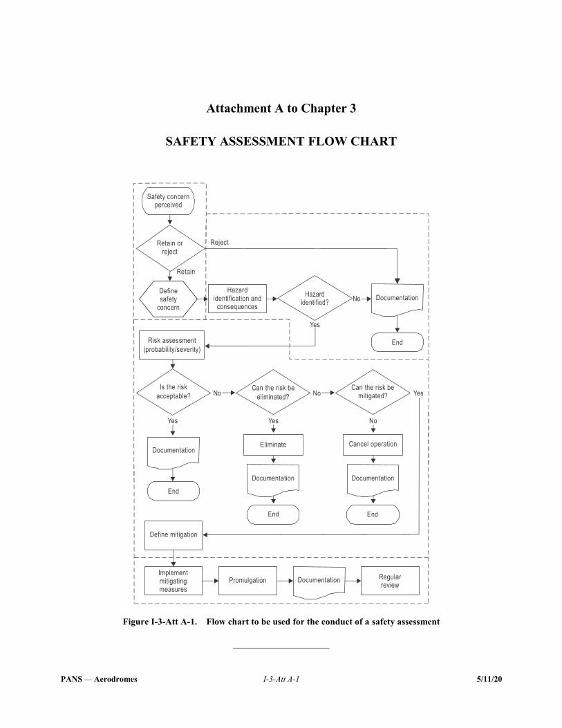
PANS — Aerodromes I-3-Att A-1 5/11/20
Attachment A to Chapter 3
SAFETY ASSESSMENT FLOW CHART
Figure I-3-Att A-1. Flow chart to be used for the conduct of a safety assessment
_____________________
Safety con erncperceived
Cancel perationo
Define itigationm
EliminateDocumentation
Documentation Documentation
Can the risk be
eliminated?
Can the risk bemitigated?
Is the risk
acceptable?
Yes
Yes
YesYes
No
No
End
EndEnd
End
Risk ssessmenta
( robability/ everity)p s
Definesafety
concern
DocumentationHazard
identification andconsequences
Implementitigatingmeasuresm
Promulgation Regulareviewr
Documentation
No
Reject
Retain
No
Retain or reject

PANS — Aerodromes I-3-Att B-1 5/11/20
Attachment B to Chapter 3
SAFETY ASSESSMENT METHODOLOGIES
FOR AERODROMES
Note.— Further guidance on safety risk probability, severity, tolerability and assessment matrix can be found in Doc 9859 — Safety Management Manual (SMM). 1. Depending on the nature of the risk, three methodologies can be used to evaluate whether it is being appropriately managed: a) Method type “A”. For certain hazards, the risk assessment strongly depends on specific aeroplane and/or system
performance. The risk level is dependent upon aeroplane/system performance (e.g. more accurate navigation capabilities), handling qualities and infrastructure characteristics. Risk assessment, then, can be based on aeroplane/system design and validation, certification, simulation results and accident/incident analysis;
b) Method type “B”. For other hazards, risk assessment is not really linked with specific aeroplane and/or system
performance but can be derived from existing performance measurements. Risk assessment, then, can be based on statistics (e.g. deviations) from existing operations or on accident analysis; development of generic quantitative risk models can be well adapted;
c) Method type “C”. In this case, a “risk assessment study” is not needed. A simple logical argument may be
sufficient to specify the infrastructure, system or procedure requirements, without waiting for additional material, e.g. certification results for newly announced aeroplanes or using statistics from existing aeroplane operations.
Risk assessment method 2. The risk assessment takes into account the probability of occurrence of a hazard and the severity of its consequences; the risk is evaluated by combining the two values for severity and probability of occurrence. 3. Each identified hazard must be classified by probability of occurrence and severity of impact. This process of risk classification will allow the aerodrome to determine the level of risk posed by a particular hazard. The classification of probability and severity refers to potential events. 4. The severity classification includes five classes ranging from “catastrophic” (class A) to “not significant” (class E). The examples in Table I-3-Att B-1, adapted from Doc 9859 with aerodrome-specific examples, serve as a guide to better understand the definition. 5. The classification of the severity of an event should be based on a “credible case” but not on a “worst case” scenario. A credible case is expected to be possible under reasonable conditions (probable course of events). A worst case may be expected under extreme conditions and combinations of additional and improbable hazards. If worst cases are to be introduced implicitly, it is necessary to estimate appropriate low frequencies.
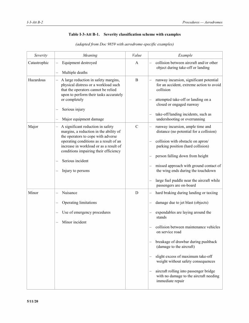
I-3-Att B-2 Procedures — Aerodromes
5/11/20
Table I-3-Att B-1. Severity classification scheme with examples
(adapted from Doc 9859 with aerodrome-specific examples)
Severity Meaning Value Example
Catastrophic – Equipment destroyed – Multiple deaths
A – collision between aircraft and/or other object during take-off or landing
Hazardous – A large reduction in safety margins, physical distress or a workload such that the operators cannot be relied upon to perform their tasks accurately or completely
– Serious injury – Major equipment damage
B – runway incursion, significant potential for an accident, extreme action to avoid collision
– attempted take-off or landing on a
closed or engaged runway – take-off/landing incidents, such as
undershooting or overrunning
Major – A significant reduction in safety margins, a reduction in the ability of the operators to cope with adverse operating conditions as a result of an increase in workload or as a result of conditions impairing their efficiency
– Serious incident – Injury to persons
C – runway incursion, ample time and distance (no potential for a collision)
– collision with obstacle on apron/
parking position (hard collision) – person falling down from height – missed approach with ground contact of
the wing ends during the touchdown – large fuel puddle near the aircraft while
passengers are on-board
Minor – Nuisance – Operating limitations – Use of emergency procedures – Minor incident
D – hard braking during landing or taxiing – damage due to jet blast (objects) – expendables are laying around the
stands – collision between maintenance vehicles
on service road – breakage of drawbar during pushback
(damage to the aircraft) – slight excess of maximum take-off
weight without safety consequences – aircraft rolling into passenger bridge
with no damage to the aircraft needing immediate repair
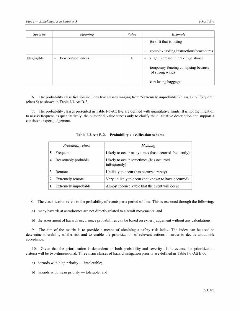
Part I — Attachment B to Chapter 3 I-3-Att B-3
5/11/20
Severity Meaning Value Example
– forklift that is tilting – complex taxiing instructions/procedures
Negligible – Few consequences E – slight increase in braking distance – temporary fencing collapsing because
of strong winds – cart losing baggage
6. The probability classification includes five classes ranging from “extremely improbable” (class 1) to “frequent” (class 5) as shown in Table I-3-Att B-2. 7. The probability classes presented in Table I-3-Att B-2 are defined with quantitative limits. It is not the intention to assess frequencies quantitatively; the numerical value serves only to clarify the qualitative description and support a consistent expert judgement.
Table I-3-Att B-2. Probability classification scheme
Probability class Meaning
5 Frequent Likely to occur many times (has occurred frequently)
4 Reasonably probable Likely to occur sometimes (has occurred infrequently)
3 Remote Unlikely to occur (has occurred rarely)
2 Extremely remote Very unlikely to occur (not known to have occurred)
1 Extremely improbable Almost inconceivable that the event will occur 8. The classification refers to the probability of events per a period of time. This is reasoned through the following: a) many hazards at aerodromes are not directly related to aircraft movements; and b) the assessment of hazards occurrence probabilities can be based on expert judgement without any calculations. 9. The aim of the matrix is to provide a means of obtaining a safety risk index. The index can be used to determine tolerability of the risk and to enable the prioritization of relevant actions in order to decide about risk acceptance. 10. Given that the prioritization is dependent on both probability and severity of the events, the prioritization criteria will be two-dimensional. Three main classes of hazard mitigation priority are defined in Table I-3-Att B-3: a) hazards with high priority — intolerable; b) hazards with mean priority — tolerable; and
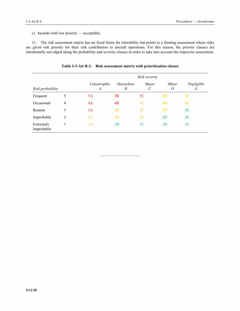
I-3-Att B-4 Procedures — Aerodromes
5/11/20
c) hazards with low priority — acceptable. 11. The risk assessment matrix has no fixed limits for tolerability but points to a floating assessment where risks are given risk priority for their risk contribution to aircraft operations. For this reason, the priority classes are intentionally not edged along the probability and severity classes in order to take into account the imprecise assessment.
Table I-3-Att B-3. Risk assessment matrix with prioritization classes
Risk probability
Risk severity
Catastrophic A
Hazardous B
Major C
Minor D
Negligible E
Frequent 5 5A 5B 5C 5D 5E
Occasional 4 4A 4B 4C 4D 4E
Remote 3 3A 3B 3C 3D 3E
Improbable 2 2A 2B 2C 2D 2E
Extremely Improbable
1 1A 1B 1C 1D 1E
_____________________
PANS — Aerodromes I-4-1 5/11/20
Chapter 4
AERODROME COMPATIBILITY
4.1 INTRODUCTION 4.1.1 This chapter outlines a methodology and procedure to assess the compatibility between aeroplane operations and aerodrome infrastructure and operations when an aerodrome accommodates an aeroplane that exceeds the certificated characteristics of the aerodrome. 4.1.2 A compatibility study should be performed collaboratively between affected stakeholders which includes the aerodrome operator, the aeroplane operator, ground handling agencies as well as the various air navigation service providers (ANSPs). 4.1.3 The following steps describe the arrangement, to be appropriately documented, between the aeroplane operator and aerodrome operator for the introduction of an aeroplane type/subtype new to the aerodrome: a) the aeroplane operator submits a request to the aerodrome operator to operate an aeroplane type/subtype new to
the aerodrome; b) the aerodrome operator identifies possible means of accommodating the aeroplane type/subtype including
access to movement areas and, if necessary, considers the feasibility and economic viability of upgrading the aerodrome infrastructure; and
c) the aerodrome operator and aircraft operator discuss the aerodrome operator’s assessment, and whether
operations of the aeroplane type/subtype can be accommodated and, if permitted, under what conditions. 4.1.4 The following procedures should be included in the aerodrome compatibility study: a) identify the aeroplane’s physical and operational characteristics (see Attachments A, B and D to this chapter); b) identify the applicable regulatory requirements; c) establish the adequacy of the aerodrome infrastructure and facilities vis-à-vis the requirements of the new
aeroplane (see the appendix to this chapter); d) identify the changes required to the aerodrome; e) document the compatibility study; and f) perform the required safety assessments identified during the compatibility study (see Chapter 3 on safety
assessment). Note 1.— A compatibility study may require a review of the obstacle limitation surfaces at an aerodrome as specified in Chapter 4, Annex 14, Volume I. Further guidance on the function of these surfaces is given in Doc 9137, Part 6 — Control of Obstacles. Where required, reporting of obstacles is prescribed in Annex 4 — Aeronautical Charts and Annex 15 — Aeronautical Information Services.
I-4-2 Procedures — Aerodromes
5/11/20
Note 2.— For aerodrome operations in low visibility conditions, additional procedures may be implemented in order to safeguard the operation of aeroplanes. Further guidance on operations in low visibility conditions are available in Doc 9137 — Airport Services Manual, Part 8 — Airport Operational Services, Doc 9476 — Manual of Surface Movement Guidance and Control Systems (SMGCS); and Doc 9830 — Advanced Surface Movement Guidance and Control Systems (A-SMGCS) Manual. Note 3.— Additional processes that ensure suitable measures are in place to protect the signal produced by the ground-based radio navigation equipment may be necessary at aerodromes with precision instrument approaches. 4.1.5 The result of the compatibility study should enable decisions to be made and should provide: a) the aerodrome operator with the necessary information in order to make a decision on allowing the operation of
the specific aeroplane at the given aerodrome; b) the aerodrome operator with the necessary information in order to make a decision on the changes required to
the aerodrome infrastructure and facilities to ensure safe operations at the aerodrome with due consideration to the harmonious future development of the aerodrome; and
c) the State with the information which is necessary for its safety oversight and the continued monitoring of the
conditions specified in the aerodrome certification. Note 1.— Each compatibility study is specific to a particular operational context and to a particular type of aeroplane. Note 2.— See Annex 6 — Operation of Aircraft, Part I — International Commercial Air Transport — Aeroplanes, Chapter 4, regarding the obligation of the aeroplane operator. Note 3.— Information resulting from the compatibility study that is considered to be of operational significance is published in accordance with Annex 14, Volume I, 2.13.1, and Annex 15.
4.2 IMPACT OF AEROPLANE CHARACTERISTICS ON THE AERODROME INFRASTRUCTURE
4.2.1 General 4.2.1.1 Introducing new types of aeroplanes into existing aerodromes may have an impact on the aerodrome facilities and services, in particular, when the aeroplane characteristics exceed the parameters that were used for planning the aerodrome. 4.2.1.2 The parameters used in aerodrome planning are defined in Annex 14, Volume I, which specifies the use of the aerodrome reference code determined in accordance with the characteristics of the aeroplane for which an aerodrome facility is intended. The aerodrome reference code provides a starting point for the compatibility study and may not be the sole means used to conduct the analysis and to substantiate the aerodrome operator’s decisions and the State’s safety oversight actions. Note.— The individual facilities required at an aerodrome are interrelated by the aerodrome reference code. The design of these facilities, including a description of the aerodrome reference code, can be found in Annex 14, Volume I, and are transposed by States into national regulations.
Part I —Chapter 4. Aerodrome compatibility I-4-3
5/11/20
4.2.2 Consideration of the aeroplane’s physical characteristics The aeroplane’s physical characteristics may influence the aerodrome dimensions, facilities and services in the movement area. These characteristics are detailed in Attachment A to this chapter.
4.2.3 Consideration of the aeroplane’s operational characteristics In order to adequately assess aerodrome compatibility, aeroplane operational characteristics should be included in the evaluation process. The operational characteristics can include the infrastructure requirements of the aeroplane as well as ground servicing requirements. These characteristics are detailed in Attachment B to this chapter.
4.3 PHYSICAL CHARACTERISTICS OF AERODROMES In order to adequately assess the aeroplane’s compatibility, aerodrome physical characteristics should be included in the evaluation process. These characteristics are detailed in the Appendix to this chapter.
_____________________

PANS — Aerodromes I-4-App-1 5/11/20
Appendix to Chapter 4
PHYSICAL CHARACTERISTICS OF AERODROMES
1. INTRODUCTION Each paragraph within this section is structured as follows: Introduction This section provides the rationale, including the basis and objectives for the various elements of the physical infrastructure required in Annex 14, Volume I, Chapter 3. References are made, where necessary, to other ICAO documents. Challenges This section identifies possible challenges based on experience, operational judgement and analysis of hazards linked to an infrastructure item in relation to ICAO provisions. Each compatibility study should determine the challenges relevant for the accommodation of the planned aeroplane at the existing aerodrome. Potential solutions This section presents possible solutions related to the identified problems. Where it is impracticable to adapt the existing aerodrome infrastructure or operations in accordance with the applicable regulation, the compatibility study or, where necessary, safety assessment, determines the appropriate solutions or possible risk mitigation measures to be implemented. Note 1.— Where possible solutions have been developed, these should be reviewed periodically to assess their continued validity. These possible solutions do not substitute or circumvent the provisions contained in Annex 14, Volume I. Note 2.— Procedures on the conduct of a safety assessment can be found in Chapter 3.
2. RUNWAYS
2.1 Runway length Note 1.— Runway length is a limiting factor on aeroplane operations and should be assessed in collaboration with the aeroplane operator. Information on aeroplane reference field length can be found in Attachment D to this chapter. Note 2.— Longitudinal slopes can have an effect on aeroplane performance.
I-4-App-2 Procedures — Aerodromes
5/11/20
2.2 Runway width Introduction 2.2.1 For a given runway width, factors affecting aeroplane operations include the characteristics, handling qualities and performance demonstrated by the aeroplane. It may be advisable to consider other factors of operational significance in order to have a safety margin for factors such as wet or contaminated runway pavement, crosswind conditions, crab angle approaches to landing, aeroplane controllability during aborted take-off, and engine failure procedures. Note.— Guidance is given in the Aerodrome Design Manual (Doc 9157), Part 1 — Runways. Challenges 2.2.2 The main issue associated with available runway width is the risk of aeroplane damage and fatalities associated with an aeroplane veering off the runway during take-off, rejected take-off or during the landing. 2.2.3 The main causes and accident factors are: a) for take-off/rejected take-off: 1) aeroplane (asymmetric spin-up and/or reverse thrust, malfunctioning of control surfaces, hydraulic system,
tires, brakes, nose-gear steering, centre of gravity and powerplant (engine failure, foreign object ingestion)); 2) temporary surface conditions (standing water, snow, dust, residuals (rubber), FOD, damage to the pavement
and runway friction coefficient); 3) permanent surface conditions (horizontal and vertical slopes and runway friction characteristics); 4) meteorological conditions (e.g. heavy rain, crosswind, strong/gusty winds, reduced visibility, snow); and 5) Human Factors (crew, maintenance, balance, payload security); b) for landing: 1) aeroplane/airframe (malfunction of the landing gear, control surfaces, hydraulic system, brakes, tires, nose-
gear steering and powerplant (reverse and thrust lever linkage)); 2) temporary surface conditions (standing water, snow, dust, residuals (e.g. rubber), FOD, damage to the
pavement and applying runway friction coefficient); 3) permanent surface conditions (horizontal and vertical slopes and runway friction characteristics); 4) prevailing meteorological conditions (heavy rain, crosswind, strong/gusty winds, thunderstorms/wind shear,
reduced visibility); 5) Human Factors (i.e. hard landings, crew, maintenance); 6) ILS localizer signal quality/interference, where autoland procedures are used; 7) any other localizer signal quality/interference of approach aid equipment;
Part I — Appendix to Chapter 4 I-4-App-3
5/11/20
8) lack of approach path guidance such as VASIS or PAPI; and 9) approach type and speed. Note.— An analysis of lateral runway excursion reports shows that the causal factor in aeroplane accidents/incidents is not the same for take-off and landing. Mechanical failure is, for instance, a frequent accident factor for runway excursions during take-off, while hazardous meteorological conditions such as thunderstorms are more often associated with landing accidents/incidents. Engine reverse thrust system malfunction and/or contaminated runway surfaces have also been a factor in a significant number of veer-offs during landing (other subjects are relevant to the aeroplane such as brake failures and high crosswinds). Potential solutions 2.2.4 The lateral runway excursion is linked to specific aeroplane characteristics, performance/handling qualities, controllability in response to such events as aeroplane mechanical failures, pavement contamination, winter operations and crosswind conditions. Runway width is not a required specific certification limitation. However, indirectly related is the determination of minimum control speed on the ground (Vmcg) and the maximum demonstrated crosswind. These additional factors should be considered as key factors in order to ensure that this kind of hazard is adequately addressed. 2.2.5 For a specific aeroplane, it may be permissible to operate on a runway with a narrower width if approved by the appropriate authorities for such operations. Note.— The maximum demonstrated crosswind is included in the aircraft flight manual. 2.2.6 Potential solutions can be developed by applying the following measures, alone or in combination with other measures. The following list is not in any particular order and is not exhaustive: a) paved inner shoulders of adequate bearing strength to provide an overall width of the runway and its (inner)
shoulders of the recommended runway width according to the reference code; b) paved/unpaved outer shoulders with adequate bearing strength to provide an overall width of the runway and its
shoulder according to the reference code; c) additional runway centre line guidance and runway edge markings; and d) increased full runway length FOD inspection, when required or requested. 2.2.7 Aerodrome operators should also take into account the possibility that certain aeroplanes are not able to make a 180-degree turn on narrower runways. When there is no proper taxiway at the end of the runway, providing a suitable runway turn pad is recommended. Note.— Particular care should be given while manoeuvring on runways having a width less than recommended to prevent the wheels of the aeroplane from leaving the pavement, while avoiding the use of large amounts of thrust that could damage runway lights and signs and cause erosion of the runway strip. For affected runways a close inspection, as appropriate, is generally considered to detect the presence of debris that may be deposited during 180-degree turns on the runway after landing. 2.2.8 Snow removal should be provided at least up to the position of the outboard engine’s intake section area to avoid snow ingestion unless specific aeroplane characteristics/procedures exist to avoid snow ingestion (significant ground clearance of the engines preventing snow ingestion, specific take-off procedure).
I-4-App-4 Procedures — Aerodromes
5/11/20
Note.— Guidance is given in Doc 9137, Part 2 — Pavement Surface Conditions. 2.2.9 Aerodromes which use embedded (inset) runway edge lights should take into account additional consequences such as: a) more frequent cleaning intervals for the embedded lights, as dirt will affect the function more quickly compared
to elevated runway edge lights; b) earlier execution of snow removal operations, as the inset lights are likely to be affected by snow more quickly;
and c) in addition, bi-directional inset lights can facilitate snow removal procedures on a wider range. 2.2.10 Location and specifications for runway signs should be considered due to the increased size of the aeroplane’s wingspan (engine location) as well as the increased thrust rating from the aeroplane’s engines.
2.3 Runway shoulders Introduction 2.3.1 The shoulders of a runway should be capable of minimizing any damage to an aeroplane veering off the runway. In some cases, the bearing strength of the natural ground may be sufficient without additional preparation to meet the requirements for shoulders. The prevention of ingestion of objects from jet engines should always be taken into account particularly for the design and construction of the shoulders. In case of specific preparation of the shoulders, visual contrast, such as the use of runway side-stripe markings, between runway and runway shoulders, may be required. Note.— Guidance is given in Doc 9157, Part 1. Challenges 2.3.2 Runway shoulders have three main functions: a) to minimize any damage to an aeroplane running off the runway ; b) to provide jet blast protection and to prevent engine FOD ingestion; and c) to support ground vehicle traffic, RFF vehicles and maintenance vehicles. Note.— Inadequate width of existing runway bridges is a special topic that needs careful evaluation. 2.3.3 Potential issues associated with runway shoulder characteristics (width, soil type, bearing strength) are: a) aeroplane damage that could occur after excursion onto the runway shoulder due to inadequate bearing
capacity; b) shoulder erosion causing ingestion of foreign objects by jet engines due to unsealed surfaces; consideration
should be given to the impact of FOD on aeroplane tires and engines as a potentially major hazard; and c) difficulties for RFF services to access a damaged aeroplane on the runway due to inadequate bearing strength.
Part I — Appendix to Chapter 4 I-4-App-5
5/11/20
2.3.4 Factors to be considered are: a) runway centre line deviations; b) powerplant characteristics (engine height, location and power); and c) soil type and bearing strength (aeroplane mass, tire pressure, gear design). Potential solutions 2.3.5 Possible solutions can be developed by applying the following measures, alone or in combination with other measures. The following list is not in any particular order and is not exhaustive: a) Excursion onto the runway shoulder. Provide the suitable shoulder as detailed in 2.3; b) Jet blast. Information about outer engine position, jet blast velocity contour and jet blast directions at take-off is
needed to calculate the required width of shoulders that has to be enhanced for protection against jet blast. Lateral deviation from the runway centre line should also be taken into account;
Note 1.— Jet blast velocity data may be available from the aircraft manufacturers. Note 2.— Relevant information is typically available in the aircraft characteristics for airport planning manual of aircraft manufacturers. c) RFF vehicles. Operational experience with aeroplanes currently operated on existing runways suggests that an
overall width of the runway and its shoulders which is compliant with the requirements is adequate to permit intervention on aeroplanes by occasional RFF vehicle traffic. However, longer upper-deck escape chutes may reduce the margin between the shoulder edge and the extension of escape slides and reduce the supporting surface available to rescue vehicles; and
d) Additional surface inspections. It may be necessary to adapt the inspection programme for FOD detection.
2.4 Runway turn pads Introduction 2.4.1 Turn pads are generally provided when an exit taxiway is not available at the runway end. A turn pad allows an aeroplane to turn back after landing and before take-off and to position itself correctly on the runway. Note.— Guidance on typical turn pads is given in Doc 9157, Part 1, Appendix 4. In particular, the design of the total width of the turn pad should be such that the nose-wheel steering angle of the aeroplane for which the turn pad is intended will not exceed 45 degrees. Challenges 2.4.2 For minimizing the risk of a turn pad excursion, the turn pad should be designed sufficiently wide to permit the 180-degree turn of the most demanding aeroplane that will be operated. The design of the turn pad generally assumes a maximum nose landing gear steering angle of 45 degrees, which should be used unless some other condition applies for the particular type of aeroplane, and considers clearances between the gears and the turn pad edge, as for a taxiway.
I-4-App-6 Procedures — Aerodromes
5/11/20
2.4.3 The main causes and accident factors of the aeroplane veering off the turn pad pavement are: a) aeroplane characteristics that are not adequate and aeroplane failure (ground manoeuvring capabilities,
especially long aeroplanes, malfunctioning of nose-gear steering, engine, brakes); b) adverse surface conditions (standing water, loss of control on ice-covered surfaces, friction coefficient); c) loss of the turn pad visual guidance (markings and lights covered by snow or inadequately maintained); and d) Human Factors, including incorrect application of the 180-degree procedure (nose-wheel steering, asymmetric
thrust, differential breaking). Note.— No turn pad excursions with passenger injuries have so far been reported. Nevertheless, an aeroplane disabled on a turn pad can have an impact on runway closure. Potential solutions 2.4.4 The ground maneuvering capabilities available from aircraft manufacturers are one of the key factors to be considered in order to determine whether an existing turn pad is suitable for a particular aeroplane. The speed of the manoeuvring aeroplane is also a factor. Note.— Relevant information is typically available in the aircraft characteristics for airport planning manual of aircraft manufacturers. 2.4.5 For a specific aeroplane, it may be permissible to operate on a runway turn pad not provided in accordance with Annex 14, Volume I, specifications, considering: a) the specific ground manoeuvring capability of the specific aeroplane (notably the maximum effective steering
angle of the nose landing gear); b) the provision for adequate clearances; c) the provision for appropriate marking and lighting; d) the provision of shoulders; e) the protection from jet blast; and f) if relevant, protection of the ILS. In this case, the turn pad can have a different shape. The objective is to enable the aeroplane to align on the runway while losing the least runway length as possible. The aeroplane is supposed to taxi at slow speed. Note.— Further advisory material on turn pads may be available from the aircraft manufacturers.
Part I — Appendix to Chapter 4 I-4-App-7
5/11/20
2.5 RUNWAY STRIPS
2.5.1 Runway strip dimensions Introduction 2.5.1.1 A runway strip is an area enclosing a runway and any associated stopway. Its purpose is to: a) reduce the risk of damage to an aeroplane running off the runway by providing a cleared and graded area which
meets specific longitudinal and transverse slopes, and bearing strength requirements; and b) protect an aeroplane flying over it during landing, balked landing or take-off by providing an area which is
cleared of obstacles, except for permitted aids to air navigation. 2.5.1.2 Particularly, the graded portion of the runway strip is provided to minimize the damage to an aeroplane in the event of a veer-off during a landing or take-off operation. It is for this reason that objects should be located away from this portion of the runway strip unless they are needed for air navigation purposes and are frangibly mounted. Note.— The dimensions and characteristics of the runway strip are detailed in Annex 14, Volume I, Chapter 3, 3.4 and Attachment A. Challenges 2.5.1.3 Where the requirements on runway strips cannot be achieved, the available distances, the nature and location of any hazard beyond the available runway strip, the type of aeroplane and the level of traffic at the aerodrome should be reviewed. Operational restrictions may be applied to the type of approach and low visibility operations that fit the available ground dimensions, while also taking into account: a) runway excursion history; b) friction and drainage characteristics of the runway; c) runway width, length and transverse slopes; d) navigation and visual aids available; e) relevance in respect of take-off or aborted take-off and landing; f) scope for procedural mitigation measures; and g) accident report. 2.5.1.4 An analysis of lateral runway excursion reports shows that the causal factor in aeroplane accidents/incidents is not the same for take-off and for landing. Therefore, take-off and landing events may need to be considered separately. Note.— Mechanical failure is a frequent accident factor in runway excursions during take-off, while hazardous meteorological conditions such as thunderstorms are more often present with landing accident/incidents. Brake failures or engine reverse thrust system malfunctions have also been factors in a significant number of landing veer-offs.
I-4-App-8 Procedures — Aerodromes
5/11/20
2.5.1.5 Lateral deviation from the runway centre line during a balked landing with the use of the digital autopilot as well as manual flight with a flight director for guidance have shown that the risk associated with the deviation of specific aeroplanes is contained within the OFZ. Note.— Provisions on OFZ are given in Annex 14, Volume I, and in Cir 301, New Larger Aeroplanes — Infringement of the Obstacle Free Zone: Operational Measures and Aeronautical Study and Cir 345, New Larger Aeroplanes — Infringement of the Obstacle Free Zone: Collision Risk Model and Aeronautical Study. 2.5.1.6 The lateral runway excursion hazard is clearly linked to specific aeroplane characteristics, performance/ handling qualities and controllability in response to such events as aeroplane mechanical failures, pavement contamination and crosswind conditions. This type of hazard comes under the category for which risk assessment is mainly based on flight crew/aeroplane performance and handling qualities. Certified limitations of the specific aeroplane is one of the key factors to be considered in order to ensure that this hazard is under control. Potential solutions 2.5.1.7 Potential solutions can be developed by applying the following measures, alone or in combination with other measures. The following list is not in any particular order and is not exhaustive: a) improving runway surface conditions and/or the means of recording and indicating rectification action,
particularly for contaminated runways, having knowledge of runways and their condition and characteristics in precipitation;
b) ensuring that accurate and up-to-date meteorological information is available and that information on runway
conditions and characteristics is passed to flight crews in a timely manner, particularly when flight crews need to make operational adjustments;
c) improving the aerodrome operator’s knowledge of recording, prediction and dissemination of wind data,
including wind shear, and any other relevant meteorological information, particularly when it is a significant feature of an aerodrome’s climatology;
d) upgrading the visual and instrument landing aids to improve the accuracy of aeroplane delivery at the correct
landing position on runways; and e) in consultation with aeroplane operators, formulating any other relevant aerodrome operating procedures or
restrictions and promulgating such information appropriately.
2.5.2 Obstacles on runway strips Introduction 2.5.2.1 An object located on a runway strip which may endanger aeroplanes is regarded as an obstacle, according to the definition of “obstacle” and should be removed, as far as practicable. Obstacles may be either naturally occurring or deliberately provided for the purpose of air navigation. Challenges 2.5.2.2 An obstacle on the runway strip may represent either: a) a collision risk for an aeroplane in flight or for an aeroplane on the ground that has veered off the runway; and

Part I — Appendix to Chapter 4 I-4-App-9
5/11/20
b) a source of interference to navigation aids. Note 1.— Mobile objects that are beyond the OFZ (inner transitional surface) but still within the runway strip, such as vehicles and holding aeroplanes at runway-holding positions, or wing tips of aeroplanes taxiing on a parallel taxiway to the runway, should be considered. Note 2.— Provisions on OFZ are given in Annex 14, Volume I, and in Circular 301, New Larger Aeroplanes — Infringement of the Obstacle Free Zone: Operational Measures and Aeronautical Study and Cir 345 — New Larger Aeroplanes — Infringement of the Obstacle Free Zone: Collision Risk Model and Aeronautical Study. Potential solutions 2.5.2.3 Potential solutions can be developed by applying the following measures, alone or in combination with other measures. The following list is not in any particular order and is not exhaustive: a) a natural obstacle should be removed or reduced in size wherever possible; alternatively, grading of the area
allows reduction of the severity of damage to the aeroplane; b) other fixed obstacles should be removed unless they are necessary for air navigation, in which case they should
be frangible and should be so constructed as to minimize the severity of damage to the aeroplane; c) an aeroplane considered to be a moving obstacle within the runway strip should respect the requirement on the
sensitive areas installed to protect the integrity of the ILS and should be subject to a separate safety assessment; and
Note.— Provisions on ILS critical and sensitive areas are given in Annex 10 — Aeronautical Telecommunications, Volume I — Radio Navigation Aids.
d) visual and instrument landing aids may be upgraded to improve the accuracy of aeroplane delivery at the correct
landing position on runways, and in consultation with aeroplane operators, any other relevant aerodrome operating procedures or restrictions may be formulated and such information promulgated appropriately.
3. RUNWAY END SAFETY AREA (RESA) Introduction 3.1 A RESA is primarily intended to reduce the risk of damage to an aeroplane undershooting or overrunning the runway. Consequently, a RESA will enable an aeroplane overrunning to decelerate, and an aeroplane undershooting to continue its landing. Challenges 3.2 Identification of specific issues related to runway overruns and undershoots is complex. There are a number of variables that have to be taken into account, such as prevailing meteorological conditions, the type of aeroplane, the load factor, the available landing aids, runway characteristics, the overall environment, as well as Human Factors. 3.3 When reviewing the RESA, the following aspects have to be taken into account: a) the nature and location of any hazard beyond the runway end;
I-4-App-10 Procedures — Aerodromes
5/11/20
b) the topography and obstruction environment beyond the RESA; c) the type of aeroplanes and level of traffic at the aerodrome and actual or proposed changes to either; d) overrun/undershoot causal factors; e) friction and drainage characteristics of the runway which have an impact on runway susceptibility to surface
contamination and aeroplane braking action; f) navigation and visual aids available; g) type of approach; h) runway length and slope, in particular, the general operating length required for take-off and landing versus the
runway distances available, including the excess of available length over that required; i) the location of the taxiways and runways; j) aerodrome climatology, including predominant wind speed and direction and likelihood of wind shear; and k) aerodrome overrun/undershoot and veer-off history. Potential solutions 3.4 Potential solutions can be developed by applying the following measures, alone or in combination with other measures. The following list is not in any particular order and is not exhaustive: a) restricting the operations during adverse hazardous meteorological conditions (such as thunderstorms); b) defining, in cooperation with aeroplane operators, hazardous meteorological conditions and other factors
relevant to aerodrome operating procedures and publishing such information appropriately; c) improving an aerodrome’s database of operational data, detection of wind data, including wind shear and other
relevant meteorological information, particularly when it is a significant change from an aerodrome’s climatology;
d) ensuring that accurate and up-to-date meteorological information, current runway conditions and other
characteristics are detected and notified to flight crews in time, particularly when flight crews need to make operational adjustments;
e) improving runway surfaces in a timely manner and/or the means of recording and indicating necessary action
for runway improvement and maintenance (e.g. friction measurement and drainage system), particularly when the runway is contaminated;
f) removing rubber build-up on runways according to a scheduled time frame; g) repainting faded runway markings and replacing inoperative runway surface lighting identified during daily
runway inspections; h) upgrading visual and instrument landing aids to improve the accuracy of aeroplane delivery at the correct
landing position on runways (including the provision of ILSs);
Part I — Appendix to Chapter 4 I-4-App-11
5/11/20
i) reducing declared runway distances in order to provide the necessary RESA; j) installing suitably positioned and designed arresting systems as a supplement or as an alternative to standard
RESA dimensions when necessary (see Note 1); k) increasing the length of a RESA and/or minimizing the potential obstruction in the area beyond the RESA; and l) publishing provisions, including the provision of an arresting system, in the AIP. Note 1.— Further guidance on arresting systems can be found in Annex 14, Volume I, Attachment A. Note 2.— In addition to the AIP entry, information/instructions may be disseminated to local runway safety teams and others to promote awareness in the community.
4. TAXIWAYS
4.1 General Introduction 4.1.1 Taxiways are provided to permit the safe and expeditious surface movement of aeroplanes. 4.1.2 A sufficiently wide taxiway permits smooth traffic flow while facilitating aeroplane ground steering. Note 1.— Guidance material is given in Doc 9157, Part 2 — Taxiways, Aprons and Holding Bays; Section 1.2 and Table 1-1 provide the formula for determining the width of a taxiway. Note 2.— Particular care should be taken while manoeuvring on taxiways having a width less than that specified in Annex 14, Volume I, to prevent the wheels of the aeroplane from leaving the pavement, while avoiding the use of large amounts of thrust that could damage taxiway lights and signs and cause erosion of the taxiway strip. Affected taxiways should be closely inspected, as appropriate, for the presence of debris that may be deposited while taxiing into position for take-off. Challenges 4.1.3 The issue arises from a lateral taxiway excursion. 4.1.4 Causes and accident factors can include: a) mechanical failure (hydraulic system, brakes, nose-gear steering); b) adverse surface conditions (standing water, loss of control on ice-covered surfaces, friction coefficient); c) loss of the taxiway centre line visual guidance (markings and lights covered by snow or inadequately
maintained); d) Human Factors (including directional control, orientation error, pre-departure workload); and e) aeroplane taxi speed.
I-4-App-12 Procedures — Aerodromes
5/11/20
Note.— The consequences of a taxiway excursion are potentially disruptive. However, consideration should be given to the greater potential impact of deviation of a larger aeroplane in terms of blocked taxiways or disabled aeroplane removal. 4.1.5 Pilot precision and attention are key issues since they are heavily related to the margin between the outer main gear wheel and the taxiway edge. 4.1.6 Compatibility studies related to taxiway width and potential deviations can include: a) the use of taxiway deviation statistics to calculate the taxiway excursion probability of an aeroplane depending
on taxiway width. The impact of taxiway guidance systems and meteorological and surface conditions on taxiway excursion probability should be assessed whenever possible;
b) view of the taxiway from the cockpit, taking into account the visual reference cockpit cut-off angle and pilot
eye height; and c) the aeroplane outer main gear wheel span. Potential solutions 4.1.7 Potential solutions can be developed by applying the following measures, alone or in combination with other measures. The following list is not in any particular order and is not exhaustive: a) the provision of taxiway centre line lights; b) conspicuous centre line marking; c) the provision of on-board taxi camera systems to assist taxi guidance; d) reduced taxi speed; e) the provision of taxi side-stripe markings; f) taxiway edge lights (inset or elevated); g) reduced wheel-to-edge clearance, using taxiway deviation data; h) enhanced snow bank clearance (engine positions); i) snow and ice control surface measures implemented on taxiway entrances to the runway, especially high-speed
taxiway exits; j) the use of alternative taxi routes; and k) the use of marshaller services (follow-me guidance). Note 1.— Taxi cameras are designed to ease the taxi and can assist the flight crew in preventing the wheels of the aeroplane from leaving the full-strength pavement during normal ground manoeuvring. Note 2.— Taxiways that are not provided with suitable shoulders may be restricted in operation.
Part I — Appendix to Chapter 4 I-4-App-13
5/11/20
4.1.8 Special attention should be given to the offset of centre line lights in relation to centre line markings, especially during winter conditions when distinguishing between markings and offset lights can be difficult. 4.1.9 Location and specifications for taxiway signs should be considered due to the engine location as well as the increased thrust in the aeroplane engines.
4.2 Taxiway curves Introduction 4.2.1 Annex 14, Volume I, 3.9.5, contains provisions on taxiway curves. Additional guidance is included in Doc 9157, Part 2. Challenges 4.2.2 Any hazard will be the result of a lateral taxiway excursion on a curved section. 4.2.3 The main causes and accident factors are the same as for a taxiway excursion on a straight taxiway section. The use of the cockpit-over-centreline steering technique on a curved taxiway will result in track-in of the main landing gear from the centre line. The amount of track-in depends on the radius of the curved taxiway and the distance from the cockpit to the main landing gear. 4.2.4 The consequences are the same as for lateral taxiway excursions on straight sections. 4.2.5 The required width of the curved portions of taxiways is related to the clearance between the outer main wheel and the taxiway edge on the inner curve. The hazard is related to the combination of the outer main gear wheel span and the distance between the nose gear/cockpit and the main gear. Consideration should be given to the effect on airfield signs and other objects nearby of jet blast from a turning aeroplane. 4.2.6 Certain aeroplanes may require wider fillets on curved sections or taxiway junctions. Potential solutions 4.2.7 Potential solutions can be developed by applying the following measures, alone or in combination with other measures. The following list is not in any particular order and is not exhaustive: a) the widening of existing fillets or the provision of new fillets; b) reduced taxi speed; c) the provision of taxiway centre line lights and taxi side-stripe markings (and inset taxiway edge lights); d) reduced wheel-to-edge clearance, using taxiway deviation data; e) pilot judgemental oversteering; and f) publication of provisions in the appropriate aeronautical documentation.
I-4-App-14 Procedures — Aerodromes
5/11/20
Note 1.— Taxi cameras are designed to ease the taxi and can assist the flight crew in preventing the wheels of the aeroplane from leaving the full-strength pavement during normal ground manoeuvring. Note 2.— Operations on taxiway curves that are not provided with suitable taxiway fillets should be restricted. 4.2.8 Special attention should be given to the offset of centre line lights in relation to centre line markings. 4.2.9 Location and specifications for taxiway signs should be considered due to the increase in the size of aeroplanes as well as the increased thrust in aeroplane engines.
5. RUNWAY AND TAXIWAY MINIMUM SEPARATION DISTANCES Introduction 5.1 A minimum distance is provided between the centre line of a runway and the centre line of the associated parallel taxiway for instrument runways and non-instrument runways. Note 1.— Doc 9157, Part 2, section 1.2, and Table 1-5, clarify that the runway/taxiway separation is based on the principle that the wing tip of an aeroplane taxiing on a parallel taxiway should be clear of the runway strip. Note 2.— It is permissible to operate with lower separation distances at an existing aerodrome if a safety assessment indicates that such lower separation distances would not adversely affect the safety or significantly affect the regularity of operations of aeroplanes. See Note 2 to Table 3-1, and Notes 2, 3 and 4 to 3.9.7 of Annex 14, Volume I. Note 3.— Doc 9157, Part 2, has related guidance in 1.2.47 to 1.2.50. Furthermore, attention is drawn to the need to provide adequate clearance at an existing aerodrome in order to operate an aeroplane with the minimum possible risk. Challenges 5.2 The potential issues associated with runway/parallel taxiway separation distances are: a) the possible collision between an aeroplane running off a taxiway and an object (fixed or mobile) on the
aerodrome; b) the possible collision between an aeroplane leaving the runway and an object (fixed or mobile) on the
aerodrome or the risk of a collision of an aeroplane on the taxiway that infringes on the runway strip; and c) possible ILS signal interference due to a taxiing or stopped aeroplane. 5.3 Causes and accident factors can include: a) Human Factors (crew, ATS); b) hazardous meteorological conditions (such as thunderstorms and wind shear); c) aeroplane mechanical failure (such as engine, hydraulic system, flight instruments, control surfaces and
autopilot);
Part I — Appendix to Chapter 4 I-4-App-15
5/11/20
d) surface conditions (standing water, loss of control on ice-covered surfaces, friction coefficient); e) lateral veer-off distance; f) aeroplane position relative to navigation aids, especially ILS; and g) aeroplane size and characteristics (especially wingspan). Note.— Common accident/incident databases deal with lateral runway excursions but do not include accident reports relative to in-flight collisions and ILS signal interference. Therefore, the causes and accident factors specific to the local environment and identified above for runway separation issues are mainly supported by local aerodrome experience. The huge variety and complexity of accident factors for collision risk should be emphasized. Potential solutions 5.4 Potential solutions can be developed by applying the following measures, alone or in combination with other measures. The following list is not in any particular order and is not exhaustive: a) place a restriction on the wingspan of aeroplanes using the parallel taxiway or on the runway, if continued
unrestricted taxiway or runway operation is desired; b) consider the most demanding length of aeroplane that can have an impact on runway/taxiway separation and the
location of holding positions (ILS); c) change taxiway routing so that the required runway airspace is free of taxiing aeroplanes; and d) employ tactical control of aerodrome movements. Note.— When A-SMGCS is available, it can be utilized as a supporting means to the proposed solutions especially in low visibility conditions.
6. TAXIWAY AND TAXILANE MINIMUM SEPARATION DISTANCES Introduction Taxiway to object separation 6.1 The taxiway minimum separation distances provide an area clear of objects that may endanger an aeroplane. Note 1.— See Annex 14, Volume I, 3.9. Note 2.— Additional guidance material on minimum separation distances is included in Doc 9157, Part 2. Parallel taxiway separation 6.2 The minimum separation distance is equal to the wingspan plus maximum lateral deviation plus increment. Note 1.— Information is given in Doc 9157, Part 2.
I-4-App-16 Procedures — Aerodromes
5/11/20
Note 2.— If the minimum required distance between the centre lines of two parallel taxiways is not provided, it is permissible to operate with lower separation distances at an existing aerodrome if a compatibility study, which may include a safety assessment, indicates that such lower separation distances would not adversely affect the safety or significantly affect the regularity of aeroplane operations. Challenges Taxiway to object separation 6.3 The separation distances during taxiing are intended to minimize the risk of a collision between an aeroplane and an object (taxiway/object separation, taxilane/object separation). Note.— Taxiway deviation statistics can be used to assess the risk of a collision between two aeroplanes or between an aeroplane and an object. 6.4 The causes and accident factors can include: a) mechanical failure (hydraulic system, brakes, nose-gear steering); b) conditions (standing water, loss of control on ice-covered surfaces, friction coefficient); c) loss of the visual taxiway guidance system (markings and lights covered by snow); and d) Human Factors (directional control, temporary loss of orientation resulting in aeroplanes being incorrectly
positioned, etc.). Parallel taxiway separation 6.5 The potential issues associated with parallel taxiway separation distances are: a) the probable collision between an aeroplane running off a taxiway and an object (aeroplane on parallel
taxiway); and b) an aeroplane running off the taxiway and infringing the opposite taxiway strip. 6.6 Causes and accident factors can include: a) Human Factors (crew, ATS); b) hazardous meteorological conditions (such as reduced visibility); c) aeroplane mechanical failure (such as engine, hydraulic system, flight instruments, control surfaces, autopilot); d) surface conditions (standing water, loss of control on ice-covered surfaces, friction coefficient); e) lateral veer-off distance; and f) aeroplane size and characteristics (especially wingspan).
Part I — Appendix to Chapter 4 I-4-App-17
5/11/20
Potential solutions Taxiway to object separation 6.7 Potential solutions can be developed by applying the following measures, alone or in combination with other measures. The following list is not in any particular order and is not exhaustive: a) the use of reduced taxiing speed; b) the provision of taxiway centre line lights; c) the provision of taxi side-stripe markings (and inset taxiway edge lights); d) the provision of special taxi routing for larger aeroplanes; e) restrictions on aeroplanes (wingspan) allowed to use parallel taxiways during the operation of a specific
aeroplane; f) restrictions on vehicles using service roads adjacent to a designated aeroplane taxi route; g) the use of “follow-me” guidance; h) the provision of reduced spacing between taxiway centre line lights; and i) the provision of straightforward taxiway naming and ground routings with respect to the hazard of taxiway
veer-offs. Note.— Special attention should be given to the offset of centre line lights in relation to centre line markings. Especially during winter conditions, distinguishing between markings and offset lights can be difficult. Parallel taxiway separation 6.8 Potential solutions can be developed by providing the following facilities, alone or in combination with other measures. The following list is not in any particular order and is not exhaustive: a) place a restriction on the wingspan of aeroplanes using the parallel taxiway if continued unrestricted taxiway
operation is desired; b) consider the most demanding length of aeroplane that can have an impact on a curved taxiway section; c) change taxiway routing; d) employ tactical control of aerodrome movements; e) use of reduced taxiing speed; f) provision of taxiway centre line lights; g) provision of taxi side-stripe markings (and inset taxiway edge lights); h) use of “follow-me” guidance; i) provision of reduced spacing between taxiway centre line lights; and
I-4-App-18 Procedures — Aerodromes
5/11/20
j) provision of straightforward taxiway naming and ground routings with respect to the hazard of taxiway veer-offs.
Note.— When A-SMGCS is available, it can be utilized as a supporting means to the proposed solutions especially in low visibility conditions.
7. TAXIWAYS ON BRIDGES Introduction 7.1 The width of that portion of a taxiway bridge capable of supporting aeroplanes, as measured perpendicularly to the taxiway centre line, is normally not less than the width of the graded area of the strip provided for that taxiway, unless a proven method of lateral restraint is provided which is not hazardous for aeroplanes for which the taxiway is intended. Note.— Annex 14, Volume I, section 3.9, and Doc 9157, Part 2, provide information on taxiways on bridges. 7.2 Access is to be provided for RFF vehicles to intervene, in both directions within the specified response time, with the largest aeroplane for which the taxiway is intended. 7.3 If aeroplane engines overhang the bridge structure, it may be necessary to protect the adjacent areas, below the bridge, from engine blast. Challenges 7.4 The following hazards are related to the width of taxiway bridges: a) landing gear leaving the load-bearing surface; b) deployment of an escape slide beyond the bridge, in case of an emergency evacuation; c) lack of manoeuvring space for RFF vehicles around the aeroplane; d) jet blast to vehicles, objects or personnel below the bridge; e) structural damage to the bridge due to the aeroplane mass exceeding the bridge design load; and f) damage to the aeroplane due to insufficient clearance of engines, wings or fuselage from bridge rails, lights or
signs. 7.5 The causes and accident factors can include: a) mechanical failure (hydraulic system, brakes, nose-gear steering); b) surface conditions (standing water, loss of control on ice-covered surfaces, friction coefficient); c) loss of the visual taxiway guidance system (markings and lights covered by snow); d) Human Factors (directional control, disorientation, pilot’s workload);
Part I — Appendix to Chapter 4 I-4-App-19
5/11/20
e) the position of the extremity of the escape slides; and f) undercarriage design. 7.6 The main causes of and accident factors for jet blast effect below the bridge are: a) powerplant characteristics (engine height, location and power); b) bridge blast protection width; and c) taxiway centre line deviation factors (see taxiway excursion hazard in 4.1.4). 7.7 In addition to the specifications of Chapter 3, Safety Assessments for Aerodromes, hazard prevention mechanisms should be based on the critical dimensions of the aeroplane in relation to the bridge width. Potential solutions 7.8 Potential solutions can be developed by applying the following measures, alone or in combination with other measures. The following list is not in any particular order and is not exhaustive: a) where feasible, strengthen existing bridges; b) provide a proven method of lateral restraint to prevent the aeroplane from veering off the full bearing strength
of the taxiway bridge; c) provide an alternative path/bridge for RFF vehicles or implement emergency procedures to taxi the aeroplane
away from such taxi bridges; d) implement jet blast procedures to reduce the effects of jet blast on the undercroft; and e) use the vertical clearance provided by high wings. 7.9 The RFF vehicles need to have access to both sides of the aeroplane to fight any fire from the best position, allowing for wind direction as necessary. In case the wingspan of the considered aeroplane exceeds the width of the bridge, another bridge nearby can be used for access to the “other” side of an aeroplane rather than an increased bridge width; in this case the surface of the bypass routes are at least stabilized where it is unpaved. Note.— The use of another bridge as mentioned in 7.9 is practicable only where bridges are paired (parallel taxiways) or when there is a service road in the surrounding area. In any case, the bridge strength is to be checked, depending on the aeroplane planning to use it. 7.10 The protection from jet blast of vehicular traffic under/near the bridge is to be studied, consistent with the overall width of the taxiway and its shoulders. 7.11 The bridge width should be compatible with the deployment of escape slides. If this is not the case, a safe and quick escape route should be ensured. Note.— Curved centre lines should be avoided leading up to, on and when leaving the bridge.
I-4-App-20 Procedures — Aerodromes
5/11/20
8. TAXIWAY SHOULDERS Introduction 8.1 Taxiway shoulders are intended to protect an aeroplane operating on the taxiway from FOD ingestion and to reduce the risk of damage to an aeroplane running off the taxiway. 8.2 The taxiway shoulder dimensions are based on current information regarding the width of the inner engine exhaust plume for breakaway thrust. Furthermore, the surface of taxiway shoulders is prepared so as to resist erosion and ingestion of the surface material by aeroplane engines. Note.— Guidance material is contained in Doc 9157, Part 2. Challenges 8.3 The factors leading to reported issues are: a) powerplant characteristics (engine height, location and power); b) taxiway shoulder width, the nature of the surface and its treatment; and c) taxiway centre line deviation factors, both from the expected minor wander from tracking error and the effect of
main gear track-in in the turn area while using the cockpit-over-centre line-steering technique. Potential solutions 8.4 Potential solutions can be developed by applying the following measures, alone or in combination with other measures. The following list is not in any particular order and is not exhaustive: a) Excursion on the taxiway shoulder. The thickness and composition of shoulder pavements should be such as to
withstand the occasional passage of the aeroplane operating at the aerodrome that has the most demanding impact on pavement loading, as well as the full load of the most demanding aerodrome emergency vehicle. The impact of an aeroplane on pavements should be assessed and, if required, existing taxiway shoulders (if allowed to be used by these heavier aeroplanes) may need to be strengthened by providing a suitable overlay.
Note.— Surface materials of an asphalt paved shoulder of 10 to 12.5 cm thick (the higher thickness where
widebodied aircraft jet blast exposure is likely) and firmly adhering to the underlying pavement layers (by way of a tack coat or other means that assures a well-bonded interface between the surface layer and the underlying strata) is generally a suitable solution.
b) Jet blast. Information on engine position and jet blast velocity contour at breakaway thrust mode is used to
assess jet blast protection requirements during taxiing operations. A lateral deviation from the taxiway centre line should be taken into account, particularly in the case of a curved taxiway and the use of the cockpit-over-centre-line steering technique. The effect of jet blast can also be managed by the use of thrust management of the engines (in particular for four-engine aircraft).
Note.— Further information concerning aeroplane characteristics including the margins between the outer
engine axis and the edge of the shoulder, and the distance from the outer engine to the ground can be found in the manufacturer’s aircraft characteristics for airport planning manual.
Part I — Appendix to Chapter 4 I-4-App-21
5/11/20
c) RFF vehicles. Operational experience with current aeroplanes on existing taxiways suggests that a compliant overall width of the taxiway and its shoulders permits the intervention of aeroplanes by occasional RFF vehicle traffic.
Note 1.— For NLA, the longer upper-deck escape chutes may reduce the margin between the shoulder edge and the extremity of these escape slides and reduce the supporting surface available to rescue vehicles. Note 2.— In some cases, the bearing strength of the natural ground may be sufficient, without special preparation, to meet the requirements for shoulders. (Doc 9157, Part 1, provides further design criteria).
9. CLEARANCE DISTANCE ON AIRCRAFT STANDS Introduction 9.1 Annex 14, Volume I, 3.13.6, recommends the minimum distance between an aeroplane using the stand and an obstacle. Note.— Doc 9157, Part 2, provides additional guidance on this subject. Challenges 9.2 The possible reasons for collision between an aeroplane and an obstacle on the apron or holding bay can be listed as: a) mechanical failure (e.g. hydraulic system, brakes, nose-gear steering); b) surface conditions (e.g. standing water, ice-covered surfaces, friction coefficient); c) loss of the visual taxi guidance system (docking system out of service); and d) Human Factors (directional control, orientation error). 9.3 The probability of a collision during taxiing depends more on Human Factors than on aeroplane performance. Unless technical failure occurs, aeroplanes will respond reliably to directional inputs from the pilot when taxiing at the usual ground speed. Nevertheless, caution should be exercised with regard to the impact of aeroplanes with larger wingspans. Potential solutions 9.4 Potential solutions can be developed by applying the following measures, alone or in combination with other measures. The following list is not in any particular order and is not exhaustive: a) appropriate condition of marking and signage; b) apron stand lead-in lights; c) azimuth guidance as a visual docking system;
I-4-App-22 Procedures — Aerodromes
5/11/20
d) appropriate training of operating and ground personnel should be ensured by an aerodrome operator; e) operational restrictions (e.g. adequate clearances before and behind parked or holding aeroplanes due to the
increased length of aeroplanes); f) temporarily downgraded adjacent aircraft stands; g) towing the aeroplane on/from the stand; h) use of remote/cargo stands or “roll-through” parking positions for handling the aeroplane; i) publication of procedures in the appropriate aeronautical documentation (i.e. closing or rerouting of taxilanes
behind parked aeroplanes); j) advanced visual guidance system; k) marshaller guidance; l) enhancing apron lighting levels in low visibility conditions; and m) use of the vertical clearances provided by high wings.
10. DE-ICING/ANTI-ICING FACILITIES Introduction 10.1 Aeroplane de-icing/anti-icing facilities supported by appropriate procedures are provided at an aerodrome where icing conditions are expected to occur. Note.— Safe and efficient aeroplane operations are of primary importance in the development of an aeroplane de-icing/anti-icing facility. (See Annex 14, Volume I, Chapter 3, section 3.15, on provisions for de-icing/anti-icing facilities.) Challenges 10.2 The challenge is to provide adequately designed and well-located de-icing/anti-icing treatment facilities for the collection and safe disposal of fluids in an environmentally safe manner. The facility must not infringe the OLS, not cause interference with radio navigation aids and be clearly visible from the air traffic control tower. In addition the facility should provide the following: a) pads of sufficient space to accommodate the aeroplane and de-icing vehicles; b) protection from jet blast; c) drainage; d) removal of contaminants; and e) lighting capability for adequate de-icing/anti-icing of aircraft under low visibility or night-time operations. Potential solutions
Part I — Appendix to Chapter 4 I-4-App-23
5/11/20
10.3 Potential solutions can be developed by applying the following measures, alone or in combination with other measures. The following list is not in any particular order and is not exhaustive: a) adequate space on the pad to ensure a clear paved area around the aeroplane to facilitate the movement of de-
icing/anti-icing vehicles; b) sufficient clearance between the pad and the adjacent manoeuvring areas taking the dimensions of aeroplanes
into consideration; c) surface markings to ensure wing tip clearance of obstructions and other aeroplanes, especially if another
aeroplane is also to be accommodated on the pad; d) the load bearing capacity of the existing structure; e) the requirement for greater quantities of de-icing/anti-icing agents; f) containment of excess run-off of de-icing/anti-icing agents; g) turning circle capabilities of specific aeroplanes; h) jet blast implications, especially in static breakaway and turns while exiting the facility, including the hazard to
smaller aeroplanes nearby of possible degradation of agents; and i) revision of pad management procedures in terms of the positioning and exiting of aeroplanes versus smaller
aeroplane types.
11. PAVEMENT DESIGN (Applicable until 27 November 2024)
Introduction 11.1 Until 27 November 2024, to facilitate flight planning, various aerodrome data are required to be published, such as data concerning the strength of pavements, which is one of the factors required to assess whether the aerodrome can be used by an aeroplane of a specific all-up mass. Note.— The aircraft classification number/pavement classification number (ACN/PCN) method is used for reporting pavement strength. Requirements are given in Annex 14, Volume I, section 2.6, and Attachment A, section 20. Doc 9157, Part 3 — Pavements, contains guidance on reporting pavement strength using the ACN/PCN method. 11.2 Until 27 November 2024, the increased mass and/or gear load of the aeroplanes may require additional pavement support. Existing pavements and their maintenance will need to be evaluated for adequacy due to differences in wheel loading, tire pressure, and undercarriage design. Bridge, tunnel and culvert load-bearing capacities are a limiting factor, requiring some operational procedures. Potential solutions 11.3 Until 27 November 2024, potential solutions can be developed by applying the following measures, alone or in combination with other measures. The following list is not in any particular order and is not exhaustive:
I-4-App-24 Procedures — Aerodromes
5/11/20
a) restrictions on aeroplanes with higher ACNs on specific taxiways, runway bridges or aprons; or b) adoption of adequate pavement maintenance programmes.
11. PAVEMENT DESIGN (Applicable as of 28 November 2024)
Introduction 11.1 As of 28 November 2024, to facilitate flight planning, various aerodrome data are required to be published, such as data concerning the strength of pavements, which is one of the factors required to assess whether the aerodrome can be used by an aeroplane of a specific all-up mass. Note.— The aircraft classification rating/pavement classification rating (ACR-PCR) method is used for reporting pavement strength. Requirements are given in Annex 14, Volume I, section 2.6, and Attachment A, section 20. Doc 9157, Part 3 — Pavements, contains guidance on reporting pavement strength using the ACR-PCR method. 11.2 As of 28 November 2024, the increased mass and/or gear load of the aeroplanes may require additional pavement support. Existing pavements and their maintenance will need to be evaluated for adequacy due to differences in wheel loading, tire pressure, and undercarriage design. Bridge, tunnel and culvert load-bearing capacities are a limiting factor, requiring some operational procedures. Potential solutions 11.3 As of 28 November 2024, potential solutions can be developed by applying the following measures, alone or in combination with other measures. The following list is not in any particular order and is not exhaustive: a) restrictions on aeroplanes with higher ACRs on specific taxiways, runway bridges or aprons; or b) adoption of adequate pavement maintenance programmes.
_____________________
PANS — Aerodromes I-4-Att A-1 5/11/20
Attachment A to Chapter 4
AEROPLANE
PHYSICAL CHARACTERISTICS
This attachment lists aeroplane characteristics that may have an impact on the relevant aerodrome characteristics, facilities and services in the movement area.
1. FUSELAGE LENGTH The fuselage length may have an impact on: a) the dimensions of the movement area (taxiway, holding bays and aprons), passenger gates and terminal areas; b) the aerodrome category for RFF; c) ground movement and control (e.g. reduced clearance behind a longer aeroplane holding at an apron or a
runway/intermediate holding position to permit the passing of another aeroplane); d) de-icing facilities; and e) clearances at the aircraft stand.
2. FUSELAGE WIDTH The fuselage width is used to determine the aerodrome category for RFF.
3. DOOR SILL HEIGHT The door sill height may have an impact on: a) the operational limits of the air bridges; b) mobile steps; c) catering trucks; d) persons with reduced mobility; and e) dimensions of the apron.
I-4-Att A-2 Procedures — Aerodromes
5/11/20
4. AEROPLANE NOSE CHARACTERISTICS The aeroplane nose characteristics may have an impact on the location of the runway-holding position of the aeroplane which should not infringe the OFZ.
5. TAIL HEIGHT The tail height may have an impact on: a) the location of the runway-holding position; b) ILS critical and sensitive areas: In addition to the tail height of the critical aeroplane, tail composition, tail
position, fuselage height and length can have an effect on ILS critical and sensitive areas; c) the dimensions of aeroplane maintenance services; d) de-icing/anti-icing facilities; e) aeroplane parking position (in relation to aerodrome OLS); f) runway/parallel taxiway separation distances; and g) the clearance of any aerodrome infrastructure or facilities built over stationary or moving aeroplanes.
6. WINGSPAN The wingspan may have an impact on: a) taxiway/taxilane separation distances (including runway/taxiway separation distances); b) the dimensions of the OFZ; c) the location of the runway-holding position (due to the impact of the wingspan on OFZ dimensions); d) the dimensions of aprons and holding bays; e) wake turbulence; f) gate selection; g) aerodrome maintenance services around the aeroplane; h) equipment for disabled aeroplane removal; and i) de-icing.
In the case of an aeroplane equipped with folding wing tips, its reference code letter may change as a result of the folding/extending of the wing tips. Consideration should be given to the wingspan configuration and resultant operations of the aeroplane at an aerodrome.
Part I — Attachment A to Chapter 4 I-4-Att A-3
5/11/20
Note.— Further information concerning aeroplanes with folding wing tips, physical characteristics and the concept of normal and non-normal operations can be found in the manufacturer’s aircraft characteristics for airport planning manual.
7. WING TIP VERTICAL CLEARANCE The wing tip vertical clearance may have an impact on: a) taxiway separation distances with height-limited objects; b) apron and holding bay clearances with height-limited objects; c) aerodrome maintenance services (e.g. snow removal); d) airfield signage clearances; and e) service road locations.
8. COCKPIT VIEW The relevant geometric parameters to assess the cockpit view are cockpit height, cockpit cut-off angle and the corresponding obscured segment. The cockpit view may have an impact on: a) runway visual references (aiming point); b) runway sight distance; c) taxiing operations on straight and curved sections; d) markings and signs on runways, turn pads, taxiways, aprons and holding bays; e) lights: in low visibility conditions, the number and spacing of visible lights when taxiing may depend on the
cockpit view; and f) calibration of PAPI/VASIS (pilot eye height above wheel height on approach). Note.— Cockpit view with reference to the obscured segment is also affected by the attitude of the aeroplane on approach.
9. DISTANCE FROM THE PILOT’S EYE POSITION TO THE NOSE LANDING GEAR
The design of taxiway curves is based on the cockpit-over-centre-line concept. The distance from the pilot’s eye position to the nose landing gear is relevant for: a) taxiway fillets (wheel track);
I-4-Att A-4 Procedures — Aerodromes
5/11/20
b) the dimensions of aprons and holding bays; and c) the dimensions of turn pads.
10. LANDING GEAR DESIGN The aeroplane landing gear design is such that the overall mass of the aeroplane is distributed so that the stresses transferred to the soil through a well-designed pavement are within the bearing capacity of the soil. The landing gear layout also has an effect on the manoeuvrability of the aeroplane and the aerodrome pavement system.
11. OUTER MAIN GEAR WHEEL SPAN The outer main gear wheel span may have an impact on: a) runway width; b) the dimensions of turn pads; c) taxiway width; d) taxiway fillets; e) the dimensions of aprons and holding bays; and f) the dimension of the OFZ.
12. WHEELBASE The wheelbase may have an impact on: a) the dimensions of turn pads; b) taxiway fillets; c) the dimensions of aprons and holding bays; and d) terminal areas and aeroplane stands.
13. GEAR STEERING SYSTEM The gear steering system may have an impact on the dimensions of turn pads and the dimensions of aprons and holding bays.
Part I — Attachment A to Chapter 4 I-4-Att A-5
5/11/20
14. MAXIMUM AEROPLANE MASS The maximum mass may have an impact on: a) the mass limitation on existing bridges, tunnels, culverts and other structures under runways and taxiways; b) disabled aeroplane removal; c) wake turbulence; and d) arresting systems when provided as an element of kinetic energy.
15. LANDING GEAR GEOMETRY, TIRE PRESSURE AND AIRCRAFT CLASSIFICATION NUMBER (ACN) VALUES
(Applicable until 27 November 2024) Until 27 November 2024, landing gear geometry, tire pressure and ACN values may have an impact on the airfield pavement and associated shoulders.
15. LANDING GEAR GEOMETRY, TIRE PRESSURE AND AIRCRAFT CLASSIFICATION RATING (ACR) VALUES
(Applicable as of 28 November 2024) As of 28 November 2024, landing gear geometry, tire pressure and ACR values may have an impact on the airfield pavement and associated shoulders.
16. ENGINE CHARACTERISTICS 16.1 The engine characteristics include engine geometry and engine airflow characteristics, which may affect aerodrome infrastructure as well as ground handling of the aeroplane and operations in adjacent areas which are likely to become affected by jet blast. 16.2 The engine geometry aspects are: a) the number of engines; b) the location of engines (span and length); c) the vertical clearance of engines; and d) the vertical and horizontal extent of possible jet blast or propeller wash. 16.3 The engine airflow characteristics are: a) idle, breakaway and take-off thrust exhaust velocities; b) thrust reverser fitment and flow patterns; and c) inlet suction effects at ground level.
I-4-Att A-6 Procedures — Aerodromes
5/11/20
16.4 The engine characteristics may be relevant for the following aerodrome infrastructure and operational aspects: a) runway shoulder width and composition (jet blast and ingestion issues during take-off and landing); b) shoulder width and composition of runway turn pads; c) taxiway shoulder width and composition (jet blast and ingestion issues during taxiing); d) bridge width (jet blast under the bridge); e) the dimensions and location of blast protection fences; f) the location and structural strength of signs; g) the characteristics of runway and taxiway edge lights; h) the separation between aeroplanes and adjacent ground service personnel, vehicles or passengers; i) snow removal procedures; j) the design of engine run-up areas and holding bays; k) the design and use of functional areas adjacent to the manoeuvring area; l) the design of air bridges; and m) the location of refuelling pits on the aircraft stand.
17. MAXIMUM PASSENGER- AND FUEL-CARRYING CAPACITY Maximum passenger- and fuel-carrying capacity may have an impact on: a) terminal facilities; b) fuel storage and distribution; c) aerodrome emergency planning; d) aerodrome rescue and fire fighting; and e) air bridge loading configuration.
18. FLIGHT PERFORMANCE Flight performance may have an impact on: a) runway width;
Part I — Attachment A to Chapter 4 I-4-Att A-7
5/11/20
b) runway length; c) the OFZ; d) runway/taxiway separation; e) wake turbulence; f) noise; and g) aiming point marking.
_____________________

PANS — Aerodromes I-4-Att B-1 5/11/20
Attachment B to Chapter 4
AEROPLANE GROUND SERVICING REQUIREMENTS
The following list of aeroplane ground servicing characteristics and requirements may affect the available aerodrome infrastructure. This list is not exhaustive; additional items may be identified by the stakeholders involved in the compatibility assessment process: a) ground power; b) passengers embarking and disembarking; c) cargo loading and unloading; d) fuelling; e) pushback and towing; f) de-icing; g) taxiing and marshalling; h) aeroplane maintenance; i) RFF; j) equipment areas; k) stand allocation; and l) disabled aircraft removal.
_____________________

PANS — Aerodromes I-4-Att C-1 5/11/20
Attachment C to Chapter 4
LIST OF REFERENCES Annex 4 — Aeronautical Charts Annex 6 — Operation of Aircraft Part I — International Commercial Air Transport — Aeroplanes Annex 10 — Aeronautical Telecommunications Volume I — Radio Navigation Aids Annex 13 — Aircraft Accident and Incident Investigation Annex 14 — Aerodromes Volume I — Aerodrome Design and Operations. Annex 15 — Aeronautical Information Services Annex 19 — Safety Management Procedures for Air Navigation Services — Air Traffic Management (PANS-ATM) (Doc 4444) Airport Services Manual (Doc 9137) Part 1 — Rescue and Fire Fighting Part 2 — Pavement Surface Conditions Part 6 — Control of Obstacles Part 8 — Airport Operational Services Aerodrome Design Manual (Doc 9157) Part 1 — Runways Part 2 — Taxiways, Aprons and Holding Bays Part 3 — Pavements Manual of Surface Movement Guidance and Control Systems (SMGCS) (Doc 9476) Manual on Certification of Aerodromes (Doc 9774) Advanced Surface Movement Guidance and Control Systems (A-SMGCS) Manual (Doc 9830) Safety Management Manual (SMM) (Doc 9859) Manual on the Prevention of Runway Incursions (Doc 9870)

I-4-Att C-2 Procedures — Aerodromes
5/11/20
New Larger Aeroplanes — Infringement of the Obstacle Free Zone: Operational Measures and Aeronautical Study (Cir 301) Operation of New Larger Aeroplanes at Existing Aerodromes (Cir 305)
_____________________
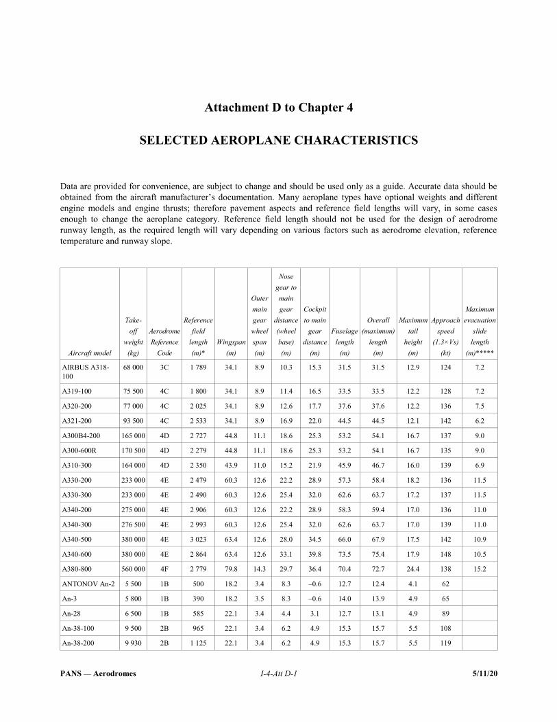
PANS — Aerodromes I-4-Att D-1 5/11/20
Attachment D to Chapter 4
SELECTED AEROPLANE CHARACTERISTICS
Data are provided for convenience, are subject to change and should be used only as a guide. Accurate data should be obtained from the aircraft manufacturer’s documentation. Many aeroplane types have optional weights and different engine models and engine thrusts; therefore pavement aspects and reference field lengths will vary, in some cases enough to change the aeroplane category. Reference field length should not be used for the design of aerodrome runway length, as the required length will vary depending on various factors such as aerodrome elevation, reference temperature and runway slope.
Aircraft model
Take-off
weight (kg)
Aerodrome
Reference
Code
Reference field
length (m)*
Wingspan (m)
Outer main gear wheel span (m)
Nose gear to main gear
distance (wheel base) (m)
Cockpit to main
gear distance
(m)
Fuselage length
(m)
Overall (maximum)
length (m)
Maximum tail
height (m)
Approach speed
(1.3×Vs) (kt)
Maximum evacuation
slide length
(m)*****
AIRBUS A318-100
68 000 3C 1 789 34.1 8.9 10.3 15.3 31.5 31.5 12.9 124 7.2
A319-100 75 500 4C 1 800 34.1 8.9 11.4 16.5 33.5 33.5 12.2 128 7.2
A320-200 77 000 4C 2 025 34.1 8.9 12.6 17.7 37.6 37.6 12.2 136 7.5
A321-200 93 500 4C 2 533 34.1 8.9 16.9 22.0 44.5 44.5 12.1 142 6.2
A300B4-200 165 000 4D 2 727 44.8 11.1 18.6 25.3 53.2 54.1 16.7 137 9.0
A300-600R 170 500 4D 2 279 44.8 11.1 18.6 25.3 53.2 54.1 16.7 135 9.0
A310-300 164 000 4D 2 350 43.9 11.0 15.2 21.9 45.9 46.7 16.0 139 6.9
A330-200 233 000 4E 2 479 60.3 12.6 22.2 28.9 57.3 58.4 18.2 136 11.5
A330-300 233 000 4E 2 490 60.3 12.6 25.4 32.0 62.6 63.7 17.2 137 11.5
A340-200 275 000 4E 2 906 60.3 12.6 22.2 28.9 58.3 59.4 17.0 136 11.0
A340-300 276 500 4E 2 993 60.3 12.6 25.4 32.0 62.6 63.7 17.0 139 11.0
A340-500 380 000 4E 3 023 63.4 12.6 28.0 34.5 66.0 67.9 17.5 142 10.9
A340-600 380 000 4E 2 864 63.4 12.6 33.1 39.8 73.5 75.4 17.9 148 10.5
A380-800 560 000 4F 2 779 79.8 14.3 29.7 36.4 70.4 72.7 24.4 138 15.2
ANTONOV An-2 5 500 1B 500 18.2 3.4 8.3 –0.6 12.7 12.4 4.1 62
An-3 5 800 1B 390 18.2 3.5 8.3 –0.6 14.0 13.9 4.9 65
An-28 6 500 1B 585 22.1 3.4 4.4 3.1 12.7 13.1 4.9 89
An-38-100 9 500 2B 965 22.1 3.4 6.2 4.9 15.3 15.7 5.5 108
An-38-200 9 930 2B 1 125 22.1 3.4 6.2 4.9 15.3 15.7 5.5 119
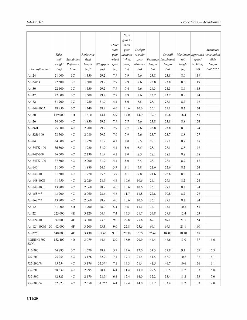
I-4-Att D-2 Procedures — Aerodromes
5/11/20
Aircraft model
Take-off
weight (kg)
Aerodrome
Reference
Code
Reference field
length (m)*
Wingspan (m)
Outer main gear wheel span (m)
Nose gear to main gear
distance (wheel base) (m)
Cockpit to main
gear distance
(m)
Fuselage length
(m)
Overall (maximum)
length (m)
Maximum tail
height (m)
Approach speed
(1.3×Vs) (kt)
Maximum evacuation
slide length
(m)*****
An-24 21 000 3C 1 350 29.2 7.9 7.9 7.6 23.8 23.8 8.6 119
An-24PB 22 500 3C 1 600 29.2 7.9 7.9 7.6 23.8 23.8 8.6 119
An-30 22 100 3C 1 550 29.2 7.9 7.4 7.6 24.3 24.3 8.6 113
An-32 27 000 3C 1 600 29.2 7.9 7.9 7.6 23.7 23.7 8.8 124
An-72 31 200 3C 1 250 31.9 4.1 8.0 8.5 28.1 28.1 8.7 108
An-148-100A 38 950 3C 1 740 28.9 4.6 10.6 10.6 26.1 29.1 8.2 124
An-70 139 000 3D 1 610 44.1 5.9 14.0 14.9 39.7 40.6 16.4 151
An-26 24 000 4C 1 850 29.2 7.9 7.7 7.6 23.8 23.8 8.8 124
An-26B 25 000 4C 2 200 29.2 7.9 7.7 7.6 23.8 23.8 8.8 124
An-32B-100 28 500 4C 2 080 29.2 7.9 7.9 7.6 23.7 23.7 8.8 127
An-74 34 800 4C 1 920 31.9 4.1 8.0 8.5 28.1 28.1 8.7 108
An-74TK-100 36 500 4C 1 920 31.9 4.1 8.0 8.5 28.1 28.1 8.8 108
An-74T-200 36 500 4C 2 130 31.9 4.1 8.0 8.5 28.1 28.1 8.8 108
An-74TK-300 37 500 4C 2 200 31.9 4.1 8.0 8.5 28.1 28.1 8.7 116
An-140 21 000 4C 1 880 24.5 3.7 8.1 7.8 21.6 22.6 8.2 124
An-140-100 21 500 4C 1 970 25.5 3.7 8.1 7.8 21.6 22.6 8.2 124
An-148-100B 41 950 4C 2 020 28.9 4.6 10.6 10.6 26.1 29.1 8.2 124
An-148-100E 43 700 4C 2 060 28.9 4.6 10.6 10.6 26.1 29.1 8.2 124
An-158*** 43 700 4C 2 060 28.6 4.6 11.7 11.8 27.8 30.8 8.2 126
An-168*** 43 700 4C 2 060 28.9 4.6 10.6 10.6 26.1 29.1 8.2 124
An-12 61 000 4D 1 900 38.0 5.4 9.6 11.1 33.1 33.1 10.5 151
An-22 225 000 4E 3 120 64.4 7.4 17.3 21.7 57.8 57.8 12.4 153
An-124-100 392 000 4F 3 000 73.3 9.0 22.8 25.6 69.1 69.1 21.1 154
An-124-100M-150 402 000 4F 3 200 73.3 9.0 22.8 25.6 69.1 69.1 21.1 160
An-225 640 000 4F 3 430 88.40 9.01 29.30 16.27 76.62 84.00 18.10 167
BOEING 707-320C
152 407 4D 3 079 44.4 8.0 18.0 20.9 44.4 46.6 13.0 137 6.6
717-200 54 885 3C 1 670 28.4 5.9 17.6 17.0 34.3 37.8 9.1 139 5.3
727-200 95 254 4C 3 176 32.9 7.1 19.3 21.4 41.5 46.7 10.6 136 6.1
727-200/W 95 254 4C 3 176 33.3** 7.1 19.3 21.4 41.5 46.7 10.6 136 6.1
737-200 58 332 4C 2 295 28.4 6.4 11.4 13.0 29.5 30.5 11.2 133 5.8
737-300 62 823 4C 2 170 28.9 6.4 12.4 14.0 32.2 33.4 11.2 133 7.0
737-300/W 62 823 4C 2 550 31.2** 6.4 12.4 14.0 32.2 33.4 11.2 133 7.0
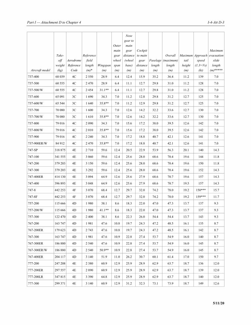
Part I — Attachment D to Chapter 4 I-4-Att D-3
5/11/20
Aircraft model
Take-off
weight (kg)
Aerodrome
Reference
Code
Reference field
length (m)*
Wingspan (m)
Outer main gear wheel span (m)
Nose gear to main gear
distance (wheel base) (m)
Cockpit to main
gear distance
(m)
Fuselage length
(m)
Overall (maximum)
length (m)
Maximum tail
height (m)
Approach speed
(1.3×Vs) (kt)
Maximum evacuation
slide length
(m)*****
737-400 68 039 4C 2 550 28.9 6.4 12.4 15.9 35.2 36.4 11.2 139 7.0
737-500 60 555 4C 2 470 28.9 6.4 11.1 12.7 29.8 31.0 11.2 128 7.0
737-500/W 60 555 4C 2 454 31.1** 6.4 11.1 12.7 29.8 31.0 11.2 128 7.0
737-600 65 091 3C 1 690 34.3 7.0 11.2 12.8 29.8 31.2 12.7 125 7.0
737-600/W 65 544 3C 1 640 35.8** 7.0 11.2 12.9 29.8 31.2 12.7 125 7.0
737-700 70 080 3C 1 600 34.3 7.0 12.6 14.2 32.2 33.6 12.7 130 7.0
737-700/W 70 080 3C 1 610 35.8** 7.0 12.6 14.2 32.2 33.6 12.7 130 7.0
737-800 79 016 4C 2 090 34.3 7.0 15.6 17.2 38.0 39.5 12.6 142 7.0
737-800/W 79 016 4C 2 010 35.8** 7.0 15.6 17.2 38.0 39.5 12.6 142 7.0
737-900 79 016 4C 2 240 34.3 7.0 17.2 18.8 40.7 42.1 12.6 141 7.0
737-900ER/W 84 912 4C 2 470 35.8** 7.0 17.2 18.8 40.7 42.1 12.6 141 7.0
747-SP 318 875 4E 2 710 59.6 12.4 20.5 22.9 53.9 56.3 20.1 140 14.3
747-100 341 555 4E 3 060 59.6 12.4 25.6 28.0 68.6 70.4 19.6 144 11.8
747-200 379 203 4E 3 150 59.6 12.4 25.6 28.0 68.6 70.4 19.6 150 11.8
747-300 379 203 4E 3 292 59.6 12.4 25.6 28.0 68.6 70.4 19.6 152 14.3
747-400ER 414 130 4E 3 094 64.9 12.6 25.6 27.9 68.6 70.7 19.6 157 14.3
747-400 396 893 4E 3 048 64.9 12.6 25.6 27.9 68.6 70.7 19.5 157 14.3
747-8 442 253 4F 3 070 68.4 12.7 29.7 32.0 74.2 78.0 19.2 150*** 15.7
747-8F 442 253 4F 3 070 68.4 12.7 29.7 32.0 74.2 78.0 19.2 159*** 11.7
757-200 115 666 4D 1 980 38.1 8.6 18.3 22.0 47.0 47.3 13.7 137 9.3
757-200/W 115 666 4D 1 980 41.1** 8.6 18.3 22.0 47.0 47.3 13.7 137 9.3
757-300 122 470 4D 2 400 38.1 8.6 22.3 26.0 54.4 54.4 13.7 143 9.3
767-200 163 747 4D 1 981 47.6 10.8 19.7 24.3 47.2 48.5 16.1 135 8.7
767-200ER 179 623 4D 2 743 47.6 10.8 19.7 24.3 47.2 48.5 16.1 142 8.7
767-300 163 747 4D 1 981 47.6 10.9 22.8 27.4 53.7 54.9 16.0 140 8.7
767-300ER 186 880 4D 2 540 47.6 10.9 22.8 27.4 53.7 54.9 16.0 145 8.7
767-300ER/W 186 880 4D 2 540 50.9** 10.9 22.8 27.4 53.7 54.9 16.0 145 8.7
767-400ER 204 117 4D 3 140 51.9 11.0 26.2 30.7 60.1 61.4 17.0 150 9.7
777-200 247 208 4E 2 380 60.9 12.9 25.9 28.9 62.9 63.7 18.7 136 12.0
777-200ER 297 557 4E 2 890 60.9 12.9 25.9 28.9 62.9 63.7 18.7 139 12.0
777-200LR 347 815 4E 3 390 64.8 12.9 25.9 28.9 62.9 63.7 18.7 140 12.0
777-300 299 371 4E 3 140 60.9 12.9 31.2 32.3 73.1 73.9 18.7 149 12.6
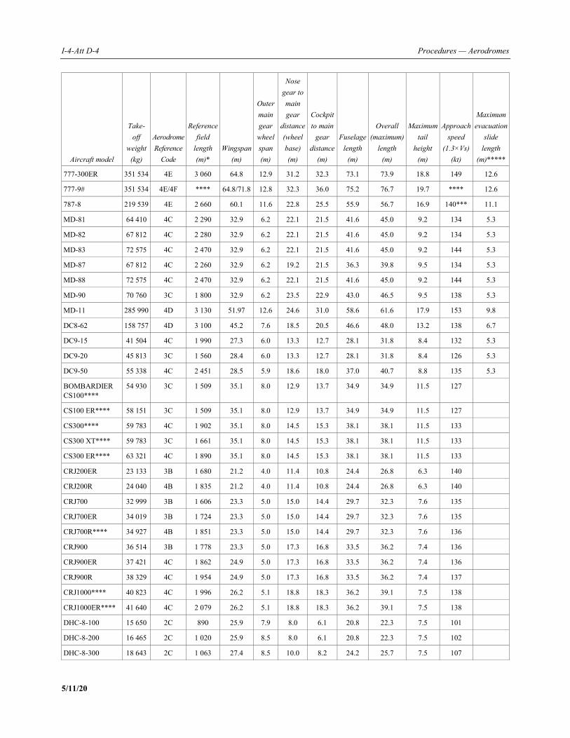
I-4-Att D-4 Procedures — Aerodromes
5/11/20
Aircraft model
Take-off
weight (kg)
Aerodrome
Reference
Code
Reference field
length (m)*
Wingspan (m)
Outer main gear wheel span (m)
Nose gear to main gear
distance (wheel base) (m)
Cockpit to main
gear distance
(m)
Fuselage length
(m)
Overall (maximum)
length (m)
Maximum tail
height (m)
Approach speed
(1.3×Vs) (kt)
Maximum evacuation
slide length
(m)*****
777-300ER 351 534 4E 3 060 64.8 12.9 31.2 32.3 73.1 73.9 18.8 149 12.6
777-9# 351 534 4E/4F **** 64.8/71.8 12.8 32.3 36.0 75.2 76.7 19.7 **** 12.6
787-8 219 539 4E 2 660 60.1 11.6 22.8 25.5 55.9 56.7 16.9 140*** 11.1
MD-81 64 410 4C 2 290 32.9 6.2 22.1 21.5 41.6 45.0 9.2 134 5.3
MD-82 67 812 4C 2 280 32.9 6.2 22.1 21.5 41.6 45.0 9.2 134 5.3
MD-83 72 575 4C 2 470 32.9 6.2 22.1 21.5 41.6 45.0 9.2 144 5.3
MD-87 67 812 4C 2 260 32.9 6.2 19.2 21.5 36.3 39.8 9.5 134 5.3
MD-88 72 575 4C 2 470 32.9 6.2 22.1 21.5 41.6 45.0 9.2 144 5.3
MD-90 70 760 3C 1 800 32.9 6.2 23.5 22.9 43.0 46.5 9.5 138 5.3
MD-11 285 990 4D 3 130 51.97 12.6 24.6 31.0 58.6 61.6 17.9 153 9.8
DC8-62 158 757 4D 3 100 45.2 7.6 18.5 20.5 46.6 48.0 13.2 138 6.7
DC9-15 41 504 4C 1 990 27.3 6.0 13.3 12.7 28.1 31.8 8.4 132 5.3
DC9-20 45 813 3C 1 560 28.4 6.0 13.3 12.7 28.1 31.8 8.4 126 5.3
DC9-50 55 338 4C 2 451 28.5 5.9 18.6 18.0 37.0 40.7 8.8 135 5.3
BOMBARDIER CS100****
54 930 3C 1 509 35.1 8.0 12.9 13.7 34.9 34.9 11.5 127
CS100 ER**** 58 151 3C 1 509 35.1 8.0 12.9 13.7 34.9 34.9 11.5 127
CS300**** 59 783 4C 1 902 35.1 8.0 14.5 15.3 38.1 38.1 11.5 133
CS300 XT**** 59 783 3C 1 661 35.1 8.0 14.5 15.3 38.1 38.1 11.5 133
CS300 ER**** 63 321 4C 1 890 35.1 8.0 14.5 15.3 38.1 38.1 11.5 133
CRJ200ER 23 133 3B 1 680 21.2 4.0 11.4 10.8 24.4 26.8 6.3 140
CRJ200R 24 040 4B 1 835 21.2 4.0 11.4 10.8 24.4 26.8 6.3 140
CRJ700 32 999 3B 1 606 23.3 5.0 15.0 14.4 29.7 32.3 7.6 135
CRJ700ER 34 019 3B 1 724 23.3 5.0 15.0 14.4 29.7 32.3 7.6 135
CRJ700R**** 34 927 4B 1 851 23.3 5.0 15.0 14.4 29.7 32.3 7.6 136
CRJ900 36 514 3B 1 778 23.3 5.0 17.3 16.8 33.5 36.2 7.4 136
CRJ900ER 37 421 4C 1 862 24.9 5.0 17.3 16.8 33.5 36.2 7.4 136
CRJ900R 38 329 4C 1 954 24.9 5.0 17.3 16.8 33.5 36.2 7.4 137
CRJ1000**** 40 823 4C 1 996 26.2 5.1 18.8 18.3 36.2 39.1 7.5 138
CRJ1000ER**** 41 640 4C 2 079 26.2 5.1 18.8 18.3 36.2 39.1 7.5 138
DHC-8-100 15 650 2C 890 25.9 7.9 8.0 6.1 20.8 22.3 7.5 101
DHC-8-200 16 465 2C 1 020 25.9 8.5 8.0 6.1 20.8 22.3 7.5 102
DHC-8-300 18 643 2C 1 063 27.4 8.5 10.0 8.2 24.2 25.7 7.5 107
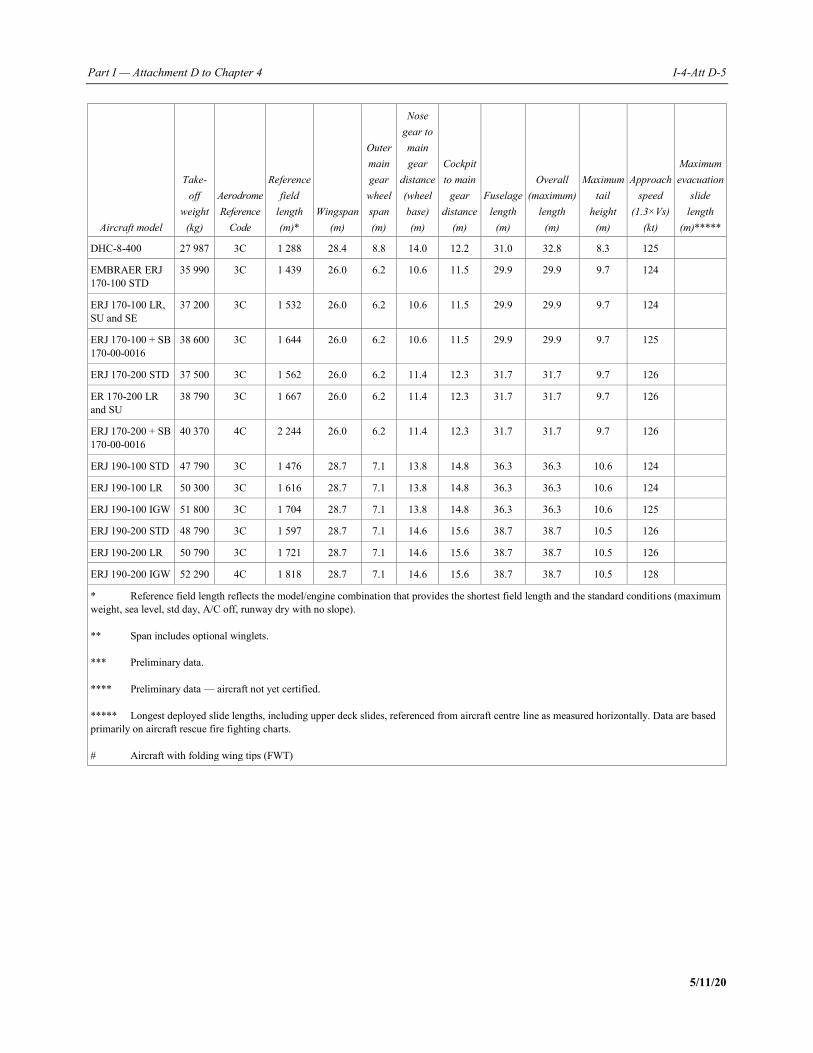
Part I — Attachment D to Chapter 4 I-4-Att D-5
5/11/20
Aircraft model
Take-off
weight (kg)
Aerodrome
Reference
Code
Reference field
length (m)*
Wingspan (m)
Outer main gear wheel span (m)
Nose gear to main gear
distance (wheel base) (m)
Cockpit to main
gear distance
(m)
Fuselage length
(m)
Overall (maximum)
length (m)
Maximum tail
height (m)
Approach speed
(1.3×Vs) (kt)
Maximum evacuation
slide length
(m)*****
DHC-8-400 27 987 3C 1 288 28.4 8.8 14.0 12.2 31.0 32.8 8.3 125
EMBRAER ERJ 170-100 STD
35 990 3C 1 439 26.0 6.2 10.6 11.5 29.9 29.9 9.7 124
ERJ 170-100 LR, SU and SE
37 200 3C 1 532 26.0 6.2 10.6 11.5 29.9 29.9 9.7 124
ERJ 170-100 + SB 170-00-0016
38 600 3C 1 644 26.0 6.2 10.6 11.5 29.9 29.9 9.7 125
ERJ 170-200 STD 37 500 3C 1 562 26.0 6.2 11.4 12.3 31.7 31.7 9.7 126
ER 170-200 LR and SU
38 790 3C 1 667 26.0 6.2 11.4 12.3 31.7 31.7 9.7 126
ERJ 170-200 + SB 170-00-0016
40 370 4C 2 244 26.0 6.2 11.4 12.3 31.7 31.7 9.7 126
ERJ 190-100 STD 47 790 3C 1 476 28.7 7.1 13.8 14.8 36.3 36.3 10.6 124
ERJ 190-100 LR 50 300 3C 1 616 28.7 7.1 13.8 14.8 36.3 36.3 10.6 124
ERJ 190-100 IGW 51 800 3C 1 704 28.7 7.1 13.8 14.8 36.3 36.3 10.6 125
ERJ 190-200 STD 48 790 3C 1 597 28.7 7.1 14.6 15.6 38.7 38.7 10.5 126
ERJ 190-200 LR 50 790 3C 1 721 28.7 7.1 14.6 15.6 38.7 38.7 10.5 126
ERJ 190-200 IGW 52 290 4C 1 818 28.7 7.1 14.6 15.6 38.7 38.7 10.5 128
* Reference field length reflects the model/engine combination that provides the shortest field length and the standard conditions (maximum weight, sea level, std day, A/C off, runway dry with no slope). ** Span includes optional winglets. *** Preliminary data. **** Preliminary data — aircraft not yet certified. ***** Longest deployed slide lengths, including upper deck slides, referenced from aircraft centre line as measured horizontally. Data are based primarily on aircraft rescue fire fighting charts. # Aircraft with folding wing tips (FWT)
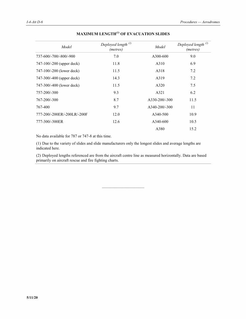
I-4-Att D-6 Procedures — Aerodromes
5/11/20
MAXIMUM LENGTH(1) OF EVACUATION SLIDES
Model Deployed length (2) (metres) Model Deployed length (2)
(metres)
737-600/-700/-800/-900 7.0 A300-600 9.0
747-100/-200 (upper deck) 11.8 A310 6.9
747-100/-200 (lower deck) 11.5 A318 7.2
747-300/-400 (upper deck) 14.3 A319 7.2
747-300/-400 (lower deck) 11.5 A320 7.5
757-200/-300 9.3 A321 6.2
767-200/-300 8.7 A330-200/-300 11.5
767-400 9.7 A340-200/-300 11
777-200/-200ER/-200LR/-200F 12.0 A340-500 10.9
777-300/-300ER 12.6 A340-600 10.5
A380 15.2
No data available for 787 or 747-8 at this time.
(1) Due to the variety of slides and slide manufacturers only the longest slides and average lengths are indicated here.
(2) Deployed lengths referenced are from the aircraft centre line as measured horizontally. Data are based primarily on aircraft rescue and fire fighting charts.
_____________________
PANS — Aerodromes II-1-1 5/11/20
PART II — AERODROME OPERATIONAL MANAGEMENT
Chapter 1
TRAINING
1.1 GENERAL 1.1.1 The activities conducted by an aerodrome operator require the competence and appropriate training of personnel in order to carry out their assigned tasks. 1.1.2 This training is generally conducted by the individual’s employer, but may also be conducted by the aerodrome operator or third parties. 1.1.3 This chapter provides the general obligations related to training programmes and competence checks for all personnel carrying out the procedures detailed in each of the following chapters of this document. Note.— Training for other activities, not contained in Part II of this document, may be carried out depending on the needs identified by the aerodrome operator. 1.1.4 Additional material related to training procedures, including more detailed programmes or requirements, can be found in a number of chapters in Part II of this document. Note.— The additional material has been provided to add information related to activity-specific training.
1.2 OBJECTIVES 1.2.1 Aerodrome operators shall ensure that training programmes are developed and implemented for all personnel involved in aerodrome operations. 1.2.2 The training programmes shall include procedures for the verification of personnel knowledge and for the practical application thereof, at adequate intervals.
1.3 OPERATIONAL PRACTICES 1.3.1 Aerodrome operators shall be responsible for ensuring that their staff and all personnel involved in aerodrome operations at the aerodrome are competent for each task they are required to carry out. The details of the training will vary depending on the person’s experience and background and the complexity of the required task.
II-1-2 Procedures — Aerodromes
5/11/20
1.3.2 Training objectives shall be identified to ensure that competence is achieved and maintained. Based on these objectives, the training programme should include content and frequency for each technical subject, as well as a method to track the progress of the required training and the maintenance of training records. 1.3.3 A training programme should include: a) theoretical training; b) practical or on-the-job training; c) testing of understanding; and d) demonstrating competence or recurrent theoretical and/or practical training. Note 1.— Provisions on demonstrating competence are included in the Appendix to this chapter. Note 2.— Demonstration of continued competence is an alternative to recurrent training. Note 3.— The attachment to this chapter provides guidance on the structure of a training programme. 1.3.4 Refresher training should be provided following an accident, incident or serious occurrence, if training-related issues have been identified as a contributing factor, or after a long-term absence to ensure that personnel are kept abreast of the most recent material, developments and practices.
_____________________
PANS — Aerodromes II-1-App-1 5/11/20
Appendix to Chapter 1
DEMONSTRATING COMPETENCE 1.1 In order to demonstrate competence in a specific task, personnel shall demonstrate that the theory, practical training and local knowledge can be applied together in a satisfactory way, usually by successfully completing a competence check. 1.2 Competence checks may be used as an alternative to recurrent training whereby personnel demonstrate continued competence in a task and therefore do not require recurrent training. 1.3 Competence checks can be completed during day-to-day activities by having a competent individual accompany and assess the staff member on a task they are required to complete. 1.4 Records of all the steps taken to achieve the task shall be made and an evaluation shall be completed. 1.5 For a team or section to be recognized as competent, periodical audits or checks should be carried out and recorded. All shortfalls should be addressed by reviewing and updating the training material, refresher training or the frequency of recurrent training. Similarly, after any accident, incident or serious occurrence, it may be prudent to review training programmes to ensure that they remain appropriate.
_____________________

PANS — Aerodromes II-1-Att-1 5/11/20
Attachment to Chapter 1
STRUCTURE OF A TRAINING PROGRAMME
1. INITIAL TRAINING
Initial training should be composed of theoretical and practical training modules. Personnel should be assessed and demonstrate their capability to safely accomplish the required tasks upon completion of the initial training and prior to starting on-the-job training.
2. RECURRENT TRAINING
The aerodrome operator should ensure that personnel complete recurrent training at suitable intervals after the completion of their initial training programme. Continuous competence checking may be used as an alternative to recurrent training.
3. REFRESHER TRAINING
When a person has not performed any of their assigned tasks for a significant period of time, or has been involved in an
accident, incident or serious occurrence, in which training-related issues have been identified as a contributing factor,
that person should complete relevant refresher training prior to: a) performing assigned tasks; or b) being allowed unescorted access on the movement area and other operational areas of the aerodrome, as
appropriate.
_____________________

PANS — Aerodromes II-2-1 5/11/20
Chapter 2
REPORTING FORMAT USING STANDARD
RUNWAY CONDITION REPORT (RCR) (Applicable on 5 November 2020)
2.1 RUNWAY SURFACE CONDITION ASSESSMENT AND REPORTING
2.1.1 General Note.— This section includes an introduction to each of the topics covered in subsequent sections. It also provides an overview of the general principles in order to understand the procedures that follow. 2.1.1.1 Assessing and reporting the condition of the movement area and related facilities is necessary in order to provide the flight crew with the information needed for safe operation of the aeroplane. The runway condition report (RCR) is used for reporting assessed information. 2.1.1.2 On a global level, movement areas are exposed to a multitude of climatic conditions and consequently a significant difference in the condition to be reported. The RCR describes a basic structure applicable for all these climatic variations. Assessing runway surface conditions rely on a great variety of techniques and no single solution can apply to every situation. Note.— Guidance on methods of assessing runway surface condition is given in the attachment to this chapter. 2.1.1.3 The philosophy of the RCR is that the aerodrome operator assesses the runway surface conditions whenever water, snow, slush, ice or frost are present on an operational runway. From this assessment, a runway condition code (RWYCC) and a description of the runway surface are reported which can be used by the flight crew for aeroplane performance calculations. This format, based on the type, depth and coverage of contaminants, is the best assessment of the runway surface condition by the aerodrome operator; however, all other pertinent information will be taken into consideration and be kept up to date and changes in conditions reported without delay. 2.1.1.4 The RWYCC reflects the runway braking capability as a function of the surface conditions. With this information, the flight crew can derive, from the performance information provided by the aeroplane manufacturer, the necessary stopping distance of an aircraft on the approach under the prevailing conditions. 2.1.1.5 The operational requirements in 2.1.1.3 stem from Annex 6 — Operation of Aircraft, Part I — International Commercial Air Transport — Aeroplanes and Annex 8 — Airworthiness of Aircraft with the objective of achieving the desired level of safety for the aeroplane operations. 2.1.1.6 Annex 14, Volume I contains high-level SARPs related to the assessment and reporting of runway surface condition. Associated objectives and operational practices are described in 2.1.2 and 2.1.3.
II-2-2 Procedures — Aerodromes
5/11/20
2.1.1.7 The operational practices are intended to provide the information needed to fulfil the syntax requirements for dissemination and promulgation specified in the Procedures for Air Navigation Services — Aeronautical Information Management (PANS-AIM, Doc 10066) and the Procedures for Air Navigation Services — Air Traffic Management (PANS-ATM, Doc 4444). Note.— For practical reasons, the RCR information string has been provisionally incorporated in the Procedures for Air Navigation Services — Aeronautical Information Management (PANS-AIM, Doc 10066) as a revision of the SNOWTAM format. 2.1.1.8 When the runway is wholly or partly contaminated by standing water, snow, slush, ice or frost, or is wet associated with the clearing or treatment of snow, slush, ice or frost, the runway condition report should be disseminated through the AIS and ATS services. When the runway is wet, not associated with the presence of standing water, snow, slush, ice or frost, the assessed information should be disseminated using the runway condition report through the ATS only. Note.— Operationally relevant information concerning taxiways and aprons are covered in the situational awareness section of the RCR. 2.1.1.9 The operational practices describe procedures to meet the operationally needed information for the flight crew and dispatchers for the following sections: a) aeroplane take-off and landing performance calculations: i) dispatch — pre-planning before commencement of flight: — take-off from a runway; and — landing on a destination aerodrome or an alternate aerodrome; ii) in flight — when assessing the continuation of flight; and — before landing on a runway; and b) situational awareness of the surface conditions on the taxiways and aprons.
2.1.2 Objectives Note.— This section contains the basic principles that have been defined for the topic and have been formulated as required for global uniform application. They cover the whole subject matter and are broken down into the individual subsections. 2.1.2.1 The RWYCC shall be reported for each third of the runway assessed. 2.1.2.2 The assessment process shall include: a) assessing and reporting the condition of the movement area; b) providing the assessed information in the correct format; and c) reporting significant changes without delay.
Part II — Chapter 2. Reporting format using standard runway condition report (RCR) II-2-3
5/11/20
2.1.2.3 The information to be reported shall be compliant with the RCR which consists of: a) aeroplane performance calculation section; and b) situational awareness section. 2.1.2.4 The information shall be included in an information string in the following order using only AIS-compatible characters: a) aeroplane performance calculation section: i) aerodrome location indicator; ii) date and time of assessment; iii) lower runway designation number; iv) RWYCC for each runway third; v) per cent coverage contaminant for each runway third; vi) depth of loose contaminant for each runway third; vii) condition description for each runway third; and viii) width of runway to which the RWYCCs apply if less than published width. b) situational awareness section: i) reduced runway length; ii) drifting snow on the runway; iii) loose sand on the runway; iv) chemical treatment on the runway; v) snowbanks on the runway; vi) snowbanks on the taxiway; vii) snowbanks adjacent to the runway; viii) taxiway conditions; ix) apron conditions; x) State-approved, and published use of, measured friction coefficient; and xi) plain language remarks.
II-2-4 Procedures — Aerodromes
5/11/20
2.1.2.5 The syntax for dissemination as described in the RCR template in the Procedures for Air Navigation Services — Aeronautical Information Management (PANS-AIM, Doc 10066), Appendix 4, is determined by the operational need of the flight crew and the capability of trained personnel to provide the information arising from an assessment. Note.― For practical reasons, the RCR information string has been provisionally incorporated in the Procedures for Air Navigation Services — Aeronautical Information Management (PANS-AIM, Doc 10066) as a revision of the SNOWTAM format. 2.1.2.6 The syntax requirement in 2.1.2.5 shall be strictly adhered to when providing the assessed information through the RCR.
2.1.3 Operational practices Note.— This section covers the specific operational practices and the ways in which they are applied in order to achieve the basic principles defined in 2.1.2 — Objectives. 2.1.3.1 Reporting, in compliance with the runway condition report, shall commence when a significant change in runway surface condition occurs due to water, snow, slush, ice or frost. 2.1.3.2 Reporting of the runway surface condition should continue to reflect significant changes until the runway is no longer contaminated. When this situation occurs, the aerodrome will issue a runway condition report that states the runway is wet or dry as appropriate. 2.1.3.3 A change in the runway surface condition used in the runway condition report is considered significant whenever there is: a) any change in the RWYCC; b) any change in contaminant type; c) any change in reportable contaminant coverage according to Table II-2-1; d) any change in contaminant depth according to Table II-2-2; and e) any other information, for example a pilot report of runway braking action, which according to assessment
techniques used, are known to be significant. Runway Condition Report — Aeroplane performance calculation section 2.1.3.4 The aeroplane performance calculation section is a string of grouped information separated by a space “ ” and ends with a return and two line feed “≪≡”. This is to distinguish the aeroplane performance calculation section from the following situational awareness section or the following aeroplane performance calculation section of another runway.
Part II — Chapter 2. Reporting format using standard runway condition report (RCR) II-2-5
5/11/20
The information to be included in this section consists of the following. a) Aerodrome location indicator: a four-letter ICAO location indicator in accordance with Doc 7910, Location
Indicators. This information is mandatory. Format: nnnn Example: ENZH b) Date and time of assessment: date and time (UTC) when the assessment was performed by the trained
personnel. This information is mandatory. Format: MMDDhhmm Example: 09111357 c) Lower runway designation number: a two- or three-character number identifying the runway for which the
assessment is carried out and reported. This information is mandatory. Format: nn[L] or nn[C] or nn[R] Example: 09L d) Runway condition code for each runway third: a one-digit number identifying the RWYCC assessed for
each runway third. The codes are reported in a three-character group separated by a “/” for each third. The direction for listing the runway thirds shall be in the direction as seen from the lower designation number.
This information is mandatory. When transmitting information on runway surface conditions by ATS to flight crews, the sections are,
however, referred to as the first, second or third part of the runway. The first part always means the first third of the runway as seen in the direction of landing or take-off as illustrated in Figures II-2-1 and II-2-2 and detailed in PANS-ATM (Doc 4444).
Format: n/n/n Example: 5/5/2
Note 1.― A change in RWYCC from, say, 5/5/2 to 5/5/3 is considered significant. (See further examples below).
Note 2.― A change in RWYCC requires a complete assessment taking into account all information available. Note 3.― Procedures for assigning a RWYCC are available in 2.1.3.12 to 2.1.3.16.
e) Per cent coverage contaminant for each runway third: a number identifying the percentage coverage. The percentages are to be reported in an up-to-nine character group separated by a “/” for each runway third. The assessment is based upon an even distribution within the runway thirds using the guidance in Table II-2-1.
II-2-6 Procedures — Aerodromes
5/11/20
This information is conditional. It is not reported for one runway third if it is dry or covered with less than 10 per cent.
Format: [n]nn/[n]nn/[n]nn Example: 25/50/100 NR/50/100 if contaminant coverage is less than 10% in the first third 25/NR/100 if contaminant coverage is less than 10% in the middle third 25/50/NR if contaminant coverage is less than 10% in the last third With uneven distribution of the contaminants, additional information is to be given in the plain language
remark part of the situational awareness section of the runway condition report. Where possible, a standardized text should be used.
Note.― When no information is to be reported, insert “NR” at its relevant position in the message to indicate to the user that no information exists (/NR/).
f) Depth of loose contaminant: dry snow, wet snow, slush or standing water for each runway third: a
two- or three-digit number representing the assessed depth (mm) of the contaminant for each runway third. The depth is reported in a six to nine character group separated by a “/” for each runway third as defined in Table II-2-2. The assessment is based upon an even distribution within the runway thirds as assessed by trained personnel. If measurements are included as part of the assessment process, the reported values are still reported as assessed depths, as the trained personnel have placed their judgment upon the measured depths to be representative for the runway third.
Format: [n]nn/[n]nn/[n]nn Examples: 04/06/12 [STANDING WATER] 02/04/09 [SLUSH] 02/05/10 [WET SNOW or WET SNOW ON TOP OF ...] 02/20/100 [DRY SNOW or DRY SNOW ON TOP OF] NR/NR/100 [DRY SNOW in the last third only] This information is conditional. It is reported only for DRY SNOW, WET SNOW, SLUSH and STANDING
WATER. Example of reporting depth of contaminant whenever there is a significant change
1) After the first assessment of runway condition, a first runway condition report is generated. The initial report is:
5/5/5 100/100/100 02/02/02 SLUSH/SLUSH/SLUSH
Note.― The full information string is not used in this example.
2) With continuing precipitation, a new runway condition report is required to be generated as subsequent
assessment reveals a change in the runway condition code. A second runway condition report is therefore created as:
2/2/2 100/100/100 03/03/03 SLUSH/SLUSH/SLUSH
3) With even more precipitation, further assessment reveals the depth of precipitation has increased from 3 mm
to 5 mm along the entire length of the runway. However, a new runway condition report is not required because the runway condition code has not changed (change in depth is less than the significant change threshold of 3 mm).
Part II — Chapter 2. Reporting format using standard runway condition report (RCR) II-2-7
5/11/20
4) A final assessment of the precipitation reveals that the depth has increased to 7 mm. A new runway condition code is required because the change in depth from the last runway condition report (second runway condition code) i.e. from 3 mm to 7 mm is greater than the significant change threshold of 3 mm. A third runway condition report is thus created as below:
2/2/2 100/100/100 07/07/07 SLUSH/SLUSH/SLUSH
For contaminants other than STANDING WATER, SLUSH, WET SNOW or DRY SNOW, the depth is not reported. The position of this type of information in the information string is then identified by /NR/. Example: /NR/
When the depth of the contaminants varies significantly within a runway third, additional information is to be given in the plain language remark part of the situational awareness section of the runway condition report. Note.— In this context a significant variation in depth in the lateral direction is more than twice the depth indicated in column 3 of Table II-2-2. Further information is available in Circular 329 — Assessment, Measurement and Reporting of Runway Surface Conditions.
g) Condition description for each runway third: to be reported in capital letters using terms specified in 2.9.5 of Annex 14, Volume I. These terms have been harmonized with the terms used in the Standards and Recommended Practices in Annexes 6, 8, 11 and 15. The condition type is reported by any of the following condition type descriptions for each runway third and separated by an oblique stroke “/”.
This information is mandatory. COMPACTED SNOW DRY DRY SNOW DRY SNOW ON TOP OF COMPACTED SNOW DRY SNOW ON TOP OF ICE FROST ICE SLUSH STANDING WATER WATER ON TOP OF COMPACTED SNOW WET WET ICE WET SNOW WET SNOW ON TOP OF COMPACTED SNOW WET SNOW ON TOP OF ICE Format: nnnn/nnnn/nnnn Example: DRY SNOW ON TOP OF COMPACTED SNOW/WET SNOW ON TOP OF COMPACTED
SNOW/WATER ON TOP OF COMPACTED SNOW
h) Width of runway to which the RWYCCs apply if less than published width is the two-digit number representing the width of cleared runway in metres.
This information is optional. Format: nn Example: 30
II-2-8 Procedures — Aerodromes
5/11/20
If the cleared runway width is not symmetrical along the centre line, additional information is to be given in the plain language remark part of the situational awareness section of the runway condition report.
Runway condition report — Situational awareness section: 2.1.3.5 All individual messages in the situational awareness section end with a full stop sign. This is to distinguish the message from subsequent message(s). The information to be included in this section consists of the following: a) Reduced runway length
This information is conditional when a NOTAM has been published with a new set of declared distances affecting the LDA.
Format: Standardized fixed text RWY nn [L] or nn [C] or nn [R] LDA REDUCED TO [n]nnn Example: RWY 22L LDA REDUCED TO 1450. b) Drifting snow on the runway This information is optional. Format: Standardized fixed text Example: DRIFTING SNOW. c) Loose sand on the runway This information is optional. Format: RWY nn[L] or nn[C] or nn[R] LOOSE SAND Example: RWY 02R LOOSE SAND. d) Chemical treatment on the runway This information is mandatory. Format: RWY nn[L] or nn[C] or nn[R] CHEMICALLY TREATED Example: RWY 06 CHEMICALLY TREATED. e) Snowbanks on the runway This information is optional. Left or right distance in metres from centre line. Format: RWY nn[L] or nn[C] or nn[R] SNOWBANK Lnn or Rnn or LRnn FM CL Example: RWY 06L SNOWBANK LR19 FM CL. f) Snowbanks on taxiway This information is optional. Left or right distance in metres from centre line. Format: TWY [nn]n SNOWBANK Lnn or Rnn or LRnn FM CL Example: TWY A SNOWBANK LR20 FM CL.
Part II — Chapter 2. Reporting format using standard runway condition report (RCR) II-2-9
5/11/20
g) Snowbanks adjacent to the runway penetrating level/profile set in the aerodrome snow plan. This information is optional. Format: RWY nn[L] or nn[C] or nn[R] ADJ SNOWBANKS Example: RWY 06R ADJ SNOWBANKS. h) Taxiway conditions This information is optional. Format: TWY [nn]n POOR Example: TWY B POOR. i) Apron conditions This information is optional. Format: APRON [nnnn] POOR Example: APRON NORTH POOR. j) State-approved and published use of measured friction coefficient This information is optional. Format: [State set format and associated procedures] Example: [Function of State set format and associated procedures]. k) Plain language remarks using only allowable characters in capital letters Where possible, standardized text should be developed. This information is optional. Format: Combination of allowable characters where use of full stop « . » marks the end of the message. Allowable characters: A B C D E F G H I J K LM N O P Q R S T U V W X Y Z 0 1 2 3 4 5 6 7 8 9 / [oblique stroke] “.” [period]“ ” [space] Complete information string 2.1.3.6 An example of a complete information string prepared for dissemination is as follows:
[COM header and Abbreviated header] (Completed by AIS) GG EADBZQZX EADNZQZX EADSZQZX 170229 EADDYNYX (SWEA0151 EADD 02170225 SNOWTAM 0151
II-2-10 Procedures — Aerodromes
5/11/20
[Aeroplane performance calculation section] EADD 02170055 09L 5/5/5 100/100/100 NR/NR/NR WET/WET/WET SNOW 02170135 09R 5/4/3 100/50/75 NR/06/06 WET/SLUSH/SLUSH 02170225 09C 3/2/1 75/100/100 06/12/12 SLUSH/WET SNOW/WET SNOW
[Situational awareness section] RWY 09L SNOWBANK R20 FM CL. RWY 09R ADJ SNOWBANKS. TWY B POOR. APRON NORTH
POOR) Assessing a runway and assigning a runway condition code 2.1.3.7 The assessed RWYCC to be reported for each third of the runway is determined by following the procedure described in 2.1.3.12 to 2.1.3.16. Note.― Guidance on methods of assessing runway surface condition, including the determination of a slippery wet runway, is given in the attachment to this chapter. 2.1.3.8 If 25 per cent or less area of a runway third is wet or covered by contaminant, a RWYCC 6 shall be reported. 2.1.3.9 If the distribution of the contaminant is not uniform, the location of the area that is wet or covered by the contaminant is described in the plain language remarks part of the situational awareness section of the runway condition report. 2.1.3.10 A description of the runway surface condition is provided using the contamination terms described in capital letters in Table II-2-3 — Assigning a runway condition code (RWYCC). 2.1.3.11 If multiple contaminants are present where the total coverage is more than 25 per cent but no single contaminant covers more than 25 per cent of any runway third, the RWYCC is based upon the judgment by trained personnel, considering what contaminant will most likely be encountered by the aeroplane and its likely effect on the aeroplane’s performance. 2.1.3.12 The RWYCC is determined using Table II-2-3. 2.1.3.13 The variables, in Table II-2-3, that may affect the runway condition code are: a) type of contaminant; b) depth of contaminant; and c) outside air temperature. Where available the runway surface temperature should preferably be used. Note.— At air temperatures of plus 3 degrees Celsius and below, with a dew point spread of 3 degrees Celsius or less, the runway surface condition may be more slippery than indicated by the runway condition code assigned by Table II-2-3. The narrow dew point spread indicates that the air mass is relatively close to saturation which is often associated with actual precipitation, intermittent precipitation, nearby precipitation or fog. This may depend on its correlation with precipitation but it may also, at least in part, depend on the exchange of water at the air-ice interface. Due to the other variables involved, such as surface temperature, solar heating and ground cooling or heating, a small temperature spread does not always mean that the braking action will be more slippery. The observation should be used by aerodrome operators as an indicator of slippery conditions but not as an absolute. 2.1.3.14 An assigned RWYCC 5, 4, 3 or 2 shall not be upgraded.
Part II — Chapter 2. Reporting format using standard runway condition report (RCR) II-2-11
5/11/20
2.1.3.15 An assigned RWYCC 1 or 0 can be upgraded using the following procedures (but see also 2.1.3.16): a) if a properly operated and calibrated State-approved measuring device and all other observations support a
higher RWYCC as judged by trained personnel; b) the decision to upgrade RWYCC 1 or 0 cannot be based upon one assessment method alone. All available
means of assessing runway slipperiness are to be used to support the decision; c) when RWYCC 1 or 0 is upgraded, the runway surface is assessed frequently during the period the higher
RWYCC is in effect to ensure that the runway surface condition does not deteriorate below the assigned code; and
d) variables that may be considered in the assessment that may affect the runway surface condition, include but
are not limited to:
i) any precipitation conditions;
ii) changing temperatures;
iii) effects of wind;
iv) frequency of runway in use; and
v) type of aeroplane using the runway. 2.1.3.16 Upgrading of RWYCC 1 or 0 using the procedures in 2.1.3.15 shall not be permitted to go beyond a RWYCC 3. 2.1.3.17 If sand or other runway treatments are used to support upgrading, the runway surface is assessed frequently to ensure the continued effectiveness of the treatment. 2.1.3.18 The RWYCC determined from Table II-2-3 should be appropriately downgraded considering all available means of assessing runway slipperiness, including the criteria given in Table II-2-4. 2.1.3.19 Where available, the pilot reports of runway braking action should be taken into consideration as part of the ongoing monitoring process, using the following principle: a) a pilot report of runway braking action is taken into consideration for downgrading purposes; and b) a pilot report of runway braking action can be used for upgrading purposes only if it is used in combination
with other information qualifying for upgrading. Note 1.— The procedures for making special air-reports regarding runway braking action are contained in the Procedures for Air Navigation Services — Air Traffic Management (PANS-ATM, Doc 4444), Chapter 4, and Appendix 1, Instructions for air-reporting by voice communications. Note 2.— Procedures for downgrading reported RWYCC can be found in 2.1.3.23 including the use of Table II-2-5, Runway condition assessment matrix (RCAM). 2.1.3.20 Two consecutive pilot reports of runway braking action of POOR shall trigger an assessment if an RWYCC of 2 or better has been reported.
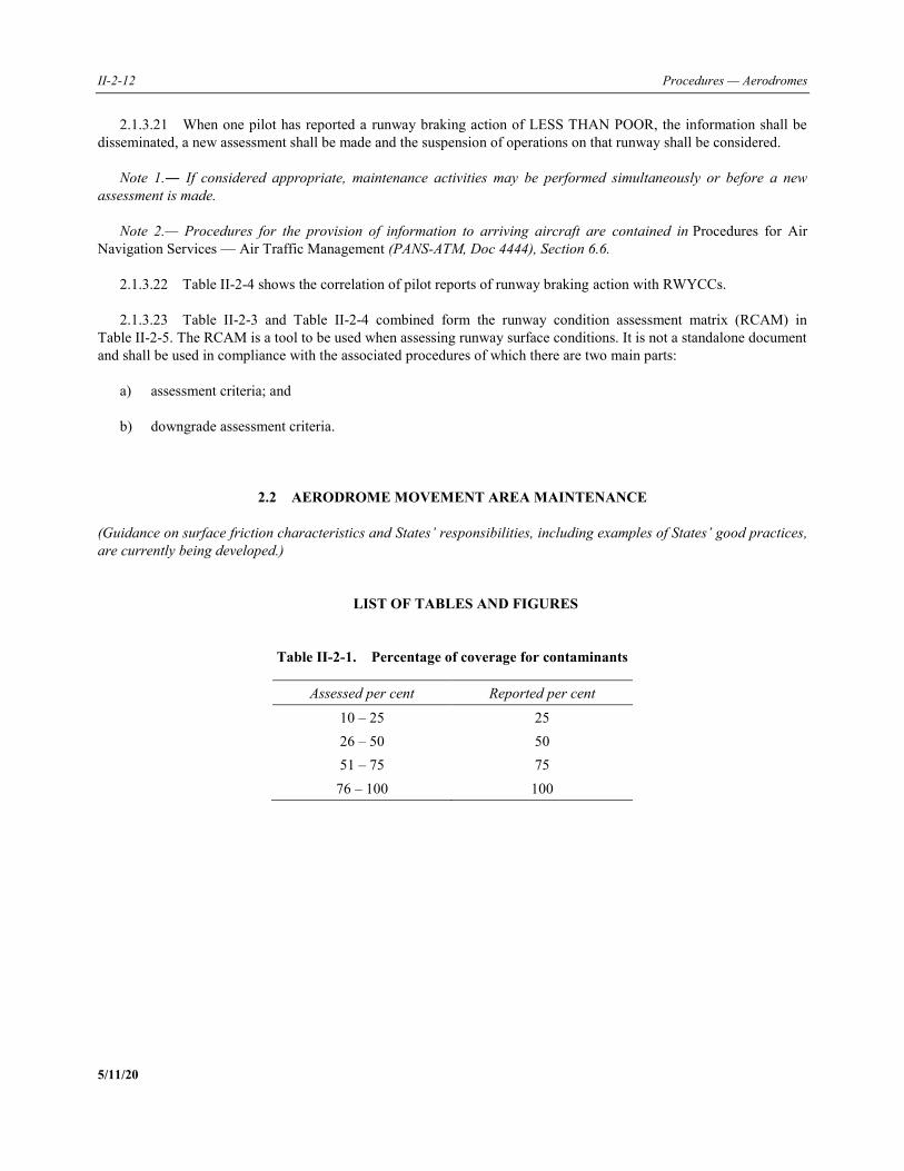
II-2-12 Procedures — Aerodromes
5/11/20
2.1.3.21 When one pilot has reported a runway braking action of LESS THAN POOR, the information shall be disseminated, a new assessment shall be made and the suspension of operations on that runway shall be considered. Note 1.― If considered appropriate, maintenance activities may be performed simultaneously or before a new assessment is made. Note 2.— Procedures for the provision of information to arriving aircraft are contained in Procedures for Air Navigation Services — Air Traffic Management (PANS-ATM, Doc 4444), Section 6.6. 2.1.3.22 Table II-2-4 shows the correlation of pilot reports of runway braking action with RWYCCs. 2.1.3.23 Table II-2-3 and Table II-2-4 combined form the runway condition assessment matrix (RCAM) in Table II-2-5. The RCAM is a tool to be used when assessing runway surface conditions. It is not a standalone document and shall be used in compliance with the associated procedures of which there are two main parts: a) assessment criteria; and b) downgrade assessment criteria.
2.2 AERODROME MOVEMENT AREA MAINTENANCE (Guidance on surface friction characteristics and States’ responsibilities, including examples of States’ good practices, are currently being developed.)
LIST OF TABLES AND FIGURES
Table II-2-1. Percentage of coverage for contaminants
Assessed per cent Reported per cent
10 – 25 25 26 – 50 50 51 – 75 75
76 – 100 100
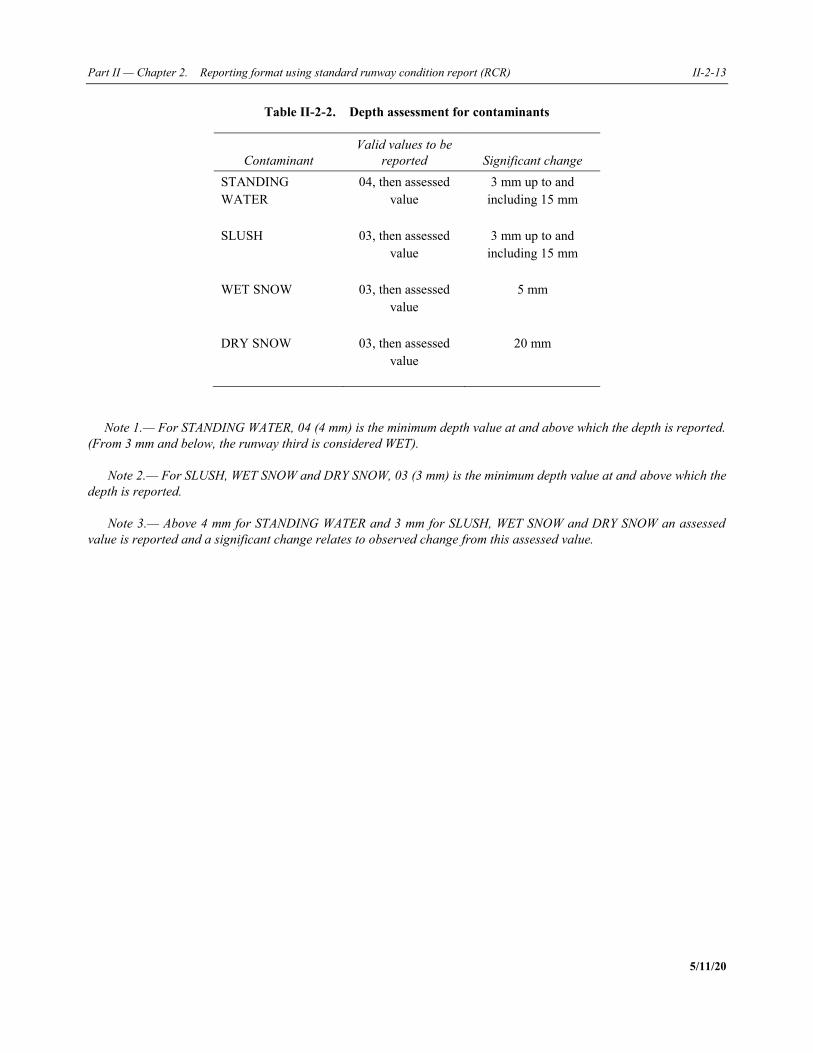
Part II — Chapter 2. Reporting format using standard runway condition report (RCR) II-2-13
5/11/20
Table II-2-2. Depth assessment for contaminants
Contaminant Valid values to be
reported Significant change STANDING WATER
04, then assessed value
3 mm up to and including 15 mm
SLUSH 03, then assessed value
3 mm up to and including 15 mm
WET SNOW 03, then assessed value
5 mm
DRY SNOW 03, then assessed value
20 mm
Note 1.— For STANDING WATER, 04 (4 mm) is the minimum depth value at and above which the depth is reported.
(From 3 mm and below, the runway third is considered WET).
Note 2.— For SLUSH, WET SNOW and DRY SNOW, 03 (3 mm) is the minimum depth value at and above which the
depth is reported.
Note 3.— Above 4 mm for STANDING WATER and 3 mm for SLUSH, WET SNOW and DRY SNOW an assessed
value is reported and a significant change relates to observed change from this assessed value.
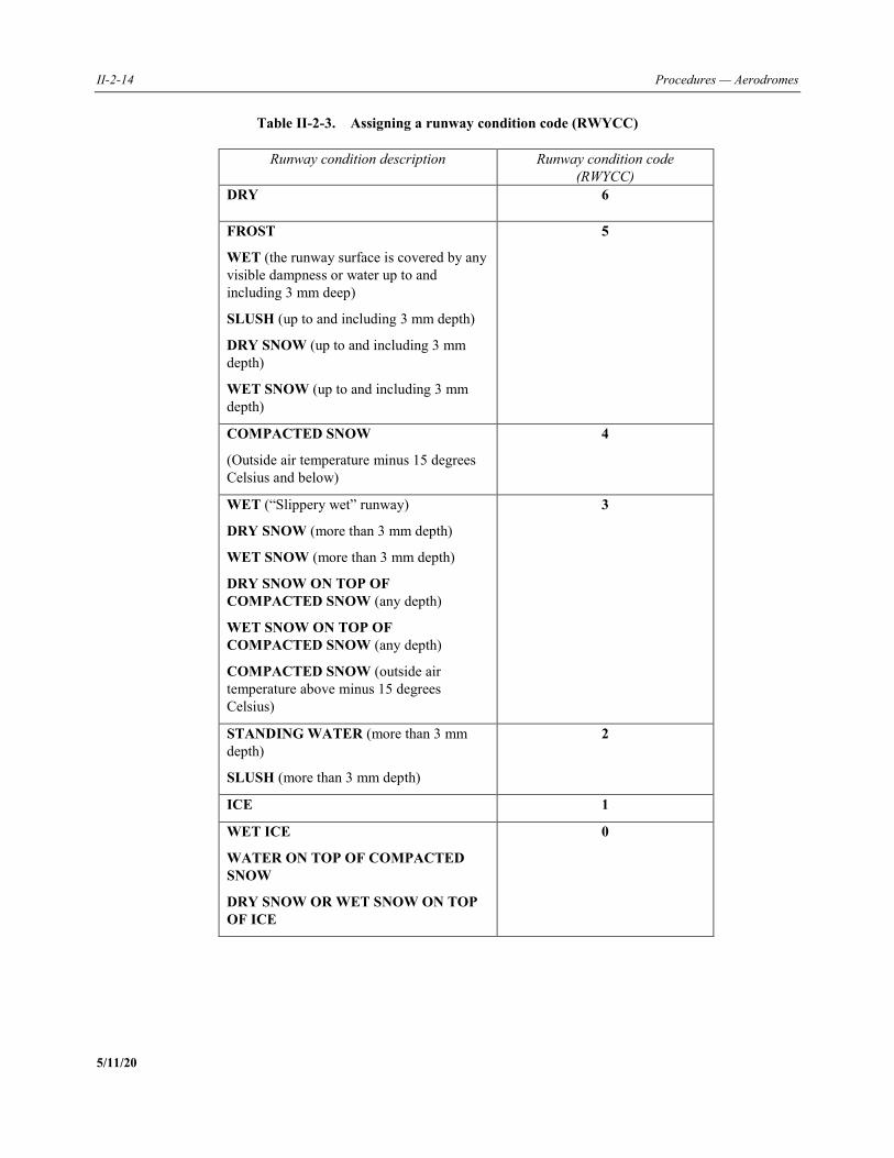
II-2-14 Procedures — Aerodromes
5/11/20
Table II-2-3. Assigning a runway condition code (RWYCC)
Runway condition description Runway condition code (RWYCC)
DRY 6
FROST
WET (the runway surface is covered by any visible dampness or water up to and including 3 mm deep)
SLUSH (up to and including 3 mm depth)
DRY SNOW (up to and including 3 mm depth)
WET SNOW (up to and including 3 mm depth)
5
COMPACTED SNOW
(Outside air temperature minus 15 degrees Celsius and below)
4
WET (“Slippery wet” runway)
DRY SNOW (more than 3 mm depth)
WET SNOW (more than 3 mm depth)
DRY SNOW ON TOP OF COMPACTED SNOW (any depth)
WET SNOW ON TOP OF COMPACTED SNOW (any depth)
COMPACTED SNOW (outside air temperature above minus 15 degrees Celsius)
3
STANDING WATER (more than 3 mm depth)
SLUSH (more than 3 mm depth)
2
ICE 1
WET ICE
WATER ON TOP OF COMPACTED SNOW
DRY SNOW OR WET SNOW ON TOP OF ICE
0
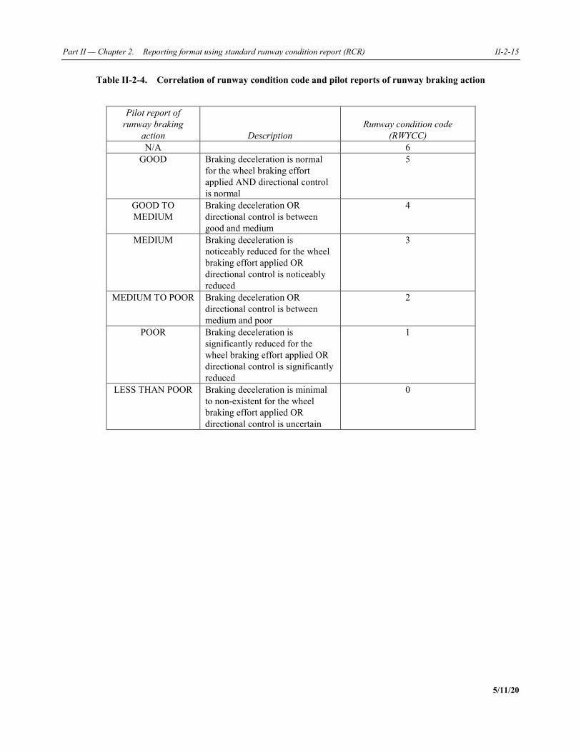
Part II — Chapter 2. Reporting format using standard runway condition report (RCR) II-2-15
5/11/20
Table II-2-4. Correlation of runway condition code and pilot reports of runway braking action
Pilot report of
runway braking action Description
Runway condition code (RWYCC)
N/A 6 GOOD Braking deceleration is normal
for the wheel braking effort applied AND directional control is normal
5
GOOD TO MEDIUM
Braking deceleration OR directional control is between good and medium
4
MEDIUM Braking deceleration is noticeably reduced for the wheel braking effort applied OR directional control is noticeably reduced
3
MEDIUM TO POOR Braking deceleration OR directional control is between medium and poor
2
POOR Braking deceleration is significantly reduced for the wheel braking effort applied OR directional control is significantly reduced
1
LESS THAN POOR Braking deceleration is minimal to non-existent for the wheel braking effort applied OR directional control is uncertain
0
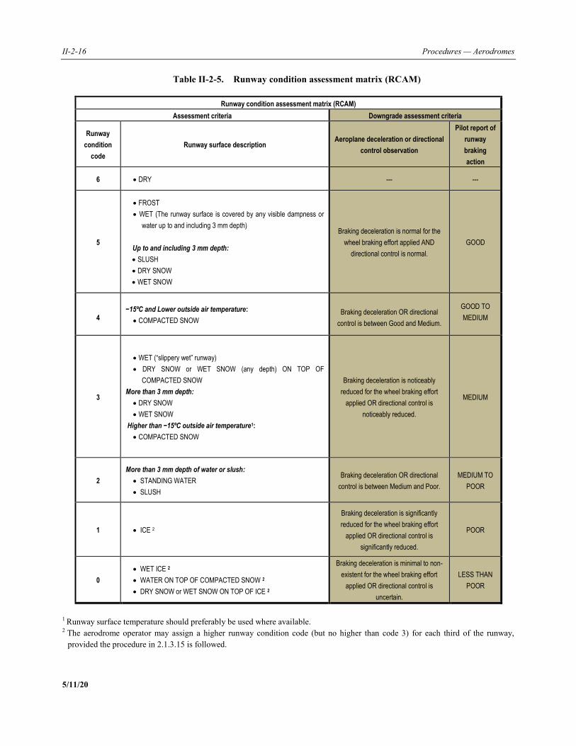
II-2-16 Procedures — Aerodromes
5/11/20
Table II-2-5. Runway condition assessment matrix (RCAM)
Runway condition assessment matrix (RCAM)
Assessment criteria Downgrade assessment criteria
Runway
condition
code
Runway surface description Aeroplane deceleration or directional
control observation
Pilot report of
runway
braking
action
6 DRY --- ---
5
FROST
WET (The runway surface is covered by any visible dampness or
water up to and including 3 mm depth)
Up to and including 3 mm depth:
SLUSH
DRY SNOW
WET SNOW
Braking deceleration is normal for the
wheel braking effort applied AND
directional control is normal.
GOOD
4 −15ºC and Lower outside air temperature:
COMPACTED SNOW Braking deceleration OR directional
control is between Good and Medium.
GOOD TO
MEDIUM
3
WET (“slippery wet” runway)
DRY SNOW or WET SNOW (any depth) ON TOP OF
COMPACTED SNOW
More than 3 mm depth:
DRY SNOW
WET SNOW
Higher than −15ºC outside air temperature1:
COMPACTED SNOW
Braking deceleration is noticeably
reduced for the wheel braking effort
applied OR directional control is
noticeably reduced.
MEDIUM
2
More than 3 mm depth of water or slush:
STANDING WATER
SLUSH
Braking deceleration OR directional
control is between Medium and Poor.
MEDIUM TO
POOR
1 ICE 2
Braking deceleration is significantly
reduced for the wheel braking effort
applied OR directional control is
significantly reduced.
POOR
0
WET ICE 2
WATER ON TOP OF COMPACTED SNOW 2
DRY SNOW or WET SNOW ON TOP OF ICE 2
Braking deceleration is minimal to non-
existent for the wheel braking effort
applied OR directional control is
uncertain.
LESS THAN
POOR
1 Runway surface temperature should preferably be used where available. 2 The aerodrome operator may assign a higher runway condition code (but no higher than code 3) for each third of the runway,
provided the procedure in 2.1.3.15 is followed.
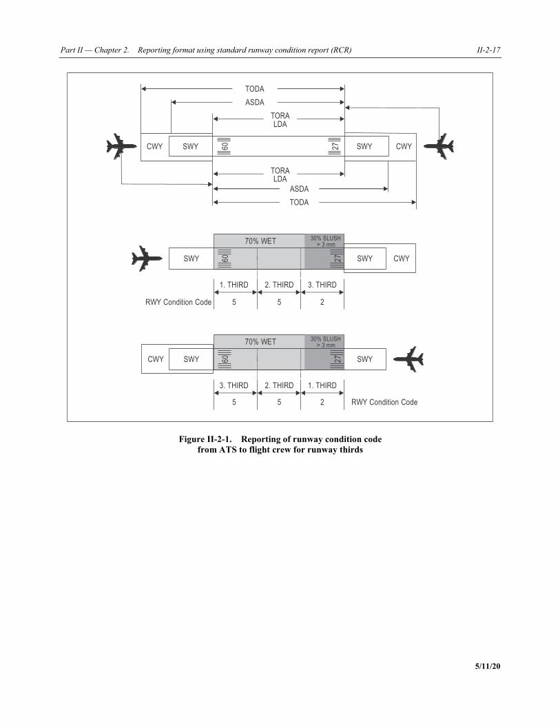
Part II — Chapter 2. Reporting format using standard runway condition report (RCR) II-2-17
5/11/20
Figure II-2-1. Reporting of runway condition code
from ATS to flight crew for runway thirds
60
27CWY CWYSWY SWY
ASDA
ASDA
TORALDA
TORALDA
TODA
TODA
1. THIRD 2. THIRD 3. THIRD
5 5 2RWY Condition Code
60
27 CWYSWYSWY
70% WET 30% SLUSH 3 mm>
3. THIRD 2. THIRD 1. THIRD
5 5 2 RWY Condition Code
60
27CWY SWYSWY
70% WET 30% SLUSH 3 mm>
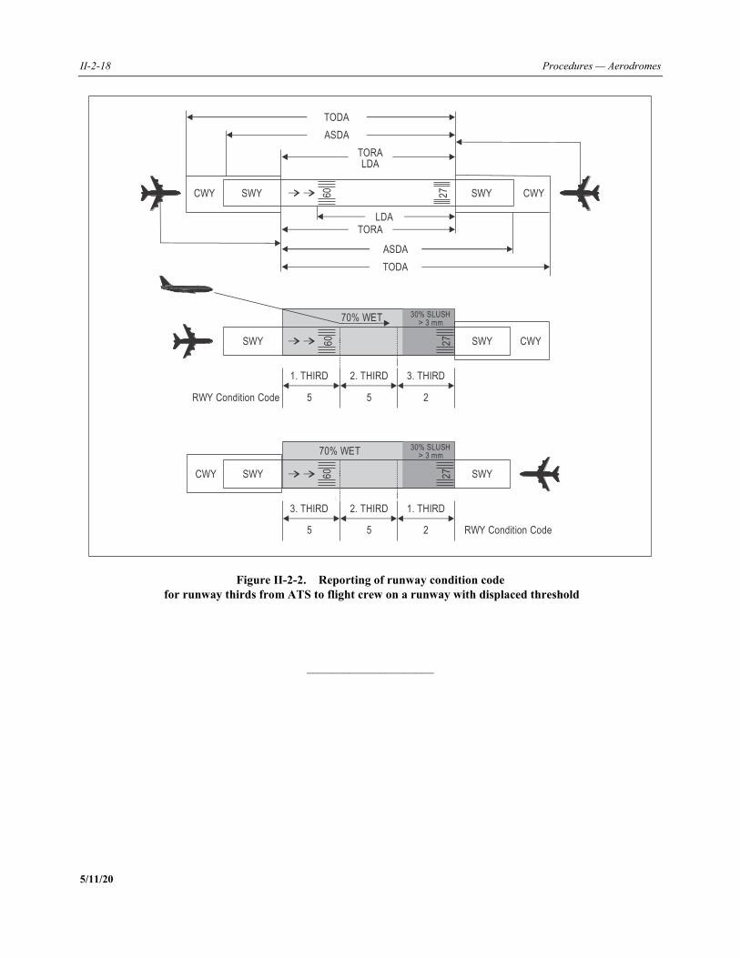
II-2-18 Procedures — Aerodromes
5/11/20
Figure II-2-2. Reporting of runway condition code
for runway thirds from ATS to flight crew on a runway with displaced threshold
_____________________
27CWY CWYSWY SWY
ASDA
ASDA
TORALDA
TORALDA
TODA
TODA
1. THIRD 2. THIRD 3. THIRD
5 5 2RWY Condition Code
60
27 CWYSWYSWY
70% WET 30% SLUSH 3 mm>
3. THIRD 2. THIRD 1. THIRD
5 5 2 RWY Condition Code
60
60
27CWY SWYSWY
70% WET 30% SLUSH 3 mm>
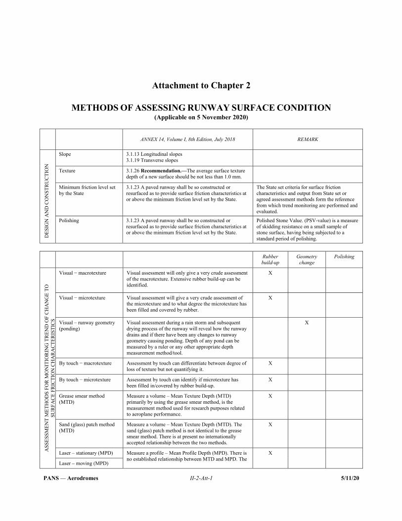
PANS — Aerodromes II-2-Att-1 5/11/20
Attachment to Chapter 2
METHODS OF ASSESSING RUNWAY SURFACE CONDITION (Applicable on 5 November 2020)
ANNEX 14, Volume I, 8th Edition, July 2018 REMARK
DES
IGN
AN
D C
ON
STR
UC
TIO
N
Slope 3.1.13 Longitudinal slopes 3.1.19 Transverse slopes
Texture 3.1.26 Recommendation.—The average surface texture depth of a new surface should be not less than 1.0 mm.
Minimum friction level set by the State
3.1.23 A paved runway shall be so constructed or resurfaced as to provide surface friction characteristics at or above the minimum friction level set by the State.
The State set criteria for surface friction characteristics and output from State set or agreed assessment methods form the reference from which trend monitoring are performed and evaluated.
Polishing 3.1.23 A paved runway shall be so constructed or resurfaced as to provide surface friction characteristics at or above the minimum friction level set by the State.
Polished Stone Value. (PSV-value) is a measure of skidding resistance on a small sample of stone surface, having being subjected to a standard period of polishing.
Rubber build-up
Geometry change
Polishing
ASS
ESSM
ENT
MET
HO
DS
FOR
MO
NIT
IOR
ING
TR
END
OF
CH
AN
GE
TO
SUR
FAC
E FR
ICTI
ON
CH
AR
ACT
ERIS
TIC
S
Visual − macrotexture Visual assessment will only give a very crude assessment of the macrotexture. Extensive rubber build-up can be identified.
X
Visual − microtexture Visual assessment will give a very crude assessment of the microtexture and to what degree the microtexture has been filled and covered by rubber.
X
Visual – runway geometry (ponding)
Visual assessment during a rain storm and subsequent drying process of the runway will reveal how the runway drains and if there have been any changes to runway geometry causing ponding. Depth of any pond can be measured by a ruler or any other appropriate depth measurement method/tool.
X
By touch − macrotexture Assessment by touch can differentiate between degree of loss of texture but not quantifying it.
X
By touch − microtexture Assessment by touch can identify if microtexture has been filled in/covered by rubber build-up.
X
Grease smear method (MTD)
Measure a volume – Mean Texture Depth (MTD) primarily by using the grease smear method, is the measurement method used for research purposes related to aeroplane performance.
X
Sand (glass) patch method (MTD)
Measure a volume – Mean Texture Depth (MTD). The sand (glass) patch method is not identical to the grease smear method. There is at present no internationally accepted relationship between the two methods.
X
Laser – stationary (MPD) Measure a profile – Mean Profile Depth (MPD). There is no established relationship between MTD and MPD. The
X
Laser – moving (MPD)
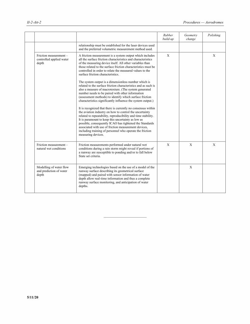
II-2-Att-2 Procedures — Aerodromes
5/11/20
Rubber build-up
Geometry change
Polishing
relationship must be established for the laser devices used and the preferred volumetric measurement method used.
Friction measurement – controlled applied water depth
A friction measurement is a system output which includes all the surface friction characteristics and characteristics of the measuring device itself. All other variables than those related to the surface friction characteristics must be controlled in order to relate the measured values to the surface friction characteristics. The system output is a dimensionless number which is related to the surface friction characteristics and as such is also a measure of macrotexture. (The system generated number needs to be paired with other information (assessment methods) to identify which surface friction characteristics significantly influence the system output.) It is recognized that there is currently no consensus within the aviation industry on how to control the uncertainty related to repeatability, reproducibility and time stability. It is paramount to keep this uncertainty as low as possible, consequently ICAO has tightened the Standards associated with use of friction measurement devices, including training of personnel who operate the friction measuring devices.
X X
Friction measurement – natural wet conditions
Friction measurements performed under natural wet conditions during a rain storm might reveal if portions of a runway are susceptible to ponding and/or to fall below State set criteria.
X X X
Modelling of water flow and prediction of water depth
Emerging technologies based on the use of a model of the runway surface describing its geometrical surface (mapped) and paired with sensor information of water depth allow real-time information and thus a complete runway surface monitoring, and anticipation of water depths.
X
_____________________
PANS — Aerodromes II-3-1 5/11/20
Chapter 3
INSPECTIONS OF THE MOVEMENT AREA
3.1 GENERAL
3.1.1 The inspection of aerodrome movement areas (including runways, taxiways and aprons, and their lighting systems, markings, signs, etc.) is required to ensure that hazards to aircraft are minimized and to create a safe and efficient operation. Aerodrome movement areas are complex and maintaining them in an optimal condition for safety depends on a large number of variables relating to the mix of aircraft operations, pavement materials and environmental conditions at each aerodrome. Inspection procedures are an integral part of ensuring the serviceability of the aerodrome and the detection of foreign object debris (FOD).
Note.— Provisions on FOD control can be found in Part II, Chapter 5 of this document.
3.1.2 Movement area inspections are mainly intended for:
a) ensuring that the conditions of the movement area and associated equipment are fit for the intended operational use;
b) identifying faults and potential hazards to the safety of aircraft or aerodrome operations and take appropriate
action; and c) providing periodic, timely and accurate updates on the condition of the movement area and the operational
status of related facilities, to be reported to air traffic services (ATS), aerodrome operations and aeronautical information services (AIS).
3.1.3 Several types of inspections are normally performed:
a) daily inspections or “Level 1 inspections” provide an overview of the general condition of the movement area
and its associated facilities; and
b) regular inspections or “Level 2 inspections” are part of the preventive maintenance of the aerodrome and consist of a more detailed verification of the conditions of the movement area and its associated facilities.
Note 1.— Daily inspections are referred to in Annex 14 — Aerodromes, Volume I — Aerodrome Design and
Operations, section 2.9.
Note 2.— Guidance on carrying out daily inspections of the movement area and on control of FOD is also given in the Manual of Surface Movement Guidance and Control Systems (SMGCS) (Doc 9476), the Advanced Surface Movement Guidance and Control Systems (A-SMGCS) Manual (Doc 9830) and the Airport Services Manual
(Doc 9137), Part 8 — Airport Operational Services.
II-3-2 Procedures — Aerodromes
5/11/20
3.1.4 Due to the potentially large areas and distances covered, Level 1 inspections may necessitate the use of vehicles. However, the higher the speed of the vehicle, the potentially less effective the inspection. The speed of the vehicle should therefore be kept as low as practical.
3.1.5 Detailed Level 2 inspections of paved surfaces, coordinated with the appropriate ATS unit, are best completed on foot, thus enabling a far more comprehensive assessment, as part of preventive maintenance.
3.1.6 Faults in the lighting systems will normally be detected via monitoring. Monitoring by visual display on the lighting control panel in the ATS unit will enable detection of circuit failures and verification that brilliancy selection by ATS is providing the desired light output. Monitoring by visual inspection also enables the detection of failed lamps and the contamination of fittings by dirt and rubber deposits or misalignment.
3.1.7 Although this chapter covers planned inspections, in certain circumstances, unplanned inspections may need to be carried out to ensure the safety of operations. These circumstances may include:
a) following the completion of works; b) a reported incident; c) a pilot/ATC report; d) adverse meteorological conditions; and/or e) an emergency response.
3.2 OBJECTIVES
3.2.1 Inspections of the movement area shall be planned so as to ensure that an appropriate level of vigilance is maintained at all times. The inspections shall cover, at a minimum, the following items:
a) the runway;
b) the remaining manoeuvring area, including taxiways and adjacent areas;
c) the apron and service areas;
d) surface conditions;
e) detection of FOD;
f) status of visual aids, including visible electrical systems or parts thereof; and
g) status of obstacles outside the aerodrome boundary.
3.2.2 An inspection programme of the movement area commensurate with the size and complexity of the aerodrome, along with the objectives set in 3.2.1 shall be established by the aerodrome operator.
3.2.3 All aerodrome inspections shall be formally documented in a log by the aerodrome operator and all records shall be maintained for future reference.
3.2.4 Each inspection shall include a reporting and follow-up mechanism to ensure that appropriate action is taken.
Part II — Chapter 3. Inspections of the movement area II-3-3
5/11/20
3.3 OPERATIONAL PRACTICES
3.3.1 Frequency of inspections
3.3.1.1 The frequency and detail of inspections may be increased from the minimum specified in Annex 14, depending on the traffic expected and the type of inspection being performed.
3.3.1.2 The frequency of aerodrome inspections should be commensurate with the level of risk identified in the aerodrome safety management system (SMS).
Note 1.— The minimum mandatory frequency of Level 1 inspections is given in Annex 14, Volume 1, 2.9.3.
Note 2.— Guidance on SMS is given in the Safety Management Manual (SMM) (Doc 9859).
3.3.2 Inspection of the manoeuvring area Runways
3.3.2.1 A runway inspection may involve the deliberate entry to an active runway. It is therefore essential that any potential hazards associated with this activity are identified and addressed so that staff with inspection duties have a clear understanding of what is involved and how the task is to be safely carried out.
3.3.2.2 All runway inspections undertaken on an active runway shall be conducted according to documented procedures developed to ensure the safety of aircraft operations and aerodrome personnel.
3.3.2.3 Procedures for the access to runways shall be established with the appropriate ATS unit. Prior to any runway inspection, radio contact shall be established with ATS and permission to begin the inspection shall be obtained and acknowledged by the inspection team.
Note.— The Appendix to this chapter elaborates on the factors to be considered in the development of these procedures.
3.3.2.4 If runway lighting is installed, inspections should be undertaken with the lights illuminated in order to enable the identification of unserviceable lamps and possible failures of light fittings.
3.3.2.5 When aircraft parts or aircraft tire pieces are found during a runway inspection, aerodrome operations and the appropriate ATS unit shall be informed immediately, so as to trace the origin of the parts and pieces and notify the appropriate aircraft operators.
Note.— Provisions on foreign object debris (FOD) control can be found in Chapter 5. Taxiways
3.3.2.6 A daily inspection should be undertaken on taxiways in regular, active use. The frequency of inspections for remaining taxiways should be assessed to ensure that they remain suitable for use when required. All inspections undertaken on an active taxiway shall be conducted according to appropriate procedures developed for the location, which ensure the safety of aircraft operations and aerodrome personnel.
Note.— The Appendix to this chapter elaborates on the factors to be considered in the development of these procedures.
II-3-4 Procedures — Aerodromes
5/11/20
3.3.2.7 Procedures for access to taxiways shall be established with the appropriate ATS unit. Prior to any taxiway inspection, radio contact shall be established with ATS and permission to begin the inspection shall be obtained and acknowledged by the inspection team, unless a local safety assessment, taking into account also the aerodrome
characteristics, size, complexity and level of traffic, has proven that a taxiway inspection can be safely conducted
without radio contact with ATS, and a corresponding procedure has been documented and promulgated.
Note.— The safety assessment methodology is included in Part I, Chapter 3 of this document.
3.3.3 Inspection of the apron
3.3.3.1 Inspections of the apron area should be undertaken at defined frequencies. Considering the level of operations undertaken at each aerodrome, the frequency may be adjusted in accordance with the level of risk identified by the aerodrome SMS.
3.3.3.2 Inspections may be undertaken in segments to account for the size and complexity of the operation.
3.3.4 Inspection of the visual aids
3.3.4.1 A routine ground inspection of all aerodrome ground lighting systems should be made daily or before use. Any deficiencies should be remedied as soon as possible, and the identified lights should again be inspected before use after the remedial action is taken. All deficiencies and associated remedial action should be logged.
3.3.4.2 Approach lighting systems should be inspected at adequate, defined frequencies. They may also be inspected upon request from aerodrome operations or ATS. The inspection should cover all the light units of the approach lighting system.
3.3.4.3 The inspecting team shall inform ATS before commencing the approach lighting system inspection.
3.3.4.4 ATS shall be informed when the inspection is complete in order to turn off any lights not required for regular operations.
3.3.4.5 If a major failure is discovered during the inspection, ATS and aerodrome maintenance shall be informed immediately.
_____________________
PANS — Aerodromes II-3-App-1 5/11/20
Appendix to Chapter 3
GENERAL PROCEDURES FOR THE INSPECTION AND DOCUMENTED REPORTING OF THE MOVEMENT AREA
1. PROCEDURE
1.1 Prior to entering the runway, an entry request (e.g. “[vehicle call sign] holding at […] for runway inspection”) shall be made. Upon leaving the runway, the control tower shall be advised when the inspection vehicle is clear of the runway. Some inspections are carried out on an ON/OFF basis (i.e. where the inspection vehicle may be required to enter or leave the runway on short notice). The request for runway entry and the notification that the vehicle is clear of the runway shall be made on each occasion that the inspection vehicle enters and leaves the runway. A listening watch shall be maintained on the appropriate radiotelephony channel during any runway inspection.
Note.— Provisions on aerodrome vehicles and drivers can be found in Chapter 9.
1.2 If, during an inspection, the control tower requests the inspection personnel to vacate the runway, the vehicle shall move outside the runway before advising the control tower that they are clear. The inspection personnel shall not re-enter the runway until in receipt of specific clearance to do so. The inspection team shall never vacate a runway by driving through an instrument landing system (ILS) critical/sensitive area.
1.3 ATC clearance shall be obtained before crossing or entering any runway.
1.4 Runway inspections should be carried out in the direction opposite to that being used for landing or taking off, primarily to ensure the visibility of, and by, the operating aircraft.
1.5 Upon final completion of a runway inspection, the control tower shall be advised of the completion of the inspection, and on the status of the manoeuvring area, as necessary.
1.6 The times of commencement and completion of the inspection shall be noted and included in the record of inspection log.
2. REPORTING
2.1 If a dangerous unserviceability is discovered during a runway inspection (e.g. damaged pit covers or broken lights), it shall be immediately reported to ATS by radiotelephony (RTF) for appropriate ATS action to be considered. The entity in charge of aerodrome operations should also be informed. 2.2 If unserviceability is found during an inspection, but which does not affect the use of the runway, it should be reported to the entity in charge of aerodrome maintenance.
II-3-App-2 Procedures — Aerodromes
5/11/20
2.3 An inspection log should include:
a) description and exact location of the failure;
b) details of the task(s) and any remedial action(s) necessary or taken, such as notification to ATS and AIS, recording of events for further analysis (including as part of the aerodrome SMS) and informing maintenance services for further action;
c) identifying the person/entity responsible for undertaking the task and/or further action; and
d) identifying the timescale by which it should be completed.
3. LEVELS OF INSPECTION
Inspection procedures on several levels are key to ensuring that the highest standards of safety and efficiency are maintained for all stakeholders on the movement area.
3.1 A typical two-level inspection system has the following main elements:
a) daily inspections (Level 1): covering the entire movement area and zones adjacent to the aerodrome boundary; and
b) regular inspections (Level 2): carried out by specialists whereby all runways, taxiways and aprons are divided up
into a number of areas and inspected in more detail. Inspections shall be performed using checklists which cover the various inspection areas and a sketch of the aerodrome, which enables the location and marking of detected problems.
3.2 A log shall be kept for all inspections, and will include:
a) details of inspection intervals and times;
b) names of persons carrying out the inspection; and
c) results and observations, if any. A log of all remedial actions identified following an inspection shall be recorded and verification of their implementation shall be undertaken.
3.3 Daily Inspections (Level 1)
3.3.1 Level 1 inspections are ideally carried out at defined intervals during the day, typically:
a) a first light inspection prior to daytime operations;
b) a last light inspection prior to night operations; and
c) other inspections may be planned in between those described above, their frequency being dictated by the hours of peak traffic.
Part II — Appendix to Chapter 3 II-3-App-3
5/11/20
3.3.2 Additional Level 1 inspections, particularly relating to the runway, may be carried out depending on local circumstances, the aerodromes hazard identification and analysis, and the safety risk assessment process (see Part I, Chapter 3).
3.3.3 Standard inspection routes should be defined and followed so that an area cannot be forgotten.
3.3.4 Inspection personnel should report anything that affects safety and the serviceability of the following:
3.3.4.1 Runways
a) The runway, including its shoulders with regard to cleanliness, rubber build-up and pit/drain covers;
b) runway cleanliness, particularly FOD which could cause engine ingestion damage;
c) presence of contaminants affecting runway friction characteristics;
d) signs of pavement surface damage, including the cracking and spalling of concrete, and looseness of aggregate material;
e) runway signs and paint markings for damage and wear;
f) the runway strip and runway end safety area (RESA) including drainage;
g) failure of precision approach path indicator (PAPI) units, runway guard lights and any other runway lights and
wing bars;
h) any object that may affect the runway strip;
i) all areas of work in progress on or adjacent to the runway;
j) the condition of all wind direction indicators for day/night operations; and
k) wildlife activity on and near the runway.
3.3.4.2 Taxiways and taxilanes
a) All taxiway pavement surfaces, particularly with regard to pavement damage, cleanliness and FOD;
b) all taxiway signs and paint markings for damage or wear;
c) any objects and excavations that may affect the taxiway strip;
d) all work in progress on or adjacent to the taxiway system;
e) all taxiway centre line and/or edge light fittings and markers;
f) the general condition of drains and covers; and
g) the state of the grass edge, including any waterlogged areas.
II-3-App-4 Procedures — Aerodromes
5/11/20
3.3.4.3 Apron areas
a) All apron pavement surfaces, particularly with regard to pavement damage, cleanliness (fuel/oil spillages) and FOD;
b) all apron signs and paint markings for damage or wear;
c) any incorrect parking of aircraft, vehicles, equipment, passenger loading bridges, etc.;
d) any work in progress areas; and
e) the general condition of drains and covers.
3.3.4.4 Aerodrome lighting
a) All runway approach lighting (including any Category III supplementary systems) should be inspected every evening at dusk prior to night operations and any defects reported;
b) all runway lighting should be checked as soon as practicable after the lighting has been switched on.
Individual light outages and circuit failures should be reported;
c) all taxiway lighting should be checked as soon as practicable and should include all centre line lights, edge lights, stop bars, runway guard lights and lead-on/lead-off lights; and
d) during the night period, all apron lighting should be inspected and any deficiencies reported.
Note.— Lighting inspections may be integrated with other on-runway inspections and be flexible in timing to cater
for the variability of daylight hours.
3.3.4.5 Grass areas (or other areas adjacent to the taxiway system)
a) The general condition of the vegetation, particularly any areas of jet blast erosion;
b) the grass length and the amount of weeds, particularly near lights and signs;
c) any areas of standing water (waterlogged grass areas should be noted and reported, particularly since they may be an attraction to birds);
d) depressions or aircraft wheel tracks;
e) excessive difference in levels at the edge of paved surfaces;
f) the cleanliness of these areas with regard to FOD; and
g) any work in progress areas.
Part II — Appendix to Chapter 3 II-3-App-5
5/11/20
3.3.5 When conducting routine daily inspections, general attention should be paid to the following points:
a) general cleanliness with particular attention to FOD which could cause engine ingestion damage. This may include debris from runway maintenance operations or excessive grit remaining after runway gritting. Any build-up of tire rubber deposits should be noted;
b) signs of damage to the pavement surface including cracking and spalling of concrete, condition of joint
sealing, cracking and looseness of aggregate in asphalt surfaces or break-up of friction courses. Damage or deterioration which could cause aircraft damage should be reported immediately for inspection by maintenance services and, if the damage is sufficiently serious, the area should remain closed to aircraft pending the results of such an inspection;
c) after rain, flooded areas should be identified and marked, if possible, to facilitate later resurfacing;
d) damage of light fittings;
e) cleanliness and visibility of runway markings; and
f) the condition and fit of pit covers.
3.3.6 The extremities of the runway should be inspected for early touchdown marks; jet blast damage to
approach lights, marker cones and threshold lights; cleanliness; and obstacles in the runway end safety area.
3.3.7 The main objective of grass cutting shall be to ensure that lights and markers are not obscured by tall vegetation. It should also be managed in such a fashion as to limit the attraction of the aerodrome to birds and other wildlife. It will be necessary to ensure that mounds of grass cuttings are not left on areas where engine ingestion is possible.
3.3.8 Zones outside the aerodrome boundary
3.3.8.1 A cursory visual inspection of the areas surrounding the aerodrome shall be made by the aerodrome operations staff to verify that no objects seem to affect any protected surfaces, particularly in the approach and departure areas of all runways.
3.3.8.2 The status of the lighting and marking of authorized obstacles shall be inspected.
3.3.8.3 Any unauthorized detected obstacles, and marking or lighting deficiencies of authorized obstacles, shall be immediately reported to the designated persons, appropriate organizations or authorities, for corrective actions to be taken.
Note.— Further guidance on obstacle control and management is contained in the Airport Services Manual (Doc 9137), Part 6 — Control of Obstacles.
3.4 Regular Inspections (Level 2)
3.4.1 Level 2 inspections consist of a more detailed verification of the condition on the movement area and its associated facilities than those carried out at Level 1. The Level 2 inspections should be carried out on foot, thus enabling a far more comprehensive assessment.
II-3-App-6 Procedures — Aerodromes
5/11/20
3.4.2 Within the Level 2 inspections process, it is recommended to proceed by dividing the movement area up into a number of zones depending on the size of the aerodrome. Each zone should be inspected in detail at defined, regular intervals. Level 2 inspections may be carried out at a time that best suits the stand demand, runway in use or other operational requirements.
3.4.3 In the case of precision approach runways, Level 2 inspections of visual aids will be more frequent and detailed than those carried out on other runways.
3.4.4 In case of a detected damage, photos should be taken to assess the evolution of the damage, in order to facilitate decision-making.
3.4.5 Inspection teams should report anything that affects the serviceability and safety of the items below. Runways
3.4.6 Runways should be inspected in detail every three months or at a reduced frequency based on runway usage, unless a documented analysis indicates a different frequency that would not affect the safety of aircraft operations. Typically, the runway may be divided up into a number of sections. Depending on the movement rate on the day of the inspection, a number of sections can be checked, as follows:
a) Surfaces. The full length and width of the runway should be inspected during the cycle. The inspections should record cracks, general break-up and any other surface failure, particularly if there are signs of debris. Special attention should be paid to the touchdown zones and other areas highly trafficked by aircraft. The touchdown zones should also receive particular attention to assess the degree of rubber build-up that may affect the runway surface friction co-efficient. Attention should also be given to rapid exits, access taxiways and runway turn pads.
b) Signs, markings and lighting. The general condition of all signs along the runway should be inspected to ensure
compliance with Annex 14, Volume I requirements. All runway markings should be inspected for conspicuity, particularly in the touchdown zones where rubber deposits may have blackened certain markings. A selection of light fittings should be inspected for general safety, particularly with regard to the torque setting of the fixings. The regularity of testing should be adjusted to achieve the target level of serviceability applicable to the service being tested.
c) Runway strip. The area surrounding the runway, including the strip, clear and graded area, and runway end safety
area (RESA) should also be inspected. Attention should be given to its general bearing strength, the nature of the surface, any obstacle that should be frangible and any other features that could cause damage to an aircraft, should it overrun into these areas.
d) Runway approach lighting systems. Twice a year, each full approach lighting system, its cables, light fittings, masts
and other support structures should be analysed for their general safety and serviceability by a physical check on foot. During the lighting check, a general assessment of the lighting pattern will be made and any outages or gross misalignments noted and reported.
e) Zones surrounding the aerodrome. At least once a week, aerodrome operations staff should conduct a review of the
areas adjacent to and surrounding the aerodrome boundary to verify that there are no obstructions infringing protected surfaces, particularly in the approach and departure areas. Items of concern will include tall trees, cranes, lights that may cause confusion to pilots, and agricultural practices that could cause an increase in wildlife activity.
Part II — Appendix to Chapter 3 II-3-App-7
5/11/20
Taxiways
3.4.7 At a time dictated by traffic movements and runway(s) in use, each section of the taxiway area should be inspected on foot and all deficiencies should be marked on a specialized map/diagram of the area. The taxiways should be inspected for the following:
a) Surfaces. All taxiway surfaces including any hard shoulders should be inspected. Surfaces should be inspected for cracks, deterioration and debris.
b) Signs, markings and lights. All taxiway paint markings should be inspected and any repainting requirements noted.
All signs should be checked for their conspicuity and stability, particularly where they may be affected by jet blast. A selection of taxiway light fittings should be verified for general safety.
c) Surrounding areas. All taxiway strips and associated grass or other paved areas should also be inspected for their
general safety, particularly with regard to obstructions and surface conditions in a similar way as the clear and graded areas of the runway are inspected.
Aprons and stands
3.4.8 The aprons and stand areas should be inspected and all defects noted on a specialized map/diagram of the area. All aprons and stands should be inspected for the following:
a) Surfaces. All aprons, stands and associated equipment parking areas should be inspected for surface break-up, particularly where FOD is being created.
b) Signs, markings and lights. All surface paint markings associated with aircraft movement and parking should be
inspected and any repainting requirements noted. Additionally, all signs, markings and lights associated with the visual docking guidance systems (VDGS) and advanced visual docking guidance systems (A-VDGS) should be checked for correct functionality and conspicuity.
c) Surrounding areas. All service roads and equipment parking areas supporting each stand should also be inspected
for general serviceability and condition, particularly where the surface may cause damage to vehicles or injury to passengers or personnel. These areas should also be inspected for general cleanliness and parking discipline.
d) Equipment. When installed, all emergency telephones should be checked for serviceability.
_____________________

PANS — Aerodromes II-4-1 5/11/20
Chapter 4
WORK IN PROGRESS (WIP)
4.1 GENERAL
4.1.1 Periodically, construction and heavy maintenance activities are performed in movement areas. If aircraft operations are to continue around the site, or access is required through movement areas, there are a number of precautions to be taken to ensure the safety of aerodrome operations. These include the protection and safety of the worksite and workers.
4.1.2 Wherever major work affecting operational areas is planned, it is important that the aerodrome operator identifies and mitigates the risks generated by work in progress (WIP).
4.1.3 Part of effective safety management related to works lies in timely and comprehensive planning coordinated with all involved parties and relevant stakeholders.
4.1.4 Prior to their commencement, all measures necessary for the works to be undertaken safely, including timely notification of resulting operational changes, need to be communicated to all involved parties and relevant stakeholders.
4.2 OBJECTIVES 4.2.1 The aerodrome operator shall develop a process for managing the aerodrome operational safety during works on the movement area. 4.2.2 The process shall clearly establish and document the responsibilities and procedures for: a) the authorization of the works;
b) the implementation of any proposed change to operational facilities; c) the date and time when the facilities will be withdrawn or changed from normal operations; d) the methods by which such changes will be promulgated; e) the oversight and control of the WIP; and f) the compliance with all relevant movement area safety rules.
II-4-2 Procedures — Aerodromes
5/11/20
4.3 OPERATIONAL PRACTICES
4.3.1 The process for managing the aerodrome operational safety during works should contain, at a minimum, the following elements:
a) a works planning procedure; b) a procedure for a safety assessment of the planned changes to the operations or systems; c) a works authorization procedure; d) a procedure for the promulgation of information related to the works; e) a procedure for worksite establishment and return to aircraft operations; and f) a procedure for monitoring, oversight and control of the works.
Note 1.— The safety assessment methodology is included in Part I, Chapter 3 of this document. Note 2.— The works authorization procedure identified in c) refers to local aerodrome operator approval for the commencement of works. Note 3.— Annex 15 — Aeronautical Information Services includes appropriate methods on the promulgation of information. Note 4.— The process for managing the aerodrome operational safety during works may concentrated in one local procedure or be divided to several procedures, depending on local circumstances. 4.3.2 The works planning procedure should provide for the planning and coordination of works on the movement area so as to ensure that they are undertaken in a safe and compliant manner, while maintaining the operational safety, capacity, and efficiency of the aerodrome operations. During the planning process, representatives from aerodrome operations and other concerned stakeholders (such as ATS) should be involved at the earliest opportunity to consider the requirements for the efficient operations of the aerodrome during the proposed works. 4.3.3 A safety assessment of all planned works should be completed beforehand in order to ensure the risks to the safe operation of aircraft have been identified by the aerodrome operator in coordination with interested parties, and appropriate mitigation measures introduced to keep risks to an acceptable level. 4.3.4 Processes, procedures, actions and decisions should be documented and made available to all relevant parties and stakeholders involved in the works or affected by any change in operations. 4.3.5 Before implementation, draft operational procedures, instructions or other information to be promulgated, should be discussed and coordinated with the directly affected stakeholders, and subjected to verification, thereby ensuring that their meaning is clear to potential users. Practical checks of proposed arrangements should be made by personnel having a comprehensive understanding of the operational implications of the works. 4.3.6 Where reduced runway length operations are required due to works, procedures shall be developed and implemented by the aerodrome operator, in accordance with provisions in Appendix 1 to this chapter. 4.3.7 Prior to the commencement of works, an authorization should be provided by the aerodrome operator to the party conducting the works. An authorization document should be used to ensure that specific permissions and conditions are recorded and agreed upon between the aerodrome operator and the relevant stakeholders. This document should also be communicated to the contractors, in order for them to be fully aware of what they can and cannot do.
Part II — Chapter 4. Work in progress II-4-3
5/11/20
4.3.8 The following actions should be taken when establishing the worksite, as well as throughout the duration of the works, when necessary: a) unserviceability markers are displayed when any portion of a taxiway, apron, or holding bay is unfit for the
movement of aircraft, but it is still possible for aircraft to bypass the area safely; b) existing markings leading into a worksite should be masked or the route closed; c) unserviceability lights should be used and existing aeronautical ground lighting and signs leading into a worksite
should be extinguished or masked on a movement area used at night or during low visibility; d) suitable site fencing should be installed to protect from jet blast, and FOD containment within the site should be
enforced; and e) the perimeter of the worksite should be clearly marked and/or lit, particularly at night or during reduced
visibility. Note 1.— Unserviceability relates to areas temporarily not available for operational use. Note 2.— A checklist for establishing worksites and returning them to operational use is included in the attachment to this chapter. Note 3.— Unserviceability markers and lights are placed at sufficiently close intervals so as to clearly delineate the unserviceable area. Note 4.— Measures for the situational awareness of pilots and drivers on the manoeuvring area need to take into consideration human factors that may lead to a runway incursion. Guidance material on Human Factors principles can be found in the Human Factors Training Manual (Doc 9683) and in the Manual on the Prevention of Runway Incursions (Doc 9870). 4.3.9 Pre-startup and regular site meetings should be held to ensure that safety requirements are met and possible conflicts between the works and operations are resolved. Points to be considered include:
a) safety awareness in relation to work on the movement area; b) workplace health and safety requirements; c) security requirements; d) protection of construction workers from aerodrome hazards, including jet blast and noise; e) procedure for quickly summoning emergency responders in case of a fire, spill, accident or similar event; and f) operational briefings on the interaction of the works with the aerodrome operations (e.g. runway(s) in use, likely
visibility conditions, meteorological conditions, safety issues). 4.3.10 Procedures should be developed and implemented to monitor the safety of the aerodrome and aircraft operations in proximity of the works, such that timely corrective action is taken when necessary to assure their continued, safe operations. Additional procedures on worksite control are included in Appendix 2 to this chapter.
_____________________

PANS — Aerodromes II-4-App 1-1 5/11/20
Appendix 1 to Chapter 4
REDUCED RUNWAY LENGTH OPERATIONS
Note.— In some cases, conducting works on a runway while maintaining flight operations may be possible. This is a complex activity directly affecting aircraft performance and safety and requires close coordination with ATS and aircraft operators. The following provides procedures on conducting works under these conditions. It is important to note that additional hazards may arise when works involving a reduction in the available runway distances are conducted. 1.1 In circumstances where works require the runway length to be reduced below the declared distances, the aerodrome operator shall:
a) identify and assess the associated risk and mitigate as necessary the potential hazards before, during, and on cessation of operations with reduced runway length available and/or WIP in order to ensure the safety of aircraft operations;
Note.— Risks may result from inappropriate or potentially misleading displays of visual aids; inappropriate or potentially misleading navigational aids; adverse environmental conditions; or unusual meteorological conditions; and from restricted obstacle clearance and wingtip separation distances. It is important to recognize that the identified hazards may cover a wide range of topics, including those that do not pose a risk only to aircraft but also to personnel, e.g. the potential risk from jet blast.
b) calculate and establish, where necessary, a revised runway strip, runway end safety area (RESA) and obstacle
limitation surfaces (OLS), such as the approach and take-off climb surfaces;
c) establish a safety zone between the area of the runway that is in use and the WIP or unusable runway; Note.— The location, size and shape of the safety zone depends on the temporary configuration of the runway, to provide for items such as RESAs, jet blast protection and abbreviated or simple approach lighting systems.
d) promulgate the details of the reduced runway distances established, using all appropriate methods. As a minimum, it is advisable to issue a NOTAM and, when possible, broadcast the information on automatic terminal information service (ATIS);
Note.— Annex 15 — Aeronautical Information Services includes appropriate methods on the promulgation of information.
e) test, wherever practicable, the suitability of a procedure prior to its implementation; f) ensure that the roles and responsibilities for operations and tasks associated with the reduction of the runway
length available and the WIP are clearly understood and complied with; g) provide markings and lights to clearly indicate the boundary of the safety zone and the WIP area;
II-4-App 1-2 Procedures — Aerodromes
5/11/20
h) clearly mark, light and/or barricade any movement area that is to be used by persons involved in the WIP, and not to be used by aircraft;
i) manage and control the movement on or around a runway or taxiway of contracted staff, who may not be as
familiar with the aerodrome and aviation practices; j) consider and address the impact on the ability of RFF and emergency services to perform their functions; and k) promulgate in a timely manner all the relevant operational information to all relevant parties.
1.2 The aerodrome operator shall be responsible for the coordination and management of the opening/closing of the runway (and other movement areas, as necessary) and the WIP. If tactical decisions concerning aircraft operations deviate from the agreed operational procedures (with the exception of an urgent safety nature), they shall be coordinated with, and approved by, the aerodrome operator. 1.3 Monitoring the safety of the aerodrome and aircraft operations in proximity of the works should be conducted by the aerodrome operator, to ensure that timely and corrective action is taken when necessary for continued, safe operations. This is particularly important when operational changes or unprecedented or unpredicted events occur.
_____________________
PANS — Aerodromes II-4-App 2-1 5/11/20
Appendix 2 to Chapter 4
WORKSITE CONTROL PROCEDURES
1.1 Aspects of the control and procedures for movement area works should include, but are not limited to:
a) all contractor drivers should be escorted by a qualified vehicle operator or undergo movement area driver training and testing;
b) access routes should be agreed upon in advance and clearly identified to minimize interference with operations
on the aerodrome; c) the existing road layout may require changes depending on the vehicle traffic levels; d) staff access routes should also be agreed upon in advance and if such a route does not exist, then a safety risk
assessment should be undertaken to ensure access can be safely achieved; e) hours of operation of the works should be agreed upon in advance; f) service clearance checks (underground location of services) should be undertaken before work commences to
ensure that cables or pipes are not damaged; g) smoking restrictions should be advertised, monitored and enforced; h) hot works restrictions (possibly involving a separate hot works permit) should be described, monitored and
enforced; i) the use of lookouts and/or a listening watch on the appropriate ATS frequency may be required, along with
suitable training for this task; j) any cranes should be suitably lit and operating heights should not infringe the protected surfaces; k) should the construction activity continue into darkness or in low visibility conditions, procedures should be in
place to discontinue or modify the activity, depending on its location and if necessary; l) procedures should be in place for taxiway crossings, if required; m) all contractors should have adequate FOD, noise and dust control measures in place to cover all eventualities; n) vehicles entering or exiting the worksite may need to be cleaned to prevent mud or debris being deposited in the
movement area; o) in case of possible adverse meteorological conditions (e.g. lightning strikes, high winds, snow) or aircraft
emergencies, an appropriate alerting mechanism should be in place and works activities may be suspended; and
II-4-App 2-2 Procedures — Aerodromes
5/11/20
p) precautions should be taken to ensure that worksite floodlighting (light direction and/or height) does not affect aircraft and ATS operations.
1.2 In terms of customer service and the availability of facilities, a scheduling process should be in place to ensure that construction or maintenance works do not close or restrict too many stands or operational areas at once. 1.3 Where significant changes to markings or lighting are being made, it may be necessary for the aerodrome operator to conduct a preliminary check in order to ensure that the proposals have been correctly implemented and are functioning as intended. 1.4 Where shift working is in operation, it will be necessary to ensure that each shift is properly and fully briefed. The aerodrome operator should obtain feedback from the parties involved to ensure the implementation of corrective measures, if necessary. 1.5 The aerodrome operator should ensure that contractors have made available a point-of-contact outside normal working hours.
_____________________
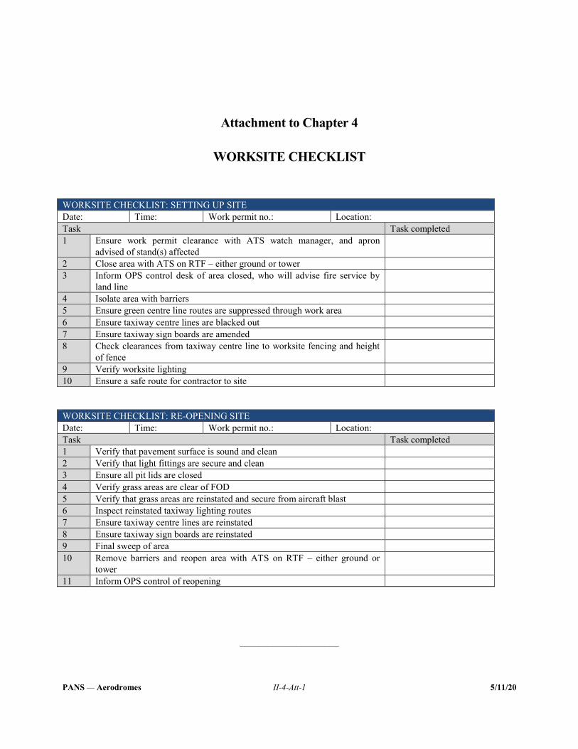
PANS — Aerodromes II-4-Att-1 5/11/20
Attachment to Chapter 4
WORKSITE CHECKLIST WORKSITE CHECKLIST: SETTING UP SITE Date: Time: Work permit no.: Location: Task Task completed 1 Ensure work permit clearance with ATS watch manager, and apron
advised of stand(s) affected
2 Close area with ATS on RTF – either ground or tower 3 Inform OPS control desk of area closed, who will advise fire service by
land line
4 Isolate area with barriers 5 Ensure green centre line routes are suppressed through work area 6 Ensure taxiway centre lines are blacked out 7 Ensure taxiway sign boards are amended 8 Check clearances from taxiway centre line to worksite fencing and height
of fence
9 Verify worksite lighting 10 Ensure a safe route for contractor to site WORKSITE CHECKLIST: RE-OPENING SITE Date: Time: Work permit no.: Location: Task Task completed 1 Verify that pavement surface is sound and clean 2 Verify that light fittings are secure and clean 3 Ensure all pit lids are closed 4 Verify grass areas are clear of FOD 5 Verify that grass areas are reinstated and secure from aircraft blast 6 Inspect reinstated taxiway lighting routes 7 Ensure taxiway centre lines are reinstated 8 Ensure taxiway sign boards are reinstated 9 Final sweep of area 10 Remove barriers and reopen area with ATS on RTF – either ground or
tower
11 Inform OPS control of reopening
_____________________

PANS — Aerodromes II-5-1 5/11/20
Chapter 5
FOREIGN OBJECT DEBRIS (FOD) CONTROL
5.1 GENERAL 5.1.1 The presence of foreign object debris (FOD) on the movement area may pose a significant hazard to the safety of aircraft operations. FOD has the potential to damage aircraft during critical phases of flight, which can lead to catastrophic loss of life and airframe, and increased maintenance and operating costs. FOD hazards can be reduced through the implementation of an FOD control programme, which would normally include FOD prevention, detection, removal and evaluation. 5.1.2 It is important that all personnel with access to the movement area understand their role in the prevention of FOD. FOD control is normally a module of the initial training given to personnel with access to the movement area. 5.1.3 It is necessary to have an established process to regularly clear the movement area of FOD. Removing FOD is the responsibility of everyone. 5.1.4 FOD may be controlled by ensuring that all personnel with movement area access, in particular inspection/maintenance personnel and ground handlers, are aware of situations which may potentially cause FOD.
5.2 OBJECTIVES 5.2.1 Aerodrome operators shall establish an FOD control programme commensurate with the assessed risks and appropriate to the local operating conditions. The programme shall consist of prevention, detection, removal and evaluation. 5.2.2 FOD prevention shall include awareness, training and education as well as measures for FOD prevention. 5.2.3 The detection of FOD shall include methods for the monitoring and inspection of the movement area. 5.2.4 Operational procedures and, where applicable, equipment, shall be provided for the removal, containment and disposal of FOD from the movement area. 5.2.5 Data and information about FOD shall be collected and analysed regularly to identify sources and trends.
II-5-2 Procedures — Aerodromes
5/11/20
5.3 OPERATIONAL PRACTICES
5.3.1 FOD prevention
5.3.1.1 Awareness 5.3.1.1.1 Aerodrome operators shall ensure that all personnel involved in aerodrome operations at the aerodrome are aware of the existence of the FOD control programme. Aerodrome personnel should be encouraged to identify potential FOD hazards, act to remove observed FOD, and propose solutions to mitigate related safety risks. 5.3.1.1.2 Aerodrome operators should designate an individual to manage the aerodrome’s FOD control programme and clearly define his/her responsibilities. Note.— This designated individual can be a dedicated FOD manager or can have other duties (e.g. operations manager, safety manager). 5.3.1.1.3 The FOD control programme should be actively supported by the senior management of all organizations operating on the movement area. 5.3.1.1.4 Aerodromes operators should consider establishing an FOD committee to assist in the management of the FOD control programme, including the determination of potentially hazardous FOD situations and evaluation of collected FOD data. The committee may include stakeholders in a position to produce or remove FOD, such as ground handlers, aircraft operators, aerodrome operations and contractor representatives, etc. Note.— The work of the FOD committee could be included in an already established safety-related committee (e.g. apron safety committee).
5.3.1.2 Training and education
The primary objectives of the FOD training programme are to increase employee awareness of the causes and effects of FOD damage and to promote active employee participation in eliminating FOD during the performance of daily work routines. A typical FOD training syllabus is included in Appendix 1 to this chapter.
5.3.1.3 FOD prevention measures
Active prevention measures to reduce the generation of FOD, commensurate with the identified safety risks, should be detailed in an aerodrome’s FOD control programme. Details of these measures are included in Appendix 2 to this chapter.
5.3.2 FOD detection 5.3.2.1 Detecting FOD is an important activity at an aerodrome. This process involves not only the timely detection of any FOD, but also the identification of its potential source and location. Provisions on FOD detection processes, systems and equipment are included in Appendix 3 to this chapter. 5.3.2.2 Detection of FOD shall be included as part of the inspection regime. Note.— See Part II, Chapter 3 — Inspections of the movement area, for the establishment of appropriate inspection procedures.
Part II — Chapter 5. Foreign object debris (FOD) control II-5-3
5/11/20
5.3.2.3 The inspection of an aircraft stand should be carried out prior to the arrival and departure of an aircraft, in order to detect and remove any FOD present.
5.3.2.4 Aerodrome operators shall establish procedures for handling FOD matters in cooperation with the appropriate ATS unit. 5.3.2.5 An aerodrome operator shall determine the most efficient way to notify all personnel involved in aerodrome operations at the aerodrome to remove the detected FOD, and notify ATS unit to take appropriate action if a risk is identified. 5.3.2.6 Although not all types of FOD will necessitate an immediate runway closure, a prompt decision is needed in all situations to assess the safety risk posed by FOD. Aerodrome operators should establish procedures for handling such matters in cooperation with the appropriate ATS unit. 5.3.2.7 When using continuously operating FOD detection technologies on a runway, a decision on the appropriate action to be taken shall be made as soon as an object is detected. If the location or characteristics of the FOD does not present an immediate safety risk, the object should be removed as soon as the operational schedule permits. If the location or characteristics of the FOD presents an immediate safety risk, provisions in the FOD management programme shall clearly indicate that a hazard exists and allow for an action to be taken that may lead to the temporary suspension of runway operations.
5.3.3 FOD removal 5.3.3.1 Detected FOD should be removed as soon as practicable after detection. Note.— Removal of FOD can be achieved through various means including manual or mechanical methods. 5.3.3.2 Provisions in the FOD management programme shall allow for an immediate removal of detected FOD which may pose an immediate safety risk to operations. 5.3.3.3 The removal of FOD should be included in the tasks of all personnel operating on the aerodrome. FOD removal operations should comply with the provisions in Appendix 3 to this chapter.
5.3.4 FOD evaluation 5.3.4.1 All FOD identified and collected on the aerodrome should be recorded, analysed and evaluated. When appropriate, an investigation should be carried out to identify the source of the FOD. 5.3.4.2 The sources of FOD, including its location and the activities generating FOD on the aerodrome, should be identified and recorded. This information should be analysed in order to identify trends and problem areas as well as to focus efforts of the FOD control programme. 5.3.4.3 The FOD control programme should be periodically reviewed and updated based on the data and trends identified through the evaluation of FOD collected on the aerodrome. The FOD evaluation processes are included in Appendix 3 to this chapter.
_____________________

PANS — Aerodromes II-5-App 1-1 5/11/20
Appendix 1 to Chapter 5
FOD TRAINING
The following subjects should be included in the FOD training programme:
a) safety of aircraft, personnel and passengers as they relate to FOD; b) overview of the FOD control programme in place at the aerodrome; c) causes and principal contributing factors of FOD; d) the consequences of ignoring FOD, and/or the incentives for preventing FOD; e) practicing clean-as-you-go work habits and the general cleanliness and inspection standards of work areas; f) FOD detection procedures, including the proper use of detection technologies (if applicable); g) requirements and procedures for the regular inspection and cleaning of movement areas; h) FOD removal procedures; i) proper care, use, and stowage of material and component or equipment items used around aircraft while in
maintenance or on aerodrome surfaces; j) control of debris in the performance of work assignments (e.g. loose items associated with luggage, ramp
equipment and construction materials); k) control over personal items and equipment; l) proper control/accountability and care of tools and hardware; m) how to report FOD incidents or potential incidents; and n) continual vigilance for potential sources of FOD.
_____________________


PANS — Aerodromes II-5-App 2-1 5/11/20
Appendix 2 to Chapter 5
FOD PREVENTION MEASURES
1. SOURCES OF FOD 1.1 FOD is derived from many sources and can be generated from personnel, aerodrome infrastructure (pavements, lights and signs), the environment (wildlife, snow, ice) or the equipment operating at the aerodrome (aircraft, aerodrome operations vehicles, maintenance equipment, fuelling trucks, other aircraft servicing equipment and construction equipment). 1.2 FOD can accumulate both on and underneath ground support equipment (GSE) stored on the apron. Jet blast can then blow FOD onto the movement area or on an aircraft. The outboard engines of four-engine aircraft can move debris from the runway edge and shoulder areas, where it tends to accumulate, back toward the centre of the runway or taxiway. 1.3 Helicopters that manoeuvre over freshly mowed or loose-dirt airside areas can also move FOD onto runways, taxiways and ramps. In addition, the high velocity outwash vortices from a helicopter, which may also send FOD to a distance of approximately three times the diameter of the rotor, can propel lightweight GSE or materials staged nearby. 1.4 FOD is often more common when aerodromes begin construction activities, but it may also be prevalent in winter conditions as ageing pavement infrastructure may be influenced by weathering (freeze and thaw cycles) and begin to crack or break apart. 1.5 Meteorological conditions may also move FOD. For example, wind can blow dry debris, such as sand or plastic bags, from relatively non-critical areas onto the flight area. Rain water and drainage can stream mud, pebbles and other small items along the path of least resistance. 1.6 The activities listed below may become sources of FOD on an aerodrome. For each activity, mitigation measures are identified.
2. AIRCRAFT SERVICING 2.1 Aircraft operators, ground handling agents and other aerodrome stakeholders generate much of the FOD found on the apron, service roads, baggage make-up areas, and areas near flight kitchens. Refuelling, catering, cabin cleaning, and baggage/cargo handling can produce broken materials. 2.2 These stakeholders should establish procedures to inspect GSE or other vehicles for signs of wear and tear that can lead to FOD hazards. 2.3 Procedures to inspect the baggage loading and unloading areas every time an aircraft is serviced should be established. Baggage pieces, including bag tags and wheels, can break off luggage and either fall onto the apron or collect in the cargo door sill of the aircraft. They can then also be knocked out of the sills and onto the apron at the next stop/destination.
II-5-App 2-2 Procedures — Aerodromes
5/11/20
3. AIRCRAFT MAINTENANCE 3.1 These activities, which may be performed on the apron, require a variety of small objects such as rivets, safety wire and bolts that become FOD when they are inadvertently left behind. 3.2 All tools should be accounted for as a matter of practice. Aids in the control of these items include checklists, shadow boards and cut-out tool tray liners. All items should be contained in a spill-proof tote bag, tray or toolbox.
4. AIR CARGO In an air cargo area, there is a high potential for blowing debris such as cargo strapping and plastic sheeting. Procedures to contain such debris, possibly by installing (and monitoring) fencing where appropriate may help to control the environment. Of course, FOD trapped by such fences should be removed regularly.
5. CONSTRUCTION 5.1 Specific FOD prevention procedures should be established and employed for each construction project. These procedures should be based on the proximity of the construction activities to the operational areas, but in general should stress containment and regular clean-up of construction debris. 5.2 Aerodrome preconstruction planning should include a means for controlling and containing FOD generated by the construction. This is especially true in high-wind environments where debris is more likely to become airborne. 5.3 The designated routes of construction vehicles on the movement area should be planned, so as to avoid or minimize crossing in critical areas of aircraft operations. If high-risk crossings cannot be avoided, subsequent provisions such as an increased frequency of FOD inspections could be implemented. 5.4 Contractors should fully understand and comply with the requirements and penalties incorporated in their contracts regarding the control and removal of FOD. To enforce these requirements, aerodrome operators may consider drafting FOD control guidance for all construction projects taking place within the movement area. Standard and project-specific FOD provisions could then be included into the contract documents for construction projects. These items may include:
a) requiring contractors to cover all loads; b) requiring contractors to secure any loose items that could easily blow away or control dust with the spraying of
water; c) ensuring the proper functioning of storm drains throughout the construction; d) specifying whether any mechanical FOD removal devices will be required; e) specifying how monitoring for FOD hazards will be accomplished; and f) requirements for inspecting and removing FOD from tires prior to traversing operational areas.
Note.— Procedures on work in progress at aerodromes can be found in Part II, Chapter 4.
Part II — Appendix 2 to Chapter 5 II-5-App 2-3
5/11/20
6. AERODROME MAINTENANCE OPERATIONS 6.1 Mowing and other maintenance operations routinely disturb the vegetation and soil in areas adjacent to those travelled by aircraft. Procedures to remove this debris, such as the use of an assigned aerodrome sweeper or personnel on foot using shovels to repair vegetation and soil, should be implemented. 6.2 Aerodrome lighting, pavement, and marking maintenance operations may generate concrete/asphalt debris as well as increase the potential for dropped repair parts, tools, and other items stored on the maintenance vehicles. Corrective procedures may include the use of aerodrome sweepers and the inspection of the worksite after maintenance is completed. 6.3 The areas listed below are typically prone to generating FOD.
6.4 Pavements 6.4.1 Deteriorating pavement can exhibit spalling or cracks. For example, pieces of concrete can break loose from pavements or FOD can develop from fatigued corner cracks. 6.4.2 The service roads which cross taxiways may generate FOD from the vehicles using them, especially in the case of construction operations. 6.4.3 Special attention should be paid to the cleaning of cracks and pavement joints, as tests have shown they are the main sources of foreign object ingestion. 6.4.4 Asphalt and concrete pavements may be the most common source of FOD on an aerodrome, and therefore, effective pavement maintenance practices are important for the prevention of FOD.
6.5 Other aerodrome surfaces 6.5.1 Movement area grass and ditches may collect and hold large amounts of light debris such as paper, cardboard, plastic and various containers that can originate from aprons, cargo ramps and hangar ramps. This debris can blow back into areas used by aircraft, unless collected in a timely manner. 6.5.2 Unpaved areas adjacent to pavements may require stabilization, as appropriate, to prevent FOD from jet wash. 6.5.3 FOD fences may collect debris on windy days. This FOD should be collected before the wind increases or changes direction and the debris blows back on to areas used by aircraft.
_____________________

PANS — Aerodromes II-5-App 3-1 5/11/20
Appendix 3 to Chapter 5
FOD DETECTION, REMOVAL AND EVALUATION
1. FOD DETECTION OPERATIONS 1.1 While operational areas are inspected as described in Part II, Chapter 3 of this document, additional inspections shall be carried out in construction areas and immediately after any aircraft or ground vehicle accident or incident, as well as following any type of material spill, to ensure that all FOD has been detected and removed. 1.2 In addition to the typical inspections, personnel on the movement area should employ a clean-as-you-go technique, by looking for FOD during the course of their regular duties. When inspections occur at night, after the runway is closed or before the runway is opened, additional lights/lighting systems on vehicles are beneficial to better detect FOD. 1.3 Vehicles should only be driven on clean, paved surfaces, when possible. If a vehicle must be driven on unpaved surfaces, the driver has a responsibility to ensure the vehicle’s tires do not transport FOD (e.g. mud or loose stones) back onto the pavement.
2. METHODS AND TECHNIQUES OF FOD DETECTION
2.1 Manual detection 2.1.1 When conducting an inspection on a runway, inspection techniques will be determined by runway availability and type of operation. Ongoing construction requires more frequent inspections. It may even be necessary to assign dedicated personnel to continually inspect for FOD during major construction activities. As part of the FOD control programme, the FOD manager may find it appropriate to involve aircraft operators. For example, flight crews should report any FOD they observe on runways and taxiways to the ATS unit and station operations. Aircraft operators and ground handling agents may also be asked to designate individuals to inspect apron areas prior to aircraft movement to and from the gate. 2.1.2 Encouraging the participation of the aerodrome’s stakeholders in inspections will reinforce the concept that FOD control is a team effort and demonstrates the aerodrome operator’s commitment to a debris-free environment. Aircraft operator personnel, when feasible, may join the aerodrome staff in movement area inspections. This practice helps increase familiarity with local aerodrome conditions, and promotes effective communication between the aerodrome and aircraft operators. 2.1.3 Periodic FOD inspections on foot should be carried out to increase the effectiveness of detection, and to inspect areas inaccessible by vehicle (such as grass areas).
II-5-App 3-2 Procedures — Aerodromes
5/11/20
2.2 Detection technologies 2.2.1 Recent technological developments have expanded the capabilities of FOD detection through automation. Advanced technologies are now available for automated FOD detection, including capabilities for continuous monitoring on runways and other aircraft movement areas to supplement the capabilities of aerodrome personnel. 2.2.2 If an aerodrome chooses to implement these new FOD detection technologies, responsibilities and procedures should be established with the ATS unit to ensure that appropriate and timely action is taken if FOD is detected. 2.2.3 The aerodrome operator should have considerable flexibility in terms of how to implement continuous detection systems at the aerodrome. The user interface may be located in the aerodrome’s operation or maintenance centre, and/or in the air traffic control (ATC) tower. Note.— Further guidance can be found in EUROCAE document ED-235 entitled Minimum Aviation System Performance Specification for Foreign Object Debris Detection System.
3. FOD REMOVAL
Once FOD is detected, the next step is removing it from the aerodrome environment. For the removal of an isolated item on a runway, the manual approach may be the most efficient. The use of FOD removal equipment may be beneficial however, especially in areas where a greater concentration of FOD may be expected, such as cargo areas and near construction sites.
4. FOD REMOVAL EQUIPMENT 4.1 The FOD removal equipment currently available may be divided into two categories: mechanical and non-mechanical. The equipment varies in size from small push units to large systems that are truck-mounted. FOD containers are also important for the management of FOD.
4.2 Mechanical systems
4.2.1 Power sweepers. The sweeper removes debris from cracks and pavement joints and is typically used throughout the movement area. Note.— For all brush systems, operators are cautioned that bristles can detach from brooms and produce FOD. Brushes made with metal bristles or spines are not recommended to be used for FOD removal purposes. Plastic or a combination of plastic/metal bristles may be appropriate, but the user should consult the equipment manufacturer for specific recommendations. 4.2.2 Vacuum systems. These systems perform FOD removal functions in a manner similar to the power sweepers described above. The systems may also perform in conjunction with mechanical brooms or other recirculation air units. 4.2.3 Jet air blowers. These systems move FOD and other debris by directing a stream of high velocity air towards the pavement surface. When used in the aerodrome environment, it is recommended that these systems incorporate a debris collection mechanism so that FOD will not simply be relocated to another area.
Part II — Appendix 3 to Chapter 5 II-5-App 3-3
5/11/20
4.3 Non mechanical systems
4.3.1 Friction mat sweepers. A rectangular assembly towed behind a vehicle that employs a series of bristle brushes and friction to sweep FOD into sets of capture scoops, which are covered by a retaining mesh to hold collected debris. 4.3.2 Magnetic bars (attached to vehicles). These bars can be suspended beneath tugs and trucks to pick up metallic material. However, the bars should be cleaned regularly to prevent them from dropping the collected debris. Magnetic bars are not able to pick up the following types of common FOD materials: titanium, aluminium alloys and certain stainless steel elements. 4.3.3 Rumble strips (also known as “FOD shakers”). While these devices may have been used in the past, they are no longer a widely accepted FOD removal system. Their effectiveness at removing debris from tires or vehicle undercarriages is negligible, and the equipment can generate its own FOD if not cleaned out regularly.
4.4 FOD containers
4.4.1 Designated FOD containers should be conspicuously placed on the apron for the storage of debris. The containers should be well marked, properly secured, and frequently emptied to prevent them from overflowing and becoming a source of FOD themselves. 4.4.2 “Closed-type” containers are preferable in order to prevent the wind from dislodging the container’s contents. Aerodrome operators should ensure that FOD containers do not blow over during periods of high winds. FOD containers should also have placards stating that hazardous materials may not be deposited in them, as appropriate. 4.4.3 Suggested locations for FOD containers include: near all entry points to the apron area, in hangars, aircraft maintenance areas, aircraft stands and baggage areas. Clearly identified storage locations increase the likelihood that collected debris will be deposited by personnel. 4.4.4 Other means for containing FOD include: FOD fencing or netting to restrict movement of airborne FOD; fencing to prevent animals from entering the aerodrome.
5. REMOVAL OPERATIONS While the exact actions of FOD removal operations are specific to each aerodrome, the following two examples represent the successful implementation of FOD removal: a) assigning an airside sweeper(s) to work with maintenance crews and/or respond as required to reports of FOD; b) deploying personnel with garbage bags to pick up potential FOD in grassy areas and along fence-lines. This
process is intended to pick up debris before it returns to the pavement areas.
II-5-App 3-4 Procedures — Aerodromes
5/11/20
6. FOD EVALUATION
6.1 FOD reporting FOD may be composed of any material. To record the location of the FODs, a suitable map of the aerodrome should be used. It is important to correctly describe the FOD, to allow for the proper identification of the source areas as well as the appropriate mitigation measures to be taken. FOD may include the following:
a) aircraft and engine fasteners (nuts, bolts, washers, safety wire, etc.); b) aircraft parts (fuel caps, landing gear fragments, oil sticks, metal sheets, trapdoors and tire fragments); c) mechanics’ tools; d) catering supplies; e) personal items (personnel badges, pens, pencils, luggage tags, drink cans, etc.); f) apron items (paper and plastic debris from catering and freight pallets, luggage parts, and debris from ramp
equipment); g) runway and taxiway materials (concrete and asphalt chunks, rubber joint materials and paint chips); h) construction debris (pieces of wood, stones, fasteners and miscellaneous metal objects); i) plastic and/or polyethylene materials; j) natural materials (plant fragments, inanimate wildlife and volcanic ash); and k) contaminants from winter conditions (snow, ice).
7. FOD RECORDING It is important that the organization maintain a record of the measures taken to fulfil the objectives of the FOD control programme. These records may be required in the event of a formal investigation of an accident or serious incident, and may also be used to identify any trends, repeats, unusual conditions, etc., in order for corrective action to be initiated. Records may also provide quantitative data for future safety risk assessments to support the analysis of operational history and improve operational capabilities.
8. CONTINUOUS IMPROVEMENT 8.1 The FOD control programme should be periodically analysed and reviewed to ensure its effectiveness. 8.2 This review provides a means for systematically assessing how well the organization is meeting its FOD control objectives. The evaluation provides a review of the existing effectiveness of the programme and, if required, results in recommendations for enhanced FOD control. In addition to supporting the aerodrome operator’s existing responsibilities for self-inspection and correction of discrepancies, an effective FOD control programme review should:
Part II — Appendix 3 to Chapter 5 II-5-App 3-5
5/11/20
a) systematically review the effectiveness of existing FOD control procedures used by aerodrome and aircraft operator personnel, including all available feedback from daily inspections, assessments, reports and other safety audits;
b) verify that the aerodrome is meeting identified performance indicators and targets; c) communicate all findings to staff and lead to implementation of agreed-upon corrective procedures, mitigation
strategies and enhanced training programmes; and d) promote safety in the overall operation of the aerodrome by improving coordination between aerodrome staff,
aircraft operator personnel and other aerodrome stakeholders.
_____________________

PANS — Aerodromes II-6-1 5/11/20
Chapter 6
WILDLIFE HAZARD MANAGEMENT
6.1 GENERAL 6.1.1 The presence of wildlife (birds and other animals) on and within the aerodrome vicinity may pose a serious hazard to aircraft operational safety. Therefore, to reduce the risk to aviation safety, active assessments, reporting and management of wildlife are necessary. 6.1.2 A wildlife hazard management programme (WHMP) is a method for aerodrome operators to adopt reasonable wildlife risk control measures, in order to prevent wildlife from colliding with aircraft. 6.1.3 While the roles and tasks of the other stakeholders (State and local authorities, aircraft operators and air navigation services providers) in the State’s policy toward wildlife hazard reduction are equally important, they will not be the focus of this document. 6.1.4 Land use around the aerodrome should, wherever possible, not be attractive habitats for wildlife.
6.2 OBJECTIVES 6.2.1 A wildlife safety risk assessment shall be conducted, covering the aerodrome and its vicinity. 6.2.2 A WHMP shall be established and tailored to the local environment and be commensurate with the wildlife safety risk assessment. 6.2.3 The WHMP shall include procedures and measures for reducing the wildlife risk at the aerodrome to an acceptable level. 6.2.4 Wildlife hazard reduction measures and procedures shall be integrated into the aerodrome operator’s safety management system (SMS).
6.3 OPERATIONAL PRACTICES
6.3.1 Wildlife hazard management programme (WHMP) 6.3.1.1 An aerodrome operator shall develop, implement and demonstrate an effective WHMP at the aerodrome, and this should be tailored to and commensurate with the size and level of complexity of the aerodrome, and the number of aircraft movements and their type, taking into account the wildlife hazards identified and the risk assessment of those hazards.
II-6-2 Procedures — Aerodromes
5/11/20
6.3.1.2 The WHMP should include, as a minimum:
a) a description of the organization, roles and tasks in the WHMP; b) procedures for collecting, reporting and recording data on wildlife strikes and observed wildlife; c) a wildlife safety risk assessment method and procedure, including annual reviews; d) procedures, means and staff for habitat and land management; e) procedures, means and staff for the expelling and deterring of wildlife; f) procedures for coordinating with other stakeholders; and g) procedures, means and provisions for the training of staff.
Note.— Provisions on training can be found in Part II, Chapter 1, Chapter 6, 6.3.8 and Appendix 1 to Chapter 6.
6.3.2 Roles and tasks in the wildlife hazard management programme (WHMP)
The WHMP should detail the roles and tasks of all personnel who:
a) develop and implement the WHMP; b) oversee the daily activities (detailed in the sections below), analyse the collected data and carry out safety risk
assessments in order to develop and implement the WHMP; c) expel and/or deter hazardous wildlife; and d) reduce the attractiveness of identified areas, if relevant.
6.3.3 Collecting, reporting and recording data on wildlife strikes and observed wildlife
6.3.3.1 An effective WHMP depends on accurate and reliable data. Reviewing and analysing wildlife strikes and wildlife observations will help identify hazards at the aerodrome and its vicinity and indicate the effectiveness of current wildlife strike prevention methods. 6.3.3.2 The aerodrome operator shall establish procedures to record and report wildlife strikes that have occurred at the aerodrome and its vicinity, in close cooperation with all relevant organizations operating at the aerodrome. 6.3.3.3 Wildlife incident reporting should comply with the criteria included in Appendix 2 to this chapter. 6.3.3.4 The aerodrome operator’s reporting system shall contain a requirement for all relevant third parties and all aerodrome personnel to report wildlife strikes, wildlife remains, including findings thereof during aerodrome inspections, and any other relevant identified hazards, to the aerodrome operator. 6.3.3.5 Wildlife activities, including incident reports, should be recorded in a wildlife log. This log should include, as a minimum, the following information:
Part II — Chapter 6. Wildlife hazard management II-6-3
5/11/20
a) the name of the person logging the data; b) date and time of the observation; c) numbers, species and location of the wildlife observations; d) proactive and reactive actions taken to decrease the number of present wildlife and the results thereof; and e) weather and lighting conditions.
6.3.3.6 The log should be completed by competent wildlife control personnel, at intervals commensurate with the number of aircraft movements and runways in use, and taking into account wildlife behavior and other relevant local circumstances. Data should be analysed to identify which species represent a hazard at specific times of day and/or year, and during different types of meteorological conditions. 6.3.3.7 Aerodrome operators should ensure that the identification of the species involved in any reported wildlife strikes is as accurate as possible, since these reports represent data that will help in the assessment of the level of safety risk that each species of wildlife presents to aircraft operations at the aerodrome. The compilation of precise wildlife observations and strike statistics should facilitate the analysis of data so as to improve wildlife hazard management.
6.3.4 Wildlife safety risk assessment 6.3.4.1 Aerodrome operators shall conduct a specific safety risk assessment of the wildlife situation and use the results to help target wildlife management measures and monitor their effectiveness. Safety risk assessments should be updated and repeated at regular intervals, commensurate with assessed risks. 6.3.4.2 The aerodrome operator’s wildlife safety risk assessment should, as a minimum:
a) define the area for the safety risk assessment, which would, in most cases, be the entire aerodrome but may also include the vicinity of the aerodrome;
b) rate the strike probability using strike data from reports for each species, information on the presence of species,
and the number of individuals and their biology, and update the data and probabilities regularly; c) rate the severity of damage arising from those strikes for each species; d) determine the risk for each species; and e) identify the causes (attractants, migration routes) of each wildlife hazard.
Note 1.— The total number of wildlife strikes is not necessarily a comprehensive measure of safety risk, or indication of the performance of the wildlife control measures, at an aerodrome. Note 2.— Provisions on safety risk evaluation methodology can be found in Part I, Chapter 3. 6.3.4.3 The aerodrome operator should prioritize its wildlife management measures on those species with the highest frequency (probability) and which may create the greatest damage (severity). Note.— Further guidance can be found in the Airport Services Manual (Doc 9137), Part 3 — Wildlife Control and Reduction.
II-6-4 Procedures — Aerodromes
5/11/20
6.3.5 Habitat and land use management 6.3.5.1 Habitat and land use management, including preventive and proactive actions, is intended to reduce the presence of wildlife on the aerodrome by taking appropriate actions. 6.3.5.2 Aerodrome operators should conduct an inventory of sites that attract wildlife within a defined radius around the aerodrome, paying particular attention to sites close to the airside and the approach and departure corridors. The appropriate radius (i.e. aerodrome vicinity) in this context should be 13 km around the aerodrome reference point. However, the radius may be extended or reduced, based on a wildlife evaluation of the aerodrome vicinity. Note.— Further guidance can be found in the Airport Services Manual (Doc 9137), Part 3 — Wildlife Control and Reduction. 6.3.5.3 Aerodrome operators should regularly review features on, and within the vicinity of, the aerodrome that attract wildlife. A management plan should be developed to reduce the attractiveness of these features and to decrease the number of hazardous wildlife present or to deny them physical access to these areas. 6.3.5.4 Aerodrome development should be designed such that it will not be attractive to hazardous wildlife and no attraction will be created during construction. This may include denying resting, roosting and feeding opportunities for hazardous wildlife. In some cases, specific wildlife hazard control may need to be employed during the construction and reinstatement phases, and wildlife hazard management controls implemented as part of any approval process. 6.3.5.5 A complete perimeter fence of adequate height, strength and structure, is the prime method of preventing hazardous wildlife, other than birds, from gaining access to the aerodrome areas. Fences and gates should remain closed and be regularly inspected. Fencing should also be trenched in order to preclude burrowing animals from gaining access to the aerodrome. 6.3.5.6 No food sources should be available to hazardous wildlife on the aerodrome. The aim should be to prevent food sources from being available through management of the aerodrome environment. 6.3.5.7 Where applicable, vegetation should be kept at a height that is considered unattractive to hazardous wildlife. Where applicable, the vegetation composition on the aerodrome should not encourage wildlife. 6.3.5.8 Agricultural crops should be discouraged from the aerodrome environment since agricultural crops and related activities (ploughing, seeding) may provide food for hazardous wildlife. 6.3.5.9 Water bodies such as depressions, open drainage ditches, ponds and lakes may be a particular hazard as they may attract hazardous wildlife. These hazards should be made less attractive by mitigation measures such as drainage, replacement by buried drain pipes, netting and fencing to deny access to wildlife that walk in or by steepening the sides. Note.— A list of types of land use that should be prevented, eliminated or mitigated in and around aerodromes is shown in the attachment to Chapter 6.
6.3.6 Expelling and deterring wildlife 6.3.6.1 Wildlife deterring and expelling techniques should be appropriate to the wildlife situation on the aerodrome and its vicinity and should be based on:
a) wildlife patrols; b) acoustics, such as distress and alarm call simulators, specific signals, natural and synthetic cries;
Part II — Chapter 6. Wildlife hazard management II-6-5
5/11/20
c) pyrotechnics, such as medium- and long-range cartridges and shell crackers; d) optical and visual deterrents, such as laser devices, flags and streamers, lights, predator models, gull models,
hawk kites, balloons; and e) other techniques such as firearms, chemical repellents, lethal chemicals, trained predators (dogs and falcons),
gas cannons, traps and relocation methods.
Note.— The effectiveness of the techniques and measures listed above may vary based on the species, location and their application. 6.3.6.2 Wildlife control personnel should be equipped with devices for deterring, dispersing or removing wildlife appropriate to the species encountered, the numbers of wildlife present, and to the area that they need to control, or obtain the means of calling on expert support at short notice. 6.3.6.3 In case hazardous wildlife are still attracted to the aerodrome after proactive measures have been implemented, it may be necessary to remove them by trapping or using lethal methods. 6.3.6.4 The challenge for wildlife hazard management is that some wildlife may become accustomed to certain dispersal techniques. Therefore, best results may be obtained if aerodrome operators routinely adjust and vary the control and dispersal measures being used. An aerodrome operator should proactively seek different or new effective ways to reduce the wildlife hazard, where or if existing methods prove ineffective. 6.3.6.5 Actions to manage wildlife should be prioritized on the movement area with particular attention given to the runways and approach/departure routes within the aerodrome vicinity. 6.3.6.6 All devices and methods should be used in compliance with national regulations or practices (e.g. in compliance with regulations on the use of firearms, environment and animal protection).
6.3.7 Coordination with stakeholders 6.3.7.1 Effective wildlife hazard management requires communication, cooperation and coordination with all relevant stakeholders. Aerodrome operators should identify which stakeholders on and off the aerodrome should be involved and consulted. Such stakeholders may include transportation officials (including government), aerodrome staff, the ATS unit, aircraft operator representatives (including pilots), nature conservation organizations (government and non-government), local municipalities/cities, and organizations responsible for land management and local planning and development approvals in the vicinity of the aerodrome. 6.3.7.2 The WHMP should include a process to hold regular meetings with the stakeholders present at the aerodrome (including aircraft operators, ATS, ground handlers, as appropriate). The aerodrome operator should encourage stakeholders to share data that was collected, reported and recorded on wildlife observations and strikes, in order to improve the WHMP. 6.3.7.3 The aerodrome operator should ensure that there is a process for rapid communication among those involved in wildlife control as well as with ATS. This is necessary when a specific wildlife hazard is present to allow the issuance of appropriate warnings to aircraft operating on, and within the vicinity, of the aerodrome, by the air navigation services provider (ANSP). 6.3.7.4 The aerodrome’s WHMP should include a process for liaising with non-aerodrome agencies, local landowners and other relevant stakeholders, to ensure that the aerodrome operator is aware of developments that may contribute to creating additional wildlife hazards in the infrastructure, vegetation, land use and activities within the aerodrome’s vicinity (e.g. crop harvesting, seed planting, ploughing, establishment of land or water features, hunting).
II-6-6 Procedures — Aerodromes
5/11/20
The aerodrome operators should consider options to influence the land-use within the vicinity of the aerodrome, in order to reduce the hazard from wildlife. Note.— Further guidance can be found in the Airport Services Manual (Doc 9137), Part 3 — Wildlife Control and Reduction. 6.3.7.5 The aerodrome operator should participate in wildlife related meetings with other aerodromes to share experience and discuss common problems.
6.3.8 Personnel training 6.3.8.1 The WHMP should include procedures for the initial and recurrent training of personnel involved in wildlife control. The minimum initial and recurrent training requirements for wildlife control personnel, and a typical training syllabus, are included in Appendix 1 to this chapter. 6.3.8.2 The training of wildlife control personnel should be conducted by competent wildlife control personnel, or specialists with proven experience in this field. 6.3.8.3 Wildlife control personnel should be fully aware of the details pertaining to aerodrome operations, the aerodrome environment and should have received appropriate training, including:
a) airside driver training, aerodrome familiarization, air traffic control communications (radiotelephony (RTF)), signs and markings, navigational aids, aerodrome operations and safety, and other matters that the aerodrome operator deems appropriate; and
b) aircraft familiarization, including aircraft identification and effect of wildlife strikes on aircraft systems.
_____________________
PANS — Aerodromes II-6-App 1-1 5/11/20
Appendix 1 to Chapter 6
WILDLIFE CONTROL TRAINING
1. INITIAL TRAINING The initial training for wildlife control personnel should, as a minimum, address the following areas:
a) an understanding of the nature and extent of the aviation wildlife hazard, and local hazard identification; b) an understanding of national and local regulations, standards and guidance material related to the aerodrome
wildlife hazards management programme (use of best-practices models); c) a broad appreciation of local wildlife ecology and biology; d) the importance of accurate wildlife identification and observations, including the use of field guides; e) local and national laws and regulations relating to protected species, and species of special concern, and the
aerodrome operators’ policies relating to them; f) high-risk species identified in the wildlife risk assessment; g) wildlife strike remains collection procedures, identification and reporting; h) active/tactical measures, using well-established effective wildlife removal, dispersal, detection and control
techniques; i) documentation of wildlife activities, control measures and reporting procedures (the aerodrome wildlife
management programme); and j) firearms, drones and any other equipment and their use on the aerodrome, including the use of personal
protective equipment.
2. RECURRENT TRAINING In order to maintain the competence of wildlife management personnel, recurrent training should be carried out, including a selection of general topics covered in the wildlife control initial training. This should include:
a) changes in the local environment; b) recent wildlife events at the aerodrome; c) changes in active and passive measures; and d) any other matters that the aerodrome operator deems appropriate.
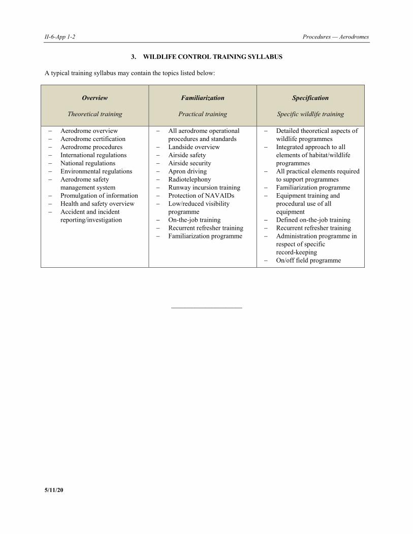
II-6-App 1-2 Procedures — Aerodromes
5/11/20
3. WILDLIFE CONTROL TRAINING SYLLABUS
A typical training syllabus may contain the topics listed below:
Overview
Theoretical training
Familiarization
Practical training
Specification
Specific wildlife training
Aerodrome overview Aerodrome certification Aerodrome procedures International regulations National regulations Environmental regulations Aerodrome safety
management system Promulgation of information Health and safety overview Accident and incident
reporting/investigation
All aerodrome operational procedures and standards
Landside overview Airside safety Airside security Apron driving Radiotelephony Runway incursion training Protection of NAVAIDs Low/reduced visibility
programme On-the-job training Recurrent refresher training Familiarization programme
Detailed theoretical aspects of wildlife programmes
Integrated approach to all elements of habitat/wildlife programmes
All practical elements required to support programmes
Familiarization programme Equipment training and
procedural use of all equipment
Defined on-the-job training Recurrent refresher training Administration programme in
respect of specific record-keeping
On/off field programme
_____________________
PANS — Aerodromes II-6-App 2-1 5/11/20
Appendix 2 to Chapter 6
WILDLIFE INCIDENT REPORTING CRITERIA The reporting forms (paper or electronic format) used by the aerodrome operator or other stakeholders at the aerodrome for reporting wildlife strikes, should contain at least the following information:
a) operator involved; b) aircraft make/model; c) engine make/model; d) aircraft registration; e) date (dd/mm/yyyy); f) local time; g) dawn/day/dusk/night; h) aerodrome name; i) runway used; j) location if en route; k) height above ground level (AGL) in ft; l) speed (indicated airspeed (IAS)) in kt; m) phase of flight:
1) parked; 2) taxi; 3) take-off run; 4) climb; 5) en route; 6) descent; 7) approach; 8) landing roll;
n) part(s) of aircraft struck or damaged:
1) radome; 2) windshield; 3) nose (excluding radome and windshield); 4) engine number (1/2/3/4); 5) propeller;
II-6-App 2-2 Procedures — Aerodromes
5/11/20
6) wing/rotor; 7) fuselage; 8) landing gear; 9) tail; 10) lights; 11) other (to be specified);
o) effect on flight:
1) none; 2) aborted take-off; 3) precautionary landing; 4) engines shut down; 5) other (to be specified);
p) sky condition:
1) no cloud; 2) some cloud; 3) overcast;
q) precipitation: 1) fog; 2) rain; 3) snow;
r) wildlife species; s) number of wildlife:
1) seen i) 1; ii) 2 to10; iii) 11 to100; iv) over 100;
2) struck:
i) 1; ii) 2 to 10; iii) 11 to 100; iv) over 100;
t) size of wildlife:
1) small; 2) medium; 3) large;
u) pilot warned of wildlife: yes/no; v) remarks (description of damage, injuries and other pertinent information); w) reporting person/organization; x) address and/or instructions for returning the form to the competent authority; and y) address within the State to which any wildlife remains, including feather fragments, should be sent.
_____________________
PANS — Aerodromes II-6-Att-1 5/11/20
Attachment to Chapter 6
LAND USE ON AND AROUND AERODROMES
The following is a non-exhaustive list of the types of land uses which have proven to attract hazardous wildlife and which should, in particular, be prevented, eliminated or mitigated on and in the vicinity of aerodromes:
a) fish processing; b) agriculture; c) cattle feed lots; d) garbage dumps and landfill sites; e) factory roofs and parking lots, or other infrastructure; f) theatres and food outlets; g) wildlife refuges; h) artificial and natural lakes; i) golf or polo courses, etc.; j) animal farms; and k) slaughterhouses.
Note.— Further guidance on land use on and around aerodromes can be found in the Airport Services Manual (Doc 9137), Part 3 — Wildlife Control and Reduction and in the Airport Planning Manual (Doc 9184), Part 2 — Land Use and Environmental Management.
_____________________

PANS — Aerodromes II-7-1 5/11/20
Chapter 7
APRON SAFETY
7.1 GENERAL
7.1.1 There are a large number of activities taking place on aprons within a congested and time-sensitive environment. Accidents, incidents and occurrences can affect the safety and health of personnel as well as cause aircraft damage. 7.1.2 Ensuring safety on the apron is primarily the responsibility of the aerodrome operator, however, all third parties operating on the apron have a responsibility to ensure the safety of their specific operations. 7.1.3 Apron hazards should be identified and, when necessary, mitigation measures should be developed as part of the aerodrome operator’s safety management system (SMS). All staff operating on the apron need to be made aware of its hazards: this may be achieved through general safety introduction training for all staff with unescorted access to the apron areas. Part of this training includes aerodrome operating procedures related to apron management and safety. Note.— Further guidance is given in the Manual on Ground Handling (Doc 10121). 7.1.4 For safe and efficient apron operations there is a need for a close liaison between the aerodrome operator, aircraft operators, air traffic services (ATS) and other third parties. The operational safety and efficiency of apron management depends very largely upon this close cooperation.
7.2 OBJECTIVES
7.2.1 The aerodrome operator, in collaboration with the apron users, shall identify hazards related to activities on the apron and establish and implement mitigation measures, as appropriate. 7.2.2 The aerodrome operator shall establish apron safety procedures, or ensure that such procedures are in place. These shall include, as a minimum, the following:
a) aircraft stand allocation; b) marshalling service; c) follow-me (leader vehicle); d) blast precautions; e) apron cleaning; f) aircraft pushbacks;
II-7-2 Procedures — Aerodromes
5/11/20
g) operation of air bridges; h) vehicle movements; i) apron discipline; and j) dissemination of information.
Note 1.— The list above contains elements of both operations and safety: this chapter only deals with the safety aspects. Note 2.— Further guidance is given in the Manual on Ground Handling (Doc 10121). 7.2.3 Procedures to collect, analyse and protect data shall be established by the aerodrome operator in order to understand and improve apron safety performance. Note.— Annex 19 — Safety Management provides further provisions on protection of safety data, safety information and related sources. 7.2.4 Information that could enhance apron safety, including specific local procedures, shall be communicated by the aerodrome operator to the relevant apron users.
7.3 OPERATIONAL PRACTICES
7.3.1 Aircraft stand allocation 7.3.1.1 A key element of aircraft stand allocation is ensuring that there is sufficient clearance between the aircraft, equipment and/or buildings. 7.3.1.2 Rules should clearly state which stands may be used by which aircraft types or groups of aircraft. The safety aspects of this involve ensuring that aircraft can only be allocated to stands that are large enough to accommodate them with the required margins.
7.3.2 Marshalling service
7.3.2.1 A marshalling service should be available to aircraft on request and provided where guidance systems do not exist or are unserviceable. Marshalling guidance may also be required to avoid a temporary safety hazard. Note.— Standard marshalling signals for fixed-wing aircraft and helicopters are included in Annex 2 — Rules of the Air (Appendix 1, Section 5). 7.3.2.2 Marshallers shall:
a) ensure that the stand-to-be used is clear of fixed and mobile obstructions; and b) take action in the event of an aircraft incident occurring during marshalling.
7.3.2.3 A distinctive high-visibility jacket or vest should be worn by the marshaller to easily distinguish them from other apron personnel.
Part II — Chapter 7. Apron safety II-7-3
5/11/20
7.3.3 Follow-me (leader vehicle)
7.3.3.1 Aerodrome operators should provide a follow-me (leader vehicle) service to lead aircraft when requested. This is especially relevant when operations occur at night or in low visibility conditions. 7.3.3.2 Follow-me vehicles should be easily identified either by a distinct marking and/or colour and be adequately equipped.
7.3.4 Blast precautions
7.3.4.1 The aerodrome operator shall ensure that all apron users are made aware of the hazards arising from jet blast and propeller slipstream. 7.3.4.2 All vehicles and wheeled equipment shall be left properly braked. Where appropriate, equipment should be left on jacks or chocked to minimize the risk of movement when subjected to jet blast or propeller slipstream. Where practicable, equipment should be parked in areas where the risk of jet blast is minimized. Particular care should be exercised with apron equipment having a large flat side surface area. 7.3.4.3 Foreign object debris (FOD) may be moved by jet blast, creating additional hazards and it is thus necessary to ensure that aprons are kept clean. Note.— See Part II, Chapter 5 of this document on FOD control. 7.3.4.4 The responsibility for the safety of passengers walking across aprons, rests with the aircraft operator or its handling agent. The relevant procedures shall be in line with the safety requirements established by the aerodrome operator. All staff operating on the apron shall be aware of the risk to passengers on aprons from jet blast, propeller slipstream and rotor wash and should be prepared to take appropriate action when necessary. 7.3.4.5 When designing or making changes to apron layouts, consideration should be given to jet blast and, if necessary, the installation of blast protection fences.
7.3.5 Apron cleaning 7.3.5.1 The aerodrome operator should ensure that at regular intervals, aircraft stands and adjacent areas should be cleaned in order to remove oil, grease and rubber marks. 7.3.5.2 Spillages may occur involving fuel, oil, hydraulic fluids, water, toilet waste and other contaminants. Aerodrome operators shall ensure that procedures are established to contain, remove and correctly dispose of such spillage. Note.— When dealing with spillages, local or national environmental protection guidelines may also apply.
7.3.6 Aircraft pushbacks
7.3.6.1 Aerodrome operators shall establish procedures or ensure that procedures are in place to ensure aircraft pushbacks are conducted safely. The following shall be included in the procedures:
a) ensure that conflicts with other pushbacks in progress or with an aircraft that is ready to taxi, as well as with other traffic on the apron, are avoided;
II-7-4 Procedures — Aerodromes
5/11/20
b) prior to pushback, ensure that the area behind the aircraft is clear of obstacles; and c) after pushback, ensure that the aircraft is positioned in such a way as to avoid concentrating break-away blast at
buildings, parked or taxiing aircraft, vehicles and/or persons on the apron. 7.3.6.2 In some cases, aircraft operators may request to “power-back” from an aircraft stand. Given the potential hazards created by power-back operations, a safety assessment shall be carried out prior to approval of the procedure. The safety assessment shall include the following factors, at the minimum:
a) jet blast or propwash; b) surface conditions; c) noise levels; d) communication with other apron users that a power-back is about to take place (especially if there is a rear of
stand road); e) manoeuvring space; f) conflict with other traffic (pushback, power-back or taxiing); and g) effect on pedestrians, buildings, vehicles, mobile equipment and other aircraft.
7.3.7 Operation of air bridges
7.3.7.1 The area used for the movement of the air bridge should be kept free of vehicles and/or equipment to ensure its safe operation. Operators should do a visual check (camera, mirrors or looking out the window) before moving the air bridge in order to ensure that there are no obstructions. 7.3.7.2 When not in use, the air bridge should be parked with the wheel base in the designated position.
7.3.8 Vehicle movements 7.3.8.1 The aerodrome operator shall ensure that the movement of vehicles on the apron is safely managed through:
a) the establishment and implementation of driving rules, and the monitoring and enforcement of their application; and
b) the establishment of vehicle driving routes, as appropriate, and the installation and maintenance of proper signs
and markings. 7.3.8.2 An overview of the topics that should be covered in the airside vehicle rules is provided in the Appendix to this chapter. Note.— Vehicle condition requirements may be in accordance with requirements established in Part II, Chapter 9 of this document.
Part II — Chapter 7. Apron safety II-7-5
5/11/20
7.3.9 Apron discipline
7.3.9.1 The aerodrome operator, either through its own means or through arrangements with other parties, should monitor activities and take action when deviations from the established rules are observed.
7.3.9.2 If the designated party for monitoring apron discipline is different from the aerodrome operator, the aerodrome operator should be informed of any deviations observed.
7.3.9.3 The aerodrome operator should establish enforcement measures, or ensure that such measures are established and implemented, in order to manage any violation of the apron safety rules.
7.3.10 Dissemination of information The aerodrome operator shall establish a process to disseminate relevant information in a timely manner on limitations to operations on the apron.
Note.— Additional information on the dissemination of information to apron users can be found in the attachment to this chapter.
_____________________

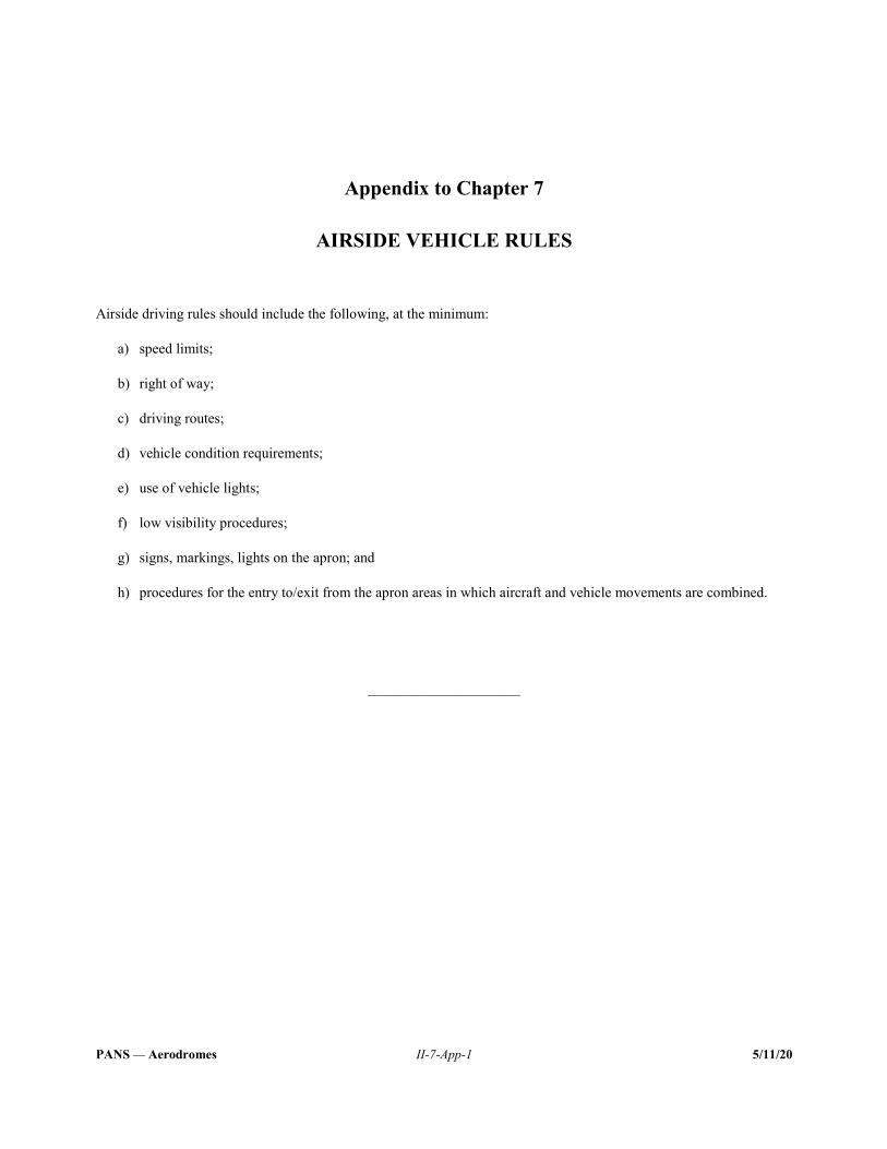
PANS — Aerodromes II-7-App-1 5/11/20
Appendix to Chapter 7
AIRSIDE VEHICLE RULES
Airside driving rules should include the following, at the minimum:
a) speed limits; b) right of way; c) driving routes; d) vehicle condition requirements; e) use of vehicle lights; f) low visibility procedures; g) signs, markings, lights on the apron; and h) procedures for the entry to/exit from the apron areas in which aircraft and vehicle movements are combined.
_____________________

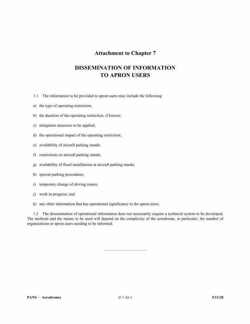
PANS — Aerodromes II-7-Att-1 5/11/20
Attachment to Chapter 7
DISSEMINATION OF INFORMATION TO APRON USERS
1.1 The information to be provided to apron users may include the following:
a) the type of operating restriction; b) the duration of the operating restriction, if known; c) mitigation measures to be applied; d) the operational impact of the operating restriction; e) availability of aircraft parking stands; f) restrictions on aircraft parking stands; g) availability of fixed installations at aircraft parking stands; h) special parking procedures; i) temporary change of driving routes; j) work in progress; and k) any other information that has operational significance to the apron users.
1.2 The dissemination of operational information does not necessarily require a technical system to be developed. The methods and the means to be used will depend on the complexity of the aerodrome, in particular, the number of organizations or apron users needing to be informed.
_____________________


PANS — Aerodromes II-8-1 5/11/20
Chapter 8
RUNWAY SAFETY
8.1 GENERAL 8.1.1 Runway safety is a key priority for aerodrome operators, aircraft operators, and air traffic services (ATS). The prevention of both runway incursions and excursions should be an important part of their programmes and activities for improving runway safety. The aerodrome operator and ATS cannot solely bring about improvements or positively manage runway safety without the coordination and cooperation of other stakeholders. 8.1.2 Improving runway safety on an aerodrome is a collaborative process, with the primary objective being to develop a runway safety action plan that identifies and addresses safety issues through effective hazard identification and risk mitigation. 8.1.3 Gathering, monitoring and analysing data on runway safety performance greatly contributes to understanding and proactively managing the risks related to the operations of a runway. Note 1.— The Manual on the Prevention of Runway Incursions (Doc 9870) provides further guidance on this matter. Note 2.— See Part II, Chapter 5 of this document for further information on FOD on the runway. Note 3.— See Part II, Chapter 6 of this document for further information on wildlife hazards affecting a runway. Note 4.— The terms “runway undershoot” and “overrun” are included in runway excursion. 8.1.4 This chapter covers the establishment of a runway safety team at an aerodrome, the identification of hazards related to runway safety, the development and implementation of action plans, collection of data and the promulgation of safety information.
8.2 OBJECTIVES 8.2.1 An aerodrome operator shall establish a runway safety team comprised of relevant organizations operating or providing services on the aerodrome. 8.2.2 The runway safety team shall identify runway related hazards. These may include aerodrome design, markings, signs and lights, as well as relevant aerodrome operations and procedures. 8.2.3 Within the context of the runway safety team, measures shall be taken to mitigate any hazards identified in accordance with the above paragraph and, as appropriate, reduce the safety risk of issues related to runway safety, including but not limited to the following:
a) runway incursion;
II-8-2 Procedures — Aerodromes
5/11/20
b) runway excursion; c) runway confusion; and d) suspension or closure of runway operations.
8.2.4 The runway safety team shall identify hazards and develop mitigation strategies and procedures to maintain runway safety during abnormal operations, including the suspension of runway operations. These strategies and procedures shall be implemented under the responsibility of the aerodrome operator. 8.2.5 Procedures to collect, monitor, analyse and protect safety data and safety information shall be established to understand and improve runway safety performance. 8.2.6 Information that could enhance runway safety, including identified hot spots and specific local procedures shall be communicated to the relevant users.
8.3 OPERATIONAL PRACTICES
8.3.1 Runway safety team (RST)
8.3.1.1 The terms of reference and composition of the runway safety team (RST) should be established and included in the aerodrome manual. Activities to be included in the terms of reference as well as the proposed composition of an RST are included in the Appendix to this chapter. 8.3.1.2 All organizations involved in the RST should participate in a collaborative process of hazard identification and safety risk assessment, as well as in the development of a robust runway safety action plan. 8.3.1.3 The primary role of the RST should be to develop a runway safety action plan. This action plan should, as a minimum, facilitate the identification of runway safety hazards and the conduct of runway safety risk assessments and recommend measures for hazard removal and mitigation of the residual risk. These measures may be developed based on local occurrences or combined with information collected from external databases. Note 1.— The runway safety action plan may be supported by a safety risk management process under the aerodrome safety management system, in accordance with the Safety Management Manual (SMM) (Doc 9859). Note 2.— For more details on the establishment of a runway safety team, see the ICAO Runway Safety Team Handbook. Note 3.— A list of causal factors to runway safety events is included in Attachment B to this chapter. 8.3.1.4 The aerodrome operator should have ownership of the runway safety action plan and ensure that it forms an effective element of the aerodrome safety management system, as appropriate.
8.3.2 Runway incursion prevention
8.3.2.1 New infrastructure and changes to existing infrastructure should be designed so as to prevent runway incursions.
Part II — Chapter 8. Runway safety II-8-3
5/11/20
8.3.2.2 Changes to manoeuvring area practices and procedures, including planned works and work in progress, should take account of runway safety and may require consultation with the RST. A safety assessment should be included for procedural and/or infrastructural changes on the manoeuvring area (see Part I, Chapters 2 and 3 of this document). 8.3.2.3 The aerodrome operator should designate taxiways in order to eliminate ground navigation errors and communication confusion. Note.— Annex 14 — Aerodromes, Volume I — Aerodrome Design and Operations, Chapter 5, provides further provisions on taxiway designation. 8.3.2.4 The aerodrome operator should avoid infringing on the lines of sight from the air traffic control (ATC) tower. The safety risks associated with visibility restrictions from the tower impacting the ability to see the manoeuvring area should be assessed and appropriately mitigated. 8.3.2.5 Procedures for conducting runway inspections should take account of runway incursion prevention. Note.— The Appendix to Part II, Chapter 3 of this document provides additional runway inspection procedures. 8.3.2.6 When relevant, the aerodrome operator should produce aerodrome charts identifying runway incursion hot spots. These charts should be periodically revised as needed, distributed locally to manoeuvring area drivers, and published in the State’s Aeronautical Information Publication (AIP). Note.— Examples of how hot spots are shown on charts are provided in the Manual on the Prevention of Runway Incursions (Doc 9870). 8.3.2.7 Safety risks associated with the identified hot spots should be assessed or mitigated at the earliest opportunity. Note.— Information on hot spots can be found in Attachment A to this chapter. 8.3.2.8 Runway incursion prevention should be taken into account if the aerodrome operator develops surface movement guidance and control systems (SMGCS) in cooperation with the aerodrome air traffic services provider. Note.— Further information can be found in the Manual of Surface Movement Guidance and Control Systems (SMGCS) (Doc 9476). 8.3.2.9 The RST should review the runway safety action plan when one or more of the following circumstances arise:
a) the volume and density of aircraft and vehicle traffic increases significantly; b) operations in lower visibility conditions than currently permitted are planned; c) the aerodrome layout has changed, i.e. new runways, taxiways, or aprons are brought into operation; d) occurrences such as unintended entry of aircraft, persons and vehicles into runways and taxiways; and e) reports received from pilots, ATC or operations personnel about unclear indication of, inter alia, lights, markers,
markings and signs etc., which can potentially lead to confusion. 8.3.2.10 The RST should periodically review the provision and operational use of visual aids aimed at protecting the runway.
II-8-4 Procedures — Aerodromes
5/11/20
8.3.2.11 Aerodrome operators should establish and implement a formal “manoeuvring area vehicle driver training and assessment programme” and periodically review driver guidelines. 8.3.2.12 Aerodrome operators should ensure that all manoeuvring area vehicle drivers are briefed on the operational conditions of the manoeuvring area (runway in use, visibility conditions, etc.) at the start of their shift and also reminded that situational awareness is maintained throughout their shift. 8.3.2.13 Aerodrome operators should ensure that procedures for the control of all vehicles on the manoeuvring area are developed and implemented in cooperation with air traffic control. 8.3.2.14 Runway-holding positions should be clearly marked, signed and, if required, lit.
8.3.3 Runway excursion prevention
8.3.3.1 Where instrument landing systems (ILS) are provided, the aerodrome operator shall ensure that the critical and sensitive areas associated with these navigational aids are protected and not subject to signal disturbances. 8.3.3.2 Aerodrome operators shall ensure that aeronautical ground lighting, signs and markings are suitable for the planned operations on the runway, in particular:
a) the aiming point and threshold should be clearly visible, contrasting with the surface, and maintained; b) runway holding positions should be clearly marked, signed and, if required, lit to prevent departing aircraft
commencing take-off roll at the wrong runway entry point; c) the use of signs at the runway holding positions used for intersection take-offs to indicate the take-off run
available should be considered; and d) the use of visual aids to indicate the runway distance remaining should be considered.
8.3.3.3 The timely removal of rubber deposits and other contaminants from the runway should be undertaken to ensure that adequate friction is maintained. 8.3.3.4 The provision of wind information, including direction, strength and gusts, to pilots on approach by ATS reduces the likelihood of an excursion. Wind sensors and wind direction indicators should be sited to give the best practicable indication of conditions along the runway and touchdown zones. 8.3.3.5 Aerodrome operators should ensure that the declared distances notified to the aeronautical information service (AIS) for publication in the AIP are correct. 8.3.3.6 Aerodrome operators shall ensure that procedures are in place for calculating accurate temporarily reduced declared distances (e.g. due to work in progress on the runway). When reduced declared distances are in operation, the aerodrome operator shall ensure that the temporary markings, lighting and signs accurately portray the reduced distances and that they are well-communicated to the AIS for publication. Consideration should also be given to measures taken to restrict access to intermediary runway entry points.
8.3.4 Runway confusion 8.3.4.1 The RST should undertake a safety assessment including the following factors, with the objective of identifying measures to reduce the risk of runway confusion:
Part II — Chapter 8. Runway safety II-8-5
5/11/20
a) night operations; b) low visibility operations; c) adverse weather; d) lack of precision in RTF communications; e) inadequate lights, markings and signs; f) intersection departures; g) work in progress; h) parallel taxiway use; i) late issue or amendment of departure clearance; j) time pressure; k) taxiway and runway geometry and configurations; and l) use of runways as taxi routes.
8.3.4.2 The manoeuvring area should be clear of situations that may lead to the selection of the incorrect runway. Examples of mitigation measures can take the form of:
a) proper identification and promulgation of hot spots; b) reduction in the size/width of runway entrance taxiways; c) closing certain runway entrance taxiways; d) covering signs with the potential for confusion during work in progress; e) isolating taxiway aerodrome ground lighting routes; and f) using enhanced markings.
Note.— Almost all departure occurrences where the correct runway was not positively identified have been due to complacency in visual acquisition. Such failure most frequently occurs when a paved surface, in proximity to the correct runway and with the same or similar orientation, is selected. 8.3.4.3 The RST should include human factors and performance in the selection of mitigation measures described in 8.3.4.2.
8.3.5 Suspension or closure of runway operations 8.3.5.1 Procedures for the temporary suspension of runway operations or planned runway closures shall be established collaboratively between the aerodrome operator and ATS. These procedures should contain roles and responsibilities, methods of promulgation of information and provisions for recommencement of runway operations. The procedures should be coordinated and regularly reviewed with the relevant stakeholders, and may contain specific local scenarios. Note 1.— Examples of scenarios and contents of procedures for the temporary suspension of runway operations or planned runway closures are found in Attachment C to this chapter.

II-8-6 Procedures — Aerodromes
5/11/20
Note 2.— Further information on reduced runway distances can be found in Appendix 1 to Part II, Chapter 4 of this document. 8.3.5.2 When temporarily suspending runway operations or closing a runway, close communication and coordination between the aerodrome operator, ATS, AIS units (when relevant) and runway users should be ensured. 8.3.5.3 The aerodrome operator, in collaboration with ATS, should ensure that the planning of construction works on the runway is, if possible, undertaken during low traffic times of the day or year.
_____________________
PANS — Aerodromes II-8-App-1 5/11/20
Appendix to Chapter 8
RUNWAY SAFETY TEAM TERMS OF REFERENCE AND COMPOSITION
1.1 The terms of reference (ToRs) of the runway safety team (RST) should include, at a minimum, the following activities:
a) analyse the safety data relating to the number, type, and, if available, severity of runway incursions; b) consider the outcome of investigation reports in order to identify local hot spots or problem areas at the
aerodrome; c) work as a cohesive team to better understand the operating difficulties of personnel working in other areas and
recommending areas for improvement; d) ensure that recommendations for the prevention of runway incursions are implemented; e) identify any local problem areas and suggest improvements; f) conduct runway safety awareness campaigns that focus on local issues, for example, producing and distributing
local hot spot maps or other guidance material as considered necessary; and g) regularly review the aerodrome and runway operations to proactively identify any situation that may contribute
to runway safety risks. Note.— Further information of RST ToRs can be found in the ICAO Runway Safety Team Handbook. 1.2 The composition of the RST should include members who are directly involved in runway operations at the given aerodrome, from the following groups:
a) aerodrome operators; b) air traffic services; c) commercial air operators; d) representatives of flight crew operating at the aerodrome; and e) members from the general aviation community (if applicable).
1.3 The RST may also include:
a) the regulatory authority (as an observer);
II-8-App-2 Procedures — Aerodromes
5/11/20
b) technical experts of controller associations; c) technical experts of pilots associations; d) military operator (if applicable, based on joint use of the aerodrome or other military roles); e) support services (de-icing, catering, ground handling, etc.); f) emergency response service providers; g) subject matter experts (meteorologists, ornithologists, accident investigation authority (AIA), etc.) (upon
invitation); and h) consideration may be given to periodically inviting members of other RSTs to promote coordination, learning
and the sharing of information.
_____________________
PANS — Aerodromes II-8-Att A-1 5/11/20
Attachment A to Chapter 8
BEST PRACTICE GUIDE FOR “HOT SPOTS” IDENTIFICATION, REMOVAL
AND PROMULGATION
1.1 Aerodrome operators, air navigation services providers (ANSPs) and other key stakeholders should be especially aware of locations on an aerodrome with a history of, or potential risk for, collisions or runway incursions. Additionally, hot spots may be locations that, although fully compliant, are potentially difficult to navigate due to awkward geometry, or where additional awareness is required, such as at runway crossing locations. 1.2 Ideally, the runway safety team (RST) will ensure that hot spots do not exist. To achieve this objective, aerodrome operators, in conjunction with the RST, should conduct an assessment to determine whether any hot spot currently exists on the aerodrome. The assessment should also address the potential for air traffic procedures (particularly acknowledging runway incursion causal factors, such as the use of conditional clearances and non-standard communications) and other aerodrome operating procedures to create any hot spots. Human factors should also be given due consideration in any hot spot assessment. 1.3 If hot spots are identified, the recommended strategy should be implemented to remove the hazard and, where this is not immediately possible, manage and mitigate the risk. These strategies may include:
a) construction of new taxiways; b) additional visual aids (signs, markings, lights); c) use of alternative routings; d) mitigating against blind spots in the aerodrome control tower; e) awareness campaigns; and f) publishing the hot spot in the AIP.
1.4 Some hot spot causal factors may be addressed swiftly but others may take much longer to remove, or it may be impracticable to remove them altogether. 1.5 A new hot spot may occur as a result of a change to the movement area or an operating procedure. An assessment should therefore be conducted before the start of any work, such as new pavement layout on the manoeuvring area, or the introduction of a new or revised operating procedure, to prevent the inadvertent creation of new hot spots. 1.6 The assessment described above should be repeated periodically to ensure its validity and take into account current aerodrome operating practices and design.

II-8-Att A-2 Procedures — Aerodromes
5/11/20
1.7 Where the measures to mitigate or remove an identified hot spot will be a lengthy process, or if it is considered that the publication of a hot spot would benefit pilot awareness, the hot spot should be notified by an appropriate means to air traffic services personnel and pilots using the aerodrome. However, if a hot spot is likely to exist for more than one aeronautical information regulation and control (AIRAC) publication cycle, it should be notified on the aerodrome chart in the AIP, as specified in Annex 4 — Aeronautical Charts and as a warning in the specific aerodrome local traffic regulations (refer to the Procedures for Air Navigation Services — Aeronautical Information Management (PANS-AIM, Doc 10066), Appendix 2, Section AD 2.20).
_____________________
PANS — Aerodromes II-8-Att B-1 5/11/20
Attachment B to Chapter 8
RUNWAY SAFETY EVENT CAUSAL FACTORS The following list is provided to identify the most common causes of runway safety events:
a) weather; b) runway surface conditions (contamination); c) aerodrome design; d) longitudinal runway slopes; e) conditional clearances; f) multiple line-up procedures; g) runway crossing procedures; h) simultaneous use of intersecting runways; i) late issuance or late changes of departure clearances; j) inadequate, improper or non-standard phraseology; k) concurrent use or use of more than one language for ATS communication; l) radio frequency congestion; m) English language competence; n) excessive pilot workload; o) excessive controller workload; p) work in progress; and q) distraction (pilot, controller, driver, etc.).
_____________________

PANS — Aerodromes II-8-Att C-1 5/11/20
Attachment C to Chapter 8
SUSPENSION OR CLOSURE OF RUNWAY OPERATIONS
1.1 Planned and unplanned events on an aerodrome can necessitate the temporary suspension of runway operations for a short period of time (counted in hours) or for a longer period of time (counted in days).
1.2 In the majority of cases, reasons for suspending runway operations will be unplanned. Examples may include:
a) short-term removal of disabled aircraft or vehicle on runway;
Note.— Guidance on removal of a disabled aircraft, including recovery equipment, is given in the Airport Services Manual (Doc 9137), Part 5 — Removal of Disabled Aircraft.
b) significant foreign object debris (FOD) on runway; c) significant wildlife strike remains on runway; d) significant failure of aeronautical ground lighting or instrument landing system (ILS); e) presence of ice/snow/flooding on runway; f) aircraft incident, e.g. tail scrape, aborted take-off, tire burst; and g) full emergency or local standby.
1.3 If runway operations must be suspended for a longer period of time due to planned circumstances,
consideration should be given to closing the runway. Examples for runway closure may include:
a) removal of disabled aircraft or heavy vehicle on runway which is expected to take significant time; b) significant deterioration of runway surface; and c) planned maintenance (e.g. rubber removal, repainting of markings, aeronautical ground lighting
maintenance/cleaning, surface repairs).
1.4 Aerodrome operators should ensure that all stakeholders are fully aware of the procedures in place in the event of a suspension of runway operations. During such a suspension, the aerodrome operator should maintain a record of all activities.
1.5 The aerodrome operator should augment the testing of the written procedure through regular table-top exercises.
II-8-Att C-2 Procedures — Aerodromes
5/11/20
1.6 The following list contains a chronological sequence of actions which should be considered and applied when deciding whether or not to suspend operations:
a) notify air traffic services (ATS) of a potential suspension of runway operations; b) authorized aerodrome personnel to gain access to the runway for assessment purposes following clearance by
ATS; c) authorized aerodrome personnel to make an initial assessment of the runway condition; d) appointed aerodrome representative to decide whether to suspend runway operations; e) communication of the decision to ATS; f) ATS to promulgate the information to pilots, vehicle drivers and other stakeholders using automatic terminal
information service (ATIS) and radiotelephony; g) a NOTAM is issued concerning the suspension of runway operations (it may also be necessary to issue a
separate NOTAM if the aerodrome is unavailable for planned diversions). If the suspension is expected to be of a short duration, i.e. less than 60 minutes, it may not be necessary to issue a NOTAM;
h) in the case of an accident, the aerodrome operator should consider whether the State’s accident investigation
authority (AIA) and/or police should be advised of the situation (in some cases, permission to clear debris may be required from AIA and/or law enforcement);
i) the aerodrome operator should contact the relevant department, maintenance contractor and aircraft operator if
relevant, to facilitate remedial works; and j) the aerodrome operator should notify the appropriate national aviation authority (depending on national
requirements and arrangements).
1.7 The aerodrome operator should ensure that if runway operations are suspended and ATS maintains authority over the access to the runway, access may only be granted under positive control of ATS as per normal operations. Alternatively, depending on the situation, non-controlled access may be granted to the runway by ATS after coordinating with the aerodrome operator. In this case, a full runway inspection should be carried out before resuming normal operations.
1.8 The aerodrome operator may decide that if the runway is closed due to a planned interruption, positive control may be handed over to another authority, e.g. airside operations department, or non-controlled access may be granted to authorized users. The coordination of runway access permissions should be agreed to and documented.
1.9 Non-controlled access is considered to be a runway which is no longer under ATS control and which may be accessed by appropriately authorized personnel.
1.10 The following list contains a chronological sequence of conditions which should be met and/or applied if runway operations are recommenced following a suspension or closure of runway operations:
a) remedial works should be completed, e.g. clearance of FOD, wildlife remains, aeronautical ground lighting repair, removal of disabled aircraft;
b) a runway inspection under the authorization of ATS is conducted; c) all vehicles and personnel should have vacated the runway and should report vacated to the relevant authority;

Part II — Attachment C to Chapter 8 II-8-Att C-3
5/11/20
d) runway availability is confirmed to ATS and, if applicable, positive control is returned to ATS; e) aerodrome operators should cancel the NOTAM (if published); f) the ANSP should promulgate the availability of the runway using ATIS and radiotelephony (if applicable); and g) normal operations may resume.
_____________________

PANS — Aerodromes II-9-1 5/11/20
Chapter 9
AIRSIDE DRIVER PERMIT SCHEME AND VEHICLE/EQUIPMENT SAFETY REQUIREMENTS
9.1 GENERAL
9.1.1 The airside of an aerodrome presents a number of challenges to drivers of vehicles and equipment not normally encountered landside. Vehicles operating around manoeuvring aircraft also create a risk which should be managed by the aerodrome operator. As such, a number of formal control measures should be in place to manage such risks. A driver training programme is one of the many control measures that may be implemented and should be a part of the aerodrome’s overall safety management system (SMS).
9.1.2 The objective of a driver training programme is to set out requirements and guidance to minimize the risk of accidents and injury to persons as well as damage to aircraft and property, arising from the use of vehicles in airside areas. Additionally, the requirements relating to permits for the manoeuvring areas are directly aimed at reducing runway incursions. Numerous incidents occur involving vehicles and their drivers on aerodromes, including runway incursions and aircraft damage, by vehicle contact.
9.1.3 The programme describes what may be considered as “good practice” guidance for airside vehicle driver training, with special attention given to a separate framework for radiotelephony training, when required. This guidance should ensure consistency and a high degree of standardization, when drivers qualify for their airside driver permit.
9.1.4 The effectiveness of the driver training programme will depend on the support it receives and the intensity of its application by all stakeholders including the ANSP, ground handling service providers, aircraft operators and other airside service providers. The success of the driver training programme will depend on the cooperation and compliance of these stakeholders.
9.1.5 Numerous vehicles and equipment operate on the airside in close proximity to aircraft. Regular inspection and maintenance of vehicles and equipment intended to be used on the airside is therefore important to reduce the risk of incidents and accidents caused by defective vehicles and equipment.
Note 1.— A vehicle is considered to be any motorized self-propelled means of transportation such as a car, pushback tractor, belt loader, baggage tug, truck, etc.
Note 2.— Mobile equipment is considered to be non-motorized.
9.2 OBJECTIVES
9.2.1 The aerodrome operator shall establish and implement a formal driver training assessment and permit scheme for all drivers operating on the airside.
II-9-2 Procedures — Aerodromes
5/11/20
9.2.2 An aerodrome operator shall establish a system for issuing and revoking airside driver permits. Airside driver permits shall have a defined validity period and the aerodrome operator shall specify the conditions for their renewal.
9.2.3 The training programme shall include the following, as a minimum;
a) a generic airside vehicle driver training programme which covers the safety of operating vehicles and equipment on the airside area, such as runways, taxiways, aprons, stands, airside roads and areas adjacent to the movement area;
b) additional training on the hazards associated with runways and taxiways; and c) the correct use of RTF and standard phraseology for drivers required to operate on the manoeuvring area.
9.2.4 The aerodrome operator shall establish requirements for the periodic inspection and maintenance of vehicles and equipment intended to operate on the airside. 9.2.5 The aerodrome operator shall establish minimum safety requirements for vehicle use on the airside.
9.3 OPERATIONAL PRACTICES
9.3.1 The airside driver permit (ADP) scheme covers three specific areas of the aerodrome. The areas have been identified separately, in recognition of the increased level of risk on:
a) the airside roads and aprons; b) the manoeuvring area excluding runways; and c) the manoeuvring area including runways.
Note.— An airside driver permit does not confer a general right-of-entry to airside areas which may require a security access authorization. 9.3.2 The aerodrome operator shall ensure that drivers of vehicles on the airside are properly trained. This may include, as appropriate to the driver’s function, knowledge of:
a) the geography of the aerodrome; b) aerodrome signs, markings and lights; c) RTF operating procedures; d) terms and phrases used in aerodrome control including the ICAO Radiotelephony Spelling Alphabet; e) rules of air traffic services as they relate to ground operations; f) aerodrome rules and procedures; g) hazards which may be encountered while driving on the movement area; h) emergency procedures, e.g. vehicle accident or breakdown; and
Part II — Chapter 9. Airside driver permit scheme and vehicle/equipment safety requirements II-9-3
5/11/20
i) rights of way. Note.— Hazards encountered while driving on the movement area may include apron taxiway crossings, danger zones around aircraft, staff and passengers walking across aprons. 9.3.3 The framework for an airside vehicle driver training programme, including airside roads and aprons, the manoeuvring area and radiotelephony, can be found in Appendices 1, 2 and 3 to this chapter. Provisions on airside driver permit record keeping can be found in Appendix 4 to this chapter. 9.3.4 Depending on the scale and complexity of the aerodrome and the individual requirements of the driver, the training programme may be adjusted for local application. 9.3.5 The driver shall be able to demonstrate competence, as appropriate, in:
a) the operation or use of vehicle radio communication devices; b) understanding and complying with ATS and local procedures; and c) vehicle navigation on the aerodrome.
9.3.6 The driver shall hold a State authorized driver’s licence, and any other required specific licences, as a prerequisite to an ADP (refer to 9.3.13 for further detail). 9.3.7 The airside roads and aprons permit is the initial permit awarded to a new driver who has successfully completed a local training course and assessment. The permit allows a driver to operate on airside roads and aprons, which may include controlled and uncontrolled taxiway crossings. The awarding of the permit allows the holder to progress their training to operate on the manoeuvring area, excluding runways. 9.3.8 The manoeuvring area (excluding runways) permit allows a driver to operate on the manoeuvring area but excludes operation on the runway. It is a pre-requisite for the candidate to successfully complete a radiotelephony course, prior to obtaining this permit. The holder of the permit should maintain competence in RTF throughout the validity period of the permit. RTF competence checks should be completed by persons approved by the aerodrome operator: this may be a training provider, their employer or the aerodrome operator itself. 9.3.9 The manoeuvring area (including runways) permit allows a driver to operate on runway(s) once the RTF training course is successfully completed. 9.3.10 All three training programmes should consist of two main parts: classroom/theoretical aspects, which should include the use of prepared presentations, maps, diagrams, videos, booklets and checklists, as appropriate; and practical training and visual familiarization on the aerodrome with a suitably trained person. The time required for the practical training part will vary depending on the complexity of the aerodrome. Following the initial training, a refresher training should be organized after an agreed period of time. 9.3.11 The aerodrome operator shall establish a procedure for the issuance of an ADP. The procedure should ensure that a permit is not issued unless the individual meets the minimum required driving standards; additionally, the individual should hold a current State or other recognized driving licence.
9.3.12 Medical requirements
9.3.12.1 An ADP procedure should include the requirements for a driver to disclose to their employer any change to their State’s driving licence.
II-9-4 Procedures — Aerodromes
5/11/20
9.3.12.2 The aerodrome operator may require that certain additional medical checks and/or assessments are carried out as part of the ADP application process. This should be based on a local safety risk assessment by the aerodrome operator and appropriate stakeholders.
9.3.13 Managing driving standards 9.3.13.1 Notwithstanding the value of SMS processes, aerodrome operators should implement rules and procedures to manage driving behaviour of personnel involved in aerodrome operations at the aerodrome. These actions should include recording of offences (e.g. speeding, bad parking, driving without lights, unsecured load) and implementation and enforcement of disciplinary measures such as the use of a points and/or fines system and the revocation of a driver’s airside driver permit (ADP). Note.— Consequences for poor driving behaviour are not contradictory to an open reporting culture. 9.3.13.2 The ADP procedure should include a period of validity for each category of permit and conditions for their renewal. Additional provisions on this subject can be found in Appendix 3 to this chapter. Provisions on airside driver permit record keeping can be found in Appendix 4 to this chapter.
9.3.14 Work equipment
9.3.14.1 Most airside vehicles are operated by drivers holding a valid State driving licence (cars, vans, etc.). However, many specialist vehicles are used airside, for example with aircraft and baggage tugs, specialist aircraft loading equipment and ground service equipment. 9.3.14.2 The State’s work equipment regulations, where applicable, may apply to all work equipment, including vehicles, tugs, luggage moving equipment, pushback vehicles, ground service equipment and most other moveable plant equipment found at an aerodrome. The ADP procedure may include recognition of a “Certificate of Competence” for specialist vehicles, instead of the State’s driving licence. Note.— “Certificates of Competence” may form part of the ADP procedure established by aerodrome operators for driving specialist vehicles where a State licence is not appropriate, e.g. aircraft tug.
9.3.15 Vehicle requirements
The aerodrome operator should develop, maintain and ensure that specific requirements for the condition and maintenance of vehicles operating airside are in place. The requirements should include:
a) specifications for vehicles to be marked and, if they are used at night or in conditions of low visibility, lighted with obstruction lights;
b) specifications for regular vehicle safety inspections; and c) specifications for the rectification of faults.
_____________________
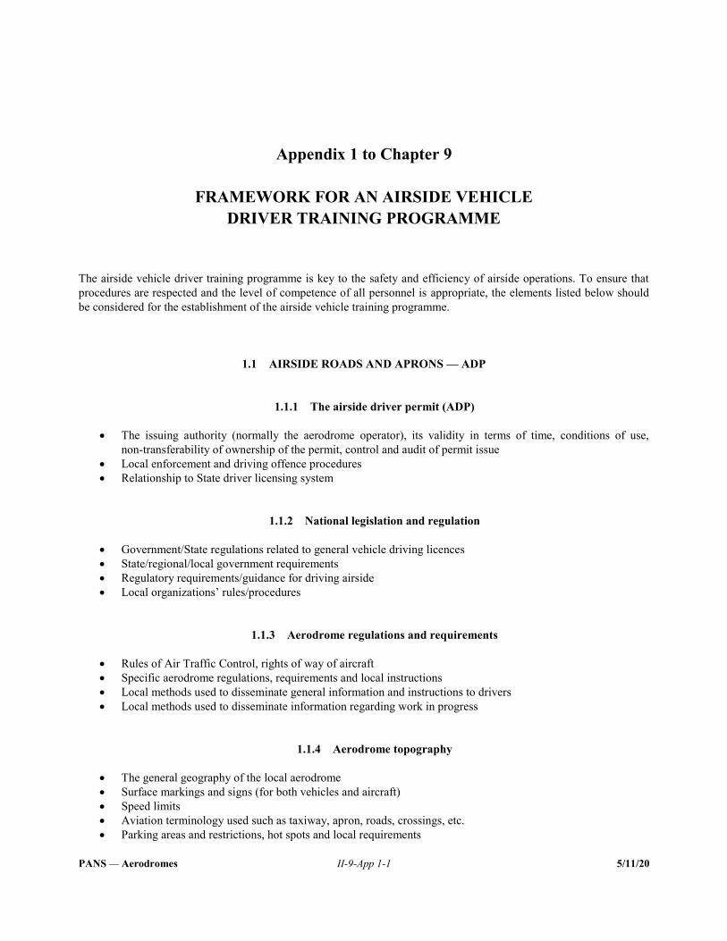
PANS — Aerodromes II-9-App 1-1 5/11/20
Appendix 1 to Chapter 9
FRAMEWORK FOR AN AIRSIDE VEHICLE DRIVER TRAINING PROGRAMME
The airside vehicle driver training programme is key to the safety and efficiency of airside operations. To ensure that procedures are respected and the level of competence of all personnel is appropriate, the elements listed below should be considered for the establishment of the airside vehicle training programme.
1.1 AIRSIDE ROADS AND APRONS — ADP
1.1.1 The airside driver permit (ADP)
The issuing authority (normally the aerodrome operator), its validity in terms of time, conditions of use, non-transferability of ownership of the permit, control and audit of permit issue
Local enforcement and driving offence procedures Relationship to State driver licensing system
1.1.2 National legislation and regulation
Government/State regulations related to general vehicle driving licences State/regional/local government requirements Regulatory requirements/guidance for driving airside Local organizations’ rules/procedures
1.1.3 Aerodrome regulations and requirements
Rules of Air Traffic Control, rights of way of aircraft Specific aerodrome regulations, requirements and local instructions Local methods used to disseminate general information and instructions to drivers Local methods used to disseminate information regarding work in progress
1.1.4 Aerodrome topography
The general geography of the local aerodrome Surface markings and signs (for both vehicles and aircraft) Speed limits Aviation terminology used such as taxiway, apron, roads, crossings, etc. Parking areas and restrictions, hot spots and local requirements
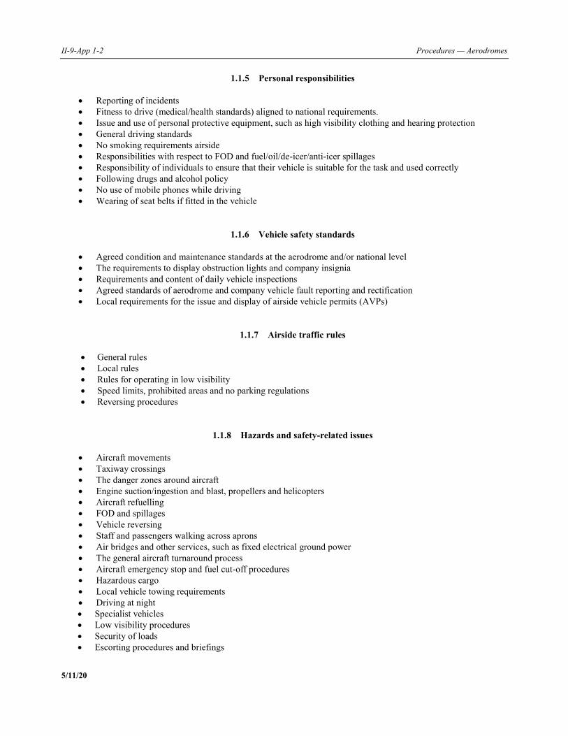
II-9-App 1-2 Procedures — Aerodromes
5/11/20
1.1.5 Personal responsibilities
Reporting of incidents Fitness to drive (medical/health standards) aligned to national requirements. Issue and use of personal protective equipment, such as high visibility clothing and hearing protection General driving standards No smoking requirements airside Responsibilities with respect to FOD and fuel/oil/de-icer/anti-icer spillages Responsibility of individuals to ensure that their vehicle is suitable for the task and used correctly Following drugs and alcohol policy No use of mobile phones while driving Wearing of seat belts if fitted in the vehicle
1.1.6 Vehicle safety standards
Agreed condition and maintenance standards at the aerodrome and/or national level The requirements to display obstruction lights and company insignia Requirements and content of daily vehicle inspections Agreed standards of aerodrome and company vehicle fault reporting and rectification Local requirements for the issue and display of airside vehicle permits (AVPs)
1.1.7 Airside traffic rules
General rules Local rules Rules for operating in low visibility Speed limits, prohibited areas and no parking regulations Reversing procedures
1.1.8 Hazards and safety-related issues
Aircraft movements Taxiway crossings The danger zones around aircraft Engine suction/ingestion and blast, propellers and helicopters Aircraft refuelling FOD and spillages Vehicle reversing Staff and passengers walking across aprons Air bridges and other services, such as fixed electrical ground power The general aircraft turnaround process Aircraft emergency stop and fuel cut-off procedures Hazardous cargo Local vehicle towing requirements Driving at night Specialist vehicles Low visibility procedures Security of loads Escorting procedures and briefings
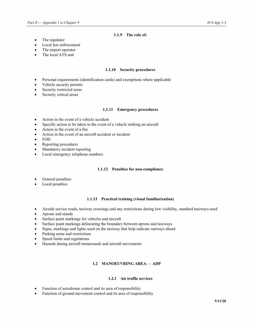
Part II — Appendix 1 to Chapter 9 II-9-App 1-3
5/11/20
1.1.9 The role of: The regulator Local law enforcement The airport operator The local ATS unit
1.1.10 Security procedures
Personal requirements (identification cards) and exemptions where applicable Vehicle security permits Security restricted areas Security critical areas
1.1.11 Emergency procedures
Action in the event of a vehicle accident Specific action to be taken in the event of a vehicle striking an aircraft Action in the event of a fire Action in the event of an aircraft accident or incident FOD Reporting procedures Mandatory incident reporting Local emergency telephone numbers
1.1.12 Penalties for non-compliance
General penalties Local penalties
1.1.13 Practical training (visual familiarization)
Airside service roads, taxiway crossings and any restrictions during low visibility, standard taxiways used Aprons and stands Surface paint markings for vehicles and aircraft Surface paint markings delineating the boundary between aprons and taxiways Signs, markings and lights used on the taxiway that help indicate runways ahead Parking areas and restrictions Speed limits and regulations Hazards during aircraft turnarounds and aircraft movements
1.2 MANOEUVRING AREA — ADP
1.2.1 Air traffic services
Function of aerodrome control and its area of responsibility Function of ground movement control and its area of responsibility
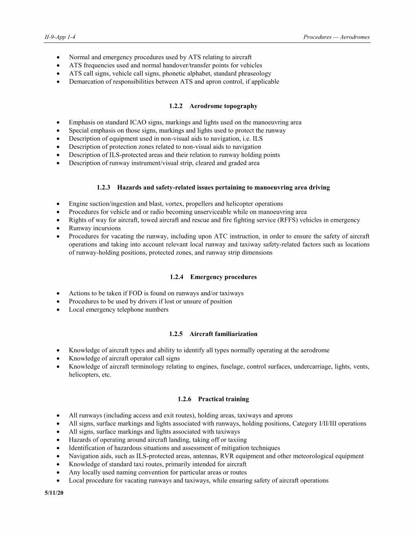
II-9-App 1-4 Procedures — Aerodromes
5/11/20
Normal and emergency procedures used by ATS relating to aircraft ATS frequencies used and normal handover/transfer points for vehicles ATS call signs, vehicle call signs, phonetic alphabet, standard phraseology Demarcation of responsibilities between ATS and apron control, if applicable
1.2.2 Aerodrome topography
Emphasis on standard ICAO signs, markings and lights used on the manoeuvring area Special emphasis on those signs, markings and lights used to protect the runway Description of equipment used in non-visual aids to navigation, i.e. ILS Description of protection zones related to non-visual aids to navigation Description of ILS-protected areas and their relation to runway holding points Description of runway instrument/visual strip, cleared and graded area
1.2.3 Hazards and safety-related issues pertaining to manoeuvring area driving
Engine suction/ingestion and blast, vortex, propellers and helicopter operations Procedures for vehicle and or radio becoming unserviceable while on manoeuvring area Rights of way for aircraft, towed aircraft and rescue and fire fighting service (RFFS) vehicles in emergency Runway incursions Procedures for vacating the runway, including upon ATC instruction, in order to ensure the safety of aircraft
operations and taking into account relevant local runway and taxiway safety-related factors such as locations of runway-holding positions, protected zones, and runway strip dimensions
1.2.4 Emergency procedures
Actions to be taken if FOD is found on runways and/or taxiways Procedures to be used by drivers if lost or unsure of position Local emergency telephone numbers
1.2.5 Aircraft familiarization
Knowledge of aircraft types and ability to identify all types normally operating at the aerodrome Knowledge of aircraft operator call signs Knowledge of aircraft terminology relating to engines, fuselage, control surfaces, undercarriage, lights, vents,
helicopters, etc.
1.2.6 Practical training
All runways (including access and exit routes), holding areas, taxiways and aprons All signs, surface markings and lights associated with runways, holding positions, Category I/II/III operations All signs, surface markings and lights associated with taxiways Hazards of operating around aircraft landing, taking off or taxiing Identification of hazardous situations and assessment of mitigation techniques Navigation aids, such as ILS-protected areas, antennas, RVR equipment and other meteorological equipment Knowledge of standard taxi routes, primarily intended for aircraft Any locally used naming convention for particular areas or routes Local procedure for vacating runways and taxiways, while ensuring safety of aircraft operations
Part II — Appendix 1 to Chapter 9 II-9-App 1-5
5/11/20
1.3 RADIOTELEPHONY
1.3.1 Hierarchy of message priority
Message priorities, understanding of distress, alerting, control and information messages
1.3.2 Phonetic alphabet
Correct pronunciation of letters, words and numbers Emphasis on drivers using standard phraseology similar to pilots
1.3.3 Aircraft, ATS and vehicle call signs
Understanding the terminology and acronyms used by ATS and pilots Knowledge of the aircraft operator call signs used at the aerodrome
1.3.4 Read-back of clearances and safety-related information
Vehicle drivers shall use standard read-back in the same manner as pilots for instructions, such as “enter/cross the runway”, and if conditional clearances are used.
Note 1.— Provisions on read-back of clearances and safety-related information by vehicle drivers operating on the manoeuvring area are contained in Annex 11 — Air Traffic Services.
Note 2.— Provisions on voice communications are contained in Annex 10 — Aeronautical Telecommunications, Volume II — Communication Procedures including those with PANS status, Chapter 5, and phraseologies to be used by pilots, ATS personnel and other ground personnel are contained in the Procedures for Air Navigation Services — Air Traffic Management (PANS-ATM, Doc 4444), Chapter 12.
1.3.5 Readability scale
Understanding the use of the readability scale from 1 to 5
1.3.6 Vehicle breakdown procedure
Local procedure for vehicle breakdown on runways or taxiways Procedure for indicating vehicle failure to the ANSP
1.3.7 Radio failure procedure
Understanding of the local procedure if radio failure occurs while on the runway or taxiway Understanding of light signals that may be used by ATS to pass instructions to vehicles
II-9-App 1-6 Procedures — Aerodromes
5/11/20
1.3.8 Transmitting techniques
Understanding the reasons for listening prior to transmitting Use of aviation English Words and sounds to be avoided Correct positioning of microphones to avoid distortion Avoidance of “clipped” transmissions Awareness of regional accents and variations of speech Speed of delivery of RTF phraseology
1.3.9 Portable radios
Correct use of radios Effective range and battery life Screening/shielding effects on the aerodrome Use of correct call signs, either relating to vehicle or an individual
1.3.10 Legal requirements (local to issuing aerodromes)
Local instructions regarding use of portable radios and hand-held microphones while driving a vehicle Local instructions on the use of mobile/cellular telephones while operating airside
_____________________
PANS — Aerodromes II-9-App 2-1 5/11/20
Appendix 2 to Chapter 9
AIRSIDE ROADS AND APRONS — ADP
1.1 REQUIREMENTS
1.1.1 It is a requirement for the issue of an ADP that the applicant is:
a) employed with an organization authorized to operate at the aerodrome; b) the holder of a current full State, or foreign equivalent driving licence which permits the holder to drive a motor
vehicle on public roads within the State; c) in possession of an operational requirement to drive a vehicle on the airside; d) medically fit to drive to State-equivalent standards; e) able to demonstrate the required driving competence; and f) able to demonstrate adequate language proficiency in the language normally used for airside operations at the
aerodrome. 1.1.2 The aerodrome operator shall set out the circumstances under which a permit will cease to be valid and must be surrendered for cancellation. Such circumstances may include:
a) cessation of the purpose for which the permit was issued; b) change of the holder’s employer; c) loss of driving licence for offences under the State’s road traffic regulations; d) any defacing, alteration, or misuse of a permit; e) proof of disregard of aerodrome traffic rules; and f) any use of a permit in relation to a customs or immigration offence.
1.2 REVALIDATION REQUIREMENTS
1.2.1 The airside roads and aprons permit may be valid for up to five years and falls due for revalidation at the anniversary of the date of issue. In order to be revalidated, the competence of the permit holder must be demonstrated, and employers must check that the driver still holds the necessary current State, or foreign equivalent driving licence.

II-9-App 2-2 Procedures — Aerodromes
5/11/20
1.2.2 Records of training and assessments for the airside roads and aprons permit should be retained. Third-party trainers/assessors must ensure that records are available for audit by the aerodrome operator.
1.3 COMMUNICATIONS SKILLS
1.3.1 It is the responsibility of the employer to ensure that the driver is proficient in the language normally used for airside operations at the aerodrome in order to complete the required training, competence assessments and designated activities on the aerodrome. Such proficiency may include:
a) the ability to complete the requisite driver training/familiarization; b) the ability to undertake successfully the operational communication requirements that may be required of
airside drivers, e.g. reporting an accident or incident on the airside; c) the ability to read and understand relevant local safety information, e.g. information and mandatory aerodrome
signs; and d) the ability to understand verbal instructions or notifications given by the police or aerodrome operations staff.
_____________________
PANS — Aerodromes II-9-App 3-1 5/11/20
Appendix 3 to Chapter 9
MANOEUVRING AREA PERMIT
1.1 REQUIREMENTS
1.1.1 The applicant shall fulfil the following requirements for the issue of a manoeuvring area permit:
a) Excluding runway:
1) as per an apron and airside roads permit, and demonstrate competence in RTF (see below, radiotelephony); and
2) require access to the manoeuvring area.
b) Including runway:
1) as per above (excluding runway); and
2) require access to the runway.
1.2 REVALIDATION REQUIREMENTS
1.2.1 Aerodrome operators shall ensure that drivers still hold the correct categories of licence for the public roads before renewing the ADP. This check should be carried out annually.
a) Excluding runway:
1) duration: up to five years; and
2) revalidation: competence should be maintained. This may be confirmed/assessed by a maintenance of competence scheme or refresher training, but in either case, must include appropriate assessments.
b) Including runway:
1) duration: up to three years; and
2) revalidation: competence should be maintained. This may be confirmed/assessed by a maintenance of
competence scheme or refresher training, but in either case, must include appropriate assessments.
II-9-App 3-2 Procedures — Aerodromes
5/11/20
1.3 MAINTENANCE OF COMPETENCE
1.3.1 The aerodrome operator should establish a system ensuring that drivers maintain competence in their driving rules, duties and procedures in those areas where they are permitted to drive. The aerodrome operator may delegate these functions to third-party driver trainers, vehicle operators or other parties, but in such circumstances, will need to conduct regular audits in order to assess the effectiveness of the training and assessment of drivers and the assessment and record-keeping of maintenance of competence of drivers. Such competence is additional to the continuing maintenance of competence to operate the vehicle/piece of equipment. 1.3.2 Examples of the areas to be assessed include, but are not limited to:
a) pushback procedures; b) towing (on the apron and on the manoeuvring area); c) runway access; d) radiotelephony; e) aerodrome topography; f) general airside driving; g) vehicle check; and h) table-top discussions.
1.4 RADIOTELEPHONY
1.4.1 The movement of vehicles on the manoeuvring area is ordinarily subject to authorization by air traffic services (ATS). Depending on the complexity of the aerodrome, ATS may operate a number of radio frequencies. Typically in these cases, the aerodrome ground controller will be responsible for all vehicles operating on the taxiways, and the air controller will be responsible for all vehicles wishing to enter or cross the runway(s). It is essential that all vehicles required to be under positive control on the manoeuvring area are equipped with the appropriate radio communication devices tuned to the appropriate frequencies. 1.4.2 All drivers of vehicles operating on the manoeuvring area shall have an appropriate level of competence with respect to the use of RTF phraseology. 1.4.3 The aerodrome operator shall establish a system of allocating RTF call signs to be used by vehicles, so that the potential for confusion between vehicles and aircraft is minimized. This is particularly important at aerodromes where the RTF frequency used by vehicles is the same as that used by aircraft, or where the RTF frequency used by vehicles is re-broadcast on the RTF frequency used by aircraft. 1.4.4 The ANSP shall be made aware of all radio call signs used at the aerodrome, whether or not they are used for communication with ATS.
_____________________
PANS — Aerodromes II-9-App 4-1 5/11/20
Appendix 4 to Chapter 9
AIRSIDE DRIVER PERMIT RECORDS
1. RECORD KEEPING
1.1 A suitable means should be provided for the secure storage of information relating to ADPs. The information should include: a) identification number; b) name; c) date of birth; d) employer; e) name of training organization; f) name of trainer; g) date of completion of training; h) date of validation; i) assessment results; j) date of revalidation; k) infringement notices; l) type of permit held; m) driving history (accidents/incidents); n) State licence checks; o) any required medical evidence; and p) copies of self-declarations of fitness or approved declarations by an occupational health practitioner. 1.2 The information described above may be kept in any suitable format and made available for audit.
— END —


Related Documents