DOC # 705304-101 REVISION # C SUPERSEDE B RELEASE DATE 2010-01-26 DOC TYPE WORK INSTR FLEXTRONICS LABORATORY MANAGEMENT SYSTEM EMC LABORATORY 213 Harry Walker Parkway South NEWMARKET, ON, L3Y 8T3 Tel: 905-952-1242 HAEFELY ESD TARGET VERIFICATION Page 1 of 13 Copyright © www.flexautomotive.net - Christian Rosu, 2009, All rights reserved. ESD TARGET VERIFICATION PER ISO 10615:2001 & 10615:2008 1. PURPOSE 1.1. To provide specific test method setup configuration instructions in full compliance with OEM specifications and international standards. 2. SCOPE 2.1. To establish consistency and repeatability in test method results using the equipment and technical resources available in EMC laboratory inventory. 3. RESPONSABILITY 3.1. EMC laboratory authorized personnel. 4. EQUIPMENT AND MATERIALS 4.1. All test equipment that requires calibration shall be within its calibration period and shall be traceable to A2LA certified labs. 4.2. EMC lab personnel must ensure that certificates of calibration are obtained when equipment is sent out for calibration or repair. Fig.4-1

Welcome message from author
This document is posted to help you gain knowledge. Please leave a comment to let me know what you think about it! Share it to your friends and learn new things together.
Transcript

DOC # 705304-101
REVISION # C
SUPERSEDE B
RELEASE DATE 2010-01-26
DOC TYPE WORK INSTR
FLEXTRONICS LABORATORY MANAGEMENT SYSTEM
EMC LABORATORY 213 Harry Walker Parkway South
NEWMARKET, ON, L3Y 8T3 Tel: 905-952-1242
HAEFELY ESD TARGET VERIFICATION
Page 1 of 13Copyright © www.flexautomotive.net - Christian Rosu, 2009, All rights reserved.
ESD TARGET VERIFICATION PER ISO 10615:2001 & 10615:2008
1. PURPOSE
1.1. To provide specific test method setup configuration instructions in full compliance with OEM specifications and international standards.
2. SCOPE
2.1. To establish consistency and repeatability in test method results using the equipment and technical resources available in EMC laboratory inventory.
3. RESPONSABILITY
3.1. EMC laboratory authorized personnel.
4. EQUIPMENT AND MATERIALS
4.1. All test equipment that requires calibration shall be within its calibration period and shall be traceable to A2LA certified labs.
4.2. EMC lab personnel must ensure that certificates of calibration are obtained when equipment is sent out for calibration or repair.
Fig.4-1

DOC # 705304-101
REVISION # C
SUPERSEDE B
RELEASE DATE 2010-01-26
DOC TYPE WORK INSTR
FLEXTRONICS LABORATORY MANAGEMENT SYSTEM
EMC LABORATORY 213 Harry Walker Parkway South
NEWMARKET, ON, L3Y 8T3 Tel: 905-952-1242
HAEFELY ESD TARGET VERIFICATION
Page 2 of 13Copyright © www.flexautomotive.net - Christian Rosu, 2009, All rights reserved.
Tbl.4-1 IDX TITLE DESCRIPTION MODEL / MAKER INVENTORY#
1. ESD SYSTEM PESD 3010 (1 to 30 KV)
ESD generator serial# 249963 Capacitor Module 330 pF Capacitor Module 150 pF Resistor Module 330 OHM Resistor Module 2000 OHM
H507174 / Haefely INV2267
2. Coaxial target - as specified in IEC 61000-4-2 2 Ohm Shunt (target verification) serial# 153476 Haefely
3.Electrometer with minimum input resistance of 100 GOHM used to verify the ESD simulator charging voltage. voltage
serial# 18103 Sensitive Research INV1744
4. Reference plane at least 1,2 m × 1,2 m & coaxial current target Haefely
5.Wideband attenuator - 50 OHM, 20 dB attached to the output of the coaxial target during the ESD simulator verification ISO-10605:2001 ANNEX-A
Haefely
6. Double shielded coaxial cable less than 2 meter long.
7. Ground strap
8. Oscilloscope TDS-784A serial# B010315 Tektronix INV2282
DOC # 705304-101
REVISION # C
SUPERSEDE B
RELEASE DATE 2010-01-26
DOC TYPE WORK INSTR
FLEXTRONICS LABORATORY MANAGEMENT SYSTEM
EMC LABORATORY 213 Harry Walker Parkway South
NEWMARKET, ON, L3Y 8T3 Tel: 905-952-1242
HAEFELY ESD TARGET VERIFICATION
Page 3 of 13Copyright © www.flexautomotive.net - Christian Rosu, 2009, All rights reserved.
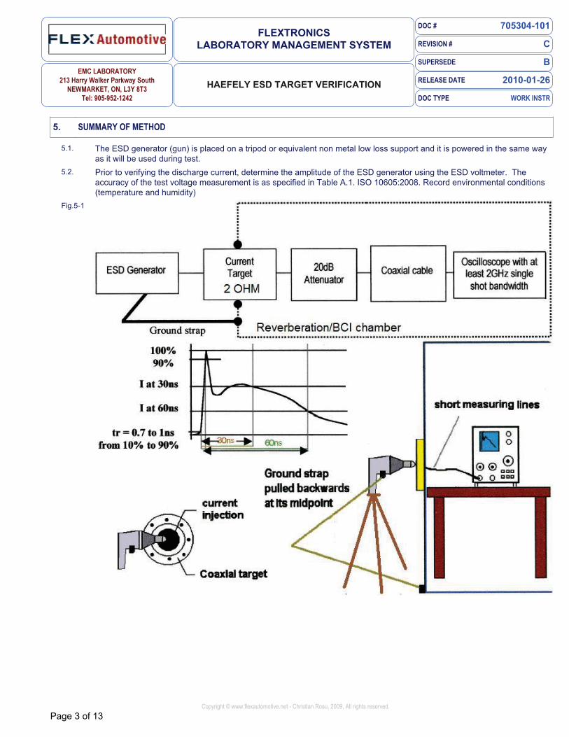
5. SUMMARY OF METHOD
5.1. The ESD generator (gun) is placed on a tripod or equivalent non metal low loss support and it is powered in the same way as it will be used during test.
5.2. Prior to verifying the discharge current, determine the amplitude of the ESD generator using the ESD voltmeter. The accuracy of the test voltage measurement is as specified in Table A.1. ISO 10605:2008. Record environmental conditions (temperature and humidity)
Fig.5-1
DOC # 705304-101
REVISION # C
SUPERSEDE B
RELEASE DATE 2010-01-26
DOC TYPE WORK INSTR
FLEXTRONICS LABORATORY MANAGEMENT SYSTEM
EMC LABORATORY 213 Harry Walker Parkway South
NEWMARKET, ON, L3Y 8T3 Tel: 905-952-1242
HAEFELY ESD TARGET VERIFICATION
Page 4 of 13Copyright © www.flexautomotive.net - Christian Rosu, 2009, All rights reserved.
6. SAFETY PRECAUTIONS
6.1. The operating temperature per ISO 10605:2008 is relaxed from 23±5°C to 25±10°C.
6.2. Allowing testing to 15°C could lead to possible electrical shock accidents (dew could form on the test equipment, the device under test or other objects and form and unexpected discharge path).
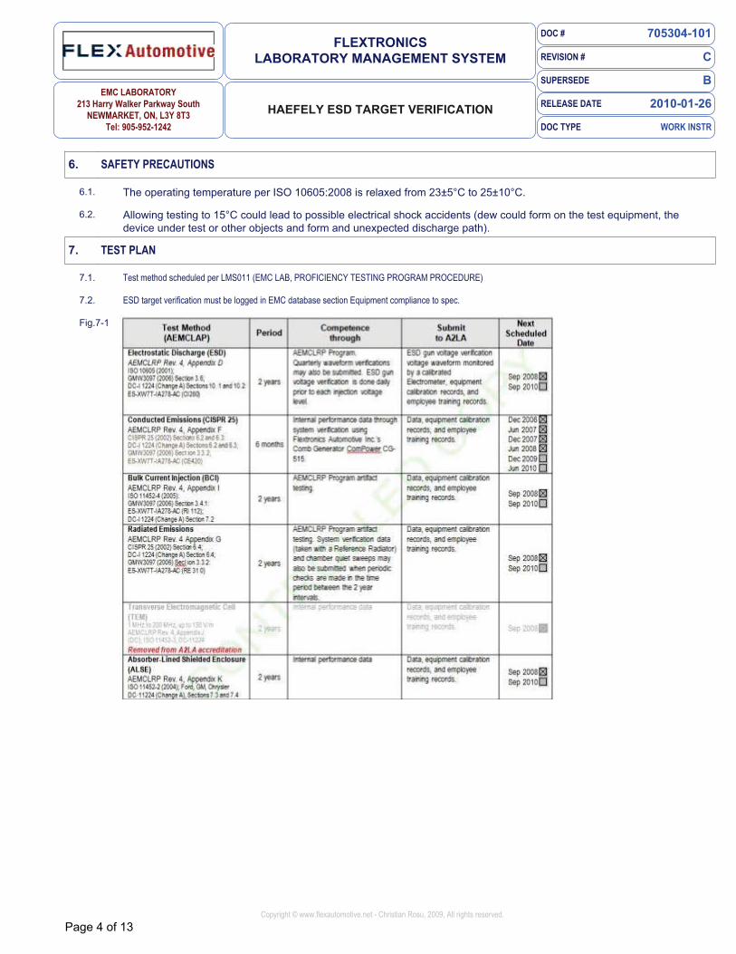
7. TEST PLAN
7.1. Test method scheduled per LMS011 (EMC LAB, PROFICIENCY TESTING PROGRAM PROCEDURE)
7.2. ESD target verification must be logged in EMC database section Equipment compliance to spec.
Fig.7-1

DOC # 705304-101
REVISION # C
SUPERSEDE B
RELEASE DATE 2010-01-26
DOC TYPE WORK INSTR
FLEXTRONICS LABORATORY MANAGEMENT SYSTEM
EMC LABORATORY 213 Harry Walker Parkway South
NEWMARKET, ON, L3Y 8T3 Tel: 905-952-1242
HAEFELY ESD TARGET VERIFICATION
Page 5 of 13Copyright © www.flexautomotive.net - Christian Rosu, 2009, All rights reserved.
8. ESD VOLTAGE VERIFICATION
8.1. Calibrate the display voltage of the simulator by adjusting the ESD simulator voltage to the desired level and polarity.
8.2. Using the electrometer specified in 4.8, verify the voltage setting of the simulator at voltage levels of ± 2 kV, ± 4 kV, ± 6 kV, ± 8 kV, ± 15 kV and ± 25 kV.
8.3. The readings shall be within ± 500 V for voltages less than ± 5 kV and ± 10 % for voltages greater than ± 5 kV.
Fig.8-1
Tbl.8-1 IDX DISCHARGE NETWORK (example report table)
TEST VOLTAGE & TOLERANCE Temperature: 22 C, Humidity: 32% POLARITY READING
1. 150 pF & 2000 OHM (ISO-10605:2001) e.g. 15 KV (+/- 10%) + 14.8 KV
2. 150 pF & 2000 OHM (ISO-10605:2001) e.g. 15 KV (+/- 10%) - 14.8 KV
3. 330 pF & 2000 OHM (ISO-10605:2001) e.g. 25 KV (+/- 10%) + 26.5 KV
4. 330 pF & 2000 OHM (ISO-10605:2001) e.g. 25 KV (+/- 10%) - 26.5 KV
5. 150 pF & 330 OHM (Chrysler)
6. 330 pF & 330 OHM (Chrysler)
DOC # 705304-101
REVISION # C
SUPERSEDE B
RELEASE DATE 2010-01-26
DOC TYPE WORK INSTR
FLEXTRONICS LABORATORY MANAGEMENT SYSTEM
EMC LABORATORY 213 Harry Walker Parkway South
NEWMARKET, ON, L3Y 8T3 Tel: 905-952-1242
HAEFELY ESD TARGET VERIFICATION
Page 6 of 13Copyright © www.flexautomotive.net - Christian Rosu, 2009, All rights reserved.
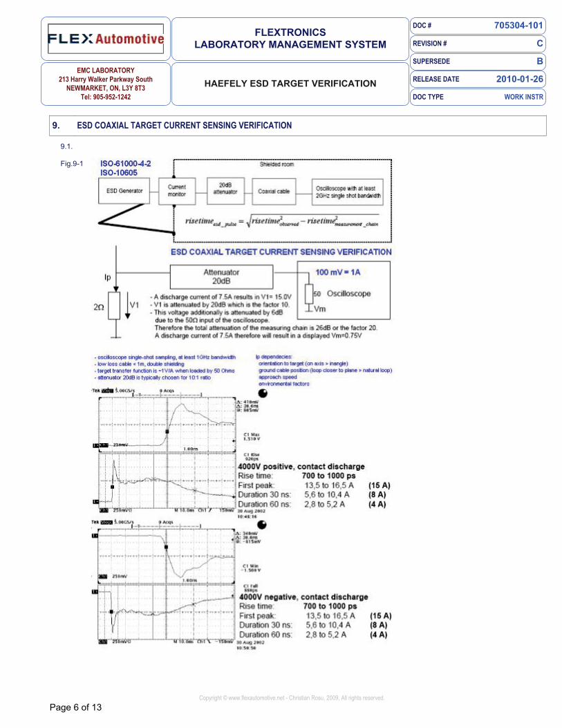
9. ESD COAXIAL TARGET CURRENT SENSING VERIFICATION
9.1.
Fig.9-1

DOC # 705304-101
REVISION # C
SUPERSEDE B
RELEASE DATE 2010-01-26
DOC TYPE WORK INSTR
FLEXTRONICS LABORATORY MANAGEMENT SYSTEM
EMC LABORATORY 213 Harry Walker Parkway South
NEWMARKET, ON, L3Y 8T3 Tel: 905-952-1242
HAEFELY ESD TARGET VERIFICATION
Page 7 of 13Copyright © www.flexautomotive.net - Christian Rosu, 2009, All rights reserved.
10. SIMULATOR'S RESISTIVE-CAPACITIVE (RC) TIME CONSTANT VERIFICATION
10.1. Set the horizontal time base and vertical amplifier level of the measurement instrument to enable the complete ESD waveform to be viewed. Set the horizontal sweep to single-event trigger.
10.2. Verify the RC time constant of the ESD simulator, for both probes if both are used, at 15 kV (air discharge) only, at both positive and negative polarities.
10.3. Move the simulator to the target very slowly, i.e. at ~ 5 mm/s.
10.4. Review the waveform and analyze its key parameters per ISO-10605:2001: a) RC time constant is (600 ± 130) ns for the 330 pF probe b) RC time constant is (300 ± 60) ns for the 150 pF probe
10.5. Verify that the RC time constant is (600 ± 130) ns for the 330 pF probe. Verify that the RC time constant is (300 ± 60) ns for the 150 pF probe
11. TEST SETUP
11.1. The vertical calibration plane with the coaxial current target is mounted in such a way that there is at least 0,6 m from the target to any edge of the plane.
11.2. The current target is mounted at the centre of the vertical calibration plane (reverberation chamber wall); .
11.3. The connection for the ESD generator return current cable (ground strap) is made at the bottom centre of the plane 0,5 m below the target (IEC 61000-4-2:2008).
11.4. The ground strap is pulled backwards at the middle of the cable, forming an isosceles triangle. It is not allowed to let the ground strap lay on the floor during calibration.
Fig.11-1

DOC # 705304-101
REVISION # C
SUPERSEDE B
RELEASE DATE 2010-01-26
DOC TYPE WORK INSTR
FLEXTRONICS LABORATORY MANAGEMENT SYSTEM
EMC LABORATORY 213 Harry Walker Parkway South
NEWMARKET, ON, L3Y 8T3 Tel: 905-952-1242
HAEFELY ESD TARGET VERIFICATION
Page 8 of 13Copyright © www.flexautomotive.net - Christian Rosu, 2009, All rights reserved.
12. TEST PROCEDURE
12.1. Connect the target output to the oscilloscope using a 50 OHM shielded cable with high shielding integrity (e.g. double shielded) of less than 2 m in length.
12.2. Ensure the 50 OHM shielded cable is not looped and it is insulated from the ground plane.
12.3. The Faraday shielded enclosure used to separate the target from the oscilloscope is in our case the Reverberation Chamber.
12.4. Set the horizontal time base and vertical amplifier level of the oscilloscope to enable the rise-time of the ESD waveform to be viewed.
12.5. Set the horizontal sweep to single event trigger.
12.6. Connect the ESD simulator high-voltage ground directly to the Reverberation Chamber wall.
12.7. Set up the ESD simulator and turn it on in accordance with its instruction manual.
12.8. Perform test per ISO10605:2008 Table A.1 — Contact discharge verification procedure
12.9. Save each valid ESD waveform acquired via oscilloscope on floppy disk.
Fig.12-1

DOC # 705304-101
REVISION # C
SUPERSEDE B
RELEASE DATE 2010-01-26
DOC TYPE WORK INSTR
FLEXTRONICS LABORATORY MANAGEMENT SYSTEM
EMC LABORATORY 213 Harry Walker Parkway South
NEWMARKET, ON, L3Y 8T3 Tel: 905-952-1242
HAEFELY ESD TARGET VERIFICATION
Page 9 of 13Copyright © www.flexautomotive.net - Christian Rosu, 2009, All rights reserved.
13. TEST REPORT - RISE TIME
13.1. Per ISO10605:2008 Table A.1 — Contact discharge verification procedure.
13.2. Report the discharge network used, ESD voltage, temperature (23 ± 5) o C and humidity (between 30 % and 60 %).
Fig.13-1

DOC # 705304-101
REVISION # C
SUPERSEDE B
RELEASE DATE 2010-01-26
DOC TYPE WORK INSTR
FLEXTRONICS LABORATORY MANAGEMENT SYSTEM
EMC LABORATORY 213 Harry Walker Parkway South
NEWMARKET, ON, L3Y 8T3 Tel: 905-952-1242
HAEFELY ESD TARGET VERIFICATION
Page 10 of 13Copyright © www.flexautomotive.net - Christian Rosu, 2009, All rights reserved.
14. TEST REPORT - RC TIME CONSTANT PER ISO-10605:2001
14.1. See chapter 12 (Test procedure) for clarification on how to measure the RC time constant per ISO-10605:2001.
14.2. For each discharge network, test voltage, and polarity report the calculated RC time constant for both AEMCLRP and ISO-10605 methods. Use the same ESD target verification aquired plot whenever is possible.
Fig.14-1

DOC # 705304-101
REVISION # C
SUPERSEDE B
RELEASE DATE 2010-01-26
DOC TYPE WORK INSTR
FLEXTRONICS LABORATORY MANAGEMENT SYSTEM
EMC LABORATORY 213 Harry Walker Parkway South
NEWMARKET, ON, L3Y 8T3 Tel: 905-952-1242
HAEFELY ESD TARGET VERIFICATION
Page 11 of 13Copyright © www.flexautomotive.net - Christian Rosu, 2009, All rights reserved.
15. TEST REPORT - RC TIME CONSTANT PER AEMCLRP
15.1. IMPORTANT: Per AEMCLRP "In determining the RC time constant, the RC time constant shall be calculated in the exponentially decaying portion of the waveform after the leading edge and/or ringing".
15.2. For each discharge network, test voltage, and polarity report the calculated RC time constant for both AEMCLRP and ISO-10605 methods. Use the same ESD target verification aquired plot whenever is possible.
Fig.15-1

DOC # 705304-101
REVISION # C
SUPERSEDE B
RELEASE DATE 2010-01-26
DOC TYPE WORK INSTR
FLEXTRONICS LABORATORY MANAGEMENT SYSTEM
EMC LABORATORY 213 Harry Walker Parkway South
NEWMARKET, ON, L3Y 8T3 Tel: 905-952-1242
HAEFELY ESD TARGET VERIFICATION
Page 12 of 13Copyright © www.flexautomotive.net - Christian Rosu, 2009, All rights reserved.
16. DEFINITIONS
16.1. Ip = peak value of the discharge current [A] (IEC-6100-4-2:2008)
16.2. I30 = value of the current 30 ns after the peak current has reached 0,1 times Ip [A] (IEC-6100-4-2:2008); I1 per ISO10605:2008
16.3. I60 = value of the current 60 ns after the peak current has reached 0,1 times Ip [A] (IEC-6100-4-2:2008); I2 per ISO10605:2008
16.4. tr = rise time of the current [ns] (from 0,1 Ip1 to 0,9 I p1 )
16.5. RC time constant = simulator's resistive-capacitive (RC) time constant (ISO10605:2001) (from Ip2 to 0,37 I p2 )
16.6. Vs = Simulator voltage
16.7. Ip1 = First vertical peak
16.8. Ip2 = Second vertical peak
REFERENCES
ISO 10605:2001 ED 1.2
ISO 10605:2008 ED 2.0
IEC 61000-4-2:2001 1-st Ed
IEC 61000-4-2:2009 2-nd Ed
REVISION CHANGES
Jan 15, 2010 A RELEASE
Jan 26, 2010 B RC Time Constant measurement clarification per AEMCLRP
END-USER FEEDBACK
very satisfied satisfied neutral dissatisfied very dissatisfied
Please rate your overall satisfaction with this LMS document and input your suggestions or comments. Your opinion is very important for us.
Survey Date

DOC # 705304-101
REVISION # C
SUPERSEDE B
RELEASE DATE 2010-01-26
DOC TYPE WORK INSTR
FLEXTRONICS LABORATORY MANAGEMENT SYSTEM
EMC LABORATORY 213 Harry Walker Parkway South
NEWMARKET, ON, L3Y 8T3 Tel: 905-952-1242
HAEFELY ESD TARGET VERIFICATION
Page 13 of 13Copyright © www.flexautomotive.net - Christian Rosu, 2009, All rights reserved.
Related Documents