DO0C U M NHT SERVICE C HT E R -ARMED 5SR VI C f.ST9C ffN ICAL -NFORUA T 101 AGE9 MCYIhIhEhfE I T "NQTIQE.- When Governm'en~t or otli'. drawings, specifications or ;Y&Aer data are used for any purxirse oth~er than~ In connection with a definitely related Goverprnient procu~rem~ent operation, the U.S. Government thereby ftaxrs no responsibility, nor any obligation whatsoever; and the fact that the Governm~ at may have formulated, furnished. ',- in any way supplied the said~ Irawiings, specifications or otkar data Is not to be regarded by himplication or otherwise as 'iany awl~ner licensing the holdier or any other person or corpora- tion, or Conveying any rights or permission to manufacture, use or s~ell any patented invention that may in any way be related thereto." * 4ASII

Welcome message from author
This document is posted to help you gain knowledge. Please leave a comment to let me know what you think about it! Share it to your friends and learn new things together.
Transcript

DO0C U M NHT SERVICE C HT E R
-ARMED 5SR VI C f.ST9C ffN ICAL -NFORUA T 101 AGE9 MCYIhIhEhfE
I T
"NQTIQE.- When Governm'en~t or otli'. drawings, specifications or;Y&Aer data are used for any purxirse oth~er than~ In connection witha definitely related Goverprnient procu~rem~ent operation, the U.S.Government thereby ftaxrs no responsibility, nor any obligationwhatsoever; and the fact that the Governm~ at may have formulated,furnished. ',- in any way supplied the said~ Irawiings, specificationsor otkar data Is not to be regarded by himplication or otherwise as'iany awl~ner licensing the holdier or any other person or corpora-
tion, or Conveying any rights or permission to manufacture, use ors~ell any patented invention that may in any way be related thereto."
* 4ASII

*Ct~
S...I
VDICEBASE
iL1..GA 0..1 7p I)OftMA't
(ciLI$ iw A IR
~~~~EP - ~ l 4 r~;:-.~. ' ~*j.
51 1 YlSLS'f E

AF TECHNICAL REPORT NO. 6590 C
LANDING-GEAR VIBRATION
WILLIAM 1. MORELANDFLIGHT RESEARCH LABORATORY
OCTOBER 1951
IRIGHT AIR DEVELOPMENT CENTER

IAF TECHNICAL REPORT NO, 6590
LANDICG.GEAR VIBRATION
William J. MorelaJd
Fligbt Research Laboratory
October 1951
RDO No. 461-1-13
Wright Air Development Center
Air Research and Development Command
United States Air Force
Wr1%t.Pattereoo Air Force Base, Dayton, Ohio
ot. wo A Wet*1't. w a.)WA*I. mewa
4 1~

FOREWORD
This report was prepared at the Flight Research Laboratory, Wright
Air Development Center, by W. J. Moreland project engineer on RDO
Number 461-1-15, "Landing Gear Vibration." The request for this pro-
ject was initiated by Mr. Frank Minch and Dr. 0. R. Rogers of the
Aircraft Laboratory. The arrangements of the equations for computation
were carried out by Paul E. Gies and George H. Moore of the Flight
Research Laboratory, Wright Air Development Center, Dayton, Ohio.
AFTR 6590

ABSTRACT
The self-excited vibration of a landing gear is generated in an
interplay of effects present in the tire, the landing gear proper,
and in the entire airframe itself. The analysis of these simultaneous
actions is given in simple form; the manner in which energy enters
the system, and the necessary structural modifications to control
shimmy are explained.
PUBLICATION REVIEW
Manuscript copy of this report has been reviewed and found satis-
factory for publication.
FOR THE COMMANDING GENERAL:
B. WILLIAMS
Lt. Colonel, USAF
Chief, Flight Uesearch Laboratory
Research Oivision
AFTR 5590 111

TABLE OF CONTENTS
I. INTRODUCTION 1
II. THE THIRD ORDER SYSTEM 2
III. THE FOURTH ORDER SYSTEM 14
IV. THE INFLUENCE OF THE AIRFRAME 36
V. THE USE OF THE CHARTS • 49
VI. GENERAL NOTES . . - 52
APPENDIX A - THE SIXTH ORDER SYSTEM • • • • 57
APPENDIX B - TIRE ELASTICITY Q1
APPENDIX C - VIRTUAL ELASTICITY . 65
BIBLIOGRAPHY - 69
AFTR.6590 iv

LIST OF ILLUSTRATIONS
FIGURE PAGE
1 NOSE WHEEL ASSEMBLY 3
2 SCHEMATIC OF NOSE WHEEL ASSEMBLY FOR THIRD
ORDER SYSTEM . . 4
3 KINEMATICS OF SWIVELING MEMBER . 5
4 GEOMETRY OF THE MOTION OF THE SWIVELING MEMBER .... 6
5 ENERGY ANALYSIS DIAGRAM 10
6 FOURTH ORDER SYSTEM .... 15
7a, b DAMPING RATIO FOR NEUTRAL STABILITY VS.
INERTIO RATIO 21-22
7c STABILITY SURFACE 23
7d STABILITY INTENSITY DIAGRAM ..... 24
8a, b, c DAMPING RATIO FOR NEUTRAL STABILITY VS. VELOCITY ... 28-30
9a CURVES SHOWING EFFECT OF VELOCITY AND TRAIL
ON NOSE WHEEL STABILITY 31
9b CURVES SHOWING EFFECT OF INERTIA RATIO MD TRAIL
ON NOSE WHEEL STABILITY 32
10 NOSEGEAR ELASTICITY VS. FREQUENCY ..... 35
11 SINGLE MODE AIRFRAME . 38
12 GROUND SHAKE TEST EQUIPMENT ARRANGEMENT 39
13 VIRTUAL AIRFRAME ELASTICITY VS. FREQUENCY 41
14 EFFECT OF AIRFRAME ELASTICITY ON NOSEGEAR STABILITY. . 42
15 MULTIPLE-MODE AIRFRAME 45
16 EFFECT OF AIRFRAME ELASTICITY ON NOSEGEAR STABILITY
FOR MULTIPLE-MODE SYSTEM 47
17 REAL AND IMAGINARY ROOT COMPONENTS OF 6th ORDER EQUATION VS. "R" 48
A-l FOURTH ORDER SYSTEM WITH MULTIPLE-MODE AIRFRAME ... 57
B-l DIAGRAM OF TIRE CHARACTERISTICS 61
B-2 EFFECTS OF RIGID AND NONRIGID TIRES 64
C-l EQUIVALENT AIRFRAME SYSTEM 65
AFTR 6590

SYMBOLS
QUANTITY UNITS
A Amplitude of pivot displacement in
a Horizontal distance betveen Pt and CG. in
Cc Reference damping coefficient (2 \^^w ) in-lb-sec
C+ Torsional damping coefficient in- lb-sec
D Differential operator notation
F] Lateral force on swiveling structure at P2 lbs
F Ground force acting normal to wheel at P± lbs
F Force at P2 parallel to flight path lbs
f a/L
I„ Moment of inertia of swiveling structure about center of gravity in-lb-sec
2 I Diametral moment of inertia of the wheel in-lb-sec
KltK2 Lumped airframe and nose gear elasticities lbs/in
Kv Virtual spring constant of non-swiveling structure lbs/in
Kt Torsional spring constant of nose gear in-lbs/radian
L Trail of wheel axis behind axis of rotation of swivel in
M Mass of airplane lb-sec /in
M1,M2 Lumped airframe masses lb-sec /in
Mr (1 ~ f)m/N
m Mass of swiveling structure lb-sec /in
siji Mass of non-swiveling structure lb-sec /in 2
*„ Mass of spindle lb-sec /in s 2
Mass of wheel lb-sec /in
2 N (m± + fm) lb-sec /in
AFTR 6590 vi

p Tire compressibility
Q CcV/KtL (Velocity ratio)
R Ratio of Ct to Cc (Damping ratio)
r1,r2,r2i Dimensionless frequencies
S 4 KtNL2/Cl (Mass ratio)
s Displacement along flight path per cycle
T
T*IS
U
V
w
in/lb
x
L /\JK1/Kt (Trail Ratio)
K1Iw/NKt (Inertia ratio)
PK±
Forward velocity of airplane
K^CV/kO V^'i/iV
Displacement of P2 from equilibrium position
Displacement of C.G. from equilibrium position
Displacement of wheel
Angle made by wheel with flight path
Angular displacement of damper piston from it% normal posit ion
Period of vibration
Circular frequency
in
in/sec
in
in
in
radians
radians
sec/cycle
radians/sec
AFTR 6590 V Ll

1
I. INTRODUCTION
Self-excited vibration in a landing gear nose wheel takes place
because a component of the contact force between the wheel and the
ground causes a drag against the forward motion of the aircraft. The
energy transferred to the nose gear by this single force results in
the violent motion called shimmy. If a precise mathematical descrip-
tion of this simple phenomenon were attempted it would involve so
many parameters that solution of the problem and interpretation of
the results become impractical, if not impossible. For example, in
the nose gear proper, the stability of the system is influenced by
the wheel load, spin-up and aerodynamic forces, gyroscopic and tire
properties and, most important, nonlinearities and airframe modes
of motion. However, the difficulties in the way of solution are due
to the mere number of factors, and, if it can be established that
some of these are more significant than others, the problem can be
simplified. In this study it has been shown that the main character-
istics of shimmy are dependent on the relationship of a single non-
dimensional number called the "inertia ratio" and the airframe
dynamics. Also, the theory developed here accounts for instability
at zero trail (Schlippe reports instability at zero trail is caused
by tire effects only), and the fall and rise of stability as the
trail increases. The dependence of stability on mass distribution
( NACA TN 760 ), and of frequency and damping on velocity (R.A.E.-
A.D. 7/5166/G. Temple ) is brought out. Guruewicz and Kruse ( ATI-
23097, translation ) comment on the "unaccountable presence of
superimposed oscillations." This effect is predicted by the theory
that follows.
The landing gear of an aircraft is at best an awkward mechanical
AFTR 6590 1

structure. The designer is beset with a number of conflicting require-
ments and functions to perform. The gear must be able to withstand
static and dynamic loading; it must have directional stability and
permit maneuvering; it must be vertically flexible and retractable;
it must be light and of minimum overall dimensions; and it must meet
all of these requirements in extremes of enviornmental conditions.
The final design must of necessity be a compromise, and any solution
which optimises one function is not likely to be satisfactory. It is
probable, however, that much more can be achieved toward the goal
of a dynamically stable system without precision artifical damping
if close attention is given to the influence of the various physical
parameters.
In order to simplify the development of the analysis, systems of
two, three and four degrees of freedom are examined in that order.
If the effect of tire elasticity is included there is little to be
gained since the results cannot be expressed with sufficient clarity
to be useful in design. It is, however, significant to compare the
behavior of the system with and without tire elasticity by means of
an analog computer. In all the cases tested it was shown that when
the simple system was stable the higher order systen, was not less
stable. This problem is discussed in more detail in Appendix (B).
II. THE THIRD ORDER SYSTEM
The purpose of analyzing this idealized system is to explain:
a. That instability may exist for a system in which the ground
forces enter inelastically.
b. The manner in which energy is transferred from the forward
motion of the aircraft to the oscillatory motion of shimmy.
APTR 6590 2

Description of the System:
The basic components of the nose wheel assembly are shown in
Fig. 1 and in the schematic diagram Fig. 2. The assumption is made
that the system consists of two parts - the swiveling structure of
mass m which is in contact with the ground through the wheel at Plt
and the non-swiveling structure of mass m± which is made up of all
parts not subject to the angular motion 9. These two parts are in
contact at the oleo bearing P2.
TRUNNION
SHOCK STRUT
LOWER RETRACTING LIN
NOSE WHEEL STEERIN 8 DAMPING MECHANISM
DIRECTION OF^V FORWARD MOTION
SCISSORS
NOSE WHEEL
NOSE WHEEL ASSEMBLY
FIGURE 1
APTR 6590

WHEEL, m
SCHEMATIC OF NOSE WHEEL ASSEMBLY FOR THIRD ORDER SYSTEM
FIGURE 2
The following assumptions are made in the analysis:
a. The non-swiveling structure (including the adjacent fuselage)
is joined to a fixed support. The elastic restoring force on
this mass m± due to the combined bending and twisting of the
fuselage is taken proportional to x, with Ki the equivalent
elasticity.
b. The wheel has neither side-slip nor distortion.
c. The swiveling member is rigid.
Kinematics of the Motion:
The component velocities of P± and P2, along the line joining
them are equal and since Px has no normal velocity, the angular
velocity of L can be found from the normal velocity of P2. In Fig. 3,
the velocity of the point P2 relative to Px is - LB. But since P± has
no velocity normal to the link L, the normal velocity of P2 is also
AFTR 5590

KINEMATICS OF SWIVELING MEMBER
FIGURE 3
the relative velocity of P2 to Px. Hence for small values of 9,
-LQ = x + VQ
_e = JL + m L L
(1)
Eq. 1 shows that the two degrees of freedom are kinematically coupl-
ed. Eq. 1 can be developed to show the nature of the motion of the
system.
From Fig. 4, let
Y = * + LQ
■••9 ■ V
Y - x L
Substitute in (1)
- Y + x = x + ^ (Y - x)
AFTR 6590

GEOMETRY OF THE MOTION OF THE SWIVELING MEMBER
FIGURE 4
-Y = £ (Y - x) = ve (1A)
If the motion of P2 is assumed sinusoidal and of amplitude A, then
Y + M Y = % x = (X A) sin ut t L L
— A sin oot - tan
Ju (2)
r£- of + (o2
The amplitude of Y may be expressed independent of frequency. Thus
or y = s = s T 2rt/u
AFTR 6590

Hence
or,
Y =
[#' AE^ll
* A sin [ -2S Vt - tan'' ~2^~] L s sV/L
Y =
/L)2 2
sin[(2n/s)Vt - tan 2n:L/s] (3)
The amplitude of P± is always less than A and lags behind the
spindle position by an angle less than 90 degrees. For example,
when (L/s) << l/4n2, the amplitude of the motion of Pj. approaches
that of P2. Also,
tan lag—^0 and lag —>0
And for (L/s) >> l/4n2, the amplitude of the motion of P± approaches
zero, while the lag angle approaches 90 degrees.
-Bvnamic!* of the Motiorn:
The following factors have been neglected in the analysis:
a. Backlash.
b. Coulomb friction.
c. Moment caused by the weight on the nose-wheel acting through
the moment arm due to the laterally deflected nose-wheel.
d. Elasticity of the tire.
AFTR 6590

e. Gyroscopic effects. Preliminary analysis indicates that
gyroscopic effects will alter principally the magnitude
rather than the nature of the motion. Moreover, it ap-
pears that local elastic effects will considerably reduce
the gyroscopic torques.
The force at P± (Fig. 2) between the wheel and the ground is F nor-
mal to the plane of the wheel. The elastic restoring force Ktx acts
on mj but the force that reaches the swiveling structure at P2 is
Kxx + m±x. (i.e. the greater x becomes, the greater will be the re-
action on the pivot P2. This is in the same direction as the spring
reaction. Hence, Force = K1x + m1x). Then the force equation becomes
(for small values of 6).
Fn - (Kxx + mxx) = mx = m(x + 69) (4)
and for the moments about the CG., for small values of 9,
Fna + (K,x + m±x)b - Cf9 = Ig0 (5)
By eliminating Fn in (U) and (5)
(K±x + Kxx)a + (x + bQ)am + (K±x + mxx)b - C 9 = I 0 (6)
Eq. l can be rewritten,
x = -te -ve
Successive differentiation of this form and substitution in (ß)
gives
AFTR 6590 8

(I + ma2 + miL2) 9 + (Ct + amV + mtLV) 0 + ^L" 6 + K±LV 9 = 0 (7)
or
2 + (Ct + amV + m±LV) " + K,L ^_ Q + K^V ^_
(I + ma2 + miL2) (I +~ma2+m1L ) (I + ma + wijL ) 6 5 &
Applying Bouth's criterion for stability,
C, + amV + mj.LV KjL2 v , Kj.LV
I + ma2 + m^ I + mo2 + niiL2 I + ma2 + miL & & O
CtL + amVL + i^VI2 > IV + ma2V + m±VL2
9 = 0 ($)
C > ^ [I„ + ma2 - (ma2 + ma6)] I 8
Ct > IfJg _ ma6) (9)
Considering usual proportions of nose-wheel assemblies,most of
the sniveling structure can be considered as concentrated at the wheel
and at the spindle P2. Then
a - L Is . b = L i
and considering the moment of inertia of the spindle about its own
axis negligible in comparison with Iw ,
h - I. + «.«" + *s*>2 - I, + L* ^ (10)
/n
Combining (9) and (10)
1 L m m
AFTR 6590 9

or,
c, > Jfl.) (il>
It follows from Eq. 11 that for the structural proportions found
in practice, the system (idealized as in Fig. 2) is inherently un-
stable. The damping required for stability increases with velocity
and moment of inertia of wheel and decreases with increasing trail.
It will be of some interest to examine how these conclusions may be
altered, even qualitatively, for apparently minor changes in the
physical system.
Energy Analysis:
In order to obtain a clear picture of the manner in which energy
is transferred from the forward motion of the aircraft to the swivel-
ing structure, the following energy analysis is useful:
ENERGY ANALYSIS DIAGRAM
FIGURE 5
AFTR 6590 10

Assume: (a) No slipping at Pa.
(b) The velocity of the aircraft remains constant in mag-
nitude and direction.
(c) The mass of the sniveling structure is concentrated
at P1.
(d) The mass mt equal to zero.
From Fig. 5:
Forces:
Fn - K,x = mj (12)
FnQ + Fp = mw(LQ x 9 + L92) (13)
Torques:
KlXL - FpLQ - Cte = IWQ (U)
From (12) and (13):
Fp = ~(Ki* + *j) 9 + mJLQ x 9 + LQ2 ) (15)
The work required to maintain the velocity of the aircraft is:
Work done against F - J0 FV dt for one cycle.
Hence from (15)'-
Wp = - V foßi* + *WY) 9 dt + mwV JoL(Q x Q + Q2) dt (16)
If x is assumed to vary harmonically, then
x = A sin wt (17)
and
y = 4sjn (ut - <?) H
APTR 6590 11

Where from (3),
H = \\1 +(^)24rt2 and cp = tan ^
... Y = - &&-sin(ut - cp) (i#)
9 = — — = — ^y cosfwt - cp) (See Eq. 1A) ^19;
From (Id),
So Ye dt = ^- Jon sinfut - cp) cosfoot - cp) iOälX = 0
Hence (16) becomes:
W = - VKt Jox8 dt + mwV J'oL(Q x 9 + 92) dt
Since the second integral is zero for the complete cycle, it
follows from (17) and (19)
K VA^ T If = + _J (j / sinwt [cos (Wt -cp)] (it
P HV
,2
f = ^i_ u sin „ j02Tt sirl
2Wt dm*
P H u
.2
If = fTj. 4- Ti sin cp r20) P ff
(Tire elasticity will increase the lag angle cp).
Energy Analysis Discussion
Eq. 20 shows that energy can be transferred from the forward
AFTR 6590 12

motion of the aircraft to the oscillatory motion of shimmy only if
a phase lag qp exists. Eq. 3 shows that for the system under discuss-
ion a finite phase lag between 0 and 90 will always be present.
An examination of Fig. 5 and the above analysis will make it clear
that the force being overcome in the forward motion is the parallel
component of the ground force (FnB) at the wheel. And because of
the phase lag <p, this force is directed predominantly against the
motion of the aircraft. Moreover, this same force in combination
with the elastic force at the spindle produce the uncompensated an-
gular acceleration which stores energy in the swiveling structure
which is the observed shimmy. In the event that the precise amount
of damping, Cf = (V/L)IW, required to prevent instability is sup-
plied, then the steady state motion will be truly harmonic and all
the energy supplied will be absorbed by the damper. The proof may
be obtained from Eq. 14 as follows:
The energy absorbed by the damper is,
E = J C+d dB over one cycle of 9
Mult. (1U) by dB
Ct0 dQ = (KlXL - FpLB) dB - Iw& dB = dE
Since flmQ dB - 0 for one cycle of sinusoidal motion, w
E = / (KtxL - FpLB) dB (21)
But, - IF LB dB =Lf(K1x + mwY) B dB which is negligible for small
values of 9
AFTR 6590 13

Hence (21) becomes:
E = KXL I x dQ
K1LA oj rx . . E = —— J0 sin tot [sin(ut - cp)J dt
HV
or, 2 2
E = — cos qp S0 sin ut äOLU
But,
Hence,
.-. E = (——n)(^) cos cp
^ = tan cp (Eq. 3)
E = K, — re sin cp r22)
Therefore the energy absorbed by the damper is precisely that
supplied to maintain the constant velocity of the aircraft. (See
Eq. 20).
III. ORDER SYSTEM
With sufficient data on the distribution of mass and elasticity
of the nose-wheel gear and its supporting structure, and on the nat-
ure of the external forces that enter the system, it is possible to
set up differential equations that describe the system more or less
accurately. Added degrees of freedom, however, increase the difficulty
of interpreting the solutions, and, if the supporting data is in-
AFTR 6590 14

accurate, may be of no practical value at all. The following equat-
ions describe an idealized system of three degrees of freedom, which,
though neglecting such factors as the decrease in lateral elasticity
caused by the offset vertical load, and the load peculiar to tire
elasticity which in a true shimmy may be small, reveals factors of
some significance.
FOURTH ORDER SYSTEM
FIGURE 6
Fig. 6 is a schematic diagram of the three degrees of freedom
system. An angular displacement 6 of the nose-wheel is transmitted
to one end of the elastic member K., the other end of which drives
the damper piston through the displacement Q±. The force in the
elastic member due to its distortion Kt(9— Q±) is the same as that
AFTR 6590 15

transmitted to the damper piston CtQ±. (It is immaterial whether the
elastic member comes before or after the damper). The analysis is:
Forces:
Fn + Fl = »ig (23)
- Kxx - Fl = m±x (2U)
Swivel Torque:
FRa - Fj^b - (damper torque) = I Q (25)
Damper Torque:
cte1 = Kt(e - ej (26)
Kinematic:
- ■ L9 = x + VG (27)
Geometric:
xg = x + 60 (28)
The above six equations contain six variable functions of time.
Eliminating Fn, Fj and Qx gives,
CtKtQ = [a(KlX + mtx + mxg) + b(KlX + mxx) - IgQ](Ct + Kf/D)D (29)
Differentiating (29) and combining with (27) and (28) gives,
[Ct(Tg + miL2 + ma2)] 9 + [Kf(I + mxL2 + ma2) + CtV(mxL + ma)] Q +
[KtV(miL + ma) + Ct(Kf + K±L2)] 9 + [Kt(CtLV + KfL2)] 0 + [K^K^V] 9
AFTR 6590 16 = ° (30)

Applying Routh's criterion for stability to this fourth order
equation gives,
[Kt(I + »iL2 + ma2) + CtV(m±L + ma)] [Ct(Kf + KXL*) + KtV(*xL + ma)]>
KiL(KtL + CtV) Ct(I + mil2 + ma2)
KiK+LV [ KJIa + «iL2 + »a2) + CtV(m1L + ma)]2
+ * l—& fc — ( 31)
K±KtL2 + CtKxLV
The inequality (31) contains nine parameters. If we elect, for
example, to solve for the threshold value of Ct sufficient to estab-
lish equilibrium it is a cubic equation in Cf with eight independent
parameters. Since the equation contains the three fundamental units
of length, force, and time, it follows from the laws of dimensional
analysis that the number of essential parameters can be reduced by
three if the equation is expressed in non-dimensional form. Moreover,
if the given relationship involves more than one of the same kind of
quantity, such as several lengths and masses, then all of the same
kind of quantity can be expressed in terms of one of them and ratios
of the others to it. In this way, as shown in the appendix, the eight
independent parameters of (31) are reduced to three. By this means
it is possible to reveal the conditions that must be met to insure
that a simultaneous change in the variables will represent an essen-
tial change in the' dynamic characteristics of the system. The four
non-dimensional parameters used to describe the system are:
R = ct / cc = ct I 2>jp
Q = CV I KfL
AFTR 6590 17
Jw

T = L/]JK1/Kt
S = WKtL2/C2c ( Where N = ut + /« )
In terms of these dimensionless Quantities, the inequality (31)
becomes:
QS(1 - f/S) R3 + [i + S(2 - T2/5)l fl2 + [fl + S)/<? - QS/4] Ä
- fi + S)/4 = 0 (32)
This equation will be used in the remainder of the report to describe
the influence of all the essential parameters on the dynamics of the
nose gear.
The dimensionless quantity T /Sw hereinafter referred to as the
" inertia ratio " is the number which serves to identify the nature
of the damping requirements for stability of any particular system.
The significance of the dimensionless parameters in eq.(32) can best
be exposed by plotting values of the threshold damping ratio R (i.e.,
R that makes the left member equal to zero ) versus T /S, the inertia
ratio. From the definitions of T and S the inertia ratio is
T2/S = KiC2/4K2/V = —i* NKt I K,
a quantity independent of the trail L for constant values of a/L.
From Descartes' rule of signs or an inspection of Fig. 7a, it can be
seen that for values of the inertia ratio less than unity the cubic
in R can have no more than one positive root, and hence the system
will be stable for all values of R above those values shown by the
ordinates of the graph. For values of the inertia ratio above unity
there is at first a range in which there are two positive roots-
AFTR 6590 18

and hence the system can be stable only between these two values of
R. Finally, beyond this range, there is a region of no positive roots
which means that the system cannot be stabilized regardless of the
damping applied. Graphs of damping ratio versus inertia ratio may be
plotted for a range of values of the dimensionless parameters Q and
5. These charts can then be entered for any given system under study
by computing the values of Q, S and T*/S. It can then be directly
determined whether the system is stable or not and whether the damp-
ing range is limited or unlimited. In order to determine what adjust-
ments in the dynamic parameters of the system would be required so
that a satisfactory point on the stability chart would be occupied,
(32) may be examined for the inertia ratio value of unity. For this
case (32) becomes quadratic from which
\(1 + S) Q - yl4fi + S) Q
Reducing the values of Q and 5 will lower R which means that the point
on the chart showing the actual system damping has penetrated further
upward into the stability region. Hence, stability can be adjusted
favorably in this region by lowering T2/S, Q and 5 simultaneously.
This may be accomplished, for example, by reducing the lateral elast-
icity and the mass of the system and increasing the torsional elast-
icity. It would be of some value to be able to determine the magnitude
of the inertia ratio beyond which stability is impossible. Since the
limit of stability is characterized by the cubic in R having two
equal roots (see Fig. 7a) the relationship between the parameters
may be found by setting the discriminant of (32) equal to zero. For
AFTR 6590 19

example, if the coefficients of R , P , R in (32) are a, b, c, res-
pectively and the constant term is d then the solution of the follow-
ing equation for T /S will be the value of the inertia ratio beyond
which stability is impossible:
18 abed - 4 b*d - 4 c3a + £>2C2 - 27 a2<f2 = 0
2 / If it is desired to extend the range of T /S it is apparent from
Fig. 7a and 7b that this may be accomplished by reducing the parame-
ters S and Q.
If Fig. 7b is plotted in three dimensions as shown in Fig 7c, a
clearer picture is obtained of the region of stability. The stable
region is inside the surface. It will be noted that, as Q becomes
large, the surface approaches the plane T /S - 1. Physically, this
may be caused by an increase in velocity. The maximum taxi velocity
(and hence the maximum Q) will be determined from aerodynamic con-
siderations. This value of Q can then be used to determine the value
of T /S required for the operating point to remain in the stable re-
gion.
In the previous discussion the surface of neutral stability was
considered. Another consideration is how the degree of stability
changes as points move into or away from the line of neutral stability.
The investigation was accomplished by assigning values to the
parameters in the fourth order equation and placing the resulting
equation in 6, on an analog computer. The logarithmic decrements were
then determined and plotted ( Fig. 7d ).
Two points of interest are to be noted. First for a given value
of R, relatively large changes of the inertia ratio can be made with-
AFTR 6590 20

4.0
0 0.2 0.4 0.6 0.8 1.0 1.2 DAMPING RATIO FOR NEUTRAL STABILITY vs.
FIGURE 7a
.4 IJ6
INERTIA RATIO
AFTR 6590 81

4.5
4 0 S = 4NK*L2
Cc2 » 1.0
3.5
3 0 SI ABLE REGION IS TO
LEFT OF THE CURVE a DC UNSTABLE
2 5
■ I
o- <
20 a.
< a
1.5
1 0
( ^
4/
0.5 o = 2~
0 INERT IA RAT 0 - T2i rS 0 0.2 0.4 0.6 0.8 1.0 1.2 1.4 1.6
DAMPING RATIO FOR NEUTRAL STABILITY vs. INERTIA RATIO
FIGURE 7 b
1.8
AFTR 6590 22

Id ü < u. DT => O (OK
>• 1U HO:
00 — <u. H (O
AFTR 6590 E3

' 1
EM
EN
T—
ST
UD
IES
ii CO
CO
NTO
UR
S
OF
EQU/
S
LOG
AR
ITH
MIC
D
EC
R
BA
SE
D
ON
A
NA
LOG
CM n
or
CO
< co z o o
\ >\
/2 vM
Si A \
^
£ 3N3 '\ \\ ii 1 1
1
CM to
o IO
00 CM
to cvi
cvi
CM
o — < CM e S
o|-i< -o + Q h- 00
in * 1 >- ' * £ <E
CO 3
-. " 2 © — 2 I- u.
2S > < t
-'or CD Id <
00 z I- ri — W
CO
d
d CM
d
CM CM
CM' o CM
CO CO *■
MT3-V
CM 00 d
CO
d d lI^^Z
CM
d
„!i„ 0I1VU ÖNIdWVa
AFTR 6590 24
out appreciably changing the rate of growth or decay of the shimmy
when operating close to the stability surface. Second, for low values
of the inertia ratio the rate of growth or decay of the shimmy is
changed considerably with a small change in R.
Analysis of the Requirements for Threshold Stability:
Case I. Zero Damping. If Ct is taken as zero, (31) becomes
2 K,K+LVKt(Ia + mxL + ma Y
or
but
L - a + I /ma
I„ = I.„ + maL — ma g y>
.-. L = L + 1,,/ma
Hence, with no damping the system is inherently unstable. The
requirement for stability can be approached by reducing the inertia
of the nose-wheel relative to the trail and mass of the system.
Case II. Zero Trail. As the trail L approaches zero, (31) becomes,
for any finite value of the velocity V
[KtlJ [CfKt] = -i-* *_g_ * 8 * * CtK±V
or
AFTR 6590 25

OP
ft = 1/2
Hence, as the trail approaches zero, the damping ratio approaches
1/2, and the absolute damping coefficient C, may be reduced by lower-
ing the torsional elasticity and the inertia of the «heel.
Case III. Zero Trail. At zero trail determine the partial deriva-
tive of the damping ratio with respect to the trail. This quantity
determines whether the required damping for a given system increases
or decreases in value as the trail is increased from zero.
From (32) with L —> 0, and ft = 1/2
9fi = CCVK%
dL 8K\
K 1_ 2CCV
Since this expression may be positive or negative it follows that
increasing the trail from zero may require more or less damping
depending upon the relative magnitudes of the two terms. Expressing
the above relation in terms of the dimensionless parameters of the
system gives
dB
dL
QT
8L 2QL
and the condition for zero slope is
QT = 2
If the dimensionless product QT exceeds 2, the damping ratio must
APTR 6590 26
be Bade greater than 1/2 to maintain stability; for QT less than
2 the threshold damping ratio becomes less than 1/2 as the trail
increases. (See Fig. 9a)
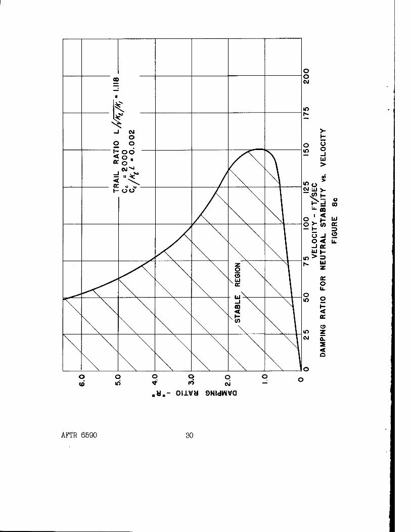
Case IV. Effect of Velocity on Stability. This relationship can
be depicted by plotting Ü as a function of Q, since Q is proportional
to V. Figs. 8a, 8b, 8c, are plotted for values of the trail ratio
T of 0.707, 1.0 and 1.118 respectively. For convenience 5 has been
taken as unity and Cc/KfL as 0.002. Inspection of these figures in-
dicates that the damping requirement increases as the velocity in-
creases, but for values of the "inertia ratio", T2/S, greater than
1.0, there is an upper limit to the damping that will stabilize the
system. As the velocity increases these two damping values coalesce,
and above this critical velocity no stability is possible. (See Fig.
8c)
Case V. Effect of Trail on Stability, For this case the value of
R may be plotted as a function of the trail ratio T. It is to be
noted that Q and 5 are each functions of L and hence both of these
parameters must be recalculated for each point plotted. For values
of the inertia ratio less than unity, stability is possible for all
values of the trail - the required damping usually increasing with
trail to a maximum and thereafter approaching zero asymptotically.
These results are shown in Fig. 9a. For values of the inertia ratio
slightly above unity the range of damping for stability is limited
(e.g. between branches of T*/S = 1.1, as shown in Fig. 9b). For
values of the inertia ratio above a certain critical value there
are intermediate values of the trail ratio for which stability is
impossible (e.g. with T /S = 1.25, the system is unstable regardless
of the damping employed if the trail ratio lies between 0.55 and
AFTR 6590 27

o
O it
I o o
<o o 0:0 „
=!<* vS> < M "S £ W > Hü O
(f) UJ
2|
< Id >
°2 U. <
UJ» ja
< I- u. (/> o
o o CM
lO
O lO
O UJ
10 in
o o _J UJ >
(0 >
o>- °t "o o -I UJ >
m
o 10
co 00 <
(0 UJ et
-I 3 < 2 3 UJ z DC O U.
<
(9
0.
CM < a
o o id
o o id
o csi
,HM 0I1VM 9NldWVQ
AFTR 6590 28

to
Z3 .
> DCO om u-< Ills -IK CDs < (OO
tss
o (0
q in
o o 10
o
.U.0I1VU ÖNIdWVd
AFTR 6590 E9
,»„- OIJLVH 9NWWVQ
AFTR 6590 30

00 N «0 lO *■ lO CM
o O o o o o o ■ "• - oiiva 9NldWVa
AFTR 6590 31

10.0 9.0 8.0
7.0
6.0
5.0
4.0
3.0
2.0
1.0 0.9 0.8 0.7
0.6
0.5
0.4
0.3
0.2
0.1
A'tO - s
o <
o z Q.
\o*
2 <
\>*
\^/
S Zur
NKt,
^-^0^^
/K, "^
CURV INER' NOSE
ES S riA i : WH
>H0W RATIC EEL
IN6 1 ) a ST A
EFFE TRAII BILIT
CT C _ ON Y
)F
TR/S tlL R ATIO - L s/K,/Kt
0.2 0.4 0.6 0.8 i.O 1.2 1.4 1.6 1.8 2.0
FIGURE 9b
2.5
AFTR 6590 32

and 1.9, Fig. 9b), and outside these values stability is possible
but only over limited ranges of damping.
Solnt.ion of Equation (30)
Eq. 30 may be expressed in non-dimensional form as shown in
Appendix A. Thus
D*Q + f r/2lfo[ 1 + S( 1__+__QRJ]D3Q +
( 1 + S ) RT2/S
[( 1 + f )R + QS/4 ] ß2e + ( T/2]J~S) S( 1 + QR ) ^
( 1 + S )RT*/S ( 1 + S ) Rf/S
+ ^ e - o ( 1 + S ) RT*/S
(33)
where the derivative is taken with respect to the dimensionless time
/\JKJN * t. The solution of Eq. 33 is:
9 = Cxe + C2e
fo2 + J'u2)t' „ fa2 - j'w2)t' (34) + C3e
+ We
in which the coefficients of the dimensionless time t' are the roots
of the characteristic equation
Y4 + Aax3 + A2y2 + /liY1 + A0 = 0 (35)
the A terms being the dimensionless coefficients of Eq. (33). If
APTR 6590 33

these coefficients are computed for the particular case of neutral
stability (by selecting values of R from the graph of Fig. 7) then
Eq. 34 must exhibit a sustained (constant amplitude) oscillation.
If the frequency of this oscillation is assigned the subscript 1,
at must be zero and the coefficients of (35) become:
A3 = - 2a2
i _y2. 2 . 2 . A2 - (a2 + u)2 + uj
J4± - - 2a2(>i1
A0 - u\(a\ + Uj)
Hence, the roots of (35,) are readily found:
a2 = — -4-/2
2 ^1
Aa 1 + i/Sfi + Qfi)
2 _ ^0^3 ^3 w2 -
It will be useful at this point to prepare a graph showing the relat-
ion between the frequency of the neutrally damped shimmy and the
lateral elasticity Kt. This has been done using Fig. 7b, (Q = 2).
Since T /S = K1Iw/NKt the values of K1 may be found by assigning
a fixed value to Iw/K-t and to N. Then, (using Kv for the variable K^)
AFTR 6590 34

K. T2/S
and
2 «I i + 1/5C1 + Qfl) iV
(36)
(Where Uj is the dimensional shimmy frequency)
Fig. 10 shows the relationship between u± and Kv> The numbers on
the graph are the damping ratios required for neutral stability and
the oo's are the neutrally damped (N.D. ) frequencies.
20
516
CO 8 10
d>4
£0
-4
10 20 30 40 50 60 70 80 90 100 110 120
(A)/ RADIANS PER SEC.
NOSEGEAR ELASTICITY vs FREQUENCY
FIGURE 10
Accompanying the motion of frequency Uj there is, of course, the
motion of frequency u2. The latter is usually lower than the former
AFTR 6590 35

and is heavily damped. The respective amplitudes of the two frequenc-
ies depend on the initial conditions and the respective modes may
be found from Eq. 34. For example, if in this equation C3 and C4 are
made equal to zero, all the initial conditions required from the mode
corresponding to the pure harmonic a^ may be found by successive
differentiation of (3k). Again, to determine the initial configuration
to insure the presence of the («)2 motion alone, Cx and C2 are set equal
to zero and the above process repeated.
IV. THE INFLUENCE OF THE AIRFRAME
In each of the preceding systems it was assumed that the point
of attachment of the elastic element (Kx) to the airframe remains
fixed laterally - or, more precisely, that the airframe has infinite
mass. But, in order to understand the true nature of the self-excited
vibration and its possible multiple modes of motion, the airframe in-
ertia and elasticity must be considered. The direct method of accom-
plishing this would be to set up the dynamics equations for the over-
all system and obtain the single high-order differential equation
from which the stability criterion and frequencies may be found as
shown in Appendix A. It is, however, simpler and more instructive to
adopt the following procedure.
The method to be described may be considered to be a modification
of the impedance method which makes it applicable to the peculiar
requirements of self-excited vibrations. The procedure is general
and will apply to any linear physical system. The advantages of this
approach are more marked in the case of systems of sixth and higher
order. It is not necessary to solve the high-order differential equat-
AFTR 6590 36

ion since the method presents more information about the shimmy and
the factors that influence it in a simpler way; but, more important,
it permits the use of experimentally determined data in the analysis
in such a manner that the effects of controllable parameters can be
readily seen. In effect, the system to be analysed has been divided
into two fourth-order systems, one of which is self-excited and the
other passive. The solutions are obtained by matching the impedances
of the two systems at their common junction.
The point of attachment of the elastic element (Kx), the oleo,
to the finite mass airframe experiences a lateral displacement (per-
pendicular to the line of flight) which will be called x±. If the
airplane is rigid all points will turn about a vertical axis which
intersects a line along the axles of the main wheels midway between
these wheels. Let the moment of inertia of the airplane about this
axis be I0. The natural frequency of the system when the lower end
of the oleo is held fixed is /\jK1d^/l0 , where d is the distance
from the axis to the strut. The quantity I0/dz may then be used to
define an equivalent mass M1 (i.e. Mx = I0/d2) in the equivalent
rectilinear system as shown in Fig. 11.
NOTE:
The system illustrated in Fig. 11, though highly idealized, may
be used to clarify the significant effects obtained with an actual
aircraft. Ground shake tests of a typical airplane were run to
determine the modes of motion. A harmonic sidewise force of grad-
ually increasing frequency was applied to the strut at the level
of the axle. Resulting motion of the aircraft was recorded with
accelerometers. The test arrangement is shown in Fig. 12.
Preliminary results show that the node position in the strut
moves upward from a point below the ground, passes through the
AFTR 6590 37

point at which the vibrator is attached (theoretically infinite
coefficient of elasticity) and on up into the fuselage. The node
then takes up various positions axially along the fuselage influ-
enced particularly by the phase relation of the wings and stab-
ilizer. It is this point that clearly illustrates the impossibility
of defining the lateral elasticity in terms of static measure-
ments. It is a dynamic measurement that may in theory vary from
minus infinity to positive infinity.
Wheel
SINGLE MODE AIRFRAME
FIGURE II
In this equivalent system if the lower part of the strut experi-
ences a simple harmonic motion of amplitude ~x and frequency u it
follows that
Spring force = K^fx sin ut — x±) = M1x1
The particular solution of the above equation is
AFTR 6590 38

Ground Shake Test Equipment Arrangement
FIGURE 12
AFTR 6590 39
KJM1 _ . x sin ut
spring force - K^x sin Ut ( 1 - r^/wj - </
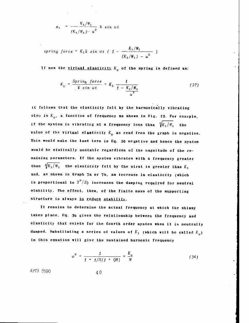
If now the virtual elasticity Ky of the spring is defined as:
Spring force 1 v = ~1~~77n~u~t~ = Kl T^KJMI (37)
5—
it follows that the elasticity felt by the harmonically vibrating
oleo is Kv, a function of frequency as shown In Fig. 13. For example,
if the system is vibrating at a frequency less than yK1/M1 the
value of the virtual elasticity Kv as read from the graph is negative.
This would make the last term in Eq. 30 negative and hence the system
would be statically unstable regardless of the magnitude of the re-
maining parameters. If the system vibrates with a frequency greater
than /^K1/M1 the elasticity felt by the strut is greater than K±
and, as shown in Graph 7a or 7b, an increase in elasticity (which
is proportional to T /S) increases the damping required for neutral
stability. The effect, then, of the finite mass of the supporting
structure is always lo reduce stability.
It remains to determine the actual frequency at which the shimmy
takes place. Eq. 36 gives the relationship between the frequency and
elasticity that exists for the fourth order system when it is neutrally
damped. Substituting a series of values of K± (which will be called K )
in this equation will give the sustained harmonic frequency
2 = 1 x Kj,
1 + 1/S(1 + QR) * N (3*}
AFTR 6590 4 0

24
20
cc 16 UJ OL
flO
l o
8
i*
-4
-8
-16
^\ VKi, KM 1 <ii«
Ky« rv,
NATURAL FREQUENCY J ^-'
1 0^3 ß 30 40 50 60 70 80 90 100 1 0 120 \ FREQUENCY IN RADIANS PER SEC.
VIRTUAL AIRFRAME ELASTICITY vs. FREQUENCY
FIGURE 13
If now a plot is made of K versus u from Eq. 36 and superimposed
on Fig. 13, the point of intersection (A, Fig. 14a) is a point of
equilibrium at which the elasticity required to maintain the sustained
AFTR 6590 41

5|6
u Q.I2 CO
o
-4
S|6 or ui o.|2 m
i o >
-4
16
2] 12 a. DO «
2 4
> * 0
-4
Xi /, i "
IÖ-N20 30 40/501 60 70 80 90 lOO 110 l20
A AIRFRAME
FREQUENCY IN RADIANS PER SEC.
NATURAL FREQUENCY OF AIRFRAME
AIRFRAME
30 40 50 60 701 80 90 100 110 120 \ I
FREQUENCY IN RADIANS PER SEC.
10 2Ö~"~30 -^0 50 60 70 80 90 | IÖ0 110 120 AIRFRAME-^^x. FREQUENCY IN RADIANS
PER SEC.
EFFECT OF AIRFRAME ELASTICITY ON NOSEGEAR STABILITY FIGURE 14
AFTR 5590 42
frequency w is supplied by the virtual elasticity of the given spring
K±. The frequency shown at the point of intersection is the frequency
of the neutrally stable shimmy, and the damping ratio shown at the
same point is the damping required for neutral stability. Any value
of R in excess of this value represents stable motion while any lesser
value causes the system to be unstable.
From Fig. 14a it can be seen that the virtual elasticity can
never be negative. Also, as Mt is increased without limit the virtual
elasticity approaches Kt (see Eq. 37). The statement has been made
that "when the frequency of the shimmy matches that of some mode of
the aircraft violent resonant oscillations will occur." The theory of
shimmy as outlined here indicates that there cannot be an accidental
coincidence of the shimmy and airframe frequencies. For example, com-
bining Eqs. 36 and 37 gives:
w2 = h + hlH. (38)
Mj. 1 + 1/S(1 + QR)
Hence, the shimmy frequency always exceeds /UK^/M^ , the natural
frequency of the single-mass mode.
Rotta (Deutsche Luftfahrtforschung, #8006 p 58, or ATI 26981) states
that the torsional rigidity of the aircraft should be large in order
not to favor the conditions for shimmy by additional degrees of free-
dom. But, increasing the rigidity against a particular mode of motion
may not influence stability, or it may actually decrease stability,
but in no circumstance can it increase stability. For example, Eqs.
8 and 9 show that the lateral elasticity K± may be increased without
limit and not affect the stability.
Maier suggests (Technische Berichte, #10, 1943) airframe elastic-
AFTR 8590 43

ity is a significant factor in shimmy if the natural frequency of
the strut and wheel coincides with that of the shimmy. But, in the
analysis given above, the reverse of this is seen to be more nearly
true, since for large values of A\JK1/M1 , Eq. 38, the two frequencies
referred to by Maier become more widely separated and the system be-
comes less stable.
If the equivalent mass Mt of the airframe is gradually reduced,
the point of intersection in Fig. 14 gradually moves outward indicat-
ing an increase in both the damping required for neutral stability
and the shimmy frequency. With M1 sufficiently reduced the second
branch of the virtual elasticity curve will intersect the nose gear
curve in two points A and B as shown in Fig. 14b. For this case
stability exists for values of the damping ratio R between those
shown at A and B. Outside of this range the system is unstable on
either side. The sustained frequency for the conditions of point A
is uA, and, as the damping ratio increases toward B, the stable fre-
quency is interpolated between uA and uß. (There is, in general,
another frequency associated with the one discussed above since this
is a fourth order system; this latter is usually relatively small
and strongly stable, and its amplitude is determined by the initial
conditions. The setting of the torsion spring Kt, i.e. whether it is
jnitally in tension or compression, is one of these conditions).
Finally, if the equivalent mass Mx is still further reduced until
the virtual elasticity curve fails to intersect the nose gear curve
(Fig. 14c) stability is impossible regardless of the damping employ-
ed. This condition could exist in a low-inertia aircraft in combi-
nation with a high lateral strut elasticity.
AFTR 6590 44

Application to Multiple-Mode Systems:
The method outlined above is general in that it may be applied to
the case of airframes that exhibit multiple modes of vibration provid-
ed that the virtual elasticity curve is determined experimentally or
computed for an equivalent lumped parameter system. For example, if
the system can be represented as shown in Fig. 15, and point P is
moved with simple harmonic motion of frequency w, the reaction of the
spring K± on the oleo at point P can be shown to be that of a simple
spring of elasticity (See Appendix C)
K. K±[l
2 / 2 (j) /<i)2
2/2... 2/2.- (1 - U) IUf)(l - 0) /OJS)
(39)
• ^P Oleo
MULTIPLE-MODE AIRFRAME FIGURE 15
AFTR 6590 45

In Eq. 39 Ki is the static elasticity of the oleo structure, u2 is
K2/M2, Uyris the first natural frequency of the airfrane and oleo,
while us is the second natural frequency of the same structure. If
a plot of K versus u from Eq. 39 is now prepared and superimposed
on Fig. 10, the points of intersection will show the frequency and
damping ratio required for dynamic equilibrium in the combined system.
For example, if the damping ratio is adjusted to the value shown at
point A Fig. 16, the system would be in dynamic equilibrium at fre-
quency uA. This must be so since if the nose gear were supplied
with a fixed-ended spring of elasticity KA and the damping adjusted
to RA the system would approach a pure harmonic motion of frequency
WA as time goes on. On the other hand, if the K± M-L K2 M2 system is
driven at point P with a forced oscillation of frequency w. it would
react on P as though the spring Kjt were fixed-ended and of elasticity
Ky. ( This assumes that the initial conditions are chosen so as to
eliminate the transient.) Hence, with damping adjusted to RA, pure
harmonic motion would insure a continuous equilibrium of forces
throughout the entire cycle. The above argument may be repeated for
points B and C. The conclusion to be drawn from this physical analys-
is of the system is that the general solution of the sixth order dif-
ferential equation must be so constituted as to be able to provide a
solution in pure harmonic motion when the damping ratio is adjusted
to any of the three values A, B or C Fig. 16. Point A represents a
possible state of motion but one which cannot be realized in any
actual case. Only between points B and C can the system be stable.
This conclusion is quite general and can *e demonstrated by a simple
analysis of the sixth order differential equation which represents
the system. Let the characteristic equation for this sixth order
AFTR 6590 46

20
5 16
tu 12 a. m
ro 8
> 0
-4
-8
-16
6jf,Us ARE THE ROOT OF THE QUADRATIC
WHERE W,8=^/M,
ä;* = /<2/M2 ,
20 30 40 50 60 70 80 90 IÖO llO 120 FREQUENCY IN RADIANS PER SEC.
AIRFRAME
EFFECT OF AIRFRAME ELASTICITY ON NOSEGEAR STABILITY FOR MULTIPLE - MODE SYSTEM
FIGURE 16
system be (See Appendix A for the differential equation)
Y6 + ABys + 44Y4 + A3Y3 + A^2 + Aty + A0 = 0 ((,0)
Now consider point A, Fig. 16. With the damping ratio R adjusted to
the value corresponding to this point a pure harmonic motion is
possible. Hence, under these conditions Eq. 40 must contain a pair
of pure imaginary roots, say ±>Wi. Dividing (40) by the factor
AFTR 6590 47

2 2 f Y + ui ) yields a fourth order equation from which the roots
o2 ± Jw2/ and a3 + j(t)3 may be found. Repeating this process for
points B and C, data is obtained for constructing the graphs of Fig.
17 which is a plot of the real and imaginary root components of Eg.
40 as a function of the damping ratio required for neutral stability.
CJa - 0.8
- U),
0.6
0.4
» °2
N -J« 0 / k E J 1.00 1.50 2.00
0>3
-== ' i 1
— ä.2 . Obi
R
° ^ -0.2 NEUTRAL
-0.4
az DAMPING RATIO
-0.6
-0.8
REAL AND IMAGINARY ROOT COMPONETS OF 6th ORDER EQUATION vs. "R"
FIGURE 17
AFTR 6590 48

The general solution for the shimmy amplitude is
With R equal to flA, a± is zero and, hence, the sustained frequency
is Uj. For R equal to fiß or Rc, a2 is zero and, hence, the sustained
frequency at these points is u)2. In general, all three frequencies
UL w2, and u3 are superimposed in the shimmy motion. (This compound
harmonic motion has been observed and reported by Guruewicz and Kruse
(ATI-23097, translation).
Examination of Fig. 17 shows that points B and C are points of
neutral stability, since the plot of a2 passes through zero at B
and C, while outside this range the system is unstable since a2 is
here positive. It is now clear why point A represents a possible mode
of motion, since this can be brought about by adjusting the initial
conditions so that the amplitudes of both the w2 and u3 modes are
each zero. Obviously, any transient disturbance under these circum-
stances would cause the u2 motion to grow without limit and so, in
any actual case, damping below that shown at point B would result
in unstable motion.
V. THE USE OF THE CHARTS
For the purpose of analyzing a given system the following steps
are recommended:
1 - Obtain the numerical values of L, m, mlt f, Kt, and Iw.
Assign a value to the taxi speed V.
AFTR 6590 49

2 - Compute Q and 5. Plot R versus T2/S. (Eq. 32)
3 - Plot Kv versus u as in Fig. 10.
4 - Plot Kv as a function of u by ground shake tests or by cal-
culation using lumped parameters. (Eq. 39)
5 - The plot (4) superimposed on (3) will give points of inter-
section which disclose the frequencies of neutral shimmy,
and the minimum and maximum values of the damping ratio re-
quired for stability.
In order to examine the effect of changing the magnitude of any
of the system dimensions Fig. 7 should be used. In constructing Fig. 7
eight independent physical parameters are involved, but all the essent-
ial information is contained in the three dimensionless numbers Q, S
and T /S. For example, suppose in a given design
Q = 4
S = 1
T2/S = 1
Fig. 7b is applicable and from it is found the minimum damping ratio
for stability
R = 0.6k
The actual damping is
Ct = RCC = 0.64 x 2 iKju
Suppose, now, the following modifications are made in the nose-gear
design:
Reduce I to 1/2 its original value.
APTR 6590 50

Reduce Kf to 3/4 its original value.
i. Ki ii 1/2 ii ii n
These modifications give the following values for the dimensionless
parameters:
<? = 3.24
S = 2.0
T2/S = 0.33
The chart of Fig. 7b may be entered by interpolation with T /S = 0.33
and Q = 3.2k to find R = 0.42. The effect of increasing S from 1.0
to 2.0 is slight in this area and may be estimated from Fig. 7a as
about 4%. Hence, the modification of the parameters makes the new R
about 0.44. Therefore, the new absolute damping (which is proport-
ional to the square root of Kf x Iw) becomes
Ct = 0.44 x 2 ]j(0.75Kt) x (0.5IJ
or, Ct = 0.27 x 2 ^ K%IU
Comparing this value of the damping with that originally required
shows a reduction of 58%. In addition, it is apparent from Fig. 7b
that the parameter changes have removed the operating point from the
region in which the upper damping is limited to one in which there
is no upper limit. Finally, it can be seen that for any stabilizing
damping ratio, say R = 1.0, at T2/S = 0.33 the rate of damping of any
given initial displacement will be greater than that found at higher
values of the inertia ratio, T*/S. These conclusions may be verified
by an inspection of Fig. 7a where it can be seen that the margin of
AFTR 6590 51
damping above that required for neutral stability becomes less as
2 / T /S increases. This of course is due to the upward slope of the
neutral stability graphs. (These conclusions have also been veri-
fied by studies on an analog computer).
Finally, the effect of varying the trail length L should be exam-
ined. It is most significant to note that the inertia ratio, T2/S,
is independent of L. However Q, S and T are functions of L. From the
data of the modified structure discussed in the preceeding example,
T2/S = 0.33 and S = 2.0 it follows that TQ = 0.66 and T = 0.815.
Entering Fig. 9a with this value of T it is evident that a given in-
crease in trail will result in a decrease in neutral damping ratio.
Considerations other than stability will dictate an upper limit to
the trail ratio selected in any given design.
VI. GENERAL NOTES
1 - Vertical Load.
The vertical load on the nose-wheel does not appear directly in
the theory presented here. Nevertheless, it is well established that
reducing the weight on the nose-wheel does reduce the magnitude of
the shimmy. This apparent contradiction is due to the following
effects: a) It is tacitly assumed that sufficient weight acts at all
times to support the friction force that acts normal to the wheel
plane. If the wheel load is reduced and skidding occurs, the energy
fed to the system is thereby reduced (See Eq. 20); b) Not only does
skidding reduce the energy fed to the system, but, at the same time,
it removes energy from the system at the contact point between the
wheel and ground, and thus reduces the damper load; c) The lighter
AFTR 6590 52

load being accompanied by an extended oleo results in a reduction in
the lateral elasticity and thereby increases the inherent stability.
(See Fig. 7).
2 - Lateral Elasticity.
The stability criteria established for all but the third-order
system show that the damping required for stability is reduced as i.
the lateral elasticity K± is reduced. On the other hand, it can be
demonstrated that for neutrally damped systems with a given initial
disturbance the amplitude of the neutral shimmy is reduced for larger
values of the lateral elasticity. (See Eq. 42). These two statements
are not contradictory but do require careful judgement in their appli-
ation. For example, accompanying the reduced amplitude in the latter
case, there will be increased frequency, spindle acceleration, and
force transmitted to the fuselage. Hence, it may be unwise to attempt
to fight a shimmy by opposing it directly with increased lateral
rigidity. In this connection, it is planned to investigate the possi-
bilities of shock mounting the nose-gear to reduce the lateral elast-
icity over a limited range of amplitude. This, of course, makes the
system nonlinear, and may best be handled by an analog computer.
3 - Hiah-Frequenc.v Modes of Motion.
From Fig. 16 it appears that if the airframe contains modes of
motion with sufficiently high frequencies, no amount of damping can
theoretically stabilize the system. Actually, the high frequency
intersections imply correspondingly high virtual lateral elasticity
so that if a pure high frequency mode is initially set up, its am -
plitude is relatively small and is effectively checked by inherent
AFTR 6590 53

hysteresis damping. In addition, it is expected that for the more
likely initial disturbances, the conditions for exciting the lower
mode will be more favorable.
4 - Velocity Effects.
The amplitude (Eq. 42), frequency (Eq. 38), and damping required
(Fig. 8) of a neutrally stable mode increase only, slightly with taxi
velocity. However, strut acceleration, spindle force and ground force
normal to the wheel plane increase approximately in direct proportion
to that velocity. This information may be found from the solution of
Eq. 8 for an initial condition of 90:
1 cos(ut + cp) (42)
30 ~ ^1 + L*KjV*Iu
Experimental evidence usually supports the view that the severity of
shimmy actually grows less with increased taxi speed. This is com-
pletely false security since the observed diminution of shimmy meant
simply that other conditions (e.g. sufficient tire friction force)
were unfavorable to maintaining the vibration. Guroewicz and Kruse,
(Untersuchung Des Spornflatterns FW190, ATI-23097) discuss a case
in which shimmy appeared to rise and fall between 80 km per hour and
90 km per hour. This phenomenon may be mistaken for simple resonance,
but when other factors are correct the shimmy may return in full
violence at higher speeds as was actually observed in these tests.
5 - Stability Without Damping.
Stability can be obtained without damping. For example, if the
damper piston is locked in position the swivel torque (Eq. 25, p 16)
APTR 6590 54

becomes
Fna-Flb-Kte - y
Combining this with Eq. 23 through Eq. 28 gives
(I„ + miL2 + ma2) 9 + V(nxL + ma) 9 + (K. + KtL
2) 9 + K^LVQ = 0
( Compare with Eq. 30 ). Applying Routh's criterion to the above
equation, the condition for stability with a locked damper is
Kt > K,IW I N
6 - Shimmy Frequencies For Neutrally Damped Systems.
a) Third order system:
4himmy = K*-L* I Tw + "*-* ( From Eq. 8 )
b) Fourth order system:
2 KJN "Shimmy = <E«- 36>
1 + 1 / S(l + QR)
c) Fourth order system with one degree of freedom in the airframe.
2 KJN "Shimmy = K^M^ + " (Eq. 38 > 1 + 1 I S(l + QR)
d) Sixth order system. (Two degrees of freedom in the airframe)
"Shimmy =(<*f+ us + Z ± |K + "I + V* ~ ^"fl + Z( *) + W! " ^)])i/2
AFTR 6590 55

Where KjN
Z = (From Eqs. 36 and 39) 1 + 1/S(1 + QR)
Use plus sign for all neutrally stable systems, u. is the first natural
frequency of the system, u the second natural frequency of the system,
and w-L = Wjlj
AFTR 6590 56

APPENDIX A
THE SIXTH ORDER SYSTEM
FOURTH ORDER SYSTEM WITH MULTIPLE-MODE AIRFRAME
FIGURE A-l
Differential Equation for the. Nose-Wheel Rear with Two Degrees of
Freedoa in the Air Frame.
The simultaneous differential equations for this case (See Fig.
Al) are:
AFTR 6590 57

Forces:
Fn+ Fl = «ig (Al)
- Fx - Kx(x - x±) = iji" CA2)
- #2C*2 ~ *i) = Mzx2 (A4)
Swivel Torque:
Fna - FZ6 - Ct0± = Ig9 ^5)
Damper Torque:
cte± = ^ce - ej Mg)
Kinematic:
- L'Q = i + V9 CA7)
Geometrie:
*g =: * + 69 (AS)
Combining the above equations gives the following differential eq-
uation in 9:
[Ct(Iw + L2N)]Da6 + [Kf(Iw + L2N) + CtVL/V]Z)79
+ [KtVLN + Ct{Kt + L2Ki + (Iv + L2N)(K1/M1 + KJM* + K2/\f1)y_DBQ
+ [Kt(KtL2 + CtVL) + {KtfIw + L*N) + CtKL/v]('A'1/A/1+R:2/M2+/(:2/W1)]i)60
APTR 6590 58

+■ [K±KtVL + Ct(KjM±)(K2/M2) { I, + L2(N + ^ + Af2)}
+ Ät<'VL^ + Ct)(K1/M1 + K2/M2 + K2/tfj]ß49
+ ßx/M1)(Ka/Mi)[Kt i Iv + L2(W + *i + Af2)} + CtKLCiV + Mx + Af2)]D30
+ (Kt)(K1/M1)(Ki/M2)[VL(N + Af± + tf2) + Ct]D29 = 0 fA9)
Substituting the following non-dimensional numbers
2
2 r2 =
Ka/Ma
KJN
2 r2i
_ Ks/M1
KJN
(Q, S T, and ß as previously defined) gives the»following different-
ial equation in 6 where the derivative is taken with respect to the
dimensionless time yK^/N t:
■>8, (T/2 fS)[j + S(l + QR)] n7f
(T2/S)(l + S)R D 9 + ' ' 2,1. r—-^- 0 8
[Q5/4 + fi { i + T2 + (T2/S)(l + S)(rj + r2 + r\xft ] ^
(T2/S)(l + S)Ä
+ (T/2VS)[Sfj + QRJfl + r2 + r2 + r\x) + r\ + r\ + r2J B
Cf/S)(l + S)R
AFTR 6590 59

[ (QS/4)(1 + r\ + r\ + r\x) (T2/S)(l + S)R
+ fl{rf + r* + r*± + (rM) (7*/S) (1 + 5[i + i/r? + r\jr\r\\ )} ] Z)*9
(T2/S)(l + S)Ä 3e
(T2/S)(l + S)R { '
By setting Wx = °° and K2 = 0 eliminates the effect of the airframe
and thus reduces the 6th order equation to 4th order.
nea + (T/*VS)ll * S(* + Wl _7Q + [fi + T*)R + QS/4] e D b + s-; if b + _j> , f Ö (T !S)(1 + S;R (r/S)(l + S)R
(T /S)(l + 5)i{ , (r/S)(l + S)R x '
AFTR 6590 60

APPENDIX B
TTRK ELASTICITY
The effect of tire elasticity and creep is confined to the kine-
matic Eq. A7 as shown in the following analysis:
P. (Wheel Center)
P8 (Spindle Center)
P0 (Contact point between tire ft ground)
DIAGRAM OF TIRE CHARACTERISTICS
FIGURE B -1
The point P0 moves over the ground at an angle to the plane of
the wheel due to the force Fn. But since time is required to estab-
lish this angle y we have:
y + dv = - CFn
AFTR 6590 61

or
- CF y = - Q-
1 + CXD-
Where C± is the time constant of this assumed first order system.
Due to this slip angle \y, the point P0 has a velocity normal to the
wheel plane equal to Vty. But because the tire is elastic, the wheel
center P± can move relative to P0. The actual stretch ( A) between
P0 and P± is due to the force Fn transmitted from the ground thru
the tire. Hence,
A - - pFn Where p is the tire compressibility.
Ä = - pFr n
The total normal velocity of P± is thus:
CFV D pF
1 + C±D n
And the angular velocity of the link is the velocity of Px relative
to P2, or:
L9 = ( - JT^~D - PFn) - (* + VQ) (Bl)
For the usual range of shimmy frequencies, it can be shown that the
effect of time constant Cx can be represented approximately by re-
placing Eq. Bl with:
Le = " To CFnV " pF" " (x + ve) (B2)
AFTR 6590 62

Eq. B2 may now replace the kinematic equation in any of the previous
systems. For example, when Eq. B2 is combined with those of the
fourth order system and non-dimensionalized by substituting
Mr = (1 - f)*/N
V = pK,
K±CV
Q, S, T, R, and dimensionless time 4/K±/N t as before, we have:
(UT2/S)R[Mr + 1 + MrS]D6Q + (T/\[s)[(Mr + i + MrS)(U/2 + WRT/{s)]D*Q
+ [UR {T*/S + 1 + Mr(l + T2)} + (WT/2^S)(Mr + 1 + MrS) +(1 + S)RT*/S]D*Q
+ [(UT/2is)(l + MrS)+ WR{T*/S + i + Mr(l + T* )} + (T/2*JS) (1+S+ SQR)]B*e
+ [UR + (WT/2'{S)(1 + MrS) + (1 + T2)i? + <?S/4]Z)29
+ [W? + (T/2l{s)S(l + Qfi )]ß9 + (QS/Ä) 9 = 0 (B3)
Setting p and C equal to zero reduces (B3) to the fourth order:
[(T2/S)(l + S)R]D*e + (T/2]fs)[l + S + SQR] D3Q + [(1 + T2)fi
+ QS/4]D2B + (T/2/\[s)[S(l + (?fl)]Z)9 + [QS/4] 9 = 0 (Bb)
The above procedure differs from that outlined by Von Schlippe
in that no account is taken of the shift of the force center in the
AFTR 6590 63

tire footprint. In an actual shimmy, the pattern of tire distortion
representing this shift would have to be established and erased ap-
proximately 25 times per second. As yet, there is no experimental
evidence that this action takes place, or that its influence can be
anything but trivial. However, when Eq. B2 was used in place of the
previous kinematic equation and the two compared on an analog, the
system having the tire constants proved to be more stable. Example
of the results are given in Fig. B2.
An experimental program on the mechanical properties of pneumatic
tires will be conducted at the Aircraft Laboratory at Wright Field
and one of its major objectives will be to explore the part played
by the tire in the phenomenon of shimmy.
mmm^M^ ™ *%,mm£zz£mmm
FieURE B 2
AFTR 6590 64

APPENDIX C
JTRTTIAT, ELASTICITY
The equivalent lumped paramater system of the airframe is shown
in Fig. Cl. Point P represents the point of attachment of the equi-
valent elastic element to the oleo. K,, represents the combined lat-
eral elasticity of the oleo and the torsional elasticity of the fuse-
lage.
M
x»
I«,
EQUIVALENT AIRFRAME SYSTEM
FIGURE C-l
Considering the forces on Mi.:
Kt(x - Xi) - K2(xi - x2) = Mxxi (Cl)
AFTR 6590 65

And for M0
Ks(xi ~ *2) = M2'x\ (C2)
.2 Substituting D x2 for x2 in Eq. C2, and solving for x2 gives
K2 x2 = *i (C3)
K2 + M2D
( D stands for the differential operator). Substituting Eq. C3 in
Eq. Cl gives
"x"x + (Kx/Mx + K2/M2 + K2/Mx) x\ + (KxK2/MxM2)xx =
(KXK2/MXM2)X+ (Kx/Mx) x (Ch)
If P is assumed to have simple harmonic motio of requency w and
amplitude ~x then,
x - x cos wt
and Eq. C4 becomes
*± + (Ui1 + U2 + U21) i\ + UiW**! = b)lul(l - (//(dg)* cosut (C5)
Whe,. Ui = Kx/Mx , w* = #2/^2 and w2,. = K,,/^ .
Assume for a trial solution that xx is A cos ut. Then Eq. C5 becomes
[u - (at + u2 + u21)w2 + WiUsl^cos ut = Wi<4f!f- uVw2)Icoswt
It can be seen that A cos ut is a steady-state solution of Eq.C5 if
APTR 6590 66

<«>i<4fi - ti)2/(«>g) x J% A ' 2 ' ' 2 2 2 2 2
(i) - ('(d1 + U2 + W21/) U + UiU2
The denominator of this expression may be written in terms- of its
factors as
(</ - w})(w2 - w*)
Where i)/ is the first natural frequency of the system, (i.e. the
value of w that causes A to become infinite), and ws is the second
natural frequency. Therefore
2 2., 2 / 2 . — _ WiWafi - u /U2; X
A 2—£— 2 / 2 — 2/,"2.- f00-' UfUgfl - (Ü /Uf)(l - W /(0S)
But (i)i(o2 = w^Jg since the last term of the biquardratic is the pro-
duct of its roots. The downward force exerted on P at any instant
t is Ki(x - xx), and hence, the virtual elasticity Kv against which
P acts is
Kt(x - xi) _ K±(~x - A) cos MI v X X COS Out
or , 2/2
v (1 - W /Uf)(l - w /ws)
As shown by the graph of this equation (See Fig. 16) the virtual
elasticity is negative from w « 0 to w - Uyr. It then becomes infinite
and positive until, at w = w2, the virtual elasticity equals the
actual elasticity Kx. Further increase in the forcing frequency causes
AFTR 6590 67

Kv to pass through zero and become minus infinity at u - us. Beyond
this frequency the value of Kv passes from positive infinity and be-
comes asymptotic to Kt as the forcing frequency increases without
limit.
AFTR 6590 68
I
BIBLIOGRAPHY
Howard, Halter B. , Jr. A Full Scale Investigation of the Effect of
Several Factors on the Shimmy of Castering Wheels. NACA TN-760.
Temple, G. Large Angle Shimmy. Issue ATI-51760, 1943.
Temple, G. A Simplified General Theory of Wheel Shimmy. Issue ATI-
40742, June 1942.
Guroewicz and Kruse. Untersuchung Des Spornflatterns FW. 190. ATI-
23097.
Rotta. Deutsche Luftfahrtforschung. #8006 ATI-26981.
Maier. Technische Berichte. #10, 1943.
Dietz, 0. and Harling R. Seitensteifigkeit und Seitenfuhrnng von
Flugzeugrefen. ATI-1980S, October 1941.
Dietrich, R., and Schlippe, B. Shimmying of a Pneumatic Wheel.
ATI-18920, October 1941.
Dietz, 0. and Harling, R. Tail Wheel Flutter. ATI-34467.
Dietrich, R., and Schlippe, B. Flutter of a Wheel With Pneumatic
Tire. ATI-51760, October 1943.
Fromm, H. Damping of Wheel Shimmy. ATI-57687, October, 1941.
Maier, E. Theoretical Investigations of the Stability of Landing
Gears. German Document 962-2995-1, Jan. 1940.
Kantrowitz, A. Stability of Castering Wheels for Aircraft Landing
Gears. NACA Report 686, 1940.
AFTR 6590 69

Lauber, J. E. Dynamic Analysis of Nose Wheel Shimmy on the C-124
Airplane. Douglas Aircraft Co. Report No. SM-13814.
Waterman, L. T. Shimmy Characteristics of Dual Landing Gears.
Fairchild Engine and Airplane Corporation, Engineering Report
No. SB-11.
Riekert, P. Shimmy Vibrations in Landing Gear. 962-1851-1, ATI-57682.
Dietz, 0. and Harling, R. Experimental Investigation of Tail-Wheel
Shimmy. ATI-68437.
Maler, E., and Renz, M. Shimmy Vibration of Dual Wheels on Tricycle
Gear. 962-2241-1, ATI-22381.
Schlippe, B. Shimmying of Wheels Equipped with Pneumatic Tires.
ATI-51760.
Schrode H. Reduction of Flutter of Tail and Nose Wheels. ATI-74544.
AFTR 6590 70
Related Documents