The content of this service document is the subject of intellectual property rights reserved by DNV GL AS ("DNV GL"). The user accepts that it is prohibited by anyone else but DNV GL and/or its licensees to offer and/or perform classification, certification and/or verification services, including the issuance of certificates and/or declarations of conformity, wholly or partly, on the basis of and/or pursuant to this document whether free of charge or chargeable, without DNV GL's prior written consent. DNV GL is not responsible for the consequences arising from any use of this document by others. The electronic pdf version of this document, available free of charge from http://www.dnvgl.com, is the officially binding version. DNV GL AS RULES FOR CLASSIFICATION Underwater technology Edition December 2015 Part 5 Types of UWT systems Chapter 7 Remotely operated vehicles

Welcome message from author
This document is posted to help you gain knowledge. Please leave a comment to let me know what you think about it! Share it to your friends and learn new things together.
Transcript

The content of this service document is the subject of intellectual property rights reserved by DNV GL AS ("DNV GL"). The useraccepts that it is prohibited by anyone else but DNV GL and/or its licensees to offer and/or perform classification, certificationand/or verification services, including the issuance of certificates and/or declarations of conformity, wholly or partly, on thebasis of and/or pursuant to this document whether free of charge or chargeable, without DNV GL's prior written consent.DNV GL is not responsible for the consequences arising from any use of this document by others.
The electronic pdf version of this document, available free of chargefrom http://www.dnvgl.com, is the officially binding version.
DNV GL AS
RULES FOR CLASSIFICATION
Underwater technologyEdition December 2015
Part 5 Types of UWT systems
Chapter 7 Remotely operated vehicles

FOREWORD
DNV GL rules for classification contain procedural and technical requirements related to obtainingand retaining a class certificate. The rules represent all requirements adopted by the Society asbasis for classification.
© DNV GL AS December 2015
Any comments may be sent by e-mail to [email protected]
If any person suffers loss or damage which is proved to have been caused by any negligent act or omission of DNV GL, then DNV GL shallpay compensation to such person for his proved direct loss or damage. However, the compensation shall not exceed an amount equal to tentimes the fee charged for the service in question, provided that the maximum compensation shall never exceed USD 2 million.
In this provision "DNV GL" shall mean DNV GL AS, its direct and indirect owners as well as all its affiliates, subsidiaries, directors, officers,employees, agents and any other acting on behalf of DNV GL.

Part
5 C
hapt
er 7
Cha
nges
- c
urre
nt
Rules for classification: Underwater technology — DNVGL-RU-UWT-Pt5Ch7. Edition December 2015 Page 3Remotely operated vehicles
DNV GL AS
CURRENT – CHANGES
This is a new document.
The rules enter into force 1 July 2016.

Part
5 C
hapt
er 7
Con
tent
s
Rules for classification: Underwater technology — DNVGL-RU-UWT-Pt5Ch7. Edition December 2015 Page 4Remotely operated vehicles
DNV GL AS
CONTENTS
Current – changes...................................................................................................... 3
Section 1 General....................................................................................................... 61 Introduction............................................................................................6
Section 2 Principles for construction of remotely operated vehicles...........................71 General................................................................................................... 72 Relation to other codes and standards................................................... 83 Definitions.............................................................................................. 84 Certification Requirements................................................................... 105 Documentation Requirements...............................................................116 Initial Test and trials............................................................................17
Section 3 Equipment................................................................................................ 201 General................................................................................................. 202 WORKING DEVICES...............................................................................203 Acrylic windows....................................................................................20
Section 4 Machinery systems................................................................................... 211 General................................................................................................. 212 Piping systems and umbilicals..............................................................213 Pressure vessels and apparatus under pressure...................................224 Arrangements for control resp. adjustment of depth, trim, positive and
negative buoyancy............................................................................... 235 Propulsion and manoeuvring equipment...............................................236 Positioning system................................................................................24
Section 5 Electrical systems.....................................................................................261 Principles.............................................................................................. 262 Power supply........................................................................................263 Power distribution................................................................................ 274 Protective measures............................................................................. 275 Electrical equipment............................................................................. 28
Section 6 Controls and communication.................................................................... 291 Design principles.................................................................................. 292 Control station......................................................................................313 Sensors and actuators.......................................................................... 31

Part
5 C
hapt
er 7
Con
tent
s
Rules for classification: Underwater technology — DNVGL-RU-UWT-Pt5Ch7. Edition December 2015 Page 5Remotely operated vehicles
DNV GL AS
4 Data transfer systems.......................................................................... 315 Navigation and locating equipment...................................................... 31
Section 7 Launcher...................................................................................................331 General................................................................................................. 332 Basic requirements............................................................................... 343 Garage.................................................................................................. 344 Lifting and coil-up/coil-off equipment for umbilicals............................ 35

Part
5 C
hapt
er 7
Sec
tion
1
Rules for classification: Underwater technology — DNVGL-RU-UWT-Pt5Ch7. Edition December 2015 Page 6Remotely operated vehicles
DNV GL AS
SECTION 1 GENERAL
1 Introduction
1.1 Scope
1.1.1 These rules are valid for the construction of remotely operated vehicles (ROV) which shall be classifiedby the Society, including their operating and monitoring systems.Unmanned underwater vehicles (UUV) may be (ROV) or autonomous underwater vehicles (AUV).
1.1.2 Remotely Operated Vehicles (ROV)For the purpose of these rules unmanned underwater vehicles, which are during the mission physicallyconnected with an umbilical to the relevant support vessel and which are controlled from there, are regardedas remotely operated vehicles (ROV). As an exception also wireless remote control is possible.
1.1.3 For further definitions, see Sec.2 [3].
1.2 ApplicationThe requirements in this chapter shall be regarded as supplementary to those given in Pt.2, Pt.3 and Pt.4.

Part
5 C
hapt
er 7
Sec
tion
2
Rules for classification: Underwater technology — DNVGL-RU-UWT-Pt5Ch7. Edition December 2015 Page 7Remotely operated vehicles
DNV GL AS
SECTION 2 PRINCIPLES FOR CONSTRUCTION OF REMOTELYOPERATED VEHICLES
1 General
1.1 Wherever expedient and feasible, ROVs shall be designed and constructed in such a way that failure of anysingle component cannot give rise to a dangerous situation.
1.2 ROVs and their components shall be designed to meet the service conditions stated in the specification.
1.3 ROVs shall be designed and built to ensure safe operation and facilitate proper maintenance and thenecessary surveys.
1.4 ROVs shall be designed and constructed in such a way that sufficient possibilities for monitoring during divedtravels are given. This can be achieved, e.g., by video systems and acoustic instruments.
1.5 ROVs shall be so equipped that the operator can be informed about the position and the operating conditionof the vehicle.
1.6 ROVs which operate with diver support shall be equipped with a TV unit for monitoring the work site and withspecial protection arrangements, which can be actuated from the control stand for the ROV.
1.7 Due care shall be taken to ensure that inadvertent movements cannot cause the remotely operated vehicle todestroy itself or equipment located at the work site or to become separated from its control and supply lines(e.g., by cable protector).
1.8 ROVs shall be so designed and constructed, that they achieve also a definite condition (e.g., positivebuoyancy) even if the control and the energy supply fail.
1.9 Measures shall be taken to avoid that the ROV gets caught. Propellers shall be provided with adequateprotection arrangements.

Part
5 C
hapt
er 7
Sec
tion
2
Rules for classification: Underwater technology — DNVGL-RU-UWT-Pt5Ch7. Edition December 2015 Page 8Remotely operated vehicles
DNV GL AS
1.10 All possible stability cases of the ROV with minimum and maximum payload (NL) including all extensioncomponents shall be considered in surfaced and submerged condition.
1.11 The centre of gravity shall be located below the centre of buoyancy.
1.12 ROVs shall be so designed, that their operation causes no inadmissible environmental loads and endangeringof the environment will be avoided as far as possible
1.13 If a special designed launcher for the ROV is provided, it shall be considered as part of the total ROV systemand to be classed together with it, see Sec.7.
2 Relation to other codes and standards
2.1
2.1.1 National codes and regulations concerning remotely operated vehicles existing alongside the Society’srules are unaffected.
3 Definitions
3.1 General DefinitionsFor general definitions see Pt.1 Ch.1.
3.2 Main dimensions and main parametersAll dimensions are related to fix installed equipment in drawn-in/turned-in condition.
Table 1 Main dimensions and main parameters for ROVs
Terms Definitions
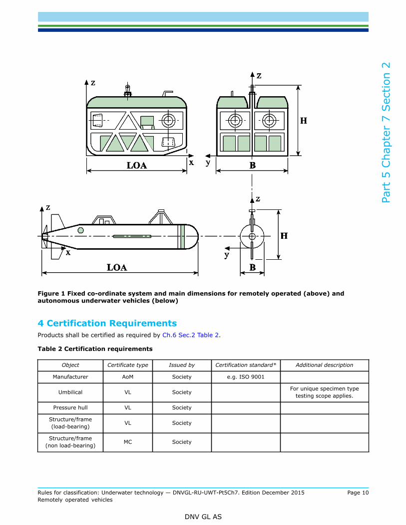
Co-ordinate system
In relation to the ROV a fixed, right-handed co-ordinatesystem x, y, z according to Figure 1 is introduced. Theorigin of the system is defined by the aft perpendicular,the centre line and the basis line of the ROV. The x-axispoints in longitudinal direction of the ROV positive forward,the y-axis positive to port and the z-axis positive upwards.Angular motions are considered positive in a clockwisedirection about the three axes.

Part
5 C
hapt
er 7
Sec
tion
2
Rules for classification: Underwater technology — DNVGL-RU-UWT-Pt5Ch7. Edition December 2015 Page 9Remotely operated vehicles
DNV GL AS
Terms Definitions
Length over all LOA
The length LOA is the length between the most forwardand most aft point of the ROV including fixed installedcomponents of equipment, measured parallel to the x-axis[m].
Total breadth (width) BThe total breadth B is the maximum breadth of the ROVincluding all fixed installed parts of equipment, measuredparallel to the y-axis [m].
Radius of the pressure tight vessel Rm
The radius Rm of a pressure tight vessel is the radius ofthe cylinder or the sphere related to the middle of the wallthickness [m].
Total height HThe total height H is the total height from baseline to upperedge of the vehicle including all permanently installed partsof equipment, measured parallel to the z-axis [m].
Draught TThe draught T in surfaced condition is the maximumvertical distance between the baseline and the watersurface [m].
DisplacementThe displacement of the surfaced ROV ready for surfacedoperation is Δ↑, the displacement of the completely divedROV is Δ↓ [t].
Payload NL
The maximum additional load for devices, equipment,materials, which are not necessary for the direct operationof the ROV, but are serving for work to be performed,investigation of the sea and scientific research is NL [kg].
Diving depthsAll diving depths are related to the baseline.
-
Nominal diving depth NDD The nominal diving depth NDD is the diving depth for theunrestricted operation of the ROV [m].
Test diving depth TDD
The test diving depth TDD is the diving depth which isrelated to an external overpressure, to which the ROVis subjected to test conditions after completion or afteressential repairs [m].
Collapse diving depth CDDThe collapse diving depth CDD is the diving depth decisivefor the design of the pressure hull, where a collapse of thepressure hull shall be expected [m].
Velocities
Velocity v0↑
The velocity v0↑ is the maximum operational speed of thesurfaced submersible [kn] at a number of revolutions ofthe propeller(s) according to the maximum continuouspropulsion power surfaced (MCR = maximum continuousrating).
Velocity v0↓The velocity v0↓ is the maximum operational speed ofthe dived submersible [kn] at a number of revolutions ofthe propeller(s) according to the maximum continuouspropulsion power dived (MCR).
Part
5 C
hapt
er 7
Sec
tion
2
Rules for classification: Underwater technology — DNVGL-RU-UWT-Pt5Ch7. Edition December 2015 Page 10Remotely operated vehicles
DNV GL AS
Figure 1 Fixed co-ordinate system and main dimensions for remotely operated (above) andautonomous underwater vehicles (below)
4 Certification RequirementsProducts shall be certified as required by Ch.6 Sec.2 Table 2.
Table 2 Certification requirements
Object Certificate type Issued by Certification standard* Additional description
Manufacturer AoM Society e.g. ISO 9001
Umbilical VL Society For unique specimen typetesting scope applies.
Pressure hull VL Society
Structure/frame(load-bearing) VL Society
Structure/frame(non load-bearing) MC Society

Part
5 C
hapt
er 7
Sec
tion
2
Rules for classification: Underwater technology — DNVGL-RU-UWT-Pt5Ch7. Edition December 2015 Page 11Remotely operated vehicles
DNV GL AS
Object Certificate type Issued by Certification standard* Additional description
Piping system
VLMC
SocietyManufacturer
> DN 50≤ DN 50
Pressure vessel VL Society
Hose line MC Manufacturer
Electrical componentand cable MC Manufacturer
Electrical penetration VL Society For unique specimen typetesting scope applies.
Power supply PC Classificationsociety support vessel supply
Pressure supply PC Classificationsociety support vessel supply
Syntactic foam VL Society
Control andautomation
Navigation andmonitoring
MC Manufacturer Diving Pressure, suitability forapplication on seagoing ships
Working device MC/VL Manufacturer/Society Depending on type
*Unless otherwise specified the certification standard is the rules.
5 Documentation Requirements
5.1 General requirements
5.1.1 Before the start of manufacture, documentation of the total system and drawings of all componentssubject to compulsory inspection, wherever applicable and to the extent specified below, shall be submittedin triplicate respectively in case of electronic transmission as single issue.
5.1.2 The documentation shall contain all the data necessary to check the design and loading of the system.Wherever necessary, calculations relating to components and descriptions of the system shall be submitted.
5.1.3 Once the documents submitted have been approved by the Society, they become binding for theexecution. Any subsequent modifications require the Society's consent before they are implemented.
Part
5 C
hapt
er 7
Sec
tion
2
Rules for classification: Underwater technology — DNVGL-RU-UWT-Pt5Ch7. Edition December 2015 Page 12Remotely operated vehicles
DNV GL AS
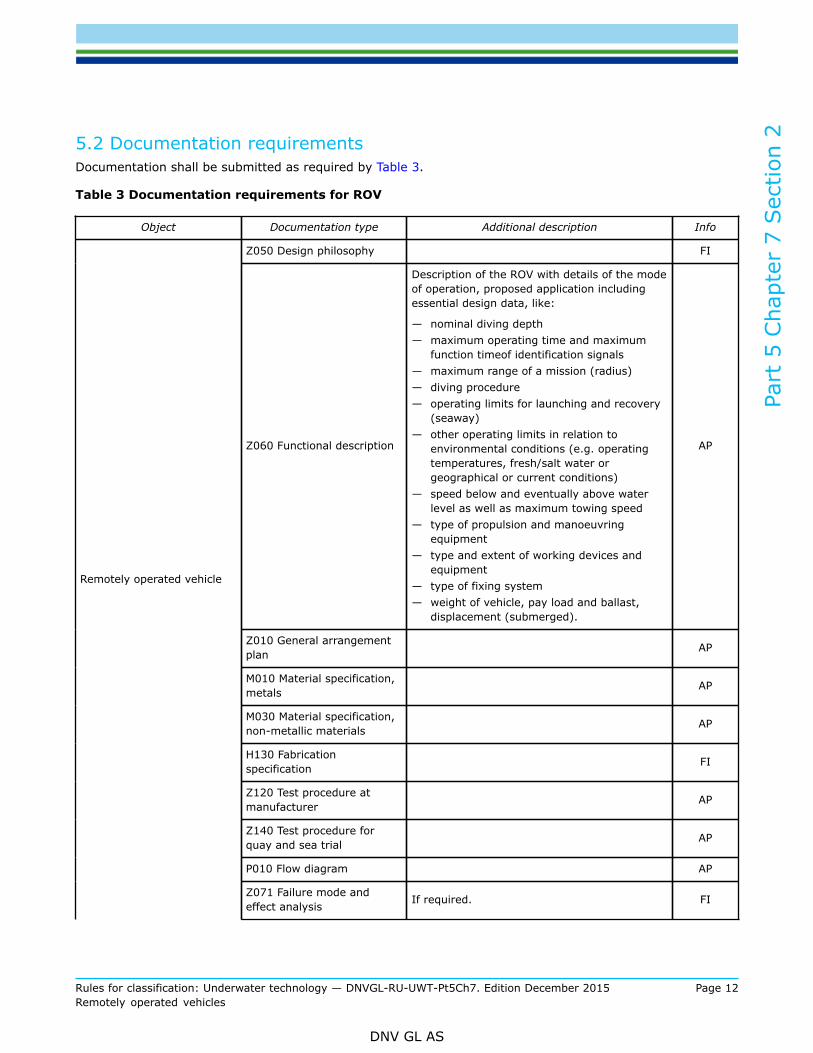
5.2 Documentation requirementsDocumentation shall be submitted as required by Table 3.
Table 3 Documentation requirements for ROV
Object Documentation type Additional description Info
Z050 Design philosophy FI
Z060 Functional description
Description of the ROV with details of the modeof operation, proposed application includingessential design data, like:
— nominal diving depth— maximum operating time and maximum
function timeof identification signals— maximum range of a mission (radius)— diving procedure— operating limits for launching and recovery
(seaway)— other operating limits in relation to
environmental conditions (e.g. operatingtemperatures, fresh/salt water orgeographical or current conditions)
— speed below and eventually above waterlevel as well as maximum towing speed
— type of propulsion and manoeuvringequipment
— type and extent of working devices andequipment
— type of fixing system— weight of vehicle, pay load and ballast,
displacement (submerged).
AP
Z010 General arrangementplan AP
M010 Material specification,metals AP
M030 Material specification,non-metallic materials AP
H130 Fabricationspecification FI
Z120 Test procedure atmanufacturer AP
Z140 Test procedure forquay and sea trial AP
P010 Flow diagram AP
Remotely operated vehicle
Z071 Failure mode andeffect analysis If required. FI

Part
5 C
hapt
er 7
Sec
tion
2
Rules for classification: Underwater technology — DNVGL-RU-UWT-Pt5Ch7. Edition December 2015 Page 13Remotely operated vehicles
DNV GL AS
Object Documentation type Additional description Info
M040 Coating specification AP
Z160 Operation manual
Including in detail the steps necessary fornormal operation as well as for emergencyoperation in a clear and conceptual form andin the necessary sequence (e.g. as checklist).In addition the measures for the loading ofthe operating systems (e.g. batteries) shallbe defined. In addition the planned lifetimeand the permissible load and mission cyclesof components of the equipment (e.g. acrylicwindows, batteries, etc.) shall be definedherein.
AP
Z180 Maintenance manual Including all procedures for the preventivemaintenance. AP
Z290 RecordIncluding documentation of all conditionsrelevant for operation (diving depth, missiontime, damages, etc.).
FI
Z120 Test procedure atmanufacturer AP
Z140 Test procedure forquay and sea trial AP
Z030 Arrangement plan
Including extensions like trimming weights,diving cells, pressure vessels, buoyancyelements, stabilizing fins, drives, umbilicalconnection, control box, search lights, ramprotection, fairing, manipulators, fixingsystems, instrument racks, etc.
APEquipment supportingstructure
H050 Structural drawing AP
Exostructure H050 Structural drawing AP
Pressure containment C030 Detailed drawing
Including drawings of the vessels andapparatus under external and internal pressurewith all essential particulars and detailsnecessary for appraising the safety of theequipment and including the specifications formaterials, manufacture and testing.
AP
S010 Piping diagram
Including of details for arrangement ofdiving, regulating and trimming systemswith mathematical proof of the static divingcapability.
AP
S090 Specification of piping,valves, flanges, fittings AP
Diving, compensating andtrimming system
S130 Filling and dischargetime calculation AP

Part
5 C
hapt
er 7
Sec
tion
2
Rules for classification: Underwater technology — DNVGL-RU-UWT-Pt5Ch7. Edition December 2015 Page 14Remotely operated vehicles
DNV GL AS
Object Documentation type Additional description Info
I020 Control systemfunctional description
Including:
— – description of the system for depth,positive and negative buoyancy and trimincluding the necessary diagrams andcomponent drawings
— data concerning scope, type and design ofbuoyancy and ballast elements and theirfixing on the supporting structure.
APControl and monitoringsystem
I200 Control and monitoringsystem documentation AP
S010 Piping diagram
Schematic diagrams including details of:
— materials— maximum allowable working pressure— maximum allowable working temperature— dimensions (diameter, wall thickness)— media carried— type of valves and connections used and
their operational parameter— type of hose lines.
AP
S041 Pneumatic controldiagram AP
S042 Hydraulic controldiagram AP
Piping systems
S050 Connections to theshell and to the sea chests AP
Pump Z100 SpecificationIncluding description of pumps and theirdrives together with all important design andoperating data.
FI
Umbilical Z100 SpecificationIf applicable, including description of thedesign of the umbilical and its single elements,as well as the requirements for lifting cables.
AP
Components filled withliquids Z100 Specification Including definition of the type of liquid (e.g.
oil, water, etc.). FI
Propulsion and steeringarrangements
C020 Assembly orarrangement drawing
Including descriptions of the propulsion andmanoeuvring equipment with data about:
— mode of operation and control of thesystems
— power consumption (type and quantity)— method of power transmission to propulsion
units— safety systems.
AP
Position keeping N060 Manoeuvring booklet The type and control of the positioning systemshall be explained. AP

Part
5 C
hapt
er 7
Sec
tion
2
Rules for classification: Underwater technology — DNVGL-RU-UWT-Pt5Ch7. Edition December 2015 Page 15Remotely operated vehicles
DNV GL AS
Object Documentation type Additional description Info
Underwater working device Z030 Arrangement planFor extension elements and working devicesthe effects on the total ROV system shall bedefined.
AP
Underwater working device /fixing system Z060 Functional description
Plans and descriptions including:
— type and control of the fixing system— size of holding power— behaviour at energy failure— type of release system.
AP
E220 Electrical systemphilosophy
Including a general arrangement drawingcontaining at least the following information:
— voltage rating of the systems— power or current ratings of electrical
consumers— switchgear and safety devices (e.g.
overcurrent relay) with indicating settingsfor short-circuit and overload protection;fuses with details of current ratings
— cable types and cross-sections:
AP
Electric system
E040 Electrical powerconsumption balance AP
Electric power system,general
E230 Power supplyarrangement AP
SwitchgearE050 Single line diagrams/consumer lists forswitchboards
AP
Electric motor E140 Assembly schedulesand technical data
Including complete documentation for electricmotor drives with details of control, measuringand monitoring systems.
AP
Battery Doc type Installation drawing including battery types. AP
Cable penetrations E110 Cable data sheet anddesign drawing
Including details of electrical penetrationsthrough pressure vessel walls. AP
E200 Short circuitcalculations
Including calculation of short-circuit conditionsof all electrical components and distributionsystems (e.g., power switches, powerprotection switches and fuses, indicating theircurrent ratings and breaking capacity).
AP
Electric system
E090 Table of Ex-installationFor the operation in explosive endangeredareas the required explosion classes shall beproven.
AP
Umbilical E110 Cable data sheet anddesign drawing
Including electrical design and connection toROV. AP
Control and monitoringsystem/complete lay out
I090 Schematic descriptionof input and output circuits Including layout of the control stand. AP

Part
5 C
hapt
er 7
Sec
tion
2
Rules for classification: Underwater technology — DNVGL-RU-UWT-Pt5Ch7. Edition December 2015 Page 16Remotely operated vehicles
DNV GL AS
Object Documentation type Additional description Info
Control and monitoringsystem/operating
I020 Control systemfunctional description
Including description of the control andoperating elements for the ROV and itsequipment.
AP
Control and monitoringsystem/operating
I030 Block (topology)diagram AP
Control and monitoringsystem/nautical and diving N060 Manoeuvring booklet
Description of the nautical and divinginstrumentation, including speed and positionindicators.
AP
Control and monitoringsystem/safety and alarm
I110 List of controlled andmonitored points
Including description of the safety and alarmsystems. AP
Control and monitoringsystem
I200 Control and monitoringsystem documentation
Including arrangement drawings/blockdiagrams of monitoring systems with lists ofmeasuring points.
AP
Control and monitoringsystem/electroniccomponents
I070 Instrument andequipment list
Including documentation for electroniccomponents such as instrument amplifiers,computers and peripheral units.
AP
Control and monitoringsystem/data transfer Z090 Equipment list
Including general diagrams and equipment listsfor the data transfer systems and signallingequipment.
AP
Control and monitoringsystem/video system T010 Functional description Including general diagram and description of
the video system. AP
Control and monitoringsystem/positioningequipment
N040 Nautical workstationarrangement plan
Including descriptions, general diagrams andequipment lists. AP
G040 Fire control plan
Including description of preventive fire andexplosion protection measures for the ROVswhich shall be used in or from explosionendangered areas.
AP
G060 Structural fireprotection drawing AP
Fire and explosion protection
G080 Hazardous areaclassification drawing AP
Launcher/general Z010 General arrangementplan
Including plans and descriptions of thelauncher with data about operating conditions,task and equipment.
AP
Launcher/garage Z030 Arrangement planIncluding plans and descriptions of the garagesystem, if applicable, and equipment of thegarage.
AP
Launcher/connections C060 Mechanical componentdocumentation
Description of the connections between thesupport vessel and the launcher as well asbetween the launcher and the ROV.
AP
AP = For approval; FI = For informationACO = As carried out; L = Local handling; R = On request; TA = Covered by type approval; VS = Vessel specific

Part
5 C
hapt
er 7
Sec
tion
2
Rules for classification: Underwater technology — DNVGL-RU-UWT-Pt5Ch7. Edition December 2015 Page 17Remotely operated vehicles
DNV GL AS
For general requirements for documentation, including definition of the info codes, see SHIP Pt.1 Ch.3 Sec.2.For a full definition of the documentation types, see SHIP Pt.1 Ch.3 Sec.3.
6 Initial Test and trials
6.1 Total systemOn completion, the ROV shall be subjected to a constructional, functional and acceptance test. This shallinclude at least the following individual tests:
— inspection of assembly (where not already performed during checking of manufacture)— measurement of weight, buoyancy and stability— testing of all safety devices— functional testing of diving and trimming equipment— functional testing of mechanical, electrical and optical equipment— functional testing of working devices including the fixing system with regard to influence on the ROV— trial trip submerged— testing of launch and recovery procedures including functional test of the launcher— verification of all essential measuring instruments— insulation test and if necessary high voltage test and on the electrical equipment— test of the control stand on the support vessel— trials and functional tests under water with diving depths up to the nominal diving depth NDD
6.2 Supporting structure
6.2.1 It shall be checked, if the not pressure-proof parts of the supporting structure (hollow bodies, pipes,etc.) are pressure equalized. Pressure-proof components shall be tested according to [6.3.3].
6.2.2 The lifting points at the ROV shall be tested statically with 2.2 times the safe working load (SWL) (=weight and payload (NL) of the ROV).
6.2.3 The fixing point of the umbilical at the ROV shall be tested statically with 2.2 times the maximumpermissible tension load of the umbilical.
6.2.4 Pressure vessels shall undergo a hydraulic pressure test before being insulated or painted. The testshall show no leakage or permanent deformation of the vessel walls.
6.2.5 The test pressure applied to vessels and apparatus with stress from internal pressure shall beequivalent to 1.5 times the maximum allowable working pressure (PB).
6.2.6 Vessels and apparatus which may be subjected to external overpressure according to the maximumallowable diving depth of the ROV shall undergo an external pressure test. The test pressure TDP shall be atleast a multiple of the nominal diving pressure NDP according to Pt.3 Ch.2 Sec.2 Table 2.
6.2.7 If the strength against pressure of vessels and apparatus cannot be sufficiently proven by calculation,an alternative verification shall be agreed with the Society.
6.2.8 All windows in pressure vessels shall be subjected to a hydraulic pressure test. The test may beperformed after installation together with the pressure vessel or stand alone in a test device. The testpressure shall be determined according to [6.3.3]. For the pressure test it shall be observed that the testpressure is not higher than 1.5 times the calculation pressure of the window.

Part
5 C
hapt
er 7
Sec
tion
2
Rules for classification: Underwater technology — DNVGL-RU-UWT-Pt5Ch7. Edition December 2015 Page 18Remotely operated vehicles
DNV GL AS
6.3 Piping systems, umbilicals and pumps6.3.1 Piping systems
a) On completion but before being insulated or painted, all piping systems shall undergo a hydraulicpressure test at 1.5 times the maximum allowable working pressure.
b) After installation, all piping systems shall undergo a tightness test at the maximum allowable workingpressure. Pipes under diving pressure shall be checked in addition with test diving pressure (TDP) (insideor outside according to the actual load case).
c) The safety systems shall be checked.
6.3.2 PumpsOn completion, pumps shall be subjected by the manufacturer to a pressure test at the maximum allowableworking pressure, a tightness test as well as a performance test.
6.3.3 Umbilicals/supply linesUmbilicals of remotely operated vehicles (ROV) shall meet special requirements. The required tests aredivided in a type test of the prototype and a routine test of the final product.All aspects for the tests and trials of umbilicals are defined in Pt.4 Ch.5.
6.3.4 As far as the requirements in [6.4] are applicable for hose assemblies they shall be used.
6.4 Trimming, compensating and diving systemsThe trimming, compensating and diving systems shall be subjected to a functional test.
6.5 Propulsion and manoeuvring equipmentThe function of the propulsion and manoeuvring plant shall be proven at the occasion of trial travel underwater.
6.6 Positioning systemThe automatic keeping of a predefined position in breadth, length and depth shall be checked.
6.7 Working devices
6.7.1 See also Ch.9 Sec.3.
6.7.2 The influence of the working devices on the total system shall be tested.
6.7.3 The working devices shall be checked at least with reference to:
— control and monitoring— functioning of safety devices— avoiding dangers for divers and the ROV.
6.7.4 The fixing systems shall be subjected to a function test where at least the following individual testsshall be performed with respect to:
— specified holding power of the fixing system— limitations of power and distance travelled of the fixing systems as well as the directing of the vehicle— simulation of an energy failure.

Part
5 C
hapt
er 7
Sec
tion
2
Rules for classification: Underwater technology — DNVGL-RU-UWT-Pt5Ch7. Edition December 2015 Page 19Remotely operated vehicles
DNV GL AS
6.8 Electrical equipment
6.8.1 Electrical machines and automation, alarm and safety systems including steering and control standsshall be tested in the manufacturer's works.The electrical systems shall be approved by the Society, preferably type approved components shall be used.Kind and scope of type tests shall be defined by the Society case by case.
6.8.2 All electrical systems and equipment shall be inspected and tested before the ROV is put into service.
6.8.3 The set points and response thresholds of electrical protective devices shall be checked.Depending on the type of device the electrical equipment of the vehicle, if possible, shall be subjected to ahigh voltage test and an insulation test with a test voltage ≥ 500 V.
6.8.4 Electrical cables under external pressure shall be checked according to the electrical requirements forumbilicals defined in [6.4.3].
6.8.5 Electrical penetrations into vessels and apparatus under pressure and underwater plug connectionsshall be subjected to a type and routine test according to Pt.4 Ch.8 Sec.3.
6.8.6 All electrical equipment which is exposed to diving pressure shall be checked additionally for isolationafter the first diving.
6.9 Automation, navigation and locating equipment3.11.1 Indicating and monitoring systems shall be checked for the accuracy of their readings, their limit valuesettings and ergonomic arrangement according to the Society’s document SHIP Pt.4 Ch.9.
6.9.1 Automation systems shall be checked for satisfactory performance under service conditions.
6.10 Launcher
6.10.1 The launching and recovery of the launcher including the ROV shall be checked in a functional test.
6.10.2 The lifting point of the launcher shall be tested with 2.2 times the safe working load. The device forharbouring the ROV to the launcher shall also be statically tested with 2.2 times the weight including payloadNL of the ROV.
6.10.3 The entrance and the exit of the ROV to or from the launcher, respectively the garage if existing, shallbe tested in dived condition and a functional test of all elements of the total system shall be performed.

Part
5 C
hapt
er 7
Sec
tion
3
Rules for classification: Underwater technology — DNVGL-RU-UWT-Pt5Ch7. Edition December 2015 Page 20Remotely operated vehicles
DNV GL AS
SECTION 3 EQUIPMENT
1 GeneralFor the intended operation purpose the ROV may be outfitted with different kind of equipment. Reference isgiven to Pt.3 Ch.4.
2 WORKING DEVICESWorking devices are components or sub-systems, which are optionally mounted to the ROV. Working devicesare e.g. tools, like manipulators or grabbers, or removable equipment frames (skids).Only working devices shall be applied to ROVs provided that the influence on the total system is investigatedand approved by the Society.Working devices shall be arranged on the ROV that the risk of trapping is minimised and that the umbilical orthe lifting cable becomes entangled.Fixing systems shall be designed and constructed such that a defined holding power can be adjusted. Inaddition, devices such as the holding claw or similar shall be possible to open in case of energy failure.Concerning all further requirements for working devices, respectively for their separate Certification, seeCh.9.
3 Acrylic windowsIf openings with acrylic windows are required in pressure-proof parts of the construction, e.g. for theapplication of search lights and cameras, the design and dimensioning of these windows shall be performedaccording to Pt.4 Ch.7. In justified cases the minimum wall thickness can be reduced in agreement with theSociety.Viewing windows of other materials as acryl glass may be approved by the Society according to separatetesting.

Part
5 C
hapt
er 7
Sec
tion
4
Rules for classification: Underwater technology — DNVGL-RU-UWT-Pt5Ch7. Edition December 2015 Page 21Remotely operated vehicles
DNV GL AS
SECTION 4 MACHINERY SYSTEMS
1 GeneralThe technical requirements for machinery systems like:
— propulsion and manoeuvring equipment— ballasting— control/compensating and trimming systems— umbilicals— piping systems— pumps and compressors— vessels and apparatus under pressure— control and monitoring
are given in Pt.4.
2 Piping systems and umbilicalsPiping systems include:
— pipe lines— fittings— hoses— pumps and compressors.
2.1 General
2.1.1 Piping systems shall be designed and installed according to internationally recognized standards. Forthe selection of the material, manufacturing and computation the Society’s document SHIP Pt.4 Ch.6 can beapplied, as far as applicable.
2.1.2 Piping systems shall be dimensioned for a design pressure (PR) equal to the maximum allowableworking pressure (PB).All piping systems which may be loaded with the diving pressure shall be designed additionally for 1.0 timesthe collapse diving pressure (CDP) (according to the load case from outside or inside).
2.2 Piping systems
2.2.1 Piping systems which may be exposed to pressures above the design pressure shall be provided withan overpressure protection which guarantees a safe blowing-off.
2.2.2 Piping systems for gases and electric cables shall be installed separately. Piping systems which areendangered to mechanical damage shall be protected.
2.3 Fittings
2.3.1 Shut-off devices shall conform to a recognized standard. Fittings with screw-down covers and spindlesshall be safeguarded against accidental unscrewing.

Part
5 C
hapt
er 7
Sec
tion
4
Rules for classification: Underwater technology — DNVGL-RU-UWT-Pt5Ch7. Edition December 2015 Page 22Remotely operated vehicles
DNV GL AS
2.3.2 Manual shut-off devices shall be closed by turning in the clockwise direction. The open and closedpositions of essential shut-off valves shall be clearly recognizable. If they shall be operated by a diver underwater they shall be so designed that the handling is possible while wearing mittens.
2.3.3 Fittings for hoses shall be made of corrosion resistant material and shall be so designed thatunintentional loosing can be excluded.
2.4 Hose assembliesAs far as the requirements of [2.6] are relevant for hose assemblies, they shall be applied.
2.5 Pumps and compressorsThe casing of pumps and compressors shall be provided pressure proof. The proof of strength shall be doneby computation. If this is only possible in an insufficient way, these casings shall be tested according to theSociety’s requirement.
2.6 UmbilicalsUmbilicals as connecting element between support vessel/launcher and launcher/ROV may contain liftingcables and supply lines, like electrical supply, hydraulic and pneumatic supply as well as signalling andmonitoring, within a joint encasing.All aspects for the design of umbilicals are treated in Pt.4 Ch.5.
2.7 Compressed air systems
2.7.1 Compressed air systems which come in contact with seawater shall be designed adequately and beseparated from other systems. In addition measures shall be taken to exclude the entrance of seawater inthe compressed air system as far as possible.
2.7.2 Compressed air systems shall be equipped with pressure indicators. Maximum working pressures shallbe marked.
2.8 Hydraulic systems
2.8.1 The pressure creating and distribution components of the hydraulic systems shall have adequateperformance if the manoeuvring systems are hydraulically driven. In addition it shall be defined if and howmuch additional capacity for working devices to be connected (compare Pt.5 Ch.9) shall be made available.
2.8.2 If the hydraulic aggregate is located on the launcher, an adequate electrical feeding via the umbilicalshall be provided. A supply with higher voltage and subsequent voltage transformation to a lower voltage ispermissible.
2.8.3 Concerning selection of materials, manufacturing and computation the Societys document SHIP Pt.4Machinery and Systemsare valid.
3 Pressure vessels and apparatus under pressure
3.1 Pressure vessels and apparatus under outside pressureThe calculation procedure of Pt.3 Ch.3 Sec.4 or an internationally recognized standard shall be applied.

Part
5 C
hapt
er 7
Sec
tion
4
Rules for classification: Underwater technology — DNVGL-RU-UWT-Pt5Ch7. Edition December 2015 Page 23Remotely operated vehicles
DNV GL AS
3.2 Pressure vessels and apparatus under internal pressureFor pressure vessels, gas cylinders and apparatus under internal pressure, the requirements defined in SHIPPt.4 Ch.7 or other recognized regulations according to state of the art (e.g., AD published rules) are valid.
4 Arrangements for control resp. adjustment of depth, trim,positive and negative buoyancyUnmanned, remotely operated vehicles shall be provided with arrangements for control respectivelyadjustment of depth, positive and negative buoyancy. It shall be secured that these arrangements areeffective under all specified conditions of heel and trim.Depending on the type of ROV the following systems may be regarded as arrangements for control andsupport of depth, trim, positive and negative buoyancy:
— lifting cable if the ROV is connected tight with it— releasable weights (for quick diving to a wanted depth resp. for emerging)— fixed resp. adjustable ballast and trimming weights— rigid buoyancy appliances, e.g. of pressure resistant foam— floodable ballast and trim tanks— propeller drives— depth rudders with dynamic effects (e.g., for towed ROVs).
The control devices shall be capable of compensating the expected differences in water density and ofensuring that the submersible attains a defined diving state.The ROV shall be stable in each operational phase and be in the position to return to the water surface.The arrangements for control of depth, trim, positive and negative buoyancy shall be controlled fromthe control stand of the ROV on the support vessel. In addition the depth of the ROV shall be indicatedcontinuously on the console.
5 Propulsion and manoeuvring equipment
5.1 Propulsion equipment
5.1.1 With regard to their type, number, size and arrangement, propulsion devices shall be designed to meetthe requirements arising from the planned purpose and location of the mission.
5.1.2 Propulsion units shall be designed for the collapse diving pressure (CDP) or shall be pressure balanced.
5.1.3 Propulsion plants for ROVs shall be designed for intermittent and continuous operation.
5.1.4 Electric propulsion motors shall be designed in accordance with the requirements of Sec.5.
5.1.5 Shaft penetrations and other penetrations through the wall of pressure vessels shall be provided with aproven seal designed for the collapse diving pressure (CDP).
5.1.6 Propellers shall be so arranged that an unintentional trapping of the ROV or getting caught in theumbilical or lifting cable can be largely excluded. For a joint mission with divers the propellers shall beprotected against unintentional approach, e.g. by ducting and grids or nets before and aft.
5.1.7 Devices for controlling the speed and/or the direction of the rotation shall be so designed such that thepropulsion motor can be stopped even in the event of their failure.
Part
5 C
hapt
er 7
Sec
tion
4
Rules for classification: Underwater technology — DNVGL-RU-UWT-Pt5Ch7. Edition December 2015 Page 24Remotely operated vehicles
DNV GL AS
5.1.8 The operating condition of the propulsion units (direction of thrust and rotation) shall be displayed atthe control stand on the support vessel.
5.2 Manoeuvring equipment
5.2.1 Remotely operated vehicles shall be equipped with suitable devices which provide the vehicle with therequired manoeuvrability under consideration of the most unfavourable operating conditions. A propellerthrust for going backwards shall be provided which enables an effective braking of the vehicle.
5.2.2 Depth and side rudder devices shall be designed for the greatest loads which result at underwaterjourneys from the steering forces resp. at planned longer surface journeys from pitching movements andwash of the sea. The equivalent stress in the rudder shaft shall not exceed 0.5 × yield strength.
5.2.3 Depth rudders shall be so designed that the wanted depth can be kept in the assigned speed rangeand under all load conditions.
5.2.4 For the swivelling devices of the propulsion units, which serve at the same time as manoeuvringdevice, the same requirements are valid as for rudders.
5.3 Mission on the bottom of the sea
5.3.1 If the movement is realised by wheels or crawlers, the foot print area shall be adjusted to thepermissible bottom pressure in the planned mission area. Design and drive shall be agreed with the Societycase by case.
5.3.2 At sandy or muddy sea bottom , propulsion units which are used for the advance shall not bepositioned too low or shall be totally avoided as the visibility around the vehicle can be strongly limited dueto the whirled up bottom material.
5.3.3 Systems for locating of obstacles, like rocks, wrecks, pipelines, offshore structures, etc. shall beprovided to avoid collisions safely.
6 Positioning systemDynamic positioning may be required for certain operational purposes For remotely controlled vehicles acooperation with the support vessel may be required.
6.1 General
6.1.1 Dynamic positioning means that a vehicle keeps automatically its position at the water surface or inthe underwater space (within accuracy of the system defined for the duty of the mission) or that it moves ona predefined track, using solely the effect of propulsors.
6.1.2 Systems for dynamic positioning shall include the following subsystems:
— as far as required for safe operation redundant source of energy with switchgear and energy distribution— a number of drives/propulsors with motor and, if necessary, gear as well as propeller, eventually slewing
gear; the control of the positioning system shall be adequate to the purpose of the mission of the ROV— suitable sensors for determination of location/position— control system including computer system with software, monitoring display at the control stand and
reference system for the position— Further details concerning the requirements for such systems are defined in SHIP Pt.6 Ch.7.
Part
5 C
hapt
er 7
Sec
tion
4
Rules for classification: Underwater technology — DNVGL-RU-UWT-Pt5Ch7. Edition December 2015 Page 25Remotely operated vehicles
DNV GL AS
6.2 Positioning systems of ROVsFor ROVs the use of dynamic positioning and the required equipment for this shall be agreed with the Societycase by case.

Part
5 C
hapt
er 7
Sec
tion
5
Rules for classification: Underwater technology — DNVGL-RU-UWT-Pt5Ch7. Edition December 2015 Page 26Remotely operated vehicles
DNV GL AS
SECTION 5 ELECTRICAL SYSTEMS
1 PrinciplesAll electrical equipment shall be so designed and installed such that it is operational and serviceable underthe design conditions specified for the remotely operated vehicle.Systems for which even a brief failure cannot be tolerated, shall be provided with battery support or shall besupplied by an uninterruptible power.Where batteries are used, the special operating conditions shall be observed. Battery chargers shall have acharacteristic conforming to the battery manufacturer's recommendations.
2 Power supply
2.1 Principles
2.1.1 Devices shall be provided enabling the ROV to be voltage absent during launching and recovery.
2.1.2 Approved supply systems are:
— direct current and single phase alternating current, with both conductors insulated from the hull of theROV
— three-phase alternating current with the three conductors insulated from the hull of the ROV; networkswith an earthed neutral are not permitted.
2.1.3 The permissible voltage and frequency deviations stated in SHIP Pt.4 Ch.8 Sec.2 [1.2] shall not beexceeded.
2.2 Main power supply
2.2.1 A power balance shall be prepared to prove that the rating of the main power supply is sufficient.
2.2.2 Appropriate diversity factors may be assumed for consumers which are intermittently connected.
2.2.3 A power margin shall be provided for transient peak loads (e.g. on motor startup).
2.2.4 A subordinate mistake shall not hinder the distribution of sufficient power for the drive of the vehicle orother essential systems, like search lights and video cameras.
2.3 Emergency power supply
2.3.1 An emergency power supply is necessary in those cases where the endangerment of the ROV, itsenvironment or its function due to a failure of the main power supply is inadmissible.
2.3.2 The emergency power supply shall be so designed that, if the main power supply fails, the ROV can bebrought in a stationary operating condition which at no time presents a danger. From this condition it shall bepossible either to recover the vehicle safely or to continue its mission after the main power supply has beenrestored.

Part
5 C
hapt
er 7
Sec
tion
5
Rules for classification: Underwater technology — DNVGL-RU-UWT-Pt5Ch7. Edition December 2015 Page 27Remotely operated vehicles
DNV GL AS
3 Power distributionElectrical distribution systems shall be so designed that a fault or failure in one circuit does not impair theoperation of other circuits.During normal operation, the emergency power distribution system may be fed via an interconnector feederfrom the main power distribution system.The lengths of cables from storage batteries to the switchboard/switching devices and end consumers shallbe kept as short as possible. These cables shall be laid separately to the corresponding circuitbreaker andshall be specially protected against mechanical damage.In switchgears, measures shall be taken for the prevention of parasitic voltages. Voltage circuits for safetyextra low voltage shall not be run in the same conductor bundle or in the same cable duct as higher voltagecircuits. Terminals for different voltage levels shall be arranged separately and marked accordingly.
4 Protective measuresEach circuit shall be protected against short circuit and overload.All consumer circuits shall be designed for all-pole switching.If remotely operated vehicles operate with diver support, electrical systems whose failure could endanger thedivers, shall be designed for high availability, e.g., with battery back-up.Where remotely operated vehicles operate with diver support, a continuous insulation-monitoring systemshall be provided which actuates a visual and audible alarm at the ROV control station when the value dropsbelow a minimum level. Where the possibility of danger to humans cannot be ruled out, provision shall bemade for the automatic disconnection of the circuit concerned.An emergency stop device for the ROV shall be installed at the control stand. It shall be designed to excludeunintentional actuation.Remotely operated vehicles with electrical equipment shall be provided with an earthing and equipotentialsystem. All non-current-carrying metal parts shall be connected to this.Where earthing is not provided via the fastenings, protective conductors shall be fitted.Where protective conductors are used, the following shall be observed:
a) The protective conductor shall take the form of an additional cable or additional line or an additional corein the power cable. The use of armouring as protective conductors shall be checked case by case and tobe approved by the Society.
b) A conductor which carries current in normal operation shall not simultaneously be used as a protectiveconductor and shall not be connected jointly with the latter to the hull of the vehicle.
c) The cross-section of the protective conductor shall be equivalent to at least half the cross-section of thephase conductors. However, with cross-sections of up to 16 mm² the cross-section shall be the same asthat of the phase conductor. With separately laid protective conductors the minimum cross-section is 4mm2.
d) The connections of the protective conductors shall be installed at locations which can be easily checked.e) In an easily accessible position on the structure of the ROV a connection point in the form of a
connecting plate with preferably M 12 stud bolts shall be provided to which, a protective conductor canbe connected without the use of tools. This connection serves for the compensation of the potentialbetween the recovered ROV and the support vessel.
f) Depending of the endangering potential of the electrical plant of the ROV a device for compensation ofthe potential shall be provided which is already effective during recovery out of the water.

Part
5 C
hapt
er 7
Sec
tion
5
Rules for classification: Underwater technology — DNVGL-RU-UWT-Pt5Ch7. Edition December 2015 Page 28Remotely operated vehicles
DNV GL AS
5 Electrical equipmentThe housings of non-pressure-compensated electrical equipment for underwater use shall be designed for thecollapse diving pressure (CDP) as a minimum.Penetrations in vessels and plug-and-socket connections shall be designed and tested in accordance with theSociety’s document SHIP Pt.4 Ch.8 Sec.3 under consideration of SHIP Pt.4 Ch.8 Sec.3 [5.1].For electrical equipment a minimum type of protection IP 44 is required.Insulation class F shall be provided for the windings of electrical machines.Underwater cables and lines shall be impervious to transverse water penetration (i.e. no water shallpenetrate the sheath) and shall be designed for an overpressure which is equivalent to the collapse divingpressure (CDP). For further requirements concerning design and testing see Pt.4 Ch.5.Drum cables shall be so designed that mechanical forces are not transmitted via electrical components.For monitoring the manoeuvres and activities of the ROV under water suitable searchlights and videocameras shall be provided.

Part
5 C
hapt
er 7
Sec
tion
6
Rules for classification: Underwater technology — DNVGL-RU-UWT-Pt5Ch7. Edition December 2015 Page 29Remotely operated vehicles
DNV GL AS
SECTION 6 CONTROLS AND COMMUNICATION
1 Design principles
1.1 General principles
1.1.1 All devices for automatically monitoring and controlling the operating parameters of a ROV shall be sodesigned and constructed that they function properly under the design and ambient conditions laid down forthe vehicle.
1.1.2 Computer aided operational control systems for the ROV are permissible. Details of the scope andredundancy of the equipment shall be agreed with the Society.The systems shall be approved by the Society and type approved components shall be used.The check contains the applied devices (hardware) as also the effectiveness of software programs belongingto them. Kind and scope of the check shall be agreed with the Society.
1.1.3 Computer aided operational control systems shall be capable of being switched to manual operation atany time. Exceptions to this rule shall be agreed with the Society.
1.1.4 No fault or failure whatsoever in the automation system shall lead to an uncontrollable operatingcondition.
1.1.5 Automation equipment shall as far as possible be protected against incorrect operation.
1.1.6 Automation equipment shall be capable of maintaining the predefined operating parameters of theROV.
1.1.7 All inadmissible deviations from the operating parameters shall automatically actuate a visual andaudible alarm at the control station.This applies additionally to automatic changeovers in the power supply system and to faults in the controland monitoring system.
1.1.8 In addition to electronic control and monitoring devices, independent safety devices shall be providedwhich prevent a fault in a system from creating an unsafe or undesirable operating condition.
1.1.9 The response settings of automation devices shall be coordinated in such a way that, when a limitvalue is reached, an indicating signal is actuated followed by the response of the safety devices on the expiryof a specific warning period or on the further variation of the process variable at a pre-set speed.
1.1.10 The overall behaviour of the automation equipment shall be compatible with the time constants of thedevices and components in the system.
1.1.11 As criterion for the noise immunity of electronic systems the IEC standard 60533 (Electromagneticcompatibility of electronic installation in ships) shall be applied.
1.2 Construction
1.2.1 Electronic automation equipment shall comprise easily interchangeable modules using the pluginsystem wherever possible. The modules should be largely standardized, and the number of module typesshould be kept small to reduce the spares inventory.
1.2.2 Plugin cards shall be clearly marked or coded as a safeguard against accidental confusion.

Part
5 C
hapt
er 7
Sec
tion
6
Rules for classification: Underwater technology — DNVGL-RU-UWT-Pt5Ch7. Edition December 2015 Page 30Remotely operated vehicles
DNV GL AS
1.2.3 Measures shall be taken to prevent condensation inside electronic equipment even when it is switchedoff. A standby heating is recommended.
1.2.4 Wherever possible, automation equipment shall be preferably operable without forced ventilation.The functioning of any cooling system shall be monitored.
1.2.5 Components shall be effectively fastened. The mechanical loading of wires and soldered connections byvibrations and shaking shall be minimized.
1.2.6 The construction of systems and equipment shall be simple and straightforward. Easy accessibility formeasurements and repairs is desirable.
1.3 Circuitry
1.3.1 Signalling, monitoring and control devices for safety related functions shall be constructed on thefailsafe principle, i.e. defects such as short circuits, earth faults and breaks cannot produce conditionsendangering humans or equipment. This shall be based on the assumption of single faults.The failure of one module, e.g. due to short circuit, shall not result in damage to other modules.
1.3.2 In programmable controllers the electrical values of the sensors shall meet the safety requirements forcontrol devices. This means primarily:– Hlevel startup, i.e., by powering via NO contacts– Llevel shutdown, i.e., by depowering via NC contactsThe requirements stated in [1.3.1] are unaffected.
1.3.3 Command and control devices for safety functions, e.g., emergency stop sensors, shall be independentof a programmable controller and shall act directly on the output device, e.g. stop solenoid valve. They shallbe safeguarded against unintentional operation.
1.3.4 Programmable controllers shall be non-interacting and in case of fault shall not cause disturbances inprogram-independent safety interlocks and safety switching sequences for fixed subroutines.
1.3.5 Freely accessible potentiometers and other components provided for adjustment or workingpointsettings shall be capable of being locked in the operating position.
1.3.6 Switchgear interfaces shall be so designed that contact chatter has no adverse effects on the operationof the equipment.
1.3.7 Printed conductors forming part of circuits extending outside the enclosure containing the printedcircuit boards shall be conditionally short circuit proof, i.e. in the event of an external short circuit only theprotective devices provided may respond without destroying the printed conductors.
1.3.8 The equipment shall not be damaged by brief voltage surges in the vehicle's power supply which maybe caused by switching operations. If not more detailed otherwise at the feeding of the remotely operatedvehicle wiring bound interference voltages and quick transient interference factors according to IEC 6100045,severity level 3 shall be considered.Where equipment is supplied from static converters, allowance shall be made for periodic voltage pulses. Theamplitude depends on the type of converter and shall be investigated in each case.An overvoltage protection adjusted to the equipment is recommended.

Part
5 C
hapt
er 7
Sec
tion
6
Rules for classification: Underwater technology — DNVGL-RU-UWT-Pt5Ch7. Edition December 2015 Page 31Remotely operated vehicles
DNV GL AS
1.4 Power supply
1.4.1 The support vessel’s power supply for control, monitoring ans safety systems shall comply with theSocietys Rules for Electrical Installations SHIP Pt.4 Ch.9.
1.4.2 The power supply shall be monitored and a failure shall be alarmed and registered.
1.4.3 Power supply units for automation equipment shall at least have short circuit and overload protectionsuch that no unsafe operating condition of the vehicle can be created by these.
1.4.4 Automation equipment shall be capable of reliable operation with the voltage and frequency deviationsmentioned in the in SHIP Pt.4 Ch.8 Sec.2 [1.2].
2 Control stationFor monitoring and controlling the ROV a control station or console shall be provided aboard the supportvessel (in a mobile container or permanently installed in the support vessel). All important data relatedto the operation of the ROV shall be displayed. This includes all controls and monitors, including TV andcommunications facilities.The instruments for supervising, open and closed loop control and operating of the ROV shall be grouped andarranged on ergonomic principles at the control stand.All monitoring and control devices shall be unambiguously labelled and marked.Limit values shall be marked for analogous measuring instruments. In case of reaching limit values on digitalindicating instruments, an alarm shall be provided.As far as feasible and rational, initiated control functions shall be indicated optically at the control station.No plants or systems that are impairing the supervision and operation of the ROV shall be installed in thearea of the control station.The prerequisites which shall be made available for the control station by the support vessel are defined inCh.6 Sec.12 [2].
3 Sensors and actuatorsAll devices for registering the operating conditions of remotely operated vehicles as well as the belongingactuators shall be approved by the Society and shall be type tested.
4 Data transfer systemsFor the use of data cables it shall be guaranteed that the specified data volume per time unit will betransmitted without disturbances under all operating conditions.In case of a failure of the data transfer, the ROV has to reach a defined and safe operating condition.If secondary "data for payloads" shall be transferred with data lines, these shall be transmitted independentlyfrom the data lines for the operation of the ROV.
5 Navigation and locating equipment
5.1 General
5.1.1 Principally the regulations of the flag state, respectively of the competent authorities, shall beconsidered.

Part
5 C
hapt
er 7
Sec
tion
6
Rules for classification: Underwater technology — DNVGL-RU-UWT-Pt5Ch7. Edition December 2015 Page 32Remotely operated vehicles
DNV GL AS
5.1.2 All the electronically operated navigation and locating equipment necessary to the safety of the ROVshall be connected to the submersible's emergency power supply. It’s operational or stand-by status shall beclearly indicated at the control station.
5.1.3 As far as is feasible and rational, remotely operated vehicles shall be equipped with an automaticemergency locating device (pinger). Locating devices shall be harmonized with those on the support ship.
Guidance note:If a launcher is provided, it can be favourable to equip it also with an emergency locating device (pinger).
---e-n-d---of---g-u-i-d-a-n-c-e---n-o-t-e---
5.1.4 ROVs shall be equipped with suitable signal systems (e.g., flashing light), which enable a quickdetection of the surfaced ROV.
5.1.5 For better visibility of the ROV at the water surface, submersibles shall be provided with contrast colourpainting or reflection material, applying preferably the colours orange, yellow or red.

Part
5 C
hapt
er 7
Sec
tion
7
Rules for classification: Underwater technology — DNVGL-RU-UWT-Pt5Ch7. Edition December 2015 Page 33Remotely operated vehicles
DNV GL AS
SECTION 7 LAUNCHER
1 General
1.1 Launcher shall serve to bring the ROV from the deck of the support vessel with assistance of the launch andrecovery system in a water depth where no essential influence of surface waves occurs anymore. By this theactual mission of the ROV can be started from this position and can also be finished in this position again.Compare also Figure 1.
1.2 For a ROV for greater depths the local mobility and manoeuvrability of the ROV shall be increased bylowering the launcher to greater depths and to connect it with a primary umbilical. From the launcher to theROV only a relative short secondary umbilical need then to be installed.
1.3 Special protection of the ROV can be provided especially during launch and recovery if the launcher isequipped with a garage for the ROV.
1.4 Measures to reduce or even avoid the transformation of the movements of the support vessel in the seawayto the coupling respectively the garage part of the launcher are recommendable. They shall be agreed inadvance with the Society and it will be to decide, if and how relevant practical trials are proven or are still tobe performed.
Figure 1 Possibilities for the application of a launcher for non-autonomous vehicles (ROV)

Part
5 C
hapt
er 7
Sec
tion
7
Rules for classification: Underwater technology — DNVGL-RU-UWT-Pt5Ch7. Edition December 2015 Page 34Remotely operated vehicles
DNV GL AS
2 Basic requirements
2.1 The suspension of the launcher shall be so designed that a turning of the launcher and, if existing, also of thegarage will be reduced as this would render the recovery of the ROV more difficult.
2.2 If the launcher is suspended on the launch and recovery device suitable measures shall be taken againstexcessive swinging caused by ship movements.
2.3 If no garage for the ROV is provided, the ROV shall be suspended with a suitable coupling device underthe construction of the launcher. Adequate guidance devices to the coupling points shall be installed on thelauncher. Concerning the successful coupling and decoupling procedures including locking, a feedback signalis required to the control stand on the support vessel.
2.4 For the umbilical winch on the launcher the same requirements as defined for the winches on the supportvessel are valid analogously.
2.5 To facilitate the control and monitoring of the procedures for start and recovery of the ROV and also to beable to overlook and check the surrounding area of the launcher an illumination system and adequate videocameras shall be installed. This can also be safeguarded by other suitable measures.
2.6 For the equipment for acoustic position finding the same requirements as defined for devices on mannedsubmersibles are valid.
2.7 For the equipment like hydraulic systems and electrical installations the same requirements as for mannedsubmersibles are valid.
3 GarageIf the launcher is equipped with a garage, the following requirements shall be met:
a) The supporting structure of the cage shall be adequately robust to be able to endure impacts and shallbe equipped with fenders if needed. For the requirements on strength see Pt.4 Ch.7 and Pt.3 Ch.2.
b) Adequate guidance devices or other aids for parking (e.g., sensors) shall be provided to facilitate theparking of the ROV in the garage.
c) After the complete entrance in the garage the ROV shall be interlocked/before the exit it shall beunlocked. About these procedures a feedback signal to the control stand on the support vessel isrequired.

Part
5 C
hapt
er 7
Sec
tion
7
Rules for classification: Underwater technology — DNVGL-RU-UWT-Pt5Ch7. Edition December 2015 Page 35Remotely operated vehicles
DNV GL AS
4 Lifting and coil-up/coil-off equipment for umbilicalsLauncher and garage described above need a lifting system which is similar as for manned submersibles. Therequirements for such a system are defined in Ch.6 Sec.11.As there are no persons involved in the recovery procedures, the static test load after assembly can bereduced from 2.2 times the safe working load SWL to 2.0 times SWL.The detailed requirements for the coil-up/coil-off mechanism are defined in Pt.4 Ch.5 Sec.2.

DNV GLDriven by our purpose of safeguarding life, property and the environment, DNV GL enablesorganizations to advance the safety and sustainability of their business. We provide classification andtechnical assurance along with software and independent expert advisory services to the maritime,oil and gas, and energy industries. We also provide certification services to customers across a widerange of industries. Operating in more than 100 countries, our 16 000 professionals are dedicated tohelping our customers make the world safer, smarter and greener.
SAFER, SMARTER, GREENER
Related Documents