The content of this service document is the subject of intellectual property rights reserved by DNV GL AS ("DNV GL"). The user accepts that it is prohibited by anyone else but DNV GL and/or its licensees to offer and/or perform classification, certification and/or verification services, including the issuance of certificates and/or declarations of conformity, wholly or partly, on the basis of and/or pursuant to this document whether free of charge or chargeable, without DNV GL's prior written consent. DNV GL is not responsible for the consequences arising from any use of this document by others. The electronic pdf version of this document, available free of charge from http://www.dnvgl.com, is the officially binding version. DNV GL AS RULES FOR CLASSIFICATION Ships Edition October 2015 Part 6 Additional class notations Chapter 5 Equipment and design features

Welcome message from author
This document is posted to help you gain knowledge. Please leave a comment to let me know what you think about it! Share it to your friends and learn new things together.
Transcript

The content of this service document is the subject of intellectual property rights reserved by DNV GL AS ("DNV GL"). The useraccepts that it is prohibited by anyone else but DNV GL and/or its licensees to offer and/or perform classification, certificationand/or verification services, including the issuance of certificates and/or declarations of conformity, wholly or partly, on thebasis of and/or pursuant to this document whether free of charge or chargeable, without DNV GL's prior written consent.DNV GL is not responsible for the consequences arising from any use of this document by others.
The electronic pdf version of this document, available free of chargefrom http://www.dnvgl.com, is the officially binding version.
DNV GL AS
RULES FOR CLASSIFICATION
ShipsEdition October 2015
Part 6 Additional class notations
Chapter 5 Equipment and design features

FOREWORD
DNV GL rules for classification contain procedural and technical requirements related to obtainingand retaining a class certificate. The rules represent all requirements adopted by the Society asbasis for classification.
© DNV GL AS October 2015
Any comments may be sent by e-mail to [email protected]
If any person suffers loss or damage which is proved to have been caused by any negligent act or omission of DNV GL, then DNV GL shallpay compensation to such person for his proved direct loss or damage. However, the compensation shall not exceed an amount equal to tentimes the fee charged for the service in question, provided that the maximum compensation shall never exceed USD 2 million.
In this provision "DNV GL" shall mean DNV GL AS, its direct and indirect owners as well as all its affiliates, subsidiaries, directors, officers,employees, agents and any other acting on behalf of DNV GL.

Part
6 C
hapt
er 5
Cha
nges
- c
urre
nt
Rules for classification: Ships — DNVGL-RU-SHIP-Pt6Ch5. Edition October 2015 Page 3Equipment and design features
DNV GL AS
CHANGES – CURRENT
This is a new document.
The rules enter into force 1 January 2016.

Part
6 C
hapt
er 5
Con
tent
s
Rules for classification: Ships — DNVGL-RU-SHIP-Pt6Ch5. Edition October 2015 Page 4Equipment and design features
DNV GL AS
CONTENTS
Changes – current...................................................................................................... 3
Section 1 Transportation of containers - Container.................................................. 141 General................................................................................................. 14
1.1 Introduction.......................................................................................141.2 Scope............................................................................................... 141.3 Application.........................................................................................141.4 Class notation....................................................................................141.5 Documentation...................................................................................141.6 Certification....................................................................................... 141.7 Surveys and testing............................................................................15
2 Container stowage arrangement...........................................................152.1 General............................................................................................. 15
3 Hull support structures.........................................................................153.1 General............................................................................................. 15
4 Special requirements...........................................................................154.1 Wave breakers................................................................................... 15
Section 2 Container ships designed without hatchcover - Hatchcoverless................ 161 General................................................................................................. 16
1.1 Introduction.......................................................................................161.2 Scope............................................................................................... 161.3 Application.........................................................................................16
2 Calculations.......................................................................................... 162.1 Strength in the intact flooded condition.................................................16
Section 3 Permanently installed cranes - Crane....................................................... 181 General................................................................................................. 18
1.1 Introduction.......................................................................................181.2 Scope............................................................................................... 181.3 Application.........................................................................................181.4 Definitions......................................................................................... 181.5 Certification....................................................................................... 181.6 Documentation...................................................................................19
2 Design loads......................................................................................... 192.1 General............................................................................................. 19

Part
6 C
hapt
er 5
Con
tent
s
Rules for classification: Ships — DNVGL-RU-SHIP-Pt6Ch5. Edition October 2015 Page 5Equipment and design features
DNV GL AS
3 Overturning and sliding........................................................................ 193.1 Overturning....................................................................................... 203.2 Sliding.............................................................................................. 20
4 Testing..................................................................................................204.1 General............................................................................................. 20
5 Stability................................................................................................ 205.1 Stability requirements for heavy lift operations...................................... 20
Section 4 Additional fire safety - F...........................................................................211 General................................................................................................. 21
1.1 Introduction.......................................................................................211.2 Scope............................................................................................... 211.3 Application.........................................................................................211.4 Class notations.................................................................................. 211.5 Documentation requirements............................................................... 211.6 Firefighter's outfit...............................................................................22
2 Accommodation.................................................................................... 232.1 General............................................................................................. 232.2 Fire integrity......................................................................................232.3 Fire detection and alarm system.......................................................... 242.4 Portable fire extinguishers................................................................... 242.5 Hose reel system............................................................................... 24
3 Machinery spaces..................................................................................253.1 General............................................................................................. 253.2 Oil systems....................................................................................... 263.3 Hot surfaces...................................................................................... 273.4 Fire detection and confirmation............................................................273.5 Local extinguishing systems.................................................................283.6 Main extinguishing systems................................................................. 303.7 Portable fire extinguishers................................................................... 32
4 Cargo decks and cargo spaces..............................................................324.1 Introduction.......................................................................................324.2 Tankers for oil, tankers for chemicals....................................................334.3 Tankers for liquefied gas..................................................................... 354.4 General cargo carriers and dry bulk cargo carriers.................................. 364.5 Ships with ro-ro decks (car carriers, general ro-ro ships, ferries)...............374.6 Container carriers...............................................................................38
Section 5 Helicopter installations - HELDK............................................................... 41

Part
6 C
hapt
er 5
Con
tent
s
Rules for classification: Ships — DNVGL-RU-SHIP-Pt6Ch5. Edition October 2015 Page 6Equipment and design features
DNV GL AS
1 General................................................................................................. 411.1 Introduction.......................................................................................411.2 Scope............................................................................................... 411.3 Application.........................................................................................411.4 Class notations.................................................................................. 411.5 Definitions......................................................................................... 421.6 Documentation requirements............................................................... 421.7 Certification requirements....................................................................441.8 Testing requirements.......................................................................... 451.9 Materials........................................................................................... 461.10 Steel and aluminium connections........................................................47
2 Design loads and load combinations.....................................................472.1 General............................................................................................. 472.2 Landing forces................................................................................... 482.3 Gravity and inertia forces - due to vessel motions and accelerations.......... 482.4 Green sea......................................................................................... 482.5 Other loads....................................................................................... 49
3 Structural strength............................................................................... 513.1 General............................................................................................. 513.2 Deck plating and stiffeners..................................................................513.3 Primary supporting members and supporting structures of erected separate
platforms.............................................................................................533.4 Miscellaneous.....................................................................................56
4 Miscellaneous........................................................................................564.1 Personnel safety.................................................................................564.2 Tie-down points................................................................................. 574.3 Surface friction of helicopter deck........................................................ 58
5 Requirements for vessel safety − qualifier (S)..................................... 585.1 Fire-fighting - General........................................................................ 585.2 Structural fire integrity........................................................................585.3 Firefighting equipment........................................................................ 595.4 Communication between helicopter and vessel....................................... 59
6 Requirements for helicopter safety − qualifier (H)............................... 606.1 Size of helicopter deck........................................................................606.2 Location............................................................................................ 606.3 Height of obstacles.............................................................................616.4 Daylight marking................................................................................626.5 Night operation marking......................................................................626.6 Instrumentation................................................................................. 63

Part
6 C
hapt
er 5
Con
tent
s
Rules for classification: Ships — DNVGL-RU-SHIP-Pt6Ch5. Edition October 2015 Page 7Equipment and design features
DNV GL AS
7 Requirements for helicopter refuelling and hangar facilities − qualifier(F)........................................................................................................ 63
7.1 Classification and application............................................................... 637.2 Helicopter refuelling area.................................................................... 647.3 Hangar..............................................................................................64
8 Requirements specified by the Norwegian Civil Aviation Authorities −qualifierCAA-N......................................................................................65
8.1 General............................................................................................. 65
Section 6 Damage stability for offshore service vessels - SF....................................671 GENERAL...............................................................................................67
1.1 Introduction.......................................................................................671.2 Scope............................................................................................... 671.3 Application.........................................................................................671.4 Documentation...................................................................................67
2 Damage stability...................................................................................682.1 Damage stability................................................................................ 68
Section 7 Special purpose ships - SPS..................................................................... 691 General................................................................................................. 69
1.1 Introduction.......................................................................................691.2 Scope............................................................................................... 691.3 Application.........................................................................................691.4 Definitions......................................................................................... 691.5 Documentation...................................................................................70
2 Requirements........................................................................................712.1 General............................................................................................. 712.2 Stability and subdivision......................................................................712.3 Machinery installations........................................................................ 712.4 Electrical installations..........................................................................722.5 Emergency source of power.................................................................722.6 Periodically unattended machinery spaces............................................. 722.7 Fire protection................................................................................... 722.8 Dangerous goods............................................................................... 722.9 Life-saving appliances......................................................................... 732.10 Radio communications.......................................................................732.11 Safety of navigation..........................................................................73
Section 8 Inert gas systems - Inert......................................................................... 741 General................................................................................................. 74

Part
6 C
hapt
er 5
Con
tent
s
Rules for classification: Ships — DNVGL-RU-SHIP-Pt6Ch5. Edition October 2015 Page 8Equipment and design features
DNV GL AS
1.1 Introduction.......................................................................................741.2 Scope............................................................................................... 741.3 Application.........................................................................................741.4 Documentation...................................................................................741.5 Certification of components................................................................. 751.6 Operation and equipment manual.........................................................75
2 Materials............................................................................................... 762.1 General............................................................................................. 76
3 Arrangement and general design..........................................................763.1 General............................................................................................. 763.2 Piping arrangement............................................................................ 773.3 Inerting of double hull spaces..............................................................783.4 Fresh air intakes................................................................................ 783.5 Level measuring of inerted tanks......................................................... 783.6 Prevention of gas leakage into non-hazardous spaces............................. 78
4 Inert gas production and treatment..................................................... 794.1 General............................................................................................. 794.2 Flue gas system.................................................................................794.3 Inert gas generator............................................................................ 804.4 Gas cleaning and cooling.....................................................................804.5 Water supply..................................................................................... 804.6 Water discharge................................................................................. 80
5 Instrumentation....................................................................................805.1 General............................................................................................. 805.2 Indication.......................................................................................... 805.3 Monitoring......................................................................................... 81
6 Survey and testing............................................................................... 826.1 Survey.............................................................................................. 836.2 Testing.............................................................................................. 83
Section 9 Offshore service vessels for transportation of low flashpoint liquids - LFL..841 General................................................................................................. 84
1.1 Introduction.......................................................................................841.2 Scope............................................................................................... 841.3 Application.........................................................................................841.4 Assumptions...................................................................................... 841.5 Definitions......................................................................................... 841.6 Documentation...................................................................................851.7 Materials........................................................................................... 86

Part
6 C
hapt
er 5
Con
tent
s
Rules for classification: Ships — DNVGL-RU-SHIP-Pt6Ch5. Edition October 2015 Page 9Equipment and design features
DNV GL AS
1.8 Surveys and testing............................................................................861.9 Certification of control and monitoring system........................................86
2 Vessel arrangement..............................................................................872.1 Tank arrangement.............................................................................. 872.2 Access and openings general............................................................... 882.3 Access and openings to accommodation................................................882.4 Access and openings to pump room and cargo tanks.............................. 882.5 Chain locker and windlass................................................................... 882.6 Miscellaneous.....................................................................................88
3 Piping system in cargo area................................................................. 883.1 General............................................................................................. 883.2 Cargo piping system...........................................................................893.3 Cargo heating system.........................................................................90
4 Gas-freeing, inerting and venting of cargo tanks..................................904.1 Gas-freeing of cargo tanks.................................................................. 904.2 Inerting of cargo tanks....................................................................... 914.3 Cargo tank venting system..................................................................91
5 Ventilation system within the cargo area............................................. 925.1 General............................................................................................. 92
6 Fire protection and extinction.............................................................. 926.1 Fire protection................................................................................... 926.2 Fire extinction....................................................................................92
7 Electrical installations in hazardous areas............................................ 937.1 General............................................................................................. 93
8 Area classification.................................................................................938.1 General............................................................................................. 938.2 Definitions......................................................................................... 93
9 Instrumentation and control system.................................................... 949.1 General............................................................................................. 949.2 Level gauging and level alarm............................................................. 949.3 Gas detection.................................................................................... 95
10 Signboards..........................................................................................9510.1 General........................................................................................... 95
11 Operational Instructions.....................................................................9511.1 General........................................................................................... 95
Section 10 Carriage of dangerous goods in packaged form and solid bulk cargoes– DG and DBC.......................................................................................................97
1 General................................................................................................. 97

Part
6 C
hapt
er 5
Con
tent
s
Rules for classification: Ships — DNVGL-RU-SHIP-Pt6Ch5. Edition October 2015 Page 10Equipment and design features
DNV GL AS
1.1 Introduction.......................................................................................971.2 Scope............................................................................................... 971.3 Application.........................................................................................971.4 Class notations.................................................................................. 971.5 Certification....................................................................................... 981.6 Definitions and abbreviations............................................................... 981.7 Documentation requirements............................................................. 1011.8 References to other rules.................................................................. 103
2 Requirements for the carriage of dangerous goods in packaged form.. 1042.1 General........................................................................................... 1042.2 Fire-extinguishing system.................................................................. 1062.3 Fire water supplies........................................................................... 1062.4 Water cooling...................................................................................1072.5 Sources of ignition related to electrical equipment................................ 1072.6 Sources of ignition related to safety of fans......................................... 1082.7 Other sources of ignition................................................................... 1082.8 Detection system..............................................................................1092.9 Ventilation....................................................................................... 1092.10 Bilge pumping................................................................................ 1102.11 Additional bilge system....................................................................1102.12 Personnel protection........................................................................1112.13 Portable fire extinguishers................................................................1112.14 Machinery space boundaries.............................................................1112.15 Separation of ro-ro spaces...............................................................112
3 Requirements for the carriage of solid bulk cargoes...........................1283.1 General........................................................................................... 1283.2 Fire-extinguishing system.................................................................. 1293.3 Fire water supplies.......................................................................... 1293.4 Sources of ignition related to electrical equipment................................ 1303.5 Sources of ignition related to safety of fans........................................ 1303.6 Other sources of ignition................................................................... 1313.7 Measurement equipment................................................................... 1313.8 Ventilation....................................................................................... 1323.9 Additional provisions on ventilation..................................................... 1323.10 Bilge pumping................................................................................ 1333.11 Personnel protection – full protective clothing.....................................1333.12 Personnel protection - self-contained breathing apparatuses................. 1343.13 No smoking signs........................................................................... 1343.14 Machinery space boundaries.............................................................134

Part
6 C
hapt
er 5
Con
tent
s
Rules for classification: Ships — DNVGL-RU-SHIP-Pt6Ch5. Edition October 2015 Page 11Equipment and design features
DNV GL AS
3.15 Other boundaries............................................................................ 1343.16 Gas sampling points........................................................................1343.17 Weather tightness...........................................................................1353.18 Fuel tanks......................................................................................1353.19 Self-unloading system..................................................................... 136
Section 11 Recovered oil reception and transportation - OILREC........................... 1471 General............................................................................................... 147
1.1 Introduction....................................................................................1471.2 Scope..............................................................................................1471.3 Application.......................................................................................1471.4 Class notations.................................................................................147
2 Documentation and testing............................................................... 1472.1 Documentation................................................................................. 1472.2 Testing............................................................................................ 148
3 Basic requirements............................................................................. 1493.1 General........................................................................................... 1493.2 Fire protection and extinction.............................................................1493.3 Tank arrangement.............................................................................1503.4 Support of heavy components............................................................151
4 Hazardous and non-hazardous areas..................................................1514.1 Area classification............................................................................1514.2 Access openings between non-hazardous spaces and hazardous area......152
5 Arrangement and equipment.............................................................. 1525.1 General........................................................................................... 1525.2 Ventilation system............................................................................ 1525.3 Tank venting system......................................................................... 1535.4 Arrangement of piping systems.......................................................... 1535.5 Tank heating - general...................................................................... 1545.6 Steam nozzle arrangement - Penetrations below top of tank...................1555.7 Steam nozzle arrangement - penetrations from top of tank.................... 1555.8 Power supply and electrical equipment...............................................1555.9 Miscellaneous requirements.............................................................. 156
6 Operational instructions..................................................................... 1566.1 General........................................................................................... 156
Section 12 Single point moorings - SPM.................................................................1581 General............................................................................................... 158
1.1 Introduction..................................................................................... 158

Part
6 C
hapt
er 5
Con
tent
s
Rules for classification: Ships — DNVGL-RU-SHIP-Pt6Ch5. Edition October 2015 Page 12Equipment and design features
DNV GL AS
1.2 Scope..............................................................................................1581.3 Application.......................................................................................1581.4 Class notations.................................................................................158
2 Procedural requirements.................................................................... 1592.1 Certification requirements..................................................................1592.2 Documentation requirements............................................................. 159
3 Materials............................................................................................. 1603.1 General........................................................................................... 160
4 Arrangement and general design........................................................1604.1 Bow chain stoppers.......................................................................... 1604.2 Bow fairleads................................................................................... 1614.3 Position of pedestal rollers.................................................................1614.4 Winches or capstans......................................................................... 1614.5 Winch storage drum......................................................................... 162
Section 13 Enhanced system verification - ESV......................................................1631 General............................................................................................... 163
1.1 Introduction..................................................................................... 1631.2 Scope..............................................................................................1631.3 Application.......................................................................................1631.4 Class notations.................................................................................1631.5 Definitions and abbreviations............................................................. 1651.6 Documentation requirements............................................................. 167
2 Hardware-in-the-loop testing..............................................................1672.1 Objectives........................................................................................1682.2 Class notations.................................................................................1682.3 HIL test requirements....................................................................... 1682.4 Requirements for the maker of the HIL test package............................. 1682.5 HIL type approval.............................................................................170
3 Documentation....................................................................................1703.1 Documentation requirements............................................................. 170
4 Tests................................................................................................... 1724.1 General........................................................................................... 1734.2 Test at manufacture’s works.............................................................. 1744.3 Test upon completion........................................................................ 1754.4 Onboard test....................................................................................175
5 HIL test package................................................................................ 1755.1 General........................................................................................... 1755.2 Risk assessment...............................................................................176

Part
6 C
hapt
er 5
Con
tent
s
Rules for classification: Ships — DNVGL-RU-SHIP-Pt6Ch5. Edition October 2015 Page 13Equipment and design features
DNV GL AS
5.3 Verification and validation..................................................................177
Section 14 Gas bunker vessels - Gas bunker..........................................................1781 General............................................................................................... 178
1.1 Introduction..................................................................................... 1781.2 Documentation................................................................................. 1801.3 Certification..................................................................................... 1831.4 Survey and testing........................................................................... 185
2 Materials............................................................................................. 1862.1 General........................................................................................... 186
3 Arrangement and system design........................................................ 1863.1 General........................................................................................... 186
4 Fire safety.......................................................................................... 1924.1 General........................................................................................... 192
5 Safety, control and montoring systems.............................................. 1925.1 General........................................................................................... 192
6 Operations.......................................................................................... 1936.1 General........................................................................................... 193
7 Special features/optional qualifiers....................................................1937.1 General........................................................................................... 193

Part
6 C
hapt
er 5
Sec
tion
1
Rules for classification: Ships — DNVGL-RU-SHIP-Pt6Ch5. Edition October 2015 Page 14Equipment and design features
DNV GL AS
SECTION 1 TRANSPORTATION OF CONTAINERS - CONTAINER
1 General
1.1 IntroductionThe additional class notation Container provides a design standard enabling safe and reliable transportationof containers on ships. Compliance with this notation, not only protects the ship, the cargo and the crew,but also provides for the maximum use of the available capacity of the ship, and for rapid and systematicdischarging and loading.
1.2 ScopeThe scope for additional class notation Container sets requirements for container storage arrangement, andrefers primarily to the Society's ship rules, IMO and IACs regulations.
1.3 ApplicationThe additional class notation Container applies to ships without the class notation Container Ship, andwill be assigned the notation Container when the vessel is found to be in compliance with the requirementsin this section. The requirements include those found in Pt.5 Ch.2 Sec.8 and Pt.5 Ch.2 Sec.9, and the Codeof Safe Practice for Cargo Stowage and Securing (CSS Code) Annex 14 adopted by MSC.1/Circ. 1352 andrelated /IACS UI SC265, considering design aspects to be implemented at the newbuilding stage.
1.4 Class notation1.4.1 Additional notation - Design and survey requirementsShips built in compliance with the requirements as specified in Table 1 will be assigned the ship additionalnotation as follows:
Table 1 Additional notation Container
Class notation Description Application Design and surveyrequirements
Container Equipped for carriage ofcontainers
Ships with notation otherthan Container Ship
Design: [2.1.1], [3.1.1] andSec.2Survey: Pt.7 Ch.1 Sec.2,Pt.7 Ch.1 Sec.3 and Pt.7Ch.1 Sec.4
1.5 Documentation1.5.1 Documentation requirementsDocumentation shall be submitted as required by Pt.5 Ch.2 Sec.1 Table 4.
1.6 Certification1.6.1 Certification requirements

Part
6 C
hapt
er 5
Sec
tion
1
Rules for classification: Ships — DNVGL-RU-SHIP-Pt6Ch5. Edition October 2015 Page 15Equipment and design features
DNV GL AS
For products that shall be installed on board, the Builder shall request the Manufacturers to order certificationas described in Pt.5 Ch.2 Sec.1 Table 5.
1.7 Surveys and testing1.7.1 ApplicationThe survey and testing requirements shall be applied as defined in Pt.5 Ch.2 Sec.1.
2 Container stowage arrangement
2.1 General2.1.1 ApplicationThe requirements regarding container stowage arrangement shall be applied as defined in Pt.5 Ch.2 Sec.8.
Guidance note:It is strongly recommended for ships designed for carrying containers on deck to ensure the compliance with Code of Safe Practicefor Cargo Stowage and Securing (CSS Code) Annex 14 adopted by MSC.1/Circ. 1352 and related /ACS UI SC265, considering designaspects to be implemented at the newbuilding stage.
---e-n-d---of---g-u-i-d-a-n-c-e---n-o-t-e---
3 Hull support structures
3.1 General3.1.1 ApplicationThe requirements regarding hull support structures for container support fittings and container securingstructures shall be applied as defined in Pt.5 Ch.2 Sec.9.
4 Special requirements
4.1 Wave breakers
4.1.1 If containers are intended to be carried above the weather deck at a location forward of 0.15 L fromF.E. a wave breaker shall be fitted in accordance with the requirements given in Pt.3 Ch.10 Sec.6 [10].

Part
6 C
hapt
er 5
Sec
tion
2
Rules for classification: Ships — DNVGL-RU-SHIP-Pt6Ch5. Edition October 2015 Page 16Equipment and design features
DNV GL AS
SECTION 2 CONTAINER SHIPS DESIGNED WITHOUT HATCHCOVER -HATCHCOVERLESS
1 General
1.1 IntroductionThe additional class notation Hatchcoverless sets requirements for container ships where one or morecargo holds are not fitted with hatch covers.
1.2 ScopeThe scope for additional class notation Hatchcoverless concerns the dimensioning of longitudinal structuresfor the intact flooded condition. Structural elements contributing to the hull girder longitudinal strength shallalso be included in the calculations; as shall still water bending moment and hull girder ultimate bendingcapacity. An exemption from International Convention of Load Line may be granted by the relevant FlagAdministration, and dual load line drafts can be assigned in the case of temporary operations without hatchcovers.
1.3 ApplicationThe additional class notation Hatchcoverless is applicable to container ships designed such that one ormore cargo holds are not fitted with hatch covers, and may be assigned when the requirements in thissection are met. Hatchcoverless notation will be assigned under the provision of compliance with MSC/Circ.608/ Rev.1, "Interim guidelines for open-top containerships."
2 Calculations
2.1 Strength in the intact flooded conditionThe dimensioning of longitudinal structures shall be verified by proving the ultimate bending capacity forthe intact flooded condition. The calculations shall include those structural elements contributing to the hullgirder longitudinal strength.
2.1.1 SymbolsMSWf = maximum vertical still water bending moment [kNm] in intact flooded conditions.MWV = vertical wave bending moment in seagoing condition[ kNm] at the ship’s transverse sectionMUf = ultimate vertical bending moments [kNm] of the ship’s transverse sectionγWV = Partial safety factor = 1.20γR = Partial safety factor = 1.20
2.1.2 DefinitionThe intact flooded condition is a condition with all open holds completely filled with water to the level of thetop of the hatch side or hatch coaming or, in the case of a ship fitted with cargo hold freeing ports, to thelevel of those ports. The hull structure is intact and not damaged.The permeability shall be 0.70 for any container or dry cargo hold. For cases where non-standardised cargo iscarried, e.g. break bulk, the permeability of the hold shall be 0.90 or substantiated by calculation.
2.1.3 Still water bending momentThe still water bending moment for the intact flooded condition shall be provided by the designer.
2.1.4 Hull girder ultimate bending capacity

Part
6 C
hapt
er 5
Sec
tion
2
Rules for classification: Ships — DNVGL-RU-SHIP-Pt6Ch5. Edition October 2015 Page 17Equipment and design features
DNV GL AS
The ultimate bending capacity for the intact flooded condition shall comply with the following criteria:

Part
6 C
hapt
er 5
Sec
tion
3
Rules for classification: Ships — DNVGL-RU-SHIP-Pt6Ch5. Edition October 2015 Page 18Equipment and design features
DNV GL AS
SECTION 3 PERMANENTLY INSTALLED CRANES - CRANE
1 General
1.1 IntroductionThe additional class notation Crane sets requirements for a design standard for permanently installed craneson vessels.
1.2 ScopeThe scope for additional class notation Crane provides requirements for cranes with respect to: safety andfunctionality, devices for locking the crane in a parked position (vessel at sea) and for supporting the cranestructure. Three terms are used in this section to describe the intended use of the crane, these are: Offshorecrane - for cargo handling outside the vessel while at sea: Shipboard crane - for cargo handling in andoutside of the vessel, in harbour or sheltered waters; Platform crane - for cargo handling on offshore vessels.For vessels with more than one crane installed, class notation CRANE may be applied to selected cranesonly. The selected cranes will be identified in the Appendix to the Class Certificate
1.3 ApplicationThe additional class notation Crane applies to the selected cranes installed on vessels. Reference is given toPt.3 Ch.1 regarding additional requirements for the supporting structure, and Pt.5 Ch.10 Sec.2, concerningstability. DNV GL Standards for Certification cover requirements for preventing overturning and sliding.Vessels found to be in compliance with the requirements in this section may be assigned the additional classnotation Crane.
1.4 Definitions
Table 1 Definitions and abbreviation
Term Definition or abbreviation
LF length of the ship as defined in the International Convention of Load Lines
offshore crane a lifting appliance on board a vessel intended for handling of loads outside the vessel while atopen sea.
shipboard crane a lifting appliance on board a ship intended for handling loads within and outside the vesselwhile in harbour and within the vessel while at sea.
platform crane a lifting appliance on board an offshore unit intended for handling loads within and outside thevessel while in harbour and within the vessel while at sea.
1.5 Certification1.5.1 For cranes that class notation CRANE shall be applied to, the Builder shall request the Manufacturers to ordercertification as described in table 2

Part
6 C
hapt
er 5
Sec
tion
3
Rules for classification: Ships — DNVGL-RU-SHIP-Pt6Ch5. Edition October 2015 Page 19Equipment and design features
DNV GL AS
Table 2 Certification requirements
Object Certificate Type Issued by CertificationStandard* Additional Description
Offshorecrane PC Society DNVGL-ST-0378 Product Certificate CG2, see
DNVGL-ST-0378
Platformcrane PC Society DNVGL-ST-0378 Product Certificate CG2, see
DNVGL-ST-0378
Shipboardcrane PC Society DNVGL-ST-0377 Product Certificate CG2, see
DNVGL-ST-0377
*Unless otherwise specified the certification standard is the rules.
1.5.2 For definition of certification types, see Pt.1 Ch.3
1.6 Documentation
1.6.1 The Builder shall submit the documentation required by Table 3.
Table 3 Documentation requirements - Builder
Object Documentation type Additional description Info
Cranes Z030 - Arrangement plan
Including:
— main dimensions— limiting positions of movable parts— location onboard during operation and in
parked position.
FI
AP = For approval; FI = For information
Guidance note:Documentation requirements to hull support of the cranes are covered in Pt.3 and electrical power supply are covered in Pt.4 Ch.8.
---e-n-d---of---g-u-i-d-a-n-c-e---n-o-t-e---
1.6.2 For general requirements to documentation, including definition of the Info codes, see Pt.1 Ch.3 Sec.2.
1.6.3 For a full definition of the documentation types, see Pt.1 Ch.3 Sec.3.
2 Design loads
2.1 GeneralIn addition to the specific design loads given in DNVGL-ST-0378 Standard for Certification of Offshore &Platform Lifting Appliancesor DNVGL-ST-0377 Standard for Certification of Shipboard Lifting Appliances, loadsdue to ship motions shall be considered. Design values of linear and angular accelerations are given in Pt.3Ch.1 Sec.4.
3 Overturning and sliding

Part
6 C
hapt
er 5
Sec
tion
3
Rules for classification: Ships — DNVGL-RU-SHIP-Pt6Ch5. Edition October 2015 Page 20Equipment and design features
DNV GL AS
3.1 OverturningDevices shall be provided for all cranes in parked position (vessel at sea) to be anchored to the hull structure.The anchoring devices shall be designed to withstand inertia forces due to ship motions and loads due to«out of service» winds. The strength calculations shall be based on accepted principles of statics and strengthof materials, applying the safety factors as stipulated for Load Case III in the DNVGL-ST-0378, or, Loadcombinations III in DNVGL-ST-0377
3.2 Sliding
3.2.1 In parked position (vessel at sea) sliding is preferably to be prevented by means of anchoring devices.See [3.1]. If sliding is intended to be prevented by friction between rail and wheels only, the coefficient offriction shall not be taken greater than 0.15.
3.2.2 For a crane in operation, sliding shall not to take place unless the forces parallel to rails exceed 1.3times the values for Load Case II in the DNVGL-ST-0378, or, Load combinations II in DNVGL-ST-0377. Whenthis is not satisfied, sliding shall be prevented by a device locking the crane in position. The strength of thisdevice shall be based on the safety factors for Load Case II/Load combination II, as referred above.
4 Testing
4.1 GeneralAfter completed installation onboard, functional testing and load testing of the crane shall be carried out asspecified in the DNVGL-ST-0378, or, DNVGL-ST-0377
5 Stability
5.1 Stability requirements for heavy lift operationsThe stability for vessels with length LLL of 24 metres and above for which lifting operations is one of thefunctions , shall be in compliance with the crane criteria given in Pt.5 Ch.10 Sec.2 [4.1], Pt.5 Ch.10 Sec.2[4.2] and Pt.5 Ch.10 Sec.2 [4.3].The crane criteria shall be applied when the maximum heeling arm created by the crane and its load exceeds0.10 m at any operational displacement.For lifting conditions carried out within clearly defined limitations as set forth by Pt.5 Ch.10 Sec.2 [4.4] thealternative intact and damage stability criteria as set forth in Pt.5 Ch.10 Sec.2 [4.4] and Pt.5 Ch.10 Sec.2[4.5]may be applied, subject to prior consent by the Society.

Part
6 C
hapt
er 5
Sec
tion
4
Rules for classification: Ships — DNVGL-RU-SHIP-Pt6Ch5. Edition October 2015 Page 21Equipment and design features
DNV GL AS
SECTION 4 ADDITIONAL FIRE SAFETY - F
1 General
1.1 IntroductionThe additional class notation F introduces preventive measures, and other measures to reduce consequencesof fires beyond that of the normal regulations. Such measures include: additional firefighters`outfits,restricted use of combustible materials, subdivision of spaces, enhanced fire detection, alarm andextinguishing systems, more attention to emergency escape and ventilation, colour TV monitoring andspecific requirements for a minimum number of communication radios for firefighters and firefighting teams.
1.2 ScopeThe scope for additional class notation F provides additional fire safety measures in accommodation spaces,machinery spaces and cargo areas through preventive measures, as well as measures for reducing theconsequences of fire. Ships can be assigned one or a combination of differing suffixes, such as: F(A), F(M)and F(C), where A represents accommodation, M machinery spaces and C deck and cargo areas, that arebuilt and equipped with the relevant requirements in this section.
1.3 ApplicationThe additional class notation F applies to cargo ships or passenger ships that comply with the SOLASregulations. The requirements in this section are supplementary to those given in SOLAS Ch. II-2, andfurther compliance shall be shown in the documentation required by Pt.4 Ch.11. Ships built and equipped inaccordance with all of the requirements of this section will be given the additional class notation: F(A, M, C).
1.4 Class notations
1.4.1 Ships with accommodation built and equipped in accordance with the requirements in [1] and [2] willbe given the additional class notation F(A).
1.4.2 Ships with machinery spaces built and equipped in accordance with the requirements in [1] and [3] willbe given the additional class notation F(M).
1.4.3 Ships with deck and cargo areas built and equipped in accordance with the requirements in [1] and [4]will be given the additional class notation F(C).
1.4.4 Ships built and equipped in accordance with all the requirements of this section will be given theadditional class notation F(A, M, C).
1.5 Documentation requirements
1.5.1 Compliance with the requirements in this section shall be shown in the documentation required byPt.4 Ch.11 (using the entry for SOLAS ships where the Society is authorised to issue safety certificates). Inaddition to these documents and plans, documentation as required by Table 1 shall be submitted for approvalor incorporated into plans required by Pt.4 Ch.11.

Part
6 C
hapt
er 5
Sec
tion
4
Rules for classification: Ships — DNVGL-RU-SHIP-Pt6Ch5. Edition October 2015 Page 22Equipment and design features
DNV GL AS
Table 1 Documentation required
Object Documentation type Additional description Info
Class notation F(A):
Fire water system Z030 - Arrangement plan Water hose reel system. AP
Accommodation spaces M070 - List of combustiblematerials AP
Class notation F(M):
Fire observation televisionmonitoring system Z030 - Arrangement plan Location of TV cameras. AP
Fire preventionarrangements Z100 - Specification Typical details and methods for shielding
of couplings in oil piping systems. AP
Fire preventionarrangements Z241 – Measurement report Infrared thermo scanning report, with
corrective measures. AP
Class notation F(C):
Cargo holds fireextinguishing system
G200 - Fixed fireextinguishing systemdocumentation
For cargo holds, as installed. AP
Cargo tank deck fireextinguishing system
G200 - Fixed fireextinguishing systemdocumentation
For cargo deck areas, as installed. AP
External surface protectionwater spraying system
G200 - Fixed fireextinguishing systemdocumentation
Arrangement and capacity. AP
AP = For approval; FI = For information
1.5.2 For general requirements to documentation, including definition of the Info codes, see Pt.1 Ch.3 Sec.2.
1.5.3 For a full definition of the documentation types, see Pt.1 Ch.3 Sec.3.
1.5.4 ManualsManuals for the fire-extinguishing systems, fire-fighting appliances and fire detection and alarm systems shallbe kept in one place e.g., wheelhouse or engine control room. The manuals shall include instructions for useof the systems, periodical maintenance and specification of periodical tests.
1.6 Firefighter's outfit
1.6.1 Ships with one or combinations of the additional class notations F(A), F(M), F(C) shall have at least 4sets of firefighter's outfit as specified in Ch.3 of Fire Safety Systems (FSS) Code. Additional requirements aregiven for some ship types under the F(C) notation in [4]. The firefighter's outfit defined in these rules neednot be additional to those required by SOLAS/II-2/A/17.
1.6.2 Each of the breathing apparatus shall be provided with cylinders of 1,800 litres capacity. The totalweight of one apparatus (including cylinder filled with air, valves and mask) shall not exceed 12.0 kg. Twospare cylinders shall be provided for each apparatus. All cylinders, apparatus and valves shall be of the sametype. Apparatus with less capacity and less weight may be accepted if deemed more suitable for the intendedservice and if more spares are provided.

Part
6 C
hapt
er 5
Sec
tion
4
Rules for classification: Ships — DNVGL-RU-SHIP-Pt6Ch5. Edition October 2015 Page 23Equipment and design features
DNV GL AS
1.6.3 The firefighter's outfit (protective clothing, boots, gloves, helmet and breathing apparatus) shallcomply with the EN and ISO standards defined by the EU marine equipment directive (MED approved).
1.6.4 A high-pressure compressor suitable for filling of the cylinders for the breathing apparatus shall beinstalled. The compressor shall be driven by a separate diesel engine or from the emergency power plantand shall be placed in an easily accessible and safe place onboard. The capacity of the compressor shall be atleast 75 litres/minute.
Guidance note:When considering the compressor location it should be kept in mind that, when a fire has broken out onboard, the compressor shouldbe operable and that the air to be compressed should be sufficiently clean for breathing purposes.
---e-n-d---of---g-u-i-d-a-n-c-e---n-o-t-e---
1.6.5 The firefighter’s outfits shall be divided between two fire stations placed at a safe distance from eachother. The fire stations shall be clearly marked and shall have access from open deck. Both stations shall bereadily accessible and located within the main accommodation block, preferably with one station on the portside and one on the starboard side. The stations shall have minimum A-0 fire integrity towards other spaces.
1.6.6 The arrangement of the fire stations shall be such that all the equipment has its own place and iseasily accessible and ready for immediate use. There shall be arrangements for hanging up protectiveclothing and other equipment, which should be stored in a suspended position.
2 Accommodation
2.1 General2.1.1 Purpose and applicationThe purpose of the requirements for fire technical subdivision of the accommodation is:
— to prevent a fire in any other part of the ship from spreading to the accommodation— to prevent a fire in the accommodation from spreading to other parts of the accommodation (within the
time limits established for the concerned material's fire-technical class)— to reduce the use of combustible material— to provide rapid detection and safe escape from the cabins and corridors.
2.2 Fire integrity2.2.1 Restricted use of combustible materialsConstruction method IC (see SOLAS Ch. II-2/9.2.3.2) shall be used.
2.2.2 Curtains and other suspended textile materials shall have resistance to flame as given in Part 7 of theFire Test Procedures (FTP) Code.
2.2.3 Furniture and other items in stairways and corridors shall only be accepted when fixed to the ship'sstructure, does not obstruct the escape ways and complies with FTP Code, Part 8.
2.2.4 Bedding components shall comply with FTP Code, Part 9.
2.2.5 Subdivision of spacesCorridors in the accommodation shall be divided by self-closing class B-15 doors at a maximum distance of20 m from each other. When transverse corridors and longitudinal corridors are connected to each other, self-closing class B-15 doors are also to be provided if the total corridor length exceeds 20 m.

Part
6 C
hapt
er 5
Sec
tion
4
Rules for classification: Ships — DNVGL-RU-SHIP-Pt6Ch5. Edition October 2015 Page 24Equipment and design features
DNV GL AS
2.2.6 All doors fitted in the corridor bulkheads (providing access to cabins, public spaces, etc.) shall be ofself-closing type. Service hatches need not to comply with this requirement.
2.2.7 If a door required to be self-closing is equipped with an approved hold back device, this shallautomatically release the door when the fire alarm is sounded.
2.2.8 All decks in the accommodation spaces, including corridors, shall be of minimum class A-0.
2.2.9 All bulkheads and decks separating the accommodation from all machinery spaces (fire category6 and 7), cargo holds and ballast and cargo pump rooms, as applicable, shall be of class A-60. Thisrequirement does not apply to fire category 7 spaces located within the accommodation unit and only servingaccommodation and service spaces, (examples are air condition machinery spaces and service trunks servingonly cabins and similar spaces).
2.2.10 All bulkhead and decks enclosing the drying rooms and laundries shall be of minimum class A-0. Thedoors, ventilation system and other penetrations shall be of A-class standard. The exhaust ducts shall haveservice hatches for cleaning and serve no other spaces but can be connected to the common accommodationair condition unit.
2.2.11 All divisional bulkheads, linings, deckhead in accommodation spaces, service spaces and controlstations shall be of at least class B-15. The sanitary unit can be accepted as part of the cabin. Divisions ofminimum A-0 class will in this context be considered to be equivalent to B-15.
2.2.12 Escape ways for accommodation and service spacesDead end corridors are prohibited. Recesses are accepted where their length along the corridor is greaterthan its width.
2.2.13 Spaces exceeding 30 m2 shall be provided with at least two independent escape routes. The primaryescape route shall be a door directly to a corridor or an open deck. Windows that are of adequate size andprovided with ladders may be used as the second means of escape for spaces between 30 m2 and 50 m2,whereas the secondary means of escape for spaces above 50 m2 shall consists of doors, corridors andstairways being independent of the primary escape.
2.3 Fire detection and alarm system2.3.1 GeneralIn all accommodation, service spaces and control stations an approved automatic fire detection and alarmsystem of addressable type shall be installed in accordance with Pt.4 Ch.9. Optical smoke detectors shallbe used, except that heat detectors shall be installed in refrigerated chambers and in any saunas. Galleysshall be provided with smoke detectors in preparation parts and heat detectors above deep fat fryers, steambaths, ovens and similar equipment.The fire detection system shall be of the addressable type.
2.4 Portable fire extinguishers2.4.1 Number and locationThe required extinguishers shall be 12 kg powder or 9 litre foam portable extinguishers of an approved type.
2.4.2 Two portable extinguishers shall be provided in corridors or stairways at each deck. In addition, atleast one such extinguisher shall be installed in all pantries, laundries, crew day rooms and similar spaces. Atleast two extinguishers of suitable type for deep fat fryers shall be provided for the galley.
2.5 Hose reel system

Part
6 C
hapt
er 5
Sec
tion
4
Rules for classification: Ships — DNVGL-RU-SHIP-Pt6Ch5. Edition October 2015 Page 25Equipment and design features
DNV GL AS
2.5.1 GeneralThe accommodation shall be provided with a water extinguishing system consisting of fire hose reels for rigidhose permanently connected to a piping system under constant pressure.
2.5.2 The hose reels shall be so located that any point in the accommodation can be reached with waterspray from at least one hose reel.
2.5.3 Hoses for hose reels shall be of at least 19 mm internal diameter and shall have a combined jet orspray nozzle. Hose length shall be maximum 20 m per hose reel.The system shall discharge freshwater of potable quality with a design pressure of not less than 3 bar at thenozzle.
2.5.4 Hose reels shall be ready for immediate use. The hose shall be operable when pressurised on the reel.
2.5.5 Conventional fire hose equipment shall be provided to fight more extensive fires in theaccommodation. When planning such systems, the fact that the fire shall be fought from the outside has tobe considered. Hydrants and hose equipment are therefore to be located outside the entrance doors to theaccommodation. Size of fire hoses should be chosen based on the number of fire fighters dedicated to thistask (38 mm hoses is recommended).
3 Machinery spaces
3.1 General3.1.1 Emergency escape and accessAt least one of the escape routes from the engine control room shall be independent of the engine room.
3.1.2 Other machinery spaces (fire category 7) and workshops not being part of engine room (fire category9) on cargo ships and similar spaces on passenger ships shall have minimum one escape route beingindependent of machinery spaces of category A.
3.1.3 VentilationAt least one of the machinery space fans shall in addition to the main power supply also have a supply fromthe emergency source of power in order to purge the machinery spaces after a fire incident. This fan shall beof the reversible type.
Guidance note:Hold time after a fire will depend on type of extinguishing media and how long the space has been on fire. In case only a gas fireextinguishing system has been used, typical hold time will be several hours.
---e-n-d---of---g-u-i-d-a-n-c-e---n-o-t-e---
3.1.4 All ventilation and air inlets shall be fitted with dampers or other closing arrangements, which canbe secured in a closed position. Indicators showing the open or closed position of the dampers shall befitted adjacent to the controls. The dampers shall be manoeuvrable from open deck or any space separatedfrom the space served by A-60 and with access directly from open deck. For passenger ships, this will bein addition to the controls arranged at the safety centre if arranged below weather deck. The hand lever ofdampers is not to be located more than 2 m above the deck.
Guidance note:The aim of these requirements is to isolate a fire to the space it originated and to prevent supply of oxygen.
---e-n-d---of---g-u-i-d-a-n-c-e---n-o-t-e---

Part
6 C
hapt
er 5
Sec
tion
4
Rules for classification: Ships — DNVGL-RU-SHIP-Pt6Ch5. Edition October 2015 Page 26Equipment and design features
DNV GL AS
3.1.5 All dampers and fire dampers enclosing the engine room shall be made of a material that is corrosionresistant in the marine environment, without the need for coatings or galvanizing, such as stainless steel of atype suitable for the marine environment.
3.1.6 Centralised fire control stationControls for release of the local extinguishing system, stop of fuel pumps and ventilation fans shall be locatedin a manned station (typically 16 hours a day). This station can be the engine control room or a mannedsafety centre. The stations shall be separated from the engine room with minimum smoke tight divisions withaccess and escape being independent of the engine room.
3.1.7 The CCTV system required by these rules and a fire detection slave panel station shall be located inthis station, in the vicinity of the controls installed in the station specified in [3.1.6].
3.1.8 Controls for release main extinguishing system and closing of oil fuel valves shall be readily accessiblebut can be located outside the centralised fire control station.
3.1.9 Ships accepted to operate with unmanned engine room shall in addition to the above have controls forrelease of the local extinguishing system also in the wheelhouse.
3.1.10 In cases where the division between engine control room and engine room is of A-class, the aboverequirement can be combined with the control positions required by SOLAS, as applicable.
3.1.11 Emergency fire pump and fire hosesThe emergency fire pump shall have a capacity of not less than 72 m3/hour. If the emergency fire pumpserves other critical safety consumers, the capacity shall be increased accordingly. The pump shall providea minimum pressure of 5.0 bar for the hydrants in the vicinity of machinery spaces with two water jets inoperation.
3.1.12 The space containing the emergency fire pump and its mover shall be well ventilated and providedwith emergency light. The pump's prime mover shall be provided with heating unless the space in which it islocated has adequate heating facilities.The emergency fire pump shall be tested with power served only from the emergency generator. The pumpshall be started and run up to full flow with all other required consumers being connected to the emergencygenerator.
3.1.13 During start of the fire pump, it has to be ensured that voltage and frequency variations are kept within thelimits given in Pt.4 Ch.8 Sec.2 [1.2.4]. Special considerations should be made when the motor driving theemergency fire pump has a power rating exceeding 30% of the rating of the emergency generator. Means tolimit voltage peaks when starting the pump may be required.
3.1.14 The size of fire hoses intended for use in machinery spaces shall be chosen based on the number offire fighters dedicated to this task (38 mm hoses are recommended).
3.2 Oil systems3.2.1 GeneralThe term oil system means systems for fuel oils, thermal oils, lubricating oils and hydraulic oils.
3.2.2 The arrangement of oil tanks, pipelines for oil under pressure, oil processing machinery etc. shall besuch that the danger of leakage and ignition is reduced to a minimum.
3.2.3 Separation of risk objectsThe following installations shall be located in space separated from the spaces containing combustion enginesand oil fired boilers:

Part
6 C
hapt
er 5
Sec
tion
4
Rules for classification: Ships — DNVGL-RU-SHIP-Pt6Ch5. Edition October 2015 Page 27Equipment and design features
DNV GL AS
— oil fired thermal oil heaters— fuel oil purifiers— incinerators.
3.2.4 The above rooms shall be provided with fixed main fire extinguishing system as per [3.6.1] and a localextinguishing system as per [3.5.1].
3.2.5 Hydraulic power aggregates, regardless of size, accepted within the engine room shall be provided withshielding plates where facing major ignition hazards, such as combustion engines (less than 10 m away) andelectric motors and similar (less than 3 m away).
3.2.6 Shielding of oil piping within machinery spaces of category AOil piping with working pressure above 15 bar located within a machinery space of category A, apart fromthose contained within separate spaces required by [3.2.3], shall not be laid above combustion machineryunless arranged in double wall piping with safe drain from annular space. All flanges and couplings shall beprovided with steel sheet screens, with small diameter bore at bottom to indicate leaks and divert leakage tosafe area. The requirement does not apply to flanges and coupling effectively screened from ignition sourcesby for instance tight floor plating.
Guidance note:Certified tape is not accepted as an equivalent.
---e-n-d---of---g-u-i-d-a-n-c-e---n-o-t-e---
3.3 Hot surfaces3.3.1 Infrared scanningAll engines, exhaust ducts, steam ducts (if any) and similar equipment, where hot surfaces above 220°C maybe expected, shall be examined by an infrared scanning camera during normal operation of the machinery(minimum 85% load).
3.3.2 A report shall be issued to the plan approval centre and the local surveyor, identifying all items withtemperatures above 220°C. The infrared scanning shall be carried out by certified personnel or in co-operation with a surveyor. The calibration of equipment to be documented and the chosen emissivity factorshall be justified.
3.3.3 Corrective actions shall be taken for all surfaces with temperatures above 220°C. Such actions mayinclude improved insulation or improved heat dissipation (cooling ribs and or similar).
3.3.4 The corrective actions may be verified by manual equipment.
3.3.5 The infrared scanning shall be repeated on an annual basis when the ship is in operation.
3.3.6 Insulation of hot surfacesAll insulation shall be made of non-combustible insulation protected by steel sheet cladding. The claddingshall be easy to dismantle and assemble wherever inspection of the protected equipment is necessary. Theintersection between the ducting system and complex geometries can be accepted with foiled faced insulationprovided that these areas are limited.For steam systems the steel sheet cladding shall only be required for areas where oil leakage can beexpected.
3.4 Fire detection and confirmation3.4.1 Fire detection

Part
6 C
hapt
er 5
Sec
tion
4
Rules for classification: Ships — DNVGL-RU-SHIP-Pt6Ch5. Edition October 2015 Page 28Equipment and design features
DNV GL AS
The requirements in SOLAS and Ch.3 Sec.1 E for ships with periodically unattended machinery space shall becomplied with for all ships with F(M) class.
3.4.2 Both machinery spaces of category A (fire category 6) and other machinery spaces (fire category 7)shall be covered by a detection system. For passenger ships, auxiliary machinery spaces (fire category 10and 11) shall also be covered by the detection system.
3.4.3 Fire detectors of more than one type shall be used for machinery spaces of category A. Smokedetectors shall be provided throughout the space as per FSS Code. In addition, flame detectors shall cover allengines, heated fuel oil separators, oil fired boilers and similar equipment.Each flame detector shall cover maximum two adjacent engines and in no case a larger coverage area thanthat approved for the detector in question. Only approved flame detectors of infrared type shall be used (UVis not considered to be equivalent).The response time (central unit scanning time) from when any detector(s) initiates an alarm, to this alarmcondition is reported at the central unit, shall not exceed 5 seconds.
3.4.4 Any workshop shall be provided smoke detectors connected to a timer function that will automaticallyreset after not more than 20 minutes. In addition, heat detector(s) not connected to this timer shall beprovided at suitable locations.
3.4.5 TV monitoring systemA colour TV monitoring system shall cover all engines with rated power above 375 kW, heated fuel oilseparators, oil fired boilers and all oil fired equipment, except for the emergency generator which need not tobe provided with this system. Monitors shall be available in a manned control station or in an engine controlroom.
3.5 Local extinguishing systems3.5.1 GeneralA local application system in accordance with SOLAS Ch. II-2, Reg.10.5.6 and IMO MSC/Circ.1387 shall beinstalled. Spaces identified in [3.2.3] shall also be protected.
3.5.2 The local application system and the main fire extinguishing system shall in addition to the specificrules applicable to each system comply with the following requirements:
— the local application system and the main fire extinguishing system shall be independent of each otherand not have common components, and
— at least one of the systems shall be fully operable even in a situation where all power supply from thespace on fire is not available and the emergency power system is out of operation.
3.5.3 The requirement addressed in [3.5.2] shall be met by accumulators having the extinguishing mediastored under sufficient pressure at all times. These accumulators shall be provided in addition to the pumpserving the fire extinguishing system under normal conditions.An arrangement where pumps driven by dedicated diesel engines or ships having two independent powersystems in addition to the emergency generator (for example vessels with additional class notation forredundant propulsion RP ) may be accepted as equivalent to the accumulator solution if the arrangement isconsidered by the Society to be robust, reliable and quick acting.
Guidance note:Examples of acceptable systems are:
1) CO2 or equivalent gas system for main fire extinguishing system and a local application system with supply from main andemergency power supply.
2) Water based main fire extinguishing system and a local application system with a pump for continues supply and back-up of20 minutes water supply (and foam supply, if applicable) from a dedicated pressure vessel.

Part
6 C
hapt
er 5
Sec
tion
4
Rules for classification: Ships — DNVGL-RU-SHIP-Pt6Ch5. Edition October 2015 Page 29Equipment and design features
DNV GL AS
---e-n-d---of---g-u-i-d-a-n-c-e---n-o-t-e---
3.5.4 ArrangementThe local application system shall be type approved by the Society in accordance with IMO MSC/Circ.1387.
3.5.5 The system shall be provided with both main and emergency power supply. Systems being served byan accumulator (for instance as a means to comply with the requirement in [3.5.2]) shall also be providedwith a water pump complying with all parts of this section. Installation consisting of pumps moved directly bya dedicated diesel engine shall be capable of delivering water at full pressure within 20 seconds (measuredfrom stand-by condition).
3.5.6 The system shall discharge freshwater of potable quality. Foam additives are accepted, whereas useof seawater is prohibited for the first 20 minutes of the discharge. The pump shall be able to operate underall conditions without the use of any self-priming system. The pump and its mover shall be provided withheating unless the space in which they are located has adequate heating facilities.
3.5.7 Separation of the system into sections shall be approved in each separate case. In any case, pumpcapacity shall be designed to simultaneously cover risk objects less than 3m apart, also when arranged asseparate sections. In addition, the water supply shall be designed to cover all auxiliary engines within a spaceor the main engine, whichever demands the largest water supply. For other multi-engine arrangements, thesystem shall cover more than half the engines within an engine room.
3.5.8 The spray head arrangement shall be according to the IMO MSC.1/Circ.1387 requirements and theconditions specified in the Society’s type approval certificate, with the additional requirement that fuel oilinstallations attached to the engines shall also be protected.Turbo charger and other turbo machinery shall be protected. The spray heads shall be installed at a minimumof 1.0 m away from such equipment.Discharge of water directly into electric generators and engine air intakes shall be avoided.
3.5.9 A test and drain valve shall be provided. The valve shall be provided with means to secure it in aclosed position after use, whereas any isolation valve shall be secured in the open position. The valves maybe located upstream or downstream of the section valves, but shall in any case be installed close to thesection valve(s). No other in-line components (check valves, etc.) shall be accepted on the dry pipe side.
3.5.10 It shall be possible to manually operate the section valves via a direct manual operation on the stem.Where this is not possible (for instance valves operated on pilot pressure) a manual by pass valve, complyingwith 3.9.5, shall be provided in parallel with the section valve. A signboard identifying the valve and itsoperation shall be posted adjacent to the bypass valve.
3.5.11 The section valves, test and drain valves, any accumulators, pump unit and its power supply andcontrol equipment shall be readily accessible and shall be located outside the protected spaces (this beingdefined as outside a boundary being of A-class standard).
3.5.12 Automatic release shall be provided for the local application system. This shall be operational evenwhen the ship is without main power, but not necessarily in the dead ship condition where manual releasefrom a readily accessible position is acceptable.A suitable combination of flame detectors of infrared type and smoke detectors shall be arranged. Dischargeof water shall be arranged upon signal from not more than two detectors whereas not less than threedetectors shall be provided for each section. All detectors shall be of approved type.The response time (central unit scanning time) from when any detector(s) initiates an alarm, to this alarmcondition is reported at the central unit, shall not exceed 5 seconds.
3.5.13 The following procedures shall be stored in the engine control room:
— Description of the operation of the system

Part
6 C
hapt
er 5
Sec
tion
4
Rules for classification: Ships — DNVGL-RU-SHIP-Pt6Ch5. Edition October 2015 Page 30Equipment and design features
DNV GL AS
— How many sections that can be released simultaneously, based on available pump or accumulator capacity— Recommendations for stop of ventilation— Guidelines for when and how to use the main firefighting system in case the local application system does
not extinguish the fire.Guidance note:When considering ventilation philosophy, note that some small droplet water mist system may be sensitive with respect to performancein well ventilated spaces, especially when distance from protected object to hazard is large. Risk of reduced propulsion or powersupply in case of erroneously release of the local extinguishing system should also be taken into consideration.
---e-n-d---of---g-u-i-d-a-n-c-e---n-o-t-e---
3.6 Main extinguishing systems3.6.1 GeneralMachinery spaces of category A shall be protected by one of the following fixed fire extinguishing systems:
— a high pressure CO2 total flooding system as described in [3.6.2]— a low pressure CO2 total flooding system as described in [3.6.3]— a water mist system as described in [3.6.4]— a high expansion foam or inside air foam system as described in [3.6.5]— an equivalent gaseous agent as described in [3.6.6].
3.6.2 The main fire extinguishing system shall in addition to these specific rules applicable to each system,comply with the functional requirements of [3.5.2] and [3.5.3].
3.6.3 The following spaces shall be covered by a fixed fire extinguishing system:
— spaces containing main electric propulsion systems (if fitted). This includes electrical motors if inside hull,switchboards and transformers serving such motors
— spaces containing the main switchboards (of any size) and switch boards with capacity exceeding 1000kW for cargo handling systems (cargo pumps or cargo compressors)
— engine control room.
The system may be omitted for bow thruster rooms if these spaces contain no other fire risks; such ascombustion machinery, fuel systems and similar equipment.The switchboard rooms and similar spaces covered by this requirement shall have a fire extinguishing systemsuitable for use on high voltage equipment. This will in general imply use of a gas based fire extinguishingsystem unless that it can be documented that other systems (water mist based on potable water) hasequivalent firefighting performance (small fires/enclosed cabinets) and do not damage the electricalequipment.
3.6.4 The main fire extinguishing system shall be type approved by the Society according to the IMOstandard applicable to the type of system.
3.6.5 If different types of main fire extinguishing systems (e.g. gas and foam) are used onboard, theprotected spaces shall be divided by minimum A-0 divisions.
3.6.6 Fixed high-pressure CO2 total flooding systemAny CO2 total flooding system for the machinery spaces category A shall comply with FSS Code Chapter 5 inaddition to this sub-section element.
3.6.7 The quantity of CO2 gas shall be sufficient for a minimum volume of 40% of the complete protectedspace, including any casing.

Part
6 C
hapt
er 5
Sec
tion
4
Rules for classification: Ships — DNVGL-RU-SHIP-Pt6Ch5. Edition October 2015 Page 31Equipment and design features
DNV GL AS
3.6.8 CO2 section valve shall be designed to avoid any corrosion problems. The moving parts of the valveshall be made of corrosion resistant materials (stainless steel or equivalent), and there shall not be metal tometal contact between the main moving part (e.g. ball) and the valve housing.
3.6.9 The CO2 valve shall also be designed for manual operation. For this purpose an extended lever shallbe provided for each type of valves with dimension exceeding DN25 (corresponding to pipe with 25 mmdiameter).
3.6.10 Piping system upstream of section valves shall be presented to the Society’s surveyor prior toinstallation of section valves to verify that these pipes are clean.
3.6.11 Slow leak valves shall be provided for the pneumatic release lines to evacuate minor leakages,whereas a pressure gauge shall be fitted to the each enclosed manifold.
3.6.12 The release station(s) shall be clearly marked. A principal diagram of the protected spaces shall beprovided at each release station if the CO2 system has more than one section valve.
3.6.13 Fixed low pressure CO2 total flooding systemAny low pressure CO2 total flooding system shall comply with FSS Code Chapter 5 and the requirements of[3.6.7] and [3.6.11] in addition to this sub-section element.
3.6.14 The CO2 tank shall be provided with an external connection (vertical pipe or multiple level drainagevalves) for determining liquid level. Float indicators are not considered as being equivalent to the externalpipe and shall not be accepted as single means of liquid indication.
3.6.15 The main tank valve and each section valve (timer operated valve) shall be provided with a manualby pass valve. This valve shall be operated manually in case the primary valves fail to operate. A signboardstating required opening time shall be posted adjacent to the bypass valve.
3.6.16 The tank and associated piping system upstream of section valves shall be presented to the Society’ssurveyor prior to filling the tank, this in order to ensure that these components are clean.
3.6.17 The release station(s) shall be clearly marked. A principal diagram of the protected spaces shall beprovided at each release station if the CO2 system has more than one section valve.
3.6.18 Water mist systemAny water mist system shall comply with SOLAS and the requirements defined in this sub-section element.
Guidance note:Reference is made to IMO MSC/Circ. 1165, as amended.
---e-n-d---of---g-u-i-d-a-n-c-e---n-o-t-e---
3.6.19 Arrangement and dimensioning of the system shall be approved in each case, taking intoconsideration the volume of protected space, capacity, location of nozzles, location of pump units and powersource.
3.6.20 Foam injection pumps, if fitted, shall be duplicated. The backup pumps shall be installed in a mannerthat minimises the risk of both pumps being stuck by foam concentrate, or any other means of being put outof operation. One acceptable solution is keep the valves to one foam pump closed after flushing, while theother is in open standby mode.
3.6.21 It shall be possible to manually operate the section valves via a direct manual operation on the stem.Where this is not possible (for instance valves operated on pilot pressure) a manual by pass valve, complyingwith the above, shall be provided in parallel with the section valve. A signboard identifying the valve and itsoperation shall be posted adjacent to the bypass valve.

Part
6 C
hapt
er 5
Sec
tion
4
Rules for classification: Ships — DNVGL-RU-SHIP-Pt6Ch5. Edition October 2015 Page 32Equipment and design features
DNV GL AS
3.6.22 High expansion and inside air foam systemAll foam systems shall comply with FSS Code Chapter 6 and the requirements defined in this sub-sectionelement.
3.6.23 Foam injection pumps, if fitted, shall be duplicated. The backup pumps shall be installed in a mannerthat minimises the risk of both pumps being stuck by foam concentrate or any other means of being put outof operation. One acceptable solution is keep the valves to one foam pump closed after flushing, while theother is in open standby mode.
3.6.24 It shall be possible to operate the foam system and the exhaust fan defined in [3.1.3] simultaneously.
3.6.25 Equivalent gaseous agent
3.6.26 Any equivalent gaseous agent for the machinery spaces category A shall comply with IMO MSC/Circ.848 as amended.
3.7 Portable fire extinguishers3.7.1 Number and locationOnly approved 12 kg powder or 9 litre foam portable extinguishers shall be installed in the category Amachinery spaces.
3.7.2 The numbers of portable extinguishers shall comply with SOLAS. In addition the following minimumnumbers shall be provided at readily accessible positions:
— 4 at the lower level and 4 at the platform level for each main engine (extinguisher can be combined ifthere are several main engines in one space)
— 1 near each auxiliary engine (3 required for 3 auxiliary engines)— 1 at the entrance to and 1 inside the spaces defined under [3.2.3].
Guidance note:The required location of the extinguishers is general, and efforts should be made to place these in the vicinity of the installationsrepresenting the greatest risk of fire. When installations are placed in separate rooms of limited size, some or all of the requiredextinguishers can be placed immediately outside the doors leading into these rooms.
---e-n-d---of---g-u-i-d-a-n-c-e---n-o-t-e---
4 Cargo decks and cargo spaces
4.1 Introduction4.1.1 Purpose, application and general requirementsThe purpose of these requirements is:
— to quickly detect and confirm a fire (applicable for enclosed spaces)— to ensure that the fire extinguishing system operates as intended and has the reliability and performance
that is needed to extinguish a fire.
4.1.2 The rules apply to the following ship types:
— tankers for oil, tankers for chemicals (including combinations)— tankers for liquefied gas (LNG, LPG)— general cargo carriers and dry bulk cargo carriers— ships with ro-ro decks (car carriers, general ro-ro ships, ferries)— container carriers.

Part
6 C
hapt
er 5
Sec
tion
4
Rules for classification: Ships — DNVGL-RU-SHIP-Pt6Ch5. Edition October 2015 Page 33Equipment and design features
DNV GL AS
Each of the above ship types has a dedicated paragraph ([4.2] through [4.6]) in this section. Only therequirements defined under the applicable paragraph(s) shall apply with respect to F(C) additional classnotation.
4.2 Tankers for oil, tankers for chemicals4.2.1 Gas detection systems and inert gas systemsThe fixed gas detection system required by SOLAS Ch. II-2, Reg.4.5.10 shall be extended to cover all otherenclosed spaces in the cargo area, including ballast tanks, but excluding cargo tanks.
4.2.2 An inert gas generating system in compliance with SOLAS Ch. II-2, Reg.4.5.5 shall be provided for alltankers with F(C) class notation (also those being less than 20 000 GT).
4.2.3 Cargo pump roomsCargo pump room shall have a fixed fire extinguishing system that complies with SOLAS and therequirements defined for F(M) additional class notation ([3.6]).
4.2.4 If a CO2 system is provided, the available quantity of CO2 gas shall be sufficient to give a minimumvolume of free gas corresponding to 45% of the gross volume. If gas fire extinguishing system of anothertype is provided, the gas concentration shall be minimum 1.3 times the ideal extinguishing concentration forthe cargos in question, but in no case less than that required by IMO MSC/Circ. 848.
Guidance note:Some of the cargoes carried on crude oil tankers and chemical tankers may require a higher concentration of the fire extinguishinggas than that established for refined fuel oils.
---e-n-d---of---g-u-i-d-a-n-c-e---n-o-t-e---
4.2.5 A smoke detection system approved for use in gas hazardous atmosphere and in compliance with IMOFSS Code Ch.9 shall be provided in the cargo pump room. The system shall be monitored from the cargocontrol room (if provided) and the wheelhouse.
4.2.6 One portable extinguisher shall be provided adjacent to the entrance of the cargo pump room andtwo shall be located in readily accessible positions in the lower part of the cargo pump room. The portableextinguishers shall be approved 12 kg powder or 9 l foam portable extinguishers.
4.2.7 Fire main system (ring main)The ship shall have a fire main on deck arranged as a ring main to the port and starboard side. Isolationvalves shall be globe valves of steel or approved fire safe butterfly valves. Both main fire pumps shall bearranged with remote start from the wheelhouse. Other requirements for the fire main shall be as specified inSOLAS and the rules.
Guidance note:Butterfly valves tested to API 607 or equivalent may be approved.
---e-n-d---of---g-u-i-d-a-n-c-e---n-o-t-e---
4.2.8 There shall be fire hose equipment for at least half the number of hydrants required for the tank deck,in no case shall less than 9 fire hoses be provided for ships below 10 000 GT and 12 fire hoses for shipsabove this size. The equipment shall be stored in clearly marked boxes made of corrosion resistant materials(FRP or equivalent). One box with a minimum of 3 hoses shall be provided next to the accommodationsuperstructure, readily accessible for use on the tank deck (not more than one deck above the tank deck).A minimum of two portable foam applicators, required by SOLAS, shall be stored next to the front of theaccommodation facing cargo area, whereas a minimum of two shall be at a suitable position for ready use onthe cargo manifolds (the position will be aft of the manifold on a standard tanker).

Part
6 C
hapt
er 5
Sec
tion
4
Rules for classification: Ships — DNVGL-RU-SHIP-Pt6Ch5. Edition October 2015 Page 34Equipment and design features
DNV GL AS
4.2.9 The size of the fire hoses shall take into account the manning and firefighting philosophy of the ship.The size of the fire hoses placed within cargo area shall have diameters of 50 mm or 38 mm. All couplingsand hose connections for use within the cargo deck area shall be interchangeable.
4.2.10 All hoses shall be capable of also handling supplies from the foam line. The hose shall be made ofsynthetic fibres and shall be approved according to the most recent edition of EN 671-2, ISO 15540 or 15541or an equivalent standard. The nozzle shall be made of metallic, corrosion resistant material. All movableparts shall be of copper alloy or equivalent. All the hydrants onboard shall be made of copper alloy or anequivalent material.
4.2.11 Foam main systemThese requirements apply to all tankers above 4 000 grt. Tankers below 4 000 grt need not a foam ringmain but shall have a fixed foam main and monitor system in compliance with the FSS Code Chapter 14(applicators only are not considered as equivalent).
4.2.12 The ship shall have an independent foam main for the deck foam extinguishing systems as specifiedin SOLAS and the rules. This line shall be arranged along the centre line as a single line with foam outletbranches to both port and starboard arranged just aft of each monitor. For the two monitors required infront of the accommodation, one foam hydrant to be arranged. Marked boxes made of corrosion resistantmaterials containing hose and foam nozzle to be placed adjacent to each foam hydrant. The arrangementshall otherwise comply with SOLAS and the rules.
4.2.13 The foam extinguishing system shall have redundancy in design with two foam mixing units and twofoam concentrate pumps placed together with the storage tank for foam concentrate in a dedicated room.
4.2.14 The water supply to the foam extinguishing system shall be supplied by the main fire pumps. Thecapacity of the pumps shall be sufficient for simultaneously meeting the requirement of the foam system asdefined in SOLAS and the rules (applied though the monitors) and with one foam nozzle engaged (400 l/min)from the foam line and two fire hoses engaged (2 x 400 l/min) from the fire main.
4.2.15 Arrangement of the foam concentrate pumps and the foam mixing units together with the main firepumps shall be such that each of the two sets will be capable of delivering the required amount of foamsolution. The pumps shall be installed in a manner that minimises the risk of both pumps being stuck by thefoam concentrate or otherwise put out of operation. One acceptable solution is keep the valves to one foampump closed after flushing, while the other is in open standby mode.
4.2.16 Foam concentrate sufficient for 30 minutes of continuous foam production shall be stored onboard.Only synthetic foam (not protein based) shall be provided.
4.2.17 The monitors shall have a free movement of plus or minus 45° in the vertical plane and in thehorizontal plane they shall be able to point at any part of the deck intended to be protected. The monitorsshall be lockable in any position within these ranges. The monitors and their foundations shall be of strongconstruction and capable of withstanding the loads that they will be subjected to on the open deck.
4.2.18 Two foam monitors at each side of the accommodation front and monitors covering the cargomanifold shall be arranged for remote control from the bridge or from another protected area with a goodview over the area covered by the monitors. The remote control arrangement shall cover the vertical as wellas the horizontal movement of the monitors. These monitors shall be of a type that is in a fixed positionwhen not operated by crew. Valves positioned within cargo area for supply of foam mixture to the monitorsshall be capable of remote operation from the same position as the remote control for the monitors.
4.2.19 Water spray protection for lifeboatsLifeboats that are not shielded by steel bulkheads from the cargo areas shall be provided with a water spraysystem. The system can be supplied from the fire main and shall in any case be capable of quick release fromthe wheelhouse. The system shall deliver minimum 10 l/min/m2 for the sides and top of each lifeboat. The

Part
6 C
hapt
er 5
Sec
tion
4
Rules for classification: Ships — DNVGL-RU-SHIP-Pt6Ch5. Edition October 2015 Page 35Equipment and design features
DNV GL AS
capacity for water spray shall be added to the requirements for the main fire pumps given in [4.2.2] and[4.2.3] if these are used for supply to the water spray system for lifeboats.
4.2.20 Firefighter’s outfitsThe ship shall be provided with not less than 6 sets of Firefighters' outfits, which shall comply with, [1.6].
4.3 Tankers for liquefied gas4.3.1 Cargo handling spacesThe following spaces shall be provided with a fire extinguishing system complying with this section:
— cargo compressor room— cargo re-liquefy room, if fitted— any electrical equipment room or other such spaces located in the cargo area.
4.3.2 The fire extinguishing system shall comply with the requirements defined for F(M) additional classnotation ([3.6]). Note the requirements for ex-rating electrical equipment in gas dangerous spaces.
4.3.3 If a CO2 system is provided, the available quantity of CO2 gas shall be sufficient to give a minimumvolume of free gas corresponding to 45% of the gross volume. If gas fire extinguishing system of anothertype is provided, the gas concentration shall be minimum 1.3 times the ideal extinguishing concentration forthe cargos in question, but in no case less than that required by IMO MSC/Circ. 848.
Guidance note:Substances like methane, ethane and heavier gases will normally require a higher concentration of the fire extinguishing gas thanthat established for fuel oils.
---e-n-d---of---g-u-i-d-a-n-c-e---n-o-t-e---
4.3.4 A smoke detection system approved for use in gas hazardous atmosphere shall be provided. Thesystem shall be monitored from the wheelhouse.
4.3.5 Fire main systemThe fire main system shall be as given for other tankers under [4.2.2].
4.3.6 In addition, fixed water monitors supplied with water from the fire main shall be arranged at the sameposition as the powder monitors for additional coverage of the cargo manifold area. The water monitors shallhave fixed arrangement for making dispersion of the water jet creating a water spray of not less than 10l/min/m2 horizontal coverage of the manifold area extending 1.5 meter to each side and aft and forwardfrom the manifold connections. The water monitors and section valve for water supply to monitors shall bearranged with both manual and remotely operation from a safe position outside of the cargo area.
4.3.7 Powder fire-extinguishing systemThe dry chemical powder fire-extinguishing systems shall satisfy the requirements as specified in Pt.5 Ch.7Sec.11 in addition the requirements in this sub-section element.
4.3.8 The dry powder stored on the tanks shall provide for 60s operation of each system, when all attachedmonitors are activated.
4.3.9 The powder distribution lines and the pressure gas lines shall be made of stainless steel grade 316 orequivalent corrosion resistant materials.
4.3.10 Nitrogen shall be provided as pressure gas for the powder. All release lines associated to the pressuretank (also on the low pressure side) shall be regarded as class I piping. However, the main powder line canbe classified as class III piping.
Guidance note:

Part
6 C
hapt
er 5
Sec
tion
4
Rules for classification: Ships — DNVGL-RU-SHIP-Pt6Ch5. Edition October 2015 Page 36Equipment and design features
DNV GL AS
CO2 is not considered as equivalent to nitrogen as the content cannot be readily checked. Class I piping is required, as pressureregulators and safety valves are sometimes clogged by the powder and become inoperative. This can pressurise piping systems notintended for direct connection with the nitrogen cylinders.
---e-n-d---of---g-u-i-d-a-n-c-e---n-o-t-e---
4.3.11 The distance from the powder tank to the monitors shall be limited to 10m. However, if full scaletesting has documented that the powder system can handle longer lines and measures are implemented toavoid free water in the lines (self-draining pipes for example), longer distances may be considered.
4.3.12 Each dry powder hose station shall consist of:
— 1 dry powder trigger nozzle— 1 dry powder hose line— 1 nitrogen gas container for pneumatic release.
The equipment shall be stored in boxes made of corrosion resistant materials. The boxes shall be clearlymarked and provided with brief instructions for operation of the system in the official language of the flagstate as well as in English.
4.3.13 Fire extinguishing in the gas venting arrangementVenting masts for cargo tank venting system on liquefied gas carriers shall be provided with a fixed systemfor extinguishing a fire at the vent outlet. Nitrogen, CO2 or any other suitable medium is acceptable.
4.3.14 Water spray system for cargo tanks and manifolds
4.3.15 The water spray system required by IGC Code 11.3 shall have piping made of CuNi or equivalentcorrosion resistant materials.
4.3.16 Water spray protection for lifeboatsLifeboats that are not shielded by steel bulkheads from the cargo areas shall be provided with a water spraysystem. The system can be supplied from the fire main and shall in any case be capable of quick release fromthe wheelhouse. The system shall deliver minimum 10 l/min/m2 for the sides and top of each lifeboat. Thecapacity for water spray shall be added to the requirements for the main fire pumps given in [3.6] if theseare used for supply to the water spray system for lifeboats.
4.3.17 Firefighter’s outfitsThe ship shall be provided with not less than 8 sets of firefighters’ outfits, which shall comply with, [1.6].
4.4 General cargo carriers and dry bulk cargo carriers4.4.1 ApplicationThe rules apply to dry cargo spaces (holds in bulk carriers and general cargo spaces) for ships having F-Cadditional class notation. The requirements apply to all cargo spaces as defined in SOLAS.
4.4.2 Fire detectionThe requirements of SOLAS, FSS Code and the rules shall be complied with.
4.4.3 All dry cargo holds shall be fitted with a detection system based on smoke extraction or heat detection,which automatically indicates the presence of smoke or abnormal heat in any of these holds.
4.4.4 Fire extinguishing systemThe requirements of SOLAS, FSS Code and the rules shall be complied with. A ship having an exemptioncertificate (and thus not provided with a fixed fire extinguishing system for cargo spaces) cannot be assignedF-C additional class notation.

Part
6 C
hapt
er 5
Sec
tion
4
Rules for classification: Ships — DNVGL-RU-SHIP-Pt6Ch5. Edition October 2015 Page 37Equipment and design features
DNV GL AS
4.4.5 The storage room for the fixed fire extinguishing medium shall be easily accessible and close to themain superstructure. Operation controls for the fixed fire extinguishing system shall be grouped and shall beeasily accessible.
4.4.6 If a high pressure CO2 system is fitted, it shall comply with the requirements regarding componentsspecifications, cleaning of piping and operational procedures for F(M) additional class notation ([3.5.4] and,[3.6.6] to, [3.6.12]). Further, when CO2 is used for extinguishing, the available quantity of CO2 gas shall besufficient to give a minimum volume of free gas corresponding to 40% of the gross volume of the largesthold.
4.4.7 Any other type of fire extinguishing system shall comply with applicable requirements specified in theF(M) additional class notation ([4.5.3] to [4.5.5] and[4.5.7]to [4.5.8]).
4.4.8 Piping carrying fire extinguishing media such as CO2 and water, for example, shall be protectedinternally and externally against corrosion for parts located outside the cargo space being protected. Fullgalvanised piping is accepted unless other requirements specify higher material standards.
4.4.9 Firefighter’s outfitsThe ship shall be provided with 4 sets of firefighters’ outfits, which shall comply with [1.4].
4.5 Ships with ro-ro decks (car carriers, general ro-ro ships, ferries)4.5.1 ApplicationThe rules apply to ro-ro decks and special category spaces for ships having F(C) additional class notation.
4.5.2 Fire detection and confirmationThe requirements of SOLAS, FSS Code and the rules shall be complied with.
4.5.3 All ro-ro and special category spaces shall be covered by combined smoke and heat detectors servedby an addressable fire detection system. The system shall be connected to a software based presentationsystem that displays the alarms on a general layout drawing.
4.5.4 Fire confirmation (TV monitoring system for passenger ships)A colour TV monitoring system shall cover all decks, including moveable decks. Monitors shall be available ina manned control station. This requirement if only applicable to passenger ships (ferries).
4.5.5 Portable extinguishersThe requirements of SOLAS, FSS Code and the rules shall be complied with.
4.5.6 The required portable extinguishers shall be approved 12 kg powder or 9 l foam portable extinguishers.
4.5.7 Fire extinguishing systemThe requirements of SOLAS, FSS Code and the rules shall be complied with. The system that is provided shallin addition comply with [4.5.6] and[4.5.8] to [4.5.9]. One of the following systems shall be installed:
— high pressure CO2 system as described in [4.5.8]— low pressure CO2 system as described in [4.5.10]— water mist system as described in [4.5.12]— water spray/mist system according to MSC.1/Circ.1430— high expansion foam or inside air foam as described in [4.5.13].
4.5.8 High pressure CO2 systemsThe requirements regarding components specifications, cleaning of piping and operational procedures for F-Madditional class notation ([3.5.4] and, [3.6.8] to, [3.6.11]) shall be implemented.

Part
6 C
hapt
er 5
Sec
tion
4
Rules for classification: Ships — DNVGL-RU-SHIP-Pt6Ch5. Edition October 2015 Page 38Equipment and design features
DNV GL AS
4.5.9 A connection from the fire main system to the CO2 discharge piping shall be provided. This connectionshall be non-permanent (spool piece or fire hose to be used) and located in a space being readily accessiblein case of a fire. It shall be possible to release the water through any of the CO2 section valves.
Guidance note:The purpose of this system is to cool down the space on fire after a CO2 release or in case the CO2 system fails to operate. It canalso be applied to cool down the cargo space above the space on fire.
---e-n-d---of---g-u-i-d-a-n-c-e---n-o-t-e---
4.5.10 Low pressure CO2 systemsThe requirements regarding tank level indication, components specifications, back-up valves, cleaning ofpiping and operational procedures for F(M) additional class notation ([3.6.13] and, [3.6.15] to [3.6.17] shallbe implemented.
4.5.11 A connection from the fire main, as defined for the high pressure CO2 systems ([4.5.9]) shall beprovided.
4.5.12 Water mistThe requirements regarding dimensioning and foam pump for F(M) additional class notation ([3.6.18]) shallbe implemented. The applicable IMO standard for this system is MSC.1/Circ.1430.
4.5.13 High expansion and inside air foam systemThe requirements regarding dimensioning and foam pump for F(M) additional class notation ([3.6.22] and[3.6.23]) shall be implemented.
4.5.14 It shall be possible to operate the foam system and at least one exhaust fan simultaneously. Thisfan can be served by power from the main switchboard, but power and control cables shall be routedindependent of the protected space.
4.5.15 Communication - radiosThe ship shall be provided with a minimum of 10 sets of type approved UHF radios of specified type Onlyone type of radio shall be used for this purpose. Relevant SOLAS requirements and the Society’s StatutoryInterpretations apply for mandatory internal communications systems.
4.5.16 At least two of the radios shall be especially adapted for use by the firefighting team (installed insidehelmet).
4.5.17 Stations for relaying the UHF signals shall be provided, where a radio at the ro-ro deck cannotcommunicate with the bridge or another radio on the ro-ro deck. This requirement shall apply to aminimum of 95% of the accessible ro-ro deck. Relevant SOLAS requirements and the Society’s StatutoryInterpretations apply for mandatory internal communications systems.
4.5.18 Firefighter’s outfitsThe ship shall be provided with 8 sets of firefighter’s outfits, which shall comply with [1.6].
4.6 Container carriers4.6.1 ApplicationThe rules apply to container carriers for ships having F(C) additional class notation.
4.6.2 Fire extinguishing system – enclosed cargo holdsThe requirements of SOLAS, FSS Code and the rules shall be complied with.

Part
6 C
hapt
er 5
Sec
tion
4
Rules for classification: Ships — DNVGL-RU-SHIP-Pt6Ch5. Edition October 2015 Page 39Equipment and design features
DNV GL AS
4.6.3 The storage room for the fixed fire extinguishing medium shall be easily accessible and close to themain superstructure. Operation controls for the fixed fire extinguishing system shall be grouped and shall beeasily accessible.
4.6.4 If a high pressure CO2 system is fitted, it shall comply with the requirements regarding componentspecifications, cleaning of piping and operational procedures for F(M) additional class notation ([3.5.4] and[3.6.8] to [3.6.11]). Further, when CO2 is used for extinguishing, the available quantity of CO2 gas shall besufficient to give a minimum volume of free gas corresponding to 40% of the gross volume of the largesthold.
4.6.5 Any other type of fire extinguishing system shall comply with applicable requirements specified in theF(M) additional class notation ([4.5.4], [4.5.5], [4.5.7] or [4.5.8]).
4.6.6 Piping carrying the fire extinguishing media such as CO2 and water, for example, shall be protectedinternally and externally against corrosion for parts located outside the cargo space being protected. Fullgalvanised piping is accepted unless other requirements specify higher material standards.
4.6.7 Fire extinguishing systems – open decksThe main fire pumps and available general service pumps shall have a total capacity of at least 250 m3/h at aminimum of 10 bar.
4.6.8 The fire main line on cargo deck shall be dimensioned for a flow of 250 m3/h at a flow velocity notexceeding 5 m/s (typically pipes with 125 mm diameter) and shall be provided with manually operableisolation valves every 40 m. Isolation valve shall also be installed adjacent to the accommodationsuperstructure before entering the cargo spaces forward and aft of this superstructure.
4.6.9 The fire main line shall have double hydrants for each 25 m. 10 fire hoses of suitable type (38 mmdiameter is recommended) shall be provided at an readily accessible locker for use on the cargo deck. Thehoses shall be divided equally both sides.
4.6.10 At least two mobile water monitors with flexible supply hoses of suitable capacity and length shallbe provided. These shall have a capacity of minimum 60 m3/h each, with an effective through length ofminimum 25 m when tested onboard with 2 monitors and 2 fire hoses in operation. The monitors shall be ofa type that can be fixed to the ships structure and thus be operated without the crew being in position.
4.6.11 At least two water mist lances shall be provided. These shall be of a type capable of penetrating astandard container. Alternatively, dedicated tools for this purpose shall be provided. A separate water supplysystem, capable of supplying the two lances for 60 minutes, shall be installed if the lances cannot use the firemain system.
Guidance note:This note applies to [4.6.9], [4.6.10] and [4.6.11]. The purpose of these systems is as follows. The large numbers of hoses arerequired to provide flexibility for the fire fighters when fighting fires in the containers or cooling the cargo hatches to avoid collapse.The mobile monitors are intended to cool down the container on fire and adjacent containers and thereby prevent the fire fromescalating and preventing any hazardous cargo form exploding due to heat radiation. The water mist lances are provided to extinguishfires in containers that cannot be accessed or where opening the container door can escalate the fire.
---e-n-d---of---g-u-i-d-a-n-c-e---n-o-t-e---
4.6.12 Communication - radiosThe ship shall be provided with a minimum of 10 sets of type approved UHF radios of specified type. Onlyone type of radio shall be used for this purpose. Relevant SOLAS requirements and the Society’s StatutoryInterpretations apply for mandatory internal communications systems.
4.6.13 At least two of the radios shall be specially adapted for use by the firefighting team (installed insidehelmet).

Part
6 C
hapt
er 5
Sec
tion
4
Rules for classification: Ships — DNVGL-RU-SHIP-Pt6Ch5. Edition October 2015 Page 40Equipment and design features
DNV GL AS
Stations for relaying the UHF signals shall be provided, where a radio at the ro-ro deck cannot communicatewith the bridge or another radio on the ro-ro deck. This requirement shall apply to a minimum of 95% of theaccessible ro-ro deck (see Pt.5 Ch.3).
4.6.14 Firefighter’s outfitsThe ship shall be provided with 8 sets of firefighters’ outfits, which shall comply with [1.6].

Part
6 C
hapt
er 5
Sec
tion
5
Rules for classification: Ships — DNVGL-RU-SHIP-Pt6Ch5. Edition October 2015 Page 41Equipment and design features
DNV GL AS
SECTION 5 HELICOPTER INSTALLATIONS - HELDK
1 General
1.1 IntroductionThe additional class notationHELDK provides a design standard for vessels with an erected landing platformfor helicopters, or a landing area arranged directly on the weather deck or on the top of a deckhouse.
1.2 ScopeThe scope for additional class notation HELDK provides requirements for design loads, structural strength,personnel safety, vessel safety and helicopter refuelling facilities for vessels with an erected or integratedhelicopter landing platform. These requirements are not intended to apply to landing areas used foroccasional or emergency operations as regulated by SOLAS Ch. II-2 Reg. 18.2.2. The responsibility forcompliance with national requirements, not covered by these rules, rests with the operator of the vessel onwhich the helicopter deck is arranged. It will be necessary also to comply with the safety regulations of theflag state in which the vessel is registered.
1.3 ApplicationThe additional class notation HELDK applies to vessels built in compliance with the relevant requirements inthis section. The basic notation HELDK may be extended by supplementary qualifiers where compliance withadditional requirements have been met; such as HELDK(S), HELDK(S, H), HELDK(S, H, F). An additionalsupplementary qualifier CAA-N may be added when the vessel has either HELDK(S, H) or HELDK(S, H, F)notation, e.g. HELDK(S, H, CAA-N).Details of these notations can be found in Table 1. If the Society is delegated to issue the SOLAS SafetyConstruction and Safety Equipment Certificates on behalf of the flag state, SOLAS Reg. II-2/18 will apply asa minimum requirement with respect to fire safety. The non-structural requirements given for the helicopterdeck notations are based on "CAP 437 - offshore helicopter landing areas - guidance on standards".
1.4 Class notations
1.4.1 Vessels built in compliance with the requirements as specified in Table 1 will be assigned the classnotations as follows:
Table 1 Optional class notations
Class notation Qualifier Purpose Application
<none> Helicopter deck structure,see [1], [2], [3] and [4]
S Vessel safety, see [5]
H Helicopter safety, see [6]
F Helicopter service facility,see [7]
HELDKMandatory:
No
Design requirements:
— this section
FiS survey requirements:
— Pt.7 Ch.1 Sec.6 CAA-NRequirements specified bythe Norwegian Civil AviationAuthorities, see [8]

Part
6 C
hapt
er 5
Sec
tion
5
Rules for classification: Ships — DNVGL-RU-SHIP-Pt6Ch5. Edition October 2015 Page 42Equipment and design features
DNV GL AS
1.5 Definitions1.5.1 TermsFor terms, symbols and definitions not defined in this section, refer to Pt.3 Ch.1 Sec.4.
Table 2 Terms
Terms Definition
helideckpurpose built helicopter landing area located on a ship including all structure,firefighting appliances and other equipment necessary for the safe operation ofhelicopters
helicopter facility helideck including any refuelling and hangar facilities
helicopter landing area an area on a ship designed for emergency landing of helicopters
RAST recovery, assist, secure and traverse
SHOLS ship helicopter operations limitations
1.6 Documentation requirements1.6.1 Class notation HELDKDocumentation shall be submitted as required by Table 3.
Table 3 Documentation requirements − class notation HELDK
Object Documentation type Additional description Info
H050 – Structural drawing Deck, substructure and safety net supports includingreaction forces at the hull supports. AP
H050 – Structural drawing Tie-down points, including capacity (breaking load). AP
H050 – Structural drawing Steel and aluminium connections, including specificationof insulation materials and bolts. AP
H080 – Strength analysesIncluding specification of helicopter type, overall lengthwith rotors running, maximum total mass and wheel loaddistribution.
FI
Z030 – Arrangement plan Including location of tie-down points. AP
Z252 – Test procedure atmanufacturer
Load test. For erected decks built up by unconventionalprofiles. AP
Helicopter deckarrangement
Z262 – Report from test atmanufacturer
Load test. For erected decks built up by unconventionalprofiles. AP
Z030 – Arrangement plan Landing net / rope net. APHelicopter decknets Z030 – Arrangement plan Safety net, including strength. AP
AP = For approval; FI = For information
1.6.2 QualifierSDocumentation shall be submitted as required by Table 4.

Part
6 C
hapt
er 5
Sec
tion
5
Rules for classification: Ships — DNVGL-RU-SHIP-Pt6Ch5. Edition October 2015 Page 43Equipment and design features
DNV GL AS
Table 4 Documentation requirements − qualifier S
Object Documentation type Additional description Info
M020 – Material specification, firerelated properties Deck and insulation towards superstructure. AP
Z030 – Arrangement plan Escape routes, rescue equipment, firefighting equipment,hatches and drainage. APHelicopter deck
arrangement
Z262 – Report from test atmanufacturer Fire test of aluminium deck. AP
Aeronauticalcommunication Z100 – Specification Details of VHF installation. AP
Helicopterdeck foam fireextinguishingsystem
G200 – Fixed fire extinguishingsystem documentation AP
AP = For approval; FI = For information
1.6.3 Qualifier −HDocumentation shall be submitted as required byTable 5.
Table 5 Documentation requirements − qualifier H
Object Documentation type Additional description Info
Helicopterobstacle-freesector
Z030 – Arrangement plan Including height of all obstacles. AP
Helicopter deckdaylight marks Z030 – Arrangement plan Including details and position of wind indicator. AP
Z030 – Arrangement plan Floodlights and perimeter lights. APHelicopter decknight operationmarks
E170 – Electrical schematicdrawing Including power supply. AP
AP = For approval; FI = For information
1.6.4 QualifierFDocumentation shall be submitted as required by Table 6.
Table 6 Documentation requirements − qualifier F
Object Documentation type Additional description Info
Helicopter deckarrangement Z100 – Specification Non-skid coating on deck between landing area and
hangar and in the hangar. AP
Hangararrangement Z030 – Arrangement plan
Including escape routes, location of equipment, drainagearrangement, rope nets and rapid securing or traversingsystem (recessed grid, rails and other arrangements).
AP

Part
6 C
hapt
er 5
Sec
tion
5
Rules for classification: Ships — DNVGL-RU-SHIP-Pt6Ch5. Edition October 2015 Page 44Equipment and design features
DNV GL AS
Object Documentation type Additional description Info
H050 – Structural drawingIncluding hangar doors. Including functional loads /design information, e.g. the horizontal components ofthe helicopter down wash on the hangar.
AP
H050 – Structural drawing Tie down points, including capacity (breaking load). APHangar
Z030 – Arrangement plan Tie down points. AP
Helicopter fuelstorage anddistributionarrangement
Z030 – Arrangement planRefuelling area, including position relative toaccommodation and embarkation areas. Includingdrainage facilities.
AP
Helicopter fuelstorage tanks H050 – Structural drawing Including inspection hatches, level indicators, ventilation
and foundations. AP
Helicopter fuelpiping system S010 – Piping diagram
Including filters, flow meters, delivery hoses, earthconnections and emergency shut-down arrangementfrom safe location.
AP
Hazardous areaclassification
G080 – Hazardous areaclassification drawing AP
Structural fireprotectionarrangements
G060 – Structural fire protectiondrawing
Helicopter hangar and service area, including decks,bulkheads, doors and closing appliances. AP
I200 – Control and monitoringsystem documentation APFire detection and
alarm systemZ030 – Arrangement plan AP
Hangarfirefightingsystem
G200 – Fixed fire extinguishingsystem documentation AP
S012 – Ducting diagram APVentilationsystems forhangars S030 – Capacity calculation AP
AP = For approval; FI = For information
1.6.5 Qualifier CAA-NDocumentation shall be submitted as required by Table 7.
Table 7 Documentation requirements − qualifier CAA-N
Object Documentation type Additional description Info
Helicopter deckarrangement Z300 – Declaration Turbulence conditions. FI
AP = For approval; FI = For information
For general requirements for documentation, including definition of the info codes, see Pt.1 Ch.3 Sec.2.For a full definition of the documentation types, see Pt.1 Ch.3 Sec.3.

Part
6 C
hapt
er 5
Sec
tion
5
Rules for classification: Ships — DNVGL-RU-SHIP-Pt6Ch5. Edition October 2015 Page 45Equipment and design features
DNV GL AS
1.7 Certification requirements1.7.1 For products that shall be installed on board, the Builder shall request the Manufacturers to order certificationas described in Table 8.
Table 8 Certification requirements
Object Certificatetype Issued by Certification
standard* Additional description
Storage tanks andassociated equipmentfor flammable liquids
PC Society For qualifierF
Foam concentrate PC Society Including physical properties and production date
Bimetallic connectionflats PC Society Approved manufacturer
*Unless otherwise specified the certification standard is the rules.
For general certification requirements, see Pt.1 Ch.3 Sec.4.For a definition of the certification types, see Pt.1 Ch.1 Sec.4 and Pt.1 Ch.3 Sec.5.
1.7.2 For general certification requirements, see Pt.1 Ch.3 Sec.4
1.7.3 For a definition of the certification types, see Pt.1 Ch.3 Sec.5.
1.8 Testing requirements1.8.1 Load test for erected helidecks built up of unconventional profilesFor erected helidecks built up of unconventional profiles, the capacity of the profiles shall be documentedthrough a load test which shall be witnessed by a surveyor. A load test procedure shall be submitted forapproval prior to the load test being carried out, and the results shall be documented in a test report whichshall be approved by the Society. Requirements to the load test are given in [1.8.2] to [1.8.5].
1.8.2 The beams shall be load tested without any permanent deflections for a load of 3 times the fraction ofthe maximum take-off mass of helicopter acting on the wheel(s)/part of tubular skid having the highest load.
1.8.3 The length between the supports shall be equal to or bigger than the maximum span that is used inthe applicable design.
1.8.4 The support of the beams shall reflect the worst possible situations in the applicable design.
1.8.5 The test load shall be distributed over an area equal to the contact area during landing, as specifiedby the helicopter manufacturer. When simulating the contact area for the helicopter wheels, rubber padsequivalent in size to the contact area shall be fitted on the steel plate onto which the force is applied.
1.8.6 Testing of landing area and hangar deckThe helicopter deck shall be hose tested for watertightness.

Part
6 C
hapt
er 5
Sec
tion
5
Rules for classification: Ships — DNVGL-RU-SHIP-Pt6Ch5. Edition October 2015 Page 46Equipment and design features
DNV GL AS
1.8.7 Drainage in the landing and hangar deck area shall be tested for functionality with all fire extinguishingsystems in operation.
1.8.8 The coating on the landing area and in the hangar (qualifier F) shall be tested in order to check thatthe required coefficient of friction or more is obtained.
1.8.9 Testing of visual landing aidsThe visual landing aids shall be tested for correct functionality.
1.8.10 Testing of fire protectionThe fire protection system shall in accordance with approved test procedures be functionality tested.The test shall cover:
— remote control functions of foam monitor(s)— validity of batch certificate for the foam concentrate— correct mixing ratio of foam proportioner— helicopter deck foam system (by means of monitors) if installed, shall include throw length of monitors
(75% of throw length credited in still air) with sea water— helicopter deck foam system (by means of pop up sprinklers) if installed, shall include function test of
pop-up nozzles and their distribution pattern in accordance with system manuals with sea water— hangar fixed fire extinguishing system complying with SOLAS 2000 II-2/10.5 shall be tested as required
for water based spray/mist/foam systems for machinery category A spaces.
1.8.11 Testing of fire integrity of aluminium structureThese rules consider aluminium helicopter decks as being equivalent to steel with respect to fire integritywhen tested as outlined below.Test procedure:
— size of prototype helicopter deck 5 ×5 m— a static load simulating actual helicopter weight to be present on the deck— helicopter fuel shall be continuously supplied to the deck for 10 minutes, so that the deck is filled with
fuel at all times during the test. At all times during the test should fuel be dripping from drainagearrangements while there is a fire on the deck.
Acceptance criteria (visual observations of the deck and sealing):
— the helicopter deck shall not collapse or be deformed— no fuel leakage or flames shall be observed under the deck.
The test shall be witnessed by a recognized society.Guidance note 1:This test does not consider other aspects, for example rotor damage caused by an overturned helicopter. For qualifier S, aluminiumhelicopter decks are required to be tested as outlined above.
---e-n-d---of---g-u-i-d-a-n-c-e---n-o-t-e---
Guidance note 2:For notation HELDK, SOLAS Ch. II-2 Reg. 18.3.2 will be used when the Society is delegated to issue SOLAS safety certificates.
---e-n-d---of---g-u-i-d-a-n-c-e---n-o-t-e---
1.9 Materials
1.9.1 The grades of steel and aluminium materials shall be in compliance with the requirements for hullmaterials given in Pt.3 Ch.3 Sec.1.

Part
6 C
hapt
er 5
Sec
tion
5
Rules for classification: Ships — DNVGL-RU-SHIP-Pt6Ch5. Edition October 2015 Page 47Equipment and design features
DNV GL AS
1.9.2 The extent of press weld testing as outlined in Pt.2 Ch.2 Sec.10 [1.10] need not be complied with forprofiles in erected aluminium helicopter decks. For such profiles, press weld testing can be carried out on onesample per heat and batch.
1.9.3 In welded zones of rolled or extruded aluminium products (heat affected zones) the mechanicalproperties given for extruded products may in general be used as basis for the scantling requirements asoutlined in Pt.3 Ch.3 Sec.1 [4].
1.10 Steel and aluminium connections
1.10.1 In sea exposed areas, to prevent galvanic corrosion, a non-hygroscopic insulation material shall beapplied between steel and aluminium. Bolts with nuts and washers shall be of stainless steel.
Guidance note:Stainless steel shim is considered applicable non-hygroscopic material.
---e-n-d---of---g-u-i-d-a-n-c-e---n-o-t-e---
1.10.2 Horizontal inertia forces in bolted connections may be required to be taken up by metal to metalstoppers with insulation tape in the gap.
1.10.3 Aluminium superstructures, which are provided with insulating material between aluminium and steel,shall be earthed to the hull. See Pt.4 Ch.8.
1.10.4 For welded connections, any bimetallic connection flats shall be delivered from approvedmanufacturer and with the Society’s product certificate. The bimetallic connection flats shall be approved foruse in sea exposed environment.Maximum allowable stresses in the bimetallic connection shall be included in the documentation.
2 Design loads and load combinations
2.1 General
2.1.1 The scantlings of each structural element shall be based on the most unfavourable of the followingloading conditions:
— landing condition— stowed condition (helicopter lashed onboard at sea).
Guidance note:In the stowed condition, the helicopter deck strength and its supporting structure may be checked using Pt.3 Ch.6 and the wheelloading requirements given in Pt.3 Ch.10 Sec.5.
---e-n-d---of---g-u-i-d-a-n-c-e---n-o-t-e---
2.1.2 Both the normal operational conditions and any identifiable accidental conditions shall be considered.The following loads are in general to be considered:
— landing impact forces— gravity and inertia forces of the helicopter in stowed position— hull still water loads (applicable for use of weather decks as helicopter deck)— sea pressure.
Guidance note:Wind loads on the helicopter in stowed condition may generally be neglected.
---e-n-d---of---g-u-i-d-a-n-c-e---n-o-t-e---

Part
6 C
hapt
er 5
Sec
tion
5
Rules for classification: Ships — DNVGL-RU-SHIP-Pt6Ch5. Edition October 2015 Page 48Equipment and design features
DNV GL AS
2.1.3 For landing platforms erected as separate structure the following loads are also to be considered:
— gravity and inertia forces of the structure with equipment— wind forces (for erected structures)— ice loads.
2.1.4 In the landing condition, the landing impact force shall be combined with associated environmentalloads. Heel and trim need not be considered.
2.1.5 The loads in [2.2] to [2.5] shall be combined as follows:Operational conditions:
1) Landing condition
— landing force— gravity forces of the structure with equipment.
2) Stowed condition (helicopter lashed onboard)
— gravity and inertia of the helicopter— gravity and inertia of the structure with equipment— hull bending loads (only applicable for integrated helicopter decks)— sea pressure— ice loads on erected helicopter deck and supporting structure— green sea on pillars supporting erected helicopter decks.
3) Wind lift forces on erected structures (no helicopter on deck).
2.2 Landing forces
2.2.1 The total vertical force from the helicopter during landing shall be taken not less than:
Pv = 3·g0·MH
where:
MH = maximum take-off mass, in t, of helicopter.
The total force Pv shall be considered as distributed on the helicopter's landing gear in the same manner aswhen the helicopter is resting on a horizontal surface and the helicopter's centre of gravity is in its normalposition in relation to the landing gear.
2.3 Gravity and inertia forces - due to vessel motions and accelerations
2.3.1 The dynamic design forces caused by the platform structure itself and, if applicable, by the helicopterin its stowed position are preferably to be taken either from direct calculations or model tests.
2.3.2 Worst case realistic load combinations for the static plus dynamic (S+D) design load scenarios of staticand dynamic design forces shall be considered.For ships in world-wide operation, inertia forces can be based on envelope accelerations determined fromPt.3 Ch.4 Sec.3 [3.3], and combined according to Table 9 for operational conditions.
2.4 Green sea

Part
6 C
hapt
er 5
Sec
tion
5
Rules for classification: Ships — DNVGL-RU-SHIP-Pt6Ch5. Edition October 2015 Page 49Equipment and design features
DNV GL AS
2.4.1 The sea pressure on helidecks shall be taken in accordance with Pt.3 Ch.4 Sec.5 [2]. Minimum seapressure is 5 kN/m2.
2.4.2 Loads from green sea on members supporting erected helicopter decks shall be included for helicopterdeck positioned in the fore ship. The horizontal pressure, in kN/m2, caused by green sea is given by thefollowing equation:
P = 4.1 CD a (1.79 CW – h0)
where:
CD = drag coefficient= 1.0 for circular cross section= 2.0 for non-circular sections
a = 2 + L/120, maximum 4.5h0 = vertical distance in m from the waterline at draught T to the load pointCW = wave load coefficient, see Pt.3 Ch.4 Sec.4.
This is a horizontal load acting in the direction of the ship longitudinal axis. It shall be used on the supportingstructures, and shall be combined with acceleration loads as specified in Pt.3 Ch.6 Sec.5 [2.3].
2.5 Other loads
2.5.1 For structures where wind suction forces may be of importance, e.g. bolted platforms, wind lift forcesPw in kN, shall be taken into account by:
where:
AD = deck area in m2
2.5.2 Ice thickness for erected structures shall be taken into account in the stowed condition as follows:
— in the North Sea 5 cm on exposed surfaces— in Arctic waters 15 cm on exposed surfaces— or by designers specification of maximum ice thickness.
2.5.3 The helicopter deck shall be checked for other loads as applicable.
Guidance note:Such loads should be presented to the Society.
---e-n-d---of---g-u-i-d-a-n-c-e---n-o-t-e---

Part
6 C
hapt
er 5
Sec
tion
5
Rules for classification: Ships — DNVGL-RU-SHIP-Pt6Ch5. Edition October 2015 Page 50Equipment and design features
DNV GL AS
Table 9 Load combinations for erected helicopter installations
Load combinations
Stowedhelicopter+ ice +
vertical andtransverse
accelerations
Stowedhelicopter+ ice +
vertical andlongitudinal
accelerations
Min. deckload 2)
Helicopterlanding Wind suction
Load cases A B C D E
Mass of structure X X X X
Mass of equipment X X X X
Mass of helicopter X X
Landing loads according to [2.2.1]3) X
Ice mass, acc. to [2.5.2], on both sidesof helideck pancake X X
Ice mass, acc. to [2.5.2], on thesupporting structure: 100 % of thesurface that get green sea loading,50% of the surface that not get greensea loading
X X
Min. green sea pressure (5 kN/m2) acc.to [2.4.1] X
Green sea pressure according [2.4.1] X 1)
Green sea load on support structure inlongitudinal direction according [2.4.2] X
Wind suction according [2.5.1] X
Vertical accelerations times mass mU·g mU(g+ aZ) mU·g mU·g
Transverse accelerations times mass ±mU·aY
Longitudinal accelerations times mass ±mU·aX
1) Green sea pressure in combination with longitudinal accelerations may be omitted after special consideration of theposition of the helicopter installation.
2) Minimum green sea pressure for checking only the local strength of the pancake for both erected and integratedhelicopter decks.
3) The landing locations for the helicopter landings shall cover the worst situations for all members and elements of thehelideck and supporting structure.
Where:
mU = mass of the unit, in taX = longitudinal envelope acceleration, in m/s2, at the centre of gravity of the unit for the considered
load case, to be obtained according to Pt.3 Ch.4 Sec.3 [3.3.1]aY = transverse envelope acceleration, in m/s2, at the centre of gravity of the unit for the considered
load case, to be obtained according to Pt.3 Ch.4 Sec.3 [3.3.2]

Part
6 C
hapt
er 5
Sec
tion
5
Rules for classification: Ships — DNVGL-RU-SHIP-Pt6Ch5. Edition October 2015 Page 51Equipment and design features
DNV GL AS
aZ = vertical envelope acceleration, in m/s2, at the centre of gravity of the unit for the considered loadcase, to be obtained according to Pt.3 Ch.4 Sec.3 [3.3.3].
3 Structural strength
3.1 General
3.1.1 Decks for helicopters supported on wheels with pneumatic tyres shall have scantlings in accordancewith the requirements given in [3.2] to [3.3].
3.2 Deck plating and stiffeners
3.2.1 The minimum net thickness, in mm, of steel plating shall not be less than:
The minimum gross thickness, in mm, of aluminium plating shall not be less than:
where:
k1 = 0.6 in separate platforms.= 0.65 in weather decks general.= 0.7 in longitudinal framed strength deck and in weather deck hatch covers.= 0.9 in transversely framed strength deck.
b = breadth of plate panel, in mm, as defined in Pt.3 Ch.3 Sec.7 [2.1]PW = fraction of total landing force Pv acting on the wheel(s) considered, in kN.
The minimum net section modulus, in cm3, of stiffeners for the static plus dynamic (S+D) design loadscenarios shall not be less than:
where:
M = bending moment, in kNm, from the most unfavourable location of landing forces point loads. Inmost cases half fixed beam ends will be a reasonable assumption.
fu = factor for unsymmetrical profiles, to be taken as:= 1.00 for flatbars and symmetrical profiles (T-profiles)= 1.03 for bulb profiles

Part
6 C
hapt
er 5
Sec
tion
5
Rules for classification: Ships — DNVGL-RU-SHIP-Pt6Ch5. Edition October 2015 Page 52Equipment and design features
DNV GL AS
= 1.15 for unsymmetrical profiles (L-profiles)Cs = permissible bending stress coefficient for supporting members not subject to hull girder stresses, to
be taken as:
— Cs = 1.0 in general (acceptance criteria AC-II).— Cs = 0.75 for class notation Offshore service vessel(+) and weather deck hatch covers (acceptance
criteria AC-I).
For supporting members subject to hull girder stresses the permissible bending stress coefficient Cs shall bein accordance with Pt.3 Ch.6 Sec.5 Table 3, applying:
— acceptance criteria AC-II in general— acceptance criteria AC-I for class notation Offshore service vessel(+)
Intersection of stiffeners and primary supporting members (PSM) shall have a net shear area, in cm2, of notless than:
3.2.2 Decks for helicopters supported on tubular skids shall have scantlings in accordance with the following.
The minimum net thickness, in mm, of steel plating shall be:
where:
k1 = 1.3 in separate platforms.= 1.4 in weatherdeck general.= 1.5 in longitudinal framed strength deck and in weather deck hatch covers.= 2 in transversely framed strength deck.
PW = fraction of total landing force Pv acting on the skid or saddle joint considered, in kN.ε = a1/ba1 = length of tubular line load, usually taken as 0.6 m (twice the distance from saddle joint to skid end).b = breadth of plate panel, in mm, as defined in Pt.3 Ch.3 Sec.7 [2.1]
If ballast tank(s) are fitted directly below the helicopter deck, corrosion addition tc shall be applied as statedin Pt.3 Ch.3 Sec.3.
The minimum gross thickness, in mm, of aluminium plating shall be:
where:

Part
6 C
hapt
er 5
Sec
tion
5
Rules for classification: Ships — DNVGL-RU-SHIP-Pt6Ch5. Edition October 2015 Page 53Equipment and design features
DNV GL AS
k1 = 1.4 for separate platforms.= 1.6 for weather deck hatch covers.
PW and ε as above.
The net section modulus of stiffeners as for wheel helicopters.
3.2.3 In cases where the deck is proposed to be built from sections, the connections between them will haveto be documented to give the same strength as required for an intact deck and also the necessary oil andfuel (including burning fuel) tightness.
3.2.4 Unconventional deck profiles in erected helidecks shall be load tested in accordance with [1.8.1].
3.3 Primary supporting members and supporting structures of erectedseparate platforms3.3.1 Yield criteria for beam analysisThe scantlings shall be based on direct stress analysis.
The calculated stresses, in N/mm2, for the static plus dynamic (S+D) design load scenarios shall comply withthe following criteria:
―
―
where:
τ =
average shear stress in member, in N/mm2, at the considered position, taken as:
Q = shear force, in kN, at the considered positionAshr-n50 = net shear area, in cm2, at the considered position
σb =
bending normal stress, in N/mm2, at the considered position, taken as:
M = bending moment, in kNm, at the considered positionZn50 = net section modulus, in cm3, at the considered position.

Part
6 C
hapt
er 5
Sec
tion
5
Rules for classification: Ships — DNVGL-RU-SHIP-Pt6Ch5. Edition October 2015 Page 54Equipment and design features
DNV GL AS
Table 10 Beam analysis of primary supporting members, definition of Cs and Ct
Acceptancecriteria Description Structural member Cs Ct
AC-IApplicable for:Vessels with class notation Offshoreservice vessel(+)
All primary supporting members 0.75 0.70
AC-II In general All primary supporting members 0.90 0.85
AC-III Emergency landing All primary supporting members 1.0 0.95

Part
6 C
hapt
er 5
Sec
tion
5
Rules for classification: Ships — DNVGL-RU-SHIP-Pt6Ch5. Edition October 2015 Page 55Equipment and design features
DNV GL AS
3.3.2 Buckling criteria for beam analysisColumn and beam-column buckling capacity calculations of supporting members shall be in accordance withDNVGL-CG-128.
The structural member is considered to have an acceptable buckling strength if it satisfies the followingcriterion for the static plus dynamic (S+D) design load scenarios:
η = maximum buckling utilisation factor based on the applied stress, as defined in DNVGL-CG-128ηall = allowable buckling utilisation factor, as defined in Table 11.
Table 11 Allowable buckling utilisation factor ηall
Acceptancecriteria Description Structural member ηall
AC-I
Applicable for:Vessels with class notationOffshore servicevessel(+)
All supporting members 0.65
AC-II In general All supporting members 0.75
Emergency landing:For notation Offshoreservice vessel(+)
All supporting members 0.75
AC-III
Emergency landing:In general
All supporting members 0.85
3.3.3 Buckling criteria for supporting bulkheadsBulkheads supporting decks and which are exposed to compressive forces from impact landing loads and/orgravity and inertia loads from the helicopter deck shall be checked for buckling strength. Buckling strengthof bulkhead stiffeners and adjoining plates shall be checked. Compressive forces shall be based on beamanalysis.
Simplified method of finding compressive axial stress, in N/mm2, based on pillar force Fpill, for the static plusdynamic (S+D) design load scenarios to be taken as:
where:
Fpill = compressive axial load acting on the bulkhead stiffener taken from beam analysis, in kN= Pw as defined in [3.2.1], in kN
t = net thickness of bulkhead plating, in mms = stiffener spacing, in mmAs = net sectional area of the stiffener without attached plating, in mm2.
The product t·s may have to be considered by the Society on a case-by-case basis in way of cut outs in thebulkhead.

Part
6 C
hapt
er 5
Sec
tion
5
Rules for classification: Ships — DNVGL-RU-SHIP-Pt6Ch5. Edition October 2015 Page 56Equipment and design features
DNV GL AS
The structural member is considered to have an acceptable buckling strength if it satisfies the followingcriterion for the static plus dynamic (S+D) design load scenarios:
where:
ηstiffener, ηplate = maximum buckling utilisation factor based on the applied stress, as defined in CG-0128Buckling Sec.3 [3.2.2] for plates and [3.2.3] for stiffeners
ηall = allowable buckling utilisation factor, as defined in Table 12.
Stresses taken from the strength assessment which are based on beam analysis and applied for bucklingcapacity calculation of plate panels shall be corrected as given in CG-0128 Buckling Sec.3 [3.2.2.7].
Table 12 Allowable buckling utilisation factor ηall
Acceptancecriteria Description Structural member ηall
AC-IApplicable for:Vessels with class notation Offshoreservice vessel(+)
Plates and stiffeners / stiffened panels 0.8
AC-II In general Plates and stiffeners / stiffened panels 1.0
AC-III Emergency landing Plates and stiffeners / stiffened panels 1.0
Tripping brackets and local stiffening of plating shall be provided where necessary.
3.4 Miscellaneous
3.4.1 In case of landing on a hatch cover section that is underlying in the packing joint, the strength andspacing of cleats shall be sufficient to keep the connection intact and tight.
4 Miscellaneous
4.1 Personnel safety
4.1.1 The landing area shall be surrounded by a safety net of not less than 1.5 m width. The safety net shallhave an upward and outboard slope of about 10° from slightly below to slightly above the level of the landingarea but not more than 250 mm.
Guidance note:The safety net may further facilitate:
— that it can be safely secured in the upright position
— that it can be secured in the lowered position, in order to avoid being blown upright by rotor downdraft

Part
6 C
hapt
er 5
Sec
tion
5
Rules for classification: Ships — DNVGL-RU-SHIP-Pt6Ch5. Edition October 2015 Page 57Equipment and design features
DNV GL AS
— that it is flush with helicopter deck in the lowered position
— that the safety net webbing is installed with slack in order to contain personnel who fall over the deck edge (avoid rebounding)
— that the safety net webbing is made of flame resistant materials
— that the safety net webbing is made of material resistant to seawater
— that it can be lowered and raised in a manner that minimises the risk for personnel falling overboard during operations.
---e-n-d---of---g-u-i-d-a-n-c-e---n-o-t-e---
4.1.2 The flexibility and tightening shall be chosen to avoid rebounding. The number and shape of rails andbrackets shall be chosen to minimise injuries.
4.1.3 The test load for safety net and safety net supporting structure surrounding a helicopter deck shall notbe taken less than 100 kg dropped from 1 m.
Guidance note 1:Approximate calculations may be based on a static load of 0.2 tons/m run of net. For soft, hammock type nets this load may beconverted into 0.2 g0 kN/m acting along inner and outer rails in an inward plane 30° below the net plane, see Figure 1.
---e-n-d---of---g-u-i-d-a-n-c-e---n-o-t-e---
Guidance note 2:In rails, brackets and other details supporting safety nets, allowable stresses in approximate static calculations may be taken asgiven in [3.3.1].
---e-n-d---of---g-u-i-d-a-n-c-e---n-o-t-e---
Figure 1 Safety net
4.1.4 A 5 cm high steel coaming shall border landing platforms and landing areas in exposed positions,to assist in minimising the probability of personnel or equipment from sliding off the helicopter deck. Thecoaming shall not impede good drainage of water and or spilt fuel.
4.2 Tie-down points
4.2.1 Helicopter decks shall have recessed tie-down points for lashing of the helicopter. The housing of thetie down point shall be sufficiently flush fitted and shall not exceed a total height of 25 mm above the landingarea, in order to avoid hazards to helicopter operations and tripping incidents. Helicopter operators canadvise on the best configuration of the tie down points on the helicopter deck.
4.2.2 The breaking load of the tie-down points for helicopters calling at the vessel should be confirmed fromhelicopter operator or manufacturer. Unless otherwise provided a force F, in kN, per tie-down where MH inkNm, is given in [2.2] may be used.

Part
6 C
hapt
er 5
Sec
tion
5
Rules for classification: Ships — DNVGL-RU-SHIP-Pt6Ch5. Edition October 2015 Page 58Equipment and design features
DNV GL AS
where:
n = the number of active tie-down points acting in same direction.
4.3 Surface friction of helicopter deck
4.3.1 The surface of helicopter decks and landing areas shall be of such a nature or so equipped thatthe static coefficient of friction between the helicopter's landing gear and the surface will be satisfactory(recommended value 0.6) in any weather condition. To prevent sliding in cold weather when there is dangerfor icing, the surface is either to have a grid of ribs (for wheel helicopters) or shall be arranged for fitting arope net/ landing net, which shall be kept on board.
4.3.2 The helicopter rope net mentioned in [4.3.1] shall have a size as given in Table 13.
Table 13 Minimum rope net size
Deck diameter D according to [6.1] Net size
Less than 13 m 6 × 9 m
13 to 14 m 9 × 9 m
14 to 20 m 12 × 12 m
More than 20 m 15 × 15 m
Note:The rope net shall be secured every 1.5 m. Mesh size and tightening shall be such as to avoid hooking of helicoptersubstructure.
5 Requirements for vessel safety − qualifier (S)
5.1 Fire-fighting - General
5.1.1 The requirements in this subsection is considered to cover the requirements in SOLAS Reg.II-2 /18.1-5.
5.2 Structural fire integrity
5.2.1 Escape routes from the helicopter deck shall be arranged on opposite sides. Minimum two escaperoutes shall be provided.
5.2.2 In general, the construction of the helicopter decks shall be of steel or other equivalent material,see also [1.8.11]. If the helicopter deck forms the deckhead of a deckhouse or superstructure, it shall beinsulated to “A-60” class standard.
5.2.3 Enclosed piping used in drainage systems should be made of steel, open scupper arrangement mayhowever be made of aluminium. The drainage arrangement shall be lead directly overboard independent of

Part
6 C
hapt
er 5
Sec
tion
5
Rules for classification: Ships — DNVGL-RU-SHIP-Pt6Ch5. Edition October 2015 Page 59Equipment and design features
DNV GL AS
any other system and shall be designed such that drainage does not fall onto any part of the ship. Drainageshall be provided at the perimeter of the helicopter decks. The deck shall be cambered approximately 1:100to assure that fuel etc. is lead away from the deck.
5.3 Firefighting equipment
5.3.1 A fixed foam application system consisting of either monitors or “pop up” nozzles with a minimumcapacity of at least 6 l/m2/min shall be provided. The system shall be able to cover the whole of thehelicopter landing area, and with sufficient foam medium to enable the foam application rate to bemaintained for at least 5 minutes.
5.3.2 In addition to the fixed foam system, two hand held foam applicators with a capacity of at least 250 l/min each shall be provided. The fire hose connection shall be suitable for both foam equipment and fire waternozzle, see [5.3.4] 3).
5.3.3 The foam shall be of an approved medium suitable for the helicopter fuel used and for use with saltwater.
5.3.4 The following firefighting appliances shall be provided and stored near the means of access to thehelideck:
1) At least two dry powder extinguishers having a total capacity of 45 kg.2) CO2 extinguishers of a total capacity of not less than 18 kg or equivalent.3) Two fire hoses and two nozzles of an approved dual purpose type (jet/spray) sufficient to reach any part
of the helicopter deck.4) Two fire-fighter’s outfits dedicated for the helicopter deck. The fire-fighter’s outfit shall comply with
Ch.3.2.1 of the FSS Code.5) The following rescue equipment:
— adjustable wrench— rescue axe, large (non wedge or aircraft type)— cutters, bolt, 60 cm— crowbar, large— hook, grab or salving— hacksaw, heavy duty c/w 6 spare blades— blanket, fire resistant— ladder (two-piece)— life line, 5 mm, 15 m in length plus rescue harness— pliers, side cutting (tin snips)— set of assorted screwdrivers— harness knife c/w sheath— gloves, fire resistant— power cutting tool.
5.4 Communication between helicopter and vessel
5.4.1 Helicopter and vessel shall communicate through a VHF installation, maritime or aeromobile.Guidance note 1:For helicopter decks with frequent landings an aeromobile VHF should be installed and licensed by the aviation authority of thecoastal state.
---e-n-d---of---g-u-i-d-a-n-c-e---n-o-t-e---
Guidance note 2:

Part
6 C
hapt
er 5
Sec
tion
5
Rules for classification: Ships — DNVGL-RU-SHIP-Pt6Ch5. Edition October 2015 Page 60Equipment and design features
DNV GL AS
For passenger ships, the communication requirements should be in accordance with SOLAS Chapter IV, Regulation 7.5.
---e-n-d---of---g-u-i-d-a-n-c-e---n-o-t-e---
Guidance note 3:For naval craft, helicopter communications should be thorough HF, V/UHF normal and VHF/UHF.
---e-n-d---of---g-u-i-d-a-n-c-e---n-o-t-e---
A portable VHF apparatus with earphones shall be available. Three-way communication between helicopter,helicopter deck and bridge shall be possible.
6 Requirements for helicopter safety − qualifier (H)
6.1 Size of helicopter deck
6.1.1 The diameter D of the helicopter deck or landing area shall be according to Table 14.
Table 14 D-value and helicopter type criteria
TypeD-value
(m)
Perimeter“D”
marking
Rotordiameter
(m)
Max. weight(kg)
“t”value
Bolkow Bo 105D 12.00 12 9.90 2 400 2.4t
Bolkow 117 13.00 13 11.00 3 200 3.2t
Agusta A109 13.05 13 11.00 2 600 2.6t
Dauphin SA 365N2 13.68 14 11.93 4 250 4.3t
EC 155B1 14.30 14 12.60 4 850 4.9t
Sikorsky S76 16.00 16 13.40 5 307 5.3t
Agusta/Bell 139 16.66 17 13.80 6 400 6.4t
Bell 212 17.46 17 14.63 5 080 5.1 t
Super Puma AS332L 18.70 19 15.00 8 599 8.6t
Bell 214ST 18.95 19 15.85 7 936 8.0t
Super Puma AS332L2 19.50 20 16.20 9 300 9.3t
EC 225 19.50 20 16.20 11 000 11.0t
Sikorsky S92 20.88 21 17.17 11 861 11.9t
Sikorsky S61 N 22.20 22 18.90 9 298 9.3t
EH101/AH101 22.80 23 18.60 14 600 14.6t
Boeing BV234LRChinook
30.18 30 18.29 21 315 21.3t
6.2 Location

Part
6 C
hapt
er 5
Sec
tion
5
Rules for classification: Ships — DNVGL-RU-SHIP-Pt6Ch5. Edition October 2015 Page 61Equipment and design features
DNV GL AS
6.2.1 For location at ship's ends a free approach and take-off sector of 210° is required. The whole deck orlanding area shall be located within this sector.
Guidance note:The ship end location is recommended.
---e-n-d---of---g-u-i-d-a-n-c-e---n-o-t-e---
6.2.2 For helicopter landing areas located amidships, across ship obstacle free sectors shall be provided.These sectors shall originate at the most forward and aft points on the periphery of the D reference circle anddiverge at 15° forward and 15° aft relative to straight transverse lines.
6.2.3 For any helicopter landing areas amidships located adjacent to the ships side with one-sided approach,the obstacle free sector shall originate at the most forward and aft points on the periphery of the D referencecircle and diverge to achieve 1.5 D at the ship’s side.
6.2.4 For erected helicopter decks there shall be sufficient separation between helicopter deck andunderlying superstructure to ensure that air may flow freely between the deck and the underlying structure.This distance shall be minimum 1 m.
6.2.5 For naval craft, the requirements in [6.2.1] to [6.2.4] may be deviated from if so required by the navy.Guidance note:Vertical component of airflow from horizontal wind velocities up to 25 m/s should not exceed 0.9 m/s over the landing area at mainrotor height.Some helicopter operators may require turbulence conditions for different wind directions above the helicopter deck and informationof possible exhaust emission from the ship that may have effect on the landing conditions.Such environmental conditions are not covered by the HELDK(S, H) notation, and are considered the operators responsibility toprovide as applicable.
---e-n-d---of---g-u-i-d-a-n-c-e---n-o-t-e---
6.3 Height of obstacles
6.3.1 The landing area should be as flush as possible to avoid hazards to helicopter operations and trippingincidents. Objects whose function requires that they are located on the helicopter deck, typically tie-downpoints, landing net (where required) and marking lights, shall not exceed a height of 25 mm above thelanding area.
6.3.2 Steel or other solid construction at perimeter may extend 50 mm above deck level.
6.3.3 In the approach sector, on and outside of perimeter, only aids essential to helicopter operations areallowed to extend up to a maximum height of 250 mm, e.g. landing lights, floodlights, foam monitors, outeredge of safety net and similar arrangements.
6.3.4 In bow or stern located helicopter landing areas, outside the obstacle free sector, obstacle heights shallbe limited to 0.05 D to a distance 0.62 D from the centre of the landing area and thence are required to bebelow a rising plane of 1:2 to a distance of 0.83 D from the centre of the landing area.
6.3.5 Forward and aft of the approach sector of a flight channel across the ship, within a length equal tohelicopter overall length forward and aft of sector, obstacles are required to be below a plane with 1:5longitudinal inclination.
6.3.6 For helicopter landing areas located adjacent to the ship’s side, outside the obstacle free sector,obstacles shall be limited to a height of 0.05 D for a distance of 0.25 D from the edge of the obstacle freesector and the landing area.

Part
6 C
hapt
er 5
Sec
tion
5
Rules for classification: Ships — DNVGL-RU-SHIP-Pt6Ch5. Edition October 2015 Page 62Equipment and design features
DNV GL AS
6.3.7 For naval craft, the requirements in [6.3.4] to [6.3.6] may be deviated from if so required by the navy.
6.3.8 No loose gear that can create foreign object damage shall be stored on or in the vicinity of thehelicopter deck.
6.4 Daylight marking
6.4.1 Obstacles, which the helicopter operator should be especially aware of, shall be painted in diagonalstripes of contrasting colours.
6.4.2 Wind direction indicator (windsock) shall be provided so as to indicate the clear area wind conditionrepresentative for the helicopter deck.
6.4.3 The perimeter of the helicopter deck shall be marked with a 300 mm white line. The preferred colour ofdeck within perimeter line is dark grey or dark green.
6.4.4 The name of the vessel shall be marked on the helicopter deck surface between the origin of theobstacle-free sector and the aiming circle in symbols not less than 1200 mm high and in a colour whichcontrasts to the helicopter deck surface.
6.4.5 Obstacle-free sector shall be marked on the helicopter deck by a black chevron, each leg being 790mm long and 100 mm wide. The chevron shall delineate the separation of the 210º obstacle-free sector andthe 150º limited obstacle sector.
6.4.6 The actual D-value of the helicopter deck shall be painted on the helicopter deck inboard of thechevron in alphanumeric symbols of 100 mm height and around the perimeter of the helicopter deck directlyopposite and in 90º to each side of the chevron in with symbol of 600 mm height and rounded down to thenearest whole number.
6.4.7 The maximum allowable mass shall be marked on the helicopter deck in a position that is readablefrom the preferred final approach direction and consist of a two-or three-digit number expressed to onedecimal place rounded to the nearest 100 kg and followed by the letter “t”. The height of the numbers shallbe 900 mm with a line width of 120 mm.
6.4.8 An aiming circle, which shall be a 1000 mm yellow line with inner diameter 0.5 D. Its centre should bedisplaced 0.1 D from the centre of the D-circle towards the outboard edge, except for decks with a midshipcross flight channel.
6.4.9 A letter H shall be painted 4 x 3 m of 750 mm white lines located in the centre of the aiming circle withthe mid-bar of the H located along the midline of the approach sector.
6.4.10 A signal flag to alert approaching helicopters that landing is prohibited in case the helicopter deck fortechnical reasons cannot be used shall be carried on board. This shall be a red flag 4 000 x 4 000 mm withyellow diagonal cross that can be laid above the 'H' inside of the aiming circle.
6.4.11 For naval crafts, marking shall be in accordance with naval requirements.Guidance note:A signal or light that shows “Helicopter operations are going on” should be installed. The indicator should be displayed on this ship'sbridge and another made clearly visible for the pilot. The indicator should be able to be switched from a go to no go mark.
---e-n-d---of---g-u-i-d-a-n-c-e---n-o-t-e---
6.5 Night operation marking

Part
6 C
hapt
er 5
Sec
tion
5
Rules for classification: Ships — DNVGL-RU-SHIP-Pt6Ch5. Edition October 2015 Page 63Equipment and design features
DNV GL AS
6.5.1 Floodlight shall be arranged for illumination of the total landing area, with care not to dazzle the pilot.Guidance note:Details of flood-lights should follow the recommendations given by ICAO's Regulation Annex 14. (ICAO = International Civil AviationOrganisation).
---e-n-d---of---g-u-i-d-a-n-c-e---n-o-t-e---
6.5.2 Green lights shall be fitted on the perimeter line, maximum 3 m apart. The intensity of lighting shall be30 candela. The lighting shall not be visible below the helicopter deck level.
Guidance note:Details of perimeter-lights should follow the recommendations given by ICAO's Regulation Annex 14.
---e-n-d---of---g-u-i-d-a-n-c-e---n-o-t-e---
6.5.3 Floodlights, perimeter lights, and obstruction lights shall have electric power fed from emergency andtransitional source of power in compliance with the requirements in Pt.4 Ch.8 Sec.7 [2]. The transitionalpower shall last for at least 30 min.The system shall also have a supply circuit from main power so that a single failure in either the main electricpower distribution system or the emergency power distribution system shall not render the helicopter decklighting inoperable.Individual protected distribution circuits shall be arranged to:
— floodlights— perimeter lights— obstruction lights.
6.5.4 The wind indicator shall be illuminated.
6.5.5 All obstacles, which may obstruct the landing approach shall be indicated by red obstruction lightsvisible from all directions, or floodlighting or a combination of both.
6.5.6 For naval craft light marking shall be in accordance with naval requirements.
6.6 Instrumentation
6.6.1 Wind velocity and direction, barometric pressure, vessel's roll and pitch shall be recorded andcommunicated to helicopter before landing. Simple instruments for this purpose shall be available.
Guidance note:For use in connection with Ship helicopter operations limitations (SHOLS), the roll and pitch information should be true values.
---e-n-d---of---g-u-i-d-a-n-c-e---n-o-t-e---
7 Requirements for helicopter refuelling and hangar facilities −qualifier (F)
7.1 Classification and application
7.1.1 The requirements in [7] apply to vessels equipped to support helicopter operations. The rulesconcerning refuelling is limited to handling of fuel with flame point above 60ºC.For fuel with lower flame point, special considerations are required and the storage tank/ systems shallcomply with the relevant regulations as given in Sec.9 concerning transport of low flashpoint liquids.

Part
6 C
hapt
er 5
Sec
tion
5
Rules for classification: Ships — DNVGL-RU-SHIP-Pt6Ch5. Edition October 2015 Page 64Equipment and design features
DNV GL AS
7.1.2 A refuelling area, a hangar, or both, complying with the requirements in [7] is sufficient to qualify forthe qualifierF.
7.1.3 The requirement in [7] cover permanent shipboard installations for refuelling and maintenance hangarfor helicopters. The requirements in this subsection are also considered to cover the requirements in SOLASReg. II-2/18.7.
7.2 Helicopter refuelling area
7.2.1 The helicopter fuel storage tanks shall be constructed to suitable standards and material that iscompatible with helicopter fuel and secured to the vessels structure. The tank shall have inspection hatch,level indicator and ventilation arrangement.
7.2.2 The pumping unit shall be arranged with flow meter and emergency shutdown system from safelocation.
7.2.3 Drainage facilities in way of the refuelling area to be arranged with drainage to collection tank ordirectly overboard.
7.2.4 One 25 kg powder extinguisher and one foam applicator shall be arranged for protection of thehelicopter refuelling station.
7.2.5 No Smoking signboard and clear refuelling instruction shall be provided at the refuelling station.
7.3 Hangar
7.3.1 The hangar shall be designed in accordance with the requirements given for superstructures as givenin Pt.3 Ch.6.
7.3.2 The deck in the hangar area shall be designed in accordance with load requirements provided for wheelloading and car deck structure.
Guidance note:Requirements are given in Pt.3 Ch.10 Sec.5, as appropriate.
---e-n-d---of---g-u-i-d-a-n-c-e---n-o-t-e---
7.3.3 The hangar door shall be weathertight and be able to withstand the horizontal component of thehelicopter down wash.
7.3.4 The hangar door shall be equipped with suitable opening and closing mechanisms of adequatestrength.
7.3.5 The hangar door or the immediate surround shall be fitted with a viewing port, which permitspersonnel to observe operations on the flight deck. The viewing port shall be fabricated from hardenedarmour plate safety glass. The viewing port shall have a minimum diameter of 150 mm and be equipped witha blackout cover.
7.3.6 There shall be a minimum clearance between hangar door and the appropriate helicopter according tothe traversing system.
Guidance note:The clearance should be ≥ 0.5 m each side for rail guided traversing systems and ≥ 0.6 m each side for non-rail guided systems.
---e-n-d---of---g-u-i-d-a-n-c-e---n-o-t-e---

Part
6 C
hapt
er 5
Sec
tion
5
Rules for classification: Ships — DNVGL-RU-SHIP-Pt6Ch5. Edition October 2015 Page 65Equipment and design features
DNV GL AS
7.3.7 The hangar shall be equipped with a general access, in addition to the main hangar door, betweenthe flight deck and the hangar area. The door shall open onto the flight deck area and maintain weathertightness and fire resistance of the hangar area.
7.3.8 The hangar shall be treated as a category A machinery space with regard to structural fire protection,ref SOLAS Ch. II-2.
7.3.9 The hangar shall be provided with mechanical ventilation of non-sparking type having a capacity of atleast 6 air changes per hour.
7.3.10 The hangar shall be provided with fixed fire detection system.
7.3.11 The hangar shall be protected by a fixed water based fire extinguishing system with application rateof not less than 10 l/min/m2 and with possibilities for injection of foam liquid for not less than 20 minutes.
7.3.12 The hangar shall be provided with drainage sufficient to handle the water spray system and also toensure safe drainage in case of spill from the helicopter.Drainage shall be lead directly overboard at safe location.
7.3.13 Electrical equipment within the height of 450 mm above the deck shall be of ex proof certified type.
7.3.14 Personnel safety equipmentThe support facility shall be equipped with:Fire-fighters outfits:
— firefighter’s equipment as required in [5].
Other personnel safety equipment including:
— goggles— helmets— gloves.
7.3.15 The deck within the hangar shall be provided with tie-down points in a pattern to ensure safemooring of the helicopter when parked. The strength of the tie down points shall comply with [4.1.4].
8 Requirements specified by the Norwegian Civil AviationAuthorities − qualifierCAA-N
8.1 General
8.1.1 The size of the helicopter deck shall not be less than 1.25 x D.
8.1.2 The stress levels calculated under [3] shall not exceed the yield stress, ReH, of the material, and notexceeding 2/3 of the ultimate strength limit of the material.
8.1.3 The rescue equipment shall in addition to [5.3.4](5) include:
— total of two 2 fire axes— total of 3 stainless steel knives— two explosion proof hand torches— hammer— jack with minimum 0.5 tonne capacity.

Part
6 C
hapt
er 5
Sec
tion
5
Rules for classification: Ships — DNVGL-RU-SHIP-Pt6Ch5. Edition October 2015 Page 66Equipment and design features
DNV GL AS
8.1.4 The number indicating maximum allowable mass shall be 1 000 mm height and 500 mm wide. Theletter “t” shall be 800 mm height and 300 mm wide. Line width shall be 150 mm for both.
8.1.5 Effects from turbulence shall be documented by testing in wind tunnel or simulation model.

Part
6 C
hapt
er 5
Sec
tion
6
Rules for classification: Ships — DNVGL-RU-SHIP-Pt6Ch5. Edition October 2015 Page 67Equipment and design features
DNV GL AS
SECTION 6 DAMAGE STABILITY FOR OFFSHORE SERVICE VESSELS -SF
1 GENERAL
1.1 IntroductionThe additional class notation SF sets requirements for vessels with length of 24 m and above complying withthe requirements for intact stability and damage stability.
1.2 ScopeThe scope for additional class notation SF provides requirements for intact and damage stability where thestability manual, approved by the National Authorities, shall be submitted as documentation of compliancewith the rule requirements. Cargo ships not complying with the definition of "Offshore supply vessel", inaccordance with IMO guidelines, may not use compliance with additional class notation SF, for exclusion ofcompliance with application of SOLAS Ch. II-1, as amended, Part B-1.
1.3 ApplicationThe additional class notation SF applies to vessels with length of 24 m and above complying with therequirements for intact stability given in Pt.5 Ch.9 Sec.2 [5], and damage stability given in this section,may be given the additional class notation SF. Examination and approval of stability documents carriedout by National Authorities, having equivalent intact and damage stability requirements (i.e. Guidelines forthe Design and Construction of Offshore Supply Vessels, 2006, IMO Res.MSC.235(82), alternatively withrespect to damage stability as amended by Amendments to the Guidelines for the Design and Constructionof Offshore Supply Vessels, 2006, IMO Res. MSC.335(90)), may be accepted as a basis for assigning theadditional class notation SF.
1.4 Documentation
1.4.1 Documentation shall be submitted as required by Table 1
Table 1 Documentation requirements
Object Document type Additional description Info
B070 - Preliminary damage stabilitycalculations AP
Damage stabilityB130 - Final damage stabilitycalculations
Not required in case of approved limit curves,or if approved lightweight data are not lessfavourable than estimated lightweight data
AP
Internal watertightintegrity
B030 - Internal watertightintegrity plan
FI
AP = For approval; FI = For information
For general requirements for documentation, including definition of the info codes, see Pt.1 Ch.3 Sec.2.For a full definition of the documentation types, see Pt.1 Ch.3 Sec.3.

Part
6 C
hapt
er 5
Sec
tion
6
Rules for classification: Ships — DNVGL-RU-SHIP-Pt6Ch5. Edition October 2015 Page 68Equipment and design features
DNV GL AS
1.4.2 Detailed description of stability documentation is given in Classification Note No. 20.1 “StabilityDocumentation”.
2 Damage stability
2.1 Damage stability
2.1.1 The damage stability calculations shall contain GM or VCG limit curves for damage conditions showingthe permissible area of operation.
2.1.2 The vessel shall comply with the damage stability requirements of IMO Res. MSC.235(82) (Guidelinesfor the Design and Construction of Offshore Supply Vessels, 2006), alternatively as amended by IMO Res.MSC.335(90) (Amendments to the Guidelines for the Design and Construction of Offshore Supply Vessels,2006).

Part
6 C
hapt
er 5
Sec
tion
7
Rules for classification: Ships — DNVGL-RU-SHIP-Pt6Ch5. Edition October 2015 Page 69Equipment and design features
DNV GL AS
SECTION 7 SPECIAL PURPOSE SHIPS - SPS
1 General
1.1 IntroductionThe additional class notation SPS sets requirements for ships that by virtue of their specialized nature ofservice are carrying special personnel who are neither crew members nor passengers as defined in the 1974SOLAS Convention.
1.2 ScopeThe scope for additional class notation SPS adds an additional level of safety in providing reference to designcriteria, construction standards and other safety measures concerning special purpose ships. A passenger orcargo ship, which is converted to a special purpose ship, will be treated as a special purpose ship constructedon the date on which the contract for conversion is signed. A memo to owners should be issued stating thenumber of persons for which the ships complies with the SPS Code. For flag administrations that have notaccepted the use of the SPS Code, their requirements will prevail whilst under that flag, only.
1.3 ApplicationThe additional class notation SPS applies to ships that fall into the category of a passenger vessel as definedin the Code of Safety for Special Purpose Ships, 2008 (2008 SPS Code), as adopted by the Maritime SafetyCommittee as resolution MSC.266(84) on 13 May 2008. References to the applicable rules and SOLAS aregiven regarding requirements for: Stability and sub-division, fire protection, lifesaving appliances, electricalinstallations, dangerous goods [IMDG Code], radio communications and safety of navigation. All shipsshall also comply with the additional class notation E0. The provisions of this section may upon specialconsideration by the Society be applied to ships of less than 500 GT.
1.4 Definitions
1.4.1 For the purpose of this section, the definitions given in Table 1 and in the SPS Code apply.
Table 1 Definitions
Term Definition
Crew all persons carried onboard the ship to provide navigationand maintenance of the ship, its machinery, systems, andarrangements essential for propulsion and safe navigationor to provide services for other persons on board
IMDG Code International Maritime Dangerous Goods Code, adoptedby the Maritime Safety Committee of the InternationalMaritime Organization IMO as resolution MSC.122(75), asamended
Length length as defined in the International Convention of LoadLines, 1966
LSA Code International Life-Saving Appliance Code, adopted by theMaritime Safety Committee by resolution MSC.48(66), asamended

Part
6 C
hapt
er 5
Sec
tion
7
Rules for classification: Ships — DNVGL-RU-SHIP-Pt6Ch5. Edition October 2015 Page 70Equipment and design features
DNV GL AS
Passenger means every person other than:
— the master and the members of the crew or otherpersons employed or engaged in any capacity on boarda ship on the business of that ship; and
— a child under one year of age.
SOLAS International Convention on Safety of Lives at Sea currentlyin force
Special personnel all persons who are not passengers or members of thecrew or children of less than one year of age and who arecarried on board in connection with the special purposeof that ship or because of special work being carried outaboard that ship. Wherever in this section the number ofspecial personnel appears as a parameter it shall includethe number of passengers carried on board
SPS Code Code of Safety for Special Purpose Ships, 2008 (2008 SPSCode), as adopted by the Maritime Safety Committee asresolution MSC.266(84) on 13 May 2008
1.5 Documentation
1.5.1 Documentation shall be submitted as specified in [1.5.2], [1.5.3] and [1.5.4].
Stability and subdivision1.5.2 Documentation shall be submitted as required by Table 2.
Table 2 Documentation requirements
Object Documentation type Additional description Info
B030 - Internal watertight integrity plan FI
B040 - Stability analysis AP
B060 - Subdivision index calculation AP
B150 - Damage control plan AP
Stability
B160 - Damage control booklet AP
AP = For approval; FI = For information
For general requirements to documentation, including definition of the info codes, see Pt.1 Ch.3 Sec.2.For a full definition of the documentation types, see Pt.1 Ch.3 Sec.3.
1.5.3 Fire protectionFor ships operating as defined under [2.7], documentation shall be submitted as given in relevant tables inthe Society Statutory Interpretations (SOLAS Ch. II-2).
1.5.4 Life-saving appliancesFor ships operating as defined under [2.9], documentation shall be submitted as given in relevant tables inthe Society’s Statutory Interpretations (SOLAS Ch. III).

Part
6 C
hapt
er 5
Sec
tion
7
Rules for classification: Ships — DNVGL-RU-SHIP-Pt6Ch5. Edition October 2015 Page 71Equipment and design features
DNV GL AS
2 Requirements
2.1 General
2.1.1 The ship shall comply with the 2008 SPS Code.
2.2 Stability and subdivision
2.2.1 The intact stability requirements of Pt.3 Ch.15 shall be complied with.
2.2.2 The stability documentation shall include calculations of the most unfavourable loading conditionsanticipated for each intended service mode.
2.2.3 For ships carrying 240 persons or more, the supplementary intact stability requirements of Pt.5 Ch.4Sec.4 [1.2] hall be complied with as though the ship is a passenger ship and the special personnel areconsidered passengers.
Guidance note:Unless required by the Flag State a SPS ship need not be considered a passenger ship for application of SOLAS regulation II-1/5.5on periodical lightweight surveys.
---e-n-d---of---g-u-i-d-a-n-c-e---n-o-t-e---
2.2.4 The subdivision and damage stability shall in general be in accordance with SOLAS II-1 as amendedwhere the ship is considered a passenger ship and special personnel are considered passengers, with an R-value calculated in accordance with SOLAS regulation II-1/6.2.3 as follows:
— for ships carrying 240 persons or more, the R-value is assigned as 1.0 R— for ships carrying not more than 60 persons, the R-value is assigned as 0.8 R; and— for ships carrying more than 60 persons, but less than 240 persons, the R-value shall be determined by
linear interpolation between the R-values given above.
2.2.5 For ships carrying 240 persons or more, the requirements of SOLAS regulations II-1/8 and II-1/8-1and of SOLAS chapter II-1, parts B-2, B-3 and B-4 shall be applied as though the ship is a passengership and the special personnel are passengers. However, SOLAS regulations II-1/14 and II-1/18 are notapplicable.
2.2.6 Except as provided in [2.2.7] for ships carrying less than 240 persons the provisions of SOLAS chapterII-1, parts B-2, B-3 and B-4 shall be applied as though the ship is a cargo ship and the special personnel arecrew. SOLAS regulations II-1/8, II-1/8-1, II-1/14 and II-1/18 are not applicable.
2.2.7 All ships shall comply with SOLAS regulations II-1/9, II-1/13, II-1/19, II-1/20 and II-1/21 as thoughthe ship is a passenger ship.
Guidance note:In general the interpretations in the Explanatory Notes to SOLAS chapter II-1 subdivision and damage stability regulations, adoptedby IMO as Resolution MSC.281(85) shall be used for the application of SOLAS chapter II-1. The recommendations in resolutionMSC.245(83) should be applied if cross-flooding systems are utilised.
---e-n-d---of---g-u-i-d-a-n-c-e---n-o-t-e---
2.3 Machinery installations
2.3.1 All ships shall comply with Pt.5 Ch.4 as though the ship is a passenger ship

Part
6 C
hapt
er 5
Sec
tion
7
Rules for classification: Ships — DNVGL-RU-SHIP-Pt6Ch5. Edition October 2015 Page 72Equipment and design features
DNV GL AS
2.3.2 All steering gear installations in special purpose ships carrying more than 240 persons shall complywith Pt.4 Ch.10 Sec.1 [2.6.2] as though the ship is a passenger ship.
2.4 Electrical installations
2.4.1 Electrical distribution systems in ships carrying more than 60 persons shall comply with Sec.4 .
2.5 Emergency source of power
2.5.1 The emergency source of electrical power in special purpose ships carrying not more than 60 personsand which are more than 50 m in length shall be capable, having regard to starting currents and thetransitory nature of certain loads, of supplying simultaneously at least the following services for a period ofhalf an hour if they depend on an electrical source for their operation:
1) any watertight doors required by SOLAS Reg. II-1/13 to be power operated together with their indicatorsand warning signals
2) the emergency arrangements to bring the lift cars to deck level for the escape of persons.
2.5.2 Installations in special purpose ships carrying more than 60 persons shall comply with : Sec.4 as if theship is a passenger ship.
2.6 Periodically unattended machinery spaces
2.6.1 All ships shall comply with the requirements contained in Ch.2 as applicable for the additional classnotation E0.
2.7 Fire protection
2.7.1 For ships carrying more than 240 persons on board, the requirements of chapter II-2 of SOLAS forpassenger ships carrying more than 36 passengers shall be applied.
2.7.2 For ships carrying more than 60, but not more than 240 persons on board, the requirements of chapterII-2 of SOLAS for passenger ships carrying not more than 36 passengers shall be applied, except that Reg.II-2/21 and 22 shall not apply.
2.7.3 For ships carrying not more than 60 persons on board, the requirements of chapter II-2 of SOLAS forcargo ships shall be applied.
Guidance note:For further details and clarification of the basic SOLAS requirements implemented in this section please see Statutory -InterpretationsSOLAS Interpretations Ch.II-2.
---e-n-d---of---g-u-i-d-a-n-c-e---n-o-t-e---
2.8 Dangerous goods
2.8.1 Dangerous goods that are carried on board for shipment as cargo and are not used on board aresubject to the provisions of the IMDG Code.
2.8.2 Spaces used for the carriage of any significant amount of dangerous goods as ships’ stores andintended for use on board shall comply with the provisions of the IMDG Code as far as reasonable andpracticable.

Part
6 C
hapt
er 5
Sec
tion
7
Rules for classification: Ships — DNVGL-RU-SHIP-Pt6Ch5. Edition October 2015 Page 73Equipment and design features
DNV GL AS
2.9 Life-saving appliances
2.9.1 The requirements of chapter III of SOLAS shall be applied with the specifications given in [2.9.2]through [2.9.6].
2.9.2 Ships carrying more than 60 persons shall comply with the requirements contained in chapter III ofSOLAS for passenger ships engaged in international voyages that are not short international voyages.
2.9.3 Notwithstanding the provisions of [2.9.2], a ship carrying more than 60 persons but not more than 200persons may in lieu of meeting the requirements of regulations 21.1.1 of chapter III of SOLAS comply withthe requirements of regulation 21.1.5 of chapter III of SOLAS, including the provision of at least two rescueboat(s) in accordance with regulation 21.2.1 of chapter III.
Guidance note:The Society considers item [2.9.3] to apply only for ships with a gross tonnage of less than 500 and with a total number of personson board less than 200.
---e-n-d---of---g-u-i-d-a-n-c-e---n-o-t-e---
2.9.4 Ships carrying not more than 60 persons shall comply with the requirements contained in ChapterIII of SOLAS for cargo ships other than tankers. Such ships may, however, carry life-saving appliances inaccordance with the passenger ship requirements in [2.9.2] if they comply with the subdivision requirementsin [2.2.4] as though the ship is carrying 60 persons.
2.9.5 Regulations 2, 19.2.3, 21.1.2, 21.1.3, 31.1.6 and 31.1.7 of Chapter III of SOLAS and the requirementsof paragraphs 4.8 and 4.9 of the LSA Code are not applicable to special purpose ships.
2.9.6 Where in Chapter III of SOLAS the term “passenger” is used; it should be read to mean “specialpersonnel”.
2.10 Radio communications
2.10.1 All special purpose ships shall carry a valid Cargo Ship Safety Radio Certificate in compliance withChapter IV of SOLAS
2.11 Safety of navigation
2.11.1 All special purpose ships shall comply with the requirements of Chapter V of SOLAS. Ships carryingnot more than 240 persons on board should comply with the provisions relating to cargo ships and shipscarrying more than 240 persons on board should comply with the provisions relating to passenger shipsaccording to the gross tonnage,

Part
6 C
hapt
er 5
Sec
tion
8
Rules for classification: Ships — DNVGL-RU-SHIP-Pt6Ch5. Edition October 2015 Page 74Equipment and design features
DNV GL AS
SECTION 8 INERT GAS SYSTEMS - INERT
1 General
1.1 IntroductionThe additional class notation Inert sets requirements for inert gas systems for tanks and void spaces withinthe cargo area. Inert gas systems are used to reduce the likelihood of fire and explosions on-board ships thatcarry crude oil, hydrocarbon gases or refined oil products.
1.2 ScopeThe scope for additional class notation Inert adds additional safety requirements for oil tankers intendedfor the carriage of oil cargoes; all ships with crude oil washing arrangement regardless of size shall be fittedwith a permanently installed inert gas systems. The inert gas system shall be designed in such a way so as toprevent hydrocarbon gases from reaching non-hazardous spaces, and prevent interconnection between tanksand spaces within the cargo area. Stored carbon dioxide systems will be the subject of special consideration,related to the risk of ignition. Inert gas systems based on other means than combustion of hydrocarbonsshall comply with the requirements of the main class rules for ship types.
1.3 ApplicationThe additional class notation Inert applies to Tanker for oil or Tanker for oil products vessels of 20 000tons deadweight and above intended for the carriage of oil cargoes, having a flash point not exceeding 60°C(closed cup test) and all ships with crude oil washing arrangement regardless of size shall be fitted with apermanently installed inert gas system complying with the requirements in this section. Tanker for oil orTanker for oil products less than 20 000 tons deadweight fitted with inert gas system and complying withthe requirements in this section may be assigned the additional class notation Inert. Oil tankers of 8000 tonsdeadweight and above constructed on or after 1 January 2016, shall be fitted with a fixed inert gas system,complying with the requirements in section. Oxygen alarm settings, will from 01.01.2016, be reduced from8% to 5%; reference is given to IMO Res.MSC.365. The requirements in this section are considered to meetthe FSS Code and SOLAS requirements
1.4 Documentation
1.4.1 Documentation shall be submitted as required by Table 1.
Table 1 Documentation requirements
Object Documentation type Additional description Info
C030 – Detailed drawing
non-return valvesdeck water seals
double-block and bleed arrangements
scrubbers
P/V breakers
AP
Inert gas system
S010 – Piping diagram (PD)Inert gas distribution to cargo tanks, ballast tanks andcargo piping. Shall include connections to e.g. cargotank venting and vapour return systems.
AP

Part
6 C
hapt
er 5
Sec
tion
8
Rules for classification: Ships — DNVGL-RU-SHIP-Pt6Ch5. Edition October 2015 Page 75Equipment and design features
DNV GL AS
S010 – Piping diagram (PD)Piping systems serving the inert gas unit such asexhaust gas, fuel supply, water supply and dischargepiping.
AP
Z161 – Operation manual See Ch.8 and 11 of MSC/Circ.353, as amended byMSC/Circ.387. AP
Inert gasgenerator Z100 - Specification If applicable. AP
Inert gas controland monitoringsystem
I200 - Control and monitoringsystem documentation AP
AP = For approval; FI = For information
1.4.2 For general requirements to documentation, including definition of the info codes, see Pt.1 Ch.3 Sec.2.
1.4.3 For a full definition of the documentation types, see Pt.1 Ch.3 Sec.3.
1.5 Certification of components
1.5.1 Certification requirements for components in inert gas systems are given in Table 2.
Table 2 Certification of Components
Component Certificatetype
Issued by Certification standard* Additional description
Inert gas blower/air blower PC Society
Inert gas generator PC Society
Scrubber PC Society
Deck water seal PC Society
Cooling water pump for scrubber PC Society
Sea water pump for deck seal PC Society
Liquid p/v breaker PC Manufacturer
P/V valves TA Society VL or MED
Control & monitoring system PC Society
Electrical motor and motor starter PC/TA Society/Manufacturer
According to Pt.4Ch.8 Sec.1 Table 3
*Unless otherwise specified the certification standard is DNV GL rules.
1.5.2 For general certification requirements, see Pt.1 Ch.3 Sec.4.
1.5.3 For a definition of the certification types, see Pt.1 Ch.3 Sec.5.

Part
6 C
hapt
er 5
Sec
tion
8
Rules for classification: Ships — DNVGL-RU-SHIP-Pt6Ch5. Edition October 2015 Page 76Equipment and design features
DNV GL AS
1.6 Operation and equipment manual
1.6.1 A ship specific operation and equipment instruction manual covering a technical description ofthe system and equipment, as well as operational safety and health requirements shall be submitted inaccordance with Table 1. The manual shall include guidelines on procedures to be followed in event of failureof the inert gas system.
Guidance note:Reference is also made to para 8 and 11 of MSC/Circ.353, as amended by MSC/Circ.387.
---e-n-d---of---g-u-i-d-a-n-c-e---n-o-t-e---
2 Materials
2.1 General
2.1.1 Materials used in piping systems for inert gas plants shall comply with the requirements specified inPt.4 Ch.6.
2.1.2 Materials used for other parts of the inert gas plant shall comply with the requirements in applicablesectionss of the rules. Works' certificates will be accepted.
2.1.3 Materials shall be selected so as to reduce the probability for corrosion and erosion.
3 Arrangement and general design
3.1 General
3.1.1 The inert gas system shall be capable of supplying a gas or mixture of gases with an oxygen content ofnot more than 5% at a capacity to satisfy the intended use under all normal operating conditions.The system shall be able to maintain an atmosphere with an oxygen content not exceeding 8% by volume inany part of any cargo tank.Inert gas plants based on flue gas from boilers which are not in operation during sea voyages (motor ships),and which are not equipped with separate inert gas generator for topping-up purposes, shall be arranged toenable production of flue gas (artificial load) whenever topping-up shall be carried out.
3.1.2 The inert gas system shall be designed and equipped in such a way as to prevent hydrocarbon gasesfrom reaching non-hazardous spaces, and prevent interconnection between tanks and spaces within thecargo area, which do not have such connections, e.g. between segregated ballast tanks and cargo tanks.
3.1.3 The inert gas may be based on flue gas from boilers or from separate inert gas generators withautomatic combustion control.
3.1.4 Systems using stored carbon dioxide will not be accepted unless the Society is satisfied that the risk ofignition from generation of static electricity by the system itself is minimised.
3.1.5 Inert gas systems based on other means than combustion of hydrocarbons such as inert gas producedby passing compressed air through hollow fibres, semi-permeable membranes or absorber materials shallcomply with the requirements of Pt.5 Ch.6 Sec.16.
3.1.6 Inert gas generators based on combustion of fuel, shall be located outside the cargo area. Spacescontaining inert gas generators shall have no direct access to accommodation service or control station

Part
6 C
hapt
er 5
Sec
tion
8
Rules for classification: Ships — DNVGL-RU-SHIP-Pt6Ch5. Edition October 2015 Page 77Equipment and design features
DNV GL AS
spaces, but may be located in machinery spaces. When located in a separate compartment, it shall beseparated by a gastight steel bulkhead and/or deck from accommodation, service and control station space.Where a separate compartment is provided, it shall be fitted with an independent mechanical extractionventilation system, providing 6 air changes per hour. Two oxygen sensors (low oxygen alarms) shall befitted and give audible and visible alarm outside the door. The compartment shall have no direct access toaccommodation spaces, service spaces and control stations.
3.2 Piping arrangement
3.2.1 The piping arrangement shall be such that the cargo tanks during unloading can be filled with inert gaswithout having open connection to the atmosphere.
3.2.2 The piping arrangement shall be such that cargo tank washing can be carried out in an inertatmosphere.
3.2.3 The supply pipes for inert gas shall be so arranged that the velocity and direction of the jet willfacilitate effective change of the tank atmosphere.With an arrangement utilising the dilution method and inlet at deck level, the diameter and flow-rate of inletsshall be such that the jet will penetrate all the way down to the tank bottom.Figure 1 may be used for determining the relationship between jet penetration depth inlet diameter andflowrateThe exhaust gas outlets shall comply with the requirements for cargo tank venting, see Pt.5 Ch.5 Sec.5 [2].For connection to cargo oil pipes, see Pt.5 Ch.5 Sec.5 [1].
Figure 1 Relation between flow-rate and penetration depth for selected inlet diameters
3.2.4 The inert gas supply main(s) shall be fitted with branch piping leading to each cargo tank. Branchpiping for inert gas shall be fitted with either stop valves or equivalent means of control for isolating each

Part
6 C
hapt
er 5
Sec
tion
8
Rules for classification: Ships — DNVGL-RU-SHIP-Pt6Ch5. Edition October 2015 Page 78Equipment and design features
DNV GL AS
tank. Any stop valves fitted shall be provided with locking arrangements. With regard to an arrangement of acommon inert gas and vent pipe, see Pt.5 Ch.5 Sec.5 [2].
3.2.5 To protect the tanks from a pressure exceeding design vapour pressure and a vacuum exceeding 0.07bar, one or more pressure/vacuum breaking devices with sufficient capacity shall be provided in the system.Such device(s) shall be installed on the inert gas main unless such devices are installed in the venting systemrequired by Pt.5 Ch.5 Sec.5, or on individual cargo tanks.If liquid filled pressure/vacuum breaking devices are fitted, means for easy control of the liquid level shall beprovided. The liquid shall be operational in the temperature range –20°C to +40°C.
3.2.6 The piping system shall be designed so as to minimize the generation of static electricity.
3.2.7 Arrangements shall be made to allow bow or stern loading and discharge pipes to be purged after useand maintained gas safe when not in use. The vent pipes connected with the purge system shall be located inthe cargo area.
3.2.8 The piping arrangement shall be such that the main inert gas line cannot be filled with cargo oil, forexample by locating the main inert gas line at sufficient height above the cargo tanks or by installing liquidbarriers in the branch lines.
3.2.9 Suitable arrangements shall be provided to enable the inert gas main to be connected to an externalsupply of inert gas. The arrangements shall be located forward of the non-return valve referred to in [3.6.3].
3.3 Inerting of double hull spaces
3.3.1 On oil tankers required to be fitted with inert gas system, double hull spaces shall be fitted withsuitable connections for supply of inert gas. Portable means may be used. Where necessary, fixed purgepipes shall be arranged.
3.3.2 Where such spaces are connected to a permanently fitted inert gas system, means shall be provided toprevent hydrocarbon gases from the cargo tanks to enter the double hull spaces through the system, e.g. byusing blank flanges.
3.4 Fresh air intakes
3.4.1 Fresh air intakes to the inert gas system for gas-freeing of cargo tanks shall be arranged. The airintakes shall be provided with blanking arrangement.
3.5 Level measuring of inerted tanks
3.5.1 Means shall be provided to allow ullaging and sounding of inerted tanks without opening the tanks.Separate ullage openings may be fitted as a reserve means.
3.6 Prevention of gas leakage into non-hazardous spaces
3.6.1 An automatically controlled valve shall be fitted near the bulkhead where the main line leaves non-hazardous spaces. The valve shall close automatically when there is no overpressure in the main line afterthe fans.
3.6.2 The inert gas main line shall have a water seal located in the cargo tank area on deck. The water sealshall prevent the return of hydrocarbon vapour to any non-hazardous spaces under all normal conditions oftrim, list and motion of the ship.

Part
6 C
hapt
er 5
Sec
tion
8
Rules for classification: Ships — DNVGL-RU-SHIP-Pt6Ch5. Edition October 2015 Page 79Equipment and design features
DNV GL AS
The water seal shall prevent entrained water in the gas. Provisions shall be made to secure operation ofwater seal below water freezing temperature.Means for easy control of the level in the sealed condition shall be provided.For oil tankers arranged also for carriage of chemicals, an arrangement alternative to the water seal may beconsidered.
3.6.3 In addition to the water seal, the inert gas main line shall have a non-return valve installed on tankdeck between the water seal and the nearest connection of any cargo tank. The non-return valve shall beprovided with positive means of closure. As an alternative to positive means of closure, an additional valvehaving such means of closure may be provided forward of the non-return valve.
3.6.4 Means shall be provided to vent the inert gas main line in a safe manner between the automaticallycontrolled valve and the second closing device on tank deck.
3.6.5 A water loop or other approved arrangement shall be fitted to all associated water supply and drainpiping and all venting or pressure sensing piping leading to non-hazardous spaces. Means shall be providedto prevent such loops from being emptied by vacuum.
3.6.6 The deck water seal and all loop arrangements shall be capable of preventing return of hydrocarbonvapours at a pressure equal to the test pressure of the cargo tanks.
4 Inert gas production and treatment
4.1 General
4.1.1 The inert gas scrubber, fans and inert gas generators shall be located aft of all cargo tanks, cargopump rooms and cofferdams separating these spaces from machinery spaces.
4.1.2 The system shall be capable of delivering inert gas to the cargo tanks at a rate of at least 125% ofthe maximum rate of discharge capacity expressed as a volume. The fan capacity shall secure an acceptablepositive pressure in the tanks and spaces at any normal operating condition.
4.1.3 At least two fans shall be provided which together will be capable of delivering to the cargo tanks atleast the volume of gas required in [4.1.2]. However, no fan shall have a capacity less than one third of thecombined fan capacity. In systems with gas generators a single fan may be accepted provided that sufficientspares for the fan and its prime mover are carried on board.
4.1.4 The fan pressure shall not exceed 0.3 bar.
4.2 Flue gas system
4.2.1 The flue gas connection from the boilers shall be located before a rotary air pre-heater, if fitted.
4.2.2 Flue gas isolating valve(s) shall be fitted in the inert gas supply main(s) between the boiler uptake(s)and the gas scrubber. These valves shall be provided with indicators.
4.2.3 In addition to the valve nearest to the boiler uptake, a sealing shall be arranged to prevent flue gasleakage when the inert gas system is not in operation.
4.2.4 A permanent arrangement for cleaning the valves nearest to the boiler uptake shall be arranged.
4.2.5 An interlocking device shall be arranged to prevent starting of soot-blowing of the boiler when thevalve nearest to the boiler uptake is open. For manual soot blowing, alarm and signboard is acceptable.

Part
6 C
hapt
er 5
Sec
tion
8
Rules for classification: Ships — DNVGL-RU-SHIP-Pt6Ch5. Edition October 2015 Page 80Equipment and design features
DNV GL AS
4.2.6 Isolating valves shall be fitted on both suction and delivery sides of each fan.
4.2.7 An adequate arrangement shall be provided for cleaning the impeller in place.
4.3 Inert gas generator
4.3.1 Two fuel oil pumps shall be fitted to the inert gas generator. A single pump may be accepted ifsufficient spares for the pump and its prime mover are carried on board.
Guidance note:A complete motor, impeller and bearings for the pump will normally be considered to be sufficient.
---e-n-d---of---g-u-i-d-a-n-c-e---n-o-t-e---
4.4 Gas cleaning and cooling
4.4.1 A gas scrubber shall be fitted for the purpose of effective cooling and cleaning of the gas. The scrubbershall be protected against corrosion.Devices shall be fitted to minimise carry-over of water and solids.For flue gas system the scrubber shall be fitted on the suction side of the fans.
4.5 Water supply
4.5.1 Both the gas scrubber and the water seal shall be supplied with cooling water from two pumps, eachof sufficient capacity for supplying the system at maximum inert gas production, and without interfering withany essential service on the ship. One of the pumps shall serve the inert gas scrubber exclusively.
4.6 Water discharge
4.6.1 The water effluent piping from scrubber, valve(s) included, shall be protected against corrosion.
4.6.2 Distance piece between overboard valve and shell plating shall be of substantial thickness, at leastequal to the shell plate thickness, but not less than 15 mm.
4.6.3 If water discharge is obtained by means of discharge pumps, a pumping arrangement equivalent to thesupply shall be provided.
4.6.4 Discharge pipes from the water seal shall lead directly to sea.
5 Instrumentation
5.1 General
5.1.1 The instrumentation shall be in accordance with Pt.4 Ch.9.
5.2 Indication
5.2.1 Instrumentation shall be fitted for continuous indication of temperature and pressure of the inert gasat the discharge side of the gas fans, whenever the fans are operating.

Part
6 C
hapt
er 5
Sec
tion
8
Rules for classification: Ships — DNVGL-RU-SHIP-Pt6Ch5. Edition October 2015 Page 81Equipment and design features
DNV GL AS
5.2.2 Instrumentation shall be fitted for continuous indication and permanent recording, at all times wheninert gas is being supplied, the:
— pressure of the inert gas supply mains forward of the non-return devices on tank deck— oxygen content of the gas in the inert gas supply main on the discharge side of the fan.
Such instrumentation shall, where practicable, be placed in the cargo control room, if fitted. In any case theinstrumentation shall be easily accessible to the officer in charge of cargo operations.
5.2.3 Meters shall be fitted on the navigation bridge to indicate the pressure of the inert gas supply mainforward of the non-return devices on tank deck.Meters shall be fitted in the machinery control room or machinery space to indicate the oxygen content of theinert gas in the inert gas supply main on the discharge side of the fans.
5.2.4 Portable instruments for measuring oxygen and flammable vapour concentration shall be provided,see Pt.5 Ch.5 Sec.9 [7]. In addition, suitable arrangement shall be made on each cargo tank and double hullspace, such that the condition of the tank atmosphere can be determined using these portable instruments.
5.3 Monitoring
5.3.1 A common alarm connection shall be provided between the local inert gas control panel and themachinery control room or machinery space to indicate failure of the inert gas plant.
5.3.2 The extent of alarm and safety functions shall be in accordance with Table 3 and Table 4.
Table 3 Monitoring of inert gas plant based on flue gas
Indication Alarms 1)
No Failure CCR3) ER Bridge CCR
3) ER
Shutdown of thevalve required
by [3.6.1]
Shutdown of blowersand fuel supply toinert gas generator
1 High oxygen content >8% X X X
1 Low pressure in IG main< 100 mm WG X X X X
3 Low-low pressure < 50mm WG X X X 2) X 2)
4 High pressure in IG main X X X
5 High water level inscrubber X X Automatic stop of
water supply included
6 Low water pr/flow toscrubber X X X
7 High temp. after blowers X 65°C 75°C 75°C
8 Low level in water seal X
9 Failure of blowers X X
10 Power failinstrumentation X X

Part
6 C
hapt
er 5
Sec
tion
8
Rules for classification: Ships — DNVGL-RU-SHIP-Pt6Ch5. Edition October 2015 Page 82Equipment and design features
DNV GL AS
Indication Alarms 1)
No Failure CCR3) ER Bridge CCR
3) ER
Shutdown of thevalve required
by [3.6.1]
Shutdown of blowersand fuel supply toinert gas generator
1) Audible and visual alarms2) Audible alarm or automatic stop of cargo pumps3) In absence of a CCR the indication or alarm shall be located in the ER
Table 4 Monitoring of inert gas generators
Indication Alarms 1)
No Failure CCR3) ER Bridge CCR 3) ER
Shutdownof the valve
requiredby [3.6.1]
Shutdown ofblowers and fuelsupply to inertgas generator
1 High oxygen content > 8% X X X
2 Low pressure in IG main < 100mm WG X X X X
3 Low-low pressure < 50 mm WG X X X 2) X 2)
4 High pressure in IG main X X X
5 High water level in scrubber X XAutomatic
stop of watersupply included
6 Low water pr/flow to scrubber X X X
7 High temp. after the inert gasgenerator X 65°C 75°C 75°C
8 Low level in water seal X
9 Failure of blowers X X
10Power fail.instrumentation
X X
11 Insufficient fuel supply X X
12 Power failure to generator X X
13 Power fail. generator controlsystem X X
14 Failure of burner (flame failure) X X
1) Audible and visual alarms2) Audible alarm or automatic stop of cargo pumps3) In absence of a CCR the indication or alarm shall be located in the ER
5.3.3 Monitoring of water supply to water seal and power supply for instrumentation shall be maintainedwhen the inert gas plant is not in use.
5.3.4 For burner control and monitoring, see Pt.4 Ch.7 Sec.6.

Part
6 C
hapt
er 5
Sec
tion
8
Rules for classification: Ships — DNVGL-RU-SHIP-Pt6Ch5. Edition October 2015 Page 83Equipment and design features
DNV GL AS
6 Survey and testing
6.1 Survey
6.1.1 Main components of the inert gas plant will be surveyed during construction by the Society. The gasscrubber and water seal shall be tested for tightness.
6.1.2 After completion, the inert gas installation shall be surveyed by the Society.
6.2 Testing
6.2.1 All alarm, shutdown and safety devices shall be function tested.
6.2.2 A function test of the plant shall be carried out under normal operating conditions, including actualpartial load conditions of boilers.
6.2.3 The capacity of the plant shall be confirmed by direct measurement of the gas flow or indirectly byrunning against maximum discharge capacity of the cargo oil pumps.

Part
6 C
hapt
er 5
Sec
tion
9
Rules for classification: Ships — DNVGL-RU-SHIP-Pt6Ch5. Edition October 2015 Page 84Equipment and design features
DNV GL AS
SECTION 9 OFFSHORE SERVICE VESSELS FOR TRANSPORTATION OFLOW FLASHPOINT LIQUIDS - LFL
1 General
1.1 IntroductionThe additional class notation LFL sets requirements for vessels intended for transportation of liquids withflashpoint below 60°C in bulk, to and from offshore installations.
1.2 ScopeThe scope for additional class notation LFL establishes requirements for the arrangement and locationof tanks and spaces with low flashpoint, and includes related piping installations, and entrances to suchspaces. Piping systems in cargo area, ventilation of cargo tanks, fire protection and extinction, electricalinstallations in hazardous areas and instrumentation and control systems all form part of the specification forthis notation.
1.3 ApplicationThe additional class notation LFL is mandatory for vessels intended for transportation of liquids withflashpoint below 60°C in bulk to and from offshore installations, which have not been assigned the classnotations Tanker for oil or Tanker for chemicals. Vessels built and equipped in compliance with therequirements of this section for carriage of liquids with flashpoint not lower than 43°C will be given theclass notation LFL(1) . If the requirements for carriage of liquids with flashpoint below 43°C have beencomplied with, then the notation LFL(2) may be given. Cargoes intended to be carried in vessels built forclass notations LFL(1) or LFL(2) shall be specified for approval by the Society. The cargoes which may becarried will be stated in the "Appendix to the Classification Certificate". Vessels built to class notation LFL(1)or LFL(2) shall comply with the requirements in Pt.5 Ch.9 Sec.2 [5] and Sec.6.
1.4 Assumptions
1.4.1 The classification of the vessel is based on the assumption that cargo handling operations are carriedout in accordance with the approved operational instruction manual, see [11].
1.4.2 It is assumed that dry cargo and low flashpoint liquid cargo are not carried simultaneously unless oneof the following conditions is satisfied:
— the cargo has a flashpoint of not less than 43°C and is only carried within areas where it is known forcertain that the ambient air temperature cannot rise to more than 10°C below the flashpoint of the cargo
— dry cargo is carried aft and low flashpoint liquid cargo forward of the superstructure, or vice versa— the cargo tanks are kept filled with inert gas and the gas-concentration in the cofferdams is monitored by
an automatic gas detection arrangement while the vessel is solely carrying dry cargo— the cargo tanks are kept filled with inert gas and the cofferdams are filled with water while the vessel is
solely carrying dry cargo— the cargo tanks are kept filled with inert gas and the cofferdams are kept filled with inert gas and
monitored by a leakage detection system while the vessel is solely carrying dry cargo.
Operational assumptions corresponding to the above will be stated in the “Appendix to the classificationcertificate”.
1.5 Definitions

Part
6 C
hapt
er 5
Sec
tion
9
Rules for classification: Ships — DNVGL-RU-SHIP-Pt6Ch5. Edition October 2015 Page 85Equipment and design features
DNV GL AS
1.5.1 A hazardous area is an area in which an explosive gas atmosphere is or may be expected to bepresent, in such quantities that it will require special precautions for:
— the construction,— installation and— use of electrical apparatus.
Hazardous areas shall be defined in compliance with [8].
1.5.2 The term cargo refers generally to liquids having flashpoint below 60°C.
1.5.3 Cargo area is that part of the offshore support vessel where cargo and cargo vapours are likely to bepresent, (see [8]).
1.6 Documentation
1.6.1 Documentation shall be submitted as required by Table 1.
Table 1 Documentation requirements
Object Documentation type Additional description Info
S010 - Piping system (PD) APCargo piping system
Z161 - Operational manual See [11]. AP
S010 - Piping system (PD) AP
Inert gas system I200 - Control and monitoring systemdocumentation AP
Cargo heating system S010 - Piping system (PD) AP
Hazardous areaclassifications
G080 - Hazardous area classificationdrawing AP
S012 - Ducting diagram (DD) In cargo area, including capacity . AP
Ventilation systemsC030 - Detailed drawing Rotating parts and casings for fans and
portable ventilators. AP
Cargo tanks pressure-vacuum valves or highvelocity vent valves
Z110 - Data sheet FI
Z030 - Arrangement plan
Electrical equipment in hazardous areas.Where relevant, based on an approved'Hazardous area classification drawing'where location of electric equipment inhazardous area is added (except batteryroom, paint stores and gas bottle store).
AP
E250 - Maintenance manual AP
Explosion (Ex) protection
Cargo tanks levelmonitoring system
E170 - Electrical schematic drawing
Single line diagrams for all intrinsicallysafe circuits, for each circuit includingdata for verification of the compatibilitybetween the barrier and the fieldcomponents.
AP

Part
6 C
hapt
er 5
Sec
tion
9
Rules for classification: Ships — DNVGL-RU-SHIP-Pt6Ch5. Edition October 2015 Page 86Equipment and design features
DNV GL AS
Object Documentation type Additional description Info
I200 - Control and monitoring systemdocumentation AP
Cargo tanks overflowprotection system
I200 - Control and monitoring systemdocumentation AP
Cargo valves and pumpscontrol and monitoringsystem
I200 - Control and monitoring systemdocumentation AP
I200 - Control and monitoring systemdocumentation APHydrocarbon gas
detection and alarmsystem, fixed Z030 - Arrangement plan AP
Z030 - Arrangement plan APCargo area leakagedetection system I200 - Control and monitoring system
documentation
In cofferdams.AP
Cargo tank deck fireextinguishing system
G200 - Fixed fire extinguishing systemdocumentation . AP
Exhaust systems Z030 - Arrangement plan Including spark arrestors. FI
Internal access Z030 - Arrangement plan See [2.1.2]. AP
AP = For approval; FI = For information
1.6.2 For general requirements to documentation, including definition of the info codes, see Pt.1 Ch.3 Sec.2.
1.6.3 For a full definition of the documentation types, see Pt.1 Ch.3 Sec.3.
1.6.4 When flag administrations survey the vessel in accordance with the current requirements of theInternational Convention on Safety of Life at Sea (SOLAS), copies of the Cargo Ship Safety ConstructionCertificate and the Cargo Ship Safety Equipment Certificate shall be submitted by the -customer or builder.This documentation shall be considered as equivalent to a survey carried out by the society.
1.7 Materials
1.7.1 Structural materials used for tank construction, together with associated piping, valves, vents and theirjointing materials, shall be suitable at the carriage temperature and pressure for the cargo to be carried.Materials used shall be presented to the Society for acceptance.
1.8 Surveys and testing
1.8.1 Before assignment of class all systems covered by this section shall be function tested. This shallinclude testing of the nitrogen system capacity to verify that it is in accordance with [4.2.4].
1.9 Certification of control and monitoring system
1.9.1 Components shall be certified as required by Table 2.

Part
6 C
hapt
er 5
Sec
tion
9
Rules for classification: Ships — DNVGL-RU-SHIP-Pt6Ch5. Edition October 2015 Page 87Equipment and design features
DNV GL AS
Table 2 Certification required
Object Certificatetype Issued by Certification
standard* Additional description
Inert gas control and monitoringsystem PC Society
Hydrocarbon gas detection and alarmsystem PC Society Only for fixed systems
Cargo tanks level monitoring system PC Society
Cargo tanks overflow protectionsystem PC Society
Cargo valves and pumps control andmonitoring system PC Society
* Unless otherwise specified the certification standard is the rules
2 Vessel arrangement
2.1 Tank arrangement
2.1.1 Cargo tanks shall not be located within the accommodation or engine room area. Engine room andaccommodation shall not be located above tanks or cofferdams.
2.1.2 Where not bounded by bottom shell plating or pump room, the cargo tanks shall be surrounded bycofferdams.For safe access to and within tanks for low flashpoint liquids and adjacent cofferdams, horizontal hatchesor openings to or within cargo tanks or cofferdams surrounding tanks for low flashpoint liquids shall havea minimum clear opening of 600 × 600mm that also facilitates the hoisting of an injured person from thebottom of the tank/cofferdam. For access through vertical openings providing main passage through thelength and breadth within cargo tanks and cofferdams surrounding tanks for low flashpoint liquids, theminimum clear opening shall not be less than 600×800 mm at a height of not more than 600 mm frombottom plating unless gratings or footholds are provided. Smaller openings may be accepted providedevacuation of an injured person from the bottom of the tank/cofferdam can be demonstrated.Minimum horizontal distance between the tank side or pipes leading from the tank and the ship's shell shallbe 760 mm.
2.1.3 Cargo tanks situated forward of the superstructure may extend to the deck plating, provided dry cargois not handled in this area.
2.1.4 Cargo tanks for liquids with a flashpoint of not less than 43°C may extend to the ship's shell and thedeck plating.Tanks for other purposes (except freshwater and lubricating oil tanks) shall be accepted as cofferdams forthese tanks.
2.1.5 The spaces forward of the collision bulkhead (forepeak) and aft of the aftermost bulkhead (afterpeak)shall not be arranged as cargo tanks nor as cofferdams.
2.1.6 Cofferdams shall be arranged for water filling. The filling system shall not be permanently connected tothe cofferdams.

Part
6 C
hapt
er 5
Sec
tion
9
Rules for classification: Ships — DNVGL-RU-SHIP-Pt6Ch5. Edition October 2015 Page 88Equipment and design features
DNV GL AS
2.1.7 Tanks on open deck may be approved after special considerations in each particular case.
2.1.8 Cargoes, which react in a hazardous manner with other cargoes or fuel oils, shall be segregated fromsuch by means of a cofferdam, pump room or tank containing a mutually compatible cargo.
2.2 Access and openings general
2.2.1 No accommodation, service spaces, control stations or machinery spaces shall be located within thecargo area.
2.3 Access and openings to accommodation
2.3.1 Entrances, air inlets and openings to accommodation, service and machinery spaces and controlstations shall, in general, not face the cargo area.For vessels with cargo tanks aft of the superstructure, entrances, air inlets and openings facing the cargoarea may be accepted provided they are situated at least 10 m from the nearest hazardous area.The following provisions apply for such boundaries:
a) Doors shall be kept closed during loading/discharge operations. Signboards shall be fitted.b) Port lights or windows shall be of a non-opening type. Inside covers of steel or equivalent material shall
be fitted in the first tier on main deck.c) Ventilation inlets shall be installed as far as practicable from the nearest hazardous area (in no case less
than 10 m).
2.4 Access and openings to pump room and cargo tanks
2.4.1 Cargo tanks and cofferdams surrounding cargo tanks shall have suitable access from open deck forcleaning and gas-freeing. Where cofferdams are provided over cargo tanks, small trunks shall be arranged topenetrate the cofferdam. The trunks shall be arranged for water filling.
2.4.2 Access openings shall not be arranged from cargo tanks or cofferdams to other spaces.
2.4.3 Pump room entrances shall be from open deck.
2.4.4 Access entrances and passages shall have a clear opening of at least 600 × 600 mm.
2.5 Chain locker and windlass
2.5.1 The chain locker shall be arranged as a non-hazardous space.
2.5.2 Windlass cable lifters and chain pipes shall be situated outside hazardous areas.
2.6 Miscellaneous
2.6.1 Exhaust outlets from combustion equipment shall have spark arrestors.
2.6.2 Surface temperatures of equipment and piping in hazardous areas shall not exceed 220°C.
3 Piping system in cargo area

Part
6 C
hapt
er 5
Sec
tion
9
Rules for classification: Ships — DNVGL-RU-SHIP-Pt6Ch5. Edition October 2015 Page 89Equipment and design features
DNV GL AS
3.1 General
3.1.1 Cargo piping systems shall comply with the requirements in Pt.5 Ch.6.
3.1.2 There shall be no permanent connection between piping systems in the cargo area and piping systemsin the remainder of the vessel. For exemption see [3.3].
3.1.3 Where non-permanent connections between piping systems in the cargo area and piping systems inthe remainder of the vessel are accepted, this separation may be achieved by the use of one of the followingarrangements:
— removing spool pieces or valves and blanking the pipe ends— blind flange valves.
Such arrangements shall not be located within a cargo tank or cofferdam.For filling and drainage of cofferdams surrounding cargo tanks, non-permanent hose connections shall beaccepted.
3.1.4 The cofferdam boundaries shall not be penetrated at a level below the top of the cargo tanks.Guidance note:Typically hydraulics for pumps and valves, cables for instrumentation.
---e-n-d---of---g-u-i-d-a-n-c-e---n-o-t-e---
3.1.5 Bulkhead penetrations shall not utilise flanges bolted through the bulkhead.
3.1.6 Deck spills shall be kept away from accommodation and service areas through suitable precautionarymeans, such as a permanent coaming of suitable height extending from side to side or around loading anddischarge stations.
3.1.7 Cargo pump room, pipe tunnels and cofferdams shall have a separate drainage system connected topumps or bilge ejectors situated entirely within the cargo area.
3.1.8 Bilge ejectors serving hazardous areas shall not be permanently connected to the drive water system.
3.1.9 Cofferdams shall be provided with sounding pipes and with air pipes led to the atmosphere. The airpipes shall be fitted with flame screens at their outlets.
3.2 Cargo piping system
3.2.1 The complete cargo piping system shall be located within the cargo area and shall be entirely separatefrom all other piping systems on board.
3.2.2 Cargoes, which react in a hazardous manner with other cargoes, shall have separate pumping andpiping systems. They shall not pass through other cargo tanks containing such cargoes unless encased in atunnel.
3.2.3 Cargo piping shall not penetrate cargo tank boundaries below the top of the tank. However,penetrations below the top of the tank may be accepted provided that a remotely operated stop valve isfitted within the cargo tank served. Where a cargo tank is adjacent to a pump room, the remotely operatedstop valve may be fitted on the cargo tank bulkhead on the pump room side.
3.2.4 Filling lines to cargo tanks shall be so arranged such that the generation of static electricity is reduced,e.g. by reducing the free fall into the tank to a minimum.

Part
6 C
hapt
er 5
Sec
tion
9
Rules for classification: Ships — DNVGL-RU-SHIP-Pt6Ch5. Edition October 2015 Page 90Equipment and design features
DNV GL AS
3.2.5 Hydraulically powered pumps, submerged in cargo tanks (e.g. deep well pumps), shall be arrangedwith double barriers, preventing the hydraulic system serving the pumps from being directly exposed to thecargo. The double barrier shall be arranged for detection and drainage of possible cargo leakages.
Guidance note:Due precautions shall be taken in order to avoid cargo release on deck due to too low location of leakage check point. E.g. Expansiontank, air blow connections.
---e-n-d---of---g-u-i-d-a-n-c-e---n-o-t-e---
3.2.6 Displacement pumps shall have relief valves with discharge to the suction line.
3.2.7 Means shall be provided such that pumps can be stopped the bridge or a similar position facing thecargo area.
3.2.8 The connecting coupling for the transfer hose shall be of a type which automatically closes atdisconnection (self-sealing type).Means of quick-release of the transfer hose shall be provided, e.g. by installation of a weak link assembly orby installation of a remotely controlled coupling.Quick-release shall be capable of being effectuated from the bridge.
3.3 Cargo heating system
3.3.1 The heating medium shall be compatible with the cargo and the temperature of the heating mediumshall not exceed 220°C.
3.3.2 The cargo heating system shall be arranged as a secondary system independent of other ship'sservices and not enter the engine room.
3.3.3 Heating or cooling systems shall be provided with valves to isolate the system for each tank.
3.3.4 For any heating system, means shall be provided to ensure that, when in any other but the emptycondition, a higher pressure than the maximum pressure head exerted by the cargo tank content on thesystem is maintained within the system.The heating circuit expansion tank shall be fitted with a gas detector or low level alarm and be vented toopen air.
3.3.5 Cargo heating pipes shall not penetrate the cargo tank boundaries other than on the top of the tank.Guidance note:If low flashpoint liquid tanks are used as tanks for recovered oil, see also Sec.11 [5.6.3].
---e-n-d---of---g-u-i-d-a-n-c-e---n-o-t-e---
4 Gas-freeing, inerting and venting of cargo tanks
4.1 Gas-freeing of cargo tanks
4.1.1 Gas freeing operations shall be carried out such that vapour is initially discharged in one of thefollowing ways:
1) through outlets at least 2 m above the cargo tank deck level with a vertical efflux velocity of at least 30m/s maintained during the gas freeing operation; or
2) through outlets at least 2 m above the cargo tank deck level with a vertical efflux velocity of at least 20m/s which are protected by suitable devices to prevent the passage of flame.

Part
6 C
hapt
er 5
Sec
tion
9
Rules for classification: Ships — DNVGL-RU-SHIP-Pt6Ch5. Edition October 2015 Page 91Equipment and design features
DNV GL AS
Guidance note 1:When the flammable vapour concentration at the outlets has been reduced to 30% of the lower flammable limit, gas freeing maythereafter be continued at cargo tank deck level.
---e-n-d---of---g-u-i-d-a-n-c-e---n-o-t-e---
Guidance note 2:Procedures to be included in the operation manual are given in [9].
---e-n-d---of---g-u-i-d-a-n-c-e---n-o-t-e---
4.2 Inerting of cargo tanks
4.2.1 Inerting of cargo tanks is required as per [1.4.2].
4.2.2 To prevent the return of cargo vapour to any gas safe spaces, the inert gas supply line shall be fittedwith two shut-off valves in series with a venting valve in between (double block and bleed valves). Inaddition a closable non-return valve shall be installed between the double block and bleed arrangement andthe cargo tank.These valves shall be located outside non-hazardous spaces and shall function under all normal conditions oftrim, list and ship motions.The following conditions shall apply:
a) The operation of the valves shall be automatically executed. Signals for opening and closing shall betaken from the process directly, e.g. inert gas flow or differential pressure.
b) An alarm for faulty operation of the valves shall be provided.
4.2.3 Where the connections to the hold spaces or to the cargo piping are non-permanent, two non-returnvalves may substitute the non-return devices required in [4.2.2].
Guidance note:Cargo tank connections for inert gas padding are considered as permanent for the purpose of this requirement.
---e-n-d---of---g-u-i-d-a-n-c-e---n-o-t-e---
4.2.4 If the cofferdams are arranged for inert gas filling, the supply lines shall be protected from the returnof cargo vapour via the tank padding supply lines with a double block and bleed arrangement.
4.2.5 The cargo discharge rate from tanks being protected shall be restricted to 80% of the inert gascapacity.
4.2.6 Low-pressure alarm shall be provided in the nitrogen supply line on the cargo tank side of any doubleblock and bleed valves and pressure reduction units.If pressure/vacuum alarms are fitted in each cargo tank as means to comply with redundant ventingrequirements, a separate low-pressure alarm is not required.
4.2.7 A high oxygen content alarm shall be provided at the cargo operation console. The alarm shall beactivated when the oxygen content in the inert gas supply exceeds 8%.
4.2.8 Where a nitrogen generator or nitrogen storage facilities are installed in a separate compartment,outside of the engine room, the separate compartment shall be fitted with an independent mechanicalextraction ventilation system, providing 6 air changes per hour. A low oxygen alarm shall be fitted.Such separate compartments shall be treated as one of other machinery spaces, with respect to fireprotection.
4.3 Cargo tank venting system

Part
6 C
hapt
er 5
Sec
tion
9
Rules for classification: Ships — DNVGL-RU-SHIP-Pt6Ch5. Edition October 2015 Page 92Equipment and design features
DNV GL AS
4.3.1 The cargo tanks shall have a breathing system for relief of pressure and vacuum. Such breathing shallbe through P/V-valves (pressure/vacuum relief valves). The system shall comply with the requirements givenin Pt.5 Ch.4 Sec.9 [2.3.1] except that the height specified in Pt.5 Ch.4 Sec.9 [2.3.7] may be reduced to 2 m.
4.3.2 Cargoes, which react in a hazardous manner with other cargoes, shall have separate tank ventingsystems.
5 Ventilation system within the cargo area
5.1 General
5.1.1 The ventilation system shall comply with the requirements given in Pt.5 Ch.4 Sec.10. The followingrequirements in Pt.5 Ch.4. Sec.10 [2.3.3] may be relaxed after special consideration in each case:
— the height of the exhaust outlets from cargo handling spaces— the horizontal distance between exhaust outlets from cargo handling spaces and the ventilation inlets to
non-hazardous spaces other than accommodation.
6 Fire protection and extinction
6.1 Fire protection
6.1.1 The vessel is in general to comply with the current requirements of the International convention forthe safety of life at sea (SOLAS) for tankers. For vessels with cargo tanks aft of the superstructure and wherethe superstructure is situated at least 10 m from nearest hazardous area, compliance with the provisions ofSOLAS for cargo ships shall be acceptable.
6.2 Fire extinction
6.2.1 The vessel shall have a fixed foam fire extinguishing system for protection of the cargo deck area.Deck area to be simultaneously protected:
— within 3 m radius from tank openings, cargo pipe flanges and cargo valves— within 5 m radius from cargo breathing valves— within 10 m radius from cargo load/unload connection(s).
The deck area defined above shall be protected by either foam monitor(s) or nozzles or a combinationof both. In case of monitors, nominal length of throw for coverage of the farthest extremity of the areaprotected by monitors shall be used.Application rate shall be not less than:
a) 5 litres/minute/m2 with sufficient supply for at least 20 minutes, applicable for return mud or oil productsfor which the class notation LFL(1) shall apply.
b) 10 litres/minute/m2 with sufficient supply for at least 20 minutes, applicable for products covered by theIBC Code or methanol or oil products for which the class notation LFL(2) shall apply.Water supply to the fixed foam fire extinguishing system shall be in addition to the water supply requiredfor the vessels fire main.The foam concentrates shall be compatible with the cargo carried.
6.2.2 In addition, the vessel should carry in a readily available position, at cargo deck level, four portablefoam applicator units with at least 8 portable 20 litre containers with foam concentrate, for use with watersupplied by the vessels fire main.

Part
6 C
hapt
er 5
Sec
tion
9
Rules for classification: Ships — DNVGL-RU-SHIP-Pt6Ch5. Edition October 2015 Page 93Equipment and design features
DNV GL AS
6.2.3 Two fire fighter's outfits shall be provided in addition to those required by SOLAS Reg. II-2/10.10.
6.2.4 Cargo pump rooms shall be protected by an approved fire extinguishing system.Fixed pressure water-spraying system and high expansion foam system may also be considered.
6.2.5 The deck foam system shall be capable of simple and rapid operation. The main control station forthe system shall be suitably located outside of the cargo area, adjacent to the accommodation spaces andreadily accessible and operable in the event of fires in the areas protected. Start of the system should besupported by automatic sequential start of the system by activation of one single button. Foam monitorsrequiring manual operation shall be positioned outside of the protected area and be readily available in caseof fire in the protected area. For pumps that also support other services such as ballast water; valves andpumps shall be in fire mode during transport of LFL(2) and in addition have remote control for switch-overto fire mode from the same position as the deck foam system operation controls in accommodation.
7 Electrical installations in hazardous areas
7.1 General
7.1.1 Electrical installations in hazardous areas shall comply with the requirements given in Pt.5 Ch.6Sec.12.
7.1.2 In hazardous areas only electrical equipment suitable for the relevant zone shall be installed. Electricalequipment not suitable for the relevant zone with arrangements for disconnection shall not be accepted.
8 Area classification
8.1 General
8.1.1 In order to facilitate the selection of appropriate electrical apparatus and the design of suitableelectrical installations, hazardous areas are divided into zones 0, 1 and 2.
8.2 Definitions
8.2.1 Hazardous areas zone 0The interiors of cargo tanks, slop tanks, any pipework of pressure-relief or other venting systems for cargoand slop tanks, pipes and equipment containing the cargo or developing flammable gases or vapours.
8.2.2 Hazardous area zone 1
1) cofferdams adjacent to cargo tanks2) hold spaces containing independent cargo tanks3) cargo pump rooms4) enclosed spaces above or adjacent to cargo tanks5) areas on open deck, or semi- enclosed spaces on deck, within 3 m of any cargo tank outlet, gas or
vapour outlet, cargo manifold valve, cargo valve, cargo pipe flange, cargo pump-room ventilation outletsand cargo tank openings for pressure release provided to permit the flow of small volumes of gas orvapour mixtures caused by thermal variation.
6) areas on open deck, or semi-enclosed spaces on open deck above and in the vicinity of any cargo gasoutlet intended for the passage of large volumes of gas or vapour mixture during cargo loading, within avertical cylinder of unlimited height and 6 m radius cantered upon the centre of the outlet, and within ahemisphere of 6 m radius below the outlet.

Part
6 C
hapt
er 5
Sec
tion
9
Rules for classification: Ships — DNVGL-RU-SHIP-Pt6Ch5. Edition October 2015 Page 94Equipment and design features
DNV GL AS
7) areas on open deck, or semi-enclosed spaces on deck, within 1.5 m of cargo pump room entrances,cargo pump room ventilation inlet, openings into cofferdams or other zone 1 spaces
8) areas on the open deck within spillage coamings surrounding cargo manifold valves and 3 m beyondthese, up to a height of 2.4 m above the deck
9) compartments for cargo hoses10) enclosed or semi-enclosed spaces in which pipes containing cargoes are located.
Guidance note 1:A cargo rail that is not open from above and with at least two sides may be considered as a semi-enclosed space. If gas tight doorsare installed in the cargo rail this may be considered when analysing and classifying the space.
---e-n-d---of---g-u-i-d-a-n-c-e---n-o-t-e---
Guidance note 2:Areas on open deck within 3 m of cargo tank access openings for vessels with cofferdams towards deck are not defined as hazardouszones. Safety precautions related to the use of such access openings in connection with gas freeing should be covered in the operationmanual.
---e-n-d---of---g-u-i-d-a-n-c-e---n-o-t-e---
8.2.3 Hazardous areas zone 2
1) Areas within 1.5 m surrounding open or semi-enclosed spaces of zone 1 as specified in [8.2.2], if nototherwise specified.
2) Spaces 4 m beyond the cylinder and 4 m beyond the sphere defined in [8.2.2] 6).3) The spaces forming an air-lock as defined in Pt.5 Ch.6 Sec.1 Table 6.4) Areas on open deck over all cargo tanks and to the full breadth of the vessel plus 3 m fore and aft of the
forward-most and aft-most cargo tank bulkhead, up to a height of 2.4 m above the deck (the open deckover the cargo area shall not be defined as a hazardous area when cofferdams are fitted above the cargotanks).
8.2.4 Spaces with access or opening located in hazardous area shall have the same zone classification as thehazardous area.
9 Instrumentation and control system
9.1 General
9.1.1 Control systems for cargo valves and pumps shall comply with the requirements given in Pt.5 Ch.5Sec.9 [2].
9.2 Level gauging and level alarm
9.2.1 Each cargo tank shall be fitted with at least one level gauging device.Where only one gauging device is fitted, it shall be arranged so that any necessary maintenance can becarried out while the cargo tank is in service. If this is not possible, means for manual sounding shall beprovided.
9.2.2 Each cargo tank shall be fitted with a high level alarm giving alarm at 95 % filling by volume. Thealarm shall be activated by a level sensing device independent of the gauging device.
9.2.3 Cofferdams surrounding cargo tanks shall be fitted with leakage detection unless they are water filledwhen carrying low flashpoint liquids or fitted with gas detection. Alarms shall be provided at a mannedcontrol station.

Part
6 C
hapt
er 5
Sec
tion
9
Rules for classification: Ships — DNVGL-RU-SHIP-Pt6Ch5. Edition October 2015 Page 95Equipment and design features
DNV GL AS
9.3 Gas detection
9.3.1 The vessel shall have portable gas measuring equipment consisting of at least two apparatus eachmeasuring:
— oxygen— hydrocarbon content in the range 1 to 100 % hydrocarbon gas by volume— low hydrocarbon gas contents (0 to 100 % LEL).
9.3.2 Cofferdams surrounding cargo tanks shall be fitted with gas detection unless they are water filled whencarrying low flashpoint liquids or fitted with leakage detection. Alarm shall be provided at a manned controlstation.
9.3.3 Arrangements shall be made to facilitate measurement of the gas concentration in all tanks and othercompartments within the cargo area.Easily accessible sampling points shall be provided for closed gas detection of cargo tanks and inertedcofferdams from open deck. Where the atmosphere in the bottom part of cofferdams cannot be reliablymeasured using flexible gas sampling hoses, such spaces shall be fitted with permanent gas sampling lines.
9.3.4 The cargo pump room shall be provided with a system for continuous monitoring of the concentrationof hydrocarbon gases in accordance with SOLAS II-2 Reg.4.5.10.1.3.
9.3.5 Sequential sampling is acceptable as long as it is dedicated for the pump room only, including exhaustducts, and the sampling time is reasonably short.
10 Signboards
10.1 General
10.1.1 Doors to accommodation and service spaces facing the cargo area shall be provided with signboardswith the following text:TO BE KEPT CLOSED DURING HANDLING OF FLAMMABLE CARGO
10.1.2 For signboards regarding electrical installations, see Pt.5 Ch.5 Sec.8.
11 Operational Instructions
11.1 General
11.1.1 An operation manual describing all essential procedures for handling of flammable cargoes shall beprepared. The manual is subject to approval and shall be kept on board.
11.1.2 The operation manual shall, in general, include the following items:
1) ship particulars2) cargo system particulars
— tank capacities— cargo handling system— inert gas N2— cargo tank venting

Part
6 C
hapt
er 5
Sec
tion
9
Rules for classification: Ships — DNVGL-RU-SHIP-Pt6Ch5. Edition October 2015 Page 96Equipment and design features
DNV GL AS
— cargo tank heating— pump room safety if applicable— cargo tank instrumentation— fire safety— gas detection.
3) Operations
— assumptions— loading— voyage— discharging— cleaning and gas freeing (tank entry)— cofferdam safety— cargo area access plan— gas detection— pump room safety.
4) Reference documents
— general arrangement— capacity plan— methanol/special product cargo system— pressure/vacuum valves flow curves— nitrogen system— cargo venting— mechanical ventilation cargo area— hazardous zones— fire extinguishing— P&A manual (if applicable)— bilge cargo area.
11.1.3 The following instructions shall be included in the operation manual as applicable:
— hydrocarbon gas measurements shall be carried out regularly— doors to accommodation and service spaces facing the cargo area shall be kept closed during cargo
handling— dry cargo shall not be handled in cargo area forward of the superstructure.
For vessels not satisfying the conditions in [1.4.2], in addition:
— dry cargo and low flashpoint liquid cargoes shall not be carried simultaneously— before the vessel enters dry cargo service, all cargo piping, tanks and compartments in the cargo area
shall be cleaned and ventilated to the extent that the hydrocarbon gas content is less than 4% of LEL.
For vessels satisfying the requirements in [4.2.1] and 8.2.2, in addition:During carriage of dry cargo the following items shall be complied with:
— the cargo tanks and piping shall be filled with inert gas and the O2-content in the tanks shall not exceed8% by volume
— the gas detection system in cofferdams surrounding the cargo tanks shall be function tested, oralternatively
— the cofferdams surrounding the cargo tanks shall be filled with inert gas and the O2-content shall notexceed 8% by volume and the leakage detection system shall be function tested, or alternatively
— the cofferdams surrounding the cargo tanks shall be filled with water.

Part
6 C
hapt
er 5
Sec
tion
10
Rules for classification: Ships — DNVGL-RU-SHIP-Pt6Ch5. Edition October 2015 Page 97Equipment and design features
DNV GL AS
SECTION 10 CARRIAGE OF DANGEROUS GOODS IN PACKAGEDFORM AND SOLID BULK CARGOES – DG AND DBC
1 General
1.1 IntroductionThe additional class notations DG and DBC set requirements for additional measures in providing anincreased level of safety for ships carrying dangerous goods, in packaged form and or solid bulk cargoes.
1.2 ScopeThe scope for additional class notation DG and DBC includes two distinct sets of requirements: one forpackaged goods and one for solid bulk cargoes. The rules in [2] are considered to satisfy the requirementsof SOLAS Reg.II-2/19 in respect of carriage of dangerous goods in packaged form. The requirementsare not applicable if such goods are transported in limited or excepted quantities according to the IMDGCode Ch.3.4 and 3.5. Furthermore the requirements do not apply to ships' stores and equipment. For thecarriage of "limited amounts of hazardous and noxious liquid substances on offshore service vessels" IMORes.A.673(16), as amended shall be considered. Whereas, the rules in [3] - Requirements for the carriageof solid bulk cargoes are considered to satisfy the requirements of SOLAS Reg.II-2/19 and the technicalprovisions of the IMSBC Code in respect of carriage of solid bulk cargoes other than grain. For the carriageof grain the requirements of the IMO International Code for the Safe Carriage of Grain in Bulk shall beobserved.
1.3 ApplicationThe additional class notations DG and DBC applies to ships complying with requirements of this section andmay be given the class notation DG, DG(P), DG(B) and or DBC as described in Table 1. The requirementsdepend upon the type of cargo space, such as open and closed ro-ro spaces, container spaces, weatherdecks and barges; the class of dangerous goods, related to hazard potential, from highly explosive to inert,and any special properties of the goods carried. The rules in this section for both packaged and solid bulkrequirements include: fire detection and extinguishing, sources of ignition, ventilation, bilge pumping,personnel protection, machinery boundaries and separation of ro-ro spaces.
1.4 Class notations
1.4.1 Ships complying with requirements of this section may be given the class notation DG, DG(P), DG(B)and/or DBC as described in Table 1.
Table 1 Notations
Class notation Qualifier Purpose Application
<None>
Arranged for carriage ofdangerous goods in solidbulk cargoes and packagedform in compliance withSOLAS Reg.II-2/19DG
B
Arranged for carriage ofdangerous goods in solidbulk cargoes in compliancewith SOLAS Reg.II-2/19

Part
6 C
hapt
er 5
Sec
tion
10
Rules for classification: Ships — DNVGL-RU-SHIP-Pt6Ch5. Edition October 2015 Page 98Equipment and design features
DNV GL AS
Class notation Qualifier Purpose Application
P
Arranged for carriageof dangerous goodsin packaged form incompliance with SOLASReg.II-2/19
DBC <None>
Arranged for carriage ofdangerous goods in solidbulk cargoes in compliancewith the technical provisionsof the IMSBC Code
1.5 Certification1.5.1 Packaged goodsOn request and when authorized by the Flag Administration the “Document of Compliance for the Carriage ofDangerous Goods” according to SOLAS Reg.II-2/19.4 may be issued after approval and successful survey.
1.5.2 Solid bulk cargoesOn request the following certificates may be issued after successful survey:When authorized by the flag administration the “Document of compliance for the carriage of dangerousgoods” according to SOLAS Reg.II-2/19.4.When authorized or not by the flag administration the “Statement of compliance for the carriage of solid bulkcargoes” certifying ship’s compliance with the technical provisions of the IMSBC Code.
1.6 Definitions and abbreviations1.6.1 Definitions
Table 2 Definitions
Term Definition
bulk cargo shipping namethe bulk cargo shipping name (BCSN) identifies a solid bulk cargothe BCSN is supplemented with the United Nations (UN) number when the cargo isdangerous goods according to the IMDG Code. (IMSBC Code Sec. 1.7)
cargo spaces cargo spaces are all spaces used for cargo and trunks to such spaces (SOLASReg.II-2/3.8)
closed ro-ro spaces closed ro-ro spaces are ro-ro spaces which are neither open ro-ro spaces nor weatherdecks. (SOLAS Reg.II-2/3.12)
container cargo spaces purpose-built container cargo spaces are cargo spaces fitted with cell guides for stowagesecuring of containers. (MSC/Circ.1120 and IACS UI SC84 Rev.2)
extended hazardous areais an area in which an explosive atmosphere is not likely to occur in normal operation and,if it does occur, is likely to do so only infrequently and will exist for a short period only.(IEC 60092-506 3.2)
Group A solid bulk cargoes of cargo Group A consists of cargoes which may liquefy if shipped with amoisture content in excess of their transportable moisture limit. (IMSBC Code Sec.1.7)

Part
6 C
hapt
er 5
Sec
tion
10
Rules for classification: Ships — DNVGL-RU-SHIP-Pt6Ch5. Edition October 2015 Page 99Equipment and design features
DNV GL AS
Term Definition
Group Bsolid bulk cargoes of cargo Group B consists of cargoes which possess a chemical hazardwhich could give rise to a dangerous situation on a ship. For classification of these cargoessee [2.1.2]. (IMSBC Code Sec.1.7)
Group C solid bulk cargoes of cargo Group C consists of cargoes which are neither liable to liquefy(Group A) nor to possess chemical hazards (Group B). (IMSBC Code Sec. 1.7)
hazardous area is an area in which an explosive atmosphere is likely to occur in normal operation. Theexplosive atmosphere may exist due to gas and or dust. (IEC 60092-506 3.1)
not specifically designedcargo spaces
cargo spaces not specifically designed for the carriage of freight containers, but intendedfor the carriage of dangerous goods in packaged form including goods in freight containersand portable tanks (SOLAS Reg.II-2/19.2.2.1)
open roro spaces
are roro spaces either open at both ends or open at one end, and provided with adequatenatural ventilation effective over their entire length through permanent openingsdistributed in the side plating or deckhead or from above, having a total area of at least10% of the total area of the space sides. (SOLAS Reg.II-2/3.35)
ro-ro spaces
are spaces not normally subdivided in any way and extending to either a substantiallength or the entire length of the ship in which goods (packaged or in bulk, in or on railor road cars, vehicles, trailers, containers, pallets, demountable tanks or in or on similarstowage units or other receptacles) can be loaded and unloaded normally in a horizontaldirection. (SOLAS Reg.II-2/3.41)
ro-ro spaces include special category spaces and vehicle spaces. (MSC/Circ.1120 and IACSUI SC85 Rev.1)
shipborne barges ships and cargo spaces intended for carriage of dangerous goods other than liquids andgases in bulk in shipborne barges. (SOLAS Reg.II-2/19.2.2.5)
weather deck
is a deck which is completely exposed to the weather from above and from at least twosides (SOLAS Reg.II-2/3.50)for the purposes of SOLAS Reg.II-2/19 a ro-ro space fully open above and with fullopenings in both ends may be treated as a weather deck. (IACS UI SC86 Rev.1)
1.6.2 Definition of hazardous areas

Part
6 C
hapt
er 5
Sec
tion
10
Rules for classification: Ships — DNVGL-RU-SHIP-Pt6Ch5. Edition October 2015 Page 100Equipment and design features
DNV GL AS
Table 3 Hazardous areas (IEC 60092-506 Annex B and IACS UI SC79 Rev.3)
Cargo classes Typical example Description
Closed cargo spaces including open ro-ro spacesand permanently fixed magazines.
Packaged form:1.1 to 1.6 except 1.4S,
2.1,
2.3 flammable,
3 FP < 23°C,
6.1 FP<< 23°C,
8 FP < 23°C, and
9 evolving flammable vapour
Solid form in bulk:
4.1,
4.2,
4.3,
5.1,
9, and
MHB capable of creatingexplosive dust and/orexplosive gas atmosphere
Pipes having open ends (e.g. ventilation ductsand bilge pipes, etc.) in a hazardous area.
Enclosed or semi-enclosed space with directopening to closed cargo space.
Enclosed or semi-enclosed space with directopening to closed cargo space with gastight doorand natural ventilation.
Packaged form:2.1,
2.3 flammable,
3 FP < 23°C,
6.1 FP < 23°C,
8 FP < 23°C, and
9 evolving flammable vapour
Solid form in bulk:
4.2, capable of creatingexplosive gas atmosphere
4.3, and
MHB, capable of creatingexplosive gas atmosphere
Where a space has an opening into an adjacenthazardous space or area, it may be made intoa non-hazardous space in accordance with thefollowing requirements:A minimum overpressure of 25 Pa (0.25 mbar)with respect to the adjacent hazardous space orarea is provided at all points inside the space andits associated ducts at which leaks are liable tooccur, all doors and windows being closed.
Visual and acoustic alarm is provided at amanned position in case of loss of pressure.

Part
6 C
hapt
er 5
Sec
tion
10
Rules for classification: Ships — DNVGL-RU-SHIP-Pt6Ch5. Edition October 2015 Page 101Equipment and design features
DNV GL AS
Cargo classes Typical example Description
Space with direct opening to closed cargo spacewith air lock and natural ventilation.
Areas on open deck, or semi-enclosed spaceson open deck, in the indicated distance fromventilation outlets of hazardous areas
Hazardous area Extendedhazardous area
Non-hazardous space Gas-tight self-closing door
1.6.3 Abbreviations
Table 4 Abbreviations
Term Definition
EmS Guide Emergency Response Procedures for Ships Carrying Dangerous Goods, as amended
FP Flashpoint (closed-cup test) (IMDG Code 1.2.1)
IEC International Electrotechnical Commision
ICLL International Convention on Load Lines, 1966, as amended
IMDG Code International Maritime Dangerous Goods Code, as amended
IMSBC Code International Maritime Solid Bulk Cargoes Code, as amended
MFAG Medical First Aid Guide for Use in Accidents Involving Dangerous Goods, as amended
SOLAS International Convention for the Safety of Life at Sea, 1974, as amended
1.7 Documentation requirements
1.7.1 Documentation shall be submitted as required by Table 5 and/orTable 6.

Part
6 C
hapt
er 5
Sec
tion
10
Rules for classification: Ships — DNVGL-RU-SHIP-Pt6Ch5. Edition October 2015 Page 102Equipment and design features
DNV GL AS
Table 5 Documentation requirement for class notation DG and DBC
Object Documentation type Additional description Info
Structural fireprotection
G060 – Structural fireprotection drawing
Bulkheads and decks separating cargo spaces frommachinery spaces and accommodation. AP
S010 – Piping diagram AP
S030 – Capacity analysis APFire water supply anddistribution system
Z030 – Arrangement plan AP
Fixed fire extinguishingsystem in cargo holds
G200 – Fixed fireextinguishing systemdocumentation
AP
ICargo handlingarrangement Z330 - Cargo list FI
Ventilation system S012 – Ducting diagram For cargo holds, cargo handling spaces and spaceshaving openings into those spaces. AP
Hazardous areaclassification
G080 - Hazardous areaclassification drawing AP
E170 - Electrical schematicdrawing
Single line diagrams for all intrinsically safe circuits,for each circuit including data for verification ofthe compatibility between the barrier and the fieldcomponents.
AP
E250 - Explosion protectedequipment maintenancemanual
APExplosion (Ex)protection
Z030 - Arrangement plan
Electrical equipment in hazardous areas. Whererelevant, based on an approved 'Hazardous areaclassification drawing' where location of electricequipment in hazardous area is added (except batteryroom, paint stores and gas bottle store).
FI
AP = For approval; FI = For information
Table 6 Additional documentation requirement for class notation DG, with qualifier P
Object Documentation type Additional description Info
Hazardous areaclassification
G080 - Hazardous areaclassification drawing AP
E170 - Electrical schematicdrawing
Single line diagrams for all intrinsically safe circuits,for each circuit including data for verification ofthe compatibility between the barrier and the fieldcomponents.
AP
Explosion (Ex)protection
E250 - Explosion protectedequipment maintenancemanual
AP

Part
6 C
hapt
er 5
Sec
tion
10
Rules for classification: Ships — DNVGL-RU-SHIP-Pt6Ch5. Edition October 2015 Page 103Equipment and design features
DNV GL AS
Object Documentation type Additional description Info
Z030 - Arrangement plan
Electrical equipment in hazardous areas. Whererelevant, based on an approved 'Hazardous areaclassification drawing' where location of electricequipment in hazardous area is added (except batteryroom, paint stores and gas bottle store).
FI
I200 Control andmonitoring systemdocumentation
APFire detection and alarmsystem
Z030 Arrangement Plan AP
Fixed extinguishingsystem in vehicle,special category and ro/ro spaces
G200 Fixed fireextinguishing systemdocumentation
AP
Cargo cooling waterspraying system
G200 Fixed fireextinguishing systemdocumentation
Applicable for vessels carrying goods of class 1
AP = For approval; FI = For information
1.7.2 For general requirements to documentation, including definition of the info codes, see Pt.1 Ch.3 Sec.2.
1.7.3 For a full definition of the documentation types, see Pt.1 Ch.3 Sec.3.
1.8 References to other rules1.8.1
— SOLAS Reg.II-2/19, Carriage of dangerous goods— SOLAS Ch.VI Pt.A, General provisions— SOLAS Ch.VI Pt.B, Special provisions of solid bulk cargoes— SOLAS Ch.VII Pt.A, Carriage of dangerous goods in packaged form— SOLAS Ch.VII Pt.A-1, Carriage of dangerous goods in solid form in bulk— ICLL, Annex B, Annex I, Ch.II, Reg.19, Ventilators, (3)— EmS— IMDG Code— IMSBC Code— MFAG— IMO Res.A.673(16), Limited amounts of hazardous and noxious liquid substances in bulk on offshore
service vessels— IMO MSC/Circ.608/Rev.1, Interim Guidelines for Open Top Containerships— IMO MSC/Circ.1120, Unified interpretations of SOLAS Chapter II-2, the FSS Code, the FTP Code and
related fire test procedures— IMO MSC.1/Circ.1395/Rev.2, List of solid bulk cargoes for which a fixed gas fire extinguishing system may
be exempted or for which a fixed gas fire-extinguishing system is ineffective— IACS UI SC52 Rev.1, Special requirements for ships carrying dangerous goods— IACS UI SC79 Rev.3, Certified Safe Type Electrical Equipment for Ships Carrying Dangerous Goods— IACS UI SC84 Rev.1, Purpose Built Container Space— IACS UI SC85 Rev.1, Ro-Ro Space— IACS UI SC86 Rev.1, Weather Decks

Part
6 C
hapt
er 5
Sec
tion
10
Rules for classification: Ships — DNVGL-RU-SHIP-Pt6Ch5. Edition October 2015 Page 104Equipment and design features
DNV GL AS
— IACS UI SC89 Rev.3, Ventilation of Cargo Spaces— IACS UI SC90 Rev.1, Bilge Drainage— IACS UI SC91 Rev.1, Personal Protection – Protective Clothing— IACS UI SC92 Rev.1, Personal Protection – Self-Contained Breathing Apparatus— IACS UI SC103 Rev.1, Insulation of machinery space boundaries— IACS UI SC109 Rev.1, Open top container holds – Water supplies— IACS UI SC110 Rev.1, Open top container holds – Ventilation— IACS UI SC111 Rev.1, Open top container holds – Bilge pumping— IACS UI SC168, Hydrants for dangerous goods— IACS UR F29 Rev.6, Non-sparking fans— IEC 60092-506, Special features – Ships carrying specific dangerous goods and materials hazardous only
in bulk
2 Requirements for the carriage of dangerous goods in packagedform
2.1 General2.1.1 Requirements for various types of cargo spaceThe requirements depend on the type of cargo space, the dangerous goods class and the special propertiesof the goods to be carried. The requirements for the different types of cargo spaces are shown in thefollowing tables:
— Table 7 for not specifically designed cargo spaces— Table 8 for container cargo spaces— Table 9 for closed ro-ro spaces— Table 10 for open ro-ro spaces— Table 11 for shipborne barges— Table 12 for weather decks
2.1.2 ClassificationThe following classes are specified for goods in packaged form in the appendix of the “Document ofCompliance for the Carriage of Dangerous goods”:Class 1.1 to 1.6:Explosives.Division 1.1: Substances and articles which have a mass explosion hazard.Division 1.2: Substances and articles which have a projection hazard but not a mass explosion hazard.Division 1.3: Substances and articles which have a fire hazard and either a minor blast hazard or a minorprojection hazard or both, but not a mass explosion hazard.Division 1.4: Substances and articles which present no significant hazard.Division 1.5: Very insensitive substances and articles which have a mass explosion hazard.Division 1.6: Extremely insensitive articles which do not have a mass explosion hazard.Class 1.4S:ExplosivesDivision 1.4, compatibility group S: Substances or articles so packaged or designed that any hazardouseffects arising from accidental functioning are confined within the package unless the package has beendegraded by fire, in which case all blast or projection effects are limited to the extent that they do notsignificantly hinder or prohibit fire-fighting or other emergency response efforts in the immediate vicinity ofthe package.

Part
6 C
hapt
er 5
Sec
tion
10
Rules for classification: Ships — DNVGL-RU-SHIP-Pt6Ch5. Edition October 2015 Page 105Equipment and design features
DNV GL AS
Class 2.1 hydrogen and hydrogen mixtures exclusively:Hydrogen and hydrogen mixtures.Class 2.1 other than hydrogen and hydrogen mixtures:Flammable gases other than hydrogen and mixtures of hydrogen.Class 2.2:Non-flammable, non-toxic gases.Class 2.3 flammable:Toxic gases with a subsidiary risk class 2.1.Class 2.3 non-flammable:Toxic gases without a subsidiary risk class 2.1.Class 3 FP < 23°C:Flammable liquids having a flashpoint below 23°C closed-cup test.Class 3 23°C ≤ FP ≤ 60°C:Flammable liquids having a flashpoint between 23°C and 60°C closed-cup test.Class 4.1:Flammable solids, self-reactive substances and solid desensitized explosives.Class 4.2:Substances liable to spontaneous combustions.Class 4.3 liquids:Liquids which, in contact with water, emit flammable gases.Class 4.3 solids:Solids which, in contact with water, emit flammable gases.Class 5.1:Oxidizing substances.Class 5.2:Organic peroxides.Class 6.1 liquids FP < 23°C:Toxic liquids having a flashpoint below 23°C closed-cup test.Class 6.1 liquids 23°C ≤ FP ≤ 60°C:Toxic liquids having a flashpoint between 23°C and 60°C closed-cup test.Class 6.1 liquids FP > 60°C:Toxic liquids having a flashpoint above 60°C closed-cup test.Class 6.1 solids:Toxic solids.Class 8 liquids FP < 23°C:Corrosive liquids having a flashpoint below 23°C closed-cup test.Class 8 liquids 23°C ≤ FP ≤ 60°C:Corrosive liquids having a flashpoint between 23°C and 60°C closed-cup test.Class 8 liquids FP > 60°C:Corrosive liquids having a flashpoint above 60°C closed-cup test.Class 8 solids:Corrosive solids.Class 9 goods evolving flammable vapour exclusively:

Part
6 C
hapt
er 5
Sec
tion
10
Rules for classification: Ships — DNVGL-RU-SHIP-Pt6Ch5. Edition October 2015 Page 106Equipment and design features
DNV GL AS
Miscellaneous dangerous substances and articles and environmentally hazardous substances evolvingflammable vapour.Class 9 other than goods evolving flammable vapour:Miscellaneous dangerous substances and articles and environmentally hazardous substances, not evolvingflammable vapour.
Guidance note:The carriage of dangerous goods of classes 6.2 (infectious substances) and 7 (radioactive materials) is not covered by the Documentof Compliance of Dangerous Goods. For the carriage of class 6.2 the IMDG Code and for the carriage of class 7 the IMDG Code andthe INF Code shall be observed.
---e-n-d---of---g-u-i-d-a-n-c-e---n-o-t-e---
2.2 Fire-extinguishing system2.2.1 Fixed gas fire-extinguishing systemCargo holds shall be equipped with a fixed CO2 fire extinguishing system.(SOLAS Reg.II-2/10.7.2)
Guidance note:Open top container cargo spaces should be provided with a fixed water-spraying system according to MSC/Circ.608/Rev.1.
---e-n-d---of---g-u-i-d-a-n-c-e---n-o-t-e---
2.2.2 Fixed pressure water-spraying systemOpen ro-ro spaces having a deck above it, ro-ro spaces not capable of being sealed and special categoryspaces shall be equipped with a pressure water-spraying system for manual operation which shall protectall parts of any deck and vehicle platform in such space. The capacity of the system shall be sufficiently forproviding at least 5 l/min/m2 of the horizontal area of decks and platforms.(SOLAS Reg.II-2/19.3.9)Drainage and pumping arrangements shall be designed in compliance with Pt.4 Ch.6, as applicable.
2.2.3 Stowage on weather deckThe requirements of [2.2.1] and [2.2.2] apply even if the dangerous goods shall be stowed exclusively on theweather deck.(MSC/Circ.1120)
2.3 Fire water supplies2.3.1 Immediate supply of waterImmediate supply of water from the fire main shall be provided by remote starting arrangement for all mainfire pumps from the navigation bridge or from other permanently manned control station or by permanentpressurization of the fire main and by automatic start-up of the main fire pumps.(SOLAS Reg.II-2/19 3.1.1)If fire water supply pumps arranged for remote starting also serve other purposes, the arrangement shall besuch that the pump selected is connected to the fire water system, e.g. by automatic change-over of valvesor visual signals for valves' positions at the remote starting position.
2.3.2 Quantity of water and arrangement of hydrantsThe capacity of the main fire pumps shall be sufficient for supplying four jets of water at the pressure asprescribed in SOLAS Reg.II-2/10.2.1.6.The number and position of hydrants shall be such that at least two of the required four jets of water, whensupplied by single lengths of hose, may reach any part of the cargo space when empty; and all four jets ofwater, each supplied by single lengths of hose may reach any part of ro-ro spaces.

Part
6 C
hapt
er 5
Sec
tion
10
Rules for classification: Ships — DNVGL-RU-SHIP-Pt6Ch5. Edition October 2015 Page 107Equipment and design features
DNV GL AS
(SOLAS Reg.II-2/19.3.1.2, MSC/Circ.1120 and IACS UI SC168 Rev.1)Guidance note:The length of the water jet is generally not to be taken more than 7 m.
---e-n-d---of---g-u-i-d-a-n-c-e---n-o-t-e---
Three additional hoses and nozzles shall be provided.(SOLAS Reg.II-2/10.2.3.2.3.1)
2.4 Water cooling
2.4.1 Cargo spaces shall be fitted with arrangements for the application of water spray (deluge system).The flow rate of water required shall be determined on the basis of 5 l/min/m2 of the largest horizontal crosssection of the cargo space or a dedicated section of it.
2.4.2 The water may be supplied by means of the main fire pumps. The water supply shall provide forsimultaneous operation of the nozzles specified in [2.3.2] and the deluge system for the largest designatedcargo space.
2.4.3 The required water shall be distributed evenly over the cargo space area from above via a fixed pipingsystem and full bore nozzles. The piping and nozzle system may be divided into sections and be integratedinto the hatch covers. Connection may be via hoses with quick acting couplings. Additional hydrants shall beprovided on deck for this purpose.
2.4.4 Drainage and pumping arrangements shall be such as to prevent the build-up of free surfaces:
— the drainage system shall have a capacity of not less than 1.25 times of the capacity discharged duringthe simultaneous operation of the water spraying system and four fire hose nozzles,
— the valves of the drainage arrangement shall be operable from outside the protected space, and— the bilge wells shall be of sufficient holding capacity and shall be arranged at both sides of the ship at a
distance from each other of not more than 40 m in each watertight compartment.
If this is not possible, the additional weight of water and the influence of the free surfaces shall be taken intoaccount in the ship's stability information.(SOLAS Reg.II-2/19 3.1.3 and II-2/19.3.1.5)
Guidance note:The water spraying system required for open top container cargo holds in paragraphs 9.2, 9.3 and 9.4 of MSC/Circ.608/Rev.1 alsosatisfies the requirement for dangerous goods. The water supply should provide the simultaneous operation of the four fire nozzlesand the water spraying system for the largest designated cargo space.
---e-n-d---of---g-u-i-d-a-n-c-e---n-o-t-e---
(MSC/Circ.1120 and IACS UI SC109 Rev.1)
2.5 Sources of ignition related to electrical equipment
2.5.1 The apparatus group and temperature class for the individual classes is specified in column "Sources ofignition" of Table 7 to Table 11.Ifany apparatus group or temperature class is given, explosion protection is required, and the followingconditions related to electrical equipment shall be complied with.
2.5.2 Electrical equipment and wiring shall not be fitted in hazardous areas unless it is essential for thesafety and operation of the ship.(IEC 60092-506, 5.1)

Part
6 C
hapt
er 5
Sec
tion
10
Rules for classification: Ships — DNVGL-RU-SHIP-Pt6Ch5. Edition October 2015 Page 108Equipment and design features
DNV GL AS
2.5.3 All electrical equipment in the hazardous area and being essential for the ship's operation shall be ofcertified safe type suitable for installation in Zone 1 for apparatus group and temperature class as shown inTable 7 to Table 11.(SOLAS Reg.II-2/19.3.2 and IEC 60092-506)
2.5.4 Electrical equipment not being essential for ship's operation need not to be of certified safe typeprovided it can be electrically disconnected from the power source, by appropriate means other than fuses(e.g. by removal of links, lockable switches), at a point external to the space and to be secured againstunintentional reconnection.
2.5.5 The electrical equipment in extended hazardous areas shall either:
— comply with [2.5.3]; or— be suitable for zone 2 for apparatus group and temperature class as shown in Table 7 to Table 11, see Pt.4
Ch.8 Sec.11 [3.2].
2.5.6 The hazardous area and extended hazardous areas shall be categorised in accordance with Table 3.
2.5.7 Cables shall be either
— protected by electrically continuous metal sheathing or metallic wire armour braid or tape, or— enclosed in screwed heavy gauge steel drawn or seam-welded and galvanized conduit.
2.5.8 All metallic protective coverings of power and lighting cables passing through a hazardous area orconnected to equipment in such an area, shall be earthed at least at each end. The metallic covering of allother cables shall be earthed at least at one end.
2.5.9 Cable penetrations of decks and bulkheads shall be gas tight, and of a recognised make.
2.5.10 Cable joints in cargo spaces shall be avoided where possible. Where joints are unavoidable, they shallbe enclosed in metal-clad or impact strength plastic junction boxes of certified safe type, or heat shrink orencapsulated crimp sleeve cable joints.
2.6 Sources of ignition related to safety of fans
2.6.1 The fans being essential for the ship's operation shall be of a type (non-sparking type) that preventsthe possibility of the ignition of flammable gas air mixtures and shall comply with Pt.5 Ch.5 Sec.6 [1.2].Otherwise the fans shall be capable of being disconnected from the power source, see [3.5.1].(SOLAS Reg.II-2/19.3.4.2, IACS UI SC52.1 Rev.1 and IACS UR F29)
2.6.2 The fan openings on deck shall be fitted with fixed wire mesh guards with a mesh size not exceeding13 mm.The purpose of the wire mesh guards is to prevent foreign objects from entering into the fan casing.(SOLAS Reg.II-2/19.3.4.2, IACS UI SC52.2 Rev.1 and MSC/Circ.1120)
2.6.3 The air inlets and outlets shall be placed at a safe distance from possible ignition sources. A sphericalradius of 3 m around the air outlets, within which ignition sources are prohibited, is required.
2.7 Other sources of ignition
2.7.1 Other sources of ignition shall not be installed in hazardous areas and extended hazardous areas, e.g.steam or thermal oil lines.
Guidance note:

Part
6 C
hapt
er 5
Sec
tion
10
Rules for classification: Ships — DNVGL-RU-SHIP-Pt6Ch5. Edition October 2015 Page 109Equipment and design features
DNV GL AS
According to the IMDG Code 7.1.2 potential sources of ignition means, but is not limited to, open fires, machinery exhausts, galleyuptakes, electrical outlets and electrical equipment including those on refrigerated or heated cargo transport units unless they areof certified safe type.
---e-n-d---of---g-u-i-d-a-n-c-e---n-o-t-e---
2.8 Detection system
2.8.1 The cargo spaces shall be equipped with a fixed fire detection and alarm system or sample extractionsmoke detection and alarm system.(SOLAS Reg.II-2/3.3)
Guidance note:If a cargo space or the weather deck is intended for the carriage of class 1 goods it is recommended to monitor adjacent cargospaces, with the exception of open ro-ro spaces, by a fixed fire detection and alarm system.
---e-n-d---of---g-u-i-d-a-n-c-e---n-o-t-e---
2.9 Ventilation2.9.1 GeneralCargo hold ventilation systems shall be separated from the ventilation systems serving other spaces.(SOLAS II-2/9.7.2.1)If cargo holds are subdivided for reasons of stability, freeboard or fire protection (e.g. separate flooding withCO2) this has to be taken into account for the design of the ventilation systems.Air ducts and components of ventilation systems shall be so installed that they are protected from damage.If adjacent spaces are not separated from cargo spaces by gastight bulkheads or decks, then they areconsidered as part of the enclosed cargo space and the ventilation requirements shall apply to the adjacentspace as for the enclosed cargo space itself.(MSC/Circ.1120 and IACS UI SC89 Rev.3)
2.9.2 DuctingThe ducting shall be arranged for removal of gases and vapours from the upper and lower part of the cargohold. This requirement is considered to be met if the ducting is arranged such that approximately 1/3 of theair volume is removed from the upper part and 2/3 from the lower part. The position of air inlets and airoutlets shall be such as to prevent short circuiting of the air.(SOLAS Reg.II-2/3.4.1)For open top container holds the mechanical ventilation is interpreted to be required only for the lower partof the cargo hold for which purpose ducting is required.(MSC/Circ.1120 and IACS UI SC110 Rev.1)
Guidance note:For the carriage of toxic cargoes in packaged form the ventilation outlets should be located at a minimum of 3 m away fromaccommodation, air intakes, machinery spaces and other enclosed work areas.
---e-n-d---of---g-u-i-d-a-n-c-e---n-o-t-e---
2.9.3 Mechanical ventilation (six air changes/h)A ventilation system which incorporates powered fans with a capacity of at least six air changes per hourbased on the empty cargo hold shall be provided.(SOLAS Reg.II-2/3.4.1)
2.9.4 Mechanical ventilation (two air changes/h)

Part
6 C
hapt
er 5
Sec
tion
10
Rules for classification: Ships — DNVGL-RU-SHIP-Pt6Ch5. Edition October 2015 Page 110Equipment and design features
DNV GL AS
The ventilation rate according to 6.2 may be reduced to not less than two air changes per hour, provided thegoods are carried in container cargo spaces in closed freight containers or portable tanks.(SOLAS Reg.II-2/19, Table 19.1, Footnote 1)
2.10 Bilge pumping2.10.1 Inadvertent pumpingThe bilge system shall be designed so as to prevent inadvertent pumping of flammable and toxic liquidsthrough pumps and pipelines in the machinery space.(SOLAS Reg.II-2/19.3.5.1)
2.10.2 Isolating valvesThe cargo hold bilge lines shall be provided with isolating valves outside the machinery space or at the pointof exit from the machinery space located close to the bulkhead.The valves shall be capable of being secured in closed position (e.g. safety locking device).Remote controlled valves shall be capable of being secured in closed position. In case a computer-basedsystem is provided, this system shall contain a corresponding safety query on the display.(SOLAS Reg.II-2/19.3.5.3)
2.10.3 Warning signsWarning signs shall be displayed at the isolating valve or control positions, e.g. “This valve to be kept securedin closed position during the carriage of dangerous goods in cargo hold nos. __ and may be operated with thepermission of the master only”.
2.11 Additional bilge system
2.11.1 An additional fixed bilge system with a capacity of at least 10 m3/h per cargo hold shall be provided.If more than two cargo holds are connected to a common system, the capacity need not exceed 25 m3/h.(SOLAS Reg.II-2/19.3.5.2)
2.11.2 The additional bilge system has to enable any leaked dangerous liquids to be removed from all bilgewells in the cargo space.
2.11.3 Pumps and pipelines shall not be installed in machinery spaces.
2.11.4 Spaces containing additional bilge pumps shall be provided with independent mechanical ventilationgiving at least six air changes per hour. If this space has access from another enclosed space, the door shallbe of self-closing type. For the design of the electrical equipment, see [2.5].(SOLAS Reg.II-2/19.3.5.4)
2.11.5 Pt.4 Ch.6 Sec.4 applies analogously.
2.11.6 Water driven ejectors shall be equipped on the suction side with a means of reverse flow protection.If bilge ejectors are used driving water may be taken from a pump in the engine room provided a non-returnvalve is fitted in the supply line.
2.11.7 If the bilge drainage of the cargo space is arranged by gravity drainage, the drainage shall be eitherled directly overboard or to a closed drain tank located outside the machinery spaces, having a minimumvolume sufficient to accumulate 1/3 of the drainage capacity per hour of the largest cargo space according toPt.4 Ch.6 Sec.4 [4].Drainage from a cargo space into bilge wells in a lower space is only permitted if that space fulfils the samerequirements as the cargo space above.

Part
6 C
hapt
er 5
Sec
tion
10
Rules for classification: Ships — DNVGL-RU-SHIP-Pt6Ch5. Edition October 2015 Page 111Equipment and design features
DNV GL AS
(SOLAS Reg.II-2/19.3.5.5)
2.11.8 Collecting tankWhere tanks are provided for collecting and storage of dangerous goods spillage, their vent pipes shall be ledto a safe position on open deck.
Guidance note:The bilge pumps for open top container cargo holds in paragraphs 8.2, of MSC/Circ.608/Rev.1 can also be for dangerous goodsprovided the arrangement satisfies the requirements under [7].
---e-n-d---of---g-u-i-d-a-n-c-e---n-o-t-e---
(IACS UI SC111 Rev.1)
2.12 Personnel protection2.12.1 Full protective clothingFour sets of full protective clothing appropriate to the properties of the cargo shall be provided.(SOLAS Reg.II-2/19.3.6.1)The protective clothing shall satisfy the equipment requirements specified in the EmS Guide for the individualsubstances.The required protective clothing is for emergency purposes.(MSC/Circ.1120 and IACS UI SC91 Rev.1)
2.12.2 Self-contained breathing apparatusesAdditional two sets of self-contained breathing apparatuses with spare air cylinders for at least two refills foreach set shall be provided.(SOLAS Reg.II-2/19.3.6.2 and IACS UI SC 92 Rev.1)
2.13 Portable fire extinguishersTwo additional portable fire extinguishers, each having a capacity of not less than 6 kg of dry powder orequivalent, shall be provided.(SOLAS Reg.II-2/19.3.7 and MSC.1/Circ.1275)
Guidance note:Equivalent to dry powder may be either CO2 or foam. 1 kg of dry powder is equal to either 1 kg CO2 or 1.8 litre foam.
---e-n-d---of---g-u-i-d-a-n-c-e---n-o-t-e---
2.14 Machinery space boundaries2.14.1 BulkheadsBulkheads between cargo spaces and machinery spaces of category A shall be provided with a fire insulationto “A-60” class standard. Otherwise the cargoes shall be stowed at least 3 m away from the machinery spacebulkhead.(SOLAS Reg.II-2/19.3.8)
2.14.2 DecksDecks between cargo and machinery spaces of category A shall be insulated to “A-60” class standard.(SOLAS Reg.II-2/19.3.8)In case that a cargo space is located partly above a machinery space of category A and the deck above themachinery space is not insulated to “A-60” class standard, the goods are prohibited in the whole of that cargo

Part
6 C
hapt
er 5
Sec
tion
10
Rules for classification: Ships — DNVGL-RU-SHIP-Pt6Ch5. Edition October 2015 Page 112Equipment and design features
DNV GL AS
space. If the uninsulated deck above the machinery space is a weather deck, the goods are prohibited onlyfor the portion of the deck located above the machinery space.(IACS UI SC103 Rev.1)
2.14.3 Insulation for goods of class 1For goods of class 1, with the exception of class 1.4S, both, the fire insulation of “A-60” class standard for thebulkhead between cargo space and machinery space of category A and stowage at least 3 m away from thisbulkhead, is required. Stowage above machinery space of category A is not permitted in any case.(SOLAS Reg.II-2/19 Table 19.3 Footnote 12)
Guidance note:Machinery spaces of category A are those spaces and trunks to such spaces which contain:
1) internal combustion machinery used for main propulsion; or
2) internal combustion machinery used for purposes other than main propulsion where such machinery has in the aggregate atotal power output of no less than 375 kW; or
3) any oil-fired boiler or oil fuel unit.
---e-n-d---of---g-u-i-d-a-n-c-e---n-o-t-e---
2.15 Separation of ro-ro spaces
2.15.1 A separation, suitable to minimise the passage of dangerous vapours and liquids, shall be providedbetween a closed ro-ro space and an adjacent open ro-ro space. Where such separation is not provided thero-ro space is considered to be a closed ro-ro space over its entire length and the special requirements forclosed ro-ro spaces apply.(SOLAS Reg.II-2/19.3.10.1)
2.15.2 A separation, suitable to minimise the passage of dangerous vapours and liquids, shall be providedbetween a closed ro-ro space and an adjacent weather deck. Where such separation is not provided thearrangements of the closed ro-ro space shall be in accordance with those required for the dangerous goodscarried on the adjacent weather deck.(SOLAS Reg.II-2/19.3.10.2)

Rules for classification: S
hips — D
NVG
L-RU
-SH
IP-Pt6Ch5. Edition O
ctober 2015Page 113
Equipment and design features
DN
V G
L AS
Part 6 Chapter 5 Section 10
Table 7 Requirements for the carriage of dangerous goods in packaged form in not specifically designed cargo spaces
Requirements
Sources of ignition 2.5-2.7
Class
Fixe
d ga
s fir
e-ex
tingu
ishi
ng s
yste
m
Wat
er s
uppl
ies
Wat
er c
oolin
g
App
arat
us g
roup
Tem
pera
ture
cla
ss
Deg
ree
of p
rote
ctio
n
Det
ectio
n sy
stem
Ven
tilat
ion
Bilg
e pu
mpi
ng
Pers
onne
l pro
tect
ion
Port
able
fire-
extin
guis
hers
Mac
hine
ry s
pace
boun
daries
1.1 to 1.6 2.2.1 2.3 2.4 IIA T5 IP65 2.8 2.14.3
1.4S 2.2.1 2.3 2.8
2.1 hydrogen andhydrogen mixturesexclusively
2.2.1 2.3 IIC T4 2.82.9.22.9.3
2.122.14.12.14.2
2.1 other thanhydrogen andhydrogen mixtures
2.2.1 2.3 IIB T4 2.82.9.22.9.3
2.122.14.12.14.2
2.2 2.2.1 2.3 2.8 2.122.14.12.14.2
2.3 flammable 1)
2.3 nonflammable 1)
3 FP < 23°C 2.2.1 2.3 IIB T4 2.82.9.22.9.3
2.102.11
2.12 2.132.14.12.14.2
3 23°C ≤ FP ≤ 60°C 2.2.1 2.3 2.8 2.12 2.132.14.12.14.2
4.1 2.2.1 2.3 2.82.9.2
2.9.3 2) 2.12 2.132.14.12.14.2
4.2 2.2.1 2.3 2.82.9.2
2.9.3 2) 2.12 2.132.14.12.14.2
4.3 liquids 1) 2.2.1 2.3 2.82.9.22.9.3
2.12 2.132.14.12.14.2

Rules for classification: S
hips — D
NVG
L-RU
-SH
IP-Pt6Ch5. Edition O
ctober 2015Page 114
Equipment and design features
DN
V G
L AS
Part 6 Chapter 5 Section 10
Requirements
Sources of ignition 2.5-2.7
Class
Fixe
d ga
s fir
e-ex
tingu
ishi
ng s
yste
m
Wat
er s
uppl
ies
Wat
er c
oolin
g
App
arat
us g
roup
Tem
pera
ture
cla
ss
Deg
ree
of p
rote
ctio
n
Det
ectio
n sy
stem
Ven
tilat
ion
Bilg
e pu
mpi
ng
Pers
onne
l pro
tect
ion
Port
able
fire-
extin
guis
hers
Mac
hine
ry s
pace
boun
daries
4.3 solids 2.2.1 2.3 2.82.9.22.9.3
2.12 2.132.14.12.14.2
5.1 2.2.1 2.3 2.82.9.2
2.9.32) 2.12 2.132.14.1
2.14.2 4)
5.2 1)
6.1 liquids FP < 23°C 2.2.1 2.3 IIB T4 2.82.9.22.9.3
2.102.11
2.12 2.132.14.12.14.2
6.1 liquids23°C ≤ FP ≤ 60°C
2.2.1 2.3 2.82.9.22.9.3
2.102.11
2.12 2.132.14.12.14.2
6.1 liquids FP > 60°C 2.2.1 2.3 2.82.102.11
2.12
6.1 solids 2.2.1 2.3 2.82.9.2
2.9.3 2) 2.12
8 liquids FP < 23°C 2.2.1 2.3 IIB T4 2.82.9.22.9.3
2.102.11
2.12 2.132.14.12.14.2
8 liquids23°C ≤ FP ≤ 60°C
2.2.1 2.3 2.82.9.22.9.3
2.102.11
3)2.12 2.13
2.14.12.14.2
8 liquids FP > 60°C 2.2.1 2.3 2.82.102.11
3)2.12
8 solids 2.2.1 2.3 2.8 2.12

Rules for classification: S
hips — D
NVG
L-RU
-SH
IP-Pt6Ch5. Edition O
ctober 2015Page 115
Equipment and design features
DN
V G
L AS
Part 6 Chapter 5 Section 10
Requirements
Sources of ignition 2.5-2.7
Class
Fixe
d ga
s fir
e-ex
tingu
ishi
ng s
yste
m
Wat
er s
uppl
ies
Wat
er c
oolin
g
App
arat
us g
roup
Tem
pera
ture
cla
ss
Deg
ree
of p
rote
ctio
n
Det
ectio
n sy
stem
Ven
tilat
ion
Bilg
e pu
mpi
ng
Pers
onne
l pro
tect
ion
Port
able
fire-
extin
guis
hers
Mac
hine
ry s
pace
boun
daries
9 goods evolvingflammable vapourexclusively
2.2.1 2.3 IIB T42.9.22.9.3
2.12
9 other than goodsevolving flammablevapour
2.2.1 2.32.9.2
2.9.3 2) 2.12
1) Under the provisions of the IMDG Code, as amended, stowage of class 2.3, class 4.3 liquids having a flashpoint less than 23°C as listed in theIMDG Codeand class 5.2 under deck is prohibited.
2) When "mechanicallyventilated spaces" are required by the IMDG Code, as amended.3) Only applicable to dangerous goods having a subsidiary risk class 6.1.4) When "protected from sources of heat" is required by the IMDG Code, as amended.

Rules for classification: S
hips — D
NVG
L-RU
-SH
IP-Pt6Ch5. Edition O
ctober 2015Page 116
Equipment and design features
DN
V G
L AS
Part 6 Chapter 5 Section 10
Table 8 Requirements for the carriage of dangerous goods in packaged form in container cargo spaces
Requirements
Sources ofIgnition 2.5-2.7
Class
Fixe
d ga
s fir
e-ex
tingu
ishi
ng s
yste
m
Wat
er s
uppl
ies
Wat
er c
oolin
g
App
arat
us g
roup
Tem
pera
ture
cla
ss
Deg
ree
of p
rote
ctio
n
Det
ectio
nsy
stem
Ven
tilat
ion
Bilg
e pu
mpi
ng
Pers
onne
l pro
tect
ion
Port
able
fire-
extin
guis
hers
Mac
hine
ry s
pace
boun
daries
1.1 to 1.6 2.2.1 2.3 2.4 IIA T5 IP65 2.8 2.14.3
1.4S 2.2.1 2.3 2.8
2.1 hydrogen andhydrogen mixturesexclusively
2.2.1 2.3 IIC T4 2.82.9.22.9.4
2.12 2.14.2
2.1 other than hydrogenand hydrogen mixtures 2.2.1 2.3 IIB T4 2.8
2.9.22.9.4
2.12 2.14.2
2.2 2.2.1 2.3 2.8 2.12 2.14.2
2.3 flammable 1)
2.3 nonflammable 1)
3 FP < 23°C 2.2.1 2.3 IIB T4 2.82.9.22.9.4
2.102.11
2.12 2.13 2.14.2
3 23°C ≤ FP ≤ 60°C 2.2.1 2.3 2.8 2.12 2.13 2.14.2
4.1 2.2.1 2.3 2.82.9.22.9.42)3)
2.12 2.13 2.14.2
4.2 2.2.1 2.3 2.82.9.22.9.42)3)
2.12 2.13 2.14.2
4.3 liquids 1) 2.2.1 2.3 2.82.9.22.9.4
2.12 2.13 2.14.2

Rules for classification: S
hips — D
NVG
L-RU
-SH
IP-Pt6Ch5. Edition O
ctober 2015Page 117
Equipment and design features
DN
V G
L AS
Part 6 Chapter 5 Section 10
Requirements
Sources ofIgnition 2.5-2.7
Class
Fixe
d ga
s fir
e-ex
tingu
ishi
ng s
yste
m
Wat
er s
uppl
ies
Wat
er c
oolin
g
App
arat
us g
roup
Tem
pera
ture
cla
ss
Deg
ree
of p
rote
ctio
n
Det
ectio
nsy
stem
Ven
tilat
ion
Bilg
e pu
mpi
ng
Pers
onne
l pro
tect
ion
Port
able
fire-
extin
guis
hers
Mac
hine
ry s
pace
boun
daries
4.3 solids 2.2.1 2.3 2.82.9.22.9.4
3)2.12 2.13 2.14.2
5.1 2.2.1 2.3 2.82.9.22.9.42)3)
2.12 2.13 2.14.2 5)
5.2 1)
6.1 liquids FP < 23°C 2.2.1 2.3 IIB T4 2.82.9.22.9.4
2.102.11
2.12 2.13 2.14.2
6.1 liquids 23°C ≤ FP ≤60°C 2.2.1 2.3 2.8
2.9.22.9.4
2.102.11
2.12 2.13 2.14.2
6.1 liquids FP > 60°C 2.2.1 2.3 2.82.102.11
2.12
6.1 solids 2.2.1 2.3 2.82.9.22.9.4
2)2.12
8 liquids FP < 23°C 2.2.1 2.3 IIB T4 2.82.9.22.9.4
2.102.11
2.12 2.13 2.14.2
8 liquids 23°C ≤ FP ≤60°C 2.2.1 2.3 2.8
2.9.22.9.4
2.102.11 4) 2.12 2.13 2.14.2
8 liquids FP > 60°C 2.2.1 2.3 2.82.10
2.11 4) 2.12
8 solids 2.2.1 2.3 2.8 2.12

Rules for classification: S
hips — D
NVG
L-RU
-SH
IP-Pt6Ch5. Edition O
ctober 2015Page 118
Equipment and design features
DN
V G
L AS
Part 6 Chapter 5 Section 10
Requirements
Sources ofIgnition 2.5-2.7
Class
Fixe
d ga
s fir
e-ex
tingu
ishi
ng s
yste
m
Wat
er s
uppl
ies
Wat
er c
oolin
g
App
arat
us g
roup
Tem
pera
ture
cla
ss
Deg
ree
of p
rote
ctio
n
Det
ectio
nsy
stem
Ven
tilat
ion
Bilg
e pu
mpi
ng
Pers
onne
l pro
tect
ion
Port
able
fire-
extin
guis
hers
Mac
hine
ry s
pace
boun
daries
9 goods evolvingflammable vapourexclusively
2.2.1 2.3 IIB T42.9.22.9.4
2.12
9 other than goodsevolving flammablevapour
2.2.1 2.32.9.22.9.4
2)2.12
1) Under the provisions of the IMDG Code, as amended, stowage of class 2.3, class 4.3 liquids having a flashpoint less than 23°C as listed in theIMDG Codeand class 5.2 under deck is prohibited.
2) When "mechanicallyventilated spaces" are required by the IMDG Code, as amended.3) For solids not applicable to closed freight containers.4) Only applicable to dangerous goods having a subsidiary risk class 6.1.5) When "protected from sources of heat" is required by the IMDG Code, as amended.

Rules for classification: S
hips — D
NVG
L-RU
-SH
IP-Pt6Ch5. Edition O
ctober 2015Page 119
Equipment and design features
DN
V G
L AS
Part 6 Chapter 5 Section 10
Table 9 Requirements for the carriage of dangerous goods in packaged form in closed ro-ro spaces
Requirements
Sources ofignition 2.5-2.7
Class
Fire
-ext
ingu
ishi
ng s
yste
m
Wat
er s
uppl
ies
Wat
er c
oolin
g
App
arat
us g
roup
Tem
pera
ture
cla
ss
Deg
ree
of p
rote
ctio
n
Det
ectio
n sy
stem
Ven
tilat
ion
Bilg
e pu
mpi
ng
Pers
onne
l pro
tect
ion
Port
able
fire-
extin
guis
hers
Mac
hine
ry s
pace
boun
daries
Sep
arat
ion
of r
o-ro
spa
ces
5)
1.1 to 1.6 2.2 2.3 2.4 IIA T5 IP65 2.8 2.14.3 2.15
1.4S 2.2 2.3 2.8 2.15
2.1 hydrogen andhydrogen mixturesexclusively
2.2 2.3 IIC T4 2.82.9.22.9.3
2.122.14.12.14.2
2.15
2.1 other than hydrogenand hydrogen mixtures 2.2 2.3 IIB T4 2.8
2.9.22.9.3
2.122.14.12.14.2
2.15
2.2 2.2 2.3 2.8 2.122.14.12.14.2
2.15
2.3 flammable 1)
2.3 nonflammable 1)
3 FP < 23°C 2.2 2.3 IIB T4 2.82.9.22.9.3
2.102.11
2.12 2.132.14.12.14.2
2.15
3 23°C ≤ FP ≤ 60°C 2.2 2.3 2.8 2.12 2.132.14.12.14.2
2.15
4.1 2.2 2.3 2.82.9.2
2.9.3 2) 2.12 2.132.14.12.14.2
2.15
4.2 2.2 2.3 2.82.9.2
2.9.3 2) 2.12 2.132.14.12.14.2
2.15

Rules for classification: S
hips — D
NVG
L-RU
-SH
IP-Pt6Ch5. Edition O
ctober 2015Page 120
Equipment and design features
DN
V G
L AS
Part 6 Chapter 5 Section 10
Requirements
Sources ofignition 2.5-2.7
Class
Fire
-ext
ingu
ishi
ng s
yste
m
Wat
er s
uppl
ies
Wat
er c
oolin
g
App
arat
us g
roup
Tem
pera
ture
cla
ss
Deg
ree
of p
rote
ctio
n
Det
ectio
n sy
stem
Ven
tilat
ion
Bilg
e pu
mpi
ng
Pers
onne
l pro
tect
ion
Port
able
fire-
extin
guis
hers
Mac
hine
ry s
pace
boun
daries
Sep
arat
ion
of r
o-ro
spa
ces
5)
4.3 liquids 1) 2.2 2.3 2.82.9.22.9.3
2.12 2.132.14.12.14.2
2.15
4.3 solids 2.2 2.3 2.82.9.22.9.3
2.12 2.132.14.12.14.2
2.15
5.1 2.2 2.3 2.82.9.2
2.9.3 2) 2.12 2.132.14.1
2.14.2 4) 2.15
5.2 1)
6.1 liquids FP < 23°C 2.2 2.3 IIB T4 2.82.9.22.9.3
2.102.11
2.12 2.132.14.12.14.2
2.15
6.1 liquids 23°C ≤ FP ≤60°C 2.2 2.3 2.8
2.9.22.9.3
2.102.11
2.12 2.132.14.12.14.2
2.15
6.1 liquids FP > 60°C 2.2 2.3 2.82.102.11
2.12 2.15
6.1 solids 2.2 2.3 2.82.9.2
2.9.3 2) 2.12 2.15
8 liquids FP < 23°C 2.2 2.3 IIB T4 2.82.9.22.9.3
2.102.11
2.12 2.132.14.12.14.2
2.15
8 liquids 23°C ≤ FP ≤60°C 2.2 2.3 2.8
2.9.22.9.3
2.102.11
3)2.12 2.13
2.14.12.14.2
2.15
8 liquids FP > 60°C 2.2 2.3 2.82.102.11
3)2.12 2.15

Rules for classification: S
hips — D
NVG
L-RU
-SH
IP-Pt6Ch5. Edition O
ctober 2015Page 121
Equipment and design features
DN
V G
L AS
Part 6 Chapter 5 Section 10
Requirements
Sources ofignition 2.5-2.7
Class
Fire
-ext
ingu
ishi
ng s
yste
m
Wat
er s
uppl
ies
Wat
er c
oolin
g
App
arat
us g
roup
Tem
pera
ture
cla
ss
Deg
ree
of p
rote
ctio
n
Det
ectio
n sy
stem
Ven
tilat
ion
Bilg
e pu
mpi
ng
Pers
onne
l pro
tect
ion
Port
able
fire-
extin
guis
hers
Mac
hine
ry s
pace
boun
daries
Sep
arat
ion
of r
o-ro
spa
ces
5)
8 solids 2.2 2.3 2.8 2.12 2.15
9 goods evolvingflammable vapourexclusively
2.2 2.3 IIB T42.9.22.9.3
2.12 2.15
9 other than goodsevolving flammablevapour
2.2 2.32.9.2
2.9.3 2) 2.12 2.15
1) Under the provisions of the IMDG Code, as amended, stowage of class 2.3, class 4.3 liquids having a flashpoint less than 23°C as listed in theIMDG Codeand class 5.2 under deck is prohibited.
2) When "mechanicallyventilated spaces" are required by the IMDG Code, as amended.3) Only applicable to dangerous goods having a subsidiary risk class 6.1.4) When "protected from sources of heat" is required by the IMDG Code, as amended.5) Only applicable for ships with keel-laying on or after 1 July 1998.

Rules for classification: S
hips — D
NVG
L-RU
-SH
IP-Pt6Ch5. Edition O
ctober 2015Page 122
Equipment and design features
DN
V G
L AS
Part 6 Chapter 5 Section 10
Table 10 Requirements for the carriage of dangerous goods in packaged form in open ro-ro spaces
Requirements
Sources of ignition 2.5-2.7Class
Fixedpressurewater fire-extinguishingsystem
Watersupplies
Watercooling Apparatus
groupTemperatureclass
Degreeofprotection
Personnelprotection
Portablefireextinguishers
Machineryspaceboundaries
1.1 to 1.6 2.2.2 2.3 2.4 IIA T5 IP65 2.14.3
1.4S 2.2.2 2.3
2.1 hydrogen andhydrogen mixturesexclusively
2.2.2 2.3 IIC T4 2.122.14.12.14.2
2.1 other than hydrogenand hydrogen mixtures 2.2.2 2.3 IIB T4 2.12
2.14.12.14.2
2.2 2.2.2 2.3 2.122.14.12.14.2
2.3 flammable 2.2.2 2.3 IIB T4 2.122.14.12.14.2
2.3 nonflammable 2.2.2 2.3 2.122.14.12.14.2
3 FP < 23°C 2.2.2 2.3 IIB T4 2.12 2.132.14.12.14.2
3 23°C ≤ FP ≤ 60°C 2.2.2 2.3 2.12 2.132.14.12.14.2
4.1 2.2.2 2.3 2.12 2.132.14.12.14.2
4.2 2.2.2 2.3 2.12 2.132.14.12.14.2
4.3 liquids 2.2.2 2.3 IIC 2) T4 2) 2.12 2.132.14.12.14.2
4.3 solids 2.2.2 2.3 2.12 2.132.14.12.14.2

Rules for classification: S
hips — D
NVG
L-RU
-SH
IP-Pt6Ch5. Edition O
ctober 2015Page 123
Equipment and design features
DN
V G
L AS
Part 6 Chapter 5 Section 10
Requirements
Sources of ignition 2.5-2.7Class
Fixedpressurewater fire-extinguishingsystem
Watersupplies
Watercooling Apparatus
groupTemperatureclass
Degreeofprotection
Personnelprotection
Portablefireextinguishers
Machineryspaceboundaries
5.1 2.2.2 2.3 2.12 2.132.14.1
2.14.2 1)
5.2 2.2.2 2.3 2.122.14.12.14.2
6.1 liquids FP < 23°C 2.2.2 2.3 IIB T4 2.12 2.132.14.12.14.2
6.1 liquids 23°C ≤ FP ≤60°C 2.2.2 2.3 2.12 2.13
2.14.12.14.2
6.1 liquids FP > 60°C 2.2.2 2.3 2.12
6.1 solids 2.2.2 2.3 2.12
8 liquids FP < 23°C 2.2.2 2.3 IIB T4 2.12 2.132.14.12.14.2
8 liquids 23°C ≤ FP ≤60°C 2.2.2 2.3 2.12 2.13
2.14.12.14.2
8 liquids FP > 60°C 2.2.2 2.3 2.12
8 solids 2.2.2 2.3 2.12
9 goods evolvingflammable vapourexclusively
2.2.2 2.3 IIB T4 2.12
9 other than goodsevolving flammablevapour
2.2.2 2.3 2.12
1) When "protected from sources of heat" is required by the IMDG Code, as amended.2) Applicable to goods having a flashpoint less than 23°C as listed in the IMDG Code, as amended.

Rules for classification: S
hips — D
NVG
L-RU
-SH
IP-Pt6Ch5. Edition O
ctober 2015Page 124
Equipment and design features
DN
V G
L AS
Part 6 Chapter 5 Section 10
Table 11 Requirements for the carriage of dangerous goods in packaged form in shipborne barges
Requirements
Sources of ignition 2.5-2.7Class
Fixedgas fire-extinguishingsystem
Watersupplies
Watercooling Apparatus
groupTemperatureclass
Degree ofprotection
Detectionsystem 2)
Ventilation2)
1.1 to 1.6 2.2.1 2.3 2.4 IIA T5 IP65 2.8
1.4S 2.2.1 2.3 2.8
2.1 hydrogen and hydrogen mixturesexclusively 2.2.1 2.3 IIC T4 2.8
2.9.22.9.3
2.1 other than hydrogen andhydrogen mixtures
2.2.1 2.3 IIB T4 2.82.9.22.9.3
2.2 2.2.1 2.3 2.8
2.3 flammable 1)
2.3 nonflammable 1)
3 FP < 23°C 2.2.1 2.3 IIB T4 2.82.9.22.9.3
3 23°C ≤ FP ≤ 60°C 2.2.1 2.3 2.8
4.1 2.2.1 2.3 2.82.9.2
2.9.3 3)
4.2 2.2.1 2.3 2.82.9.2
2.9.3 3)
4.3 liquids 1) 2.2.1 2.3 2.82.9.22.9.3
4.3 solids 2.2.1 2.3 2.82.9.22.9.3
5.1 2.2.1 2.3 2.82.9.2
2.9.3 3)
5.2 1)
6.1 liquids FP < 23°C 2.2.1 2.3 IIB T4 2.82.9.22.9.3

Rules for classification: S
hips — D
NVG
L-RU
-SH
IP-Pt6Ch5. Edition O
ctober 2015Page 125
Equipment and design features
DN
V G
L AS
Part 6 Chapter 5 Section 10
Requirements
Sources of ignition 2.5-2.7Class
Fixedgas fire-extinguishingsystem
Watersupplies
Watercooling Apparatus
groupTemperatureclass
Degree ofprotection
Detectionsystem 2)
Ventilation2)
6.1 liquids 23°C ≤ FP ≤ 60°C 2.2.1 2.3 2.82.9.22.9.3
6.1 liquids FP > 60°C 2.2.1 2.3 2.8
6.1 solids 2.2.1 2.3 2.82.9.2
2.9.3 3)
8 liquids FP < 23°C 2.2.1 2.3 IIB T4 2.82.9.22.9.3
8 liquids 23°C ≤ FP ≤ 60°C 2.2.1 2.3 2.82.9.22.9.3
8 liquids FP > 60°C 2.2.1 2.3 2.8
8 solids 2.2.1 2.3 2.8
9 goods evolving flammable vapourexclusively 2.2.1 2.3 IIB T4
2.9.22.9.3
9 other than goods evolving flammablevapour 2.2.1 2.3
2.9.22.9.3 3)
1) Under the provisions of the IMDG Code, as amended, stowage of class 2.3, class 4.3 liquids having a flashpoint less than 23°C listed in theIMDG Code and class 5.2 under deck is prohibited.
2) In the special case where the barges are capable of containing flammable vapours or alternatively if they are capable of discharging flammablevapours to a safe outside the barge carrier compartment by means of ventilation ducts connected to the barges, these requirements may bereduced or waived to the satisfaction of the Administration.
3) When “mechanically-ventilated spaces” are required by the IMDG Code, as amended.

Rules for classification: S
hips — D
NVG
L-RU
-SH
IP-Pt6Ch5. Edition O
ctober 2015Page 126
Equipment and design features
DN
V G
L AS
Part 6 Chapter 5 Section 10
Table 12 Requirements for the carriage of dangerous goods in packaged form on the weather deck
Requirements
Class Fixed fire-extinguishing
systemWater supplies Personnel
protectionPortable fire-extinguishers
Machinery spaceboundaries
1.1 to 1.6 2.2.3 2.3 2.14.3
1.4S 2.2.3 2.3
2.1 hydrogen and hydrogen mixtures exclusively 2.2.3 2.3 2.122.14.12.14.2
2.1 other than hydrogen and hydrogen mixtures 2.2.3 2.3 2.122.14.12.14.2
2.2 2.2.3 2.3 2.122.14.12.14.2
2.3 flammable 2.2.3 2.3 2.122.14.12.14.2
2.3 nonflammable 2.2.3 2.3 2.122.14.12.14.2
3 FP < 23°C 2.2.3 2.3 2.12 2.132.14.12.14.2
3 23°C ≤ FP ≤ 60°C 2.2.3 2.3 2.12 2.132.14.12.14.2
4.1 2.2.3 2.3 2.12 2.132.14.12.14.2
4.2 2.2.3 2.3 2.12 2.132.14.12.14.2
4.3 liquids 2.2.3 2.3 2.12 2.132.14.12.14.2
4.3 solids 2.2.3 2.3 2.12 2.132.14.12.14.2
5.1 2.2.3 2.3 2.12 2.132.14.1
2.14.2 1)
5.2 2.2.3 2.3 2.122.14.12.14.2

Rules for classification: S
hips — D
NVG
L-RU
-SH
IP-Pt6Ch5. Edition O
ctober 2015Page 127
Equipment and design features
DN
V G
L AS
Part 6 Chapter 5 Section 10
Requirements
Class Fixed fire-extinguishing
systemWater supplies Personnel
protectionPortable fire-extinguishers
Machinery spaceboundaries
6.1 liquids FP < 23°C 2.2.3 2.3 2.12 2.132.14.12.14.2
6.1 liquids 23°C ≤ FP ≤ 60°C 2.2.3 2.3 2.12 2.132.14.12.14.2
6.1 liquids FP > 60°C 2.2.3 2.3 2.12
6.1 solids 2.2.3 2.3 2.12
8 liquids FP < 23°C 2.2.3 2.3 2.12 2.132.14.12.14.2
8 liquids 23°C ≤ FP ≤ 60°C 2.2.3 2.3 2.12 2.132.14.12.14.2
8 liquids FP > 60°C 2.2.3 2.3 2.12
8 solids 2.2.3 2.3 2.12
9 goods evolving flammable vapour exclusively 2.2.3 2.3 2.12
9 other than goods evolving flammable vapour 2.2.3 2.3 2.12
1) When “protected from sources of heat” is required by the IMDG Code, as amended.

Part
6 C
hapt
er 5
Sec
tion
10
Rules for classification: Ships — DNVGL-RU-SHIP-Pt6Ch5. Edition October 2015 Page 128Equipment and design features
DNV GL AS
3 Requirements for the carriage of solid bulk cargoes
3.1 General3.1.1 RequirementsThe requirements depend on the dangerous goods class and special properties of the cargoes to be carried.The cargoes of Group B and the applicable provisions are shown in Table 1. For cargoes of Group A and C therequirements of [3.1.3] shall be observed.
3.1.2 ClassificationDangerous goods in solid form in bulk are being classified in accordance with the IMDG Code.Class 4.1: Flammable solidsReadily combustible solids and solids which may cause fire through friction.Class 4.2: Substances liable to spontaneous combustionMaterials, other than pyrophoric materials, which, in contact with air without energy supply, are liable to self-heating.Class 4.3: Substances which, in contact with water, emit flammable gasesSolids which, by interaction with water, are liable to become spontaneously flammable or to give offflammable gases in dangerous quantities.Class 5.1: Oxidizing substancesMaterials that, while in themselves not necessarily combustible, may, generally by yielding oxygen, cause, orcontribute to, the combustion of other material.Class 7: Radioactive materialMaterials containing radionuclides where both the activity concentration and the total activity in theconsignment exceed the values specified in 2.7.2.2.1 to 2.7.2.2.6 of the IMDG Code.Class 9: Miscellaneous dangerous substancesMaterials which, during transport, present a danger not covered by other classes.Class MHB: Materials hazardous only in bulkMaterials which may possess chemical hazards when transported in bulk other than materials classified asdangerous goods in the IMDG Code.The class "MHB" is supplemented with one or more notational reference(s) in brackets as listed below whenthe material possesses recognized chemical hazard(s) according to the IMSBC Code, 9.2.3:
— Combustible solid: MHB (CB)— Self-heating solids: MHB (SH)— Solids that evolve flammable gas when wet: MHB (WF)— Solids that evolve toxic gas when wet: MHB (WT)— Toxic solids: MHB (TX)— Corrosive solids: MHB (CR)— Other hazards: MHB (OH)
3.1.3 Documentation
— All ships intended for the carriage of solid bulk cargoes shall be provided with following documentation:The IMSBC Code, as amended.
— The approved Loading Manual.— The approved Stability Information.— The bulk cargo booklet according to SOLAS Reg.VI/7.2.— The MFAG. To be provided for cargoes of Group B only.

Part
6 C
hapt
er 5
Sec
tion
10
Rules for classification: Ships — DNVGL-RU-SHIP-Pt6Ch5. Edition October 2015 Page 129Equipment and design features
DNV GL AS
(IMSBC Code 3.1.2)
3.2 Fire-extinguishing system3.2.1 Fixed gas fire-extinguishing systemAll cargo holds of the following ships shall be equipped with a fixed CO2 fire extinguishing system:
— ships intended for the carriage of dangerous goods in solid form in compliance with SOLAS Reg.II-2/19— ships of 2000 GT and above intended for the carriage of cargoes of class MHB and cargoes of Group A and
C.
(SOLAS Reg.II-2/10.7.1.3 and II-2/10.7.2)Guidance note:For ships of less than 500 GT the requirement may be dispensed with subject to acceptance by the flag administration.
---e-n-d---of---g-u-i-d-a-n-c-e---n-o-t-e---
3.2.2 Exemption certificateA ship may be exempted from the requirement of a fixed gas fire extinguishing system if constructed andsolely intended for the carriage of cargoes as specified in MSC.1/Circ.1395/Rev.2. Such exemption may begranted only if the ship is fitted with steel hatch covers and effective means of closing all ventilators andother openings leading to the cargo spaces.(SOLAS Reg.II-2/10.7.1.4)For cargoes according to MSC.1/Circ.1395/Rev.2, Table 2 a fire-extinguishing system giving equivalentprotection shall be provided.For fire-extinguishing systems giving equivalent protection refer to [3.3.2].(MSC/Circ.1120)
3.3 Fire water supplies3.3.1 Immediate supply of waterImmediate supply of water from the fire main shall be provided by remote starting arrangement for all mainfire pumps from the navigation bridge or from other continuously manned control station or by permanentpressurization of the fire main and by automatic start-up of the main fire pumps.(SOLAS Reg.II-2/19 3.1.1)If fire water supply pumps arranged for remote starting also serve other purposes, the pump selected shallbe connected to the fire water system, e.g. by automatic change-over of valves or visual signals for valves'correct positions at the remote starting position.
3.3.2 Quantity of water and arrangement of hydrantsThe capacity of the main fire pumps shall be sufficient for supplying four jets of water at the pressure asprescribed SOLAS Reg.II-2/10.2.1.6).The number and position of hydrants shall be such that at least two of the required four jets of water, whensupplied by single lengths of hose, may reach any part of the cargo space when empty; and all four jets ofwater, each supplied by single lengths of hose may reach any part of ro-ro spaces.(SOLAS Reg.II-2/19.3.1.2, MSC/Circ.1120 and IACS UI SC168 Rev.1)
Guidance note:The length of the water jet is generally not to be taken more than 7 m.
---e-n-d---of---g-u-i-d-a-n-c-e---n-o-t-e---
Three additional hoses and nozzles shall be provided.(SOLAS Reg.II-2/10.2.3.2.3.1)

Part
6 C
hapt
er 5
Sec
tion
10
Rules for classification: Ships — DNVGL-RU-SHIP-Pt6Ch5. Edition October 2015 Page 130Equipment and design features
DNV GL AS
3.4 Sources of ignition related to electrical equipment
3.4.1 The degree of explosion protection for the individual classes is specified in column "Sources of ignition"of Table 1. If explosion protection is required the following conditions shall be complied with.
3.4.2 Electrical equipment and wiring shall not be fitted in hazardous areas unless it is essential for thesafety and operation of the ship.(IEC 60092-506, 5.1)
3.4.3 All electrical equipment in the hazardous area and being essential for the ship's operation shall be ofcertified safe type corresponding to the degree of explosion protection as shown in Table 1.(SOLAS Reg.II-2/19.3.2)
3.4.4 Electrical equipment that are not essential to ship's operation need not to be of certified safe typeprovided it can be electrically disconnected from the power source, by appropriate means other than fuses(e.g. by removal of links, lockable switches), at a point external to the space and to be secured againstunintentional reconnection.
3.4.5 The electrical equipment in extended hazardous areas shall either:
— be appropriate for use in the adjacent space in accordance with Table 1; or— be suitable for zone 2, see Pt.4 Ch.8 Sec.11 [3.2].
3.4.6 The hazardous areas and extended hazardous areas shall be categorised in accordance with Table 3.
3.4.7 Cables shall be either
— protected by electrically continuous metal sheathing or metallic wire armour braid or tape; or— enclosed in screwed heavy gauge steel drawn or seam-welded and galvanized conduit.
3.4.8 All metallic protective coverings of power and lighting cables passing through a hazardous area orconnected to equipment in such an area shall be earthed at least at each end. The metallic covering of allother cables shall be earthed at least at one end.
3.4.9 Cable penetrations of decks and bulkheads shall be gas tight, and of a recognised make.
3.4.10 Cable joints in cargo spaces shall be avoided where possible. Where joints are unavoidable, they shallbe enclosed in metal-clad or impact strength plastic junction boxes of certified safe type, or heat shrink orencapsulated crimp sleeve cable joints.
3.5 Sources of ignition related to safety of fans
3.5.1 The fans being essential for the ship's operation shall be of a type (non-sparking type) that preventsthe possibility of the ignition of flammable gas air mixtures and shall comply with Pt.5 Ch.5 Sec.6 [1.2].Otherwise the fans shall be capable of being disconnected from the power source, see [3.4.1.3].(SOLAS Reg.II-2/19.3.4.2, IACS UI SC52.1 Rev.1 and IACS UR F29)
3.5.2 The fan openings on deck shall be fitted with fixed wire mesh guards with a mesh size not exceeding13 mm.The purpose of the wire mesh guards is to prevent foreign objects from entering into the fan casing.(SOLAS Reg.II-2/19.3.4.2, IACS UI SC52.2 Rev.1 and MSC/Circ.1120)

Part
6 C
hapt
er 5
Sec
tion
10
Rules for classification: Ships — DNVGL-RU-SHIP-Pt6Ch5. Edition October 2015 Page 131Equipment and design features
DNV GL AS
3.5.3 The air inlets and outlets shall be placed at a safe distance from possible ignition sources. A sphericalradius of 3 m around the air outlets, within which ignition sources are prohibited, is required.
3.6 Other sources of ignitionOther sources of ignition shall not be installed in hazardous areas and extended hazardous areas, e.g. steamor thermal oil lines.
Guidance note:According to the IMSBC Code Subsec.1.7 potential sources of ignition means, but is not limited to, open fires, machinery exhausts,galley uptakes, electrical outlets and electrical equipment unless they are of certified safe type.
---e-n-d---of---g-u-i-d-a-n-c-e---n-o-t-e---
3.7 Measurement equipment
3.7.1 Portable equipment required for the carriage of individual cargoes shall be available on board prior toloading.
3.7.2 Surface temperatureMeans shall be provided for measuring the surface temperature of the cargo. In case of portable temperaturesensors, the arrangement shall enable the measurement without entering the hold.
3.7.3 Cargo temperatureMeans shall be provided for measuring the temperature inside the cargo. In case of portable temperaturesensors, the arrangement shall enable the measurement without entering the hold.
Guidance note:Detailed requirements on temperature measurement for the individual cargoes should be agreed with the shipper.
---e-n-d---of---g-u-i-d-a-n-c-e---n-o-t-e---
3.7.4 Gas measurementFor the quantitative measurements of the following gases in the cargo spaces and adjacent enclosed spacessuitable detectors for each gas or combination of gases shall be provided:
a) acetyleneb) ammoniac) arsined) carbon dioxidee) carbon monoxidef) hydrogeng) hydrogen cyanideh) hydrogen sulphidei) methanej) oxygen (0 - 21% by volume)k) phosphinel) silanem) sulphur dioxiden) toxic gases that may be given off from the particular cargo according to shipper’s instructions/material
safety data sheet(SOLAS Reg.VI/3.1, IMSBC Code 3.2.5 and IMSBC Code Appendix 1)Suitable personal gas detection equipment for crew entering cargo spaces and adjacent enclosed spacesfor following gases shall be provided:
o) carbon monoxide meters

Part
6 C
hapt
er 5
Sec
tion
10
Rules for classification: Ships — DNVGL-RU-SHIP-Pt6Ch5. Edition October 2015 Page 132Equipment and design features
DNV GL AS
p) oxygen meters(IMSBC Code Appendix 1)
3.7.5 Acidity of bilge waterMeans shall be provided for testing the acidity of the water in the bilge wells.
3.8 Ventilation3.8.1 GeneralCargo hold ventilation systems shall be separated from the ventilation systems serving other spaces.If cargo holds are subdivided for reasons of stability, freeboard or fire protection (e.g. separate flooding withCO2) this has to be taken into account for the design of the ventilation systems.Air ducts and components of ventilation systems shall be so installed that they are protected from damage.If adjacent spaces are not separated from cargo spaces by gastight bulkheads or decks, then they shall beconsidered as part of the enclosed cargo space and the ventilation requirements shall apply to the adjacentspace as for the enclosed cargo space itself.(MSC/Circ.1120 and IACS UI SC89 Rev.3)
3.8.2 DuctingThe ducting shall be arranged such that the space above the cargo can be ventilated and that exchange ofair from outside to inside the entire cargo space is provided. The position of air inlets and air outlets shall besuch as to prevent short circuiting of the air.
3.8.3 Natural ventilationA ventilation system which does not incorporate mechanical fans is sufficient.
3.8.4 Mechanical ventilationA ventilation system which incorporates powered fans with an unspecified capacity shall be provided.
3.8.5 Mechanical ventilation (six air changes/h)A ventilation system which incorporates powered fans with a capacity of at least six air changes per hourbased on the empty cargo hold shall be provided.
3.8.6 Continuous mechanical ventilationA ventilation system which incorporates at least two powered fans with a capacity of at least three airchanges per hour each (six air changes/h in total) based on the empty cargo hold shall be provided.(IACS UI SC 89 Rev.3)
3.8.7 Portable fansIf ventilation fans are required portable fans may be used instead of fixed ones. If so, suitable arrangementsfor securing the fans safely shall be provided. Electrical connections shall be fixed and expertly laid for theduration of the installation. Details shall be submitted for approval.
3.9 Additional provisions on ventilation3.9.1 Spark arresting screensAll ventilation openings on deck shall be fitted with suitable spark arresting screens prior to loading. Sparkarresting screens are considered portable equipment shall be available on board prior to loading.(IMSBC Code Appendix 1)
3.9.2 Openings for continuous mechanical ventilation

Part
6 C
hapt
er 5
Sec
tion
10
Rules for classification: Ships — DNVGL-RU-SHIP-Pt6Ch5. Edition October 2015 Page 133Equipment and design features
DNV GL AS
The ventilation openings shall comply with the requirements of the Load Line Convention, for openings notfitted with means of closure. According to ICLL, Regulation 19(3) the openings shall be arranged at least 4.50m above deck in position 1 and at least 2.30 m above deck in position 2.(IMSBC Code Para. 3.5.4 and IACS UI SC89 Rev.3)
Guidance note:This does not prohibit ventilators from being fitted with a means of closure as required for fire protection purposes under SOLASReg.II-2/5.2.1.1.
---e-n-d---of---g-u-i-d-a-n-c-e---n-o-t-e---
(IACS UI SC89 Rev.3)
3.9.3 Escaping gasesThe ventilation outlets shall be arranged at least 10 m away from living quarters on or under deck.
3.10 Bilge pumping3.10.1 Inadvertent pumpingThe bilge system shall be designed so as to prevent inadvertent pumping of flammable and toxic liquidsthrough pumps and pipelines in the machinery space.(SOLAS Reg.II-2/19.3.5.1)
3.10.2 Isolating valvesThe cargo hold bilge lines shall be provided with isolating valves outside the machinery space or at the pointof exit from the machinery space located close to the bulkhead.The valves shall be capable of being secured in closed position (e.g. safety locking device).Remote controlled valves shall be capable of being secured in closed position. In case a computer-basedsystem is provided, this system shall contain a corresponding safety query on the display.(SOLAS Reg.II-2/19.3.5.3)
3.10.3 Warning signsWarning signs shall be displayed at the isolating valve or control positions, e.g. “This valve to be kept securedin closed position during the carriage of dangerous goods in cargo hold nos. __ and may be operated with thepermission of the master only”.
3.10.4 Inspection of bilge pumping arrangementsPrior to loading, the safety of the bilge pumping arrangements for cargo holds shall be approved by the flagadministration.(IMSBC Code Appendix 1)
3.11 Personnel protection – full protective clothing
3.11.1 The protective clothing shall satisfy the equipment requirements specified in the EmS Guide for theindividual substances.The required protective clothing is for emergency purposes.(MSC/Circ.1120 and IACS UI SC91 Rev.1)
3.11.2 Two sets of full protective clothing appropriate to the properties of the cargo shall be provided.(IMSBC Code Appendix 1 Emergency procedures)
3.11.3 Four sets of full protective clothing appropriate to the properties of the cargo shall be provided.(SOLAS Reg.II-2/19.3.6.1)

Part
6 C
hapt
er 5
Sec
tion
10
Rules for classification: Ships — DNVGL-RU-SHIP-Pt6Ch5. Edition October 2015 Page 134Equipment and design features
DNV GL AS
3.12 Personnel protection - self-contained breathing apparatuses
3.12.1 Two sets of self-contained breathing apparatuses with spare air cylinders for at least two refills foreach set shall be provided.(IMSBC Code Appendix 1 Emergency procedures)
3.12.2 Additional two sets of self-contained breathing apparatuses with spare air cylinders for at least tworefills for each set shall be provided.(SOLAS II-2/19.3.6.2 and IACS UI SC92 Rev.1)
3.13 No smoking signs“NO SMOKING” signs shall be posted in the vicinity of cargo holds and in areas adjacent to cargo holds.
3.14 Machinery space boundaries3.14.1 A-60 insulationBulkheads between cargo spaces and machinery spaces of category A shall be provided with a fire insulationto “A-60” class standard. Otherwise the cargoes shall be stowed at least 3 m away from the machinery spacebulkhead.
Guidance note:The 3 m distance can be provided by a grain bulkhead, big bags or by other means of separation.
---e-n-d---of---g-u-i-d-a-n-c-e---n-o-t-e---
Decks between cargo and machinery spaces of category A shall be insulated to “A-60” class standard.(SOLAS Reg.II-2/19.3.8)
Guidance note:Machinery spaces of category A are those spaces and trunks to such spaces which contain:
1) internal combustion machinery used for main propulsion; or
2) internal combustion machinery used for purposes other than main propulsion where such machinery has in the aggregate atotal power output of no less than 375 kW; or
3) any oil-fired boiler or oil fuel unit.
---e-n-d---of---g-u-i-d-a-n-c-e---n-o-t-e---
3.14.2 Gas-tightnessAll boundaries between the cargo hold and the machinery space shall be gastight. Cable penetrations are notpermitted.Interconnection of cargo hold ventilation trunks with other cargo holds, accommodation or work areas is notpermitted.
3.14.3 Inspection of engine room bulkheadPrior to loading, the bulkheads to the engine room shall be inspected and approved by the Administration asgastight.
3.15 Other boundariesAll boundaries of the cargo holds shall be resistant to fire and passage of water (at least “A-0” standard).
3.16 Gas sampling points

Part
6 C
hapt
er 5
Sec
tion
10
Rules for classification: Ships — DNVGL-RU-SHIP-Pt6Ch5. Edition October 2015 Page 135Equipment and design features
DNV GL AS
Two gas sampling points per cargo hold shall be arranged in the hatch cover or hatch coaming preferably oneon each side, provided with threaded stubs and sealing caps according to Figure 1. The sampling points shallbe located as high as possible, e.g. upper part of hatch. Fore and aft location may also be accepted if this isdeemed more advantageous.
Figure 1 Gas sampling points
3.17 Weather tightnessHatch covers, closures for all ventilators and other closures for openings leading to the cargo holds shall beinspected and tested in the presence of a surveyor (hose testing or equivalent) to verify weather-tightness.
3.18 Fuel tanks3.18.1 TightnessPrior to loading, fuel tanks situated under the cargo spaces shall be pressure tested in the presence of asurveyor to verify that there is no leakage of manholes and piping systems leading to the tanks.
3.18.2 Sources of heatStowage adjacent to sources of heat, including fuel tanks which may require heating is not permitted.
Guidance note:For AMMONIUM NITRATE UN 1942 heating arrangements for fuel tanks should be disconnected and shall remain disconnected duringthe entire voyage.
---e-n-d---of---g-u-i-d-a-n-c-e---n-o-t-e---
3.18.3 Sources of heatStowage adjacent to sources of heat and to fuel tanks heated to more than 55°C is not permitted.
Guidance note:For BROWN COAL BRIQUETTES and COAL this requirement is considered to be met if the fuel oil temperature is controlled at less than55°C. This temperature should not exceed for periods greater than 12 hours in any 24-hour period and the maximum temperaturereached should not exceed 65°C.
---e-n-d---of---g-u-i-d-a-n-c-e---n-o-t-e---
3.18.4 Sources of heatStowage to sources of heat and to tanks, double bottoms or pipes containing fuel oil heated to more than50°C is not permitted.

Part
6 C
hapt
er 5
Sec
tion
10
Rules for classification: Ships — DNVGL-RU-SHIP-Pt6Ch5. Edition October 2015 Page 136Equipment and design features
DNV GL AS
Means shall be provided to monitor and to control the temperature so that it does not exceed 50°C
3.19 Self-unloading system
3.19.1 Types of self-unloading systems:
— Closed: The part of the system located outside the cargo hold is fully enclosed, e.g. pneumatic systems orfully enclosed chain conveyors.
— Open: Open type systems, e.g. belt conveyors and bucket conveyors.
For some cargoes the use of self-unloading systems are not permitted due to hazards involved. For othercargoes only closed systems are permitted.
3.19.2 Spaces containing self-unloading systems shall be provided with a water flushing system enablingeasy cleaning/removal of dust deposits.
3.19.3 Self-unloading systems of the open type shall be arranged for emergency stop from convenientlocations within the cargo handling spaces and on open deck.
3.19.4 Spaces containing self-unloading systems shall be fitted with mechanical ventilation giving at least 6air changes per hour.
3.19.5 Electrical equipment in spaces containing self-unloading systems shall comply with the requirementsunder [3.4].Conveyor belts shall be made from materials not liable to accumulate static electricity.
3.19.6 Depending on the properties of the cargoes the spaces containing self-unloading systems shall beequipped either with:
a) a fixed CO2 fire extinguishing system; orb) a fixed water spaying system with a of at least 5 l/min/m2 of the largest horizontal area.
Drainage and pumping arrangements shall be designed in compliance with Pt.4 Ch.6, as applicable.Guidance note:According to the IMSBC Code 3.1.2 regular fire safety risk assessments shall be carried out for cargo handling areas on self-unloadingbulk carriers featuring internally installed conveyor systems within the ships structure. Due consideration shall be given to thefire prevention and the effective operation of fire detection systems, containment and suppression under all anticipated operatingconditions and cargoes.
---e-n-d---of---g-u-i-d-a-n-c-e---n-o-t-e---

Rules for classification: S
hips — D
NVG
L-RU
-SH
IP-Pt6Ch5. Edition O
ctober 2015Page 137
Equipment and design features
DN
V G
L AS
Part 6 Chapter 5 Section 10
Table 13 Requirements for solid bulk cargoes
Cargo Requirements
Sourcesof ignition3.4-3.6
Self-unloadingsystem 3.19
Bulk CargoShippingName
Cla
ss (
Sub
sidi
ary
risk
)
Fire
-ext
ingu
ishi
ng s
yste
m
Wat
er s
uppl
ies
App
arat
us g
roup
Tem
pera
ture
cla
ss
Deg
ree
of p
rote
ctio
n
Tem
pera
ture
mea
sure
men
t
Gas
mea
sure
men
t
Aci
dity
of bi
lge
wat
er
Ven
tilat
ion
Add
ition
al p
rovi
sion
on
vent
ilatio
n
Bilg
e pu
mpi
ng
Pers
onne
l pro
tect
ion
No
smok
ing
sign
s
Mac
hine
ry s
pace
boun
daries
Oth
er b
ound
arie
s
Gas
sam
plin
g po
ints
Wea
ther
tig
htne
ss
Fuel
tan
ks
Type
Fire
ext
ingu
ishi
ng s
yste
m
Aluminahydrate MHB 3.2.2
3.11.23.12.2
Closed/Open
Aluminiumferrosiliconpowder UN1395
4.3(6.1)
3.2.2 IIC T2
3.7.4c) f)k)
l)
3.8.23.8.6
3.9.23.9.3
3.11.33.12.2
3.13 3.14Closed/Open
3.19.6a)
Aluminiumnitrate UN1438
5.1 3.2.2 3.33.8.23.8.3
3.11.33.12.2
Closed/Open
3.19.6b)
Aluminiumsilicon powder,uncoated UN1398
4.3 3.2.2 IIC T2
3.7.4c) f)k)
l)
3.8.23.8.6
3.9.23.9.3
3.11.33.12.2
3.13 3.14Closed/Open
3.19.6a)
Aluminiumsmelting by-products oraluminiumremelting by-products UN3170
4.3 3.2.2 IIC T2
3.7.4a)b)f)
3.8.23.8.6
3.9.23.9.3
3.10.13.10.2
3.10.3
3.11.33.12.2
3.133.14.13.14.2
Closed/Open
3.19.6a)

Rules for classification: S
hips — D
NVG
L-RU
-SH
IP-Pt6Ch5. Edition O
ctober 2015Page 138
Equipment and design features
DN
V G
L AS
Part 6 Chapter 5 Section 10
Cargo Requirements
Sourcesof ignition3.4-3.6
Self-unloadingsystem 3.19
Bulk CargoShippingName
Cla
ss (
Sub
sidi
ary
risk
)
Fire
-ext
ingu
ishi
ng s
yste
m
Wat
er s
uppl
ies
App
arat
us g
roup
Tem
pera
ture
cla
ss
Deg
ree
of p
rote
ctio
n
Tem
pera
ture
mea
sure
men
t
Gas
mea
sure
men
t
Aci
dity
of bi
lge
wat
er
Ven
tilat
ion
Add
ition
al p
rovi
sion
on
vent
ilatio
n
Bilg
e pu
mpi
ng
Pers
onne
l pro
tect
ion
No
smok
ing
sign
s
Mac
hine
ry s
pace
boun
daries
Oth
er b
ound
arie
s
Gas
sam
plin
g po
ints
Wea
ther
tig
htne
ss
Fuel
tan
ks
Type
Fire
ext
ingu
ishi
ng s
yste
m
Aluminiumsmelting/remeltingby-products,processed
MHB 3.2.1 IIC T1
3.7.4a)b)f)
3.8.23.8.6
3.9.23.9.3
3.10.13.10.2
3.10.33.13 3.14.2
Closed/Open
3.19.6a)
Ammoniumnitrate UN1942
5.1 3.2.2 3.3 T31) 3.7.3
3.8.23.8.3
3.11.33.12.2
3.13 3.14.1 3.173.18.13.18.2
Notper-mitted
Ammoniumnitrate basedfertilizers UN2067
5.1 3.2.2 3.3 T31) 3.7.3
3.8.23.8.3
3.11.33.12.2
3.13 3.14.1 3.173.18.13.18.4
Notper-mitted
Ammoniumnitrate basedfertilizers UN2071
9 3.2.2 3.3 T31) 3.7.3
3.8.23.8.3
3.11.33.12.2
3.13 3.14.1 3.17 3.18.4Not
per-mitted
Amorphoussodium silicatelumps
MHB(CR) 3.2.2
Barium nitrateUN 1446
5.1(6.1)
3.2.2 3.33.8.23.8.3
3.11.33.12.2
Closed/Open
3.19.6b)
Boric acid MHB(TX) 3.2.2

Rules for classification: S
hips — D
NVG
L-RU
-SH
IP-Pt6Ch5. Edition O
ctober 2015Page 139
Equipment and design features
DN
V G
L AS
Part 6 Chapter 5 Section 10
Cargo Requirements
Sourcesof ignition3.4-3.6
Self-unloadingsystem 3.19
Bulk CargoShippingName
Cla
ss (
Sub
sidi
ary
risk
)
Fire
-ext
ingu
ishi
ng s
yste
m
Wat
er s
uppl
ies
App
arat
us g
roup
Tem
pera
ture
cla
ss
Deg
ree
of p
rote
ctio
n
Tem
pera
ture
mea
sure
men
t
Gas
mea
sure
men
t
Aci
dity
of bi
lge
wat
er
Ven
tilat
ion
Add
ition
al p
rovi
sion
on
vent
ilatio
n
Bilg
e pu
mpi
ng
Pers
onne
l pro
tect
ion
No
smok
ing
sign
s
Mac
hine
ry s
pace
boun
daries
Oth
er b
ound
arie
s
Gas
sam
plin
g po
ints
Wea
ther
tig
htne
ss
Fuel
tan
ks
Type
Fire
ext
ingu
ishi
ng s
yste
m
Brown coalbriquettes MHB 3.2.2 IIA T4 IP55 3.7.3
3.7.4e)
i) j)3.7.5 3.12.1 3.13 3.15 3.16 3.17 3.18.3
Closed/Open
3.19.6a)
Calciumnitrate UN1454
5.1 3.2.2 3.33.8.23.8.3
3.11.33.12.2
Closed/Open
Castor beansor castor mealor castorpomace orcastor flakeUN 2969
9 3.2.1 3.33.8.23.8.3
3.11.33.12.2
Closed3.19.6a) orb)
Charcoal MHB 3.2.13.7.4
j)Closed/Open
3.19.6a) orb)
Clinker ash,wet MHB 3.2.2 3.11.2
Closed/Open
Coal MHB 3.2.2 IIA T4 IP55 3.7.3
3.7.4d)e)
i) j)
3.7.53.8.23.8.3
3.12.1 3.13 3.15 3.16 3.17 3.18.3Closed/Open
3.19.6a)
Coal tar pitch MHB 3.2.2 3.11.2Closed/Open
3.19.6a) orb)

Rules for classification: S
hips — D
NVG
L-RU
-SH
IP-Pt6Ch5. Edition O
ctober 2015Page 140
Equipment and design features
DN
V G
L AS
Part 6 Chapter 5 Section 10
Cargo Requirements
Sourcesof ignition3.4-3.6
Self-unloadingsystem 3.19
Bulk CargoShippingName
Cla
ss (
Sub
sidi
ary
risk
)
Fire
-ext
ingu
ishi
ng s
yste
m
Wat
er s
uppl
ies
App
arat
us g
roup
Tem
pera
ture
cla
ss
Deg
ree
of p
rote
ctio
n
Tem
pera
ture
mea
sure
men
t
Gas
mea
sure
men
t
Aci
dity
of bi
lge
wat
er
Ven
tilat
ion
Add
ition
al p
rovi
sion
on
vent
ilatio
n
Bilg
e pu
mpi
ng
Pers
onne
l pro
tect
ion
No
smok
ing
sign
s
Mac
hine
ry s
pace
boun
daries
Oth
er b
ound
arie
s
Gas
sam
plin
g po
ints
Wea
ther
tig
htne
ss
Fuel
tan
ks
Type
Fire
ext
ingu
ishi
ng s
yste
m
Copra (dry)UN 1363 4.2 3.2.1 3.3 3.7.3
3.7.4j)
3.8.23.8.3
3.11.33.12.2
3.13 3.14.1 3.18.2Closed/Open
3.19.6a) orb)
Direct reducediron (A)Briquettes, hotmoulded
MHB 3.2.2 IIC T2 3.7.33.7.4f) j)
3.8.23.8.3
3.13 3.15 3.17Notper-
mitted
Direct reducediron (B)Lumps,pellets, cold-mouldedbriquettes 2)
MHB 3.2.2 IIC T2 3.7.33.7.4f) j)
3.13 3.15 3.17Not
per-mitted
Direct reducediron (C) By-product fines2)
MHB 3.2.2 IIC T2 3.7.33.7.4f) j)
3.13 3.15 3.17Not
per-mitted
Ferrophosphorus MHB 3.2.2 IIC T13.7.4
k)n)
3.8.23.8.6
3.9.23.9.3
3.12.1 3.13Closed/Open
3.19.6a)
Ferrosilicon UN1408
4.3(6.1)
3.2.2 IIC T13.7.4c) f)k)
3.8.23.8.6
3.9.23.9.3
3.103.11.33.12.2
3.13 3.14 Closed3.19.6
a)

Rules for classification: S
hips — D
NVG
L-RU
-SH
IP-Pt6Ch5. Edition O
ctober 2015Page 141
Equipment and design features
DN
V G
L AS
Part 6 Chapter 5 Section 10
Cargo Requirements
Sourcesof ignition3.4-3.6
Self-unloadingsystem 3.19
Bulk CargoShippingName
Cla
ss (
Sub
sidi
ary
risk
)
Fire
-ext
ingu
ishi
ng s
yste
m
Wat
er s
uppl
ies
App
arat
us g
roup
Tem
pera
ture
cla
ss
Deg
ree
of p
rote
ctio
n
Tem
pera
ture
mea
sure
men
t
Gas
mea
sure
men
t
Aci
dity
of bi
lge
wat
er
Ven
tilat
ion
Add
ition
al p
rovi
sion
on
vent
ilatio
n
Bilg
e pu
mpi
ng
Pers
onne
l pro
tect
ion
No
smok
ing
sign
s
Mac
hine
ry s
pace
boun
daries
Oth
er b
ound
arie
s
Gas
sam
plin
g po
ints
Wea
ther
tig
htne
ss
Fuel
tan
ks
Type
Fire
ext
ingu
ishi
ng s
yste
m
Ferrosilicon MHB 3.2.2 IIC T13.7.4c) f)k)
3.8.23.8.6
3.9.23.9.3
3.10 3.12.2 3.133.14.23.14.3
Closed3.19.6
a)
Ferrous metalborings,shavings,turnings orcuttings UN2793
4.2 3.2.1 3.3 3.7.23.7.4
j)3.8.23.8.3
3.11.33.12.2
3.13 3.14.1Closed/Open
3.19.6a)
Fishmeal(fishscrap),stabilized UN2216
9 3.2.1 3.3 3.7.33.7.4
j)3.8.23.8.3
3.11.33.12.2
Closed/Open
3.19.6a) orb)
Fluorspar MHB 3.2.2 Closed
Granulatednickel matte(less than2% moisturecontent)
MHB 3.2.23.11.23.12.1
Closed/Open
Iron oxide,spent or Ironsponge, spentUN 1376
4.2 3.2.1 3.3 IIA T2 IP55
3.7.4g)
h) j)m)
3.8.23.8.3
3.11.33.12.2
3.13 3.14.1Closed/Open
Lead nitrateUN 1469
5.1(6.1)
3.2.2 3.33.8.23.8.3
3.11.33.12.2
Closed3.19.6
b)

Rules for classification: S
hips — D
NVG
L-RU
-SH
IP-Pt6Ch5. Edition O
ctober 2015Page 142
Equipment and design features
DN
V G
L AS
Part 6 Chapter 5 Section 10
Cargo Requirements
Sourcesof ignition3.4-3.6
Self-unloadingsystem 3.19
Bulk CargoShippingName
Cla
ss (
Sub
sidi
ary
risk
)
Fire
-ext
ingu
ishi
ng s
yste
m
Wat
er s
uppl
ies
App
arat
us g
roup
Tem
pera
ture
cla
ss
Deg
ree
of p
rote
ctio
n
Tem
pera
ture
mea
sure
men
t
Gas
mea
sure
men
t
Aci
dity
of bi
lge
wat
er
Ven
tilat
ion
Add
ition
al p
rovi
sion
on
vent
ilatio
n
Bilg
e pu
mpi
ng
Pers
onne
l pro
tect
ion
No
smok
ing
sign
s
Mac
hine
ry s
pace
boun
daries
Oth
er b
ound
arie
s
Gas
sam
plin
g po
ints
Wea
ther
tig
htne
ss
Fuel
tan
ks
Type
Fire
ext
ingu
ishi
ng s
yste
m
Lime(unslaked) MHB 3.2.2 Closed
Linted cottonseed MHB 3.2.1
3.7.4j)
3.12.1 3.17Closed/Open
3.19.6a) orb)
Magnesia(unslaked) MHB 3.2.2 Closed
3.19.6a)
Magnesiumnitrate UN1474
5.1 3.2.2 3.33.8.23.8.3
3.11.33.12.2
Closed/Open
3.19.6b)
Metal sulphideconcentrates MHB 3.2.1
3.7.4j) n)
3.12.1 Closed3.19.6
a)
Peat moss MHB 3.2.23.7.4d) j)
3.8.23.8.3
Closed/Open
3.19.6a) orb)
Petroleumcoke (calcinedor uncalcined)
MHB 3.2.23.11.23.12.1
Closed/Open
3.19.6a) orb)
Pitch prill MHB 3.2.23.8.23.8.3
3.11.23.12.1
3.18.2 Closed3.19.6a) orb)

Rules for classification: S
hips — D
NVG
L-RU
-SH
IP-Pt6Ch5. Edition O
ctober 2015Page 143
Equipment and design features
DN
V G
L AS
Part 6 Chapter 5 Section 10
Cargo Requirements
Sourcesof ignition3.4-3.6
Self-unloadingsystem 3.19
Bulk CargoShippingName
Cla
ss (
Sub
sidi
ary
risk
)
Fire
-ext
ingu
ishi
ng s
yste
m
Wat
er s
uppl
ies
App
arat
us g
roup
Tem
pera
ture
cla
ss
Deg
ree
of p
rote
ctio
n
Tem
pera
ture
mea
sure
men
t
Gas
mea
sure
men
t
Aci
dity
of bi
lge
wat
er
Ven
tilat
ion
Add
ition
al p
rovi
sion
on
vent
ilatio
n
Bilg
e pu
mpi
ng
Pers
onne
l pro
tect
ion
No
smok
ing
sign
s
Mac
hine
ry s
pace
boun
daries
Oth
er b
ound
arie
s
Gas
sam
plin
g po
ints
Wea
ther
tig
htne
ss
Fuel
tan
ks
Type
Fire
ext
ingu
ishi
ng s
yste
m
Potassiumnitrate UN1486
5.1 3.2.2 3.33.8.23.8.3
3.11.33.12.2
Closed/Open
3.19.6b)
Pyrites,calcined MHB 3.2.2
Closed/Open
Radioactivematerial,low specificactivity(LSA-1) UN2912
7 3.2.23.11.23.12.1
Closed3.19.6a) orb)
Radioactivematerial,surfacecontaminatedobjects(SCO-1) UN2913
7 3.2.23.11.23.12.1
Closed3.19.6a) orb)
Sawdust MHB 3.2.13.7.4
j)3.8.23.8.3
Closed/Open
3.19.6a) orb)
Seed cake,containingvegetable oilUN 1386 (a)
4.2 3.2.1 3.3 3.7.33.7.4
j)3.8.23.8.3
3.11.33.12.2
3.13 3.14.1 Closed/Open
3.19.6a)

Rules for classification: S
hips — D
NVG
L-RU
-SH
IP-Pt6Ch5. Edition O
ctober 2015Page 144
Equipment and design features
DN
V G
L AS
Part 6 Chapter 5 Section 10
Cargo Requirements
Sourcesof ignition3.4-3.6
Self-unloadingsystem 3.19
Bulk CargoShippingName
Cla
ss (
Sub
sidi
ary
risk
)
Fire
-ext
ingu
ishi
ng s
yste
m
Wat
er s
uppl
ies
App
arat
us g
roup
Tem
pera
ture
cla
ss
Deg
ree
of p
rote
ctio
n
Tem
pera
ture
mea
sure
men
t
Gas
mea
sure
men
t
Aci
dity
of bi
lge
wat
er
Ven
tilat
ion
Add
ition
al p
rovi
sion
on
vent
ilatio
n
Bilg
e pu
mpi
ng
Pers
onne
l pro
tect
ion
No
smok
ing
sign
s
Mac
hine
ry s
pace
boun
daries
Oth
er b
ound
arie
s
Gas
sam
plin
g po
ints
Wea
ther
tig
htne
ss
Fuel
tan
ks
Type
Fire
ext
ingu
ishi
ng s
yste
m
Seed cake,containingvegetable oilUN 1386 (b)mechanicallyexpelled seeds
4.2 3.2.1 3.3 IIA T3 3.7.33.7.4
j)3.8.23.8.3
3.9.13.11.33.12.2
3.13 3.14.1 Closed/Open
3.19.6a)
Seed cake,containingvegetableoil UN 1386(b) solventextractedseeds
4.2 3.2.1 3.3 IIA T3 3.7.33.7.4
j)3.8.23.8.5
3.9.13.11.33.12.2
3.13 3.14.1 Closed/Open
3.19.6a)
Seed cake UN2217 4.2 3.2.1 3.3 IIA T3 3.7.3
3.7.4j)
3.8.23.8.3
3.9.13.11.33.12.2
3.13 3.14.1 Closed/Open
3.19.6a)
Silicomanganese(low carbon) MHB 3.2.2 IIC T1
3.7.4c) f)j) k)
3.8.23.8.3
3.12.1 3.13 3.17 Closed/Open
3.19.6a)
Sodium nitrateUN 1498 5.1 3.2.2 3.3
3.8.23.8.3
3.11.33.12.2
Closed/Open
3.19.6b)
Sodium nitrateand Potassiumnitrate mixtureUN 1499
5.1 3.2.2 3.33.8.23.8.3
3.11.33.12.2
Closed/Open
3.19.6b)

Rules for classification: S
hips — D
NVG
L-RU
-SH
IP-Pt6Ch5. Edition O
ctober 2015Page 145
Equipment and design features
DN
V G
L AS
Part 6 Chapter 5 Section 10
Cargo Requirements
Sourcesof ignition3.4-3.6
Self-unloadingsystem 3.19
Bulk CargoShippingName
Cla
ss (
Sub
sidi
ary
risk
)
Fire
-ext
ingu
ishi
ng s
yste
m
Wat
er s
uppl
ies
App
arat
us g
roup
Tem
pera
ture
cla
ss
Deg
ree
of p
rote
ctio
n
Tem
pera
ture
mea
sure
men
t
Gas
mea
sure
men
t
Aci
dity
of bi
lge
wat
er
Ven
tilat
ion
Add
ition
al p
rovi
sion
on
vent
ilatio
n
Bilg
e pu
mpi
ng
Pers
onne
l pro
tect
ion
No
smok
ing
sign
s
Mac
hine
ry s
pace
boun
daries
Oth
er b
ound
arie
s
Gas
sam
plin
g po
ints
Wea
ther
tig
htne
ss
Fuel
tan
ks
Type
Fire
ext
ingu
ishi
ng s
yste
m
Solidified fuelsrecycled frompaper andplastics
MHB 3.2.1 T3 IP553.7.4
j)3.11.2 3.13 Closed/
Open3.19.6
b)
Sulphur UN1350 4.1 3.2.2 3.3 T4 IP55
3.8.23.8.3
3.9.13.11.33.12.2
3.13 3.14.1 Notpermitted
Tankage MHB 3.2.1 3.7.33.11.23.12.1
Closed/Open
3.19.6a) orb)
Vanadium ore MHB 3.2.2 3.12.1 Closed3.19.6a) orb)
Woodchipshaving amoisturecontent of 15% or more
MHB 3.2.23.7.4
d)j) p)
3.8.23.8.3
3.12.1 Closed/Open
3.19.6a) orb)
Woodchipshaving amoisturecontent of lessthan 15 %
MHB 3.2.13.7.4
d)j) p)
3.8.23.8.3
3.12.1 Closed/Open
3.19.6a) orb)

Rules for classification: S
hips — D
NVG
L-RU
-SH
IP-Pt6Ch5. Edition O
ctober 2015Page 146
Equipment and design features
DN
V G
L AS
Part 6 Chapter 5 Section 10
Cargo Requirements
Sourcesof ignition3.4-3.6
Self-unloadingsystem 3.19
Bulk CargoShippingName
Cla
ss (
Sub
sidi
ary
risk
)
Fire
-ext
ingu
ishi
ng s
yste
m
Wat
er s
uppl
ies
App
arat
us g
roup
Tem
pera
ture
cla
ss
Deg
ree
of p
rote
ctio
n
Tem
pera
ture
mea
sure
men
t
Gas
mea
sure
men
t
Aci
dity
of bi
lge
wat
er
Ven
tilat
ion
Add
ition
al p
rovi
sion
on
vent
ilatio
n
Bilg
e pu
mpi
ng
Pers
onne
l pro
tect
ion
No
smok
ing
sign
s
Mac
hine
ry s
pace
boun
daries
Oth
er b
ound
arie
s
Gas
sam
plin
g po
ints
Wea
ther
tig
htne
ss
Fuel
tan
ks
Type
Fire
ext
ingu
ishi
ng s
yste
m
Wood pelletscontainingadditives and/or binders
MHB(WF) 3.2.1 IIB T4 IP55
3.7.4e) j)
o)p)
3.8.23.8.3
3.12.1 Closed/Open
3.19.6a) orb)
Wood pelletsnot containingany additivesand/or binders
MHB(OH) 3.2.2 T3 IP55
3.7.4e) j)
o)p)
3.8.23.8.3
3.12.1 Closed/Open
3.19.6a) orb)
Wood products- General MHB 3.2.2
3.7.4d)
j) p)
3.8.23.8.3
3.12.1 Closed/Open
3.19.6a) orb)
Wood torrefied MHB 3.2.1 T3 IP55
3.7.4d)
e) j)
o)p)
3.12.1 Closed/Open
3.19.6a) orb)
Zinc ashes UN1435 4.3 3.2.2 IIC T2
3.7.4f)n)
3.8.23.8.6
3.9.23.11.33.12.2
3.13 3.14.1 Closed/Open
3.19.6a)
1) All electrical equipment, other than that of approved intrinsically safe type, shall be disconnected according to [3.4.3].2) Additional requirements for DIRECT REDUCED IRON (B) and (C) shall be agreed upon with the Society.

Part
6 C
hapt
er 5
Sec
tion
11
Rules for classification: Ships — DNVGL-RU-SHIP-Pt6Ch5. Edition October 2015 Page 147Equipment and design features
DNV GL AS
SECTION 11 RECOVERED OIL RECEPTION AND TRANSPORTATION -OILREC
1 General
1.1 IntroductionThe additional class notation OILREC sets requirements for shipboard systems and arrangements inperforming occasional handling, storage and transportation of recovered oil with flash point below 60°C;hence, providing assistance in limiting environmental consequences from an oil spill at sea.
1.2 ScopeThe scope for additional class notation OILREC establishes an increased level of safety concerning therequirements for the arrangement, safety and operation of a vessel, equipped and arranged for oil recovery,at sea. Safety issues covered by this class notation include: fire and explosion during handling, storage andtransportation of oil recovered from an oil spill at sea, supporting structures for equipment employed duringoil recovery operations, stability and floatability and available power to equipment used during oil recoveryoperations.
1.3 ApplicationThe additional class notation OILRECapplies to vessels equipped for the recovery of oil from an oil spill atsea. The oil recovery system covered by this class notation includes the system for transfer and pumping ofrecovered oil; from the oil skimmer's connection flange up to and including the discharge delivery flange.It is assumed that the operation of the vessel during oil recovery operations will be in accordance with theapproved operation manual, see [6.1]. Vessels found to be in compliance with these rules may be given theadditional class notation OILREC.
1.4 Class notations
1.4.1 Vessels built and equipped in compliance with the requirements given in this section may be given theclass notation OILREC.
2 Documentation and testing
2.1 Documentation2.1.1 Documentation shall be submitted as required by Table 1.
Table 1 Documentation requirements
Object Documentation type Additional description Info
S010 - Piping diagram APOil recoverypiping system. Z160 - Operation manual See [6.1]. AP
Heating system S010 - Piping diagram AP

Part
6 C
hapt
er 5
Sec
tion
11
Rules for classification: Ships — DNVGL-RU-SHIP-Pt6Ch5. Edition October 2015 Page 148Equipment and design features
DNV GL AS
Object Documentation type Additional description Info
Z030 - Arrangement plan Including steam nozzle arrangements with tankpenetrations AP
Hazardous areas G080 - Hazardous area classificationdrawing AP
Z030 - Arrangement plan
Electrical equipment in hazardous areas. Whererelevant, based on an approved 'Hazardous areaclassification drawing' where location of electricequipment in hazardous area is added (except batteryroom, paint stores and gas bottle store).
FI
E090 - Table of Ex-installation AP
Z163 - Maintenance manual Electrical equipment in hazardous areas, see Pt.5 Ch.5Sec.8 [5.1]. FI
E170 Electrical schematic drawing
Single line diagrams for all intrinsically safe circuits,for each circuit including data for verification ofthe compatibility between the barrier and the fieldcomponents.
AP
Electricalinstallations inhazardous areas
E040 - Electrical load balance For oil recovery operations, if applicable. AP
Exhaust system Z030 - Arrangement plan Including spark arrestors. FI
Structural fireprotectionarrangements
G060 - Structural fire protectiondrawing See however [1.3.4]. AP
Fire extinguishingequipment,mobile
Z030 - Arrangement plan At working deck, see however [1.3.4]. AP
Oil recoveryequipment H050 - Structural drawing Supporting structures and fastening arrangements,
including reaction forces. AP
Operationalmanual Z160 - Operation manual see [6.1]. AP
AP = For approval; FI = For information
2.1.2 For general requirements to documentation, including definition of the info codes, see Pt.1 Ch.3 Sec.2.
2.1.3 For a full definition of the documentation types, see Pt.1 Ch.3 Sec.3.
2.1.4 If fire extinguishing equipment and structural fire protection and/or stability and floatability have beenapproved by a flag administration applying requirements which may be considered equivalent to those of therules, such approval, satisfactorily documented, may be accepted as evidence of compliance with the rulerequirements.
2.2 Testing2.2.1 Upon completion, the procedure of changing to the vessel’s oil recovery mode shall be demonstratedand such an operation shall be simulated to verify that the vessel will be able to operate as intended anddescribed in the operation manual.

Part
6 C
hapt
er 5
Sec
tion
11
Rules for classification: Ships — DNVGL-RU-SHIP-Pt6Ch5. Edition October 2015 Page 149Equipment and design features
DNV GL AS
The test need not include oil recovery equipment that will be put on board during mobilization.
3 Basic requirements
3.1 General
3.1.1 The vessel shall be provided with:
— a suitable working deck for use in oil recovery operations— storage tanks for recovered oil— permanently installed pumping and piping arrangement for transfer and discharge of recovered oil.
3.1.2 The vessel shall have adequate stability and floatability in all relevant operational conditions. Thestability and floatability properties will be considered in each particular case.
3.1.3 The visibility from the manoeuvring station shall be such that the master can easily monitor oilrecovery operations both on deck and in the water.
3.1.4 The oil tanks and the deck area, from where the operation is performed, shall be as far away from theaccommodation as possible.
3.1.5 Deck spills shall be kept away from accommodation and service areas through suitable precautionarymeans, such as a permanent coaming of suitable height extending from side to side or around loading anddischarge stations.
3.1.6 Exhaust outlets from machinery shall be located as high as practicable above the deck and shall befitted with spark arresters.
3.2 Fire protection and extinction
3.2.1 For vessels with cargo tanks forward of the superstructure, the exterior boundaries of superstructuresand deckhouses enclosing the accommodation, including any overhanging decks which support suchaccommodation, shall be constructed of steel and insulated to A60 fire integrity.The whole portion which face the cargo area (up to bridge windows) and on the outward sides for a distanceof 3 m from the end boundary facing the cargo area shall be protected. The distance of 3 m shall bemeasured horizontally and parallel to the middle line of the ship from the boundary which faces the cargoarea at each deck level.The sides of these superstructures and deckhouses, A-60 insulation shall be carried up to the underside ofthe bridge navigation deck.In lieu of A-60 fire integrity, construction to A-0 fire integrity with a permanently installed water-sprayingsystem in compliance with [2.2.4] may be accepted.
Guidance note:The external boundaries of service spaces used as deck stores need not to be insulated provided there is no direct or indirect accessto any other spaces and that they are insulated to A-60 standard towards adjacent spaces.
---e-n-d---of---g-u-i-d-a-n-c-e---n-o-t-e---
3.2.2 The requirement in [2.2.1] is also applicable to vessels with cargo tanks aft of the superstructure,provided the exterior boundaries of superstructures and deckhouses enclosing accommodation, including anyoverhanging decks which support such accommodation, are situated within 10 m of the nearest hazardousarea seen in profile, see Figure 1.

Part
6 C
hapt
er 5
Sec
tion
11
Rules for classification: Ships — DNVGL-RU-SHIP-Pt6Ch5. Edition October 2015 Page 150Equipment and design features
DNV GL AS
Figure 1 Distance from hazardous area
3.2.3 The requirement in [2.2.1] is also applicable for access doors, windows and portholes fitted in suchboundaries.Windows and portholes fitted with permanently hinged inside deadlights of steel having a thickness not lessthan 3 mm will be accepted in lieu A-0 standard, provided the Oil Recovery Operation (ORO) manual specifiesthat these deadlights are closed during oil recovery operations.Water-/weathertight doors constructed of steel will be accepted in lieu of A-0 standard. If they are fitted withwindows/portholes, deadlights as mentioned above shall be fitted.
3.2.4 The water-spraying system referred to in [2.2.1] shall have a capacity of at least 10 litres/minute/m2.The system shall be fully activated from bridge.
3.2.5 For protection of the working deck area two semi-portable 25 kg dry powder fire extinguishers shall beprovided. They shall be stored in readily available spaces adjacent to the working deck.In addition, the vessel should carry two portable foam applicator units with at least 4 portable 20 litrecontainers with foam concentrate, for use with water supplied by the vessels fire main.
3.3 Tank arrangement
3.3.1 Recovered oil shall not be stored in tanks within the accommodation and/or machinery spaces ofcategory A.
3.3.2 Tanks intended for storage of recovered oil shall be separated from machinery spaces of category Aand accommodation by means of:
— cofferdams or— tanks for other purposes (fuel oil, ballast etc.) or— dry compartments other than accommodation.
For easy access to all parts, the cofferdams shall have a minimum width of 600 mm.
3.3.3 Where cofferdams are impractical to arrange, tanks adjacent to the engine room may be accepted forstorage of recovered oil provided the tank bulkhead is:
— accessible for inspection— carried continuously through abutting plate panels, except that full penetration welding may be used at
the top of the tank

Part
6 C
hapt
er 5
Sec
tion
11
Rules for classification: Ships — DNVGL-RU-SHIP-Pt6Ch5. Edition October 2015 Page 151Equipment and design features
DNV GL AS
— pressure tested at every complete periodical survey.
3.3.4 All openings to the tanks for recovered oil shall be located on open deck.
3.3.5 Tanks for recovered oil shall have suitable access hatches with minimum clear opening of 600 ×600mm from open deck for cleaning and gas-freeing. Long tanks shall have access in both ends.
3.3.6 Tanks exceeding a breadth of 0.56 B or a length of 0.1 L or 12 m whichever is the greater shall beprovided with wash bulkheads or similar arrangement to reduce liquid sloshing in partially filled tanks.
3.3.7 The height of tanks for recovered oil shall not be less than 1.5 m. Internal obstructions in tanks forrecovered oil shall be provided with adequate openings to allow a full flow of oil. The area of one singleopening shall for that purpose not to be less than twice the sectional area of the discharge pipe.The openings shall be so arranged that the tanks can be effectively drained.
3.3.8 Any coating in tanks for recovered oil shall be of an oil and dispersion resistant type.
3.4 Support of heavy components
3.4.1 The strength of the supporting structures for equipment applied during oil recovery operations can bebased on the assumption that the oil recovery operations will take place in moderate sea conditions.
3.4.2 For cranes intended for use during oil recovery operations, dynamic loads due to the vessel's motionsshall be taken into account. In general the cranes and their supporting structures shall have scantlings basedon at least twice the working load of the crane.
4 Hazardous and non-hazardous areas
4.1 Area classification
4.1.1 In order to facilitate the selection of appropriate electrical apparatus and the design of suitableelectrical installations, hazardous areas are divided into zones 0, 1 and 2.
4.1.2 Hazardous areas zone 0:The interiors of cargo tanks, any pipe work of pressure-relief or other venting systems for cargo tanks, pipesand equipment containing the cargo or developing flammable gases or vapours.
4.1.3 Hazardous areas zone 1:
1) Cargo pump room.2) Enclosed or semi-enclosed spaces in which recovered oil pipe flanges and or valves are located.3) Enclosed or semi-enclosed spaces in which oil contaminated equipment for handling of recovered oil are
located.4) Areas on the open deck or semi-enclosed spaces on the deck within a distance of 3 m from oil skimmer
equipment, hoses and valves used for recovered oil handling, openings and air pipes from tanks forrecovered oil and openings and ventilation outlets from hazardous areas.
Guidance note:A cargo rail that is not open from above and with at least two sides will be considered as a semi-enclosed space. If gas tight doorsare installed in the cargo rail this may be considered when analysing and classifying the space.
---e-n-d---of---g-u-i-d-a-n-c-e---n-o-t-e---
4.1.4 Hazardous areas zone 2:

Part
6 C
hapt
er 5
Sec
tion
11
Rules for classification: Ships — DNVGL-RU-SHIP-Pt6Ch5. Edition October 2015 Page 152Equipment and design features
DNV GL AS
1) Cofferdams and spaces adjacent to tanks intended for storage of recovered oil, not containing pipeflanges or valves.
2) Open deck over tanks intended for storage of recovered oil and 3 m forward and aft of this area, to thefull width of the ship, on the open deck up to a height of 2.4 m above the deck.
4.1.5 A space with access doors or other openings into a hazardous area shall be considered to have thesame hazardous zone classification as the adjacent hazardous area. See however [3.2.1].
4.1.6 Non-hazardous areas are areas which are not defined as hazardous in the above.
4.2 Access openings between non-hazardous spaces and hazardous area
4.2.1 A non-hazardous space with access doors to hazardous area may be accepted as non-hazardous on thefollowing conditions:
1) The non-hazardous room shall have overpressure ventilation with 20 air changes per hour in relation tothe hazardous area.
2) The doors shall be gastight.3) The doors shall be self-closing and preferably arranged to swing into the non-hazardous space so that
they are kept closed by the overpressure.4) If a door cannot be made self-closing, a second self-closing door in accordance with 2) and 3) above
shall be arranged. The doors shall be arranged with sufficient spacing to allow for safe passage.5) Self-closing doors may be used for passage, but shall not remain open during oil recovery operations.
Signboards shall be fitted to this effect.6) Emergency escape hatches to open deck that cannot be made self-closing need not be arranged with
an air lock, but during oil recovery operations they can only be used for emergency escape purpose.Signboards shall be fitted to this effect.
Guidance note:A watertight sliding door is not accepted as a self-closing door as the self-closing mode is considered too hazardous. Hence, a secondself-closing door in accordance with 2) and 3) above shall be arranged. The doors shall be arranged with sufficient spacing to allowfor safe passage.
---e-n-d---of---g-u-i-d-a-n-c-e---n-o-t-e---
4.2.2 Access doors to non-hazardous spaces not normally entered may be accepted without thearrangements in [3.2.1] 3) and 4) provided it is locked closed during oil recovery operations and fitted withsignboards to that effect.
5 Arrangement and equipment
5.1 General
5.1.1 Systems and safety arrangements for handling of recovered oil shall be permanently installed in orderto minimize the time needed to make the vessel operational for oil recovery tasks.
5.1.2 Systems and arrangements shall be such that procedures for and practical execution of filling, venting,discharge, sounding, etc. will be simple to perform.
5.1.3 All electrical and mechanical equipment for use in hazardous areas during oil recovery operations shallbe certified for operation in gas contaminated atmosphere.
5.2 Ventilation system

Part
6 C
hapt
er 5
Sec
tion
11
Rules for classification: Ships — DNVGL-RU-SHIP-Pt6Ch5. Edition October 2015 Page 153Equipment and design features
DNV GL AS
5.2.1 Hazardous and non-hazardous spaces shall be independently ventilated.
5.2.2 Non-hazardous spaces adjacent to hazardous areas shall have mechanical ventilation withoverpressure relative to hazardous areas. The inlet air shall be taken from a non-hazardous area at least 1.5m from the boundaries of any hazardous area. The outlet air shall be led to a non-hazardous area on opendeck.
5.2.3 Hazardous spaces shall have mechanical ventilation of extraction type, with 8 air changes per hour.The inlet air for hazardous enclosed spaces shall be taken from non-hazardous areas. The outlet air shall beled to an open area, which, in the absence of the considered outlet, would be of the same or lesser hazardthan the ventilated space.
5.2.4 Small hazardous spaces located on or above cargo deck level (e.g. deck stores) may be accepted withnatural ventilation only.
5.2.5 Spaces which normally would be regarded as zone 2 according to [3.1.4] 1) above may be acceptedas non-hazardous on the condition that the following special requirements to ventilation in addition to thosegiven in [4.2.2] above are complied with:
— the ventilation capacity shall be at least 20 changes of air per hour— the arrangement of ventilation inlet and outlet openings in the room shall be such that the entire room is
efficiently ventilated, taking special consideration to locations where gas may be released or accumulated.
5.2.6 Fans serving hazardous spaces shall be in compliance with Pt.5 Ch.5 Sec.6 [1.2].
5.2.7 For hazardous spaces or when the space is dependent on ventilation for its area classification, thefollowing requirements apply:
1) Operation of the ventilation shall be monitored.2) In the event of failure of ventilation, the following requirements apply;
— an audible and visual alarm shall be given at a manned location— immediate action shall be taken to restore ventilation.
5.3 Tank venting system
5.3.1 Ventilation outlets from the tanks shall be led to open deck.The outlets shall have a minimum height of 2.4 m above deck and be located at a minimum horizontaldistance of 5 m away from openings to accommodation and other non-hazardous spaces, ventilation intakesfor accommodation and engine room and non-certified safe electrical equipment.
5.3.2 Portable ventilation outlet pipes intended for use during oil spill recovery operations only, may beaccepted.
5.3.3 The venting arrangement shall in general comply with the requirements given for the main class.
5.4 Arrangement of piping systems
5.4.1 There shall be no permanent connection between hazardous piping systems and other piping systemsin the vessel, unless specified in this section.
5.4.2 The system for pumping and transfer of recovered oil shall be permanently installed and shall belocated outside machinery spaces, accommodation and other non-hazardous areas.Flexible hoses shall not be used in the system for pumping and transfer of recovered oil.

Part
6 C
hapt
er 5
Sec
tion
11
Rules for classification: Ships — DNVGL-RU-SHIP-Pt6Ch5. Edition October 2015 Page 154Equipment and design features
DNV GL AS
5.4.3 Oil recovery piping systems shall be of pipe class II defined in Pt.4 Ch.6 irrespective of design pressureand temperature.
5.4.4 The transfer system shall be arranged such that simultaneous filling and discharge will be possible.
5.4.5 For coupling of portable skimming equipment one filling connection with branch pipes to all tanks forrecovered oil shall be arranged on deck close to the skimming equipment.
5.4.6 The filling line shall be provided with means for injection of emulsion-breaking chemicals.For tanks provided with heating the requirements may be dispensed with.
5.4.7 Piping systems for recovered oil shall be segregated from all other piping systems with blind flangevalves.Any part of a piping system not segregated from the oil recovery tanks or piping systems by blind flangevalves are considered to be part of the oil recovery system. Such systems shall also be covered by thecleaning procedures in the operation manual required in [6.1.1].
5.4.8 Correct positions (open or closed) of blind flange valves shall be identified by colour marking orsignboards.
5.4.9 Parts of existing cargo piping may be used for pumping and transfer of recovered oil. However, for suchsystems the design pressure shall be taken as the highest design pressure of any interconnected system.
Guidance note:Temporary manipulation of displacement pump safety valves is not accepted as a means for reducing the design pressure.
---e-n-d---of---g-u-i-d-a-n-c-e---n-o-t-e---
5.4.10 The internal diameter of sounding pipes from tanks for recovered oil shall not be less than 50 mm.The sounding pipes shall be located on open deck.
5.4.11 Bilge drainage of the pump room and other hazardous spaces shall be independent of the bilgesystem in the remainder of the vessel.
5.5 Tank heating - general
5.5.1 For closed heating systems, refer to Pt.5 Ch.5 Sec.4 [4.1]and Pt.5 Ch.6 Sec.7 [1.1.3] to Pt.5 Ch.6Sec.7 [1.1.5].
5.5.2 To prevent the return of oil or vapour to any part of the system located in non-hazardous spaces, thesteam supply line shall be fitted with two shut-off valves in series with a venting valve in between (doubleblock and bleed valves).These valves shall be located outside non-hazardous spaces and shall function under all normal conditions oftrim, list and motion of the ship. The bleed pipe for the automatic double block and bleed system shall be ledto open air and in an area away from where personnel may be located. It is recommended that the outlet islocated or protected to prevent water ingress.The following conditions apply:
a) The operation of the valves shall be automatically executed. Signals for opening and closing shall betaken from the process directly, e.g. pressure sensor on steam delivery side of the double block andbleed.
b) An alarm for faulty operation of the valves shall be provided.Manual drain valves or air blowing connections may be accepted into enclosed spaces provided these aredefined as hazardous zone 1.

Part
6 C
hapt
er 5
Sec
tion
11
Rules for classification: Ships — DNVGL-RU-SHIP-Pt6Ch5. Edition October 2015 Page 155Equipment and design features
DNV GL AS
5.5.3 Threaded connections will not be accepted for attaching the nozzles to the cargo tanks, nor as methodof pipe/valve joining. I.e. flange connections are required.
5.6 Steam nozzle arrangement - Penetrations below top of tank
5.6.1 Flexible hoses shall not be incorporated in the steam system if steam nozzle penetrations are fittedbelow the top of the tank. Non-permanent pipe connections to steam nozzles shall be made of steel piping.Blind covers shall be fitted when steam nozzles are not permanently installed.
5.6.2 Each tank penetration below top of tank shall be fitted with a closable non-return valve or a non-returnvalve and a closable valve in series. Non-return valves integrated in nozzles will be specially considered.
5.6.3 If steam nozzles penetrate below top of tank in tanks otherwise used for low flashpoint liquids(LFL(1)/LFL(2)) the following apply:
— [5.6.2] applies— the steam piping, non-return valves and isolation valves shall be located in cofferdams— the steam piping shall be led from top of cofferdam with spool piece or blind flange valve in open air at
deck level— the arrangement is not to require access in the cofferdam for installation or operation of the system, i.e.
isolation valves need to be remote operated.
5.7 Steam nozzle arrangement - penetrations from top of tank
5.7.1 Steam lances fitted on deck shall be configured with hatch raised 760 mm above deck. (A Load Linerequirement.)
5.7.2 Steam nozzles shall be fixed to the tank during oil recovery operation. This implies that at least onenozzle is required per tank.The penetration shall be gastight and compatible with steam, oil and seawater. An arrangement bolting thesealing to the hatch and the nozzle is required.
5.7.3 The steam supply system shall be permanently installed. However flexible hoses of short and rigid typemay be accepted for connecting nozzles to the steam supply system. Flexible hoses and couplings shall betype approved for the relevant steam temperature.
5.8 Power supply and electrical equipment
5.8.1 Electrical installations in hazardous areas shall comply with the requirements given in Pt.4 Ch.8Sec.10.
5.8.2 Means to disconnect the electrical supply to non-certified electrical equipment in hazardous spacesshall be arranged for. Signboards shall be fitted at the respective switches and such equipment shall be listedin the operation manual referred to in [6.1].Electrical cables led through these spaces and electrical equipment in the machinery spaces are exempted.Systems or components supporting main functions or safety systems will not be accepted disconnectedduring oil recovery operations.
5.8.3 Non-certified safe electrical equipment located in hazardous areas on open deck shall be disconnectedduring oil recovery operation.

Part
6 C
hapt
er 5
Sec
tion
11
Rules for classification: Ships — DNVGL-RU-SHIP-Pt6Ch5. Edition October 2015 Page 156Equipment and design features
DNV GL AS
5.8.4 The arrangement of power supply to non-permanent oil skimming and pumping equipment shall as faras practicable be permanently installed.For circuits with higher rating, the outlet shall be arranged from a connection box, provided with a door whichis interlocked with a switch.The supply from the main switchboard to the connection box or socket-outlet shall be permanently installed,and provided with separate switchgear with short-circuit and over current protection in each insulated phase.
5.8.5 Non-permanent oil skimming and pumping equipment and independent power-packages shall becertified as safe for operation in gas-contaminated atmosphere.
5.8.6 The socket-outlet and connection boxes mentioned in [5.8.4] shall be located at easily accessibleplaces and in such a way that flexible cables are not carried through doors or port lights leading from workingdeck to machinery or accommodation spaces.
5.9 Miscellaneous requirements
5.9.1 A portable hydrocarbon gas-measuring instrument of approved type shall be provided on board.
5.9.2 The deck area where handling of hoses and equipment for recovered oil takes place shall be providedwith adequate lighting.
5.9.3 If sea water cooling is provided for machinery, low sea suction shall be arranged.
5.9.4 Exhaust pipes or any other pipes with surface temperature exceeding 220°C shall not pass throughhazardous areas.
5.9.5 Signboards shall be fixed by screws, rivets or equal.
6 Operational instructions
6.1 General
6.1.1 The vessel shall have an approved operation manual on board. The manual shall give informationregarding the safe use of the vessel during oil recovery operations and shall have references to encloseddrawings.
6.1.2 The operation manual shall give information regarding the following:
1) Arrangement and equipment:
— tank arrangement— transfer system— gas measuring instrument— various equipment
2) Mobilisation:
— checking of all equipment taken onboard to ascertain that it is certified for use in gas-contaminatedatmospheres
— mounting and fastening of non-permanent equipment— blanking-off of pipes— assembling of air pipes— disconnection of electrical power supply— closing of openings between non-hazardous and hazardous areas

Part
6 C
hapt
er 5
Sec
tion
11
Rules for classification: Ships — DNVGL-RU-SHIP-Pt6Ch5. Edition October 2015 Page 157Equipment and design features
DNV GL AS
— start of additional ventilation equipment— change-over to low suction for cooling water pumps— fitting of signboards regarding the use of open flame, non-certified electrical equipment etc.
3) Operation:
— guidelines regarding safe distance from an oil spill source. If gases are traced on open deck, thevessel shall be withdrawn immediately
— gas measurements during operation (on open deck and in spaces where gas might accumulate)— actions to be taken if gases are traced in enclosed spaces (cleaning, ventilation, emptying of adjacent
tanks, etc.)— precautions against overfilling of tanks— discharging.
4) Cleaning and gas-freeing of tanks and pipes.
5) Reference drawings.The operations manual shall as a minimum refer to the valid stability documentation.
Guidance note:Relevant additional loading conditions and/or stability instructions to be included in the stability manual.
---e-n-d---of---g-u-i-d-a-n-c-e---n-o-t-e---

Part
6 C
hapt
er 5
Sec
tion
12
Rules for classification: Ships — DNVGL-RU-SHIP-Pt6Ch5. Edition October 2015 Page 158Equipment and design features
DNV GL AS
SECTION 12 SINGLE POINT MOORINGS - SPM
1 General
1.1 IntroductionThe additional class notation SPM sets requirements for tankers being moored to single point moorings.
1.2 ScopeThe scope for additional class notation SPM establishes requirements for tankers being moored to singlepoint moorings. Consideration will be given to the special bow loading and mooring arrangements foroffshore loading, and as such will be included in the Appendix to the Classification Certificate. The suitabilityof bow mooring arrangements on shuttle tankers will be taken on a case-by-case basis.
1.3 ApplicationThe additional class notation SPM applies to ships fitted with equipment enabling them to be moored tosingle point moorings. These requirements cover the parts of OCIMF's (Oil Companies' International MarineForum) "Recommendations for Equipment Employed in the Bow Mooring of Conventional Tankers at SinglePoint Moorings" Fourth Edition May 2007 applicable for the vessel, and are supplementary to those for theship type notation Tanker for oil. The class notation SPM may be given in combination with Bow loading.Ships built in compliance with the requirements as specified in Table 1 will be assigned the additional notationSPM.
1.4 Class notations1.4.1 Additional class notation related to equipment and design features - SPMShips built in compliance with the requirements as specified in Table 1 will be assigned the additional notationSPM:
Table 1 Class notation
Class Notation Qualifier Purpose Application
SPMMandatory:
Yes
Design requirements:
[4]FiS requirements:
Pt.7 Ch.1 Sec.2, Pt.7Ch.1 Sec.3, and Pt.7 Ch.1Sec.4
<None> Single point mooring Mandatory for Tanker for oil when installed 1)
1) Oil carriers having a mooring and loading system in the bow for transfer of crude oil from offshore loading terminals tothe ship, i.e. notation Bow loading, are not necessarily specially equipped to be moored at single point mooring buoys.In such cases, the class notation SPM is not mandatory.
1.4.2 SPM in combination with bow loadingThe class notation SPM may be given in combination with Bow loading.

Part
6 C
hapt
er 5
Sec
tion
12
Rules for classification: Ships — DNVGL-RU-SHIP-Pt6Ch5. Edition October 2015 Page 159Equipment and design features
DNV GL AS
Guidance note 1:Due to the special bow loading and mooring arrangements for offshore loadings, requirements in [6] may be subject to specialconsiderations. The special considerations, with assumptions, shall be clearly stated in the ship’s Appendix to Classification Certificate.
---e-n-d---of---g-u-i-d-a-n-c-e---n-o-t-e---
Guidance note 2:Tanker customer/operators should check with the SPM terminal operators the suitability of bow mooring arrangements on shuttletankers on a case-by-case basis.
---e-n-d---of---g-u-i-d-a-n-c-e---n-o-t-e---
2 Procedural requirements
2.1 Certification requirements2.1.1 GeneralFor a definition of the certificate types see Pt.1 Ch.3 Sec.4 and Pt.1 Ch.3 Sec.5.
2.1.2 Class notation SPMFor products that shall be installed on board, the Builder shall request the Manufacturers to order certificationas described inTable 2.
Table 2 Certification requirements - SPM
Object Certificatetype Issued by Certification standard* Additional description
Chain stopper PC Society SWL
Bow fairlead PC Society SWL
Winch or capstan MC Society SWL
Pedestal roller MC Society SWL
* Unless otherwise specified the certification standard is the rules.
2.2 Documentation requirements2.2.1 GeneralFor general requirements to documentation, including definition of the Info codes, see Pt.1 Ch.3 Sec.1.For a full definition of the documentation types, see Pt.1 Ch.3 Sec.3.
2.2.2 Class notation SPMDocumentation shall be submitted as required by Table 3.
Table 3 Documentation requirements - SPM
Object Documentation type Additional description Info
Single point mooringarrangement Z030 – Arrangement plan
Fairleads, bow chainstoppers, winches, capstans,pedestal rollers and winchstorage drums.
FI

Part
6 C
hapt
er 5
Sec
tion
12
Rules for classification: Ships — DNVGL-RU-SHIP-Pt6Ch5. Edition October 2015 Page 160Equipment and design features
DNV GL AS
Object Documentation type Additional description Info
Single point mooringfairleads C030 – Detailed drawing AP
Single point mooringequipment supportingstructures
H050 – Structural drawing AP
AP = For approval; FI = For information
2.2.3 For general requirements to documentation, including definition of the Info codes, see Pt.1 Ch.3 Sec.2.
2.2.4 For a full definition of the documentation types, see Pt.1 Ch.3 Sec.3.
3 Materials
3.1 General
3.1.1 The materials used in bow fairleads shall comply with the requirements specified in Pt.2 Ch.2.
3.1.2 The materials used for bow chain stopper shall comply with the requirements specified in Pt.3 Ch.11Sec.1 [6.2].
4 Arrangement and general design
4.1 Bow chain stoppers
4.1.1 The arrangement and capacity of bow chain stoppers shall be in accordance with Table 4.Guidance note:Some terminals may have different requirement than those given in Table 4 due to their location and operational practices, i.e. someterminals may require ships of less than 150 000 tonnes DWT to moor using two bow chain stoppers and some terminals may electto moor ships of more than 150 000 tonnes DWT on a single bow chain stopper.
---e-n-d---of---g-u-i-d-a-n-c-e---n-o-t-e---
4.1.2 A standard 76 mm stud-link chain shall be secured when the chain engaging pawl or bar is in closedposition. When in open position, the chain and associated fittings shall be allowed to pass freely.
4.1.3 The structural strength of the stopper, bow fairlead and supporting structure shall be based on a safetyfactor of 2.0 against the yield criterion when applying a load equal to SWL.
4.1.4 Stoppers shall be located between 2.7 and 3.7 m inboard from the bow fairlead.
4.1.5 When positioning, due consideration shall be given to the correct alignment of stoppers relative to thedirect lead between bow fairlead and pedestal roller or the drum end of the winch or capstan.
4.1.6 Stoppers shall be fitted as close as possible to the deck structure, however, taking due consideration topossible obstacles in order to obtain a free lead through the fairleads.
4.1.7 Upon installation bow stoppers shall be load tested to the equivalent SWL and a test certificate shall beissued. The test certificate shall be available for inspection on board the ship.

Part
6 C
hapt
er 5
Sec
tion
12
Rules for classification: Ships — DNVGL-RU-SHIP-Pt6Ch5. Edition October 2015 Page 161Equipment and design features
DNV GL AS
Guidance note:The installation test required by [3.1.7] may be omitted if the actual bow stopper has been type approved, and proof load testingto the equivalent SWL was carried out for type approval. Applicable strength of the supporting structure should be documented byadequate analyses. the Society will issue a declaration confirming that evaluation of the support strength has been carried out withacceptable results. A document issued by the Society should in such cases be available onboard.
---e-n-d---of---g-u-i-d-a-n-c-e---n-o-t-e---
Table 4 Arrangement and capacity for single point mooring
Ship size(tonnes DW)
Chafe chainsize (mm) Grade Number of
bow fairleads
Numberof bow
stoppersSWL (tonnes) Minimum breaking
load (tonnes)
100 000 or less 76 K3 1 1 200 438
Over 100 000 but notgreater than 150 000 76 R3 1 1 250 498
Over 150 000 76 R4 2 2 350 612
Note: “tonnes DW” refers to the deadweight at maximum summer draught
4.2 Bow fairleads
4.2.1 Bow fairleads shall measure at least 600 × 450 mm.
4.2.2 For ships fitted with two fairleads: When practicable the fairleads shall be spaced 2.0 m apart, fromcentre to centre. In any event, the fairleads shall not be spaced more than 3.0 m apart.
4.2.3 For ships fitted with one fairlead: The fairlead shall be positioned on the centre line.
4.2.4 Leads shall be oval or round in shape and adequately faired when fitted in order to prevent chafechains from fouling on the lower lip when heaving inboard. Square leads are not suitable.
Guidance note:“Adequately faired” will be achieved if 3 links of chain have contact with the fairlead simultaneously at the design conditions.The design force should be established at an angle of 90° to the sides and 30° up or downwards. The same allowable design stressas for the stoppers applies.
---e-n-d---of---g-u-i-d-a-n-c-e---n-o-t-e---
4.3 Position of pedestal rollers
4.3.1 Winches or capstans shall be positioned to enable a direct pull to be achieved on the continuation ofthe direct lead line between the bow fairleads and bow stoppers. Alternatively, if found required, a pedestalroller shall be positioned between the stopper and the winch or the capstan, in order to achieve direct pull.
Guidance note:The use of more than one pedestal roller or a too acute change of direction of the mooring line is not recommended.
---e-n-d---of---g-u-i-d-a-n-c-e---n-o-t-e---
4.3.2 The distance between the bow stoppers and pedestal roller shall be considered so that an unrestrictedline pull is achieved from the bow fairlead and through the bow stopper.

Part
6 C
hapt
er 5
Sec
tion
12
Rules for classification: Ships — DNVGL-RU-SHIP-Pt6Ch5. Edition October 2015 Page 162Equipment and design features
DNV GL AS
4.4 Winches or capstans
4.4.1 Winches or capstans shall be capable of lifting at least 15 tonnes.
4.5 Winch storage drum
4.5.1 If a winch storage drum is used to stow the pick-up rope, it shall be of sufficient size to accommodate150 m rope with 80 mm in diameter.

Part
6 C
hapt
er 5
Sec
tion
13
Rules for classification: Ships — DNVGL-RU-SHIP-Pt6Ch5. Edition October 2015 Page 163Equipment and design features
DNV GL AS
SECTION 13 ENHANCED SYSTEM VERIFICATION - ESV
1 General
1.1 IntroductionThe additional class notation ESV is a design standard that provides the framework for earlier, deeper, andbroader testing and verification of selected systems by using various verification methods.
1.2 ScopeThe scope for additional class notation ESV specifies the requirements for obtaining the class notation ESV.These requirements apply to marine and offshore systems and cover test and verification methods thatmay be utilized to assist in verification of the functionality and performance of selected systems in order toprovide objective evidence of acceptable functionality and quality according to stated requirements. Theseverification methods are aligned with certification activities, for example; type approval, manufacturingsurvey, on board testing, and sea trials, in order to provide additional evidence of expected and requiredfunctionality.
1.3 ApplicationThe additional class notation ESV applies to vessels where specified on board systems have undergoneenhanced system verification (ESV). A class notation as specified in these rules may be assigned when one ormore methods have been used for enhanced system verification. Application of such methods aims to provideadditional objective evidence of functionality and quality during normal, abnormal and degraded systemstatus. Application of ESV verification provides an additional broader, deeper and earlier verification of theapplicable requirements, when compared to main class test activities.In addition to the generic requirements given in these rules, functional requirements and any qualityrequirements for the stated system(s) shall be specified. In this context all main and additional classrequirements applicable for the system(s) in question, applies.Upon special agreement other rules and requirements may be applicable when relevant. Where rules andrequirements have conflicting requirements, such conflicts should be clarified, concluded, and documented ineach case.
1.4 Class notations
1.4.1 Vessels built and tested in compliance with the requirements of these rules may be assigned classnotationESV.In addition at least one qualifier describing the target control and monitoring (TCM)system shall be selectedfrom table 1. For each TCM qualifier, one qualifier describing the verification method (VM) shall be selectedfrom table 2Resulting syntax: ESV(TCM1[VM1], ... TCMn[VMn])
Guidance note:Example of the class notation for more than one TCM is ESV(DP[HIL-IS], PMS[HIL-DS]). The vessel having undergone enhancedverification of the dynamic positioning control system by use of the verification method Hardware-in-the-loop with independenttest package and enhanced verification of the main electric power control and monitoring system by use of the verification methodHardware-in-the-loop with independent test program and test package report, and test simulator package provided by the supplier.
---e-n-d---of---g-u-i-d-a-n-c-e---n-o-t-e---

Part
6 C
hapt
er 5
Sec
tion
13
Rules for classification: Ships — DNVGL-RU-SHIP-Pt6Ch5. Edition October 2015 Page 164Equipment and design features
DNV GL AS
1.4.2 The scope of target control and monitoring systems TCM defined in the table below applies for the ESVclass notation unless otherwise agreed by customer and the Society.
Table 1 Control and monitoring systems having undergone enhanced verification
Qualifierfor TCM TCMsystem Typical sub-systems and components Rule reference
DP
Dynamicpositioningautomatic controlsystem
DP control systemPart of the DP control system as defined by the rules istypical not included in the target system, e.g. referencesystem and sensors.
Ch.3 Sec.2Ch.3 Sec.1
TAMThruster assistedmooring controlSystem
Thruster assisted control systemPart of the thruster assisted control system as defined bythe rules is typical not included in the target system, e.g.reference system and sensors.
DNVGL-OS-E301
PMSMain electricpower control andmonitoring system
— remote control and monitoring of power generation— remote control and monitoring of power distribution— load dependent start/stop— load sharing— blackout prevention and load reduction— blackout recovery.
Pt.4 Ch.8
SPT
Steering, propulsionand thruster controland monitoringsystem
— steering control and monitoring system— propulsion control and monitoring system— thruster control and monitoring system.
Pt.4 Ch.10Pt.4 Ch.5
ICSIntegrated controland monitoringsystem
— control and monitoring of vessel main function— control and monitoring of valves and pumps— main alarm system.
Pt.4 Ch.9
DRILLDrilling andwell control andmonitoring system
— zone management/anti-collision system— rotation system— hoisting system— hydraulic power unit— equipment handling
— vertical pipe handler— horizontal pipe handler— cranes and winches
— heave compensation and tensioning system
— marine riser tensioners— active compensation systems— passive compensation systems
— drilling fluid circulation and cementing
— mud circulation system— cementing system.
DNVGL-OS-E101

Part
6 C
hapt
er 5
Sec
tion
13
Rules for classification: Ships — DNVGL-RU-SHIP-Pt6Ch5. Edition October 2015 Page 165Equipment and design features
DNV GL AS
Qualifierfor TCM TCMsystem Typical sub-systems and components Rule reference
BOPBlowoutprevention controlarrangement
— operator panels— choke and kill— diverter— emergency disconnect system— acoustic control system— hydraulic power unit— stack control.
DNVGL-OS-E101
CRANE Crane control andmonitoring system
— control and monitoring— safety functions.
Pt.5 Ch.10Sec.2DNVGL-
ST-0377DNVGL-ST-0378
Guidance note:For each system in Table 1 a reference to the relevant rules or Offshore Standards (OS) are listed. The rules or standards identifiedwill provide more specific requirements of the systems. Pt.4 Ch.9 or OS-D202 provides generic common requirements to, and isapplicable for, all systems listed above.
---e-n-d---of---g-u-i-d-a-n-c-e---n-o-t-e---
1.4.3 The verification method signifying the method of verification is defined in Table 2.
Table 2 Verification method signifying the method of verification
Qualifier forverification
method (VM)Description
HIL-IS HIL test package provided by independent HIL supplier
HIL-DSHIL test program package and HIL test package report provided by independent HIL supplier.HIL test simulator package provided by the organization delivering the HIL target system.
1.5 Definitions and abbreviations
1.5.1 General definitions can be found in the rules. Specific definitions can be found for control systems inPt.4 Ch.9 and in the target system's specific rule reference listed in Table 1.
Table 3 Definitions and abbreviation
Term Definition or abbreviation
abnormal mode unusual or exceptional
closed loop a control system with an active feedback loop

Part
6 C
hapt
er 5
Sec
tion
13
Rules for classification: Ships — DNVGL-RU-SHIP-Pt6Ch5. Edition October 2015 Page 166Equipment and design features
DNV GL AS
Term Definition or abbreviation
control computersystem
a system consisting of at least one computer or processor with CPU processing and I/Ocapacity, and one or several operator stations. The control computer system also includes thenetwork, interface, and cabling for signal communication, and the HW/SW platform with thecontrollers containing both basic software and application specific software
Guidance note 1:A control computer system also includes control and management networks and interface used forintegration with other control systems and decentralized command and/monitoring terminals
---e-n-d---of---g-u-i-d-a-n-c-e---n-o-t-e---
Guidance note 2:An operator stations constitute the command and monitoring functionality of the control system,consisting usually of human-machine interfaces (HMI’s), Visual Display Unit’s (VDU’s), alarm panels,joysticks, switches, printers and alike
---e-n-d---of---g-u-i-d-a-n-c-e---n-o-t-e---
degraded mode/condition reduced in quality or value
ESV enhanced system verification
failure [IEEE610.12-1990] the inability of a system or component to perform its required functionswithin specified performance requirements.
failure mode[IEEE 610.12-1990] the physical or functional manifestation of a failure. For example, asystem in failure mode may be characterized by slow operation, incorrect outputs, or completetermination of execution.
failure testing
to test the functions of a target system by inducing relevant failures in the system in order toverify compliance with the stated requirements
Guidance note:This may be done by inducing relevant failures in the system or components connected to it, eithersimulated or real, and observing and reporting the effects of these failures on the behaviour of thetarget system
---e-n-d---of---g-u-i-d-a-n-c-e---n-o-t-e---
function [IEEE 610.12-1990] a defined objective or characteristic action of a system or component
functional requirements a requirement that specifies a function that a system or system component shall be able toperform [IEEE 610.12:1990]
functional testingTesting functions of a system to verify compliance with the stated functional specification andrequirements. The main objective is to reveal failures occurring in design, implementation,integration, and configuration
HIL testing by “Hardware-In-the-Loop” simulation
HIL simulator
a real-time simulator constructed by hardware and software, which is configured for thecontrol system under consideration and interfaced to the target system or component throughappropriate I/O. During testing with an HIL simulator the target system or component will notexperience significant difference from being connected to the real system
HW hardware (computer hardware).
SW software (computer hardware).
repeatability a test case is repeatable if the outcome of the specified test case for several test runs isunchanged.

Part
6 C
hapt
er 5
Sec
tion
13
Rules for classification: Ships — DNVGL-RU-SHIP-Pt6Ch5. Edition October 2015 Page 167Equipment and design features
DNV GL AS
Term Definition or abbreviation
target system an identified set of equipment with hardware and software that is subject to analysis, testingand verification.
testability
the extent to which a test objective and feasible test can be designed to determine whether arequirement is metTestability of a function in a system requires controllability and observability of that function:
Controllability: A function in a system is controllable if for each possible behaviour of thefunction, i.e. each possible output data value, condition, or state, there exists a set of actionsthat can be applied to the inputs of the system such that the corresponding behaviour isachieved.
Observability: A function in a system is observable if any arbitrary behaviour of the functioncan be determined from the outputs of the system.
replica hardware the replica hardware is an identical copy of the target system hardware installed on board thevessel.
test activity
an activity for testing a specified target system according to a defined test scope and testprogram in order to partly or fully meet the overall objective of ESV. Test activities may rangefrom testing of isolated modules or subsystems in laboratory conditions, testing of integratedmodules, integration testing of complex systems consisting of equipment from many makers,to full-scale testing of an integrated control system.
Guidance note:A test activity may be divided into one or several test sessions due to practical considerations of theavailability of the target system. Typically, each test activity has a documented Test Program to becarried out in one or several test sessions.
---e-n-d---of---g-u-i-d-a-n-c-e---n-o-t-e---
test package
a test package consists of the following elements:
— one or several tool(s) for the specific testing or analysis to be carried out— all documentation required for planning and approval of the specified testing to be carried
out— all documentation required for execution and reporting— all analysis and test results including findings and conclusions.
Guidance note:An HIL simulator may be the testing tool referred above.
---e-n-d---of---g-u-i-d-a-n-c-e---n-o-t-e---
validation [ISO 9001] confirmation, through the provision of objective evidence, that the requirements fora specific intended use or application have been fulfilled
verification [ISO 9001] confirmation, through the provision of objective evidence, that specifiedrequirements have been fulfilled
1.6 Documentation requirements1.6.1 General documentation related to enhanced system verification (ESV)Documentation requirements are given in the specific sections describing the different ESV methods.In addition, systems subject to Enhanced System Verification shall be documented as for main class, relevantclass notations and standards.

Part
6 C
hapt
er 5
Sec
tion
13
Rules for classification: Ships — DNVGL-RU-SHIP-Pt6Ch5. Edition October 2015 Page 168Equipment and design features
DNV GL AS
2 Hardware-in-the-loop testing
2.1 Objectives
2.1.1 The objective of a Hardware-In-the-Loop (HIL) test is to test the specified target system by means ofa Hardware-In-the-Loop simulator in order to provide objective evidence of acceptable functionality (duringnormal, abnormal and degraded condition) according to stated or implied requirements.
2.2 Class notations
2.2.1 Ships which have undergone HIL testing in compliance with requirements in this section may beassigned the class notations as described in [1.4].
2.3 HIL test requirements
2.3.1 Functional requirements for the target system shall be referred and form the basis for the tests in theHIL test package.
2.3.2 In order to obtain an ESV notation based on HIL testing, the tests shall comprise a minimum set ofspecified hardware components, software programs, and system functions. Typically, this shall include, butnot be limited to the sub-systems as specified in Table 1.
Guidance note:Other system that those listed in Table 1 may be granted HIL Test Certificate in compliance with DNVGL StandardDNVGL-ST-0373Hardware in the Loop Testing (HIL)
---e-n-d---of---g-u-i-d-a-n-c-e---n-o-t-e---
2.3.3 The HIL test package consists of the following elements:
— HIL test program package including all documents required for planning and executing the specified teststo be carried out as specified in Table 5.
— HIL test simulator package including the HIL simulator and supporting documentation as specified in Table6.
— HIL test package report including all analysis and test results including findings and conclusion asspecified in Table 7.
See also [5] HIL Test Package.
2.4 Requirements for the maker of the HIL test package
2.4.1 For VM qualifierHIL-IS the company that makes the complete HIL test package shall be independentfrom the company delivering the target system.In general the following issues should be addressed, in order to verify the organisational independency of theHIL test package maker:
— the company should have testing and verification as one of its main activities— involvement in the design and development process, in terms of delivering design propositions and
solutions for the target system to be HIL tested— independency with respect to personnel and technology— ownership and other business relationships.

Part
6 C
hapt
er 5
Sec
tion
13
Rules for classification: Ships — DNVGL-RU-SHIP-Pt6Ch5. Edition October 2015 Page 169Equipment and design features
DNV GL AS
2.4.2 For VM qualifierHIL-DSthe company that makes the HIL test program package and the HIL testpackage report shall be independent from the company delivering the target system. The company thatmakes the HIL test simulator package may be dependent upon the company delivering the target system.
Guidance note:In general the following issues should be addressed, in order to verify the organisational independency of the maker of the HIL testprogram package and HIL test package report.
— the company should have testing and verification as one of its main activities
— involvement in the design and development process, in terms of delivering design propositions and solutions for the targetsystem to be HIL tested
— independency with respect to personnel and technology
— ownership and other business relationships.
---e-n-d---of---g-u-i-d-a-n-c-e---n-o-t-e---
2.4.3 The HIL test simulator technology shall be based on other (diverse) technology than the target systemtechnology. This means that:
— the HIL simulator shall be implemented by means of a separate hardware unit— the HIL simulator application software shall be sufficiently diverse from the target system application
software
2.4.4 For VM qualifier HIL-IS the HIL simulator application software shall be sufficiently diverse from thetarget system testing tools used in design and development of the target system.
2.4.5 The maker(s) of HIL test package shall have a documented quality management system.Guidance note:This may be a recognized system such as e.g. ISO 9001 or equivalent.
---e-n-d---of---g-u-i-d-a-n-c-e---n-o-t-e---
2.4.6 The quality management system to the maker(s) of the HIL test package, shall have documentedprocedures for:
— operation as an independent maker of HIL test packages where independency is required— verification and validation— preparation of HIL test packages including a statement of the intended use of the test packages— preparation of the HIL test interface to the target system— software development and software quality assurance— maintaining competence in the target system domain— identification of hazards and risks related to HIL testing— preparation of instructions for risk control measures to other involved parties— execution of test activities including connection and disconnection of the HIL simulator— preparation of reports, results evaluation, and retesting— archiving of HIL test packages including reports with version control of tests carried out for specific
vessels and systems during the system life cycle— competence requirements and training for personnel involved in all phases of HIL testing— requirements verification— design and version control.
2.4.7 Upon request the maker(s) of the HIL test package shall demonstrate and document that theprocedures in the quality management system are applied in its HIL test package deliveries.
2.4.8 The Society shall be informed about organisational and technical dependencies. The Society mayrequest documentation to verify independency.

Part
6 C
hapt
er 5
Sec
tion
13
Rules for classification: Ships — DNVGL-RU-SHIP-Pt6Ch5. Edition October 2015 Page 170Equipment and design features
DNV GL AS
2.5 HIL type approval
2.5.1 The target system can be HIL Type Approved.
2.5.2 For an HIL Type Approval to be valid, the delivered hardware and software shall be covered by the HILType Approval Certificate.
Guidance note:This means that the HIL Type Approval certificate should specify the hardware components and the software versions. Note that theHIL Type Approval certificate does not imply that the hardware in itself is type approved and tested according to DNVGL-CG-0339 orother standards stating environmental requirements. However, relevant environmental requirements should always apply.
---e-n-d---of---g-u-i-d-a-n-c-e---n-o-t-e---
3 Documentation
3.1 Documentation requirements
3.1.1 Each target control and monitoring system subject to HIL testing, documentation shall be submitted asrequired by Table 4l:
Table 4 Documentation requirement
Object Documentation type Additional description Info
I240 - HIL test program package See Table 5 AP
I241 - HIL test simulator package See Table 6 APTarget control andmonitoring system
I250 - HIL test package report See Table 7 AP
AP = For approval=
3.1.2 For qualifier HIL-DS the following documentation shall, in addition, be submitted to the maker of theHIL test program package for information:
— I241 – HIL test simulator package.
3.1.3 For general requirements concerning documentation, see Pt.1 Ch.3 Sec.3.
Table 5 Content of I240 - HIL test program package
Applicable system Description of documentation
Vessel Vessel system design intention and philosophy (e.g. redundant thrusters, power generation, andcontrol systems)
Control system Operational vessel system intention and philosophy (e.g. related to operational modes, redundancy,operational boundaries, and limitations)

Part
6 C
hapt
er 5
Sec
tion
13
Rules for classification: Ships — DNVGL-RU-SHIP-Pt6Ch5. Edition October 2015 Page 171Equipment and design features
DNV GL AS
Applicable system Description of documentation
Control system
Upon request, a failure mode description describing relevant failures in sub-systems and theirsinterfaces and how it will affect the target system(s).
The following aspects shall as a minimum be covered:
— identification of relevant failures and their potential cause(s)— description of the system expected response to each of the above failures— comments to the consequence of each of these failure— reference to the relevant HIL test case
Guidance note:In addition to the target system it selves, this description should also identify and describe relevant failuresin sub-systems and other relevant systems. As an example, reference system and sensors of the DP ControlSystem, power systems and thruster systems will typical be part of the failure mode description for DP-HIL.
---e-n-d---of---g-u-i-d-a-n-c-e---n-o-t-e---
Control system
Test Plan.Test project overview.
Test Package objective and intended use.
Overview of target system hardware, software and functions to be tested.
Specification or reference to functional requirements (e.g. reference to classification rules,configuration and technical specifications for the vessel, end user requirements, etc.).
Test activity schedule.
Risk assessment of planned testing including emergency procedures for handling critical situationsduring testing.
Responsibilities, resources and approvals:
— list of involved companies, name of contact person/title, contact information— identification of test package and test activity— references to other test plans and reports
Procedures for the testing, verification, validation and for handling of findings.
If use of replica hardware; procedures for handling of software changes and transfer of softwarefrom target system hardware to replica hardware and return.
Control system
Test programs (one for each test activity) including listing of functions and failure modes to betested and corresponding test cases.Based upon the functional description, each test case shall be described specifying:
— test purpose— test setup— test method— expected results and acceptance criteria— space for notes and conclusions— signature from the tester— space for additional signature(s)
Table 6 Content of I241 - HIL test simulator package
Applicable system Description of documentation
Vessel Vessel system design intention and philosophy (e.g. redundant thrusters, power generation, andcontrol systems)

Part
6 C
hapt
er 5
Sec
tion
13
Rules for classification: Ships — DNVGL-RU-SHIP-Pt6Ch5. Edition October 2015 Page 172Equipment and design features
DNV GL AS
Applicable system Description of documentation
Control system Operational vessel system intention and philosophy (e.g. related to operational modes, redundancy,operational boundaries, and limitations)
HIL simulator
HIL simulator configuration report (one for each HIL simulator to be used) including:
— identification of HIL simulator hardware and software versions— specification of the HIL simulator functionality— HIL simulator configuration— HIL simulator verification results.
HIL simulator
HIL simulator operator manual (one for each HIL simulator to be used) including:
— user interface functionality— operation modes— operation instruction— presentation of trends and test log
HIL simulator
Procedures for HIL simulator interfacing, test start-up, and test closure (one for each test activity)Description of test system configuration and test simulation methods.
Specification of test interface of HIL simulator.
Identification of HIL simulator hardware components and software versions.
Identification of target system hardware components and software versions.
Table 7 Content of I250 - HIL test package report
Applicable system Description of documentation
Control system
Test report (one for each test activity) shall include recorded results of each test case withsignatures by tester and attending Society surveyor.The finding shall be described in a template containing the following information elements:
— reference to the approved test package/plan and specific item (system, ship, version, date, testactivity)
— description of the finding, including an explanation of why it is a finding— recommended action or follow up— responsible party for following up corrective action— deadline for completion of the action.
Control system
Test summary report including:
— a summary of test activities, test results, and findings— validation results of test package with respect to intended use of the test package.
Control system
HIL test notation document.When testing is completed and all findings are concluded an HIL test notation document shall beprepared.
This shall contain a specification of:
— the target system identification (hardware and software components, parts, serial numbers andsoftware versions
— reference to the functional requirements applied.
4 Tests

Part
6 C
hapt
er 5
Sec
tion
13
Rules for classification: Ships — DNVGL-RU-SHIP-Pt6Ch5. Edition October 2015 Page 173Equipment and design features
DNV GL AS
4.1 General
4.1.1 HIL testing shall be carried out at the manufacturer’s works. The HIL testing shall assure that thetarget system has been configured and completed according to relevant functional specifications andrequirements.
Guidance note:HIL testing at the manufacturer’s works is the main site where witnessing of the tests are assumed. However, upon agreement, othersites may be accepted. This implies that e.g. tests planned at the manufacturers works could upon agreement be carried out at thedock, on board or at a dedicated test laboratory.
---e-n-d---of---g-u-i-d-a-n-c-e---n-o-t-e---
4.1.2 All tests shall be according to test programs approved by the Society upfront the HIL test.
4.1.3 Before the HIL test session commences, an opening meeting shall be arranged between theresponsible parties. The following items should be clarified:
— responsibilities related to the HIL test session— emergency procedures and responsibilities for potential hazardous situations during the HIL test session— the test setup and objectives of the HIL tests to be carried out— the schedule and sequence for carrying out the HIL testing.
4.1.4 The tests shall be performed according to the approved test programs in the HIL test package. The testresults for each test shall be recorded. The conclusion of each single test shall be documented in the HIL testreport.
4.1.5 Testing, as described in [4.1.4], shall be witnessed by a surveyor. Upon special agreement, parts of thetesting may be carried out without present or available surveyor. Each single test outcome shall be presentedto the surveyor, if requested. The surveyor may request any test to be repeated. Due to this, the HIL testsimulator shall not be disconnected before the surveyor has confirmed that no more testing will be requestedto be witnessed in the current test session.
Guidance note 1:To provide support, to ensure that the system under test is performing properly and to clarify issues, it is recommended that arepresentative of the manufacturer is present during testing.
---e-n-d---of---g-u-i-d-a-n-c-e---n-o-t-e---
Guidance note 2:To gain knowledge of the system under test and to clarify issues, it is recommended that a representative of the end user is presentduring testing.
---e-n-d---of---g-u-i-d-a-n-c-e---n-o-t-e---
4.1.6 After an HIL test activity is completed, the complete set of results shall be documented in the HIL testreport package. Each test and each conclusion shall be documented and signed. In the case where sometests have become not applicable or are not possible to carry out or it has been decided to postpone the teststo a later HIL test activity, then such conclusions shall also be documented.
4.1.7 After the HIL test activity, a closing meeting shall be arranged between the responsible parties. Thepurpose of the meeting is to agree upon the findings from the testing. For each finding a responsible partyfor follow up within a set deadline shall be agreed, documented, and signed as applicable.
4.1.8 The finding shall as a minimum be categorised into class-related and non-class related. Thecategorization shall be approved by the Society.
Guidance note:

Part
6 C
hapt
er 5
Sec
tion
13
Rules for classification: Ships — DNVGL-RU-SHIP-Pt6Ch5. Edition October 2015 Page 174Equipment and design features
DNV GL AS
Class-related findings may be given as comments and/or conditions as found necessary.Non-class-related findings may be required to be finally concluded before the ESV notation is issued. These conclusions may e.g. bevoid, or no action. However, in case the conclusions imply changes to the system, these changes should be approved.
---e-n-d---of---g-u-i-d-a-n-c-e---n-o-t-e---
4.1.9 The conclusions from the closing meeting shall be documented in an HIL test summary report asdescribed in Table 7. The HIL test summary report shall be distributed to all parties involved in the HIL testactivity and the agreed actions shall be followed up.
4.1.10 After completion of an HIL test activity, the HIL test report shall be prepared by the maker of the HILtest package report. The HIL test report shall be submitted to the Society.
4.1.11 The personnel responsible for performing the HIL testing shall be qualified according to the qualityrequirements in [2.4.6]. Documentation of completed training shall be available on the Society’s request.
Guidance note:The HIL testing may be carried out by personnel from e.g. the maker of the HIL test package, the system manufacturer, the yard,the vessel customer, or a marine consultant.
---e-n-d---of---g-u-i-d-a-n-c-e---n-o-t-e---
4.1.12 The HIL test shall as a minimum consist of two HIL test activities:
— test at manufacturing— test upon completion.
Guidance note:The HIL test activities may, upon agreement, consist of more than two activities.
---e-n-d---of---g-u-i-d-a-n-c-e---n-o-t-e---
4.1.13 The HIL testing may be limited in test scope or omitted when the target system is HIL TypeApproved.
Guidance note 1:The requirement to the scope of the HIL testing may be based on the total system functionality and the degree of configuration andcustomisation for the specific target system delivery.
---e-n-d---of---g-u-i-d-a-n-c-e---n-o-t-e---
Guidance note 2:The certification requirements according to main class and other class notations may not be omitted based on HIL Type Approval.
---e-n-d---of---g-u-i-d-a-n-c-e---n-o-t-e---
4.2 Test at manufacture’s works
4.2.1 HIL testing at the manufacturer’s works shall be carried out based on an approved HIL test package.
4.2.2 The HIL testing at the manufacturer’s works shall verify closed loop functionality and response of thetarget system when connected to the HIL simulator. Normal, degraded and abnormal operation shall besimulated.
4.2.3 The HIL testing at the manufacture works shall be done before delivery from manufacture.Guidance note:The HIL testing at the manufacturer’s works may, upon agreement, be combined with other certification activities.
---e-n-d---of---g-u-i-d-a-n-c-e---n-o-t-e---

Part
6 C
hapt
er 5
Sec
tion
13
Rules for classification: Ships — DNVGL-RU-SHIP-Pt6Ch5. Edition October 2015 Page 175Equipment and design features
DNV GL AS
4.2.4 The HIL testing at the manufacture’s works may be carried out on replica hardware.
4.3 Test upon completion
4.3.1 HIL testing upon completion shall be carried out based on an approved HIL test package.
4.3.2 The HIL testing upon completion shall include retest of findings from the test at the manufacture’sworks. In addition, a verification of what was done after the test, including modification, adjustments andparameterization.
4.3.3 The HIL testing upon completion shall be done after commissioning and before the ESV notation isassigned.
Guidance note:The HIL testing upon completion may, upon agreement, be combined with other activities.
---e-n-d---of---g-u-i-d-a-n-c-e---n-o-t-e---
4.3.4 The HIL testing upon completion can be carried out on board or on replica hardware.
4.4 Onboard test
4.4.1 Testing on board the vessel shall be carried out based on an approved test package in order to assurethat the target system has been configured, and installed according to relevant functional specifications andrequirements for the vessel.
Guidance note:The on board test may be omitted upon agreement.
---e-n-d---of---g-u-i-d-a-n-c-e---n-o-t-e---
4.4.2 The on board testing shall verify normal closed loop functionality and response of the total systemupon normal, degraded and abnormal operation.
4.4.3 The target system and other possible influenced systems shall be reinstated and set back to normaloperational mode after completion of the testing. Successfully reinstatement of the systems shall be verified.
4.4.4 For the notations ESV(DP[HIL-IS]) and ESV(DP[HIL-DS]), onboard test shall be carried out.
5 HIL test package
5.1 General
5.1.1 A HIL test package is a test package including HIL simulator(s) as testing tools and all documentationrequired for description and reporting of the HIL testing.
Guidance note:The required documentation for the HIL test package can be found in Table 5, Table 6 and Table 7.
---e-n-d---of---g-u-i-d-a-n-c-e---n-o-t-e---
5.1.2 The HIL test package shall refer to the specific functional requirements related to the target systemwhich has formed the basis for the HIL test scope. Reference to these functional requirements shall be statedin the HIL test notation document.

Part
6 C
hapt
er 5
Sec
tion
13
Rules for classification: Ships — DNVGL-RU-SHIP-Pt6Ch5. Edition October 2015 Page 176Equipment and design features
DNV GL AS
5.1.3 The applicable parts of the HIL test package documentation shall be prepared for serving as workingdocuments during the HIL tests.
5.1.4 The intended use of the HIL test package shall also be stated. The intended use statement shall givedirections for the HIL test scope.
Guidance note:The intended use of the HIL test package may be to verify specific functional requirements for a specified type of future vesseloperation. The intended use may also include statements of methods for selection of the verification and test scope.
---e-n-d---of---g-u-i-d-a-n-c-e---n-o-t-e---
5.1.5 The HIL test package shall describe the target system and possible interfaced systems as necessary.
5.1.6 The package shall contain test cases related to the normal, degraded and abnormal operation of thetarget and simulated systems. Normally single and common failure modes and common components shouldbe extensively analysed and tested. Multiple failures should be tested if found relevant.
Guidance note 1:Operation in all normal modes and transfer between operational modes and the corresponding functional requirements, should bethe basis for establishing the HIL test scope. In addition, failure testing is also to be included in the test scope. General types offailures to be simulated could be, but not limited to:
— sensors or input devices failure modes (dropout, noise, calibration errors, drift, bias, signal freeze, wild point,…)
— failure mode of actuators, drives, power system components or other electro-mechanical components
— feedback from sensors on actuator failure modes
— failure modes in computer networks
— failure modes related to overload of networks
— failures affecting weighting and voting mechanisms
— failures affecting protective safety functions
— failures affecting alarms, monitoring, and analysis functions
— failures causing and/or otherwise affecting switch-over in redundant systems
— common mode failures affecting several components and/or signals
— emergency handling (special emergency functions required during emergency handling could be tested)
— reconstruction of relevant reported failures/incidents related to the system and/or operation.
---e-n-d---of---g-u-i-d-a-n-c-e---n-o-t-e---
Guidance note 2:When establishing the HIL test scope, verification planned to be carried out by other methods (e.g. FMEA), should be considered.The purpose should be to give input to the HIL test scope and to align the execution of the tests in an efficient manner.
---e-n-d---of---g-u-i-d-a-n-c-e---n-o-t-e---
5.1.7 Testing shall be performed for all relevant operational modes of the target system. The need for testingin different operational modes of relevant equipment and systems connected to the target systems shall alsobe evaluated.
5.1.8 The Society shall approve the relevant parts of the HIL test package upfront each HIL test activity. Inaddition to these rules, the approval will also be based on the specified functional requirements for the targetsystem.
5.2 Risk assessment
5.2.1 A risk assessment for each test activity shall be a part of the HIL test package.Guidance note:

Part
6 C
hapt
er 5
Sec
tion
13
Rules for classification: Ships — DNVGL-RU-SHIP-Pt6Ch5. Edition October 2015 Page 177Equipment and design features
DNV GL AS
The intention is to ensure that the responsible parties have identified possible hazards and risks related to HIL testing and thatsufficient overall actions for emergency handling have been planned and agreed. Items which typically should be considered ifappropriate:
— specification of equipment to be tested
— specification of personnel required for the HIL testing
— specification of required environmental conditions during the HIL test
— hazard identification for the equipment during the HIL test operation
— hazard identification (personnel safety) for the personnel during HIL testing
— hazard identification for the vessel and the vessel environment
— availability of an emergency procedure for handling possible hazardous situation.
---e-n-d---of---g-u-i-d-a-n-c-e---n-o-t-e---
5.3 Verification and validation
5.3.1 The HIL test package shall contain procedures for verification and validation of the configured HILsimulator. The scope of verification and validation shall be based on the specific intended use of the HILtesting.
5.3.2 Functional suitability and accuracy of the simulator shall be documented according to procedures[5.3.1] in order to ensure sufficiently accurate and valid test results. This shall as a minimum include:
— verification tests to document that the simulator functions are correct and sufficiently accurate— validation tests to document that the functional suitability of the simulator is according to the intended
use of the HIL testing.
Verification and validation activities and/or assessments shall be documented as required in [3].Guidance note:The key element for planning the validation activities is to analyse the intended use statement and identify possible critical factors/elements in the simulator/test package which may leave the test results not representative. A set of relevant validation activitiesfor the HIL simulator and HIL test package should be identified and measures for limiting possible inaccuracies and uncertaintiesshould be described.In case the objective of the HIL testing is to test the qualitative behaviour of functions and failure handling, it should be validatedthat the accuracy of the simulator is sufficient to obtain testability of the target functions.If, on the other hand, the objective of the HIL testing is to test both the qualitative and quantitative behaviour of functions in the targetsystem, it should be validated that the performance of the simulator is sufficiently accurate and realistic to assess the target systemperformance. It is recognized that some validation tests can only be carried out by full-scale trials. In order to collect informationsupporting the correctness of the simulator, such validation tests are advised.
---e-n-d---of---g-u-i-d-a-n-c-e---n-o-t-e---

Part
6 C
hapt
er 5
Sec
tion
14
Rules for classification: Ships — DNVGL-RU-SHIP-Pt6Ch5. Edition October 2015 Page 178Equipment and design features
DNV GL AS
SECTION 14 GAS BUNKER VESSELS - GAS BUNKER
1 General
1.1 Introduction1.1.1 ObjectiveThe objective of this section is to outline requirements for carriers and barges intended for the transport ofliquefied gas with dedicated gas fuel transfer equipment for supply of bunker for gas fuelled ships on regularbasis
1.1.2 ScopeThis section covers safety of the gas bunker vessel, its gas bunker related equipment and installations on-board. It outlines requirements for design, construction and required operational procedures with regard toconnection and disconnection of transfer arrangements, bunker transfer and vapour return
1.1.3 ApplicationThis section applies to the vessels with the ship type notation Liquefied Gas Carrier built in compliance withPt.5 Ch.7This section provides requirements for features that are relevant for a bunkering vessel due to its particularoperations and which are not covered by Pt.5 Ch.7. Arrangement and equipment of vessels operating inrestricted areas or vessels for inland waterways not in compliance with Pt.5 Ch.5 and Pt.5 Ch.7 will beassessed on a case to case basis
1.1.4 Class notationA ship complying with relevant parts of this section may be given the additional class notation Gas bunker,with qualifiers as given in [1.1.5] below may be added to the notation.
1.1.5 Special features
1.1.5.1 A ship equipped for handling of excess vapour return from the receiving ship in compliance with[7.1.1] may have the qualifier VR x (vapour recovery with capacity x kW) added to the notation.
1.1.5.2 A ship equipped for enhanced positioning by means of controllable thrust vectors (fixed or directioncontrolled thrusters) in compliance with [7.1.2] may have qualifier EPC (enhanced positioning control) addedto the class notation.
1.1.5.3 A ship equipped with enhanced transfer control system in compliance with [7.1.3] may have thequalifier TC added to the class notation.
Guidance note:An example of a class notation for a bunkering vessel with qualifiers for vapour return and for enhanced transfer control can be asfollows: 1A Tanker for liquefied gas (-163˚C, 500 kg/m3, 0.7 bar) Gas bunker (VR 500, TC).
---e-n-d---of---g-u-i-d-a-n-c-e---n-o-t-e---
1.1.6 Terms and definitionsExcept where expressly provided otherwise, the following definitions apply to this section:

Part
6 C
hapt
er 5
Sec
tion
14
Rules for classification: Ships — DNVGL-RU-SHIP-Pt6Ch5. Edition October 2015 Page 179Equipment and design features
DNV GL AS
Table 1 Terms and definitions
Terms Definition
automatic identification system (AIS) an automatic tracking system used on ships and by vessel traffic services(VTS) for identifying and locating vessels by electronically exchangingdata with other nearby ships, AIS base stations, and satellites
boiling point the temperature at which a product exhibits a vapour pressure equal tothe atmospheric pressure
bunker (transfer) connections liquid and vapour connections between ships used for liquid producttransfer to receiving ship and product vapour return to the bunker vessel
bunker operation control position position where continuous watch is maintained during bunker transfer,such position may be a cargo (bunker) control room or a station in thecargo area
cargo (bunker) control room (station) a space used in the control of cargo (bunker) handling operations
compressed natural gas tank (CNG tank) this term describes cargo containment system for natural gas where thecargo is carried in gaseous form under high pressure with or withoutrefrigeration
emergency shutdown (ESD) complex of measures that safely and effectively stops all cargo relatedoperations and equipment, terminates the transfer and brings cargosystem in safe state
emergency release coupling (ERC) device to provide a means of quick release of the transfer connections byexcessive force applied to the coupling when such action is required asan emergency measureMay be also referred to as a “MBC” – marine breakaway coupling.
emergency release system (ERS) ERC system that provides a positive means of quick release of transferconnections and safe isolation of bunker vessel and receiving ship gasfuel systems
flammability limits the conditions defining the state of fuel-oxidant mixture at whichapplication of an adequately strong external ignition source is only justcapable of producing flammability in a given test apparatus
inert gas a gas or mixture of gases containing insufficient oxygen to supportcombustion
manifold the flanged pipe assembly mounted onboard ship to which thepresentation flange of the transfer arm or spool piece connects
manifold valve presentation valve or valves fitted at the manifold
operational envelope room in which the presentation flanges of bunker vessel and receivingship can operate safely without applying excessive strain, compression,bending or shear forces to the bunker connections
pendant a hand held portable unit for controlling a specified function
presentation flange flange at the manifold assembly or spool piece adapter used for bunkerconnections
pressure surge in the context of this rule section effect of strong, wavelike, cyclicincrease of pressure in the pipeline transporting liquid due to sudden flowinterruption or rapid change in flow rate or direction

Part
6 C
hapt
er 5
Sec
tion
14
Rules for classification: Ships — DNVGL-RU-SHIP-Pt6Ch5. Edition October 2015 Page 180Equipment and design features
DNV GL AS
Terms Definition
powered emergency release coupling (PERC) type of ERC where a stored energy is used for release to ensure breakoutthrough any ice build-up
purging (inerting) process of displacement of air or product gas with inert atmosphere
quick connect/disconnect coupler (QC/DC) manual or hydraulic mechanical device used to clamp the transferarrangement presentation flange to manifold of receiving ship withoutuse of bolted connectionsQC/DC is used in context of this rule section for routine connect anddisconnect operations.
quick release coupling group of couplings for emergency disconnection of the line, parting it totwo sections in predictable, safe mannerUnlike QC/DC the quick release coupling is emergency device notintended for regular duty.
redundancy the ability of a component or system to maintain its function when onefailure has occurredRedundancy can be achieved, for instance, by installation of multiplecomponents, systems or alternative means of performing a function.
safe working load (SWL) static load which can be safely applied to the accessory without risk ofdamage or breaking itSWL is typically 80% of the design load.
ship shore link (SSL) means of communicating shut-down signals, data and voicecommunications between ship and shore
1.2 Documentation1.2.1 Documentation requirements
1.2.1.1 Documentation shall be submitted as required by Table 2.
Table 2 Documentation requirements
Object Documentation type Additional description Qualifiers Info
E170 – Electrical schematicdrawing
Single line diagrams for allintrinsically safe circuits, foreach circuit including data forverification of the compatibilitybetween the barrier and the fieldcomponents
APExplosion (Ex)protection
Z030 – Arrangement plan Electrical equipment in hazardousareas. Where relevant, basedon an approved 'Hazardous areaclassification drawing' wherelocation of electric equipment inhazardous area is added (exceptbattery room, paint stores and gasbottle store).
AP

Part
6 C
hapt
er 5
Sec
tion
14
Rules for classification: Ships — DNVGL-RU-SHIP-Pt6Ch5. Edition October 2015 Page 181Equipment and design features
DNV GL AS
Object Documentation type Additional description Qualifiers Info
E250 – Explosion protectedequipment maintenancemanual
AP
I200 – Control andmonitoring systemdocumentation
APEmergencyshutdown system
G130 – Cause and effectdiagram
Including interconnection withother systems that gives alarm andtrigger automatic shutdown
AP
I200 – Control andmonitoring systemdocumentation
For the bunkering installation APFire and gasdetection and alarmsystems
Z030 – Arrangement plan Location of gas detector, lines,valves and sampling points onboard
AP
S011 – Piping andinstrumentation diagram(P&ID)
Bunker transfer system AP
H080 – Strength analysis Supporting structures andfoundations for transfer arm
AP
I200 – Control andmonitoring systemdocumentation
For the bunker transfer system AP
Z030 – Arrangement plan Bunker manifold includingprotection against low-temperaturecargo leaks
AP
Z030 – Arrangement plan Transfer arms, transfer hosesincluding hose supports andsuspension systems as applicable
FI
Z030 – Arrangement plan Working envelope diagram for thetransfer arm
FI
Z100 – Specification Transfer arms and transfer hoses FI
Z141 – Commissioningprocedure
Bunker equipment AP
Z160 – Operation manual Bunker operations AP
Z100 – Specification ERC, ERS FI
Z100 – Specification QC/DC FI
Cargo piping system
Z100 – Specification Permissible manifold loads for thenominal diameter of the transferarm connection.
FI

Part
6 C
hapt
er 5
Sec
tion
14
Rules for classification: Ships — DNVGL-RU-SHIP-Pt6Ch5. Edition October 2015 Page 182Equipment and design features
DNV GL AS
Object Documentation type Additional description Qualifiers Info
Z100 – Specification FI
S030 – Capacity analysis Capacity calculations for additionalvapour management system
FI
Vapour handlingCargo system
S011 – Piping andinstrumentation diagram(P&ID)
AP
Z030 – Arrangement plan FI
Z100 – Specification Quick release hooks / quickmooring release device
FI
Mooringarrangement
Z030 – Arrangement plan Fenders FI
H080 – Strength analysis Supporting structure for hosehandling cranes
AP
Z030 – Arrangement plan Hose handling cranes includingsuspension system
FI
Offshore cranes
Z100 – Specification Suspension system for cargotransfer hoses
FI
I020 − Control systemfunctional description
EPC AP
I030 − System block diagram(topology)
EPC AP
I040 − User interfacedocumentation
EPC AP
I050 − Power supplyarrangement
EPC AP
I070 − Instrument andequipment list
EPC FI
I080 − Data sheet withenvironmental specifications
EPC AP
I140 − Software quality plan EPC FI
Z252 − Test procedure atmanufacturer
EPC AP
Z253 − Test procedure forquay and sea trial
EPC AP
Independent joystickcontrol system
Z160 − Operation manual EPC FI
Thrusters Z110 – Data sheet EPC FI
I020 – Control systemfunctional description
EPC APThruster controlmode selectionsystem
I030 – System block diagram(topology)
EPC AP

Part
6 C
hapt
er 5
Sec
tion
14
Rules for classification: Ships — DNVGL-RU-SHIP-Pt6Ch5. Edition October 2015 Page 183Equipment and design features
DNV GL AS
Object Documentation type Additional description Qualifiers Info
I040 – User interfacedocumentation
EPC AP
I050 – Power supplyarrangement
EPC AP
I070 – Instrument andequipment list
EPC FI
I080 – Data sheet withenvironmental specifications
EPC AP
I140 – Software quality plan EPC FI
I150 – Circuit diagram EPC AP
Z252 − Test procedure atmanufacturer
EPC AP
Z253 − Test procedure forquay and sea trial
EPC AP
Z161 – Operation manual EPC FI
I200 – Control andmonitoringsystem documentation
VR AP
Z100 – Specification VR AP
S010 – Piping diagram (PD) VR AP
Vapour handlingsystem
VR AP
I200 – Control andmonitoringsystem documentation
VR AP
S010 – Piping diagram (PD) VR AP
Reliquefactionsystem
Z100 – Specification VR FI
I200 – Control andmonitoring systemdocumentation
TC APCargo pressurealarm system
I260 – Field instrumentsperiodic test plan
TC FI
Cargo pumps controland monitoringsystem
I200 – Control andmonitoring systemdocumentation
TC AP
1.2.1.2 For general documentation requirements, including definition of the info codes, see Pt.1 Ch.3 Sec.2.
1.2.1.3 For a full definition of the documentation types, see Pt.1 Ch.3 Sec.3.
1.3 Certification

Part
6 C
hapt
er 5
Sec
tion
14
Rules for classification: Ships — DNVGL-RU-SHIP-Pt6Ch5. Edition October 2015 Page 184Equipment and design features
DNV GL AS
1.3.1 Certification requirements
1.3.1.1 Components shall be certified according to requirements given in Pt.5 Ch.7. In addition, the followingcomponents shall be certified as given in Table 3.
Table 3 Certification requirements
Additional descriptionObject Certificate
type Issued by Certificationstandard* Parameter Rule requirements
Quick release mooringarrangement
PC Manufacturer [3.1.9]
Hose Crane PC Society [3.1.7]
Bunker (transfer) hoses PC Society EN1474 [3.1.6] and Pt.5 Ch.7Sec.5 [11.6]
Bunker (transfer) arms PC Society EN1474 [3.1.8]
ERC PC Society [3.1.4]
ERS PC Society [3.1.4]
QCDC coupling PC Society [3.1.3]
Transfer control and safetysystems
PC Society [7] and Pt.4 Ch.9
Nitrogen system, control andmonitoring system
PC Society Pt.4 Ch.9
Cargo pumps control andmonitoring system
PC Society Pt.4 Ch.9
Gas combustion unit PC Manufacturer DNVGL-CG-0042
Cargo valves controlandmonitoring system
PC Society [5.1.2] and Pt.4 Ch.9
Hydrocarbon gas detection andalarm system, fixed
PC Society [5.1.1] and Pt.5 Ch.7Sec.13
Vapour handling system PC Society Pt.5 Ch.7 Sec.13
*Unless otherwise specified the certification standard is DNV GL rules.
NotesPC: Product certificate
1.3.1.2 For general certification requirements, see Pt.1 Ch.3 Sec.4.
1.3.1.3 For a definition of the certification types, see Pt.1 Ch.3 Sec.5
1.3.2 Standards
1.3.2.1 Recognized standards given in Table 4 that can be used and will be considered in each case.
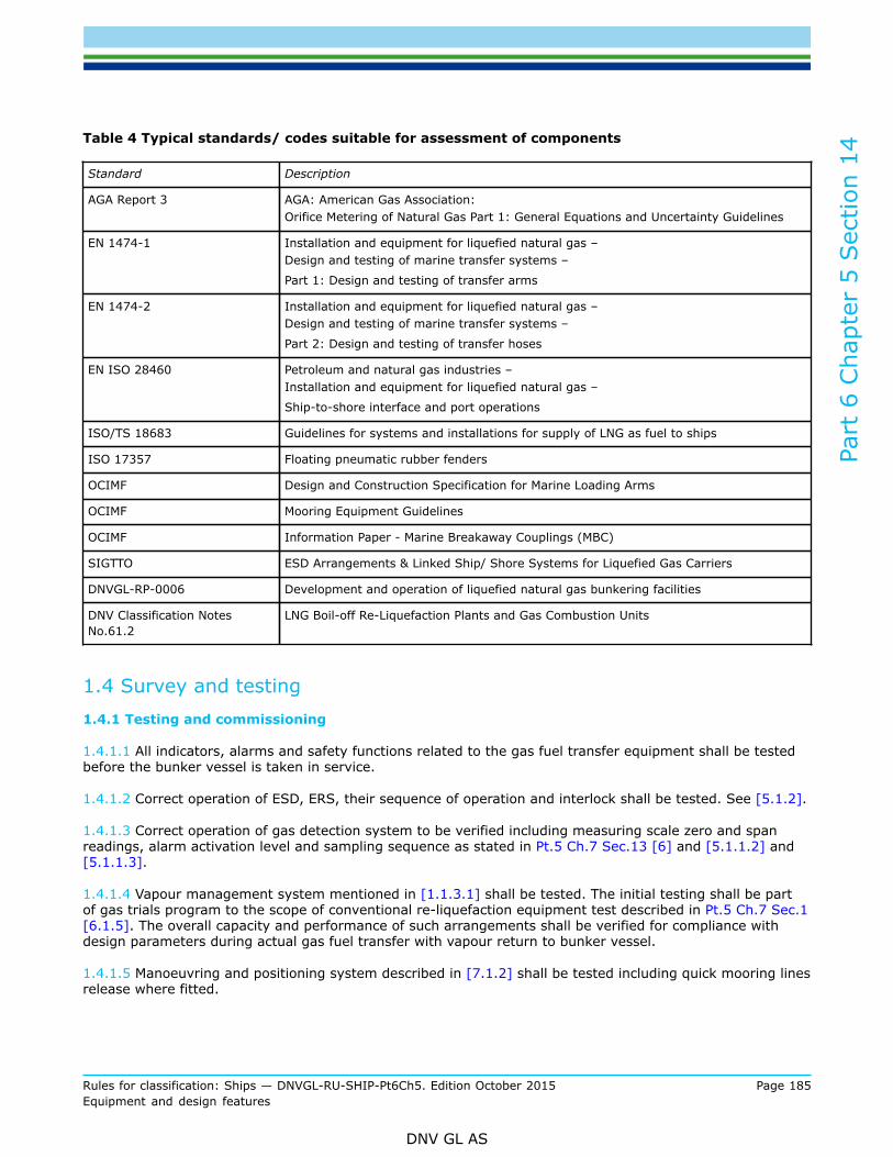
Part
6 C
hapt
er 5
Sec
tion
14
Rules for classification: Ships — DNVGL-RU-SHIP-Pt6Ch5. Edition October 2015 Page 185Equipment and design features
DNV GL AS
Table 4 Typical standards/ codes suitable for assessment of components
Standard Description
AGA Report 3 AGA: American Gas Association:Orifice Metering of Natural Gas Part 1: General Equations and Uncertainty Guidelines
EN 1474-1 Installation and equipment for liquefied natural gas –Design and testing of marine transfer systems –
Part 1: Design and testing of transfer arms
EN 1474-2 Installation and equipment for liquefied natural gas –Design and testing of marine transfer systems –
Part 2: Design and testing of transfer hoses
EN ISO 28460 Petroleum and natural gas industries –Installation and equipment for liquefied natural gas –
Ship-to-shore interface and port operations
ISO/TS 18683 Guidelines for systems and installations for supply of LNG as fuel to ships
ISO 17357 Floating pneumatic rubber fenders
OCIMF Design and Construction Specification for Marine Loading Arms
OCIMF Mooring Equipment Guidelines
OCIMF Information Paper - Marine Breakaway Couplings (MBC)
SIGTTO ESD Arrangements & Linked Ship/ Shore Systems for Liquefied Gas Carriers
DNVGL-RP-0006 Development and operation of liquefied natural gas bunkering facilities
DNV Classification NotesNo.61.2
LNG Boil-off Re-Liquefaction Plants and Gas Combustion Units
1.4 Survey and testing1.4.1 Testing and commissioning
1.4.1.1 All indicators, alarms and safety functions related to the gas fuel transfer equipment shall be testedbefore the bunker vessel is taken in service.
1.4.1.2 Correct operation of ESD, ERS, their sequence of operation and interlock shall be tested. See [5.1.2].
1.4.1.3 Correct operation of gas detection system to be verified including measuring scale zero and spanreadings, alarm activation level and sampling sequence as stated in Pt.5 Ch.7 Sec.13 [6] and [5.1.1.2] and[5.1.1.3].
1.4.1.4 Vapour management system mentioned in [1.1.3.1] shall be tested. The initial testing shall be partof gas trials program to the scope of conventional re-liquefaction equipment test described in Pt.5 Ch.7 Sec.1[6.1.5]. The overall capacity and performance of such arrangements shall be verified for compliance withdesign parameters during actual gas fuel transfer with vapour return to bunker vessel.
1.4.1.5 Manoeuvring and positioning system described in [7.1.2] shall be tested including quick mooring linesrelease where fitted.

Part
6 C
hapt
er 5
Sec
tion
14
Rules for classification: Ships — DNVGL-RU-SHIP-Pt6Ch5. Edition October 2015 Page 186Equipment and design features
DNV GL AS
1.4.1.6 Equipment fitted for purging with inert gas including the supply system, connection to the cargosystem, instrumentation and back flow prevention arrangement to be tested to ensure correct installation,operation and where applicable - alarms.
1.4.1.7 Equipment installed for gas fuel transfer its instrumentation, control and alarm systems.
1.4.1.8 Where the gas fuel main component is liquefied natural gas, the class surveyor shall witness firstbunkering operation.
1.4.1.9 The fenders shall be manufactured, tested and maintained in accordance with ISO 17357. Numberand size of the fenders shall meet recommendations of OCIMF/SIGTTO/ICS Ship to ship transfer guide.
1.4.1.10 After completed installation on board, functional testing of the crane for hose support shall becarried out as specified in DNVGL-ST-0377Standard for Shipboard Lifting Appliances.
2 Materials
2.1 General2.1.1 Material requirements
2.1.1.1 Requirements for materials, documentation and testing are covered in Pt.5 Ch.7.Guidance note:Where mixtures of hydrocarbon gases are used as gas fuel, the material should be selected with following assumption: for a designtemperature of –165°C when methane is used as main component for the gas fuel, however for other hydrocarbon mixtures higherdesign temperature may be considered depend on intended gas fuel composition.
---e-n-d---of---g-u-i-d-a-n-c-e---n-o-t-e---
2.1.1.2 For CNG tanks, the use of materials not covered by Pt.5 Ch.7 shall be specially considered andapproved by the Society.
3 Arrangement and system design
3.1 General3.1.1 Bunker manifold area
3.1.1.1 Bunker manifold area and escape routes shall have safe access for crew engaged in operation. It shallhave unrestricted natural ventilation and be sufficiently illuminated.
Guidance note:Unrestricted natural ventilation presumes an open bunker station located above the open deck. Alternative arrangement may beaccepted on a case by case basis.
---e-n-d---of---g-u-i-d-a-n-c-e---n-o-t-e---
Guidance note:Two floodlights per bunker station will be considered as sufficient illumination when they are located wide apart to minimise shadowareas on deck and high enough to minimise dazzle effect to personnel involved in handling of transfer connections.
---e-n-d---of---g-u-i-d-a-n-c-e---n-o-t-e---

Part
6 C
hapt
er 5
Sec
tion
14
Rules for classification: Ships — DNVGL-RU-SHIP-Pt6Ch5. Edition October 2015 Page 187Equipment and design features
DNV GL AS
3.1.1.2 Bunker manifold platforms arranged for access to bunker connection shall have sufficient strength toprovide support points for hoses where applicable, transfer arms and other bunker connection and manifoldarrangements.
3.1.1.3 Arrangement of work platforms in areas where liquid spill may occur shall exclude liquid spillaccumulation at the platform surface. Gratings used in this location shall be suitable for low temperaturesand correspond to boiling point of gas bunker. Area under the gratings shall be equipped with spill collectingtrays with drainage arrangements suitable for draining the accumulated spill overboard. The drain shall befitted with a valve.
Guidance note:The spill collecting tray, drain pipe and valve fitted to the drain has to be suitable for carried product. This valve is not considered tobe part of the cargo system therefore the manufacturer’s work certificate for material and work product certificate will be accepted.
---e-n-d---of---g-u-i-d-a-n-c-e---n-o-t-e---
3.1.1.4 When bunker boiling point is lower than design temperature of the hull steel, the hull in the manifoldarea shall be effectively protected from low temperature in case of a major bunker spill. Where water curtainis used for hull protection, the pumps shall be arranged with redundancy.
3.1.1.5 The bunker connections shall be clearly visible from the navigation bridge and bunker operationcontrol position where continuous watch is kept during the transfer. CCTV can be accepted as substitute forthe direct view when it provides unobstructed view of the bunker connections.
3.1.1.6 The area shall be clear of obstructions which may interfere with quick release described in Pt.5 Ch.7Sec.13 [3.1.4].
3.1.2 Cargo tanks filling
3.1.2.1 Bunker vessel shall be able to abort bunkering operation at any stage in case of emergency. Cargotanks on bunker vessel therefore shall not have restrictions on intermediate filling. However, internal transferbetween cargo tanks within short period of time to leave dangerous sloshing zone may be accepted uponspecial considerations.
3.1.2.2 For assessment of membrane cargo tanks, reference is made to DNVGL-CG-0158.
3.1.3 Bunker transfer arrangement
3.1.3.1 Possibility to perform tightness test of the bunker connections between bunker vessel and receivingship prior to operation shall be provided. Such procedure shall be described in the operation manual asrequired in Sec.6.
3.1.3.2 Suitable arrangements for inerting of the lines before filling them with the bunker vapour and for safedisplacement of bunker liquid and vapour from bunker lines prior to disconnection shall be provided.
3.1.3.3 Sections of the line where liquid may remain after the bunker transfer shall be equipped withdrain system leading back to the cargo tanks. Means to ensure that section of the transfer line outboardof manifold valve is free of liquid shall be provided. Where such arrangement is a control valve with drainopened to atmosphere, this control valve bore has to be limited by 1.5 mm.
3.1.3.4 The section of the line between valve and presentation flange shall be equipped with pressure gaugevisible from the drain valve position.
3.1.3.5 Bunker transfer piping system for products with boiling point below -55°C shall be thermally insulatedto minimise heat leaks to transferred gas bunker and protect personnel from direct contact with coldsurfaces.

Part
6 C
hapt
er 5
Sec
tion
14
Rules for classification: Ships — DNVGL-RU-SHIP-Pt6Ch5. Edition October 2015 Page 188Equipment and design features
DNV GL AS
3.1.3.6 Arrangement for monitoring of distance between the bunker vessel and receiving ship manifolds intransverse and longitudinal directions shall be fitted. Exceeding of permitted working distance shall triggeralarm following automatic stop of transfer and closing of manifold valves.
3.1.3.7 Where quick connect/disconnect couplings (QC/DC) are used they shall be equipped with mechanicallocking device to prevent inadvertent release. Powered QC/DC shall stay in “as is” position at loss of power.
3.1.4 Emergency release for bunker connection
3.1.4.1 The bunker vessel shall have arrangement for quick release of bunker connections in case ofemergency.
3.1.4.2 Emergency release couplings (ERC) used in bunker connection shall be of “dry-break” type andbe capable to self-disconnect upon application of force at any direction of vessel’s relative motion whichexceeds design loads and at pressure surge exceeding the coupling design pressure. ERC fitted in lines fortransfer of gas fuel at temperature below zero degrees Celsius shall be capable to break-away through theice accumulated on the coupling during the transfer.
3.1.4.3 In addition to ERC, the bunker connections shall be equipped with powered emergency releasesystem (ERS) operational in all conditions. The actuating ERS power shall have reserve storage of energysufficient for disconnection of all transfer lines in case the main source of actuating power becomesunavailable (for example in case of cargo area black-out). Where ERS is fitted outboard the insulating flangedescribed in [3.1.12], the insulation flange shall not be shorted by use of electrically continuous hydraulichoses.
Guidance note:Where the ERS is the dual-mode coupling and, in addition to positive means of quick release, can be parted by excessive forcesapplied to the coupling or disengage when the distance between the supplying and receiving vessels flanges exceeds safe operationalenvelope, the ERC fitting required in [3.1.4.2] may be omitted.
---e-n-d---of---g-u-i-d-a-n-c-e---n-o-t-e---
3.1.4.4 The ERS shall not disconnect the coupling at accidental black-out.Guidance note:Requirements of [3.1.4.3] is referred to an actuator device which positively disconnects the coupling (for example a hydraulic servomotor), requirement [3.1.4.4] is referred to the control circuits which shall not trigger disconnection at accidental loss of electricalpower to the ERS control circuits.
---e-n-d---of---g-u-i-d-a-n-c-e---n-o-t-e---
3.1.4.5 Activation of ERS or ERC shall not impose excessive pressure surge effect in the system. Pressuresurge effect for different flow rates and closing time of valves in transfer system shall be documented.Operational restrictions caused by closing time of valves on receiving ship shall be reflected in the vessel’scargo plant operation manual.
3.1.4.6 Where the bunker connections are supported by hose crane, the quick release couplings shallbe fitted at the receiving ship end (outward of the hose crane suspension point). Alternatively, the quickrelease couplings may be fitted at bunker vessel end when the hose suspension point has arrangements forautomatic release synchronized with the quick release coupling.
3.1.4.7 When ERS is activated it shall release in two steps: first the ESD shall be triggered to stop thetransfer and then release the ERS flanges.
3.1.4.8 Testing of ERS circuits shall be possible without disconnecting the ERS coupling.

Part
6 C
hapt
er 5
Sec
tion
14
Rules for classification: Ships — DNVGL-RU-SHIP-Pt6Ch5. Edition October 2015 Page 189Equipment and design features
DNV GL AS
3.1.4.9 Where hoses are used for transfer, release of ERC or ERS may potentially lead to hard impact of thehoses ends against the ships structures. Arrangements preventing the impact have to be provided. Release ofthe hoses shall not impose excessive stress to the manifold valves of the vessel.
3.1.4.10 Where rigid transfer arms are used for gas fuel transfer, the part of the transfer arm inboard of thequick release coupling shall retract automatically toward bunker vessel to avoid contact with other part andreceiving vessel due to vessels motion.
3.1.4.11 ERS shall be capable to be activated by manual controls situated in at least two remote locations onbunker vessel. One of these locations should be the bunker operation control position.
3.1.4.12 Excessive pressure in bunker connections shall activate alarm and automatic stop of transfer.Capability to adjust the activation set point has to be provided, but it shall not exceed design pressure of thetransfer lines.
3.1.5 Bunker manifold
3.1.5.1 The manifold for transfer of liquid shall be fitted with manually operated stop valve and a remotely/automatically operated valve (ESD valve) fitted in series.
Guidance note:The two valves requirements should be applicable irrespective of design pressure of cargo tanks fitted at the bunker vessel to makethe transfer connection suitable for operation with different MARVS setting at supply and receiving vessels.
---e-n-d---of---g-u-i-d-a-n-c-e---n-o-t-e---
3.1.5.2 The vapour return manifold shall be fitted with a remotely/automatically operated stop valve. Manuallocal operation of the valve shall be possible, e.g. by portable means.
3.1.5.3 Safe working load (SWL) of the manifold shall meet the recommendations of Manifoldrecommendations for liquefied gas carriers (OCIMF, 2011) and be capable to accommodate forces occurringdue to vessel’s relative motion, ERC self-release force and following it dynamic forces.
3.1.5.4 Information about maximum safe working load (SWL) of bunker connection shall be availableonboard and posted at the bunker station.
3.1.6 Bunker hoses
3.1.6.1 Hoses for gas fuel transfer shall be certified in accordance with requirements for cargo hose in Pt.5Ch.7 Sec.5 [11.6].
3.1.6.2 Hoses for transfer of liquid shall be protected by relief valves fitted outboard manifold valve.
3.1.6.3 Hoses used for liquid transfer shall be single length hoses from export manifold to import manifoldand provide sufficient allowance for vessel’s relative motion (including rolling) within operation envelope.
Guidance note:Combination of hoses connected in series may be accepted for gas fuel transfer when effective control of the connections integritycan be arranged and when such connections will not impose excessive stress to the hoses flexible part or change hose radius beyondacceptable limits.
---e-n-d---of---g-u-i-d-a-n-c-e---n-o-t-e---
3.1.6.4 Arrangements for support of the hoses at critical points such as: hose rails, handrails, hosesuspension points, etc. shall be provided to avoid excessive local stress and for maintaining of acceptablebending radius of the hoses. Such arrangements shall not constrain emergency release function described in[3.1.4].

Part
6 C
hapt
er 5
Sec
tion
14
Rules for classification: Ships — DNVGL-RU-SHIP-Pt6Ch5. Edition October 2015 Page 190Equipment and design features
DNV GL AS
3.1.6.5 Sufficient space for hose stowage after disconnection from receiving ship shall be available. Thestowage arrangement shall consider permitted bending radius for the hoses.
3.1.6.6 Where the stowed hoses may contain residues of liquid with boiling temperature below the hull steeldesign temperature, the ship hull structure shall be protected from the low temperature effect in the way ofthe bunker hoses stowage location.
3.1.6.7 The arrangement of the hoses when they are connected for the gas fuel transfer shall considerpossible direct contact or close proximity with hull structures. The hull in such locations shall be effectivelyprotected from the effect of low temperatures.
3.1.7 Hose handling cranes
3.1.7.1 Bunker vessel shall be fitted with deck crane or cranes for handling of transfer hoses, reducers, spoolpieces and other equipment used for transfer, including transfers at sea.
3.1.7.2 Where the crane is used for hose support during the transfer, it shall be delivered with DNV GLCertificate of compliance with DNV Standard for certification No.2.22 “Lifting Appliances”. The cranecertification by other recognized standard may be accepted based on special considerations.
3.1.7.3 Arrangements to maintain hose bend radius within limits shall be provided. Where cradles are usedfor support they have to be able to handle all hoses used for bunkering.
3.1.8 Rigid transfer arms
3.1.8.1 Rigid transfer arms and transfer systems based on foldable arms intended for use as gas fuel transferarrangement will be specially considered.
Guidance note:Acceptance criteria may be based on assessment of acceleration forces acting on the transfer arm, permissible manifold loads for thenominal diameter of the transfer arm connection, transfer arm location on bunker vessel and working envelope considering allowancefor fenders, transfer arm support arrangements in operational and stowed positions, effect of the hull vibration on the transfer arm,maintenance of the transfer arm and testing program.
---e-n-d---of---g-u-i-d-a-n-c-e---n-o-t-e---
3.1.8.2 Standard EN1474 for design and construction shall be applied.
3.1.9 Mooring equipment
3.1.9.1 Bunker vessel shall be equipped with sufficient number of closed type fairleads for safe mooring toreceiving ship. Mooring fittings and arrangements shall have their safe working load (SWL) correspondingto wind and current forces acting on the bunker vessel with allowance for dynamic forces occurring due tovessel’s relative movement.
Guidance note:Reference to is made to OCIMF Mooring equipment guidelines.
---e-n-d---of---g-u-i-d-a-n-c-e---n-o-t-e---
3.1.9.2 Steel mooring wires shall not be used unless the synthetic tails are fitted at the wire ends.
3.1.9.3 Provisions shall be made for emergency cast-off of mooring lines.Guidance note:Where fixed or portable quick release mooring hooks are used they should comply with a recognised standard.
---e-n-d---of---g-u-i-d-a-n-c-e---n-o-t-e---

Part
6 C
hapt
er 5
Sec
tion
14
Rules for classification: Ships — DNVGL-RU-SHIP-Pt6Ch5. Edition October 2015 Page 191Equipment and design features
DNV GL AS
3.1.9.4 Sufficient number of fittings shall be available for primary (parallel body length) and secondary (bowand stern quarters and superstructures) fenders.
3.1.9.5 The fenders shall be sized to provide sufficient energy absorption for the size of the vessel atapproach velocities and sea mooring conditions.
Guidance note:Number and size of the fenders should meet recommendations of OCIMF/SIGTTO/ICS Ship to ship transfer guide.
---e-n-d---of---g-u-i-d-a-n-c-e---n-o-t-e---
3.1.10 Communication equipment
3.1.10.1 The bunker vessel shall be equipped with effective communication means for internal purpose(onboard communications), for communication between the bunker vessel and receiving vessel and forexternal communications.
3.1.10.2 Where portable radios are used for communication with receiving ship, they shall be of approvedtype suitable for gas-hazardous areas. The bunker vessel shall have sufficient set of spare radios with thesame operating frequencies table for the receiving vessel duty personnel. Minimum two portable radios shallbe available for receiving vessel. Where the ships have wired communication link the number of portableradios can be reduces to one.
3.1.10.3 To reduce risk of current induction in hose cranes or rigid transfer arms, high power transmittingequipment such as MF/HF radios shall be provided with capability to be earthed manually and equipmentwith low transmitting power such as VHF radios, AIS transceivers shall have low power operation mode withtransmission power not exceeding 1W.
3.1.11 Inert gas system/nitrogen supply
3.1.11.1 Bunker vessel shall have onboard source of suitable inert gas for inerting, purging of gas fueltransfer lines and for testing of the bunker connection for tightness prior to transfer.
3.1.11.2 Installed onboard inert gas production plant shall comply with requirements ofPt.5 Ch.7 Sec.9 [2].
3.1.11.3 The inert gas stored or produced on board for purging of gas fuel transfer lines shall have dewpointsufficiently low to eliminate risk of water condensate accumulation in the piping system.
3.1.11.4 Where boiling point of the gas fuel is below -55°C the vessel shall be equipped with nitrogen supplysystem for gas fuel transfer lines inerting/purging. For fuel gas with warmer boiling point, inert gas producedby combustion of fuel or gas may be used.
3.1.11.5 Suitable arrangement to prevent back-flow of hydrocarbons from cargo system into the inert gassystem shall be provided. When the source of inert gas is located outside the cargo area, the line shall beequipped with removable spool piece located on the open deck of cargo area.
3.1.11.6 When the back flow preventer consists of non-return valves installed in series, the spool piece[3.1.11.5] shall be removed after every inerting/purging operation. A warning sign shall be posted at thevalves location and corresponding instruction included into the cargo plant operation manual.
3.1.11.7 Where a double block and bleed device is fitted to prevent the back-flow, it shall be equipped withalarms prescribed with Sec.9 [4.2.2].
3.1.11.8 The inert gas supply connections to cargo system shall be equipped with shut off valves and havea branch connection to supply the inert gas to receiving ship through a flexible hose of sufficient length forcases when inert gas source is not available on the other ship.

Part
6 C
hapt
er 5
Sec
tion
14
Rules for classification: Ships — DNVGL-RU-SHIP-Pt6Ch5. Edition October 2015 Page 192Equipment and design features
DNV GL AS
3.1.12 Static electrical charge and galvanic currents
3.1.12.1 To reduce risk of high energy spark between bunker vessel and receiving ship due to hulls’ electricalpotential difference, electrical insulation between ships shall be maintained at any stage of gas fuel transfer.Each transfer connection including connection bunker vessel and receiving ship shall have insulation flange.
3.1.12.2 Bonding wires shall not be used between ships unless required by the national administration. Inthis case the connection shall be mechanically and electrically sound and be fitted with suitable for hazardousarea switch. Warning shall be posted stating that the switch shall be in “off” position before connecting anddisconnecting the bonding cable.
3.1.12.3 Insulation flange shall have resistance of at least 1 kΩ but less than 1 MΩ to dissipate static charge.
3.1.12.4 Insulated section of the bunker hose or rigid transfer arm shall have possibility to be stowed withoutelectrical contact with hull upon disconnection.
4 Fire safety
4.1 General4.1.1 Fire protection
4.1.1.1 Fire protection and fire extinction arrangements of gas bunker vessel shall meet requirements of Pt.5Ch.7 Sec.11.
4.1.1.2 Spark arresting arrangements shall be provided at exhaust outlets of internal combustion enginesand boilers using oil as fuel and at incinerators exhaust outlets. Spark arrestors fitted in the exhaust outletsshall meet a recognized standard
4.1.1.3 Use of vapour oxidising equipment not in compliance with [7.1.1.6] shall be restricted during bunkeroperations.
5 Safety, control and montoring systems
5.1 General5.1.1 Gas detection
5.1.1.1 Installed onboard gas detection system shall be capable to measure gas concentration in themanifold connections area in addition to location described in Pt.5 Ch.7 Sec.13 [6.1.2] and have arrangementto provide a remote gas detection point for receiving ship.
Guidance note:This additional gas detector may be part of gas detection system required by Pt.5 Ch.7 Sec.13 [6] if requirements of [5.1.1.2] are met.
---e-n-d---of---g-u-i-d-a-n-c-e---n-o-t-e---
5.1.1.2 Gas detecting equipment at the manifold connection shall provide continuous monitoring and activatealarm when concentration of hydrocarbons reaches 30% of lower flammable limit (LFL).
5.1.1.3 Audible and visible alarm from the permanently installed gas detection equipment shall be located onthe navigation bridge in the bunkering operation control position and at the gas detector readout location.
5.1.2 Emergency shutdown system

Part
6 C
hapt
er 5
Sec
tion
14
Rules for classification: Ships — DNVGL-RU-SHIP-Pt6Ch5. Edition October 2015 Page 193Equipment and design features
DNV GL AS
5.1.2.1 An emergency shutdown system (ESD) pendant with manual activation button shall be available forreceiving ship.
Guidance note:If a bunker vessel has capability to connect own ESD system to receiving vessel ESD system this arrangement can replace thependant requirement.
---e-n-d---of---g-u-i-d-a-n-c-e---n-o-t-e---
5.1.2.2 In addition to Pt.5 Ch.7 requirements for ESD, the ESD function shall be initiated in followingcircumstances:
— automatically, if the distance of connection on receiving ship from the connection on bunker vesselexceeds safe operational envelope for transfer arrangement
— by activating manual ESD button on ESD pendant— automatically at ERS activation.
5.1.2.3 Opening of main transfer valves shall not be possible unless ERS is re-assembled.
6 Operations
6.1 General6.1.1 Operation manual
6.1.1.1 Operation manual shall be provided for crew and contain instructions and guidance for the following:
— preparation before the bunkering including restriction of activities/operations during gas fuel transfer— information to be exchanged between bunker vessel and receiving ship prior to operation— hose handling guidelines reflecting specific hose manufacturer instructions for the hose handling— procedures for connection including line inerting and tightness test— preparations for start of bunkering, i.e. preparedness of fire-fighting, tightness testing, establishing
communications, allocation of personnel/responsibilities— pre-cooling of transfer connection(s) and transfer procedures— draining of the pipeline, purging and disconnection on completion of the transfer— operational restrictions to prevent dangerous pressure surge effect in the pipes— fire safety during the transfer— procedures for raising alarms— procedures in case of communications failure— suspension of operation during emergencies— procedures for authorization of ERS activation— emergency procedures for: gas fuel leakage, termination of the bunkering and emergency disconnection,
response in case of unintentional disconnection of ERS, etc.
6.1.1.2 Cargo system piping diagram, function flowchart or cause and effect (C&E) diagram for ESD andrelated systems shall be available in the bunker/cargo control room where such room is established.
7 Special features/optional qualifiers
7.1 General7.1.1 Vapour management

Part
6 C
hapt
er 5
Sec
tion
14
Rules for classification: Ships — DNVGL-RU-SHIP-Pt6Ch5. Edition October 2015 Page 194Equipment and design features
DNV GL AS
7.1.1.1 Arrangements for handling excess vapour from receiving ship shall be provided with capacitysufficient to prevent venting of gas fuel vapour to the atmosphere.
7.1.1.2 Such additional arrangements and systems may be built on the following principles:
— re-liquefaction of vapours by means of mechanical refrigeration— thermal oxidation of excess vapours— a system allowing accumulation of the vapour in compressed state— by other means acceptable to the Society— a combination of the above.
7.1.1.3 Such arrangement and systems shall meet design conditions stated in Pt.5 Ch.7 Sec.7 unless otherambient conditions are specially agreed.
7.1.1.4 Redundancy requirements in Pt.5 Ch.7 Sec.7 are not applicable for this optional system.
7.1.1.5 Process piping for handling excess vapour from receiving ship shall be adequately separated to avoidover-pressurising cargo system on bunker vessel.
7.1.1.6 If vapour disposal is by means of oxidation, the installation shall comply with DNV Classification notesNo. 61.2 except that the exhaust gas shall have a maximum exit temperature of 250°C. Exhaust outlet forsuch system shall be located on the side opposite to receiving vessel and directed outward.
7.1.1.7 When the system is based on accumulation of compressed vapour on bunker vessel, dueconsiderations shall be made for safe operational margin. Additional pressure control systems with capacityto maintain cargo pressure/temperature within the limits shall be fitted.
7.1.1.8 Compressor installed for vapour extraction from receiving ship shall be fitted with automatic pressureand flow control, and be provided with surge protection and provisions for emergency stop.
7.1.2 Manoeuvring and positioning
7.1.2.1 The bunker vessel shall have longitudinal and transverse trust capabilities at approach and departurespeed and retain sufficient manoeuvrability at speed vector alterations.
7.1.2.2 Control positions locations shall provide unobstructed view in the approach sector.
7.1.2.3 Independent system shall be available to provide information about vessel heading, speed vectorand acceleration, rudder angle, vessel’s rate of turn, engine RPM and propeller pitch and thruster vectors atmooring control position. Failure of a sensor, system or equipment shall trigger alarm.
7.1.2.4 The vessel shall be equipped with independent joystick control system for positioning andmanoeuvring which shall comply with Ch.3 Sec.1 [6.2].
7.1.2.5 The instruments [7.1.2.3] readings shall be clearly visible from the control positions in any ambientlight conditions including bright Sun and do not constrain view due to scatter of own light at night.
7.1.3 Enhanced transfer control
7.1.3.1 The transfer control system shall have provisions of automatic control of flow rate and limitingpressure in the transfer system. Parameters of the control system critical for the safe transfer shall haveadjustable settings.
7.1.3.2 Deviations from set values mentioned in [7.1.3.1] shall activate audible and visual alarms at thebunker operations control position and on the navigation bridge.

Part
6 C
hapt
er 5
Sec
tion
14
Rules for classification: Ships — DNVGL-RU-SHIP-Pt6Ch5. Edition October 2015 Page 195Equipment and design features
DNV GL AS
7.1.3.3 The transfer control system for liquid shall automatically reduce the liquid transfer rate when setvalues for pressure in the vapour return/vapour recovery system is exceeded.
7.1.3.4 If the transfer rate exceeds a maximum value, alarm and automatic stop of transfer shall beactivated and manifold valves closed.
7.1.3.5 The receiving vessel shall have possibility to control transfer flow rate by means of a ship-to-ship link,e.g. flexible cable and pendant with means of control.

DNV GLDriven by our purpose of safeguarding life, property and the environment, DNV GL enablesorganizations to advance the safety and sustainability of their business. We provide classification andtechnical assurance along with software and independent expert advisory services to the maritime,oil and gas, and energy industries. We also provide certification services to customers across a widerange of industries. Operating in more than 100 countries, our 16 000 professionals are dedicated tohelping our customers make the world safer, smarter and greener.
SAFER, SMARTER, GREENER
Related Documents