The electronic pdf version of this document, available free of charge from http://www.dnvgl.com, is the officially binding version. DNV GL AS RECOMMENDED PRACTICE DNVGL-RP-F401 Edition June 2017 Electrical power cables in subsea applications

Welcome message from author
This document is posted to help you gain knowledge. Please leave a comment to let me know what you think about it! Share it to your friends and learn new things together.
Transcript
The electronic pdf version of this document, available free of chargefrom http://www.dnvgl.com, is the officially binding version.
DNV GL AS
RECOMMENDED PRACTICE
DNVGL-RP-F401 Edition June 2017
Electrical power cables in subseaapplications

FOREWORD
DNV GL recommended practices contain sound engineering practice and guidance.
© DNV GL AS June 2017
Any comments may be sent by e-mail to [email protected]
This service document has been prepared based on available knowledge, technology and/or information at the time of issuance of thisdocument. The use of this document by others than DNV GL is at the user's sole risk. DNV GL does not accept any liability or responsibilityfor loss or damages resulting from any use of this document.
Cha
nges
- c
urre
nt
Recommended practice — DNVGL-RP-F401. Edition June 2017 Page 3Electrical power cables in subsea applications
DNV GL AS
CHANGES – CURRENT
GeneralThis document supersedes the February 2012 edition of DNV-RP-F401.The purpose of the revision of this service document is to comply with the new DNV GL document reference code system and profile requirements following the merger between DNV and GL in 2013. Changes mainly consist of updated company name and references to other documents within the DNV GL portfolio.
Some references in this service document may refer to documents in the DNV GL portfolio not yet published (planned published within 2017). In such cases please see the relevant legacy DNV or GL document. References to external documents (non-DNV GL) have not been updated.
Editorial correctionsIn addition to the above stated changes, editorial corrections may have been made.
Con
tent
s
Recommended practice — DNVGL-RP-F401. Edition June 2017 Page 4Electrical power cables in subsea applications
DNV GL AS
CONTENTS
Changes – current.................................................................................................. 3
Section 1 Introduction............................................................................................ 61.1 General............................................................................................. 6
Section 2 Scope.......................................................................................................72.1 Application........................................................................................72.2 Applicable standards.........................................................................72.3 Terminology...................................................................................... 7
Section 3 Requirements.......................................................................................... 93.1 General construction requirements...................................................93.2 Conductor....................................................................................... 103.3 Electrical insulation of core – breakdown strength......................... 103.4 Screen/sheath for prevention water exposure to the insulationsystem.................................................................................................. 113.5 Water blocking................................................................................123.6 Degassing....................................................................................... 123.7 Longitudinal gas barrier................................................................. 133.8 Armour............................................................................................133.9 Anchoring of armour.......................................................................133.10 Radial compression – load carrying capacity................................ 143.11 Flexibility/compliance...................................................................143.12 Bending radius..............................................................................143.13 Coiling...........................................................................................14
Section 4 References.............................................................................................154.1 References...................................................................................... 15
Appendix A Qualification with respect to fatigue.................................................. 16A.1 Limitations......................................................................................16A.2 Definitions...................................................................................... 16A.3 Input data...................................................................................... 17A.4 Pre-test straining............................................................................17A.5 Qualification principles................................................................... 17A.6 Qualification based on components................................................ 18A.7 Qualification of complete cable cross section................................. 20A.8 Electrical verification tests............................................................. 21
Con
tent
s
Recommended practice — DNVGL-RP-F401. Edition June 2017 Page 5Electrical power cables in subsea applications
DNV GL AS
Appendix B Test methods – fatigue loading of complete cables............................24B.1 General........................................................................................... 24B.2 4-point-bending.............................................................................. 24B.3 Bending against template...............................................................25
Appendix C Fatigue testing detection techniques................................................. 26C.1 Metallic materials........................................................................... 26C.2 Plastic materials............................................................................. 28
Appendix D Estimation of fatigue design curves – least squares method.............. 29
Appendix E Estimation of fatigue design curves - incomplete observations ofnumber of cycles to failure...................................................................................31
Changes – historic................................................................................................33
Recommended practice — DNVGL-RP-F401. Edition June 2017 Page 6Electrical power cables in subsea applications
DNV GL AS
SECTION 1 INTRODUCTION
1.1 GeneralThis recommended practice is to be used as a supplement to ISO 13 628-5 /1/ with regards to electricalpower cables. This ISO standard does not give requirements to such cables on a detailed level. This RPcovers additional requirements for power cables being submerged in seawater at large water depths and/orbeing exposed to dynamic excitation, e.g. when suspended from floating production units.The RP is intended to be used together with /1/. In case of conflict between the ISO standard and thisdocument the ISO standard shall prevail.It is a pre-requisite that power cables are designed and fabricated according to existing IEC standards.
Recommended practice — DNVGL-RP-F401. Edition June 2017 Page 7Electrical power cables in subsea applications
DNV GL AS
SECTION 2 SCOPE
2.1 ApplicationThe RP covers electrical power cables, as single cables or integrated in an umbilical in an application coveredby ISO 13 628-5 /1/.The RP covers cables which comply with IEC 60 502-1 /2/ and IEC 60 502-2 /3/.The RP applies to cables used for AC power transmission. DC cables are not covered.
Guidance note:Examples of single cables may e.g. be power supply to direct electrical heating systems for pipelines, main power supply fromshore to floating production units, power supply from floating units to subsea installation etc.
---e-n-d---o-f---g-u-i-d-a-n-c-e---n-o-t-e---
Guidance note:The following definition of an umbilical is given in /1/: “group of functional components, such as electric cables, optical fibre cables,hoses, and tubes, laid up or bundled together or in combination with each other, that generally provides hydraulics, fluid injection,power and/or communication services”.
---e-n-d---o-f---g-u-i-d-a-n-c-e---n-o-t-e---
2.2 Applicable standardsPower cables shall comply with the following standards unless otherwise stated:
— IEC 60 502-1, Power cables with extruded insulation and their accessories for rated voltages from 1 kV(Um = 1,2 kV) up to 30 kV (Um = 36 kV) - Part 1: Cables for rated voltages of 1 kV (Um = 1,2 kV) and 3kV (Um = 3,6 kV) /2/
— IEC 60 502-2, Power cables with extruded insulation and their accessories for rated voltages from 1 kV(Um = 1,2 kV) up to 30 kV (Um = 36 kV) - Part 2: Cables for rated voltages from 6 kV (Um = 7,2 kV) upto 30 kV (Um = 36 kV) /3/
— IEC 60 228, Conductors of insulated cables /4/
and the following recommendations:
— Cigré TB490, Recommendations for Testing of Long AC Submarine Cables with Extruded Insulation forSystem Voltage above 30 (36) to 500 (550) kV, 2012 /5/.
2.3 TerminologyThe terminology used in the document follows the terminology specified in /2/ or /3/:
Table 2-1 Definitions of terminology
Term Description
AC lternating current
armour covering consisting of a metal tape(s) or wires, generally used to protect the cable from externalmechanical effects
note in this RP Armour is used for the components providing the longitudinal strength and stiffness to thecable
conductor part of a cable which has the specific function of carrying current
conductorscreen
electrical screen of non-metallic and/or metallic material covering the conductor
Recommended practice — DNVGL-RP-F401. Edition June 2017 Page 8Electrical power cables in subsea applications
DNV GL AS
Term Description
core assembly comprising a conductor with its own insulation (and screens if any)
DC direct current
insulationscreen
non-metallic, semi-conducting layer in combination with a metallic layer applied on the insulation
insulation assembly of insulating materials incorporated in a cable with the specific function of withstandingvoltage
oversheath non-metallic sheath applied over a covering, generally metallic, ensuring the protection of the cablefrom the outside
screen conducting layer or assembly of conducting layers having the function of control of the electric fieldwithin the insulation
sheath uniform and continuous tubular covering of metallic or non-metallic material, generally extruded. (NorthAmerica: jacket)
strand one of the wires in a stranded conductor
In addition the term water blocking is used for powder, tape, grease, compound, yarn or glue applied under asheath or into the interstices of a conductor to prevent water migrating along the cable.A barrier sheath, IEC 60 050-461 /6/, having the function of protecting the insulation and its screen fromoutside contamination may be specified by the purchaser.
Recommended practice — DNVGL-RP-F401. Edition June 2017 Page 9Electrical power cables in subsea applications
DNV GL AS
SECTION 3 REQUIREMENTS
3.1 General construction requirements
3.1.1 Insulation systemThe insulation system shall consist of a fully bonded true triple extruded XLPE system (extrusion of conductorscreen, insulation and insulation screen simultaneously). The insulation screen is not required for cablesaccording to /2/. The use of other insulation system(s) is the subject of agreement between manufacturerand purchaser.
3.1.2 ConductorA joint of the entire conductor cross section of the conductor shall not be located in a dynamic part of acable, i.e. parts of the cable not resting on the seabed or otherwise prevented from motion.
3.1.3 ArmourCables shall be balanced with respect to torsion. Un-balanced designs may be used subject to agreementbetween manufacturer and purchaser. Test methods and acceptance criteria may have to be modified for un-balanced designs.
3.1.4 Thermal conditionsCable routing and installation method (e.g. burial, rock dumping, guide tubes etc.) may reduce the heattransport from the cable. Ancillary equipment like bend stiffeners may act as thermal insulators on theoutside of the cable reducing the heat transport from the cable. Hence, the cable system shall be designedto meet the worst case thermal loads. The temperature shall not exceed the thermal limitations for anymaterials in the power cable.
3.1.5 Longitudinal static strength of cableThe conductor and sheath(s) or screen(s) shall not be taken into account when assessing the longitudinalcapacity of the cable cross section. The strain in the conductor and sheath(s)/screen(s) shall be limited bythe strain in the load carrying elements in the cable cross section.For applications where it can be shown that it is acceptable that the conductor contributes to the longitudinalcapacity of the cable, e.g. at smaller water depths, the load carrying capacity of the conductor may be takeninto account. In such a case it shall be demonstrated that failure due to creep or any other failure mechanismwill not occur.A joint of the entire cable cross section shall not be located in dynamic part(s) of a cable, i.e. parts of thecable not resting on the seabed or otherwise supported.
3.1.6 Fatigue strength of cable.Cables exposed to dynamic excitation (e.g. cables suspended between floating installations and the seabottom, cables exposed to vortex induced vibrations) shall be qualified with respect to fatigue as specified inthis document. For static applications (e.g. cables resting on the sea bed) such qualification is not mandatory.However, dynamic effects during installation shall be considered.
Recommended practice — DNVGL-RP-F401. Edition June 2017 Page 10Electrical power cables in subsea applications
DNV GL AS
3.1.7 Hydrostatic strengthThe components in the cable cross section shall, when the complete cross section is subjected to an externalhydrostatic pressure not smaller than the larger of 3.5 MPa or the pressure corresponding to the maximumwater depth multiplied by a factor of 1.25, not exhibit any damage that may impair its capacity with respectto mechanical loads.Casings (including seals) for cable joints or terminations shall, when subjected to an external hydrostaticpressure not smaller than the larger of 3.5 MPa or the pressure corresponding to the maximum water depthmultiplied by a factor of 1.5, not exhibit any damage or leakage.The effect of external hydrostatic pressure on the electrical properties of the cable is handled elsewhere.
3.2 Conductor
3.2.1 Static strength of conductorThe conductor shall be supported in the longitudinal direction of the cable such that failure due to creep isprevented. This shall be confirmed by calculations based on adequate test data or data available in literature.The evaluation of creep shall consider the effect of service temperature on the rate of creep. Variations in theservice temperature shall be considered or a conservative approach chosen.
Guidance note:For cables suspended in large water depths the self-weight of the conductor may induce unacceptable creep in the conductor if theconductor is not supported.
---e-n-d---o-f---g-u-i-d-a-n-c-e---n-o-t-e---
3.2.2 Fatigue strength of conductorConductors in cables exposed to dynamic loading shall be qualified with respect to fatigue. A procedure forthe qualification of power cables with respect to fatigue is given in App.A.A failed strand may have a detrimental effect on the conductor screen. It is recommended that failure of onestrand is used as fatigue failure criterion. Alternative failure criteria may be agreed upon between purchaserand manufacturer.The safety factor on fatigue life, determined by calculation or testing, shall not be smaller than 10 unlessotherwise agreed between manufacturer and purchaser.
Guidance note:Electra 189 includes tests for cable joints for submarine cables. These tests are however considered sufficient for static applicationsonly with respect to demonstrating sufficient fatigue strength. Depending on the application, further tests need to be carried out.
---e-n-d---o-f---g-u-i-d-a-n-c-e---n-o-t-e---
3.3 Electrical insulation of core – breakdown strengthCable insulation for wet applications shall be qualified in accordance with CENELEC HD 605 S2 /7/Sec.5.4.15.It is recognised that these tests are carried out using tap water at a small water head (for practical purposesthe specified tests can be considered carried out at atmospheric pressure) and at a temperature of 40ºC.The cables will be exposed to sea water, a significantly higher hydrostatic pressure and temperatures withina wide range, the maximum temperature exceeding 40ºC. An evaluation of the significance of the actualservice conditions with respect to the test conditions shall be carried out and the test conditions modifiedaccordingly.
Recommended practice — DNVGL-RP-F401. Edition June 2017 Page 11Electrical power cables in subsea applications
DNV GL AS
For dry applications, i.e. where the cable cross section includes a sheath preventing radial water transportto the insulation and where this sheath is duly qualified in accordance with this document, the qualificationspecified above need not be carried out.
Guidance note:Dynamic response of the cable is assumed not to have any adverse effect on the capacity of the insulation with respect tobreakdown strength. It is, however, advised that research in the matter is consulted when becoming available.
---e-n-d---o-f---g-u-i-d-a-n-c-e---n-o-t-e---
3.4 Screen/sheath for prevention water exposure to the insulationsystem
3.4.1 GeneralSheaths for prevention or slowing down of radial water transport are not prescribed in cables conforming toIEC 60 502-1 and 2, /2/ and /3/. The requirement for a metallic sheath is the subject of agreement betweenmanufacturer and purchaser. Herein such a sheath is referred to as a barrier sheath /6/.
3.4.2 Static strength/overstraining of screen/sheathIn suspended cables the barrier sheath shall be supported in the longitudinal direction of the cable suchthat failure due to creep is prevented. Alternatively it shall be demonstrated by analysis based on adequatedata on creep that creep failure will not occur. The evaluation of creep shall consider the effect of servicetemperature on the rate of creep.
Guidance note:The hydrostatic pressure on the cable may be sufficient to support the barrier sheath if the coefficient of friction to the adjacentcomponents in the cross section and the load carrying capacity of these components are sufficiently large.
---e-n-d---o-f---g-u-i-d-a-n-c-e---n-o-t-e---
3.4.3 BucklingIf not properly supported, bending of a barrier sheath may induce local buckling, particularly forcombinations of thin materials made from material with a large Young modulus (e.g. metallic tubes or foils).Local buckling shall be prevented.
3.4.4 Corrosion of sheath/screenThe material in the barrier sheath shall be chosen such that it has the sufficient resistance to corrosionconsidering the service environment: exposure to sea water, temperature. There shall be no penetration ofthe sheath due to corrosion (holes, pits, cracks etc.) during the service life of the cable.
3.4.5 Fatigue strength of barrier sheaths – global loadsBarrier sheaths in cables exposed to dynamic loading shall be qualified with respect to fatigue. A procedurefor the qualification of power cables with respect to fatigue is given in App.A.Penetration of the sheath, e.g. a crack, hole etc., shall constitute failure. The safety factor on fatiguelife, determined by calculation or testing, shall not be smaller than 10 unless otherwise agreed betweenmanufacturer and purchaser.
Recommended practice — DNVGL-RP-F401. Edition June 2017 Page 12Electrical power cables in subsea applications
DNV GL AS
3.4.6 Fatigue strength of barrier sheath – thermal effects/radial expansionRepeated thermal expansion/contraction of components inside of the sheath may induce fatigue stress in thecircumferential direction. The number of load cycles may be small, but the circumferential strain induced inthe sheath may be relatively large. The number and magnitude of the load cycles shall be specified by thepurchaser as well as the relevant service temperatures.A satisfactory fatigue life of the sheath shall be demonstrated by recognised methods taking into accountdeformation in the non-linear regime of the materials. The design with respect to fatigue shall be based onfatigue design curves or by direct testing on cable samples. Fatigue design curves shall be determined bytesting at the strain levels that are relevant and be expressed as fatigue life in number of load cycles vs.strain range. Damage accumulation shall be carried out in accordance with recognised methods.The fatigue life may alternatively be determined by testing of samples of cable by exposing the cable toheating cycles while applying the relevant external pressure.Penetration of the sheath, e.g. a crack, hole etc., shall constitute failure. The safety factor on fatiguelife, determined by calculation or testing, shall not be smaller than 10 unless otherwise agreed betweenmanufacturer and purchaser.
3.5 Water blocking
3.5.1 Water blockingBlock against water transport along the conductor and the interstice between screen and external sheathshall be fitted.The type of water block is subject to agreement between purchaser and manufacturer.
3.5.2 Longitudinal water blocking along conductorThe cable shall be tested in accordance with and comply with the requirements given in /5/. The test shall becarried out with sea water, preferably with artificial sea water according to recognized standards or accordingto agreement between purchaser and manufacture. The test pressure shall not be lower than the maximumhydrostatic pressure in operation.
3.5.3 Longitudinal water blocking between screen and external sheathThe cable shall be tested in accordance with and comply with the requirements given in /5/. Alternativerequirements may be agreed upon between manufacturer and purchaser.The simultaneous effect of an external hydrostatic pressure on the external sheath on the water transportalong the cable may be considered and included in the test procedure.
3.6 DegassingCables shall be de-gassed as part of the manufacturing process. The de-gassing procedure is subject toagreement between the purchaser and manufacturer.
Guidance note:There is at present no generally accepted procedure for degassing.
---e-n-d---o-f---g-u-i-d-a-n-c-e---n-o-t-e---
Recommended practice — DNVGL-RP-F401. Edition June 2017 Page 13Electrical power cables in subsea applications
DNV GL AS
3.7 Longitudinal gas barrierThe use of gas blocks, continuous or intermittent, is the subject of agreement between manufacturer andpurchaser.The design and fabrication of the cable shall aim at minimising the volume of trapped voids inside the cable.
3.8 Armour
3.8.1 Static strengthThe allowable utilization factors for load carrying elements for longitudinal loads are specified in Table 3-1.The utilisation factor shall be taken as the ratio of the applied load to the lesser of the specified minimumyield strength and 90% of the specified minimum ultimate tensile strength of the steel material in thearmour.For armour of other material than steel the utilisation factors are subject to agreement between thepurchaser and the manufacturer.
Table 3-1 Armour utilisation factors
Utilisation factor
Normal operation 0.67
Installation 0.78
Abnormal operation 1.00
3.8.2 Fatigue strengthArmour in cables exposed to dynamic loading shall be qualified with respect to fatigue. A procedure for thequalification of power cables with respect to fatigue is given in App.A.The safety factor on fatigue life, determined by calculation or testing, shall not be smaller than 10.
3.9 Anchoring of armour
3.9.1 Static strengthThe utilisation factor of anchoring of armour in end terminations shall comply with Table 3-1. The utilisationratio shall be calculated as the applied load divided by the capacity of the termination.
3.9.2 Fatigue strengthArmour anchors subjected to significant fatigue loading shall be qualified with respect to fatigue strength bytesting. The safety factor on fatigue life, determined by calculation or testing, shall not be smaller than 10.
Recommended practice — DNVGL-RP-F401. Edition June 2017 Page 14Electrical power cables in subsea applications
DNV GL AS
3.10 Radial compression – load carrying capacity
3.10.1 Radial compression – load casesAll radial loads on the cable cross section shall be considered. The design load cases shall include, but not belimited to:
— hydrostatic pressure— installation loads, e.g. clamping forces from caterpillar, temporary hang-off— contact forces in chutes— loads from clamps for anchors, buoyancy modules etc.— support reactions, e.g. over mid-water arches.
3.10.2 Radial compression – allowable load/stress/strainThe manufacturer shall specify the allowable compression loads, short term and long term, and/or allowablecompression strains as relevant, for each of the types of loads identified in accordance with [3.10.1].The manufacturer shall specify radial compression creep data enabling the proper design of clamps withrespect to possible relaxation of clamp forces due to creep. Creep data shall reflect the service temperaturesthe cable will experience.Compression may lead to damage of the semi-conducting screen when compressed on the conductor. Thisfailure mode shall be considered when determining the allowable compression force.
Guidance note:The maximum allowable compression force/strain may have a large impact on the choice of installation method, installationequipment, design of ancillary equipment like clamps etc. A clear specification of the allowables is therefore important at an earlystage. The design of the cross section may be the subject to an iterative process between manufacturer and purchaser.
---e-n-d---o-f---g-u-i-d-a-n-c-e---n-o-t-e---
3.11 Flexibility/compliancePossible requirements to the flexibility of the cable shall be clearly stated by the purchaser.The manufacturer shall specify the flexibility or the bending stiffness of the cable, maximum and minimum,for different temperatures as agreed with the manufacturer. The flexibility depends on the curvature ofthe cable. The flexibility should as a minimum be stated for the minimum bending radius specified by themanufacturer for installation and service.
3.12 Bending radiusPossible requirements to the allowable minimum bending radius of the cable, during installation andoperation, shall be clearly stated by the purchaser.The manufacturer shall specify the minimum allowable bending radius for different temperatures for storage,installation and operation.
3.13 CoilingCables which during manufacture, storage or installation may be subjected to coiling shall be qualified inaccordance with /8/.
Recommended practice — DNVGL-RP-F401. Edition June 2017 Page 15Electrical power cables in subsea applications
DNV GL AS
SECTION 4 REFERENCES
4.1 References/1/ ISO 13628-5 Petroleum and natural gas industries - Design and operation of subsea production systems
- Part 5: Subsea umbilicals
/2/ IEC 60 502-1 Power cables with extruded insulation and their accessories for rated voltages from 1 kV(Um = 1,2 kV) up to 30 kV (Um = 36 kV) - Part 1: Cables for rated voltages of 1 kV (Um = 1,2 kV) and3 kV (Um = 3,6 kV)
/3/ IEC 60 502-2 Power cables with extruded insulation and their accessories for rated voltages from 1 kV(Um = 1,2 kV) up to 30 kV (Um = 36 kV) - Part 2: Cables for rated voltages from 6 kV (Um = 7,2 kV)up to 30 kV (Um = 36 kV)
/4/ IEC 60 228 Conductors of insulated cables
/5/ Cigré TB490, Recommendations for Testing of Long AC Submarine Cables with Extruded Insulation forSystem Voltage above 30 (36) to 500 (550) kV
/6/ IEC 60 050-461 International Electrotechnical Vocabulary - Part 461: Electric cables
/7/ CENELEC HD 605 S2 Electric cables - Additional test methods
/8/ Cigré TB623, Recommendations for Mechanical Testing of Submarine Cables
/9/ DNVGL-RP-C203 Fatigue design of offshore steel structures
Recommended practice — DNVGL-RP-F401. Edition June 2017 Page 16Electrical power cables in subsea applications
DNV GL AS
APPENDIX A QUALIFICATION WITH RESPECT TO FATIGUE
A.1 LimitationsThis section covers qualification with respect fatigue loading in the high cycle regime.Due to the limited strain levels normally expected in service, well known insulation and oversheath materialswith large strain to failures need not be subjected to a qualification procedure. The following materials areconsidered to have adequate fatigue strength with respect to mechanical damage:
— low density thermoplastic polyethylene (PE)— high density thermoplastic polyethylene (HDPE)— cross-linked polyethylene (XLPE)— ethylene propylene rubber (EPR),
unless significantly modified with fillers, additives or similar.For other insulation materials a qualification with respect to fatigue shall be carried out. The qualificationprogram will be subject to agreement in each particular case.
A.2 DefinitionsC Curvature. C = 1/ρCmax The maximum curvature during one deformation cycle = 1/ ρmin
Cmin The minimum curvature during one deformation cycle = 1/ ρmax
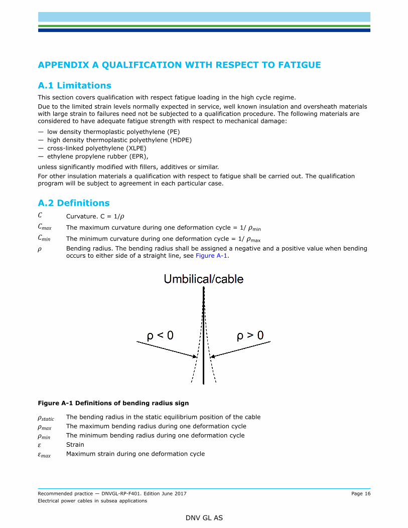
ρ Bending radius. The bending radius shall be assigned a negative and a positive value when bendingoccurs to either side of a straight line, see Figure A-1.
Figure A-1 Definitions of bending radius sign
ρstatic The bending radius in the static equilibrium position of the cableρmax The maximum bending radius during one deformation cycleρmin The minimum bending radius during one deformation cycleε Strainεmax Maximum strain during one deformation cycle
Recommended practice — DNVGL-RP-F401. Edition June 2017 Page 17Electrical power cables in subsea applications
DNV GL AS
εmin Minimum strain during one deformation cycle
Rρ Curvature ratio. Rρ =
Rε Strain ratio. Rμ = εmin/ εmax
N Number of deformation cycles
D Accumulated fatigue damage
k Number of strain/stress blocksni Number of cycles in strain block iNi Number of cycles to failure at strain range for strain block im Slope of fatigue curve.
A.3 Input dataA detailed drawing of the cable cross section shall be available as well as specifications of all materials andcomponents included in the cross section. The specification shall be given on a level of detail that is sufficientto carry out the qualification.
A.4 Pre-test strainingThe cable and its components will be subjected to operations during which it may be deformed in ways thatmay have an effect on the fatigue properties. Examples of such operations are:
— cold work during closing and compacting of conductor— forming during cable manufacturing (e.g. metallic sheaths, screen or armour wire)— bending during reeling operations during manufacturing of the cable— bending when manufacturing the umbilical— bending during installation.
The effect of these operations on the mechanical properties shall be represented and/or simulated in arepresentative manner, on cable samples or the individual components prior to testing.
A.5 Qualification principles
A.5.1 Qualification methodThe different components in the cable cross section may be qualified separately, see [A.6]. For thesubsequent qualification of the complete cable cross section a reliable model of the cable cross sectionshall be established. This model shall as a minimum describe how the local response of the components isdependent on the global response of the cable, how the different components interact in the cable crosssection, how relevant material parameters scale with size, where relevant, etc. Important factors are frictionbetween the components. Calculation tools and assumptions for this purpose will in such a case also besubject to qualification.Alternatively, qualification can be carried out on a complete cable cross section, i.e. all tests are carried outon samples of the complete cable as delivered from the manufacturer, see [A.7] (In some cases it may besufficient to carry out testing on complete cores, i.e. when it can be demonstrated that the componentsoutside the core do not have any effect on the test results.)Irrespective of the approach that is chosen a number of electrical verification tests shall be carried out, see[A.8].
Recommended practice — DNVGL-RP-F401. Edition June 2017 Page 18Electrical power cables in subsea applications
DNV GL AS
For the mechanical tests relatively short samples may be used. For the electrical tests the length of thespecimens shall be as specified in the specified standards. Hence, excess cable length may have to beincluded in the mechanical test specimens to carry out the subsequent electrical tests.
Guidance note:Existing calculation tools applied to umbilicals might be possible to use to calculate the response of some of the components in thecross section, e.g. conductor, screen wire, armour wire.
---e-n-d---o-f---g-u-i-d-a-n-c-e---n-o-t-e---
A.5.2 Load conditionsThe fatigue load effect due to bending of the cable may be specified in terms of bending radius, i.e. adeformation. Some of the materials, e.g. copper, may be deformed non-linearly. For such materials fatiguetests and results should be performed in controlled strain and presented as strain vs. number of load cycles.
A.5.3 Load effect ratio – mean stress/strainA cable will be subjected to a static curvature on which a dynamic curvature is superimposed and in additiona tensile load. Consequently stress or strain ratio may vary from application to application and along thecable. Stress/strain ratio shall be reflected in the qualification.
A.5.4 TemperatureTest conditions shall reflect the range of the service temperature whenever the temperature has a significantinfluence on the properties. Alternatively, generally accepted methods for modifying material properties dueto temperature effects may be applied.Fatigue testing may heat the test specimens, particularly at higher test frequencies and/or if the specimenhas some form of insulation, e.g. when testing a complete core or cable cross section. Further, the cablecontains visco-elastic materials and some materials may be deformed into their non-linear regime, leadingto further generation of heat. This shall be considered when carrying out the tests. Control of the testtemperature shall be established.
A.6 Qualification based on components
A.6.1 Qualification testingA.6.1.1 ConductorTest shall be carried out as uni-axial tensile tests on individual conductor strands (single wires). A fatiguedesign curve shall be established as specified in [A.6.2]. The failure criterion is broken strand. Due to therelatively strong non-linear behaviour of copper the tests may have to be carried out in controlled strain.The possible effect on the fatigue strength of wear and/or fretting between the strands shall be considered.Fretting damage may occur due to the sliding between strands when the core is bent. The amount of frettingdepends also on the compressive force between the strands, due e.g. to external hydrostatic pressure, fittingof clamps for buoyancy modules of anchors. It shall be demonstrated that wear/fretting is not significant withrespect to the fatigue strength. Otherwise alternative test methods shall be used, e.g. fatigue testing of thecomplete conductor, e.g. in a completed core of cable.
A.6.1.2 Solid metallic tube sheathQualification can be based on small scale testing of samples taken from the tube. A fatigue design curve shallbe established as specified in [A.6.2]. The failure criterion is broken specimen.Test specimens shall be cut in the longitudinal direction of the tube and shall include the whole thickness. Anarrow gauge section may be included in the specimen.
Recommended practice — DNVGL-RP-F401. Edition June 2017 Page 19Electrical power cables in subsea applications
DNV GL AS
Test specimens shall also include longitudinal weld(s), if any. Test shall be carried out on both base materialand welds.
A.6.1.3 Sheath – other configurationsSome types of sheaths, e.g. based on metallic foils, are not possible to fatigue test as individual components.Qualification of such sheaths should be based on testing of cores or complete cable cross sections.Alternatively testing could be carried out with the foil adhered to adjacent plastic layer for stabilisation of thefoil, see [A.6.1.2].Special attention shall be given to adhesive bonds used in foils. Such bonds will be subjected to a shear loadwhen the cable is bent. The effect of the fatigue shear stress shall be considered.Other configurations of e.g. solid closed corrugated profiles may or may not be suitable to qualify based onsmall scale testing. It may be impossible from a practical point of view, or the geometry may not lend itselfto reliable analysis of local stress/strain response. Such configurations should be tested either as a singlecomponent or as part of the complete cable cross section depending on the possibility to generate reliabletest results.
A.6.1.4 Longitudinal armour, wire screenSteel tensile armour will normally operate in the linear elastic regime. Fatigue testing can therefore becarried out in load control and fatigue design curves can be presented based on stress range. A fatiguedesign curve shall be established as specified in [A.6.2].For other materials, e.g. copper screen wires, fatigue curves determined in load control may not berepresentative. For such materials the requirements may have to be adapted, but shall follow the sameprinciples.Testing shall include welds for joining armour wire, if used in the dynamic section of the cable.
A.6.2 Fatigue design curveA.6.2.1 Fatigue testingTesting shall be carried out at minimum three different stress/strain range levels. For the lowest stress/strainrange it shall be aimed at obtaining fatigue lives of at least of the order of 2×10⁶ load cycles. For the higheststress/strain range it shall be aimed at obtaining fatigue lives of the order of 104 load cycles.A minimum of 5 valid test results shall be obtained for each stress/strain range level.A suitable method of gripping the specimens should be developed so that the specimens do not sustaindamage that may have an effect on the fatigue life. Alternatively, specimens failing in the gripping area maybe accepted if the fatigue design curve is based on these results.The tests shall preferably be carried out at the R-ratio(s) and at the mean strain(s) that is relevant based onthe loading conditions. If the strain range to be tested is completely or partly on the compression side testingmay be impossible due to problems with the stability of the specimens.
A.6.2.2 Presentation and analysis of fatigue test resultsResults shall be presented as stress or strain range, as applicable, versus number of cycles to failure. Theresults shall be presented numerically and in plots that present the results in a representative manner.R-values, pretension and specimen temperature shall be stated as well as any observations that may berelevant for the evaluation of the results.Fatigue design curve(s) shall be estimated based on the data using the least squares method (see App.D).The design curve shall be given at the mean minus 2 standard deviations in log(N), i.e. representing a 97.5%probability of survival.For data for which complete information about the number of cycles to failure is not available (e.g. whentesting complete cross sections) the method given in App.E may be applied. The design curve shall representa 97.5% probability of survival. It is also referred to /9/ that gives a procedure for how to analyse data ofthis type.
Recommended practice — DNVGL-RP-F401. Edition June 2017 Page 20Electrical power cables in subsea applications
DNV GL AS
If the number of tested stress levels is sufficiently large the mean and design curves may be divided in morethan one regression line, thus increasing accuracy.
A.7 Qualification of complete cable cross section
A.7.1 Qualification testingThe qualification program shall address as a minimum the items given in [A.6].Testing shall be conducted to establish fatigue design curves (SN-curves) for the different components listedin [A.6] for which satisfactory fatigue life can not be demonstrated by alternative means.Failure of the cable cross section is defined as failure of at least one of the components.
Guidance note:For a cross section with a solid metallic sheath it may be the case that the sheath will be the component with the shortest fatiguelife by a significant margin. If this can be demonstrated by other means than testing of the cross section, fatigue testing of theremaining components may not be necessary. Similar evaluations may be relevant for other components.
---e-n-d---o-f---g-u-i-d-a-n-c-e---n-o-t-e---
A.7.2 Fatigue design curveA.7.2.1 Test methodThe test methods shown in App.B may be used. Other test methods providing reliable results may beaccepted.Testing shall be carried out for realistic R-values, including the effect of pre-tension. Alternatively generallyacceptable methods for converting test results for R-values different from the test conditions may be used.Dynamic axial tension shall be considered.If 4-point-bending is used, due regard to the proper control of the bending radius shall be established, seeApp.B.The length of the gauge section shall be at least 6 times the outer diameter of the cable, in any case notsmaller than 400 mm. The length of the specimens and the configuration of the test fixture shall be such thatend effects are eliminated in the gauge section.
A.7.2.2 Number of testsA fatigue design curve shall be established. The curve shall be given as allowable number of load cycles vs.stress/strain/curvature range, as applicable. The curve shall be based on testing of at least three differentstrain/curvature range levels. For the lowest range it shall be aimed at obtaining fatigue lives of at least2×106 load cycles. For the highest range it shall be aimed at obtaining fatigue lives of the order of 2×10³
load cycles. Non-metallic materials may require testing at additional strain levels.A minimum of 5 valid test results shall be obtained for each strain/curvature range level.If tests are carried out at more strain levels the design curve may be divided in more than one straightsegment, thus increasing the accuracy.
A.7.2.3 Detection of failureA clear definition of failure shall be stated when reporting the results. This definition may be based on theacceptance criteria of the component in question, [A.5], but may alternatively have to be defined based onwhat can be detected during the tests. For metallic materials failure may be defined as e.g. breakdown of thestiffness of the specimen, the observation of a macroscopic fatigue crack, the breakage of a core strand etc.Detection techniques shall be established for all the relevant acceptance criteria. Detection techniques arediscussed In App.C. Where non-destructive detection techniques that provide a reliable indication of the pointof failure are not available conservative measure of the fatigue life of the specimens must be applied.
Recommended practice — DNVGL-RP-F401. Edition June 2017 Page 21Electrical power cables in subsea applications
DNV GL AS
A.7.2.4 Presentation of test results and analysisFor the presentation and analyses of the results, see [A.6.2.2].
A.8 Electrical verification tests
A.8.1 GeneralThere exists limited service experience from the use of LV and MV cables in subsea dynamic applications.In order to ensure that all possible failure modes are covered it is also required that cable samples shallundergo standard electrical tests followed by a prescribed fatigue load (in the form of a full scale bendingtest) followed by the same standard electrical tests.The following tests shall be carried out irrespective of which qualification alternative is chosen: testing of thewhole cross section or testing of components.
A.8.2 Test method – electrical verification tests – long specimensThe tests include verifying the electrical and some mechanical properties prior to and after the test samplebeing subjected to a prescribed fatigue load.Pre-fatigue electrical testsThe following tests, Table A-1, shall be carried out prior to fatigue loading.
Table A-1 Pre-fatigue electrical tests
Type of test Test specification Acceptance criteria
Conductor resistance IEC 60 502-1 Sec. 15.2
IEC 60 502-2 Sec. 16.2
IEC 60 502-1 Sec. 15.2
IEC 60 502-2 Sec. 16.2
Partial discharge IEC 60 502-2 Sec. 16.3 IEC 60 502-2 Sec. 16.3
Voltage IEC 60 502-1 Sec. 15.3
IEC 60 502-2 Sec. 16.4
IEC 60 502-1 Sec. 15.3
IEC 60 502-2 Sec. 16.4
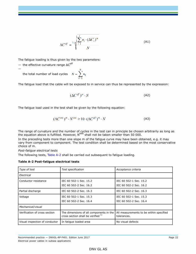
Application of fatigue loadingSubsequent to the pre-fatigue electrical tests the specimens shall be subjected to dynamic loading. Themethods shown in App.B may be used for applying dynamic deformation to the specimens, with due regardto the control of the curvature.The length of the gauge section (the part of the specimen exposed to dynamic loading) shall be at least 6times the outer diameter of the cable, in any case not smaller than 400 mm. The length of the specimensand the configuration of the test fixture shall be such that end effects have been eliminated in the gaugesection. The length of the specimens shall also be in accordance with the requirements of the specified IECtest standards.All specimens shall be subjected to the same deformation in terms of range of curvature, strain range etc.The curvature/strain range shall be based on the application for which cable cross section is to be qualified.The fatigue load shall be described by a histogram or similar giving the curvature range and correspondingnumber of cycles. The effective curvature ΔCeff shall be calculated according to the following equation:
Recommended practice — DNVGL-RP-F401. Edition June 2017 Page 22Electrical power cables in subsea applications
DNV GL AS
(A1)
The fatigue loading is thus given by the two parameters:
— the effective curvature range ΔCeff
—
the total number of load cycles
The fatigue load that the cable will be exposed to in service can thus be represented by the expression:
(A2)
The fatigue load used in the test shall be given by the following equation:
(A3)
The range of curvature and the number of cycles in the test can in principle be chosen arbitrarily as long asthe equation above is fulfilled. However, Ntest shall not be taken smaller than 50 000.In the preceding tests more than one slope m of the fatigue curve may have been obtained, e.g. it mayvary from component to component. The test condition shall be determined based on the most conservativechoice of m.Post-fatigue electrical testsThe following tests, Table A-2 shall be carried out subsequent to fatigue loading.
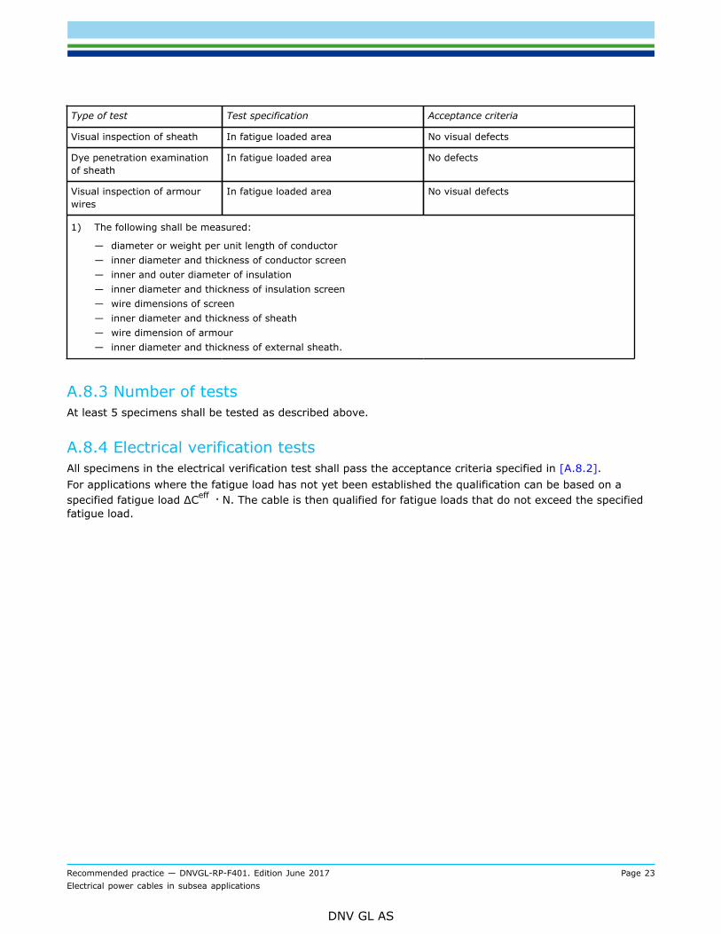
Table A-2 Post-fatigue electrical tests
Type of test Test specification Acceptance criteria
Electrical
Conductor resistance IEC 60 502-1 Sec. 15.2
IEC 60 502-2 Sec. 16.2
IEC 60 502-1 Sec. 15.2
IEC 60 502-2 Sec. 16.2
Partial discharge IEC 60 502-2 Sec. 16.3 IEC 60 502-2 Sec. 16.3
Voltage IEC 60 502-1 Sec. 15.3
IEC 60 502-2 Sec. 16.4
IEC 60 502-1 Sec. 15.3
IEC 60 502-2 Sec. 16.4
Mechanical/visual
Verification of cross section The dimensions of all components in thecross section shall be verified 1)
All measurements to be within specifiedtolerances.
Visual inspection of conductor In fatigue loaded area No visual defects
Recommended practice — DNVGL-RP-F401. Edition June 2017 Page 23Electrical power cables in subsea applications
DNV GL AS
Type of test Test specification Acceptance criteria
Visual inspection of sheath In fatigue loaded area No visual defects
Dye penetration examinationof sheath
In fatigue loaded area No defects
Visual inspection of armourwires
In fatigue loaded area No visual defects
1) The following shall be measured:
— diameter or weight per unit length of conductor— inner diameter and thickness of conductor screen— inner and outer diameter of insulation— inner diameter and thickness of insulation screen— wire dimensions of screen— inner diameter and thickness of sheath— wire dimension of armour— inner diameter and thickness of external sheath.
A.8.3 Number of testsAt least 5 specimens shall be tested as described above.
A.8.4 Electrical verification testsAll specimens in the electrical verification test shall pass the acceptance criteria specified in [A.8.2].For applications where the fatigue load has not yet been established the qualification can be based on aspecified fatigue load ΔCeff · N. The cable is then qualified for fatigue loads that do not exceed the specifiedfatigue load.
Recommended practice — DNVGL-RP-F401. Edition June 2017 Page 24Electrical power cables in subsea applications
DNV GL AS
APPENDIX B TEST METHODS – FATIGUE LOADING OF COMPLETECABLES
B.1 GeneralTwo methods for fatigue testing are considered applicable for testing of complete cable cross sections:
— 4-point-bend testing— bending against template.
These two methods are described in the following sections.Alternative methods for applying a fatigue deformation and/or for detecting failure may be accepted subjectto a qualification of the reliability of the method(s) to impart a realistic fatigue deformation and/or to detectfailures(s).
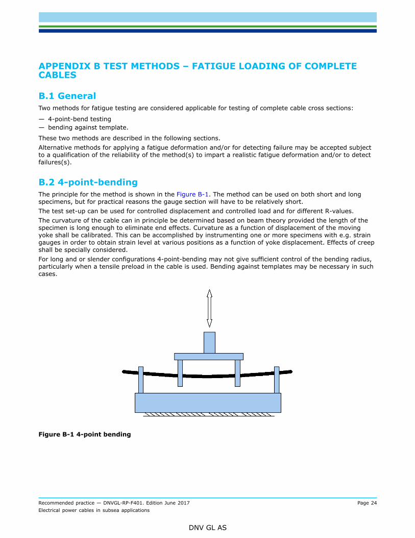
B.2 4-point-bendingThe principle for the method is shown in the Figure B-1. The method can be used on both short and longspecimens, but for practical reasons the gauge section will have to be relatively short.The test set-up can be used for controlled displacement and controlled load and for different R-values.The curvature of the cable can in principle be determined based on beam theory provided the length of thespecimen is long enough to eliminate end effects. Curvature as a function of displacement of the movingyoke shall be calibrated. This can be accomplished by instrumenting one or more specimens with e.g. straingauges in order to obtain strain level at various positions as a function of yoke displacement. Effects of creepshall be specially considered.For long and or slender configurations 4-point-bending may not give sufficient control of the bending radius,particularly when a tensile preload in the cable is used. Bending against templates may be necessary in suchcases.
Figure B-1 4-point bending
Recommended practice — DNVGL-RP-F401. Edition June 2017 Page 25Electrical power cables in subsea applications
DNV GL AS
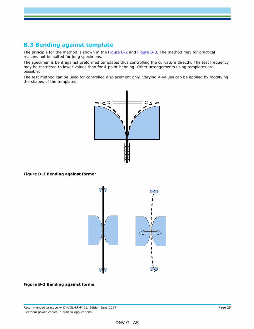
B.3 Bending against templateThe principle for the method is shown in the Figure B-2 and Figure B-3. The method may for practicalreasons not be suited for long specimens.The specimen is bent against preformed templates thus controlling the curvature directly. The test frequencymay be restricted to lower values than for 4-point-bending. Other arrangements using templates arepossible.The test method can be used for controlled displacement only. Varying R-values can be applied by modifyingthe shapes of the templates.
Figure B-2 Bending against former
Figure B-3 Bending against former
Recommended practice — DNVGL-RP-F401. Edition June 2017 Page 26Electrical power cables in subsea applications
DNV GL AS
APPENDIX C FATIGUE TESTING DETECTION TECHNIQUES
C.1 Metallic materialsMetallic materials are/may be used in the following components:
— conductor core— sheath— screen— armour.
A number of different techniques for detecting defects are available, depending on the component inquestion. Detection techniques are discussed below. Common for all or most of the techniques is that theyare impossible to automate or that automation will require a significant effort.
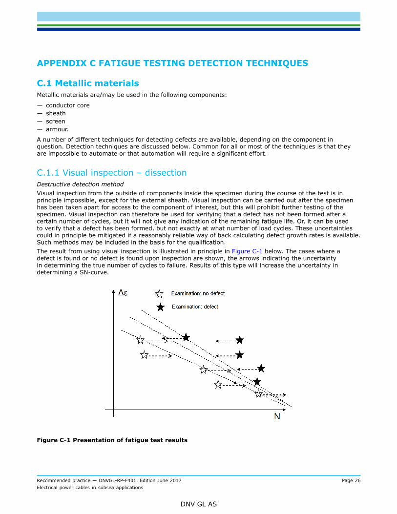
C.1.1 Visual inspection – dissectionDestructive detection methodVisual inspection from the outside of components inside the specimen during the course of the test is inprinciple impossible, except for the external sheath. Visual inspection can be carried out after the specimenhas been taken apart for access to the component of interest, but this will prohibit further testing of thespecimen. Visual inspection can therefore be used for verifying that a defect has not been formed after acertain number of cycles, but it will not give any indication of the remaining fatigue life. Or, it can be usedto verify that a defect has been formed, but not exactly at what number of load cycles. These uncertaintiescould in principle be mitigated if a reasonably reliable way of back calculating defect growth rates is available.Such methods may be included in the basis for the qualification.The result from using visual inspection is illustrated in principle in Figure C-1 below. The cases where adefect is found or no defect is found upon inspection are shown, the arrows indicating the uncertaintyin determining the true number of cycles to failure. Results of this type will increase the uncertainty indetermining a SN-curve.
Figure C-1 Presentation of fatigue test results
Recommended practice — DNVGL-RP-F401. Edition June 2017 Page 27Electrical power cables in subsea applications
DNV GL AS
C.1.2 Structural breakdown/Reduction of stiffnessNon-destructive detection methodStructural breakdown or a measurable reduction of the specimen stiffness is indicative of failure of one ormore of the load carrying components, e.g. a solid tube sheath or armour wires.The method is most sensitive for the component giving the largest contribution to the stiffness of the crosssection, e.g. a solid metal tubular sheath. It is relatively less sensitive to failure of armour or screen wires.Such wires are helically wound and relatively numerous such that a fairly large number of wires have to failin close proximity before a detectable change in stiffness occurs.Similarly, it is questionable whether failure in the core can be detected by this method.For early detection of fatigue cracks calibration of the detection method is probably required, i.e. the stiffnessas a function of crack size. The sensitivity to small cracks may be low.Longitudinal cracks, e.g. in longitudinal weld seams, may not be possible to detect by this method due totheir relatively small effect on the stiffness.
C.1.3 Electrical resistanceNon-destructive detection methodFatigue crack growth in metallic materials will eventually increase their electrical resistance. However, thesensitivity of this technique may not be sufficiently high for many cable cross sections.Currents applied to the sheath may pass through the semi-conducting layers under the sheath giving noor very little appreciable increase in resistance as the length of the damage in the sheath is short, furtherreducing the sensitivity of the method. Whether the sensitivity of this method is sufficient or not has to bedetermined from case to case.The resistance of wire screens may not increase appreciably until a large portion of the wires are broken inone cross section.The resistance of armour wire could be used as a detection method, provided the individual armour wires areisolated from one another.
C.1.4 Eddy currentNon-destructive detection methodMay be developed for use for detection of fatigue cracks in metal sheaths and screens and armour wires.Depending on the level of development of the tools early detection of fatigue cracks may be possible. Asignificant amount of development and calibration work may be necessary.Eddy current can not be used, or is difficult to use, for components inside metallic screens or sheaths.The method may require a significant investment for automating the inspection during testing.
C.1.5 X-rayNon-destructive detection methodX-ray is a well developed technique for detection of defects in metallic materials. However, the ability ofthe technique to discover defects in complete cables, in terms of sensitivity and discrimination between thedifferent components, has to be demonstrated in each individual case.The method is not possible to automate.
Recommended practice — DNVGL-RP-F401. Edition June 2017 Page 28Electrical power cables in subsea applications
DNV GL AS
C.1.6 LeakageNon-destructive detection methodMay tentatively be used for detection of through-wall defects on solid metal sheaths by applying compressedair on the inside of the sheath. The method requires free passage of air inside and outside of the sheath. Thismay not be possible to achieve for all cross section designs.
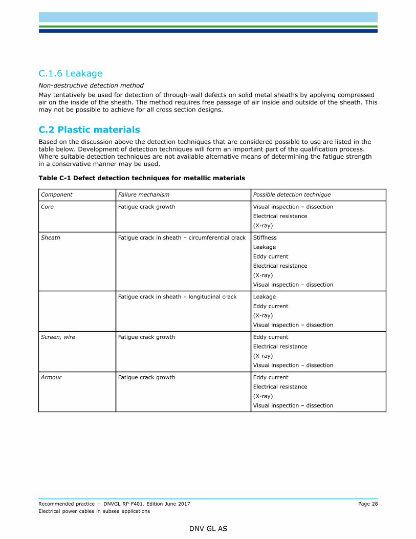
C.2 Plastic materialsBased on the discussion above the detection techniques that are considered possible to use are listed in thetable below. Development of detection techniques will form an important part of the qualification process.Where suitable detection techniques are not available alternative means of determining the fatigue strengthin a conservative manner may be used.
Table C-1 Defect detection techniques for metallic materials
Component Failure mechanism Possible detection technique
Core Fatigue crack growth Visual inspection – dissection
Electrical resistance
(X-ray)
Sheath Fatigue crack in sheath – circumferential crack Stiffness
Leakage
Eddy current
Electrical resistance
(X-ray)
Visual inspection – dissection
Fatigue crack in sheath – longitudinal crack Leakage
Eddy current
(X-ray)
Visual inspection – dissection
Screen, wire Fatigue crack growth Eddy current
Electrical resistance
(X-ray)
Visual inspection – dissection
Armour Fatigue crack growth Eddy current
Electrical resistance
(X-ray)
Visual inspection – dissection
Recommended practice — DNVGL-RP-F401. Edition June 2017 Page 29Electrical power cables in subsea applications
DNV GL AS
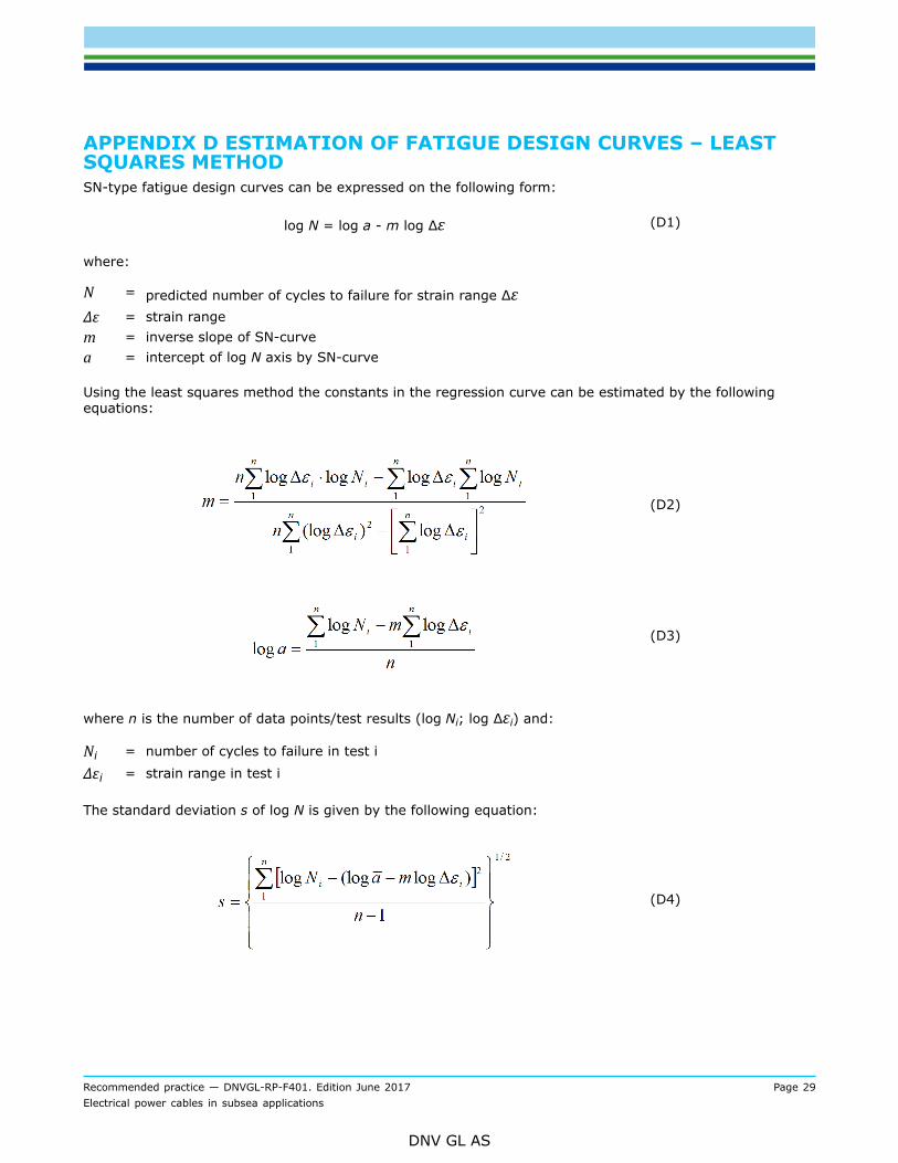
APPENDIX D ESTIMATION OF FATIGUE DESIGN CURVES – LEASTSQUARES METHODSN-type fatigue design curves can be expressed on the following form:
log N = log a - m log Δε (D1)
where:
N = predicted number of cycles to failure for strain range ΔεΔε = strain rangem = inverse slope of SN-curvea = intercept of log N axis by SN-curve
Using the least squares method the constants in the regression curve can be estimated by the followingequations:
(D2)
(D3)
where n is the number of data points/test results (log Ni; log Δεi) and:
Ni = number of cycles to failure in test i
Δεi = strain range in test i
The standard deviation s of log N is given by the following equation:
(D4)
Recommended practice — DNVGL-RP-F401. Edition June 2017 Page 30Electrical power cables in subsea applications
DNV GL AS
A fatigue design curve design curve can then be defined by the following equation, based on a 97.5%probability of survival:
log N = log - m log Δε
where:
log = log a - 2 s.
Recommended practice — DNVGL-RP-F401. Edition June 2017 Page 31Electrical power cables in subsea applications
DNV GL AS
APPENDIX E ESTIMATION OF FATIGUE DESIGN CURVES -INCOMPLETE OBSERVATIONS OF NUMBER OF CYCLES TO FAILUREThe procedure below applies to situation where the exact numbers of cycles to failure for the test specimensare not known.
SN-type fatigue design curves can be expressed on the following form:
log N = log a - m log Δε (E1)
N = predicted number of cycles to failure for strain range ΔεΔε = strain rangem = inverse slope of SN-curvea = intercept of log N axis by SN-curve
For simplicity the equation above is written as:
y = A + Bx (E2)
where:
x = log Δεy = log NA = log aB = - m
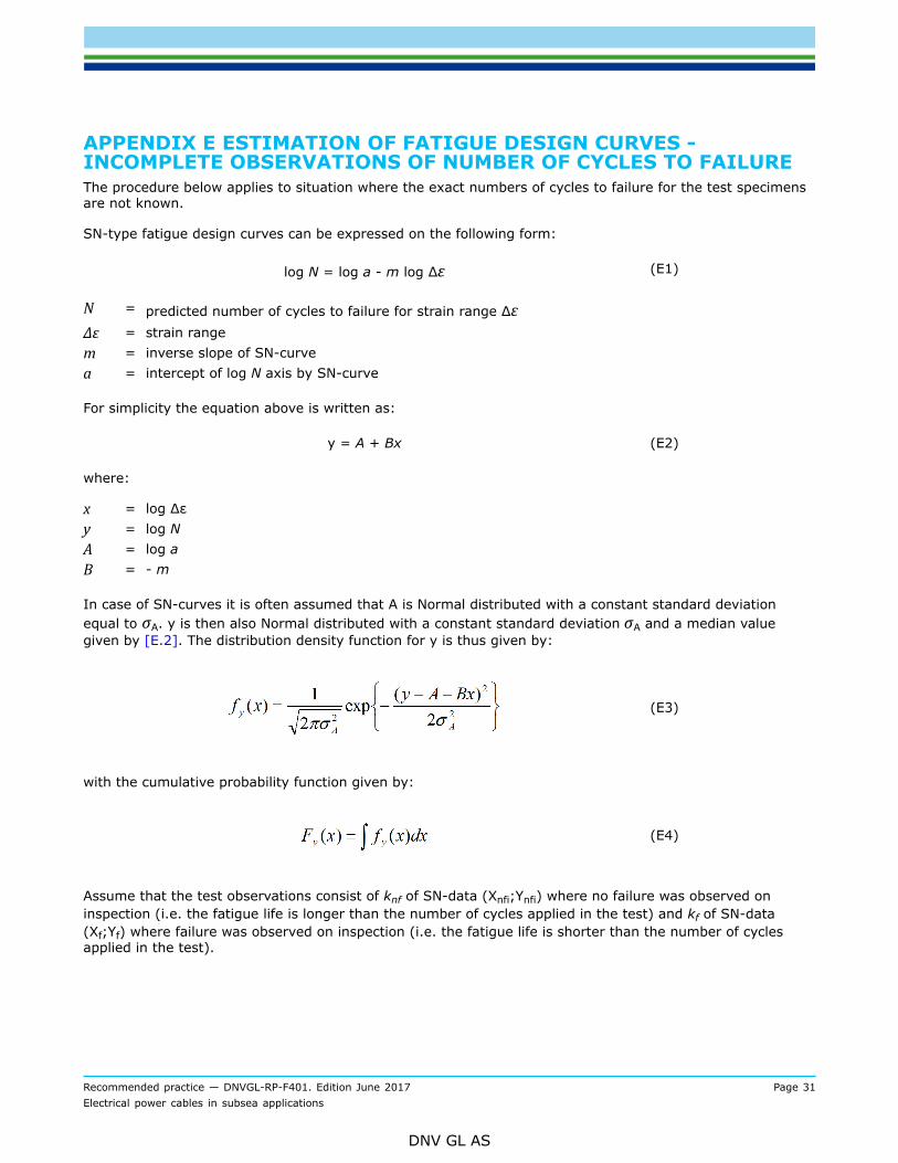
In case of SN-curves it is often assumed that A is Normal distributed with a constant standard deviationequal to σA. y is then also Normal distributed with a constant standard deviation σA and a median valuegiven by [E.2]. The distribution density function for y is thus given by:
(E3)
with the cumulative probability function given by:
(E4)
Assume that the test observations consist of knf of SN-data (Xnfi;Ynfi) where no failure was observed oninspection (i.e. the fatigue life is longer than the number of cycles applied in the test) and kf of SN-data(Xf;Yf) where failure was observed on inspection (i.e. the fatigue life is shorter than the number of cyclesapplied in the test).
Recommended practice — DNVGL-RP-F401. Edition June 2017 Page 32Electrical power cables in subsea applications
DNV GL AS
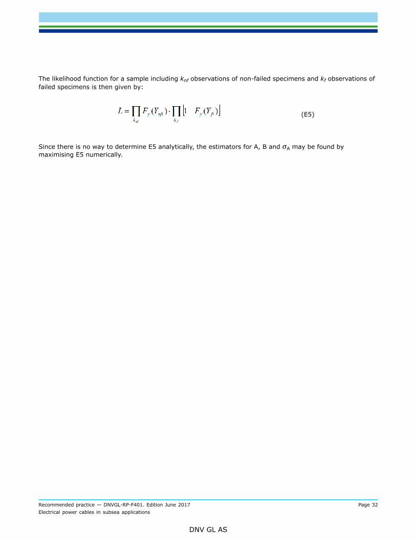
The likelihood function for a sample including knf observations of non-failed specimens and kf observations offailed specimens is then given by:
(E5)
Since there is no way to determine E5 analytically, the estimators for A, B and σA may be found bymaximising E5 numerically.
Cha
nges
– h
isto
ric
Recommended practice — DNVGL-RP-F401. Edition June 2017 Page 33Electrical power cables in subsea applications
DNV GL AS
CHANGES – HISTORICThere are currently no historical changes for this document.

About DNV GLDriven by our purpose of safeguarding life, property and the environment, DNV GL enablesorganizations to advance the safety and sustainability of their business. We provide classification,technical assurance, software and independent expert advisory services to the maritime, oil & gasand energy industries. We also provide certification services to customers across a wide rangeof industries. Operating in more than 100 countries, our experts are dedicated to helping ourcustomers make the world safer, smarter and greener.
SAFER, SMARTER, GREENER
Related Documents