RECOMMENDED PRACTICE DET NORSKE VERITAS DNV-RP-J201 QUALIFICATION PROCEDURES FOR CO 2 CAPTURE TECHNOLOGY APRIL 2010

DNV-RP-J201 Qualification Procedures for CO2 Capture Technology April 2010
Oct 26, 2014
Welcome message from author
This document is posted to help you gain knowledge. Please leave a comment to let me know what you think about it! Share it to your friends and learn new things together.
Transcript

RECOMMENDED PRACTICE
DET NORSKE VERITAS
DNV-RP-J201
QUALIFICATION PROCEDURES FOR CO2 CAPTURE TECHNOLOGY
APRIL 2010

FOREWORDDET NORSKE VERITAS (DNV) is an autonomous and independent foundation with the objectives of safeguarding life, prop-erty and the environment, at sea and onshore. DNV undertakes classification, certification, and other verification and consultancyservices relating to quality of ships, offshore units and installations, and onshore industries worldwide, and carries out researchin relation to these functions.DNV Offshore Codes consist of a three level hierarchy of documents:— Offshore Service Specifications. Provide principles and procedures of DNV classification, certification, verification and con-
sultancy services.— Offshore Standards. Provide technical provisions and acceptance criteria for general use by the offshore industry as well as
the technical basis for DNV offshore services.— Recommended Practices. Provide proven technology and sound engineering practice as well as guidance for the higher level
Offshore Service Specifications and Offshore Standards.DNV Offshore Codes are offered within the following areas:A) Qualification, Quality and Safety MethodologyB) Materials TechnologyC) StructuresD) SystemsE) Special FacilitiesF) Pipelines and RisersG) Asset OperationH) Marine OperationsJ) Cleaner EnergyO) Subsea Systems
Amendments and Corrections This document is valid until superseded by a new revision. Minor amendments and corrections will be published in a separatedocument normally updated twice per year (April and October). For a complete listing of the changes, see the “Amendments and Corrections” document located at: http://webshop.dnv.com/global/, under category “Offshore Codes”.The electronic web-versions of the DNV Offshore Codes will be regularly updated to include these amendments and corrections.
Comments may be sent by e-mail to [email protected] subscription orders or information about subscription terms, please use [email protected] information about DNV services, research and publications can be found at http://www.dnv.com, or can be obtained from DNV, Veritas-veien 1, NO-1322 Høvik, Norway; Tel +47 67 57 99 00, Fax +47 67 57 99 11.
© Det Norske Veritas. All rights reserved. No part of this publication may be reproduced or transmitted in any form or by any means, including pho-tocopying and recording, without the prior written consent of Det Norske Veritas.
Computer Typesetting (Adobe FrameMaker) by Det Norske Veritas.Printed in Norway.
If any person suffers loss or damage which is proved to have been caused by any negligent act or omission of Det Norske Veritas, then Det Norske Veritas shall pay compensation to such personfor his proved direct loss or damage. However, the compensation shall not exceed an amount equal to ten times the fee charged for the service in question, provided that the maximum compen-sation shall never exceed USD 2 million.In this provision "Det Norske Veritas" shall mean the Foundation Det Norske Veritas as well as all its subsidiaries, directors, officers, employees, agents and any other acting on behalf of DetNorske Veritas.

Recommended Practice DNV-RP-J201, April 2010 Introduction – Page 3
INTRODUCTION
— BackgroundOver the last decade, substantial resources have been di-rected towards developing cost-efficient solutions that in-volves CO2 capture, transport, and storage (CCS).The carbon capture technologies that are available todayrequire large efforts to integrate, optimise, and to scale upthe process components to an industrially mature process.Currently there are several different new technologies un-der development and testing for CO2 capture. This devel-opment will accelerate over the coming decades.New CO2 capture technology is generally not adequatelycovered by established codes and procedures. It musttherefore be qualified by a systematic process where its re-quired performance is targeted and obtained by definingthe expectations to the technology and identifying the risks
that need to be reduced through adequate qualificationmethods, such as analyses and testing.This Recommended Practice (RP) has therefore been de-veloped in order to address the need for guidance for thequalification of CO2 capture technology.
— AcknowledgmentThe development of this RP was organized as a joint in-dustry project with Aker (Aker Clean Carbon and AkerSolutions), Statoil, Statkraft and Det Norske Veritas AS aspartners. The project gratefully acknowledges receiving50% of its funding from Gassnova SF-the Norwegian stateenterprise for carbon capture and storage. DNV furthergratefully acknowledges the support by the project part-ners.
DET NORSKE VERITAS

Recommended Practice DNV-RP-J201, April 2010Page 4 – Introduction
DET NORSKE VERITAS
Recommended Practice DNV-RP-J201, April 2010 Contents – Page 5
CONTENTS
1. GENERAL .............................................................. 7
1.1 Introduction .............................................................7
1.2 Objective...................................................................7
1.3 Scope .........................................................................71.3.1 Application ......................................................................... 71.3.2 Boundaries .......................................................................... 7
1.4 Use of the procedure................................................81.4.1 Users ................................................................................... 81.4.2 Project development phases................................................ 8
1.5 Structure of this document .....................................8
1.6 Relationship to other codes.....................................8
1.7 References ................................................................8
1.8 Definitions ................................................................9
1.9 Abbreviations...........................................................9
2. CO2 CAPTURE CONCEPTS AND TECHNOLOGIES...................................... 10
2.1 Introduction ...........................................................10
2.2 CO2 capture concepts - an overview....................10
2.3 CO2 capture technologies – state of the art.........10
2.4 Challenges and uncertainties in CO2 capture concepts ....................................................12
3. QUALIFICATION PHILOSOPHY AND PRINCIPLES .............................................. 12
3.1 Introduction ...........................................................12
3.2 Philosophy ..............................................................12
3.3 Principles ................................................................12
4. QUALIFICATION PROCESS ........................... 12
5. QUALIFICATION BASIS .................................. 13
5.1 Introduction ...........................................................13
5.2 Methodology...........................................................13
5.3 System description and specification of CO2 capture technology ................................................13
5.4 Requirements .........................................................13
5.5 Functional requirements for CO2 capture technology...............................................................14
5.6 Critical parameters list .........................................14
6. TECHNOLOGY ASSESSMENT ....................... 14
6.1 Introduction ...........................................................14
6.2 Methodology...........................................................14
6.3 Technology breakdown for CO2 capture processes .................................................................15
6.3.1 Sub-systems and components with functions ................... 156.3.2 Unit operations with unit processes .................................. 15
6.4 Process sequences ..................................................16
6.5 Technology classification ......................................16
6.6 Technology classification for CO2 capture processes................................................................. 17
6.7 Identification of main challenges and uncertainties (HAZID) .................................. 17
7. THREAT ASSESSMENT .................................. 177.1 Introduction........................................................... 177.2 Methodology .......................................................... 177.3 Qualitative definition of probability classes ....... 177.4 Qualitative definition of consequence classes ..... 187.5 Definition of acceptable risk................................. 187.6 Assessment of acceptable risk for CO2 capture
processes................................................................. 197.7 Failure mode identification & risk ranking
methodologies ....................................................... 207.8 Workshop guidelines............................................. 20
8. DEVELOP QUALIFICATION PLAN ............. 208.1 Introduction........................................................... 208.2 Methodology .......................................................... 208.3 Basis for the analysis and selection ..................... 208.4 Qualification methods........................................... 218.5 Development of the technology qualification
plan ........................................................................ 218.6 Detailed description of the selected activities
in the TQP.............................................................. 21
9. EXECUTE QUALIFICATION PLAN .............. 219.1 Introduction........................................................... 219.2 Methodology .......................................................... 219.3 Execution of the qualification activities .............. 219.4 Collection and documentation of data ................ 229.5 Traceability of data............................................... 229.6 Determination of performance margin ............... 22
10. PERFORMANCE ASSESSMENT..................... 2210.1 Introduction........................................................... 2210.2 Methodology .......................................................... 2210.3 Decision analysis.................................................... 22
11. CONCEPT IMPROVEMENT............................ 22
APP. A DESCRIPTION OF CO2 CAPTURE TECHNOLOGIES............................................................. 23
APP. B SPECIFICATION AND REQUIREMENTS .. 25
APP. C SCALE-UP OF CO2 CAPTURE TECHNOLOGIES............................................................. 27
APP. D QUALIFICATION EXAMPLES...................... 29
APP. E TEMPLATES ..................................................... 34
DET NORSKE VERITAS

Recommended Practice DNV-RP-J201, April 2010Page 6 – Contents
DET NORSKE VERITAS
Recommended Practice DNV-RP-J201, April 2010Page 7
1. General1.1 IntroductionThere is a growing concern that global warming and climatechange are the anthropogenic results of greenhouse gas emis-sions from the combustion of fossil fuels, such as natural gas,oil and coal. The world's population is steadily growing, as areits energy needs. It is expected that a significant part of theworld's future need for electrical energy and heat will comefrom burning of fossil fuels, implying increased carbon diox-ide (CO2) emissions to the atmosphere.Currently there are several different technologies under devel-opment and testing for CO2 capture. Regarding the develop-ment work with large-scale CO2 capture processes for CCSapplication, such as for energy production, consecutive scaleup, validation and verification work are necessary. The fullsize plants are so large and expensive that an owner acting in acommercial environment cannot tolerate a technical failure. Technology qualification is a systematic set of activities thatcontribute to managing the risk associated with the implemen-tation of new technology. It will therefore play an importantrole in increasing the confidence in new and scaled-up CO2capture technologies. Technology qualification is a confirmation by examination andprovision of evidence that the new technology meets the spec-ified requirements for the intended use. This RecommendedPractice (RP) provides qualification procedures for how toprove that the new CO2 capture technology is fit for purpose.
1.2 ObjectiveThe objective of this RP is to provide a systematic approach forthe qualification of fossil fuel power generation technologieswith CO2 capture.
1.3 ScopeThe scope of this RP is to provide a supplement to DNV’sgeneric qualification procedures for new technology, DNV-RP-A203 /1/, by giving guidance for how to utilise these pro-cedures for fossil fuel power generation technologies with CO2capture.
1.3.1 ApplicationThis RP is applicable for components, equipment, processes,and process systems (assemblies) that can be defined as newCO2 capture technology or concepts. The procedure covers,but is not limited to, the three main concepts for capturing CO2from power generation processes based on fossil fuels as illus-trated in Fig. 1-1:
— Post combustion; the CO2 is removed from the powerplant flue gas after the combustion process
— Pre combustion; the CO2 is captured before combustingthe hydrogen-rich fuel
— Oxy-fuel combustion; the fuel is combusted using almostpure oxygen at near stoichiometric conditions producing aflue gas consisting mainly of CO2 and H2O.
Figure 1-1Overview of CO2 capture concepts in fossil fuel power production
1.3.2 BoundariesThe procedure covers the first step in the CO2 capture, trans-port, and storage (CCS) value chain as shown by the dashedline in Fig. 1-2. The dashed line shows the scope of the presentdocument. The transport and storage elements are covered byDNV-RP-J202 /3/ and DNV-RP-J203*, respectively. Thecompression facilities needed to bring the captured CO2 to therequired transportation pressure are considered part of thescope. * Planned publication in October 2010.
Figure 1-2The CO2 capture, transport, and storage (CCS) value chain
Power PlantConventional
Hydrocarbon conversion
Power PlantOxy-fuel
Combustion
CO2 capture
CO2 captureCO conversionFossil fuels 2
3
1
CO2 ”capture”(water removal)
CO2 to transport and
storage
Exhaust
Exhaust
Air separationH2O
O2
Power PlantH2-rich fuel
H2, CO, CO2, H2O
H2
H2, CO2
Flue gas
CO2, H2O
CO2
1: Post combustion2: Pre combustion3: Oxy-fuel combustion
H2O
Remaining air (N2)
CO2compression
DNV-RP-J201 DNV-RP-J202 DNV-RP- J203*
Capture(incl. compression)
Transport Storage
DET NORSKE VERITAS

Recommended Practice DNV-RP-J201, April 2010 Page 8
1.4 Use of the procedure
1.4.1 UsersUsers of the procedure will typically be:
— The manufacturer, who offers the new CO2 capture tech-nology to the market
— The company, which integrates the new technology into alarger system
— The end-users, who must optimise the benefits of theirinvestment through selection between competing technol-ogies.
1.4.2 Project development phasesThe qualification process can be run throughout the develop-ment of the new technology, or be started at any time in thedevelopment. However, if a significant modification (physicalor operational) is planned during operation, a review should bemade with regards to revisiting the qualification process.Examples of project development phases are: strategy, feasi-bility and concept selection, design, construction, installationand commissioning, operation and life extension, and decom-missioning.
1.5 Structure of this documentThis Recommended Practice is organised into three parts:
— An introductory part (Sec.1 to Sec.4) where CO2 captureconcepts and technologies are described, philosophy andprinciples of technology qualification are presented andthe qualification process is introduced.
— The main body: the description of the qualification workprocess (Sec.5 to Sec.11).
— Appendices (Appendix A to Appendix E) that containadditional and supplemental information as well as exam-ples and templates.
To get a first overview of the qualification work process, onecould read through the introductory chapters (Sec.3 and Sec.4),and the first part (the sections called introduction and method-ology) of each step in the qualification procedure (Sec.5 toSec.11). The remaining body of each chapter after the method-ology section, and the appendices, gives more detailed descrip-tion and information.
1.6 Relationship to other codesGeneric qualification procedures for new technology are cov-ered by DNV-RP-A203 /1/, whereas DNV-OSS-401 /2/ coverstechnology qualification management. While these procedurescover a generic approach, the present document provides amore specific qualification procedure on how to utilize DNV-RP-A203 for qualification of CO2 capture technologies.The present document covers the capture part of the CCS valuechain. The transport part and the storage part are covered byDNV-RP-J202 “Design and Operation of CO2 Pipelines” /3/and DNV-RP-J203 “Selection and Qualification of Sites andProjects for Geological Storage of CO2” (to be published) asshown in Fig. 1-2.
1.7 References
/1/ Det Norske Veritas AS. 2001. Recommended PracticeDNV-RP-A203 Qualification Procedures for NewTechnology. Høvik. Norway
/2/ Det Norske Veritas AS. 2006. Offshore Service Specifi-cation DNV-OSS-401 Technology Qualification Man-
agement. Høvik. Norway/3/ Det Norske Veritas AS. To be published April 2010.
Recommended Practice DNV-RP-J202 Design andOperation of CO2 Pipelines. Høvik. Norway
/4/ The European Technology Platform for Zero EmissionFossil Fuel Power Plants (ZEP). 2006. The final reportfrom Working Group 1 Power Plant and Carbon Diox-ide Capture
/5/ Intergovernmental Panel on Climate Change. 2005.IPCC Special Report on Carbon Dioxide Capture andStorage. Metz, B., Davidson, O., de Coninck, H., Loos,M., Meyer, L. (Eds.). Cambridge Univ. Press
/6/ Bailey, D.W. and Feron, P.H.M. 2005. Post-combus-tion Decarbonisation Processes, Oil & Gas Science andTechnology – Rev. IFP, Vol. 60, No. 3, pp. 461-474
/7/ Eide, L.I. and Bailey, D.W. 2005. PrecombustionDecarbonisation Processes. Oil & Gas Science andTechnology – Rev. IFP, Vol. 60, No. 3, pp. 475-484
/8/ Anheden, M., Yan, J., and De Smedt, G. 2005. Denitro-genation (or Oxyfuel Concepts). Oil & Gas Science andTechnology – Rev. IFP. Vol. 60, No. 3, pp. 485-495
/9/ Feron, P.H.M. 2005. Progress in post-combustion CO2capture. European CO2 Capture and Storage Confer-ence Towards Zero Emission Power Plants. 13-15April, Brussels, Belgium
/10/ Bisio, A. and Kabel, R. 1985. Scale up of chemicalprocesses: Conversion from laboratory scale tests tosuccessful commercial size design, Wiley & Sons
/11/ Sinnot, R.K. 1999. Chemical engineering design. Coul-son & Richardson’s
/12/ Peters, S. P. and Timmerhaus K. D. 1991. Plant Designand Economics for Chemical Engineers (4th Ed.),McGraw-Hill, New York
/13/ Brandt, H., Isaksen, S. and Friedemann S.H. 2009.Deepwater Developments: Successful Application ofNew Technology. SPE 125048
/14/ Høyland, A. and Rausand, M. 1994. System ReliabilityTheory, Models and Statistical Methods. Wiley, NewYork
/15/ International Energy Agency (IEA). 2004. Prospectsfor CO2 capture and storage, OECD/IEA
/16/ Mattisson, T. and Lyngfelt, A. Capture of CO2 usingchemical-looping combustion. In Scandinavian-NordicSection of Combustion Institute. 2001. Göteborg
/17/ Figueroa, J.D., Fout, T., Plasynski, S., McIlvried, H.,Srivastava, R. D, Advances in CO2 capture technology--The U.S. Department of Energy's Carbon Sequestra-tion Program, International Journal of GreenhouseGas Control, Volume 2, Issue 1, January 2008, Pages9-20
/18/ Norges vassdrags- og energidirektorat, 2006, CO2-håndtering på Kårstø (in Norwegian only), Svendsen,P.T. (Red.), Rapport nr 13
/19/ Kapur, K.C. and Lamberson, L.R. 1977. Reliability inEngineering Design, John Wiley & Sons Inc., NewYork
/20/ IEEE Std. 1413.1. 2002. IEEE Guide for Selecting andUsing Reliability Predictions Based on IEEE 1413.
/21/ Kline et al. 1974. Guidelines for process scale up,Chem. Eng. Prog., 70(10), 67-70
/22/ Kohl, A. and Nielsen, R. 1997. Gas Purification, Gulfprofessional Publishing
/23/ Choi, Gerald N. et al. 2005. CO2 removal from powerplant flue gas – cost efficient design and integrationstudy, Nexant Inc., San Francisco, CA, USA.
DET NORSKE VERITAS

Recommended Practice DNV-RP-J201, April 2010Page 9
1.8 Definitions
1.9 Abbreviations
CAP Chilled Ammonia ProcessCCS Carbon Capture and StorageCFD Computational Fluid DynamicsCLC Chemical Looping CombustionDEA DiEthanolAmineDNV Det Norske VeritasEOR Enhanced Oil RecoveryFEM Finite Element MethodFMECA Failure Mode, Effects, and Criticality AnalysisFMIRR Failure Mode Identification & Risk RankingFTA Fault Tree AnalysisHAZID Hazard IdentificationHAZOP Hazard and Operability StudySHE Safety, Health and EnvironmentIPCC Intergovernmental Panel on Climate ChangeJIP Joint Industry ProjectMDEA MethylDiEthanolAmine
MEA MonoEthanolAmine OPERA Operational Problem AnalysisPFD Process Flow DiagramP&ID Process piping and Instrumentation DiagramPSA Pressure Swing AdsorptionQA Quality AssuranceQB Qualification BasisQC Quality ControlR&D Research and DevelopmentRAM Reliability, Availability and MaintainabilityRP Recommended PracticeSWIFT Structured What-If Checklist TA Technology AssessmentTSA Temperature Swing AdsorptionTQP Technology Qualification PlanZEP Zero Emissions Platform: The European Technol-
ogy Platform for Zero Emission Fossil Fuel PowerPlant
Term DefinitionAvailability For a repairable system: the probability that the system is operating at a specified timeConsequence Resulting event from the happening of the failure. Consequence is measured by the magnitude of its effects. Conse-
quence is expressed as the number of people injured or killed, area affected, outage time, mission delay, money lost, etc.
Failure Termination of the ability of an item to perform the required (specified) functionFailure frequency The number of failures divided by the time (calendar or operational)Failure mechanism The physical, chemical or other process which lead or have led to a failureFailure mode The observed manner of failure (on a specified level)Failure probability The probability of failure occurring within a specified time period, or at a specified condition (e.g. during start up or
load changes)FME(C)A Failure modes, effect (and criticality) analysisHAZOP Hazard and operability study New technology Technology that has not been proven in the field with a documented track record for a defined application and defined
operational environmentPerformance margin Tested or analyzed maximum performance divided by required/ design performance. For a qualified system it must be
larger than oneProcess The transformation from one state to another, where state refers to the condition of a system as described by its prop-
erties (such as mass, volume, energy, pressure, and temperature)Proven technology Technology that has a documented track record in the field for a defined operational environmentQualification Qualification is the process of providing the evidence that the technology will function within specific limits or oper-
ating regime with an acceptable level of confidenceReliability The ability of an item to perform a required function under given environmental and operational conditions and for a
stated period of timeRisk The combined failure probability and consequence of failureTechnology The scientific study and use of applied sciences, and the application of this to practical tasks in industryThreat A potential risk with significant uncertainty about the consequence of failure and/ or likelihood of occurrence that
requires further investigation to either quantify as a risk or remove from further considerationUnit operation A structure of logic used for synthesizing and analyzing processing schemes in the chemical and allied industries, in
which the basic underlying concept is that all processing schemes can be composed from and decomposed into a series of individual or unit steps
Verification Confirmation by examination and provision of objective evidence that specified requirements have been fulfilled
DET NORSKE VERITAS

Recommended Practice DNV-RP-J201, April 2010 Page 10
2. CO2 CAPTURE CONCEPTS AND TECHNOLOGIES2.1 IntroductionSectors where CO2 capture is relevant are fossil fuel electricitygeneration, industry such as iron, steel and cement production,and fossil fuel production and transformation. The main tech-nological concepts for CO2 capture contain a majority of proc-esses and components that are predominantly commerciallyavailable today. These processes and components, however,are not operated at conditions or scale planned for CCS appli-cations. The carbon capture technologies that are availabletoday require large efforts to integrate, optimise, and to scaleup the process components to an industrially mature process.There are also some novel carbon capture concepts that usenew components that are not known in industry today. Thesenovel technologies will need a longer development and quali-fication program before commercial deployment. The main challenges within the development and implementa-tion of large-scale CO2 capture technologies are to ensure thatthey are cost-efficient and reliable, safe, and environmentallyfriendly. It will be of major interest for technology vendors,operators, as well as governments, that these technologies canbe implemented with technological risks adequately under-stood and managed to an acceptable level so as to give confi-dence, and that they will work as intended over the lifetime ofthe project. Managing the risk by scaling up CO2 capture technologies wasdescribed by ZEP as /4/:Concerning the development work with large-scale industrialprocesses as for energy production, consecutive scale up, val-idation and verification work is necessary. Although principlesand mechanisms are well known, verification is necessary toreduce risks, since the full size plants are so large and expen-sive that an owner acting in a commercial environment cannottolerate a technical failure.Technology qualification is a systematic set of activities thatcontribute to managing the risk associated with the implemen-tation of new technology. Technology qualification will there-fore play an important role in increasing the confidence in newand scaled-up CO2 capture technologies. Technology qualification is used to confirm that a technologymeets certain requirements within specific limits with anacceptable level of confidence. This can be done by identifica-tion, assessment, and management of potential risks throughimplementation of the qualification process.
2.2 CO2 capture concepts - an overviewFor fossil fuel power production, there are three main conceptsto reducing the CO2 content in the combustion gases. These arepost-combustion, pre-combustion, and oxy-fuel combustion.A schematic illustration is shown in Fig. 1-1.In post-combustion capture, the CO2 is removed from thepower plant flue gas. The state-of-the-art technique for sepa-
rating CO2 from flue gases is via chemical solvent scrubbing(usually with an amine). The CO2 reacts with the amine in theabsorber and is later separated from the amine solution in thestripper, then dried, compressed, and transported to the storagesite. For flue gases with a low partial pressure, a large amountof energy is needed to regenerate the solvent. Improved sol-vents and optimized processes are currently being developed.Alternative methods for separating CO2 from flue gases arealso evolving. A more detailed overview of post combustiondecarbonisation processes can be found in Ref. /4/, /5/, /6/.Pre-combustion capture is a technique where the CO2 is cap-tured before burning the fuel in a combustor. It is commer-cially available for several applications, including hydrogen,ammonia, and synthetic gas production. The technique con-sists of a natural gas reforming or coal gasification step fol-lowed by water gas shift reforming of the gas, with subsequentsteps for separation of CO2 and H2 to produce a H2-rich gas.The main challenge within this concept to make it economi-cally feasible is to develop gas turbines that reliably can burnfuel with a high H2 content /4/. Because of the world-wideinterest in the hydrogen economy, a lot of R&D efforts are cur-rently put into this field. A description of pre-combustiondecarbonisation technology can be found in Ref. /4/, /5/, /7/.In Oxy-fuel carbon capture (also called denitrogenation), thefuel is combusted using almost pure oxygen at near stoichio-metric conditions. This creates a flue gas consisting of mainlyCO2 and H2O (and small amounts of SOx and NOx). A portionof the CO2 in the flue gas is recycled in order to control thecombustion temperature. Oxy-fuel combustion has been usedwithin the metal and glass manufacturing industries for sometime, but has so far not been applied to full-scale conventionalsteam boilers. The main challenges with this concept are thenew combustion environment in the burner, and the highenergy demand of the air separation unit. An overview of oxy-fuel processes can be found in Ref. /4/, /5/, /8/.Each of the three pathways described above has inherentadvantages and disadvantages (see Sec.2.4 below).
2.3 CO2 capture technologies – state of the artThe technologies for capture of CO2 can broadly be classifiedunder four categories:
— Absorption by solvents — Adsorption by sorbents— Membranes — Cryogenic separation.
In addition to these four main separation processes, there are sev-eral novel CO2 capture technologies that cannot easily begrouped under these categories, such as biotechnological. Theseare denoted as emerging technologies. A brief description of thevarious CO2 capture technology categories is given in AppendixA with further details in Ref. /4/, /5/, /6/, /7/, /8/. The main prin-ciple for separation in each of these four different processes isvisualized in Fig. 2-1.
DET NORSKE VERITAS

Recommended Practice DNV-RP-J201, April 2010Page 11
Figure 2-1General schemes of the main separation processes relevant for CO2 capture (source: IPCC /5/)
The application of each capture technique depends mainly onthe gas mixture that contains carbon dioxide. Its composition,temperature, pressure, CO2 concentration and removal quan-tity of CO2 are some of the criteria to decide the appropriatecapture technology. Chemical absorption when carbon dioxidepartial pressure is low (post-combustion capture), is currentlyconsidered state-of-the-art for separation.
The applicability of the different separation technologies to thedifferent concepts can be visualized in a “CO2 capture tool-box” as shown in Table 2-1 /4/, /5/, /9/. In this table, currentand foreseen technology approaches are listed for the variouscapture concepts. The current leading commercial options areshown in bold italic. A more detailed description of the capturetechnologies is given in Appendix A.
Table 2-1 CO2 capture toolbox /4/, /5/, /9/Capture Route Post combustion Pre combustion Oxy fuel combustionSeparation task CO2/N2 CO2/N2 CO2/N2
Capture Technologies
Current Future Current Future Current Future
Solvents (Absorption)
Chemical solvents
Improved solvents Novel contacting equipment Improved design of processes
Physical solvent Chemical solvents
Improved solvents Novel contacting equipment Improved design of processes
N. A. Biomimetic solvents
Solid sorbents (Adsorption)
Zeolites Activated carbon
Carbonates Carbon based sorbents
Zeolites Activated carbon
Alumina Carbonates Hydrotalcites Silicates
Zeolites Activated car-bon
Adsorbents for CO2/N2 separation, Perovskites Oxygen chemical looping
Membranes Polymeric Ceramic Facilitated transport Carbon Contactors
Polymeric Ceramic Palladium Reactors Contactors
Polymeric Ion transport membranes Facilitated transport
Cryogenic Liquefaction Hybrid processes Liquefaction Hybrid processes Distillation Improved distillation
Emerging (bio-technological)
Algae production High pressure applications
Biomimetic approaches
Energy conversion Novel power cycles Hydrogen combustion
Improved burner design
Combustion in O2/CO2/H2O atmosphere
Improved burner design
DET NORSKE VERITAS

Recommended Practice DNV-RP-J201, April 2010 Page 12
2.4 Challenges and uncertainties in CO2 capture conceptsThe three CO2 capture concepts have different challenges anduncertainties. Major challenges and uncertainties with the dif-
ferent capture routes are summarized in Table 2-2.
3. QUALIFICATION PHILOSOPHY AND PRINCIPLES3.1 IntroductionImplementation of new technology introduces uncertaintiesand risks to technology developers, operators, and end-users.The procedure described in this document is a method to iden-tify and analyse risks related to development, production anduse of the new technology. Typically, concepts with wellknown and proven technology are often preferred to solutionswith elements of non-proven technology, despite the fact thatthe latter may be the most cost-effective. Business opportunities and growth are often revealed throughnew technology. Qualifying new technology and hence man-aging the risk by its implementation, increases the level of con-fidence and the potential profit.
3.2 PhilosophyThe qualification shall be based on the following philosophy:
— The qualification process shall be based on a systematicrisk based approach.
— Possible threats (or failure modes) to the technology shallbe identified, and their relevance shall be determinedbased on their risk, i.e. the combined probability and con-sequences of a failure mode occurring. Risk in this contextis related to the functionality of the new technology.
— Screening the technology based on the identified novel ele-ments to focus the effort to areas where the uncertainty is mostsignificant. The uncertainty can be associated with the tech-nology itself and/or the operating conditions/ environment.
— The level of the qualification efforts will be proportionalto the uncertainty associated with the technology, i.e.greater uncertainty requires a higher performance marginand more robust qualification methods.
— Analyses shall, when practical, be used to document fulfil-ment of the specifications and predict the performancemargin. As a general principle, the analyses should be ver-ified by experiments.
— The QA/ QC system for manufacturing, assembly, instal-lation, start-up, commissioning, modification, repair anddecommissioning of the technology is an integral part ofthe qualification process.
3.3 PrinciplesThe following principles shall control the qualification:
— Specifications and requirements shall be clearly defined,quantified and documented.
— A rigorous failure mode identification shall be conductedfor the technology. Risk assessment tools shall be used todetermine the consequence and likelihood of failure for atechnology application. Failure modes that are not identi-fied pose a significant risk to the successful implementa-tion of the technology.
— The performance margin shall be established based on rec-ognized methods, standards, or on combinations of alluncertainties used in the data, operation, calculations andtests.
— The qualification efforts (analysis, testing, previous expe-rience, etc.) for each technology failure mode shall be doc-umented and traceable, along with the establishedperformance margin.
— When experience is used as proof of fulfilment of the spec-ifications, then evidence shall be collated and validated.The experience must be at the relevant operating condi-tion/ environment.
— The limiting material and functional parameters, such asyield strength, friction factors, and thermal expansioncoefficient, to be used in analyses should be determinedthrough tests, given by reference to recognized literatureor expert judgement.
4. QUALIFICATION PROCESSThe steps in the technology qualification process are illustratedin Fig. 4-1 below. The amount of rigor or effort applied to stepshould be proportional to the uncertainty of the technology andthe consequence of failure (technology classification, seeSec. 6.5). The output from one step is input to the next. The process isiterative in nature in the way that concept improvements mightbe needed in order for the technology to be qualified.A description of the various steps, including more specificissues regarding CO2 capture process qualification, is given inSec.5 to Sec.Sec.11.
Table 2-2 Major challenges within the three main concepts for carbon capture Concept Major Challenges
Post-combustion capture
— High energy consumption for absorbent regeneration and CO2 compression— Most major units need scale-up— Large-scale equipment needs optimizing and process integration— Extended “clean-up” of exhaust gas including desulphurization— Corrosion— Solvent degradation— Uncertainties of SHE properties of solvent (amines) degradations products.
Pre-combustion capture
— High energy consumption for CO2 separation, fuel gas processing, and CO2 compression— Large-scale equipment needs optimizing and process integration— Combustion of H2-rich fuel in gas turbine power plants— Coal gasification units need demonstration for power plant application— Low plant availability: high consequence of plant downtime— Extensive supporting systems requirements.
Oxy-fuel combustion capture
— High energy consumption for O2 production and CO2 compression— Large-scale equipment needs optimizing and process integration— Combustion process not demonstrated at a larger scale— Cooled CO2 recycle required to maintain temperatures within limits of combustor materials— Low plant availability: high consequence of plant downtime— Corrosion— New thermodynamic properties for CO2/H2O mixtures.
DET NORSKE VERITAS
Recommended Practice DNV-RP-J201, April 2010Page 13
Figure 4-1Main steps in the technology qualification process
5. QUALIFICATION BASIS5.1 IntroductionThe purpose of the qualification basis is, in the absence of rel-evant codes and procedures, to define the expectations of thetechnology.The qualification basis document defines how the technologywill be used and what the acceptance criteria will be in terms ofa fully qualified product. It also specifies performance expecta-tions and behaviour through out the life cycle of the technology.Through further qualification processes, the expectationsdescribed in the qualification basis shall be fulfilled.
5.2 MethodologyThe technology shall be unambiguously and completelydescribed, through text, calculation data, drawings and otherrelevant documents. It is important that the limits of the tech-nology are stated and that all relevant interfaces are clearlydefined. The specification shall identify all phases of the newtechnology’s life and all relevant parameters.The qualification basis should include the following key ele-ments /1/:
a) System description and specification with the availabledetail level at each phase of the development process. Itshould at least include:
— System description of the technology to be qualifiedincluding system boundaries and boundary conditions
— Functional/ operational limitations and main data— Interfacing system requirements— Authority requirements— Safety, Health and Environment (SHE) requirements— Reliability targets — Main principles for technology life cycle (such as
design, construction, commissioning, operation andmaintenance, and decommissioning)
— Environment and loads— Main principles for manufacturing and quality assur-
ance— List of assumptions and conditions to be fulfilled from
the qualification process (generated in the qualifica-tion process).
b) Functional requirements.
The specification and functional requirements shall be quanti-tative and complete. Note that these requirements must havebeen agreed upon by all relevant stakeholders.Based on the specification, a review/ screening of all possiblerequirements and limitations to the technology shall be per-formed and the functional requirements specified. The criticalparameters shall be identified and a critical parameters listshall be created (see Sec.5.6). A more detailed description of how this can be done for CO2capture technologies is given in the remaining sections of thischapter (Sec.5.3 to Sec.5.6).
5.3 System description and specification of CO2 cap-ture technologyThere exist no specific standard for the information needed tobuild a process plant based on, for instance, a chemical,mechanical, or a thermal process. A general guidance is thatthe description and specification in the qualification basis forCO2 capture technology should follow the standard proceduregiven in Sec.5.2 as applicable to the carbon capture concept. Astandardized scope of the information needed to build a com-mercial chemical process unit is given in Ref /10/ as:
— Project description— Process description— basis for the commercial plant— Heat and material balance— Process flow sheet— Process piping and instrumentation diagrams— Utility piping and instrumentation— Plot plan— Major equipment outline drawings and specifications— Process safety— Utilities requirements— Environmental— Instrument specifications— Piping and line specifications.
Process scale-up should be approached at the first stage indescribing the new technology, i.e. from the knowledge ofwhat it is believed the commercial unit will look like. In the evolution of a process system, from idea to commercialdesign, there is a continuous interaction between design/ eco-nomic studies and experimental program (such as laboratory,pilot plant, or mock-up). The process scale-up is rarely a sim-ple and direct path, but rather a combination of theoreticalmodels, correlations and empirical experience. Scale-up issuesare briefly presented in Appendix C, whereas a more detaileddescription of how to describe a process system and the impor-tance with regards to scale-up in process design developmentcan be found in Ref. /11/, /12/, /13/. A description of differentdocumentation types for describing a process system and theirimportance is given in Appendix B.
5.4 RequirementsA number of requirements must be achieved for a commercialplant to be successful. It is of crucial importance that the require-ments, and the impact of setting them, are thoroughly discussed,understood, and agreed by all project participants. Functionalrequirements are described in Sec.5.5, whereas a description ofinterfacing and authority requirements, SHE requirements, andrequirements to plant availability for CO2 capture processes isgiven in Appendix B. A general description of state-of-the-artCO2 capture concepts and technologies is given in Sec.2.
Qualification Basis
Technology Deployment
Con
cept
Im
prov
emen
t
Develop Qualification Plan
Execute Qualification Plan
Performance Assessment
Technology Assessment
Threat Assessment
Qualification Basis
Technology Deployment
Con
cept
Im
prov
emen
t
Develop Qualification PlanDevelop Qualification Plan
Execute Qualification Plan Execute Qualification Plan
Performance AssessmentPerformance Assessment
Technology AssessmentTechnology Assessment
Threat Assessment
DET NORSKE VERITAS
Recommended Practice DNV-RP-J201, April 2010 Page 14
5.5 Functional requirements for CO2 capture tech-nologyThe following sections give guidance for how to identify thequalification goals for CO2 capture technology such as thefunctional requirements. Functional requirements describe the purpose(s) of the tech-nology. The functional requirements of the system should:
— Clearly define what the technology should do— Be quantifiable— Be established as early as possible and updated throughout
the qualification process.
Based on the system description and the flow diagrams,described in Sec.5.3, the breakdown of the capture technologywill enable identification of system requirements at differentlevels of detail. For example, the CO2 capture performance,expressed as CO2 avoidance or capture rate, is a high-levelprocess parameter that is likely to be part of the qualificationbasis defined at an early stage of the qualification process.Beneath the high-level process system requirements, each sub-process and/or material and energy stream will have knownspecifications that are of importance to the overall perform-ance or system integration. Furthermore, functional require-ments on a component level should be established forcomponents considered essential for the functionality of thetotal process. Table 5-1 exemplifies typical functional require-ments for the different capture technology routes.
Note that the functional requirements are subject to continuousupdating during the qualification process, as technologyassessment and failure mode identification most likely willreveal functional requirements on sub-components, not fore-seen at the initial stage of the qualification process.
Guidance note:Review and possibly update of the requirements given in thequalification basis might be needed after each step in the qualifi-cation work process.
---e-n-d---of---G-u-i-d-a-n-c-e---n-o-t-e---
5.6 Critical parameters listThe purpose of the critical parameters list is to document thevital governing parameters for the technology. Key issues suchas dimensioning loads, capacities and functional requirementsfrom the qualification basis shall be summarised in the list.This ensures that the relevant input parameters for analysesand tests are used and updated with possible changes in designduring the qualification process.The critical parameters list should cover all parameters that aregoverning for the identified failure modes of concern, andshould specify the limits/ boundaries for these parameterswithin the scope of the qualification. Further, this list should
also specify the main concerns and uncertainties with the givenparameters. The parameters and their limits should be estab-lished in the initial phase of the technology qualification proc-ess (defining of qualification basis). However, both theparameters and their limits might change as the qualificationprogresses. Upon conclusion of the qualification process, thecritical parameters list will represent the qualification envelopeof the technology, i.e. this list will define the boundaries withinwhich the technology is considered qualified.A critical parameters list template is shown in Appendix E.
6. TECHNOLOGY ASSESSMENT6.1 IntroductionThe purpose of the technology assessment is to divide the tech-nology into manageable elements in order to assess which ele-ments involve aspects of new technology and identify the keychallenges and uncertainties.Input to the technology assessment comes from the qualifica-tion basis, and the output is a list of the novel technology ele-ments in the concept and the main challenges anduncertainties.
6.2 MethodologyThe technology assessment shall include the following issues:
— Breaking down the technology into manageable elements— Assessment of the technology elements with respect to
novelty (technology classification)— Identification of the main challenges and uncertainties
related to the new technology aspects.
The technology break down shall be achieved by dividing thetechnology into one or more of the following types of ele-ments, as relevant:
— Sub-systems and components with functions, and/or — Unit operations with unit processes— Process sequences — Project execution phases based on procedures for manu-
facturing, installation and operation.
The degree of novelty of the technology shall be determined byclassifying the technology elements with respect to applicationarea and technology maturity. Elements classified as new tech-nology shall be subject to the further assessment.The main challenges and uncertainties related to the new tech-nology aspects shall be identified. For complex systems, suchas power plants with CO2 capture processes, it is recom-mended that the main challenges and uncertainties are identi-fied by carrying out a high level HAZID (HazardIdentification).
Table 5-1 Examples of functional requirements for CO2 capture concepts and system levelsCapture Concept
System level Post-combustion (absorption) Pre-combustion Oxy-fuel combustionProcess CO2 capture rate
CO2 purityPower consumptionEmissions (solvent)
Energy efficiencyPower productionCO2 avoidedCO2 purity
Energy efficiencyPower productionCO2 avoidedCO2 purity
Sub-process Steam qualitySolvent consumptionInhibitor addition
Reformer/shift conversionTurbine energy deliveryH2 dilution
Turbine energy deliverySteam generationO2 purity
Component Absorber packing material corro-sion resistance CO2 loadingStripper reboiler duty Flue gas blower duty
Catalyst performanceCombustor flame temperature, flame flashback, auto ignitionNOx emissions
Combustor flame temperature, radia-tion and soot levels, CO emissionsExpander coolingTurbine material choice
DET NORSKE VERITAS

Recommended Practice DNV-RP-J201, April 2010Page 15
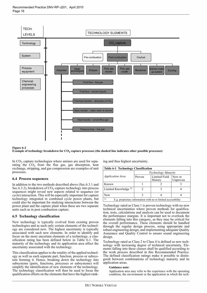
6.3 Technology breakdown for CO2 capture processesIn order to fully understand the novel elements in a technology,the technology needs to be broken down in to manageable ele-ments. Two different routes for performing technology break-down of CO2 capture technologies are shown below. The mostfavourable division must be considered on a case-by-casebasis.
6.3.1 Sub-systems and components with functionsA technology breakdown for sub-systems and componentswith functions might often start with a general process flowdiagram (PFD) for the process plant. Each unit operation in thePFD should then be listed and broken down into detailed parts,so technical expertise can judge the novelty. Fig. 6-1 gives anexample of the technology breakdown for a typical post-com-bustion capture plant including an absorber.
Figure 6-1Example of technology breakdown and levels for subsystems and components
6.3.2 Unit operations with unit processesAn alternative, or supplement to, technology breakdown intosub-systems and components with functions can be to startwith the PFD, and for each unit operation in the PFD, divideinto unit processes. Hence, a unit operation consists of a set ofunit processes. Unit processes can be categorized as:
1) Fluid flow processes, including fluids transportation, fil-tration, solids fluidization etc.
2) Heat transfer processes, including evaporation, condensa-tion etc.
3) Mass transfer processes, including gas absorption, distil-lation, extraction, adsorption, drying etc.
4) Pressure change processes, including gas compression,
expansion, etc.5) Thermodynamic processes, including gas liquefaction,
refrigeration etc. 6) Mechanical processes, including solids transportation,
crushing and pulverization, sieving etc.7) Chemical reactions, including combustion, oxidation,
isomerisation etc.
This approach will increase the likelihood that new aspects notdirectly connected to single components, as shown inSec.6.3.1, are discovered. An example of a technology break-down into unit processes is shown in Fig. 6-2. Note that in theexample shown in Fig. 6-2, the term process equipment is usedinstead of unit operations.
CO2 capture
Pre-combustion Post-combustion
Absorber
Oxyfuel
ReclaimerFlue gascooler
Flue gasblowerStripperHeat-
exchangersSolvent make
up system Ducting
Water washsection
Absorbersection
Gas distributor
Absorber packing
Solvent distributor
Absorber collector
Absorber control and monitoring system
Demister
Absorber housing
Absorber redistributor
TECH.
LEVELS TECHNOLOGY ELEMENTS
Technology
System
Subsystems
Components
Parts
DET NORSKE VERITAS
Recommended Practice DNV-RP-J201, April 2010 Page 16
Figure 6-2Example of technology breakdown for CO2 capture processes (the dashed line indicates other possible processes)
In CO2 capture technologies where amines are used for sepa-rating the CO2 from the flue gas, gas absorption, heatexchange, stripping, and gas compression are examples of unitprocesses.
6.4 Process sequencesIn addition to the two methods described above (Sec.6.3.1 andSec.6.3.2), breakdown of CO2 capture technology into processsequences might reveal new aspects related to sequence (orcycle) interaction. This will be especially important for capturetechnology integrated in combined cycle power plants, butcould also be important for studying interactions between thepower plant and the capture plant when these are two separateunits such as in post combustion capture.
6.5 Technology classificationNew technology is typically evolved from existing proventechnologies and as such only certain elements of the technol-ogy are considered new. The highest uncertainty is typicallyassociated with such new elements. In order to identify andfocus on the more uncertain elements of a technology, a clas-sification rating has been defined below in Table 6-1. Thematurity of the technology and its application area affect theuncertainty associated with the technology.This classification applies to the totality of the applied technol-ogy as well as each separate part, function, process or subsys-tem forming it. Hence, breaking down the technology intosubsystems (parts, functions, processes or subsystems) willsimplify the identification of new elements of the technology.The technology classification will then be used to focus thequalification efforts on the elements that have the highest rank-
ing and thus highest uncertainty.
Technology rated as Class 1 is proven technology with no newtechnical uncertainties where proven methods for qualifica-tion, tests, calculations and analysis can be used to documentthe performance margins. It is important not to overlook theelements falling into this category, as they may be critical forthe overall performance. These elements should be handledthrough the regular design process, using appropriate androbust engineering design, and implementing adequate QualityAssurance and Quality Control to ensure sound engineeringdesign.Technology rated as Class 2 to Class 4 is defined as new tech-nology with increasing degree of technical uncertainty. Ele-ments falling into these classes shall be qualified according tothe work process described in this Recommended Practice.The defined classification ratings make it possible to distin-guish between combinations of technology maturity and itsapplication areas.
Guidance note:Application area may refer to the experience with the operatingcondition, the environment or the application in which the tech-
CO2 capture
Pre-combustion Post-combustion
Absorber
Oxyfuel
ReclaimerFlue gascooler
Flue gasblowerStripperHeat-
exchangersSolvent make
up system Ducting
Fluid flow – flue gas
Chemical reaction – absorption of CO2
Mass transfer – water wash of solvent
Fluid flow – solvent (l iquid)
Heat transfer – solvent/flue gas
Pressure drop – flue gas
TECH.
LEVELS TECHNOLOGY ELEMENTS
Technology
System
Process equipment
Chemical engineering processes
Table 6-1 Technology Classification
Application AreaTechnology Maturity
Proven Limited Field History
New or Unproven
Known 1 2 3Limited Knowledge 1) 2 3 4
New 3 4 41) E.g. proprietary information with no or limited accessibility
DET NORSKE VERITAS
Recommended Practice DNV-RP-J201, April 2010Page 17
nology shall be used. A change in the environment or in the useof the technology for a different application than before, will leadto increasing degree of uncertainty. The most uncertain case is noexperience in the industry for a particular application of the tech-nology in question, in which case the category “New” would bechosen for Application Area. The least uncertain case is whenthere is sufficiently documented knowledge for the use of thetechnology element for similar conditions and application, inwhich case the category “Known” would be chosen for “Appli-cation Area”.“Technology Maturity” refers to the technology itself. A changein any of the elements of existing technology (parts, functions,processes, subsystems) will lead to increased uncertainty result-ing in selecting the Technology Maturity level of “Limited FieldHistory” or “New or Unproven”. This increased uncertainty maychange the overall performance of the technology and the accept-ance criteria.
---e-n-d---of---G-u-i-d-a-n-c-e---n-o-t-e---
6.6 Technology classification for CO2 capture proc-essesThe basis for technology classification is described in Sec.6.5.The degree of novelty of the capture process shall be deter-mined by classifying the technology elements with respect toTable 6-1, i.e. the level of technology maturity and experiencewith the operating conditions. The objective of the categorization with respect to “level oftechnology maturity” is to establish to what degree the technol-ogy has been verified through field experience.
Guidance note:Example:The absorber in Fig. 6-1 has been designed and manufactured inline with established engineering practice and has been operatedwith a documented track record. Consequently it is considered tobe proven technology.If the absorber has to be redesigned (using the same overall prin-ciples) to accommodate changes in the functional requirements(temperature, pressure, size, flow, etc.), the category for thisabsorber will change to limited field historyIn the event that a new type of absorber is developed, which isconceptually different from the established design, the absorberwill be categorised as new or unproven.“Experience with the operating condition” or application area,relates to the working environment and functional requirementsof the new technology. The application area should be definedfor the total system, as well as for all the individual parts formingit.Example:If a new solvent is introduced in a traditional absorber, the appli-cation area for the absorber will be new. However, some of thecomponents inside or outside of the absorber may not experienceany change in environment as they will operate under the sameconditions as before, thus the application area for these compo-nents will be known.
---e-n-d---of---G-u-i-d-a-n-c-e---n-o-t-e---
6.7 Identification of main challenges and uncertain-ties (HAZID)After the technology classification the main challenges anduncertainties can be identified. For complex systems like CO2capture plants, it is recommended that the main challenges anduncertainties are at this point in the process, identified by car-rying out a high level HAZID (HAZard IDentification). A high level HAZID is a means of obtaining a better under-standing of a system at an early stage, and to identify which
parts of the system that need to be further developed and/ ordocumented in more detail, prior to the failure mode identifi-cation and risk ranking.The need for a high level HAZID is related to the stakeholders’need to identify the main challenges at an early stage. TheHAZID has similarities to the failure mode identification andrisk ranking, and if the technology is well documented andready to perform this step, a high level HAZID might not bejustified at this stage in the qualification process.
7. Threat assessment 7.1 IntroductionThe objective of this step is to identify all relevant threats, heredefined as failure modes of concern, for the elements definedas new technology in the technology assessment and, for each,judge the associated risks. The inputs to the failure mode identification are the qualifica-tion basis (Sec.5) and the list of the new technology elementsdeveloped in the technology assessment. The output is a failuremode registry containing all identified failure modes of con-cern and their associated risk. Note that it is impossible todevelop an adequate qualification plan unless the potentialfailure modes have been identified and are understood.
7.2 MethodologyThe threat assessment consists of the following key steps:
— Qualitative definition of various classes of probability andclasses reflecting the consequence severity. This is doneprior to the identification of failure modes.
— Definition of acceptable risk by defining a risk matrixshowing fully acceptable combinations (“low risk”) andunacceptable combinations (“high risk”) as well as inter-mediate combinations (“medium risk”) of the probabilityand consequence classes.
— Identification of all potential failure modes and their riskranking.
— For each failure mode, rank the risk by assigning a proba-bility class and a consequence class based on previousexperience and expert judgements. In the latter case uncer-tainties shall be reflected by selecting conservativeclasses. This is done as an integral part of the failure modeidentification and risk ranking (FMIRR) method.
— Storing the information for each failure mode in a failuremode registry.
For complex systems like CO2 capture technologies, the fail-ure mode identification and risk ranking process is recom-mended to be carried out as workshops, involving a panel ofexperts covering the necessary fields of competences andexperiences.
7.3 Qualitative definition of probability classesThe probability classes should be developed to capture thespan in failure rates from elements that fail every year to equip-ment that is designed to have one failure per 10 000 years (typ-ically steel structures). Three classes can be defined betweenthe extremes very high and very low. Low failure probabilityis the 1 000-year event, medium corresponds to the 100-yearevent and high corresponds to the 10-year event. Table 7-1shows an example of failure probability classes. The classesmust be chosen in each individual case using expert judgementand previous experience.
DET NORSKE VERITAS
Recommended Practice DNV-RP-J201, April 2010 Page 18
7.4 Qualitative definition of consequence classesSimilar to the probability classes, consequence classes must bechosen in each individual case using expert judgement and pre-vious experience. An example of consequence classes isshown in Table 7-2. The number of defined classes has been reduced by combiningseveral types of consequences into one set of classes. A singleclass could therefore represent specific impacts on humaninjury, pollution and/or production. Within one class, the con-sequences of the three types of impact could be defined to rep-resent similar levels of severity. For instance, a major injury, a moderate pollution, and up to 2days of down time may be regarded (by the qualification proc-ess stakeholders) as equally severe events; consequencemedium. For a particular event of more than one type ofimpact, the type of impact giving the highest class shall be gov-erning in the selection of a single consequence class.
7.5 Definition of acceptable riskThe risk of a failure mode is the product of combined probabilityand consequence. The critical failure modes shall be rankedaccording to the risk matrix shown in Table 7-3. In general, therisk levels indicate the attention the failure mode shall be given:
Low risk AcceptableMedium risk May be accepted on an individual basis. Risk
reducing measure should be consideredHigh risk Unacceptable. Risk reducing measure shall
be implemented.Risk acceptance involves a subjective balancing of benefitswith risks. Two people who may agree on the degree of riskinvolved may disagree on its acceptability. Hence, acceptablerisk is a subjective measure. However, some risks may be effi-ciently mitigated with a limited amount of effort and cost (e.g.visit reference plants, consult documentation, etc). Hence, it isrecommended that a conservative and a cost-benefit approachis taken when assessing the risks, so that risks are not left outfrom the remaining steps of the qualification process.
Table 7-1 Example of failure probability classesNo. Name Description Indicative Annual
Failure Rate (up to)*
1 Very Low Negligible event frequency 1.0E-04*
2 Low Event unlikely to occur 1.0E-03*
3 Medium Event rarely expected to occur 1.0E-02*
4 High One or several events expected to occur during the lifetime 1.0E-01*
5 Very high One or several events expected to occur each year 1.0E+00*
* The numbers in this column are presented for exemplification purpose only and must not be used as quantitative guidelines.
Table 7-2 Example of failure consequence classes Impact on:
No. Name Injury Pollution Production*
1 Very Low No or superficial injuries No effect No effect*
2 Low Slight injury, a few lost work days Minor consequences Some reduced capacity*
3 Medium Major injury, long term absence Moderate consequences Up to 2 days down time*
4 High Single fatality or permanent disability Considerable consequences Up to 2 weeks down time*
5 Very high Multiple fatalities Severe consequences More than 2 months down time*
* The numbers in this column are presented for exemplification purpose only and must not be used as quantitative guidelines.
DET NORSKE VERITAS
Recommended Practice DNV-RP-J201, April 2010Page 19
7.6 Assessment of acceptable risk for CO2 capture processesThe consequence of failure for CO2 capture technologies can,as described in Sec.7.4, be coarsely divided into two mainclasses; personnel (injury) and operational (pollution or pro-duction issues). The consequence of personnel injuries should be defined inaccordance with the acceptance criteria set by the operator andcommonly used in industry for similar process plants.
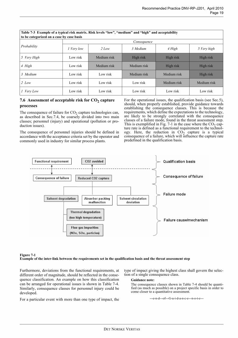
For the operational issues, the qualification basis (see Sec.5),should, when properly established, provide guidance towardsestablishing the consequence classes. This is because therequirements, which define the expectations to the technology,are likely to be strongly correlated with the consequenceclasses of a failure mode, found in the threat assessment step.This is exemplified in Fig. 7-1 in the case where the CO2 cap-ture rate is defined as a functional requirement to the technol-ogy. Here, the reduction in CO2 capture is a typicalconsequence of a failure, which will influence the capture ratepredefined in the qualification basis.
Figure 7-1Example of the inter-link between the requirements set in the qualification basis and the threat assessment step
Furthermore, deviations from the functional requirements, atdifferent order of magnitude, should be reflected in the conse-quence classification. An example on how this classificationcan be arranged for operational issues is shown in Table 7-4.Similarly, consequence classes for personnel injury could bedeveloped. For a particular event with more than one type of impact, the
type of impact giving the highest class shall govern the selec-tion of a single consequence class.
Guidance note:The consequence classes shown in Table 7-4 should be quanti-fied (as much as possible) on a project specific basis in order tocome closer to a quantitative assessment.
---e-n-d---of---G-u-i-d-a-n-c-e---n-o-t-e---
Table 7-3 Example of a typical risk matrix. Risk levels “low”, “medium” and “high” and acceptability to be categorized on a case by case basis
ProbabilityConsequence
1 Very low 2 Low 3 Medium 4 High 5 Very high
5 Very High Low risk Medium risk High risk High risk High risk
4 High Low risk Medium risk Medium risk High risk High risk
3 Medium Low risk Low risk Medium risk Medium risk High risk
2 Low Low risk Low risk Low risk Medium risk Medium risk
1 Very Low Low risk Low risk Low risk Low risk Low risk
DET NORSKE VERITAS

Recommended Practice DNV-RP-J201, April 2010 Page 20
7.7 Failure mode identification & risk ranking meth-odologies There are several hazard or failure mode identification tech-niques commonly used in the industry. The selection ofmethod should take into consideration the complexity andmaturity of the concept being considered. The failure modeidentification & risk ranking should follow the technologybreak down described in Sec.6. The lists of novel elementsidentified in the TA step should be the starting point whengoing into the FMIRR. The output is a list (failure mode regis-try) of all identified failure modes, failure mechanisms and theuncertainties that are associated with an unacceptable risk.Various methods for risk analysis can be used for the threatassessment step. Table 7-5 lists some of the advantages anddisadvantages with different methods.
7.8 Workshop guidelinesWhen using inter disciplinary workshops to identify and rankfailure modes by their risk, it is crucial that these workshopshave the relevant expertise present and are handled in a struc-tured manner. It is of crucial importance that the qualificationsof these members include the disciplines necessary to under-stand the potential failure modes of the technology.
8. Develop qualification plan 8.1 IntroductionThe objective of this step is to select qualification methods thatadequately address the identified failure modes of concernwith respect to its risk and determination of sufficient perform-ance margins. The selected qualification methods will be input to a technol-ogy qualification plan where the various issues will be outlined
as qualification activities needed to be executed. These activi-ties will generate the evidence that each failure mode is quali-fied with an adequate performance margin.
8.2 MethodologyThe development of the qualification plan consists of the fol-lowing main steps:
— Analysis and selection of qualification methods for eachfailure mode based on requirements set by the user or thecustomer in the qualification basis.
— Development of a technology qualification plan in order toshow how each of the failure modes will be qualified andwhat the performance margin will be.
— Develop a detailed description of how to carry out each ofthe selected qualification methods.
The choice of methods to achieve qualification will depend onthe nature of the requirement as stated in the QB. For instance,if a reliability target is set, this would require a quantitativereliability prediction and the methods to generate data willdepend upon what type of input this predictive methodrequires.
8.3 Basis for the analysis and selection Qualification shall be achieved by providing documented evi-dence that each specific requirement (as stated in the qualifica-tion basis) has been met, within a stated acceptance criteria. Failure probabilities, and if relevant, consequences of failure,and performance margins shall be determined for each failuremode of concern. The determination shall be performed at thelevel of detail relevant for the respective development phase ofthe technology. If a quantitative reliability target is stated in the qualificationbasis, then a quantitative reliability method is required to doc-ument fulfilment of the target.
Table 7-4 Example of how failure consequence classes could be developed in the qualification of a typical post combustion carbon capture process based on amine absorption
No Name
Consequence classes (production & pollution)
Emissions Capture rate Energy consumption Reliability/on-stream fac-tor
1 Very low No effect/qualification basis
No effect/qualification basis
No effect/qualification basis
No effect/qualification basis
2 Low Slight increase Slight reduction Slight increase Slight reduction
3 Medium Significant increase Significant reduction Significant increase Significant reduction (days)
4 High High increase High reduction High increase High reduction (weeks)
5 Very high Severe increase Severe reduction Severe increase Severe reduction (months)
Table 7-5 Advantages and disadvantages with different risk analyses methods Method Advantages Challenges and DisadvantagesFailure mode, effect and criticality analysis (FMECA)
Highly systematic as well as simple to apply Investigating one failure mode at a time may not identify critical combinations of failures
Hazard and Operability study (HAZOP) Highly systematic tool which enables identi-fication of the most inconceivable incidents
Resource consumingRequires detailed information (PFDs at least) for producing useful results.Experienced facilitator required
Fault Tree Analysis (FTA) Thorough investigation of (already) identi-fied incidentCan be used at different level of detailCan be a powerful tool when describing the failure mode structure and cause-and-effects
Might not be applicable for identifying (new) incidents.Time consuming to set upNot suitable for accurately modelling all types of systems
Structured what-if checklist (SWIFT) Applicable even if detailed design informa-tion is not available
Experienced facilitator essential, as well as good checklists
Operational Problem Analysis (OPERA) Emphasis on the product interfaces Emphasis on technical problems and human error without going into details about causes
DET NORSKE VERITAS
Recommended Practice DNV-RP-J201, April 2010Page 21
For each failure mode of concern, it should be determined ifthe failure mechanisms can be simulated by recognized andgenerally accepted methods. In the case where recognized andgenerally accepted methods do not exist, the correctness of thesuggested method should be qualified.
Guidance note:When practical, a qualitative approach can be used in earlydevelopment phases normally reflecting the first iteration of thequalification process. This may be done when the failure modesof concern have been listed in the failure mode registry in thecourse of the threat assessment step (see previous chapter). Theexpert panel goes through each failure mode and decides whattypes of qualification activities shall be conducted in each sepa-rate case. The choice of qualification activities will depend on thetype of failure mode, its degree of uncertainty, and its risk level. Consequence of failure shall, when required, be determinedthrough recognized qualification methods. Consequence classesshall be described based on the data generated from these meth-ods or the preliminary classes found in the threat assessment stepshall be updated.
---e-n-d---of---G-u-i-d-a-n-c-e---n-o-t-e---
8.4 Qualification methodsThe following methods can be used for qualification:
— Failure mode avoidance, such as operational procedures orinterlocks
— Previous documented experience with similar equipmentand operating conditions
— Analytical methods such as handbook solutions, empiricalcorrelations or mathematical formulas
— Numerical methods, such as process simulation models,CFD, FEM, corrosion models, etc.
— Experimental methods, such as:- Laboratory tests (simplified tests targeted towards a
specific failure mode to enhance knowledge about forexample material behaviour)
- Test to reduce uncertainties in numerical and analyticalmodels (such as erosion models, limited number offatigue tests)
- Scale-up studies using pilot plants, mock-ups or dem-onstration plants.
The methods listed above, and combination of these, can beemployed to determine failure probability (and if relevant con-sequence of failure), and performance margin. Additionalmethods for qualification may also be relevant.A general guidance to the selection of qualification activitiesfor scaling up CO2 capture processes is given in Appendix C.
Guidance note:The selection of type and number of qualification methodsdepend on the risk for the failure mode, technology class, andlevel of confidence in the methods to be used. The objective is to select the qualification methods that providethe most reliable and cost-effective combination (i.e. an optimalinteraction). The selection of the methods should therefore bebased on optimization of related cost versus accuracy, such ascost-benefit analysis. Each qualification method might oftenaddress several failure modes. Thus, the methods should beselected in a systematic manner to reduce unnecessary overlap-ping.
---e-n-d---of---G-u-i-d-a-n-c-e---n-o-t-e---
8.5 Development of the technology qualification plan The selected qualification methods will be specified furtherand outlined as activities in a technology qualification plan(TQP). The qualification activities shall be linked to the failuremode register developed during the failure mode identificationand risk ranking. Objectives for each of the qualification activ-ities shall be defined. Cost-benefit analysis may be required asdecision support in order to assess the remaining degree of
uncertainty after the qualification activities have been exe-cuted for each of the failure modes. A qualification plan tem-plate is shown in Appendix E.Upon completion of the activities of the technology qualifica-tion plan, the technology shall fulfil the requirements includingthe acceptance criteria set forth in the qualification basis.
8.6 Detailed description of the selected activities in the TQPThe means and purpose of the qualification activities must bedescribed unambiguously. In this context this implies that themethod for qualification is described at a level necessary tocarry out the activities and obtain satisfactory results depend-ing on technology maturity (development phase). Guidance on relevant activities for scaling up CO2 captureprocesses is given in Appendix C.
9. Execute Qualification Plan9.1 IntroductionThe objective of this step is to carry out the qualification activ-ities prescribed in the technology qualification plan developedin the previous step to document performance margins for thefailure modes of concern. The execution of the technology qualification plan is likely torepresent a significant part of the costs in the qualificationprocess. It is also likely be time consuming compared to theother steps. It is therefore of importance that the qualificationactivities are well chosen and planned in order to derive theinformation needed to address the identified failure modes, andto avoid spending resources on tests that do not give suchinformation.
9.2 MethodologyThe execution of the qualification plan consists of the follow-ing key steps:
— Carrying out the qualification activities in the technologyqualification plan
— Collection and documentation of the data generated by therespective qualification activities
— Ensure traceability of the data — For each failure mode, determine the performance margin.
Guidance note:If there has been a time delay between the development of theTQP and the execution of it, it is recommended that a review isundertaken prior to execution to assure that the qualificationactivities in the TQP still properly address the failure modes ofconcern. Review and check of qualification activities can be to: - Check / ask / verify if the planned activity for each failure
mode will actually find the performance margins of concern,i.e.: will the planned test find the performance margin to thespecified operational requirements with the desired level ofconfidence?
- Check that the operational limits that were specified in thequalification basis are correctly specified for each failuremode of concern (check with the critical parameters list)
- Ask how the planned tests will validate the analyticalmodel(s)
- Check the level of accuracy of the planned activity. Is theaccuracy of the desired level?
- Outline what is sufficient evidence and how evidence shouldbe generated and documented.
---e-n-d---of---G-u-i-d-a-n-c-e---n-o-t-e---
9.3 Execution of the qualification activitiesThe qualification activities outlined in the TQP shall be exe-cuted according to the guidelines outlined in Sec.8.6. The exe-
DET NORSKE VERITAS
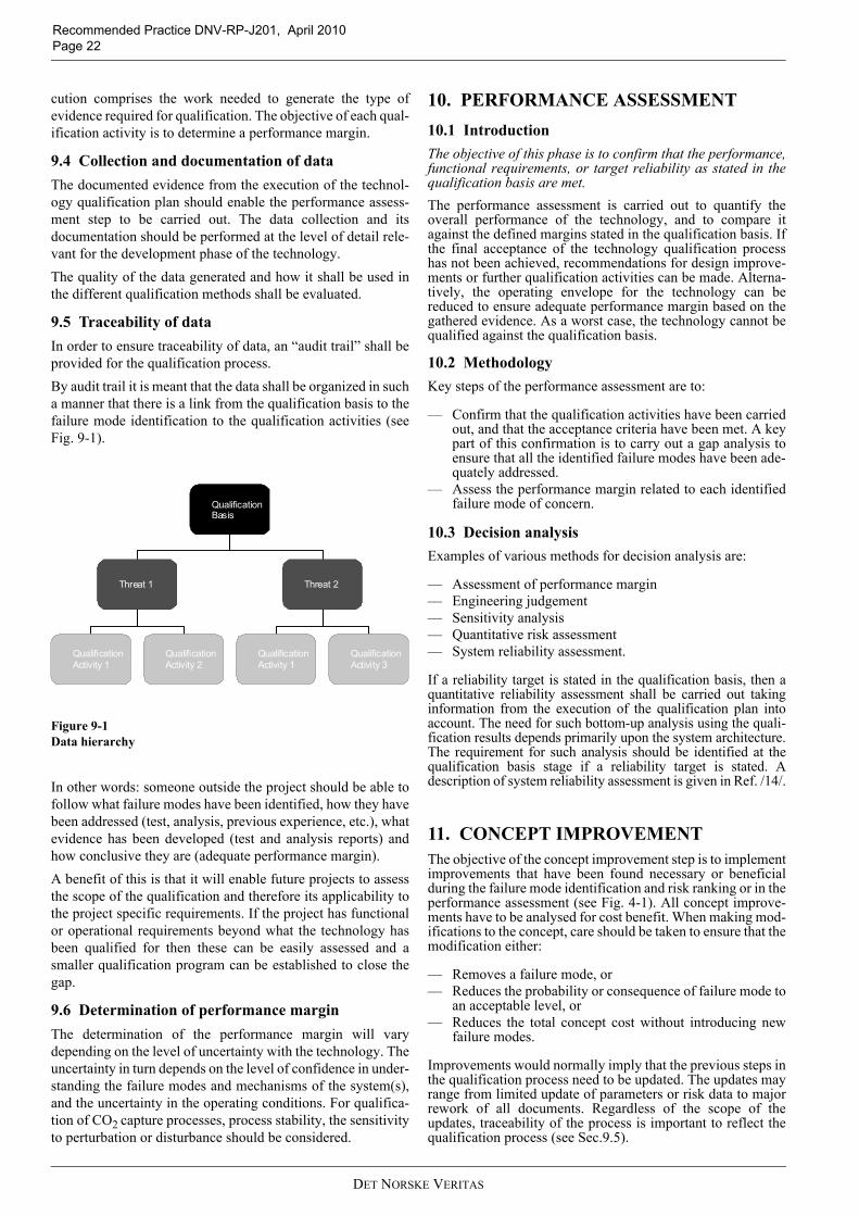
Recommended Practice DNV-RP-J201, April 2010 Page 22
cution comprises the work needed to generate the type ofevidence required for qualification. The objective of each qual-ification activity is to determine a performance margin.
9.4 Collection and documentation of dataThe documented evidence from the execution of the technol-ogy qualification plan should enable the performance assess-ment step to be carried out. The data collection and itsdocumentation should be performed at the level of detail rele-vant for the development phase of the technology. The quality of the data generated and how it shall be used inthe different qualification methods shall be evaluated.
9.5 Traceability of dataIn order to ensure traceability of data, an “audit trail” shall beprovided for the qualification process. By audit trail it is meant that the data shall be organized in sucha manner that there is a link from the qualification basis to thefailure mode identification to the qualification activities (seeFig. 9-1).
Figure 9-1Data hierarchy
In other words: someone outside the project should be able tofollow what failure modes have been identified, how they havebeen addressed (test, analysis, previous experience, etc.), whatevidence has been developed (test and analysis reports) andhow conclusive they are (adequate performance margin).A benefit of this is that it will enable future projects to assessthe scope of the qualification and therefore its applicability tothe project specific requirements. If the project has functionalor operational requirements beyond what the technology hasbeen qualified for then these can be easily assessed and asmaller qualification program can be established to close thegap.
9.6 Determination of performance marginThe determination of the performance margin will varydepending on the level of uncertainty with the technology. Theuncertainty in turn depends on the level of confidence in under-standing the failure modes and mechanisms of the system(s),and the uncertainty in the operating conditions. For qualifica-tion of CO2 capture processes, process stability, the sensitivityto perturbation or disturbance should be considered.
10. PERFORMANCE ASSESSMENT10.1 IntroductionThe objective of this phase is to confirm that the performance,functional requirements, or target reliability as stated in thequalification basis are met. The performance assessment is carried out to quantify theoverall performance of the technology, and to compare itagainst the defined margins stated in the qualification basis. Ifthe final acceptance of the technology qualification processhas not been achieved, recommendations for design improve-ments or further qualification activities can be made. Alterna-tively, the operating envelope for the technology can bereduced to ensure adequate performance margin based on thegathered evidence. As a worst case, the technology cannot bequalified against the qualification basis.
10.2 MethodologyKey steps of the performance assessment are to:
— Confirm that the qualification activities have been carriedout, and that the acceptance criteria have been met. A keypart of this confirmation is to carry out a gap analysis toensure that all the identified failure modes have been ade-quately addressed.
— Assess the performance margin related to each identifiedfailure mode of concern.
10.3 Decision analysisExamples of various methods for decision analysis are:
— Assessment of performance margin — Engineering judgement— Sensitivity analysis— Quantitative risk assessment— System reliability assessment.
If a reliability target is stated in the qualification basis, then aquantitative reliability assessment shall be carried out takinginformation from the execution of the qualification plan intoaccount. The need for such bottom-up analysis using the quali-fication results depends primarily upon the system architecture.The requirement for such analysis should be identified at thequalification basis stage if a reliability target is stated. Adescription of system reliability assessment is given in Ref. /14/.
11. CONCEPT IMPROVEMENTThe objective of the concept improvement step is to implementimprovements that have been found necessary or beneficialduring the failure mode identification and risk ranking or in theperformance assessment (see Fig. 4-1). All concept improve-ments have to be analysed for cost benefit. When making mod-ifications to the concept, care should be taken to ensure that themodification either:
— Removes a failure mode, or— Reduces the probability or consequence of failure mode to
an acceptable level, or— Reduces the total concept cost without introducing new
failure modes.
Improvements would normally imply that the previous steps inthe qualification process need to be updated. The updates mayrange from limited update of parameters or risk data to majorrework of all documents. Regardless of the scope of theupdates, traceability of the process is important to reflect thequalification process (see Sec.9.5).
Qualification Basis
Threat 1 Threat 2
Qualification Activity 1
Qualification Activity 2
Qualification Activity 1
Qualification Activity 3
Qualification Basis
Threat 1 Threat 2
Qualification Activity 1
Qualification Activity 2
Qualification Activity 1
Qualification Activity 3
DET NORSKE VERITAS

Recommended Practice DNV-RP-J201, April 2010Page 23
APPENDIX A DESCRIPTION OF CO2 CAPTURE TECHNOLOGIES
This appendix gives a more detailed description of the capturetechnologies outlined in Table 2-1. The different technologycategories for CO2 capture, as listed in Table A-1 are describedbelow.
A.1 Absorption Chemical absorption uses organic and inorganic aqueous solu-tions to weakly bond with carbon dioxide forming intermedi-ate compounds. Organic amines are able to react with carbondioxide forming water soluble compounds from streams withlow CO2 partial pressure. They are distinguished in primary,secondary and tertiary forms. The primary amine, monoeth-anolamine (MEA), is currently the most widely used solvent.The MEA solution is contacted with flue gas in an absorberwhere CO2 is absorbed by the solution. MEA reacts with CO2in the gas stream to form MEA carbamate. The CO2-rich MEAsolution is then sent to a stripper where it is reheated to releasealmost pure CO2. This process is generally uneconomic as itrequires large equipment size and intensive energy input.Besides MEA, diethanolamine (DEA) and methyldieth-anolamine (MDEA) are often used as absorbents. Inorganic solvents include potassium carbonate, sodium car-bonate and aqueous ammonia. Soluble carbonate compoundreact with carbon dioxide to form bicarbonate. The latter, whenheated, releases CO2, regenerating the initial carbonate. Thereare two available systems using ammonia, the ammonia-basedwet scrubbing and the chilled ammonia process (CAP). Inprinciple, ammonia and its derivatives react with CO2 by arange of mechanisms. For instance, ammonium carbonate,water and CO2 react and form ammonium bicarbonate.In physical absorption, the solvents form a weaker bond toCO2 than chemical solvents, with the advantage of lower costof regeneration. Binding takes place at high pressure with theCO2 released when the pressure is reduced. The only energyneeded for CO2 capture is the power required for gas pressuri-zation. The amount of energy per tonne of CO2 is proportionalto the inverse of the CO2 concentration in the gas. Specificphysical solvents include cold methanol which is used in theRectisol process, dimethylether or polyethylene glycol whichis used in the Selexol process, propylene carbonate used in theFluor process and n-methyl-2pyrollidone.Of the separation methods described above, chemical absorp-tion is the preferred method at CO2 concentrations lower
than 10% (such as flue gases from gas-fired power plants),because its energy use is not particularly sensitive to low CO2partial pressures. Physical absorption is the preferred methodat higher CO2 partial pressures.
A.2 AdsorptionSome solid materials with high surface areas, such as zeolites,molecular sieves and activated carbon, can be used to separateCO2 from gas mixtures by adsorption, where chemical reac-tions between the adsorbent and CO2 may or may not occurduring the separation process. These processes operate onrepeated cycles with the basic steps being adsorption andregeneration. The regeneration can be done by reducing thepressure, by so-called pressure swing adsorption (PSA), or byincreasing the temperature, in temperature swing adsorption(TSA). Electrical and vacuum swing adsorption are also avail-able techniques for regeneration. Currently, adsorption is not considered attractive for large-scale separation of CO2 from flue gas because the capacity andCO2 selectivity of available adsorbents are low.
A.3 MembranesCarbon dioxide may be recovered using membranes. Gas sep-aration membranes are available as ceramic, polymeric andceramic/polymeric hybrids. The driving force for separation isgiven by the difference in partial pressure of gas speciesbetween the feed side and permeate side of the membrane. Gasseparation membrane energy efficiencies can be higher thanfor absorption separation systems, as a limited pressure dropacross the membrane is sufficient to achieve separation. Theirmodular design also allows their use in combination withsmall-scale modular fuel cells, foreseen as a power plant con-cept for the future. While membranes are widely applied forgas separation, they have yet to be applied at power plant scale.The disadvantage of membrane separation systems for CO2capture is that their separation efficiency is relatively poor andthe purity of CO2 is relatively low /15/.Micro-porous solids are used as gas absorption membranesthat work as contacting devices between the gas and the liquidphase, increasing the contact area, thus reducing the size of thescrubbing equipment. They have potential to reduce the masstransfer of undesirable gas phase components such as oxygenand nitrous oxide, which are known to degrade thealkanolamine solvent.Membranes are also applied for membrane reformers forhydrogen production in pre-combustion capture concepts. Thereformer consists of a steam reformer equipped with hydrogenselective membrane modules of palladium-based alloy andnickel-based catalyst and can perform steam reforming reac-tion, water gas shift reaction and hydrogen separation at thesame time without a shift converter and PSA. This process iscalled membrane-enhanced steam reforming. The permeate(hydrogen) can be combusted, whereas the CO2-rich retentateis further purified as appropriate.
A.4 Cryogenic separation Cryogenics take advantage of the critical pressures and tem-peratures of specific elements and compounds in a mixture andare commonly used today for purification of CO2 in gasstreams that already have high CO2 concentrations. Cryogenicseparation offers high recovery of CO2, but the large amountof energy required to provide the refrigeration necessary forthe process, particularly for dilute gas streams, is the major dis-advantage. Cryogenic separation is the most common way ofproducing oxygen in the oxy-fuel combustion concept.
Table A-1 CO2 capture technologiesCapture Category Specific TechnologyAbsorption Chemical absorption (amine, hindered
amine and inorganic)Physical absorption
Adsorption
Pressure swing adsorption
Temperature swing adsorption
Electric swing adsorption
Vacuum swing adsorption
Membranes
Gas absorption membranes
Gas separation membranes
Membrane reactors/reformers
Cryogenics Compression and refrigeration
Emerging technologiesChemical looping combustion; Enzyme based systems; Solid sorbents
DET NORSKE VERITAS
Recommended Practice DNV-RP-J201, April 2010 Page 24
A.5 Novel technologiesThere are several novel CO2 capture concepts being developedin the wake of the first large-scale commercial CO2 captureprojects. Some of these concepts are briefly delineated below: Chemical looping combustion (CLC) is an oxygen supply con-cept based on the use of a metal/metal oxide system to providea reversible chemical reaction for oxygen supply /16/. Notethat the CLC technology is often also categorized under theoxy-fuel combustion concept. In one reactor the metal reactswith air to produce a metal oxide; in another reactor, the metaloxide reacts with the fuel to produce syngas and metal. Metaland metal oxide are transported from one reactor to the other.Such a system avoids energy intensive air separation for pureoxygen supply. CLC has several advantages compared withconventional combustion. The exhaust gas stream from airreactor is harmless, consisting mainly of nitrogen. In a well-designed system, there should be no thermal formation of NOxsince the regeneration of oxygen carrier takes place at moder-ate temperatures (without a flame). The exhaust gas from thefuel reactor consists of CO2 and H2O. Separation of CO2 canbe done by condensing H2O. This is the major advantage withCLC which avoids the huge energy penalty necessary in tradi-tional amine scrubbing process to capture CO2. A number of solid sorbents can be used to react with CO2 toform stable compounds at one set of operating conditions andthen, at another set of conditions, be regenerated to liberate theabsorbed CO2 and reform the original compound. For exam-
ple, lithium zirconate (Li2ZrO3) and lithium silicate (Li4SiO4)have been investigated as high temperature CO2 absorbents.Desired features, such as large capacity, rapid absorption, widerange of temperature and concentrations of CO2, and stability,make these compounds strong candidates for developing com-mercially competitive CO2 adsorbents. In another concept,solid CaO-based sorbents can be applied for high temperatureCO2 capture (>500°C) from flue gas to form CaCO3, which isregenerated in a parallel process to form pure CO2 and theoxide is circulated back to the capture vessel. These types ofsorbents are attractive for high temperature in-situ CO2 capturein novel pre-combustion concepts. However, solids are inher-ently more difficult to work with than liquids, and no solidsorbent system for large scale recovery of CO2 from flue gashas yet been commercialized.Biologically based capture systems are another potential ave-nue for improvement in CO2 capture technology. These sys-tems are based upon naturally occurring reactions of CO2 inliving organisms. One of these possibilities is the use ofenzymes. An enzyme-based system, utilizing carbonic anhy-drase in a hollow fibre contained liquid membrane, canachieve CO2 capture and release by mimicking the mechanismof the mammalian respiratory system /17/. The idea behind thisprocess is to use immobilized enzyme at the gas/liquid inter-face to increase the mass transfer and separation of CO2 fromflue gas.
DET NORSKE VERITAS

Recommended Practice DNV-RP-J201, April 2010Page 25
APPENDIX B SPECIFICATION AND REQUIREMENTS
This appendix gives an additional description to the specifica-tion relevant for the qualification of fossil fuel-fired powerplants equipped with CO2 capture processes as described inSec.5.
B.1 Documentation describing the process systemFor the purpose of defining the qualification basis, an overallstudy of the process system, expressed as a process flow dia-gram (PFD) with relevant additional information (specifica-tion) should form the basis for establishing the functionalrequirements for the process. The process flow diagram shouldbe clear, comprehensive, accurate and complete. However, the
extent to which it can be drawn up before any work is done onthe detailed design of equipment will depend on the complex-ity of the process and the information available, which is likelyto reflect the maturity of the process development program,e.g. exploratory research, process research, pilot plant studiesor development of a commercial unit. Process piping andinstrumentation diagrams (P&IDs) and equipment specifica-tion sheets are only likely to be available at late stages of proc-ess development. Table B-1 shows the documentation that detailed systemdescription for CO2 capture technology could include.
B.2 Interfacing system requirementsThere will be several types of interfaces that need to be consid-ered prior to the construction and building of a process plant.Such interfaces could be physical interfaces, connections, orsupply points, as well as documental interfaces such as con-tractual agreements, with external operators /18/. An important interface for CO2 capture systems is the integra-tion between the capture unit/ capture plant and the powerplant. For oxy-fuel, and pre-combustion concepts, the CO2capture processes are integrated within the power plant,whereas for the post combustion concept, the capture plant andthe power plant would normally be two separate units. Hence,integration of a capture process into a power plant will intro-
duce different challenges depending on the chosen technology.In all three capture concepts, the effects of the interactionsbetween the power plant and the capture plant must be consid-ered. For a gas power plant, with post combustion capture,conditions in the capture plant can influence the gas powerplant (back pressure) or produce new requirements regardingsteam production (effect on low pressure turbine).The boundaries for the CO2 capture process are in this docu-ment defined as the interface to the CO2 transport element (seeSec.1.3.2). Typical interfacing requirement for this boundarywould be specifications to the CO2 product stream composi-tion and pressure.
Table B-1 Documentation types and description /10/, /11/ Documentation type Description
Con
cept
ual Process description A detailed description of how the process operates and all system interfaces.
Basis for commercial plant The basis for a commercial plant should be established, including items such as production rate, battery limits requirements, specifications on feed and product streams, etc.
Heat and material balancesA heat, material and pressure balance including all the pertinent physical characteristics of the process fluids involved. Moreover, utility streams involved in heat transfer to the process system should be shown.
Dra
win
gs
Block diagramsSimplest form of graphical presentation, where each block represent a single piece of equipment or a complete stage in the process. Useful for highlighting mass and energy stream interactions between subsystems.
Process flow diagram (PFD)
The key document in process design, showing the equipment selected to carry out the process; the stream connections and operating conditions. The flow sequence should be presented in its simplest form. Principal control systems should be shown and all major equipment items clearly indicated. Oper-ating conditions should be shown at principal points in the process:1) Stream composition2) Total stream flow rate3) Stream temperature4) Nominal operating pressure5) Stream enthalpy (optional)6) Physical property data, e.g. density and viscosity (optional)
Process piping and instru-mentation diagrams (P&ID)
The P&ID shows the arrangement of the process equipment, piping, pumps, instruments, valves and other fittings. It should include:1) All process equipment, identified by an equipment number2) All pipes with size and material of construction 3) All valves, control and block valves, by size and type4) Ancillary fittings that are part of the piping system, such as inline sight-glasses, strainers and steam traps5) Pumps6) All control loops and instruments For simple processes, the utility (service) lines can be shown on the P&ID. For complex processes, sep-arate diagrams should be used to show the service lines. The service connections to each unit, however, should be shown on the P&ID.
Spec
ifica
tion
shee
ts Major equipment outline drawings and specifications
Specification sheets for major equipment, such as heat exchangers, pumps and vessels, should be used. For example, vessel sketches, inducing specified pressure and temperature ratings, metal thickness, nozzle orientation and special internals should be shown.
DET NORSKE VERITAS

Recommended Practice DNV-RP-J201, April 2010 Page 26
B.3 Authority requirementsThe authorities will require that the plant is built and operatedaccording to national and international regulations, applicablecodes, and standards, related to pollution, emissions, safety,etc. Such requirements are highly dependent on the country inwhich the plant is to be installed and operated.General rules and regulations that need to be considered for agas-fired power plant with CO2 capture in Norway are forinstance /18/:
— Consequence assessment requirements— Safety rules and regulations— Legislations on pollution and climate quotas— The petroleum legislation— Other new/special regulations.
It will be important to secure the necessary permissions fromthe government at an early stage in order to ensure the progressof the project. It is recommended these requirements areincluded as early as possible in the qualification basis.
B.4 Requirements to safety, health and the environmentA CO2 capture plant or power plant fitted with CO2 capturetechnology will require to comply with considerable SHE regu-lations in design, construction, and operation. Examples of SHErequirements are emissions to air and technical safety /18/.
B.5 Reliability, availability, and maintainability requirementsFor CO2 capture processes, plant availability is the most com-monly used reliability parameter. Availability requirements aretypically expressed as the fraction of time the equipment isable to perform its intended function under given operatingconditions, whereas maintainability requirements are typicallyexpressed as the mean time needed to return failed or shutdownequipment back to normal service.Requirements for plant availability for a CO2 capture processmight vary based on the type of capture concept. The conse-quences for the downtime for a post combustion capture unitmight be small compared to a process that is fully integratedwith the power plant, such as in a pre-combustion process oran oxy-fuel combustion process. Strict targets for reliability, availability, and maintainability(RAM) can strongly influence a project’s economy by impos-ing very comprehensive tests and analyses in order to docu-ment fulfilment. It is of crucial importance that the impact ofsetting such requirements are thoroughly discussed, under-stood, and agreed by all project participants. Before setting tar-gets, it can be instructive (or helpful) to investigate how asystem’s reliability or availability targets are met. A moredetailed guidance on the prediction of system reliability can befound in Ref. /14/, /19/, /20/.It is recommended that system availability is investigated asearly as possible in the project. Before more detailed informa-tion is available, one could use fault-tree analysis or a simpli-fied RAM analysis with the input from a HAZID for support inthe decision making.
DET NORSKE VERITAS

Recommended Practice DNV-RP-J201, April 2010Page 27
APPENDIX C SCALE-UP OF CO2 CAPTURE TECHNOLOGIES
This appendix describes scale-up issues related to CO2 capturetechnologies, where a traditional chemical engineeringapproach to the scale-up path from laboratory to commercialdesign is described and compared to the principles of this Rec-ommended Practice.
C.1 IntroductionScale-up is essential in qualification of process systems. ACO2 capture technology may be qualified and even wellproven at a given scale. However, it will still need to be quali-fied for a larger scale.The discussions are limited to scale-up of separation vesselstypically used for physical and chemical absorption of CO2 forpost-combustion capture. Scaling issues related to oxy-fuelcombustion and catalytic reforming reactors used in pre-com-bustion systems are not discussed, neither are any utility sys-tems.The idea of separating CO2 from flue gas streams started backin 1970’s, not with concern about the greenhouse effect, but asa possible economic source of CO2, mainly for enhanced oilrecovery (EOR) operations. Other application areas for CO2usage include carbonated beverages, food industry, brewing,welding, chemical feed stocks, fire extinguisher and solventextraction. Several plants are in commercial operation today,however, all existing plants are much smaller than proposedCCS plant for a typical power plant in terms of tonnage of CO2handled for the purpose of CCS.
C.2 Scale-up of post combustion CO2 capture unitsOne of the most known, and frequently cited, commercial CO2post-combustion capture facilities that has been in recent oper-ation, is the Bellingham (Massachusetts, US) facility, wherecapture rates of ~320 t CO2/day were experienced, in theperiod from 1991 to 2005. In order to capture 90% of a 400MW natural gas fired combined cycle, units of approximately3200 t CO2/day are required. For example, this would equal ascale-up ratio of 10, relative to the Bellingham plant.In general, the critical aspects of scale-up relate to the impactof surface/ volume and height/diameter ratios on flow patterns,gas/liquid dispersion and heat transfer. Typical problems maybe of physical nature, chemical nature, or involve some aspectsof both. For chemical processes in general, some features con-sidered to be of particular importance when moving fromsmall-scale to commercial unit, are listed in Table C-1.In addition to the issues listed in Table C-1, presence of impu-rities not considered at laboratory scale could be encounteredfor a commercial operation and foul or poison catalysts or sol-vents. Moreover, some impurities in recycle streams, e.g. sol-vent recycle, might accumulate over time and causeoperational problems not foreseen at smaller scale.
The major challenge with CO2 capture from flue gases fromnatural gas powered plants compared to coal fired powerplants, is related to combustion with a large excess of air,resulting in:
— Large total volume of gas to be scrubbed— Low concentrations of CO2— High concentrations of oxygen that degrade amine sol-
vents.
The most common separation vessels employed for CO2scrubbing are counter current absorbers. The design of countercurrent absorbers normally involves the following steps:
— Selection of contactor (type of trays or packing)— Calculation of mass and heat balances— Estimation of required column height (based on mass and
heat transfer analysis)— Calculation of required column diameter (based on gas/
liquid flow rates and hydraulic considerations)— Mechanical design of the hardware.
Detailed reviews on commonly used design procedures forabsorbers, including theoretical equilibrium calculations,empirical correlations and computer-assisted models, are pre-sented by Kohl and Nielsen (1997) /22/.A common feature for absorbers is the optimum in operationalconditions for gas and liquid flow rates, which should yieldgood wetting of the packing material and at the same timeavoiding the occurrence of flooding. The diameter of a packedcolumn is usually established on the basis of flooding correla-tions, whereas the height of the column relates to the masstransfer efficiency. Increased volumetric flow of flue gas is likely to require largerabsorbers to be designed and constructed, than previous expe-rienced, as it is often desirable to treat the large volumes of gasin a single train rather than a number of parallel trains, due toeconomy of scale reasons (reduces the number of vessels, thequantity of piping, valves, and instrumentation). Hence, theselarger columns will introduce practical challenges related todesign and fabrication. Uniform gas and liquid distribution is indispensable for a largesize tower to obtain required performance. As the absorbercross sectional area increases, there is likely to be an increasednumber of challenges in maintaining uniform distribution ofthe solvent over the packing in packed columns, or of main-taining even distribution of solvent over large plate areas inplate columns. The most severe effects of uneven distributionin the absorber column on the capture performance can besummarized as:
— Uneven solvent distribution – If all the surface area of thepacking is not wetted, then less surface area will be avail-able for mass transfer of CO2 from the flue gas to the sol-vent.
— Flue gas bypass – The flue gas will follow the path of leastresistance. The parts of the tower with the greatest liquidflow will receive the least gas flow and the part with theleast solvent will receive the most flue gas. This contrib-utes to the loss of performance.
Also, as the diameter becomes large, heavy structural membersmust be employed to support the trays or packing, and suchheavy structural members require an increased absorber col-umn internal volume at great expense.The previous discussions on design and size of large scaleabsorbers are also valid for the stripper vessel. However, the
Table C-1 Scale-up issues /10/
Scale-up issues Challenges
Shape and geometry of reactorFluid by-passing; Pressure drop;Stagnation zones resulting in changes in residence time distri-bution
Surface-to-volume ratios; height-to-diameter ratios
Gradients of concentration and temperature; Flow patterns; Gas/liquid distribution
Materials of construction Different contaminant levels
Heat removalTemperature profiles; Hot/cold-spots; Run-away reac-tions
DET NORSKE VERITAS
Recommended Practice DNV-RP-J201, April 2010 Page 28
sizes of stripper vessels are generally smaller than for absorb-ers, as the gas throughput is more dependent on the amount ofCO2 fixated in the recycled solvent. Furthermore, the abovediscussions are not meant to be a comprehensive and thoroughassessment of scaling effects and design of large-scale CO2capture units. However, it highlights some challenging fea-tures likely to be encountered when scaling-up and designingvery large absorption towers.
C.3 Technology qualification and scale-upTo follow a direct path from laboratory scale to a commercialfull-scale design requires either an enormous amount of infor-mation that often is unavailable or beyond scientific and engi-neering judgement normally considered possible anddesirable. On the other hand, building intermediate-scale pilotplants is an expensive task. The pilot will require the samenumber of instruments and controllers as the full scale plant,and even more instrumentation will be required to gather datarequired for the scale-up studies. Moreover, the operating costof a pilot is high as it is necessary to staff the pilot with bothengineers and operators. There is always a limited amount oftime and money for process development. Therefore, calcu-lated risks will have to be taken in the design, construction andstart-up of the “first commercial unit”. These calculated risksshould be minimized and assessed in a systematic manner. The current Recommended Practice provides a systematic pro-cedure for managing the risks associated with CO2 capturetechnologies, where in particular two aspects of scale-up arerelevant:
1) Scale-up as a source of risk. The scale-up ratios of future commercial post-combustioncapture plants relative to previous experience could typi-cally be in the order of magnitude of 10. This might not
seem like a very great figure, compared to historic scale-up data for other chemical processes /10/. However, con-sidering the urgency of deployment of CCS as a green-house gas mitigation technology, the relatively shorttimeframe for scale-up development introduces additionalchallenges for technology developers. Moreover, novelpre-combustion and oxy-fuel capture systems, such ashydrogen membrane reactors or chemical looping com-bustion, are likely to have scale-up ratios of a much higherorder of magnitude than for an amine-based post-combus-tion plant. Therefore, the scale of operation itself intro-duces risks, which should be identified, assessed andmanaged using technology qualification following theprinciples of the current Recommended Practice.
2) Scale-up as a qualification method (pilot plants). The technology qualification plan, following the threatassessment step, is developed in order to show how eachof the identified failure modes will be qualified. Qualifica-tion methods are selected to adequately address the identi-fied failure modes of concern. This might be computermodelling, theoretical investigations, laboratory experi-mental investigations, previous experience, handbooksolutions or pilot scale tests. Building a pilot plant isexpensive and time consuming, and should only be justi-fied if it contributes to the reduction of the risks and mini-mizes the chances of failure of the commercial plant. Theselected qualification method should be directed primarilyat attacking areas of doubt and uncertainty. Therefore,scale-up studies using pilots should address the failuremodes of concern, rather than being a miniaturized com-mercial system. Technology qualification, following theprinciples of the current Recommended Practice, is anefficient methodology and tool in assessing whether a pilotplant should be built or not.
DET NORSKE VERITAS
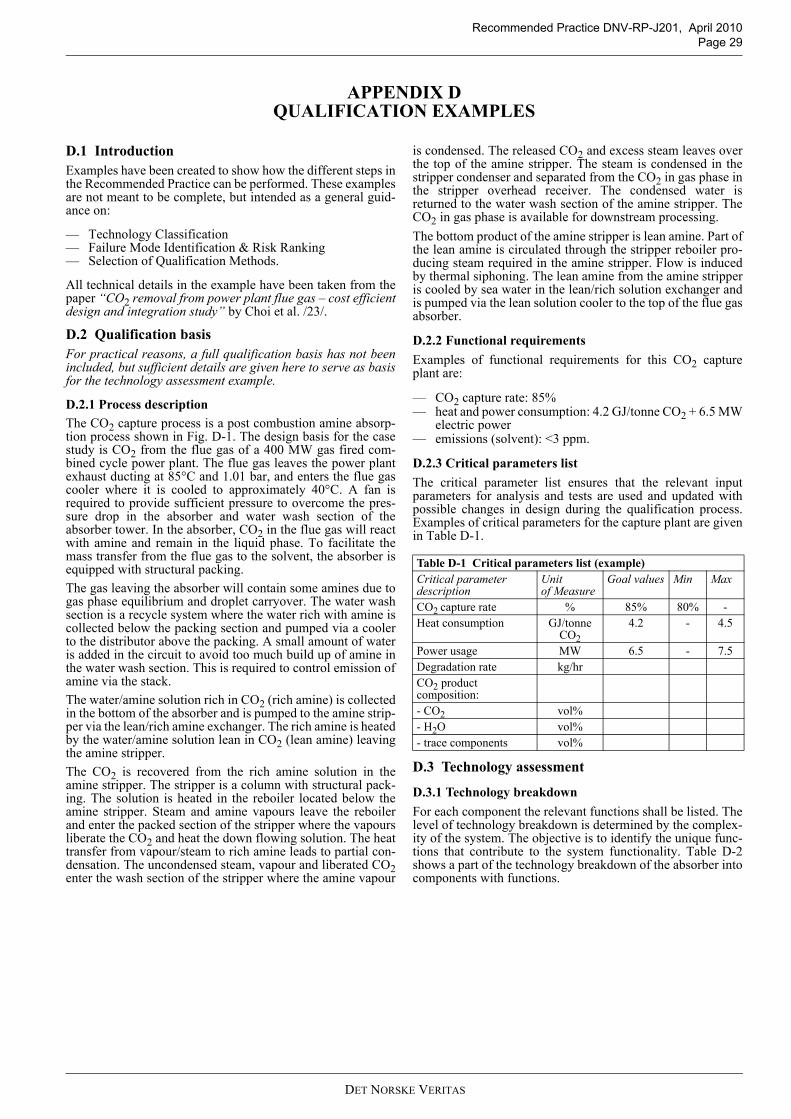
Recommended Practice DNV-RP-J201, April 2010Page 29
APPENDIX D QUALIFICATION EXAMPLES
D.1 IntroductionExamples have been created to show how the different steps inthe Recommended Practice can be performed. These examplesare not meant to be complete, but intended as a general guid-ance on:
— Technology Classification— Failure Mode Identification & Risk Ranking— Selection of Qualification Methods.
All technical details in the example have been taken from thepaper “CO2 removal from power plant flue gas – cost efficientdesign and integration study” by Choi et al. /23/.
D.2 Qualification basisFor practical reasons, a full qualification basis has not beenincluded, but sufficient details are given here to serve as basisfor the technology assessment example.
D.2.1 Process descriptionThe CO2 capture process is a post combustion amine absorp-tion process shown in Fig. D-1. The design basis for the casestudy is CO2 from the flue gas of a 400 MW gas fired com-bined cycle power plant. The flue gas leaves the power plantexhaust ducting at 85°C and 1.01 bar, and enters the flue gascooler where it is cooled to approximately 40°C. A fan isrequired to provide sufficient pressure to overcome the pres-sure drop in the absorber and water wash section of theabsorber tower. In the absorber, CO2 in the flue gas will reactwith amine and remain in the liquid phase. To facilitate themass transfer from the flue gas to the solvent, the absorber isequipped with structural packing. The gas leaving the absorber will contain some amines due togas phase equilibrium and droplet carryover. The water washsection is a recycle system where the water rich with amine iscollected below the packing section and pumped via a coolerto the distributor above the packing. A small amount of wateris added in the circuit to avoid too much build up of amine inthe water wash section. This is required to control emission ofamine via the stack.The water/amine solution rich in CO2 (rich amine) is collectedin the bottom of the absorber and is pumped to the amine strip-per via the lean/rich amine exchanger. The rich amine is heatedby the water/amine solution lean in CO2 (lean amine) leavingthe amine stripper. The CO2 is recovered from the rich amine solution in theamine stripper. The stripper is a column with structural pack-ing. The solution is heated in the reboiler located below theamine stripper. Steam and amine vapours leave the reboilerand enter the packed section of the stripper where the vapoursliberate the CO2 and heat the down flowing solution. The heattransfer from vapour/steam to rich amine leads to partial con-densation. The uncondensed steam, vapour and liberated CO2enter the wash section of the stripper where the amine vapour
is condensed. The released CO2 and excess steam leaves overthe top of the amine stripper. The steam is condensed in thestripper condenser and separated from the CO2 in gas phase inthe stripper overhead receiver. The condensed water isreturned to the water wash section of the amine stripper. TheCO2 in gas phase is available for downstream processing. The bottom product of the amine stripper is lean amine. Part ofthe lean amine is circulated through the stripper reboiler pro-ducing steam required in the amine stripper. Flow is inducedby thermal siphoning. The lean amine from the amine stripperis cooled by sea water in the lean/rich solution exchanger andis pumped via the lean solution cooler to the top of the flue gasabsorber.
D.2.2 Functional requirementsExamples of functional requirements for this CO2 captureplant are:
— CO2 capture rate: 85%— heat and power consumption: 4.2 GJ/tonne CO2 + 6.5 MW
electric power— emissions (solvent): <3 ppm.
D.2.3 Critical parameters listThe critical parameter list ensures that the relevant inputparameters for analysis and tests are used and updated withpossible changes in design during the qualification process.Examples of critical parameters for the capture plant are givenin Table D-1.
D.3 Technology assessment
D.3.1 Technology breakdownFor each component the relevant functions shall be listed. Thelevel of technology breakdown is determined by the complex-ity of the system. The objective is to identify the unique func-tions that contribute to the system functionality. Table D-2shows a part of the technology breakdown of the absorber intocomponents with functions.
Table D-1 Critical parameters list (example) Critical parameter description
Unit of Measure
Goal values Min Max
CO2 capture rate % 85% 80% -Heat consumption GJ/tonne
CO24.2 - 4.5
Power usage MW 6.5 - 7.5Degradation rate kg/hrCO2 product composition:- CO2 vol%- H2O vol%- trace components vol%
DET NORSKE VERITAS

Recommended Practice DNV-RP-J201, April 2010 Page 30
Figu
re D
-1
Proc
ess F
low
Dia
gram
/23/
DET NORSKE VERITAS
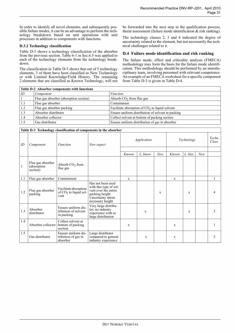
Recommended Practice DNV-RP-J201, April 2010Page 31
In order to identify all novel elements, and subsequently pos-sible failure modes, it can be an advantage to perform the tech-nology breakdown based on unit operations with unitprocesses in addition to components with functions.
D.3.2 Technology classificationTable D-3 shows a technology classification of the absorberfrom the previous section. Table 6-1 in Sec.6.5 was applied toeach of the technology elements from the technology break-down. The classification in Table D-3 shows that out of 5 technologyelements, 3 of them have been classified as New Technologyor with Limited Knowledge/Field History. The remaining2 elements that are classified as Known Technology, will not
be forwarded into the next step in the qualification process,threat assessment (failure mode identification & risk ranking).The technology classes 2, 3 and 4 indicated the degree ofuncertainty related to the element, but not necessarily the tech-nical challenges related to it.
D.4 Failure mode identification and risk rankingThe failure mode, effect and criticality analysis (FMECA)methodology may form the basis for the failure mode identifi-cation. This methodology should be performed by an interdis-ciplinary team, involving personnel with relevant competence.An example of an FMECA worksheet for a specific componentfrom Table D-3 is given in Table D-4.
Table D-2 Absorber components with functionsID Component Function1 Flue gas absorber (absorption section) Absorb CO2 from flue gas1.1 Flue gas absorber Containment1.2 Flue gas absorber packing Facilitate absorption of CO2 to liquid solvent1.3 Absorber distributor Ensure uniform distribution of solvent in packing1.4 Absorber collector Collect solvent at bottom of packing section1.5 Gas distributor Ensure uniform distribution of gas in absorber
Table D-3 Technology classification of components in the absorber
ID Component Function New aspectApplication Technology Techn.
Class.
Known L. know. New Known L. hist. New
1Flue gas absorber (absorption section)
Absorb CO2 from flue gas
1.1 Flue gas absorber Containment x x 1
1.2 Flue gas absorber packing
Facilitate absorption of CO2 to liquid sol-vent
Has not been used with this type of sol-vent over the entire packing height. Uncertainty about necessary height
x x 4
1.3 Absorber distributor
Ensure uniform dis-tribution of solvent in packing
Very large distribu-tor, no industry experience with so large distribution
x x 3
1.4Absorber collector
Collect solvent at bottom of packing section
x x 1
1.5Gas distributor
Ensure uniform dis-tribution of gas in absorber
Large distributor compared to general industry experience
x x 2
DET NORSKE VERITAS
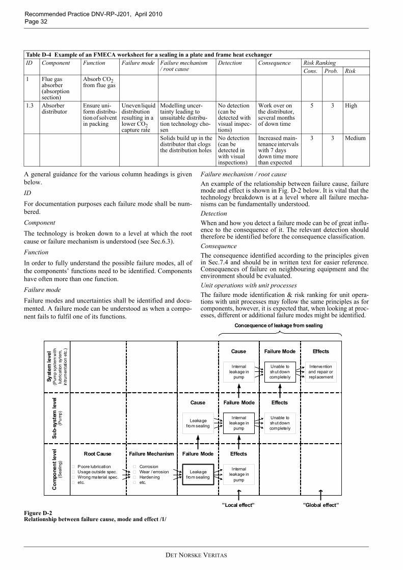
Recommended Practice DNV-RP-J201, April 2010 Page 32
A general guidance for the various column headings is givenbelow.IDFor documentation purposes each failure mode shall be num-bered.ComponentThe technology is broken down to a level at which the rootcause or failure mechanism is understood (see Sec.6.3). FunctionIn order to fully understand the possible failure modes, all ofthe components’ functions need to be identified. Componentshave often more than one function.Failure modeFailure modes and uncertainties shall be identified and docu-mented. A failure mode can be understood as when a compo-nent fails to fulfil one of its functions.
Failure mechanism / root causeAn example of the relationship between failure cause, failuremode and effect is shown in Fig. D-2 below. It is vital that thetechnology breakdown is at a level where all failure mecha-nisms can be fundamentally understood.DetectionWhen and how you detect a failure mode can be of great influ-ence to the consequence of it. The relevant detection shouldtherefore be identified before the consequence classification.ConsequenceThe consequence identified according to the principles givenin Sec.7.4 and should be in written text for easier reference.Consequences of failure on neighbouring equipment and theenvironment should be evaluated.Unit operations with unit processesThe failure mode identification & risk ranking for unit opera-tions with unit processes may follow the same principles as forcomponents, however, it is expected that, when looking at proc-esses, different or additional failure modes might be identified.
Figure D-2 Relationship between failure cause, mode and effect /1/
Table D-4 Example of an FMECA worksheet for a sealing in a plate and frame heat exchanger ID Component Function Failure mode Failure mechanism
/ root causeDetection Consequence Risk Ranking
Cons. Prob. Risk1 Flue gas
absorber (absorption section)
Absorb CO2 from flue gas
1.3 Absorber distributor
Ensure uni-form distribu-tion of solvent in packing
Uneven liquid distribution resulting in a lower CO2 capture rate
Modelling uncer-tainty leading to unsuitable distribu-tion technology cho-sen
No detection(can be detected with visual inspec-tions)
Work over on the distributor, several months of down time
5 3 High
Solids build up in the distributor that clogs the distribution holes
No detection(can be detected in with visual inspections)
Increased main-tenance intervals with 7 days down time more than expected
3 3 Medium
Leakagefrom sealing
Internal leakage in
pump
CorrosionWear / errosionHardeningetc.
Poore lubricationUsage outside spec.Wrong material spec.etc.
Internal leakage in
pump
Failure ModeFailure Mechanism Effects
Failure ModeCause
Leakagefrom sealing
Unable to shut down complete ly
Effects
Unable to shut down complete ly
Failure ModeCause
Internal leakage in
pump
Intervention and repair or replacement
Effects
Com
pone
nt le
vel
(Sea
ling)
Sub-
syst
em le
vel
(Pu
mp)
Syst
em le
vel
(Pum
p sy
stem
with
lubr
icat
ion s
ytem
,in
trum
enta
tion
etc.
)
”Local effect” ”Global effect”
Concequence of leakage from sealing
Root Cause
DET NORSKE VERITAS

Recommended Practice DNV-RP-J201, April 2010Page 33
D.4.1 Risk rankingThe risk ranking should follow the principles given in Sec.7.5.The results from the risk ranking process should be summa-rized in a common risk matrix that shows the failure modeswith medium and high risk (see Table 7-3).
D.5 Selection of qualification methodsQualification activities have been selected to address the fail-ure modes given medium and high criticality in the risk rank-ing. For failure modes with low risk, it is assumed thatadequate reliability is ensured through conventional design.The selection of activities is based on the assumption that bestengineering practice is followed in the design and that ade-quate quality control and testing is applied.
Table D-4 shows one selection of a qualification method for afailure mode with high risk.
Table D-5 Qualification activities for failure mode 1.3 from Table D-4 Activity ID Component Failure
ModeFailure Mechanism
A sectioning of the absorber should be evaluated. If section-ing is not feasible, a full-scale mock-up of a distributor should be tested to ensure that the liquid distribution is uniform.
1.3 Absorber distributor
Uneven liquid dis-tribution resulting in a lower CO2 cap-ture rate
Modelling uncertainty leading to unsuitable distribution technology chosen
DET NORSKE VERITAS

Recommended Practice DNV-RP-J201, April 2010 Page 34
APPENDIX E TEMPLATES
E.1 Critical parameters listTable E-1 suggests a critical parameters list template. The listwill be continuously updated and its dimension increased
throughout the qualification process. See Sec.5.6 for furtherdescription.
E.2 Technology qualification planA TQP template is suggested in Table E-2.
Table E-1 Critical parameters list templateQualification Basis Failure Mode Registry
Unit of Measure Design Values/ Acceptance criteria
Failure Mode ID
ID Critical parameter description [ ] Min Max ID1 Functions1,11,22 Performance2,13 Geometry and Weight
4 Boundary conditions and Environ-ment
5 Materials
6 SHE
7 Scale-up
8 Reliability
9 QA/QC
Table E-2 Technology qualification plan template
No. Activity description ID
Com
pone
nt/ P
roce
ss
Failu
re M
ode
Failu
re M
echa
nism
Anal
ytic
al m
etho
d
Com
puta
tiona
l m
etho
d
Expe
rim
enta
l m
etho
d
Han
dboo
k so
lutio
n
Prev
ious
exp
erie
nce
Failu
re M
ode
avoi
d-an
ce
1
2
3
4
5
DET NORSKE VERITAS
Related Documents