DMX-Master 3-FX DMX-controller user manual

Welcome message from author
This document is posted to help you gain knowledge. Please leave a comment to let me know what you think about it! Share it to your friends and learn new things together.
Transcript
DMX-Master 3-FXDMX-controller
user manual

Musikhaus Thomann e.K.
Treppendorf 30
96138 Burgebrach
Germany
Telephone: +49 (0) 9546 9223-0
E-mail: [email protected]
Internet: www.thomann.de
24.10.2014, ID: 294610 (V2) | SW T1.4
Table of contents
1 General notes............................................................................................................................................... 5
2 Safety instructions..................................................................................................................................... 7
3 Features....................................................................................................................................................... 11
4 Installation.................................................................................................................................................. 12
5 Setup.............................................................................................................................................................. 14
6 Connections and operating elements........................................................................................... 15
7 Basics............................................................................................................................................................. 25
8 Operating.................................................................................................................................................... 288.1 Introduction....................................................................................................................................... 288.2 Scenes and banks............................................................................................................................. 338.3 Chaser sequences............................................................................................................................ 408.4 Blackout............................................................................................................................................... 498.5 Overlay scenes................................................................................................................................... 538.6 Effects generator.............................................................................................................................. 568.7 Cross-fades......................................................................................................................................... 65
Table of contents
DMX-Master 3-FX
3
8.8 Channel inversion............................................................................................................................ 688.9 Assigning the jog wheels Pan and Tilt for rotation and inclination .............................. 708.10 Playback............................................................................................................................................ 738.11 MIDI control..................................................................................................................................... 828.12 Operating mode ‘Easy Mode’.................................................................................................... 908.13 Saving data and reloading......................................................................................................... 928.14 Complementary functions......................................................................................................... 94
9 Technical data........................................................................................................................................ 101
10 Protecting the environment............................................................................................................ 102
Table of contents
DMX-controller
4
1 General notes
This user manual contains important information on safe operation of the device. Read andfollow all safety notes and all instructions. Save this manual for future reference. Make surethat it is available to all persons using this device. If you sell the device, include the manual forthe next owner.
Our products are subject to a process of continuous development. We therefore reserve theright to make changes without notice.
This section provides an overview of the symbols and signal words used in this user manual.
Signal word Meaning
DANGER! This combination of symbol and signal word indicates animmediate dangerous situation that will result in death orserious injury if it is not avoided.
NOTICE! This combination of symbol and signal word indicates a pos‐sible dangerous situation that can result in material andenvironmental damage if it is not avoided.
Symbols and signal words
General notes
DMX-Master 3-FX
5
Warning signs Type of danger
Warning – danger zone.
General notes
DMX-controller
6
2 Safety instructions
This device is intended to be used to control spot lights, dimmers, light effects, moving headsor other DMX-controlled devices. Use the device only as described in this user manual. Anyother use or use under other operating conditions is considered to be improper and may resultin personal injury or property damage. No liability will be assumed for damages resulting fromimproper use.
This device may be used only by persons with sufficient physical, sensorial, and intellectualabilities and having corresponding knowledge and experience. Other persons may use thisdevice only if they are supervised or instructed by a person who is responsible for their safety.
Intended use
Safety instructions
DMX-Master 3-FX
7
DANGER!Danger for childrenEnsure that plastic bags, packaging, etc. are disposed of properly and are notwithin reach of babies and young children. Choking hazard!
Ensure that children do not detach any small parts (e.g. knobs or the like) fromthe unit. They could swallow the pieces and choke!
Never let children unattended use electrical devices.
Safety
Safety instructions
DMX-controller
8
NOTICE!External power supplyThe device is powered by an external power supply. Before connecting theexternal power supply, ensure that the input voltage (AC outlet) matches thevoltage rating of the device and that the AC outlet is protected by a residual cur‐rent circuit breaker. Failure to do so could result in damage to the device and pos‐sibly the user.
Unplug the external power supply before electrical storms occur and when thedevice is unused for long periods of time to reduce the risk of electric shock orfire.
NOTICE!Risk of fireDo not cover the device nor any ventilation slots. Do not place the device nearany direct heat source. Keep the device away from naked flames.
Safety instructions
DMX-Master 3-FX
9
NOTICE!Operating conditionsThis device has been designed for indoor use only. To prevent damage, neverexpose the device to any liquid or moisture. Avoid direct sunlight, heavy dirt, andstrong vibrations.
Safety instructions
DMX-controller
10
3 Features
Special characteristics of the device:
n control of up to 16 DMX devices with 16 DMX channels each (256 channels)n 240 scenes on 30 banks (8 per bank)n six chases with up to 250 single stepsn six overlay scenesn integrated effect generatorn fade in time, fade out time and speed for scenes and chases can be adjusted per channeln all channels invertiblen jog wheels for the control of pan and tilt movementsn operating modes: ‘Play Mode’ , ‘Program Mode’ , ‘Setup Mode’ and ‘Easy Mode’n Functions: desk lock, auto-start, blackout, freeze, copyn MIDI control (synthesizer and MIDI keyboard)n data backup and restore via USB interfacen suitable for 19" racks (four rack units)
Features
DMX-Master 3-FX
11
4 Installation
Unpack and carefully check that there is no transportation damage before using the unit. Keepthe equipment packaging. To fully protect the device against vibration, dust and moistureduring transportation or storage use the original packaging or your own packaging materialsuitable for transport or storage, respectively.
The device fits into 19" racks, it occupies four rack units.
Before you install the device, remove the cover (ten fastening screws). Then mount the deviceinto the racks using the optionally available mounting brackets.
Mounting into a rack
Installation
DMX-controller
12
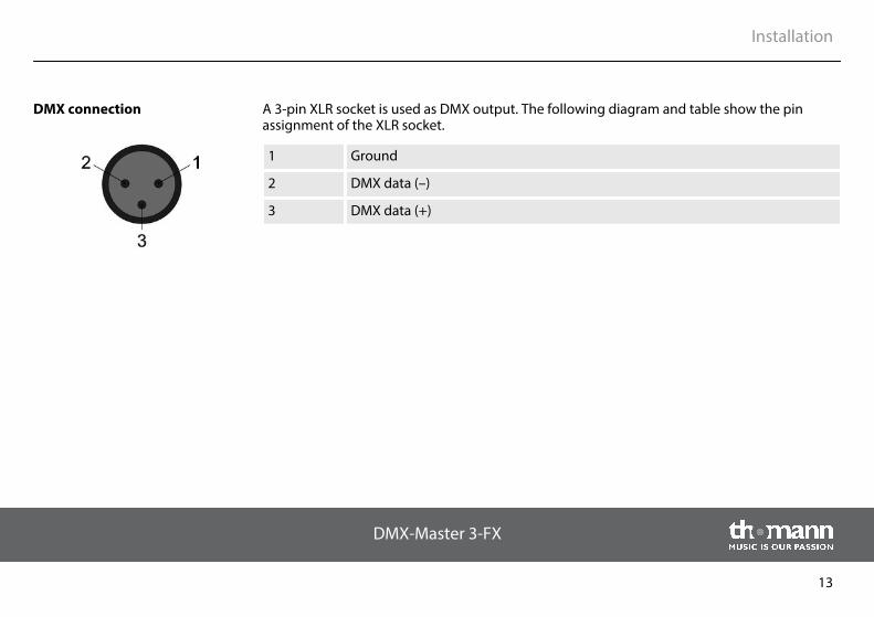
A 3-pin XLR socket is used as DMX output. The following diagram and table show the pinassignment of the XLR socket.
1 Ground
2 DMX data (–)
3 DMX data (+)
DMX connection
Installation
DMX-Master 3-FX
13
5 Setup
Establish all connections as long as the unit is switched off. Use the shortest possible high-quality cables for all connections.
Connect the power supply unit which is included in the delivery to the 9-V input of the device,then put the mains plug into the socket.
Turn on the device using the main switch at the back side. After turning the device on the dis‐plays shows the software version and the operation mode for a short time. The related displayLEDs light up.
Connecting the power supplyunit
Turning the device on
Setup
DMX-controller
14
6 Connections and operating elements
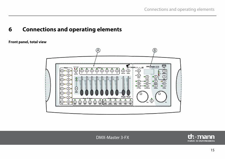
Front panel, total view
Connections and operating elements
DMX-Master 3-FX
15
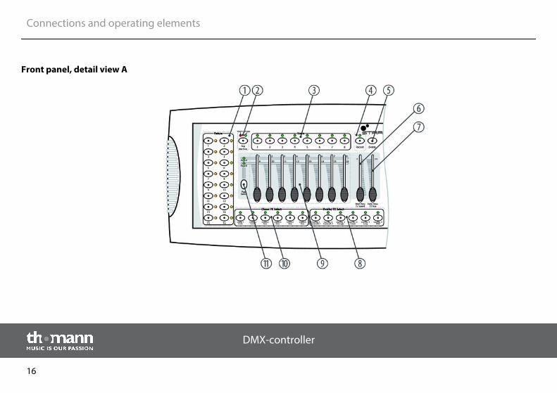
Front panel, detail view A
Connections and operating elements
DMX-controller
16
1 Button block [Fixture]
Buttons 1 to 16 for selecting the control channels. The corresponding indicator LED shows whether the respectivechannel is switched (LED is on) or deactivated (LED is off).
2 Button [Fog Machine]
Activates a connected fog machine. The control LEDs Heating and Ready indicate the operating status of the fogmachine.
3 Button block [Scene]
Buttons 1 to 8 for enabling / disabling of the programmed scenes. The control LEDs indicate which scenes are ena‐bled (LED is on).
4 Button [Record]
Button for recording own sequences.
5 Button [Delete]
Button for deleting sequences.
Connections and operating elements
DMX-Master 3-FX
17
6 Wait Time | FX Speed
Slider for adjusting the programme and effect speed as well as the input sensitivity of the microphone.
7 Fade Time | FX Size
Slider for adjusting the fade in and out time in scene or programme changes as well as the display size of the effect.
8 Button block [Overlay FX Select]
Buttons 1 to 6 for enabling / disabling of the Overlay scenes. The control LEDs indicate which scenes are enabled(LED is on).
9 Slider with dual function for adjusting DMX channels 1 to 16. Switching between memory banks 1…8 and 9…16 isdone using the Shift key (11).
10 Button block [Chaser FX Select]
Buttons 1 to 6 for enabling / disabling of the Chasers. The control LEDs indicate which Chaser sequences are enabled(LED is on).
11 Button [Page Select]
Button for switching between memory banks 1…8 and 9…16 (slider with dual function for adjusting the DMX chan‐nels). The control LEDs [Page A] and [Page B] indicate which of the two memory banks is currently active.
Connections and operating elements
DMX-controller
18
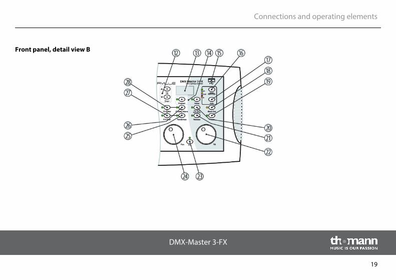
Front panel, detail view B
Connections and operating elements
DMX-Master 3-FX
19
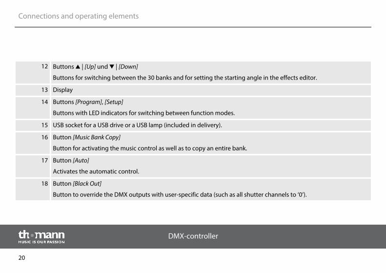
12 Buttons | [Up] und | [Down]
Buttons for switching between the 30 banks and for setting the starting angle in the effects editor.
13 Display
14 Buttons [Program], [Setup]
Buttons with LED indicators for switching between function modes.
15 USB socket for a USB drive or a USB lamp (included in delivery).
16 Button [Music Bank Copy]
Button for activating the music control as well as to copy an entire bank.
17 Button [Auto]
Activates the automatic control.
18 Button [Black Out]
Button to override the DMX outputs with user-specific data (such as all shutter channels to ‘0’).
Connections and operating elements
DMX-controller
20
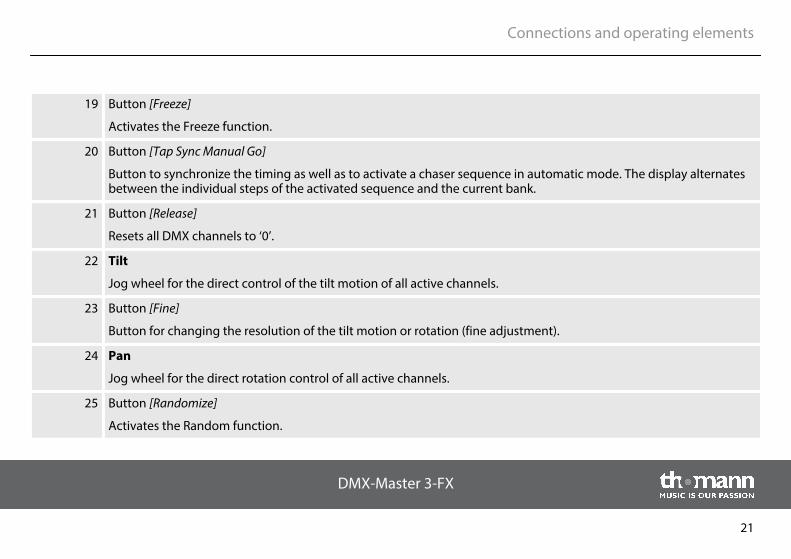
19 Button [Freeze]
Activates the Freeze function.
20 Button [Tap Sync Manual Go]
Button to synchronize the timing as well as to activate a chaser sequence in automatic mode. The display alternatesbetween the individual steps of the activated sequence and the current bank.
21 Button [Release]
Resets all DMX channels to ‘0’.
22 Tilt
Jog wheel for the direct control of the tilt motion of all active channels.
23 Button [Fine]
Button for changing the resolution of the tilt motion or rotation (fine adjustment).
24 Pan
Jog wheel for the direct rotation control of all active channels.
25 Button [Randomize]
Activates the Random function.
Connections and operating elements
DMX-Master 3-FX
21
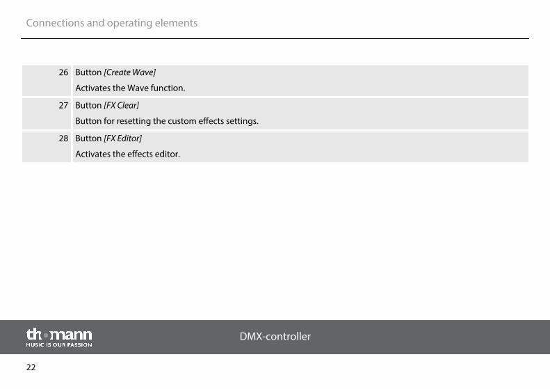
26 Button [Create Wave]
Activates the Wave function.
27 Button [FX Clear]
Button for resetting the custom effects settings.
28 Button [FX Editor]
Activates the effects editor.
Connections and operating elements
DMX-controller
22
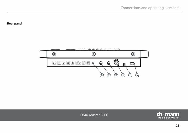
Rear panel
Connections and operating elements
DMX-Master 3-FX
23
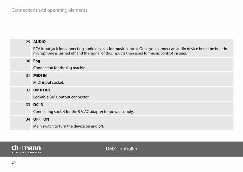
29 AUDIO
RCA input jack for connecting audio devices for music control. Once you connect an audio device here, the built-inmicrophone is turned off and the signal of this input is then used for music control instead.
30 Fog
Connection for the fog machine.
31 MIDI IN
MIDI input socket.
32 DMX OUT
Lockable DMX output connector.
33 DC IN
Connecting socket for the 9 V AC adapter for power supply.
34 OFF | ON
Main switch to turn the device on and off.
Connections and operating elements
DMX-controller
24
7 Basics
This chapter provides basic information about the data transmission using the DMX protocol.
DMX signals are generated by a DMX controller. The signals are transferred over a DMX cableto the connected devices. Each connection can transmit up to 512 channels. For each channel,a value between 0 and 255 is being transmitted. The 512 channels form a so-called ‘DMX uni‐verse’.
DMX devices are connected serially, that means the sending device transmits signals to all con‐nected receivers (daisy chain). The order of the receivers in the daisy chain does not mattersince all devices filter and process the relevant data independently from each other.
To create the daisy chain, the DMX input of the first receiver is connected to the DMX output ofthe controller or another DMX master. The output of the first receiver is connected to the inputof the second one, and so on. The output of the last receiver in the DMX chain must be termi‐nated using a resistor (110 Ω, ¼ W).
Signal transmission
Cabling
Basics
DMX-Master 3-FX
25
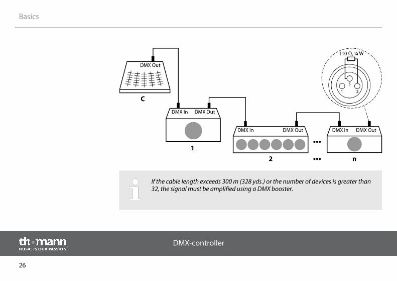
If the cable length exceeds 300 m (328 yds.) or the number of devices is greater than32, the signal must be amplified using a DMX booster.
Basics
DMX-controller
26
Each DMX devices operates on a specific number of channels to transfer the incoming controlsignals into movements, changing of light intensity or colour, and so on. Since all receiversthat are part of a DMX daisy chain receive all signals, a start address must be assigned to eachDMX device. Starting from this address (a value between 0 and 512) the incoming signals arebeing evaluated and transferred into the functions of the receiver (internal channel assign‐ment).
It is no problem to use a start address more than once in a DMX chain. In that case, the relevantreceivers operate synchronously (identical movement, light intensity, colour, and so on).
When setting the DMX address, the counting method of the device determines the firstchannel. Depending on the device, the channel numbers may start from 0 or from 1. Theaddress range may therefore reach from 0 to 511 or from 1 to 512.
Signal processing
Addressing
Basics
DMX-Master 3-FX
27
8 Operating
8.1 Introduction
This device controls up to 16 DMX devices (eg. dimmers, LED spot lights, moving heads orscanners) with each 16 internal DMX channels. In total, 240 scenes are available in 30 banks(eight scenes per bank) with which six chaser sequences with 250 individual steps can be pro‐grammed. The chaser sequences can be played in the following modes:
n manualn music controlledn automaticn MIDI-controlled
Operating
DMX-controller
28
The device operates in four different modes with different functions. When the device isturned on the ‘Play Mode’ is activated automatically. The respective operating mode is dis‐played.
n ‘Play Mode’In this mode, the programmed scenes, banks and chaser sequences can be played back inthe previously selected mode (automatic, sound activated, MIDI-controlled).
n ‘Program Mode’In this mode, scenes, effects, banks, chaser sequences, cross-fades and blackouts can beprogrammed.
n ‘Setup Mode’In this mode, different parameters can be adjusted (MIDI channel, MIDI control via key‐board or synthesizer, channel inversion, fade times, jog wheel assignment).
n ‘Easy Mode’In this mode, the settings of the connected DMX devices can be tested.
In ‘Easy Mode’ and ‘Play Mode’, channels 1 to 160 can be controlled.
To activate a specific mode, press and hold the respective button for three seconds:
n ‘Play Mode’Standard mode, activated when the device is turned on.
n ‘Program Mode’
Selecting the operating mode
Operating
DMX-Master 3-FX
29
Button [Program].n ‘Setup Mode’
Button [Setup].n ‘Easy Mode’
Buttons [Program] and [Setup] simultaneously
Switching between the operating modes is possible at any time. To return to the operatingmode ‘Play Mode’, press and hold the button of that mode to which you have previouslychanged from the ‘Play Mode’ for three seconds.
Operating
DMX-controller
30
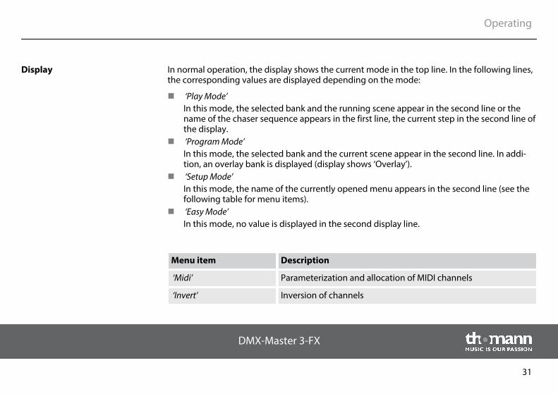
In normal operation, the display shows the current mode in the top line. In the following lines,the corresponding values are displayed depending on the mode:
n ‘Play Mode’In this mode, the selected bank and the running scene appear in the second line or thename of the chaser sequence appears in the first line, the current step in the second line ofthe display.
n ‘Program Mode’In this mode, the selected bank and the current scene appear in the second line. In addi‐tion, an overlay bank is displayed (display shows ‘Overlay’).
n ‘Setup Mode’In this mode, the name of the currently opened menu appears in the second line (see thefollowing table for menu items).
n ‘Easy Mode’In this mode, no value is displayed in the second display line.
Menu item Description
‘Midi’ Parameterization and allocation of MIDI channels
‘Invert’ Inversion of channels
Display
Operating
DMX-Master 3-FX
31
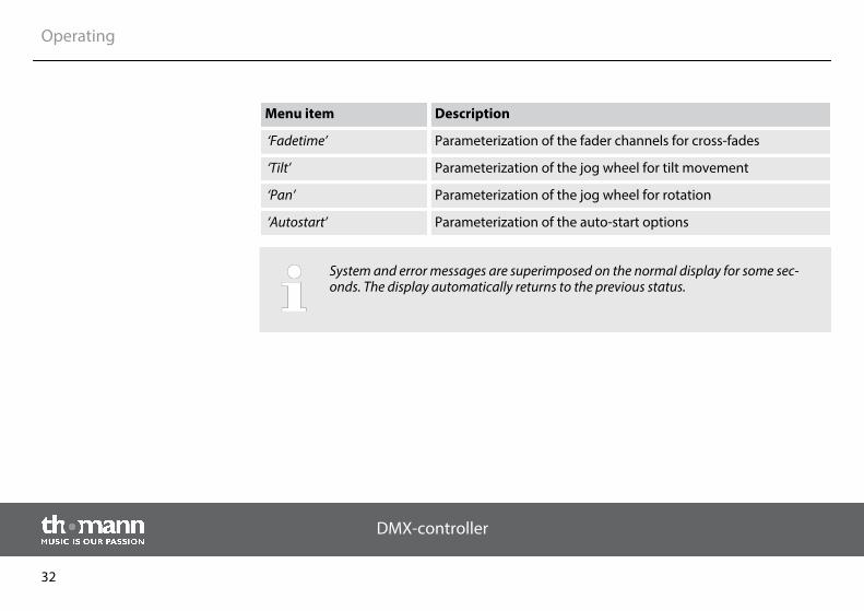
Menu item Description
‘Fadetime’ Parameterization of the fader channels for cross-fades
‘Tilt’ Parameterization of the jog wheel for tilt movement
‘Pan’ Parameterization of the jog wheel for rotation
‘Autostart’ Parameterization of the auto-start options
System and error messages are superimposed on the normal display for some sec‐onds. The display automatically returns to the previous status.
Operating
DMX-controller
32
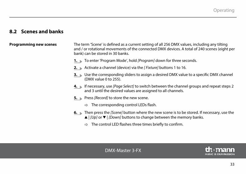
8.2 Scenes and banks
The term ‘Scene’ is defined as a current setting of all 256 DMX values, including any tiltingand / or rotational movements of the connected DMX devices. A total of 240 scenes (eight perbank) can be stored in 30 banks.
1. To enter ‘Program Mode’, hold [Program] down for three seconds.
2. Activate a channel (device) via the [ Fixture] buttons 1 to 16.
3. Use the corresponding sliders to assign a desired DMX value to a specific DMX channel(DMX value 0 to 255).
4. If necessary, use [Page Select] to switch between the channel groups and repeat steps 2and 3 until the desired values are assigned to all channels.
5. Press [Record] to store the new scene.
ð The corresponding control LEDs flash.
6. Then press the [Scene] button where the new scene is to be stored. If necessary, use the | [Up] or | [Down] buttons to change between the memory banks.
ð The control LED flashes three times briefly to confirm.
Programming new scenes
Operating
DMX-Master 3-FX
33
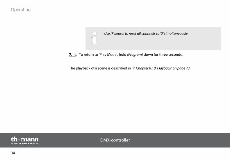
Use [Release] to reset all channels to ‘0’ simultaneously.
7. To return to ‘Play Mode’, hold [Program] down for three seconds.
The playback of a scene is described in Ä Chapter 8.10 ‘Playback’ on page 73.
Operating
DMX-controller
34
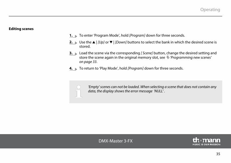
1. To enter ‘Program Mode’, hold [Program] down for three seconds.
2. Use the | [Up] or | [Down] buttons to select the bank in which the desired scene isstored.
3. Load the scene via the corresponding [ Scene] button, change the desired setting andstore the scene again in the original memory slot, see Ä ‘Programming new scenes’ on page 33.
4. To return to ‘Play Mode’, hold [Program] down for three seconds.
‘Empty’ scenes can not be loaded. When selecting a scene that does not contain anydata, the display shows the error message ‘NULL’ .
Editing scenes
Operating
DMX-Master 3-FX
35
1. To enter ‘Program Mode’, hold [Program] down for three seconds.
2. Use the | [Up] or | [Down] buttons to select the bank in which the desired scene isstored.
3. Load the scene you want to copy (Source) via the corresponding [ Scene] button.
4. Use the | [Up] or | [Down] buttons to select the bank into which you want to copythe scene (destination).
5. Press [Record].
6. Then press the [ Scene] button where the copied scene is to be stored.
ð The corresponding control LEDs flash three times briefly to confirm.
7. To return to ‘Play Mode’, hold [Program] down for three seconds.
‘Empty’ scenes can not be loaded. When selecting a scene that does not contain anydata, the display shows the error message ‘NULL’ .
Copying scenes
Operating
DMX-controller
36
This feature allows the transfer of all DMX values that are assigned to a DMX device, toanother.
1. To enter ‘Program Mode’, hold [Program] down for three seconds.
2. Keep the [Fixture] button pressed that is assigned to the DMX device whose settings youwant to copy (source).
3. Additionally press the [Fixture] button of the DMX device to which the settings are to becopied (destination).
ð The display shows the message ‘COPY’ . The corresponding control LEDs flash threetimes briefly to confirm.
This indicates that the data has been saved successfully.
4. To return to ‘Play Mode’, hold [Program] down for three seconds.
You can copy the settings to other devices if you hold down the first [Fixture] buttonand then press the [Fixture] button of another device.
Copying device settings
Operating
DMX-Master 3-FX
37
The changes are carried out in the buffer memory only. If you want to save the newvalues permanently, save the scene as described above.
1. To enter ‘Program Mode’, hold [Program] down for three seconds.
2. Use the | [Up] or | [Down] buttons to select the bank from which you want to copy.
3. Press [Record].
4. Use the | [Up] or | [Down] buttons to select the bank into which you want to copy.
5. Press [Music Bank Copy]
ð The corresponding control LEDs flash three times briefly to confirm.
This indicates that the data has been saved successfully.
6. To return to ‘Play Mode’, hold [Program] down for three seconds.
Copying an entire bank
Operating
DMX-controller
38
1. To enter ‘Program Mode’, hold [Program] down for three seconds.
2. Use the | [Up] or | [Down] buttons to select the bank in which the desired scene isstored.
3. Hold down the [DELETE] button and simultaneously press the [ Scene] button of thescene you want to delete.
ð The corresponding control LEDs flash three times briefly to confirm.
This indicates that the scene has been deleted successfully.
4. To return to ‘Play Mode’, hold [Program] down for three seconds.
A deleted scene can not be restored.
Deleting a scene
Operating
DMX-Master 3-FX
39
1. To enter ‘Program Mode’, hold [Program] down for three seconds.
2. Use the | [Up] or | [Down] buttons to select the bank you want to delete.
3. Hold down the [DELETE] button and simultaneously press [Music Bank Copy].
ð The corresponding control LEDs flash three times briefly to confirm.
This indicates that all scene of the bank have been deleted successfully.
4. To return to ‘Play Mode’, hold [Program] down for three seconds.
8.3 Chaser sequences
A chaser sequence (Chaser) is a programme that calls up a maximum of 250 scenes one afterthe other. The scenes that make up a chaser sequence must have been programmed previ‐ously.
Deleting banks
Programming Chaser sequences
Operating
DMX-controller
40
With this function, a scene is inserted at the current edit point in a chaser sequence.
1. To enter ‘Program Mode’, hold [Program] down for three seconds.
2. Press the [CHASER] button of that chaser sequence you want to edit. You can only editone chaser sequence at a time.
If you select a chaser sequence that already contains scenes the edit point auto‐matically jumps to the end of the chaser sequence.
3. Press the [Scene] button of the scene you want to insert.
4. Press [Record].
ð The corresponding control LEDs flash three times briefly to confirm.
This indicates that the scene has been inserted successfully.
The upper line of the display shows the number of the processed chaser sequenceand the edit point, the bottom line of the display shows the bank and the insertedscene.
Chaser sequence playback is described in Ä Chapter 8.10 ‘Playback’ on page 73.
Inserting a scene into a chasersequence
Operating
DMX-Master 3-FX
41
5. Repeat steps 3 and 4 until the chaser sequence is complete. A chaser sequence can con‐tain a maximum of 250 scenes. Once this number is reached, the display shows the mes‐sage ‘Chaser Full’ .
6. To return to ‘Play Mode’, hold [Program] down for three seconds.
Operating
DMX-controller
42
With this function, a bank containing several scenes will be inserted at the current edit pointinto a chaser sequence.
1. To enter ‘Program Mode’, hold [Program] down for three seconds.
2. Press the [CHASER] button of the chaser sequence you want to edit. You can only editone chaser sequence at a time.
If you select a chaser sequence that already contains scenes the edit point auto‐matically jumps to the end of the chaser sequence.
3. Use the | [Up] or | [Down] buttons to select the bank you want to insert.
4. Press [Music Bank Copy].
5. Press [Record].
ð The corresponding control LEDs flash three times briefly to confirm.
This indicates that the scene has been inserted successfully.
6. To return to ‘Play Mode’, hold [Program] down for three seconds.
Inserting a bank into a chasersequence
Operating
DMX-Master 3-FX
43
With this function you can change the location where to insert new scenes or banks into anexisting chaser sequence.
1. To enter ‘Program Mode’, hold [Program] down for three seconds.
2. Press the [CHASER] button of the chaser sequence you want to edit.
If you select a chaser sequence that already contains scenes the edit point auto‐matically jumps to the end of the chaser sequence.
3. Press [Tap Sync Manual Go].
ð The display shows the current edit point.
4. Use the | [Up] or | [Down] buttons to select the desired edit point.
For example, if you next want to insert a scene between the third and fourth position ofthe chaser sequence, move the edit point until the display shows ‘C:1 P003’ .
C:1 stands for Chaser 1 and P003 for step 3.
5. Press [Tap Sync Manual Go].
Changing the edit point of achaser sequence
Operating
DMX-controller
44
6. Now you can insert scenes or banks in the changed edit point (Ä ‘Inserting a scene into achaser sequence’ on page 41).
7. To return to ‘Play Mode’, hold [Program] down for three seconds.
Operating
DMX-Master 3-FX
45
With this function, the scene in the current edit point is removed from a chaser sequence.
1. To enter ‘Program Mode’, hold [Program] down for three seconds.
2. Press the [CHASER] button of the chaser sequence you want to edit. You can only editone chaser sequence at a time.
If you select a chaser sequence that already contains scenes the edit point auto‐matically jumps to the end of the chaser sequence.
3. Press [Tap Sync Manual Go].
ð The display shows the current edit point.
4. Use the | [Up] or | [Down] buttons to select the desired edit point.
5. Press [DELETE].
ð The corresponding control LEDs flash three times briefly to confirm.
This indicates that the scene has been removed successfully.
Removing scene from a chasersequence
Operating
DMX-controller
46
All scenes that have been lying behind the removed scene, slip one positionforward. If you press, for example, three times [DELETE], the three scenesafter the initial edit point are removed.
6. To return to ‘Play Mode’, hold [Program] down for three seconds.
With this function, a chaser sequence is deleted, i.e., all the scenes are removed from it.
1. To enter ‘Program Mode’, hold [Program] down for three seconds.
2. Hold [DELETE] down.
3. Press additionally the [CHASER] button of the chaser sequence you want to delete.
ð The corresponding control LEDs flash three times briefly to confirm.
This indicates that all scenes have been removed successfully from the chasersequence.
4. To return to ‘Play Mode’, hold [Program] down for three seconds.
Deleting a chaser sequence
Operating
DMX-Master 3-FX
47
With this function, all chaser sequences are deleted, i.e., all the scenes are removed from them.
1. Make sure that the device is turned on.
2. Hold down | [Up] or | [Down] simultaneously and switch the device off.
3. Keep the buttons pushed and turn the device back on.
ð All control LEDs flash three times briefly to confirm.
Deleting all chaser sequences
Operating
DMX-controller
48
8.4 Blackout
You can configure the blackout as desired. It can be set which channel on which connectedDMX device is overridden by the blackout mode, and with what value. This makes it possible,for example, to only dim connected lights at the press of a button, without changing the set‐tings for colour, rotation or tilt.
To set up or change the blackout mode, proceed as follows:
1. To enter ‘Program Mode’, hold [Program] down for three seconds.
2. Use the | [Up] or | [Down] buttons to select bank 31.
ð The display shows ‘Overlay’ .
Now you can configure the blackout mode like a normal scene.
3. If you want to change an existing configuration of the blackout, proceed to Step 4.
Otherwise a tip:
If the blackout mode shall override only a few channels (for example, only the dimmer ofsome DMX devices), press [Release]. Thus, all channels are switched to ‘OFF’. This meansthat they are not overridden by the blackout mode. In the following you need then justturn on the channels that are to be overridden.
To reconfigure the blackout mode proceed to step 5.
Setting up or changing theBlackout function
Operating
DMX-Master 3-FX
49
4. Press [BLACKOUT] once to load an existing configuration.
5. Press the [Fixture] buttons belonging to those DMX devices whose blackout settings youwant to edit.
6. Use the [Scene] buttons to turn individual channels on or off. The display shows either‘CHxx: ON’ (i.e., channel xx is overridden by blackout mode) or ‘CHxx: OFF’ (i.e., channelxx is not affected by blackout mode).
7. Use the slider to set the desired values. For testing purposes, you can also use channelsthat are set to ‘off’.
8. Repeat steps 3 to 7 for further DMX units, if necessary.
9. When the blackout settings are complete, press [Record].
10. Press [BLACKOUT].
ð The corresponding control LEDs flash three times briefly to confirm.
This indicates that the blackout settings have been saved.
11. To return to ‘Play Mode’, hold [Program] down for three seconds.
Operating
DMX-controller
50
Make sure that no channels with set fade times for cross-fades are overridden by theblackout mode. This ensures that all channels are restored with the correct valueswhen you cancel the blackout mode.
If a channel with a set fade time is overridden by the blackout mode, it is only gradu‐ally restored to its previous value when cancelling the blackout.
Operating
DMX-Master 3-FX
51
Use this function to set all 256 channels in relation to the blackout mode to ‘on’ with the asso‐ciated value 0.
To reset the blackout mode settings, proceed as follows:
1. To enter ‘Program Mode’, hold [Program] down for three seconds.
2. Use the | [Up] or | [Down] buttons to select bank 31.
ð The display shows ‘Overlay’ .
3. Press [DELETE] and [BLACKOUT] simultaneously.
ð The corresponding control LEDs flash three times briefly to confirm.
This indicates that the blackout settings have been reset.
4. To return to ‘Play Mode’, hold [Program] down for three seconds.
Resetting the blackout settings
Operating
DMX-controller
52
8.5 Overlay scenes
Similar to the blackout function, you can use overlay scenes to quickly superimpose thenormal run of scenes with different settings at the press of a key. It is conceivable, for example,to turn the strobe function of some DMX devices on and off during the normal course.
Note that the blackout mode has a higher priority than the overlay scenes. This means that youcan use the blackout mode even on active overlay function, since the blackout mode over‐writes the values of the overlay scenes.
For setting up or changing overlay scenes, proceed as follows:
1. To enter ‘Program Mode’, hold [Program] down for three seconds.
2. Use the | [Up] or | [Down] buttons to select bank 31.
ð The display shows ‘Overlay’ .
Now you can configure the overlay scenes like a normal scene.
3. If you want to change an existing overlay scene, proceed to step 4.
To reconfigure an overlay scene, proceed to step 5.
4. Press the [Scene] button of an existing overlay scene to load the existing configuration.
Empty scenes can not be loaded. In this case, the display shows the message ‘NULL’ .
Setting up or changing Overlayscenes
Operating
DMX-Master 3-FX
53
5. Press the [Fixture] buttons belonging to those DMX devices whose Overlay settings youwant to edit.
6. Use the [Scene] buttons to turn individuals channels on or off. The display shows either‘CHxx: ON’ (i.e., channel xx is overwritten by the overlay scene) or ‘CHxx: OFF’ (i.e.,channel xx is not affected by the Overlay scene).
If the overlay scene shall override only a few channels, press [Release]. This switches allchannels to ‘off’ and the value 0. This means that they are not overwritten by the overlayscene. In the following you need then just to turn on those channels that are to be over‐written.
7. Use the sliders to set the desired values. For testing purposes, you can also use channelsthat are set to ‘off’.
Use [PAGE] to toggle between channels 1…8 and 9…16.
8. Repeat steps 3 to 7 for further DMX devices, if necessary.
9. When the overlay settings are complete, press [Record].
10. Press the [Overlay] button of the respective overlay scene 1…6 you want to store.
ð The corresponding control LEDs flash three times briefly to confirm.
This indicates that the overlay settings have been saved.
11. To return to ‘Play Mode’, hold [Program] down for three seconds.
Operating
DMX-controller
54
To delete an overlay scene, proceed as follows:
1. To enter ‘Program Mode’, hold [Program] down for three seconds.
2. Use the | [Up] or | [Down] buttons to select bank 31.
ð The display shows ‘Overlay’ .
3. Simultaneously press [DELETE] and the [Scene] button of the Overlay scene to be deleted.
ð The corresponding control LEDs flash three times briefly to confirm.
4. To return to ‘Play Mode’, hold [Program] down for three seconds.
When an overlay scene is set up, you can use it in the ‘Play Mode’. Simply press the [Overlay]button of the overlay scene during the programme run.
To turn off the overlay scene, press the associated [Overlay] button again.
Deleting Overlay scenes
Calling up and disabling Overlayscenes
Operating
DMX-Master 3-FX
55
8.6 Effects generator
The effects generator can save movement pattern for rotation (pan) and inclination (tilt) formoving heads and scanners along with normal DMX values in an overlay scene. 12 differentmovement patterns can be selected and adjusted in size, speed and output angles. The outputangle can be modified individually for each connected DMX device. Thus, the effects of thevarious devices can be programmed independently from each other.
With the effects, the effort of allocating rotation and tilt channel for each affected device isconnected. Thereby the values generated by the effect are added to the rotation and tilt valuesthat are stored in the overlay scene. So the data stored in the overlay scene values form thebasis of the effect.
Operating
DMX-controller
56
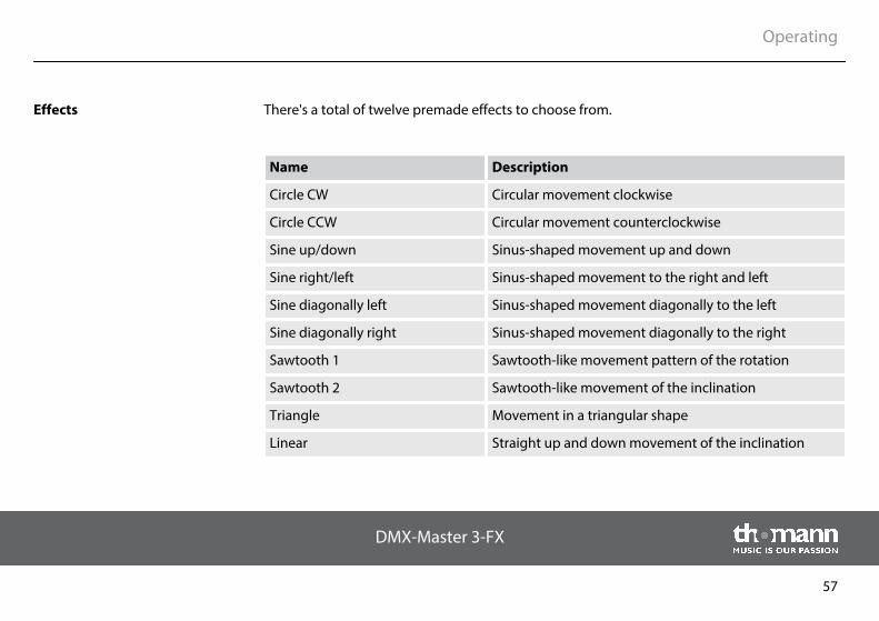
There's a total of twelve premade effects to choose from.
Name Description
Circle CW Circular movement clockwise
Circle CCW Circular movement counterclockwise
Sine up/down Sinus-shaped movement up and down
Sine right/left Sinus-shaped movement to the right and left
Sine diagonally left Sinus-shaped movement diagonally to the left
Sine diagonally right Sinus-shaped movement diagonally to the right
Sawtooth 1 Sawtooth-like movement pattern of the rotation
Sawtooth 2 Sawtooth-like movement of the inclination
Triangle Movement in a triangular shape
Linear Straight up and down movement of the inclination
Effects
Operating
DMX-Master 3-FX
57
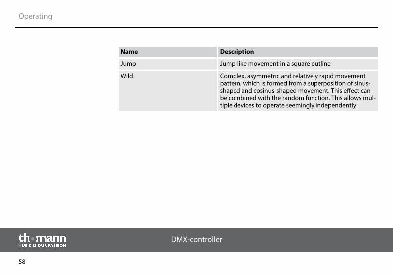
Name Description
Jump Jump-like movement in a square outline
Wild Complex, asymmetric and relatively rapid movementpattern, which is formed from a superposition of sinus-shaped and cosinus-shaped movement. This effect canbe combined with the random function. This allows mul‐tiple devices to operate seemingly independently.
Operating
DMX-controller
58
If you have selected an effect in the effects generator, each time you press the [Create Wave]button you can move the default angle of the previously selected DMX devices, so that a wavemotion is created. This assumes that the default angles of all selected DMX devices are initiallyidentical. This is the case when you select a new effect. First time you press the [Create Wave]button the DMX devices execute a wave motion.
When pressing the [Create Wave] button a second time every second DMX unit swivels 180°.
When pressing the [Create Wave] button a third time the DMX devices perform a wave move‐ment in reverse direction.
When pressing the [Create Wave] button a fourth time the DMX devices return to their homepositions.
Example
In the ‘Program Mode’ you have selected the desired DMX devices and opened the EffectsGenerator. Use the slider to adjust the value 128 as an effects mid position for rotation and tilt.Now you can select the effect ‘Sine up / down’ and choose speed and size. All selected DMXdevices perform the same movements (sinus-shaped from bottom to top) in sync with eachother.
Wave motion with the ‘CreateWave’ button
Operating
DMX-Master 3-FX
59
As soon as you press [Create Wave], the synchronous movement changes to a wave motion,which continues gradually through all the selected DMX devices. When you press the buttonnext time the devices split up in two groups that perform alternating movements opposite toeach other. If you press [Create Wave] again a backward travelling wave is generated. The wavedisappears when you press the button again.
Operating
DMX-controller
60
If you have selected an effect in the Effects Generator, each time you press the [Randomize]button will change the default angle of the previously selected DMX devices randomly andindependently from each other, so that a seemingly random motion occurs. Each time youpress the button again, the unit generates a new arrangement of values, thus creating a newmovement pattern.
To stop the random function, simply press the button for the desired effect again, for example[Triangle]. The last set values for size and speed are maintained.
Example
In the ‘Program Mode’ you have selected the desired DMX devices and opened the EffectsGenerator. Use the slider to adjust the value 128 as an effects mid position for rotation and tilt.Now you can select the effect ‘Wild’ and choose speed and size. All selected DMX devices per‐form the same movements (complex asymmetrical pattern) in sync with each other.
As soon as you press [Randomize], the movement is random. All devices move, but in a dif‐ferent way. When you combine this effect with a small circular Gobo, you get a great search‐light effect with just a few keystrokes.
Random function with the ‘Ran‐domize’ button
Operating
DMX-Master 3-FX
61
With this function, the settings of a preset effect can be changed.
1. To enter ‘Program Mode’, hold [Program] down for three seconds.
2. Press [FX Editor].
ð The control LEDs of the effect buttons light up.
3. Press the [Fixture] buttons of those DMX devices that you want to be affected by thechanges.
4. Press the effect button of the effect that you want to change.
5. Use the sliders FX Speed and FX Size to adjust speed and size of the effect.
With | [Up] or | [Down] you can change the default angle for rotation and tilt in stepsof 45° (see similar function Ä ‘Wave motion with the ‘Create Wave’ button’ on page 59 andÄ ‘Random function with the ‘Randomize’ button’ on page 61).
6. With the other sliders you can change DMX values, also while the Effects Generator isopened. The values set here for rotation and tilt become the basis for the effect.
Use [PAGE] to toggle between channels 1…8 and 9…16.
7. If necessary, repeat steps 3 to 6 for further DMX devices connected.
8. If you want to reverse the changes you have made for the selected DMX devices, press[FX Clear].
Changing an effect
Operating
DMX-controller
62
9. Press [FX Editor] to close the effects generator.
10. To return to ‘Play Mode’, hold [Program] down for three seconds.
If you are in the ‘Program Mode’, you can delete the effect of the selected DMX devices at anytime by pressing the [FX Clear]. It is not necessary to open the Effects Generator.
If you want to delete an effect to an already stored scene, you have to load that scenefirst, then delete the effect and subsequently store the scene again.
Deleting an effect
Operating
DMX-Master 3-FX
63
1. To enter ‘Program Mode’, hold [Program] down for three seconds.
2. Press [FX Editor].
ð The control LEDs of the effect buttons light up.
3. Press the [Fixture] buttons of those DMX devices, that you want to be affected by thechanges.
4. Press the effect button of the effect, that you want to change.
5. Use the sliders FX Speed and FX Size to set speed and size of the effect.
With | [Up] or | [Down] you can change the default angle for rotation and tilt in stepsof 45° (see similar function Ä ‘Wave motion with the ‘Create Wave’ button’ on page 59 undÄ ‘Random function with the ‘Randomize’ button’ on page 61).
6. To save this movement press [RECORD] and select one of the six overlay scenes.
ð The control LEDs flash three times briefly to confirm.
7. To return to ‘Play Mode’, hold [Program] down for three seconds.
Saving an effect in an overlayscene
Operating
DMX-controller
64
8.7 Cross-fades
With the help of the cross-fade function, it is possible to set DMX channels that are drivenslowly and evenly up or down to a target value upon changes. This device generates the nec‐essary intermediate steps automatically.
Cross-fades are useful only for movements and dimmer settings. Therefore, it is possible withthis function to define, which channels are affected and which are not.
Operating
DMX-Master 3-FX
65
To set up the cross-fade for a DMX channel, proceed as follows:
1. To enter ‘Setup Mode’, hold the [Program] down for three seconds.
2. Use the | [Up] or | [Down] buttons to select the menu item ‘Fadetime’ . Now you canchange the channels for cross-fades.
3. Press the [Fixture] buttons of those DMX devices, that you want to be affected by thechanges.
4. Use the [Scene] buttons, to turn individual channels on or off. The display shows either‘CHxx: ON’ (i.e., the cross-fade will be assigned to channel xx) or ‘CHxx: OFF’ (i.e., channelxx is not affected by the cross-fade).
5. Use [PAGE] to toggle between channels 1…8 and 9…16.
6. If necessary, repeat steps 3 to 5 for further connected DMX devices.
7. Press [Record] to save, otherwise your changes are currently effective, but won't beapplied permanently, though.
8. To return to ‘Play Mode’, hold [Setup] down for three seconds.
9. Use the slider Fade Time to set the cross-fade time.
Setting up and storing channelsfor cross-fades
Operating
DMX-controller
66
To delete the cross-fade for a DMX channel, proceed as follows:
1. To enter ‘Setup Mode’, hold the [Program] down for three seconds.
2. Use the | [Up] or | [Down] buttons to select the menu item ‘Fadetime’ .
3. Use the [Fixture] button to select the respective device for which you want to delete thecross-fade.
4. Press [Delete].
ð The respective control LEDs flash three times briefly to confirm and the displayshows the message ‘Fadetime RESET’ .
5. To return to ‘Play Mode’, hold [Setup] down for three seconds.
Deleting channels for cross-fades
Operating
DMX-Master 3-FX
67
8.8 Channel inversion
The channel inversion is preferably used for Pan / Tilt movements to allow, for example, twoopposite moving heads to move inverse to each other.
Each of the 256 DMX channels can be inverted individually. The inversion is turned on and offin the setup menu. It will also be removed when you delete the device memory (Ä ‘Initializingdevice memory’ on page 94).
Operating
DMX-controller
68
To turn the channel inversion for a DMX channel on or off, proceed as follows:
1. To enter ‘Setup Mode’, hold the [Program] down for three seconds.
2. Use the | [Up] or | [Down] buttons to select the menu item ‘Invert’ .
3. Press the [Fixture] buttons of those DMX devices, that you want to be affected by thechanges.
4. Use the [Scene] buttons to turn individual channels on or off. The display shows either‘Setup Inverted’ (i.e., the channel xx is being inverted) or ‘Setup Normal’ (i.e., channel xxis not being inverted).
5. Use [PAGE] to toggle between channels 1…8 and 9…16.
6. If necessary, repeat steps 3 to 5 for further connected DMX devices.
7. Press [Record] to save, otherwise your changes are currently effective, but won't beapplied permanently, though.
ð The corresponding control LEDs flash three times briefly to confirm.
8. To return to ‘Play Mode’, hold [Setup] down for three seconds.
Turning channel inversion on oroff
Operating
DMX-Master 3-FX
69
To turn off the inversion for all DMX channels, proceed as follows:
1. To enter ‘Setup Mode’, hold [Program] down for three seconds.
2. Use the | [Up] or | [Down] buttons to select the menu item ‘Invert’ .
3. Select all [Fixture] buttons to be able to remove the inversion on all devices.
4. Press [Delete].
ð All control LEDs flash three times briefly to confirm.
5. To return to ‘Play Mode’, hold [Setup] down for three seconds.
8.9 Assigning the jog wheels Pan and Tilt for rotation and inclination
You can assign both jog wheels Pan and Tilt for each connected DMX device to one of 16 DMXchannels. Thus the two jog wheels serve as additional controls in addition to the sliders. Thesettings that you make with the jog wheel form the basis for the values generated by theeffects generator for rotation and inclination.
Turning off inversion for allchannels
Operating
DMX-controller
70
The assignment of the jog wheels to DMX channels may be different for the various connectedDMX devices, for example, channel 1 and 2 at DMX unit #1 and channel 5 and 6 at DMX unit #2.Nevertheless, you can use the jog wheels for both DMX devices.
After deleting the device memory, the jog wheels for all DMX devices are assigned to channels1 and 2 (Ä ‘Initializing device memory’ on page 94).
Operating
DMX-Master 3-FX
71
To assign DMX channels to both jog wheels Pan and Tilt for rotation and inclination, proceedas follows:
1. To enter ‘Setup Mode’, hold [Setup] down for three seconds.
2. Select ‘Pan’ or ‘Tilt’ .
3. Press the [Fixture] buttons of those DMX devices, that you want to be affected by thechanges.
4. Use the [Scene] buttons, to assign a rotation or inclination channel. The display showseither ‘Channel pan XY’ (i.e., channel xy is being assigned to jog wheel Pan) or ‘ChannelTilt XY’ (i.e., channel xy is being assigned to jog wheel Tilt).
5. Use [PAGE] to toggle between channels 1…8 and 9…16.
6. If necessary, repeat steps 2 to 5 for further connected DMX devices.
7. Press [Record] to save, otherwise your changes are currently effective, but won't beapplied permanently, though.
ð The corresponding control LEDs flash three times briefly to confirm.
8. To return to ‘Play Mode’, hold [Setup] down for three seconds.
Configuring jog wheels
Operating
DMX-controller
72
You can use the two jog wheels in both ‘Play Mode’ and ‘Program Mode’. The respectivelyassigned DMX channels change with the currently controlled DMX device according to theassociation that you've made.
Use the [Fine] button to determine whether turning the jog wheel sends out one DMX step([Fine] on) or eight DMX steps ([Fine] off).
8.10 Playback
1. Make sure that the device is in ‘Play Mode’ and that the control LED Manual is lit.
2. Use the | [Up] or | [Down] buttons to select the bank with the desired scene.
3. Press one of the [Scene] buttons.
Use [Tap Sync Manual Go] to skip to the next used scene in the bank. This function is alsoavailable for music control and playback with auto beat. This allows a scene to be‘detached’ during a quiet passage of music.
Using Jog Wheels
Calling up a scene manually
Operating
DMX-Master 3-FX
73
Using this function, a bank made of saved scenes or a chaser sequence is played back in anendless loop.
1. Press [Auto].
ð The last stopped auto beat is automatically used and appears in the display.
The LED ‘Auto’ lights up.
2. Use the | [Up] or | [Down] buttons to select the desired bank from which the corre‐sponding scenes are to be played in auto mode.
3. Set the playback speed using the FX Speed slider.
The set time is shown in the display. Maximum is 5 min.
4. Set the fade time using the Fade Time slider. It determines in steps from 0 to 255 howfast the device fades from one step to the next. The longest fade time is 30 seconds.Smaller movements are executed faster.
5. To cancel the Auto Beat function, press [Auto] again.
Bank playback with Auto Beat
Operating
DMX-controller
74
1. Press [Music Bank Copy].
ð The last set sound sensitivity is automatically used and appears in the display.
The LED ‘Music’ lights up.
2. Use the | [Up] or | [Down] buttons to select the desired bank.
The assigned scenes of the bank are being called up music-controlled one after theother.
3. Use the slider FX Speed to adjust the responsiveness of the sound control between ‘fast’and ‘slow’. Thereby, ‘slow’ reacts relatively sensitively, ‘fast’ relatively insensitively.
With this setting, the sensitivity of the built-in microphone is not directly changed (thehardware controls that automatically), but the response to the music. The setting deter‐mines how far apart two bass beats must be to trigger the device. Once you connect anaudio device to the AUDIO connector, the built-in microphone is turned off and thesignal of this input is used for music control instead.
When switching on, the responsiveness is set to ‘normal’, which represents a goodstarting point that fits most often.
Bank playback with music con‐trol
Operating
DMX-Master 3-FX
75
4. Set the Fade speed with the Fade Time slider. It determines in steps from 0 to 255 howfast the device fades from one step to the next. The longest fade time is 32 seconds.Smaller movements are executed faster.
5. To turn the music control off, press [Music Bank Copy] again.
[Tap Sync Manual Go] lets you skip to the next assigned scene in the bank. This function is notavailable when playing with Auto Beat. This allows a scene to be ‘detached’ during a quiet pas‐sage of music.
Operating
DMX-controller
76
During automatic playback, you can use sliders to override the automatically generated values.This allows you to make minor changes in live operation without having to reprogrammescenes.
Proceed as follows, to override channels manually with the sliders:
1. Make sure that the unit is in ‘Play Mode’.
2. Press the [Fixture] button that belongs to the respective DMX device. Multiple devicesmay be selected at a time.
3. Set the desired output values using the respective sliders.
4. Use [PAGE] to toggle between channels 1…8 and 9…16.
5. Repeat steps 2 to 4 until all settings match your requirement.
6. The settings made will override the preprogrammed values. They are maintained untilyou press [Release].
Manually overriding channelswith the sliders
Operating
DMX-Master 3-FX
77
A chaser sequence must be programmed before you can call it up (Ä ‘Programming Chasersequences’ on page 40). Empty chaser sequences can not be started.
1. Press of the [Chaser] buttons. If you press the button again, the chaser sequence is deac‐tivated.
2. Make sure that the Auto Beat function and music control are deactivated.
ð The selected chaser sequence is loaded and starts with its first step.
3. [Tap Sync Manual Go] lets you skip to the next step within the chaser sequence.
Several chaser sequences can be selected at a time. Then they run down successively.At the end of the top line, the display shows the number of the currently runningchaser sequence.
Manually calling up a chasersequence
Operating
DMX-controller
78
1. Press at least one of the [Chaser] buttons. If you press the button again, the chasersequence is deactivated.
2. Press [Auto].
ð The LED ‘Auto’ lights up.
3. Adjust the playback speed with the FX Speed slider and the Fade Time or using the[Tap Sync Manual Go] button.
Several chaser sequences can be selected at a time. Then they run down successively.At the end of the top line, the display shows the number of the currently runningchaser sequence.
Chaser sequence playback withAuto Beat
Operating
DMX-Master 3-FX
79
1. Press at least one of the [Chaser] buttons. If you press the button again, the chasersequence is deactivated.
2. Press [Music Bank Copy].
ð The LED ‘Music’ lights up.
[Tap Sync Manual Go] lets you skip to the next assigned scene in the sequence. Thisfunction is not available when playing with Auto Beat. This allows a scene to be‘detached’ during a quiet passage of music.
Several chaser sequences can be selected at a time. Then they run down successively.At the end of the top line, the display shows the number of the currently runningchaser sequence.
Chaser sequence playback withmusic control
Operating
DMX-controller
80
Using this function, you can briefly stop playback and resume from the same point of a sceneor chaser sequence. All parameters are retained, such as Auto Beat and music control.
The function is only available in ‘Play Mode’.
1. Press [Freeze] to freeze the running playback.
2. Press [Freeze] again to resume playback.
Freezing playback and startingagain
Operating
DMX-Master 3-FX
81
8.11 MIDI control
You can control the device using a MIDI keyboard or another MIDI device. The unit receives theMIDI notes and calls up related functions. The following MIDI control variants are available:
n MIDI synthesizer assignmentIn this variant the individual scenes of the first 15 banks are accessible directly via MIDI.Additionally, chaser sequences and blackouts can be controlled.
n MIDI keyboard assignmentIn this variant, the 49 keys of a keyboard can control the functions of the device. The 30banks and six chaser sequences can be called up directly as programmes. In addition, fea‐tures such as overlay, freezing, auto beat and music control are available.
In both MIDI control variants, execution and fade speeds can be controlled using MIDI mes‐sage types ‘Pitch Wheel’ and ‘Modulation Wheel’.
Values transmitted with the MIDI message ‘Pitch Wheel’ control the rundown speed and thevalue selection for auto-beat and for the responsiveness of the sound control.
For auto-beat, the value range is limited to 10.96 s. This simplifies handling in live operation,because on the one hand, higher values are rarely needed, on the other hand, the resolution ofmost pitch wheels is not sufficient to generate lower values with the necessary accuracy.
Overview
Using ‘Pitch Wheel’
Operating
DMX-controller
82
Values transmitted with the MIDI message ‘Modulation Wheel’ control the fade speed in arange of 0 s to 30 s.
Using ‘Modulation Wheel’
Operating
DMX-Master 3-FX
83
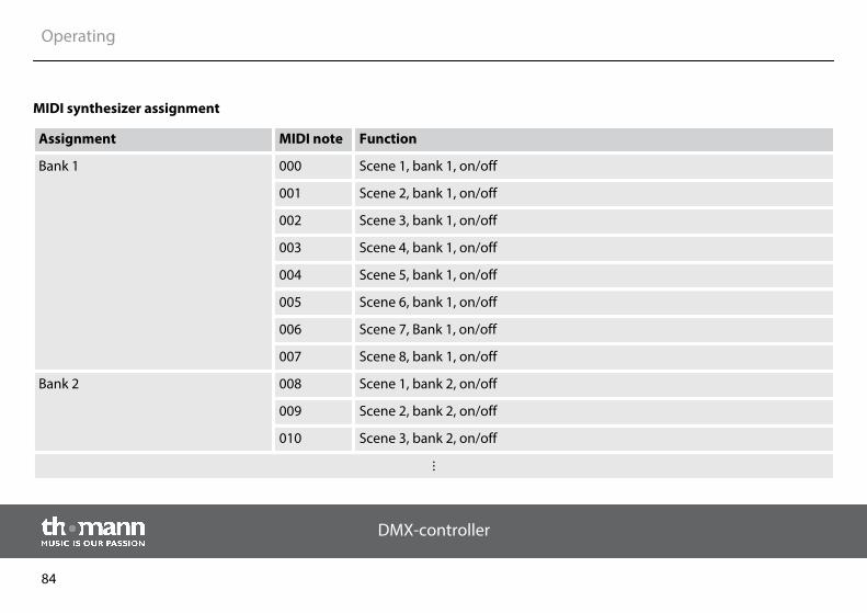
Assignment MIDI note Function
Bank 1 000 Scene 1, bank 1, on/off
001 Scene 2, bank 1, on/off
002 Scene 3, bank 1, on/off
003 Scene 4, bank 1, on/off
004 Scene 5, bank 1, on/off
005 Scene 6, bank 1, on/off
006 Scene 7, Bank 1, on/off
007 Scene 8, bank 1, on/off
Bank 2 008 Scene 1, bank 2, on/off
009 Scene 2, bank 2, on/off
010 Scene 3, bank 2, on/off
MIDI synthesizer assignment
Operating
DMX-controller
84
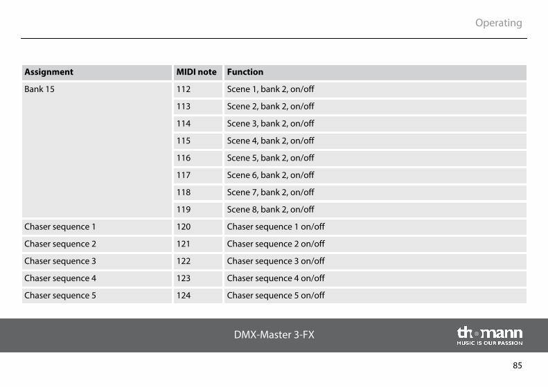
Assignment MIDI note Function
Bank 15 112 Scene 1, bank 2, on/off
113 Scene 2, bank 2, on/off
114 Scene 3, bank 2, on/off
115 Scene 4, bank 2, on/off
116 Scene 5, bank 2, on/off
117 Scene 6, bank 2, on/off
118 Scene 7, bank 2, on/off
119 Scene 8, bank 2, on/off
Chaser sequence 1 120 Chaser sequence 1 on/off
Chaser sequence 2 121 Chaser sequence 2 on/off
Chaser sequence 3 122 Chaser sequence 3 on/off
Chaser sequence 4 123 Chaser sequence 4 on/off
Chaser sequence 5 124 Chaser sequence 5 on/off
Operating
DMX-Master 3-FX
85
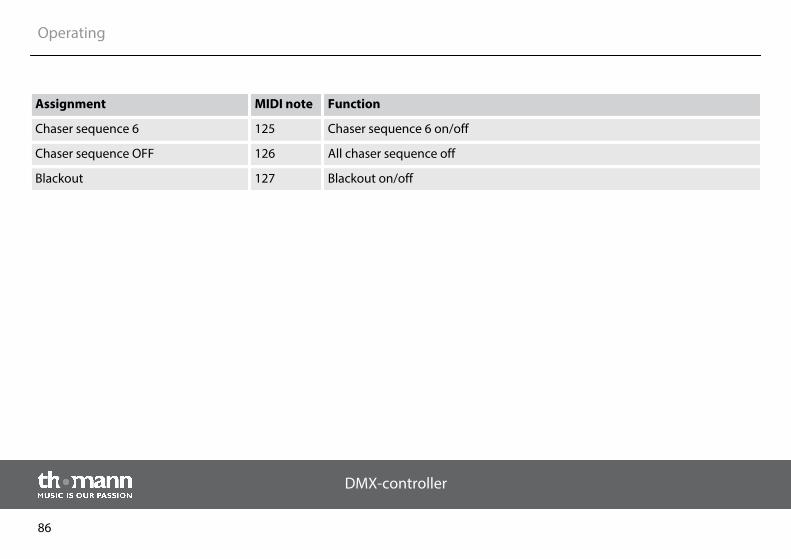
Assignment MIDI note Function
Chaser sequence 6 125 Chaser sequence 6 on/off
Chaser sequence OFF 126 All chaser sequence off
Blackout 127 Blackout on/off
Operating
DMX-controller
86
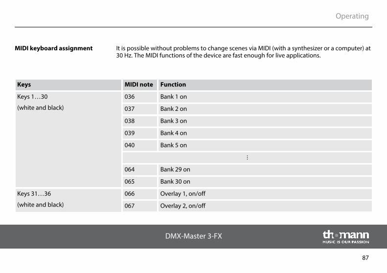
It is possible without problems to change scenes via MIDI (with a synthesizer or a computer) at30 Hz. The MIDI functions of the device are fast enough for live applications.
Keys MIDI note Function
Keys 1…30
(white and black)
036 Bank 1 on
037 Bank 2 on
038 Bank 3 on
039 Bank 4 on
040 Bank 5 on
064 Bank 29 on
065 Bank 30 on
Keys 31…36
(white and black)
066 Overlay 1, on/off
067 Overlay 2, on/off
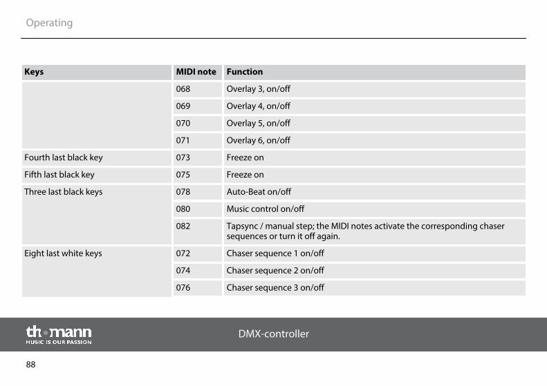
MIDI keyboard assignment
Operating
DMX-Master 3-FX
87
Keys MIDI note Function
068 Overlay 3, on/off
069 Overlay 4, on/off
070 Overlay 5, on/off
071 Overlay 6, on/off
Fourth last black key 073 Freeze on
Fifth last black key 075 Freeze on
Three last black keys 078 Auto-Beat on/off
080 Music control on/off
082 Tapsync / manual step; the MIDI notes activate the corresponding chasersequences or turn it off again.
Eight last white keys 072 Chaser sequence 1 on/off
074 Chaser sequence 2 on/off
076 Chaser sequence 3 on/off
Operating
DMX-controller
88
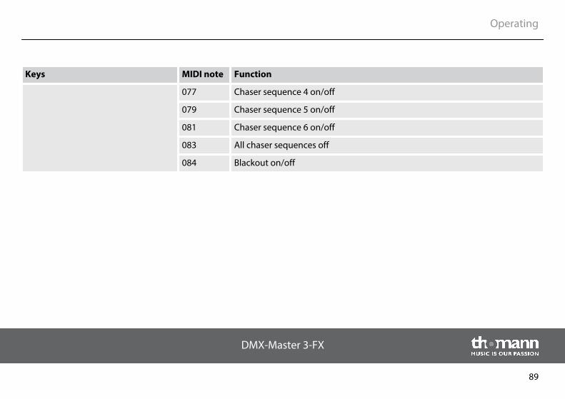
Keys MIDI note Function
077 Chaser sequence 4 on/off
079 Chaser sequence 5 on/off
081 Chaser sequence 6 on/off
083 All chaser sequences off
084 Blackout on/off
Operating
DMX-Master 3-FX
89
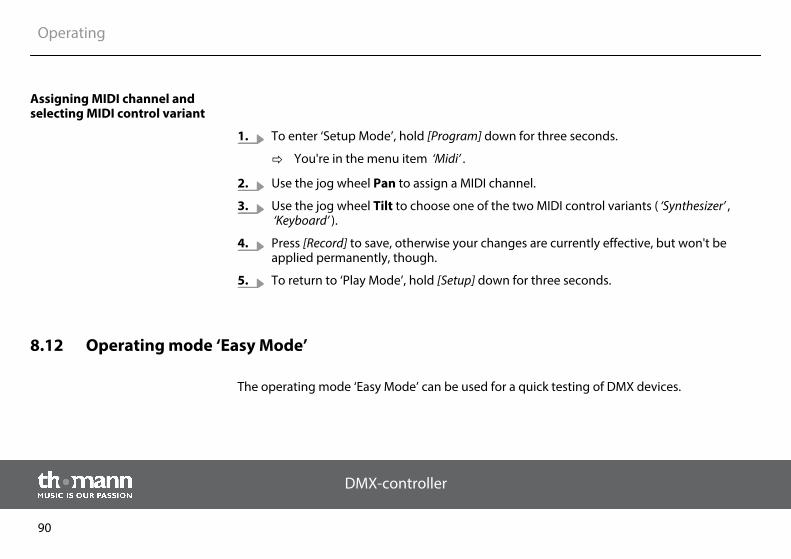
1. To enter ‘Setup Mode’, hold [Program] down for three seconds.
ð You're in the menu item ‘Midi’ .
2. Use the jog wheel Pan to assign a MIDI channel.
3. Use the jog wheel Tilt to choose one of the two MIDI control variants ( ‘Synthesizer’ ,‘Keyboard’ ).
4. Press [Record] to save, otherwise your changes are currently effective, but won't beapplied permanently, though.
5. To return to ‘Play Mode’, hold [Setup] down for three seconds.
8.12 Operating mode ‘Easy Mode’
The operating mode ‘Easy Mode’ can be used for a quick testing of DMX devices.
Assigning MIDI channel andselecting MIDI control variant
Operating
DMX-controller
90
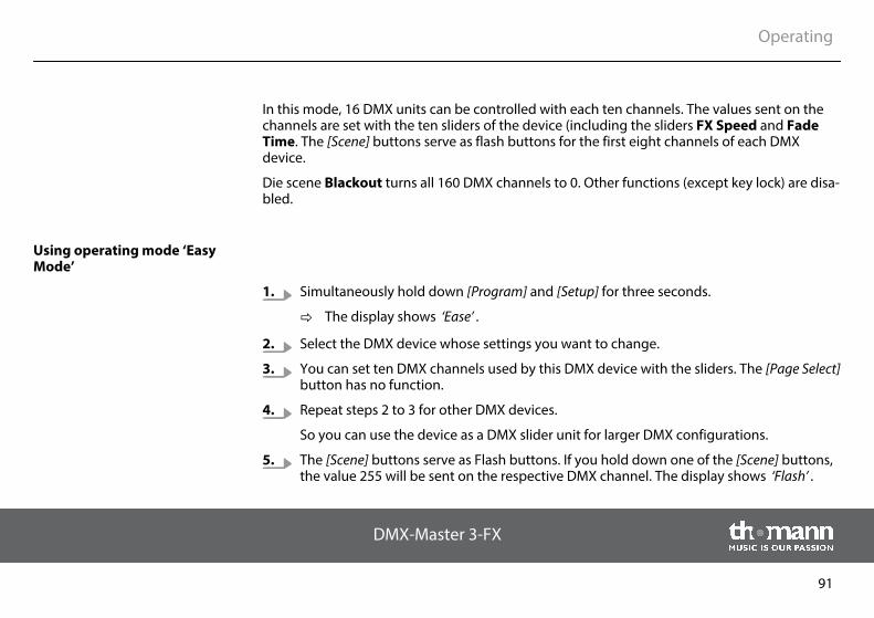
In this mode, 16 DMX units can be controlled with each ten channels. The values sent on thechannels are set with the ten sliders of the device (including the sliders FX Speed and FadeTime. The [Scene] buttons serve as flash buttons for the first eight channels of each DMXdevice.
Die scene Blackout turns all 160 DMX channels to 0. Other functions (except key lock) are disa‐bled.
1. Simultaneously hold down [Program] and [Setup] for three seconds.
ð The display shows ‘Ease’ .
2. Select the DMX device whose settings you want to change.
3. You can set ten DMX channels used by this DMX device with the sliders. The [Page Select]button has no function.
4. Repeat steps 2 to 3 for other DMX devices.
So you can use the device as a DMX slider unit for larger DMX configurations.
5. The [Scene] buttons serve as Flash buttons. If you hold down one of the [Scene] buttons,the value 255 will be sent on the respective DMX channel. The display shows ‘Flash’ .
Using operating mode ‘EasyMode’
Operating
DMX-Master 3-FX
91
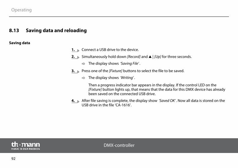
8.13 Saving data and reloading
1. Connect a USB drive to the device.
2. Simultaneously hold down [Record] and | [Up] for three seconds.
ð The display shows ‘Saving File’ .
3. Press one of the [Fixture] buttons to select the file to be saved.
ð The display shows ‘Writing’ .
Then a progress indicator bar appears in the display. If the control LED on the[Fixture] button lights up, that means that the data for this DMX device has alreadybeen saved on the connected USB drive.
4. After file saving is complete, the display show ‘Saved OK’ . Now all data is stored on theUSB drive in the file ‘CA-1616’.
Saving data
Operating
DMX-controller
92
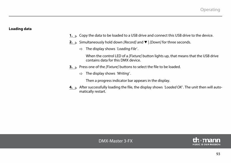
1. Copy the data to be loaded to a USB drive and connect this USB drive to the device.
2. Simultaneously hold down [Record] and | [Down] for three seconds.
ð The display shows ‘Loading File’ .
When the control LED of a [Fixture] button lights up, that means that the USB drivecontains data for this DMX device.
3. Press one of the [Fixture] buttons to select the file to be loaded.
ð The display shows ‘Writing’ .
Then a progress indicator bar appears in the display.
4. After successfully loading the file, the display shows ‘Loaded OK’ . The unit then will auto‐matically restart.
Loading data
Operating
DMX-Master 3-FX
93
8.14 Complementary functions
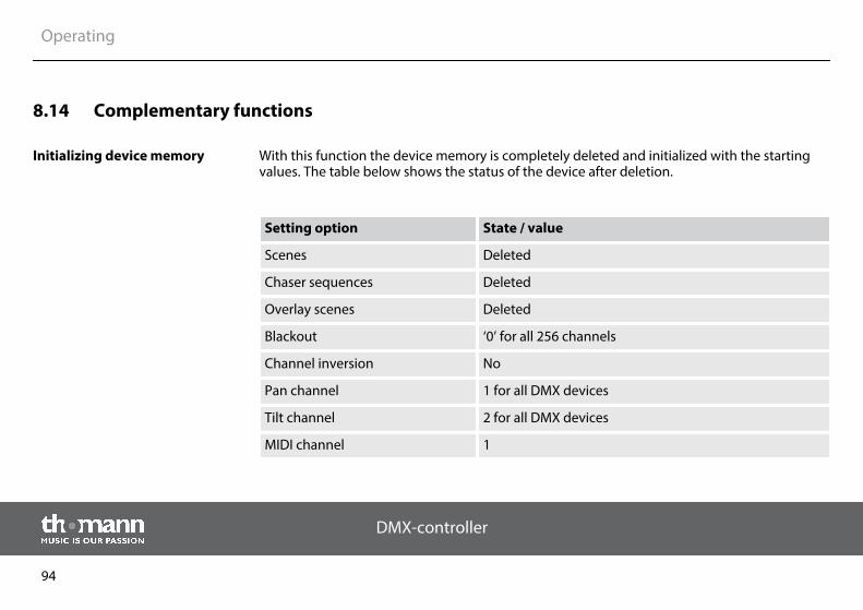
With this function the device memory is completely deleted and initialized with the startingvalues. The table below shows the status of the device after deletion.
Setting option State / value
Scenes Deleted
Chaser sequences Deleted
Overlay scenes Deleted
Blackout ‘0’ for all 256 channels
Channel inversion No
Pan channel 1 for all DMX devices
Tilt channel 2 for all DMX devices
MIDI channel 1
Initializing device memory
Operating
DMX-controller
94
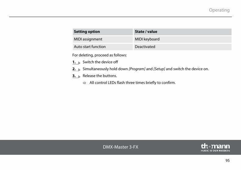
Setting option State / value
MIDI assignment MIDI keyboard
Auto start function Deactivated
For deleting, proceed as follows:
1. Switch the device off
2. Simultaneously hold down [Program] and [Setup] and switch the device on.
3. Release the buttons.
ð All control LEDs flash three times briefly to confirm.
Operating
DMX-Master 3-FX
95
The device is equipped with an optional key lock ("desklock"), which blocks the user interfaceand thus prevents accidental changes.
To activate the key lock, simultaneously press [Page Select], [Program] and [Setup]. While thekey lock is enabled, all buttons, faders and jog wheels are not functional. Controlling via MIDIinterface fully continues to function.
To cancel the key lock, press either [Page Select], [Program] and [Setup] simultaneously orswitch the device off and back on again.
If you want the user interface of the device to become active immediately after switching on,make the appropriate settings using the Auto Start function (Ä ‘Auto-start function’ on page 97).
Key lock
Operating
DMX-controller
96
The auto-start feature allows you to specify that the device is in a preselected playback config‐uration after power on. You can also specify that immediately after turning on the key lock isactive.
1. To enter ‘Setup Mode’, hold [Program] down for three seconds.
2. Use the | [Up] or | [Down] buttons to select the menu item ‘Autostrt’ .
3. Use the jog wheel Pan to enable of disable the auto start function.
4. Press [Record] to save, otherwise your changes are currently effective, but won't beapplied permanently, though.
5. To return to ‘Play Mode’, hold [Setup] down for three seconds.
1. To enter ‘Setup Mode’, hold [Program] down for three seconds.
2. Use the | [Up] or | [Down] buttons to select the menu item ‘Autostrt’ .
3. Use the jog wheel Tilt to enable or disable the key lock function on auto-start.
4. Press [Record] to save, otherwise your changes are currently effective, but won't beapplied permanently, though.
5. To return to ‘Play Mode’, hold [Setup] down for three seconds.
Auto-start function
Setting up the auto-start func‐tion
Configuring key lock on auto-start
Operating
DMX-Master 3-FX
97
Applying the current playback configuration for auto-start
You can save the current playback configuration in a way that it automatically becomes activewhen you turn on the device next time. For this purpose, the auto-start function must be setup first.
To save the current playback configuration simultaneously press [Record] and[Tap Sync Manual Go]. All control LEDs flash three times briefly to confirm.
When the device is turned on, a message appears in the display (the so-called logo), which canbe configured by you. An individually arranged logo is not deleted when you initialize thedevice memory.
1. Make sure that the device is switched off.
2. Hold down [Auto] and switch the device on.
3. Use the jog wheel Pan to adjust the cursor position in the display.
4. Use the jog wheel Tilt to select the character on the cursor position.
5. Press [Record] to save.
ð The display shows ‘Logo Saved’ .
6. Switch the device off and back on again.
Adapting the logo
Operating
DMX-controller
98
Proceed as follows, to reset the logo to factory defaults.
1. Make sure that the device is switched off.
2. Hold down [Auto] and switch the device on.
3. Press [Delete].
4. Press [Record] to confirm.
5. Switch the device off and back on again.
Resetting the logo
Operating
DMX-Master 3-FX
99
Proceed as follows, to bring the firmware of the device up to date.
Therefore you need a completely empty FAT32 formatted USB drive.
1. Create a folder in the root directory of the USB drive named ‘DMX-MASTER-3-FX’.
2. Copy the file ‘DMX-MASTER-3-FX.SUP’ to the ‘DMX-MASTER-3-FX’ folder.
3. Connect the USB drive to the device.
4. Turn off the device.
5. Simultaneously hold down [Record], | [Up] and [Program] and turn the device back onagain.
ð The display shows ‘Loading’ , the firmware update starts.
6. After firmware update is complete, the display shows ‘Write Success!’ .
7. Switch the device off and then back on again.
ð The unit will now start with the updated firmware.
Updating the firmware
Operating
DMX-controller
100
9 Technical data
Mains power supply 12 V (DC)
Dimensions (W × H × D) 526 mm × 232 mm × 88 mm (4 rack units) (20.7 in. × 9.1 in. × 3.4 in.)
Weight 3.5 kg (7.7 lbs)
Technical data
DMX-Master 3-FX
101
10 Protecting the environment
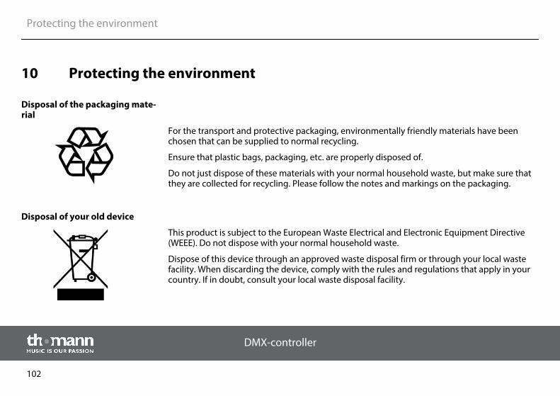
For the transport and protective packaging, environmentally friendly materials have beenchosen that can be supplied to normal recycling.
Ensure that plastic bags, packaging, etc. are properly disposed of.
Do not just dispose of these materials with your normal household waste, but make sure thatthey are collected for recycling. Please follow the notes and markings on the packaging.
This product is subject to the European Waste Electrical and Electronic Equipment Directive(WEEE). Do not dispose with your normal household waste.
Dispose of this device through an approved waste disposal firm or through your local wastefacility. When discarding the device, comply with the rules and regulations that apply in yourcountry. If in doubt, consult your local waste disposal facility.
Disposal of the packaging mate‐rial
Disposal of your old device
Protecting the environment
DMX-controller
102


Musikhaus Thomann e.K. · Treppendorf 30 · 96138 Burgebrach · Germany · www.thomann.de
Related Documents