DMRC Electrical Standards & Design Wing DMES-E/0007 SPECIFICATIONS FOR SUPPLY & INSTALLATION OF CONDUIT WIRING OF ELEVATED STATION Draft-1 1 DELHI METRO RAIL CORPORATION LIMITED DMRC ELECTRICAL STANDARDS & DESIGN WING (DESDW) SPECIFICATION NO. DMES- E/0007/DMRC-E-E&M-CONDUIT WIRING-01 SPECIFICATIONS FOR SUPPLY & INSTALLATION OF CONDUIT WIRING OF ELEVATED STATION Issued on: Date Stage 8 April 2015 Draft-1 DELHI METRO RAIL CORPORATION LTD. 7 th Floor, B-Wing, Metro Bhawan, Fire Brigade Lane, Barakhamba Road, New Delhi –110 001

Welcome message from author
This document is posted to help you gain knowledge. Please leave a comment to let me know what you think about it! Share it to your friends and learn new things together.
Transcript

DMRC Electrical Standards & Design Wing DMES-E/0007
SPECIFICATIONS FOR SUPPLY & INSTALLATION OF CONDUIT WIRING OF ELEVATED STATION
Draft-1
1
DELHI METRO RAIL CORPORATION LIMITED
DMRC ELECTRICAL STANDARDS & DESIGN WING (DESDW)
SPECIFICATION NO.
DMES- E/0007/DMRC-E-E&M-CONDUIT WIRING-01
SPECIFICATIONS FOR SUPPLY & INSTALLATION OF CONDUIT WIRING OF ELEVATED STATION
Issued on:
Date Stage
8 April 2015 Draft-1
DELHI METRO RAIL CORPORATION LTD.
7th Floor, B-Wing, Metro Bhawan, Fire Brigade Lane,
Barakhamba Road, New Delhi –110 001

DMRC Electrical Standards & Design Wing DMES-E/0007
SPECIFICATIONS FOR SUPPLY & INSTALLATION OF CONDUIT WIRING OF ELEVATED STATION
Draft-1
2
Previous Record of specification
Stage Date
Draft -1 08-Apr-15
DMRC Electrical Standards & Design Wing DMES-E/0007
SPECIFICATIONS FOR SUPPLY & INSTALLATION OF CONDUIT WIRING OF ELEVATED STATION
Draft-1
3
Table of Contents 1. DETAILED DESCRIPTION OF THE EQUIPMENT AND ITS APPLICATION IN DMRC: CONDUIT WIRING ... 4
2. GOVERNING SPECIFICATIONS ............................................................................................................... 4
2.3 STANDARDS .......................................................................................................................................... 4
2.4 ABBREVIATIONS ................................................................................................................................... 5
3. TECHNICAL REQUIREMENT ................................................................................................................... 6
4. INSTALLATION REQUIREMENT .............................................................................................................. 7
4.1 WIRING DIAGRAM ................................................................................................................................. 7
4.2 GUIDELINES FOR DRAWING OF WIRES ................................................................................................. 7
4.2.1Bunching Of Wires ................................................................................................................................ 7
4.2.2Termination / Jointing Of Wires............................................................................................................ 7
4.3 PRECAUTIONS DURING DRAWING OF WIRES ....................................................................................... 8
5. POINT WIRING ....................................................................................................................................... 9
5.1 SYSTEM OF WIRING ............................................................................................................................... 9
5.2 PARAMETERS ......................................................................................................................................... 9
6. INSPECTION, CHECKS AND TESTS ........................................................................................................ 10
7. Annexure A: ACCEPTANCE TEST REPORT ............................................................................................ 11
8. Annexure B: Checklist for Conduit Wiring .......................................................................................... 12
DMRC Electrical Standards & Design Wing DMES-E/0007
SPECIFICATIONS FOR SUPPLY & INSTALLATION OF CONDUIT WIRING OF ELEVATED STATION
Draft-1
4
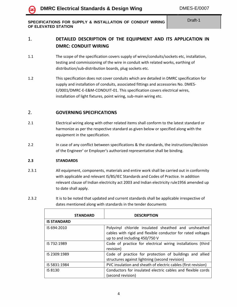
1. DETAILED DESCRIPTION OF THE EQUIPMENT AND ITS APPLICATION IN
DMRC: CONDUIT WIRING
1.1 The scope of the specification covers supply of wires/conduits/sockets etc, installation,
testing and commissioning of the wire in conduit with related works, earthing of
distribution/sub-distribution boards, plug sockets etc.
1.2 This specification does not cover conduits which are detailed in DMRC specification for
supply and installation of conduits, associated fittings and accessories No. DMES-
E/0001/DMRC-E-E&M-CONDUIT-01. This specification covers electrical wires,
installation of light fixtures, point wiring, sub-main wiring etc.
2. GOVERNING SPECIFICATIONS
2.1 Electrical wiring along with other related items shall conform to the latest standard or
harmonize as per the respective standard as given below or specified along with the
equipment in the specification.
2.2 In case of any conflict between specifications & the standards, the instructions/decision
of the Engineer' or Employer's authorized representative shall be binding.
2.3 STANDARDS
2.3.1 All equipment, components, materials and entire work shall be carried out in conformity
with applicable and relevant IS/BS/IEC Standards and Codes of Practice. In addition
relevant clause of Indian electricity act 2003 and Indian electricity rule1956 amended up
to date shall apply.
2.3.2 It is to be noted that updated and current standards shall be applicable irrespective of
dates mentioned along with standards in the tender documents
STANDARD DESCRIPTION
IS STANDARD
IS 694:2010 Polyvinyl chloride insulated sheathed and unsheathed cables with rigid and flexible conductor for rated voltages up to and including 450/750 V
IS 732:1989 Code of practice for electrical wiring installations (third revision)
IS 2309:1989 Code of practice for protection of buildings and allied structures against lightning (second revision)
IS 5831:1984 PVC insulation and sheath of electric cables (first revision)
IS 8130 Conductors for insulated electric cables and flexible cords (second revision)

DMRC Electrical Standards & Design Wing DMES-E/0007
SPECIFICATIONS FOR SUPPLY & INSTALLATION OF CONDUIT WIRING OF ELEVATED STATION
Draft-1
5
2.3.3 Codes and standards mean the latest. Where not specified otherwise the installation
shall generally follow the Indian standards/British Standards/IEC standards.
2.4 ABBREVIATIONS
S. No. Abbreviation Description
1 PVC Poly-vinyl Chloride
2 XLPE Cross-Linked Polyethylene
3 FR Fire Retardant
4 FRLSH Flame Retardant Low Smoke and Halogen
5 MS Mild Steel
6 GI Galvanised Iron
DMRC Electrical Standards & Design Wing DMES-E/0007
SPECIFICATIONS FOR SUPPLY & INSTALLATION OF CONDUIT WIRING OF ELEVATED STATION
Draft-1
6
3. TECHNICALREQUIREMENT
3.1 PVC Cables/Wires for rated voltages up to 450/750 V.
3.2 Electrical wires shall confirm to IS 694-2010. Generally there are three types of electrical
wires used in Metro system described at Sl No. 17, 19 and 20 of the specification IS 694-
2010..
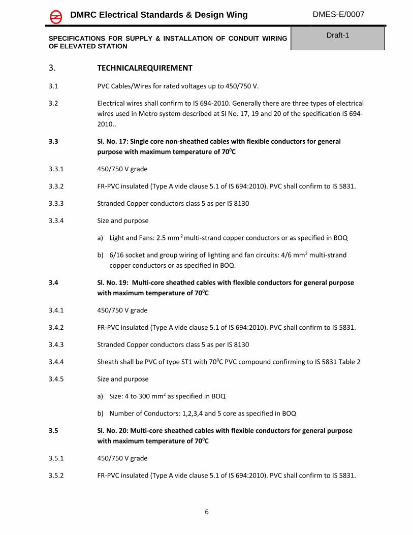
3.3 Sl. No. 17: Single core non-sheathed cables with flexible conductors for general
purpose with maximum temperature of 700C
3.3.1 450/750 V grade
3.3.2 FR-PVC insulated (Type A vide clause 5.1 of IS 694:2010). PVC shall confirm to IS 5831.
3.3.3 Stranded Copper conductors class 5 as per IS 8130
3.3.4 Size and purpose
a) Light and Fans: 2.5 mm 2 multi-strand copper conductors or as specified in BOQ
b) 6/16 socket and group wiring of lighting and fan circuits: 4/6 mm2 multi-strand
copper conductors or as specified in BOQ.
3.4 Sl. No. 19: Multi-core sheathed cables with flexible conductors for general purpose
with maximum temperature of 700C
3.4.1 450/750 V grade
3.4.2 FR-PVC insulated (Type A vide clause 5.1 of IS 694:2010). PVC shall confirm to IS 5831.
3.4.3 Stranded Copper conductors class 5 as per IS 8130
3.4.4 Sheath shall be PVC of type ST1 with 700C PVC compound confirming to IS 5831 Table 2
3.4.5 Size and purpose
a) Size: 4 to 300 mm2 as specified in BOQ
b) Number of Conductors: 1,2,3,4 and 5 core as specified in BOQ
3.5 Sl. No. 20: Multi-core sheathed cables with flexible conductors for general purpose
with maximum temperature of 700C
3.5.1 450/750 V grade
3.5.2 FR-PVC insulated (Type A vide clause 5.1 of IS 694:2010). PVC shall confirm to IS 5831.
DMRC Electrical Standards & Design Wing DMES-E/0007
SPECIFICATIONS FOR SUPPLY & INSTALLATION OF CONDUIT WIRING OF ELEVATED STATION
Draft-1
7
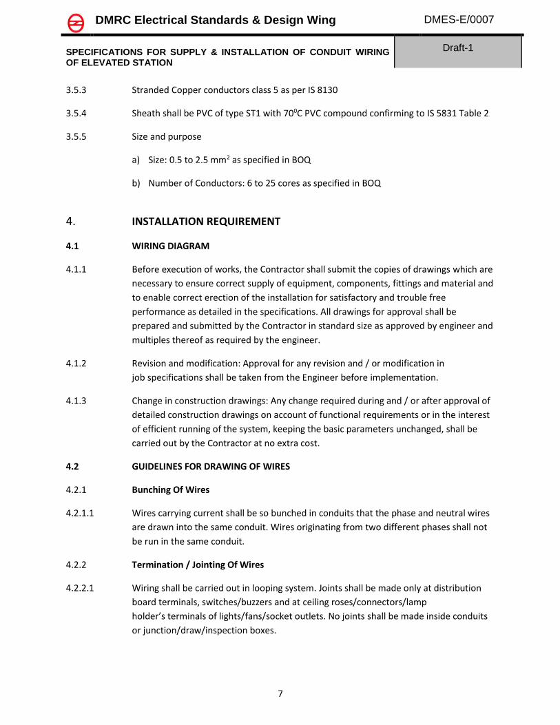
3.5.3 Stranded Copper conductors class 5 as per IS 8130
3.5.4 Sheath shall be PVC of type ST1 with 700C PVC compound confirming to IS 5831 Table 2
3.5.5 Size and purpose
a) Size: 0.5 to 2.5 mm2 as specified in BOQ
b) Number of Conductors: 6 to 25 cores as specified in BOQ
4. INSTALLATION REQUIREMENT
4.1 WIRING DIAGRAM
4.1.1 Before execution of works, the Contractor shall submit the copies of drawings which are
necessary to ensure correct supply of equipment, components, fittings and material and
to enable correct erection of the installation for satisfactory and trouble free
performance as detailed in the specifications. All drawings for approval shall be
prepared and submitted by the Contractor in standard size as approved by engineer and
multiples thereof as required by the engineer.
4.1.2 Revision and modification: Approval for any revision and / or modification in
job specifications shall be taken from the Engineer before implementation.
4.1.3 Change in construction drawings: Any change required during and / or after approval of
detailed construction drawings on account of functional requirements or in the interest
of efficient running of the system, keeping the basic parameters unchanged, shall be
carried out by the Contractor at no extra cost.
4.2 GUIDELINES FOR DRAWING OF WIRES
4.2.1 Bunching Of Wires
4.2.1.1 Wires carrying current shall be so bunched in conduits that the phase and neutral wires
are drawn into the same conduit. Wires originating from two different phases shall not
be run in the same conduit.
4.2.2 Termination / Jointing Of Wires
4.2.2.1 Wiring shall be carried out in looping system. Joints shall be made only at distribution
board terminals, switches/buzzers and at ceiling roses/connectors/lamp
holder’s terminals of lights/fans/socket outlets. No joints shall be made inside conduits
or junction/draw/inspection boxes.

DMRC Electrical Standards & Design Wing DMES-E/0007
SPECIFICATIONS FOR SUPPLY & INSTALLATION OF CONDUIT WIRING OF ELEVATED STATION
Draft-1
8
4.2.2.2 Wiring conductors shall be continuous from outlet to outlet. Joints where unavoidable,
due to any specified reasons shall be brought to the notice of Engineer and made by
approved connectors only with his permission. Specific prior permission from Engineer
in writing shall be obtained before making such joint.
4.2.2.3 Insulation shall be shaved off for a length of 15 mm at the end of wire and it shall not be
removed by cutting it square or wringing. Strands of wires shall not be cut for
connecting terminals.
4.2.2.4 Conductors having nominal cross sectional area up to 10-sqmm shall be cage clamped.
4.2.2.5 Heat-shrinkable sleeves of good quality of relevant standard as approved by the
Engineer shall be used on thimble connections.
4.2.2.6 At all bolted terminals, current carrying or non-current carrying shall be provided with
adequately sized flat and spring washer as per the requirements. Brass nuts and bolts
shall be used for all current carrying connections.
4.2.2.7 The pressure applied to tighten terminal screws shall be just adequate, and should not
dent or damage or cut any strand of the conductor.
4.2.2.8 Switches controlling lights, fans, socket outlets etc. shall be connected to the phase wire
of circuits only.
4.2.2.9 Only certified and licensed wire-men shall be employed to do wiring / jointing work.
4.2.3 Load Balancing - Balancing of circuits in three-phase installation shall be planned before
the commencement of wiring and shall be strictly adhered to. Distribution of circuits in
three phase installation shall be as per distribution chart indicated in drawings.
4.2.4 Colour Code of Conductors· All wires shall be colour coded as follows:
Phase Colour of Wire
R Red
Y Yellow
B Blue
N Black
Earth control, if any Grey
4.3 PRECAUTIONS DURING DRAWING OF WIRES
4.3.1 The drawing of wires shall be executed with due regard to the following:
DMRC Electrical Standards & Design Wing DMES-E/0007
SPECIFICATIONS FOR SUPPLY & INSTALLATION OF CONDUIT WIRING OF ELEVATED STATION
Draft-1
9
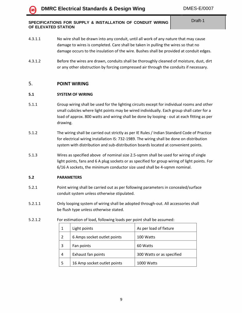
4.3.1.1 No wire shall be drawn into any conduit, until all work of any nature that may cause
damage to wires is completed. Care shall be taken in pulling the wires so that no
damage occurs to the insulation of the wire. Bushes shall be provided at conduit edges.
4.3.1.2 Before the wires are drawn, conduits shall be thoroughly cleaned of moisture, dust, dirt
or any other obstruction by forcing compressed air through the conduits if necessary.
5. POINT WIRING
5.1 SYSTEM OF WIRING
5.1.1 Group wiring shall be used for the lighting circuits except for individual rooms and other
small cubicles where light points may be wired individually. Each group shall cater for a
load of approx. 800 watts and wiring shall be done by looping - out at each fitting as per
drawing.
5.1.2 The wiring shall be carried out strictly as per IE Rules / Indian Standard Code of Practice
for electrical wiring installation IS: 732-1989. The wiring shall be done on distribution
system with distribution and sub-distribution boards located at convenient points.
5.1.3 Wires as specified above of nominal size 2.5-sqmm shall be used for wiring of single
light points, fans and 6 A plug sockets or as specified for group wiring of light points. For
6/16 A sockets, the minimum conductor size used shall be 4-sqmm nominal.
5.2 PARAMETERS
5.2.1 Point wiring shall be carried out as per following parameters in concealed/surface
conduit system unless otherwise stipulated.
5.2.1.1 Only looping system of wiring shall be adopted through-out. All accessories shall
be flush type unless otherwise stated.
5.2.1.2 For estimation of load, following loads per point shall be assumed:
1 Light points As per load of fixture
2 6 Amps socket outlet points 100 Watts
3 Fan points 60 Watts
4 Exhaust fan points 300 Watts or as specified
5 16 Amp socket outlet points 1000 Watts
DMRC Electrical Standards & Design Wing DMES-E/0007
SPECIFICATIONS FOR SUPPLY & INSTALLATION OF CONDUIT WIRING OF ELEVATED STATION
Draft-1
10
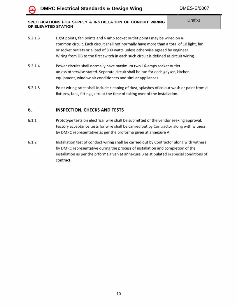
5.2.1.3 Light points, fan points and 6 amp socket outlet points may be wired on a
common circuit. Each circuit shall not normally have more than a total of 10 light, fan
or socket outlets or a load of 800 watts unless otherwise agreed by engineer.
Wiring from DB to the first switch in each such circuit is defined as circuit wiring.
5.2.1.4 Power circuits shall normally have maximum two 16-amps socket outlet
unless otherwise stated. Separate circuit shall be run for each geyser, kitchen
equipment, window air conditioners and similar appliances.
5.2.1.5 Point wiring rates shall include cleaning of dust, splashes of colour wash or paint from all
fixtures, fans, fittings, etc. at the time of taking over of the installation.
6. INSPECTION, CHECKS AND TESTS
6.1.1 Prototype tests on electrical wire shall be submitted of the vendor seeking approval.
Factory acceptance tests for wire shall be carried out by Contractor along with witness
by DMRC representative as per the proforma given at annexure A.
6.1.2 Installation test of conduct wiring shall be carried out by Contractor along with witness
by DMRC representative during the process of installation and completion of the
installation as per the prforma given at annexure B as stipulated in special conditions of
contract.

DMRC Electrical Standards & Design Wing DMES-E/0007
SPECIFICATIONS FOR SUPPLY & INSTALLATION OF CONDUIT WIRING OF ELEVATED STATION
Draft-1
11
7. Annexure A:
Specified Values Type Test Values Observed Values
Unit (Specified Values shall
be as per IS 694:2010
and the Cable selected)
Type test Values
shall be the same as
submitted at the
time of Vendor
DRUM/COIL No.:
Black Black Black
1 mm
2-
3
4mm
5mm
6mm
-
i) a) Volume resistivity (at 27 oC) Ohm cm
b) Volume resistivity (at 90 oC) Ohm cm
ii) a) Tensile strength (Before ageing) N/mm2
b) Elongation at break (Before
ageing)
%
-
i) a) Tensile strength (Before ageing) N/mm2
b) Elongation at break (Before
ageing)
%
9
-
i) Oxygen Index Test
ii) Temperature Index Test -
11
i) As per IS 10810 (Pt 53)
ii) Time of burning after removal the
flame
(Manufacturer) (Contractor) (DMRC Inspecting officer)
Flammability test
Date and Signature:
Annealing Test (for Copper Wires After
stranding)
Thickness of Insulation
Thickness of Outer sheath
Overall dia of core
Type of compound
Type of compound
8
Test on Outer Sheath (as per IS- 5831-
1984)
10
FR Test
Routine High Voltage test at R. temp.
Maximum size of Conductor
Conductor Resistance (ohms/km
corrected at 20 oC)
7
Test on Insulation (As per IS-5831-1984)
S. No.
Test Descriptions
Core Idenditification
Colour of Outer Sheath
Acceptance Test ReportCustomer Name:
P.O. No. & Date:
Description:
Specification: IS 694:2010 & Data Sheet
DMRC Electrical Standards & Design Wing DMES-E/0007
SPECIFICATIONS FOR SUPPLY & INSTALLATION OF CONDUIT WIRING OF ELEVATED STATION
Draft-1
12
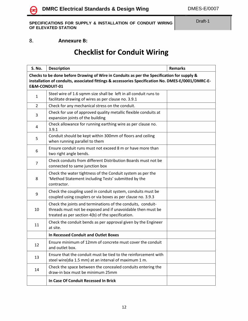
8. Annexure B:
Checklist for Conduit Wiring
S. No. Description Remarks
Checks to be done before Drawing of Wire in Conduits as per the Specification for supply & installation of conduits, associated fittings & accessories Specification No. DMES-E/0001/DMRC-E-E&M-CONDUIT-01
1 Steel wire of 1.6 sqmm size shall be left in all conduit runs to facilitate drawing of wires as per clause no. 3.9.1
2 Check for any mechanical stress on the conduit.
3 Check for use of approved quality metallic flexible conduits at expansion joints of the building
4 Check allowance for running earthing wire as per clause no. 3.9.1
5 Conduit should be kept within 300mm of floors and ceiling when running parallel to them
6 Ensure conduit runs must not exceed 8 m or have more than two right angle bends.
7 Check conduits from different Distribution Boards must not be connected to same junction box
8 Check the water tightness of the Conduit system as per the ‘Method Statement including Tests’ submitted by the contractor.
9 Check the coupling used in conduit system, conduits must be coupled using couplers or via boxes as per clause no. 3.9.3
10 Check the joints and terminations of the conduits, conduit-threads must not be exposed and if unavoidable then must be treated as per section 4(b) of the specification.
11 Check the conduit bends as per approval given by the Engineer at site.
In Recessed Conduit and Outlet Boxes
12 Ensure minimum of 12mm of concrete must cover the conduit and outlet box.
13 Ensure that the conduit must be tied to the reinforcement with steel wire(dia 1.5 mm) at an interval of maximum 1 m.
14 Check the space between the concealed conduits entering the draw-in box must be minimum 25mm
In Case Of Conduit Recessed In Brick

DMRC Electrical Standards & Design Wing DMES-E/0007
SPECIFICATIONS FOR SUPPLY & INSTALLATION OF CONDUIT WIRING OF ELEVATED STATION
Draft-1
13
15 Ensure 10 mm space must be available between conduits and depth must be sufficient so that minimum thickness of plaster over conduit is 6 mm
16 Check the Heavy duty pressed steel clamps screwed to MS flat strip saddled at maximum 600mm must be provided where chase has been cut for conduiting
17 Ensure Galvanised Chicken wire mesh of 0.6 mm thick with 10 to 15 mm aperture must be provided for full length of the chase in the plaster
18 Ensure that all boxes for accessories and draw/junction boxes must have outer rim flushed in the finished surface, in case of concealed conduits
In Case Of Surface Conduiting
19 Check for approved make spacer saddle at an interval not exceeding 600 mm and 300 mm from the fittings.
20 Good quality of workmanship must be ensured in case of surface conduiting
21 Check that the loop earthing wire must be connected to a screwed earth stead inside outlet boxes to make an effective contact with the metal body.
22 Ensure that all outlets and switch boxes shall be provided with temporary covers and plugs before plaster and concreting work to safeguard against filling up with mortar/plaster etc.
23 Check entire conduit system including outlets and boxes must be thoroughly cleaned after completion of erection and before drawing of wires.
24 Check loop earthing is provided by means of insulated stranded copper conductor wires of sizes as per BOQ laid along with wiring inside the conduits for all wiring outlets.
Checks to be done after Drawing of Wire in Conduits as per the Specification for Conduit Wiring of Elevated Stations Specification No. DMES-E/0007/DMRC-E-E&M-WIRING-01
25 Check the phase and neutral must be drawn in the same conduit.
26 Ensure two different phases must not run in same conduit.
27 Check the wiring, no joint must be present in the conduits or junction/draw/inspection boxes, except with prior written approval from Engineer at site.
28 Check all bolted terminals, brass approved flat washer of large area must be used.

DMRC Electrical Standards & Design Wing DMES-E/0007
SPECIFICATIONS FOR SUPPLY & INSTALLATION OF CONDUIT WIRING OF ELEVATED STATION
Draft-1
14
29 Check that good quality heat shrinkable sleeves are used at the terminations.
30 Check the switches controlling lights, fans, socket outlets etc. must be connected to the phase wire of circuit only.
31 Ensure bushes must be provided at the conduit edges and proper care must be taken so that no damage occurs to the insulation of the wire.
32 Insulation resistance must be tested. This must not be less than 50 divided by the number of points in the circuit in mega ohms.(50/no. of circuits)
33 Check the earth continuity of various equipment installed.
34
Measure current and voltage of all the lighting circuits at the sub-distribution board with all the lamps switched on to ensure that these are within design values, in case of 3 phase the load must be balanced reasonably.
35
Measure the minimum and maximum illumination levels after installation of all the lamps along with the supplier of lamp/luminaries and shall and shall comply with the designed value
36 Check the phase sequence to ensure correct phase sequence.
*Note: The test for insulation resistance must be carried out when all the equipment are disconnected from the circuit.
Date & Sign
(Contractor) (DMRC representative)
Related Documents