volume 3 highway structures: inspection and maintenance section 4 assessment part 16 Bd 61/10 the assessment of composite highway Bridges and structures summary This Standard gives requirements and guidance for the assessment of existing composite highway bridges and structures on motorways and other trunk roads. This is a revised document to be incorporated into Design Manual for Roads and Bridges. It supersedes and replaces BD 61/96 and BA 61/96. instructions for use 1. Remove existing contents pages for Volume 3 and insert new contents pages for Volume 3 dated June 2010. 2. Remove BD 61/96 and BA 61/96 from Volume 3, Section 4 and archive as necessary. 3. Insert BD 61/10 into Volume 3, Section 4, Part 16. 4. Please archive this sheet as appropriate. Note: A quarterly index with a full set of Volume Contents Pages is available separately from The Stationery Office Ltd. design manual for roads and Bridges June 2010

Welcome message from author
This document is posted to help you gain knowledge. Please leave a comment to let me know what you think about it! Share it to your friends and learn new things together.
Transcript
volume 3 highway structures: inspection and maintenance section 4 assessment
part 16
Bd 61/10
the assessment of composite highway Bridges and structures
summary
This Standard gives requirements and guidance for the assessment of existing composite highway bridges and structures on motorways and other trunk roads. This is a revised document to be incorporated into Design Manual for Roads and Bridges. It supersedes and replaces BD 61/96 and BA 61/96.
instructions for use
1. Remove existing contents pages for Volume 3 and insert new contents pages for Volume 3 dated June 2010.
2. Remove BD 61/96 and BA 61/96 from Volume 3, Section 4 and archive as necessary.
3. Insert BD 61/10 into Volume 3, Section 4, Part 16.
4. Please archive this sheet as appropriate.
Note: A quarterly index with a full set of Volume Contents Pages is available separately from The Stationery Office Ltd.
design manual for roads and Bridges
June 2010
design manual for roads and Bridges Bd 61/10 volume 3, section 4, part 16
The Assessment of Composite Highway Bridges and Structures
Summary: This Standard gives requirements and guidance for the assessment of existing composite highway bridges and structures on motorways and other trunk roads. This is a revised document to be incorporated into Design Manual for Roads and Bridges. It supersedes and replaces BD 61/96 and BA 61/96.
the highways agency
transport scotland
welsh assemBly government llywodraeth cynulliad cymru
the department for regional development northern ireland

June 2010
volume 3 section 4 part 16 Bd 61/10
registration of amendments
amend no
page no signature & date of incorporation of
amendments
amend no page no signature & date of incorporation of
amendments
registration of amendments

June 2010
volume 3 section 4 part 16 Bd 61/10
registration of amendments
amend no
page no signature & date of incorporation of
amendments
amend no page no signature & date of incorporation of
amendments
registration of amendments
volume 3 highway sructures: inspection and maintenance section 4 assessment
part 16
Bd 61/10
the assessment of composite highway Bridges and structures
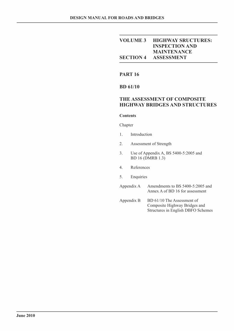
contents
Chapter
1. Introduction
2. Assessment of Strength
3. Use of Appendix A, BS 5400-5:2005 and BD 16 (DMRB 1.3)
4. References
5. Enquiries
Appendix A Amendments to BS 5400-5:2005 and Annex A of BD 16 for assessment
Appendix B BD 61/10 The Assessment of Composite Highway Bridges and Structures in English DBFO Schemes
design manual for roads and Bridges
June 2010
June 2010
volume 3 section 4 part 16 Bd 61/10
1. introduction
general
1.1 This Standard, which replaces BD 16 for assessment purposes, gives requirements and guidance for the assessment of existing composite structures and structural elements. It must be used in conjunction with BD 21, BD 37, BD 86, BD 56, BD 44 and other relevant documents. The revisions in the present Standard mainly concern the changes in the British Standard BS 5400-5:2005 and improvements to existing clauses based on the use of the earlier assessment standard.
1.2 Appendix A of this Standard contains the relevant assessment clauses and annexes which have been presented in the same format as the design clauses in BS 5400-5:2005. These clauses have been specifically developed to suit assessment conditions and, therefore, must not be used in new design or construction. The commentary is contained alongside the assessment clauses. It contains explanations for the main changes from the design code, BS 5400-5:2005, and gives advice on the interpretation of the assessment requirements. Also included are comments and references which provide additional information, and sometimes assessment criteria, appropriate to special situations. Where such situations arise, any special method of analysis or variation of criteria proposed for an assessment should be agreed with the Technical Approval Authority (TAA).
1.3 All references to characteristic strength should be to characteristic strength or to worst credible strength.
1.4 The major changes to the Standard compared to the earlier version are as follows:
a) A single BD with mandatory clauses including commentary/guidance replacing the previous BD and BA 61.
b) To cover old forms of construction cast iron and wrought iron have been inserted in addition to steel.
c) Loading standards BD 37 and BD 86 have been added since the scope of assessment has changed.
d) Clarifications have been made to a number of clauses based on the use of the earlier assessment standards.
e) The latest revisions to BS 5400-5 have been included in the Standard.
scope
1.5 This Standard gives requirements for the assessment of existing steel/concrete composite highway bridges and structures on trunk roads and motorways. For use in Northern Ireland, this Standard is applicable to all roads.
equivalence
1.6 The construction of highway structures will normally be carried out under contracts incorporating the Specification for Highway Works (MCHW 1). In such cases products conforming to equivalent standards or technical specifications of other states of the European Economic Area and tests undertaken in other states of the European Economic Area will be acceptable in accordance with the terms of the 104 and 105 Series of clauses of that Specification. Any contract not containing these clauses must contain suitable clauses of mutual recognition having the same effect
implementation
1.7 This Standard must be used forthwith for the assessment of steel/concrete composite highway bridges and structures. The requirements must be applied to assessments already in progress provided that, in the opinion of the Overseeing Organisation, this would not result in significant additional expense or delay. Its application to particular assessments must be confirmed with the Overseeing Organisation.
mandatory sections
1.8 Sections of this document which form part of the standards of the Overseeing Organisations are highlighted by being contained in boxes. These are the sections with which the Design Organisations must comply or must have agreed a suitable departure from standard with the relevant TAAs. The remainder of the document is commended to Design Organisations for consideration.
1/1
chapter 1 introduction
June 2010
volume 3 section 4 part 16 Bd 61/10
2. assessment of strength
general
2.1 The objective of this Standard is to produce a more realistic assessment of the strength of composite elements than has previously been possible using the requirements of the existing design code. This in part is achieved by taking advantage of the information available to an assessing engineer in respect of the material strength, geometrical properties and imperfections which can only be predicted at the design stage.
2.2 Many of the criteria given in the design code are based on experimental evidence which in some cases have been either conservatively interpreted for use in design or updated by later evidence allowing a less conservative interpretation. For assessment purposes such criteria have been reviewed and amended where appropriate.
2.3 The following assessment criteria differ in some respects from criteria used in design:
a) There is relaxation or partial relaxation of some design criteria which are of significance in a minority of structures.
b) Measured characteristic strength with modified safety factors may be used in place of design values.
c) Forms of shear connection, strengthening and stiffening, including incidental forms, are taken into account where their presence can be identified.
d) It may be appropriate to assess some structures on the basis that composite action exists, even though they were not designed as composite structures.
2.4 This standard contains certain requirements on partial and combination factors for abnormal vehicles. In assessment for Special Types General Order (STGO) and Special Order (SO) vehicle loading, and associated Type HA or Authorised Weight (AW) vehicle loading, the γfl values and combination factors must be in accordance with BD 86.
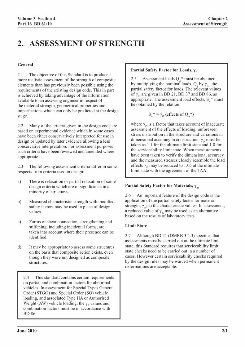
partial safety factor for loads, γfl
2.5 Assessment loads QA* must be obtained by multiplying the nominal loads, Qk by γfL, the partial safety factor for loads. The relevant values of γfL are given in BD 21, BD 37 and BD 86, as appropriate. The assessment load effects, SA* must be obtained by the relation:
SA* = γf3 (effects of QA*)
where γf3 is a factor that takes account of inaccurate assessment of the effects of loading, unforeseen stress distribution in the structure and variations in dimensional accuracy in construction. γf3 must be taken as 1.1 for the ultimate limit state and 1.0 for the serviceability limit state. When measurements have been taken to verify the dimensional accuracy and the measured stresses closely resemble the load effects γf3 may be reduced to 1.05 at the ultimate limit state with the agreement of the TAA.
partial safety factor for materials, γm
2.6 An important feature of the design code is the application of the partial safety factor for material strength, γm, to the characteristic values. In assessment, a reduced value of γm may be used as an alternative based on the results of laboratory tests.
limit state
2.7 Although BD 21 (DMRB 3.4.3) specifies that assessments must be carried out at the ultimate limit state, this Standard requires that serviceability limit state checks need to be carried out in a number of cases. However certain serviceability checks required by the design rules may be waived when permanent deformations are acceptable.
2/1
chapter 2 assessment of strength
June 2010
volume 3 section 4 part 16 Bd 61/10
2/2
chapter 2 assessment of strength
fatigue
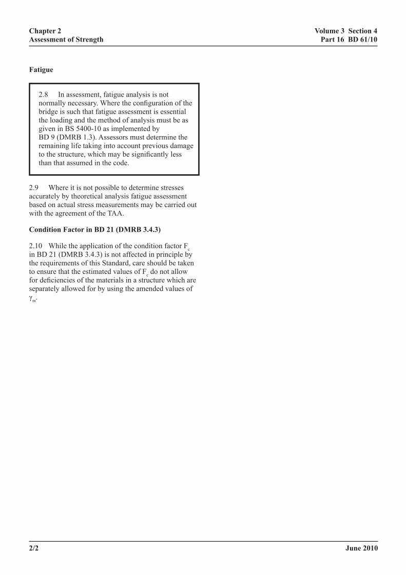
2.8 In assessment, fatigue analysis is not normally necessary. Where the configuration of the bridge is such that fatigue assessment is essential the loading and the method of analysis must be as given in BS 5400-10 as implemented by BD 9 (DMRB 1.3). Assessors must determine the remaining life taking into account previous damage to the structure, which may be significantly less than that assumed in the code.
2.9 Where it is not possible to determine stresses accurately by theoretical analysis fatigue assessment based on actual stress measurements may be carried out with the agreement of the TAA.
condition factor in Bd 21 (dmrB 3.4.3)
2.10 While the application of the condition factor Fc in BD 21 (DMRB 3.4.3) is not affected in principle by the requirements of this Standard, care should be taken to ensure that the estimated values of Fc do not allow for deficiencies of the materials in a structure which are separately allowed for by using the amended values of γm.
June 2010
volume 3 section 4 part 16 Bd 61/10
3. use of appendiX a, Bs 5400-5:2005 and Bd 16 (dmrB 1.3)
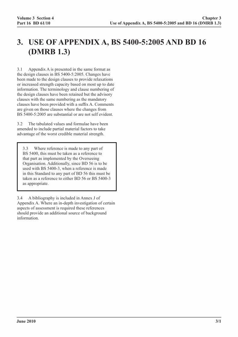
3.1 Appendix A is presented in the same format as the design clauses in BS 5400-5:2005. Changes have been made to the design clauses to provide relaxations or increased strength capacity based on most up to date information. The terminology and clause numbering of the design clauses have been retained but the advisory clauses with the same numbering as the mandatory clauses have been provided with a suffix A. Comments are given on those clauses where the changes from BS 5400-5:2005 are substantial or are not self evident.
3.2 The tabulated values and formulae have been amended to include partial material factors to take advantage of the worst credible material strength.
3.3 Where reference is made to any part of BS 5400, this must be taken as a reference to that part as implemented by the Overseeing Organisation. Additionally, since BD 56 is to be used with BS 5400-3, when a reference is made in this Standard to any part of BD 56 this must be taken as a reference to either BD 56 or BS 5400-3 as appropriate.
3.4 A bibliography is included in Annex J of Appendix A. Where an in-depth investigation of certain aspects of assessment is required these references should provide an additional source of background information.
3/1
chapter 3 use of appendix a, Bs 5400-5:2005 and Bd 16 (dmrB 1.3)
June 2010
volume 3 section 4 part 16 Bd 61/10
4. references
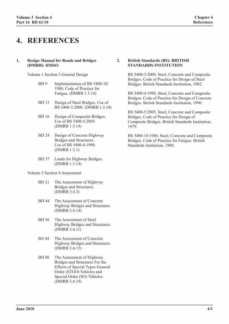
1. design manual for roads and Bridges (dmrB): hmso
Volume 1 Section 3 General Design
BD 9 Implementation of BS 5400-10: 1980, Code of Practice for Fatigue. (DMRB 1.3.14)
BD 13 Design of Steel Bridges. Use of BS 5400-3:2000. (DMRB 1.3.14)
BD 16 Design of Composite Bridges. Use of BS 5400-5:2005. (DMRB 1.3.14)
BD 24 Design of Concrete Highway Bridges and Structures. Use of BS 5400-4:1990. (DMRB 1.3.1)
BD 37 Loads for Highway Bridges. (DMRB 1.3.14)
Volume 3 Section 4 Assessment
BD 21 The Assessment of Highway Bridges and Structures. (DMRB 3.4.3)
BD 44 The Assessment of Concrete Highway Bridges and Structures. (DMRB 3.4.14)
BD 56 The Assessment of Steel Highway Bridges and Structures. (DMRB 3.4.11)
BA 44 The Assessment of Concrete Highway Bridges and Structures. (DMRB 3.4.15)
BD 86 The Assessment of Highway Bridges and Structures For the Effects of Special Types General Order (STGO) Vehicles and Special Order (SO) Vehicles. (DMRB 3.4.19)
2. British standards (Bs): British standards institution
BS 5400-3:2000. Steel, Concrete and Composite Bridges. Code of Practice for Design of Steel Bridges. British Standards Institution, 1982.
BS 5400-4:1990. Steel, Concrete and Composite Bridges. Code of Practice for Design of Concrete Bridges. British Standards Institution, 1990.
BS 5400-5:2005. Steel, Concrete and Composite Bridges. Code of Practice for Design of Composite Bridges. British Standards Institution, 1979.
BS 5400-10:1980. Steel, Concrete and Composite Bridges. Code of Practice for Fatigue. British Standards Institution, 1980.
4/1
chapter 4 references
June 2010
volume 3 section 4 part 16 Bd 61/10
5/1
chapter 5 enquiries
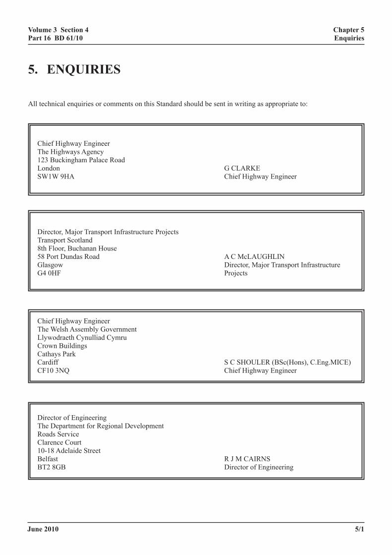
5. enquiries
All technical enquiries or comments on this Standard should be sent in writing as appropriate to:
Chief Highway Engineer The Highways Agency 123 Buckingham Palace Road London G CLARKE SW1W 9HA Chief Highway Engineer
Director, Major Transport Infrastructure Projects Transport Scotland 8th Floor, Buchanan House 58 Port Dundas Road A C McLAUGHLIN Glasgow Director, Major Transport Infrastructure G4 0HF Projects
Chief Highway Engineer The Welsh Assembly Government Llywodraeth Cynulliad Cymru Crown Buildings Cathays Park Cardiff S C SHOULER (BSc(Hons), C.Eng.MICE) CF10 3NQ Chief Highway Engineer
Director of Engineering The Department for Regional Development Roads Service Clarence Court 10-18 Adelaide Street Belfast R J M CAIRNS BT2 8GB Director of Engineering
June 2010
volume 3 section 4 part 16 Bd 61/10
a/1
appendix a
appendiX a amendments to Bs 5400-5:2005 and anneX a of Bd 16 for assessment
June 2010
volume 3 section 4 part 16 Bd 61/10
a/2
appendix a
contents
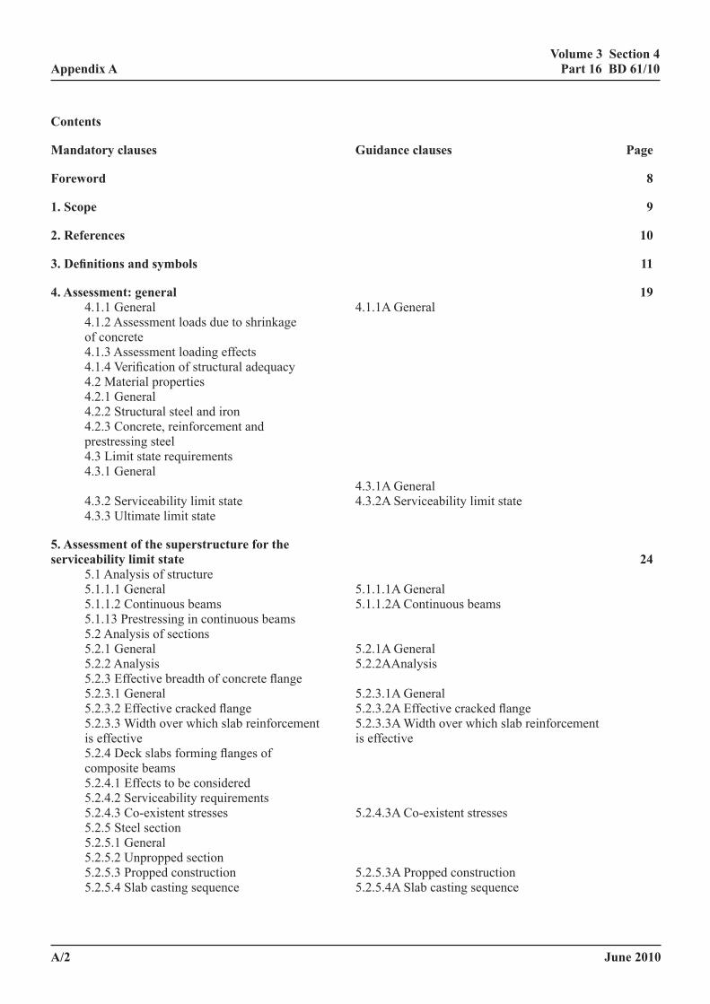
mandatory clauses guidance clauses page
foreword 8
1. scope 9
2. references 10
3. definitions and symbols 11
4. assessment: general 19 4.1.1 General 4.1.1A General 4.1.2 Assessment loads due to shrinkage of concrete 4.1.3 Assessment loading effects 4.1.4 Verification of structural adequacy 4.2 Material properties 4.2.1 General 4.2.2 Structural steel and iron 4.2.3 Concrete, reinforcement and prestressing steel 4.3 Limit state requirements 4.3.1 General 4.3.1A General 4.3.2 Serviceability limit state 4.3.2A Serviceability limit state 4.3.3 Ultimate limit state
5. assessment of the superstructure for the serviceability limit state 24 5.1 Analysis of structure 5.1.1.1 General 5.1.1.1A General 5.1.1.2 Continuous beams 5.1.1.2A Continuous beams 5.1.13 Prestressing in continuous beams 5.2 Analysis of sections 5.2.1 General 5.2.1A General 5.2.2 Analysis 5.2.2AAnalysis 5.2.3 Effective breadth of concrete flange 5.2.3.1 General 5.2.3.1A General 5.2.3.2 Effective cracked flange 5.2.3.2A Effective cracked flange 5.2.3.3 Width over which slab reinforcement 5.2.3.3A Width over which slab reinforcement is effective is effective 5.2.4 Deck slabs forming flanges of composite beams 5.2.4.1 Effects to be considered 5.2.4.2 Serviceability requirements 5.2.4.3 Co-existent stresses 5.2.4.3A Co-existent stresses 5.2.5 Steel section 5.2.5.1 General 5.2.5.2 Unpropped section 5.2.5.3 Propped construction 5.2.5.3A Propped construction 5.2.5.4 Slab casting sequence 5.2.5.4A Slab casting sequence
June 2010
volume 3 section 4 part 16 Bd 61/10
a/3
appendix a
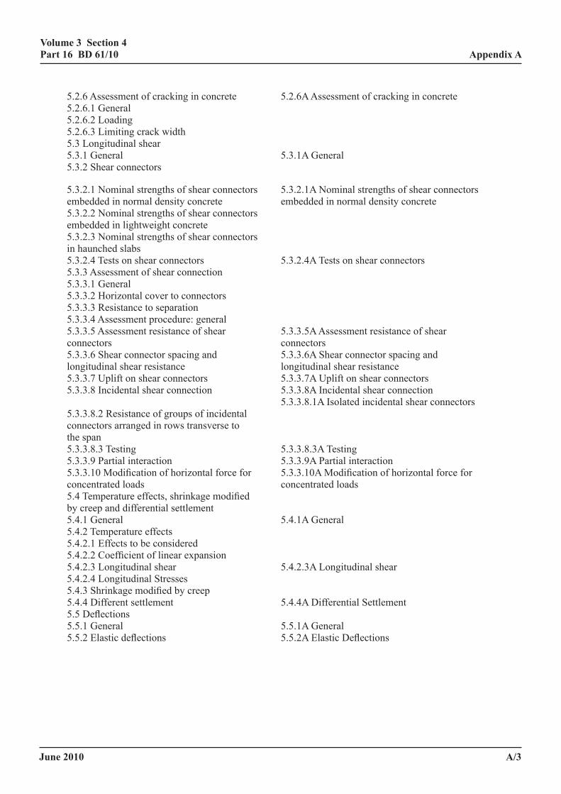
5.2.6 Assessment of cracking in concrete 5.2.6A Assessment of cracking in concrete 5.2.6.1 General 5.2.6.2 Loading 5.2.6.3 Limiting crack width 5.3 Longitudinal shear 5.3.1 General 5.3.1A General 5.3.2 Shear connectors
5.3.2.1 Nominal strengths of shear connectors 5.3.2.1A Nominal strengths of shear connectors embedded in normal density concrete embedded in normal density concrete 5.3.2.2 Nominal strengths of shear connectors embedded in lightweight concrete 5.3.2.3 Nominal strengths of shear connectors in haunched slabs 5.3.2.4 Tests on shear connectors 5.3.2.4A Tests on shear connectors 5.3.3 Assessment of shear connection 5.3.3.1 General 5.3.3.2 Horizontal cover to connectors 5.3.3.3 Resistance to separation 5.3.3.4 Assessment procedure: general 5.3.3.5 Assessment resistance of shear 5.3.3.5A Assessment resistance of shear connectors connectors 5.3.3.6 Shear connector spacing and 5.3.3.6A Shear connector spacing and longitudinal shear resistance longitudinal shear resistance 5.3.3.7 Uplift on shear connectors 5.3.3.7A Uplift on shear connectors 5.3.3.8 Incidental shear connection 5.3.3.8A Incidental shear connection 5.3.3.8.1A Isolated incidental shear connectors 5.3.3.8.2 Resistance of groups of incidental connectors arranged in rows transverse to the span 5.3.3.8.3 Testing 5.3.3.8.3A Testing 5.3.3.9 Partial interaction 5.3.3.9A Partial interaction 5.3.3.10 Modification of horizontal force for 5.3.3.10A Modification of horizontal force for concentrated loads concentrated loads 5.4 Temperature effects, shrinkage modified by creep and differential settlement 5.4.1 General 5.4.1A General 5.4.2 Temperature effects 5.4.2.1 Effects to be considered 5.4.2.2 Coefficient of linear expansion 5.4.2.3 Longitudinal shear 5.4.2.3A Longitudinal shear 5.4.2.4 Longitudinal Stresses 5.4.3 Shrinkage modified by creep 5.4.4 Different settlement 5.4.4A Differential Settlement 5.5 Deflections 5.5.1 General 5.5.1A General 5.5.2 Elastic deflections 5.5.2A Elastic Deflections
June 2010
volume 3 section 4 part 16 Bd 61/10
a/4
appendix a
6. assessment of superstructure for the ultimate limit state 57 6.1 Analysis of structure 6.1.1 General 6.1.1A General 6.1.2 Deck slabs forming the flanges of composite beams 6.1.3 Composite action 6.1.3A Composite action 6.1.4 Distribution of bending moments and vertical shear forces 6.1.4.1 Elastic analysis 6.1.4.2 Redistribution of support moments 6.1.4.2A Redistribution of support moments in principal longitudinal members in principal longitudinal members 6.1.4.3 Redistribution of span moments in 6.1.4.3A Redistribution of span moments in principal longitudinal members principal longitudinal members 6.1.5 Temperature effects, shrinkage modified 6.1.5A Temperature effects, shrinkage by creep and differential settlement modified by creep and differential settlement 6.1.6 Vertical shear resistance of composite 6.1.6A Shear resistance of composite beams beams 6.2 Analysis of Sections 6.2.1 General 6.2.2 Plastic moment of resistance of sections 6.2.2A Bending resistance of compact sections 6.2.3 Moment of resistance of non-compact. 6.2.3.3A Conditions under which lateral cross sections torsional buckling can be disregarded 6.2.3.1 General 6.2.3.2 Bending resistance of non-compact sections 6.2.3.3 Conditions under which lateral torsional buckling is disregarded. 6.3 Longitudinal Shear 6.3.1 General 6.3.1A General 6.3.2 Deck slab 6.3.2.1 Haunches 6.3.3 Transverse reinforcement 6.3.3.1 Definitions and general requirements 6.3.3.1A Definition and general requirements 6.3.3.2 Longitudinal shear 6.3.3.3 Interaction between longitudinal shear and transverse bending 6.3.3.4 Minimum transverse reinforcement 6.3.3.5 Minimum transverse reinforcement in haunched beams 6.3.3.6 Curtailment of transverse reinforcement 6.3.3.7 Detailing of transverse reinforcement 6.3.4 Shear Connectors
7. composite box girders 77 7.1 General 7.2 Effective Span 7.3 Effective Breadth 7.4 Distribution of Bending Moments and Vertical Shear Forces 7.5 Longitudinal Shear 7.5.1 Spacing of shear connectors 7.5.2 Assessment of shear connectors 7.6 Torsion 7.7 Composite Plate
June 2010
volume 3 section 4 part 16 Bd 61/10
a/5
appendix a
8. cased beams and filler beam construction 61 8.1 Scope 8.1.1 Introduction 8.1.2 Cased beams 8.1.3 Complying filler beams 8.1.4 Non-complying filler beams 8.1.5 Vertical shear resistance 8.1.6 Procedure when longitudinal shear resistance is inadequate 8.1.7 Punching shear resistance 8.1.8 Effect of end restraints and of finishings and infill material not satisfying BD 44 8.2 Limit State Requirements 8.3 Analysis of Structure 8.3.1 General 8.3.2 Transverse moments in filler beam decks (approximate method) 8.4 Analysis of Sections 8.5 Longitudinal Shear 8.5.1 Serviceability limit state 8.5.2 Ultimate limit state 8.6 Temperature and Shrinkage Effects 8.6.1 General 8.6.2 Longitudinal stresses and strains 8.6.3 Longitudinal shear 8.7 Assessment of Cracking 8.7.1 General 8.7.2 Cased beams 8.7.3 Filler beams 8.8 Construction
9. permanent formwork 95
9.1 General 9.2 Materials 9.4 Temporary Construction Loading 9.3 Structural Participation 9.5 Assessment 9.5.1 General 9.5.2 Non-participating formwork 9.5.3 Participating formwork 9.6 Special Requirements for Precast Concrete or Composite Precast Concrete Participating Formwork 9.6.1 Assessment 9.6.2 Welding of reinforcement 9.6.3 Interfaces 9.6.4 Cover to reinforcement
June 2010
volume 3 section 4 part 16 Bd 61/10
a/6
appendix a
10. assessment of friction grip bolts used as shear connectors in composite beams 97 10.1 General 10.2 Assessment Requirements: Static Loading 10.2.1 Serviceability limit state. 10.2.2 Ultimate limit state 10.3 Fatigue 10.4 Other Considerations
11. composite columns 99
11.1 General 11A Composite columns 11.1.1 Scope 11.1.2 Materials 11.1.2.1 Steel 11.1.2.2 Concrete 11.1.2.3 Reinforcement 11.1.3 Shear connection 11.1.4 Concrete contribution factor 11.1.6 Limits on slenderness 11.2 Moments and Forces in Columns 11.2.2 Semi-empirical assessment method for restrained composite columns 11.2.2.1 Scope 11.2.2.2 Moments and forces on the restrained column 11.2.2.3 Equivalent pin-ended column 11.2.2.4 Effective length 11.2.2.5 Transverse Loads 11.2.2.6 Column self weight 11.3 Analysis of Columns 11.3.1 Concrete encased steel section 11.3.2 Major and minor axes 11.3.3 Definition of slender columns 11.3.4 Slenderness limits for column lengths 11.3.5 Short columns that resist combined compression and bending 11.3.5.1 Scope 11.3.5.2 Design eccentricities of the axial force 11.3.5.3 Assessment for bending about the major axis 11.3.5.4 Assessment for bending about the minor axis 11.3.5.5 Assessment for biaxial bending 11.3.6 Slender Columns 11.3.7 Ultimate strength of axially loaded concrete filled circular hollow sections 11.3.8 Tensile cracking of concrete 11.3.9 Details
June 2010
volume 3 section 4 part 16 Bd 61/10
a/7
appendix a
12. influence of method of construction on assessment 109 12.1 Sequence of construction 12.2 Permanent formwork
13. prestressing in composite construction 110 13.1 General 13.2 Methods of prestressing 13.3 Limit state requirements 13.4 Prestressing the steel beam 13.5 Stress limitations in concrete at transfer 13.6 Loss of prestress
14. Jack arch and trough construction 112 14.1 Jack arch construction 14.2 Trough construction
annex a (normative) crack widths in composite beams 114
annex B (informative) lateral-torsional buckling of composite beams with slab and girders tied laterally and rotationally 116
annex c (informative) lateral-torsional buckling of composite beams with slab and girders tied laterally but not rotationally 122
annex d (normative) vibration of composite bridges 131
annex e (informative) f fatigue in reinforcement of composite beams 133
annex f – not used -
annex g (informative) significance of nominal considerations 135
annex h (informative) suggested properties of infill material not satisfying Bd 44 for the assessment of filler beams and jack arches 137
annex i (informative) sample flow charts illustrating the assessment procedures for bridge decks considered in clauses 8 and 14 140
annex J Bibliography 145
annex K references 148

June 2010
volume 3 section 4 part 16 Bd 61/10
a/8
appendix a
foreword
In the original drafting of BS 5400, important innovations had been made in respect of loading and environmental assumptions, design philosophy, load factors, service stresses and structural analysis, taking into account theoretical and experimental research and several design studies made on components and on complete bridges. In drafting of the Assessment version of the Standards further work of this nature has been undertaken, some of which is relevant only to assessment.
the relationship between parts 3, part 4 and part 5 of Bs 5400
The design of composite bridges requires the combined use of Part 3, Part 4 and Part 5 of BS 5400.
BS 5400-3 was drafted on the assumption that for the design of steelwork in bridges with either steel or concrete decks the methods of global analysis and all the procedures for satisfying the limit state criteria would be as prescribed in BS 5400-3. For beams it is used without any modification in conjunction with those provisions of BS 5400-5 that are applicable to the properties of the composite slab and its connection to the steel section.
It will be noted that more serviceability checks are required for composite than for steel bridges. This difference is due to the special characteristics of composite construction, such as the large shape factor of certain composite sections; the addition of stresses in a two-phase structure (bare steel/wet concrete and composite); and the effects of shrinkage and temperature on the girders and on the shear connectors. It is considered inadvisable to entirely dispense with these secondary effects for purposes of assessment, but wherever possible the criteria have been relaxed.
assessment standards. For the assessment of existing bridges, BD 56 (DMRB 3.4) is used in place of BS 5400-3 and BD 44 (DMRB 3.4) is used in place of BS 5400-4. However when the steel sections are to be assessed prior to composite action BD 56 must be used otherwise BD 61 will be used for all steel/concrete composite bridges.
BD 61 has expanded BS 5400-5 to include the following forms of construction:
Partial shear connection
older forms of shear connectors lacking the capacity to resist uplift
various forms of incidental shear connection
filler beam construction not satisfying Clause 8
jack arch construction.
Rules for lateral torsional buckling which are particularly applicable to composite beams are included.
Reference is made to iron structures; guidance of whether wrought, ductile or cast iron is applicable is given in the Standard.
NOTE: There are a number of situations in which dimensional and other criteria specified in this Standard may be infringed without significantly affecting the structural performance (for example in clauses 5.3.3 and 6.3.3). These are indicated by the words “(see * in foreword)”. An agreed procedure with the TAA should then be adopted taking into account the guidance in the Standard.
June 2010
volume 3 section 4 part 16 Bd 61/10
a/9
appendix a
1 scope
This Standard augments the provisions of BD 56 (DMRB 3.4) for structural steel, BD 44 (DMRB 3.4) for reinforced and prestressed concrete and BD 9 (DMRB 3.1) for fatigue when components of steel and reinforced concrete are so interconnected that they act compositely.
It gives requirements and guidance for assessment of rolled or fabricated steel sections, cased or uncased, and for filler beam systems when used in composite construction. Consideration is given to simply supported and continuous composite beams, composite columns and to the special problems of composite box beams. The requirements for the concrete element cover normal and lightweight aggregate, cast in situ and precast concrete. Prestressing and the use of permanent formwork designed to act compositely with in situ concrete are also covered.

June 2010
volume 3 section 4 part 16 Bd 61/10
a/10
appendix a
2 references
The titles of the standards publications referred to in this Standard are listed at the end of this document.
June 2010
volume 3 section 4 part 16 Bd 61/10
a/11
appendix a
3 definitions and symBols
3.1 definitions
For the purpose of this Standard the following definitions, and those given in BS 5400-1, apply.
3.1.1 uncased composite beam. A beam composed of either rolled or built-up structural steel, wrought iron, or cast iron sections, without a concrete encasement, which acts in conjunction with a concrete slab where the two elements are interconnected so as to form a composite section.
3.1.2 composite box beam. A steel box girder acting compositely with a concrete slab.
NOTE: In a closed steel box the concrete is cast on the top steel flange, whereas in an open steel box the box is closed by the concrete slab.
3.1.3 composite column. A column composed either of a hollow steel section with an infill of concrete or of a steel section cased in concrete so that in either case there is interaction between steel and concrete.
3.1.4 composite plate. An in situ concrete slab cast upon, and acting compositely with, a structural steel plate.
3.1.5 concrete slab. The structural concrete slab that forms part of the deck of the bridge and acts compositely with the steel beams. The slab may be of precast, cast in situ or composite construction.
3.1.6 composite slab. An in situ concrete slab that acts compositely with structurally participating permanent formwork.
3.1.7 participating permanent formwork. Formwork to in situ concrete, when the strength of the formwork is assumed to contribute to the strength of the composite slab.
3.1.8 non-participating permanent formwork. Permanent formwork that does, or does not, act compositely with the in situ concrete, but where the formwork is neglected in calculating the strength of the slab.
3.1.9 filler beam construction. Rolled or built-up iron or steel sections that act in conjunction with a concrete slab and which are contained within the slab or with slab surfaces flush with one or both flanges.
3.1.10 cased beam construction. Rolled or built-up iron or steel sections, fully or partially encased in concrete, but not such that they are fully within the depth of the slab, such that composite action occurs.
3.1.11 Jack arch construction. Rolled or built-up iron or steel sections separated by concrete, stone or brick arches supported by the lower flanges, generally with loose fill or concrete fill above.
3.1.12 interaction
3.1.12.1 complete interaction. This implies that no significant slip occurs between the steel and the concrete slab or encasement.
3.1.12.2 partial interaction. This implies that slip occurs at the interface between steel and concrete and a discontinuity in strain occurs but that composite action is still capable of being generated.
3.1.13 shear connector. A mechanical device to ensure interaction between concrete and steel.
3.1.14 connector modulus. The elastic shear stiffness of a shear connector.
3.1.15 worst credible strength. Worst credible strength at a location is the lower bound to the estimated strength. (see BD 44 for concrete and reinforcement).
June 2010
volume 3 section 4 part 16 Bd 61/10
3.1.16 cross section redistribution class. Criteria relating to the permitted redistribution of support moments.
3.1.17 slip. Movement of concrete along the steel/concrete interface
3.1.18 separation. Movement of concrete perpendicular to the steel/concrete interface.
3.1.19 yield moment – moment at first yield according to elastic theory using full composite section, if appropriate with ultimate limit state γm factors.
3.1.20 complying filler Beam. Filler beam in which the transverse reinforcement is assessed to be adequate for moments described in the standard.
3.2 symbols
The symbols used in this Standard are as follows:
A Area of equivalent cracked transformed section
A1, A2 Projected areas of concrete resisting connector forces
Ab Cross-sectional area of transverse reinforcement in the bottom of the slab effective in resisting bursting stresses in the concrete from the connector forces
Abs Cross-sectional area of other transverse reinforcement in the bottom of the slab
Abv Cross-sectional area of additional transverse reinforcement
Ac Cross-sectional area of concrete
Ae Effective cross-sectional area of transverse reinforcement
Aft Cross-sectional area of top flange of steel section
Ar Cross-sectional area of reinforcement
As Cross-sectional area of steel section
Ast Area of the encased tension flange of the structural steel member
At Area of tension reinforcement, cross-sectional area of transverse reinforcement near the top of the slab
a Distance from centroid of steel section to axis of rotation
a1 Distance from the compression face to the point at which the crack width is calculated
acr Distance from the point considered to the surface of the nearest longitudinal bar
b Width of section or portion of flange or least lateral dimension of a column or overall depth of composite column perpendicular to the minor axis
bc Width of section or portion of slab
be Effective breadth of portion of flange
bf Breadth of flange
a/12
appendix a
June 2010
volume 3 section 4 part 16 Bd 61/10
a/13
appendix a
bfc Breadth of compression flange
bfo Breadth of flange outstand
bft Breadth of compression flange
bs External dimension of the wall of the RHS or the breadth of steel section
bsc Dimension of a connector transverse to the span
bt Effective breadth of the composite section at the level of the tension reinforcement
bw Half the distance between the centre lines of webs
C A constant (with appropriate subscripts)
c Constant
cmin Minimum cover to the tension reinforcement
cnom Cover to outermost reinforcement controlling cracking
D Diameter
d Diameter of shank of stud, or width of channel or bar connector
De External diameter of CHS
dw Depth of steel web
Ec Static short term secant modulus of elasticity of concrete
Er Modulus of elasticity of steel reinforcement
Es Modulus of elasticity of structural steel
ex, ey Eccentricities of axial load about x and y axis
FT Tensile force per unit length
fc Concrete strength
fcc Enhanced characteristic strength of triaxially contained concrete
fci Concrete strength at (initial) transfer
fcu Characteristic or worst credible concrete cube strength
fk Characteristic resistance
fL Longitudinal stress
fmax Maximum longitudinal stress in concrete flange
fry Characteristic or worst credible strength of reinforcement
ftc Tensile stress in uncracked concrete flange
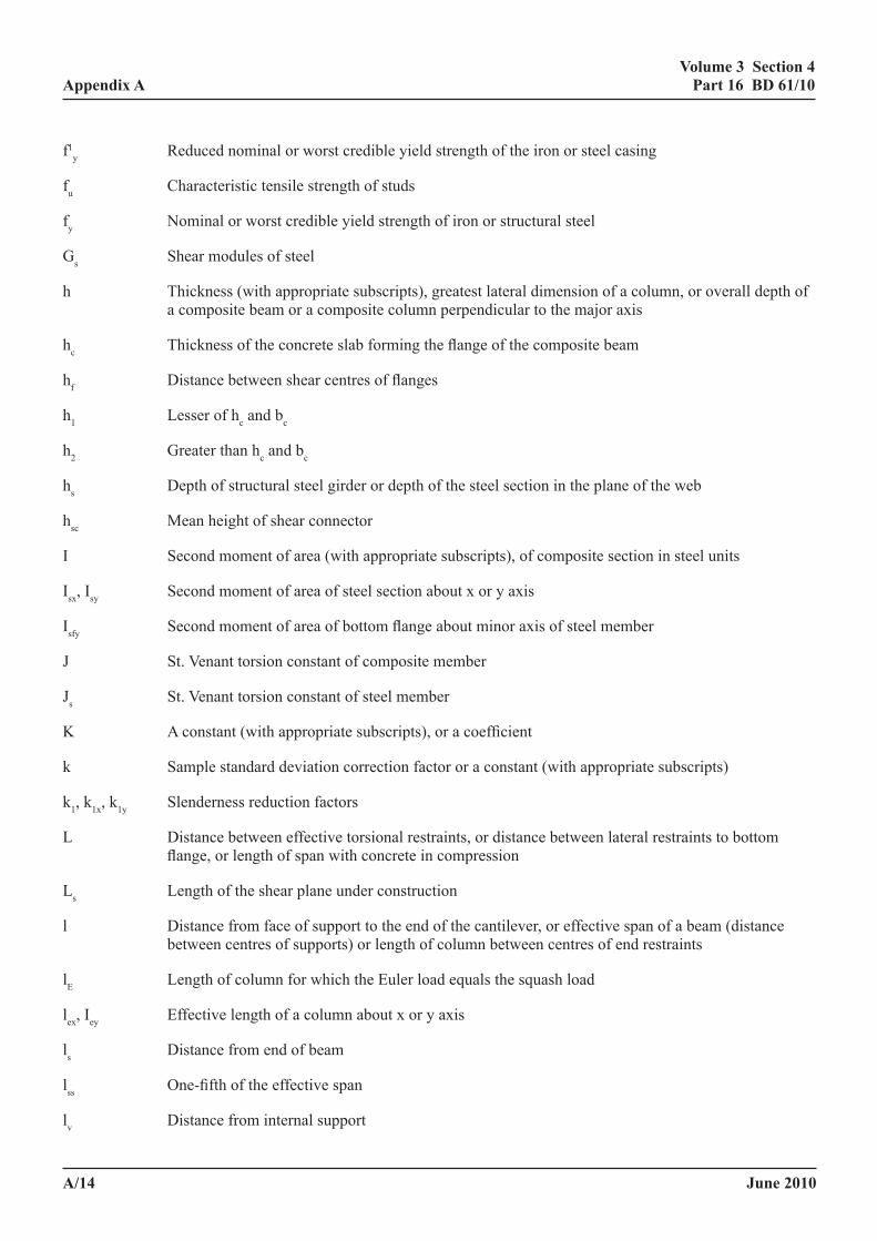
June 2010
volume 3 section 4 part 16 Bd 61/10
a/14
appendix a
f1y Reduced nominal or worst credible yield strength of the iron or steel casing
fu Characteristic tensile strength of studs
fy Nominal or worst credible yield strength of iron or structural steel
Gs Shear modules of steel
h Thickness (with appropriate subscripts), greatest lateral dimension of a column, or overall depth of a composite beam or a composite column perpendicular to the major axis
hc Thickness of the concrete slab forming the flange of the composite beam
hf Distance between shear centres of flanges
h1 Lesser of hc and bc
h2 Greater than hc and bc
hs Depth of structural steel girder or depth of the steel section in the plane of the web
hsc Mean height of shear connector
I Second moment of area (with appropriate subscripts), of composite section in steel units
Isx, Isy Second moment of area of steel section about x or y axis
Isfy Second moment of area of bottom flange about minor axis of steel member
J St. Venant torsion constant of composite member
Js St. Venant torsion constant of steel member
K A constant (with appropriate subscripts), or a coefficient
k Sample standard deviation correction factor or a constant (with appropriate subscripts)
k1, k1x, k1y Slenderness reduction factors
L Distance between effective torsional restraints, or distance between lateral restraints to bottom flange, or length of span with concrete in compression
Ls Length of the shear plane under construction
l Distance from face of support to the end of the cantilever, or effective span of a beam (distance between centres of supports) or length of column between centres of end restraints
lE Length of column for which the Euler load equals the squash load
lex, Iey Effective length of a column about x or y axis
ls Distance from end of beam
lss One-fifth of the effective span
lv Distance from internal support
June 2010
volume 3 section 4 part 16 Bd 61/10
a/15
appendix a
lw Length of wheel patch
M Bending moment (with appropriate subscripts)
Mmax Maximum moment
Mtx Equivalent uniform bending moment
Mu Ultimate moment of resistance
Mux Ultimate moment of resistance about the major axis
Muy Ultimate moment of resistance about the minor axis
Mx Moment acting about the major axis, longitudinal bending moment per unit width of filler beam deck
My Moment acting about the minor axis, longitudinal bending moment per unit width of filler beam deck
m Constant, or statistical expressions (with appropriate subscripts) used in calculating γmt
mt Equivalent uniform bending moment factor
N Ultimate axial load at the section considered, or actual number of commercial vehicles
Na Equivalent number of SFV's
Nax, Nay Axial failure loads
Nf The endurance for a particular stress range (N in BS 5400-10)
Npl Squash load of a column
Nux Axial failure load of a member subjected to a constant ultimate moment Mx
Nuxy Axial failure load of a member in biaxial bending or about an undefined axis
Nuy Axial failure load of a member subjected to a constant ultimate moment My
n Total number of connectors per unit length of girder or number of sample, or number of connectors in a row transverse to the beam
n’ Number of connectors per unit length placed within 200mm of the centre line of the web
na, nb Equivalent number of standard fatigue vehicles in 5.3.2.1
Pa Worst credible static connector strength
Pam Nominal present mean static strength at time of assessment
PD Axial load capacity of composite sections
Pim Initial nominal static connector strength
P’im Reduced Pim accounting for the presence of other connectors.
June 2010
volume 3 section 4 part 16 Bd 61/10
a/16
appendix a
Pr Range of longitudinal shear in connector from passage of an SFV
Pu Failure load of the connectors at concrete strength fc, or axial load in steel section
p Reduction factor for longitudinal shear force due to partial interaction
Q Longitudinal shear force
Q* Assessment or worst credible load
Q’ Reduced longitudinal shear force
Qk Nominal load effect
Qx Longitudinal shear on a connector at a distance x from the web centre line in box girder
q Longitudinal shear per unit length, or ratio of tapered to total length between torsional restraints
qp Longitudinal shear force per unit length of beam on the particular shear plane considered
qr Assessment longitudinal shear resistance per unit length
R Ratio of greater to lesser depth of section between effective torsional restraints
R* Resistance as defined in BS 5400-1
rx, ry The greater and lesser radii of gyration of a structural steel section
rxy Radius of gyration about xy axis
S s or 0.87s depending on cross section slenderness
S* Loading effects
s The shape factor or a constant stress of 1 N/mm2 re-expressed where necessary in units consistent with those used for other quantities
sb Spacing of bars
s’L Equivalent spacing of connector rows
sL Longitudinal spacing of individual connectors
sT Transverse spacing of individual connectors
Tu Tension
t Wall thickness
tfc, tfo Compression flange thickness
tw Web thickness
VD Shear resistance of steel or iron member
v1 Ultimate longitudinal shear stress of concrete
June 2010
volume 3 section 4 part 16 Bd 61/10
a/17
appendix a
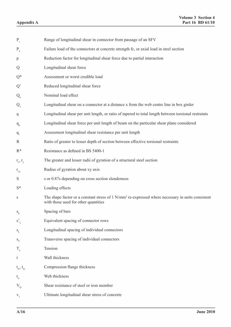
vt Slenderness parameter
wsc Dimension of a connector along the span
X Ratio of limiting to elastic critical stresses
x Neutral axis depth, coordinate, distance, or depth of section in compression, or torsional index
y Coordinate with appropriate subscript
Zxe is the lowest value of Zxc, Zxt and Zxr
Zxc, Zxt and Zxr are the effective elastic section moduli of a composite section of a slab on girder (composite or non-composite) for bending about the x-axis of the extreme fibres of the structural steel section in compression and in tension and of the reinforcement in tension respectively
Zxpr Reduced plastic modulus of effective section due to axial load
Zxp Effective plastic section modulus of beams Zpe as defined in BD 56
α1 Angle between axis of moment and direction of tensile reinforcement
αc Concrete contribution factor
αe Modular ratio
αL Ratio of the product of the partial safety factors γfl γf3 for abnormal vehicles to the corresponding product for normal live assessment loading for the limit state being considered
β Ratio of the smaller to the larger of the two end moments acting about each axis with appropriate subscripts
βL Coefficient of linear thermal expansion
γb Additional safety factor for incidental shear connectors
γfL Partial safety factor for loads and load effects
γf1, γf2, γf3 Partial safety factors for loads and load effects
γm Partial safety factor for strength
γmb Partial safety factor for bond strength
γmc Partial safety factor for concrete strength
γmr Partial safety factor for reinforcement strength
γmt Partial safety factor for strength from testing
γmv Partial safety factor for concrete shear strength
∆ Mi Beam end moments
∆f Difference between the free strains at the centroid of the concrete slab and the centroid of the steel beam
June 2010
volume 3 section 4 part 16 Bd 61/10
a/18
appendix a
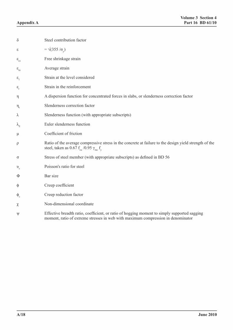
δ Steel contribution factor
ε = √(355 /σy)
εcs Free shrinkage strain
εm Average strain
ε1 Strain at the level considered
εr Strain in the reinforcement
η A dispersion function for concentrated forces in slabs, or slenderness correction factor
ηt Slenderness correction factor
λ Slenderness function (with appropriate subscripts)
λE Euler slenderness function
μ Coefficient of friction
ρ Ratio of the average compressive stress in the concrete at failure to the design yield strength of the steel, taken as 0.67 fcu /0.95 γmc fy
σ Stress of steel member (with appropriate subscripts) as defined in BD 56
υs Poisson's ratio for steel
Φ Bar size
φ Creep coefficient
φc Creep reduction factor
χ Non-dimensional coordinate
ψ Effective breadth ratio, coefficient, or ratio of hogging moment to simply supported sagging moment, ratio of extreme stresses in web with maximum compression in denominator
June 2010
volume 3 section 4 part 16 Bd 61/10
a/19
appendix a
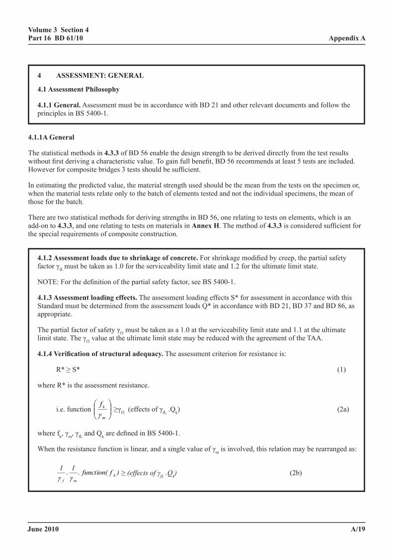
4 assessment: general
4.1 assessment philosophy
4.1.1 general. Assessment must be in accordance with BD 21 and other relevant documents and follow the principles in BS 5400-1.
4.1.1a general
The statistical methods in 4.3.3 of BD 56 enable the design strength to be derived directly from the test results without first deriving a characteristic value. To gain full benefit, BD 56 recommends at least 5 tests are included. However for composite bridges 3 tests should be sufficient.
In estimating the predicted value, the material strength used should be the mean from the tests on the specimen or, when the material tests relate only to the batch of elements tested and not the individual specimens, the mean of those for the batch.
There are two statistical methods for deriving strengths in BD 56, one relating to tests on elements, which is an add-on to 4.3.3, and one relating to tests on materials in annex h. The method of 4.3.3 is considered sufficient for the special requirements of composite construction.
4.1.2 assessment loads due to shrinkage of concrete. For shrinkage modified by creep, the partial safety factor γfL must be taken as 1.0 for the serviceability limit state and 1.2 for the ultimate limit state.
NOTE: For the definition of the partial safety factor, see BS 5400-1.
4.1.3 assessment loading effects. The assessment loading effects S* for assessment in accordance with this Standard must be determined from the assessment loads Q* in accordance with BD 21, BD 37 and BD 86, as appropriate.
The partial factor of safety γf3 must be taken as a 1.0 at the serviceability limit state and 1.1 at the ultimate limit state. The γf3 value at the ultimate limit state may be reduced with the agreement of the TAA.
4.1.4 verification of structural adequacy. The assessment criterion for resistance is:
R* ≥ S* (1)
where R* is the assessment resistance.
i.e. function
m
kfγ
≥γf3 (effects of γfL .Qk) (2a)
where fk, γm, γfL and Qk are defined in BS 5400-1.
When the resistance function is linear, and a single value of γm is involved, this relation may be rearranged as:
)Qof(effects)ffunction(11 kfLkmf
... γγγ
− ≥ (effectsofγfL.Qk) (2b)
June 2010
volume 3 section 4 part 16 Bd 61/10
a/20
appendix a
It is noted that the format of equation 2a is used in BD 44 whereas the format given in equation 2b is used in BD 56. Therefore when using this Standard in conjunction with either BD 56 or BD 44 γf3 must be applied correctly. In this Standard the approach in BD 56 has been adopted throughout.
For purposes of assessment, alternative methods of calculating strength or resistance of elements can be used provided that the results of an adequate number of representative laboratory tests are performed to enable statistical relationships between the strength or resistance predicted by the alternative method and that observed to be obtained. The tests must relate to elements having dimensional parameters of similar size to those for the parts assessed. Consideration must be given to the similarity of the situations, the condition, the material properties and the loading.
In those circumstances, the value of resistance to be used in assessment may be taken as
The value of the predicted mean resistance/γmγf3
where γm must be replaced by the value of γm calculated in accordance with 4.3.3 of BD 56. For shear connectors in beams, the value of γm so calculated must be multiplied by an additional safety factor of 1.25 to allow for the brittle nature of failure along the shear connection.
4.2 material properties
4.2.1 general. In analysing a structure to determine the load effects, the material properties associated with the unfactored characteristic, or worst credible, strength must be used, irrespective of the limit state being considered. For analysis of sections, the appropriate value of the partial factor of safety γm, to be used in determining the design strength, must be taken from BD 56, BD 44 or below depending on the materials and limit state. It should be noted that the stress limitations given in BD 44 allow for γm. The appropriate values of γm are explicitly given in the expressions for assessment resistance in this Standard.
The values of γm at the ultimate limit state are as given in Table 4.1.
Table 4.1: Values of γm at the ultimate limit state
Structuralcomponentandbehaviour γmShearconnectorsinisolation 1.10
Shearconnectorsinbeam 1.375
At the serviceability limit state, γm for shear connectors in beams is replaced by γslip = 1.375 and a variable quantity given by 5.3.2.1 taking into account fatigue damage.
4.2.2 structural steel and iron. The characteristic, nominal or worst credible properties of structural steel or iron must be determined in accordance with BD 56 or BD 21 as appropriate.
4.2.3 concrete, reinforcement and prestressing steels. The characteristic or worst credible properties of concrete, reinforcement and prestressing steels must be determined in accordance with BD 44. For sustained loading, it is sufficiently accurate to assume a modulus of elasticity of concrete equal to one half of the value used for short term loading.
June 2010
volume 3 section 4 part 16 Bd 61/10
a/21
appendix a
4.3 limit state requirements
4.3.1 general. Except as specified in this Standard all structural steelwork in composite beams must be checked for conformity with the requirements of BD 56 in relation to all limit states. The effects of creep, shrinkage and temperature must be calculated in accordance with the recommendations of this Standard, for the relevant limit state.
The concrete and reinforcement in concrete slabs must satisfy the limit state requirements of BD 44 including the serviceability limit state stress limitations given in 4.1.1.3 of BS 5400-4 as modified by 5.2.6.3 and 5.5 below. Deflection estimates may be disregarded unless specifically requested. Where they are part of a composite beam section they must also satisfy the limit state requirements of this Standard. The method of assessing crack widths at the serviceability limit state must follow the requirements of this Standard.
Shear connectors must be assessed to meet the requirements of the serviceability limit state and the ultimate limit state given in this Standard.
Structural steelwork must satisfy the fatigue requirements of BS 5400-10. Reinforcement must satisfy the fatigue requirements of BD 44.
When construction does not comply with the provisions of 5.3.3.3 and 6.3.3 composite action at the ultimate limit state must be disregarded unless it can be shown to be effective at large deflections of the beam (see 6.1.3).
4.3.1a general
Comments made here relate only to the limiting criteria specified. Deflections are seldom by themselves critical, although:
(a) they are taken into account in buildings because deflection of flat soffits above 20mm or span/500 is visible and may cause cracking of brittle finishes whereas L/350 deflections may cause cracking of less brittle finishes(5). Neither of these criteria are routinely considered in bridge design and neither are appropriate to assessment except in unusual circumstances;
(b) a check on deflection provides an implicit guide to vibration, which in the Standard is more accurately taken into account by specific criteria;
(c) when the headroom below is insufficient the deflection may exacerbate the difficulties.
Deflection calculations however are needed for comparison with deflection measurements and it is mainly for this reason that the rules have been developed; more accurate procedures are available(6).
4.3.2 serviceability limit state. A serviceability limit state is reached when any of the following conditions occur:
(a) The stress in the structural steel reaches σyc/γmγf3 or γyt/γmγf3, where γyc and γyt are defined in BD 56. See also 5.2.1 below.
(b) The stress in cast iron reaches the limits in BD 21with the values of γfl for dead and superimposed load as in BD 21 and for ALL (Assessment Live Load) γfl =1.0for STGO and SO vehicles γfl =1.0for Associated Type HA or AW vehicles combined with STGO or SO vehicles γfl =1.0
June 2010
volume 3 section 4 part 16 Bd 61/10
a/22
appendix a
(c) The stress in concrete reaches the appropriate limit given in BD 44 or the stress in the reinforcement reaches 0.80 fry/γmrγf3. See also 5.2.1 below.
(d) The width of a crack in concrete assessed in accordance with annex a reaches the appropriate limit given in BS 5400-4 as modified by 5.2.6.3 below.
(e) The vibration in a structure supporting a footway or cycle track reaches the appropriate limit given in BD 37.
(f) The slip at the interface between steel concrete becomes excessive.
NOTE 1: In deriving the rules slip has been assumed to occur when the calculated load on a shear connector exceeds 0.55 times its nominal initial mean static strength when the risk from fatigue is high and at 0.60 times its nominal initial mean static strength when the risk from fatigue is low. This criterion is implicitly taken into account in the safety factors and in the allowance for fatigue.
NOTE 2: There are no SLS stress limits for wrought iron in BD 21.
4.3.2a serviceability limit state
(a) Checks at the serviceability limit state (SLS) are more important for composite bridges than either steel or concrete bridges for the following reasons:
• being lighter and more flexible than concrete bridges and normally of shorter span than steel bridges they are more prone to vibration problems than either concrete or steel bridges;
• the most common type shear connectors, studs, exhibit unusual fatigue behaviour as discussed in 5.3.2.1, which needs to be taken into account, albeit approximately;
• compact cross sections sometimes have very high shape factors, which have the effect of increasing the criticality of the performance at SLS;
• the SLS condition relative to the ultimate limit state (hereafter ULS) conditions is more critical in assessment than in design due to the less conservative assumptions at ULS;
• moment redistribution is now permitted at ULS but not at SLS which further increases the criticality of the SLS condition.
(b) The shear check for structural steel at SLS is not necessary for sections assessed elastically at ULS in which no moments have been redistributed. For other situations the SLS condition tends to be more critical than in initial design (for the reason given above) and so needs to be checked.
An important relaxation in the rules, which is not appropriate to design, is that the stress check at SLS disregards both lateral torsional and local buckling. For composite beams it is considered to be adequately taken into account at ULS.
(c) There is no firm evidence to differentiate between the stress limit in the reinforcement of 0.75fry in BS 5400-4(7) and that of 0.80fry in BS 8110 and for assessment the higher of the two values has been adopted. It should be noted however that the limit in BS 8110 only relates to the validity of the expression for the determination of crack widths, whereas in BS 5400-4 it also applies to consideration of fatigue. There are stress limits in BD 44 relating to fatigue in reinforcement which are very restrictive in relation to unpropped composite beams as the stress in the reinforcement is mainly due to live loads. It is considered the relaxation is justifiable here because there is no evidence of fatigue failures in the reinforcement of composite bridges. The fatigue in the reinforcement of composite beams is considered in annex e.
June 2010
volume 3 section 4 part 16 Bd 61/10
a/23
appendix a
(d) The limiting crack width has been set at 0.4mm for the slab of a composite beam, which compares with the limit of 0.25mm for reinforced concrete construction in a non-aggressive environment in BS 5400-4. The higher limit in the assessment of composite beams is justified because:
(i) In studies on the relationship between crack widths and corrosion in reinforced concrete beams the conclusions indicated that corrosion was mainly determined by the quality of the concrete, which was significantly more important even than the cover. No relationship between corrosion and crack width could be made over a wide range of crack widths and the limit of 0.4mm is not close to the range of crack widths at which corrosion might be expected to increase. These conclusions would appear to be unaffected were these findings to be expressed in terms of the crack angle (crack width/cover to longitudinal steel), which is now recognised as more relevant to corrosion than the crack width. Beeby(8) has investigated what aspect of the concrete quality was most important; he found there was little to choose between the water/cement ratio and the strength, both of which were of rather greater importance than the cement content (better correlation still would be expected with permeability or porosity determined by mercury vapour diffusion).
(ii) It is generally easier to satisfy crack width criteria in reinforced concrete bridge beams and slabs than in composite beams since most of the flexural resistance is provided by large reinforcing bars, mainly within the width of the rib (and mainly confined by stirrup reinforcement). The large total bar perimeter and excess area of reinforcement over the minimum required for crack control and the appreciable amount of reinforcement (provided for other reasons) in the slab enables small crack widths to be achieved at little cost to the design. In contrast in composite beams the crack width is the determining factor in selecting the longitudinal slab reinforcement at support locations in many designs, so there is an incentive to ensure that the criteria are not unduly conservative. The choice of a less conservative limiting crack width is also influenced by the fact that a composite beam is not wholly reliant upon the strength of the reinforcement (as in a reinforced concrete beam) and that about half the reinforcement is in the bottom of the slab, so slight corrosion to the top reinforcement would not endanger the structure (which is generally protected by waterproofing). If the waterproofing has degraded or there is evidence of corrosion this needs to be reconsidered in assessment.
(e) Limiting criteria for vibration are given in BD 49, as modified by annex d.
(f) The limit to the load on the shear connector at SLS, of 55% of the nominal static strength, was specified with a view to limiting the slip under the passage of heavy vehicles. For the majority of minor roads, when the risk of fatigue failure of the shear connectors is low, some increase is clearly warranted. In the new method the shear connector strength depends upon the fatigue history, unlike the method in the Design Code in which there is no such dependence. For this reason no checks are required on the slip, though it should be noted that the limiting criterion specified in this clause was adopted when selecting the connector stiffness used in developing some of the deemed-to-satisfy criteria in the Standard (see 5.3.2 and 5.3.3).
(g) Failure at the serviceability limit state does not necessarily dictate strengthening of the structure unless there are structural problems caused by the serviceability failure. Typically an inspection and monitoring programme will be appropriate as part of the maintenance strategy, which should be included in the approval in principle document (see BD 79).
4.3.3 ultimate limit state. General requirements for composite structures at the ultimate limit state are as given in BS 5400-1.
June 2010
volume 3 section 4 part 16 Bd 61/10
a/24
appendix a
5 assessment of the superstructure for the serviceaBility limit state
5.1 analysis of structure
5.1.1 distribution of bending moments and vertical shear forces
5.1.1.1 general. The distributions of bending moments and vertical shear forces, due to loading on a simply supported composite member, may be calculated by an elastic analysis assuming the concrete to be uncracked and unreinforced. The effects of shear lag may be neglected.
For continuous construction other than prestressed construction this method of global analysis or alternative methods accepted by the TAA may be adopted subject to the requirements of 5.1.1.2(b), but where aspects of the construction assessed from the results of these analyses fail the specified criteria they must be reassessed using the methods in 5.1.1.2(a).
5.1.1.1a general
The requirements of 5.1.1 are quite different from those in the Design Code but the clause structure has been retained as far as possible. As a result 5.1.1.1 contains both the general statements and the simplified method of designing continuous composite beams. The simplified method could be regarded as the general method, since it is appropriate to simply supported and continuous beams (see below). It is deemed to be a Category A method for the purposes of this commentary.
For simply supported spans the global analysis is governed by considerations of equilibrium, so bending moments and vertical shear forces are independent of whether or not shear lag is taken into account.
For continuous construction a simplified procedure is given in 5.1.1.1 whereby the concrete at supports is assumed to be uncracked and shear lag is neglected. This procedure however overestimates the support moments, and aspects of the construction failing the assessment criteria must be repeated using the more accurate method of analysis in 5.1.1.2(a).
The simplified procedure in 5.1.1.1 underestimates the mid-span moments and this is taken into account by the correction in 5.1.1.2(b). It should be noted however that in spans of substantially uniform depth, the mid-span region under nominal assessment live loading is seldom critical and the construction can generally be assumed to have sufficient capacity for negative moment redistribution (moment redistributed from the support to the midspan) to compensate for the inaccuracy in the analysis.
The degree of inaccuracy of the representation of the method in 5.1.1.1 for continuous beams depends on the situation. It may accurately represent the situation in prestressed composite bridges but it poorly represents the situation in some older bridges in which there may be little or no reinforcement in the slab. It is also inappropriate where there is a low grade fill with some compression resistance, which may sometimes be taken into account (see Clause 8). The method is appropriate to the rare circumstances in which the determination of a reliable estimate of the effective breadth is impossible.
June 2010
volume 3 section 4 part 16 Bd 61/10
a/25
appendix a
5.1.1.2 continuous beams. In continuous beams, the distributions of bending moments and vertical shear forces must be calculated assuming the appropriate steel member acts compositely with a concrete flange.
The effective breadth of the uncracked concrete flange may be assumed to be constant over any span and may be taken as the quarter-span value for uniformly distributed loading given in BD 56 for α = 0, except for beams simply supported one end and fixed or continuous the other when the mean of the quarter-span values for the fixed ended and simply supported beams may be used. For a b/l value of 0.125 or less ψ may be assumed to be 1.00. The concrete must be assumed to be cracked in accordance with 5.2.3.2.
Either:
(a) the distribution of bending moments must be determined as in 5.1.1.1 but neglecting the stiffening effect of the concrete over 15% of the length of the span on each side of each support. For this purpose, longitudinal tensile reinforcement in the slab may be included. Or, alternatively,
(b) provided adjacent spans do not differ appreciably in length, uncracked unreinforced concrete may be assumed throughout. The maximum sagging moments in each span adjacent to each support must then be increased by 40ftc/fcu% to allow for cracking of the concrete slab at the support. In this case, the support moments, except for cantilevers, must be reduced by 10% in beams of substantially uniform cross section in beams of span not exceeding 40m or 5% for beams of longer span.
5.1.1.2a continuous Beams
The check in the Design Code to determine whether or not the cross section is cracked invariably shows that the cross section is cracked. Whilst accepting that there may be situations, in lightly loaded short span beams and in composite cross members in longer span bridges, where the concrete is uncracked, for purposes of assessment the cracked condition may generally be assumed. The use of the cracked section properties should therefore be regarded as a feature of the assessment method. Frequently no cracks will be observable, but their absence is not considered sufficient justification for the assumption of uncracked conditions.
The use of the same effective breadth in both the global and cross section analysis will give a more economic assessment of the support cross section than the procedure in the Design Code. The procedure in the Design Code has been justified, to the required degree of accuracy for the Standard, by finite element studies. However for b/l ratios of 0.125 or less the designer has the option of using the full breadth for the global analysis. Intermediate effective breadths between the theoretical and unity give a more economical solution for b/l ratios less than 0.125, so the assessor may choose to group cross sections in a beam (for this purpose a continuous beam over many spans may be considered to be a single beam). At greater b/l ratios the assumption of the full breadth in the global analysis is considered too conservative for assessment generally, but there is no objection to its adoption on theoretical grounds. For example it might be appropriate in short span structures (say of 12m span or less). In each span variation is only required between the support and mid-span cross section.
It should be noted that the assumption of a mean cracked length of 15% gives a good indication of the distribution of moments for cracked lengths of between 10-25% of the span and is generally applicable.
The method in 5.1.1.2(b) differs from the general method in 5.1.1.1 in that shear lag is taken into account.
5.1.1.3 prestressing in continuous beams. Where the concrete flange in the hogging (negative) moment region of a continuous composite beam is longitudinally prestressed the distribution of bending moments and vertical shear forces must be determined in accordance with 5.1.1.2(b), but the support moments must not be reduced.
June 2010
volume 3 section 4 part 16 Bd 61/10
a/26
appendix a
5.2 analysis of sections
5.2.1 general. The stresses in composite sections must be determined in accordance with 5.2.2 to 5.2.5. When no moment is redistributed at the ULS, then at cross sections assessed elastically at the ULS no stress checks are required at the SLS. Crack widths must be assessed in accordance with 5.2.6 if required.
5.2.1a general
See also comments under 5.1.1.2.
Assumptions regarding the method of construction are now considered; these affect 5.2.5.2 to 5.2.5.4 and also the global analysis.
It is necessary for the engineer to assess the worst credible construction sequence, which should take into account design and construction procedures current when the bridge was designed and constructed. Occasionally the special nature of the construction may suggest the use of special procedures and these should be taken into account where appropriate.
For simply supported composite beams the greatest flexural resistance is obtained with propped construction, whereby the beam is propped until the slab has hardened. For reasons unrelated to composite action the size of the steel beam is generally larger than the minimum achievable with propped construction and normally sufficient resistance is obtained by using unpropped construction, when the slab is cast on the beam in the unpropped condition. When the method of construction is unknown it is required to make safe assumptions, but which do not result in the structure being overstressed. Unfortunately, no single set of assumptions can be made which can be regarded as generally safe.
If propped construction is assumed when unpropped construction was used, it is likely that the shear connection and possibly the slab will be found to be overstressed, whereas the steel section will have a large reserve capacity. If unpropped construction is assumed when propped construction was used, it is likely that the shear connection will be found to have a large reserve capacity but the steel section will be overstressed.
Where it is suspected this situation has been encountered on completing the assessment the structure should be re-examined for evidence of the sequence of construction and possible signs of distress in areas which the calculations suggest have been overstressed. The subsequent procedure should then be agreed with the TAA.
However it is noted that the usual assumptions in composite bridge design in 1963(11) were that the steel carried the weight of the steel section and the weight of the wet concrete, and the composite section carried the applied load (which included the surfacing). This corresponds to present day practice except in regards to the practice (which was common by 1970) of concreting the part of slab at mid span before that at the support.
It is suggested therefore that for bridges constructed since 1960 the unpropped condition should be assumed, but that the casting of the support section last should only be assumed when it can be justified. Otherwise it is advisable to make the assumption that the slab over the entire length of the beam was placed in one pour. The worst case scenario, that the support sections were cast first, is considered unjustifiable.
For internal beams of spans up to at least 40m the stresses in the concrete from live load sufficiently exceed those from superimposed dead load that the short term concrete properties may be assumed throughout. In other situations the engineer should make a sensible assessment in differentiating between short term and long term cross section properties, taking into account the lesser sensitivity of the global analysis to the precise properties assumed than in the cross section analysis, which reduces as the ratio of the area of concrete to that of the steel beam increases.
June 2010
volume 3 section 4 part 16 Bd 61/10
a/27
appendix a
In deriving the cross section properties of the cracked cross section it should be noted that the elastic modulus of reinforcement in BS 5400-4 is 200,000 N/mm2 and the elastic modulus for steel in BS 5400-3 is 205,000 N/mm2, consequently the modular ratio of the reinforcement should be taken as 1.025.
5.2.2 analysis. Stresses due to bending moments and vertical shear forces must be calculated by elastic theory using the appropriate elastic properties given in 4.2 and effective breadths as given in 5.2.3, assuming that there is full interaction between the steel beam and the concrete in compression.
When the cross section of a beam and the applied loading increases by stages and the actual construction sequence is unknown, worst credible construction sequences must be assumed initially These must be used in assessing the adequacy of the final condition. The bending stresses must not exceed the appropriate limits given in 6.2.4 using the appropriate values of γm and γf3 for the serviceability limit state except that the limiting tensile stress in the reinforcement must be replaced by
0.80 fry/ γmrγf3
However, in the event of a failure due to the assumed construction sequence a more realistic procedure must be used in agreement with the TAA. Such procedure must take into account any evidence of possible signs distress following inspection of the structure.
5.2.2a analysis
Vertical shear was required to be checked at SLS in the Design Code. However for steel sections the rules in BD 56 impose no restrictions on the webs at SLS, so the check on vertical shear is omitted from assessment.
5.2.3 effective breadth of concrete flange
5.2.3.1 general. In calculating the stresses in a concrete flange, and in the absence of rigorous analysis, the effect of in-plane shear flexibility (i.e. shear lag) must be allowed for by assuming an effective breadth of flange in accordance with 5.2.3.2, 5.2.3.3 and BD 56, except that for b/l values less than 0.05, a ψ value of 1.0 may be assumed.
5.2.3.1a general
Finite element studies on composite beams have indicated that shear lag may be neglected, within the accuracy required for assessment, for b/l ratios of 0.05 or less.
5.2.3.2 effective cracked flange. For a concrete flange in tension (which is assumed to be cracked), the effective breadth ratio ψ must be replaced by the effective cracked flange factor, which is:
( ) 312 +ψ (5.1)
where ψ is the effective breadth ratio for the uncracked concrete flange.
5.2.3.2a effective cracked flange
The effective cracked flange factor is a new term, but the effective breadth obtained is the same as given by the method in the Design Code. The use of an effective breadth for cracked sections wider than that for uncracked sections is attributable to the shear stiffness of a cracked slab being greater than the longitudinal stiffness(12). It is moreover supported by evidence from tests.
June 2010
volume 3 section 4 part 16 Bd 61/10
a/28
appendix a
5.2.3.3 width over which slab reinforcement is effective. Only reinforcement within the effective breadth of the concrete slab must be assumed to be effective in analysing cross sections. The effective area of longitudinal reinforcement must be taken as Σ(Ar cos4 α1), where α1 is the angle between the bars and the web of the steel beam. When the reinforcement assumed to be at its design strength in tension produces a net transverse force on the steel beam this force must be taken into account in the assessment or the effective areas adopted such that there is no net transverse force.
5.2.3.3a width over which slab reinforcement is effective
The common situation in skew bridges, in which the slab reinforcement is not parallel to the beam, is now taken into account. Theoretically for strength calculations (as in this paragraph) the angle in the expression should be squared, but reflecting the lack of research on flexural resistances of composite beams and reinforced concrete beams with the slab reinforcement so arranged, and the need therefore to be conservative, the angle has been taken to the power of four. This has the benefit to the assessor that the same power is used when calculating the cross section properties for determining the crack width (when it is theoretically correct), so that the same cross section properties may sometimes be used for purposes of both strength and crack width control calculations. It is noted that in BS 5400-4 non-parallel reinforcement is taken into account in the calculation of crack widths, but not of flexural resistance.
This is because in reinforced concrete T-beams most of the main top tensile reinforcement is contained within the stirrups and therefore must lie within the width of the web, and so be parallel to the beam.
5.2.4 deck slabs forming flanges of composite beams
5.2.4.1 effects to be considered. The slab must be assessed to resist:
(a) the effects of loading acting directly on it, and
(b) the effects of loading acting on the composite member or members of which it forms a part, including effects of any differential displacement of the composite members.
Where these effects co-exist, they must be combined in accordance with 4.8 of BD 44.
5.2.4.2 serviceability requirements. When required, crack widths must be assessed in accordance with 5.2.6.
5.2.4.3 co-existent stresses. In calculating co-existent stresses in a deck slab, which also forms the flange of a composite beam, the global longitudinal bending stress across the deck width must be calculated in accordance with ANNEX A.6 of BD 56.
5.2.4.3a co-existent stresses
Co-existent stresses in the deck slab need to be taken into account particularly in bridges with skew. Annex A of BD 56 applies only to the steel flange of box girders.
June 2010
volume 3 section 4 part 16 Bd 61/10
a/29
appendix a
5.2.5 steel section
5.2.5.1 general. The serviceability limit state must be checked in accordance with BD 56; and the requirements and guidance in 5.2.5.2 to 5.2.5.4.
5.2.5.2 unpropped construction. Except as noted in 5.2.5.4, where the steel section carried load prior to the development of composite action, the resulting stresses and deflections must be added algebraically to those later induced in the composite member, of which the steel section forms a part, and the appropriate limit states must be satisfied.
5.2.5.3 propped construction. Where composite action has been assumed for the whole of the assessment load, bending induced prior to the attainment of composite action must be disregarded for the purposes of assessment.
5.2.5.3a propped construction. In propped construction it is likely that the beams were propped at discrete locations rather than continuously, so that the beam would have spanned between the props. The propped state may be disregarded for the purposes of assessment, unless it is evident that excessive prop settlement has occurred. To do otherwise would be impractical as details of the propping may be unavailable, and most composite beams, even non-compact ones, have some capacity for stress redistribution within the cross-section. Even if they do not it is most unlikely that the stresses would be sufficiently high to invalidate any aspect of the assessment. See also comments under 5.2.1.
5.2.5.4 slab casting sequence. The dead load stresses in the composite section must be assessed for the construction sequences defined in 5.2.2 and 12.1, using the effective breadth determined from BD 56 as modified in this Standard and the relevant design procedures.
NOTE: For the purpose of estimating the effective breadth of the slab, where the slab was or is assumed to have been concreted in stages, the effective span must be taken as the continuous length of concrete in the flange containing the section under consideration which is assumed to act compositely.
5.2.5.4a slab casting sequence. See comments under 5.2.1 and 12.1.
5.2.6a assessment of cracking in concrete
Reinforcement in the slab controls the development of cracking resulting from differential thermal strains during curing and subsequently, shrinkage on the loss of moisture and flexural strains. Whilst the cracking itself does not invalidate the strength assessment it may:
(a) affect the susceptibility of the reinforcement to corrosion and also, when the crack passes through the full depth of the slab (which is likely only in the deeper beams);
(b) when cracking passes through the full depth of the slab it is accommodated by slip of the shear connectors which, although taken into account in the methods of analysis, does not otherwise necessarily occur (see 5.3.2.1(b)(ii)). When the slab is protected by a waterproof membrane, water ingress cannot occur, so depending on the quality of the waterproofing and its maintenance cracking may be unimportant. The concrete in edge beams however may be more exposed and so too is the soffit, particularly for wide spacings of main beams.
If there is evidence of significant cracking or corrosion, stress and crack width calculations may help in diagnosing the cause and the likely crack width should be assessed where a significant increase in the loading is likely.
June 2010
volume 3 section 4 part 16 Bd 61/10
a/30
appendix a
5.2.6.1a general. Adequate reinforcement is required in composite beams to prevent cracking from adversely affecting the appearance or durability of the structure. In using 5.2.6.2 shrinkage (except when the abnormal circumstances in 5.2.6.3 apply) and thermal effects may be disregarded.
note: Special requirements for cased beams and filler beams are given in clause 8.
5.2.6.2 loading. For assessing the crack widths in 5.2.6.3, live loads equal to 50% of full Type HA must be used. Settlement must also be included.
5.2.6.3 limiting crack width. In consideration of the present condition, change of usage or other reason, the widths of cracks in the slab of a composite beam must not exceed the limiting values given in BS 5400-4 except that a crack width of 0.4mm is acceptable for assessment. Surface crack widths in the slab of a composite beam under the action of the loadings specified in 5.2.6.2 may be calculated by the appropriate method given in annex a. In calculating the strain due to global longitudinal bending, account may be taken of the beneficial effect of shear lag in regions remote from the webs in accordance with Annex A.6 of BD 56. Crack widths on the side faces and the underside of cased beams must be checked in accordance with BS 5400-4.
Where it is suspected that the concrete was subject to abnormally high shrinkage strains (>0.0006) allowance must be included for the increased tensile strain in the concrete slab. In the absence of a rigorous analysis, the value of longitudinal strain at the level where the crack width is being considered must be increased by adding 50% of the assessed shrinkage strain.
5.3 longitudinal shear
5.3.1 general. The longitudinal shear in composite beams at the serviceability limit state must be assessed from the vertical shear stresses determined from a global analysis assuming cracked sections at the supports over which the beams are continuous, as specified in 5.1.1.2. The longitudinal force per unit length of the beam on longitudinal shear planes, q or qp as appropriate, must be calculated elastically, using the properties of the transformed composite cross section, assuming the concrete flange to be uncracked and unreinforced in both sagging and hogging moment regions. The quarter-span values of the effective breadth in BD 56 must be used except for beams simply supported one end and fixed or continuous the other, when the mean of the quarter-span values for the fixed ended and simply supported beams may be used.
Where the second moment of area of the composite section, thus obtained, varies significantly along the length of any span account must be taken of this variation of stiffness in calculating the longitudinal shear flow.
The effects of short term and long term loading must be determined from separate global analyses except where a single analysis using the short term concrete properties is considered sufficient.
5.3.1a general
The distribution of vertical shear from which the longitudinal shear force is calculated is affected less by the global analysis than the distribution of bending moments and so a global analysis using cracked section properties at supports may be used.
Studies on continuous beams of different spans, with medium and relatively high amounts of slab reinforcement and short and long term concrete properties, indicated that global analyses employing the cracked cross section properties required significantly fewer shear connectors at the supports and in total than analyses employing uncracked cross section properties throughout. Taking into account the effect of tension stiffening in the concrete (see annex a), in both the global analysis and cross section check, cracked analysis is considered to be potentially unsafe(13). Consequently the method in the Design Code is retained, with a modification to the effective breadth in beams simply supported one end and fixed or continuous the other, when the analyses suggested that the method of the Design Code overestimated the effective breadth.
June 2010
volume 3 section 4 part 16 Bd 61/10
a/31
appendix a
Due to the doubt over the assessment of the shrinkage effects expressed later, and the uncertainty as to whether differential settlement will occur, these effects are only included in the load combinations which include temperature.
The equation for determining longitudinal shear per unit length is
+=
=
IAy
dxdM
IVAy
IMAy
dxdq
with the second term being zero for beams of uniform section. The second term can increase (e.g. haunched sections at supports) or decrease (e.g. on ‘fish-bellied’ girders) the value of q.
Where the section changes suddenly (e.g. at a splice), this can usually be ignored if the changes in neutral axis level or second moment of area are small(24), noting that an increase in I due to the steel section changing is usually accompanied by an increase in y. If the change in longitudinal force Q is significant, then ½ Q may be applied each side of the change in section over a length of lss (see 5.4.2.3).
5.3.2 shear connectors
5.3.2.1 nominal strengths of shear connectors embedded in normal density concrete.
(a) nominal initial mean static strengths. Table 5.1 gives the nominal initial mean static strengths Pim of commonly used types of connectors, which are illustrated in Figure 5.1, in relation to the specified characteristic cube strengths or worst credible strengths of the normal grades of concrete. The nominal strengths given in Table 5.1 must be used where the slab is haunched provided that the haunch complies with 6.3.2.1. For other haunches reference must be made to 5.3.2.3.
(b) nominal present mean static strength.
The nominal present mean static strength at the time of the assessment Pam is given by:
P0.82kPP
23.3N-1P=P im
im
r2+m
aimam ≤
(5.2)
where
Na is the equivalent number of Standard Fatigue Vehicles (SFV) as defined in BS 5400-10 and may be taken as 0.5062N for modern traffic.
N is the actual number of commercial vehicles carried by the bridge since construction.
Pr is the range of the longitudinal shear in the connector from the passage of an SFV.
m is 5.1.
k is 1.0 except where otherwise agreed.
Where the standard fatigue vehicle induces further fatigue shear cycles exceeding 0.4Pr, these should be taken into account by including additional terms in the equation for Pam with the appropriate values of (Pr/Pim) and Na (if the flow of commercial vehicles varies between lanes).
June 2010
volume 3 section 4 part 16 Bd 61/10
a/32
appendix a
(c) strengths of connectors not included in table 5.1. Static strengths must be determined experimentally by push-out tests in accordance with 5.3.2.4. Where the connector type is included in Table 5.1, but the appropriate size is not given, the fatigue strength must be determined in accordance with BS 5400-10.
(d) strength of connectors not complying with 5.3.3.3. There are various connections between slabs and steel girders which do not satisfy the general requirements of 5.3.3, and which would perform poorly if tested in accordance with 5.3.2.4(b), but which nevertheless are known to have sufficient shear resistance to control the behaviour of composite bridges under serviceability loading. These may be used, subject to agreement, in assessing the performance of a bridge (at the serviceability limit state or for fatigue) in accordance with the provisions in 5.3.3.8.
5.3.2.1a nominal strength of shear connections embedded in normal density concrete
(a) nominal initial mean static strength
The term ‘nominal’ to describe the strength is intended to indicate that these strengths are not necessarily related to routine testing. They are nevertheless considered to accurately represent the strength of the shear connectors.
The nominal strengths in the Design Code are the mean values from tests, not characteristic values as sometimes assumed, and this is now clear in the terminology. More recent research using improved test specimens and reanalysis of earlier research has resulted in an increase in the predicted strength of stud shear connectors of about 10%(4)(14), which assumes the weld collar having a height of 0.28d(15). The significance of this feature was not appreciated until 1981 and, as the current programme of bridge assessment extends only to structures built before the end of 1985, it is considered inevitable that many shear connectors will have lower weld collars. In recognition of the impracticality of inspecting more than a small sample of shear connectors on any bridge, this increase has not been taken into account in Table 5.1. The strengths in Table 5.1 have however been adjusted to reflect the variation in strengths suggested by the more recent work.
Furthermore, recent research(16) has established that longitudinal cracks weaken the shear connectors, so the use of strengths somewhat lower than the values now being used for design makes a nominal adjustment for this effect. In the very occasional case of severe cracking, or construction joints being encountered on the line of shear connectors, the reduction in strength indicated in (16) should be taken into account.
Channels and bar shear connectors have not been subject to the same intensity of research as stud shear connectors and adjustments to these values have been made solely on the basis of the strengths of studs.
(b) nominal present mean static strength
The nominal present mean static strength is the nominal initial mean static strength reduced to take account of the progressive damage suffered by the shear connection since the bridge was constructed(17)(18).
Shear connectors exhibit the unusual characteristic that the static strength is reduced in proportion to the equivalent number of fatigue vehicles which have passed. Other materials suffer similar degradation(19), but in general materials can be subject to a significant and sometimes very large number of fatigue cycles before the degradation commences.
Combining Oehlers’ requirements with those of BS 5400-10 one obtains
( )
−= ∑
=
n
i
mimriimam PPPP
1/
132011 when Na ≤ 107 (5.2a)
June 2010
volume 3 section 4 part 16 Bd 61/10
a/33
appendix a
Where n is the total number of stress cycles which may be of varying amplitude (this is the ‘n’ in BS 5400-10). Due to the high power of m it is permissible in practical situations to take n as Na, the equivalent number of SFV.
Pri is the range of the shear connector force for the ith reservoir.
This method is found to be conservative compared to the present method for taking into account fatigue in shear connectors in BS 5400-10. Taking into account a nominal increase in strength to reflect the absence of stud shear connector failures two modifications have been introduced. One is a correction factor k and the other the correction for low stress fatigue from BS 5400-10.
The following expression is proposed for the usual circumstances in which Pri/kPim is less than 0.133.
( )
−= ∑
=
+n
i
mimriimam kPPPP
1
2/3.23
11 (5.2b)
Where
n and Pri are as equation 5.2(a),
k is considered below.
If Pri/kPim is greater than 0.133, equation 5.2(a) should be used but with Pri/kPim in place of Pri/Pim.
Including only the peak to peak reservoirs the expression 5.2(b) simplifies to expression 5.2 of the Standard.
Whilst it has not been shown that the above approach applies to types of shear connectors other than welded studs, it has been extended to other types of shear connectors on the assumption that it is applicable to shear connectors part of which are flexible and part rigid and to rigid types on the assumption that their performance in fatigue is at least equivalent to that of the studs. Where the shear connectors are not welded, methods relating to the procedures in BS 5400-10(20) are acceptable as an alternative.
There is however as yet no evidence, despite unforeseen increases in HGV loading, that any fatigue failures of shear connectors have occurred in bridges, either for road or rail traffic. The new fatigue criterion will generally be found to be less restrictive than the rules in the Design Code for most composite bridges as they are a relatively new form of construction, there being few composite bridges constructed in the UK before 1950. The clause however may be found to be more conservative than the rules in the Design Code which are nearer the end of their fatigue design life than any are believed to be at present.
Should a structure fail the assessment criteria the measures proposed are:
(i) conduct an inspection to determine if the bond has been broken. When the bond has been broken, friction may be used in assessing the effect of imposed load on shear connectors, and a coefficient of friction of 0.40 is suggested. When the bond has not been broken, a situation considered to exist in the majority of composite bridges (but see 5.2.6(b)) Pri may be reduced by a factor of 1.15 for stud shear connectors and 1.25 for other connectors(18) subject to TAA approval.
(ii) take into account other forms of incidental shear connection or other incidental strengthening as may be appropriate to the bridge.
(iii) review the latest literature, because this is a subject on which research can be expected to continue, as the cumulative damage law for shear connectors of equation 5.2 differs from that for most other materials, for which the resistance reduces significantly only towards the end of the design life.
June 2010
volume 3 section 4 part 16 Bd 61/10
a/34
appendix a
A possible rule for calculating Na (21) is that the number of years in the following periods should be multiplied by:
1925 to 1950 by 1/5 1950 to 1965 by 1/3 1965 to 1975 by 1/2 1975 to 1990 by 2/3
Due to the high power of m (5.1) it is not necessary to consider all reservoirs (see BS 5400-10). For a fatigue reservoir of a depth of 40% of the peak to peak range the effect for an equivalent number of occurrences is only 2 - 3% of the peak to peak values. It is therefore permissible to neglect fatigue reservoirs more shallow than this depth.
For assessment, checks on the fatigue endurance of shear connectors in accordance with BS 5400-10 are not required.
(c) strength of connectors not included in table 5.1
See comments in 5.3.2.4.
(d) strength of connectors not complying with 5.3.3.3
Shear connectors not satisfying 5.3.3.3 are essentially of two types:
(i) there are connectors similar in form to complying connectors, except that they lack the capacity to resist uplift, which were assumed in the design to be shear connectors;
(ii) there are shallow devices projecting into the slab from the beam which were not considered to be shear connectors in the original design.
In the Standard the two types are considered by the same approach (see 5.3.3.8), except that with the very shallow connectors larger safety factors are required and that without other devices to resist the uplift they offer little shear resistance at ULS.
5.3.2.2 nominal strengths of shear connectors embedded in lightweight concrete. The strengths of shear connectors in lightweight concrete of density greater than 1400 kg/m3 must be taken as 15% less than the values for normal density concrete in 5.3.2.1(a) or as determined by the tests in accordance with 5.3.2.1(c).
5.3.2.3 nominal strengths of shear connectors in haunched slabs. Where the haunch does not comply with 6.3.2.1 the nominal initial mean static strength of the shear connectors Pim must be determined experimentally by push-out tests from published work (see 5.3.2.4).
The fatigue strength must be determined in accordance with BS 5400-10.
5.3.2.4 tests on shear connectors
(a) nominal initial mean static strength. The nominal initial mean static strength of a shear connector may be determined by push out tests. No fewer than three tests are to be made and the nominal initial mean static strength Pim is taken as the lowest value of fcuP/fc for any of the tests, where P is the failure load of the connectors at concrete strength fc, and fcu is the lower of the specified characteristic or worst credible cube strength at 28 days. For five or more tests the mean value is taken. Sometimes it may be permitted to justify strength by calculation, when the effects of bending must be included.
(b) details of tests. Suitable dimensions for the push-out specimens are given in Figure 5.3. Bond at the interfaces of the flanges of the steel beam and the concrete must be prevented by greasing the flange or by other suitable means. The slab and reinforcement must be either as given in Figure 5.3 or as in the beams for which the test is designed.
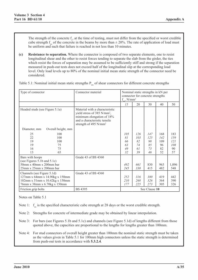
June 2010
volume 3 section 4 part 16 Bd 61/10
a/35
appendix a
The strength of the concrete fc, at the time of testing, must not differ from the specified or worst credible cube strength fcu of the concrete in the beams by more than ± 20%. The rate of application of load must be uniform and such that failure is reached in not less than 10 minutes.
(c) resistance to separation. Where the connector is composed of two separate elements, one to resist longitudinal shear and the other to resist forces tending to separate the slab from the girder, the ties which resist the forces of separation may be assumed to be sufficiently stiff and strong if the separation measured in push-out tests does not exceed half of the longitudinal slip at the corresponding load level. Only load levels up to 80% of the nominal initial mean static strength of the connector need be considered.
Table 5.1: Nominal initial mean static strengths Pim of shear connectors for different concrete strengths
Type of connector Connector material Nominal static strengths in kN per connector for concrete strengths fcu, N/mm2
15 20 30 40 50Headed studs (see Figure 5.1a) Material with a characteristic
yield stress of 385 N/mm2, minimum elongation of 18% and a characteristic tensile strength of 495 N/mm2
Diameter, mm Overall height, mm25 22 19 19 16 13
100 100 100 75 75 65
1058166634932
12610382746139
14712598857346
16814210996 82 52
18315912110890 57
Bars with hoops (see Figures 5.1b and 5.1c) 50mm x 40mm x 200mm bar 25mm x 25mm x 200mm bar
Grade 43 of BS 4360 492245
661330
830 415
963 482
1,096 548
Channels (see Figure 5.1d) 127mm x 64mm x 14.90kg x 150mm 102mm x 51mm x 10.42kg x 150mm 76mm x 38mm x 6.70kg x 150mm
Grade 43 of BS 4360 252210177
316268225
380326273
419 364 305
442 390 326
Friction grip bolts BS 4395 See Clause 10
Notes on Table 5.1
Note 1: fcu is the specified characteristic cube strength at 28 days or the worst credible strength.
Note 2: Strengths for concrete of intermediate grade may be obtained by linear interpolation.
Note 3: For bars (see Figures 5.1b and 5.1c) and channels (see Figure 5.1d) of lengths different from those quoted above, the capacities are proportional to the lengths for lengths greater than 100mm.
Note 4: For stud connectors of overall height greater than 100mm the nominal static strength must be taken as the values given in Table 5.1 for 100mm high connectors unless the static strength is determined from push-out tests in accordance with 5.3.2.4.
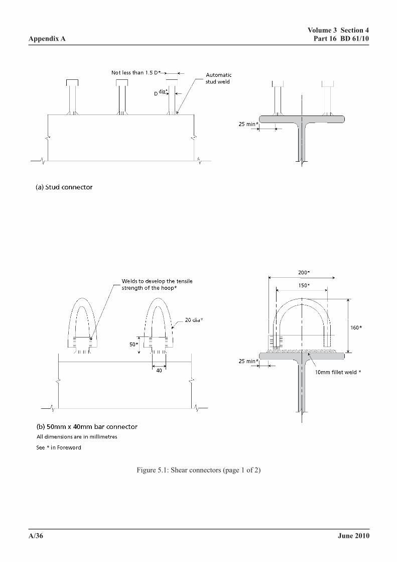
June 2010
volume 3 section 4 part 16 Bd 61/10
a/36
appendix a
Volume 3 Section 4 Appendix A Part 16 BD 61/09
April 2009 A/42
Figure 5.1: Shear connectors (page 1 of 2) Figure 5.1: Shear connectors (page 1 of 2)
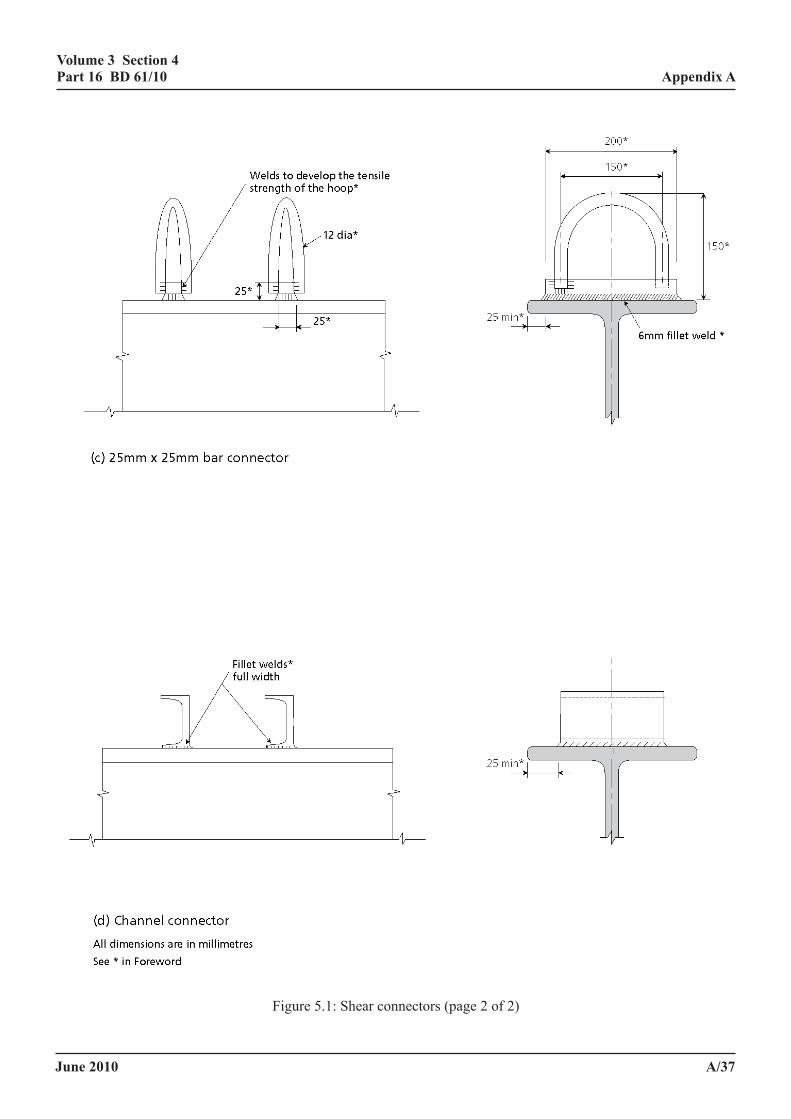
June 2010
volume 3 section 4 part 16 Bd 61/10
a/37
appendix aVolume 3 Section 4 Appendix A
Part 16 BD 61/09
April 2009 A/43
Figure 5.1: Shear connectors (page 2 of 2)
Figure 5.1: Shear connectors (page 2 of 2)
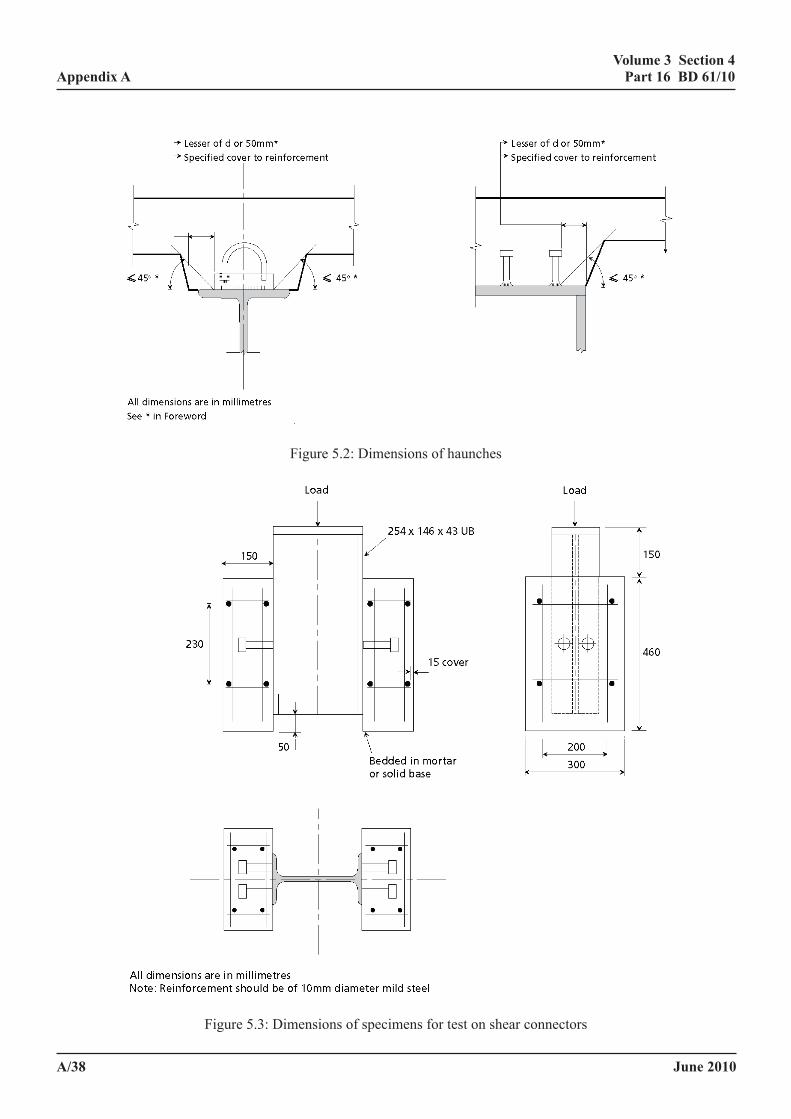
June 2010
volume 3 section 4 part 16 Bd 61/10
a/38
appendix a
Volume 3 Section 4 Appendix A Part 16 BD 61/09
April 2009 A/44
Figure 5.2: Dimensions of haunches
Figure 5.3: Dimensions of specimens for test on shear connectors
Figure 5.2: Dimensions of haunches
Volume 3 Section 4 Appendix A Part 16 BD 61/09
April 2009 A/44
Figure 5.2: Dimensions of haunches
Figure 5.3: Dimensions of specimens for test on shear connectors Figure 5.3: Dimensions of specimens for test on shear connectors
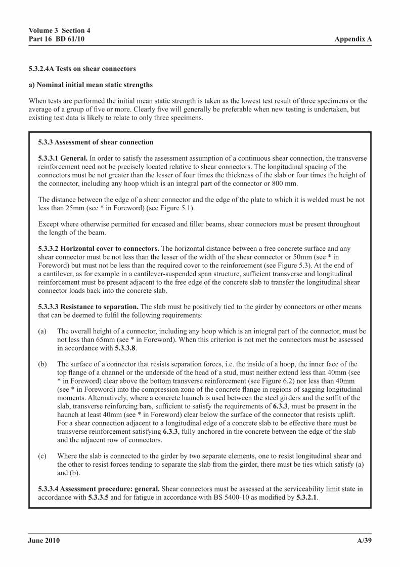
June 2010
volume 3 section 4 part 16 Bd 61/10
a/39
appendix a
5.3.2.4a tests on shear connectors
a) nominal initial mean static strengths
When tests are performed the initial mean static strength is taken as the lowest test result of three specimens or the average of a group of five or more. Clearly five will generally be preferable when new testing is undertaken, but existing test data is likely to relate to only three specimens.
5.3.3 assessment of shear connection
5.3.3.1 general. In order to satisfy the assessment assumption of a continuous shear connection, the transverse reinforcement need not be precisely located relative to shear connectors. The longitudinal spacing of the connectors must be not greater than the lesser of four times the thickness of the slab or four times the height of the connector, including any hoop which is an integral part of the connector or 800 mm.
The distance between the edge of a shear connector and the edge of the plate to which it is welded must be not less than 25mm (see * in Foreword) (see Figure 5.1).
Except where otherwise permitted for encased and filler beams, shear connectors must be present throughout the length of the beam.
5.3.3.2 horizontal cover to connectors. The horizontal distance between a free concrete surface and any shear connector must be not less than the lesser of the width of the shear connector or 50mm (see * in Foreword) but must not be less than the required cover to the reinforcement (see Figure 5.3). At the end of a cantilever, as for example in a cantilever-suspended span structure, sufficient transverse and longitudinal reinforcement must be present adjacent to the free edge of the concrete slab to transfer the longitudinal shear connector loads back into the concrete slab.
5.3.3.3 resistance to separation. The slab must be positively tied to the girder by connectors or other means that can be deemed to fulfil the following requirements:
(a) The overall height of a connector, including any hoop which is an integral part of the connector, must be not less than 65mm (see * in Foreword). When this criterion is not met the connectors must be assessed in accordance with 5.3.3.8.
(b) The surface of a connector that resists separation forces, i.e. the inside of a hoop, the inner face of the top flange of a channel or the underside of the head of a stud, must neither extend less than 40mm (see * in Foreword) clear above the bottom transverse reinforcement (see Figure 6.2) nor less than 40mm (see * in Foreword) into the compression zone of the concrete flange in regions of sagging longitudinal moments. Alternatively, where a concrete haunch is used between the steel girders and the soffit of the slab, transverse reinforcing bars, sufficient to satisfy the requirements of 6.3.3, must be present in the haunch at least 40mm (see * in Foreword) clear below the surface of the connector that resists uplift. For a shear connection adjacent to a longitudinal edge of a concrete slab to be effective there must be transverse reinforcement satisfying 6.3.3, fully anchored in the concrete between the edge of the slab and the adjacent row of connectors.
(c) Where the slab is connected to the girder by two separate elements, one to resist longitudinal shear and the other to resist forces tending to separate the slab from the girder, there must be ties which satisfy (a) and (b).
5.3.3.4 assessment procedure: general. Shear connectors must be assessed at the serviceability limit state in accordance with 5.3.3.5 and for fatigue in accordance with BS 5400-10 as modified by 5.3.2.1.
June 2010
volume 3 section 4 part 16 Bd 61/10
a/40
appendix a
Shear connectors must be checked for static strength at the ultimate limit state as required by 5.3.3.6 or 6.1.3, or when redistribution of stresses from the tension flange or web panels has been made in accordance with BD 56.
5.3.3.5 assessment resistance of shear connectors. The assessment longitudinal shear resistance of shear connectors Pa is
Pa = Pam/γslip γf3 (5.3)
where Pam is the nominal present mean static strength at assessment (5.3.2.1) and γslip for shear connectors is given in 4.2.1.
5.3.3.5a assessment resistance of shear connectors
The design longitudinal shear resistance of a connector Ps, disregarding γf3, is
Pam/γslip
where γslip is a reduction factor to ensure that slip is not excessive, which in 4.2.1 is assigned a value of 1.375.
The maximum value Pam permitted by equation 5.2 is 0.82Pim, so that the maximum value of Ps is 0.82Pim/1.375 or 0.60Pim, in which 0.60 is the Figure in 4.3.2(e). It only applies when the risk from fatigue is low, as when the fatigue risk is high the first criterion in equation 5.2 gives a lower value of Pam.
5.3.3.6 shear connector spacing and longitudinal shear resistance
(1) Connector spacings not greater than 1000mm or span/20
The size and spacing of the connectors at each end of each span under the maximum loading considered must be such that the maximum longitudinal shear force per unit length q does not exceed the assessment longitudinal shear resistance qr per unit length by more than the margins in Table 5.2, in which the fatigue vulnerability adopted must be agreed. The size and spacing of connectors required must extend:
10% of the length of the span for q/qr ≤ 1.1
20% of the length of the span for 1.1 < q/qr ≤ 1.25
33% of the length of the span for q/qr > 1.25
but not greater than 5m.
Elsewhere the size and longitudinal spacing of connectors present may be constant over any length over which the total assessment shear force does not exceed the product of the number of connectors and the assessment static strength per connector as defined in 5.3.2.5, provided the maximum shear force per unit length does not exceed the assessment shear resistance per unit length by more than the margin in Table 5.2.
Where the connector spacing satisfies the above requirements except over regions not exceeding span/8 where the shear connectors do not comply with 5.3.3.7 then the shear connectors over this region must comply with 5.3.3.8 and q/qr locally must not exceed unity.
June 2010
volume 3 section 4 part 16 Bd 61/10
a/41
appendix a
(2) Connector spacing exceeding 1000mm or span/20, but less than span/8.
The size and spacing of the connectors under the maximum loading considered must be such that the maximum longitudinal shear force per unit length q does not exceed the assessment shear resistance qr at any section taking account of the elastic distribution of longitudinal shear
(3) Connector spacings exceeding span/8
The connectors must be assessed for the force obtained from an analysis with the beam modelled such that the slab and beam are rigidly connected by discrete connections at the position of the connectors. The connectors must be checked for the combined effect of horizontal and vertical loading and the transverse reinforcement must be assessed to resist the bursting stresses in the concrete
Table 5.2: Maximum values of the ratio of shear flow to longitudinal shear resistance (q/qr)
Fatiguevulnerability
Connectorclass Atsimplesupports Atfixedsupports ElsewhereinBeams
High Classa 1.05 1.25 1.25
Classb 1.05 1.05 1.1
Classc 1.0 1.0 1.0
Low Classa 1.25 1.5 1.5
Classb 1.05 1.05 1.1
Classc 1.0 1.0 1.0
Note: Fatigue vulnerability is considered high in motorway and trunk road bridges.
Class a connectors are connectors in beams of span not exceeding 25m, with a steel beam to slab depth ratio not less than 2.2 and with a stiffness of the shear connection under static load nowhere exceeding 4,000MN/m per metre of beam at 60% of ultimate load and with the resistance using Table 5.1 not exceeding 2.0MN/m
Class b connectors are connectors satisfying 5.3.3.1 to 5.3.3.3, but which are excluded from the definition of class a connectors.
Class c connectors are the connectors considered in 5.3.3.8 which do not satisfy 5.3.3.1 to 5.3.3.3.
For continuous beams over internal supports the values for Class a connectors may be determined by interpolating between the simple support and the fixed support condition, pro-rata the ratio of the actual support moment from the loadings causing the longitudinal shear to the moment from that loading if the beam was fixed at that support.
5.3.3.6a shear connector spacing and longitudinal shear resistance
For the purposes of assessment the rules for calculating the connector forces have been developed to cover any spacing of shear connector groups as follows(22):
(1) not greater than 1000mm nor span/20
(2) exceeding 1000mm but less than span/8
(3) exceeding span/8
June 2010
volume 3 section 4 part 16 Bd 61/10
a/42
appendix a
The VAy/I method is used for (1) and may be used for (2), but a more accurate result is obtained for (2) using the approach required for (3).
(1) is the normal situation for which, in the Design Code, q/qr is 1.0 at the end of a span and 1.10 elsewhere, with the maximum values maintained over 10% of the span. For assessment these restrictions have been relaxed by taking advantage of the flexibility of shear connectors and the facts that at internal supports (see Figure 5.5):
(i) where the spans are similar the shear connectors under dead load are undeflected (due to symmetry) and so unloaded, and;
(ii) the horizontal forces in the shear connectors at the ends are redistributed as a result of the shear deflection of the steel beam.
The values of q/qr take into account variation in the ratios of adjacent span lengths up to 1.50, with a reasonable allowance for distributed live load effects, but not concentrated loads. If account has been taken of cracking the values in Table 5.2 would be appreciably greater.
Table 5.2 was determined from finite element analyses of bridges with spans between 10 and 25 metres, and Class a shear connectors were assumed to be studs with a stiffness of 200kN/mm (13)(23) whereas Class b and c connectors were assumed to be rigid. The stiffness of the shear connection increases as the number of shear connectors increases, which reduces the redistribution of longitudinal shear along the span in continuous beams. In simply supported beams the redistribution due to flexibility is small and may be adverse, but there will be some benefit from shrinkage, so there is a small net benefit. Class a shear connectors allow up to 20 number 19mm studs per metre, which have a stiffness per metre run of 4000kN/mm (or 4000MN/m). In fact the benefit from shear connector flexibility reduces only slowly with increase in stiffness and if the stiffness specified for class a connectors were doubled, q/qr values would be mid way between those for class a and b shear connectors in Table 5.2.
Shear connectors in beams in which the steel beam to slab depth ratio is less than 2.2 are excluded from class a due to the increased tendency of large tensile forces developing in the shear connectors with reduction in the depth of the steel beam from end effects in simply supported beams and from shear deflection in continuous beams.
For (2) q/qr must not exceed unity and the shear connector force needs to be estimated for the distribution of the shear flow mid way between adjacent groups of shear connectors such that the force in the ith shear connector is
∑≥ Xrisi dqP .
as shown in Figure 5.6.
For connector spacings exceeding span/8 the method in (2) may not provide an accurate estimate of the connector forces for concentrated loads (though it has been shown to give a good indication of the shear connector forces under uniform loading up to a spacing exceeding span/4). For this situation an analysis is required in which the steel beam and concrete slab are modelled as separate members connected rigidly at the position of the shear connectors. For beams of normal span there is little advantage with such connector spacings of including the effect of connector flexibility. Furthermore for most situations in which these conditions apply the connectors are likely to be rigid (see 5.3.3.8).
June 2010
volume 3 section 4 part 16 Bd 61/10
a/43
appendix a
5.3.3.7 uplift on shear connectors. Where the shear connectors are subject to significant direct tension due either to:
(a) forces tending to separate the slab from a girder caused, for example, by differential bending of the girders or of the two sides of a box girder or from tension field action in a web, or
(b) transverse moments on a group of connectors resulting from transverse bending of the slab particularly in the region of diaphragms or transverse cross bracing, or from the forces generated at the corners when the slab acts as part of a 'U' frame,
then additional ties, suitably anchored, must be present to resist these forces.
Where stud connectors are used and are subject to both shear Q and tension due to uplift Tu the equivalent shear Qmax to be used in checking the connectors for static strength and fatigue must be taken as:
/3)T+Q(=Q 2u
2max
(5.5)
In addition the stud connectors must be also checked at the ultimate limit state in accordance with 6.3.4 using the appropriate value of Qmax.
5.3.3.7a uplift on shear connectors
In deriving the uplift forces on the shear connectors in unstiffened girders from differential bending of adjacent girders it is acceptable to disregard the stiffness of the web, so that the slab/beam connection is assumed to be pinned in the transverse direction. With stiffened webs however, particularly in the deeper beams, the effect of the rigidity of the connection may be significant and therefore should be evaluated.
Shear connectors may also subject to significant direct tension due to slab tie-down forces, particularly severe in the corners of some skew slabs. Another common situation which causes uplift in shear connectors occurs where there are composite cross girders which do not extend outside the external main girders, i.e., the cantilever is a concrete slab. Parapet impact combined with accidental wheel loading can cause significant uplift in shear connectors on the crossbeam near its junction with the main beam.
5.3.3.8 incidental shear connection. Attachments to beams penetrating the concrete slab have the potential to provide longitudinal shear resistance between the beam and slab, so too have steps in the top surface of the metal beam (for example at flange plates) when they occur such as to oppose relative movement of the slab and steel girder. These generally lack the resistance to uplift and so do not satisfy the requirements of 5.3.3.1 to 5.3.3.7. Testing may be desirable in circumstances other than that in 5.3.3.8.3 and these must be agreed with the TAA. Where the attachments would suffer fatigue damage or cause fatigue damage to the metal beam if they acted as shear connectors, their possible action as shear connectors must be disregarded, but possible damage to the beam must be taken into account or inspections made to ensure that the attachments are in good condition and the flanges and connecting plates are uncracked.
5.3.3.8a incidental shear connection
The method for assessing the strength of incidental shear connectors is derived from the method for bar connectors in BS EN 1994. The method gives appreciably lower strengths than those in Table 5.1 for bar connectors and an additional safety factor γb introduced for incidental shear connectors which has the values:
1.25 for bolt heads, plate ends and other vertical surfaces 2.00 for rivet heads
June 2010
volume 3 section 4 part 16 Bd 61/10
a/44
appendix a
These values have been derived from an assessment of the relative efficiency of these devices compared to shear connectors satisfying the requirements of 5.3.3.7.
Attention is drawn to the increased stresses in many bolt groups resulting from their action as shear connectors, and frequently this action would appear to increase the shear in half the bolts and reduce it in the other half (compare Figures 5.9a and 5.9b). Possible actions then are:
(i) assess the spare capacity in the bolts and take this as the limiting capacity of the group of incidental shear connectors;
(ii) assess the bolts taking into account the extra force from the incidental shear connection;
(iii) disregard the incidental action on the grounds that bolt failure of this kind has never been attributed to incidental action;
(iv) take full advantage of the incidental shear connection and ignore its possible adverse effects for the reasons given under (iii).
The procedure adopted should be included in the AIP document.
Consideration has been given to specifying an upper limit to the increase in the resistance permissible with incidental shear connections. For tall devices, which may be effective as shear connectors but for their lack of capacity to resist uplift forces, and which were probably designed as shear connectors, no upper limit is imposed. Provisional limitations to the increase in the capacity of the steel beam permissible for bolts and other vertical bearing surfaces of 40%, and for rivet heads of 33%, are to be used until more accurate values can be justified.
For tall devices formed of plate which are clearly not rigid it is proposed that Pim given by equation 5.6 is multiplied by a factor k which is the ratio of the area of plate which under the design pressure (Pam/A1) deflects by no more than 0.2mm to the total area of the plate.
In checks assuming devices act as incidental shear connectors unpropped construction is appropriate, so these devices carry no longitudinal shear under the self weight of the structure. They may however be assumed to be effective in carrying longitudinal shear from the superimposed dead load.
(a) provision of devices to resist uplift
In riveted or bolted construction, composite action can be ensured by replacing some of the rivets or bolts by long bolts(25) or other suitable devices, as shown in Figure 5.8. This would provide a nominal uplift capacity at positions where the analysis showed this to be most effective. Each scheme needs to be assessed on its merits, taking into account that the passage of a concentrated load will tend to cause uplift in the shear connectors at all positions. The frequency of the position of restraint to uplift therefore must ensure:
(i) the capacity of the slab to carry the load to where the uplift is resisted;
(ii) that significant vertical separation between the slab and the beam cannot occur.
For this purpose a maximum separation of 0.5mm disregarding the loading on the slab is suggested.
Where the whole of the deck is replaced, the replacement of rivets or bolts can be done on a more systematic basis.
For heavily trafficked bridges there is advantage to be gained by providing devices to resist uplift which do not themselves carry longitudinal shear, since the longitudinal shear significantly reduces their capacity to resist uplift (see 5.3.3.7). Fewer devices would then be needed.
Where the girders are of cast or wrought iron, careful consideration should be given to the selection of connectors; there may be reasons for preferring mechanical fixings (as in Figure 5.8) to welded fixings in this situation.
June 2010
volume 3 section 4 part 16 Bd 61/10
a/45
appendix a
(b) Buckle plates and troughs
The undulation of the concrete surface in contact with the steelwork in construction using buckle plates and troughs constitutes a potential shear connection. The connectors between these features and the steel beam should be capable of carrying the longitudinal shear force calculated assuming full interaction.
5.3.3.8.1a isolated incidental shear connectors. The initial static strength of rigid shear connectors lacking resistance to uplift forces may be taken as the lower of the shear strength of the weld and:
γγ
η
bmc
cu1im
fA0.80=P (5.6)
where
η = (A2/A1)0.5, but
≤ 2.5 for normal density concrete, or ≤ 2.0 for lightweight concrete of density not less than 1400kg/m3
A1 = bsc hsc
A2 is the area of concrete over which the shear connector force is distributed on the rear plane of the next shear connector, assuming a lateral dispersion angle of 1:5 from the front plane of the connector (see Figure 5.4)
bsc is the dimension of the connector transverse to the span
hsc the mean height of the shear connector.
For an isolated internal connector (defined such that the lateral dispersion line, shown in Figure 5.4, does not intersect the edge of the slab), the value of A2/A1 is:
bw-
bs0.4+1
hw-
hs0.2+1=
AA
sc
sc
sc
L
sc
sc
sc
L
1
2 (5.7)
when
hw+1-
hh5
hS
sc
sc
sc
c
sc
L
≤ or,
bw-
bs0.4+1h
h=AA
sc
sc
sc
Lsc
c
1
2
(5.8)
when
hw+1-
hh5>
hS
sc
sc
sc
c
sc
L
where
wsc is the dimension of the individual connectors along the span
sL is the spacing of the shear connectors longitudinally
hc is the depth of the concrete slab.
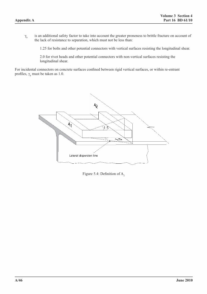
June 2010
volume 3 section 4 part 16 Bd 61/10
a/46
appendix a
γb is an additional safety factor to take into account the greater proneness to brittle fracture on account of the lack of resistance to separation, which must not be less than:
1.25 for bolts and other potential connectors with vertical surfaces resisting the longitudinal shear.
2.0 for rivet heads and other potential connectors with non-vertical surfaces resisting the longitudinal shear.
For incidental connectors on concrete surfaces confined between rigid vertical surfaces, or within re-entrant profiles, γb must be taken as 1.0.
Volume 3 Section 4 Appendix A Part 16 BD 61/09
April 2009 A/53
γb is an additional safety factor to take into account the greater proneness to brittle fracture on account of the lack of resistance to separation, which must not be less than:
1.25 for bolts and other potential connectors with vertical surfaces resisting the
longitudinal shear. 2.0 for rivet heads and other potential connectors with non-vertical surfaces resisting the
longitudinal shear. For incidental connectors on concrete surfaces confined between rigid vertical surfaces, or within re-entrant profiles, γb must be taken as 1.0.
Figure 5.4: Definition of A2 Figure 5.4: Definition of A2
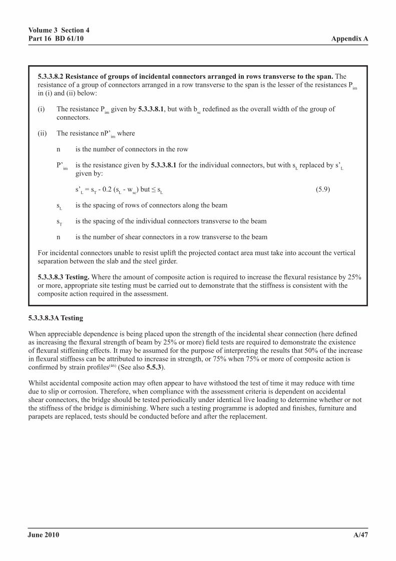
June 2010
volume 3 section 4 part 16 Bd 61/10
a/47
appendix a
5.3.3.8.2 resistance of groups of incidental connectors arranged in rows transverse to the span. The resistance of a group of connectors arranged in a row transverse to the span is the lesser of the resistances Pim in (i) and (ii) below:
(i) The resistance Pim given by 5.3.3.8.1, but with bsc redefined as the overall width of the group of connectors.
(ii) The resistance nP’im where
n is the number of connectors in the row
P’im is the resistance given by 5.3.3.8.1 for the individual connectors, but with sL replaced by s’L given by:
s’L = sT - 0.2 (sL - wsc) but ≤ sL (5.9)
sL is the spacing of rows of connectors along the beam
sT is the spacing of the individual connectors transverse to the beam
n is the number of shear connectors in a row transverse to the beam
For incidental connectors unable to resist uplift the projected contact area must take into account the vertical separation between the slab and the steel girder.
5.3.3.8.3 testing. Where the amount of composite action is required to increase the flexural resistance by 25% or more, appropriate site testing must be carried out to demonstrate that the stiffness is consistent with the composite action required in the assessment.
5.3.3.8.3a testing
When appreciable dependence is being placed upon the strength of the incidental shear connection (here defined as increasing the flexural strength of beam by 25% or more) field tests are required to demonstrate the existence of flexural stiffening effects. It may be assumed for the purpose of interpreting the results that 50% of the increase in flexural stiffness can be attributed to increase in strength, or 75% when 75% or more of composite action is confirmed by strain profiles(46) (See also 5.5.3).
Whilst accidental composite action may often appear to have withstood the test of time it may reduce with time due to slip or corrosion. Therefore, when compliance with the assessment criteria is dependent on accidental shear connectors, the bridge should be tested periodically under identical live loading to determine whether or not the stiffness of the bridge is diminishing. Where such a testing programme is adopted and finishes, furniture and parapets are replaced, tests should be conducted before and after the replacement.
June 2010
volume 3 section 4 part 16 Bd 61/10
a/48
appendix a
5.3.3.9 partial interaction. When the fatigue risk is low the required resistance for Class a shear connectors on the longitudinal shear plane may be reduced by the reduction in force in the slab due to the flexibility of the shear connectors. Elastic analysis assuming cross sections remain plane may be used by reducing the modulus of elasticity of the concrete and slab reinforcement, providing:
(1) Where the vulnerability to fatigue damage is low and very limited inelasticity in the shear connection at the serviceability limit state is acceptable the total force in the slab is not less than p times the force derived using the full value of the short term of modulus elasticity of the concrete, where
p = 0.60 + 0.025 l where 16m ≥ l ≥ 8m (5.10)
where l is the length in metres of the span with concrete in compression, which for beams of substantially uniform cross section may be taken as:
the full span for simply supported beams,
0.70 times the full span for fixed ended beam,
0.85 times the span for a simple support one end and with continuity the other.
but for spans up to 25m with continuity at one or both ends p need not be taken greater than 0.95.
(2) The beam with the reduced elastic modulus satisfies all the requirements of this Standard except for the control of cracking, for which p must be taken as unity.
(3) The shear connectors are of class a as defined in 5.3.3.6.
5.3.3.9a partial interaction
For short span beams with Class a connectors two effects combine which improve the overall efficiency of composite beams.
(i) the deflection of flexible shear connectors not only redistributes but also significantly reduces the longitudinal force, but the reduction in the moment of resistance of the composite section in bridges of normal span designed for full interaction (as in the Design Code) is too small to justify consideration;
(ii) continuous beams with elastic shear connectors possess the ability to redistribute the longitudinal shear force along the shear connection in such a way as to reduce the maximum shear flow in bridges of normal spans designed for full interaction (as in the Standard)(13)(26). The amount of redistribution is significant even when the shear connectors remain elastic, but in continuous short span beams without point loads a substantially uniform distribution of shear flow occurs, and a virtually uniform distribution is obtained with minimal inelasticity in the shear connection.
The procedure adopted is to assess the moments and forces using the short term modulus of elasticity and then to reduce the modulus of elasticity such that the force in the slab is not less than “p” times the value obtained using the short term modulus. The entire cross section is then checked for this slab stiffness.
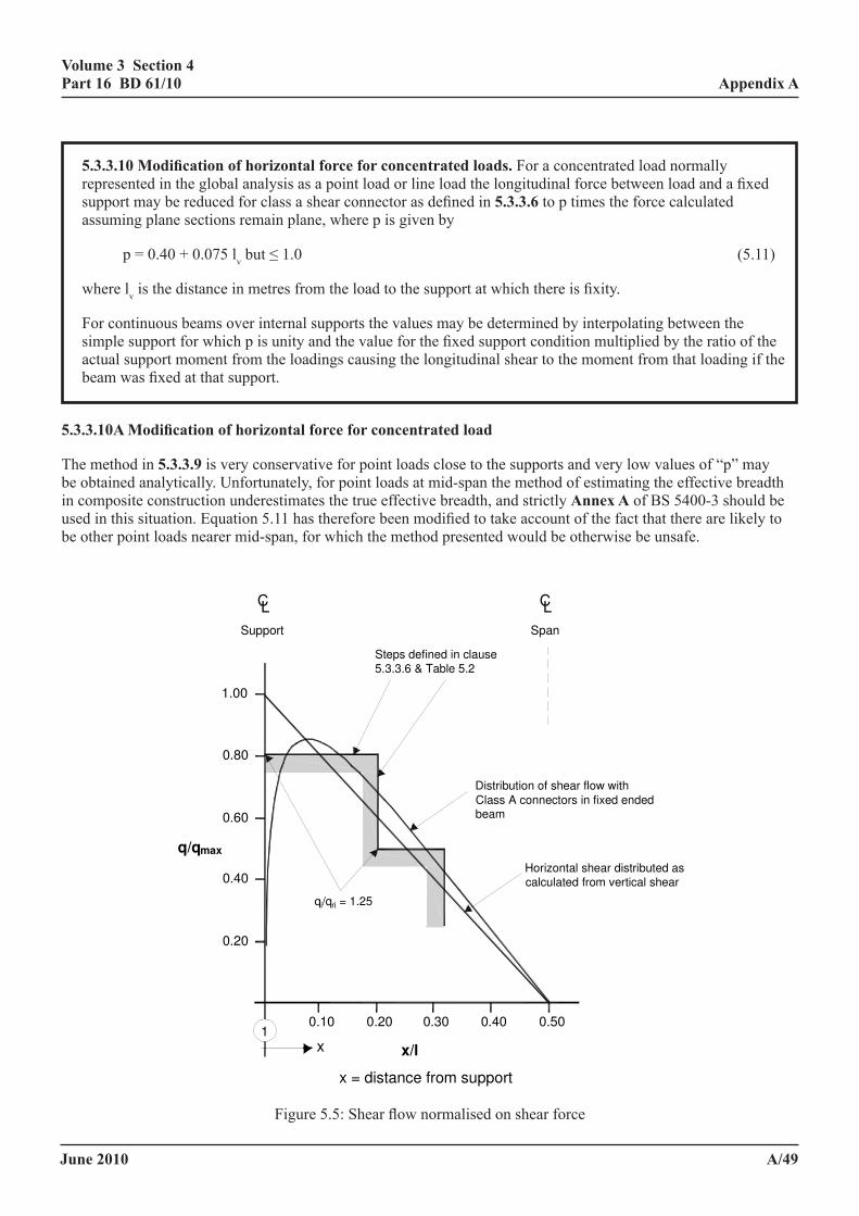
June 2010
volume 3 section 4 part 16 Bd 61/10
a/49
appendix a
5.3.3.10 modification of horizontal force for concentrated loads. For a concentrated load normally represented in the global analysis as a point load or line load the longitudinal force between load and a fixed support may be reduced for class a shear connector as defined in 5.3.3.6 to p times the force calculated assuming plane sections remain plane, where p is given by
p = 0.40 + 0.075 lv but ≤ 1.0 (5.11)
where lv is the distance in metres from the load to the support at which there is fixity.
For continuous beams over internal supports the values may be determined by interpolating between the simple support for which p is unity and the value for the fixed support condition multiplied by the ratio of the actual support moment from the loadings causing the longitudinal shear to the moment from that loading if the beam was fixed at that support.
5.3.3.10a modification of horizontal force for concentrated load
The method in 5.3.3.9 is very conservative for point loads close to the supports and very low values of “p” may be obtained analytically. Unfortunately, for point loads at mid-span the method of estimating the effective breadth in composite construction underestimates the true effective breadth, and strictly annex a of BS 5400-3 should be used in this situation. Equation 5.11 has therefore been modified to take account of the fact that there are likely to be other point loads nearer mid-span, for which the method presented would be otherwise be unsafe.
x = distance from support
x/l
0.10 0.20 0.30 0.40 0.501
0.20
0.40
0.60
0.80
1.00
x
CL
Support Span
Steps defined in clause
5.3.3.6 & Table 5.2
Distribution of shear flow with
Class A connectors in fixed endedbeam
Horizontal shear distributed as
calculated from vertical shear
q/qmax
qi/qri = 1.25
CL
Figure 5.7: Shear flow normalised on shear force
Figure 5.5: Shear flow normalised on shear force
June 2010
volume 3 section 4 part 16 Bd 61/10
a/50
appendix a
Figure 5.9: Interaction of bolt forces from flexure and incidental shear connector action
dx
L
= = =
CL Support
Concrete slab
CL Support
Concrete slabUnloaded
end of plate
Loaded
end of plate
=
Figure 5.8: Calculation of shear connector force when S span/8
(a) Bolt distortion due to flexure
(b) Bolt distortion due to incidental shear connector action
Figure 5.6: Calculation of shear connector force when S ≥ span/8
Figure 5.9: Interaction of bolt forces from flexure and incidental shear connector action
dx
L
= = =
CL Support
Concrete slab
CL Support
Concrete slabUnloaded
end of plate
Loaded
end of plate
=
Figure 5.8: Calculation of shear connector force when S span/8
(a) Bolt distortion due to flexure
(b) Bolt distortion due to incidental shear connector action
(a) Bolt distortion due to flexure (b) Bolt distortion due to incidental shear connector action
Figure 5.7: Interaction of bolt forces from flexure and incidental shear connector action
June 2010
volume 3 section 4 part 16 Bd 61/10
a/51
appendix a
Long bolts or othersuitable devices toreplace rivets if required
Rivets Buckle plate
Top flange
Figure 5.10: Typical device to resist uplift
mmmmmm
Shrinkage moments
l
(a) Assumptions in design
mmmmmm
Shrinkage moments
l
0.15 l
(b) Assumptions in assessment
Figure 5.11: Application of shrinkage moments
Figure 5.8: Typical device to resist uplift
Long bolts or othersuitable devices toreplace rivets if required
Rivets Buckle plate
Top flange
Figure 5.10: Typical device to resist uplift
mmmmmm
Shrinkage moments
l
(a) Assumptions in design
mmmmmm
Shrinkage moments
l
0.15 l
(b) Assumptions in assessment
Figure 5.11: Application of shrinkage moments
Figure 5.9: Application of shrinkage moments

June 2010
volume 3 section 4 part 16 Bd 61/10
a/52
appendix a
5.4 temperature effects, shrinkage modified by creep and differential settlement.
5.4.1 general. Longitudinal stresses due to the effects of temperature and shrinkage modified by creep must be considered at the serviceability limit state for the beam section. Serviceability checks are however essential for shear connectors. In such checks account must be taken of the longitudinal shear forces arising from these effects. Where appropriate, variations in the stiffness of the composite beam along its length due to variations in the cross section of the steel member or where the concrete flange was cast in stages, must be taken into account when calculating the longitudinal shear force per unit length. When the casting sequence is unknown worst credible sequences must be assumed (see 5.2.5.4).
For assessment, differential settlement and shrinkage need only be included in the load combinations which include temperature.
5.4.1a general
Whilst there is no justification for completely eliminating temperature effects and shrinkage modified by creep in assessment, their effect can be modified such that they are less onerous than in the design situation. The justification for this is in part that the design situation specified is very conservative, having to take account of the worst likely situation (which is usually more severe than the actual situation) and in part the very few occurrences of damage to structures attributed to thermal and shrinkage effects.
Measures taken to relax the severity of the measure in this clause are as follows:
(i) include differential settlement and shrinkage only in the load combination which includes temperature, so these effects are excluded for the combination with the highest load factors on dead and live load, which tends to be critical;
(ii) assume that concrete cracked in tension is unable to carry thermal and shrinkage strains, and that the moments from these effects are applied to the beam at 0.15l(10) from the supports, as shown in Figure 5.9 (see 5.4.2.1). In fixed ended beams this reduces the support moment due to shrinkage by 30%; and
(iii) in the calculation of ls in equation 5.12, reduce the concentrated loading from temperature and shrinkage at simply supported ends of span by 20% for class a connectors and 10% for class b connectors (see 5.4.2.2).
5.4.2 temperature effects
5.4.2.1 effects to be considered. Longitudinal stresses and longitudinal shear forces due to temperature effects must be taken into account where appropriate. The effects to be considered are:
(a) primary effects due to a temperature difference through the depth of the cross section of the composite member.
(b) primary effects due to a uniform change of temperature in a composite member where the coefficients of thermal expansion of the structural steel or iron and concrete aggregate are significantly different, and
(c) secondary effects, in continuous members, due to redistribution of the moments and support reaction caused by temperature effects of the types described in (a) or (b).
June 2010
volume 3 section 4 part 16 Bd 61/10
a/53
appendix a
In the absence of a partial interaction analysis (see 3.1.13.2), longitudinal stresses and shear forces due to temperature effects must be calculated by elastic theory assuming that full interaction exists between the concrete slab and the steel beam. The stiffness must be based on the transformed composite cross section using a modular ratio of αe appropriate to short term loading. The effective breadth of concrete flange must be taken as the actual breadth. Alternatively where b/l does not exceed 0.20 it may be taken as the quarter-span value for uniformly distributed loading in BD 56, except for beams simply supported one end and fixed or continuous the other, when the mean of the effective breadth values for the simply supported and fixed ended cases may be used. Concrete must either be assumed to be uncracked, except that for calculating longitudinal bending stresses due to the secondary effects in (c) above the concrete in tension may be ignored, or be assumed to be cracked as in 5.1.1.1(a) and the thermal strains in the zone of cracked concrete disregarded in the global analysis.
5.4.2.2 coefficient of linear expansion
(a) structural steel and reinforcement. The coefficient of linear expansion βL may be taken as 12 x 10-6/0C.
(b) concrete. The coefficient of linear expansion βL, of normal density concrete (2300 kg/m3 or greater), must be taken as 12 x 10-6/0C, except when limestone aggregates are used, when a value of 9 x 10⁻⁶/0C must be adopted. For lightweight aggregate concrete (density 1400 kg/m3 to 2300 kg/m3) the coefficient of linear expansion must normally be taken as 8 x 10⁻⁶/0C.
5.4.2.3 longitudinal shear. The longitudinal shear force Q, due to either a temperature difference through the depth of the cross section or differential thermal expansion between the concrete and steel beam, must be assumed to be transmitted from the concrete slab to the steel beam by connectors at each end of the beam ignoring the effects of bond. The forces on the connectors must be calculated on the basis that the rate of transfer of load varies linearly from 2Q/ls at each end of the beam to zero at a distance ls from each end of the beam, where
fKQ/2=ls ∆ (5.12)
where
Q is the longitudinal shear force due to the primary effects of temperature. To take account of the proportion of Q transmitted elsewhere in the span (which is well distributed and so is disregarded) the value of Q, for the purpose of this sub-clause, may be reduced by a factor of 0.8 for connectors Class a in 5.3.3.6(3) or 0.9 for connectors Class b.
∆f is the difference between the free strains at the centroid of the concrete slab and the centroid of the steel beam, and
(N/mm)modulusConnector
(mm)connectorstheofspacing=K
The value of K in mm2/N will vary with the connector and concrete type and may be taken from Table 5.3.
Alternatively, where stud shear connectors are used the rate of transfer of load may be assumed to be constant for a distance lss from each end of the beam, where lss is equal to one-fifth of the effective span.
June 2010
volume 3 section 4 part 16 Bd 61/10
a/54
appendix a
5.4.2.3a longitudinal shear
There is a problem inherited from CP117 Part 2 in relation to the K values which appear unconservative, but modifications based upon more accurate theory are overconservative. This is that the present requirements allow for only 1.67 shear connectors per metre, whereas in practice at the ends of beams there are likely to be 10 to 25 connectors/metre(13). For shrinkage such a reduction could be attributed to early age effects, but if this was the case then the shrinkage force would be many times too high. Such a justification for the use of the specified K values for shrinkage is not applicable to their use for temperature, for which they can only be justified on the grounds that:
(i) Differential temperature movements in the sense which increases forces in connectors at the free end are generally much less than the shrinkage movements (which occur in the opposite direction).
(ii) Differential temperature movements which occur in the sense which increase moments at the penultimate support are unloading the end shear connectors, so due to inelastic effects, the stiffness is lower.
5.4.2.4 longitudinal stresses. Longitudinal stress due to temperature effects must be calculated using the assumptions given in 5.4.2.1.
5.4.3 shrinkage modified by creep. When the effects of shrinkage modified by creep adversely affect the maximum resultant forces on the shear connectors or the maximum resultant stresses in the concrete slab and the steel beam, they must be calculated in the manner described for temperature effects in 5.4.2.1, 5.4.2.3 and 5.4.2.4, but using values of εcs the free shrinkage strain and a modular ratio αe, appropriate to long term loading, which must be taken as the approximate value of 2Es/Ec or the more accurate value of Es/φcEc.
where
Ec is the static secant modulus of elasticity of concrete.
Es is the elasticity of structural steel.
NOTE: Values of εcs and φc are given in Table 5.4.
The values in Table 5.4 must only be used where the concrete specification complies with the limits given in Figure 5.10. For situations outside the scope of Figure 5.10 and Table 5.4, or where a better estimation of the effect of shrinkage modified by creep is required, the value of free shrinkage strain εcs and the creep coefficient φ must be determined in accordance with appendix c of BS 5400-4.
The value of φc must then be taken as
φ
φ+11=c (5.13)
Table 5.3: K Values for estimating transfer lengths
Stud Connectors Other Connectors
Normal density concrete 0.003 0.0015
Lightweight aggregate concrete 0.006 0.003
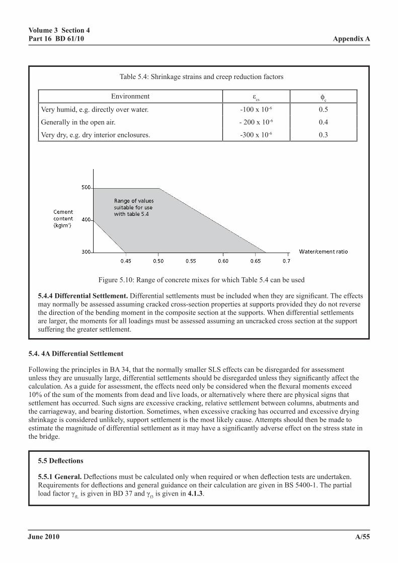
June 2010
volume 3 section 4 part 16 Bd 61/10
a/55
appendix a
Table 5.4: Shrinkage strains and creep reduction factors
Environment εcs φc
Very humid, e.g. directly over water. -100 x 10-6 0.5
Generally in the open air. - 200 x 10-6 0.4
Very dry, e.g. dry interior enclosures. -300 x 10-6 0.3
Volume 3 Section 4 Appendix A Part 16 BD 61/09
April 2009 A/62
Figure 5.5: Range of concrete mixes for which Table 5.4 can be used
5.4.4 Differential Settlement. Differential settlements must be included when they are significant. The effects may normally be assessed assuming cracked cross-section properties at supports provided they do not reverse the direction of the bending moment in the composite section at the supports. When differential settlements are larger, the moments for all loadings must be assessed assuming an uncracked cross section at the support suffering the greater settlement. 5.4. 4A Differential Settlement Following the principles in BA 34, that the normally smaller SLS effects can be disregarded for assessment unless they are unusually large, differential settlements should be disregarded unless they significantly affect the calculation. As a guide for assessment, the effects need only be considered when the flexural moments exceed 10% of the sum of the moments from dead and live loads, or alternatively where there are physical signs that settlement has occurred. Such signs are excessive cracking, relative settlement between columns, abutments and the carriageway, and bearing distortion. Sometimes, when excessive cracking has occurred and excessive drying shrinkage is considered unlikely, support settlement is the most likely cause. Attempts should then be made to estimate the magnitude of differential settlement as it may have a significantly adverse effect on the stress state in the bridge.
Table 5.4: Shrinkage strains and creep reduction factors
Environment εcs φc
Very humid, e.g. directly over water. Generally in the open air. Very dry, e.g. dry interior enclosures.
-100 x 10−6
- 200 x 10−6
-300 x 10−6
0.5
0.4
0.3
Figure 5.10: Range of concrete mixes for which Table 5.4 can be used
5.4.4 differential settlement. Differential settlements must be included when they are significant. The effects may normally be assessed assuming cracked cross-section properties at supports provided they do not reverse the direction of the bending moment in the composite section at the supports. When differential settlements are larger, the moments for all loadings must be assessed assuming an uncracked cross section at the support suffering the greater settlement.
5.4. 4a differential settlement
Following the principles in BA 34, that the normally smaller SLS effects can be disregarded for assessment unless they are unusually large, differential settlements should be disregarded unless they significantly affect the calculation. As a guide for assessment, the effects need only be considered when the flexural moments exceed 10% of the sum of the moments from dead and live loads, or alternatively where there are physical signs that settlement has occurred. Such signs are excessive cracking, relative settlement between columns, abutments and the carriageway, and bearing distortion. Sometimes, when excessive cracking has occurred and excessive drying shrinkage is considered unlikely, support settlement is the most likely cause. Attempts should then be made to estimate the magnitude of differential settlement as it may have a significantly adverse effect on the stress state in the bridge.
5.5 deflections
5.5.1 general. Deflections must be calculated only when required or when deflection tests are undertaken. Requirements for deflections and general guidance on their calculation are given in BS 5400-1. The partial load factor γfL is given in BD 37 and γf3 is given in 4.1.3.
June 2010
volume 3 section 4 part 16 Bd 61/10
a/56
appendix a
5.5.1a general
See comments in 4.3.1.
5.5.2 elastic deflections. In calculating elastic deflections, consideration must be given to the sequence of construction and, where appropriate, proper account must be taken of the deflections of the steel section due to loads applied to it prior to the development of composite action and of partial composite action where deck slabs are cast in stages. Where the construction sequence is unknown the worst credible sequence must be assumed (see 5.2.5.4).
Deflections must be calculated by elastic theory using the elastic properties given in 4.2 and assuming full interaction between the concrete and steel beam. Allowance for in-plane shear flexibility (shear lag effects) in the flange must be made in calculations based on the elementary theory of bending by using an effective breadth of flange in accordance with BS 5400-3. The quarter-span values must be used throughout.
In the absence of a more rigorous analysis of the effects of creep, the deflections due to sustained loading must be calculated by using a modulus of elasticity of concrete appropriate to sustained loading determined in accordance with 4.2.3. Alternatively, under sustained loading, the modulus of elasticity must be taken as 1/(1 + φ) times the short term modulus given in 4.2.3, where φ is the creep coefficient determined in accordance with appendix c of BS 5400-4 or as φc times the short term modulus, where φc is given in Table 5.4 for concrete mixes complying with Figure 5.10.
5.5.2a elastic deflections
The importance of shear deflection of the webs of steel beams is disregarded in conventional steelwork calculations, but its effect has been shown to be very significant in continuous beams. For typical continuous composite beams with a span to steel beam depth ratios of 20 and 27 the shear deflection in cracked analyses increases the deflection by 22% and 13%, and it is very much higher both for lower span/depth ratios and if the uncracked, or partially cracked, state of the concrete is taken into account. In simply supported beams the effect is still significant, increasing the deflection typically by 25% at an l/d ratio of 10, 9% at an l/d ratio of 20 and 6% at an l/d ratio of 6. The shear deflection is generally more significant in composite beams than steel beams because the shear stress in the webs is higher.
However, deflections of all bridges tend to be significantly less than theory predicts, which is due, inter alia, to unintended composite action, unintended lateral distribution (e.g., from erection bracing which has not been removed) and from bearing restraint (the effect of which is often large). Unless advantage is taken of such unintended composite action, the shear deflection may be disregarded.
Unintended composite action includes not only the effect of incidental shear connectors but also the stiffening effects of the carriageway and the parapets. This is why in 5.3.3.8.3 of the commentary only a proportion of the increased stiffness found in tests may be attributed to incidental shear connectors. However the stiffening from the carriageway and parapet are significantly enhanced by the incidental shear connection, so these effects may be indicative of its occurrence.
What is unknown, when incidental shear connection is justified by testing, is how close the condition to the failure of the shear connection is. For this reason special care should be taken to ensure structures with incidental shear connectors are not overloaded, either during the test or as a result of change of traffic usage.
June 2010
volume 3 section 4 part 16 Bd 61/10
a/57
appendix a
6 assessment of superstructure for the ultimate limit state
6.1 analysis of structure
6.1.1a general. Except where alternative methods are given in 6.1.2 elastic analysis must be used to determine the distribution of bending moments, shear forces and axial loads due to the design ultimate traffic loadings specified in BD 21, but with the load combinations in BD 37. The use of alternative methods must be in accordance with 8.2 of BS 5400-1 and must only be undertaken where they can be shown to model adequately the combined effects of local and global loads due to combinations 1 - 5 as given in BD 37. Wrought iron and cast iron structures must be assessed elastically as for steel using the material properties and strengths in BD 21. Shrinkage, temperature and differential settlement effects must be disregarded at the ULS except for the most slender cross sections.
6.1.2 deck slabs forming the flanges of composite beams. The deck slab must be assessed to resist separately the effects of loading given in 5.2.4.1, but assessment loads relevant to the ultimate limit state must be used. In general, the effects of local wheel loading on the slab must be determined by elastic analysis. Alternatively, an inelastic method of analysis, e.g. yield line theory, is permissible where an appropriate solution exists subject to the requirements in 6.1.1.
The resistance to global effects must be determined in accordance with 6.2. For local effects the assessment of the slab cross section must be in accordance with BD 44. The combined effects of global bending and local wheel loading must be taken into account in accordance with BD 44.
Proper account must be taken of the interaction between longitudinal shear forces and transverse bending of the slab in the region of the shear connection. The methods given in 6.3 may be deemed to satisfy these requirements.
6.1.3 composite action. Where, for a beam built in stages, the entire load is assumed to act on the final cross section in accordance with 9.9.5 of BD 56, or where tensile stresses are redistributed from the web or the tension flange in accordance with 9.5.4 or 9.5.5 respectively of BD 56, the shear connectors and transverse reinforcement must be assessed for the corresponding longitudinal shear in accordance with 6.3.
Composite action from shear connectors not complying with 5.3.3.3 must be disregarded at the ultimate limit state, except:
(i) where the connectors can be shown to be strong enough to resist the bending including any additional bending caused by the calculated separation gap when lift-off occurs or
(ii) in checking for lateral-torsional buckling in accordance with annex c.
Where (i) apply the contact area between the connector and the concrete must be adjusted for any separation. When the construction cannot be justified by this procedure consideration must be given to providing nominal ties to ensure the integrity of the construction generally and particularly in sagging moment regions in the vicinity of hinges or the greatest sagging moment curvatures.
June 2010
volume 3 section 4 part 16 Bd 61/10
a/58
appendix a
6.1.3a composite action
Composite action from incidental connectors at ULS is only permitted where separation is taken into account and when the connectors can resist the bending due to separation. Separation at ULS is most likely to occur under heavy axle loads, and adjacent to any cross sections at which inelastic rotation has occurred. It is however sufficient for the purposes of the calculation to assume elastic conditions throughout and model the structure as discussed in 5.3.3.6, but using an iterative procedure in which connections are removed when the deflection exceeds 0.50mm, which with adjustment to the resistance could be relaxed to a significant proportion of the depth of the connectors, or when the moment exceeds their flexural capacity.
Lift off is unlikely to occur over appreciable lengths of beam, even under the effect of concentrated loads. This is because away from the immediate vicinity of these loads the self weight of the slab will ensure the slab is in contact with the beam. For this reason shallow incidental shear connectors may be assumed to provide lateral restraint to the top flange at ULS, even though composite action may be inappropriate for the design of the cross section.
6.1.4 distribution of bending moments and vertical shear forces
6.1.4.1 elastic analysis. The assessment envelopes of bending moments and vertical shear forces which are produced by the whole of any particular combination of loads applied to the composite member may be found by elastic analysis, in accordance with 5.1.1.2.
6.1.4.2 redistribution of support moments in principal longitudinal members. For beams which have a substantially uniform cross section throughout each span, and for which the elastic section modulus at the level of the reinforcement is not less than that at the level of the underside of the structural steel part, a portion of the support moments may be redistributed to the span provided that equilibrium between the internal forces and external loads is maintained under each appropriate combination of ultimate loads. In the global analysis the concrete adjacent to the support may be assumed to be cracked as in 5.1.1.2(a) or uncracked throughout the span. The corresponding proportions of the support moments which may be redistributed depend upon the cross section redistribution classes (defined in Table 6.2 and 6.3) and are given in Table 6.1.
In Table 6.1, the cross section class in the hogging moment region is the higher class number for the flange and web given in Tables 6.2 and 6.3 when the cross-sections are assessed elastically or in Tables 6.2 and 6.4 when they are assessed plastically. Cross sections excluded from redistribution class 3 are in class 4.
When cross sections in Class 1 are assessed elastically the redistribution must not exceed that permitted for Class 2 cross sections.
In Tables 6.2, 6.3 and 6.4
σε y355/=
bfo is the width of the flange outstand as defined in Figure 1 of BD 56.
tfo is the thickness of the flange outstand, as defined in Figure 1 of BD 56.
dw is the depth of the web as defined in Figure 1 of BD 56.
tw is the thickness of the web.
ψ is the extreme stress in the less highly compressed part of the web (usually in tension) as a proportion of the extreme stress in the more highly compressed part calculated elastically. Tensile stresses are negative and compressive stresses positive.
α is the proportion of the web depth in compression.
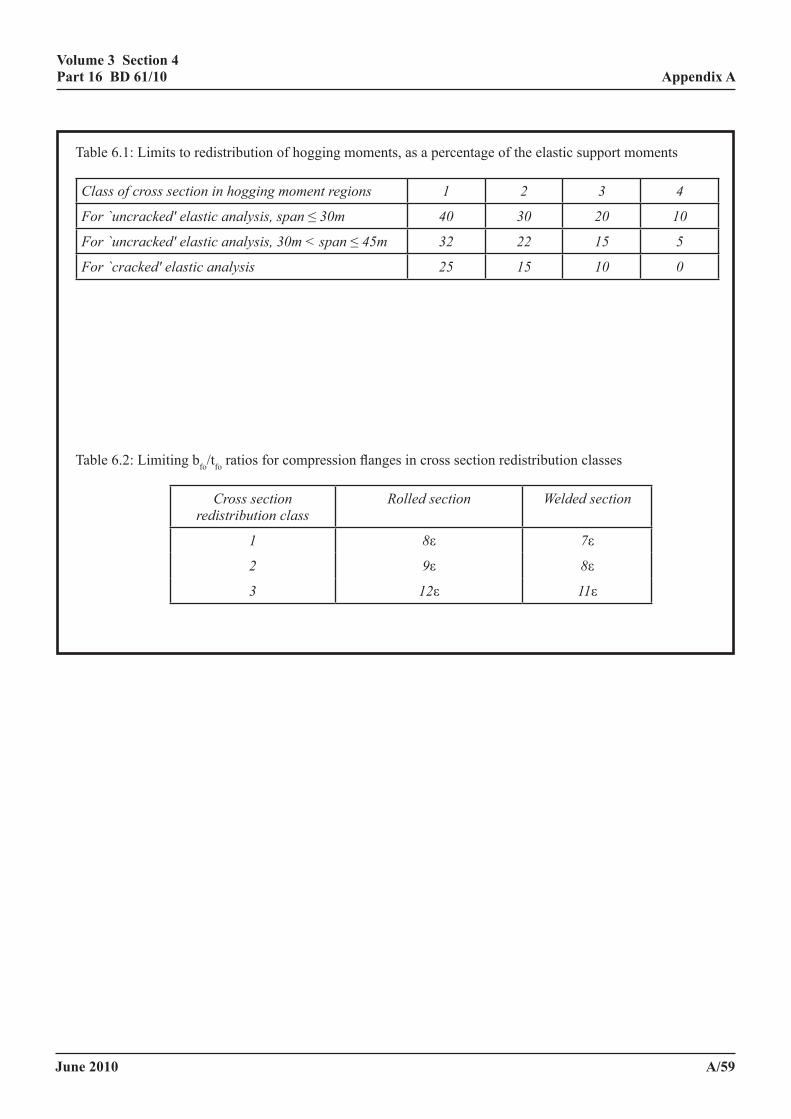
June 2010
volume 3 section 4 part 16 Bd 61/10
a/59
appendix a
Table 6.1: Limits to redistribution of hogging moments, as a percentage of the elastic support moments
Classofcrosssectioninhoggingmomentregions 1 2 3 4
For`uncracked'elasticanalysis,span≤30m 40 30 20 10
For`uncracked'elasticanalysis,30m<span≤45m 32 22 15 5
For`cracked'elasticanalysis 25 15 10 0
Table 6.2: Limiting bfo/tfo ratios for compression flanges in cross section redistribution classes
Crosssectionredistributionclass
Rolledsection Weldedsection
1 8ε 7ε
2 9ε 8ε
3 12ε 11ε
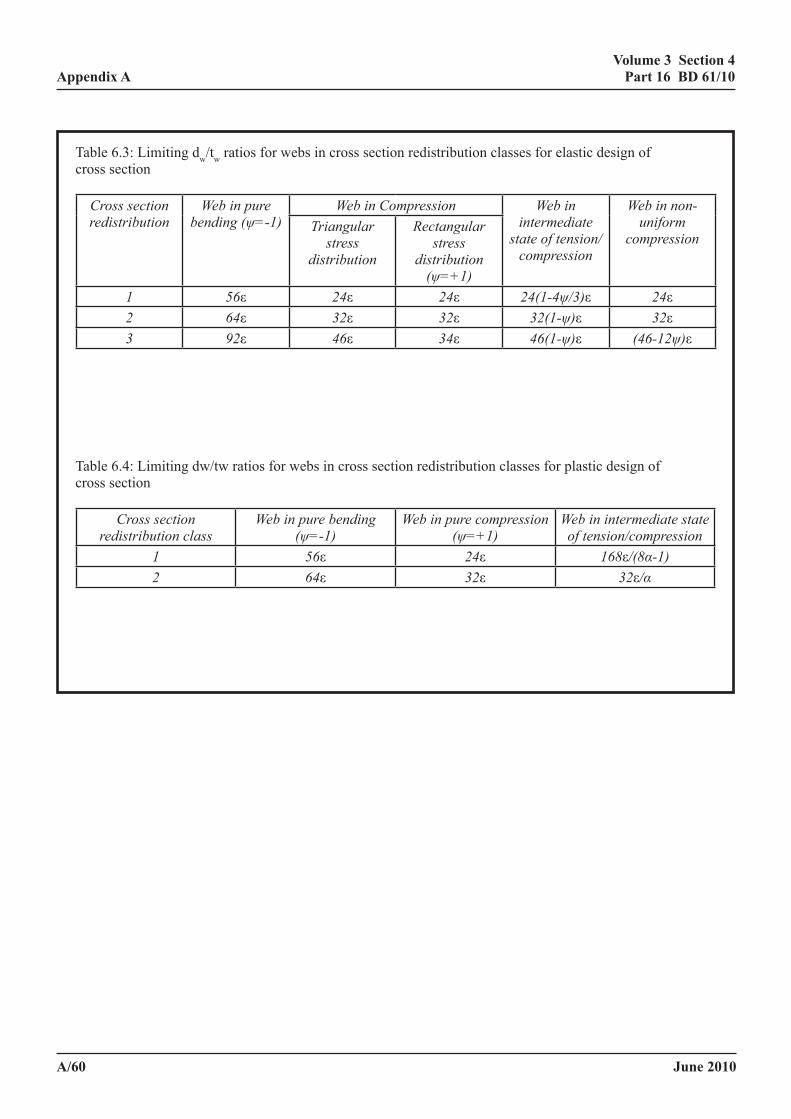
June 2010
volume 3 section 4 part 16 Bd 61/10
a/60
appendix a
Table 6.3: Limiting dw/tw ratios for webs in cross section redistribution classes for elastic design of cross section
Crosssectionredistribution
Webinpurebending(ψ=-1)
WebinCompression Webinintermediatestateoftension/compression
Webinnon-uniform
compressionTriangularstress
distribution
Rectangularstress
distribution(ψ=+1)
1 56ε 24ε 24ε 24(1-4ψ/3)ε 24ε2 64ε 32ε 32ε 32(1-ψ)ε 32ε3 92ε 46ε 34ε 46(1-ψ)ε (46-12ψ)ε
Table 6.4: Limiting dw/tw ratios for webs in cross section redistribution classes for plastic design of cross section
Crosssectionredistributionclass
Webinpurebending(ψ=-1)
Webinpurecompression(ψ=+1)
Webinintermediatestateoftension/compression
1 56ε 24ε 168ε/(8α-1)2 64ε 32ε 32ε/α
June 2010
volume 3 section 4 part 16 Bd 61/10
a/61
appendix a
6.1.4.2a redistribution of support moments in principal longitudinal members
In BS EN 1993 and BS EN 1994 there are four classes of cross section which compare with two in BS 5400-3, described as compact and non-compact. The finer cross section classification permits a more economical calculation procedure to be defined for many cross sections, and BD 56 has followed BS EN 1993 in dividing compact cross sections into those suitable and those unsuitable for plastic analysis.
Plastic global analysis is not used in the Standard for two reasons, as follows:
(1) The rules necessary for plastic analysis of composite beams have onerous restrictions, which severely restrict their usefulness in the assessment of UK bridges. One is effectively a requirement that most of the loading is uniformly distributed and there are others restricting the ratios of adjacent span lengths. Of these the former is the most restrictive in application to UK bridges. Furthermore the rules were derived for beams of uniform cross section, although this is not a limitation on the method.
(2) The method in assuming unlimited redistribution of support moments results in the ULS becoming less critical than the SLS, to the extent that the assessment relies upon the SLS check for satisfactory performance of the bridge, rather than in ensuring against severe infringements of the SLS condition - the most appropriate approach for assessment.
In BS EN 1994 the cross section classes determine a number of aspects of the calculation, but they have been adopted in the Standard purely to define the amount of redistribution permitted, and, to avoid confusion with the compact and non-compact definitions in BD 56, they are described as “cross section redistribution classes”. The values in the Table for cracked analysis are intended (in BS EN 1994) to give comparable results to those for uncracked analysis; it is likely however that in the larger bridges, when the strength of the steel section by itself is high in comparison to that of the composite cross section, that the uncracked analysis, after moment redistribution, will result in lower support moments. Therefore as an interim measure until more precise guidance can be offered the amount of redistribution made when spans exceed 30m has been reduced, and when spans exceed 45m cracked analysis is required.
The cross sections are defined by the more critical of the web and compression flange cross section slenderness. For assessment, having redistributed the moments, one has the option for the more compact cross sections of designing them elastically or plastically (see 6.2.2), and for this reason the cross section classes are defined both in terms of the elastic and plastic stress distribution. The limits for the elastic redistribution have been derived such that they approximately agree with those for the plastic redistribution in Table 6.4, which differentiates between cross section classes 1, 2 and 3 only in terms of the plastic cross section, and so the values in Table 6.3 are an approximation to those in Table 6.4, which may be used instead, even if an elastic cross section check is intended. However for plastic assessment of the cross section Table 6.3 may not be used.
The use of an elastic cross-section check for cross-sections at which the degree of moment redistribution ensures plasticity within the cross-section effectively introduces a degree of partial shear connection equivalent to that for full interaction and an even lower degree where 5.3.3.9 applies.
Moment redistribution is restricted to beams of substantially uniform cross-section throughout each span. The reason for this restriction is that a unit moment at supports produces a greater support rotation in a beam with a reduced mid span cross-section than in a beam of uniform cross-section over its length. The degree of moment redistribution is related to the hinge rotation capacity and upon there being spare flexural capacity at the more critical cross-sections in adjacent spans. For spans in which the cross-sections are non-uniform the permitted redistribution at a support could be taken as k times the value in Table 6.1 where:
end rotation of beam B under unit moment at that support k = end rotation of beam A under unit moment at that support
June 2010
volume 3 section 4 part 16 Bd 61/10
a/62
appendix a
where:
beam A is the actual beam, but which may be considered fixed at the remote end of the span
beam B is a beam with the second moment of area of the support cross-section uniform across the span and with the same fixity at the remote end as beam A
However k may be taken as unity where the second moment of area of the cracked support cross-section does not exceed the second moment of area at the mid span cross-section.
6.1.4.3 redistribution of span moments in principal longitudinal members. Subject to the limitations on uniformity in 6.1.4.2, where all cross sections in the span concerned and the adjacent spans are in cross section classes 1 and 2, a portion of the span moments may be redistributed to the supports, providing the maximum hogging moments for the loading cases concerned are not increased by more than 20% for cracked elastic analysis and 10% for uncracked elastic analysis.
6.1.4.3a redistribution of span moment in principal longitudinal members
In assessment of bridges for STGO vehicles there may be some benefit to be gained for redistributing mid-span moment to the support. For beams in which the cross section varies substantially the correction in 6.1.4.2 does not apply but, where the support sections are stiffer, the permitted degrees of redistribution may be applied to the span section. When this is done the ratio of adjacent span lengths should satisfy the requirements for plastic analysis in BS 5950-3.
6.1.5 temperature effects, shrinkage modified by creep and differential settlement. The shrinkage, temperature and differential settlement effects may be disregarded provided that at supports where the beam is continuous there are no cross sections of beams in cross section redistribution class 4 as defined in 6.1.4.2, when these effects must be included The methods given in 5.4.2 and 5.4.3 may be used but the partial factors of safety must be appropriate to the ultimate limit state.
6.1.5a temperature effects, shrinkage modified by creep and differential settlement
Where there are no obvious construction defects and no appreciable transverse loads on the girder then the requirement from BD 56 that shrinkage should be included when
yult
peLT M
Mσ
λ355
30≥
is onerous and in most circumstances may be relaxed to:
yult
peLT M
Mσ
λ355
70≥
and may be disregarded in bridges more than 15 years old entirely if the condition is considered good.
See also comments under 6.1.
June 2010
volume 3 section 4 part 16 Bd 61/10
a/63
appendix a
6.1.6 a vertical shear resistance of composite beams
No moment redistribution is permitted in determining the shear forces.
When the shear force V is too high to satisfy the inequalities (c) and (d) in 9.9.3.1 of BD 56 and the subsequent modification for rolled sections, these inequalities may be replaced by the following:
(1 - α) VD + α VNC ≥ V (6.1)
where
α = (D - 800)/800, but 1.0 ≥ α ≥ 0.0
D is the depth of the steel member at the cross section in mm,
VD is the shear capacity under pure shear in BD 56, and
VNC is the lowest value of V when the above mentioned inequalities in BD 56 have a value of unity assuming proportional loading.
Alternatively when cross sections are designed elastically in accordance with 6.2 and redistribution of moments in 6.1.4.2 is limited to 15% for cracked and 30% for uncracked analysis, the shear force V applied to the steel cross section in accordance with 9.9.3.1 of BD 56 may be reduced by the shear carried by the slab in an analysis in which the slab is represented by an uncracked plate element with an elastic modulus adjusted to take account of cracking.
The coincidental direct tension in the slab reduces its shear strength and must be taken into account. The shear strength is first estimated using BD 44, and the reduction due to the tension must be based on the latest edition of AASHTO(30).
6.1.6a vertical shear resistance of composite beams
Tests show that for shear, composite beams may be designed disregarding the interaction of shear and moment. However the tests were confined mainly to beams in which the ratio of the slab depth to the girder depth was rather greater than in bridges with steel girder depths greater than 800mm, and this is taken into account in the assessment rules. This assumes concrete deck thicknesses of about 230mm(29).
The rule for shear interpolates between a condition of no moment-shear interaction for a steel beam with a depth of 800mm and the normal design situation in BS 5400-3 in a steel beam with a depth of 1600mm.
An alternative procedure is allowed whereby the shear in the steel beam is reduced by the shear carried by the slab in a finite element analysis in which the slab is modelled by plate elements. It is suggested that cracking in the slab can be adequately taken into account by reducing the stiffness of the slab over a length of 0.15l from the supports to two-thirds of that of the cracked slab disregarding tension stiffening. This method is not permitted when the moment redistribution taken exceeds that permitted for a beam in cross section redistribution class 2. For this method the moment/shear interaction expressions of BD 56 must be used.
The coincidental direct tension in the slab reduces its shear strength and must be taken into account. The shear strength is first estimated using BD 44, and the reduction due to the tension should be based on the latest edition of AASHTO(30).
June 2010
volume 3 section 4 part 16 Bd 61/10
a/64
appendix a
6.2 analysis of sections
6.2.1 general. The strength of composite sections must be assessed in accordance with BD 56 as modified by this standard and in accordance with 6.2.2, 6.2.3 and 6.2.4.
6.2.2 plastic moment of resistance of sections
The plastic moment of resistance of the compact section at the stage under consideration with longitudinal shear connections satisfying 5.3.3.1 to 5.3.3.7, 6.3.3 and 6.3.4 must be determined in accordance with 9.7.1 of BD 56 assuming that the entire load acts on the cross section of the beam subject to the following:
The plastic modulus Zpe must include the transformed area of the concrete in compression which must be obtained from:
The gross area of the concrete x myc
mccufγσγ
//67.0
where
fcu is the characteristic or worst credible concrete cube strength.
σyc is the nominal or worst credible yield stress of the steel compression flange as defined in BD 56.
γm is the partial material factor for steel in accordance with BD 56.
γmc is the partial material factor for concrete in compression in accordance with BD 44.
Concrete in tension must be ignored but the transformed area of the reinforcement in concrete subject to tension must be included and must be obtained from:
The gross area of reinforcement x γσ
γ
myc
mrry
//f
where
fry is the characteristic or worst credible yield strength of the reinforcement.
γmr is the partial material factor for reinforcement in accordance with BD 44.
Compact cross sections with shear connectors in accordance with 5.3.3.8 must be designed for lateral torsional buckling according to 6.2.3.1(4).
6.2.2a Bending resistance of compact sections
The coefficient in the parabolic stress block for concrete is increased from the value of 0.60 used in reinforced concrete design/assessment to 0.67. This is roughly equivalent to a uniform stress block above the neutral axis of 0.45fcu used in column design in the Design Code and in the more accurate stress block of BS 8110. It is noted that, based on studies by Stark(31), BS EN 1994 uses a higher concrete strength than BS EN 1992.
Lateral-torsional buckling is disregarded in the assessment of composite beams with compact cross sections when the shear connectors have adequate capacity to resist uplift forces, when U-frame action exists.
June 2010
volume 3 section 4 part 16 Bd 61/10
a/65
appendix a
Compact beams with incidental shear connectors however are subject to lateral torsional instability and they should be checked in accordance with annex B.
Whether the composite cross section or the steel cross section alone is employed in the check depends upon criteria given in 6.1.3 of the Standard. With shallow devices extra ties may be required if it is required to assume the entire cross section is composite.
6.2.3 moment of resistance of non-compact cross sections
6.2.3.1 general
(1) A steel flange that is attached to a concrete or composite slab by shear connection in accordance with 5.3.3.3 and 6.3.3 is assumed to be laterally stable, provided that the overall width of the slab is not less than the depth of the steel member.
(2) All other steel flanges in compression must be checked for lateral stability.
(3) An alternative calculation procedure for assessing lateral torsional buckling at the supports of composite beams is given in annex B.
(4) The calculation procedure for assessing the lateral-torsional buckling effect of composite beams with incidental shear connectors assuming U-frame action is inadmissible, but a calculation procedure assuming lateral restraint to the top flange is permitted. Suitable procedures for this type of restraint are given in annex c (this is developed from annex g of BS 5950 Part 1).
(5) Where the modulus of elasticity of the concrete has been reduced in accordance with 5.3.3.9 this should be taken into account in assessing the bending resistance.
(6) Lateral restraints to compression flanges not in contact with the concrete slab must be assessed in accordance with 9.12.1 of BD 56.
6.2.3.2 Bending resistance of non-compact sections
The moment of resistance of non compact cross section if lateral torsional buckling is prevented must be determined in accordance with 9.8 of BD 56 except that Mult must not exceed Zxr x(fryγm/γmr) or Zxs x(0.75 fcuγm/γmc) as appropriate.
Where
Zxr is the elastic modulus of the transformed section with respect to the extreme reinforcement for a section where the concrete is in tension.
Zxs is the elastic modulus of the transformed section with respect to the extreme fibre of the concrete where the concrete is in compression.
fcu is the characteristic or the worst credible strength of concrete cube strength.
fry is the characteristic or the worst credible yield strength of the reinforcement.
γf3 is the partial safety factor in accordance with BD 56.
γm is the partial material factor for steel in accordance with BD 56.
γmc is the partial material factor for concrete in compression in accordance with BD 44.
γmr is the partial material factor for reinforcement in accordance with BD 44.
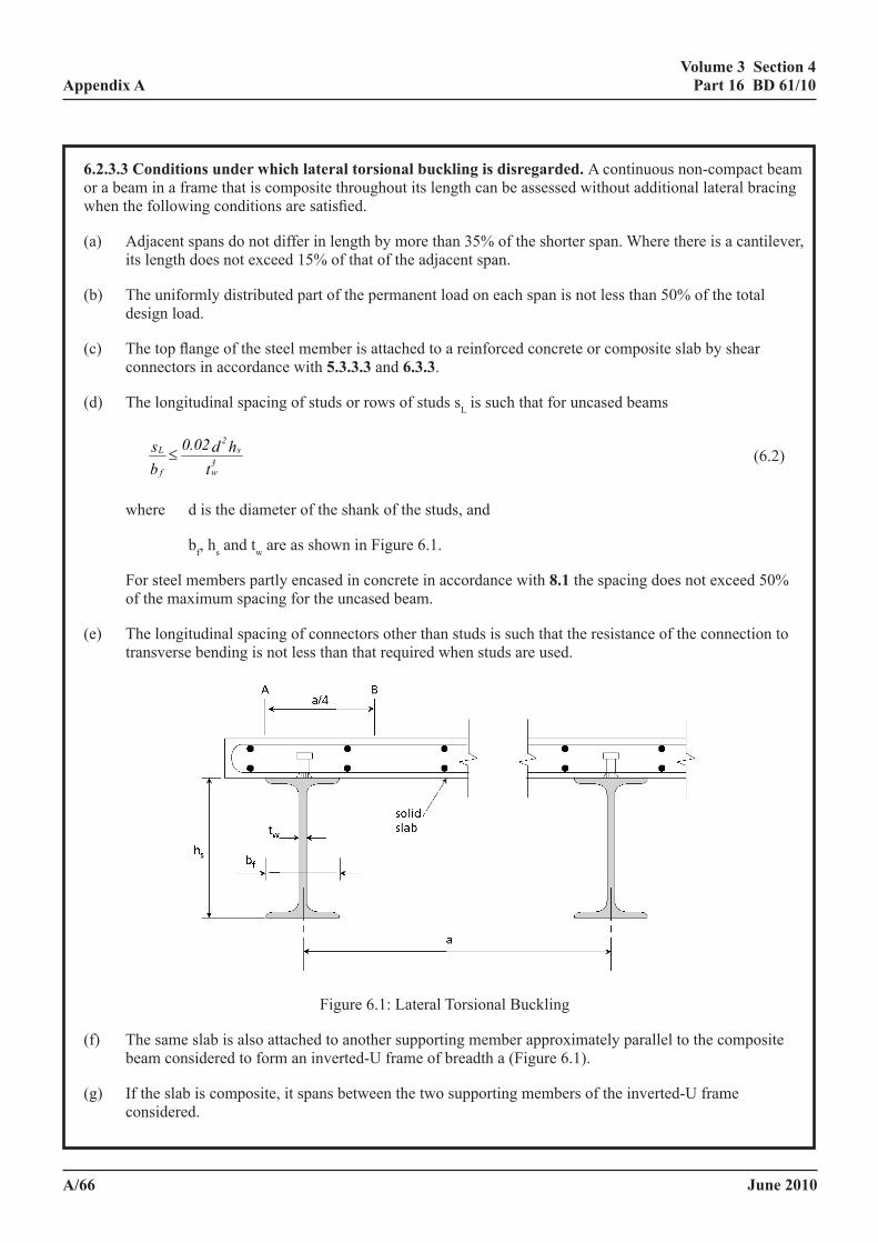
June 2010
volume 3 section 4 part 16 Bd 61/10
a/66
appendix a
6.2.3.3 conditions under which lateral torsional buckling is disregarded. A continuous non-compact beam or a beam in a frame that is composite throughout its length can be assessed without additional lateral bracing when the following conditions are satisfied.
(a) Adjacent spans do not differ in length by more than 35% of the shorter span. Where there is a cantilever, its length does not exceed 15% of that of the adjacent span.
(b) The uniformly distributed part of the permanent load on each span is not less than 50% of the total design load.
(c) The top flange of the steel member is attached to a reinforced concrete or composite slab by shear connectors in accordance with 5.3.3.3 and 6.3.3.
(d) The longitudinal spacing of studs or rows of studs sL is such that for uncased beams
t
hd0.02bs
3w
s2
f
L ≤ (6.2)
where d is the diameter of the shank of the studs, and
bf, hs and tw are as shown in Figure 6.1.
For steel members partly encased in concrete in accordance with 8.1 the spacing does not exceed 50% of the maximum spacing for the uncased beam.
(e) The longitudinal spacing of connectors other than studs is such that the resistance of the connection to transverse bending is not less than that required when studs are used.
Volume 3 Section 4 Appendix A Part 16 BD 61/09
April 2009 A/75
Figure 6.1: Lateral Torsional Buckling (f) The same slab is also attached to another supporting member approximately parallel to the
composite beam considered to form an inverted-U frame of breadth a (Figure 6.1). (g) If the slab is composite, it spans between the two supporting members of the inverted-U frame
considered. (h) Where the slab is simply-supported at the composite beam considered, fully anchored top
reinforcement must be present over the length AB shown in Figure 6.1. The area of this reinforcement is such that the resistance of the slab to hogging transverse bending, per unit length of beam, is not less than fy tw
2 /4γm, where the notation is as in (d) above. (j) At each support of the steel member, its bottom flange is laterally restrained and its web is
stiffened. Elsewhere the web may be unstiffened. (k) The bending stiffness of the solid or composite slab is such that:-
swscc a/ht0.35EIE 3≥ (6.3)
where EcIc is the mean of the flexural stiffnesses per unit width of slab at mid-span and above
the steel beam considered, neglecting concrete in tension, and including transformed areas of reinforcement and any profiled sheeting that contributes to the resistance of the slab in accordance with BD 44.
Ec is the short term secant modulus of elasticity of the concrete Es is the modulus of elasticity of the structural steel, tw, a, and hs are as shown in Figure 6.1 (l) The steel member is an UB, UC, joist section or another hot-rolled section of similar shape, with
Figure 6.1: Lateral Torsional Buckling
(f) The same slab is also attached to another supporting member approximately parallel to the composite beam considered to form an inverted-U frame of breadth a (Figure 6.1).
(g) If the slab is composite, it spans between the two supporting members of the inverted-U frame considered.
June 2010
volume 3 section 4 part 16 Bd 61/10
a/67
appendix a
(h) Where the slab is simply-supported at the composite beam considered, fully anchored top reinforcement must be present over the length AB shown in Figure 6.1. The area of this reinforcement is such that the resistance of the slab to hogging transverse bending, per unit length of beam, is not less than fy tw
2 /4γm, where the notation is as in (d) above.
(j) At each support of the steel member, its bottom flange is laterally restrained and its web is stiffened. Elsewhere the web may be unstiffened.
(k) The bending stiffness of the solid or composite slab is such that:
swscc a/ht0.35EIE 3≥ (6.3)
where
EcIc is the mean of the flexural stiffnesses per unit width of slab at mid-span and above the steel beam considered, neglecting concrete in tension, and including transformed areas of reinforcement and any profiled sheeting that contributes to the resistance of the slab in accordance with BD 44.
Ec is the short term secant modulus of elasticity of the concrete.
Es is the modulus of elasticity of the structural steel.
tw, a and hs are as shown in Figure 6.1.
(l) The steel member is an UB, UC, joist section or another hot-rolled section of similar shape, with yield stress not exceeding 355 N/mm2.
6.2.3.3a conditions under which lateral torsional buckling can be disregarded
When the steel section comprises a UB, UC or similar section with equal flanges of strength not exceeding 355 N/mm2 and certain other conditions (unrelated to the cross section slenderness) are satisfied, lateral torsional effects can be disregarded. The conditions were derived by consideration of annex B, but taking into account work by Weston, Nethercot and Crisfield(32) which shows that lateral torsional buckling can be disregarded for λLT values up to 60, which includes all UB sections not exceeding 355 N/mm2. It will be found that for a very few cross sections annex B gives slightly lower strengths than the method of 6.2.3.3, even when all the conditions on 6.2.3.3 are satisfied(33).
June 2010
volume 3 section 4 part 16 Bd 61/10
a/68
appendix a
6.2.4 construction in stages
Beams which have non compact cross sections at supports must satisfy the following rules. Composite sections are considered to be built in stages. A check for adequacy must be made at each stage of construction including the final stage of assessment in accordance with 9.9.5 of BD 56.
In addition to the limitations stated in 9.9.5.4 a) and b) of BD 56 the total accumulated stresses must not exceed
a) 0.75 fcu/γmc γf3 for concrete in compression or
b) fry//γmr γf3 for reinforcement in tension
In the application of 9.9.5.5 and 9.9.5.6 of BD 56 where the fibre being considered is either concrete in compression or reinforcement in tension the value of M, Mx,max, MDx, My,max, MD,max should be based on Zxr, Zxs, Mult, as defined in 6.2.3.
fry is the characteristic or worst credible yield strength of the reinforcement.
γf3 is the partial safety factor in accordance with 4.1.2 and BD 56.
γm is the partial material factor for steel in accordance with 4.1.2 and BD 56.
γmc is the partial material factor for concrete in compression in accordance with BD 44.
γmr is the partial material factor for reinforcement in accordance with BD 44.
6.3 longitudinal shear
6.3.1 general
When cross sections are assessed elastically the horizontal shear should be assessed from the effect of vertical shear on the elastic cross section in accordance with 5.3.
When cross sections are assessed plastically the longitudinal shear in beams between supports and the positions of maximum sagging moments in the adjacent spans is the sum of the forces in the slab either end of this region determined from the analysis in 6.1.4.1. Longitudinal shear under moment reversal need not be checked. There are no special conditions either for the distribution of shear connectors or relating to the position of point loads, both of which are adequately taken into account at the serviceability limit state.
The shear flow used to assess the transverse reinforcement must be determined for the maximum shear flow resistance of shear connectors required.
For any span which has compact cross-sections at supports where there is continuity, the strength of the shear connection must be checked adjacent to cross sections where plasticity occurs. The slab forces, calculated from the assumptions made in satisfying 6.2.2, must be resisted over the length between peak moments in opposite sense or between peak moments and points of zero moment. Intermediate equilibrium checks on the cross section must be made either side of significant point loads and at intervals along the span of the greater of 5m or span/10.
Transverse reinforcement and shear connectors must satisfy these requirements.
June 2010
volume 3 section 4 part 16 Bd 61/10
a/69
appendix a
The resistance of shear connectors must be obtained from the method in 5.3.3.5, as modified by 6.3.4. The longitudinal shear resistance so calculated need not exceed the value assessed using plastic cross sections analysis.
Where the other provisions in 6.3.2 and 6.3.3 are not satisfied a reduced resistance may be employed with the agreement of the TAA.
Alternative rules to those in 6.3.3.1 to 6.3.3.6 for the area of transverse reinforcement are given in 6.3.3.8, though these are less general in their application.
6.3.1a general
A check is required on the strength of the shear connectors at ULS on spans where cross sections are assumed in the assessment to be plastic(46), but no check is required on spans where the beam is assumed to be elastic throughout. Shear connector will also have to be checked at ULS if stresses are redistributed from the web or tension flange or if there is uplift in the connectors. When cross sections are designed plastically, the compression force in the concrete in the sagging moment region and the tensile force in the reinforcement in the adjacent hogging moment region (which act in the same direction) are combined, and a check is made that there are sufficient shear connectors between the two sections to resist this force.
When stud shear connectors or other flexible shear connectors are used, there is sufficient redistribution of the longitudinal force between the shear connectors to obviate the need to check the distribution of longitudinal shear under this condition. When the shear connectors are rigid a different situation exists and the condition could be somewhat more critical. However, there is no known evidence suggesting that a beam designed for the elastic longitudinal shear distribution at SLS performs poorly at ULS, so no check is required.
The longitudinal shear force from a concentrated load is uniform between the load and the adjacent supports, both in the plastic and elastic design of the longitudinal shear connection, so it is unlikely to be critical at ULS provided the yield moment is not exceeded. No check at the load is then required. If, however, the yield moment is exceeded, due to the absence of a recognised intermediate state of plasticity, a plastic hinge must be assumed under the point load. This is likely to produce a more critical condition for the check on the longitudinal shear resistance.
The effective breadth used in determining the longitudinal shear may now be taken as the quarter span values, except for very wide slabs.
The plastic capacity provides an upper limit to the longitudinal shear force calculated elastically. This situation is only likely to be realised where there are deep edge beams integral with the slab.
6.3.2 deck slab. The deck slab and its reinforcement must be capable of resisting the assessment forces imposed on it by the shear connectors without excessive slip or separation and without longitudinal splitting, local crushing or bursting. Of particular concern is where there is a free concrete surface adjacent to a connector, e.g. at an end or a side of a slab or in a haunch.
NOTE: Construction in accordance with 6.3.1 to 6.3.3 satisfies these requirements for the ultimate limit state and is deemed to satisfy the fatigue and serviceability requirements for transverse reinforcement. Where separate ultimate limit state checks are necessary for shear connectors the requirements are given in 6.3.4. Special consideration must be given to details which are not in accordance with 5.3 and 6.3.1 to 6.3.3.
6.3.2.1 haunches. Where concrete haunches are used between the steel flange and the soffit of the concrete slab the sides of the haunch must lie outside a line drawn at 450 from the outside edge of the connectors as shown in Figure 5.2. The requirements of 5.3 and 6.3 to 6.3.3.7 inclusive must also apply.
June 2010
volume 3 section 4 part 16 Bd 61/10
a/70
appendix a
6.3.3 transverse reinforcement
6.3.3.1 definitions and general requirements.
(a) The assessment method given in 6.3.3.2 to 6.3.3.5 is applicable to haunched and unhaunched composite beams of normal density concrete or lightweight aggregate concrete. The method takes account of interaction between longitudinal shear and transverse bending of the slab.
Attention is drawn to the difference between the meaning of the symbols q and qp:
q is the total longitudinal shear force per unit length of composite beam at the steel or iron/ concrete interface, determined in accordance with 6.3.1;
qp is the assessment longitudinal shear force per unit length of beam on the particular shear plane considered. It is equal to or less than q, depending on the shear plane.
(b) Only reinforcement transverse to the steel or iron beam that is fully anchored on both sides of a possible plane of longitudinal shear failure (shear plane) must be included in the definitions given below. Cross-sectional areas of transverse reinforcement per unit length of beam are defined thus:
At is reinforcement placed near the top of the slab forming the flange of the composite beam and may include that provided for flexure;
Ab is reinforcement placed in the bottom of the slab or haunch at a clear distance not greater than 50mm from the nearest surface of the steel or iron beam (see * in Foreword), and at a clear distance of not less than 40mm below that surface of each shear connector that resists uplift forces, including that bottom reinforcement provided for flexure (see * in Foreword);
Abs is other reinforcement in the bottom of the slab placed at a clear distance greater than 50mm from the nearest surface of the steel or iron beam (see * in Foreword);
Abv is reinforcement placed in the bottom of the slab or haunch, but excluding that provided for flexure, which complies in all other respects with the definition of Ab above.
NOTE 1: Where the depth of a haunch does not exceed 50mm, reinforcement in the bottom of a slab may be included in the definitions of Ab and Abv provided that it is placed at a clear distance of not less than 40mm below that surface of each shear connector which resists uplift forces (see * in Foreword) and at a clear distance not greater than 80mm from the nearest surface of the steel beam (see * in Foreword).
Examples of five types of shear plane are given in Figure 6.2 with typical arrangements that satisfy the definitions of Ab, At and Abs as given above.
Ae is the reinforcement crossing a shear plane that is assumed to be effective in resisting shear failure along that plane.
NOTE 2: For planes in unhaunched beams that do not cross the whole thickness of the slab (Plane type 2-2 in Figure 6.2), Ae = 2Ab.
For planes that cross the whole depth of the slab (shear plane type 1-1 in Figure 6.2) Ae is the total area of fully anchored reinforcement intersected by that plane including reinforcement provide for flexure, e.g. in shear plane type 1-1 in Figure 6.2(a), Ae = At + Ab.
June 2010
volume 3 section 4 part 16 Bd 61/10
a/71
appendix a
For planes in haunched beams that do not cross the whole depth of the slab (shear plane types 3-3, 4-4, or 5-5 in Figure 6.2) Ae is the total area of fully anchored reinforcement intersected by that plane, which is placed at a clear distance of not less than 40mm below that surface of each shear connector that resists uplift forces and may include the area of the hoop in a bar and hoop connector where appropriate.
For planes of type 5-5 (see Figure 6.2(d)) in cased beams Ae is the total cross sectional area of stirrups (both legs) crossing the shear plane (see 8.5.2 and 8.8).
(c) Ls is the length of the shear plane under consideration;
fry is the characteristic or worst credible yield strength of the transverse reinforcement but not greater than 500 N/mm2;
fcu is the characteristic cube strength of concrete or worst credible cube strength used in the assessment of the slab but not greater than 45 N/mm2;
s is a constant stress of 1 N/mm2 re-expressed where necessary in units consistent with those used for the other quantities.
(d) When the spacing of shear connectors does not exceed 1000mm or span/20 the size and spacing of transverse reinforcement must follow the requirements relating the shear flow and the longitudinal shear resistance in 5.3.3.6(1). When this connector spacing is exceeded the connector force must be assumed to be resisted over a distance equal to the lesser of 600mm, or three times the thickness of the slab on the compression side of the shear connectors. The total area of transverse reinforcement required in this zone to resist the local shear connector forces must not be less than:
(i) the calculated area in 6.3.3 if the conditions in 6.3.3.8 are not satisfied, or alternatively
(ii) half the calculated area in 6.3.3 if the conditions in 6.3.3.8 are satisfied.
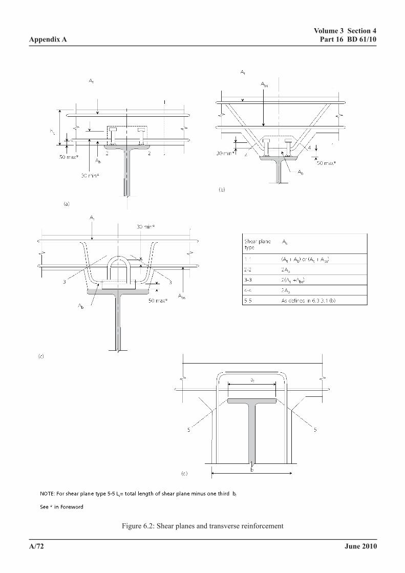
June 2010
volume 3 section 4 part 16 Bd 61/10
a/72
appendix aVolume 3 Section 4 Appendix A Part 16 BD 61/09
April 2009 A/81
Figure 6.2: Shear planes and transverse reinforcement
Figure 6.2: Shear planes and transverse reinforcement
June 2010
volume 3 section 4 part 16 Bd 61/10
a/73
appendix a
6.3.3.1a definition and general requirements
The rules for transverse reinforcement in the Design Code require broadly similar amounts of transverse reinforcement to the rules in BS EN 1992 (for reinforced concrete) which is used in design to BS EN 1994(34). The areas of transverse reinforcement required by these codes are very much higher than those required by BS 8100(35), in which the minimum transverse reinforcement in the slabs of T beams is 0.15%, which is placed near the top surface. The same quantity of reinforcement is required for mild steel, high yield steel, smooth bars and deformed bars. The amount specified is the same as in CP 114(36), the code of practice used in designing concrete buildings in the 1960’s (and for minor structures until more recently), but it had been increased to 0.30% (with similar lack of qualification) in CP 110(37), issued in 1972. The drafting committee of BS 8110, which replaced CP 110 in 1985, chose to revert to the earlier values on the practical consideration that no problems were known to have resulted from this aspect of construction in building structures designed to CP 114.
The satisfactory performance of building structures designed to CP 114 and BS 8110 is attributed to the fact that the cracking of the slab parallel to the face of the beam is never sufficient to significantly reduce the longitudinal shear resistance of the beam below its uncracked strength, which is so high, at least with good concrete, as to be able to carry the longitudinal shear without assistance from the reinforcement. The rules in the Design Code and BS EN 1992(38) however are based on tests in which large cracks had been induced along the sides of the beams (by high slab loading), a degree of cracking only to be expected when the slab was on the point of failure. BS 8110, therefore, effectively recognises the practicality of a situation that is likely to occur in bridges. BS 5400-4 requires the same minimum amount of transverse reinforcement as BS 8110, but, on account of considerations unrelated to the strength of the shear connection, slabs designed to BS 5400-4 usually have much more reinforcement than the minimum requirement for transverse reinforcement.
When shear connectors are grouped such that the spacing exceeds span/8 the bursting stresses on the concrete are likely to be higher than when the connectors are more uniformly distributed. Successive stress blocks, as used for end block design(39) need to be considered to ensure that splitting does not occur. This approach does not work well for shear connections as the transverse tensile stress on the bearing side of a loaded area is greatest over a distance of 0.2d to 2.0d(7), and for 19mm studs this zone is about 0 to 50mm in front of the bearing face of the stud. There is however no requirement for transverse reinforcement over this distance, but reinforcement is nevertheless likely within 100mm of the bearing face.
For this reason the alternative approach has been adopted, of preventing splitting in the general vicinity of the shear connectors by requiring that the longitudinal shear due to the group is carried over a limited distance on the compression side of the group of shear connectors, using the normal design expression of the Standard.
The indirect tensile forces from incidental shear connectors are lower than those from other shear connectors. The requirement for longitudinal shear resistance carried locally is therefore reduced.
June 2010
volume 3 section 4 part 16 Bd 61/10
a/74
appendix a
6.3.3.2 longitudinal shear. The longitudinal shear force per unit length qp on any shear plane through the concrete must not exceed the lesser of the following:
(a) k1 fcu Ls/γmvγf3 (6.4)
(b) v1Ls/γmvγf3 + 0.80 Aefry/γmrγf3 (6.5)
where
k1 is a constant equal to 0.23 for normal density concrete and 0.18 for lightweight aggregate concrete.
v1 is the ultimate longitudinal shear stress in the concrete for the shear plane under consideration, to be taken as 1.35 N/mm2 for normal density concrete and 1.05N/mm2 for lightweight aggregate concrete.
γmv is 1.50 but may be reduced to 1.25 when the characteristic strength is ≥45 N/mm2 or the worst credible strength ≥35N/mm2.
If fcu is taken to be less than 20 N/mm2, the term v1Ls in (b) must be replaced by k2fcuLs where k2 is a constant equal to 0.060 for normal density concrete and 0.045 for lightweight aggregate concrete.
In haunched beams, not less than half the reinforcement required to satisfy (b) above in respect of shear planes through the haunch (planes 3-3 and 4-4 in Figure 6.2) must be bottom reinforcement that complies with the definition of Abv in 6.3.3.1(b).
6.3.3.3 interaction between longitudinal shear and transverse bending.
(a) Beams with transverse compression around shear connectors. Where the assessment loading at the ultimate limit state causes transverse compression in the region of the shear connectors, no account need be taken of interaction between longitudinal shear and transverse bending providing the requirements of 6.3.3.2 are satisfied.
(b) Beams with shear planes passing through the full depth of slab. Where the shear plane passes through the full depth of the slab, no account need be taken of the interaction between longitudinal shear and transverse bending.
(c) unhaunched beams with shear planes passing round the connectors. In unhaunched beams where the assessment loading at the ultimate limit state causes transverse tension in the slab in the region of the shear connectors, account must be taken of the effect of this on the strength of shear planes that do not cross the whole depth of the slab (plane 2-2 in Figure 6.2) by replacing 6.3.3.2(b) by
qp < v1Ls/γmvγf3 + 1.60Abv fry/γmr γf3 (6.6)
Where the assessment loads at the ultimate limit state can cause transverse compression in the slab in the region of the shear connectors account may be taken of the beneficial effect of this on the strength of shear planes that do not cross the whole depth of the slab (shear plane type 2-2 in Figure 6.2) by replacing 6.3.3.2(b) by
qp < v1Ls /γmvγf3 + 0.80Ae fry/γmr γf3 + 1.60FT/γf (6.7)
June 2010
volume 3 section 4 part 16 Bd 61/10
a/75
appendix a
where
FT is the minimum tensile force per unit length of beam in the transverse reinforcement in the top of the slab due to transverse bending of the slab. Only loading that is of a permanent nature must be considered when calculating FT.
NOTE: For remaining symbols see 6.3.3.1(a), (b) and (c).
(d) haunched beams. In haunched beams, where the assessment loading at the ultimate limit state causes transverse tension in the slab in the vicinity of the shear connectors, no account of this need be taken, provided the reinforcement required to satisfy 6.3.3.3(a) is reinforcement that satisfies the definition of Abv and the haunch dimensions satisfy the requirements of 6.3.2.1.
6.3.3.4 minimum transverse reinforcement. The cross sectional area, per unit length of beam, of reinforcement in the slab transverse to the steel or iron beam must be not less than
0.7γmrshc/fry
where
hc is the thickness of the concrete slab forming the flange of the composite beam.
Not less than 50% of this area of reinforcement is required near the bottom of the slab so that it satisfies the definition of Abv given in 6.3.3.1(b).
Where the length of a possible plane of shear failure around the connectors (shear plane 2-2 in Figure 6.2) is less than or equal to twice the thickness of the slab hc, reinforcement in addition to that required for flexure is required in the bottom of the slab transverse to the steel or iron beam to prevent longitudinal splitting around the connectors. The cross sectional area of this additional reinforcement, per unit length of beam, Abv must be not less than 0.7 γmr s hc/fry. This additional reinforcement is not required if the minimum compressive force per unit length of beam, acting normal to and over the surface of the shear plane, is greater than 1.4 shc.
6.3.3.5 minimum transverse reinforcement in haunched beams. The cross-sectional area of transverse reinforcement in a haunch per unit length of beam Abv as defined in 6.3.3.1(b) must not be less than
0.35γmrsLs/fry
where
Ls is the length of a possible plane of shear failure around the connectors (see shear plane type 3-3 or 4-4 in Figure 6.2).
6.3.3.6 curtailment of transverse reinforcement. The transverse reinforcement provided to resist longitudinal shear which is curtailed is acceptable provided the conditions 6.3.3 are satisfied in all respects for the shear planes through the slab of type 1-1 in Figure 6.2. For this purpose the longitudinal shear force per unit, length qp for such a plane, must be assumed to vary linearly from the calculated maximum force on the relevant plane, which is adjacent to the shear connectors, to zero mid-way between the centre line of the beam and that of an adjacent beam or to zero at an adjacent free edge.
6.3.3.7 detailing of transverse reinforcement. The spacing of bottom transverse reinforcement bars, if present and satisfying the conditions in 6.3.3, must be not greater than four times the projection of the connectors (including any hoop which is an integral part of the connector) above the bars nor greater than 600mm (see *in Foreword).
June 2010
volume 3 section 4 part 16 Bd 61/10
a/76
appendix a
6.3.4 shear connectors. The design of the shear connectors need not be considered at the ultimate state except as directed in 5.3.3.6, 6.1.3 or where redistribution of stresses from the web or the tension flange is carried out in accordance with BD 56. Then the size and spacing of shear connectors must be determined in accordance with 5.3.3.5 except that longitudinal shear per unit length must be determined in accordance with 6.3.1 and the assessed static strength, per connector at the ultimate limit state, must be taken as
Pam/γm γf3
where
Pam is the nominal present mean static strength as defined in 5.3.2.1 or 5.3.2.2, but the 0.82 limit in the equation of 5.3.2.1(b) must be disregarded.
γm = 1.375
June 2010
volume 3 section 4 part 16 Bd 61/10
a/77
appendix a
7 composite BoX girders
7.1 general
Composite box girders must satisfy the relevant requirements for steel box girders given in BD 56, together with the requirements for uncased beams given in this Standard and also those given in this clause.
7.2 effective span
The effective spans for bending of longitudinal or transverse box girders must be as defined in BS 5400-1.
7.3 effective Breadth
The effective breadth of concrete flange for serviceability limit state calculations must be determined in accordance with BD 56. For closed box girders when the steel top flange, which is continuous between webs, acts compositely with the concrete deck slab the effective breadth of the composite plate must also be determined in accordance with BD 56.
7.4 distribution of Bending moments and vertical shear forces
In the absence of more exact analysis the distribution of longitudinal bending moments and vertical shear forces may be calculated in accordance with 5.1.1 or 6.1 as appropriate.
7.5 longitudinal shear
7.5.1 spacing of shear connectors. The concrete slab must be positively tied down to the top steel flange plate in accordance with the requirements of 5.3.3.3 and 5.3.3.6.
In closed box girders, shear connectors must be present over the whole area of the top flange plate at spacings longitudinally and transversely not greater than 600mm or three times the thickness of any concrete slab or four times the height of the connector (including any hoop which is an integral part of the connector), whichever is the least. The longitudinal spacing of these shear connectors must not exceed twenty five times (see * in Foreword), and the transverse spacing must not exceed forty times (see * in Foreword), the thickness of the top flange plate.
In open-top box girders the spacing of shear connectors must satisfy the requirements for composite I beams in 5.3.3.1.
The distance from the edge of the top flange plate to the near edge of the nearest row of shear connectors must not exceed twelve times the thickness of the plate (see * in Foreword).
7.5.2 assessment of shear connectors. The shear connectors in box girders must satisfy clause 5 for the serviceability limit state, except that in closed box girders the number of shear connectors and their distribution over the breadth of the steel flange plate must satisfy 5.3.3.4 and 5.3.3.6 and the following requirements.
NOTE 1: The connectors at any cross section must be assumed to be all of the same type and size. The assessment of the shear connectors between each steel web and its associated concrete flange must be considered for each web separately.
June 2010
volume 3 section 4 part 16 Bd 61/10
a/78
appendix a
The longitudinal shear force Qx on a connector at distance x from the web centre line must be determined from:
0.15+)bx-K(1
nq=Q 2
wx (7.1)
where
q is the assessment longitudinal shear due to global and local loadings per unit length of girder at the serviceability limit state for the web considered, calculated assuming full interaction between the steel plate and the concrete slab (in accordance with 5.3.1).
K is a coefficient determined from Figure 7.1.
bw is equal to half the distance between the centre lines of adjacent webs, or, for portions projecting beyond an outer web, the distance from the centre line of the web to the free edge of the steel flange.
n is the total number of connectors per unit length of girder within breadth bw, including any provided in accordance with 7.5.1 or 7.7(a).
n’ is the number of connectors per unit length placed within 200mm of the centre line of the web considered.
NOTE 2. The force on any connector due to coexistent global and local loadings must not exceed its assessed strength at the serviceability limit state determined from clause 5.
If the connector density (number of shear connectors per unit area of steel flange) in any area outside the effective breadth of the steel flange exceeds the least density within the effective breadth at the cross section considered, the connectors additional to those that would give equal densities must be omitted when calculating n in this assessment method.
NOTE 3: This method is not applicable when connectors are placed in groups or when the number of connectors in any transverse row across the flange is small.
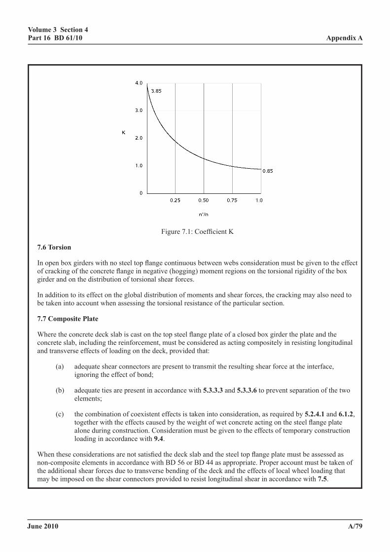
June 2010
volume 3 section 4 part 16 Bd 61/10
a/79
appendix a
Volume 3 Section 4 Appendix A Part 16 BD 61/09
April 2009 A/88
Figure 7.1: Coefficient K 7.6 Torsion In open box girders with no steel top flange continuous between webs consideration must be given to the effect of cracking of the concrete flange in negative (hogging) moment regions on the torsional rigidity of the box girder and on the distribution of torsional shear forces. In addition to its effect on the global distribution of moments and shear forces, the cracking may also need to be taken into account when assessing the torsional resistance of the particular section. 7.7 Composite Plate Where the concrete deck slab is cast on the top steel flange plate of a closed box girder the plate and the concrete slab, including the reinforcement, must be considered as acting compositely in resisting longitudinal and transverse effects of loading on the deck, provided that: (a) adequate shear connectors are present to transmit the resulting shear force at the interface,
ignoring the effect of bond; (b) adequate ties are present in accordance with 5.3.3.3 and 5.3.3.6 to prevent separation of
the two elements; (c) the combination of coexistent effects is taken into consideration, as required by 5.2.4.1 and
6.1.2, together with the effects caused by the weight of wet concrete acting on the steel flange plate alone during construction. Consideration must be given to the effects of temporary construction loading in accordance with 9.4.
Figure 7.1: Coefficient K
7.6 torsion
In open box girders with no steel top flange continuous between webs consideration must be given to the effect of cracking of the concrete flange in negative (hogging) moment regions on the torsional rigidity of the box girder and on the distribution of torsional shear forces.
In addition to its effect on the global distribution of moments and shear forces, the cracking may also need to be taken into account when assessing the torsional resistance of the particular section.
7.7 composite plate
Where the concrete deck slab is cast on the top steel flange plate of a closed box girder the plate and the concrete slab, including the reinforcement, must be considered as acting compositely in resisting longitudinal and transverse effects of loading on the deck, provided that:
(a) adequate shear connectors are present to transmit the resulting shear force at the interface, ignoring the effect of bond;
(b) adequate ties are present in accordance with 5.3.3.3 and 5.3.3.6 to prevent separation of the two elements;
(c) the combination of coexistent effects is taken into consideration, as required by 5.2.4.1 and 6.1.2, together with the effects caused by the weight of wet concrete acting on the steel flange plate alone during construction. Consideration must be given to the effects of temporary construction loading in accordance with 9.4.
When these considerations are not satisfied the deck slab and the steel top flange plate must be assessed as non-composite elements in accordance with BD 56 or BD 44 as appropriate. Proper account must be taken of the additional shear forces due to transverse bending of the deck and the effects of local wheel loading that may be imposed on the shear connectors provided to resist longitudinal shear in accordance with 7.5.
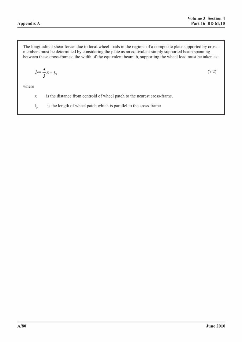
June 2010
volume 3 section 4 part 16 Bd 61/10
a/80
appendix a
The longitudinal shear forces due to local wheel loads in the regions of a composite plate supported by cross-members must be determined by considering the plate as an equivalent simply supported beam spanning between these cross-frames; the width of the equivalent beam, b, supporting the wheel load must be taken as:
l+x34=b w (7.2)
where
x is the distance from centroid of wheel patch to the nearest cross-frame.
lw is the length of wheel patch which is parallel to the cross-frame.
June 2010
volume 3 section 4 part 16 Bd 61/10
a/81
appendix a
8 cased Beams and filler Beam construction
8.1 scope
This clause applies to simply supported filler beam decks, with or without the soffit or the upper surface of the flanges of the steel or iron member exposed, and to simply supported or continuous cased beams. The requirements apply only where the encasement or filling is of normal density concrete (2300 kg/m3 or greater) and the characteristic or worst credible strength of the concrete is not less than 25N/mm2. In calculations the characteristic or worst credible strength must not be taken in excess of 40N/mm2.
8.1.1 introduction
Since BS 5400-5, BD 21 and BA 16 were written certain aspects of the assessment of cased beams and filler beams have been re-examined. Less conservative methods have been developed for the assessment of longitudinal and transverse shear. New methods of analysis have been developed for old forms of construction which does not conform to BD 61. New guidance is provided on incidental stiffening and strengthening, particularly in relation to the fill.
Sample flow charts summarising the use of the various methods for the assessment of cased beam decks and for filler beams are appended in annex i.
One problem in the assessment of cased beams may be that if plastic cross section analysis is to be permitted at ULS, the longitudinal shear strength of the steel/concrete interface may be exceeded.
This is also the situation for some filler beams, but tests have been conducted on construction without transverse reinforcement, or with reinforcement inadequate to satisfy the requirements of 8.3.2, which indicate the plastic design of the composite cross section at ULS is often achievable. In a form of filler beam construction developed in France(41), which includes special details and transverse prestressing, no check is required on the local bond stress at either SLS or ULS. However until such time as longitudinal shear in filler beams has been researched a check on the longitudinal shear on planes of type 6 and 7 in Figure 8.3 is required as a safeguard against possible failure modes not yet observed.
Alternative procedures to those in 8.1.4, 8.1.8 and annex h are permitted provided they are justified and provided they take into account differences in the performance of the structure at SLS and ULS.
8.1.2 cased beams
Cased beams exist which do not comply with the requirements of the Standard, and reduced interface shears are appropriate for less efficient casings and partial casings which do not have efficient confining reinforcement and may be entirely unreinforced. These are types B, C and D in Figure 8.2. Permissible interface bond stresses at SLS for these beams are as follows (N/mm2):
A. (As in Standard) 0.10√fcu but ≤ 0.70
B. 20mm ≤ cover ≤ 50mm 0.07√fcu but ≤ 0.40
C. 0.06√fcu but ≤ 0.35
D. Cover ≥ 50mm 0.10√fcu but ≤ 0.50
At ULS the same values apply but for partial shear connection calculations the longitudinal shear stress should not exceed 0.50N/mm2.
June 2010
volume 3 section 4 part 16 Bd 61/10
a/82
appendix a
The following conditions apply:
(i) For cased beams of types A and C the checks required are as follows. Partial shear connection calculations should assume plastic methods of cross section design and a ductile shear connection. The equilibrium method is the method of 5.5.2 of BS 5950-3 or the 'plastic theory' method of 6.2.1.2 of EN 1994 Part 1-1(4). The linear interpolation method is the more conservative method of 6.2.1.2 of EN 1994 Part 1-1(4).
(ii) For spans exceeding 12m the local bond stress at SLS should not exceed the permissible bond stress given above nor 0.5N/mm2. At ULS the moment of resistance should be taken as the yield moment.
For spans exceeding 9m and up to 12m, the local bond stress at SLS should not exceed the permissible bond stress. At ULS the moment of resistance should be taken as the yield moment.
For spans between 6m and 9m, the local bond stress at SLS should not exceed the permissible bond stress. At ULS the moment of resistance should be assessed as the greater of the yield moment and the flexural resistance assuming partial shear connection by the linear interpolation method.
For spans less than 6m, at SLS the local bond stress should not exceed the permissible bond stress. At ULS the moment of resistance should be assessed as the greater of the yield moment and the flexural resistance assuming partial shear connection by the equilibrium method.
(iii) Where the moment of resistance is taken as the yield moment the design strength of the metal should not be taken greater than 275N/mm2.
(iv) The moment of resistance for cased beams type B should not be taken greater than the yield moment. Checks on the shear connection at ULS are not required.
(v) The moment of resistance for beams type D should not be taken greater than the lower of the moment at bond failure and the moment of resistance calculated in accordance with clause 6 of the Standard assuming full composite action. A check at SLS is not required.
(vi) The moment of resistance for beams of types A and C may be assumed to be the yield moment where this is sufficient to satisfy the assessment loading.
(vii) These rules do not apply to cased beams where the soffit of the slab is above the top flange of the steel beam by more than 25mm. This is because, despite the rules, cased beams rely disproportionately upon the bond to the top flange, which is reduced by raising the soffit of the slab. There is no relevant experimental work on such construction, but clearly lower interface bond stress would be needed, possibly 20% lower for beams type A and C and 40% lower for beam type B and zero for beam type D.
(viii) In beams with abnormal concrete depths above the metal beam the depth of concrete used in calculation should be restricted such that the elastic neutral axis lies within the depth of the steel section for both elastic and plastic cross section analysis.
(ix) As an alternative to (viii) the full depth of concrete may be assumed and the metal beam concentrated at the centroid of the steel section.
(x) The yield moment and flexural resistance are calculated using the assessment strengths of materials appropriate to the ULS.
(xi) Generally the same rules apply to cased beams not attached to a slab, when they are subject to the same slenderness limitations as RC beams.
June 2010
volume 3 section 4 part 16 Bd 61/10
a/83
appendix a
8.1.3 complying filler beams
This section considers only filler beam construction in which the transverse reinforcement is adequate to resist the moments obtained from orthotropic plate or conventional grillage analysis. For this situation it is recommended that orthotropic plate analysis is adopted for analysis, but grillage representations, allowing for the different stiffness transversely and longitudinally, are an acceptable alternative. The transverse distribution rules of BA 16 are inappropriate for this form of construction.
The method in 8.3.2 of the Standard, which gives transverse distribution rules for 45 units of HB loading, should now be regarded as a Category A alternative (see Foreword). However providing the conditions in 8.3.2(b) and (d) are satisfied:
(i) the transverse hogging moment may be taken as 10% of the maximum sagging moment, and
(ii) it may be assumed that there is a linear reduction in the transverse sagging moment in the 2m side strips as specified in the Standard.
Filler beams may be assessed assuming the principles in 8.1.2, but the stress on the shear connection at ULS taken as 1.4 times the values for cased beams type A and:
For spans exceeding 8m the permissible bond strength should not be exceeded at SLS and the flexural capacity at ULS should be assessed as the greater of the yield moment and the flexural resistance assuming partial shear connection by the linear interpolation method.
For spans less than 8m the permissible bond strengths at SLS should not be exceeded at SLS and the flexural capacity at ULS should be assessed as the greater of the yield moment and the flexural resistance assuming partial shear connection by the equilibrium method.
Alternatively, irrespective of the span, for beams satisfying 8.3.2(c) of the Standard the moment of resistance may be assumed to be the full plastic moment of resistance without a check on the bond stress at ULS, provided the yield stress of the metal beam used in the calculation is not greater than 275N/mm2 and provided 8.1.2(vi) is satisfied or provided there is not more than 75mm of concrete above the top flange of the steel section. Where of these conditions only 8.3.2(c) of the Standard is not satisfied the moment of resistance may be taken as the yield moment.
8.1.4 non-complying filler beams
(i) Filler beams with concrete encasement/infill
For beams not complying with 8.1.3 of the above, providing there is no evidence of excessive corrosion, fretting action or cracking (in the case of cemented materials) sufficient to adversely affect the achievement of composite action, 8.1, 8.3.1, 8.4, 8.5.1 and 8.5.2 apply.
In filler beams without transverse reinforcement, the lateral distribution of load is greater than that suggested by grillage analysis with pinned transverse members. To reproduce the actual distribution the flexural stiffness of beams should be based on the composite cross section, and the torsional stiffness of internal beams taken as that of the rectangle of concrete horizontally between mid span of adjacent infill elements and vertically by a height above the soffit of the metal beam no greater than 1.5 times the vertical distance between the flanges. Suitable grillages for analysing filler beam decks are shown in Figure 8.4, where the member properties to be assumed are shown in Table 8.1. In using the grillage in Figure 8.4(b) the torsion per unit width is to be taken as the sum of the torsions per unit width in the two directions. The two grillages give similar distributions of bending moments and torsions, but that in Figure 8.4(b) allows lateral distribution of reactions, whereas the grillage in Figure 8.4(a) allows none. In skewed bridges the transverse beams should be approximately perpendicular to the longitudinal beams.
June 2010
volume 3 section 4 part 16 Bd 61/10
a/84
appendix a
Table 8.1: Cross Section Properties for Global Analysis of Non-complying Filler Beams
Lateral Distribution of Reactions:
Disregarded (as in Figure 8.4(a)
Included (as in Figure 8.4(b)
Main beams I J A*
IcompositeJsteelAcomposite or ∞
IcompositeJsteelAcomposite or ∞
Intermediate beams I J A*
- - -
0 Jconcrete/2Aconcrete or ∞
Transverse beams I J A*
0 JconcreteAconcrete or ∞
IconcreteJconcrete/2Aconcrete or ∞
* Analysis is insensitive to A
The grillage in Figure 8.4(b) should only be used where the abutments are sufficient to resist the torsions, a condition which may be assumed providing.
(a) the abutments are in good condition and not sufficiently cracked so as to relieve torsion moments, and
(b) the slab should project a distance equal to the depth of the metal beam past the end of the beam, or
(c) the concrete in the deck should be monolithic with a substantial abutment beam of depth not less than 50% greater than the depth of the filler deck, or
(d) the concrete in the deck should be monolithic with a concrete abutment.
In assessing the results of the analysis, the flexural resistance may be assumed to be the same as for complying filler beams providing the effective concrete is restricted for torsion to that within a depth above the steel beam soffit of 1.5 times the depth between the flanges. For flexure 8.1.2(vi) applies (the alternative in 8.1.2(vii) does not apply). The torsional strength of the concrete may be taken as
βγγ 5.0)/(41.0 mc
CUf when the beam spacing/depth ratio of the metal beams exceeds 2.0
or otherwise
3
5.0)/(58.0f
mccufγ
γ
When this stress is exceeded the reduced stiffness given by the expression H1 in annex h, may be used, when no check on the stress is required.
June 2010
volume 3 section 4 part 16 Bd 61/10
a/85
appendix a
(ii) Filler beams with masonry infill
Dense brickwork filler beams with the mortar fully bonded to the bricks and the metal beams must be assessed in accordance with the above provisions and those in 5.4 (of BD 61), except the bond stress in 8.5.1 and the strength of the shear planes through the masonry must be taken not greater than 0.35N/mm2, the resistance of attachments must not be taken greater than 60% of the value in 5.3.3.8.1 and moment of resistance should not be taken in excess of the yield moment of the composite section as defined above in 8.1.2(x).
For the analysis two methods are permitted is as follows: An analysis using comparable section properties as those in Table 8.1, for which the stiffness is calculated as 1000 times the compressive strength in accordance with annex h (clause h1), when the torsional stresses in the masonry should not exceed:
5.0
3
)/(65.0
f
mmkfγ
γ
when the beam spacing/depth ratio of the metal beams exceeds 2.0, or otherwise
3
5.0)/(75.0
f
mmkfγ
γ
Where this is exceeded the stiffness may be reduced to that given by expression H1 in annex h, when no check on the stress is required.
When the brickwork is not bonded to the steel beams, similar provisions apply except that the bond must be taken not greater than 0.30N/mm2 and the resistance of attachments must be taken no greater than 40% of the values in 5.3.3.8.1.
Where the soffit between the beam flanges is of sound structural material and the material above is weaker but complies with 8.1.8, then providing the total depth of the deck less the top 75 mm of surfacing is not less than 20% thicker than the depth of the metal beams, the transverse stiffness per unit length may be taken as 2% of the longitudinal stiffness, per unit width. No checks are then required on the stresses in the elements orthogonal to the girders in the analysis.
8.1.5 vertical shear resistance
For cased beams and filler beams the shear resistance of cemented material up to 250mm above the level of the steelwork, and for a width on either side as shown in Figure 8.5, may be added to that of the steelwork assuming a shear strength of concrete vc based on the concrete strength fcu as given in BD 44. Strictly this value applies only when there is a small amount of longitudinal reinforcement and for this purpose the steelwork is deemed to be effective as reinforcement. The shear assumed to be carried by the concrete should not exceed 15% of the total shear in cased beams and 30% of the total shear in filler beams.
For dense brickwork filler beams the provisions of 8.4 (of BD 61) apply.
8.1.6 procedure when longitudinal shear resistance is inadequate
When the longitudinal shear exceeds the permissible interface bond stress at either SLS or ULS composite action should be disregarded and all beams with fill on both sides should be considered to be compact, irrespective of the cross section slenderness.
8.1.7 punching shear resistance
The punching shear resistance to a wheel load may be assessed assuming the load is replaced by two strip loads, each of which has the same width and centroid of the part of the load which would be carried by statics to the
June 2010
volume 3 section 4 part 16 Bd 61/10
a/86
appendix a
supporting beam. The shear may be assumed to be carried over a width equal to the loaded width plus av, assuming a concrete strength of 3vcd/av, where av is the distance from the strip to the face of the web of the neighbouring metal beam and d is the depth from the surface of the concrete to the lower web/flange intersection of the metal beam. For dense brickwork the shear strength should be taken as 3 fv/avγmv, where fv is from BS 5628 and γmv is taken as 2.5.
For a wheel load on a bay adjacent to an edge beam the resistance should be taken as 70% of that for an internal bay of similar dimensions, unless it can be shown that the horizontal thrust resulting from the arching action shown in Fig 8.6 can be adequately resisted.
Flexural checks under local loading are not required providing the beam spacing to web depth ration does not exceed 4.0 for internal bays and 2.5 for external bays. Where checks are necessary arching action may be assumed and horizontal composite action between the lower part of the metal beam and the concrete on either side of the web equal to the least of:
• the half of the distance between the webs of the metal beams • the position of the centreline of the nearest load • the edge of the construction.
8.1.8 effect of end restraints and of finishing and infill material not satisfying Bd 44
Where tests with vehicles of weight not less than 70% of the assessment vehicle suggest there are significant incidental strengthening effects under four passages of the vehicle, or where these effects can confidently be regarded of comparable or better characteristics to those demonstrated to have substantial stiffness in the literature, an increase in strength may be taken into account as follows:
(i) Effect of end restraint
The effect of end restraint from friction in resisting the resolved longitudinal and transverse forces (if any are assumed) may be taken into account calculated from the dead loads above the level of the soffit, including that in the abutment beam and a coefficient of friction of:
0.35 for concrete on masonry or masonry on masonry
0.50 for concrete cast on concrete with an unprepared surface
0.60 for concrete cast on concrete with a prepared surface, or monolithic concrete of strength not exceeding 20N/mm2
0.75 for monolithic concrete of strength exceeding 20N/mm2
It should be noted that where the abutments are thicker than the slab there may be significant end moments from continuity with the support, but this should be discounted due to the likely loss of this effect when the concrete cracks, unless there is flexural reinforcement present satisfying BD 44.
(ii) Effect of finishing
The contribution of the concrete which would not normally be regarded of structural quality (here described as “weak concrete”), masonry and well compacted (cohesive or weakly cemented cohesive) material, between and above the steelwork, may be taken into account in the assessment of the effect of live loads on the longitudinal bending (for stiffness and strength) of filler beam decks, where it can be shown that the material is in contact with the full depth of the web or on flat rough concrete surfaces of construction satisfying 8.1.2, 8.1.3 or 8.1.4. The following guidance is restricted to metals for which the characteristic or worst credible strength does not exceed 275 N/mm2 and relates to checks on load levels up to SLS loading. The effective cross section to be used in the calculations is as defined in annex h, Section H5. The method assumes that the better traffic compaction of the fill in the older bridges offset the probably greater variability of the properties in the original materials. The effect of any finishing above sprayed-on waterproofing systems should be disregarded.
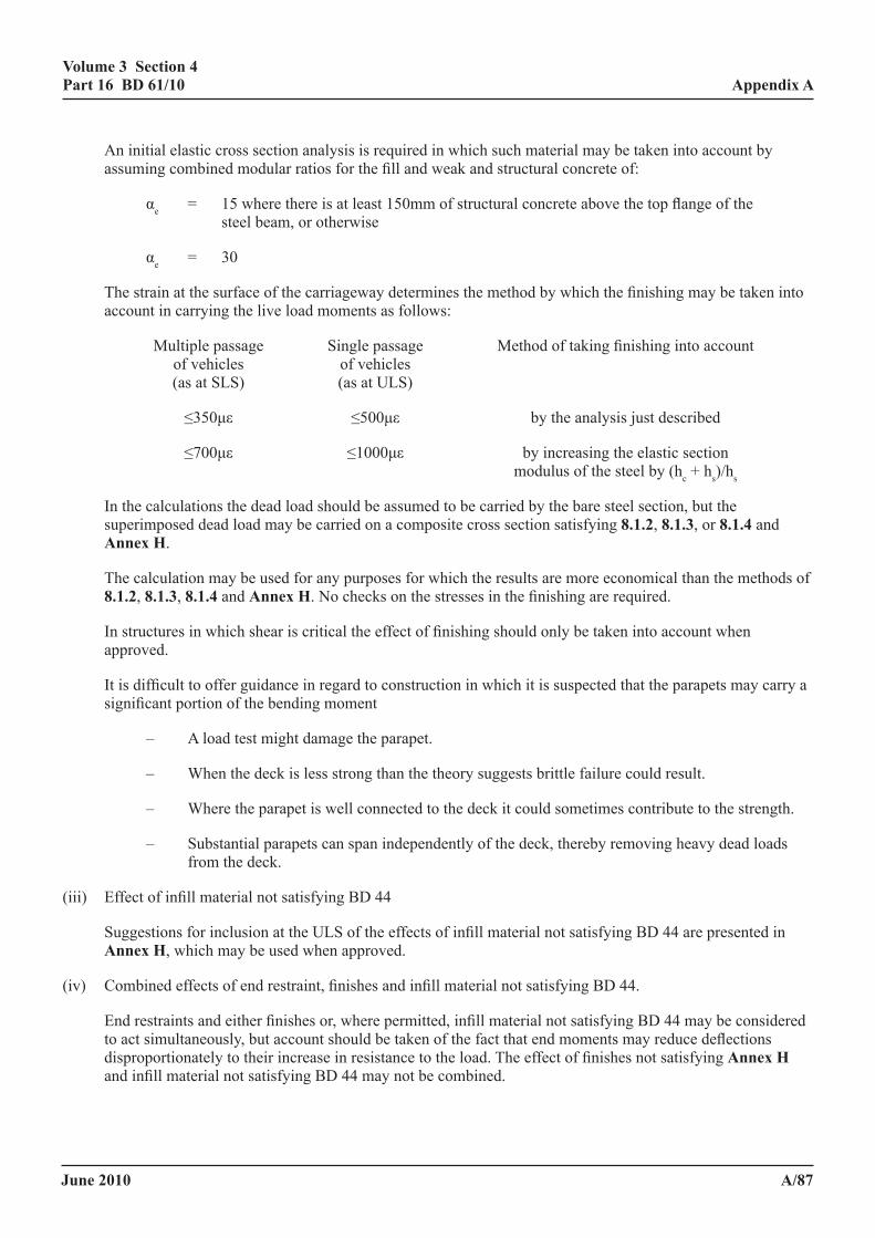
June 2010
volume 3 section 4 part 16 Bd 61/10
a/87
appendix a
An initial elastic cross section analysis is required in which such material may be taken into account by assuming combined modular ratios for the fill and weak and structural concrete of:
αe = 15 where there is at least 150mm of structural concrete above the top flange of the steel beam, or otherwise
αe = 30
The strain at the surface of the carriageway determines the method by which the finishing may be taken into account in carrying the live load moments as follows:
Multiple passage Single passage Method of taking finishing into account of vehicles of vehicles (as at SLS) (as at ULS)
≤350με ≤500με by the analysis just described
≤700με ≤1000με by increasing the elastic section modulus of the steel by (hc + hs)/hs
In the calculations the dead load should be assumed to be carried by the bare steel section, but the superimposed dead load may be carried on a composite cross section satisfying 8.1.2, 8.1.3, or 8.1.4 and annex h.
The calculation may be used for any purposes for which the results are more economical than the methods of 8.1.2, 8.1.3, 8.1.4 and annex h. No checks on the stresses in the finishing are required.
In structures in which shear is critical the effect of finishing should only be taken into account when approved.
It is difficult to offer guidance in regard to construction in which it is suspected that the parapets may carry a significant portion of the bending moment
– A load test might damage the parapet.
– When the deck is less strong than the theory suggests brittle failure could result.
– Where the parapet is well connected to the deck it could sometimes contribute to the strength.
– Substantial parapets can span independently of the deck, thereby removing heavy dead loads from the deck.
(iii) Effect of infill material not satisfying BD 44
Suggestions for inclusion at the ULS of the effects of infill material not satisfying BD 44 are presented in annex h, which may be used when approved.
(iv) Combined effects of end restraint, finishes and infill material not satisfying BD 44.
End restraints and either finishes or, where permitted, infill material not satisfying BD 44 may be considered to act simultaneously, but account should be taken of the fact that end moments may reduce deflections disproportionately to their increase in resistance to the load. The effect of finishes not satisfying annex h and infill material not satisfying BD 44 may not be combined.
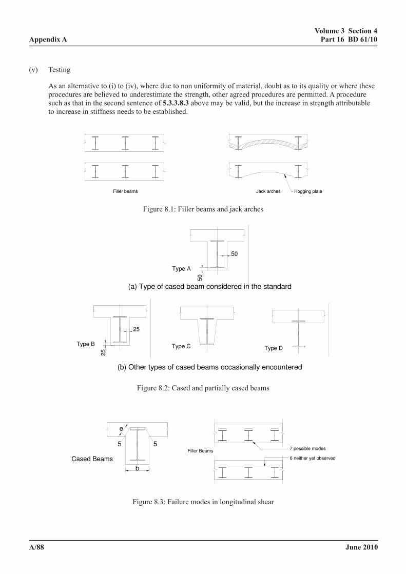
June 2010
volume 3 section 4 part 16 Bd 61/10
a/88
appendix a
(v) Testing
As an alternative to (i) to (iv), where due to non uniformity of material, doubt as to its quality or where these procedures are believed to underestimate the strength, other agreed procedures are permitted. A procedure such as that in the second sentence of 5.3.3.8.3 above may be valid, but the increase in strength attributable to increase in stiffness needs to be established.
Filler beams Jack arches Hogging plate
50
50
Type A
25
25
Type B Type C Type D
Cased Beams
e
5 5
b
6 neither yet observed
Filler Beams7 possible modes
Figure 8.1: Filler beams and jack arches
(a) Type of cased beam considered in the standard
(b) Other types of cased beams occasionally encountered
Figure 8.2: Cased and partially cased beams
Figure 8.3: Failure modes in longitudinal shear
Figure 8.1: Filler beams and jack arches
Filler beams Jack arches Hogging plate
50
50
Type A
25
25
Type B Type C Type D
Cased Beams
e
5 5
b
6 neither yet observed
Filler Beams7 possible modes
Figure 8.1: Filler beams and jack arches
(a) Type of cased beam considered in the standard
(b) Other types of cased beams occasionally encountered
Figure 8.2: Cased and partially cased beams
Figure 8.3: Failure modes in longitudinal shear
Figure 8.2: Cased and partially cased beams
Filler beams Jack arches Hogging plate
50
50
Type A
25
25
Type B Type C Type D
Cased Beams
e
5 5
b
6 neither yet observed
Filler Beams7 possible modes
Figure 8.1: Filler beams and jack arches
(a) Type of cased beam considered in the standard
(b) Other types of cased beams occasionally encountered
Figure 8.2: Cased and partially cased beams
Figure 8.3: Failure modes in longitudinal shear Figure 8.3: Failure modes in longitudinal shear
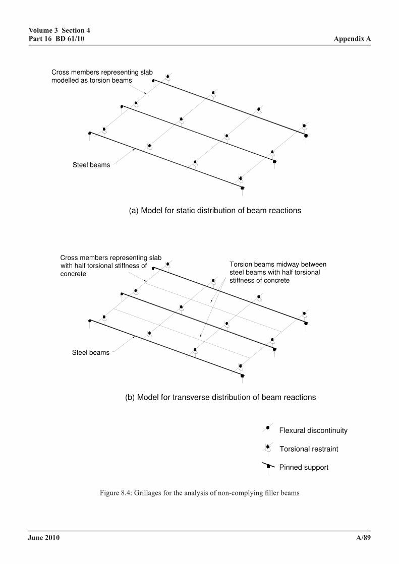
June 2010
volume 3 section 4 part 16 Bd 61/10
a/89
appendix a
Cross members representing slab
modelled as torsion beams
Steel beams
Cross members representing slabwith half torsional stiffness of
concrete
Steel beams
Torsion beams midway betweensteel beams with half torsional
stiffness of concrete
Figure 8.4: Grillages for the analysis of non-complying filler beams
(a) Model for static distribution of beam reactions
(b) Model for transverse distribution of beam reactions
Flexural discontinuity
Torsional restraint
Pinned support
Figure 8.4: Grillages for the analysis of non-complying filler beams
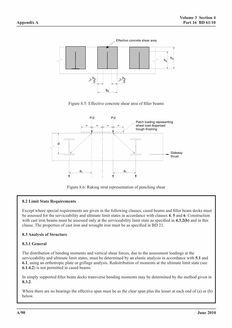
June 2010
volume 3 section 4 part 16 Bd 61/10
a/90
appendix a
Figure 8.5: Effective concrete shear area of filler beams
Figure 8.6: Raking strut representation of punching shear
a
d
=
P/2
==
P/2
=
av v
Patch loading representing wheel load dispersed trough finishing
Sideway thrust
Effective concrete shear area
hh
h3s
es
h3s
be
Figure 8.5: Effective concrete shear area of filler beams
Figure 8.5: Effective concrete shear area of filler beams
Figure 8.6: Raking strut representation of punching shear
a
d
=
P/2
==
P/2
=
av v
Patch loading representing wheel load dispersed trough finishing
Sideway thrust
Effective concrete shear area
hh
h3s
es
h3s
be
Figure 8.6: Raking strut representation of punching shear
8.2 limit state requirements
Except where special requirements are given in the following clauses, cased beams and filler beam decks must be assessed for the serviceability and ultimate limit states in accordance with clauses 4, 5 and 6. Construction with cast iron beams must be assessed only at the serviceability limit state as specified in 4.3.2(b) and in this clause. The properties of cast iron and wrought iron must be as specified in BD 21.
8.3 analysis of structure
8.3.1 general
The distribution of bending moments and vertical shear forces, due to the assessment loadings at the serviceability and ultimate limit states, must be determined by an elastic analysis in accordance with 5.1 and 6.1, using an orthotropic plate or grillage analysis. Redistribution of moments at the ultimate limit state (see 6.1.4.2) is not permitted in cased beams.
In simply supported filler beam decks transverse bending moments may be determined by the method given in 8.3.2.
Where there are no bearings the effective span must be as the clear span plus the lesser at each end of (a) or (b) below.
June 2010
volume 3 section 4 part 16 Bd 61/10
a/91
appendix a
(a) the lesser of the depth of the metal section and the depth from the soffit to the elastic neutral axis of the metal section.
(b) half the projection of the metal beam past the face of the support.
8.3.2 transverse moments in filler beam decks (approximate method). This method is applicable to filler beam decks subject to the full nominal assessment live loading (the UDL and KEL) and/or up to the equivalent of 45 units of type HB loading where the following conditions are satisfied:
(a) the construction consists of simply supported steel or iron beams solidly encased in normal density concrete;
(b) the span in the direction of the beams is not less than 6m and not greater than 18m and the angle of skew does not exceed 20o;
(c) the clear spacing between the tips of the flanges of the beams does not exceed two-thirds of their depth;
(d) the overall breadth of the deck does not exceed 14m;
(e) the amount of transverse reinforcement in the top of the slab is not less than 300mm2/m if mild steel is used or 200mm2/m if high yield steel is used.
The maximum transverse sagging moment per unit length of deck, My due to either HA or HB loading, at any point not less than 2m from a free edge, is
My = (0.95 - 0.04 l) Mx αL (8.1)
where
Mx is the longitudinal bending moment per unit width of deck at the point considered due to the full nominal assessment live loading for the limit state considered.
l is the span of the beams in metres.
αL is the ratio of the product of the partial safety factors γfLγf3 for the HB loading to the corresponding product for the full nominal assessment live loading for the limit state being considered.
Longitudinal bending moments per unit width of deck due to the full assessment loading are found by analysis of the deck as a set of separate longitudinal strips each of width not exceeding the width of one traffic lane.
It is assumed that there is a linear reduction in My from the value at 2m from the free edge of the deck to zero at the edge.
The transverse hogging moment at any point may be taken as 0.1 My per unit length of deck.
June 2010
volume 3 section 4 part 16 Bd 61/10
a/92
appendix a
8.4 analysis of sections
The moments of resistance of cased and filler beams must be assessed in accordance with 5.2 and 6.2 at the serviceability and ultimate limit states respectively. For this purpose a beam must be considered as compact (class 2 in Table 6.1) provided any part of the steel or iron section not encased in concrete satisfies the criteria given in BD 56 (DMBR 3.4.11) and BD 21( duly modified for buckling), except that any wrought iron or steel beam next to a cast iron beam must be assessed as a class 3 cross-section and the moment of resistance of a cased beam with a slab width exceeding 1.5 times the depth of the metal section must be restricted to 60% of the plastic moment of resistance of the composite section. Vertical shear must generally be assumed to be resisted by the steel or iron section alone and the effects of shear lag in filler beam decks must be neglected. (See also 8.1.5)). The stresses in cast iron must not exceed the limits in 4.3.2(b). Where there is sufficient bond between the section and the concrete vertical shear can be carried by the concrete subject to the agreement of the TAA.
8.5 longitudinal shear
8.5.1 serviceability limit state. The longitudinal shear force per unit length between the concrete and steel beam must be calculated by elastic theory, in accordance with 5.3.1 except that, in positive (sagging) moment regions of cased beams and in filler beams, concrete in tension must be neglected. Shear lag effects must be neglected in filler beam decks. The shear force to be transferred must be that appropriate to the area of concrete and steel reinforcement in compression.
For highway bridges and footbridges, providing there is no evidence of corrosion, fretting action or cracking sufficient to adversely affect the achievement of composite action, the longitudinal shear force may be assumed to be resisted by bond between the steel or iron and concrete provided the local bond stress nowhere exceeds 0.5 N/mm2 in cased beams or 0.7N/mm2 in filler beams. The bond may be assumed to be developed uniformly only over both sides of the web and the upper surface of the top and bottom flanges of the steel beam where there is complete encasement and over both sides of the web and the upper surface of the top flange of the steel beam where the beam soffit is exposed. Where both flanges of a filler beam are exposed, the bond may be assumed to be developed uniformly over both sides of the web provided that the filler beams are adequately tied together e.g. by reinforcement passing through the webs or through tie bars. Where the local bond stress, calculated in the manner described, exceeds 0.5 N/mm2 in cased beams or 0.7 N/mm2 in filler beams the bond must be ignored entirely.
Where there are attachments present satisfying the requirements for incidental longitudinal shear connectors in 5.3.3.8.1 the resistance of these may be assumed in addition to the bond, but because of the (elastic) local bond criterion this is permitted only where connectors are well distributed.
8.5.2 ultimate limit state. The longitudinal shear force per unit length of beam must be calculated in accordance with 8.5.1, but for the assessment loading at the ultimate limit state. Where there are no shear connectors to transmit the longitudinal shear force due to vertical loading (see 8.5.1), particular attention must be given to shear planes of type 5-5 (Figure 6.2(d)). In the assessment of filler beams in which the beam spacing exceeds that in 8.3.2(c) possible failure planes through the concrete must be examined including planes partially on the steel/concrete interface, when part of the interface must be taken as 2/3 that in through concrete. The total cross sectional area per unit length of beam of fully anchored reinforcement intersecting the shear surface Ae must not be less than
γmr(qpγf3 - v1Ls/γmv)
0.8fry (8.2)
June 2010
volume 3 section 4 part 16 Bd 61/10
a/93
appendix a
where
qp is the longitudinal shear force per unit length at the ultimate limit state acting on that shear plane.
Ls is the total length of shear plane minus one third bf.
NOTE: The remaining terms are as defined in 6.3.3.
In the assessment of the effects of incidental shear connectors at ULS isolated connectors within span/5 of the supports only may be considered and separation gaps (6.1.3) must be disregarded.
8.6 temperature and shrinkage effects
8.6.1 general. Temperature and shrinkage effects need not be considered in filler beam construction. In cased beams, other than filler beams, consideration must be given to the effects of temperature and shrinkage at the serviceability limit state. In the absence of more precise information the effects of temperature in cased beams must be determined using the temperature effects given in BD 37 for a similar reinforced concrete structure. The effects of shrinkage as modified by creep must be assessed using the values of free shrinkage strain Ecs and the reduction factor for creep φc as given in 5.4.3.
8.6.2 longitudinal stresses and strains. Longitudinal stresses and strains due to temperature effects and shrinkage modified by creep must be calculated in accordance with 5.4.2 and 5.4.3.
8.6.3 longitudinal shear. There must be shear connectors at the ends of cased beams, to transmit the longitudinal shear force Q, due to temperature effects and shrinkage modified by creep as described in 5.4.2.3 and 5.4.3. The longitudinal shear force to be transmitted by the connectors must be the net longitudinal force in the steel or iron beam due to temperature and shrinkage effects calculated on an elastic basis assuming full interaction. It may be assumed to be distributed at the ends of the beam in the manner described in 5.4.2.3. The concrete must be assumed to be uncracked. The effective breadth of the concrete flange must be determined in accordance with 5.4.2.1.
8.7 assessment of cracking
8.7.1 general. The methods given in 5.2.6, supplemented by the provisions in 8.7.2 and 8.7.3, may be used to assess whether the degree of cracking is not excessive at the serviceability limit state. Tensile reinforcement, satisfying the provisions of this clause, may be assumed to contribute to the section properties of the composite beam.
8.7.2 cased beams. Longitudinal bars placed in the side face of beams to control flexural cracking must be of a diameter Φ such that:
ry
b
fbss
≥Φ (8.3)
where
sb is the spacing of bars in the side face of the beam.
b is the breadth of the section at the point where the crack width is being considered.
s is a constant stress of 1 N/mm2, re-expressed where necessary in units consistent with those used for other quantities.
fry is the characteristic yield stress of the reinforcement.
June 2010
volume 3 section 4 part 16 Bd 61/10
a/94
appendix a
Where the overall depth of a cased beam exceeds 750mm there must be longitudinal bars at 250mm spacing or closer in the side faces of the beam over a distance of two-thirds of the overall depth measured from the tension face, unless the assessment of crack widths (see 5.2.6) shows that a greater spacing is acceptable.
8.7.3 filler beams. The widths of cracks due to transverse bending of a filler beam deck must be assessed in accordance with BS 5400-4, as for a reinforced concrete slab, neglecting any contribution from the steel beams to the control of cracking.
8.8 construction
The concrete cover to the metal beam must not be less than 50mm, except that the underside of the bottom flanges of the filler beam can be exposed.
The soffit and upper surface of exposed flanges of filler beams must be protected against corrosion.
In cased beams, other than filler beams, there must be stirrups formed by reinforcing bars enclosing the steel or iron beam and longitudinal reinforcement for control of cracking of the beam encasement. The spacing of the stirrups must not exceed 600mm. The total cross-sectional area of stirrups (both legs) crossing a possible plane of shear failure of type 5-5 (Figure 6.2(d)) must be not less than
0.7 γmr s Ls/fry per unit length of beam (8.4)
where
Ls is as defined in Figure 6(d).
s is defined in 6.3.3.1.
NOTE: Alternatively, mesh of equivalent area may be used.
Concrete cover to reinforcement must be in accordance with the requirements of BD 44.
When the above criteria are not met an agreed procedure must be adopted (see * in Foreword).
June 2010
volume 3 section 4 part 16 Bd 61/10
a/95
appendix a
9 permanent formworK
9.1 general
The assessment requirements of this clause apply to formwork for in situ concrete generally supported from the steelwork or ironwork, which is an integral part of the permanent construction. Where the steel or iron plate forming the top flange of a closed box girder acts as permanent formwork to the concrete deck slab separate assessment requirements are given in 7.7.
Special attention must be given to checking that there is a suitable seal between the steelwork or ironwork and the permanent formwork and that there is no corrosion.
9.2 materials
Materials used as permanent formwork which may be included in the assessment are as follows:
(a) reinforced or prestressed precast concrete.
(b) precast concrete acting compositely with a steel girder or lattice embedded in the overlying in situ concrete.
(c) profiled steel sheeting.
(d) reinforced plastic or glass reinforced cement sheeting or similar.
9.3 structural participation
Permanent formwork may be considered as either:
(a) structurally participating with the overlying in situ concrete slab under the action of loading imposed upon the slab after casting; or
(b) structurally non-participating.
9.4 temporary construction loading
Attention is drawn to the possibility of damage having occurred from handling, from construction plant and from the mounding of concrete that may have occurred during casting. The assessment loads due to temporary construction loading must be determined in accordance with BS 5975 and BD 37. Where the temporary loading is of a transient nature and the resultant stresses and strains are not locked into the structure there is no need to consider this.
9.5 assessment
9.5.1 general. The permanent formwork must be assessed to establish the stresses and deflections that would have arisen from temporary construction loading and it must satisfy the relevant limit states given in BD 44 and BD 56 as appropriate, see 9.4.
9.5.2 non-participating formwork. Permanent formwork made from the materials given in 9.2(d) must be considered as structurally non-participating. Where the permanent formwork is structurally non-participating account must be taken of any effects of differential shrinkage or composite action that may adversely affect the structure. Assessment criteria for cover to reinforcement and crack control applicable to the in situ slab must be satisfied ignoring the presence of the formwork.
June 2010
volume 3 section 4 part 16 Bd 61/10
a/96
appendix a
9.5.3 participating formwork. Where composite action between the permanent formwork and in situ slab exists, the assessment of the composite slab must satisfy all relevant requirements of this Standard and in particular the:
(a) fatigue behaviour;
(b) durability;
(c) bond between permanent formwork and concrete slab both under long term and under impact loading;
(d) corrosion protection.
Participating formwork must only be included in the assessment with the prior agreement of the appropriate TAA.
9.6 special requirements for precast concrete or composite precast concrete participating formwork
9.6.1 assessment. To qualify as participating formwork precast concrete units must comply with the relevant clauses given in BD 44. With continuity between units achieved by the lapping of reinforcement projecting from units, post-tensioning, and the use of high-strength bolts or other means acceptable to the TAA.
9.6.2 welding of reinforcement. Reinforcement that has been welded must only be included when the effects of repeated loading can be shown not to have been detrimental to the permanent structure. Compliance with BD 44 is deemed to satisfy this requirement.
9.6.3 interfaces. Interfaces between precast and in situ concrete must have developed sufficient shear resistance to ensure composite action in both the transverse and longitudinal directions.
9.6.4 cover to reinforcement. Where the clear distance between a precast unit and reinforcement embedded in the in situ concrete slab exceeds the maximum nominal size of aggregate used in the in situ concrete by less than 5mm and there are known problems with the structure the absence of voids beneath the reinforcement must be demonstrated to the satisfaction of the TAA.
June 2010
volume 3 section 4 part 16 Bd 61/10
a/97
appendix a
10 assessment of friction grip Bolts used as shear connectors in composite Beams
10.1 general
High strength friction grip bolts are used to provide the shear connection between the steel or iron member and the concrete slab forming the flange of the composite beam. The following method must be used for the assessment of the connection where general grade bolts complying with the requirements of BS 4395-1 is used in accordance with BS 4604-1. The resistance of higher grades of bolts must only be included when justified by adequate tests.
10.2 assessment requirements: static loading
10.2.1 serviceability limit state. The longitudinal shear resistance per unit length developed by friction between the concrete slab and steel or iron beam must be not less than the longitudinal shear force per unit length at the serviceability limit state assessed in accordance with clause 5. The assessment frictional resistance developed by each bolt at the interface must be taken as:
μ(net tensile force in the bolt)/1.2γf3
where μ, the coefficient of friction at first slip may be taken as 0.45 provided the criteria of 10.4 are satisfied.
Where the concrete flange is cast in situ on the steel beam the value of μ must be taken as 0.50. The nominal initial tensile force in the bolt must be taken as the proof load as given in BS 4604: Part 1 provided there is evidence that the method of tightening complies with the requirements of that British Standard. In determining the net tensile force in the bolt account must be taken of the loss of bolt tension due to shrinkage of the concrete and creep of the steel or iron and concrete.
Where the connectors are subject to external tensile forces in addition to shear, e.g. where loads are suspended from the steelwork or ironwork, account must be taken of the reduction in effective clamping force in the bolt.
10.2.2 ultimate limit state. Shear connectors which comply with 10.2.1 are deemed to satisfy the requirements at the ultimate limit state. When assessing the possibility of longitudinal shear failure through the depth of the slab in accordance with 6.3.3, it must be taken into account that the presence of pockets for the bolts reduces the length of the effective shear plane.
10.3 fatigue
For connections subject only to shear in the plane of the friction interface no account need be taken of the effects of repeated loading.
June 2010
volume 3 section 4 part 16 Bd 61/10
a/98
appendix a
10.4 other considerations
The resistance of the connection must only be taken into account if all the following conditions are satisfied:
• there must be a uniform bearing surface between the steel or iron beam and the concrete slab;
• suitable washers or bearing plates must have been provided to spread the loads from the bolts in order to prevent the concrete underneath being crushed;
• where the slab is precast suitable bedding material can be shown to be present between the slab and the steel beam;
• similarly the inspection or record drawings must have confirmed that there is nothing present on the interface (for example applied finishes, oil, dirt, loose rust, loose mill scale, burrs and other defects) which would prevent a uniform seating between the two elements or would interfere with the development of friction between them;
• Adequate reinforcement, for example in the form of spirals, must be present to ensure that the load is transferred from the bolt to the interface without local splitting or crushing of the concrete slab;
• The details around the bolt holes need careful scrutiny to ensure that local crushing forces on the concrete have not been increased by loads being directly transmitted via the bolt heads. The details must be such as to ensure that forces and moments can be adequately transmitted across the joints between adjacent precast units, and that there are no gaps between the flange and the concrete slab, where corrosion could take place.
June 2010
volume 3 section 4 part 16 Bd 61/10
a/99
appendix a
11 composite columns
11.1 general
11.1.1 scope. This clause gives an assessment method for concrete encased steel or wrought iron sections and concrete filled circular and rectangular hollow steel sections which takes account of the composite action between the various elements forming the cross section. For axi-symmetric columns, moments must be resolved into the principal directions. For columns which are not axisymmetic bending about the two principal axes of the column is considered separately for each axis. A method is given in 11.3.5.5 for determining the effect of interaction when bending about both axes occurs simultaneously. The column may be either statically determinate or rigidly connected to other members at one or both ends, in which case the loads and moments depend on the relative stiffnesses of adjoining members and cannot be obtained by statics alone. Members are assumed to be rigidly connected where, for example, the connection possesses the full rigidity that can be made possible by welding or by the use of high strength friction grip bolts.
Where construction does not satisfy the requirements of the assessment methods of this clause the method of BS 5400-5 or a cased strut method, such as that in BS 5950-1, may be employed with the agreement of the TAA.
11.1.2 materials
11.1.2.1 steel or iron or wrought iron. In columns formed from concrete encased steel or iron sections the structural steel or iron section used in the assessment must be one of the following:
(a) a rolled steel joist or universal section of grade 43 or 50 steel which complies with the requirements of BS 4: Part 1 and BS 4360; or
(b) a symmetrical I-section fabricated from grade 43 or 50 steel complying with BS 4360.
(c) a symmetrical I-section of which the properties are taken from information on the drawings or in BD 21.
Concrete filled hollow steel or iron sections used in the assessment may be either rectangular or circular and must:
(1) be a symmetrical box section fabricated from grade 43 or 50 steel complying with BS 4360 or iron complying with BD 21; or
(2) a structural hollow steel section complying with BS 4360 and BS 4-2 or BS 4848-2 as appropriate or wrought iron complying with BD 21; and
(3) have a wall thickness of not less than:
bs√fy/3Es for each wall in a rectangular section (RHS), or
De√fy/8Es for circular hollow section (CHS)
where
bs is the external dimension of the wall of the RHS.
De is the outside diameter of the CHS.
Es is the modulus of elasticity of steel or wrought iron.
fy is the nominal yield strength of steel or wrought iron.
June 2010
volume 3 section 4 part 16 Bd 61/10
a/100
appendix a
11.1.2.2 concrete. The concrete must be of normal density (not less than 2300 kg/m3) with a characteristic 28 day cube strength or lowest credible strength of not less than 20 N/mm2 for concrete filled tubes nor less than 25 N/mm2 for concrete encased sections and a nominal maximum size of aggregate not exceeding 20mm.
11.1.2.3 reinforcement. Steel reinforcement must comply with the relevant clauses on strength of materials given in BD 44.
11.1.3 shear connection. To use this assessment method provision is required for loads applied to the composite column to be distributed between the steel and concrete elements in such proportions that the shear stresses at the steel/concrete interface are nowhere excessive. Shear connectors must be present where these shear stresses, due to the assessment ultimate loads, would otherwise exceed 0.6 N/mm2 for cased sections or 0.4 N/mm2 for concrete filled hollow steel sections.
11.1.4 concrete contribution factor. The method of analysis in 11.3 is restricted to composite cross sections where the concrete contribution factor αc, as given below, lies between the following limits:
for concrete encased steel or wrought iron sections 0.15 < αc < 0.8.
for concrete filled hollow steel or wrought iron sections 0.10 < αc < 0.8.
where
0.67 Ac fcu αc= Npl γmc
and the squash load Npl is given by:
Asfy Arfry 0.67 Acfcu Npl= + + γmγf3 γmrγf3 γmcγf3
except that for concrete filled circular hollow steel or iron sections αc and Npl must be determined in accordance with 11.3.7.
In the previous expressions,
γm = 1.05.
As is the cross-sectional area of the rolled or fabricated structural steel section.
Ar is the cross-sectional area of reinforcement.
Ac is the area of concrete in the cross section.
fy is the nominal yield strength or worst credible strength of the structural steel or iron.
fry is the characteristic yield strength or worst credible strength of the reinforcement.
fcu is the characteristic 28 day cube strength or worst credible cube strength of the concrete.
June 2010
volume 3 section 4 part 16 Bd 61/10
a/101
appendix a
11.1.5 steel contribution factor. The steel contribution factor is
As fy δ= Npl γmγf3
11.1.6 limits on slenderness. The ratio of the effective length, determined in accordance with 11.2.2.4 to the least lateral dimension of the composite column, must not exceed:
(a) 55 for concrete filled circular hollow sections; or
(b) 65 for concrete filled rectangular hollow sections.
11.2 moments and forces in columns
11.2.1 general. The loads and moments acting in the two principal planes of the column, due to loading at the ultimate limit state, must be determined by an appropriate analysis in which the actual length of the column is taken as the distance between the centres of end restraints. Proper account must be taken of the rotational and directional restraint afforded by adjoining members and the reduction in member stiffness due to inelasticity and axial compression. Alternatively, the method given in 11.2.2 may be used.
11.2.2 semi-empirical assessment method for restrained composite columns
11.2.2.1 scope. The semi-empirical method of analysis given in 11.2.2.2 to 11.2.2.6 is only applicable to isolated columns or columns forming part of a single storey frame provided that the restraining members attached to the ends of the column remain elastic under their assessment ultimate load; otherwise the stiffness of the restraining members must be appropriately reduced in calculating the effective length of the column and the end moments. The method is not applicable to cast iron sections.
1.2.2.2 moments and forces on the restrained column. End moments and forces acting in the two principal planes of the column must be determined either by statics, where appropriate, or by an elastic analysis neglecting the effect of axial loads both on member stiffness and on changes in the geometry of the structure as it deflects under load. The relative stiffness of members (I/l) must be based on the gross (concrete assumed uncracked) transformed composite cross section using an appropriate modulus of elasticity determined from BD 44, with 1 taken as the distance between centres of end restraints.
11.2.2.3 equivalent pin-ended column. The actual column must be replaced by an equivalent pin-ended column of length equal to the effective length of the restrained column in the plane of bending and subjected to the same end loads and end moments as the restrained column, except that where the column is free to sway, the equivalent pin ended column must always be considered to be in single curvature bending with the smaller end moment in a particular plane taken as the calculated value or three-quarters of the larger end moment, whichever is greater. The strength of the equivalent pin-ended column must then be determined in accordance with 11.3.
11.2.2.4 effective length. The effective length of the restrained column must be determined from Table 11 of BD 44.
11.2.2.5 transverse loads. Transverse loads must be included in the elastic analysis of the restrained column if this results in a more severe loading condition. In a braced frame (or column) when the maximum resultant moment within the length of the column Mmax, due to the whole of the assessment ultimate loads, is greater than half the modulus of the algebraic sum of the end moments the alternative loading condition of single curvature bending must also be considered with the end moments equal to Mmax. Single curvature bending is here assumed to produce end moments of the same sign at each end of the column.
June 2010
volume 3 section 4 part 16 Bd 61/10
a/102
appendix a
11.2.2.6 column self weight. The axial component of self weight must be considered in assessment as an additional end load acting concentrically on the column. In raking columns, account must also be taken of the bending moments in the column due to the normal component of its self weight.
11.3 analysis of columns
11.3.1 concrete encased steel section. Assessment methods are given for both short and slender column lengths subjected to any combination of axial load and bending moments at their ends such that the transverse shear force does not exceed VD/3 where VD is as defined in BD 56.
No account is taken of transverse loading applied within the column length, so that any such loading must be negligible.
The steel section must be a rolled or fabricated H or I section with
rx/hs≥0.39 and ry/bs>0.24
where
rx is the greater radius of gyration of the steel section,
ry is the lesser radius of gyration of the steel section,
hs is the depth of the steel section in the plane of the web,
bs is the breadth of the steel section.
The value of the yield strength of the structural steel to be used in calculations must not exceed 355N/mm2.. The concrete cover to the structural steel must be fully bonded to the steel and must be unaffected by cracks likely to affect the composite action.
11.3.2 major and minor axes. For the methods of 11.3, the major and minor axes of bending of the composite section are to be taken as the major and minor axes of the structural steel section.
11.3.3 definition of slender columns. For the methods of 11.3 a column length is defined as short when neither of the ratios lex/h and ley/b exceeds 12,
where
h is the overall depth of the composite section perpendicular to the major axis, and
b is the overall depth of the composite section perpendicular to the minor axis.
lex and ley are the effective lengths calculated in accordance with 11.2.2.4 in respect of the major axis and minor axis respectively.
It must otherwise be considered as slender.
11.3.4 slenderness limits for column lengths. The effective length lex must not exceed the least of:
20h, 250 rx and 100 h12 /h2
The effective length ley must not exceed the least of:
20b, 250 ry and 100 h12 /h2
June 2010
volume 3 section 4 part 16 Bd 61/10
a/103
appendix a
Where
h1 is the lesser of h and b
h2 is the greater of h and b
other symbols are as defined in 11.3.1 and 11.3.3.
11.3.5 short columns that resist combined compression and bending.
11.3.5.1 scope. Concrete-encased short columns may be assessed in accordance with 11.3.5.2 to 11.3.5.5 if the following conditions are satisfied.
(1) The steel contribution ratioδ, defined in 11.1.5 is not less than 0.50.
(2) The assessment eccentricities of the axial force, ex and ey satisfy
ex>| 1.5h and (11.1a)
ey>| 1.0b (11.1b)
where ex and ey are determined in accordance with 11.3.5.2.
(3) Neither hs/h nor bs/b is less than 0.50, where the symbols are as defined in 11.3.1 and 11.3.3.
Where the end moments about the minor axis are nominally zero and the column is unrestrained against failure about the minor axis, the column is likely to fail in a biaxial mode unless the axial load is very small. The column must be such that:
(a) the requirements of 11.3.3 are satisfied, and
(b) the assessment load acting on the column N is not greater than the strength of the column in biaxial bending Nuxy calculated from the equation given in 11.3.5.5 except that Nuy must be calculated from 11.3.5.4 taking ey as equal to 0.03b to allow for construction tolerances, where b is the least lateral dimension of the column.
11.3.5.2 design eccentricities of the axial force. Assessment resistances given in 11.3.5.3 to 11.3.5.5 are for columns subjected to single-curvature bending. The eccentricity of loading about each axis must be taken as the greater of the values for the two ends of the column, subject to conditions (1) to (3) below.
(1) Where the applied load is eccentric about one axis only, the eccentricity about that axis must be taken as not less than 0.04h1, where h1 is as defined in 11.3.4. No nominal eccentricity about the other axis need be considered.
(2) Where the applied load is eccentric about both axes, neither eccentricity must be taken as less than 0.04h1.
(3) Where 11.3.5 is used for an axially loaded column, the eccentricity of loading must be taken as 0.04h1 about the axis that gives the lower strength.
June 2010
volume 3 section 4 part 16 Bd 61/10
a/104
appendix a
For a column subject to double-curvature bending, or with at least one end prevented from rotation in the plane or planes considered, the design resistances given in 11.3.5.3 to 11.3.5.5 must be increased as follows:
(a) by 5% when lex/h ≤ 8 and ley /b ≤ 8, and
(b) by 10% when lex /h > 8 and ley /b ≤ 12
11.3.5.3 assessment for bending about the major axis. The assessment ultimate load must not exceed the assessment resistance Nux given by:
Nux=Np1k1/(1+k2) (11.3)
where
)/3-(1+/hh/he2.3=k
s
x2 δδ
Npl is the squash load calculated in accordance with 11.1.4.
k1 is the lower of the values of k1x and k1y.
k1x and k1y are slenderness reduction factors
other symbols are as defined elsewhere in 11.3.
Values of k1x and k1y are given in Figure 11.1. As an alternative, they may be calculated from the following equations, which must only be used within the bounds of the Figure:
31.2+
hh26.1-
hl0.24.5-
hl
10001-1.007=k sexex
1x
0.1)+(0.4220-
bl+32.9-33.23-
bl
10001-1.010=k y
eyy
ey1y ββ
where βy=(1-δ)bs/b
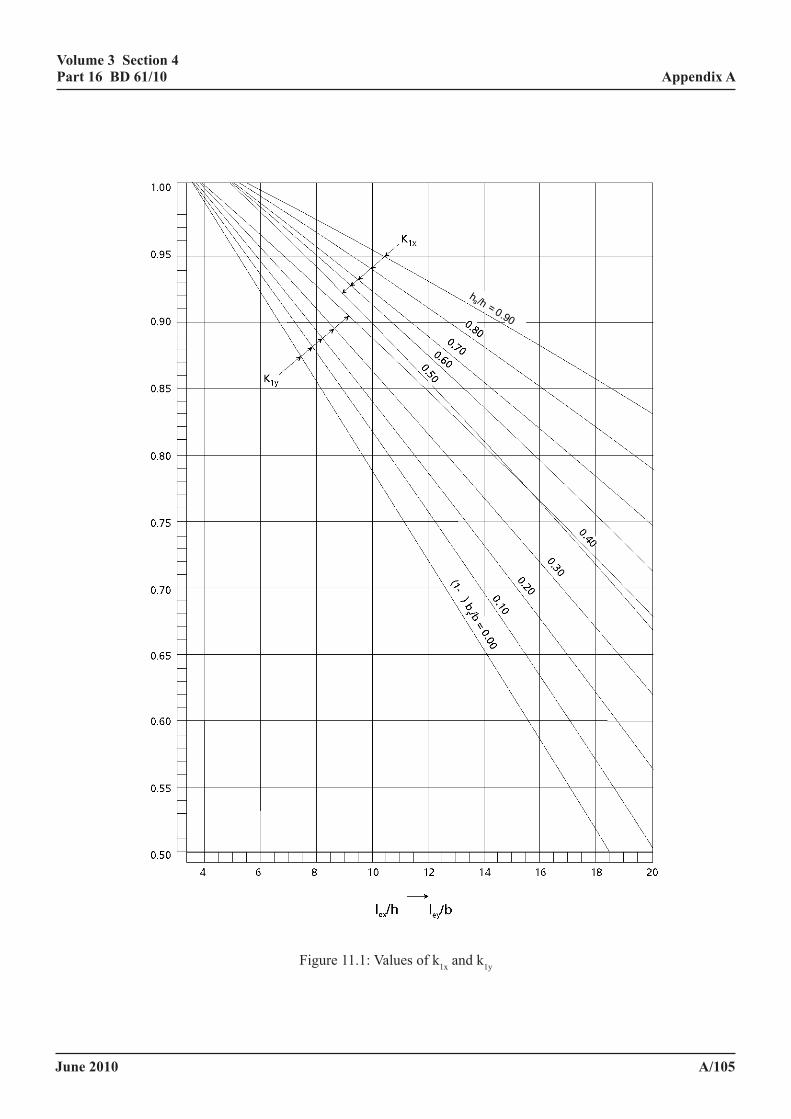
June 2010
volume 3 section 4 part 16 Bd 61/10
a/105
appendix a
hs /h = 0.90
Figure 11.1: Values of k1x and k1y
June 2010
volume 3 section 4 part 16 Bd 61/10
a/106
appendix a
11.3.5.4 assessment for bending about the minor axis. The assessment ultimate load must not exceed the design resistance Nuy given by:
Nuy=Np1K1/(1+k3) (11.4)
where
)/2-(1+/bb/be4=k
s
y3 δδ
Other symbols are as defined elsewhere in 11.3.
11.3.5.5 assessment for biaxial bending. The design ultimate load must not exceed the assessment resistance Nuxy given by
Nuxy=Np1K1/(1+k2+k3) (11.5)
where the symbols are as defined in 11.1.4 and elsewhere in 11.3.
11.3.6 slender columns. A concrete-encased column length that is slender as defined in 11.3.3 may be assessed conservatively by the methods given for short columns in 11.3.5. Alternatively, and providing that the conditions (1) to (3) of 11.3.5.1 are satisfied, the assessment resistance may be calculated from 11.3.5.2 to 11.3.5.5, with k2 and k3 replaced by k4 and k5 given by
k4=k2[1=(λmax-12)/37]
k5=k3[1=(λmax-12)/37]
where
λmax is the greater of ley/b and 12, when k1y ≤ k1x, or
λmax is the greater of 0.7 lex/h and 12, when k1y > k1x
other symbols are as defined elsewhere in 11.3.
The substitutions for k2 and k3 are both applicable when the column length is slender about one axis only.
11.3.7 ultimate strength of axially loaded concrete filled circular hollow sections. In axially loaded columns formed from concrete filled circular hollow steel or iron sections account must be taken of the enhanced strength of triaxially contained concrete in the method given above by replacing the expressions for αc and Npl given in 11.1.4 by the following:
3
67.0
fmcpl
cccc N
Afλγ
α = (11.6)
33
67.0''
fmcpl
ccc
fm
syc N
AfAf
λγγγα += (11.7)
where
γm = 1.05
γmc = 1.50
June 2010
volume 3 section 4 part 16 Bd 61/10
a/107
appendix a
fcc is an enhanced characteristic strength of triaxially contained concrete under axial load, given by:
fDtC+f=f ye
1cucc (11.8)
f’y is a reduced nominal yield strength of the steel or iron casing, given by:
f’y = C2 fy
C1 and C2 are constants given in Table 11.1.
De is the outside diameter of the tube.
t is the wall thickness of the steel or iron casing and the remaining symbols are defined as in 11.1 and 11.2.2.4.
Table 11.1 Value of constants C1 and C2 for axially loaded concrete filled circular hollow sections
D1e
eC1 C2
0 5 10 15 20 25
9.47 6.40 3.81 1.80 0.48 0.00
0.76 0.80 0.85 0.90 0.95 1.00
11.3.8 tensile cracking of concrete. No check for crack control need be made in the following:
(a) concrete filled hollow steel sections, or
(b) concrete encased steel or iron sections provided the assessment axial load at the ultimate limit state is greater than 0.3 fcu Ac/γmc, where the symbols are as defined in 11.1.4.
Where the assessment axial load in concrete encased steel or iron sections is less than the value given in (b) and tensile stresses due to bending can occur in one or more faces of the composite section, cracking of the concrete must be assessed in accordance with 5.2.6 considering the column as a beam.
11.3.9 details. To prevent local spalling of the concrete under loading above the capacity of the bare steel or iron section, reinforcement must be present in concrete encased sections. Stirrups of an appropriate diameter must be present throughout the length of the column at a spacing not exceeding 200mm anchored around at least four longitudinal bars.
The concrete cover to the nearest surface of the steel member must be fully bonded to the steel or iron steel member, there must be no cracks likely to affect the composite action, and proper compaction of the concrete must be established, including between steel elements.
11a composite columns
June 2010
volume 3 section 4 part 16 Bd 61/10
a/108
appendix a
The Standard does not consider filled tubes subject to bending. The method for designing cased columns in the Design Code is more elaborate and more conservative than the method in BS EN 1994 and it is seldom used. A method has been produced (43) which is simpler than either method and which has been calibrated to give column strengths agreeing with strengths obtained using the Design Code to the following tolerances:
at normal eccentricities of column 5% unsafe to load (ex/hx and ey/hy ≤ 0.60 for 10% safe uniaxial bending)
for biaxial bending and at higher 10% unsafe to eccentricities in uniaxial bending 25% safe
This is the basis of the present assessment procedure.
The method is considered to be generally conservative compared to the method in EC4.
June 2010
volume 3 section 4 part 16 Bd 61/10
a/109
appendix a
12 influence of method of construction on assessment
12.1 sequence of construction.
Where a partially cast slab is assumed to act compositely the shear connection must be assumed for this condition as well as for the final condition.
Consideration must be given to the possibility of damage having occurred to partly matured concrete as a result of limited composite action, due to deformation of the steel beams under subsequent concreting operations. Damage is likely to have occurred where loading of the composite section was not delayed until the concrete has attained a cube strength of 20N/mm2.
Where the composite section was loaded before the concrete had attained its 28 day characteristic cube strength the elastic properties and limiting compressive stresses of the concrete and the nominal strengths of shear connectors must be based upon fc, the cube strength of the concrete at the time considered, except that no reduction in stiffness of the concrete need be made if
0.75 fcu < fc < fcu
Where the cube strength of the concrete at the time considered fc, was not less than 20 N/mm2, the nominal strengths of shear connectors must be determined by linear interpolation of the values given in Table 5.1.
12.2 permanent formwork
Requirements for temporary construction loading, which must be assumed in assessing the permanent formwork, are given in 9.4.
June 2010
volume 3 section 4 part 16 Bd 61/10
a/110
appendix a
13 prestressing in composite construction
13.1 general
Prestressing can reduce, or in some circumstances prevent, the cracking of concrete under service loading so increasing stiffness and improving the protection of steel from corrosion.
13.2 methods of prestressing
Among the methods by which prestressing may have been achieved are the following:
(a) system whereby a moment is applied to the steel section in the same direction as it will act in the structure. The tension flange is then encased in concrete and the moment relaxed when the concrete has adequate strength;
(b) the use of jacking to alter the relative levels of the supports of a continuous member after part or whole of the concrete deck has been cast and matured;
(c) prestressing the concrete slab or sections of the slab by tendons or jacking whilst it is independent of the steel section and subsequently connecting them;
(d) prestressing the steel beam by tendons prior to concreting irrespective of whether they were or were not released after the concrete has matured;
(e) prestressing the composite sections by tendons or jacking.
Special consideration must be given to composite beams which have been prestressed by an external system or by tendons not directly bonded to the concrete. In these circumstances, the effect of the prestressing forces must take account of the deformation of the whole structure.
13.3 limit state requirements
Prestressed composite members must be assessed for the serviceability and ultimate limit states in accordance with the general requirements of this and other parts of this Standard.
13.4 prestressing the steel Beam
Consideration must be given to the stresses that were developed in the steel beam during prestressing. The stresses in the steelwork must not exceed the limiting stresses given in BD 56.
13.5 stress limitations in concrete at transfer
Where it is considered that cracking resulted from stresses at transfer these must be calculated in accordance with 5.2.
Where the concrete was pre-compressed by the release of a temporary prestress in the steel beam the compressive stress in the concrete at transfer, or where the concrete slab or a section of the slab was permanently prestressed before it acted compositely with the steel beam, the stresses in the concrete at transfer, in tension or compression, must not exceed the limitations given in BD 44 for prestressed concrete.
June 2010
volume 3 section 4 part 16 Bd 61/10
a/111
appendix a
13.6 loss of prestress
The loss of prestress and the effects of shrinkage in non composite prestressed concrete members must be calculated in accordance with the requirements of BD 44.
Where the concrete acts compositely with the steel section account must be taken of the reduction in prestress and the effect on the stresses in the composite section due to elastic deformation, shrinkage and creep of the concrete and relaxation in the prestressing steel or tendon.
June 2010
volume 3 section 4 part 16 Bd 61/10
a/112
appendix a
14 JacK arch and trough construction
A method for assessing jack arches which may be used on the approval of the TAA is given below; this is less conservative than the method in BA 16.
For trough construction the method in BA 16 is generally appropriate, but there are situations in which greater strengths can be justified and these are discussed in the standard.
14.1 Jack arch construction
The rules for the assessment of jack arches are the same as those for non-complying filler beams subject to the following modifications.
It is at present premature to identify a preferred simple approach to the analysis of jack arches. However restrictions in the scope are necessary for most methods (including that in BA 16), as indicated below.
(i) The method of clause 7 of BA 16 which permits the use of clause 8 of BD 61, but with the simple transverse distribution rules in clause 2 of BA 16. It is permitted to use this method with the provisions of BD 21 and BD 61.
(ii) An orthotropic plate or grillage analysis in which the depth of the transverse members is taken as an effective depth, constant across each vault, equal to the thickness at the crown of the arch plus one fifth of the vertical distance between the crown and the soffit of the steel section(40). The tensile stresses in these members, neglecting arch compression, should not exceed 70% of the limiting torsional stresses in clause 8. Methods (i) and (ii) only are admissible where the edge girders, or ties at a spacing longitudinally not exceeding 1.3 times the spacing of the metal beams, are sufficient to resist the lateral thrusts.
(iii) The analysis in Table 8.1 with Jconcrete assessed from the area of concrete of the depth of the rectangle described in 8.1.4, but extending horizontally between the crowns of the adjacent vaults.
For masonry the above methods may be used with the following modification. Method (i) may only be used when the condition factor for the masonry in BD 21 and BA 16 is not less than 0.90 and when the minimum depth of material at the crown, excluding the top 75mm of surfacing, is not less than the depth of the metal beam. Where there is concrete above the masonry the thickness of masonry in this section should be the depth of masonry at the crown. The stiffnesses of the materials may be estimated by the method in H1 (opening paragraph). The interface stresses between masonry and concrete need not be checked. It is permitted to use this method with the provision of BD 21, BD 61 and relevant parts clause 8, but neither 8.1.8, nor the related parts of annex h. Methods (ii) and (iii) above are both applicable with the modifications for masonry in 8.1.4, providing the condition factor is not less than 0.70. The method in the last paragraph 8.1.4 is of general applicability but the tensile stress check for method (ii) above should be used.
A flow chart summarising the use of the various methods here, in BA 16 and BD 21, is included in annex i.
The effective perimeter assumed to provide bond should be restricted to the upper surface of the top flange and the web where the infill is at least 50mm thick. The bond strength for concrete at SLS and the stress on the shear connection at ULS reduced by a factor of 1.40 (or some other agreed factor), and the option of sometimes using the plastic moment of resistance does not apply.
The shear resistance of jack arches may be assumed to be the same as for filler beams in 8.1.5.
The effect of finishing may be taken into account by the method in 8.1.8. When the girders are of cast iron the values of αe should be halved.
June 2010
volume 3 section 4 part 16 Bd 61/10
a/113
appendix a
In hogging plate construction, which is the more modern form of jack arch construction (in which the beams are more likely to be of mild steel than cast iron), the horizontal shear resisted between the hogging plate and the fill should be disregarded, except where the fill is of concrete when incidental shear connection from rivet (or bolt) heads may be taken into account.
Tie rods are often present in jack arches to resist the arch thrust along the sides of the bridge. The adequacy of these should be established. Where these are sufficient the resistance of the arches to transverse loads should be established, for example by an arch program. Where these are insufficient, spreading of the arches should be taken into account by use of a multiple arch program.
14.2 trough construction
Smooth troughs with ‘open’ profiles have substantially lower incidental composite action than jack arch or filler beam construction, so troughs should be assessed in accordance with BD 21, though the following modifications are permitted. Where the depth of ‘fill’ is nowhere less than 70% of the total depth the transverse stiffness may be assumed to be 10% of the longitudinal stiffness. Transversely there is full composite action, but as troughs are seldom interconnected transversely this affects stiffness, but not strength. However where there are rivet or bolt heads penetrating concrete overlays the rules for incidental shear connectors in 5.3.3.8 may be used, and, where the surfaces of the troughs are sufficiently steep that these devices resist uplift, consideration may be given to reducing values of γb. Alternative procedures to the above are permitted provided they can be justified and provided they take into account differences in the performance of the structure at SLS and ULS.
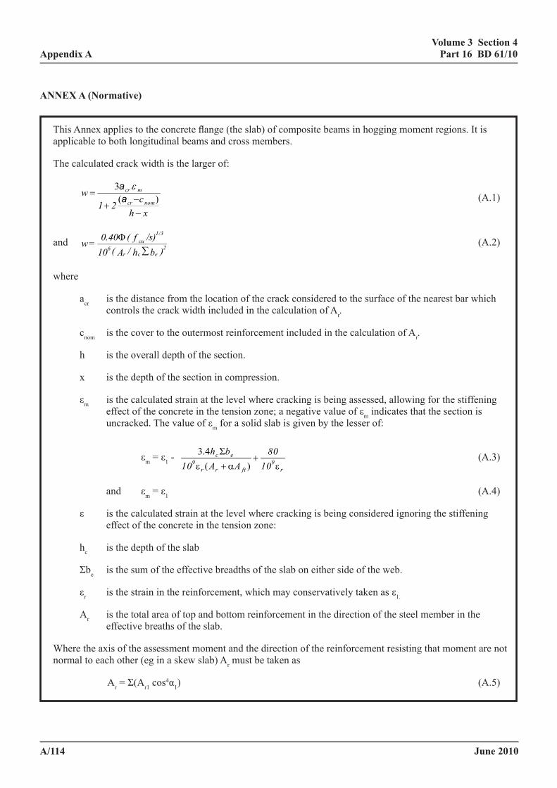
June 2010
volume 3 section 4 part 16 Bd 61/10
a/114
appendix a
anneX a (normative)
This Annex applies to the concrete flange (the slab) of composite beams in hogging moment regions. It is applicable to both longitudinal beams and cross members.
The calculated crack width is the larger of:
xhc21
wnomcr
mcr
−−
+=
)(3aa ε
(A.1)
and )bh/A(10
/s)f(0.40=w 2ecr
6cu
1/3
∑Φ (A.2)
where
acr is the distance from the location of the crack considered to the surface of the nearest bar which controls the crack width included in the calculation of Ar.
cnom is the cover to the outermost reinforcement included in the calculation of Ar.
h is the overall depth of the section.
x is the depth of the section in compression.
εm is the calculated strain at the level where cracking is being assessed, allowing for the stiffening effect of the concrete in the tension zone; a negative value of εm indicates that the section is uncracked. The value of εm for a solid slab is given by the lesser of:
εm = ε1 - r
9ftrr
9ec
1080
AA10bh
ε+
α+ε )(Σ4.3 (A.3)
and εm = ε1 (A.4)
ε is the calculated strain at the level where cracking is being considered ignoring the stiffening effect of the concrete in the tension zone:
hc is the depth of the slab
Σbe is the sum of the effective breadths of the slab on either side of the web.
εr is the strain in the reinforcement, which may conservatively taken as ε1.
Ar is the total area of top and bottom reinforcement in the direction of the steel member in the effective breaths of the slab.
Where the axis of the assessment moment and the direction of the reinforcement resisting that moment are not normal to each other (eg in a skew slab) Ar must be taken as
Ar = Σ(Ar1 cos4α1) (A.5)
June 2010
volume 3 section 4 part 16 Bd 61/10
a/115
appendix a
Ar1 is the area of reinforcement in a particular direction
α1 is the angle between the axis of the assessment moment and the direction of the reinforcement, Ar1, resisting that moment.
α is yft/yr
Φ is the diameter of the reinforcement near the top of the slab.
Aft is the area of the tension flange.
yr is the distance from the neutral axis to the centroid of the reinforcement.
yft is the distance from the neutral axis to the centre line of the tension flange of the steel section.
fcu Characteristic or worst credible concrete cube strength.
s a constant stress of 1 N/mm2 re-expressed where necessary in units consistent with those used for other quantities.

June 2010
volume 3 section 4 part 16 Bd 61/10
a/116
appendix a
anneX B (informative)
lateral-torsional BucKling of composite Beams with slaB and girders tied laterally and rotationally
B.1 general
B.1.1 This annex deals with the assessment of the hogging moment region of non-compact girders in which the slabs and girders are tied horizontally and vertically such that flexural transverse stiffness of the slab restrains the girder. This condition may be assumed when the conditions in 5.3.3.3 are satisfied.
B.2 Based on a continuous inverted-u frame model
B.2.1 elastic critical stress.
(1) This clause is applicable to non-compact composite girders or portions of girders with continuity at one or both ends and a restrained top flange, that satisfy conditions (c) and (f) to (j) of 6.2.3.3. The steel member must be a doubly symmetrical or mono-symmetrical rolled or welded I-section of uniform depth throughout the span considered. The shear connection must satisfy (7) and (8) below.
(2) The model for this method is the continuous inverted-U frame. It does not rely on the provision of web stiffeners except those required by 6.2.3.3(j).
(3) No special provision need be made at internal supports to provide warping fixity or to prevent rotation in plan of the steel bottom flange.
(4) The elastic critical buckling moments from the hogging moment at an internal support may be taken as:
( )( )[ ]0.5sfys2
4sss4c
cr IEπC/16LkJGLCk M += (B.1)
where
L is the length of the beam between points at which the bottom flange of the steel member is laterally restrained.
C4 is a property of the distribution of bending moment within length L given in Tables B.1 to B.3. Where the bending moments at the supports are unequal, C4 relates to the support with the larger hogging moment.
(5) The properties of the effective cross-section refer to those in the hogging moment region and are as follows:
kc is a factor given in B.2.2 or B.2.3.
Es and Gs are respectively the modulus of elasticity and the shear modulus for steel, given in BD 56.
A is the area of the equivalent cracked transformed composite section, calculated with the effective breadth of the concrete flange in 5.2.3 and the short term modulus of elasticity of concrete neglecting concrete in tension but including reinforcement in tension.
Ix is the second moment of area for major-axis bending of the composite section of Area A.
As is the area of the structural steel section.
June 2010
volume 3 section 4 part 16 Bd 61/10
a/117
appendix a
rxy2 = (Isx + Isy)/As (B.2)
Isx & Isy are second moments of area of the structural steel section about the centroid of area A.
Isfy is the second moment of area of the bottom flange about the minor axis of the steel member.
Js is the St Venant torsion constant of the steel section.
ks is a transverse stiffness per unit length of the beam, given by
k+kkk=k
21
21s (B.3)
k1 is the flexural stiffness of the cracked concrete or composite slab in the direction transverse to the steel beam, which may be taken as
k1 = 4EsI2/a for a slab continuous across the steel beam, (B.4)
and
k1 = 2EsI2/a for a simply supported or cantilever slab (B.5)
EsI2 is the “cracked” flexural stiffness per unit width of the concrete or composite slab and I2 must be taken as the lower of:
the value at mid-span of the slab, for sagging bending, and the value at an internal support of the slab, for hogging bending
k2 is the flexural stiffness of the steel web, to be taken as:
h)v-(14
tE=ks
2s
3ws
2 for an uncased beam (B.6)
)b/t4+(1h16
btE=kftwef
2ftws
2α
for a cased beam (B.7)
αe is the modular ratio for long term loading calculated in accordance with 5.4.3.
υs is Poisson's ratio for steel.
bft is the breadth of the steel flange of the steel member to which shear connectors are attached.
hf is the distance between the shear centres of the flanges of the steel member.
Other symbols are defined in Figure B.1.
(6) λLT is obtained from
cr
pes
2LT
ZE
M π λ = (B.8)
where
Mcr is the elastic buckling moment as determined in (4).
June 2010
volume 3 section 4 part 16 Bd 61/10
a/118
appendix a
(7) Except where specific account is taken of the influence of inverted U-frame action on the resistance of the shear connection, the longitudinal spacing of studs or rows of studs, sL must be such that:
Xk
X)-(1df0.4bs
s
2u
ft
L ≤ (B.9)
where
X is MR/Mcr
d is the diameter of the studs.
fu is the characteristic tensile strength of the studs (see Table 5.1).
ks is as defined in B.2.2(5).
bft is as defined in (5).
MR is as defined in 9.8 of BD 56.
Mcr can be taken from (4) above.
(8) The longitudinal spacing of connectors other than studs must be such that the resistance of the connection to transverse bending is not less than that required when studs are used.
B.2.2 doubly symmetrical steel sections
Where the cross section of the steel member is symmetrical about both axes, the factor kc in B.2.1 is given by:
h+e
r+/4hI/Ih=k
f
2yx
2f
xsxfc (B.10)
where
)A-(AyAAI=e
scs
sx (B.11)
yc is the distance between the centroid of the area of the steel member and mid-depth of the slab.
Other symbols are defined in B.2.1.
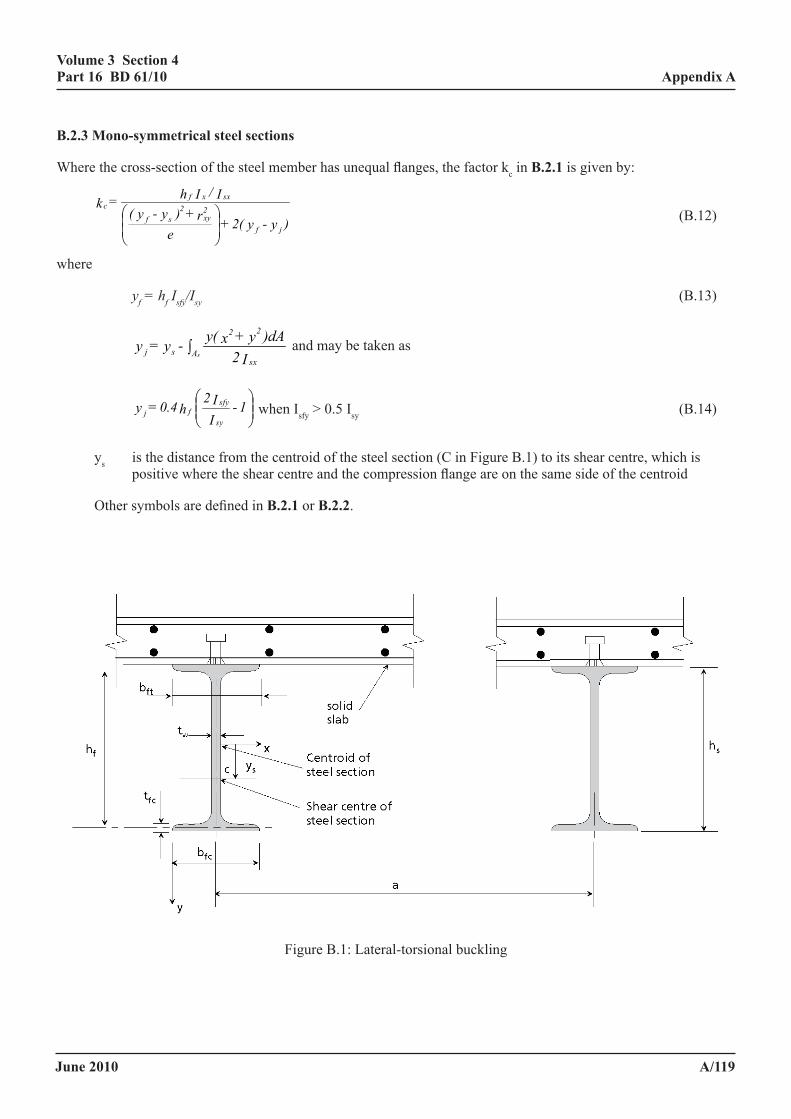
June 2010
volume 3 section 4 part 16 Bd 61/10
a/119
appendix a
B.2.3 mono-symmetrical steel sections
Where the cross-section of the steel member has unequal flanges, the factor kc in B.2.1 is given by:
)y-y2(+e
r+)y-y(I/Ih=k
jf
2xy
2sf
sxxfc
(B.12)
where
yf=hfIsfy/Isy (B.13)
I2)dAy+xy(-y=y
sx
22
Asj s∫ and may be taken as
1-
II2h0.4=ysy
sfyfj when Isfy > 0.5 Isy (B.14)
ys is the distance from the centroid of the steel section (C in Figure B.1) to its shear centre, which is positive where the shear centre and the compression flange are on the same side of the centroid
Other symbols are defined in B.2.1 or B.2.2.
Volume 3 Section 4 Appendix A Part 16 BD 61/09
April 2009 A/130
Other symbols are defined in B.2.1 or B.2.2.
Figure B.1: Lateral-torsional buckling
Figure B.1: Lateral-torsional buckling
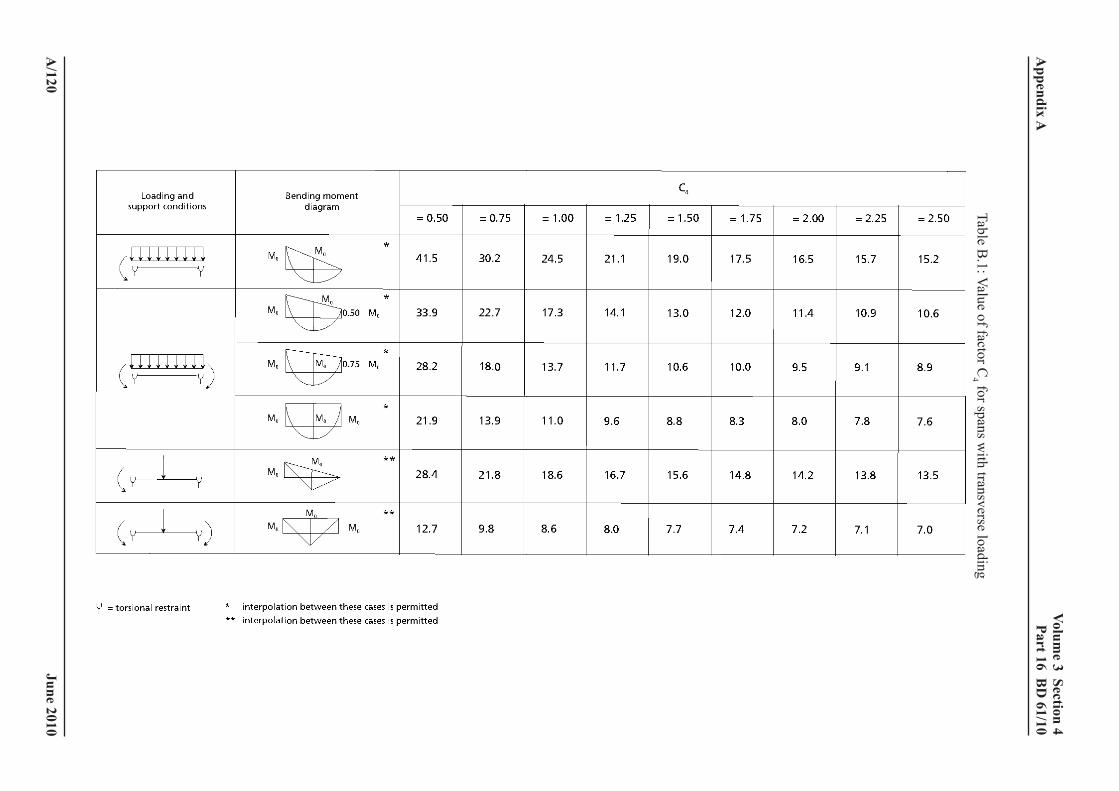
June 2010
volume 3 section 4
part 16 Bd
61/10
a/120
appendix a
Table B.1: Value of factor C
4 for spans with transverse loading
Volum
e 3 Section 4 A
ppendix A
Part 16 BD
61/09 A
pril 2009 A
/131
Table B.1: V
alue of factor C4 for spans w
ith transverse loading
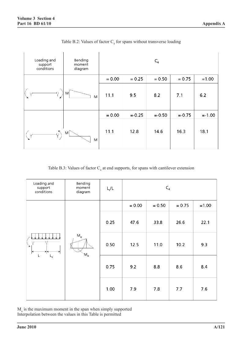
June 2010
volume 3 section 4 part 16 Bd 61/10
a/121
appendix a
Table B.2: Values of factor C4 for spans without transverse loadingVolume 3 Section 4 Appendix A Part 16 BD 61/09
April 2009 A/132
Table B.2: Values of factor C4 for spans without transverse loading
Table B.3: Values of factor C4 at end supports, for spans with cantilever extension
Mo is the maximum moment in the span when simply supported Interpolation between the values in this Table is permitted
Table B.3: Values of factor C4 at end supports, for spans with cantilever extension
Volume 3 Section 4 Appendix A Part 16 BD 61/09
April 2009 A/132
Table B.2: Values of factor C4 for spans without transverse loading
Table B.3: Values of factor C4 at end supports, for spans with cantilever extension
Mo is the maximum moment in the span when simply supported Interpolation between the values in this Table is permitted
Mo is the maximum moment in the span when simply supportedInterpolation between the values in this Table is permitted
June 2010
volume 3 section 4 part 16 Bd 61/10
a/122
appendix a
anneX c (informative)
lateral-torsional BucKling of composite Beams with slaBs and girders tied laterally But not rotationally
c.1 general
c.1.1 introduction.
c.1.1.1 scope. This annex deals with the assessment of the hogging moment regions of compact and non-compact girders, or portions of girders between effective torsional restraints to both flanges, along which the tension flange is laterally restrained at intervals. See Figure C.1. The rules below do not include the effects of minor axis bending. Where appropriate these effects must be included in the summation checks in c.2(a)(1) and c.2(a)(2), as in 9.9.4.2 and 9.9.4.1 of BD 56.
c.1.1.2 application of rules to incidental shear connectors at least 50mm deep and satisfying the spacing rules of 5.3.3.4.
In applying the following rules P, Mtx and Mx must be determined from
P = Asσs-mean, and
)Z1/+Z(1/)Z1/+ZM(1/
=MorMsectioncrosscomposite-nonxtxc
sectioncrosscompositextxcxtx
where
σs-mean is the stress in the composite cross section at the centroid of the steel section.
M is Mtx or Mx as applicable to the whole beam.
Zxc and Zxt are respectively the section moduli at extreme fibres of the structural steel section subject to compression and tension (both taken as positive).
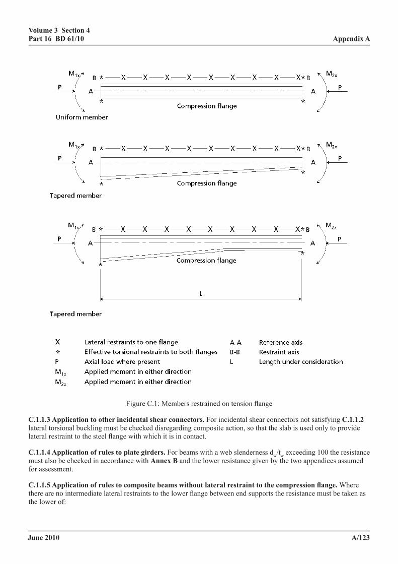
June 2010
volume 3 section 4 part 16 Bd 61/10
a/123
appendix a
Volume 3 Section 4 Appendix A Part 16 BD 61/09
April 2009 A/134
Figure C.1: Members restrained on tension flange C.1.1.3 Application to other incidental shear connectors. For incidental shear connectors not satisfying C.1.1.2 lateral torsional buckling must be checked disregarding composite action, so that the slab is used only to provide lateral restraint to the steel flange with which it is in contact. C.1.1.4 Application of rules to plate girders. For beams with a web slenderness dw/tw exceeding 100_ the resistance must also be checked in accordance with Annex B and the lower resistance given by the two appendices assumed for assessment. C.1.1.5 Application of rules to composite beams without lateral restraint to the compression flange. Where there are no intermediate lateral restraints to the lower flange between end supports the resistance must be taken as the lower of:-
Figure C.1: Members restrained on tension flange
c.1.1.3 application to other incidental shear connectors. For incidental shear connectors not satisfying c.1.1.2 lateral torsional buckling must be checked disregarding composite action, so that the slab is used only to provide lateral restraint to the steel flange with which it is in contact.
c.1.1.4 application of rules to plate girders. For beams with a web slenderness dw/tw exceeding 100 the resistance must also be checked in accordance with annex B and the lower resistance given by the two appendices assumed for assessment.
c.1.1.5 application of rules to composite beams without lateral restraint to the compression flange. Where there are no intermediate lateral restraints to the lower flange between end supports the resistance must be taken as the lower of:
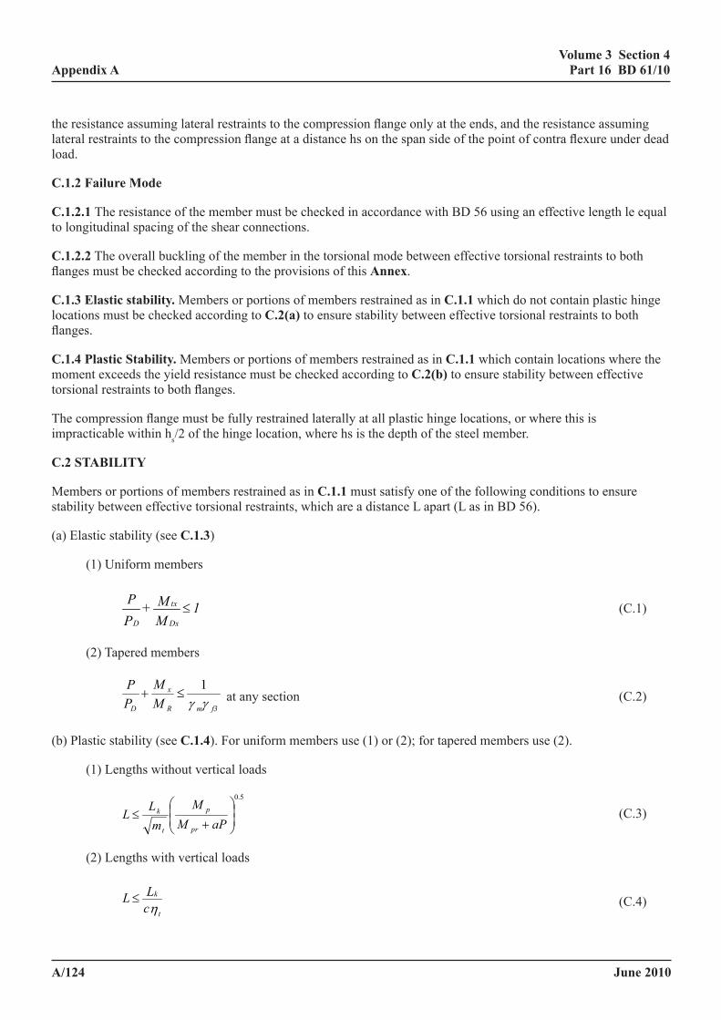
June 2010
volume 3 section 4 part 16 Bd 61/10
a/124
appendix a
the resistance assuming lateral restraints to the compression flange only at the ends, and the resistance assuming lateral restraints to the compression flange at a distance hs on the span side of the point of contra flexure under dead load.
c.1.2 failure mode
c.1.2.1 The resistance of the member must be checked in accordance with BD 56 using an effective length le equal to longitudinal spacing of the shear connections.
c.1.2.2 The overall buckling of the member in the torsional mode between effective torsional restraints to both flanges must be checked according to the provisions of this annex.
c.1.3 elastic stability. Members or portions of members restrained as in c.1.1 which do not contain plastic hinge locations must be checked according to c.2(a) to ensure stability between effective torsional restraints to both flanges.
c.1.4 plastic stability. Members or portions of members restrained as in c.1.1 which contain locations where the moment exceeds the yield resistance must be checked according to c.2(b) to ensure stability between effective torsional restraints to both flanges.
The compression flange must be fully restrained laterally at all plastic hinge locations, or where this is impracticable within hs/2 of the hinge location, where hs is the depth of the steel member.
c.2 staBility
Members or portions of members restrained as in c.1.1 must satisfy one of the following conditions to ensure stability between effective torsional restraints, which are a distance L apart (L as in BD 56).
(a) Elastic stability (see c.1.3)
(1) Uniform members
1MM+
PP
Dx
tx
D≤ (C.1)
(2) Tapered members
f3mR
x
D
MM
PP
γγ1
≤+ at any section (C.2)
(b) Plastic stability (see c.1.4). For uniform members use (1) or (2); for tapered members use (2).
(1) Lengths without vertical loads
5.0
+≤
aPMM
mLL
pr
p
t
k (C.3)
(2) Lengths with vertical loads
η t
k
cLL ≤ (C.4)
June 2010
volume 3 section 4 part 16 Bd 61/10
a/125
appendix a
where
P is the applied axial load where present
PD is the compression resistance determined in accordance with BD 56, except that for buckling about the minor axis the slenderness must be taken as λTC
λTC is defined in c.3.2
Mtx is mtMAx
mt is as defined in c.3.4
MAx is the maximum moment on the member or portion of the member under consideration.
MDx is the bending resistance of the beam derived in accordance with 9.9.1 of BD 56.
λTB is as defined in c.3.3
M1x, M2x is the applied moment (see Figure C.1).
A is the effective cross-sectional area at the section considered.
Zxp is the plastic modulus of the effective section cross section considered.
Mp is σyZxp
Mpr is σyZxpr
Zxpr is the reduced plastic modulus of the effective section due to axial load.
a is as defined in c.3.1
Lk is as defined in c.3.5
ηt is as defined in c.3.6
c is as defined in c.3.3
Mx is the applied moment
MR is as defined in 9.8 of BD 56.
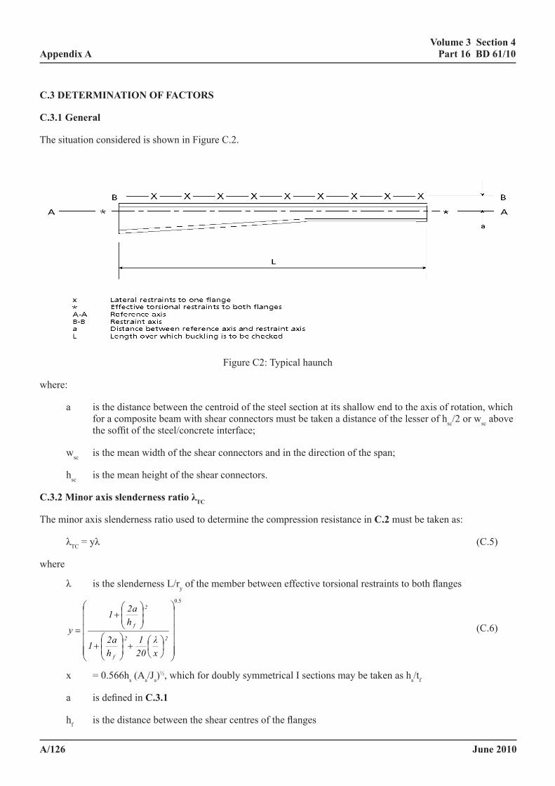
June 2010
volume 3 section 4 part 16 Bd 61/10
a/126
appendix a
c.3 determination of factors
c.3.1 general
The situation considered is shown in Figure C.2.
Volume 3 Section 4 Appendix A Part 16 BD 61/09
April 2009 A/137
C.3 DETERMINATION OF FACTORS C.3.1 General The situation considered is shown in figure C.2.
Figure C2: Typical haunch where: a is the distance between the centroid of the steel section at its shallow end to the axis of
rotation, which for a composite beam with shear connectors must be taken a distance of the lesser of hsc/2 or wsc above the soffit of the steel/concrete interface;
wsc is the mean width of the shear connectors and in the direction of the span; hsc is the mean height of the shear connectors. C.3.2 Minor axis slenderness ratio λTC The minor axis slenderness ratio used to determine the compression resistance in C.2 must be taken as:
λTC = yλ (C.5)
where λ is the slenderness L/ry of the member between effective torsional restraints to both flanges
5.0
⎟⎟⎟⎟⎟⎟
⎠
⎞
⎜⎜⎜⎜⎜⎜
⎝
⎛
⎟⎠⎞
⎜⎝⎛+⎟
⎟⎠
⎞⎜⎜⎝
⎛+
⎟⎟⎠
⎞⎜⎜⎝
⎛+
=22
f
2
f
xλ
201
h2a1
h2a1
y (C.6)
x = 0.566hs (As/Js)½, which for doubly symmetrical I sections may be taken as hs/tf
Figure C2: Typical haunch
where:
a is the distance between the centroid of the steel section at its shallow end to the axis of rotation, which for a composite beam with shear connectors must be taken a distance of the lesser of hsc/2 or wsc above the soffit of the steel/concrete interface;
wsc is the mean width of the shear connectors and in the direction of the span;
hsc is the mean height of the shear connectors.
c.3.2 minor axis slenderness ratio λtc
The minor axis slenderness ratio used to determine the compression resistance in c.2 must be taken as:
λTC = yλ (C.5)
where
λ is the slenderness L/ry of the member between effective torsional restraints to both flanges
5.0
+
+
+
=22
f
2
f
xλ
201
h2a1
h2a1
y (C.6)
x = 0.566hs (As/Js)½, which for doubly symmetrical I sections may be taken as hs/tf
a is defined in c.3.1
hf is the distance between the shear centres of the flanges
June 2010
volume 3 section 4 part 16 Bd 61/10
a/127
appendix a
c.3.3 minor axis slenderness ratios λtB
The minor axis slenderness ratio λTB used to determine the bending resistance in c.2 must be taken as:
λTB = ηt k4vtcλ (C.7)
where
5.0
4
+
+
=22
f
ft
xλ
201
h2a1
ha
v (C.8)
For tapered members vt is calculated by reference to the smallest section:
where
a is defined in c.3.1
λ is defined in c.3.2
hf is as defined in c.3.2
x is as defined in c.3.2
k4 is as defined in BD 56 except for tapered members where k4 must be taken as 1.0
ηt is taken as 1.0 where there are no intermediate loads between restraints; otherwise ηt is as defined in c.3.6
c is taken as 1.0 for uniform members and as follows for tapered members:
1/22/3q1R9x
31C )( −−
+= (C.9)
R is the ratio of the greater depth to the lesser depth of the section between effective torsional restraints
q is the ratio of the tapered length to the total length of the section between effective torsional restraints.
c.3.4 equivalent uniform moment factor mt
The value of mt must be taken as 1.0 when intermediate loads are applied between effective torsional restraints.
Otherwise mt must be obtained from Table C.1 where:
y is obtained from c.3.2;
βt is the ratio of the algebraically smaller end moment to the larger. Moments which produce compression on the unrestrained flange must be taken as positive. When βt<-1 the value of βt must be taken as -1. See Figure C.3.
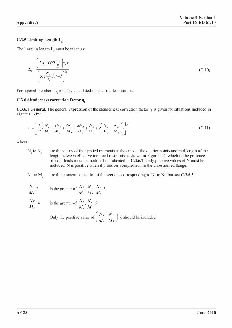
June 2010
volume 3 section 4 part 16 Bd 61/10
a/128
appendix a
c.3.5 limiting length lk
The limiting length Lk must be taken as:
2
1σ
σ
−
+
=
1JE
5.4
xrE
6005.4L
2s
y
yy
k (C.10)
For tapered members Lk must be calculated for the smallest section.
c.3.6 slenderness correction factor ηt
c.3.6.1 general. The general expression of the slenderness correction factor ηt is given for situations included in Figure C.3 by:
2
1
−+++++=η
E
E
s
s
5
5
4
4
3
3
2
2
1
1t M
NMN2
MN
M3N
M4N
M3N
MN
121 (C.11)
where
N1 to N5 are the values of the applied moments at the ends of the quarter points and mid length of the length between effective torsional restraints as shown in Figure C.4, which in the presence of axial loads must be modified as indicated in c.3.6.2. Only positive values of N must be included. N is positive when it produces compression in the unrestrained flange.
M1 to M5 are the moment capacities of the sections corresponding to N1 to N5, but see c.3.6.3.
MN
s
s 2 is the greater of MN,
MN,
MN
4
4
3
3
2
2 3
MN
E
E 4 is the greater of MN,
MN
5
5
1
1 5
Only the positive value of MN-
MN
E
E
s
s
6 should be included
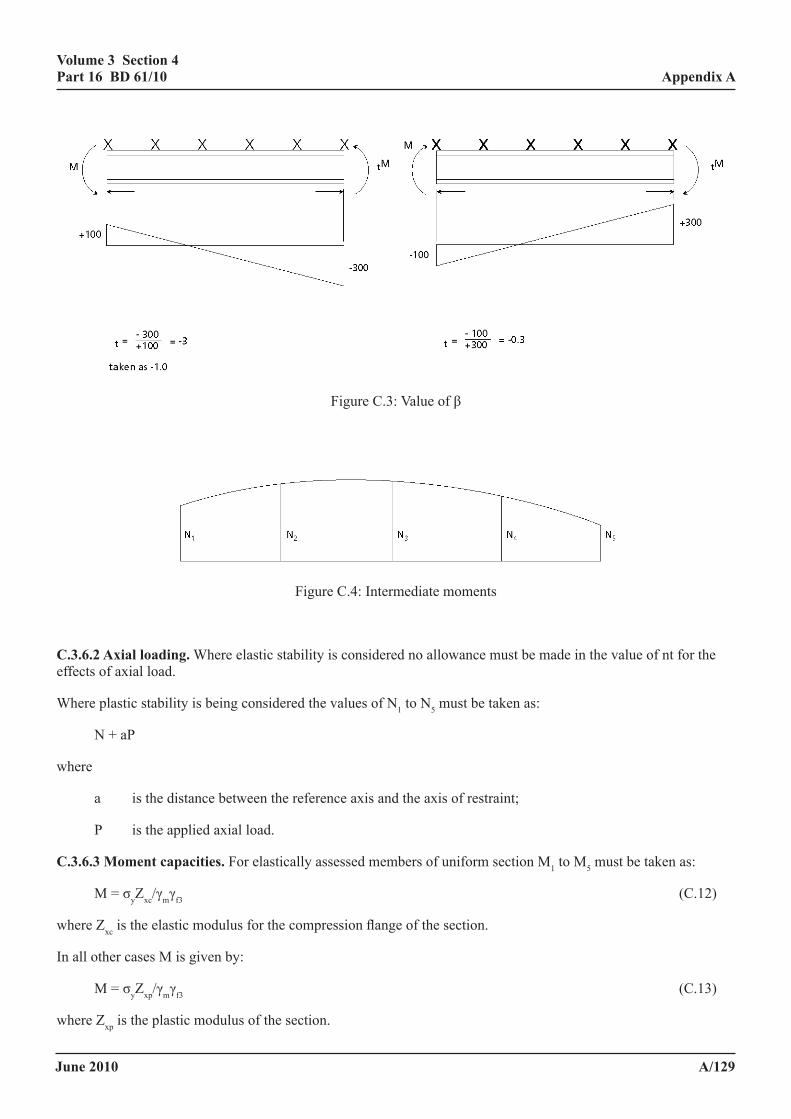
June 2010
volume 3 section 4 part 16 Bd 61/10
a/129
appendix aVolume 3 Section 4 Appendix A
Part 16 BD 61/09
April 2009 A/140
Figure C.3: Value of β
Figure C.4: Intermediate moments
C.3.6.2 Axial loading. Where elastic stability is considered no allowance must be made in the value of nt for the effects of axial load. Where plastic stability is being considered the values of N1 to N5 must be taken as:
N + aP
where a is the distance between the reference axis and the axis of restraint; P is the applied axial load. C.3.6.3 Moment capacities. For elastically assessed members of uniform section M1 to M5 must be taken as:
M = σyZxc/γmγf3 (C.12)
where Zxc is the elastic modulus for the compression flange of the section. In all other cases M is given by:
M = σyZxp/γmγf3 (C.13)
where Zxp is the plastic modulus of the section.
Figure C.3: Value of β
Volume 3 Section 4 Appendix A Part 16 BD 61/09
April 2009 A/140
Figure C.3: Value of β
Figure C.4: Intermediate moments
C.3.6.2 Axial loading. Where elastic stability is considered no allowance must be made in the value of nt for the effects of axial load. Where plastic stability is being considered the values of N1 to N5 must be taken as:
N + aP
where a is the distance between the reference axis and the axis of restraint; P is the applied axial load. C.3.6.3 Moment capacities. For elastically assessed members of uniform section M1 to M5 must be taken as:
M = σyZxc/γmγf3 (C.12)
where Zxc is the elastic modulus for the compression flange of the section. In all other cases M is given by:
M = σyZxp/γmγf3 (C.13)
where Zxp is the plastic modulus of the section.
Figure C.4: Intermediate moments
c.3.6.2 axial loading. Where elastic stability is considered no allowance must be made in the value of nt for the effects of axial load.
Where plastic stability is being considered the values of N1 to N5 must be taken as:
N + aP
where
a is the distance between the reference axis and the axis of restraint;
P is the applied axial load.
c.3.6.3 moment capacities. For elastically assessed members of uniform section M1 to M5 must be taken as:
M = σyZxc/γmγf3 (C.12)
where Zxc is the elastic modulus for the compression flange of the section.
In all other cases M is given by:
M = σyZxp/γmγf3 (C.13)
where Zxp is the plastic modulus of the section.
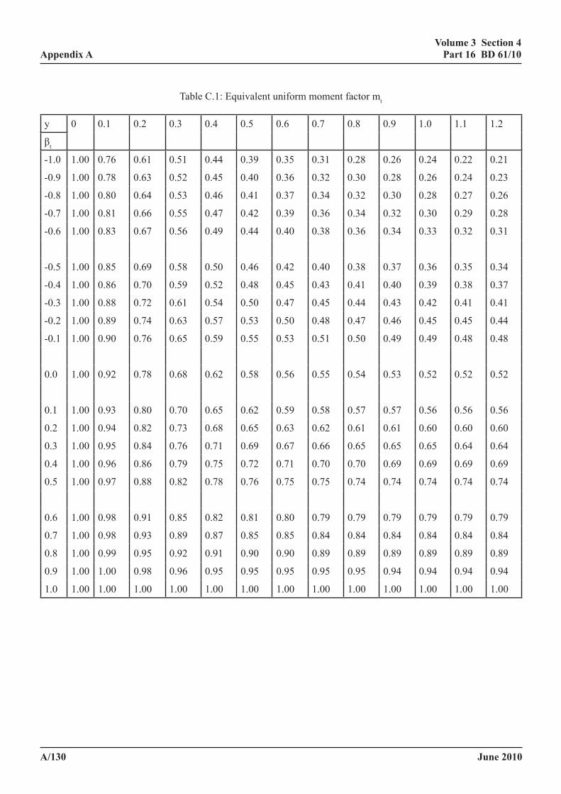
June 2010
volume 3 section 4 part 16 Bd 61/10
a/130
appendix a
Table C.1: Equivalent uniform moment factor mt
y 0 0.1 0.2 0.3 0.4 0.5 0.6 0.7 0.8 0.9 1.0 1.1 1.2
βt
-1.0 1.00 0.76 0.61 0.51 0.44 0.39 0.35 0.31 0.28 0.26 0.24 0.22 0.21
-0.9 1.00 0.78 0.63 0.52 0.45 0.40 0.36 0.32 0.30 0.28 0.26 0.24 0.23
-0.8 1.00 0.80 0.64 0.53 0.46 0.41 0.37 0.34 0.32 0.30 0.28 0.27 0.26
-0.7 1.00 0.81 0.66 0.55 0.47 0.42 0.39 0.36 0.34 0.32 0.30 0.29 0.28
-0.6 1.00 0.83 0.67 0.56 0.49 0.44 0.40 0.38 0.36 0.34 0.33 0.32 0.31
-0.5 1.00 0.85 0.69 0.58 0.50 0.46 0.42 0.40 0.38 0.37 0.36 0.35 0.34
-0.4 1.00 0.86 0.70 0.59 0.52 0.48 0.45 0.43 0.41 0.40 0.39 0.38 0.37
-0.3 1.00 0.88 0.72 0.61 0.54 0.50 0.47 0.45 0.44 0.43 0.42 0.41 0.41
-0.2 1.00 0.89 0.74 0.63 0.57 0.53 0.50 0.48 0.47 0.46 0.45 0.45 0.44
-0.1 1.00 0.90 0.76 0.65 0.59 0.55 0.53 0.51 0.50 0.49 0.49 0.48 0.48
0.0 1.00 0.92 0.78 0.68 0.62 0.58 0.56 0.55 0.54 0.53 0.52 0.52 0.52
0.1 1.00 0.93 0.80 0.70 0.65 0.62 0.59 0.58 0.57 0.57 0.56 0.56 0.56
0.2 1.00 0.94 0.82 0.73 0.68 0.65 0.63 0.62 0.61 0.61 0.60 0.60 0.60
0.3 1.00 0.95 0.84 0.76 0.71 0.69 0.67 0.66 0.65 0.65 0.65 0.64 0.64
0.4 1.00 0.96 0.86 0.79 0.75 0.72 0.71 0.70 0.70 0.69 0.69 0.69 0.69
0.5 1.00 0.97 0.88 0.82 0.78 0.76 0.75 0.75 0.74 0.74 0.74 0.74 0.74
0.6 1.00 0.98 0.91 0.85 0.82 0.81 0.80 0.79 0.79 0.79 0.79 0.79 0.79
0.7 1.00 0.98 0.93 0.89 0.87 0.85 0.85 0.84 0.84 0.84 0.84 0.84 0.84
0.8 1.00 0.99 0.95 0.92 0.91 0.90 0.90 0.89 0.89 0.89 0.89 0.89 0.89
0.9 1.00 1.00 0.98 0.96 0.95 0.95 0.95 0.95 0.95 0.94 0.94 0.94 0.94
1.0 1.00 1.00 1.00 1.00 1.00 1.00 1.00 1.00 1.00 1.00 1.00 1.00 1.00
June 2010
volume 3 section 4 part 16 Bd 61/10
a/131
appendix a
anneX d: viBration of composite Bridges (normative)
d.1 traffic vibration
Vibration is not normally a problem in older bridges as they are generally heavier than modern bridges, although on some of the more heavily trafficked bridges it is possible that a degree of loosening of parts of the structure has occurred. In this case vibration of those parts is possible. The main concern is with footbridges. Foot and cycle track bridges need not be checked if the span is less than 35m for simply supported spans or 40m if continuous one or both ends. Highway bridges need not be checked if the span is less than 55m for simply supported spans or 65m if continuous one or both ends. Foot and cycle track bridges with rolled steel beams with non-structural parapets are particularly prone to vibration problems.
Nevertheless checks must be made on any bridge about which there has been public complaint.
d.2 aerodynamic vibration
Aerodynamic criteria are given in BD 49(9). However composite highway bridges need not be checked for aerodynamic effects when two of the three following criteria are satisfied:
(a) the deck widths do not exceed 12m if not more than 10m above ground level, or otherwise 15m,
(b) the edge details satisfy 2.1.3.2 of BD 49 and the overhang should not be less than 0.75d4,
(c) both the following are satisfied:
(i) the super elevation of the line between the top of the fascias on either side of the bridge does not exceed 1/40, and
(ii) the incident wind within ±45o of the normal to the span is not consistently inclined to the horizontal (on account of the local topography).
Footbridges need not be checked for spans less than 35m when condition (b) above and (c)(ii) are satisfied; otherwise they need not be checked for spans less than 30m.
Further, vortex shedding need not be considered for any composite bridge of span less than 70m.
These limits are rather greater than the limits advisable for steel bridges as composite decks are very stiff torsionally and therefore are not particularly susceptible to the more dramatic form of vibrational instability. Cable suspension bridges pose particular problems, but are not considered here.
d.3 cantilevered footways
Footways cantilevered from vehicular bridges may pose particular problems and should be checked when the length of the cantilever from the primary beams exceed 10m. Sometimes there is a problem with shorter cantilevers, but this is due to interaction with the transverse bending.
June 2010
volume 3 section 4 part 16 Bd 61/10
a/132
appendix a
d.4 calculation procedures
Generally the bridge design codes quoted above should be sufficient, but the information may be supplemented by the procedure in clause 7.6 of reference 50 and by the use of computer programs, many of which give the frequencies and shapes of the main modes of vibrations, although with some this facility may require the choice of particular, and more powerful, types of elements.
There is a problem in continuous bridges of whether the exciting energy is sufficient to excite adjacent spans, as when this is the case the effective stiffness of continuous beams reduces to a value similar to that of simply supported beams. Some account of this is taken in the method of ref. 50. More sophisticated use of computers is permissible to determine the effect of particular excitations, but then the problem is encountered of how best to represent the excitation.
d.5 damping values
It is acceptable to assume a logarithmic decrement of 0.04 for composite bridges, as suggested in BD 37(49).
June 2010
volume 3 section 4 part 16 Bd 61/10
a/133
appendix a
anneX e: fatigue in reinforcement of composite Beams (informative)
There are two methods of considering fatigue in reinforcement in BD 44. In the first method, which relates to local combination 1 at SLS under HA loading, the permissible stress ranges for unwelded non-corroded reinforcement under imposed loading are given. In shorter span composite bridges these criteria may be critical(21). In this situation the alternative method which refers to BS 5400-10(20) should be used.
Corrosion and manufacturers markings can significantly reduce the resistance to a greater extent than the loss of bar area might suggest. Such conditions are not specifically taken into account, but could be assumed to be taken into account in the general conservatism of the first method. For composite beams in which the reinforcement is corroded, BA 38(52) should be used in estimating the remaining fatigue life.

June 2010
volume 3 section 4 part 16 Bd 61/10
a/134
appendix a
anneX f: not used

June 2010
volume 3 section 4 part 16 Bd 61/10
a/135
appendix a
anneX g: significance of nominal considerations (informative)
There are a number of situations in which dimensional and other criteria specified in the Standard may be infringed without significantly affecting the structural performance, but which in some may significantly affect its rate of deterioration after the assessment. Other criteria may not significantly affect the performance of many structures. Some aspects of the construction which are clearly satisfactory need only be checked by calculation if there is a likelihood of them becoming affected by a change of use.
The measures to be taken depend upon the category of the infringement as follows:
Category A: Where these criteria are infringed by 20% or more an inspection must ensure that the concrete has not spalled locally as a result of corrosion.
Category B: Where these criteria are infringed the strength may be lower than assumed in the Standard. When infringed the effect on the strength must be assessed.
Category C: As Category B, but assess only when infringements are greater than 5% (or 7% when they affect areas).
Category D: As Category B, but assess only when infringements are greater than 35%.
The various dimensional criteria of the Standard are categorised as follows:
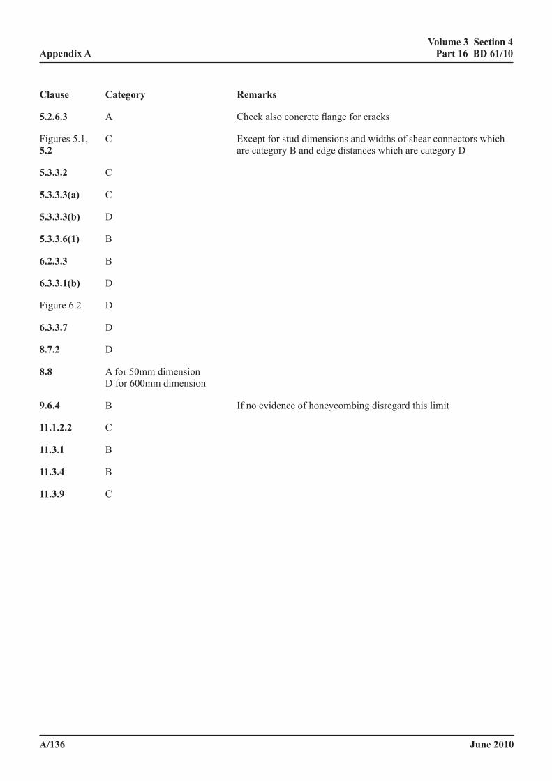
June 2010
volume 3 section 4 part 16 Bd 61/10
a/136
appendix a
clause category remarks
5.2.6.3 A Check also concrete flange for cracks
Figures 5.1, C Except for stud dimensions and widths of shear connectors which 5.2 are category B and edge distances which are category D
5.3.3.2 C
5.3.3.3(a) C
5.3.3.3(b) D
5.3.3.6(1) B
6.2.3.3 B
6.3.3.1(b) D
Figure 6.2 D
6.3.3.7 D
8.7.2 D
8.8 A for 50mm dimension D for 600mm dimension
9.6.4 B If no evidence of honeycombing disregard this limit
11.1.2.2 C
11.3.1 B
11.3.4 B
11.3.9 C
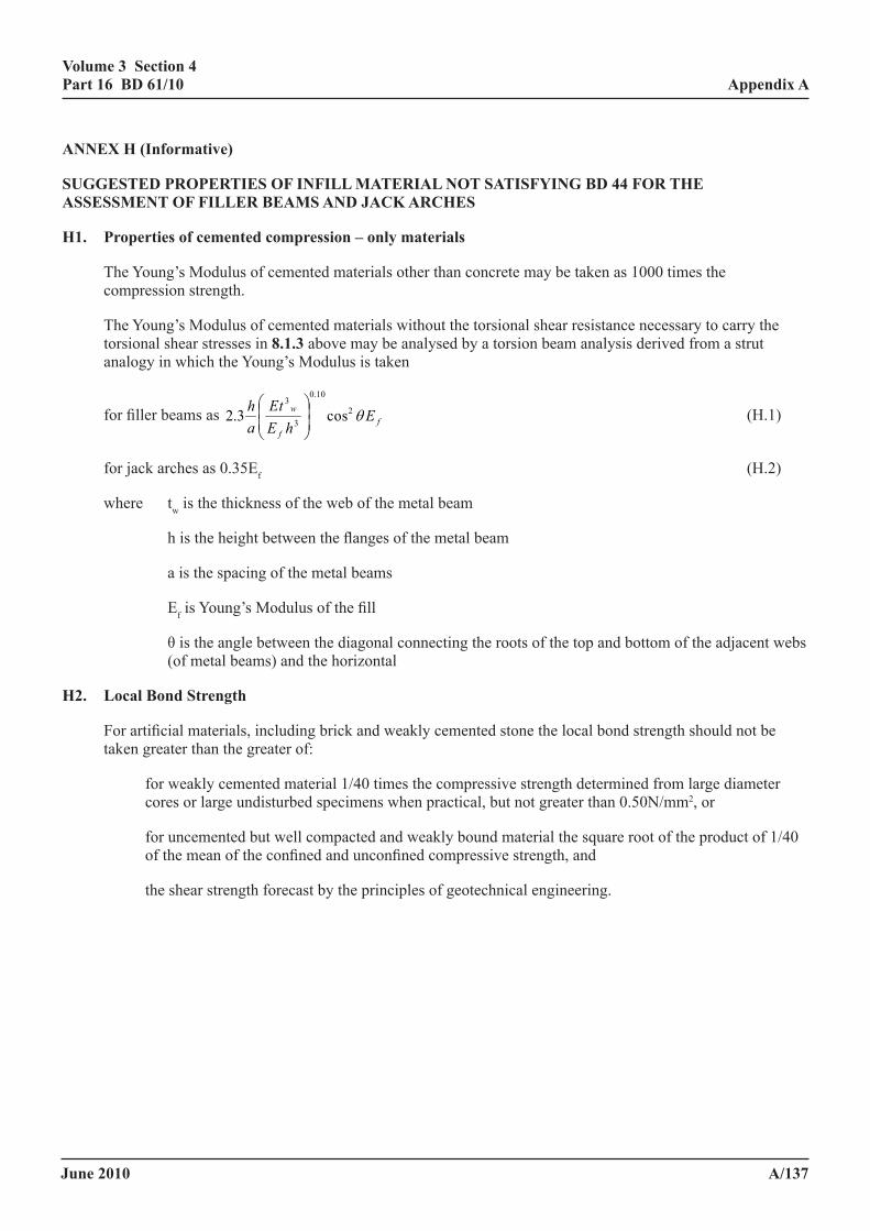
June 2010
volume 3 section 4 part 16 Bd 61/10
a/137
appendix a
anneX h (informative)
suggested properties of infill material not satisfying Bd 44 for the assessment of filler Beams and JacK arches
h1. properties of cemented compression – only materials
The Young’s Modulus of cemented materials other than concrete may be taken as 1000 times the compression strength.
The Young’s Modulus of cemented materials without the torsional shear resistance necessary to carry the torsional shear stresses in 8.1.3 above may be analysed by a torsion beam analysis derived from a strut analogy in which the Young’s Modulus is taken
for filler beams as ff
w EhEtE
ah θ2
10.0
3
3
cos3.2
(H.1)
for jack arches as 0.35Ef (H.2)
where tw is the thickness of the web of the metal beam
h is the height between the flanges of the metal beam
a is the spacing of the metal beams
Ef is Young’s Modulus of the fill
θ is the angle between the diagonal connecting the roots of the top and bottom of the adjacent webs (of metal beams) and the horizontal
h2. local Bond strength
For artificial materials, including brick and weakly cemented stone the local bond strength should not be taken greater than the greater of:
for weakly cemented material 1/40 times the compressive strength determined from large diameter cores or large undisturbed specimens when practical, but not greater than 0.50N/mm2, or
for uncemented but well compacted and weakly bound material the square root of the product of 1/40 of the mean of the confined and unconfined compressive strength, and
the shear strength forecast by the principles of geotechnical engineering.
June 2010
volume 3 section 4 part 16 Bd 61/10
a/138
appendix a
h3. soils
Using the principles of geotechnical engineering soils and other fill material beneath the blacktop on bridge decks which are predominately granular:
(i) are insufficiently stiff, and
(ii) suffer longitudinal shear failure at too low a load
to justify the stiffening effects of beam cross-sections demonstrated in load tests on old bridges. There is however evidence that the properties of well compacted hard standings perpendicular to the surfaces appreciably exceed the most optimistic properties forecast by geotechnical engineering. It is therefore premature at the present time to include geotechnical engineering principles in the routine assessment of bridge decks.
h4. Blacktop
The stiffness of blacktop is temperature dependent, but as the upper layer is disregarded (see 8.1.8 (ii)) it is conservative to assume a maximum temperature of 20°C and a stiffness of 2000MPa, when the blacktop is in direct contact with the deck.
In the absence of specific information on the adhesion of blacktop the local bond strengths in H2 may be assumed.
h5. restrictions on the effective cross-section
In assessing the resistance of the cross-section the following restrictions apply:
(a) In calculating the resistance of the composite cross section the top 75 mm of finishing should be disregarded, the part of the fill in tension should be disregarded and, to provide an additional margin of safety, the depth of the fill in excess of 200mm above the steelwork should be reduced by:
30% for weakly cemented materials, or
40% for uncemented materials.
Any material below the soffit of the metal beams should be neglected as this is liable to spall.
(b) Unless justified by load tests the flexural strength of filler beams at ULS should not exceed the strength of the composite cross-section steel/concrete cross-section by more than:
35% for weakly cemented materials, or
20% for uncemented materials.
(c) In the absence of contrary evidence the proportionate increase at strength at ULS should be taken as half the increase in strength forecast in the load tests.
(d) For strength assessment at loadings not exceeding those at the SLS (as for cast iron) the proportionate increase in strength under the assessment loading should not be taken greater than 70% the increase in strength forecast from the load tests.
June 2010
volume 3 section 4 part 16 Bd 61/10
a/139
appendix a
(e) In no case should the strengthening effect at ULS assessed elastically using the modular ratios in 8.1.8(ii) be taken greater than that suggested by the measured deflection (or preferably strain) readings, nor greater than:
2.5 times the strength of the bare metal section, or
1.7 times the strength of a composite section which satisfies 8.1.2, 8.1.3 or 8.1.4.
(f) When interpreting the results of load tests:-
i) the transverse distribution characteristics are easily established;
ii) it is less easy, and needs more instrumentation, to determine whether composite action, partial end fixity or arching action is responsible for the low strains. It is acceptable in assessment calculations to attribute the entire benefit to composite action. When this is done the limiting values in (e) may be increased to:
3.2 times the strength of the bare metal section or
2.2 times the strength of a composite section which satisfies 8.1.2, 8.1.3, and 8.1.4.
(g) The rules for jack arches are as for filler beams except that, when the depth of construction is less than 1.5 times the depth of the bare metal section, the increase in the bending resistance of the composite section should not be taken greater than 30% of the bare metal section.
(h) The above approach has not been checked for situations in which the ratio of the depth of fill to the span is such that arching action in the fill occurs in the direction of the span. For this situation, the fill within the depth of the metal beams may be considered as acting compositely with them, and the fill above is to be considered as spanning by arching action and anchored at the ends by friction against the composite section, or by lateral resistance from material of at least similar compressive strength and compaction.
June 2010
volume 3 section 4 part 16 Bd 61/10
a/140
appendix a
anneX i (informative)
sample flow charts illustrating the assessment procedures for Bridge decKs considered in clauses 8 and 14
Due to the large variation in the bridge types covered by clauses 8 and 14 it is not possible to produce flow charts covering all the situations likely to be encountered and the different checks necessary for cast iron, wrought iron and steel.
Sample flow charts are included for:
Cased beams Filler beam decks with concrete infill Jack arch decks with masonry vaults.
The advisory criteria for filler beams and cased beams are different from those specified as mandatory requirements (boxed) and are also different for different types of construction. It is often easier to refer to the flow chart first to identify which checks are required. The text then gives details of the checks.
These summarise the options for the analysis and the assessment procedures.
notes for the assessment of cased Beams and cased Beam decks
1. The commentary gives rules for construction complying with BD 61 which, overall, generally justifies an increase in capacity.
2. The methods normally employed for cased beams are grillage analysis, analysis with ribbed thin plate FE elements and the method in Clause 2 of BA 16. Orthotropic plate analyses have been used but are not common.
3. The method contained in the commentary shows higher local bond stresses at SLS than the method using the requirements (boxed) in the Standard and thus the latter normally is found to be the critical condition. However in the commentary the flexural resistance is subject to a more rigorous check at ULS which often gives a lower capacity than the simple check using the method given as requirements. Therefore it is inadmissible to check flexure/interface bond stresses at SLS using the commentary and at ULS using the requirements.
4. The effect of incidental effects in 8.1.8 on cased beam construction has not been assessed, but there is no reason why they should not be considered in the assessment of cased beams, provided the assessed strength of the metal beams does not exceed 275N/mm2 and provided sprayed on waterproofing systems (on the beam) have not been used. Normally the effects should be considered only when they are appreciable.
notes for assessment of filler Beams
1. The commentary considers construction beyond the scope of the Design Code, which includes construction in which there is insufficient reinforcement to resist transverse moments. It also gives rules for construction complying with the requirements (boxed), which overall generally justifies an increase in capacity.
2. The commentary contains different rules from those given as requirements (boxed) for bond stresses, shear on longitudinal planes through the concrete and vertical shear it has a new clause on punching shear from point loads.
June 2010
volume 3 section 4 part 16 Bd 61/10
a/141
appendix a
3. The commentary gives higher local bond stresses at SLS than that using the requirements and thus using the later, is normally found to be the critical condition. However in the commentary the flexural resistance is subject to a more rigorous check at ULS which often gives a lower capacity than the simple check given as requirements. Therefore it is inadmissible to check flexure/interface bond stresses at SLS using the commentary and at ULS using the requirements..
4. The commentary gives higher shear resistance.
5. Besides advice in the Foreword and that implicit in the flow chart it is beyond the scope of the Standard and the commentary to advise on procedures to best suit an individual project.
6. Where there are masonry infill the assessment procedure is similar, but the stiffness and limiting stresses are appropriately modified.
7. Where incidental effects are included it is always necessary to ascertain the capacity without these effects since the permitted increase in capacity for these effects is related to the capacity of the deck without them.
notes for the assessment of Jack arch decks
1. In the method of BA 16 Clause 7 there is no requirement for stress checks in the elements transverse to the metal beams; so the method is potentially unsafe. To kerb the use of this method where the method is likely to be unsafe restrictions have been placed on the condition factor of the masonry, and the method is not permitted where there is poor lateral restraint.
2. Where there is concrete above the masonry see 14.1. In this situation method (iii) of 14.1 (the torsion beam method) may be difficult to apply.
3. Besides the advice in Notes 1 and 2 and that implicit in the flow chart it is beyond the scope of the Standard to advise on choice of the different methods or how the guidance can be best used for a particular project.
4. Where the vaults are of concrete (lined or unlined) see 14.1.
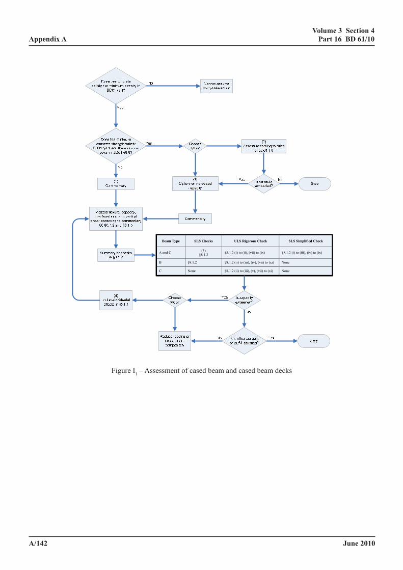
June 2010
volume 3 section 4 part 16 Bd 61/10
a/142
appendix a
Volume 3 Section 4 Appendix A Part 16 BD 61/09
April 2009 A/153
Beam Type SLS Checks ULS Rigorous Check SLS Simplified Check
A and C (3) §8.1.2 §8.1.2 (i) to (ii), (vii) to (ix) §8.1.2 (i) to (iii), (iv) to (ix)
B §8.1.2 §8.1.2 (ii) to (iii), (iv), (vii) to (xi) None
C None §8.1.2 (ii) to (iii), (v), (vii) to (xi) None
Figure I1 - Assessment of Cased Beam and cased Beam decks
Figure I1 – Assessment of cased beam and cased beam decks
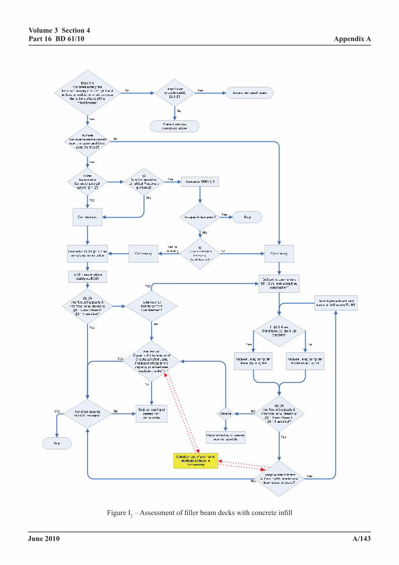
June 2010
volume 3 section 4 part 16 Bd 61/10
a/143
appendix a
Volume 3 Section 4 Appendix A Part 16 BD 61/09
April 2009 A/154
Figure I2 - Assessment of Filler Beam Decks with Concrete Infill Figure I2 – Assessment of filler beam decks with concrete infill
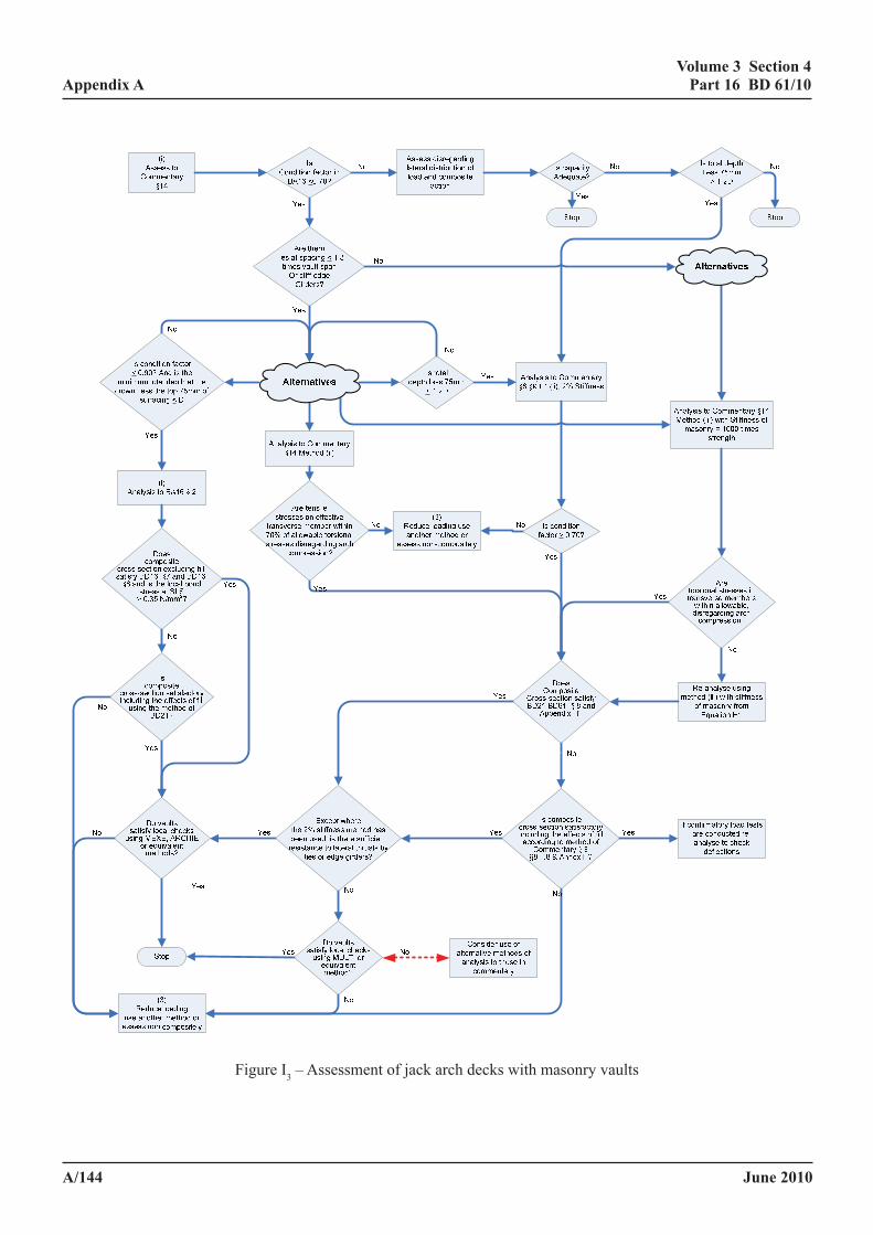
June 2010
volume 3 section 4 part 16 Bd 61/10
a/144
appendix aVolume 3 Section 4 Appendix A Part 16 BD 61/09
April 2009 A/155
Figure I3- Assessment of Jack Arch Decks with Masonry Vaults
Figure I3 – Assessment of jack arch decks with masonry vaults
June 2010
volume 3 section 4 part 16 Bd 61/10
a/145
appendix a
anneX J: BiBliography
1. Not used.
2. BA 44/96 “The Use of Departmental Standard BD 44 for the Assessment of Concrete Highway Bridges and Structures”, Design Manual for Roads and Bridges.
3. BD 56 “The Assessment of Steel Highway Bridges and Structures”, Design Manual for Roads and Bridges.
4. BS EN 1994, “Design of composite steel and concrete structures: Part 1 1 General rules and rules for buildings”, European Pre-standard, Final Draft, prENV 1994 1 1:1002E ECN, April 1992 (BSI Document No 92/14118 of Committee B/525/4).
5. BS 8110: Part 2, “Structural use of concrete: Part 2: Code of practice of special circumstances”, British Standards Institution, 1985.
6. Technical Paper TP12, “Testing of composite bridges”, Background document for BS 5400 Part 5; Use for Assessment of Bridges.
7. BS 5400: Part 4, “Steel, concrete and composite bridge - Part 4: Code of Practice for the design of concrete bridges”, British Standards Institution, 1990.
8. Beeby AW. “Cover to reinforcement and corrosion protection”, International Symposium on behaviour of offshore concrete, ARBEM, Brest, 1980.
9. BD 49/93, “Design rules for aerodynamic effects on bridges”, Design Manual for Roads and Bridges.
10. Technical Paper No 2, “Global Analysis and cross section design - serviceability limit state”, Background Document for “BS 5400 Part 5: Use for Assessment of Bridges”.
11. McHardy Young J “Examples of the design of steel girder bridges in accordance with BS 153: Parts 3A, 3B and 4 (as at October, 1963)”, British Constructional Steelwork Association, Publication No 22, 1963.
12. Smith DGE, “Effective breadths of reinforced concrete T-beams and composite beams in hogging moment regions”, document written in preparing Ref. 34.
13. Technical Note No 7, “Partial interaction and assessment of the longitudinal shear connections”, Background document for BS 5400 Part 5: Use for Assessment.
14. Oehlers DJ and Johnson RP, “The strength of stud shear connectors in composite beams”, The Structural Engineer, Vol. 65B, No 2, June 1987 pp. 44-48.
15. Johnson RP and Oehlers DJ, “Analysis and design for longitudinal shear in composite T-beams”, Proc. Inst. Civ. Engnrs., Pt 2, 71, Dec 1981, pp. 989-1021.
16. Oehlers DJ and Park SM, “Shear connectors in composite beams with longitudinally cracked slabs”, Journal of Structural Engineering, ASCE, Vol. 118, No 8, August 1992, pp. 2004-2022.
17. Oehlers DJ, “Assessing the residual strength of shear connectors in composite bridges”, Bridge Management 2, Thomas Telford, London, 1993, pp. 842-851.
18. Technical Paper TP10, “Shear Connectors”, Background document for BS 5400:Part 5 “Use for Assessment of Bridges”.
19. Oehlers DJ, “Residual strength of structural components subject to cyclic loads”, Journal of Structural Engineering, ASCE, Vol. 118, No 10, Oct 1992, pp. 2645-2658.
June 2010
volume 3 section 4 part 16 Bd 61/10
a/146
appendix a
20. BS 5400:Part 10: “Steel, concrete and composite bridges, Part 10. Code of Practice for fatigue”, BSI 1980.
21. Technical Paper TP13, “Fatigue in composite beams”, Background document for BS 5400 Part 5: Use for Assessment of Bridges.
22. Technical Paper No 9, “Incidental shear connectors”, Background document for “BS 5400 Part 5: Use for Assessment of Bridges”.
23. Menzies JB, “CP117 and shear connectors in steel-concrete composite beams made with normal density or lightweight concrete”, The Structural Engineer, No 3 Vol. 49, March 1971, pp. 137-154.
24. Johnson RP and Buckby RJ, “Composite Structures of Steel and Concrete: Volume 2: Bridges”, Collins, London, 2nd Edition, 1986.
25. Hayward A, “Traditional forms of composite construction”, Subcontract Study report prepared for Scott Wilson Kirkpatrick by Cass Howard and Partners on behalf of the TRL/DoT, 9 July 1993.
26. Johnson RP, “Loss of interaction in short span composite beams and plates”, Journal of Constructional Steel Research, Vol. 1, No 2, Jan 1981, pp. 11-16.
27. BA 34/90, “Technical requirements for the assessment and strengthening programme for highway structures - Stage 1 - Older short span bridges and retaining structures”, Design Manual for Roads and Bridges.
28. BS 5950 Part 3, “Structural use of steelwork in building: Section 3.1: Code of Practice for design of continuous composite beams”, British Standards Institution, 1990.
29. Technical Paper No 4, “Global analysis, cross section slenderness criteria and shear at the ultimate limit state”, Background Document for BS 5400 Part 5: Use for Assessment of Bridges.
30. “Standard specifications for highway bridges”, American Association of State Highways and Transportation Officials", 15th Edition, 1992.
31. Stark JWB, “Rectangular stress blocks for concrete”, Technical Paper S16 for EC4 Drafting Panel, June 1984.
32. Weston G, Nethercot DA and Crisfield MA, “Lateral buckling in continuous composite bridge girders”, The Structural Engineer, Vol. 69, No 5, 5 March 1991, pp. 79-87.
33. Technical Paper No TP6, “Lateral torsional buckling in composite beams”, Background Paper. BS 5400: Part 5: Use of Assessment of Bridges.
34. Smith DGE and Johnson RP, “Commentary on the 1985 draft of BS EN 1994: Composite steel and concrete structures”, Building Research Establishment, 1986.
35. BS 8110: Part 1, “Structural use of concrete: Part 1: Code of practice for design and construction”, British Standards Institution, 1985.
36. CP 114, “The Structural use of reinforced concrete in buildings”, British Standard Code of Practice, British Standard Institution, 1957.
37. CP 110 Part 1, “The structural use of concrete : Part 1 : Design, materials and workmanship”, British Standard Institution, 1972.
38. BS EN 1992, “Design of concrete structures: Part 1. General rules and rules for buildings”, European Committee for Standardisation, Dec 1991. Issued as DD ENV:1992 1 1:1992 together with UK National Application Document, March 1993.
June 2010
volume 3 section 4 part 16 Bd 61/10
a/147
appendix a
39. Guyon Y, “Prestressed Concrete, Volume 1: Simply supported beams”, John Wiley and Sons, 1953.
40. Technical Paper TP11, “Cased beams, filler beams and Jack arches”. Background document for BS 5400: Part 5: Use for Assessment of Bridges.
41. “Ponts dalles á poutrelles ajoureés precontraints” (filler beams), PSI-PAP Guide de conception, Service d'Etudes Techniques et des Autoroutes (SETRA), Dec 1985, Bridges Division, part translation by Department of Transport, 1993.
42. Ricketts NJ and Low AMC, “The Assessment of Filler beam bridge decks without transverse reinforcement”, Transport Research Laboratory, 1993 (In preparation).
43. Johnson RP and Smith DGE, “A simple design method for composite columns”, The Structural Engineer, Part A, Vol. 58A, No 3, March 1980, pp. 85-93.
44. Technical Paper No 5, “Cracking, tension stiffening and effective breadths in composite beams”, Background Document for “BS 5400 Part 5: Use for Assessment of Bridges”.
45. Randl E and Johnson RP, “Widths of initial cracks in concrete tension flanges of composite beams”, IABSE Proceedings, P54/82, Nov 1982.
46. Technical Paper No TP8, “Design and assessment requirements for longitudinal shear resistance at the ultimate limit state”, Background paper for BS 5400 Part 5: Use for Assessment of Bridges.
47. BS 5400: Part 3, “Steel concrete and composite bridges, Part 3, Code of Practice for the design of steel bridges”, British Standards Institution, 2000.
48. BS 5950: Part 1, “Structural use of steelwork in building - Part 1: Code of practice for design in simple and continuous construction: hot rolled sections”, BSI, 1990.
49. BD 37/01, “Loads for Highway Bridges”, Design Manual for Roads and Bridges.
50. Wyatt TA, “Design guide on vibration of floors”, The Steel Construction Institute/Construction Industry Research and Information Association, Steel Construction Institute, 1989.
51. Tilly GP, “Fatigue classification of steel reinforcing beams”, Transport and Road Research Laboratory, Dept of Transport, Crowthorne, May 1988.
52 BA 38/93, “Assessment of the Fatigue Life of Corroded or Damaged Reinforcing Bars”, Design Manual for Roads and Bridges.
June 2010
volume 3 section 4 part 16 Bd 61/10
a/148
appendix a
anneX K: references
BS 4 Structural steel sections Part 1 Hot-rolled sections
BS 4395 High strength friction grip bolts and associated nuts and washers for structural engineering Part 1 General grade
BS 4604 The use of high strength friction grip bolts in structural steelwork Part 1 General grade
BS 5400 Steel, concrete and composite bridges Part 1 General statement Part 2 Specification for loads Part 3 Code of practice for design of steel bridges Part 4 Code of practice for design of concrete bridges Part 6 Specification for materials and workmanship, steel Part 7 Specification for materials and workmanship, concrete, reinforcement and prestressing tendons Part 8 Requirements for materials and workmanship, concrete, reinforcement and prestressing tendons Part 9 Code of practice for bearings Part 10 Code of practice for fatigue
BS 5950 Structural use of steelwork in building Part 1 Code of practice for design in simple and continuous construction: hot rolled sections
BS 5975 Code of practice for falsework
Design Manual for Roads and Bridges:
Volume 1 Section 3 General Design
BD 9/81 Implementation of BS 5400: Part 10: 1980: Code of Practice for Fatigue
BD 13/06 Design of Steel Bridges: Use of BS 5400: Part 3: 1982
BD 16/82 Design of Composite Bridges: Use of BS 5400: Part 5: 1979
BD 24/92 Design of Concrete Bridges: Use of BS 5400: Part 4: 1990
BD 37/01 Loads for Highway Bridges
Volume 3 Section 4 Assessment
BD 21/01 The Assessment of Highway Bridges and Structures.
BD 44/95 The Assessment of Concrete Highway Bridges and Structures
BD 46/92 Technical Requirements for the Assessment and Strengthening Programme for Highway Structures: Stage 2 – Modern Short Span Bridges
BD 50/92 Technical Requirements for the Assessment and Strengthening Programme for Highway Structures: Stage 3 – Long Span Bridges
BD 56/10 The Assessment of Steel Highway Bridges and Structures
June 2010
volume 3 section 4 part 16 Bd 61/10
a/149
appendix a
BA 16/97 The Assessment of Highway Bridges and Structures
BA 34/90 Technical Requirements for the Assessment and Strengthening Programme for Highway Structures, Stage 1 – Older Short Span Bridges and Retaining Structures
BA 44/96 The Assessment of Concrete Highway Bridges and Structures

June 2010
volume 3 section 4 part 16 Bd 61/10
B/1
appendix B
appendiX B Bd 61/10 the assessment of composite highway Bridges and structures in english dBfo schemes
When used on the M25 DBFO Scheme, this standard is to be amended as follows:
para no. description
1.8 Delete “or must have agreed a suitable departure from standard with the relevant TAAs” and insert “or submit a proposal to the Department's Nominee as an Alternative Proposal, unless it is in respect of the Works in relation to a Later Upgraded Section and before the Price Adjustment in respect of such Later Upgraded Section is determined, in which case a Departure from Standard is to be applied for”.
Appendix A
5.1.1.1 Delete “accepted by the TAA” and insert “for which there has been no objection under the Review Procedure”.
9.6.1 Delete “TAA” and insert “Department’s Nominee”.
9.6.4 Delete “TAA” and insert “Department’s Nominee”.
When used on all other English DBFO Scheme, this standard is to be amended as follows:
para no. description
All occurrences
A requirement for agreement, approval or acceptance of the TAA shall mean that there is no objection under the Review Procedure.
1.7 Delete the heading and paragraph and insert “Not used”
1.8 Delete “the Design Organisations” and insert “the Designer”.
Delete “or must have agreed a suitable departure from standard with the relevant TAAs” and insert “or submit a proposal to the Department's Nominee as an Alternative Proposal”.
Delete “to Design Organisations” and insert “to the Designer”.
Appendix A
5.3.3.8A Delete “be included in the AIP document” and insert “be included in the TAF document”.
9.6.4 Delete “TAA” and insert “Department’s Nominee”.
Related Documents


