DME Hot Sprue Bushings

Welcome message from author
This document is posted to help you gain knowledge. Please leave a comment to let me know what you think about it! Share it to your friends and learn new things together.
Transcript

DME Hot Sprue Bushings

D-M
AX High Performance Hot Sprue Bushings
D-MAX High Performance Hot Sprue Bushings
HigH-performance capability
witH engineered and
commodity-grade resins

U.S. 800-626-6653 n Canada 800-387-6600 n [email protected] n www.milacron.com
54 D-MAX Hot Sprue Bushings
Plastic Materials and Specifications
D-M
AX H
ot S
prue
Bus
hing
s |
Pla
stic
Mat
eria
ls a
nd S
peci
ficat
ions
Plastic Material Process conditions
MATERIAL STANDARD
RESIN SYMBOL
PROCESS TEMPERATURE
MOLD TEMPERATURE
HOT RUNNER TEMPERATURE
DENSITY MELTING
SOLID DENSITY
[°C] [°F] [°C] [°F] [°C] [°F] [g/cm3] [Ibs/inch3] [g/cm3] [Ibs/inch3]
Styrene Butadiene SB 210 410 70 158 230 446 0.93 0.0366 1.02 0.0369
Polyurethane PUR 220 428 45 113 240 464 0.93 0.0366 1.11 0.0401
Styrene-acrylonitrile SAN 230 446 80 176 255 491 0.99 0.0358 1.08 0.0390
Polystyrene PS 210 410 45 113 230 446 0.95 0.0343 1.05 0.0379
Polycarbonate PC 300 572 80 176 330 626 1.08 0.0390 1.20 0.0434
Polyphenylene Oxide-Styrene PPO 260 500 80 176 300 572 0.99 0.0358 1.13 0.0408
Polyethylene PE 200 392 25 77 225 437 0.74 0.0267 0.96 0.0347
Polypropylene PP 225 437 40 104 245 473 0.73 0.0264 0.91 0.0329
Polyether-etherketone PEEK 330 626 165 329 370 698 1.13 0.0408 1.37 0.0495
Polyphenylene Sulfide PPS 300 572 110 230 330 626 1.53 0.0553 1.70 0.0614
Polyebutylene Terephthalate PBT 265 509 60 140 290 554 1.44 0.0520 1.57 0.0567
Polyamide 6 PA 6 220 428 90 194 250 482 0.98 0.0354 1.14 0.0412
Polyamide 66 PA 66 255 491 90 194 280 536 1.09 0.0394 1.26 0.0455
Thermal Plastic Elastomers TPE 240 464 35 95 265 509 0.78 0.0282 0.90 0.0325
Polyoxymethylene (Polyacetal) POM 180 356 100 212 200 392 1.16 0.0419 1.42 0.0513
Polymethyl Methacrylate PMMA 235 455 70 158 250 482 1.09 0.0394 1.18 0.0426
Acrylonitrile Butadiene Styrene ABS 225 437 70 158 250 482 0.95 0.0343 1.08 0.0390
NOTE: Temperature and density values shown above are general, and may not apply to your application. Please refer to proper processing data for the resin grade intended for your specific application. Failure to use temperature settings appropriate to the specific resin and resin grade intended for your application may result in poor part quality, or inability to produce acceptable molded parts.
n Large number of bushing and tip combinationsn Three flow channel sizesn Lengths up to 190mm
n High performance capabilityn Standard and wear-resistant tipsn Precise thermal control

U.S. 800-626-6653 n Canada 800-387-6600 n [email protected] n www.milacron.com
55
Ø0.31R0.50
R0.75
0.16
.50
MIN
A + BE
R0.016 MAX
0.22
Min
. - .5
5 M
ax.
1.29
90.
000
+0.0
01
0.12
R0.125ØO
Ø0.3750 0.0000+0.0005
30°
Ø1.187 MIN
0.00
5 L
AND
MAX
0.02
0 A
T TA
NG.
0.10
00.
180
80° Ø1.187 MIN
30°
0.08
0 M
IN.ØS 0.0000
+0.0005
30°
Ø1.187 MIN
ØS 0.0000+0.0005
Ø1.187 MIN30°
25° MAX
ØS 0.0000+0.0005
0.08
0 M
IN.
Ø1.187 Min. - Ø1.250 Max.
0.31 MIN
0.08
0 M
IN.
NOTE: MATCH MACHINENOZZLE TIP ORIFICE
INSULATION SHEET(OPTIONAL)
WATER LINES 1/2-24 UNTORQUE TO 30 FT/LBS
12
5
R0.010-0.015CUSTOMER RADIUS TOSUIT
3
4
Ø4.000 LOCATING RING BORE 1.
57CE
NTR
AL
R0.38
Ø2.165 HEAD HEATER BORE
Ø1.575 + 0.0010.000 Head Bore
0.717 + 0.0010.000
R0.24
1.6
56
1.50
0.7
5
0.3
3
0.3
3
3.50
0.49 (2) 5/16-18 UNC Tap
“o” dia.“s” dia.
UNFILLED RESIN FILLED RESIN
0.028 Min. 0.062 Min.
*0.3750
0.5005
0.7505
1.0005
D-MAX Hot Sprue BushingsD
-MAX Hot Sprue Bushings | D
-MAX High Perform
ance Series 250
High Performance Hot Sprue Bushing 250 Series
BUsHinG and coMPonent sPeciFications
ASSEMBLY “A” DIMENSION
ASSEMBLY COMPONENTSBUSHING BODY
DETAIL #1HIGH PERFORMANCE
HEATER DETAIL #2 WATTAGE HEAD HEATER DETAIL #3 WATTAGE THERMOCOUPLE
DETAIL #4DMAX06055 2.165in (55.00mm) DEP06055 CIH0081S 440
RDP38021 500 DTC38001
DMAX06067 2.657in (67.50mm) DEP06067 CIH0082S 350DMAX06080 3.150in (80.00mm) DEP06080 CIH0083S 400DMAX06092 3.642in (92.50mm) DEP06092 CIH0084S 565DMAX06105 4.134in (105.00mm) DEP06105 CIH0085S 500DMAX06130 5.118in (130.00mm) DEP06130 CIH0086S 500DMAX06155 6.102in (155.00mm) DEP06155 CIH0087S 550
POINT GATE (BODILESS)
note: Dimensions shown in inches unless specified otherwise. For selection of gate diameter it is important to take into consideration the material flow characteristics, share rate of resin, molding conditions, fill time requirements, gate vestige, wall thickness and configuration of parts to be molded. Situations requiring high injection velocities must be considered when selecting small gate diameters. High injection rates may require larger gates due to shear heat build up (e.g. high weight thin wall applications). See material manufacturer’s literature for further information regarding material to be molded.
To compensate for nozzle’s growth when heat is applied, the linear expansion of the nozzle (BE) at a given temperature must be added to the nominal “A” dimension. The formula below shows how to figure boring depth (dimension “A” + BE). The tip of the nozzle will now be flush with the cavity line at processing temperature.
Formula for determining this expansion factor is as follows:BE = “A” dimension x 0.00000633 x nozzle set point - 68ºF (assuming the mold is at 68ºF during operation). If mold temperature is different, substitute 68ºF with actual mold temperature.
EXAMPLE: Given a 4.134 inch “A” dimension, with a set point of 500ºF:
BE = 4.134 x 0.00000633 x (500 - 68) = 0.011Thus “A” + BE will be 4.145
NOTE: The above information is only given as an example; variations may occur based on mold configurations and cooling factor. In some instances, it may be necessary to obtain an empirical factor.
STD. SPRUE AND POINT GATE (FULL BODY)
EXTENDED SPRUE AND EXTENDED POINT GATE
(FULL BODY) RUNNER DESIGN
EXTENDED SPRUE AND EXTENDED POINT GATE
(FULL BODY) ANGLE DESIGN
* Point Gate (Full Body) only.
Ø0.31R0.50
R0.75
0.16
.50
MIN
A + BE
R0.016 MAX
0.22
Min
. - .5
5 M
ax.
1.29
90.
000
+0.0
01
0.12
R0.125ØO
Ø0.3750 0.0000+0.0005
30°
Ø1.187 MIN
0.00
5 L
AND
MAX
0.02
0 A
T TA
NG.
0.10
00.
180
80° Ø1.187 MIN
30°
0.08
0 M
IN.ØS 0.0000
+0.0005
30°
Ø1.187 MIN
ØS 0.0000+0.0005
Ø1.187 MIN30°
25° MAX
ØS 0.0000+0.0005
0.08
0 M
IN.
Ø1.187 Min. - Ø1.250 Max.
0.31 MIN
0.08
0 M
IN.
NOTE: MATCH MACHINENOZZLE TIP ORIFICE
INSULATION SHEET(OPTIONAL)
WATER LINES 1/2-24 UNTORQUE TO 30 FT/LBS
12
5
R0.010-0.015CUSTOMER RADIUS TOSUIT
3
4
Ø4.000 LOCATING RING BORE 1.
57CE
NTR
AL
R0.38
Ø2.165 HEAD HEATER BORE
Ø1.575 + 0.0010.000 Head Bore
0.717 + 0.0010.000
R0.24
1.6
56
1.50
0.7
5
0.3
3
0.3
3
3.50
0.49 (2) 5/16-18 UNC Tap
* Locating rings must be ordered separately.

U.S. 800-626-6653 n Canada 800-387-6600 n [email protected] n www.milacron.com
56 D-MAX Hot Sprue Bushings
High Performance Hot Sprue Bushing 375 Series
D-M
AX H
ot S
prue
Bus
hing
s |
D-M
AX H
igh
Perf
orm
ance
Ser
ies
375
BUsHinG and coMPonent sPeciFications
ASSEMBLY “A” DIMENSION
ASSEMBLY COMPONENTSBUSHING BODY
DETAIL #1HIGH PERFORMANCE
HEATER DETAIL #2 WATTAGE HEAD HEATER DETAIL #3 WATTAGE THERMOCOUPLE
DETAIL #4DMAX10060 2.362in (60.00mm) DEP10060 CIH0088S 400
RDP50021 750 DTC38001
DMAX10072 2.854in (72.50mm) DEP10072 CIH0089S 450DMAX10085 3.346in (85.00mm) DEP10085 CIH0090S 550DMAX10097 3.839in (97.50mm) DEP10097 CIH0091S 700DMAX10110 4.331in (110.00mm) DEP10110 CIH0092S 800DMAX10135 5.315in (135.00mm) DEP10135 CIH0093S 900DMAX10160 6.299in (160.00mm) DEP10160 CIH0094S 1000DMAX10185 7.283in (185.00mm) DEP10185 CIH0095S 1100
note: Dimensions shown in inches unless specified otherwise. For selection of gate diameter it is important to take into consideration the material flow characteristics, share rate of resin, molding conditions, fill time requirements, gate vestige, wall thickness and configuration of parts to be molded. Situations requiring high injection velocities must be considered when selecting small gate diameters. High injection rates may require larger gates due to shear heat build up (e.g. high weight thin wall applications). See material manufacturer’s literature for further information regarding material to be molded.
To compensate for nozzle’s growth when heat is applied, the linear expansion of the nozzle (BE) at a given temperature must be added to the nominal “A” dimension. The formula below shows how to figure boring depth (dimension “A” + BE). The tip of the nozzle will now be flush with the cavity line at processing temperature.
Formula for determining this expansion factor is as follows:BE = “A” dimension x 0.00000633 x nozzle set point - 68ºF (assuming the mold is at 68ºF during operation). If mold temperature is different, substitute 68ºF with actual mold temperature.
EXAMPLE: Given a 2.362 inch “A” dimension, with a set point of 500ºF:
BE = 2.362 x 0.00000633 x (500 - 68) = 0.0064Thus “A” + BE will be 2.368
NOTE: The above information is only given as an example; variations may occur based on mold configurations and cooling factor. In some instances, it may be necessary to obtain an empirical factor.
“o” dia. “s” dia.UNFILLED RESIN FILLED RESIN
0.028 Min. 0.062 Min.0.50050.75051.0005
POINT GATE (BODILESS)
EXTENDED SPRUE AND EXTENDED POINT GATE
(FULL BODY) RUNNER DESIGN
EXTENDED SPRUE AND EXTENDED POINT GATE
(FULL BODY) ANGLE DESIGN
Ø0.47 R0.50R0.75
0.16
0.50
MIN
R0.016 MAX
0.22
Min
. - .5
5 M
ax.
1.29
90.
000
+0.0
01
0.12
R0.187ØO
Ø0.5000 0.0000+0.0005
30°
Ø1.437 MIN
0.00
5 L
AND
MAX
0.02
0 A
T TA
NG.
0.10
00.
180
80° Ø1.437 MIN
30°
0.08
0 M
IN.
0.0000+0.0005
30°
Ø1.437 MIN
0.0000+0.0005
Ø1.437 MIN30°
25° MAX
0.0000+0.0005
0.08
0 M
IN.
Ø1.437 Min. -Ø1.625 Max.
0.31 MIN
0.08
0 M
IN.
NOTE: MATCH MACHINENOZZLE TIP ORIFICE
INSULATION SHEET(OPTIONAL)
WATER LINES 5/8-20 UNTORQUE TO 30 FT/LBS
1
2
R0.010-0.015CUSTOMER RADIUS TOSUIT
3
5
4
Ø4.000 LOCATING RING BORE
1.77
1.57
CEN
TRAL
R0.38
Ø2.913 HEAD HEATER BORE
1.6
56
0.933 + 0.0040.000
Head Bore Ø2.008 + 0.0010.000
R0.25
0.3
7
0.3
7
0.71
3.50
0.7
5
(2) 5/16-18 UNC Tap
A + BE
ØS
ØS ØS
Ø0.47 R0.50R0.75
0.16
0.50
MIN
R0.016 MAX
0.22
Min
. - .5
5 M
ax.
1.29
90.
000
+0.0
01
0.12
R0.187ØO
Ø0.5000 0.0000+0.0005
30°
Ø1.437 MIN
0.00
5 L
AND
MAX
0.02
0 A
T TA
NG.
0.10
00.
180
80° Ø1.437 MIN
30°
0.08
0 M
IN.
0.0000+0.0005
30°
Ø1.437 MIN
0.0000+0.0005
Ø1.437 MIN30°
25° MAX
0.0000+0.0005
0.08
0 M
IN.
Ø1.437 Min. -Ø1.625 Max.
0.31 MIN
0.08
0 M
IN.
NOTE: MATCH MACHINENOZZLE TIP ORIFICE
INSULATION SHEET(OPTIONAL)
WATER LINES 5/8-20 UNTORQUE TO 30 FT/LBS
1
2
R0.010-0.015CUSTOMER RADIUS TOSUIT
3
5
4
Ø4.000 LOCATING RING BORE
1.77 1.
57CE
NTR
AL
R0.38
Ø2.913 HEAD HEATER BORE
1.6
56
0.933 + 0.0040.000
Head Bore Ø2.008 + 0.0010.000
R0.25
0.3
7
0.3
7
0.71
3.50
0.7
5
(2) 5/16-18 UNC Tap
A + BE
ØS
ØS ØS
* Locating rings must be ordered separately.
STD. SPRUE AND POINT GATE (FULL BODY)

U.S. 800-626-6653 n Canada 800-387-6600 n [email protected] n www.milacron.com
57D-MAX Hot Sprue Bushings
High Performance Hot Sprue Bushing 625 Series
D-M
AX Hot Sprue Bushings | High Performance Hot Sprue Bushing 625 Series
POINT GATE (BODILESS)
STD. SPRUE AND POINT GATE (FULL BODY)
EXTENDED SPRUE RUNNER DESIGN EXTENDED SPRUE AND
ANGLE DESIGN
Ø0.625
R 0.750
0.46
9-0
.001
0.00
0
0.37
5
0.06
X 4
5˚
0.06
X 4
5˚
0.06
X 4
5˚
Ø2.756 0.000+0.001
HEAD BOREØ4.000 LOCATING RING BORE
1.174
1.378
1.174
Ø8.00 DWL(OPTIONAL FORANTI-ROTATION)
3.50
0.751.
743
30°
25° MAX.
0.08
MIN
.
30°
Ø2.125 MIN
0.08
MIN
.
30°
ØS
0.6
33 M
in. -
1.2
83 M
ax.
0.31 MIN.
0.08
MIN
.
MIN. WIRE CHANNEL
Ø8 X18LG DWL(OPTIONAL FOR ANTI-ROTATION)
INSULATION SHEET(OPTIONAL)
1"-16 UNTORQUE TO 30 FT/LBS
NOTE: MATCH MACHINENOZZLE TIP ORIFICE
R0.030
1
2
3
4
5
6
(4) 5/16-18 UNC
WATER LINES
CUSTOMER RADIUS TOSUIT
+.0005-.0000
BUSHING HEATER CABLE EXIT
A + BE
ØS
Ø2.125 MIN Ø2.125 MIN
ØS
2.125 MIN.
+.0005-.0000 +.0005
-.0000
Ø2.125 HEATER BORE
Ø2.125 MIN80°
30°
0.00
5 L
AND
MAX
0.02
0 A
T TA
NG.
0.12
50.
235
Ø0.6250 0.0000+0.0005
0.4
7
R0.312
R0.010-0.015
R0.125
ØO
HEAD
C’B
ORE
625 SERIESPOINT GATE (BODILESS)
MACHINING DIMENSIONS
note: Dimensions shown in inches unless specified otherwise.
BUsHinG and coMPonent sPeciFications
ASSEMBLY “A” DIMENSION
ASSEMBLY COMPONENTSBUSHING BODY
DETAIL #1BUSHING HEAD
DETAIL #2CAST-IN HEATER
DETAIL #3 WATTAGE HEAD HEATER DETAIL #4 WATTAGE THERMOCOUPLE
DETAIL #5DMAX16090 3.543in (90.00mm) DEP16090
DBP16001
CIH0104-S 847
RDP38021 500 DTC62501
DMAX16115 4.528in (115.00mm) DEP16115 CIH0096-S 1000DMAX16140 5.512in (140.00mm) DEP16140 CIH0097-S 1030DMAX16165 6.496in (165.00mm) DEP16165 CIH0098-S 1100DMAX16190 7.480in (190.00mm) DEP16190 CIH0099-S 1000DMAX16215 8.465in (215.00mm) DEP16215 CIH0101-S 1200DMAX16240 9.449in (240.00mm) DEP16240 CIH0102-S 1200DMAX16265 10.433in (265.00mm) DEP16265 CIH0103-S 1200
For selection of gate diameter it is important to take into consideration the material flow characteristics, shear rate of resin, molding conditions, fill time requirements, gate vestige, wall thickness and configuration of parts to be molded. Situations requiring high injection velocities must be considered when selecting small gate diameters. High injection rates may require larger gates due to shear heat build up (e.g. high weight thin wall applications). See material manufacturer’s literature for further information regarding material to be molded.
To compensate for nozzle’s growth when heat is applied, the linear expansion of the nozzle (BE) at a given temperature must be added to the nominal “A” dimension. The formula below shows how to figure boring depth (dimension “A” + BE). The tip of the nozzle will now be flush with the cavity line at processing temperature.
Formula for determining this expansion factor is as follows:BE = “A” dimension x 0.00000633 x nozzle set point - 68ºF (assuming the mold is at 68ºF during operation). If mold temperature is different, substitute 68ºF with actual mold temperature.
EXAMPLE: Given a 3.543in “A” dimension, with a set point of 500ºF and mold temperature 68ºF:
BE = 3.543 x 0.00000633 x (500 - 68) = .010Thus “A” + BE will be 3.553
NOTE: The above information is only given as an example; variations may occur based on mold configurations and cooling factor. In some instances, it may be necessary to obtain an empirical factor.
Ø0.625
R 0.7500.
469
-0.0
010.
000
0.37
5
0.06
X 4
5˚
0.06
X 4
5˚
0.06
X 4
5˚
Ø2.756 0.000+0.001
HEAD BOREØ4.000 LOCATING RING BORE
1.174
1.378
1.174
Ø8.00 DWL(OPTIONAL FORANTI-ROTATION)
3.50
0.75
1.74
3
30°
25° MAX.
0.08
MIN
.
30°
Ø2.125 MIN
0.08
MIN
.
30°
ØS
0.6
33 M
in. -
1.2
83 M
ax.
0.31 MIN.
0.08
MIN
.
MIN. WIRE CHANNEL
Ø8 X18LG DWL(OPTIONAL FOR ANTI-ROTATION)
INSULATION SHEET(OPTIONAL)
1"-16 UNTORQUE TO 30 FT/LBS
NOTE: MATCH MACHINENOZZLE TIP ORIFICE
R0.030
1
2
3
4
5
6
(4) 5/16-18 UNC
WATER LINES
CUSTOMER RADIUS TOSUIT
+.0005-.0000
BUSHING HEATER CABLE EXIT
A + BE
ØS
Ø2.125 MIN Ø2.125 MIN
ØS
2.125 MIN.
+.0005-.0000 +.0005
-.0000
Ø2.125 HEATER BORE
Ø2.125 MIN80°
30°
0.00
5 L
AND
MAX
0.02
0 A
T TA
NG.
0.12
50.
235
Ø0.6250 0.0000+0.0005
0.4
7
R0.312
R0.010-0.015
R0.125
ØO
HEAD
C’B
ORE
625 SERIESPOINT GATE (BODILESS)
MACHINING DIMENSIONS
“o” dia.“s” dia.
UNFILLED RESIN FILLED RESIN
0.080 Min. 0.100 Min. 1.0005
* Locating rings must be ordered separately.

U.S. 800-626-6653 n Canada 800-387-6600 n [email protected] n www.milacron.com
58
Ø2.03
ØT 5° PER SIDE
C
E
5° PER SIDE
0.750
A
RETAINER TIP
NEEDLE
L
ØT
A
RETAINER TIP
NEEDLE
A
ØT ØO
E
RETAINER TIP
NEEDLE
A
ØO
ØT
D-MAX Hot Sprue Bushings
Gate Tip Detail
D-M
AX H
ot S
prue
Bus
hing
s |
Gat
e Ti
p D
etai
l
Ø2.03
ØT 5° PER SIDE
C
E
5° PER SIDE
0.750
A
RETAINER TIP
NEEDLE
L
ØT
A
RETAINER TIP
NEEDLE
A
ØT ØO
E
RETAINER TIP
NEEDLE
A
ØO
ØT
SERIES GATE TIP ITEM NUMBER B DIA. T DIA. L C
250
SPRUE GATEEHT0010
.080
.500 .250 .375EHT0011 .750EHT0012 1.000 .100
1.125EXTENDED SPRUE GATEEHT0013 .500 1.000EHT0014 .750EHT0015 1.000 .850
375
SPRUE GATEEHT0016
.125
.500.250 .375EHT0017 .750
EHT0018 1.000
EXTENDED SPRUE GATEEHT0019 .500
1.000 1.125EHT0020 .750EHT0021 1.000
625 SPRUE GATE EHT0022 .187 1.000 .250 .500 EXTENDED SPRUE GATE EHT0023 1.000 1.250
SERIES GATE TIP ITEM NUMBER T DIA.INCLUDES
NEEDLE RETAINER TIP
250STANDARD EHT0005
.375EHN0015 EHT0024
EHT1314 EHT0324
WEAR RESISTANT EHT1308 EHN0401 EHT0324 EHT1313 EHT1324
375STANDARD EHT0039
.500EHN0016 EHT0025
EHT1312 EHT0325
WEAR RESISTANT EHT1303 EHN0400 EHT0325 EHT1309 EHT1325
625STANDARD EHT1306
.625EHN0019 EHT1354
EHT1311 EHT0326
WEAR RESISTANT EHT1307 EHN0402 EHT0326 EHT1310 EHT1354
Point Gate (Bodiless)
(Add .750 to A dimension for extended sprue gate tips.)
SERIES TYPE ITEM NUMBER T DIA. O DIA. EINCLUDES
NEEDLE RETAINER TIP
250
STANDARD
EHT2001 .375 .060
.187
EHN0015
EHT0026 EHT2002 .080 EHT0027 EHT2003 .500 .060 EHT0028 EHT2004 .080 EHT0029
WEAR RESISTANT
EHT2005 .375 .060
EHN0401
EHT1326 EHT2006 .080 EHT1327 EHT2007 .500 .060 EHT1328 EHT2008 .080 EHT1329
375
STANDARD
EHT2009 .500 .080
.230
EHN0016
EHT0030 EHT2010 .100 EHT0031 EHT2011 .750 .080 EHT0032 EHT2012 .100 EHT0033 EHT2013 1.000 .080 EHT0034 EHT2014 .100 EHT0035
WEAR RESISTANT
EHT2015 .500 .080
EHN0400
EHT1330 EHT2016 .100 EHT1331 EHT2017 .750 .080 EHT1332 EHT2018 .100 EHT1333 EHT2019 1.000 .080 EHT1334 EHT2020 .100 EHT1335
625 STANDARD EHT2021 1.000 .125 .250 EHN0019 EHT0036WEAR RESISTANT EHT2022 EHN0402 EHT1336
Point Gate (Full Body)
SERIES TYPE ITEM NUMBER T DIA. O DIA. EINCLUDES
NEEDLE RETAINER TIP
250
STANDARD
EHT2301 .375 .060
.938
EHN0015
EHT2326 EHT2302 .080 EHT2327 EHT2303 .500 .060 EHT2328 EHT2304 .080 EHT2329
WEAR RESISTANT
EHT2305 .375 .060
EHN0401
EHT2326 EHT2306 .080 EHT2327 EHT2307 .500 .060 EHT2328 EHT2308 .080 EHT2329
375
STANDARD
EHT2309 .500 .080
.980
EHN0016
EHT2330 EHT2310 .100 EHT2331 EHT2311 .750 .080 EHT2332 EHT2312 .100 EHT2333 EHT2313 1.000 .080 EHT2334 EHT2314 .100 EHT2335
WEAR RESISTANT
EHT2315 .500 .080
EHN0400
EHT2330 EHT2316 .100 EHT2331 EHT2317 .750 .080 EHT2332 EHT2318 .100 EHT2333 EHT2319 1.000 .080 EHT2334 EHT2320 .100 EHT2335
625 STANDARD EHT2321 1.000 .125 1.000 EHN0019 EHT2336WEAR RESISTANT EHT2322 EHN0402
Point Gate (Full Body Extended)
SERIES THREAD TYPE250 1/2-24 UN375 5/8-20 UN625 1"-16 UN
Sprue Gate/Extended Sprue Gate

U.S. 800-626-6653 n Canada 800-387-6600 n [email protected] n www.milacron.com
59D
-MAX Hot Sprue Bushings | 250, 375 &
625 Series Locating RingsD-MAX Hot Sprue Bushings
250, 375 & 625 Series Locating Rings
ITEM NUMBER Ø D
DMAXLR1034 34.00 (1.34")
DMAXLR1046 46.00 (1.81")
DMAXLR1063 63.00 (2.48")
NOTE: Dimensions shown in millimeters, inches in parentheses
5/16-18 TAPPED THRU (2)DRILLED AND C’BOREDFOR 5/16 DIA. SOCKETHEAD CAP SCREW (4)
5/16-18 TAPPED THRU (2)
DMAXLR1063DMAXLR1034 & DMAXLR1046
250, 375 & 625 HIGH PERFORMANCE LOCATING RINGS
DMAX HOT SPRUE BUSHINGS
A
A
ØD
45°
Ø101.35 [3.990]
Ø38.2 [1.50]
SECTION A-A
DRILLED AND C’BOREDFOR 5/16 DIA. SOCKETHEAD CAP SCREW (2)
34.00 [1.339]
15.88 [0.625]
36.0 [1.42]
Ø84.12 [3.312]
Ø84.12 [3.312]
29.39 [1.157]
Ø101.35 [3.990]
9.9 [0.39]
44.28 [1.743]
32.00 [1.260]17.0 [0.67]
ØD
250, 375 & 625 Series Locating Rings

ideal for direct
part gating,
single-cavity molds
DME Gate-Mate® Hot Sprue Bushings

U.S. 800-626-6653 n Canada 800-387-6600 n [email protected] n www.milacron.com
61Gate-Mate® Hot Sprue Bushings
Gate-Mate® Applications and Benefits
BODY
THERMOCOUPLE
SQUARECOIL HEATER
TIP
DME Gate-Mate® Hot Sprue BushingsThe DME Gate-Mate® Hot Sprue Bushing is designed for direct part gating in single-cavity molds, eliminating the conventional cold sprue. The unique design of the bushing provides minimal gate vestige, without the objectionable witness lines so commonly found on direct gated parts.
The bushing transfers molten plastics from the machine nozzle to the mold cavity via a direct channel in the body. The plated copper alloy tip provides an improved temperature profile in the gate area.
The DME Gate-Mate® Hot Sprue Bushing utilizes an advanced design square coil heater and independent thermocouple, strategically located for precise temperature control. The bushing is available in three sizes to suit a variety of applications.
See the DME Control Systems Catalog for Smart Series® Single Zone Temperature Controllers.
TYPICAL APPLICATION
TOP OFMOLD
LOCATIONRING
CAVITY
CORE
PART
Advantages n Direct part gating eliminating a cold sprue to trim and no witness
lines on the molded partn Minimal gate vestige resulting in better part appearance
n Faster start-ups providing positive temperature control of gate arean Reduced cycle times because the bushing allows cooling channels
to be placed closer to the gate arean Cooler cavities with no direct contact between bushing tip and cavity
n Improved part quality with a shorter injection path and elimination of sprue, meaning no regrind
n Increased production with faster cycles and no sprue trimmingn Easy installation and operation, and available in three standard
sizes suitable for most applications
n Positive temperature control with J-Type thermocouple and DME Smart-Series® (and G-Series) controllers
Mini and Jumbo Style Gate-Mate Bushings Shown
NOTE: Mini Gate-Mate is also available with a cast-in heater with integral thermocouple.
Typical Applications
Benefitsn Eliminates sprues, reduces cycle time, improves
part quality, increases productionn Provides optimum gate cosmeticsn Plated copper alloy tip improves temperature
profile in gate arean Self insulating material layer surrounds tip for
better tip control and part coolingn Square coil heater and independent thermocouple
provide precise temperature controln Optional cast in heater available for Mini
Gate-Mate bushing
Gate-Mate
® Hot Sprue Bushings | Gate-Mate
® Applications and Benefits

U.S. 800-626-6653 n Canada 800-387-6600 n [email protected] n www.milacron.com
62
Mini Gate-Mate®
Gate-Mate® Hot Sprue Bushings
The Mini Gate-Mate Bushings are ideal for fast cycling single cavity molds. The compact design permits shorter overall stack-up of the “A” side mold plates. The Mini Gate-Mate Bushings are provided with either a square coil heater or a cast-in heater. Thermocouple placement provides better heater control, and the overall body design improves thermal insulation. Square coil heater, thermocouple and tip are all replaceable.
Sub-assemblies include square coil heater and thermocouple or cast-in heater with integral thermocouple. Tip to be ordered separately.
1.086
-20
.010 DIA.
21
Mini Gate-Mate® Tips
1/2 sPH. radiUs BUsHinG sUB-asseMBlY
ITEM NUMBER HEATER TYPE
GMB0116 SQUARE COIL
GMB0111 CAST-IN
Flat BUsHinG sUB-asseMBlY
ITEM NUMBER HEATER TYPE
GMB0117 SQUARE COIL
GMB0112 CAST-IN
ITEM NUMBER
TIP STYLE
GMT0100 STANDARD
GMT4101 WEAR RESISTANT
Contact for DME for tip recommendations and assistance with your application.
1.500
.250.625
.281
.6250 DIA.
1.187HEATER
1.375
SPH. RADIUS TYPE BUSHING21
Dimensions same as radius type bushing
FLAT TYPE BUSHINGFlat Type Bushing
1⁄2" SPH. Radius Type Bushing
Radius TypeFlat Type
Gate
-Mat
e® H
ot S
prue
Bus
hing
s |
Min
i Gat
e-M
ate®

U.S. 800-626-6653 n Canada 800-387-6600 n [email protected] n www.milacron.com
63Gate-Mate® Hot Sprue Bushings
Mini Gate-Mate® Machining Dimensions
NOTE:The expansion factor must be taken into consideration prior to machining for and installation of the bushing. This factor (BE) must then be added to the A dimension. The formula for determining this expansion factor is as follows:
BE = “A” dimension x 0.00000633 x nozzle set point - 68ºF (assuming the mold is at 68ºF during operation). If mold temperature is different, substitute 68ºF with actual mold temperature.
EXAMPLE:Given a setpoint of 500°F: BE = 1.375 × .0000063 × (500 – 68) = .004 thus 1.375 + .004 = 1.379.Please note that the above information is given as an example. Variations may occur based on mold configuration and cooling factor. In some instances, it may be necessary to obtain an empirical factor.
SUB-ASSEMBLY REFERENCE
BODY TYPE
HEATER TYPE (240 VAC, 250 WATT)
THERMOCOUPLE (36" LEADS)
GMB0111 1⁄2 RADIUS (CAST IN)CIH0100
N/A(INTEGRAL TO HEATER)GMB0112 FLAT
GMB0116 1⁄2 RADIUS (SQUARE COIL)SCH0004 TCG0100
GMB0117 FLAT
ITEM NUMBER
6548
NOTES:1. Two (2) 5⁄16-18 S.H.C.S. are included with Locating Ring2. Two (2) Drilled and C’bored holes for 5⁄16-18 S.H.C.S. are
on a 1.656 circle radius in Locating Ring3. C’bore depth in Top Clamp Plate and C’bore depth in
Locating Ring can be altered to suit application
BUSHING ASSIMBLY
.31 MIN. DISTANCE BETWEEN WATERLINE AND DROP
+.0005–.0000
.6250 DIA.
.125 RAD.
.219 MIN.
.719 MAX.
.400
4.000 DIA.
+.001–.000
.125 RAD.
.125
.625 WIRE CHANNEL1.125 DIA.
.125 MIN.
.407 MAX.
1.501 DIA.
1.375 + BESEE NOTE
+.0005–.0000
.6250 DIA.
.125 RAD.
.187 SPH. RAD..005 LAND (MAX.)
.030.030 MIN.
.80˚INCL
118˚
Machining Dimensions for Bushings
Replacement Parts
3.990 DIA.1.50 DIA.
-18 TAPPED THRU
DRILLED & C'BORED FOR -18 S.H.C.S.
1.500
.218
165
16532
7
1.250
.53
2.375
Mini Gate-Mate Bushing Locating Ring
Gate-Mate
® Hot Sprue Bushings | Mini Gate-M
ate® M
achining Dim
ensions

U.S. 800-626-6653 n Canada 800-387-6600 n [email protected] n www.milacron.com
64
Medium Gate-Mate®
Gate-Mate® Hot Sprue Bushings
NOTES:1. Thru-hole tip is designed .040 shorter in length to be a direct
replacement for the standard tip; use a .030 to .060 diameter gate2. A .030 minimum diameter gate is recommended when using the
super sharp tip3. Contact DME for tip recommendations and assistance with
your application
BUSHING ASSEMBLY
A
L
2.156 DIA.
.024 DIA.7500 DIA.
.2501.062
.562
.730
BUSHING SUB-ASSEMBLY
A
L
2.156 DIA.
7500 DIA.
.2501.062
.562
.730
BUsHinG asseMBlY (inclUdes GMt2 tiP)
ITEMNUMBER A L DUAL
SPH. RAD.GMB5232 2.375 3.437
1/2 & 3/4GMB5332 3.375 4.437
BUsHinG sUB-asseMBlY (order tiP seParatelY)
ITEMNUMBER A L DUAL
SPH. RAD.GMB0020 2.375 3.437
1⁄2 & 3⁄4GMB0030 3.375 4.437
The Medium Gate-Mate Bushing is designed for direct part gating in single cavity molds, eliminating the conventional cold sprue. The unique design of the bushing provides minimal gate vestige, without the objectionable witness lines so commonly found on direct gated parts.
The bushing transfers molten plastics from the machine nozzle to the mold cavity via a direct channel in the body. The bushing, in conjunction with the recommended tip and gate configuration, controls gate vestige height.
The Medium Gate-Mate Bushing utilizes an advanced design square coil heater and an independent thermocouple, strategically located for precise temperature control.
TIP STYLE
TIP ITEM NUMBER
O DIA.
TIP LENGTH
TIP DIA.
HOLE DIA.
STANDARD GMT2 .044 MIN.
1.730
.024
N/A
WEAR RESISTANT GMT0400 .055 MIN.
SUPER SHARP GMT0301 .030 MIN.
.010SUPER SHARPWEAR RESISTANT GMT0401 .055 MIN.
THRU HOLE GMT0302* .030 MIN..050 MAX
1.690 .090 .050THRU HOLE
WEAR RESISTANT GMT0402* .055 MIN.
NO HOLE GMT0303 .044 MIN. 1.730 .024 N/A
Medium Gate-Mate® Tips
TIP DIA.
TYPICAL .125 DIA. HOLE
TIP DIA.
HOLE DIA.TIP DIA.
.11810˚ ˚0"
NO HOLE
MOLDMAKER TO MACHINE
THRU HOLETHRU HOLE WEAR RESISTANT
STANDARD WEAR RESISTANT
SUPER SHARPSUPER SHARP WEAR RESISTANT
TIPLENGTH
-20(typ.)2
1
Bushing Assembly Bushing Sub-Assembly
*Contact DME for details to modify thru-hole tips for larger “O” diameters.
Gate
-Mat
e® H
ot S
prue
Bus
hing
s |
Med
ium
Gat
e-M
ate®

U.S. 800-626-6653 n Canada 800-387-6600 n [email protected] n www.milacron.com
65Gate-Mate® Hot Sprue Bushings
Medium Gate-Mate® Machining Dimensions
NOTE:The expansion factor must be taken into consideration prior to machining for, and installing bushing. This factor (BE) must then be added to the nominal A dimension. Formula for determining this expansion is as follows: BE = “A” dimension x 0.00000633 x nozzle set point - 68ºF (assuming the mold is at 68ºF during operation). If mold temperature is different, substitute 68ºF with actual mold temperature.
EXAMPLE:Given a 2.375 inch A dimension, with a Bushing Set Point temp. of 500°F: BE = 2.375 × .0000063 × (500 – 68) = .006 thus A + BE will be 2.381.Please note that the above information is given as an example. Variations may occur based on mold configurations and cooling factor. In some instances, it may be necessary to obtain an empirical factor.
iteM nUMBer reFerence
sQUare coil Heaters (240 Vac)
tHerMocoUPle (tYPe J, 36" leads)
BUSHING ASSEMBLY
BUSHING SUB-ASSEMBLY
ITEM NUMBER WATTS LENGTH ITEM
NUMBER LENGTH
GMB5232 GMB0020 SCH3142 315 1.70 TC9600 1.35
GMB5332 GMB0030 SCH3242 315 2.70 TC9700 2.35
ITEM NUMBER
6545
NOTES:1. Two (2) 5⁄16 -18 S.H.C.S. are included with
Locating Ring2. Two (2) Drilled and C’bored holes for
5⁄16 -18 S.H.C.S. are on a 1.656 circle radius in Locating Ring
3. C’bore depth in Top Clamp Plate and C’bore depth in Locating Ring can be altered to suit application
Machining Dimensions for Bushings
Replacement Parts
Medium Gate-Mate Locating Ring
BUSHING ASSIMBLY
.31 MIN. DISTANCE BETWEEN WATERLINE AND DROP
+.0005–.0000
.7500 DIA..125 RAD.
.219.563
.875
4.000 DIA.
+.002–.000
.125 RAD.
.140
.625 WIRE CHANNEL
1.625 DIA.
2.187 DIA.
30˚
2.157 DIA.
A + BESEE NOTE
3.990 DIA.2.216 DIA.
-18 TAPPED THRU
DRILLED & C'BORED FOR -18 S.H.C.S.
1.781
.218
165
16532
7
1.250
.53
2.375
Improved tip insulation, elimination of material degradation in threaded area of tip, and faster color changes can be achieved through use of a Gate Shell Insulator.
+.0005–.0000
.7500 DIA.
.375 RAD.
.187 SPH. RAD..005 LAND (MAX.)
.030TO SUIT.044 MIN.
(.030 MIN. FORSUPER SHARP TIP)
.80˚INCL
90˚
iteM nUMBer reFerence
ABUSHING
ASSEMBLYBUSHING
SUB-ASSEMBLY
GMB5232 GMB0020 2.375
GMB5332 GMB0030 3.375
Gate-Mate
® Hot Sprue Bushings | Medium
Gate-Mate
® Machining D
imensions

U.S. 800-626-6653 n Canada 800-387-6600 n [email protected] n www.milacron.com
66 Gate-Mate® Hot Sprue Bushings
Jumbo Gate-Mate®
TIP DIA.
-16(typ.)
TIPLENGTH
TIP DIA.
HOLE DIA.
STANDARDWEAR RESISTANT
43
THRU HOLETHRU HOLE WEAR RESISTANT
NOTES:1. Thru-hole tip designed .040 shorter in length to be a
direct replacement for the standard tip; use a .080 to .125 diameter gate
2. Contact DME for tip recommendations and assistance with your application
The Jumbo Gate-Mate Bushing is designed for direct part gating in single cavity molds, eliminating the conventional cold sprue. The unique design of the bushing provides minimal gate vestige, without the objectionable witness lines so commonly found on direct gated parts.
The bushing transfers molten plastics from the machine nozzle to the mold cavity via a direct channel in the body. The bushing, in conjunction with the recommended tip and gate configuration, controls gate vestige height.
The Jumbo Gate-Mate Bushing utilizes an advanced design square coil heater and an independent thermocouple, strategically located for precise temperature control.
TIP STYLE
ITEM NUMBER
TIP LENGTH
TIP DIA.
HOLE DIA.
STANDARD GMT00041.855 .030 N/A
WEAR RESISTANT GMT0406
THRU HOLE GMT0007
1.815 .140 .100THRU HOLE WEAR RESISTANT GMT0407
Jumbo Gate-Mate® Tips
BUSHING ASSEMBLY
A
L
2.625 DIA.
.030 DIA.1.2500 DIA.
.5001.062
.562
.855
BUSHING SUB-ASSEMBLY
A
L
2.625 DIA.
1.2500 DIA.
.5001.062
.562
.855
Bushing Assembly Bushing Sub-Assembly
BUsHinG asseMBlY (inclUdes GMt0004 tiP)
ITEMNUMBER A L SPH. RAD.GMB0008 2.500 3.562
1/2 & 3/4GMB0009 3.500 4.562
BUsHinG sUB-asseMBlY (order tiP seParatelY)
ITEMNUMBER A L SPH. RAD.GMB0113 2.500 3.562
1/2 & 3/4GMB0114 3.500 4.562
Gate
-Mat
e® H
ot S
prue
Bus
hing
s |
Jum
bo G
ate-
Mat
e®

U.S. 800-626-6653 n Canada 800-387-6600 n [email protected] n www.milacron.com
67
Jumbo Gate-Mate® Machining Dimensions
Gate-Mate® Hot Sprue Bushings
NOTE:The expansion factor must be taken into consideration prior to machining for, and installing bushing. This factor (BE) must then be added to the nominal A dimension. Formula for determining this expansion is as follows: BE = “A” dimension x 0.00000633 x nozzle set point - 68ºF (assuming the mold is at 68ºF during operation). If mold temperature is different, substitute 68ºF with actual mold temperature.
EXAMPLE:Given a 2.500 inch A dimension, with a Bushing Set Point temp. of 500°F: BE = 2.500 × .0000063 × (500 – 68) = .007 thus A + BE will be 2.507.
Please note that this information is given as an example. Variations may occur based on mold configurations and cooling factor. In some instances, it may be necessary to obtain an empirical factor.
iteM nUMBer reFerence
sQUare coil Heaters (240 Vac)
tHerMocoUPle (tYPe J, 36" leads)
BUSHING ASSEMBLY
BUSHING SUB-ASSEMBLY
ITEM NUMBER WATTS LENGTH ITEM
NUMBER LENGTH
GMB0008 GMB0113 SCH0002 600 1.70 TC0002 1.18
GMB0009 GMB0114 SCH0001 800 2.70 TC0001 2.18
ITEM NUMBER
GMB0007
NOTES:1. Two (2) 5⁄16 -18 S.H.C.S. are included
with Locating Ring2. Two (2) Drilled and C’bored holes for
5⁄16 -18 S.H.C.S. are on a 1.656 Circle radius in Locating Ring
3. C’bore depth in Top Clamp Plate and C’bore depth in locating ring can be altered to suit application
Machining Dimensions for Bushings
Replacement Parts
Jumbo Gate-Mate Locating Ring
Improved tip insulation, elimination of material degradation in threaded area of tip, and faster color changes can be achieved through use of a Gate Shell Insulator.
BUSHING ASSIMBLY
.31 MIN. DISTANCE BETWEEN WATERLINE AND DROP
+.0005–.0000
1.2500 DIA..125 RAD.
.219.563
1.000
4.000 DIA.
+.002–.000
.125 RAD.
.140
.625 WIRE CHANNEL.
2.000 DIA.
2.750 DIA.
30˚
2.626 DIA.
A + BESEE NOTE
+.0005–.0000
1.2500 DIA.
.375 RAD.
.187 SPH. RAD.
.005 LAND (MAX.)
.030TO SUIT
.070 MIN.
.80˚INCL
90˚
3.990 DIA.2.687 DIA.
-18 TAPPED THRU
DRILLED & C'BORED FOR -18 S.H.C.S.
1.50
.218
165
327
165
iteM nUMBer reFerence
ABUSHING ASSEMBLY
BUSHING SUB-ASSEMBLY
GMB0008 GMB0113 2.500
GMB0009 GMB0114 3.500
Gate-Mate
® Hot Sprue Bushings | Jumbo Gate-M
ate® M
achining Dim
ensions

DME Straight-Shot™ Hot Sprue Bushings
reduce cycle times
and save material costs

U.S. 800-626-6653 n Canada 800-387-6600 n [email protected] n www.milacron.com
69Hot Runner System
s | 4-Zone and 8-Zone Timer-Based Sequencers
Straight-Shot Hot Sprue Bushings | High-Performance Series Straight-Shot
High-Performance Series Straight-Shot™
BUsHinG asseMBlY rePlaceMent Parts
O DIA.
SHOULDER LENGTH
A
BUSHING ASSEMBLY
ITEM NUMBER
SHOULDER BUSHING
ITEM NUMBER
TIP ITEM
NUMBER
RETAINERITEM
NUMBER
BODY ITEM
NUMBER
SPACER ITEM
NUMBER
HEATER ITEM
NUMBER
THERMOCOUPLE ITEM
NUMBER
.062
7⁄8 HPS0607S2 HPS1007
HPT0001 HPT0601 HPS0001 HPT1001 HPS2001 HPS3001
13⁄8 HPS0613S2 HPS1013
17⁄8 HPS0617S2 HPS1017
23⁄8 HPS0623S2 HPS1023
27⁄8 HPS0627S2 HPS1027
33⁄8 HPS0633S2 HPS1033
37⁄8 HPS0637S2 HPS1037
.125
7⁄8 HPS1207S2 HPS1007
HPT0002 HPT1201 HPS0001 HPT1001 HPS2001 HPS3001
13⁄8 HPS1213S2 HPS1013
17⁄8 HPS1217S2 HPS1017
23⁄8 HPS1223S2 HPS1023
27⁄8 HPS1227S2 HPS1027
33⁄8 HPS1233S2 HPS1033
37⁄8 HPS1237S2 HPS1037
NOTE: High-Performance Series Straight-Shot Hot Sprue Bushings heater has voltage of 240 VAC, 700 watts. Thermocouple is “J” type.
R.750
.312 DIA.
R.500
.17
.015 RELIEF.62A=
TO 3
"0" DIA.1.000 DIA.
1.995 DIA. .08
5.00(S-TYPE)
+.000–.005
87
87
“S” Type (Standard Tip Configuration)
n .062 or .125 DIA. Tips with .08 Land area
n Seven shoulder lengths from 7⁄8 to 37⁄8
n .500 And .750 Spherical radius for machine nozzle
n Replaces conventional cold sprue bushings to reduce cycle time and save material costs
n Efficiently processes commodity or engineering grade resins
n Provides low vestige gate cosmetics (.062 or .125 Gate diameters available)
n High-watt density heater with distributed wattage to help prevent tip freeze-offs
High-Performance Straight-Shot bushings are available as S-type
A= TO 3"0" DIA.
1.000 DIA.
1.995 DIA. +.000−.005 .08
R.750
R.500
.17
.015 RELIEF
.62
5.28(E-TYPE)
5.00(S-TYPE)
878
7
NOTE:The expansion factor must be taken into consideration prior to machining for and installation of the bushing. This factor (BE) must then be added to the A dimension. The formula for determining this expansion factor is as follows:
BE = “A” dimension x 0.00000633 x nozzle set point - 68ºF (assuming the mold is at 68ºF during operation). If mold temperature is different, substitute 68ºF with actual mold temperature.
EXAMPLE:Given a setpoint of 500°F: BE = 1.375 × .0000063 × (500 – 68) = .004 thus 1.375 + .004 = 1.379.Please note that the above information is given as an example. Variations may occur based on mold configuration and cooling factor. In some instances, it may be necessary to obtain an empirical factor.
Straight-Shot Hot Sprue Bushings

U.S. 800-626-6653 n Canada 800-387-6600 n [email protected] n www.milacron.com
70Ho
t Run
ner
Syst
ems
| 4
-Zon
e an
d 8-
Zone
Tim
er-B
ased
Seq
uenc
ers
Straight-Shot Hot Sprue Bushings
High-Performance Series Straight-Shot™
Stra
ight
-Sho
t Hot
Spr
ue B
ushi
ngs
| H
igh-
Perf
orm
ance
Ser
ies
Stra
ight
-Sho
t
“E” Type (Extended Tip Configuration)
n Replaces conventional cold sprue bushings to reduce cycle time and save material costs
n Efficiently processes commodity or engineering grade resins
n High-watt density heater with distributed wattage to help prevent tip freeze-offs
n .062 or .125 DIA. Tips with 0.49 Land area for machining of molded part details
n Seven shoulder lengths from 7⁄8 to 37⁄8
n .500 And .750 Spherical radius for machine nozzle
FIG. 1
.277 MAX.DEPTH
.277 MAX.DEPTH
FIG. 2
GATE3° MIN.
15° MAX.
MAX..277 MAX.
FIG. 3
GATE3° MIN.
.277 MAX.DEPTH
FIG. 4
BUsHinG asseMBlY rePlaceMent Parts
O DIA.
SHOULDER LENGTH
A
BUSHING ASSEMBLY
ITEM NUMBER
SHOULDER BUSHING
ITEM NUMBER
TIP ITEM
NUMBER
RETAINERITEM
NUMBER
BODY ITEM
NUMBER
SPACER ITEM
NUMBER
HEATER ITEM
NUMBER
THERMOCOUPLE ITEM
NUMBER
.062
7⁄8 HPS0607E2 HPS2007
HPT0001 HPT0602 HPS0001 HPT1001 HPS2001 HPS3001
13⁄8 HPS0613E2 HPS201317⁄8 HPS0617E2 HPS201723⁄8 HPS0623E2 HPS202327⁄8 HPS0627E2 HPS202733⁄8 HPS0633E2 HPS203337⁄8 HPS0637E2 HPS2037
.125
7⁄8 HPS1207E2 HPS2007
HPT0002 HPT1202 HPS0001 HPT1001 HPS2001 HPS3001
13⁄8 HPS1213E2 HPS201317⁄8 HPS1217E2 HPS201723⁄8 HPS1223E2 HPS202327⁄8 HPS1227E2 HPS202733⁄8 HPS1233E2 HPS203337⁄8 HPS1237E2 HPS2037
NOTE: High-Performance Series Straight-Shot Hot Sprue Bushings heater has voltage of 240 VAC, 700 watts. Thermocouple is “J” type.
E-TYPE (EXTENDED TIP CONFIGURATION)
R.750R.500 .17
.015 RELIEF.62
CUSTOMER MAY ALTER(.500 MAX.) TO ACCOMMODATENON-STANDARD "A" LENGTHS
"0" DIA.1.000 DIA.
1.995 DIA. +.000– .005
.490
5.28(E-TYPE)
.312 DIA.
A = 87
87 TO 3
NOTE:The expansion factor must be taken into consideration prior to machining for and installation of the bushing. This factor (BE) must then be added to the A dimension. The formula for determining this expansion factor is as follows:
BE = “A” dimension x 0.00000633 x nozzle set point - 68ºF (assuming the mold is at 68ºF during opera-tion). If mold temperature is different, substitute 68ºF with actual mold temperature.
EXAMPLE:Given a setpoint of 500°F:
BE = 1.375 × .0000063 × (500 – 68) = .004 thus 1.375 + .004 = 1.379.
Please note that the above information is given as an example. Variations may occur based on mold configuration and cooling factor. In some instances, it may be necessary to obtain an empirical factor.
Always machine runner or part contour to the .277 maximum depth at centerline of gate. However, do not weaken the bushing face by exceeding this maximum dimension (Figures 1 and 2). Always machine part contour to the .277 maximum depth at edge of retainer, with 15° maximum angle. Machine a 3° minimum taper to the gate diameter. This will result in a small sprue on the part being molded (Figure 3). Machine a 3° minimum taper to the gate for a reverse taper sprue on the part being molded (Figure 4). Retainer material is H-13 steel 46-52 HRC.
High-Performance Straight-Shot Bushings are available as E-type

U.S. 800-626-6653 n Canada 800-387-6600 n [email protected] n www.milacron.com
71Hot Runner System
s | 4-Zone and 8-Zone Timer-Based Sequencers
Straight-Shot Hot Sprue Bushings
S-Series Straight-Shot™
Straight-Shot Hot Sprue Bushings | S-Series Straight-Shot
R
WITH 120 VOLT HEATER SHOULDER
LENGTHA
WITH 240 VOLT HEATER
ITEM NUMBER ITEM NUMBER
1⁄2
SSBT4507S1 7⁄8 SSBT4507S2
SSBT4513S1 13⁄8 SSBT4513S2
SSBT4517S1 17⁄8 SSBT4517S2
SSBT4523S1 23⁄8 SSBT4523S2
SSBT4527S1 27⁄8 SSBT4527S2
SSBT4533S1 33⁄8 SSBT4533S2
SSBT4537S1 37⁄8 SSBT4537S2
3⁄4
SSBT6507S1 7⁄8 SSBT6507S2
SSBT6513S1 13⁄8 SSBT6513S2
SSBT6517S1 17⁄8 SSBT6517S2
SSBT6523S1 23⁄8 SSBT6523S2
SSBT6527S1 27⁄8 SSBT6527S2
SSBT6533S1 33⁄8 SSBT6533S2
SSBT6537S1 37⁄8 SSBT6537S2
Larger Shots – Extended Heater LifeDME developed Straight-Shot Hot Sprue Bushings to eliminate sprues, permit larger shots and faster fills, and greatly extend heater life.
The bushings feature an unrestricted “straight-shot” channel to feed the part or runner. Material in the channel is heated by a special helical tubular heater which surrounds the melt stream. This heater distributes heat uniformly throughout the bushing and is virtually impervious to moisture, gases and plastics contamination.
The helical tubular heater (120 or 240 volt) is thermocouple equipped so temperature can be closely controlled using a DME single-zone Closed Loop Temperature Controller.
The standard S-Series Straight-Shot is designed for direct part gating or for feeding half-round or trapezoidal runners. It is supplied with a .16 diameter gate and no gate land. Available in seven standard shoulder lengths with either a 1⁄2" or 3⁄4" spherical radius and 120 or 240 volt heater. The S-Series Straight-Shot can be retrofitted to almost any mold that uses a conventional sprue bushing.
NOTE: 5° heater lead is standard. For 90° lead, add “90” to end of item number (e.g., SSBT4507S190).
Typical Applications
DIRECT PART GATING FEEDING A TRAPEZOIDAL RUNNER
.62
1.000 DIA.
.16 DIA. .31 DIA.
.015RELIEF
.015RELIEF
1.995 DIA. +.000–.005
.19
A =
R
.340
.19
5.09
87
87 TO 3
U.S. Patent No. 4,273,525
NOTE:The expansion factor must be taken into consideration prior to machining for and installation of the bushing. This factor (BE) must then be added to the A dimension. The formula for determining this expansion factor is as follows:
BE = “A” dimension x 0.00000633 x nozzle set point - 68ºF (assuming the mold is at 68ºF during operation). If mold temperature is different, substitute 68ºF with actual mold temperature.
EXAMPLE: Given a setpoint of 500°F:
BE = 1.375 × .0000063 × (500 – 68) = .004 thus 1.375 + .004 = 1.379. Please note that the above information is given as an example. Variations may occur based on mold configuration and cooling factor. In some instances, it may be necessary to obtain an empirical factor.

U.S. 800-626-6653 n Canada 800-387-6600 n [email protected] n www.milacron.com
72Ho
t Run
ner
Syst
ems
| 4
-Zon
e an
d 8-
Zone
Tim
er-B
ased
Seq
uenc
ers
Stra
ight
-Sho
t Hot
Spr
ue B
ushi
ngs
| E
-Ser
ies
Stra
ight
-Sho
t
E-Series Straight-Shot™
Straight-Shot Hot Sprue Bushings
R
WITH 120 VOLT HEATER SHOULDER
LENGTHA
WITH 240 VOLT HEATER
ITEM NUMBER ITEM NUMBER
1⁄2
SSBT4507E1 7⁄8 SSBT4507E2
SSBT4513E1 13⁄8 SSBT4513E2
SSBT4517E1 17⁄8 SSBT4517E2
SSBT4523E1 23⁄8 SSBT4523E2
SSBT4527E1 27⁄8 SSBT4527E2
SSBT4533E1 33⁄8 SSBT4533E2
SSBT4537E1 37⁄8 SSBT4537E2
3⁄4
SSBT6507E1 7⁄8 SSBT6507E2
SSBT6513E1 13⁄8 SSBT6513E2
SSBT6517E1 17⁄8 SSBT6517E2
SSBT6523E1 23⁄8 SSBT6523E2
SSBT6527E1 27⁄8 SSBT6527E2
SSBT6533E1 33⁄8 SSBT6533E2
SSBT6537E1 37⁄8 SSBT6537E2
The DME standard E-Series Straight-Shot (Long Style) is available in seven standard shoulder lengths with either a ½" or ¾" spherical radius and 120 or 240 volt heater. The E-Series Straight-Shot (Long Style) can be retrofitted to suit the particular molding application.
note: 5° heater lead is standard. For 90° lead, add “90” to end of item number (e.g., SSBT4507E190).
DME standard E-Series Straight-Shot Hot Sprue Bushings (Long and Short Styles) provide a .25 inch extra stock allowance on the front face to permit machining of runner profiles or part contours into that face. They are supplied with a .06 diameter gate and a .25 inch gate land. The gate diameter can be enlarged to suit the particular molding application. Long Style
See DME Control Systems Catalog for temperature controllers.
E-Series (Long Style)
ENLARGED VIEW AS SUPPLIED
.06 DIA.
.25 LAND
1.000 DIA.
.06 DIA. .31 DIA.
.015RELIEF
.015RELIEF
1.995 DIA. +.000–.005
.44
.25
R
.62 .340
.19
5.34
A = 87
87 TO 3
E-Series Straight-Shot (Long Style) Hot Sprue Bushings
NOTE:Must always be altered as shown in Figures 1 thru 6 (see next page).
NOTE:The expansion factor must be taken into consideration prior to machining for and installation of the bushing. This factor (BE) must then be added to the A dimension. The formula for determining this expansion factor is as follows:
BE = “A” dimension x 0.00000633 x nozzle set point - 68ºF (assuming the mold is at 68ºF during operation). If mold temperature is different, substitute 68ºF with actual mold temperature.
EXAMPLE:Given a setpoint of 500°F:
BE = 1.375 × .0000063 × (500 – 68) = .004 thus 1.375 + .004 = 1.379.Please note that the above information is given as an example. Variations may occur based on mold configuration and cooling factor. In some instances, it may be necessary to obtain an empirical factor.

U.S. 800-626-6653 n Canada 800-387-6600 n [email protected] n www.milacron.com
73Hot Runner System
s | 4-Zone and 8-Zone Timer-Based Sequencers
E-Series Straight-Shot™
Straight-Shot Hot Sprue Bushings | E-Series Straight-Shot ™
Straight-Shot Hot Sprue Bushings
NOTE:The expansion factor must be taken into consideration prior to machining for and installation of the bushing. This factor (BE) must then be added to the A dimension. The formula for determining this expansion factor is as follows:
BE = “A” dimension x 0.00000633 x nozzle set point - 68ºF (assuming the mold is at 68ºF during operation). If mold temperature is different, substitute 68ºF with actual mold temperature.
EXAMPLE:Given a setpoint of 500°F:
BE = 1.375 × .0000063 × (500 – 68) = .004 thus 1.375 + .004 = 1.379.
Please note that the above information is given as an example. Variations may occur based on mold configuration and cooling factor. In some instances, it may be necessary to obtain an empirical factor.
The DME standard E-Series Straight-Shot (Short Style) is intended to suit the requirements of smaller injection molding machines and is supplied with a 7/8" A dimension. The A dimension can be altered to suit the particular molding application.
NOTE: 5° heater lead is standard. For 90° lead, add “90” to end of item number (e.g., SSBT4407E290).
WITH 240 VOLT HEATER R A
DIMENSIONITEM NUMBER
SSBT4407E2 1⁄27⁄8
SSBT0407E2 NONE
E-Series Straight-Shot Hot Sprue Bushings (Short Style)
Design Guidelines for Altering E-Series Straight-Shot Hot Sprue Bushings (Long and Short Styles)
Always remove the .25 extra stock allowance and alter the A dimension to suit whenever gating into a flat part surface. Minimum stock removal of .25 provides an approximate .06 gate diameter (Figure 1).
Maximum stock removal of .268 provides an approximate .08 gate diameter (Figure 2). Maximum stock removal of .268 is recommended for gate diameters larger than .08 (Figures 3 and 4).
E-Series (Short Style)
.06 DIA.
.25 LAND
1.000 DIA.
.06 DIA. .25 DIA.
.015 RELIEF
.44
.25
R
.340
.19
3.22
1.995 DIA. +.000–.005A = 8
7
ENLARGED VIEW AS SUPPLIED SSBT4407E2 SSBT0407E2
FIG. 1 FIG. 2 FIG. 3 FIG. 4
.12 DIA.
.268 MAX.DEPTH
.09 DIA.
.268 MAX.DEPTH
.08 DIA.
.268 MAX.DEPTH
.06 DIA.
.25 MIN.DEPTH
FIG. 5 FIG. 6
*GATE DIA.
.268 MAX.DEPTH
*GATE DIA.
.268 MAX.DEPTH
Always machine runner profile or part contour to the .268 maximum depth at centerline of gate (Figures 5 and 6). However, do not weaken the bushing face by exceeding this maximum dimension. * Resultant gate diameter may be enlarged to suit the particular
molding application.
Short StyleSee the DME Control Systems Catalog for temperature controllers.
NOTE: Must always be altered as shown in Figures 1 thru 6 (see below).

U.S. 800-626-6653 n Canada 800-387-6600 n [email protected] n www.milacron.com
74Ho
t Run
ner
Syst
ems
| 4
-Zon
e an
d 8-
Zone
Tim
er-B
ased
Seq
uenc
ers
ER-Series Straight-Shot™
Straight-Shot Hot Sprue BushingsSt
raig
ht-S
hot H
ot S
prue
Bus
hing
s |
ER-
Serie
s St
raig
ht-S
hot™
R
WITH 120 VOLT HEATER SHOULDER
LENGTHA
WITH 240 VOLT HEATER
ITEM NUMBER
ITEM NUMBER
1⁄2
SSBT4507ER1 7⁄8 SSBT4507ER2
SSBT4513ER1 13⁄8 SSBT4513ER2
SSBT4517ER1 17⁄8 SSBT4517ER2
SSBT4523ER1 23⁄8 SSBT4523ER2
SSBT4527ER1 27⁄8 SSBT4527ER2
SSBT4533ER1 33⁄8 SSBT4533ER2
SSBT4537ER1 37⁄8 SSBT4537ER2
3⁄4
SSBT6507ER1 7⁄8 SSBT6507ER2
SSBT6513ER1 13⁄8 SSBT6513ER2
SSBT6517ER1 17⁄8 SSBT6517ER2
SSBT6523ER1 23⁄8 SSBT6523ER2
SSBT6527ER1 27⁄8 SSBT6527ER2
SSBT6533ER1 33⁄8 SSBT6533ER2
SSBT6537ER1 37⁄8 SSBT6537ER2
The DME standard ER-Series Straight-Shot (Long Style) is available in seven standard shoulder lengths with either a 1/2" or 3/4" spherical radius and 120 or 240 volt heater. The ER-Series Straight-Shot (Long Style) can be retrofitted to suit the particular molding application.NOTE: 5° heater lead is standard. For 90°
lead, add “90” to end of item number (e.g., SSBT4507ER190).
The DME standard ER-Series Straight-Shot Hot Sprue Bushings (Long and Short Styles), like the standard E-Series, are supplied with a .25 inch extra stock allowance on the front face to permit machining of runner profiles or part contours into that face. These bushings feature a “reverse taper” design that originates from under the heat source, providing easier start-ups.
The ER-Series design can also be used when a reverse taper will benefit a particular application. These bushings are supplied with a .12 diameter orifice and a .50 long reverse taper. The orifice may be enlarged and the taper i ncreased to suit.
ER-Series (Long Style)
NOTE: For minimum projection on runner/part, alter the bushing face (See figures 1 thru 3 on next page).
ENLARGED VIEW AS SUPPLIED
1.000 DIA.
.12 DIA.
.015RELIEF
.015RELIEF
1.995 DIA.+.000–.005
.50
5˚
.44
R
.62 .340
.19
5.34
.31 DIA.
A = 87
87 TO 3
(Long Style)
ER-Series Straight-Shot (Long Style) Hot Sprue Bushings
NOTE:The expansion factor must be taken into consideration prior to machining for and installation of the bushing. This factor (BE) must then be added to the A dimension. The formula for determining this expansion factor is as follows:
BE = “A” dimension x 0.00000633 x nozzle set point - 68ºF (assuming the mold is at 68ºF during operation). If mold temperature is different, substitute 68ºF with actual mold temperature.
EXAMPLE:Given a setpoint of 500°F:
BE = 1.375 × .0000063 × (500 – 68) = .004 thus 1.375 + .004 = 1.379.
Please note that the above information is given as an example. Variations may occur based on mold configuration and cooling factor. In some instances, it may be necessary to obtain an empirical factor.

U.S. 800-626-6653 n Canada 800-387-6600 n [email protected] n www.milacron.com
75Hot Runner System
s | 4-Zone and 8-Zone Timer-Based Sequencers
Straight-Shot Hot Sprue Bushings
ER-Series Straight-Shot™
Straight-Shot Hot Sprue Bushings | ER-Series Straight-Shot ™
1.000 DIA.
.12 DIA.
.25 DIA.
.015 RELIEF
.50
.44
R
.340
.19
3.22
A = 1.995 DIA. +.000–.005
5˚
87
NOTE: For minimum projection on runner/part, alter the bushing face (See figures 1 through 3 below).
ENLARGED VIEW AS SUPPLIED
Short Style
SSBT4407ER2 SSBT0407ER2
ER-Series Straight-Shot Hot Sprue Bushings (Short Style)
WITH 240 VOLT HEATER R A
DIMENSIONITEM NUMBER
SSBT4407ER2 1⁄27⁄8
SSBT0407ER2 NONE
The DME standard ER-Series Straight-Shot (Short Style) is intended to suit the requirements of smaller injection molding machines and is supplies with a 7/8" A dimension. The A dimension can be altered to suit the particular molding application.NOTE: 5° heater lead is standard. For 90° lead, add “90” to end of item number
(e.g., SSBT4407ER290).
Design Guidelines for Altering ER-Series Straight-Shot Hot Sprue Bushings (Long and Short Styles)
For minimum projection on runner/part, machine the runner profile or part contour .25 inch deep into the bushing face at the centerline of the orifice (See Figures 1 and 2). When gating into a flat surface, remove the .25 inch extra stock allowance on the bushing face (See Figure 3). However, do not weaken the bushing face by exceeding the .25 inch dimension. The A dimension can be altered by removing stock from the front face of the 2.00 diameter bushing shoulder.
.25.25MIN.
RUNNER
FIG. 1 .25.25MIN.
PART
FIG. 2
RUNNER/PART
FIG. 3
ER-Series (Short Style)
NOTE:The expansion factor must be taken into consideration prior to machining for and installation of the bushing. This factor (BE) must then be added to the A dimension. The formula for determining this expansion factor is, as follows: BE = “A” dimension x 0.00000633 x nozzle set point - 68ºF (assuming the mold is at 68ºF during operation). If mold temperature is different, substitute 68ºF with actual mold temperature.
EXAMPLE:Given a setpoint of 500°F: BE = 1.375 × .0000063 × (500 – 68) = .004 thus 1.375 + .004 = 1.379.Please note that the above information is given as an example. Variations may occur based on mold configuration and cooling factor. In some instances, it may be necessary to obtain an empirical factor.
.25.25MIN.

U.S. 800-626-6653 n Canada 800-387-6600 n [email protected] n www.milacron.com
76Ho
t Run
ner
Syst
ems
| 4
-Zon
e an
d 8-
Zone
Tim
er-B
ased
Seq
uenc
ers
Straight-Shot Hot Sprue Bushings
T-Series Straight-Shot™
Stra
ight
-Sho
t Hot
Spr
ue B
ushi
ngs
| T
-Ser
ies
Stra
ight
-Sho
t™
R
WITH 120 VOLT HEATER
L
WITH 240 VOLT HEATER
ITEM NUMBER
ITEM NUMBER
1⁄2 SSBT4517T107 7⁄8 SSBT4517T207
SSBT4517T113 13⁄8 SSBT4517T213
3⁄4 SSBT6517T107 7⁄8 SSBT6517T207
SSBT6517T113 13⁄8 SSBT6517T213
For Improved Performance and Increased Productivity:n Use DME standard T-Series (3-Plate) Mold Bases
(See DME Mold Bases and Plates Catalog)
The DME standard “T” Series Straight-Shot improves the performance of three-plate molds by virtually eliminating the sprue from the runner system. It is available with either 1/2" or 3/4" spherical radius, 120 or 240 volt heater and a 7/8" or 13/8" long stripper plate bushing to suit the application.NOTE: 5° heater lead is standard. For 90° lead, add “90” to end of item
number (e.g., SSBT4517T10790).
.31 DIA.
.25
.97
1.4995DIA.
No. 10-24 × LONGF H S (2) INCLUDED
5.09
+.0000–.0005
.97
.340
.19A = 1 1.995 DIA.
1.69 DIA.
R
L
87
21
.16 DIA.
+.000–.005
T-Series Straight-Shot Hot Sprue Bushings
Replacement Stripper Bushings
ITEMNUMBER* L
SSSB07 7⁄8
SSSB13 13⁄8*Includes mounting screws.
X-1PLATE
X-2PLATE
A-CLAMPINGPLATE
MOLDOPEN
TYPICAL APPLICATIONTypical Application
NOTE:The expansion factor must be taken into consideration prior to machining for and installation of the bushing. This factor (BE) must then be added to the A dimension. The formula for determining this expansion factor is as follows:
BE = “A” dimension x 0.00000633 x nozzle set point - 68ºF (assuming the mold is at 68ºF during operation). If mold temperature is different, substitute 68ºF with actual mold temperature.
EXAMPLE:Given a setpoint of 500°F: BE = 1.375 × .0000063 × (500 – 68) = .004 thus 1.375 +
.004 = 1.379.Please note that the above information is given as an example. Variations may occur based on mold configuration and cooling factor. In some instances, it may be necessary to obtain an empirical factor.

U.S. 800-626-6653 n Canada 800-387-6600 n [email protected] n www.milacron.com
77Hot Runner System
s | 4-Zone and 8-Zone Timer-Based Sequencers
Straight-Shot Hot Sprue Bushings
TR-Series Straight-Shot™
Straight-Shot Hot Sprue Bushings | TR-Series Straight-Shot ™
The DME standard TR-Series Straight-Shot Hot Sprue Bushing, like the standard T-Series, improves the performance of three-plate runner molds by minimizing the length of protrusion on the runner system. This bushing features a “reverse taper” design that originates from under the heat source, providing easier start-ups.
The TR-Series design can also be used when a reverse taper will benefit a particular application. The bushing is supplied with a .12 diameter orifice and a .25 long reverse taper. The orifice may be enlarged and the taper increased to suit. The bushing is available with either 1/2" or 3/4" spherical radius, 120 or 240 volt heater and a 7/8" or 13/8" long stripper-plate bushing to suit the application.
R
WITH 120 VOLT HEATER
L
WITH 240 VOLT HEATER
ITEM NUMBER
ITEM NUMBER
1⁄2 SSBT4517TR107 7⁄8 SSBT4517TR207
SSBT4517TR113 13⁄8 SSBT4517TR213
3⁄4 SSBT6517TR107 7⁄8 SSBT6517TR207
SSBT6517TR113 13⁄8 SSBT6517TR213
TR-Series Straight-Shot Hot Sprue Bushings
1.4995DIA.
.12 DIA.
.31 DIA.
.25.25
.97
5.09
.97
.340
.191.995 DIA.
1.69 DIA.
No. 10-24 x LONGF H S (2) INCLUDED
+.000–.005
+.0000–.0005
R
L
5˚
A = 871
21
X-1PLATE
X-2PLATE
A-CLAMPINGPLATE
MOLDOPEN
TYPICAL APPLICATION
.25 MIN.
Typical Application
NOTE:The expansion factor must be taken into consideration prior to machining for and installation of the bushing. This factor (BE) must then be added to the A dimension. The formula for determining this expansion factor is as follows:
BE = “A” dimension x 0.00000633 x nozzle set point - 68ºF (assuming the mold is at 68ºF during operation). If mold temperature is different, substitute 68ºF with actual mold temperature.
EXAMPLE: Given a setpoint of 500°F:
BE = 1.375 × .0000063 × (500 – 68) = .004 thus 1.375 + .004 = 1.379.Please note that the above information is given as an example. Variations may occur based on mold configuration and cooling factor. In some instances, it may be necessary to obtain an empirical factor.
Important:To prevent “pushback” of the hot sprue bushing due to injection pressure – and assure a positive tapered seal with the stripper plate bushing – secure the hot sprue bushing to the A-Clamping Plate. A dowel or flat key installed under the locating ring (shown) or clamping-type locating ring may be used.
For Improved Performance and Increased Productivity:n Use DME standard T-Series (3-Plate)
Mold Bases (see DME Mold Bases and Plates Catalog)
NOTE: 5° heater lead is standard. For 90° lead, add “90” to end of item number (e.g., SSBT4517TR10790).

U.S. 800-626-6653 n Canada 800-387-6600 n [email protected] n www.milacron.com
78Ho
t Run
ner
Syst
ems
| 4
-Zon
e an
d 8-
Zone
Tim
er-B
ased
Seq
uenc
ers
Straight-Shot Hot Sprue Bushings
Straight-Shot™ Bushings Replacement Parts
Stra
ight
-Sho
t Hot
Spr
ue B
ushi
ngs
| S
trai
ght-
Shot
Bus
hing
s Re
plac
emen
t Par
ts
5˚ heater lead, with 48"long shielded leads
5˚
5˚
ITEM NUMBER* VOLTS WATTS L BUSHING SERIES
SSTC31 120 300 45⁄8 S, E & ER (Long Style), T & TR
SSTC32 240 300 45⁄8 S, E & ER (Long Style), T & TR
SSTC42 240 250 21⁄2 E & ER (Short Style)* Includes installation wrench.
Replacement Heaters for Straight-Shot Hot Sprue Bushings Standard
5˚
L
90˚
L
48"
THERMOCOUPLE
Available On Request:Heaters with 90° exit leads. Add “90” to item number.Example: SSTC3190
Straight-Shot Heater Installation and Removal Wrench (Included with heaters above).
ITEM NUMBER USED WITH
WR0875 SSTC31 & 32 Series
WR0874 SSTC42 Series
Replacement Parts for Discontinued Hot Sprue Bushings (HBT6630 through 6636), Temperature Controllers (PFC5) and Control Modules (FC5)
Threaded type thermocouple is spring loaded and supplied with cable and mini plug.
ITEM NUMBER
TCT4
DIA. LENGTH VOLTS WATTS ITEM NUMBER
1/4 21/2 240 200 HBTC2022*1/4 33/4 240 300 HBTC2032**
Thermocouple Cartridge Heaters
DIA. LENGTH WATTS VOLTS ITEM NUMBER
1/4 21/2 240 200 HBC2022*1/4 33/4 240 300 HBC2032**
Cartridge Heaters
Replacement Fuses for Temperature Control Modules (FC5) and Temper ature Controllers (PFC5)
See the DME Control Systems Catalog for new controllers.
ITEM NUMBER AMPS
ABC5 5
13X5 5
ID OD1/2
3/4
* Used with Hot Sprue Bushings 5 3⁄16 long; heater supplied with leads 48" long.
** Used with Hot Sprue Bushings 6 3⁄16 long; heater supplied with leads 46" long.

U.S. 800-626-6653 n Canada 800-387-6600 n [email protected] n www.milacron.com
text 79Hot Runner System
s | 4-Zone and 8-Zone Timer-Based Sequencers
Integrally Heated Hot Sprue Bushings | Features and BenefitsIntegrally Heated Hot Sprue Bushings
Integrally Heated Sprue Bushings .750" SERIES
The Integrally Heated Sprue Bushing is uniquely designed for high performance and reliability for direct gating applications, even with the most demanding molding cycles and plastic resins.
The product’s advanced heat transfer capability is attributed to its integrally heated design, resulting in a more uniform heat profile. Maximum heat 600ºF.
A replaceable thermocouple is strategically located near the melt flow channel to optimize processing conditions with all thermoplastics.
Features and Benefits:n Distributed watt density – maintains a more uniform heat profile.n High refractory insulation – provides superior heat transfer.n Streamlined flow channel – minimizes pressure loss.n Fully sealed construction – maintains highest product reliability.n High-grade alloy steel construction – increases durability and longer life.n Replaceable thermocouple – allows for Type “J” or “K”.
Direct Gating Diagram
Tip Styles and Flow Diagrams
Insulating Washer
Locating Ring
Water Line
Wire ChannelPower & T/C Bushing Leads
Insulating Washer
Sprue Tip Extra Stock Sprue Tip
Maximum heat 600ºF
Recommended for Commodity Resins
Only

U.S. 800-626-6653 n Canada 800-387-6600 n [email protected] n www.milacron.com
80 Integrally Heated Hot Sprue Bushings
Integrally Heated Sprue Bushings .750" SERIES USER GUIDE
Inte
gral
ly H
eate
d Ho
t Spr
ue B
ushi
ngs
| U
ser’s
Gui
de
Integrally Heated Sprue Bushings
The DME Integrally Heated Sprue Bushing is an exclusive medium volume bushing with the ability to process a wide range of resins. Its streamlined flow channel terminates in a reverse taper gate, providing minimal pressure loss and allowing for rapid gate freeze. The formation of a small gate stub on the part or runner results in a machine hold-time reduction, with no increase in sink marks on the part.
The Sprue Bushing’s superior heat transfer capacity is attributed to its integrally heated design. To optimize processing conditions for all thermoplastics, a replaceable thermocouple is strategically located near the flow channel. The Integrally Heated Sprue Bushing has a .187" flow diameter, and is offered in two head styles and two gate styles to suit a broad range of applications.
Gating Options for Sprue BushingsSPRUE GATESuitable for most applications, the Sprue Gate is provided as standard on the Heated Sprue Bushing. (Please note that this gate style is not intended for machining.) The press fit areas are held to ± .0005".
EXTRA STOCk SPRUE GATEThe Extra Stock Sprue Gate is available for applications requiring machining of the gate area for runner profiles, part contours, or adjustment of the bushing height. The .750" diameter bushing has .500” of extra stock. The press fit areas are held to ± .0005”.
Head Options for Sprue Bushings.500" Radius*Provided with a 0.500" radius to mate with 0.500" radius machine nozzles. Reinforced contact area for improved strength and heat transfer.
.750" Radius*Provided with a 0.750" radius to mate with 0.750" radius machine nozzles. Reinforced contact area for improved strength and heat transfer.
*Other radii are available by special request.
Gating Options Gate DiametersSprue .080" to .125"* max. (2mm to 3.2mm* max.)Extra Stock Sprue .080" to .125"* max. (2mm to 3.2mm* max.)
Gating Options
Commodity Resin
Sprue ~
Extra Stock Sprue ~
Resin ViscosityGating Options High Medium Low
Sprue 50g 150g 300gExtra Stock Sprue 50g 150g 300g
.750" Series Resin Compatibility.750" Series Maximum Shot Weights (0.080" Gate)
Reference: High Viscosity = Melt Flow (0.02 – 6); Medium Viscosity = Melt Flow (7 – 15); Low Viscosity = Melt Flow (16 – up). The values expressed in grams are for reference purposes only. Part dimensions, wall thickness, mold condition, and molding parameters must also be considered.
* Re-machine gate diameter, if necessary, for larger shot weights. Maintain gate angle and remove all machine marks.
Contact DME when exceeding minimum shot weight and process heat temperature at 600ºF.
~ = Recommended
U.S. 800-626-6653 n Canada 800-387-6600 n [email protected] n www.milacron.com
81Integrally Heated Hot Sprue Bushings
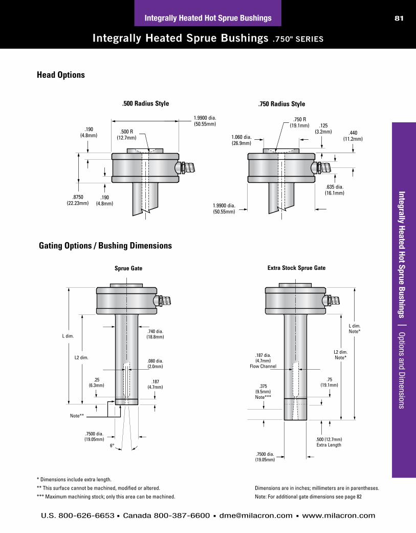
Integrally Heated Sprue Bushings .750" SERIES
Integrally Heated Hot Sprue Bushings | Options and D
imensions
L dim.
.190(4.8mm)
1.9900 dia.(50.55mm)
.7500 dia.(19.05mm)
.8750(22.23mm)
.750 R(19.1mm)
L2 dim.
.187(4.7mm)
.080 dia.(2.0mm)
.740 dia.(18.8mm)
.25(6.3mm)
.440(11.2mm)
.125(3.2mm)
1.060 dia.(26.9mm)
.500 Radius Style .750 Radius Style
.190(4.8mm)
.500 R(12.7mm)
1.9900 dia.(50.55mm)
.635 dia.(16.1mm)
.75(19.1mm)
L2 dim.Note*
.375(9.5mm)Note***
.187 dia.(4.7mm)
Flow Channel
.7500 dia.(19.05mm)
.500 (12.7mm)Extra Length
L dim.Note*
Sprue Gate Extra Stock Sprue Gate
Note**
6°
Head Options
Gating Options / Bushing Dimensions
L dim.
.190(4.8mm)
1.9900 dia.(50.55mm)
.7500 dia.(19.05mm)
.8750(22.23mm)
.750 R(19.1mm)
L2 dim.
.187(4.7mm)
.080 dia.(2.0mm)
.740 dia.(18.8mm)
.25(6.3mm)
.440(11.2mm)
.125(3.2mm)
1.060 dia.(26.9mm)
.500 Radius Style .750 Radius Style
.190(4.8mm)
.500 R(12.7mm)
1.9900 dia.(50.55mm)
.635 dia.(16.1mm)
.75(19.1mm)
L2 dim.Note*
.375(9.5mm)Note***
.187 dia.(4.7mm)
Flow Channel
.7500 dia.(19.05mm)
.500 (12.7mm)Extra Length
L dim.Note*
Sprue Gate Extra Stock Sprue Gate
Note**
6°
* Dimensions include extra length.
** This surface cannot be machined, modified or altered.
*** Maximum machining stock; only this area can be machined.
Dimensions are in inches; millimeters are in parentheses.
Note: For additional gate dimensions see page 82
L dim.
.190(4.8mm)
1.9900 dia.(50.55mm)
.7500 dia.(19.05mm)
.8750(22.23mm)
.750 R(19.1mm)
L2 dim.
.187(4.7mm)
.080 dia.(2.0mm)
.740 dia.(18.8mm)
.25(6.3mm)
.440(11.2mm)
.125(3.2mm)
1.060 dia.(26.9mm)
.500 Radius Style .750 Radius Style
.190(4.8mm)
.500 R(12.7mm)
1.9900 dia.(50.55mm)
.635 dia.(16.1mm)
.75(19.1mm)
L2 dim.Note*
.375(9.5mm)Note***
.187 dia.(4.7mm)
Flow Channel
.7500 dia.(19.05mm)
.500 (12.7mm)Extra Length
L dim.Note*
Sprue Gate Extra Stock Sprue Gate
Note**
6°

U.S. 800-626-6653 n Canada 800-387-6600 n [email protected] n www.milacron.com
82 Integrally Heated Hot Sprue Bushings
Integrally Heated Sprue Bushings .750" SERIES SPECIFICATIONS
Inte
gral
ly H
eate
d Ho
t Spr
ue B
ushi
ngs
| S
peci
ficat
ions
Gate Style L Dim. L2 Dim. .500 Radius Head .750 Radius Head Watts Thermocouple
Sprue 2.375" (60.3) 1.500" (38.1) SB031000 SB031001 315 MT020020
2.875" (73.0) 2.000" (50.8) SB031008 SB031009 370 MT020020
3.375" (85.7) 2.500" (63.5) SB031016 SB031017 425 MT020020
3.875" (98.4) 3.000" (76.2) SB031024 SB031025 480 MT020020
4.375" (111.1) 3.500" (88.9) SB031032 SB031033 535 MT020021
Gate Style L Dim. L2 Dim. .500 Radius Head .750 Radius Head Watts Thermocouple
Extra Stock Sprue 2.875" (73.0) 2.000" (50.8) SB031004 SB031005 315 MT020020
3.375" (85.7) 2.500" (63.5) SB031012 SB031013 370 MT020020
3.875" (98.4) 3.000" (76.2) SB031020 SB031021 425 MT020020
4.375" (111.1) 3.500" (88.9) SB031028 SB031029 480 MT020020
4.875" (123.8) 4.000" (101.6) SB031036 SB031037 535 MT020021
Mold Power-Thermocouple Input ConnectorA Single-Zone Power-Thermocouple Input Connector is available for mounting in or on the mold to accept the power-thermocouple cable from the mainframe. The water-resistant connector has an integral retaining latch for a secure cable connection and numbered screw-type terminals for power and thermocouple lead wires.*Can be mounted on top of mold
Armored Mold Power-Thermocouple CablesSingle-Zone Mold Power-Thermocouple Cables are constructed of special lead wire for use in high temperature environments, and are available to connect the mainframe to the input connector on the mold. Available in lengths of 10 or 20 feet. Integral retaining latches on the mainframe and mold connections provide secure cable connections. Connector configurations ensure proper insertion of cable.
Recommended Mold Pocket LayoutFor Mold Power-Thermocouple Input Connector (CkPTIC1)
ITEM NUMBER
MPTC10
MPTC20
ITEM NUMBER
CKPTIC1
For complete information on temperature controls, please see dMe control systems catalog.
All specifications are subject to change without notification.Dimensions are in inches; millimeters are in parentheses.
Right (Standard)*
* Standard Lead exit –60" (1.52m) wrapped - 600 volt leads;right angle lead exit; and 6" (15.2cm)stainless steel, square-lock armored cable.
1.360.91
0.901.180 0.25 R 0.55
MOLD SURFACE
MOUNTING SURFACE
1.00
2.00
4.00 MIN.
1.452.00
0.460.32
NO. 4-40 NC-2B TAP.50 DEEP MIN. (2) PLACES
0.25 R
1.503.50
0.14REF
REF

U.S. 800-626-6653 n Canada 800-387-6600 n [email protected] n www.milacron.com
83Integrally Heated Hot Sprue Bushings | M
achining Dim
ensionsIntegrally Heated Hot Sprue Bushings
Integrally Heated Sprue Bushings .750" SERIES
.750" Series Bore & Gate Dimensions
in: + 0.0005– 0
mm: + 0.01– 0
Tol. “a” Table
in: + 0.0010– 0
mm: + 0.02– 0
Tol. “b” Table
L2 dim. + exp.(See page 4 for L2 dim.)
2.05 dia.(52.1mm) .8752
a
(22.23mm)a
.110(2.8mm)
Gate
1.9910b
dia.(50.57mm)
b
Insulating Washer Option Standard Bore
L2 dim. – .125 + Exp.L2 dim. – (3.2mm) + Exp.{See page 4 for L2 dim.}
.860 dia.(21.8mm)
.500 min.(12.7mm)
Bottom Washer
Top Washer
.125(3.2mm)
.125(3.2mm)
1.125(28.6mm)
.235(6.0mm)
.760(19.3mm)
.080(2.0mm)
.860 dia.(21.8mm)
.7505a
dia.(19.06mm)
a
.118(3.0mm)
.125(3.2mm)
Water Line
.118 min.(3.0mm)
.7505a
dia.(19.06mm)
a
30° max.
.860 dia.(21.8mm)
.493 max.(12.5mm)
Thermal Expansion (Exp.) FormulasExp. in = L2 in. × 6.88 × 10⁻⁶ × (Processing Temp. – 70°F)
Exp. mm = L2 mm × 13 × 10-6 × (Processing Temp. – 21°C)
Ref: 10-6 = 0.000001
All specifications are subject to change without notification.
Dimensions are inches. Millimeters are in parentheses.
in: + 0.0005– 0
mm: + 0.01– 0
Tol. “a” Table
in: + 0.0010– 0
mm: + 0.02– 0
Tol. “b” Table
L2 dim. + exp.(See page 4 for L2 dim.)
2.05 dia.(52.1mm) .8752
a
(22.23mm)a
.110(2.8mm)
Gate
1.9910b
dia.(50.57mm)
b
Insulating Washer Option Standard Bore
L2 dim. – .125 + Exp.L2 dim. – (3.2mm) + Exp.{See page 4 for L2 dim.}
.860 dia.(21.8mm)
.500 min.(12.7mm)
Bottom Washer
Top Washer
.125(3.2mm)
.125(3.2mm)
1.125(28.6mm)
.235(6.0mm)
.760(19.3mm)
.080(2.0mm)
.860 dia.(21.8mm)
.7505a
dia.(19.06mm)
a
.118(3.0mm)
.125(3.2mm)
Water Line
.118 min.(3.0mm)
.7505a
dia.(19.06mm)
a
30° max.
.860 dia.(21.8mm)
.493 max.(12.5mm)
Top Bottom
Item Number MAX10015 MAX10027
O.D. 1.99 (50.5mm)
1.99 (50.5mm)
I.D. 1.07 (27.2mm)
.810 (20.6mm)
Thickness .125 (3.2mm)
.125 (3.2mm)
Insulating Washer Specifications
Sprue Gate Extra Stock Sprue Gate
Bore & Gate Tolerances
Note: Insulating Washers are not required, but are recommended for high tem-perature applications.

U.S. 800-626-6653 n Canada 800-387-6600 n [email protected] n www.milacron.com
84 Integrally Heated Hot Sprue Bushings
Integrally Heated Sprue Bushings .750" SERIES
Inte
gral
ly H
eate
d Ho
t Spr
ue B
ushi
ngs
| L
ocat
ing
Ring
& K
eyin
g O
ptio
ns
Operating & Servicing InstructionsThe Integrally Heated Sprue Bushing bodies are identical in design, but differ in length and head style. All Sprue Bushings feature an integrated heater; Type “J” thermocouple; 60” wrapped - 600 volt leads; right angle lead exit; and 6” stainless steel, square-lock armored cable.
Start-Up/Operating ProceduresIf the temperature controller does not utilize “soft start” technology, set the controller to 200°F (93.3°C) in automatic mode or 10% in manual mode. Allow bushing to “soak” for 15 minutes before increasing to processing temperature. This step will allow the unit to dissipate potential moisture and prolong heater life.
Power Requirementsn 240 Volts AC – 15 amp fuse
n Grounding – Integrally Heated Bushings utilize the direct contact of the bushing, mold plates, and machine platens to establish a path for grounding.
*WarninG*There must be a ground present between the mold “hot half” and the temperature control system or damage may occur to the bushing, thermocouple and/or temperature control system.
Maximum heat 600ºF
For 5/16 - 18 SHCS(2 places)
1.625 R(41.3mm)
5.490 dia.(139.4mm)
3.990" dia(101.3mm)
Customer to machine counterbore.
.510(12.9mm)
1.135(28.8mm)
.75 R min.(19.1mm)
.83 R min.*(21.1mm)
Dowel Pin
5/16 - 18 THDJack Screw location(2 places)
Socket HeadCap Screw
Locating Ring Dimensions
ITEM NUMBER
L.R.D.
ML010012 3.990” (101.3mm)
Machining Options for keying
For 5/16 - 18 SHCS(2 places)
1.625 R(41.3mm)
5.490 dia.(139.4mm)
3.990" dia(101.3mm)
Customer to machine counterbore.
.510(12.9mm)
1.135(28.8mm)
.75 R min.(19.1mm)
.83 R min.*(21.1mm)
Dowel Pin
5/16 - 18 THDJack Screw location(2 places)
Socket HeadCap Screw
*Centerline for #10 Screw
Dimensions are in inches; millimeters are in parentheses.
Related Documents


