Ch t 3 Ch t 3 Chapter 3 Sketch Mode Chapter 3 Sketch Mode Sketch Mode Sketch Mode May 11, 2007 © 2007 ANSYS, Inc. All rights reserved. ANSYS, Inc. Proprietary Inventory #002496 3-1

Welcome message from author
This document is posted to help you gain knowledge. Please leave a comment to let me know what you think about it! Share it to your friends and learn new things together.
Transcript
Ch t 3Ch t 3Chapter 3
Sketch Mode
Chapter 3
Sketch ModeSketch ModeSketch Mode
May 11, 2007© 2007 ANSYS, Inc. All rights reserved.
ANSYS, Inc. Proprietary Inventory #0024963-1
Training Manual
ContentsTraining Manual
Desig
• DesignModeler Geometry• Length Units
D i M d l G t i E titi
• Sketch Dimensions• Sketch Display gnM
odele
• DesignModeler Geometric Entities• Sketch Mode• New Plane Button
N Sk h B
• Dimension Editing• Workshop 3.1• Modifying Sketches er• New Sketch Button
• “From Face” Plane/Sketch• The Sketch Mode GUI
y g• Sketch Instance• Sketch Projection• Geometry Interfaces• Planes and Sketches
• Plane Transforms• Sketching Tools
• Geometry Interfaces• Attaching to a CAD Session• Importing CAD Files
P iti i I t• Sketching - Basic Shapes• Sketch Details• Sketch Constraints
• Positioning Imports• Import Units• Exporting a Model
May 11, 2007© 2007 ANSYS, Inc. All rights reserved.
Inventory #0024963-2
ANSYS, Inc. Proprietary
• Workshop 3.2
Training Manual
DesignModeler GeometryTraining Manual
Desig
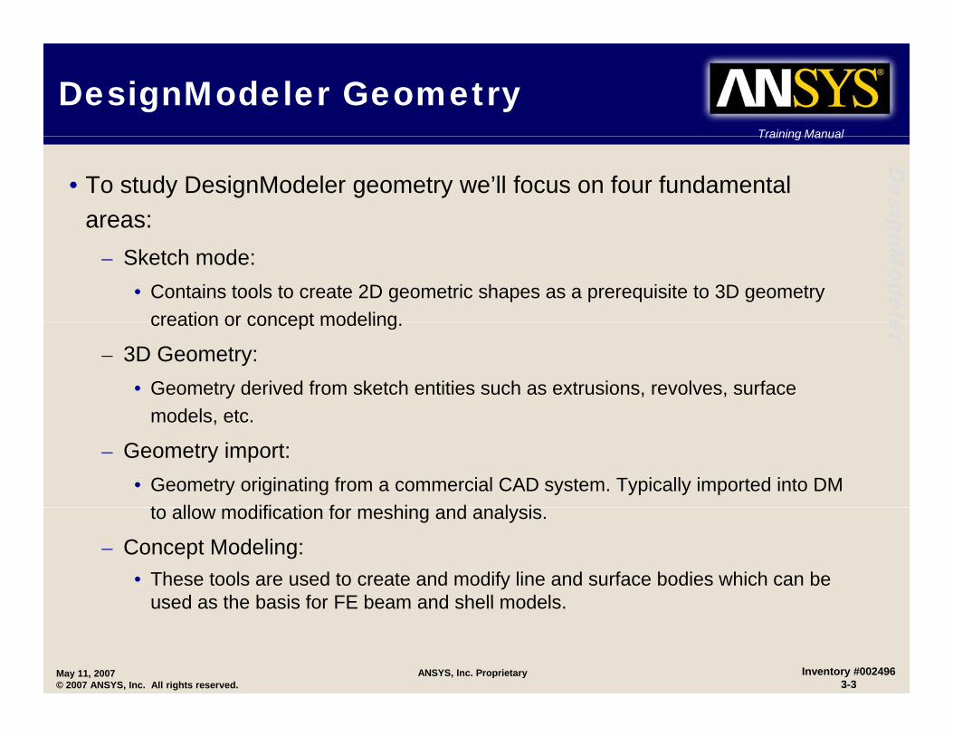
• To study DesignModeler geometry we’ll focus on four fundamental areas: gnM
odele
– Sketch mode:• Contains tools to create 2D geometric shapes as a prerequisite to 3D geometry
creation or concept modeling ercreation or concept modeling.
– 3D Geometry:• Geometry derived from sketch entities such as extrusions, revolves, surface
models etcmodels, etc.
– Geometry import:• Geometry originating from a commercial CAD system. Typically imported into DM
t ll difi ti f hi d l ito allow modification for meshing and analysis.
– Concept Modeling:• These tools are used to create and modify line and surface bodies which can be
used as the basis for FE beam and shell models
May 11, 2007© 2007 ANSYS, Inc. All rights reserved.
Inventory #0024963-3
ANSYS, Inc. Proprietary
used as the basis for FE beam and shell models.
Training Manual
Length UnitsTraining Manual
Desig
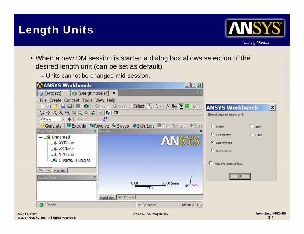
• When a new DM session is started a dialog box allows selection of the desired length unit (can be set as default) gnM
odele
– Units cannot be changed mid-session.
er
May 11, 2007© 2007 ANSYS, Inc. All rights reserved.
Inventory #0024963-4
ANSYS, Inc. Proprietary
Training Manual
DesignModeler Geometric EntitiesTraining Manual
Desig
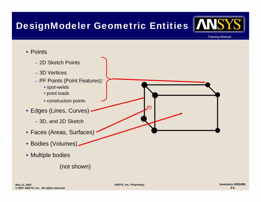
• Points
2D Sketch Points
gnModele
– 2D Sketch Points
– 3D Vertices– PF Points (Point Features):
• spot-welds erspot welds• point loads• construction points
• Edges (Lines, Curves)g ( )
– 3D, and 2D Sketch
• Faces (Areas, Surfaces)
• Bodies (Volumes)
• Multiple bodies
( t h )
May 11, 2007© 2007 ANSYS, Inc. All rights reserved.
Inventory #0024963-5
ANSYS, Inc. Proprietary
(not shown)

Training Manual
Sketch ModeTraining Manual
Desig
• DM sketches are created on planes. In a new DM session there are three default orthogonal planes in place at the global origin (XY, ZX, YZ). gnM
odele
• Users may create and position new planes as needed by defining origin and orientation or by using existing geometry as a reference.
• The process to begin sketching is twofold: er• The process to begin sketching is twofold:1. Identify the plane upon which you wish to sketch.
2. Create or identify the sketch which lies on the desired plane.
U t l d d• Users may create as many planes as needed.
• Each plane may have multiple sketches associated with them.
• In the next few pages we’ll look at plane and sketch entity creation and tools to assist in sketching.
May 11, 2007© 2007 ANSYS, Inc. All rights reserved.
Inventory #0024963-6
ANSYS, Inc. Proprietary
Training Manual
New Plane ButtonTraining Manual
Desig
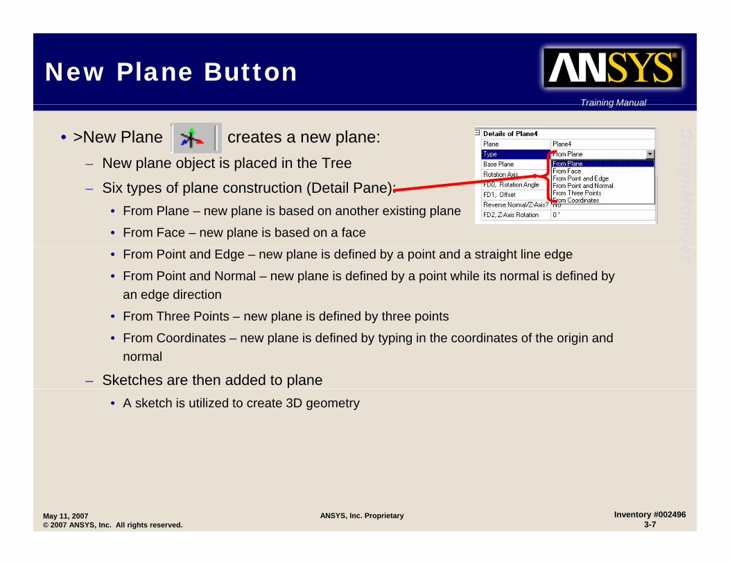
• >New Plane creates a new plane: – New plane object is placed in the Tree gnM
odele
– Six types of plane construction (Detail Pane):• From Plane – new plane is based on another existing plane
• From Face – new plane is based on a face er• From Point and Edge – new plane is defined by a point and a straight line edge
• From Point and Normal – new plane is defined by a point while its normal is defined by an edge direction
• From Three Points – new plane is defined by three pointsFrom Three Points new plane is defined by three points
• From Coordinates – new plane is defined by typing in the coordinates of the origin and normal
– Sketches are then added to plane• A sketch is utilized to create 3D geometry
May 11, 2007© 2007 ANSYS, Inc. All rights reserved.
Inventory #0024963-7
ANSYS, Inc. Proprietary
Training Manual
New Sketch ButtonTraining Manual
Desig
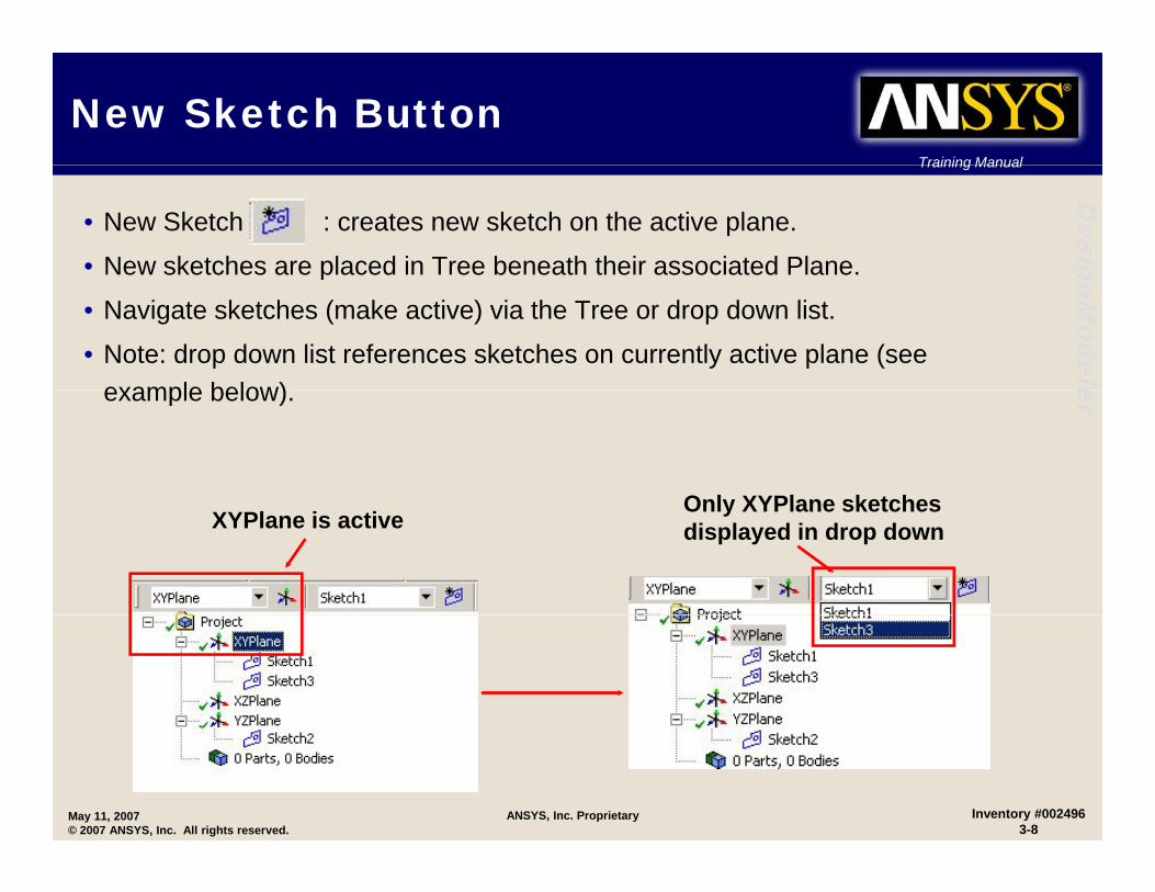
• New Sketch : creates new sketch on the active plane.
• New sketches are placed in Tree beneath their associated Plane. gnModele
p
• Navigate sketches (make active) via the Tree or drop down list.
• Note: drop down list references sketches on currently active plane (see example below) erexample below).
Only XYPlane sketchesXYPlane is active
Only XYPlane sketches displayed in drop down
May 11, 2007© 2007 ANSYS, Inc. All rights reserved.
Inventory #0024963-8
ANSYS, Inc. Proprietary
Training Manual
“From Face” Plane/Sketch ShortcutTraining Manual
Desig
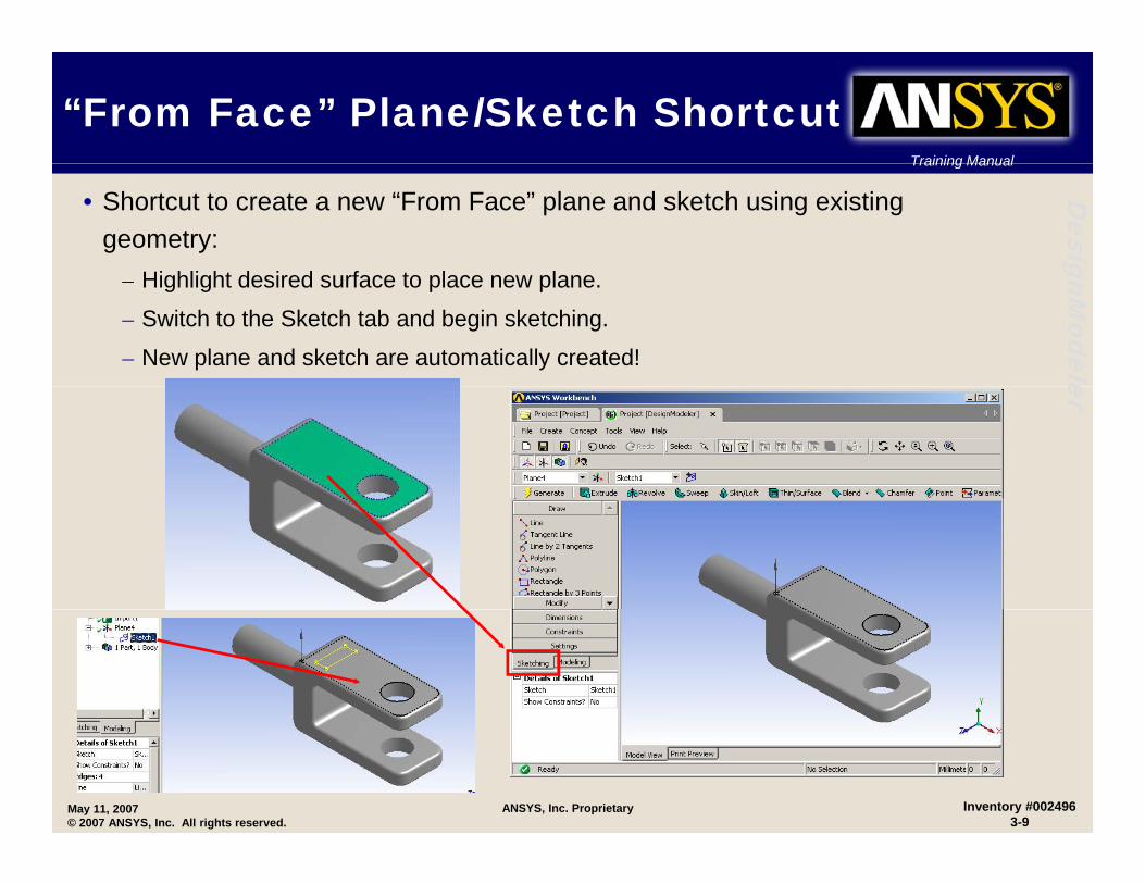
• Shortcut to create a new “From Face” plane and sketch using existing geometry:
Hi hli ht d i d f t l l
gnModele
– Highlight desired surface to place new plane.
– Switch to the Sketch tab and begin sketching.
– New plane and sketch are automatically created! er
May 11, 2007© 2007 ANSYS, Inc. All rights reserved.
Inventory #0024963-9
ANSYS, Inc. Proprietary

Training Manual
Plane TransformsTraining Manual
Desig
• Up to 9 plane transformations are available. They can be applied quickly by choosing the desired transform through the RMB in the “Transform” field in the gnM
odele
plane detail window.
er
May 11, 2007© 2007 ANSYS, Inc. All rights reserved.
Inventory #0024963-10
ANSYS, Inc. Proprietary
Training Manual
Plane Transforms…Training Manual
Desig
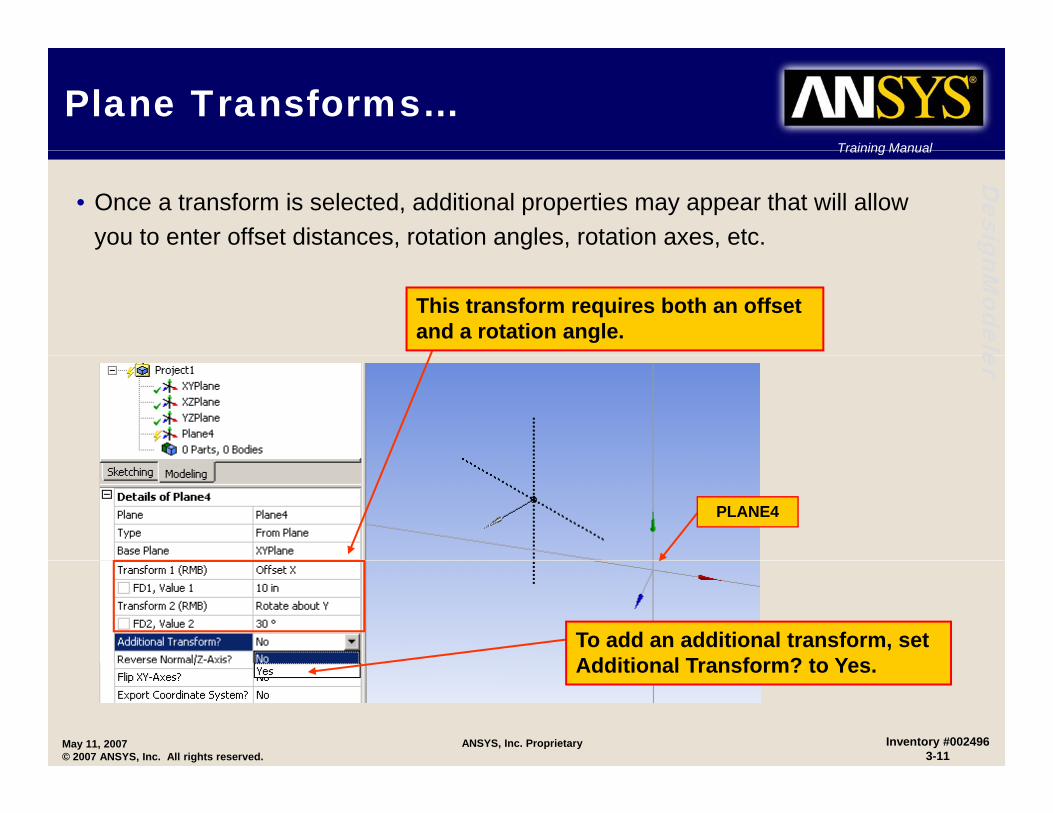
• Once a transform is selected, additional properties may appear that will allow you to enter offset distances, rotation angles, rotation axes, etc. gnM
odele
This transform requires both an offset and a rotation angle. er
PLANE4
To add an additional transform, set Additional Transform? to Yes
May 11, 2007© 2007 ANSYS, Inc. All rights reserved.
Inventory #0024963-11
ANSYS, Inc. Proprietary
Additional Transform? to Yes.

Training Manual
Planes and Sketch DetailsTraining Manual
DesigAfter setting plane
details the
The plane origin can be turned on/off.
gnModele
details, the “Generate” button creates the new plane. erNote: this step is not necessary for sketch creation.
Can “Generate”Can Generate with RMB
The triad and display ruler can be turned on/off.
The “Details” for each plane and sketch controls basic
Triad
Ruler
May 11, 2007© 2007 ANSYS, Inc. All rights reserved.
Inventory #0024963-12
ANSYS, Inc. Proprietary
behavior.
Training Manual
The Sketch Mode GUITraining Manual
Desig
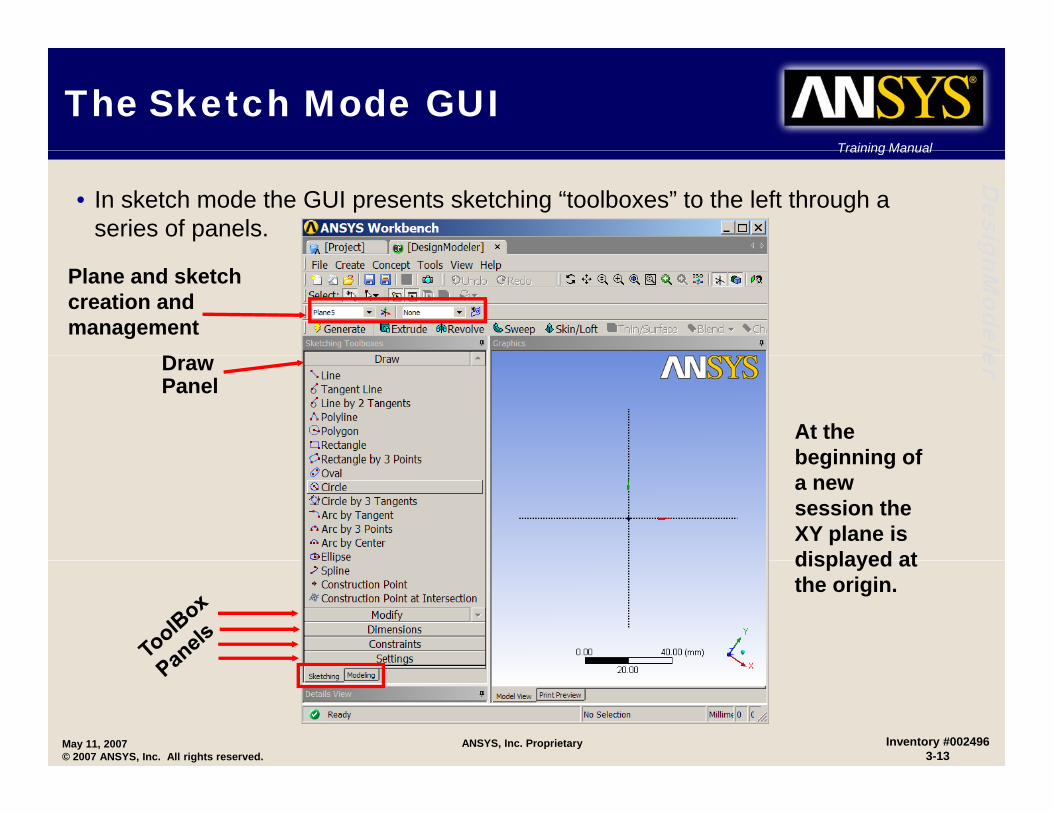
• In sketch mode the GUI presents sketching “toolboxes” to the left through a series of panels. gnM
odele
Plane and sketch creation and management
D
er
At the beginning of
DrawPanel
beginning of a new session the XY plane is displayed atdisplayed at the origin.
May 11, 2007© 2007 ANSYS, Inc. All rights reserved.
Inventory #0024963-13
ANSYS, Inc. Proprietary

Training Manual
Sketching Tools - GridTraining Manual
Desig
• The “Settings” panel allows a sketch grid to be defined and displayed (default = off). gnM
odele
– Snap feature applies to major and minor spacing.
er
May 11, 2007© 2007 ANSYS, Inc. All rights reserved.
Inventory #0024963-14
ANSYS, Inc. Proprietary
Major spacing (solid)
Minor spacing (dashed)

Training Manual
Sketching Tools – Grid…Training Manual
Desig
• Grid Snaps per Minor allows snapping to points in between minor grid lines.
gnModele
This rectangle is snapped halfway between two minor grid lines if Snaps per Minor is set to 2 er
May 11, 2007© 2007 ANSYS, Inc. All rights reserved.
Inventory #0024963-15
ANSYS, Inc. Proprietary

Training Manual
Sketching Tools – RulerTraining Manual
Desig
• The Ruler tool allows you to get a quick sense of scale.
gnModeleer
May 11, 2007© 2007 ANSYS, Inc. All rights reserved.
Inventory #0024963-16
ANSYS, Inc. Proprietary
Training Manual
Sketching Tools – Auto Constraints
Training Manual
Desig
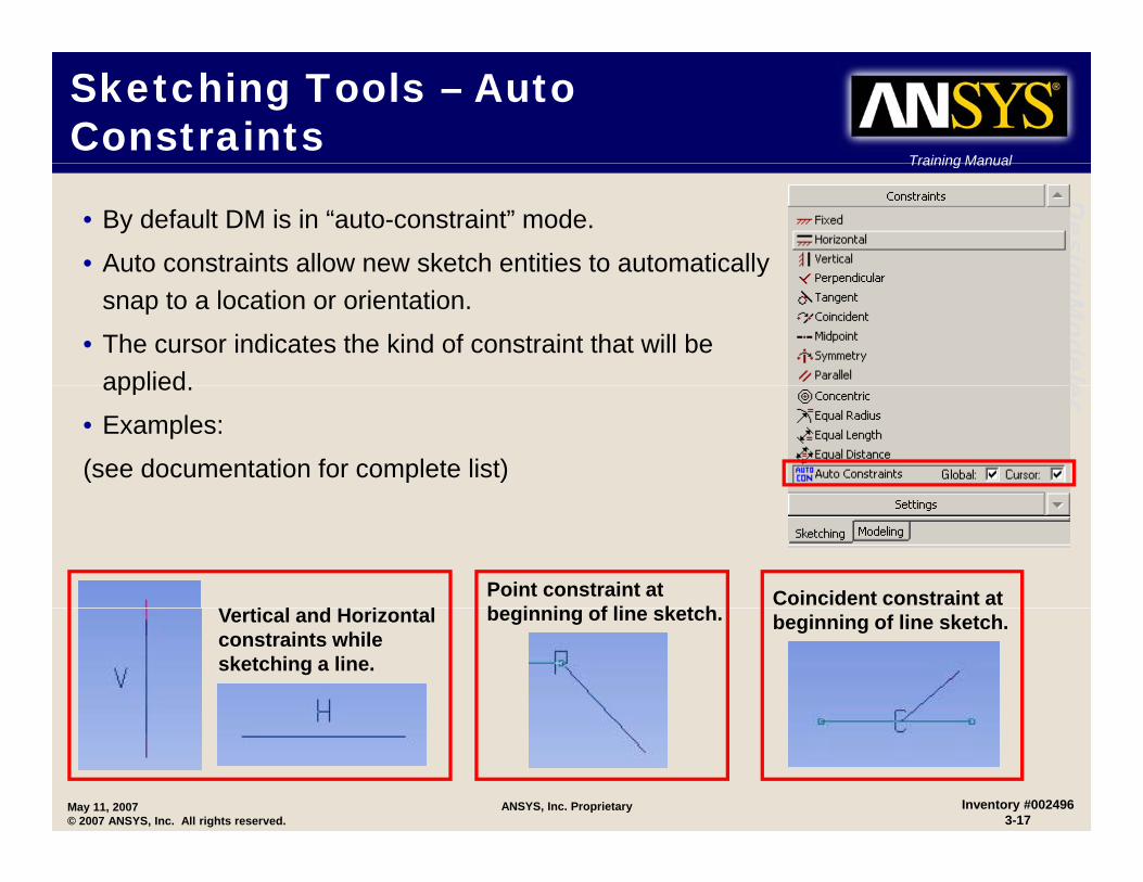
• By default DM is in “auto-constraint” mode.
• Auto constraints allow new sketch entities to automatically gnModele
ysnap to a location or orientation.
• The cursor indicates the kind of constraint that will be applied erapplied.
• Examples:
(see documentation for complete list)
V ti l d H i t lPoint constraint at b i i f li k t h
Coincident constraint at Vertical and Horizontal constraints while sketching a line.
beginning of line sketch. beginning of line sketch.
May 11, 2007© 2007 ANSYS, Inc. All rights reserved.
Inventory #0024963-17
ANSYS, Inc. Proprietary
Training Manual
Sketching Tools – TipsTraining Manual
Desig
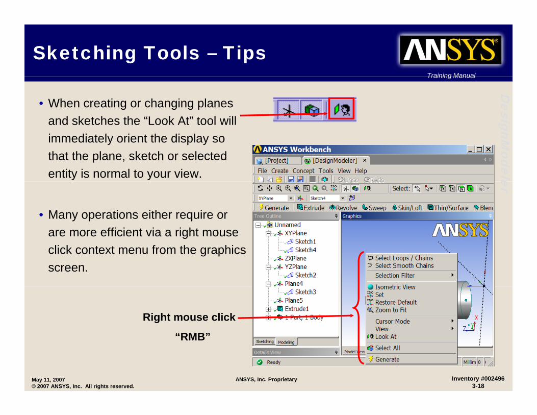
• When creating or changing planes and sketches the “Look At” tool will gnM
odele
immediately orient the display so that the plane, sketch or selected entity is normal to your view. er
• Many operations either require or are more efficient via a right mouseare more efficient via a right mouse click context menu from the graphics screen.
Right mouse click
“RMB”
May 11, 2007© 2007 ANSYS, Inc. All rights reserved.
Inventory #0024963-18
ANSYS, Inc. Proprietary
RMB

Training Manual
Sketching Tools – Tips …Training Manual
Desig
• The Undo/Redo buttons are available in sketch mode only.
R th l t l t d k t hi ti
gnModele
– Removes the last completed sketching operation.– Multiple undo’s allowed.– IMPORTANT: Each plane stores its own Undo “stack”.
er
• The “Back” operation (available via RMB) acts like a micro undo during sketching operations.
• Remember: only one sketch is active at any time!
May 11, 2007© 2007 ANSYS, Inc. All rights reserved.
Inventory #0024963-19
ANSYS, Inc. Proprietary
Training Manual
Sketching Tools – Tips …Training Manual
Desig
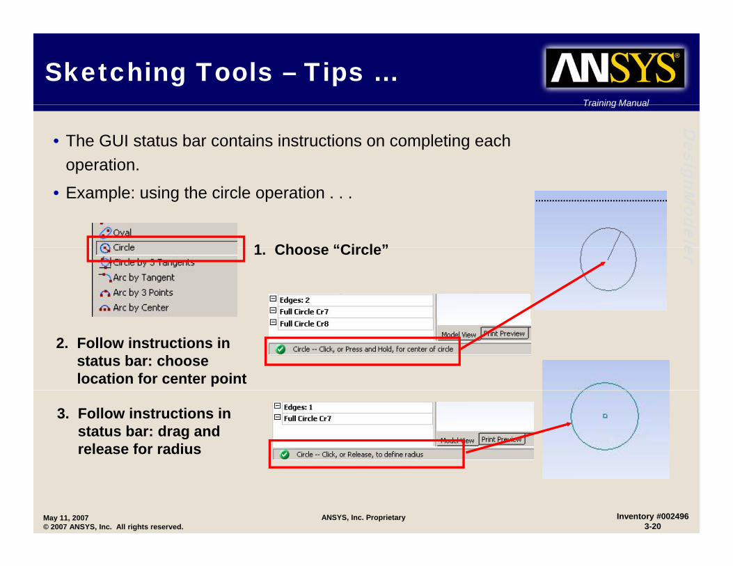
• The GUI status bar contains instructions on completing each operation. gnM
odele
• Example: using the circle operation . . .
1 Choose “Circle”
er1. Choose “Circle”
2. Follow instructions in status bar: choose location for center point
3. Follow instructions in status bar: drag and release for radius
May 11, 2007© 2007 ANSYS, Inc. All rights reserved.
Inventory #0024963-20
ANSYS, Inc. Proprietary
Training Manual
Sketching – Basic ShapesTraining Manual
Desig
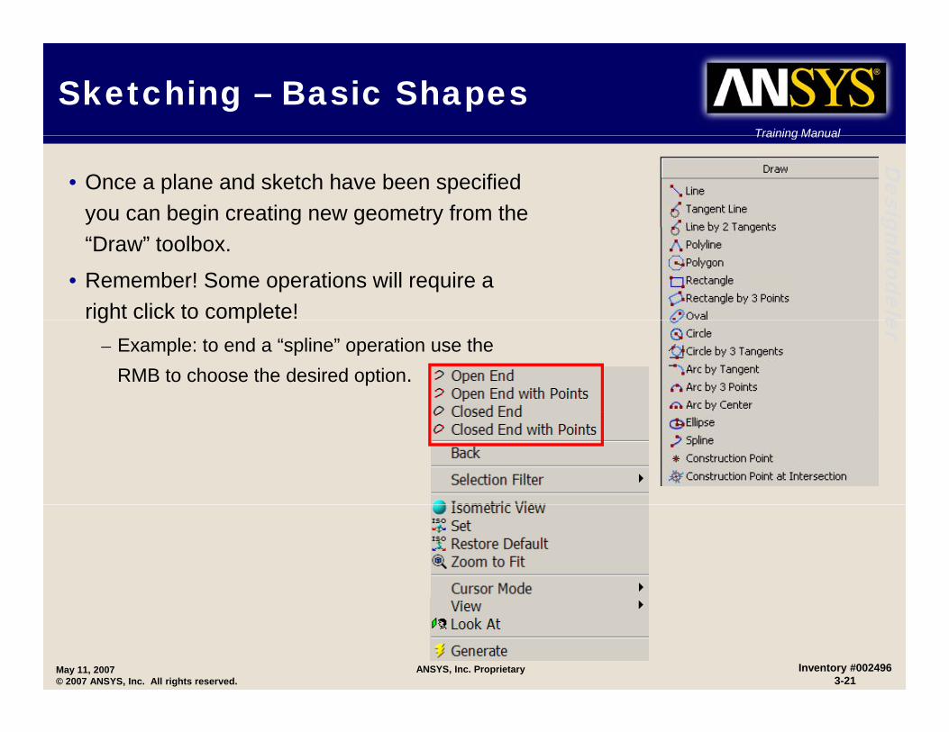
• Once a plane and sketch have been specified you can begin creating new geometry from the gnM
odele
“Draw” toolbox.
• Remember! Some operations will require a right click to complete! erg p
– Example: to end a “spline” operation use the RMB to choose the desired option.
May 11, 2007© 2007 ANSYS, Inc. All rights reserved.
Inventory #0024963-21
ANSYS, Inc. Proprietary

Training Manual
Sketch DetailsTraining Manual
Desig
• Reference numbers for the entities in each sketch (lines, circles, polygons, etc.) can be viewed. gnM
odele
• Useful for parametric modeling discussed later.
er
Can rename sketches from Detail pane.
May 11, 2007© 2007 ANSYS, Inc. All rights reserved.
Inventory #0024963-22
ANSYS, Inc. Proprietary

Training Manual
Sketch Details …Training Manual
Desig
• Highlighting lines in the graphics screen (sketch mode only), will display details for the line. gnM
odele
Can rename sketch entities from Detail pane erpane.
Details forDetails for highlighted line
May 11, 2007© 2007 ANSYS, Inc. All rights reserved.
Inventory #0024963-23
ANSYS, Inc. Proprietary
Training Manual
Sketch ConstraintsTraining Manual
Desig
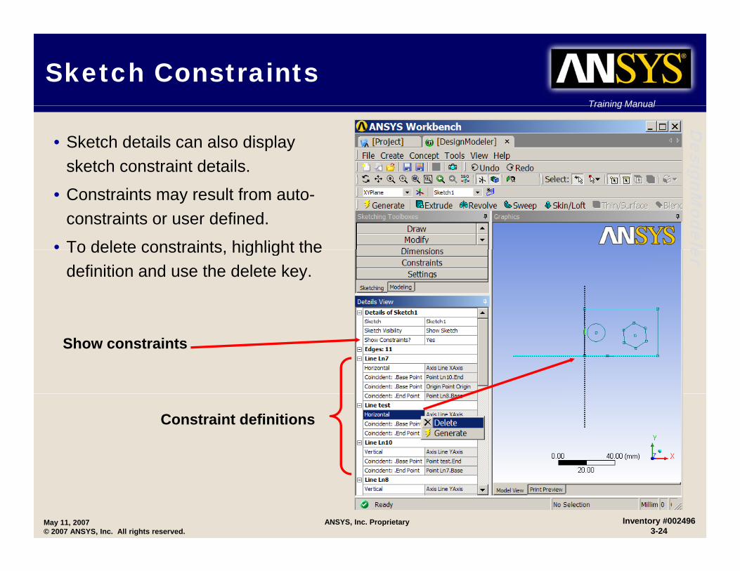
• Sketch details can also display sketch constraint details. gnM
odele
• Constraints may result from auto-constraints or user defined.
• To delete constraints highlight the erTo delete constraints, highlight the definition and use the delete key.
Show constraints
Constraint definitions
May 11, 2007© 2007 ANSYS, Inc. All rights reserved.
Inventory #0024963-24
ANSYS, Inc. Proprietary
Training Manual
Sketch Constraints . . . Training Manual
Desig
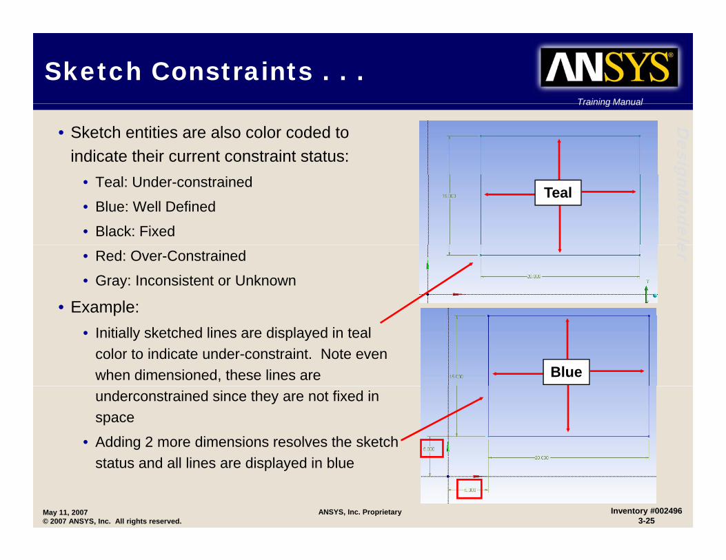
• Sketch entities are also color coded to indicate their current constraint status: gnM
odele
• Teal: Under-constrained
• Blue: Well Defined
• Black: Fixed
Teal
er• Red: Over-Constrained
• Gray: Inconsistent or Unknown
• Example:p• Initially sketched lines are displayed in teal
color to indicate under-constraint. Note even when dimensioned, these lines are Blueunderconstrained since they are not fixed in space
• Adding 2 more dimensions resolves the sketch
May 11, 2007© 2007 ANSYS, Inc. All rights reserved.
Inventory #0024963-25
ANSYS, Inc. Proprietary
status and all lines are displayed in blue
Training Manual
Sketch Constraints . . . Training Manual
Desig
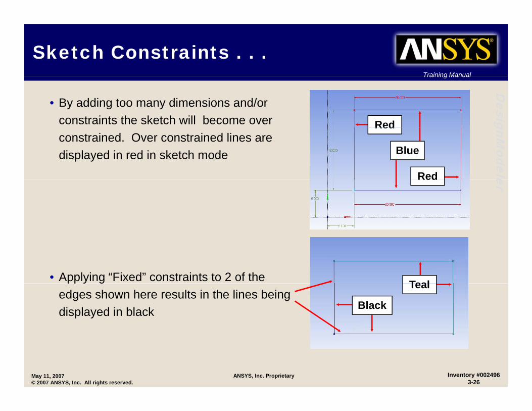
• By adding too many dimensions and/or constraints the sketch will become over Red gnM
odele
constrained. Over constrained lines are displayed in red in sketch mode Blue
Red
Red
erRed
• Applying “Fixed” constraints to 2 of the Tealpp y gedges shown here results in the lines being displayed in black
Teal
Black
May 11, 2007© 2007 ANSYS, Inc. All rights reserved.
Inventory #0024963-26
ANSYS, Inc. Proprietary
Training Manual
Sketch Constraints . . .Training Manual
Desig
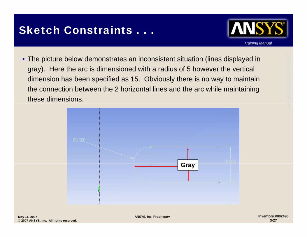
• The picture below demonstrates an inconsistent situation (lines displayed in gray). Here the arc is dimensioned with a radius of 5 however the vertical gnM
odele
dimension has been specified as 15. Obviously there is no way to maintain the connection between the 2 horizontal lines and the arc while maintaining these dimensions. er
GGray
May 11, 2007© 2007 ANSYS, Inc. All rights reserved.
Inventory #0024963-27
ANSYS, Inc. Proprietary

Training Manual
Sketch DimensionsTraining Manual
Desig
• DesignModeler contains a complete dimensioning toolbox. gnM
odele
• In addition to individual dimension assignment, semi-automatic dimensioning is available.
– Semi-automatic cycles through dimension choices erSemi automatic cycles through dimension choices until model is fully constrained or user chooses to exit semi-automatic mode.
– Right mouse button controls skip or end functions.
• The General dimensioning tool allows quick access to all primary dimensions via a right click context menu.context menu.
Right Mouse Click
May 11, 2007© 2007 ANSYS, Inc. All rights reserved.
Inventory #0024963-28
ANSYS, Inc. Proprietary

Training Manual
Sketch Dimensions …Training Manual
Desig
• Move function allows placement of dimension to be modified.
• Animate to view dynamic changes applied to the selected dimension. gnModele
y g pp
• Dimensions can be displayed as the dimension value and/or name.
er
May 11, 2007© 2007 ANSYS, Inc. All rights reserved.
Inventory #0024963-29
ANSYS, Inc. Proprietary

Training Manual
Sketch Dimensions …Training Manual
Desig
• To modify dimensions highlight then change value in details window.
gnModele
Highlight dimension
er
May 11, 2007© 2007 ANSYS, Inc. All rights reserved.
Inventory #0024963-30
ANSYS, Inc. Proprietary
Enter new value
Training Manual
Dimension EditingTraining Manual
Desig
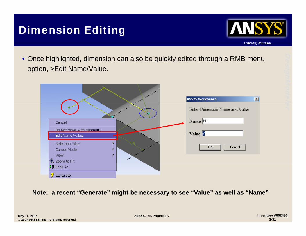
• Once highlighted, dimension can also be quickly edited through a RMB menu option, >Edit Name/Value. gnM
odeleer
Note: a recent “Generate” might be necessary to see “Value” as well as “Name”
May 11, 2007© 2007 ANSYS, Inc. All rights reserved.
Inventory #0024963-31
ANSYS, Inc. Proprietary
Note: a recent Generate might be necessary to see Value as well as Name
Training Manual
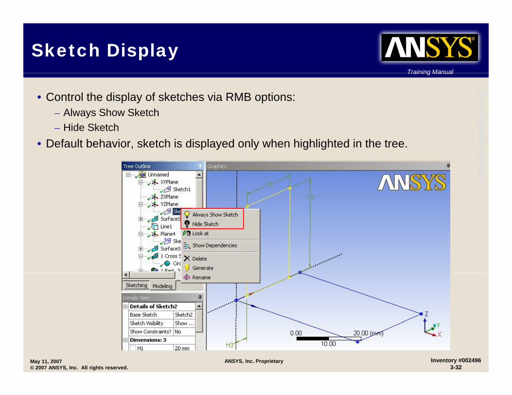
Sketch DisplayTraining Manual
Desig
• Control the display of sketches via RMB options:– Always Show Sketch gnM
odele
– Hide Sketch• Default behavior, sketch is displayed only when highlighted in the tree.
er
May 11, 2007© 2007 ANSYS, Inc. All rights reserved.
Inventory #0024963-32
ANSYS, Inc. Proprietary
SketchingSketching
Workshop 3-1
May 11, 2007© 2007 ANSYS, Inc. All rights reserved.
ANSYS, Inc. Proprietary Inventory #0024963-33
Training Manual
Workshop 3-1, Sketching Training Manual
Desig
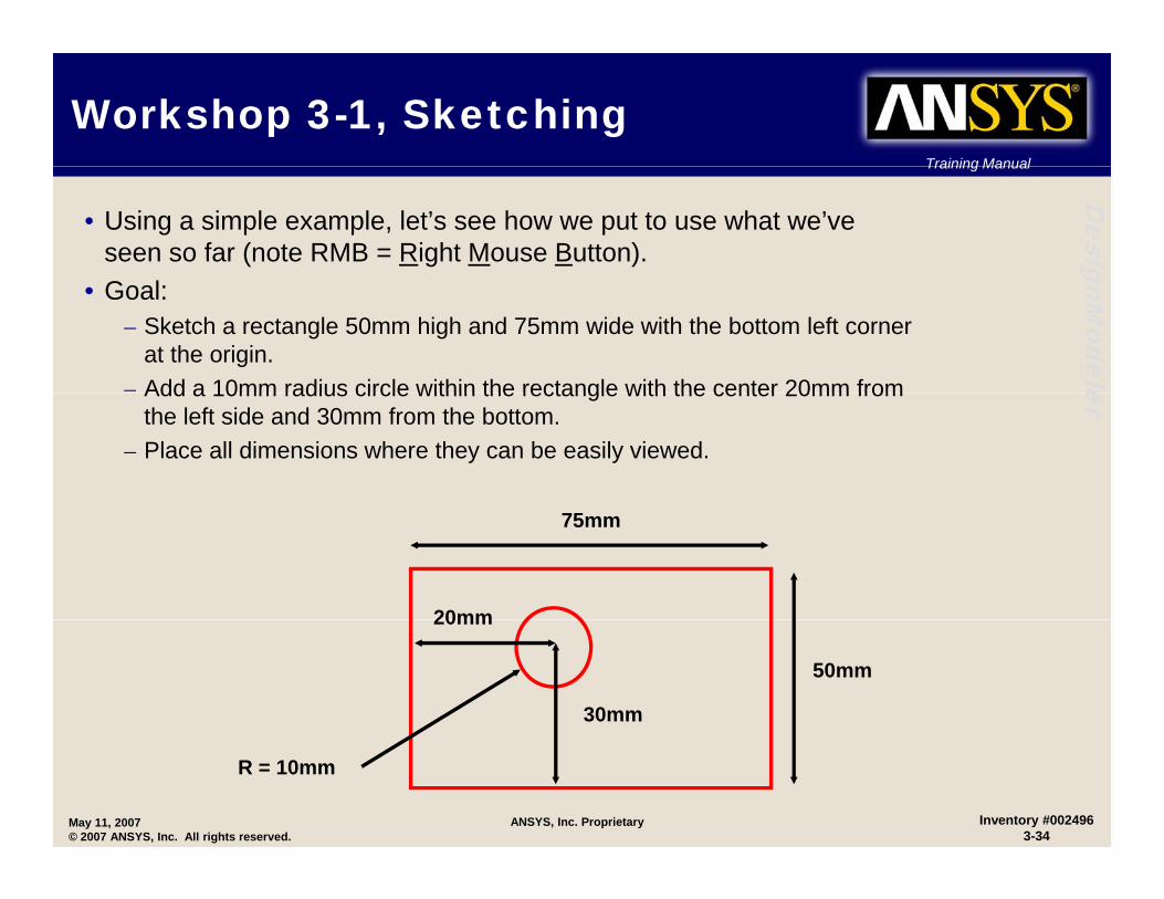
• Using a simple example, let’s see how we put to use what we’ve seen so far (note RMB = Right Mouse Button). gnM
odele
• Goal:– Sketch a rectangle 50mm high and 75mm wide with the bottom left corner
at the origin.– Add a 10mm radius circle within the rectangle with the center 20mm from erAdd a 10mm radius circle within the rectangle with the center 20mm from
the left side and 30mm from the bottom.– Place all dimensions where they can be easily viewed.
75mm
20mm
50mm
30mm
20mm
May 11, 2007© 2007 ANSYS, Inc. All rights reserved.
Inventory #0024963-34
ANSYS, Inc. Proprietary
R = 10mm
Training Manual
Workshop 3-1, SketchingTraining Manual
Desig
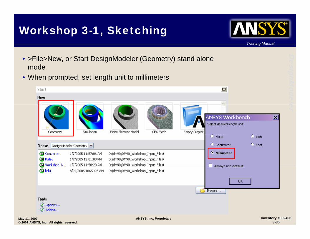
• >File>New, or Start DesignModeler (Geometry) stand alone mode gnM
odele
• When prompted, set length unit to millimeters
er
May 11, 2007© 2007 ANSYS, Inc. All rights reserved.
Inventory #0024963-35
ANSYS, Inc. Proprietary

Training Manual
Workshop 3-1, SketchingTraining Manual
Desig
• When DM starts, switch to sketch mode using the sketch tab.
N t th “L k At” i ( RMB ti ) t i t th
Icon
gnModele
– Note: use the “Look At” icon (or RMB options) to orient the sketch plane in the normal direction.
• Select the “Rectangle” tool and place the cursor at the origin. erorigin.
– Once the “P” (point constraint) symbol shows, click, hold and drag, then release to create the rectangle.
RMBRMB
Click
May 11, 2007© 2007 ANSYS, Inc. All rights reserved.
Inventory #0024963-36
ANSYS, Inc. Proprietary
Training Manual
Workshop 3-1, SketchingTraining Manual
Desig
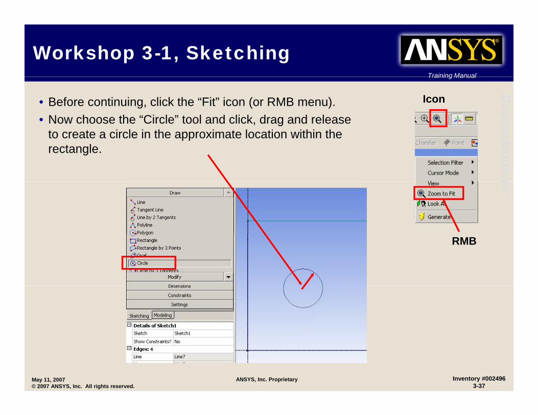
• Before continuing, click the “Fit” icon (or RMB menu).• Now choose the “Circle” tool and click, drag and release
Icon
gnModele
to create a circle in the approximate location within the rectangle.
er
RMB
May 11, 2007© 2007 ANSYS, Inc. All rights reserved.
Inventory #0024963-37
ANSYS, Inc. Proprietary
Training Manual
Workshop 3-1, SketchingTraining Manual
Desig
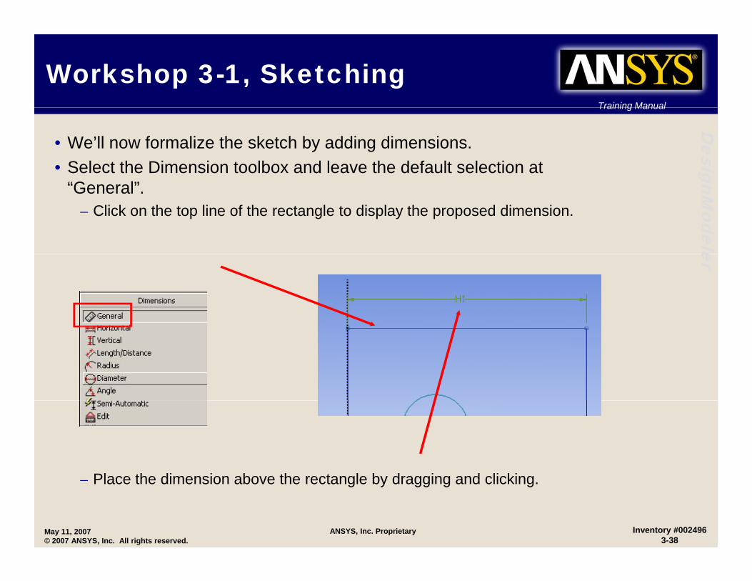
• We’ll now formalize the sketch by adding dimensions.• Select the Dimension toolbox and leave the default selection at gnM
odele
“General”.– Click on the top line of the rectangle to display the proposed dimension.
er
Pl th di i b th t l b d i d li ki
May 11, 2007© 2007 ANSYS, Inc. All rights reserved.
Inventory #0024963-38
ANSYS, Inc. Proprietary
– Place the dimension above the rectangle by dragging and clicking.

Training Manual
Workshop 3-1, SketchingTraining Manual
Desig
• Repeat the preceding steps to add the remaining dimensions.• Next modify the details for each dimension to the desired values as gnM
odele
shown.
75
er
50mm
75mm
20mm
50mm
30mm
D = 20mm
May 11, 2007© 2007 ANSYS, Inc. All rights reserved.
Inventory #0024963-39
ANSYS, Inc. Proprietary

Training Manual
Workshop 3-1, SketchingTraining Manual
Desig
• To complete our sketch use the “Move” function in the Dimension toolbox to position (drag) the dimensions (like below for example). gnM
odeleer
May 11, 2007© 2007 ANSYS, Inc. All rights reserved.
Inventory #0024963-40
ANSYS, Inc. Proprietary

Training Manual
Workshop 3-1, SketchingTraining Manual
Desig
• Now try animating several dimensions:– Choose the “Animate” function then click
on a dimension in the graphics window. gnModeleer
– Change the dimension display from “Name” to “Value”.
May 11, 2007© 2007 ANSYS, Inc. All rights reserved.
Inventory #0024963-41
ANSYS, Inc. Proprietary
Training Manual
Workshop 3-1, SketchingTraining Manual
Desig
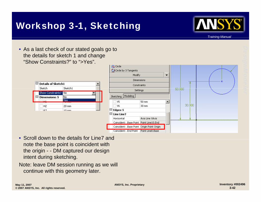
• As a last check of our stated goals go to the details for sketch 1 and change “Show Constraints?” to “>Yes”
gnModele
Show Constraints? to >Yes .
er
• Scroll down to the details for Line7 andScroll down to the details for Line7 and note the base point is coincident with the origin - - DM captured our design intent during sketching.
Note: leave DM session running as we will
May 11, 2007© 2007 ANSYS, Inc. All rights reserved.
Inventory #0024963-42
ANSYS, Inc. Proprietary
Note: leave DM session running as we will continue with this geometry later.
Training Manual
Modifying SketchesTraining Manual
Desig
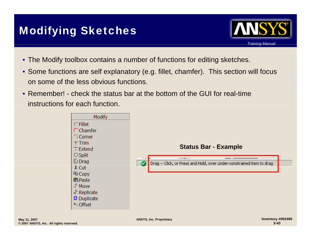
• The Modify toolbox contains a number of functions for editing sketches.
• Some functions are self explanatory (e.g. fillet, chamfer). This section will focus gnModele
p y ( g , )on some of the less obvious functions.
• Remember! - check the status bar at the bottom of the GUI for real-time instructions for each function erinstructions for each function.
Status Bar - Example
May 11, 2007© 2007 ANSYS, Inc. All rights reserved.
Inventory #0024963-43
ANSYS, Inc. Proprietary

Training Manual
Modifying Sketches …Training Manual
Desig
• Split:– RMB Options (choose before selecting edge): gnM
odele
• Split Edge at Selection (default): splits an edge into two pieces at the selection location (unless the edge is a full circle or ellipse). For a full circle or ellipse, both start and end endpoints are created at the selection location.
• Split Edges at Point: Select a point and all edges which pass through the selected point
er• Split Edges at Point: Select a point, and all edges, which pass through the selected point, are split there.
• Split Edge at All Points: Select an edge and it is split at all points that it passes through and that have a coincident constraint to it.
• Split Edge into n Equal Segments: Set the value n in the edit box and then select the edge which you want to Split.
– Note: up to 100 allowed for n.
“S lit” i f l f k t h t b d ith Ski /L ft– “Split” is useful for sketches to be used with Skin/Loft
– “Split” edges also offer greater control in subsequent meshing and/or boundary condition operations.
May 11, 2007© 2007 ANSYS, Inc. All rights reserved.
Inventory #0024963-44
ANSYS, Inc. Proprietary

Training Manual
Modifying Sketches …Training Manual
Desig
• Drag:– Can drag a point or edge using the cursor. gnM
odele
– How the model changes depends on what is selected, existing constraints and dimensions.
– Can pre-select multiple entities before issuing the Drag function. er
Drag - Example
Select corner point of rectangle and dragrectangle and drag.
May 11, 2007© 2007 ANSYS, Inc. All rights reserved.
Inventory #0024963-45
ANSYS, Inc. Proprietary
Training Manual
Modifying Sketches …Training Manual
Desig
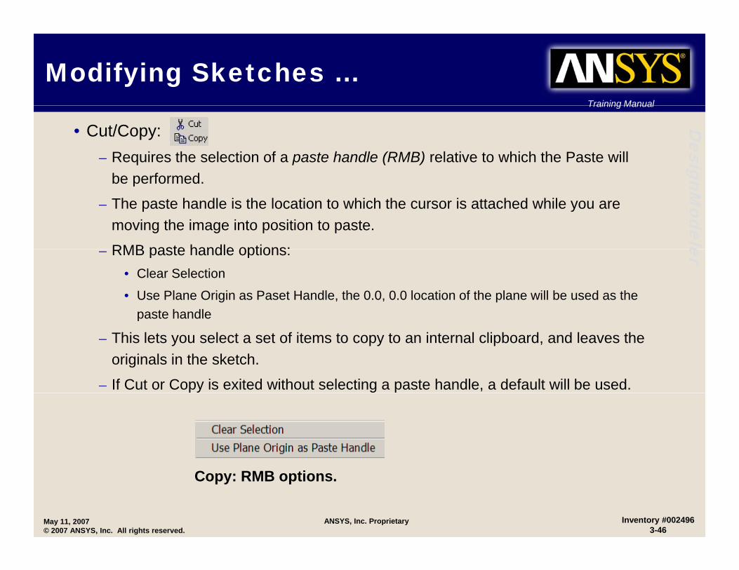
• Cut/Copy:– Requires the selection of a paste handle (RMB) relative to which the Paste will
be performed
gnModele
be performed.
– The paste handle is the location to which the cursor is attached while you are moving the image into position to paste.
RMB paste handle options: er– RMB paste handle options:• Clear Selection
• Use Plane Origin as Paset Handle, the 0.0, 0.0 location of the plane will be used as the paste handlep
– This lets you select a set of items to copy to an internal clipboard, and leaves the originals in the sketch.
– If Cut or Copy is exited without selecting a paste handle, a default will be used.
May 11, 2007© 2007 ANSYS, Inc. All rights reserved.
Inventory #0024963-46
ANSYS, Inc. Proprietary
Copy: RMB options.

Training Manual
Modifying Sketches …Training Manual
Desig
• Paste:– RMB Context Menu:
gnModele
RMB Context Menu:• Rotate by +/- r Degrees
• Flip Horizontally / Vertically
• Scale by Factor f or 1/f er
• Paste at Plane Origin
• Change Paste Handle
• End
– Paste lets you take items placed on the clipboard by Cut or Copy and place them i t th t ( ) k t h if itinto the current (or new) sketch, even if it is on a different plane.
May 11, 2007© 2007 ANSYS, Inc. All rights reserved.
Inventory #0024963-47
ANSYS, Inc. Proprietary

Training Manual
Modifying Sketches …Training Manual
Desig
– A Copy/Paste example . . . • After creating a rectangle we wish to copy it, rotate it by 45 degrees
with respect to the origin and scale it by a factor of 0 5
gnModele
with respect to the origin and scale it by a factor of 0.5.
er
3. RMB
1. Copy
2. Select edges
May 11, 2007© 2007 ANSYS, Inc. All rights reserved.
Inventory #0024963-48
ANSYS, Inc. Proprietary
Training Manual
Modifying Sketches …Training Manual
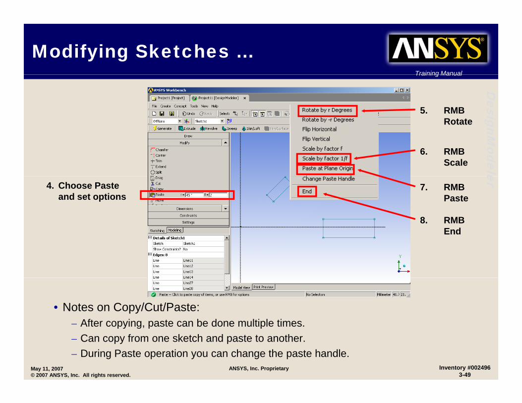
Desig5. RMB
Rotate gnModele
6. RMB Scale er
4. Choose Paste and set options
7. RMB Paste
8. RMB End
• Notes on Copy/Cut/Paste:– After copying, paste can be done multiple times.
May 11, 2007© 2007 ANSYS, Inc. All rights reserved.
Inventory #0024963-49
ANSYS, Inc. Proprietary
y g– Can copy from one sketch and paste to another.– During Paste operation you can change the paste handle.

Training Manual
Modifying Sketches – Quick Cut/Copy/Paste
Training Manual
Desig
• Cut, Copy, and Paste commands are available as RMB options in sketching mode. gnM
odeleer
1) Select source edges
2) RMB>Copy
3) Select paste origin3) Select paste origin
4) Paste the edges
May 11, 2007© 2007 ANSYS, Inc. All rights reserved.
Inventory #0024963-50
ANSYS, Inc. Proprietary
Training Manual
Modifying Sketches …Training Manual
Desig
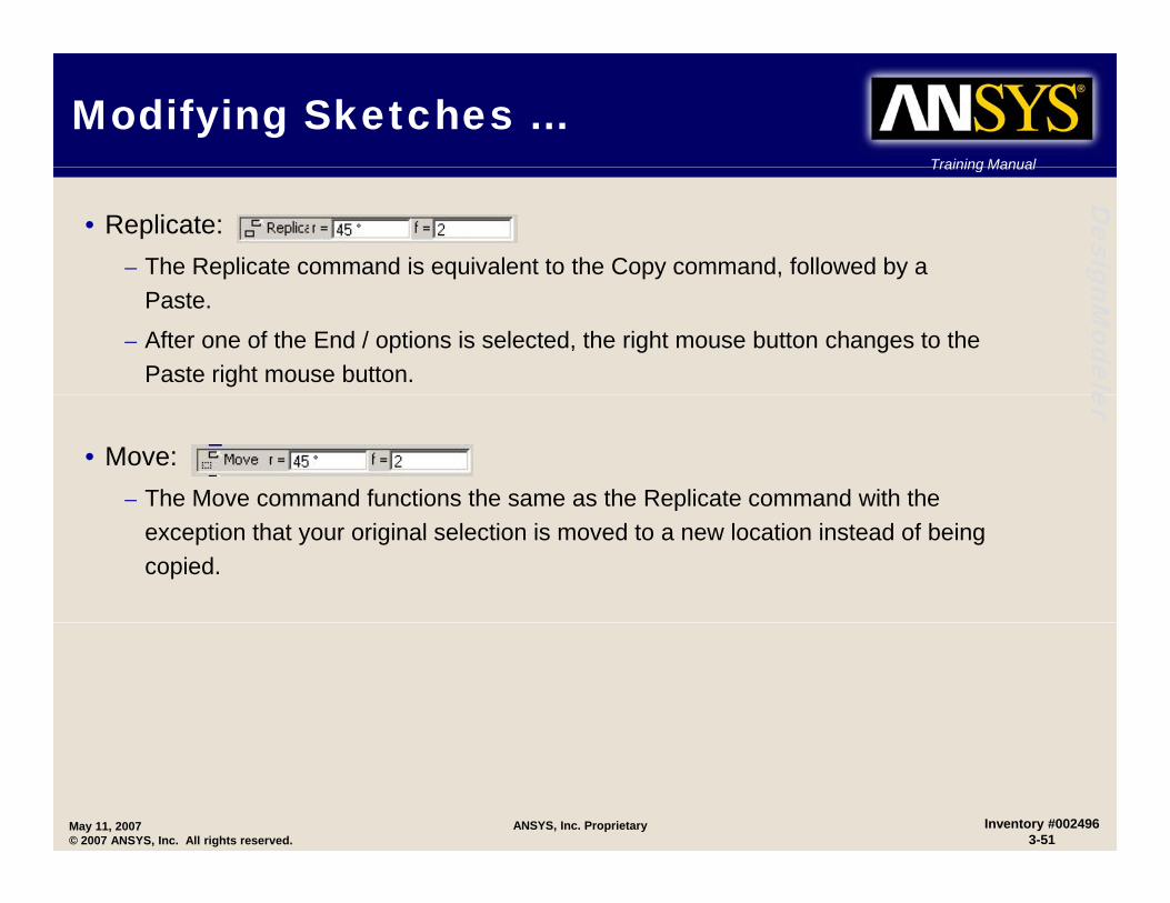
• Replicate: – The Replicate command is equivalent to the Copy command, followed by a gnM
odele
Paste.
– After one of the End / options is selected, the right mouse button changes to the Paste right mouse button. er
• Move:– The Move command functions the same as the Replicate command with the p
exception that your original selection is moved to a new location instead of being copied.
May 11, 2007© 2007 ANSYS, Inc. All rights reserved.
Inventory #0024963-51
ANSYS, Inc. Proprietary
Training Manual
Modifying Sketches …Training Manual
Desig
• Offset:– The Offset function allows you to create a set of lines and arcs that are offset by an gnM
odele
equal distance from an existing set of lines and arcs.
– The original set of lines and arcs must be connected in an open or closed profile.
– Preselect or select the edges then choose the right mouse button option “End erselection / Place offset”
– The cursor location is used to determine three things: • Offset distance
• Offset side
• Offset area
– Distance and Side are clear but the “area” is very important:• If portions of your selected curves would collapse out or cross over one another given the
current offset side and distance, the cursor location determines which area of offset curves is kept.
• An example . . .
May 11, 2007© 2007 ANSYS, Inc. All rights reserved.
Inventory #0024963-52
ANSYS, Inc. Proprietary
p

Training Manual
Modifying Sketches …Training Manual
Desig
First we choose all
gnModele
First we choose all edges to be offset
er
The direction and distance the cursor is moved determinesmoved determines the offset.
May 11, 2007© 2007 ANSYS, Inc. All rights reserved.
Inventory #0024963-53
ANSYS, Inc. Proprietary

Training Manual
Modifying Sketches …Training Manual
Desig
Notice as the offset is dragged
gnModele
Notice as the offset is dragged further, the arc will eventually intersect the bottom line.
er
By alternating the cursor location (left and right) we can determine ( g )which offset region will be retained.
May 11, 2007© 2007 ANSYS, Inc. All rights reserved.
Inventory #0024963-54
ANSYS, Inc. Proprietary

Training Manual
Sketch DuplicationTraining Manual
Desig
• Duplicate items from another sketch or plane boundary (all sketches must be in the current plane).
• Allows a plane boundary (perhaps from CAD import) to be gnModele
p y (p p p )duplicated as new sketch entities.
• An Example . . .
er
The new sketch now contains a
sketch line coincident with the top arc in the CAD
model
A face is selected on an With the new plane active, from Sketch
model.
May 11, 2007© 2007 ANSYS, Inc. All rights reserved.
Inventory #0024963-55
ANSYS, Inc. Proprietary
A face is selected on an imported CAD model and a
plane created.
With the new plane active, from Sketch mode > modify, “Duplicate” is selected
and an edge from the plane selected.
Training Manual
Sketch InstanceTraining Manual
Desig
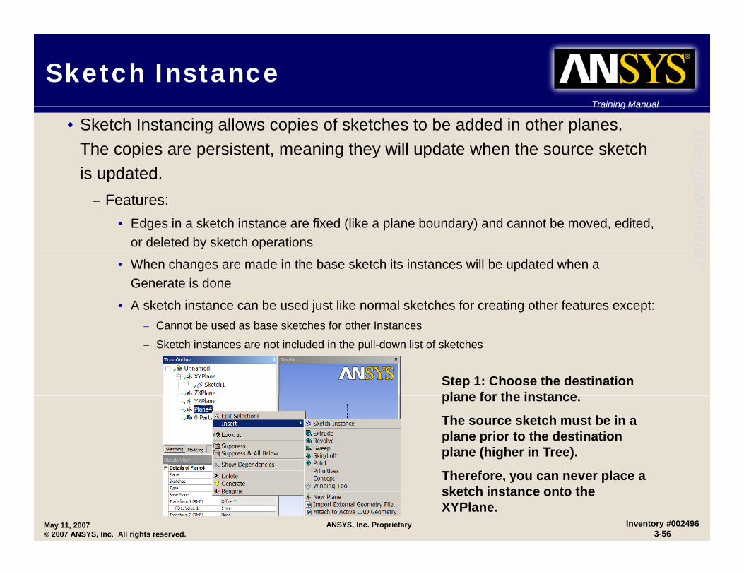
• Sketch Instancing allows copies of sketches to be added in other planes. The copies are persistent, meaning they will update when the source sketch is updated. gnM
odele
is updated.– Features:
• Edges in a sketch instance are fixed (like a plane boundary) and cannot be moved, edited, or deleted by sketch operations er
• When changes are made in the base sketch its instances will be updated when a Generate is done
• A sketch instance can be used just like normal sketches for creating other features except:Cannot be sed as base sketches for other Instances– Cannot be used as base sketches for other Instances
– Sketch instances are not included in the pull-down list of sketches
Step 1: Choose the destination plane for the instanceplane for the instance.
The source sketch must be in a plane prior to the destination plane (higher in Tree).
May 11, 2007© 2007 ANSYS, Inc. All rights reserved.
Inventory #0024963-56
ANSYS, Inc. Proprietary
Therefore, you can never place a sketch instance onto the XYPlane.

Training Manual
Sketch Instance…Training Manual
DesiggnM
odeleerStep 2: Choose the source sketch via Apply/Cancel buttons.
Step 3: Modify the placement options. The sketch instance may be
ff t t t d doffset, rotated, and scaled.
St 4 Cli k G t t
May 11, 2007© 2007 ANSYS, Inc. All rights reserved.
Inventory #0024963-57
ANSYS, Inc. Proprietary
Step 4: Click Generate to complete the sketch instance.

Training Manual
Sketch Instance…Training Manual
Desig
• Example: Sketch2 is instanced onto Plane4 as Sketch5. Note how the instance appears as fixed edges, similar to plane boundary edges. gnM
odeleer
May 11, 2007© 2007 ANSYS, Inc. All rights reserved.
Inventory #0024963-58
ANSYS, Inc. Proprietary

Training Manual
Sketch ProjectionTraining Manual
Desig
• Sketch Projection:– Project 3D geometry onto a plane to create new sketch entities. gnM
odele
– Select vertices, edges, surfaces or bodies to project.– Cannot be modified using normal sketch tools.– Remain associated to input geometry (if 3D geometry changes, the sketch
projection can update). erprojection can update).
May 11, 2007© 2007 ANSYS, Inc. All rights reserved.
Inventory #0024963-59
ANSYS, Inc. Proprietary
3D Geometry selected for projection
Sketch projected onto existing plane
Training Manual
Geometry InterfacesTraining Manual
Desig
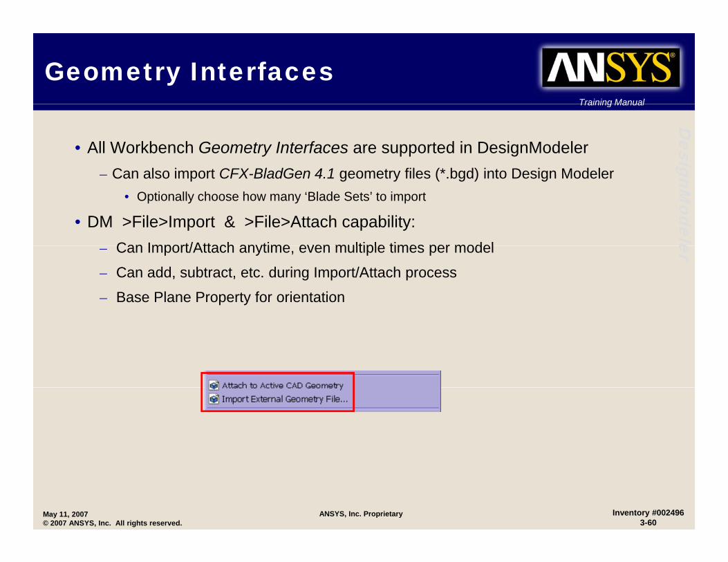
• All Workbench Geometry Interfaces are supported in DesignModeler– Can also import CFX-BladGen 4 1 geometry files (* bgd) into Design Modeler
gnModele
– Can also import CFX-BladGen 4.1 geometry files ( .bgd) into Design Modeler• Optionally choose how many ‘Blade Sets’ to import
• DM >File>Import & >File>Attach capability:Can Import/Attach anytime even multiple times per model
er– Can Import/Attach anytime, even multiple times per model
– Can add, subtract, etc. during Import/Attach process
– Base Plane Property for orientation
May 11, 2007© 2007 ANSYS, Inc. All rights reserved.
Inventory #0024963-60
ANSYS, Inc. Proprietary

Training Manual
Attaching to a CAD SessionTraining Manual
Desig
• If a CAD session is currently open, this automatically imports the model into the DesignModeler session gnM
odele
• File>Attach to Active CAD File
• Maintains bi-directional associativity
er
May 11, 2007© 2007 ANSYS, Inc. All rights reserved.
Inventory #0024963-61
ANSYS, Inc. Proprietary
Training Manual
Attaching to a CAD SessionTraining Manual
Desig
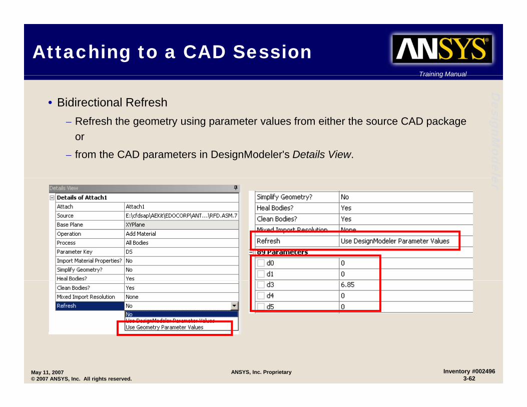
• Bidirectional Refresh– Refresh the geometry using parameter values from either the source CAD package gnM
odele
g y g p p gor
– from the CAD parameters in DesignModeler's Details View.
er
May 11, 2007© 2007 ANSYS, Inc. All rights reserved.
Inventory #0024963-62
ANSYS, Inc. Proprietary
Training Manual
Importing CAD FilesTraining Manual
Desig
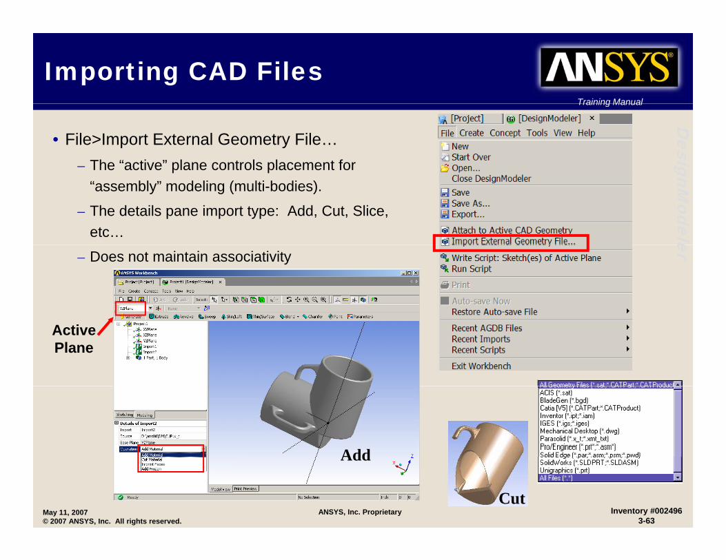
• File>Import External Geometry File…– The “active” plane controls placement for gnM
odele
“assembly” modeling (multi-bodies).
– The details pane import type: Add, Cut, Slice, etc… er– Does not maintain associativity
Active Plane
Add
May 11, 2007© 2007 ANSYS, Inc. All rights reserved.
Inventory #0024963-63
ANSYS, Inc. ProprietaryCut
Add

Training Manual
Positioning ImportsTraining Manual
Desig
• Both Import and Attach have a “Base Plane” property. gnM
odele
– Specify the plane (orientation) in which the Import or Attach model is referenced…
– When creating a new Import or Attach er
feature, the active plane is chosen as the Base Plane by default
– Users select planes from the tree view or Plane pull-down list prior to import
• Example:– XY chosen for first import
– YZ plane for second import
– Add material option chosen
May 11, 2007© 2007 ANSYS, Inc. All rights reserved.
Inventory #0024963-64
ANSYS, Inc. Proprietary

Training Manual
Import UnitsTraining Manual
Desig
• Most file formats store units information in the file (automatically set on import).
Th SAT fil f t t b t t th t l th it i th i t d t il
gnModele
• The SAT file format must be set to the correct length unit via the import details (Prior to Generate)
– DM then converts the model length units into the current unit system er
May 11, 2007© 2007 ANSYS, Inc. All rights reserved.
Inventory #0024963-65
ANSYS, Inc. Proprietary
Training Manual
Exporting a ModelTraining Manual
Desig
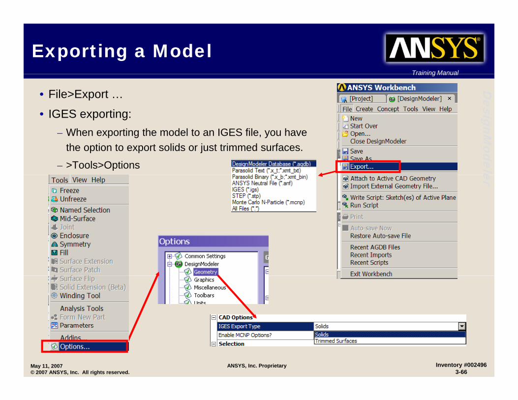
• File>Export …
• IGES exporting: gnModele
– When exporting the model to an IGES file, you have the option to export solids or just trimmed surfaces.
– >Tools>Options er
May 11, 2007© 2007 ANSYS, Inc. All rights reserved.
Inventory #0024963-66
ANSYS, Inc. Proprietary
Training Manual
GeometryBody Attributes
Training Manual
Desig
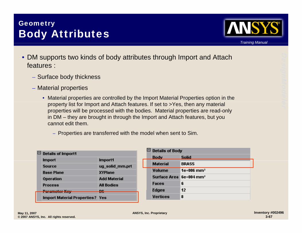
• DM supports two kinds of body attributes through Import and Attach features : gnM
odele
– Surface body thickness
– Material properties• Material properties are controlled by the Import Material Properties option in the erproperty list for Import and Attach features. If set to >Yes, then any material
properties will be processed with the bodies. Material properties are read-only in DM – they are brought in through the Import and Attach features, but you cannot edit them.
P ti t f d ith th d l h t t Si– Properties are transferred with the model when sent to Sim.
May 11, 2007© 2007 ANSYS, Inc. All rights reserved.
Inventory #0024963-67
ANSYS, Inc. Proprietary
Training Manual
Geometry…Body Attributes
Training Manual
Desig
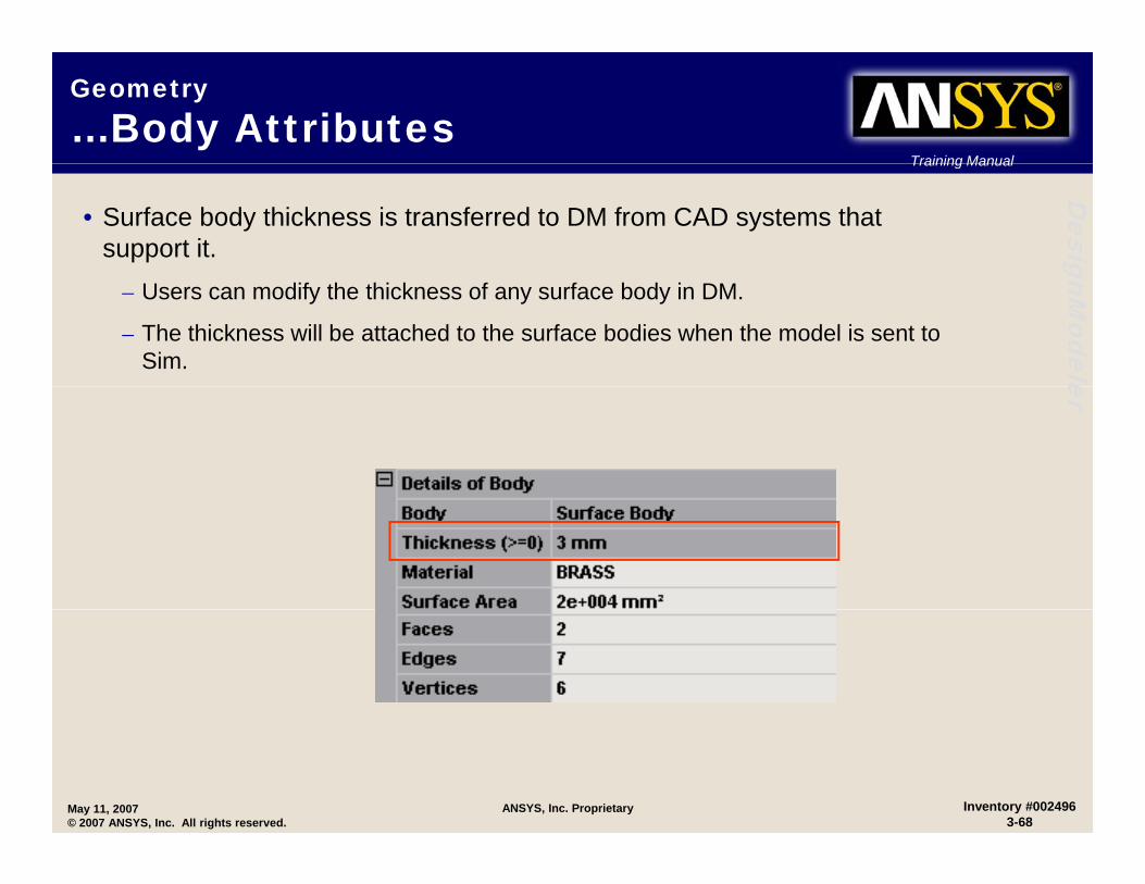
• Surface body thickness is transferred to DM from CAD systems that support it. gnM
odele
– Users can modify the thickness of any surface body in DM.
– The thickness will be attached to the surface bodies when the model is sent to Sim. er
May 11, 2007© 2007 ANSYS, Inc. All rights reserved.
Inventory #0024963-68
ANSYS, Inc. Proprietary

3D Geometry3D Geometry
Workshop 3-2
May 11, 2007© 2007 ANSYS, Inc. All rights reserved.
ANSYS, Inc. Proprietary Inventory #0024963-69
Training Manual
Workshop 3-2, 3D GeometryTraining Manual
Desig
• Goals:– Utilize the model created in Workshop 3-1 and generate 3D
t f th k t h
gnModele
geometry from the sketch.– Create a new sketch and extrude it to create a boss on the
original model. – Create another sketch and Imprint a face on the boss to allow for erapplying boundary conditions to an FE model.– Save the model and Exit.
• Start Page (if workshop 3-1 was closed):Ch th ti “O ”– Choose the option “Open”
May 11, 2007© 2007 ANSYS, Inc. All rights reserved.
Inventory #0024963-70
ANSYS, Inc. Proprietary
Training Manual
Workshop 3-2, 3D GeometryTraining Manual
Desig
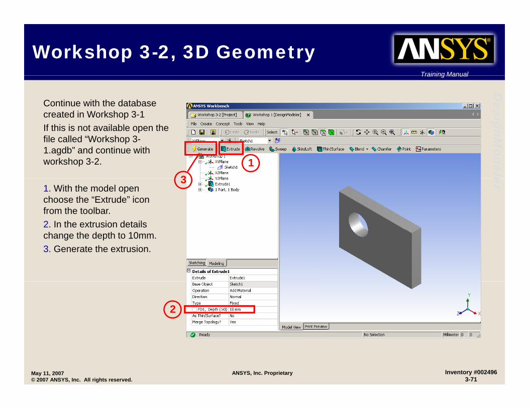
Continue with the database created in Workshop 3-1If this is not available open the
gnModele
If this is not available open the file called “Workshop 3-1.agdb” and continue with workshop 3-2. 1
3
er
1. With the model open choose the “Extrude” icon from the toolbar.2. In the extrusion details
3
change the depth to 10mm.3. Generate the extrusion.
2
May 11, 2007© 2007 ANSYS, Inc. All rights reserved.
Inventory #0024963-71
ANSYS, Inc. Proprietary

Training Manual
Workshop 3-2, 3D GeometryTraining Manual
Desig
4. Insure that the XYPlane is active and click on the “New Plane” icon 4
gnModele
Plane icon. 4
er
5. In the Details of Plane4 set Transform 1 to be “Offset Z” and change the offset “Value” to 50mm. 5
6
6. “Generate” the Plane.5
May 11, 2007© 2007 ANSYS, Inc. All rights reserved.
Inventory #0024963-72
ANSYS, Inc. Proprietary
Training Manual
Workshop 3-2, 3D GeometryTraining Manual
Desig
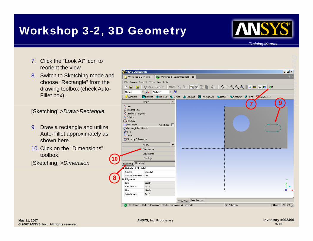
7. Click the “Look At” icon to reorient the view.
8 Switch to Sketching mode and
gnModele
8. Switch to Sketching mode and choose “Rectangle” from the drawing toolbox (check Auto-Fillet box).
7 9 er
[Sketching] >Draw>Rectangle
9. Draw a rectangle and utilize Auto-Fillet approximately as
7
pp yshown here.
10. Click on the “Dimensions” toolbox.
[Sketching] >Dimension 10
8
May 11, 2007© 2007 ANSYS, Inc. All rights reserved.
Inventory #0024963-73
ANSYS, Inc. Proprietary

Training Manual
Workshop 3-2, 3D GeometryTraining Manual
Desig
11. Dimension the sketch as shown below. Note: your dimension names may not match those shown. gnM
odeleer
1111
May 11, 2007© 2007 ANSYS, Inc. All rights reserved.
Inventory #0024963-74
ANSYS, Inc. Proprietary

Training Manual
Workshop 3-2, 3D GeometryTraining Manual
Desig
12. From the toolbar choose “Extrude” (do not generate yet!)
gnModele
yet!).
An isometric view shows the12
15
erAn isometric view shows the proposed (wireframe) extrude using a surface-normal direction (facing away from the original model).
13. From the Detail window change the direction field from Normal to “Reversed”.
14. Change the Type to “To Next”15. “Generate” the extrusion.
13
14
May 11, 2007© 2007 ANSYS, Inc. All rights reserved.
Inventory #0024963-75
ANSYS, Inc. Proprietary
Training Manual
Workshop 3-2, 3D GeometryTraining Manual
Desig
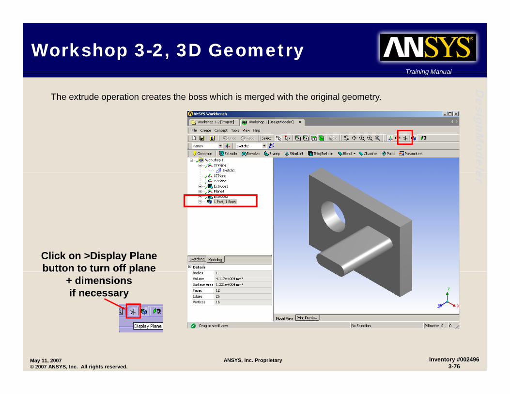
The extrude operation creates the boss which is merged with the original geometry.
gnModeleer
Click on >Display Planebutton to turn off planebutto to tu o p a e
+ dimensionsif necessary
May 11, 2007© 2007 ANSYS, Inc. All rights reserved.
Inventory #0024963-76
ANSYS, Inc. Proprietary
Training Manual
Workshop 3-2, 3D GeometryTraining Manual
Desig
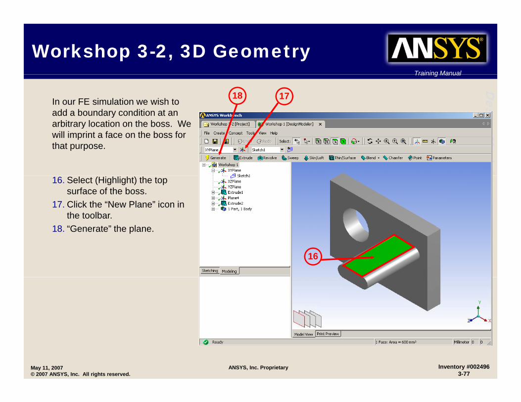
In our FE simulation we wish to add a boundary condition at an arbitrary location on the boss We
1718
gnModele
arbitrary location on the boss. We will imprint a face on the boss for that purpose.
er16. Select (Highlight) the top surface of the boss.
17. Click the “New Plane” icon in the toolbar.
18 “G t ” th l18. “Generate” the plane.
16
May 11, 2007© 2007 ANSYS, Inc. All rights reserved.
Inventory #0024963-77
ANSYS, Inc. Proprietary

Training Manual
Workshop 3-2, 3D GeometryTraining Manual
DesiggnM
odele
19. Click the “Look At” icon from the toolbar.
20. Go to sketch mode and
19
erchoose circle from the draw toolbox.
[Sketching] >Draw>Circle20
21. Draw a circle approximately like the one shown here.
21
May 11, 2007© 2007 ANSYS, Inc. All rights reserved.
Inventory #0024963-78
ANSYS, Inc. Proprietary

Training Manual
Workshop 3-2, 3D GeometryTraining Manual
Desig
22 Add di i h t
gnModele
22. Add dimensions as shown at right. Note your dimension names may not match those shown here.
[Sketching] >Dimensions>General 22
er[Sketching] >Dimensions>General 22
May 11, 2007© 2007 ANSYS, Inc. All rights reserved.
Inventory #0024963-79
ANSYS, Inc. Proprietary

Training Manual
Workshop 3-2, 3D GeometryTraining Manual
Desig23. Choose “Extrude” from the
toolbar (do not Generate).
gnModele
toolbar (do not Generate).24. In the details change the
operation to “Imprint Faces”.25. “Generate” the extrusion 25
23 er
24
May 11, 2007© 2007 ANSYS, Inc. All rights reserved.
Inventory #0024963-80
ANSYS, Inc. Proprietary
Training Manual
Workshop 3-2, 3D GeometryTraining Manual
DesiggnM
odele
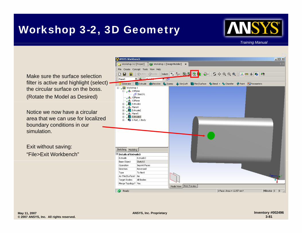
Make sure the surface selection filter is active and highlight (select) the circular surface on the boss.(Rotate the Model as Desired) er
Notice we now have a circular area that we can use for localized boundary conditions in our simulationsimulation.
Exit without saving:“File>Exit Workbench”
May 11, 2007© 2007 ANSYS, Inc. All rights reserved.
Inventory #0024963-81
ANSYS, Inc. Proprietary

Related Documents