DLS-1 V6.7U PC5015, PC5010 PC1575, PC1555, PC580 PC4020, PC4010, PC4000 PC3000, PC2550, PC2525 PC1550, PC1500, PC1150 PC550 and DSC8400 WLS900 DOWNLOADING SOFTWARE

Welcome message from author
This document is posted to help you gain knowledge. Please leave a comment to let me know what you think about it! Share it to your friends and learn new things together.
Transcript
DLS-1 V6.7U
PC5015, PC5010
PC1575, PC1555, PC580
PC4020, PC4010, PC4000
PC3000, PC2550, PC2525
PC1550, PC1500, PC1150
PC550 and DSC8400
WLS900
DOWNLOADINGSOFTWARE

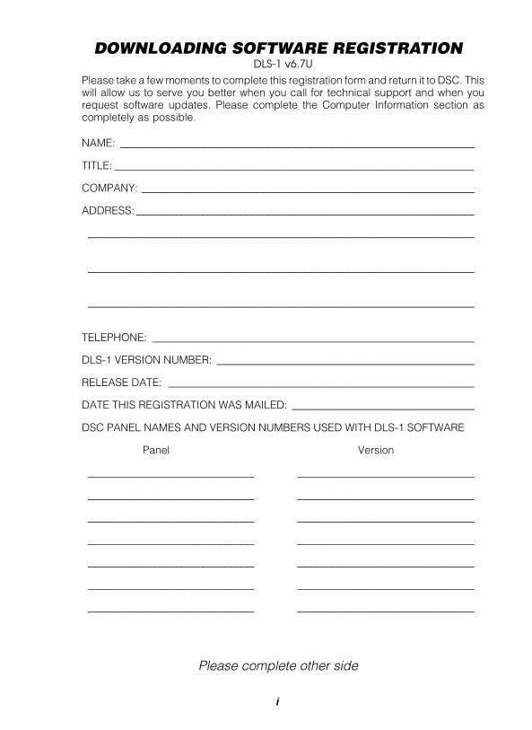
DOWNLOADING SOFTWARE REGISTRATIONDLS-1 v6.7U
Please take a few moments to complete this registration form and return it to DSC. Thiswill allow us to serve you better when you call for technical support and when yourequest software updates. Please complete the Computer Information section ascompletely as possible.
NAME: __________________________________________________________________
TITLE: ___________________________________________________________________
COMPANY: ______________________________________________________________
ADDRESS: _______________________________________________________________
________________________________________________________________________
________________________________________________________________________
________________________________________________________________________
TELEPHONE: ____________________________________________________________
DLS-1 VERSION NUMBER: ________________________________________________
RELEASE DATE: _________________________________________________________
DATE THIS REGISTRATION WAS MAILED: __________________________________
DSC PANEL NAMES AND VERSION NUMBERS USED WITH DLS-1 SOFTWARE
Panel Version
_______________________________ _________________________________
_______________________________ _________________________________
_______________________________ _________________________________
_______________________________ _________________________________
_______________________________ _________________________________
_______________________________ _________________________________
_______________________________ _________________________________
Please complete other side
i

COMPUTER INFORMATIONMuch of the information below can be found in the View Computer Configurationsection in the Main Menu of the DLS-1. Also, if required, refer to the installation manualsthat came with your computer and any hardware and software you may be using.
COMPUTER NAME AND TYPE:_____________________________________________
MAIN PROCESSOR TYPE: _________________________________________________
NUMBER OF RS-232 PORTS: _____________________
NUMBER OF PRINTER PORTS: ___________________
MOUSE TYPE (IF APPLICABLE): ___________________________________________
FLOPPY DISK FORMAT:3.5" 5.25"
MODEM MAKE AND MAXIMUM BAUD RATE: ________________________________
OPERATING SYSTEM NAME AND VERSION: ________________________________
BASE MEMORY:_________________ EXPANSION MEMORY:________________
VIDEO DISPLAY ADAPTER: ________________________________________________
MONITOR TYPE: _________________________________________________________
CURRENT VIDEO MODE:__________________________________________________
FREE HARD DISK SPACE: ________ TOTAL HARD DISK SPACE: ___________
TSR PROGRAMS RUNNING (IF APPLICABLE):
_______________________________ _________________________________
_______________________________ _________________________________
_______________________________ _________________________________
DO YOU RUN A NETWORK? _______________
IF YES, NAME AND VERSION: _____________________________________________
ADDITIONAL COMPUTER INFORMATION: __________________________________
________________________________________________________________________
________________________________________________________________________
________________________________________________________________________
ii

MAIL YOUR COMPLETED REGISTRATIONFORM TO:
Digital Security ControlsDLS-1 Registration1645 Flint RoadDownsview, OntarioM3J 2J6Canada
iii

iv
IMPORTANTThe following information pertains to the SECURITY of your program. This sectionshould be read and fully understood before attempting to install your DLS-1 Software.
You will be asked for an 8 digit security stamp when installing the program. Write thisstamp down in the space provided on the next page and keep it in a safe place. Thissecurity code is used to stamp all of your Customer Work Files. This means that yourCustomer Work Files can only be used on a system that has been installed with thesame stamp. This stamp must be 8 characters long or you will be asked to re-enter it.The stamp can be made up of any combination of numbers, letters or characters. Notethat all letters are case sensitive; that is, “A” is not the same as “a”. If you plan onrunning the DLS-1 Software on more than one computer, the Security Stamp usedduring installation must be the same on all computers. This will allow you to transferCustomer Work Files from one computer to another.
The “DSCINST” routine must be used every time the DLS-1 Software is installed.
If you routinely run programs that optimize the performance of (defragment) your harddrive (eg. the Norton Utilities Speed Disk program), when you next run the DLS-1Downloading Software, you will get an error message explaining that the security of thesoftware has been tampered with. At the point of the error message, you will be askedto enter your 8 character Security Stamp. If you enter the correct stamp, the programwill re-initialize itself, and it will then function normally.
NOTE: If you have installed the software before, it is very important that you answer“NO” when asked if you wish to delete the present customer work files. If you donot answer “NO”, you will lose all of your customer work files.
NOTE: If you will be running on a local area network (LAN), all DLS-1 installations MUSThave the same Security Stamp in order to share workfiles. Please see section1.1.3 in this manual for more information.
v

vi

DO NOT FORGET TO RECORD YOUR SECURITY STAMP ASTHERE IS NO WAY TO RECOVER IT AT A LATER DATE. WRITEDOWN YOUR STAMP EXACTLY AS YOU ENTER ITINTO THE COMPUTER.
(i.e. WRITE DOWN “UPPERCASE” AND “lowercase”CHARACTERS WHERE THEY OCCUR.)
NOTE: If you will be running on a local area network (LAN), all DLS-1installations MUST have the same Security Stamp in orderto share workfiles. Please see section 1.1.3 in this manualfor more information.
SECURITY STAMP
REMOVE THIS PAGE AND STORE IT IN A SAFE PLACE. IT WILLBE NECESSARY TO KNOW THE SECURITY STAMP IF YOUHAVE TO REINITIALIZE OR REINSTALL THE SOFTWARE AT ALATER DATE.
vii

viii
DOWNLOADING SOFTWAREDLS-1 VERSION 6.7U
The DSC DLS-1 Downloading Software is designed to work with the followingcontrol panels:
DSC Control Panels• PC5015• PC5010• PC4020• PC4010• PC4000• PC3000• PC2550• PC2525• PC1575• PC1555• PC1550• PC1500• PC1150• PC580• PC550• DSC8400 Digital Communicator• WLS900
The DLS-1 software package and an MS-DOS compatible PC will allow you to do mostof the functions accessible at the system keypad from a remote location using amodem, or for a faster connection, locally using PC-Link.
In addition, you will be able to read and/or print out the data that has beenprogrammed into all of the memory locations in the control panels’ ProgrammingSections.
The editing functions are presented on the computer screen in a layout that is almostidentical to the installation manual. Help screens are sensitive to your position in theprogram and are only a keystroke away.
This manual will tell you what you need to know to put the DLS-1 to work. Please referto the table of contents.
ix

x

TABLE OF CONTENTS DLS-1 v6.7U
xi
1 GETTING STARTED1.1 MINIMUM EQUIPMENT REQUIREMENTS............................................... 3
1.1.1 MOUSE REQUIREMENTS ................................................................ 4
1.1.2 PRINTER REQUIREMENTS .............................................................. 4
1.1.3 NETWORKING SUPPORT ................................................................ 4
1.1.4 MEMORY REQUIREMENTS .............................................................. 4
1.2 CONNECTING THE MODEM TO THE COMPUTER ................................ 5
1.3 SETTING UP PC-LINK ............................................................................. 5
1.4 INSTALLING THE DLS-1 SOFTWARE ..................................................... 6
1.5 RUNNING THE DLS-1 SOFTWARE ......................................................... 9
1.6 KEYBOARD AND MOUSE FUNCTIONS ................................................ 10
2 USING THE DLS-1 SOFTWARE2.1 HOW TO DOWNLOAD AND UPLOAD: STEP-BY-STEP INSTRUCTIONS15
2.1.1 PREPARE THE PANEL FOR COMMUNICATION WITH DLS-1 ........ 15
2.2 RUN THE DLS-1 SOFTWARE .................................................................... 19
2.3 LOG ON ..................................................................................................... 19
2.4 CREATE A CUSTOMER WORK FILE ......................................................... 20
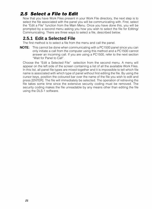
2.5 SELECT A FILE TO EDIT ............................................................................ 21
2.5.1 EDIT A SELECTED FILE ................................................................... 21
2.5.2 WAIT FOR THE PANEL TO CALL ..................................................... 22
2.5.3 EXECUTE BATCH FILES .................................................................. 22
2.6 ENTER NECESSARY DATA INTO THE WORK FILE .................................. 23
2.7 EXECUTE DOWNLOAD AND UPLOAD FUNCTIONS ............................... 23
2.8 TERMINATE COMMUNICATION WITH THE PANEL ................................. 24
2.9 SAVE CHANGES AND EXIT EDIT A FILE .................................................. 24
3 DLS-1 FILE MENUS3.1 MAIN MENU .......................................................................................... 27
3.2 EDIT A FILE ........................................................................................... 27
3.2.1 EDIT A SELECTED FILE ................................................................... 27
PC4020, PC4010, PC4000, PC580, PC1555, PC1575,PC5010 & PC5015 ....................................................................... 27PC3000, PC2550, PC2525, PC1550, PC1500, PC1150, PC550,DSC8400 AND WLS900 MENUS ................................................. 43
3.2.2 WAIT FOR PANEL TO CALL.............................................................. 48
3.2.3 EXECUTE BATCH FILES .................................................................. 48
3.3 ANSWERING MACHINE OVERRIDE FEATURE .................................... 49
3.4 NOTES FOR SECTION 3 ....................................................................... 50
TABLE OF CONTENTS DLS-1 v6.7U
xii
4 WORKING WITH DLS-1 FILES4.1 CREATE A FILE .......................................................................................... 53
4.1.1 INITIALIZING A NEW WORK FILE..................................................... 54
4.2 RENAME A FILE ......................................................................................... 54
4.3 DELETE FILE(S) ......................................................................................... 54
4.4 TRANSFER FILE(S) .................................................................................... 55
4.5 DEFAULT FILE MAINTENANCE ................................................................ 56
4.6 PRINTER FUNCTIONS ............................................................................... 56
4.6.1 PRINT A FILE .................................................................................... 56
4.6.2 PRINT FILE LIST ............................................................................... 56
4.6.5 PRINT BATCH JOBS PENDING ........................................................ 57
4.7 ACCESS CODE MAINTENANCE ............................................................... 57
4.8 PROGRAM CONFIGURATION ................................................................... 59
4.9 VIEW COMPUTER CONFIGURATION ....................................................... 61
4.10 OPERATIONS LOG .................................................................................. 63
4.11 CREATE BATCH FILE .............................................................................. 64
4.12 LOG OFF .................................................................................................. 66
APPENDICESAPPENDIX A: ILLEGAL CHARACTERS ............................................................ 69
APPENDIX B: AUTOEXEC.BAT......................................................................... 69
APPENDIX C: ERROR MESSAGES ................................................................... 69
APPENDIX D: COMPUTER COMPATIBILITY .................................................... 70
APPENDIX E: MODEM COMPATIBILITY .......................................................... 71
APPENDIX F: GLOSSARY ................................................................................. 74
APPENDIX G: MODEM TROUBLESHOOTING ................................................. 76
APPENDIX H: CALLING FOR TECHNICAL SUPPORT ..................................... 79
APPENDIX I: PC4020 / PC4000 DIAGNOSTICS ............................................... 80
APPENDIX J: PC4010 DIAGNOSTICS .............................................................. 81
1
1 GETTING STARTED
1.1 Minimum Equipment Requirements 31.1.1 Mouse Requirements 41.1.2 Printer Requirements 41.1.3 Networking Support 41.1.4 Memory Requirements 4
1.2 Connecting the Modem to the Computer 5
1.3 Setting Up PC-Link 5
1.4 Installing the DLS-1 Software 6
1.5 Running the DLS-1 Software 9
1.6 Keyboard and Mouse Functions 10Keyboard Functions ....................................................................... 10Mouse Functions ............................................................................ 12

2
3
1.1 Minimum Equipment Requirements1 IBM AT, XT or true compatible.
2 Minimum of 640K RAM. A minimum of 590K of conventional memory must beavailable.
3 Serial card with RS-232 connector.
4 Operating system - MS-DOS* version 5.0 or later.The DLS-1 Software is not compatible with Microsoft Windows* unless usedwith DLS-2.
5 One hard disk drive and either one or two diskette drives. A minimum of 14.6megabytes of space on the hard disk is required.
6 Compatible modem (must be capable of 110 baud communication; refer toAppendix E for a list of compatible modems)
7 The following DSC Control Panels are compatible with the DLS-1Version 6.7U software:
• PC5015, software version 2.2• PC5010, software version 1.x to version 2.0• PC4020, software version 1.x to version 2.x• PC4010, software version 1.x to version 2.x• PC4000, software version 1.1 to version 1.3x• PC3000, hardware revision R4 or later with software version 7.2 to version 7.7x• PC3000, hardware revision R4 or later with software version 7.5xL• PC2550, software version 1.0 to version 1.3x• PC2525, software version 1.0 and version 1.1• PC1575, software version 1.x• PC1555, software version 2.0 to version 2.3• PC1550, software version 2.0 to version 4.0• PC1500, software version 1.0 to version 4.0• PC1150, software version 1.0 to version 2.3• PC580, software version 2.1• PC550, software versions 1.0 and 1.1• DSC8400 Digital Communicator, software version 2.3L• WLS900, software version 2.2x
NOTE: DLS-1 is compatible with Microsoft Networking. Operation with other Networkshas not been investigated by DSC. In order for the DLS software to operate, yourNetwork Administrator will have to make sure that each DLS user has full (read/write/rename/delete/file locking) access to the directories where the DSC customer workfiles (WF) and batch files (JOB) are located.
*Microsoft, MS-DOS and Windows are registered trademarks of Microsoft Corp.
4
1.1.1 Mouse RequirementsEither a bus mouse or serial mouse can be used with the DLS-1 v6.7 software. However,if you are using a bus mouse, the mouse card must be set for IRQ 5 or greater. Referto your mouse installation manual for more information on how to change the IRQsettings. Mouse support is only available when editing PC4020, PC4010, PC4000,PC580, PC1555, PC1575, PC5010 and PC5015 files.
1.1.2 Printer RequirementsThe DLS-1 v6.7 software can support a parallel printer connected to LPT1, LPT2 orLPT3 (parallel port 1, 2 or 3). An 80-character printer that uses IBM Character Set 1is suggested. Refer to your printer’s manual for the specifications of the printer youare using.
1.1.3 Networking SupportNetworking support has been added to the DLS-1 package, so that multiple users canrun DLS-1 over a local area network (LAN). When using networking support, you canhave one main DLS-1 installation which will include the workfiles, and auxiliaryinstallations on other machines which will have access to the workfiles of the maininstallation. Refer to section 1.3 "Installing the DLS-1 Software" for more information.
NOTE: All DLS-1 installations running on a LAN, must have the same security stampin order to share workfiles.
NOTE: DLS-1 is compatible with Microsoft Networking. Operation with other Networkshas not been investigated by DSC. In order for the DLS software to operate, yourNetwork Administrator will have to make sure that each DLS user has full (read/write/rename/delete/file locking) access to the directories where the DSC customer workfiles (WF) and batch files (JOB) are located.
Note:Note:Note:Note:Note: If DLS-2 is being used to access DLS-1 workfiles, please ensure that the DLS-1 is not running in a networked environment.
1.1.4 Memory RequirementsFor DLS-1 v6.7 to run correctly, your computer must have a minimum of 590K ofconventional memory available for DLS-1 v6.7. To find out how much conventionalmemory is available, at the DOS prompt, type [MEM].
The computer displays the available conventional memory beside the title “LargestExecutable Program Size”.
If less than 590K conventional memory is available, you may encounter “Error 7”messages, or other problems when you run DLS-1.
If your computer does not have enough conventional memory, it is possible to edit theAUTOEXEC.BAT and CONFIG.SYS files so that more conventional memory is availablewhen you start the computer.
NOTE::::: Changing the AUTOEXEC.BAT and CONFIG.SYS files may cause the computerto stop working or cause errors in other programs. Only your system administrator orqualified computer technicians should make changes to these files.
DLS-1 versions 6.3 and higher have network support capability. As a result, DLS-1versions 6.3 and higher used on operating systems other than Windows95, require thatthe file SHARE.EXE is included in the AUTOEXEC.BAT file. See section 1.4 “InstallingDLS-1 - step 15”, and Appendix B “Autoexec.bat” for more information.
5
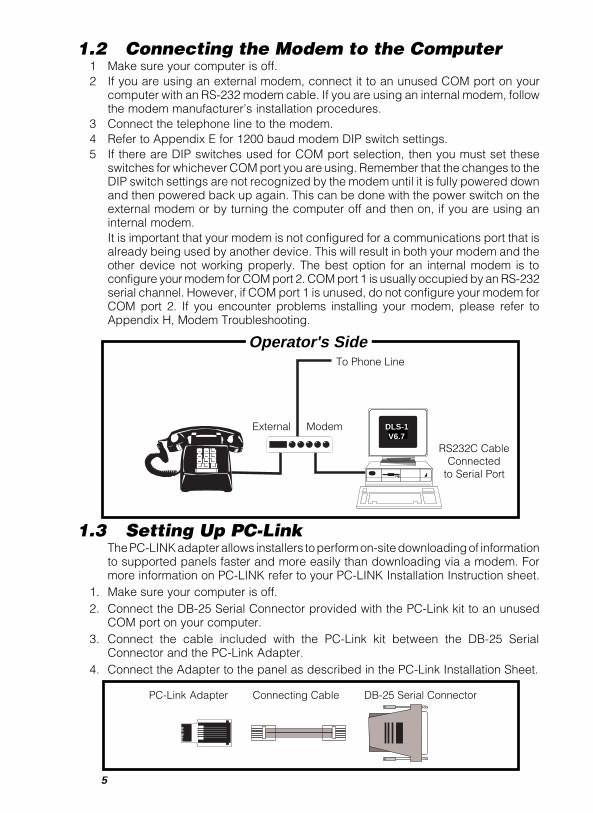
1.2 Connecting the Modem to the Computer1 Make sure your computer is off.2 If you are using an external modem, connect it to an unused COM port on your
computer with an RS-232 modem cable. If you are using an internal modem, followthe modem manufacturer’s installation procedures.
3 Connect the telephone line to the modem.4 Refer to Appendix E for 1200 baud modem DIP switch settings.5 If there are DIP switches used for COM port selection, then you must set these
switches for whichever COM port you are using. Remember that the changes to theDIP switch settings are not recognized by the modem until it is fully powered downand then powered back up again. This can be done with the power switch on theexternal modem or by turning the computer off and then on, if you are using aninternal modem.It is important that your modem is not configured for a communications port that isalready being used by another device. This will result in both your modem and theother device not working properly. The best option for an internal modem is toconfigure your modem for COM port 2. COM port 1 is usually occupied by an RS-232serial channel. However, if COM port 1 is unused, do not configure your modem forCOM port 2. If you encounter problems installing your modem, please refer toAppendix H, Modem Troubleshooting.
External Modem
Operator's Side
RS232C CableConnected
to Serial Port
To Phone Line
DLS-1V6.7
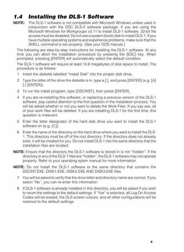
PC-Link Adapter Connecting Cable DB-25 Serial Connector
1.3 Setting Up PC-LinkThe PC-LINK adapter allows installers to perform on-site downloading of informationto supported panels faster and more easily than downloading via a modem. Formore information on PC-LINK refer to your PC-LINK Installation Instruction sheet.
1. Make sure your computer is off.2. Connect the DB-25 Serial Connector provided with the PC-Link kit to an unused
COM port on your computer.3. Connect the cable included with the PC-Link kit between the DB-25 Serial
Connector and the PC-Link Adapter.4. Connect the Adapter to the panel as described in the PC-Link Installation Sheet.
6
1.4 Installing the DLS-1 SoftwareNOTE: The DLS-1 software is not compatible with Microsoft Windows unless used in
conjunction with the DSC DLS-2 software package. If you are using theMicrosoft Windows for Workgroups v3.11 to install DLS-1 software, 32-bit fileaccess must be disabled. Do not use a system (boot) disk to install DLS-1. If youhave multiple operating systems and experience problems, make sure that theSHELL command is set properly. (See your DOS manual.)
The following are step-by-step instructions for installing the DLS-1 software. At anytime you can abort the installation procedure by pressing the [ESC] key. Whenprompted, pressing [ENTER] will automatically select the default condition.
The DLS-1 software will require at least 14.6 megabytes of disk space to install. Theprocedure is as follows:
1 Insert the diskette labelled “Install Disk” into the proper disk drive.
2 Type the letter of the drive the diskette is in, type a [:], and press [ENTER] (e.g. [A][:] [ENTER]).
3 To run the install program, type [DSCINST], then press [ENTER].
4 If you are re-installing this software, or replacing a previous version of the DLS-1software, pay careful attention to the first question in the installation process. Youwill be asked whether or not you want to delete the Work Files. If you say yes, allof your work files will be deleted. If you are installing DLS-1 for the first time, thisquestion is irrelevant.
5 Enter the letter designator of the hard disk drive you want to install the DLS-1software on (e.g. [C]).
6 Enter the name of the directory on the hard drive where you want to install the DLS-1. This directory must be off of the root directory. If the directory does not alreadyexist, it will be created for you. Do not install DLS-1 into the same directory that theinstallation files are located.
NOTE::::: Ensure that the directory the DLS-1 software is stored in is not “hidden”. If thedirectory or any of the DLS-1 files are “hidden”, the DLS-1 software may not operateproperly. Refer to your operating sytem manual for more information.
NOTE::::: Do not install the DLS-1 software to the same directory that contains theDSCINT.EXE, DISK1.EXE, DISK2.EXE AND DISK3.EXE files.
7 You will be asked to verify that the drive letter and directory name are correct. If youselect “No”, you can re-enter this information.
8 If DLS-1 software is already installed in this directory, you will be asked if you wishto return the settings to the default settings. If “Yes” is selected, all Log On AccessCodes will be erased, the DLS screen colours, and all other configurations will berestored to the default settings.
7
9 You will now be asked for four items of information concerning the output ports andmodem to be used on your computer:
• Enter the number of the COM port you want to use for the modem (1 to 4).
• Enter the number of the parallel printer port (LPT) you want to use for the printer(1 or 3).
• Indicate if your modem is External (press [E]), or Internal (press [I]).
• Indicate the modem name or type (1 of 6):Practical Peripherals PM1200 modemCompatible 1200 baud modemCompatible 2400 baud modemHayes Smartmodem Optima 2400 baud modem (+FAX 96)DSC MD12 Modem (default selection)
Stradcom Pocket Modem
If you are using a 1200 baud modem other than the Practical Peripherals model,select the compatible 1200 baud modem. If you are using a 2400 baud modemother than the Hayes Optima, select the compatible 2400 baud modem.The configuration file will now be updated. Additional configuration can be donefrom within the program, using the Program Configuration function. See section 4.9"View Computer Configuration".
10 Enter the path to the workfiles (e.g. [c:\dls1]). This information is used for auxiliaryinstallations where the DLS-1 software will be sharing workfiles with the maininstallation over a LAN. If networking support will not be used, or if this is the maininstallation on a networked system, press [ENTER] and then press any key, tocontinue.
11 Make sure you still have the “Install Disk” in the diskette drive, as the file DISK1.EXEwill be decompressed from this diskette onto the hard drive.
12 When prompted, insert the diskette labelled “Source 1 Disk” and press any key. Theprogram will decompress the file DISK2.EXE onto the hard drive. Press any key tocontinue.
13 When prompted, insert the diskette labelled “Source 2 Disk” and press any key. Theprogram will decompress the file DISK3.EXE onto the hard drive. Press any key tocontinue.
14 You will now be prompted to enter your eight digit security stamp. This stamp isused to identify all of your Work Files. If you are installing the software to replace anolder version and you wish to use your old Work Files, then the stamp you enter nowmust be identical to the stamp used with the previous version of the DLS-1 software.When entering the stamp, remember that “UPPERCASE” and “lowercase” characterscan be used, and they are not the same (i.e. “a” and “A” are not the same). Thestamp must be exactly eight characters long. After you have entered this stamp,make sure you write it down on the page provided at the front of this manual, andkeep it in a safe place. It is important that the security stamp be recorded andsafely filed: if it is forgotten, there is no way to recover the security stamp fromthe computer or from the program.If you wish to share workfiles between DLS-1 installations over a LAN, all DLS-1installations must have the same security stamp.
8
15 DLS-1 will now search the AUTOEXEC.BAT file on your computer to see if theprogram SHARE.EXE is installed. If you are running DLS-1 from MS-DOS, SHARE.EXEmust be loaded before running the DLS-1 package.NOTE: This step is not relevant if you are running DLS-1 in an MS-DOS shellunder Windows95.If your AUTOEXEC.BAT file does not include loading the SHARE.EXE program,DLS-1 will give the following message:
SHARE.EXE is not installed in the C:\AUTOEXEC.BAT file.If not running Windows 95, then it must be installed.Press any key to continue.
If this message appears, you must add the following line to your AUTOEXEC.BATfile (Refer to your operating system manual for instructions on editing yourAUTOEXEC.BAT file.):
C:\DOS\SHARE.EXENOTE: If MS-DOS is installed in a drive and/or directory other than C:\DOS, youmust correct the above line to include the drive/directory where MS-DOS isinstalled.
16 The installation process is now complete. Remove the diskette from the drive, andstore the diskettes in a safe place.
17 Read this manual in its entirety before attempting to run the software.NOTE: If you encounter problems while installing DLS-1, make sure thefollowing lines are in the CONFIG.SYS file on your computer. (Refer to youroperating system manual for instructions on editing the CONFIG.SYS file.):For DOS and Windows v3.11 and earlier:SHELL=C:\DOS\COMMAND.COM C:\DOS /E:512 /P
For Windows 95:SHELL=C:\WINDOWS\COMMAND\COMMAND.COM C:\WINDOWS\COMMAND /E:512 /P
9
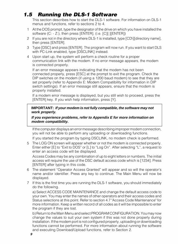
1.5 Running the DLS-1 SoftwareThis section describes how to start the DLS-1 software. For information on DLS-1menus and functions, refer to sections 2 to 4.
1 At the DOS prompt, type the designator of the drive on which you have installed thesoftware (C: - Z:), then press [ENTER]. (i.e. [C][:][ENTER])
2 If you are not in the directory where DLS-1 is installed, type [CD\][directory name],then press [ENTER].
3 Type [DSC] and press [ENTER]. The program will now run. If you want to start DLSwith PC-Link enabled, type [DSCLINK] instead.
4 Upon start up, the system will perform a check routine for a propercommunication link with the modem. If no error message appears, the modemis connected properly.If an error message appears indicating that the modem has not beenconnected properly, press [ESC] at the prompt to exit the program. Check theDIP switches on the modem (if using a 1200 baud modem) to see that they areset properly (refer to Appendix E: Modem Compatibility for information in DIPswitch settings). If an error message still appears, ensure that the modem isproperly installed.If a modem error message is displayed, but you still wish to proceed, press the[ENTER] key. If you wish help information, press [Y].
IMPORTANT: If your modem is not fully compatible, the software may notwork properly.If you experience problems, refer to Appendix E for more information onmodem compatibility.
If the computer displays an error message describing improper modem connection,you will not be able to perform any uploading or downloading functions.If you started the program by typing DSCLINK, no modem check is performed.
5 The LOG ON screen will appear whether or not the modem is connected properly.Enter either [E] to “Exit to DOS” or [L] to “Log On”. After selecting “L”, a request toenter an access code will be displayed.Access Codes may be any combination of up to eight letters or numbers. The initialaccess will require the use of the DSC default access code which is [1234]. Press[ENTER] after typing in this code.
6 The statement “Operator Access Granted” will appear and so will the operator’sname and/or identifier. Press any key to continue. The Main Menu will now bedisplayed.
7 If this is the first time you are running the DLS-1 software, you should immediatelydo the following.a) Select ACCESS CODE MAINTENANCE and change the default access code toyour own. You may enter the names of other operators and their access codes andStatus selections at this point. Refer to section 4.7 "Access Code Maintenance" formore information. Keep a written record of all codes as it will be impossible to enterthe program if they are lost.b) Return to the Main Menu and select PROGRAM CONFIGURATION. You may nowchange the values to suit your own system if this was not done properly duringinstallation. If the modem port is not configured properly, uploading or downloadingfunctions cannot be performed. For more information about running the softwareand executing Download/Upload functions, refer to Section 2.

10
1.6 Keyboard and Mouse FunctionsThe following explains how to enter or change data and make selections from theDLS-1 V6.7 menus using the keyboard and the mouse. It is important that the conceptspresented in this section be understood before proceeding, as instructions throughoutthe manual assume you are familiar with the use of both the keyboard and the mouse.
On your keyboard, make sure the NUM LOCK key is in the cursor position (Num Locklight OFF) to ensure proper function of the keys.
NOTE: The PC4020, PC4010, PC4000, PC580, PC1555, PC1575, PC5010, PC5015and WLS900 files, do not support all of the keyboard functions. Only thePC580, PC1555, PC1575, PC5010, PC5015, PC4010, PC4020, and PC4000panels support the use of a mouse.
Keyboard Functions[ENTER] / [RETURN]
Used to enter data after it has been selected or inputted.
[ESC]Used to abort most procedures. [ESC] will allow you to escape from data inputswithout changing the value in the computer memory, escape from submenus andfrom certain procedures as in Attempting to Make Connection.
[HOME]When in the Edit a File, Create a File, Rename a File, Delete File(s), Transfer File(s),or Help functions, [HOME] will return you to the top of the list of customer Work Files.In Edit a Selected File, it will return you to the first edit screen. [HOME] is also usedin the Operations Log to change viewing screens.
[END]When in the Edit a File, Create a File, Rename a File, Delete File(s), Transfer File(s),or Help functions, [END] will send you to the bottom of the list of customer Work Files.In Edit a Selected File, [END] will send you to the last edit screen. It is also used in theOperations Log and the Event Buffer to change viewing screens.
[Õ] (UP Arrow)Allows you to scroll up through screens that use the cursor.
[Ô] (DOWN Arrow)Allows you to scroll down through screens that use the cursor.
[PAGE UP]Used when viewing different screens to move to the previous screen.
[PAGE DOWN]Used when viewing different screens to move to the next screen.
[PrtSc or Print Screen]Pressing this key will cause the screen to be printed on the printer (cannot be usedunder Windows '95).
[Y]Used to enter “YES” for options.
[N]Used to enter “NO” for options.
[F1]Creates a window and displays a help message sensitive to your position in theprogram.
11
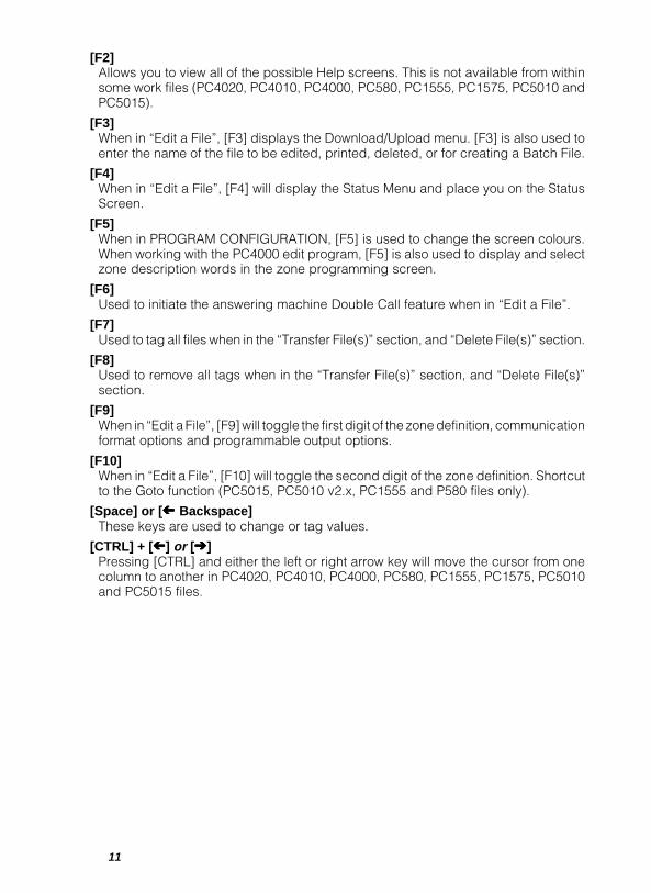
[F2]Allows you to view all of the possible Help screens. This is not available from withinsome work files (PC4020, PC4010, PC4000, PC580, PC1555, PC1575, PC5010 andPC5015).
[F3]When in “Edit a File”, [F3] displays the Download/Upload menu. [F3] is also used toenter the name of the file to be edited, printed, deleted, or for creating a Batch File.
[F4]When in “Edit a File”, [F4] will display the Status Menu and place you on the StatusScreen.
[F5]When in PROGRAM CONFIGURATION, [F5] is used to change the screen colours.When working with the PC4000 edit program, [F5] is also used to display and selectzone description words in the zone programming screen.
[F6]Used to initiate the answering machine Double Call feature when in “Edit a File”.
[F7]Used to tag all files when in the “Transfer File(s)” section, and “Delete File(s)” section.
[F8]Used to remove all tags when in the “Transfer File(s)” section, and “Delete File(s)”section.
[F9]When in “Edit a File”, [F9] will toggle the first digit of the zone definition, communicationformat options and programmable output options.
[F10]When in “Edit a File”, [F10] will toggle the second digit of the zone definition. Shortcutto the Goto function (PC5015, PC5010 v2.x, PC1555 and P580 files only).
[Space] or [ Ó Ó Ó Ó Ó Backspace]These keys are used to change or tag values.
[CTRL] + [ ÓÓÓÓÓ] or [ÈÈÈÈÈ]Pressing [CTRL] and either the left or right arrow key will move the cursor from onecolumn to another in PC4020, PC4010, PC4000, PC580, PC1555, PC1575, PC5010and PC5015 files.

12
Mouse FunctionsNOTE: Only the PC4020, PC4010, PC4000, PC580, PC1555, PC1575, PC5010 andPC5015 files support the use of a mouse.
A “mouse” is an input device that connects to your computer to assist in variousoperations. While the DLS-1 software does not require a mouse to run, the DLS-1 willsupport most common mice. The mouse can be used for the following operations:
• Cursor movement• Feature and Option selection
Before you begin using the mouse, you should have installed the mouse according tothe instructions in the documentation that came with your mouse.
The mouse pointer is usually represented by a reverse-video box ( ). This pointerexists separately from the DLS-1 cursor (usually a dash ) and it should not bemistaken as the DLS-1 cursor. In this manual, “pointer” will refer to the mouse pointer( ), and “cursor” will refer to the normal dash-type cursor ( ).
Instructions in this manual will tell you how to use the mouse in order to selectinformation or options.
“Click” means to press a mouse button, and then release it.
“Double Click” means to press and release a mouse button twice in rapid succession.Whenever “double click” is used in this manual, always “double click” on the LEFTmouse button.
“Left Click” means to press the LEFT mouse button once, and then release it. Thisperforms the same function as pressing [ENTER].
“Right Click” means to press the RIGHT mouse button once, and then release it. Thisperforms the same function as pressing [ESC].
Cursor MovementUsing the mouse pointer, you can “point” to a specific location on the screen. Clickthe left mouse button to move the DLS-1 cursor to that location on the screen.
Like the normal cursor keys, the mouse cannot be used to position the cursor wherethere is no text or data on the screen.
Feature and Option SelectionThe mouse can be used to select any DLS-1 feature or option. Move the pointer to thedesired option, then double click the mouse button.
Press the right mouse button to exit from the current menu. Pressing the right mousebutton serves the same function as pressing [ESC]. Double click the left mouse buttonto select the currently indicated item. Double clicking the left mouse button serves thesame function as pressing [ENTER].
13
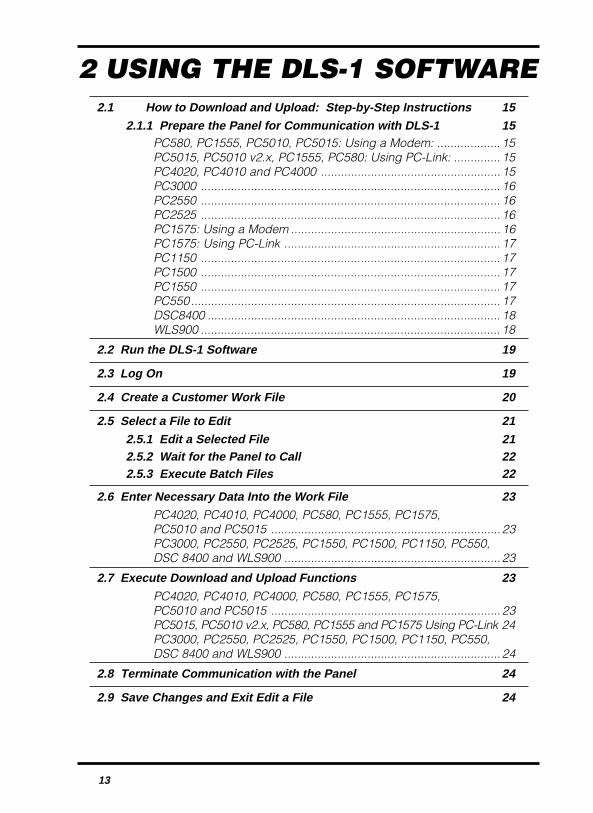
2 USING THE DLS-1 SOFTWARE2.1 How to Download and Upload: Step-by-Step Instructions 15
2.1.1 Prepare the Panel for Communication with DLS-1 15PC580, PC1555, PC5010, PC5015: Using a Modem: ................... 15PC5015, PC5010 v2.x, PC1555, PC580: Using PC-Link: .............. 15PC4020, PC4010 and PC4000 ...................................................... 15PC3000 .......................................................................................... 16PC2550 .......................................................................................... 16PC2525 .......................................................................................... 16PC1575: Using a Modem ............................................................... 16PC1575: Using PC-Link ................................................................. 17PC1150 .......................................................................................... 17PC1500 .......................................................................................... 17PC1550 .......................................................................................... 17PC550............................................................................................. 17DSC8400 ........................................................................................ 18WLS900 .......................................................................................... 18
2.2 Run the DLS-1 Software 19
2.3 Log On 19
2.4 Create a Customer Work File 20
2.5 Select a File to Edit 212.5.1 Edit a Selected File 212.5.2 Wait for the Panel to Call 222.5.3 Execute Batch Files 22
2.6 Enter Necessary Data Into the Work File 23PC4020, PC4010, PC4000, PC580, PC1555, PC1575,PC5010 and PC5015 ..................................................................... 23PC3000, PC2550, PC2525, PC1550, PC1500, PC1150, PC550,DSC 8400 and WLS900 ................................................................. 23
2.7 Execute Download and Upload Functions 23
PC4020, PC4010, PC4000, PC580, PC1555, PC1575,PC5010 and PC5015 ..................................................................... 23PC5015, PC5010 v2.x, PC580, PC1555 and PC1575 Using PC-Link 24PC3000, PC2550, PC2525, PC1550, PC1500, PC1150, PC550,DSC 8400 and WLS900 ................................................................. 24
2.8 Terminate Communication with the Panel 24
2.9 Save Changes and Exit Edit a File 24

14
15
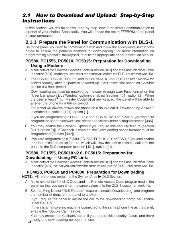
2.1 How to Download and Upload: Step-by-StepInstructions
In this section, you will be shown, step-by-step, how to do simple communication toa panel of your choice. Specifically, you will upload the entire EEPROM of the panelto your computer.
2.1.1 Prepare the Panel for Communication with DLS-1Go to the panel you wish to communicate with and follow the appropriate instructionsbelow to ensure the panel is enabled for downloading. For more information onprogramming a panel at the keypad, refer to the appropriate panel Installation Manual.
PC580, PC1555, PC5010, PC5015: Preparation for Downloading— Using a Modem:A Make note of the Download Access Code in section [403] and the Panel Identifier Code
in section [404] , so that you can enter the same values into the DLS-1 customer work file.
B The PC5015, PC5010, PC1555 and PC580 have a 6-hour DLS answer window foradded security: after the panel is powered-up, it will answer the phone on a doublecall for a 6-hour period.Downloading can also be enabled by the user through User Functions when the“User Can Enable DLS Window” option is enabled (section [401], option [2]). Whenthe user enters [∗][6][Master Code][5] at any keypad, the panel will be able toanswer the phone for a 6-hour period.The panel will always answer the phone on a double call if “Downloading Answer”is enabled in section [401], option [1].
If you are programming a PC580, PC1555, PC5010 v2.0 or PC5015, you can alsoprogram the panel to answer a call after a specified number of rings in section [406].
C You may enable the Callback Option if you require this security feature (section[401], option [3]). If Callback is enabled, the Downloading phone number must beprogrammed (section [402]).
D If you are programming a PC580, PC1555, PC5010 v2.0 or PC5015, you can enablethe User-initiated call-up feature, which will allow the user to initiate a call from thepanel to the DLS computer (section [401], option [4]).
PC580, PC1555, PC5010 v2.0, PC5015: Preparation forDownloading — Using PC-Link:A Make note of the Download Access Code in section [403] and the Panel Identifier Code
in section [404] so that you can enter the same values into the DLS-1 customer work file.
PC4020, PC4010 and PC4000: Preparation for Downloading:NOTE: All references pertain to the System Area þ DLS Section.
A Make note of the Panel ID Code and the Remote Access Code programmed in thepanel so that you can enter the same values into the DLS-1 customer work file.
B Set the “Ring Detect / DLS Enabled” feature to enable Downloading, and programthe number of rings for the panel to answer.If you require the panel to initiate the call to the downloading computer, enable“User Call Up”.If there is an answering machine connected to the same phone line as the panel,enable the “Double Call” feature.You may enable the Callback option if you require this security feature and thereis only one downloading computer in use.

16
C If you have enabled the User Call Up or the Callback features, you must programthe Downloading Phone Number.
NOTE: For further information regarding programming of the panel via the LCD4500keypad, please refer to the control panel Programming Manual.
PC3000: Preparation for Downloading:A Make note of the Download Access Code in section [26] and the Panel Identifier Code
in section [48] so that you can enter the same values into the DLS-1 customer workfile.
B In Section [47] Modem Configuration: set the number of rings for the panel toanswer; enable Downloading at option [5].
If you want the user to be able to initiate downloading calls, use option [6] toenable User Initiated Call Up.
If there is an answering machine connected to the same phone line as the panel,enable the Answering Machine Connected feature at option [7].
Enable the Call Back feature at option [8].
C If you enabled the User Initiated Callup feature or the Call Back feature you mustalso program the Downloading Call Back Telephone Number in section [46].
PC2550: Preparation for Downloading:A Note the Downloading Access Code in section [27] and the Panel Identifier Code
in section [28] so that you can enter the same values into the DLS-1 customerwork file.
B Follow step B for the PC3000.
C Follow step C for the PC3000.
PC2525: Preparation for Downloading:A Note the Downloading Access Code in section [72] and the Panel Identifier Code in
section [73] so that you can enter the same values into the DLS-1 customer workfile.
B In Section [74], set the number of rings the panel will wait before it answers. In Section[70]: enable Ring Detect at option [1]; if the panel is to initiate downloading calls,enable User Initiated Call Up at option [2]; if there is an answering machineconnected to the same phone line as the panel, enable the Answering MachineConnected feature at option [3]; enable the Call Back feature at option [4].
C If User Initiated Callup or the Callback feature is enabled, a Downloading CallBack Telephone Number must be programmed in Section [71].
PC1575: Preparation for Downloading — Using a ModemA Make note of the Download Access Code in section [73] and the Panel Identifier Code
in section [74] so that you can enter the same values into the DLS-1 customer work file.
B The PC1575 has a time-limited DLS answer window for added security. After thepanel is powered-up, it will answer calls for a 6-hour period. This feature allows youto perform downloading without having to do keypad programming. The panel willanswer after 12 rings, or following the Answering Machine Override format (seesection 3.3).
Downloading can also be enabled by the user through User Functions when the“User Can Enable DLS Window” option is enabled (section [71], option [2]). Whenthe user enters [∗][6][Master Code][5] at any keypad, the panel will answer thephone for a 1-hour period.

17
The PC1575 can also be programmed to always answer a call on the programmednumber of rings, by enabling option [1], section [71]. If there is an answeringmachine on the same phone line as the panel, enable the “Answering MachineOverride” feature (section [71], option [6]). This will always answer the phone on adouble-call.
C You may enable the Callback Option if you require this security feature (section[71], option [3]). If Callback is enabled, the Downloading phone number must beprogrammed in section [72].
PC1575: Preparation for Downloading — Using PC-LinkA Note the Downloading Access Code in section [73] so that you can enter the same
value into the DLS-1 customer work file.
PC1150: Preparation for Downloading:A Note the Downloading Access Code in section [27] and the Panel Identifier Code
in section [28] so that you can enter the same values into the DLS-1 customerwork file.
B Enable the control panel to call the downloading computer at option [ 2], section[14]. The downloading computer’s telephone number must also be programmedin section [26].
C Section [31] must have option [1] turned on to enable downloading. Option [3]should be ON to enable the Answering Machine Override feature. To use the CallBack feature, turn on option [2]. Set the number of rings for answer in section [29].For the Call Back feature, program the downloading phone number in section [26].
PC1500: Preparation for Downloading:A Note the Downloading Access Code in section [27] and the Panel Identifier Code
in section [28] so that you can enter the same values into the DLS-1 customerwork file.
B In section [14] 3rd System Option Code, enable option [2] to allow the panel toinitiate calls to the downloading computer; this must be done as the PC1500 canonly initiate calls and cannot answer incoming calls. If you wish the [∗][4] functionto require an Access Code, enable option [4] in section [14].
C In section [26], the Downloading Telephone Number must be programmed with thephone number of the Downloading computer.
PC1550: Preparation for Downloading:A Follow step A for the PC1500.
B The PC1500 steps B & C are only necessary if you wish the PC1550 to Initiate aCallup.
C Section [31] must have option [1] turned on to enable downloading. Option [3]should be on to enable the Answering Machine feature. To use the Call Backfeature, enable option [2]. Set the number of rings for answer in section [29]. For theCall Back feature, program the downloading phone number in section [26].
PC550: Preparation for Downloading:A Note the Downloading Access Code programmed in Section [12] so that you can
enter the same values into the DLS-1 customer Work File.
B In Section [06], 2nd System Option Code, turn on Zone Light 3 to enabledownloading.

18
NOTE: The “double call” technique is the only method available to connect to thePC550 for downloading. Refer to Programming Section [06] 2nd System OptionCode in the PC550 Installation Manual.
DSC8400: Preparation for Downloading:A Note the Downloading Access Code programmed in Section [23] and the Digital
Communicator Identification Code programmed in Section [24] so that you canenter the same values into the DLS-1 customer Work File.
B Set the Number of Rings Before Answering in Section [25]. Enable downloadingby turning on option [1], section [10]. If the system is to periodically call thedownloading computer, enable option [4], section [10]. If an answering machineis connected to the same line as the DSC8400,the Answering Machine Overridefeature must be enabled (section [10], option [3]). To use the call back feature,enable option [2], section [10].
C If periodic downloading or the call back feature are enabled, a DownloadingTelephone Number must be programmed in Section [22].
NOTE: If periodic downloading is enabled (section [10], option [4]), a time must beprogrammed in section [13]. The interval, in days, for periodic downloading may bealso programmed in section [13].
WLS900: Preparation for DownloadingA Make note of the Download Access Code in section [72] and the panel identifier
code in section [73] so that you can enter these values into the DLS-1 customerwork file.
B In section [70], enable downloading by turning on option 1. If the panel is to use theDouble Call feature, turn off option [2]. If callback is to be enabled, turn on option[3]. If the user is to initiate the call from the panel to the computer, turn on option [4].If the panel is to initiate the call to the computer periodically, turn on option [5].
C If Callback was enabled, the phone number the panel must call to reach thecomputer must be programmed in section [71].
D If the Double Call feature is not enabled, the panel will answer a call from thecomputer after a specific number of rings. The number of rings the panel will answerafter can be programmed in section [74].

19
2.2 Run the DLS-1 SoftwareIf you are not already in the installed directory, type:
[CD\] [name of the directory where the DLS-1 software is installed], then press [ENTER].
Now type [DSC] to start the DLS-1 software. If you are using PC-Link, type [DSCLINK]instead. (You can also switch between modem and PC-Link modes using the PC580,PC1555, PC5010 v2.0 or PC5015 “Downloading/Uploading Control” menu.)
The DLS-1 software will first try to initialize the modem. If the modem does not initializeproperly, a warning message will be displayed. You will be asked if you wish to returnto DOS (press [ESC]), or if you wish to view a help message which will list possibleexplanations for the modem’s failure to initialize. Press [Y] to view the help message,or press any other key to continue on with the DLS-1 software.
If the problem is in the DLS-1 program configuration, the modem can be initialized ata later time when the configuration is changed.
If you are using PC-Link, no modem initialization is performed.
NOTENOTENOTENOTENOTE: If screen errors are encountered while running DLS-1 in Windows, make surethat DLS-1 is running in a maximized window.
2.3 Log OnThe DLS-1 program will display the title screen and a menu asking if you wish to LogOn (press the [L] key), or if you wish to exit to DOS (press the [E] key). A window willappear and ask for your access code.
If this is the first time you are running the DLS-1 software, you must use the defaultaccess code, which is [1234]. When prompted, enter this code, or any other code youmay have previously programmed. If you enter a valid code, the screen will display“Operator Access Granted To” followed by the name of the operator. This message willbe flashing. If you used the default access code to log on, the operator name will be“DSC DEFAULT”.
If you enter an invalid code the message will read “ACCESS DENIED”. You will then begiven another attempt to enter a correct code. If you are unable to enter a valid code,press [ESC] at the Access Code entry prompt then select “Exit to DOS” (press [E]) andyou will be returned to DOS. You only have three chances to enter a valid access codebefore the program is terminated.
Once a valid code has been entered, you will go directly to the Main Menu.

20
2.4 Create a Customer Work FileIf this is your first session, there will be no Customer Work Files present in the Work Filedirectory. In this case select the “Create A File” function from the Main Menu. If thereare any files present on the disk, the file names will be displayed along the right sideof the screen. To scroll through these names, use the [ARROW] keys, [PG UP] and [PGDN] keys, or [HOME] and [END] Keys. The first item in creating a new file is to enterthe FILE NAME. You are limited to alphanumeric characters only for file names. Severalfile names are reserved as default files for use by the DLS-1 Software:
PC1150 PC15V2 PC25 PC307L PC5008 PC550 PC90PC15 PC15V3 PC2513 PC40 PC5012 PC551PC1552 PC15V4 PC2525 PC41 PC5015 PC560PC1553 P16 PC2585 PC412 PC5082 PC580PC1555 PC16 PC30 PC42 PC5083 PC583PC1575 P1664 PC3077 PC422 PC51 PC8423
These files contain the factory default settings of their respective control panels. Thesesettings are changeable through the Default File Maintenance function selected fromthe Main Menu. If the file name you choose already exists, you will be warned of thatfact and asked if you wish to over-write the file. If you select “Yes”, the old file will bedeleted and a new one will be created in its place.
NOTE: By doing this you can quickly return a file to default settings.
Once you have entered a valid file name, you must select the type of panel the file isto work with. Each panel has a unique file type and only that file type can be used tocommunicate with the panel. For example, a PC3000 Work File may only be used tocommunicate with and store data from a PC3000 control panel. From the list presented,select the panel type. Note that for the PC4020, PC4010, PC3000, PC2550, PC1550/PC1500 and PC550, there are different file versions. These version numbers representsoftware versions of the control panels; for example, for a PC1500 with version 2.1software, select VER2.X. For the PC1550, you must select the VER1.X, VER2.X, VER3.Xor VER4.X file.
After the panel type is selected, a window will appear which will allow you to selectwhich default file to use. Refer to Section 4.5 for information on creating default files.For now, select “Factory”. The file will be immediately created and you will bereturned to the main menu.
The new work file which you have just created is an exact copy of the factory defaultsettings for the selected control panel.
21
2.5 Select a File to EditNow that you have Work Files present in your Work File directory, the next step is toselect the file associated with the panel you will be communicating with. First, selectthe “Edit a File” function from the Main Menu. Once you have done this, you will beprompted by a second menu asking you how you wish to select the file for Editing/Communicating. There are three ways to select a file, described below.
2.5.1 Edit a Selected FileThe first method is to select a file from the menu and call the panel.
NOTE:NOTE:NOTE:NOTE:NOTE: This cannot be done when communicating with a PC1500 panel since you canonly initiate a call from the computer using this method and a PC1500 cannotanswer an incoming call. If you are using a PC1500, refer to the next section“Wait for Panel to Call”.
Choose the “Edit a Selected File” selection from the second menu. A menu willappear on the left side of the screen containing a list of all the available Work Files.In this list, all panel file types are mixed together and it is impossible to tell which filename is associated with which type of panel without first editing the file. By using thecursor keys, position the coloured bar over the name of the file you wish to edit andpress [ENTER]. The file will immediately be selected. The operation of retrieving thefile takes some time since the extensive security coding must be removed. Thesecurity coding makes the file unreadable by any means other than editing the fileusing the DLS-1 software.

22
2.5.2 Wait for the Panel to CallNOTE: The PC4000 must be using version 1.3 or later software to support this feature.
If you are using a PC1500 or wish to initiate a call from any other supported panel, selectthe Wait for Panel to Call option from the “Edit a File” menu. Once this item is selected,the computer will display a message “Waiting for a panel to call”. The modem andDLS-1 software go into an “Auto-Answer” mode and wait until a ring is detected on thephone line.
The software keeps a running count of the rings that occur and when the preset numberof rings are received, as set using the Program Configuration function from the MainMenu, it will pick up the line. Three rings are selected as the default setting; the numberof rings may be changed in the Program Configuration.
Once the call is answered, the panel sends its Panel Identification Code. The DLS-1software now scans your Work File directory looking for a match to the panel that hascalled.
If a match is not found, the software displays a message and proceeds to terminatecommunications with the panel. If a match is found, the file is retrieved in the samemanner as in the Edit a Selected File method described above, except that during fileretrieval and afterwards, the panel and the computer remain in the on-line state. As aresult, there is no need to then make a connection to the panel before executingUpload/Download functions.
NOTE: It cannot be over stressed that all panels installed in the field and all Work Filescreated must always have a Panel Identifier Code that is exclusive to that panelor Work File. In other words, you must never have two panels or Work Filesprogrammed with the same code. If two identical codes are programmed, thereis a good chance that the wrong Work File will be selected and there is no wayto tell if this happens.
The repercussions of this could be serious. For example: If you wanted tochange the Maid’s code you would go to that section in the file and enter theMaid’s code ONLY and then Download that section to the panel. All the Usercodes would then be changed in that panel and since it was the wrong WorkFile it is quite possible that many if not all the User Access Codes would nowbe different than those already in the panel!
2.5.3 Execute Batch FilesThis method does not apply to this example. Refer to the topic on Batch File operationsin Section 4.11.
23
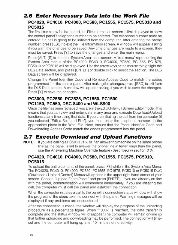
2.6 Enter Necessary Data Into the Work FilePC4020, PC4010, PC4000, PC580, PC1555, PC1575, PC5010 andPC5015The first time a new file is opened, the File Information screen is first displayed to allowthe control panel’s telephone number to be entered. The telephone number must beentered if a call is going to be initiated from the computer. After entering the phonenumber, press [ESC] to exit the File Information screen. A window will appear askingif you want the changes to be saved. Any time changes are made to a screen, theymust be saved. Press [Y] to save the changes and enter the main menu.Press [ALT]-[S] to enter the System Area menu screen. A “tree menu” representing theSystem Area menus of the PC4020, PC4010, PC4000, PC580, PC1555, PC1575,PC5010 or PC5015 will be displayed. Use the arrow keys or the mouse to highlight theDLS Data section, and press [ENTER] or double click to select the section. The DLSData screen will be displayed.Change the Panel Identifier Code and Remote Access Code to match the codesprogrammed into the control panel. After making the changes, press [ESC] to exit fromthe DLS Data screen. A window will appear asking if you wish to save the changes.Press [Y] to save the changes.
PC3000, PC2550, PC2525, PC1550, PC1500PC1150, PC550, DSC 8400 and WLS900Once the file has been retrieved, you are in the Edit A File Full Screen Editor mode. Thismeans that you can view and enter data in any area and execute Download/Uploadfunctions at any time using that data. If you are initiating the call from the computer (ifyou selected “Edit a Selected File”), you must enter the telephone number in theappropriate place in the Work File. Next, ensure that the Panel Identifier Code andDownloading Access Code match the codes programmed into the panel.
2.7 Execute Download and Upload FunctionsNOTE: If you are calling a PC5010 v1.x, or if an answering machine on the same phone
line as the panel is set to answer the phone line in fewer rings than the panel,use the Answering Machine Override feature (described in section 3.3).
PC4020, PC4010, PC4000, PC580, PC1555, PC1575, PC5010,PC5015To upload the entire contents of the panel, press [F3] while in the System Area Menu.The PC4020, PC4010, PC4000, PC580, PC1555, PC1575, PC5010 or PC5015 DUC(Download / Upload Control) Menus will appear in the upper right hand corner of yourscreen. Choose “Upload Entire Panel” and press [ENTER]. If you are already on-linewith the panel, communication will commence immediately. If you are initiating thecall, the computer must call the panel and establish the connection.When the computer initiates a call to the panel, a connection status window will showthe progress of the steps taken to connect with the panel. Warning messages will bedisplayed if any problems are encountered.After the connection is made, the window will display the progress of the uploadingprocedure as a percentage figure. When “100%” is reached, the data transfer iscomplete and the status window will disappear.The computer will remain on-line sothat further uploading and downloading may be performed. The connection will time-out and the computer will hang up after 10 minutes of no activity.
24
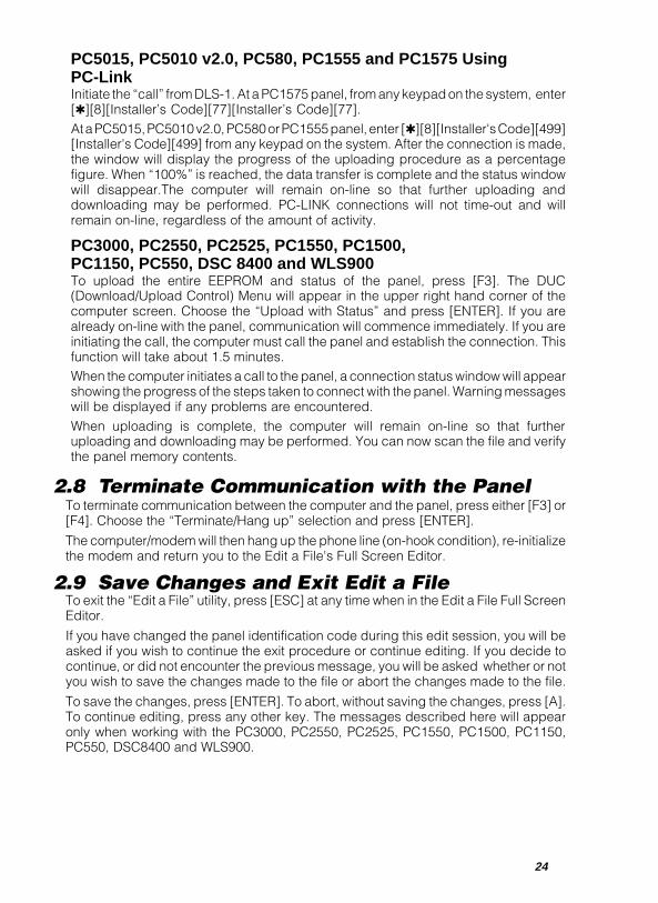
PC5015, PC5010 v2.0, PC580, PC1555 and PC1575 UsingPC-LinkInitiate the “call” from DLS-1. At a PC1575 panel, from any keypad on the system, enter[✱][8][Installer’s Code][77][Installer’s Code][77].At a PC5015, PC5010 v2.0, PC580 or PC1555 panel, enter [✱][8][Installer's Code][499][Installer's Code][499] from any keypad on the system. After the connection is made,the window will display the progress of the uploading procedure as a percentagefigure. When “100%” is reached, the data transfer is complete and the status windowwill disappear.The computer will remain on-line so that further uploading anddownloading may be performed. PC-LINK connections will not time-out and willremain on-line, regardless of the amount of activity.
PC3000, PC2550, PC2525, PC1550, PC1500,PC1150, PC550, DSC 8400 and WLS900To upload the entire EEPROM and status of the panel, press [F3]. The DUC(Download/Upload Control) Menu will appear in the upper right hand corner of thecomputer screen. Choose the “Upload with Status” and press [ENTER]. If you arealready on-line with the panel, communication will commence immediately. If you areinitiating the call, the computer must call the panel and establish the connection. Thisfunction will take about 1.5 minutes.When the computer initiates a call to the panel, a connection status window will appearshowing the progress of the steps taken to connect with the panel. Warning messageswill be displayed if any problems are encountered.When uploading is complete, the computer will remain on-line so that furtheruploading and downloading may be performed. You can now scan the file and verifythe panel memory contents.
2.8 Terminate Communication with the PanelTo terminate communication between the computer and the panel, press either [F3] or[F4]. Choose the “Terminate/Hang up” selection and press [ENTER].
The computer/modem will then hang up the phone line (on-hook condition), re-initializethe modem and return you to the Edit a File's Full Screen Editor.
2.9 Save Changes and Exit Edit a FileTo exit the “Edit a File” utility, press [ESC] at any time when in the Edit a File Full ScreenEditor.
If you have changed the panel identification code during this edit session, you will beasked if you wish to continue the exit procedure or continue editing. If you decide tocontinue, or did not encounter the previous message, you will be asked whether or notyou wish to save the changes made to the file or abort the changes made to the file.
To save the changes, press [ENTER]. To abort, without saving the changes, press [A].To continue editing, press any other key. The messages described here will appearonly when working with the PC3000, PC2550, PC2525, PC1550, PC1500, PC1150,PC550, DSC8400 and WLS900.
25
3 DLS-1 FILE MENUS
3.1 Main Menu 27
3.2 Edit a File 273.2.1 Edit a Selected File 27
PC4020, PC4010, PC4000, PC580, PC1555, PC1575,PC5010 and PC5015 ..................................................................... 27
PC4020, PC4010, PC4000 Menus ....................................... 29
PC5015, PC5010, PC1555, PC1575, PC580 Menus ........... 33
PC4020, PC4010, PC4000, PC580, PC1555, PC1575,PC5010 and PC5015 Downloading/UploadingControl (DUC) Menus ........................................................... 35
PC4020, PC4010, PC4000, PC580, PC1555, PC1575,PC5010 and PC5015 Status DUC Menus ............................ 37
PC3000, PC2550, PC2525, PC1550, PC1500, PC1150, PC550,DSC8400 and WLS900 Menus ...................................................... 43
PC3000, PC2550, PC2525, PC1550, PC1500, PC1150,PC550, DSC8400 and WLS900Downloading/Uploading Control (DUC) Menus ................... 44
PC3000, PC2550, PC2525, PC1550, PC1500, PC1150,PC550, DSC8400 and WLS900 Status DUC Menus ............ 45
3.2.2 Wait for Panel to Call 483.2.3 Execute Batch Files 48
3.3 Answering Machine Override Feature 49
3.4 Notes for Section 3 50

26
27
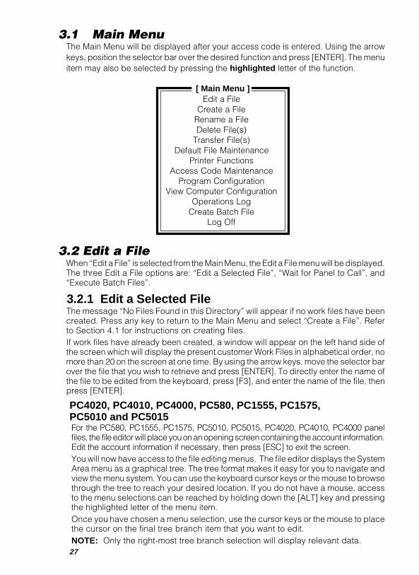
3.1 Main MenuThe Main Menu will be displayed after your access code is entered. Using the arrowkeys, position the selector bar over the desired function and press [ENTER]. The menuitem may also be selected by pressing the highlighted letter of the function.
[ Main Menu ]Edit a File
Create a FileRename a FileDelete File(s)
Transfer File(s)Default File Maintenance
Printer FunctionsAccess Code Maintenance
Program ConfigurationView Computer Configuration
Operations LogCreate Batch File
Log Off
3.2 Edit a FileWhen “Edit a File” is selected from the Main Menu, the Edit a File menu will be displayed.The three Edit a File options are: “Edit a Selected File”, “Wait for Panel to Call”, and“Execute Batch Files”.
3.2.1 Edit a Selected FileThe message “No Files Found in this Directory” will appear if no work files have beencreated. Press any key to return to the Main Menu and select “Create a File”. Referto Section 4.1 for instructions on creating files.If work files have already been created, a window will appear on the left hand side ofthe screen which will display the present customer Work Files in alphabetical order, nomore than 20 on the screen at one time. By using the arrow keys, move the selector barover the file that you wish to retrieve and press [ENTER]. To directly enter the name ofthe file to be edited from the keyboard, press [F3], and enter the name of the file, thenpress [ENTER].
PC4020, PC4010, PC4000, PC580, PC1555, PC1575,PC5010 and PC5015For the PC580, PC1555, PC1575, PC5010, PC5015, PC4020, PC4010, PC4000 panelfiles, the file editor will place you on an opening screen containing the account information.Edit the account information if necessary, then press [ESC] to exit the screen.You will now have access to the file editing menus. The file editor displays the SystemArea menu as a graphical tree. The tree format makes it easy for you to navigate andview the menu system. You can use the keyboard cursor keys or the mouse to browsethrough the tree to reach your desired location. If you do not have a mouse, accessto the menu selections can be reached by holding down the [ALT] key and pressingthe highlighted letter of the menu item.Once you have chosen a menu selection, use the cursor keys or the mouse to placethe cursor on the final tree branch item that you want to edit.NOTE: Only the right-most tree branch selection will display relevant data.

28
Press [ENTER] or click the left mouse button. A new window will be displayedcontaining the data of the menu selection you made. In this window, you may enterthe necessary data for the Work File.
After you have entered the data within a window and you decide to edit anotherwindow, press the [ESC] key. You will be asked whether or not you want to save thescreen. If you want to save your changes, choose [Yes] and the screen contents willbe saved to the file. If you choose [No], the screen contents will not be saved to thefile and your changes will be ignored.
To exit any window, press [ESC] or click the right mouse button to return to theprevious window.
PC4000 Panel Notes:The PC4000 software version 1.3 contains new sections that are not in the PC4000version 1.2 and earlier software. These sections are marked in the work file with an “∗”along with a note on the screen stating that the indicated section is only available forsoftware version 1.3 and greater. If you are using a software version earlier than 1.3,ignore these sections.
The new sections in the version 1.3 software include:
Partition MaskSystem Area þ Access Code Info þ Access Codes þ Partitions 1 through 8
Follows Includes AlarmsCrystal Time Base
System Area þ System Options þ Sys Toggle Opts
European DialPC ID Use RestoreTLM & Alarm AudRingbackFTC Audible Bell
System Area þ Communicator þ Comms Toggles
4/3 DTMF FormatSystem Area þ Communicator þ Main Items þ 1st Number þ Comms Format
þ 2nd Number þ Comms Formatþ 3rd Number þ Comms Format
Second Master Reporting CodesSystem Area þ Communicator þ Reporting Codes þ Misc Codes
4216 Zone FollowerSystem Area þ PGM Outputs þ 4216 Options þ Which 4216
Zone FollowerZone Alarm
System Area þ SW Aux Outputþ Main bell Outputþ 4204 Options þ Which 4204þ 4216 Options þ Which Outputþ 4216 Custom þ Which Output
29
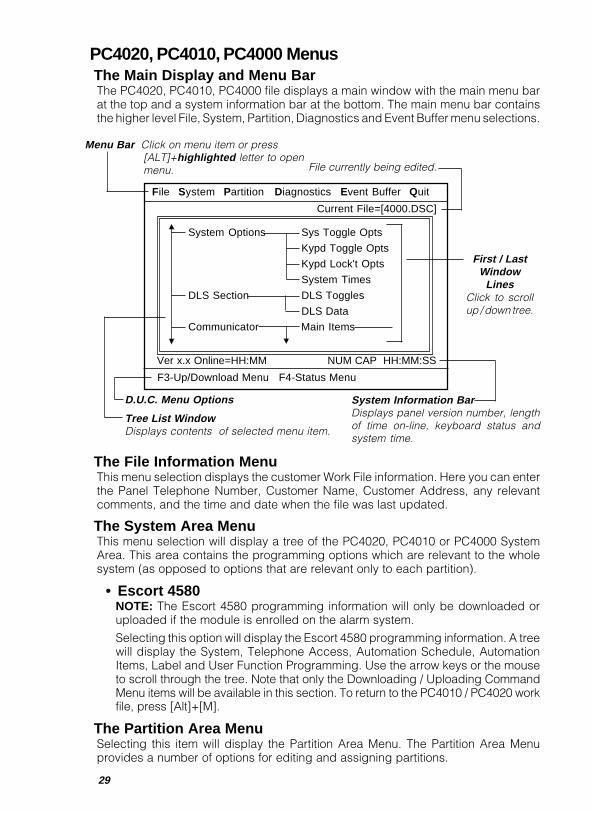
PC4020, PC4010, PC4000 MenusThe Main Display and Menu BarThe PC4020, PC4010, PC4000 file displays a main window with the main menu barat the top and a system information bar at the bottom. The main menu bar containsthe higher level File, System, Partition, Diagnostics and Event Buffer menu selections.
The File Information MenuThis menu selection displays the customer Work File information. Here you can enterthe Panel Telephone Number, Customer Name, Customer Address, any relevantcomments, and the time and date when the file was last updated.
The System Area MenuThis menu selection will display a tree of the PC4020, PC4010 or PC4000 SystemArea. This area contains the programming options which are relevant to the wholesystem (as opposed to options that are relevant only to each partition).
• Escort 4580NOTE: The Escort 4580 programming information will only be downloaded oruploaded if the module is enrolled on the alarm system.
Selecting this option will display the Escort 4580 programming information. A treewill display the System, Telephone Access, Automation Schedule, AutomationItems, Label and User Function Programming. Use the arrow keys or the mouseto scroll through the tree. Note that only the Downloading / Uploading CommandMenu items will be available in this section. To return to the PC4010 / PC4020 workfile, press [Alt]+[M].
The Partition Area MenuSelecting this item will display the Partition Area Menu. The Partition Area Menuprovides a number of options for editing and assigning partitions.
File System Partition Diagnostics Event Buffer Quit
Current File=[4000.DSC]
Ver x.x Online=HH:MM NUM CAP HH:MM:SS
F3-Up/Download Menu F4-Status Menu
System Options Sys Toggle Opts
Kypd Toggle Opts
Kypd Lock't Opts
System Times
DLS Section DLS Toggles
DLS Data
Communicator Main Items
D.U.C. Menu Options
Tree List WindowDisplays contents of selected menu item.
File currently being edited.
Menu Bar Click on menu item or press[ALT]+highlighted letter to openmenu.
First / LastWindow
LinesClick to scrollup / down tree.
System Information BarDisplays panel version number, lengthof time on-line, keyboard status andsystem time.
30
At the bottom of the screen, the partition assignment will be displayed. If the numberfor a partition is displayed, then that partition is enabled (active). In the default setting,only Partition 1 is enabled.
The “Information Source” displays where the data for the active partition(s) was obtained.
• “File” means the data was obtained from the work file.
• “Keyboard” means the user has entered data with the Assign Partitions commandto enable partitions, but the information has not yet been saved to the file.
• “Panel” means the partition assignment has been uploaded from or downloadedto the control panel.
The following menu items are available when the Partition Area Menu is selected:
• Assign PartitionsA menu for enabling partitions will appear. The partitions and their labels will beshown; an arrow will indicate the selected partitions.NOTE: A partition must be assigned before it is active. Ensure that you activate
the desired partitions when downloading.To send the assignment to the control panel, exit this section and select DownloadPartition Assign from the Partition Area Menu.
• Edit PartitionsA menu for selecting which partition to edit will appear. The menu tree forprogramming partitions will be displayed and the zones assigned to the partitionwill also be displayed. Use the [Up] and [Down] arrow keys to select the partitionto edit, and then press [ENTER].To add or remove zones to or from a partition, select Add/Delete Zones from thepartition menu tree. Enter the 3-digit zone number and press [ENTER] to add ordelete a zone. Any zone that is highlighted will be added to the partition.After selecting the zone assignment, return to the partition menu tree by pressing the[ESC] key. A window will appear and ask if you wish to save the zone assignment to file.To save the zone assignment, answer “Yes”. Press [F3] to call up the Upload/DownloadZone Assignment Menu. Download the zone assignment to the control panel.
• Copy PartitionsAfter editing a partition, the programming changes can be copied to anotherpartition. Use this feature to speed and simplify programming when several ofyour partitions are to be programmed with the same or mostly the same settings.When selected, a menu will appear to select which partition to copy from.Next, a menu will appear to select which partition to copy to.The Customer ID Code, Partition Toggle Options, Partition Times and the PartitionLabel will be copied. Note that the Zone Assignment will not be copied.
• Upload Partition AssignSelecting this option will upload the Partition Assignment from the control panel.This will allow you to view which partitions have been enabled.
• Download Partition AssignSelecting this option will download the edited Partition Assignment to the control panel.
• Initialize ModemSelecting this option will re-initialize the modem using the current defaultsincluding the setting stored in the Modem Command File (MODEMSTR.FIL). Usethis feature if the software is unable to automatically re-initialize the modem.
31
• Terminate Call / Hang UpSelect this option to terminate the call to the panel. Since the panel and the modemwill stay on-line after the first communication, you may wish to hang up the callwhile while you edit the work file. When you are ready to download the editedWorkfile to the control panel, you may call the panel again and reconnect.
• Exit From This MenuSelecting this option will return you to the edit screens, allowing you to makechanges or examine the Work File. Selecting this option will not hang up the modemand the control panel. To hang up, you must select “Terminate Call/Hang Up”.
Diagnostics Menu• Upload Diagnostics
Selecting this option will upload the Diagnostics of the control panel. Diagnosticsrefers to the trouble status reported by the modules to the control panel. An “E”,“T” or “L” will appear beside a module number if that module is currently reportinga trouble condition. If no letters appear, there are no troubles.“E” means the control panel can no longer communicate with the module“T” means the tamper zone is currently violated“L” means the module is not receiving enough power from the CombusTo determine what the Module Numbers represent, refer to Appendix J or press[F1] when working with PC4010 and PC4020 files.
• View File ContentsThe last diagnostics upload can be reviewed at any time by viewing the filecontents.
Event Buffer MenuSelecting Event Buffer Menu will display a menu of options for uploading, viewing andprinting the Event Buffer.
• Upload Entire Event BufferThis option uploads the Event Buffer from the control panel. The partition label,the date and time for each event, and the events themselves will be displayed.Note that partition labels are loaded from the computer file, and may differ fromwhat is programmed in the control panel. It is suggested that the partition labelsbe uploaded before the event buffer so that any changes may be updated.On the PC4000, the date is displayed as MM:DD, where MM is the month and DDis the day. The year is only displayed as an event; when the year changes, it islogged on the event buffer as shown below:
For the PC4000: Partition Date Time EventPartition... 1 00/00 00:00 The Year is now ’96
Note that the PC4020 and PC4010 print the year with each event, as shown below:For the PC4020 Partition Date Time Event
and PC4010: Partition... 1 00/00/96 00:00 Installer Lead In
The PC4020, PC4010 and PC4000 keep track of both previously uploaded eventsand new events. When you append the uploaded event buffer to the Event BufferFile (refer to Save Event Buffer) only the new events will be appended to the EventBuffer File. This prevents the duplication of events in the Event Buffer File. If youupload the entire event buffer and do not append the new events to the Event BufferFile, there is no way to append the events to the file later. When uploaded later, theywill be considered old events and will not be appended to the Event Buffer File.
32
• Upload New Events OnlyThis selection will allow you to upload only new events that have occurred sincethe last time the event buffer was uploaded. These events can then be appendedto the event buffer file to create a continuous file of events on the event buffer.
• Upload Last 16 EventsThis selection will allow you to upload the 16 most recent events in the event buffer.This function does not affect the “new event” status of events in the panel. If the last16 events are new events, they will still be considered new events the next time theevent buffer is uploaded. Note that the last 16 events cannot be saved or appended.
• Print Event BufferSelecting this option will allow the event buffer to be printed on a printerconnected to the computer. When selected, you will be given the option ofprinting the Uploaded Event Buffer, the Event Buffer on File, or the last 16 events.Selecting “Event Buffer on File” will print the event buffer that has been savedin the computer’s memory using the Save Event Buffer option. Selecting “Last16 Events” will print the last 16 events stored in the event buffer.
• View Saved Event BufferSelecting this option will display the contents of the event buffer file that has beencreated using the Save Event Buffer option.
• Save Event BufferSelecting this option will save the uploaded event buffer to a file on your disk drive.The event buffer files on your disk drive will have the same name as the Work Filename, but with a different extension. For example, if your Work File is calledPC4000.DSC, the Event Buffer File will be named PC4000.BUF.
You will be asked to either Save or Append the Event Buffer file. When the eventbuffer is Saved to a file, any information already in the file will be overwritten. If theevent buffer is Appended to the file, new events in the event buffer are attachedto the end of any previous information already saved to your Event Buffer File.
When viewing an appended Event Buffer File, the two event buffers areseparated by a highlighted “Event Buffer Appended” message. The date andtime shows when the event buffer was appended.
• Initialize ModemSelecting this option will re-initialize the modem using the current defaultsincluding the setting stored in the Modem Command File (MODEMSTR.FIL). Usethis feature if the software is unable to automatically re-initialize the modem.
• Terminate Call / Hang UpSelect this option to terminate the call to the panel. Since the panel and the modemwill stay on-line after the first communication, you may wish to hang up the callwhile while you edit the work file. When you are ready to download the editedWorkfile to the control panel, you may call the panel again and reconnect.
• Exit From This MenuSelecting this option will return you to the edit screens, allowing you to makechanges or examine the Work File. Selecting this option will not hang up the modemand the control panel. To hang up, you must select “Terminate Call/Hang Up”.
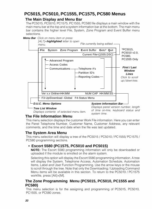
33
PC5015, PC5010, PC1555, PC1575, PC580 MenusThe Main Display and Menu BarThe PC5015, PC5010, PC1575, PC1555, PC580 file displays a main window with themain menu bar at the top and a system information bar at the bottom. The main menubar contains the higher level File, System, Zone Program and Event Buffer menuselections.
The File Information MenuThis menu selection displays the customer Work File information. Here you can enterthe Panel Telephone Number, Customer Name, Customer Address, any relevantcomments, and the time and date when the file was last updated.
The System Area MenuThis menu selection will display a tree of the PC5015 / PC5010 / PC1555/ PC1575 /PC580 programming sections.
• Escort 5580 (PC1575, PC5010 and PC5015)NOTE: The Escort 5580 programming information will only be downloaded oruploaded if the module is enrolled on the alarm system.Selecting this option will display the Escort 5580 programming information. A treewill display the System, Telephone Access, Automation Schedule, AutomationItems, Label and User Function Programming. Use the arrow keys or the mouseto scroll through the tree. Note that only the Downloading / Uploading CommandMenu items will be available in this section. To return to the PC5010 / PC1575workfile, press [Alt]+[M].
The Zone Programming Menu (PC5015, PC5010, PC1555 andPC580)This menu selection is for the assigning and programming of PC5015, PC5010,PC1555, or PC580 zones.
File System Zone Program Event Buffer Goto* Quit
Current File=[1555.DSC]
F3-Up/Download -Global F4-Status Menu
Advanced Program
Access Codes
Communications Telephone #'s
Partition ID's
Reporting Codes
D.U.C. Menu Options
Tree List WindowDisplays contents of selected menu item.
File currently being edited.
Menu Bar Click on menu item or press[ALT]+highlighted letter to openmenu.
First / LastWindow
LinesClick to scrollup / down tree.
System Information BarDisplays panel version number, lengthof time on-line, keyboard status andsystem time.
Ver x.x Online=HH:MM NUM CAP HH:MM:SS
*PC5015,PC5010 v2.0,PC580,PC1555 Only
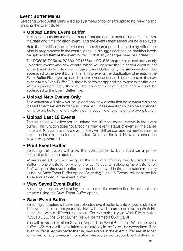
34
Event Buffer MenuSelecting Event Buffer Menu will display a menu of options for uploading, viewing andprinting the Event Buffer.
• Upload Entire Event BufferThis option uploads the Event Buffer from the control panel. The partition label,the date and time for each event, and the events themselves will be displayed.
Note that partition labels are loaded from the computer file, and may differ fromwhat is programmed in the control panel. It is suggested that the partition labelsbe uploaded before the event buffer so that any changes may be updated.
The PC5015, PC5010, PC580, PC1555 and PC1575 keep track of both previouslyuploaded events and new events. When you append the uploaded event bufferto the Event Buffer File (refer to Save Event Buffer) only the new events will beappended to the Event Buffer File. This prevents the duplication of events in theEvent Buffer File. If you upload the entire event buffer and do not append the newevents to the Event Buffer File, there is no way to append the events to the file later.When uploaded later, they will be considered old events and will not beappended to the Event Buffer File.
• Upload New Events OnlyThis selection will allow you to upload only new events that have occurred sincethe last time the event buffer was uploaded. These events can then be appendedto the event buffer file to create a continuous file of events on the event buffer.
• Upload Last 16 EventsThis selection will allow you to upload the 16 most recent events in the eventbuffer. This function does not affect the “new event” status of events in the panel.If the last 16 events are new events, they will still be considered new events thenext time the event buffer is uploaded. Note that the last 16 events cannot besaved or appended.
• Print Event BufferSelecting this option will allow the event buffer to be printed on a printerconnected to the computer.
When selected, you will be given the option of printing the Uploaded EventBuffer, the Event Buffer on File, or the last 16 events. Selecting “Event Buffer onFile” will print the event buffer that has been saved in the computer’s memoryusing the Save Event Buffer option. Selecting “Last 16 Events” will print the last16 events stored in the event buffer.
• View Saved Event BufferSelecting this option will display the contents of the event buffer file that has beencreated using the Save Event Buffer option.
• Save Event BufferSelecting this option will save the uploaded event buffer to a file on your disk drive.The event buffer files on your disk drive will have the same name as the Work Filename, but with a different extension. For example, if your Work File is calledPC5010.DSC, the Event Buffer File will be named PC5010.BUF.You will be asked to either Save or Append the Event Buffer file. When the eventbuffer is Saved to a file, any information already in the file will be overwritten. If theevent buffer is Appended to the file, new events in the event buffer are attachedto the end of any previous information already saved to your Event Buffer File.

35
When viewing an appended Event Buffer File, the two event buffers are separatedby a highlighted “Event Buffer Appended” message. The date and time showswhen the event buffer was appended.
• Goto (PC5015, PC5010 v2.0, PC1555 and PC580 only)This function will allow you to enter the exact programming screens you wish to viewor edit by pressing [ALT][G] or [F10]. When the "Enter Section Number" windowappears, enter the number of the programming section you want to go to. Refer tothe PC5015, PC5010 v2.0, PC1555 or PC580 Installation Manual for a list ofprogramming section numbers.
• Enable Modem / PC-Link (PC5015, PC5010 v2.0, PC1555 andPC580 only)This function will toggle the communications mode between using a modem linkand PC-Link.
• Initialize ModemSelecting this option will re-initialize the modem using the current defaultsincluding the setting stored in the Modem Command File (MODEMSTR.FIL). Usethis feature if the software is unable to automatically re-initialize the modem.
• Terminate Call / Hang UpSelect this option to terminate the call to the panel. Since the panel and the modemwill stay on-line after the first communication, you may wish to hang up the callwhile while you edit the work file. When you are ready to download the editedWorkfile to the control panel, you may call the panel again and reconnect.
• Exit From This MenuSelecting this option will return you to the edit screens, allowing you to makechanges or examine the Work File. Selecting this option will not hang up the modemand the control panel. To hang up, you must select “Terminate Call/Hang Up”.
PC4020, PC4010, PC4000, PC580, PC1555, PC1575,PC5010 and PC5015 Downloading/Uploading Control(DUC) MenusWhile in the PC4020, PC4010, PC4000, PC580, PC1555, PC1575, PC5010 andPC5015 File Editor Section, any screen that displays “F3 Upload/Download menu” inthe DUC Menu Options bar at the bottom of the screen will allow the Download/UploadControl window to be accessed by pressing [F3].
Upload Entire Panel / Upload Entire Module Info (Escort)This function uploads the entire programming contents of the panel or the Escort.Select this option using up and down arrow keys, and press [ENTER]. Diagnostics,Event Buffer and Status are not uploaded.
Download Entire Panel / Download Entire Module Info (Escort)This function will download the entire programming contents of the selected file to thepanel or the Escort. The download procedure is similar to the upload proceduredescribed above. Keypad togggles, function keys and options will be sent to allkeypads on the system.
36
Upload Window ContentsThis selection appears in the place of the “Upload Entire Panel / Upload EntireModule Info” section on the DUC menu if you are editing one of the individualwindows in the tree menu. This function will allow you to upload only the contentsof the window that you are currently in. Certain windows, such as the File Informationwindow, are for clarification of the Work Files and cannot be uploaded or downloaded.
Download Window ContentsThis function will download only the contents of the window you are currently in.Keypad togggles, function keys and options will be sent to all keypads on the system.
Print All Screens (PC4020 v2.x, PC4010 v2.x, PC580, PC1555,PC1575, PC5010 and PC5015 only)This function will print all programming information for all sections of the selectedfile. If you choose to print to a file, the text file will be in the WF directory with thefilename extension .PRN for panel files and .PRT for Escort files.
NOTENOTENOTENOTENOTE: After Print Screens is selected, a second menu will be displayed with thefollowing options: “Send Output to File” will print all screens to an ASCII file withthe same name as the account file with .PRN as the extension. “Send Output toPrinter” will print to the printer selected in the program configuration.
Print Selected Screens (PC4020 v2.x, PC4010 v2.x, PC580,PC1555, PC1575, PC5010 and PC5015 only)This function will print all programming information for selected windows within afile. To select a window for printing, press [CTRL][P] while the window is displayed.When “Print Selected Screens” is selected, all windows tagged with the [CTRL][P]command will be printed. To deselect a window, press [CTRL][P] again while thewindow is displayed.If you choose to print to a file, the text file will be in the WF directory with the filenameextension .PRN for panel files and .PRT for Escort files.
Clear Print TagsThis function will clear all of the print tags that have been selected to be printed.
Enable Modem / PC-Link ( PC5015, PC5010 v2.0, PC580, PC1555and PC1575 only)This function will toggle the communications mode between using a modem linkand PC-Link.
Initialize ModemThis function will re-initialize the modem to the current defaults, including thesettings entered into the Modem Command File (MODEMSTR.FIL). This is useful ifthe connection with the panel has been broken (e.g. if the modem power cordbecame unplugged) and the software is unable to automatically re-initialize themodem . When you have fixed the problem, making this selection should re-initializethe modem, allowing you to reconnect to the panel.
Terminate Call / Hang UpSelect this option to terminate the call to the panel. Since the panel and the modemwill stay on-line after the first communication, you may wish to hang up the call whilewhile you edit the work file. When you are ready to download the edited Workfile tothe control panel, you may call the panel again and reconnect.
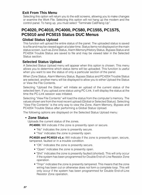
37
Exit From This MenuSelecting this option will return you to the edit screens, allowing you to make changesor examine the Work File. Selecting this option will not hang up the modem and thecontrol panel. To hang up, you must select “Terminate Call/Hang Up”.
PC4020, PC4010, PC4000, PC580, PC1555, PC1575,PC5010 and PC5015 Status DUC MenusGlobal Status UploadThis function will upload the entire status of the panel. The uploaded status is savedto a file and may be viewed again at a later time. Status items not displayed on the mainstatus screen, such as Zone Status, Alarm Memory/History Status, Bypass Status andPC4204 Trouble Status are saved to file and may be viewed later in the SelectedStatus section.
Selected Status UploadA Selected Status Upload menu will appear when this option is chosen. This menuallows you to determine which status items will be uploaded. This function is usefulwhen you want to see the status of only a particular section of the panel.
When Zone Status, Alarm Memory Status, Bypass Status and PC4204 Trouble Statusare selected, another menu will be displayed to allow you to either Upload the Statusor View the File Contents.
Selecting “Upload the Status” will initiate an upload of the current status of theselected item. If you upload zone status using PC-Link, it will display the status at thetime the PC-Link session was initiated.
Selecting “View File Contents” will load the status from the computer’s memory. Thevalues shown are from the most recent upload (Global or Selected Status). Selecting“View File Contents“ is the only way to view the Zone, Alarm Memory, Bypass andPC4204 Trouble Status after performing a Global Status Upload.
The following options are displayed on the Selected Status Upload menu:
• Zone StatusUploads the current status of the zones.
PC4000: Will indicate if the zone is presently open or secure.
• “No” indicates the zone is presently secure.• “Yes” indicates the zone is presently open.
PC4020 and PC4010 v1.x: Will indicate if the zone is presently open, secure,tampered, faulted or in a trouble condition.
• “OK” indicates the zone is presently secure.• “Open” indicates the zone is presently open.• “Shrt” indicates the zone is presently faulted (shorted). This will only occur
if the system has been programmed for Double End-of-Line Resistor Zoneoperation.
• “Tmpr” indicates the zone is presently tampered. This means that the zonewiring has been cut or otherwise does not form a complete loop. This willonly occur if the system has been programmed for Double End-of-LineResistor Zone operation.
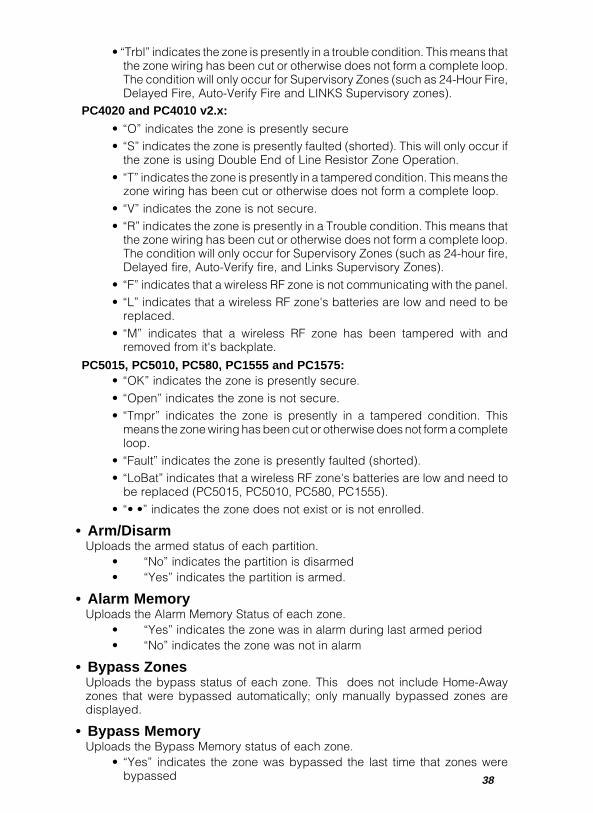
38
• “Trbl” indicates the zone is presently in a trouble condition. This means thatthe zone wiring has been cut or otherwise does not form a complete loop.The condition will only occur for Supervisory Zones (such as 24-Hour Fire,Delayed Fire, Auto-Verify Fire and LINKS Supervisory zones).
PC4020 and PC4010 v2.x:
• “O” indicates the zone is presently secure• “S” indicates the zone is presently faulted (shorted). This will only occur if
the zone is using Double End of Line Resistor Zone Operation.• “T” indicates the zone is presently in a tampered condition. This means the
zone wiring has been cut or otherwise does not form a complete loop.• “V” indicates the zone is not secure.• “R” indicates the zone is presently in a Trouble condition. This means that
the zone wiring has been cut or otherwise does not form a complete loop.The condition will only occur for Supervisory Zones (such as 24-hour fire,Delayed fire, Auto-Verify fire, and Links Supervisory Zones).
• “F” indicates that a wireless RF zone is not communicating with the panel.• “L” indicates that a wireless RF zone's batteries are low and need to be
replaced.• “M” indicates that a wireless RF zone has been tampered with and
removed from it's backplate.
PC5015, PC5010, PC580, PC1555 and PC1575:• “OK” indicates the zone is presently secure.• “Open” indicates the zone is not secure.• “Tmpr” indicates the zone is presently in a tampered condition. This
means the zone wiring has been cut or otherwise does not form a completeloop.
• “Fault” indicates the zone is presently faulted (shorted).• “LoBat” indicates that a wireless RF zone's batteries are low and need to
be replaced (PC5015, PC5010, PC580, PC1555).• “• •” indicates the zone does not exist or is not enrolled.
• Arm/DisarmUploads the armed status of each partition.
• “No” indicates the partition is disarmed• “Yes” indicates the partition is armed.
• Alarm MemoryUploads the Alarm Memory Status of each zone.
• “Yes” indicates the zone was in alarm during last armed period• “No” indicates the zone was not in alarm
• Bypass ZonesUploads the bypass status of each zone. This does not include Home-Awayzones that were bypassed automatically; only manually bypassed zones aredisplayed.
• Bypass MemoryUploads the Bypass Memory status of each zone.
• “Yes” indicates the zone was bypassed the last time that zones werebypassed
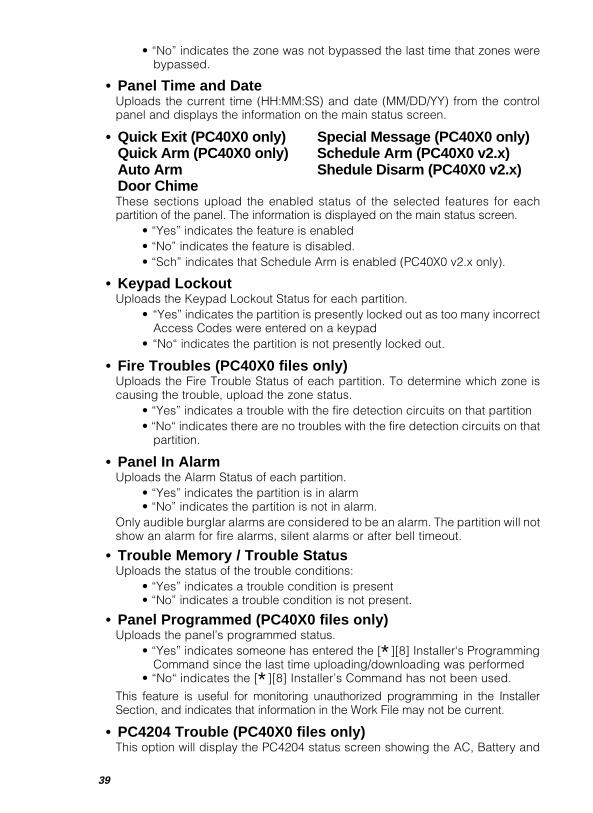
39
• “No” indicates the zone was not bypassed the last time that zones werebypassed.
• Panel Time and DateUploads the current time (HH:MM:SS) and date (MM/DD/YY) from the controlpanel and displays the information on the main status screen.
• Quick Exit (PC40X0 only) Special Message (PC40X0 only)Quick Arm (PC40X0 only) Schedule Arm (PC40X0 v2.x)Auto Arm Shedule Disarm (PC40X0 v2.x)Door ChimeThese sections upload the enabled status of the selected features for eachpartition of the panel. The information is displayed on the main status screen.
• “Yes” indicates the feature is enabled• “No” indicates the feature is disabled.• “Sch” indicates that Schedule Arm is enabled (PC40X0 v2.x only).
• Keypad LockoutUploads the Keypad Lockout Status for each partition.
• “Yes” indicates the partition is presently locked out as too many incorrectAccess Codes were entered on a keypad
• “No“ indicates the partition is not presently locked out.
• Fire Troubles (PC40X0 files only)Uploads the Fire Trouble Status of each partition. To determine which zone iscausing the trouble, upload the zone status.
• “Yes” indicates a trouble with the fire detection circuits on that partition• “No“ indicates there are no troubles with the fire detection circuits on that
partition.
• Panel In AlarmUploads the Alarm Status of each partition.
• “Yes” indicates the partition is in alarm• “No” indicates the partition is not in alarm.
Only audible burglar alarms are considered to be an alarm. The partition will notshow an alarm for fire alarms, silent alarms or after bell timeout.
• Trouble Memory / Trouble StatusUploads the status of the trouble conditions:
• “Yes” indicates a trouble condition is present• “No” indicates a trouble condition is not present.
• Panel Programmed (PC40X0 files only)Uploads the panel’s programmed status.
• “Yes” indicates someone has entered the [∗][8] Installer‘s ProgrammingCommand since the last time uploading/downloading was performed
• “No“ indicates the [∗][8] Installer’s Command has not been used.
This feature is useful for monitoring unauthorized programming in the InstallerSection, and indicates that information in the Work File may not be current.
• PC4204 Trouble (PC40X0 files only)This option will display the PC4204 status screen showing the AC, Battery and

40
Auxiliary Power Supply trouble status of all the PC4204s installed on the system.• “Yes” indicates a trouble has occurred with a PC4204• “No” indicates a trouble has not occurred.
• Tamper Reset Required (PC40X0 v2.x / PC5015 / PC5010 /PC1575 / PC1555 / PC580 files only)Uploads the tamper status of zones.
• “Yes” indicates a tamper condition is present and it must be reset beforethe panel can arm.
• “No” indicates a tamper condition is not present.
• Installer Lockout (PC40X0 v2.x / PC5015 / PC5010 / PC1575/ PC1555 / PC580 files only)Uploads the status of Installer Lockout.
• “Yes” indicates that Installer Lockout is enabled, and hardware defaultingis impossible.
• “No” indicates that Installer Lockout is disabled.
Arm / DisarmThis option is used to arm and disarm partitions. When you select this function, amenu will appear where you can select which partitions to arm, and which partitionsto disarm. Select the partitions you wish to arm and those you wish to disarm, thenselect the “execute” command.If a partition is already armed, already disarmed, or is not ready to be armed, an errormessage will appear. The message will indicate which partitions were alreadyarmed, already disarmed, or not ready to be armed.The computer will verify that the panel armed or disarmed the requested partitions.If any partition(s) failed to arm or disarm, a message will appear to indicate whichpartitions did not arm or disarm.
Bypass ZonesThis option displays a Bypass Status Screen. Before this screen is shown, thecurrent Bypass Status will be uploaded. “Yes” or “No” will be displayed beside eachzone number. Toggle between “Yes” and “No” using the cursor keys to determinewhich zones will be bypassed:
• “Yes” indicates that the zone will be bypassed• “No” indicates that the zone will not be bypassed.
On the PC4020, PC4010 and PC4000, an asterisk (∗) may appear to the left of thezone number: the asterisk indicates Bypass Memory. The zones marked with an (∗)were bypassed the last time zones were bypassed on that partition. After selectingwhich zones to bypass, press the [ESC] key to call up a menu to download thechanges to the control panel.
Set Panel Time and DateWhen selected, the time and date on the control panel may be changed. Enter twodigits each for the day, month, year, hour and minutes. You can also update thepanel's time and date with the time and date settings from your computer. To ensurethe panel is updated as accurately as possible:
1. Make sure your computer has the correct time and date.
2. Make sure your computer is connected to the control panel.
3. Press [S] to update the panel.
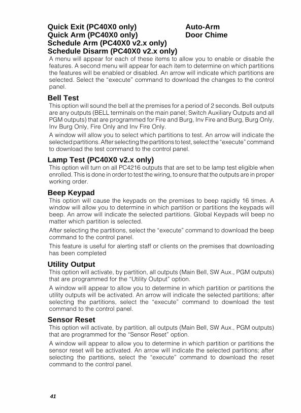
41
Quick Exit (PC40X0 only) Auto-ArmQuick Arm (PC40X0 only) Door ChimeSchedule Arm (PC40X0 v2.x only)Schedule Disarm (PC40X0 v2.x only)A menu will appear for each of these items to allow you to enable or disable thefeatures. A second menu will appear for each item to determine on which partitionsthe features will be enabled or disabled. An arrow will indicate which partitions areselected. Select the “execute” command to download the changes to the controlpanel.
Bell TestThis option will sound the bell at the premises for a period of 2 seconds. Bell outputsare any outputs (BELL terminals on the main panel; Switch Auxiliary Outputs and allPGM outputs) that are programmed for Fire and Burg, Inv Fire and Burg, Burg Only,Inv Burg Only, Fire Only and Inv Fire Only.A window will allow you to select which partitions to test. An arrow will indicate theselected partitions. After selecting the partitions to test, select the “execute” commandto download the test command to the control panel.
Lamp Test (PC40X0 v2.x only)This option will turn on all PC4216 outputs that are set to be lamp test eligible whenenrolled. This is done in order to test the wiring, to ensure that the outputs are in properworking order.
Beep KeypadThis option will cause the keypads on the premises to beep rapidly 16 times. Awindow will allow you to determine in which partition or partitions the keypads willbeep. An arrow will indicate the selected partitions. Global Keypads will beep nomatter which partition is selected.After selecting the partitions, select the “execute” command to download the beepcommand to the control panel.This feature is useful for alerting staff or clients on the premises that downloadinghas been completed
Utility OutputThis option will activate, by partition, all outputs (Main Bell, SW Aux., PGM outputs)that are programmed for the “Utility Output” option.A window will appear to allow you to determine in which partition or partitions theutility outputs will be activated. An arrow will indicate the selected partitions; afterselecting the partitions, select the “execute” command to download the testcommand to the control panel.
Sensor ResetThis option will activate, by partition, all outputs (Main Bell, SW Aux., PGM outputs)that are programmed for the “Sensor Reset” option.A window will appear to allow you to determine in which partition or partitions thesensor reset will be activated. An arrow will indicate the selected partitions; afterselecting the partitions, select the “execute” command to download the resetcommand to the control panel.
42
Combus Reset (PC40X0 only)This option is used to re-initialize communications between the main panel and themodules by removing power from the modules to reset them. Special note whenusing Combus Reset on a PC4000 Control Panel only: a Combus reset willterminate the connection between the panel and the downloading computer.
Send LCD MessageUse this option to send a message to display on the LCD keypads installed on thepremises. When selected, a window will allow you to enter a 32 character message (2lines of 16 characters each). Type the message and press [ENTER].On PC40X0 files, a window will allow you to determine which partition or partitionswill display the message on the LCD4500 keypads. An arrow will indicate theselected partitions. After selecting the partitions, select the “execute” command todownload the message to the control panel. The message will be displayed on all thekeypads assigned to the designated partitions.The message will be displayed when the partition is disarmed. The message will beerased after the partition has been armed and disarmed three (3) times. If anothermessage is downloaded to the control panel, the new message will immediately replacethe first. The message is erased from Global Keypads only after all partitions to whichthe message was sent have been armed and disarmed three times.On PC5015, PC5010, PC580, PC1555 and PC1575 panels, the message will bedisplayed after 30 seconds of inactivity (i.e. no keypresses) on each LCD keypad. Themessage can be cleared from the keypad display by pressing any key. It will then re-appear after 30 seconds of inactivity on the keypad. The message will be erased afterhaving been cleared from the keypad the number of times programmed in the panel. Ifanother message is downloaded to the control panel, the new message will immediatelyreplace the first message.
Special Message (PC40X0 only)This option is used to enable or disable the special message feature for each of thepartitions on the PC4020 / PC4010 / PC4000. Special messages are the twomessages the installer can program for the user. They are the Fail to Arm messageand the Alarm When Armed message.
Remote Operation (PC4020 and PC4010 Only)This option is used to enable or disable outputs programmed for remote operation.
Reset Latching Tamper (PC40X0 v2.x / PC5015 / PC5010 / PC1575/ PC1555 / PC580 files only)This option is used when the system uses Double End-of-Line Resistor Zones and theTamper Inhibit Arming option is enabled or if the system has 24-hour Latching Zones.Selecting “Reset Latching Tamper” will reset the tamper condition and allow the affectedpartition to be armed as if installers programming had been entered from a keypad.
Installer Lockout (PC40X0 v2.x / PC5015 / PC5010 / PC1575 /PC1555 / PC580 files only)Enabling this feature will make hardware defaulting impossible. The panel is onlyable to be defaulted using the Installer’s Code. Only users that have access to “ViewSecure Data” can use this option.
Enable Modem / PC-Link ( PC5015, PC5010 v2.0, PC580, PC1555and PC1575 only)This function will toggle the communications mode between using a modem link andPC-Link.

43
PC3000, PC2550, PC2525, PC1550, PC1500, PC1150,PC550, DSC8400 and WLS900 MenusThe file editor is divided into four sections:
• Specific Account Information (name, address)• EEPROM data• System Status Information• Record of Last 8 Changes to the File; the most recent change to the file will be
shown first.
Specific Account InformationTo “Edit a File”, enter the customer’s name and address in the appropriate box. Two48-character comment lines are provided for account information. The telephonenumber to be used for accessing the panel must be entered in the space designated“[Control Panel Model] TELEPHONE NUMBER”.
Before a call to the panel can be initiated, the phone number of the panel must beentered. Enter the number in the 16-character space provided and then press[ENTER]. In addition to the numbers 0-9, any dial modifier may be entered in thisfield. For information on dial modifiers, refer to your modem instruction manual. Notethat the characters A B C D # ∗ ! and @ apply only to DTMF dialling. The dial modifierdigits/characters supported by DLS-1 Software are: 0 through 9 # ∗ A B C D T P ,W @ ! R ; .
System Status InformationThe programming sections shown here correspond with the Programming Worksheetsof the control panel; data may be entered, changed or deleted as desired.
PC3000 Panel Notes:In the PC3000 software versions 7.5 and 7.6, and the PC2550 software versions1.1 and 1.2, there are some sections that are either changed or are completelynew.These differences are noted in the Work File and Programming Worksheetsfor each changed or new section.The “+” sign is used to indicate “and later” (for example, 1.1+ means for version1.1 and later). The “-” sign is used to indicate “and earlier” (for example, 7.4-means for version 7.4 and earlier). Be sure to note the version of the panel you arecommunicating with before uploading or downloading these different sections.Note that Sections [55] and [56] are new sections added in the PC3000 softwareversion 7.6.In the PC3000 software versions prior to 7.5, Section [19] Zone Light 1 was used for“Send Opening After Alarm”. In version 7.5 and later, this zone light now means “BellPulses Always”. Sections [43], [44], [45], [50], [51], [52], [53] and [54] are newsections in version 7.5 that did not exist in previous software versions. If you arecommunicating with a PC3000 with software earlier than version 7.5, disregardthese sections.Note that there is a new file for the PC3000 software version 7.7; refer to the PC3000software version 7.7 Installation Manual for information on the new ProgrammingSections.
PC2550 Panel Notes:In the PC2550 software version 1.0, the last Closing Reporting Code in Section [8]was called “Delayed Closing Code”; in software version 1.1, this code is now called“Auto Arm Cancel Code”. In Section [18], Zone Light 2 was called “Delayed ClosingEnabled”; in software version 1.1, it is now called “Bell Pulsed”. Zone Light 8 was

44
“Not Used” in version 1.0; in version 1.1 Zone Light [8] is now “Bell Follows SwingerShutdown”. Sections [50], [52] and [53] are new sections in version 1.1 that did notexist in version 1.0. If you are communicating with a PC2550 with software earlierthan version 1.1, disregard these sections. Note that Sections [54] and [55] arenew sections added in the PC2550 software version 1.2.
Other Panel Notes:Note that there are new files for: PC2550 software version 1.3, the PC2525 version1.0, the PC1550 version 4.0 and the PC550 version 1.0. Refer to the InstallationManuals included with the control panels for complete information on Programmingand Programming Sections.
System Status InformationThe status of the panel is displayed on a single screen. Status includes armed status,zone status, bypass status, memory status, trouble status, history, user function statusand options such as door chime and other, as well as the current system time on thepanel. The history levels of the bypass status, alarm memory and trouble statusare represented by a “ ∗∗∗∗∗” character meaning first history level, and a “$”character representing a second history level. Only the alarm memory has twohistory levels; bypass status and trouble status have one history level. Thesecharacters are displayed to the right of each zone or trouble. No history indicators willbe shown if there are no histories for these items.
Record of Last Eight Changes:Recent Upload/Download ActivityThe [H01] section provides a detailed list of recent upload and download activity.Whenever the Edit a File function or Batch File function is executed, regardless ofwhether or not the changes are saved, an entry is made in this section. If any uploadingor downloading functions are performed, the length of time “on-line” is recorded withthe entry. The Edit entry is not made until after the “Edit a File” function is exited;therefore, any upload or download entries in that section correspond to the Edit entryimmediately above them. Regardless of how many uploading or downloading functionsare performed in one “Edit a File” session, only one entry for each will be made. Whena new entry is made, it is put in the first position (the top), and all other entries aremoved down one space, which will remove the last entry from the list.
Zone InformationThe [H02] and [H03] sections provide space (32 characters) to describe each zone.
PC3000, PC2550, PC2525, PC1550, PC1500, PC1150,PC550, DSC8400 and WLS900 Downloading/UploadingControl (DUC) MenusPressing [F3] when in the “Edit a File” screens will display the “Download/Upload Control“ menu.
Upload With StatusThis function loads the entire memory of the EEPROM in the panel to the customerWork File and takes approximately 2 minutes. The status will also be loaded. Thisfunction should be performed every time changes are to be made to a panel as theinformation in the customer Work File is only valid since the last full EEPROM upload.
Upload W/O StatusThis function loads the panel memory into the customer Work File but not the status.This will be the information in the panel at the present time. Remember, theinformation in the Work File is only valid since the last full EEPROM upload.
45
DownloadThis function downloads the entire customer Work File to the panel. All changesmade to the Work File will be changed in the panel. Making changes to the Work Fileonly will NOT change the panel until the changes are downloaded.
Upload Selected ItemThis function allows you to upload only a portion of the panel memory. Position thecoloured bar in the section you wish to upload and press [ENTER]. Certain itemssuch as address and comments are for clarification of the Work File and cannot beuploaded or downloaded.
Download Selected ItemThis function will allow you to download a section of the Work File to the panel. It willbe much quicker than an entire download since less information will be transmitted.It is useful when only a few changes have been made to the Work File.
Initialize ModemThis function will re-initialize the modem to the current defaults including whateverwas entered into the Modem Command File (MODEMSTR.FIL). This is useful if forsome reason the connection with the panel was broken (e.g. if the modem powercord became unplugged) and the software is unable to automatically re-initialize themodem. When you have fixed the problem, making this selection should allow themodem to re-initialize allowing you to reconnect to the panel.
Terminate Call / Hang UpSelect this option to terminate the call to the panel. Since the panel and the modemwill stay on-line after the first communication, you may wish to hang up the call whilewhile you edit the work file. When you are ready to download the edited Workfile tothe control panel, you may call the panel again and reconnect.
Exit From This MenuSelecting this option will return you to the edit screens, allowing you to make changesor examine the Work File. Selecting this option will not hang up the modem and thecontrol panel. To hang up, you must select “Terminate Call/Hang Up”.
PC3000, PC2550, PC2525, PC1550, PC1500, PC1150,PC550, DSC8400 and WLS900 Status DUC MenusPressing [F4] when in the “Edit a File” screens will automatically display the status pageand the “Status Download/Upload Control” menu.
Continuous Update FeatureThe continuous update feature allows you to constantly monitor the status of thepanel. When selecting any of the status upload selections in the status D.U.C menu,you will be prompted as to whether you wish to enable this feature. When thisfunction is active, the computer will constantly monitor whatever status you havechosen to upload (either global status upload or any selected item), and it willupdate the status screen accordingly until you press [ESC] to cancel the upload oruntil an alarm is detected. The frequency of the screen update depends on whichstatus you have selected to upload (i.e. the more items selected for upload, the lessthe screen update frequency).
Global Status UploadThis function will upload the entire status of the panel, changing the values in thecustomer Work File. The status in the Work File is not valid until this function is prompted.
46
Upload Selected StatusSelecting this function will display a second menu in which you can select whichstatus items you wish to upload. The rest of the status will not be uploaded and thusis not valid. This function is useful when you only want to see the status of a particularsection. With this function you can enable the continuous update feature asdescribed above.NOTE: Not available for DSC8400.
Arm / Disarm ControlThis function will produce another menu with which you can select to arm or disarmthe panel. The panel will beep three times and wait the duration of the exit delaybefore arming. The panel will not arm if zones are in violation; and a zone violationerror will be displayed. In this event, a message will appear explaining the panel cannot be armed. After arming or disarming the panel, the computer will check that thepanel did in fact arm or disarm and upon hanging up, will send the appropriate arm/disarm code to the central station if programmed to do so.NOTE: Not available for DSC8400.
Bypass ZonesThis function will produce another menu in which you can select to bypass anynumber of individual zones or clear all bypassed zones. Use the cursor up and downkeys to move to the line (zone) you wish to tag. With the cursor on the desired zone,press the [Space] bar to tag that zone. Continue moving the cursor and taggingzones as desired. To clear all bypass zones tag the “Clear all Bypasses” selectiononly. Once you have made your selections press [ENTER] to initiate the operation.NOTE: You can not clear all bypasses and bypass a zone in one operation.
Not available for DSC8400.
Set Panel Time and DateThis function will display a window where you can enter the system time and date.On the PC1550, PC1500, PC2525, PC2550 v1.3, PC3000 v7.7 and DSC8400, onlythe system time can be changed. The date is used for the on-site printer function.The format used to enter the time and date is: DDMMYYHHMM, if you wish to usethe computer time and date, press [S] when prompted. If there is currently a loss of timetrouble on the panel, when the system date is downloaded the trouble will be reset.NOTE: Not available for PC550.
Quick Arm StatusA menu will appear in which you can choose to enable or disable the quick arm feature.After making a selection, the program will update the panel and return to the [F4] menu.NOTE: Not available for PC550, DSC8400 or WLS900.
For the PC1150, refer to Programming Section [31] Zone Light 5.
Auto-Arm StatusA menu will appear in which you can select to enable or disable the auto arm feature.After making a selection, the program will update the panel and return to the [F4] menu.NOTE: Not available for PC550, DSC8400 or WLS900.
Door Chime StatusA menu will appear in which you can enable or disable the door chime feature. Afterselecting your choice, the program will update the panel and return to the [F4] menu.NOTE: Not available for DSC8400.
47
Interrupt SW AUX Supply (PC3000 and PC2550 ONLY)Selecting this function will cause the SW AUX. output of the panel to turn off for 10seconds. This function can be used to reset a smoke alarm connected to the SW AUX.Supply and is only available on the PC3000 and PC2550 panels.
Beep KeypadThis function will beep the keypad buzzer rapidly 16 times (e.g. This function is usefulif you wish to alert someone at the premises. You could execute this function to informsomeone that you have finished downloading if you were to terminate the callimmediately afterwards).NOTE: Not available for DSC8400 or WLS900.
Bell TestThe Bell Test function will sound the bell at the premises for a period of two seconds.This functions exactly the same way as the Bell Test function that is executed from thekeypad ( [∗][6][Master Code][8] ). NOTE: Bell Test is not available for the PC1150or DSC8400.
PGM Output ControlSelecting the PGM Output Control function makes a sub-menu appear in which youcan select to either turn the PGM Output on or off. The programmable output can beused to operate devices such as a garage door opener, special lighting or doorstrikes.
NOTE: Not available for WLS900.When using the PC550 with v1.0 software, do not toggle the PGM Output.
Terminate Call / Hang UpOnce editing is complete, choosing this selection will hang up the call with the panel.Since the panel and the modem will stay on-line after the first communication, you maywish to hang up the modem and the panel while changes are being made to the WorkFile and reconnect when ready to upload or download the Work File to the panel. Thismust be done before exiting the “Edit a File” section of the program.
Exit From This MenuExit From This Menu will return you to the edit screens, allowing you to make changesor examine the Work File. This will not hang up the modem and panel. To hang up youmust select “Terminate Call/Hang Up”. To exit from “Edit a File”, press the [ESC] key;you will be prompted to press [ENTER] to save any changes or [A] to abort the editwithout saving changes. Normally all changes should be saved; the abort functionshould be used with caution.
48
3.2.2 Wait for Panel to CallNOTE: PC4000 panels do not support this feature unless they are equipped with
version 1.3 software or later. PC5010 v1.x does not support this feature.This function is used whenever an incoming call from a panel is expected. Calls frompanels may originate in two ways: as a user-initiated request for downloading, or asan automatically initiated periodic request for downloading from the panel. When thepanel places a call, the DLS-1 software will answer the phone on the number of ringsprogrammed in the Program Configuration section. The DLS-1 software will thenattempt to match the panel with the correct Work File by using the Panel Identificationcode. The Work File is retrieved and if the remaining access codes are correct, the“Edit a File” editor appears. All download functions may now be performed using the[F3] and [F4] menus. It is very important that all panels and Work Files have differentidentification codes. If two files have the same code, the DLS-1 software may matchthe panel with the wrong Work File. Do not confuse this function with the “ExecuteBatch Files” function. The “Wait for Panel to Call” function requires an operatorpresent to execute any downloading functions. The “Execute Batch Files” functiondoes not need the presence of an operator.
3.2.3 Execute Batch FilesNOTE: This feature is not yet supported by the PC4020, PC4010, PC4000,
PC550, PC580, PC1555, PC1575, PC5010 or PC5015 panel software.This function is used to place the DLS-1 in automatic answer mode in which incomingcalls from panels are matched up with corresponding Batch Files (list of commandsto be executed). The Batch Files are created via the function “Create Batch Files” andare erased after being executed. A detailed itemized print out is generated as eachBatch File is being processed. The print function is an option. If there is no printerconnected, the operation will work properly, except a printout will not be generated.If you are using DLS-1 on a network, do not use a shared printer. If a match is notfound, the call is terminated (i.e. no Batch Files). The printout will only identify theunmatched calling panel if a Work File exists for it.
49
3.3 Answering Machine Override FeatureTo use the Answering Machine Override feature, the various control panels must beprogrammed as follows:
PC5010 v1.x: Section [401] Light 1. When downloading is enabled, the double-call function is enabled automaticallyPC5015, PC5010 v2.0, PC1555, PC580: Section [401] Light 1 ON.PC4020, PC4010 and PC4000: the Double Call feature in the System Area þ DLS
Section must be enabledPC3000: Section [47] Zone Light 7 ONPC2550: Section [47] Zone Light 7 ONPC2525: Section [70] Zone Light 3 ONPC1575: Section [71] Zone Light 6 ONPC1550: Section [31] Zone Light 3 ONPC1150: Section [31] Zone Light 3 ONPC550: Section [06] Zone Light 3 ON. When downloading is enabled, the double-
call function is enabled automatically.DSC8400: Section [10] Zone Light 3 ONWLS900: Section [70] Option 2.
To use the Override feature, you must begin by initiating a call to a panel which sharesa line with an answering machine. Listen to the modem speaker to hear when thephone line rings once. Press [F6]. The computer will immediately hang up the line —this alerts the panel that the next call is for it. After a few seconds, the computer willautomatically call the panel again.The panel will now pick up the phone line after thefirst ring. Regular Download/Upload and Status DUC menu options can now beprocessed.
50
3.4 Notes for Section 3When the panel is on-line with the computer but no uploading/downloading is beingperformed, a command is sent to the panel every 20 seconds to tell the panel to remainon-line. If the communication is terminated without first sending the hang-up commandto the panel, the panel will time out and go into the on-hook state. This prevents thepanel from staying on the line and thus disabling the communicator. When sending thetransmission, the modem will beep a number of times every 20 seconds. During thattime any key presses will be stored in the keyboard buffer until the transmission isfinished.
After all [F3] and [F4] commands other than “Upload Selected Status” are executed,the downloading software automatically uploads the current alarm status. If the panelis in alarm, a window will appear on the screen and the computer’s speaker will producea siren-like sound. NOTE: This feature is not supported on the PC4000.
All communications will time out after 10 minutes of inactivity. If the computer and thepanel have accidentally been left on-line, the computer will automatically hang up thecall.
As soon as communication between the computer and the panel is established, thesoftware version number of the panel is displayed in the upper right-hand corner of thescreen, immediately to the left of the on-line timer. When communication is terminated,this information and the on-line timer will disappear. For the PC1555, PC1575, PC5010,PC4020, PC4010 and PC4000, the software version number is displayed in the bottomleft-hand corner of the screen.
The DLS-1 features a Transmission (Tx efficiency) Monitor to measure the quality of theconnection between the computer and the control panel. Transmission is constantlymonitored and the results are displayed as a percentage in the bottom-left-hand cornerof the screen, or by a bar graph in the middle of the screen for the PC1555, PC1575,PC5010, PC4020, PC4010 and PC4000 panels. The software keeps track of how manycommands have been sent to the panel, and how many commands failed and had tobe repeated. As a result, the quality of the communication can be found. This figure isupdated every time the computer sends a command to the panel, except fortransmissions used to maintain contact with the panel (NOP Instructions). If trouble isencountered when communicating with a certain panel, this feature could be used tohelp determine if the problem lies in the communication connection.
Every time a byte (character) is sent to the panel or received from the panel, anindication is made on the bottom of the screen. An “S” character is used to representa byte that has been sent to the panel, and an “R” character is used to represent a bytethat is received from the panel. This feature is useful if you have an internal modem andcannot view communication status lights, or if you have an external modem that islocated out-of-sight.
If any kind of panel-initiated call is used to communicate with the downloadingcomputer and the connection is not made, a failure to communicate trouble will not begenerated in the panel.
51
4 WORKING WITH DLS-1 FILES
4.1 Create a File 534.1.1 Initializing a New Work File 54
4.2 Rename a File 54
4.3 Delete File(s) 54
4.4 Transfer File(s) 55
4.5 Default File Maintenance 56
4.6 Printer Functions 564.6.1 Print a File 564.6.2 Print File List 564.6.3 Print Batch Jobs Pending 57
4.7 Access Code Maintenance 57
4.8 Program Configuration 59
4.9 View Computer Configuration 61
4.10 Operations Log 63
4.11 Create Batch File 64
4.12 Log Off 66

52
53
4.1 Create a FileUpon selecting the Create A File function, a window will appear on the right-hand-sideof the screen displaying the present customer Work Files.
By using letter and number keys only, enter the name of the new Work File. You mayuse the arrow keys to scan the list of the present Work Files to see if the file namealready exists. File names may be from one to eight characters. Certain charactersare illegal (see Appendix A) and the message “character [ ] is invalid” will bedisplayed when they are used.
If the file name specified already exists, a warning message will appear. If you press[ENTER] the file will be overwritten with the values in the default file you choose in thefollowing screen. Make sure you have entered the correct name before pressing[ENTER]. Press [ESC] to choose a different file name. By overwriting an existing file,you can reset it to any one of the available default file settings.
Next, the “Select Panel Type” screen will appear. Choose the default file for the panelmodel you will be connecting to, and then the software version (if necessary). Thereare sixteen types of Work Files (PC5015, PC5010, WLS900, PC4020, PC4010,PC4000, PC3000, PC2550, PC2525, PC1575, PC1555, PC1500/PC1550, PC1150,PC580, PC550 and DSC8400). The PC1500 has four types of files (ver1.x, ver 2.x, ver3.x and ver 4.x). The PC1550 file uses the PC1500 2.x, 3.x or 4.x file. If the controlpanel is a PC1500 with version 2.x software in an R2 board, the ver 2.x file can be usedbut some functions will be unavailable (Ring Detection, Call Back, AnsweringMachine feature and section [29] in the PC1500 manual).
In addition to the ready-made default files, you may also create a custom default file inthe Default File Maintenance selection of the main menu. (See section 4.5, page 60.)
Note that the DLS-1 software is able to accommodate up to 10 000 work files.However, hardware limitations, such as a shortage of space on your hard disk driveor unused RAM, may prevent you from creating this number of files.
If memory problems are encountered, DLS-2 can be used in conjunction with DLS-1.This will allow more accounts to be created and accessed.

54
4.1.1 Initializing a New Work FileWhen a new customer Work File is created, certain values must be programmed beforeuploading or downloading the panel. The first item to program is the account phonenumber, located on page one of the new file. Enter the phone number of the panel. Ifthis is not programmed, no uploading or downloading can be performed. The next itemthat must be programmed is the remote access code. If this item is incorrect, the panelwill send the error message “Wrong Access Code” and the program will place you onthis item so that you may change it to the correct value. The default values are:
PC5015 = [5015]PC5010 = [5010]PC4020 = [4920]PC4010 = [4910]PC4000 = [4900]PC3000 = [3030]
PC2550 and PC2525 = [2525]PC1575 = [1575]PC1555 = [1555]
PC1550 and PC1500 = [1515]PC1150 = [1515]
PC580 = [0580]PC550 = [0505]
DSC8400 = [8484]WLS900 = [9090]
This item should only be changed once you are on-line with the panel, unless a newnumber has been programmed in the panel by the installer.
4.2 Rename a FileThis function allows you to give a file a new name without changing the contents of thefile.
4.3 Delete File(s)This function is used to permanently remove Work Files from your hard drive. Whenyou execute this function, a window appears displaying the current Work Files. Toselect a file for deletion, using the cursor keys, position the coloured bar over the filename, and press [Space] to tag the file. To tag all the files, press [F7]. To remove allthe tags, press [F8]. If you want to delete just one file, and you do not want to scrollthrough the list to find it, and you know the name of the file, press [F3] and enter thename of the file to delete.
If you now have more than one file tagged for deletion, you are prompted as to whetheror not you want to confirm each deletion. If you press [N] for “No”, then the files willbe deleted one after another. If you press [Y] for “Yes”, then you will be asked toconfirm the deleting of each file.
NOTE: For security reasons, do not attempt to delete Customer Work Files or OperationsLog files from DOS. Always use the DLS-1 utilities to do this.
55
4.4 Transfer File(s)Selecting this function will call up a sub-menu prompting you to import or export files.To load files from disk, select IMPORT and to store files to disk, select EXPORT.
Once import or export has been selected, a sub-menu will ask you to select drive A:,drive B: or the hard drive.
If EXPORT is selected, a window on the right side of the screen will display the presentcustomer Work Files in alphabetical order, 20 at a time. Press [Space] to tag a singlefile, [F7] to tag all files, [F8] to clear all tags. To tag a file by entering the name, press[F3].
Selecting IMPORT will display all the customer Work Files on the selected disk in awindow on the right hand side of the screen.
Use the arrow keys to scan through the files, [space] to tag a single file, [F7] to tag allfiles, [F8] to clear all tags. To tag a file by entering the name, press [F3].
If a file you are trying to load is already in your Work File directory, you will be askedif you wish to overwrite that file. Pressing [Y] will overwrite the file on your hard drive withthe one in the source path; pressing any other key will not overwrite the file and theprogram will continue with the next file to be transferred. If no files are found in thesource path, the program will display the message “No Files Found”. If that occurs,make sure the source path is correct.
Note: When importing 40X0 v2.0 files from DLS-1 v5.6 or v6.0, new sections for40X0 v2.1 will be added, but the new defaults will be incorrect.
IMPORTANT NOTE:If you are using the IMPORT function to import files that were exported to floppy disk(drive A: or B:) by an earlier version of DLS-1 than Version 3.0 (Oct. 22/90), you will haveto do the following to be able to Import :1 At the DOS prompt type MD C:\TEMP2 Insert the file disk into drive A3 Type COPY A:\*.DSC C:\TEMP\*.*4 Insert the new formatted disk into drive A5 Type MD A:\DSCFILES6 Type COPY C:\TEMP\*.DSC A:\DSCFILES\*.*7 Type DIR A:\DSCFILES to check if the correct files are on the disk8 If the correct files exist on the disk type ERASE C:\TEMP\*.*9 Type CD \
10 Type RD C:\TEMPYou may now IMPORT from the new disk. Delete the DSC Work Files from the old diskif you wish. To copy the files from the disk to the sub-directory DSCFILES on the samedisk, make sure the free space on the disk is sufficient to duplicate the files.
After ensuring that space is available:
1 Insert the file disk into drive A2 Type MD A:\DSCFILES3 Type COPY A:\*.DSC A:\DSCFILES4 Type DIR A:\DSCFILES5 If the correct files are there, type ERASE A:\*.DSC
Now, use this disk to IMPORT from.
56
4.5 Default File MaintenanceUsing a modified version of the “Edit a File” editor, you can change the default filesused when a new customer Work File is created. This is a valuable timesaving featureas it allows you to preprogram the features that are common from one customer toanother. A series of menus will appear so that the panel type and software version maybe selected. Then a list of the available default files (maximum of five) is displayed fromwhich you may select your particular file type. This is necessary so that the correct filetype is retrieved.
NOTE: Uploading and downloading cannot be performed from the default files.
HINT: The five individual default files that you may define will allow you more versatilityin programming your customer Work Files to reflect specific peculiarities, suchas geographic area, receiver types, etc., that a group of your customers mayhave in common.
4.6 Printer FunctionsSelecting this menu item takes you to a second menu where you can choose to either“Print A File ”, “Print File List”, or “Print Batch Jobs Pending”.
4.6.1 Print a FileNOTE: This function is not supported for the PC4020 v2.0, PC4010 v2.0, PC580,
PC1555, PC1575, PC5010 and PC5015. Files for these panels can be printedfrom the Edit a File menu.
This will produce a hard copy of a customer Work File. A menu will appear on the left sideof the screen displaying a list of Work Files (20 at a time). Use the arrow keys to selectthe Work File to be printed and press [ENTER]. To directly enter the file name, press [F3],then type the file name and press [ENTER]. After the file is decoded, a window will appearprompting you to set your printer. Make sure your printer is turned on and on-line. Press[ENTER] to begin printing. You may press [ESC] to abort the printing.
NOTE: Printing may continue after [ESC] is pressed until the printer buffer is empty.
PC4020, PC4010 and PC4000 v1.0 FilesPC4020, PC4010 and PC4000 files display a window which allows you to select whichsections in a file to print. Select sections to print by pressing [space].
An arrow to the left of a section indicates that section has been selected for printing.An arrow to the right of a section indicates there are subsections for selectingpartitions, outputs, etc.
To select or clear all sections for printing, or to initiate the printing of the file, press [F3]to call up the Printer Functions Menu.
• Tag Entire File: selects (tags) all the sections for printing• Untag Entire File: clears all tags from all sections; none will be printed• Print: prints the file on your printer.
NOTE: PC4020 v2.x, PC4010 v2.x, PC580, PC1555, PC1575, PC5010 and PC5015files are printable from within the editing screen. See Section 3.2.1.
4.6.2 Print File ListThe Print File List function prints a list of all the names of your customer Work Files,and sorts them by type. This enables you to distinguish the type (i.e. PC1500 version1.X, PC1500 version 2.X, and so on) of all files in your Work File directory. The printoutwill also display at the bottom of the list, any files that are currently in use by otherDLS-1 users
57
4.6.3 Print Batch Jobs PendingThis function prints a list of Customer Work Files which have batch files createdand are waiting for the panel to call. This function enables you to keep track of thepanels which have not called in for servicing.
4.7 Access Code MaintenanceSelect this function to display all of the operators and their access codes. Use the arrowkeys to position the coloured bar over the desired operator and press [ENTER]. A menuwill appear. Use the arrow keys to select the desired function and press [ENTER].
The first time you use the DLS-1 software you use the default operator name and accesscode [1234], which is operator 1. Operator 1 is given full status (i.e. will be able toperform every operation) by default. Operator 1 cannot be deleted. You should changethe Operator 1 name and access code immediately, to maintain the security of any datayou enter.
The operator name and access code may only contain number and letter characters.Make sure you keep a written record of all the operator names and codes in a safelocation. You will not be able to use the software if the codes are lost.
Each time a new operator is created, they will automatically be able to perform all thesame functions as Operator 1. For example, if you haven't changed the status optionsfor Operator 1, each new operator you create will have permission to perform everyoperation. To change the status of a new operator, select each status option you wishto change using the arrow keys, and press [Space] to toggle the option ON or OFF.
The status options for Operator 1 can be changed by selecting Operator 1 and then“Modify Default Status” from the sub-menu.
To exit Access Code Maintenance, press [ESC]. The prompt “Save Changes (Y/N)?”will be displayed. If [N] is entered, the changes will not be saved. Press [Y] to save allchanges.
Below is a brief description of each Operator Status Toggle Option:
Create & Edit A File - Create & Edit A File - Create & Edit A File - Create & Edit A File - Create & Edit A File - With this option set to “No”, the DLS-1 user will not be able tocreate any new workfiles or edit the existing workfiles contained in the DLS-1 package.
Print A File - Print A File - Print A File - Print A File - Print A File - With this option set to “No”, the DLS-1 user will not be able to perform the“Print A File” function from within the “Printer Functions” section. The user will also notbe able to "Print All Screens" or "Print Selected Screens" from within the following files:PC580, PC1575, PC4000, PC4010, PC4020, PC5010, P-16, P-1664 and DC1664 files.The user will, however, be able to print the event buffer from within each of the abovementioned files.
Operations Log - Operations Log - Operations Log - Operations Log - Operations Log - With this option set to “No”, the DLS-1 user will not be able to accessthe “Operations Log” function from the DLS-1 Main Menu.
Access Code Maintenance - Access Code Maintenance - Access Code Maintenance - Access Code Maintenance - Access Code Maintenance - With this option set to “No”, the DLS-1 user will not beable to access the “Access Code Maintenance” section from the Main Menu. This willmake it impossible for the user to add or delete DLS-1 operators, or change the operatorstatus of any of the DLS-1 operators.
Program Configuration - Program Configuration - Program Configuration - Program Configuration - Program Configuration - With this option set to “No”, the DLS-1 user will not haveaccess to the “Program Configuration” section from within the Main Menu. This willmake it impossible for the DLS-1 user to edit or change the modem settings used bythe DLS-1 package.
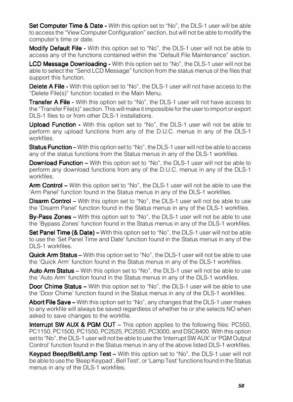
58
Set Computer Time & Date - Set Computer Time & Date - Set Computer Time & Date - Set Computer Time & Date - Set Computer Time & Date - With this option set to “No”, the DLS-1 user will be ableto access the “View Computer Configuration” section, but will not be able to modify thecomputer’s time or date.
Modify Default File - Modify Default File - Modify Default File - Modify Default File - Modify Default File - With this option set to “No”, the DLS-1 user will not be able toaccess any of the functions contained within the “Default File Maintenance” section.
LCD Message Downloading - LCD Message Downloading - LCD Message Downloading - LCD Message Downloading - LCD Message Downloading - With this option set to “No”, the DLS-1 user will not beable to select the “Send LCD Message” function from the status menus of the files thatsupport this function.
Delete A File - Delete A File - Delete A File - Delete A File - Delete A File - With this option set to “No”, the DLS-1 user will not have access to the“Delete File(s)” function located in the Main Menu.
Transfer A File - Transfer A File - Transfer A File - Transfer A File - Transfer A File - With this option set to “No”, the DLS-1 user will not have access tothe “Transfer File(s)” section. This will make it impossible for the user to import or exportDLS-1 files to or from other DLS-1 installations.
Upload Function - Upload Function - Upload Function - Upload Function - Upload Function - With this option set to “No”, the DLS-1 user will not be able toperform any upload functions from any of the D.U.C. menus in any of the DLS-1workfiles.
Status Function – Status Function – Status Function – Status Function – Status Function – With this option set to “No”, the DLS-1 user will not be able to accessany of the status functions from the Status menus in any of the DLS-1 workfiles.
Download Function – Download Function – Download Function – Download Function – Download Function – With this option set to “No”, the DLS-1 user will not be able toperform any download functions from any of the D.U.C. menus in any of the DLS-1workfiles.
Arm Control – Arm Control – Arm Control – Arm Control – Arm Control – With this option set to “No”, the DLS-1 user will not be able to use the‘Arm Panel’ function found in the Status menus in any of the DLS-1 workfiles.
Disarm Control – Disarm Control – Disarm Control – Disarm Control – Disarm Control – With this option set to “No”, the DLS-1 user will not be able to usethe ‘Disarm Panel’ function found in the Status menus in any of the DLS-1 workfiles.
By-Pass Zones –By-Pass Zones –By-Pass Zones –By-Pass Zones –By-Pass Zones – With this option set to “No”, the DLS-1 user will not be able to usethe ‘Bypass Zones’ function found in the Status menus in any of the DLS-1 workfiles.
Set Panel Time (& Date) –Set Panel Time (& Date) –Set Panel Time (& Date) –Set Panel Time (& Date) –Set Panel Time (& Date) – With this option set to “No”, the DLS-1 user will not be ableto use the ‘Set Panel Time and Date’ function found in the Status menus in any of theDLS-1 workfiles.
Quick Arm Status – Quick Arm Status – Quick Arm Status – Quick Arm Status – Quick Arm Status – With this option set to “No”, the DLS-1 user will not be able to usethe ‘Quick Arm’ function found in the Status menus in any of the DLS-1 workfiles.
Auto Arm Status – Auto Arm Status – Auto Arm Status – Auto Arm Status – Auto Arm Status – With this option set to “No”, the DLS-1 user will not be able to usethe ‘Auto Arm’ function found in the Status menus in any of the DLS-1 workfiles.
Door Chime Status – Door Chime Status – Door Chime Status – Door Chime Status – Door Chime Status – With this option set to “No”, the DLS-1 user will be able to usethe ‘Door Chime’ function found in the Status menus in any of the DLS-1 workfiles.
Abort File Save – Abort File Save – Abort File Save – Abort File Save – Abort File Save – With this option set to “No”, any changes that the DLS-1 user makesto any workfile will always be saved regardless of whether he or she selects NO whenasked to save changes to the workfile.
Interrupt SW AUX & PGM OUT – Interrupt SW AUX & PGM OUT – Interrupt SW AUX & PGM OUT – Interrupt SW AUX & PGM OUT – Interrupt SW AUX & PGM OUT – This option applies to the following files: PC550,PC1150, PC1500, PC1550, PC2525, PC2550, PC3000, and DSC8400. With this optionset to “No”, the DLS-1 user will not be able to use the ‘Interrupt SW AUX’ or ‘PGM OutputControl’ function found in the Status menus in any of the above listed DLS-1 workfiles.
Keypad Beep/Bell/Lamp Test – Keypad Beep/Bell/Lamp Test – Keypad Beep/Bell/Lamp Test – Keypad Beep/Bell/Lamp Test – Keypad Beep/Bell/Lamp Test – With this option set to “No”, the DLS-1 user will notbe able to use the ‘Beep Keypad’, Bell Test’, or ‘Lamp Test’ functions found in the Statusmenus in any of the DLS-1 workfiles.
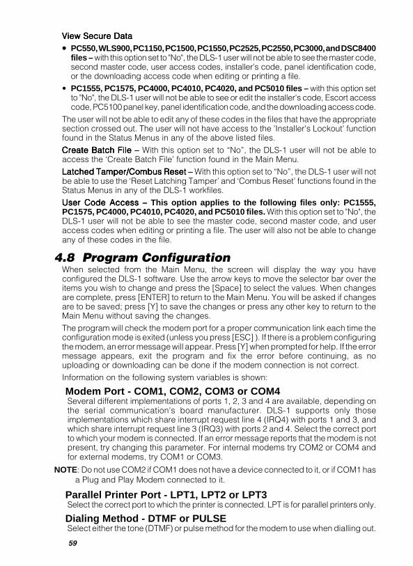
59
View Secure DataView Secure DataView Secure DataView Secure DataView Secure Data
••••• PC550, WLS900, PC1150, PC1500, PC1550, PC2525, PC2550, PC3000, and DSC8400files – with this option set to "No", the DLS-1 user will not be able to see the master code,second master code, user access codes, installer's code, panel identification code,or the downloading access code when editing or printing a file.
• PC1555, PC1575, PC4000, PC4010, PC4020, and PC5010 files – with this option setto "No", the DLS-1 user will not be able to see or edit the installer's code, Escort accesscode, PC5100 panel key, panel identification code, and the downloading access code.
The user will not be able to edit any of these codes in the files that have the appropriatesection crossed out. The user will not have access to the 'Installer's Lockout' functionfound in the Status Menus in any of the above listed files.
Create Batch File – Create Batch File – Create Batch File – Create Batch File – Create Batch File – With this option set to “No”, the DLS-1 user will not be able toaccess the ‘Create Batch File’ function found in the Main Menu.
Latched Tamper/Combus Reset – Latched Tamper/Combus Reset – Latched Tamper/Combus Reset – Latched Tamper/Combus Reset – Latched Tamper/Combus Reset – With this option set to “No”, the DLS-1 user will notbe able to use the ‘Reset Latching Tamper’ and ‘Combus Reset’ functions found in theStatus Menus in any of the DLS-1 workfiles.
User Code Access – User Code Access – User Code Access – User Code Access – User Code Access – This option applies to the following files only: PC1555,PC1575, PC4000, PC4010, PC4020, and PC5010 files. With this option set to "No", theDLS-1 user will not be able to see the master code, second master code, and useraccess codes when editing or printing a file. The user will also not be able to changeany of these codes in the file.
4.8 Program ConfigurationWhen selected from the Main Menu, the screen will display the way you haveconfigured the DLS-1 software. Use the arrow keys to move the selector bar over theitems you wish to change and press the [Space] to select the values. When changesare complete, press [ENTER] to return to the Main Menu. You will be asked if changesare to be saved; press [Y] to save the changes or press any other key to return to theMain Menu without saving the changes.The program will check the modem port for a proper communication link each time theconfiguration mode is exited (unless you press [ESC] ). If there is a problem configuringthe modem, an error message will appear. Press [Y] when prompted for help. If the errormessage appears, exit the program and fix the error before continuing, as nouploading or downloading can be done if the modem connection is not correct.Information on the following system variables is shown:
Modem Port - COM1, COM2, COM3 or COM4Several different implementations of ports 1, 2, 3 and 4 are available, depending onthe serial communication's board manufacturer. DLS-1 supports only thoseimplementations which share interrupt request line 4 (IRQ4) with ports 1 and 3, andwhich share interrupt request line 3 (IRQ3) with ports 2 and 4. Select the correct portto which your modem is connected. If an error message reports that the modem is notpresent, try changing this parameter. For internal modems try COM2 or COM4 andfor external modems, try COM1 or COM3.
NOTE: Do not use COM2 if COM1 does not have a device connected to it, or if COM1 hasa Plug and Play Modem connected to it.
Parallel Printer Port - LPT1, LPT2 or LPT3Select the correct port to which the printer is connected. LPT is for parallel printers only.
Dialing Method - DTMF or PULSESelect either the tone (DTMF) or pulse method for the modem to use when dialling out.

60
If in doubt, or if your telephone line is not capable of tone, select pulse (DTMF is widelyaccepted, however some areas still operate with pulse dialling).
Dialing Condition - Wait for Dial Tone or Blind DialIf you choose Wait for Dial Tone, then whenever the modem goes off-hook, before itdials, it will wait a predetermined amount of time for the dial tone to be present. If thedial tone is not present, you will be advised by a beep from the computer, and amessage on the screen. In cases where dial tone is not present, (such as cellularphone systems) it is necessary to dial without waiting for the dial tone. This is called“Blind Dialing”, because the modem will simply go off-hook without first checking forthe presence of a dial tone, and immediately dial the phone number.
NOTE: Blind Dialing should only be used in cases where dial tone is not required,because if the number is dialed before the dial tone is given on a normal phoneline system, the call may not be placed correctly, because some of the digitswill be missed by the switching network.
Modem Speaker Control - On Always, Off Always, orOn Until Connection
If your modem has a built-in speaker, you can instruct it to always be on, always beoff, or on only for the dialling part and until a connection has been established withthe panel.
Speaker Volume - Low, Medium, or HighIf your modem’s speaker is used, you can select the speaker’s volume using thisvariable.
Number of Rings for Auto Answer - 1 through 6Set the number of rings before your modem answers an incoming call from the panel.
Modem Initialization Speed - Fast or SlowMost modems will initialize at a higher speed than that of the communication with thepanel, therefore the fast setting saves a small amount of time. If however, youexperience problems with your modem try the SLOW setting.
Internal or ExternalIf your modem is a separate unit connected to the back of your computer with a cable,it is External. If your modem is inside the computer (if you connect the telephone lineto the back of the computer) then it is Internal.
Modem Name or TypePress the [space bar] to view the 5 available modem types. The DSC MD12 modemcannot be used with any other modems. If the modem is not a Practical PeripheralsPM1200, select the compatible 1200 baud modem if a 1200 baud modem is beingused. If a 2400 baud modem other than the Hayes Optima is being used, select thecompatible 2400 baud modem.
NOTE: The DSC MD12 should not be selected when using any other modem. If thishappens, communications may not be possible to the panel.
Baud Rate SelectionNOTE: Only DSC MD12 modems with software version 1.1 and later support BaudRate Selection. Modems with software versions 1.0 and earlier will always operate at300 Baud.
This option only applies when used with the DSC MD12 modem. The options for thissection are as follows:
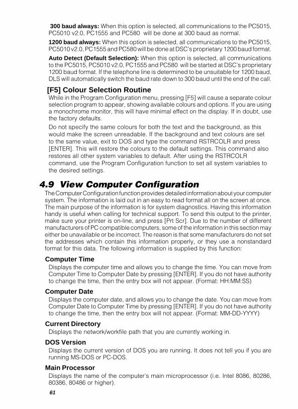
61
300 baud always: When this option is selected, all communications to the PC5015,PC5010 v2.0, PC1555 and PC580 will be done at 300 baud as normal.
1200 baud always: When this option is selected, all communications to the PC5015,PC5010 v2.0, PC1555 and PC580 will be done at DSC’s proprietary 1200 baud format.
Auto Detect (Default Selection): When this option is selected, all communicationsto the PC5015, PC5010 v2.0, PC1555 and PC580 will be started at DSC’s proprietary1200 baud format. If the telephone line is determined to be unsuitable for 1200 baud,DLS will automatically switch the baud rate down to 300 baud until the end of the call.
[F5] Colour Selection RoutineWhile in the Program Configuration menu, pressing [F5] will cause a separate colourselection program to appear, showing available colours and options. If you are usinga monochrome monitor, this will have minimal effect on the display. If in doubt, usethe factory defaults.Do not specify the same colours for both the text and the background, as thiswould make the screen unreadable. If the background and text colours are setto the same value, exit to DOS and type the command RSTRCOLR and press[ENTER]. This will restore the colours to the default settings. This command alsorestores all other system variables to default. After using the RSTRCOLRcommand, use the Program Configuration function to set all system variables tothe desired settings.
4.9 View Computer ConfigurationThe Computer Configuration function provides detailed information about your computersystem. The information is laid out in an easy to read format all on the screen at once.The main purpose of the information is for system diagnostics. Having this informationhandy is useful when calling for technical support. To send this output to the printer,make sure your printer is on-line, and press [Prt Scr]. Due to the number of differentmanufacturers of PC compatible computers, some of the information in this section mayeither be unavailable or be incorrect. The reason is that some manufacturers do not setthe addresses which contain this information properly, or they use a nonstandardformat for this data. The following information is supplied by this function:
Computer TimeDisplays the computer time and allows you to change the time. You can move fromComputer Time to Computer Date by pressing [ENTER]. If you do not have authorityto change the time, then the entry box will not appear. (Format: HH:MM:SS)
Computer DateDisplays the computer date, and allows you to change the date. You can move fromComputer Date to Computer Time by pressing [ENTER]. If you do not have authorityto change the time, then the entry box will not appear. (Format: MM-DD-YYYY)
Current DirectoryDisplays the network/workfile path that you are currently working in.
DOS VersionDisplays the current version of DOS you are running. It does not tell you if you arerunning MS-DOS or PC-DOS.
Main ProcessorDisplays the name of the computer’s main microprocessor (i.e. Intel 8086, 80286,80386, 80486 or higher).
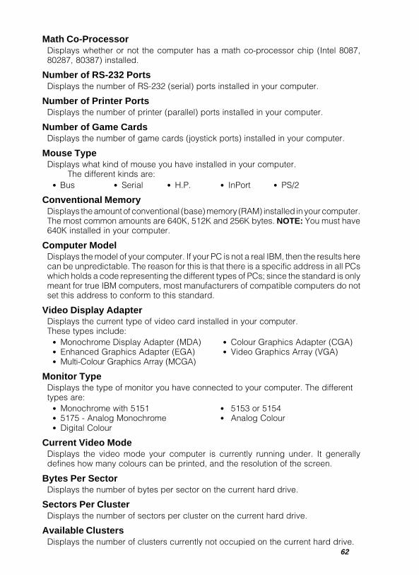
62
Math Co-ProcessorDisplays whether or not the computer has a math co-processor chip (Intel 8087,80287, 80387) installed.
Number of RS-232 PortsDisplays the number of RS-232 (serial) ports installed in your computer.
Number of Printer PortsDisplays the number of printer (parallel) ports installed in your computer.
Number of Game CardsDisplays the number of game cards (joystick ports) installed in your computer.
Mouse TypeDisplays what kind of mouse you have installed in your computer.
The different kinds are:• Bus • Serial • H.P. • InPort • PS/2
Conventional MemoryDisplays the amount of conventional (base) memory (RAM) installed in your computer.The most common amounts are 640K, 512K and 256K bytes. NOTE: You must have640K installed in your computer.
Computer ModelDisplays the model of your computer. If your PC is not a real IBM, then the results herecan be unpredictable. The reason for this is that there is a specific address in all PCswhich holds a code representing the different types of PCs; since the standard is onlymeant for true IBM computers, most manufacturers of compatible computers do notset this address to conform to this standard.
Video Display AdapterDisplays the current type of video card installed in your computer.These types include:
• Monochrome Display Adapter (MDA) • Colour Graphics Adapter (CGA)• Enhanced Graphics Adapter (EGA) • Video Graphics Array (VGA)• Multi-Colour Graphics Array (MCGA)
Monitor TypeDisplays the type of monitor you have connected to your computer. The differenttypes are:
• Monochrome with 5151 • 5153 or 5154• 5175 - Analog Monochrome • Analog Colour• Digital Colour
Current Video ModeDisplays the video mode your computer is currently running under. It generallydefines how many colours can be printed, and the resolution of the screen.
Bytes Per SectorDisplays the number of bytes per sector on the current hard drive.
Sectors Per ClusterDisplays the number of sectors per cluster on the current hard drive.
Available ClustersDisplays the number of clusters currently not occupied on the current hard drive.

63
Free Disk SpaceDisplays the total number of bytes free (not used for files) on the current hard drive.Note that: Bytes Per Sector x Sectors Per Cluster x Available Clusters = Free DiskSpace.
Total ClustersDisplays the total number of clusters the current hard drive has.
Total Disk SpaceDisplays the total number of bytes the current hard drive has; in other words, the “size”of the hard drive. Note that: Bytes Per Sector x Sectors Per Cluster x Total Clusters = TotalDisk Space.
Floppy Drive InformationDisplays the type of all the floppy disk drives installed in your computer.The possible types are:
• 5.25 inch 360K • 5.25 inch 1.2M• 3.5 inch 720K • 3.5 inch 1.44M
4.10 Operations LogSelecting this function will display the Operations Log Menu. The Operations Log filestores records of all activity performed on the system. Operator name, date, function,DOS file name and time are recorded. All the possible log entries recorded are as follows:
Log Entries:Access - when access records were examined.Arm - when a panel is remotely armed.Batch - when a Batch File is executed.Create - when a file was created.Delete - when Work Files are deleted.Disarm - when a panel is remotely disarmed.Download - when information was downloaded.Download LCD - when information was downloaded to an LCD keypad.Edit - when a file was edited.Failed Attempts - when an attempt to enter the program has failed, or any otherattempted function has failed.Install - when the software was initially installed.Log Off - when an operator has logged off.Log On - when an operator has logged on.Modify - when the default file has been modified.Operations Log - when Operations Log was examined.Panel in Alarm - when the panel was in alarm.Print - when a file was printed.Program/Computer - when program/computer configuration was changed.Reinstall - when the software was reinstalled.Rename a File - when a Work File was renamed.Stored Opslog to Diskette - when the entire Operations Log was stored to disk.Transfer - when Work Files are transferred.Upload - when information was uploaded.
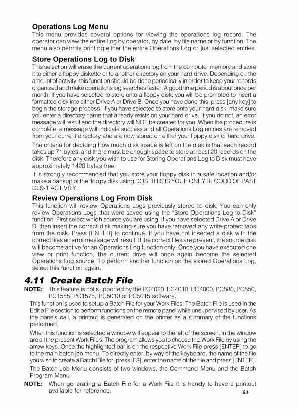
64
Operations Log MenuThis menu provides several options for viewing the operations log record. Theoperator can view the entire Log by operator, by date, by file name or by function. Themenu also permits printing either the entire Operations Log or just selected entries.
Store Operations Log to DiskThis selection will erase the current operations log from the computer memory and storeit to either a floppy diskette or to another directory on your hard drive. Depending on theamount of activity, this function should be done periodically in order to keep your recordsorganized and make operations log searches faster. A good time period is about once permonth. If you have selected to store onto a floppy disk, you will be prompted to insert aformatted disk into either Drive A or Drive B. Once you have done this, press [any key] tobegin the storage process. If you have selected to store onto your hard disk, make sureyou enter a directory name that already exists on your hard drive. If you do not, an errormessage will result and the directory will NOT be created for you. When the procedure iscomplete, a message will indicate success and all Operations Log entries are removedfrom your current directory and are now stored on either your floppy disk or hard drive.
The criteria for deciding how much disk space is left on the disk is that each recordtakes up 71 bytes, and there must be enough space to store at least 20 records on thedisk. Therefore any disk you wish to use for Storing Operations Log to Disk must haveapproximately 1420 bytes free.It is strongly recommended that you store your floppy disk in a safe location and/ormake a backup of the floppy disk using DOS. THIS IS YOUR ONLY RECORD OF PASTDLS-1 ACTIVITY.
Review Operations Log From DiskThis function will review Operations Logs previously stored to disk. You can onlyreview Operations Logs that were saved using the “Store Operations Log to Disk”function. First select which source you are using. If you have selected Drive A or DriveB, then insert the correct disk making sure you have removed any write-protect tabsfrom the disk. Press [ENTER] to continue. If you have not inserted a disk with thecorrect files an error message will result. If the correct files are present, the source diskwill become active for an Operations Log function only. Once you have executed oneview or print function, the current drive will once again become the selectedOperations Log source. To perform another function on the stored Operations Log,select this function again.
4.11 Create Batch FileNOTE: This feature is not supported by the PC4020, PC4010, PC4000, PC580, PC550,
PC1555, PC1575, PC5010 or PC5015 software.This function is used to setup a Batch File for your Work Files. The Batch File is used in theEdit a File section to perform functions on the remote panel while unsupervised by user. Asthe panels call, a printout is generated on the printer as a summary of the functionsperformed.When this function is selected a window will appear to the left of the screen. In the windoware all the present Work Files. The program allows you to choose the Work File by using thearrow keys. Once the highlighted bar is on the respective Work File press [ENTER] to goto the main batch job menu. To directly enter, by way of the keyboard, the name of the fileyou wish to create a Batch File for, press [F3], enter the name of the file and press [ENTER].The Batch Job Menu consists of two windows; the Command Menu and the BatchProgram Menu.
NOTE: When generating a Batch File for a Work File it is handy to have a printoutavailable for reference.
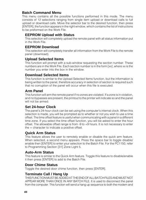
65
Batch Command MenuThis menu contains all the possible functions performed in this mode. The menuconsists of 12 selections ranging from single item upload or download calls to fullupload or download calls. Move the selector bar to the desired function, then press[ENTER], the function appears in the right window, which contains the list of instructionsto be preformed on the Work File.
EEPROM Upload with StatusThis selection will completely upload the remote panel with all status information putin the Work File.
EEPROM DownloadThis selection will completely transfer all information from the Work File to the remotepanel (download).
Upload Selected ItemsThis function will prompt with a sub-window requesting the section number. Thesenumbers are in the Work File. Each section number is in the form [xx] ,where xx is thenumber you enter into the box in the window.
Download Selected ItemsThis function is similar to the Upload Selected Items function, but the information isbeing written to the panel, therefore accuracy in selection of section is required suchthat no corruption of the panel will occur when this file is executed.
Arm PanelThis function will arm the remote panel if no zones are violated. If a zone is in violation,and no bypasses are present, the printout to the printer will indicate so and the panelwill not be armed.
Set 24-hour ClockThe panel’s 24-hour clock can be set using the computer’s internal clock. When thisselection is made, you will be prompted as to whether or not you wish to use a timeoffset. The time offset feature is useful when communicating with a panel in a differenttime zone. If you select the time offset function, you will be asked to enter the houroffset. The allowable offset range is from -9 to +9 hours. It is not necessary to enterthe + character to indicate a positive offset.
Quick Arm StatusThis feature allows the user to remotely enable or disable the quick arm feature.When selected, a second menu appears. Press the space bar to toggle disable/enable then [ENTER] to enter your selection to the Batch File. For the PC1150, referto Programming Section [31] Zone Light 5.
Auto-Arm StatusThis feature is similar to the Quick Arm feature. Toggle this feature to disable/enableit then press [ENTER] to add to the Batch File.
Door Chime StatusToggle the desired door chime function, then press [ENTER].
Terminate Call / Hang UpTHIS FUNCTION MUST BE ADDED AT THE END OF ALL BATCH FILES AND MUST NOTAPPEAR MORE THAN ONCE IN ANY BATCH FILE. It is used to disconnect the panelfrom the computer. This function will send a hang up sequence to both the modem and
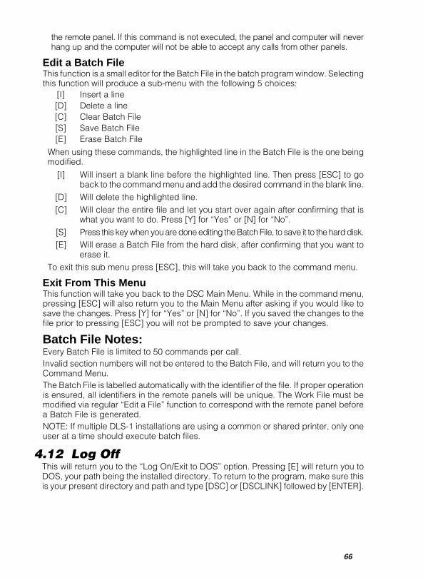
66
the remote panel. If this command is not executed, the panel and computer will neverhang up and the computer will not be able to accept any calls from other panels.
Edit a Batch FileThis function is a small editor for the Batch File in the batch program window. Selectingthis function will produce a sub-menu with the following 5 choices:
[I] Insert a line[D] Delete a line[C] Clear Batch File[S] Save Batch File[E] Erase Batch File
When using these commands, the highlighted line in the Batch File is the one beingmodified.
[I] Will insert a blank line before the highlighted line. Then press [ESC] to goback to the command menu and add the desired command in the blank line.
[D] Will delete the highlighted line.[C] Will clear the entire file and let you start over again after confirming that is
what you want to do. Press [Y] for “Yes” or [N] for “No”.[S] Press this key when you are done editing the Batch File, to save it to the hard disk.[E] Will erase a Batch File from the hard disk, after confirming that you want to
erase it.To exit this sub menu press [ESC], this will take you back to the command menu.
Exit From This MenuThis function will take you back to the DSC Main Menu. While in the command menu,pressing [ESC] will also return you to the Main Menu after asking if you would like tosave the changes. Press [Y] for “Yes” or [N] for “No”. If you saved the changes to thefile prior to pressing [ESC] you will not be prompted to save your changes.
Batch File Notes:Every Batch File is limited to 50 commands per call.Invalid section numbers will not be entered to the Batch File, and will return you to theCommand Menu.The Batch File is labelled automatically with the identifier of the file. If proper operationis ensured, all identifiers in the remote panels will be unique. The Work File must bemodified via regular “Edit a File” function to correspond with the remote panel beforea Batch File is generated.NOTE: If multiple DLS-1 installations are using a common or shared printer, only oneuser at a time should execute batch files.
4.12 Log OffThis will return you to the “Log On/Exit to DOS” option. Pressing [E] will return you toDOS, your path being the installed directory. To return to the program, make sure thisis your present directory and path and type [DSC] or [DSCLINK] followed by [ENTER].
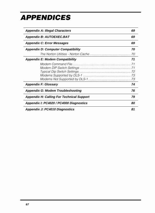
67
APPENDICES
Appendix A: Illegal Characters 69
Appendix B: AUTOEXEC.BAT 69
Appendix C: Error Messages 69
Appendix D: Computer Compatibility 70The Norton Utilities - Norton Cache ............................................... 70
Appendix E: Modem Compatibility 71Modem Command File ................................................................... 71Modem DIP Switch Settings ........................................................... 71Typical Dip Switch Settings ........................................................... 72Modems Supported by DLS-1 ....................................................... 73Modems Not Supported by DLS-1 ................................................. 73
Appendix F: Glossary 74
Appendix G: Modem Troubleshooting 76
Appendix H: Calling For Technical Support 79
Appendix I: PC4020 / PC4000 Diagnostics 80
Appendix J: PC4010 Diagnostics 81

68

69
Appendix A: Illegal CharactersSome characters are reserved by DOS and cannot be used when entering customerfile names. Please refer to your DOS manual for a list of valid characters.
Appendix B: AUTOEXEC.BATLoading SHARE.EXE in MS-DOSNOTE: This step is not relevant if you are running DLS-1 in an MS-DOS shell underWindows95.If you are running DLS-1 from MS-DOS, SHARE.EXE must be loaded before runningthe DLS-1 package. During the installation process, DLS-1 will search theAUTOEXEC.BAT file on your computer to see if the program SHARE.EXE is installed.If your AUTOEXEC.BAT file does not include directions to load the SHARE.EXEprogram, DLS-1 will show the following message:
SHARE.EXE is not installed in the C:\AUTOEXEC.BAT file.If not running Windows 95, then it must be installed.Press any key to continue.
If this message appears, you must add the following lines to your AUTOEXEC.BAT file(Refer to your operating system manual for instructions on editing your AUTOEXEC.BATfile.):
C:\DOS\SHARE.EXENOTE: If MS-DOS is installed in a drive and/or directory other than C:\DOS, youmust correct the above line to include the drive/directory where MS-DOS isinstalled.
How to Have Your Computer Load DLS-1 at StartupWhen the computer is first turned on, the AUTOEXEC.BAT file will be run. This file willallow you to specify operating parameters for your computer. The following linescould be added to the end of your AUTOEXEC.BAT file for automatic execution of theDLS-1 software:
C:CD\DIRNAMEDSC
In the above example it is assumed that the DLS-1 software was installed on the C:Drive. If this is not so on your system, change the C: to the letter of the drive your DLS-1software was installed on (i.e. D: through Z:).
NOTE: These lines must be added to the AUTOEXEC.BAT file after the linesrefering to the SHARE.EXE program (see above subsection).
Appendix C: Error MessagesNormally, during the course of operations, error messages may be displayed on thescreen. The error message is usually self explanatory and is caused by such thingsas a printer running out of paper or a modem not being connected, etc. The errormessage will usually suggest or infer what action is required to correct the situation.After any type of Run Time Error, DLS-1 should be restarted. If an error message isgenerated and you are unable to correct the error it could be due to a hardwarecompatibility problem or not enough conventional memory error. Refer to AppendixD and Appendix E for Computer Compatibility and Modem information and Section1.1.4. for Memory Requirements.
70
Appendix D: Computer CompatibilityThe DLS-1 software was designed to run on an IBM PC XT, AT, 386, 486 or higher ortrue compatible. Not all computers that claim compatibility with IBM are actually100% compatible. If you suspect that your computer is not 100% compatible we suggestyou contact the supplier of your computer.
Due to the variety of Compatible computers available we cannot tell you specificallywhat can (if anything) be done to correct a compatibility problem. The following aretypical items that could improve or help.
1 Make sure you are using a current version of MS-DOS. DOS ver 5.0 or greater isrecommended. The DLS-1 Software is not compatible with Microsoft Windows.
2 Make sure your computer is configured properly. The XT uses dip switches on themotherboard and the AT uses a setup/diagnostic program. Consult your computer'soperations manual for specific information on setting up your computer.
3 Some memory resident programs may conflict with the DLS-1 software. If you areexperiencing problems, try running your computer without them active. Refer to theowner’s manual of the memory resident program to determine how to disable it.
4 The hardware installed in the expansion slots of your computer could be causinga conflict with the serial channel or modem that the DLS-1 software is trying to use.If you are using an internal modem, set it for COM2 and make sure no otherhardware is selected on COM2. If you are using an external modem, make surethe serial port it is connected to is working properly. NOTE: If the modem isconnected to COM 1, there should not be a serial device connected to COM 3 (andvice versa). The same is true for COM 2 and COM4: if the modem is connected toCOM 2, there should not be a serial device connected to COM 4, and vice versa.
The Norton Utilities - Norton CacheTo improve file access speed, it is suggested that you use a cache program, such asNorton Cache. Cache programs set aside a portion of memory in your computer for thetemporary storage of files. By accessing these files in memory rather than having toretrieve them from a disk drive, the computer’s speed and performance is improved.Minimum system requirements for Norton Cache are: DOS 3.0 or higher and 256 K ofconventional memory. Contact your computer or software dealer for more information.
71
Appendix E: Modem CompatibilityModem Command File
If you still encounter communication problems with your modem, you may want to makeuse of the MODEMSTR.FIL file. It is not recommended that you use this utility unless youfeel you have a good knowledge of modem commands. This file is present on thedirectory you have installed the DLS-1 software into.
To change the information in this file, it is necessary to use a text editor such as EDLINor EDIT which are supplied with DOS, or any other text editor other than a wordprocessor such as Wordperfect® or WordStar®.
The first line of the file is the dial modifier section. If you have a need to use dial modifierson a regular basis, then by entering a dial modifier onto this line, it will be dialled beforethe phone number of the panel programmed in the Work File is dialled. For a fullexplanation of dial modifiers, consult your modem manual.
If you wish to add a command sent to the modem during initialization, you may do soby adding lines to the file after the line that says “MODEM COMMAND SECTION” andbefore the line that says “END OF FILE”. Any command that you enter should includethe “AT” part of the command. As an example you may wish to change S9 (CarrierDetect Response Time) value from the default of 0.4 seconds to 1 second. To do this,the entry in the file would be: AT S9=10.
The command to set S9 to 0.4 second is still executed, however the execution of thecommand in the file overrides the previous setting because any command entered inthe file is always executed after the default command.
Modem DIP Switch SettingsThe modem configuration should be as follows:
• DTR STATUS - Follow.• DTR - “Hangs up” and goes to command state if the signal drops.• RESULT CODE FORMAT - Words.• RESULT CODE DISPLAY - Enabled.• CHARACTER ECHO - Characters echoed in command state.• AUTO-ANSWER - Disabled.• CARRIER DETECT - Always on.• TELCO JACK TYPE - RJ-11, RJ-41S, RJ-45S.• COMMAND RECOGNITION - Enabled.• COMMUNICATION STANDARD - 1200 BPS, Bell 212A.• RESPONSE TO DTR TRANSITION - Hangs up and goes to command state.• M/S RATIO - USA.• INTELLIGENT MODE - Enabled.• DCD - Support use, always true.
NOTE: Some of these settings may not be configurable on your modem. If that is thecase, ignore them as they do not apply.
NOTE: If you do not have one of the modems listed on the next page, you can attemptto configure your modem based on the setting as listed above. Some settingsare given different names on different modems. Refer to your modem manual,your modem dealer or the modem manufacturer for more information.
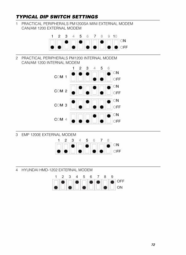
72
3 EMP 1200E EXTERNAL MODEM
1 PRACTICAL PERIPHERALS PM1200SA MINI EXTERNAL MODEMCAN/AM 1200 EXTERNAL MODEM
2 PRACTICAL PERIPHERALS PM1200 INTERNAL MODEMCAN/AM 1200 INTERNAL MODEM
TYPICAL DIP SWITCH SETTINGS
4 HYUNDAI HMD-1202 EXTERNAL MODEM
73
Modems Supported by DLS-1The following is a list of modems that are supported by the DLS-1 software. Eachmodem has been compatibility-tested by DSC.
• Practical Peripherals PM1200SA Mini 1200 baud external
• EMP 1200E 1200 baud external
• Hayes Smartmodem Optima 2400 (+FAX 96) 2400 baud external
• Hyundai HMD-1200 1200 baud external
• SupraModem 2400 Model 50-2400-0 2400 baud external
• DSC MD12 Modem 1200 baud external
• Stradcom Pocket Modem 1200 baud external
• Cardinal MD2400EX 2400 baud external
Modems Not Supported by DLS-1The following is a list of modems NOT supported by the DLS-1 software. Eachmodem has been tested by DSC. This is not a complete list. What is not impliedhere is that any modem not listed here will work. Due to the large number ofmodems on the market, it is very difficult to account for the compatibility of everymodem. The only modems officially supported or not supported are modems wehave tested at DSC. This list is meant as a partial guideline only.
As new releases of this manual are issued with the DLS-1 software, this list may beupdated to include more modem names.
The following modems are not supported by the DSC DLS-1 software:• All non-Hayes compatible modems• All modems that do not support the Bell 103, 110- baud standard• All Hayes Smartmodem 1200 modems• All Capetronic modems• All INMAC modems• All EVEREX modems• ATI 1200 baud internal modem• Cardinal MB2450 2400 baud internal• Hayes Smartmodem 2400 3124US 2400 baud external
• Hayes Smartmodem 2400B Model 230AA 2400 baud internal• Practical Peripherals 2400 baud external modem• SmarTEAM Micro 1200 external modem• GVC 1200 baud external modem• US Robotics Sportster 1200 external modem• US Robotics Sportster 2400 external modem• Incomm Data Systems Midget PC 12 internal modem• ACEEX DM-2400 2400 bps external modem• GVC SM24 2400 bps external modem• Motorola FastTalk 1200E external modem

74
Appendix F: GlossaryAccess Code
A personal access code entered upon execution of the DLS-1 software. There are upto sixteen access codes supported.
AUTOEXEC.BATSee Appendix B.
Baud RateUsed to measure the speed of a modem.
Call BackRefers to the ability of the panel to call back the operator before uploading ordownloading may take place. This is a security feature which ensures that only theauthorized downloading computer may access the panel.
Call Back NumberThe telephone number the panel will call if the Call Back feature is enabled.
COM PortShort for communications port, which is used by the computer to communicate with anexternal device, such as a modem or serial printer. Com ports are considered serial devices.
Customer Work FileThe file pertaining to a particular panel, sometimes referred to as a Customer Account.
DIP SwitchAn acronym meaning Dual In-line Package. It is a series of switches used to configurea modem.
DOS File nameThe 8 character name and optional 3 character extension given to a file to distinguishit from other files.
DTMFInitials for Dual Tone Multi-Frequency, commonly known as “Touch Tone”. DTMF isa method of telephone dialling.
EEPROMAn acronym meaning Electronically Erasable Programmable Read Only Memory.
Enter / ReturnThese two words are used to describe a key on the computer keyboard. On most IBMPC compatible keyboards, Enter is usually used, but they are interchangeable.
FloppyThis term is another name for a computer diskette. Sometimes called “floppy”diskettes, the term refers to the fact that the diskette can bend. Both 3.5" and 5.25"diskettes are considered a floppy for the purpose of this manual.
Forced AnswerThis function forces the panel to seize the phone line for the purpose of downloadingwith an on-site computer (PC3000 and PC4020 / PC4000 only). In the PC3000,Section 28 (Auxiliary Input), number 4 refers to the Forced Answer option. For thePC4020 / PC4000, one of the zone type selections is “Forced Answer“.
Hard DriveThis name describes a certain type of storage media used by a computer. It is sometimescalled a “fixed disk”, because it is not removable from the computer like a diskette is.
Job DirectoryThis is a sub-directory of the DLS-1 installed directory containing all Batch File information.
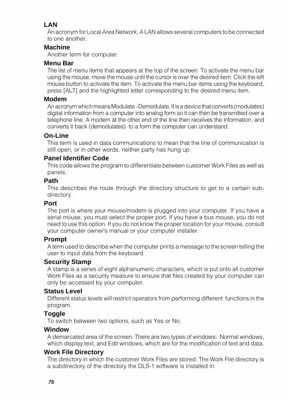
75
LANAn acronym for Local Area Network. A LAN allows several computers to be connectedto one another.
MachineAnother term for computer.
Menu BarThe list of menu items that appears at the top of the screen. To activate the menu barusing the mouse, move the mouse until the cursor is over the desired item. Click the leftmouse button to activate the item. To activate the menu bar items using the keyboard,press [ALT] and the highlighted letter corresponding to the desired menu item.
ModemAn acronym which means Modulate - Demodulate. It is a device that converts (modulates)digital information from a computer into analog form so it can then be transmitted over atelephone line. A modem at the other end of the line then receives the information, andconverts it back (demodulates) to a form the computer can understand.
On-LineThis term is used in data communications to mean that the line of communication isstill open, or in other words, neither party has hung up.
Panel Identifier CodeThis code allows the program to differentiate between customer Work Files as well aspanels.
PathThis describes the route through the directory structure to get to a certain sub-directory.
PortThe port is where your mouse/modem is plugged into your computer. If you have aserial mouse, you must select the proper port. If you have a bus mouse, you do notneed to use this option. If you do not know the proper location for your mouse, consultyour computer owner’s manual or your computer installer.
PromptA term used to describe when the computer prints a message to the screen telling theuser to input data from the keyboard.
Security StampA stamp is a series of eight alphanumeric characters, which is put onto all customerWork Files as a security measure to ensure that files created by your computer canonly be accessed by your computer.
Status LevelDifferent status levels will restrict operators from performing different functions in theprogram.
ToggleTo switch between two options, such as Yes or No.
WindowA demarcated area of the screen. There are two types of windows: Normal windows,which display text, and Edit windows, which are for the modification of text and data.
Work File DirectoryThe directory in which the customer Work Files are stored. The Work File directory isa subdirectory of the directory the DLS-1 software is installed in.

76
Appendix G: Modem TroubleshootingThis section lists many of the common problems people have when trying to get theirmodems to work, and provides detailed information on how to solve them. Generally,most modem problems are easy to fix, although they may not be immediatelyrecognizable.
1 Check Modem DIP Switch Settings (1200 baud modems only). This is the mostcommon source of communication errors. When you first get your modem, thefactory DIP switch settings may be different than those required by the DLS-1software. The most common one set wrong is the DTR (Data Terminal Ready)Status switch (on most modems this is SW 1, but check your modem manual). Thisswitch must be set to “Follow DTR” or in other words, support the use of the DTRsignal. Please refer to Appendix D for a list of the DIP switch settings for all DSCsupported modems. If you do not have one of the DSC approved modems, youmay attempt to set your modem according to the specifications listed in AppendixD.
2 Check Modem Specifications. Although most Hayes compatible modems claimto be 100% compatible, many are not. The common specification left out of manyHayes compatible modems is that they do not support the Bell 103 Simplex Mode110 Baud Standard; in other words, they will not communicate at 110 baud. Thereason for this is that 110 baud is not a common transmission speed, whereas1200 and 2400 baud are quite common. As a reference, check the modem manualor even the modem box packaging. If you still are not sure, contact themanufacturer of your modem.
3 Cancel Call Waiting. When Call Waiting is enabled, and another call comes inwhen you are already connected, the connection is briefly cutoff, and then a highbeep tone is generated. The problem with this is that the modem will interpret thisas a loss of carrier and immediately hang-up. This will happen if the second callcomes in on either the panel end, or the computer end of the connection. Mostareas that provide call waiting service, have a means to disable it by pressing asequence of keys on your phone. To cancel Call Waiting, dial 70# or ∗70 on atouch-tone phone. Incoming callers will then hear a busy signal, and yourcommunication will not be interrupted.
4 Check Cable Connections. This is one of the most common problems that peoplehave when trying to get the modem to work. If the modem is an external one, thenmake sure you have plugged the modem cable into the correct serial port (if youhave more than one). Also make sure the phone line is plugged into the proper walljack and the correct modem jack. Some modems provide an extra jack in whichto plug in a voice telephone; this jack is usually marked “To Phone”, but issometimes unmarked. If you plug the line and/or phone into the wrong modemjack in some modems this will prevent proper operation of the modem.
5 Check For Dial Tone. If you are having problems dialling out or receiving calls,then it is possible that the phone is not properly connected to the wall jack you areusing. The easiest way to test for this is to plug a regular telephone directly intothe jack, lift the receiver and listen for the dial tone. If you do not hear a dial tone,then you know the phone line is broken at some point. Call your telephonecompany to repair such a problem.
6 Check Computer Hardware . If you have an EXTERNAL modem, check to makesure you have an external serial port that you can plug the modem cable into. Manycomputers have two serial ports; one for a mouse and one for a modem or serialprinter. Serial ports are identified by their shape and connection pins. They are
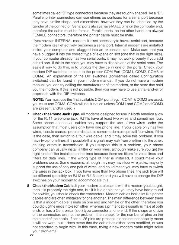
77
sometimes called “D” type connectors because they are roughly shaped like a “D”.Parallel printer connectors can sometimes be confused for a serial port becausethey have similar shape and dimensions, however they can be identified by thegender of the connector. Serial ports always have MALE pins on the computer end,therefore the cable must be female. Parallel ports, on the other hand, are alwaysFEMALE connectors, therefore the printer cable must be male.
If you have an INTERNAL modem, it is not necessary to have a serial port, becausethe modem itself effectively becomes a serial port. Internal modems are installedinside your computer and plugged into an expansion slot. Make sure that youhave plugged it into the correct type of expansion slot (one that is the right size).If your computer already has two serial ports, it may not work properly if you adda third port. If this is the case, you may have to disable one of the serial ports. Theeasiest way to do this, is to unplug the device in one of the ports. Check yourmodem DIP switches to set it to the proper COM Port (COM1, COM2, COM3 orCOM4). An explanation of the DIP switches (sometimes called Configurationswitches) can be found in your modem manual. If you do not have a modemmanual, you can try calling the manufacturer of the modem, or the store that soldyou the modem. If this is not possible, then you may have to use a trial-and-errorapproach with the DIP switches.
NOTE: You must use the first available COM port. (eg. if COM1 & COM2 are used,you must use COM3. COM4 will not function unless COM1 and COM2 and COM3are present and/or used.)
7 Check the Phone Jack Type. All modems designed for use in North America allowfor the RJ11 telephone jack. RJ11s have at least two wires and sometimes four.Some phone connection cables only support the use of two wires under theassumption that most users only have one phone line. If your cable only has twowires, it could cause a problem because some modems require all four wires. If thisis the case, then switch to a four wire cable, and it may solve this problem. If youhave two phone lines, it is possible that signals may leak from one line into the other,causing errors in transmission. If you suspect this is a problem, your phonecompany can usually install a filter on your lines, although make sure you get theright kind of filter installed on the lines because there are filters for voice lines andfilters for data lines. If the wrong type of filter is installed, it could make yourproblems worse. Some modems, although they may have four wire jacks, may onlysupport the use of only one pair of wires, and could mean you may have to switchthe wires in the jack box. If you have more than two phone lines, the jack type willbe different (possibly an RJ12 or RJ13 jack) and you will have to change the DIPswitches on your modem to accommodate this.
8 Check the Modem Cable. If your modem cable came with the modem you bought,then it is probably the right one, but if it is a cable that you may have had aroundfor a while, you should check the connectors. Modem cables look a lot like printercables and are often mistaken for one another. The main difference between themis that a modem cable is male on one end and female on the other, therefore youcould plug the ends into each other, whereas a printer cable usually is male at bothends or has a Centronics (slot) type connector at one end. If the shape and sizeof the connectors are not the problem, then check for the number of pins on themale end of the cable. If not all 25 pins are present, it does not necessarily meanit will not work, but it does mean that the cable has either been modified, or wasnot standard to begin with. In this case, trying a new modem cable might solveyour problems.
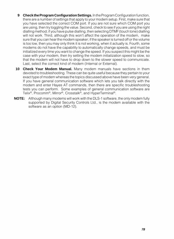
78
9 Check the Program Configuration Settings. In the Program Configuration function,there are a number of settings that apply to your modem setup. First, make sure thatyou have selected the correct COM port. If you are not sure which COM port youare using, then try toggling the value. Second, check to see if you are using the rightdialling method; if you have pulse dialling, then selecting DTMF (touch tone) diallingwill not work. Third, although this won’t affect the operation of the modem, makesure that you can hear the modem speaker; if the speaker is turned off or the volumeis too low, then you may only think it is not working, when it actually is. Fourth, somemodems do not have the capability to automatically change speeds, and must beinitialized every time you want to change the speed. If you suspect this might be thecase with your modem, then try setting the modem initialization speed to slow, sothat the modem will not have to drop down to the slower speed to communicate.Last, select the correct kind of modem (Internal or External).
10 Check Your Modem Manual. Many modem manuals have sections in themdevoted to troubleshooting. These can be quite useful because they pertain to yourexact type of modem whereas the topics discussed above have been very general.If you have general communication software which lets you talk directly with themodem and enter Hayes AT commands, then there are specific troubleshootingtests you can perform. Some examples of general communication software areTelix®, Procomm®, Mirror®, Crosstalk®, and HyperTerminal®.
NOTE: Although many modems will work with the DLS-1 software, the only modem fullysupported by Digital Security Controls Ltd., is the modem available with thesoftware as an option (MD-12).

79
Appendix H: Calling For Technical SupportWhat Information to Have Ready
In order to make problem solving easier and faster, before calling for technical support,please have the following information ready:
1 DLS-1 Downloading Software version number and release date.
2 Modem type and manufacturer.
3 Computer type and manufacturer.
4 Your modem manual and DLS-1 manual.
5 The DIP switch settings for your modem (if using a 1200 baud modem).
6 List of all memory-resident programs and TSRs running in the background.
7 A copy of your CONFIG.SYS file. To print this file, type PRNTAUTO [ENTER]from the DOS prompt; to display this file on the screen, type SHOWAUTO[ENTER] from the DOS prompt.
8 A copy of your AUTOEXEC.BAT file. To print this file, type PRNTAUTO [ENTER]from the DOS prompt; to display this file on the screen, type SHOWAUTO[ENTER] from the DOS prompt.
9 All information from the Computer Configuration function screen.
10 All information from the Program Configuration screen.
11 Does this problem happen all of the time, or only occasionally?
12 Are there any discernable patterns surrounding your problem?
13 If your error was in communication, list the panel type and software version(e.g.: PC3000 version 7.5).
14 A complete description of any error messages that were displayed on thescreen. If the error message says “A Run-Time Error Has Occurred”, write downthe error type, address and error location.
15 All steps taken in the program up to the point where your problem occurs.
16 Any other information surrounding the problem that you feel may be useful inaiding the technical support representative in solving your problem.
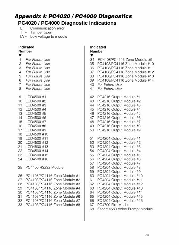
80
Appendix I: PC4020 / PC4000 DiagnosticsPC4020 / PC4000 Diagnostic Indications
E = Communication errorT = Tamper openLV= Low voltage to module
IndicatedNumber▼1 For Future Use2 For Future Use3 For Future Use4 For Future Use5 For Future Use6 For Future Use7 For Future Use8 For Future Use
9 LCD4500 #110 LCD4500 #211 LCD4500 #312 LCD4500 #413 LCD4500 #514 LCD4500 #615 LCD4500 #716 LCD4500 #817 LCD4500 #918 LCD4500 #1019 LCD4500 #1120 LCD4500 #1221 LCD4500 #1322 LCD4500 #1423 LCD4500 #1524 LCD4500 #16
25 PC4400 RS232 Module
26 PC4108/PC4116 Zone Module #127 PC4108/PC4116 Zone Module #228 PC4108/PC4116 Zone Module #329 PC4108/PC4116 Zone Module #430 PC4108/PC4116 Zone Module #531 PC4108/PC4116 Zone Module #632 PC4108/PC4116 Zone Module #733 PC4108/PC4116 Zone Module #8
IndicatedNumber▼34 PC4108/PC4116 Zone Module #935 PC4108/PC4116 Zone Module #1036 PC4108/PC4116 Zone Module #1137 PC4108/PC4116 Zone Module #1238 PC4108/PC4116 Zone Module #1339 PC4108/PC4116 Zone Module #1440 For Future Use41 For Future Use
42 PC4216 Output Module #143 PC4216 Output Module #244 PC4216 Output Module #345 PC4216 Output Module #446 PC4216 Output Module #547 PC4216 Output Module #648 PC4216 Output Module #749 PC4216 Output Module #850 PC4216 Output Module #9
51 PC4204 Output Module #152 PC4204 Output Module #253 PC4204 Output Module #354 PC4204 Output Module #455 PC4204 Output Module #556 PC4204 Output Module #657 PC4204 Output Module #758 PC4204 Output Module #859 PC4204 Output Module #960 PC4204 Output Module #1061 PC4204 Output Module #1162 PC4204 Output Module #1263 PC4204 Output Module #1364 PC4204 Output Module #1465 PC4204 Output Module #1566 PC4204 Output Module #1667 PC4700 Fire Module68 Escort 4580 Voice Prompt Module

81
Appendix J: PC4010 DiagnosticsPC4010 Diagnostic Indications
E = Communication errorT = Tamper openLV= Low voltage to module
IndicatedNumber▼1 For Future Use2 For Future Use3 For Future Use4 For Future Use5 For Future Use6 For Future Use7 For Future Use8 For Future Use
9 LCD4500 #110 LCD4500 #211 LCD4500 #312 LCD4500 #413 LCD4500 #514 LCD4500 #615 LCD4500 #716 LCD4500 #817 For Future Use18 For Future Use19 For Future Use20 For Future Use21 For Future Use22 For Future Use23 For Future Use24 For Future Use
25 PC4400 RS232 Module
26 PC4108/PC4116 Zone Module #127 PC4108/PC4116 Zone Module #228 PC4108/PC4116 Zone Module #329 PC4108/PC4116 Zone Module #430 PC4108/PC4116 Zone Module #531 PC4108/PC4116 Zone Module #632 PC4108/PC4116 Zone Module #733 PC4108/PC4116 Zone Module #8
IndicatedNumber▼34 For Future Use35 For Future Use36 For Future Use37 For Future Use38 For Future Use39 For Future Use40 For Future Use41 For Future Use
42 PC4216 Output Module #143 PC4216 Output Module #244 PC4216 Output Module #345 PC4216 Output Module #446 PC4216 Output Module #547 PC4216 Output Module #648 PC4216 Output Module #749 PC4216 Output Module #850 PC4216 Output Module #9
51 PC4204 Output Module #152 PC4204 Output Module #253 PC4204 Output Module #354 PC4204 Output Module #455 PC4204 Output Module #556 PC4204 Output Module #657 PC4204 Output Module #758 PC4204 Output Module #859 PC4204 Output Module #960 PC4204 Output Module #1061 PC4204 Output Module #1162 PC4204 Output Module #1263 For Future Use64 For Future Use65 For Future Use66 For Future Use67 PC4700 Fire Module68 Escort 4580 Voice Prompt Module

82


©1998 Digital Security Controls Ltd.1645 Flint Road, Downsview, Ontario, Canada M3J 2J6
(416) 665-8460 • 1-800-387-3630Printed in Canada 29003369 R0
Related Documents