DLC Single Axis Control Card for Firmware Versions DA and DG User Manual DOK-CONTRL-DLC*A+DLC*G-AW03-AE-P mannesmann Rexroth engineering Indramat Rexroth

Welcome message from author
This document is posted to help you gain knowledge. Please leave a comment to let me know what you think about it! Share it to your friends and learn new things together.
Transcript
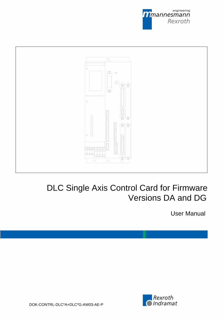
DLC Single Axis Control Card for FirmwareVersions DA and DG
User Manual
DOK-CONTRL-DLC*A+DLC*G-AW03-AE-P
mannesmannRexroth
engineering
IndramatRexroth
About this Documentation DLC-A and DLC-G
DOK-CONTRL-DLC*A+DLC*G-AW03-AE-P • 12/99
DLC Single Axis Control Card for Firmware Versions DA and DG
User Manual
DOK-CONTRL-DLC*A+DLC*G-AW03-AE-P • 12/99
• DLC-A/DLC-G User Manual
• 120-0400-B324-03/AE
• Part No. 286834
This documentation is written for both operating personnel and themachine builder. It explains how to interface, install, set up and operatethe Indramat DLC Positioning Control with DA or DG software.
Description ReleaseDate
Notes
Initial Release 6/94 Rev. A
Updated/added ParametersUpdated CommandsUpdated/added Status CodesUpdated/rearranged Error CodesAdded Alphabetical and NumericalTables of Error Codes. DeletedAppendix C, DLC ProgramCommands/Format. Deleted AppendixD, Parameter Input Sheets
7/95 Rev. B
Combine DLC-A (Pub. # 68000) andDLC-G (Pub. # 68006) ManualsParameter additions and changes
12/99 Rev. C
1999 Mannesmann Rexroth Indramat
Copying this document, giving it to others and the use or communication ofthe contents thereof without express authority, are forbidden. Offenders areliable for the payment of damages. All rights are reserved in the event of thegrant of a patent or the registration of a utility model or design (DIN 34-1).
All rights are reserved with respect to the content of this documentationand the availability of the product.
Mannesmann Rexroth Indramat GmbH
INDRAMAT Hoffman Estates • 5150 Prairie Stone Parkway • HoffmanEstates, IL 60192 • USA
Phone: 847-645-3600 • Fax: 847-645-6201
http://www.rexroth.com/indramat
Dept. ESV (HK).
Title
Type of Documentation
Document Typecode
Internal File Reference
Purpose of Documentation
Record of Revisions
Copyright
Validity
Published by
DLC-A and DLC-G Table of Contents I
DOK-CONTRL-DLC*A+DLC*G-AW03-AE-P • 12/99
Table of Contents
1 General Description ............................................................................................ 1-1
1.1 DLC Configuration.............................................................................................................................. 1-4
1.2 About This Manual ............................................................................................................................. 1-5
Hardware and Software Support........................................................................................................ 1-5
How To Use This Manual ................................................................................................................... 1-5
1.3 System Features ................................................................................................................................ 1-7
Superior Performance ........................................................................................................................ 1-7
Easy to Operate ................................................................................................................................. 1-7
Parameter-Adaptable to Multiple Machines ....................................................................................... 1-7
Fully Self-Diagnostic........................................................................................................................... 1-7
Programming Structure ...................................................................................................................... 1-7
Programmable Acceleration Rate ...................................................................................................... 1-8
Programmable I/O .............................................................................................................................. 1-8
Control/Machine System I/O Interconnection..................................................................................... 1-8
Homing ............................................................................................................................................... 1-8
Registration ........................................................................................................................................ 1-8
RS-232/485 Serial Interface............................................................................................................... 1-8
CTA Remote Keypad/Display............................................................................................................. 1-8
Optional IDS Module .......................................................................................................................... 1-9
Optional Station Operator Terminal (SOT) and Screen Manager...................................................... 1-9
MotionManagerTM (Option) ............................................................................................................. 1-10
Optional CTA 10 User Interface ....................................................................................................... 1-10
1.4 Standard Configuration Of DKS With DLC Control Card/DEA 4 Input/Output Card........................ 1-11
Standard Configuration Of DKS With DLC Control Card/DEA 4 Input/Output Card And OptionalDEF 1 Incremental Encoder Interface Card........................................................................................ 1-13
1.5 Specifications ................................................................................................................................... 1-14
Physical Specifications--Operating Environment ............................................................................. 1-14
Control Specifications....................................................................................................................... 1-14
I/O Interface...................................................................................................................................... 1-14
Options ............................................................................................................................................. 1-15
2 Controls and Indicators ...................................................................................... 2-1
2.1 CTA Keypad and Display ................................................................................................................... 2-1
2.2 Data Entry Keys ................................................................................................................................. 2-2
2.3 CTA Display Screens ......................................................................................................................... 2-4
Scrolling Through Display Screens .................................................................................................... 2-4
Parameter Mode Display Screens ..................................................................................................... 2-8
Drive Diagnostic/DLC Status/DLC Hardware/Software Version Display Screens............................. 2-8
Tool Correction Data Screen (DLC-G only) ...................................................................................... 2-9
System/Auxiliary I/O Status Screens .............................................................................................. 2-10
II Table of Contents DLC-A and DLC-G
DOK-CONTRL-DLC*A+DLC*G-AW03-AE-P • 12/99
Counter Screen ................................................................................................................................ 2-13
Axis Information Screen ................................................................................................................... 2-14
Mode/Tasks Screens........................................................................................................................ 2-15
Edit Screen....................................................................................................................................... 2-16
3 Functional Description of DEA 4 I/O Connections ........................................... 3-1
3.1 Signal Definitions................................................................................................................................ 3-1
3.2 Interface Descriptions......................................................................................................................... 3-1
Operating Mode Selection.................................................................................................................. 3-5
Safety Interlocks................................................................................................................................. 3-6
Normal Operation Signals .................................................................................................................. 3-7
Axis Homing ....................................................................................................................................... 3-8
Manual Mode Operations................................................................................................................. 3-11
Fault/Diagnostic Monitoring.............................................................................................................. 3-12
Feed Monitoring / Program Interruption ........................................................................................... 3-13
Special Functions ............................................................................................................................. 3-14
3.3 DEA 4 Input Signal Descriptions ...................................................................................................... 3-15
Parameter Mode Select.................................................................................................................... 3-15
Automatic Mode Select .................................................................................................................... 3-15
Emergency Stop ....................................................................................................................... 3-16
Cycle Start ........................................................................................................................................ 3-16
Cycle Stop .................................................................................................................................. 3-17
Jog Forward ..................................................................................................................................... 3-17
Jog Reverse ..................................................................................................................................... 3-18
Clear (External) ................................................................................................................................ 3-18
Auxiliary Inputs 1 Through 7............................................................................................................. 3-18
3.4 DEA 4 Output Signal Descriptions ................................................................................................... 3-19
System Fault Indicator............................................................................................................... 3-19
Manual Mode Indicator..................................................................................................................... 3-19
Automatic Mode Indicator................................................................................................................. 3-20
Parameter Mode Indicator................................................................................................................ 3-20
Automatic Cycle Running Indicator .................................................................................................. 3-20
Auxiliary Outputs 1 Through 11........................................................................................................ 3-20
4 Parameters ........................................................................................................... 4-1
4.1 Description of Parameter Sets ........................................................................................................... 4-1
4.2 Parameter List .................................................................................................................................... 4-2
4.3 Entering the Parameters .................................................................................................................... 4-3
Displaying of Decimals ....................................................................................................................... 4-4
Auxiliary Inputs/Outputs ..................................................................................................................... 4-4
Unit of Measurement .......................................................................................................................... 4-5
4.4 Linear or Rotary Operation................................................................................................................. 4-5
4.5 Parameter Descriptions...................................................................................................................... 4-6
Parameter A100 - Maximum Velocity................................................................................................. 4-7
Parameter A101 - Jog Velocity........................................................................................................... 4-8
Parameter A102 - Acceleration Rate ................................................................................................. 4-9
Parameter A103 - Position Gain (KV Factor) ................................................................................... 4-10
DLC-A and DLC-G Table of Contents III
DOK-CONTRL-DLC*A+DLC*G-AW03-AE-P • 12/99
Parameter A104 - Encoder Resolution ............................................................................................ 4-11
Parameter A105 - Free..................................................................................................................... 4-12
Parameter A106 - Position Tolerance .............................................................................................. 4-13
Parameter A107 - Position Pre-Signal ............................................................................................. 4-14
Parameter A108 - Feed Constant .................................................................................................... 4-15
Parameter A109 - Direction of Operation......................................................................................... 4-16
Parameter A110 - Homing Setup ..................................................................................................... 4-17
Parameter A111 - Homing Offset..................................................................................................... 4-18
Parameter A112 - Homing Acknowledgements ............................................................................... 4-19
Parameter A113 - Travel Limit, Minimum Value .............................................................................. 4-20
Parameter A114 - Travel Limit, Maximum Value ............................................................................. 4-21
Parameter A115 - Special Functions (Disable Following Error, Velocity Achieved/MasterEncoder Averaging/Velocity Feed Forward) .................................................................................... 4-22
Parameter A116 - Rotary Axis Gear Ratio ....................................................................................... 4-23
Parameter A117 - Second Acceleration Rate .................................................................................. 4-24
Parameter A118 - Brake Release (as of software version DA1-04VRS and DG1-03T03A) ........... 4-25
Parameter A119 - Free..................................................................................................................... 4-26
Parameter A120 - Feed Angle Monitoring, Feed Interrupt............................................................... 4-27
Parameter A121 - Maximum Motor Speed....................................................................................... 4-28
Parameter A122 - Monitor Window.................................................................................................. 4-29
Parameter A123 - Follow Axis / Measuring Wheel Mode (Requires DEF Card) ..................................... 4-31
Parameter A124 - Free..................................................................................................................... 4-33
Parameter A125 - Jerk Constant (as of software version DA1-04VRS) .......................................... 4-34
Parameter A126 - Position Window (as of software version DA1-04VRS)...................................... 4-35
Parameter B000 - Enable Axis 2 (DG software only)...................................................................... 4-36
Parameter B001 - System Inputs (DG software only)..................................................................... 4-37
Parameter B001 - Serial Jog Enable (DA software only)................................................................. 4-38
Parameter B002 - User I/O (As of software version DA1-04V07/DG1-04V07)................................ 4-39
Parameter B003 - Serial Interface.................................................................................................... 4-40
Parameter B004 - Serial Interface.................................................................................................... 4-41
Parameter B005 - Memory Display .................................................................................................. 4-42
Parameter B006 - Start Task 2 & 3 .................................................................................................. 4-43
Parameter B007 - Display Language / Decimal Place / Keypad Lockout........................................ 4-44
Parameter B008 - M Function Inputs and Outputs (DLC-G only) .................................................... 4-46
Parameter B009 - M Function Timer (DLC-G only) ......................................................................... 4-47
Parameter B010 - Free..................................................................................................................... 4-48
Parameter B011 - Manual Vector..................................................................................................... 4-49
Parameter B012 - Program Interrupt Vector, Jump on Event .......................................................... 4-50
Parameter B013 - Velocity Override (as of software version DLC1.1-DA1-04V00)......................... 4-51
Parameter B014 - Restart Vector (as of software version DA1.1-03.03/DG01.1-03.03) ................. 4-52
Parameter B015 - Cycle Time (as of software version DA01.1-03V05 / DG01.1-03V05) ............... 4-53
Parameter B016 - External Encoder 1: Encoder Selection (as of software version DA01.1-01.2) ........ 4-54
Parameter B017 - External Encoder 1: Pulses/Revolution (as of software version DA01.1-01.2)......... 4-55
Parameter B018 - External Encoder 1: Feed Constant (as of software version DA01.1-01.2) ....... 4-56
Parameter B019 - Offset Dimension External Encoder 1 ................................................................ 4-57
Parameter B020 - External Encoder 2: Encoder Selection (as of software version DA01.1-01.2) ........ 4-58
Parameter B021 - External Encoder 2: Pulses/Revolution (as of software version DA01.1-01.2)......... 4-59
Parameter B022 - External Encoder 2: Feed Constant (as of software version DA01.1-01.2) ....... 4-60
Parameter B023 - Offset Dimension External Encoder 2 ................................................................ 4-61
Parameter C000 - Analog Output: Channel 1 (as of software version DA01.1-01.6) ...................... 4-62
IV Table of Contents DLC-A and DLC-G
DOK-CONTRL-DLC*A+DLC*G-AW03-AE-P • 12/99
Parameter C001 - Analog Output: Channel 2 (as of software version DA01.1-01.6) ...................... 4-63
Parameter C002 - Overload Factor (as of software version DA01.1-01.6)...................................... 4-64
Parameter C003 - Position Data Scaling at Analog Outputs AK1 and AK2 (as of softwareversion DA01.1-01.6) ....................................................................................................................... 4-65
Parameter C004 - Velocity Data Scaling at Analog Outputs AK1 and AK2 (as of softwareversion DA01.1-01.6) ....................................................................................................................... 4-66
Parameter C005 - Velocity Loop Monitoring (as of software version DA01.1-01.6) ........................ 4-67
Parameter C006 - Position Velocity Window (as of software version DA01.1-01.6) ....................... 4-68
Parameter C007 - Absolute Encoder - Reference Position (as of software version DA01.1-01.6) ....... 4-69
Parameter C008 - Error Reaction (as of software version DA01.1-01.6) ........................................ 4-70
Parameter C009 - Current Loop Proportional Gain (as of software version DA01.1-01.6) ............. 4-71
Parameter C010 - Velocity Loop Proportional Gain (as of software version DA01.1-01.6)............. 4-72
Parameter C011 - Velocity Loop Integral Reaction Time (as of software version DA01.1-01.6)........ 4-73
Parameter C012 - Smoothing Time Constant (as of software version DA01.1-01.6) ...................... 4-74
Parameter C013 - External Brake Release...................................................................................... 4-75
Parameter C100 - Set Standard Drive Tuning Parameters Via CTA (as of software versionDA01.1-01.6) .................................................................................................................................... 4-76
Parameter C101 - Set Absolute Position (as of software version DA1-04 / DG1-04V04) ............... 4-77
4.6 M Functions...................................................................................................................................... 4-78
General Description.......................................................................................................................... 4-78
M = = Selection of an M Function..................................................................................................... 4-79
M Function Table Set-Up ................................................................................................................. 4-80
4.7 Parameter Data Sheets.................................................................................................................... 4-81
A Parameter Input Sheet.................................................................................................................. 4-81
B Parameter Input Sheet.................................................................................................................. 4-82
C Parameter Input Sheet.................................................................................................................. 4-83
5 Programming ....................................................................................................... 5-1
5.1 Positioning.......................................................................................................................................... 5-1
5.2 Auxiliary Inputs/Outputs ..................................................................................................................... 5-2
Programming Inputs/Outputs ............................................................................................................. 5-2
Inputs/Outputs Signal Definition......................................................................................................... 5-2
5.3 Multi-Tasking ...................................................................................................................................... 5-4
5.4 Start of the Program........................................................................................................................... 5-4
5.5 End of the Program ............................................................................................................................ 5-4
5.6 Programming Mode............................................................................................................................ 5-4
5.7 General Format .................................................................................................................................. 5-5
5.8 Command Summary .......................................................................................................................... 5-5
Positioning Commands ...................................................................................................................... 5-6
Position Support Commands ............................................................................................................. 5-7
Branch Commands............................................................................................................................. 5-8
Jump Commands ............................................................................................................................... 5-8
Auxiliary Functions ............................................................................................................................. 5-9
Counter Commands ........................................................................................................................... 5-9
Timer Commands............................................................................................................................... 5-9
Other Commands ............................................................................................................................... 5-9
5.9 Command Descriptions.................................................................................................................... 5-10
ACC Acceleration Change ............................................................................................................... 5-11
AEA Auxiliary Output ON/OFF......................................................................................................... 5-12
DLC-A and DLC-G Table of Contents V
DOK-CONTRL-DLC*A+DLC*G-AW03-AE-P • 12/99
AKN Acknowledge Single Input ....................................................................................................... 5-13
AKP Acknowledge Parallel Input ..................................................................................................... 5-14APE Activate Parallel Outputs ......................................................................................................... 5-15
APJ Activate Parallel Output, then Jump ......................................................................................... 5-16
ATS Acknowledge Output Status .................................................................................................... 5-18
BAC Branch And Count ................................................................................................................... 5-19
BCA Branch Conditional on Acknowledgment (Output-Dependent) ............................................... 5-21
BCB Binary Conditional Branch (Inputs).......................................................................................... 5-22BCD Binary Coded Decimal Conditional Branch (Inputs) ................................................................ 5-23
BCE Branch Conditional on Single Input ......................................................................................... 5-24
BIC Branch Conditional On Binary Inputs ...................................................................................... 5-25
BIO Branch Input/Output Compare................................................................................................. 5-26
BMB Branch on Multiple Binary Outputs .......................................................................................... 5-27
BPA Branch on Parallel Acknowledgments (Outputs)..................................................................... 5-28BPE Branch on Parallel Inputs ........................................................................................................ 5-29
BPT Branch on Position Test .......................................................................................................... 5-30
BZP Branch If the Target Position Exceeds the Position Limit Value ............................................. 5-31
CID Change Instruction Data.......................................................................................................... 5-32
CIO Copy Input/Output to Output..................................................................................................... 5-33CLA Clear Absolute Position ........................................................................................................... 5-34
CLC Clear Counter .......................................................................................................................... 5-35
COC Cam Output Control................................................................................................................. 5-36
CON Continuous Operation.............................................................................................................. 5-38
COU Count ....................................................................................................................................... 5-39
CPL Clear Position Lag ................................................................................................................... 5-40CST Change Subroutine Stack........................................................................................................ 5-41
D== Tool Correction Memory Selection........................................................................................... 5-42FAK Factor All Motions.................................................................................................................... 5-43
FUN Functions ................................................................................................................................. 5-44
F== Feedrate................................................................................................................................... 5-45G01 Linear Feed.............................................................................................................................. 5-46
G04 Dwell Time............................................................................................................................... 5-47
G40 Tool Correction Deactivated .................................................................................................... 5-48
G43 Tool Correction - Added .......................................................................................................... 5-49G44 Tool Correction - Subtracted ................................................................................................... 5-50
G60 Exact Stop ............................................................................................................................... 5-51
G61 Velocity Rate Optimization ...................................................................................................... 5-52
G74 Reference Axis ........................................................................................................................ 5-53
G90 Absolute Dimensions............................................................................................................... 5-54
G91 Incremental Dimensions .......................................................................................................... 5-55HOM Home Axis 1 ............................................................................................................................ 5-56
JMP Jump Unconditional ................................................................................................................. 5-57
JSR Jump to Subroutine ................................................................................................................. 5-58
JST Jump and Stop......................................................................................................................... 5-59
JTK Jump in Task ........................................................................................................................... 5-60KDI Copy Position Difference ......................................................................................................... 5-61
MOM Torque Reduction .................................................................................................................... 5-62
M== Selection of an M function........................................................................................................ 5-64NOP No Operation (Blank Block) ..................................................................................................... 5-65
VI Table of Contents DLC-A and DLC-G
DOK-CONTRL-DLC*A+DLC*G-AW03-AE-P • 12/99
PBK Positioning Interrupt................................................................................................................. 5-66
PFA Absolute Position Feed To Positive Stop ................................................................................ 5-67PFI Incremental Position Feed To Positive Stop ........................................................................... 5-68
POA Position Absolute..................................................................................................................... 5-69
POI Position Incremental ................................................................................................................ 5-70
POM Position On Memory (Requires IDS Setup)............................................................................. 5-71
PSA Position Absolute (With In-Position Signal) ............................................................................. 5-72
PSI Position Incremental (With In-Position Signal) ........................................................................ 5-73PSM Position On Memory (with In-Position Signal) (Requires IDS Setup)...................................... 5-74
PST Position Test ............................................................................................................................ 5-75
REF Referencing (Detect Registration Mark Input) ......................................................................... 5-76
REP Conditional Jump if Search Distance is Exceeded, Referenced to REF Command............... 5-77
RMI Registration Mark Interrupt ...................................................................................................... 5-79
RSV Restart Vector.......................................................................................................................... 5-82RTS Return from Subroutine ........................................................................................................... 5-83
SAC Set Absolute Counter .............................................................................................................. 5-84
SIN Sine Oscillation ........................................................................................................................ 5-85
SO1 Scanning of Inputs and Modifying a Position/Velocity (Special Option #1) .................................. 5-86
STH Send to Host ............................................................................................................................ 5-89STO Send Information To Outputs .................................................................................................. 5-90
VCA Velocity Change Absolute ....................................................................................................... 5-92
VCC Velocity Change Command..................................................................................................... 5-93
VEO Velocity Override Command.................................................................................................... 5-94
WAI Wait (Time Delay) .................................................................................................................... 5-96
WRI Write in Absolute Position (Teach Command) ........................................................................ 5-97
5.10 Tool Correction................................................................................................................................. 5-99
D==, G40, G43, G44 ........................................................................................................................ 5-99
Input................................................................................................................................................ 5-100
Selecting a Correction Memory...................................................................................................... 5-101
D== ................................................................................................................................................. 5-101Activating Tool Correction .............................................................................................................. 5-102
Deactivating Tool Correction.......................................................................................................... 5-103
External Tool Correction................................................................................................................. 5-103
6 Installation/Start-Up ............................................................................................ 6-1
6.1 Mounting Cabinet ............................................................................................................................... 6-1
6.2 Power ................................................................................................................................................. 6-3
6.3 Cable Routing..................................................................................................................................... 6-3
6.4 Hardware Installation.......................................................................................................................... 6-3
6.5 Electrical Installation........................................................................................................................... 6-3
6.6 DLC/DEA 4.1 Connectors .................................................................................................................. 6-4
6.7 Pre-Operation Start Up Tests............................................................................................................. 6-4
6.8 Connections ....................................................................................................................................... 6-4
6.9 DEA 4.1 Input Connections................................................................................................................ 6-5
6.10 DEA 4.1 Output Connections ............................................................................................................. 6-6
6.11 Power-Up ........................................................................................................................................... 6-6
6.12 Digital AC Servo Amplifier Parameter Entry....................................................................................... 6-6
Changing The Display Language....................................................................................................... 6-6
DLC-A and DLC-G Table of Contents VII
DOK-CONTRL-DLC*A+DLC*G-AW03-AE-P • 12/99
Main Menu.......................................................................................................................................... 6-7
Setting the Amplifier’s Parameters to Operate with the DLC Control Card .......................................... 6-7
Analog Outputs................................................................................................................................... 6-7
Bipolar Velocity Limit Value................................................................................................................ 6-8
Overload Factor.................................................................................................................................. 6-8
Position Data Scaling at the Analog Output (Degrees/10V) .............................................................. 6-8
Velocity Data Scaling At The Analog Output (RPM/10V)................................................................... 6-8
6.13 Parameter Entry ................................................................................................................................. 6-9
6.14 Program Entry .................................................................................................................................. 6-10
6.15 Axis Jogging in Manual Mode .......................................................................................................... 6-10
6.16 Automatic Mode Operation .............................................................................................................. 6-11
7 Serial Interface..................................................................................................... 7-1
7.1 Connector Wiring (DB-9).................................................................................................................... 7-1
Signal Level Requirements ................................................................................................................ 7-2
Serial Cable Configurations ............................................................................................................... 7-2
7.2 Data Format ....................................................................................................................................... 7-3
Word Length....................................................................................................................................... 7-3
Parity Check ....................................................................................................................................... 7-3
Baud Rate .......................................................................................................................................... 7-4
Interface Mode ................................................................................................................................... 7-4
7.3 DLC Control String Protocol............................................................................................................... 7-4
First (1) Control String Character (Transmission Type) ..................................................................... 7-4
Second (2) Control String Character (DLC Unit # Identifier).............................................................. 7-5
Third (3) Control String Character (Information Type) ....................................................................... 7-5
Other Important Control Characters................................................................................................... 7-5
7.4 Information Characters....................................................................................................................... 7-6
7.5 CHECKSUM Calculations .................................................................................................................. 7-6
7.6 Sending Information to the DLC......................................................................................................... 7-7
Sending Program Blocks to the DLC ................................................................................................. 7-7
Sending Parameters to the DLC ........................................................................................................ 7-8
7.7 Alphabetical Listing of Commands..................................................................................................... 7-9
7.8 Information Request ......................................................................................................................... 7-11
Requesting a Program Block from the DLC..................................................................................... 7-11
Requesting a Parameter from the DLC............................................................................................ 7-11
Requesting System Status from the DLC ........................................................................................ 7-12
Status 51 = User Inputs (Hexadecimal) ........................................................................................... 7-19
Status 52 = User Outputs (Hexadecimal) ........................................................................................ 7-19
Status 53 = System Fault ................................................................................................................. 7-19
8 Diagnostics And Troubleshooting ..................................................................... 8-1
8.1 Digital AC Servo Drive Normal Operating Diagnostics ...................................................................... 8-1
8.2 DLC System Error Code And System Error Messages ..................................................................... 8-2
8.3 Serial Communication Errors ............................................................................................................. 8-9
8.4 G-Code Programming Errors ........................................................................................................... 8-12

VIII Table of Contents DLC-A and DLC-G
DOK-CONTRL-DLC*A+DLC*G-AW03-AE-P • 12/99
A Programming Notes ............................................................................................A-1
A.1 Axis Homing for the DLC....................................................................................................................A-1
General...............................................................................................................................................A-1
Normal Homing ..................................................................................................................................A-1
Homing Without Using the Homing Routine.......................................................................................A-2
Homing to a Switch ............................................................................................................................A-2
Homing to the Marker Pulse...............................................................................................................A-3
Homing Routine at Start of User Program .........................................................................................A-3
B DLC Display Screen Map ....................................................................................B-1
C Drawings and Schematics ..................................................................................C-1
C.1 DKS/DLC-A/MDD Interconnection (Sheets 1 – 10) .......................................................................... C-2
C.2 RS 232 Data Interface Interconnection........................................................................................... C-12
C.3 SOT – DLC RS485 Interconnection ................................................................................................ C-13
C.4 Timing Diagram for DLC with DKS, DDS or DDC........................................................................... C-14
D Installation Drawings ..........................................................................................D-1
D.1 DKS 1.1 Dimensions ......................................................................................................................... D-2
D.2 CTA Keyboard and Cabinet Cutout Dimensions............................................................................... D-3
D.3 CTA 04 Keyboard and Cabinet Cutout Dimensions.......................................................................... D-4
D.4 IDS and Cabinet Cutout Dimensions ................................................................................................ D-5
D.5 CTA 10 Keyboard and Cabinet Cutout Dimensions.......................................................................... D-6
D.6 CTA/DLC Interconnection ................................................................................................................. D-7
E DLC Type Code Descriptions .............................................................................E-1
E.1 DLC Hardware Type Code Description..............................................................................................E-1
E.2 Software Type Code Description .......................................................................................................E-1
E.3 IDS Hardware Type Code Description ...............................................................................................E-1
E.4 IDS Software Type Code Description ................................................................................................E-2
E.5 SOT Hardware Type Codes...............................................................................................................E-2
E.6 SOT Software Type Codes ................................................................................................................E-2
I Index ...................................................................................................................... I-1
DLC-A and DLC-G General Description 1-1
DOK-CONTRL-DLC*A+DLC*G-AW03-AE-P • 12/99
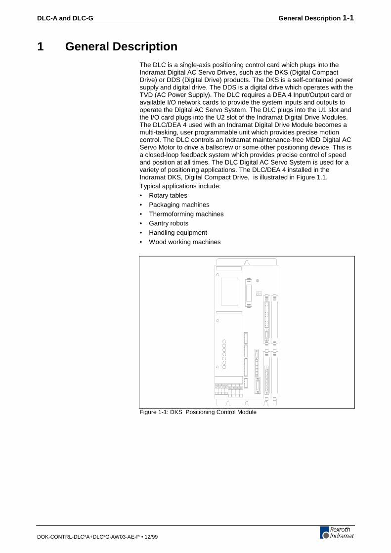
1 General DescriptionThe DLC is a single-axis positioning control card which plugs into theIndramat Digital AC Servo Drives, such as the DKS (Digital CompactDrive) or DDS (Digital Drive) products. The DKS is a self-contained powersupply and digital drive. The DDS is a digital drive which operates with theTVD (AC Power Supply). The DLC requires a DEA 4 Input/Output card oravailable I/O network cards to provide the system inputs and outputs tooperate the Digital AC Servo System. The DLC plugs into the U1 slot andthe I/O card plugs into the U2 slot of the Indramat Digital Drive Modules.The DLC/DEA 4 used with an Indramat Digital Drive Module becomes amulti-tasking, user programmable unit which provides precise motioncontrol. The DLC controls an Indramat maintenance-free MDD Digital ACServo Motor to drive a ballscrew or some other positioning device. This isa closed-loop feedback system which provides precise control of speedand position at all times. The DLC Digital AC Servo System is used for avariety of positioning applications. The DLC/DEA 4 installed in theIndramat DKS, Digital Compact Drive, is illustrated in Figure 1.1.Typical applications include:• Rotary tables• Packaging machines• Thermoforming machines• Gantry robots• Handling equipment• Wood working machines
Figure 1-1: DKS Positioning Control Module

1-2 General Description DLC-A and DLC-G
DOK-CONTRL-DLC*A+DLC*G-AW03-AE-P • 12/99
The extensive program command set permits the DLC to perform evencomplex processing tasks. It can do multi-tasking, operating one motionprogram and two background programs simultaneously. The DLC can beprogrammed both on-line, and off-line.The DLC can be used in remote operation, where it is controlled by thecustomer's line control, usually a computer or a programmable controller,which controls operation of the whole machine. The function of the linecontrol is to convey commands and to receive information via I/Oconnections from the DLC Digital AC Servo System.The DLC requires an I/O card be plugged into the U2 slot of the DKS. TheDEA 4 card provides 15 inputs ( 8 system/ 7 auxiliary) and 16 outputs ( 5system/11 auxiliary). Optional cards can increase the auxiliary inputs to37 and the auxiliary outputs to 43. In many applications, the DLC/DEA 4with an Indramat Digital Controller Module can provide sufficient machinecontrol without the use of an external line control. Other information, suchas programs, parameters, and system status can be communicated (twoway) between the DLC and a host device, such as a computer,programmable controller or Indramat SOT, via a multi-format serialcommunications port.

DLC-A and DLC-G General Description 1-3
DOK-CONTRL-DCL*A+DLC*G-AW03-AE-P • 12/99
Figure 1-2: Block Diagram
1-4 General Description DLC-A and DLC-G
DOK-CONTRL-DLC*A+DLC*G-AW03-AE-P • 12/99
1.1 DLC Configuration
The DLC Digital AC Servo System typical configuration consists of:• DLC 1.1 control card• DEA 4.1 Input/Output card• Digital Drive (DKS/DDS)• MDD Digital AC Servo MotorComplete interconnect cable sets are also available from Indramat. Thecomponents are chosen to best fit the required application. Figure 1-2 is ablock diagram of a typical DLC Servo System configuration. Thesecomponents are designed into a mechanical system. For example, itcould feed some type of material into another processing station, such asa punch press, thermoforming station, packaging machine, etc.The machine builder or user enters data into the DLC parameters tospecify the mechanical and operating characteristics of the system.Based on this data, plus the feed length and feed rate entered by theoperator, the DLC issues positioning commands to the digital drive, aDKS (Digital Compact Drive) or DDS (Digital Drive), which controls thecurrent driving the MDD AC Servo Motor, which drives the mechanicalfeed mechanism.The MDD AC Servo Motor includes a high-resolution feedback, whichprovides velocity and position feedback to the digital controller, ensuringprecise, repeatable positioning of the material being fed. The finalaccuracy of the feed system depends on various factors, such as type ofmaterial, gearbox backlash and other machine mechanics.System components are modular, thus installation and replacement ofany component of the system is fast and easy. The Indramat Digital DriveModules and the MDD AC Servo Motor have quick-connect cabling. Thedrive and MDD Servo Motor are matched for optimum operation using aplug-in DSM module. Thus, should a failure occur, replacement of thedigital drive is accomplished quickly without the need for electronic finetuning. This results in a minimum of lost production because of machinedowntime.The system is designed to ensure operating integrity and safety, usingvarious inputs and outputs for handshaking to assure that the feeder andsubsequent processing station or device operate in harmony. A completediagnostic system monitors all inputs, outputs and operating conditionsand stops the system if a fault is detected. Diagnostic messages aredisplayed to aid the operator in troubleshooting problems and quicklygetting the system back into production.

DLC-A and DLC-G General Description 1-5
DOK-CONTRL-DLC*A+DLC*G-AW03-AE-P • 12/99
1.2 About This Manual
This document is written for both operating personnel and the machinebuilder. It explains how to interface, install, setup and operate theIndramat DLC Positioning Control with DA or DG software.
Hardware and Software SupportThis manual describes the DLC 1.1 hardware, used with:• DA software versions DA 01.1-01.6 up through version DA 01.1-03.xx• DG software versions DG 01.1-02.7 through DG 01.1-03.xxIndramat provides assistance for any problems you may encounter withthis system. Your first source of information should be this manual. Toreport a problem or request assistance, call Indramat at (847) 645-3600,between 9:00 AM and 5:00 PM Central time. Ask for a Service Engineeror call our 24 hour Service Hotline at 1-800-860-1055. You may also writeor FAX to the following:Rexroth IndramatAttn: Service Department5150 Prairie Stone ParkwayHoffman Estates, IL 60192FAX: (847) 645-6201
How To Use This ManualThe manual is organized such that Chapters 1 and 2 describe the DLCcontrol and its operation. These chapters, plus Chapter 8 on diagnostics,will be sufficient for most operating personnel. Chapters 3-8 providefunctional description, installation, setup, parameter entry, programming,and diagnostic and troubleshooting information required by the machinebuilder and setup personnel.General DescriptionThis section describes the DLC control and the features which make itwell suited for motion control. Describes and illustrates various options.Lists specifications.Controls & IndicatorsThis section describes the CTA keypad and displays interfaced with theDLC control cardFunctional DescriptionThis section describes all pre-defined, plus several user definable, inputand output signals and the various interfacing and operating modes of theDLC. This information is necessary for interfacing the DLC to the machinebuilder’s equipment, control panel design and troubleshooting.ParametersThis section describes all user-entered parameters required to adapt theDLC to the mechanical and electrical characteristics of each application.ProgrammingThis section describes all program commands provided in the DLC for theuser to create the executable program, as desired for the application.
Chapter 1
Chapter 2
Chapter 3
Chapter 4
Chapter 5
1-6 General Description DLC-A and DLC-G
DOK-CONTRL-DLC*A+DLC*G-AW03-AE-P • 12/99
Installation/Start-upThis section describes procedures for installing a DLC control system.Provides an example of a DLC start-up and testing procedure.Serial InterfaceThis section describes the multi-format RS-232/485 port and the protocolfor two way communication between the DLC and a host device.Diagnostics & TroubleshootingThis section describes the DLC's self-diagnostic system, lists andexplains all diagnostic messages and describes troubleshootingprocedures.
AppendicesDA and DG Programming NotesThis section is periodically updated with hints and examples of use forprogramming commands.Display MapThis section shows the DLC display screens which appear on the CTAcontrol panel.Interconnect DrawingsThis section contains interconnect drawings for• DKS-DLC• RS232 Data Interface• SOT-DLC RS485• CTA-DLCA timing diagram for the DLC with DKS,DDS or DDC is also included.Installation DrawingsThis section contains a DKS 1.1 dimensional outline drawing as well asCTA and IDS cabinet cutout dimensions for remote mounting.DLC Type Code DescriptionsThis section shows how to interpret the data plate for hardware/softwareoptions included.
Chapter 6
Chapter 7
Chapter 8
Appendix A
Appendix B
Appendix C
Appendix D
Appendix E

DLC-A and DLC-G General Description 1-7
DOK-CONTRL-DLC*A+DLC*G-AW03-AE-P • 12/99
1.3 System Features
Superior PerformanceThe system offers high precision motion control with feed resolution of0.001 inch. Note that maximum system performance depends on themechanical characteristics of the user's system.
Easy to OperateThe user simply and easily operates the control system by entering asimple user program using the optional interfaces. Operating statusmessages appear on the display in the user selected language - English,French, German, Spanish, Italian or Portuguese. Other input and displayoptions are described later in this section. The DLC system includesfeatures to make setup quick and easy, eliminating time consumingmechanical setup or complex programming when changing parts.
Parameter-Adaptable to Multiple MachinesThe machine manufacturer or the user easily adapts the DLC to themechanical and electrical characteristics of an application by enteringdata into a set of parameters, using the DLC's optional CTA keypad anddisplay. These parameters define the characteristics of the machine, suchas: maximum and minimum feed lengths, jog, acceleration anddeceleration rates, units of feed measurement, RS-232/485 serialcommunication characteristics, etc. This allows one single type of DLCcontrol to handle the mechanics of various types of different machines.Thus, plant personnel need be familiar with only one control system.Generally, parameters are entered once when setting up the system, thenchanged only if the configuration changes or if different types ofoperations are required. The factory installed DLC executive programinterprets the parameters to match the DLC Digital AC Servo System tothe machine, and translates operator-entered commands into motioncontrol signals, coordinating the feed motion with the parts of the othermachinery. Complicated system programming is not required.
Fully Self-DiagnosticSystem protection is paramount. The DLC detects normal operatingstatus, operator errors, errors in the control itself and machine faults.Both fault and normal status messages can displayed on the DLC'soptional CTA interface, in the user selected language. Thus, the operatoris informed of the current operating status of the system and is alerted toany condition that causes a fault. This helps the operator quickly locateand correct problems.The DLC processor models and predicts the motion profile, andcontinuously compares it with the actual response of the servo controller,thereby detecting irregularities in drive conditions, such as drive runawayor excess position lag conditions. Parameters allow the user to set themagnitude of certain variations, as required for the application, before anerror is considered a fault condition.
Programming StructureThe basic program for standard motions is user programmed. The userprepares a program of up to 3000 lines/blocks, utilizing pre-definedcommands. These commands, represented by three letter mnemoniccodes, specify the function. The DLC, when used with the optional CTAkeypad/display, guides the user for proper entry of the necessary data foreach command/function utilized, such as, desired position, desired
1-8 General Description DLC-A and DLC-G
DOK-CONTRL-DLC*A+DLC*G-AW03-AE-P • 12/99
velocity, etc. The DLC can be programmed to run up to three separatetask simultaneously (multi-tasking). The DLC can be programmed withseveral sub-routines. The user can select a different sub-routine from themain program to run different applications. The user can customize theoperation of the DLC control for any number of particular applications.The user can download program blocks to the DLC from a host device(computer, PLC, etc.), while the control is in operation. Therefore, theeffective program size can be much larger than 3000 lines, if needed.
Programmable Acceleration RateThe acceleration rate, set by parameter, can be changed (reduced) byprogramming command. The rate can be changed to different levels forsubsequent moves "on the fly" in automatic mode. This is useful forestablishing proper rates for new materials or setting required rates fordifferent materials without changing parameter settings.
Programmable I/OThe Standard DLC requires a DEA 4 card which includes a set of 7auxiliary inputs and 11 auxiliary outputs which can be defined by the userfor electrically controlling and acknowledging machine functions. OptionalI/O cards can increases the auxiliary I/O to 37 inputs and 43 outputs.Additional outputs can be programmed as flags.The Standard DLC Control is illustrated in Figure 1.5. The Extendedversion, with additional I/O connections, is illustrated in Figure 1.6.
Control/Machine System I/O InterconnectionThe DLC has 8 input and 5 output connections which are pre-defined.They include connections to the machine and its control panel for modeselection, cycle start and stop, emergency stop, mode selectionacknowledgment, etc. These connections are typically made to keephandshake between the control and machine. For example, on a slide,the control will not position if the ram is too close to the material, and/orthe external operation will not start until the positioning is complete. Theaxis will not position if an external operation is pending.
HomingHoming allows absolute referencing for the axis. The user can initiatehoming in the manual mode or automatic mode of operation. The DLCoffers a great deal of flexibility in customizing the homing routine tocompensate for backlash, forward-moving-only applications, homing to aswitch, or a variety of other needs.
RegistrationRegistration control maintains each position as close as possible to aregistration mark printed on the material. This ensures that printedpatterns are kept in alignment with the finished product. Registrationaccuracy is limited to 1 millisecond input acknowledgment time.
RS-232/485 Serial InterfaceA multi-format serial interface allows communication with aprogrammable logic controller, a Indramat IDS or SOT, a personalcomputer or other host device. All information normally entered withoptional CTA display can be communicated over the RS-232/485 SerialInterface at rates of up to 19200 Baud.
CTA Remote Keypad/DisplayThe CTA is a remote keypad/display which is mounted separately fromthe DLC. The DLC Digital AC Servo System is panel-mounted inside a
DLC-A and DLC-G General Description 1-9
DOK-CONTRL-DLC*A+DLC*G-AW03-AE-P • 12/99
cabinet, with the CTA separately mounted on the cabinet surface. Whenusing CTA 01.3-B, with backlit display, the maximum distance from theDLC card is 30 feet. When using CTA 01.3-N, with non-backlit display, themaximum distance from the DLC card is 90 feet.
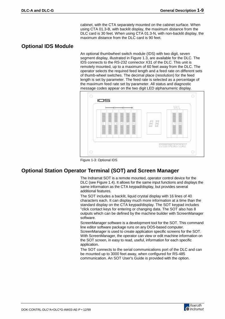
Optional IDS ModuleAn optional thumbwheel switch module (IDS) with two digit, sevensegment display, illustrated in Figure 1.3, are available for the DLC. TheIDS connects to the RS-232 connector X31 of the DLC. This unit isremotely mounted, up to a maximum of 60 feet away from the DLC. Theoperator selects the required feed length and a feed rate on different setsof thumb-wheel switches. The decimal place (resolution) for the feedlength is set by parameter. The feed rate is selected as a percentage ofthe maximum feed rate set by parameter. All status and diagnosticmessage codes appear on the two digit LED alphanumeric display.
Figure 1-3: Optional IDS
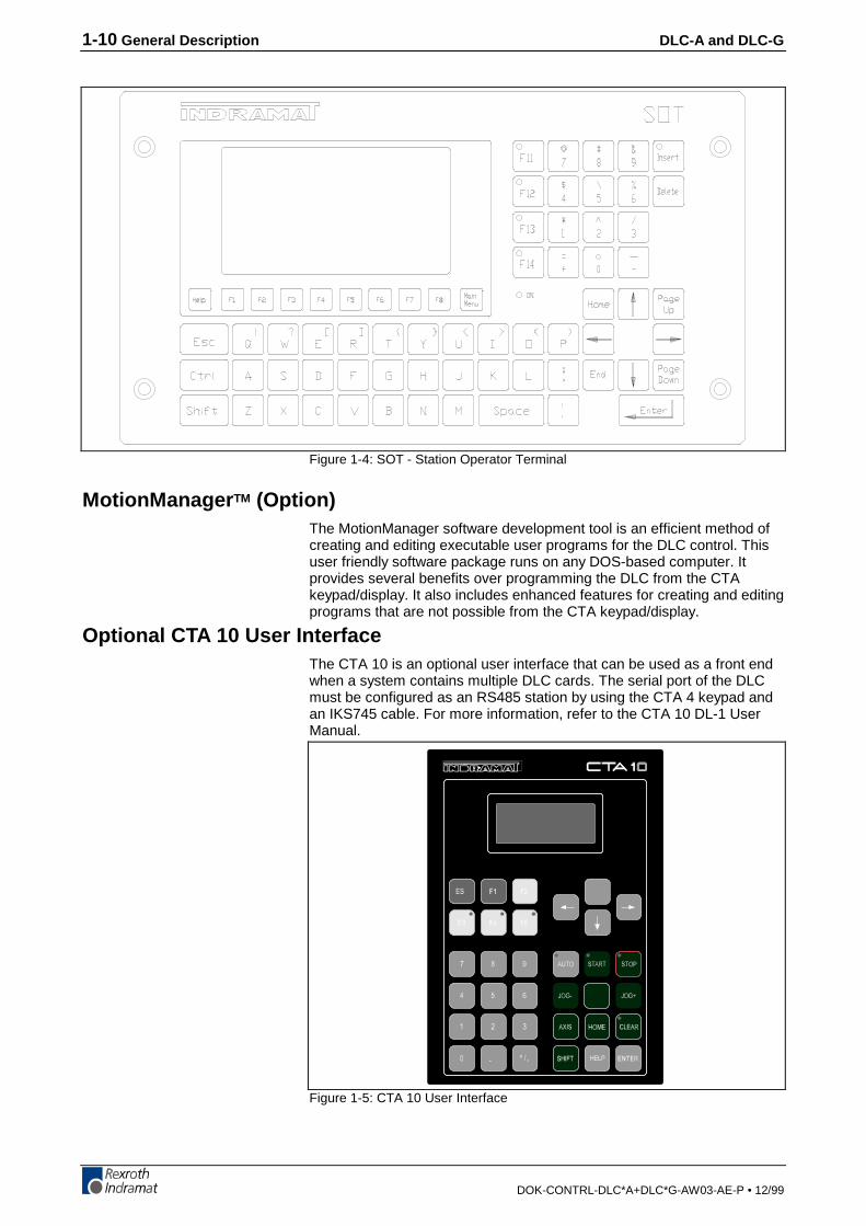
Optional Station Operator Terminal (SOT) and Screen ManagerThe Indramat SOT is a remote mounted, operator control device for theDLC (see Figure 1.4). It allows for the same input functions and displays thesame information as the CTA keypad/display, but provides severaladditional features.The SOT includes a backlit, liquid crystal display with 16 lines of 40characters each. It can display much more information at a time than thestandard display on the CTA keypad/display. The SOT keypad includes"click contact keys for entering or changing data. The SOT also has 8outputs which can be defined by the machine builder with ScreenManagersoftware.ScreenManager software is a development tool for the SOT. This commandline editor software package runs on any DOS-based computer.ScreenManager is used to create application specific screens for the SOT.With ScreenManager, the operator can view or edit machine information onthe SOT screen, in easy to read, useful, information for each specificapplication.The SOT connects to the serial communications port of the DLC and canbe mounted up to 3000 feet away, when configured for RS-485communication. An SOT User's Guide is provided with the option.
1-10 General Description DLC-A and DLC-G
DOK-CONTRL-DLC*A+DLC*G-AW03-AE-P • 12/99
Figure 1-4: SOT - Station Operator Terminal
MotionManager TM (Option)The MotionManager software development tool is an efficient method ofcreating and editing executable user programs for the DLC control. Thisuser friendly software package runs on any DOS-based computer. Itprovides several benefits over programming the DLC from the CTAkeypad/display. It also includes enhanced features for creating and editingprograms that are not possible from the CTA keypad/display.
Optional CTA 10 User InterfaceThe CTA 10 is an optional user interface that can be used as a front endwhen a system contains multiple DLC cards. The serial port of the DLCmust be configured as an RS485 station by using the CTA 4 keypad andan IKS745 cable. For more information, refer to the CTA 10 DL-1 UserManual.
Figure 1-5: CTA 10 User Interface
DLC-A and DLC-G General Description 1-11
DOK-CONTRL-DLC*A+DLC*G-AW03-AE-P • 12/99
1.4 Standard Configuration Of DKS With DLC ControlCard/DEA 4 Input/Output Card
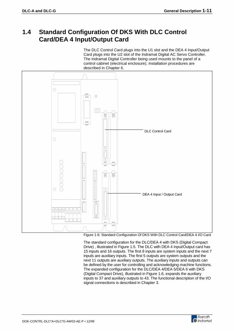
The DLC Control Card plugs into the U1 slot and the DEA 4 Input/OutputCard plugs into the U2 slot of the Indramat Digital AC Servo Controller.The Indramat Digital Controller being used mounts to the panel of acontrol cabinet (electrical enclosure). Installation procedures aredescribed in Chapter 6.
DLC Control Card
DEA 4 Input / Output Card
Figure 1-6: Standard Configuration Of DKS With DLC Control Card/DEA 4 I/O Card
The standard configuration for the DLC/DEA 4 with DKS (Digital CompactDrive) , illustrated in Figure 1.5. The DLC with DEA 4 Input/Output card has15 inputs and 16 outputs. The first 8 inputs are system inputs and the next 7inputs are auxiliary inputs. The first 5 outputs are system outputs and thenext 11 outputs are auxiliary outputs. The auxiliary inputs and outputs canbe defined by the user for controlling and acknowledging machine functions.The expanded configuration for the DLC/DEA 4/DEA 5/DEA 6 with DKS(Digital Compact Drive), illustrated in Figure 1.6, expands the auxiliaryinputs to 37 and auxiliary outputs to 43. The functional description of the I/Osignal connections is described in Chapter 3.

1-12 General Description DLC-A and DLC-G
DOK-CONTRL-DLC*A+DLC*G-AW03-AE-P • 12/99
DLC Control Card
DEA 5 Input / Output Card (Optional)
DEA 4 Input / Output Card
DEA 6 Input / Output Card (Optional)
Figure 1-7: Expanded I/O Configuration Of DKS With DLC Control Card/DEA 4,5, 6, I/O card
DLC-A and DLC-G General Description 1-13
DOK-CONTRL-DLC*A+DLC*G-AW03-AE-P • 12/99
Standard Configuration Of DKS With DLC Control Card/DEA 4 Input/OutputCard And Optional DEF 1 Incremental Encoder Interface Card
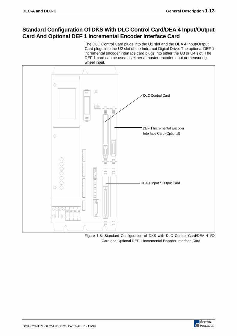
The DLC Control Card plugs into the U1 slot and the DEA 4 Input/OutputCard plugs into the U2 slot of the Indramat Digital Drive. The optional DEF 1incremental encoder interface card plugs into either the U3 or U4 slot. TheDEF 1 card can be used as either a master encoder input or measuringwheel input.
DLC Control Card
DEF 1 Incremental EncoderInterface Card (Optional)
DEA 4 Input / Output Card
Figure 1-8: Standard Configuration of DKS with DLC Control Card/DEA 4 I/OCard and Optional DEF 1 Incremental Encoder Interface Card

1-14 General Description DLC-A and DLC-G
DOK-CONTRL-DLC*A+DLC*G-AW03-AE-P • 12/99
1.5 SpecificationsThe following sections provide full specifications for the DLC Control andoptions.
Note: Performance specifications can vary, depending on themechanical limitations of the equipment.
Physical Specifications--Operating EnvironmentConvection41 to 113 °F(5 to 45 °C)-22 to 185 °F(-30 to 85 °C)3,280 ft. (1000 meters)(higher altitudes permitted with proper cooling)
Control SpecificationsHigh Resolution With Single-turn or Multi-turn Absolute, ResolverIncremental Encoder requires DEF incremental encoder interface card.Absolute encoder (GDM only) requires a DFF interface card.0.001 inches (0.01 mm)Normal - 0.1 - 99.9% of Maximum Velocity
DG: Feed Rate values can be in µpm(Operator Selectable)
Jog - 0.1 - 99.9% of Maximum Velocity(Parameter Selectable)
Note: Maximum Feed Rate will vary, depending on the mechanicaldesign of the equipment.
Forward / Reverse (Manual Mode only)0.01 - 99.99 seconds in 0.01 stepsLimited only by number of program linesLCD (Optional Backlit Version Available,Four (4) line, 16 Characters/Line, 20 membrane switch keys.
I/O Interface8 (+24 Vdc @ 10 mA)(pre-defined function)7 - Standard37 - Expanded(user defined and programmable)5 (+24 Vdc @ up to 100 mA, Sourcing)(pre-defined function)11 - Standard43 - Expanded (User defined and programmable)
CAUTION: Inputs will have a 10 mA current draw at 24 Vdc. Outputs arethermally protected by a current limiter circuit which eliminatesrequirement for added fuses. If the load on the output causes acurrent draw in excess of 100 mA, the output bank of 8 outputsshuts off. The entire bank of 8 outputs on the DEA card mustthem be reset by cycling system power off and back on.
Cooling
Allowable AmbientTemperature Range
Storage and TransportTemperature Range
Maximum Operating Altitudeat Rated Values
Position Feedback
Measuring Wheel Feedback
Feed Length ResolutionFeed Rate
Jogging
Programmable Dwell Time
Programmable Counters
CTA Keypad/Display
System Inputs
Auxiliary Inputs
with DEA card
System Outputswith DEA card
Auxiliary Outputs

DLC-A and DLC-G General Description 1-15
DOK-CONTRL-DLC*A+DLC*G-AW03-AE-P • 12/99
OptionsAn IKS 745 cable allows remote mounting of CTA (keypad/display) to themachine's control panel.This standard interface allows remote operation and other data transferbetween the DLC and a optional host device, such as the IDS, SOT,computer or programmable controllerA remote thumbwheel switch module used for entering feed length and feedrate for operation; displays status and fault codes via a two-digit LED.Station Operator Terminal- Used with ScreenManager to createapplication specific screens for displaying diagnostics, entering feedlength, feed rate, viewing input/output status, etc.
CTA Remote Keypad/Display
RS-232/485 Interface Options
IDS Module
SOT
1-16 General Description DLC-A and DLC-G
DOK-CONTRL-DLC*A+DLC*G-AW03-AE-P • 12/99
DLC-A and DLC-G Controls and Indicators 2-1
DOK-CONTRL-DLC*A+DLC*G-AW03-AE-P • 12/99
2 Controls and IndicatorsThis chapter contains a general description of the DLC control layout, plusthe following information:
1. Description of DLC with optional CTA keypad and display.
2. Description of the functions of the keys on the CTA keypad.
3. Description of display screens; how to scroll through different screensand how to interpret and change data on the screens.
The CTA keypad and display module (Figure 2.1) attaches to connectorX30 on the DLC via 04-0745 shielded ribbon cable. The systeminput/output connections (via DEA 4.1 I/O card) are described in Chapter3. The connections are further described in Chapter 6 for installation.
2.1 CTA Keypad and Display
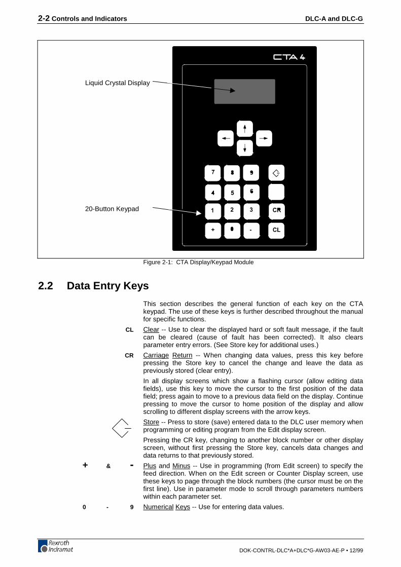
The CTA keypad / display panel consist of a keypad with pressure-sensitive membrane type keys and a liquid crystal display (LCD) whichshows up to four lines of 16 alphanumeric characters each. The numberof lines and characters showing depends on the selected display modeand the current operating status of the control.
The display informs the operator of the operating status of the DLCsystem and displays all diagnostic messages. It is also used whenentering or editing program or parameters from the keypad.
The keypad contains all the keys required for data entry, cursormovement, clearing fault/error messages, entering program andparameter data, etc.
The following sections describe the keypad and display functions.
The keypad and display module must be remotely mounted. The standardlength for the IKS745 ribbon cable is 8 feet. Different lengths must bespecified when ordering this cable. The maximum cable length is 90 feet..
2-2 Controls and Indicators DLC-A and DLC-G
DOK-CONTRL-DLC*A+DLC*G-AW03-AE-P • 12/99
Liquid Crystal Display
20-Button Keypad
Figure 2-1: CTA Display/Keypad Module
2.2 Data Entry Keys
This section describes the general function of each key on the CTAkeypad. The use of these keys is further described throughout the manualfor specific functions.
Clear -- Use to clear the displayed hard or soft fault message, if the faultcan be cleared (cause of fault has been corrected). It also clearsparameter entry errors. (See Store key for additional uses.)
Carriage Return -- When changing data values, press this key beforepressing the Store key to cancel the change and leave the data aspreviously stored (clear entry).
In all display screens which show a flashing cursor (allow editing datafields), use this key to move the cursor to the first position of the datafield; press again to move to a previous data field on the display. Continuepressing to move the cursor to home position of the display and allowscrolling to different display screens with the arrow keys.
Store -- Press to store (save) entered data to the DLC user memory whenprogramming or editing program from the Edit display screen.
Pressing the CR key, changing to another block number or other displayscreen, without first pressing the Store key, cancels data changes anddata returns to that previously stored.
Plus and Minus -- Use in programming (from Edit screen) to specify thefeed direction. When on the Edit screen or Counter Display screen, usethese keys to page through the block numbers (the cursor must be on thefirst line). Use in parameter mode to scroll through parameters numberswithin each parameter set.
Numerical Keys -- Use for entering data values.
CL
CR
+ & -
0 - 9

DLC-A and DLC-G Controls and Indicators 2-3
DOK-CONTRL-DLC*A+DLC*G-AW03-AE-P • 12/99
Left and Right Arrow -- Use to move the cursor to the left or right oneposition at a time. From certain display screens (ones without a cursor),the right and left arrow keys select additional display screens (see nextsection).
Up and Down Arrows -- Use to scroll through display screens (see nextsection), or to change parameter sets (see Chapter 4) in parametermode. Use to scroll through program commands when on the Edit screen.With the cursor positioned next to the command mnemonic (i.e. NOP_),press these keys to step through the program commands in alphabeticalorder.
Note: All displays illustrated in this manual use an underlinecharacter (_ ) to represent the cursor.
Å Æ
È Ç
2-4 Controls and Indicators DLC-A and DLC-G
DOK-CONTRL-DLC*A+DLC*G-AW03-AE-P • 12/99
2.3 CTA Display Screens
The CTA uses its liquid crystal display for several screens. The operatingmode and keyboard selections determine the resulting display.
When the DLC is in Parameter Mode, data for each parameter can beviewed, entered or edited. While in Automatic or Manual Mode, otherdisplay screens show the control software version, operation statusmessages, faults, status of each input and output, counters, etc. The Editscreen allows programming or editing the program data.
The following section describes procedures for scrolling through each ofthese display screens. Each following section describes the function ofeach screen, procedures to edit the screens data, etc.
Scrolling Through Display ScreensRefer to the "Display Map" in Figure 2.2 for a full illustration of the displayaccess procedure. For convenience, the same illustration is included inAppendix C. This section describes the basic procedures for reading this"map" and scrolling through the different displays. Each display screen isfully described in the following sections.
To allow easier description, each row of the map is labeled A, B, C, etc. Ingeneral, use the up or down arrow keys to scroll through the differentdisplay screens. Use the left or right arrow keys to scroll through thedisplays on each row. All rows allow wrapping from the last screen on therow back to the first screen, and vice versa, by continuing to press theright (or left) arrow key.
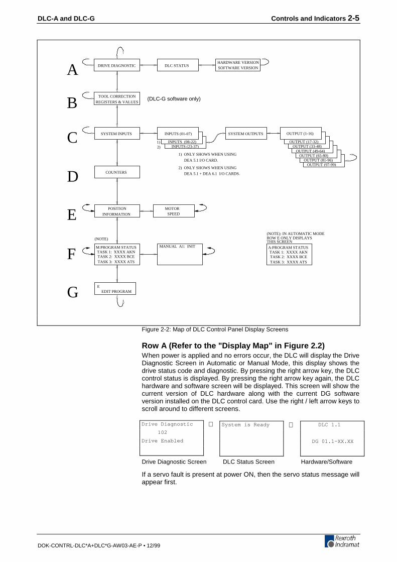
DLC-A and DLC-G Controls and Indicators 2-5
DOK-CONTRL-DLC*A+DLC*G-AW03-AE-P • 12/99
(DLC-G software only)
A
C
D
E
F
G
HARDWARE VERSIONSOFTWARE VERSION
DLC STATUSDRIVE DIAGNOSTIC
SYSTEM INPUTS INPUTS (01-07)
2) INPUTS (23-37)
SYSTEM OUTPUTS OUTPUT (1-16)
OUTPUT (17-32)OUTPUT (33-48)
OUTPUT (49-64)OUTPUT (65-80)
OUTPUT (81-96)OUTPUT (97-99)
POSITION
INFORMATION
COUNTERS
MOTORSPEED
(NOTE)
M:PROGRAM STATUSTASK 1: XXXX AKNTASK 2: XXXX BCETASK 3: XXXX ATS
MANUAL A1: INIT
EEDIT PROGRAM
(NOTE): IN AUTOMATIC MODEROW E ONLY DISPLAYSTHIS SCREEN
A:PROGRAM STATUSTASK 1: XXXX AKNTASK 2: XXXX BCETASK 3: XXXX ATS
INPUTS (08-22)1)
DEA 5.1 + DEA 6.1 I/O CARDS.
2) ONLY SHOWS WHEN USING
DEA 5.1 I/O CARD.
1) ONLY SHOWS WHEN USING
B REGISTERS & VALUES
TOOL CORRECTION
Figure 2-2: Map of DLC Control Panel Display Screens
Row A (Refer to the "Display Map" in Figure 2.2)When power is applied and no errors occur, the DLC will display the DriveDiagnostic Screen in Automatic or Manual Mode, this display shows thedrive status code and diagnostic. By pressing the right arrow key, the DLCcontrol status is displayed. By pressing the right arrow key again, the DLChardware and software screen will be displayed. This screen will show thecurrent version of DLC hardware along with the current DG softwareversion installed on the DLC control card. Use the right / left arrow keys toscroll around to different screens.
Drive Diagnostic Screen DLC Status Screen Hardware/Software
If a servo fault is present at power ON, then the servo status message willappear first.
System is Ready⇔ DLC 1.1
DG 01.1-XX.XX
⇔Drive Diagnostic
102
Drive Enabled
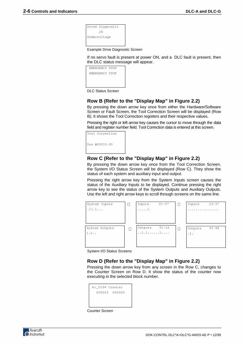
2-6 Controls and Indicators DLC-A and DLC-G
DOK-CONTRL-DLC*A+DLC*G-AW03-AE-P • 12/99
Example Drive Diagnostic Screen
If no servo fault is present at power ON, and a DLC fault is present, thenthe DLC status message will appear.
DLC Status Screen
Row B (Refer to the "Display Map" in Figure 2.2)By pressing the down arrow key once from either the Hardware/SoftwareScreen or Fault Screen, the Tool Correction Screen will be displayed (RowB). It shows the Tool Correction registers and their respective values.
Pressing the right or left arrow key causes the cursor to move through the datafield and register number field. Tool Correction data is entered at this screen.
Row C (Refer to the "Display Map" in Figure 2.2)By pressing the down arrow key once from the Tool Correction Screen,the System I/O Status Screen will be displayed (Row C). They show thestatus of each system and auxiliary input and output.
Pressing the right arrow key from the System Inputs screen causes thestatus of the Auxiliary Inputs to be displayed. Continue pressing the rightarrow key to see the status of the System Outputs and Auxiliary Outputs.Use the left and right arrow keys to scroll through screens on the same line.
System I/O Status Screens
Row D (Refer to the "Display Map" in Figure 2.2)Pressing the down arrow key from any screen in the Row C, changes tothe Counter Screen on Row D. It show the status of the counter nowexecuting in the selected block number.
A:_0104 Counter
000003 000005
Counter Screen
Drive Diagnostic
26
Undervoltage
EMERGENCY STOP
EMERGENCY STOP
Tool Correction
Dnn ±00010.00
System Inputs
.11.1...
Inputs 01-07
.....1.⇔
Outputs 01-16
..1.1......1....Outputs 97-99
.1.⇔⇔System Outputs
1.1..
⇔ Inputs 23-37
................

DLC-A and DLC-G Controls and Indicators 2-7
DOK-CONTRL-DLC*A+DLC*G-AW03-AE-P • 12/99
Row E (Refer to the "Display Map" in Figure 2.2)Pressing the down arrow key from the display in Row D, changes to theAxis Information Screen in Row E. The Axis Information Screen consistsof the axis position, axis following error, and the remaining distance to bepositioned.
Pressing the right arrow key causes the Speed of Axis 1 to be displayed.This screen will display the commanded and actual speed of the axis inrevolutions per minute (RPM).
Axis 1 Information Motor Speed of Axis 1
Row F (Refer to the "Display Map" in Figure 2.2)Press the down arrow key from any display in Row E to see the CurrentProgram Status. If the DLC is in Manual Mode, a "M" appears on thescreen, along with the status of Task 1, 2 and 3. Use the left / right arrowkeys to toggle between this screen and the Axis 1 Enabled screen.
Manual Mode Task Screen Axis Enabled Screen
When the DLC is in Automatic Mode, only the task display is available onthis row. An "A" appears on the screen (Automatic Mode), along with thestatus of Task 1, 2 and 3.
Automatic Mode Task Screen
Row G (Refer to the "Display Map" in Figure 2.2)From any screen in Row F, press the down arrow key to display theProgram Edit screen in Row G. Notice the "E" in the upper left corner ofthe screen easily identifies it as the Edit display screen.
Edit Screen
Note: From Row G, press the down arrow key to wrap to a displayscreen in Row A.From Row A, press the up arrow key to display the Edit screenin Row G.
⇔ Speed Axis 1:
Com: 0500 RPM
Act: 0500 RPM
Axis 1: Iner.
Pos.: +00001.000
FE. : +00000.010
Rem.: +00000.000
⇔ Manual A1 Init.M: Progr.Status
Task 1:0091 BCE
Task 2:0366 VCC
Task 3:0901 BCE
A: Progr.Status
Task 1:0091 BCE
Task 2:0366 VCC
Task 3:0901 BCE
E _0096 BCE
0200 02 1
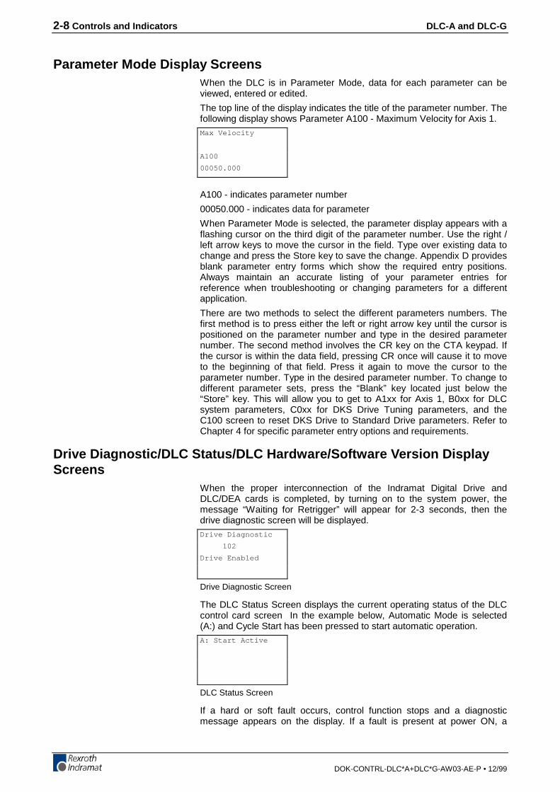
2-8 Controls and Indicators DLC-A and DLC-G
DOK-CONTRL-DLC*A+DLC*G-AW03-AE-P • 12/99
Parameter Mode Display ScreensWhen the DLC is in Parameter Mode, data for each parameter can beviewed, entered or edited.
The top line of the display indicates the title of the parameter number. Thefollowing display shows Parameter A100 - Maximum Velocity for Axis 1.
A100 - indicates parameter number
00050.000 - indicates data for parameter
When Parameter Mode is selected, the parameter display appears with aflashing cursor on the third digit of the parameter number. Use the right /left arrow keys to move the cursor in the field. Type over existing data tochange and press the Store key to save the change. Appendix D providesblank parameter entry forms which show the required entry positions.Always maintain an accurate listing of your parameter entries forreference when troubleshooting or changing parameters for a differentapplication.
There are two methods to select the different parameters numbers. Thefirst method is to press either the left or right arrow key until the cursor ispositioned on the parameter number and type in the desired parameternumber. The second method involves the CR key on the CTA keypad. Ifthe cursor is within the data field, pressing CR once will cause it to moveto the beginning of that field. Press it again to move the cursor to theparameter number. Type in the desired parameter number. To change todifferent parameter sets, press the “Blank” key located just below the“Store” key. This will allow you to get to A1xx for Axis 1, B0xx for DLCsystem parameters, C0xx for DKS Drive Tuning parameters, and theC100 screen to reset DKS Drive to Standard Drive parameters. Refer toChapter 4 for specific parameter entry options and requirements.
Drive Diagnostic/DLC Status/DLC Hardware/Software Version DisplayScreens
When the proper interconnection of the Indramat Digital Drive andDLC/DEA cards is completed, by turning on to the system power, themessage “Waiting for Retrigger” will appear for 2-3 seconds, then thedrive diagnostic screen will be displayed.
Drive Diagnostic Screen
The DLC Status Screen displays the current operating status of the DLCcontrol card screen In the example below, Automatic Mode is selected(A:) and Cycle Start has been pressed to start automatic operation.
DLC Status Screen
If a hard or soft fault occurs, control function stops and a diagnosticmessage appears on the display. If a fault is present at power ON, a
Max Velocity
A100
00050.000
Drive Diagnostic
102
Drive Enabled
A: Start Active

DLC-A and DLC-G Controls and Indicators 2-9
DOK-CONTRL-DLC*A+DLC*G-AW03-AE-P • 12/99
diagnostic status message appears first (instead of the Drive DiagnosticDisplay).
See Chapter 8 for diagnostic messages and troubleshooting procedures.
Example Fault Status Display
By pressing the right arrow key, the current DLC hardware/DA softwareversion installed in the Indramat Digital Drive will be displayed inAutomatic or Manual Modes.
Hardware/Software Screen
DLC-1.1 - indicates hardware type
DG�01.1-XX.XX - indicates software number (XX.XX = revisionnumber)
Press the left or right arrow keys to scroll through the Servo Status, DLCStatus, and DLC Hardware/Software Version screens.
Tool Correction Data Screen (DLC-G only)The tool length correction consists of a tool correction memory with 20selectibale Tool Correction registers, D00...D19. D00 is effective uponentering automatic operation and is active once the program is started.
Inputting of correction values is possible on-line through the CTAkeyboard. Tool Correction register values can be entered in manual andautomatic mode. External Tool Correction data input is also possiblethrough parallel inputs using the SO1 command (see Chapter 5 for acomplete description of the SO1 command)
It is possible to use the Tool Correction registers for a variable memory,however, only one correction value can be selected and calculated perprogramming command.
Each correction value memory can accept a seven-digit correction value.The eighth digit is the sign bit (+/-).
EMERGENCY STOP
EMERGENCY STOP
DLC 1.1
DG 01.1-XX.XX
Tool Correction
Dnn ±00010.

2-10 Controls and Indicators DLC-A and DLC-G
DOK-CONTRL-DLC*A+DLC*G-AW03-AE-P • 12/99
System/Auxiliary I/O Status ScreensSystem/Auxiliary I/O Status screens show the status of each system andauxiliary input and output. These displays are helpful to verify wiringduring start-up or troubleshooting. They also provide a quick summary ofsystem/auxiliary status during normal operation.
System I/O Status Screens
The status of each of the input or output signal lines on a screen arerepresented by a character in the bottom row of the display. A Low signal(0 volts) is represented by a decimal (.). A High signal (+24 volts) isindicated by a one (1). The system Inputs and Outputs have a fixed orpre-defined function for the DLC. The first fifteen lines (inputs) of the DEA4, connector X17, are for system and auxiliary inputs. The first eight aresystem inputs. The next seven are user-programmable auxiliary inputs.Two additional cards, DEA 5 and DEA 6, can be installed to expand theDLC auxiliary inputs up to 37 Chapter 3 provides a functional descriptionfor each of these I/O connections. Table 2.1 (following this section)provides a legend of the Input signal function for each Input screen, andthe corresponding connector for hardware I/O connections.
The next sixteen lines (outputs) of DEA 4 connector X17, are for systemand auxiliary outputs. The first five are system outputs. The next elevenare user-programmable auxiliary outputs. Two additional cards, DEA 5and DEA 6, can be installed to expand the DLC auxiliary outputs up to 43.With either the Standard or Expanded DLC, these output points above theauxiliary connections (hardware), can be programmed as software flags.Certain output flags are set in firmware and can be queried by the userprogram. Chapter 5 defines the restrictions and use of these auxiliaryoutputs as software flags. Table 2.2 (following this section) provides alegend of the Output signal function for each Output screen, and thecorresponding connector for hardware I/O connections.
⇔ ⇔
System Outputs
1.1..⇔
System Inputs
.11.1...
Inputs 01-07
.....1.
Inputs 23-37
................
Outputs 01-16
..1.1......1....⇔ Outputs 97-99
.1.
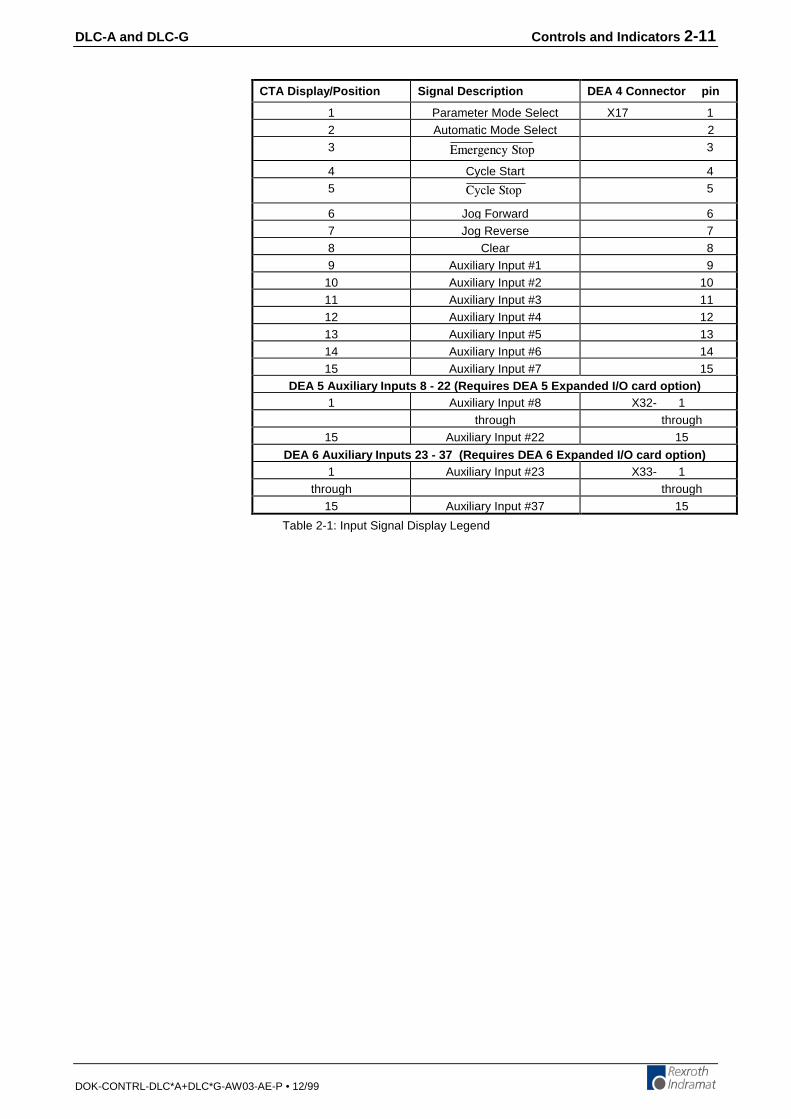
DLC-A and DLC-G Controls and Indicators 2-11
DOK-CONTRL-DLC*A+DLC*G-AW03-AE-P • 12/99
CTA Display/Position Signal Description DEA 4 Connector pin
1 Parameter Mode Select X17 12 Automatic Mode Select 23 'OGTIGPE[�5VQR 3
4 Cycle Start 45 %[ENG�5VQR 5
6 Jog Forward 67 Jog Reverse 78 Clear 89 Auxiliary Input #1 9
10 Auxiliary Input #2 1011 Auxiliary Input #3 1112 Auxiliary Input #4 1213 Auxiliary Input #5 1314 Auxiliary Input #6 1415 Auxiliary Input #7 15
DEA 5 Auxiliar y Inputs 8 - 22 (Requires DEA 5 Ex panded I/O card o ption )1 Auxiliary Input #8 X32- 1
through through15 Auxiliary Input #22 15
DEA 6 Auxiliar y Inputs 23 - 37 (Requires DEA 6 Ex panded I/O card o ption )1 Auxiliary Input #23 X33- 1
through through15 Auxiliary Input #37 15
Table 2-1: Input Signal Display Legend
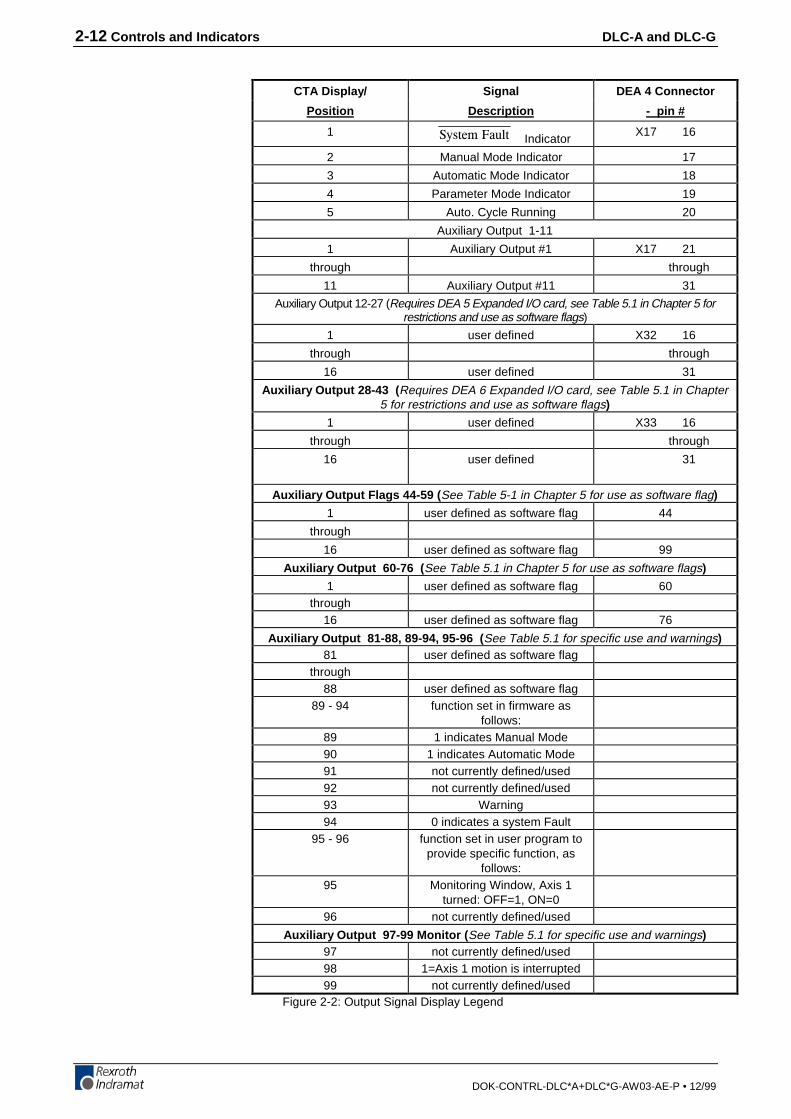
2-12 Controls and Indicators DLC-A and DLC-G
DOK-CONTRL-DLC*A+DLC*G-AW03-AE-P • 12/99
CTA Display/ Signal DEA 4 Connector
Position Description - pin #
1 5[UVGO�(CWNV IndicatorX17 16
2 Manual Mode Indicator 17
3 Automatic Mode Indicator 18
4 Parameter Mode Indicator 19
5 Auto. Cycle Running 20
Auxiliary Output 1-11
1 Auxiliary Output #1 X17 21
through through
11 Auxiliary Output #11 31
Auxiliary Output 12-27 (Requires DEA 5 Expanded I/O card, see Table 5.1 in Chapter 5 forrestrictions and use as software flags)
1 user defined X32 16
through through
16 user defined 31
Auxiliary Output 28-43 ( Requires DEA 6 Expanded I/O card, see Table 5.1 in Chapter5 for restrictions and use as software flags)
1 user defined X33 16
through through
16 user defined 31
Auxiliary Output Flags 44-59 ( See Table 5-1 in Chapter 5 for use as software flag)
1 user defined as software flag 44
through
16 user defined as software flag 99
Auxiliary Output 60-76 ( See Table 5.1 in Chapter 5 for use as software flags)
1 user defined as software flag 60through
16 user defined as software flag 76
Auxiliary Output 81-88, 89-94, 95-96 ( See Table 5.1 for specific use and warnings)81 user defined as software flag
through88 user defined as software flag
89 - 94 function set in firmware asfollows:
89 1 indicates Manual Mode90 1 indicates Automatic Mode91 not currently defined/used92 not currently defined/used93 Warning94 0 indicates a system Fault
95 - 96 function set in user program toprovide specific function, as
follows:95 Monitoring Window, Axis 1
turned: OFF=1, ON=096 not currently defined/used
Auxiliary Output 97-99 Monitor ( See Table 5.1 for specific use and warnings)97 not currently defined/used98 1=Axis 1 motion is interrupted99 not currently defined/used
Figure 2-2: Output Signal Display Legend
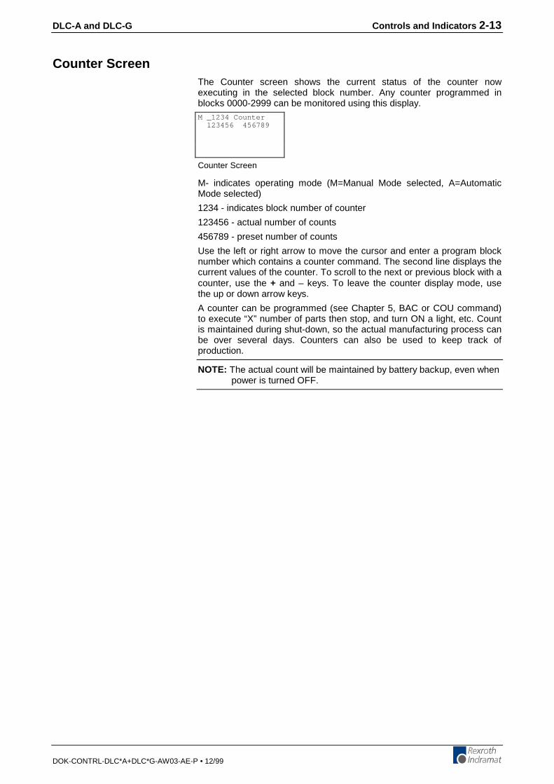
DLC-A and DLC-G Controls and Indicators 2-13
DOK-CONTRL-DLC*A+DLC*G-AW03-AE-P • 12/99
Counter ScreenThe Counter screen shows the current status of the counter nowexecuting in the selected block number. Any counter programmed inblocks 0000-2999 can be monitored using this display.
Counter Screen
M- indicates operating mode (M=Manual Mode selected, A=AutomaticMode selected)
1234 - indicates block number of counter
123456 - actual number of counts
456789 - preset number of counts
Use the left or right arrow to move the cursor and enter a program blocknumber which contains a counter command. The second line displays thecurrent values of the counter. To scroll to the next or previous block with acounter, use the + and – keys. To leave the counter display mode, usethe up or down arrow keys.
A counter can be programmed (see Chapter 5, BAC or COU command)to execute “X” number of parts then stop, and turn ON a light, etc. Countis maintained during shut-down, so the actual manufacturing process canbe over several days. Counters can also be used to keep track ofproduction.
NOTE: The actual count will be maintained by battery backup, even whenpower is turned OFF.
M _1234 Counter 123456 456789
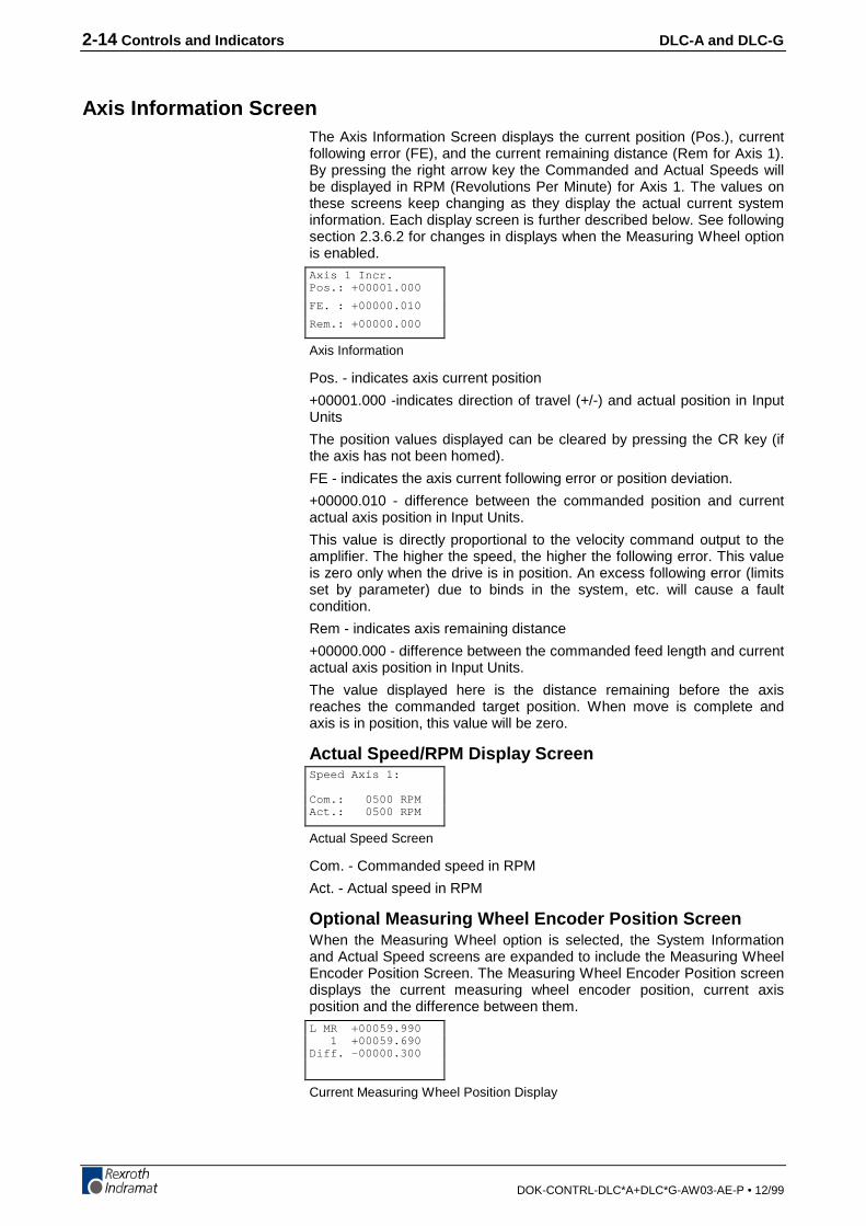
2-14 Controls and Indicators DLC-A and DLC-G
DOK-CONTRL-DLC*A+DLC*G-AW03-AE-P • 12/99
Axis Information ScreenThe Axis Information Screen displays the current position (Pos.), currentfollowing error (FE), and the current remaining distance (Rem for Axis 1).By pressing the right arrow key the Commanded and Actual Speeds willbe displayed in RPM (Revolutions Per Minute) for Axis 1. The values onthese screens keep changing as they display the actual current systeminformation. Each display screen is further described below. See followingsection 2.3.6.2 for changes in displays when the Measuring Wheel optionis enabled.
Axis Information
Pos. - indicates axis current position
+00001.000 -indicates direction of travel (+/-) and actual position in InputUnits
The position values displayed can be cleared by pressing the CR key (ifthe axis has not been homed).
FE - indicates the axis current following error or position deviation.
+00000.010 - difference between the commanded position and currentactual axis position in Input Units.
This value is directly proportional to the velocity command output to theamplifier. The higher the speed, the higher the following error. This valueis zero only when the drive is in position. An excess following error (limitsset by parameter) due to binds in the system, etc. will cause a faultcondition.
Rem - indicates axis remaining distance
+00000.000 - difference between the commanded feed length and currentactual axis position in Input Units.
The value displayed here is the distance remaining before the axisreaches the commanded target position. When move is complete andaxis is in position, this value will be zero.
Actual Speed/RPM Display Screen
Actual Speed Screen
Com. - Commanded speed in RPM
Act. - Actual speed in RPM
Optional Measuring Wheel Encoder Position ScreenWhen the Measuring Wheel option is selected, the System Informationand Actual Speed screens are expanded to include the Measuring WheelEncoder Position Screen. The Measuring Wheel Encoder Position screendisplays the current measuring wheel encoder position, current axisposition and the difference between them.
Current Measuring Wheel Position Display
Axis 1 Incr.Pos.: +00001.000
FE. : +00000.010
Rem.: +00000.000
Speed Axis 1:
Com.: 0500 RPMAct.: 0500 RPM
L MR +00059.990 1 +00059.690Diff. -00000.300
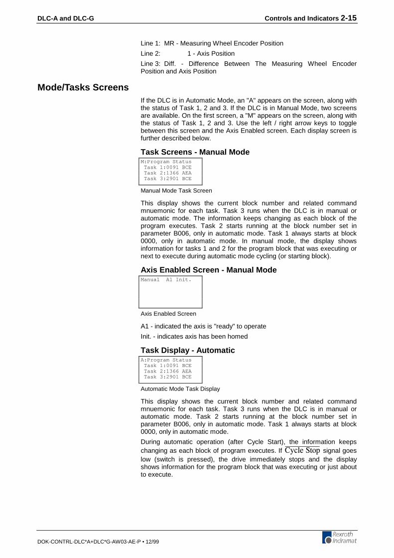
DLC-A and DLC-G Controls and Indicators 2-15
DOK-CONTRL-DLC*A+DLC*G-AW03-AE-P • 12/99
Line 1: MR - Measuring Wheel Encoder Position
Line 2: 1 - Axis Position
Line 3: Diff. - Difference Between The Measuring Wheel EncoderPosition and Axis Position
Mode/Tasks ScreensIf the DLC is in Automatic Mode, an "A" appears on the screen, along withthe status of Task 1, 2 and 3. If the DLC is in Manual Mode, two screensare available. On the first screen, a "M" appears on the screen, along withthe status of Task 1, 2 and 3. Use the left / right arrow keys to togglebetween this screen and the Axis Enabled screen. Each display screen isfurther described below.
Task Screens - Manual Mode
Manual Mode Task Screen
This display shows the current block number and related commandmnuemonic for each task. Task 3 runs when the DLC is in manual orautomatic mode. The information keeps changing as each block of theprogram executes. Task 2 starts running at the block number set inparameter B006, only in automatic mode. Task 1 always starts at block0000, only in automatic mode. In manual mode, the display showsinformation for tasks 1 and 2 for the program block that was executing ornext to execute during automatic mode cycling (or starting block).
Axis Enabled Screen - Manual Mode
Axis Enabled Screen
A1 - indicated the axis is "ready" to operate
Init. - indicates axis has been homed
Task Display - Automatic
Automatic Mode Task Display
This display shows the current block number and related commandmnuemonic for each task. Task 3 runs when the DLC is in manual orautomatic mode. Task 2 starts running at the block number set inparameter B006, only in automatic mode. Task 1 always starts at block0000, only in automatic mode.
During automatic operation (after Cycle Start), the information keepschanging as each block of program executes. If %[ENG�5VQR signal goeslow (switch is pressed), the drive immediately stops and the displayshows information for the program block that was executing or just aboutto execute.
M:Program Status Task 1:0091 BCE Task 2:1366 AEA Task 3:2901 BCE
Manual A1 Init.
A:Program Status Task 1:0091 BCE Task 2:1366 AEA Task 3:2901 BCE

2-16 Controls and Indicators DLC-A and DLC-G
DOK-CONTRL-DLC*A+DLC*G-AW03-AE-P • 12/99
Edit ScreenUse the Program Edit screen to enter the complete executable program.Also use this screen to edit or review an existing program.
Edit Screen
E - indicates edit screen
0096 - block number, 0000-2999 is user selectable for edit and review -automatically increments to next higher number during programming
BCE - command mneumonic
0200 02 1 - data for the block command
When first scrolling to this screen, a flashing cursor appears in the homeposition (first digit of the block number). As with other display screenswhich include a cursor, press the left or right arrow keys to move thecursor within the screen. Also, press the CR key to move the cursor to thehome position. Press CR again to position the cursor to the first positionof the previous field. Continue pressing the CR key until the cursor is inhome position or over the left digit of the block number, before using theup/down arrow keys to scroll to different display screens.
To select different program blocks of information to display (for review oredit), press the right/left arrow keys to position the cursor over the firstdigit of the block number and type over the existing block number.Command and data for this selected block will then appear. To scrollthrough the block numbers, press the CR key to locate the cursor in thetop line, then use the + or - key to scroll through the blocks. Theblock number will increase or decrease accordingly and display therespective data for each block.
To enter program, start at block "0000" for task 1. Note that task 2 andtask 3 programs start at the block number assigned by the user inparameter B006. If block "0000" is not displayed, press the CR key untilthe cursor is positioned on the first digit of the block number. Type thenumber "0000" to display that block number.
To enter or change a program command for each block, first press theright arrow key until the cursor moves to the right of the three digitprogram command mnemonic (i.e. NOP_). Press the up or down arrowkeys to increment or decrement through the commands alphabetically.When the desired command appears on the screen, press the right arrowkey. The cursor moves to the beginning of the second line where the datafields appear specifically for the selected command. If this block was notpreviously programmed with this same command, asterisks (*) appear inthe digit positions where data must be entered. After entering andverifying the program block, press the Store key to save the programmedblock to memory. The next program block number automatically appears,waiting to be programmed. Continue this process until all lines of userprogram are done. Note that the program can be edited or added to at alater time.
When changing data from the Edit screen, pressing the CR key beforepressing the Store key, will cancel the change and leave the data aspreviously stored (saved). The display remains at the same block numberand the cursor moves to the first position of the previous field. Changingto another block number, display screen, etc. without first pressing theStore key also causes loss of a change to a block's data.
Chapter 5 provides the information on commands required for creatingthe user executable program.
E _0096 BCE0200 02 1

DLC-A and DLC-G Functional Description of DEA 4 I/O Connections 3-1
DOK-CONTRL-DLC*A+DLC*G-AW03-AE-P • 12/99
3 Functional Description of DEA 4 I/O ConnectionsThe DLC motion control system is designed to function harmoniouslywithin the machine builder's equipment design. The DEA 4 Input/Outputcard which plugs into the U2 slot of Indramat's Digital Drives. The DEA 4provides several input / output signals to handshake between the DLCcontrol and the machine builder's equipment. This chapter describes thefunctional operation of the interfacing inputs and outputs of the DEA 4with DLC control card.
The first sections of this chapter describe the various interface functionsin terms of the inputs / outputs involved with each. This includes the pre-defined I/O connections of the DLC/DEA 4, as well as certain functionswhich the user can select through parameter or programming, usingauxiliary I/O connections. Certain auxiliary output functions are set infirmware, as described in Chapter 5 for user programming.
This first section is followed by an individual description of each pre-defined I/O signal, including name, pin assignments, and functionaldescription. The designer utilizes these signals as necessary toimplement the DLC for the application, including the design of the systemcontrol panel.
3.1 Signal Definitions
The states of the input and output signals described in this manual are:
• High = +24 Vdc
• Low = 0 Vdc
A signal line is described as "active high" when its associated action isinitiated by a high (+24 Vdc) signal level. It is described as "active low"when its function is initiated by a low signal (0 volts). Active low signalsare shown in this manual (when specifically referred to as a signal) with abar (line) over the signal name, as an example, 'OGTIGPE[�5VQR . Thissignal must be high during normal operation. If it goes low, the DLCinitiates the actions required for an emergency stop function.
3.2 Interface Descriptions
The DLC input and output signals provide handshaking to/from themachine builder's equipment. Certain I/O signals should be considered asfunctional groups of signals, working in concert.
These functions include:
• Operating Mode Selection
• Safety Interlocks
• Normal Operation Signals
• Axis Homing
• Manual Operations
• Fault/Diagnostic Circuitry
• Feed Monitoring / Program Interruption
• Special Functions
Figures 3.1, 3.2 and 3.3 illustrate the DEA 4 X17 Input/Output, DEA 5 X32Input/Output and DEA 6 X33 Input/Output connectors and each pindesignation.
The following sections describe each group of interface functions, firstlisting the I/O signals involved (and section where each signal isindividually described), then describing the general function of the signals.

3-2 Functional Description of DEA 4 I/O Connections DLC-A and DLC-G
DOK-CONTRL-DLC*A+DLC*G-AW03-AE-P • 12/99
Figure 3-1: DEA 4 X17 Input/Output Connector and Pin Designations

DLC-A and DLC-G Functional Description of DEA 4 I/O Connections 3-3
DOK-CONTRL-DLC*A+DLC*G-AW03-AE-P • 12/99
Figure 3-2: DEA 5 X32 Input/Output Connector and Pin Designations
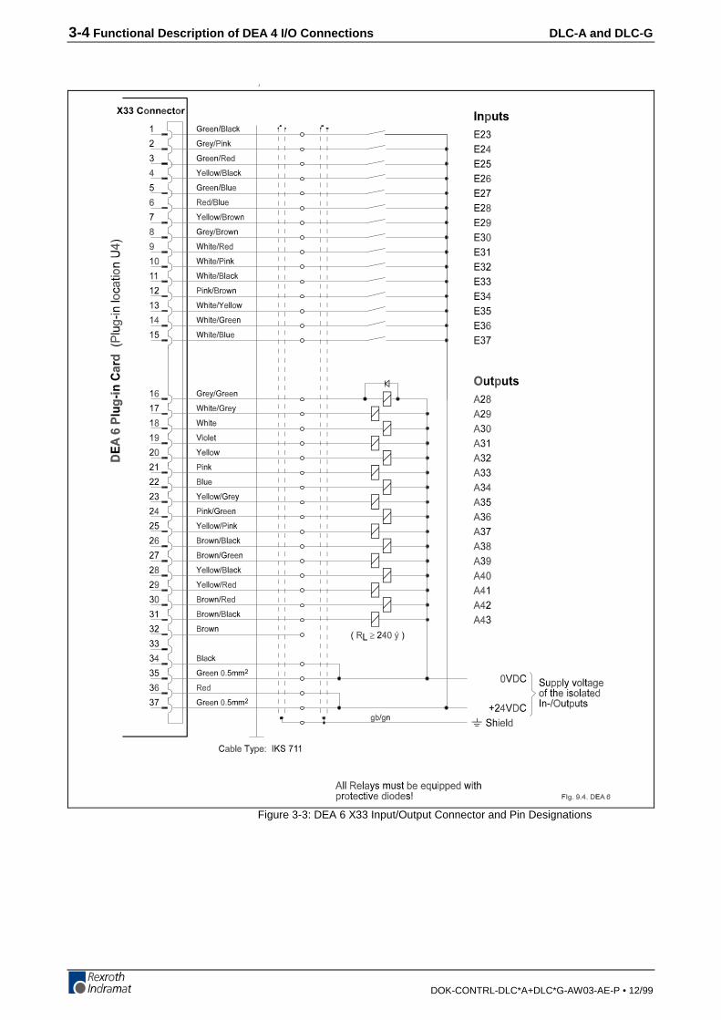
3-4 Functional Description of DEA 4 I/O Connections DLC-A and DLC-G
DOK-CONTRL-DLC*A+DLC*G-AW03-AE-P • 12/99
.1
Figure 3-3: DEA 6 X33 Input/Output Connector and Pin Designations
DLC-A and DLC-G Functional Description of DEA 4 I/O Connections 3-5
DOK-CONTRL-DLC*A+DLC*G-AW03-AE-P • 12/99
Operating Mode Selection
InputsParameter Mode Select (3.3)
Automatic Mode Select (3.3)
OutputsManual Mode Indicator (3.4)
Auto Mode Indicator (3.4)
Parameter Mode Indicator (3.4)
The DLC will always be in one of three operating modes:
• Parameter Mode - Allows entry/verification of the parametersrequired to adapt the control for the specific requirements of theapplication.
• Automatic Mode - Runs the user written executable program forautomatic cycle operation (Task 1 and 2 run after a Cycle Start input).
• Manual Mode - Default mode when neither of the above areselected. In this mode, the jog inputs are used to position the axisforward or reverse, through the system.
Parameter and Automatic Modes are selected by bringing the appropriatesignal line high (+24 Vdc). A fault is diagnosed and an "Invalid ModeSelection" error message is issued if Parameter Mode is selected whileAutomatic Mode is selected.
The suggested interface design is to wire the Parameter Mode signal to akey-switch, where a key is required to enter Parameter Mode and/ormount the switch inside the cabinet. This helps to prevent unauthorizedparameter changes. Wire the Automatic Mode input signal to a two-position selector switch, where Manual Mode is selected when the switchis set to an open contact position.
The DLC has outputs to verify or acknowledge the currently selectedmode. These are typically wired to indicator lights on the user's controlpanel or to a PLC.
3-6 Functional Description of DEA 4 I/O Connections DLC-A and DLC-G
DOK-CONTRL-DLC*A+DLC*G-AW03-AE-P • 12/99
Safety Interlocks
Inputs• 'OGTIGPE[�5VQR (3.3)
'OGTIGPE[�5VQR -- The 'OGTIGPE[�5VQR input must remain high forthe DLC to operate. The system incorporates an Emergency Stop (E-Stop) chain. This is a circuit connected in series to both the DLC and theuser's machine. Should any sensor in the E-stop chain open, alloperations immediately stop. Note that the time taken to stop depends onthe wiring method used, and inertia of the load connected to the servomotor on the machine. Note that task 3 of the user program continues torun during an 'OGTIGPE[�5VQR fault condition. When 'OGTIGPE[�5VQRis reset and a “CLEAR” signal is issued, task 3 starts at the beginningblock and continues to run.
Elements connected in the E-stop chain commonly include the'OGTIGPE[�5VQR switch on the user's control panel; E-stop switch(es)on the machine; switches on lubrication or coolant pumps; and varioussafety interlock switches on guards and doors.
Outputs
• 5[UVGO�(CWNV Indicator (3.4)
There are several categories of faults, as described in Chapter 8. Ingeneral, once a fault is detected, an error message is displayed on theCTA display, the 5[UVGO�(CWNV Indicator output turns OFF and all axesare immediately decelerated to a stop.
The fault recovery procedure is to first troubleshoot and remedy theproblem. Then, press the Clear key on the DLC control panel (or externalClear input on user control panel, see section 3.2.6) to clear the DLC faultstatus and diagnostic message on the display.
DLC-A and DLC-G Functional Description of DEA 4 I/O Connections 3-7
DOK-CONTRL-DLC*A+DLC*G-AW03-AE-P • 12/99
Normal Operation Signals
InputsCycle Start (3.3)
%[ENG�5VQR (3.3)
The automatic execution of the user program begins when the Cycle Startline goes high (momentary) with the DLC in Automatic Mode. Once theautomatic cycle begins, it is normally stopped by actuating the%[ENG�5VQR input (signal goes low). The system will also stop if an erroris detected or if the DLC is switched to Manual Mode.
OutputsAxis Nearing Position (Pre Signal) (A107)
Axis In-Position (A106)
An auxiliary output (Position Pre-signal) can be assigned in parameterA107 to turn ON when the axis position is at a specified distance (in inputunits) from the target position of the commanded feed. Use this pre-signalwhen there is a need to anticipate the end of a feed, so another processcan be initiated ahead of time. An example use would be to turn on aheater for bag sealing or plastic thermal forming operations. See Chapter4 for further information on this parameter function.
An auxiliary output (Axis In-Position) can be assigned in parameter A106to turn ON when the axis position is within the position threshold specifiedin this parameter. This position threshold does not affect the accuracy ofthe feed. It tells the program when to read the next program block (seePSI, PSA in Chapter 5). This output can be used to turn ON a light orbuzzer on the user's control panel, or as a flag in the program to start asub-routine program operation, etc. See Chapter 4 for further informationon this parameter function.
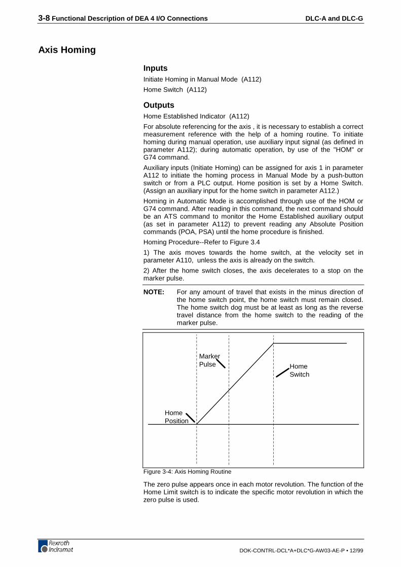
3-8 Functional Description of DEA 4 I/O Connections DLC-A and DLC-G
DOK-CONTRL-DCL*A+DLC*G-AW03-AE-P • 12/99
Axis Homing
InputsInitiate Homing in Manual Mode (A112)
Home Switch (A112)
OutputsHome Established Indicator (A112)
For absolute referencing for the axis , it is necessary to establish a correctmeasurement reference with the help of a homing routine. To initiatehoming during manual operation, use auxiliary input signal (as defined inparameter A112); during automatic operation, by use of the "HOM" orG74 command.
Auxiliary inputs (Initiate Homing) can be assigned for axis 1 in parameterA112 to initiate the homing process in Manual Mode by a push-buttonswitch or from a PLC output. Home position is set by a Home Switch.(Assign an auxiliary input for the home switch in parameter A112.)
Homing in Automatic Mode is accomplished through use of the HOM orG74 command. After reading in this command, the next command shouldbe an ATS command to monitor the Home Established auxiliary output(as set in parameter A112) to prevent reading any Absolute Positioncommands (POA, PSA) until the home procedure is finished.
Homing Procedure--Refer to Figure 3.4
1) The axis moves towards the home switch, at the velocity set inparameter A110, unless the axis is already on the switch.
2) After the home switch closes, the axis decelerates to a stop on themarker pulse.
NOTE: For any amount of travel that exists in the minus direction ofthe home switch point, the home switch must remain closed.The home switch dog must be at least as long as the reversetravel distance from the home switch to the reading of themarker pulse.
MarkerPulse Home
Switch
HomePosition
Figure 3-4: Axis Homing Routine
The zero pulse appears once in each motor revolution. The function of theHome Limit switch is to indicate the specific motor revolution in which thezero pulse is used.

DLC-A and DLC-G Functional Description of DEA 4 I/O Connections 3-9
DOK-CONTRL-DLC*A+DLC*G-AW03-AE-P • 12/99
In the homing procedure, regardless of the beginning position, the slidemust stop on the Home Limit switch, closing it. The next zero pulse afterthe closing of the Home Limit switch indicates the reference position.
In many cases, some position other than home, such as the center line ofthe machine, is used as the reference position for machining. Allprogrammed distances are then specified in reference to this point. Thisis established by entering the distance from home to the new referencelocation as the Reference Position (Homing Offset) in parameter A111.When the control is homed, this value will be loaded into the positioncounter, and all moves will be made in reference to this position.
Placement of the Homing SwitchAs described above, the reference position of the AC servo drive isdetermined after it has moved onto the switch.
The reference position can be set in steps of one motor revolution each,by using the position the switch is in when it is activated. By monitoringthe switching point of the homing switch and the marker pulse, a DLCdiagnostic check eliminates the danger that these two are so close toeach other that the switching tolerance limits will result in uncertaintyabout the motor revolution to be evaluated. If the switching point of thehoming switch is closer than 1/16 of a motor revolution, with respect tothe marker pulse, the control unit will not complete the homing process,and will change over to fault indication. The display will show: "MarkerPulse 1?.” The homing switch should be relocated by 1/3 of the feedconstant.
3-10 Functional Description of DEA 4 I/O Connections DLC-A and DLC-G
DOK-CONTRL-DLC*A+DLC*G-AW03-AE-P • 12/99
Activating the Homing SwitchActivating the homing switch must be done in such a way that the switchcloses upon backing up, i.e. upon the movement away from the workpiece. The dog cam for activating the homing switch must be long enoughso that the activation is not canceled by a continuing reverse movementup to the minus travel limit of the axis. This is required to indicate to thecontrol unit in which direction the slide must be moved in order toapproach the reference position.
Since the interrelationship between the direction of rotation of a servomotor and the movement away from, and toward, the work piece dependson the particular design of the machine, the homing direction must bealso set correctly in the parameters.
If there is no marker pulse within one revolution of the motor's feedback,homing sequence is halted, and a fault is displayed. The display will show:"No Marker Pulse 1.”
Interruption of the Homing RoutineIf, while in manual operation, there is a stop, an interruption, feed anglemonitoring, or a switch of operating modes, the homing cycle isinterrupted and must be restarted. After an interruption or stop occurswhile in automatic operation, the homing cycle is restarted immediately byactivating the Cycle Start input and initiating a HOM or G74 command inthe program. After a fault or a change of operating modes during thehoming cycle, the DLC must be re-initiated (switch to Auto Mode, pressCycle Start).
Over-Travel SwitchesIt is recommended that you install forward and reverse over-travelswitches on applications that have limited axis travel, such as a slide or aballscrew driven axis. The switches should be wired to the %[ENG�5VQRinput of the DLC. You must reserve distance beyond the limit switches toallow for the axis to decelerate to a stop.

DLC-A and DLC-G Functional Description of DEA 4 I/O Connections 3-11
DOK-CONTRL-DLC*A+DLC*G-AW03-AE-P • 12/99
Manual Mode Operations
Inputs• Jog Forward (3.3)
• Jog Reverse (3.3)
• Initiate Manual Vector Program (B011)
The Jog inputs allow the axis to jog in the forward or reverse direction.Parameter A101 specifies the axis jog feed rate for Axis 1. It usually is setto approximately 10% of the maximum feed rate. It can never be morethan the maximum feed rate.
In Manual Mode, the axis can be jogged forward or reverse. The Joginputs are not functional in Parameter or Automatic Modes. A high on theJog Forward input causes the axis to feed forward at the velocity set inparameter A101. The feed continues as long as the Jog Forward remainshigh. The Jog Reverse operates similarly, jogging the axis in the reversedirection.
In order to make use of the software travel limits when in Manual Mode,the axis must be homed first. It is recommended to prevent jogging byinterlocking with the Home Established output (A112), until the axis homeposition is established.
An auxiliary input, Initiate Manual Vector Program , can be assigned inparameter B011 and used to initiate a user program to run in ManualMode. This program must not contain any feed instructions and shouldnot be located in the main program. Select by parameter to start thisprogram by an external input (push-button switch) or automatically whenmode is changed from Automatic to Manual. The program is aborted ifswitched out of Manual Mode. The manual vector is not accepted whilejogging or homing in Manual Mode (see last section). Jogging or homingis not possible while the manual vector program is running. The manualvector program must end with an RTS command.
An example use of the Manual Vector program is to use the APEcommand to set the states of auxiliary outputs. This command isprogrammed to set a bank/group of ten outputs individually to ON, OFF orDon't Care states. This allows setting outputs for a "shut-down" mode, oras default before starting automatic operation. See Chapter 4 foradditional information on parameters and Chapter 5 for programmingcommands.
Outputs• Manual mode indicator
Refer to Section (3.2) Operating Mode Selection (Manual Mode Indicator(3.4))
3-12 Functional Description of DEA 4 I/O Connections DLC-A and DLC-G
DOK-CONTRL-DLC*A+DLC*G-AW03-AE-P • 12/99
Fault/Diagnostic Monitoring
Inputs• Clear (External) (3.3)
The fault recovery procedure is to first troubleshoot and remedy theproblem. Then, press the Clear key on the CTA control panel (or externalClear input on user control panel) to clear the DLC fault status anddiagnostic message on the display.
Outputs
5[UVGO�(CWNV Indicator (3.4)
The DLC includes extensive diagnostic monitoring circuitry, detectingnormal operating status, operator errors, errors in the control itself andmachine faults.
There are several categories of faults, as described in Chapter 8. Ingeneral, once a fault is detected, an error message is displayed on theCTA display, the 5[UVGO�(CWNV Indicator output turns off and the axiswill decelerated to a stop. If the system is operating properly, the5[UVGO�(CWNV Indicator output will be on.
DLC-A and DLC-G Functional Description of DEA 4 I/O Connections 3-13
DOK-CONTRL-DLC*A+DLC*G-AW03-AE-P • 12/99
Feed Monitoring / Program Interruption
Inputs• Interrupt Vector Program (B012)
• Feed Angle Monitoring (A120)
• (GGF�+PVGTTWRV (A120)
An auxiliary input, Interrupt Vector/Program, can be assigned inparameter B012 to interrupt the user program at any time and start anInterrupt Vector sub-routine program (Automatic Mode Task 1 only).When this input goes high, the current program sequence will beinterrupted immediately or after the current subroutine program is finished(option set in parameter). The program sequence will then continue at thestart program block number assigned in the parameter for the InterruptVector program. See Chapter 4 for further information on this parameterfunction.
An auxiliary input, Feed Angle Monitoring, can be assigned in parameterA120 to prevent the program from executing any position commands. TheDLC will process all program blocks not containing any positioncommands. If there is no signal at the assigned input, the programcontinues to execute until it processes to a block containing a positioncommand. The DLC will stop in this block until there is a signal at theinput. If the input signal turns OFF during a feed, the feed will be stoppedand an error message will be displayed.
An auxiliary input, (GGF�+PVGTTWRV ((GGF�*QNF ) can be assigned inparameter A120 to prevent the program from executing any positioncommands. The DLC will process all program blocks not containing anyfeed lengths. If the input is low, the program continues to execute until itprocesses to a block containing a feed length. The DLC will stop in thisblock until the assigned input goes high. If the input goes low duringpositioning, the positioning will be stopped. Positioning will automaticallyresume as soon as the signal goes high.
An example of use for this signal is in conjunction with a material loop.Material is fed from an uncoiler into a looping pit, with an optical sensor inthe pit tied to the (GGF�+PVGTTWRV line. If the material pulls too tight, thesignal goes low and the cycle is interrupted. As soon as an adequateamount of material is fed into the looping pit, the signal returns high andthe cycle immediately resumes. See Chapter 4 for further information onthis parameter function.
WARNING: If the automatic cycle is interrupted by a low on the(GGF�+PVGTTWRV line, all motion is suspended. Once thissignal is restored high, the cycle will immediately resume.The work area should not be entered if the motion hasstopped as a result of this signal.
3-14 Functional Description of DEA 4 I/O Connections DLC-A and DLC-G
DOK-CONTRL-DLC*A+DLC*G-AW03-AE-P • 12/99
Special Functions
Inputs• Detect Registration Mark
• Enable Measuring Wheel Operation and Dual Encoder Option
An auxiliary input, Detect Registration Mark , can be assigned in the REFcommand to cause the DLC to search for a registration mark on thematerial. To provide this input signal, use a sensor which detects aprinted mark or stamp on each piece of material. A high signal must bepresent on this input when a reference mark is present under the sensor.The accuracy and duration of this signal is essential to the properoperation of position correction, especially if the mark needs to bedetected at high speeds. The DLC can detect a registration input signal in1 millisecond. Refer to the REF program command in Chapter 5 foradditional information on using this feature.
For External Encoder operation , an optional encoder input card must beinstalled in the Indramat Digital Drive Product. Also, the external encoderoption must be enable in parameters A123, B016 through B022. Theseparameters enable the external encoder function and establish the feedconstant and the number impulses of the encoder. They also allowassigning an auxiliary input for selecting either the external encoder ormotor high resolution feedback. During external encoder operation, themeasurement of lengths is from the external encoder, rather than themotor's high resolution feedback.
The Dual Encoder Option in parameter A123 allows quicker responsewith external encoder operation. When selected, the position loop isclosed using motor high resolution feedback and the external encoderprovides adjustments to the length during feeding. When this option is notselected, the Position Loop is closed using the external encoder. Lack ofstiffness in the mechanical components between the motor and theexternal encoder can require using a lower gain, which decreases theresponse time.
During manual operation, the position feedback always comes from themotor's high resolution feedback. During automatic operation, there is achoice between continuous external encoder operation and using anauxiliary input signal to select external encoder operation.
Error messages are:
a) Excess Pos. Lag
b) Drive Runaway
c) External Enc. Error
Outputs• Achieved Programmed Velocity
The Achieved Programmed Velocity Output is an auxiliary output whichcan be assigned to turn on when the commanded velocity is equal to theactual velocity. This auxiliary output is programmed in the SpecialFunction parameter A115.
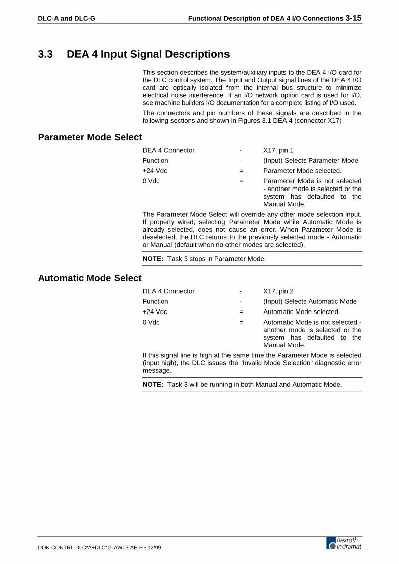
DLC-A and DLC-G Functional Description of DEA 4 I/O Connections 3-15
DOK-CONTRL-DLC*A+DLC*G-AW03-AE-P • 12/99
3.3 DEA 4 Input Signal Descriptions
This section describes the system/auxiliary inputs to the DEA 4 I/O card forthe DLC control system. The Input and Output signal lines of the DEA 4 I/Ocard are optically isolated from the internal bus structure to minimizeelectrical noise interference. If an I/O network option card is used for I/O,see machine builders I/O documentation for a complete listing of I/O used.
The connectors and pin numbers of these signals are described in thefollowing sections and shown in Figures 3.1 DEA 4 (connector X17).
Parameter Mode SelectDEA 4 Connector - X17, pin 1
Function - (Input) Selects Parameter Mode
+24 Vdc = Parameter Mode selected.
0 Vdc = Parameter Mode is not selected- another mode is selected or thesystem has defaulted to theManual Mode.
The Parameter Mode Select will override any other mode selection input.If properly wired, selecting Parameter Mode while Automatic Mode isalready selected, does not cause an error. When Parameter Mode isdeselected, the DLC returns to the previously selected mode - Automaticor Manual (default when no other modes are selected).
NOTE: Task 3 stops in Parameter Mode.
Automatic Mode SelectDEA 4 Connector - X17, pin 2
Function - (Input) Selects Automatic Mode
+24 Vdc = Automatic Mode selected.
0 Vdc = Automatic Mode is not selected -another mode is selected or thesystem has defaulted to theManual Mode.
If this signal line is high at the same time the Parameter Mode is selected(input high), the DLC issues the "Invalid Mode Selection" diagnostic errormessage.
NOTE: Task 3 will be running in both Manual and Automatic Mode.

3-16 Functional Description of DEA 4 I/O Connections DLC-A and DLC-G
DOK-CONTRL-DLC*A+DLC*G-AW03-AE-P • 12/99
Emergency Stop
DEA 4 Connector - X17, pin 3
Function - (Input) Commands the servosystem to stop immediately
+24 Vdc = Allows the DLC to operateproperly.
0 Vdc = The servo system iscommanded immediately to zerovelocity. Drive reaches zerospeed in the minimum timepossible - given the inertia andmaximum torque available. TheDLC issues an "EmergencyStop" diagnostic message.
WARNING: This signal must be used to ensure safety.
WARNING: The E-Stop signal should go through the Zks input on theDKS drive (X9, pin 1 & 2) in series with this DLC input.
Conditions which warrant pressing the E-Stop include:
1. Any condition posing an immediate danger to personnel.
2. A jam in the machinery or any other condition that poses animmediate harm to the system equipment.
NOTE: The Task 3 program will continue to operate during an E-Stopcondition. When the E-Stop condition no longer exists and theclear input is issued, Task 3 will jump to the first block in Task3 and then run.
Cycle StartDEA 4 Connector - X17, pin 4
Function - (Input) Starts automatic cycle
+24 Vdc = (momentary) Starts theexecution of the programs inTask 1 and 2, when AutomaticMode is selected.
0 Vdc = Has no effect on the systemoperation. Once initiated, only asystem failure (fault or error), thepresence of the'OGTIGPE[�5VQR or
%[ENG�5VQR (or user defined
(GGF�+PVGTTWRV ) will halt theautomatic cycle.
This input is typically wired to a normally open push-button switch on theuser control panel.
NOTE: Task 3 will be running in both Manual and Automatic Mode.

DLC-A and DLC-G Functional Description of DEA 4 I/O Connections 3-17
DOK-CONTRL-DLC*A+DLC*G-AW03-AE-P • 12/99
Cycle Stop
DEA 4 Connector - X17, pin 5Function - (Input) Used to stop the
automatic cycle+24 Vdc = (Continuous) Allows Automatic
Mode operation.0 Vdc = (Momentary) Stops the
execution of the program in Task1 and 2 in Automatic Mode.
This input is typically wired to a normally closed push-button switch on theuser control panel.When this input goes low during the execution of a program in Task 1 and2, the program will stop in the block it is currently executing. When a cyclestart is re-applied, the program will continue from where it stopped. If aposition command is executing and a cycle stop is applied, the axis willimmediately decelerate to a stop. The deceleration rate is the same asthe acceleration rate.
NOTE: The axis cannot be jogged when this input is low.
Jog ForwardDEA 4 Connector - X17, pin 6, for Axis 1Function - (Input) Jogs the axis in the
forward direction+24 Vdc = In Manual Mode, the axis feeds
forward at the velocity set inParameters A101. The axis willfeed forward as long as the highsignal is present (switch heldclosed).
0 Vdc = In Manual Mode, the axis stopsfeeding forward when a lowsignal is present (switch isreleased).
This input is typically wired to a normally open push-button switch on theuser control panel.Jog Forward is not functional when the DLC is in the Parameter orAutomatic Mode.
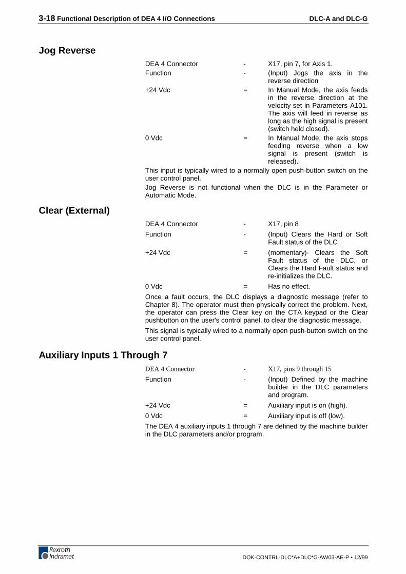
3-18 Functional Description of DEA 4 I/O Connections DLC-A and DLC-G
DOK-CONTRL-DLC*A+DLC*G-AW03-AE-P • 12/99
Jog ReverseDEA 4 Connector - X17, pin 7, for Axis 1.Function - (Input) Jogs the axis in the
reverse direction+24 Vdc = In Manual Mode, the axis feeds
in the reverse direction at thevelocity set in Parameters A101.The axis will feed in reverse aslong as the high signal is present(switch held closed).
0 Vdc = In Manual Mode, the axis stopsfeeding reverse when a lowsignal is present (switch isreleased).
This input is typically wired to a normally open push-button switch on theuser control panel.Jog Reverse is not functional when the DLC is in the Parameter orAutomatic Mode.
Clear (External)DEA 4 Connector - X17, pin 8
Function - (Input) Clears the Hard or SoftFault status of the DLC
+24 Vdc = (momentary)- Clears the SoftFault status of the DLC, orClears the Hard Fault status andre-initializes the DLC.
0 Vdc = Has no effect.
Once a fault occurs, the DLC displays a diagnostic message (refer toChapter 8). The operator must then physically correct the problem. Next,the operator can press the Clear key on the CTA keypad or the Clearpushbutton on the user's control panel, to clear the diagnostic message.
This signal is typically wired to a normally open push-button switch on theuser control panel.
Auxiliary Inputs 1 Through 7DEA 4 Connector - X17, pins 9 through 15
Function - (Input) Defined by the machinebuilder in the DLC parametersand program.
+24 Vdc = Auxiliary input is on (high).
0 Vdc = Auxiliary input is off (low).
The DEA 4 auxiliary inputs 1 through 7 are defined by the machine builderin the DLC parameters and/or program.
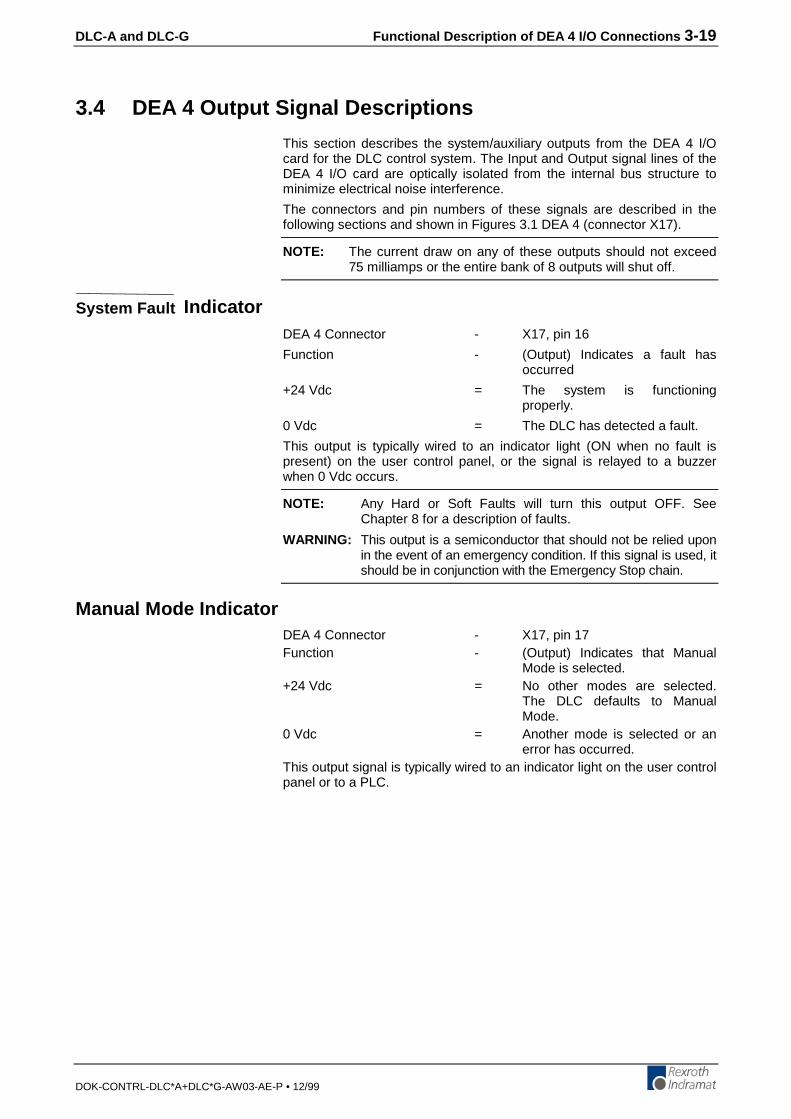
DLC-A and DLC-G Functional Description of DEA 4 I/O Connections 3-19
DOK-CONTRL-DLC*A+DLC*G-AW03-AE-P • 12/99
3.4 DEA 4 Output Signal Descriptions
This section describes the system/auxiliary outputs from the DEA 4 I/Ocard for the DLC control system. The Input and Output signal lines of theDEA 4 I/O card are optically isolated from the internal bus structure tominimize electrical noise interference.
The connectors and pin numbers of these signals are described in thefollowing sections and shown in Figures 3.1 DEA 4 (connector X17).
NOTE: The current draw on any of these outputs should not exceed75 milliamps or the entire bank of 8 outputs will shut off.
System Fault IndicatorDEA 4 Connector - X17, pin 16
Function - (Output) Indicates a fault hasoccurred
+24 Vdc = The system is functioningproperly.
0 Vdc = The DLC has detected a fault.
This output is typically wired to an indicator light (ON when no fault ispresent) on the user control panel, or the signal is relayed to a buzzerwhen 0 Vdc occurs.
NOTE: Any Hard or Soft Faults will turn this output OFF. SeeChapter 8 for a description of faults.
WARNING: This output is a semiconductor that should not be relied uponin the event of an emergency condition. If this signal is used, itshould be in conjunction with the Emergency Stop chain.
Manual Mode IndicatorDEA 4 Connector - X17, pin 17Function - (Output) Indicates that Manual
Mode is selected.+24 Vdc = No other modes are selected.
The DLC defaults to ManualMode.
0 Vdc = Another mode is selected or anerror has occurred.
This output signal is typically wired to an indicator light on the user controlpanel or to a PLC.
3-20 Functional Description of DEA 4 I/O Connections DLC-A and DLC-G
DOK-CONTRL-DLC*A+DLC*G-AW03-AE-P • 12/99
Automatic Mode IndicatorDEA 4 Connector - X17, pin 18Function - (Output) Indicates that Automatic
Mode is selected+24 Vdc = Automatic Mode is selected.0 Vdc = Another mode is currently
selected, or normal conditionsthat allow Automatic Modeoperation are not satisfactory, ora fault is preventing entry intoAutomatic Mode.
This output signal is typically wired to an indicator light on the user controlpanel or to a PLC.
Parameter Mode IndicatorDEA 4 Connector - X17, pin 19
Function - (Output) Indicates thatParameter Mode is selected.
+24 Vdc = Parameter Mode is selected.This overrides any other modeselection.
0 Vdc = Parameter Mode is not selected.
This output signal is typically wired to an indicator light on the user controlpanel or to a PLC.
Automatic Cycle Running IndicatorDEA 4 Connector - X17, pin 20
Function - (Output) Indicates that AutomaticMode is selected and cycle starthas been pressed.
+24 Vdc = Automatic Mode is selected andthe cycle start has been pressedto start the user program in Task1 and 2.
0 Vdc = Automatic Mode is not selected.
Automatic Mode is selected and cycle start has not been pressed. Anerror has occurred, preventing the operation of the automatic cycle.
This output signal is typically wired to an indicator light on the user controlpanel or to a PLC.
Auxiliary Outputs 1 Through 11DEA 4 Connector - X17, pins 21 through 31
Function - (Output) Defined by the machinebuilder in the DLC parametersand program.
+24 Vdc = Auxiliary output is on (high).
0 Vdc = Auxiliary output is off (low).
The DEA 4 auxiliary outputs 1 through 11 are defined by the machinebuilder in the DLC parameters and/or program.

DLC-A and DLC-G Parameters 4-1
DOK-CONTRL-DLC*A+DLC*G-AW03-AE-P • 12/99
4 ParametersThis chapter describes the user-entered parameters required for the DLCto perform the motion control operation. The user adapts the DLC to hismachine and the mechanical characteristics of the application by enteringvalues for various parameters. These parameters permit a standardcontrol system to conform to different but similar applications. It alsoassures that all application parameters are written with a uniform dataformat. The user must enter parameter values into the DLC memory priorto the operation and programming of the DLC control.
Note: All values for parameters must be known before an applicationprogram can be written. If a function is programmed orattempted which would exceed the bounds established by theparameters, the control will halt and a diagnostic error will bedisplayed.
4.1 Description of Parameter Sets
The DLC includes the following sets of parameters.
Parameter Set A (Axis Parameters):
This axis parameter set (A100 through A125) includes the axis operatingvalues for Automatic and Manual Mode operation. These parametersallow the user to configure the DLC for the motor and drive package thatthe DLC is controlling. They also allow the user to set the various factorsof the motion profile, as required for the material and application. Theseinclude the resolution of the feed, acceleration rate, feed rate in differentmodes, etc.
Parameter Set B (System Parameters):
This system parameter set establishes the operating arrangement of theDLC. It allows the user to configure the DLC for various options such asthe language that shows on the display (English, German, SpanishFrench, Italian, or Portuguese); selecting control interface options, suchas the IDS or SOT; selecting and configuring other optional features likesynchronization, measuring wheel operation, multi-tasking, etc.
Parameter Set C (Drive Parameters):
This parameter set allows drive tuning through the DLC. Drive parameterscan be tuned using the CTA keypad or RS232 serial interface. Defaultdrive parameters can be set only by using the CTA keypad. Processingmust not occur simultaneously over the CTA keypad and RS232 serialdrive interface. Drive parameters are viewed and edited in the samemanner as for A and B parameters. C parameters are administered in thedrive. With each new power-up, the C parameters are sent from the driveto the DLC.
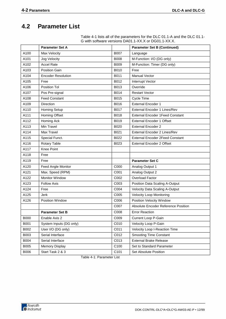
4-2 Parameters DLC-A and DLC-G
DOK-CONTRL-DLC*A+DLC*G-AW03-AE-P • 12/99
4.2 Parameter List
Table 4-1 lists all of the parameters for the DLC 01.1-A and the DLC 01.1-G with software versions DA01.1-XX.X or DG01.1-XX.X.
Parameter Set A Parameter Set B (Continued)
A100 Max Velocity B007 Language
A101 Jog Velocity B008 M-Function: I/O (DG only)
A102 Accel Rate B009 M-Function: Timer (DG only)
A103 Position Gain B010 Free
A104 Encoder Resolution B011 Manual Vector
A105 Free B012 Interrupt Vector
A106 Position Tol B013 Override
A107 Pos Pre-signal B014 Restart Vector
A108 Feed Constant B015 Cycle Time
A109 Direction B016 External Encoder 1
A110 Homing Setup B017 External Encoder 1 Lines/Rev
A111 Homing Offset B018 External Encoder 1Feed Constant
A112 Homing Ack B019 External Encoder 1 Offset
A113 Min Travel B020 External Encoder 2
A114 Max Travel B021 External Encoder 2 Lines/Rev
A115 Special Funct. B022 External Encoder 2Feed Constant
A116 Rotary Table B023 External Encoder 2 Offset
A117 Knee Point
A118 Free
A119 Free Parameter Set C
A120 Feed Angle Monitor C000 Analog Output 1
A121 Max. Speed (RPM) C001 Analog Output 2
A122 Monitor Window C002 Overload Factor
A123 Follow Axis C003 Position Data Scaling A-Output
A124 Free C004 Velocity Data Scaling A-Output
A125 Jerk C005 Velocity Loop Monitoring
A126 Position Window C006 Position Velocity Window
C007 Absolute Encoder Reference Position
Parameter Set B C008 Error Reaction
B000 Enable Axis 2 C009 Current Loop P-Gain
B001 System Inputs (DG only) C010 Velocity Loop P-Gain
B002 User I/O (DG only) C011 Velocity Loop I-Reaction Time
B003 Serial Interface C012 Smooting Time Constant
B004 Serial Interface C013 External Brake Release
B005 Memory Display C100 Set to Standard Parameter
B006 Start Task 2 & 3 C101 Set Absolute Position
Table 4-1: Parameter List
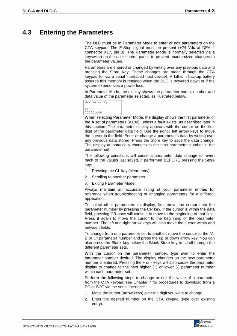
DLC-A and DLC-G Parameters 4-3
DOK-CONTRL-DLC*A+DLC*G-AW03-AE-P • 12/99
4.3 Entering the Parameters
The DLC must be in Parameter Mode to enter or edit parameters on theCTA keypad. The E-Stop signal must be present (+24 Vdc at DEA 4connector X17, pin 3). The Parameter Mode is normally selected via akeyswitch on the user control panel, to prevent unauthorized changes tothe parameter values.
Parameters are entered or changed by writing over any previous data andpressing the Store Key. These changes are made through the CTAkeypad (or via a serial interfaced host device). A Lithium backup batteryassures this memory is retained when the DLC is powered down or if thesystem experiences a power loss.
In Parameter Mode, the display shows the parameter name, number anddata value of the parameter selected, as illustrated below.
When selecting Parameter Mode, the display shows the first parameter ofthe A set of parameters (A100), unless a fault exists, as described later inthis section. The parameter display appears with the cursor on the firstdigit of the parameter data field. Use the right / left arrow keys to movethe cursor in the field. Enter or change a parameter's data by writing overany previous data stored. Press the Store key to save the data change.The display automatically changes to the next parameter number in theparameter set.
The following conditions will cause a parameter data change to revertback to the values last saved, if performed BEFORE pressing the Storekey:
1. Pressing the CL key (clear entry),
2. Scrolling to another parameter,
3. Exiting Parameter Mode.
Always maintain an accurate listing of your parameter entries forreference when troubleshooting or changing parameters for a differentapplication.
To select other parameters to display, first move the cursor onto theparameter number by pressing the CR key. If the cursor is within the datafield, pressing CR once will cause it to move to the beginning of that field.Press it again to move the cursor to the beginning of the parameternumber. The left and right arrow keys will also move the cursor within andbetween fields.
To change from one parameter set to another, move the cursor to the “A,B or C” parameter number and press the up or down arrow key. You canalso press the Blank key below the Block Store key to scroll through thedifferent parameter sets.
With the cursor on the parameter number, type over to enter theparameter number desired. The display changes as the new parameternumber is entered. Pressing the + or - keys will also cause the parameterdisplay to change to the next higher (+) or lower (-) parameter numberwithin each parameter set.
Perform the following steps to change or edit the value of a parameterfrom the CTA keypad; see Chapter 7 for procedures to download from aPC or SOT via the serial interface:
1. Move the cursor (arrow keys) over the digit you want to change.
2. Enter the desired number on the CTA keypad (type over existingentry).
Max Velocity
A10000050.000
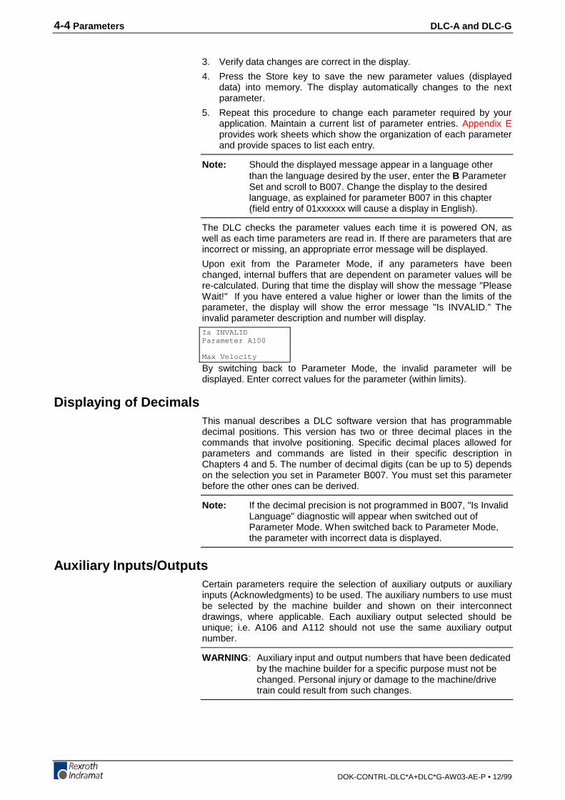
4-4 Parameters DLC-A and DLC-G
DOK-CONTRL-DLC*A+DLC*G-AW03-AE-P • 12/99
3. Verify data changes are correct in the display.
4. Press the Store key to save the new parameter values (displayeddata) into memory. The display automatically changes to the nextparameter.
5. Repeat this procedure to change each parameter required by yourapplication. Maintain a current list of parameter entries. Appendix Eprovides work sheets which show the organization of each parameterand provide spaces to list each entry.
Note: Should the displayed message appear in a language otherthan the language desired by the user, enter the B ParameterSet and scroll to B007. Change the display to the desiredlanguage, as explained for parameter B007 in this chapter(field entry of 01xxxxxx will cause a display in English).
The DLC checks the parameter values each time it is powered ON, aswell as each time parameters are read in. If there are parameters that areincorrect or missing, an appropriate error message will be displayed.
Upon exit from the Parameter Mode, if any parameters have beenchanged, internal buffers that are dependent on parameter values will bere-calculated. During that time the display will show the message "PleaseWait!" If you have entered a value higher or lower than the limits of theparameter, the display will show the error message "Is INVALID.” Theinvalid parameter description and number will display.
By switching back to Parameter Mode, the invalid parameter will bedisplayed. Enter correct values for the parameter (within limits).
Displaying of DecimalsThis manual describes a DLC software version that has programmabledecimal positions. This version has two or three decimal places in thecommands that involve positioning. Specific decimal places allowed forparameters and commands are listed in their specific description inChapters 4 and 5. The number of decimal digits (can be up to 5) dependson the selection you set in Parameter B007. You must set this parameterbefore the other ones can be derived.
Note: If the decimal precision is not programmed in B007, "Is InvalidLanguage" diagnostic will appear when switched out ofParameter Mode. When switched back to Parameter Mode,the parameter with incorrect data is displayed.
Auxiliary Inputs/OutputsCertain parameters require the selection of auxiliary outputs or auxiliaryinputs (Acknowledgments) to be used. The auxiliary numbers to use mustbe selected by the machine builder and shown on their interconnectdrawings, where applicable. Each auxiliary output selected should beunique; i.e. A106 and A112 should not use the same auxiliary outputnumber.
WARNING: Auxiliary input and output numbers that have been dedicatedby the machine builder for a specific purpose must not bechanged. Personal injury or damage to the machine/drivetrain could result from such changes.
Is INVALIDParameter A100
Max Velocity
DLC-A and DLC-G Parameters 4-5
DOK-CONTRL-DLC*A+DLC*G-AW03-AE-P • 12/99
Unit of MeasurementThe user specifies most parameter data in terms of input units (IU). A unitis defined by the user, and can be feet, inches, millimeters, degrees,radians, etc. Once the user has chosen the unit of measurement, then allposition and feed rate data must be in accordance to that unit, where it islogically required.
For example, the input unit could be specified as inches. The maximumfeed rate in parameter A100 will be programmed in inches per second.The acceleration parameter would then be in units of inches per secondsquared.
The F== feedrate command calculates the feed rate for you using theformula (Parameter A108 x 60). Therefore, all speeds programmed usingthe F== command are always in units-per-minute (upm).
Note that positioning commands for the application program are to two orthree decimal places. If you require positioning to 0.001,” set the decimalselection in parameter B007 to three places. In general, when using USSystem (inches) measurements, set B007 for three decimal places. Whenusing Metric (millimeters), set B007 for two decimal places.
4.4 Linear or Rotary Operation
The DLC is capable of Linear or Rotary operation for each axis. Mostapplications will utilize the linear method of programming (i.e. Ball Screw,Belt, Slide). Some applications require the special features allowed withrotary programming (A116 - Rotary Table).
Linear operation (programming) allows each axis minimum andmaximum software over-travel limits (effective after the axis has beenhomed). Motions can be programmed in any type of Input Units (i.e.inches, mm, degrees, etc.).
Rotary operation (programming) allows each axis the capability of 360degrees of motion. The actual position screen (L P Screen), counts from0 degrees to the value set in A108, resetting back to zero after eachcomplete revolution (360 degrees). Each axis can be programmed tomake multiple revolutions in either direction (direction is relative to theprogramming of A109 - Direction of Operation). The software over-travellimits are disabled when implementing rotary programming.
4-6 Parameters DLC-A and DLC-G
DOK-CONTRL-DLC*A+DLC*G-AW03-AE-P • 12/99
4.5 Parameter Descriptions
The following sections describe each parameter, as required for the DLCto command motion. Each parameter description includes an illustrationof the CTA display and the formula required to obtain the parametervalue, where applicable.
For easy reference, this section describes each parameter in numericalorder, (A100 through A125, then B000 through B023, then C000 throughC012), as shown in Table 4-1, and each new parameter begins on a newpage.
Note: When entering the axis parameter data (A100-A125) andsystem parameter data (B000-B023), the Feed Constantparameter A108 needs to be determined before the velocityparameters can be entered correctly. The Feed Constantparameter (A108) sets the Input Units for positioning the axis.
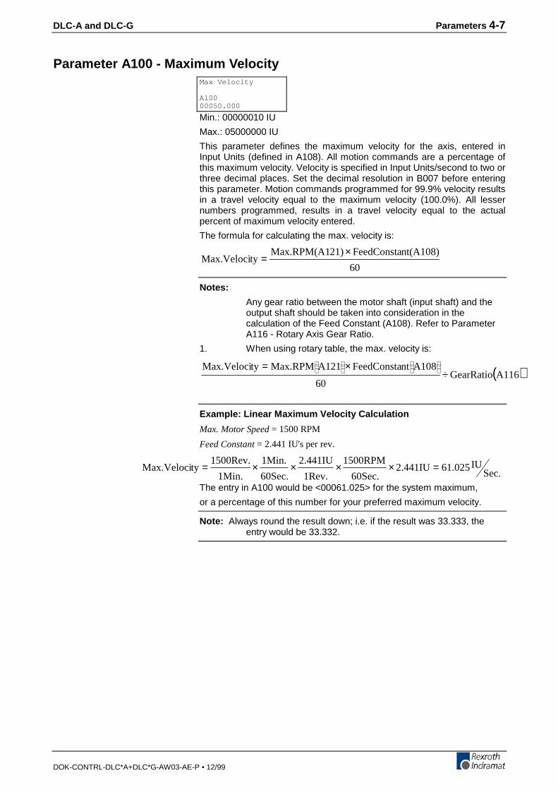
DLC-A and DLC-G Parameters 4-7
DOK-CONTRL-DLC*A+DLC*G-AW03-AE-P • 12/99
Parameter A100 - Maximum Velocity
Min.: 00000010 IU
Max.: 05000000 IU
This parameter defines the maximum velocity for the axis, entered inInput Units (defined in A108). All motion commands are a percentage ofthis maximum velocity. Velocity is specified in Input Units/second to two orthree decimal places. Set the decimal resolution in B007 before enteringthis parameter. Motion commands programmed for 99.9% velocity resultsin a travel velocity equal to the maximum velocity (100.0%). All lessernumbers programmed, results in a travel velocity equal to the actualpercent of maximum velocity entered.
The formula for calculating the max. velocity is:
60
nt(A108)FeedConsta21)Max.RPM(A1tyMax.Veloci
×=
Notes:
Any gear ratio between the motor shaft (input shaft) and theoutput shaft should be taken into consideration in thecalculation of the Feed Constant (A108). Refer to ParameterA116 - Rotary Axis Gear Ratio.
1. When using rotary table, the max. velocity is:
( )A116GearRatio60
A108ntFeedConstaA121Max.RPMtyMax.Veloci÷
×=
Example: Linear Maximum Velocity Calculation
Max. Motor Speed = 1500 RPM
Feed Constant = 2.441 IU's per rev.
Sec.IU61.0252.441IU
60Sec.
1500RPM
1Rev.
2.441IU
60Sec.
1Min.
1Min.
1500Rev.tyMax.Veloci =××××=
The entry in A100 would be <00061.025> for the system maximum,
or a percentage of this number for your preferred maximum velocity.
Note: Always round the result down; i.e. if the result was 33.333, theentry would be 33.332.
Max Velocity
A10000050.000
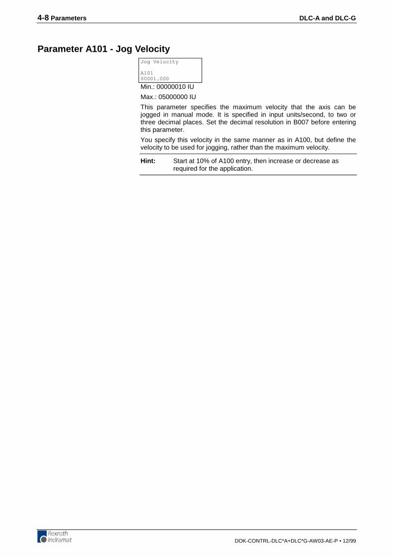
4-8 Parameters DLC-A and DLC-G
DOK-CONTRL-DLC*A+DLC*G-AW03-AE-P • 12/99
Parameter A101 - Jog Velocity
Min.: 00000010 IU
Max.: 05000000 IU
This parameter specifies the maximum velocity that the axis can bejogged in manual mode. It is specified in input units/second, to two orthree decimal places. Set the decimal resolution in B007 before enteringthis parameter.
You specify this velocity in the same manner as in A100, but define thevelocity to be used for jogging, rather than the maximum velocity.
Hint: Start at 10% of A100 entry, then increase or decrease asrequired for the application.
Jog Velocity
A10100001.000
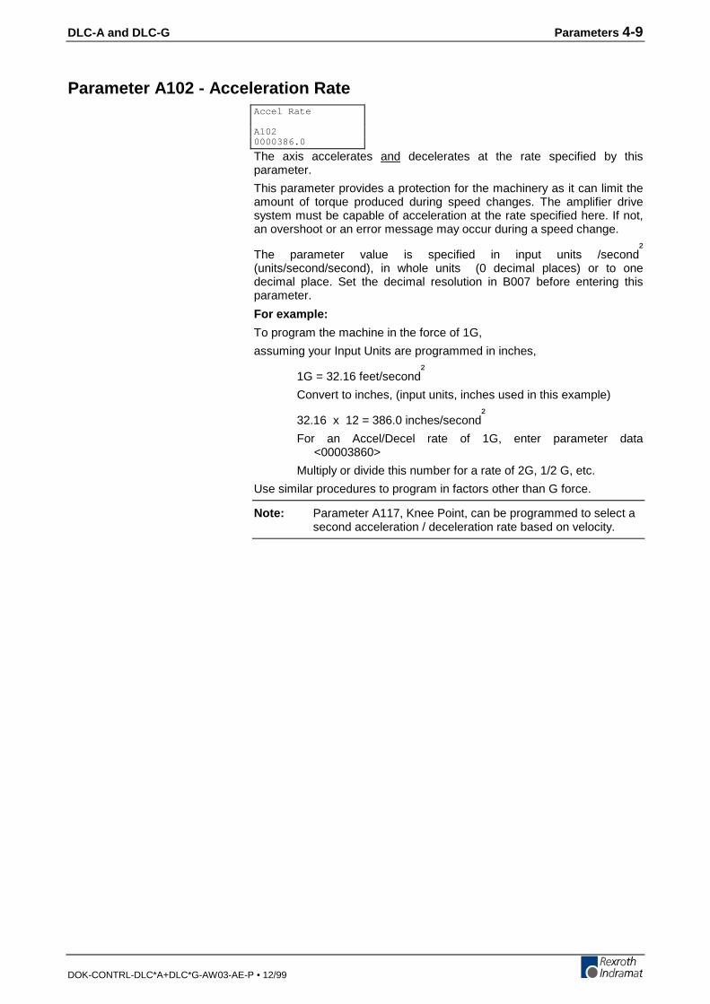
DLC-A and DLC-G Parameters 4-9
DOK-CONTRL-DLC*A+DLC*G-AW03-AE-P • 12/99
Parameter A102 - Acceleration Rate
The axis accelerates and decelerates at the rate specified by thisparameter.
This parameter provides a protection for the machinery as it can limit theamount of torque produced during speed changes. The amplifier drivesystem must be capable of acceleration at the rate specified here. If not,an overshoot or an error message may occur during a speed change.
The parameter value is specified in input units /second²
(units/second/second), in whole units (0 decimal places) or to onedecimal place. Set the decimal resolution in B007 before entering thisparameter.
For example:
To program the machine in the force of 1G,
assuming your Input Units are programmed in inches,
1G = 32.16 feet/second²
Convert to inches, (input units, inches used in this example)
32.16 x 12 = 386.0 inches/second²
For an Accel/Decel rate of 1G, enter parameter data<00003860>
Multiply or divide this number for a rate of 2G, 1/2 G, etc.
Use similar procedures to program in factors other than G force.
Note: Parameter A117, Knee Point, can be programmed to select asecond acceleration / deceleration rate based on velocity.
Accel Rate
A1020000386.0

4-10 Parameters DLC-A and DLC-G
DOK-CONTRL-DLC*A+DLC*G-AW03-AE-P • 12/99
Parameter A103 - Position Gain (KV Factor)
0000 - Not Used, set to 0000
01.00 - Position Gain
Minimum: 0.01
Maximum: 10.00
This is the axis position gain of the system.
The standard machining Kv Factor = 1. Entering a larger number (highergain) will yield a tighter system (less following error). Entering too large anumber can result in overshoot, oscillation, and/or high wear on thesystem parts (bearings, chains, gears, etc.). Set this parameter foroptimum high performance (not necessarily maximum) for your system.
Input is specified to two decimal places.
Hint: A gain of 3 to 5 is typical when the motor is matched to the loadinertia.
This entry sets the amount of velocity command given to the amplifier pera given position error (deviation). The following error (deviation) whilefeeding is inversely proportional to the KV selected.
FE1000
Vel.KV
×= or
KV1000
Vel.FE
×=
Where:
• Vel (velocity) is in IU/minute
• FE (following error) is in IU (input units)
• KV=Velocity (in IU/minute) per thousand IU of Following Error
Position Gain
A1030000 01.00

DLC-A and DLC-G Parameters 4-11
DOK-CONTRL-DLC*A+DLC*G-AW03-AE-P • 12/99
Parameter A104 - Encoder Resolution
00 = Encoder resolution; sets maximum number of allowable motorturns.
00 = Default setting; ±65,536 motor turns
12 = 12 bit resolution; ±524,288 motor turns
13 = 13 bit resolution; ±262,144 motor turns
14 = 14 bit resolution; ±131,072 motor turns
15 = 15 bit resolution; ±65,536 motor turns
000000 = Not Used, set to 000000.
Note: This applies to single turn high resolution feedback only.
Encoder
A10400 000000

4-12 Parameters DLC-A and DLC-G
DOK-CONTRL-DLC*A+DLC*G-AW03-AE-P • 12/99
Parameter A105 - Free
Parameter A105, Free, is currently undefined.
Free
A10500000000
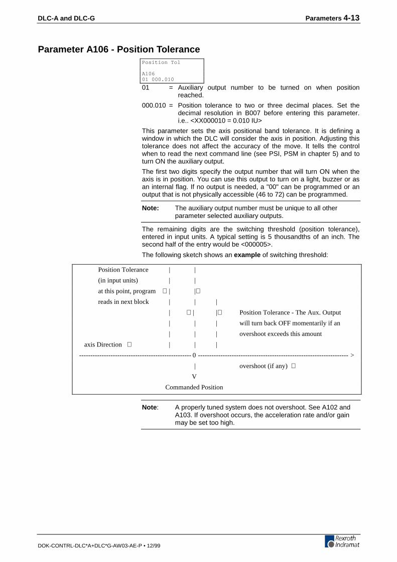
DLC-A and DLC-G Parameters 4-13
DOK-CONTRL-DLC*A+DLC*G-AW03-AE-P • 12/99
Parameter A106 - Position Tolerance
01 = Auxiliary output number to be turned on when positionreached.
000.010 = Position tolerance to two or three decimal places. Set thedecimal resolution in B007 before entering this parameter.i.e.. <XX000010 = 0.010 IU>
This parameter sets the axis positional band tolerance. It is defining awindow in which the DLC will consider the axis in position. Adjusting thistolerance does not affect the accuracy of the move. It tells the controlwhen to read the next command line (see PSI, PSM in chapter 5) and toturn ON the auxiliary output.
The first two digits specify the output number that will turn ON when theaxis is in position. You can use this output to turn on a light, buzzer or asan internal flag. If no output is needed, a "00" can be programmed or anoutput that is not physically accessible (46 to 72) can be programmed.
Note: The auxiliary output number must be unique to all otherparameter selected auxiliary outputs.
The remaining digits are the switching threshold (position tolerance),entered in input units. A typical setting is 5 thousandths of an inch. Thesecond half of the entry would be <000005>.
The following sketch shows an example of switching threshold:
Note : A properly tuned system does not overshoot. See A102 andA103. If overshoot occurs, the acceleration rate and/or gainmay be set too high.
Position Tol
A10601 000.010
Position Tolerance | |
(in input units) | |
at this point, program ⇒| |⇐reads in next block | | |
| ⇒| |⇐ Position Tolerance - The Aux. Output
| | | will turn back OFF momentarily if an
| | | overshoot exceeds this amount
axis Direction ⇒ | | |
-------------------------------------------------- 0 ------------------------------------------------------------------- >
| overshoot (if any) ⇒V
Commanded Position
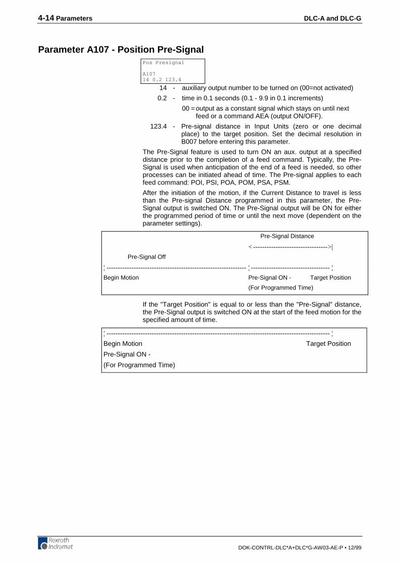
4-14 Parameters DLC-A and DLC-G
DOK-CONTRL-DLC*A+DLC*G-AW03-AE-P • 12/99
Parameter A107 - Position Pre-Signal
14 - auxiliary output number to be turned on (00=not activated)
0.2 - time in 0.1 seconds (0.1 - 9.9 in 0.1 increments)
00 =output as a constant signal which stays on until nextfeed or a command AEA (output ON/OFF).
123.4 - Pre-signal distance in Input Units (zero or one decimalplace) to the target position. Set the decimal resolution inB007 before entering this parameter.
The Pre-Signal feature is used to turn ON an aux. output at a specifieddistance prior to the completion of a feed command. Typically, the Pre-Signal is used when anticipation of the end of a feed is needed, so otherprocesses can be initiated ahead of time. The Pre-signal applies to eachfeed command: POI, PSI, POA, POM, PSA, PSM.
After the initiation of the motion, if the Current Distance to travel is lessthan the Pre-signal Distance programmed in this parameter, the Pre-Signal output is switched ON. The Pre-Signal output will be ON for eitherthe programmed period of time or until the next move (dependent on theparameter settings).
If the "Target Position" is equal to or less than the "Pre-Signal" distance,the Pre-Signal output is switched ON at the start of the feed motion for thespecified amount of time.
Pos Presignal
A10714 0.2 123.4
¦ --------------------------------------------------------------------------------------------------- ¦
Begin Motion Target Position
Pre-Signal ON -
(For Programmed Time)
Pre-Signal Distance
< --------------------------------->|
Pre-Signal Off
¦ -------------------------------------------------------------- ¦ ----------------------------------- ¦
Begin Motion Pre-Signal ON - Target Position
(For Programmed Time)
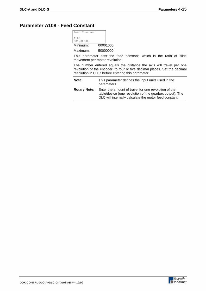
DLC-A and DLC-G Parameters 4-15
DOK-CONTRL-DLC*A+DLC*G-AW03-AE-P • 12/99
Parameter A108 - Feed Constant
Minimum: 00001000
Maximum: 50000000
This parameter sets the feed constant, which is the ratio of slidemovement per motor revolution.
The number entered equals the distance the axis will travel per onerevolution of the encoder, to four or five decimal places. Set the decimalresolution in B007 before entering this parameter.
Note: This parameter defines the input units used in theparameters.
Rotary Note: Enter the amount of travel for one revolution of thetable/device (one revolution of the gearbox output). TheDLC will internally calculate the motor feed constant.
Feed Constant
A108001.00000

4-16 Parameters DLC-A and DLC-G
DOK-CONTRL-DLC*A+DLC*G-AW03-AE-P • 12/99
Parameter A109 - Direction of Operation
This parameter allows changing the axis direction ( +/- ) through softwarein the DLC.
0 = Not used, set to 0
1 = Direction
0 = Direction of operation remains unchanged
1 = Reverse motor direction
000000 = Not used, set to all zeros.
Direction
A1090 1 000000
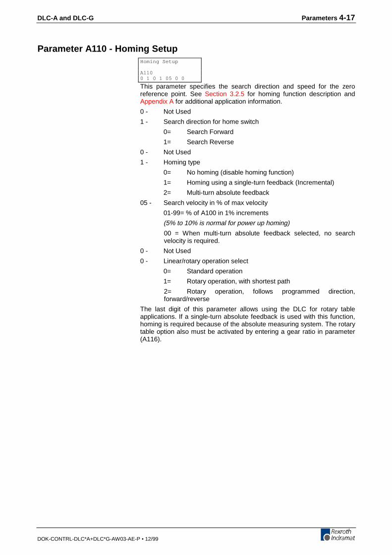
DLC-A and DLC-G Parameters 4-17
DOK-CONTRL-DLC*A+DLC*G-AW03-AE-P • 12/99
Parameter A110 - Homing Setup
This parameter specifies the search direction and speed for the zeroreference point. See Section 3.2.5 for homing function description andAppendix A for additional application information.
0 - Not Used
1 - Search direction for home switch
0= Search Forward
1= Search Reverse
0 - Not Used
1 - Homing type
0= No homing (disable homing function)
1= Homing using a single-turn feedback (Incremental)
2= Multi-turn absolute feedback
05 - Search velocity in % of max velocity
01-99= % of A100 in 1% increments
(5% to 10% is normal for power up homing)
00 = When multi-turn absolute feedback selected, no searchvelocity is required.
0 - Not Used
0 - Linear/rotary operation select
0= Standard operation
1= Rotary operation, with shortest path
2= Rotary operation, follows programmed direction,forward/reverse
The last digit of this parameter allows using the DLC for rotary tableapplications. If a single-turn absolute feedback is used with this function,homing is required because of the absolute measuring system. The rotarytable option also must be activated by entering a gear ratio in parameter(A116).
Homing Setup
A1100 1 0 1 05 0 0
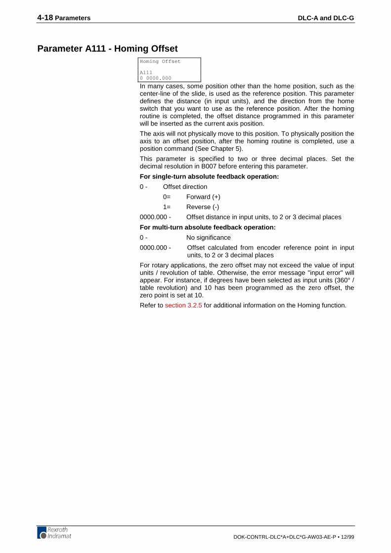
4-18 Parameters DLC-A and DLC-G
DOK-CONTRL-DLC*A+DLC*G-AW03-AE-P • 12/99
Parameter A111 - Homing Offset
In many cases, some position other than the home position, such as thecenter-line of the slide, is used as the reference position. This parameterdefines the distance (in input units), and the direction from the homeswitch that you want to use as the reference position. After the homingroutine is completed, the offset distance programmed in this parameterwill be inserted as the current axis position.
The axis will not physically move to this position. To physically position theaxis to an offset position, after the homing routine is completed, use aposition command (See Chapter 5).
This parameter is specified to two or three decimal places. Set thedecimal resolution in B007 before entering this parameter.
For single-turn absolute feedback operation:
0 - Offset direction
0= Forward (+)
1= Reverse (-)
0000.000 - Offset distance in input units, to 2 or 3 decimal places
For multi-turn absolute feedback operation:
0 - No significance
0000.000 - Offset calculated from encoder reference point in inputunits, to 2 or 3 decimal places
For rotary applications, the zero offset may not exceed the value of inputunits / revolution of table. Otherwise, the error message "input error" willappear. For instance, if degrees have been selected as input units (360° /table revolution) and 10 has been programmed as the zero offset, thezero point is set at 10.
Refer to section 3.2.5 for additional information on the Homing function.
Homing Offset
A1110 0000.000
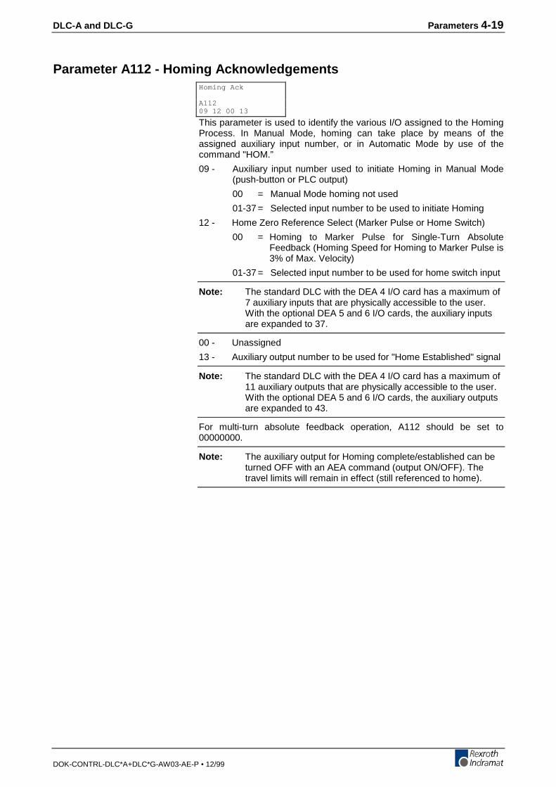
DLC-A and DLC-G Parameters 4-19
DOK-CONTRL-DLC*A+DLC*G-AW03-AE-P • 12/99
Parameter A112 - Homing Acknowledgements
This parameter is used to identify the various I/O assigned to the HomingProcess. In Manual Mode, homing can take place by means of theassigned auxiliary input number, or in Automatic Mode by use of thecommand "HOM.”
09 - Auxiliary input number used to initiate Homing in Manual Mode(push-button or PLC output)
00 = Manual Mode homing not used
01-37 = Selected input number to be used to initiate Homing
12 - Home Zero Reference Select (Marker Pulse or Home Switch)
00 = Homing to Marker Pulse for Single-Turn AbsoluteFeedback (Homing Speed for Homing to Marker Pulse is3% of Max. Velocity)
01-37 = Selected input number to be used for home switch input
Note: The standard DLC with the DEA 4 I/O card has a maximum of7 auxiliary inputs that are physically accessible to the user.With the optional DEA 5 and 6 I/O cards, the auxiliary inputsare expanded to 37.
00 - Unassigned
13 - Auxiliary output number to be used for "Home Established" signal
Note: The standard DLC with the DEA 4 I/O card has a maximum of11 auxiliary outputs that are physically accessible to the user.With the optional DEA 5 and 6 I/O cards, the auxiliary outputsare expanded to 43.
For multi-turn absolute feedback operation, A112 should be set to00000000.
Note: The auxiliary output for Homing complete/established can beturned OFF with an AEA command (output ON/OFF). Thetravel limits will remain in effect (still referenced to home).
Homing Ack
A11209 12 00 13

4-20 Parameters DLC-A and DLC-G
DOK-CONTRL-DLC*A+DLC*G-AW03-AE-P • 12/99
Parameter A113 - Travel Limit, Minimum Value
This parameter specifies the travel limit value in the negative direction, inreference to the Home Position. The limit is effective only after the axishas been Homed.
In the Manual Mode, the corresponding Jog key is disabled when thisposition has been reached. If, in the Automatic Mode, the commandedposition is smaller (more negative) than this limit value, an error messagewill be displayed.
The travel limit value is measured from the reference point, HomePosition, and is not added to, or subtracted from, the offset distance.
This parameter is specified in input units to two or three decimal places.Set the decimal resolution in B007 before entering this parameter.
For multi-turn absolute feedback operation:
A plus sign will appear for this parameter (instead of a minus sign) andthe value here will be the minimum travel allowed. The travel limit value ismeasured from the zero point of the encoder and is not added to, orsubtracted from, the offset distance.
Min Travel
A113-01234.567

DLC-A and DLC-G Parameters 4-21
DOK-CONTRL-DLC*A+DLC*G-AW03-AE-P • 12/99
Parameter A114 - Travel Limit, Maximum Value
This parameter specifies the travel limit value in the positive direction, inreference to the Home Position. The limit is effective only after the axishas been Homed.
In the Manual Mode, the corresponding Jog key is disabled when thisposition has been reached. If, in the automatic mode, the commandedposition is greater than this limit value, an error message will bedisplayed.
The travel limit value is measured from the reference point, HomePosition, and is not added to, or subtracted from, the offset distance.
This parameter is specified in input units to two or three decimal places.Set the decimal resolution in B007 before entering this parameter.
For multi-turn absolute feedback operation:
The travel limit value is measured from the zero point of the encoder andis not added to, or subtracted from, the offset distance.
Max Travel
A114+01234.567

4-22 Parameters DLC-A and DLC-G
DOK-CONTRL-DLC*A+DLC*G-AW03-AE-P • 12/99
Parameter A115 - Special Functions(Disable Following Error,Velocity Achieved/Master Encoder Averaging/Velocity Feed Forward)
12 - Aux. Input to disable following error (01-37)
34 - Aux. Output to acknowledge following error is disabled
56 - Aux. Output to indicate when the programmed velocity has beenachieved.
7 - Not used - Enter 0
8 - Averaging of Master Encoder input pulse train for Master/SlaveMode (See FOL command).
0 = No Averaging, No Velocity Feed Forward (1-9= VelocityFeed Forward Mode)
1 = Average over 1 read
2 = Average over 2 reads
3 = Average over 4 reads
4 = Average over 8 reads
5 = Average over 16 reads
6 = Average over 32 reads
7 = Average over 64 reads
8 = Average over 128 reads
9 = Average over 256 reads
Note: 1 Read = 1 millisecond. Feed forward automatically adjusts forfollowing error between the axes, when averaging is selected.Any remaining following error can usually be minimized byslightly changing A121 RPM/10V (typical adjustment is lessthan 2%).
If no Special Functions are used, enter <00000000>.
Special Function
A11512 34 56 7 8
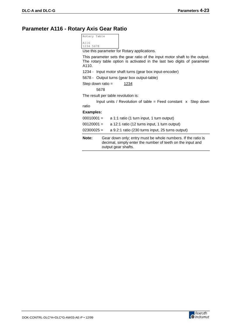
DLC-A and DLC-G Parameters 4-23
DOK-CONTRL-DLC*A+DLC*G-AW03-AE-P • 12/99
Parameter A116 - Rotary Axis Gear Ratio
Use this parameter for Rotary applications.
This parameter sets the gear ratio of the input motor shaft to the output.The rotary table option is activated in the last two digits of parameterA110.
1234 - Input motor shaft turns (gear box input-encoder)
5678 - Output turns (gear box output-table)
Step down ratio = 1234
5678
The result per table revolution is:
Input units / Revolution of table = Feed constant x Step downratio
Examples:
00010001 = a 1:1 ratio (1 turn input, 1 turn output)
00120001 = a 12:1 ratio (12 turns input, 1 turn output)
02300025 = a 9.2:1 ratio (230 turns input, 25 turns output)
Note: Gear down only; entry must be whole numbers. If the ratio isdecimal, simply enter the number of teeth on the input andoutput gear shafts.
Rotary Table
A1161234 5678

4-24 Parameters DLC-A and DLC-G
DOK-CONTRL-DLC*A+DLC*G-AW03-AE-P • 12/99
Parameter A117 - Second Acceleration Rate
12 - Velocity change point (in % of Velocity Max - A100) - Above this%, the second acceleration turns on - Knee point ofacceleration change.
00 = Disables this parameter
01-99= % in increments of 1%
00386.0 - Second acceleration - Input Units/second²(units/second/second) to zero or one decimal place, above the knee pointvelocity. Set the decimal resolution in B007 before entering thisparameter.
The first acceleration below the knee point velocity is programmed inparameter A102.
This function is effective in Automatic operation as well as in Manualoperation (for instance, jogging). The only limitation for the userprogramming is that the command ACC (change of acceleration) is noteffective as long as this parameter is switched ON (can use one or other).
CAUTION: Since the second acceleration may be greater than the firstacceleration, the greater of the two values is to beconsidered the maximum acceleration.
Knee Point
A11712 00386.0

DLC-A and DLC-G Parameters 4-25
DOK-CONTRL-DLC*A+DLC*G-AW03-AE-P • 12/99
Parameter A118 - Brake Release(as of software version DA1-04VRS and DG1-03T03A)
To be functional, this parameter must be enabled in Parameter C013.
xx- Input ‘Brake release’
00- External brake release function disabled.
yy- Output ‘Brake released’
00- No output programmed.
The output is functional only if the input ‘Brakerelease’ is also programmed.
Brake Release
A118xx yy 0000
4-26 Parameters DLC-A and DLC-G
DOK-CONTRL-DLC*A+DLC*G-AW03-AE-P • 12/99
Parameter A119 - Free
Parameter A119 Free, is currently undefined.
Free
A11900000000
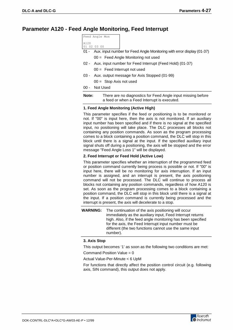
DLC-A and DLC-G Parameters 4-27
DOK-CONTRL-DLC*A+DLC*G-AW03-AE-P • 12/99
Parameter A120 - Feed Angle Monitoring, Feed Interrupt
01 - Aux. input number for Feed Angle Monitoring with error display (01-37)
00 = Feed Angle Monitoring not used
02 - Aux. input number for Feed Interrupt (Feed Hold) (01-37)
00 = Feed Interrupt not used
03 - Aux. output message for Axis Stopped (01-99)
00 = Stop Axis not used
00 - Not Used
Note: There are no diagnostics for Feed Angle input missing beforea feed or when a Feed Interrupt is executed.
1. Feed Angle Monitoring (Active High)
This parameter specifies if the feed or positioning is to be monitored ornot. If "00" is input here, then the axis is not monitored. If an auxiliaryinput number has been specified and if there is no signal at the specifiedinput, no positioning will take place. The DLC processes all blocks notcontaining any position commands. As soon as the program processingcomes to a block containing a position command, the DLC will stop in thisblock until there is a signal at the input. If the specified auxiliary inputsignal shuts off during a positioning, the axis will be stopped and the errormessage "Feed Angle Loss 1" will be displayed.
2. Feed Interrupt or Feed Hold (Active Low)
This parameter specifies whether an interruption of the programmed feedor position command currently being process is possible or not. If "00" isinput here, there will be no monitoring for axis interruption. If an inputnumber is assigned, and an interrupt is present, the axis positioningcommand will not be processed. The DLC will continue to process allblocks not containing any position commands, regardless of how A120 isset. As soon as the program processing comes to a block containing aposition command, the DLC will stop in this block until there is a signal atthe input. If a position command is currently being processed and theinterrupt is present, the axis will decelerate to a stop.
WARNING: The continuation of the axis positioning will occurimmediately as the auxiliary input, Feed Interrupt returnshigh. Also, if the feed angle monitoring has been specifiedfor the axis, the Feed Interrupt input number must bedifferent (the two functions cannot use the same inputnumber).
3. Axis Stop
This output becomes ‘1’ as soon as the following two conditions are met:
Command Position Value = 0
Actual Value-Per-Minute < 6 UpM
For functions that directly affect the position control circuit (e.g. followingaxis, SIN command), this output does not apply.
Feed Angle Mon
A12001 02 03 00

4-28 Parameters DLC-A and DLC-G
DOK-CONTRL-DLC*A+DLC*G-AW03-AE-P • 12/99
Parameter A121 - Maximum Motor Speed
2000 - Maximum motor RPM
0000 - Unassigned set to 0000
This parameter defines the maximum RPM of the motor.
Example: A121 entry for 2000 RPM motor is:
Max. Speed [RPM]
A1212000 0000
Max. Speed [RPM]
A1212000 0000
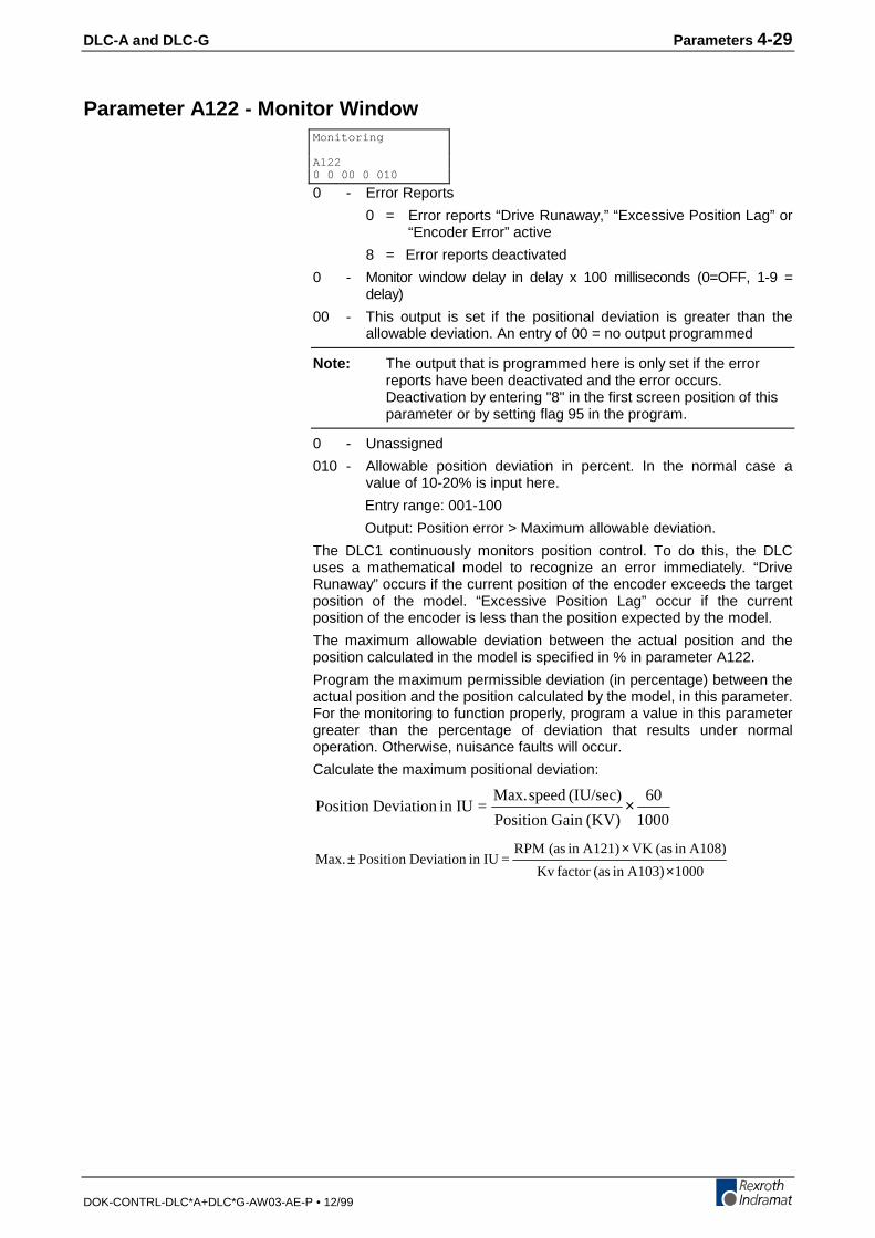
DLC-A and DLC-G Parameters 4-29
DOK-CONTRL-DLC*A+DLC*G-AW03-AE-P • 12/99
Parameter A122 - Monitor Window
0 - Error Reports
0 = Error reports “Drive Runaway,” “Excessive Position Lag” or“Encoder Error” active
8 = Error reports deactivated
0 - Monitor window delay in delay x 100 milliseconds (0=OFF, 1-9 =delay)
00 - This output is set if the positional deviation is greater than theallowable deviation. An entry of 00 = no output programmed
Note: The output that is programmed here is only set if the errorreports have been deactivated and the error occurs.Deactivation by entering "8" in the first screen position of thisparameter or by setting flag 95 in the program.
0 - Unassigned
010 - Allowable position deviation in percent. In the normal case avalue of 10-20% is input here.
Entry range: 001-100
Output: Position error > Maximum allowable deviation.
The DLC1 continuously monitors position control. To do this, the DLCuses a mathematical model to recognize an error immediately. “DriveRunaway” occurs if the current position of the encoder exceeds the targetposition of the model. “Excessive Position Lag” occur if the currentposition of the encoder is less than the position expected by the model.
The maximum allowable deviation between the actual position and theposition calculated in the model is specified in % in parameter A122.
Program the maximum permissible deviation (in percentage) between theactual position and the position calculated by the model, in this parameter.For the monitoring to function properly, program a value in this parametergreater than the percentage of deviation that results under normaloperation. Otherwise, nuisance faults will occur.
Calculate the maximum positional deviation:
1000
60
(KV)Gain Position
(IU/sec) speed Max.=IUin Deviation Position ×
1000 A103)in (asfactor Kv
A108)in (asVK A121)in (as RPM = IUin Deviation Position Max.
××
±
Monitoring
A1220 0 00 0 010
4-30 Parameters DLC-A and DLC-G
DOK-CONTRL-DLC*A+DLC*G-AW03-AE-P • 12/99
Example:
max. RPM (A121) = 2000 RPM
IU VK (A108) = 0.39 in
Kv (A103) = 1
Monitoring (A122) = 20%
100%in. 0.7810001
in. 0.392000=IUin Deviation Position Max. ==
××
±
20% corresponds to 40 mm
If A122 = 00000020, the DLC will issue an error if the actual followingerror differs from the expected following error by more than 20%. Take20% of 0.78 in: 0.20 x 0.78 = 0.16. At a positional deviation of 0.16 in.,the controller interrupts the positioning process and reports a ExcessivePosition Lag or Drive Runaway.
A Drive Runaway would occur if the error exceeded 0.78 + 0.016 = 0.796inches. Excessive Position Lag would occur if the following error wentbelow 0.78 - 0.016 = 0.764 inches. When feeding at a lower speed thefollowing error will be lower, but the maximum deviation from theexpected following error will still be ± 0.16 inches.
Note the following:
• If you change the parameters Position Gain or Maximum Velocity, youdo not need to reprogram the Monitoring Window, because it isentered in percentage of maximum position deviation.
• If the Monitoring Window entry, as converted, is smaller than thePosition Tolerance, the DLC is unable to correctly distinguish between"Drive Runaway" and "Excessive Position Lag." Therefore, theconverted Monitoring Window parameter should be greater than thePosition Tolerance.
• If the programmed entry for Monitoring Window is too small, even anormal feed will generate a "Drive Runaway" or "Excessive Position Lag.”
• The Monitoring Window value depends on your application. Youshould enter the lowest percentage possible that will not causenuisance faults.
Possible causes for "Drive Runaway"
• The axis moved when no command value has been output.
• The maximum RPM in A121 is smaller than specified RPM, check theDSM software module.
• A122 entry is too small (typical setting is 10%).
Possible causes for "Excessive Position Lag"
• Position command issued, but no movement detected:
• The motor cannot turn because of a mechanical bind.
• The maximum RPM in A121 is greater than specified RPM, check theDSM software module.
• The acceleration is too great (A102, also A117 second acceleration)
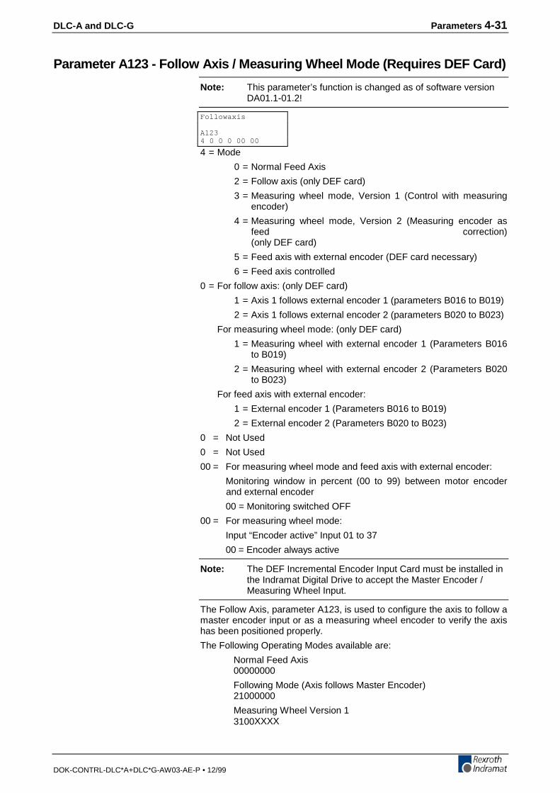
DLC-A and DLC-G Parameters 4-31
DOK-CONTRL-DLC*A+DLC*G-AW03-AE-P • 12/99
Parameter A123 - Follow Axis / Measuring Wheel Mode (Requires DEF Card)
Note: This parameter’s function is changed as of software versionDA01.1-01.2!
4 = Mode
0 = Normal Feed Axis
2 = Follow axis (only DEF card)
3 = Measuring wheel mode, Version 1 (Control with measuringencoder)
4 = Measuring wheel mode, Version 2 (Measuring encoder asfeed correction)(only DEF card)
5 = Feed axis with external encoder (DEF card necessary)
6 = Feed axis controlled
0 = For follow axis: (only DEF card)
1 = Axis 1 follows external encoder 1 (parameters B016 to B019)
2 = Axis 1 follows external encoder 2 (parameters B020 to B023)
For measuring wheel mode: (only DEF card)
1 = Measuring wheel with external encoder 1 (Parameters B016to B019)
2 = Measuring wheel with external encoder 2 (Parameters B020to B023)
For feed axis with external encoder:
1 = External encoder 1 (Parameters B016 to B019)
2 = External encoder 2 (Parameters B020 to B023)
0 = Not Used
0 = Not Used
00 = For measuring wheel mode and feed axis with external encoder:
Monitoring window in percent (00 to 99) between motor encoderand external encoder
00 = Monitoring switched OFF
00 = For measuring wheel mode:
Input “Encoder active” Input 01 to 37
00 = Encoder always active
Note: The DEF Incremental Encoder Input Card must be installed inthe Indramat Digital Drive to accept the Master Encoder /Measuring Wheel Input.
The Follow Axis, parameter A123, is used to configure the axis to follow amaster encoder input or as a measuring wheel encoder to verify the axishas been positioned properly.
The Following Operating Modes available are:
Normal Feed Axis00000000
Following Mode (Axis follows Master Encoder)21000000
Measuring Wheel Version 13100XXXX
Followaxis
A1234 0 0 0 00 00
4-32 Parameters DLC-A and DLC-G
DOK-CONTRL-DLC*A+DLC*G-AW03-AE-P • 12/99
Measuring Wheel Version 24100XXXX
When parameter A123, Follow Axis, is programmed with all zeros, theaxis is a normal feed axis.
When using the Follow Axis, Measuring Wheel Version 1 or 2, thefollowing parameters must be programmed:
External Encoder 1 Parameter B016
External Encoder 1, Lines/Rev Parameter B017
External Encoder 1, Constant Parameter B018
External Encoder 1, Offset Parameter B019
When the Follow Axis, parameter A123, is programmed with 21000000,the axis will follow the master encoder input in Automatic or ManualMode.
When the Follow Axis, parameter A123, is programmed with 3100XXXX,the Measuring Wheel Version 1 is selected. In Automatic Mode, theMeasuring Wheel Version 1 will close the position loop on the measuringwheel encoder. Any slight difference between the load and motor positionwill be compensated for during the position move.
When the Follow Axis, parameter A123, is programmed with 4100XXXX,the Measuring Wheel Version 2 is selected. In Automatic Mode, theMeasuring Wheel Version 2 will close the position loop on the axis. Theaxis position is compared to the measuring wheel encoder position andthe difference is compensated for, during the axis move. When the axis isin the in-position tolerance window (defined in parameter A106, PositionTolerance), no compensation for the difference will occur. Compensationfor the difference occurs when the axis is commanded out of the positiontolerance window. This allows a degree of backlash in the mechanicalsystem without effecting the stability of the servo. The following formulashould be used when using this option to get optimum results.
316.66)(Gain
rateon Accelerati=TolerancePosition
×
When using the Measuring Wheel Version 1 (3100XXXX) or Version 2(4100XXXX), the machine builder can program a percentage of deviationand an auxiliary input to enable the measuring wheel function. Thepercentage of deviation defines how much difference between themeasuring wheel encoder position and the axis position will be allowed.When the difference becomes greater than this percentage the error"Encoder Fault A1" will occur.
Note: If "00" is specified for the percent deviation, there will be nocomparison between the measuring wheel position and themotor's position.
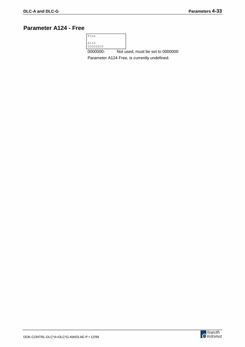
DLC-A and DLC-G Parameters 4-33
DOK-CONTRL-DLC*A+DLC*G-AW03-AE-P • 12/99
Parameter A124 - Free
0000000- Not used, must be set to 0000000
Parameter A124 Free, is currently undefined.
Free
A12400000000

4-34 Parameters DLC-A and DLC-G
DOK-CONTRL-DLC*A+DLC*G-AW03-AE-P • 12/99
Parameter A125 - Jerk Constant(as of software version DA1-04VRS)
0000- Not used
0.000- Time constant for acceleration (s)
Range: 0.000 - 1.024
0 = Constant acceleration
The ‘Time constant for acceleration’ displays the time in which theDLC builds up the acceleration.
Jerk Constant
A1250000 0.000
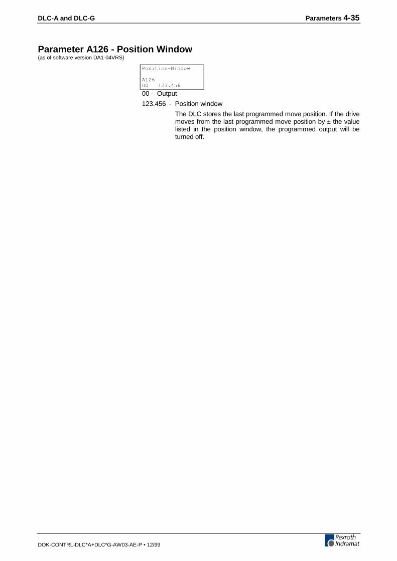
DLC-A and DLC-G Parameters 4-35
DOK-CONTRL-DLC*A+DLC*G-AW03-AE-P • 12/99
Parameter A126 - Position Window(as of software version DA1-04VRS)
00 - Output
123.456 - Position window
The DLC stores the last programmed move position. If the drivemoves from the last programmed move position by ± the valuelisted in the position window, the programmed output will beturned off.
Position-Window
A12600 123.456
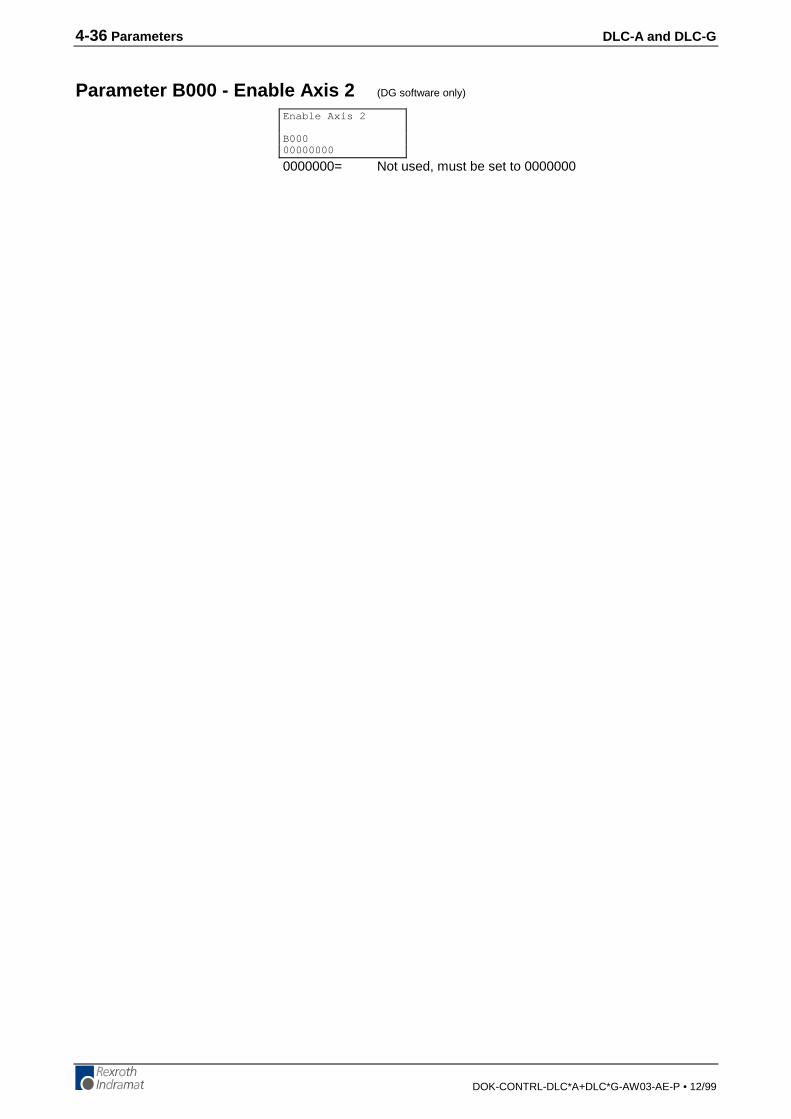
4-36 Parameters DLC-A and DLC-G
DOK-CONTRL-DLC*A+DLC*G-AW03-AE-P • 12/99
Parameter B000 - Enable Axis 2 (DG software only)
0000000= Not used, must be set to 0000000
Enable Axis 2
B00000000000
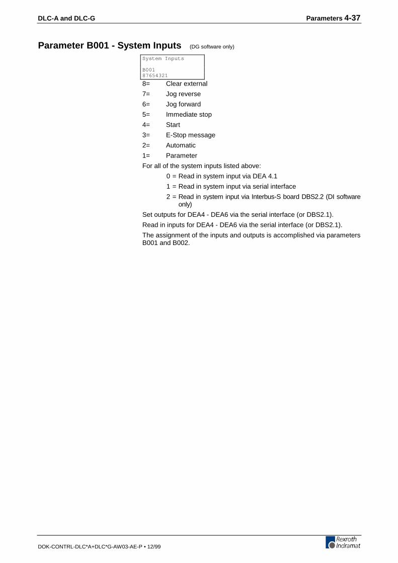
DLC-A and DLC-G Parameters 4-37
DOK-CONTRL-DLC*A+DLC*G-AW03-AE-P • 12/99
Parameter B001 - System Inputs (DG software only)
8= Clear external
7= Jog reverse
6= Jog forward
5= Immediate stop
4= Start
3= E-Stop message
2= Automatic
1= Parameter
For all of the system inputs listed above:
0 = Read in system input via DEA 4.1
1 = Read in system input via serial interface
2 = Read in system input via Interbus-S board DBS2.2 (DI softwareonly)
Set outputs for DEA4 - DEA6 via the serial interface (or DBS2.1).
Read in inputs for DEA4 - DEA6 via the serial interface (or DBS2.1).
The assignment of the inputs and outputs is accomplished via parametersB001 and B002.
System Inputs
B00187654321

4-38 Parameters DLC-A and DLC-G
DOK-CONTRL-DLC*A+DLC*G-AW03-AE-P • 12/99
Parameter B001 - Serial Jog Enable (DA software only)
00000000 - Enable or disable Serial Jog
00000000 = Disabled
01100000 = Enabled
Serial Jog
B00100000000
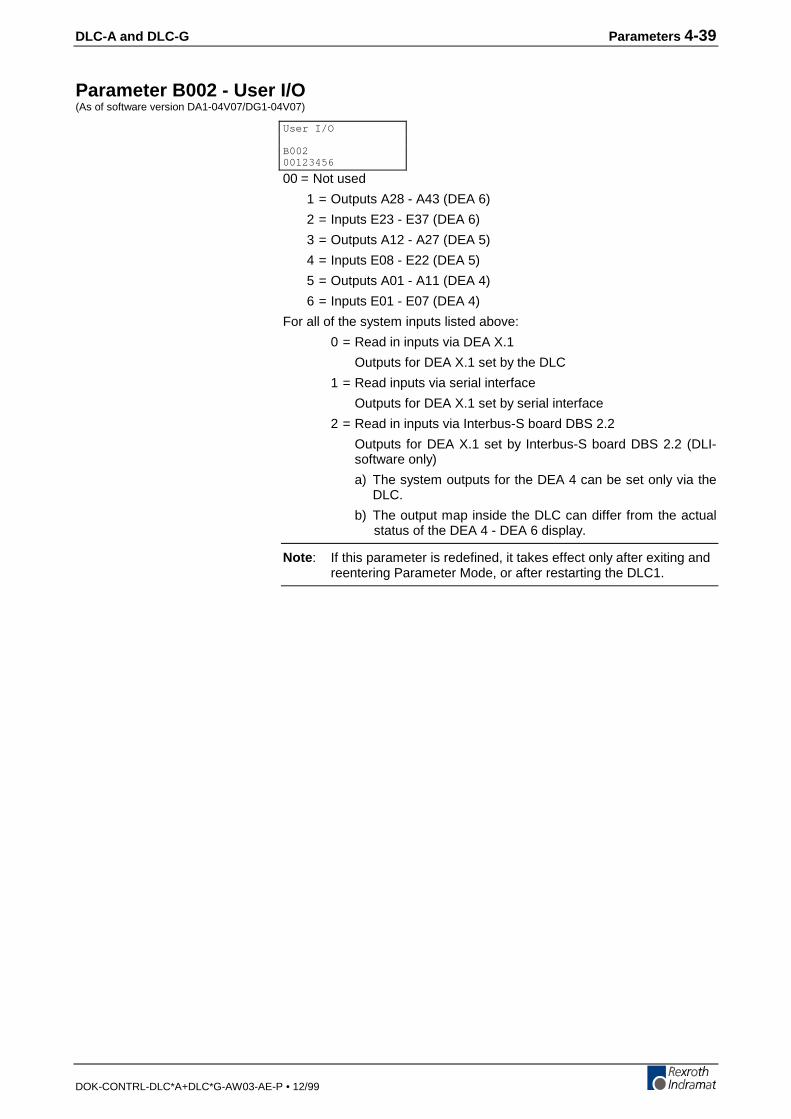
DLC-A and DLC-G Parameters 4-39
DOK-CONTRL-DLC*A+DLC*G-AW03-AE-P • 12/99
Parameter B002 - User I/O(As of software version DA1-04V07/DG1-04V07)
00 = Not used
1 = Outputs A28 - A43 (DEA 6)
2 = Inputs E23 - E37 (DEA 6)
3 = Outputs A12 - A27 (DEA 5)
4 = Inputs E08 - E22 (DEA 5)
5 = Outputs A01 - A11 (DEA 4)
6 = Inputs E01 - E07 (DEA 4)
For all of the system inputs listed above:
0 = Read in inputs via DEA X.1
Outputs for DEA X.1 set by the DLC
1 = Read inputs via serial interface
Outputs for DEA X.1 set by serial interface
2 = Read in inputs via Interbus-S board DBS 2.2
Outputs for DEA X.1 set by Interbus-S board DBS 2.2 (DLI-software only)
a) The system outputs for the DEA 4 can be set only via theDLC.
b) The output map inside the DLC can differ from the actualstatus of the DEA 4 - DEA 6 display.
Note : If this parameter is redefined, it takes effect only after exiting andreentering Parameter Mode, or after restarting the DLC1.
User I/O
B00200123456
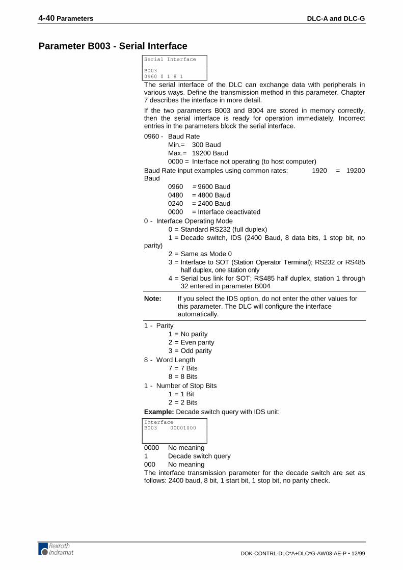
4-40 Parameters DLC-A and DLC-G
DOK-CONTRL-DLC*A+DLC*G-AW03-AE-P • 12/99
Parameter B003 - Serial Interface
The serial interface of the DLC can exchange data with peripherals invarious ways. Define the transmission method in this parameter. Chapter7 describes the interface in more detail.
If the two parameters B003 and B004 are stored in memory correctly,then the serial interface is ready for operation immediately. Incorrectentries in the parameters block the serial interface.
0960 - Baud RateMin.= 300 BaudMax.= 19200 Baud0000 = Interface not operating (to host computer)
Baud Rate input examples using common rates: 1920 = 19200Baud
0960 = 9600 Baud0480 = 4800 Baud0240 = 2400 Baud0000 = Interface deactivated
0 - Interface Operating Mode0 = Standard RS232 (full duplex)1 = Decade switch, IDS (2400 Baud, 8 data bits, 1 stop bit, no
parity)2 = Same as Mode 03 = Interface to SOT (Station Operator Terminal); RS232 or RS485
half duplex, one station only4 = Serial bus link for SOT; RS485 half duplex, station 1 through
32 entered in parameter B004
Note: If you select the IDS option, do not enter the other values forthis parameter. The DLC will configure the interfaceautomatically.
1 - Parity1 = No parity2 = Even parity3 = Odd parity
8 - Word Length7 = 7 Bits8 = 8 Bits
1 - Number of Stop Bits1 = 1 Bit2 = 2 Bits
Example: Decade switch query with IDS unit:
0000 No meaning1 Decade switch query000 No meaningThe interface transmission parameter for the decade switch are set asfollows: 2400 baud, 8 bit, 1 start bit, 1 stop bit, no parity check.
Serial Interface
B0030960 0 1 8 1
InterfaceB003 00001000

DLC-A and DLC-G Parameters 4-41
DOK-CONTRL-DLC*A+DLC*G-AW03-AE-P • 12/99
Parameter B004 - Serial Interface
1 - Checksum/Hardware Handshake (RTS/CTS)
0 = Checksum ON, RTS/CTS OFF
1 = Checksum OFF, RTS/CTS OFF
2 = Checksum ON, RTS/CTS ON
3 = Checksum OFF, RTS/CTS ON
4 = Disables checksum operation.
1 - Transmission Acknowledgment - " Y CR/LF "
0 = Acknowledgment OFF
1 = Acknowledgment ON
08 - Station Number, 01-32
Used with serial bus for SOT communication (See Parameter B003:Serial Interface - Interface Mode description)
9 - Error Code Over Serial Interface
0 = Function Disabled
1 = In case of DLC fault, automatically send an error message viathe serial interface. See Status 53 in chapter 7 for details.
T = Serial Jog Time Out
Time = T*25msec, use T = 4 or 6 for best results.
00 = Transmission Delay For RS485 Communication (In Milliseconds)
00 = No Delay
02 = 2 msec (use for CTA10 or SOT)
This parameter allows the integration of the calculation of the check suminto the interface. The DLC will perform a bit count comparison from oneoperation (processing). If a "0" is not programmed in the first bit, a checksum is not required for communication, i.e. instead of "Checksum CR/LF,”a "_CR/LF" is sufficient. If it is important that the data sent to the DLC isreceived correctly, it is recommended that the checksum be turned ON.The host device must be programmed to calculate and send thechecksum with each transmission to use this option.
Transmission Acknowledgment, when active, returns a "Y" "CR/LF" fromthe DLC to the Host Device. This occurs after any command transmittedto the DLC that does not require any other response from the DLC.
The Transmission Delay For RS485 Mode, in milliseconds, is used todefine a time delay for switching between the transmit and receive mode.In RS485 mode, when the last character is received, it switchesimmediately to transmit mode. This immediate switching can causeproblems with some PC-RS485 driver cards, if they are not fast enough toswitch to receive mode. The transmission delay allows the PC drivers toswitch from transmit to receive mode without communication errors.
Serial Interface
B0041 1 08 9 T 00
4-42 Parameters DLC-A and DLC-G
DOK-CONTRL-DLC*A+DLC*G-AW03-AE-P • 12/99
Parameter B005 - Memory Display
Note: For service use only!
This parameter is for use by the Indramat Service Department.
Set to 00 000000.
Memory Display
B00500 000000
DLC-A and DLC-G Parameters 4-43
DOK-CONTRL-DLC*A+DLC*G-AW03-AE-P • 12/99
Parameter B006 - Start Task 2 & 3
1500 - Starting block number for second task
0001-2999 = Any Block number except 0000 or a block numberof another task
0000 = Task 2 program disabled
2000 - Starting block number for third task
0001-2999 = Any block number except 0000 or a block number ofanother task
0000 = Task 3 program disabled
Task 1 always starts at block 0000.
This parameter allows running separate programs at the same time. Assoon as the DLC is switched to Manual or Automatic mode, Task 3begins running. As soon as Cycle Start is activated, in Auto Mode, Task 1and 2 start running. Also, the system output, Automatic Cycle Running(Connector X17, pin 20) will turn on.
Note: Do not access the same routine by two tasks at the sametime (within 1 millisecond) or a system fault will occur. Theuser program must be in place for task 3 before leaving theparameter mode because task 3 will start runningimmediately. If the task 3 program is not in place, you willsee “ERROR INVALID BLOCK #.”
Warning: Do not use task 3 for servo commands. Task 3 continuesrunning in Manual Mode and during an E-Stop.
Start Task 2 & 3
B0061500 2000
4-44 Parameters DLC-A and DLC-G
DOK-CONTRL-DLC*A+DLC*G-AW03-AE-P • 12/99
Parameter B007 - Display Language / Decimal Place / Keypad Lockout
Use this parameter to specify in which language text will display on theCTA display and to set the number of decimal places used in positioningcommands and certain parameters. It also allows disabling any programentry/changes from the CTA keypad.
01 - Language
00 = German
01 = English
02 = French
03 = Spanish
04 = Italian
05 = Portuguese
03 - Number of decimal places used in positioning commands andcertain parameters
02 = Metric (e. g., millimeters, XXX.YY)
03 = US System (e. g., inches, XX.YYY)
The number entered for decimal places specifies how many digits are tothe right of the decimal point for positioning commands and manyparameters. Make your selection depending on the resolution required.See Appendix E, parameter input sheets, showing the decimal location foreach parameter, with resolution set at 2 or 3 in B007.
Parameter # affected 4 th digit of B007 =2 =3
A102, A107, A117 0 1
A100, A101, A106, A111, A113, A114 2 3
A108, B018 4 5
Command affected 4 th digit of B007 =2 =3
POI, PSI, POA, PSA, PSM, POM, PST, VCC,VCA, BPT, BZP, PFA, PFI, REP, SAC
2 3
Figure 4-1: Decimal place settings
0 - Unassigned, set to 0.
0 - Enable "fault code via outputs"
0 = No fault code via outputs
1 = Fault code via outputs, 01 to 08
2 = Fault code via outputs, 09 to 16
3 = Fault code via outputs, 17 to 24
4 = Fault code via outputs, 25 to 32
5 = Fault code via outputs, 33 to 40
6 = Fault code via outputs, 41 to 48
If the function is enabled, an appropriate fault code is outputted via theprogrammed output when there is a fault. The fault code consists of 2 hexdigits.
Fault code assignment:
00 to 3F - General disturbance
40 to 6F - Disturbance axis 1
For a complete list of fault codes and explanations, see chapter 8,Diagnostics and Troubleshooting.
Language
B00701 03 0 0 45
DLC-A and DLC-G Parameters 4-45
DOK-CONTRL-DLC*A+DLC*G-AW03-AE-P • 12/99
45 - Lock-out feature
00 = Allows program entry/storage from the CTA keypad.
45 = Inhibits storage in memory of program blocks which areentered via the CTA keypad.
55 = Command data, but not commands, can be altered (as ofsoftware version DA1-04VRS).
Note: Programming can still be accomplished via the RS232/485serial interface, such as by downloading from MotionManagerprogram development tool. The lock-out feature preventsaccidental or unauthorized changes via the CTA keypad.
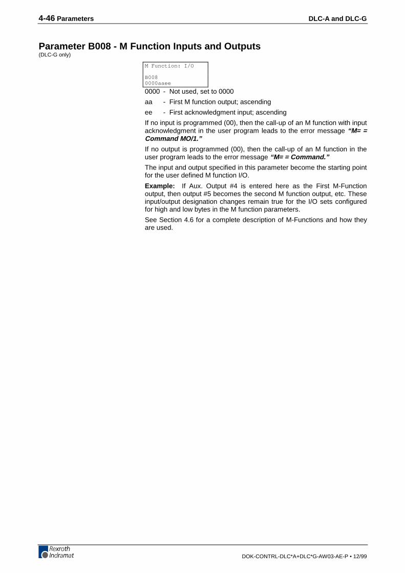
4-46 Parameters DLC-A and DLC-G
DOK-CONTRL-DLC*A+DLC*G-AW03-AE-P • 12/99
Parameter B008 - M Function Inputs and Outputs(DLC-G only)
0000 - Not used, set to 0000
aa - First M function output; ascending
ee - First acknowledgment input; ascending
If no input is programmed (00), then the call-up of an M function with inputacknowledgment in the user program leads to the error message “M= =Command MO/1.”
If no output is programmed (00), then the call-up of an M function in theuser program leads to the error message “M= = Command.”
The input and output specified in this parameter become the starting pointfor the user defined M function I/O.
Example: If Aux. Output #4 is entered here as the First M-Functionoutput, then output #5 becomes the second M function output, etc. Theseinput/output designation changes remain true for the I/O sets configuredfor high and low bytes in the M function parameters.
See Section 4.6 for a complete description of M-Functions and how theyare used.
M Function: I/O
B0080000aaee
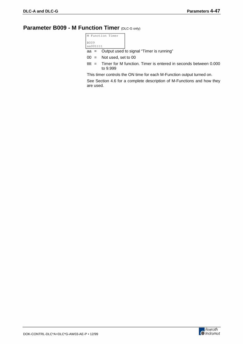
DLC-A and DLC-G Parameters 4-47
DOK-CONTRL-DLC*A+DLC*G-AW03-AE-P • 12/99
Parameter B009 - M Function Timer (DLC-G only)
aa = Output used to signal “Timer is running”
00 = Not used, set to 00
tttt = Timer for M function. Timer is entered in seconds between 0.000to 9.999
This timer controls the ON time for each M-Function output turned on.
See Section 4.6 for a complete description of M-Functions and how theyare used.
M Function Timer
B009aa00tttt
4-48 Parameters DLC-A and DLC-G
DOK-CONTRL-DLC*A+DLC*G-AW03-AE-P • 12/99
Parameter B010 - Free
0000000 - Not used, must be set to 0000000
Parameter B010 Free, is currently undefined.
Free
B01000000000

DLC-A and DLC-G Parameters 4-49
DOK-CONTRL-DLC*A+DLC*G-AW03-AE-P • 12/99
Parameter B011 - Manual Vector
07 = Aux. input number to initiate Manual Vector program start withrising signal edge
00 = Manual Vector Disabled
01-37 = Aux. Input Number
1 = 0 = Start only with aux. input number
1 = Start with either aux. input number or any time you switchinto manual mode.
0 = Not used, set to 0.
2500= Start block of Manual Vector program, Block 0000-2999.
Note: You must use the Command RTS, Return from Subroutine, toterminate the Manual Vector program.
This function allows you to run a user program in Manual Mode. Thisprogram must conclude with an "RTS" (the subroutine stack will not bechanged). This program must not contain any feed instructions. Theprogram is aborted if there is a switch over from "Manual" to "Automatic"or to "Parameter Mode." The program is started externally by means of arising signal edge at one of the aux. inputs. If "00" is input for the aux.input, the Manual Vector is disabled. When programming ParameterB011, make sure that the start block of the Manual Vector program is notlocated in the main program.
Notes: The manual vector input is not accepted during jogging orhoming (in the manual mode).
While the manual vector program is running, jogging orhoming is not possible.
It is not possible to start the manual vector program unless theaxis is enabled.
Manual - Vector
B01107 1 0 2500
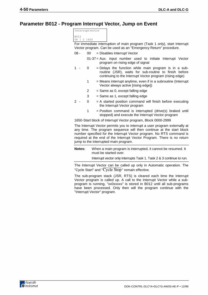
4-50 Parameters DLC-A and DLC-G
DOK-CONTRL-DLC*A+DLC*G-AW03-AE-P • 12/99
Parameter B012 - Program Interrupt Vector, Jump on Event
For immediate interruption of main program (Task 1 only), start InterruptVector program. Can be used as an "Emergency Return" procedure.
08 - 00 = Disables Interrupt Vector
01-37 = Aux. input number used to initiate Interrupt Vectorprogram on rising edge of signal
1 - 0 = Delays the function while main program is in a sub-routine (JSR), waits for sub-routine to finish beforecontinuing to the Interrupt Vector program (rising edge)
1 = Means interrupt anytime, even if in a subroutine (InterruptVector always active [rising edge])
2 = Same as 0, except falling edge
3 = Same as 1, except falling edge
2 - 0 = A started position command will finish before executingthe Interrupt Vector program
1 = Position command is interrupted (drive(s) braked untilstopped) and execute the Interrupt Vector program
1650-Start block of Interrupt Vector program, Block 0000-2999
The Interrupt Vector permits you to interrupt a user program externally atany time. The program sequence will then continue at the start blocknumber specified for the Interrupt Vector program. No RTS command isrequired at the end of the Interrupt Vector Program. There is no returnjump to the interrupted main program.
Notes: When a main program is interrupted, it cannot be resumed. Itmust be started over.
Interrupt vector only interrupts Task 1. Task 2 & 3 continue to run.
The Interrupt Vector can be called up only in Automatic operation. The"Cycle Start" and "%[ENG�5VQR" remain effective.
The sub-program stack (JSR, RTS) is cleared each time the InterruptVector program is called up. A call to the Interrupt Vector while a sub-program is running, "xx0xxxxx" is stored in B012 until all sub-programshave been processed. Only then will the program continue with the"Interrupt Vector" program.
Interruptvector
B01208 1 2 1650
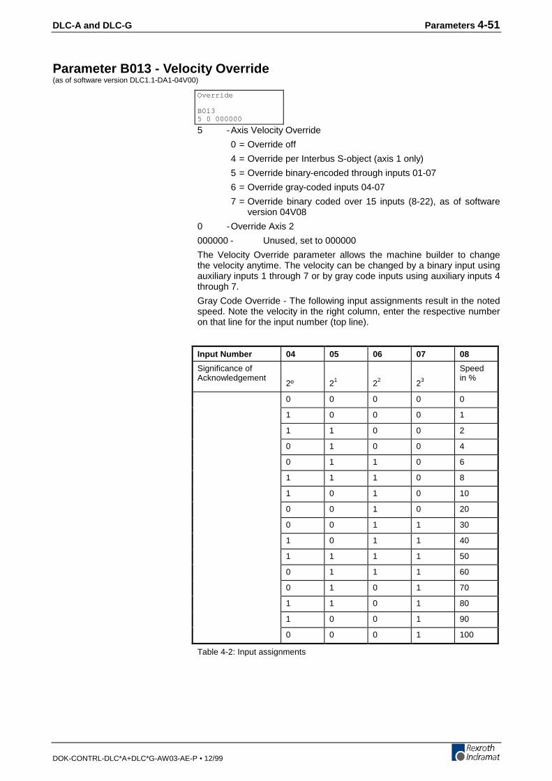
DLC-A and DLC-G Parameters 4-51
DOK-CONTRL-DLC*A+DLC*G-AW03-AE-P • 12/99
Parameter B013 - Velocity Override(as of software version DLC1.1-DA1-04V00)
5 -Axis Velocity Override
0 = Override off
4 = Override per Interbus S-object (axis 1 only)
5 = Override binary-encoded through inputs 01-07
6 = Override gray-coded inputs 04-07
7 = Override binary coded over 15 inputs (8-22), as of softwareversion 04V08
0 -Override Axis 2
000000 - Unused, set to 000000
The Velocity Override parameter allows the machine builder to changethe velocity anytime. The velocity can be changed by a binary input usingauxiliary inputs 1 through 7 or by gray code inputs using auxiliary inputs 4through 7.
Gray Code Override - The following input assignments result in the notedspeed. Note the velocity in the right column, enter the respective numberon that line for the input number (top line).
Input Number 04 05 06 07 08
Significance ofAcknowledgement
2º 21 22 23
Speedin %
0 0 0 0 0
1 0 0 0 1
1 1 0 0 2
0 1 0 0 4
0 1 1 0 6
1 1 1 0 8
1 0 1 0 10
0 0 1 0 20
0 0 1 1 30
1 0 1 1 40
1 1 1 1 50
0 1 1 1 60
0 1 0 1 70
1 1 0 1 80
1 0 0 1 90
0 0 0 1 100
Table 4-2: Input assignments
Override
B0135 0 000000
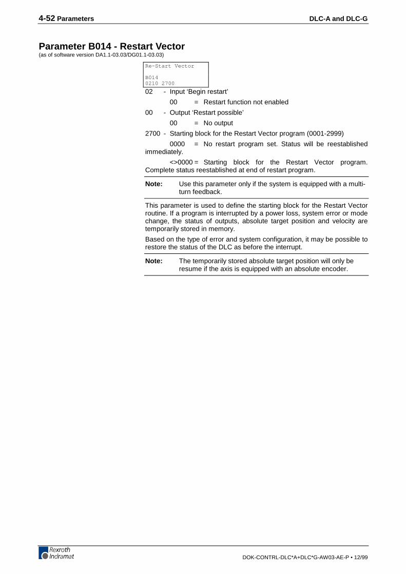
4-52 Parameters DLC-A and DLC-G
DOK-CONTRL-DLC*A+DLC*G-AW03-AE-P • 12/99
Parameter B014 - Restart Vector(as of software version DA1.1-03.03/DG01.1-03.03)
02 - Input ‘Begin restart’
00 = Restart function not enabled
00 - Output ‘Restart possible’
00 = No output
2700 - Starting block for the Restart Vector program (0001-2999)
0000 = No restart program set. Status will be reestablishedimmediately.
<>0000 = Starting block for the Restart Vector program.Complete status reestablished at end of restart program.
Note: Use this parameter only if the system is equipped with a multi-turn feedback.
This parameter is used to define the starting block for the Restart Vectorroutine. If a program is interrupted by a power loss, system error or modechange, the status of outputs, absolute target position and velocity aretemporarily stored in memory.
Based on the type of error and system configuration, it may be possible torestore the status of the DLC as before the interrupt.
Note: The temporarily stored absolute target position will only beresume if the axis is equipped with an absolute encoder.
Re-Start Vector
B0140210 2700
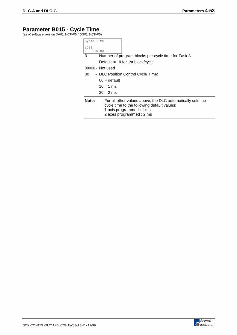
DLC-A and DLC-G Parameters 4-53
DOK-CONTRL-DLC*A+DLC*G-AW03-AE-P • 12/99
Parameter B015 - Cycle Time(as of software version DA01.1-03V05 / DG01.1-03V05)
0 - Number of program blocks per cycle time for Task 3
Default = 0 for 1st block/cycle
00000- Not used
00 - DLC Position Control Cycle Time:
00 = default
10 = 1 ms
20 = 2 ms
Note: For all other values above, the DLC automatically sets thecycle time to the following default values:1 axis programmed : 1 ms2 axes programmed : 2 ms
Cycle-Time
B0150 00000 00
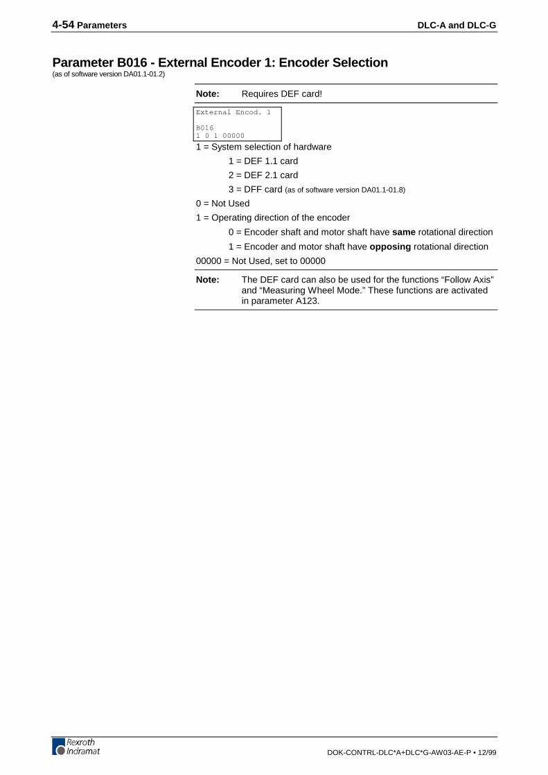
4-54 Parameters DLC-A and DLC-G
DOK-CONTRL-DLC*A+DLC*G-AW03-AE-P • 12/99
Parameter B016 - External Encoder 1: Encoder Selection(as of software version DA01.1-01.2)
Note: Requires DEF card!
1 = System selection of hardware
1 = DEF 1.1 card
2 = DEF 2.1 card
3 = DFF card (as of software version DA01.1-01.8)
0 = Not Used
1 = Operating direction of the encoder
0 = Encoder shaft and motor shaft have same rotational direction
1 = Encoder and motor shaft have opposing rotational direction
00000 = Not Used, set to 00000
Note: The DEF card can also be used for the functions “Follow Axis”and “Measuring Wheel Mode.” These functions are activatedin parameter A123.
External Encod. 1
B0161 0 1 00000
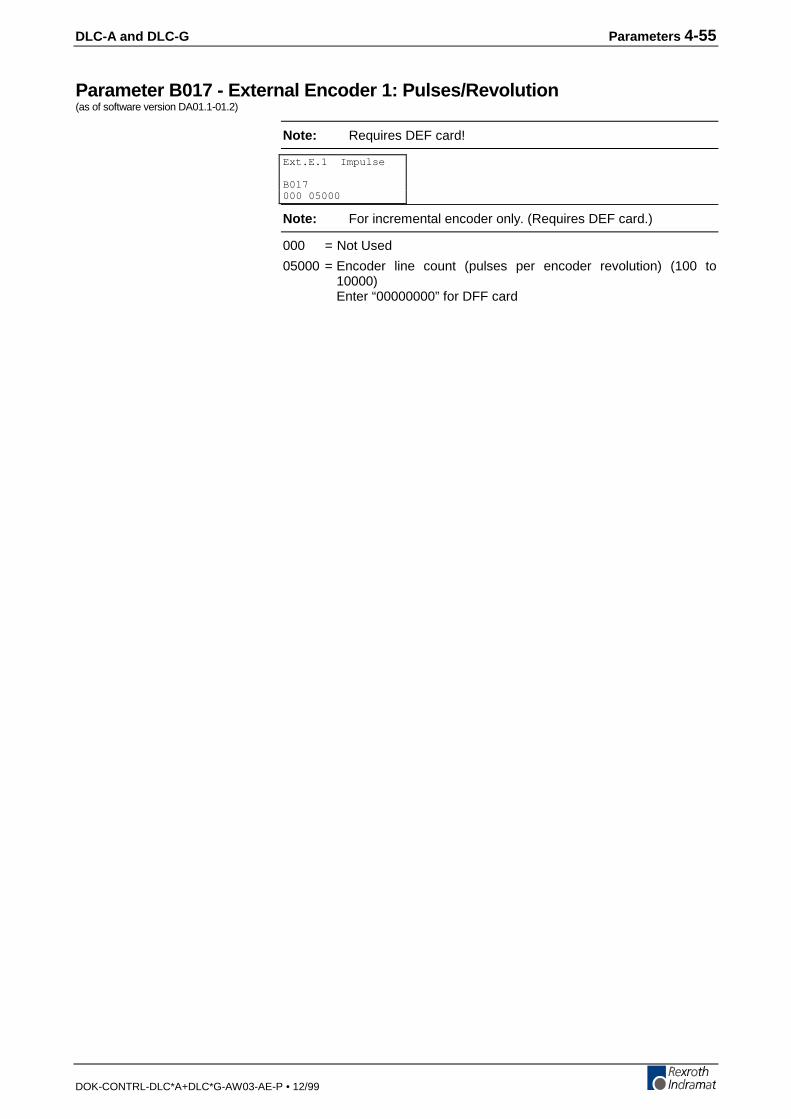
DLC-A and DLC-G Parameters 4-55
DOK-CONTRL-DLC*A+DLC*G-AW03-AE-P • 12/99
Parameter B017 - External Encoder 1: Pulses/Revolution(as of software version DA01.1-01.2)
Note: Requires DEF card!
Note: For incremental encoder only. (Requires DEF card.)
000 = Not Used
05000 = Encoder line count (pulses per encoder revolution) (100 to10000)Enter “00000000” for DFF card
Ext.E.1 Impulse
B017000 05000

4-56 Parameters DLC-A and DLC-G
DOK-CONTRL-DLC*A+DLC*G-AW03-AE-P • 12/99
Parameter B018 - External Encoder 1: Feed Constant(as of software version DA01.1-01.2)
Note: Requires DEF or DFF card!
Feed constant of external encoder 1 in input units.
The distance per encoder revolution.
Ext.E.1 Constant
B018020.00000
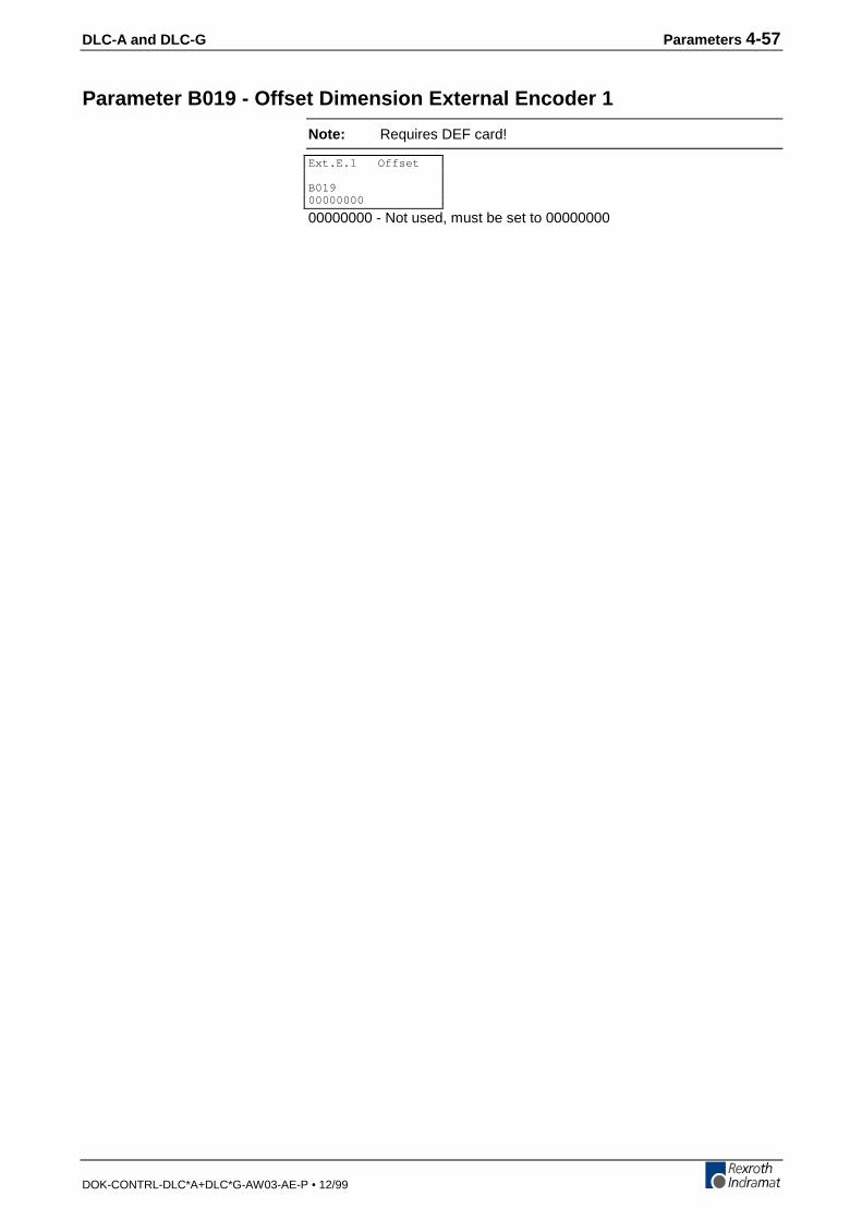
DLC-A and DLC-G Parameters 4-57
DOK-CONTRL-DLC*A+DLC*G-AW03-AE-P • 12/99
Parameter B019 - Offset Dimension External Encoder 1
Note: Requires DEF card!
00000000 - Not used, must be set to 00000000
Ext.E.1 Offset
B01900000000

4-58 Parameters DLC-A and DLC-G
DOK-CONTRL-DLC*A+DLC*G-AW03-AE-P • 12/99
Parameter B020 - External Encoder 2: Encoder Selection(as of software version DA01.1-01.2)
Note: Requires DEF card!
1 = System selection of hardware
1 = DEF1.1 card
2 = DEF2.1 card
0 = Not Used
0 = Operating direction of the encoder
0 = Encoder shaft and motor shaft have same rotational direction
1 = Encoder and motor shaft have opposing rotational direction
00000= Not Used, set to 00000
Note: The measuring wheel encoder can also be used for thefunctions “Follow Axis,” “Measuring Wheel Mode” and“Positioning with External Encoder.” When two externalencoders are used simultaneously the system selection inparameters B016 and B020 must not be identical! Thesefunctions are activated in parameter A123.
External Encod. 2
B0201 0 0 00000

DLC-A and DLC-G Parameters 4-59
DOK-CONTRL-DLC*A+DLC*G-AW03-AE-P • 12/99
Parameter B021 - External Encoder 2: Pulses/Revolution(as of software version DA01.1-01.2)
Note: For incremental encoder only. (Requires DEF card)
000 = Not Used
05000 = Encoder line count (pulses per encoder revolution) (100 to10000)
Ext.E.2 Impulse
B021000 05000

4-60 Parameters DLC-A and DLC-G
DOK-CONTRL-DLC*A+DLC*G-AW03-AE-P • 12/99
Parameter B022 - External Encoder 2: Feed Constant(as of software version DA01.1-01.2)
Note: Requires DEF card!
Feed constant of external encoder 2 in input units.
The distance per encoder revolution.
Entry range: From 000.0,1000 to 500.0,0000 in input units
Entry resolution: 4 or 5 digits after the decimal point (see parameterB007)(Also see parameter A108)
Ext.Enc.2 VK
B022050.00000
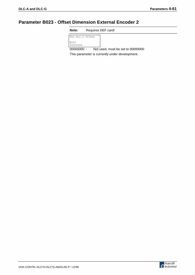
DLC-A and DLC-G Parameters 4-61
DOK-CONTRL-DLC*A+DLC*G-AW03-AE-P • 12/99
Parameter B023 - Offset Dimension External Encoder 2
Note: Requires DEF card!
00000000 - Not used, must be set to 00000000
This parameter is currently under development.
Ext.Enc.2 Offset
B02300000000
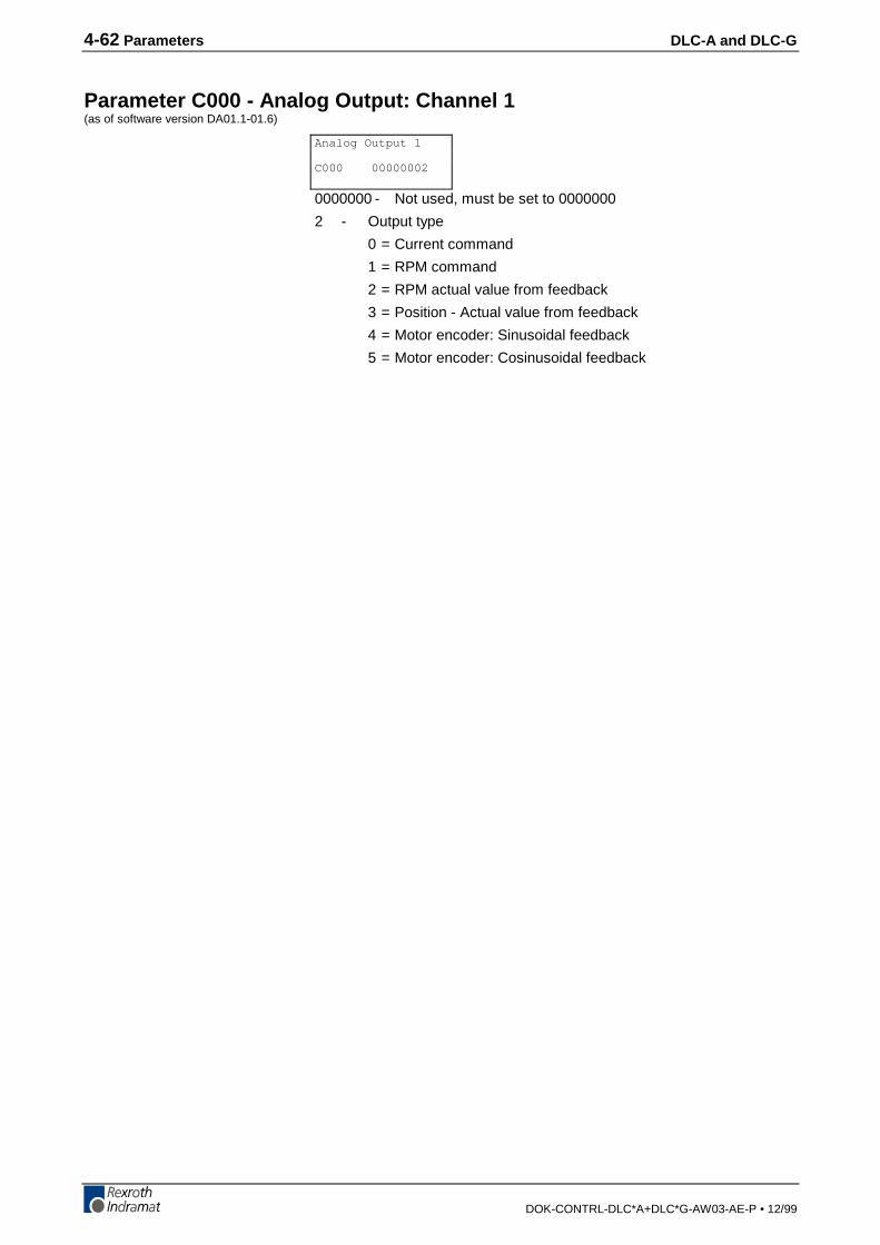
4-62 Parameters DLC-A and DLC-G
DOK-CONTRL-DLC*A+DLC*G-AW03-AE-P • 12/99
Parameter C000 - Analog Output: Channel 1(as of software version DA01.1-01.6)
0000000 - Not used, must be set to 0000000
2 - Output type
0 = Current command
1 = RPM command
2 = RPM actual value from feedback
3 = Position - Actual value from feedback
4 = Motor encoder: Sinusoidal feedback
5 = Motor encoder: Cosinusoidal feedback
Analog Output 1
C000 00000002
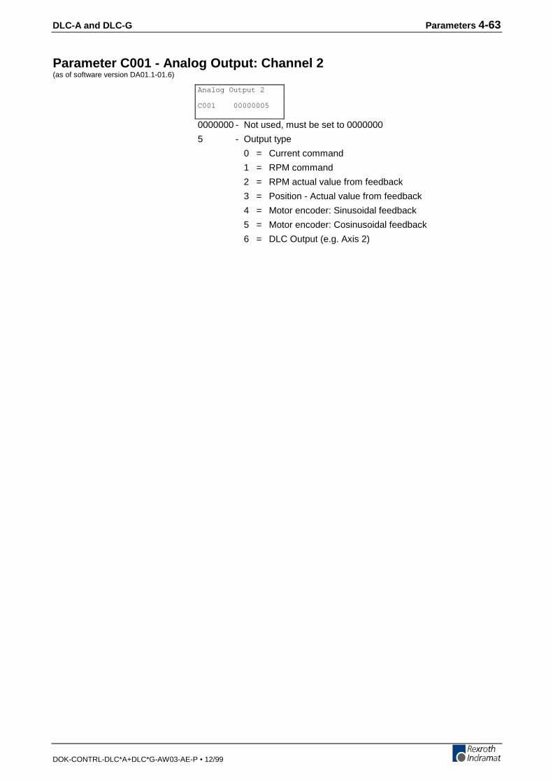
DLC-A and DLC-G Parameters 4-63
DOK-CONTRL-DLC*A+DLC*G-AW03-AE-P • 12/99
Parameter C001 - Analog Output: Channel 2(as of software version DA01.1-01.6)
0000000 - Not used, must be set to 0000000
5 - Output type
0 = Current command
1 = RPM command
2 = RPM actual value from feedback
3 = Position - Actual value from feedback
4 = Motor encoder: Sinusoidal feedback
5 = Motor encoder: Cosinusoidal feedback
6 = DLC Output (e.g. Axis 2)
Analog Output 2
C001 00000005
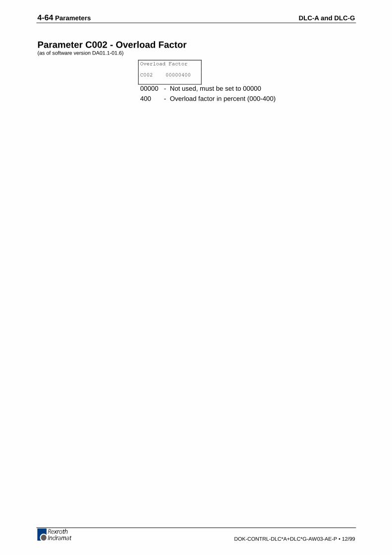
4-64 Parameters DLC-A and DLC-G
DOK-CONTRL-DLC*A+DLC*G-AW03-AE-P • 12/99
Parameter C002 - Overload Factor(as of software version DA01.1-01.6)
00000 - Not used, must be set to 00000
400 - Overload factor in percent (000-400)
Overload Factor
C002 00000400
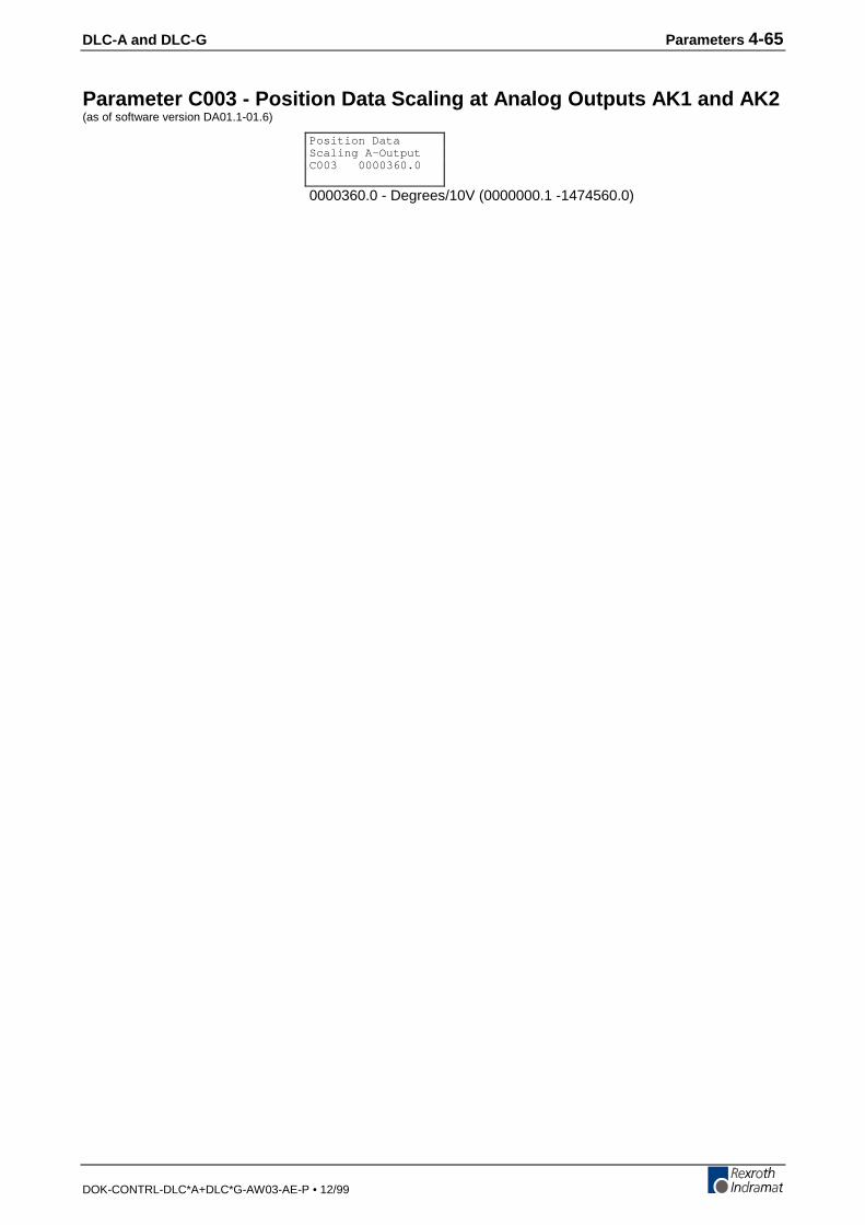
DLC-A and DLC-G Parameters 4-65
DOK-CONTRL-DLC*A+DLC*G-AW03-AE-P • 12/99
Parameter C003 - Position Data Scaling at Analog Outputs AK1 and AK2(as of software version DA01.1-01.6)
0000360.0 - Degrees/10V (0000000.1 -1474560.0)
Position DataScaling A-OutputC003 0000360.0
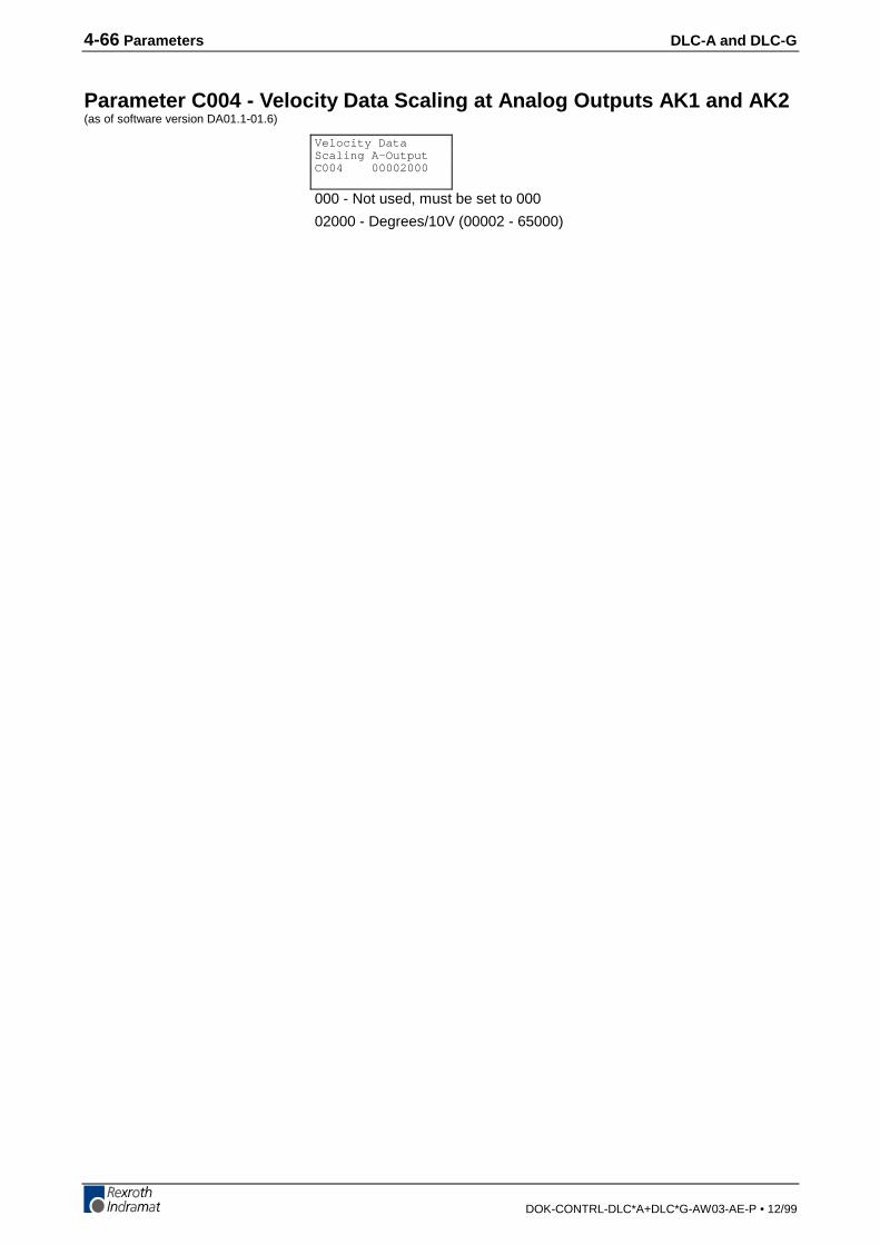
4-66 Parameters DLC-A and DLC-G
DOK-CONTRL-DLC*A+DLC*G-AW03-AE-P • 12/99
Parameter C004 - Velocity Data Scaling at Analog Outputs AK1 and AK2(as of software version DA01.1-01.6)
000 - Not used, must be set to 000
02000 - Degrees/10V (00002 - 65000)
Velocity DataScaling A-OutputC004 00002000
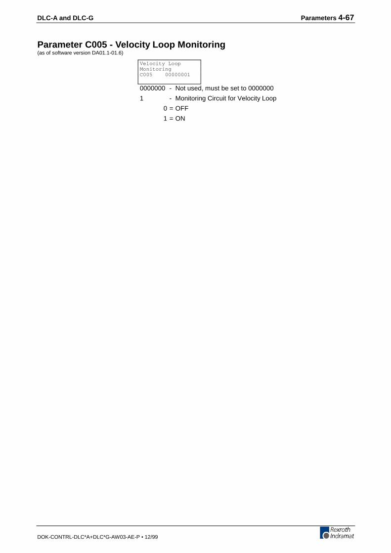
DLC-A and DLC-G Parameters 4-67
DOK-CONTRL-DLC*A+DLC*G-AW03-AE-P • 12/99
Parameter C005 - Velocity Loop Monitoring(as of software version DA01.1-01.6)
0000000 - Not used, must be set to 0000000
1 - Monitoring Circuit for Velocity Loop
0 = OFF
1 = ON
Velocity LoopMonitoringC005 00000001
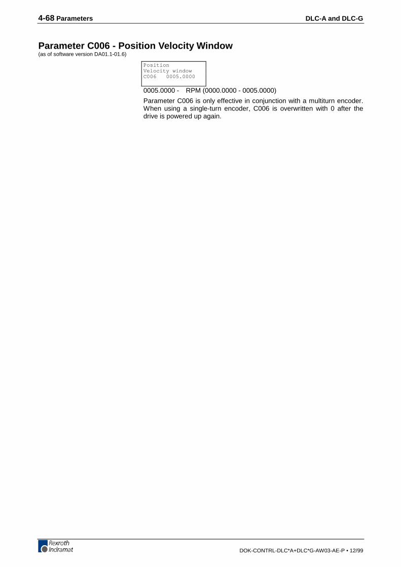
4-68 Parameters DLC-A and DLC-G
DOK-CONTRL-DLC*A+DLC*G-AW03-AE-P • 12/99
Parameter C006 - Position Velocity Window(as of software version DA01.1-01.6)
0005.0000 - RPM (0000.0000 - 0005.0000)
Parameter C006 is only effective in conjunction with a multiturn encoder.When using a single-turn encoder, C006 is overwritten with 0 after thedrive is powered up again.
PositionVelocity windowC006 0005.0000
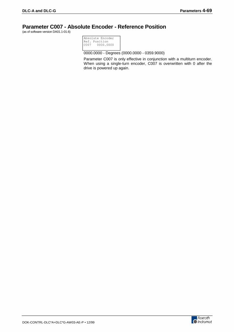
DLC-A and DLC-G Parameters 4-69
DOK-CONTRL-DLC*A+DLC*G-AW03-AE-P • 12/99
Parameter C007 - Absolute Encoder - Reference Position(as of software version DA01.1-01.6)
0000.0000 - Degrees (0000.0000 - 0359.9000)
Parameter C007 is only effective in conjunction with a multiturn encoder.When using a single-turn encoder, C007 is overwritten with 0 after thedrive is powered up again.
Absolute EncoderRef. PositionC007 0000.0000
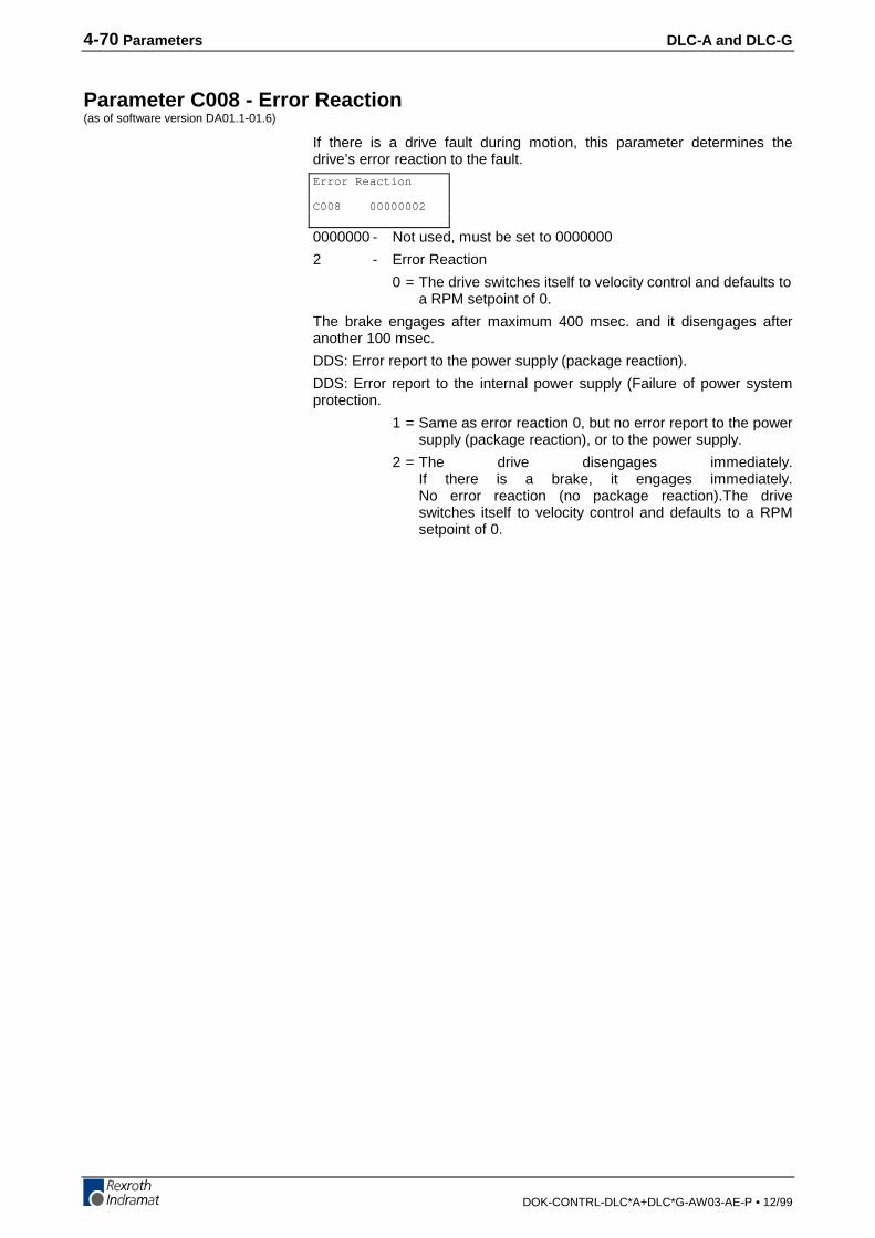
4-70 Parameters DLC-A and DLC-G
DOK-CONTRL-DLC*A+DLC*G-AW03-AE-P • 12/99
Parameter C008 - Error Reaction(as of software version DA01.1-01.6)
If there is a drive fault during motion, this parameter determines thedrive’s error reaction to the fault.
0000000 - Not used, must be set to 0000000
2 - Error Reaction
0 = The drive switches itself to velocity control and defaults toa RPM setpoint of 0.
The brake engages after maximum 400 msec. and it disengages afteranother 100 msec.
DDS: Error report to the power supply (package reaction).
DDS: Error report to the internal power supply (Failure of power systemprotection.
1 = Same as error reaction 0, but no error report to the powersupply (package reaction), or to the power supply.
2 = The drive disengages immediately.If there is a brake, it engages immediately.No error reaction (no package reaction).The driveswitches itself to velocity control and defaults to a RPMsetpoint of 0.
Error Reaction
C008 00000002
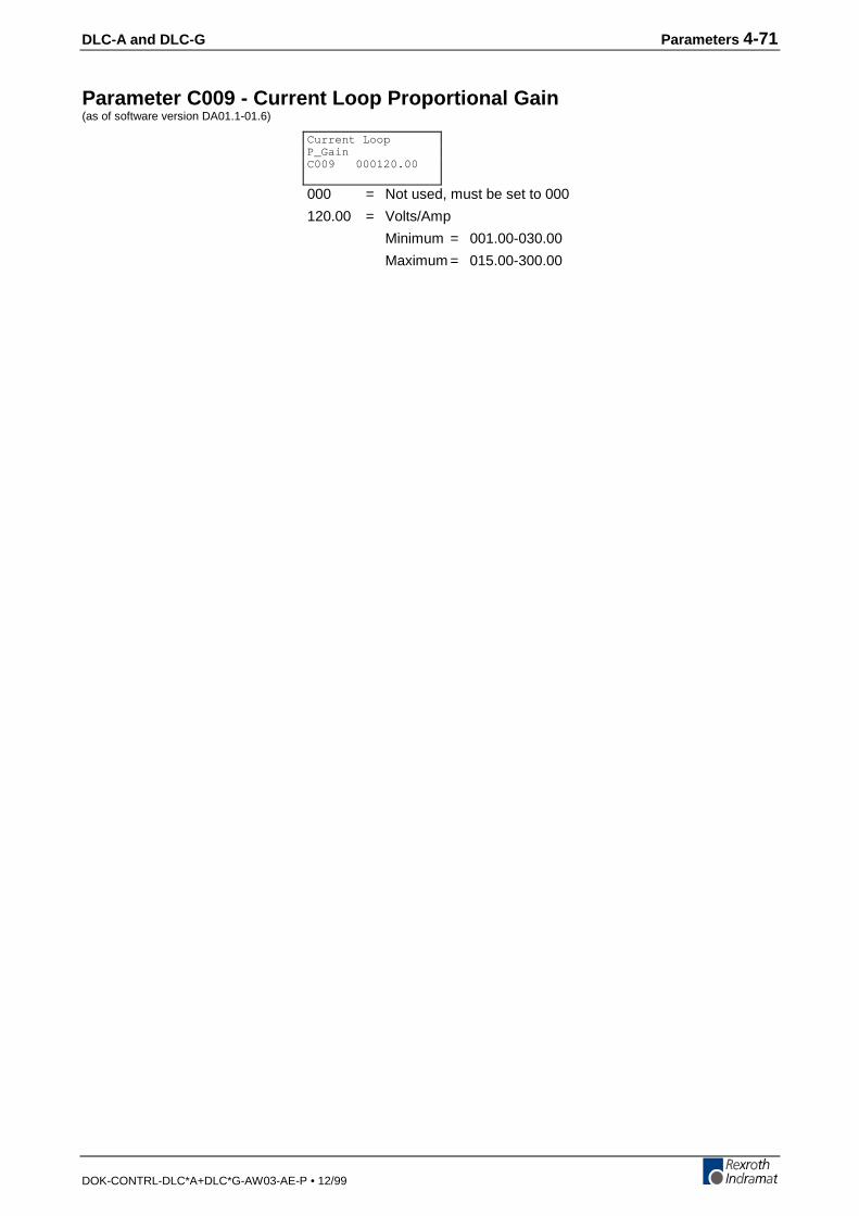
DLC-A and DLC-G Parameters 4-71
DOK-CONTRL-DLC*A+DLC*G-AW03-AE-P • 12/99
Parameter C009 - Current Loop Proportional Gain(as of software version DA01.1-01.6)
000 = Not used, must be set to 000
120.00 = Volts/Amp
Minimum = 001.00-030.00
Maximum = 015.00-300.00
Current LoopP_GainC009 000120.00
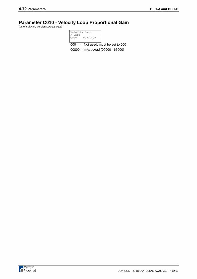
4-72 Parameters DLC-A and DLC-G
DOK-CONTRL-DLC*A+DLC*G-AW03-AE-P • 12/99
Parameter C010 - Velocity Loop Proportional Gain(as of software version DA01.1-01.6)
000 = Not used, must be set to 000
00800 = mAsec/rad (00000 - 65000)
Velocity LoopP_GainC010 00000800

DLC-A and DLC-G Parameters 4-73
DOK-CONTRL-DLC*A+DLC*G-AW03-AE-P • 12/99
Parameter C011 - Velocity Loop Integral Reaction Time(as of software version DA01.1-01.6)
000 = Not used, must be set to 000
2500.0 = msec (0000.1 - 6500.0)
Velocity LoopI_Reaction TimeC011 0002500.0
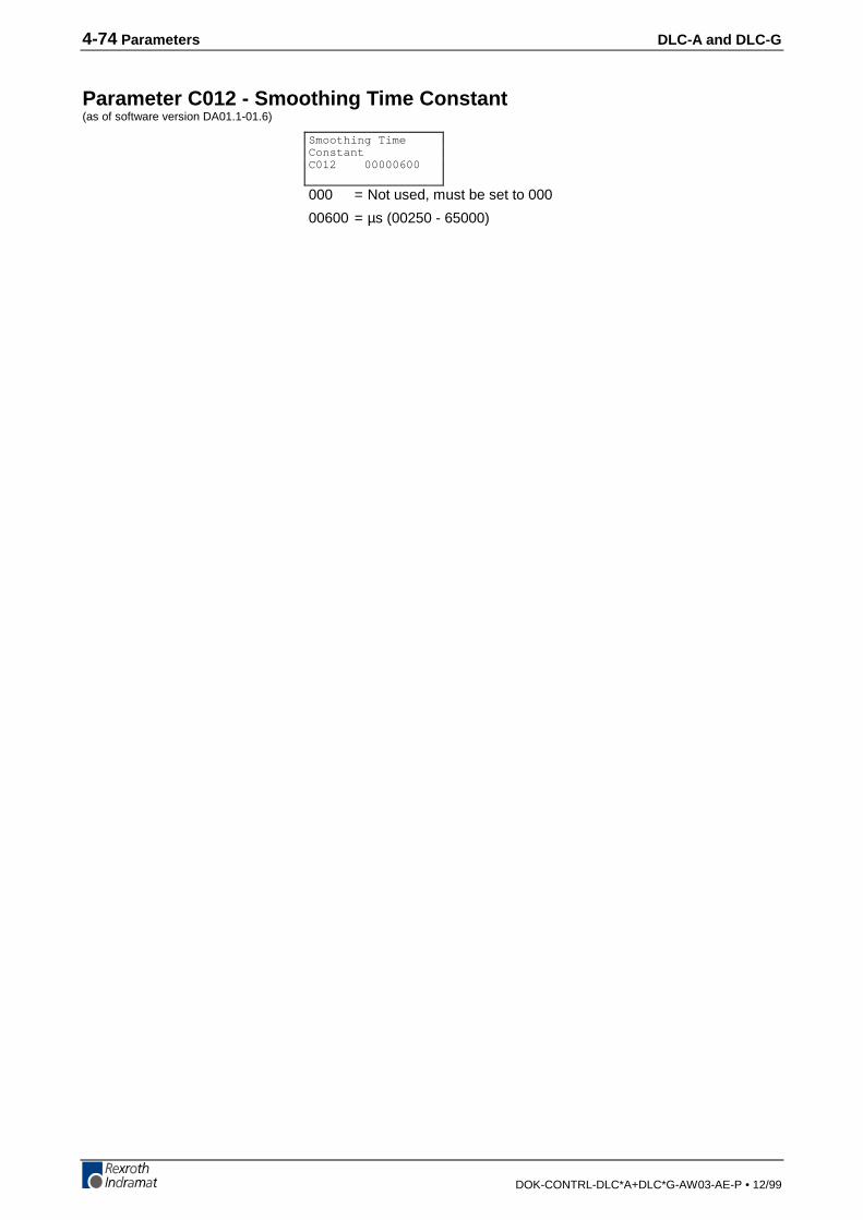
4-74 Parameters DLC-A and DLC-G
DOK-CONTRL-DLC*A+DLC*G-AW03-AE-P • 12/99
Parameter C012 - Smoothing Time Constant(as of software version DA01.1-01.6)
000 = Not used, must be set to 000
00600 = µs (00250 - 65000)
Smoothing TimeConstantC012 00000600
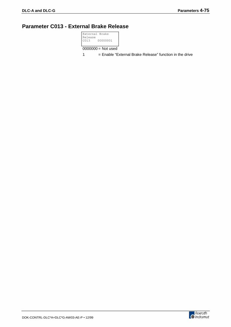
DLC-A and DLC-G Parameters 4-75
DOK-CONTRL-DLC*A+DLC*G-AW03-AE-P • 12/99
Parameter C013 - External Brake Release
0000000 = Not used
1 = Enable “External Brake Release” function in the drive
External BrakeReleaseC013 00000001

4-76 Parameters DLC-A and DLC-G
DOK-CONTRL-DLC*A+DLC*G-AW03-AE-P • 12/99
Parameter C100 - Set Standard Drive Tuning Parameters Via CTA(as of software version DA01.1-01.6)
From the C-Parameter group, pressing the blank key again displays theC100 parameter. In this menu, the drive parameters can be set to theirdefault values.
This menu consists of only the parameter C100.
The standard parameters are set after entering the number 00005301and pressing the block store key.
After pressing the block store key this menu item exits to “DriveParameter C000.”
If the entry is made incorrectly, the menu exits to “Drive Parameters”without setting the standard parameters, i.e. there is no control monitoringof the entry.
Set Standard DrvParams Over CTAC100 00000000CODE: 00005301
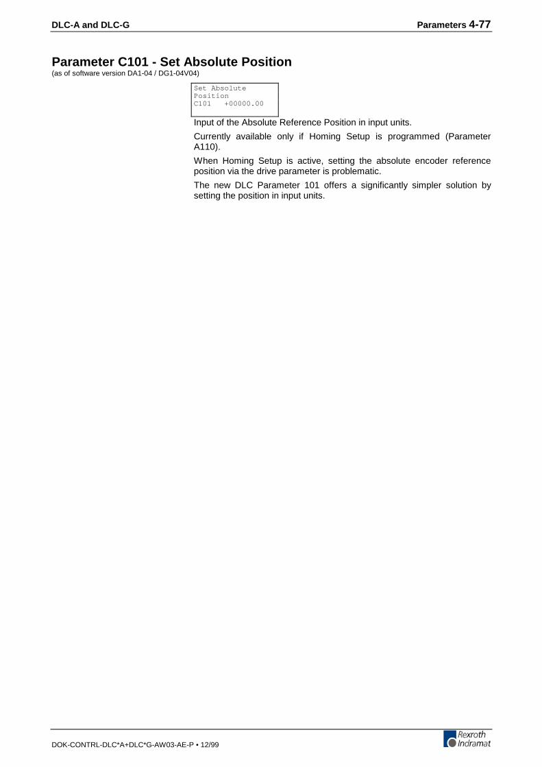
DLC-A and DLC-G Parameters 4-77
DOK-CONTRL-DLC*A+DLC*G-AW03-AE-P • 12/99
Parameter C101 - Set Absolute Position(as of software version DA1-04 / DG1-04V04)
Input of the Absolute Reference Position in input units.
Currently available only if Homing Setup is programmed (ParameterA110).
When Homing Setup is active, setting the absolute encoder referenceposition via the drive parameter is problematic.
The new DLC Parameter 101 offers a significantly simpler solution bysetting the position in input units.
Set AbsolutePositionC101 +00000.00

4-78 Parameters DLC-A and DLC-G
DOK-CONTRL-DLC*A+DLC*G-AW03-AE-P • 12/99
4.6 M Functions
General DescriptionPre-defined M functions are available to simplify handshaking betweenthe DLC and the line control during program execution. Pre-definedmeans that the given M function affects fixed assigned outputs that are tobe acknowledged by inputs that are also fixed.
Any inconsistency in the acknowledgments leads to the program stoppingin Task 1 and 2, as well as axis movement halting, until restoration of thedefined acknowledgment. Up to 64 predefined M functions can be used.Outputs and acknowledgment inputs should always be sequential. Mfunctions are monitored during processing of the selected command or ifprogrammed as such, they can be permanently monitored.
Selection occurs in the running program (Task 1 or 2) in the GO1command or by the M word as a separate command.
E 1000 G011 ±000010.00 mm

DLC-A and DLC-G Parameters 4-79
DOK-CONTRL-DLC*A+DLC*G-AW03-AE-P • 12/99
M = = Selection of an M Function
mm - Number (00...63) of the M function to be selected
A pre-coded M function is either set in a separate block using “M== “ or incombination with a G01 command. If the M function is programmed in aG01 block, it is set after the programmed position has been reached(within the limits set by A106, Position Tolerance). If G01 is programmedwithin a G61 contouring mode, the M function is set so as to allowoptimum speed.
If the M functions set are time dependent, it is important to note that theirstatus will change according to the M function table after the set time inParameter B009 has expired.
The status of the inputs and outputs, after processing the M function, aredefined in the M Function table. The table of M functions is specified inparameters only and can be modified by the CTA keyboard or serialllythrough the RS 232/RS 485 port.
E 1000 M==mm
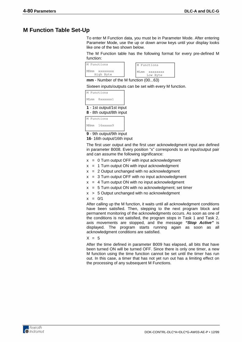
4-80 Parameters DLC-A and DLC-G
DOK-CONTRL-DLC*A+DLC*G-AW03-AE-P • 12/99
M Function Table Set-UpTo enter M Function data, you must be in Parameter Mode. After enteringParameter Mode, use the up or down arrow keys until your display lookslike one of the two shown below.
The M Function table has the following format for every pre-defined Mfunction:
mm - Number of the M function (00...63)
Sixteen inputs/outputs can be set with every M function.
1 - 1st output/1st input8 - 8th output/8th input
9 - 9th output/9th input16- 16th output/16th input
The first user output and the first user acknowledgment input are definedin parameter B008. Every position “x” corresponds to an input/output pairand can assume the following significance:
x = 0 Turn output OFF with input acknowledgmentx = 1 Turn output ON with input acknowledgmentx = 2 Output unchanged with no acknowledgmentx = 3 Turn output OFF with no input acknowledgmentx = 4 Turn output ON with no input acknowledgmentx = 5 Turn output ON with no acknowledgment; set timerx > 5 Output unchanged with no acknowledgmentx = 0/1After calling up the M function, it waits until all acknowledgment conditionshave been satisfied. Then, stepping to the next program block andpermanent monitoring of the acknowledgments occurs. As soon as one ofthe conditions is not satisfied, the program stops in Task 1 and Task 2,axis movements are stopped, and the message “Stop Active” isdisplayed. The program starts running again as soon as allacknowledgment conditions are satisfied.
X = 5
After the time defined in parameter B009 has elapsed, all bits that havebeen turned ON will be turned OFF. Since there is only one timer, a newM function using the time function cannot be set until the timer has runout. In this case, a timer that has not yet run out has a limiting effect onthe processing of any subsequent M Functions.
M Functions
MLmm xxxxxxxx Low Byte
M Functions
MHmm xxxxxxxx High Byte
M Functions
MLmm 8xxxxxx1
M Functions
MHmm 16xxxxx9
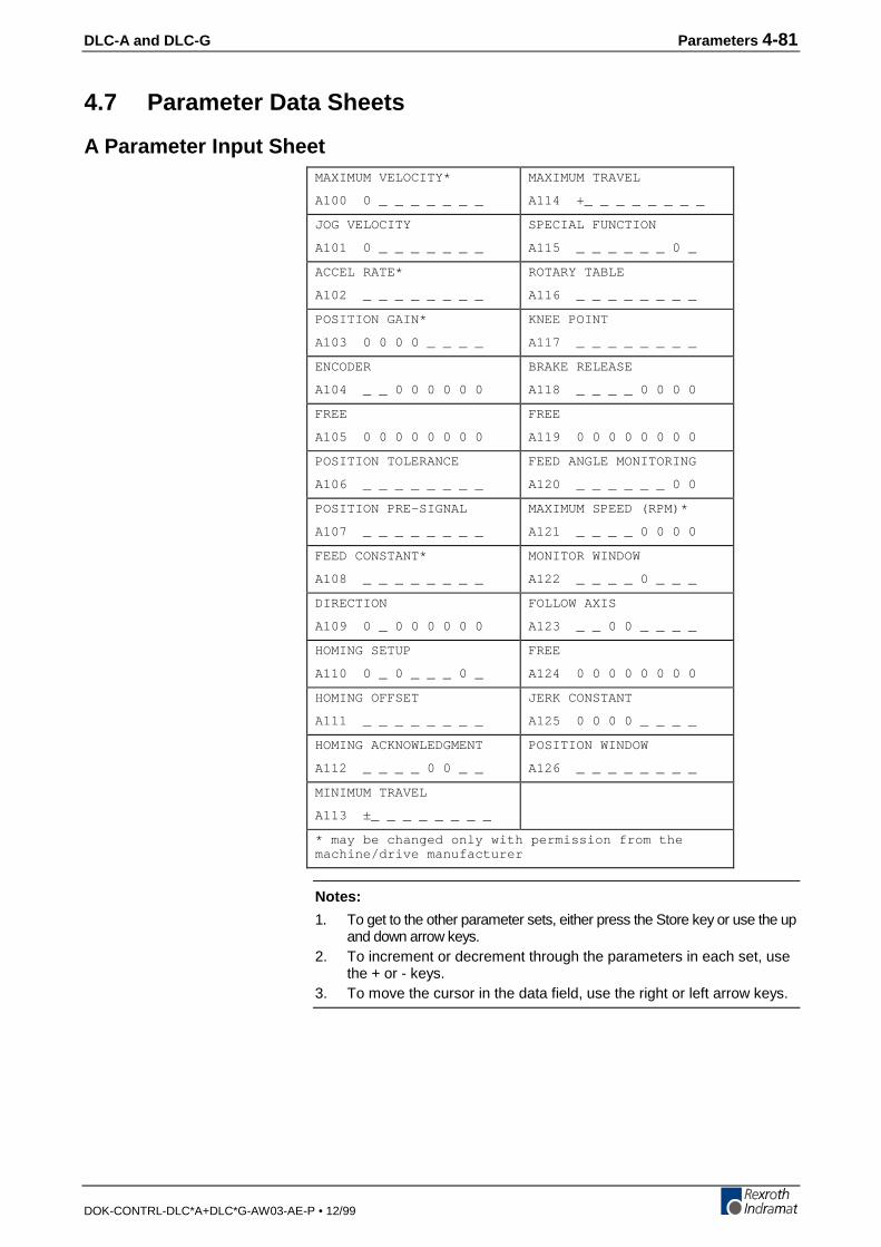
DLC-A and DLC-G Parameters 4-81
DOK-CONTRL-DLC*A+DLC*G-AW03-AE-P • 12/99
4.7 Parameter Data Sheets
A Parameter Input SheetMAXIMUM VELOCITY*
A100 0 _ _ _ _ _ _ _
MAXIMUM TRAVEL
A114 +_ _ _ _ _ _ _ _
JOG VELOCITY
A101 0 _ _ _ _ _ _ _
SPECIAL FUNCTION
A115 _ _ _ _ _ _ 0 _
ACCEL RATE*
A102 _ _ _ _ _ _ _ _
ROTARY TABLE
A116 _ _ _ _ _ _ _ _
POSITION GAIN*
A103 0 0 0 0 _ _ _ _
KNEE POINT
A117 _ _ _ _ _ _ _ _
ENCODER
A104 _ _ 0 0 0 0 0 0
BRAKE RELEASE
A118 _ _ _ _ 0 0 0 0
FREE
A105 0 0 0 0 0 0 0 0
FREE
A119 0 0 0 0 0 0 0 0
POSITION TOLERANCE
A106 _ _ _ _ _ _ _ _
FEED ANGLE MONITORING
A120 _ _ _ _ _ _ 0 0
POSITION PRE-SIGNAL
A107 _ _ _ _ _ _ _ _
MAXIMUM SPEED (RPM)*
A121 _ _ _ _ 0 0 0 0
FEED CONSTANT*
A108 _ _ _ _ _ _ _ _
MONITOR WINDOW
A122 _ _ _ _ 0 _ _ _
DIRECTION
A109 0 _ 0 0 0 0 0 0
FOLLOW AXIS
A123 _ _ 0 0 _ _ _ _
HOMING SETUP
A110 0 _ 0 _ _ _ 0 _
FREE
A124 0 0 0 0 0 0 0 0
HOMING OFFSET
A111 _ _ _ _ _ _ _ _
JERK CONSTANT
A125 0 0 0 0 _ _ _ _
HOMING ACKNOWLEDGMENT
A112 _ _ _ _ 0 0 _ _
POSITION WINDOW
A126 _ _ _ _ _ _ _ _
MINIMUM TRAVEL
A113 ±_ _ _ _ _ _ _ _
* may be changed only with permission from themachine/drive manufacturer
Notes:
1. To get to the other parameter sets, either press the Store key or use the upand down arrow keys.
2. To increment or decrement through the parameters in each set, usethe + or - keys.
3. To move the cursor in the data field, use the right or left arrow keys.
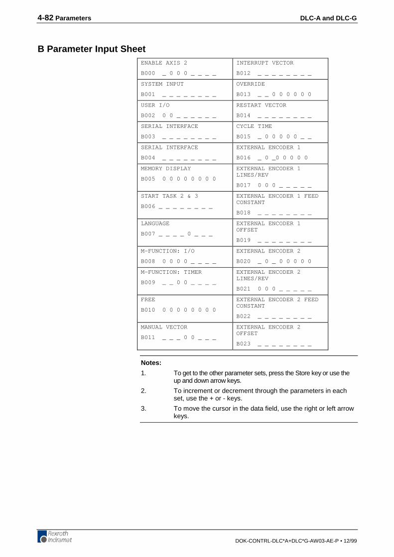
4-82 Parameters DLC-A and DLC-G
DOK-CONTRL-DLC*A+DLC*G-AW03-AE-P • 12/99
B Parameter Input SheetENABLE AXIS 2
B000 _ 0 0 0 _ _ _ _
INTERRUPT VECTOR
B012 _ _ _ _ _ _ _ _
SYSTEM INPUT
B001 _ _ _ _ _ _ _ _
OVERRIDE
B013 _ _ 0 0 0 0 0 0
USER I/O
B002 0 0 _ _ _ _ _ _
RESTART VECTOR
B014 _ _ _ _ _ _ _ _
SERIAL INTERFACE
B003 _ _ _ _ _ _ _ _
CYCLE TIME
B015 _ 0 0 0 0 0 _ _
SERIAL INTERFACE
B004 _ _ _ _ _ _ _ _
EXTERNAL ENCODER 1
B016 _ 0 _0 0 0 0 0
MEMORY DISPLAY
B005 0 0 0 0 0 0 0 0
EXTERNAL ENCODER 1LINES/REV
B017 0 0 0 _ _ _ _ _
START TASK 2 & 3
B006 _ _ _ _ _ _ _ _
EXTERNAL ENCODER 1 FEEDCONSTANT
B018 _ _ _ _ _ _ _ _
LANGUAGE
B007 _ _ _ _ 0 _ _ _
EXTERNAL ENCODER 1OFFSET
B019 _ _ _ _ _ _ _ _
M-FUNCTION: I/O
B008 0 0 0 0 _ _ _ _
EXTERNAL ENCODER 2
B020 _ 0 _ 0 0 0 0 0
M-FUNCTION: TIMER
B009 _ _ 0 0 _ _ _ _
EXTERNAL ENCODER 2LINES/REV
B021 0 0 0 _ _ _ _ _
FREE
B010 0 0 0 0 0 0 0 0
EXTERNAL ENCODER 2 FEEDCONSTANT
B022 _ _ _ _ _ _ _ _
MANUAL VECTOR
B011 _ _ _ 0 0 _ _ _
EXTERNAL ENCODER 2OFFSET
B023 _ _ _ _ _ _ _ _
Notes:
1. To get to the other parameter sets, press the Store key or use theup and down arrow keys.
2. To increment or decrement through the parameters in eachset, use the + or - keys.
3. To move the cursor in the data field, use the right or left arrowkeys.
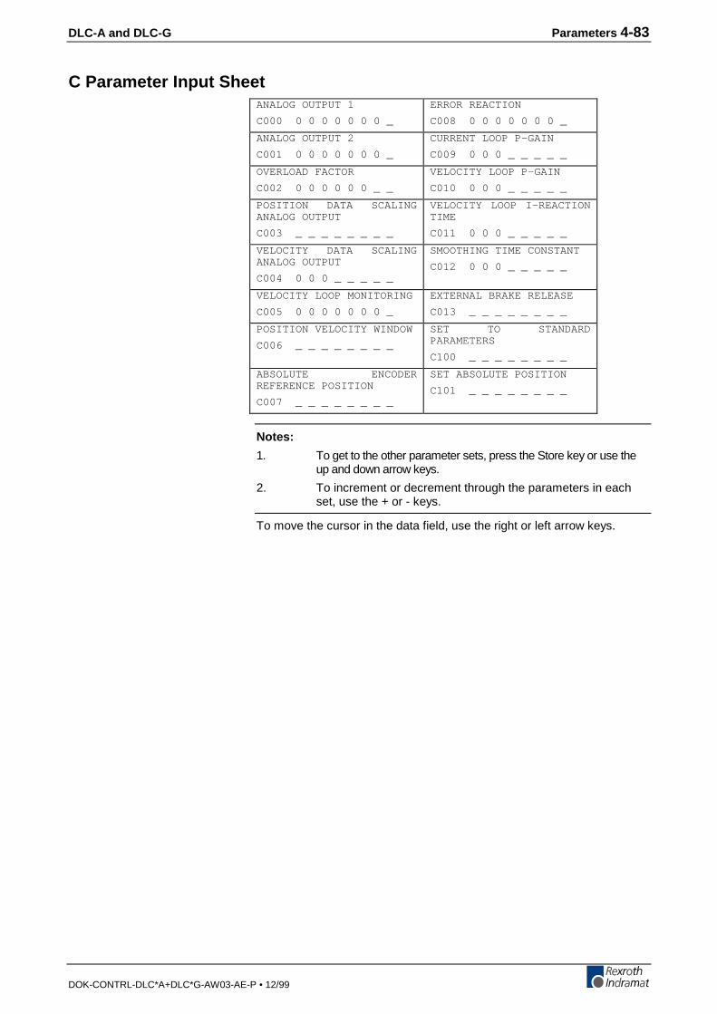
DLC-A and DLC-G Parameters 4-83
DOK-CONTRL-DLC*A+DLC*G-AW03-AE-P • 12/99
C Parameter Input SheetANALOG OUTPUT 1
C000 0 0 0 0 0 0 0 _
ERROR REACTION
C008 0 0 0 0 0 0 0 _
ANALOG OUTPUT 2
C001 0 0 0 0 0 0 0 _
CURRENT LOOP P-GAIN
C009 0 0 0 _ _ _ _ _
OVERLOAD FACTOR
C002 0 0 0 0 0 0 _ _
VELOCITY LOOP P-GAIN
C010 0 0 0 _ _ _ _ _
POSITION DATA SCALINGANALOG OUTPUT
C003 _ _ _ _ _ _ _ _
VELOCITY LOOP I-REACTIONTIME
C011 0 0 0 _ _ _ _ _
VELOCITY DATA SCALINGANALOG OUTPUT
C004 0 0 0 _ _ _ _ _
SMOOTHING TIME CONSTANT
C012 0 0 0 _ _ _ _ _
VELOCITY LOOP MONITORING
C005 0 0 0 0 0 0 0 _
EXTERNAL BRAKE RELEASE
C013 _ _ _ _ _ _ _ _
POSITION VELOCITY WINDOW
C006 _ _ _ _ _ _ _ _
SET TO STANDARDPARAMETERS
C100 _ _ _ _ _ _ _ _
ABSOLUTE ENCODERREFERENCE POSITION
C007 _ _ _ _ _ _ _ _
SET ABSOLUTE POSITION
C101 _ _ _ _ _ _ _ _
Notes:
1. To get to the other parameter sets, press the Store key or use theup and down arrow keys.
2. To increment or decrement through the parameters in eachset, use the + or - keys.
To move the cursor in the data field, use the right or left arrow keys.
4-84 Parameters DLC-A and DLC-G
DOK-CONTRL-DLC*A+DLC*G-AW03-AE-P • 12/99
DLC-A and DLC-G Programming 5-1
DOK-CONTRL-DLC*A+DLC*G-AW03-AE-P • 12/99
5 ProgrammingThe application program of the system is defined and entered by the user.It can be entered directly via the CTA keypad and display, or from a remoteterminal device interfaced through the RS-232, or RS-485 port. Theapplication program flow is similar to a Basic program. Three lettermnemonic commands are used. There are 3000 programming lines/blocksavailable for user programming, numbered 0000 through 2999.
The Indramat MotionManagerTM Program Development Tool provides anefficient method of creating and editing the user program for the DLCcontrol. It is a software package that runs on any DOS-based computer. Itprovides several benefits over programming the DLC from its control panel.It also includes enhanced features for creating and editing program that arenot possible from the DLC control panel. Refer to Publication IA 74733 forspecific information on using this software program.
This chapter begins by describing some basic information that should beconsidered before creating a program for the DLC. It then describes themethods to enter the user program directly into the CTA keypad anddisplay. It further describes the programming commands and their functionin a user program.
5.1 Positioning
Two types of positioning can be selected in the system, absolute andincremental. All positioning is done in the units of your choice and arereferred to as Input Units (IU) . Input Units are the user’s desired units ofmeasure (i.e. inches, mm, radians, degrees, etc.).
In absolute positioning, all movements of the slide are made someabsolute distance from the machine reference point. Thus, if the slide is at+2 inches from home, and an absolute position command to move +3inches is executed, a one inch feed in the positive direction will result.
In incremental positioning, all movements of the slide are made in thecommanded direction to the distance specified, starting from the currentposition. Thus, if a slide is at +2 inches from home, an incrementalcommand to move +3 inches will result in the slide being positioned +5inches from home.
5-2 Programming DLC-A and DLC-G
DOK-CONTRL-DLC*A+DLC*G-AW03-AE-P • 12/99
5.2 Auxiliary Inputs/OutputsThe DLC has a set of I/O points with a predefined use. It also includes aset of I/O points which can be defined by the user for controlling machinefunctions. They will be referred to as auxiliary inputs and auxiliary outputs(or aux. inputs and aux. outputs). Auxiliary inputs are also known asacknowledgments. Certain commands are provided for use to addressthese inputs and outputs. The I/O Commands are described in section5.8.5.
Warning: Auxiliary input and output numbers that have been dedicated bythe machine builder for a specific purpose must not bechanged. Personal injury or damage to the machine/drive traincould result from such changes.
Programming Inputs/OutputsCertain outputs are predefined in the DLC internal program and cannot bechanged by the user program. When the DLC is powered ON, it setscertain outputs, per the internal program, to default position. Likewise,when a fault occurs, it sets many outputs OFF. Outputs are re-established,either through hardware or software, i.e. the Automatic Mode Indicatorturns ON after that mode is selected by input (assuming all other conditionsare met), a software flag is turned ON or OFF as the user programexecutes the block containing the command.Chapter 3 describes the functional use of each system input/output, as wellas many programming and parameter entries specifying input or outputconnections. Several I/O are available for use as flags in the user program.Certain output flags are set in firmware and can be queried by the userprogram. Table 5.1 list the hardware outputs that can be used in theprogram to electrically signal an external component. It also lists the outputsoftware flags that can be used internally in the program. It defines theoutput flags which are set in firmware. Refer to this table whenprogramming an output.
Inputs/Outputs Signal DefinitionThere are two states that system inputs/outputs and auxiliaryinputs/outputs could hold. The "ON" or High state, means that there is a+24 Vdc signal present at the input/output. The "OFF" or Low state, meansthat there is a O Vdc signal at the input/output. A signal line is described as“Active High” when its associated action is initiated by a High (+24 volts)signal level. It is described as “Active Low” when its function is initiated by aLow signal (0 volts). An active low signal must remain in the high state toallow normal operation. Refer to Chapter 3 for further description of I/Osignals.
DLC with DEA 4 11 Hardware Outputs 1-11
88 Software Flags 12-99
DLC with DEA 4 & DEA 5 27 Hardware Outputs 12-27
48 Software Flags 28-99
DLC with DEA 4 43 Hardware Outputs 28-43
DEA 5, & DEA 6 80 Software Flags 44-99
Table 5-1: Output Definitions
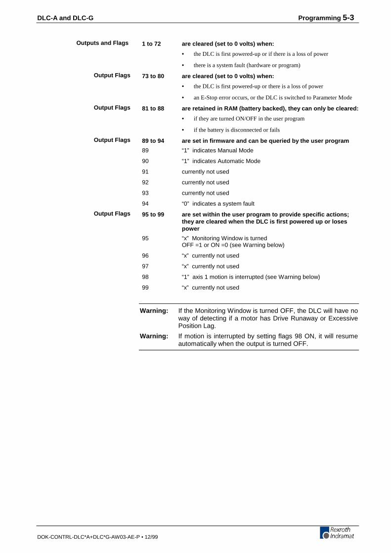
DLC-A and DLC-G Programming 5-3
DOK-CONTRL-DLC*A+DLC*G-AW03-AE-P • 12/99
1 to 72 are cleared (set to 0 volts) when:
• the DLC is first powered-up or if there is a loss of power
• there is a system fault (hardware or program)
73 to 80 are cleared (set to 0 volts) when:
• the DLC is first powered-up or there is a loss of power
• an E-Stop error occurs, or the DLC is switched to Parameter Mode
81 to 88 are retained in RAM (battery backed), they can only be cleared:
• if they are turned ON/OFF in the user program
• if the battery is disconnected or fails
89 to 94 are set in firmware and can be queried by the user program
89 “1” indicates Manual Mode
90 “1” indicates Automatic Mode
91 currently not used
92 currently not used
93 currently not used
94 “0” indicates a system fault
95 to 99 are set within the user program to provide specific actions;they are cleared when the DLC is first powered up or losespower
95 “x” Monitoring Window is turnedOFF =1 or ON =0 (see Warning below)
96 “x” currently not used
97 “x” currently not used
98 “1” axis 1 motion is interrupted (see Warning below)
99 “x” currently not used
Warning: If the Monitoring Window is turned OFF, the DLC will have noway of detecting if a motor has Drive Runaway or ExcessivePosition Lag.
Warning: If motion is interrupted by setting flags 98 ON, it will resumeautomatically when the output is turned OFF.
Outputs and Flags
Output Flags
Output Flags
Output Flags
Output Flags
5-4 Programming DLC-A and DLC-G
DOK-CONTRL-DLC*A+DLC*G-AW03-AE-P • 12/99
5.3 Multi-Tasking
The DLC is capable of operating one motion program and two backgroundPLC programs simultaneously when multiple tasks are programmed (seenext section). This allows a single DLC to operate one motion program andtwo background processes at the same time or utilize multi-tasking in asingle process.
5.4 Start of the Program
When the DLC is first powered up or an error is cleared, the program blockpointer is set to block 0000 for Task 1. If Tasks 2 and 3 are used, they willstart at their assigned starting point as user defined in parameter B006. Allprograms must start at their assigned starting points; Task 1 must start atblock 0000. Blocks of numbers of programming will be followedsequentially unless a jump or branch instruction is encountered.
If block 2999 is executed and it is not a jump command, all motions arestopped, and an error code is displayed. Typically, the last command blockyou enter will be a jump command to return to the start of the next cycle orto return from a sub-program routine.
5.5 End of the Program
Take extreme care to control the flow of the program. This is especiallyimportant when using multi-tasking. Most programs are designed so theywill loop back to the start of each task and wait for the proper sequence ofevents before starting again. Make sure that each task will not interferewith another task.
5.6 Programming Mode
The DLC must be in either Automatic or Manual mode to accept programentry/edit from the front panel. It is recommended that the DLC be placedin manual mode when editing the program, especially when this involveschanging a command, or several blocks.
Warning: Program entry in Automatic Mode, while the unit is in operation,will be accepted as soon as the Store key is pressed. The nexttime the block is scanned in the program, the updated data willbe executed. It is recommended that the DLC be placed inManual Mode when editing the program. Complete and verifythe program changes before returning to Automatic Mode.Have accurate listings of the program and parameters whenediting, to reduce the possibility of errors.
DLC-A and DLC-G Programming 5-5
DOK-CONTRL-DLC*A+DLC*G-AW03-AE-P • 12/99
5.7 General Format
The general format, shown on the CTA display during program entry / edit,is as follows:
E = shows the display is in the program edit mode
0000 = block number displayed; command or data can be viewedor edited.
You can select any block number 0000-2999 to display. To scroll throughthe block numbers, first press the CR key to locate the cursor in the topline (or use the left/right arrow keys). Then use the + and - keys to scrollup or down through the block numbers. You can also type the blocknumber desired directly over the existing number.
ABC = 3-letter mnemonic of command programmed in displayedblock
To scroll through the commands, position the cursor to the right of thedisplayed command three letter mnemonic. Use the up or down arrow keysto scroll alphabetically through commands. When the desired command ison the display, press the right arrow key to select the command and movethe cursor into the data field that appears for the specific command on thesecond line.
(Data) = Most command requires entry of data specific for thatcommand, as described in the following sections.
5.8 Command Summary
The various commands can be classified into categories by their function,as described in the following sections. These sections describe the generaluse and differences between all the programming commands. For futurereference, you can use these sections to select the specific commanddesired for the general function. Then refer to that command description insection 5.9 for further details on how it works and requirements for itsentry.
E _0000 ABC
(DATA)
5-6 Programming DLC-A and DLC-G
DOK-CONTRL-DLC*A+DLC*G-AW03-AE-P • 12/99
Positioning CommandsThere are two major types of positioning commands: Incremental -movement from one point to the next point, or Absolute - movement inrelationship to a known home point. These can be further broken into twodifferent functional types of positional commands.
1. Commands that require the axis to be at the final programmedposition, as determined by the In Position Signal, before stepping tothe next block. These are identified by the letter "S" in the mnemonic(Stop).
2. Commands that, after being read into the position buffer, immediatelygo to the next block for further program execution. These areidentified by the letter "O" in the mnemonic (Onward).
The following is a list of the position commands:
G01 Linear Feed with M Functions
G60 Position with Exact Stop
G61 Begin Velocity Rate Optimization profile
POI Incremental position command
PSI Incremental position command with In Position Acknowledged
POAAbsolute position command
PSA Absolute position command with In Position Acknowledged
POMIncremental or Absolute positioning to IDS thumbwheel switch setting
PSMIncremental or Absolute positioning to IDS with In PositionAcknowledged
PFA Absolute position to a positive stop
PFI Incremental position to a positive stop
Position commands have the following characteristics:
• Position commands must include three components: axis, Position orDistance, and Velocity.
• Positions are programmed directly in units of your choice: inches,metric, degrees, etc.
• You can select either two or three decimal points of accuracy (inparameter B007).
• The acceleration rates specified in parameter A102 will be used asdefaults, unless they are changed with the ACC command prior to themotion.
• Select either Constant acceleration or Knee Point acceleration profile.
• Motion can be independent or simultaneous.
• Axis can be programmed for Rotary motion (rotation resetting to zeroafter one revolution).
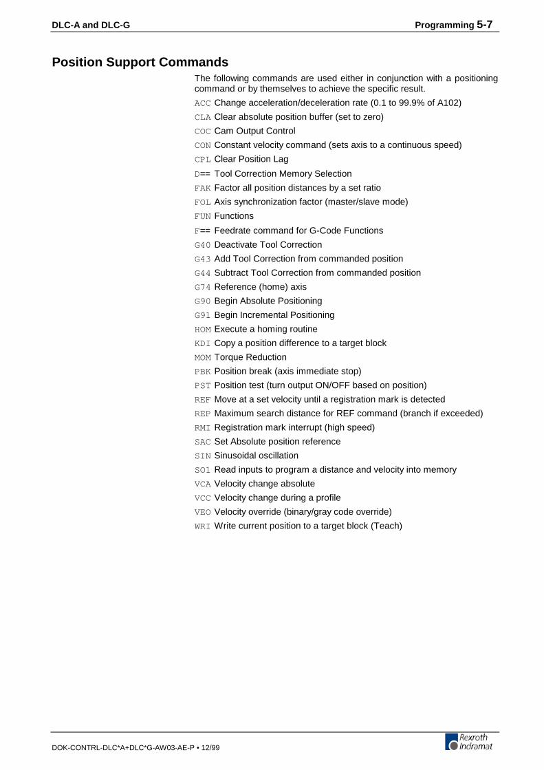
DLC-A and DLC-G Programming 5-7
DOK-CONTRL-DLC*A+DLC*G-AW03-AE-P • 12/99
Position Support CommandsThe following commands are used either in conjunction with a positioningcommand or by themselves to achieve the specific result.
ACCChange acceleration/deceleration rate (0.1 to 99.9% of A102)
CLA Clear absolute position buffer (set to zero)
COCCam Output Control
CONConstant velocity command (sets axis to a continuous speed)
CPL Clear Position Lag
D== Tool Correction Memory Selection
FAK Factor all position distances by a set ratio
FOL Axis synchronization factor (master/slave mode)
FUNFunctions
F== Feedrate command for G-Code Functions
G40 Deactivate Tool Correction
G43 Add Tool Correction from commanded position
G44 Subtract Tool Correction from commanded position
G74 Reference (home) axis
G90 Begin Absolute Positioning
G91 Begin Incremental Positioning
HOMExecute a homing routine
KDI Copy a position difference to a target block
MOMTorque Reduction
PBK Position break (axis immediate stop)
PST Position test (turn output ON/OFF based on position)
REF Move at a set velocity until a registration mark is detected
REPMaximum search distance for REF command (branch if exceeded)
RMI Registration mark interrupt (high speed)
SACSet Absolute position reference
SIN Sinusoidal oscillation
SO1 Read inputs to program a distance and velocity into memory
VCAVelocity change absolute
VCCVelocity change during a profile
VEOVelocity override (binary/gray code override)
WRI Write current position to a target block (Teach)
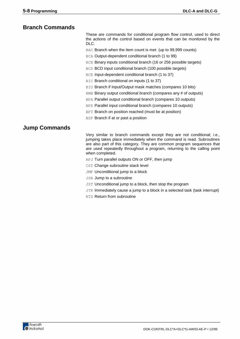
5-8 Programming DLC-A and DLC-G
DOK-CONTRL-DLC*A+DLC*G-AW03-AE-P • 12/99
Branch CommandsThese are commands for conditional program flow control, used to directthe actions of the control based on events that can be monitored by theDLC.
BACBranch when the item count is met (up to 99,999 counts)
BCAOutput-dependent conditional branch (1 to 99)
BCBBinary inputs conditional branch (16 or 256 possible targets)
BCDBCD input conditional branch (100 possible targets)
BCE Input-dependent conditional branch (1 to 37)
BIC Branch conditional on inputs (1 to 37)
BIO Branch if Input/Output mask matches (compares 10 bits)
BMBBinary output conditional branch (compares any # of outputs)
BPA Parallel output conditional branch (compares 10 outputs)
BPE Parallel input conditional branch (compares 10 outputs)
BPT Branch on position reached (must be at position)
BZP Branch if at or past a position
Jump CommandsVery similar to branch commands except they are not conditional; i.e.,jumping takes place immediately when the command is read. Subroutinesare also part of this category. They are common program sequences thatare used repeatedly throughout a program, returning to the calling pointwhen completed.
APJ Turn parallel outputs ON or OFF, then jump
CST Change subroutine stack level
JMP Unconditional jump to a block
JSR Jump to a subroutine
JST Unconditional jump to a block, then stop the program
JTK Immediately cause a jump to a block in a selected task (task interrupt)
RTS Return from subroutine
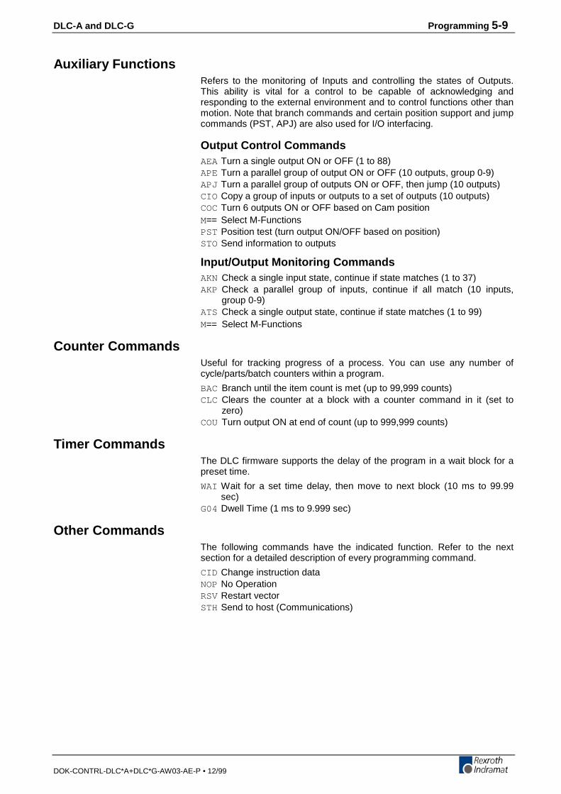
DLC-A and DLC-G Programming 5-9
DOK-CONTRL-DLC*A+DLC*G-AW03-AE-P • 12/99
Auxiliary FunctionsRefers to the monitoring of Inputs and controlling the states of Outputs.This ability is vital for a control to be capable of acknowledging andresponding to the external environment and to control functions other thanmotion. Note that branch commands and certain position support and jumpcommands (PST, APJ) are also used for I/O interfacing.
Output Control CommandsAEA Turn a single output ON or OFF (1 to 88)APE Turn a parallel group of output ON or OFF (10 outputs, group 0-9)APJ Turn a parallel group of outputs ON or OFF, then jump (10 outputs)CIO Copy a group of inputs or outputs to a set of outputs (10 outputs)COCTurn 6 outputs ON or OFF based on Cam positionM== Select M-FunctionsPST Position test (turn output ON/OFF based on position)STOSend information to outputs
Input/Output Monitoring CommandsAKN Check a single input state, continue if state matches (1 to 37)AKP Check a parallel group of inputs, continue if all match (10 inputs,
group 0-9)ATS Check a single output state, continue if state matches (1 to 99)M== Select M-Functions
Counter CommandsUseful for tracking progress of a process. You can use any number ofcycle/parts/batch counters within a program.
BAC Branch until the item count is met (up to 99,999 counts)CLC Clears the counter at a block with a counter command in it (set to
zero)COUTurn output ON at end of count (up to 999,999 counts)
Timer CommandsThe DLC firmware supports the delay of the program in a wait block for apreset time.
WAI Wait for a set time delay, then move to next block (10 ms to 99.99sec)
G04 Dwell Time (1 ms to 9.999 sec)
Other CommandsThe following commands have the indicated function. Refer to the nextsection for a detailed description of every programming command.
CID Change instruction dataNOPNo OperationRSVRestart vectorSTH Send to host (Communications)
5-10 Programming DLC-A and DLC-G
DOK-CONTRL-DLC*A+DLC*G-AW03-AE-P • 12/99
5.9 Command Descriptions
This section describes each programming command. The first line of theillustrated displays are as previously described, with E indicating Edit Mode,a random block line number, the three letter mnemonic for the commandand relative data fields.
This manual principally describes hardware versions DLC 1.1 and DLC 2.1with software version DG01.1-XX.X. The software has parameter selectedtwo or three decimal place precision in the commands that involvepositioning- and position-related parameters (See Parameter B007).
Each command requires specific data. All places for required data in a userprogram block which contains illegal characters (a space or an undefinedcharacter - not a number or the +/- sign) are replaced by the asteriskcharacter (*) in the display. This enables the user to easily recognize whichpoints in a command data needs be programmed. A program block has thecorrect syntax when it contains no asterisk (*) characters in the display.
The following sections fully describe the use and data field entryrequirements of each command.
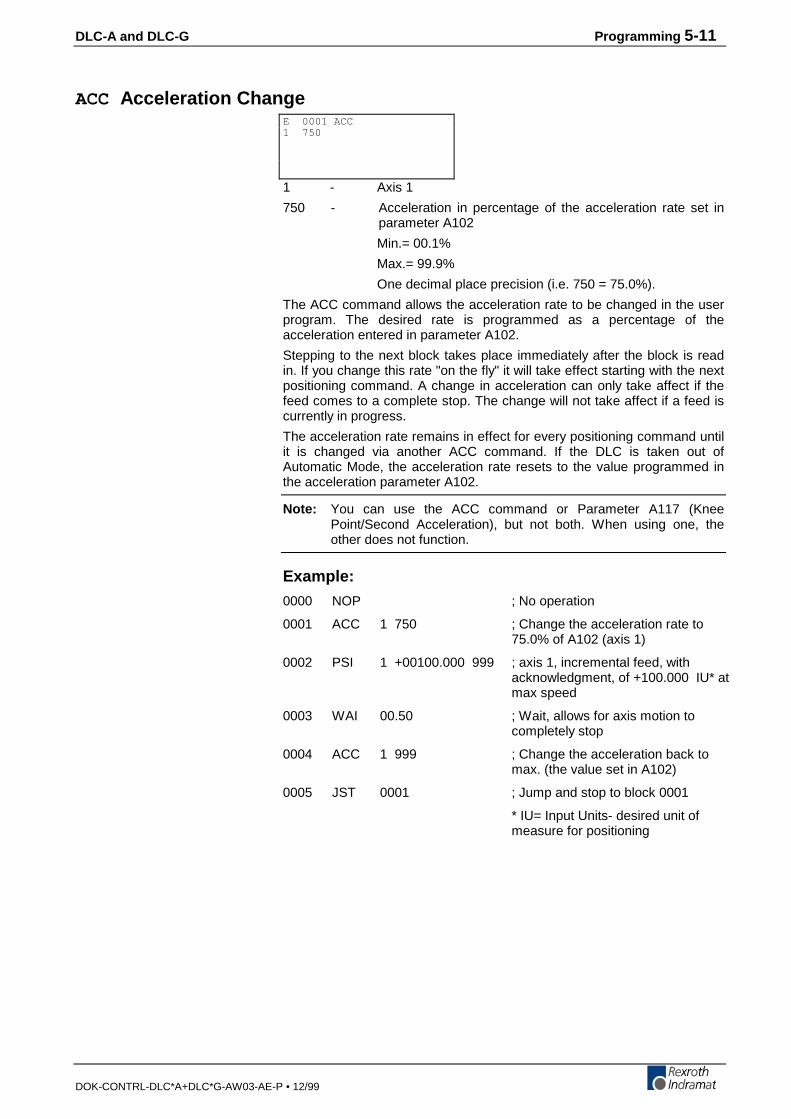
DLC-A and DLC-G Programming 5-11
DOK-CONTRL-DLC*A+DLC*G-AW03-AE-P • 12/99
ACC Acceleration Change
1 - Axis 1
750 - Acceleration in percentage of the acceleration rate set inparameter A102
Min.= 00.1%
Max.= 99.9%
One decimal place precision (i.e. 750 = 75.0%).
The ACC command allows the acceleration rate to be changed in the userprogram. The desired rate is programmed as a percentage of theacceleration entered in parameter A102.
Stepping to the next block takes place immediately after the block is readin. If you change this rate "on the fly" it will take effect starting with the nextpositioning command. A change in acceleration can only take affect if thefeed comes to a complete stop. The change will not take affect if a feed iscurrently in progress.
The acceleration rate remains in effect for every positioning command untilit is changed via another ACC command. If the DLC is taken out ofAutomatic Mode, the acceleration rate resets to the value programmed inthe acceleration parameter A102.
Note: You can use the ACC command or Parameter A117 (KneePoint/Second Acceleration), but not both. When using one, theother does not function.
Example:
0000 NOP ; No operation
0001 ACC 1 750 ; Change the acceleration rate to75.0% of A102 (axis 1)
0002 PSI 1 +00100.000 999 ; axis 1, incremental feed, withacknowledgment, of +100.000 IU* atmax speed
0003 WAI 00.50 ; Wait, allows for axis motion tocompletely stop
0004 ACC 1 999 ; Change the acceleration back tomax. (the value set in A102)
0005 JST 0001 ; Jump and stop to block 0001
* IU= Input Units- desired unit ofmeasure for positioning
E 0001 ACC1 750
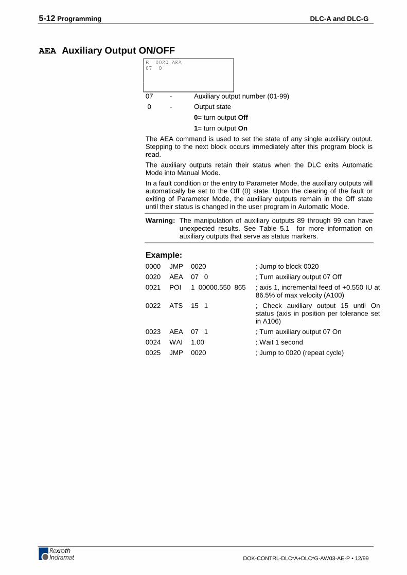
5-12 Programming DLC-A and DLC-G
DOK-CONTRL-DLC*A+DLC*G-AW03-AE-P • 12/99
AEA Auxiliary Output ON/OFF
07 - Auxiliary output number (01-99)
0 - Output state
0= turn output Off
1= turn output On
The AEA command is used to set the state of any single auxiliary output.Stepping to the next block occurs immediately after this program block isread.
The auxiliary outputs retain their status when the DLC exits AutomaticMode into Manual Mode.
In a fault condition or the entry to Parameter Mode, the auxiliary outputs willautomatically be set to the Off (0) state. Upon the clearing of the fault orexiting of Parameter Mode, the auxiliary outputs remain in the Off stateuntil their status is changed in the user program in Automatic Mode.
Warning: The manipulation of auxiliary outputs 89 through 99 can haveunexpected results. See Table 5.1 for more information onauxiliary outputs that serve as status markers.
Example:0000 JMP 0020 ; Jump to block 0020
0020 AEA 07 0 ; Turn auxiliary output 07 Off
0021 POI 1 00000.550 865 ; axis 1, incremental feed of +0.550 IU at86.5% of max velocity (A100)
0022 ATS 15 1 ; Check auxiliary output 15 until Onstatus (axis in position per tolerance setin A106)
0023 AEA 07 1 ; Turn auxiliary output 07 On
0024 WAI 1.00 ; Wait 1 second
0025 JMP 0020 ; Jump to 0020 (repeat cycle)
E 0020 AEA07 0
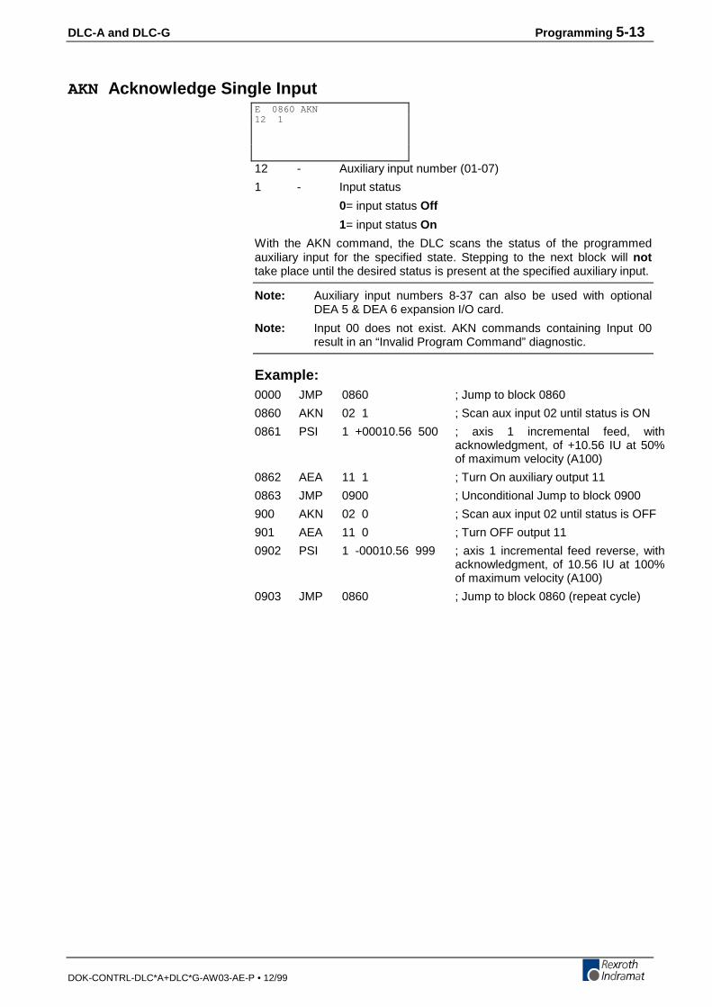
DLC-A and DLC-G Programming 5-13
DOK-CONTRL-DLC*A+DLC*G-AW03-AE-P • 12/99
AKN Acknowledge Single Input
12 - Auxiliary input number (01-07)
1 - Input status
0= input status Off
1= input status On
With the AKN command, the DLC scans the status of the programmedauxiliary input for the specified state. Stepping to the next block will nottake place until the desired status is present at the specified auxiliary input.
Note: Auxiliary input numbers 8-37 can also be used with optionalDEA 5 & DEA 6 expansion I/O card.
Note: Input 00 does not exist. AKN commands containing Input 00result in an “Invalid Program Command” diagnostic.
Example:0000 JMP 0860 ; Jump to block 0860
0860 AKN 02 1 ; Scan aux input 02 until status is ON
0861 PSI 1 +00010.56 500 ; axis 1 incremental feed, withacknowledgment, of +10.56 IU at 50%of maximum velocity (A100)
0862 AEA 11 1 ; Turn On auxiliary output 11
0863 JMP 0900 ; Unconditional Jump to block 0900
900 AKN 02 0 ; Scan aux input 02 until status is OFF
901 AEA 11 0 ; Turn OFF output 11
0902 PSI 1 -00010.56 999 ; axis 1 incremental feed reverse, withacknowledgment, of 10.56 IU at 100%of maximum velocity (A100)
0903 JMP 0860 ; Jump to block 0860 (repeat cycle)
E 0860 AKN12 1
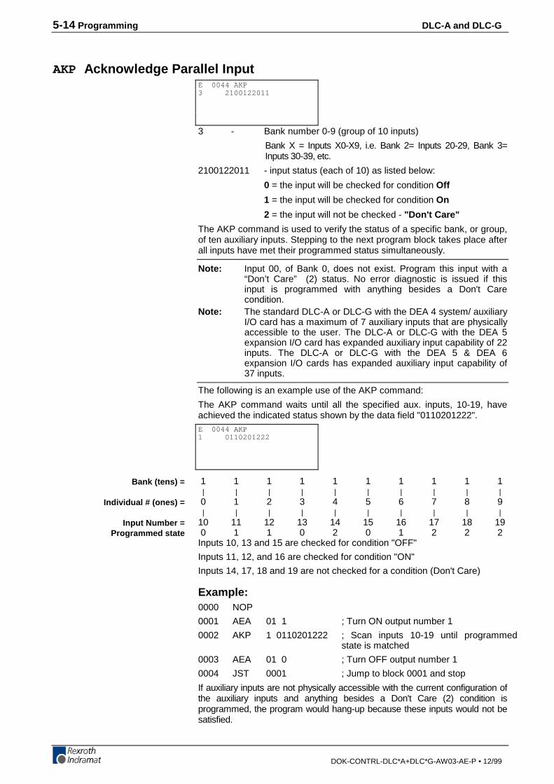
5-14 Programming DLC-A and DLC-G
DOK-CONTRL-DLC*A+DLC*G-AW03-AE-P • 12/99
AKP Acknowledge Parallel Input
3 - Bank number 0-9 (group of 10 inputs)
Bank X = Inputs X0-X9, i.e. Bank 2= Inputs 20-29, Bank 3=Inputs 30-39, etc.
2100122011 - input status (each of 10) as listed below:
0 = the input will be checked for condition Off
1 = the input will be checked for condition On
2 = the input will not be checked - "Don't Care"
The AKP command is used to verify the status of a specific bank, or group,of ten auxiliary inputs. Stepping to the next program block takes place afterall inputs have met their programmed status simultaneously.
Note: Input 00, of Bank 0, does not exist. Program this input with a“Don’t Care” (2) status. No error diagnostic is issued if thisinput is programmed with anything besides a Don't Carecondition.
Note: The standard DLC-A or DLC-G with the DEA 4 system/ auxiliaryI/O card has a maximum of 7 auxiliary inputs that are physicallyaccessible to the user. The DLC-A or DLC-G with the DEA 5expansion I/O card has expanded auxiliary input capability of 22inputs. The DLC-A or DLC-G with the DEA 5 & DEA 6expansion I/O cards has expanded auxiliary input capability of37 inputs.
The following is an example use of the AKP command:
The AKP command waits until all the specified aux. inputs, 10-19, haveachieved the indicated status shown by the data field "0110201222".
1 1 1 1 1 1 1 1 1 1 | | | | | | | | | | 0 1 2 3 4 5 6 7 8 9 | | | | | | | | | |10 11 12 13 14 15 16 17 18 19 0 1 1 0 2 0 1 2 2 2Inputs 10, 13 and 15 are checked for condition "OFF"
Inputs 11, 12, and 16 are checked for condition "ON"
Inputs 14, 17, 18 and 19 are not checked for a condition (Don't Care)
Example:0000 NOP
0001 AEA 01 1 ; Turn ON output number 1
0002 AKP 1 0110201222 ; Scan inputs 10-19 until programmedstate is matched
0003 AEA 01 0 ; Turn OFF output number 1
0004 JST 0001 ; Jump to block 0001 and stop
If auxiliary inputs are not physically accessible with the current configuration ofthe auxiliary inputs and anything besides a Don't Care (2) condition isprogrammed, the program would hang-up because these inputs would not besatisfied.
E 0044 AKP3 2100122011
E 0044 AKP1 0110201222
Bank (tens) =
Individual # (ones) =
Input Number =Programmed state
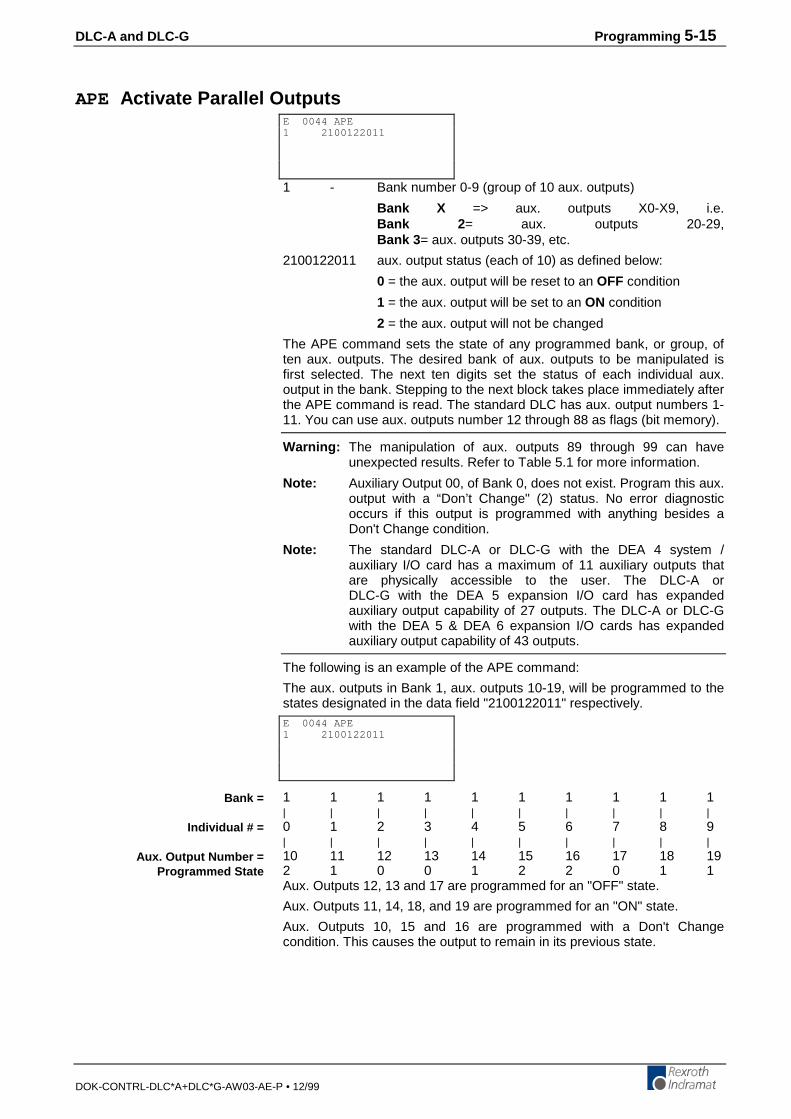
DLC-A and DLC-G Programming 5-15
DOK-CONTRL-DLC*A+DLC*G-AW03-AE-P • 12/99
APE Activate Parallel Outputs
1 - Bank number 0-9 (group of 10 aux. outputs)
Bank X => aux. outputs X0-X9, i.e.Bank 2 = aux. outputs 20-29,Bank 3 = aux. outputs 30-39, etc.
2100122011 aux. output status (each of 10) as defined below:
0 = the aux. output will be reset to an OFF condition
1 = the aux. output will be set to an ON condition
2 = the aux. output will not be changed
The APE command sets the state of any programmed bank, or group, often aux. outputs. The desired bank of aux. outputs to be manipulated isfirst selected. The next ten digits set the status of each individual aux.output in the bank. Stepping to the next block takes place immediately afterthe APE command is read. The standard DLC has aux. output numbers 1-11. You can use aux. outputs number 12 through 88 as flags (bit memory).
Warning: The manipulation of aux. outputs 89 through 99 can haveunexpected results. Refer to Table 5.1 for more information.
Note: Auxiliary Output 00, of Bank 0, does not exist. Program this aux.output with a “Don’t Change" (2) status. No error diagnosticoccurs if this output is programmed with anything besides aDon't Change condition.
Note: The standard DLC-A or DLC-G with the DEA 4 system /auxiliary I/O card has a maximum of 11 auxiliary outputs thatare physically accessible to the user. The DLC-A orDLC-G with the DEA 5 expansion I/O card has expandedauxiliary output capability of 27 outputs. The DLC-A or DLC-Gwith the DEA 5 & DEA 6 expansion I/O cards has expandedauxiliary output capability of 43 outputs.
The following is an example of the APE command:
The aux. outputs in Bank 1, aux. outputs 10-19, will be programmed to thestates designated in the data field "2100122011" respectively.
1 1 1 1 1 1 1 1 1 1| | | | | | | | | |0 1 2 3 4 5 6 7 8 9| | | | | | | | | |10 11 12 13 14 15 16 17 18 192 1 0 0 1 2 2 0 1 1Aux. Outputs 12, 13 and 17 are programmed for an "OFF" state.
Aux. Outputs 11, 14, 18, and 19 are programmed for an "ON" state.
Aux. Outputs 10, 15 and 16 are programmed with a Don't Changecondition. This causes the output to remain in its previous state.
E 0044 APE1 2100122011
E 0044 APE1 2100122011
Bank =
Individual # =
Aux. Output Number =Programmed State
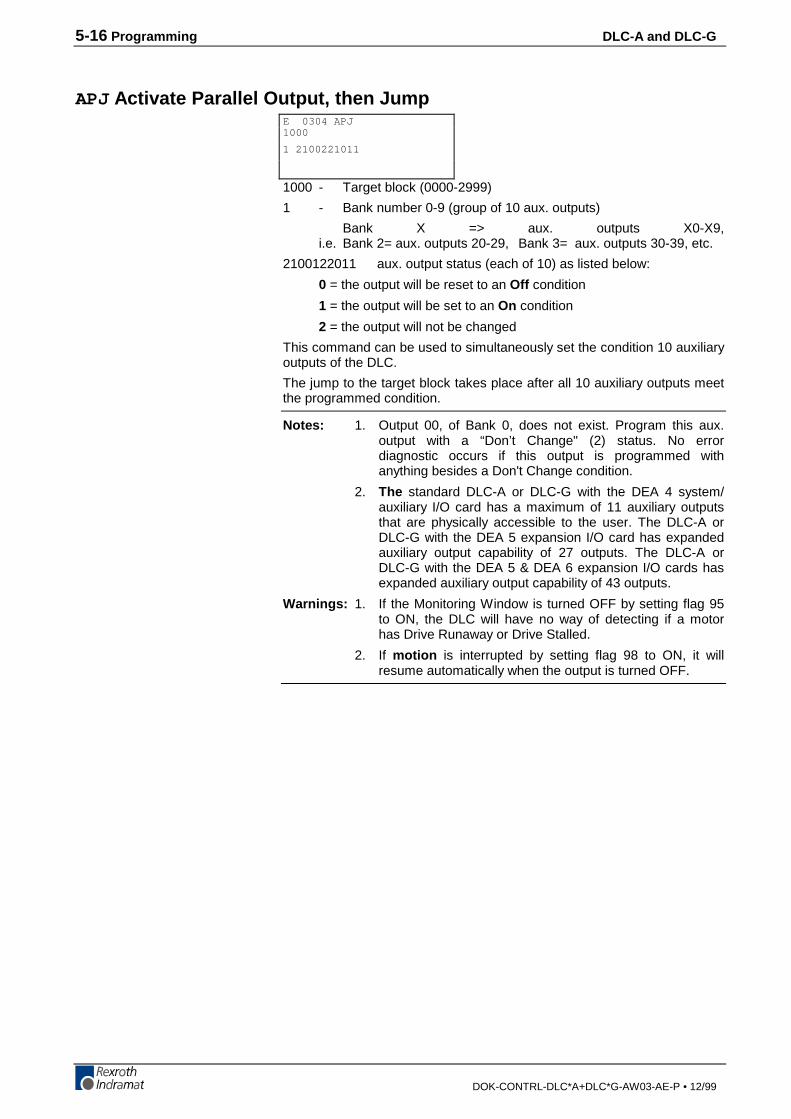
5-16 Programming DLC-A and DLC-G
DOK-CONTRL-DLC*A+DLC*G-AW03-AE-P • 12/99
APJ Activate Parallel Output, then Jump
1000 - Target block (0000-2999)
1 - Bank number 0-9 (group of 10 aux. outputs)
Bank X => aux. outputs X0-X9,i.e. Bank 2= aux. outputs 20-29, Bank 3= aux. outputs 30-39, etc.
2100122011 aux. output status (each of 10) as listed below:
0 = the output will be reset to an Off condition
1 = the output will be set to an On condition
2 = the output will not be changed
This command can be used to simultaneously set the condition 10 auxiliaryoutputs of the DLC.
The jump to the target block takes place after all 10 auxiliary outputs meetthe programmed condition.
Notes: 1. Output 00, of Bank 0, does not exist. Program this aux.output with a “Don’t Change" (2) status. No errordiagnostic occurs if this output is programmed withanything besides a Don't Change condition.
2. The standard DLC-A or DLC-G with the DEA 4 system/auxiliary I/O card has a maximum of 11 auxiliary outputsthat are physically accessible to the user. The DLC-A orDLC-G with the DEA 5 expansion I/O card has expandedauxiliary output capability of 27 outputs. The DLC-A orDLC-G with the DEA 5 & DEA 6 expansion I/O cards hasexpanded auxiliary output capability of 43 outputs.
Warnings: 1. If the Monitoring Window is turned OFF by setting flag 95to ON, the DLC will have no way of detecting if a motorhas Drive Runaway or Drive Stalled.
2. If motion is interrupted by setting flag 98 to ON, it willresume automatically when the output is turned OFF.
E 0304 APJ1000
1 2100221011
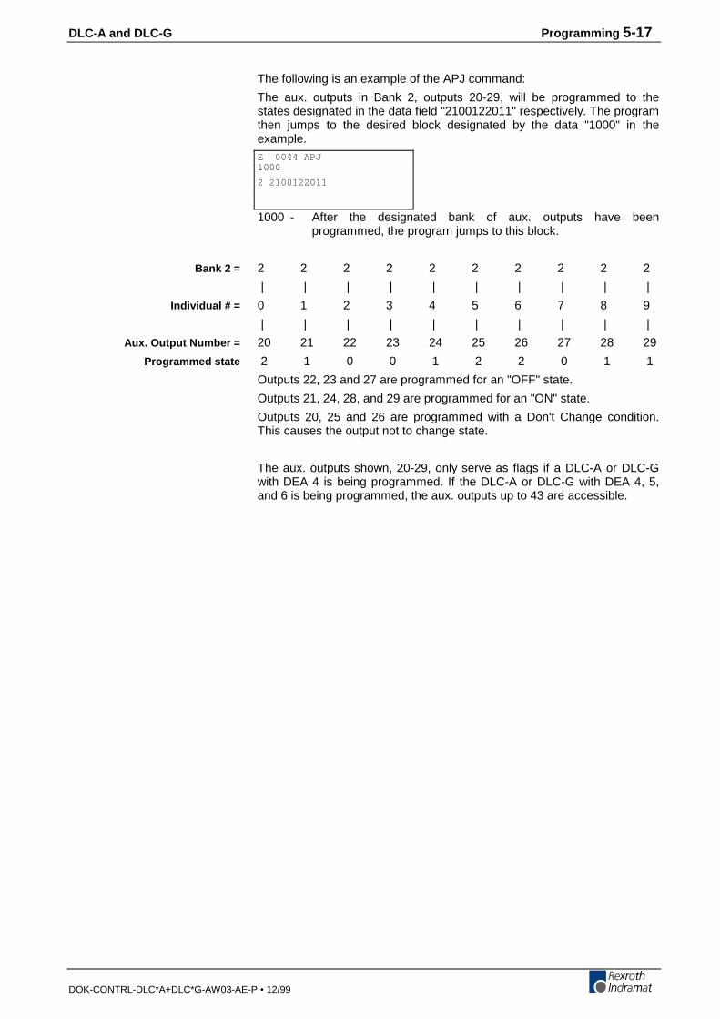
DLC-A and DLC-G Programming 5-17
DOK-CONTRL-DLC*A+DLC*G-AW03-AE-P • 12/99
The following is an example of the APJ command:
The aux. outputs in Bank 2, outputs 20-29, will be programmed to thestates designated in the data field "2100122011" respectively. The programthen jumps to the desired block designated by the data "1000" in theexample.
1000 - After the designated bank of aux. outputs have beenprogrammed, the program jumps to this block.
2 2 2 2 2 2 2 2 2 2
| | | | | | | | | |
0 1 2 3 4 5 6 7 8 9
| | | | | | | | | |
20 21 22 23 24 25 26 27 28 29
2 1 0 0 1 2 2 0 1 1
Outputs 22, 23 and 27 are programmed for an "OFF" state.
Outputs 21, 24, 28, and 29 are programmed for an "ON" state.
Outputs 20, 25 and 26 are programmed with a Don't Change condition.This causes the output not to change state.
The aux. outputs shown, 20-29, only serve as flags if a DLC-A or DLC-Gwith DEA 4 is being programmed. If the DLC-A or DLC-G with DEA 4, 5,and 6 is being programmed, the aux. outputs up to 43 are accessible.
E 0044 APJ1000
2 2100122011
Bank 2 =
Individual # =
Aux. Output Number =
Programmed state
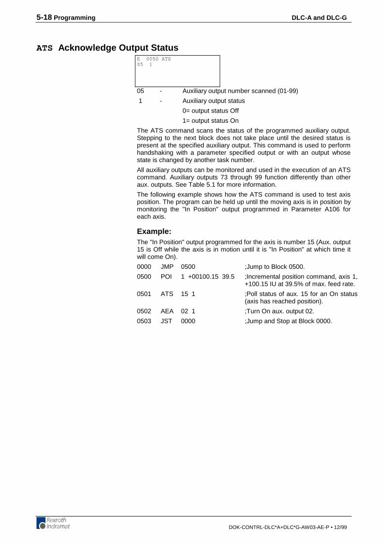
5-18 Programming DLC-A and DLC-G
DOK-CONTRL-DLC*A+DLC*G-AW03-AE-P • 12/99
ATS Acknowledge Output Status
05 - Auxiliary output number scanned (01-99)
1 - Auxiliary output status
0= output status Off
1= output status On
The ATS command scans the status of the programmed auxiliary output.Stepping to the next block does not take place until the desired status ispresent at the specified auxiliary output. This command is used to performhandshaking with a parameter specified output or with an output whosestate is changed by another task number.
All auxiliary outputs can be monitored and used in the execution of an ATScommand. Auxiliary outputs 73 through 99 function differently than otheraux. outputs. See Table 5.1 for more information.
The following example shows how the ATS command is used to test axisposition. The program can be held up until the moving axis is in position bymonitoring the "In Position" output programmed in Parameter A106 foreach axis.
Example:The "In Position" output programmed for the axis is number 15 (Aux. output15 is Off while the axis is in motion until it is "In Position" at which time itwill come On).
0000 JMP 0500 ;Jump to Block 0500.
0500 POI 1 +00100.15 39.5 ;Incremental position command, axis 1,+100.15 IU at 39.5% of max. feed rate.
0501 ATS 15 1 ;Poll status of aux. 15 for an On status(axis has reached position).
0502 AEA 02 1 ;Turn On aux. output 02.
0503 JST 0000 ;Jump and Stop at Block 0000.
E 0050 ATS05 1
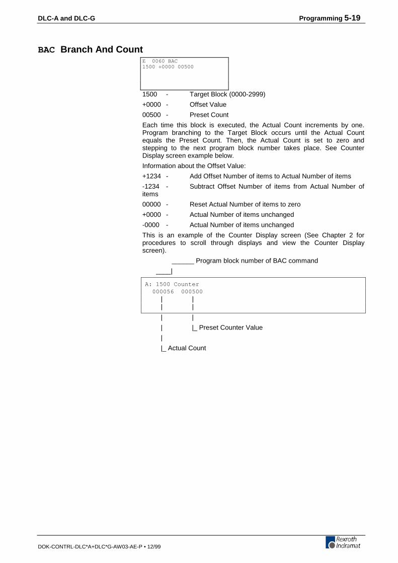
DLC-A and DLC-G Programming 5-19
DOK-CONTRL-DLC*A+DLC*G-AW03-AE-P • 12/99
BAC Branch And Count
1500 - Target Block (0000-2999)
+0000 - Offset Value
00500 - Preset Count
Each time this block is executed, the Actual Count increments by one.Program branching to the Target Block occurs until the Actual Countequals the Preset Count. Then, the Actual Count is set to zero andstepping to the next program block number takes place. See CounterDisplay screen example below.
Information about the Offset Value:
+1234 - Add Offset Number of items to Actual Number of items
-1234 - Subtract Offset Number of items from Actual Number ofitems
00000 - Reset Actual Number of items to zero
+0000 - Actual Number of items unchanged
-0000 - Actual Number of items unchanged
This is an example of the Counter Display screen (See Chapter 2 forprocedures to scroll through displays and view the Counter Displayscreen).
______ Program block number of BAC command
____|
A: 1500 Counter 000056 000500 | | | |
| |
| |_ Preset Counter Value
|
|_ Actual Count
E 0060 BAC1500 +0000 00500
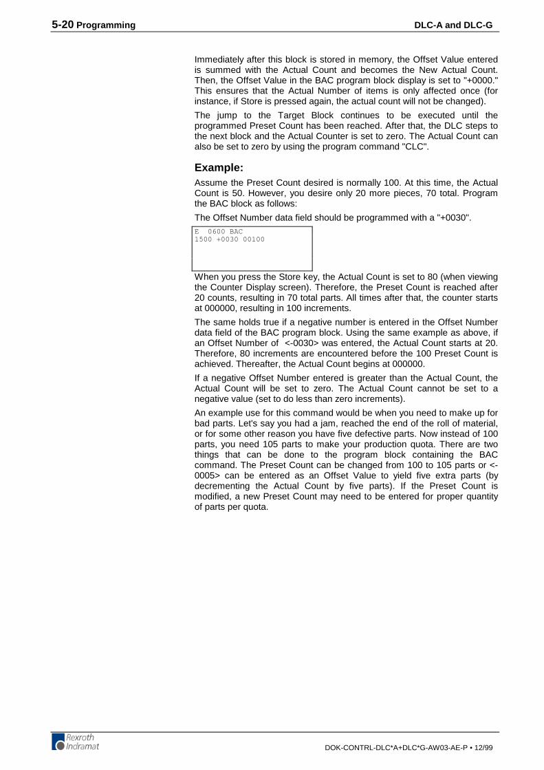
5-20 Programming DLC-A and DLC-G
DOK-CONTRL-DLC*A+DLC*G-AW03-AE-P • 12/99
Immediately after this block is stored in memory, the Offset Value enteredis summed with the Actual Count and becomes the New Actual Count.Then, the Offset Value in the BAC program block display is set to "+0000."This ensures that the Actual Number of items is only affected once (forinstance, if Store is pressed again, the actual count will not be changed).
The jump to the Target Block continues to be executed until theprogrammed Preset Count has been reached. After that, the DLC steps tothe next block and the Actual Counter is set to zero. The Actual Count canalso be set to zero by using the program command "CLC".
Example:Assume the Preset Count desired is normally 100. At this time, the ActualCount is 50. However, you desire only 20 more pieces, 70 total. Programthe BAC block as follows:
The Offset Number data field should be programmed with a "+0030".
When you press the Store key, the Actual Count is set to 80 (when viewingthe Counter Display screen). Therefore, the Preset Count is reached after20 counts, resulting in 70 total parts. All times after that, the counter startsat 000000, resulting in 100 increments.
The same holds true if a negative number is entered in the Offset Numberdata field of the BAC program block. Using the same example as above, ifan Offset Number of <-0030> was entered, the Actual Count starts at 20.Therefore, 80 increments are encountered before the 100 Preset Count isachieved. Thereafter, the Actual Count begins at 000000.
If a negative Offset Number entered is greater than the Actual Count, theActual Count will be set to zero. The Actual Count cannot be set to anegative value (set to do less than zero increments).
An example use for this command would be when you need to make up forbad parts. Let's say you had a jam, reached the end of the roll of material,or for some other reason you have five defective parts. Now instead of 100parts, you need 105 parts to make your production quota. There are twothings that can be done to the program block containing the BACcommand. The Preset Count can be changed from 100 to 105 parts or <-0005> can be entered as an Offset Value to yield five extra parts (bydecrementing the Actual Count by five parts). If the Preset Count ismodified, a new Preset Count may need to be entered for proper quantityof parts per quota.
E 0600 BAC1500 +0030 00100
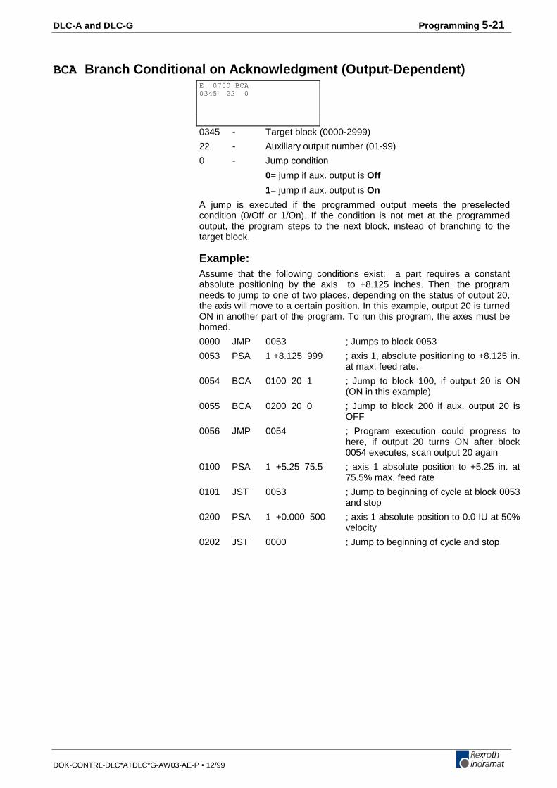
DLC-A and DLC-G Programming 5-21
DOK-CONTRL-DLC*A+DLC*G-AW03-AE-P • 12/99
BCA Branch Conditional on Acknowledgment (Output-Dependent)
0345 - Target block (0000-2999)
22 - Auxiliary output number (01-99)
0 - Jump condition
0= jump if aux. output is Off
1= jump if aux. output is On
A jump is executed if the programmed output meets the preselectedcondition (0/Off or 1/On). If the condition is not met at the programmedoutput, the program steps to the next block, instead of branching to thetarget block.
Example:Assume that the following conditions exist: a part requires a constantabsolute positioning by the axis to +8.125 inches. Then, the programneeds to jump to one of two places, depending on the status of output 20,the axis will move to a certain position. In this example, output 20 is turnedON in another part of the program. To run this program, the axes must behomed.
0000 JMP 0053 ; Jumps to block 0053
0053 PSA 1 +8.125 999 ; axis 1, absolute positioning to +8.125 in.at max. feed rate.
0054 BCA 0100 20 1 ; Jump to block 100, if output 20 is ON(ON in this example)
0055 BCA 0200 20 0 ; Jump to block 200 if aux. output 20 isOFF
0056 JMP 0054 ; Program execution could progress tohere, if output 20 turns ON after block0054 executes, scan output 20 again
0100 PSA 1 +5.25 75.5 ; axis 1 absolute position to +5.25 in. at75.5% max. feed rate
0101 JST 0053 ; Jump to beginning of cycle at block 0053and stop
0200 PSA 1 +0.000 500 ; axis 1 absolute position to 0.0 IU at 50%velocity
0202 JST 0000 ; Jump to beginning of cycle and stop
E 0700 BCA0345 22 0
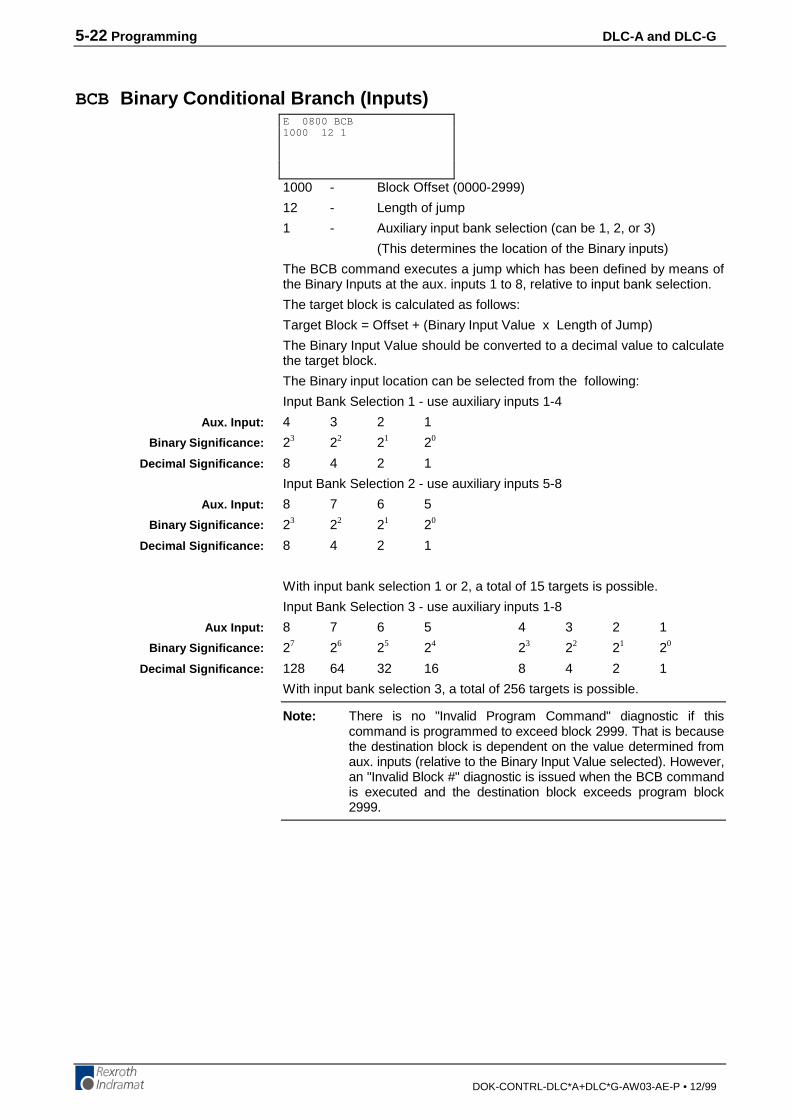
5-22 Programming DLC-A and DLC-G
DOK-CONTRL-DLC*A+DLC*G-AW03-AE-P • 12/99
BCB Binary Conditional Branch (Inputs)
1000 - Block Offset (0000-2999)
12 - Length of jump
1 - Auxiliary input bank selection (can be 1, 2, or 3)
(This determines the location of the Binary inputs)
The BCB command executes a jump which has been defined by means ofthe Binary Inputs at the aux. inputs 1 to 8, relative to input bank selection.
The target block is calculated as follows:
Target Block = Offset + (Binary Input Value x Length of Jump)
The Binary Input Value should be converted to a decimal value to calculatethe target block.
The Binary input location can be selected from the following:
Input Bank Selection 1 - use auxiliary inputs 1-4
4 3 2 1
23 22 21 20
8 4 2 1
Input Bank Selection 2 - use auxiliary inputs 5-8
8 7 6 5
23 22 21 20
8 4 2 1
With input bank selection 1 or 2, a total of 15 targets is possible.
Input Bank Selection 3 - use auxiliary inputs 1-8
8 7 6 5 4 3 2 1
27 26 25 24 23 22 21 20
128 64 32 16 8 4 2 1
With input bank selection 3, a total of 256 targets is possible.
Note: There is no "Invalid Program Command" diagnostic if thiscommand is programmed to exceed block 2999. That is becausethe destination block is dependent on the value determined fromaux. inputs (relative to the Binary Input Value selected). However,an "Invalid Block #" diagnostic is issued when the BCB commandis executed and the destination block exceeds program block2999.
E 0800 BCB1000 12 1
Aux. Input:
Binary Significance:
Decimal Significance:
Aux. Input:
Binary Significance:
Decimal Significance:
Aux Input:
Binary Significance:
Decimal Significance:
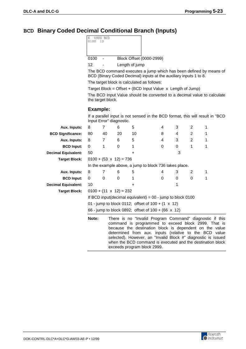
DLC-A and DLC-G Programming 5-23
DOK-CONTRL-DLC*A+DLC*G-AW03-AE-P • 12/99
BCD Binary Coded Decimal Conditional Branch (Inputs)
0100 - Block Offset (0000-2999)
12 - Length of jump
The BCD command executes a jump which has been defined by means ofBCD (Binary Coded Decimal) inputs at the auxiliary inputs 1 to 8.
The target block is calculated as follows:
Target Block = Offset + (BCD Input Value x Length of Jump)
The BCD Input Value should be converted to a decimal value to calculatethe target block.
Example:If a parallel input is not sensed in the BCD format, this will result in "BCDInput Error" diagnostic.
8 7 6 5 4 3 2 1
80 40 20 10 8 4 2 1
8 7 6 5 4 3 2 1
0 1 0 1 0 0 1 1
50 + 3
0100 + (53 x 12) = 736
In the example above, a jump to block 736 takes place.
8 7 6 5 4 3 2 1
0 0 0 1 0 0 0 1
10 + 1
0100 + (11 x 12) = 232
If BCD input(decimal equivalent) = 00 - jump to block 0100
01 - jump to block 0112; offset of 100 + (1 x 12)
66 - jump to block 0892; offset of 100 + (66 x 12)
Note: There is no "Invalid Program Command" diagnostic if thiscommand is programmed to exceed block 2999. That isbecause the destination block is dependent on the valuedetermined from aux. inputs (relative to the BCD valueselected). However, an "Invalid Block #" diagnostic is issuedwhen the BCD command is executed and the destination blockexceeds program block 2999.
E 0900 BCD0100 12
Aux. Inputs:
BCD Significance:
Aux. Inputs:
BCD Input:
Decimal Equivalent:
Target Block:
Aux. Inputs:
BCD Input:
Decimal Equivalent:
Target Block:
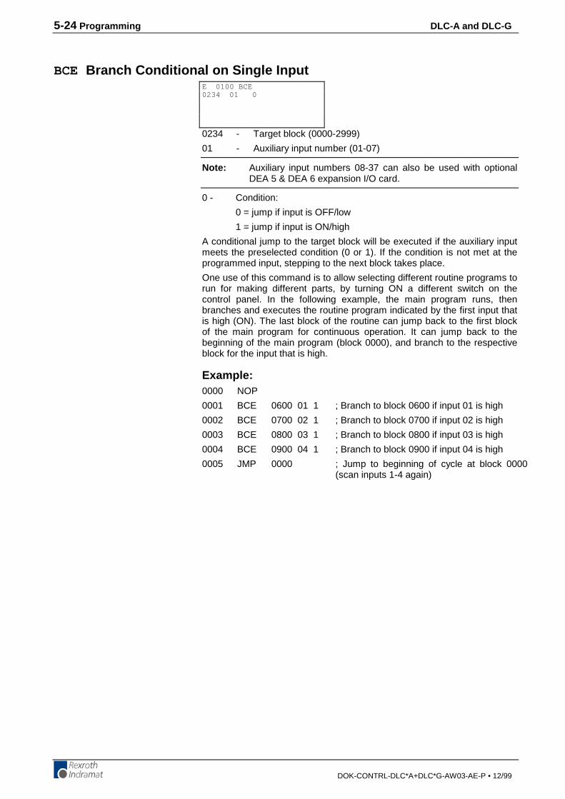
5-24 Programming DLC-A and DLC-G
DOK-CONTRL-DLC*A+DLC*G-AW03-AE-P • 12/99
BCE Branch Conditional on Single Input
0234 - Target block (0000-2999)
01 - Auxiliary input number (01-07)
Note: Auxiliary input numbers 08-37 can also be used with optionalDEA 5 & DEA 6 expansion I/O card.
0 - Condition:
0 = jump if input is OFF/low
1 = jump if input is ON/high
A conditional jump to the target block will be executed if the auxiliary inputmeets the preselected condition (0 or 1). If the condition is not met at theprogrammed input, stepping to the next block takes place.
One use of this command is to allow selecting different routine programs torun for making different parts, by turning ON a different switch on thecontrol panel. In the following example, the main program runs, thenbranches and executes the routine program indicated by the first input thatis high (ON). The last block of the routine can jump back to the first blockof the main program for continuous operation. It can jump back to thebeginning of the main program (block 0000), and branch to the respectiveblock for the input that is high.
Example:0000 NOP
0001 BCE 0600 01 1 ; Branch to block 0600 if input 01 is high
0002 BCE 0700 02 1 ; Branch to block 0700 if input 02 is high
0003 BCE 0800 03 1 ; Branch to block 0800 if input 03 is high
0004 BCE 0900 04 1 ; Branch to block 0900 if input 04 is high
0005 JMP 0000 ; Jump to beginning of cycle at block 0000(scan inputs 1-4 again)
E 0100 BCE0234 01 0
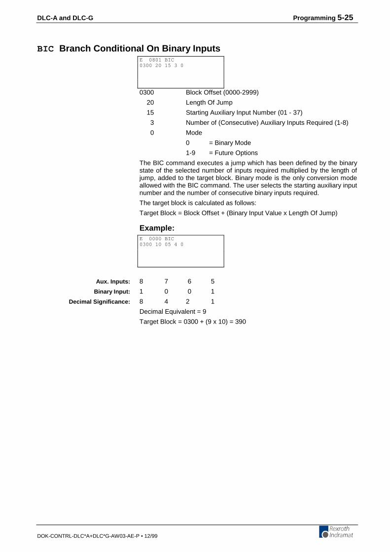
DLC-A and DLC-G Programming 5-25
DOK-CONTRL-DLC*A+DLC*G-AW03-AE-P • 12/99
BIC Branch Conditional On Binary Inputs
0300 Block Offset (0000-2999)
20 Length Of Jump
15 Starting Auxiliary Input Number (01 - 37)
3 Number of (Consecutive) Auxiliary Inputs Required (1-8)
0 Mode
0 = Binary Mode
1-9 = Future Options
The BIC command executes a jump which has been defined by the binarystate of the selected number of inputs required multiplied by the length ofjump, added to the target block. Binary mode is the only conversion modeallowed with the BIC command. The user selects the starting auxiliary inputnumber and the number of consecutive binary inputs required.
The target block is calculated as follows:
Target Block = Block Offset + (Binary Input Value x Length Of Jump)
Example:
8 7 6 5
1 0 0 1
8 4 2 1
Decimal Equivalent = 9
Target Block = 0300 + (9 x 10) = 390
E 0801 BIC0300 20 15 3 0
E 0000 BIC0300 10 05 4 0
Aux. Inputs:
Binary Input:
Decimal Significance:
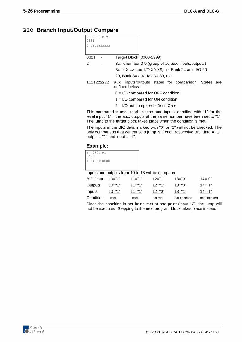
5-26 Programming DLC-A and DLC-G
DOK-CONTRL-DLC*A+DLC*G-AW03-AE-P • 12/99
BIO Branch Input/Output Compare
0321 - Target Block (0000-2999)
2 - Bank number 0-9 (group of 10 aux. inputs/outputs)
Bank X => aux. I/O X0-X9, i.e. Bank 2= aux. I/O 20-
29, Bank 3= aux. I/O 30-39, etc.
1111222222 aux. inputs/outputs states for comparison. States aredefined below:
0 = I/O compared for OFF condition
1 = I/O compared for ON condition
2 = I/O not compared - Don't Care
This command is used to check the aux. inputs identified with "1" for thelevel input "1" if the aux. outputs of the same number have been set to "1".The jump to the target block takes place when the condition is met.
The inputs in the BIO data marked with "0" or "2" will not be checked. Theonly comparison that will cause a jump is if each respective BIO data = "1",output = "1" and input = "1".
Example:
Inputs and outputs from 10 to 13 will be compared
BIO Data 10="1" 11="1" 12="1" 13="0" 14="0"
Outputs 10="1" 11="1" 12="1" 13="0" 14="1"
Inputs 10="1" 11="1" 12="0" 13="1" 14="1"
Condition met met not met not checked not checked
Since the condition is not being met at one point (input 12), the jump willnot be executed. Stepping to the next program block takes place instead.
E 0801 BIO0321
2 1111222222
E 0801 BIO0400
1 1110000000

DLC-A and DLC-G Programming 5-27
DOK-CONTRL-DLC*A+DLC*G-AW03-AE-P • 12/99
BMB Branch on Multiple Binary Outputs
1234 - Block Offset (0000-2999), used to calculate Target Block
45 - Length of Jump
67 - Starting Output Number (01-99)
8 - Number of Outputs (consecutive) Being Used
This command will cause a jump to be executed which is determined bymeans of the output assignment as defined in the command.
Example:
12 11 10 09 08 07 06 05
128 64 32 16 08 04 02 01
0 0 1 1 0 0 1 1
Output value = 51
The target block is calculated as follows:
Block offset + ( output value x length of jump )
0100 + ( 51 x 02 )
Target block = 0202
E 0120 BMB1234 45 67 8
E 1200 BMB0100 02 05 8
Outputs:
Significance:
Output value:
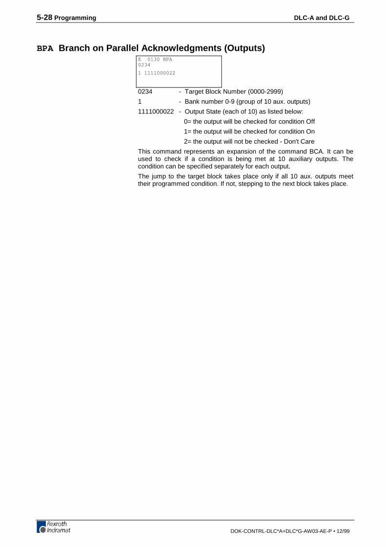
5-28 Programming DLC-A and DLC-G
DOK-CONTRL-DLC*A+DLC*G-AW03-AE-P • 12/99
BPA Branch on Parallel Acknowledgments (Outputs)
0234 - Target Block Number (0000-2999)
1 - Bank number 0-9 (group of 10 aux. outputs)
1111000022 - Output State (each of 10) as listed below:
0= the output will be checked for condition Off
1= the output will be checked for condition On
2= the output will not be checked - Don't Care
This command represents an expansion of the command BCA. It can beused to check if a condition is being met at 10 auxiliary outputs. Thecondition can be specified separately for each output.
The jump to the target block takes place only if all 10 aux. outputs meettheir programmed condition. If not, stepping to the next block takes place.
E 0130 BPA0234
1 1111000022

DLC-A and DLC-G Programming 5-29
DOK-CONTRL-DLC*A+DLC*G-AW03-AE-P • 12/99
BPE Branch on Parallel Inputs
0345 - Target Block
3 - Bank number 0-3 (group of 10 aux. inputs)
1111000022 - Input State (each of 10) as listed below:
0= the input will be checked for condition OFF
1= the input will be checked for condition ON
2= the input will not be checked - Don't Care
This command represents an expansion of the command "BCE". It can beused to check simultaneously if a condition is being met at 10 auxiliaryinputs. The condition can be specified separately for each input.
The jump to the target block takes place only if all 10 inputs meet theprogrammed condition. If not, stepping to the next block takes place.
E 1500 BPE0345
6 1111000022
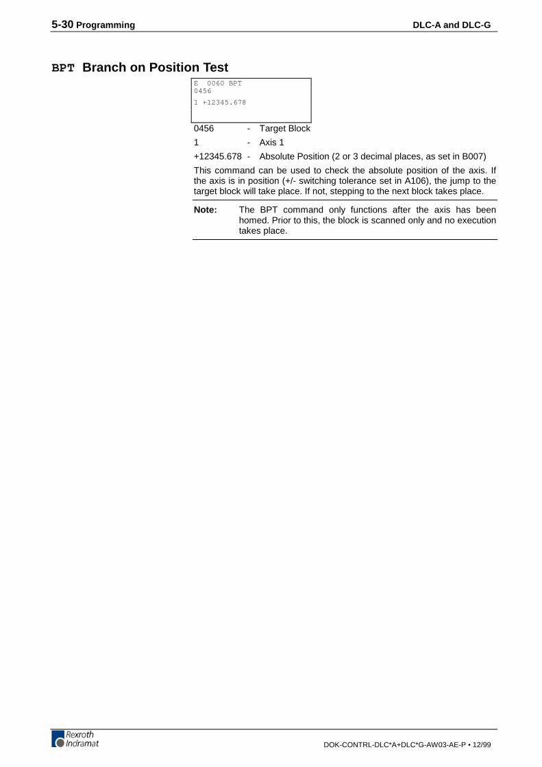
5-30 Programming DLC-A and DLC-G
DOK-CONTRL-DLC*A+DLC*G-AW03-AE-P • 12/99
BPT Branch on Position Test
0456 - Target Block
1 - Axis 1
+12345.678 - Absolute Position (2 or 3 decimal places, as set in B007)
This command can be used to check the absolute position of the axis. Ifthe axis is in position (+/- switching tolerance set in A106), the jump to thetarget block will take place. If not, stepping to the next block takes place.
Note: The BPT command only functions after the axis has beenhomed. Prior to this, the block is scanned only and no executiontakes place.
E 0060 BPT0456
1 +12345.678

DLC-A and DLC-G Programming 5-31
DOK-CONTRL-DLC*A+DLC*G-AW03-AE-P • 12/99
BZP Branch If the Target Position Exceeds the Position Limit Value
0678 - Target Block
1 - Axis 1
+12345.678 - Position Limit Value (to 2 or 3 decimal places, as set inB007)
You can use this command to check that a commanded positions does notexceed the position limit value set by this command.
At the execution of this block, the jump to the target block takes place if theactual position, or the target position, of the axis, is equal to or greaterthan, the programmed position limit value.
If the actual position, or the target position, is less than the programmedposition limit value, the program steps to the next block, instead of jumpingto the branch block number.
Note: The BZP command only functions after the axis has beenhomed. Prior to this, the block is scanned only and no executiontakes place.
E 1550 BZP0678
1 +12345.678
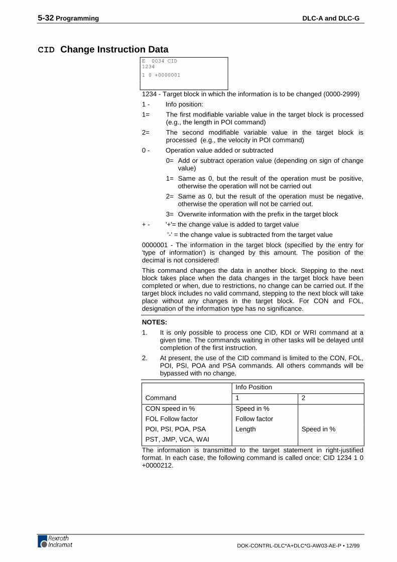
5-32 Programming DLC-A and DLC-G
DOK-CONTRL-DLC*A+DLC*G-AW03-AE-P • 12/99
CID Change Instruction Data
1234 - Target block in which the information is to be changed (0000-2999)
1 - Info position:
1= The first modifiable variable value in the target block is processed(e.g., the length in POI command)
2= The second modifiable variable value in the target block isprocessed (e.g., the velocity in POI command)
0 - Operation value added or subtracted
0= Add or subtract operation value (depending on sign of changevalue)
1= Same as 0, but the result of the operation must be positive,otherwise the operation will not be carried out
2= Same as 0, but the result of the operation must be negative,otherwise the operation will not be carried out.
3= Overwrite information with the prefix in the target block
+ - '+'= the change value is added to target value
'-' = the change value is subtracted from the target value
0000001 - The information in the target block (specified by the entry for'type of information') is changed by this amount. The position of thedecimal is not considered!
This command changes the data in another block. Stepping to the nextblock takes place when the data changes in the target block have beencompleted or when, due to restrictions, no change can be carried out. If thetarget block includes no valid command, stepping to the next block will takeplace without any changes in the target block. For CON and FOL,designation of the information type has no significance.
NOTES:
1. It is only possible to process one CID, KDI or WRI command at agiven time. The commands waiting in other tasks will be delayed untilcompletion of the first instruction.
2. At present, the use of the CID command is limited to the CON, FOL,POI, PSI, POA and PSA commands. All others commands will bebypassed with no change.
Info Position
Command 1 2
CON speed in % Speed in %
FOL Follow factor Follow factor
POI, PSI, POA, PSA Length Speed in %
PST, JMP, VCA, WAI
The information is transmitted to the target statement in right-justifiedformat. In each case, the following command is called once: CID 1234 1 0+0000212.
E 0034 CID1234
1 0 +0000001
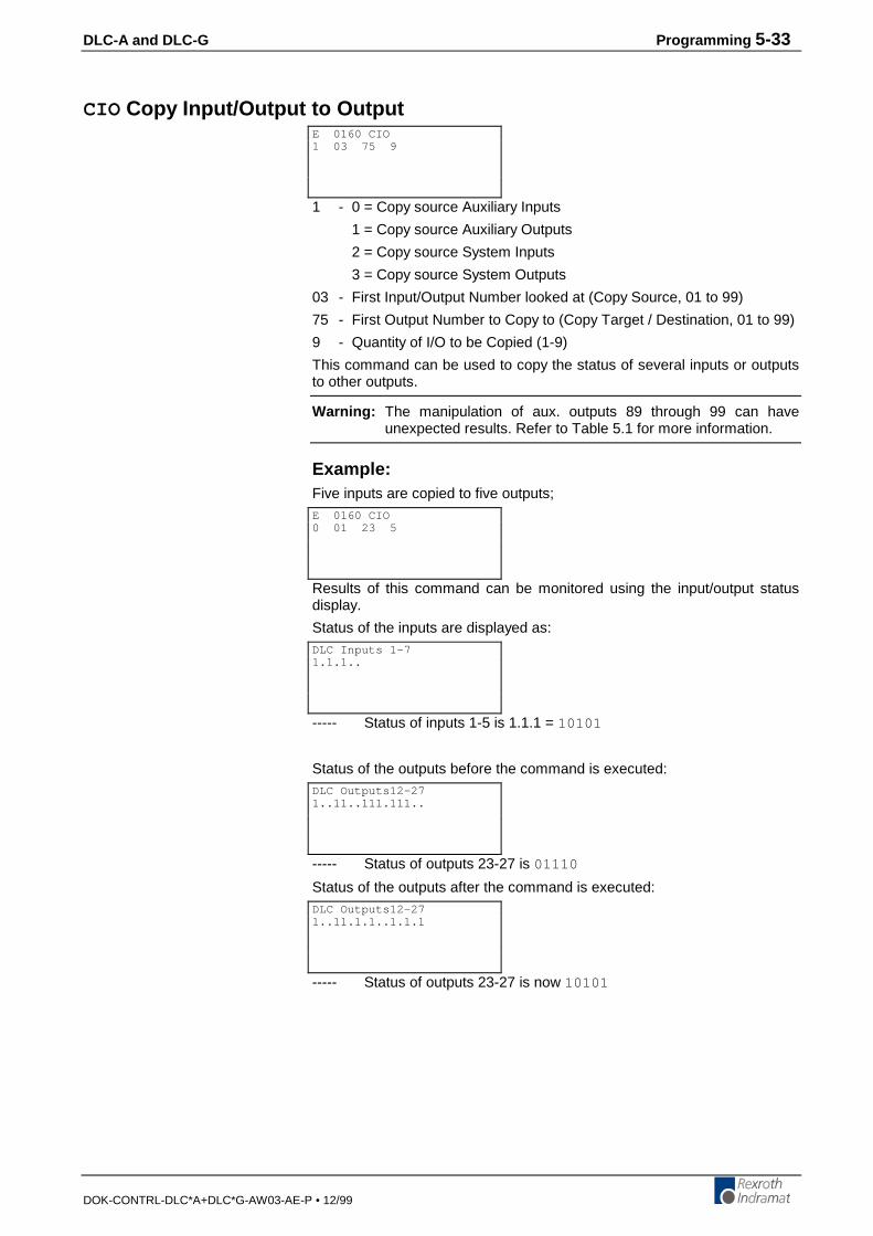
DLC-A and DLC-G Programming 5-33
DOK-CONTRL-DLC*A+DLC*G-AW03-AE-P • 12/99
CIO Copy Input/Output to Output
1 - 0 = Copy source Auxiliary Inputs
1 = Copy source Auxiliary Outputs
2 = Copy source System Inputs
3 = Copy source System Outputs
03 - First Input/Output Number looked at (Copy Source, 01 to 99)
75 - First Output Number to Copy to (Copy Target / Destination, 01 to 99)
9 - Quantity of I/O to be Copied (1-9)
This command can be used to copy the status of several inputs or outputsto other outputs.
Warning: The manipulation of aux. outputs 89 through 99 can haveunexpected results. Refer to Table 5.1 for more information.
Example:Five inputs are copied to five outputs;
Results of this command can be monitored using the input/output statusdisplay.
Status of the inputs are displayed as:
----- Status of inputs 1-5 is 1.1.1 = 10101
Status of the outputs before the command is executed:
----- Status of outputs 23-27 is 01110
Status of the outputs after the command is executed:
----- Status of outputs 23-27 is now 10101
E 0160 CIO1 03 75 9
E 0160 CIO0 01 23 5
DLC Inputs 1-71.1.1..
DLC Outputs12-271..11..111.111..
DLC Outputs12-271..11.1.1..1.1.1
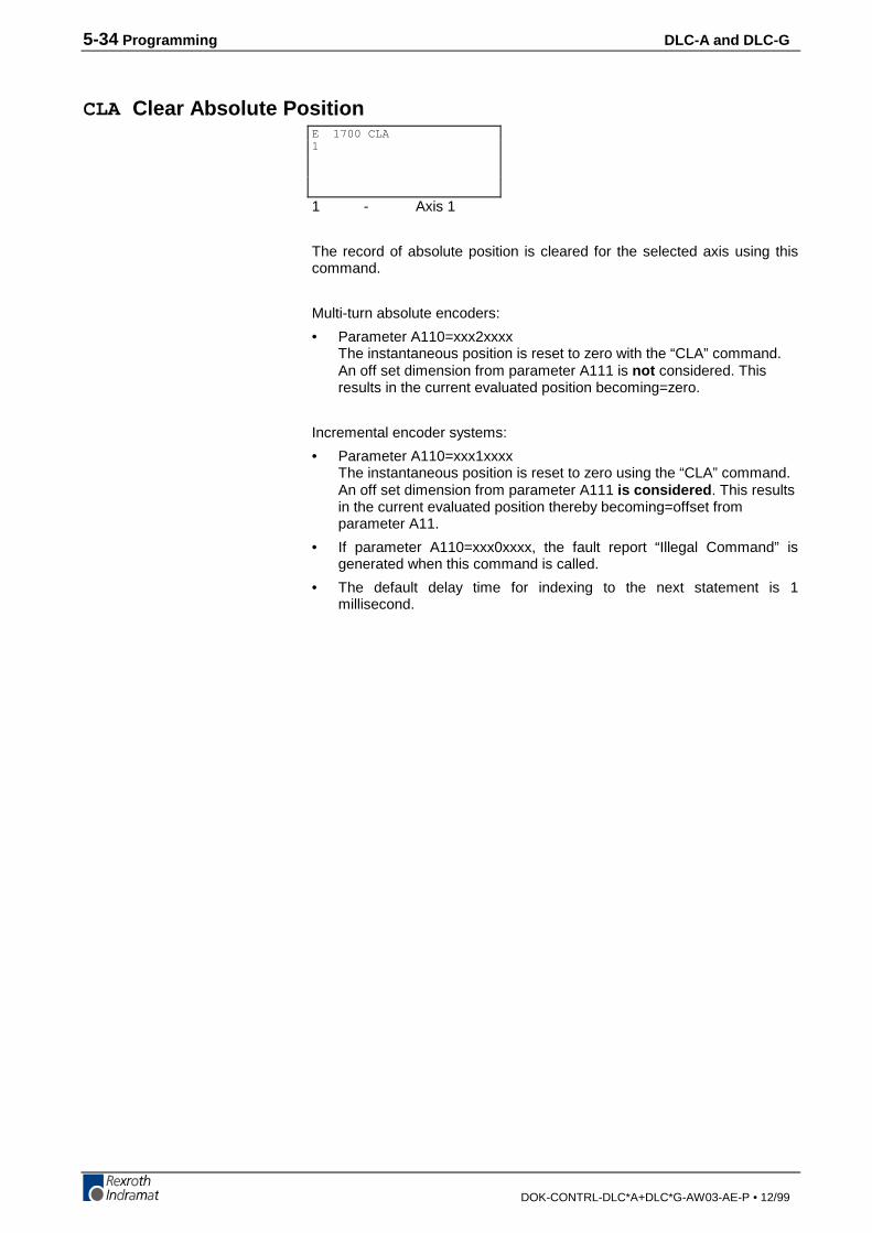
5-34 Programming DLC-A and DLC-G
DOK-CONTRL-DLC*A+DLC*G-AW03-AE-P • 12/99
CLA Clear Absolute Position
1 - Axis 1
The record of absolute position is cleared for the selected axis using thiscommand.
Multi-turn absolute encoders:
• Parameter A110=xxx2xxxxThe instantaneous position is reset to zero with the “CLA” command.An off set dimension from parameter A111 is not considered. Thisresults in the current evaluated position becoming=zero.
Incremental encoder systems:
• Parameter A110=xxx1xxxxThe instantaneous position is reset to zero using the “CLA” command.An off set dimension from parameter A111 is considered . This resultsin the current evaluated position thereby becoming=offset fromparameter A11.
• If parameter A110=xxx0xxxx, the fault report “Illegal Command” isgenerated when this command is called.
• The default delay time for indexing to the next statement is 1millisecond.
E 1700 CLA1
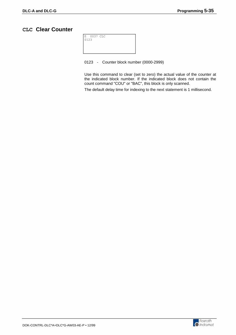
DLC-A and DLC-G Programming 5-35
DOK-CONTRL-DLC*A+DLC*G-AW03-AE-P • 12/99
CLC Clear Counter
0123 - Counter block number (0000-2999)
Use this command to clear (set to zero) the actual value of the counter atthe indicated block number. If the indicated block does not contain thecount command "COU" or "BAC", this block is only scanned.
The default delay time for indexing to the next statement is 1 millisecond.
E 0037 CLC0123

5-36 Programming DLC-A and DLC-G
DOK-CONTRL-DLC*A+DLC*G-AW03-AE-P • 12/99
COC Cam Output Control
1 - Axis 1
05 - Number of the first of six aux. outputs to be set
110022 - Status of the 6 aux. outputs starting with the first:
0= resets output to Off
1= sets output to On
2= output remains unchanged
+090 - Test position of axis in Input Units to zero or one decimal place(can be + or -)
• If B007 is set for 2 decimal places (B007= xx02xxxx), the testposition has no decimals (i.e. 360= 360).
• If B007 is set for 3 decimal places (B007= xx03xxxx), the testposition has one decimal (i.e. 360= 36.0).
The COC command sets a bank of six aux. outputs relative to the axisposition in degrees. The DLC waits for the programmed axis to reach thetest position before setting the six aux. outputs to the desired states. Thefirst of six consecutive aux. outputs to be changed is entered in theprogram block. The DLC then advances to the next program block.
Due to the scan time, the delay of setting the output states compared to theaxis position takes 1 millisecond. Therefore, the actual position of the axiswhen the outputs are set can vary with the present velocity of the axis. Theformula used to calculate the accuracy of the outputs is:
Speed in EGE/sec. x 1 msec
1000
If the axis has been homed, all test positions are taken in reference to thecurrent absolute position. If the axis has not been homed, the test positionis taken in reference to the last incremental feed.
E 0020 COC1 05 110022 +090
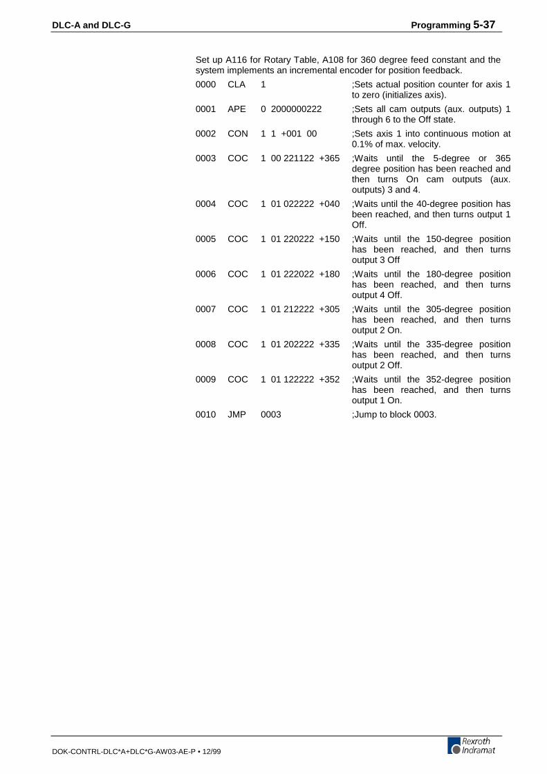
DLC-A and DLC-G Programming 5-37
DOK-CONTRL-DLC*A+DLC*G-AW03-AE-P • 12/99
Set up A116 for Rotary Table, A108 for 360 degree feed constant and thesystem implements an incremental encoder for position feedback.
0000 CLA 1 ;Sets actual position counter for axis 1to zero (initializes axis).
0001 APE 0 2000000222 ;Sets all cam outputs (aux. outputs) 1through 6 to the Off state.
0002 CON 1 1 +001 00 ;Sets axis 1 into continuous motion at0.1% of max. velocity.
0003 COC 1 00 221122 +365 ;Waits until the 5-degree or 365degree position has been reached andthen turns On cam outputs (aux.outputs) 3 and 4.
0004 COC 1 01 022222 +040 ;Waits until the 40-degree position hasbeen reached, and then turns output 1Off.
0005 COC 1 01 220222 +150 ;Waits until the 150-degree positionhas been reached, and then turnsoutput 3 Off
0006 COC 1 01 222022 +180 ;Waits until the 180-degree positionhas been reached, and then turnsoutput 4 Off.
0007 COC 1 01 212222 +305 ;Waits until the 305-degree positionhas been reached, and then turnsoutput 2 On.
0008 COC 1 01 202222 +335 ;Waits until the 335-degree positionhas been reached, and then turnsoutput 2 Off.
0009 COC 1 01 122222 +352 ;Waits until the 352-degree positionhas been reached, and then turnsoutput 1 On.
0010 JMP 0003 ;Jump to block 0003.
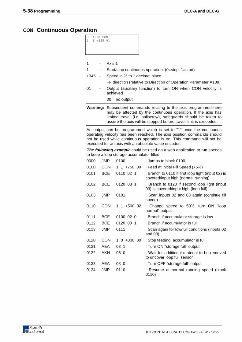
5-38 Programming DLC-A and DLC-G
DOK-CONTRL-DLC*A+DLC*G-AW03-AE-P • 12/99
CON Continuous Operation
1 - Axis 1
1 - Start/stop continuous operation (0=stop, 1=start)
+345 - Speed in % to 1 decimal place
+/- direction (relative to Direction of Operation Parameter A109)
01 - Output (auxiliary function) to turn ON when CON velocity isachieved
00 = no output
Warning: Subsequent commands relating to the axis programmed heremay be affected by the continuous operation. If the axis haslimited travel (i.e. ballscrew), safeguards should be taken toassure the axis will be stopped before travel limit is exceeded.
An output can be programmed which is set to "1" once the continuousoperating velocity has been reached. The axis position commands shouldnot be used while continuous operation is on. This command will not beexecuted for an axis with an absolute value encoder.
The following example could be used on a web application to run speedsto keep a loop storage accumulator filled:
0000 JMP 0100 ; Jumps to block 0100
0100 CON 1 1 +750 00 ; Feed at initial Fill Speed (75%)
0101 BCE 0110 02 1 ; Branch to 0110 if first loop light (input 02) iscovered/input high (normal running),
0102 BCE 0120 03 1 ; Branch to 0120 if second loop light (input03) is covered/input high (loop full)
0103 JMP 0101 ; Scan inputs 02 and 03 again (continue fillspeed)
0110 CON 1 1 +500 02 ; Change speed to 50%, turn ON "loopnormal" output
0111 BCE 0100 02 0 ; Branch if accumulator storage is low
0112 BCE 0120 03 1 ; Branch if accumulator is full
0113 JMP 0111 ; Scan again for low/full conditions (inputs 02and 03)
0120 CON 1 0 +000 00 ; Stop feeding, accumulator is full
0121 AEA 03 1 ; Turn ON "storage full" output
0122 AKN 03 0 ; Wait for additional material to be removedto uncover loop full sensor
0123 AEA 03 0 ; Turn OFF "storage full" output
0124 JMP 0110 ; Resume at normal running speed (block0110)
E 1900 CON1 1 +345 01
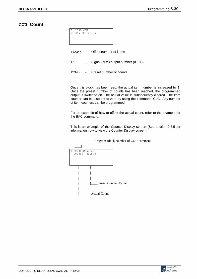
DLC-A and DLC-G Programming 5-39
DOK-CONTRL-DLC*A+DLC*G-AW03-AE-P • 12/99
COU Count
+12345 - Offset number of items
12 - Signal (aux.) output number (01-88)
123456 - Preset number of counts
Once this block has been read, the actual item number is increased by 1.Once the preset number of counts has been reached, the programmedoutput is switched on. The actual value is subsequently cleared. The itemcounter can be also set to zero by using the command 'CLC.' Any numberof item counters can be programmed.
For an example of how to offset the actual count, refer to the example forthe BAC command.
This is an example of the Counter Display screen (See section 2.3.5 forinformation how to view the Counter Display screen).
_______ Program Block Number of COU command
____|
| |
| |
| |
| |____ Preset Counter Value
|
|_______ Actual Count
E 2000 COU+12345 12 123456
A: 2000 Counter 000056 000500
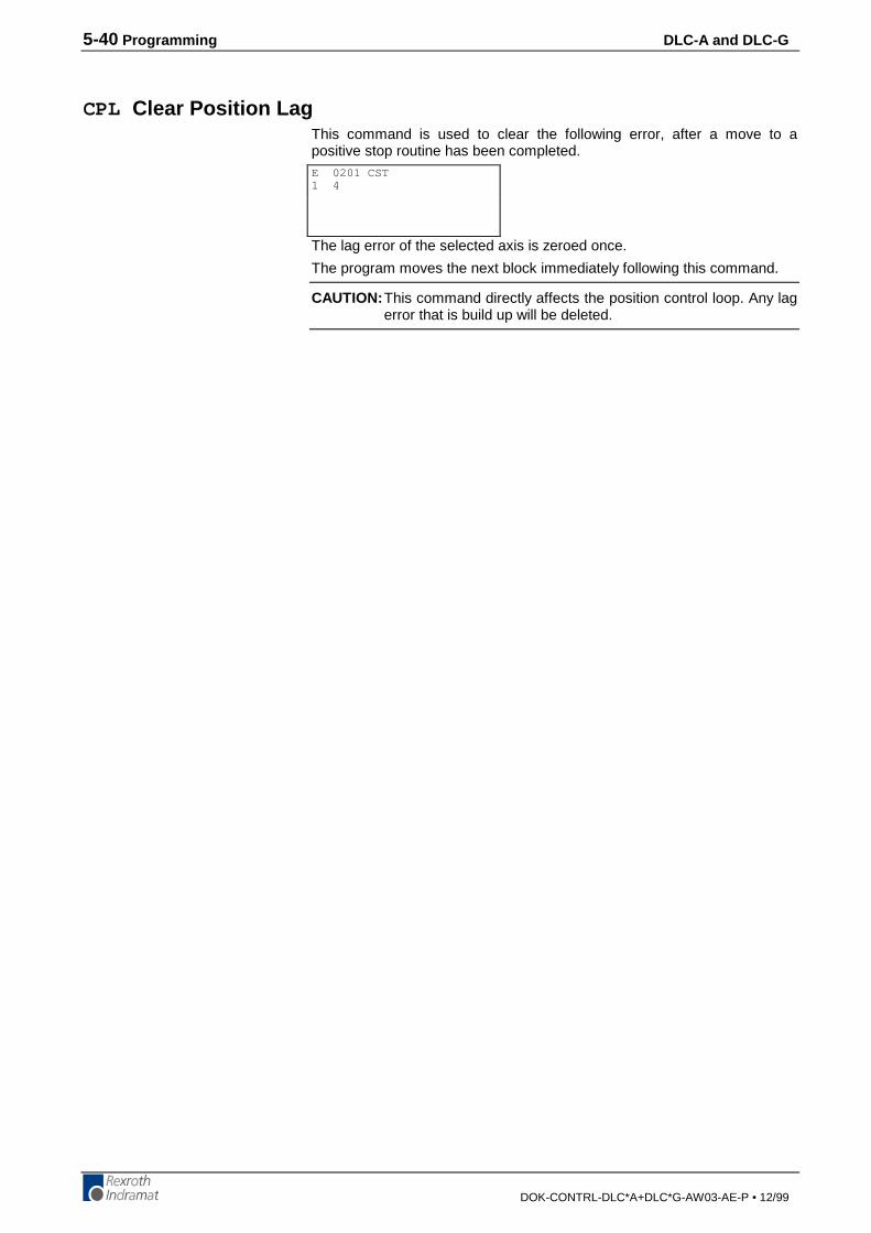
5-40 Programming DLC-A and DLC-G
DOK-CONTRL-DLC*A+DLC*G-AW03-AE-P • 12/99
CPL Clear Position LagThis command is used to clear the following error, after a move to apositive stop routine has been completed.
The lag error of the selected axis is zeroed once.
The program moves the next block immediately following this command.
CAUTION: This command directly affects the position control loop. Any lagerror that is build up will be deleted.
E 0201 CST1 4

DLC-A and DLC-G Programming 5-41
DOK-CONTRL-DLC*A+DLC*G-AW03-AE-P • 12/99
CST Change Subroutine Stack
1 - Changes subroutine level (0-2)
0= changes subroutine level in Task 1 and Task 2.
1= changes subroutine level in Task 1 only.
2= changes subroutine level in Task 2 only.
4 - Set subroutine stack to this level
0= sets stack to zero (See Note below.)
1-9= change subroutine stack level from one to nine levels
The starting block for Task 2 is set up in "Parameter B006 - Start Task 2 &3". Task 1 programming does not need to be set up in parameters.
The CST command is used to change to different subroutine stack levels.It is used in conjunction with JSR and RTS. Task 1 and Task 2 have amaximum number of nine stack levels that can be changed in a single CSTcommand. The CST command can be used in subroutines to allow formore functions when program space is limited.
After using a CST command to correct a stack, the next RTS command willjump the program beyond undesirable subroutines to a selected level.
Note: If the stack is set to zero, an RTS command cannot be used as thisbecomes the programs main level. If an RTS command is usedafter setting the stack to zero, the error "RTS Nesting" will occur.
Example:The following example shows the program flow and the CST command(Subroutine level 3, block, "E0309 CST 1 1", is used to change thesubroutine stack level to level 1, in Task 1).
Figure 5-1: Program Flow, CST Command
E 0201 CST1 4
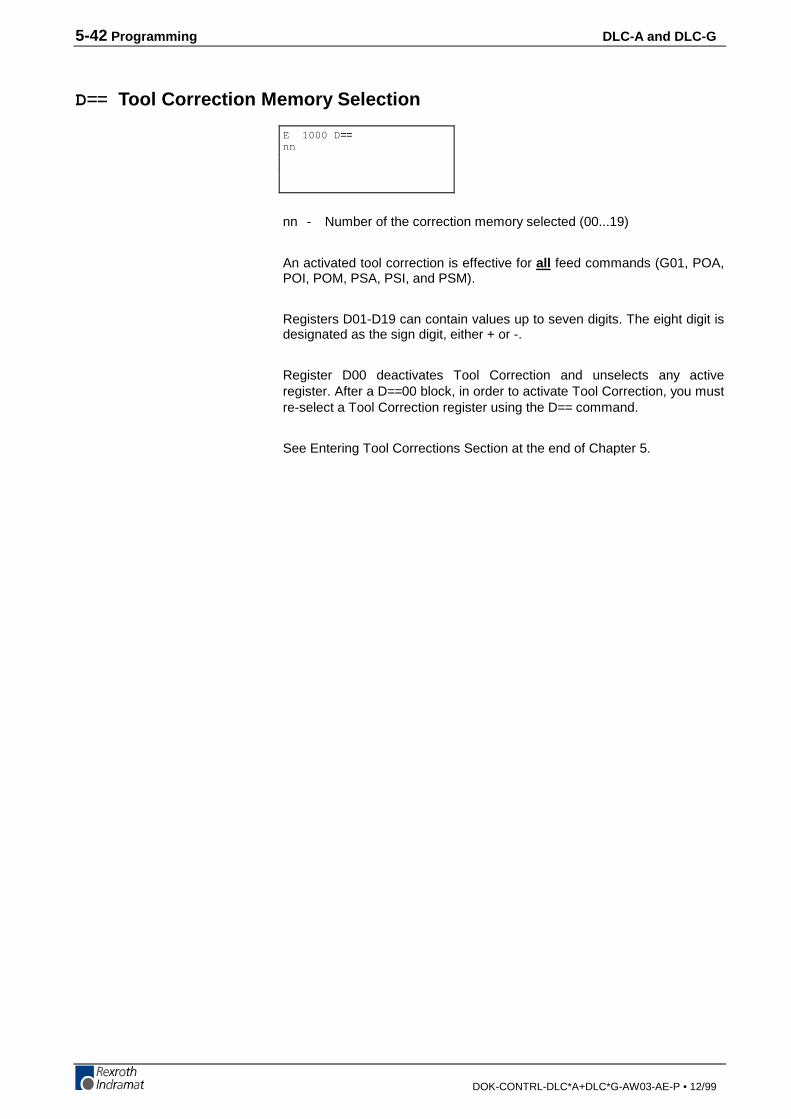
5-42 Programming DLC-A and DLC-G
DOK-CONTRL-DLC*A+DLC*G-AW03-AE-P • 12/99
D== Tool Correction Memory Selection
nn - Number of the correction memory selected (00...19)
An activated tool correction is effective for all feed commands (G01, POA,POI, POM, PSA, PSI, and PSM).
Registers D01-D19 can contain values up to seven digits. The eight digit isdesignated as the sign digit, either + or -.
Register D00 deactivates Tool Correction and unselects any activeregister. After a D==00 block, in order to activate Tool Correction, you mustre-select a Tool Correction register using the D== command.
See Entering Tool Corrections Section at the end of Chapter 5.
E 1000 D ==nn
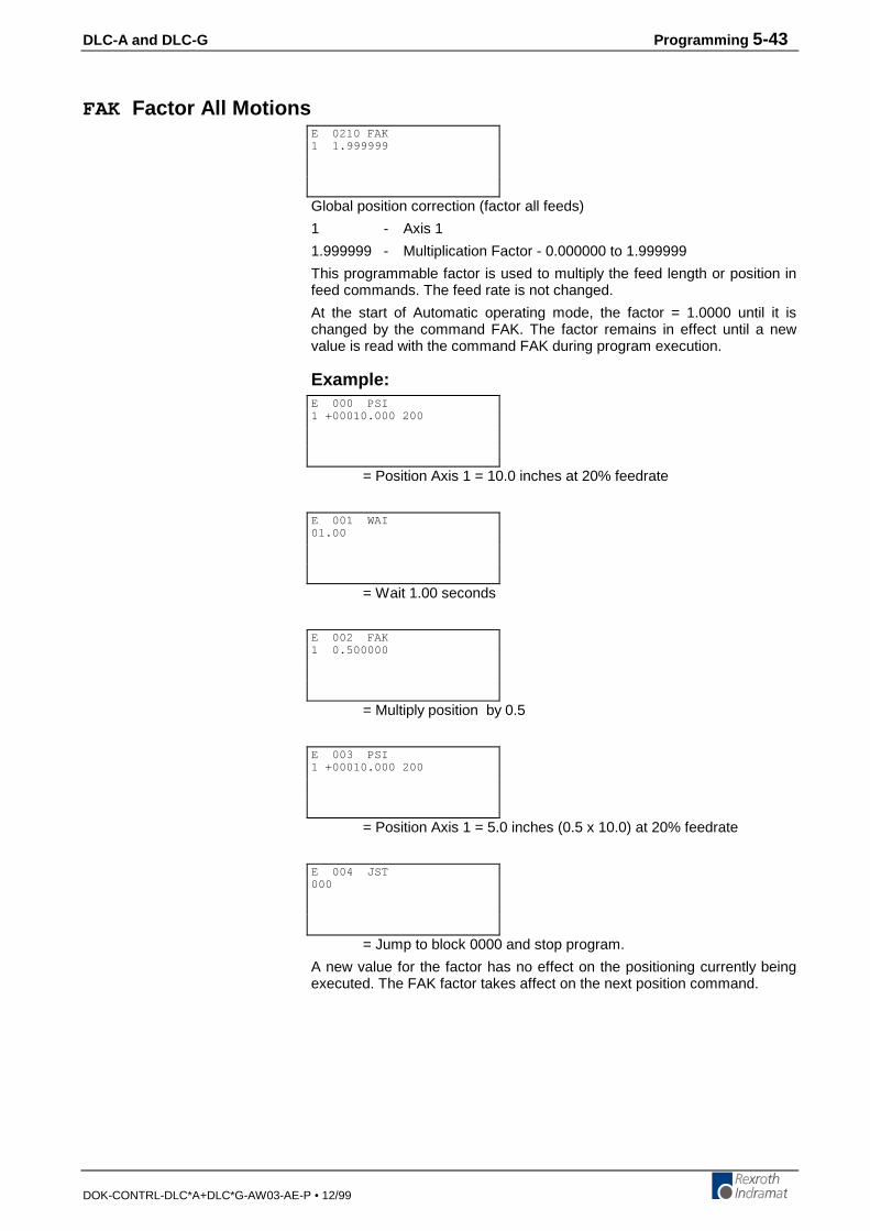
DLC-A and DLC-G Programming 5-43
DOK-CONTRL-DLC*A+DLC*G-AW03-AE-P • 12/99
FAK Factor All Motions
Global position correction (factor all feeds)
1 - Axis 1
1.999999 - Multiplication Factor - 0.000000 to 1.999999
This programmable factor is used to multiply the feed length or position infeed commands. The feed rate is not changed.
At the start of Automatic operating mode, the factor = 1.0000 until it ischanged by the command FAK. The factor remains in effect until a newvalue is read with the command FAK during program execution.
Example:
= Position Axis 1 = 10.0 inches at 20% feedrate
= Wait 1.00 seconds
= Multiply position by 0.5
= Position Axis 1 = 5.0 inches (0.5 x 10.0) at 20% feedrate
= Jump to block 0000 and stop program.
A new value for the factor has no effect on the positioning currently beingexecuted. The FAK factor takes affect on the next position command.
E 0210 FAK1 1.999999
E 000 PSI1 +00010.000 200
E 001 WAI01.00
E 002 FAK1 0.500000
E 003 PSI1 +00010.000 200
E 004 JST000
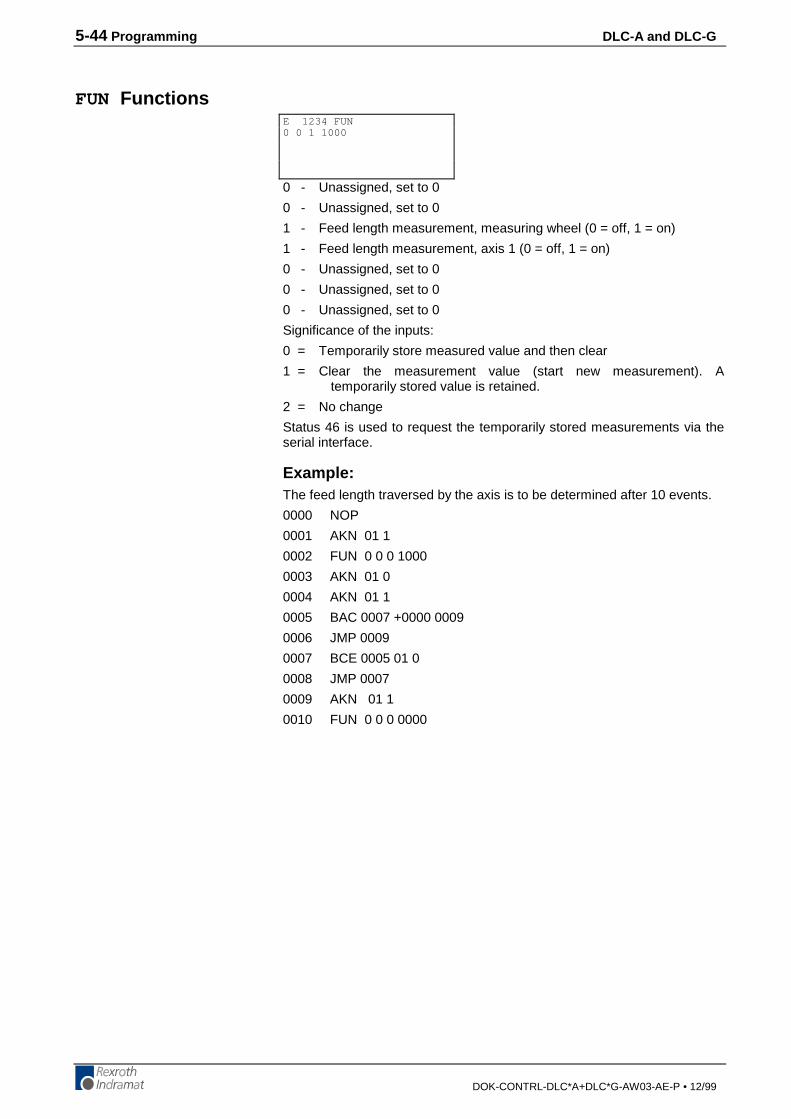
5-44 Programming DLC-A and DLC-G
DOK-CONTRL-DLC*A+DLC*G-AW03-AE-P • 12/99
FUN Functions
0 - Unassigned, set to 0
0 - Unassigned, set to 0
1 - Feed length measurement, measuring wheel (0 = off, 1 = on)
1 - Feed length measurement, axis 1 (0 = off, 1 = on)
0 - Unassigned, set to 0
0 - Unassigned, set to 0
0 - Unassigned, set to 0
Significance of the inputs:
0 = Temporarily store measured value and then clear
1 = Clear the measurement value (start new measurement). Atemporarily stored value is retained.
2 = No change
Status 46 is used to request the temporarily stored measurements via theserial interface.
Example:The feed length traversed by the axis is to be determined after 10 events.
0000 NOP
0001 AKN 01 1
0002 FUN 0 0 0 1000
0003 AKN 01 0
0004 AKN 01 1
0005 BAC 0007 +0000 0009
0006 JMP 0009
0007 BCE 0005 01 0
0008 JMP 0007
0009 AKN 01 1
0010 FUN 0 0 0 0000
E 1234 FUN0 0 1 1000

DLC-A and DLC-G Programming 5-45
DOK-CONTRL-DLC*A+DLC*G-AW03-AE-P • 12/99
F== Feedrate
010000.00 - Feedrate in units/min (to 2 or 3 decimal places, dependingon setting in B007)
Range of values: 0...Fmax (Fmax = Parameter A100 x 60)
If Fmax is exceeded, this command leads to the error message “F ==Command”
The “F== “ instruction is valid for all feed commands (including PSA, POM,PSI...).When an “F== “ feedrate is programmed, the % of Vmax feedrate active inthe program blocks up to that point is then ignored. This “F== “ feedrateremains effective in memory until it is overwritten by a new “F== “ value, oruntil it is canceled by the command: “F== 000000.00”.
After processing a command having the contents “F==000000.00”, theprevious feedrate (in % of Vmax) is reactivated and becomes valid for allsubsequent programming blocks. Once this occurs, it is no longer possibleto use the G01 command.
E 1000 F ==010000.00
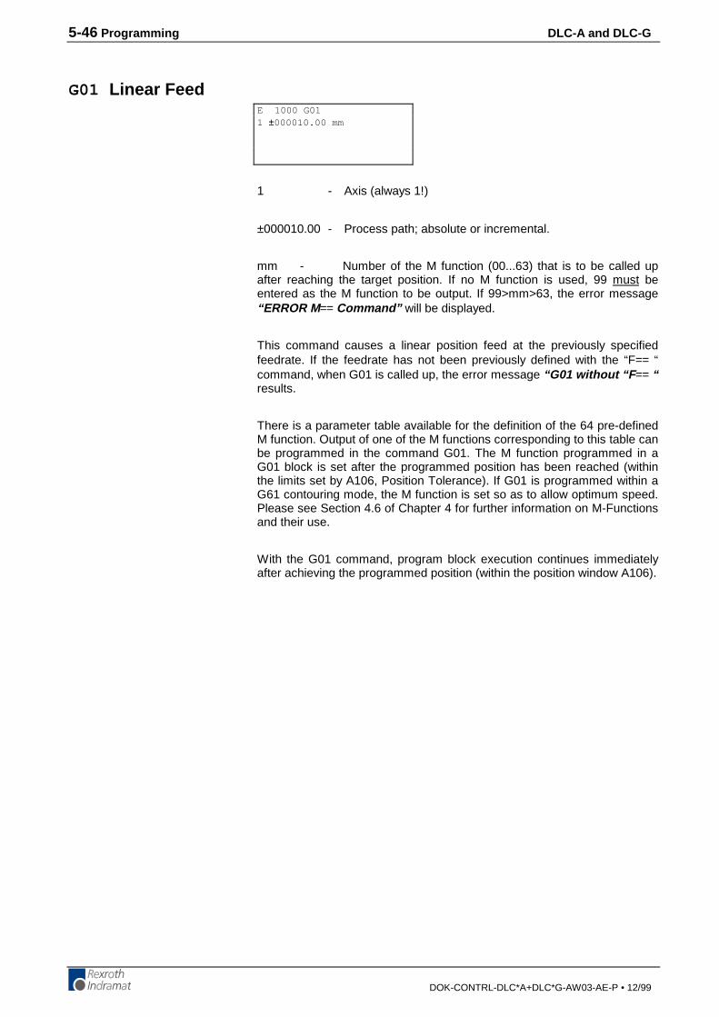
5-46 Programming DLC-A and DLC-G
DOK-CONTRL-DLC*A+DLC*G-AW03-AE-P • 12/99
G01 Linear Feed
1 - Axis (always 1!)
±000010.00 - Process path; absolute or incremental.
mm - Number of the M function (00...63) that is to be called upafter reaching the target position. If no M function is used, 99 must beentered as the M function to be output. If 99>mm>63, the error message“ERROR M == Command” will be displayed.
This command causes a linear position feed at the previously specifiedfeedrate. If the feedrate has not been previously defined with the “F== “command, when G01 is called up, the error message “G01 without “F == “results.
There is a parameter table available for the definition of the 64 pre-definedM function. Output of one of the M functions corresponding to this table canbe programmed in the command G01. The M function programmed in aG01 block is set after the programmed position has been reached (withinthe limits set by A106, Position Tolerance). If G01 is programmed within aG61 contouring mode, the M function is set so as to allow optimum speed.Please see Section 4.6 of Chapter 4 for further information on M-Functionsand their use.
With the G01 command, program block execution continues immediatelyafter achieving the programmed position (within the position window A106).
E 1000 G011 ±000010.00 mm

DLC-A and DLC-G Programming 5-47
DOK-CONTRL-DLC*A+DLC*G-AW03-AE-P • 12/99
G04 Dwell Time
tt.tt - Wait time in seconds
This command causes a delay in further execution of the program. Itcorresponds to the WAI command.
Program block execution is delayed by the programmed dwell time.
E 1000 G04tt.tt
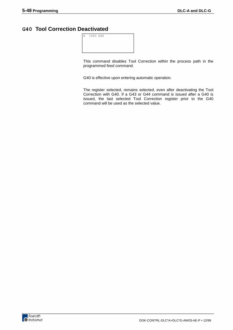
5-48 Programming DLC-A and DLC-G
DOK-CONTRL-DLC*A+DLC*G-AW03-AE-P • 12/99
G40 Tool Correction Deactivated
This command disables Tool Correction within the process path in theprogrammed feed command.
G40 is effective upon entering automatic operation.
The register selected, remains selected, even after deactivating the ToolCorrection with G40. If a G43 or G44 command is issued after a G40 isissued, the last selected Tool Correction register prior to the G40command will be used as the selected value.
E 1000 G40
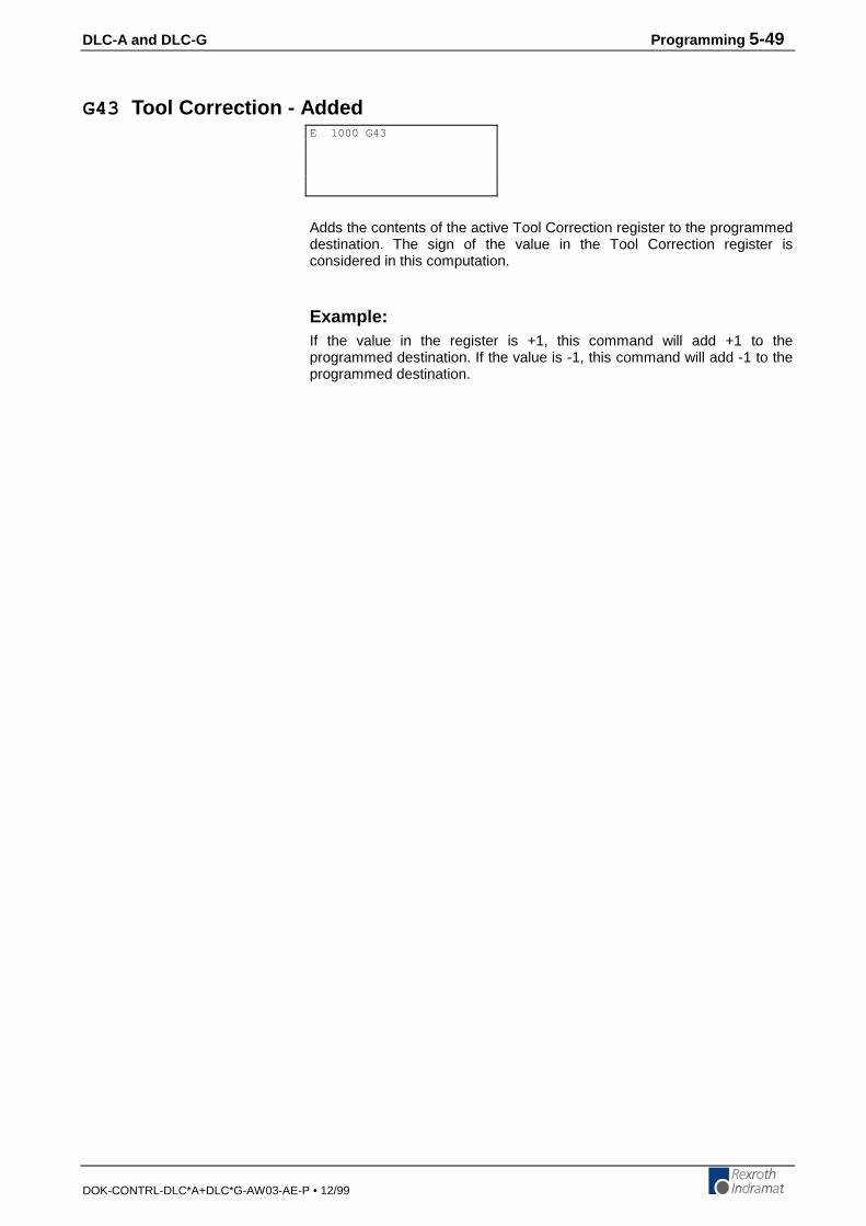
DLC-A and DLC-G Programming 5-49
DOK-CONTRL-DLC*A+DLC*G-AW03-AE-P • 12/99
G43 Tool Correction - Added
Adds the contents of the active Tool Correction register to the programmeddestination. The sign of the value in the Tool Correction register isconsidered in this computation.
Example:If the value in the register is +1, this command will add +1 to theprogrammed destination. If the value is -1, this command will add -1 to theprogrammed destination.
E 1000 G43
5-50 Programming DLC-A and DLC-G
DOK-CONTRL-DLC*A+DLC*G-AW03-AE-P • 12/99
G44 Tool Correction - Subtracted
Subtracts the contents of the active Tool Correction register to theprogrammed destination. The sign of the value in the Tool Correctionregister is considered in this computation.
Example:If the value in the register is +1, this command will subtract +1 to theprogrammed destination. If the value is -1, this command will subtract -1 tothe programmed destination (which means it will add 1 to the programmeddestination).
E 1000 G44

DLC-A and DLC-G Programming 5-51
DOK-CONTRL-DLC*A+DLC*G-AW03-AE-P • 12/99
G60 Exact Stop
If this command is invoked prior to a G01 command, all subsequent G01commands are processed with exact stop (i.e., with Lag finishing). Thismeans the execution of the next program block does not begin until theprogrammed position has been reached (within the position windowparameter A106).
G60 is the default mode and is automatically active after restarting theprogram.
E 1000 G60

5-52 Programming DLC-A and DLC-G
DOK-CONTRL-DLC*A+DLC*G-AW03-AE-P • 12/99
G61 Velocity Rate Optimization
This instruction enables processing of a velocity rate optimization profileusing G01 and F== instructions. This profile may be up to a maximum of20 blocks long and begins with the G61 command and ends with the G60command.
This optimization prevents the axis from stopping between G01 positioningcommands (without Lag finishing), even when the feed rate or programdistance is changed. Within this profile, there may not be any programmingcommands that would prevent program execution from continuingimmediately with the next block, (e.g., dwell time, program jumps, branchjumps, etc.). No change in direction of motion is possible within the profile.All positioning commands must be programmed only in absolute or only inincremental positioning. Any active Tool Correction is observed.
If a G60 programming command is encountered, the Velocity Optimizationends. If there is no G60 instruction after 20 blocks from the first G01command, the error message “No G60” is displayed.
Program Example:N0000 G91 ;Set incremental positioning
N0001 G61 ;Velocity rate optimization turned on
N0002 F== 010000.00 ;Set F = 10 m/min
N0003 G01 1 +000200.00 01 ;Move 200 mm and set M01
N0004 F== 005000.00 ;Change F = 5 m/min
N0005 G01 1 +000100.00 99 ;Move 100 mm. No M Function.
N0006 F== 002000.00 ;Change F = 2 m/min.
N0007 AEA 01 1 ;Set output 01 high
N0008 G01 1 +000050.00 02 ;Move 50 mm and set M02.
N0009 G60 ;Velocity rate optimization turned off.
N0010 G04 01.00 ;1 second dwell time
N0011 JMP 0000 ;Repeat cycle
E 1000 G61
DLC-A and DLC-G Programming 5-53
DOK-CONTRL-DLC*A+DLC*G-AW03-AE-P • 12/99
G74 Reference Axis
a - Axis (always 1)
This command corresponds to the HOM command. All criteria and limitsthat apply to the HOM command also apply to the G74 command.
For further information, see the description for the HOM command.
E 1000 G74a
5-54 Programming DLC-A and DLC-G
DOK-CONTRL-DLC*A+DLC*G-AW03-AE-P • 12/99
G90 Absolute Dimensions
This command causes all subsequent process commands having a Gcode to be interpreted as absolute process commands.
G90 is the default and is effective upon entering automatic operation andafter a program restart.
E 1000 G90
DLC-A and DLC-G Programming 5-55
DOK-CONTRL-DLC*A+DLC*G-AW03-AE-P • 12/99
G91 Incremental Dimensions
This command causes all subsequent process commands having a Gcode to be interpreted as incremental process commands.
Once selected, G91 is effective for all subsequent blocks until it isunselected by a G90 command or until the program is restarted.
E 1000 G91
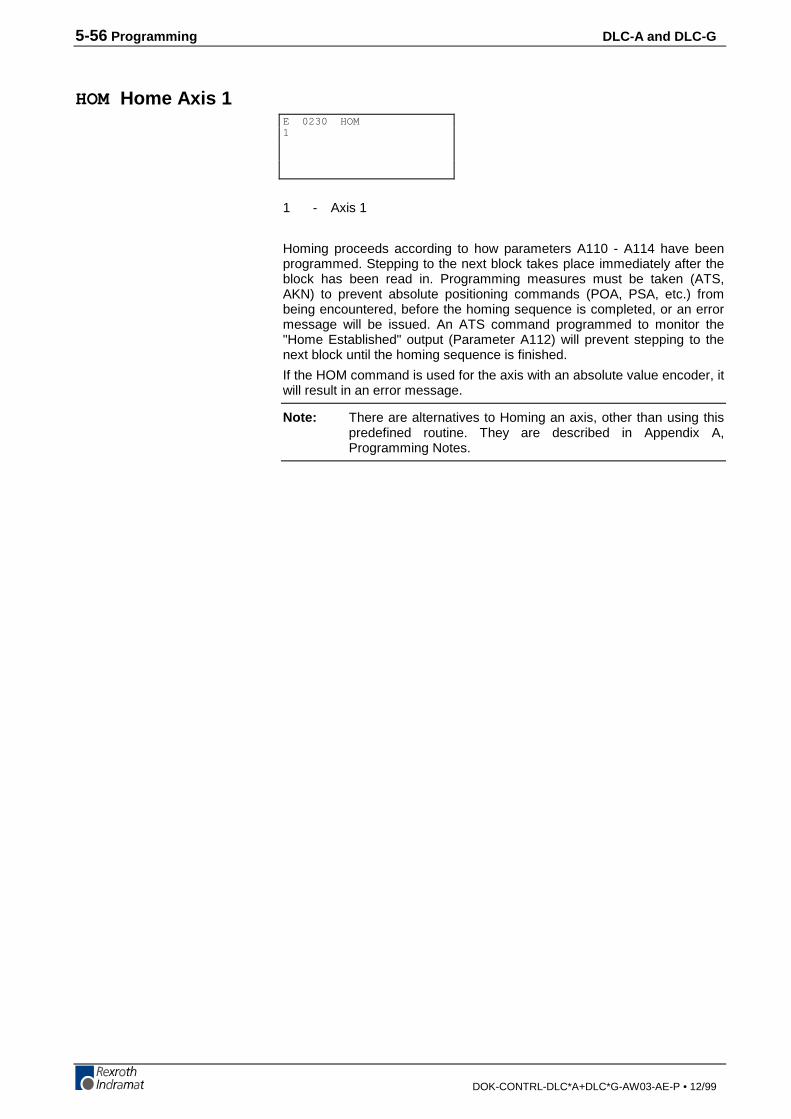
5-56 Programming DLC-A and DLC-G
DOK-CONTRL-DLC*A+DLC*G-AW03-AE-P • 12/99
HOM Home Axis 1
1 - Axis 1
Homing proceeds according to how parameters A110 - A114 have beenprogrammed. Stepping to the next block takes place immediately after theblock has been read in. Programming measures must be taken (ATS,AKN) to prevent absolute positioning commands (POA, PSA, etc.) frombeing encountered, before the homing sequence is completed, or an errormessage will be issued. An ATS command programmed to monitor the"Home Established" output (Parameter A112) will prevent stepping to thenext block until the homing sequence is finished.
If the HOM command is used for the axis with an absolute value encoder, itwill result in an error message.
Note: There are alternatives to Homing an axis, other than using thispredefined routine. They are described in Appendix A,Programming Notes.
E 0230 HOM1

DLC-A and DLC-G Programming 5-57
DOK-CONTRL-DLC*A+DLC*G-AW03-AE-P • 12/99
JMP Jump Unconditional
1234 - Target block
When this command is encountered in a given task, the program willimmediately jump to the specified target block.
There are several other commands that also provide an unconditionaljump, but provide added features in the same block. They can be usefulwhen program space is limited. Refer to section 5.8, Command Summary,for alternatives.
E 2500 JMP1234
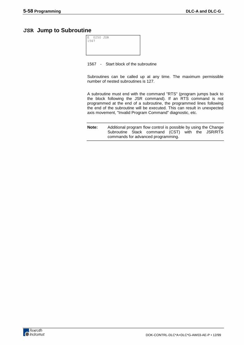
5-58 Programming DLC-A and DLC-G
DOK-CONTRL-DLC*A+DLC*G-AW03-AE-P • 12/99
JSR Jump to Subroutine
1567 - Start block of the subroutine
Subroutines can be called up at any time. The maximum permissiblenumber of nested subroutines is 127.
A subroutine must end with the command "RTS" (program jumps back tothe block following the JSR command). If an RTS command is notprogrammed at the end of a subroutine, the programmed lines followingthe end of the subroutine will be executed. This can result in unexpectedaxis movement, "Invalid Program Command" diagnostic, etc.
Note: Additional program flow control is possible by using the ChangeSubroutine Stack command (CST) with the JSR/RTScommands for advanced programming.
E 0250 JSR1567
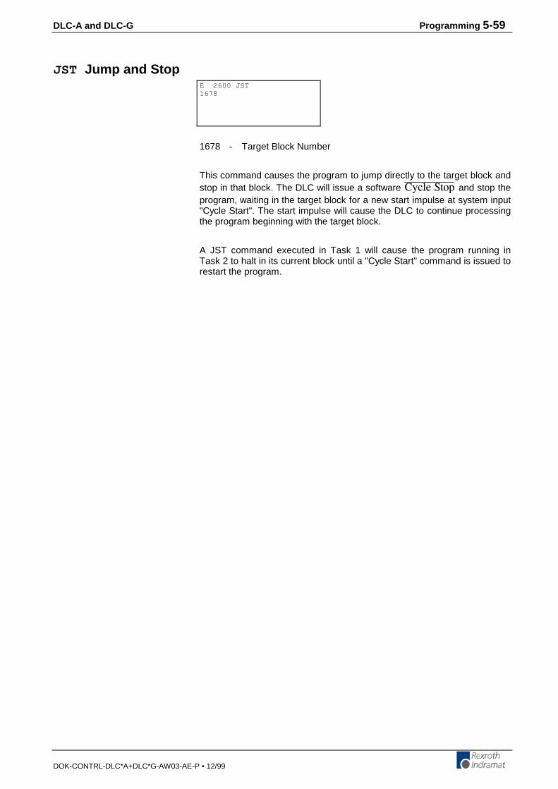
DLC-A and DLC-G Programming 5-59
DOK-CONTRL-DLC*A+DLC*G-AW03-AE-P • 12/99
JST Jump and Stop
1678 - Target Block Number
This command causes the program to jump directly to the target block andstop in that block. The DLC will issue a software %[ENG�5VQR and stop theprogram, waiting in the target block for a new start impulse at system input"Cycle Start". The start impulse will cause the DLC to continue processingthe program beginning with the target block.
A JST command executed in Task 1 will cause the program running inTask 2 to halt in its current block until a "Cycle Start" command is issued torestart the program.
E 2600 JST1678

5-60 Programming DLC-A and DLC-G
DOK-CONTRL-DLC*A+DLC*G-AW03-AE-P • 12/99
JTK Jump in Task
1000 - Target block
1 - 1= Task 1
2= Task 2
The JTK command is used for initiating an Unconditional Jump within aselected task. This command terminates the current program sequence forthe selected task and then causes it to jump to the target block. If the taskis currently executing a move profile, the motion is completed before thetask can be interrupted. If necessary, a PBK command can be used beforethe JTK to terminate the motion thereby providing an immediate interrupt.The JTK command permits the use of many specific interrupt routinestrapped by numerous events.
Note: If only one (input dependent) interrupt routine is needed, it isrecommended to use the interrupt vector parameter B012.
In most applications, the JTK command will be issued from one of theother tasks, typically Task 3. If used correctly, the JTK command canprovide many of the functions available in B012 (Interrupt Vector) with theadditional flexibility to use any event or series of events: position, count,one or more inputs or outputs to cause an interrupt to Task 1 or 2.
E 1345 JTK1000 1
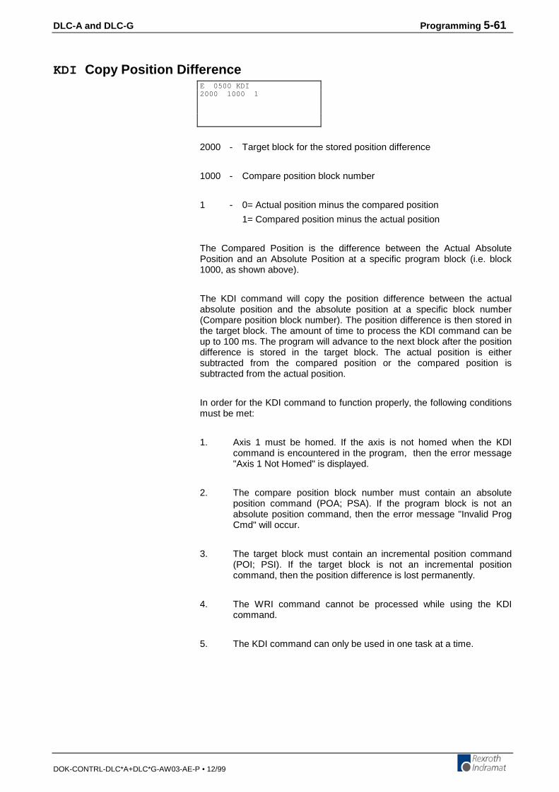
DLC-A and DLC-G Programming 5-61
DOK-CONTRL-DLC*A+DLC*G-AW03-AE-P • 12/99
KDI Copy Position Difference
2000 - Target block for the stored position difference
1000 - Compare position block number
1 - 0= Actual position minus the compared position
1= Compared position minus the actual position
The Compared Position is the difference between the Actual AbsolutePosition and an Absolute Position at a specific program block (i.e. block1000, as shown above).
The KDI command will copy the position difference between the actualabsolute position and the absolute position at a specific block number(Compare position block number). The position difference is then stored inthe target block. The amount of time to process the KDI command can beup to 100 ms. The program will advance to the next block after the positiondifference is stored in the target block. The actual position is eithersubtracted from the compared position or the compared position issubtracted from the actual position.
In order for the KDI command to function properly, the following conditionsmust be met:
1. Axis 1 must be homed. If the axis is not homed when the KDIcommand is encountered in the program, then the error message"Axis 1 Not Homed" is displayed.
2. The compare position block number must contain an absoluteposition command (POA; PSA). If the program block is not anabsolute position command, then the error message "Invalid ProgCmd" will occur.
3. The target block must contain an incremental position command(POI; PSI). If the target block is not an incremental positioncommand, then the position difference is lost permanently.
4. The WRI command cannot be processed while using the KDIcommand.
5. The KDI command can only be used in one task at a time.
E 0500 KDI2000 1000 1

5-62 Programming DLC-A and DLC-G
DOK-CONTRL-DLC*A+DLC*G-AW03-AE-P • 12/99
MOM Torque Reduction
1 - Axis 1020 - Percentage Of Maximum Torque Until Positive Stop Is Reached
Minimum Percentage = 000Maximum Percentage = 400
040 - Percentage Of Maximum Torque At Positive StopMinimum Percentage = 000Maximum Percentage = 100
01 - Aux. Input for Torque Reduction00 = No input needed, reduce torque on execution of MOM
command.01-07 = Reduce torque any time input is high after one
execution of MOM command.123 - Percentage Of Maximum Torque
Minimum Percentage = 000Maximum Percentage = 400
Note: If the percentage of maximum torque values, entered in theMOM command, are greater than the maximum percentageallowed, the value entered will be interpreted as 100 percent.
The MOM command is used to limit the torque to the motor, when a positivestop is reached, or when MOM command is executed. The MOM commandrequires a PFI (Incremental Position To Positive Stop) or PFA (AbsolutePosition To Positive Stop) command to assist in positioning to a positive stop.The MOM command will determine the maximum torque allowed whilepositioning to the positive stop and the maximum torque allowed when thepositive stop is reached. When the positive stop is reached, the programmedtorque is applied until another position command (POI, POA, .etc) is executed.
Stepping to the next block takes place immediately after the MOMcommand is read in the program.
The percentage of maximum torques are valid for all PFA or PFIcommands until a new MOM command redefines the percentages. TheMOM command can be executed from another task.
When executing the MOM command from another task, the newpercentages are valid immediately, even during the execution the PFA orPFI command in a separate task.
A typical application consists of programming the MOM command for thepercentages of torque required and then commanding the axis to position,by using the PFI or PFA command. The commanded position must begreater than or equal to the positive stop position. The axis will travel to theprogrammed position, at percentage of maximum torque until positive stopis reached. The program flow will remain on the PFA or PFI program blockuntil the positive stop is reached or the until the programmed distance, inthe PFA or PFI command is completed.
If the programmed distance in the PFA or PFI command is completed beforethe positive stop is reached, the next program block will be executed. Thenext program block can be a jump (JMP) command to an error routine to tellthe machine operator that the positive stop was not reached.
When the positive stop is reached, the percentage of maximum torque atpositive stop will be enabled and the program flow will jump over the blockimmediately after the PFA or PFI command and the program will continue.
It is also possible to overwrite the torque limit while driving.
E 1345 MOM1 020 040 01 123
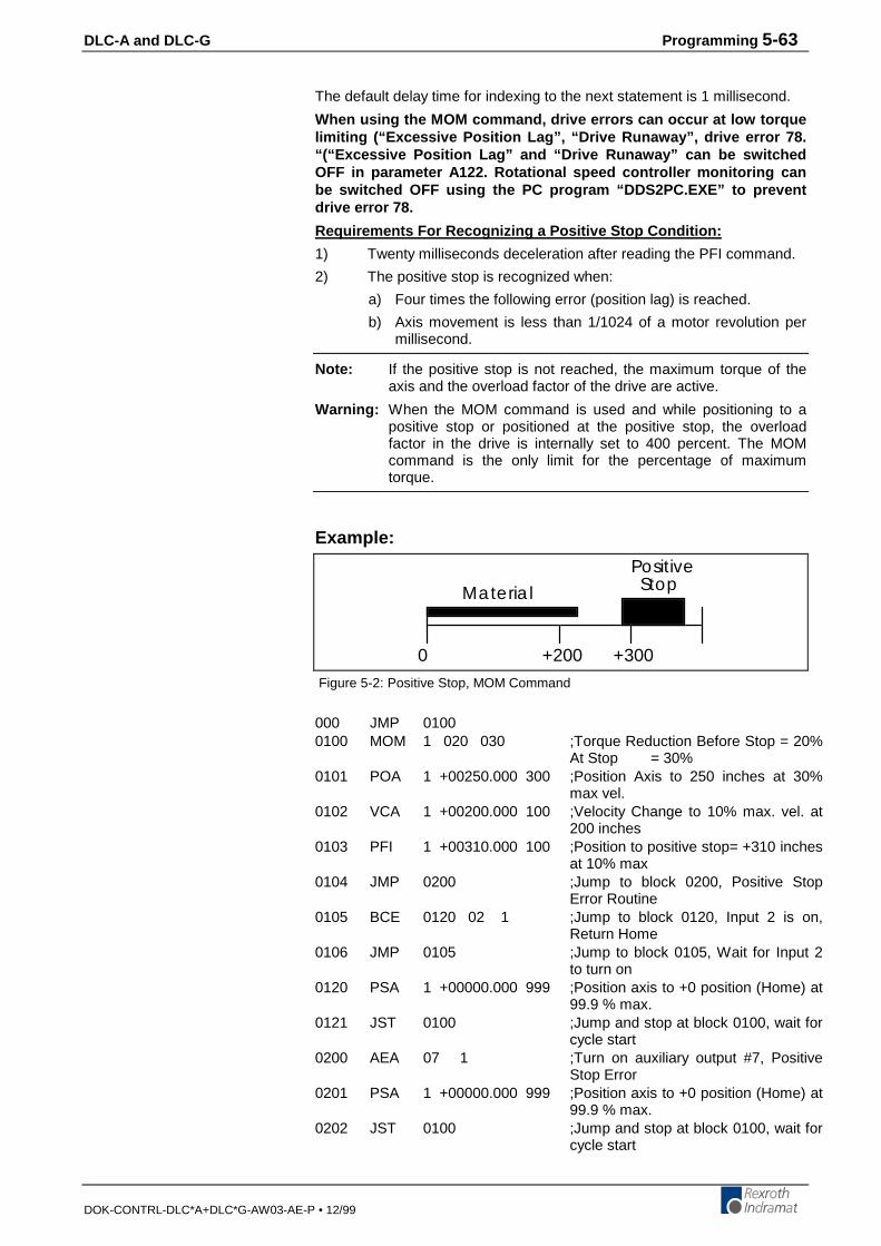
DLC-A and DLC-G Programming 5-63
DOK-CONTRL-DLC*A+DLC*G-AW03-AE-P • 12/99
The default delay time for indexing to the next statement is 1 millisecond.
When using the MOM command, drive errors can occur at low torquelimiting (“Excessive Position Lag”, “Drive Runaway”, drive error 78.“(“Excessive Position Lag” and “Drive Runaway” can be switchedOFF in parameter A122. Rotational speed controller monitoring canbe switched OFF using the PC program “DDS2PC.EXE” to preventdrive error 78.
Requirements For Recognizing a Positive Stop Condition:
1) Twenty milliseconds deceleration after reading the PFI command.
2) The positive stop is recognized when:
a) Four times the following error (position lag) is reached.
b) Axis movement is less than 1/1024 of a motor revolution permillisecond.
Note: If the positive stop is not reached, the maximum torque of theaxis and the overload factor of the drive are active.
Warning: When the MOM command is used and while positioning to apositive stop or positioned at the positive stop, the overloadfactor in the drive is internally set to 400 percent. The MOMcommand is the only limit for the percentage of maximumtorque.
Example:
+200 +3000
Material
PositiveStop
Figure 5-2: Positive Stop, MOM Command
000 JMP 01000100 MOM 1 020 030 ;Torque Reduction Before Stop = 20%
At Stop = 30%0101 POA 1 +00250.000 300 ;Position Axis to 250 inches at 30%
max vel.0102 VCA 1 +00200.000 100 ;Velocity Change to 10% max. vel. at
200 inches0103 PFI 1 +00310.000 100 ;Position to positive stop= +310 inches
at 10% max0104 JMP 0200 ;Jump to block 0200, Positive Stop
Error Routine0105 BCE 0120 02 1 ;Jump to block 0120, Input 2 is on,
Return Home0106 JMP 0105 ;Jump to block 0105, Wait for Input 2
to turn on0120 PSA 1 +00000.000 999 ;Position axis to +0 position (Home) at
99.9 % max.0121 JST 0100 ;Jump and stop at block 0100, wait for
cycle start0200 AEA 07 1 ;Turn on auxiliary output #7, Positive
Stop Error0201 PSA 1 +00000.000 999 ;Position axis to +0 position (Home) at
99.9 % max.0202 JST 0100 ;Jump and stop at block 0100, wait for
cycle start
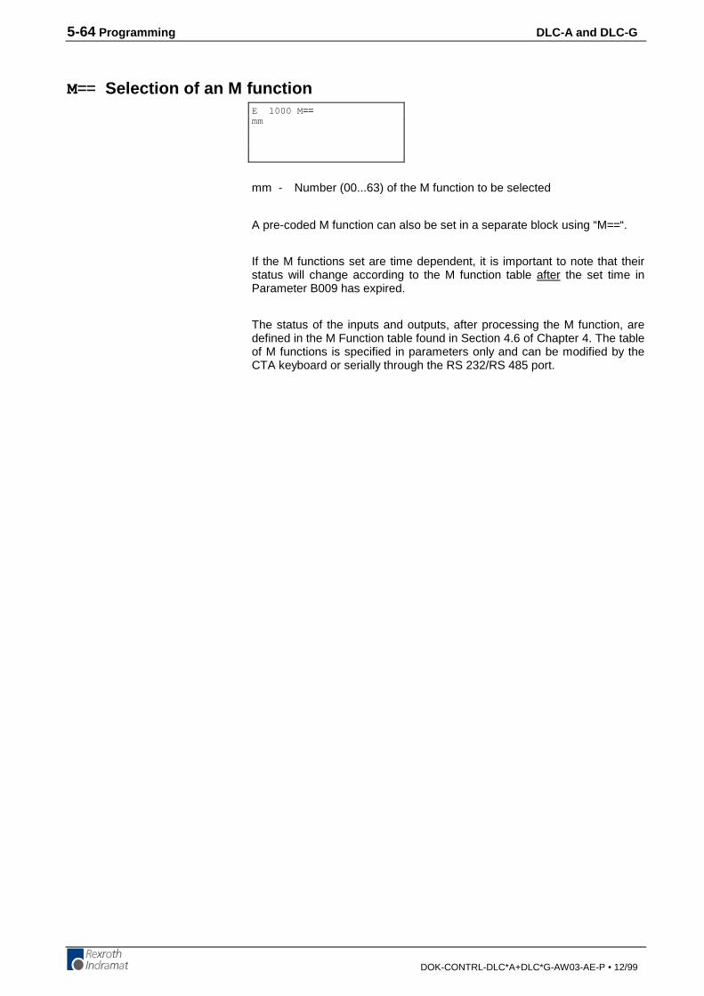
5-64 Programming DLC-A and DLC-G
DOK-CONTRL-DLC*A+DLC*G-AW03-AE-P • 12/99
M== Selection of an M function
mm - Number (00...63) of the M function to be selected
A pre-coded M function can also be set in a separate block using “M==“.
If the M functions set are time dependent, it is important to note that theirstatus will change according to the M function table after the set time inParameter B009 has expired.
The status of the inputs and outputs, after processing the M function, aredefined in the M Function table found in Section 4.6 of Chapter 4. The tableof M functions is specified in parameters only and can be modified by theCTA keyboard or serially through the RS 232/RS 485 port.
E 1000 M ==mm

DLC-A and DLC-G Programming 5-65
DOK-CONTRL-DLC*A+DLC*G-AW03-AE-P • 12/99
NOP No Operation (Blank Block)
This is the command to describe a blank block. During processing in theautomatic mode, this blank block is scanned only: processing continueswith the next block.
NOP's can be used to reserve program block space for future programchange and expansion. Also use NOP's in the program where you maywant to add commands "on the fly" to modify production.
NOP's may also be used as a program delay for each block. Note that thesmallest delay programmable in the WAI command is 10 milliseconds. TheNOP command allows for smaller increments of delay.
The default delay time for each NOP block is 1 millisecond.
E 0021 NOP
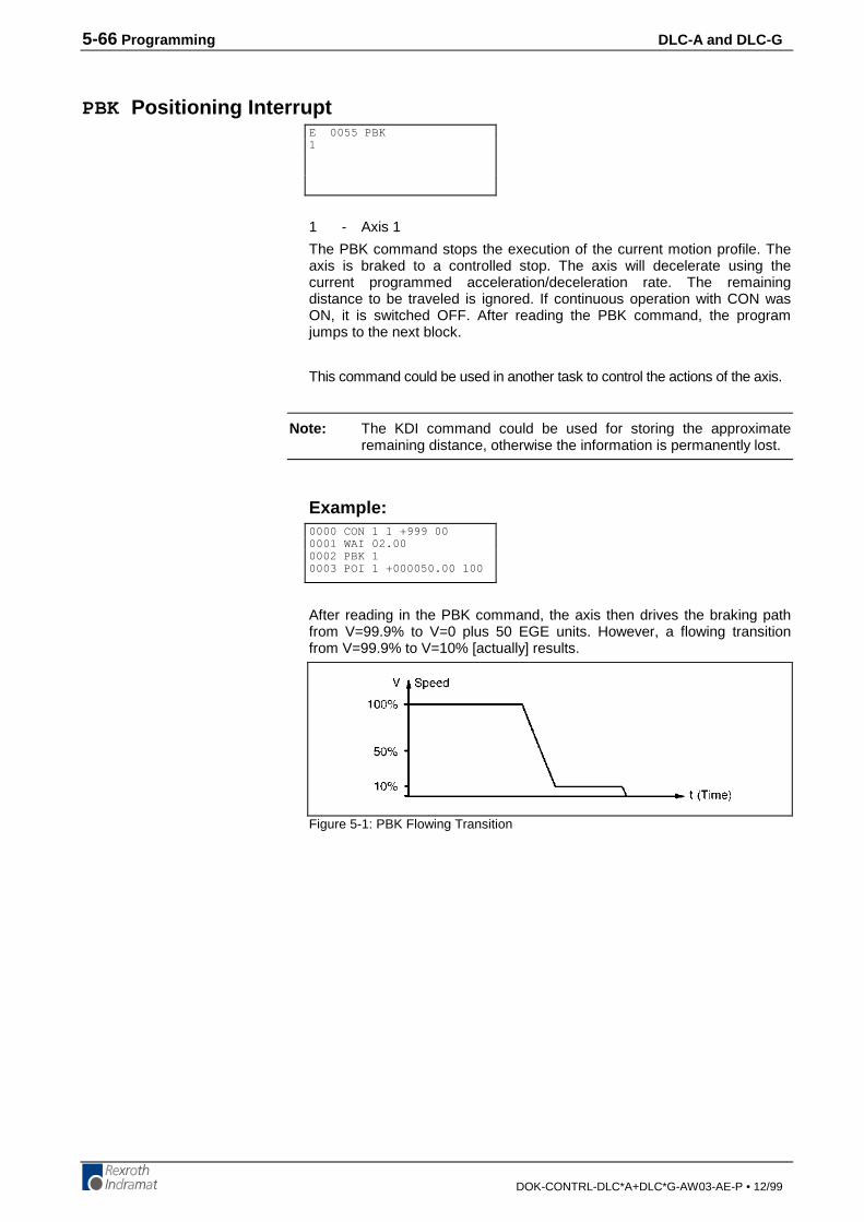
5-66 Programming DLC-A and DLC-G
DOK-CONTRL-DLC*A+DLC*G-AW03-AE-P • 12/99
PBK Positioning Interrupt
1 - Axis 1
The PBK command stops the execution of the current motion profile. Theaxis is braked to a controlled stop. The axis will decelerate using thecurrent programmed acceleration/deceleration rate. The remainingdistance to be traveled is ignored. If continuous operation with CON wasON, it is switched OFF. After reading the PBK command, the programjumps to the next block.
This command could be used in another task to control the actions of the axis.
Note: The KDI command could be used for storing the approximateremaining distance, otherwise the information is permanently lost.
Example:
After reading in the PBK command, the axis then drives the braking pathfrom V=99.9% to V=0 plus 50 EGE units. However, a flowing transitionfrom V=99.9% to V=10% [actually] results.
Figure 5-1: PBK Flowing Transition
E 0055 PBK1
0000 CON 1 1 +999 000001 WAI 02.000002 PBK 10003 POI 1 +000050.00 100
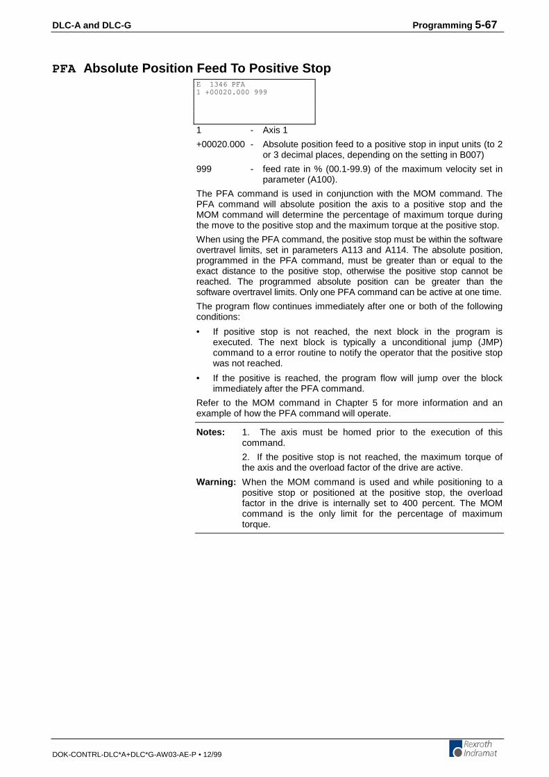
DLC-A and DLC-G Programming 5-67
DOK-CONTRL-DLC*A+DLC*G-AW03-AE-P • 12/99
PFA Absolute Position Feed To Positive Stop
1 - Axis 1
+00020.000 - Absolute position feed to a positive stop in input units (to 2or 3 decimal places, depending on the setting in B007)
999 - feed rate in % (00.1-99.9) of the maximum velocity set inparameter (A100).
The PFA command is used in conjunction with the MOM command. ThePFA command will absolute position the axis to a positive stop and theMOM command will determine the percentage of maximum torque duringthe move to the positive stop and the maximum torque at the positive stop.
When using the PFA command, the positive stop must be within the softwareovertravel limits, set in parameters A113 and A114. The absolute position,programmed in the PFA command, must be greater than or equal to theexact distance to the positive stop, otherwise the positive stop cannot bereached. The programmed absolute position can be greater than thesoftware overtravel limits. Only one PFA command can be active at one time.
The program flow continues immediately after one or both of the followingconditions:
• If positive stop is not reached, the next block in the program isexecuted. The next block is typically a unconditional jump (JMP)command to a error routine to notify the operator that the positive stopwas not reached.
• If the positive is reached, the program flow will jump over the blockimmediately after the PFA command.
Refer to the MOM command in Chapter 5 for more information and anexample of how the PFA command will operate.
Notes: 1. The axis must be homed prior to the execution of thiscommand.
2. If the positive stop is not reached, the maximum torque ofthe axis and the overload factor of the drive are active.
Warning: When the MOM command is used and while positioning to apositive stop or positioned at the positive stop, the overloadfactor in the drive is internally set to 400 percent. The MOMcommand is the only limit for the percentage of maximumtorque.
E 1346 PFA1 +00020.000 999
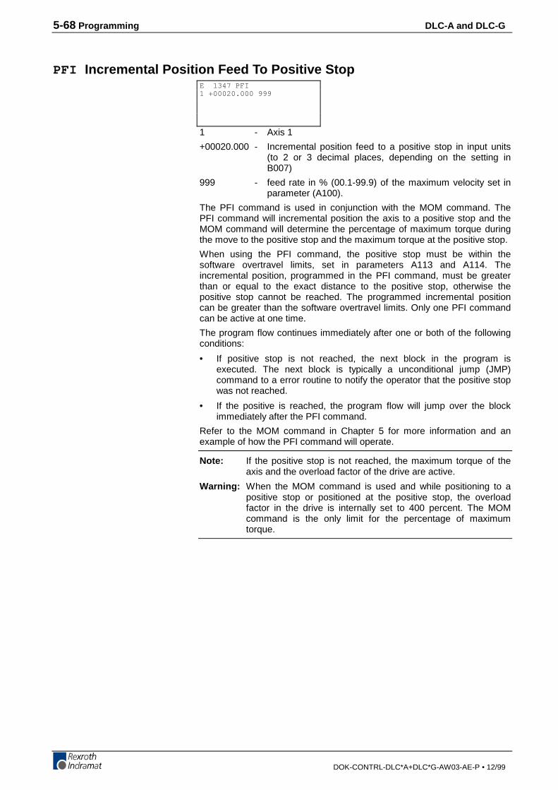
5-68 Programming DLC-A and DLC-G
DOK-CONTRL-DLC*A+DLC*G-AW03-AE-P • 12/99
PFI Incremental Position Feed To Positive Stop
1 - Axis 1
+00020.000 - Incremental position feed to a positive stop in input units(to 2 or 3 decimal places, depending on the setting inB007)
999 - feed rate in % (00.1-99.9) of the maximum velocity set inparameter (A100).
The PFI command is used in conjunction with the MOM command. ThePFI command will incremental position the axis to a positive stop and theMOM command will determine the percentage of maximum torque duringthe move to the positive stop and the maximum torque at the positive stop.
When using the PFI command, the positive stop must be within thesoftware overtravel limits, set in parameters A113 and A114. Theincremental position, programmed in the PFI command, must be greaterthan or equal to the exact distance to the positive stop, otherwise thepositive stop cannot be reached. The programmed incremental positioncan be greater than the software overtravel limits. Only one PFI commandcan be active at one time.
The program flow continues immediately after one or both of the followingconditions:
• If positive stop is not reached, the next block in the program isexecuted. The next block is typically a unconditional jump (JMP)command to a error routine to notify the operator that the positive stopwas not reached.
• If the positive is reached, the program flow will jump over the blockimmediately after the PFI command.
Refer to the MOM command in Chapter 5 for more information and anexample of how the PFI command will operate.
Note: If the positive stop is not reached, the maximum torque of theaxis and the overload factor of the drive are active.
Warning: When the MOM command is used and while positioning to apositive stop or positioned at the positive stop, the overloadfactor in the drive is internally set to 400 percent. The MOMcommand is the only limit for the percentage of maximumtorque.
E 1347 PFI1 +00020.000 999
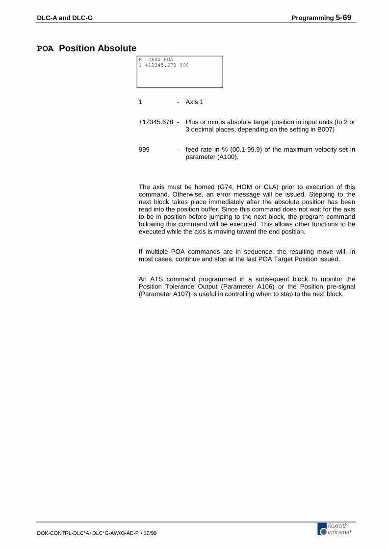
DLC-A and DLC-G Programming 5-69
DOK-CONTRL-DLC*A+DLC*G-AW03-AE-P • 12/99
POA Position Absolute
1 - Axis 1
+12345.678 - Plus or minus absolute target position in input units (to 2 or3 decimal places, depending on the setting in B007)
999 - feed rate in % (00.1-99.9) of the maximum velocity set inparameter (A100).
The axis must be homed (G74, HOM or CLA) prior to execution of thiscommand. Otherwise, an error message will be issued. Stepping to thenext block takes place immediately after the absolute position has beenread into the position buffer. Since this command does not wait for the axisto be in position before jumping to the next block, the program commandfollowing this command will be executed. This allows other functions to beexecuted while the axis is moving toward the end position.
If multiple POA commands are in sequence, the resulting move will, inmost cases, continue and stop at the last POA Target Position issued.
An ATS command programmed in a subsequent block to monitor thePosition Tolerance Output (Parameter A106) or the Position pre-signal(Parameter A107) is useful in controlling when to step to the next block.
E 2800 POA1 +12345.678 999
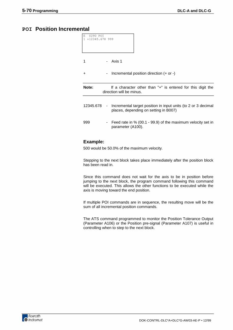
5-70 Programming DLC-A and DLC-G
DOK-CONTRL-DLC*A+DLC*G-AW03-AE-P • 12/99
POI Position Incremental
1 - Axis 1
+ - Incremental position direction (+ or -)
Note: If a character other than "+" is entered for this digit thedirection will be minus.
12345.678 - Incremental target position in input units (to 2 or 3 decimalplaces, depending on setting in B007)
999 - Feed rate in % (00.1 - 99.9) of the maximum velocity set inparameter (A100).
Example:500 would be 50.0% of the maximum velocity.
Stepping to the next block takes place immediately after the position blockhas been read in.
Since this command does not wait for the axis to be in position beforejumping to the next block, the program command following this commandwill be executed. This allows the other functions to be executed while theaxis is moving toward the end position.
If multiple POI commands are in sequence, the resulting move will be thesum of all incremental position commands.
The ATS command programmed to monitor the Position Tolerance Output(Parameter A106) or the Position pre-signal (Parameter A107) is useful incontrolling when to step to the next block.
E 0290 POI1 +12345.678 999
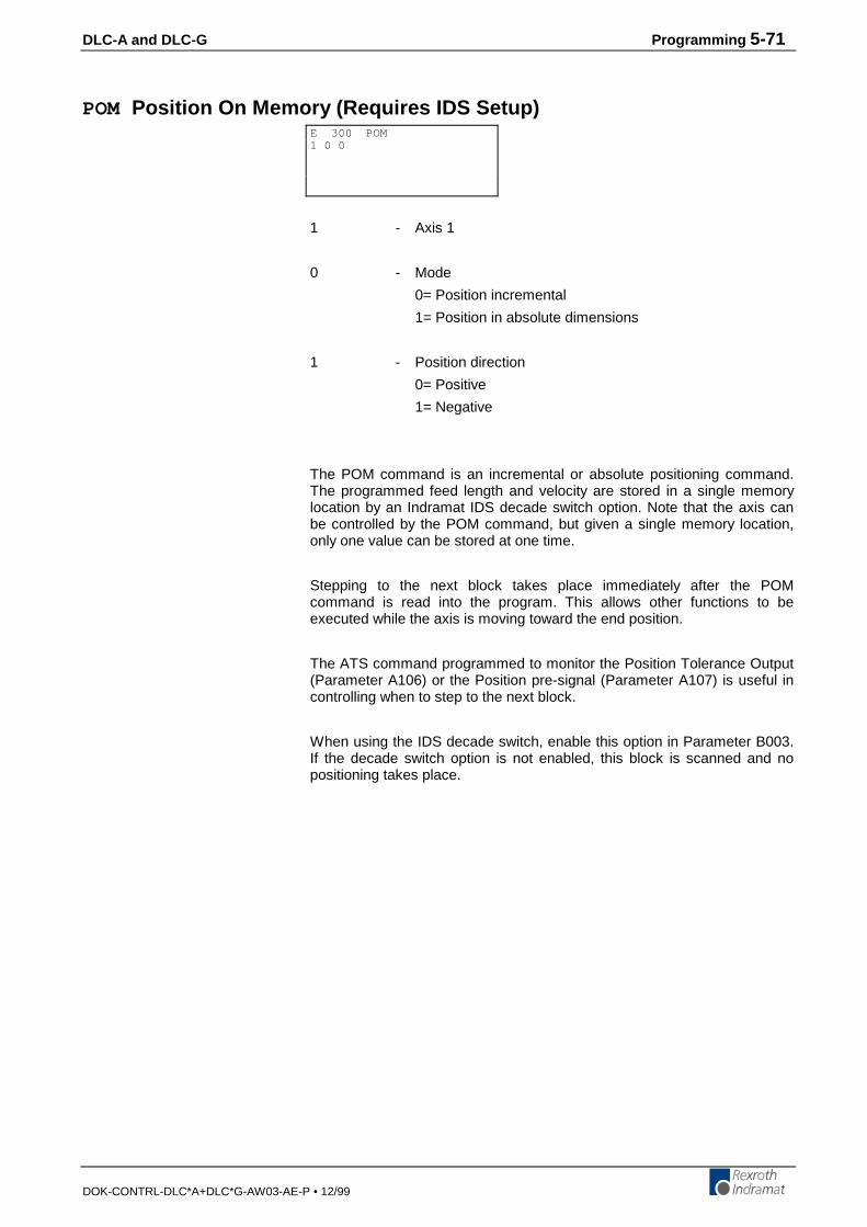
DLC-A and DLC-G Programming 5-71
DOK-CONTRL-DLC*A+DLC*G-AW03-AE-P • 12/99
POM Position On Memory (Requires IDS Setup)
1 - Axis 1
0 - Mode
0= Position incremental
1= Position in absolute dimensions
1 - Position direction
0= Positive
1= Negative
The POM command is an incremental or absolute positioning command.The programmed feed length and velocity are stored in a single memorylocation by an Indramat IDS decade switch option. Note that the axis canbe controlled by the POM command, but given a single memory location,only one value can be stored at one time.
Stepping to the next block takes place immediately after the POMcommand is read into the program. This allows other functions to beexecuted while the axis is moving toward the end position.
The ATS command programmed to monitor the Position Tolerance Output(Parameter A106) or the Position pre-signal (Parameter A107) is useful incontrolling when to step to the next block.
When using the IDS decade switch, enable this option in Parameter B003.If the decade switch option is not enabled, this block is scanned and nopositioning takes place.
E 300 POM1 0 0
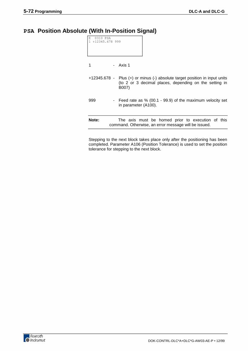
5-72 Programming DLC-A and DLC-G
DOK-CONTRL-DLC*A+DLC*G-AW03-AE-P • 12/99
PSA Position Absolute (With In-Position Signal)
1 - Axis 1
+12345.678 - Plus (+) or minus (-) absolute target position in input units(to 2 or 3 decimal places, depending on the setting inB007)
999 - Feed rate as % (00.1 - 99.9) of the maximum velocity setin parameter (A100).
Note: The axis must be homed prior to execution of thiscommand. Otherwise, an error message will be issued.
Stepping to the next block takes place only after the positioning has beencompleted. Parameter A106 (Position Tolerance) is used to set the positiontolerance for stepping to the next block.
E 0310 PSA1 +12345.678 999

DLC-A and DLC-G Programming 5-73
DOK-CONTRL-DLC*A+DLC*G-AW03-AE-P • 12/99
PSI Position Incremental (With In-Position Signal)
1 - Axis 1
+ - Incremental position direction, plus (+) or minus (-)
Note: If a character other than "+" is entered for this position, thedirection will be negative.
12345.678 - Incremental target position in input units (to 2 or 3 decimalplaces, depending on setting in B007)
999 - feed rate as % (00.1 - 99.9) of the maximum velocity set inparameter (A100)
Stepping to the next block takes place only after the positioning has beencompleted. Parameter A106 (Position Tolerance) is used to set the positiontolerance for stepping to the next block.
E 1420 PSI1 +12345.678 999
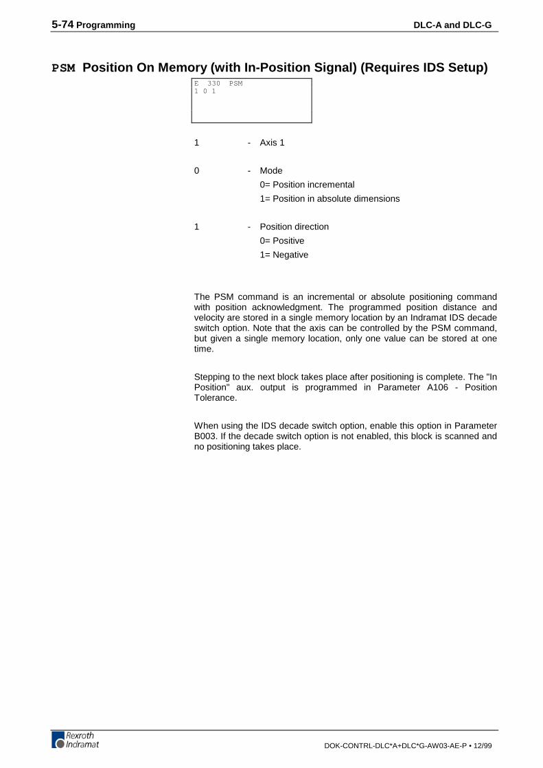
5-74 Programming DLC-A and DLC-G
DOK-CONTRL-DLC*A+DLC*G-AW03-AE-P • 12/99
PSM Position On Memory (with In-Position Signal) (Requires IDS Setup)
1 - Axis 1
0 - Mode
0= Position incremental
1= Position in absolute dimensions
1 - Position direction
0= Positive
1= Negative
The PSM command is an incremental or absolute positioning commandwith position acknowledgment. The programmed position distance andvelocity are stored in a single memory location by an Indramat IDS decadeswitch option. Note that the axis can be controlled by the PSM command,but given a single memory location, only one value can be stored at onetime.
Stepping to the next block takes place after positioning is complete. The "InPosition" aux. output is programmed in Parameter A106 - PositionTolerance.
When using the IDS decade switch option, enable this option in ParameterB003. If the decade switch option is not enabled, this block is scanned andno positioning takes place.
E 330 PSM1 0 1
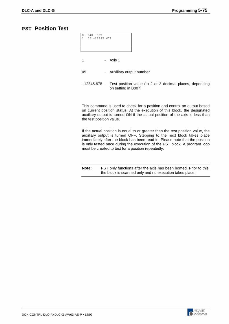
DLC-A and DLC-G Programming 5-75
DOK-CONTRL-DLC*A+DLC*G-AW03-AE-P • 12/99
PST Position Test
1 - Axis 1
05 - Auxiliary output number
+12345.678 - Test position value (to 2 or 3 decimal places, dependingon setting in B007)
This command is used to check for a position and control an output basedon current position status. At the execution of this block, the designatedauxiliary output is turned ON if the actual position of the axis is less thanthe test position value.
If the actual position is equal to or greater than the test position value, theauxiliary output is turned OFF. Stepping to the next block takes placeimmediately after the block has been read in. Please note that the positionis only tested once during the execution of the PST block. A program loopmust be created to test for a position repeatedly.
Note: PST only functions after the axis has been homed. Prior to this,the block is scanned only and no execution takes place.
E 340 PST1 05 +12345.678
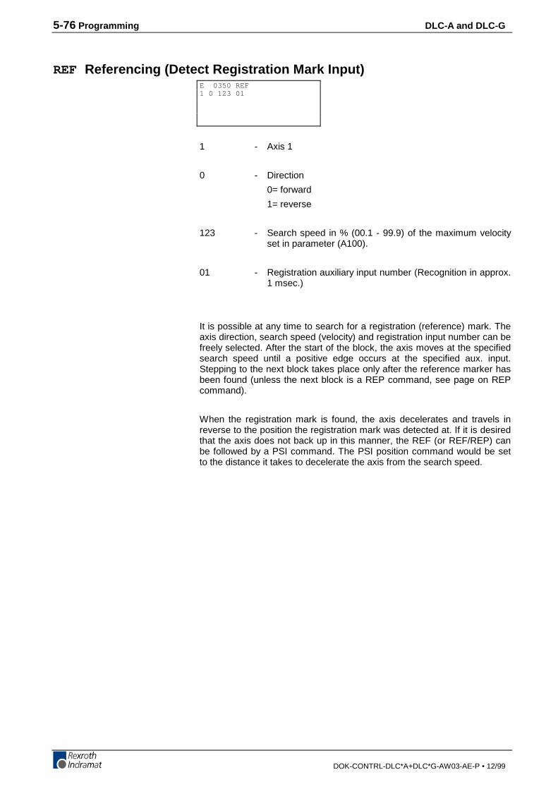
5-76 Programming DLC-A and DLC-G
DOK-CONTRL-DLC*A+DLC*G-AW03-AE-P • 12/99
REF Referencing (Detect Registration Mark Input)
1 - Axis 1
0 - Direction
0= forward
1= reverse
123 - Search speed in % (00.1 - 99.9) of the maximum velocityset in parameter (A100).
01 - Registration auxiliary input number (Recognition in approx.1 msec.)
It is possible at any time to search for a registration (reference) mark. Theaxis direction, search speed (velocity) and registration input number can befreely selected. After the start of the block, the axis moves at the specifiedsearch speed until a positive edge occurs at the specified aux. input.Stepping to the next block takes place only after the reference marker hasbeen found (unless the next block is a REP command, see page on REPcommand).
When the registration mark is found, the axis decelerates and travels inreverse to the position the registration mark was detected at. If it is desiredthat the axis does not back up in this manner, the REF (or REF/REP) canbe followed by a PSI command. The PSI position command would be setto the distance it takes to decelerate the axis from the search speed.
E 0350 REF1 0 123 01
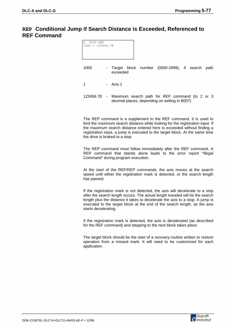
DLC-A and DLC-G Programming 5-77
DOK-CONTRL-DLC*A+DLC*G-AW03-AE-P • 12/99
REP Conditional Jump if Search Distance is Exceeded, Referenced toREF Command
1000 - Target block number (0000-2999), if search pathexceeded
1 - Axis 1
123456.78 - Maximum search path for REF command (to 2 or 3decimal places, depending on setting in B007)
The REP command is a supplement to the REF command. It is used tolimit the maximum search distance while looking for the registration input. Ifthe maximum search distance entered here is exceeded without finding aregistration input, a jump is executed to the target block. At the same timethe drive is braked to a stop.
The REP command must follow immediately after the REF command. AREP command that stands alone leads to the error report “IllegalCommand” during program execution.
At the start of the REF/REP commands, the axis moves at the searchspeed until either the registration mark is detected, or the search lengthhas passed.
If the registration mark is not detected, the axis will decelerate to a stopafter the search length occurs. The actual length traveled will be the searchlength plus the distance it takes to decelerate the axis to a stop. A jump isexecuted to the target block at the end of the search length, as the axisstarts decelerating.
If the registration mark is detected, the axis is decelerated (as describedfor the REF command) and stepping to the next block takes place.
The target block should be the start of a recovery routine written to restoreoperation from a missed mark. It will need to be customized for eachapplication.
E 0030 REP1000 1 123456.78

5-78 Programming DLC-A and DLC-G
DOK-CONTRL-DLC*A+DLC*G-AW03-AE-P • 12/99
The following command combinations are permitted:
1. Reference position travel, without driving to an offset dimensionand without search distance limiting,
2. Reference position travel, driving to an offset dimension withoutsearch distance limiting,
3. Reference position travel is programmed in the REF command.Limiting to max. 500 mm is programmed in the REP command.
4. Reference position travel with search distance limiting and offsetdimension.
Reference position travel is programmed in the REF command.
Limiting to max. 900 mm is programmed in the REP command.
An offset dimension of 123 mm is programmed in the POI command.
The REP command and the feed (POI or PSI possible) are processed inthe same controller cycle as the REF command.
0020 REF 1 0 050 05
0000 REF 1 0 50 100001 PSI 1 +000200.00 100
0030 REF 1 0 100 120031 REP 0900 1 000500
0055 REF 1 1 222 110056 REP 0900 10057 POI 1 +000123.00 99

DLC-A and DLC-G Programming 5-79
DOK-CONTRL-DLC*A+DLC*G-AW03-AE-P • 12/99
RMI Registration Mark Interrupt
This command can be used to initiate additional processing, independentlyof the positioning program. The additional registration mark processing isinititated after the recognition of an input pulse, and after an offset hasbeen traversed. The startup signal edge of the pulse is evaluated. Thepositioning program is interrupted for this registration mark processing andsubsequently continued.
0 - Mode
0 = Wait for pulse at the registration mark input(stepping to the next block takes place afterrecognition of the pulse and traversing the offset.)
1 = Terminate registration mark processing continueprogram. (stepping to the next block takes placeimmediately)
01 - Registration mark input
00 = No registration mark selected
01-16 = Standard auxiliary input (recognition in approx. 1msec)
The registration mark program has to be programmed in Task 2. An offsetcan be programmed in the form of an incremental position command (POI,PSI, POM, or PSM). The incremental position command has to follow theRMI command directly.
E 0300 RMI0 01
5-80 Programming DLC-A and DLC-G
DOK-CONTRL-DLC*A+DLC*G-AW03-AE-P • 12/99
Example of application:
Perforated sheet metal should be cut according to the location of theperforations, which are stamped into the flat sheet metal on the stampingtable. The material is then fed through the pass rolling mill. A hole servesas a reference signal for recognition of the registration mark. Since anunknown change of length occurs during profiling, the same feed programcannot be used for the cutting process because the possibility that theperforation will drift to the edge cannot be excluded. Because of thisreason, cutting is done depending on the reference hole.
The reference hole can be detected by means of a light barrier, initiator, orsimilar device.
Notes:
• Cannot be used simultaneously with a REF command
• Will be ignored in the case of re-start
• The RMI works correctly only with feeds and offset feeds in positivedirection (e.g., PSI 1 +....)
• In Task 2, (RMI program) there should be no other feed except for theoffset
• After the RMI command (RMI 0 XX) has been called up, masking ahole is no longer possible
• Recognition of an additional registration mark prior to the command'RMI 1 XX' is not possible
The velocity that can be changed by means of the offset feed is returned toits old value when the program resumes. The interruption, feed monitoringand override functions may be used.
DLC-A and DLC-G Programming 5-81
DOK-CONTRL-DLC*A+DLC*G-AW03-AE-P • 12/99
Sample program:
Task1: PSI 1 +000050.00 999
JSR stamp1
PSI 1 +000025.00 999
JSR stamp2
JMP task1
Stamp1: AEA 01 1 ;stamping with stamp 1
WAI 00.20
AEA 01.00
RTS
Stamp2: AEA 02 1 ;stamping with stamp 2
WAI 00.20
AEA 02 0
RTS
Task2: RMI 0 01 ;wait for registration mark
;pulse and traversing of offsetdistance
PSI 1 +000015.50 500 ;offset distance from position ofregistration mark
JSR tool
RMI 1 01
JMP task2
Tool: AEA 03 1 ;cutter on
WAI 00.25 ;waiting time
AEA 03 0 ;cutter off
WAI 00.20 ;waiting time
RTS
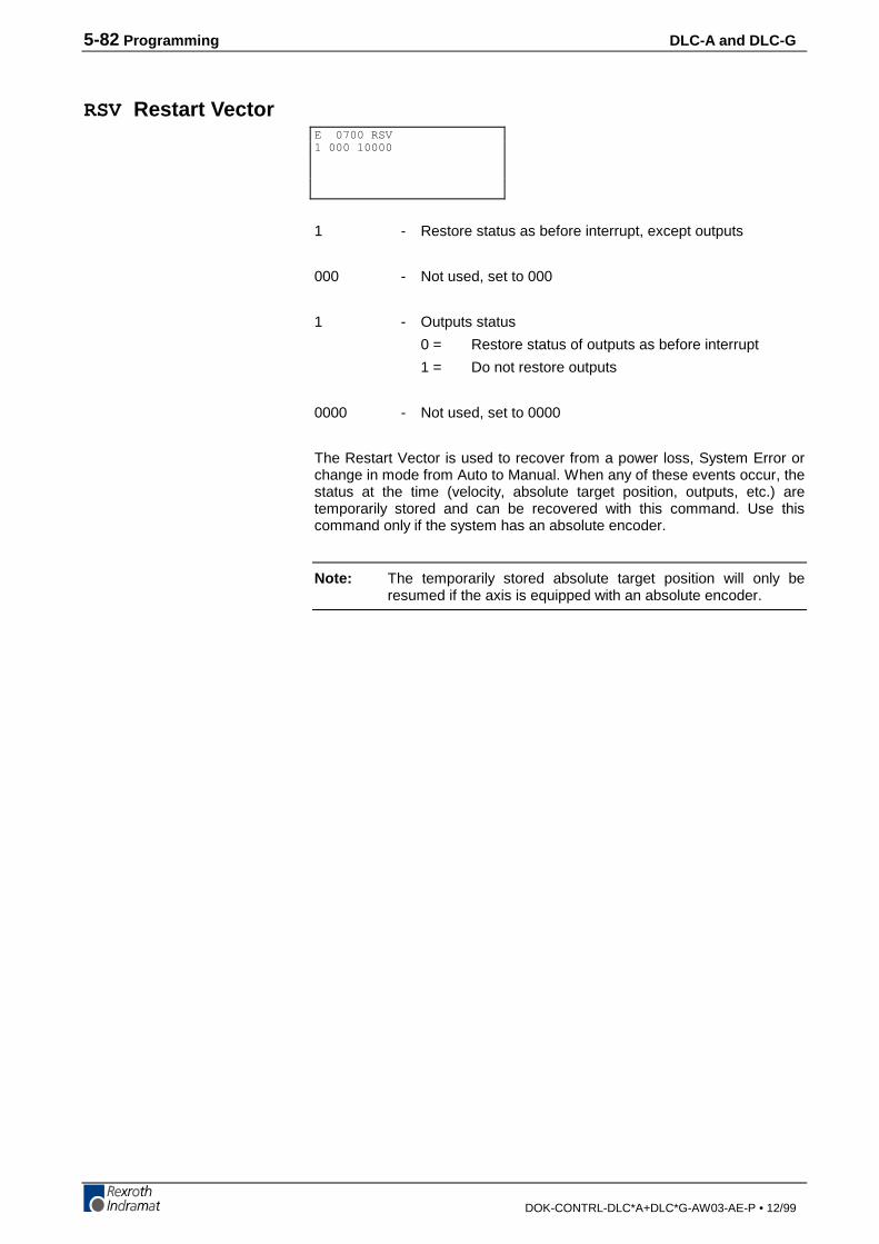
5-82 Programming DLC-A and DLC-G
DOK-CONTRL-DLC*A+DLC*G-AW03-AE-P • 12/99
RSV Restart Vector
1 - Restore status as before interrupt, except outputs
000 - Not used, set to 000
1 - Outputs status
0 = Restore status of outputs as before interrupt
1 = Do not restore outputs
0000 - Not used, set to 0000
The Restart Vector is used to recover from a power loss, System Error orchange in mode from Auto to Manual. When any of these events occur, thestatus at the time (velocity, absolute target position, outputs, etc.) aretemporarily stored and can be recovered with this command. Use thiscommand only if the system has an absolute encoder.
Note: The temporarily stored absolute target position will only beresumed if the axis is equipped with an absolute encoder.
E 0700 RSV1 000 10000
DLC-A and DLC-G Programming 5-83
DOK-CONTRL-DLC*A+DLC*G-AW03-AE-P • 12/99
RTS Return from Subroutine
The RTS command is used to return from a subroutine which has beencalled by using the JSR command. The program is continued at the pointwhere the subroutine had been called which is the next block after the JSRcommand.
If in multiple subroutines, the RTS command will take the program backonly to the level of the current subroutine stack.
Note: Additional program flow control is possible by using the ChangeSubroutine Stack command (CST) with the JSR/RTScommands for advanced programming.
E 0370 RTS

5-84 Programming DLC-A and DLC-G
DOK-CONTRL-DLC*A+DLC*G-AW03-AE-P • 12/99
SAC Set Absolute Counter
1 - Axis 1
0 - 0= Absolute offset (offset change)
1= Set absolute position with respect to the commandposition.
2= Set absolute position, with respect to the actualposition.
+12345.678 - Absolute position or offset, plus (+) or minus (-)
This command is used to set or change the value of the absolute positioncounter. The axis must be homed before this command can be used.
E 0300 SAC1 0 +12345.678
DLC-A and DLC-G Programming 5-85
DOK-CONTRL-DLC*A+DLC*G-AW03-AE-P • 12/99
SIN Sine Oscillation
1 - Axis 1
10 - Auxiliary input which enables SIN function
12.345 - Amplitude in Input Units (to 2 or 3 decimal places,depending on setting in B007)
999 - Frequency of oscillation in Hertz (0.01 to 9.99)
This function will start up with 0 degrees when the enable input is switchedOn. When the enable input is switched Off, the function ends at 360degrees. After this, stepping to the next block will take place. The axis mustbe homed, or an error will occur when this command is read.
E 0380 SIN1 10 12.345 999
5-86 Programming DLC-A and DLC-G
DOK-CONTRL-DLC*A+DLC*G-AW03-AE-P • 12/99
SO1 Scanning of Inputs and Modifying a Position/Velocity(Special Option #1)
0 - 0 = Read decade switch values
1 = Convert input values into a position and store this in theposition section of the POI, PSI, POA, PSA, VCC, PST,commands
2 = Convert input values into a velocity and store this in the velocitysection of the POI, PSI, POA, PSA, VCC commands
3 = Convert into a length and write to the tool correction memorydefined under “data target” replacing the informationcontained in this memory.
4 = Convert into a length and write to the tool correction memorydefined under “data target”, adding to the informationcontained in the selected memory.
5 = Convert into a length and write to the tool correction memorydefined under “data target”, subtracting from the informationcontained in the selected memory.
In modes 3 through 5 a maximum of 7 digits are evaluated (the 8th digitfrom the right is the mathematical operation).
1 - Decimal Position: To 2 or 3 decimal places, depending on settingin B007.
For 3 decimal places For 2 decimal places
1= 10-3
1= 10-2
2= 10-2
2= 10-1
3= 10-1
3= 100
4= 100
4= 101
5= 101
5= 102
6= 102
6= 103
7= 103
7= 104
8= 104
8= 105
9= Sign (+ / -) 9= Sign (+ / -)
ee - Starting input number for inputted data, with the BCD value:
ee= 10
ee+1= 11
ee+2= 12
ee+3= 13
0010 - Data targetIn mode 1...2: Program block (0000 to 2999)In mode 3...5: Number of the correction memory (01 to 19)
The SO1 command is used to read in length information via decadeswitches or from a programmable logic controller (PLC).
E 1000 SO10 1 ee 0010
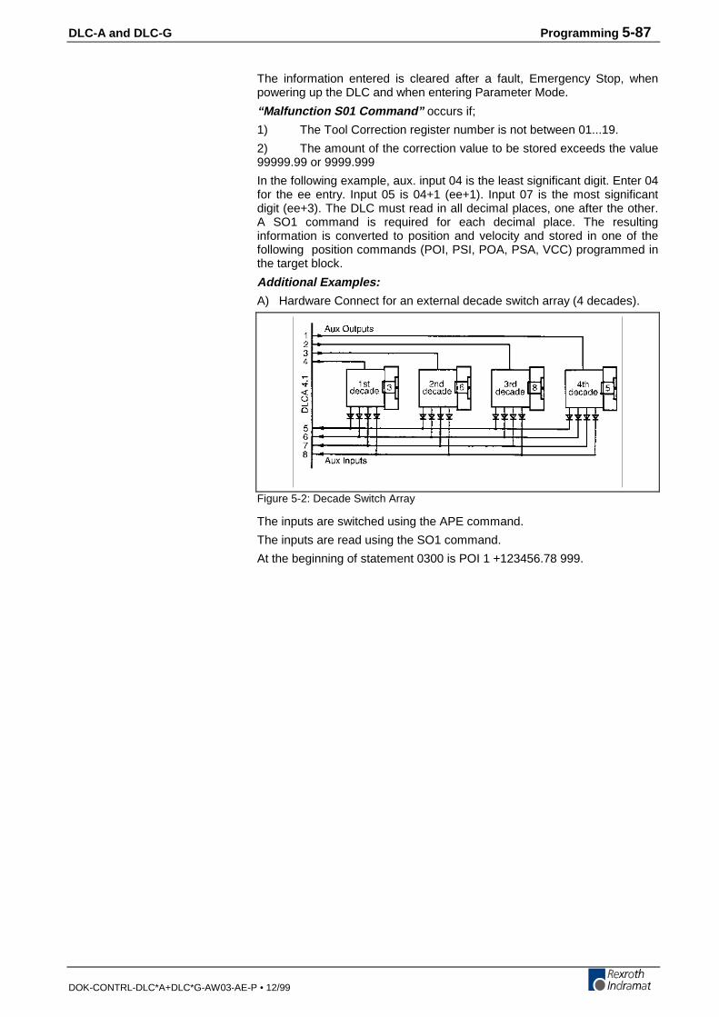
DLC-A and DLC-G Programming 5-87
DOK-CONTRL-DLC*A+DLC*G-AW03-AE-P • 12/99
The information entered is cleared after a fault, Emergency Stop, whenpowering up the DLC and when entering Parameter Mode.
“Malfunction S01 Command” occurs if;
1) The Tool Correction register number is not between 01...19.
2) The amount of the correction value to be stored exceeds the value99999.99 or 9999.999
In the following example, aux. input 04 is the least significant digit. Enter 04for the ee entry. Input 05 is 04+1 (ee+1). Input 07 is the most significantdigit (ee+3). The DLC must read in all decimal places, one after the other.A SO1 command is required for each decimal place. The resultinginformation is converted to position and velocity and stored in one of thefollowing position commands (POI, PSI, POA, PSA, VCC) programmed inthe target block.
Additional Examples:
A) Hardware Connect for an external decade switch array (4 decades).
Figure 5-2: Decade Switch Array
The inputs are switched using the APE command.
The inputs are read using the SO1 command.
At the beginning of statement 0300 is POI 1 +123456.78 999.
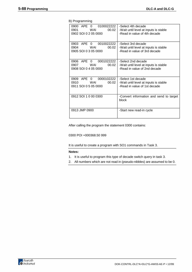
5-88 Programming DLC-A and DLC-G
DOK-CONTRL-DLC*A+DLC*G-AW03-AE-P • 12/99
B) Programming
0900 APE 0 01000222220901 WAI 00.020902 SOI 0 2 05 0000
-Select 4th decade-Wait until level at inputs is stable-Read in value of 4th decade
0903 APE 0 00100222220904 WAI 00.020905 SOI 0 3 05 0000
-Select 3rd decade-Wait until level at inputs is stable-Read in value of 3rd decade
0906 APE 0 00010222220907 WAI 00.020908 SOI 0 4 05 0000
-Select 2nd decade-Wait until level at inputs is stable-Read in value of 2nd decade
0909 APE 0 00001022220910 WAI 00.020911 SOI 0 5 05 0000
-Select 1st decade-Wait until level at inputs is stable-Read in value of 1st decade
0912 SOI 1 0 00 0300 -Convert information and send to targetblock
0913 JMP 0900 -Start new read-in cycle
After calling the program the statement 0300 contains:
0300 POI +000368.50 999
It is useful to create a program with SO1 commands in Task 3.
Notes:
1. It is useful to program this type of decade switch query in task 3.
2. All numbers which are not read in (pseudo-nibbles) are assumed to be 0.

DLC-A and DLC-G Programming 5-89
DOK-CONTRL-DLC*A+DLC*G-AW03-AE-P • 12/99
STH Send to Host
0 - Type of information
00 = Status 00, 02, 03, 05, 06, 07, 08, 09, 10, 19, 47, 48, 49, 50,51, 52, 53
1 = Counter status of preset and actual number of pieces. Theblock number of the counter must be entered in the status codefield.
0002 - Code for Status, options as below:0000 = Actual position of each axis 0041 = Registration Position (REF)
0002 = Current program blocknumber
0043 = Measuring Wheel
0003 = Actual position as ahexadecimal value
0046 = Length Counter
0005 = Software versiondescription
0047 = Actual RPM, MW
x006 = Current input state 0048 = Actual Motor RPM
x007 = Current output state 0050 = System I/O (Hexadecimal)
0008 = Current Block (Task 1, 2, 3) 0051 = Aux. Inputs (Hexadecimal)
0009 = Measuring Wheel 0052 = Aux. Outputs (Hexadecimal)
0010 = Following Error 0053 = DLC System Error
0018 = Servo Diagnostic
0019 = DLC Hardware / Software
Note: In x06 and x07, x = Input/output bank number, 0-9
Program-controlled data output via the serial interface (see Chapter 7).Stepping to the next block takes place immediately after the block hasbeen read in. Serial interface must have been activated throughparameters B003 and B004. Otherwise, stepping to the next block takesplace without having an output transmitted.
Examples of STH entry:0__0003______
Status `03' actual position of axis 1 and 2 in Hexadecimal, is transmitted toHost device via the serial interface.
1__1000______
Status of counter located in block 1000. The desired and actual number ofpieces, is transmitted to Host device via the serial interface.
E 0390 STH0 0019
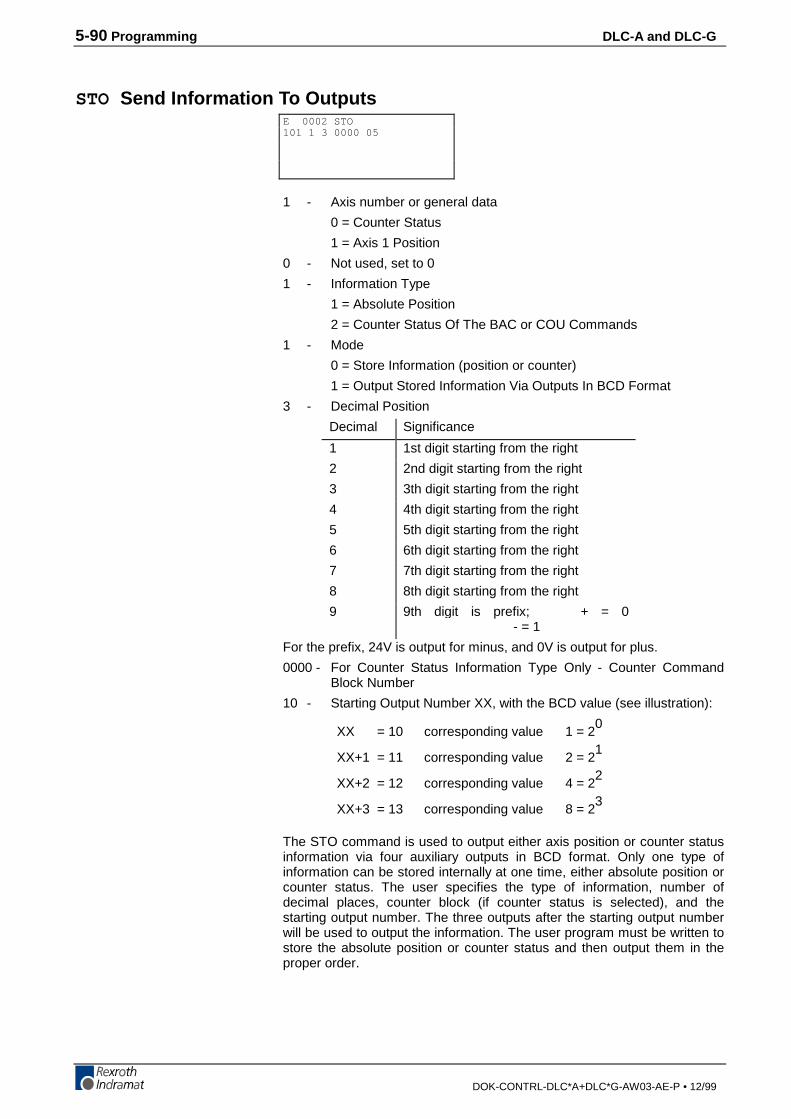
5-90 Programming DLC-A and DLC-G
DOK-CONTRL-DLC*A+DLC*G-AW03-AE-P • 12/99
STO Send Information To Outputs
1 - Axis number or general data
0 = Counter Status
1 = Axis 1 Position
0 - Not used, set to 0
1 - Information Type
1 = Absolute Position
2 = Counter Status Of The BAC or COU Commands
1 - Mode
0 = Store Information (position or counter)
1 = Output Stored Information Via Outputs In BCD Format
3 - Decimal Position
Decimal Significance
1 1st digit starting from the right
2 2nd digit starting from the right
3 3th digit starting from the right
4 4th digit starting from the right
5 5th digit starting from the right
6 6th digit starting from the right
7 7th digit starting from the right
8 8th digit starting from the right
9 9th digit is prefix; + = 0 - = 1
For the prefix, 24V is output for minus, and 0V is output for plus.
0000 - For Counter Status Information Type Only - Counter CommandBlock Number
10 - Starting Output Number XX, with the BCD value (see illustration):
XX = 10 corresponding value 1 = 20
XX+1 = 11 corresponding value 2 = 21
XX+2 = 12 corresponding value 4 = 22
XX+3 = 13 corresponding value 8 = 23
The STO command is used to output either axis position or counter statusinformation via four auxiliary outputs in BCD format. Only one type ofinformation can be stored internally at one time, either absolute position orcounter status. The user specifies the type of information, number ofdecimal places, counter block (if counter status is selected), and thestarting output number. The three outputs after the starting output numberwill be used to output the information. The user program must be written tostore the absolute position or counter status and then output them in theproper order.
E 0002 STO101 1 3 0000 05
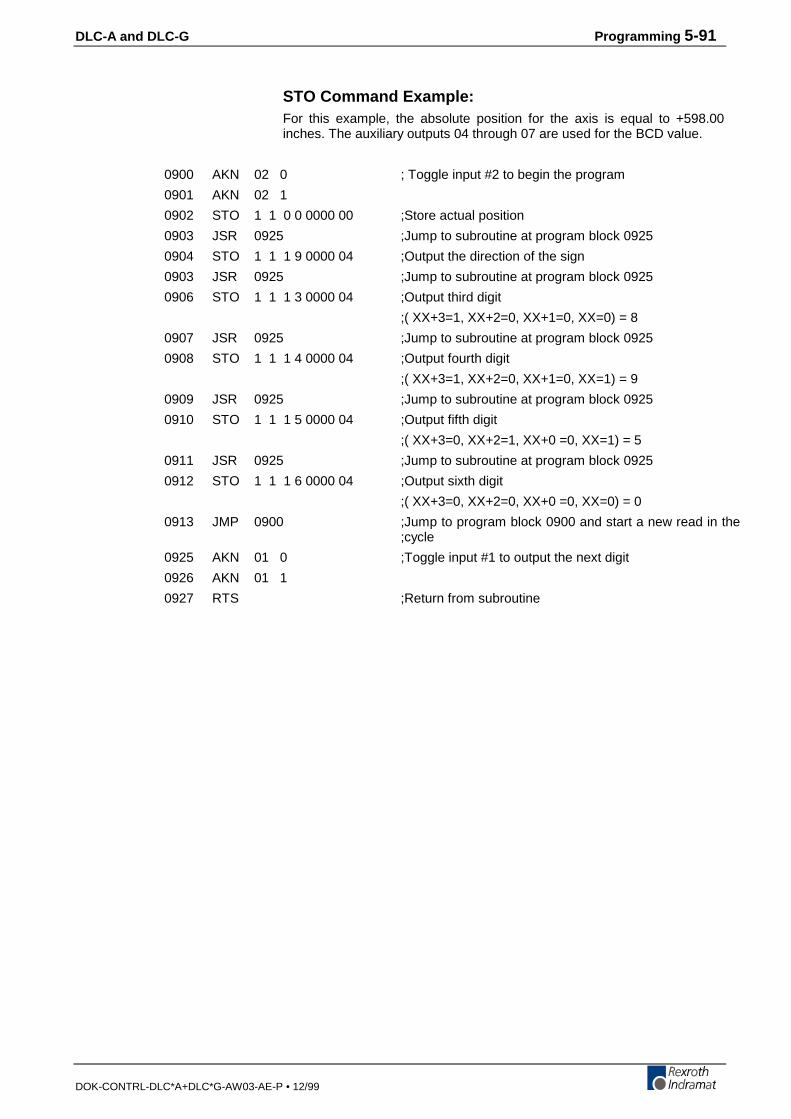
DLC-A and DLC-G Programming 5-91
DOK-CONTRL-DLC*A+DLC*G-AW03-AE-P • 12/99
STO Command Example:For this example, the absolute position for the axis is equal to +598.00inches. The auxiliary outputs 04 through 07 are used for the BCD value.
0900 AKN 02 0 ; Toggle input #2 to begin the program
0901 AKN 02 1
0902 STO 1 1 0 0 0000 00 ;Store actual position
0903 JSR 0925 ;Jump to subroutine at program block 0925
0904 STO 1 1 1 9 0000 04 ;Output the direction of the sign
0903 JSR 0925 ;Jump to subroutine at program block 0925
0906 STO 1 1 1 3 0000 04 ;Output third digit
;( XX+3=1, XX+2=0, XX+1=0, XX=0) = 8
0907 JSR 0925 ;Jump to subroutine at program block 0925
0908 STO 1 1 1 4 0000 04 ;Output fourth digit
;( XX+3=1, XX+2=0, XX+1=0, XX=1) = 9
0909 JSR 0925 ;Jump to subroutine at program block 0925
0910 STO 1 1 1 5 0000 04 ;Output fifth digit
;( XX+3=0, XX+2=1, XX+0 =0, XX=1) = 5
0911 JSR 0925 ;Jump to subroutine at program block 0925
0912 STO 1 1 1 6 0000 04 ;Output sixth digit
;( XX+3=0, XX+2=0, XX+0 =0, XX=0) = 0
0913 JMP 0900 ;Jump to program block 0900 and start a new read in the;cycle
0925 AKN 01 0 ;Toggle input #1 to output the next digit
0926 AKN 01 1
0927 RTS ;Return from subroutine

5-92 Programming DLC-A and DLC-G
DOK-CONTRL-DLC*A+DLC*G-AW03-AE-P • 12/99
VCA Velocity Change Absolute
1 - Axis 1
+12345.678 - Absolute position to be reached before the velocity change(to 2 or 3 decimal places, depending on the setting inB007)
999 - Speed in % (00.1 - 99.9) of the maximum velocity set inparameter (A100)
The VCA command is used to alter the current rate of velocity at somepoint along a path. Multiple VCA commands can be used to create a "step"effect in the velocity profile. Stepping to the next block takes place whenthe absolute position has been reached.
This function is designed to work in conjunction with the positioncommands POA, POI, and POM.
Example:0000 POA 1 +00100.000 999 ;Position axis to +100 inches at 99.9 % max.
0001 VCA 1 +00050.000 250 ;Velocity change at +50 inches to 25.0% max.
0002 VCA 1 +00075.000 500 ;Velocity change at +75 inches to 50.0% max.
0003 VCA 1 +00090.000 100 ;Velocity change at +90 inches to 10.0% max.
0004 ATS 15 1 ;Acknowledge axis is in-position (A106)
0005 WAI 01 . 00 ;Dwell for 1 second
0006 JST 0000 ;Jump and stop at program block 0000
E 0410 VCA1 +12345.678 999
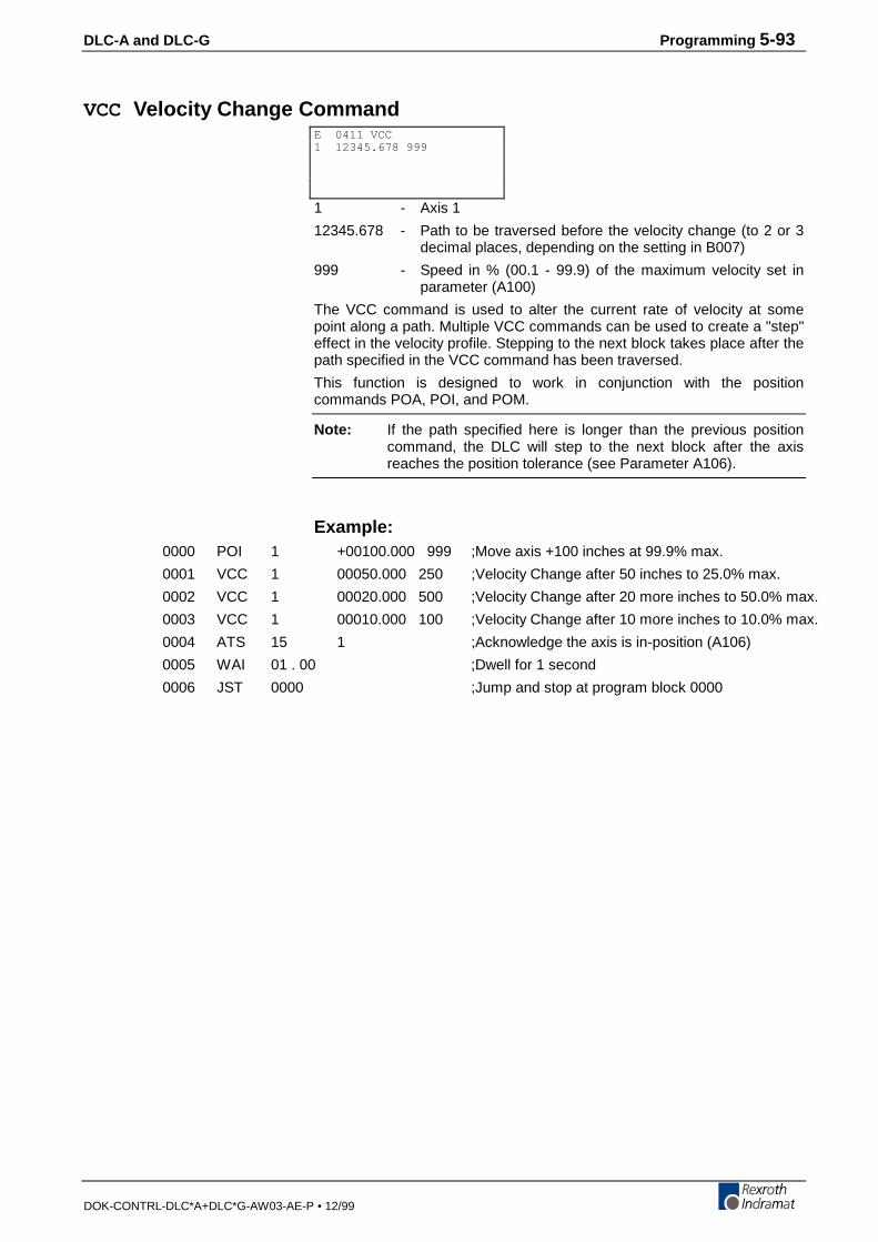
DLC-A and DLC-G Programming 5-93
DOK-CONTRL-DLC*A+DLC*G-AW03-AE-P • 12/99
VCC Velocity Change Command
1 - Axis 1
12345.678 - Path to be traversed before the velocity change (to 2 or 3decimal places, depending on the setting in B007)
999 - Speed in % (00.1 - 99.9) of the maximum velocity set inparameter (A100)
The VCC command is used to alter the current rate of velocity at somepoint along a path. Multiple VCC commands can be used to create a "step"effect in the velocity profile. Stepping to the next block takes place after thepath specified in the VCC command has been traversed.
This function is designed to work in conjunction with the positioncommands POA, POI, and POM.
Note: If the path specified here is longer than the previous positioncommand, the DLC will step to the next block after the axisreaches the position tolerance (see Parameter A106).
Example:0000 POI 1 +00100.000 999 ;Move axis +100 inches at 99.9% max.
0001 VCC 1 00050.000 250 ;Velocity Change after 50 inches to 25.0% max.
0002 VCC 1 00020.000 500 ;Velocity Change after 20 more inches to 50.0% max.
0003 VCC 1 00010.000 100 ;Velocity Change after 10 more inches to 10.0% max.
0004 ATS 15 1 ;Acknowledge the axis is in-position (A106)
0005 WAI 01 . 00 ;Dwell for 1 second
0006 JST 0000 ;Jump and stop at program block 0000
E 0411 VCC1 12345.678 999
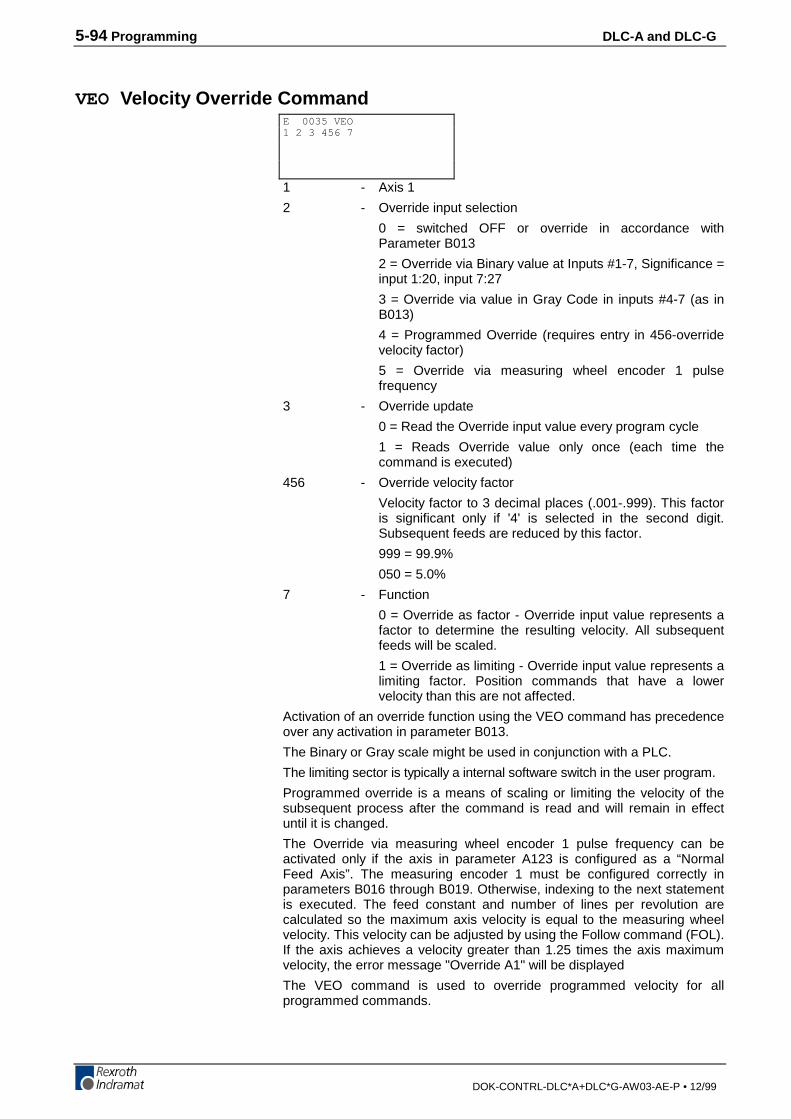
5-94 Programming DLC-A and DLC-G
DOK-CONTRL-DLC*A+DLC*G-AW03-AE-P • 12/99
VEO Velocity Override Command
1 - Axis 1
2 - Override input selection
0 = switched OFF or override in accordance withParameter B013
2 = Override via Binary value at Inputs #1-7, Significance =input 1:20, input 7:27
3 = Override via value in Gray Code in inputs #4-7 (as inB013)
4 = Programmed Override (requires entry in 456-overridevelocity factor)
5 = Override via measuring wheel encoder 1 pulsefrequency
3 - Override update
0 = Read the Override input value every program cycle
1 = Reads Override value only once (each time thecommand is executed)
456 - Override velocity factor
Velocity factor to 3 decimal places (.001-.999). This factoris significant only if '4' is selected in the second digit.Subsequent feeds are reduced by this factor.
999 = 99.9%
050 = 5.0%
7 - Function
0 = Override as factor - Override input value represents afactor to determine the resulting velocity. All subsequentfeeds will be scaled.
1 = Override as limiting - Override input value represents alimiting factor. Position commands that have a lowervelocity than this are not affected.
Activation of an override function using the VEO command has precedenceover any activation in parameter B013.
The Binary or Gray scale might be used in conjunction with a PLC.
The limiting sector is typically a internal software switch in the user program.
Programmed override is a means of scaling or limiting the velocity of thesubsequent process after the command is read and will remain in effectuntil it is changed.
The Override via measuring wheel encoder 1 pulse frequency can beactivated only if the axis in parameter A123 is configured as a “NormalFeed Axis”. The measuring encoder 1 must be configured correctly inparameters B016 through B019. Otherwise, indexing to the next statementis executed. The feed constant and number of lines per revolution arecalculated so the maximum axis velocity is equal to the measuring wheelvelocity. This velocity can be adjusted by using the Follow command (FOL).If the axis achieves a velocity greater than 1.25 times the axis maximumvelocity, the error message "Override A1" will be displayed
The VEO command is used to override programmed velocity for allprogrammed commands.
E 0035 VEO1 2 3 456 7
DLC-A and DLC-G Programming 5-95
DOK-CONTRL-DLC*A+DLC*G-AW03-AE-P • 12/99
1. With the function “Override as factor” the override velocity factor ismultiplied by the programmed speed of the commands.
2. With the function “Override as limiting” the override is multiplied by theprogrammed speed parameter Vmax (parameter A100). This multipliedvalue is then valid as the max. speed limit.
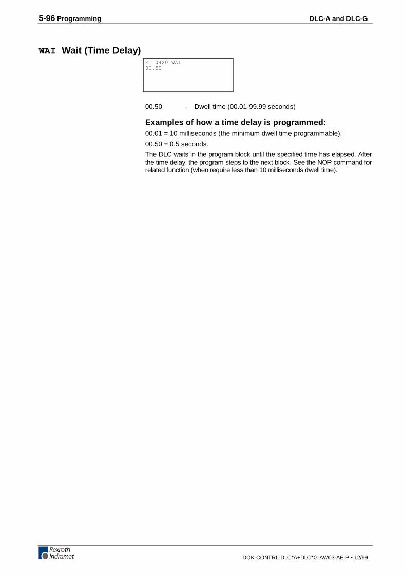
5-96 Programming DLC-A and DLC-G
DOK-CONTRL-DLC*A+DLC*G-AW03-AE-P • 12/99
WAI Wait (Time Delay)
00.50 - Dwell time (00.01-99.99 seconds)
Examples of how a time delay is programmed:00.01 = 10 milliseconds (the minimum dwell time programmable),
00.50 = 0.5 seconds.
The DLC waits in the program block until the specified time has elapsed. Afterthe time delay, the program steps to the next block. See the NOP command forrelated function (when require less than 10 milliseconds dwell time).
E 0420 WAI00.50
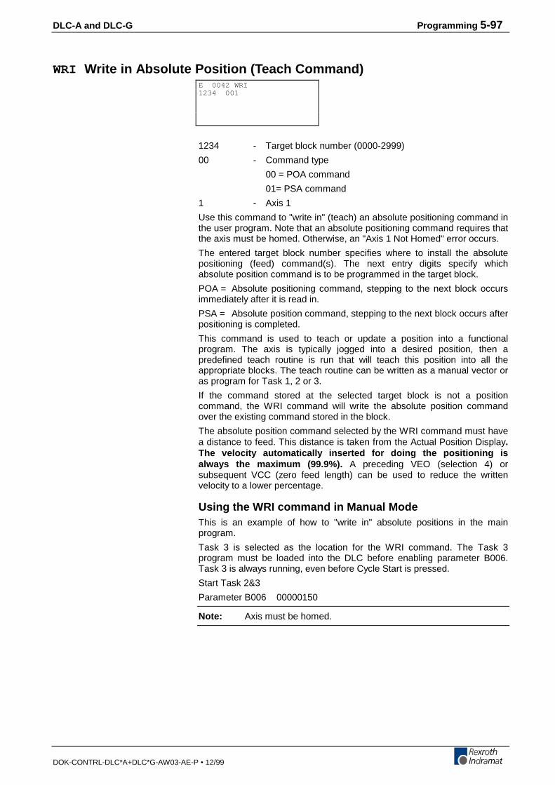
DLC-A and DLC-G Programming 5-97
DOK-CONTRL-DLC*A+DLC*G-AW03-AE-P • 12/99
WRI Write in Absolute Position (Teach Command)
1234 - Target block number (0000-2999)
00 - Command type
00 = POA command
01= PSA command
1 - Axis 1
Use this command to "write in" (teach) an absolute positioning command inthe user program. Note that an absolute positioning command requires thatthe axis must be homed. Otherwise, an "Axis 1 Not Homed" error occurs.
The entered target block number specifies where to install the absolutepositioning (feed) command(s). The next entry digits specify whichabsolute position command is to be programmed in the target block.
POA = Absolute positioning command, stepping to the next block occursimmediately after it is read in.
PSA = Absolute position command, stepping to the next block occurs afterpositioning is completed.
This command is used to teach or update a position into a functionalprogram. The axis is typically jogged into a desired position, then apredefined teach routine is run that will teach this position into all theappropriate blocks. The teach routine can be written as a manual vector oras program for Task 1, 2 or 3.
If the command stored at the selected target block is not a positioncommand, the WRI command will write the absolute position commandover the existing command stored in the block.
The absolute position command selected by the WRI command must havea distance to feed. This distance is taken from the Actual Position Display.The velocity automatically inserted for doing the positioning isalways the maximum (99.9%). A preceding VEO (selection 4) orsubsequent VCC (zero feed length) can be used to reduce the writtenvelocity to a lower percentage.
Using the WRI command in Manual ModeThis is an example of how to "write in" absolute positions in the mainprogram.
Task 3 is selected as the location for the WRI command. The Task 3program must be loaded into the DLC before enabling parameter B006.Task 3 is always running, even before Cycle Start is pressed.
Start Task 2&3
Parameter B006 00000150
Note: Axis must be homed.
E 0042 WRI1234 001
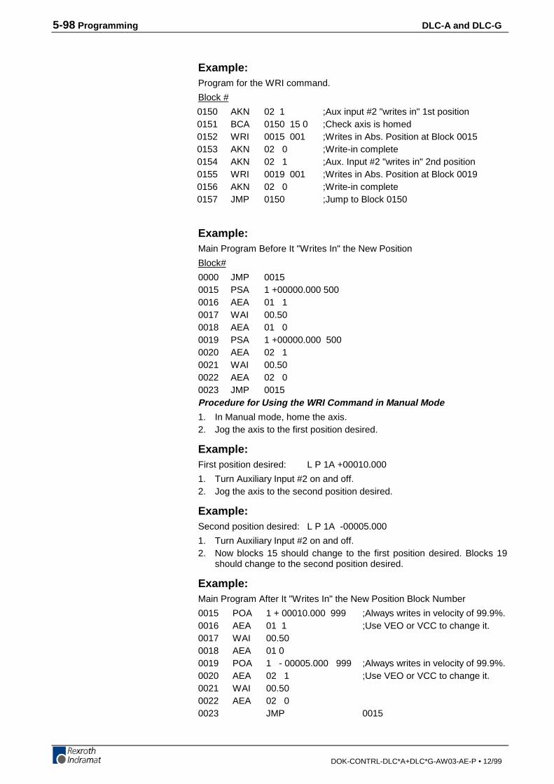
5-98 Programming DLC-A and DLC-G
DOK-CONTRL-DLC*A+DLC*G-AW03-AE-P • 12/99
Example:Program for the WRI command.
Block #
0150 AKN 02 1 ;Aux input #2 "writes in" 1st position0151 BCA 0150 15 0 ;Check axis is homed0152 WRI 0015 001 ;Writes in Abs. Position at Block 00150153 AKN 02 0 ;Write-in complete0154 AKN 02 1 ;Aux. Input #2 "writes in" 2nd position0155 WRI 0019 001 ;Writes in Abs. Position at Block 00190156 AKN 02 0 ;Write-in complete0157 JMP 0150 ;Jump to Block 0150
Example:Main Program Before It "Writes In" the New Position
Block#
0000 JMP 00150015 PSA 1 +00000.000 5000016 AEA 01 10017 WAI 00.500018 AEA 01 00019 PSA 1 +00000.000 5000020 AEA 02 10021 WAI 00.500022 AEA 02 00023 JMP 0015Procedure for Using the WRI Command in Manual Mode
1. In Manual mode, home the axis.2. Jog the axis to the first position desired.
Example:First position desired: L P 1A +00010.000
1. Turn Auxiliary Input #2 on and off.2. Jog the axis to the second position desired.
Example:Second position desired: L P 1A -00005.000
1. Turn Auxiliary Input #2 on and off.2. Now blocks 15 should change to the first position desired. Blocks 19
should change to the second position desired.
Example:Main Program After It "Writes In" the New Position Block Number
0015 POA 1 + 00010.000 999 ;Always writes in velocity of 99.9%.0016 AEA 01 1 ;Use VEO or VCC to change it.0017 WAI 00.500018 AEA 01 00019 POA 1 - 00005.000 999 ;Always writes in velocity of 99.9%.0020 AEA 02 1 ;Use VEO or VCC to change it.0021 WAI 00.500022 AEA 02 00023 JMP 0015
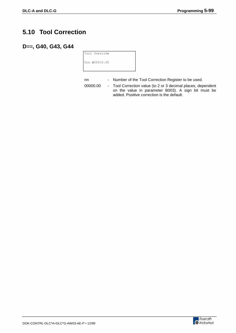
DLC-A and DLC-G Programming 5-99
DOK-CONTRL-DLC*A+DLC*G-AW03-AE-P • 12/99
5.10 Tool Correction
D==, G40, G43, G44
nn - Number of the Tool Correction Register to be used.
00000.00 - Tool Correction value (to 2 or 3 decimal places, dependenton the value in parameter B003). A sign bit must beadded. Positive correction is the default.
Tool Override
Dnn ±00010.00
5-100 Programming DLC-A and DLC-G
DOK-CONTRL-DLC*A+DLC*G-AW03-AE-P • 12/99
InputThe tool length correction consists of a tool correction memory with 19selectable Tool Correction registers, D01...D19. D00 is effective uponentering automatic operation and is active once the program is started.
Inputting of correction values is possible on-line through the CTA keyboardor through the serial interfaces. Tool Correction register values can beentered in manual and automatic mode. External Tool Correction datainput is also possible through parallel inputs using the SO1 command (seeChapter 5 for a complete description of the SO1 command).
It is possible to use the Tool Correction register for a variable memory,however, only one correction value can be selected and calculated perprogramming command.
Each correction value memory can accept a seven-digit correction value.The eighth digit is the mathematical operator (+/-).
The commands G43 and G44 enable the selected Tool Correction register.Its value is then added or subtracted from the destination programmedaccording to the mathematical operator (+/-).
Tool correction is disabled with the command G40 or by selecting theregister D00.
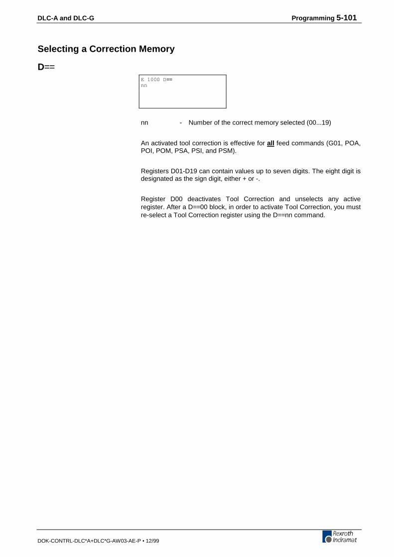
DLC-A and DLC-G Programming 5-101
DOK-CONTRL-DLC*A+DLC*G-AW03-AE-P • 12/99
Selecting a Correction Memory
D==
nn - Number of the correct memory selected (00...19)
An activated tool correction is effective for all feed commands (G01, POA,POI, POM, PSA, PSI, and PSM).
Registers D01-D19 can contain values up to seven digits. The eight digit isdesignated as the sign digit, either + or -.
Register D00 deactivates Tool Correction and unselects any activeregister. After a D==00 block, in order to activate Tool Correction, you mustre-select a Tool Correction register using the D==nn command.
E 1000 D ==nn
5-102 Programming DLC-A and DLC-G
DOK-CONTRL-DLC*A+DLC*G-AW03-AE-P • 12/99
Activating Tool Correction
G43 Tool Correction - Activated
Adds the contents of the active Tool Correction register to the programmeddestination. The sign of the value in the Tool Correction register isconsidered in this computation.
Example:If the value in the register is +1, this command will add +1 to theprogrammed destination. If the value is -1, this command will add -1 to theprogrammed destination.
G44 Tool Correction - Subtracted
Subtracts the contents of the active Tool Correction register to theprogrammed destination. The sign of the value in the Tool Correctionregister is considered in this computation.
Example:If the value in the register is +1, this command will subtract +1 to theprogrammed destination. If the value is -1, this command will subtract -1 tothe programmed destination (which means it will add 1 to the programmeddestination).
E 1000 G43
E 1000 G44

DLC-A and DLC-G Programming 5-103
DOK-CONTRL-DLC*A+DLC*G-AW03-AE-P • 12/99
Deactivating Tool CorrectionThere are two ways to deactivate a tool correction value:
• Select Tool Correction memory 00 with a D==00 command.
• Disable the Tool Correction function with the G40 command.
G40 Tool Correction Deactivated
This command disables Tool Correction within the process path in theprogrammed feed command.
G40 is effective upon entering automatic operation.
The register selected remains selected, even after deactivating the ToolCorrection with G40. If a G43 or G44 command is issued after a G40 isissued, the last selected Tool Correction register prior to the G40command will be used as the selected value.
External Tool CorrectionTool Correction registers can also be specified on-line using the SO1command. The SO1 command is used to read in information via decadeswitches or from a programmable controller.
E 1000 G40
5-104 Programming DLC-A and DLC-G
DOK-CONTRL-DLC*A+DLC*G-AW03-AE-P • 12/99
DLC-A and DLC-G Installation/Start-Up 6-1
DOK-CONTRL-DLC*A+DLC*G-AW03-AE-P • 12/99
6 Installation/Start-UpThis Chapter covers the installation and initial start up testing proceduresfor the DLC control system. The typical DLC Control system consists ofthe following components:
• DLC Control Module Card
• DEA 4.1 System/Auxiliary I/O card
• CTA Keypad & Display with remote mounting kit(Optional) andIKS745 cable
• Power Supply
• Digital AC Servo Drive
• MDD Digital AC Servo Motor
The instructions in this chapter primarily describe the installation of theDLC Control Module Card. The installation particulars of the othercomponents (such as a TVD, TVM or KDV power supply, the DDS DigitalAC Servo Drive, or DKS self-contained power supply and digital drivemodule) are explained in detail in their respective manuals.
Tools required:
• A small 1/8” blade, standard screwdriver
• A multimeter (VOM)
• An appropriate wrench for 1/4” machine type bolts (used for mountingmodule(s) to the cabinet.
• VT 100 terminal or PC with VT 100 terminal emulation software
• IN 391 Cable, PC to Indramat Digital AC Servo Drive
6.1 Mounting Cabinet
It is recommended the Amplifier and Power Supply be mounted in acabinet, side by side (see Figure 6.1). The enclosure should be sufficientto protect the equipment from contaminants, such as water, oil, etc.Indramat recommends a NEMA 4 or 12 enclosure or equivalent.
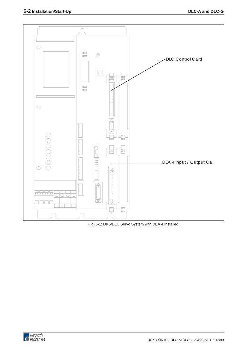
6-2 Installation/Start-Up DLC-A and DLC-G
DOK-CONTRL-DLC*A+DLC*G-AW03-AE-P • 12/99
DLC Control Card
DEA 4 Input / Output Car
Fig. 6-1: DKS/DLC Servo System with DEA 4 Installed
DLC-A and DLC-G Installation/Start-Up 6-3
DOK-CONTRL-DLC*A+DLC*G-AW03-AE-P • 12/99
6.2 Power
The DLC receives its power from the digital drive being used. Refer toseparate manuals (listed in Appendix B) for power requirements of theother modules (power supply, servo drive, etc.).
6.3 Cable Routing
For higher reliability, the high resolution feedback cables must be shieldedand routed away from high voltage power sources to reduce electricalnoise.
Do not route the cables near high amperage type machines, like weldingequipment, which produce strong magnetic field interference.
Suppress inductive loads (such as solenoids and motors) that areswitched ON and OFF during DLC system operation, with R-C networks(AC) or diodes (DC).
Correct grounding is essential for trouble free operation. The groundconnection must be made by observing strictly the branching conditionsshown in the wiring diagram.
1. Transformer - Heat Dissipation
The incoming 3-Phase power must be ground referenced. Use anisolation transformer with a "Y" secondary if this cannot be confirmed.Refer to TVD/TVM/KDV/DKS (or appropriate) manual for additionalinformation.
If a transformer is needed for operation, exercise caution on its location.Do not install the transformer in the same cabinet as the modules unlessa sufficient method of cooling is applied.
6.4 Hardware Installation
See Appendix D for mounting hole dimensions and location of the CTAkeypad and display module, the cut-out dimensions for the remotekeypad, keypad gasket and mounting holes and cut-out dimensions forthe optional IDS.
The mounting dimensions and cabinet cut-out data for the TVD/DDS orDKS are located in the units respective support manuals.
The method of mounting the MDD Digital AC servomotor is dependentupon the application. Additional information and a drawing package forthe MDD servomotor is available on request from Indramat.
6.5 Electrical Installation
There are many variations of wiring techniques used to connect the DEA4 System/Auxiliary I/O card to the machine builder's equipment. TheInterconnect Drawings supplied with this manual (see Appendix C) showan example of the connections to a typical machine.
6-4 Installation/Start-Up DLC-A and DLC-G
DOK-CONTRL-DLC*A+DLC*G-AW03-AE-P • 12/99
6.6 DLC/DEA 4.1 Connectors
This section describes the connectors on the DLC/DEA 4.1 plug-in cards.Refer to Figure 1.5 in Chapter 1 for an illustration of the DLC/DEA 4.1card and its connector locations in the DKS.
X17: DEA 4.1 System/Auxiliary Input/Output Cable (Cable 04-0123)
X30: CTA Keypad & Display
Female, 34 pin shielded ribbon cable connected to the front panel of theDLC. The cable is an IKS 745 and its standard length is 2 meters. Itconnects from the DLC to the back of the CTA. Refer to the DKS/DLCinterconnects in Appendix C for the proper orientation of the IKS 745cable.
X31: RS-232/485 Communications Port (Interface)
Female, DB 9 connector is located on the lower front panel of the DLC. Itis used for serial communication between the DLC and a host terminal,SOT or the IDS option. Refer to Chapter 7 for description of this multi-functional, two-way communications port.
6.7 Pre-Operation Start Up Tests
The following sections are intended to provide the user with an exampleof a DLC Digital AC Servo System start-up. They provide an example of asingle axis application that will verify proper function of the system.
WARNING: The information given in the following sections may not besuitable for a specific application. If you use this examplefor testing, do not mechanically connect the servomotor tothe actual load.
6.8 Connections
Note: Do not apply power until all connections have been made.Refer to the drawings in Appendixes C and D for mounting andconnection information
1. Install the TVD/DDS (Power Supply/Digital AC Servo Drive or DKS(Digital Compact Drive) per their respective support manuals.
2. Connect the MDD motor power cable and high resolution feedbackcable to the DDS or DKS per interconnect drawings in Appendix C, orrefer to the DDS or DKS support manuals.
3. Connect the optional CTA Keypad/Display to the DLC Connector X30via IKS 745 ribbon cable. Refer to the interconnect drawings inAppendix C.
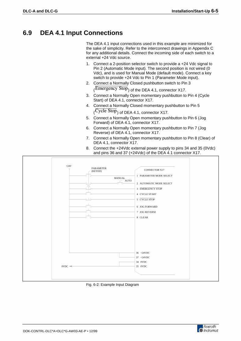
DLC-A and DLC-G Installation/Start-Up 6-5
DOK-CONTRL-DLC*A+DLC*G-AW03-AE-P • 12/99
6.9 DEA 4.1 Input Connections
The DEA 4.1 input connections used in this example are minimized forthe sake of simplicity. Refer to the interconnect drawings in Appendix Cfor any additional details. Connect the incoming side of each switch to aexternal +24 Vdc source.
1. Connect a 2-position selector switch to provide a +24 Vdc signal toPin 2 (Automatic Mode input). The second position is not wired (0Vdc), and is used for Manual Mode (default mode). Connect a keyswitch to provide +24 Vdc to Pin 1 (Parameter Mode input).
2. Connect a Normally Closed pushbutton switch to Pin 3
('OGTIGPE[�5VQR) of the DEA 4.1, connector X17.3. Connect a Normally Open momentary pushbutton to Pin 4 (Cycle
Start) of DEA 4.1, connector X17.4. Connect a Normally Closed momentary pushbutton to Pin 5
(%[ENG�5VQR ) of DEA 4.1, connector X17.5. Connect a Normally Open momentary pushbutton to Pin 6 (Jog
Forward) of DEA 4.1, connector X17.6. Connect a Normally Open momentary pushbutton to Pin 7 (Jog
Reverse) of DEA 4.1, connector X17.7. Connect a Normally Open momentary pushbutton to Pin 8 (Clear) of
DEA 4.1, connector X17.8. Connect the +24Vdc external power supply to pins 34 and 35 (0Vdc)
and pins 36 and 37 (+24Vdc) of the DEA 4.1 connector X17.
+24VPARAMETER(KEYED)
MANUALAUTO
0VDC
CONNECTOR X17
1 PARAMETER MODE SELECT
2 AUTOMATIC MODE SELECT
3 EMERGENCY STOP
4 CYCLE START
5 CYCLE STOP
6 JOG FORWARD
7 JOG REVERSE
8 CLEAR
36 +24VDC
37 +24VDC
34 0VDC
35 0VDC
Fig. 6-2: Example Input Diagram
6-6 Installation/Start-Up DLC-A and DLC-G
DOK-CONTRL-DLC*A+DLC*G-AW03-AE-P • 12/99
6.10 DEA 4.1 Output Connections
For the purpose of a sample start-up, the connections for the DEA 4.1outputs are not necessary. The ends of the unused wires in cable 04-0123 should be wrapped in electrical tape to prevent any damage to theoutputs. Refer to the interconnect drawings in Appendix C for properlyinterfacing the DEA 4.1 system /auxiliary outputs with the machine.
6.11 Power-Up
The system can now be powered up. All voltages should be checked by aqualified electrician to ensure proper signals and connections.
The digital drive being used has two 7 segment LEDs, H1, which displaysthe current operating status of the digital controller. If all connections arecorrect the H1 status will be "bb". If the diagnostic is not "bb", consult thedigital controller manual for information on how to correct the problem.
The CTA display should also display no errors. Consult Chapter 8,Diagnostics And Troubleshooting for more information on how to correctthe problem.
The DLC Digital Servo Systems is ready for drive & system parameters tobe installed.
6.12 Digital AC Servo Amplifier Parameter Entry
The Indramat Digital AC Servo Amplifier contains an RS232 interface,Connector X2. This interface gives you information regarding the status ofthe drive and allows you to read and adjust all the amplifier’s systemparameters. The RS232 interface provides screens and menus which areaccessible via a VT 100 terminal or a PC computer with a VT100emulator, (e.g. Procomm, Windows 3.1, etc.). The communicationsettings are as follows:
Baud Rate: 9600
Parity: None
Data Bits: 8
Stop Bits: 1
Connect the VT 100 terminal or PC with VT 100 terminal emulationsoftware to the Digital AC Servo Amplifier to connector X2 via an IN 391cable and press the <Enter> key. This will bring up the Main Menuscreen.
Note: Digital drive parameters can also be set with the CTA keypad.If using the keypad for drive parameter entry, skip this sectionand refer to Chapter 4.
Changing The Display LanguageIn order to change the language displayed on the screen, press thenumber 3 from the Main Menu.
German Text = Press the number 1
English Text = Press the number 2
After the selection, the Main Menu screen will be displayed.
DLC-A and DLC-G Installation/Start-Up 6-7
DOK-CONTRL-DLC*A+DLC*G-AW03-AE-P • 12/99
Main MenuThe Main Menu allows you to view the following information:
• Drive Status
• Parameters
• Language Selection
• ESC = Exit Program
In order for the DLC to operate properly, the Digital Amplifier’s parametersmust coincide with the parameters programmed in the DLC. To check oradjust the parameter currently in the amplifier, press number 2 from theMain Menu screen.
The Drive Parametrization screen will be displayed. Consult theamplifier’s manual for a description and the proper parameter values forthe amplifier/motor combination being used, press the letter “c” tocontinue.
The Parameter Menu screen will display the following selection list,application parameters, drive parameters, and parameter management.When setting up an Indramat Digital Amplifier with the DLC, theapplication and drive parameters must be set correctly.
Setting the Amplifier’s Parameters to Operate with the DLC Control Card1. Press the number 6, Motor & Drive Data.
This will display the current amplifier/motor combination. Look underthe Motor Parameters and make a note of the Maximum Velocity ofMotor (RPM). Press <ESC> to return to the Parameter Menu.
2. Press the number 1, Operation Mode Scaling.The Operation Mode allows the user to configure the followingamplifier parameters:• Analog Outputs
• Bipolar Velocity Limit Value
• Overload Factor
• Analog Output - Position Data Scaling
• Analog Output - Velocity Data Scaling
Analog OutputsThe Indramat Digital Amplifier has two analog outputs. AK1 (ConnectorX3, pin 1, referenced to OVm, pin 2) and AK2 (Connector X3, referencedto Ovm, pin 4). These outputs can be configured to output following items:
• Velocity Command Value
• Velocity Feedback Value
• Position Feedback Value
• Motor Encoder - Sine
• Motor Encoder - Cosine
• Current Command Value
Press the up or down arrow keys to position the cursor on the properchannel. Then press the left or right arrow keys to select the desiredoutput. Continue pressing until the desired output is selected.
6-8 Installation/Start-Up DLC-A and DLC-G
DOK-CONTRL-DLC*A+DLC*G-AW03-AE-P • 12/99
Bipolar Velocity Limit ValueThe Bipolar Velocity Limit Value sets the motor’s maximum velocity limitin the forward or reverse direction.
Position the cursor to the right of the Bipolar Velocity Limit Value and typein the desired velocity in revolutions per minute (RPM).
Note: The value entered should not exceed the maximum velocity ofthe motor. If an operating velocity of less than maximum isdesired, enter that value here.
Overload FactorThe Overload Factor is determined based on the desired intermittenttorque and duty cycle of the system. Consult the Indramat Digital AmplifierSelection List for the proper Overload Factor Value.
For the purpose of testing the DLC with the Indramat Amplifier, set theOverload Factor to 100%. Position the cursor to the right of the OverloadFactor and type 100, then hit enter.
Position Data Scaling at the Analog Output (Degrees/10V)When the position values are selected for either of the analog outputs, thePosition Data Scaling defines a zero to ten volt linear scaling based uponthe angle of the motor’s rotor position.
For example, if 360 degrees were entered, one revolution of the motorwould provide one linear voltage ramp from 0 to 10V.
Position the cursor to the right of the Position Data Scaling and type in thedesired degrees. Typically, 360 degrees is entered.
Velocity Data Scaling At The Analog Output (RPM/10V)When the velocity values are selected for either of the analog outputs, theVelocity Data Scaling defines a zero to ten volts linear scaling based uponthe velocity of the motor in RPM. For example, if the Bipolar Velocity Limitis 3000 RPM, then when the motor is operating at 1500 RPM, 5 volts willbe the output.
1. Position the cursor to the right of the Velocity Data Scaling and type inthe desired velocity per 10 Volts.Typically the value entered here is the same value entered in theBipolar Velocity Limit Value.
2. Press <ESC> to return to the Parameter Menu.The Absolute Encoder Parameters are automatically set by theamplifier.When power is applied, the amplifier reads the type of motorconnected and sets the Absolute Encoder Parameters based upon asingle or multi-turn feedback.
3. Press the number 3, error Reaction.There are three types of Error Reaction to select. The Error Reactionselected determines how the amplifier will react when a shutdownerror occurs. Typically 0 is selected as the Error Reaction.
4. Press <ESC> to return to Parameter Menu.The Torque Limits are currently not available.
5. Press the number 5, Gain Parameters.The Gain Parameters allow the user to adjust the velocity/current loopgains of the amplifier.
6. To set the amplifier/motor combination to standard values, position thecursor to Reset To Standard Parameters and press the <Enter> key.
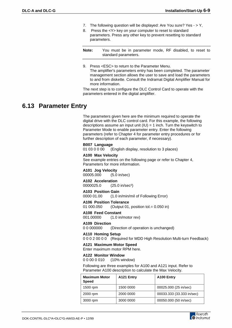
DLC-A and DLC-G Installation/Start-Up 6-9
DOK-CONTRL-DLC*A+DLC*G-AW03-AE-P • 12/99
7. The following question will be displayed: Are You sure? Yes - > Y,8. Press the <Y> key on your computer to reset to standard
parameters. Press any other key to prevent resetting to standardparameters.
Note: You must be in parameter mode, RF disabled, to reset tostandard parameters.
9. Press <ESC> to return to the Parameter Menu.The amplifier's parameters entry has been completed. The parametermanagement section allows the user to save and load the parametersto and from diskette. Consult the Indramat Digital Amplifier Manual formore information.
The next step is to configure the DLC Control Card to operate with theparameters entered in the digital amplifier.
6.13 Parameter Entry
The parameters given here are the minimum required to operate thedigital drive with the DLC control card. For this example, the followingdescriptions assume an input unit (IU) = 1 inch. Turn the keyswitch toParameter Mode to enable parameter entry. Enter the followingparameters (refer to Chapter 4 for parameter entry procedures or forfurther description of each parameter, if necessary).
B007 Language01 03 0 0 00 (English display, resolution to 3 places)
A100 Max VelocitySee example entries on the following page or refer to Chapter 4,Parameters for more information.
A101 Jog Velocity00005.000 (5.0 in/sec)
A102 Acceleration0000025.0 (25.0 in/sec²)
A103 Position Gain0000 01.00 (1.0 in/min/mil of Following Error)
A106 Position Tolerance01 000.050 (Output 01, position tol.= 0.050 in)
A108 Feed Constant001.00000 (1.0 in/motor rev)
A109 Direction0 0 000000 (Direction of operation is unchanged)
A110 Homing Setup0 0 0 2 00 0 0 (Required for MDD High Resolution Multi-turn Feedback)
A121 Maximum Motor SpeedEnter maximum motor RPM here.
A122 Monitor Window0 0 00 0 010 (10% window)
Following are three examples for A100 and A121 input. Refer toParameter A100 description to calculate the Max Velocity.
Maximum MotorSpeed
A121 Entry A100 Entry
1500 rpm 1500 0000 00025.000 (25 in/sec)
2000 rpm 2000 0000 00033.333 (33.333 in/sec)
3000 rpm 3000 0000 00050.000 (50 in/sec)
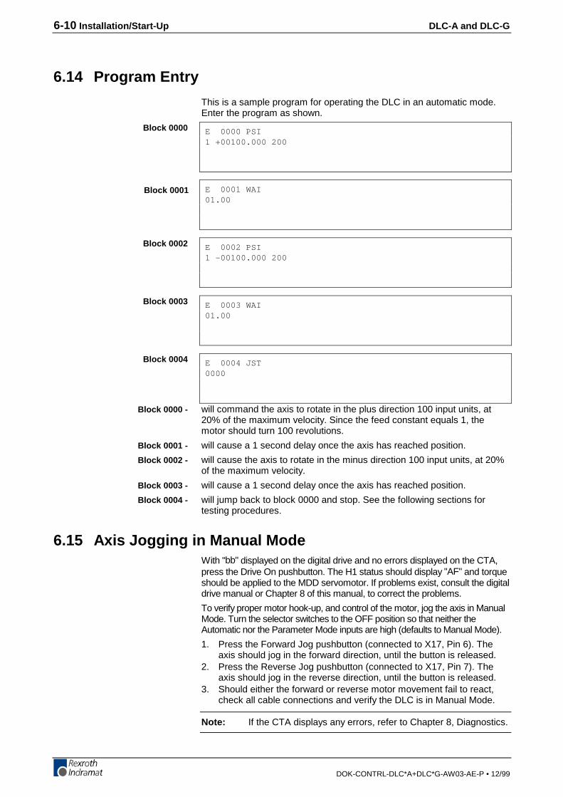
6-10 Installation/Start-Up DLC-A and DLC-G
DOK-CONTRL-DLC*A+DLC*G-AW03-AE-P • 12/99
6.14 Program Entry
This is a sample program for operating the DLC in an automatic mode.Enter the program as shown.
E 0000 PSI1 +00100.000 200
E 0001 WAI01.00
E 0002 PSI1 -00100.000 200
E 0003 WAI01.00
E 0004 JST0000
will command the axis to rotate in the plus direction 100 input units, at20% of the maximum velocity. Since the feed constant equals 1, themotor should turn 100 revolutions.
will cause a 1 second delay once the axis has reached position.
will cause the axis to rotate in the minus direction 100 input units, at 20%of the maximum velocity.
will cause a 1 second delay once the axis has reached position.
will jump back to block 0000 and stop. See the following sections fortesting procedures.
6.15 Axis Jogging in Manual ModeWith "bb" displayed on the digital drive and no errors displayed on the CTA,press the Drive On pushbutton. The H1 status should display "AF" and torqueshould be applied to the MDD servomotor. If problems exist, consult the digitaldrive manual or Chapter 8 of this manual, to correct the problems.
To verify proper motor hook-up, and control of the motor, jog the axis in ManualMode. Turn the selector switches to the OFF position so that neither theAutomatic nor the Parameter Mode inputs are high (defaults to Manual Mode).
1. Press the Forward Jog pushbutton (connected to X17, Pin 6). Theaxis should jog in the forward direction, until the button is released.
2. Press the Reverse Jog pushbutton (connected to X17, Pin 7). Theaxis should jog in the reverse direction, until the button is released.
3. Should either the forward or reverse motor movement fail to react,check all cable connections and verify the DLC is in Manual Mode.
Note: If the CTA displays any errors, refer to Chapter 8, Diagnostics.
Block 0000
Block 0001
Block 0002
Block 0003
Block 0004
Block 0000 -
Block 0001 -
Block 0002 -
Block 0003 -
Block 0004 -
DLC-A and DLC-G Installation/Start-Up 6-11
DOK-CONTRL-DLC*A+DLC*G-AW03-AE-P • 12/99
6.16 Automatic Mode Operation
To run the sample program and check Automatic Mode operation:
1. Turn the selector switch to Automatic Mode (wired to connector X17,Pin 2).
2. Press the Cycle Start pushbutton (connected to X17, Pin 4)
Note: The DLC will execute the sample program and stop after onecycle. Change block 0004 to JMP 0000 to run the cyclecontinuously.
3. Press the Cycle Stop pushbutton to stop operation. Press Cycle Startto restart the program.
Note: %[ENG�5VQR will cause an immediate stop without error.
'OGTIGPE[�5VQR will cause an immediate stop also, but willcause a fault to be displayed. De-actuate the E-stop switchand press the CL (clear) key on the CTA keypad to clear thefault, to allow restarting the operation.
6-12 Installation/Start-Up DLC-A and DLC-G
DOK-CONTRL-DLC*A+DLC*G-AW03-AE-P • 12/99

DLC-A and DLC-G Serial Interface 7-1
DOK-CONTRL-DLC*A+DLC*G-AW03-AE-P • 12/99
7 Serial InterfaceThe DLC Control Card includes a multi-format RS-232/485 port for two-way communication of programs, parameters and system status betweenthe DLC and a host device. The interface protocol is designed to easilytransmit and receive data to and from the DLC. This chapter describesthe protocol and other communication requirements.
The host device must strictly adhere to the communications format asdescribed in this chapter to achieve proper communication, or one ofseveral "RS Format Errors" will be returned through the port (or indicatedon the control status display, see Figure 2.2 for a map of displays)indicating that the information was not properly formatted or understood.
User programs (Block information) can be downloaded to the DLC when itis in any mode of operation (Auto, Manual, or Parameter). The same istrue for system status. System parameters can be downloaded to theDLC, only when it is in Parameter Mode. If attempted in any other mode,the host receives a "Invalid Mode" error message through the port.Parameters can be read from the DLC in any mode.
The optional Indramat program assembler software (MotionManager)allows you to write and edit user programs and parameter list on any DOSbased computer. You can download these into the DLC control throughthe serial interface. You can also upload the information from the DLCand make a print out of your program and parameter files.
The optional Indramat SOT (Station Operator Terminal) is a remotemounted, operator control device for the DLC. It is used to communicateprogram and parameter information between the DLC and SOT. Thesoftware in the SOT includes Help screens to assist the operator in usingthe SOT and for entering information correctly. The Indramat command lineeditor (Screen Manager), is used to write information and prompt lines forthe operator that will appear on the SOT display (16 lines, 40 characterseach). Contact Indramat for additional information on these options.
7.1 Connector Wiring (DB-9)
The serial interface connector (standard DB 9), is the X31 connector,located on the front of the DLC Control Card.
Refer to Figure 7.1 for a pin-out diagram of the multi-function port (X31connector). It shows the pin numbers and definitions of signal connectionsfor each type of communication.
Fig. 7-1: DLC X31 Connector
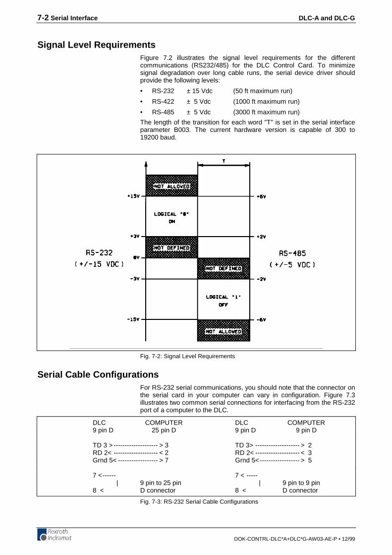
7-2 Serial Interface DLC-A and DLC-G
DOK-CONTRL-DLC*A+DLC*G-AW03-AE-P • 12/99
Signal Level RequirementsFigure 7.2 illustrates the signal level requirements for the differentcommunications (RS232/485) for the DLC Control Card. To minimizesignal degradation over long cable runs, the serial device driver shouldprovide the following levels:
• RS-232 ± 15 Vdc (50 ft maximum run)
• RS-422 ± 5 Vdc (1000 ft maximum run)
• RS-485 ± 5 Vdc (3000 ft maximum run)
The length of the transition for each word "T" is set in the serial interfaceparameter B003. The current hardware version is capable of 300 to19200 baud.
Fig. 7-2: Signal Level Requirements
Serial Cable ConfigurationsFor RS-232 serial communications, you should note that the connector onthe serial card in your computer can vary in configuration. Figure 7.3illustrates two common serial connections for interfacing from the RS-232port of a computer to the DLC.
DLC COMPUTER DLC COMPUTER9 pin D 25 pin D 9 pin D 9 pin D
TD 3 > -------------------- > 3 TD 3> -------------------- > 2RD 2< -------------------- < 2 RD 2< -------------------- < 3Grnd 5< ------------------ > 7 Grnd 5<------------------ > 5
7 <------ 7 < -----| 9 pin to 25 pin | 9 pin to 9 pin
8 < D connector 8 < D connector
Fig. 7-3: RS-232 Serial Cable Configurations

DLC-A and DLC-G Serial Interface 7-3
DOK-CONTRL-DLC*A+DLC*G-AW03-AE-P • 12/99
The DLC requires only three lines of the standard 9-pin connector for RS-232 communication. Pin 3 is for Transmitted Data, pin 2 for ReceivedData, and pin 5 is the Data Signal Ground. Typically, pin 1 connects thecable shield to ground on one end only. The transmit data connectionfrom one device connects to the receive data of the other device, and viceversa. Signal ground connection must be common on both devices. Pins7 and 8 are jumped on the DLC side only. Consult the manufacturersinformation for the serial card in your computer for its specific pinconfiguration. Indramat can supply a standard serial cable (cable # 05-0046) to connect from 9 pin PC to 9 pin DLC card. You may prefer to buythe required connectors and wire the cable in-house. Note that most serialcards do not provide a signal strong enough to go through a cable longerthan about 50 feet. When possible, use a shielded cable no more than25-50 feet long. Only connect the pins shown in this figure. Wiresconnected on any pins other than the ones shown may causecommunications errors.
7.2 Data Format
To achieve proper communications, configure the communicationparameters (B003 and B004) to match between your computer and theDLC. Figure 7.4 illustrates the data format. Following sections describeeach parameter for data communication. Section 7.5 further describes theChecksum options of parameter B004.
Fig. 7-4: Data Format
Word LengthThe word length is set in parameter B003 (see Chapter 4 for entryprocedures).
• 7 = 7 bit word length• 8 = 8 bit word length
Parity CheckThe parity type is set in parameter B003 (see Chapter 4 for entryprocedures).
• 1 = no parity• 2 = even parity• 3 = odd parity

7-4 Serial Interface DLC-A and DLC-G
DOK-CONTRL-DLC*A+DLC*G-AW03-AE-P • 12/99
Baud RateThe baud rate is set in parameter B003 (see Chapter 4 for entryprocedures).
You may choose any baud rate from among the following values:
Parameter Entry Baud Rate
0030 0300
0060 0600
0120 1200
0240 2400
0320 3200
0480 4800
0640 6400
0960 9600
1920 19200
Interface ModeThe interface mode is set in parameter B003 (see Chapter 4 for entryprocedures).
You may choose from among the following:
0 Standard RS232 (Full Duplex)
1 IDS, decade switch option
2 Same as Mode 0
3 Serial port for SOT (Station Operator Terminal);RS-232 half duplex, one station ONLY
4 Serial bus for SOT; RS-485, half duplex, station 1 through 32entered in parameter B004
7.3 DLC Control String Protocol
The following sections describe each control character requirements forproper protocol.
First (1) Control String Character (Transmission Type)All data transmissions to the DLC must start with one of the followingcontrol characters to identify what type of transmission is to follow:
? Hexadecimal 3FThe DLC interprets this character (received via the RxD channel)as a "Request for Information" - when followed by the properrequesting codes, the DLC will transmit the desired data via theTxD channel.
# Hexadecimal 23This character signifies a block of "Information to be Stored" intomemory. The data that follows will be read into the propermemory location.
! Hexadecimal 21This character signifies a "System Parameter" or "ControlCommand" is to follow.
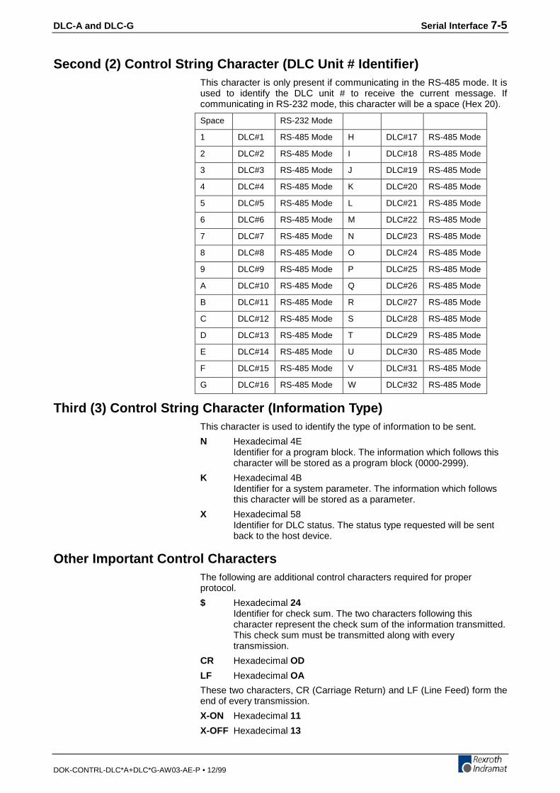
DLC-A and DLC-G Serial Interface 7-5
DOK-CONTRL-DLC*A+DLC*G-AW03-AE-P • 12/99
Second (2) Control String Character (DLC Unit # Identifier)This character is only present if communicating in the RS-485 mode. It isused to identify the DLC unit # to receive the current message. Ifcommunicating in RS-232 mode, this character will be a space (Hex 20).
Space RS-232 Mode
1 DLC#1 RS-485 Mode H DLC#17 RS-485 Mode
2 DLC#2 RS-485 Mode I DLC#18 RS-485 Mode
3 DLC#3 RS-485 Mode J DLC#19 RS-485 Mode
4 DLC#4 RS-485 Mode K DLC#20 RS-485 Mode
5 DLC#5 RS-485 Mode L DLC#21 RS-485 Mode
6 DLC#6 RS-485 Mode M DLC#22 RS-485 Mode
7 DLC#7 RS-485 Mode N DLC#23 RS-485 Mode
8 DLC#8 RS-485 Mode O DLC#24 RS-485 Mode
9 DLC#9 RS-485 Mode P DLC#25 RS-485 Mode
A DLC#10 RS-485 Mode Q DLC#26 RS-485 Mode
B DLC#11 RS-485 Mode R DLC#27 RS-485 Mode
C DLC#12 RS-485 Mode S DLC#28 RS-485 Mode
D DLC#13 RS-485 Mode T DLC#29 RS-485 Mode
E DLC#14 RS-485 Mode U DLC#30 RS-485 Mode
F DLC#15 RS-485 Mode V DLC#31 RS-485 Mode
G DLC#16 RS-485 Mode W DLC#32 RS-485 Mode
Third (3) Control String Character (Information Type)This character is used to identify the type of information to be sent.
N Hexadecimal 4EIdentifier for a program block. The information which follows thischaracter will be stored as a program block (0000-2999).
K Hexadecimal 4BIdentifier for a system parameter. The information which followsthis character will be stored as a parameter.
X Hexadecimal 58Identifier for DLC status. The status type requested will be sentback to the host device.
Other Important Control CharactersThe following are additional control characters required for properprotocol.
$ Hexadecimal 24Identifier for check sum. The two characters following thischaracter represent the check sum of the information transmitted.This check sum must be transmitted along with everytransmission.
CR Hexadecimal OD
LF Hexadecimal OA
These two characters, CR (Carriage Return) and LF (Line Feed) form theend of every transmission.
X-ON Hexadecimal 11
X-OFF Hexadecimal 13
7-6 Serial Interface DLC-A and DLC-G
DOK-CONTRL-DLC*A+DLC*G-AW03-AE-P • 12/99
Serial transmission can be controlled using handshaking.
• If the DLC is sending data via the TxD channel and receives the "X-OFF" signal (Hexadecimal 13/ASCII DC3) via the RxD channel, theDLC will interrupt the transmission until the "X-ON" signal(Hexadecimal 11/ASCII DC1) is received again via the RxD channel.
• If the DLC is receiving data via the RxD channel, and an interruptionof the data transmission becomes necessary, the DLC will send the"X-OFF" signal (Hexadecimal 13/ASCII DC3) via the TxD channel.When the transmission can be resumed, the DLC will send the "X-ON"signal (Hexadecimal 11/ASCII DC1) via the TxD channel.
7.4 Information Characters
All information characters are coded in hexadecimal. The followingcharacters are used for exchange of information:
0
through
9
Hexadecimal 30
through
Hexadecimal 39
A
through
Z
Hexadecimal 41
through
Hexadecimal 5A
Used as command codes for the DLC, depending on programming,
A - Z must be uppercase.
_ (space) Hexadecimal 20
For creating the desired format, the space-character is used.
Note: This chapter indicates a space with the underline character.
+ Hexadecimal 2B
- Hexadecimal 2D
The operational sign must be transmitted for position command blocks
. Hexadecimal 2E
, Hexadecimal 2C
Used in data fields, depends on Language selected if responds withperiod (.) or comma (,). The DLC treats both the same.
7.5 CHECKSUM Calculations
If checksum is enabled in parameter B004, the following example showshow it would be calculated. After all characters are added together, theHigh-byte is added to the Low-byte, then the compliment of the two istaken. This number should immediately follow the "$" character.
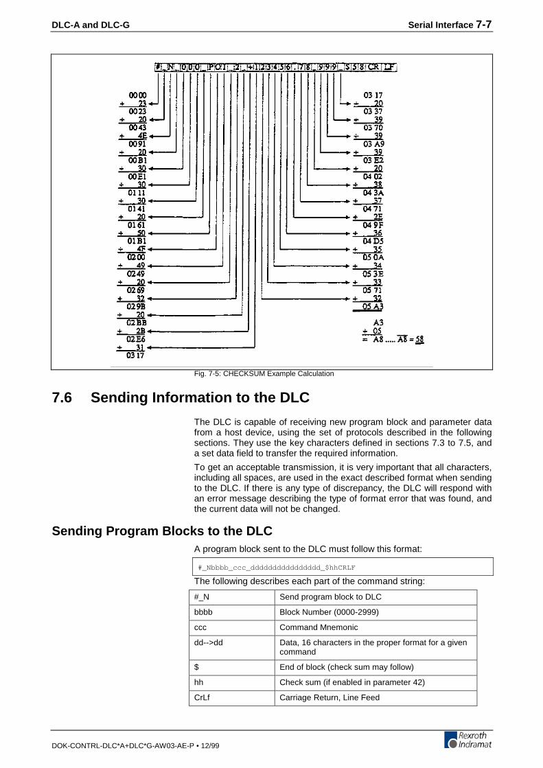
DLC-A and DLC-G Serial Interface 7-7
DOK-CONTRL-DLC*A+DLC*G-AW03-AE-P • 12/99
Fig. 7-5: CHECKSUM Example Calculation
7.6 Sending Information to the DLC
The DLC is capable of receiving new program block and parameter datafrom a host device, using the set of protocols described in the followingsections. They use the key characters defined in sections 7.3 to 7.5, anda set data field to transfer the required information.
To get an acceptable transmission, it is very important that all characters,including all spaces, are used in the exact described format when sendingto the DLC. If there is any type of discrepancy, the DLC will respond withan error message describing the type of format error that was found, andthe current data will not be changed.
Sending Program Blocks to the DLCA program block sent to the DLC must follow this format:
#_Nbbbb_ccc_dddddddddddddddd_$hhCRLF
The following describes each part of the command string:
#_N Send program block to DLC
bbbb Block Number (0000-2999)
ccc Command Mnemonic
dd-->dd Data, 16 characters in the proper format for a givencommand
$ End of block (check sum may follow)
hh Check sum (if enabled in parameter 42)
CrLf Carriage Return, Line Feed
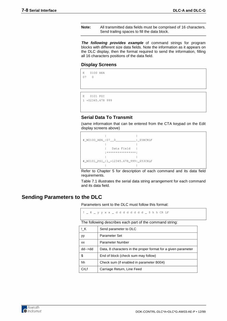
7-8 Serial Interface DLC-A and DLC-G
DOK-CONTRL-DLC*A+DLC*G-AW03-AE-P • 12/99
Note: All transmitted data fields must be comprised of 16 characters.Send trailing spaces to fill the data block.
The following provides example of command strings for programblocks with different size data fields. Note the information as it appears onthe DLC display, then the format required to send the information, fillingall 16 characters positions of the data field.
Display Screens
E 0100 AEA
07 0
E 0101 PSI
1 +02345.678 999
Serial Data To Transmit(same information that can be entered from the CTA keypad on the Editdisplay screens above)
| |
#_N0100_AEA_|07__0___________|_$5BCRLF
| |
| Data Field |
|****************|
| |
#_N0101_PSI_|1_+12345.678_999|_$53CRLF
| |
Refer to Chapter 5 for description of each command and its data fieldrequirements.
Table 7.1 illustrates the serial data string arrangement for each commandand its data field.
Sending Parameters to the DLCParameters sent to the DLC must follow this format:
! _ K _ y y x x _ d d d d d d d d _ $ h h CR LF
The following describes each part of the command string:
!_K Send parameter to DLC
yy Parameter Set
xx Parameter Number
dd-->dd Data, 8 characters in the proper format for a given parameter
$ End of block (check sum may follow)
hh Check sum (if enabled in parameter B004)
CrLf Carriage Return, Line Feed
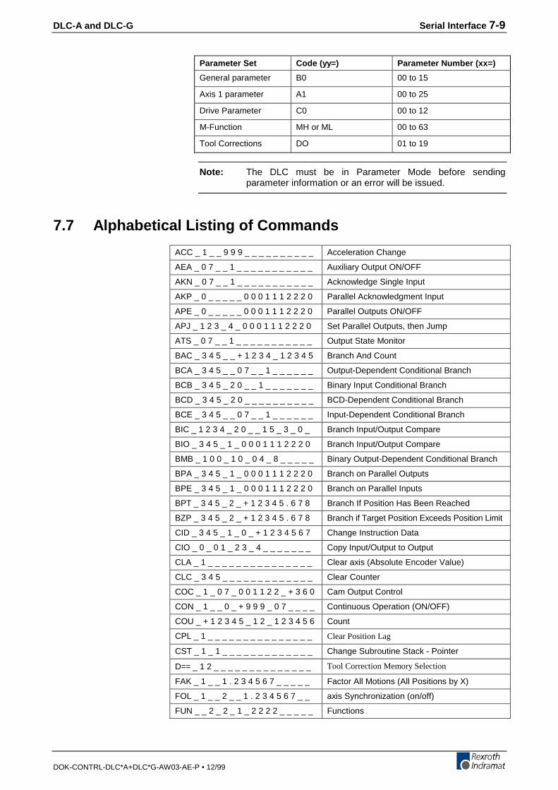
DLC-A and DLC-G Serial Interface 7-9
DOK-CONTRL-DLC*A+DLC*G-AW03-AE-P • 12/99
Parameter Set Code (yy=) Parameter Number (xx=)
General parameter B0 00 to 15
Axis 1 parameter A1 00 to 25
Drive Parameter C0 00 to 12
M-Function MH or ML 00 to 63
Tool Corrections DO 01 to 19
Note: The DLC must be in Parameter Mode before sendingparameter information or an error will be issued.
7.7 Alphabetical Listing of Commands
ACC _ 1 _ _ 9 9 9 _ _ _ _ _ _ _ _ _ _ Acceleration Change
AEA _ 0 7 _ _ 1 _ _ _ _ _ _ _ _ _ _ _ Auxiliary Output ON/OFF
AKN _ 0 7 _ _ 1 _ _ _ _ _ _ _ _ _ _ _ Acknowledge Single Input
AKP _ 0 _ _ _ _ _ 0 0 0 1 1 1 2 2 2 0 Parallel Acknowledgment Input
APE _ 0 _ _ _ _ _ 0 0 0 1 1 1 2 2 2 0 Parallel Outputs ON/OFF
APJ _ 1 2 3 _ 4 _ 0 0 0 1 1 1 2 2 2 0 Set Parallel Outputs, then Jump
ATS _ 0 7 _ _ 1 _ _ _ _ _ _ _ _ _ _ _ Output State Monitor
BAC _ 3 4 5 _ _ + 1 2 3 4 _ 1 2 3 4 5 Branch And Count
BCA _ 3 4 5 _ _ 0 7 _ _ 1 _ _ _ _ _ _ Output-Dependent Conditional Branch
BCB _ 3 4 5 _ 2 0 _ _ 1 _ _ _ _ _ _ _ Binary Input Conditional Branch
BCD _ 3 4 5 _ 2 0 _ _ _ _ _ _ _ _ _ _ BCD-Dependent Conditional Branch
BCE _ 3 4 5 _ _ 0 7 _ _ 1 _ _ _ _ _ _ Input-Dependent Conditional Branch
BIC _ 1 2 3 4 _ 2 0 _ _ 1 5 _ 3 _ 0 _ Branch Input/Output Compare
BIO _ 3 4 5 _ 1 _ 0 0 0 1 1 1 2 2 2 0 Branch Input/Output Compare
BMB _ 1 0 0 _ 1 0 _ 0 4 _ 8 _ _ _ _ _ Binary Output-Dependent Conditional Branch
BPA _ 3 4 5 _ 1 _ 0 0 0 1 1 1 2 2 2 0 Branch on Parallel Outputs
BPE _ 3 4 5 _ 1 _ 0 0 0 1 1 1 2 2 2 0 Branch on Parallel Inputs
BPT _ 3 4 5 _ 2 _ + 1 2 3 4 5 . 6 7 8 Branch If Position Has Been Reached
BZP _ 3 4 5 _ 2 _ + 1 2 3 4 5 . 6 7 8 Branch if Target Position Exceeds Position Limit
CID _ 3 4 5 _ 1 _ 0 _ + 1 2 3 4 5 6 7 Change Instruction Data
CIO _ 0 _ 0 1 _ 2 3 _ 4 _ _ _ _ _ _ _ Copy Input/Output to Output
CLA _ 1 _ _ _ _ _ _ _ _ _ _ _ _ _ _ _ Clear axis (Absolute Encoder Value)
CLC _ 3 4 5 _ _ _ _ _ _ _ _ _ _ _ _ _ Clear Counter
COC _ 1 _ 0 7 _ 0 0 1 1 2 2 _ + 3 6 0 Cam Output Control
CON _ 1 _ _ 0 _ + 9 9 9 _ 0 7 _ _ _ _ Continuous Operation (ON/OFF)
COU _ + 1 2 3 4 5 _ 1 2 _ 1 2 3 4 5 6 Count
CPL _ 1 _ _ _ _ _ _ _ _ _ _ _ _ _ _ _ Clear Position Lag
CST _ 1 _ 1 _ _ _ _ _ _ _ _ _ _ _ _ _ Change Subroutine Stack - Pointer
D== _ 1 2 _ _ _ _ _ _ _ _ _ _ _ _ _ _ Tool Correction Memory Selection
FAK _ 1 _ _ 1 . 2 3 4 5 6 7 _ _ _ _ _ Factor All Motions (All Positions by X)
FOL _ 1 _ _ 2 _ _ 1 . 2 3 4 5 6 7 _ _ axis Synchronization (on/off)
FUN _ _ 2 _ 2 _ 1 _ 2 2 2 2 _ _ _ _ _ Functions
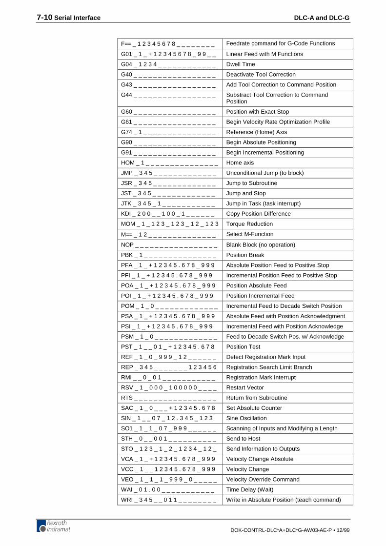
7-10 Serial Interface DLC-A and DLC-G
DOK-CONTRL-DLC*A+DLC*G-AW03-AE-P • 12/99
F== _ 1 2 3 4 5 6 7 8 _ _ _ _ _ _ _ _ Feedrate command for G-Code Functions
G01 _ 1 _ + 1 2 3 4 5 6 7 8 _ 9 9 _ _ Linear Feed with M Functions
G04 _ 1 2 3 4 _ _ _ _ _ _ _ _ _ _ _ _ Dwell Time
G40 _ _ _ _ _ _ _ _ _ _ _ _ _ _ _ _ _ Deactivate Tool Correction
G43 _ _ _ _ _ _ _ _ _ _ _ _ _ _ _ _ _ Add Tool Correction to Command Position
G44 _ _ _ _ _ _ _ _ _ _ _ _ _ _ _ _ _ Substract Tool Correction to CommandPosition
G60 _ _ _ _ _ _ _ _ _ _ _ _ _ _ _ _ _ Position with Exact Stop
G61 _ _ _ _ _ _ _ _ _ _ _ _ _ _ _ _ _ Begin Velocity Rate Optimization Profile
G74 _ 1 _ _ _ _ _ _ _ _ _ _ _ _ _ _ _ Reference (Home) Axis
G90 _ _ _ _ _ _ _ _ _ _ _ _ _ _ _ _ _ Begin Absolute Positioning
G91 _ _ _ _ _ _ _ _ _ _ _ _ _ _ _ _ _ Begin Incremental Positioning
HOM _ 1 _ _ _ _ _ _ _ _ _ _ _ _ _ _ _ Home axis
JMP _ 3 4 5 _ _ _ _ _ _ _ _ _ _ _ _ _ Unconditional Jump (to block)
JSR _ 3 4 5 _ _ _ _ _ _ _ _ _ _ _ _ _ Jump to Subroutine
JST _ 3 4 5 _ _ _ _ _ _ _ _ _ _ _ _ _ Jump and Stop
JTK _ 3 4 5 _ 1 _ _ _ _ _ _ _ _ _ _ _ Jump in Task (task interrupt)
KDI _ 2 0 0 _ _ 1 0 0 _ 1 _ _ _ _ _ _ Copy Position Difference
MOM _ 1 _ 1 2 3 _ 1 2 3 _ 1 2 _ 1 2 3 Torque Reduction
M== _ 1 2 _ _ _ _ _ _ _ _ _ _ _ _ _ _ Select M-Function
NOP _ _ _ _ _ _ _ _ _ _ _ _ _ _ _ _ _ Blank Block (no operation)
PBK _ 1 _ _ _ _ _ _ _ _ _ _ _ _ _ _ _ Position Break
PFA _ 1 _ + 1 2 3 4 5 . 6 7 8 _ 9 9 9 Absolute Position Feed to Positive Stop
PFI _ 1 _ + 1 2 3 4 5 . 6 7 8 _ 9 9 9 Incremental Position Feed to Positive Stop
POA _ 1 _ + 1 2 3 4 5 . 6 7 8 _ 9 9 9 Position Absolute Feed
POI _ 1 _ + 1 2 3 4 5 . 6 7 8 _ 9 9 9 Position Incremental Feed
POM _ 1 _ 0 _ _ _ _ _ _ _ _ _ _ _ _ _ Incremental Feed to Decade Switch Position
PSA _ 1 _ + 1 2 3 4 5 . 6 7 8 _ 9 9 9 Absolute Feed with Position Acknowledgment
PSI _ 1 _ + 1 2 3 4 5 . 6 7 8 _ 9 9 9 Incremental Feed with Position Acknowledge
PSM _ 1 _ 0 _ _ _ _ _ _ _ _ _ _ _ _ _ Feed to Decade Switch Pos. w/ Acknowledge
PST _ 1 _ _ 0 1 _ + 1 2 3 4 5 . 6 7 8 Position Test
REF _ 1 _ 0 _ 9 9 9 _ 1 2 _ _ _ _ _ _ Detect Registration Mark Input
REP _ 3 4 5 _ _ _ _ _ _ _ 1 2 3 4 5 6 Registration Search Limit Branch
RMI _ _ 0 _ 0 1 _ _ _ _ _ _ _ _ _ _ _ Registration Mark Interrupt
RSV _ 1 _ 0 0 0 _ 1 0 0 0 0 0 _ _ _ _ Restart Vector
RTS _ _ _ _ _ _ _ _ _ _ _ _ _ _ _ _ _ Return from Subroutine
SAC _ 1 _ 0 _ _ _ + 1 2 3 4 5 . 6 7 8 Set Absolute Counter
SIN _ 1 _ _ 0 7 _ 1 2 . 3 4 5 _ 1 2 3 Sine Oscillation
SO1 _ 1 _ 1 _ 0 7 _ 9 9 9 _ _ _ _ _ _ Scanning of Inputs and Modifying a Length
STH _ 0 _ _ 0 0 1 _ _ _ _ _ _ _ _ _ _ Send to Host
STO _ 1 2 3 _ 1 _ 2 _ 1 2 3 4 _ 1 2 _ Send Information to Outputs
VCA _ 1 _ + 1 2 3 4 5 . 6 7 8 _ 9 9 9 Velocity Change Absolute
VCC _ 1 _ _ 1 2 3 4 5 . 6 7 8 _ 9 9 9 Velocity Change
VEO _ 1 _ 1 _ 1 _ 9 9 9 _ 0 _ _ _ _ _ Velocity Override Command
WAI _ 0 1 . 0 0 _ _ _ _ _ _ _ _ _ _ _ Time Delay (Wait)
WRI _ 3 4 5 _ _ 0 1 1 _ _ _ _ _ _ _ _ Write in Absolute Position (teach command)
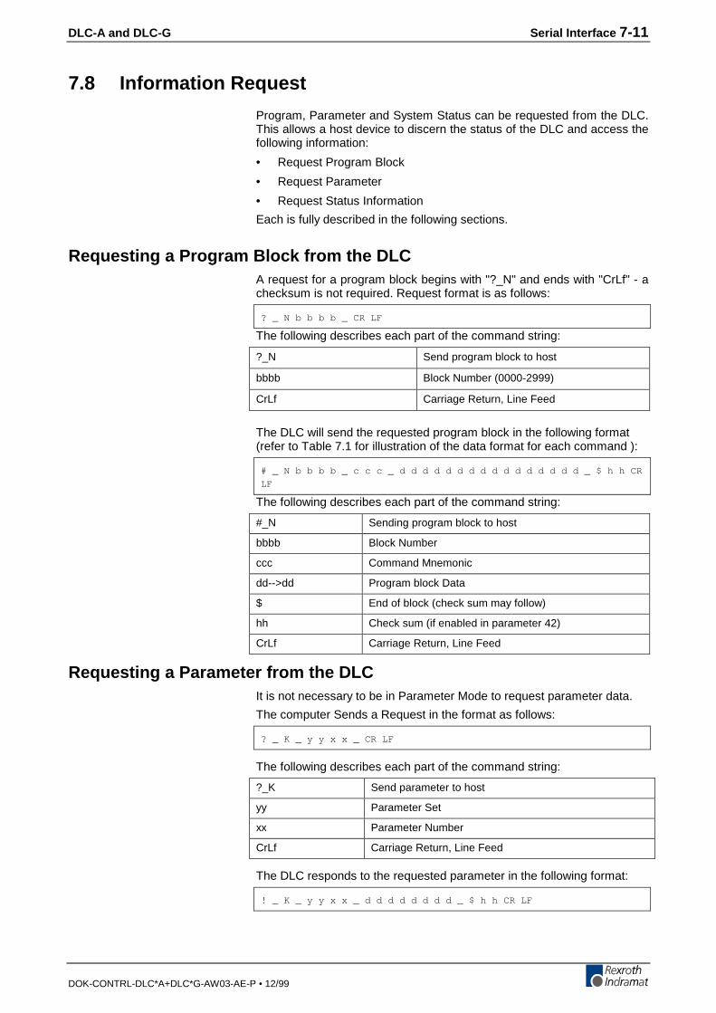
DLC-A and DLC-G Serial Interface 7-11
DOK-CONTRL-DLC*A+DLC*G-AW03-AE-P • 12/99
7.8 Information Request
Program, Parameter and System Status can be requested from the DLC.This allows a host device to discern the status of the DLC and access thefollowing information:
• Request Program Block
• Request Parameter
• Request Status Information
Each is fully described in the following sections.
Requesting a Program Block from the DLCA request for a program block begins with "?_N" and ends with "CrLf" - achecksum is not required. Request format is as follows:
? _ N b b b b _ CR LF
The following describes each part of the command string:
?_N Send program block to host
bbbb Block Number (0000-2999)
CrLf Carriage Return, Line Feed
The DLC will send the requested program block in the following format(refer to Table 7.1 for illustration of the data format for each command ):
# _ N b b b b _ c c c _ d d d d d d d d d d d d d d d d _ $ h h CR
LF
The following describes each part of the command string:
#_N Sending program block to host
bbbb Block Number
ccc Command Mnemonic
dd-->dd Program block Data
$ End of block (check sum may follow)
hh Check sum (if enabled in parameter 42)
CrLf Carriage Return, Line Feed
Requesting a Parameter from the DLCIt is not necessary to be in Parameter Mode to request parameter data.
The computer Sends a Request in the format as follows:
? _ K _ y y x x _ CR LF
The following describes each part of the command string:
?_K Send parameter to host
yy Parameter Set
xx Parameter Number
CrLf Carriage Return, Line Feed
The DLC responds to the requested parameter in the following format:
! _ K _ y y x x _ d d d d d d d d _ $ h h CR LF
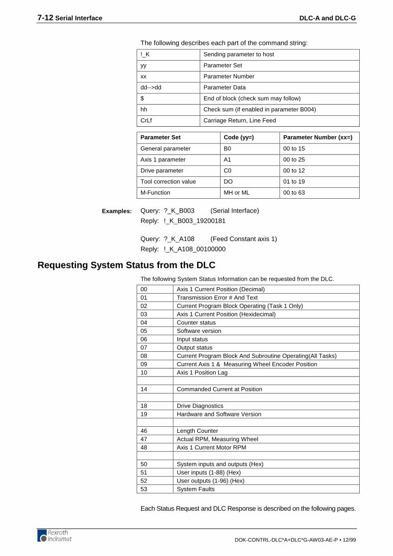
7-12 Serial Interface DLC-A and DLC-G
DOK-CONTRL-DLC*A+DLC*G-AW03-AE-P • 12/99
The following describes each part of the command string:
!_K Sending parameter to host
yy Parameter Set
xx Parameter Number
dd-->dd Parameter Data
$ End of block (check sum may follow)
hh Check sum (if enabled in parameter B004)
CrLf Carriage Return, Line Feed
Parameter Set Code (yy=) Parameter Number (xx=)
General parameter B0 00 to 15
Axis 1 parameter A1 00 to 25
Drive parameter C0 00 to 12
Tool correction value DO 01 to 19
M-Function MH or ML 00 to 63
Query: ?_K_B003 (Serial Interface)
Reply: !_K_B003_19200181
Query: ?_K_A108 (Feed Constant axis 1)
Reply: !_K_A108_00100000
Requesting System Status from the DLCThe following System Status Information can be requested from the DLC.
00 Axis 1 Current Position (Decimal)01 Transmission Error # And Text02 Current Program Block Operating (Task 1 Only)03 Axis 1 Current Position (Hexidecimal)04 Counter status05 Software version06 Input status07 Output status08 Current Program Block And Subroutine Operating(All Tasks)09 Current Axis 1 & Measuring Wheel Encoder Position10 Axis 1 Position Lag
14 Commanded Current at Position
18 Drive Diagnostics19 Hardware and Software Version
46 Length Counter47 Actual RPM, Measuring Wheel48 Axis 1 Current Motor RPM
50 System inputs and outputs (Hex)51 User inputs (1-88) (Hex)52 User outputs (1-96) (Hex)53 System Faults
Each Status Request and DLC Response is described on the following pages.
Examples:
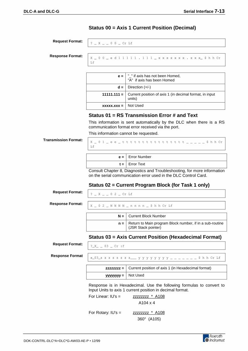
DLC-A and DLC-G Serial Interface 7-13
DOK-CONTRL-DLC*A+DLC*G-AW03-AE-P • 12/99
Status 00 = Axis 1 Current Position (Decimal)
? _ X _ _ 0 0 _ Cr Lf
X _ 0 0 _ e d 1 1 1 1 1 . 1 1 1 _ x x x x x x x . x x x_ $ h h Cr
Lf
e = "_" if axis has not been Homed,"A" if axis has been Homed
d = Direction (+/-)
11111.111 = Current position of axis 1 (in decimal format, in inputunits)
xxxxx.xxx = Not Used
Status 01 = RS Transmission Error # and TextThis information is sent automatically by the DLC when there is a RScommunication format error received via the port.
This information cannot be requested.
X _ 0 1 _ e e _ t t t t t t t t t t t t t t t t _ _ _ _ _ $ h h Cr
Lf
e = Error Number
t = Error Text
Consult Chapter 8, Diagnostics and Troubleshooting, for more informationon the serial communication error used in the DLC Control Card.
Status 02 = Current Program Block (for Task 1 only)
? _ X _ _ 0 2 _ Cr Lf
X _ 0 2 _ N N N N _ n n n n _ $ h h Cr Lf
N = Current Block Number
n = Return to Main program Block number, if in a sub-routine(JSR Stack pointer)
Status 03 = Axis Current Position (Hexadecimal Format)
?_X_ _ 03 _ Cr :f
x_03_z z z z z z z z___ y y y y y y y y _ _ _ _ _ _ _ $ h h Cr Lf
zzzzzzzz = Current position of axis 1 (in Hexadecimal format)
yyyyyyyy = Not Used
Response is in Hexadecimal. Use the following formulas to convert toInput Units to axis 1 current position in decimal format.
For Linear: IU's = zzzzzzzz * A108
A104 x 4
For Rotary: IU's = zzzzzzzz * A108
360° (A105)
Request Format:
Response Format:
Transmission Format:
Request Format:
Response Format:
Request Format:
Response Format

7-14 Serial Interface DLC-A and DLC-G
DOK-CONTRL-DLC*A+DLC*G-AW03-AE-P • 12/99
Status 04 = Counter Status
? _ X _ _ 0 4 _ N N N N _ Cr Lf
X _ 0 4 _ N N N N _ a a a a a a _ t t t t t t _ _ _ _ _ _ $ h h Cr
Lf
NNNN= Counter block number
aaaaaa= Actual count
tttttt= Target count
Status 05 = Software Version
? _ X _ _ 0 5 _ Cr Lf
X _ 0 5 _ _ v v v v v v v v v v v v v v v v _ $ h h Cr Lf
v = Software version (as displayed on the CTA display)
"___DA 01.1-03.02___"
Status 06 = Input Status
? _ X _ _ 0 6 _ b _ Cr Lf
X _ 0 6 _ b _ e e e e e e e e e e e e e e e e _ $ h h Cr Lf
16 inputs are always represented
b= Bank number (Input range)
0= System Inputs 1-8 (DEA 4.1 card)
1= Aux. Inputs 1-7 (DEA 4.1 card)
2= Aux. Inputs 08-22 (DEA 5.1 card)
3= Aux. Inputs 23-37 (DEA 6.1 card)
e= State of each of 15 inputs in sequence, as follows:
0= OFF (0 Vdc)
1= ON (24 Vdc)
Request Format:
Response Format:
Request Format:
Response Format:
Example:
Request Format:
Response Format:
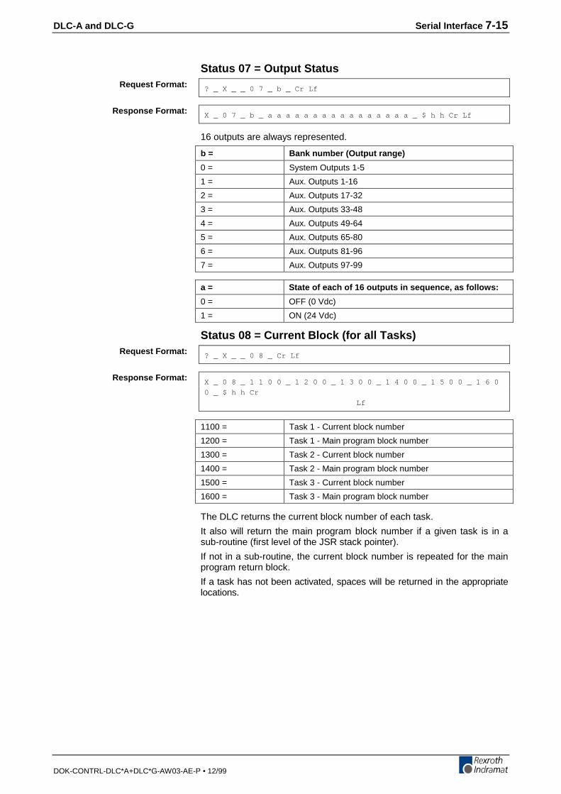
DLC-A and DLC-G Serial Interface 7-15
DOK-CONTRL-DLC*A+DLC*G-AW03-AE-P • 12/99
Status 07 = Output Status
? _ X _ _ 0 7 _ b _ Cr Lf
X _ 0 7 _ b _ a a a a a a a a a a a a a a a a _ $ h h Cr Lf
16 outputs are always represented.
b = Bank number (Output range)
0 = System Outputs 1-5
1 = Aux. Outputs 1-16
2 = Aux. Outputs 17-32
3 = Aux. Outputs 33-48
4 = Aux. Outputs 49-64
5 = Aux. Outputs 65-80
6 = Aux. Outputs 81-96
7 = Aux. Outputs 97-99
a = State of each of 16 outputs in sequence, as follows:
0 = OFF (0 Vdc)
1 = ON (24 Vdc)
Status 08 = Current Block (for all Tasks)
? _ X _ _ 0 8 _ Cr Lf
X _ 0 8 _ 1 1 0 0 _ 1 2 0 0 _ 1 3 0 0 _ 1 4 0 0 _ 1 5 0 0 _ 1 6 0
0 _ $ h h Cr
Lf
1100 = Task 1 - Current block number
1200 = Task 1 - Main program block number
1300 = Task 2 - Current block number
1400 = Task 2 - Main program block number
1500 = Task 3 - Current block number
1600 = Task 3 - Main program block number
The DLC returns the current block number of each task.
It also will return the main program block number if a given task is in asub-routine (first level of the JSR stack pointer).
If not in a sub-routine, the current block number is repeated for the mainprogram return block.
If a task has not been activated, spaces will be returned in the appropriatelocations.
Request Format:
Response Format:
Request Format:
Response Format:

7-16 Serial Interface DLC-A and DLC-G
DOK-CONTRL-DLC*A+DLC*G-AW03-AE-P • 12/99
Status 09 = Measuring Wheel / Motor Encoder (PositionReadings)
? _ X _ _ 0 9 _ Cr Lf
X _ 0 9 _ _ x ± 1 2 3 4 5 . 6 7 8 _ ± 1 2 3 4 5 . 6 7 8 _ $ h h Cr
Lf
X_09 = Status 09
_ = Reserved - not used at present
x = "A" - Axis 1 has been homed"_" - Axis 1 has not been homed
±12345.678 = First Position Axis 1 in EGE- if Measuring Wheel activated, all MW movements areused- if MW deactivated, all motor transmitter movements areused
±12345.678 = Second Position Axis 1 in EGE
Status 10 = Axis 1 Position Lag
? _ X _ _ 1 0 _ Cr Lf
X _ 1 0 _ d 1 1 1 1 1 . 1 1 1 _ x x x x x x . x x x _ $ h h Cr Lf
X_10 = Status 10
d = Direction (+/-)
11111.111 = Position Lag of Axis 1 (in input units)
xxxxx.xxx = Not Used
Status 14 = Command Current at Position
? _ X _ _ 1 4 _ Cr Lf
X _ 14e ±12345.678 ±123.45$hh Cr Lf
X_14 = Status 14
e = “A” - Axis 1 has been homed“-” - Axis 1 has not been homed
±12345.678 = Position of Axis 1
±123.45 = Commanded current in amps
Status 18 = Drive Diagnostics
? _ X _ _ 1 8 _ Cr Lf
X _ 18 123 _ t t t t t t t t t t t t t t t t _ _ _ _ $ h h Cr Lf
X_18 = Status 18
123 = Drive diagnostic code
t = Drive diagnostic text
Request Format:
Response format:
Request Format:
Response Format:
Request Format:
Response Format:
Request Format:
Response Format:

DLC-A and DLC-G Serial Interface 7-17
DOK-CONTRL-DLC*A+DLC*G-AW03-AE-P • 12/99
Status 19 = Hardware and Software Version
? _ X _ _ 1 9 _ Cr Lf
X _ 1 9 _ H H H H H H H H H H H H H H _ _ S S S S S S S S S S S S
S S _ _ $ h h Cr Lf
X_19 = Status 19
H = Hardware Version (example: __DLC-1.1-A__)
S = Software Version (example: __DA01.1-03.02__)
Status 46 = Length Counter
? _ X _ _ 4 6 _ A _ Cr Lf
A = axis number (1) 0 = Measuring wheel
Note: When A = 0: If the measuring wheel option has not been set inparameters B 009 and B 010, the error message 'M-Wheel P.'will be sent instead of Status 46.
X _ 4 6 _ A _ d 1 2 3 4 5 . 6 7 8 _ $ h h Cr Lf
X_46 = Status 46
A = axis number (1), measuring wheel (0)
d = Direction (+/-)
12345.678 = Length selected axis has fed between the programmedON and OFF of the command FUN (in input units)
Status 47 = Actual RPM, Measuring Wheel
? _ X _ _ 4 7 _ Cr Lf
X _ 4 7 _ O _ d 1 2 3 4 . 5 6 _ $ h h Cr Lf
X_47 = Status 47
d = Direction (+/-)
o = Measuring Wheel axis
1234.56 = Actual RPM of the Measuring Wheel
Note: If the measuring wheel option has not been set in parametersB 009 and B 010, the error message '10M-Wheel P. False' willbe sent instead of Status 47.
Request Format:
Response Format:
Request Format:
Response Format:
Request Format:
Response Format:

7-18 Serial Interface DLC-A and DLC-G
DOK-CONTRL-DLC*A+DLC*G-AW03-AE-P • 12/99
Status 48 = Axis Current Motor RPM
? _ X _ _ 4 8 _ Cr Lf
X _ 4 8 _ 1 _ d 1 2 3 4 . 5 6 _ x _ y z z z z . z z _ $ h h Cr Lf
X_48 = Status 48
1 = axis number 1
d = Direction (+/-)
1234.56 = Actual RPM of axis 1
x = Not Used
y = Not Used
zzzz.zz = Not Used
Status 50 = System Inputs and Outputs Hexadecimal
? _ x _ _ 5 0 _ Cr Lf
X _ 5 0 _ e e e e a a a a $ h h Cr Lf
e = Four system inputs (Hexadecimal)
a = Four system outputs (Hexadecimal)
.1 Hexadecimal Conversion Table
Weight = 2 3 22 21 20 e/a
0 0 0 0 0
0 0 0 1 1
0 0 1 0 2
0 0 1 1 3
0 1 0 0 4
0 1 0 1 5
0 1 1 0 6
0 1 1 1 7
1 0 0 0 8
1 0 0 1 9
1 0 1 0 A
1 0 1 1 B
1 1 0 0 C
1 1 0 1 D
1 1 1 0 E
Request Format:
Response Format:
Request Format:
Response Format:

DLC-A and DLC-G Serial Interface 7-19
DOK-CONTRL-DLC*A+DLC*G-AW03-AE-P • 12/99
.2 Status 50 Example::��A��������A��������������������(��������J��J��%4��.(
���� ���� ���� �������� ���� ���� ����
������������5[UVGO�+PRWVU��������������������� ��������������5[UVGO�1WVRWVU�������������������
In this example:
• System inputs 3, 5, 6, and 7 are at +24 volts.
• System outputs 1, 4, 5, 6, 7, and 8 are at +24 volts.
Status 51 = User Inputs (Hexadecimal)
? _ X _ _ 5 1 _ CR LF
X _ 5 1 _ e e e e e e e e e e e e e e e e e e e e $ H h CR LF
Input numbers (e = user input, hexadecimal code)
e e e e e e e e e e e e e e e e e e e e
| | | | | | | | | | | | | | | | | | | |
36 32 28 24 20 16 12 8 4 =23
35 31 27 23 19 15 11 7 3 =22
34 30 26 22 18 14 10 6 2 =21
37 33 29 25 21 17 13 9 5 1 =20
0 is transmitted for all other inputs that do not exist in hardware.
Status 52 = User Outputs (Hexadecimal)? _ X _ _ 5 2 _ CR LF
X _ 5 2 _ a a a a a a a a a a a a a a a a a a a a a a a a $ H h CR
LF
Output numbers (a = user output, hexadecimal code)
a a a a a a a a a a a a a a a a a a a a a a a a
| | | | | | | | | | | | | | | | | | | | | | | |
96 92 88 84 80 76 72 68 64 60 56 52 48 44 40 36 32 28 24 20 16 12 8 4 =2 3
95 91 87 83 79 75 71 67 63 59 55 51 47 43 39 35 31 27 23 19 15 11 7 3 =2 2
94 90 86 82 78 74 70 66 62 58 54 50 46 42 38 34 30 26 22 18 14 10 6 2 =2 1
93 89 85 81 77 73 69 65 61 57 53 49 45 41 37 33 29 25 21 17 13 9 5 1 =2 0
Status 53 = System Fault? _ X _ _ 5 3 _ Cr Lf
X _ 5 3_ n n _ t t t t t t t t t t t t t t t t _ $ h h Cr Lf
n n = error code (hexadecimal)
t = Fault message text
Fault message texts and error codes are listed in detail in chapter 8.
Request Format:
Response Format:
Request Format:
Response Format:
Request Format:
Response Format:

7-20 Serial Interface DLC-A and DLC-G
DOK-CONTRL-DLC*A+DLC*G-AW03-AE-P • 12/99
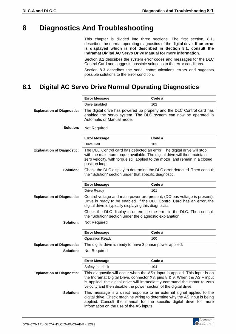
DLC-A and DLC-G Diagnostics And Troubleshooting 8-1
DOK-CONTRL-DLC*A+DLC*G-AW03-AE-P • 12/99
8 Diagnostics And TroubleshootingThis chapter is divided into three sections. The first section, 8.1,describes the normal operating diagnostics of the digital drive. If an erroris displayed which is not described in Section 8.1, consult theIndramat Digital AC Servo Drive Manual for more information .
Section 8.2 describes the system error codes and messages for the DLCControl Card and suggests possible solutions to the error conditions.
Section 8.3 describes the serial communications errors and suggestspossible solutions to the error condition.
8.1 Digital AC Servo Drive Normal Operating Diagnostics
Error Message Code #
Drive Enabled 102
The digital drive has powered up properly and the DLC Control card hasenabled the servo system. The DLC system can now be operated inAutomatic or Manual mode.
Not Required
Error Message Code #
Drive Halt 103
The DLC Control card has detected an error. The digital drive will stopwith the maximum torque available. The digital drive will then maintainzero velocity, with torque still applied to the motor, and remain in a closedposition loop.
Check the DLC display to determine the DLC error detected. Then consultthe "Solution" section under that specific diagnostic.
Error Message Code #
Drive Ready 101
Control voltage and main power are present, (DC bus voltage is present).Drive is ready to be enabled. If the DLC Control Card has an error, thedigital drive is typically displaying this diagnostic.
Check the DLC display to determine the error in the DLC. Then consultthe "Solution" section under the diagnostic explanation.
Not Required
Error Message Code #
Operation Ready 100
The digital drive is ready to have 3 phase power applied.
Not Required
Error Message Code #
Safety Interlock 104
This diagnostic will occur when the AS+ input is applied. This input is onthe Indramat Digital Drive, connector X3, pins 8 & 9. When the AS + inputis applied, the digital drive will immediately command the motor to zerovelocity and then disable the power section of the digital drive.
This message is a direct response to an external signal applied to thedigital drive. Check machine wiring to determine why the AS input is beingapplied. Consult the manual for the specific digital drive for moreinformation on the use of the AS inputs.
Explanation of Diagnostic:
Solution:
Explanation of Diagnostic:
Solution:
Explanation of Diagnostic:
Solution:
Explanation of Diagnostic:
Solution:
Explanation of Diagnostic:
Solution:

8-2 Diagnostics And Troubleshooting DLC-A and DLC-G
DOK-CONTRL-DLC*A+DLC*G-AW03-AE-P • 12/99
8.2 DLC System Error Code And System Error Messages
When the DLC detects an error, all outputs are turned off and the errormessage appears on the CTA display. After the error has been corrected,the message must be cleared by pressing the CL key on the CTA keypad,or by providing a +24-volt input to the external Clear input (connector X17,pin 8).
Typically, the word "ERROR" appears on the top line of the display. Thesecond line displays one of the following messages:
Error Message Code #
(No diagnostic message is displayed) 00
When the DLC Control card is operating properly , with no system errorspresent, requesting the Status Code 53 through an external host devicecauses the DLC Control card to transmit the error code "00".
No error message will be displayed on the CTA panel, if used. If anotherMMI device is used, it may display a message in response to thisinformation.
Not Required
Error Message Code #
Abs. Range 45
This error occurs if the maximum number of turns of the multi-turnabsolute feedback has been exceeded.
Verify that the distance traveled does not exceed the maximum number ofturns of the absolute encoder.
Error Message Code #
Axis 1 Not Homed 48
This error occurs if the DLC program encounters an absolute positioncommand for the axis, but that axis has not yet been homed.
1. Refer to Chapter 3, Section 3.2.4 for details on Homing.2. Verify that the axis homing parameters, A110 through A114, are
correct. The axis can be homed in Manual or Automatic mode. Referto Chapter 4 for more information on the Homing parameters.
3. Verify that the axis position command in the DLC program is correct.Refer to Chapter 5 for more information on positioning commands.
Error Message Code #
Axis No. False 16
Incorrect axis selected in a feed command. Must be axis #1 only.
Check program block feed command axis designation.
Error Message Code #
Battery Is Low 04
This condition occurs when the Lithium battery which retains the DLCmemory (program, parameters, counter status, tool correction values, M-Function set-up, etc.) during power OFF, is below minimum voltage level.
A battery test is made at DLC power up. If the battery is low, the errormessage is displayed. This message will also re-appear every tenminutes as a reminder. During Normal operation in any of the threeoperating modes (manual, automatic or parameter), a battery test is madeevery four hours. If the battery is still low, this diagnostic will re-appear,but no fault will be issued.
Explanation of Diagnostic:
Solution:
Explanation of Diagnostic:
Solution:
Explanation of Diagnostic:
Solution:
Explanation of Diagnostic:
Solution:
Explanation of Diagnostic:
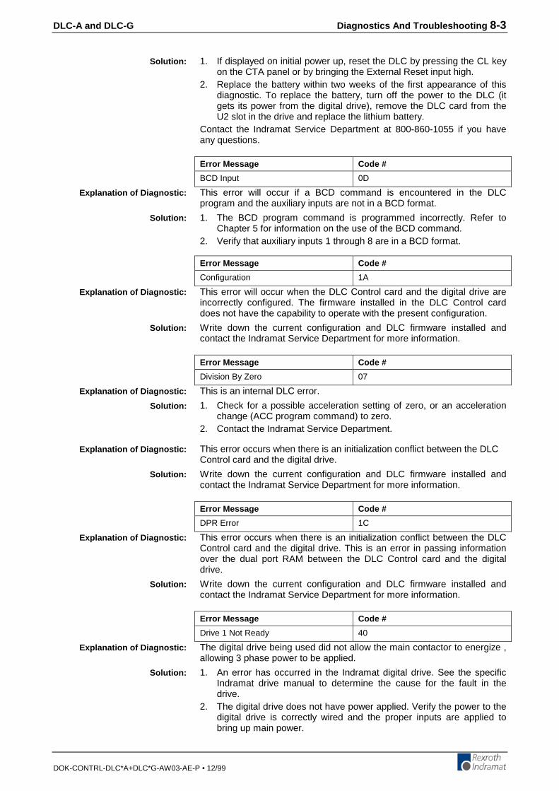
DLC-A and DLC-G Diagnostics And Troubleshooting 8-3
DOK-CONTRL-DLC*A+DLC*G-AW03-AE-P • 12/99
1. If displayed on initial power up, reset the DLC by pressing the CL keyon the CTA panel or by bringing the External Reset input high.
2. Replace the battery within two weeks of the first appearance of thisdiagnostic. To replace the battery, turn off the power to the DLC (itgets its power from the digital drive), remove the DLC card from theU2 slot in the drive and replace the lithium battery.
Contact the Indramat Service Department at 800-860-1055 if you haveany questions.
Error Message Code #
BCD Input 0D
This error will occur if a BCD command is encountered in the DLCprogram and the auxiliary inputs are not in a BCD format.
1. The BCD program command is programmed incorrectly. Refer toChapter 5 for information on the use of the BCD command.
2. Verify that auxiliary inputs 1 through 8 are in a BCD format.
Error Message Code #
Configuration 1A
This error will occur when the DLC Control card and the digital drive areincorrectly configured. The firmware installed in the DLC Control carddoes not have the capability to operate with the present configuration.
Write down the current configuration and DLC firmware installed andcontact the Indramat Service Department for more information.
Error Message Code #
Division By Zero 07
This is an internal DLC error.
1. Check for a possible acceleration setting of zero, or an accelerationchange (ACC program command) to zero.
2. Contact the Indramat Service Department.
This error occurs when there is an initialization conflict between the DLCControl card and the digital drive.
Write down the current configuration and DLC firmware installed andcontact the Indramat Service Department for more information.
Error Message Code #
DPR Error 1C
This error occurs when there is an initialization conflict between the DLCControl card and the digital drive. This is an error in passing informationover the dual port RAM between the DLC Control card and the digitaldrive.
Write down the current configuration and DLC firmware installed andcontact the Indramat Service Department for more information.
Error Message Code #
Drive 1 Not Ready 40
The digital drive being used did not allow the main contactor to energize ,allowing 3 phase power to be applied.
1. An error has occurred in the Indramat digital drive. See the specificIndramat drive manual to determine the cause for the fault in thedrive.
2. The digital drive does not have power applied. Verify the power to thedigital drive is correctly wired and the proper inputs are applied tobring up main power.
Solution:
Explanation of Diagnostic:
Solution:
Explanation of Diagnostic:
Solution:
Explanation of Diagnostic:
Solution:
Explanation of Diagnostic:
Solution:
Explanation of Diagnostic:
Solution:
Explanation of Diagnostic:
Solution:
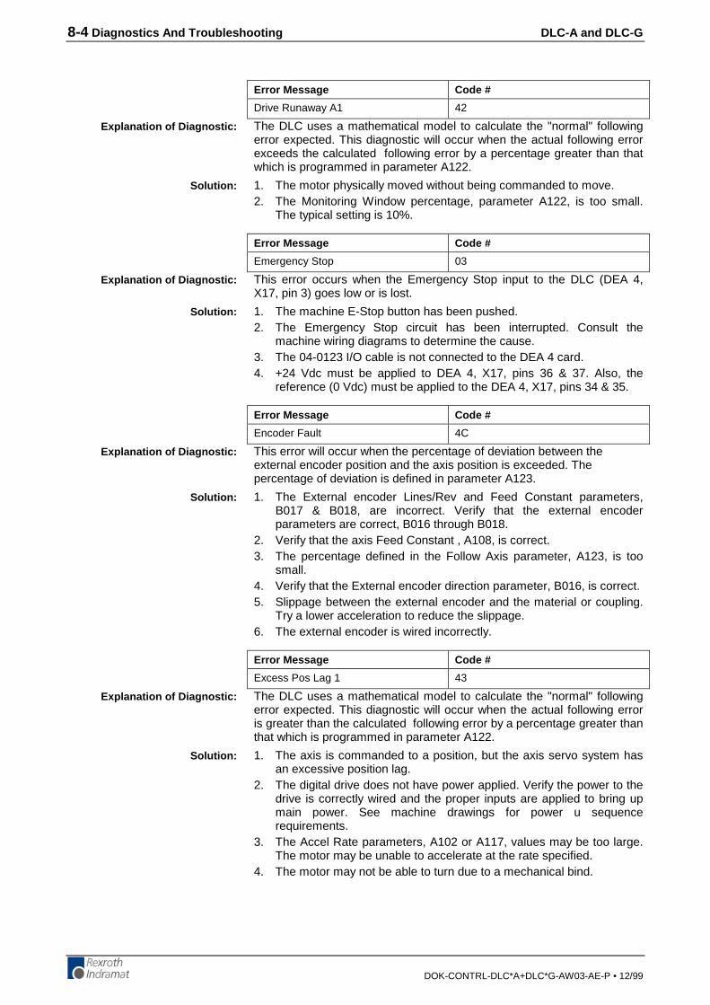
8-4 Diagnostics And Troubleshooting DLC-A and DLC-G
DOK-CONTRL-DLC*A+DLC*G-AW03-AE-P • 12/99
Error Message Code #
Drive Runaway A1 42
The DLC uses a mathematical model to calculate the "normal" followingerror expected. This diagnostic will occur when the actual following errorexceeds the calculated following error by a percentage greater than thatwhich is programmed in parameter A122.
1. The motor physically moved without being commanded to move.2. The Monitoring Window percentage, parameter A122, is too small.
The typical setting is 10%.
Error Message Code #
Emergency Stop 03
This error occurs when the Emergency Stop input to the DLC (DEA 4,X17, pin 3) goes low or is lost.
1. The machine E-Stop button has been pushed.2. The Emergency Stop circuit has been interrupted. Consult the
machine wiring diagrams to determine the cause.3. The 04-0123 I/O cable is not connected to the DEA 4 card.4. +24 Vdc must be applied to DEA 4, X17, pins 36 & 37. Also, the
reference (0 Vdc) must be applied to the DEA 4, X17, pins 34 & 35.
Error Message Code #
Encoder Fault 4C
This error will occur when the percentage of deviation between theexternal encoder position and the axis position is exceeded. Thepercentage of deviation is defined in parameter A123.
1. The External encoder Lines/Rev and Feed Constant parameters,B017 & B018, are incorrect. Verify that the external encoderparameters are correct, B016 through B018.
2. Verify that the axis Feed Constant , A108, is correct.3. The percentage defined in the Follow Axis parameter, A123, is too
small.4. Verify that the External encoder direction parameter, B016, is correct.5. Slippage between the external encoder and the material or coupling.
Try a lower acceleration to reduce the slippage.6. The external encoder is wired incorrectly.
Error Message Code #
Excess Pos Lag 1 43
The DLC uses a mathematical model to calculate the "normal" followingerror expected. This diagnostic will occur when the actual following erroris greater than the calculated following error by a percentage greater thanthat which is programmed in parameter A122.
1. The axis is commanded to a position, but the axis servo system hasan excessive position lag.
2. The digital drive does not have power applied. Verify the power to thedrive is correctly wired and the proper inputs are applied to bring upmain power. See machine drawings for power u sequencerequirements.
3. The Accel Rate parameters, A102 or A117, values may be too large.The motor may be unable to accelerate at the rate specified.
4. The motor may not be able to turn due to a mechanical bind.
Explanation of Diagnostic:
Solution:
Explanation of Diagnostic:
Solution:
Explanation of Diagnostic:
Solution:
Explanation of Diagnostic:
Solution:
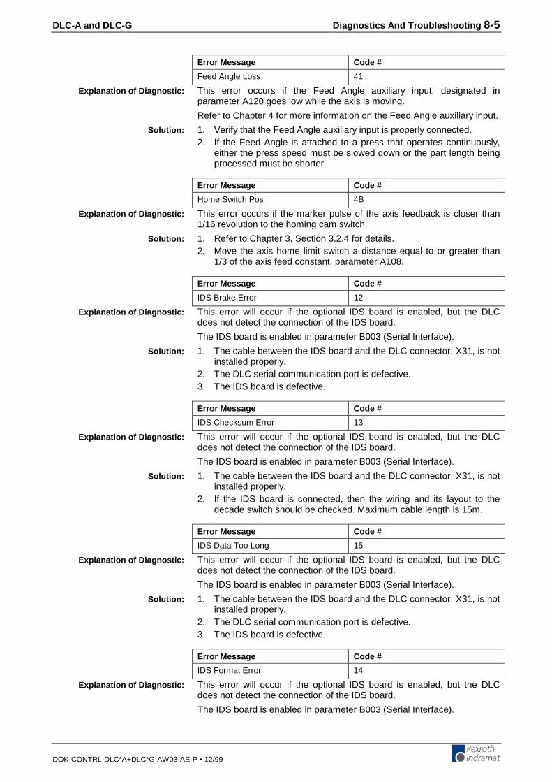
DLC-A and DLC-G Diagnostics And Troubleshooting 8-5
DOK-CONTRL-DLC*A+DLC*G-AW03-AE-P • 12/99
Error Message Code #
Feed Angle Loss 41
This error occurs if the Feed Angle auxiliary input, designated inparameter A120 goes low while the axis is moving.
Refer to Chapter 4 for more information on the Feed Angle auxiliary input.
1. Verify that the Feed Angle auxiliary input is properly connected.2. If the Feed Angle is attached to a press that operates continuously,
either the press speed must be slowed down or the part length beingprocessed must be shorter.
Error Message Code #
Home Switch Pos 4B
This error occurs if the marker pulse of the axis feedback is closer than1/16 revolution to the homing cam switch.
1. Refer to Chapter 3, Section 3.2.4 for details.2. Move the axis home limit switch a distance equal to or greater than
1/3 of the axis feed constant, parameter A108.
Error Message Code #
IDS Brake Error 12
This error will occur if the optional IDS board is enabled, but the DLCdoes not detect the connection of the IDS board.
The IDS board is enabled in parameter B003 (Serial Interface).
1. The cable between the IDS board and the DLC connector, X31, is notinstalled properly.
2. The DLC serial communication port is defective.3. The IDS board is defective.
Error Message Code #
IDS Checksum Error 13
This error will occur if the optional IDS board is enabled, but the DLCdoes not detect the connection of the IDS board.
The IDS board is enabled in parameter B003 (Serial Interface).
1. The cable between the IDS board and the DLC connector, X31, is notinstalled properly.
2. If the IDS board is connected, then the wiring and its layout to thedecade switch should be checked. Maximum cable length is 15m.
Error Message Code #
IDS Data Too Long 15
This error will occur if the optional IDS board is enabled, but the DLCdoes not detect the connection of the IDS board.
The IDS board is enabled in parameter B003 (Serial Interface).
1. The cable between the IDS board and the DLC connector, X31, is notinstalled properly.
2. The DLC serial communication port is defective.3. The IDS board is defective.
Error Message Code #
IDS Format Error 14
This error will occur if the optional IDS board is enabled, but the DLCdoes not detect the connection of the IDS board.
The IDS board is enabled in parameter B003 (Serial Interface).
Explanation of Diagnostic:
Solution:
Explanation of Diagnostic:
Solution:
Explanation of Diagnostic:
Solution:
Explanation of Diagnostic:
Solution:
Explanation of Diagnostic:
Solution:
Explanation of Diagnostic:
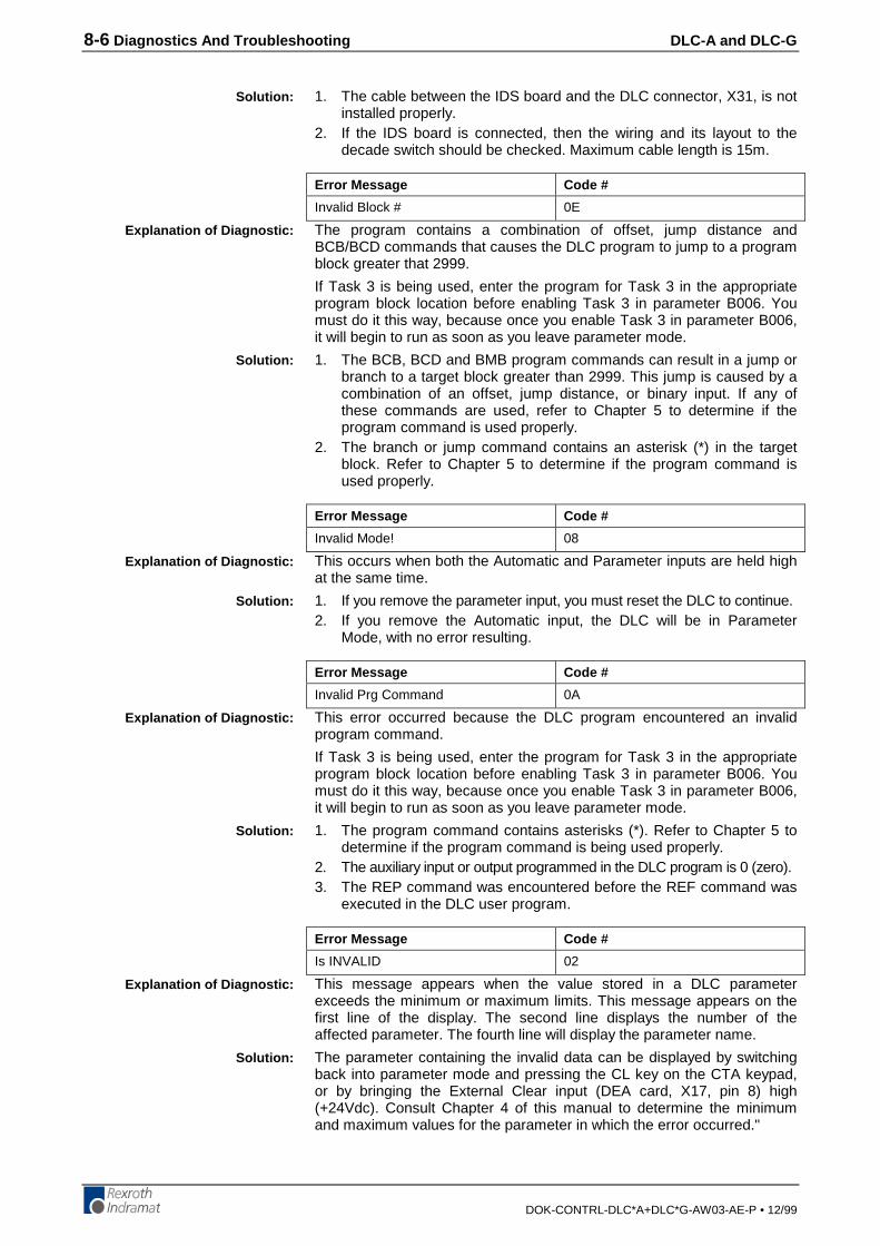
8-6 Diagnostics And Troubleshooting DLC-A and DLC-G
DOK-CONTRL-DLC*A+DLC*G-AW03-AE-P • 12/99
1. The cable between the IDS board and the DLC connector, X31, is notinstalled properly.
2. If the IDS board is connected, then the wiring and its layout to thedecade switch should be checked. Maximum cable length is 15m.
Error Message Code #
Invalid Block # 0E
The program contains a combination of offset, jump distance andBCB/BCD commands that causes the DLC program to jump to a programblock greater that 2999.
If Task 3 is being used, enter the program for Task 3 in the appropriateprogram block location before enabling Task 3 in parameter B006. Youmust do it this way, because once you enable Task 3 in parameter B006,it will begin to run as soon as you leave parameter mode.
1. The BCB, BCD and BMB program commands can result in a jump orbranch to a target block greater than 2999. This jump is caused by acombination of an offset, jump distance, or binary input. If any ofthese commands are used, refer to Chapter 5 to determine if theprogram command is used properly.
2. The branch or jump command contains an asterisk (*) in the targetblock. Refer to Chapter 5 to determine if the program command isused properly.
Error Message Code #
Invalid Mode! 08
This occurs when both the Automatic and Parameter inputs are held highat the same time.
1. If you remove the parameter input, you must reset the DLC to continue.2. If you remove the Automatic input, the DLC will be in Parameter
Mode, with no error resulting.
Error Message Code #
Invalid Prg Command 0A
This error occurred because the DLC program encountered an invalidprogram command.
If Task 3 is being used, enter the program for Task 3 in the appropriateprogram block location before enabling Task 3 in parameter B006. Youmust do it this way, because once you enable Task 3 in parameter B006,it will begin to run as soon as you leave parameter mode.
1. The program command contains asterisks (*). Refer to Chapter 5 todetermine if the program command is being used properly.
2. The auxiliary input or output programmed in the DLC program is 0 (zero).3. The REP command was encountered before the REF command was
executed in the DLC user program.
Error Message Code #
Is INVALID 02
This message appears when the value stored in a DLC parameterexceeds the minimum or maximum limits. This message appears on thefirst line of the display. The second line displays the number of theaffected parameter. The fourth line will display the parameter name.
The parameter containing the invalid data can be displayed by switchingback into parameter mode and pressing the CL key on the CTA keypad,or by bringing the External Clear input (DEA card, X17, pin 8) high(+24Vdc). Consult Chapter 4 of this manual to determine the minimumand maximum values for the parameter in which the error occurred."
Solution:
Explanation of Diagnostic:
Solution:
Explanation of Diagnostic:
Solution:
Explanation of Diagnostic:
Solution:
Explanation of Diagnostic:
Solution:
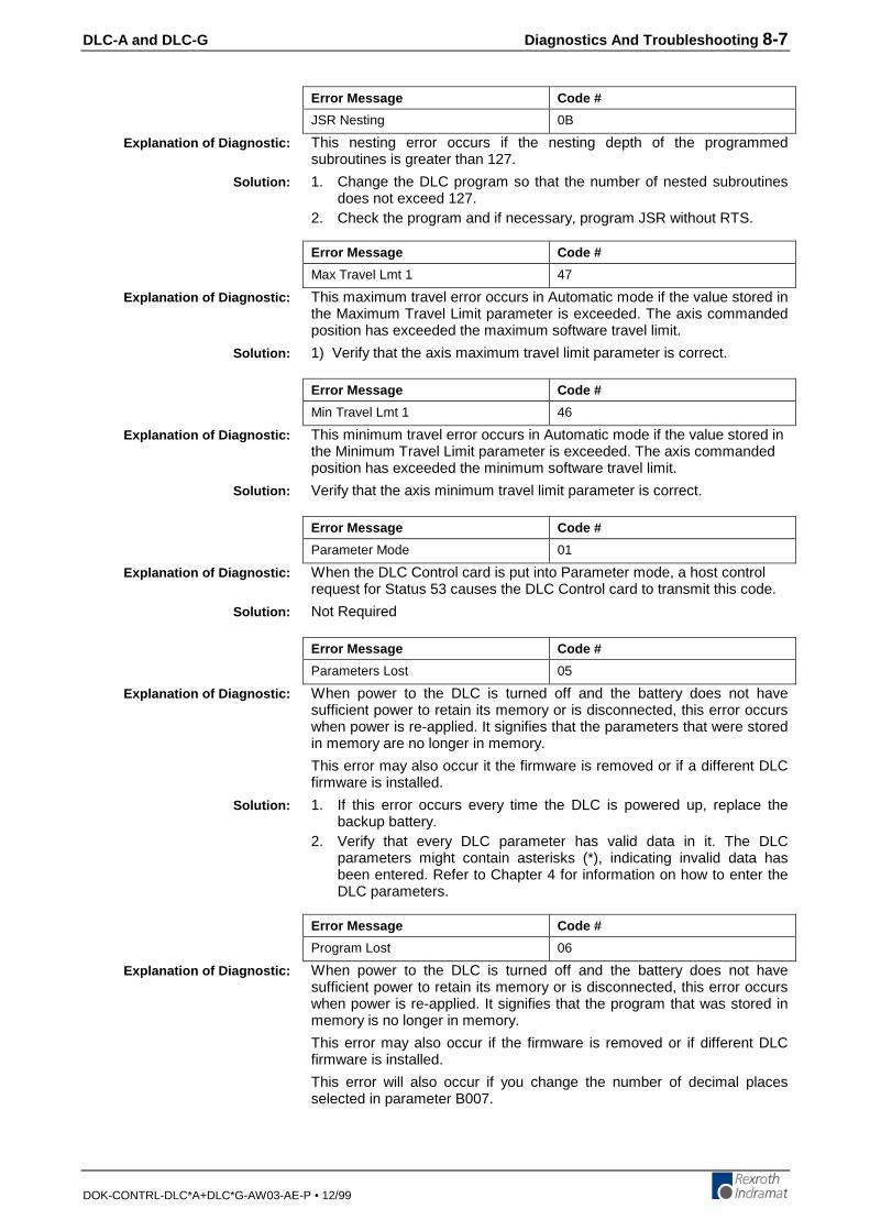
DLC-A and DLC-G Diagnostics And Troubleshooting 8-7
DOK-CONTRL-DLC*A+DLC*G-AW03-AE-P • 12/99
Error Message Code #
JSR Nesting 0B
This nesting error occurs if the nesting depth of the programmedsubroutines is greater than 127.
1. Change the DLC program so that the number of nested subroutinesdoes not exceed 127.
2. Check the program and if necessary, program JSR without RTS.
Error Message Code #
Max Travel Lmt 1 47
This maximum travel error occurs in Automatic mode if the value stored inthe Maximum Travel Limit parameter is exceeded. The axis commandedposition has exceeded the maximum software travel limit.
1) Verify that the axis maximum travel limit parameter is correct.
Error Message Code #
Min Travel Lmt 1 46
This minimum travel error occurs in Automatic mode if the value stored inthe Minimum Travel Limit parameter is exceeded. The axis commandedposition has exceeded the minimum software travel limit.
Verify that the axis minimum travel limit parameter is correct.
Error Message Code #
Parameter Mode 01
When the DLC Control card is put into Parameter mode, a host controlrequest for Status 53 causes the DLC Control card to transmit this code.
Not Required
Error Message Code #
Parameters Lost 05
When power to the DLC is turned off and the battery does not havesufficient power to retain its memory or is disconnected, this error occurswhen power is re-applied. It signifies that the parameters that were storedin memory are no longer in memory.
This error may also occur it the firmware is removed or if a different DLCfirmware is installed.
1. If this error occurs every time the DLC is powered up, replace thebackup battery.
2. Verify that every DLC parameter has valid data in it. The DLCparameters might contain asterisks (*), indicating invalid data hasbeen entered. Refer to Chapter 4 for information on how to enter theDLC parameters.
Error Message Code #
Program Lost 06
When power to the DLC is turned off and the battery does not havesufficient power to retain its memory or is disconnected, this error occurswhen power is re-applied. It signifies that the program that was stored inmemory is no longer in memory.
This error may also occur if the firmware is removed or if different DLCfirmware is installed.
This error will also occur if you change the number of decimal placesselected in parameter B007.
Explanation of Diagnostic:
Solution:
Explanation of Diagnostic:
Solution:
Explanation of Diagnostic:
Solution:
Explanation of Diagnostic:
Solution:
Explanation of Diagnostic:
Solution:
Explanation of Diagnostic:
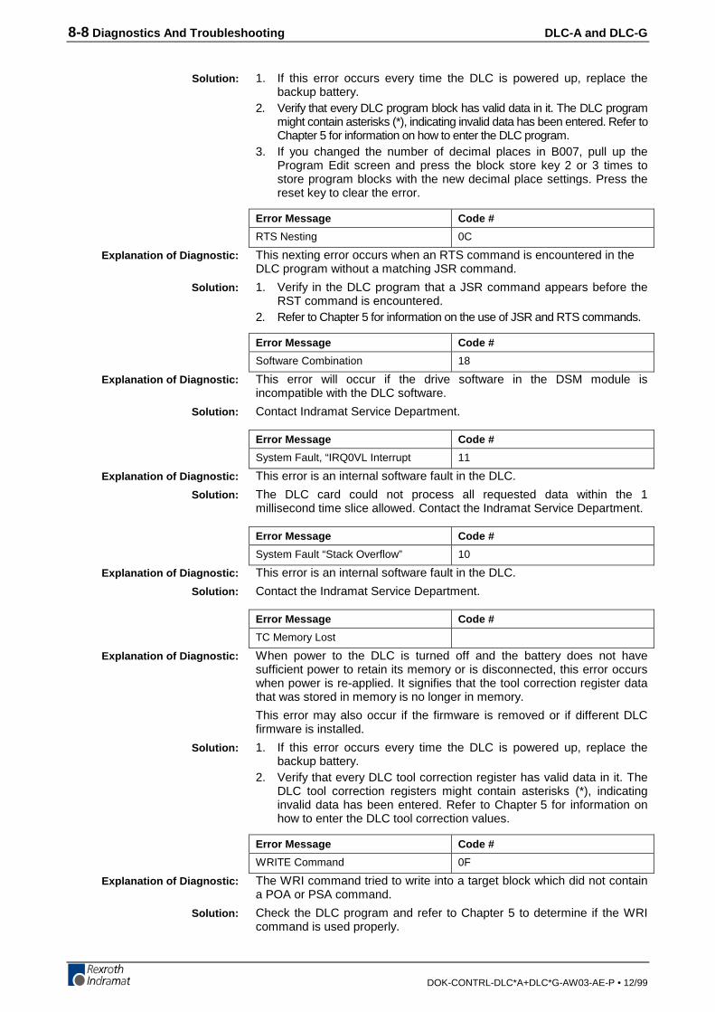
8-8 Diagnostics And Troubleshooting DLC-A and DLC-G
DOK-CONTRL-DLC*A+DLC*G-AW03-AE-P • 12/99
1. If this error occurs every time the DLC is powered up, replace thebackup battery.
2. Verify that every DLC program block has valid data in it. The DLC programmight contain asterisks (*), indicating invalid data has been entered. Refer toChapter 5 for information on how to enter the DLC program.
3. If you changed the number of decimal places in B007, pull up theProgram Edit screen and press the block store key 2 or 3 times tostore program blocks with the new decimal place settings. Press thereset key to clear the error.
Error Message Code #
RTS Nesting 0C
This nexting error occurs when an RTS command is encountered in theDLC program without a matching JSR command.
1. Verify in the DLC program that a JSR command appears before theRST command is encountered.
2. Refer to Chapter 5 for information on the use of JSR and RTS commands.
Error Message Code #
Software Combination 18
This error will occur if the drive software in the DSM module isincompatible with the DLC software.
Contact Indramat Service Department.
Error Message Code #
System Fault, “IRQ0VL Interrupt 11
This error is an internal software fault in the DLC.
The DLC card could not process all requested data within the 1millisecond time slice allowed. Contact the Indramat Service Department.
Error Message Code #
System Fault “Stack Overflow” 10
This error is an internal software fault in the DLC.
Contact the Indramat Service Department.
Error Message Code #
TC Memory Lost
When power to the DLC is turned off and the battery does not havesufficient power to retain its memory or is disconnected, this error occurswhen power is re-applied. It signifies that the tool correction register datathat was stored in memory is no longer in memory.
This error may also occur if the firmware is removed or if different DLCfirmware is installed.
1. If this error occurs every time the DLC is powered up, replace thebackup battery.
2. Verify that every DLC tool correction register has valid data in it. TheDLC tool correction registers might contain asterisks (*), indicatinginvalid data has been entered. Refer to Chapter 5 for information onhow to enter the DLC tool correction values.
Error Message Code #
WRITE Command 0F
The WRI command tried to write into a target block which did not containa POA or PSA command.
Check the DLC program and refer to Chapter 5 to determine if the WRIcommand is used properly.
Solution:
Explanation of Diagnostic:
Solution:
Explanation of Diagnostic:
Solution:
Explanation of Diagnostic:
Solution:
Explanation of Diagnostic:
Solution:
Explanation of Diagnostic:
Solution:
Explanation of Diagnostic:
Solution:
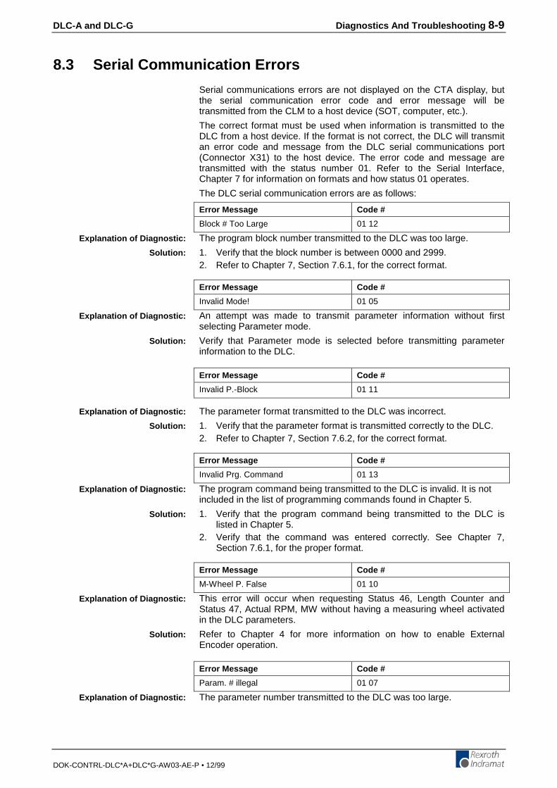
DLC-A and DLC-G Diagnostics And Troubleshooting 8-9
DOK-CONTRL-DLC*A+DLC*G-AW03-AE-P • 12/99
8.3 Serial Communication Errors
Serial communications errors are not displayed on the CTA display, butthe serial communication error code and error message will betransmitted from the CLM to a host device (SOT, computer, etc.).
The correct format must be used when information is transmitted to theDLC from a host device. If the format is not correct, the DLC will transmitan error code and message from the DLC serial communications port(Connector X31) to the host device. The error code and message aretransmitted with the status number 01. Refer to the Serial Interface,Chapter 7 for information on formats and how status 01 operates.
The DLC serial communication errors are as follows:
Error Message Code #
Block # Too Large 01 12
The program block number transmitted to the DLC was too large.
1. Verify that the block number is between 0000 and 2999.2. Refer to Chapter 7, Section 7.6.1, for the correct format.
Error Message Code #
Invalid Mode! 01 05
An attempt was made to transmit parameter information without firstselecting Parameter mode.
Verify that Parameter mode is selected before transmitting parameterinformation to the DLC.
Error Message Code #
Invalid P.-Block 01 11
The parameter format transmitted to the DLC was incorrect.
1. Verify that the parameter format is transmitted correctly to the DLC.2. Refer to Chapter 7, Section 7.6.2, for the correct format.
Error Message Code #
Invalid Prg. Command 01 13
The program command being transmitted to the DLC is invalid. It is notincluded in the list of programming commands found in Chapter 5.
1. Verify that the program command being transmitted to the DLC islisted in Chapter 5.
2. Verify that the command was entered correctly. See Chapter 7,Section 7.6.1, for the proper format.
Error Message Code #
M-Wheel P. False 01 10
This error will occur when requesting Status 46, Length Counter andStatus 47, Actual RPM, MW without having a measuring wheel activatedin the DLC parameters.
Refer to Chapter 4 for more information on how to enable ExternalEncoder operation.
Error Message Code #
Param. # illegal 01 07
The parameter number transmitted to the DLC was too large.
Explanation of Diagnostic:
Solution:
Explanation of Diagnostic:
Solution:
Explanation of Diagnostic:
Solution:
Explanation of Diagnostic:
Solution:
Explanation of Diagnostic:
Solution:
Explanation of Diagnostic:
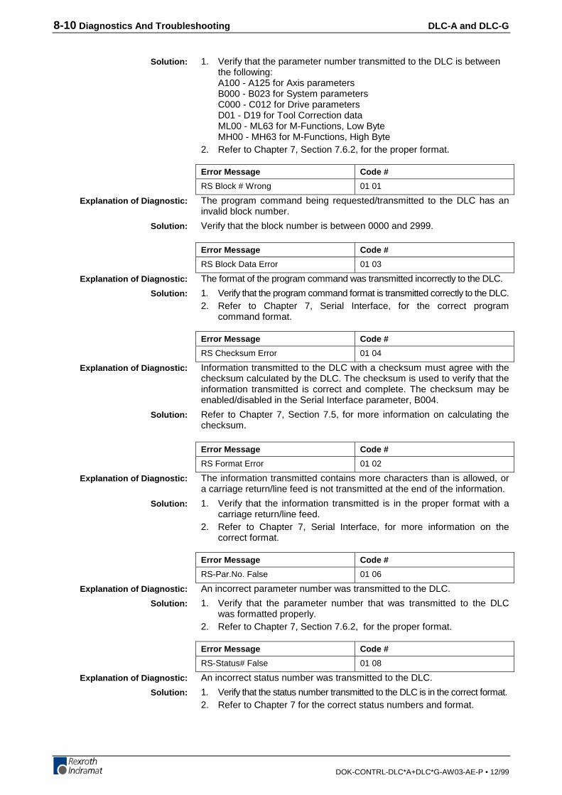
8-10 Diagnostics And Troubleshooting DLC-A and DLC-G
DOK-CONTRL-DLC*A+DLC*G-AW03-AE-P • 12/99
1. Verify that the parameter number transmitted to the DLC is betweenthe following:A100 - A125 for Axis parametersB000 - B023 for System parametersC000 - C012 for Drive parametersD01 - D19 for Tool Correction dataML00 - ML63 for M-Functions, Low ByteMH00 - MH63 for M-Functions, High Byte
2. Refer to Chapter 7, Section 7.6.2, for the proper format.
Error Message Code #
RS Block # Wrong 01 01
The program command being requested/transmitted to the DLC has aninvalid block number.
Verify that the block number is between 0000 and 2999.
Error Message Code #
RS Block Data Error 01 03
The format of the program command was transmitted incorrectly to the DLC.
1. Verify that the program command format is transmitted correctly to the DLC.2. Refer to Chapter 7, Serial Interface, for the correct program
command format.
Error Message Code #
RS Checksum Error 01 04
Information transmitted to the DLC with a checksum must agree with thechecksum calculated by the DLC. The checksum is used to verify that theinformation transmitted is correct and complete. The checksum may beenabled/disabled in the Serial Interface parameter, B004.
Refer to Chapter 7, Section 7.5, for more information on calculating thechecksum.
Error Message Code #
RS Format Error 01 02
The information transmitted contains more characters than is allowed, ora carriage return/line feed is not transmitted at the end of the information.
1. Verify that the information transmitted is in the proper format with acarriage return/line feed.
2. Refer to Chapter 7, Serial Interface, for more information on thecorrect format.
Error Message Code #
RS-Par.No. False 01 06
An incorrect parameter number was transmitted to the DLC.
1. Verify that the parameter number that was transmitted to the DLCwas formatted properly.
2. Refer to Chapter 7, Section 7.6.2, for the proper format.
Error Message Code #
RS-Status# False 01 08
An incorrect status number was transmitted to the DLC.
1. Verify that the status number transmitted to the DLC is in the correct format.2. Refer to Chapter 7 for the correct status numbers and format.
Solution:
Explanation of Diagnostic:
Solution:
Explanation of Diagnostic:
Solution:
Explanation of Diagnostic:
Solution:
Explanation of Diagnostic:
Solution:
Explanation of Diagnostic:
Solution:
Explanation of Diagnostic:
Solution:
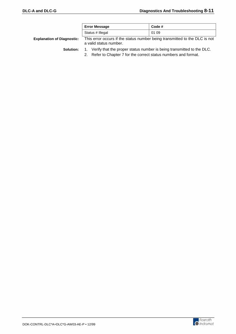
DLC-A and DLC-G Diagnostics And Troubleshooting 8-11
DOK-CONTRL-DLC*A+DLC*G-AW03-AE-P • 12/99
Error Message Code #
Status # Illegal 01 09
This error occurs if the status number being transmitted to the DLC is nota valid status number.
1. Verify that the proper status number is being transmitted to the DLC.2. Refer to Chapter 7 for the correct status numbers and format.
Explanation of Diagnostic:
Solution:
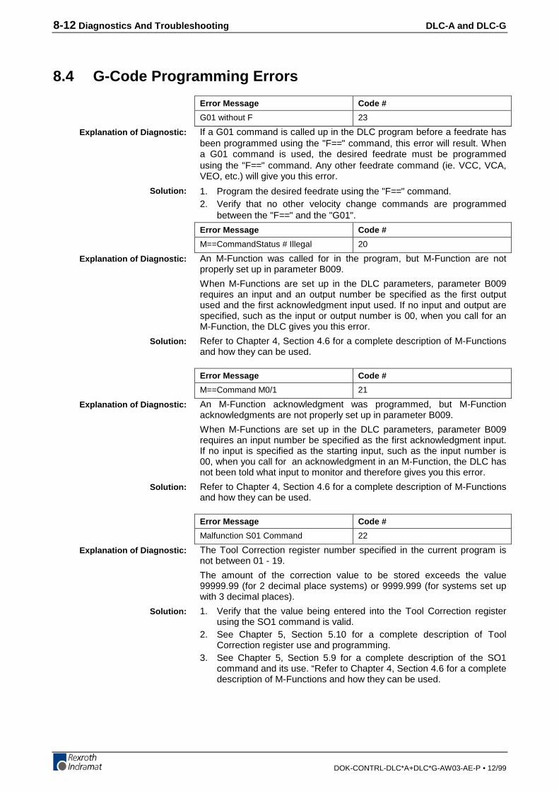
8-12 Diagnostics And Troubleshooting DLC-A and DLC-G
DOK-CONTRL-DLC*A+DLC*G-AW03-AE-P • 12/99
8.4 G-Code Programming Errors
Error Message Code #
G01 without F 23
If a G01 command is called up in the DLC program before a feedrate hasbeen programmed using the "F==" command, this error will result. Whena G01 command is used, the desired feedrate must be programmedusing the "F==" command. Any other feedrate command (ie. VCC, VCA,VEO, etc.) will give you this error.
1. Program the desired feedrate using the "F==" command.2. Verify that no other velocity change commands are programmed
between the "F==" and the "G01".
Error Message Code #
M==CommandStatus # Illegal 20
An M-Function was called for in the program, but M-Function are notproperly set up in parameter B009.
When M-Functions are set up in the DLC parameters, parameter B009requires an input and an output number be specified as the first outputused and the first acknowledgment input used. If no input and output arespecified, such as the input or output number is 00, when you call for anM-Function, the DLC gives you this error.
Refer to Chapter 4, Section 4.6 for a complete description of M-Functionsand how they can be used.
Error Message Code #
M==Command M0/1 21
An M-Function acknowledgment was programmed, but M-Functionacknowledgments are not properly set up in parameter B009.
When M-Functions are set up in the DLC parameters, parameter B009requires an input number be specified as the first acknowledgment input.If no input is specified as the starting input, such as the input number is00, when you call for an acknowledgment in an M-Function, the DLC hasnot been told what input to monitor and therefore gives you this error.
Refer to Chapter 4, Section 4.6 for a complete description of M-Functionsand how they can be used.
Error Message Code #
Malfunction S01 Command 22
The Tool Correction register number specified in the current program isnot between 01 - 19.
The amount of the correction value to be stored exceeds the value99999.99 (for 2 decimal place systems) or 9999.999 (for systems set upwith 3 decimal places).
1. Verify that the value being entered into the Tool Correction registerusing the SO1 command is valid.
2. See Chapter 5, Section 5.10 for a complete description of ToolCorrection register use and programming.
3. See Chapter 5, Section 5.9 for a complete description of the SO1command and its use. “Refer to Chapter 4, Section 4.6 for a completedescription of M-Functions and how they can be used.
Explanation of Diagnostic:
Solution:
Explanation of Diagnostic:
Solution:
Explanation of Diagnostic:
Solution:
Explanation of Diagnostic:
Solution:
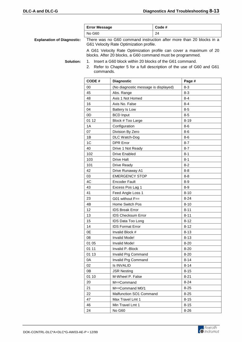
DLC-A and DLC-G Diagnostics And Troubleshooting 8-13
DOK-CONTRL-DLC*A+DLC*G-AW03-AE-P • 12/99
Error Message Code #
No G60 24
There was no G60 command instruction after more than 20 blocks in aG61 Velocity Rate Optimization profile.
A G61 Velocity Rate Optimization profile can cover a maximum of 20blocks. After 20 blocks, a G60 command must be programmed.
1. Insert a G60 block within 20 blocks of the G61 command.2. Refer to Chapter 5 for a full description of the use of G60 and G61
commands.
CODE # Diagnostic Page #
00 (No diagnostic message is displayed) 8-3
45 Abs. Range 8-3
48 Axis 1 Not Homed 8-4
16 Axis No. False 8-4
04 Battery Is Low 8-5
0D BCD Input 8-5
01 12 Block # Too Large 8-19
1A Configuration 8-6
07 Division By Zero 8-6
1B DLC Watch-Dog 8-6
1C DPR Error 8-7
40 Drive 1 Not Ready 8-7
102 Drive Enabled 8-1
103 Drive Halt 8-1
101 Drive Ready 8-2
42 Drive Runaway A1 8-8
03 EMERGENCY STOP 8-8
4C Encoder Fault 8-9
43 Excess Pos Lag 1 8-9
41 Feed Angle Loss 1 8-10
23 G01 without F== 8-24
4B Home Switch Pos 8-10
12 IDS Break Error 8-11
13 IDS Checksum Error 8-11
15 IDS Data Too Long 8-12
14 IDS Format Error 8-12
0E Invalid Block # 8-13
08 Invalid Mode! 8-13
01 05 Invalid Mode! 8-20
01 11 Invalid P.-Block 8-20
01 13 Invalid Prg Command 8-20
0A Invalid Prg Command 8-14
02 Is INVALID 8-14
0B JSR Nesting 8-15
01 10 M-Wheel P. False 8-21
20 M==Command 8-24
21 M==Command M0/1 8-25
22 Malfunction SO1 Command 8-25
47 Max Travel Lmt 1 8-15
46 Min Travel Lmt 1 8-15
24 No G60 8-26
Explanation of Diagnostic:
Solution:
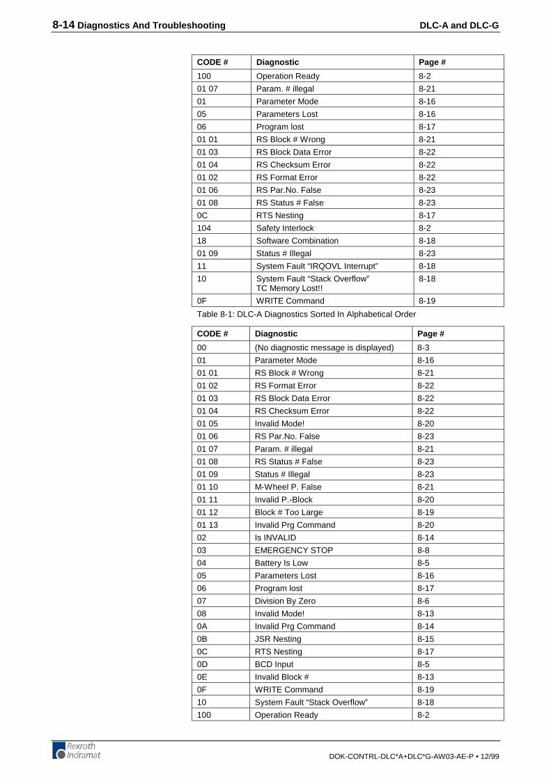
8-14 Diagnostics And Troubleshooting DLC-A and DLC-G
DOK-CONTRL-DLC*A+DLC*G-AW03-AE-P • 12/99
CODE # Diagnostic Page #
100 Operation Ready 8-2
01 07 Param. # illegal 8-21
01 Parameter Mode 8-16
05 Parameters Lost 8-16
06 Program lost 8-17
01 01 RS Block # Wrong 8-21
01 03 RS Block Data Error 8-22
01 04 RS Checksum Error 8-22
01 02 RS Format Error 8-22
01 06 RS Par.No. False 8-23
01 08 RS Status # False 8-23
0C RTS Nesting 8-17
104 Safety Interlock 8-2
18 Software Combination 8-18
01 09 Status # Illegal 8-23
11 System Fault “IRQOVL Interrupt” 8-18
10 System Fault “Stack Overflow”TC Memory Lost!!
8-18
0F WRITE Command 8-19
Table 8-1: DLC-A Diagnostics Sorted In Alphabetical Order
CODE # Diagnostic Page #
00 (No diagnostic message is displayed) 8-3
01 Parameter Mode 8-16
01 01 RS Block # Wrong 8-21
01 02 RS Format Error 8-22
01 03 RS Block Data Error 8-22
01 04 RS Checksum Error 8-22
01 05 Invalid Mode! 8-20
01 06 RS Par.No. False 8-23
01 07 Param. # illegal 8-21
01 08 RS Status # False 8-23
01 09 Status # Illegal 8-23
01 10 M-Wheel P. False 8-21
01 11 Invalid P.-Block 8-20
01 12 Block # Too Large 8-19
01 13 Invalid Prg Command 8-20
02 Is INVALID 8-14
03 EMERGENCY STOP 8-8
04 Battery Is Low 8-5
05 Parameters Lost 8-16
06 Program lost 8-17
07 Division By Zero 8-6
08 Invalid Mode! 8-13
0A Invalid Prg Command 8-14
0B JSR Nesting 8-15
0C RTS Nesting 8-17
0D BCD Input 8-5
0E Invalid Block # 8-13
0F WRITE Command 8-19
10 System Fault “Stack Overflow” 8-18
100 Operation Ready 8-2
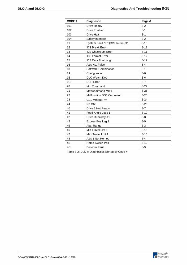
DLC-A and DLC-G Diagnostics And Troubleshooting 8-15
DOK-CONTRL-DLC*A+DLC*G-AW03-AE-P • 12/99
CODE # Diagnostic Page #
101 Drive Ready 8-2
102 Drive Enabled 8-1
103 Drive Halt 8-1
104 Safety Interlock 8-2
11 System Fault “IRQOVL Interrupt” 8-18
12 IDS Break Error 8-11
13 IDS Checksum Error 8-11
14 IDS Format Error 8-12
15 IDS Data Too Long 8-12
16 Axis No. False 8-4
18 Software Combination 8-18
1A Configuration 8-6
1B DLC Watch-Dog 8-6
1C DPR Error 8-7
20 M==Command 8-24
21 M==Command M0/1 8-25
22 Malfunction SO1 Command 8-25
23 G01 without F== 8-24
24 No G60 8-26
40 Drive 1 Not Ready 8-7
41 Feed Angle Loss 1 8-10
42 Drive Runaway A1 8-8
43 Excess Pos Lag 1 8-9
45 Abs. Range 8-3
46 Min Travel Lmt 1 8-15
47 Max Travel Lmt 1 8-15
48 Axis 1 Not Homed 8-4
4B Home Switch Pos 8-10
4C Encoder Fault 8-9
Table 8-2: DLC-A Diagnostics Sorted by Code #
8-16 Diagnostics And Troubleshooting DLC-A and DLC-G
DOK-CONTRL-DLC*A+DLC*G-AW03-AE-P • 12/99
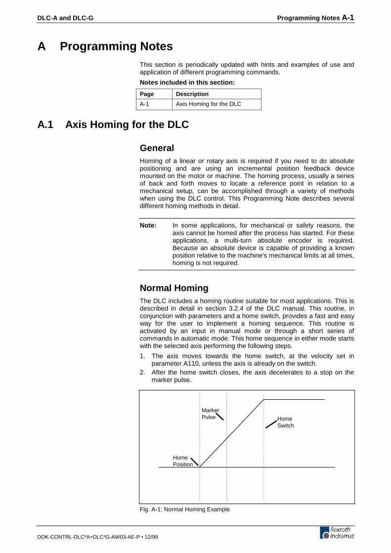
DLC-A and DLC-G Programming Notes A-1
DOK-CONTRL-DLC*A+DLC*G-AW03-AE-P • 12/99
A Programming NotesThis section is periodically updated with hints and examples of use andapplication of different programming commands.
Notes included in this section:
Page Description
A-1 Axis Homing for the DLC
A.1 Axis Homing for the DLC
GeneralHoming of a linear or rotary axis is required if you need to do absolutepositioning and are using an incremental position feedback devicemounted on the motor or machine. The homing process, usually a seriesof back and forth moves to locate a reference point in relation to amechanical setup, can be accomplished through a variety of methodswhen using the DLC control. This Programming Note describes severaldifferent homing methods in detail.
Note: In some applications, for mechanical or safety reasons, theaxis cannot be homed after the process has started. For theseapplications, a multi-turn absolute encoder is required.Because an absolute device is capable of providing a knownposition relative to the machine's mechanical limits at all times,homing is not required.
Normal HomingThe DLC includes a homing routine suitable for most applications. This isdescribed in detail in section 3.2.4 of the DLC manual. This routine, inconjunction with parameters and a home switch, provides a fast and easyway for the user to implement a homing sequence. This routine isactivated by an input in manual mode or through a short series ofcommands in automatic mode. This home sequence in either mode startswith the selected axis performing the following steps.
1. The axis moves towards the home switch, at the velocity set inparameter A110, unless the axis is already on the switch.
2. After the home switch closes, the axis decelerates to a stop on themarker pulse.
MarkerPulse Home
Switch
HomePosition
Fig. A-1: Normal Homing Example
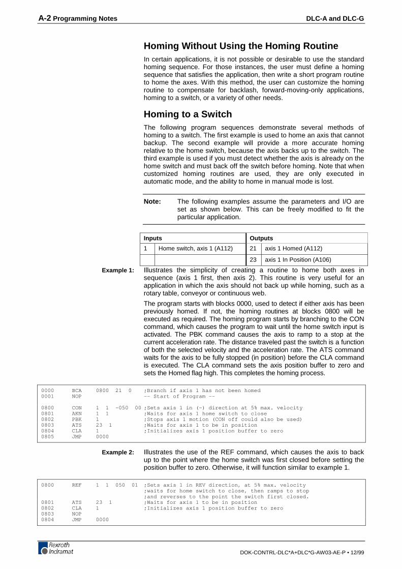
A-2 Programming Notes DLC-A and DLC-G
DOK-CONTRL-DLC*A+DLC*G-AW03-AE-P • 12/99
Homing Without Using the Homing RoutineIn certain applications, it is not possible or desirable to use the standardhoming sequence. For those instances, the user must define a homingsequence that satisfies the application, then write a short program routineto home the axes. With this method, the user can customize the homingroutine to compensate for backlash, forward-moving-only applications,homing to a switch, or a variety of other needs.
Homing to a SwitchThe following program sequences demonstrate several methods ofhoming to a switch. The first example is used to home an axis that cannotbackup. The second example will provide a more accurate homingrelative to the home switch, because the axis backs up to the switch. Thethird example is used if you must detect whether the axis is already on thehome switch and must back off the switch before homing. Note that whencustomized homing routines are used, they are only executed inautomatic mode, and the ability to home in manual mode is lost.
Note: The following examples assume the parameters and I/O areset as shown below. This can be freely modified to fit theparticular application.
Inputs Outputs
1 Home switch, axis 1 (A112) 21 axis 1 Homed (A112)
23 axis 1 In Position (A106)
Illustrates the simplicity of creating a routine to home both axes insequence (axis 1 first, then axis 2). This routine is very useful for anapplication in which the axis should not back up while homing, such as arotary table, conveyor or continuous web.
The program starts with blocks 0000, used to detect if either axis has beenpreviously homed. If not, the homing routines at blocks 0800 will beexecuted as required. The homing program starts by branching to the CONcommand, which causes the program to wait until the home switch input isactivated. The PBK command causes the axis to ramp to a stop at thecurrent acceleration rate. The distance traveled past the switch is a functionof both the selected velocity and the acceleration rate. The ATS commandwaits for the axis to be fully stopped (in position) before the CLA commandis executed. The CLA command sets the axis position buffer to zero andsets the Homed flag high. This completes the homing process.
0000 BCA 0800 21 0 ;Branch if axis 1 has not been homed0001 NOP -- Start of Program --
0800 CON 1 1 -050 00 ;Sets axis 1 in (-) direction at 5% max. velocity0801 AKN 1 1 ;Waits for axis 1 home switch to close0802 PBK 1 ;Stops axis 1 motion (CON off could also be used)0803 ATS 23 1 ;Waits for axis 1 to be in position0804 CLA 1 ;Initializes axis 1 position buffer to zero0805 JMP 0000
Illustrates the use of the REF command, which causes the axis to backup to the point where the home switch was first closed before setting theposition buffer to zero. Otherwise, it will function similar to example 1.
0800 REF 1 1 050 01 ;Sets axis 1 in REV direction, at 5% max. velocity;waits for home switch to close, then ramps to stop;and reverses to the point the switch first closed.
0801 ATS 23 1 ;Waits for axis 1 to be in position0802 CLA 1 ;Initializes axis 1 position buffer to zero0803 NOP0804 JMP 0000
Example 1:
Example 2:

DLC-A and DLC-G Programming Notes A-3
DOK-CONTRL-DLC*A+DLC*G-AW03-AE-P • 12/99
Illustrates a routine that is very useful for applications in which the axisshould not back up past the home switch. The program starts with blocks0000, used to detect if either axis has been previously homed. If not, thehoming routines at blocks 0800 will be executed as required. The homingprogram starts by branching to a BCE command that will branch to block805 (core homing program) if the switch is not closed. If the home switchwas closed, the program will drop down to the next three steps,comprised of a CON command which will cause the axis to move off theswitch at a set velocity, an AKN command which causes the program towait until the home switch input is opened, and the PBK which causes theaxis to ramp to a stop.
The REF command starts the core homing program, used to locate thehome switch. The axis moves toward the home switch at a set velocityuntil the switch is closed. After this, the axis ramps to a stop and thenmoves in the reverse direction, stopping at the point where the switch wasfirst closed. The ATS command waits for the axis to be fully stopped (inposition) before the CLA command is executed. The CLA command setthe axis position buffer to zero and sets the Homed Flag high. Thiscompletes the homing process for a given axis.
0000 BCA 0800 21 0 ;Branch if axis 1 has not been homed
0800 BCE 0805 1 0 ;Branch if axis 1 is not on the home switch0801 CON 1 1 +050 00 Sets axis 1 in (+) direction at 5% max. velocity0802 AKN 1 0 Waits for axis 1 home switch to open0803 PBK 1 Stops axis 1 motion0804 NOP0805 REF 1 1 050 01 ;Sets axis 1 in REV direction at 5% max. velocity, waits
for home switch to close, then ramps to a stopand reverses to the point the switch first closed.
0806 ATS 23 1 Waits for axis 1 to be in position0807 CLA 1 Initializes axis 1 position buffer to zero0808 JMP 0000
Homing to the Marker PulseWhen the DLC Servo System is first powered up, it knows where the motorpulse is located. The DLC can tell the axis to home to the marker pulse.This is very useful for single revolution applications where the rotatingmechanisms are directly attached to the motor shaft (rotary knife, printdrum). This type of operation is enabled when the home switch inputis set to 00 in parameter A112. The homing routine can be activated by aninput in manual mode, or through a short series of commands in automaticmode. This home sequence, in either mode, starts with the axis performingthe following steps:
1) The axis moves in the desired direction (CW, CCW) at the velocity set inparameter A110, until the marker pulse is detected.
Homing Routine at Start of User Program0000 BCE 005 21 1 ;Branch if axis 1 is already homed0001 HOM 1 Home axis 1 (figure 2)0002 ATS 21 1 Wait for axis 1 Homed output0003 JMP 0010
0010 NOP ; -- Start of Program --0011
Example 3:
A-4 Programming Notes DLC-A and DLC-G
DOK-CONTRL-DLC*A+DLC*G-AW03-AE-P • 12/99
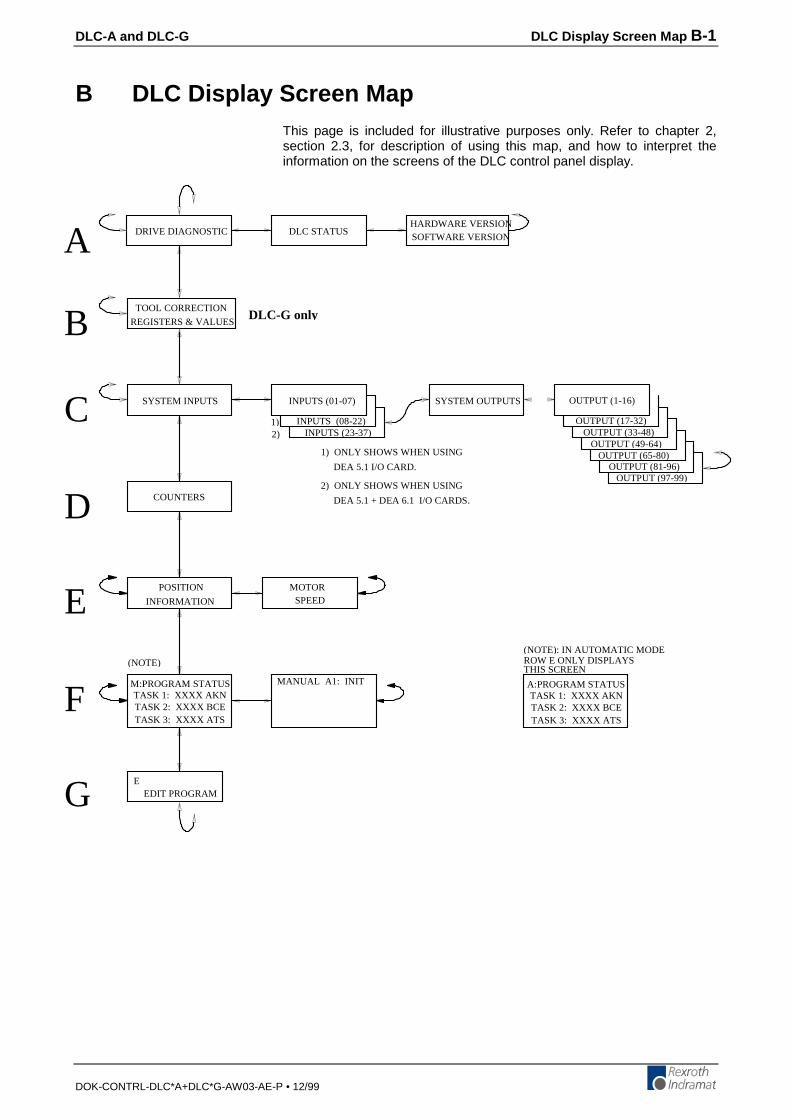
DLC-A and DLC-G DLC Display Screen Map B-1
DOK-CONTRL-DLC*A+DLC*G-AW03-AE-P • 12/99
B DLC Display Screen MapThis page is included for illustrative purposes only. Refer to chapter 2,section 2.3, for description of using this map, and how to interpret theinformation on the screens of the DLC control panel display.
A
C
D
E
F
G
HARDWARE VERSIONSOFTWARE VERSION
DLC STATUSDRIVE DIAGNOSTIC
SYSTEM INPUTS INPUTS (01-07)
2) INPUTS (23-37)
SYSTEM OUTPUTS OUTPUT (1-16)
OUTPUT (17-32)OUTPUT (33-48)
OUTPUT (49-64)OUTPUT (65-80)
OUTPUT (81-96)OUTPUT (97-99)
POSITION
INFORMATION
COUNTERS
MOTORSPEED
(NOTE)
M:PROGRAM STATUSTASK 1: XXXX AKNTASK 2: XXXX BCETASK 3: XXXX ATS
MANUAL A1: INIT
EEDIT PROGRAM
(NOTE): IN AUTOMATIC MODEROW E ONLY DISPLAYSTHIS SCREEN
A:PROGRAM STATUSTASK 1: XXXX AKNTASK 2: XXXX BCETASK 3: XXXX ATS
INPUTS (08-22)1)
DEA 5.1 + DEA 6.1 I/O CARDS.
2) ONLY SHOWS WHEN USING
DEA 5.1 I/O CARD.
1) ONLY SHOWS WHEN USING
B REGISTERS & VALUES
TOOL CORRECTIONDLC-G only
B-2 DLC Display Screen Map DLC-A and DLC-G
DOK-CONTRL-DLC*A+DLC*G-AW03-AE-P • 12/99
DLC-A and DLC-G Drawings and Schematics C-1
DOK-CONTRL-DLC*A+DLC*G-AW03-AE-P • 12/99
C Drawings and Schematics
CAUTION: The drawings in this Appendix are included for illustrativepurposes only and are subject to change without notice. Checkwith Indramat to be sure you are working with the latestdrawings prior to installing, wiring and powering equipment.
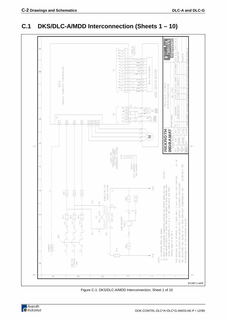
C-2 Drawings and Schematics DLC-A and DLC-G
DOK-CONTRL-DLC*A+DLC*G-AW03-AE-P • 12/99
C.1 DKS/DLC-A/MDD Interconnection (Sheets 1 – 10)
b1162-1.wmf
Figure C-1: DKS/DLC-A/MDD Interconnection, Sheet 1 of 10
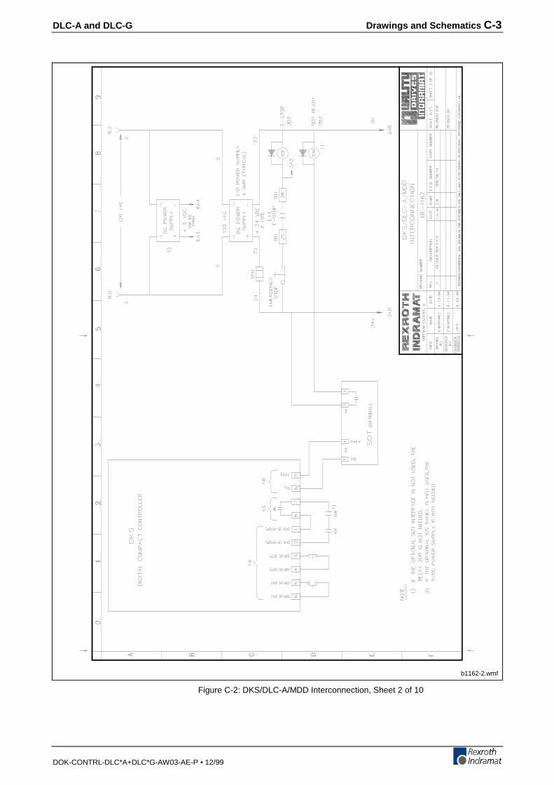
DLC-A and DLC-G Drawings and Schematics C-3
DOK-CONTRL-DLC*A+DLC*G-AW03-AE-P • 12/99
b1162-2.wmf
Figure C-2: DKS/DLC-A/MDD Interconnection, Sheet 2 of 10
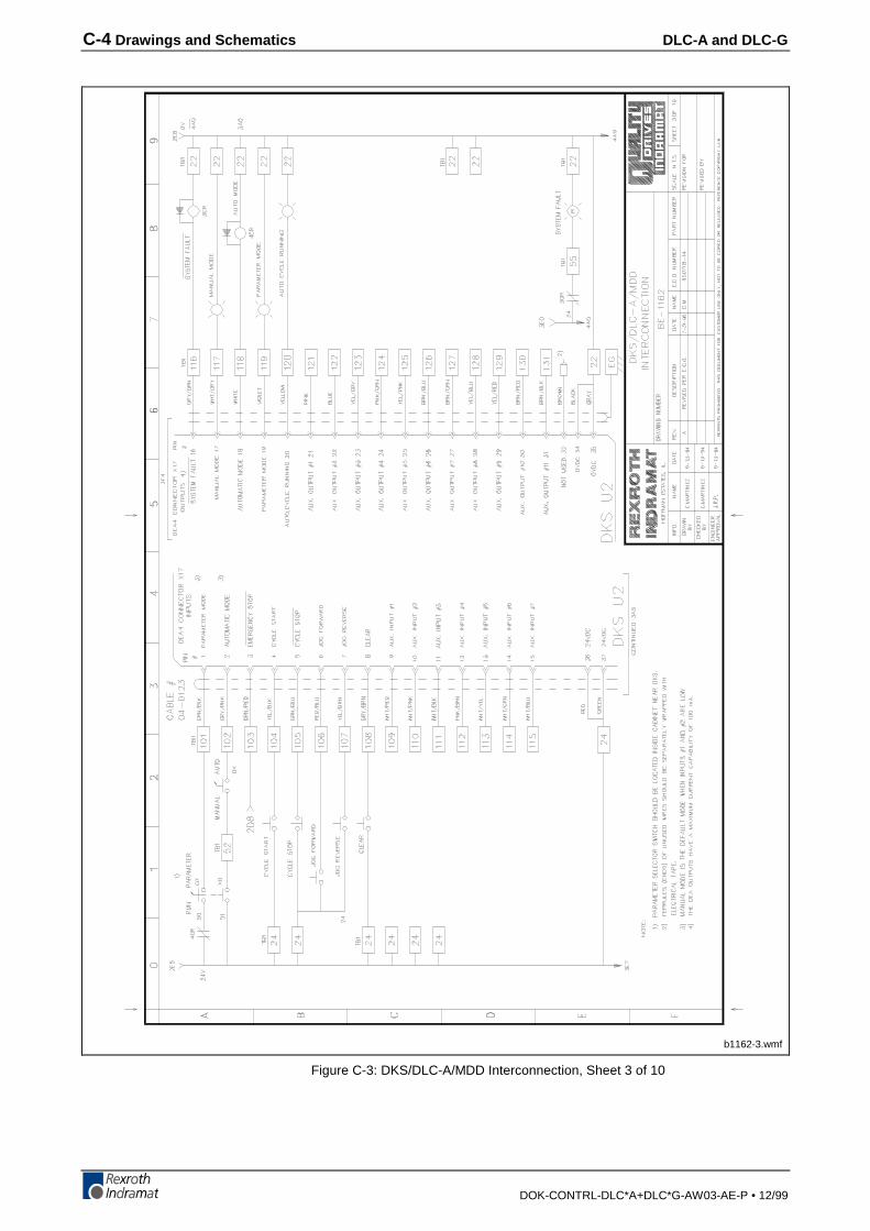
C-4 Drawings and Schematics DLC-A and DLC-G
DOK-CONTRL-DLC*A+DLC*G-AW03-AE-P • 12/99
b1162-3.wmf
Figure C-3: DKS/DLC-A/MDD Interconnection, Sheet 3 of 10

DLC-A and DLC-G Drawings and Schematics C-5
DOK-CONTRL-DLC*A+DLC*G-AW03-AE-P • 12/99
b1162-4.wmf
Figure C-4: DKS/DLC-A/MDD Interconnection, Sheet 4 of 10
\
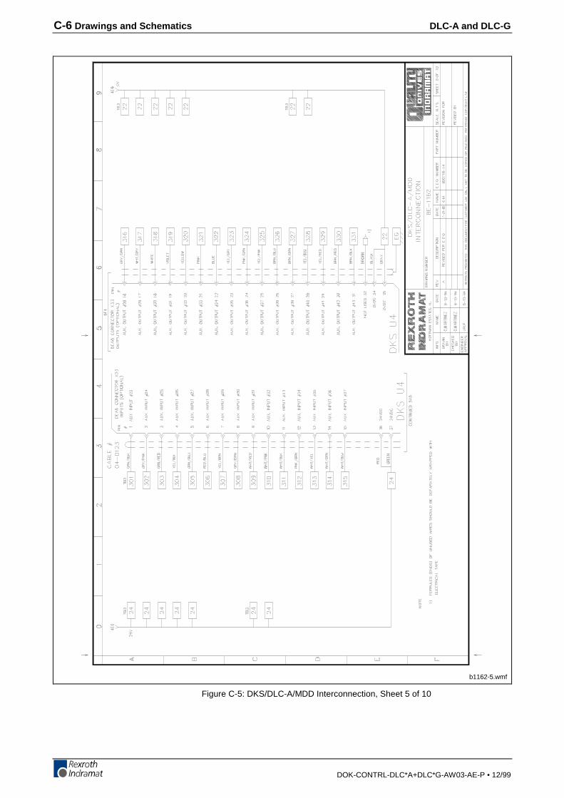
C-6 Drawings and Schematics DLC-A and DLC-G
DOK-CONTRL-DLC*A+DLC*G-AW03-AE-P • 12/99
b1162-5.wmf
Figure C-5: DKS/DLC-A/MDD Interconnection, Sheet 5 of 10
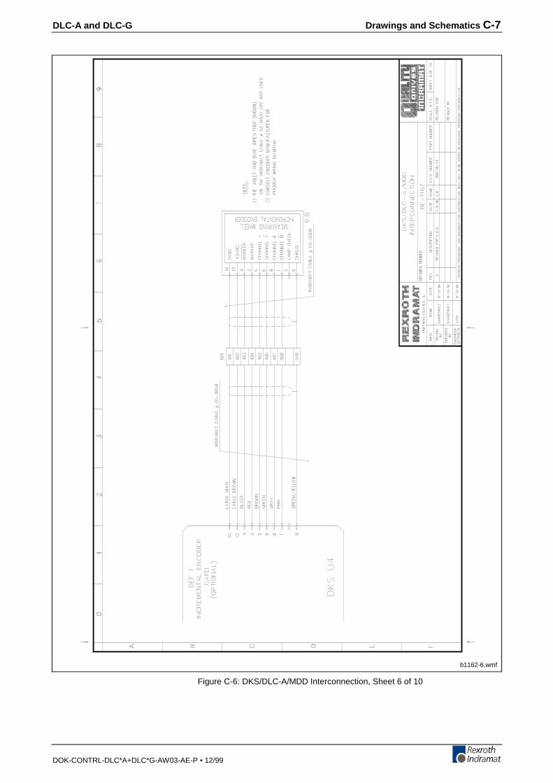
DLC-A and DLC-G Drawings and Schematics C-7
DOK-CONTRL-DLC*A+DLC*G-AW03-AE-P • 12/99
b1162-6.wmf
Figure C-6: DKS/DLC-A/MDD Interconnection, Sheet 6 of 10
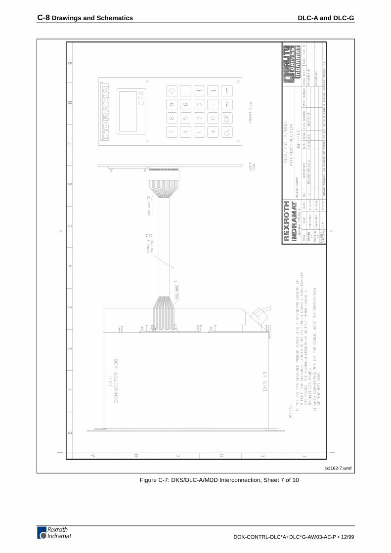
C-8 Drawings and Schematics DLC-A and DLC-G
DOK-CONTRL-DLC*A+DLC*G-AW03-AE-P • 12/99
b1162-7.wmf
Figure C-7: DKS/DLC-A/MDD Interconnection, Sheet 7 of 10
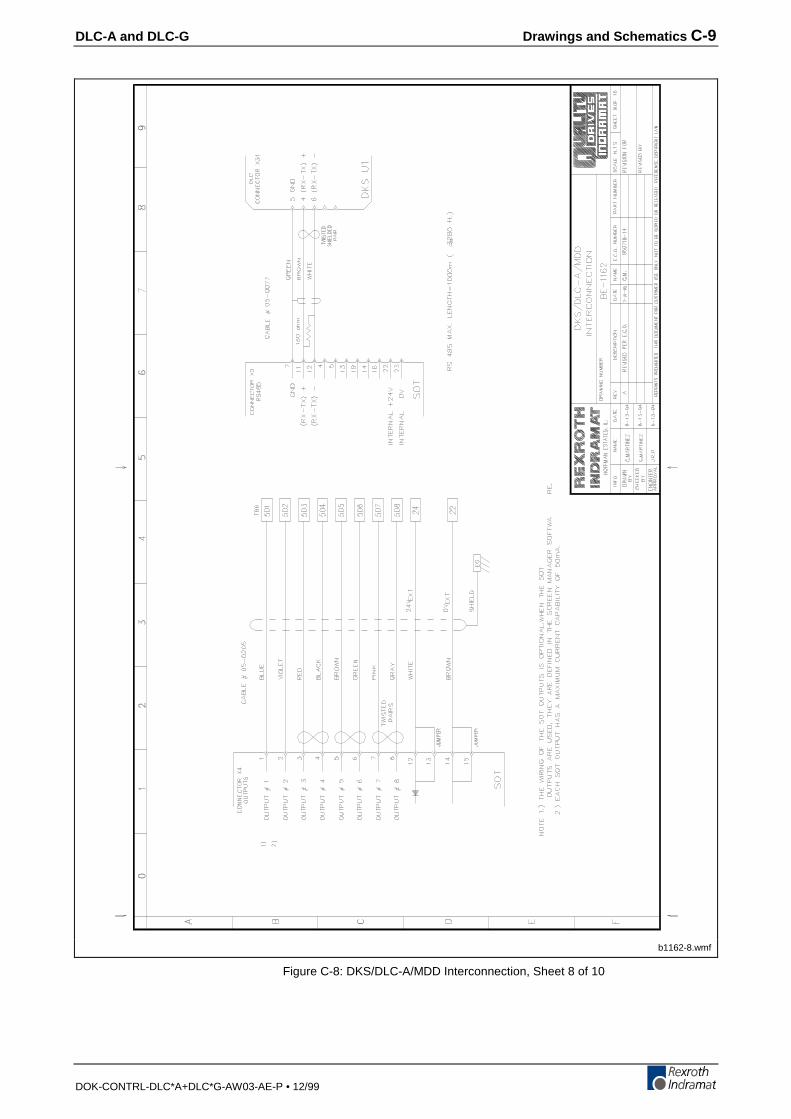
DLC-A and DLC-G Drawings and Schematics C-9
DOK-CONTRL-DLC*A+DLC*G-AW03-AE-P • 12/99
b1162-8.wmf
Figure C-8: DKS/DLC-A/MDD Interconnection, Sheet 8 of 10
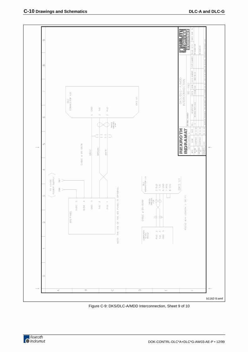
C-10 Drawings and Schematics DLC-A and DLC-G
DOK-CONTRL-DLC*A+DLC*G-AW03-AE-P • 12/99
b1162-9.wmf
Figure C-9: DKS/DLC-A/MDD Interconnection, Sheet 9 of 10

DLC-A and DLC-G Drawings and Schematics C-11
DOK-CONTRL-DLC*A+DLC*G-AW03-AE-P • 12/99
b1162-10.wmf
Figure C-10: DKS/DLC-A/MDD Interconnection, Sheet 10 of 10
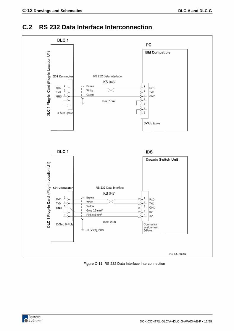
C-12 Drawings and Schematics DLC-A and DLC-G
DOK-CONTRL-DLC*A+DLC*G-AW03-AE-P • 12/99
C.2 RS 232 Data Interface Interconnection
Figure C-11: RS 232 Data Interface Interconnection

DLC-A and DLC-G Drawings and Schematics C-13
DOK-CONTRL-DLC*A+DLC*G-AW03-AE-P • 12/99
C.3 SOT – DLC RS485 Interconnection
fig906.wmf
Figure C-12: SOT – DLC RS485 Interconnection with up to 32 Stations
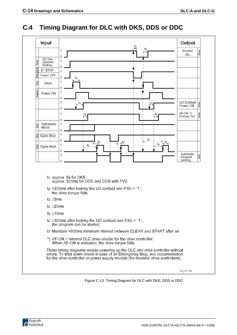
C-14 Drawings and Schematics DLC-A and DLC-G
DOK-CONTRL-DLC*A+DLC*G-AW03-AE-P • 12/99
C.4 Timing Diagram for DLC with DKS, DDS or DDC
Figure C-13: Timing Diagram for DLC with DKS, DDS or DDC

DLC-A and DLC-G Installation Drawings D-1
DOK-CONTRL-DLC*A+DLC*G-AW03-AE-P • 12/99
D Installation Drawings
CAUTION: The drawings in this Appendix are included for illustrativepurposes only and are subject to change without notice. Checkwith Indramat to be sure you are working with the latestdrawings prior to installing, wiring and powering equipment.
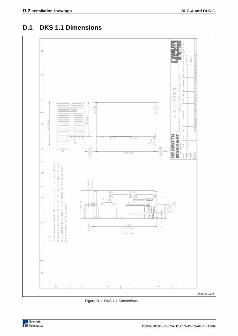
D-2 Installation Drawings DLC-A and DLC-G
DOK-CONTRL-DLC*A+DLC*G-AW03-AE-P • 12/99
D.1 DKS 1.1 Dimensions
dks1-out.wmf
Figure D-1: DKS 1.1 Dimensions
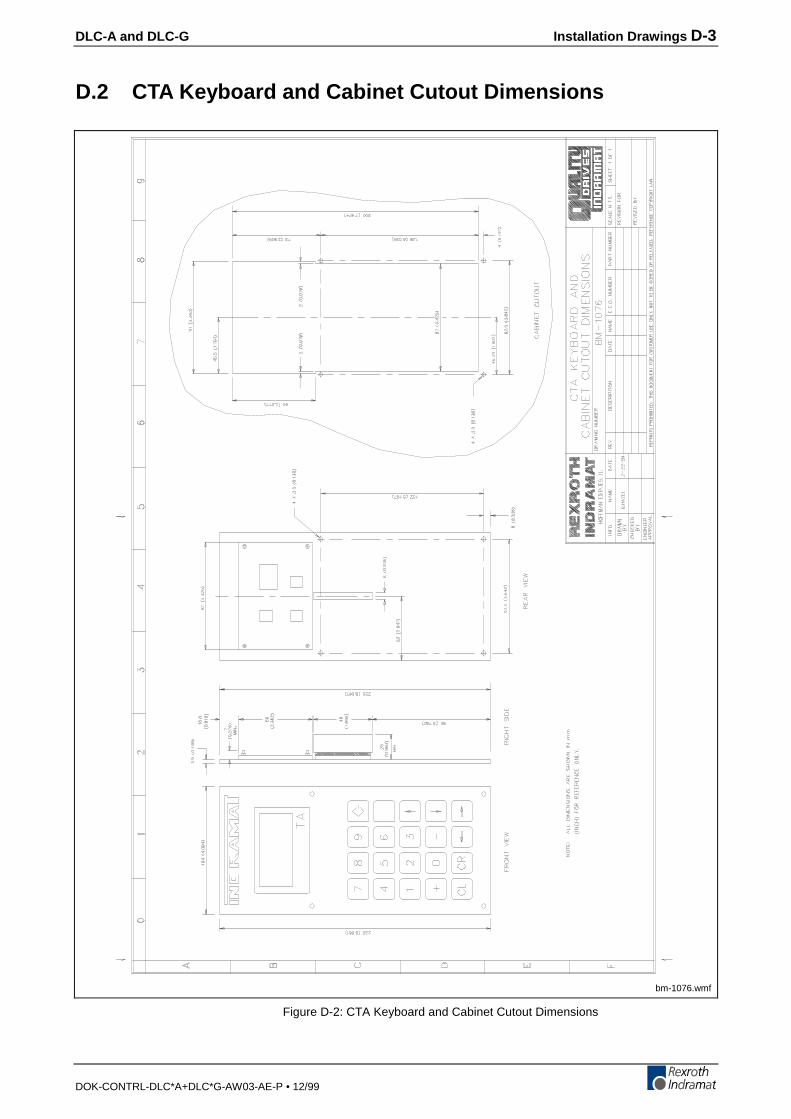
DLC-A and DLC-G Installation Drawings D-3
DOK-CONTRL-DLC*A+DLC*G-AW03-AE-P • 12/99
D.2 CTA Keyboard and Cabinet Cutout Dimensions
bm-1076.wmf
Figure D-2: CTA Keyboard and Cabinet Cutout Dimensions
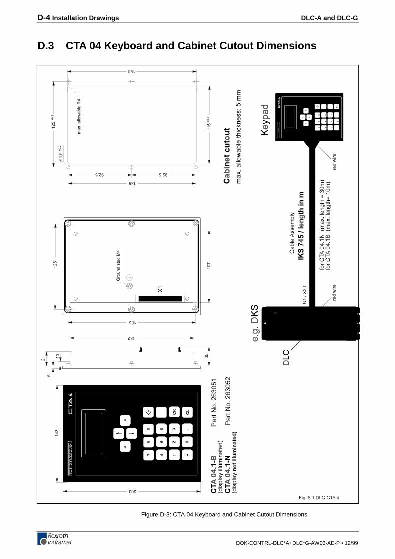
D-4 Installation Drawings DLC-A and DLC-G
DOK-CONTRL-DLC*A+DLC*G-AW03-AE-P • 12/99
D.3 CTA 04 Keyboard and Cabinet Cutout Dimensions
Figure D-3: CTA 04 Keyboard and Cabinet Cutout Dimensions
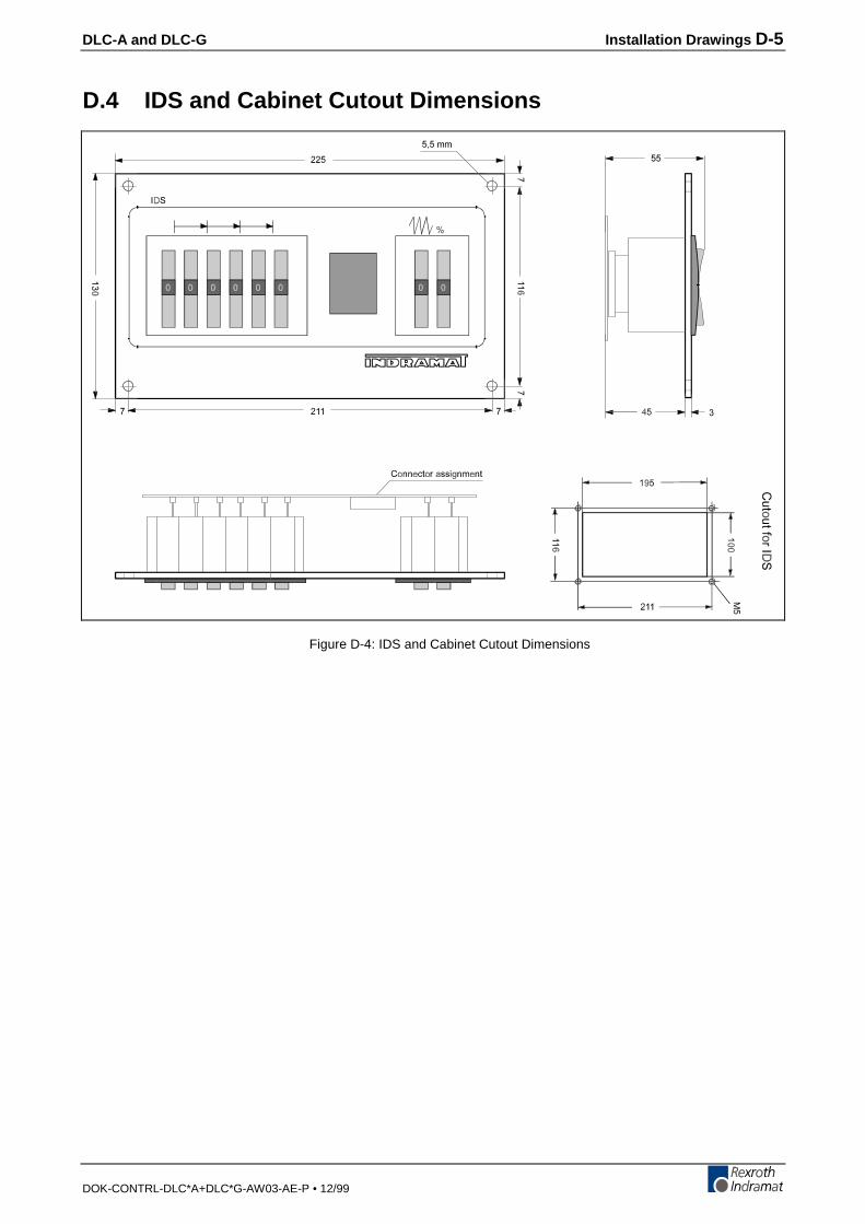
DLC-A and DLC-G Installation Drawings D-5
DOK-CONTRL-DLC*A+DLC*G-AW03-AE-P • 12/99
D.4 IDS and Cabinet Cutout Dimensions
Figure D-4: IDS and Cabinet Cutout Dimensions
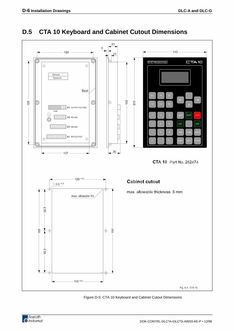
D-6 Installation Drawings DLC-A and DLC-G
DOK-CONTRL-DLC*A+DLC*G-AW03-AE-P • 12/99
D.5 CTA 10 Keyboard and Cabinet Cutout Dimensions
Figure D-5: CTA 10 Keyboard and Cabinet Cutout Dimensions

DLC-A and DLC-G Installation Drawings D-7
DOK-CONTRL-DLC*A+DLC*G-AW03-AE-P • 12/99
D.6 CTA/DLC Interconnection
Figure D-6: CTA/DLC Interconnection

D-8 Installation Drawings DLC-A and DLC-G
DOK-CONTRL-DLC*A+DLC*G-AW03-AE-P • 12/99
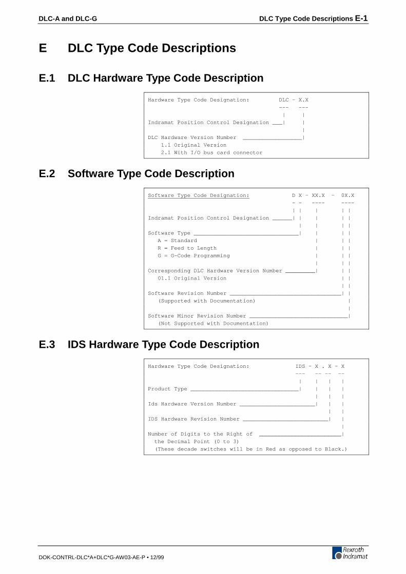
DLC-A and DLC-G DLC Type Code Descriptions E-1
DOK-CONTRL-DLC*A+DLC*G-AW03-AE-P • 12/99
E DLC Type Code Descriptions
E.1 DLC Hardware Type Code Description
Hardware Type Code Designation: DLC - X.X
--- ---
| |
Indramat Position Control Designation ___| |
|
DLC Hardware Version Number __________________|
1.1 Original Version
2.1 With I/O bus card connector
E.2 Software Type Code Description
Software Type Code Designation: D X - XX.X - 0X.X
- - ---- ----
| | | | |
Indramat Position Control Designation ______| | | | |
| | | |
Software Type ________________________________| | | |
A = Standard | | |
R = Feed to Length | | |
G = G-Code Programming | | |
| | |
Corresponding DLC Hardware Version Number _________| | |
01.1 Original Version | |
| |
Software Revision Number __________________________________| |
(Supported with Documentation) |
|
Software Minor Revision Number ______________________________|
(Not Supported with Documentation)
E.3 IDS Hardware Type Code Description
Hardware Type Code Designation: IDS - X . X - X
--- -- -- --
| | | |
Product Type _________________________________| | | |
| | |
Ids Hardware Version Number _______________________| | |
| |
IDS Hardware Revision Number __________________________| |
|
Number of Digits to the Right of _________________________|
the Decimal Point (0 to 3)
(These decade switches will be in Red as opposed to Black.)
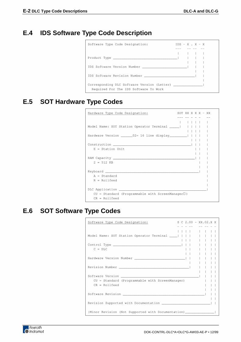
E-2 DLC Type Code Descriptions DLC-A and DLC-G
DOK-CONTRL-DLC*A+DLC*G-AW03-AE-P • 12/99
E.4 IDS Software Type Code Description
Software Type Code Designation: IDS - X . X - X
--- -- -- --
| | | |
Product Type _________________________________| | | |
| | |
IDS Software Version Number _______________________| | |
| |
IDS Software Revision Number __________________________| |
|
Corresponding DLC Software Version (Letter) _______________|
Required For The IDS Software To Work
E.5 SOT Hardware Type Codes
Hardware Type Code Designation: SOT XX X X X - XX
--- -- - - - --
| | | | | |
Model Name: SOT Station Operator Terminal _____| | | | | |
| | | | |
Hardware Version ______02= 16 line display_________| | | | |
| | | |
Construction ________________________________________| | | |
E = Station Unit | | |
| | |
RAM Capacity __________________________________________| | |
2 = 512 KB | |
| |
Keyboard ________________________________________________| |
A = Standard |
R = Rollfeed |
|
DLC Application _____________________________________________|
CU = Standard (Programmable with ScreenManager )
CR = Rollfeed
E.6 SOT Software Type Codes
Software Type Code Designation: S C 2.00 - XX.02.X X
- - - -- -- -- - -
| | | | | | | |
Model Name: SOT Station Operator Terminal ____| | | | | | | |
| | | | | | |
Control Type ___________________________________| | | | | | |
C = DLC | | | | | |
| | | | | |
Hardware Version Number __________________________| | | | | |
| | | | |
Revision Number ____________________________________| | | | |
| | | |
Software Version ________________________________________| | | |
CU = Standard (Programmable with ScreenManager) | | |
CR = Rollfeed | | |
| | |
Software Revision __________________________________________| | |
| |
Revision Supported with Documentation _________________________| |
|Minor Revision (Not Supported with Documentation)_______________|
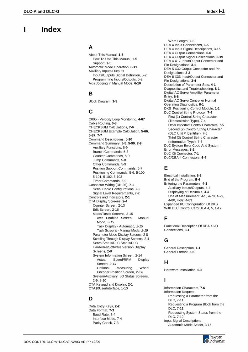
DLC-A and DLC-G Index I-1
DOK-CONTRL-DLC*A+DLC*G-AW03-AE-P • 12/99
I Index
AAbout This Manual, 1-5
How To Use This Manual, 1-5Support, 1-5
Automatic Mode Operation, 6-11Auxiliary Inputs/Outputs
Inputs/Outputs Signal Definition, 5-2Programming Inputs/Outputs, 5-2
Axis Jogging in Manual Mode, 6-10
BBlock Diagram, 1-3
CC005 - Velocity Loop Monitoring, 4-67Cable Routing, 6-3CHECKSUM Calculations, 7-6CHECKSUM Example Calculation, 5-66,5-87, 7-7Command Descriptions, 5-10Command Summary, 5-5, 5-99, 7-9
Auxiliary Functions, 5-9Branch Commands, 5-8Counter Commands, 5-9Jump Commands, 5-8Other Commands, 5-9Position Support Commands, 5-7Positioning Commands, 5-6, 5-100,5-101, 5-102, 5-103Timer Commands, 5-9
Connector Wiring (DB-25), 7-1Serial Cable Configurations, 7-2Signal Level Requirements, 7-2
Controls and Indicators, 2-1CTA Display Screens, 2-4
Counter Screen, 2-13Edit Screen, 2-16Mode/Tasks Screens, 2-15
Axis Enabled Screen - ManualMode, 2-15Task Display - Automatic, 2-15Task Screens - Manual Mode, 2-15
Parameter Mode Display Screens, 2-8Scrolling Through Display Screens, 2-4Servo Status/DLC Status/DLCHardware/Software Version DisplayScreens, 2-8System Information Screen, 2-14
Actual Speed/RPM DisplayScreen, 2-14Optional Measuring WheelEncoder Position Screen, 2-14
System/Auxiliary I/O Status Screens,2-9, 2-10
CTA Keypad and Display, 2-1CTA10UserInterface, 1-10
DData Entry Keys, 2-2Data Format, 7-3
Baud Rate, 7-4Interface Mode, 7-4Parity Check, 7-3
Word Length, 7-3DEA 4 Input Connections, 6-5DEA 4 Input Signal Descriptions, 3-15DEA 4 Output Connections, 6-6DEA 4 Output Signal Descriptions, 3-19DEA 4 X17 Input/Output Connector andPin Designations, 3-1DEA 5 X32 Output Connector and PinDesignations, 3-3DEA 6 X33 Input/Output Connector andPin Designations, 3-4Description of Parameter Sets, 4-1Diagnostics and Troubleshooting, 8-1Digital AC Servo Amplifier ParameterEntry, 6-6Digital AC Servo Controller NormalOperating Diagnostics, 8-1DKS Positioning Control Module, 1-1DLC Control String Protocol, 7-4
First (1) Control String Character(Transmission Type), 7-4Other Important Control Characters, 7-5Second (2) Control String Character(DLC Unit # Identifier), 7-5Third (3) Control String Character(Information Type), 7-5
DLC System Error Code And SystemError Messages, 8-2DLC X6 Connector, 7-1DLC/DEA 4 Connectors, 6-4
EElectrical Installation, 6-3End of the Program, 5-4Entering the Parameters, 4-3
Auxiliary Inputs/Outputs, 4-4Displaying of Decimals, 4-4Unit of Measurement, 4-5, 4-78, 4-79,4-80, 4-82, 4-83
Expanded I/O Configuration Of DKSWith DLC Control Card/DEA 4, 5, 1-12
FFunctional Description Of DEA 4 I/OConnections, 3-1
GGeneral Description, 1-1General Format, 5-5
HHardware Installation, 6-3
IInformation Characters, 7-6Information Request
Requesting a Parameter from theDLC, 7-11Requesting a Program Block from theDLC, 7-11Requesting System Status from theDLC, 7-12
Input Signal DescriptionsAutomatic Mode Select, 3-15
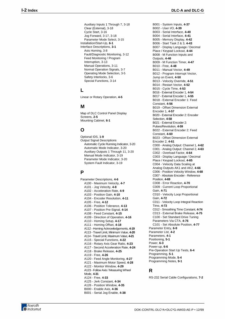
I-2 Index DLC-A and DLC-G
DOK-CONTRL-DLC*A+DLC*G-AW03-AE-P • 12/99
Auxiliary Inputs 1 Through 7, 3-18Clear (External), 3-18Cycle Start, 3-16Jog Forward, 3-17, 3-18Parameter Mode Select, 3-15
Installation/Start-Up, 6-1Interface Descriptions, 3-1
Axis Homing, 3-8Fault/Diagnostic Monitoring, 3-12Feed Monitoring / ProgramInterruption, 3-13Manual Operations, 3-11Normal Operation Signals, 3-7Operating Mode Selection, 3-5Safety Interlocks, 3-6Special Functions, 3-14
LLinear or Rotary Operation, 4-5
MMap of DLC Control Panel DisplayScreens, 2-5Mounting Cabinet, 6-1
OOptional IDS, 1-9Output Signal Descriptions
Automatic Cycle Running Indicator, 3-20Automatic Mode Indicator, 3-20Auxiliary Outputs 1 Through 11, 3-20Manual Mode Indicator, 3-19Parameter Mode Indicator, 3-20System Fault Indicator, 3-19
PParameter Descriptions, 4-6
A100 - Maximum Velocity, 4-7A101 - Jog Velocity, 4-8A102 - Acceleration Rate, 4-9A103 - Position Gain, 4-10A104 - Encoder Resolution, 4-11A105 - Free, 4-12A106 - Position Tolerance, 4-13A107 - Position Pre-Signal, 4-14A108 - Feed Constant, 4-15A109 - Direction of Operation, 4-16A110 - Homing Setup, 4-17A111 - Homing Offset, 4-18A112 - Homing Acknowledgements, 4-19A113 - Travel Limit, Minimum Value, 4-20A114 - Travel Limit, Maximum Value, 4-21A115 - Special Functions, 4-22A116 - Rotary Axis Gear Ratio, 4-23A117 - Second Acceleration Rate, 4-24A118 - Brake Release, 4-25A119 - Free, 4-26A120 - Feed Angle Monitoring, 4-27A121 - Maximum Motor Speed, 4-28A122 - Monitor Window, 4-29A123 - Follow Axis / Measuring WheelMode, 4-31A124 - Free, 4-33A125 - Jerk Constant, 4-34A126 - Position Window, 4-35B000 - Enable Axis, 4-36B001 - Serial Jog Enable, 4-38
B001 - System Inputs, 4-37B002 - User I/O, 4-39B003 - Serial Interface, 4-40B004 - Serial Interface, 4-41B005 - Memory Display, 4-42B006 - Start Task 2 & 3, 4-43B007 - Display Language / DecimalPlace / Keypad Lockout, 4-44B008 - M Function Inputs andOutputs, 4-46B009 - M Function Timer, 4-47B010 - Free, 4-48B011 - Manual Vector, 4-49B012 - Program Interrupt Vector,Jump on Event, 4-50B013 - Velocity Override, 4-51B014 - Restart Vector, 4-52B015 - Cycle Time, 4-53B016 - External Encoder 1, 4-54B017 - External Encoder 1, 4-55B018 - External Encoder 1: FeedConstant, 4-56B019 - Offset Dimension ExternalEncoder 1, 4-57B020 - External Encoder 2: EncoderSelection, 4-58B021 - External Encoder 2:Pulses/Revolution, 4-59B022 - External Encoder 2: FeedConstant, 4-60B023 - Offset Dimension ExternalEncoder 2, 4-61C000 - Analog Output: Channel 1, 4-62C001 - Analog Output: Channel 2, 4-63C002 - Overload Factor, 4-64C003 - Display Language / DecimalPlace / Keypad Lockout, 4-65C004 - Velocity Data Scaling atAnalog Outputs AK1 and AK2, 4-66C006 - Position Velocity Window, 4-68C007 - Absolute Encoder - ReferencePosition, 4-69C008 - Error Reaction, 4-70C009 - Current Loop ProportionalGain, 4-71C010 - Velocity Loop ProportionalGain, 4-72C011 - Velocity Loop Integral ReactionTime, 4-73C012 - Smoothing Time Constant, 4-74C013 - External Brake Release, 4-75C100 - Set Standard Drive TuningParameters Via CTA, 4-76C101 - Set Absolute Position, 4-77
Parameter Entry, 6-9Parameter List, 4-2Parameters, 4-1Positioning, 5-1Power, 6-3Power-up, 6-6Pre-Operation Start Up Tests, 6-4Programming, 5-1Programming Mode, 5-4Programming Notes, 9-1
RRS-232 Serial Cable Configurations, 7-2
DLC-A and DLC-G Index I-3
DOK-CONTRL-DLC*A+DLC*G-AW03-AE-P • 12/99
SSending Information to the DLC, 7-7
Sending Parameters to the DLC, 7-8Sending Program Blocks to the DLC, 7-7
Serial Communication Errors, 8-9, 8-12Serial Interface, 7-1Signal Definitions, 3-1Signal Level Requirements, 7-2SOT - Station Operator Terminal, 1-10Specifications, 1-14
Control Specifications, 1-14Options, 1-15Physical, 1-14
Standard Configuration Of DKS With DLCControl Card/DEA 4 I/O ca, 1-11, 1-13Standard Configuration Of DKS WithDLC Control Card/DEA 4 Input/, 1-11Standard Configuration Of DKS With DLCControl Card/DEA 4 Input/Output Card
Standard Configuration Of DKS WithDLC Control Card/DEA 4 Input/, 1-13
System Features, 1-7
TTransformer - Heat Dissipation, 6-3
I-4 Index DLC-A and DLC-G
DOK-CONTRL-DLC*A+DLC*G-AW03-AE-P • 12/99

DLC-A and DLC-G Customer Service Locations
DOK-CONTRL-DLC*A+DLC*G-AW03-AE-P • 12/99
Customer Service Locations
Americas (United States, Canada, and Latin America)USA
Rexroth CorporationINDRAMAT Division5150 Prairie Stone ParkwayHoffman Estates, Illinois 60192
Phone: 847/645-36 00Fax: 857/645-62 01
USA
Rexroth CorporationINDRAMAT Division2110 Austin AvenueRochester Hills, Michigan 48309
Phone: 810/853-82 90Fax: 810/853-82 90
INDRAMAT Service Hotlines
USA:1-800-860-1055
Canada:1-847-645-3600(request Service Department)
Latin America:(US Phone No.) 847-645-3600(request Service Department)
Canada
Basic Technologies CorporationBurlington Division3426 Mainway DriveBurlington, OntarioCanada L7M 1A8
Phone: 905/335-55 11Fax: 905/335-41 84
Mexico
Motorización yDiseño de Controles, S.A. deC.V.Av. Dr. Gustavo Baz No. 288Col. Parque Industrial la IomaApartado Postal No. 31854060 TlalnepantlaEstado de MexicoMexico
Phone: 5/397 86 44Fax: 5/398 98 88
Argentina
Mannesmann Rexroth S.A.I.C.Division INDRAMATAcassusso 48 41/71605 Munro (Buenos Aires)Argentina
Phone: 01/756 01 4001/756 02 40
Telex: 262 66 rexro arFax: 01/756 01 36
Argentina
NakaseAsesoramiento TecnicoDiaz Velez 29291636 Olivos(Provincia de Buenos Aires)Argentina
Phone: 01/790 52 30
Brazil
Mannesmann RexrothAutomação Ltda.Divisão INDRAMATRua Georg Rexroth, 609Vila Padre AnchietaBR-09.951-250 Diadema-SPCaixa Postal 377BR-09.901-970 Diadema-SP
Phone: 011/745 90 65011/745 90 70
Fax: 011/745 90 50
Customer Service in the Americas
Asia, Australia, and Far EastAustralia
Australian Industrial MachineryServices Pty. Ltd.Unit 3/45 Horne STCampbellfield VIC 2061Australia
Phone: 03/93 59 0228Fax: 03/93 59 02886
China
Rexroth (China) Ltd.Shanghai OfficeRoom 206Shanghai Intern. Trade Centre2200 Yanan Xi LuShanghai 200335P.R. China
Phone: 021/627 55 333Fax: 021/627 55 666
China
Rexroth (China) Ltd.Shanghai Parts & ServiceCentre199 Wu Cao Road, Hua CaoMinhang DistrictShanghai 201 103P.R. China
Phone: 021/622 00 058Fax: 021/622 00 068
China
Rexroth (China) Ltd.1430 China World Trade Centre1, Jianguomenwai AvenueBeijing 100004P.R. China
Phone: 010/50 50 380Fax: 010/50 50 379
China
Rexroth (China) Ltd.A-5F., 123 Lian Shan StreetSha He Kou DistrictDalian 116 023P.R. China
Phone: 0411/46 78 930Fax: 0411/46 78 932
Hong Kong
Rexroth (China) Ltd.19 Cheung Shun Street1st Floor, Cheung Sha Wan,Kowloon, Hong Kong
Phone: 741 13 51/-54 or741 14 30
Telex: 3346 17 GL REX HXFax: 786 40 19
786 07 33
India
Mannesmann Rexroth (India)Ltd.INDRAMAT DivisionPlot. 96, Phase IIIPeenya Industrial AreaBangalore - 560058India
Phone: 80/839 21 0180/839 73 74
Telex: 845 5028 RexBFax: 80/839 43 45
Japan
Rexroth Co., Ltd.INDRAMAT DivisionI.R. BuildingNakamachidai 4-26-44Tsuzuki-ku, Yokohama 226Japan
Phone: 045/942-72 10Fax: 045/942-03 41
Korea
Rexroth-Seki Co Ltd.1500-12 Da-Dae-DongSaha-Gu, Pusan, 604-050Korea
Phone: 051/264 90 01Fax: 051/264 90 10
Korea
Seo Chang Corporation Ltd.Room 903, Jeail Building44-35 Yoido-DongYoungdeungpo-KuSeoul, Korea
Phone: 02/780-82 07 ~9Fax: 02/784-54 08
Customer Service in Asia, Australia, and the Far East
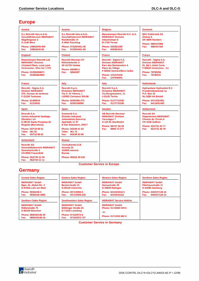
Customer Service Locations DLC-A and DLC-G
DOK-CONTRL-DLC*A+DLC*G-AW03-AE-P • 12/99
EuropeAustria
G.L.Rexroth Ges.m.b.H.Geschäftsbereich INDRAMATHägelingasse 3A-1140 Wien
Phone: 1/9852540-400Fax: 1/9852540-93
Austria
G.L.Rexroth Ges.m.b.H.Geschäftsbereich INDRAMATRandlstraße 14A-4061 Pasching
Phone: 07229/4401-36Fax: 07229/4401-80
Belgium
Mannesmann Rexroth N.V.-S.A.INDRAMAT DivisionIndustrielaan 8B-1740 Ternat
Phone: 02/5823180Fax: 02/5824310
Denmark
BEC Elektronik ASZinkvej 6DK-8900 Randers
Phone: 086/447866Fax: 086/447160
England
Mannesmann Rexroth Ltd.INDRAMAT Division4 Esland Place, Love LaneCirencester, Glos GL7 1YG
Phone: 01285/658671Fax: 01285/654991
Finland
Rexroth Mecman OYRiihimiehentie 3SF-01720 Vantaa
Phone: 0/848511Fax: 0/846387
France
Rexroth - Sigma S.A.Division INDRAMATParc des Barbanniers 4,Place du VillageF-92632 Gennevilliers Cedex
Phone: 1/41475430Fax: 1/47946941
France
Rexroth - Sigma S.A.Division INDRAMAT91, Bd 1 Joliot CurieF-69634 Venissieux - Cx
Phone: 78785256Fax: 78785231
France
Rexroth - Sigma S.A.Division INDRAMAT270, Avenue de lardenneF-31100 Toulouse
Phone: 61499519Fax: 61310041
Italy
Rexroth S.p.A.Divisione INDRAMATVia G. Di Vittoria, 1I-20063 Cernusco S/N.MI
Phone: 02/92365-270Fax: 02/92108069
Italy
Rexroth S.p.A.Divisione INDRAMATVia Borgomanero, 11I-10145 Torino
Phone: 011/7712230Fax: 011/7710190
Netherlands
Hydraudyne Hydrauliek B.V.Kruisbroeksestraat 1aP.O. Box 32NL-5280 AA Boxtel
Phone: 04116/51951Fax: 04116/51483
Spain
Rexroth S.A.Centro Industrial SantiagoObradors s/nE-08130 Santa Perpetua deMogoda (Barcelona)
Phone: 03/718 68 51Telex: 591 81Fax: 03/718 98 62
Spain
Goimendi S.A.División IndramatJolastokieta (Herrera)Apartado 11 37E-San Sebastion, 20017
Phone: 043/40 01 63Telex: 361 72Fax: 043/39 93 95
Sweden
AB Rexroth MecmanINDRAMAT DivisionVaruvägen 7S-125 81 Stockholm
Phone: 08/727 92 00Fax: 08/64 73 277
Switzerland
Rexroth SADépartement INDRAMATChemin de l`Ecole 6CH-1036 Sullens
Phone: 021/731 43 77Fax: 021/731 46 78
Switzerland
Rexroth AGGeeschäftsbereich INDRAMATGewerbestraße 3CH-8500 Frauenfeld
Phone: 052/720 21 00Fax: 052/720 21 11
Russia
Tschudnenko E.B.Arsenia 22153000 IvanovoRussia
Phone: 093/22 39 633
Customer Service in Europe
GermanyCentral Sales Region
INDRAMAT GmbHBgm.-Dr.-Nebel-Str. 2D-97816 Lohr am Main
Phone: 09352/40-0Fax: 09352/40-4885
Eastern Sales Region
INDRAMAT GmbHBeckerstraße 31D-09120 Chemnitz
Phone: 0371/3555-0Fax: 0371/3555-230
Western Sales Region
INDRAMAT GmbHHansastraße 25D-40849 Ratingen
Phone: 02102/4318-0Fax: 02102/41315
Northern Sales Region
INDRAMAT GmbHFährhausstraße 11D-22085 Hamburg
Phone: 040/227126-16Fax: 040/227126-15
Southern Sales Region
INDRAMAT GmbHRidlerstraße 75D-80339 München
Phone: 089/540138-30Fax: 089/540138-10
Southwestern Sales Region
INDRAMAT GmbHBöblinger Straße 25D-71229 Leonberg
Phone: 07152/972-6Fax: 07152/972-727
INDRAMAT Service Hotline
INDRAMAT GmbHPhone: 0172/660 040 6
-or-
Phone: 0171/333 882 6
Customer Service in Germany


286834
IndramatRexroth
Prin
ted
in G
erm
any
Related Documents