UC DAVIS Campus Design Guide UTILITIES - DIVISION 33 1 July 2014 DIVISION 33 – UTILITIES DESIGN CRITERIA OVERVIEW OF EXISTING CAMPUS MEDIUM AND HIGH VOLTAGE SYSTEM 115 KV TO 12470 VOLTS MAIN SUBSTATION The Main Substation receives two 115 KV feeders From PG&E and is capable of switching to either one, manually or automatically with twelve PASCO SF6 Isolation switches and six AREVA 1,200-amp SF6 high voltage circuit breakers. These circuit breakers in conjunction with the 4 inch aluminum bussing; isolate, switch and distribute power to future transformer “H”, back up service to switch station S1 and to transformer “G”. Design Notes: For installation of transformer “H”, review as-built for equipment installed to accommodate future equipment. Future equipment must be tested, integrated and commissioned as new. Relays must be set to the new fault and coordination study. TRANSFORMER “G” Transformer “G” has multiple KVA ratings of 30, 40, 56 MVA’s depending on the configuration of the onboard cooling fans. The transformer is equipped with an automatic load tap changer and provides seamless voltage correction for high or low voltage conditions. Transformer “G” requires no future modifications and is in its built out condition. Transformer “G” is connected to a capacitor bank that is capable of providing 19,200 KVARS automatically in four 4,800 KVARS per step. The capacitor bank maintains the campus electrical system with a power factor that insures UC with the best utility rate possible. Design Notes: Capacitor bank “G” requires no modification and is in its built out condition. TRANSFORMER “G’ SWITCHGEAR Switchgear “G’ receives 12470 volts from transformer “G”. Equipped with a 3000 AMP bus, protection devices by SEL, metering by ION and distributes through nine Powell circuit breakers. The switchgear has two 3000 AMP breakers, one to future transformer “H” switchgear and one to switch station S2-1, two 2000 AMP breakers, one to the capacitor bank, the second to switch station S2-2, six 1200 AMP breakers, one serving South Campus, and one for transformer “F”, and four spare breakers for future use. Design Notes: The existing spare breakers are completely built out and require testing, commissioning, integration and relay setting to the new fault current and coordination study. The cabling shall be designed per Campus Design Guide (CDG). 115 KV RING BUS SWITCH STATION 115 KV is also routed to the ring bus switch station and distributed through 4 inch aluminum ring bus bars and 8 SF6 S&C 200 series circuit switchers that services 6 transformers and their respective feeders and capacitor banks identified as; AF, BF, CF, EF and FF with a backup feeder

Welcome message from author
This document is posted to help you gain knowledge. Please leave a comment to let me know what you think about it! Share it to your friends and learn new things together.
Transcript
UC DAVIS Campus Design Guide
UTILITIES - DIVISION 33 1 July 2014
DIVISION 33 – UTILITIES
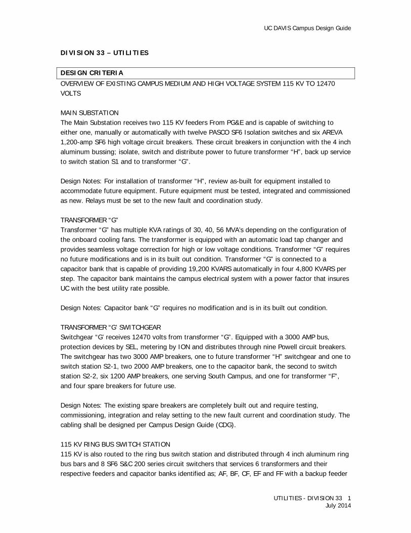
DESIGN CRITERIA OVERVIEW OF EXISTING CAMPUS MEDIUM AND HIGH VOLTAGE SYSTEM 115 KV TO 12470 VOLTS MAIN SUBSTATION The Main Substation receives two 115 KV feeders From PG&E and is capable of switching to either one, manually or automatically with twelve PASCO SF6 Isolation switches and six AREVA 1,200-amp SF6 high voltage circuit breakers. These circuit breakers in conjunction with the 4 inch aluminum bussing; isolate, switch and distribute power to future transformer “H”, back up service to switch station S1 and to transformer “G”. Design Notes: For installation of transformer “H”, review as-built for equipment installed to accommodate future equipment. Future equipment must be tested, integrated and commissioned as new. Relays must be set to the new fault and coordination study. TRANSFORMER “G” Transformer “G” has multiple KVA ratings of 30, 40, 56 MVA’s depending on the configuration of the onboard cooling fans. The transformer is equipped with an automatic load tap changer and provides seamless voltage correction for high or low voltage conditions. Transformer “G” requires no future modifications and is in its built out condition. Transformer “G” is connected to a capacitor bank that is capable of providing 19,200 KVARS automatically in four 4,800 KVARS per step. The capacitor bank maintains the campus electrical system with a power factor that insures UC with the best utility rate possible. Design Notes: Capacitor bank “G” requires no modification and is in its built out condition. TRANSFORMER “G’ SWITCHGEAR Switchgear “G’ receives 12470 volts from transformer “G”. Equipped with a 3000 AMP bus, protection devices by SEL, metering by ION and distributes through nine Powell circuit breakers. The switchgear has two 3000 AMP breakers, one to future transformer “H” switchgear and one to switch station S2-1, two 2000 AMP breakers, one to the capacitor bank, the second to switch station S2-2, six 1200 AMP breakers, one serving South Campus, and one for transformer “F”, and four spare breakers for future use. Design Notes: The existing spare breakers are completely built out and require testing, commissioning, integration and relay setting to the new fault current and coordination study. The cabling shall be designed per Campus Design Guide (CDG). 115 KV RING BUS SWITCH STATION 115 KV is also routed to the ring bus switch station and distributed through 4 inch aluminum ring bus bars and 8 SF6 S&C 200 series circuit switchers that services 6 transformers and their respective feeders and capacitor banks identified as; AF, BF, CF, EF and FF with a backup feeder

UC DAVIS Campus Design Guide
UTILITIES - DIVISION 33 2 July 2014
DF with no capacitor bank. Transformers A, B, C, D and E are the oldest and produce approximately 10.5 MVA’s each at 12,470 volts. Transformer “F” has multiple KVA ratings; 12, 16 and 22.4 MVA’s at 12,470 volts. Transformer F’s capacitor bank is rated at 7200 KVARS and 4 steps at 1800 KVARS. Design Notes: Transformers A, B, C, and D equipment feed the Campus by way of underground cabling and have been upgraded to copper. All cables have been derated for temperature and for number of cables in a ductbank. The ductbank has the capability of being cooled by water tubes installed in the ductbank. Water was never brought to the site. The oldest transformers and their equipment can be reviewed for efficiency, impedance and speed of dealing with line droops. All of these can contribute to additional costs. UNIVERSITY 12KV SWITCH STATIONS Switch stations are constructed with multiple circuit breakers and capable of distributing 2000 to 3000 amps at 12470 volts to feeders and other substations, substations provide a second level of protection to the main substation and reduce the areas of the campus that would be affected by a local outage. The switch station protection consists of relays that can detect; out of phase, overcurrent, phase to phase and ground fault. The substation can also isolate an area that would require maintenance or modification. HSD SWITCH STATION HSD switch station is located near Thurman Laboratory in the Health Sciences District is serviced by 2 feeders, one from transformer F and one from switch station S2-1 the switchgear building is double ended built with ten General Electric Powervac circuit breakers. Each side has 2000 amp rated main breakers and 4 1200 amp feeder breakers set to 600 amps. There are 2 existing, fully-equipped, spare 1200 amp breakers one on each side of the double ended switchgear. Design Notes: The existing spare breakers are completely built out and require testing, commissioning, integration and relay setting to the new fault current and coordination study. The cabling shall be designed per Campus Design Guide. SWITCH STATION S2-1 Switch station S2-1 is a walk-in outdoor switchgear furnished with Powell circuit breakers; one 3000 amp main and one 3000 amp tie breaker; one 2000 amp to the Health Sciences District (HSD) switchgear building and 7 circuit breakers rated at 1200 amps and set to 600 amps for bulk feeders. This substation was constructed to breakup bulk and loop feeders supplied by the ring bus switch station. The construction of the Thermal Energy Storage (TES) tank, addition to the Central Heating and Cooling Plant and expansions in the Primate District back up the HSD.
UC DAVIS Campus Design Guide
UTILITIES - DIVISION 33 3 July 2014
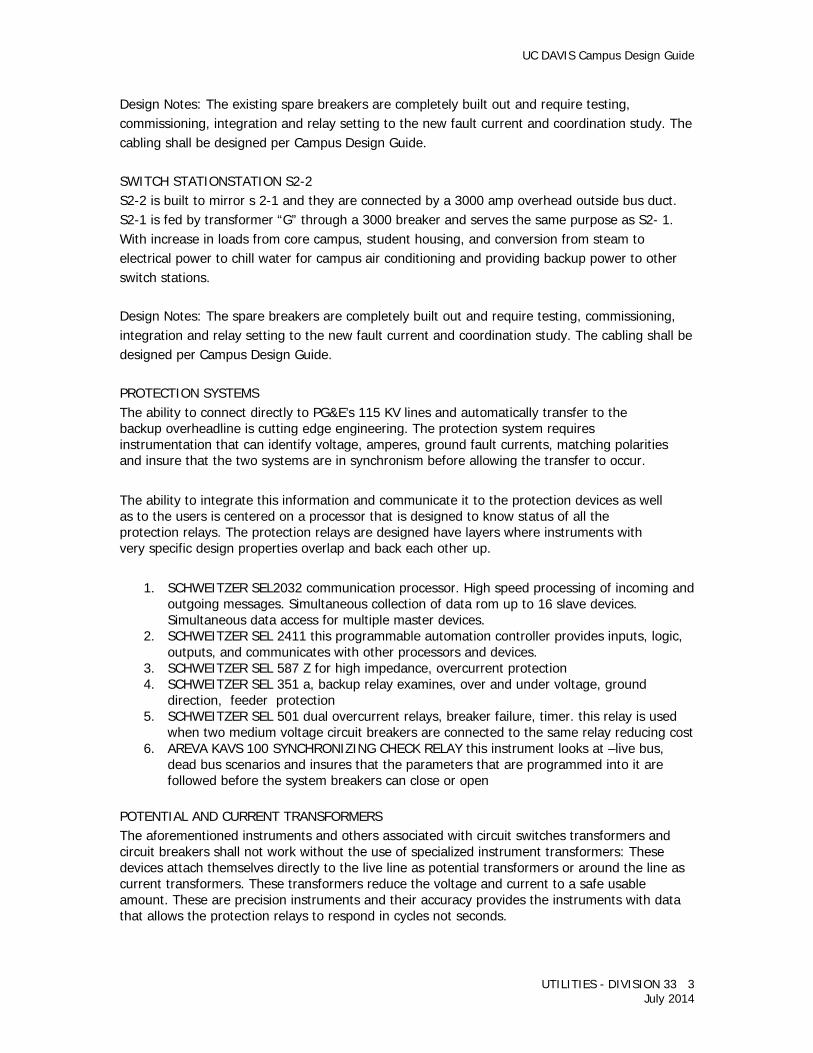
Design Notes: The existing spare breakers are completely built out and require testing, commissioning, integration and relay setting to the new fault current and coordination study. The cabling shall be designed per Campus Design Guide. SWITCH STATIONSTATION S2-2 S2-2 is built to mirror s 2-1 and they are connected by a 3000 amp overhead outside bus duct. S2-1 is fed by transformer “G” through a 3000 breaker and serves the same purpose as S2- 1. With increase in loads from core campus, student housing, and conversion from steam to electrical power to chill water for campus air conditioning and providing backup power to other switch stations. Design Notes: The spare breakers are completely built out and require testing, commissioning, integration and relay setting to the new fault current and coordination study. The cabling shall be designed per Campus Design Guide. PROTECTION SYSTEMS The ability to connect directly to PG&E’s 115 KV lines and automatically transfer to the backup overheadline is cutting edge engineering. The protection system requires instrumentation that can identify voltage, amperes, ground fault currents, matching polarities and insure that the two systems are in synchronism before allowing the transfer to occur. The ability to integrate this information and communicate it to the protection devices as well as to the users is centered on a processor that is designed to know status of all the protection relays. The protection relays are designed have layers where instruments with very specific design properties overlap and back each other up.
1. SCHWEITZER SEL2032 communication processor. High speed processing of incoming and outgoing messages. Simultaneous collection of data rom up to 16 slave devices. Simultaneous data access for multiple master devices.
2. SCHWEITZER SEL 2411 this programmable automation controller provides inputs, logic, outputs, and communicates with other processors and devices.
3. SCHWEITZER SEL 587 Z for high impedance, overcurrent protection 4. SCHWEITZER SEL 351 a, backup relay examines, over and under voltage, ground
direction, feeder protection 5. SCHWEITZER SEL 501 dual overcurrent relays, breaker failure, timer. this relay is used
when two medium voltage circuit breakers are connected to the same relay reducing cost 6. AREVA KAVS 100 SYNCHRONIZING CHECK RELAY this instrument looks at –live bus,
dead bus scenarios and insures that the parameters that are programmed into it are followed before the system breakers can close or open
POTENTIAL AND CURRENT TRANSFORMERS The aforementioned instruments and others associated with circuit switches transformers and circuit breakers shall not work without the use of specialized instrument transformers: These devices attach themselves directly to the live line as potential transformers or around the line as current transformers. These transformers reduce the voltage and current to a safe usable amount. These are precision instruments and their accuracy provides the instruments with data that allows the protection relays to respond in cycles not seconds.

UC DAVIS Campus Design Guide
UTILITIES - DIVISION 33 4 July 2014
BULK, LOOP, AND RADIAL FEEDERS The object for efficiently delivering electricity to the final users is one where electricity is received as high a voltage as available thereby reducing the size of wire required to transport it. When the voltage is reduced the ampacity and wire required to carry the same load is increased. The switch stations provide this point of distribution to interrupters, switches medium voltage cable. There are three methods that these cables are run:
1. BULK FEEDERS are the largest trunk lines used to date and their size is restricted by existing conduits, campus standard 5 inch size and the equipment they serve. The cable size of the bulk feeder is one set of three 350 kcmil copper conductor in existing 4 inch conduit or one set of three 500 kcmill copper in 5 inch conduit. These cable sets of three conductors can be doubled or tripled depending on the equipment to be served.
2. RADIAL FEEDERS are duct banks that are dedicated to one interrupter and one transformer or a group of transformers with no backup feeder or return to the point of distribution.
3. LOOP FEEDERS are standard for new construction. This method utilizes switches, interrupters and transformers. Transformers have 3 loads and make before break switches. This equipment allows the transformer to connect 2 sets of different cables at once. The cables can be switched straight through to another transformer or isolate a feeder for backup that can be switched on for emergency or maintenance.
POTHOLING Pothole all utilities that need to be exposed during construction, utility crossings, and points of connection, during the design phase and before finalizing the construction documents.
UTILITY LINE SIGNS, MARKERS, AND FLAGS 33 05 26 Refer to the University’s Standard Specification Section 33 05 26 Utility Line Signs, Markers, and Flags.
Utility Meters 33 05 33 The utility meters shall be as follows:
UC DAVIS Campus Design Guide
UTILITIES - DIVISION 33 5 July 2014
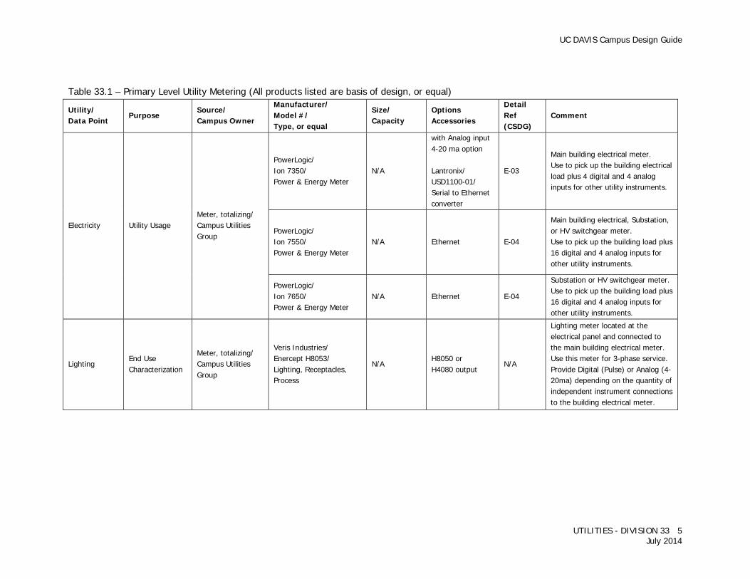
Table 33.1 – Primary Level Utility Metering (All products listed are basis of design, or equal)
Utility/ Data Point
Purpose Source/ Campus Owner
Manufacturer/ Model #/ Type, or equal
Size/ Capacity
Options Accessories
Detail Ref (CSDG)
Comment
Electricity Utility Usage Meter, totalizing/ Campus Utilities Group
PowerLogic/ Ion 7350/ Power & Energy Meter
N/A
with Analog input 4-20 ma option Lantronix/ USD1100-01/ Serial to Ethernet converter
E-03
Main building electrical meter. Use to pick up the building electrical load plus 4 digital and 4 analog inputs for other utility instruments.
PowerLogic/ Ion 7550/ Power & Energy Meter
N/A Ethernet E-04
Main building electrical, Substation, or HV switchgear meter. Use to pick up the building load plus 16 digital and 4 analog inputs for other utility instruments.
PowerLogic/ Ion 7650/ Power & Energy Meter
N/A Ethernet E-04
Substation or HV switchgear meter. Use to pick up the building load plus 16 digital and 4 analog inputs for other utility instruments.
Lighting End Use Characterization
Meter, totalizing/ Campus Utilities Group
Veris Industries/ Enercept H8053/ Lighting, Receptacles, Process
N/A H8050 or H4080 output
N/A
Lighting meter located at the electrical panel and connected to the main building electrical meter. Use this meter for 3-phase service. Provide Digital (Pulse) or Analog (4-20ma) depending on the quantity of independent instrument connections to the building electrical meter.

UC DAVIS Campus Design Guide
UTILITIES - DIVISION 33 6 July 2014
Table 33.1 – Primary Level Utility Metering (cont’d)
Utility/ Data Point
Purpose Source/ Campus Owner
Manufacturer/ Model #/ Type, or equal
Size/ Capacity
Options Accessories
Detail Ref (CSDG)
Comment
Lighting End Use Characterization
Meter, totalizing/ Campus Utilities Group
Hoyt Electrical Instruments/ T-1KW1/ Lighting, Receptacles, Process
N/A N/A N/A
Lighting meter located at the electrical panel and connected to the main building electrical meter. Use this meter for single-phase service. Provide pulse output. Good for individual circuit monitoring but requires a Digital input on the Ion Meter.
Natural Gas Utility Usage
Meter, totalizing/ Campus Utilities Group All gas meter are connected to the main electrical meter and SCADA
American Meter Company/ AC-250/ Diaphragm Meter
Max 250 scfh
Miners & Pisani CMC1 Domestic Meter Pulsing Index 1 Pulse per cubic foot
P-08 Design Engineer shall size meter based on max building load.
American Meter Company/ AL-425/ Diaphragm Meter
Max 425 scfh
Miners & Pisani CMC2 Domestic Meter Pulsing Index 1 Pulse per cubic foot
P-08 Design Engineer shall size meter based on max building load.
American Meter Company/ AC-630/ Diaphragm Meter
Max 630 scfh
Miners & Pisani CMC2 Domestic Meter Pulsing Index 1 Pulse per cubic foot
P-08 Design Engineer shall size meter based on max building load.
UC DAVIS Campus Design Guide
UTILITIES - DIVISION 33 7 July 2014
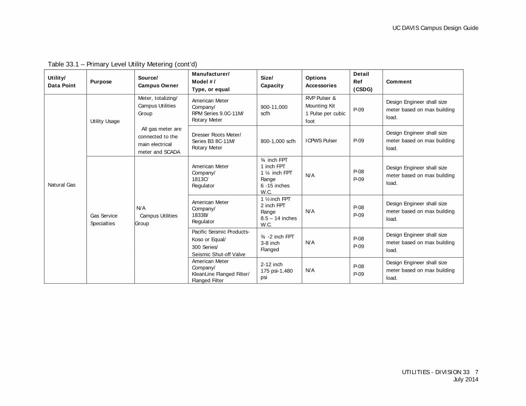
Table 33.1 – Primary Level Utility Metering (cont’d)
Utility/ Data Point
Purpose Source/ Campus Owner
Manufacturer/ Model #/ Type, or equal
Size/ Capacity
Options Accessories
Detail Ref (CSDG)
Comment
Natural Gas
Utility Usage
Meter, totalizing/ Campus Utilities Group
All gas meter are connected to the main electrical meter and SCADA
American Meter Company/ RPM Series 9.0C-11M/ Rotary Meter
900-11,000 scfh
RVP Pulser & Mounting Kit 1 Pulse per cubic foot
P-09 Design Engineer shall size meter based on max building load.
Dresser Roots Meter/ Series B3 8C-11M/ Rotary Meter
800-1,000 scfh ICPWS Pulser P-09 Design Engineer shall size meter based on max building load.
Gas Service Specialties
N/A Campus Utilities Group
American Meter Company/ 1813C/ Regulator
¾ inch FPT 1 inch FPT 1 ¼ inch FPT Range 6 -15 inches W.C.
N/A P-08 P-09
Design Engineer shall size meter based on max building load.
American Meter Company/ 1833B/ Regulator
1 ½inch FPT 2 inch FPT Range 8.5 – 14 inches W.C.
N/A P-08 P-09
Design Engineer shall size meter based on max building load.
Pacific Seismic Products-Koso or Equal/ 300 Series/ Seismic Shut-off Valve
¾ -2 inch FPT 3-8 inch Flanged
N/A P-08 P-09
Design Engineer shall size meter based on max building load.
American Meter Company/ KleanLine Flanged Filter/ Flanged Filter
2-12 inch 175 psi-1,480 psi
N/A P-08 P-09
Design Engineer shall size meter based on max building load.
UC DAVIS Campus Design Guide
UTILITIES - DIVISION 33 8 July 2014
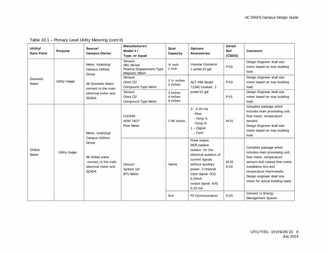
Table 33.1 – Primary Level Utility Metering (cont’d)
Utility/ Data Point
Purpose Source/ Campus Owner
Manufacturer/ Model #/ Type, or equal
Size/ Capacity
Options Accessories
Detail Ref (CSDG)
Comment
Domestic Water
Utility Usage
Meter, totalizing/ Campus Utilities Group All Domestic Water connect to the main electrical meter and SCADA
Sensus/ SR1 Series/ Positive Displacement Type Magnetic Meter
¾ inch 1 inch
Impulse Contactor 1 pulse/10 gal
P-03 Design Engineer shall size meter based on max building load.
Sensus/ Omni C2/ Compound Type Meter
1 ½ inches 2 inches
ACT-PAK Model 713AC totalizer, 1 pulse/10 gal
P-03 Design Engineer shall size meter based on max building load.
Sensus/ Omni C2/ Compound Type Meter
3 inches 4 inches 6 inches
P-01 Design Engineer shall size meter based on max building load.
Chilled Water
Utility Usage
Meter, totalizing/ Campus Utilities Group
All chilled water connect to the main electrical meter and SCADA
FLEXIM/ ADM 7407/ Flow Meter
2-96 inches
3 - 4-20 ma -Flow - Temp S -Temp R 1 – Digital - Tonh
M-01
Complete package which includes main processing unit, flow meter, temperature sensors. Design Engineer shall size meter based on max building load.
Onicon/ System 10/ BTU Meter
Varies
Pulse output, MCR passive isolator, for the electrical isolation of current signals without auxiliary power, 2-channel input signal: 0(4) 0.20mA output signal: 0(4) 0.20 mA
M-02 E-03
Complete package which includes main processing unit, flow meter, temperature sensors and related flow meter installation kits and temperature thermowells. Design engineer shall size meter for actual building loads.
N/A P2 Communication E-03 Connect to Energy Management System

UC DAVIS Campus Design Guide
UTILITIES - DIVISION 33 9 July 2014
Table 33.1 – Primary Level Utility Metering (cont’d)
Utility/ Data Point
Purpose Source/ Campus Owner
Manufacturer/ Model #/ Type, or equal
Size/ Capacity
Options Accessories
Detail Ref (CSDG)
Comment
Steam Utility Usage
Meter, totalizing/ Campus Utilities Group All steam connect to the main electrical meter and SCADA Use when not all condensate is returned
Yokogawa/ Yewflo Vortex/ Flow Meter
Varies N/A M-09 Design engineer shall size meter for actual building loads.
Steam Condensate
Utility Usage
Meter, totalizing/ Campus Utilities Group All Steam Condensate connect to the main electrical meter and SCADA Use when all condensate is returned
Niagara Meter/ MTX-413/ Flow Meter
Up to 2 inches Pulse output M-10
Design engineer shall size meter for actual building loads. 2 inches Turbine type with Pulse output and display.

UC DAVIS Campus Design Guide
UTILITIES - DIVISION 33 10 July 2014
Table 33.2 – Secondary Level Utility Metering (All products listed are basis of design, or equal)
Utility/ Data Point
Purpose Source/ Campus Owner
Manufacturer/ Model #/ Type, or equal
Size/ Capacity
Options Accessories
Detail Ref (CSDG)
Comment
Receptacles, Process or Misc.
End Use Characterization
Meter, totalizing/ Campus Utilities Group
Same as Lighting Meter See Table 33.1
Fan Energy End Use Characterization
Fan VFD/ Energy Management Office
N/A Fan energy is monitored at fan VFD using building Energy Management System
Pumps energy End Use Characterization
Pump VFD/ Energy Management Office
N/A Pump energy is monitored at pump VFD using building Energy Management System
Heating Hot Water Flow and Energy
End Use Characterization
Meter, totalizing/ Energy Management Office
Onicon/ F-12xx/ Flow Meter
Varies Temperature sensors on supply and return
N/A
Design Engineer shall size meter for actual building loads. Energy is calculated by Energy Management System using flow and temperature data.
Domestic Hot Water Flow and Energy
End Use Characterization
Meter, totalizing/ Energy Management Office
Niagara/ MTX-413/ Flow Meter
Varies Temperature sensors on supply and return
M-10
Design Engineer shall size meter for actual building loads. Energy is calculated by Energy Management System using flow and temperature data.
Utility Water Utility Usage Meter, totalizing/ Campus Utilities
Same as Domestic Water See Table 33.1
Design Engineer shall size meter for actual building loads.
Reclaim Water System
End Use Characterization
Meter, Totalizing/TBD
Niagara/MTX…Flow Meter TBD Totalizing register & pulse contact closure
M-10 Design Engineer shall size meter for actual building loads.
Building Occupancy Sensor Monitoring
Occupancy Monitoring
Energy Management System/ Energy Management Office
TBD TBD TBD TBD No feedback from the EMO shop on Mfg or Model or type
UC DAVIS Campus Design Guide
UTILITIES - DIVISION 33 11 July 2014
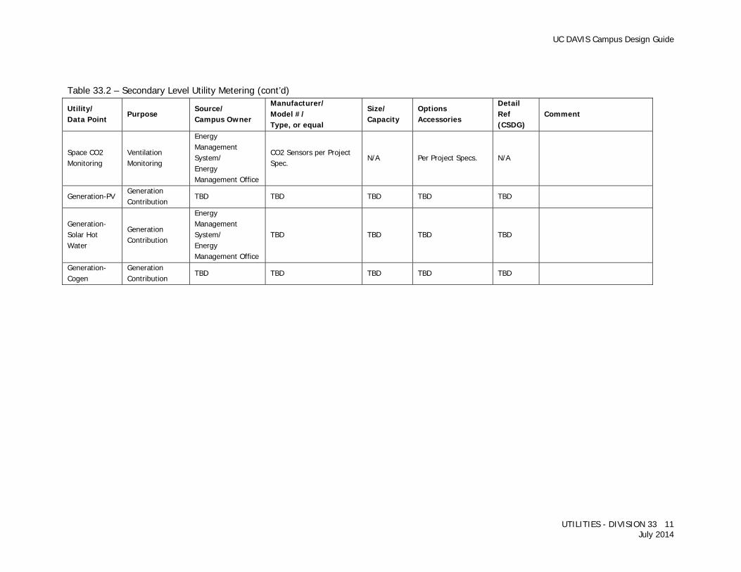
Table 33.2 – Secondary Level Utility Metering (cont’d)
Utility/ Data Point
Purpose Source/ Campus Owner
Manufacturer/ Model #/ Type, or equal
Size/ Capacity
Options Accessories
Detail Ref (CSDG)
Comment
Space CO2 Monitoring
Ventilation Monitoring
Energy Management System/ Energy Management Office
CO2 Sensors per Project Spec.
N/A Per Project Specs. N/A
Generation-PV Generation Contribution
TBD TBD TBD TBD TBD
Generation-Solar Hot Water
Generation Contribution
Energy Management System/ Energy Management Office
TBD TBD TBD TBD
Generation-Cogen
Generation Contribution
TBD TBD TBD TBD TBD
UC DAVIS Campus Design Guide
UTILITIES - DIVISION 33 12 July 2014
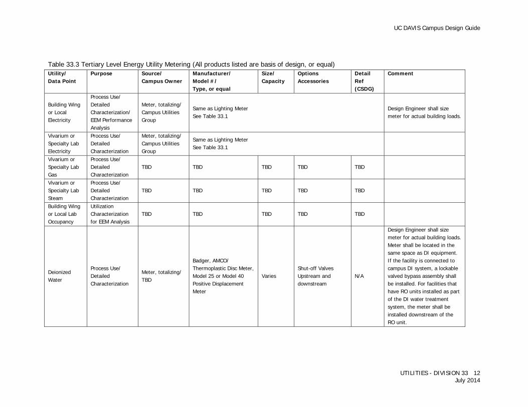
Table 33.3 Tertiary Level Energy Utility Metering (All products listed are basis of design, or equal) Utility/ Data Point
Purpose Source/ Campus Owner
Manufacturer/ Model #/ Type, or equal
Size/ Capacity
Options Accessories
Detail Ref (CSDG)
Comment
Building Wing or Local Electricity
Process Use/ Detailed Characterization/ EEM Performance Analysis
Meter, totalizing/ Campus Utilities Group
Same as Lighting Meter See Table 33.1
Design Engineer shall size meter for actual building loads.
Vivarium or Specialty Lab Electricity
Process Use/ Detailed Characterization
Meter, totalizing/ Campus Utilities Group
Same as Lighting Meter See Table 33.1
Vivarium or Specialty Lab Gas
Process Use/ Detailed Characterization
TBD TBD TBD TBD TBD
Vivarium or Specialty Lab Steam
Process Use/ Detailed Characterization
TBD TBD TBD TBD TBD
Building Wing or Local Lab Occupancy
Utilization Characterization for EEM Analysis
TBD TBD TBD TBD TBD
Deionized Water
Process Use/ Detailed Characterization
Meter, totalizing/ TBD
Badger, AMCO/ Thermoplastic Disc Meter, Model 25 or Model 40 Positive Displacement Meter
Varies Shut-off Valves Upstream and downstream
N/A
Design Engineer shall size meter for actual building loads. Meter shall be located in the same space as DI equipment. If the facility is connected to campus DI system, a lockable valved bypass assembly shall be installed. For facilities that have RO units installed as part of the DI water treatment system, the meter shall be installed downstream of the RO unit.
UC DAVIS Campus Design Guide
UTILITIES - DIVISION 33 13 July 2014
WATER DISTRIBUTION 33 11 00 GENERAL Refer to Campus Standard Specifications Section 33 11 00 Water Utility Distribution Piping and Section 33 08 10 Commissioning of Water Utilities for requirements. Main Line - A pipe that serves more than one service connection, branch line, fire hydrant, or any pipe that is 4 inch or larger. Service Connections:
Small (<2 inch) – Corp stop at main. Medium (2 inch) – Gate valve on service at main Large (>2 inch) – Three valve tee Fire service line – Pipe that serves the internal fire suppression system of a building.
Branch Line – Chilled water connection from a main line to facility. Domestic Water – Campus potable water system used for all uses, including fire protection. Utility Water – Non-potable water system, primarily used for landscape irrigation. Industrial Water – Non-potable water supply system inside a building. A building's industrial water system is created by installing a backflow prevention device at a tee, downstream of the domestic water service backflow prevention device. The industrial water backflow device is intended to protect the building's occupants from labs and other research areas. Because industrial water is only located inside a building, it is not covered by this guideline. Refer to University’s Standard Specification Section 33 12 13 Backflow Preventers. Details Required on Plans - Where pipes have conflicts with other facilities, a detail or profile must be shown on the plans, or the plans must be sufficiently annotated to give clear direction for the installation. Plans shall show plan and profile details of connection to existing mains. Details shall accurately show any depth transitions or fittings required to make connections. Any deviation in alignment (horizontal or vertical), such as an under-crossing or over-crossing, shall be noted on the plans and contain a detail specific to each location. The detail shall show plan and profile views and include all relevant details, such as modified backfill materials, air vacuum/release valves, fittings, and type of pipe. Plans shall note the location of all tie-ins and type of shutdown required, i.e. routine, large, or major. Valves shall be numbered per University valve numbering system, consult with University’s Representative for requirements. DOMESTIC HOT WATER For piping requirements refer to Facility Water Distribution Section 22 11 00 in the Campus Design Guide.
UC DAVIS Campus Design Guide
UTILITIES - DIVISION 33 14 July 2014
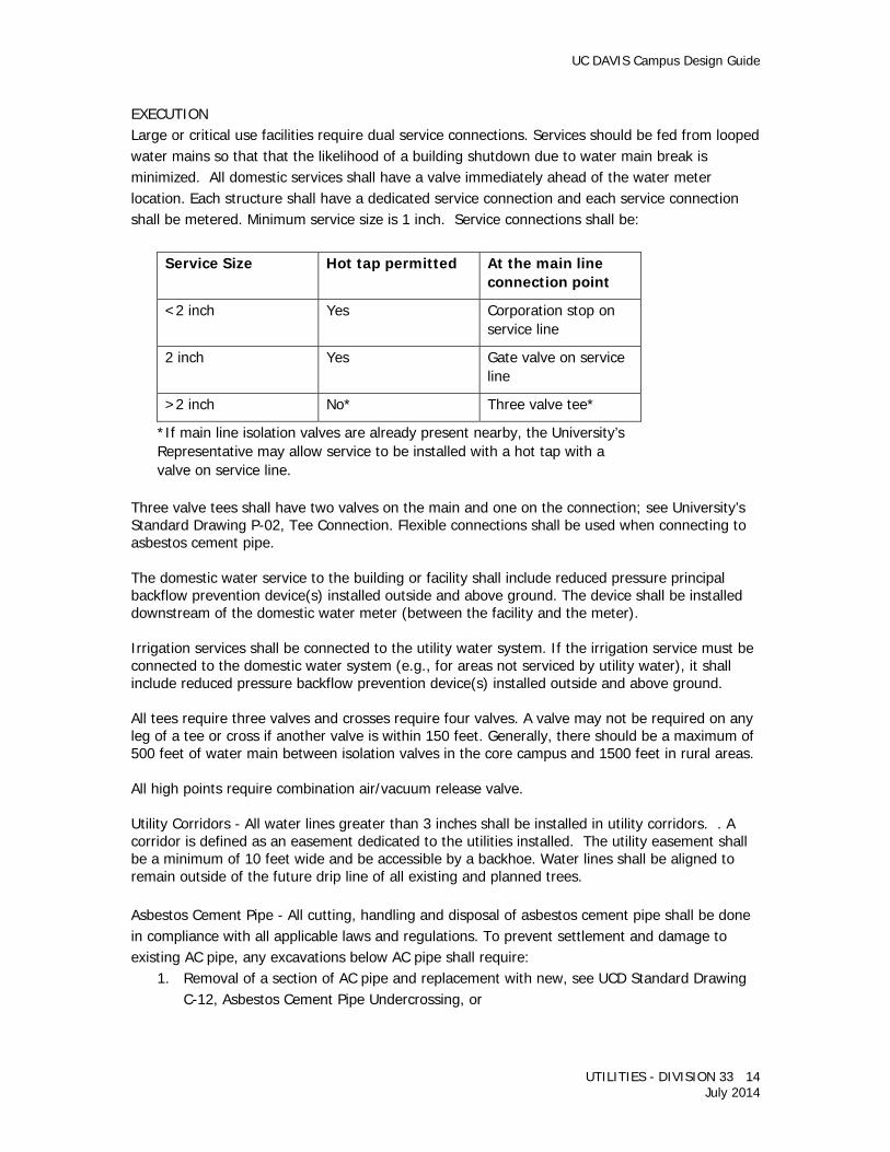
EXECUTION Large or critical use facilities require dual service connections. Services should be fed from looped water mains so that that the likelihood of a building shutdown due to water main break is minimized. All domestic services shall have a valve immediately ahead of the water meter location. Each structure shall have a dedicated service connection and each service connection shall be metered. Minimum service size is 1 inch. Service connections shall be:
Service Size Hot tap permitted At the main line connection point
<2 inch Yes Corporation stop on service line
2 inch Yes Gate valve on service line
>2 inch No* Three valve tee*
*If main line isolation valves are already present nearby, the University’s Representative may allow service to be installed with a hot tap with a valve on service line.
Three valve tees shall have two valves on the main and one on the connection; see University’s Standard Drawing P-02, Tee Connection. Flexible connections shall be used when connecting to asbestos cement pipe. The domestic water service to the building or facility shall include reduced pressure principal backflow prevention device(s) installed outside and above ground. The device shall be installed downstream of the domestic water meter (between the facility and the meter). Irrigation services shall be connected to the utility water system. If the irrigation service must be connected to the domestic water system (e.g., for areas not serviced by utility water), it shall include reduced pressure backflow prevention device(s) installed outside and above ground. All tees require three valves and crosses require four valves. A valve may not be required on any leg of a tee or cross if another valve is within 150 feet. Generally, there should be a maximum of 500 feet of water main between isolation valves in the core campus and 1500 feet in rural areas. All high points require combination air/vacuum release valve. Utility Corridors - All water lines greater than 3 inches shall be installed in utility corridors. . A corridor is defined as an easement dedicated to the utilities installed. The utility easement shall be a minimum of 10 feet wide and be accessible by a backhoe. Water lines shall be aligned to remain outside of the future drip line of all existing and planned trees. Asbestos Cement Pipe - All cutting, handling and disposal of asbestos cement pipe shall be done in compliance with all applicable laws and regulations. To prevent settlement and damage to existing AC pipe, any excavations below AC pipe shall require:
1. Removal of a section of AC pipe and replacement with new, see UCD Standard Drawing C-12, Asbestos Cement Pipe Undercrossing, or
UC DAVIS Campus Design Guide
UTILITIES - DIVISION 33 15 July 2014
2. Cement slurry backfill against undisturbed soil to support AC pipe (maximum of 2 feet depth of slurry backfill allowed).
Minimum Cover is the distance from the top of the pipe to final finished grade measured directly over the pipe. For mains, branch, and service connections, the minimum cover is:
36 inches for pipe sizes up to 8 inches 40 inches for 10 inch pipe 44 inches for 12 inch pipe 48 inches for pipe sizes 16 inches and larger
Where cover is less than standard or greater than 7 feet, written approval from the University’s Representative is required. Where cover is less than the standard, ductile iron pipe is required. Flame cutting of pipe by means of oxyacetylene torch is not allowed. Mechanical Restraints - Provide number of restraints and pipe length per manufacturer’s table at changes in pipe direction, changes in pipe sizes, dead end stops and at valves. New installations shall use restrained joint fittings. Thrust blocks should only be used if connecting to existing unrestrained pipe or fittings and be explicitly shown on the plans, including location and thrust block size. Thrust blocks shall conform to UC Davis Standard Drawings C-13, Thrust Block Horizontal, and C14, Thrust Block Vertical, and be the minimum size necessary to provide restraint. Provisions shall be made to insure that pipe joints, fittings and valves are not covered by the thrust block concrete. Separation from Other Utilities - For utilities not covered by State Health Standards, separation between water lines and other utilities, such as pipes, vaults, and manholes, shall never be less than 1 ft.
FIRE SUPPRESSION WATER DISTRIBUTION PIPING 33 11 19 All design, work and materials described herein shall be approved by the State Fire Marshal (SFM) as represented by the University Fire Department Designated Campus Fire Marshal (UCDFD/DCFM). For work beyond the connection to the water main and above the blank flange at the bottom of the building riser, see Site Water Line and Fire Suppression sections. All work shall be designed in accordance with the requirements of the UCDFD/DCFM, the applicable editions of National Fire Protection Association (NFPA) 13 and 24, and the appropriate editions of the California Building code and the California Fire Code. Coordinate the approval of the UCDFD/DCFM and the University’s Representative. Coordinate the electrical conduit installation for supervisory systems. SUBMITTALS Underground fire protection system shop drawings shall show all information required by NFPA 24. In addition, the shop drawings shall show the Soil Bearing Capacity of the soil (see Soils Report) and the location, design, and size of mechanical restraints.
UC DAVIS Campus Design Guide
UTILITIES - DIVISION 33 16 July 2014
MATERIALS All material shall be currently listed in the Underwriters Laboratories, Inc., Fire Protection Equipment List and/or the Factory Mutual Approval Guide for use as intended in underground fire line installations and shall be acceptable to the UCD/DCFM. Material pending approval shall not be acceptable. See Section 21 00 00 Fire Suppression for information on valves and additional requirements. Vertical piping, piping installed within 5 feet of the building and piping under all footings and slabs shall be cast or ductile iron. Drain piping that is installed underground shall be PVC or galvanized pipe, wrapped to protect against corrosion. Uniflanges shall not be used on vertical piping, above ground, or in the basement. Tops of vertical risers shall be rodded down to the 90 degree bend at the base of the riser. Horizontal risers shall be rodded back to deadman of sufficient size to secure the flanged fitting. Fire Hydrants: Clow Corporation Model #92, Clow Model #76 or Long Beach Iron Works, Inc. Model #651, or equal with 2.5 inch outlets and one 4.5 inch outlet. All outlets shall have a National Standard fire hose thread. Hydrants shall be wet barrel type. Refer to Campus Standard Specification Section 33 12 19, Fire Hydrants, and Standard Detail F-01, Hydrant, for more information
1. Install with the outlets facing the street and meeting the other requirements shown on the diagram shown below.
2. The University shall paint the hydrant in accordance with National Fire Protection Association (NFPA) 24, edition 2010 as amended, requirements.
3. Where subject to mechanical injury, protect hydrants as approved by University Fire Prevention Services so as not to interfere with connection to the outlets.
Double Check Valves Assembly: A double check valves assembly and Fire Department Connection (FDC) is required on all fire lines. Refer to the Campus Standard Detail F-02, Double Check Valve Assembly-FW Service for more information
1. Location of this assembly must be approved by the Campus Architect and Campus Fire Department. Locate the assembly outside of the building in an accessible location mounted on a minimum 6-inch height concrete slab so that it remains clear of adjacent vegetation. Insulate the above ground piping 6 inches and smaller with removable blanket insulation (fiberglass insulation is not acceptable).
2. Assembly shall be UL listed for fire protection service. 3. Where subject to mechanical injury, protection shall be provided. The means of approved
protection shall be arranged in a manner, which shall not interfere with the connection to inlets.

UC DAVIS Campus Design Guide
UTILITIES - DIVISION 33 17 July 2014
4. Fire department connections shall be located not less than 40 feet from the buildings and property protected. The fire department connection shall be clearly visible from the street. The fire department connection shall front the street of primary fire department vehicular access and shall be located within 25 feet of a fire hydrant. Fire department connection inlets shall be located 30 to 36 inches above grade on street front and as measured at all inlets within a three-foot radius. Note: Where conditions do not permit, the fire department connection shall be placed where it will be readily accessible in case of fire and not liable to injury. All fire department connection locations shall be approved by the University Fire Prevention Services. a. Systems with a flow demand of 500 gpm or less: Provide four-inch pipe mount by 2-
1/2 inch (Siamese), brass, dual clapper, freestanding fire department inlet connections, one-inch cast lettering, brass finish with plugs and chains or sensible caps.
b. Systems with a flow demand greater than 500 gpm: Provide six-inch pipe mount by 2-1/2 inch, 4-way, brass, four clapper freestanding fire department inlet corrections, one-inch cast lettering, brass finish. Inlet corrections shall be oriented in a quad arrangement.
5. Maintain a 5-foot clear radius around the fire department connection. Grade variation within this radius shall not exceed 1:12. The fire department connection shall be arranged so that hose lines can be ready and conveniently attached to inlets without interference from any nearby objects including buildings, fences, posts, or other fire department connections.
6. Underground piping serving the fire department connections shall be wet pipe under system pressure with check valve at each fire department connection.
7. Paint the FDC with 2 coats of reflective paint (bright white with a minimum visual light reflectance value of 90%) and provide a building identification sign or pictogram as approved by Fire Prevention Services.
INSTALLATION Piping shall be installed as per the requirements of this Division and in a manner acceptable to the UCD/DCFM and the University‘s Representative. Give special attention to materials and coatings. Provide mechanical restraints. Thrust blocks shall not be permitted except for Fire Hydrants. Depth of bury for piping shall be a minimum of 36 inches under vehicular paving. Measurement is from the top of the pipe to grade. When the system riser is close to a foundation or footing, underground fittings of proper length shall be used to avoid pipe joints located in or under the wall or footing. When the connection passes through a foundation or footing below grade, a 1 to 2 inch clearance shall be provided around the pipe, and the clear space filled with asphalt mastic or similar flexible waterproofing material. INSPECTION & TESTING Inspections are required by the UCD/DCFM and University’s Representative. An inspection of underground installation, back flush, and hydrostatic test shall be conducted by the Contractor
UC DAVIS Campus Design Guide
UTILITIES - DIVISION 33 18 July 2014
and witnessed by a representative of the UCD/DCFM prior to backfill. Disinfect line from point of connection to Building Fire Protection as per Section 33 13 00 Disinfection of Water Distribution Systems. All piping shall be hydrostatic-pressure tested in accordance with these standards, and NFPA 24-2010 edition, as amended. Underground piping shall be center-loaded and all fittings, joints, strapping, and thrust blocking shall be exposed for hydrostatic pressure testing and inspection per NFPA 24. Contractor shall prepare and complete NFPA 24 inspection and installation certificates prior to acceptance testing and have them signed off by the UCD/DCFM and the University’s Representative immediately after acceptance testing and approval.
DOMESTIC WATER PIPING DISINFECTION 33 13 00 The Campus has developed a Standard Specification Section 33 13 00 for Domestic Water Piping Disinfection. The specification shall be modified by the Design Professional to meet project requirements. An electronic copy (Word document) is available, contact the University’s Representative.
SANITARY SEWERAGE UTILITIES 33 30 00 Refer to Campus Standard Specifications 33 08 30 Commissioning of Sewer Utilities, Section 33 31 00 Sanitary Utility Sewerage Piping, and 33 39 23 Sanitary Utility Sewerage Cleanout for requirements.
Slopes through Manholes
1. When sewers of uniform slope pass through a manhole, the slope shall be maintained and the invert at the center of the manhole shall be given.
2. When sewers change slope at a manhole, incoming and outgoing invert elevations shall be given.
3. Provide sufficient drop through a manhole to compensate for energy loss caused by change of alignment. A minimum drop of 0.1 foot is required for a change of alignment greater than 30 degrees.
4. When pipe sizes change at structures, design the inlet crown at least as high as the outlet crown.
Connection to Existing Campus Sewer Main
1. Connect new mains to existing at existing manholes or by constructing a new manhole over the point of connection.
2. Where an existing sewer main is to be extended, remove the existing plug, cleanout, or rodding inlet and install a manhole. The main may be extended without installation of a structure only if it is on the same line and grade, the pipe size and material are the same and the manhole spacing is adequate.
3. Elevations of mains connecting to existing sewer mains shall be as follows:

UC DAVIS Campus Design Guide
UTILITIES - DIVISION 33 19 July 2014
a. Side sewer mains connecting to an existing main at an angle of 30 degrees or greater shall be at least 0.1 foot higher than the existing.
b. Connect sewer mains so that the crown of the smaller main is no lower than the crown of the larger main.
c. Connections to Trunk Sewers shall be made so that the invert grade of the new main shall be no lower than the crown of the Trunk sewer.
4. For lateral connections to existing mains 12 inches and larger, use taps and saddles per UC Davis Standard Detail C-18.
Inverted Siphons
1. Inverted siphons shall be used only upon special approval after all other design options have been investigated.
2. The siphon shall be designed with two barrels, with a gate system directing the flow towards either the primary or secondary barrel.
3. Design to achieve a minimum velocity of 3 FPS maintained for several hours a day. 4. Vertical curves shall be used for all change in slope (100 feet minimum). 5. The rising slope of the downstream leg of the siphon shall be limited to 15%.
Sewer Force Mains
1. Sewer force mains shall conform to the Water Construction Standards for water mains. 2. Sewer force mains shall be laid with a constant slope toward the pump station to allow
for complete draining of the pipeline. 3. Locator boxes shall be placed at every horizontal change in alignment or a maximum of
every 500 feet. 4. Boxes shall conform to valve box requirements per UCD Standard Detail P-01 with the
lids clearly marked, “SEWER.”
Alignment 1. Horizontal and vertical separation from Domestic Water lines must conform to the State
of California, Department of Health Services, “Criteria for the Separation of Water and Sanitary Sewer.”
2. In general, design sewer mains in straight street sections to run parallel to the street centerline. All mains must be a minimum five feet clear from all buildings, building overhangs, etc.
3. In curved streets, design the sewer alignment generally on one side of the centerline to allow installation of other facilities such as water, storm drains, etc. without using transverse crossings. Provide an alignment such that no part of the sewer main is less than 1 foot from the lip of gutter.
4. Vertical curves or bend fittings in gravity sewer mains are not allowed. Laterals
1. Provide a separate lateral and cleanout for each building and structure. 2. Cleanouts: Pipe extension to grade with compression type plug. Install curb box over
riser pipe. Use precast concrete box Christy F8 with cast iron lid or approved equal in
UC DAVIS Campus Design Guide
UTILITIES - DIVISION 33 20 July 2014
non-traffic areas and Christy G5 with cast iron lid or approved equal in traffic areas. Lids shall be marked “SEWER.”
3. Lateral cleanouts shall be installed within 10 feet of the structure. 4. Sewer laterals serving buildings or facilities which have plumbing fixtures with flood level
rim elevations located below the next upstream sewer manhole rim require an approved backwater valve. Fixtures above such elevation shall not discharge through the backwater valve per UPC Section 409. Backwater valves shall be installed in a vault, pit or basement so the valve is easily accessible for maintenance. A cleanout must be installed within 5 feet downstream of the valve.
Sanitary Sewer Manholes and Rodding Inlets
1. A manhole is required at every horizontal or vertical change in alignment. 2. Maximum distance between manholes is 300 feet. 3. A manhole is required at the end of every main in excess of 200 feet in length. Rodding
inlets may be installed in lieu of manholes at the end of a sewer main where the distance is less than 200 feet to the nearest manhole and the main size is 10 inches or less.
4. Manholes shall be constructed with eccentric cones. 5. 60 inch diameter manholes are required for mains 18 inches or larger in diameter. 6. The manhole shall be designed such that the angle in the horizontal plain between the
downstream and any incoming sewer is a minimum of 90 degrees. 7. Stubs provided out of manholes for future extension shall have rodding inlets provided
when more than 20 feet of pipe is installed or where service laterals are connected to the stub.
8. Standard drop manhole installations are required when the difference in elevation between the incoming and outgoing sewer is greater than 2 feet. While not encouraged, drop manholes may be required because of some physical restraints. They may not however, be used to merely avoid extra depth of trenching unless unusual circumstances exist. Upstream slope changes should be used to avoid the need for a drop manhole.
9. When one drop connection is required, use a 60 inches diameter manhole. When two or more drop connections are required, use a 72 inches diameter manhole.
Industrial Waste Discharges
1. Grease traps, grease and sand traps, grease interceptors, and sampling structures as may be required by the University shall be shown on the plans submitted for approval, and comply with the appropriate Sewer Standard Plans.
2. Food Service facilities must have a grease interceptor installed outside the facility in an area accessible for accessible for service vehicles.
3. Trash enclosures and other outdoor pad areas used for washing shall be plumbed to the sanitary sewer system at grease interceptor or other connection point approved by University. Preventive measures must be taken to eliminate the intrusion of any rainwater or surface runoff.
4. Wash pad areas must be diked and/or sloped so that the smallest area possible drains to the sewer.

UC DAVIS Campus Design Guide
UTILITIES - DIVISION 33 21 July 2014
Lift Stations 1. Lift stations shall not be allowed where an acceptable alternative gravity route exists. 2. Design the lift station to serve the entire tributary at build-out densities in accordance
with sewer system master plan, LRDP and I/I allowances. 3. All pumps, regardless of station type, shall be non-clogging, capable of passing a
minimum 3 inches diameter sphere. 4. Lift stations are not allowed within the street. 5. Provide a 12-foot paved access road to allow service vehicles to be parked off the street
and clear of the sidewalks. Turnarounds are required for stations constructed along heavily traveled streets. Provide service vehicle access to wet well.
6. Provide a reinforced concrete base slab sized adequately to counteract buoyancy. Provide supporting design calculations.
7. Provide a single surface pad over site that incorporates lift station access, wet well access and supporting generator and fuel supply tanks, as necessary.
8. Provide restrained flexible couplings on all outlet piping within 2 feet of the station wall. 9. All wet well components and all items in the wet well shall be non-corrosive plastic,
stainless steel or other approved material. 10. Wet well to be minimum 72 inches in diameter with 4-hour capacity or as necessary to
accommodate pumping equipment for submersible stations. Provide resilient-seat gate valve on inlet pipeline into wet well to provide wet well isolation.
11. Odor control systems shall be required. 12. Provide 6 inch PVC emergency by-pass system consisting of a suction line and a
discharge line and a standpipe equipped with a cap and cam-lock connector. Bypass shall be located in a vault. Standpipe connects to force main through an AWWA resilient-seat-gate valve with stainless steel trim and a check valve. The suction and discharge lines shall have gate valves for isolation. Adequately support all piping.
13. Provide 1-inch minimum water service with reduced pressure backflow preventer and piping insulation.
14. Provide a minimum of two pumps and controls to alternate lead and lag pumping. 15. Provide hour meters for each pump that records pump run time, only if the motor is
operating. 16. Provide a magnetic flow meter on the discharge of the pump station. Meters may be in
an approved vault. Display shall be installed in pump station control panel. 17. All pumps, motors, internal valves and piping, level indicators, control panel, shall be
assembled as a package. Supply and warranty shall be through one company. Submersible Pumping Stations
1. The lift station shall consist of a minimum of two submersible centrifugal sewage pumps, guide rails, wet well access, discharge seal and elbow, motor control center, starters, liquid level control system and all hardware necessary to make a complete working system. Supply and warranty shall be through a single company. Manufacturers: ITT Flygt, Gorman Rupp Company or equal.
2. The pumps shall be electric, submersible, centrifugal non-clogging units capable of passing a 3-inch sphere. Pump and motor shall be suitable for continuous operation at
UC DAVIS Campus Design Guide
UTILITIES - DIVISION 33 22 July 2014
full name plate load while the motor is completely submerged, partially submerged or not submerged. All electrical equipment/panels shall be above ground.
3. Each pump shall be furnished with a discharge connection system, which shall permit removal and installation of pump without the need for the operator to enter the wet well.
4. All hardware in wet well, chains, cables and slide rails shall be 316 stainless steel. Lift Station Piping and Valving
1. When not included with package stations, all internal main lift station piping shall be flanged or Victaulic to allow for disassembly.
2. All main piping shall have manual vents and drains to allow draining of sewage prior to piping disassembly.
3. Resilient-seat-gate valves shall be used in station discharge piping. If space does not permit isolation valves for each pump use 3-way valves.
4. Main Pump Check Valves shall be cast iron swing checks with externally weighted lever return. Check valve shall not be installed in the vertical. Disc shall be 316 stainless steel or cast iron with bronze trim. Pivot arm and bearing shall be 316 stainless steel or cast iron with bronze trim. Pivot arm and bearing shall be 316 stainless steel or bronze. Seat shall be field replaceable with neoprene facing. Electrical Equipment: a. Free standing electrical service with transfer switch, with heavy duty electrical
weatherproof enclosure securely mounted in a manner acceptable to the Director of Utilities, a minimum of 24–inches above the ground. Provide generator receptacle to match Utility Division standard or stand-by generator. Provide a concrete pad around steel supports.
b. All pump motors shall have solid state soft starters. They shall be Allen-Bradley or equal and provided with solid state smart type motor starters with a pump control option used to provide ramp starting and stopping of motors. The controller shall have the following start modes: soft start with selectable kick starts, current limit and full voltage.
c. Interior Lighting: Provide all control panels with a fluorescent interior light of the same approximate width of the control panel located along the top of the panel. Provide light with a separate light switch.
d. UPS: Provide an uninterruptible power supply sized for 150% of calculated load with sufficient battery backup time for 30 minutes of operation. Provide American Power Conversion, Best Power Products or equal.
e. Selectors and Pushbuttons: Provide corrosion resistant 30mm selectors and pushbuttons by Allen-Bradley or Square-D.
f. Sewer lift station electrical controls must comply with standards as established by the University’s Representative to ensure compatibility with existing control and SCADA systems.
STORM DRAINAGE UTILITIES 33 40 00 Size piping to accommodate a minimum of a minimum of 10 year storm event. Comply with the requirements of Section 33 30 00 Sanitary Sewerage Utilities except as modified below. Replace the word “sewer” with “storm” as appropriate.
UC DAVIS Campus Design Guide
UTILITIES - DIVISION 33 23 July 2014
Connection to Existing Campus Storm Main 1. Provide a manhole at building main lateral connection to the Campus storm main. 2. For pipe penetrations through existing and new manholes, core through, install gasket
around pipe, grout penetration on both sides and install a minimum of 6 inches around collar outside of the manhole penetration.
3. Tap Connection - Use commercially manufactured wyes for branch connections. Field cutting into piping shall not be permitted. Spring wyes into existing line and encase entire wye, plus 6 inches overlap, with not less than 6 inches of 3000 psi 28-day compressive strength concrete.
For branch connections from side into existing 24 inch or larger piping, or to underground structures, cut opening into unit sufficiently large to allow 3 inches of concrete to be packed around entering connection. Cut ends of connection passing through pipe or structure wall to conform to shape of and be flush with inside wall, unless otherwise indicated. On outside of pipe structure wall, encase entering connection in 6 inches of concrete for minimum length of 12 inches to provide additional support or collar from connection to undisturbed ground. Use epoxy bonding compound as interface between new and existing concrete and piping materials.
Take care while making tap connections to prevent concrete or debris from entering existing piping or structure. Remove debris, concrete, or other extraneous material, which may accumulate.
Material Transfer Areas/Loading Docks
1. Direct connections from depressed loading docks (truck wells) to storm drains are prohibited.
2. Design drainage for new construction and/or redevelopment loading dock projects to minimize run-on and runoff of storm water. Loading areas must be sloped to direct flow towards a drain inlet connected directly to the sanitary sewer, or with a shutoff valve and sump with enough capacity to hold a spill while the valve is closed. Design to flow under gravity so the sump outlet is located at the upper portion of the sump to avoid creating a situation where water must be pumped out of the sump since most of the campus sewer/storm laterals are not very deep.
3. Valves located in loading dock areas should be left open to facilitate drainage of storm water during normal conditions, and immediately closed in the event of a spill or sanitizing of the area.
NATURAL GAS DISTRIBUTION 33 51 00 METERING The natural gas meter shall be installed at service connection to the building in an accessible location. Meter shall be capable of local and remote read-out. See Division 22 for more information. Refer to the Campus Standard Specification Section 35 51 13 Natural Gas Piping. STEEL PIPE Pipe - Black steel, Schedule 40 with X-Trucoat, Greenline, or equal, factory wrap on buried lines.
UC DAVIS Campus Design Guide
UTILITIES - DIVISION 33 24 July 2014
Fittings 1. Buried: Steel butt-welding or socket welding type 2. Above Ground: Welding, or malleable iron threaded.
Valves
1. Underground: Valves under three inches shall be threaded and made up with threaded nipples, in a vise, before inserting into the line by welding. Valves three inches and larger shall be generally flanged and attached to slip-on welding flanges.
2. Lubricated plug cock: 1 inch and larger, Rockwell 115, Walworth, or equal. Provide lubricated plug cock for all below grade applications. Extend lubrication port and valve handle to a minimum of 6 inches below grade in valve box.
3. Corporation stops of dissimilar metal shall not be used. Unions
1. Underground: Unions shall not be used. 2. Above ground: Flanged or threaded metal-to-metal shall be used. 3. Dielectric (insulated) unions shall be installed at designated points for cathodic
protection. 4. Regulators and meters shall be protected from damage.
Corrosion Control - In order to provide protection of metal pipe from external, internal and atmospheric corrosion, provide an external protective coating and a cathodic protection system designed to protect the pipeline in its entirety.
1. Field Wrapping with cold - applied tape a. Field joints shall use “Protectowrap” #200 with 1170 primer or equal. When coating
odd shapes containing bolts, voids, or hard-to-wrap surfaces, two coats of mastic-type primer shall be used instead of the above primer, with special care to assure that all surfaces are coated without introducing voids or pockets.
b. The bare metal surface to be wrapped must be dry and cleaned of rust, dirt, oil, and weld slag.
c. Whenever tape wrap is applied over yard wrap, the outer coating of Kraft paper, whitewash, mica, flakes, protective plastic outer wrap, etc., shall be removed.
d. Plastic coated pipe, prime area to be wrapped plus a minimum length of 4 inches from the cutback edge.
e. Tape shall be applied by first lapping over approximately one tape width of the prepared end of the wrap. The wrap should be spiraled along the line, with each spiral overlapping the previous spiral by one-half the tape width plus one-quarter inch, to assure a double thickness at all points. The tape should be applied with enough tension to achieve a tightly bonded smooth wrap, free of wrinkles or voids. Do not over-stretch.
2. Asphalt Coating - Small defects (less than 3 inches across) - slight damage where the asphalt wrap is still bonded to the pipe and no penetration has occurred may be repaired by a single patch. Prepare the surface of the asphalt wrap by removing the outside coating with a wire brush, prime and apply the single layer of tape so that it extends 2 inches beyond the damaged area in all directions. If penetration of the asphalt wrap has

UC DAVIS Campus Design Guide
UTILITIES - DIVISION 33 25 July 2014
occurred or the bond has been broken, all loose wrapping shall be removed to the bare pipe. The area shall be primed and the standard spiral wrap applied. Large defects (greater than 3 inches across) - if the pipe coating is still bonded and penetration has not occurred, prepare the surface by removing the outside coating with a wire brush, prime, and wrap tape completely around pipe, extended two inches beyond the damaged area on each side. If penetration of the coating has occurred or the bond has been broken, all loose or damaged coating shall be removed. Prime and apply the first layer of tape, patch fashion, the next layer use the standard spiral wrap, extending 2 inches beyond the damaged area.
3. Plastic or Tape Coating - On plastic-coated pipe, repairs shall be treated as a large defect by wrapping completely around the pipe as required. The entire plastic surface to be coated shall be cleaned. On tape-coated pipe, repairs shall be done by removing the outer wrap several inches back from the area of defect, then prime and apply tape to the damaged area. It is not necessary to remove the inner wrap.
Inspection of Materials - Each length of pipe and each other component must be visually inspected at the site to ensure it has not sustained any visual damage, and the pipe shall be inspected for holidays, using an approved holiday tester, prior to installation in trench. Coordinate test with University’s Representative for witnessing. At least 48 hrs. notice shall be given. Lacerations of the protective coating shall be carefully examined prior to the repair of the coating to see if the pipe surface has been damaged. All repairs, replacements, or changes shall be inspected before they are covered up. Qualification of Welders - Only welders who are currently qualified in accordance with the following may perform welds on gas pipeline:
1. Section IX of the American Society of Mechanical Engineers Association (ASME) Boiler and Pressure Vessel Code.
2. Section 3 of American Petroleum Institute (API) Standard 1104 3. Appendix C of Federal Register, Vol. 35, No. 161.
Underground Clearance - Sufficient clearance shall be maintained between mains and other underground structures to:
1. Permit installation and operation of maintenance and emergency control devices such as leak clamps.
2. Permit installation of service laterals to both the mains and to other underground structures.
3. Provide heat damage protection from other underground facilities such as steam or electric power lines. This is especially critical for cathodically protected pipeline, which must be isolated from underground foreign piping.
PLASTIC PIPE No plastic natural gas lines shall be accepted on UC Davis central campus without approval of University’s Representative. Service Lines (plastic)
UC DAVIS Campus Design Guide
UTILITIES - DIVISION 33 26 July 2014
1. 24 inch minimum of cover in streets; 18 inch minimum of cover otherwise. 2. For main connections, a protective sleeve designed for the specific type of connection
shall be used to reduce stress concentrations. 3. At building wall the transition from plastic pipe to more rigid piping should be protected
from shear and bending as at the main connection. Where possible the trench bottom should be compacted and smoothed, where not possible, some other method of continuous support for the service line should be provided over the disturbed soil.
4. The service line shall be graded so as to drain any possible condensate into the main. 5. Each service line shall be installed so as to minimize anticipate piping strain and external
loading. 6. Each service line shall have a service line valve.
Inspection
1. Plastic pipe and tubing shall be carefully inspected for cuts, scratches, gouges and other imperfections before use.
2. Each imperfection or damage that would impair the serviceability of plastic pipe shall be removed or repaired by a patching saddle.
3. The patch or sleeve material shall be the same type and grade and wall thickness shall be at least equal to that of the pipe. The sleeve shall extend at least 1/2 inch beyond the damaged area. The joint line between the halves shall be as far as possible from the defect.
4. Each plastic pipe joint shall be made in accordance with manufacturer’s recommendations using the proper type equipment required for the type of joint required. Plastic pipe may not be joined by a threaded joint or miter joint.
Installation of Pipe in a Ditch. For mains, a minimum covering of 24 inches.
1. Piping shall be installed with sufficient clearance, or shall be insulated from any source of heat, such as steam or electric power lines, particularly when installed in common trenches.
2. Inspect condition of ditch bottom just before pipe is lowered in. 3. Plastic pipe shall be laid on undisturbed soil, well compacted soil, well tamped soil, or
other continuous support. Blocking shall not be used to support pipe. 4. Piping shall be installed with sufficient slack to provide for possible contraction. 5. Piping shall be installed with enough clearance to allow proper maintenance and to
protect against damage that might result from proximity to other structures. 6. Bends should be free of buckles, cracks, or other damage, and may not be deflected to a
radius smaller than the minimum recommended by the manufacturer. Valve installation - Designed to protect the plastic material against excessive torsion or shearing load when the valve is operated and from any other secondary stresses that might be exerted through the valve or its enclosure. Prevent excessive strains at valve installations by:
1. Use a valve having low operating torque. 2. Anchor the valve body to resist twisting.

UC DAVIS Campus Design Guide
UTILITIES - DIVISION 33 27 July 2014
3. Make the transition from plastic to metal some distance from the valve. Any transition shall be supported by undisturbed or well compacted soil, by bridging or by sleeve encasement. Transition pieces 2 feet long will usually provide sufficient stabilization.
4. Use rigid pipe casing fastened to the valve. Casing pieces 2 feet long will usually provide stabilization.
5. Use a metallic pipe sleeve rigidly connected to the valve and encasing the plastic. Cathodic Protection of Isolated Steel components in Plastic piping systems – Provide one of the following:
1. A small galvanic anode directly connected to the steel component. 2. Each steel component may be connected to a locator wire which is also connected to one
or more galvanic anodes. To facilitate monitoring, the locator wire may be terminated at one or more service risers.
3. Use of certain metal fittings in plastic pipelines without coating, cathodic protection, and monitoring when adequate external corrosion control is provided by alloy.
4. Type 316 stainless steel or equally corrosion resistant component. Valve enclosures - Where curb boxes or other enclosures are used, they shall not be supported by the plastic pipe and shall not in any way impose secondary stresses. Valve operating stems shall be extended as per University’s Standard Drawing, P-07, Gas Valve and Valve Box. TESTING (steel and plastic) Mains shall be pressure tested at a minimum of 100 psi, for a minimum time of 4 hours. Service lines shall be pressure tested at a minimum of 50 psi, for a minimum time of 4 hours.
HYDRONIC ENERGY DISTRIBUTION 33 61 00 The campus has a chilled water system providing chilled water for cooling. The system consists of supply and return lines. Provide pipe and fittings per the requirements for water mains included in Section 33 11 00 Water Utility Distribution. Valves - Class 250B butterfly valves, Mueller Lineseal XP Class 250, or equal. Chilled water system butterfly valves shall be flanged or mechanical joint type and shall be of the rubber seat type. Valve discs shall rotate 90 degrees from the full open position to the tight shut position. The valve seat shall provide a tight shutoff at a pressure differential of 150 psi upstream and 0 psi downstream in either direction. Valve shall open with a counter-clockwise rotation, have a 2 inch operating nut for buried valves and hand wheel for open installations, and have o-ring seals. Buried valves shall be rated for buried service and coated with asphalt varnish. Branch Connections (chilled water) - All connections to the chilled water distribution system shall use three valve tees per the requirements for water service lines greater than 2” as described in Section 33 11 00 Water Tapping - When using tapping valves on the chilled water system, install an additional butterfly valve and abandon tapping valve in place (in open position).

UC DAVIS Campus Design Guide
UTILITIES - DIVISION 33 28 July 2014
HEATING HOT WATER AND 2-PIPE CHANGE OVER DISTRIBUTION PIPE The campus also has limited heating hot water and 2-pipe changeover distribution systems. The underground hot water distribution piping shall be schedule 40 pipe with welded joints or type K copper pipe with brazed joints in powder insulating fill material, Gilsulate 500 XR, or equal.
STEAM ENERGY DISTRIBUTION 33 63 00 The campus has a steam distribution system that provides comfort heating, domestic and industrial hot water heating and process heating to the main campus buildings. The system consists of steam boilers currently operating at 150 psig. The steam system and all components shall be rated for a minimum of 300 psig. PIPE AND TUBE MATERIALS STEAM PIPE: Site steam pipe shall be black steel Schedule 40 with beveled ends and welded joints. Pipes smaller than 2 inches, if located in steam vaults or above ground and accessible, can be threaded. All threaded nipples used for steam pipe shall be Schedule 80 black steel. All field welded piping steam piping shall comply with ASME B31.1. The contractor shall comply with the following as detailed in ASME B31.1:
1. Welding shall be performed by qualified certified welders. The Contractor shall submit welding certification documentation on all welders of the system to the University’s Representative for review.
2. The Contractor shall submit proper welding procedures to the University’s Representative for review.
3. Welds shall meet radiographic testing requirements. 4. The University’s Representative shall hire an independent third party welding inspector
to: a. Visually inspect completed welds at random b. Inspect correct joint fit-up. c. Perform radiographic inspection of 10% of all welds at selected at random by the
welding inspector. 5. Hydrostatic pressure test of the completed system shall comply with the provisions and
requirements of ASME B31.1. a. Use water as the test medium b. Subject piping system to a hydrostatic test pressure which at every point in the
system is not less than 1.5 times the design pressure, but shall not exceed the maximum allowable test pressure of any components. The pressure shall be continuously maintained for a minimum time of 10 minutes and may then be reduced to the design pressure and held for such time as may be necessary to conduct the examinations for leakage. All joints and connections shall show no visual evidence of weeping or leaking.
UC DAVIS Campus Design Guide
UTILITIES - DIVISION 33 29 July 2014
STEAM CONDENSATE PIPE Site condensate return pipe shall be Type K copper with brazed joints. Brazing filler to be 15 percent silver. INSULATION UNDERGROUND All underground steam and condensate pipe should be insulated with a powder insulating fill material, Gilsulate 500 XR, or equal. Insulation should be installed to a thickness as required so that the temperature at the outer edge of the insulating envelope does not exceed 100 deg. F. at the installed, compacted condition. Heat transfer calculations determining the required insulation thickness should be reviewed by the University. STEAM AND CONDENSATE PIPE RELATIVE TO OTHER UTILITIES
1. Steam and condensate pipe should be installed relative to chilled water pipes at distances that minimize thermal losses. The design engineer shall provide heat transfer calculations for the University’s review.
2. For steam and condensate pipe installed parallel to new or existing plastic pipe a 10 ft. minimum separation is required from the outer edge of the powder insulation to the other utility.
3. For steam and condensate pipe installed parallel to new or existing metal pipe a 5 ft. minimum separation distance is required from the outer edge of the powder insulation to the other utility.
4. For steam and condensate pipe installed perpendicular to new or existing pipe (crossover) a 3 ft. minimum separation distance is required. When maintaining these separation distances is not possible or practical, upon approval by the University, the plastic pipe should be transitioned to metal pipe for at least 10 feet on either side of the crossover.
5. If at any time during design or construction it is determined the above distances cannot be maintained consult with the University’s Representative to review options on a case by case basis (i.e.: other strategies may involve installing insulation board between utilities, providing heat transfer calculations for an alternative proposal or rerouting the existing utilities to provide required separations).
6. Shop drawings of the site piping showing new and existing utilities with the above distances must be submitted to the University’s Representative for review.
INSULATION IN STEAM VAULTS All steam and condensate piping shall be insulated. Provide calcium silicate insulation with aluminum jacketing. VALVES & FITTINGS All high pressure steam valves and fittings shall be rated for a minimum of 300 psig, including flanges, valves, strainers and traps. Fitting bend radius shall be 6 times the pipe diameter for all underground condensate piping. Fitting bend radius shall be a minimum of 3 times the pipe diameter for all aboveground and vault condensate piping.
UC DAVIS Campus Design Guide
UTILITIES - DIVISION 33 30 July 2014
PRESSURE REDUCING STATIONS All steam pressure reducing valves should be operated by pneumatic pilot as opposed to spring loaded steam pilot operation. Provide dual PRV (1/3, 2/3 arrangement), Leslie model GPS or equal, no known equal. No by-pass around PRV station. Provide dedicated air compressor (oil less) with dryer to serve Steam and EMS (Energy Management Systems). All compressed air tanks should be fitted with an automatic blowdown device that is electrically operated and utilizes a built in timer. STEAM TRAPS High pressure steam trap shall be TLV Model J3S-X-10, stainless steel body with free floating ball and thermostatic air vent, to fully integrate with existing campus steam distribution system, or equal (no known equal). For building exterior applications, i.e. steam vaults, the “high pressure” boundary is considered to be the steam trap. All piping material upstream of the steam trap is considered “high pressure” and shall consist of components with a minimum pressure rating of 300 psig. The stream trap shall have a minimum pressure rating of 300 psig. Components downstream of the trap shall have a minimum pressure rating of 150 psig. Steam traps, regardless of type, shall be carefully sized for the application and condensate load to be handled. PIPING INSTALLATION
1. There shall be no underground high pressure steam/condensate distribution piping under buildings.
2. Use fittings for all changes in direction and all branch connections on steam system. Use annealed sweeps on all changes in direction on condensate system.
3. Install steam supply piping at a minimum, uniform grade of 1/4 inch in 10 feet downward in the direction of flow.
4. Install condensate return piping sloped downward in the direction of steam supply. Provide condensate return pump at the building to discharge condensate back to the Campus collection system. Condensate from traps within the building branch steam vaults shall be routed and connected to the building condensate receiver, as condensate coolers will not be useful at these locations.
5. Make reductions in pipe sizes using eccentric reducer fitting installed with the level side down.
6. Anchor piping to ensure proper direction of expansion and contraction. Provide expansion loops and joints. Design Professional shall provide stress analysis and details for anchors, supports, guides and expansion loops on Drawings. Support of steam and condensate piping must account for expansion and contraction, vibration and the dead load of the piping and its contents. Location of supports, anchors, and guides for underground piping shall meet insulation manufacturer’s requirements.
UC DAVIS Campus Design Guide
UTILITIES - DIVISION 33 31 July 2014
7. Underground Condensate lines shall have boot silver brazed to bottom of line at each anchor, support or guide.
8. Install drip legs at low points and natural drainage points in the system, such as at the ends on mains, bottoms of risers. In straight runs with no natural drainage points, install drip legs at intervals not exceeding 200 feet where pipe is pitched down in the direction of the steam flow. NOTE: Drip legs shall be sized properly to separate and collect the condensate. For automatic warm-up, collecting legs should always be the same size as the main and be at least 28 inches long to provide the hydraulic head for the pressure differential necessary for the trap to discharge before a positive pressure is built up in the steam main. Actual drip leg details shall be presented on the drawings.
9. Drip legs at vertical risers shall be full size and extend beyond the rise. Size drip legs at other locations same diameter as the main. Provide an 18 inch drip leg for steam mains smaller than 6 inches. In steam mains 6 inches and larger, provide drip legs sized 2 pipe sizes smaller than the main, but not less than 4 inches.
10. Drip legs, dirt pockets, and strainer blow downs shall be equipped with gate valves to allow removal of dirt and scale.
11. Install steam traps close to drip legs. Both must be installed in an accessible steam vault. STEAM VAULTS Refer to University’s Standard Drawing M-04, Steam Vault Typical Layout, in CDG Section IV.
1. 24 inches or larger round aluminum vented manhole access cover. Open grate cast steel may be used in traffic areas.
2. Metal access ladder with non-slip rung construction extending to the top of the vault opening.
3. At least one additional louvered opening ducted to the bottom of the vault to provide natural venting.
4. Concrete floor with a pre-cast sump pit. 5. Dedicated electrical service into the vault with a switched light(s) and duplex service
receptacle. 6. Heat rated sump pump plumbed outside to a sanitary drain. 7. Condensate cooler. 8. Maximum two rings for vent and entry from top of vault to grade; seals between rings
shall be rated for minimum 500˚ F. STEAM TRAP INSTALLATION Install steam traps in accessible locations. Refer to Standard Drawing M-06, High Pressure Steam Trap Set, in CDG Section IV for a typical trap detail. Steam traps should be piped in such a way as to make service and inspection of operation as safe and efficient as possible. VALVE APPLICATIONS
1. Rated shut-off duty valves at each branch connection to supply mains, and elsewhere as indicated.
2. Install gate valves at low points in mains, risers, branch lines, and elsewhere as required for system drainage. All valves must be in vaults.
3. Install high point vents and low point drains for venting and draining the system.

UC DAVIS Campus Design Guide
UTILITIES - DIVISION 33 32 July 2014
4. Install appropriately placed test points for hydrostatic testing. Minimum point size to be 1 inch diameter pipe with schedule 80 pipe and 300 psig rated fittings and valves.
5. After the hydrostatic test pressure has been applied for at least 10 minutes, examine the system for leakage. Eliminate leaks by tightening, repairing, or replacing components as appropriate, and repeat hydrostatic test until there are no leaks.
POWER SYSTEM STUDY 33 71 00 Conform to the following guidelines:
1. Perform Short Circuit, Protective Device Evaluation and Protective Device Coordination Studies. Study shall be prepared and signed by a California registered Electrical Engineer. Submit studies to University’s Representative prior to receiving final acceptance of distribution equipment shop drawings or prior to release of equipment for manufacturer. If formal completion of studies may cause delay in equipment manufacture, acceptance from University’s Representative may be obtained for preliminary submittal of sufficient study data to ensure that selection of device ratings and characteristics shall be satisfactory. Provide for both normal and emergency systems.
2. Studies shall include all portions of electrical distribution system from the point of connection, primary of service transformers down to and including 480V and 208V distribution system. Normal system connections and those which result in maximum fault condition shall be adequately covered in the study.
3. Study report shall summarize results of system study in a final report. The following sections shall be included in the report:
a. Description, purpose, basis and scope of study and single line diagram of that portion of power system which is included within scope of study.
b. Tabulations of circuit breaker, fuse and other protective device ratings versus calculated short circuit duties and commentary regarding same.
c. Protective device time versus current coordination curves, tabulations or relay and circuit breaker trip settings, fuse selection and commentary regarding same.
d. Fault current calculations including a definition of terms and guide for interpretation of computer printout.
4. Protective Device Testing, Calibration and Adjustment: Equipment manufacturer shall provide the services of a qualified field engineer and necessary tools and equipment to test, calibrate, and adjust the protective relays and circuit breaker trip devices as recommended in the power system study.
ELECTRICAL UTILITY POLES 33 71 16 Conform to the following guidelines:
1. All overhead 12kV main distribution wire shall be 336.4 MCM AAC or Number 4 ACSR. 2. All overhead bulk or trunk lines rated for loads above 200 amps but below 400 amps
shall be 336.4 MCM AAC wire. 3. All tap lines rated for loads below 200 amps shall be Number 4 ACSR wire. 2. All pole top construction shall be tri-mount with king pin, per PG&E standards. 3. All guys shall use insulating rod (fiberglass, with clevis and tongue ends). Guy insulators
shall be porcelain.

UC DAVIS Campus Design Guide
UTILITIES - DIVISION 33 33 July 2014
4. All overhead lines shall be 3-phase, 3 wire. 5. Inline hook stick isolating load break switches shall be installed where practical to aid in
isolating sections for repair. See Section 33 77 00 Medium Voltage Utility Switchgear and Protection Devices.
6. All cross arms and brackets shall be of steel or fiberglass construction. 7. All Potheads on risers shall be porcelain. 8. All cable terminations in cabinets shall be cold shrink with skirts (no rollovers). 9. Overhead lines shall have fault indicators installed at convenient location to facilitate fault
location. 10. Surge arresters shall be used on trunk or backbone feeders during the transition from
overhead to underground. The lighting arrester shall be installed on the riser when determined necessary.
ELECTRICAL UNDERGROUND DUCTS AND MANHOLES 33 71 19 Electrical Duct - All 12KV electrical power ducts shall be constructed with concrete encasement and with minimum 30-inch cover to top of concrete. Concrete encased raceway shall be PVC schedule 40 duct and end bells. Elbows shall be factory made, use a minimum radius of 48 inches. Provide GRC elbows on runs greater than 100 feet or on runs with more than two 90-degree elbows. Install 3" minimum concrete encasement on duct banks. Multiple runs shall maintain 3 inch minimum separation between runs. Provide plastic spacers at maximum 5 feet-0 inch centers to maintain 3-inch spacing between conduits. Drive two reinforcing bars to anchor the conduits at 10 feet-0 inch centers to prevent floating during concrete pour. Specify color mix as 10-lbs red oxide per yard of concrete. All ducts shall drain to a manhole or pull box. All ducts shall be at least 10 feet from steam lines unless engineered to prevent heat damage. All underground conduits and ducts 2 inches and larger shall be proven clear by pulling through a mandrel 0.25 inches smaller than the inside diameter. ELECTRICAL MANHOLES Manholes shall be sized to accommodate all feeders, wiring, switching, and extensions to future buildings. Manholes shall be reinforced concrete, cast-in-place, or precast and designed for H20-44 wheel loading. Provide knockouts for future duct connections. Electrical manholes shall be an octagon design. Minimum inside clear width shall be 8 feet-0 inches, minimum inside clear height 8 feet-0 inches. Locate sumps in manholes with powered sump pumps in an unused corner and for manholes without a powered sump pump, locate sumps in the center. Pulling irons shall be installed the wall opposite of each duct line entrance. Spacing of manhole steps or ladder rungs shall not exceed 16 inches. Manholes with equipment shall be equipped with convenience receptacles for equipment and appropriate switching and lighting. Manhole Cover - Manholes should include manhole covers stamped/cast with "ELECTRICAL" in the top of cover. Manhole covers should be two-piece, covered with a 48 inch outer-ring and a 24 inch inner-ring complete with two 2 inch opening for manhole hook accessibility.
UC DAVIS Campus Design Guide
UTILITIES - DIVISION 33 34 July 2014
Medium Voltage Pull Box - Minimum size of pull boxes shall be 4 feet by 6 feet by 3 feet, precast reinforced concrete. Pull boxes shall be rated for HS 20-44 wheel loading and stamped/cast with "ELECTRICAL" in the top of cover. MANHOLE AUXILIARY POWER SYSTEM The main 480 volt feed comes from steam plant emergency generator and is routed to manholes where it is transformed down to 120 volts. System shall provide 240/120 volt single phase power in each of the Manholes from Emergency Power Panel. The system shall consist of the following main elements.
1. Connection to the existing Auxiliary Power system. 2. Cable Bus 3. Load Transformer Service Unit 4. Connection to the existing auxiliary power circuits in each Manhole for the existing
lighting, convenience power, and sump pumps. 5. Connection to circuit Interrupters for Control Power.
The entire system in the Manholes shall be water tight, submersible in each Manhole, from 6 inches below the Manhole ceiling to the bottom of the Manhole. Cable Bus - 480 V, 2 wire, from the connection to the existing system, common to a load transformer in each of the Manholes. A Multi Conductor Cable, 3 conductor No. 6 AWG stranded copper conductors, sheathed. Cable type USE, with two Phase conductors and one ground conductor. Phase conductors color coded, insulated 600 volt XHHW. Ground conductor bare. Sheath-gray neoprene. Load Transformer Service Units - 480/240/120 V, 5kVA single phase, two winding with primary and secondary breakers, provided in each manhole. Encapsulated. Primary connection to terminals in a junction box. Primary Circuit Breaker, 10/2, 480 volt. Secondary connection to three 15/1 circuit beakers in a junction box. Secondary panel board consisting of four 15/1 circuit breakers, 120 volt. Transformer secondary midpoint grounded to the local ground cable. NEMA 1A general purpose enclosure. Miscellaneous Devices
1. Auxiliary Wiring: Code type XHHW stranded copper No. 12 AWG minimum, except for cord to sump pump motor. Cord for sump pump furnished with sump pump.
2. Terminal Blocks: Provide a 3 point (circuit) 3 tier (tier common) assembly for No. 10 and No. 12 conductors. Bottom 2 tiers for No. 10 conductors, top tier for No. 12 conductors. Unit shall be Cage Clamp type for 2 conductors each side of terminal as manufactured by WAGO Corp., T&B Corp., or equal.
3. Boxes: Cast Aluminum or steel with bolt-fastened cast gasketed covers. 4. Raceway in Manholes: Rigid galvanized steel conduit with threaded watertight couplings
and connectors. 5. All splices shall be sealed in epoxy encapsulated splice kits.
UC DAVIS Campus Design Guide
UTILITIES - DIVISION 33 35 July 2014
MEDIUM VOLTAGE WIRING 33 71 49 1. Conductor size:
a. 200amp Feeders: No. 2/0 Copper b. 600amp Feeders: parallel run of 350 mcm Copper c. All other Larger Cables: Copper
2. Insulation: EPR, 220 mils (min.) 3. Stranded Shield: Extruded semi-conducting Ethylene Propylene Rubber (EPR). 4. Shield: Extruded semi-conducting EPR, in void free contact with the extruded insulation. 5. Fault indicators shall be current reset type capable of automatically being reset when line
current is restored. Furnish with auxiliary contacts for remote indication of indicator status.
6. Shield Drain must be spiral wrapped copper tape, 0.005 inch thick min. Wrap half lapped shall not exceed 25 percent.
7. Encapsulating Jacket: Extruded HMW-PE, CPE or PVC outer jacket enclosing the cable assembly.
8. Conductor rating shall be 105 degree C normal, 140 degree C emergency, 250 degree C short circuit conditions operating temperatures. 133% insulation level.
9. The assembly process shall be “triple extrusion” where the strand shield, insulation, and insulation shield are extruded on the conductor in a single operation. All conductors shall be class B stranded, compact concentric.
CABLE CONNECTIONS Provide Elastimold non-load break or equal. All outside terminations shall be glass with skirts. All inside terminations shall have skirts to 5 additional separations.
1. Apparatus Connections, 200amp. Used for connection of a feeder, cable 4/0 and smaller, to a device. Consists of the following components: a. Apparatus Bushing: Universal Bushing Well. Elastimold No. K1601PC with appropriate
shank length, or equal. b. Bushing Insert: Elastimold No. 1601A4, or equal. c. Elbow Connector: Elastimold No. 166LR Loadbreak Elbow, with grounding adapter
and Bailing Assembly, or equal. 2. Apparatus Connections, 600amp. Used for connection of a feeder, cable 250 mcm, and
larger, to a device. Consists of Elastimold 650LR apparatus connection with grounding adaptor, or equal.
3. Junction, 600amp, 4 way. Used for joining a combination of cables. 4. Transition Splices. Used for connection of lead sheathed, paper insulated, cable (PILC) to
EPR or XLPE insulated, jacketed cable. Raychem No. HVS1580 High Voltage Transition (stop) Joint or equal. Splice is not to be connected to ground.
5. Non Separable Splices, 200amp. Used where required for the connection of cables 4/0 AWG and smaller. Elastimold PCJ type 2 Splice with an Elastimold No. 30 MA cable Shield Adaptor each side of the Splice or equal.

UC DAVIS Campus Design Guide
UTILITIES - DIVISION 33 36 July 2014
15 KV Cable Splice 1. Types - Splice kits shall be of the heat-shrinkable elastomeric type, Raychem HVS-1520S
Series, or the separable connector elbow type, Elastomold 655LR Series, Cooper Power Systems or equal. Cable splice kits shall be the standard product of a single manufacturer.
2. Materials - Cable splice kits shall contain materials that are completely compatible with the conductors, insulations, shields, and jackets and which are approved by the cable manufacturer.
3. Cable splices shall be suitable for continuous immersion in water. Medium Voltage Separable Connectors - Provide ESNA-type connectors with insulated bushings. Elastimold or equal (Non-Load Break). Provide capacitance test point. Connectors shall satisfy requirements of IEEE 386 and shall be designed for use with the specific cable and type of installation required. The manufacturer shall provide all components and at least two copies of complete directions for assembling, and putting the unit into service, (one of which shall be submitted for record). TESTING High Potential Tests After cables are installed, a high potential test shall be performed on each conductor. An initial voltage shall be applied and increased in no less that 5 uniform steps up to the maximum test voltage. The minimum time at each step shall be no less than required for test current to stabilize. The high potential test shall be a DC test. If the applied voltage is interrupted at any time during the test on a conductor, the test shall be started again from the beginning. Hold final voltage for 5 min. Test potentials shall be as follows:
Nominal Cable Rating DC Test Initial Voltage 15KV 15KV Final Voltage 15KV 63KV
Reports of voltage test results shall be submitted for review with 3 copies of each report prepared in the following format:
1. A separate 8-1/2 by 11-inch report sheet shall be prepared for each separately tested section of high voltage cable.
2. Each report shall be headed with the project identification. 3. The following additional data shall appear on each report sheet: a. Date b. Name of operator performing test c. Name of company operator is employed by d. Section of cable tested e. Type of cable insulation f. Cable length g. Nominal rating of cable h. Cable manufacturer and product identification i. Size of conductor
UC DAVIS Campus Design Guide
UTILITIES - DIVISION 33 37 July 2014
j. Identification of test equipment k. Test type l. Project identification m. Signature of the test equipment operator and the signature of the Contractor. 4. The test results shall be plotted on a log-log graph and shall have microamperes on the
left and kilovolts across the bottom. The graph shall also provide a current vs. time test to be recorded in 1-minute intervals after final test voltage has been reached.
Insulation Tests - Electrical insulation resistance tests shall be made by the Contractor in the presence of the University’s Representative for all new sectionalizing switches using a constant voltage magneto generator capable of measuring 2,000 megohms. Tests shall be made between phase conductors and grounded phase conductors. Insulation resistance shall not be less than 750 megohms. The Contractor shall furnish the University‘s Representative with a record of all insulation resistance measurements.
MEDIUM-VOLTAGE TRANSFORMERS 33 73 13 SERVICE TRANSFORMERS, PAD MOUNTED Dead front pad mounted unit transformer (PMT), front access only, self-cooled, oil insulated, complying with the ratings. Transformers shall be installed so they are not visible to the general public (behind walls or concealed by other means). Clearance: Maintain 8 feet working clearance in front of transformers (PG&E UG-1). Ratings:
Primary Voltage 12,470 volts Secondary Voltage Specify on Drawings Primary Windings Three Phase Delta, copper Secondary Windings Three Phase Wye, copper Continuous kVA Rating Specify in Schedule and on Drawings Primary BIL 95 kV, minimum Secondary BIL 30kV, minimum
Primary Connection - Loop feed, 6 200 amp universal busing wells. Primary Switching - Three, 2 position load break, load make switches; a switch for feeder A side, a switch for feeder B side and a switch for transformer winding. Primary switches, arranged as shown on the Drawing. Switches rated 200-amp continuous, 6000 amp for 1 second (minimum). Primary Fusing - Internal Fault Protection: Current limiting fuses, Class E, in-tank installed. Overload Protection: Expulsion fuses, dead front installed Bay-O-Net. Furnish one spare set of fuses in original cartons. Primary Taps & Tap Changing - Four full capacity primary taps, 2.5 percent each (2 taps above & 2 taps below operating voltage), with external operated no load tap changing switch. Switch with tap connection indicating plate readable from 5 feet away.
UC DAVIS Campus Design Guide
UTILITIES - DIVISION 33 38 July 2014
Secondary Connections - Spade bushings: National Electrical Manufacturers Association (NEMA) drilled copper terminal, 1.75 inch hole spacing. Provide secondary bus supports using an insulating material to prevent spade from bending due to cable weight. Terminal Compartments - Provide terminal compartments enclosing primary and secondary cable connections and transformer auxiliary equipment. Compartments constructed of formed steel with full width and height doors for each compartment. Compartment dimensions as follows: Height: The maximum of 66 inches or the transformer height plus 2 inches (approx.) Depth: 18 inches minimum, 24 inches maximum. Width: Primary Compartment 42 inches min.; Secondary Compartment 24 inches min. Finish - Prior to prime coating, all welds shall be ground smooth. Rust inhibiting prime coat over cleaned and degreased surfaces. Vinyl paint for finish coat on all surfaces. Color shall be Munsell No. 7GY3.29/1.5 Green. Latches - Three Point Vault Style. Grounding Pads - Steel ground pad welded to tank wall in primary and secondary compartment. Each pad drilled and tapped for two 3/8 inch (min.) steel bolts. Auxiliary Devices - The following is auxiliary equipment to be furnished by the transformer manufacturer with the transformer.
1. Pressure relief valve. 2. Oil Level Gauge: With normal level at full load rated temperature rise indicated. 3. Oil Temperature Gauge: Calibrated in deg. C, with full load temperature rise indicated. 4. Bronze Drain and Sampling Valve: 1-inch trade size, minimum, with FPT plugged
discharge. 5. Oil Fill Connection: Capped, 1.25-inch trade size, minimum. 6. Ground Connection Pads: One each in primary and secondary compartments, drilled and
tapped for two 3/8 inch steel bolts (minimum) each. Testing - Field testing requirements for oil filled transformers to include ASTM D877 dielectric liquid test and other NETA requirements.
CAST COIL DRY TRANSFORMERS For use in special conditions only. Approval of the University’s Representative is required. The requirements for Service Transformers, Pad Mounted apply except as modified below.
Primary Winding - cast in Epoxy Resin Secondary Winding - Encapsulated in Epoxy Resin Core - of laminated transformer steel Enclosure - Ventilated Steel with hinged doors and access panels
UC DAVIS Campus Design Guide
UTILITIES - DIVISION 33 39 July 2014
Ratings Secondary BIL .......................................... 10 kV Secondary Connection Arrangement ........... Wye Rated Ambient Temperature ..................... 40 deg. C Rated Temp Rise, Base Rating ................... 80 deg. C Base kVA Rating ....................................... As Called for Overload Rating ....................................... 130 percent of Base kVA rating(min) Maximum Losses - No Load ....................... As called for Load ....................................................... As called for
Setting and Mounting - The assembly constructed on a steel channel base arranged for four point mounting only. The unit provided complete with vibration isolating mountings. The units each furnished complete with required anchor bolts. Primary Service Cable - Shielded copper cable entering vertical on the primary end. Cable connected to the transformer primary bussing with two hole NEMA spade pressure connectors. Cable insulation and shield shall be terminated in a slip on stress cone terminator. Secondary Service Cable - Copper cable entering vertical on the secondary end. MEDIUM VOLTAGE UTILITY SWITCHGEAR AND PROTECTION DEVICES 33 77 00 CIRCUIT INTERRUPTERS Three phase circuit interrupters for automatic over-current protection of 12 kV underground feeders and for remote manual switching of a circuit. Unit shall be controlled with electronic control panel included with the assembly, and field constructed push button control station. Tripping and closing signals are initiated from the control unit. Signals from the control unit energize the operating circuits in the recloser and release the stored-energy trip mechanism when an over current occurs. Recloser units and control panels shall be mounted on the wall of the manhole and remote manual control units shall be mounted at the manhole entrances. Trayer Engineering Corporation or equal (basis of design)
1. Ratings: Operating Continuous Interrupting Momentary Control Voltage Current Current Current Voltage 12,470 200 12,000A 6,000 (min) 20 ac 2. Vacuum Interrupter: The Interrupter unit to be vacuum style, controlled by stored energy
trip and close mechanisms. Contacts to be copper alloy material. 3. Electronic Control Panel Enclosure: Type National Electrical Manufacturers Association
(NEMA) 12 rain-tight enclosure mounted on manhole wall. 4. Manual Control: Provide the following manual control functions: a. Electric operated Trip and Close, with control switch at the Control Panel, with flag
indication of interrupter Open or Closed. b. Mechanical trip and close, operable without control power form either the line
switched or a remote power source. c. Interrupter pad-lockable in the open position.
UC DAVIS Campus Design Guide
UTILITIES - DIVISION 33 40 July 2014
d. All operators shall be able to be padlocked. 5. Remote Manual Control: Provide a remote trip and close push button control station for
each interrupter as follows: a. Two-unit Pilot Light Station indicating Interrupter OPEN and Interrupter CLOSED. b. Two unit Push Button Station for interrupter TRIP and interrupter CLOSE. 6. Automatic Control: Provide the following functions, all field setable: a. Phase over current, inverse time trip - 200 amps. b. Ground over current, inverse time trip - 50 amps. c. Inrush restraint on phase and ground trips. d. Provide indication of cause of trip. 7. Primary Connections: Universal bushing wells, 200 amp, each with a parking stand. 8. Vacuum Circuit Switching Unit: Unit comes with electric and manual operation. Unit is an
assembly of frame mounted vacuum switching bottles, current sensing transformers, auxiliary switches and electric operator with oil insulation in steel housing. Unit to have dead front construction and lifting lugs.
9. Low voltage closing solenoid to be installed to provide contact closing energy. 10. Universal Bushing Wells: Compatible with all industry standard plug inserts for load break
and non load break separable UD cable connectors rated for 200 amp, 15 kV service. Recloser to be supplied with the following bushing arrangement: 200 amp wells load and source.
11. Low Voltage Closing: Include equipment for internal operation of low voltage DC closing solenoid and associated wiring.
12. Auxiliary Switch: For remote indication of recloser contact position or switching. Three stage switch to be mounted on the recloser frame.
13. Bushing Type Current Transformer: Multi ratio current transformers to be factory installed on load side bushings. Primary/secondary current ratios of 600:5 to be provided. Secondary taps to be factory wired to terminal blocks on the control panel.
14. Control Cable: As required for sensing and control between Recloser and Control Panel and to bring the auxiliary contacts to the control panel. Cable Connection to Recloser shall be waterproof, connection to the Control Panel with screw connectors.
15. Mounting Bolts for Recloser: Four 1/2 inch by 6 inch hex head expansion bolts, with 4 1/2 inch expansion anchors. Bolts and anchors galvanized or cadmium plated.
Recloser Ratings - Vacuum Switching Unit
Number of poles ...................................3 Voltage ................................................15 kV, 3 Phase Current, normal ....................................200 Amp Current, interrupting .............................200 Amp Current, 1 Second ................................12,000 Amp Operation ............................................Spring stored energy trip and close Instrument Transformers ......................Phase current and ground Current. Spring Charging ...................................24-Volt DC Universal Motor Test Voltage AC - 1 min. .......................35 kV Test Voltage DC - 15 min ......................55kV

UC DAVIS Campus Design Guide
UTILITIES - DIVISION 33 41 July 2014
No. of operations at Rated current ......................................230 Control Voltage ....................................24-Volt DC
Electronic Control Panel Assembly - A unit for automatic over current operation and remote manual operation of the switching unit. Control to include accessories for remote close with cold load pickup and annunciator type target; automatically reset; phase and ground. 1. Control Power Supply: Provide self-contained, internally supplied control power. 2. Ground Connection Fitting: 1/4 inch by 1 inch steel stud bolt welded to the enclosure.
3. Control Unit Enclosure: The Control Panel Assembly shall be mounted in a type 12 NEMA weather proof cabinet with hinged, captive bolt fastened door, with provision for padlocking closed. Finish coat of epoxy enamel.
Remote Manual Control Station
1. Pilot Light Station, 2 lights, 1 push button switch. Station in cast gasketed submersible enclosure. One light RED and 1 light GREEN, each with lamp transformer and lamp, labeled OPEN and CLOSED. Pushbutton switch 2 position momentary contact labeled LAMP TEST. Units General Electric CR103J, Square D, or equal.
2. Push Button Control Station - Heavy Duty Oil Tite pendant type Control Station. Each station two unit, each unit two position momentary contact, depress to close, in steel enclosure. Push button switches labeled OPEN and CLOSE. Units General Electric Model CR2940 FG202A, Square D, or equal.
3. Retractile Cord - Four conductors No. 18 AWG Type SJO coiled retracting cord, 48-inch coiled length extensible to 25 feet. Cord Belden NO. 9483, Alpha Wire Co., or equal.
4. Control Station Hook - For supporting the Push Button Control Station of the roof of the manhole available to the operator. Galvanized open hook bolt, 3/16 inch, installed in an after-set insert nut. The nut to provide not less than 2 inch concrete penetration.
PADMOUNT MEDIUM VOLTAGE SWITCH AND VACUUM INTERUPTOR COMBINATION Switches shall be designed, tested and built in accordance with ANSI C37.72. Each switch assembly shall be rated as follows:
Max. design voltage, kV 15.5
Impulse level (BIL), kV 95
Cont. & loadbreak, Amps 600
1 min., withstand, AC kV 34
15 min. withstand, DC kV 53
Mom. Current, kA Asym. 20
Fault-close, kA Asym. 20
1 sec. Current, kA Sym. 12
10 operation overload interrupt capability, A 2,000
Load interrupt, endurance at 600A, Operations 10,000
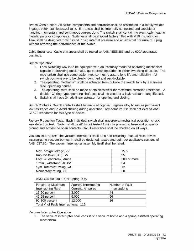
UC DAVIS Campus Design Guide
UTILITIES - DIVISION 33 42 July 2014
Switch Construction: All switch components and entrances shall be assembled in a totally welded 7-gauge #304 stainless steel tank. Entrances shall be internally connected and capable of handling momentary and continuous current duty. The switch shall contain no electrically floating metallic parts or components. Switches shall be shipped factory filled with #10 insulating oil. Tank shall be designed to withstand 7 psig internal pressure and an external pressure of 7 psig without affecting the performance of the switch. Cable Entrances: Cable entrances shall be tested to ANSI/IEEE 386 and be 600A apparatus bushings. Switch Operation
1. Each switching way is to be equipped with an internally mounted operating mechanism capable of providing quick-make, quick-break operation in either switching direction. The mechanism shall use compression type springs to assure long life and reliability. All switch positions are to be clearly identified and pad-lockable.
2. The operating mechanism shall be actuated from outside the switch tank by a stainless steel operating handle.
3. The operating shaft shall be made of stainless steel for maximum corrosion resistance. A double “O” ring type operating shaft seal shall be used for a leak resistant, long life seal.
4. Switch shall have 24 vdc linear actuator for opening and closing. Switch Contacts: Switch contacts shall be made of copper/tungsten alloy to assure permanent low resistance and to avoid sticking during operation. Temperature rise shall not exceed ANSI C37.72 standards for this type of device. Factory Production Tests: Each individual switch shall undergo a mechanical operation check, leak detection test. Switch shall be AC hi-pot tested 1 minute phase-to-phase and phase-to-ground and across the open contacts. Circuit resistance shall be checked on all ways. Vacuum Interrupter: The vacuum interrupter shall be a non-reclosing, manual reset device incorporating vacuum bottles. It shall be designed, tested and built per applicable sections of ANSI C37.60. The vacuum interrupter assembly itself shall be rated:
Max. design voltage, kV 15.5 Impulse level (BIL), kV 95 Cont. & loadbreak, Amps 200 or more 1 min., withstand, AC kV 34 Sym. Interrupt rating, kA 12 Momentary rating, kA 20
ANSI C37.60 Fault Interrupting Duty
Percent of Maximum Interrupting Rate
Approx. Interrupting Current, Amperes
Number of Fault Interruptions
15-20 percent 2,000 44 45-55 percent 6,000 56 90-100 percent 12,000 16 Total # of Fault Interruptions: 116
Vacuum Interrupter Operation
1. The vacuum interrupter shall consist of a vacuum bottle and a spring-assisted operating mechanism.
UC DAVIS Campus Design Guide
UTILITIES - DIVISION 33 43 July 2014
2. The vacuum interrupter operating mechanism shall consist of the support assembly, linkage, spring latch mechanism and solenoid utilized for electronic tripping. Interrupting time shall be three cycles maximum (50m Sec).
3. Each tap phase is to be equipped with an individual vacuum interrupter fully enclosed in an oil-insulated switch tank. Electrical opening of the vacuum interrupter shall be by a solenoid that is activated from the control box external to the switch tank. Electrical opening shall be field selectable. Closing (reset) of the vacuum interrupter shall be manual with the use of a mechanical lever.
4. The mechanical linkage assembly shall provide for a “trip-free” operation that allows for the vacuum interrupter to interrupt independent of the operating lever if closing into a faulted or heavily loaded phase or circuit. Interruption or reset shall be three phase.
Electronic Control
1. Drawout over-current relays shall be provided to sense load and fault current on each phase of the load tap circuits. Relays shall be powered by a capacitor trip devices powered by a fused potential transformer mounted inside the oil-insulated switch tank. No external power source shall be required.
2. The relays shall monitor the load or fault current on the individual phases of the tap circuits using input from the current transformers.
3. All tripping shall be three phase. Temperature range shall be –40 degrees C to +85 degrees C.
4. Manual tripping shall be provided.
Enclosure 1. The enclosure for the switch assembly shall be made of 11-gauge #304 stainless steel
and manufactured to ANSI C37.72 and C57.12.28 standards. After assembly, the enclosure shall be finished with a coating of UV resistant paint.
2. Enclosures shall be filled with transformer oil. 3. The enclosure shall be provided with four lifting eyes that provide a balanced lift for the
complete assembly. 4. Enclosure access doors shall have stainless steel hinges. Access doors to the power
cable compartments shall be equipped with a latch mechanism and penta-head bolt assembly.
Standard Components
1. Oil fill port. 2. Four lifting provisions. 3. Welded entrance bushings. 4. Oil level gauge. 5. Grounding provisions for one 1/2-inch – 13 ground connection per switch way plus
provisions for one 1/2-inch – 13 tank ground connections. 6. Three-line diagram and stainless steel nameplate, permanently mounted. 7. Stainless steel tank and lids, stainless steel and brass fasteners, with no external
aluminum parts. 8. Tank coating to be light gray (ASA 70) paint with primer, 3-mil-thick minimum. 9. Pad-lockable operating mechanism with position indication. 10. Phase designation nameplates. 11. Open/closed indicators mounted to the moving interrupter shaft.
Field Testing: Provide the services of a factory representative to test switches and interrupters. The test shall include:
1. Insulation test using 2,500 vdc source.
UC DAVIS Campus Design Guide
UTILITIES - DIVISION 33 44 July 2014
2. High potential test: Test each pole to be ground for 1 minute at 75 percent of DC test conducted at factory. The University will furnish records of previous factory test results.
3. Contact resistance test across each switch blade. 4. Operation test of all switch and vacuum interrupters.
MEDIUM VOLTAGE LOAD BREAK SWITCHES (SECTIONALIZING SWITCHES) Three phase 600 amp, 12.47kV underground feeders and for remote switching of a circuit. Each unit shall be manufactured by Trayer, or equal and controlled by an electronic control panel furnished with the assembly, and a remote push button control and Pilot Lamp station. The complete assembly, including the control panels, shall be capable of operation, without damage, when fully submerged in water to a depth of 5 feet. Ratings
1. Operating Voltage .................................................................... 15,500 volts line to line 2. BIL ......................................................................................... 95kV 3. AC Withstand, on minute .......................................................... 35kV 4. DC Withstand, 15 minutes ......................................................... 53kV 5. Continuous Current................................................................... 600 amps 6. Fault Current Interrupting ......................................................... 12000 amps 7. Min. # of Fault Operations (50 percent rating at X/R= max.) ....... 100 8. Control Power, from external source .......................................... 120 volts a.c. 9. Cable Connections .................................................................... 600-amp bushing for separable connection
Provide ground connection fittings, remote manual control panel station and enclosure, and manual control features as required under CIRCUIT INTERRUPTER above. In addition provide: 1. Automatic Control - Provide the following functions, all field setable:
a. Phase over-current, inverse time trip - curve C, 200 amp minimum trip. b. Phase Current instantaneous trip, adjustable with dip switch field set at a multiple of
minimum pick up. Set for 1 b times minimum pick up. c. Ground over-current, inverse time trip - curve 1, 20 amp minimum trip. d. Inrush restraint on phase and ground trips.
2. Annunciation - Provide a labeled flag to indicate phase, ground fault, or instantaneous trip initiation.
3. Auxiliary Switch - Provide a four circuit (2 Form A, 2 Form B) auxiliary switch, with cable connection to terminals in the Control Panel.
Execution 1. Interrupter Installation in Manholes - Mount horizontal on the support frame, the support
frame mounted on the wall of the manhole. a. Cable Connections - Apparatus Bushing for separable connector, 600-amp. Cable to
be trained and tied in such configuration that the connecting fitting can be pulled without undoing or relocating the cable bundles.
UC DAVIS Campus Design Guide
UTILITIES - DIVISION 33 45 July 2014
b. Control Cable termination - Control cable to be terminated in the Interrupter at the factory. Terminate the free end in the Electronic Control Panel with factory installed cord grip connector.
2. Control Panel Assembly Installation - Obtain control power from the manhole auxiliary power circuit. Connections to circuit shall be watertight. Setting and adjustment of the electronic relays will be done by the University.
3. Manual Remote Control a. Install the remote manual control devices to permit the opening and closing of the
interrupter from outside the manhole while observing the lamps indicating open or closed condition of the interrupter. Install device suspended on a hook called for at a location convenient to the operator to grasp from the manhole access ladder. Location must be approved by the University’s Representative prior to installation.
b. Retractile Cord - Install with cord grip connectors to the Pilot Light Station and to the Control Station.
c. Control Wiring - Run in rigid steel conduit, except for the retractile cord between the pilot light station and the push button control station.
Primary Sectionalizing Switches: The sectionalizing switches shall be SF6 filled type rated 15,000 volts, 600 amperes, load-break 40,000 amperes momentary. Switch shall be 3 or 4-way type, and each way shall be 3-pole, 2-position, “on-off” position. Cable entrances shall be through the top of the tank and shall be apparatus bushings with ESNA type 600 amp elbow connectors for single-conductor as required. Handle on each way of each switch shall be fitted with spring operator. The switch shall be mounted on a frame to the wall in the manhole and shall be complete with SF6 gas. The inside of the tank shall be painted white. The switch shall be fitted with pressure gauge and valve for filling. The switch shall be furnished with provisions for padlock interlock on the outside ways of the switch and shall prevent motion of this way to any position without the key (which will be released only when existing sectionalizing switch on the supply side is locked in off or on position). TESTING Field Testing of Medium Voltage Interrupters - A factory representative shall test switches and interrupters as follows:
1. Insulation test using 2,500 vdc source. 2. High potential test: Test each pole to be ground for 1 minute at 95 percent of DC test
(75% for padmount switches) conducted at factory. The University will furnish records of previous factory test results.
3. Contact resistance test across each switchblade. 4. Operation test of all switch and vacuum interrupters.
The following field tests will be performed by the University’s Representative. 1. Manual Trip and close tests from each location where this function is specified. 2. Automatic trip test using simulated fault current.

UC DAVIS Campus Design Guide
UTILITIES - DIVISION 33 46 July 2014
MEDIUM VOLTAGE DUCT BANK GROUNDING 33 79 83 In the core campus area, install a 2/0 copper conductor (or larger) in all H/V duct banks. The 2/0 conductor shall be attached to the ground rods placed in the duct bank system. Ground rods shall be installed in splice locations and all equipment and material in these locations shall be bonded to the 2/0 copper conductor. GROUND BONDS Ground Bus to Trans Neutral .................................................... Two No. 2/0 AWG Ground Bus to transformer enclosure, distribution panel enclosure, cable box cover, trench cover and ground electrode loop ....................................................... No. 2/0 AWG GROUND RODS Copper clad steel rods, 1-inch by the required dimension, in sectional 10 foot lengths with pointed end, driven to a depth where the rod top is not less than 6 inches below finish grade at the equipment pad and two inches above the floor in the equipment vault. Protect rod top with a driving tool while driving to prevent deformation or other damage. CABLE CONNECTIONS
1. To Ground Rods - Exothermic weld, Cadweld or equal, utilizing weld molds furnished by the weld manufacturer and the type and size recommended by the weld manufacturer.
2. Ground Cable Splices - Exothermic weld, Cadweld, or equal, utilizing molds of the type and size recommended by the weld manufacturer.
3. To Ground Buses and to Equipment - Pressure indented copper cable terminal, one hole: Burndy HYLUG, T&B Blue, or equal. Install with inch galvanized or cadmium plated steel machine bolts with beveled washer each side.
TESTING Grounding test shall be by fall-of potential method by an independent testing agency.
Related Documents