Divergence of Airfoils MECH6481 Project 2013 Zeinab El-Sayegh Concordia University, Montreal, Quebec, CANADA 12/05/2013 12/16/2013

Welcome message from author
This document is posted to help you gain knowledge. Please leave a comment to let me know what you think about it! Share it to your friends and learn new things together.
Transcript
Divergence of Airfoils MECH6481 Project
2013
Zeinab El-Sayegh
Concordia University, Montreal, Quebec, CANADA
12/05/2013
12/16/2013
Divergence of Airfoils
by
Zeinab El-Sayegh
ID: 7126247
A project
Submitted in fulfillment
Of the requirements of
MECH 6481
Concordia University
December 2013
ABSTRACT
Divergence is a static aeroelastic effect that involves the interaction of
aerodynamic and elastic forces. Wing torsional divergence is the most common
divergence that occurs when the local angle of the wing increases to the point where
structural failure occurs. This happens when the lifting forces on a wing induce a
torsional moment that twists the wing about its elastic axis. This twist results in an
increase of the local angle of attack. This in turn produces more lift, which in turn
induces further twist. Eventually, the aerodynamic forces and the elastic reactive forces
will either reach equilibrium, or the reactive forces will be overcome. The local angle of
attack and the aerodynamics forces will continue to increase, until structural failure
occurs. This happens at a specific speed called divergence speed. If the aircraft exceeds
this speed, the aerodynamic moment increase will be greater than the elastic restoring
torque. Divergence speed is primarily affected by the coupling between the torsional and
bending degrees of freedom[1]. There are some physical and mechanical parameters that
affect the divergence speed; this report studies the divergence phenomena in two cases
(torsion; torsion and bending) it also explain how those parameters affect the divergence
speed.
Keywords: divergence, Reynolds number, viscosity, area, density ….
Divergence of Airfoils
ii
TABLE OF CONTENTS
LIST OF FIGURES ………………..………...……………………………………. iii
1. INTRODUCTION ................................................................................................... 1
2. MODELING OF AIRCRAFT WINGS .................................................................... 2
2.1 Divergence Due to Twisting .............................................................................. 3
2.2 Divergence Due to Bending and Twisting ......................................................... 5
2.3 Variables Affecting Divergence ........................................................................ 6
3. STRUCTURAL DESIGN AND ANALYSIS .......................................................... 7
3.1 Wing Design ..................................................................................................... 7
3.1.1 Rectangular wing: ...................................................................................... 7
3.1.2 Elliptical wing ............................................................................................ 8
3.1.3 Swept wing ................................................................................................ 8
3.1.4 Delta wing ................................................................................................. 9
3.2 Effect of Structure on Divergence Speed ........................................................... 9
3.2.1 Characteristic area ...................................................................................... 9
3.2.2 Distance form elastic axis to aerodynamic center...................................... 10
4. EFFECT OF REYNOLDS NUMBER ................................................................... 15
4.1 Effect on Density ............................................................................................ 15
4.2 Effect on Lift Coefficient ................................................................................ 16
5. EFFECT OF VISCOSITY ..................................................................................... 18
6. CONCLUSION ..................................................................................................... 19
7. LIST OF REFERENCES ....................................................................................... 20
8. APPENDIX A: CALCULATION OF AC .............................................................. 21
9. APPENDIX B: EFFECT OF REYNOLDS NUMBER ........................................... 22
10. APPENDIX C: ORINALITY FORM OF EXPECTATION ................................... 23
iii
LIST OF FIGURES
FIGURE 2.1: AIRCRAFT WING SECTION [1] ........................................................................ 2
FIGURE 2.2: AIRFOIL SUBJECT TO TORSION [2] .................................................................. 3
FIGURE 2.3: AIRFOIL SUBJECT TO BENDING AND TORSION [1] ............................................ 5
FIGURE 3.1: RECTANGULAR WING [3] ............................................................................... 7
FIGURE 3.2: ELLIPTICAL WING [3] .................................................................................... 8
FIGURE 3.3: SWEPT WING [3] ........................................................................................... 8
FIGURE 3.4: DELTA WING [3] ........................................................................................... 9
FIGURE 3.5: VARIATION OF DIVERGENCE SPEED WITH RESPECT TO THE AREA ................... 10
FIGURE 3.6: SHOWS TYPES OF CHAMBERS IN AN AIRFOIL ................................................. 11
FIGURE 3.7: SAMPLE OF AN AC CALCULATOR [5] ........................................................... 12
FIGURE 4.1: VARIATION OF DENSITY WITH RESPECT TO THE REYNOLDS NUMBER ............. 16
FIGURE 4.2: EFFECT OF REYNOLDS NUMBER ON CL ........................................................ 17
FIGURE 5.1: VARIATION OF REYNOLDS NUMBER AS A FUNCTION OF THE VISCOSITY ......... 18
1
1. INTRODUCTION
Wings are airfoils that create lift when moving rapidly through the air. They are
built in many shapes and sizes. Wing design varies to provide certain desirable flight
characteristics. When the shape of the wing vary many characteristic changes such as
Control at various operating speeds, the amount of lift generated, balance, and stability.
The wings of an aircraft can be attached to the fuselage at the top, mid-fuselage,
or at the bottom. They may extend perpendicular to the horizontal plain of the fuselage or
can angle up or down slightly. This angle is known as the wing dihedral. The dihedral
angle affects the lateral stability of the aircraft.
Wings develop the major portion of the lift of a heavier-than-air aircraft. Wing
structures carry some of the heavier loads found in the aircraft structure. The particular
design of a wing depends on many factors, such as the size, weight, speed, rate of climb,
and use of the aircraft. The wing must be constructed so that it holds its aerodynamics
shape under the extreme stresses of combat maneuvers or wing loading. Wing
construction is similar in most modern aircraft.
2
2. MODELING OF AIRCRAFT WINGS
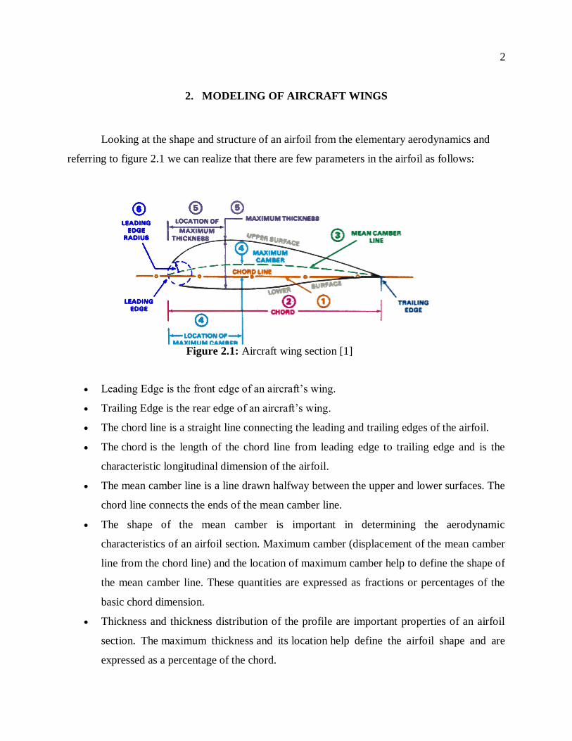
Looking at the shape and structure of an airfoil from the elementary aerodynamics and
referring to figure 2.1 we can realize that there are few parameters in the airfoil as follows:
Leading Edge is the front edge of an aircraft‟s wing.
Trailing Edge is the rear edge of an aircraft‟s wing.
The chord line is a straight line connecting the leading and trailing edges of the airfoil.
The chord is the length of the chord line from leading edge to trailing edge and is the
characteristic longitudinal dimension of the airfoil.
The mean camber line is a line drawn halfway between the upper and lower surfaces. The
chord line connects the ends of the mean camber line.
The shape of the mean camber is important in determining the aerodynamic
characteristics of an airfoil section. Maximum camber (displacement of the mean camber
line from the chord line) and the location of maximum camber help to define the shape of
the mean camber line. These quantities are expressed as fractions or percentages of the
basic chord dimension.
Thickness and thickness distribution of the profile are important properties of an airfoil
section. The maximum thickness and its location help define the airfoil shape and are
expressed as a percentage of the chord.
Figure 2.1: Aircraft wing section [1]
3
The leading edge radius of the airfoil is the radius of curvature given the leading edge
shape.
2.1 Divergence Due to Twisting
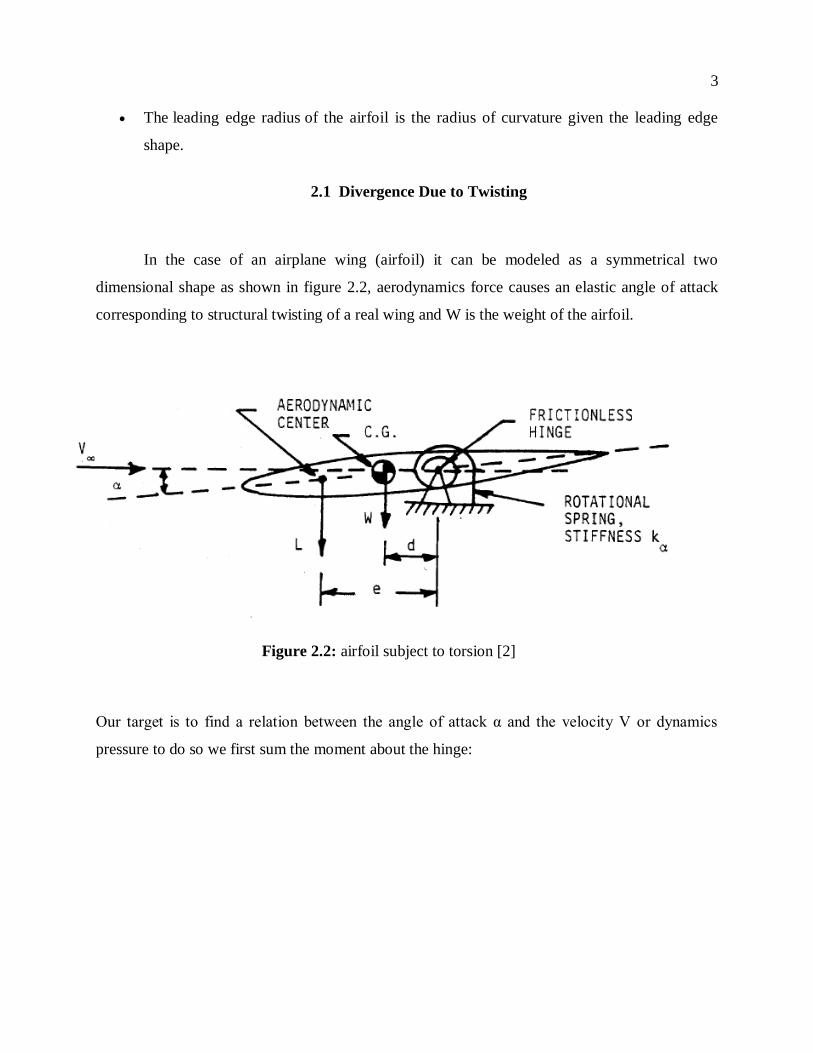
In the case of an airplane wing (airfoil) it can be modeled as a symmetrical two
dimensional shape as shown in figure 2.2, aerodynamics force causes an elastic angle of attack
corresponding to structural twisting of a real wing and W is the weight of the airfoil.
Our target is to find a relation between the angle of attack α and the velocity V or dynamics
pressure to do so we first sum the moment about the hinge:
Figure 2.2: airfoil subject to torsion [2]
4
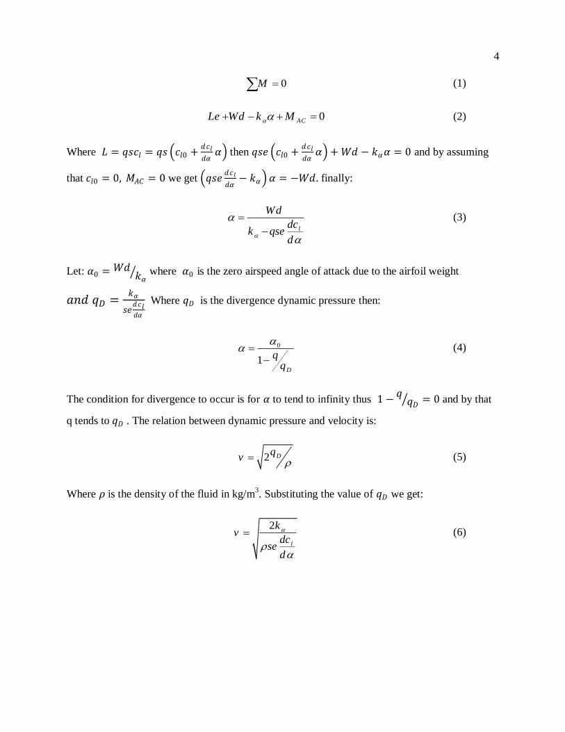
0M (1)
0ACLe Wd k M (2)
Where 𝐿 = 𝑞𝑠𝑐𝑙 = 𝑞𝑠 𝑐𝑙0 +𝑑𝑐𝑙
𝑑𝛼𝛼 then 𝑞𝑠𝑒 𝑐𝑙0 +
𝑑𝑐𝑙
𝑑𝛼𝛼 + 𝑊𝑑 − 𝑘𝛼𝛼 = 0 and by assuming
that 𝑐𝑙0 = 0, 𝑀𝐴𝐶 = 0 we get 𝑞𝑠𝑒𝑑𝑐𝑙
𝑑𝛼− 𝑘𝛼 𝛼 = −𝑊𝑑. finally:
l
Wd
dck qse
d
(3)
Let: 𝛼0 = 𝑊𝑑𝑘𝛼 where 𝛼0 is the zero airspeed angle of attack due to the airfoil weight
𝑎𝑛𝑑 𝑞𝐷 =𝑘𝛼
𝑠𝑒𝑑𝑐𝑙𝑑𝛼
Where 𝑞𝐷 is the divergence dynamic pressure then:
0
1D
(4)
The condition for divergence to occur is for 𝛼 to tend to infinity thus 1 −𝑞𝑞𝐷 = 0 and by that
q tends to 𝑞𝐷 . The relation between dynamic pressure and velocity is:
2 Dqv
(5)
Where 𝜌 is the density of the fluid in kg/m3. Substituting the value of 𝑞𝐷 we get:
2
l
kv
dcse
d
(6)
5
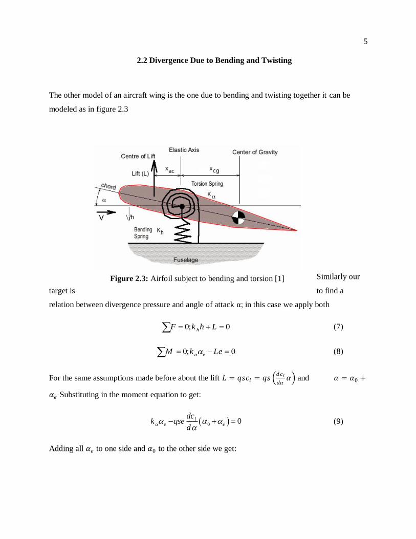
2.2 Divergence Due to Bending and Twisting
The other model of an aircraft wing is the one due to bending and twisting together it can be
modeled as in figure 2.3
Similarly our
target is to find a
relation between divergence pressure and angle of attack α; in this case we apply both
0; 0hF k h L (7)
0; 0eM k Le (8)
For the same assumptions made before about the lift 𝐿 = 𝑞𝑠𝑐𝑙 = 𝑞𝑠 𝑑𝑐𝑙
𝑑𝛼𝛼 and 𝛼 = 𝛼0 +
𝛼𝑒 Substituting in the moment equation to get:
0 0le e
dck qse
d
(9)
Adding all 𝛼𝑒 to one side and 𝛼0 to the other side we get:
Figure 2.3: Airfoil subject to bending and torsion [1]
6
0
l
el
dcqSe
ddc
k qsed
(10)
The condition for divergence remains the same in all cases for 𝛼𝑒 to tend to infinity thus
𝑘𝛼 − 𝑞𝑠𝑒𝑑𝑐𝑙
𝑑𝛼= 0 and finding q from the equation we get:
D
l
kq q
dcse
d
(11)
2.3 Variables Affecting Divergence
It is shown from the above derivation that the divergence speed is identical in both cases
of twisting alone and twisting and bending together. The divergence velocity depends basically
on 𝑘𝛼 (rotational spring stiffness); S (wing area); e (distance from elastic axis to aerodynamic
center); 𝑑𝑐𝑙
𝑑𝛼 (lift curve slope) and density of the material. In the following chapters we will study
each effect of those variables by itself.
7
3. STRUCTURAL DESIGN AND ANALYSIS
The wings are airfoils attached to each side of the fuselage and are the main lifting
surfaces that support the airplane in flight. There are numerous wing designs, sizes, and shapes
used by the various manufacturers. Each fulfills a certain need with respect to the expected
performance of the airplane. The number of wings can also vary. Airplanes with a single set of
wings are referred to as monoplanes, while those with two sets are called biplanes. Many high-
wing airplanes have external braces, or wing struts, which transmit the flight and landing loads
through the struts to the main fuselage structure. Since the wing struts are usually attached
approximately halfway out on the wing, this type of wing structure is called semi-cantilever.
3.1 Wing Design
In designing aircraft wings there are many types of wings that can be taken into
consideration below are some types of wings:
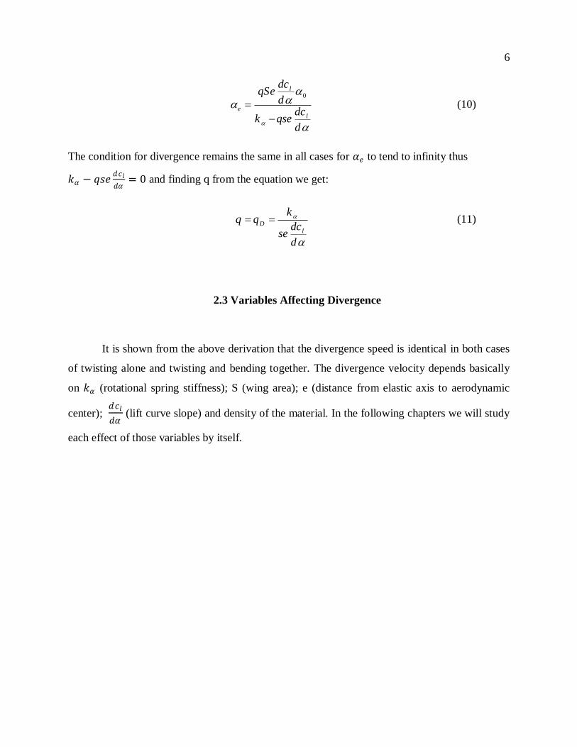
3.1.1 Rectangular wing:
It is sometimes referred to as the “Hershey Bar” it is a good general purpose wing. It can
carry a reasonable load and fly at a reasonable speed, but does nothing superbly well. It is ideal
for personal aircraft as it is easy to control in the air as well as inexpensive to build and maintain
[3].
Figure 3.1: rectangular wing [3]
8
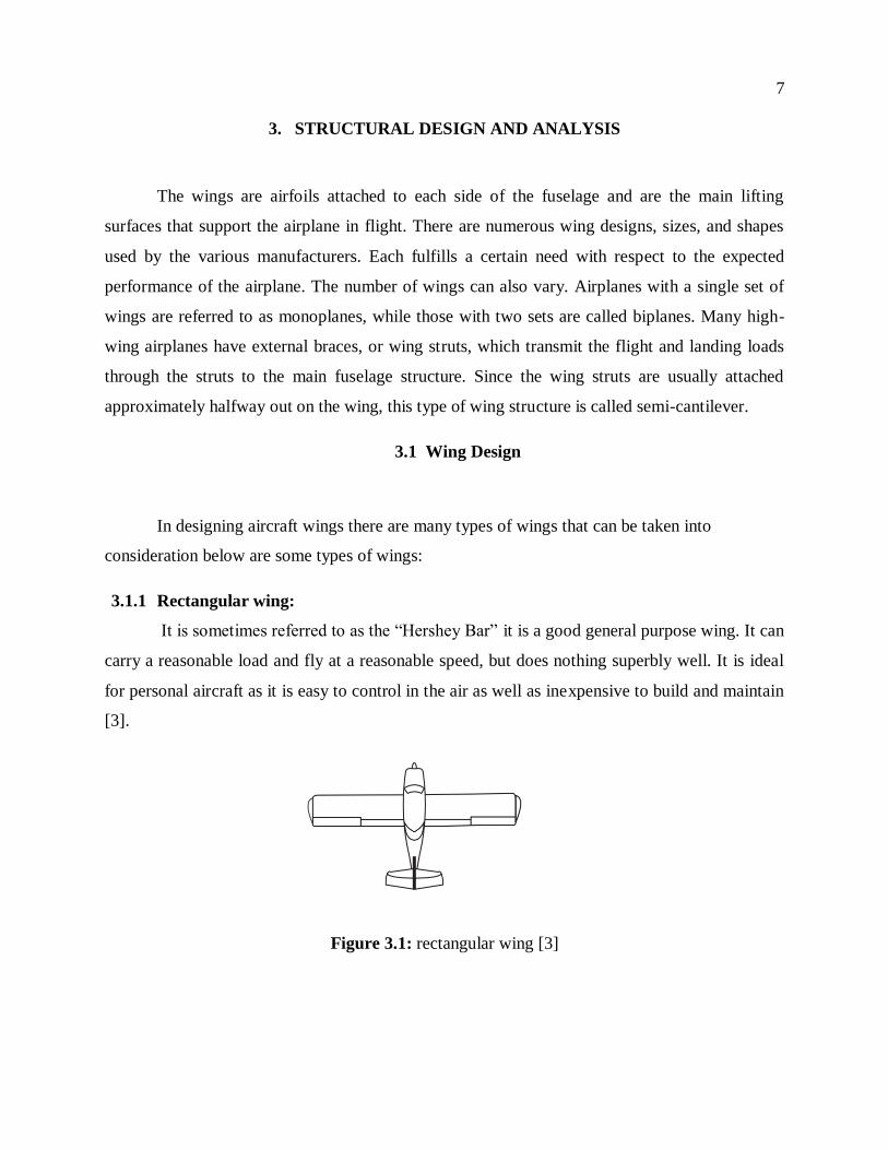
3.1.2 Elliptical wing
It is similar to the rectangular wing and was common on tail-wheel aircraft produced in
the 1930s. It excels however in use on gliders, where its long wingspan can capture the wind
currents easily, providing lift without the need for a lot of forward momentum, or airspeed.
Figure 3.2: Elliptical wing [3]
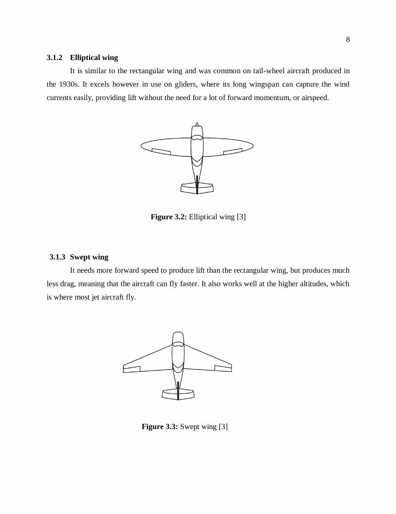
3.1.3 Swept wing
It needs more forward speed to produce lift than the rectangular wing, but produces much
less drag, meaning that the aircraft can fly faster. It also works well at the higher altitudes, which
is where most jet aircraft fly.
Figure 3.3: Swept wing [3]
9
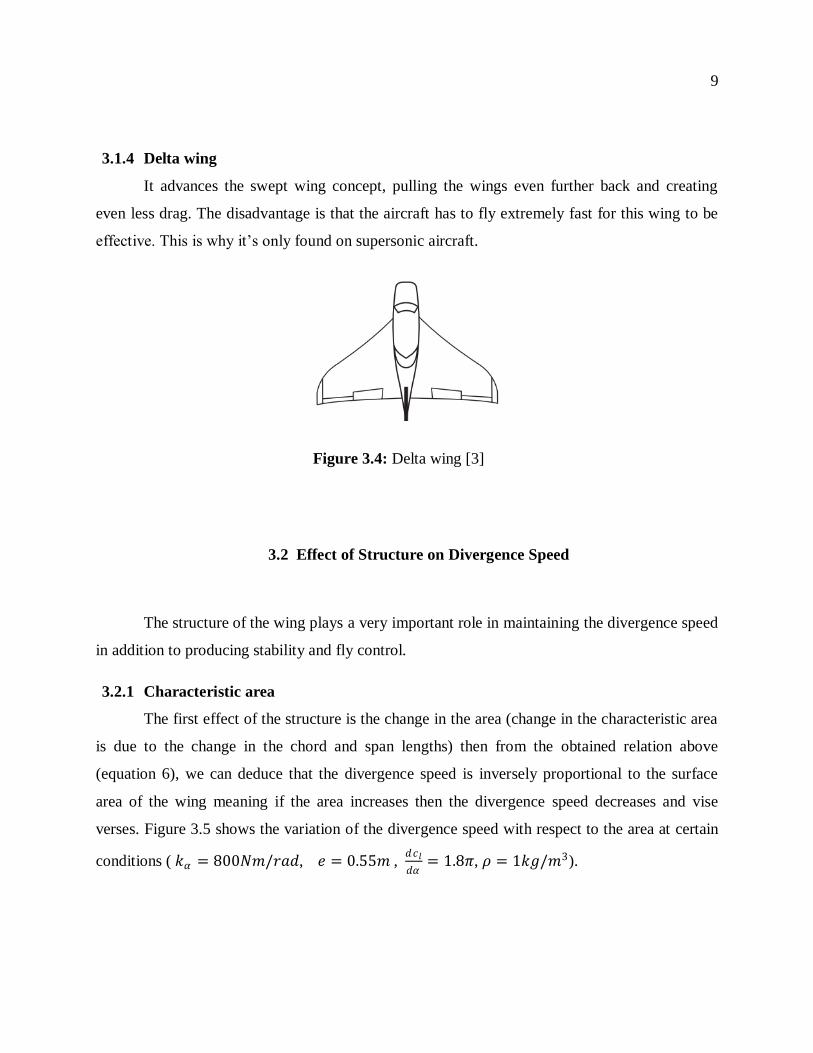
3.1.4 Delta wing
It advances the swept wing concept, pulling the wings even further back and creating
even less drag. The disadvantage is that the aircraft has to fly extremely fast for this wing to be
effective. This is why it‟s only found on supersonic aircraft.
3.2 Effect of Structure on Divergence Speed
The structure of the wing plays a very important role in maintaining the divergence speed
in addition to producing stability and fly control.
3.2.1 Characteristic area
The first effect of the structure is the change in the area (change in the characteristic area
is due to the change in the chord and span lengths) then from the obtained relation above
(equation 6), we can deduce that the divergence speed is inversely proportional to the surface
area of the wing meaning if the area increases then the divergence speed decreases and vise
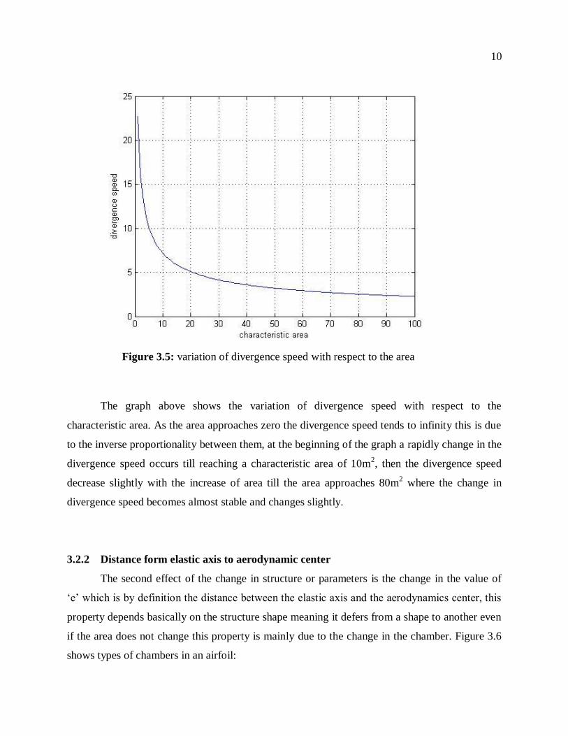
verses. Figure 3.5 shows the variation of the divergence speed with respect to the area at certain
conditions ( 𝑘𝛼 = 800𝑁𝑚/𝑟𝑎𝑑, 𝑒 = 0.55𝑚 , 𝑑𝑐𝑙
𝑑𝛼= 1.8𝜋, 𝜌 = 1𝑘𝑔/𝑚3).
Figure 3.4: Delta wing [3]
10
The graph above shows the variation of divergence speed with respect to the
characteristic area. As the area approaches zero the divergence speed tends to infinity this is due
to the inverse proportionality between them, at the beginning of the graph a rapidly change in the
divergence speed occurs till reaching a characteristic area of 10m2, then the divergence speed
decrease slightly with the increase of area till the area approaches 80m2 where the change in
divergence speed becomes almost stable and changes slightly.
3.2.2 Distance form elastic axis to aerodynamic center
The second effect of the change in structure or parameters is the change in the value of
„e‟ which is by definition the distance between the elastic axis and the aerodynamics center, this
property depends basically on the structure shape meaning it defers from a shape to another even
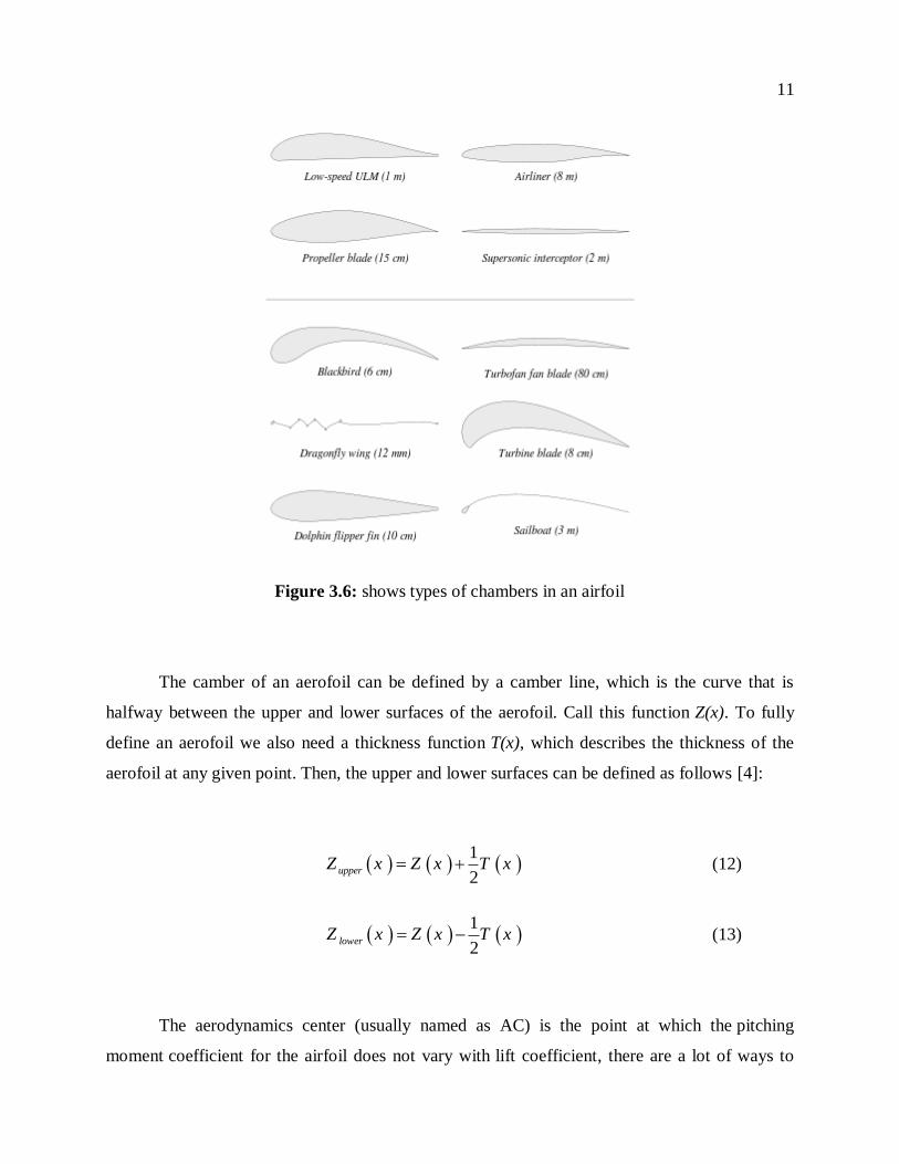
if the area does not change this property is mainly due to the change in the chamber. Figure 3.6
shows types of chambers in an airfoil:
Figure 3.5: variation of divergence speed with respect to the area
11
Figure 3.6: shows types of chambers in an airfoil
The camber of an aerofoil can be defined by a camber line, which is the curve that is
halfway between the upper and lower surfaces of the aerofoil. Call this function Z(x). To fully
define an aerofoil we also need a thickness function T(x), which describes the thickness of the
aerofoil at any given point. Then, the upper and lower surfaces can be defined as follows [4]:
1
2upperZ x Z x T x (12)
1
2lowerZ x Z x T x (13)
The aerodynamics center (usually named as AC) is the point at which the pitching
moment coefficient for the airfoil does not vary with lift coefficient, there are a lot of ways to
12
calculate the aerodynamic center using the geometry and summation of moments we can find its
location however there are specific programs that simply calculates it, there is also a calculator
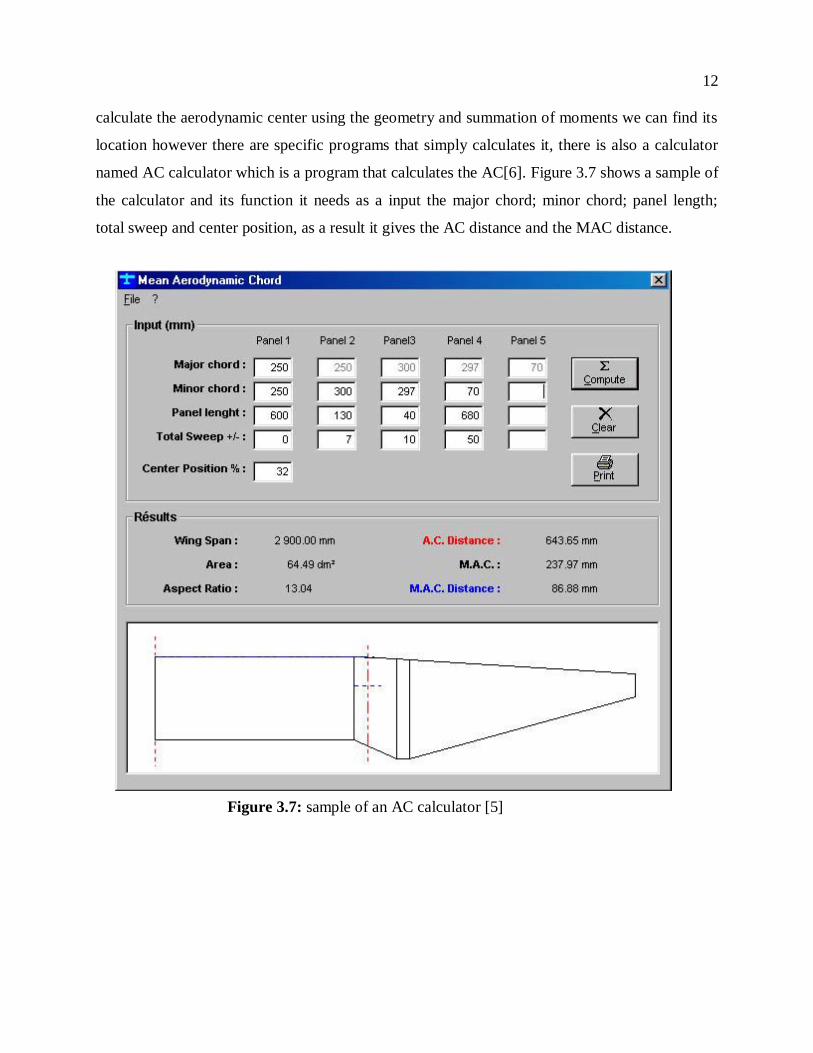
named AC calculator which is a program that calculates the AC[6]. Figure 3.7 shows a sample of
the calculator and its function it needs as a input the major chord; minor chord; panel length;
total sweep and center position, as a result it gives the AC distance and the MAC distance.
Figure 3.7: sample of an AC calculator [5]
13
Traditional way to calculate the aerodynamics center is by assuming that the aircraft is
performing a steady flight. The aircraft is then in equilibrium. This means that the moment
coefficient about the center of gravity (CG) must be 0. (Cmcg = 0.) Now assume that the aircraft
gets a small deviation from this steady flight. For example, α increases to α + dα. Then due to the
change in angle of attack, Cmcg is no longer zero. Instead, it will get a value of dCmcg . We can
now distinguish three cases.
• The change in moment dCmcg is in the same direction as dα. We thus have dCmcg /dα
> 0. In this case, the moment causes α to diverge away from the equilibrium position. The
aircraft is therefore unstable.
• The change in moment dCmcg is directed oppositely to dα. We now have dCmcg /dα <
0. In this case, the moment causes α to get back to its equilibrium position. The aircraft is thus
stable.
• The change in moment dCmcg = 0, and thus also dCmcg /dα = 0. In this case, we are in
a new equilibrium position. This situation is called neutrally stable.
There is also another method to calculate the AC refer to appendix A for further
information. Researches gave a general case for the finding of the aerodynamics center in the 3D
case it is simplified by three equations as follows [6]:
m nAC ref
z y
dC dCX X c c
dC dC (14)
L nAC ref
z x
dC dCY Y c c
dC dC (15)
L mAC ref
y x
dC dCZ Z c c
dC dC (16)
14
Where:
Cn = yawing moment coefficient
Cm = pitching moment coefficient
Cl = rolling moment coefficient
ref = reference point
Cx = X-force ~= Drag
Cy = Y-force ~= Side Force
Cz = Z-force ~= Lift
c = reference length
The elastic axis (also known as the shear center or torsional axis) is an imaginary point on
a section, where a shear force can be applied without inducing any torsion. In general, the shear
center is not the centroid. For cross-sectional areas having one axis of symmetry, the shear center
is located on the axis of symmetry. For those having two axes of symmetry, the shear center lies
on the centroid of the cross-section. The elastic axis location basically depends on the structure
of the airfoil, to calculate the elastic axis we should calculate the shear center of each section and
join them together [7]. The shear center calculation needs a simple calculation steps:
First calculate the shear stress:
0
s
xs
z
Vt ydA
I (17)
Vx is the vertical load; Iz is the moment of inertia about z-axis; Y is the distance from the neutral
axis; A is the area from and t is the thickness, then finding Q which is the force
0
b
sQ tds (18)
In this step we should multiply Q by the distance „e‟ which is the location of the shear center and
sum the moment to find the value of „e‟.
15
4. EFFECT OF REYNOLDS NUMBER
Reynolds number (Re) is a dimensionless quantity that is used to help predict similar
flow patterns in different fluid flow situations. The Reynolds number is defined to be the ratio of
inertial forces to viscous forces. Reynolds numbers frequently arise when performing scaling of
fluid dynamics problems, and as such can be used to determine dynamic similitude between two
different cases of fluid flow. They are also used to characterize different flow regimes within a
similar fluid, such as laminar or turbulent flow [8].
The Reynolds number is defined as:
inertial forces vLRe
viscous forces
(19)
Where:
v is the mean velocity of the object relative to the fluid (SI units: m/s)
L is a characteristic linear dimension, (travelled length of the fluid; hydraulic
diameter when dealing with river systems) (m)
𝜇 is the dynamic viscosity of the fluid (Pa·s or N·s/m² or kg/(m·s))
𝜌 is the density of the fluid (kg/m³).
4.1 Effect on Density
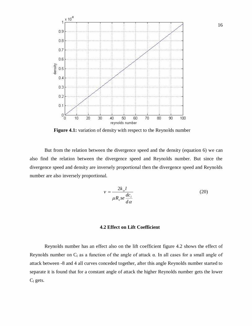
Reynolds number has many effects on the divergence speed it affects the density, from
the equation 19, density and Reynolds number are proportional so as the density increases
Reynolds number increases figure 4.1 shows the variation of density with respect to the
Reynolds number.
16
But from the relation between the divergence speed and the density (equation 6) we can
also find the relation between the divergence speed and Reynolds number. But since the
divergence speed and density are inversely proportional then the divergence speed and Reynolds
number are also inversely proportional.
2
le
k lv
dcR se
d
(20)
4.2 Effect on Lift Coefficient
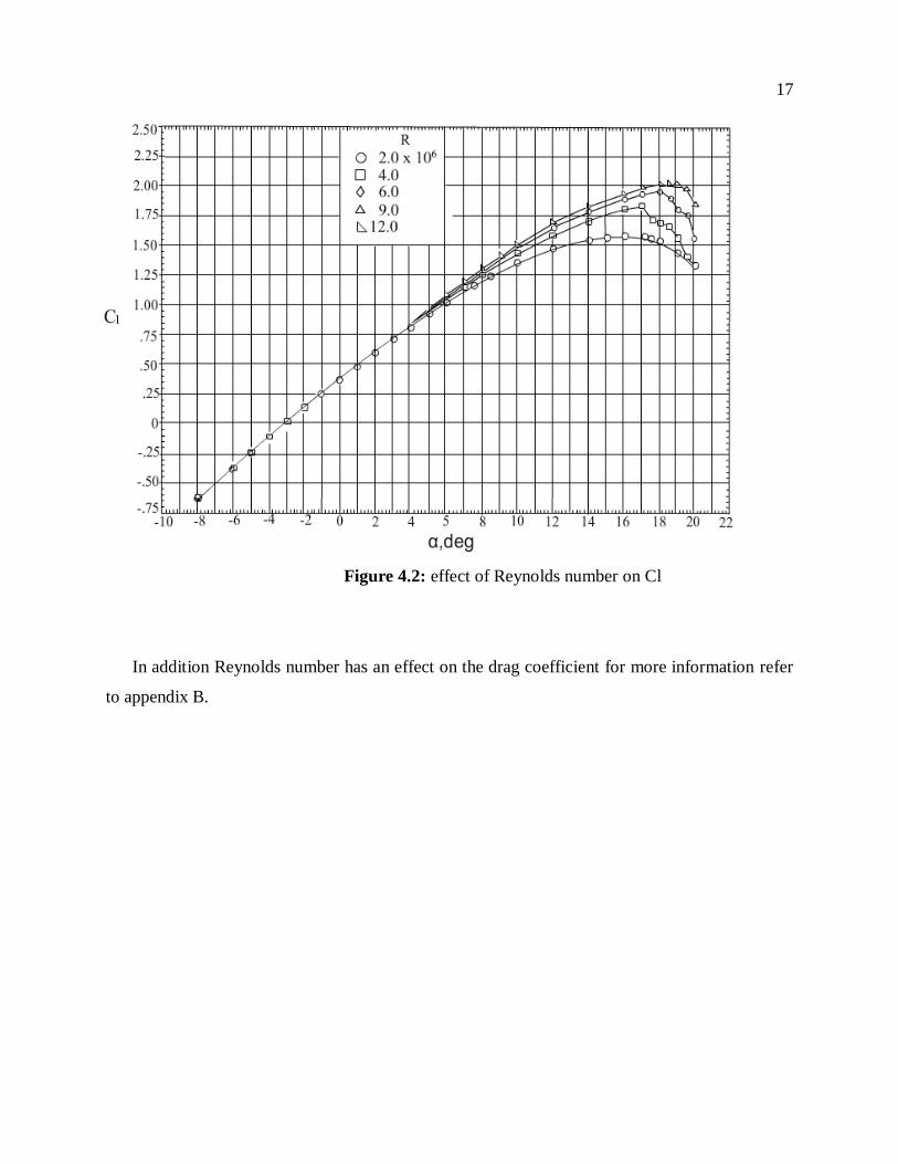
Reynolds number has an effect also on the lift coefficient figure 4.2 shows the effect of
Reynolds number on Cl as a function of the angle of attack α. In all cases for a small angle of
attack between -8 and 4 all curves conceded together, after this angle Reynolds number started to
separate it is found that for a constant angle of attack the higher Reynolds number gets the lower
Cl gets.
Figure 4.1: variation of density with respect to the Reynolds number
17
Figure 4.2: effect of Reynolds number on Cl
In addition Reynolds number has an effect on the drag coefficient for more information refer
to appendix B.
18
5. EFFECT OF VISCOSITY
Viscosity of a fluid is a measure of its resistance to gradual deformation by shear
stress or tensile stress. Viscosity is due to friction between neighboring particles of the fluid that
are moving at different velocities. A fluid that has no resistance to shear stress is known as
an ideal fluid [9].
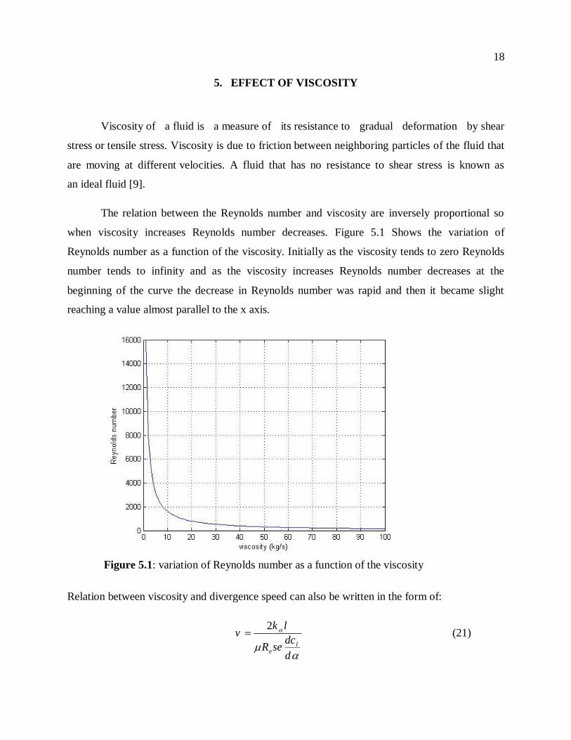
The relation between the Reynolds number and viscosity are inversely proportional so
when viscosity increases Reynolds number decreases. Figure 5.1 Shows the variation of
Reynolds number as a function of the viscosity. Initially as the viscosity tends to zero Reynolds
number tends to infinity and as the viscosity increases Reynolds number decreases at the
beginning of the curve the decrease in Reynolds number was rapid and then it became slight
reaching a value almost parallel to the x axis.
Relation between viscosity and divergence speed can also be written in the form of:
2
le
k lv
dcR se
d
(21)
Figure 5.1: variation of Reynolds number as a function of the viscosity
19
6. CONCLUSION
The majority of procedures and rules in aviation are written in blood. Scientists design
and build the safest aircraft possible, given the best available knowledge and skill. Inevitably, an
unforeseen circumstance will cause a catastrophic wing failure. Every failure and accident must
be learned from to prevent a repeated incident. Science discovered some phenomena that
aircrafts passes through such as flutter; buffeting; and divergence.
Divergence is considered one of the most important phenomena; it could lead to the
failure of the aircraft if it wasn‟t treated right. Many parameters affect the divergence critical
speed (structure; viscosity; Reynolds number…) this report analyzed those parameters and
studied their effect on the divergence speed and on each others. These parameters should be
taken into consideration and critically chosen for the aircraft not to reach the divergence critical
speed in order not to fail.
20
7. LIST OF REFERENCES
[1] < www.aerodynamics4students.com>
[2] <http://www.dept.aoe.vt.edu/~simpson/aoe4154/aerodiv.pdf>
[3] NASA, “Wing Design”, www.aeronautics.nasa.gov/pdf/wing_design_k-12.pdf
[4] Bisplinghoff, R.L., Ashley, H. and Halfman, H., Aeroelasticity. Dover Science, 1996, ISBN
0-486-69189-6, 880 pgs.
[5] <http://www.southernsoaringclub.org.za/a-AC-calculator.html>
[6] Benson, Tom (2006). "Aerodynamic Center (ac)". The Beginner's Guide to Aeronautics.
NASA Glenn Research Center. Retrieved 2006-04-01.
[7] Jiyu Sun, Bharat Bhushan, The structure and mechanical properties of dragonfly wings and
their role on fly ability C. R. Mecanique 340 3–17(2012).
[8] W Kuntjoro, AMH Abdul Jalil, J Mahmud, Wing Structure Static Analysis using
Superelement, Procedia Engineering 41 1600 – 1606 (2012).
[9] < www.ias.ac.in/initiat/sci_ed/resources/chemistry/Viscosity.pdf>
21
8. APPENDIX A: CALCULATION OF AC
Another method to find the AC location is a bit tedious but provides the best answer for
any wing. Using the plan form for one wing, establish a reference that is perpendicular to the
fuselage. This reference line should be near where the spar will be, but the fore and aft location is
not important. Divide the semi-span into 10 equal segments. In the center of each segment
measure the chord and the distance from the leading edge to the reference line. Enter these
numbers into the MAC Worksheet as shown in the example. Complete the calculations across
the sheet for each segment. Now sum the chord, chord-squared and chord-times-x columns. The
"mean aerodynamic chord" (MAC) for the wing is the chord-squared sum divided by the chord
sum. The location of the leading edge of the MAC (from the reference line) is the chord-times-x
sum divided by the chord sum. (These calculations are easily done on a computer spreadsheet.)
Locate the MAC on your wing plan relative to your reference line. Now locate the 1/4 chord of
the MAC. This is the aerodynamic center of your wing, and a good starting point for the center
of gravity. (Notice that merely averaging the chord values or the 1/4 chord locations will produce
an ac that is .25 inches farther aft then the correct value for the Pelican.)
22
9. APPENDIX B: EFFECT OF REYNOLDS NUMBER
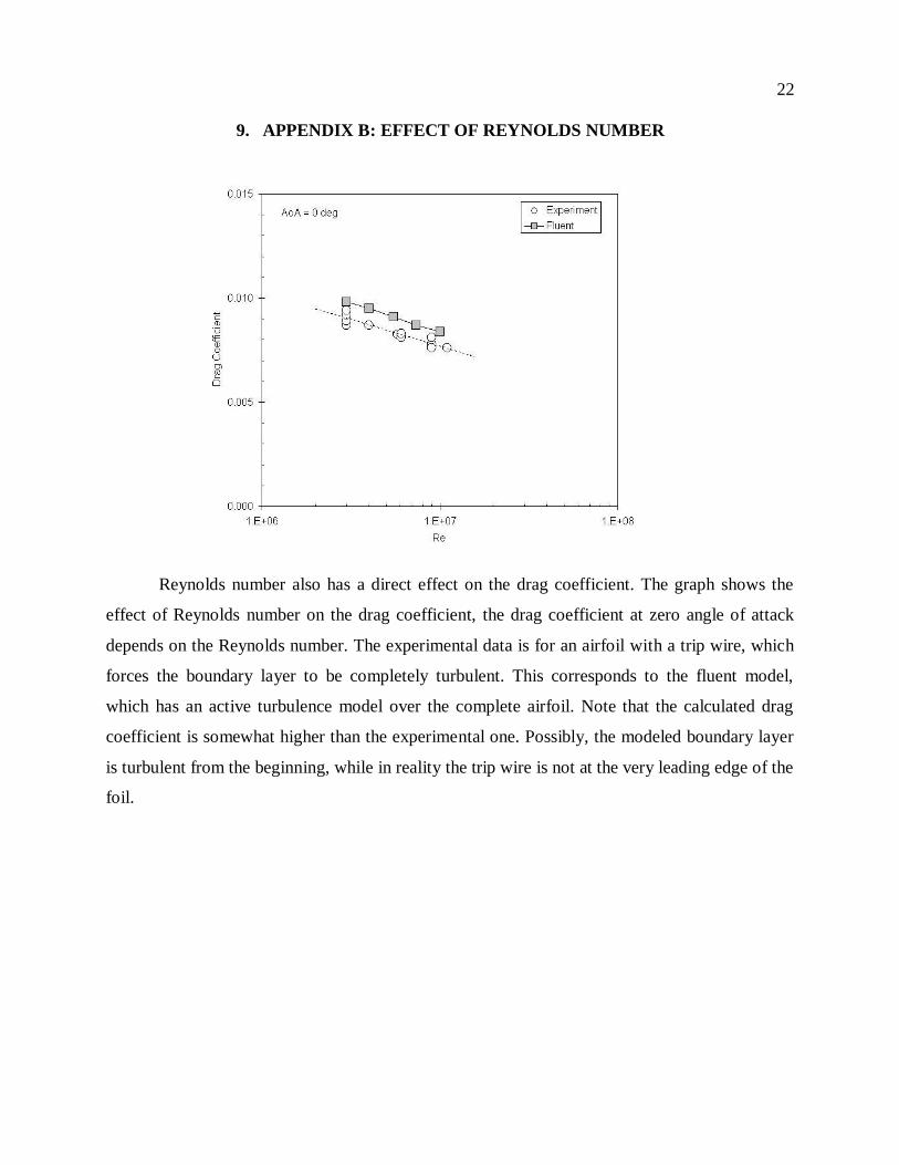
Reynolds number also has a direct effect on the drag coefficient. The graph shows the
effect of Reynolds number on the drag coefficient, the drag coefficient at zero angle of attack
depends on the Reynolds number. The experimental data is for an airfoil with a trip wire, which
forces the boundary layer to be completely turbulent. This corresponds to the fluent model,
which has an active turbulence model over the complete airfoil. Note that the calculated drag
coefficient is somewhat higher than the experimental one. Possibly, the modeled boundary layer
is turbulent from the beginning, while in reality the trip wire is not at the very leading edge of the
foil.
23
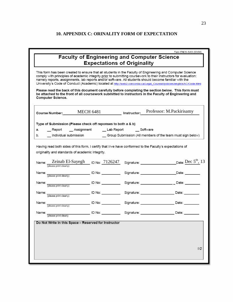
10. APPENDIX C: ORINALITY FORM OF EXPECTATION
Dec 5th, 13
Professor: M.Packirisamy
Zeinab El-Sayegh
7126247
MECH 6481
24
© Copyright 2013 reserved
Related Documents