DIVAtech D F24/F32/F37 INSTRUCTIONS FOR USE, INSTALLATION AND MAINTENANCE EN cod. 3541R751 - Rev. 00 - 03/2021

Welcome message from author
This document is posted to help you gain knowledge. Please leave a comment to let me know what you think about it! Share it to your friends and learn new things together.
Transcript
DIVAtech D F24/F32/F37
INSTRUCTIONS FOR USE, INSTALLATION AND MAINTENANCEEN
cod.
354
1R75
1 -
Rev
. 00
- 0
3/20
21
DIVAtech D F
cod. 3541R751 - Rev. 00 - 03/20212 EN
DIVAtech D F
2 EN
EN1. GENERAL WARNINGS• Carefully read and follow the instructions contained in this instruction booklet.• After boiler installation, inform the user regarding its operation and give him this
manual, which is an integral and essential part of the product and must be kept withcare for future reference.
• Installation and maintenance must be carried out by professionally qualified person-nel, in compliance with the current regulations and according to the manufacturer'sinstructions. Do not carry out any operation on the sealed control parts.
• Incorrect installation or inadequate maintenance can result in damage or injury. TheManufacturer declines any liability for damage due to errors in installation and use,or failure to follow the instructions.
• Before carrying out any cleaning or maintenance operation, disconnect the unit fromthe electrical power supply using the switch and/or the special cut-off devices.
• In case of a fault and/or poor operation, deactivate the unit and do not try to repairit or directly intervene. Contact professionally qualified personnel. Any repair/re-placement of the products must only be carried out by qualified personnel using orig-inal replacement parts. Failure to comply with the above could affect the safety ofthe unit.
• This unit must only be used for its intended purpose. Any other use is deemed im-proper and therefore hazardous.
• The packing materials are potentially hazardous and must not be left within thereach of children.
• The unit must not be used by people (including children) with limited physical, sen-sory or mental abilities or without experience and knowledge of it, unless instructedor supervised in its use by someone responsible for their safety.
• The unit and its accessories must be appropriately disposed of, in compliance withthe current regulations.
• The images given in this manual are a simplified representation of the product. Inthis representation there may be slight and insignificant differences with respect tothe product supplied.
2. OPERATING INSTRUCTIONS2.1 IntroductionDear Customer,DIVAtech D F is a high-efficiency sealed chamber heat generator for heating and hotwater production running on natural gas or LPG, and equipped with a microprocessorcontrol system.2.2 Control panelPanel
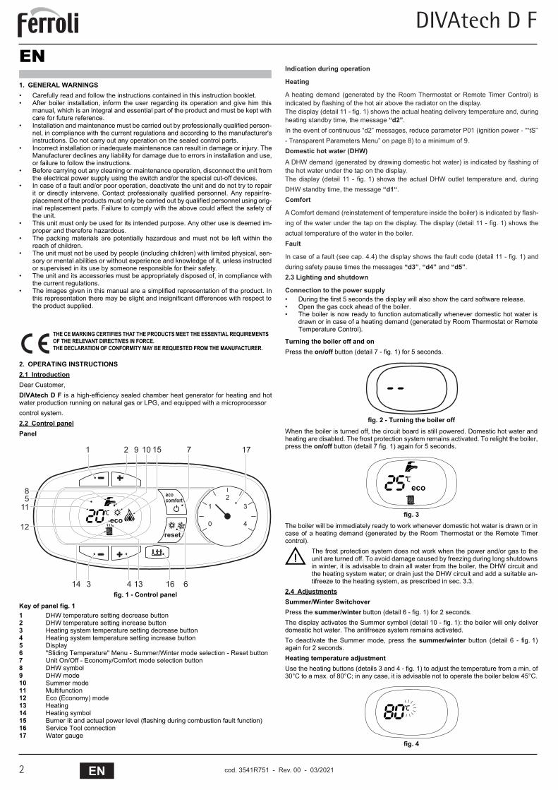
fig. 1 - Control panelKey of panel fig. 11 DHW temperature setting decrease button2 DHW temperature setting increase button3 Heating system temperature setting decrease button4 Heating system temperature setting increase button5 Display6 "Sliding Temperature" Menu - Summer/Winter mode selection - Reset button7 Unit On/Off - Economy/Comfort mode selection button8 DHW symbol9 DHW mode10 Summer mode11 Multifunction12 Eco (Economy) mode13 Heating14 Heating symbol15 Burner lit and actual power level (flashing during combustion fault function)16 Service Tool connection17 Water gauge
• During the first 5 seconds the display will also show the card software release.• Open the gas cock ahead of the boiler.• The boiler is now ready to function automatically whenever domestic hot water is
drawn or in case of a heating demand (generated by Room Thermostat or RemoteTemperature Control).
Turning the boiler off and onPress the on/off button (detail 7 - fig. 1) for 5 seconds.
fig. 2 - Turning the boiler offWhen the boiler is turned off, the circuit board is still powered. Domestic hot water andheating are disabled. The frost protection system remains activated. To relight the boiler,press the on/off button (detail 7 fig. 1) again for 5 seconds.
fig. 3The boiler will be immediately ready to work whenever domestic hot water is drawn or incase of a heating demand (generated by the Room Thermostat or the Remote Timercontrol).
BThe frost protection system does not work when the power and/or gas to theunit are turned off. To avoid damage caused by freezing during long shutdownsin winter, it is advisable to drain all water from the boiler, the DHW circuit andthe heating system water; or drain just the DHW circuit and add a suitable an-tifreeze to the heating system, as prescribed in sec. 3.3.
2.4 AdjustmentsSummer/Winter SwitchoverPress the summer/winter button (detail 6 - fig. 1) for 2 seconds.The display activates the Summer symbol (detail 10 - fig. 1): the boiler will only deliverdomestic hot water. The antifreeze system remains activated.To deactivate the Summer mode, press the summer/winter button (detail 6 - fig. 1)again for 2 seconds.Heating temperature adjustmentUse the heating buttons (details 3 and 4 - fig. 1) to adjust the temperature from a min. of30°C to a max. of 80°C; in any case, it is advisable not to operate the boiler below 45°C.
fig. 4
THE CE MARKING CERTIFIES THAT THE PRODUCTS MEET THE ESSENTIAL REQUIREMENTS OF THE RELEVANT DIRECTIVES IN FORCE.THE DECLARATION OF CONFORMITY MAY BE REQUESTED FROM THE MANUFACTURER.
�
�
�
��
�����
����������
� ��
��
��
��
�
�
� �
����
�����
�
��
� � � � �����
cod. 3541R750 - Rev. 00 - 09/2019
Indication during operation
Heating
A heating demand (generated by the Room Thermostat or Remote Timer Control) is indicated by flashing of the hot air above the radiator on the display.The display (detail 11 - fig. 1) shows the actual heating delivery temperature and, during heating standby time, the message “d2”.In the event of continuous “d2” messages, reduce parameter P01 (ignition power - ““tS”- Transparent Parameters Menu” on page 8) to a minimum of 9.Domestic hot water (DHW)A DHW demand (generated by drawing domestic hot water) is indicated by flashing of the hot water under the tap on the display.The display (detail 11 - fig. 1) shows the actual DHW outlet temperature and, during DHW standby time, the message “d1“. Comfort
A Comfort demand (reinstatement of temperature inside the boiler) is indicated by flash-ing of the water under the tap on the display. The display (detail 11 - fig. 1) shows the actual temperature of the water in the boiler.Fault
In case of a fault (see cap. 4.4) the display shows the fault code (detail 11 - fig. 1) and during safety pause times the messages “d3”, “d4” and “d5”.2.3 Lighting and shutdown
Connection to the power supply
DIVAtech D F
3ENcod. 3541R751 - Rev. 00 - 03/2021
DIVAtech D F
3EN
DHW temperature adjustmentUse the DHW buttons (details 1 and 2 - fig. 1) to adjust the temperature from a min. of40°C to a max. of 55°C.
fig. 5Room temperature adjustment (with optional room thermostat)Using the room thermostat, set the temperature required in the rooms. If the room ther-mostat is not installed, the boiler will keep the system at the set system delivery setpointtemperature.Room temperature adjustment (with optional remote timer control)Using the remote timer control, set the required temperature in the rooms. The boiler willadjust the system water according to the required room temperature. For operation withremote timer control, please refer to the relevant instruction manual.ECO/COMFORT selectionThe unit has a function that ensures a high domestic hot water delivery speed and max-imum comfort for the user. When the device is activated (COMFORT mode), the watercontained in the boiler is kept hot, thereby ensuring immediate availability of hot wateron opening the tap, without waiting times.The user can deactivate the device (ECO mode) by pressing the eco/comfort button(detail 7 - fig. 1). In ECO mode the display activates the ECO symbol (detail 12 - fig. 1).To activate the COMFORT mode, press the eco/comfort button (detail 7 - fig. 1) again.Sliding TemperatureWhen the optional external probe is installed the boiler adjustment system works with"Sliding Temperature". In this mode, the heating system temperature is regulated ac-cording to weather conditions, to ensure the high comfort and energy efficiency through-out the year. In particular, as the outside temperature increases the system deliverytemperature decreases according to a specific "compensation curve".With the Sliding Temperature adjustment, the temperature set with the heating buttons(detail 3 - fig. 1) becomes the maximum system delivery temperature. It is advisable toset a maximum value to allow system adjustment throughout its useful operating range.The boiler must be adjusted at the time of installation by qualified personnel. However,the user can make any further adjustments necessary to optimise comfort levels.Compensation curve and curve offsetPress the reset button (detail 6 - fig. 1) for 5 seconds to access the “Sliding temperature”menu; the display shows “CU” flashing.Use the DHW buttons (detail 1 - fig. 1) to adjust the desired curve from 1 to 10 accordingto the characteristic (fig. 6). By setting the curve to 0, the sliding temperature adjustmentis disabled.Press the heating buttons (detail 3 - fig. 1) to access parallel curve offset; the displayshows “OF” flashing. Use the DHW buttons (detail 1 - fig. 1) to adjust parallel curve offsetaccording to the characteristic (fig. 7).Press the reset button (detail 6 - fig. 1) again for 5 seconds to exit the "Sliding Temper-ature" menu.If the room temperature is lower than the required value, it is advisable to set a higherorder curve and vice versa. Proceed by increasing or decreasing in steps of one andcheck the result in the room.
fig. 6 - Compensation curves
fig. 7 - Example of compensation parallel curve offset
Adjustments from Remote Timer Control
AIf the Remote Timer Control (optional) is connected to the boiler, the above ad-justments are managed according to that given in table 1.
Table. 1
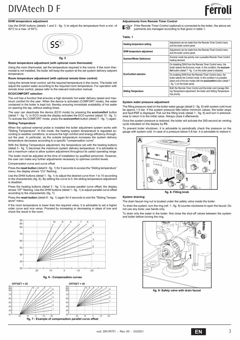
System water pressure adjustmentThe filling pressure read on the boiler water gauge (detail 2 - fig. 8) with system cold mustbe approx 1.0 bar. If the system pressure falls below minimum values, the boiler stopsand fault F37 is displayed. Pull out the filling knob (detail 1 - fig. 8) and turn it anticlock-wise to return it to the initial value. Always close it afterwards.Once the system pressure is restored, the boiler will activate the 300-second air ventingcycle indicated on the display by Fh.To prevent boiler shutdown, it is advisable to periodically check the pressure on thegauge with system cold. In case of a pressure below 0.8 bar, it is advisable to restore it.
fig. 8- Filling knobSystem drainingThe drain faucet ring nut is located under the safety valve inside the boiler.To drain the system, turn the ring (ref. 1 - fig. 9) counter-clockwise to open the faucet. Donot use any tools; use hands only.To drain only the water in the boiler, first close the shut-off valves between the systemand boiler before turning the ring.
fig. 9- Safety valve with drain faucet
� � � � �����
��
��
��
��
��
��
��
����
�� �� � ��� ���
�
�
�
�
�
����� �
��
��
��
��
��
��
��
����
��
��
��
��
��
��
��
����
�
�
�
�
�
����� �
�
�
�
������� �
����������� �����������
Heating temperature setting Adjustment can be made from the Remote Timer Control menu and the boiler control panel.
DHW temperature adjustment Adjustment can be made from the Remote Timer Control menu and the boiler control panel.
Summer/Winter Switchover Summer mode has priority over a possible Remote Timer Control heating demand.
Eco/Comfort selection
On disabling DHW from the Remote Timer Control menu, the boiler selects the Economy mode. In this condition, the eco/com-fort button (detail 7 - fig. 1) on the boiler panel is disabled.On enabling DHW from the Remote Timer Control menu, the boiler selects the Comfort mode. In this condition it is possible select one of the two modes with the eco/comfort button (detail 7 - fig. 1) on the boiler panel.
Sliding TemperatureBoth the Remote Timer Control and the boiler card manage Slid-ing Temperature adjustment: the boiler card Sliding Temperature has priority.
�
�
�
�
�
�
cod. 3541R750 - Rev. 00 - 09/2019
DIVAtech D F
cod. 3541R751 - Rev. 00 - 03/20214 EN
DIVAtech D F
4 EN
3. INSTALLATION3.1 General InstructionsBOILER INSTALLATION MUST ONLY BE PERFORMED BY QUALIFIED PERSON-NEL, IN ACCORDANCE WITH ALL THE INSTRUCTIONS GIVEN IN THIS TECHNICALMANUAL, THE PROVISIONS OF CURRENT LAW, THE PRESCRIPTIONS OF NA-TIONAL AND LOCAL STANDARDS AND THE RULES OF PROPER WORKMANSHIP.3.2 Place of installation
BThe combustion circuit is sealed with respect to the place of installationand therefore the unit can be installed in any room except in a garage. Theplace of installation must be sufficiently ventilated to prevent the creationof dangerous conditions in case of even small gas leaks. Otherwise theremay be a risk of suffocation and intoxication or explosion and fire. Thissafety precaution is required by EEC Directive No. 2009/142 for all gasunits, including so-called sealed chamber units.
The unit is designed to operate in a partially protected place, with a minimum tempera-ture of -5°C. If provided with the special antifreeze kit, it can be used with a minimum tem-perature down to -15°C. The boiler must be installed in a sheltered place, for instanceunder the slope of a roof, inside a balcony or in a protected recess.The place of installation must be free of flammable materials, objects and dusts or cor-rosive gases.The boiler is arranged for wall mounting and comes as standard with a hooking bracket.Wall fixing must ensure stable and effective support for the generator.
AIf the unit is enclosed in a cabinet or mounted alongside, there must be suffi-cient space for removing the casing and for normal maintenance activities
3.3 Plumbing connectionsImportant
BThe safety valve outlet must be connected to a funnel or collection pipe to pre-vent water spurting onto the floor in case of overpressure in the heating circuit.Otherwise, if the discharge valve cuts in and floods the room, the boiler manu-facturer cannot be held liable.
BBefore making the connection, check that the unit is arranged for operation withthe type of fuel available and carefully clean all the system pipes.
Carry out the relevant connections according to the diagram in fig. 2.3 and the symbolson the unit.Note: The unit is equipped with an internal bypass in the heating circuit.Water system characteristicsIn the presence of water harder than 25° Fr (1°F = 10ppm CaCO3), use suitably treatedwater in order to avoid possible scaling in the boiler.Antifreeze system, antifreeze fluids, additives and inhibitorsWhen necessary, antifreeze fluids, additives and inhibitors can be used only if the man-ufacturer of such fluids or additives guarantees that they are suitable and do not causedamage to the exchanger or other components and/or materials of the boiler and system.Do not use generic antifreeze fluids, additives or inhibitors that are not specific for use inheating systems and compatible with the materials of the boiler and system.3.4 Gas connectionThe gas must be connected to the relevant connection (see fig. 2.3) in conformity withthe current standards, using a rigid metal pipe or a continuous surface flexible s/steeltube and installing a gas cock between the system and boiler. Make sure all the gas con-nections are tight.3.5 Electrical connectionsIMPORTANT
BBEFORE CARRYING OUT ANY OPERATION THAT REQUIRES REMOVINGTHE CASING, DISCONNECT THE BOILER FROM THE ELECTRIC MAINSWITH THE MAIN SWITCH.NEVER TOUCH THE ELECTRICAL COMPONENTS OR CONTACTS WITHTHE MAIN SWITCH TURNED ON! DANGER OF ELECTRIC SHOCK WITHRISK OF INJURY OR DEATH!
BThe unit must be connected to an efficient grounding system in accordance withapplicable safety regulations. Have the efficiency and suitability of the ground-ing system checked by professionally qualified personnel; the Manufacturer de-clines any liability for damage caused by failure to earth the system.The boiler is prewired and provided with a three-pole cable, without a plug, forconnection to the electric line. The connections to the grid must be made witha permanent connection and equipped with a bipolar switch whose contactshave a minimum opening of at least 3 mm, interposing fuses of max. 3A be-tween the boiler and the line. Make sure to respect the polarities (LINE: brownwire / NEUTRAL: blue wire / GROUND: yellow-green wire) in the connectionsto the electric line.
BThe unit's supply cable MUST NOT BE REPLACED BY THE USER. If the ca-ble gets damaged, turn the unit off and have the cable replaced only byprofessionally qualified personnel. In case of replacement, only use cable“HAR H05 VV-F” 3x0.75 mm2 with max. external diameter of 8 mm.
Room thermostat (optional)
BIMPORTANT: THE ROOM THERMOSTAT MUST HAVE VOLTAGE-FREECONTACTS. CONNECTING 230 V TO THE ROOM THERMOSTAT TERMI-NALS WILL PERMANENTLY DAMAGE THE ELECTRONIC BOARD.When connecting time controls or a timer, do not take the power supply forthese devices from their breaking contacts Their power supply must be bymeans of direct connection from the mains or with batteries, depending on thekind of device.
Accessing the electrical terminal blockThe electrical terminal block can be accessed after removing the casing. The layout ofthe terminals for the various connections is also given in the wiring diagram in fig. 31.
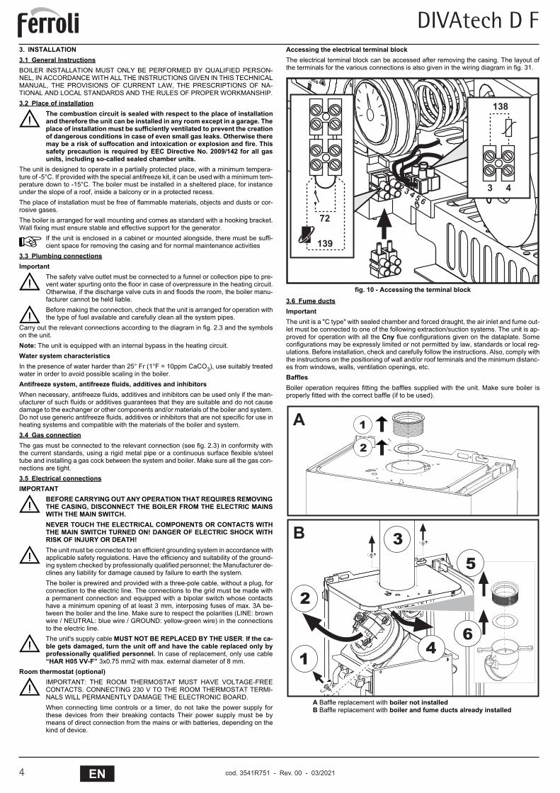
fig. 10 - Accessing the terminal block3.6 Fume ductsImportantThe unit is a "C type" with sealed chamber and forced draught, the air inlet and fume out-let must be connected to one of the following extraction/suction systems. The unit is ap-proved for operation with all the Cny flue configurations given on the dataplate. Someconfigurations may be expressly limited or not permitted by law, standards or local reg-ulations. Before installation, check and carefully follow the instructions. Also, comply withthe instructions on the positioning of wall and/or roof terminals and the minimum distanc-es from windows, walls, ventilation openings, etc.BafflesBoiler operation requires fitting the baffles supplied with the unit. Make sure boiler isproperly fitted with the correct baffle (if to be used).
A Baffle replacement with boiler not installedB Baffle replacement with boiler and fume ducts already installed
� � � � � �
��
���
���
� �
� �
�
� �
�
��
�
�
cod. 3541R750 - Rev. 00 - 09/2019
DIVAtech D F
5ENcod. 3541R751 - Rev. 00 - 03/2021
DIVAtech D F
5EN
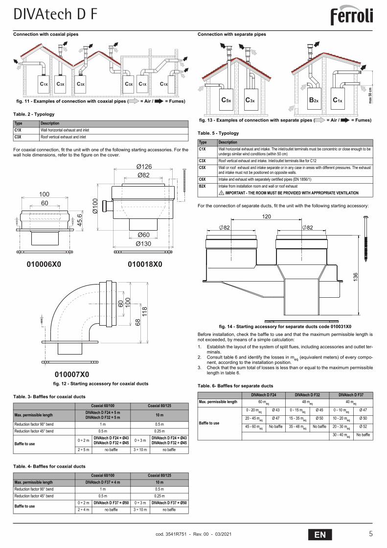
Connection with coaxial pipes
fig. 11 - Examples of connection with coaxial pipes ( = Air / = Fumes)
Table. 2 - Typology
For coaxial connection, fit the unit with one of the following starting accessories. For thewall hole dimensions, refer to the figure on the cover.
fig. 12 - Starting accessory for coaxial ducts
Table. 3- Baffles for coaxial ducts
Table. 4- Baffles for coaxial ducts
Connection with separate pipes
fig. 13 - Examples of connection with separate pipes ( = Air / = Fumes)
Table. 5 - Typology
For the connection of separate ducts, fit the unit with the following starting accessory:
fig. 14 - Starting accessory for separate ducts code 010031X0Before installation, check the baffle to use and that the maximum permissible length isnot exceeded, by means of a simple calculation:1. Establish the layout of the system of split flues, including accessories and outlet ter-
minals.2. Consult table 6 and identify the losses in meq (equivalent meters) of every compo-
nent, according to the installation position.3. Check that the sum total of losses is less than or equal to the maximum permissible
length in table 6.
Table. 6- Baffles for separate ducts
Type DescriptionC1X Wall horizontal exhaust and inletC3X Roof vertical exhaust and inlet
Coaxial 60/100 Coaxial 80/125
Max. permissible length DIVAtech D F24 = 5 mDIVAtech D F32 = 5 m 10 m
Reduction factor 90° bend 1 m 0.5 mReduction factor 45° bend 0.5 m 0.25 m
Baffle to use0 ÷ 2 m DIVAtech D F24 = Ø43
DIVAtech D F32 = Ø45 0 ÷ 3 m DIVAtech D F24 = Ø43DIVAtech D F32 = Ø45
2 ÷ 5 m no baffle 3 ÷ 10 m no baffle
Coaxial 60/100 Coaxial 80/125Max. permissible length DIVAtech D F37 = 4 m 10 mReduction factor 90° bend 1 m 0.5 mReduction factor 45° bend 0.5 m 0.25 m
Baffle to use0 ÷ 2 m DIVAtech D F37 = Ø50 0 ÷ 3 m DIVAtech D F37 = Ø502 ÷ 4 m no baffle 3 ÷ 10 m no baffle
��� ������ ��� ������
�������
�������
���
�
����������������
�����
����
��������
����
����
��
Type DescriptionC1X Wall horizontal exhaust and intake. The inlet/outlet terminals must be concentric or close enough to be
undergo similar wind conditions (within 50 cm)C3X Roof vertical exhaust and intake. Inlet/outlet terminals like for C12C5X Wall or roof exhaust and intake separate or in any case in areas with different pressures. The exhaust
and intake must not be positioned on opposite walls.C6X Intake and exhaust with separately certified pipes (EN 1856/1)B2X Intake from installation room and wall or roof exhaust
IMPORTANT - THE ROOM MUST BE PROVIDED WITH APPROPRIATE VENTILATION
DIVAtech D F24 DIVAtech D F32 DIVAtech D F37Max. permissible length 60 meq 48 meq 40 meq
Baffle to use
0 - 20 meq Ø 43 0 - 15 meq Ø 45 0 - 10 meq Ø 47
20 - 45 meq Ø 47 15 - 35 meq Ø 50 10 - 20 meq Ø 50
45 - 60 meq No baffle 35 - 48 meq No baffle 20 - 30 meq Ø 52
30 - 40 meq No baffle
��� ��� ��� ��� ���
����
��
���
��
���
��
cod. 3541R750 - Rev. 00 - 09/2019
DIVAtech D F
cod. 3541R751 - Rev. 00 - 03/20216 EN
DIVAtech D F
6 EN
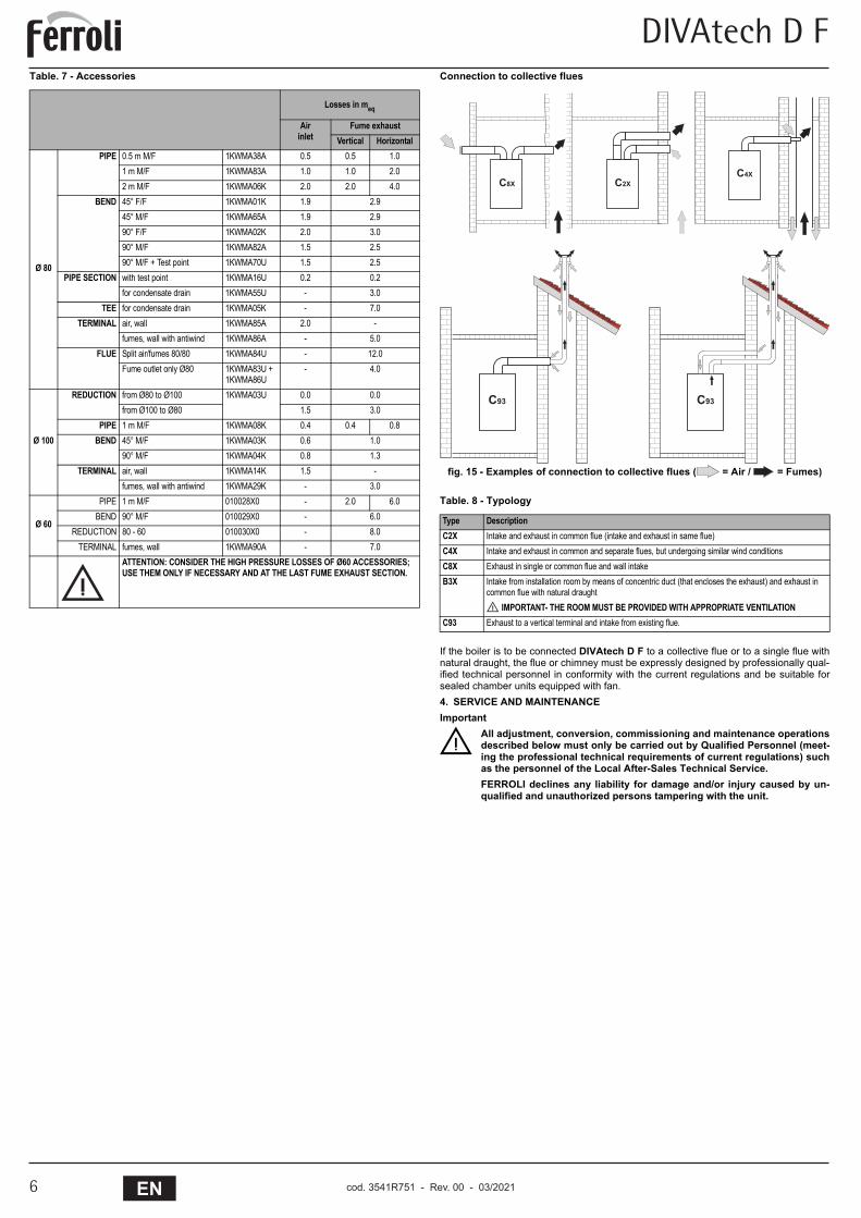
Table. 7 - Accessories Connection to collective flues
fig. 15 - Examples of connection to collective flues ( = Air / = Fumes)
Table. 8 - Typology
If the boiler is to be connected DIVAtech D F to a collective flue or to a single flue withnatural draught, the flue or chimney must be expressly designed by professionally qual-ified technical personnel in conformity with the current regulations and be suitable forsealed chamber units equipped with fan.4. SERVICE AND MAINTENANCEImportant
BAll adjustment, conversion, commissioning and maintenance operationsdescribed below must only be carried out by Qualified Personnel (meet-ing the professional technical requirements of current regulations) suchas the personnel of the Local After-Sales Technical Service.FERROLI declines any liability for damage and/or injury caused by un-qualified and unauthorized persons tampering with the unit.
Losses in meq
Airinlet
Fume exhaustVertical Horizontal
Ø 80
PIPE 0.5 m M/F 1KWMA38A 0.5 0.5 1.01 m M/F 1KWMA83A 1.0 1.0 2.02 m M/F 1KWMA06K 2.0 2.0 4.0
BEND 45° F/F 1KWMA01K 1.9 2.945° M/F 1KWMA65A 1.9 2.990° F/F 1KWMA02K 2.0 3.090° M/F 1KWMA82A 1.5 2.590° M/F + Test point 1KWMA70U 1.5 2.5
PIPE SECTION with test point 1KWMA16U 0.2 0.2for condensate drain 1KWMA55U - 3.0
TEE for condensate drain 1KWMA05K - 7.0TERMINAL air, wall 1KWMA85A 2.0 -
fumes, wall with antiwind 1KWMA86A - 5.0FLUE Split air/fumes 80/80 1KWMA84U - 12.0
Fume outlet only Ø80 1KWMA83U +1KWMA86U
- 4.0
Ø 100
REDUCTION from Ø80 to Ø100 1KWMA03U 0.0 0.0from Ø100 to Ø80 1.5 3.0
PIPE 1 m M/F 1KWMA08K 0.4 0.4 0.8BEND 45° M/F 1KWMA03K 0.6 1.0
90° M/F 1KWMA04K 0.8 1.3TERMINAL air, wall 1KWMA14K 1.5 -
fumes, wall with antiwind 1KWMA29K - 3.0
Ø 60
PIPE 1 m M/F 010028X0 - 2.0 6.0BEND 90° M/F 010029X0 - 6.0
REDUCTION 80 - 60 010030X0 - 8.0TERMINAL fumes, wall 1KWMA90A - 7.0
ATTENTION: CONSIDER THE HIGH PRESSURE LOSSES OF Ø60 ACCESSORIES; USE THEM ONLY IF NECESSARY AND AT THE LAST FUME EXHAUST SECTION.
Type DescriptionC2X Intake and exhaust in common flue (intake and exhaust in same flue)C4X Intake and exhaust in common and separate flues, but undergoing similar wind conditionsC8X Exhaust in single or common flue and wall intakeB3X Intake from installation room by means of concentric duct (that encloses the exhaust) and exhaust in
common flue with natural draught IMPORTANT- THE ROOM MUST BE PROVIDED WITH APPROPRIATE VENTILATION
C93 Exhaust to a vertical terminal and intake from existing flue.
��� ������
������
cod. 3541R750 - Rev. 00 - 09/2019
DIVAtech D F
7ENcod. 3541R751 - Rev. 00 - 03/2021
DIVAtech D F
7EN
4.1 AdjustmentsGas conversion
BALL COMPONENTS DAMAGED DURING CONVERSION OPERATIONSMUST BE REPLACED.
The unit can operate on natural gas or LPG and is factory-set for use with one of thesetwo gases, as clearly shown on the packing and on the data plate. Whenever a gas dif-ferent from that for which the unit is arranged has to be used, the special conversion kitwill be required, proceeding as follows:1. Disconnect the boiler power supply and close the gas cock.2. Replace the nozzles at the main burner, fitting the nozzles specified in the technical
data table in cap. 5, according to the type of gas used3. Switch the boiler power on and open the gas cock.4. Modify the parameter for the type of gas:
• put the boiler in standby mode• press the DHW buttons details 1 and 2 - fig. 1 for 10 seconds: the display shows
“b01“ flashing.• press the DHW buttons details 1 and 2 - fig. 1 to set the parameter 00 (for nat-
ural gas operation) or 01 (for LPG operation).• press the DHW buttons details 1 and 2 - fig. 1 for 10 seconds.• the boiler will return to standby mode
5. Adjust the minimum and maximum pressures at the burner (ref. relevant para-graph), setting the values given in the technical data table for the type of gas used
6. Apply the sticker contained in the conversion kit, near the data plate as proof of theconversion.
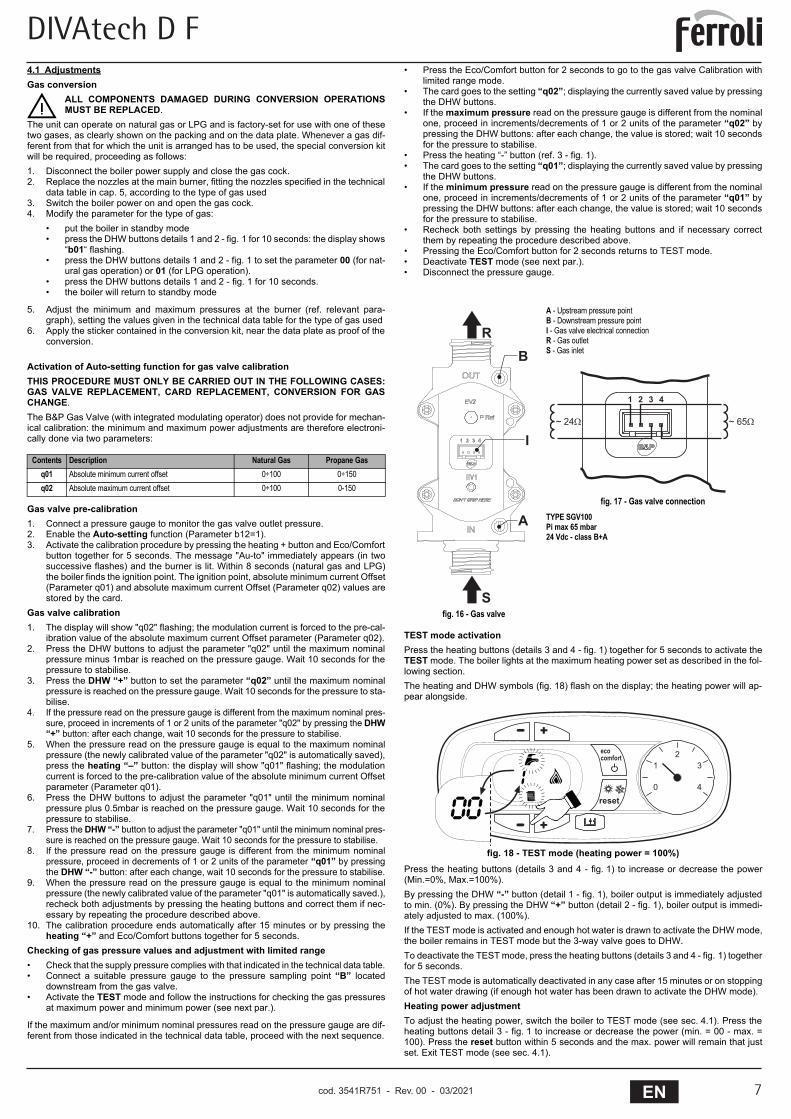
Activation of Auto-setting function for gas valve calibrationTHIS PROCEDURE MUST ONLY BE CARRIED OUT IN THE FOLLOWING CASES:GAS VALVE REPLACEMENT, CARD REPLACEMENT, CONVERSION FOR GASCHANGE.The B&P Gas Valve (with integrated modulating operator) does not provide for mechan-ical calibration: the minimum and maximum power adjustments are therefore electroni-cally done via two parameters:
Gas valve pre-calibration1. Connect a pressure gauge to monitor the gas valve outlet pressure.2. Enable the Auto-setting function (Parameter b12=1).3. Activate the calibration procedure by pressing the heating + button and Eco/Comfort
button together for 5 seconds. The message "Au-to" immediately appears (in twosuccessive flashes) and the burner is lit. Within 8 seconds (natural gas and LPG)the boiler finds the ignition point. The ignition point, absolute minimum current Offset(Parameter q01) and absolute maximum current Offset (Parameter q02) values arestored by the card.
Gas valve calibration1. The display will show "q02" flashing; the modulation current is forced to the pre-cal-
ibration value of the absolute maximum current Offset parameter (Parameter q02).2. Press the DHW buttons to adjust the parameter "q02" until the maximum nominal
pressure minus 1mbar is reached on the pressure gauge. Wait 10 seconds for thepressure to stabilise.
3. Press the DHW “+” button to set the parameter “q02” until the maximum nominalpressure is reached on the pressure gauge. Wait 10 seconds for the pressure to sta-bilise.
4. If the pressure read on the pressure gauge is different from the maximum nominal pres-sure, proceed in increments of 1 or 2 units of the parameter "q02" by pressing the DHW“+” button: after each change, wait 10 seconds for the pressure to stabilise.
5. When the pressure read on the pressure gauge is equal to the maximum nominalpressure (the newly calibrated value of the parameter "q02" is automatically saved),press the heating “–” button: the display will show "q01" flashing; the modulationcurrent is forced to the pre-calibration value of the absolute minimum current Offsetparameter (Parameter q01).
6. Press the DHW buttons to adjust the parameter "q01" until the minimum nominalpressure plus 0.5mbar is reached on the pressure gauge. Wait 10 seconds for thepressure to stabilise.
7. Press the DHW “-” button to adjust the parameter "q01" until the minimum nominal pres-sure is reached on the pressure gauge. Wait 10 seconds for the pressure to stabilise.
8. If the pressure read on the pressure gauge is different from the minimum nominalpressure, proceed in decrements of 1 or 2 units of the parameter “q01” by pressingthe DHW “-” button: after each change, wait 10 seconds for the pressure to stabilise.
9. When the pressure read on the pressure gauge is equal to the minimum nominalpressure (the newly calibrated value of the parameter "q01" is automatically saved.),recheck both adjustments by pressing the heating buttons and correct them if nec-essary by repeating the procedure described above.
10. The calibration procedure ends automatically after 15 minutes or by pressing theheating “+” and Eco/Comfort buttons together for 5 seconds.
Checking of gas pressure values and adjustment with limited range• Check that the supply pressure complies with that indicated in the technical data table.• Connect a suitable pressure gauge to the pressure sampling point “B” located
downstream from the gas valve.• Activate the TEST mode and follow the instructions for checking the gas pressures
at maximum power and minimum power (see next par.).
If the maximum and/or minimum nominal pressures read on the pressure gauge are dif-ferent from those indicated in the technical data table, proceed with the next sequence.
• Press the Eco/Comfort button for 2 seconds to go to the gas valve Calibration withlimited range mode.
• The card goes to the setting “q02”; displaying the currently saved value by pressingthe DHW buttons.
• If the maximum pressure read on the pressure gauge is different from the nominalone, proceed in increments/decrements of 1 or 2 units of the parameter “q02” bypressing the DHW buttons: after each change, the value is stored; wait 10 secondsfor the pressure to stabilise.
• Press the heating “-” button (ref. 3 - fig. 1).• The card goes to the setting “q01”; displaying the currently saved value by pressing
the DHW buttons.• If the minimum pressure read on the pressure gauge is different from the nominal
one, proceed in increments/decrements of 1 or 2 units of the parameter “q01” bypressing the DHW buttons: after each change, the value is stored; wait 10 secondsfor the pressure to stabilise.
• Recheck both settings by pressing the heating buttons and if necessary correctthem by repeating the procedure described above.
• Pressing the Eco/Comfort button for 2 seconds returns to TEST mode.• Deactivate TEST mode (see next par.).• Disconnect the pressure gauge.
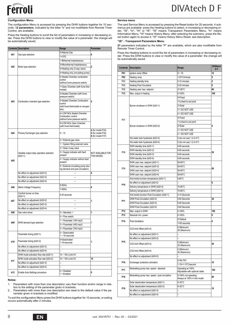
TEST mode activationPress the heating buttons (details 3 and 4 - fig. 1) together for 5 seconds to activate theTEST mode. The boiler lights at the maximum heating power set as described in the fol-lowing section.The heating and DHW symbols (fig. 18) flash on the display; the heating power will ap-pear alongside.
fig. 18 - TEST mode (heating power = 100%)Press the heating buttons (details 3 and 4 - fig. 1) to increase or decrease the power(Min.=0%, Max.=100%).By pressing the DHW “-” button (detail 1 - fig. 1), boiler output is immediately adjustedto min. (0%). By pressing the DHW “+” button (detail 2 - fig. 1), boiler output is immedi-ately adjusted to max. (100%).If the TEST mode is activated and enough hot water is drawn to activate the DHW mode,the boiler remains in TEST mode but the 3-way valve goes to DHW.To deactivate the TEST mode, press the heating buttons (details 3 and 4 - fig. 1) togetherfor 5 seconds.The TEST mode is automatically deactivated in any case after 15 minutes or on stoppingof hot water drawing (if enough hot water has been drawn to activate the DHW mode).Heating power adjustmentTo adjust the heating power, switch the boiler to TEST mode (see sec. 4.1). Press theheating buttons detail 3 - fig. 1 to increase or decrease the power (min. = 00 - max. =100). Press the reset button within 5 seconds and the max. power will remain that justset. Exit TEST mode (see sec. 4.1).
Contents Description Natural Gas Propane Gasq01 Absolute minimum current offset 0÷100 0÷150q02 Absolute maximum current offset 0÷100 0-150
fig. 16 - Gas valve
A - Upstream pressure pointB - Downstream pressure pointI - Gas valve electrical connectionR - Gas outletS - Gas inlet
fig. 17 - Gas valve connectionTYPE SGV100Pi max 65 mbar24 Vdc - class B+A
�
�
�
�
�
����������
����������
�
�
�
��
�����
����������
����
�� �
� � � � � � � ��������
����
�� �
� � � � � � � ��������
cod. 3541R750 - Rev. 00 - 09/2019
DIVAtech D F
cod. 3541R751 - Rev. 00 - 03/20218 EN
DIVAtech D F
8 EN
Configuration MenuThe configuration Menu is accessed by pressing the DHW buttons together for 10 sec-onds. 12 parameters, indicated by the letter "b” and not modifiable from Remote TimerControl, are available.Press the Heating buttons to scroll the list of parameters in increasing or decreasing or-der. Press the DHW buttons to view or modify the value of a parameter: the change willbe automatically saved.
Notes:1. Parameters with more than one description vary their function and/or range in rela-
tion to the setting of the parameter given in brackets.2. Parameters with more than one description are reset to the default value if the pa-
rameter given in brackets is modified.To exit the configuration Menu press the DHW buttons together for 10 seconds, or exitingoccurs automatically after 2 minutes.
Service menuThe card Service Menu is accessed by pressing the Reset button for 20 seconds. 4 sub-menus are available: press the Heating buttons to select, in increasing or decreasing or-der, "tS", "In", "Hi" or "rE". "tS" means Transparent Parameters Menu, "In" meansInformation Menu, "Hi" means History Menu: after selecting the submenu, press the Re-set button again to access it; "rE" means History Menu Reset: see description.“tS” - Transparent Parameters Menu21 parameters indicated by the letter "P” are available, which are also modifiable fromRemote Timer Control.Press the Heating buttons to scroll the list of parameters in increasing or decreasing or-der. Press the DHW buttons to view or modify the value of a parameter: the change willbe automatically saved.
Contents Description Range Parameter
b01 Gas type selection0=Natural Gas
01=LPG
b02 Boiler type selection
1=Bithermal instantaneous
22=Monothermal instantaneous3=Heating only (3-way valve)4=Heating only (circulating pump)
b03 Combustion chamber type selection
0=Sealed Chamber combustion control(without fume pressure switch)
0
1=Open Chamber (with fume ther-mostat)2=Sealed Chamber (with fume pressure switch)3=Sealed Chamber Combustion control(with fume thermostat on recuper-ator)4=LOW NOx Sealed Chamber Combustion control(without fume pressure switch)5=LOW NOx Open Chamber(with fume thermostat)
b04 Primary Exchanger type selection 0 ÷ 134 (for model F24)5 (for model F32)6 (for model F37)
b05
Variable output relay operation selection (b02=1)
0 = External gas valve
NOT AVAILABLE FOR THIS MODEL
1 = System filling solenoid valve2 = Solar 3-way valve3 = Supply indicator with fault present4 = Supply indicator without fault present5 = External circulating pump (dur-ing demand and post circulation)
No effect on adjustment (b02=2) -- 0No effect on adjustment (b02=3) --No effect on adjustment (b02=4) --
b06 Mains Voltage Frequency0=50Hz
01=60Hz
b07
Comfort burner on time(b02=1) 0-20 seconds
5No effect on adjustment (b02=2) --No effect on adjustment (b02=3) --No effect on adjustment (b02=4) --
b08 Gas valve driver 0 = Standard, 1 0
b09 DHW demand type selection
0 = Flow switch
11 = Flowmeter (190 imp/l)2 = Flowmeter (450 imp/l)3 = Flowmeter (700 imp/l)
b10
Flowmeter timing (b02=1) 0 = Deactivated1 ÷ 10=seconds
0Flowmeter timing (b02=2) 0=Deactivated1-10=seconds
No effect on adjustment (b02=3) --No effect on adjustment (b02=4) --
b11
DHW mode activation flow rate (b02=1) 10 ÷ 100 L/min/10DHW mode activation flow rate (b02=2) 10 ÷ 100 L/min/10 15No effect on adjustment (b02=3) --No effect on adjustment (b02=4) --
b12 Enable Auto-Settings procedure 0 = Disabled1 = Enabled 0
Contents Description Range DIVAtech D F
P01 Ignition ramp Offset 9 ÷ 19 15
P02 Heating ramp 1-20°C/minute 5P03 Heating standby time 0-10 minutes 2P04 Heating Post-Circulation 0-20 minutes 6P05 Heating user max. setpoint 31-85°C 80P06 Max. output in heating 0-100% 100
P07
Burner shutdown in DHW (b02=1)
0=Fixed1=Linked to set point2=Solar3 = DO NOT USE4 = DO NOT USE
Burner shutdown in DHW (b02=2)
0=Fixed
01=Linked to set point2=Solar3 = DO NOT USE4 = DO NOT USE
Hot water tank hysteresis (b02=3) 0 (do not use) 1-2-3-4°CHot water tank hysteresis (b02=4) 0 (do not use) 1-2-3-4°C
P08
DHW standby time (b02=1) 0-60 seconds
30DHW standby time (b02=2) 0-60 secondsDHW standby time (b02=3) 0-60 secondsDHW standby time (b02=4) 0-60 seconds
P09
DHW user max. setpoint (b02=1) 50-65°C
50DHW user max. setpoint (b02=2) 50-65°CDHW user max. setpoint (b02=3) 50-65°CDHW user max. setpoint (b02=4) 50-65°C
P10
Anti-inertia function temperature (b02=1) 5-85°CNo effect on adjustment (b02=2) -- 0Delivery temperature in DHW (b02=3) 70-85°CDelivery temperature in DHW (b02=4) 70-85°C
P11
Anti-inertia function Post-Circulation (b02=1) 0-10 SecondsDHW Post-Circulation (b02=2) 0-60 Seconds 30DHW Post-Circulation (b02=3) 0-60 SecondsDHW Post-Circulation (b02=4) 0-60 Seconds
P12 Max. output in DHW 0-100% 100P13 Absolute min. power 0-100% 0
P14 Post-Ventilation0=Default
01=50 seconds
P15
CO2 limit Offset (b03=0) 0 (Minimum)30 (Maximum)
No effect on adjustment (b03=1) --No effect on adjustment (b03=2) --
CO2 limit Offset (b03=3) 0 (Minimum)30 (Maximum) 20
CO2 limit Offset (b03=4) 0 (Minimum)30 (Maximum)
No effect on adjustment (b03=5) --
P16 Exchanger protection activation0=No F43
101-15=1-15°C/second
P17 Modulating pump max. speed - absolute Operating at 100%.Adjustable with optional cable. 100
P18 Modulating pump max. speed - post circulation 0-100% not operating.Always at 100% in this model 60
P19
Solar deactivation temperature (b02=1) 0÷20°C
10Solar deactivation temperature (b02=2) 0÷20°CNo effect on adjustment (b02=3) --No effect on adjustment (b02=4) --
cod. 3541R750 - Rev. 00 - 09/2019
DIVAtech D F
9ENcod. 3541R751 - Rev. 00 - 03/2021
DIVAtech D F
9EN
Notes:1. Parameters with more than one description vary their function and/or range in rela-
tion to the setting of the parameter given in brackets.2. Parameters with more than one description are reset to the default value if the pa-
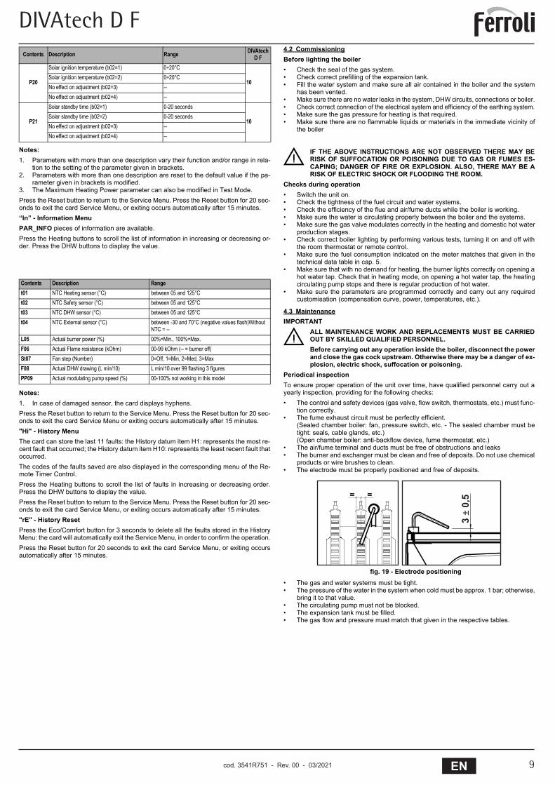
rameter given in brackets is modified.3. The Maximum Heating Power parameter can also be modified in Test Mode.Press the Reset button to return to the Service Menu. Press the Reset button for 20 sec-onds to exit the card Service Menu, or exiting occurs automatically after 15 minutes.“In” - Information MenuPAR_INFO pieces of information are available.Press the Heating buttons to scroll the list of information in increasing or decreasing or-der. Press the DHW buttons to display the value.
Notes:1. In case of damaged sensor, the card displays hyphens.Press the Reset button to return to the Service Menu. Press the Reset button for 20 sec-onds to exit the card Service Menu or exiting occurs automatically after 15 minutes."Hi" - History MenuThe card can store the last 11 faults: the History datum item H1: represents the most re-cent fault that occurred; the History datum item H10: represents the least recent fault thatoccurred.The codes of the faults saved are also displayed in the corresponding menu of the Re-mote Timer Control.Press the Heating buttons to scroll the list of faults in increasing or decreasing order.Press the DHW buttons to display the value.Press the Reset button to return to the Service Menu. Press the Reset button for 20 sec-onds to exit the card Service Menu, or exiting occurs automatically after 15 minutes."rE" - History ResetPress the Eco/Comfort button for 3 seconds to delete all the faults stored in the HistoryMenu: the card will automatically exit the Service Menu, in order to confirm the operation.Press the Reset button for 20 seconds to exit the card Service Menu, or exiting occursautomatically after 15 minutes.
4.2 CommissioningBefore lighting the boiler• Check the seal of the gas system.• Check correct prefilling of the expansion tank.• Fill the water system and make sure all air contained in the boiler and the system
has been vented.• Make sure there are no water leaks in the system, DHW circuits, connections or boiler.• Check correct connection of the electrical system and efficiency of the earthing system.• Make sure the gas pressure for heating is that required.• Make sure there are no flammable liquids or materials in the immediate vicinity of
the boiler
BIF THE ABOVE INSTRUCTIONS ARE NOT OBSERVED THERE MAY BERISK OF SUFFOCATION OR POISONING DUE TO GAS OR FUMES ES-CAPING; DANGER OF FIRE OR EXPLOSION. ALSO, THERE MAY BE ARISK OF ELECTRIC SHOCK OR FLOODING THE ROOM.
Checks during operation• Switch the unit on.• Check the tightness of the fuel circuit and water systems.• Check the efficiency of the flue and air/fume ducts while the boiler is working.• Make sure the water is circulating properly between the boiler and the systems.• Make sure the gas valve modulates correctly in the heating and domestic hot water
production stages.• Check correct boiler lighting by performing various tests, turning it on and off with
the room thermostat or remote control.• Make sure the fuel consumption indicated on the meter matches that given in the
technical data table in cap. 5.• Make sure that with no demand for heating, the burner lights correctly on opening a
hot water tap. Check that in heating mode, on opening a hot water tap, the heatingcirculating pump stops and there is regular production of hot water.
• Make sure the parameters are programmed correctly and carry out any requiredcustomisation (compensation curve, power, temperatures, etc.).
4.3 MaintenanceIMPORTANT
BALL MAINTENANCE WORK AND REPLACEMENTS MUST BE CARRIEDOUT BY SKILLED QUALIFIED PERSONNEL.Before carrying out any operation inside the boiler, disconnect the powerand close the gas cock upstream. Otherwise there may be a danger of ex-plosion, electric shock, suffocation or poisoning.
Periodical inspectionTo ensure proper operation of the unit over time, have qualified personnel carry out ayearly inspection, providing for the following checks:• The control and safety devices (gas valve, flow switch, thermostats, etc.) must func-
tion correctly.• The fume exhaust circuit must be perfectly efficient.
(Sealed chamber boiler: fan, pressure switch, etc. - The sealed chamber must betight: seals, cable glands, etc.)(Open chamber boiler: anti-backflow device, fume thermostat, etc.)
• The air/fume terminal and ducts must be free of obstructions and leaks• The burner and exchanger must be clean and free of deposits. Do not use chemical
products or wire brushes to clean.• The electrode must be properly positioned and free of deposits.
fig. 19 - Electrode positioning• The gas and water systems must be tight.• The pressure of the water in the system when cold must be approx. 1 bar; otherwise,
bring it to that value.• The circulating pump must not be blocked.• The expansion tank must be filled.• The gas flow and pressure must match that given in the respective tables.
P20
Solar ignition temperature (b02=1) 0÷20°C
10Solar ignition temperature (b02=2) 0÷20°CNo effect on adjustment (b02=3) --No effect on adjustment (b02=4) --
P21
Solar standby time (b02=1) 0-20 seconds
10Solar standby time (b02=2) 0-20 secondsNo effect on adjustment (b02=3) --No effect on adjustment (b02=4) --
Contents Description Ranget01 NTC Heating sensor (°C) between 05 and 125°Ct02 NTC Safety sensor (°C) between 05 and 125°Ct03 NTC DHW sensor (°C) between 05 and 125°Ct04 NTC External sensor (°C) between -30 and 70°C (negative values flash)Without
NTC = --L05 Actual burner power (%) 00%=Min., 100%=Max.F06 Actual Flame resistance (kOhm) 00-99 kOhm (-- = burner off)St07 Fan step (Number) 0=Off, 1=Min, 2=Med, 3=MaxF08 Actual DHW drawing (L min/10) L min/10 over 99 flashing 3 figuresPP09 Actual modulating pump speed (%) 00-100% not working in this model
Contents Description Range DIVAtech D F
����
���� �
cod. 3541R750 - Rev. 00 - 09/2019
DIVAtech D F
cod. 3541R751 - Rev. 00 - 03/202110 EN
DIVAtech D F
10 EN
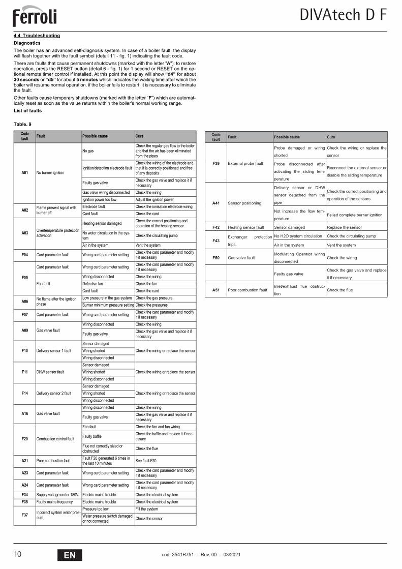
4.4 TroubleshootingDiagnosticsThe boiler has an advanced self-diagnosis system. In case of a boiler fault, the displaywill flash together with the fault symbol (detail 11 - fig. 1) indicating the fault code.There are faults that cause permanent shutdowns (marked with the letter "A"): to restoreoperation, press the RESET button (detail 6 - fig. 1) for 1 second or RESET on the op-tional remote timer control if installed. At this point the display will show “d4” for about30 seconds or “d5” for about 5 minutes which indicates the waiting time after which theboiler will resume normal operation. if the boiler fails to restart, it is necessary to eliminatethe fault.Other faults cause temporary shutdowns (marked with the letter “F”) which are automat-ically reset as soon as the value returns within the boiler's normal working range.List of faults
Table. 9
Codefault Fault Possible cause Cure
A01 No burner ignition
No gasCheck the regular gas flow to the boiler and that the air has been eliminated from the pipes
Ignition/detection electrode faultCheck the wiring of the electrode and that it is correctly positioned and free of any deposits
Faulty gas valve Check the gas valve and replace it if necessary
Gas valve wiring disconnected Check the wiringIgnition power too low Adjust the ignition power
A02 Flame present signal with burner off
Electrode fault Check the ionisation electrode wiringCard fault Check the card
A03 Overtemperature protection activation
Heating sensor damaged Check the correct positioning and operation of the heating sensor
No water circulation in the sys-tem Check the circulating pump
Air in the system Vent the system
F04 Card parameter fault Wrong card parameter setting Check the card parameter and modify it if necessary
F05
Card parameter fault Wrong card parameter setting Check the card parameter and modify it if necessary
Fan faultWiring disconnected Check the wiringDefective fan Check the fanCard fault Check the card
A06 No flame after the ignition phase
Low pressure in the gas system Check the gas pressureBurner minimum pressure setting Check the pressures
F07 Card parameter fault Wrong card parameter setting Check the card parameter and modify it if necessary
A09 Gas valve faultWiring disconnected Check the wiring
Faulty gas valve Check the gas valve and replace it if necessary
F10 Delivery sensor 1 faultSensor damaged
Check the wiring or replace the sensorWiring shortedWiring disconnected
F11 DHW sensor faultSensor damaged
Check the wiring or replace the sensorWiring shortedWiring disconnected
F14 Delivery sensor 2 faultSensor damaged
Check the wiring or replace the sensorWiring shortedWiring disconnected
A16 Gas valve faultWiring disconnected Check the wiring
Faulty gas valve Check the gas valve and replace it if necessary
F20 Combustion control fault
Fan fault Check the fan and fan wiring
Faulty baffle Check the baffle and replace it if nec-essary
Flue not correctly sized or obstructed Check the flue
A21 Poor combustion fault Fault F20 generated 6 times in the last 10 minutes See fault F20
A23 Card parameter fault Wrong card parameter setting Check the card parameter and modify it if necessary
A24 Card parameter fault Wrong card parameter setting Check the card parameter and modify it if necessary
F34 Supply voltage under 180V. Electric mains trouble Check the electrical systemF35 Faulty mains frequency Electric mains trouble Check the electrical system
F37 Incorrect system water pres-sure
Pressure too low Fill the systemWater pressure switch damaged or not connected Check the sensor
cod. 3541R750 - Rev. 00 - 09/2019
Code fault Fault Possible cause Cure
F39 External probe fault
Probe damaged or wiring
shorted
Check the wiring or replace the
sensor
Probe disconnected after
activating the sliding tem-
perature
Reconnect the external sensor or
disable the sliding temperature
A41 Sensor positioning
Delivery sensor or DHW
sensor detached from the
pipe
Check the correct positioning and
operation of the sensors
Not increase the flow tem-
peratureFailed complete burner ignition
F42 Heating sensor fault Sensor damaged Replace the sensor
F43Exchanger protection
trips.
No H2O system circulation Check the circulating pump
Air in the system Vent the system
F50 Gas valve faultModulating Operator wiring
disconnectedCheck the wiring
Faulty gas valveCheck the gas valve and replace
it if necessary
A51 Poor combustion faultInlet/exhaust flue obstruc-
tionCheck the flue
DIVAtech D F
11ENcod. 3541R751 - Rev. 00 - 03/2021
DIVAtech D F
11EN
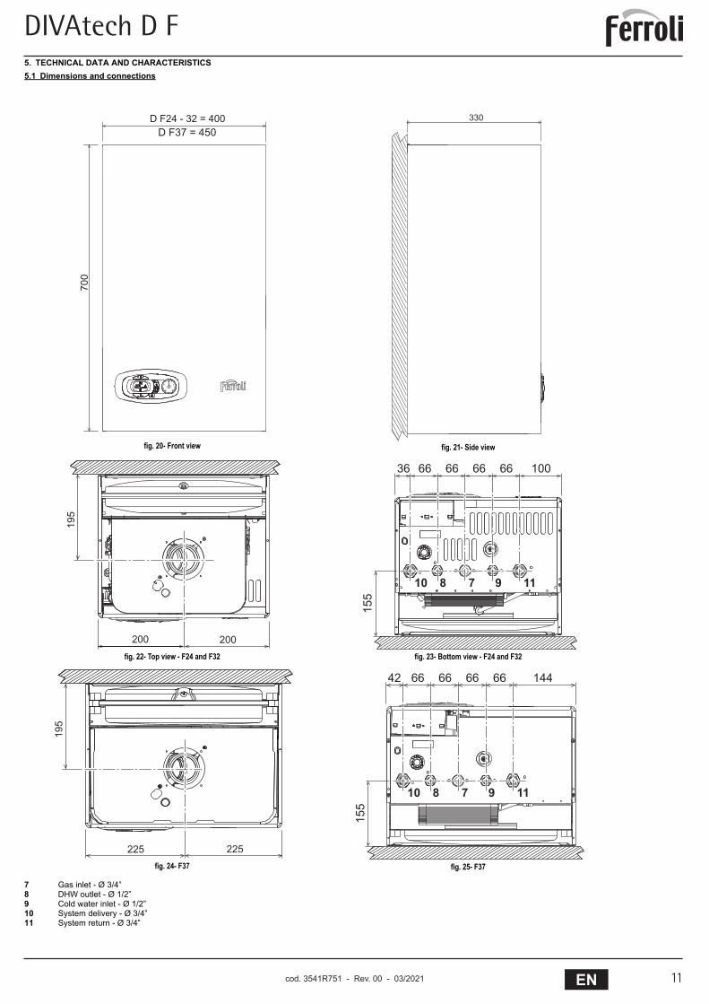
5. TECHNICAL DATA AND CHARACTERISTICS5.1 Dimensions and connections
7 Gas inlet - Ø 3/4”8 DHW outlet - Ø 1/2”9 Cold water inlet - Ø 1/2”10 System delivery - Ø 3/4”11 System return - Ø 3/4”
fig. 20- Front view fig. 21- Side view
fig. 22- Top view - F24 and F32 fig. 23- Bottom view - F24 and F32
fig. 24- F37 fig. 25- F37
���
�
�
�
�
�
���������������������������
���
���
���
�� �� �� �� �� ���
���
�� � � � ��
���
���
�� �� �� �� �� ���
���
�� � � � ��
���
���
cod. 3541R750 - Rev. 00 - 09/2019
DIVAtech D F
cod. 3541R751 - Rev. 00 - 03/202112 EN
DIVAtech D F
12 EN
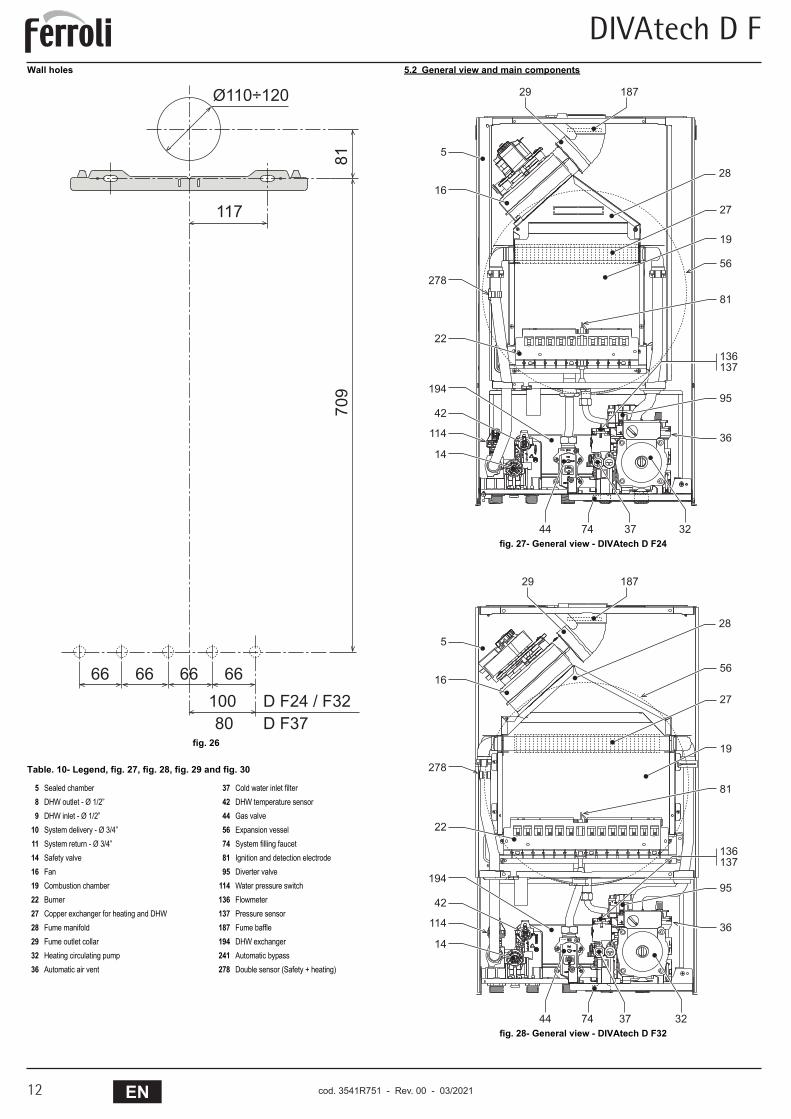
Wall holes
fig. 26
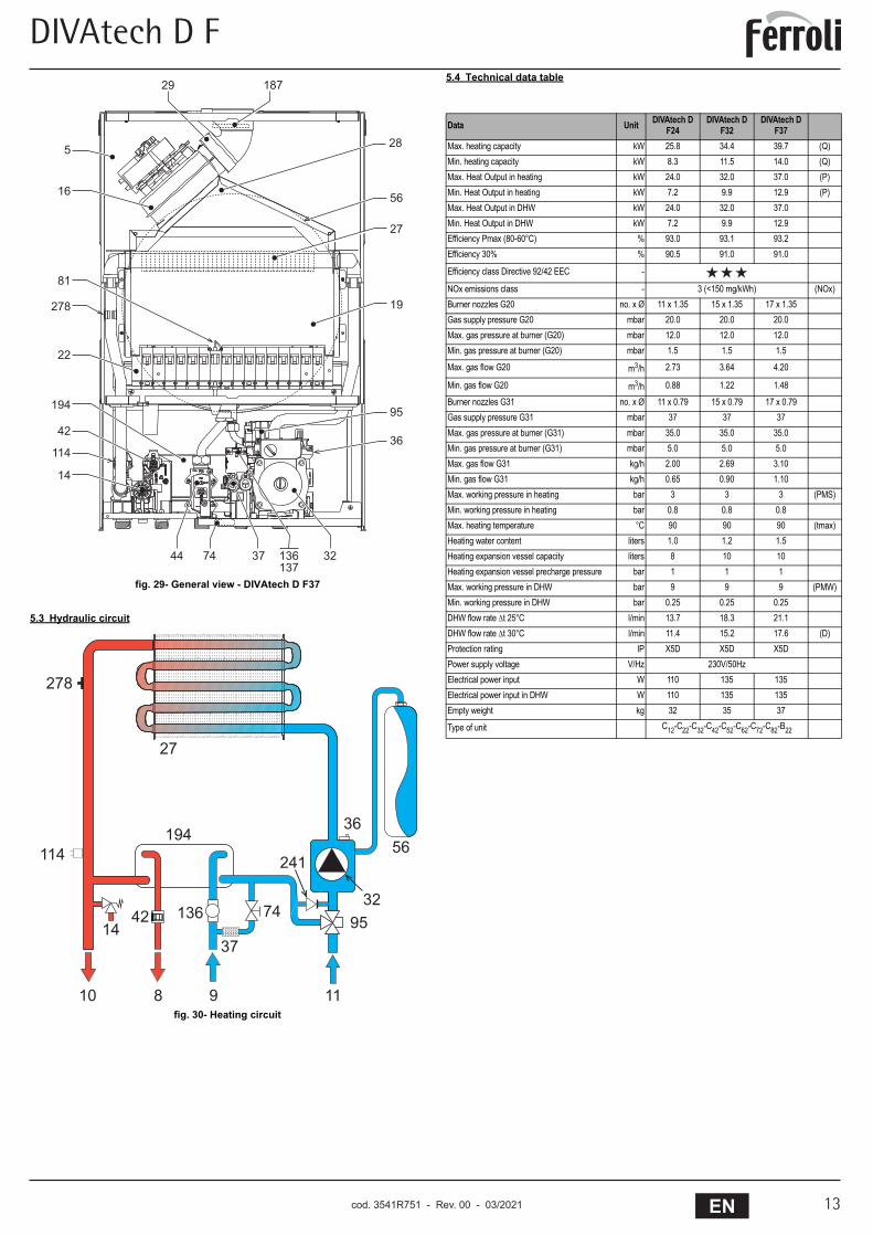
Table. 10- Legend, fig. 27, fig. 28, fig. 29 and fig. 30
5.2 General view and main components
fig. 27- General view - DIVAtech D F24
fig. 28- General view - DIVAtech D F32
5 Sealed chamber 37 Cold water inlet filter8 DHW outlet - Ø 1/2” 42 DHW temperature sensor9 DHW inlet - Ø 1/2” 44 Gas valve
10 System delivery - Ø 3/4” 56 Expansion vessel11 System return - Ø 3/4” 74 System filling faucet14 Safety valve 81 Ignition and detection electrode16 Fan 95 Diverter valve19 Combustion chamber 114 Water pressure switch22 Burner 136 Flowmeter27 Copper exchanger for heating and DHW 137 Pressure sensor28 Fume manifold 187 Fume baffle29 Fume outlet collar 194 DHW exchanger32 Heating circulating pump 241 Automatic bypass36 Automatic air vent 278 Double sensor (Safety + heating)
���
���
��������
��
�� �� �� ��
��� ������������� �����
����
��
���
��
���
��
��
��
������
��
��
��
�
��
���
��
���
�� ��
��
��
����
��
���
��
���
��
��
��
������
��
��
��
�
��
���
��
���
�� ��
��
��
cod. 3541R750 - Rev. 00 - 09/2019
DIVAtech D F
13ENcod. 3541R751 - Rev. 00 - 03/2021
DIVAtech D F
13EN
fig. 29- General view - DIVAtech D F37
5.3 Hydraulic circuit
fig. 30- Heating circuit
5.4 Technical data table
����
��
���
��
���
��
��
��
������
��
��
�
��
���
��
���
�� ��
��
��
��
��
���
���
���� � �
����
����
���
����
��� ��
���
��
Data Unit DIVAtech D F24
DIVAtech D F32
DIVAtech D F37
Max. heating capacity kW 25.8 34.4 39.7 (Q)Min. heating capacity kW 8.3 11.5 14.0 (Q)Max. Heat Output in heating kW 24.0 32.0 37.0 (P)Min. Heat Output in heating kW 7.2 9.9 12.9 (P)Max. Heat Output in DHW kW 24.0 32.0 37.0Min. Heat Output in DHW kW 7.2 9.9 12.9Efficiency Pmax (80-60°C) % 93.0 93.1 93.2Efficiency 30% % 90.5 91.0 91.0
Efficiency class Directive 92/42 EEC -
NOx emissions class - 3 (<150 mg/kWh) (NOx)Burner nozzles G20 no. x Ø 11 x 1.35 15 x 1.35 17 x 1.35Gas supply pressure G20 mbar 20.0 20.0 20.0Max. gas pressure at burner (G20) mbar 12.0 12.0 12.0Min. gas pressure at burner (G20) mbar 1.5 1.5 1.5
Max. gas flow G20 m3/h 2.73 3.64 4.20
Min. gas flow G20 m3/h 0.88 1.22 1.48
Burner nozzles G31 no. x Ø 11 x 0.79 15 x 0.79 17 x 0.79Gas supply pressure G31 mbar 37 37 37Max. gas pressure at burner (G31) mbar 35.0 35.0 35.0Min. gas pressure at burner (G31) mbar 5.0 5.0 5.0Max. gas flow G31 kg/h 2.00 2.69 3.10Min. gas flow G31 kg/h 0.65 0.90 1.10Max. working pressure in heating bar 3 3 3 (PMS)Min. working pressure in heating bar 0.8 0.8 0.8Max. heating temperature °C 90 90 90 (tmax)Heating water content liters 1.0 1.2 1.5Heating expansion vessel capacity liters 8 10 10Heating expansion vessel precharge pressure bar 1 1 1Max. working pressure in DHW bar 9 9 9 (PMW)Min. working pressure in DHW bar 0.25 0.25 0.25DHW flow rate t 25°C l/min 13.7 18.3 21.1DHW flow rate t 30°C l/min 11.4 15.2 17.6 (D)Protection rating IP X5D X5D X5DPower supply voltage V/Hz 230V/50HzElectrical power input W 110 135 135Electrical power input in DHW W 110 135 135Empty weight kg 32 35 37
Type of unit C12-C22-C32-C42-C52-C62-C72-C82-B22
cod. 3541R750 - Rev. 00 - 09/2019
DIVAtech D F
cod. 3541R751 - Rev. 00 - 03/202114 EN
DIVAtech D F
14 EN
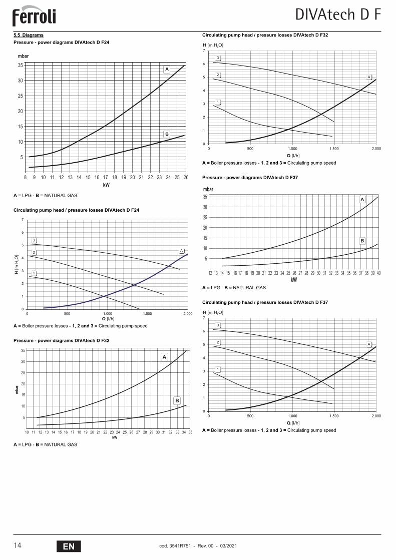
5.5 DiagramsPressure - power diagrams DIVAtech D F24
A = LPG - B = NATURAL GAS
Circulating pump head / pressure losses DIVAtech D F24
A = Boiler pressure losses - 1, 2 and 3 = Circulating pump speed
Pressure - power diagrams DIVAtech D F32
A = LPG - B = NATURAL GAS
Circulating pump head / pressure losses DIVAtech D F32
A = Boiler pressure losses - 1, 2 and 3 = Circulating pump speed
Pressure - power diagrams DIVAtech D F37
A = LPG - B = NATURAL GAS
Circulating pump head / pressure losses DIVAtech D F37
A = Boiler pressure losses - 1, 2 and 3 = Circulating pump speed
�
� � �� �� �� �� �� �� �� �� �� �� �� �� �� �� �� �� ��
��
��
��
��
��
��
�
��
����
�
�
�
�
�
�
�
�
�
� ��� ����� ����� �����
��������
����
����
�
�
�
�
���� �� �� �� �� �� �� �� �� �� �� �� �� �� �� �� �� �� �� �� �� �� �� �� �� ��
��
��
��
��
��
��
�
���
�
�
�
�
�
�
�
�
�
�
�
� ��� ����� ����� �����
��������
���������
�
�
�
�
�
�� �� �� �� �� �� �� �� �� �� �� �� �� �� �� �� �� �� �� �� �� �� �� �� �� �� �� �� ����
��
��
��
��
��
��
�
����
�
�
�
�
�
�
�
�
� ��� ����� ����� �����
��������
���������
�
�
�
cod. 3541R750 - Rev. 00 - 09/2019
DIVAtech D F
15ENcod. 3541R751 - Rev. 00 - 03/2021
DIVAtech D F
15EN
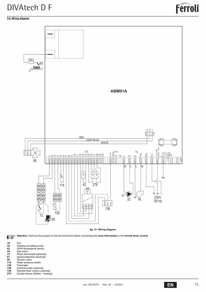
5.6 Wiring diagram
fig. 31- Wiring diagram
AAttention: Remove the jumper on the terminal block before connecting the room thermostat or the remote timer control.
16 Fan32 Heating circulating pump42 DHW temperature sensor44 Gas valve72 Room thermostat (optional)81 Ignition/detection electrode95 Diverter valve114 Water pressure switch136 Flowmeter138 External probe (optional)139 Remote timer control (optional)278 Double sensor (Safety + heating)
�����
��
�����������
��
��
��
�� ��
���
��
��
����
��
���
������
��
� � �
�� ��������
����
��
�
��
�
���
���
���
�����
���
cod. 3541R750 - Rev. 00 - 09/2019

Via
Related Documents


