(916) 774-1100 FAX: (916) 774-1117 CUSTOMER NAME: SITELINE ARCHITECTURE JOB NAME: DISTRICT SUPPORT SERVICES BUILDING ERICKSON CONSTRUCTION 8350 INDUSTRIAL AVE. ROSEVILLE, CA 95678 55.5# LOAD WET SEALS JOB LOCATION: 10840 GILMORE WAY, GRASS VALLEY 6:12 PITCH ROOF TRUSSES

Welcome message from author
This document is posted to help you gain knowledge. Please leave a comment to let me know what you think about it! Share it to your friends and learn new things together.
Transcript
(916) 774-1100 FAX: (916) 774-1117
CUSTOMER NAME: SITELINE ARCHITECTURE
JOB NAME: DISTRICT SUPPORT SERVICES BUILDING
ERICKSON CONSTRUCTION8350 INDUSTRIAL AVE.ROSEVILLE, CA 95678
55.5# LOAD
WET SEALS
JOB LOCATION: 10840 GILMORE WAY, GRASS VALLEY
6:12 PITCH
ROOF TRUSSES

1
2
6
T1
3
7
T2
8
4
5
M-3x5
M-3x5
M-1.5x4
M-3x5
M-5x6
M-3x5
M-3x5
M-1.5x4
M-3x5
M-3x5
3-02-02
0-06-06
1-00
0-10-04
1-00
4-04
3-04
5.0"
6-11-08
8-08
1.1"
3-04
4-04
0-10-04
2-00
1-00
0-06-06
6.0012 12
6.00
JOB NAME: SERVICES BLDG TRUSS - 1
Unbalanced live loads have been considered for this design.
Staple or equal at non-structuralvertical members (uon).
LUMBER SPECIFICATIONSTC: 2x4 DF #1&BTR; 2x6 DF #2 T1, T2BC: 2x4 DF #1&BTRWEBS: 2x4 DF STAND TC LATERAL SUPPORT <= 12"OC. UON.BC LATERAL SUPPORT <= 12"OC. UON. OVERHANGS: 12.0" 12.0"
TRUSS SPAN 8'- 8.0" LOAD DURATION INCREASE = 1.15 (Non-Rep) SPACED 24.0" O.C. LOADINGLL( 38.5)+DL( 10.0) ON TOP CHORD = 48.5 PSF DL ON BOTTOM CHORD = 7.0 PSF TOTAL LOAD = 55.5 PSF Snow: ASCE 7-10, 38.5 PSF Roof Snow(Ps) Pg=50 PSF, Cs=1, Ce=1, Ct=1.1, I=1 LIMITED STORAGE DOES NOT APPLY DUE TO THE SPATIALREQUIREMENTS OF CBC 2013 NOT BEING MET. BOTTOM CHORD CHECKED FOR 10PSF LIVE LOAD. TOPAND BOTTOM CHORD LIVE LOADS ACT NON-CONCURRENTLY.
Scale: 0.5072
VERTICAL DEFLECTION LIMITS: LL=L/360, TL=L/240 MAX LL DEFL = -0.001" @ -1'- 0.0" Allowed = 0.067" MAX TL CREEP DEFL = -0.001" @ -1'- 0.0" Allowed = 0.100" MAX LL DEFL = -0.028" @ 0'- 0.0" Allowed = 0.057" MAX TL CREEP DEFL = -0.039" @ 0'- 0.0" Allowed = 0.085" MAX LL DEFL = -0.062" @ 4'- 4.0" Allowed = 0.212" MAX TL CREEP DEFL = -0.088" @ 4'- 4.0" Allowed = 0.319" MAX LL DEFL = -0.028" @ 8'- 8.0" Allowed = 0.057" MAX TL CREEP DEFL = -0.039" @ 8'- 8.0" Allowed = 0.085" MAX LL DEFL = -0.001" @ 9'- 8.0" Allowed = 0.067" MAX TL CREEP DEFL = -0.001" @ 9'- 8.0" Allowed = 0.100" MAX HORIZ. LL DEFL = 0.002" @ 7'- 8.0" MAX HORIZ. TL DEFL = 0.002" @ 7'- 8.0"
CBC2013/IBC2012 MAX MEMBER FORCES 4WR/GDF95/Cq=0.90 1-2=( 0) 69 2-6=(-101) 247 7-3=(-373) 78 2-3=(-365) 110 6-7=( -88) 265 3-4=(-365) 110 7-8=( -88) 265 4-5=( 0) 69 8-4=(-101) 247 BEARING MAX VERT MAX HORZ BRG REQUIRED BRG AREA LOCATIONS REACTIONS REACTIONS SIZE SQ.IN. (SPECIES) 0'- 10.3" -65/ 655V -40/ 40H 3.50" 0.95 DF ( 625) 7'- 9.8" -47/ 655V 0/ 0H 3.50" 0.95 DF ( 625)
Wind: 110 mph, h=15ft, TCDL=6.0,BCDL=4.2, ASCE 7-10, (All Heights), Enclosed, Cat.2, Exp.C, MWFRS(Dir), load duration factor=1.6, Truss designed for wind loads in the plane of the truss only.
Truss designed for 4x2 outlookers. 2x let-insof equal or greater grade as structural topchord. Insure tight fit at each end of let-in.Outlookers must be cut with care and arepermissible at inlet board areas only.
Max CSI: TC:0.21 BC:0.80 Web:0.27
Truss: 1
DATE: 3/29/2016DES. BY: EE
SEQ.: 6378814TRANS ID: 435039
MiTek USA, Inc./CompuTrus Software 7.6.7-SP3(1L)-E
This design prepared from computer input byERICKSON CONSTRUCTION - MS
WARNINGS: 1. Builder and erection contractor should be advised of all General Notes and Warnings before construction commences. 2. 2x4 compression web bracing must be installed where shown +. 3. Additional temporary bracing to insure stability during construction is the responsibility of the erector. Additional permanent bracing of the overall structure is the responsibility of the building designer. 4. No load should be applied to any component until after all bracing and fasteners are complete and at no time should any loads greater than design loads be applied to any component. 5. CompuTrus has no control over and assumes no responsibility for the fabrication, handling, shipment and installation of components. 6. This design is furnished subject to the limitations set forth by TPI/WTCA in BCSI, copies of which will be furnished upon request.
GENERAL NOTES, unless otherwise noted: 1. This design is based only upon the parameters shown and is for an individual building component. Applicability of design parameters and proper incorporation of component is the responsibility of the building designer. 2. Design assumes the top and bottom chords to be laterally braced at 2' o.c. and at 10' o.c. respectively unless braced throughout their length by continuous sheathing such as plywood sheathing(TC) and/or drywall(BC). 3. 2x Impact bridging or lateral bracing required where shown + + 4. Installation of truss is the responsibility of the respective contractor. 5. Design assumes trusses are to be used in a non-corrosive environment, and are for "dry condition" of use. 6. Design assumes full bearing at all supports shown. Shim or wedge if necessary. 7. Design assumes adequate drainage is provided. 8. Plates shall be located on both faces of truss, and placed so their center lines coincide with joint center lines. 9. Digits indicate size of plate in inches.10. For basic connector plate design values see ESR-1311, ESR-1988 (MiTek)

1
2
6
3
7 8
4
5
M-3x5
M-5x6
M-3x5 M-3x5
3-02-02
0-06-06
1-00
0-10-04
1-00
4-04
3-04
5.0"
6-11-08
8-08
1.1"
3-04
4-04
1-00
0-10-04
1-00
0-06-06
6.0012 12
6.00
JOB NAME: SERVICES BLDG TRUSS - 2
Unbalanced live loads have been considered for this design.
LUMBER SPECIFICATIONSTC: 2x6 DF #2BC: 2x4 DF #1&BTRWEBS: 2x4 DF STAND TC LATERAL SUPPORT <= 12"OC. UON.BC LATERAL SUPPORT <= 12"OC. UON. OVERHANGS: 12.0" 12.0"
TRUSS SPAN 8'- 8.0" LOAD DURATION INCREASE = 1.15 SPACED 24.0" O.C. LOADINGLL( 38.5)+DL( 10.0) ON TOP CHORD = 48.5 PSF DL ON BOTTOM CHORD = 7.0 PSF TOTAL LOAD = 55.5 PSF Snow: ASCE 7-10, 38.5 PSF Roof Snow(Ps) Pg=50 PSF, Cs=1, Ce=1, Ct=1.1, I=1 LIMITED STORAGE DOES NOT APPLY DUE TO THE SPATIALREQUIREMENTS OF CBC 2013 NOT BEING MET. BOTTOM CHORD CHECKED FOR 10PSF LIVE LOAD. TOPAND BOTTOM CHORD LIVE LOADS ACT NON-CONCURRENTLY.
OFF JOINT BEARINGS SHALL BE REVIEWED AND APPROVED BY THE BUILDING DESIGNER.
Scale: 0.4976
VERTICAL DEFLECTION LIMITS: LL=L/360, TL=L/240 MAX LL DEFL = -0.001" @ -1'- 0.0" Allowed = 0.067" MAX TL CREEP DEFL = -0.001" @ -1'- 0.0" Allowed = 0.100" MAX LL DEFL = -0.028" @ 0'- 0.0" Allowed = 0.057" MAX TL CREEP DEFL = -0.039" @ 0'- 0.0" Allowed = 0.085" MAX LL DEFL = -0.062" @ 4'- 4.0" Allowed = 0.212" MAX TL CREEP DEFL = -0.088" @ 4'- 4.0" Allowed = 0.319" MAX LL DEFL = -0.028" @ 8'- 8.0" Allowed = 0.057" MAX TL CREEP DEFL = -0.039" @ 8'- 8.0" Allowed = 0.085" MAX LL DEFL = -0.001" @ 9'- 8.0" Allowed = 0.067" MAX TL CREEP DEFL = -0.001" @ 9'- 8.0" Allowed = 0.100" MAX HORIZ. LL DEFL = 0.002" @ 7'- 8.0" MAX HORIZ. TL DEFL = 0.002" @ 7'- 8.0"
CBC2013/IBC2012 MAX MEMBER FORCES 4WR/GDF95/Cq=0.90 1-2=( 0) 69 2-6=(-101) 247 7-3=(-373) 78 2-3=(-365) 110 6-7=( -88) 265 3-4=(-365) 110 7-8=( -88) 265 4-5=( 0) 69 8-4=(-101) 247 BEARING MAX VERT MAX HORZ BRG REQUIRED BRG AREA LOCATIONS REACTIONS REACTIONS SIZE SQ.IN. (SPECIES) 0'- 10.3" -65/ 655V -40/ 40H 3.50" 0.95 DF ( 625) 7'- 9.8" -47/ 655V 0/ 0H 3.50" 0.95 DF ( 625)
Wind: 110 mph, h=15ft, TCDL=6.0,BCDL=4.2, ASCE 7-10, (All Heights), Enclosed, Cat.2, Exp.C, MWFRS(Dir), load duration factor=1.6, Truss designed for wind loads in the plane of the truss only.
Max CSI: TC:0.18 BC:0.70 Web:0.27
Truss: 2
DATE: 3/29/2016DES. BY: EE
SEQ.: 6378815TRANS ID: 435039
MiTek USA, Inc./CompuTrus Software 7.6.7-SP3(1L)-E
This design prepared from computer input byERICKSON CONSTRUCTION - MS
WARNINGS: 1. Builder and erection contractor should be advised of all General Notes and Warnings before construction commences. 2. 2x4 compression web bracing must be installed where shown +. 3. Additional temporary bracing to insure stability during construction is the responsibility of the erector. Additional permanent bracing of the overall structure is the responsibility of the building designer. 4. No load should be applied to any component until after all bracing and fasteners are complete and at no time should any loads greater than design loads be applied to any component. 5. CompuTrus has no control over and assumes no responsibility for the fabrication, handling, shipment and installation of components. 6. This design is furnished subject to the limitations set forth by TPI/WTCA in BCSI, copies of which will be furnished upon request.
GENERAL NOTES, unless otherwise noted: 1. This design is based only upon the parameters shown and is for an individual building component. Applicability of design parameters and proper incorporation of component is the responsibility of the building designer. 2. Design assumes the top and bottom chords to be laterally braced at 2' o.c. and at 10' o.c. respectively unless braced throughout their length by continuous sheathing such as plywood sheathing(TC) and/or drywall(BC). 3. 2x Impact bridging or lateral bracing required where shown + + 4. Installation of truss is the responsibility of the respective contractor. 5. Design assumes trusses are to be used in a non-corrosive environment, and are for "dry condition" of use. 6. Design assumes full bearing at all supports shown. Shim or wedge if necessary. 7. Design assumes adequate drainage is provided. 8. Plates shall be located on both faces of truss, and placed so their center lines coincide with joint center lines. 9. Digits indicate size of plate in inches.10. For basic connector plate design values see ESR-1311, ESR-1988 (MiTek)

12
3
6 45
M-3x8
M-1.5x4
M-1.5x4
M-6x6
M-1.5x4
M-3x8
4-09-02
0-06-06
1-00
0-10-04
7-06
7-06
6-02-08
13-03-08
6.0"
15-00
3.0"
6-09-05
7-06
7-06
0-10-04
1-00
0-06-06
6.0012 12
6.00
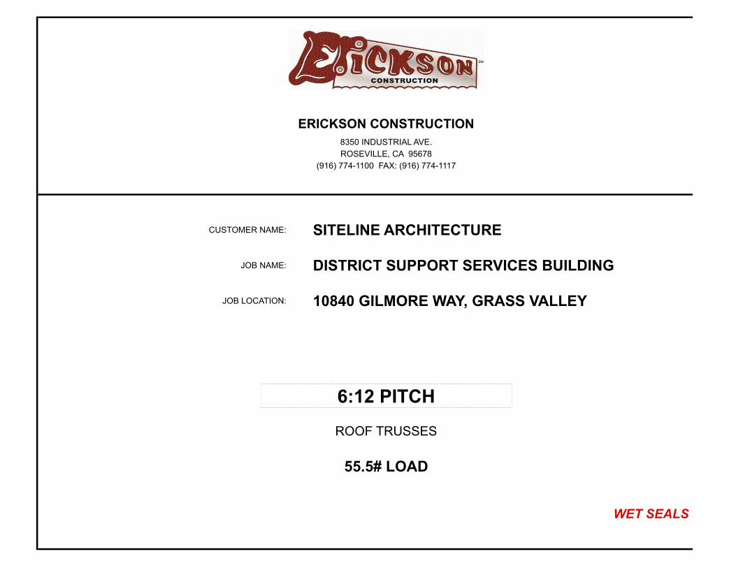
JOB NAME: SERVICES BLDG TRUSS - 3
Unbalanced live loads have been considered for this design.
Staple or equal at non-structuralvertical members (uon).
LUMBER SPECIFICATIONSTC: 2x6 DF #2BC: 2x4 DF #1&BTRWEBS: 2x4 DF STAND TC LATERAL SUPPORT <= 12"OC. UON.BC LATERAL SUPPORT <= 12"OC. UON. OVERHANGS: 12.0" 12.0"
TRUSS SPAN 15'- 0.0" LOAD DURATION INCREASE = 1.15 (Non-Rep) SPACED 24.0" O.C. LOADINGLL( 38.5)+DL( 10.0) ON TOP CHORD = 48.5 PSF DL ON BOTTOM CHORD = 7.0 PSF TOTAL LOAD = 55.5 PSF Snow: ASCE 7-10, 38.5 PSF Roof Snow(Ps) Pg=50 PSF, Cs=1, Ce=1, Ct=1.1, I=1 LIMITED STORAGE DOES NOT APPLY DUE TO THE SPATIALREQUIREMENTS OF CBC 2013 NOT BEING MET. BOTTOM CHORD CHECKED FOR 10PSF LIVE LOAD. TOPAND BOTTOM CHORD LIVE LOADS ACT NON-CONCURRENTLY.
Scale: 0.3346
VERTICAL DEFLECTION LIMITS: LL=L/360, TL=L/240 MAX LL DEFL = -0.001" @ -1'- 0.0" Allowed = 0.067" MAX TL CREEP DEFL = -0.001" @ -1'- 0.0" Allowed = 0.100" MAX LL DEFL = -0.031" @ 0'- 0.0" Allowed = 0.057" MAX TL CREEP DEFL = -0.031" @ 0'- 0.0" Allowed = 0.085" MAX TL CREEP DEFL = -0.016" @ 7'- 6.0" Allowed = 0.635" MAX LL DEFL = -0.031" @ 15'- 0.0" Allowed = 0.057" MAX TL CREEP DEFL = -0.031" @ 15'- 0.0" Allowed = 0.085" MAX LL DEFL = -0.001" @ 16'- 0.0" Allowed = 0.067" MAX TL CREEP DEFL = -0.001" @ 16'- 0.0" Allowed = 0.100" MAX TC PANEL LL DEFL = 0.012" @ 3'- 9.9" Allowed = 0.477" MAX HORIZ. LL DEFL = 0.006" @ 13'- 10.3" MAX HORIZ. TL DEFL = 0.009" @ 13'- 10.3"
CBC2013/IBC2012 MAX MEMBER FORCES 4WR/GDF95/Cq=0.90 1-2=( 0) 77 2-6=(0) 570 2-3=(-838) 21 2-3=(-838) 21 6-4=(0) 570 6-3=( 0) 268 3-4=(-838) 21 3-4=(-838) 21 4-5=( 0) 77 BEARING MAX VERT MAX HORZ BRG REQUIRED BRG AREA LOCATIONS REACTIONS REACTIONS SIZE SQ.IN. (SPECIES) 0'- 10.3" -51/ 1007V -58/ 58H 3.50" 1.45 DF ( 625) 14'- 1.7" -72/ 1006V 0/ 0H 3.50" 1.45 DF ( 625)
Wind: 110 mph, h=15ft, TCDL=6.0,BCDL=4.2, ASCE 7-10, (All Heights), Enclosed, Cat.2, Exp.C, MWFRS(Dir), load duration factor=1.6, Truss designed for wind loads in the plane of the truss only.
Max CSI: TC:0.54 BC:0.35 Web:0.24
Truss: 3
DATE: 3/29/2016DES. BY: EE
SEQ.: 6378816TRANS ID: 435039
MiTek USA, Inc./CompuTrus Software 7.6.7-SP3(1L)-E
This design prepared from computer input byERICKSON CONSTRUCTION - MS
WARNINGS: 1. Builder and erection contractor should be advised of all General Notes and Warnings before construction commences. 2. 2x4 compression web bracing must be installed where shown +. 3. Additional temporary bracing to insure stability during construction is the responsibility of the erector. Additional permanent bracing of the overall structure is the responsibility of the building designer. 4. No load should be applied to any component until after all bracing and fasteners are complete and at no time should any loads greater than design loads be applied to any component. 5. CompuTrus has no control over and assumes no responsibility for the fabrication, handling, shipment and installation of components. 6. This design is furnished subject to the limitations set forth by TPI/WTCA in BCSI, copies of which will be furnished upon request.
GENERAL NOTES, unless otherwise noted: 1. This design is based only upon the parameters shown and is for an individual building component. Applicability of design parameters and proper incorporation of component is the responsibility of the building designer. 2. Design assumes the top and bottom chords to be laterally braced at 2' o.c. and at 10' o.c. respectively unless braced throughout their length by continuous sheathing such as plywood sheathing(TC) and/or drywall(BC). 3. 2x Impact bridging or lateral bracing required where shown + + 4. Installation of truss is the responsibility of the respective contractor. 5. Design assumes trusses are to be used in a non-corrosive environment, and are for "dry condition" of use. 6. Design assumes full bearing at all supports shown. Shim or wedge if necessary. 7. Design assumes adequate drainage is provided. 8. Plates shall be located on both faces of truss, and placed so their center lines coincide with joint center lines. 9. Digits indicate size of plate in inches.10. For basic connector plate design values see ESR-1311, ESR-1988 (MiTek)

12
3
4
8
5
67
M-3x8
M-3x5
M-1.5x4
M-4x6
M-3x5
M-3x8
4-09-02
0-06-06
1-00
0-10-04
1-02-02
7-06
7-06
5-02-02
13-03-08
4.0"
15-00
3.0"
5-02-02
7-06
7-06
1-05-07
0-10-04
1-00
0-06-06
6.0012 12
6.00
JOB NAME: SERVICES BLDG TRUSS - 4
Unbalanced live loads have been considered for this design.
LUMBER SPECIFICATIONSTC: 2x6 DF #2BC: 2x4 DF #1&BTRWEBS: 2x4 DF STAND TC LATERAL SUPPORT <= 12"OC. UON.BC LATERAL SUPPORT <= 12"OC. UON. LETINS: 1-11-00 1-11-00 OVERHANGS: 12.0" 12.0"
TRUSS SPAN 15'- 0.0" LOAD DURATION INCREASE = 1.15 SPACED 24.0" O.C. LOADINGLL( 38.5)+DL( 10.0) ON TOP CHORD = 48.5 PSF DL ON BOTTOM CHORD = 7.0 PSF TOTAL LOAD = 55.5 PSF Snow: ASCE 7-10, 38.5 PSF Roof Snow(Ps) Pg=50 PSF, Cs=1, Ce=1, Ct=1.1, I=1 LIMITED STORAGE DOES NOT APPLY DUE TO THE SPATIALREQUIREMENTS OF CBC 2013 NOT BEING MET. BOTTOM CHORD CHECKED FOR 10PSF LIVE LOAD. TOPAND BOTTOM CHORD LIVE LOADS ACT NON-CONCURRENTLY.
Scale: 0.3366
VERTICAL DEFLECTION LIMITS: LL=L/360, TL=L/240 MAX LL DEFL = -0.001" @ -1'- 0.0" Allowed = 0.067" MAX TL CREEP DEFL = -0.001" @ -1'- 0.0" Allowed = 0.100" MAX LL DEFL = -0.029" @ 0'- 0.0" Allowed = 0.057" MAX TL CREEP DEFL = -0.039" @ 0'- 0.0" Allowed = 0.085" MAX LL DEFL = -0.023" @ 7'- 6.0" Allowed = 0.424" MAX TL CREEP DEFL = -0.042" @ 7'- 6.0" Allowed = 0.635" MAX LL DEFL = -0.029" @ 15'- 0.0" Allowed = 0.057" MAX TL CREEP DEFL = -0.039" @ 15'- 0.0" Allowed = 0.085" MAX LL DEFL = -0.001" @ 16'- 0.0" Allowed = 0.067" MAX TL CREEP DEFL = -0.001" @ 16'- 0.0" Allowed = 0.100" MAX HORIZ. LL DEFL = 0.006" @ 13'- 10.3" MAX HORIZ. TL DEFL = 0.009" @ 13'- 10.3"
CBC2013/IBC2012 MAX MEMBER FORCES 4WR/GDF95/Cq=0.90 1- 2=( 0) 77 2- 8=(0) 572 2- 3=(-885) 23 2- 3=(-885) 23 8- 6=(0) 572 8- 4=( 0) 266 3- 4=(-770) 28 5- 6=(-885) 23 4- 5=(-770) 28 5- 6=(-885) 23 6- 7=( 0) 77 BEARING MAX VERT MAX HORZ BRG REQUIRED BRG AREA LOCATIONS REACTIONS REACTIONS SIZE SQ.IN. (SPECIES) 0'- 10.3" -53/ 1007V -59/ 59H 3.50" 1.45 DF ( 625) 14'- 1.7" -74/ 1006V 0/ 0H 3.50" 1.45 DF ( 625)
Wind: 110 mph, h=15ft, TCDL=6.0,BCDL=4.2, ASCE 7-10, (All Heights), Enclosed, Cat.2, Exp.C, MWFRS(Dir), load duration factor=1.6, Truss designed for wind loads in the plane of the truss only.
Max CSI: TC:0.36 BC:0.30 Web:0.12
Truss: 4
DATE: 3/29/2016DES. BY: EE
SEQ.: 6378817TRANS ID: 435039
MiTek USA, Inc./CompuTrus Software 7.6.7-SP3(1L)-E
This design prepared from computer input byERICKSON CONSTRUCTION - MS
WARNINGS: 1. Builder and erection contractor should be advised of all General Notes and Warnings before construction commences. 2. 2x4 compression web bracing must be installed where shown +. 3. Additional temporary bracing to insure stability during construction is the responsibility of the erector. Additional permanent bracing of the overall structure is the responsibility of the building designer. 4. No load should be applied to any component until after all bracing and fasteners are complete and at no time should any loads greater than design loads be applied to any component. 5. CompuTrus has no control over and assumes no responsibility for the fabrication, handling, shipment and installation of components. 6. This design is furnished subject to the limitations set forth by TPI/WTCA in BCSI, copies of which will be furnished upon request.
GENERAL NOTES, unless otherwise noted: 1. This design is based only upon the parameters shown and is for an individual building component. Applicability of design parameters and proper incorporation of component is the responsibility of the building designer. 2. Design assumes the top and bottom chords to be laterally braced at 2' o.c. and at 10' o.c. respectively unless braced throughout their length by continuous sheathing such as plywood sheathing(TC) and/or drywall(BC). 3. 2x Impact bridging or lateral bracing required where shown + + 4. Installation of truss is the responsibility of the respective contractor. 5. Design assumes trusses are to be used in a non-corrosive environment, and are for "dry condition" of use. 6. Design assumes full bearing at all supports shown. Shim or wedge if necessary. 7. Design assumes adequate drainage is provided. 8. Plates shall be located on both faces of truss, and placed so their center lines coincide with joint center lines. 9. Digits indicate size of plate in inches.10. For basic connector plate design values see ESR-1311, ESR-1988 (MiTek)

1
2
3
6
4
5
M-3x8
M-3x5
M-1.5x4
M-4x6
M-3x5
M-3x8
4-03-06
0-06-06
0-10-04
2-03-14
7-06
7-06
5-02-02
13-03-08
4.0"
15-00
3.0"
5-02-02
7-06
7-06
2-03-14
0-10-04
0-06-06
6.0012 12
6.00
JOB NAME: SERVICES BLDG TRUSS - 5
Unbalanced live loads have been considered for this design.
LUMBER SPECIFICATIONSTC: 2x6 DF #2BC: 2x4 DF #1&BTRWEBS: 2x4 DF STAND TC LATERAL SUPPORT <= 12"OC. UON.BC LATERAL SUPPORT <= 12"OC. UON. LETINS: 1-11-00 1-11-00
TRUSS SPAN 15'- 0.0" LOAD DURATION INCREASE = 1.15 SPACED 24.0" O.C. LOADINGLL( 38.5)+DL( 10.0) ON TOP CHORD = 48.5 PSF DL ON BOTTOM CHORD = 7.0 PSF TOTAL LOAD = 55.5 PSF Snow: ASCE 7-10, 38.5 PSF Roof Snow(Ps) Pg=50 PSF, Cs=1, Ce=1, Ct=1.1, I=1 LIMITED STORAGE DOES NOT APPLY DUE TO THE SPATIALREQUIREMENTS OF CBC 2013 NOT BEING MET. BOTTOM CHORD CHECKED FOR 10PSF LIVE LOAD. TOPAND BOTTOM CHORD LIVE LOADS ACT NON-CONCURRENTLY.
Scale: 0.3624
VERTICAL DEFLECTION LIMITS: LL=L/360, TL=L/240 MAX LL DEFL = 0.000" @ 0'- 0.0" Allowed = 0.057" MAX TL CREEP DEFL = 0.000" @ 0'- 0.0" Allowed = 0.085" MAX LL DEFL = -0.034" @ 2'- 1.9" Allowed = 0.424" MAX TL CREEP DEFL = -0.034" @ 2'- 1.9" Allowed = 0.635" MAX LL DEFL = 0.000" @ 0'- 0.0" Allowed = 0.057" MAX TL CREEP DEFL = 0.000" @ 0'- 0.0" Allowed = 0.085" MAX HORIZ. LL DEFL = 0.006" @ 13'- 10.3" MAX HORIZ. TL DEFL = 0.010" @ 13'- 10.3"
CBC2013/IBC2012 MAX MEMBER FORCES 4WR/GDF95/Cq=0.90 1-2=(-897) 34 1-6=(0) 595 1-2=(-897) 34 2-3=(-789) 43 6-5=(0) 595 6-3=( 0) 266 3-4=(-789) 43 4-5=(-897) 34 4-5=(-897) 34 BEARING MAX VERT MAX HORZ BRG REQUIRED BRG AREA LOCATIONS REACTIONS REACTIONS SIZE SQ.IN. (SPECIES) 0'- 10.3" -26/ 833V -51/ 51H 3.50" 1.20 DF ( 625) 14'- 1.7" -47/ 832V 0/ 0H 3.50" 1.20 DF ( 625)
Wind: 110 mph, h=15ft, TCDL=6.0,BCDL=4.2, ASCE 7-10, (All Heights), Enclosed, Cat.2, Exp.C, MWFRS(Dir), load duration factor=1.6, Truss designed for wind loads in the plane of the truss only.
Max CSI: TC:0.38 BC:0.30 Web:0.12
Truss: 5
DATE: 3/29/2016DES. BY: EE
SEQ.: 6378818TRANS ID: 435039
MiTek USA, Inc./CompuTrus Software 7.6.7-SP3(1L)-E
This design prepared from computer input byERICKSON CONSTRUCTION - MS
WARNINGS: 1. Builder and erection contractor should be advised of all General Notes and Warnings before construction commences. 2. 2x4 compression web bracing must be installed where shown +. 3. Additional temporary bracing to insure stability during construction is the responsibility of the erector. Additional permanent bracing of the overall structure is the responsibility of the building designer. 4. No load should be applied to any component until after all bracing and fasteners are complete and at no time should any loads greater than design loads be applied to any component. 5. CompuTrus has no control over and assumes no responsibility for the fabrication, handling, shipment and installation of components. 6. This design is furnished subject to the limitations set forth by TPI/WTCA in BCSI, copies of which will be furnished upon request.
GENERAL NOTES, unless otherwise noted: 1. This design is based only upon the parameters shown and is for an individual building component. Applicability of design parameters and proper incorporation of component is the responsibility of the building designer. 2. Design assumes the top and bottom chords to be laterally braced at 2' o.c. and at 10' o.c. respectively unless braced throughout their length by continuous sheathing such as plywood sheathing(TC) and/or drywall(BC). 3. 2x Impact bridging or lateral bracing required where shown + + 4. Installation of truss is the responsibility of the respective contractor. 5. Design assumes trusses are to be used in a non-corrosive environment, and are for "dry condition" of use. 6. Design assumes full bearing at all supports shown. Shim or wedge if necessary. 7. Design assumes adequate drainage is provided. 8. Plates shall be located on both faces of truss, and placed so their center lines coincide with joint center lines. 9. Digits indicate size of plate in inches.10. For basic connector plate design values see ESR-1311, ESR-1988 (MiTek)

12
13
3 4
14 15
5
16
6
17
7
18
8
19
9
20
10
1112
M-3x10
M-3x8
M-7x8 M-3x8
M-7x8(S)
M-7x8(S)
M-1.5x4M-7x8(S)
M-3x8
M-3x8
M-7x8
M-3x10
4-00-02
0-06-06
1-00
6-00
6-00
6-00
3-08-08
4-00
4-00
4-00
0.25"
4-01-12
3-10-04
0.25"
4-01-12
28-00
40-00
4-05-04
4-00
4-00
0.25"
4-00
4-00
1.31"
4-00
3-08-08
6-00
6-00
6-00
1-00
0-06-06
6.0012 12
6.00
485# 485#
JOB NAME: SERVICES BLDG TRUSS - 6
M-3x5 where shown; Jts:5,7-8,14,17,19
LUMBER SPECIFICATIONSTC: 2x6 DF #2BC: 2x6 DF #2WEBS: 2x4 DF STAND TC LATERAL SUPPORT <= 12"OC. UON.BC LATERAL SUPPORT <= 12"OC. UON. OVERHANGS: 12.0" 12.0"
( 3 ) complete trusses required.Attach 3 ply with 3"x.131 DIA GUNnails staggered: 9" oc in 2 row(s) throughout 2x6 top chords, 9" oc in 2 row(s) throughout 2x6 bottom chords, 9" oc in 1 row(s) throughout 2x4 webs.
40-00-00 HIP EB SETBACK 6-00-00 FROM END WALL LOAD DURATION INCREASE = 1.15 (Non-Rep) LOADING Snow: ASCE 7-10, 38.5 PSF Roof Snow(Ps) Pg=50 PSF, Cs=1, Ce=1, Ct=1.1, I=1, Lu=25' TC UNIF LL( 38.5)+DL( 10.0)= 48.5 PSF 0'- 0.0" TO 40'- 0.0" VBC UNIF LL( 0.0)+DL( 7.0)= 7.0 PSF 0'- 0.0" TO 40'- 0.0" VBC UNIF LL( 0.0)+DL( 14.0)= 14.0 PLF 0'- 0.0" TO 6'- 0.0" VBC UNIF LL( 77.0)+DL( 34.0)= 111.0 PLF 6'- 0.0" TO 34'- 0.0" VBC UNIF LL( 0.0)+DL( 14.0)= 14.0 PLF 34'- 0.0" TO 40'- 0.0" V TC CONC LL( 385.0)+DL( 100.0)= 485.0 LBS @ 6'- 0.0" TC CONC LL( 385.0)+DL( 100.0)= 485.0 LBS @ 34'- 0.0" LIMITED STORAGE DOES NOT APPLY DUE TO THE SPATIAL REQUIREMENTS OF CBC 2013 NOT BEING MET. BOTTOM CHORD CHECKED FOR 10PSF LIVE LOAD. TOP AND BOTTOM CHORD LIVE LOADS ACT NON-CONCURRENTLY.
VERTICAL DEFLECTION LIMITS: LL=L/360, TL=L/240 MAX LL DEFL = -0.000" @ -1'- 0.0" Allowed = 0.067" MAX TL CREEP DEFL = -0.000" @ -1'- 0.0" Allowed = 0.100" MAX LL DEFL = -0.457" @ 22'- 0.0" Allowed = 1.314" MAX TL CREEP DEFL = -0.721" @ 22'- 0.0" Allowed = 1.971" MAX LL DEFL = -0.000" @ 41'- 0.0" Allowed = 0.067" MAX TL CREEP DEFL = -0.000" @ 41'- 0.0" Allowed = 0.100" MAX HORIZ. LL DEFL = 0.109" @ 39'- 8.5" MAX HORIZ. TL DEFL = 0.151" @ 39'- 8.5"
CBC2013/IBC2012 MAX MEMBER FORCES 4WR/GDF95/Cq=0.90 1- 2=( 0) 75 2-13=(-267) 8025 13- 3=( -57) 3456 19- 9=( -75) 2514 2- 3=( -9132) 381 13-14=(-429) 11937 13- 4=(-5004) 213 9-20=(-5004) 213 3- 4=( -8028) 357 14-15=(-528) 14691 4-14=( -75) 2517 20-10=( -57) 3456 4- 5=(-12183) 528 15-16=(-582) 16053 14- 5=(-3210) 126 5- 6=(-14793) 621 16-17=(-582) 16056 5-15=( -24) 1440 6- 7=(-16071) 672 17-18=(-582) 16020 15- 6=(-1581) 72 7- 8=(-14790) 621 18-19=(-528) 14688 6-16=( 0) 498 8- 9=(-12183) 528 19-20=(-429) 11937 6-17=( -45) 90 9-10=( -8028) 357 20-11=(-264) 8025 17- 7=( 0) 552 10-11=( -9132) 381 7-18=(-1560) 72 11-12=( 0) 75 18- 8=( -24) 1449 8-19=(-3204) 126 BEARING MAX VERT MAX HORZ BRG REQUIRED BRG AREA LOCATIONS REACTIONS REACTIONS SIZE SQ.IN. (SPECIES) 0'- 0.0" -199/ 4517V -66/ 66H 3.50" 7.23 DF ( 625) 40'- 0.0" -199/ 4517V 0/ 0H 3.50" 7.23 DF ( 625)
Scale: 0.1029
Wind: 110 mph, h=15ft, TCDL=6.0,BCDL=4.2, ASCE 7-10, (All Heights), Enclosed, Cat.2, Exp.C, MWFRS(Dir), load duration factor=1.6, Truss designed for wind loads in the plane of the truss only.
Max CSI: TC:0.27 BC:0.87 Web:0.67
Truss: 6
DATE: 3/29/2016DES. BY: EE
SEQ.: 6378819TRANS ID: 435039
MiTek USA, Inc./CompuTrus Software 7.6.7-SP3(1L)-E
This design prepared from computer input byERICKSON CONSTRUCTION - MS
WARNINGS: 1. Builder and erection contractor should be advised of all General Notes and Warnings before construction commences. 2. 2x4 compression web bracing must be installed where shown +. 3. Additional temporary bracing to insure stability during construction is the responsibility of the erector. Additional permanent bracing of the overall structure is the responsibility of the building designer. 4. No load should be applied to any component until after all bracing and fasteners are complete and at no time should any loads greater than design loads be applied to any component. 5. CompuTrus has no control over and assumes no responsibility for the fabrication, handling, shipment and installation of components. 6. This design is furnished subject to the limitations set forth by TPI/WTCA in BCSI, copies of which will be furnished upon request.
GENERAL NOTES, unless otherwise noted: 1. This design is based only upon the parameters shown and is for an individual building component. Applicability of design parameters and proper incorporation of component is the responsibility of the building designer. 2. Design assumes the top and bottom chords to be laterally braced at 2' o.c. and at 10' o.c. respectively unless braced throughout their length by continuous sheathing such as plywood sheathing(TC) and/or drywall(BC). 3. 2x Impact bridging or lateral bracing required where shown + + 4. Installation of truss is the responsibility of the respective contractor. 5. Design assumes trusses are to be used in a non-corrosive environment, and are for "dry condition" of use. 6. Design assumes full bearing at all supports shown. Shim or wedge if necessary. 7. Design assumes adequate drainage is provided. 8. Plates shall be located on both faces of truss, and placed so their center lines coincide with joint center lines. 9. Digits indicate size of plate in inches.10. For basic connector plate design values see ESR-1311, ESR-1988 (MiTek)

1
2
3
12
4 5
13 14
6
15
7
16
8 9
17
10
11
M-4x10
M-1.5x4
M-6x12
M-7x8 M-4x8
M-8x8(S)
M-7x8(S)
M-1.5x4 M-3x5
M-3x5
M-8x8(S)
M-4x8 M-7x8
M-6x12
M-1.5x4
M-4x10
5-00-02
0-06-06
1-00
5-05-03
7-10-04
8-00
2-06-13 5-08-08
6-01-12
0.25"
4-01-12
3-10-04
0.25"
4-01-12
24-00
40-00
4-05-04
4-00
4-00
0.25"
6-01-12
5-08-08
1.69"
2-06-13
8-00
7-10-04
5-05-03
0-06-06
6.0012 12
6.00
JOB NAME: SERVICES BLDG TRUSS - 7
JT 2, 11: Heel to plate corner = 0.75"
LUMBER SPECIFICATIONSTC: 2x6 DF #2BC: 2x6 DF #2WEBS: 2x4 DF STAND TC LATERAL SUPPORT <= 12"OC. UON.BC LATERAL SUPPORT <= 12"OC. UON. OVERHANGS: 12.0" 0.0"
TRUSS SPAN 40'- 0.0" LOAD DURATION INCREASE = 1.15 SPACED 24.0" O.C. LOADINGLL( 38.5)+DL( 10.0) ON TOP CHORD = 48.5 PSF DL ON BOTTOM CHORD = 7.0 PSF TOTAL LOAD = 55.5 PSF Snow: ASCE 7-10, 38.5 PSF Roof Snow(Ps) Pg=50 PSF, Cs=1, Ce=1, Ct=1.1, I=1, Lu=25' LIMITED STORAGE DOES NOT APPLY DUE TO THE SPATIALREQUIREMENTS OF CBC 2013 NOT BEING MET. BOTTOM CHORD CHECKED FOR 10PSF LIVE LOAD. TOPAND BOTTOM CHORD LIVE LOADS ACT NON-CONCURRENTLY.
Scale: 0.2007
VERTICAL DEFLECTION LIMITS: LL=L/360, TL=L/240 MAX LL DEFL = -0.001" @ -1'- 0.0" Allowed = 0.067" MAX TL CREEP DEFL = -0.001" @ -1'- 0.0" Allowed = 0.100" MAX LL DEFL = -0.471" @ 22'- 0.0" Allowed = 1.314" MAX TL CREEP DEFL = -0.721" @ 22'- 0.0" Allowed = 1.971" MAX HORIZ. LL DEFL = 0.139" @ 39'- 8.5" MAX HORIZ. TL DEFL = 0.188" @ 39'- 8.5"
CBC2013/IBC2012 MAX MEMBER FORCES 4WR/GDF95/Cq=0.90 1- 2=( 0) 77 2-12=(-137) 3781 3-12=( -450) 92 9-17=( -49) 1465 2- 3=(-4354) 204 12-13=(-172) 5885 12- 4=( -44) 1459 17-10=(-493) 82 3- 4=(-4278) 199 13-14=(-191) 6453 12- 5=(-2523) 116 4- 5=(-3795) 184 14-15=(-191) 6454 5-13=( 0) 587 5- 6=(-5916) 270 15-16=(-192) 6443 13- 6=( -761) 38 6- 7=(-6448) 288 16-17=(-175) 5887 6-14=( 0) 132 7- 8=(-5918) 272 17-11=(-147) 3795 6-15=( -107) 110 8- 9=(-3801) 188 15- 7=( -18) 137 9-10=(-4286) 205 7-16=( -756) 38 10-11=(-4366) 212 16- 8=( 0) 592 8-17=(-2518) 115 BEARING MAX VERT MAX HORZ BRG REQUIRED BRG AREA LOCATIONS REACTIONS REACTIONS SIZE SQ.IN. (SPECIES) 0'- 0.0" -128/ 2398V -78/ 82H 3.50" 3.84 DF ( 625) 40'- 0.0" -100/ 2225V 0/ 0H 3.50" 3.56 DF ( 625)
Wind: 110 mph, h=15ft, TCDL=6.0,BCDL=4.2, ASCE 7-10, (All Heights), Enclosed, Cat.2, Exp.C, MWFRS(Dir), load duration factor=1.6, Truss designed for wind loads in the plane of the truss only.
Max CSI: TC:0.51 BC:0.92 Web:0.95
Truss: 7
DATE: 3/29/2016DES. BY: EE
SEQ.: 6378820TRANS ID: 435039
MiTek USA, Inc./CompuTrus Software 7.6.7-SP3(1L)-E
This design prepared from computer input byERICKSON CONSTRUCTION - MS
WARNINGS: 1. Builder and erection contractor should be advised of all General Notes and Warnings before construction commences. 2. 2x4 compression web bracing must be installed where shown +. 3. Additional temporary bracing to insure stability during construction is the responsibility of the erector. Additional permanent bracing of the overall structure is the responsibility of the building designer. 4. No load should be applied to any component until after all bracing and fasteners are complete and at no time should any loads greater than design loads be applied to any component. 5. CompuTrus has no control over and assumes no responsibility for the fabrication, handling, shipment and installation of components. 6. This design is furnished subject to the limitations set forth by TPI/WTCA in BCSI, copies of which will be furnished upon request.
GENERAL NOTES, unless otherwise noted: 1. This design is based only upon the parameters shown and is for an individual building component. Applicability of design parameters and proper incorporation of component is the responsibility of the building designer. 2. Design assumes the top and bottom chords to be laterally braced at 2' o.c. and at 10' o.c. respectively unless braced throughout their length by continuous sheathing such as plywood sheathing(TC) and/or drywall(BC). 3. 2x Impact bridging or lateral bracing required where shown + + 4. Installation of truss is the responsibility of the respective contractor. 5. Design assumes trusses are to be used in a non-corrosive environment, and are for "dry condition" of use. 6. Design assumes full bearing at all supports shown. Shim or wedge if necessary. 7. Design assumes adequate drainage is provided. 8. Plates shall be located on both faces of truss, and placed so their center lines coincide with joint center lines. 9. Digits indicate size of plate in inches.10. For basic connector plate design values see ESR-1311, ESR-1988 (MiTek)

12
3
12
4
13
5 6
14
7
15
8 9
16
10
11M-4x10
M-1.5x4
M-3x5
M-7x8 M-1.5x4
MHS-7x16(S)
M-3x5
M-3x5
M-3x5
MHS-7x16(S)
M-1.5x4 M-7x8
M-3x5
M-1.5x4
M-4x10
6-00-02
0-06-06
1-00
5-06-03
8-00
10-00
4-05-13
5-10-04
3-10-04
0.25"
4-01-12
8-01-12
20-00
40-00
4-03-08
4-01-12
3-10-04
0.25"
1.69"
3-10-04
5-10-04
4-05-13
10-00
8-00
5-06-03
0-06-06
6.0012 12
6.00
JOB NAME: SERVICES BLDG TRUSS 8
LUMBER SPECIFICATIONSTC: 2x6 DF #2BC: 2x4 DF #1&BTRWEBS: 2x4 DF STAND TC LATERAL SUPPORT <= 12"OC. UON.BC LATERAL SUPPORT <= 12"OC. UON. OVERHANGS: 12.0" 0.0"
TRUSS SPAN 40'- 0.0" LOAD DURATION INCREASE = 1.15 SPACED 24.0" O.C. LOADINGLL( 38.5)+DL( 10.0) ON TOP CHORD = 48.5 PSF DL ON BOTTOM CHORD = 7.0 PSF TOTAL LOAD = 55.5 PSF Snow: ASCE 7-10, 38.5 PSF Roof Snow(Ps) Pg=50 PSF, Cs=1, Ce=1, Ct=1.1, I=1, Lu=25' LIMITED STORAGE DOES NOT APPLY DUE TO THE SPATIALREQUIREMENTS OF CBC 2013 NOT BEING MET. BOTTOM CHORD CHECKED FOR 10PSF LIVE LOAD. TOPAND BOTTOM CHORD LIVE LOADS ACT NON-CONCURRENTLY.
Scale: 0.1882
VERTICAL DEFLECTION LIMITS: LL=L/360, TL=L/240 MAX LL DEFL = -0.001" @ -1'- 0.0" Allowed = 0.067" MAX TL CREEP DEFL = -0.001" @ -1'- 0.0" Allowed = 0.100" MAX LL DEFL = -0.350" @ 18'- 0.0" Allowed = 1.314" MAX TL CREEP DEFL = -0.547" @ 18'- 0.0" Allowed = 1.971" MAX HORIZ. LL DEFL = 0.141" @ 39'- 8.5" MAX HORIZ. TL DEFL = 0.196" @ 39'- 8.5"
CBC2013/IBC2012 MAX MEMBER FORCES 4WR/GDF95/Cq=0.90 1- 2=( 0) 77 2-12=(-139) 3466 3-12=(-552) 92 16-10=(-587) 99 2- 3=(-4069) 207 12-13=( -75) 3431 12- 4=( -4) 547 3- 4=(-3898) 208 13-14=(-137) 4943 4-13=( -65) 1697 4- 5=(-4474) 232 14-15=(-124) 4944 5-13=(-651) 60 5- 6=(-4460) 231 15-16=( -78) 3433 13- 6=(-765) 64 6- 7=(-4949) 246 16-11=(-146) 3471 6-14=(-119) 181 7- 8=(-4451) 237 14- 7=( -46) 188 8- 9=(-4464) 238 7-15=(-817) 35 9-10=(-3908) 212 15- 8=(-624) 57 10-11=(-4074) 212 15- 9=( -71) 1678 9-16=( -2) 585 BEARING MAX VERT MAX HORZ BRG REQUIRED BRG AREA LOCATIONS REACTIONS REACTIONS SIZE SQ.IN. (SPECIES) 0'- 0.0" -129/ 2398V -98/ 102H 3.50" 3.84 DF ( 625) 40'- 0.0" -101/ 2220V 0/ 0H 3.50" 3.55 DF ( 625)
Wind: 110 mph, h=15ft, TCDL=6.0,BCDL=4.2, ASCE 7-10, (All Heights), Enclosed, Cat.2, Exp.C, MWFRS(Dir), load duration factor=1.6, Truss designed for wind loads in the plane of the truss only.
Max CSI: TC:0.40 BC:0.73 Web:0.75
Truss: 8
DATE: 3/29/2016DES. BY: EE
SEQ.: 6378821TRANS ID: 435039
MiTek USA, Inc./CompuTrus Software 7.6.7-SP3(1L)-E
This design prepared from computer input byERICKSON CONSTRUCTION - MS
WARNINGS: 1. Builder and erection contractor should be advised of all General Notes and Warnings before construction commences. 2. 2x4 compression web bracing must be installed where shown +. 3. Additional temporary bracing to insure stability during construction is the responsibility of the erector. Additional permanent bracing of the overall structure is the responsibility of the building designer. 4. No load should be applied to any component until after all bracing and fasteners are complete and at no time should any loads greater than design loads be applied to any component. 5. CompuTrus has no control over and assumes no responsibility for the fabrication, handling, shipment and installation of components. 6. This design is furnished subject to the limitations set forth by TPI/WTCA in BCSI, copies of which will be furnished upon request.
GENERAL NOTES, unless otherwise noted: 1. This design is based only upon the parameters shown and is for an individual building component. Applicability of design parameters and proper incorporation of component is the responsibility of the building designer. 2. Design assumes the top and bottom chords to be laterally braced at 2' o.c. and at 10' o.c. respectively unless braced throughout their length by continuous sheathing such as plywood sheathing(TC) and/or drywall(BC). 3. 2x Impact bridging or lateral bracing required where shown + + 4. Installation of truss is the responsibility of the respective contractor. 5. Design assumes trusses are to be used in a non-corrosive environment, and are for "dry condition" of use. 6. Design assumes full bearing at all supports shown. Shim or wedge if necessary. 7. Design assumes adequate drainage is provided. 8. Plates shall be located on both faces of truss, and placed so their center lines coincide with joint center lines. 9. Digits indicate size of plate in inches.10. For basic connector plate design values see ESR-1311, ESR-1988 (MiTek)

12
3
10
4
11
5
12
6
13
7
14
8
9M-6x8
M-7x8
M-6x12(S) M-7x8(S)
M-7x8
M-6x8
7-00-02
0-06-06
1-00
5-06-03
8-00
12-00
6-05-13
6-00
0.25"
6-00
8-00
16-00
40-00
4-03-08
4-00
5-08-08
0.25"
1.69"
6-00
6-05-13
12-00
8-00
5-06-03
0-06-06
6.0012 12
6.00
JOB NAME: SERVICES BLDG TRUSS - 9
M-3x5 where shown; Jts:3,5-6,8,10,12,14
LUMBER SPECIFICATIONSTC: 2x6 DF #2BC: 2x4 DF #1&BTRWEBS: 2x4 DF STAND TC LATERAL SUPPORT <= 12"OC. UON.BC LATERAL SUPPORT <= 12"OC. UON. OVERHANGS: 12.0" 0.0"
TRUSS SPAN 40'- 0.0" LOAD DURATION INCREASE = 1.15 SPACED 24.0" O.C. LOADINGLL( 38.5)+DL( 10.0) ON TOP CHORD = 48.5 PSF DL ON BOTTOM CHORD = 7.0 PSF TOTAL LOAD = 55.5 PSF Snow: ASCE 7-10, 38.5 PSF Roof Snow(Ps) Pg=50 PSF, Cs=1, Ce=1, Ct=1.1, I=1, Lu=25' BOTTOM CHORD CHECKED FOR A 20 PSF LIMITED STORAGELIVE LOAD AT LOCATION(S) SPECIFIED BY CBC 2013.THE BOTTOM CHORD DEAD LOAD IS A MINIMUM OF 10 PSF.
Scale: 0.1882
VERTICAL DEFLECTION LIMITS: LL=L/360, TL=L/240 MAX LL DEFL = -0.001" @ -1'- 0.0" Allowed = 0.067" MAX TL CREEP DEFL = -0.001" @ -1'- 0.0" Allowed = 0.100" MAX LL DEFL = -0.264" @ 18'- 0.0" Allowed = 1.314" MAX TL CREEP DEFL = -0.456" @ 18'- 0.0" Allowed = 1.971" MAX HORIZ. LL DEFL = 0.120" @ 39'- 8.5" MAX HORIZ. TL DEFL = 0.180" @ 39'- 8.5"
CBC2013/IBC2012 MAX MEMBER FORCES 4WR/GDF95/Cq=0.90 1- 2=( 0) 77 2-10=(-149) 3748 3-10=( -721) 117 14- 8=(-729) 123 2- 3=(-4406) 216 10-11=( -55) 3265 10- 4=( -26) 791 3- 4=(-4007) 221 11-12=( -95) 4156 4-11=( -18) 1088 4- 5=(-3597) 206 12-13=( -83) 4159 11- 5=(-1002) 90 5- 6=(-4168) 231 13-14=( -60) 3232 5-12=( -155) 252 6- 7=(-3556) 212 14- 9=(-156) 3763 12- 6=( 0) 344 7- 8=(-4031) 225 6-13=(-1138) 61 8- 9=(-4414) 221 13- 7=( -25) 1062 7-14=( -24) 838 BEARING MAX VERT MAX HORZ BRG REQUIRED BRG AREA LOCATIONS REACTIONS REACTIONS SIZE SQ.IN. (SPECIES) 0'- 0.0" -129/ 2528V -117/ 121H 3.50" 4.04 DF ( 625) 40'- 0.0" -101/ 2416V 0/ 0H 3.50" 3.87 DF ( 625)
Wind: 110 mph, h=15ft, TCDL=6.0,BCDL=4.2, ASCE 7-10, (All Heights), Enclosed, Cat.2, Exp.C, MWFRS(Dir), load duration factor=1.6, Truss designed for wind loads in the plane of the truss only.
Max CSI: TC:0.73 BC:0.84 Web:1.00
Truss: 9
DATE: 3/29/2016DES. BY: EE
SEQ.: 6378822TRANS ID: 435039
MiTek USA, Inc./CompuTrus Software 7.6.7-SP3(1L)-E
This design prepared from computer input byERICKSON CONSTRUCTION - MS
WARNINGS: 1. Builder and erection contractor should be advised of all General Notes and Warnings before construction commences. 2. 2x4 compression web bracing must be installed where shown +. 3. Additional temporary bracing to insure stability during construction is the responsibility of the erector. Additional permanent bracing of the overall structure is the responsibility of the building designer. 4. No load should be applied to any component until after all bracing and fasteners are complete and at no time should any loads greater than design loads be applied to any component. 5. CompuTrus has no control over and assumes no responsibility for the fabrication, handling, shipment and installation of components. 6. This design is furnished subject to the limitations set forth by TPI/WTCA in BCSI, copies of which will be furnished upon request.
GENERAL NOTES, unless otherwise noted: 1. This design is based only upon the parameters shown and is for an individual building component. Applicability of design parameters and proper incorporation of component is the responsibility of the building designer. 2. Design assumes the top and bottom chords to be laterally braced at 2' o.c. and at 10' o.c. respectively unless braced throughout their length by continuous sheathing such as plywood sheathing(TC) and/or drywall(BC). 3. 2x Impact bridging or lateral bracing required where shown + + 4. Installation of truss is the responsibility of the respective contractor. 5. Design assumes trusses are to be used in a non-corrosive environment, and are for "dry condition" of use. 6. Design assumes full bearing at all supports shown. Shim or wedge if necessary. 7. Design assumes adequate drainage is provided. 8. Plates shall be located on both faces of truss, and placed so their center lines coincide with joint center lines. 9. Digits indicate size of plate in inches.10. For basic connector plate design values see ESR-1311, ESR-1988 (MiTek)

12 10
3
11
4 5
12
6
13
7
14
8
9M-6x8
M-6x6
M-1.5x4M-6x12(S)
M-7x8 M-3x5
M-3x5
M-3x5 M-7x8
M-7x8(S)M-1.5x4
M-6x6
M-6x8
8-00-02
0-06-06
1-00
7-10-04
8-00
14-00
6-00
6-00
0.25"
4-00
8-01-12
12-00
40-00
4-03-08
1.69"
4-01-12
3-08-08
0.25"
6-00
6-00
14-00
8-00
7-10-04
0-06-06
6.0012 12
6.00
JOB NAME: SERVICES BLDG TRUSS - 10
LUMBER SPECIFICATIONSTC: 2x6 DF #2BC: 2x4 DF #1&BTRWEBS: 2x4 DF STAND TC LATERAL SUPPORT <= 12"OC. UON.BC LATERAL SUPPORT <= 12"OC. UON. OVERHANGS: 12.0" 0.0"
TRUSS SPAN 40'- 0.0" LOAD DURATION INCREASE = 1.15 SPACED 24.0" O.C. LOADINGLL( 38.5)+DL( 10.0) ON TOP CHORD = 48.5 PSF DL ON BOTTOM CHORD = 7.0 PSF TOTAL LOAD = 55.5 PSF Snow: ASCE 7-10, 38.5 PSF Roof Snow(Ps) Pg=50 PSF, Cs=1, Ce=1, Ct=1.1, I=1, Lu=25' BOTTOM CHORD CHECKED FOR A 20 PSF LIMITED STORAGELIVE LOAD AT LOCATION(S) SPECIFIED BY CBC 2013.THE BOTTOM CHORD DEAD LOAD IS A MINIMUM OF 10 PSF.
Scale: 0.1882
VERTICAL DEFLECTION LIMITS: LL=L/360, TL=L/240 MAX LL DEFL = -0.001" @ -1'- 0.0" Allowed = 0.067" MAX TL CREEP DEFL = -0.001" @ -1'- 0.0" Allowed = 0.100" MAX LL DEFL = -0.240" @ 18'- 0.0" Allowed = 1.314" MAX TL CREEP DEFL = -0.418" @ 18'- 0.0" Allowed = 1.971" MAX HORIZ. LL DEFL = 0.124" @ 39'- 8.5" MAX HORIZ. TL DEFL = 0.184" @ 39'- 8.5"
CBC2013/IBC2012 MAX MEMBER FORCES 4WR/GDF95/Cq=0.90 1- 2=( 0) 77 2-10=(-110) 3906 10- 3=( 0) 253 8-14=(0) 277 2- 3=(-4601) 193 10-11=(-111) 3904 3-11=(-1135) 96 3- 4=(-3570) 211 11-12=( -56) 3278 11- 4=( -41) 1136 4- 5=(-3004) 205 12-13=( -47) 3318 11- 5=( -826) 77 5- 6=(-3324) 220 13-14=(-114) 3905 5-12=( -209) 312 6- 7=(-2980) 210 14- 9=(-114) 3907 12- 6=( -37) 415 7- 8=(-3520) 217 6-13=( -972) 51 8- 9=(-4596) 196 7-13=( -46) 1144 13- 8=(-1206) 95 BEARING MAX VERT MAX HORZ BRG REQUIRED BRG AREA LOCATIONS REACTIONS REACTIONS SIZE SQ.IN. (SPECIES) 0'- 0.0" -129/ 2654V -137/ 141H 3.50" 4.25 DF ( 625) 40'- 0.0" -101/ 2539V 0/ 0H 3.50" 4.06 DF ( 625)
Wind: 110 mph, h=15ft, TCDL=6.0,BCDL=4.2, ASCE 7-10, (All Heights), Enclosed, Cat.2, Exp.C, MWFRS(Dir), load duration factor=1.6, Truss designed for wind loads in the plane of the truss only.
Max CSI: TC:0.78 BC:0.78 Web:0.98
Truss: 10
DATE: 3/29/2016DES. BY: EE
SEQ.: 6378823TRANS ID: 435039
MiTek USA, Inc./CompuTrus Software 7.6.7-SP3(1L)-E
This design prepared from computer input byERICKSON CONSTRUCTION - MS
WARNINGS: 1. Builder and erection contractor should be advised of all General Notes and Warnings before construction commences. 2. 2x4 compression web bracing must be installed where shown +. 3. Additional temporary bracing to insure stability during construction is the responsibility of the erector. Additional permanent bracing of the overall structure is the responsibility of the building designer. 4. No load should be applied to any component until after all bracing and fasteners are complete and at no time should any loads greater than design loads be applied to any component. 5. CompuTrus has no control over and assumes no responsibility for the fabrication, handling, shipment and installation of components. 6. This design is furnished subject to the limitations set forth by TPI/WTCA in BCSI, copies of which will be furnished upon request.
GENERAL NOTES, unless otherwise noted: 1. This design is based only upon the parameters shown and is for an individual building component. Applicability of design parameters and proper incorporation of component is the responsibility of the building designer. 2. Design assumes the top and bottom chords to be laterally braced at 2' o.c. and at 10' o.c. respectively unless braced throughout their length by continuous sheathing such as plywood sheathing(TC) and/or drywall(BC). 3. 2x Impact bridging or lateral bracing required where shown + + 4. Installation of truss is the responsibility of the respective contractor. 5. Design assumes trusses are to be used in a non-corrosive environment, and are for "dry condition" of use. 6. Design assumes full bearing at all supports shown. Shim or wedge if necessary. 7. Design assumes adequate drainage is provided. 8. Plates shall be located on both faces of truss, and placed so their center lines coincide with joint center lines. 9. Digits indicate size of plate in inches.10. For basic connector plate design values see ESR-1311, ESR-1988 (MiTek)
12 10
3
4
11
5
T2
12
6
13
7
14
8
9M-6x8
M-6x6
M-1.5x4
M-1.5x4
MHS-7x16(S)
M-7x8
M-3x5
M-7x8
MHS-7x16(S)
M-1.5x4
M-1.5x4
M-6x6
M-6x8
9-00-02
0-06-06
1-00
7-10-04
8-00
16-00
6-00
5-10-04 2-01-12
0.25"
6-01-12
8-00
8-00
40-00
1.69"
6-01-12
0.25"
2-01-12 5-10-04
6-00
16-00
8-00
7-10-04
0-06-06
6.0012 12
6.00
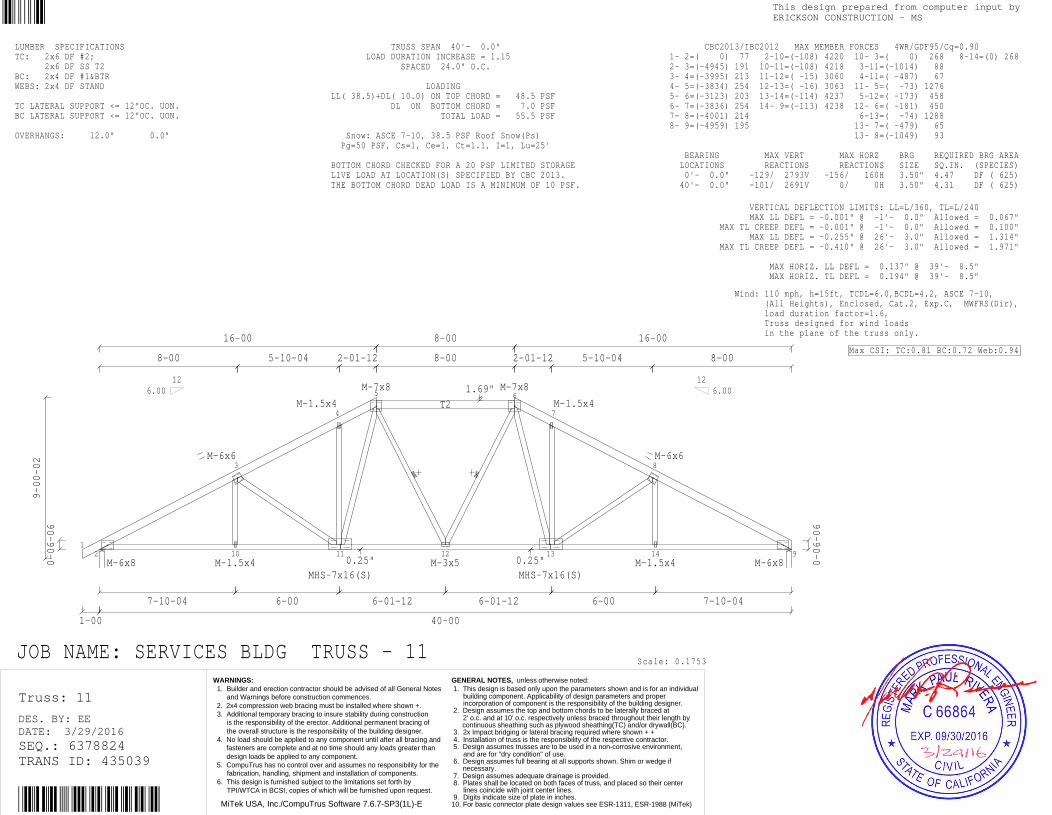
JOB NAME: SERVICES BLDG TRUSS - 11
LUMBER SPECIFICATIONSTC: 2x6 DF #2; 2x6 DF SS T2BC: 2x4 DF #1&BTRWEBS: 2x4 DF STAND TC LATERAL SUPPORT <= 12"OC. UON.BC LATERAL SUPPORT <= 12"OC. UON. OVERHANGS: 12.0" 0.0"
TRUSS SPAN 40'- 0.0" LOAD DURATION INCREASE = 1.15 SPACED 24.0" O.C. LOADINGLL( 38.5)+DL( 10.0) ON TOP CHORD = 48.5 PSF DL ON BOTTOM CHORD = 7.0 PSF TOTAL LOAD = 55.5 PSF Snow: ASCE 7-10, 38.5 PSF Roof Snow(Ps) Pg=50 PSF, Cs=1, Ce=1, Ct=1.1, I=1, Lu=25' BOTTOM CHORD CHECKED FOR A 20 PSF LIMITED STORAGELIVE LOAD AT LOCATION(S) SPECIFIED BY CBC 2013.THE BOTTOM CHORD DEAD LOAD IS A MINIMUM OF 10 PSF.
Scale: 0.1753
VERTICAL DEFLECTION LIMITS: LL=L/360, TL=L/240 MAX LL DEFL = -0.001" @ -1'- 0.0" Allowed = 0.067" MAX TL CREEP DEFL = -0.001" @ -1'- 0.0" Allowed = 0.100" MAX LL DEFL = -0.255" @ 26'- 3.0" Allowed = 1.314" MAX TL CREEP DEFL = -0.410" @ 26'- 3.0" Allowed = 1.971" MAX HORIZ. LL DEFL = 0.137" @ 39'- 8.5" MAX HORIZ. TL DEFL = 0.194" @ 39'- 8.5"
CBC2013/IBC2012 MAX MEMBER FORCES 4WR/GDF95/Cq=0.90 1- 2=( 0) 77 2-10=(-108) 4220 10- 3=( 0) 268 8-14=(0) 268 2- 3=(-4945) 191 10-11=(-108) 4218 3-11=(-1014) 88 3- 4=(-3995) 213 11-12=( -15) 3060 4-11=( -487) 67 4- 5=(-3834) 254 12-13=( -16) 3063 11- 5=( -73) 1276 5- 6=(-3123) 203 13-14=(-114) 4237 5-12=( -173) 458 6- 7=(-3836) 254 14- 9=(-113) 4238 12- 6=( -181) 450 7- 8=(-4001) 214 6-13=( -74) 1288 8- 9=(-4959) 195 13- 7=( -479) 65 13- 8=(-1049) 93 BEARING MAX VERT MAX HORZ BRG REQUIRED BRG AREA LOCATIONS REACTIONS REACTIONS SIZE SQ.IN. (SPECIES) 0'- 0.0" -129/ 2793V -156/ 160H 3.50" 4.47 DF ( 625) 40'- 0.0" -101/ 2691V 0/ 0H 3.50" 4.31 DF ( 625)
Wind: 110 mph, h=15ft, TCDL=6.0,BCDL=4.2, ASCE 7-10, (All Heights), Enclosed, Cat.2, Exp.C, MWFRS(Dir), load duration factor=1.6, Truss designed for wind loads in the plane of the truss only.
Max CSI: TC:0.81 BC:0.72 Web:0.94
Truss: 11
DATE: 3/29/2016DES. BY: EE
SEQ.: 6378824TRANS ID: 435039
MiTek USA, Inc./CompuTrus Software 7.6.7-SP3(1L)-E
This design prepared from computer input byERICKSON CONSTRUCTION - MS
WARNINGS: 1. Builder and erection contractor should be advised of all General Notes and Warnings before construction commences. 2. 2x4 compression web bracing must be installed where shown +. 3. Additional temporary bracing to insure stability during construction is the responsibility of the erector. Additional permanent bracing of the overall structure is the responsibility of the building designer. 4. No load should be applied to any component until after all bracing and fasteners are complete and at no time should any loads greater than design loads be applied to any component. 5. CompuTrus has no control over and assumes no responsibility for the fabrication, handling, shipment and installation of components. 6. This design is furnished subject to the limitations set forth by TPI/WTCA in BCSI, copies of which will be furnished upon request.
GENERAL NOTES, unless otherwise noted: 1. This design is based only upon the parameters shown and is for an individual building component. Applicability of design parameters and proper incorporation of component is the responsibility of the building designer. 2. Design assumes the top and bottom chords to be laterally braced at 2' o.c. and at 10' o.c. respectively unless braced throughout their length by continuous sheathing such as plywood sheathing(TC) and/or drywall(BC). 3. 2x Impact bridging or lateral bracing required where shown + + 4. Installation of truss is the responsibility of the respective contractor. 5. Design assumes trusses are to be used in a non-corrosive environment, and are for "dry condition" of use. 6. Design assumes full bearing at all supports shown. Shim or wedge if necessary. 7. Design assumes adequate drainage is provided. 8. Plates shall be located on both faces of truss, and placed so their center lines coincide with joint center lines. 9. Digits indicate size of plate in inches.10. For basic connector plate design values see ESR-1311, ESR-1988 (MiTek)

12 10
3
11
4
12
5 6
13 14
7
15
8
9M-6x8
M-7x8(S)
M-1.5x4
M-3x5
MHS-6x14(S)M-4x6
M-7x8 M-7x8
M-4x6MHS-6x14(S)
M-3x5
M-1.5x4
M-7x8(S)
M-6x8
10-00-02
0-06-06
1-00
7-10-04
8-00
0.25"
18-00
5-10-04
6-00
0.25"
4-00
4-00
1.69"
4-00
4-00
4-00
4-07
40-00
8-07-11
4-00
4-00
0.25"
6-00
5-10-04
18-00
0.25"
8-00
7-10-04
0-06-06
6.0012 12
6.00
JOB NAME: SERVICES BLDG TRUSS - 12
Unbalanced live loads have been considered for this design.
LUMBER SPECIFICATIONSTC: 2x6 DF #2BC: 2x4 DF #1&BTRWEBS: 2x4 DF STAND TC LATERAL SUPPORT <= 12"OC. UON.BC LATERAL SUPPORT <= 12"OC. UON. OVERHANGS: 12.0" 0.0"
TRUSS SPAN 40'- 0.0" LOAD DURATION INCREASE = 1.15 SPACED 24.0" O.C. LOADINGLL( 38.5)+DL( 10.0) ON TOP CHORD = 48.5 PSF DL ON BOTTOM CHORD = 7.0 PSF TOTAL LOAD = 55.5 PSF Snow: ASCE 7-10, 38.5 PSF Roof Snow(Ps) Pg=50 PSF, Cs=1, Ce=1, Ct=1.1, I=1, Lu=25' BOTTOM CHORD CHECKED FOR A 20 PSF LIMITED STORAGELIVE LOAD AT LOCATION(S) SPECIFIED BY CBC 2013.THE BOTTOM CHORD DEAD LOAD IS A MINIMUM OF 10 PSF.
Scale: 0.1627
VERTICAL DEFLECTION LIMITS: LL=L/360, TL=L/240 MAX LL DEFL = -0.001" @ -1'- 0.0" Allowed = 0.067" MAX TL CREEP DEFL = -0.001" @ -1'- 0.0" Allowed = 0.100" MAX LL DEFL = -0.299" @ 22'- 3.5" Allowed = 1.314" MAX TL CREEP DEFL = -0.460" @ 22'- 3.5" Allowed = 1.971" MAX HORIZ. LL DEFL = 0.146" @ 39'- 8.5" MAX HORIZ. TL DEFL = 0.203" @ 39'- 8.5"
CBC2013/IBC2012 MAX MEMBER FORCES 4WR/GDF95/Cq=0.90 1- 2=( 0) 77 2-10=(-109) 4356 3-10=( 0) 275 15- 8=(0) 275 2- 3=(-5093) 192 10-11=(-108) 4360 3-11=( -909) 83 3- 4=(-4224) 214 11-12=( -38) 3599 4-11=( -9) 610 4- 5=(-3556) 230 12-13=( 0) 3035 4-12=(-1302) 88 5- 6=(-3035) 220 13-14=( -38) 3602 12- 5=( -43) 1207 6- 7=(-3557) 230 14-15=(-113) 4379 6-13=( -44) 1202 7- 8=(-4230) 216 15- 9=(-115) 4375 13- 7=(-1297) 90 8- 9=(-5108) 196 14- 7=( -12) 622 14- 8=( -928) 89 BEARING MAX VERT MAX HORZ BRG REQUIRED BRG AREA LOCATIONS REACTIONS REACTIONS SIZE SQ.IN. (SPECIES) 0'- 0.0" -129/ 2851V -175/ 179H 3.50" 4.56 DF ( 625) 40'- 0.0" -101/ 2749V 0/ 0H 3.50" 4.40 DF ( 625)
Wind: 110 mph, h=15ft, TCDL=6.0,BCDL=4.2, ASCE 7-10, (All Heights), Enclosed, Cat.2, Exp.C, MWFRS(Dir), load duration factor=1.6, Truss designed for wind loads in the plane of the truss only.
Max CSI: TC:0.77 BC:0.73 Web:0.99
Truss: 12
DATE: 3/29/2016DES. BY: EE
SEQ.: 6378825TRANS ID: 435039
MiTek USA, Inc./CompuTrus Software 7.6.7-SP3(1L)-E
This design prepared from computer input byERICKSON CONSTRUCTION - MS
WARNINGS: 1. Builder and erection contractor should be advised of all General Notes and Warnings before construction commences. 2. 2x4 compression web bracing must be installed where shown +. 3. Additional temporary bracing to insure stability during construction is the responsibility of the erector. Additional permanent bracing of the overall structure is the responsibility of the building designer. 4. No load should be applied to any component until after all bracing and fasteners are complete and at no time should any loads greater than design loads be applied to any component. 5. CompuTrus has no control over and assumes no responsibility for the fabrication, handling, shipment and installation of components. 6. This design is furnished subject to the limitations set forth by TPI/WTCA in BCSI, copies of which will be furnished upon request.
GENERAL NOTES, unless otherwise noted: 1. This design is based only upon the parameters shown and is for an individual building component. Applicability of design parameters and proper incorporation of component is the responsibility of the building designer. 2. Design assumes the top and bottom chords to be laterally braced at 2' o.c. and at 10' o.c. respectively unless braced throughout their length by continuous sheathing such as plywood sheathing(TC) and/or drywall(BC). 3. 2x Impact bridging or lateral bracing required where shown + + 4. Installation of truss is the responsibility of the respective contractor. 5. Design assumes trusses are to be used in a non-corrosive environment, and are for "dry condition" of use. 6. Design assumes full bearing at all supports shown. Shim or wedge if necessary. 7. Design assumes adequate drainage is provided. 8. Plates shall be located on both faces of truss, and placed so their center lines coincide with joint center lines. 9. Digits indicate size of plate in inches.10. For basic connector plate design values see ESR-1311, ESR-1988 (MiTek)

12
3
9 10
4
5
11 12
6
13
7
8M-4x10
M-7x8(S)
M-1.5x4
M-6x6
M-7x8(S)
M-4x8
M-4x8
M-7x8(S)
M-6x6
M-1.5x4
M-7x8(S)
M-6x8
11-00-02
0-06-06
1-00
7-10-04
8-00
0.25"
20-00
5-10-04
5-10-04
0.25"
6-03-08
6-01-12
4.0"
40-00
2.9"
6-01-12
6-03-08
0.25"
5-10-04
5-10-04
20-00
0.25"
8-00
7-10-04
0-06-06
6.0012 12
6.00
JOB NAME: SERVICES BLDG TRUSS - 13
LUMBER SPECIFICATIONSTC: 2x6 DF #2BC: 2x4 DF #1&BTRWEBS: 2x4 DF STAND TC LATERAL SUPPORT <= 12"OC. UON.BC LATERAL SUPPORT <= 12"OC. UON. OVERHANGS: 12.0" 0.0"
TRUSS SPAN 40'- 0.0" LOAD DURATION INCREASE = 1.15 SPACED 24.0" O.C. LOADINGLL( 38.5)+DL( 10.0) ON TOP CHORD = 48.5 PSF DL ON BOTTOM CHORD = 7.0 PSF TOTAL LOAD = 55.5 PSF Snow: ASCE 7-10, 38.5 PSF Roof Snow(Ps) Pg=50 PSF, Cs=1, Ce=1, Ct=1.1, I=1 BOTTOM CHORD CHECKED FOR A 20 PSF LIMITED STORAGELIVE LOAD AT LOCATION(S) SPECIFIED BY CBC 2013.THE BOTTOM CHORD DEAD LOAD IS A MINIMUM OF 10 PSF.
Scale: 0.1501
VERTICAL DEFLECTION LIMITS: LL=L/360, TL=L/240 MAX LL DEFL = -0.001" @ -1'- 0.0" Allowed = 0.067" MAX TL CREEP DEFL = -0.001" @ -1'- 0.0" Allowed = 0.100" MAX LL DEFL = -0.218" @ 26'- 1.0" Allowed = 1.314" MAX TL CREEP DEFL = -0.383" @ 26'- 1.0" Allowed = 1.971" MAX HORIZ. LL DEFL = 0.112" @ 39'- 8.5" MAX HORIZ. TL DEFL = 0.161" @ 39'- 8.5"
CBC2013/IBC2012 MAX MEMBER FORCES 4WR/GDF95/Cq=0.90 1- 2=( 0) 77 2- 9=(-109) 3633 3- 9=( 0) 269 13- 7=(0) 268 2- 3=(-4278) 192 9-10=(-108) 3636 3-10=( -735) 78 3- 4=(-3517) 216 10-11=( -42) 3033 4-10=( 0) 590 4- 5=(-2649) 222 11-12=( -43) 3064 4-11=(-1334) 113 5- 6=(-2672) 222 12-13=(-113) 3683 11- 5=( -119) 1682 6- 7=(-3555) 218 13- 8=(-114) 3680 11- 6=(-1355) 115 7- 8=(-4324) 196 12- 6=( 0) 599 12- 7=( -740) 83 BEARING MAX VERT MAX HORZ BRG REQUIRED BRG AREA LOCATIONS REACTIONS REACTIONS SIZE SQ.IN. (SPECIES) 0'- 0.0" -129/ 2475V -195/ 199H 3.50" 3.96 DF ( 625) 40'- 0.0" -101/ 2389V 0/ 0H 3.50" 3.82 DF ( 625)
Wind: 110 mph, h=15ft, TCDL=6.0,BCDL=4.2, ASCE 7-10, (All Heights), Enclosed, Cat.2, Exp.C, MWFRS(Dir), load duration factor=1.6, Truss designed for wind loads in the plane of the truss only.
Max CSI: TC:0.79 BC:0.64 Web:0.74
Truss: 13
DATE: 3/29/2016DES. BY: EE
SEQ.: 6378826TRANS ID: 435039
MiTek USA, Inc./CompuTrus Software 7.6.7-SP3(1L)-E
This design prepared from computer input byERICKSON CONSTRUCTION - MS
WARNINGS: 1. Builder and erection contractor should be advised of all General Notes and Warnings before construction commences. 2. 2x4 compression web bracing must be installed where shown +. 3. Additional temporary bracing to insure stability during construction is the responsibility of the erector. Additional permanent bracing of the overall structure is the responsibility of the building designer. 4. No load should be applied to any component until after all bracing and fasteners are complete and at no time should any loads greater than design loads be applied to any component. 5. CompuTrus has no control over and assumes no responsibility for the fabrication, handling, shipment and installation of components. 6. This design is furnished subject to the limitations set forth by TPI/WTCA in BCSI, copies of which will be furnished upon request.
GENERAL NOTES, unless otherwise noted: 1. This design is based only upon the parameters shown and is for an individual building component. Applicability of design parameters and proper incorporation of component is the responsibility of the building designer. 2. Design assumes the top and bottom chords to be laterally braced at 2' o.c. and at 10' o.c. respectively unless braced throughout their length by continuous sheathing such as plywood sheathing(TC) and/or drywall(BC). 3. 2x Impact bridging or lateral bracing required where shown + + 4. Installation of truss is the responsibility of the respective contractor. 5. Design assumes trusses are to be used in a non-corrosive environment, and are for "dry condition" of use. 6. Design assumes full bearing at all supports shown. Shim or wedge if necessary. 7. Design assumes adequate drainage is provided. 8. Plates shall be located on both faces of truss, and placed so their center lines coincide with joint center lines. 9. Digits indicate size of plate in inches.10. For basic connector plate design values see ESR-1311, ESR-1988 (MiTek)
1
2
6
3
***
A
7
4
5
8MHS-6x14
M-3x6
M-3x8
M-7x8
M-4x12 M-7x12
M-2x4
7-11-10
0-06-06
1-00
5-03-07
5-03-07
5"
2-05-01
2-06-13
13-11
6-02-08
6-00-12
7-05-14
6.0012
2834#
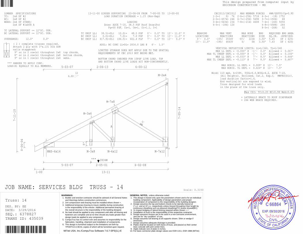
JOB NAME: SERVICES BLDG TRUSS - 14
LUMBER SPECIFICATIONSTC: 2x6 DF #2BC: 2x8 DF #2WEBS: 2x4 DF STAND; 2x4 DF #1&BTR A TC LATERAL SUPPORT <= 12"OC. UON.BC LATERAL SUPPORT <= 12"OC. UON. OVERHANGS: 12.0" 0.0"
*** HANGER TO APPLY CONC.LOAD(S) EQUALLY TO ALL MEMBERS.
( 2 ) complete trusses required.Attach 2 ply with 3"x.131 DIA GUNnails staggered: 9" oc in 2 row(s) throughout 2x6 top chords, 8" oc in 2 row(s) throughout 2x8 bottom chords, 9" oc in 1 row(s) throughout 2x4 webs.
13-11-00 GIRDER SUPPORTING 23-08-08 FROM 7-00-00 TO 13-00-00 LOAD DURATION INCREASE = 1.15 (Non-Rep) LOADING Snow: ASCE 7-10, 38.5 PSF Roof Snow(Ps) Pg=50 PSF, Cs=1, Ce=1, Ct=1.1, I=1 TC UNIF LL( 38.5)+DL( 10.0)= 48.5 PSF 0'- 0.0" TO 13'- 11.0" VBC UNIF LL( 0.0)+DL( 7.0)= 7.0 PSF 0'- 0.0" TO 13'- 11.0" VBC UNIF LL( 417.9)+DL( 184.5)= 602.4 PLF 7'- 0.0" TO 13'- 0.0" V ADDL: BC CONC LL+DL= 2834.0 LBS @ 6'- 1.5" LIMITED STORAGE DOES NOT APPLY DUE TO THE SPATIAL REQUIREMENTS OF CBC 2013 NOT BEING MET. BOTTOM CHORD CHECKED FOR 10PSF LIVE LOAD. TOP AND BOTTOM CHORD LIVE LOADS ACT NON-CONCURRENTLY.
Scale: 0.3150
VERTICAL DEFLECTION LIMITS: LL=L/360, TL=L/240 MAX LL DEFL = -0.000" @ -1'- 0.0" Allowed = 0.067" MAX TL CREEP DEFL = -0.000" @ -1'- 0.0" Allowed = 0.100" MAX LL DEFL = -0.033" @ 7'- 8.5" Allowed = 0.444" MAX TL CREEP DEFL = -0.113" @ 7'- 8.5" Allowed = 0.667" MAX HORIZ. LL DEFL = 0.009" @ 13'- 7.5" MAX HORIZ. TL DEFL = 0.024" @ 13'- 7.5"
CBC2013/IBC2012 MAX MEMBER FORCES 4WR/GDF95/Cq=0.90 1-2=( 0) 76 2-6=(-256) 5718 6-3=( -18) 1752 2-3=(-6574) 246 6-7=(-256) 5698 3-7=(-1506) 68 3-4=(-5434) 234 7-8=(-214) 4608 7-4=( -160) 5050 4-5=( -186) 120 4-8=(-5588) 264 8-5=( -268) 52 BEARING MAX VERT MAX HORZ BRG REQUIRED BRG AREA LOCATIONS REACTIONS REACTIONS SIZE SQ.IN. (SPECIES) 0'- 0.0" -155/ 3534V -87/ 223H 3.50" 5.65 DF ( 625) 13'- 11.0" -190/ 4643V 0/ 0H 3.50" 7.43 DF ( 625)
Wind: 110 mph, h=15ft, TCDL=6.0,BCDL=4.2, ASCE 7-10, (All Heights), Enclosed, Cat.2, Exp.C, MWFRS(Dir), load duration factor=1.6, End vertical(s) are exposed to wind, Truss designed for wind loads in the plane of the truss only.
+ LATERALLY BRACE TO ROOF DIAPHRAGM+ 2X4 WEB BRACE REQUIRED.
Max CSI: TC:0.25 BC:0.98 Web:0.67
Truss: 14
DATE: 3/29/2016DES. BY: EE
SEQ.: 6378827TRANS ID: 435039
MiTek USA, Inc./CompuTrus Software 7.6.7-SP3(1L)-E
This design prepared from computer input byERICKSON CONSTRUCTION - MS
WARNINGS: 1. Builder and erection contractor should be advised of all General Notes and Warnings before construction commences. 2. 2x4 compression web bracing must be installed where shown +. 3. Additional temporary bracing to insure stability during construction is the responsibility of the erector. Additional permanent bracing of the overall structure is the responsibility of the building designer. 4. No load should be applied to any component until after all bracing and fasteners are complete and at no time should any loads greater than design loads be applied to any component. 5. CompuTrus has no control over and assumes no responsibility for the fabrication, handling, shipment and installation of components. 6. This design is furnished subject to the limitations set forth by TPI/WTCA in BCSI, copies of which will be furnished upon request.
GENERAL NOTES, unless otherwise noted: 1. This design is based only upon the parameters shown and is for an individual building component. Applicability of design parameters and proper incorporation of component is the responsibility of the building designer. 2. Design assumes the top and bottom chords to be laterally braced at 2' o.c. and at 10' o.c. respectively unless braced throughout their length by continuous sheathing such as plywood sheathing(TC) and/or drywall(BC). 3. 2x Impact bridging or lateral bracing required where shown + + 4. Installation of truss is the responsibility of the respective contractor. 5. Design assumes trusses are to be used in a non-corrosive environment, and are for "dry condition" of use. 6. Design assumes full bearing at all supports shown. Shim or wedge if necessary. 7. Design assumes adequate drainage is provided. 8. Plates shall be located on both faces of truss, and placed so their center lines coincide with joint center lines. 9. Digits indicate size of plate in inches.10. For basic connector plate design values see ESR-1311, ESR-1988 (MiTek)

12
12
3 4
13
5
14 15
6
16
7
17
8
18
9
19
10
11
M-3x10 M-3x8
M-7x8 M-3x8
M-7x8(S)
M-7x8(S)
M-1.5x4
M-7x8(S)
M-3x8
M-3x8
M-7x8
M-3x10
4-00-02
0-06-06
1-00
6-00
6-00
6-00
3-08-08
4-00
4-00
4-00
0.25"
4-01-12
3-10-04
0.25"
4-01-12
28-00
40-00
4-05-04
4-00
4-00
0.25"
4-00
4-00
1.31"
4-00
3-08-08
6-00
6-00
6-00
0-06-06
6.0012 12
6.00
485# 485#
JOB NAME: SERVICES BLDG TRUSS - 16
M-3x5 where shown; Jts:5,7-8,13,16,18
LUMBER SPECIFICATIONSTC: 2x6 DF #2BC: 2x6 DF #2WEBS: 2x4 DF STAND TC LATERAL SUPPORT <= 12"OC. UON.BC LATERAL SUPPORT <= 12"OC. UON. OVERHANGS: 12.0" 0.0"
( 3 ) complete trusses required.Attach 3 ply with 3"x.131 DIA GUNnails staggered: 9" oc in 2 row(s) throughout 2x6 top chords, 9" oc in 2 row(s) throughout 2x6 bottom chords, 9" oc in 1 row(s) throughout 2x4 webs.
40-00-00 HIP EB SETBACK 6-00-00 FROM END WALL LOAD DURATION INCREASE = 1.15 (Non-Rep) LOADING Snow: ASCE 7-10, 38.5 PSF Roof Snow(Ps) Pg=50 PSF, Cs=1, Ce=1, Ct=1.1, I=1, Lu=25' TC UNIF LL( 38.5)+DL( 10.0)= 48.5 PSF 0'- 0.0" TO 40'- 0.0" VBC UNIF LL( 0.0)+DL( 7.0)= 7.0 PSF 0'- 0.0" TO 40'- 0.0" VBC UNIF LL( 0.0)+DL( 14.0)= 14.0 PLF 0'- 0.0" TO 6'- 0.0" VBC UNIF LL( 77.0)+DL( 34.0)= 111.0 PLF 6'- 0.0" TO 34'- 0.0" VBC UNIF LL( 0.0)+DL( 14.0)= 14.0 PLF 34'- 0.0" TO 40'- 0.0" V TC CONC LL( 385.0)+DL( 100.0)= 485.0 LBS @ 6'- 0.0" TC CONC LL( 385.0)+DL( 100.0)= 485.0 LBS @ 34'- 0.0" LIMITED STORAGE DOES NOT APPLY DUE TO THE SPATIAL REQUIREMENTS OF CBC 2013 NOT BEING MET. BOTTOM CHORD CHECKED FOR 10PSF LIVE LOAD. TOP AND BOTTOM CHORD LIVE LOADS ACT NON-CONCURRENTLY.
VERTICAL DEFLECTION LIMITS: LL=L/360, TL=L/240 MAX LL DEFL = -0.000" @ -1'- 0.0" Allowed = 0.067" MAX TL CREEP DEFL = -0.000" @ -1'- 0.0" Allowed = 0.100" MAX LL DEFL = -0.457" @ 22'- 0.0" Allowed = 1.314" MAX TL CREEP DEFL = -0.721" @ 22'- 0.0" Allowed = 1.971" MAX HORIZ. LL DEFL = 0.109" @ 39'- 8.5" MAX HORIZ. TL DEFL = 0.151" @ 39'- 8.5"
CBC2013/IBC2012 MAX MEMBER FORCES 4WR/GDF95/Cq=0.90 1- 2=( 0) 75 2-12=(-285) 8028 12- 3=( -57) 3456 8-18=(-3204) 123 2- 3=( -9132) 381 12-13=(-450) 11940 12- 4=(-5004) 213 18- 9=( -72) 2514 3- 4=( -8031) 360 13-14=(-549) 14694 4-13=( -75) 2517 9-19=(-5004) 210 4- 5=(-12186) 528 14-15=(-606) 16059 13- 5=(-3210) 126 19-10=( -57) 3456 5- 6=(-14796) 624 15-16=(-606) 16062 5-14=( -24) 1440 6- 7=(-16077) 678 16-17=(-606) 16026 14- 6=(-1581) 72 7- 8=(-14799) 627 17-18=(-552) 14697 6-15=( 0) 498 8- 9=(-12192) 534 18-19=(-453) 11946 6-16=( -42) 96 9-10=( -8040) 366 19-11=(-291) 8037 16- 7=( 0) 549 10-11=( -9141) 387 7-17=(-1557) 72 17- 8=( -24) 1449 BEARING MAX VERT MAX HORZ BRG REQUIRED BRG AREA LOCATIONS REACTIONS REACTIONS SIZE SQ.IN. (SPECIES) 0'- 0.0" -200/ 4521V -59/ 63H 3.50" 7.23 DF ( 625) 40'- 0.0" -172/ 4456V 0/ 0H 3.50" 7.13 DF ( 625)
Scale: 0.1070
Wind: 110 mph, h=15ft, TCDL=6.0,BCDL=4.2, ASCE 7-10, (All Heights), Enclosed, Cat.2, Exp.C, MWFRS(Dir), load duration factor=1.6, Truss designed for wind loads in the plane of the truss only.
Max CSI: TC:0.28 BC:0.88 Web:0.67
Truss: 16
DATE: 3/29/2016DES. BY: EE
SEQ.: 6378828TRANS ID: 435039
MiTek USA, Inc./CompuTrus Software 7.6.7-SP3(1L)-E
This design prepared from computer input byERICKSON CONSTRUCTION - MS
WARNINGS: 1. Builder and erection contractor should be advised of all General Notes and Warnings before construction commences. 2. 2x4 compression web bracing must be installed where shown +. 3. Additional temporary bracing to insure stability during construction is the responsibility of the erector. Additional permanent bracing of the overall structure is the responsibility of the building designer. 4. No load should be applied to any component until after all bracing and fasteners are complete and at no time should any loads greater than design loads be applied to any component. 5. CompuTrus has no control over and assumes no responsibility for the fabrication, handling, shipment and installation of components. 6. This design is furnished subject to the limitations set forth by TPI/WTCA in BCSI, copies of which will be furnished upon request.
GENERAL NOTES, unless otherwise noted: 1. This design is based only upon the parameters shown and is for an individual building component. Applicability of design parameters and proper incorporation of component is the responsibility of the building designer. 2. Design assumes the top and bottom chords to be laterally braced at 2' o.c. and at 10' o.c. respectively unless braced throughout their length by continuous sheathing such as plywood sheathing(TC) and/or drywall(BC). 3. 2x Impact bridging or lateral bracing required where shown + + 4. Installation of truss is the responsibility of the respective contractor. 5. Design assumes trusses are to be used in a non-corrosive environment, and are for "dry condition" of use. 6. Design assumes full bearing at all supports shown. Shim or wedge if necessary. 7. Design assumes adequate drainage is provided. 8. Plates shall be located on both faces of truss, and placed so their center lines coincide with joint center lines. 9. Digits indicate size of plate in inches.10. For basic connector plate design values see ESR-1311, ESR-1988 (MiTek)

1
2
3
12
4 5
13 14
6
15
7
16
8 9
17
10
11
M-4x10
M-1.5x4
M-6x12
M-7x8 M-4x8
M-8x8(S)
M-7x8(S)
M-1.5x4 M-3x5
M-3x5
M-8x8(S)
M-4x8 M-7x8
M-6x12
M-1.5x4
M-4x10
5-00-02
0-06-06
1-00
5-05-03
7-10-04
8-00
2-06-13 5-08-08
6-01-12
0.25"
4-01-12
3-10-04
0.25"
4-01-12
24-00
40-00
4-05-04
4-00
4-00
0.25"
6-01-12
5-08-08
1.69"
2-06-13
8-00
7-10-04
5-05-03
0-06-06
6.0012 12
6.00
JOB NAME: SERVICES BLDG TRUSS - 17
JT 2, 11: Heel to plate corner = 0.75"
LUMBER SPECIFICATIONSTC: 2x6 DF #2BC: 2x6 DF #2WEBS: 2x4 DF STAND TC LATERAL SUPPORT <= 12"OC. UON.BC LATERAL SUPPORT <= 12"OC. UON. OVERHANGS: 12.0" 0.0"
TRUSS SPAN 40'- 0.0" LOAD DURATION INCREASE = 1.15 SPACED 24.0" O.C. LOADINGLL( 38.5)+DL( 10.0) ON TOP CHORD = 48.5 PSF DL ON BOTTOM CHORD = 7.0 PSF TOTAL LOAD = 55.5 PSF Snow: ASCE 7-10, 38.5 PSF Roof Snow(Ps) Pg=50 PSF, Cs=1, Ce=1, Ct=1.1, I=1, Lu=25' LIMITED STORAGE DOES NOT APPLY DUE TO THE SPATIALREQUIREMENTS OF CBC 2013 NOT BEING MET. BOTTOM CHORD CHECKED FOR 10PSF LIVE LOAD. TOPAND BOTTOM CHORD LIVE LOADS ACT NON-CONCURRENTLY.
Scale: 0.2007
VERTICAL DEFLECTION LIMITS: LL=L/360, TL=L/240 MAX LL DEFL = -0.001" @ -1'- 0.0" Allowed = 0.067" MAX TL CREEP DEFL = -0.001" @ -1'- 0.0" Allowed = 0.100" MAX LL DEFL = -0.471" @ 22'- 0.0" Allowed = 1.314" MAX TL CREEP DEFL = -0.721" @ 22'- 0.0" Allowed = 1.971" MAX HORIZ. LL DEFL = 0.139" @ 39'- 8.5" MAX HORIZ. TL DEFL = 0.188" @ 39'- 8.5"
CBC2013/IBC2012 MAX MEMBER FORCES 4WR/GDF95/Cq=0.90 1- 2=( 0) 77 2-12=(-137) 3781 3-12=( -450) 92 9-17=( -49) 1465 2- 3=(-4354) 204 12-13=(-172) 5885 12- 4=( -44) 1459 17-10=(-493) 82 3- 4=(-4278) 199 13-14=(-191) 6453 12- 5=(-2523) 116 4- 5=(-3795) 184 14-15=(-191) 6454 5-13=( 0) 587 5- 6=(-5916) 270 15-16=(-192) 6443 13- 6=( -761) 38 6- 7=(-6448) 288 16-17=(-175) 5887 6-14=( 0) 132 7- 8=(-5918) 272 17-11=(-147) 3795 6-15=( -107) 110 8- 9=(-3801) 188 15- 7=( -18) 137 9-10=(-4286) 205 7-16=( -756) 38 10-11=(-4366) 212 16- 8=( 0) 592 8-17=(-2518) 115 BEARING MAX VERT MAX HORZ BRG REQUIRED BRG AREA LOCATIONS REACTIONS REACTIONS SIZE SQ.IN. (SPECIES) 0'- 0.0" -128/ 2398V -78/ 82H 3.50" 3.84 DF ( 625) 40'- 0.0" -100/ 2225V 0/ 0H 3.50" 3.56 DF ( 625)
Wind: 110 mph, h=15ft, TCDL=6.0,BCDL=4.2, ASCE 7-10, (All Heights), Enclosed, Cat.2, Exp.C, MWFRS(Dir), load duration factor=1.6, Truss designed for wind loads in the plane of the truss only.
Max CSI: TC:0.51 BC:0.92 Web:0.95
Truss: 17
DATE: 3/29/2016DES. BY: EE
SEQ.: 6378829TRANS ID: 435039
MiTek USA, Inc./CompuTrus Software 7.6.7-SP3(1L)-E
This design prepared from computer input byERICKSON CONSTRUCTION - MS
WARNINGS: 1. Builder and erection contractor should be advised of all General Notes and Warnings before construction commences. 2. 2x4 compression web bracing must be installed where shown +. 3. Additional temporary bracing to insure stability during construction is the responsibility of the erector. Additional permanent bracing of the overall structure is the responsibility of the building designer. 4. No load should be applied to any component until after all bracing and fasteners are complete and at no time should any loads greater than design loads be applied to any component. 5. CompuTrus has no control over and assumes no responsibility for the fabrication, handling, shipment and installation of components. 6. This design is furnished subject to the limitations set forth by TPI/WTCA in BCSI, copies of which will be furnished upon request.
GENERAL NOTES, unless otherwise noted: 1. This design is based only upon the parameters shown and is for an individual building component. Applicability of design parameters and proper incorporation of component is the responsibility of the building designer. 2. Design assumes the top and bottom chords to be laterally braced at 2' o.c. and at 10' o.c. respectively unless braced throughout their length by continuous sheathing such as plywood sheathing(TC) and/or drywall(BC). 3. 2x Impact bridging or lateral bracing required where shown + + 4. Installation of truss is the responsibility of the respective contractor. 5. Design assumes trusses are to be used in a non-corrosive environment, and are for "dry condition" of use. 6. Design assumes full bearing at all supports shown. Shim or wedge if necessary. 7. Design assumes adequate drainage is provided. 8. Plates shall be located on both faces of truss, and placed so their center lines coincide with joint center lines. 9. Digits indicate size of plate in inches.10. For basic connector plate design values see ESR-1311, ESR-1988 (MiTek)

12
3
12
4
13
5 6
14
7
15
8 9
16
10
11M-4x10
M-1.5x4
M-3x5
M-7x8 M-1.5x4
MHS-7x16(S)
M-3x5
M-3x5
M-3x5
MHS-7x16(S)
M-1.5x4 M-7x8
M-3x5
M-1.5x4
M-4x10
6-00-02
0-06-06
1-00
5-06-03
8-00
10-00
4-05-13
5-10-04
3-10-04
0.25"
4-01-12
8-01-12
20-00
40-00
4-03-08
4-01-12
3-10-04
0.25"
1.69"
3-10-04
5-10-04
4-05-13
10-00
8-00
5-06-03
0-06-06
6.0012 12
6.00
JOB NAME: SERVICES BLDG TRUSS - 18
JT 2, 11: Heel to plate corner = 0.75"
LUMBER SPECIFICATIONSTC: 2x6 DF #2BC: 2x4 DF #1&BTRWEBS: 2x4 DF STAND TC LATERAL SUPPORT <= 12"OC. UON.BC LATERAL SUPPORT <= 12"OC. UON. OVERHANGS: 12.0" 0.0"
TRUSS SPAN 40'- 0.0" LOAD DURATION INCREASE = 1.15 SPACED 24.0" O.C. LOADINGLL( 38.5)+DL( 10.0) ON TOP CHORD = 48.5 PSF DL ON BOTTOM CHORD = 7.0 PSF TOTAL LOAD = 55.5 PSF Snow: ASCE 7-10, 38.5 PSF Roof Snow(Ps) Pg=50 PSF, Cs=1, Ce=1, Ct=1.1, I=1, Lu=25' LIMITED STORAGE DOES NOT APPLY DUE TO THE SPATIALREQUIREMENTS OF CBC 2013 NOT BEING MET. BOTTOM CHORD CHECKED FOR 10PSF LIVE LOAD. TOPAND BOTTOM CHORD LIVE LOADS ACT NON-CONCURRENTLY.
Scale: 0.1882
VERTICAL DEFLECTION LIMITS: LL=L/360, TL=L/240 MAX LL DEFL = -0.001" @ -1'- 0.0" Allowed = 0.067" MAX TL CREEP DEFL = -0.001" @ -1'- 0.0" Allowed = 0.100" MAX LL DEFL = -0.350" @ 18'- 0.0" Allowed = 1.314" MAX TL CREEP DEFL = -0.547" @ 18'- 0.0" Allowed = 1.971" MAX HORIZ. LL DEFL = 0.141" @ 39'- 8.5" MAX HORIZ. TL DEFL = 0.196" @ 39'- 8.5"
CBC2013/IBC2012 MAX MEMBER FORCES 4WR/GDF95/Cq=0.90 1- 2=( 0) 77 2-12=(-139) 3466 3-12=(-552) 92 16-10=(-587) 99 2- 3=(-4069) 207 12-13=( -75) 3431 12- 4=( -4) 547 3- 4=(-3898) 208 13-14=(-137) 4943 4-13=( -65) 1697 4- 5=(-4474) 232 14-15=(-124) 4944 5-13=(-651) 60 5- 6=(-4460) 231 15-16=( -78) 3433 13- 6=(-765) 64 6- 7=(-4949) 246 16-11=(-146) 3471 6-14=(-119) 181 7- 8=(-4451) 237 14- 7=( -46) 188 8- 9=(-4464) 238 7-15=(-817) 35 9-10=(-3908) 212 15- 8=(-624) 57 10-11=(-4074) 212 15- 9=( -71) 1678 9-16=( -2) 585 BEARING MAX VERT MAX HORZ BRG REQUIRED BRG AREA LOCATIONS REACTIONS REACTIONS SIZE SQ.IN. (SPECIES) 0'- 0.0" -129/ 2398V -98/ 102H 3.50" 3.84 DF ( 625) 40'- 0.0" -101/ 2220V 0/ 0H 3.50" 3.55 DF ( 625)
Wind: 110 mph, h=15ft, TCDL=6.0,BCDL=4.2, ASCE 7-10, (All Heights), Enclosed, Cat.2, Exp.C, MWFRS(Dir), load duration factor=1.6, Truss designed for wind loads in the plane of the truss only.
Max CSI: TC:0.40 BC:0.73 Web:0.75
Truss: 18
DATE: 3/29/2016DES. BY: EE
SEQ.: 6378830TRANS ID: 435039
MiTek USA, Inc./CompuTrus Software 7.6.7-SP3(1L)-E
This design prepared from computer input byERICKSON CONSTRUCTION - MS
WARNINGS: 1. Builder and erection contractor should be advised of all General Notes and Warnings before construction commences. 2. 2x4 compression web bracing must be installed where shown +. 3. Additional temporary bracing to insure stability during construction is the responsibility of the erector. Additional permanent bracing of the overall structure is the responsibility of the building designer. 4. No load should be applied to any component until after all bracing and fasteners are complete and at no time should any loads greater than design loads be applied to any component. 5. CompuTrus has no control over and assumes no responsibility for the fabrication, handling, shipment and installation of components. 6. This design is furnished subject to the limitations set forth by TPI/WTCA in BCSI, copies of which will be furnished upon request.
GENERAL NOTES, unless otherwise noted: 1. This design is based only upon the parameters shown and is for an individual building component. Applicability of design parameters and proper incorporation of component is the responsibility of the building designer. 2. Design assumes the top and bottom chords to be laterally braced at 2' o.c. and at 10' o.c. respectively unless braced throughout their length by continuous sheathing such as plywood sheathing(TC) and/or drywall(BC). 3. 2x Impact bridging or lateral bracing required where shown + + 4. Installation of truss is the responsibility of the respective contractor. 5. Design assumes trusses are to be used in a non-corrosive environment, and are for "dry condition" of use. 6. Design assumes full bearing at all supports shown. Shim or wedge if necessary. 7. Design assumes adequate drainage is provided. 8. Plates shall be located on both faces of truss, and placed so their center lines coincide with joint center lines. 9. Digits indicate size of plate in inches.10. For basic connector plate design values see ESR-1311, ESR-1988 (MiTek)

12
T1
10
3
11
4 T2
5
12
T3
13
6
14
7
T4
89
M-4x10
M-7x8(S)
M-3x8
M-1.5x4
M-1.5x4
M-3x5+
M-3x8M-6x6
M-3x8+
M-3x6
M-3x8+
M-7x8(S)
M-1.5x4 M-3x6
M-3x8+
M-4x8
M-4x8
M-3x6M-1.5x4
M-7x8(S)
M-3x8+
M-3x6
M-3x8+
M-6x6
M-3x8M-3x5+
M-1.5x4
M-1.5x4
M-3x8
M-7x8(S)
M-4x10
11-00-02
0-06-06
1-00
7-10-04
8-00
0.25"
20-00
5-10-04
5-10-04
0.25"
6-03-08
6-01-12
4.0"
40-00
2.9"
6-01-12
6-03-08
0.25"
5-10-04
5-10-04
20-00
0.25"
8-00
7-10-04
1-00
0-06-06
6.0012 12
6.00
JOB NAME: SERVICES BLDG TRUSS - 19
Staple or equal at non-structuralvertical members (uon).
LUMBER SPECIFICATIONSTC: 2x4 DF #1&BTR; 2x6 DF #2 T1-T4BC: 2x4 DF #1&BTRWEBS: 2x4 DF STAND TC LATERAL SUPPORT <= 12"OC. UON.BC LATERAL SUPPORT <= 12"OC. UON. OVERHANGS: 12.0" 12.0"
TRUSS SPAN 40'- 0.0" LOAD DURATION INCREASE = 1.15 (Non-Rep) SPACED 24.0" O.C. LOADINGLL( 38.5)+DL( 10.0) ON TOP CHORD = 48.5 PSF DL ON BOTTOM CHORD = 7.0 PSF TOTAL LOAD = 55.5 PSF Snow: ASCE 7-10, 38.5 PSF Roof Snow(Ps) Pg=50 PSF, Cs=1, Ce=1, Ct=1.1, I=1 BOTTOM CHORD CHECKED FOR A 20 PSF LIMITED STORAGELIVE LOAD AT LOCATION(S) SPECIFIED BY CBC 2013.THE BOTTOM CHORD DEAD LOAD IS A MINIMUM OF 10 PSF.
Scale: 0.1451
VERTICAL DEFLECTION LIMITS: LL=L/360, TL=L/240 MAX LL DEFL = -0.001" @ -1'- 0.0" Allowed = 0.067" MAX TL CREEP DEFL = -0.001" @ -1'- 0.0" Allowed = 0.100" MAX LL DEFL = -0.218" @ 13'- 11.0" Allowed = 1.314" MAX TL CREEP DEFL = -0.382" @ 13'- 11.0" Allowed = 1.971" MAX LL DEFL = -0.001" @ 41'- 0.0" Allowed = 0.067" MAX TL CREEP DEFL = -0.001" @ 41'- 0.0" Allowed = 0.100" MAX HORIZ. LL DEFL = 0.112" @ 39'- 8.5" MAX HORIZ. TL DEFL = 0.161" @ 39'- 8.5"
CBC2013/IBC2012 MAX MEMBER FORCES 4WR/GDF95/Cq=0.90 1- 2=( 0) 77 2-10=(-89) 3657 3-10=( 0) 269 2- 3=(-4305) 191 10-11=(-87) 3660 3-11=( -735) 78 3- 4=(-3545) 215 11-12=(-21) 3057 4-11=( 0) 589 4- 5=(-2667) 221 12-13=(-21) 3057 4-12=(-1350) 113 5- 6=(-2667) 221 13-14=(-87) 3660 12- 5=( -119) 1679 6- 7=(-3545) 215 14- 8=(-89) 3657 12- 6=(-1351) 113 7- 8=(-4305) 191 13- 6=( 0) 589 8- 9=( 0) 77 13- 7=( -735) 78 14- 7=( 0) 268 BEARING MAX VERT MAX HORZ BRG REQUIRED BRG AREA LOCATIONS REACTIONS REACTIONS SIZE SQ.IN. (SPECIES) 0'- 0.0" -129/ 2488V -202/ 202H 3.50" 3.98 DF ( 625) 40'- 0.0" -129/ 2488V 0/ 0H 3.50" 3.98 DF ( 625)
Wind: 110 mph, h=15ft, TCDL=6.0,BCDL=4.2, ASCE 7-10, (All Heights), Enclosed, Cat.2, Exp.C, MWFRS(Dir), load duration factor=1.6, Truss designed for wind loads in the plane of the truss only.
Truss designed for 4x2 outlookers. 2x let-insof equal or greater grade as structural topchord. Insure tight fit at each end of let-in.Outlookers must be cut with care and arepermissible at inlet board areas only.
Max CSI: TC:0.87 BC:0.71 Web:0.74
Truss: 19
DATE: 3/29/2016DES. BY: EE
SEQ.: 6378831TRANS ID: 435039
MiTek USA, Inc./CompuTrus Software 7.6.7-SP3(1L)-E
This design prepared from computer input byERICKSON CONSTRUCTION - MS
WARNINGS: 1. Builder and erection contractor should be advised of all General Notes and Warnings before construction commences. 2. 2x4 compression web bracing must be installed where shown +. 3. Additional temporary bracing to insure stability during construction is the responsibility of the erector. Additional permanent bracing of the overall structure is the responsibility of the building designer. 4. No load should be applied to any component until after all bracing and fasteners are complete and at no time should any loads greater than design loads be applied to any component. 5. CompuTrus has no control over and assumes no responsibility for the fabrication, handling, shipment and installation of components. 6. This design is furnished subject to the limitations set forth by TPI/WTCA in BCSI, copies of which will be furnished upon request.
GENERAL NOTES, unless otherwise noted: 1. This design is based only upon the parameters shown and is for an individual building component. Applicability of design parameters and proper incorporation of component is the responsibility of the building designer. 2. Design assumes the top and bottom chords to be laterally braced at 2' o.c. and at 10' o.c. respectively unless braced throughout their length by continuous sheathing such as plywood sheathing(TC) and/or drywall(BC). 3. 2x Impact bridging or lateral bracing required where shown + + 4. Installation of truss is the responsibility of the respective contractor. 5. Design assumes trusses are to be used in a non-corrosive environment, and are for "dry condition" of use. 6. Design assumes full bearing at all supports shown. Shim or wedge if necessary. 7. Design assumes adequate drainage is provided. 8. Plates shall be located on both faces of truss, and placed so their center lines coincide with joint center lines. 9. Digits indicate size of plate in inches.10. For basic connector plate design values see ESR-1311, ESR-1988 (MiTek)

12 10
3
11
4
5
12 13
6
14
7
89
M-6x8
M-7x8(S)
M-1.5x4
M-6x6
M-7x8(S)M-6x8
M-4x8
M-6x12(S)
M-6x6
M-1.5x4
M-7x8(S)
M-6x80-06-06
1-00
7-10-04
8-00
0.25"
20-00
5-10-04
5-10-04
0.25"
6-03-08
6-01-12
4.0"
40-00
2.9"
6-01-12
6-03-08
0.25"
5-10-04
5-10-04
20-00
0.25"
8-00
7-10-04
1-00
0-06-06
6.0012 12
6.00
JOB NAME: 0432 - SERVICES - 20
LUMBER SPECIFICATIONSTC: 2x6 DF #2BC: 2x4 DF #1&BTRWEBS: 2x4 DF STAND TC LATERAL SUPPORT <= 12"OC. UON.BC LATERAL SUPPORT <= 12"OC. UON. OVERHANGS: 12.0" 12.0"
TRUSS SPAN 40'- 0.0" LOAD DURATION INCREASE = 1.15 SPACED 24.0" O.C. LOADING LL( 38.5)+DL( 10.0) ON TOP CHORD = 48.5 PSF DL ON BOTTOM CHORD = 7.0 PSF TOTAL LOAD = 55.5 PSF Snow: ASCE 7-10, 38.5 PSF Roof Snow(Ps) Pg=50 PSF, Cs=1, Ce=1, Ct=1.1, I=1 ADDL: TC UNIF LL+DL= 6.0 PSF 23'- 0.0" TO 37'- 0.0" V BOTTOM CHORD CHECKED FOR A 20 PSF LIMITED STORAGE LIVE LOAD AT LOCATION(S) SPECIFIED BY CBC 2013. THE BOTTOM CHORD DEAD LOAD IS A MINIMUM OF 10 PSF.
Scale: 0.1619
VERTICAL DEFLECTION LIMITS: LL=L/360, TL=L/240 MAX LL DEFL = -0.001" @ -1'- 0.0" Allowed = 0.067" MAX TL CREEP DEFL = -0.001" @ -1'- 0.0" Allowed = 0.100" MAX LL DEFL = -0.218" @ 13'- 11.0" Allowed = 1.314" MAX TL CREEP DEFL = -0.406" @ 26'- 1.0" Allowed = 1.971" MAX LL DEFL = -0.001" @ 41'- 0.0" Allowed = 0.067" MAX TL CREEP DEFL = -0.001" @ 41'- 0.0" Allowed = 0.100" MAX HORIZ. LL DEFL = 0.112" @ 39'- 8.5" MAX HORIZ. TL DEFL = 0.168" @ 39'- 8.5"
CBC2013/IBC2012 MAX MEMBER FORCES 4WR/GDF95/Cq=0.90 1- 2=( 0) 77 2-10=(-92) 3738 3-10=( 0) 268 2- 3=(-4398) 194 10-11=(-90) 3741 3-11=( -731) 78 3- 4=(-3639) 219 11-12=(-24) 3142 4-11=( 0) 587 4- 5=(-2763) 225 12-13=(-27) 3213 4-12=(-1348) 113 5- 6=(-2779) 225 13-14=(-96) 3887 12- 5=( -122) 1759 6- 7=(-3737) 221 14- 8=(-97) 3884 12- 6=(-1458) 118 7- 8=(-4569) 200 13- 6=( 0) 636 8- 9=( 0) 77 13- 7=( -819) 81 14- 7=( 0) 268 BEARING MAX VERT MAX HORZ BRG REQUIRED BRG AREA LOCATIONS REACTIONS REACTIONS SIZE SQ.IN. (SPECIES) 0'- 0.0" -130/ 2532V -202/ 202H 3.50" 4.05 DF ( 625) 40'- 0.0" -134/ 2624V 0/ 0H 3.50" 4.20 DF ( 625)
Wind: 110 mph, h=15ft, TCDL=6.0,BCDL=4.2, ASCE 7-10, (All Heights), Enclosed, Cat.2, Exp.C, MWFRS(Dir), load duration factor=1.6, Truss designed for wind loads in the plane of the truss only.
Max CSI: TC:0.75 BC:0.67 Web:0.78
Truss: 20
DATE: 5/23/2016DES. BY: MJ
SEQ.: 6398414TRANS ID: 436363
MiTek USA, Inc./CompuTrus Software 7.6.7-SP3(1L)-E
This design prepared from computer input byERICKSON CONSTRUCTION - MS
WARNINGS: 1. Builder and erection contractor should be advised of all General Notes and Warnings before construction commences. 2. 2x4 compression web bracing must be installed where shown +. 3. Additional temporary bracing to insure stability during construction is the responsibility of the erector. Additional permanent bracing of the overall structure is the responsibility of the building designer. 4. No load should be applied to any component until after all bracing and fasteners are complete and at no time should any loads greater than design loads be applied to any component. 5. CompuTrus has no control over and assumes no responsibility for the fabrication, handling, shipment and installation of components. 6. This design is furnished subject to the limitations set forth by TPI/WTCA in BCSI, copies of which will be furnished upon request.
GENERAL NOTES, unless otherwise noted: 1. This design is based only upon the parameters shown and is for an individual building component. Applicability of design parameters and proper incorporation of component is the responsibility of the building designer. 2. Design assumes the top and bottom chords to be laterally braced at 2' o.c. and at 10' o.c. respectively unless braced throughout their length by continuous sheathing such as plywood sheathing(TC) and/or drywall(BC). 3. 2x Impact bridging or lateral bracing required where shown + + 4. Installation of truss is the responsibility of the respective contractor. 5. Design assumes trusses are to be used in a non-corrosive environment, and are for "dry condition" of use. 6. Design assumes full bearing at all supports shown. Shim or wedge if necessary. 7. Design assumes adequate drainage is provided. 8. Plates shall be located on both faces of truss, and placed so their center lines coincide with joint center lines. 9. Digits indicate size of plate in inches.10. For basic connector plate design values see ESR-1311, ESR-1988 (MiTek)
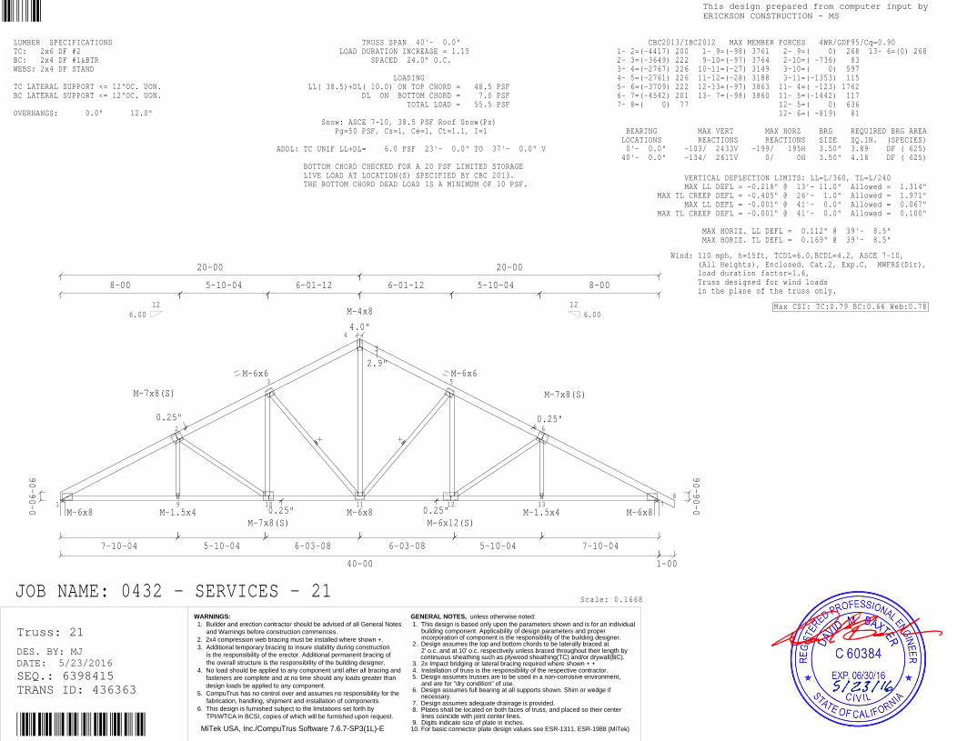
1
2
9 10
3
4
11 12
5
13
6
78
M-6x8
M-7x8(S)
M-1.5x4
M-6x6
M-7x8(S)M-6x8
M-4x8
M-6x12(S)
M-6x6
M-1.5x4
M-7x8(S)
M-6x80-06-06
7-10-04
8-00
0.25"
20-00
5-10-04
5-10-04
0.25"
6-03-08
6-01-12
4.0"
40-00
2.9"
6-01-12
6-03-08
0.25"
5-10-04
5-10-04
20-00
0.25"
8-00
7-10-04
1-00
0-06-06
6.0012 12
6.00
JOB NAME: 0432 - SERVICES - 21
LUMBER SPECIFICATIONSTC: 2x6 DF #2BC: 2x4 DF #1&BTRWEBS: 2x4 DF STAND TC LATERAL SUPPORT <= 12"OC. UON.BC LATERAL SUPPORT <= 12"OC. UON. OVERHANGS: 0.0" 12.0"
TRUSS SPAN 40'- 0.0" LOAD DURATION INCREASE = 1.15 SPACED 24.0" O.C. LOADING LL( 38.5)+DL( 10.0) ON TOP CHORD = 48.5 PSF DL ON BOTTOM CHORD = 7.0 PSF TOTAL LOAD = 55.5 PSF Snow: ASCE 7-10, 38.5 PSF Roof Snow(Ps) Pg=50 PSF, Cs=1, Ce=1, Ct=1.1, I=1 ADDL: TC UNIF LL+DL= 6.0 PSF 23'- 0.0" TO 37'- 0.0" V BOTTOM CHORD CHECKED FOR A 20 PSF LIMITED STORAGE LIVE LOAD AT LOCATION(S) SPECIFIED BY CBC 2013. THE BOTTOM CHORD DEAD LOAD IS A MINIMUM OF 10 PSF.
Scale: 0.1668
VERTICAL DEFLECTION LIMITS: LL=L/360, TL=L/240 MAX LL DEFL = -0.218" @ 13'- 11.0" Allowed = 1.314" MAX TL CREEP DEFL = -0.405" @ 26'- 1.0" Allowed = 1.971" MAX LL DEFL = -0.001" @ 41'- 0.0" Allowed = 0.067" MAX TL CREEP DEFL = -0.001" @ 41'- 0.0" Allowed = 0.100" MAX HORIZ. LL DEFL = 0.112" @ 39'- 8.5" MAX HORIZ. TL DEFL = 0.169" @ 39'- 8.5"
CBC2013/IBC2012 MAX MEMBER FORCES 4WR/GDF95/Cq=0.90 1- 2=(-4417) 200 1- 9=(-98) 3761 2- 9=( 0) 268 13- 6=(0) 268 2- 3=(-3649) 222 9-10=(-97) 3764 2-10=( -736) 83 3- 4=(-2767) 226 10-11=(-27) 3149 3-10=( 0) 597 4- 5=(-2761) 226 11-12=(-28) 3188 3-11=(-1353) 115 5- 6=(-3709) 222 12-13=(-97) 3863 11- 4=( -123) 1762 6- 7=(-4542) 201 13- 7=(-98) 3860 11- 5=(-1442) 117 7- 8=( 0) 77 12- 5=( 0) 636 12- 6=( -819) 81 BEARING MAX VERT MAX HORZ BRG REQUIRED BRG AREA LOCATIONS REACTIONS REACTIONS SIZE SQ.IN. (SPECIES) 0'- 0.0" -103/ 2433V -199/ 195H 3.50" 3.89 DF ( 625) 40'- 0.0" -134/ 2611V 0/ 0H 3.50" 4.18 DF ( 625)
Wind: 110 mph, h=15ft, TCDL=6.0,BCDL=4.2, ASCE 7-10, (All Heights), Enclosed, Cat.2, Exp.C, MWFRS(Dir), load duration factor=1.6, Truss designed for wind loads in the plane of the truss only.
Max CSI: TC:0.79 BC:0.66 Web:0.78
Truss: 21
DATE: 5/23/2016DES. BY: MJ
SEQ.: 6398415TRANS ID: 436363
MiTek USA, Inc./CompuTrus Software 7.6.7-SP3(1L)-E
This design prepared from computer input byERICKSON CONSTRUCTION - MS
WARNINGS: 1. Builder and erection contractor should be advised of all General Notes and Warnings before construction commences. 2. 2x4 compression web bracing must be installed where shown +. 3. Additional temporary bracing to insure stability during construction is the responsibility of the erector. Additional permanent bracing of the overall structure is the responsibility of the building designer. 4. No load should be applied to any component until after all bracing and fasteners are complete and at no time should any loads greater than design loads be applied to any component. 5. CompuTrus has no control over and assumes no responsibility for the fabrication, handling, shipment and installation of components. 6. This design is furnished subject to the limitations set forth by TPI/WTCA in BCSI, copies of which will be furnished upon request.
GENERAL NOTES, unless otherwise noted: 1. This design is based only upon the parameters shown and is for an individual building component. Applicability of design parameters and proper incorporation of component is the responsibility of the building designer. 2. Design assumes the top and bottom chords to be laterally braced at 2' o.c. and at 10' o.c. respectively unless braced throughout their length by continuous sheathing such as plywood sheathing(TC) and/or drywall(BC). 3. 2x Impact bridging or lateral bracing required where shown + + 4. Installation of truss is the responsibility of the respective contractor. 5. Design assumes trusses are to be used in a non-corrosive environment, and are for "dry condition" of use. 6. Design assumes full bearing at all supports shown. Shim or wedge if necessary. 7. Design assumes adequate drainage is provided. 8. Plates shall be located on both faces of truss, and placed so their center lines coincide with joint center lines. 9. Digits indicate size of plate in inches.10. For basic connector plate design values see ESR-1311, ESR-1988 (MiTek)

7
1
2
8 9
3
10
4
56
M-1.5x4
M-5x6
M-4x8
M-5x6
M-6x8(S)
M-3x5
M-1.5x4
M-7x8(S)
M-3x8
8-06-06
4-00
4-00
4-00
5.0"
1.1"
6-01-12
6-03-08
0.25"
24-00
5-10-04
5-10-04
20-00
0.25"
8-00
7-10-04
1-00
0-06-06
6.0012 12
6.00
JOB NAME: 0432 - SERVICES - 22
LUMBER SPECIFICATIONSTC: 2x6 DF #2BC: 2x4 DF #1&BTRWEBS: 2x4 DF STAND TC LATERAL SUPPORT <= 12"OC. UON.BC LATERAL SUPPORT <= 12"OC. UON. OVERHANGS: 0.0" 12.0"
TRUSS SPAN 24'- 0.0" LOAD DURATION INCREASE = 1.15 SPACED 24.0" O.C. LOADING LL( 38.5)+DL( 10.0) ON TOP CHORD = 48.5 PSF DL ON BOTTOM CHORD = 7.0 PSF TOTAL LOAD = 55.5 PSF Snow: ASCE 7-10, 38.5 PSF Roof Snow(Ps) Pg=50 PSF, Cs=1, Ce=1, Ct=1.1, I=1 ADDL: TC UNIF LL+DL= 6.0 PSF 7'- 0.0" TO 21'- 0.0" V BOTTOM CHORD CHECKED FOR A 20 PSF LIMITED STORAGE LIVE LOAD AT LOCATION(S) SPECIFIED BY CBC 2013. THE BOTTOM CHORD DEAD LOAD IS A MINIMUM OF 10 PSF.
Scale: 0.2146
VERTICAL DEFLECTION LIMITS: LL=L/360, TL=L/240 MAX LL DEFL = -0.071" @ 16'- 1.7" Allowed = 0.781" MAX TL CREEP DEFL = -0.142" @ 16'- 1.7" Allowed = 1.171" MAX LL DEFL = -0.001" @ 25'- 0.0" Allowed = 0.067" MAX TL CREEP DEFL = -0.001" @ 25'- 0.0" Allowed = 0.100" MAX HORIZ. LL DEFL = 0.028" @ 23'- 8.5" MAX HORIZ. TL DEFL = 0.046" @ 23'- 8.5"
CBC2013/IBC2012 MAX MEMBER FORCES 4WR/GDF95/Cq=0.90 1- 2=( -582) 131 7- 8=(-128) 222 7- 1=(-1376) 79 10- 4=(0) 268 2- 3=( -700) 126 8- 9=( 0) 1320 1- 8=( -35) 1103 3- 4=(-1631) 123 9-10=( -11) 2080 8- 2=( -45) 145 4- 5=(-2515) 104 10- 5=( -13) 2077 8- 3=(-1301) 118 5- 6=( 0) 77 9- 3=( 0) 703 9- 4=( -909) 85 BEARING MAX VERT MAX HORZ BRG REQUIRED BRG AREA LOCATIONS REACTIONS REACTIONS SIZE SQ.IN. (SPECIES) 0'- 0.0" -67/ 1397V -301/ 158H 3.50" 2.24 DF ( 625) 24'- 0.0" -88/ 1644V 0/ 0H 3.50" 2.63 DF ( 625)
Wind: 110 mph, h=15ft, TCDL=6.0,BCDL=4.2, ASCE 7-10, (All Heights), Enclosed, Cat.2, Exp.C, MWFRS(Dir), load duration factor=1.6, End vertical(s) are exposed to wind, Truss designed for wind loads in the plane of the truss only.
Max CSI: TC:0.55 BC:0.43 Web:0.93
Truss: 22
DATE: 5/23/2016DES. BY: MJ
SEQ.: 6398416TRANS ID: 436363
MiTek USA, Inc./CompuTrus Software 7.6.7-SP3(1L)-E
This design prepared from computer input byERICKSON CONSTRUCTION - MS
WARNINGS: 1. Builder and erection contractor should be advised of all General Notes and Warnings before construction commences. 2. 2x4 compression web bracing must be installed where shown +. 3. Additional temporary bracing to insure stability during construction is the responsibility of the erector. Additional permanent bracing of the overall structure is the responsibility of the building designer. 4. No load should be applied to any component until after all bracing and fasteners are complete and at no time should any loads greater than design loads be applied to any component. 5. CompuTrus has no control over and assumes no responsibility for the fabrication, handling, shipment and installation of components. 6. This design is furnished subject to the limitations set forth by TPI/WTCA in BCSI, copies of which will be furnished upon request.
GENERAL NOTES, unless otherwise noted: 1. This design is based only upon the parameters shown and is for an individual building component. Applicability of design parameters and proper incorporation of component is the responsibility of the building designer. 2. Design assumes the top and bottom chords to be laterally braced at 2' o.c. and at 10' o.c. respectively unless braced throughout their length by continuous sheathing such as plywood sheathing(TC) and/or drywall(BC). 3. 2x Impact bridging or lateral bracing required where shown + + 4. Installation of truss is the responsibility of the respective contractor. 5. Design assumes trusses are to be used in a non-corrosive environment, and are for "dry condition" of use. 6. Design assumes full bearing at all supports shown. Shim or wedge if necessary. 7. Design assumes adequate drainage is provided. 8. Plates shall be located on both faces of truss, and placed so their center lines coincide with joint center lines. 9. Digits indicate size of plate in inches.10. For basic connector plate design values see ESR-1311, ESR-1988 (MiTek)

6
1
2
7 8
3
9
4
5M-1.5x4
M-4x4
M-4x8
M-5x6
M-6x8(S)
M-3x5
M-1.5x4
M-7x8(S)
M-3x8
10-06-06
8-06-06
4-00
4-00
4-00
5.0"
1.1"
6-01-12
6-03-08
0.25"
24-00
5-10-04
5-10-04
20-00
0.25"
8-00
7-10-04
0-06-06
6.0012 12
6.00
JOB NAME: SERVICES BLDG TRUSS - 23
LUMBER SPECIFICATIONSTC: 2x6 DF #2BC: 2x4 DF #1&BTRWEBS: 2x4 DF STAND TC LATERAL SUPPORT <= 12"OC. UON.BC LATERAL SUPPORT <= 12"OC. UON.
TRUSS SPAN 24'- 0.0" LOAD DURATION INCREASE = 1.15 SPACED 24.0" O.C. LOADINGLL( 38.5)+DL( 10.0) ON TOP CHORD = 48.5 PSF DL ON BOTTOM CHORD = 7.0 PSF TOTAL LOAD = 55.5 PSF Snow: ASCE 7-10, 38.5 PSF Roof Snow(Ps) Pg=50 PSF, Cs=1, Ce=1, Ct=1.1, I=1 BOTTOM CHORD CHECKED FOR A 20 PSF LIMITED STORAGELIVE LOAD AT LOCATION(S) SPECIFIED BY CBC 2013.THE BOTTOM CHORD DEAD LOAD IS A MINIMUM OF 10 PSF.
Scale: 0.2129
VERTICAL DEFLECTION LIMITS: LL=L/360, TL=L/240 MAX LL DEFL = -0.072" @ 16'- 1.7" Allowed = 0.781" MAX TL CREEP DEFL = -0.129" @ 16'- 1.7" Allowed = 1.171" MAX HORIZ. LL DEFL = 0.029" @ 23'- 8.5" MAX HORIZ. TL DEFL = 0.043" @ 23'- 8.5"
CBC2013/IBC2012 MAX MEMBER FORCES 4WR/GDF95/Cq=0.90 1- 2=( -551) 130 6- 7=(-126) 215 6- 1=(-1302) 77 8- 4=(-841) 87 2- 3=( -654) 125 7- 8=( 0) 1226 1- 7=( -33) 1041 9- 4=( 0) 269 3- 4=(-1510) 121 8- 9=( -30) 1928 7- 2=( -55) 123 4- 5=(-2329) 102 9- 5=( -31) 1925 7- 3=(-1197) 116 8- 3=( -1) 665 BEARING MAX VERT MAX HORZ BRG REQUIRED BRG AREA LOCATIONS REACTIONS REACTIONS SIZE SQ.IN. (SPECIES) 0'- 0.0" -66/ 1324V -294/ 156H 3.50" 2.12 DF ( 625) 24'- 0.0" -56/ 1437V 0/ 0H 3.50" 2.30 DF ( 625)
Wind: 110 mph, h=15ft, TCDL=6.0,BCDL=4.2, ASCE 7-10, (All Heights), Enclosed, Cat.2, Exp.C, MWFRS(Dir), load duration factor=1.6, End vertical(s) are exposed to wind, Truss designed for wind loads in the plane of the truss only.
Max CSI: TC:0.58 BC:0.41 Web:0.91
Truss: 23
DATE: 3/29/2016DES. BY: EE
SEQ.: 6378835TRANS ID: 435039
MiTek USA, Inc./CompuTrus Software 7.6.7-SP3(1L)-E
This design prepared from computer input byERICKSON CONSTRUCTION - MS
WARNINGS: 1. Builder and erection contractor should be advised of all General Notes and Warnings before construction commences. 2. 2x4 compression web bracing must be installed where shown +. 3. Additional temporary bracing to insure stability during construction is the responsibility of the erector. Additional permanent bracing of the overall structure is the responsibility of the building designer. 4. No load should be applied to any component until after all bracing and fasteners are complete and at no time should any loads greater than design loads be applied to any component. 5. CompuTrus has no control over and assumes no responsibility for the fabrication, handling, shipment and installation of components. 6. This design is furnished subject to the limitations set forth by TPI/WTCA in BCSI, copies of which will be furnished upon request.
GENERAL NOTES, unless otherwise noted: 1. This design is based only upon the parameters shown and is for an individual building component. Applicability of design parameters and proper incorporation of component is the responsibility of the building designer. 2. Design assumes the top and bottom chords to be laterally braced at 2' o.c. and at 10' o.c. respectively unless braced throughout their length by continuous sheathing such as plywood sheathing(TC) and/or drywall(BC). 3. 2x Impact bridging or lateral bracing required where shown + + 4. Installation of truss is the responsibility of the respective contractor. 5. Design assumes trusses are to be used in a non-corrosive environment, and are for "dry condition" of use. 6. Design assumes full bearing at all supports shown. Shim or wedge if necessary. 7. Design assumes adequate drainage is provided. 8. Plates shall be located on both faces of truss, and placed so their center lines coincide with joint center lines. 9. Digits indicate size of plate in inches.10. For basic connector plate design values see ESR-1311, ESR-1988 (MiTek)

6
1T1
2
7
T2
8
3
9
4
T3
5M-1.5x4
M-3x5+
M-4x5M-3x5
M-1.5x4M-3x8+
M-3x5
M-3x8+
M-4x8
M-5x6
M-3x5
M-1.5x4
M-6x8(S)
M-3x8+M-3x8+
M-3x5M-3x5
M-3x5
M-3x5+
M-1.5x4
M-1.5x4
M-3x5M-7x8(S)
M-3x8
10-06-06
8-08-02
3-08-08
3-08-08
3-08-08
5.0"
1.1"
6-01-12
6-03-08
0.25"
23-08-08
5-10-04
5-10-04
20-00
0.25"
8-00
7-10-04
0-06-06
6.0012 12
6.00
JOB NAME: SERVICES BLDG TRUSS - 24
Staple or equal at non-structuralvertical members (uon).
LUMBER SPECIFICATIONSTC: 2x4 DF #1&BTR; 2x6 DF #2 T1-T3BC: 2x4 DF #1&BTRWEBS: 2x4 DF STAND TC LATERAL SUPPORT <= 12"OC. UON.BC LATERAL SUPPORT <= 12"OC. UON.
TRUSS SPAN 23'- 8.5" LOAD DURATION INCREASE = 1.15 (Non-Rep) SPACED 24.0" O.C. LOADINGLL( 38.5)+DL( 10.0) ON TOP CHORD = 48.5 PSF DL ON BOTTOM CHORD = 7.0 PSF TOTAL LOAD = 55.5 PSF Snow: ASCE 7-10, 38.5 PSF Roof Snow(Ps) Pg=50 PSF, Cs=1, Ce=1, Ct=1.1, I=1 BOTTOM CHORD CHECKED FOR A 20 PSF LIMITED STORAGELIVE LOAD AT LOCATION(S) SPECIFIED BY CBC 2013.THE BOTTOM CHORD DEAD LOAD IS A MINIMUM OF 10 PSF.
Scale: 0.2057
VERTICAL DEFLECTION LIMITS: LL=L/360, TL=L/240 MAX LL DEFL = -0.071" @ 15'- 10.2" Allowed = 0.771" MAX TL CREEP DEFL = -0.127" @ 15'- 10.2" Allowed = 1.156" MAX HORIZ. LL DEFL = 0.028" @ 23'- 5.0" MAX HORIZ. TL DEFL = 0.042" @ 23'- 5.0"
CBC2013/IBC2012 MAX MEMBER FORCES 4WR/GDF95/Cq=0.90 1- 2=( -509) 129 6- 7=(-125) 218 6- 1=(-1288) 75 8- 4=(-842) 88 2- 3=( -617) 123 7- 8=( 0) 1194 1- 7=( -36) 1047 9- 4=( 0) 268 3- 4=(-1474) 119 8- 9=( -28) 1898 7- 2=( -62) 110 4- 5=(-2294) 99 9- 5=( -29) 1894 7- 3=(-1197) 115 8- 3=( -1) 666 BEARING MAX VERT MAX HORZ BRG REQUIRED BRG AREA LOCATIONS REACTIONS REACTIONS SIZE SQ.IN. (SPECIES) 0'- 0.0" -65/ 1308V -296/ 155H 3.50" 2.09 DF ( 625) 23'- 8.5" -55/ 1421V 0/ 0H 3.50" 2.27 DF ( 625)
Wind: 110 mph, h=15ft, TCDL=6.0,BCDL=4.2, ASCE 7-10, (All Heights), Enclosed, Cat.2, Exp.C, MWFRS(Dir), load duration factor=1.6, End vertical(s) are exposed to wind, Truss designed for wind loads in the plane of the truss only.
Truss designed for 4x2 outlookers. 2x let-insof equal or greater grade as structural topchord. Insure tight fit at each end of let-in.Outlookers must be cut with care and arepermissible at inlet board areas only.
Max CSI: TC:0.68 BC:0.46 Web:0.95
Truss: 24
DATE: 3/29/2016DES. BY: EE
SEQ.: 6378836TRANS ID: 435039
MiTek USA, Inc./CompuTrus Software 7.6.7-SP3(1L)-E
This design prepared from computer input byERICKSON CONSTRUCTION - MS
WARNINGS: 1. Builder and erection contractor should be advised of all General Notes and Warnings before construction commences. 2. 2x4 compression web bracing must be installed where shown +. 3. Additional temporary bracing to insure stability during construction is the responsibility of the erector. Additional permanent bracing of the overall structure is the responsibility of the building designer. 4. No load should be applied to any component until after all bracing and fasteners are complete and at no time should any loads greater than design loads be applied to any component. 5. CompuTrus has no control over and assumes no responsibility for the fabrication, handling, shipment and installation of components. 6. This design is furnished subject to the limitations set forth by TPI/WTCA in BCSI, copies of which will be furnished upon request.
GENERAL NOTES, unless otherwise noted: 1. This design is based only upon the parameters shown and is for an individual building component. Applicability of design parameters and proper incorporation of component is the responsibility of the building designer. 2. Design assumes the top and bottom chords to be laterally braced at 2' o.c. and at 10' o.c. respectively unless braced throughout their length by continuous sheathing such as plywood sheathing(TC) and/or drywall(BC). 3. 2x Impact bridging or lateral bracing required where shown + + 4. Installation of truss is the responsibility of the respective contractor. 5. Design assumes trusses are to be used in a non-corrosive environment, and are for "dry condition" of use. 6. Design assumes full bearing at all supports shown. Shim or wedge if necessary. 7. Design assumes adequate drainage is provided. 8. Plates shall be located on both faces of truss, and placed so their center lines coincide with joint center lines. 9. Digits indicate size of plate in inches.10. For basic connector plate design values see ESR-1311, ESR-1988 (MiTek)

7
1
8
2
9
3 4
10
5
6
M-1.5x4
M-5x6
M-5x6
M-3x5
M-6x8(S)
M-1.5x4 M-7x8
M-3x5
M-1.5x4
M-3x8
5-06-06
5-04-11
5-08-08
6-00
13-08-08
4-01-12
3-10-04
0.25"
1.69"
3-10-04
23-08-08
5-10-04
4-05-13
10-00
8-00
5-06-03
0-06-06
126.00
JOB NAME: SERVICES BLDG TRUSS - 25
LUMBER SPECIFICATIONSTC: 2x6 DF #2BC: 2x4 DF #1&BTRWEBS: 2x4 DF STAND TC LATERAL SUPPORT <= 12"OC. UON.BC LATERAL SUPPORT <= 12"OC. UON.
TRUSS SPAN 23'- 8.5" LOAD DURATION INCREASE = 1.15 SPACED 24.0" O.C. LOADINGLL( 38.5)+DL( 10.0) ON TOP CHORD = 48.5 PSF DL ON BOTTOM CHORD = 7.0 PSF TOTAL LOAD = 55.5 PSF Snow: ASCE 7-10, 38.5 PSF Roof Snow(Ps) Pg=50 PSF, Cs=1, Ce=1, Ct=1.1, I=1, Lu=25' LIMITED STORAGE DOES NOT APPLY DUE TO THE SPATIALREQUIREMENTS OF CBC 2013 NOT BEING MET. BOTTOM CHORD CHECKED FOR 10PSF LIVE LOAD. TOPAND BOTTOM CHORD LIVE LOADS ACT NON-CONCURRENTLY.
Scale: 0.2882
VERTICAL DEFLECTION LIMITS: LL=L/360, TL=L/240 MAX LL DEFL = -0.070" @ 9'- 10.2" Allowed = 0.771" MAX TL CREEP DEFL = -0.111" @ 9'- 10.2" Allowed = 1.156" MAX HORIZ. LL DEFL = 0.025" @ 23'- 5.0" MAX HORIZ. TL DEFL = 0.036" @ 23'- 5.0"
CBC2013/IBC2012 MAX MEMBER FORCES 4WR/GDF95/Cq=0.90 1- 2=(-1299) 103 7- 8=(-46) 122 7- 1=(-1445) 82 4-10=( -7) 623 2- 3=(-1625) 122 8- 9=( 0) 1362 1- 8=( -67) 1713 10- 5=(-633) 104 3- 4=(-1636) 123 9-10=( 0) 1443 8- 2=(-1088) 94 4- 5=(-1899) 125 10- 6=(-71) 1908 2- 9=( -21) 490 5- 6=(-2322) 126 9- 3=( -538) 50 9- 4=( -204) 309 BEARING MAX VERT MAX HORZ BRG REQUIRED BRG AREA LOCATIONS REACTIONS REACTIONS SIZE SQ.IN. (SPECIES) 0'- 0.0" -61/ 1481V -159/ 75H 3.50" 2.37 DF ( 625) 23'- 8.5" -59/ 1438V 0/ 0H 3.50" 2.30 DF ( 625)
Wind: 110 mph, h=15ft, TCDL=6.0,BCDL=4.2, ASCE 7-10, (All Heights), Enclosed, Cat.2, Exp.C, MWFRS(Dir), load duration factor=1.6, End vertical(s) are exposed to wind, Truss designed for wind loads in the plane of the truss only.
Max CSI: TC:0.32 BC:0.42 Web:0.76
Truss: 25
DATE: 3/29/2016DES. BY: EE
SEQ.: 6378837TRANS ID: 435039
MiTek USA, Inc./CompuTrus Software 7.6.7-SP3(1L)-E
This design prepared from computer input byERICKSON CONSTRUCTION - MS
WARNINGS: 1. Builder and erection contractor should be advised of all General Notes and Warnings before construction commences. 2. 2x4 compression web bracing must be installed where shown +. 3. Additional temporary bracing to insure stability during construction is the responsibility of the erector. Additional permanent bracing of the overall structure is the responsibility of the building designer. 4. No load should be applied to any component until after all bracing and fasteners are complete and at no time should any loads greater than design loads be applied to any component. 5. CompuTrus has no control over and assumes no responsibility for the fabrication, handling, shipment and installation of components. 6. This design is furnished subject to the limitations set forth by TPI/WTCA in BCSI, copies of which will be furnished upon request.
GENERAL NOTES, unless otherwise noted: 1. This design is based only upon the parameters shown and is for an individual building component. Applicability of design parameters and proper incorporation of component is the responsibility of the building designer. 2. Design assumes the top and bottom chords to be laterally braced at 2' o.c. and at 10' o.c. respectively unless braced throughout their length by continuous sheathing such as plywood sheathing(TC) and/or drywall(BC). 3. 2x Impact bridging or lateral bracing required where shown + + 4. Installation of truss is the responsibility of the respective contractor. 5. Design assumes trusses are to be used in a non-corrosive environment, and are for "dry condition" of use. 6. Design assumes full bearing at all supports shown. Shim or wedge if necessary. 7. Design assumes adequate drainage is provided. 8. Plates shall be located on both faces of truss, and placed so their center lines coincide with joint center lines. 9. Digits indicate size of plate in inches.10. For basic connector plate design values see ESR-1311, ESR-1988 (MiTek)

8
1
9
2
10
3 4
11
5
6
7
M-1.5x4
M-4x8
M-4x8
M-3x5
M-7x8(S)
M-3x5 M-6x6
M-3x8
M-1.5x4
M-3x8
5-00-02
4-04-11
5-08-08
6-00
4-00
15-08-08
4-00
0.25"
23-08-08
6-01-12
5-08-08
1.69"
2-06-13
8-00
7-10-04
5-05-03
1-00
0-06-06
126.00
JOB NAME: SERVICES BLDG TRUSS - 26
LUMBER SPECIFICATIONSTC: 2x6 DF #2BC: 2x6 DF #2WEBS: 2x4 DF STAND TC LATERAL SUPPORT <= 12"OC. UON.BC LATERAL SUPPORT <= 12"OC. UON. OVERHANGS: 0.0" 12.0"
TRUSS SPAN 23'- 8.5" LOAD DURATION INCREASE = 1.15 SPACED 24.0" O.C. LOADINGLL( 38.5)+DL( 10.0) ON TOP CHORD = 48.5 PSF DL ON BOTTOM CHORD = 7.0 PSF TOTAL LOAD = 55.5 PSF Snow: ASCE 7-10, 38.5 PSF Roof Snow(Ps) Pg=50 PSF, Cs=1, Ce=1, Ct=1.1, I=1, Lu=25' LIMITED STORAGE DOES NOT APPLY DUE TO THE SPATIALREQUIREMENTS OF CBC 2013 NOT BEING MET. BOTTOM CHORD CHECKED FOR 10PSF LIVE LOAD. TOPAND BOTTOM CHORD LIVE LOADS ACT NON-CONCURRENTLY.
Scale: 0.2886
VERTICAL DEFLECTION LIMITS: LL=L/360, TL=L/240 MAX LL DEFL = -0.087" @ 10'- 0.0" Allowed = 0.771" MAX TL CREEP DEFL = -0.133" @ 10'- 0.0" Allowed = 1.156" MAX LL DEFL = -0.001" @ 24'- 8.5" Allowed = 0.067" MAX TL CREEP DEFL = -0.001" @ 24'- 8.5" Allowed = 0.100" MAX HORIZ. LL DEFL = 0.023" @ 23'- 5.0" MAX HORIZ. TL DEFL = 0.032" @ 23'- 5.0"
CBC2013/IBC2012 MAX MEMBER FORCES 4WR/GDF95/Cq=0.90 1- 2=(-1668) 103 8- 9=(-33) 103 8- 1=(-1441) 80 11- 5=(-498) 80 2- 3=(-2226) 128 9-10=( 0) 1750 1- 9=( -73) 1996 3- 4=(-1768) 106 10-11=(-13) 2249 9- 2=(-1103) 90 4- 5=(-2003) 111 11- 6=(-42) 1908 2-10=( -26) 685 5- 6=(-2270) 118 10- 3=( -440) 54 6- 7=( 0) 77 3-11=( -585) 57 4-11=( -6) 510 BEARING MAX VERT MAX HORZ BRG REQUIRED BRG AREA LOCATIONS REACTIONS REACTIONS SIZE SQ.IN. (SPECIES) 0'- 0.0" -59/ 1482V -132/ 61H 3.50" 2.37 DF ( 625) 23'- 8.5" -87/ 1504V 0/ 0H 3.50" 2.41 DF ( 625)
Wind: 110 mph, h=15ft, TCDL=6.0,BCDL=4.2, ASCE 7-10, (All Heights), Enclosed, Cat.2, Exp.C, MWFRS(Dir), load duration factor=1.6, End vertical(s) are exposed to wind, Truss designed for wind loads in the plane of the truss only.
Max CSI: TC:0.42 BC:0.35 Web:0.88
Truss: 26
DATE: 3/29/2016DES. BY: EE
SEQ.: 6378838TRANS ID: 435039
MiTek USA, Inc./CompuTrus Software 7.6.7-SP3(1L)-E
This design prepared from computer input byERICKSON CONSTRUCTION - MS
WARNINGS: 1. Builder and erection contractor should be advised of all General Notes and Warnings before construction commences. 2. 2x4 compression web bracing must be installed where shown +. 3. Additional temporary bracing to insure stability during construction is the responsibility of the erector. Additional permanent bracing of the overall structure is the responsibility of the building designer. 4. No load should be applied to any component until after all bracing and fasteners are complete and at no time should any loads greater than design loads be applied to any component. 5. CompuTrus has no control over and assumes no responsibility for the fabrication, handling, shipment and installation of components. 6. This design is furnished subject to the limitations set forth by TPI/WTCA in BCSI, copies of which will be furnished upon request.
GENERAL NOTES, unless otherwise noted: 1. This design is based only upon the parameters shown and is for an individual building component. Applicability of design parameters and proper incorporation of component is the responsibility of the building designer. 2. Design assumes the top and bottom chords to be laterally braced at 2' o.c. and at 10' o.c. respectively unless braced throughout their length by continuous sheathing such as plywood sheathing(TC) and/or drywall(BC). 3. 2x Impact bridging or lateral bracing required where shown + + 4. Installation of truss is the responsibility of the respective contractor. 5. Design assumes trusses are to be used in a non-corrosive environment, and are for "dry condition" of use. 6. Design assumes full bearing at all supports shown. Shim or wedge if necessary. 7. Design assumes adequate drainage is provided. 8. Plates shall be located on both faces of truss, and placed so their center lines coincide with joint center lines. 9. Digits indicate size of plate in inches.10. For basic connector plate design values see ESR-1311, ESR-1988 (MiTek)
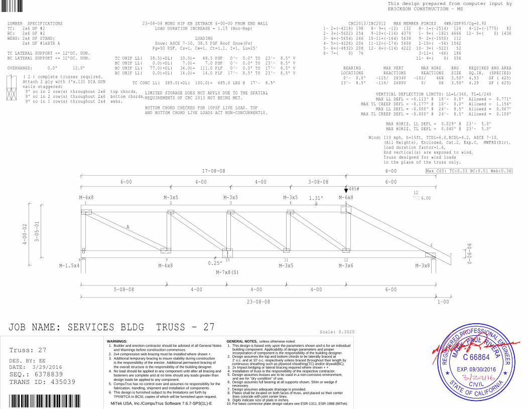
8
1
A
9
2
10
3
11
4
12
5
6
7
M-1.5x4
M-4x8
M-4x8
M-3x5
M-7x8(S)
M-3x5
M-3x5
M-3x5
M-3x6
M-6x8
M-3x8
4-00-02
3-05-01
5-08-08
6-00
4-00
4-00
17-08-08
0.25"
4-00
23-08-08
4-00
1.31"
4-00
3-08-08
6-00
6-00
6-00
1-00
0-06-06
126.00
485#
JOB NAME: SERVICES BLDG TRUSS - 27
LUMBER SPECIFICATIONSTC: 2x6 DF #2BC: 2x6 DF #2WEBS: 2x4 DF STAND; 2x4 DF #1&BTR A TC LATERAL SUPPORT <= 12"OC. UON.BC LATERAL SUPPORT <= 12"OC. UON. OVERHANGS: 0.0" 12.0"
( 2 ) complete trusses required.Attach 2 ply with 3"x.131 DIA GUNnails staggered: 9" oc in 2 row(s) throughout 2x6 top chords, 9" oc in 2 row(s) throughout 2x6 bottom chords, 9" oc in 1 row(s) throughout 2x4 webs.
23-08-08 MONO HIP EB SETBACK 6-00-00 FROM END WALL LOAD DURATION INCREASE = 1.15 (Non-Rep) LOADING Snow: ASCE 7-10, 38.5 PSF Roof Snow(Ps) Pg=50 PSF, Cs=1, Ce=1, Ct=1.1, I=1, Lu=25' TC UNIF LL( 38.5)+DL( 10.0)= 48.5 PSF 0'- 0.0" TO 23'- 8.5" VBC UNIF LL( 0.0)+DL( 7.0)= 7.0 PSF 0'- 0.0" TO 23'- 8.5" VBC UNIF LL( 77.0)+DL( 34.0)= 111.0 PLF 0'- 0.0" TO 17'- 8.5" VBC UNIF LL( 0.0)+DL( 14.0)= 14.0 PLF 17'- 8.5" TO 23'- 8.5" V TC CONC LL( 385.0)+DL( 100.0)= 485.0 LBS @ 17'- 8.5" LIMITED STORAGE DOES NOT APPLY DUE TO THE SPATIAL REQUIREMENTS OF CBC 2013 NOT BEING MET. BOTTOM CHORD CHECKED FOR 10PSF LIVE LOAD. TOP AND BOTTOM CHORD LIVE LOADS ACT NON-CONCURRENTLY.
Scale: 0.3020
VERTICAL DEFLECTION LIMITS: LL=L/360, TL=L/240 MAX LL DEFL = -0.113" @ 10'- 0.0" Allowed = 0.771" MAX TL CREEP DEFL = -0.177" @ 10'- 0.0" Allowed = 1.156" MAX LL DEFL = -0.000" @ 24'- 8.5" Allowed = 0.067" MAX TL CREEP DEFL = -0.000" @ 24'- 8.5" Allowed = 0.100" MAX HORIZ. LL DEFL = 0.029" @ 23'- 5.0" MAX HORIZ. TL DEFL = 0.040" @ 23'- 5.0"
CBC2013/IBC2012 MAX MEMBER FORCES 4WR/GDF95/Cq=0.90 1- 2=(-4218) 198 8- 9=( -12) 132 8- 1=(-2514) 124 4-12=(-1770) 82 2- 3=(-5602) 254 9-10=(-116) 4370 1- 9=( -182) 4666 12- 5=( 0) 1436 3- 4=(-5654) 266 10-11=(-164) 5638 9- 2=(-1550) 112 4- 5=(-4226) 206 11-12=(-174) 5606 2-10=( -56) 1562 5- 6=(-4832) 208 12- 6=(-114) 4222 10- 3=( -522) 52 6- 7=( 0) 76 3-11=( -66) 186 11- 4=( 0) 556 BEARING MAX VERT MAX HORZ BRG REQUIRED BRG AREA LOCATIONS REACTIONS REACTIONS SIZE SQ.IN. (SPECIES) 0'- 0.0" -115/ 2834V -101/ 46H 3.50" 4.53 DF ( 625) 23'- 8.5" -119/ 2680V 0/ 0H 3.50" 4.29 DF ( 625)
Wind: 110 mph, h=15ft, TCDL=6.0,BCDL=4.2, ASCE 7-10, (All Heights), Enclosed, Cat.2, Exp.C, MWFRS(Dir), load duration factor=1.6, End vertical(s) are exposed to wind, Truss designed for wind loads in the plane of the truss only.
Max CSI: TC:0.33 BC:0.51 Web:0.36
Truss: 27
DATE: 3/29/2016DES. BY: EE
SEQ.: 6378839TRANS ID: 435039
MiTek USA, Inc./CompuTrus Software 7.6.7-SP3(1L)-E
This design prepared from computer input byERICKSON CONSTRUCTION - MS
WARNINGS: 1. Builder and erection contractor should be advised of all General Notes and Warnings before construction commences. 2. 2x4 compression web bracing must be installed where shown +. 3. Additional temporary bracing to insure stability during construction is the responsibility of the erector. Additional permanent bracing of the overall structure is the responsibility of the building designer. 4. No load should be applied to any component until after all bracing and fasteners are complete and at no time should any loads greater than design loads be applied to any component. 5. CompuTrus has no control over and assumes no responsibility for the fabrication, handling, shipment and installation of components. 6. This design is furnished subject to the limitations set forth by TPI/WTCA in BCSI, copies of which will be furnished upon request.
GENERAL NOTES, unless otherwise noted: 1. This design is based only upon the parameters shown and is for an individual building component. Applicability of design parameters and proper incorporation of component is the responsibility of the building designer. 2. Design assumes the top and bottom chords to be laterally braced at 2' o.c. and at 10' o.c. respectively unless braced throughout their length by continuous sheathing such as plywood sheathing(TC) and/or drywall(BC). 3. 2x Impact bridging or lateral bracing required where shown + + 4. Installation of truss is the responsibility of the respective contractor. 5. Design assumes trusses are to be used in a non-corrosive environment, and are for "dry condition" of use. 6. Design assumes full bearing at all supports shown. Shim or wedge if necessary. 7. Design assumes adequate drainage is provided. 8. Plates shall be located on both faces of truss, and placed so their center lines coincide with joint center lines. 9. Digits indicate size of plate in inches.10. For basic connector plate design values see ESR-1311, ESR-1988 (MiTek)

12
3
4
M-3x5 M-1.5x4
M-1.5x4
4-00-02
0-06-06
1-00 6-00
6-00
3-06-06
6.0012
JOB NAME: SERVICES BLDG TRUSS - M1
LUMBER SPECIFICATIONSTC: 2x6 DF #2BC: 2x4 DF #1&BTRWEBS: 2x4 DF STAND TC LATERAL SUPPORT <= 12"OC. UON.BC LATERAL SUPPORT <= 12"OC. UON. OVERHANGS: 12.0" 0.0"
TRUSS SPAN 6'- 0.0" LOAD DURATION INCREASE = 1.15 SPACED 24.0" O.C. LOADINGLL( 38.5)+DL( 10.0) ON TOP CHORD = 48.5 PSF DL ON BOTTOM CHORD = 7.0 PSF TOTAL LOAD = 55.5 PSF Snow: ASCE 7-10, 38.5 PSF Roof Snow(Ps) Pg=50 PSF, Cs=1, Ce=1, Ct=1.1, I=1 LIMITED STORAGE DOES NOT APPLY DUE TO THE SPATIALREQUIREMENTS OF CBC 2013 NOT BEING MET. BOTTOM CHORD CHECKED FOR 10PSF LIVE LOAD. TOPAND BOTTOM CHORD LIVE LOADS ACT NON-CONCURRENTLY.
Scale: 0.5435
VERTICAL DEFLECTION LIMITS: LL=L/360, TL=L/240 MAX LL DEFL = -0.001" @ -1'- 0.0" Allowed = 0.067" MAX TL CREEP DEFL = -0.001" @ -1'- 0.0" Allowed = 0.100" MAX TC PANEL LL DEFL = -0.047" @ 3'- 0.3" Allowed = 0.385" MAX BC PANEL TL DEFL = -0.066" @ 3'- 0.9" Allowed = 0.344" MAX HORIZ. LL DEFL = -0.000" @ 5'- 10.3" MAX HORIZ. TL DEFL = -0.000" @ 5'- 10.3"
CBC2013/IBC2012 MAX MEMBER FORCES 4WR/GDF95/Cq=0.90 1-2=( 0) 77 2-4=(-34) 31 3-4=(-282) 45 2-3=(-150) 107 BEARING MAX VERT MAX HORZ BRG REQUIRED BRG AREA LOCATIONS REACTIONS REACTIONS SIZE SQ.IN. (SPECIES) 0'- 0.0" -46/ 542V -38/ 101H 3.50" 0.87 DF ( 625) 6'- 0.0" -20/ 323V 0/ 0H 3.50" 0.52 DF ( 625)
Wind: 110 mph, h=15ft, TCDL=6.0,BCDL=4.2, ASCE 7-10, (All Heights), Enclosed, Cat.2, Exp.C, MWFRS(Dir), load duration factor=1.6, End vertical(s) are exposed to wind, Truss designed for wind loads in the plane of the truss only.
Max CSI: TC:0.34 BC:0.22 Web:0.11
Truss: M1
DATE: 3/29/2016DES. BY: EE
SEQ.: 6378840TRANS ID: 435039
MiTek USA, Inc./CompuTrus Software 7.6.7-SP3(1L)-E
This design prepared from computer input byERICKSON CONSTRUCTION - MS
WARNINGS: 1. Builder and erection contractor should be advised of all General Notes and Warnings before construction commences. 2. 2x4 compression web bracing must be installed where shown +. 3. Additional temporary bracing to insure stability during construction is the responsibility of the erector. Additional permanent bracing of the overall structure is the responsibility of the building designer. 4. No load should be applied to any component until after all bracing and fasteners are complete and at no time should any loads greater than design loads be applied to any component. 5. CompuTrus has no control over and assumes no responsibility for the fabrication, handling, shipment and installation of components. 6. This design is furnished subject to the limitations set forth by TPI/WTCA in BCSI, copies of which will be furnished upon request.
GENERAL NOTES, unless otherwise noted: 1. This design is based only upon the parameters shown and is for an individual building component. Applicability of design parameters and proper incorporation of component is the responsibility of the building designer. 2. Design assumes the top and bottom chords to be laterally braced at 2' o.c. and at 10' o.c. respectively unless braced throughout their length by continuous sheathing such as plywood sheathing(TC) and/or drywall(BC). 3. 2x Impact bridging or lateral bracing required where shown + + 4. Installation of truss is the responsibility of the respective contractor. 5. Design assumes trusses are to be used in a non-corrosive environment, and are for "dry condition" of use. 6. Design assumes full bearing at all supports shown. Shim or wedge if necessary. 7. Design assumes adequate drainage is provided. 8. Plates shall be located on both faces of truss, and placed so their center lines coincide with joint center lines. 9. Digits indicate size of plate in inches.10. For basic connector plate design values see ESR-1311, ESR-1988 (MiTek)
Related Documents